Siemens RF382R RFID Reader User Manual SIMATIC RF382R Scanmode
Siemens AG RFID Reader SIMATIC RF382R Scanmode
UserManual.wiki
>
Siemens
>
RF382R User Manual
user manual
Navigation menu
Upload a User Manual
Namespaces
Wiki Guide
HTML
PDF
Info
Views
User Manual
Discussion / Help
Navigation
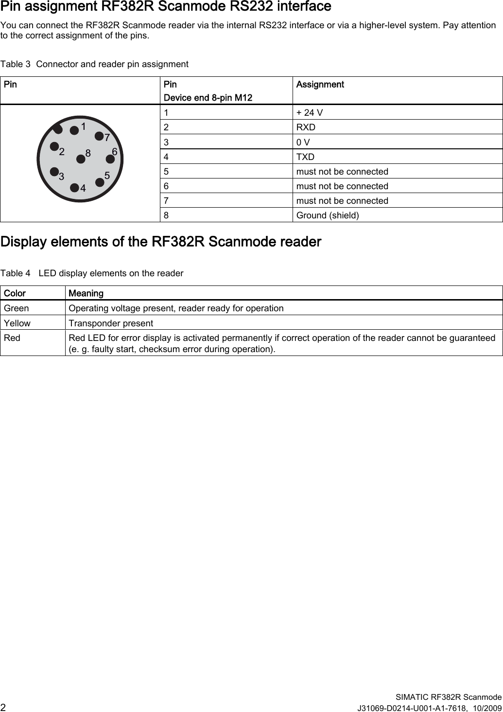
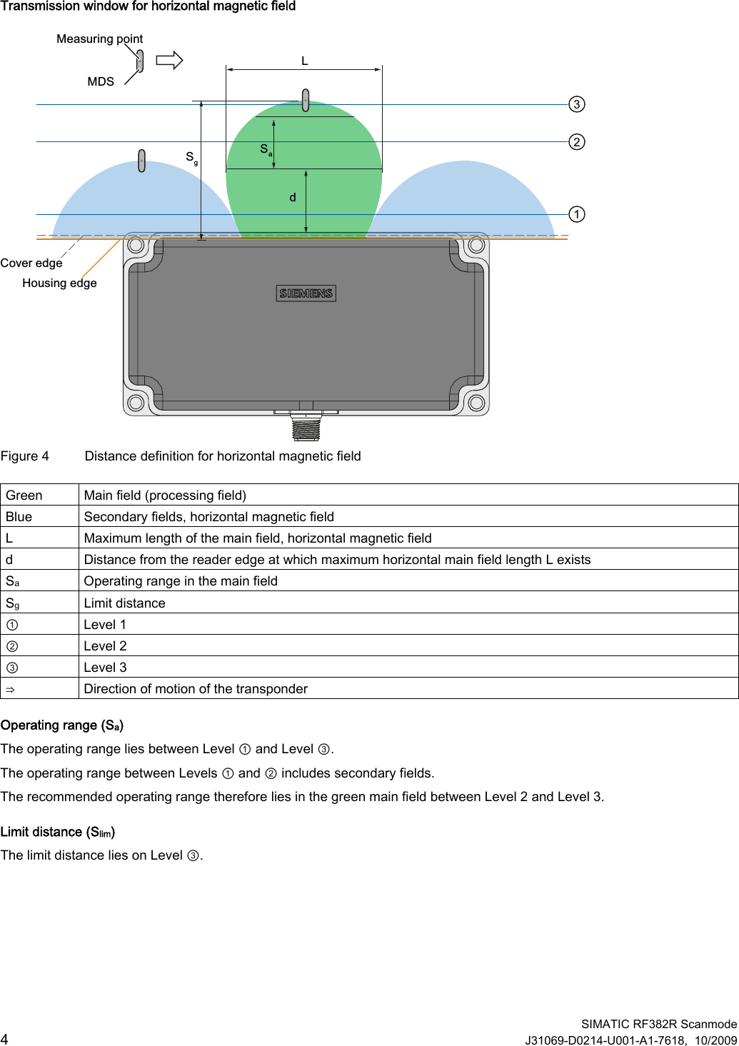
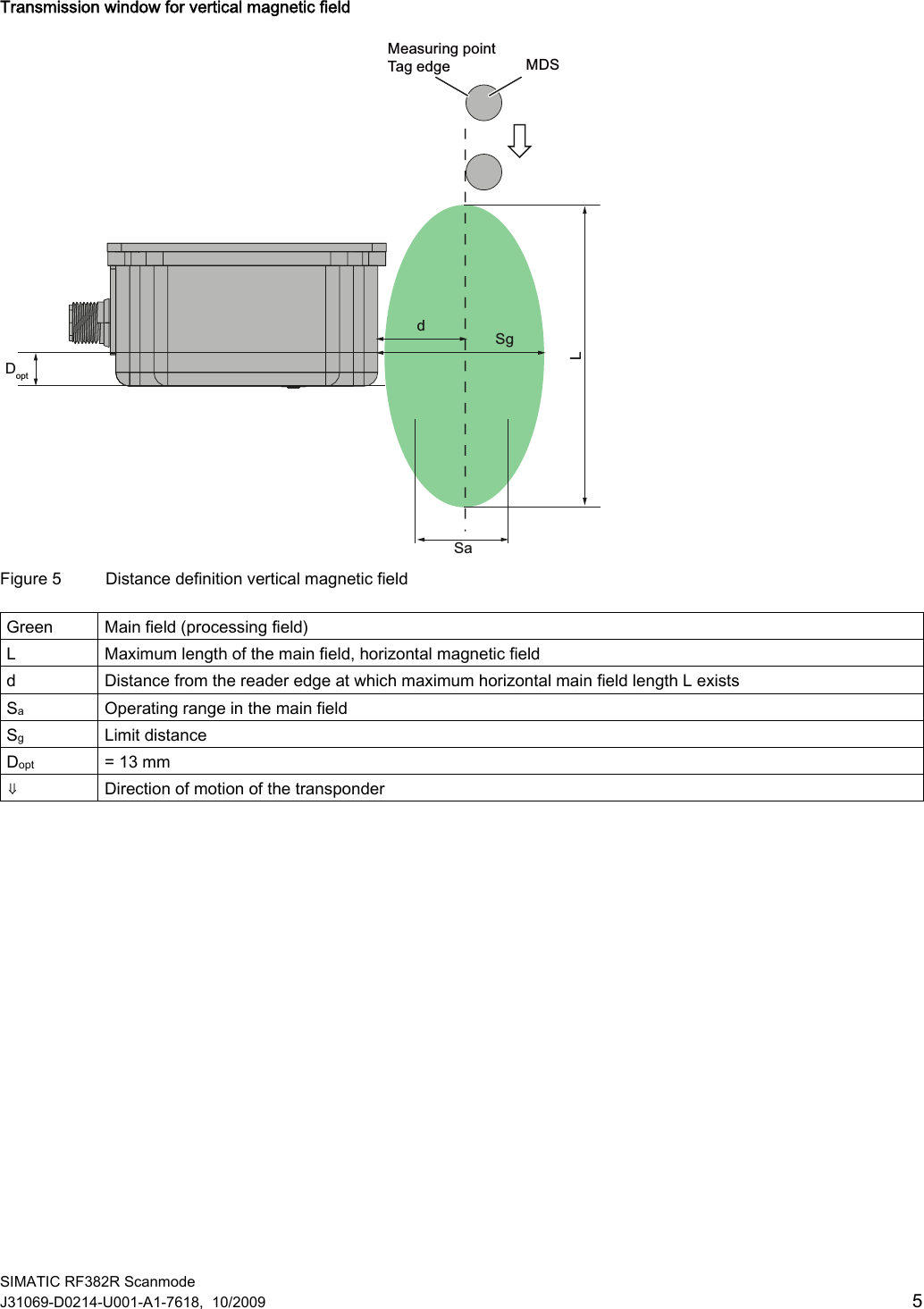
![SIMATIC RF382R Scanmode J31069-D0214-U001-A1-7618, 10/2009 3 Transmission window Orientation of magnetic fields of the SIMATIC RF382R Scanmode For many applications it may be best to operate the reader so that the tags move from left to right (or from right to left) at a certain distance in front of the narrow edge of the reader. This direction of movement uses the horizontal magnetic field of the reader, see figure below. You also have the option of moving the tags up and down (or down and up) past the narrow edge of the reader. This direction of movement uses the vertical magnetic field of the reader. KRUL]RQWDOYHUWLFDO Figure 1 Definition of horizontal and vertical magnetic reader field Maximum magnetic field strength The reader creates the maximum magnetic field about 13 mm below the upper reader edge. For the largest possible reading range the tags you want to read should move in this range. This applies whether you use the horizontal or the vertical magnetic field. 'RSW PP Figure 2 Line of maximum magnetic field strength The area of the maximum field strength and, therefore, the maximum range is identified by a laser icon: Figure 3 Laser icon marking](https://usermanual.wiki/Siemens/RF382R/User-Guide-1349876-Page-3.png)