Siemens RF382R RFID Reader User Manual SIMATIC RF382R Scanmode
Siemens AG RFID Reader SIMATIC RF382R Scanmode
Siemens >
user manual
© Siemens Ⓟ 2009
J31069-D0214-U001-A1-7618, 10/2009 1
SIMATIC Sensors
RFID systems
SIMATIC RF382R Scanmode
Operating Instructions (Compact)
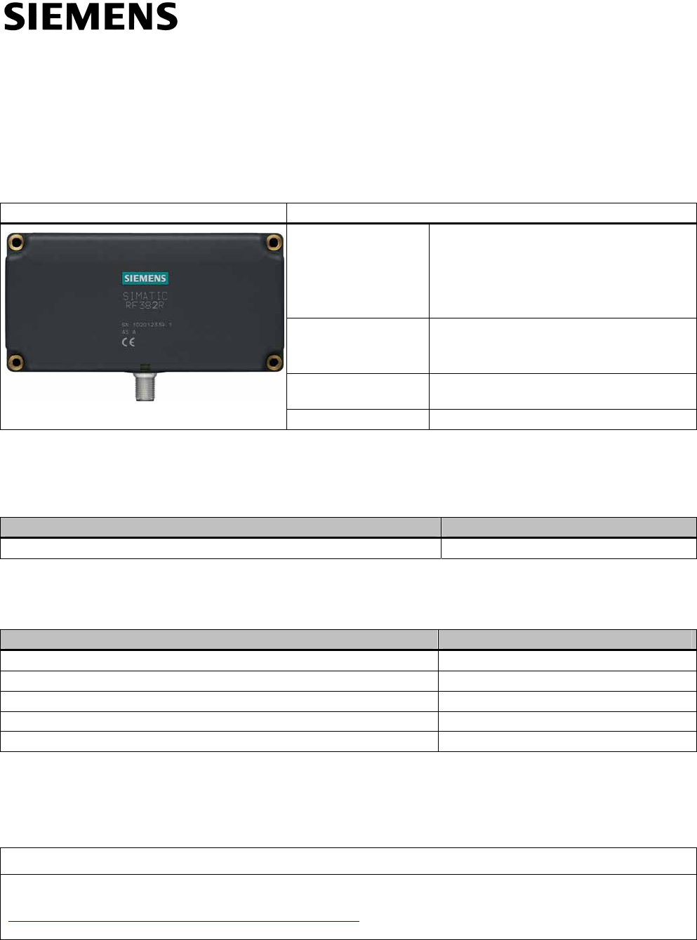
Characteristics
RF382R Scanmode Characteristics
Operating range Suitable for high speeds, e.g. in
● Suspension conveyor systems
● Assembly lines
● Production
● Order picking
Antenna field Designed for transponders that are directed
sideways past the long side of the antenna.
See Chapter Transmission window (Page 3)
Read distance Depending on transponder; see Field data for
MDS and SLG (Page 6)
Degree of protection IP67
Ordering data
Table 1 RF382R Scanmode ordering data
Product Order No.
RF382R Scanmode 6GT2801-3AB20-0AX0
Table 2 RF382R Scanmode ordering data for accessories
Accessories Order No.
Simatic Sensors connecting cable, length: 5 m 6GT2891-0FH50
Simatic Sensors RF380R connecting cable RS232 6GT2891-0KH50
Wide-range power supply 24 V, 4 A, with Euro plug 6GT2898-0AA00
Wide-range power supply 24 V, 4 A, with UK plug 6GT2898-0AA10
Wide-range power supply 24 V, 4 A, with US plug 6GT2898-0AA20
Safety instructions for the device/system
NOTICE
This device/system may only be used for the application instances that have been described in the catalog and the
technical documentation "SIMATIC RF300 System Manual
(http://support.automation.siemens.com/WW/view/en/21738946)" and only in combination with third-party devices and
components recommended and/or approved by Siemens.
Any changes or modifications not expressly approved by the party responsible for compliance could void the user's authority to operate the
equipment
SIMATIC RF382R Scanmode
2 J31069-D0214-U001-A1-7618, 10/2009
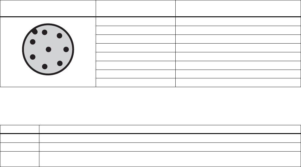
Pin assignment RF382R Scanmode RS232 interface
You can connect the RF382R Scanmode reader via the internal RS232 interface or via a higher-level system. Pay attention
to the correct assignment of the pins.
Table 3 Connector and reader pin assignment
Pin Pin
Device end 8-pin M12
Assignment
1 + 24 V
2 RXD
3 0 V
4 TXD
5 must not be connected
6 must not be connected
7 must not be connected
8 Ground (shield)
Display elements of the RF382R Scanmode reader
Table 4 LED display elements on the reader
Color Meaning
Green Operating voltage present, reader ready for operation
Yellow Transponder present
Red Red LED for error display is activated permanently if correct operation of the reader cannot be guaranteed
(e. g. faulty start, checksum error during operation).
SIMATIC RF382R Scanmode
J31069-D0214-U001-A1-7618, 10/2009 3
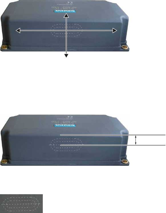
Transmission window
Orientation of magnetic fields of the SIMATIC RF382R Scanmode
For many applications it may be best to operate the reader so that the tags move from left to right (or from right to left) at a
certain distance in front of the narrow edge of the reader. This direction of movement uses the horizontal magnetic field of
the reader, see figure below.
You also have the option of moving the tags up and down (or down and up) past the narrow edge of the reader. This
direction of movement uses the vertical magnetic field of the reader.
KRUL]RQWDO
YHUWLFDO
Figure 1 Definition of horizontal and vertical magnetic reader field
Maximum magnetic field strength
The reader creates the maximum magnetic field about 13 mm below the upper reader edge. For the largest possible reading
range the tags you want to read should move in this range. This applies whether you use the horizontal or the vertical
magnetic field.
'RSW PP
Figure 2 Line of maximum magnetic field strength
The area of the maximum field strength and, therefore, the maximum range is identified by a laser icon:
Figure 3 Laser icon marking
SIMATIC RF382R Scanmode
4 J31069-D0214-U001-A1-7618, 10/2009
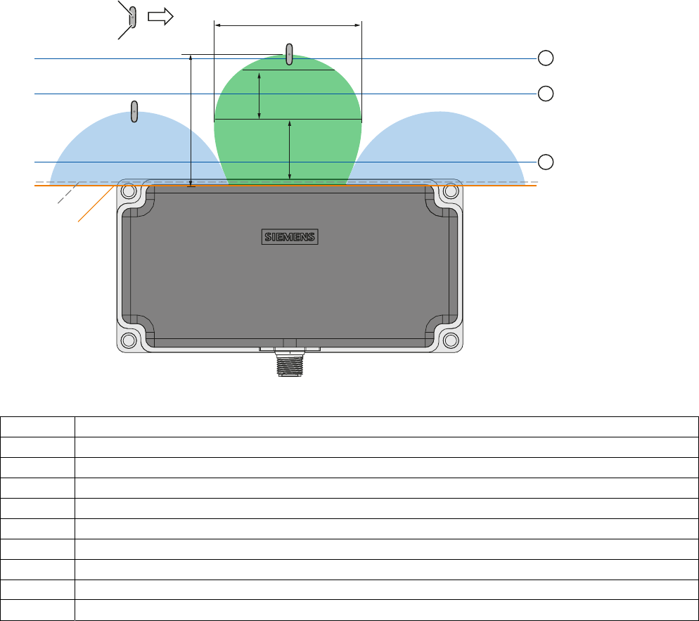
Transmission window for horizontal magnetic field
+RXVLQJHGJH
&RYHUHGJH
0'6
0HDVXULQJSRLQW
/
6
J
6
D
G
Figure 4 Distance definition for horizontal magnetic field
Green Main field (processing field)
Blue Secondary fields, horizontal magnetic field
L Maximum length of the main field, horizontal magnetic field
d Distance from the reader edge at which maximum horizontal main field length L exists
Sa Operating range in the main field
Sg Limit distance
① Level 1
② Level 2
③ Level 3
⇒ Direction of motion of the transponder
Operating range (Sa)
The operating range lies between Level ① and Level ③.
The operating range between Levels ① and ② includes secondary fields.
The recommended operating range therefore lies in the green main field between Level 2 and Level 3.
Limit distance (Slim)
The limit distance lies on Level ③.
SIMATIC RF382R Scanmode
J31069-D0214-U001-A1-7618, 10/2009 5
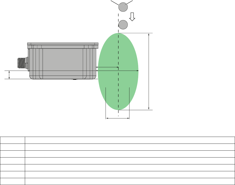
Transmission window for vertical magnetic field
6D
G6J
/
'
RSW
0HDVXULQJSRLQW
7DJHGJH 0'6
Figure 5 Distance definition vertical magnetic field
Green Main field (processing field)
L Maximum length of the main field, horizontal magnetic field
d Distance from the reader edge at which maximum horizontal main field length L exists
Sa Operating range in the main field
Sg Limit distance
Dopt = 13 mm
⇓ Direction of motion of the transponder

SIMATIC RF382R Scanmode
6 J31069-D0214-U001-A1-7618, 10/2009
Field data for MDS and SLG
The following tables show the field data of transponders with SIMATIC RF382R Scanmode. The technical specifications
listed below are typical data and apply at an ambient temperature of +22 °C.
Tolerances of ±20% are admissible due to production and temperature conditions.
Field data horizontal field
Table 5 Length of the transmission window L
MDS D124 MDS D160 MDS D324 MDS D424 MDS D460
60 50 60 65 50
All dimensions in mm
Table 6 Usable field width with dynamic operation (median deviation) in mm
MDS D124 MDS D160 MDS D324 MDS D424 MDS D460
20 20 20 20 20
All dimensions in mm
Table 7 Operating range
MDS D124 MDS D160 MDS D324 MDS D424 MDS D460
40…65 35….50 40…65 40…65 30…50
All dimensions in mm
Table 8 Limit distance
MDS D124 MDS D160 MDS D324 MDS D424 MDS D460
75 65 75 75 60
All dimensions in mm
Field data vertical field
Table 9 Length of the transmission window at different distances d (reader tag edge)
d (mm) MDS D124 MDS D160 MDS D324 MDS D424 MDS D460
2 155 130 155 150 120
10 150 125 150 145 115
20 140 110 140 135 105
30 130 100 130 120 90
All dimensions in mm

SIMATIC RF382R Scanmode
J31069-D0214-U001-A1-7618, 10/2009 7
Table 10 Usable field width with dynamic operation (median deviation)
MDS D124 MDS D160 MDS D324 MDS D424 MDS D460
25 25 25 25 25
All dimensions in mm
Table 11 Operating range in mm (Sa)
MDS D124 MDS D160 MDS D324 MDS D424 MDS D460
10…25 10…25 10…25 10…25 10…25
All dimensions in mm
Table 12 Limit distance in mm (Sg)
MDS D124 MDS D160 MDS D324 MDS D424 MDS D460
75 65 75 75 60
All dimensions in mm
Note
Tips if the range is too short
If the range of the antenna is too short, you must check
● the power supply/switched-mode power supply (interference)
● whether there are monitors or other sources of interference nearby
● whether there is metal in the environment
Minimum distance from transponder to transponder (without multitag mode), in mm
The values are valid at a distance of 20 mm (reader-tag).
Table 13 Minimum distance transponder
MDS D124 to
MDS D124
MDS D160 to
MDS D160
MDS D324 to
MDS D324
MDS D424 to
MDS D424
MDS D460 to
MDS D460
Horizontal main
field
100 100 100 100 100
Vertical main field 150 120 150 180 120
The minimum distance can be undershot in multitag mode.
NOTICE
Extension of the data transmission time if distance values are undershot
If the distance values specified in the tables are undershot, it is possible that the inductive fields will be affected. The time
required for data transmission can increase unpredictably.
For this reason, please observe the values in the tables.
SIMATIC RF382R Scanmode
8 J31069-D0214-U001-A1-7618, 10/2009
Traversing speed with RF382R Scanmode
The following table shows the traversing speed of a transponder through the main field. The direction of motion of the
transponder is horizontal.
Table 14 Traversing speed of different transponders
MDS D124 MDS D160
MDS D460
MDS D324
MDS D424
UID number
(8 bytes)
1.5 m/s 1.5 m/s 1.5 m/s
Mounting on metal
The RF382R can be mounted directly on metal. Flush mounting on metal is not permitted.
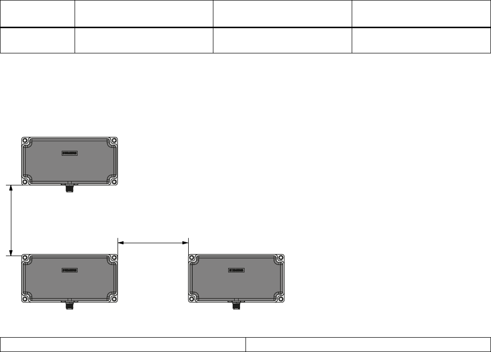
Minimum distance between several RF382R Scanmode readers
'
'
Figure 6 Minimum distance between several RF382R Scanmode readers
Minimum distance D from RF382R to RF382R D ≥ 200 mm
SIMATIC RF382R Scanmode
J31069-D0214-U001-A1-7618, 10/2009 9
Setting the parameters of the RF382R
Certain parameters of the scan mode can be changed during operation. These parameters are transferred from the host to
the reader via the serial interface for this purpose.
You can change the following parameters this way:
● ScanMode: Single Read (single reading of a tag) or Continuous Read (continuous reading of a tag)
● LockTime: Lock time for the setting "Continuous Read"
● Retentive: The parameters are stored in the non-volatile Flash memory of the reader.
The interface parameters for transfer are set permanently to 38400, 8, n, 1. This data sequence can be easily integrated into
an existing application because the parameter assignment frame is open.
Structure of the parameter assignment frame to the reader
You can transfer a new parameter set to the reader at any time during operation. When a parameter set is received, scan
mode will be interrupted, and the new parameters are checked and adopted if they are found to be "good". Scan mode will
start up immediately once the parameters have been accepted.
Note
Data will be lost during parameter setting (which means from receipt of a parameter frame until acknowledgment) if
operation continues.
The parameters are either saved in RAM (status = 00) only or retentively (status = 01). The command for transmission of
parameters ("Para") is 01.
Data backup takes place with a simple EXOR operation (BCC) of all data bytes to be transferred.
The parameters will be transferred as a data sequence (message frame). The following parameters can be modified:
● "LockTime" parameter; you can set values of 0..65535 (time base 100 ms)
● "ScanMode" parameter; you can set ContinousRead (00) and SingleRead (01)
All the other parameter bytes are reserved for future use and have to be assigned with 0.
Sending parameters to the reader
Command
byte
"Para"
Status 1st byte
(res.)
… 6th byte
"ScanMode"
7th byte
"LockTime"
(HighByte)
8th byte
"LockTime"
(LowByte)
… 21st byte
(res.)
BCC
The command message frame consists of 24 bytes that you always have to transfer completely.
Acknowledgment of the reader
Acknowledgment
byte
"Para"
Error code BCC
The acknowledgment message frame consists of three bytes. The acknowledgment byte is identical to the command byte.
The error code is zero if the parameters are accepted without errors. An error code other than zero means that the
parameters have not been accepted. The following error codes are defined:
01 The command byte is incorrect (only "Para" is permitted)
02 The status byte is incorrect (RAM or retentive only)
03 The Scanmode parameter is incorrect (ContinousRead and SingleRead permitted only)
04 The BCC value in the parameter message frame is incorrect.
05 Data could not be saved retentively (error with Flash type request)
06 Data could not be saved retentively (error with Flash delete)
07 Data could not be saved retentively (error with Flash writing)

SIMATIC RF382R Scanmode
10 J31069-D0214-U001-A1-7618, 10/2009
Technical specifications
Table 15 RF382R technical specifications
Inductive interface to the MDS
Transmission frequency 13.56 MHz
Transmit power Approx. 0.7 W
Supported transponders (reader air interface) Transponder to ISO 15693
Antenna Integrated, horseshoe shape
HOST interface RS232
Baud rate 38400 baud
Read distances of the reader See Chapter Field data for MDS and SLG (Page 6)
Minimum distance between two RF382R Scanmode readers 200 mm
Cable length reader - HOST max. 30 m
Maximum data transmission rate
transponder (tag) - reader (reading)
600 byte/s
Functions Read transponder serial number
Power supply 24 V DC
Display elements 2-color LED
(operating voltage, presence, error)
Plug connector M12 (8-pin)
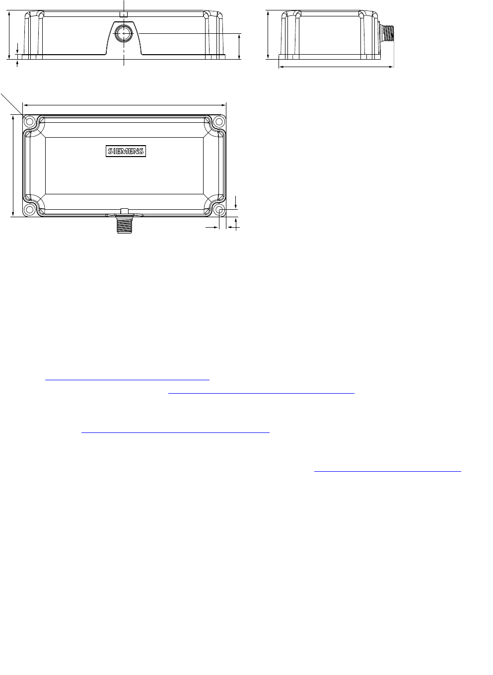
Housing
● Dimensions (in mm)
● Color
● Material
● 160 x 80 x 41 (without M12 device connector)
● Anthracite
● Plastic PA 12
Mounting 4 x M5 screws
Ambient temperature
● Operation
● Transport and storage
● -25 °C to +70 °C
● -40 °C to +85 °C
Degree of protection to EN 60529
Shock to EN 60721-3-7 Class 7 M2
Vibration to EN 60721-3-7 Class 7 M2
IP67
50g
20g
Weight approx. 550 g
MTBF (Mean Time Between Failures) 1 x 10⁶ h
Approvals Radio to R&TTE guidelines EN 300 330,
EN 301489, CE
Current consumption typ. 140 mA
Max. power consumption (DC input) 3.5 W
SIMATIC RF382R Scanmode
J31069-D0214-U001-A1-7618, 10/2009 11
Dimension drawing
Figure 7 Dimension drawing
Service & Support
Technical Support
You can access technical support for all IA/DT projects via the following:
● Phone: + 49 (0) 180 5050 222
(€ 0.14 /min. from the German landline network, deviating mobile communications prices are possible)
● E-mail (mailto:support.automation@siemens.com)
● Internet: Online support request form: (www.siemens.com/automation/support-request)
Service & support at IA/DT
Support homepage (www.siemens.com/automation/service&support)
RFID homepage
For general information about our identification systems, visit RFID homepage (www.siemens.com/simatic-sensors/rf).
Siemens AG
Industry Sector
Postfach 48 48
90026 NÜRNBERG
SIMATIC RF382R Scanmode
J31069-D0214-U001-A1-7618, 10/2009
FCC Information to the user:
This equipment has been tested and found to comply with the limits for a Class A digital device, pursuant to part 15 of
the FCC Rules. These limits are designed to provide reasonable protection against harmful interference when the
equipment is operated in a commercial environment. This equipment generates, uses, and can radiate radio
frequency energy and, if not installed and used in accordance with the instruction manual, may cause harmful
interference to radio communications. Operation of this equipment in a residential area is likely to cause harmful
interference in which case the user will be required to correct the interference at his own expense.