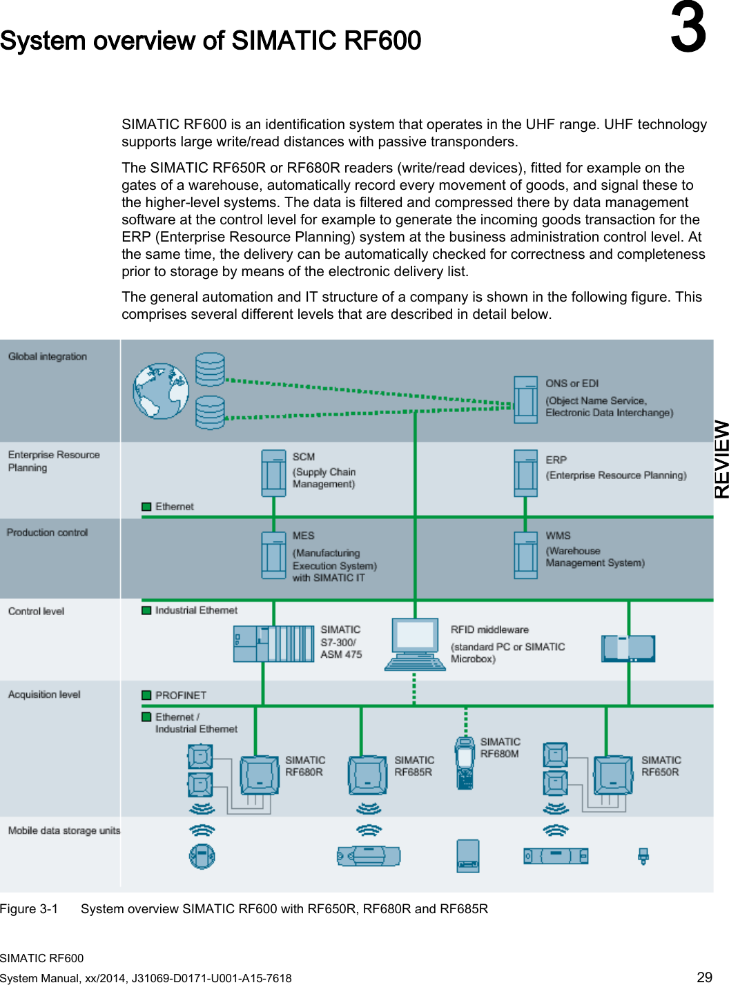
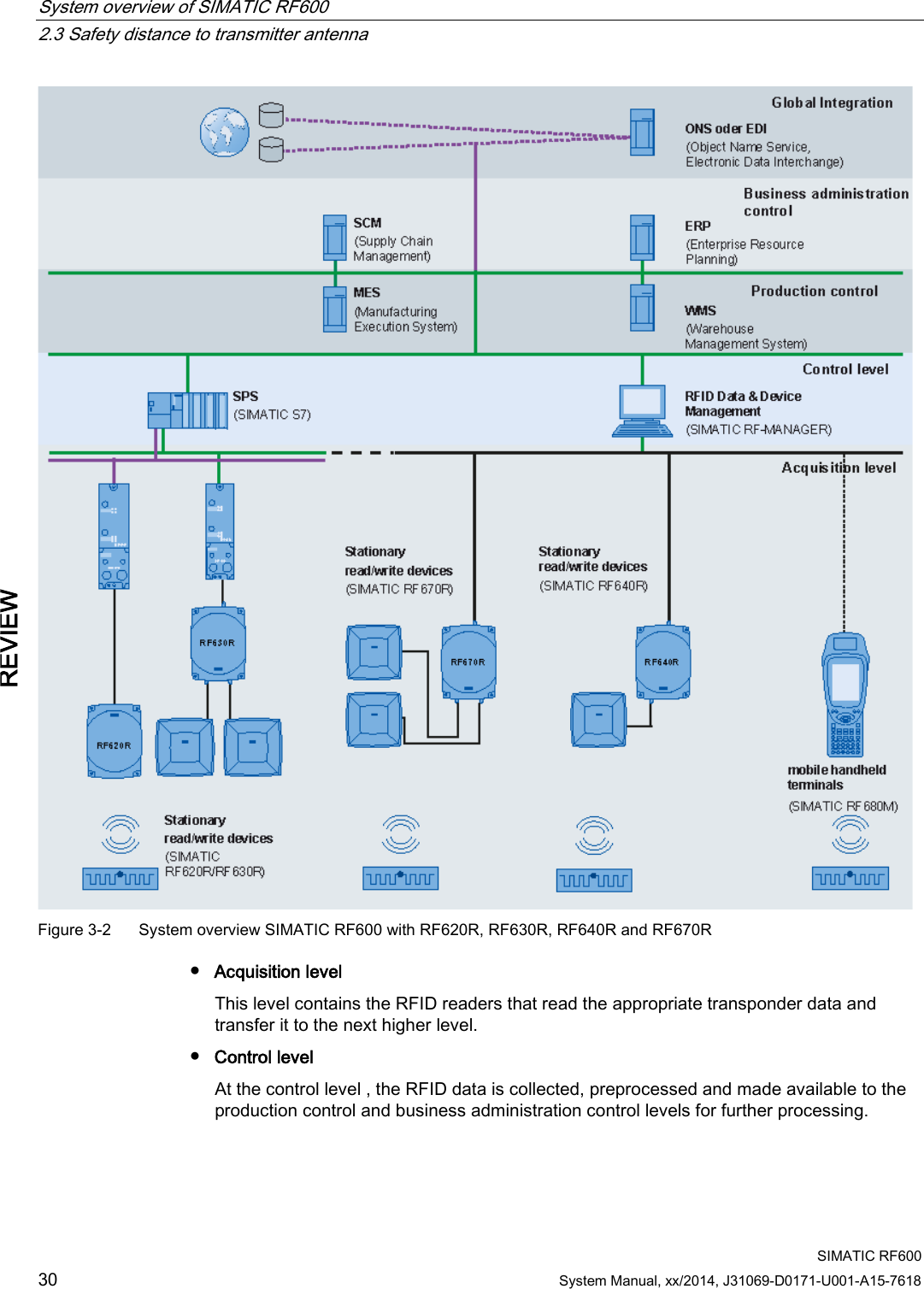
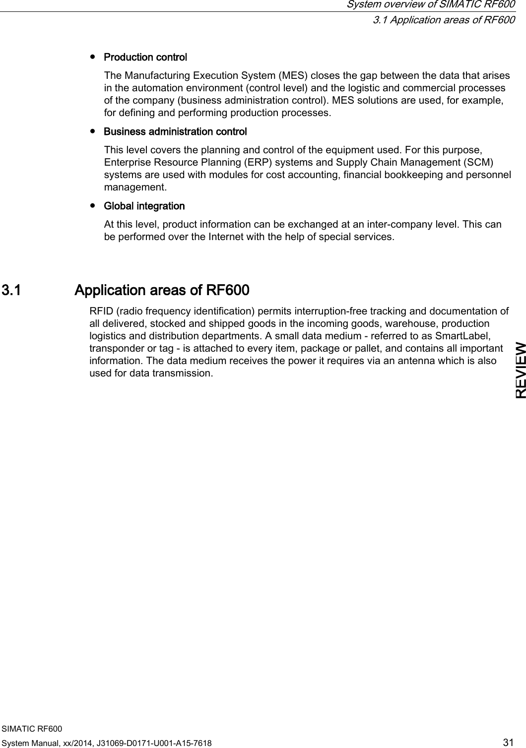
Siemens RF600R2 RFID UHF Reader RF650R, RF680R, RF685R User Manual SIMATIC RF600
Siemens AG RFID UHF Reader RF650R, RF680R, RF685R SIMATIC RF600
Siemens >
Contents
- 1. User Manual part 1
- 2. User Manual part 2
- 3. User Manual
User Manual part 1
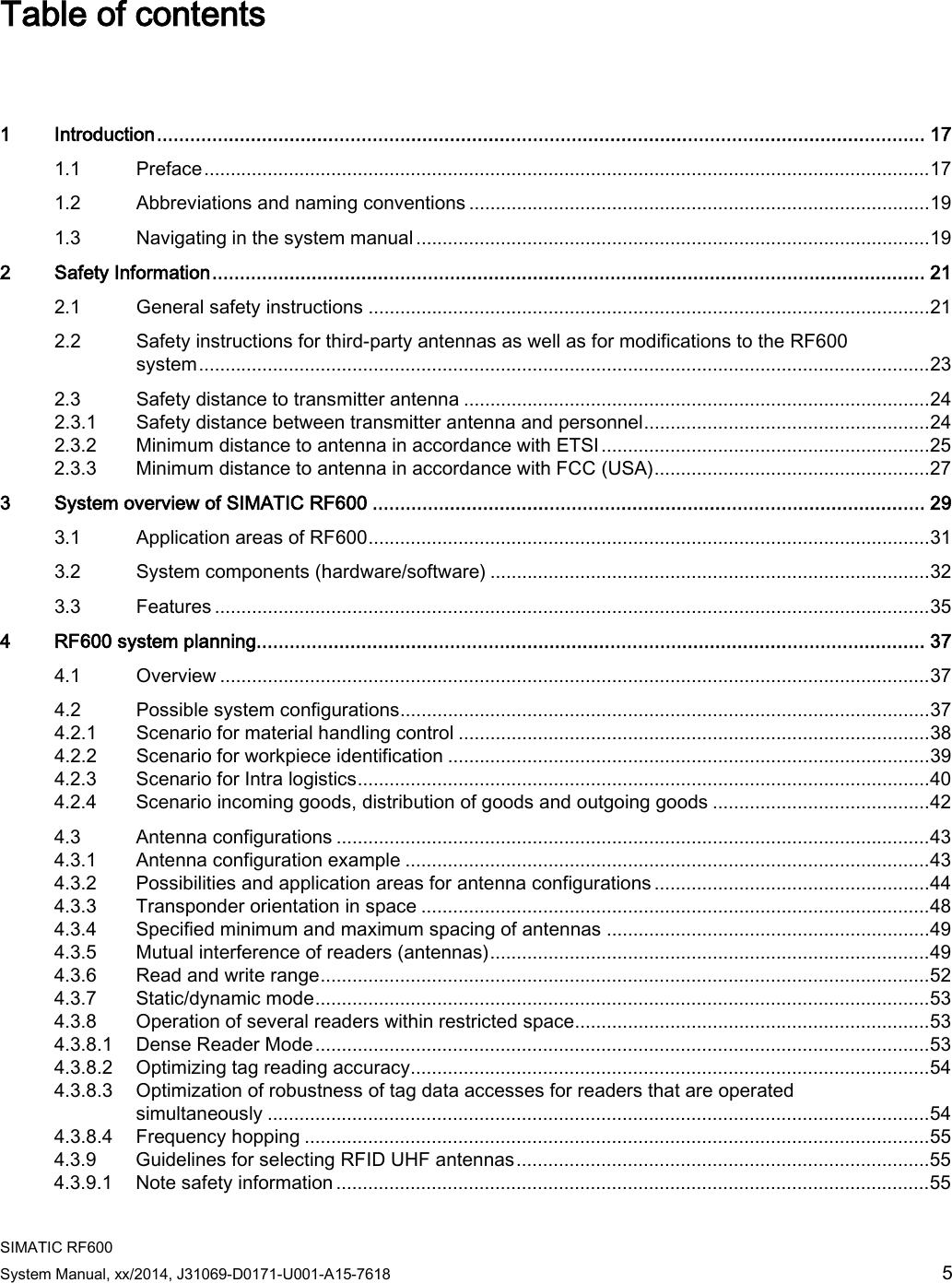
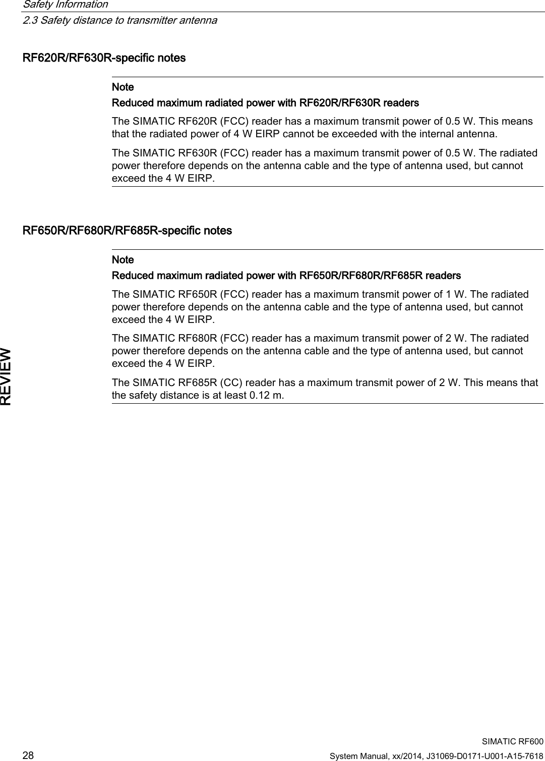
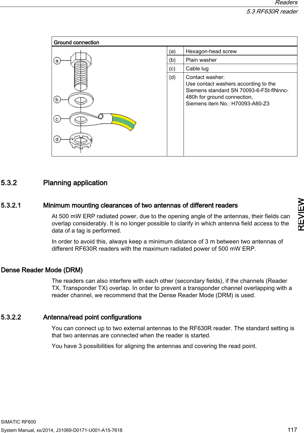
![Safety Information 2.3 Safety distance to transmitter antenna SIMATIC RF600 24 System Manual, xx/2014, J31069-D0171-U001-A15-7618 REVIEW Note User responsibility for modified product As a user of the modified product, you accept responsibility for use of the complete RFID product comprising both SIMATIC RF600 components and third-party RFID components. This particularly applies to modification or replacement of: • Antennas • Antenna cables • readers • Power supply units with connection cables 2.3 Safety distance to transmitter antenna 2.3.1 Safety distance between transmitter antenna and personnel For antenna configurations where it is possible to be briefly or constantly within the transmission range of the antennas, as in loading ramps, for example, minimum distances must be maintained. Limits The ICRP (International Commission of Radiological Protection) has worked out limit values for human exposure to HF fields that are also recommended by the ICNIRP (International Commission of Non Ionizing Radiological Protection). In German legislation on emissions (since 1997), the following limit values apply. These can vary according to frequency: Frequency f [MHz] Electrical field strength E [V/m] Magnetic field strength H [A/m] 10 - 400 27,5 0,073 400 - 2.000 1.375 x f1/2 0.0037 x f1/2 2.000 - 300.000 61 0,16 The limit values for the 900 MHz reader antenna alternating field are thus: Electrical field strength: E = 41.25 V/m Magnetic field strength: H = 0.111 A/m HF power density: E x H = 4.57 W/m2](https://usermanual.wiki/Siemens/RF600R2.User-Manual-part-1/User-Guide-2334392-Page-24.png)
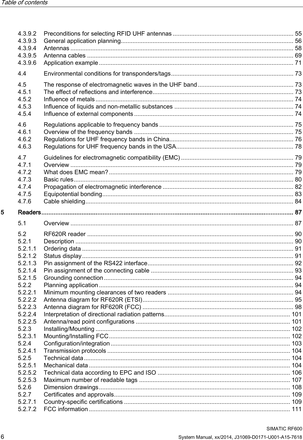
![Safety Information 2.3 Safety distance to transmitter antenna SIMATIC RF600 System Manual, xx/2014, J31069-D0171-U001-A15-7618 25 REVIEW 2.3.2 Minimum distance to antenna in accordance with ETSI Minimum distance to antenna in accordance with ETSI (EU, EFTA, Turkey) At a transmission frequency of 900 MHz, the wavelength of the electromagnetic wave λ is approximately 0.34 m. For distances less than 1 λ in the near field, the electrical field strength (1/r) diminishes exponentially to the power three over distance, and for distances greater than 1 λ, it diminishes exponentially to the power two over distance. The horizontal line at 41.25V/m marks the "safety limit value". For the maximum permitted transmit power (1/r2) in accordance with ETSI (2 W ERP), the "safety distance" is d = 0.24 m. This means that personnel should not remain closer than 24 cm to the transmitter antenna for extended periods (for several hours without interruption). Remaining within the vicinity of the antenna for a brief period, even for repeated periods (at a distance < 0.24 m), is harmless according to current knowledge. Distance to transmitter antenna [m] Feld strength [V/m] % of limit value 1 10 24 5 2 5 If the transmitter power is set lower than the highest permissible value (2 watts ERP), the "safety distance" reduces correspondingly. The values for this are as follows: Radiated power ERP [W] Safety distance to transmitter antenna [m] 2.0 0.24 1.0 0.17 0.5 0.12](https://usermanual.wiki/Siemens/RF600R2.User-Manual-part-1/User-Guide-2334392-Page-25.png)
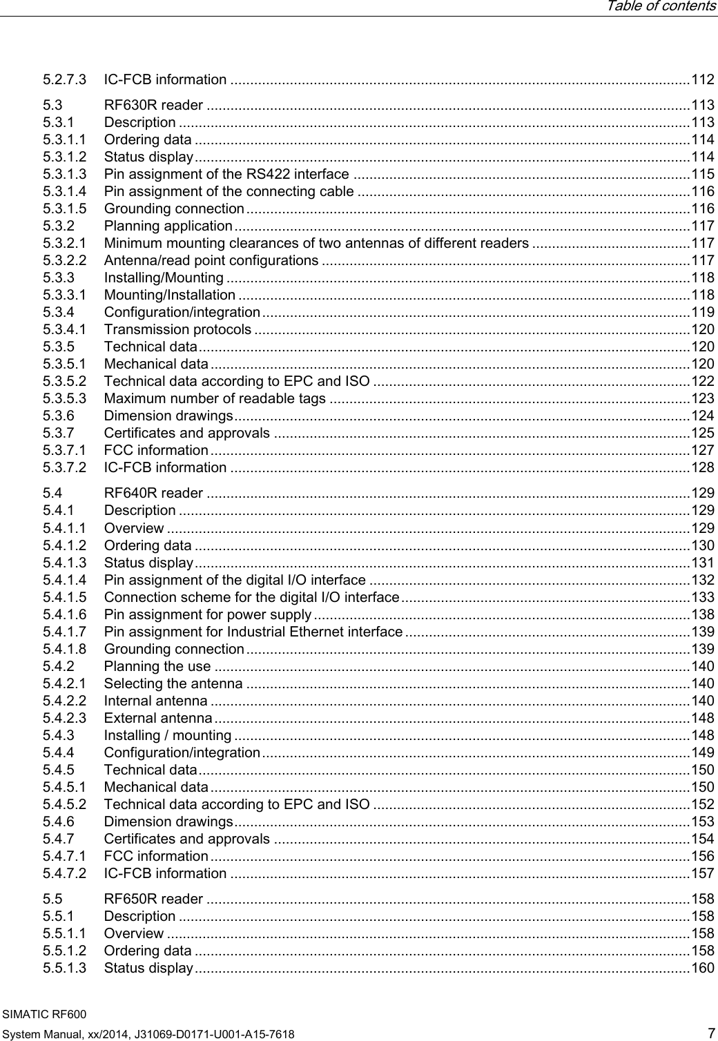
![Safety Information 2.3 Safety distance to transmitter antenna SIMATIC RF600 System Manual, xx/2014, J31069-D0171-U001-A15-7618 27 REVIEW 2.3.3 Minimum distance to antenna in accordance with FCC (USA) Minimum distance to antenna in accordance with FCC (USA) For the maximum permitted radiated power in accordance with FCC (4 W EIRP), the "safety distance" is d = 0.26 m. This means that personnel should not remain closer than 26 cm to the transmitter antenna for extended periods (several hours without interruption). Remaining within the vicinity of the antenna for brief period, even repeated periods (at a distance < 0.26 m) is harmless to health according to current knowledge. The horizontal line at 41.25 V/m marks the "safety limit value". Distance to transmitter antenna [m] Feld strength [V/m] % of limit value 1 10.9 26 5 2.2 5.3 If the transmit power is set lower than the highest permitted value (4 W EIRP), the "safety distance" reduces correspondingly. The values for this are as follows: Radiated power EIRP [W] Safety distance to transmitter antenna [m] 4.0 0.26 <2.5 >0.20 Generally a safety distance of at least 0.2 m should be maintained.](https://usermanual.wiki/Siemens/RF600R2.User-Manual-part-1/User-Guide-2334392-Page-27.png)
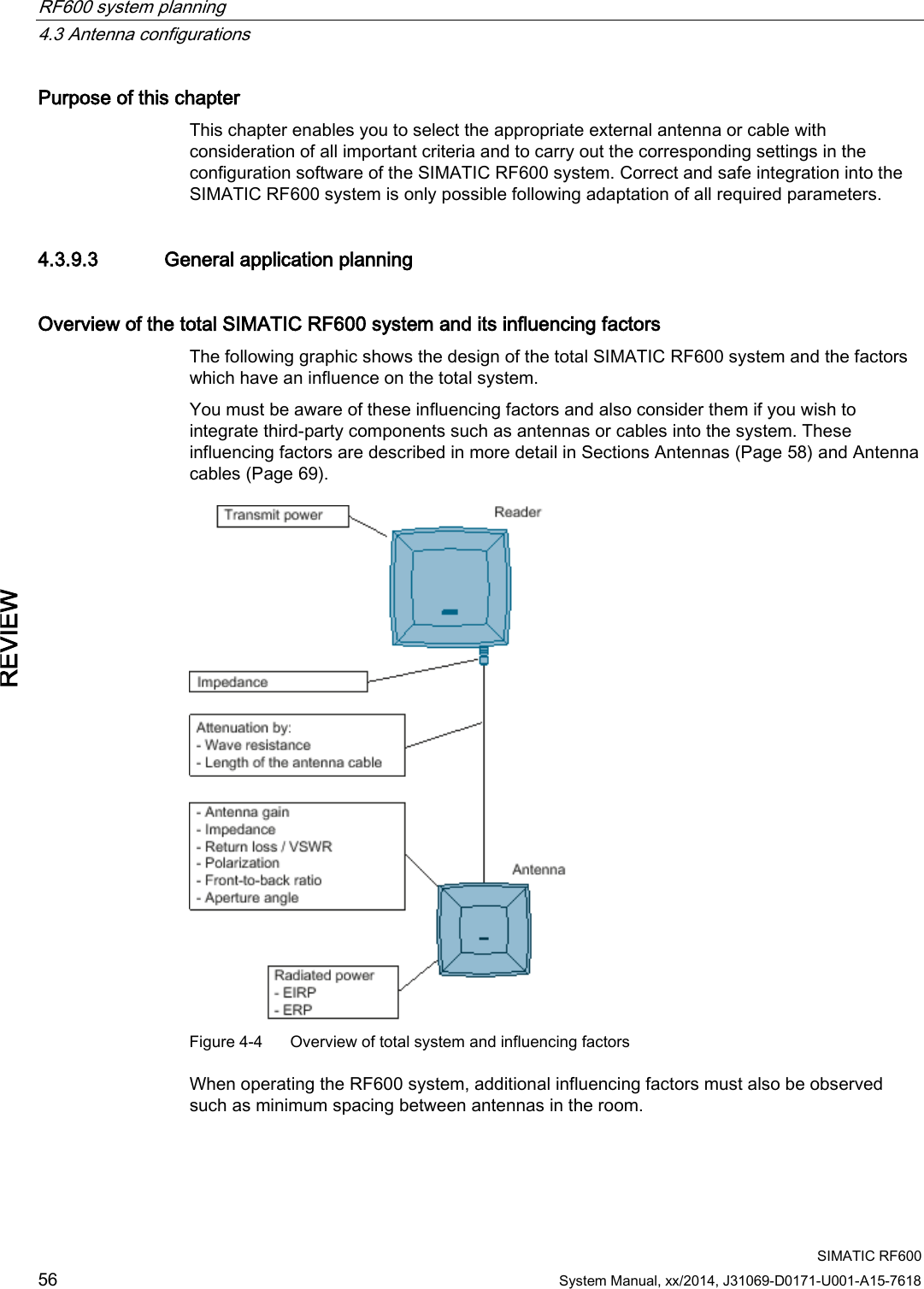
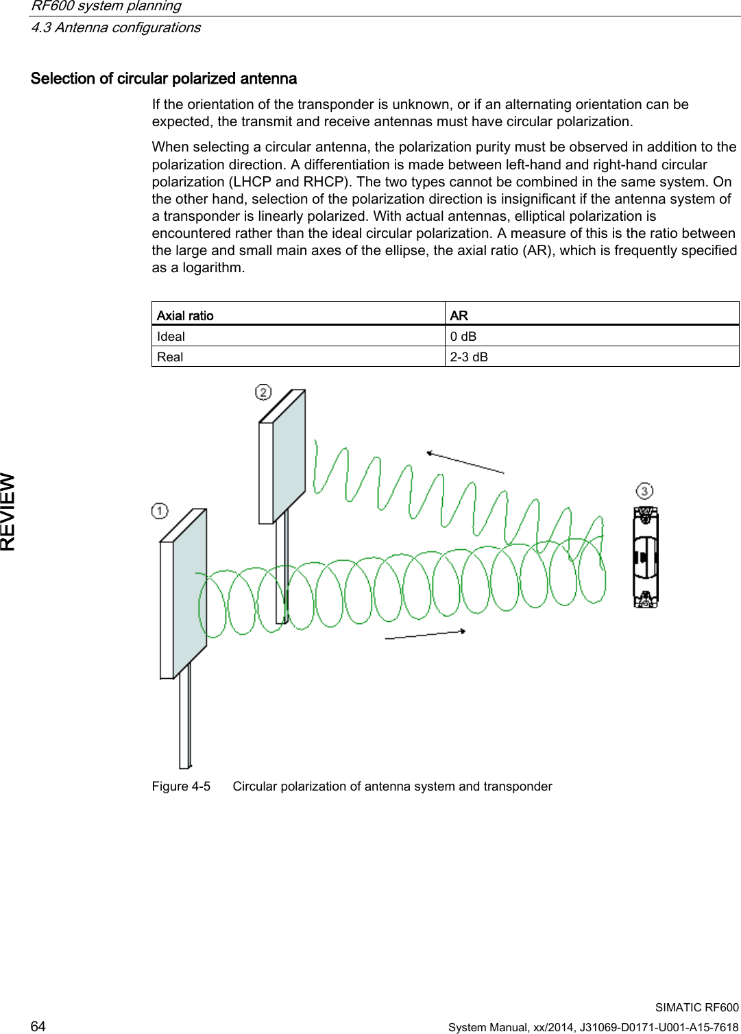
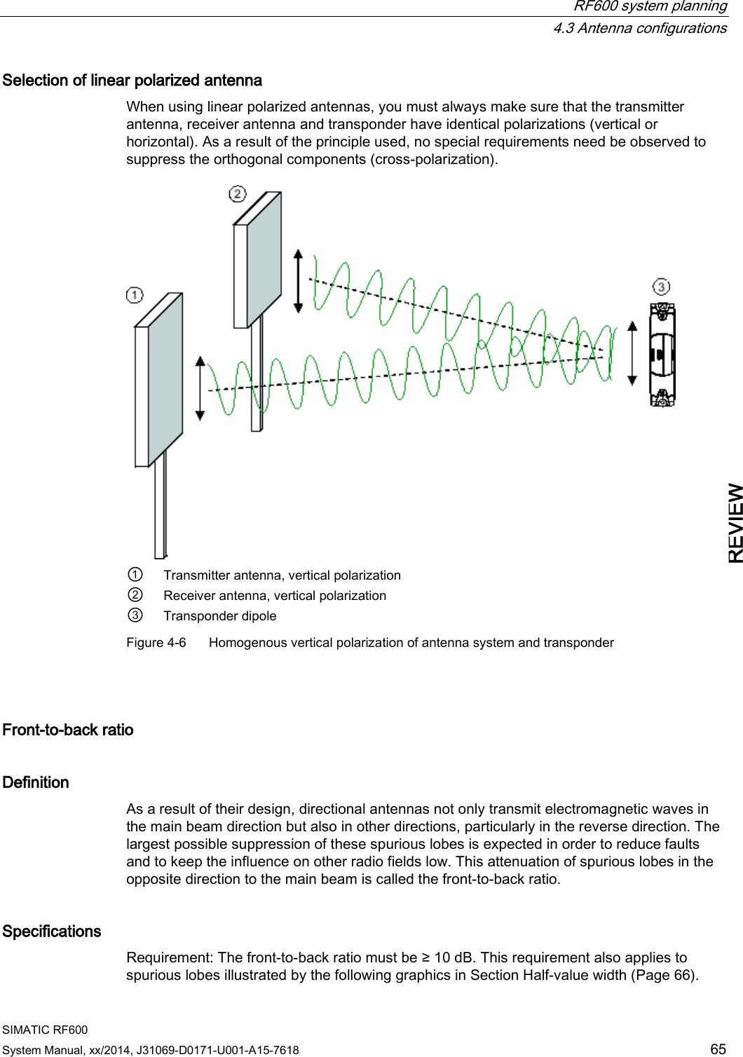
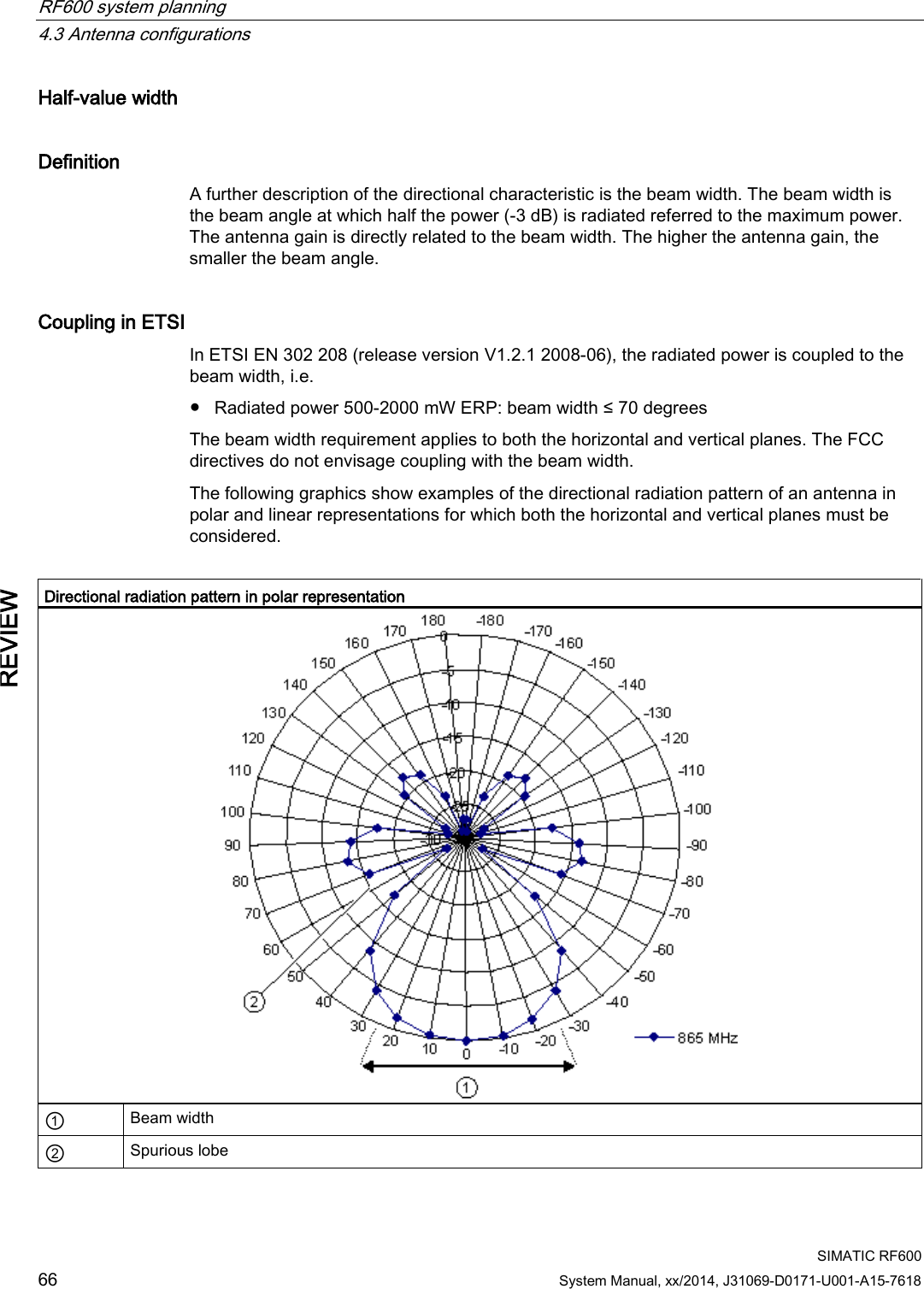
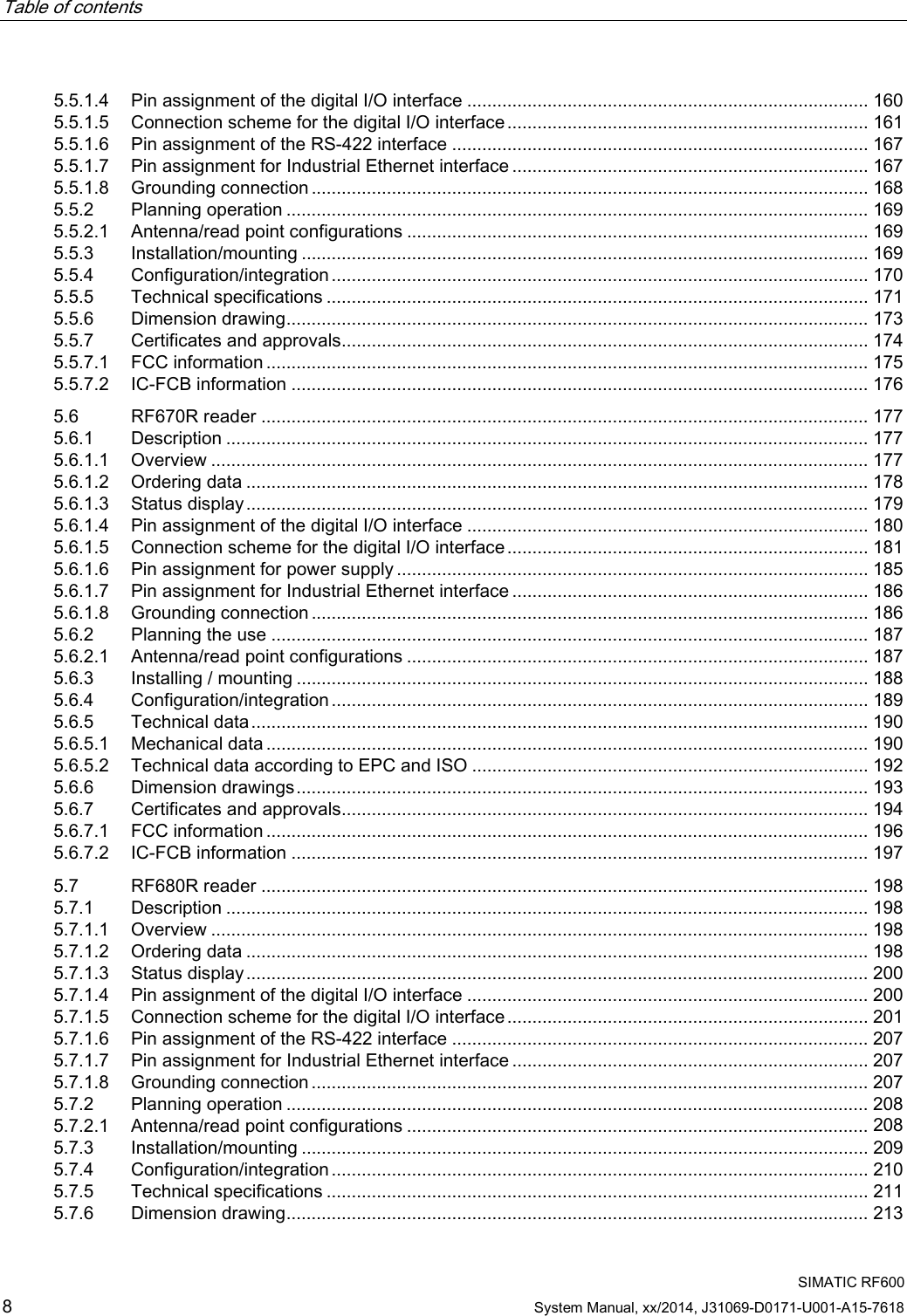
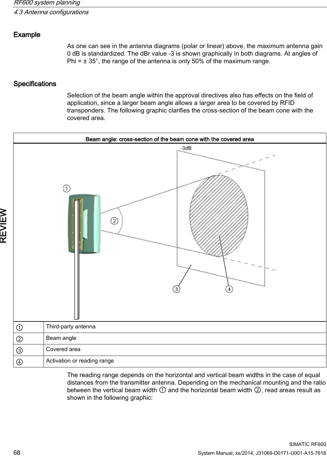
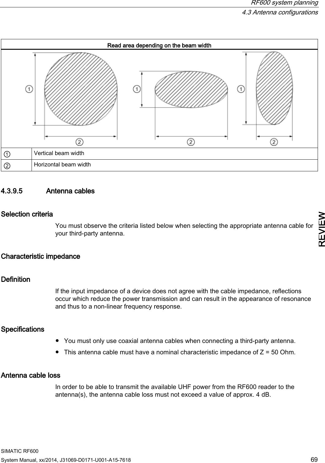
![RF600 system planning 4.3 Antenna configurations SIMATIC RF600 System Manual, xx/2014, J31069-D0171-U001-A15-7618 67 REVIEW Directional radiation pattern in linear representation ① Beam width ② Spurious lobe Interpretation of directional radiation patterns The following overview table will help you with the interpretation of radiation patterns. The table shows which dBi values correspond to which read/write ranges (in %): You can read the radiated power depending on the reference angle from the directional radiation patterns, and thus obtain information on the read/write range with this reference angle with regard to a transponder. The dBr values correspond to the difference between the maximum dBi value and a second dBi value. Deviation from maximum antenna gain [dBr] Read/write range [%] 0 100 -3 70 -6 50 -9 35 -12 25 -15 18 -18 13](https://usermanual.wiki/Siemens/RF600R2.User-Manual-part-1/User-Guide-2334392-Page-67.png)
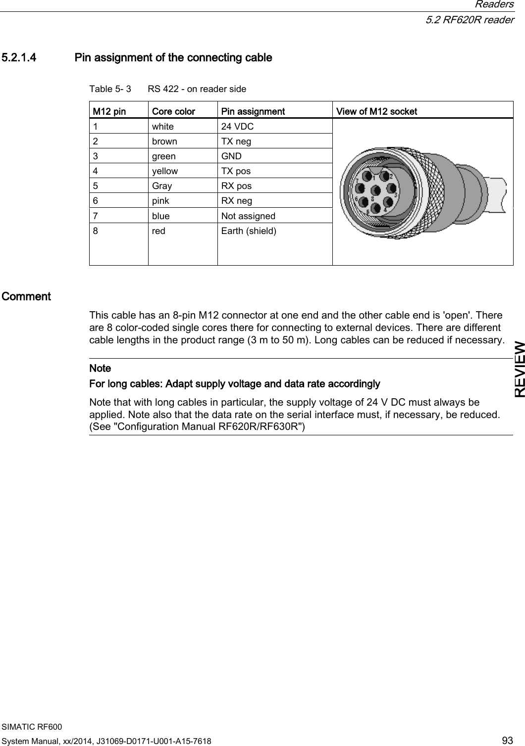
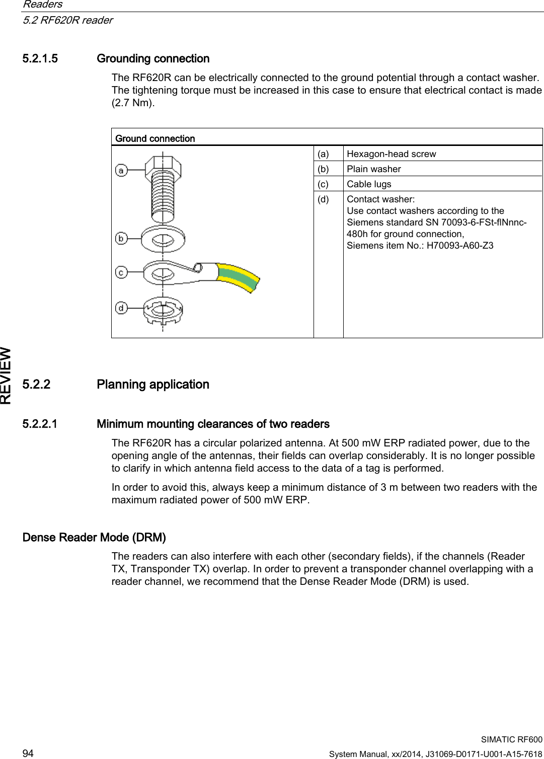
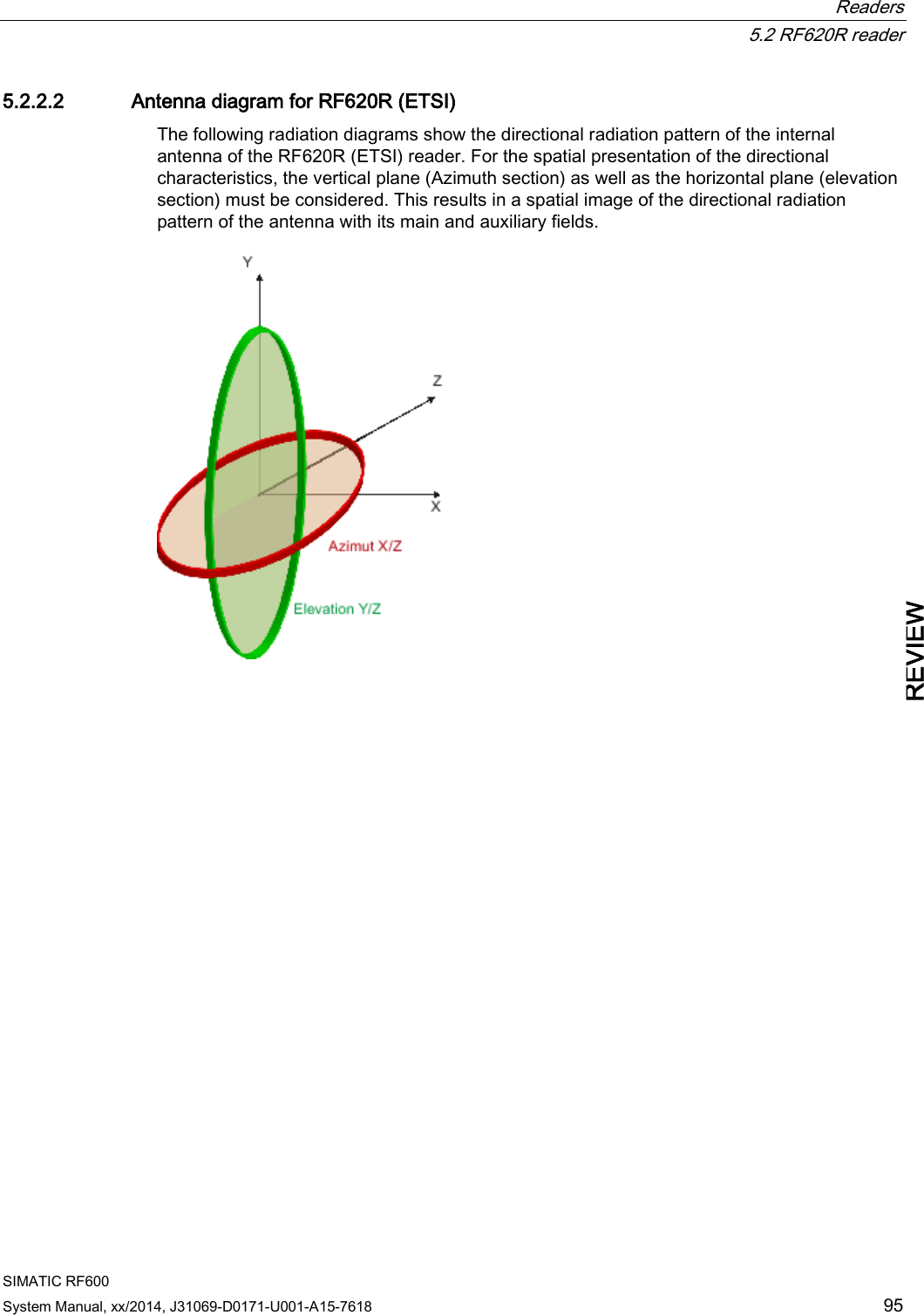

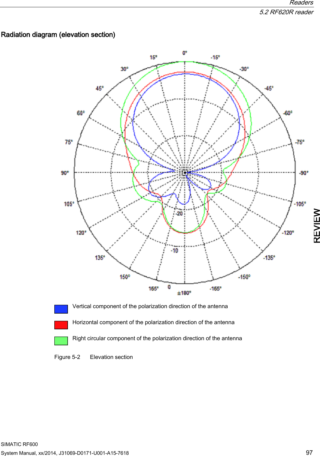
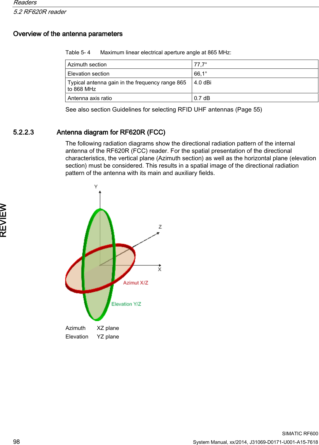

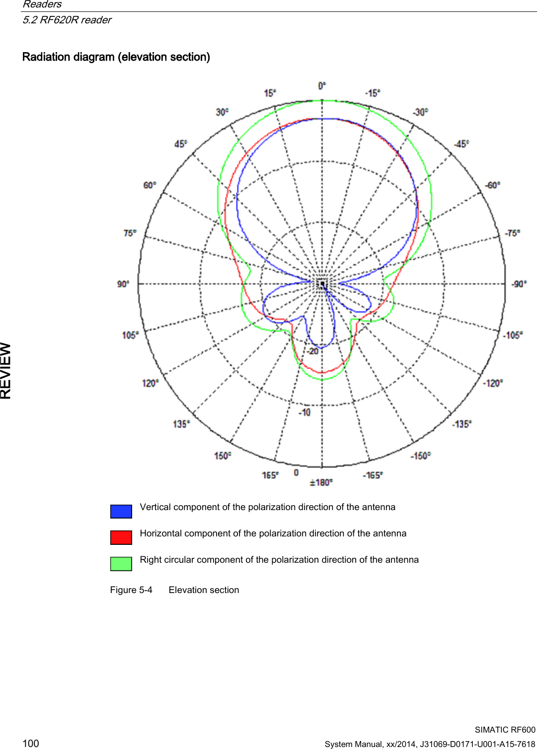
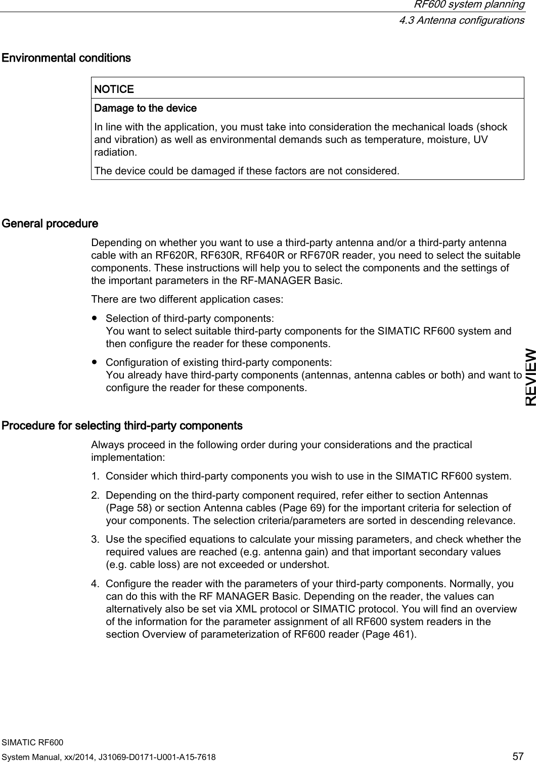
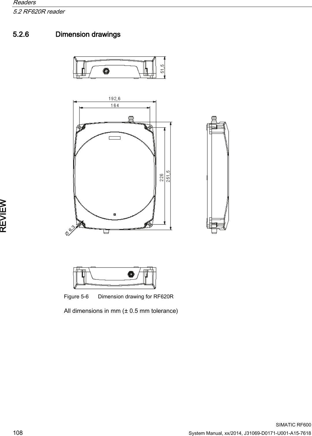
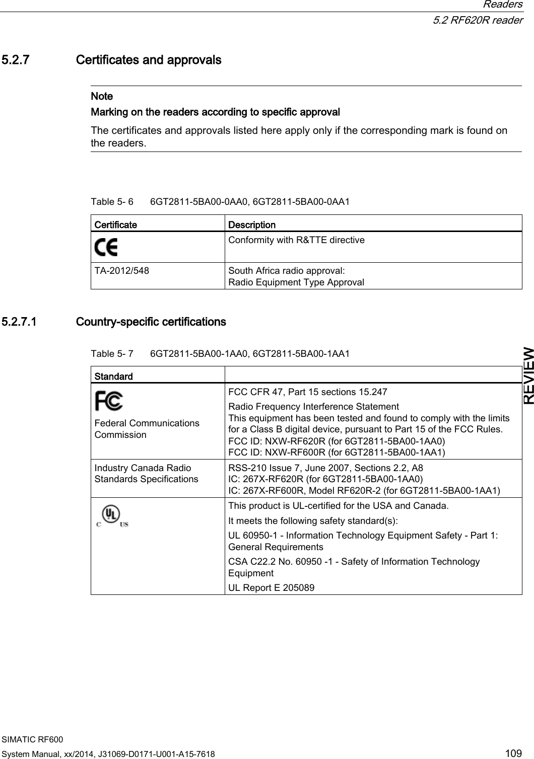
![Readers 5.2 RF620R reader SIMATIC RF600 System Manual, xx/2014, J31069-D0171-U001-A15-7618 101 REVIEW Overview of the antenna parameters Table 5- 5 Maximum linear electrical aperture angle at 865 MHz: Azimuth section 75,4 ° Elevation section 69,1 ° Typical antenna gain in the frequency range 902 to 928 MHz 4.0 dBi ± 0.5 dB Antenna axis ratio <1 dB see also section Guidelines for selecting RFID UHF antennas (Page 55). 5.2.2.4 Interpretation of directional radiation patterns The following overview table will help you with the interpretation of directional radiation patterns. The table shows which dBi values correspond to which read/write ranges (in %): You can read the radiated power depending on the reference angle from the directional radiation patterns, and thus obtain information on the read/write range with this reference angle with regard to a transponder. The dBr values correspond to the difference between the maximum dBi value and a second dBi value. Deviation from maximum antenna gain [dBr] Read/write range [%] 0 100 -3 70 -6 50 -9 35 -12 25 -15 18 -18 13 Example As one can see from the section Antenna diagram for RF620R (ETSI) (Page 95), the maximum antenna gain is 0 dB. In the Azimuth diagram, the antenna gain falls by 3°dB at approximately ± 39°. Therefore the dBr value is -3. The antenna range is only 50% of the maximum range at ± 39° from the Z axis within the horizontal plane. 5.2.2.5 Antenna/read point configurations The RF620R reader has an internal circular polarized antenna. You can cover one read point with this antenna. When several RF620R readers are used, the readers are addressed via the SIMATIC level.](https://usermanual.wiki/Siemens/RF600R2.User-Manual-part-1/User-Guide-2334392-Page-101.png)

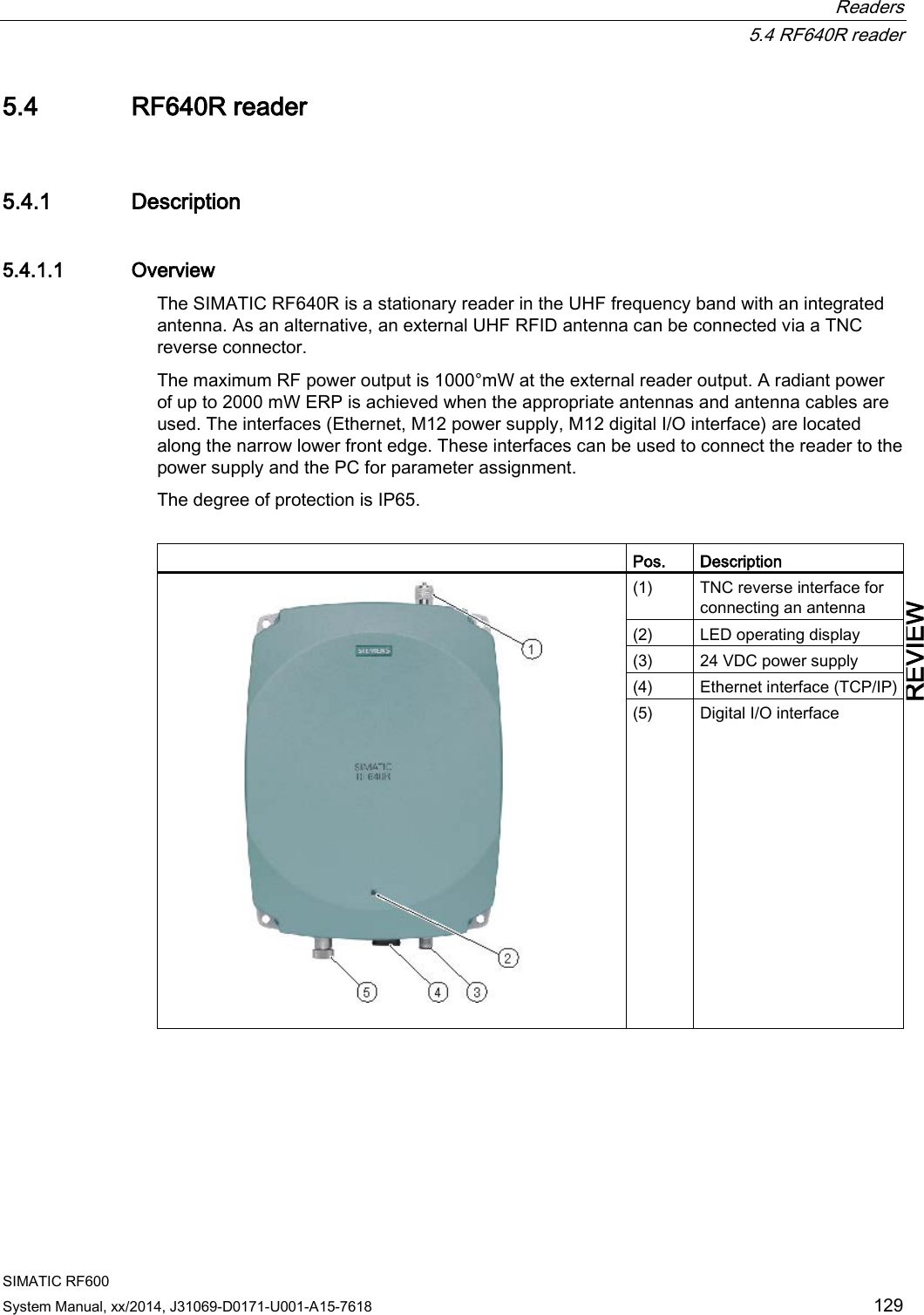

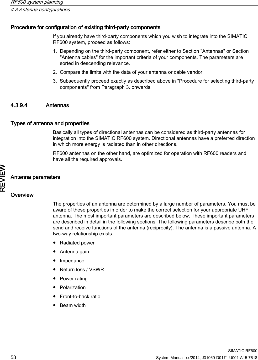
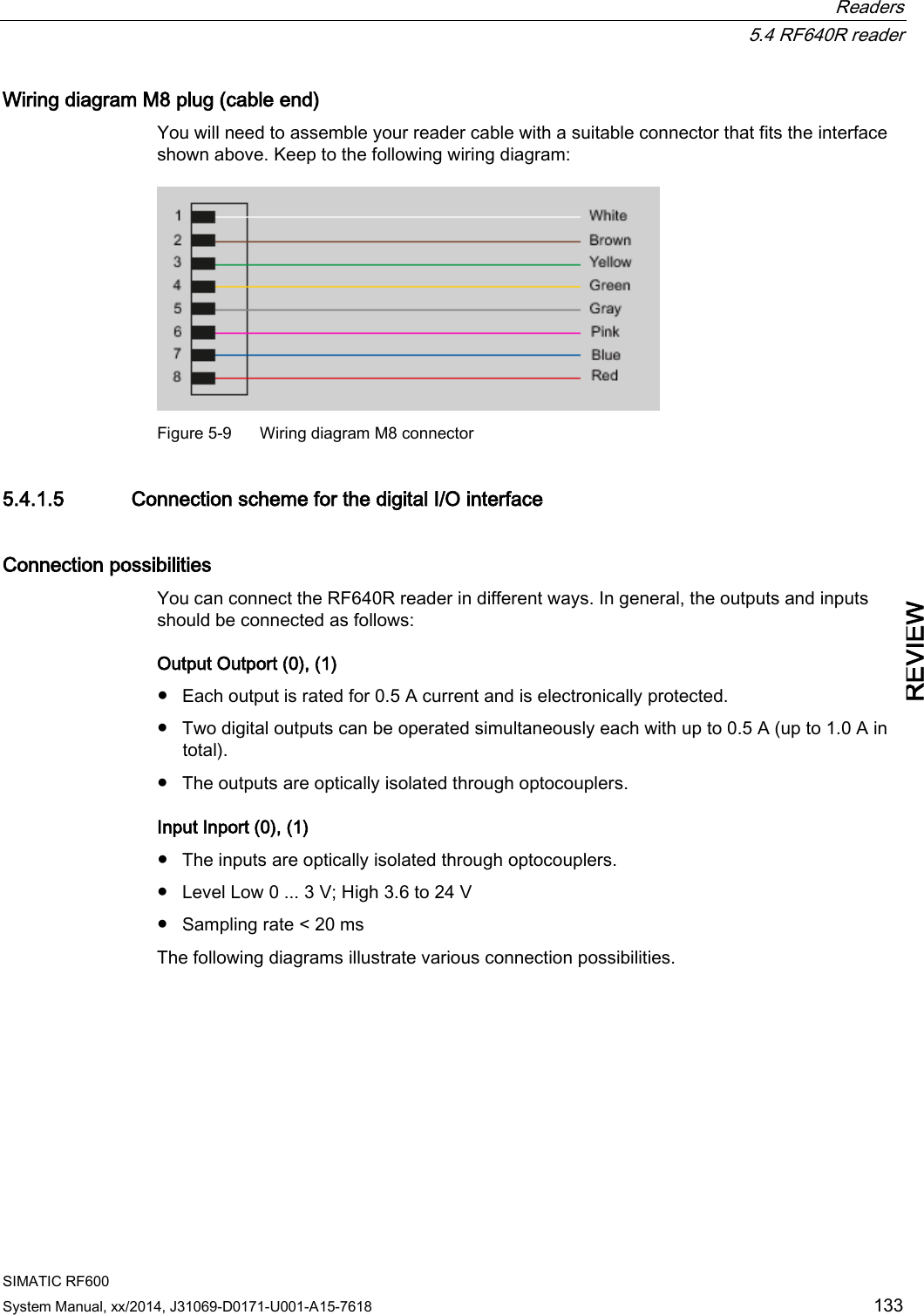
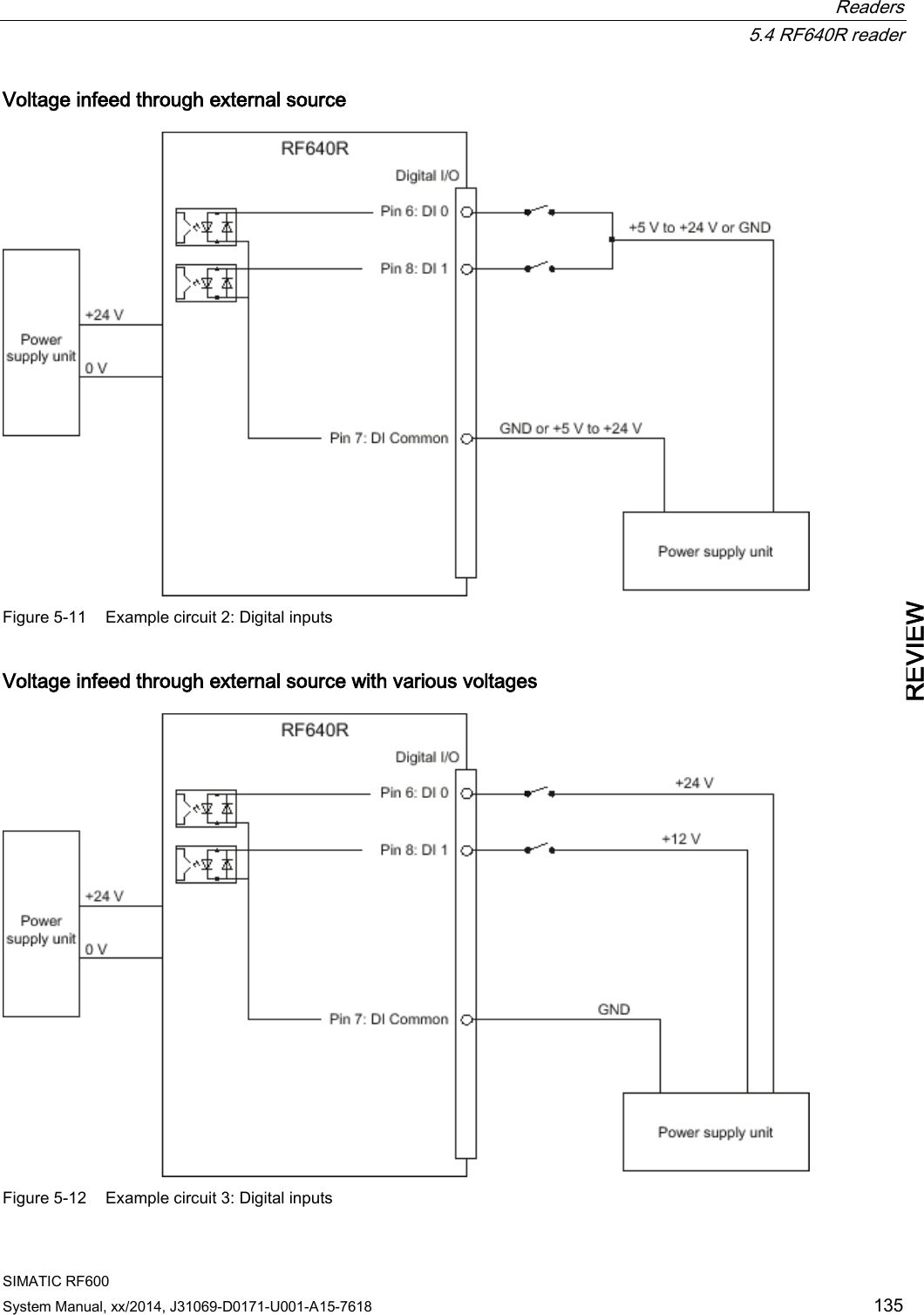
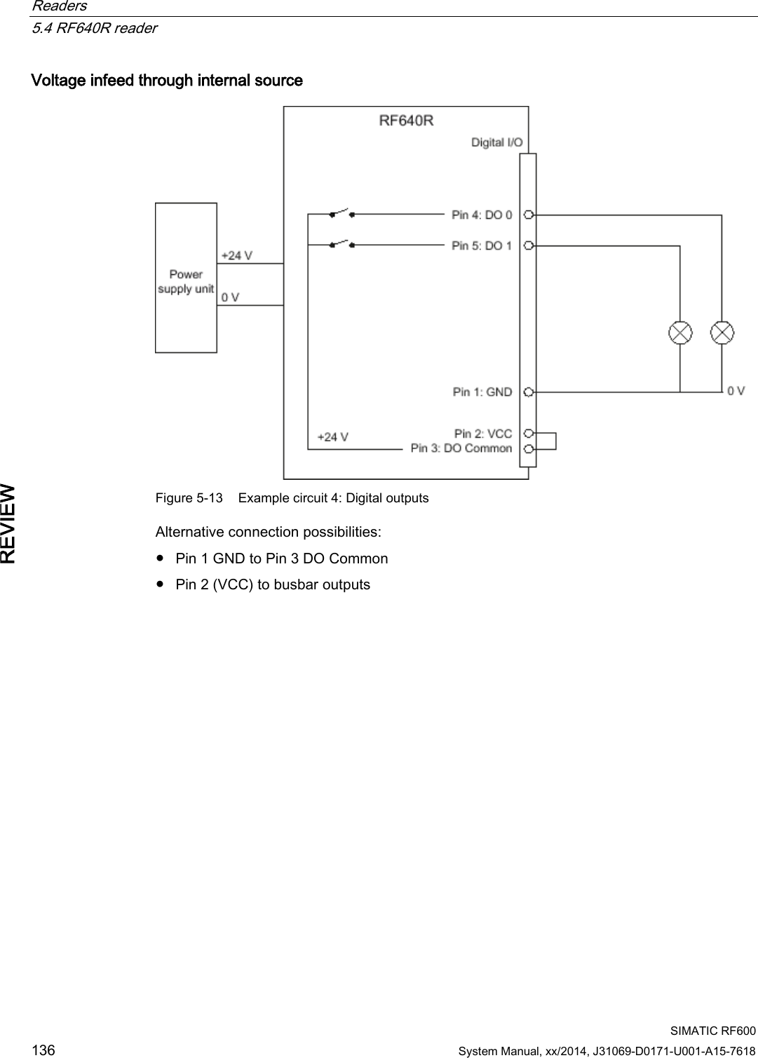
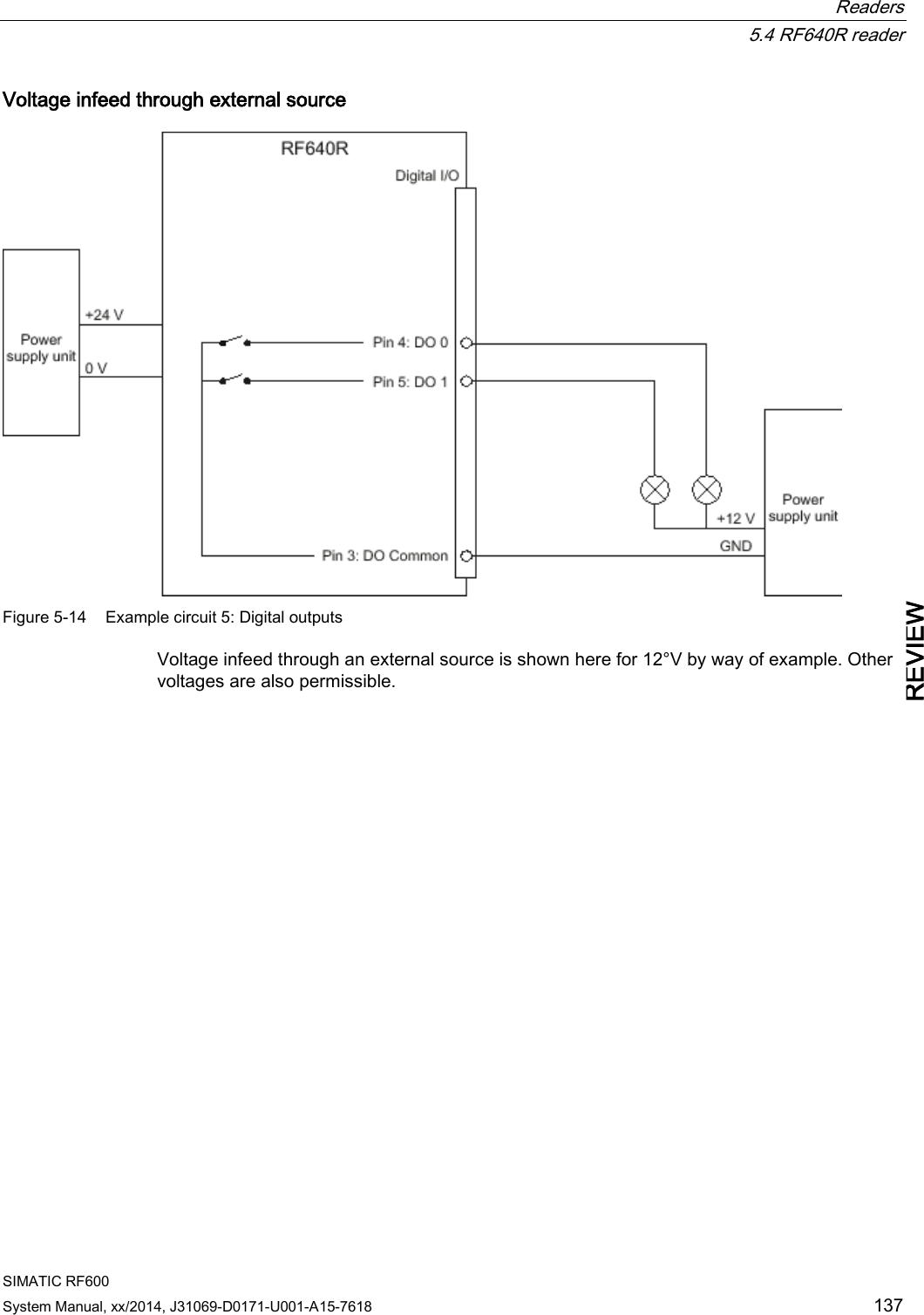
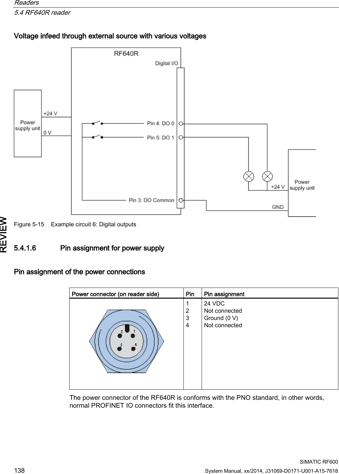
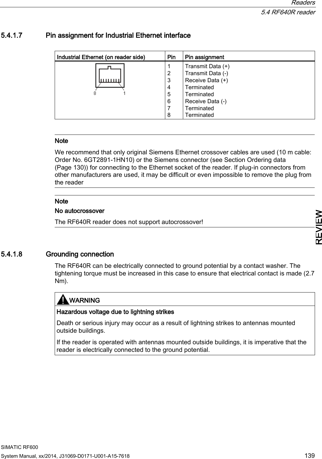
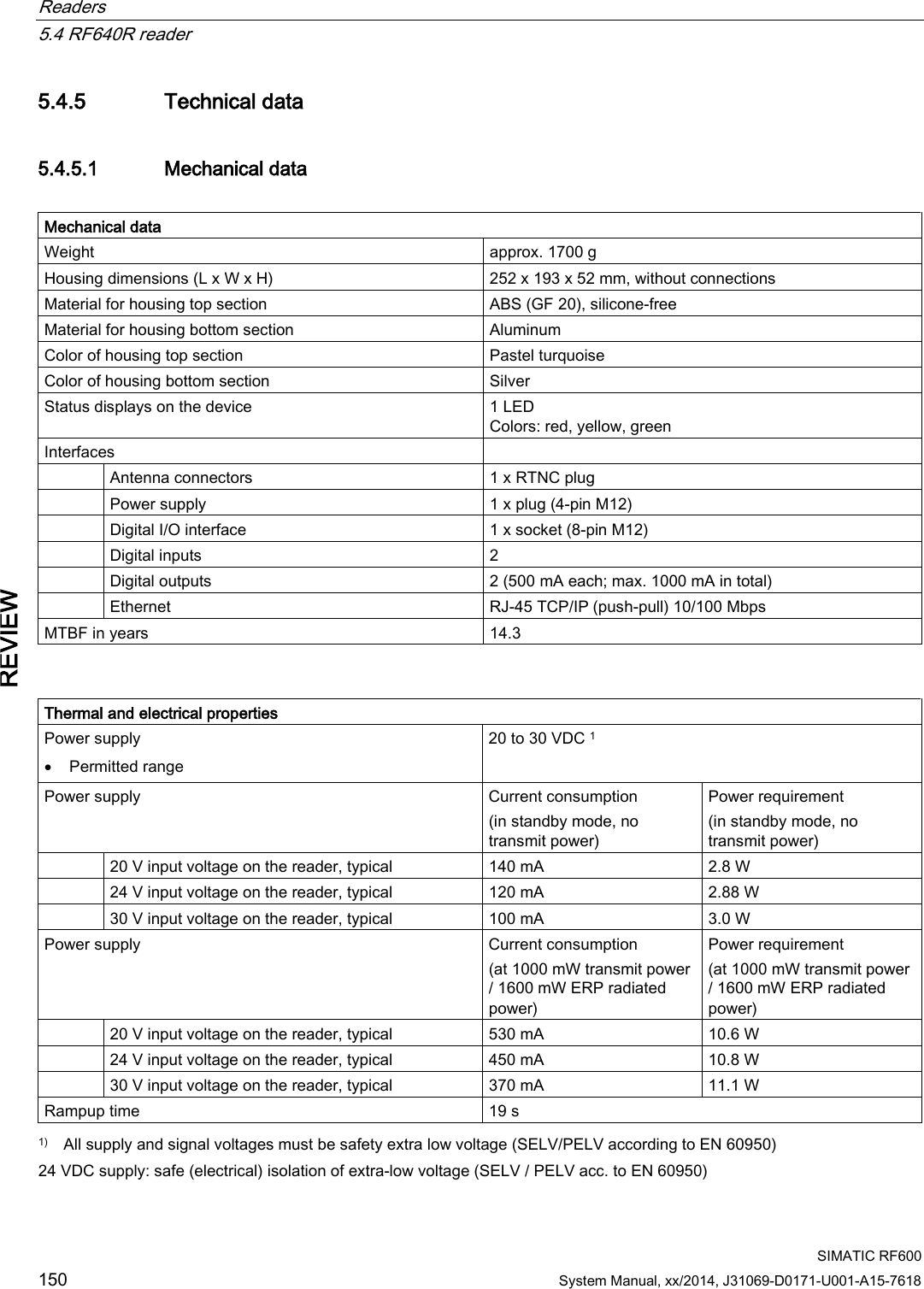
![Readers 5.4 RF640R reader SIMATIC RF600 132 System Manual, xx/2014, J31069-D0171-U001-A15-7618 REVIEW 5.4.1.4 Pin assignment of the digital I/O interface Pin assignment, socket Digital I/O socket (on reader side) Pin Pin assignment 1 GND (output to supply the digital outputs [not electrically isolated]) 2 VCC (output for supplying the digital outputs [not RF310M, RF680M electrically isolated]) 3 DO common 4 DO 0 5 DO 1 6 DI 0 7 DI common 8 DI 1 Shield is applied to the reader housing so that the knurled ring is connected to GND of the reader. View of the connector Table 5- 13 Digital I/O, for cable with open cable ends View of M12 connector M12 pin Wire color Pin assignment 1 white GND (output to supply the digital outputs [not electrically isolated]) 2 brown VCC (output for supplying the digital outputs [not electrically isolated]) 3 green DO common 4 yellow DO 0 5 gray DO 1 6 pink DI 0 7 blue DI common 8 red DI 1 Knurled ring Shield Knurled ring connected to GND of the reader](https://usermanual.wiki/Siemens/RF600R2.User-Manual-part-1/User-Guide-2334392-Page-132.png)
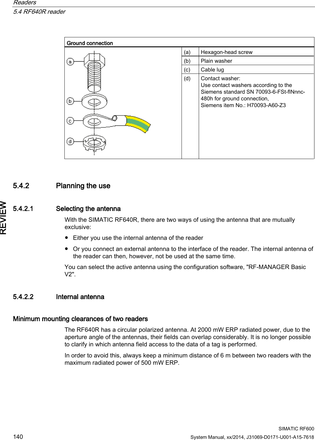
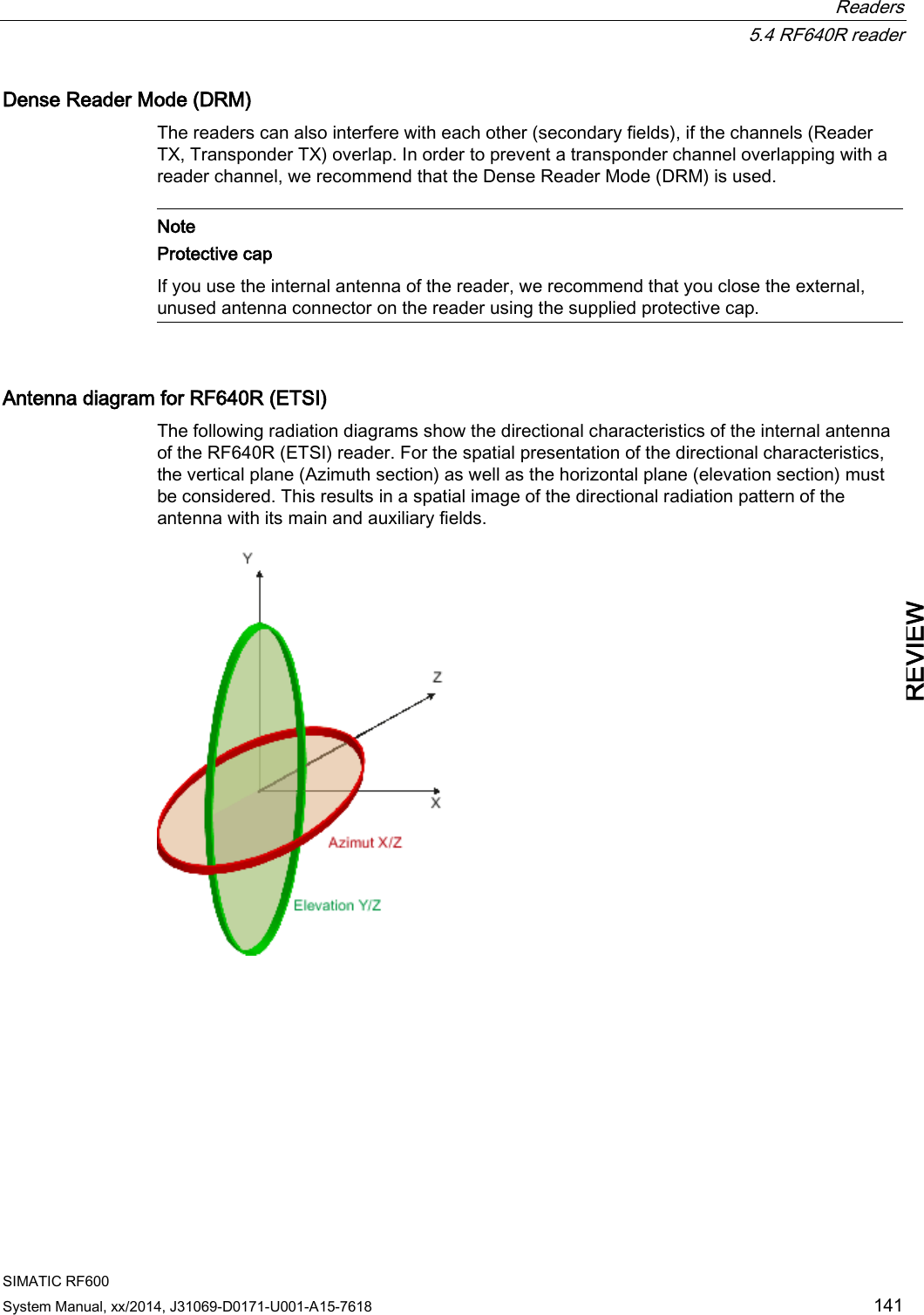
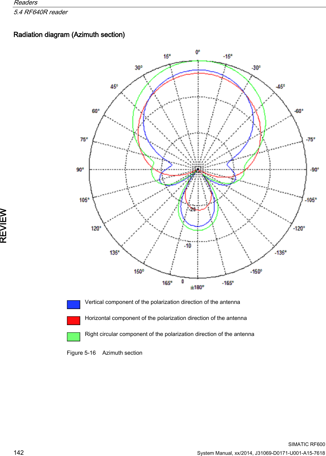

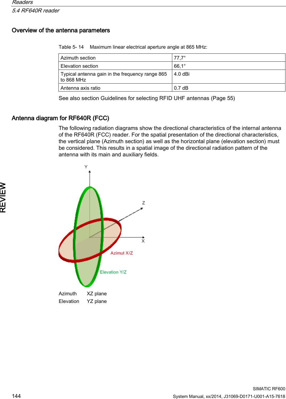
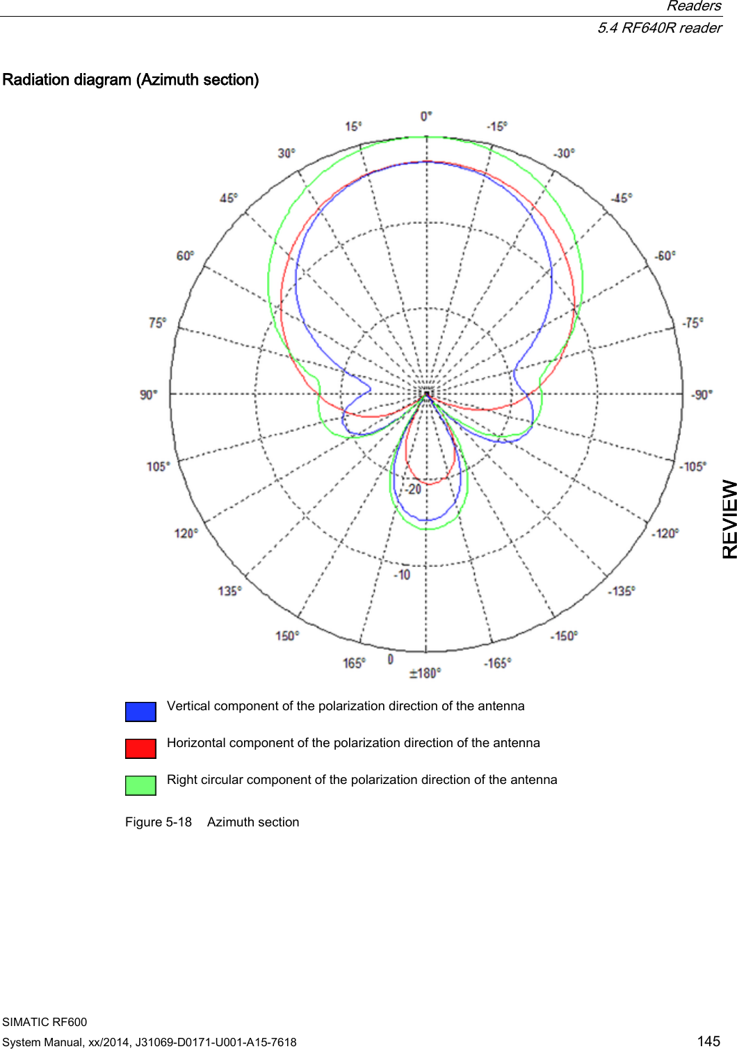

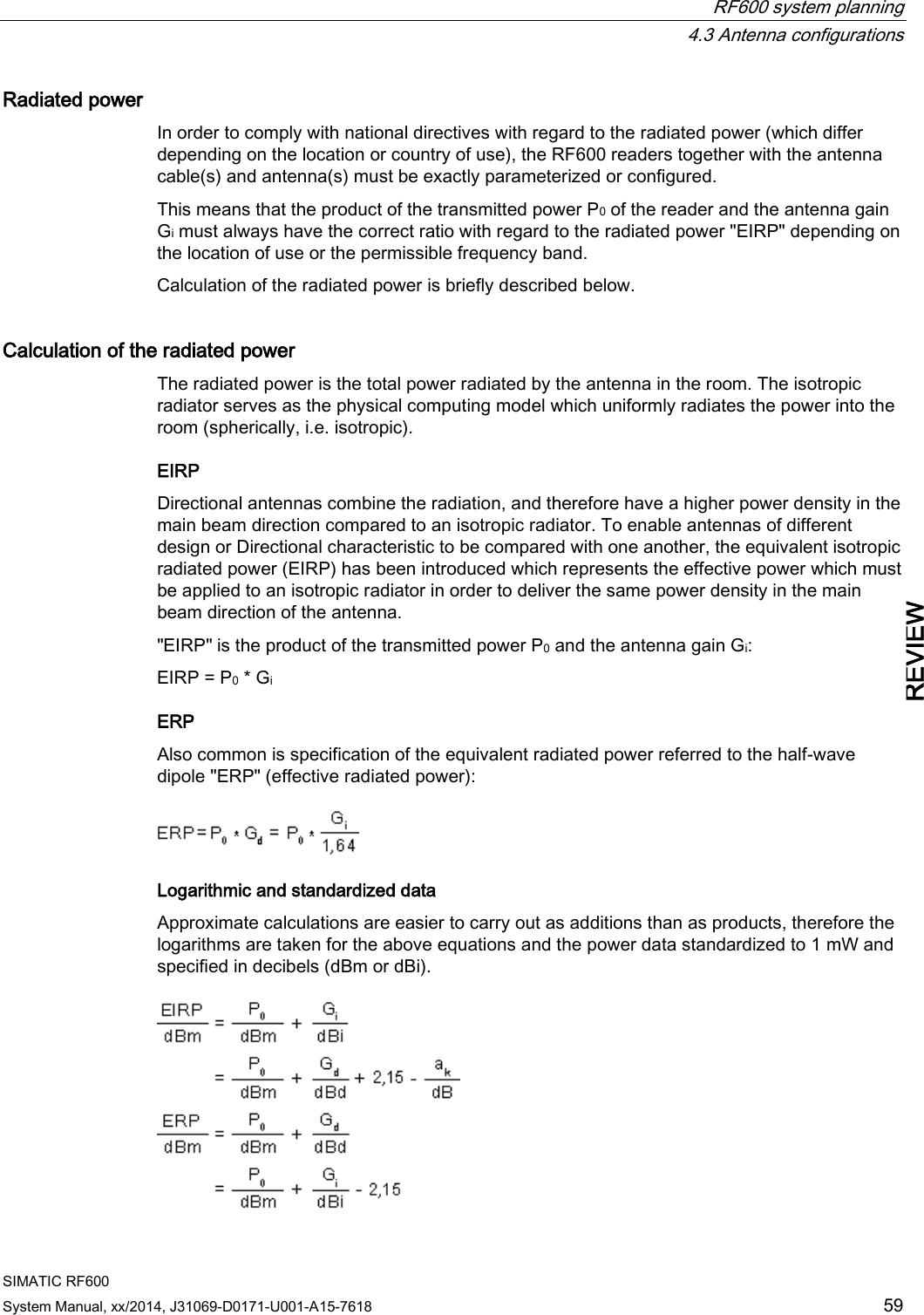
![Readers 5.4 RF640R reader SIMATIC RF600 System Manual, xx/2014, J31069-D0171-U001-A15-7618 147 REVIEW Overview of the antenna parameters Table 5- 15 Maximum linear electrical aperture angle at 865 MHz: Azimuth section 75,4 ° Elevation section 69,1 ° Typical antenna gain in the frequency range 902 to 928 MHz 4.0 dBi ± 0.5 dB Antenna axis ratio <1 dB see also section Guidelines for selecting RFID UHF antennas (Page 55). Interpretation of directional radiation patterns The following overview table will help you with the interpretation of directional radiation patterns. The table shows which dBi values correspond to which read/write ranges (in %): You can read the radiated power depending on the reference angle from the directional radiation patterns, and thus obtain information on the read/write range with this reference angle with regard to a transponder. The dBr values correspond to the difference between the maximum dBi value and a second dBi value. Deviation from maximum antenna gain [dBr] Read/write range [%] 0 100 -3 70 -6 50 -9 35 -12 25 -15 18 -18 13 Example As one can see from the section Antenna diagram for RF640R (ETSI) (Page 141), the maximum antenna gain is 0 dB. In the Azimuth diagram, the antenna gain falls by 3°dB at approximately ± 39°. Therefore the dBr value is -3. The antenna range is only 50% of the maximum range at ± 39° from the Z axis within the horizontal plane. Antenna/read point configurations The RF640R reader has an internal circular polarized antenna. You can cover one read point with this antenna. When several RF640R readers are used, the readers are addressed via the SIMATIC level.](https://usermanual.wiki/Siemens/RF600R2.User-Manual-part-1/User-Guide-2334392-Page-147.png)
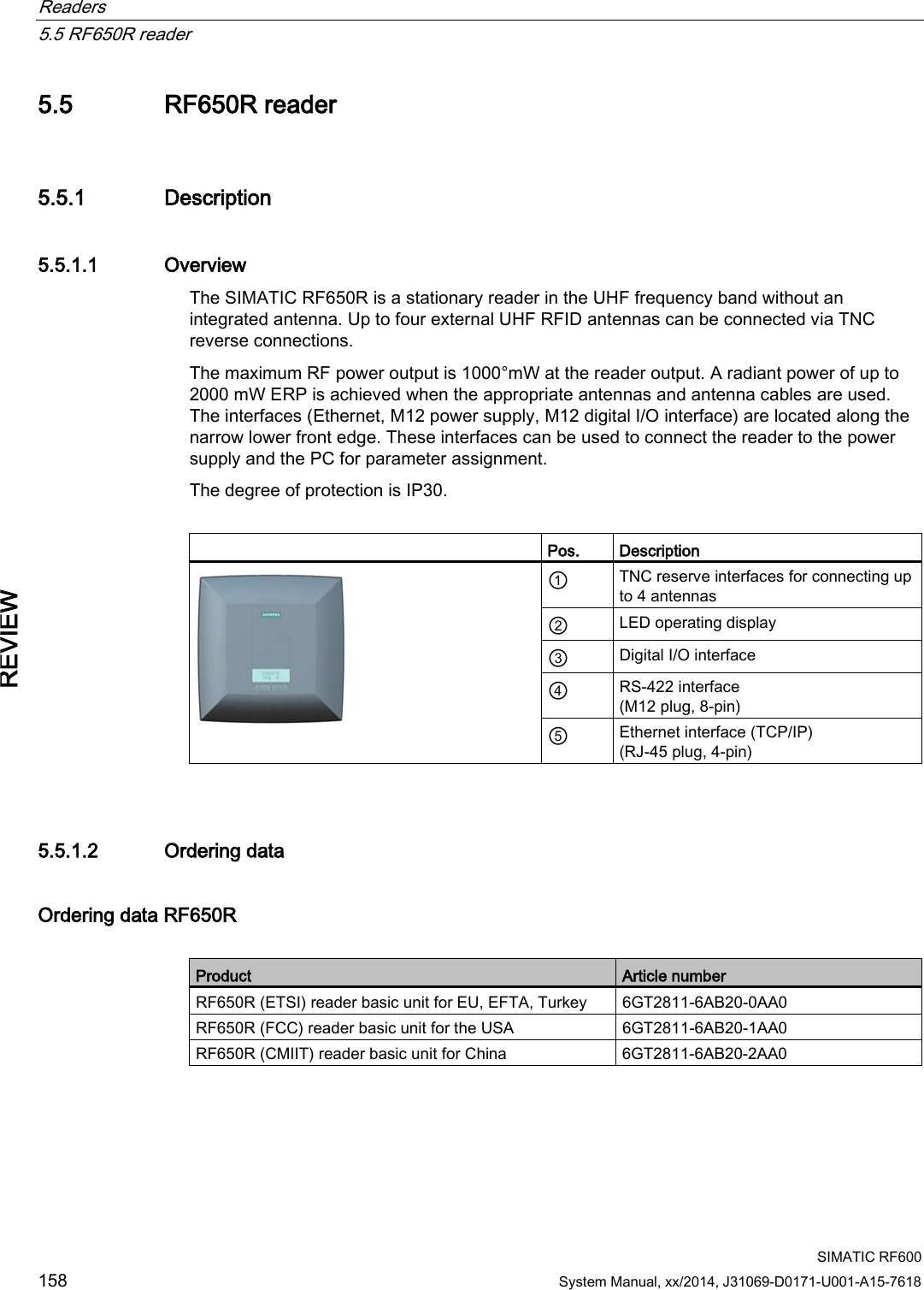

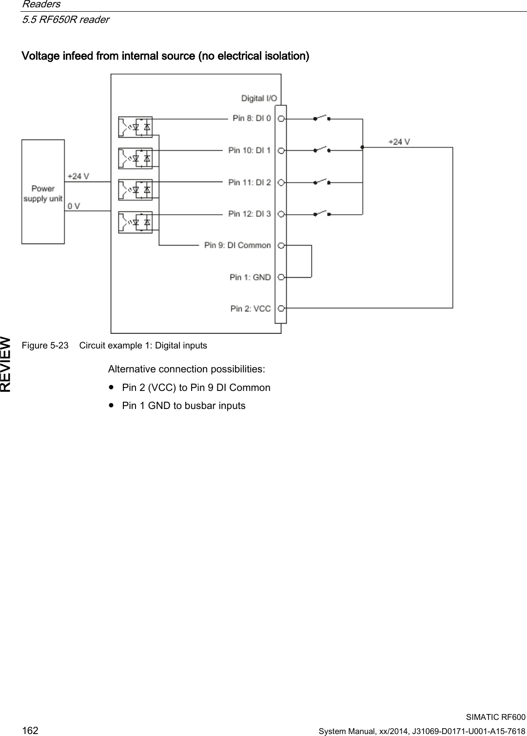
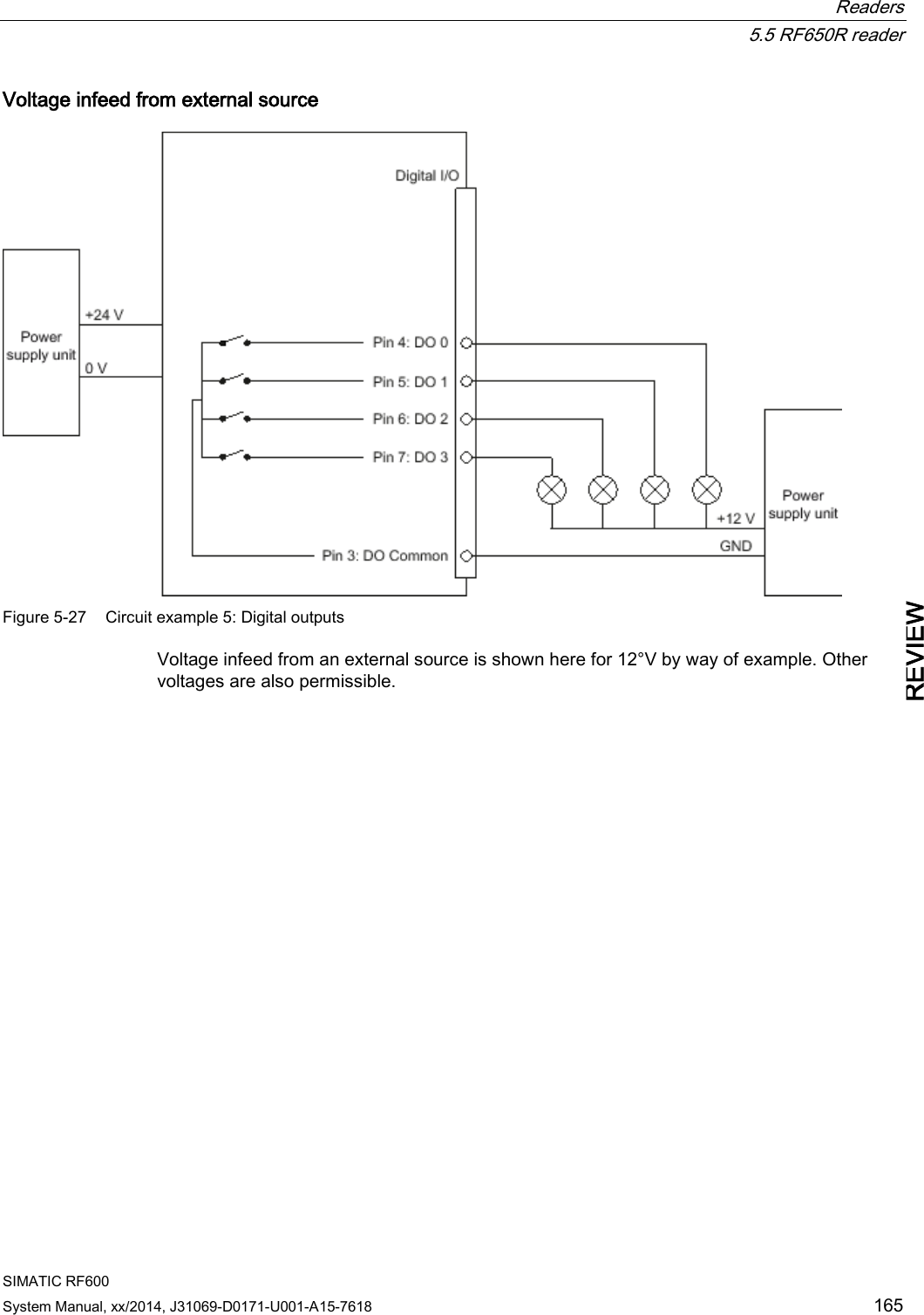
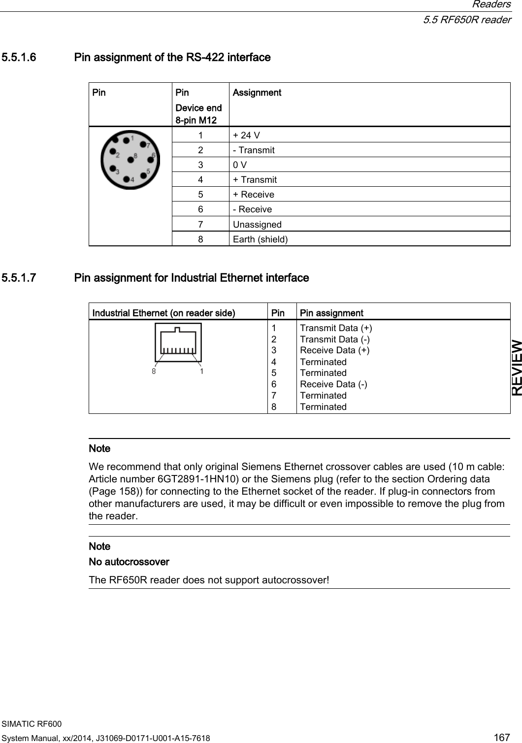
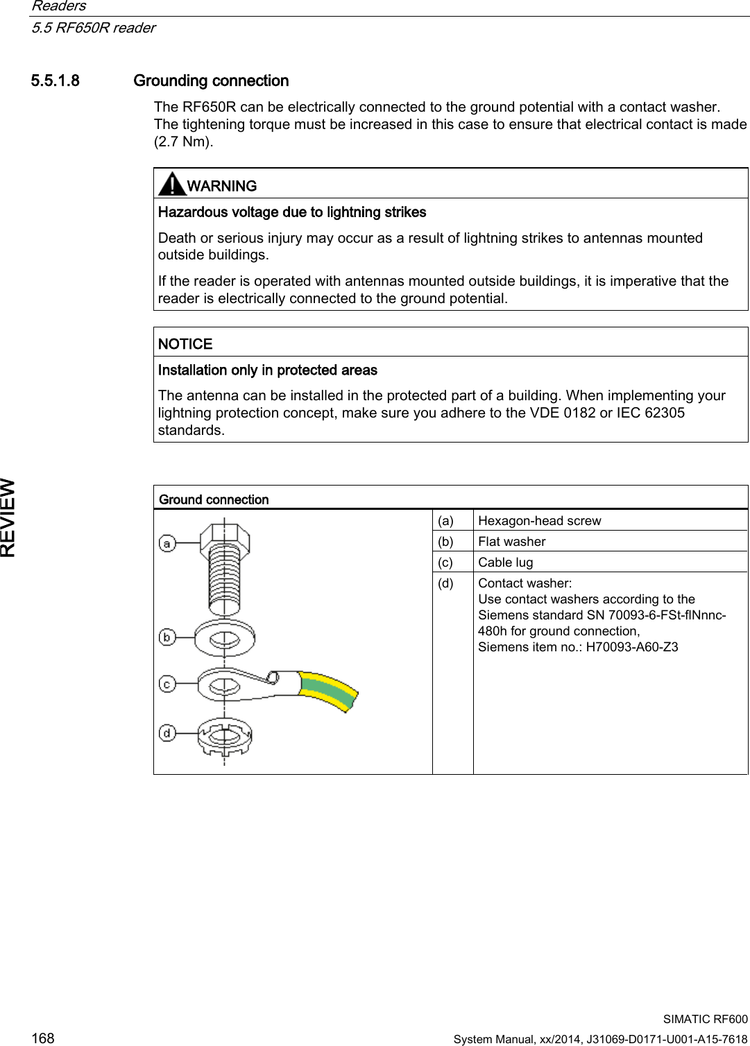
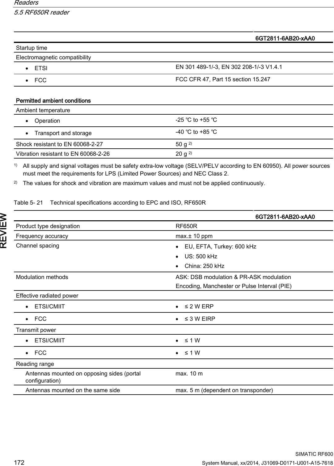
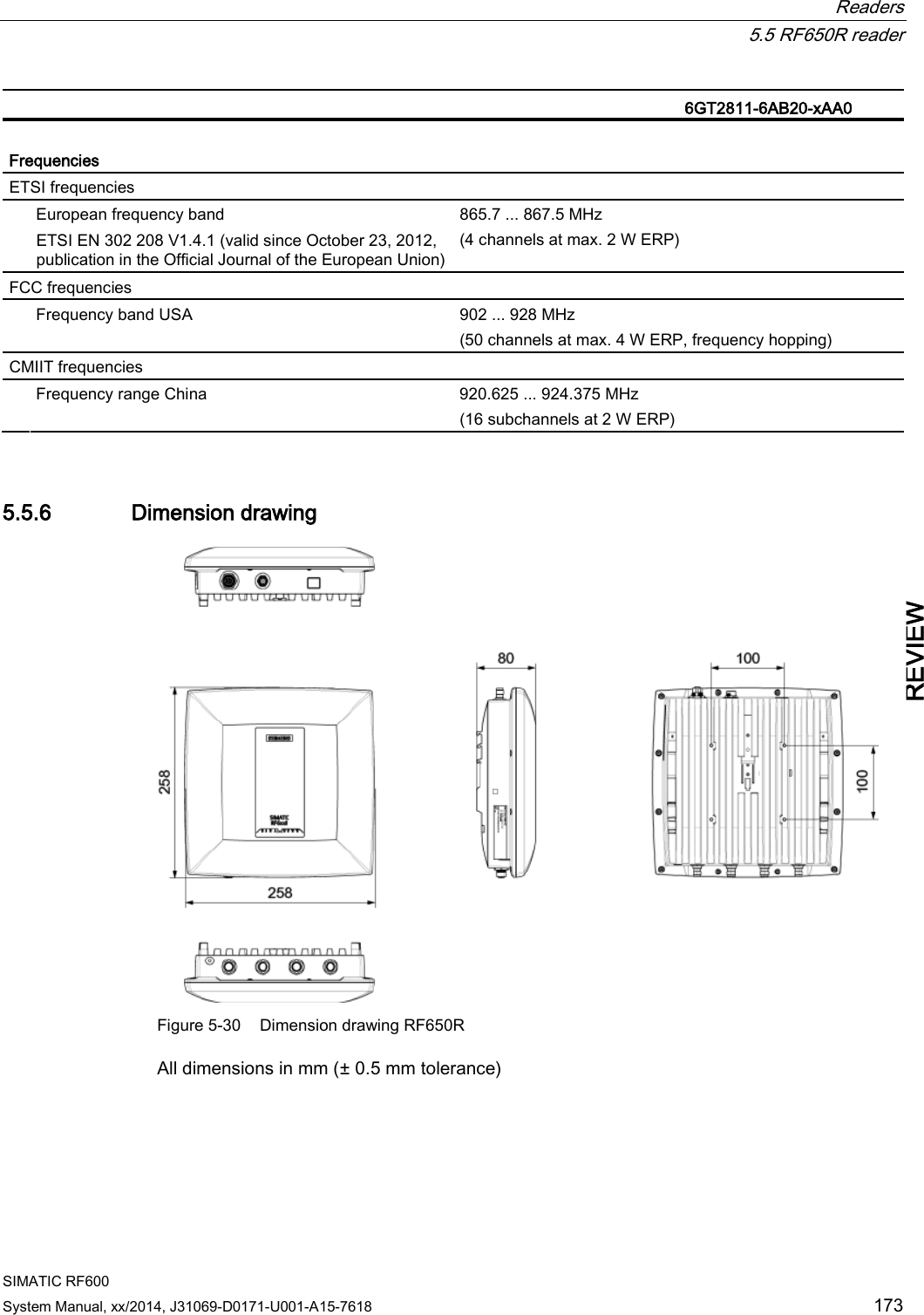
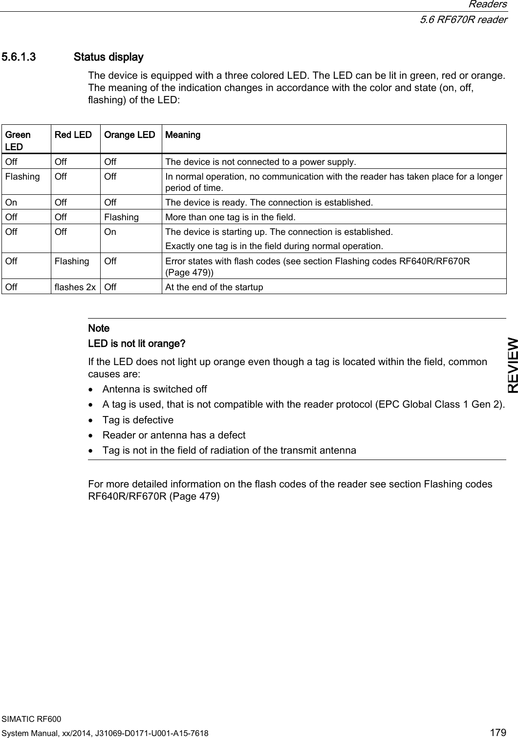
![Readers 5.5 RF650R reader SIMATIC RF600 160 System Manual, xx/2014, J31069-D0171-U001-A15-7618 REVIEW 5.5.1.3 Status display The device is equipped with 7 three-colored LEDs. The operating statuses of the reader are displayed by the "RUN/STOP", "ERROR", "MAINT" and "PRESENCE" LEDs. The LEDs can be lit green, red or orange. The meaning of the display changes according to the color and status (on, off, flashing) of the LED: R/S ERR MT PRE Meaning The device is turned off. The device is starting up. - - - The device is ready for operation. The connection is established. - - - The device is working. Transponder data can be read or written. - - - There is an error. - - - Maintenance work required. - - - There is transponder in the antenna field. - - - There are multiple transponders in the antenna field. For more detailed information on the flash codes of the reader, refer to the section LED displays RF650R/RF680R/RF685R (Page 480). 5.5.1.4 Pin assignment of the digital I/O interface View of socket (reader end) Table 5- 19 M12 socket (reader end) Pin Pin assignment 1 2 3 4 5 6 7 8 9 10 11 12 GND (output for supply of digital inputs/outputs [not electrically isolated]) VCC (output for supply of digital inputs/outputs [not electrically isolated]) DO Common / Outport Common DO 0 / Outport 00 DO 1 / Outport 01 DO 2 / Outport 02 DO 3 / Outport 03 DI 0 / Inport 00 DI Common / Inport Common DI 1 / Inport 01 DI 2 / Inport 02 DI 3 / Inport 03](https://usermanual.wiki/Siemens/RF600R2.User-Manual-part-1/User-Guide-2334392-Page-160.png)


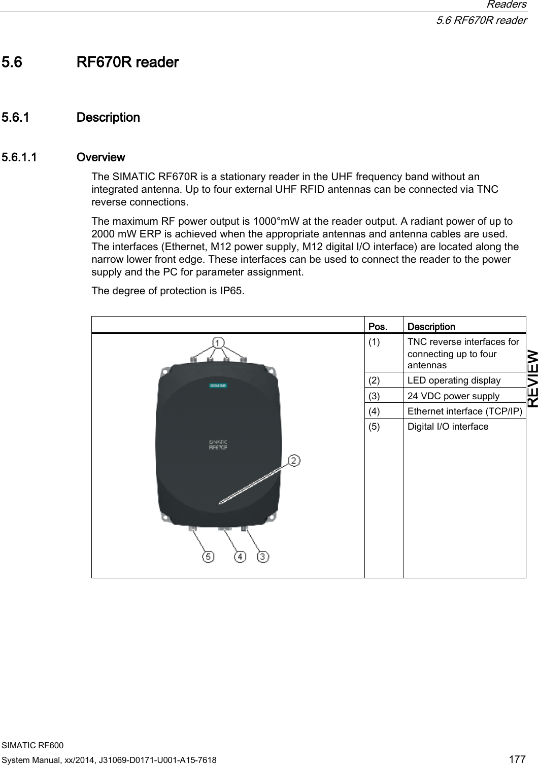

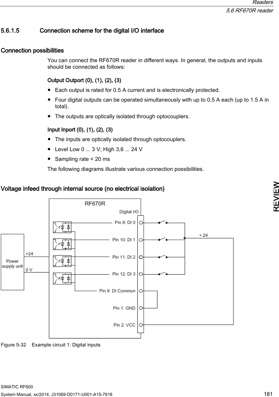
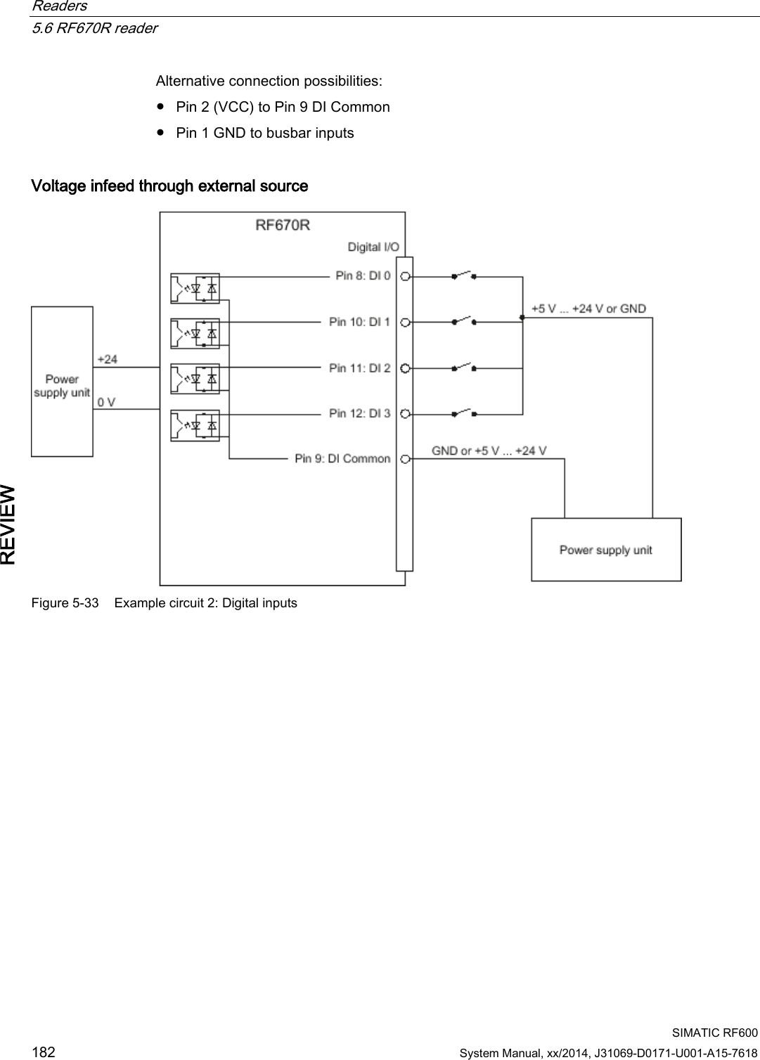
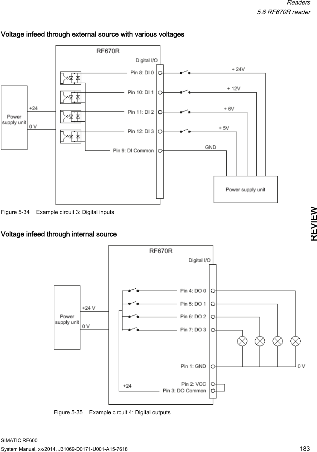
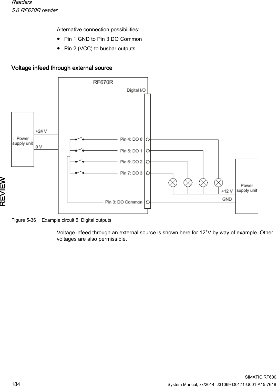
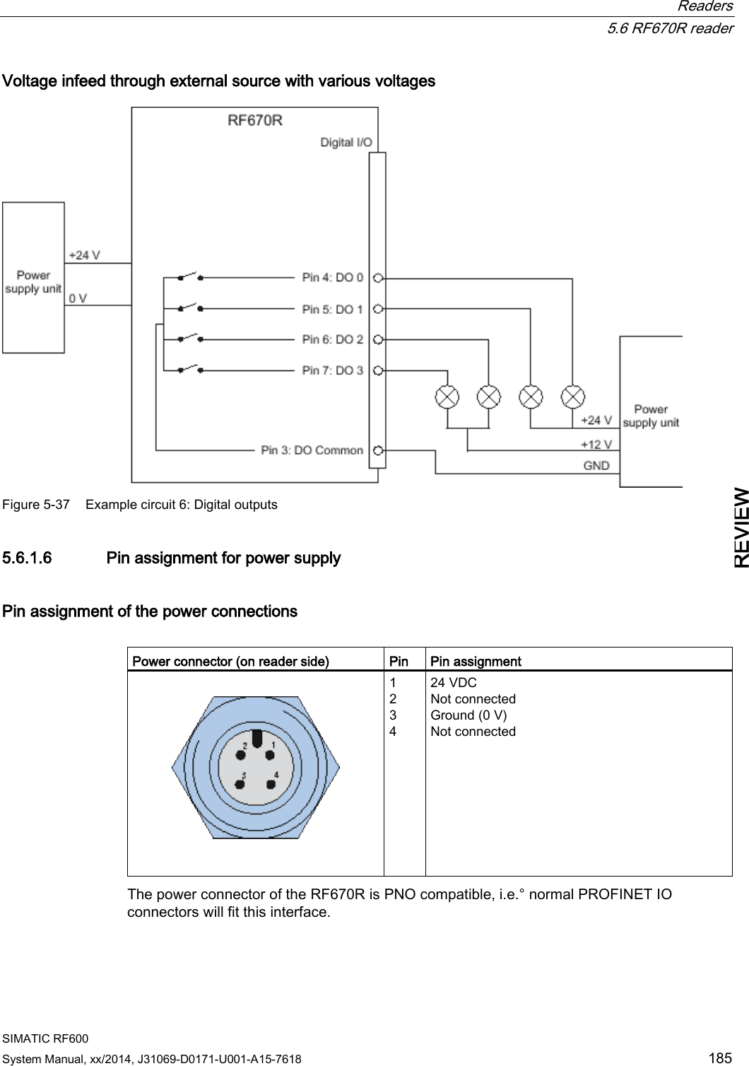
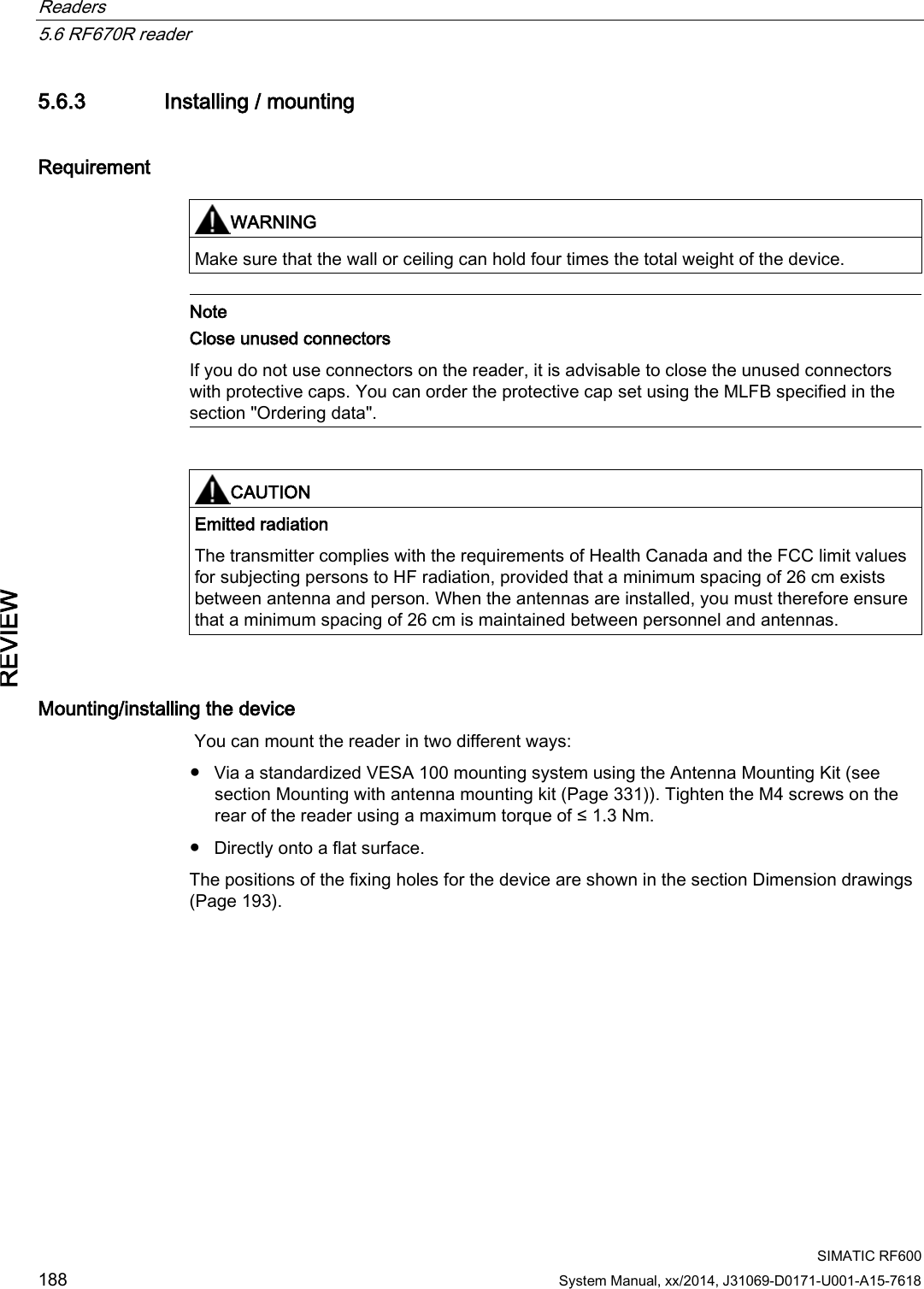
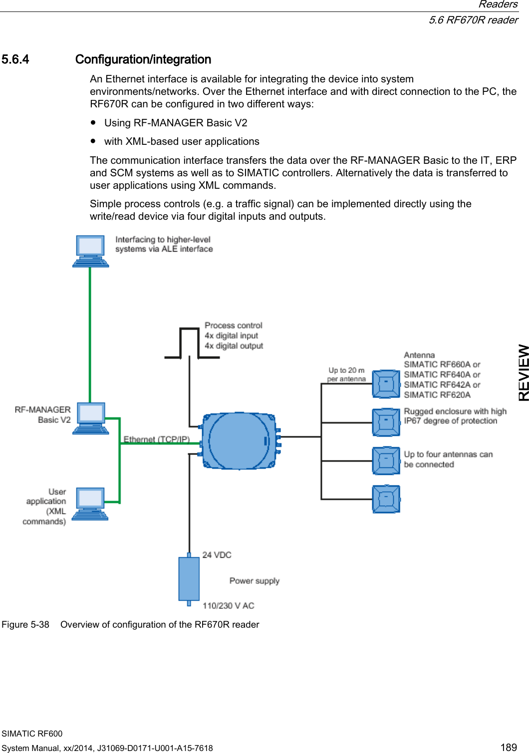
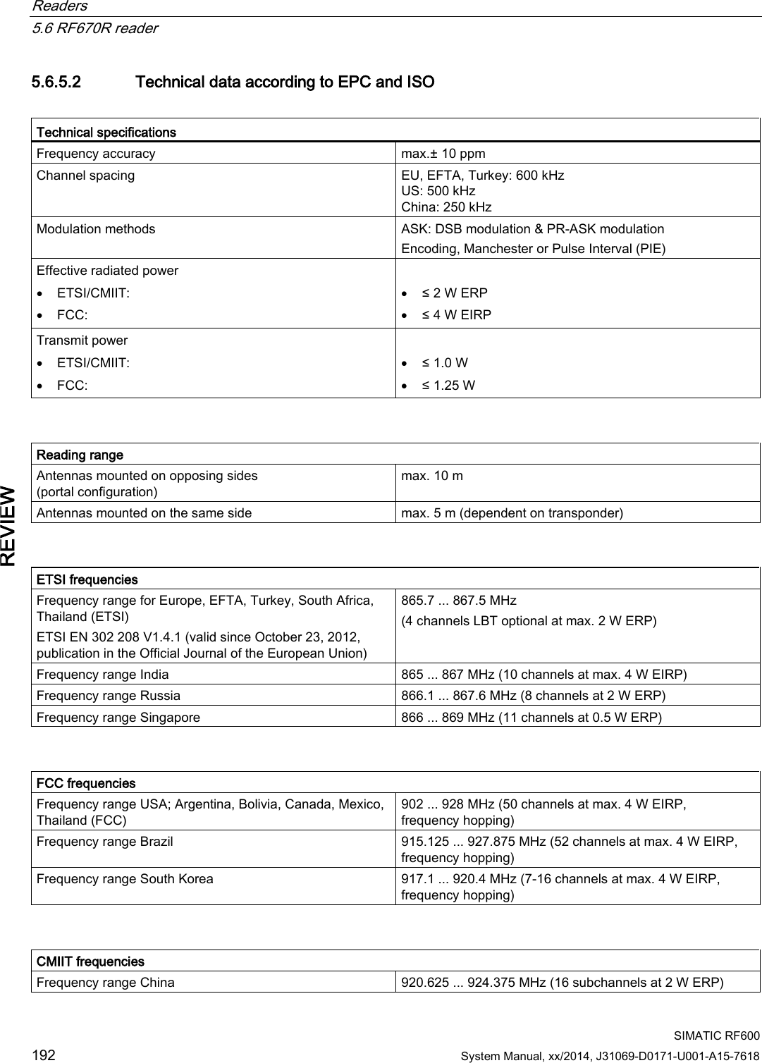
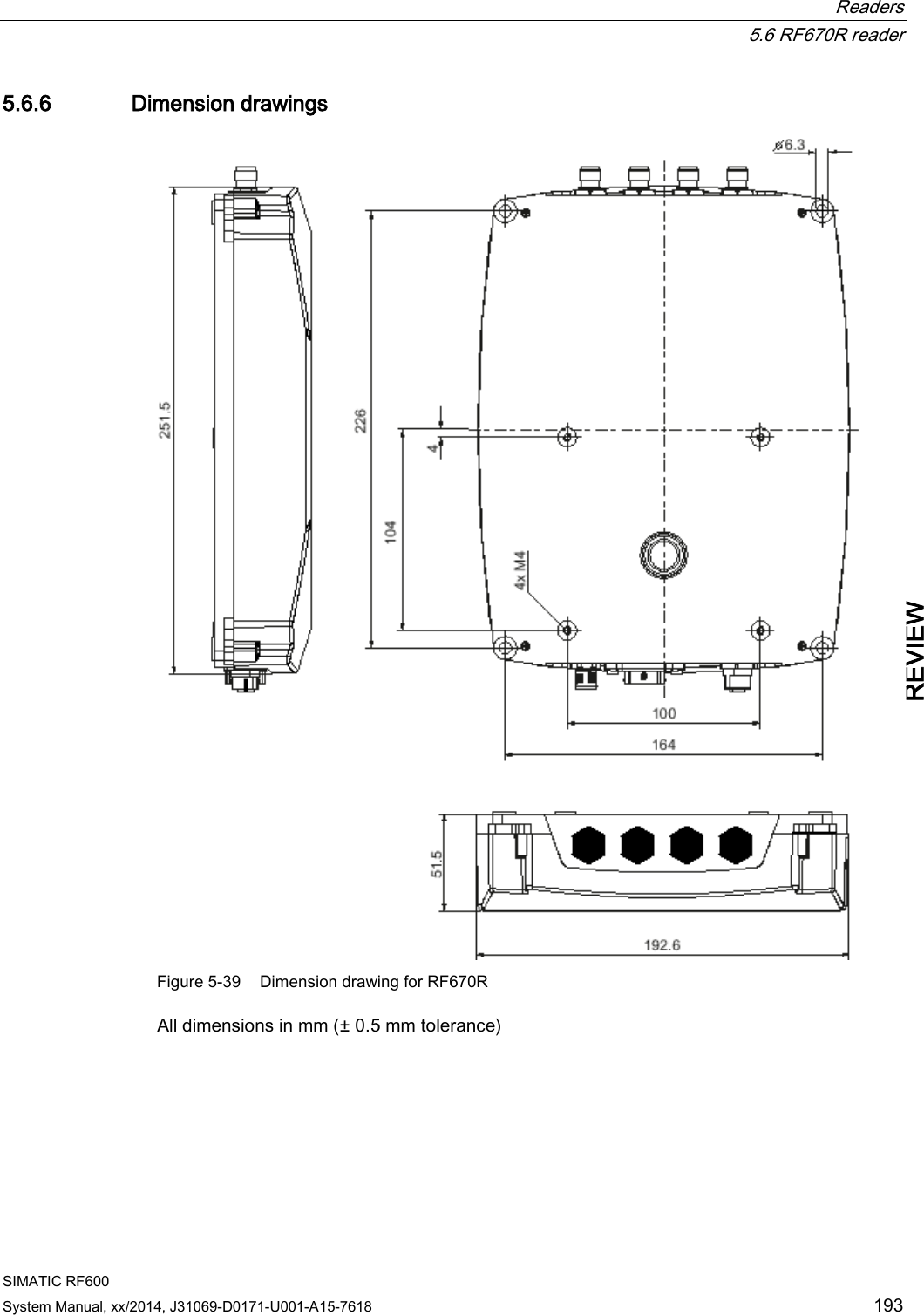
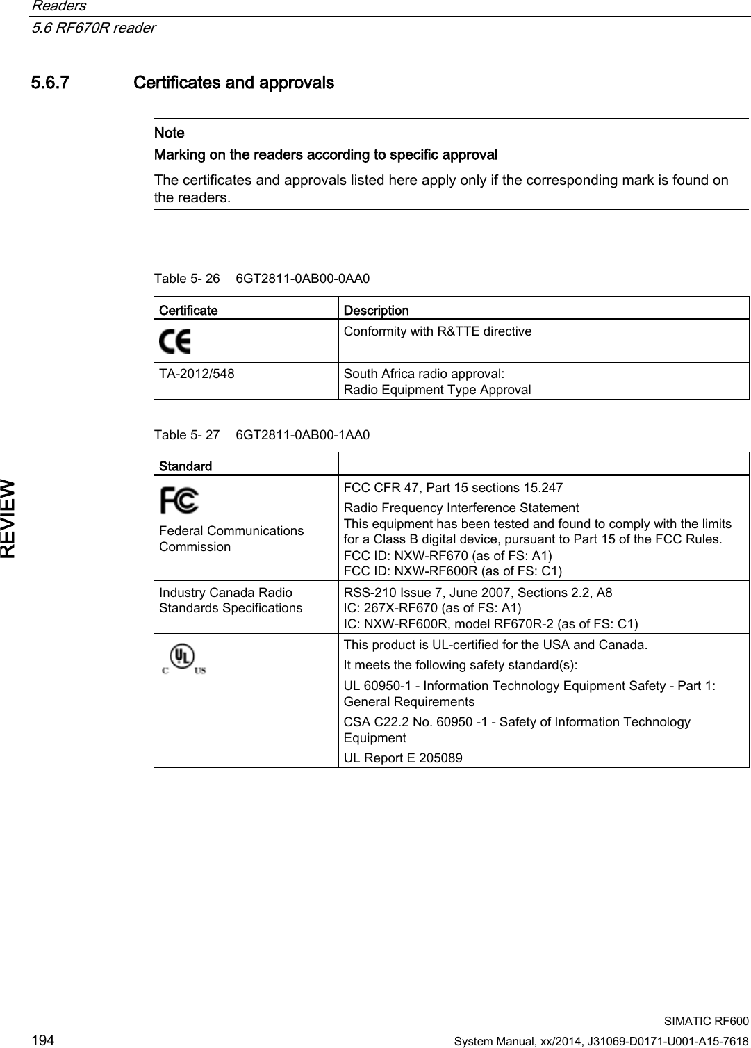
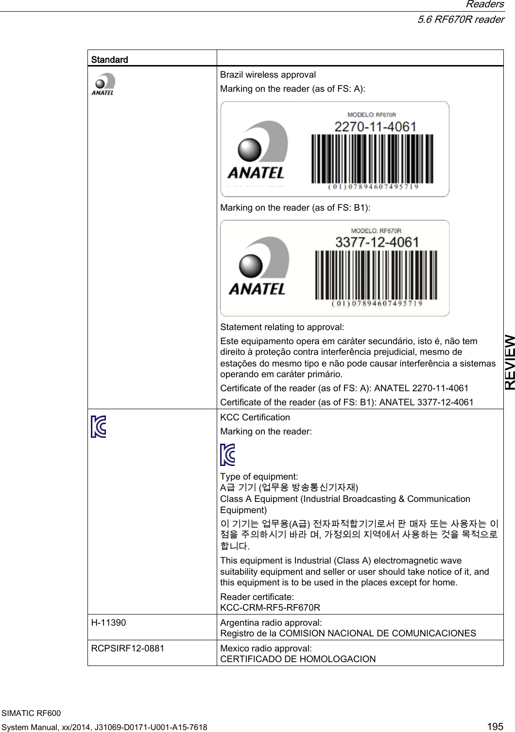
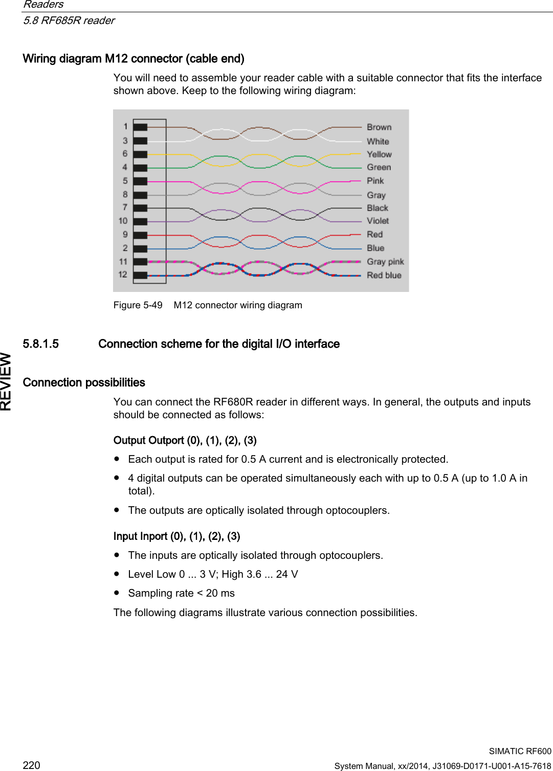
![Readers 5.6 RF670R reader SIMATIC RF600 180 System Manual, xx/2014, J31069-D0171-U001-A15-7618 REVIEW 5.6.1.4 Pin assignment of the digital I/O interface View of socket (reader end) Table 5- 25 M12 socket (reader end) Pin Pin assignment 1 2 3 4 5 6 7 8 9 10 11 12 GND (output for supply of digital inputs/outputs [not electrically isolated]) VCC (output for supply of digital inputs/outputs [not electrically isolated]) DO Common / Outport Common DO 0 / Outport 00 DO 1 / Outport 01 DO 2 / Outport 02 DO 3 / Outport 03 DI 0 / Inport 00 DI Common / Inport Common DI 1 / Inport 01 DI 2 / Inport 02 DI 3 / Inport 03 Wiring diagram M12 connector (cable end) You will need to assemble your reader cable with a suitable connector that fits the interface shown above. Keep to the following wiring diagram: Figure 5-31 M12 connector wiring diagram](https://usermanual.wiki/Siemens/RF600R2.User-Manual-part-1/User-Guide-2334392-Page-180.png)
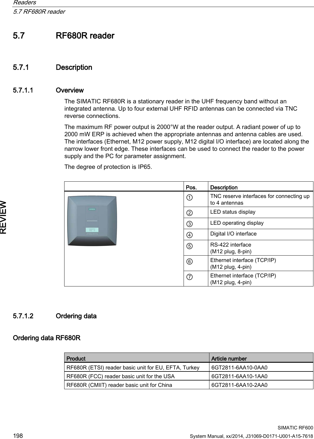
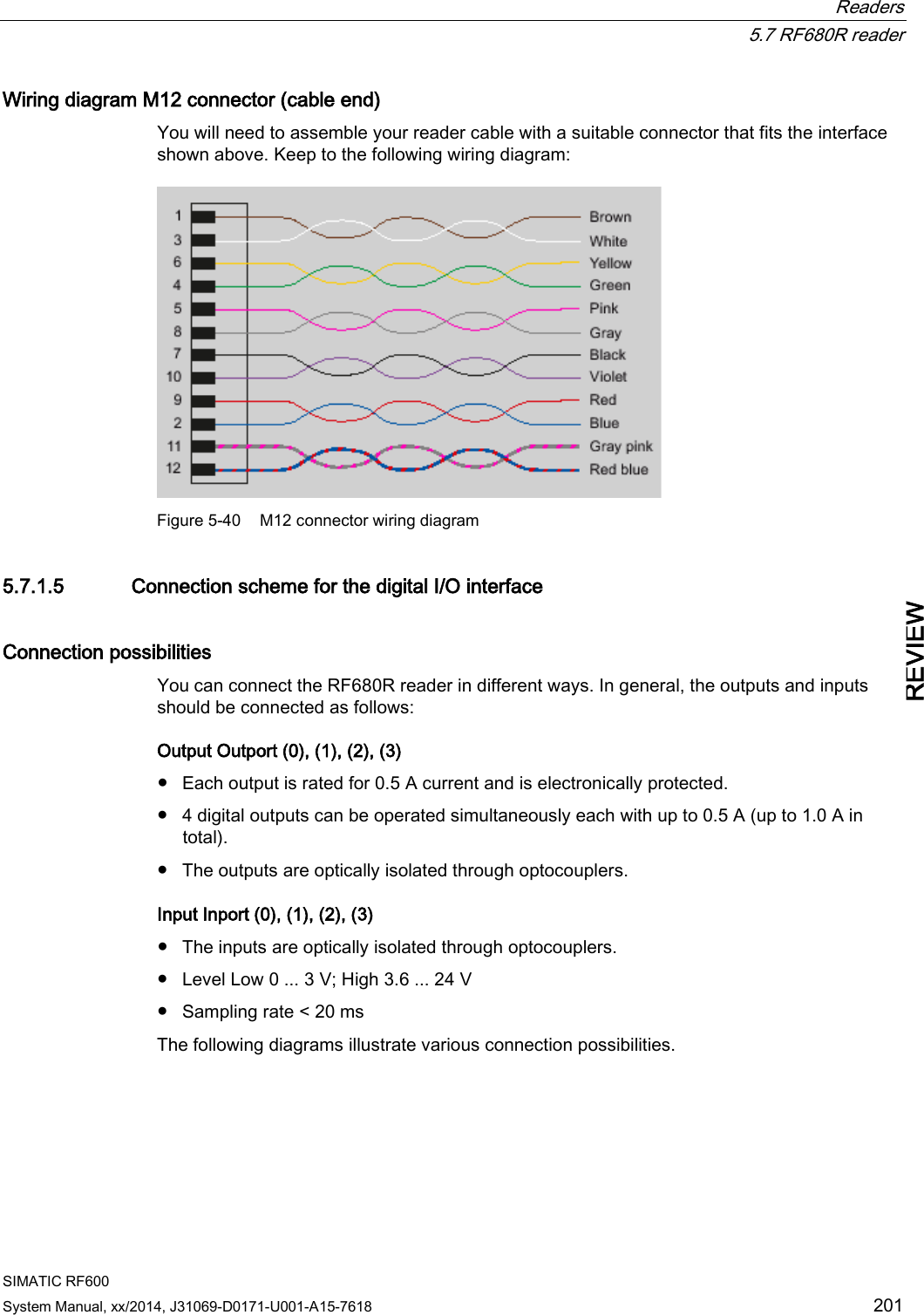
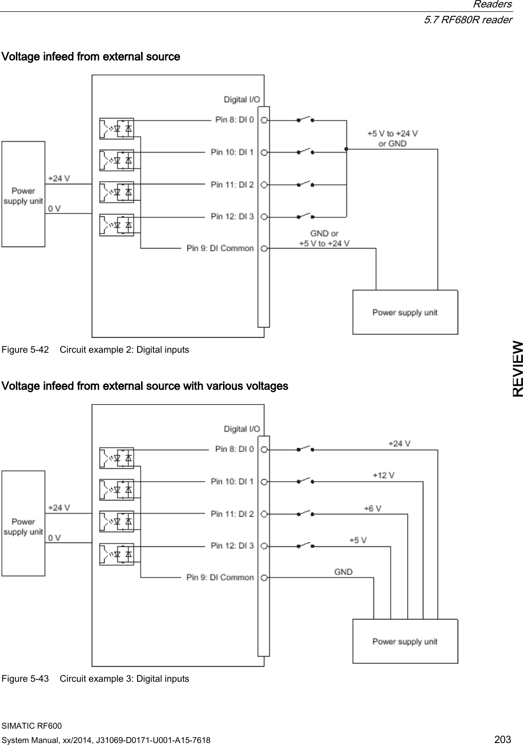
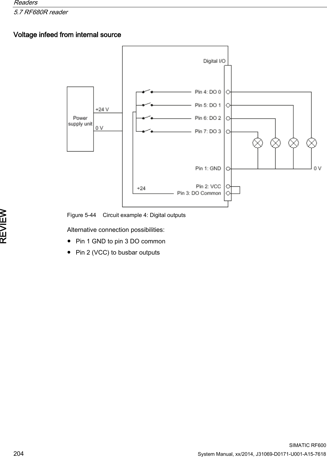
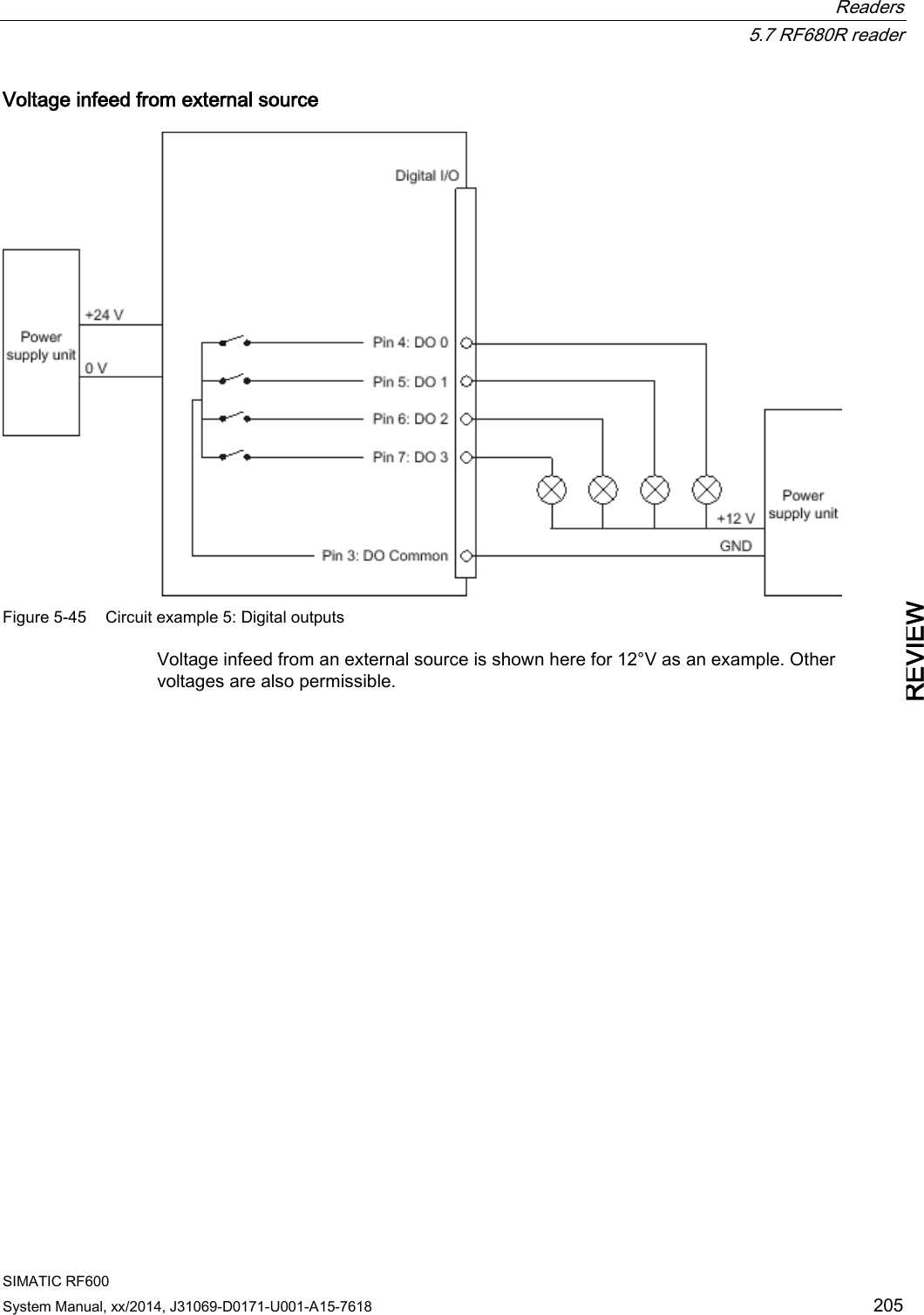
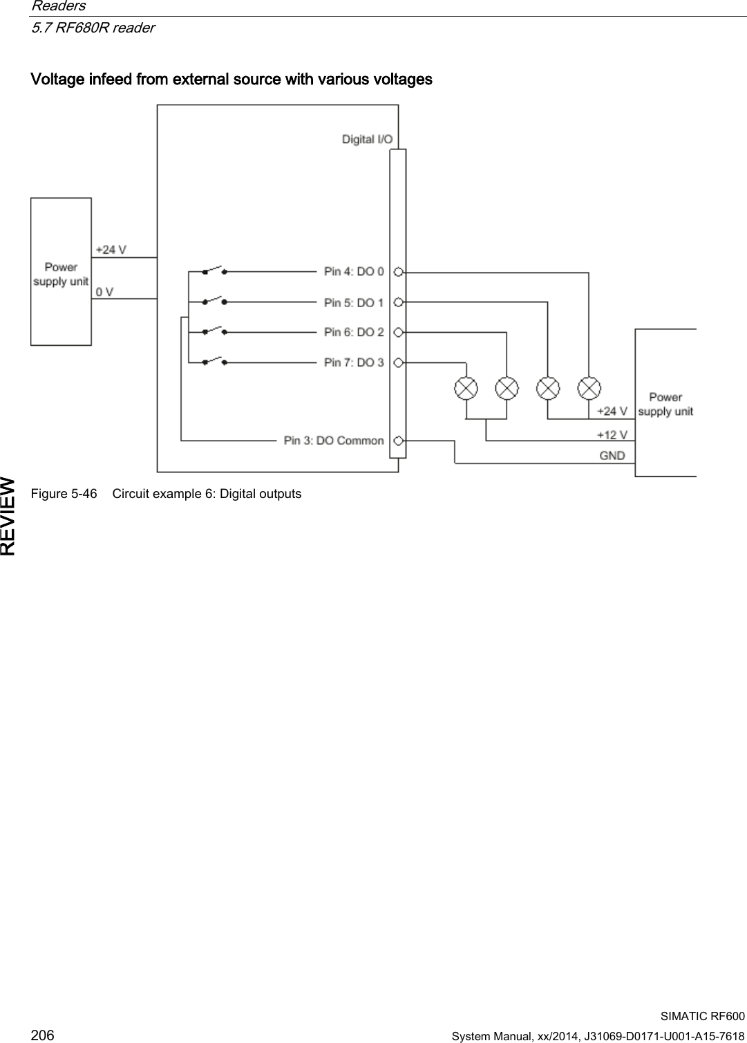
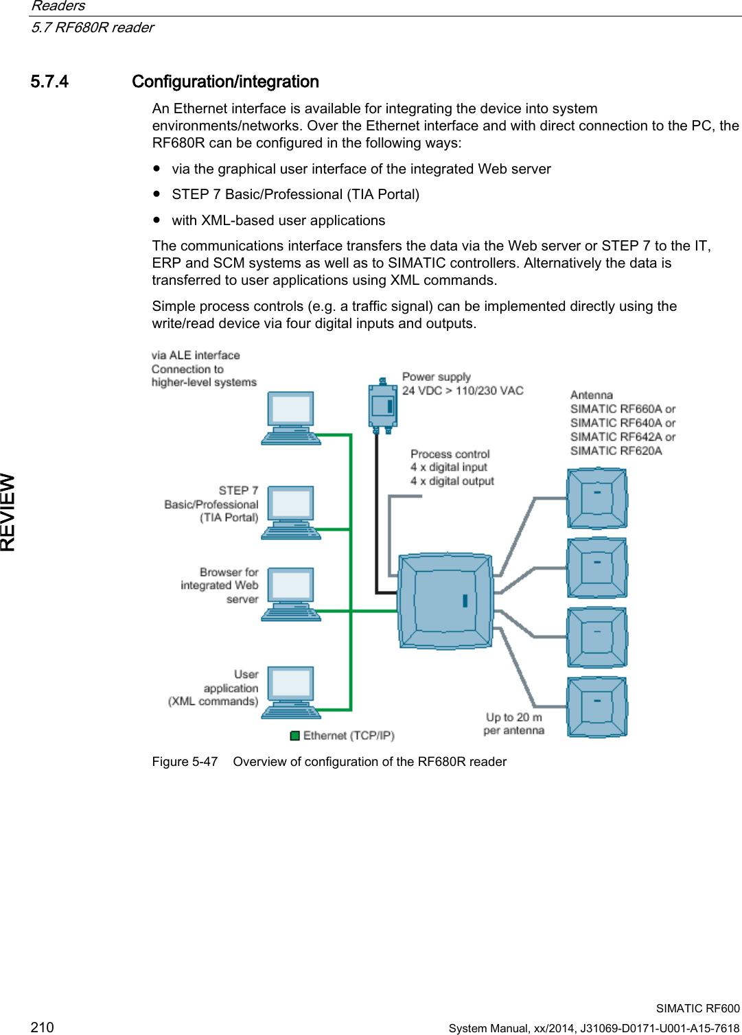
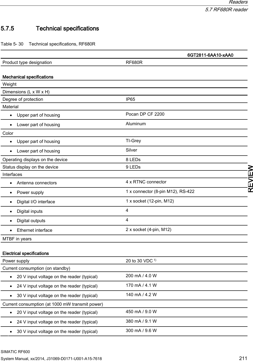
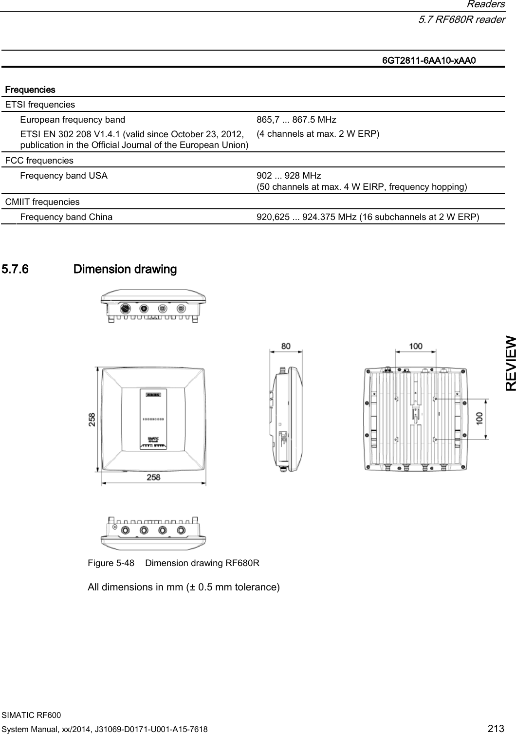
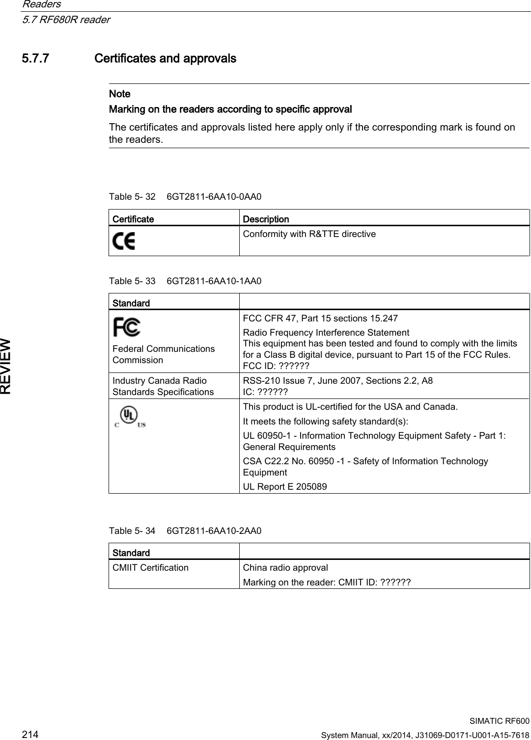
![Readers 5.7 RF680R reader SIMATIC RF600 200 System Manual, xx/2014, J31069-D0171-U001-A15-7618 REVIEW 5.7.1.3 Status display The device is equipped with 17 three-colored LEDs. The operating statuses of the reader are displayed by the "RUN/STOP", "ERROR", "MAINT" and "PRESENCE" LEDs. The LEDs can be lit green, red or orange. The meaning of the display changes according to the color and status (on, off, flashing) of the LED: R/S ERR MT PR Meaning The device is turned off. The device is starting up. - - - The device is ready for operation. The connection is established. - - - The device is working. Transponder data can be read or written. - - - There is an error. - - - Maintenance work required. - - - There is transponder in the antenna field. - - - There are multiple transponders in the antenna field. For more detailed information on the flash codes of the reader, refer to the section LED displays RF650R/RF680R/RF685R (Page 480). 5.7.1.4 Pin assignment of the digital I/O interface View of socket (reader end) Table 5- 29 M12 socket (reader end) Pin Pin assignment 1 2 3 4 5 6 7 8 9 10 11 12 GND (output for supply of digital inputs/outputs [not electrically isolated]) VCC (output for supply of digital inputs/outputs [not electrically isolated]) DO Common / Outport Common DO 0 / Outport 00 DO 1 / Outport 01 DO 2 / Outport 02 DO 3 / Outport 03 DI 0 / Inport 00 DI Common / Inport Common DI 1 / Inport 01 DI 2 / Inport 02 DI 3 / Inport 03](https://usermanual.wiki/Siemens/RF600R2.User-Manual-part-1/User-Guide-2334392-Page-200.png)


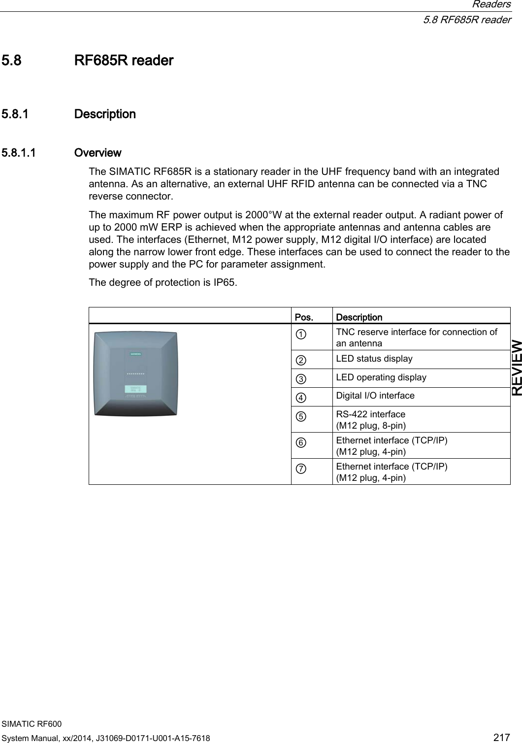
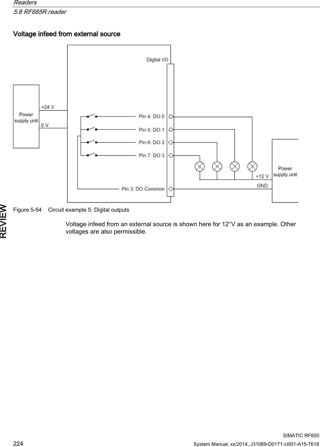
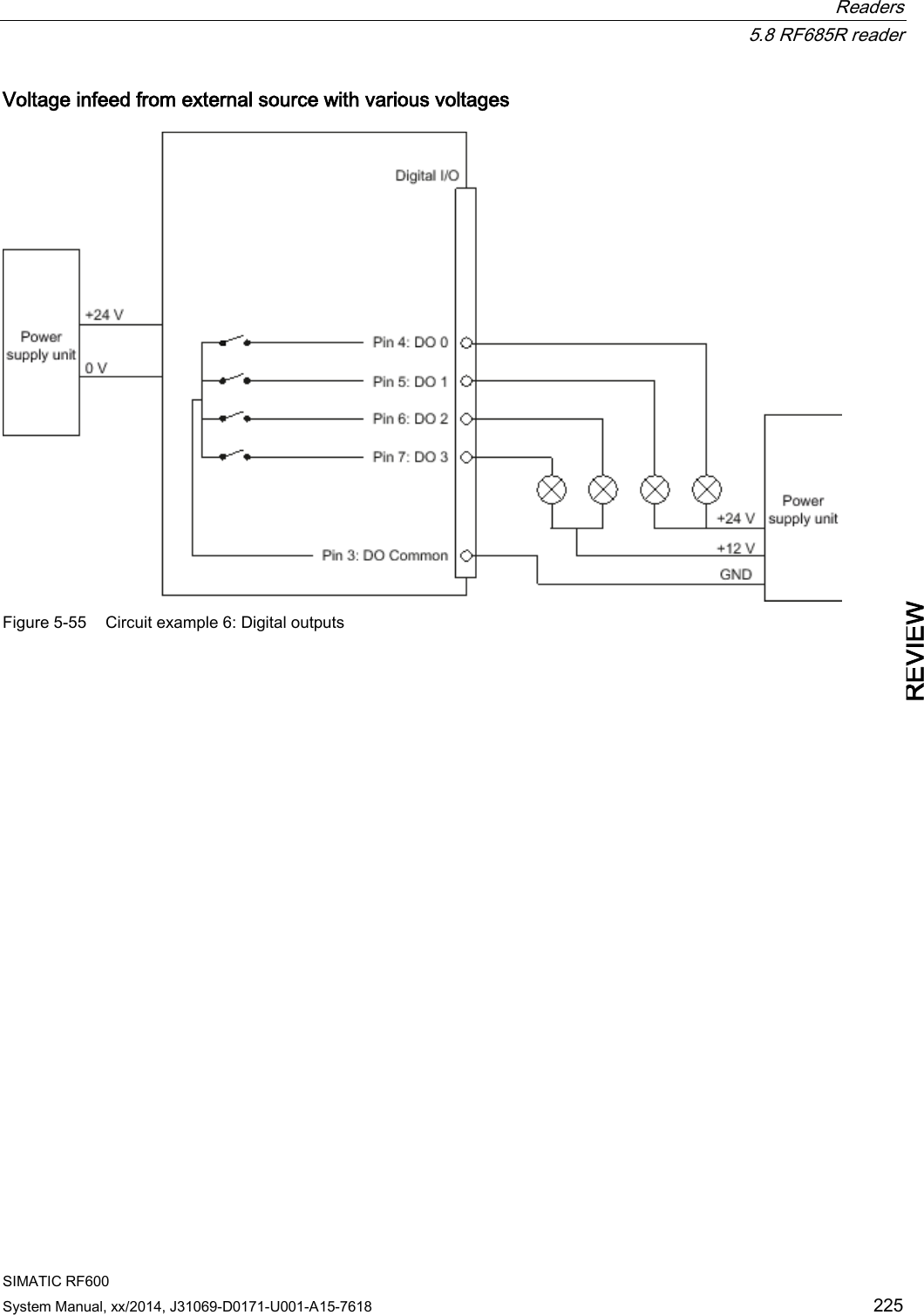
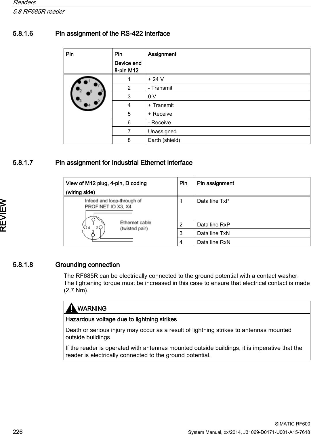
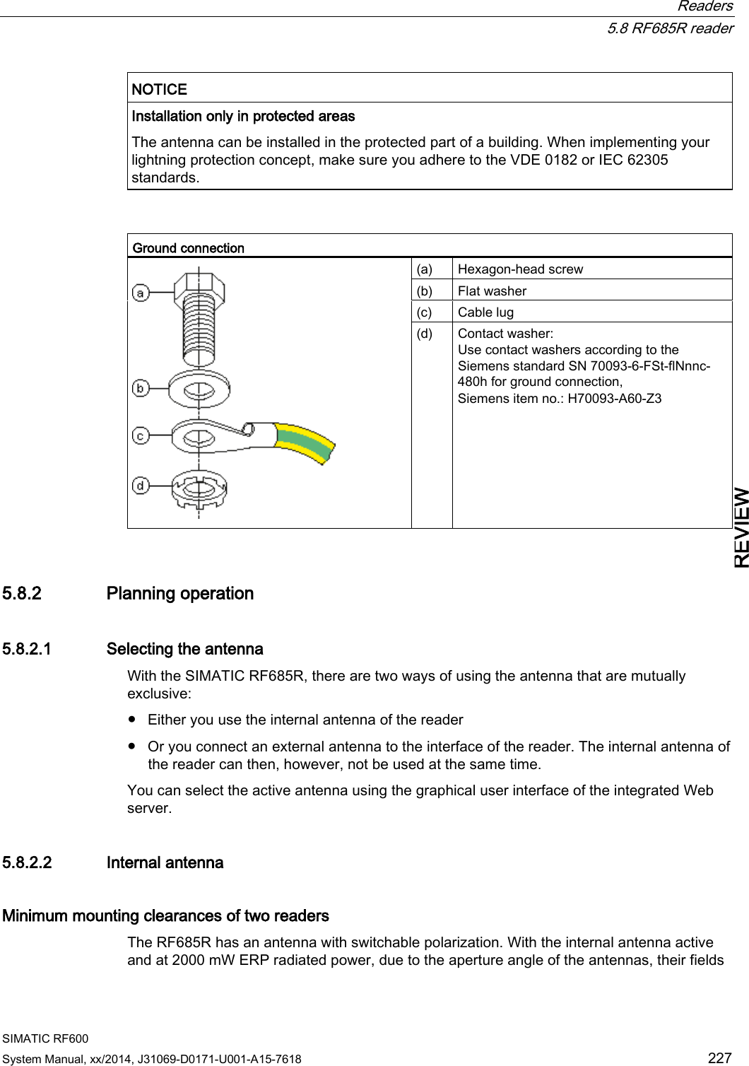
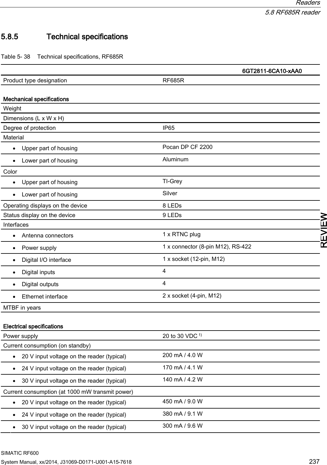
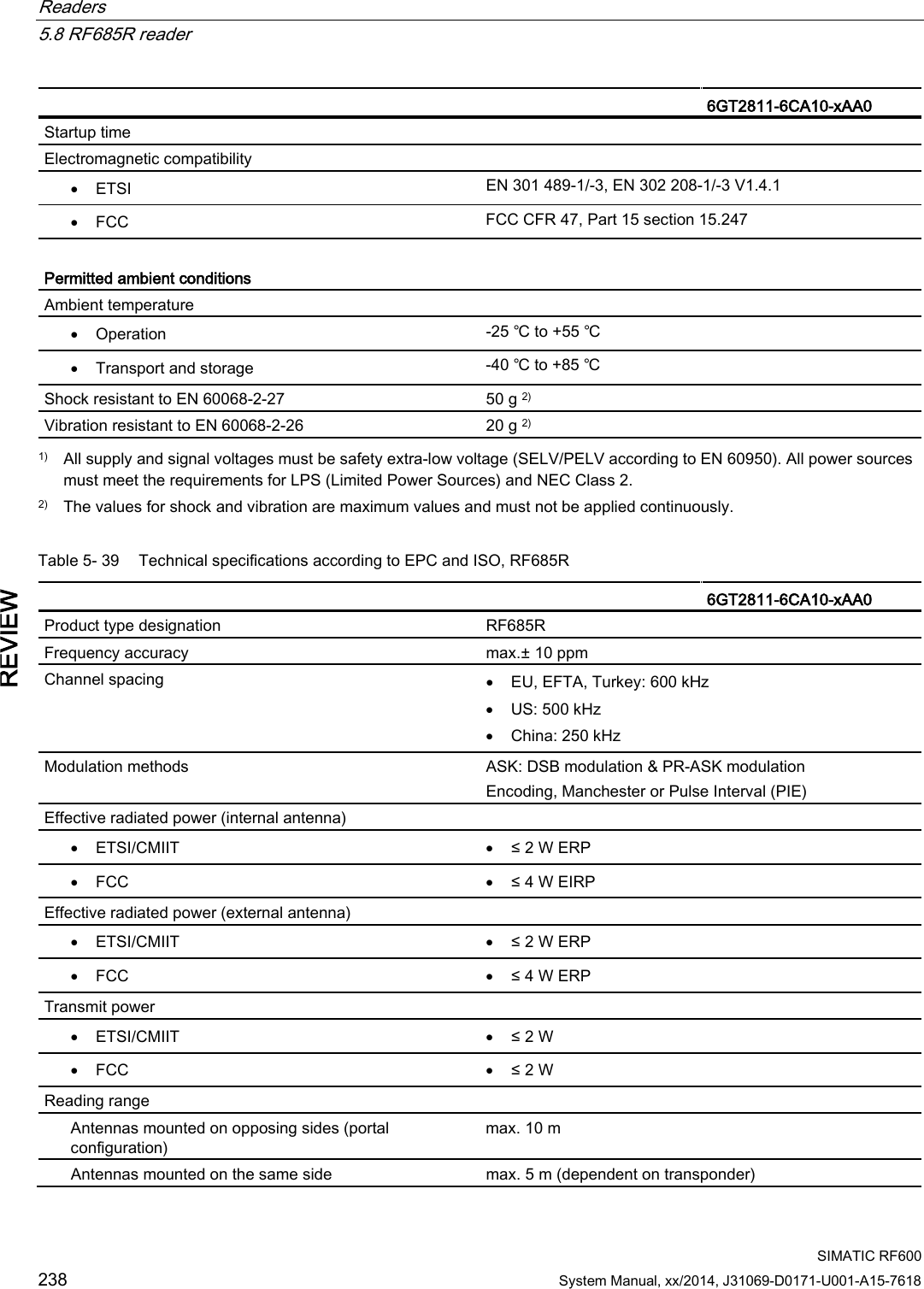
![Readers 5.8 RF685R reader SIMATIC RF600 System Manual, xx/2014, J31069-D0171-U001-A15-7618 219 REVIEW 5.8.1.3 Status display The device is equipped with 17 three-colored LEDs. The operating statuses of the reader are displayed by the "RUN/STOP", "ERROR", "MAINT" and "PRESENCE" LEDs. The LEDs can be lit green, red or orange. The meaning of the display changes according to the color and status (on, off, flashing) of the LED: R/S ERR MT PR Meaning The device is turned off. The device is starting up. - - - The device is ready for operation. The connection is established. - - - The device is working. Transponder data can be read or written. - - - There is an error. - - - Maintenance work required. - - - There is transponder in the antenna field. - - - There are multiple transponders in the antenna field. For more detailed information on the flash codes of the reader, refer to the section LED displays RF650R/RF680R/RF685R (Page 480). 5.8.1.4 Pin assignment of the digital I/O interface View of socket (reader end) Table 5- 35 M12 socket (reader end) Pin Pin assignment 1 2 3 4 5 6 7 8 9 10 11 12 GND (output for supply of digital inputs/outputs [not electrically isolated]) VCC (output for supply of digital inputs/outputs [not electrically isolated]) DO Common / Outport Common DO 0 / Outport 00 DO 1 / Outport 01 DO 2 / Outport 02 DO 3 / Outport 03 DI 0 / Inport 00 DI Common / Inport Common DI 1 / Inport 01 DI 2 / Inport 02 DI 3 / Inport 03](https://usermanual.wiki/Siemens/RF600R2.User-Manual-part-1/User-Guide-2334392-Page-219.png)
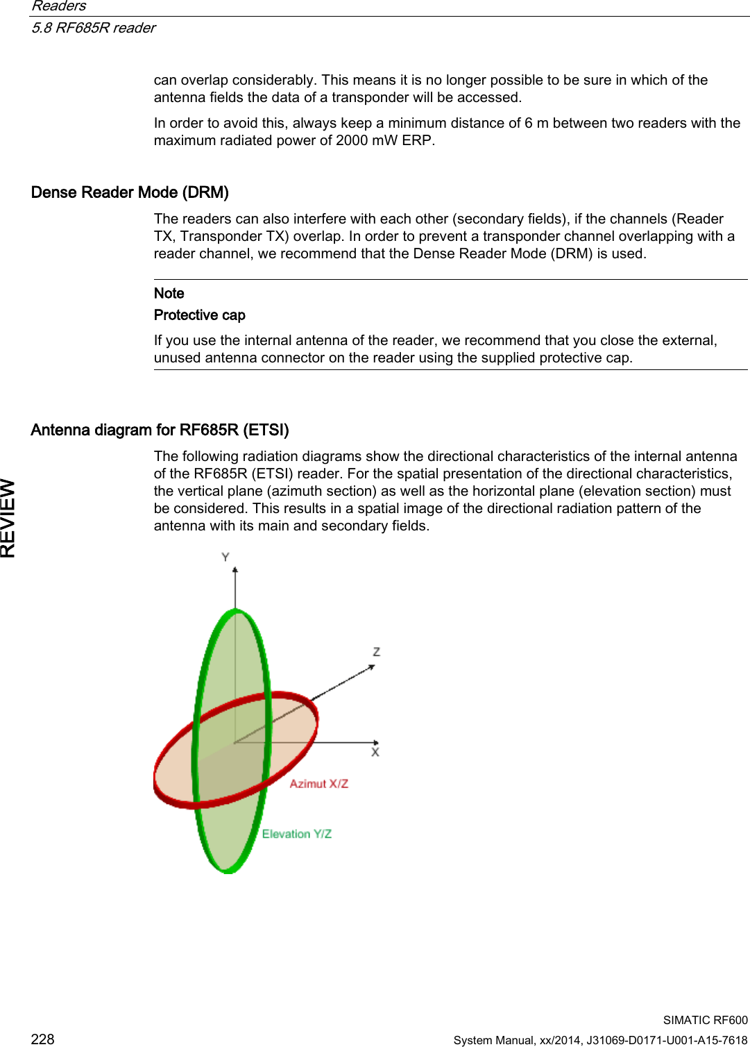
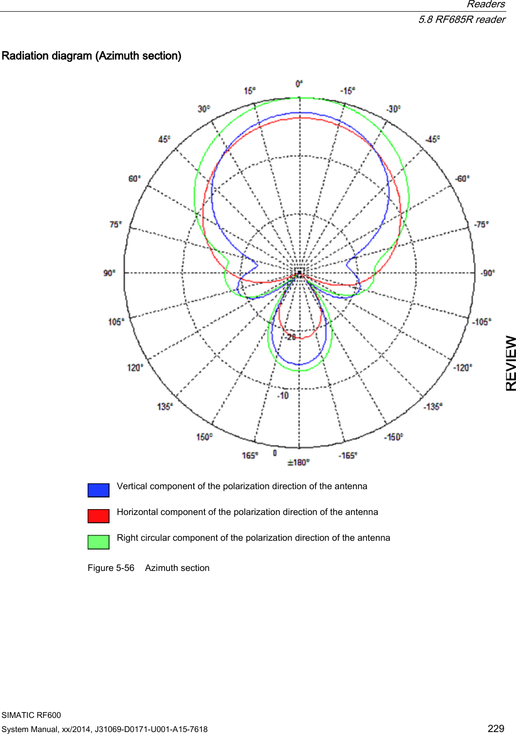
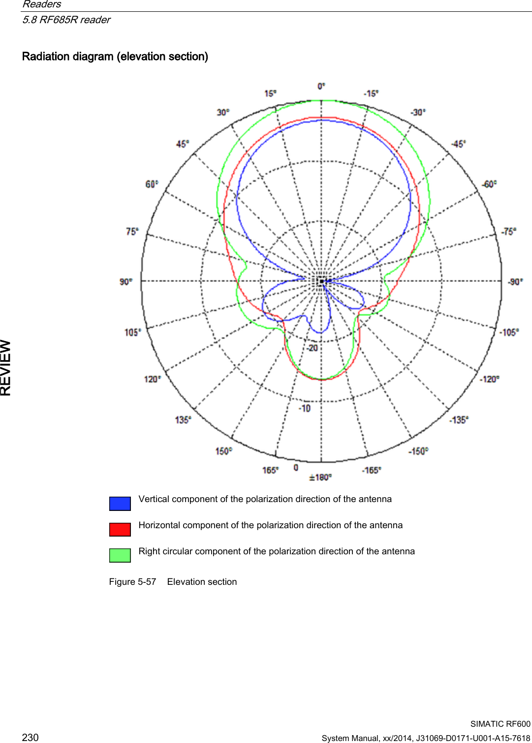
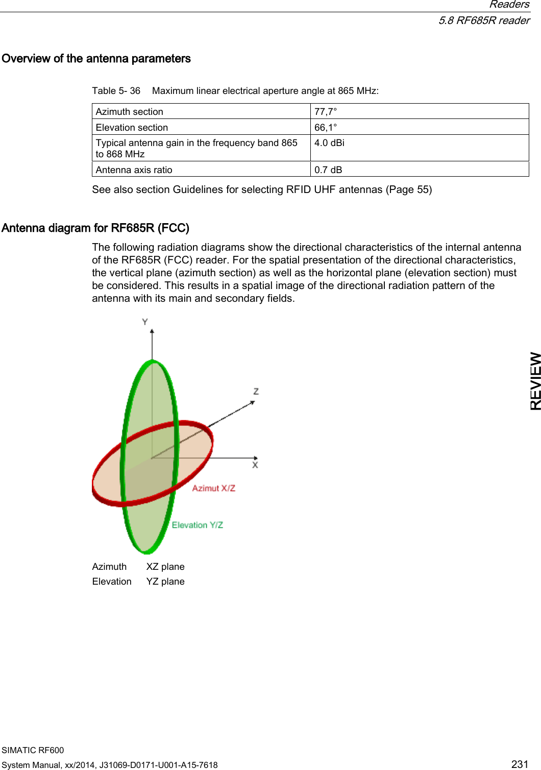
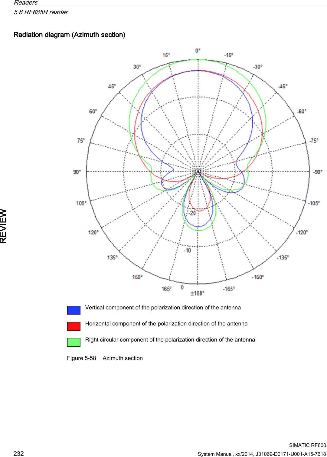
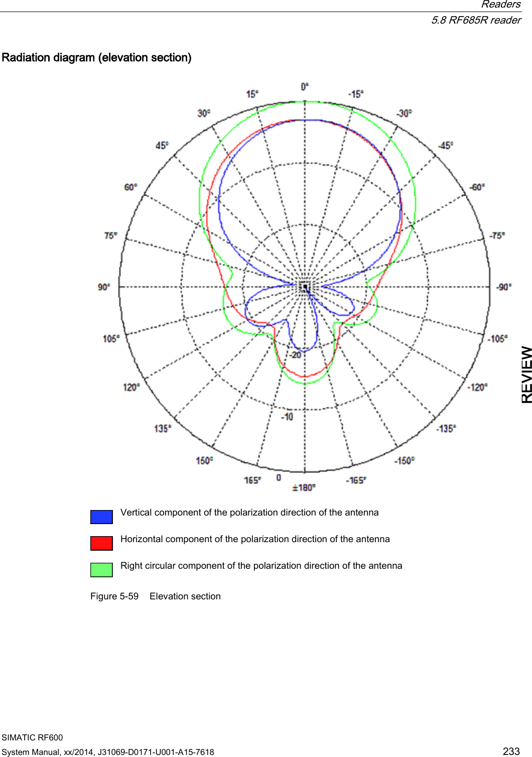
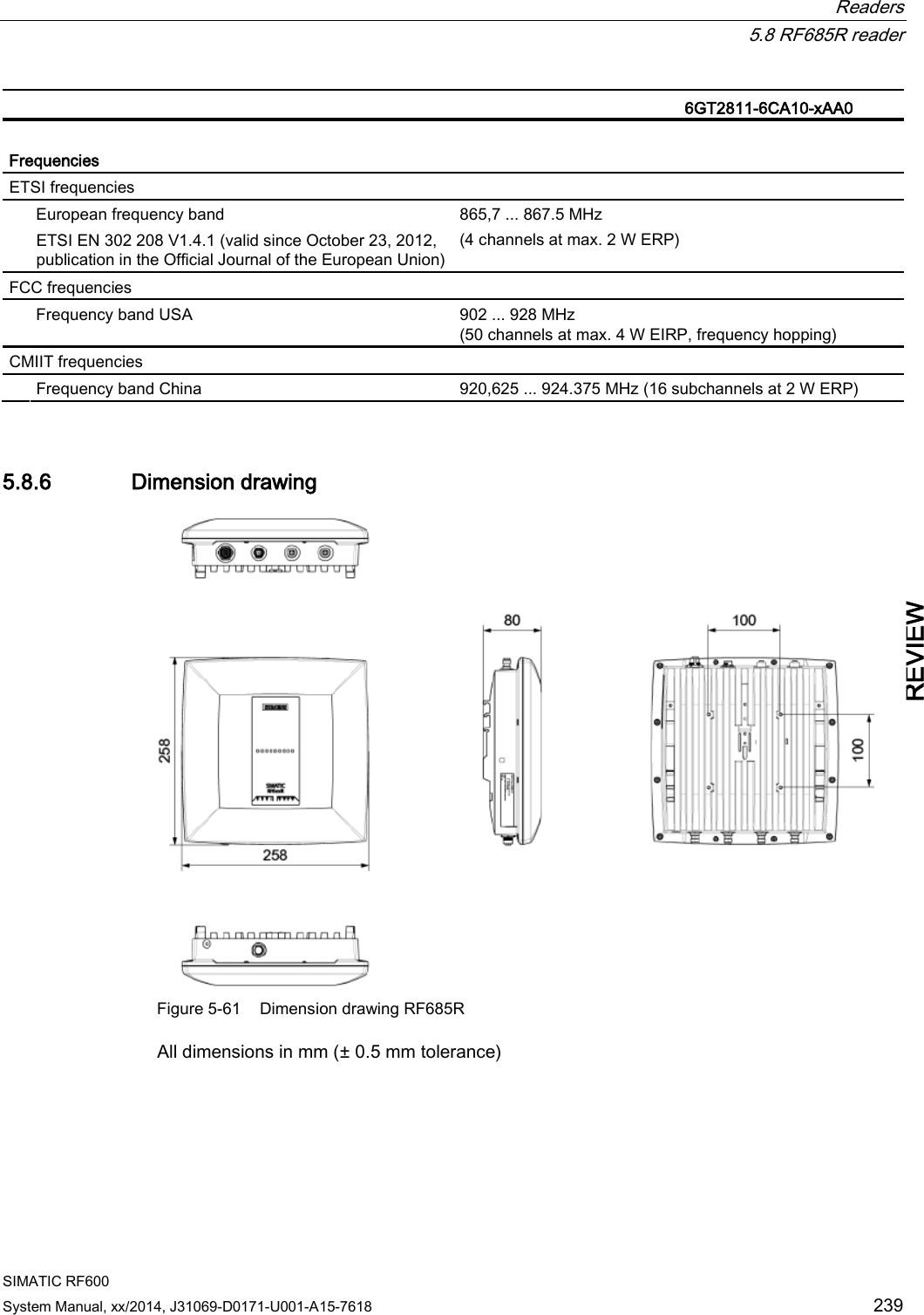
![Readers 5.8 RF685R reader SIMATIC RF600 234 System Manual, xx/2014, J31069-D0171-U001-A15-7618 REVIEW Overview of the antenna parameters Table 5- 37 Maximum linear electrical aperture angle at 865 MHz: Azimuth section 75,4 ° Elevation section 69,1 ° Typical antenna gain in the frequency band 902 to 928 MHz 4.0 dBi ± 0.5 dB Antenna axis ratio <1 dB See also section Guidelines for selecting RFID UHF antennas (Page 55). Interpretation of directional radiation patterns The following overview table will help you with the interpretation of directional radiation patterns. The table shows which dBi values correspond to which read/write ranges (in %): You can read the radiated power depending on the reference angle from the directional radiation patterns, and thus obtain information on the read/write range with this reference angle with regard to a transponder. The dBr values correspond to the difference between the maximum dBi value and a second dBi value. Deviation from maximum antenna gain [dBr] Read/write range [%] 0 100 -3 70 -6 50 -9 35 -12 25 -15 18 -18 13 Example As can be seen in the section Antenna diagram for RF685R (ETSI) (Page 228), the maximum antenna gain 0 dB is standardized. In the Azimuth diagram, the antenna gain falls by 3°dB at approximately ± 39°. Therefore the dBr value is -3. The antenna range is only 50% of the maximum range at ± 39° from the Z axis within the horizontal plane. Antenna/read point configurations The RF685R reader has a switchable antenna (circular or linear polarization). You can cover one read point with this antenna. When several RF685R readers are used, the readers are addressed via the SIMATIC level.](https://usermanual.wiki/Siemens/RF600R2.User-Manual-part-1/User-Guide-2334392-Page-234.png)

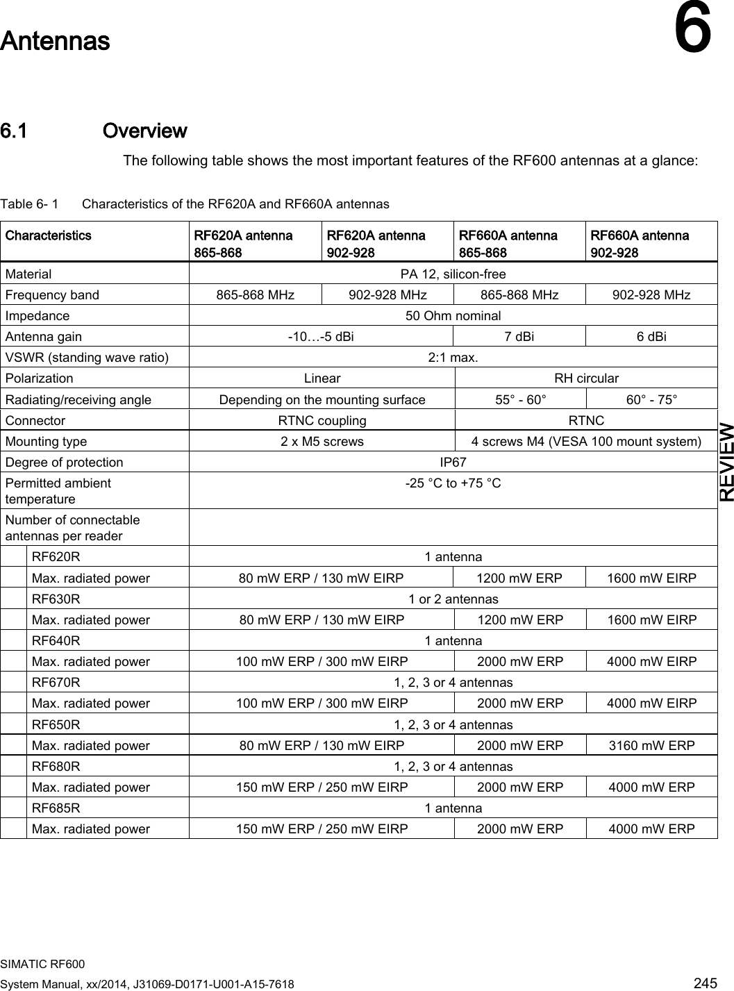
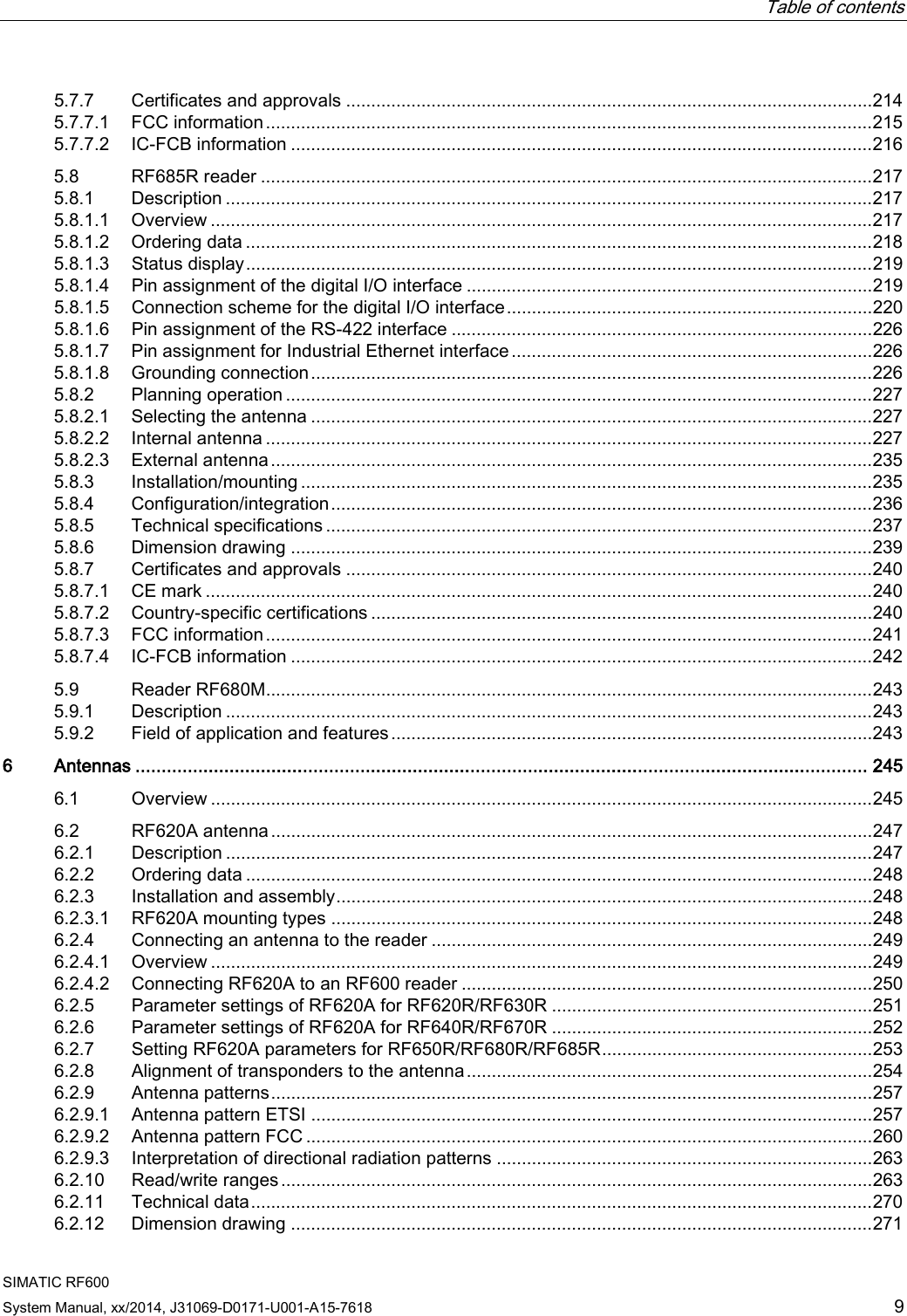
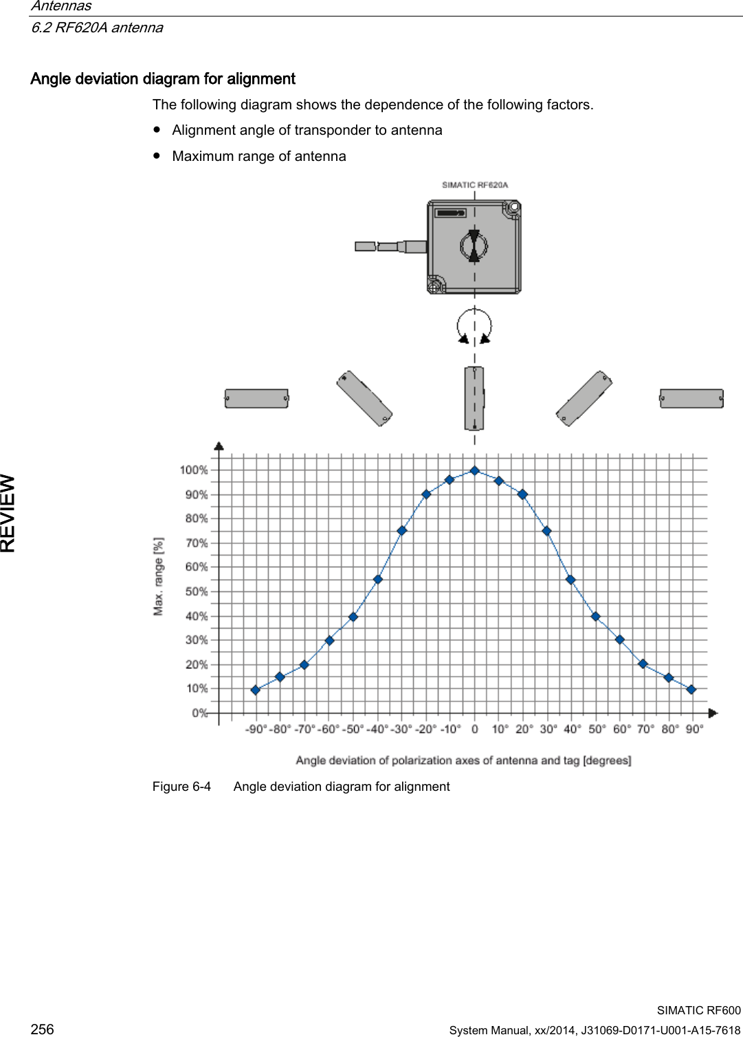
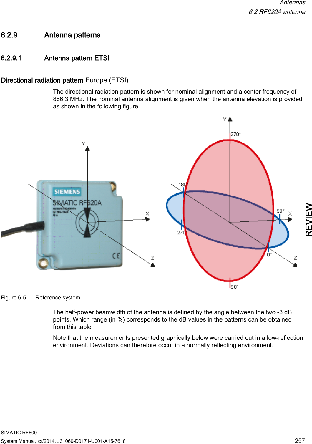
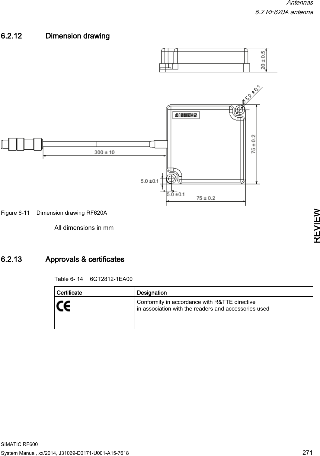
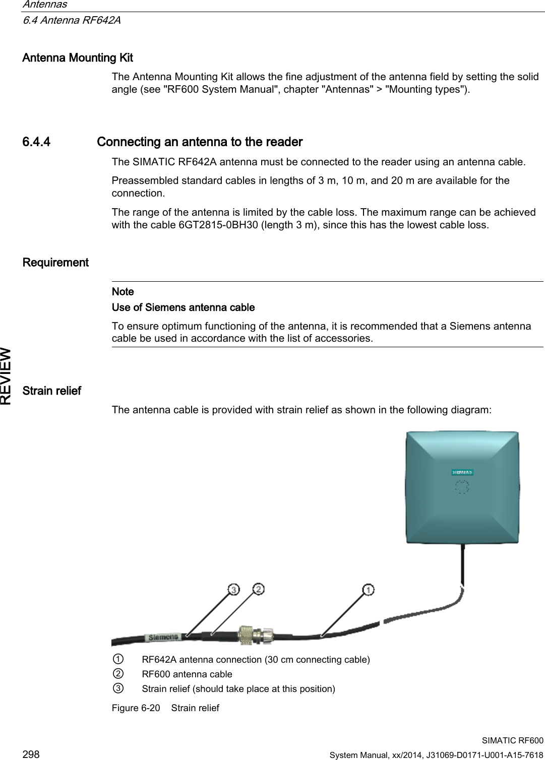
![Antennas 6.2 RF620A antenna SIMATIC RF600 System Manual, xx/2014, J31069-D0171-U001-A15-7618 249 REVIEW 6.2.4 Connecting an antenna to the reader 6.2.4.1 Overview The SIMATIC RF620A antenna must be connected to the reader using an antenna cable. Requirement Note Use of Siemens antenna cable To ensure optimum functioning of the antenna, it is recommended that a Siemens antenna cable is used in accordance with the list of accessories. Strain relief The antenna cable is provided with strain relief as shown in the following diagram: ① RF620A connecting cable ② RF600 antenna cable ③ Strain relief (should take place at this position) Figure 6-1 Strain relief Bending radii and bending cycles of the cable Cable designation Order no. Length [m] Cable loss [dB] Bending radius [mm] Bending cycle RF620A connecting cable 15 1 Mal Antenna cable 6GT2815-0BH30 3 1 51 1 Mal Antenna cable, suitable for drag chains 6GT2815-2BH50 5 1,25 48 1) Antenna cable 6GT2815-1BN10 10 2 77 1 Mal Antenna cable 6GT2815-0BN10 10 4 51 1 Mal](https://usermanual.wiki/Siemens/RF600R2.User-Manual-part-1/User-Guide-2334392-Page-249.png)
![Antennas 6.2 RF620A antenna SIMATIC RF600 250 System Manual, xx/2014, J31069-D0171-U001-A15-7618 REVIEW Cable designation Order no. Length [m] Cable loss [dB] Bending radius [mm] Bending cycle Antenna cable, suitable for drag chains 6GT2815-2BN15 15 4 24 1) Antenna cable 6GT2815-0BN20 20 4 77 1 Mal 1) With cables suitable for drag chains, 3 million bending cycles at a bending radius of 6.5 m and bending through ± 180 ° are permitted. 6.2.4.2 Connecting RF620A to an RF600 reader Preassembled standard cables in lengths of 3 m, 5 m, 10 m, 15 m and 20 m are available to connect the antenna. The read range is limited by the cable loss. The maximum range can be achieved with the 6GT2815-0BH30 cable (length 3 m) since this has the lowest cable loss. Connection of one antenna When one antenna is used, we recommend that you close the remaining antenna connector on the RF600 reader using the supplied protective cap. Connection of two antennas When using two antennas on the RF600 readers, there are no limitations regarding its positioning. Note Protective cap If you use the internal antenna of the reader, we recommend that you close the external, unused antenna connector on the reader using the supplied protective cap.](https://usermanual.wiki/Siemens/RF600R2.User-Manual-part-1/User-Guide-2334392-Page-250.png)
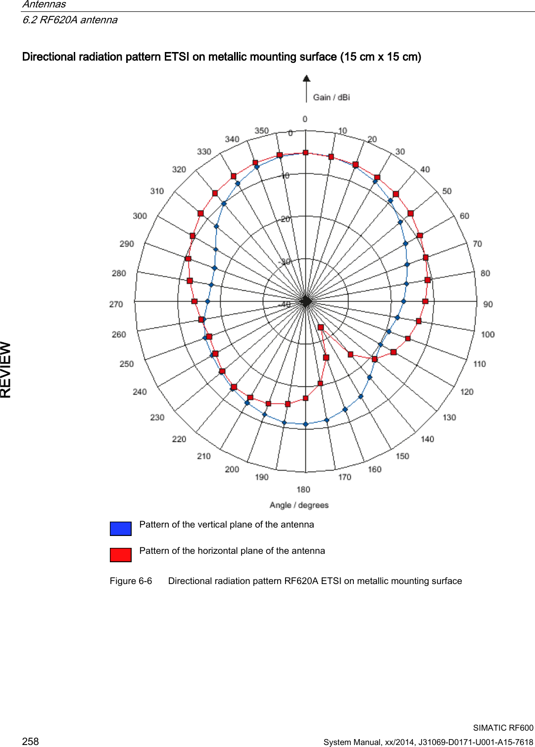
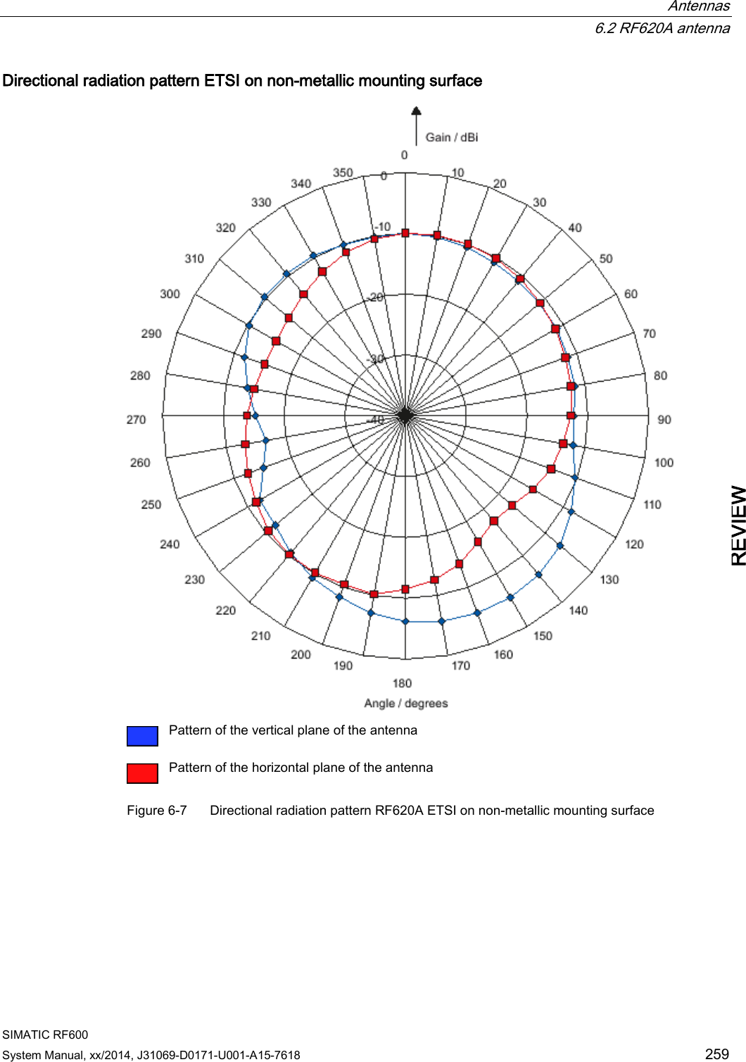
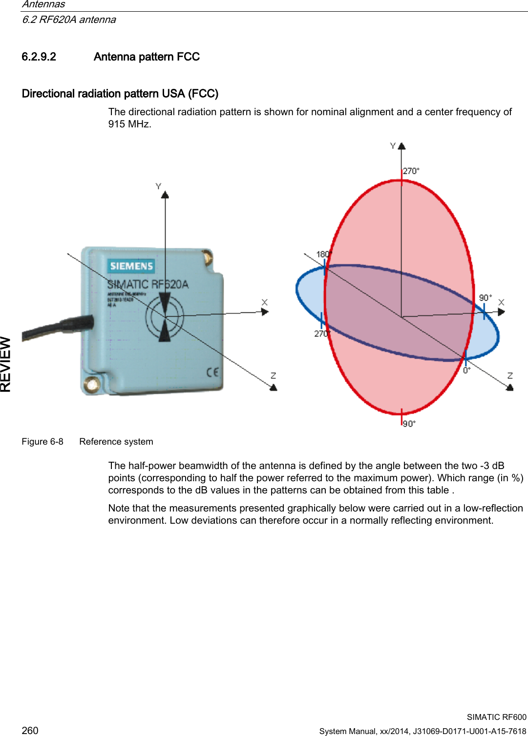
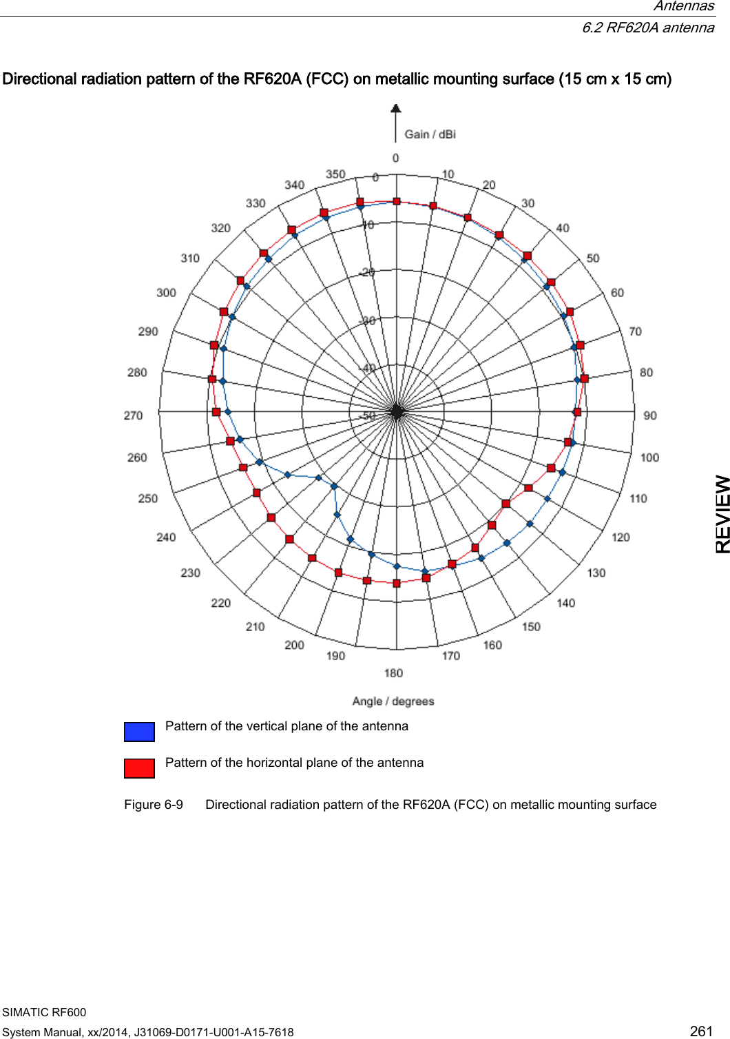
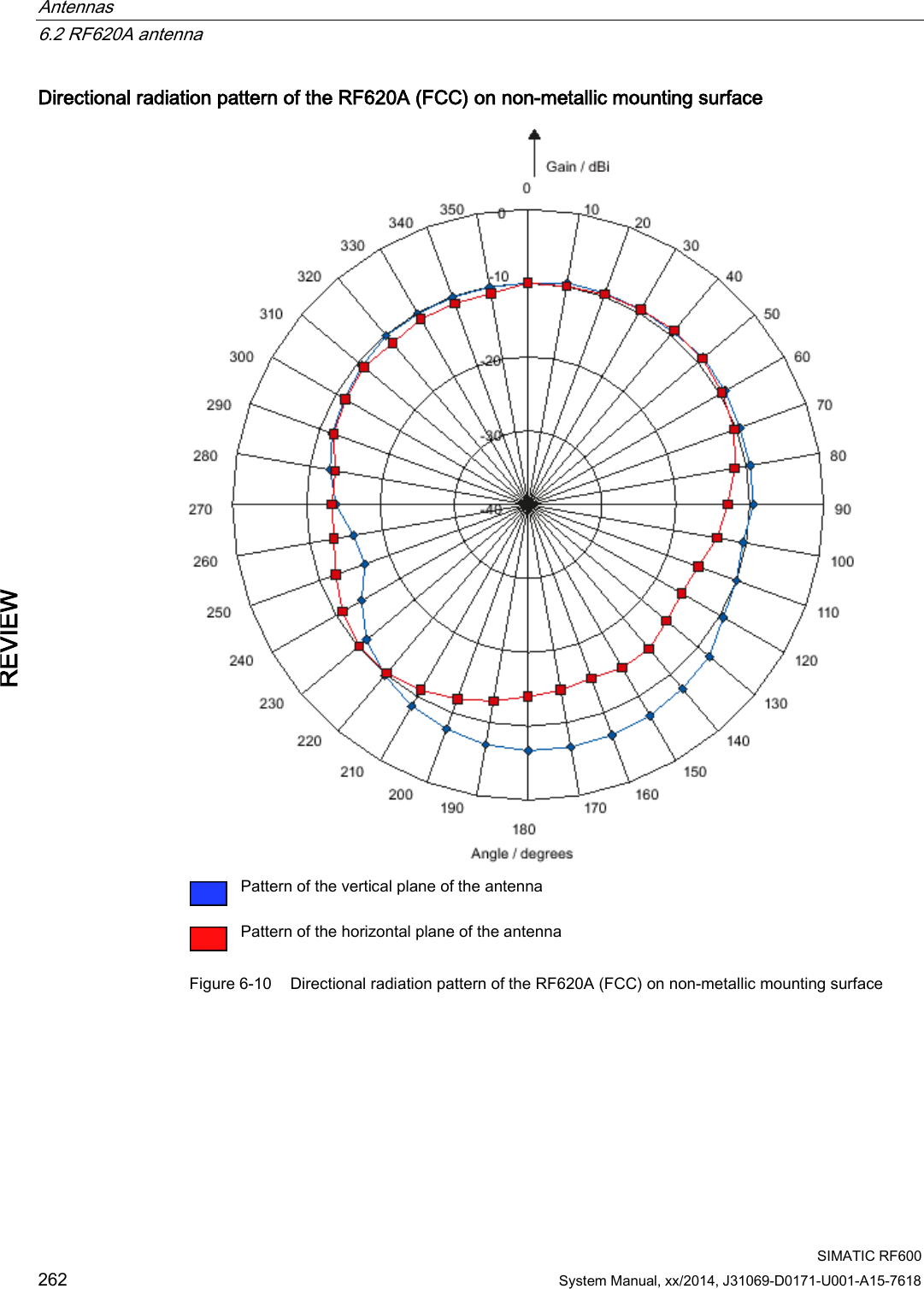
![Antennas 6.2 RF620A antenna SIMATIC RF600 System Manual, xx/2014, J31069-D0171-U001-A15-7618 263 REVIEW 6.2.9.3 Interpretation of directional radiation patterns The following overview table will help you with the interpretation of directional radiation patterns. The table shows which dBi values correspond to which read/write ranges (in %): You can read the radiated power depending on the reference angle from the directional radiation patterns, and thus obtain information on the read/write range with this reference angle with regard to a transponder. The dBr values correspond to the difference between the maximum dBi value and a second dBi value. Deviation from maximum antenna gain [dBr] Read/write range [%] 0 100 -3 70 -6 50 -9 35 -12 25 -15 18 -18 13 Example As can be seen from the Antenna pattern ETSI (Page 257), the maximum antenna gain is -5 dBi. In the vertical plane, the antenna gain has dropped to approx. -11 dBi at +40° and 320°. Therefore the dBr value is -6. The antenna range is only 50% of the maximum range at ± 40° from the Z axis within the vertical plane (see values shown in blue in the directional radiation pattern: Characteristic of the vertical plane of the antenna and the associated representation of the reference system). 6.2.10 Read/write ranges The following tables show the typical read/write ranges of RF600 readers which are connected to the RF620A antenna via the 3 m antenna cable (1 dB loss) and various types of transponders. Note Tolerances Please note that tolerances of ±20% are admissible due to production and temperature conditions.](https://usermanual.wiki/Siemens/RF600R2.User-Manual-part-1/User-Guide-2334392-Page-263.png)
![Antennas 6.2 RF620A antenna SIMATIC RF600 264 System Manual, xx/2014, J31069-D0171-U001-A15-7618 REVIEW When using other antenna cables, the ranges listed here are reduced as a result of the higher antenna cable losses in the following manner: Cable designation Order No. Length [m] Cable loss [dB] Read/write range [%] Antenna cable 6GT2815-0BH30 3 1 100 Antenna cable, suitable for drag chains 6GT2815-2BH50 5 1.25 98 Antenna cable 6GT2815-1BN10 10 2 90 Antenna cable 6GT2815-0BN10 10 4 70 Antenna cable, suitable for drag chains 6GT2815-2BN15 15 4 70 Antenna cable 6GT2815-0BN20 20 4 70 The measuring tolerances in the following tables are ±3 cm. Reading ranges RF620R/RF630R Table 6- 5 Reading ranges RF620R/RF630R Transponder Connection to RF620R/RF630R RF620A ETSI on metal [cm] RF620A ETSI on non-metal [cm] RF620A FCC on metal [cm] RF620A FCC on non-metal [cm] RF630L (6GT2810-2AB00, -2AB01, -2AB02-0AX0) 90 1) 70 1) 60 1) 50 1) RF630L (6GT2810-2AB03) 55 50 55 45 RF680L 55 50 55 45 RF610T 55 50 55 45 RF620T 55 45 70 60 RF625T 30 2) 25 2) 45 2) 30 2) RF630T 25 2) 20 2) 35 2) 25 2) RF640T Gen 2 55 2) 45 2) 40 2) 35 2) RF680T 60 50 90 70 1) Transponder mounted on cardboard 2) Transponder mounted on metal](https://usermanual.wiki/Siemens/RF600R2.User-Manual-part-1/User-Guide-2334392-Page-264.png)
![Antennas 6.2 RF620A antenna SIMATIC RF600 System Manual, xx/2014, J31069-D0171-U001-A15-7618 265 REVIEW Writing ranges RF620R/RF630R Table 6- 6 Writing ranges RF620R/RF630R Transponder Connection to RF620R/RF630R RF620A ETSI on metal [cm] RF620A ETSI on non-metal [cm] RF620A FCC on metal [cm] RF620A FCC on non-metal [cm] RF630L (6GT2810-2AB00, -2AB01, -2AB02-0AX0) 45 1) 40 1) 35 1) 30 1) RF630L (6GT2810-2AB03) 35 30 20 25 RF680L 35 30 20 25 RF610T 35 30 20 25 RF620T 30 30 40 35 RF625T 20 2) 5 2) 20 2) 10 2) RF630T 15 2) 5 2) 15 2) 10 2) RF640T Gen 2 35 2) 20 2) 20 2) 15 2) RF680T 40 30 40 35 1) Transponder mounted on cardboard 2) Transponder mounted on metal Reading ranges RF640R/RF670R Table 6- 7 Reading ranges RF640R/RF670R Transponder Connection to RF640R/RF670R RF620A ETSI on metal [cm] RF620A ETSI on non-metal [cm] RF620A FCC on metal [cm] RF620A on non-metal [cm] RF630L (6GT2810-2AB00, -2AB01, -2AB02-0AX0) 135 1) 120 1) 100 1) 90 1) RF630L (6GT2810-2AB03) 85 70 75 65 RF680L 85 70 75 65 RF610T 85 70 75 65 RF620T 85 85 95 95 RF625T 50 2) 45 2) 60 2) 45 2) RF630T 40 2) 35 2) 50 2) 35 2) RF640T 40 2) 35 2) 40 2) 30 2)](https://usermanual.wiki/Siemens/RF600R2.User-Manual-part-1/User-Guide-2334392-Page-265.png)
![Antennas 6.2 RF620A antenna SIMATIC RF600 266 System Manual, xx/2014, J31069-D0171-U001-A15-7618 REVIEW Transponder Connection to RF640R/RF670R RF620A ETSI on metal [cm] RF620A ETSI on non-metal [cm] RF620A FCC on metal [cm] RF620A on non-metal [cm] RF640T Gen 2 90 2) 70 2) 70 2) 50 2) RF680T 90 90 135 95 1) Transponder mounted on cardboard 2) Transponder mounted on metal Writing ranges RF640R/RF670R Table 6- 8 Writing ranges RF640R/RF670R Transponder Connection to RF640R/RF670R RF620A ETSI on metal RF620A ETSI on non-metal RF620A FCC on metal RF620A on non-metal RF630L (6GT2810-2AB00, -2AB01, -2AB02-0AX0) 110 1) 90 1) 55 1) 50 1) RF630L (6GT2810-2AB03) 75 70 60 55 RF680L 75 70 60 55 RF610T 75 70 60 55 RF620T 60 55 60 45 RF625T 40 2) 30 2) 45 2) 30 2) RF630T 30 2) 25 2) 35 2) 25 2) RF640T 35 2) 30 2) 25 2) 25 2) RF640T Gen 2 70 2) 60 2) 50 2) 40 2) RF680T 80 75 100 80 1) Transponder mounted on cardboard 2) Transponder mounted on metal](https://usermanual.wiki/Siemens/RF600R2.User-Manual-part-1/User-Guide-2334392-Page-266.png)
![Antennas 6.2 RF620A antenna SIMATIC RF600 System Manual, xx/2014, J31069-D0171-U001-A15-7618 267 REVIEW Read distances RF650R Table 6- 9 Read distances RF650R Transponder Connection to RF650R RF620A ETSI on metal [cm] RF620A ETSI on non-metal [cm] RF620A FCC on metal [cm] RF620A on non-metal [cm] RF630L (6GT2810-2AB00, -2AB01, -2AB02-0AX0) 135 1) 120 1) 100 1) 90 1) RF630L (6GT2810-2AB03) 85 70 75 65 RF680L 85 70 75 65 RF610T 85 70 75 65 RF620T 85 85 95 95 RF625T 50 2) 45 2) 60 2) 45 2) RF630T 40 2) 35 2) 50 2) 35 2) RF640T 40 2) 35 2) 40 2) 30 2) RF640T Gen 2 90 2) 70 2) 70 2) 50 2) RF680T 90 90 135 95 1) Transponder mounted on cardboard 2) Transponder mounted on metal Write distances RF650R Table 6- 10 Write distances RF650R Transponder Connection to RF650R RF620A ETSI on metal [cm] RF620A ETSI on non-metal [cm] RF620A FCC on metal [cm] RF620A on non-metal [cm] RF630L (6GT2810-2AB00, -2AB01, -2AB02-0AX0) 110 1) 90 1) 55 1) 50 1) RF630L (6GT2810-2AB03) 75 70 60 55 RF680L 75 70 60 55 RF610T 75 70 60 55 RF620T 60 55 60 45 RF625T 40 2) 30 2) 45 2) 30 2) RF630T 30 2) 25 2) 35 2) 25 2) RF640T 35 2) 30 2) 25 2) 25 2)](https://usermanual.wiki/Siemens/RF600R2.User-Manual-part-1/User-Guide-2334392-Page-267.png)
![Antennas 6.2 RF620A antenna SIMATIC RF600 268 System Manual, xx/2014, J31069-D0171-U001-A15-7618 REVIEW Transponder Connection to RF650R RF620A ETSI on metal [cm] RF620A ETSI on non-metal [cm] RF620A FCC on metal [cm] RF620A on non-metal [cm] RF640T Gen 2 70 2) 60 2) 50 2) 40 2) RF680T 80 75 100 80 1) Transponder mounted on cardboard 2) Transponder mounted on metal Read distances RF680R/RF685R Table 6- 11 Read distances RF680R/RF685R Transponder Connection to RF680R/RF685R RF620A ETSI on metal [cm] RF620A ETSI on non-metal [cm] RF620A FCC on metal [cm] RF620A on non-metal [cm] RF630L (6GT2810-2AB00, -2AB01, -2AB02-0AX0) 1) 1) 1) 1) RF630L (6GT2810-2AB03) RF680L RF610T RF620T RF625T 2) 2) 2) 2) RF630T 2) 2) 2) 2) RF640T 2) 2) 2) 2) RF640T Gen 2 2) 2) 2) 2) RF680T 1) Transponder mounted on cardboard 2) Transponder mounted on metal](https://usermanual.wiki/Siemens/RF600R2.User-Manual-part-1/User-Guide-2334392-Page-268.png)
![Antennas 6.2 RF620A antenna SIMATIC RF600 System Manual, xx/2014, J31069-D0171-U001-A15-7618 269 REVIEW Write distances RF680R/RF685R Table 6- 12 Write distances RF680R/RF685R Transponder Connection to RF680R/RF685R RF620A ETSI on metal [cm] RF620A ETSI on non-metal [cm] RF620A FCC on metal [cm] RF620A on non-metal [cm] RF630L (6GT2810-2AB00, -2AB01, -2AB02-0AX0) 1) 1) 1) 1) RF630L (6GT2810-2AB03) RF680L RF610T RF620T RF625T 2) 2) 2) 2) RF630T 2) 2) 2) 2) RF640T 2) 2) 2) 2) RF640T Gen 2 2) 2) 2) 2) RF680T 1) Transponder mounted on cardboard 2) Transponder mounted on metal](https://usermanual.wiki/Siemens/RF600R2.User-Manual-part-1/User-Guide-2334392-Page-269.png)
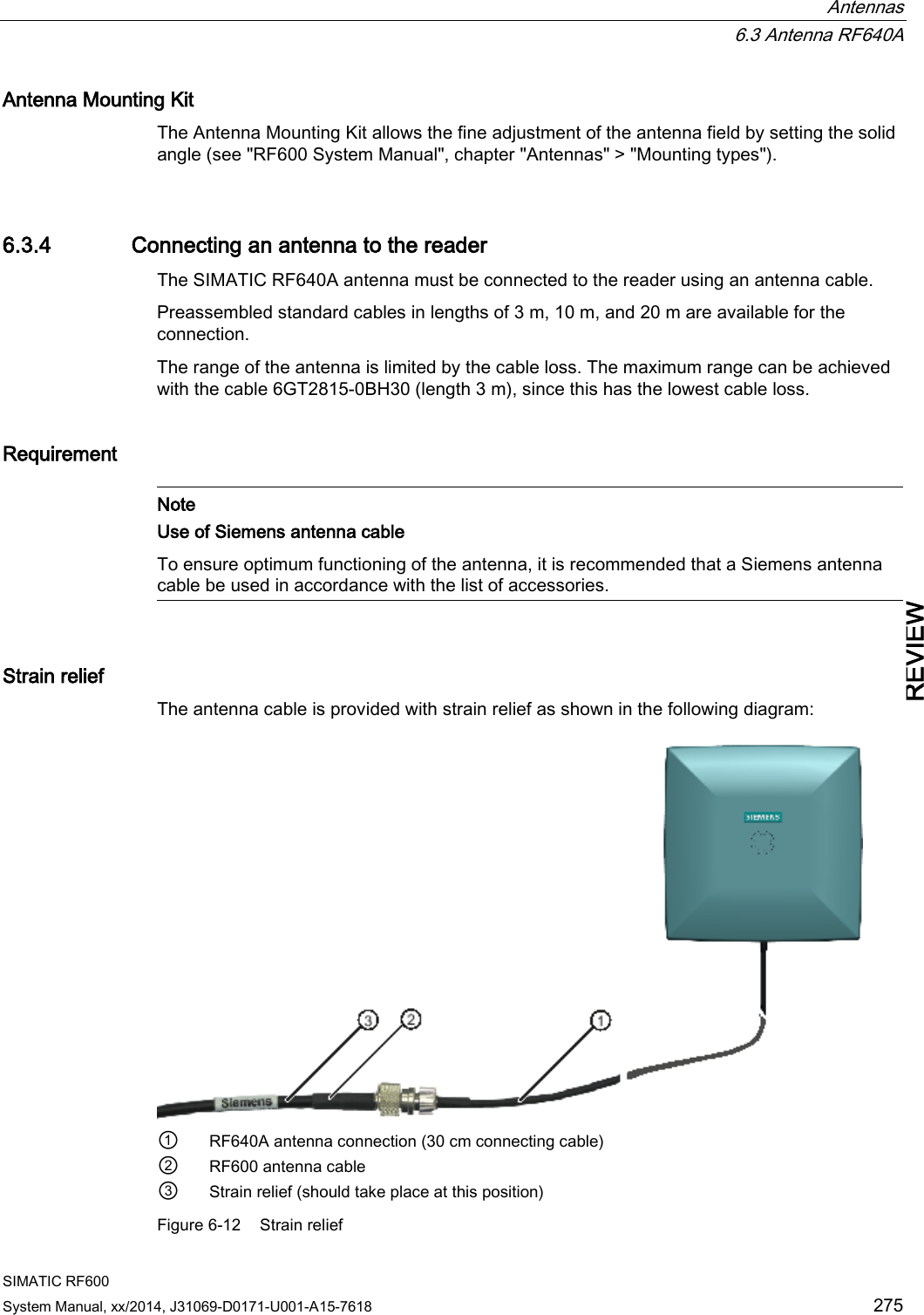
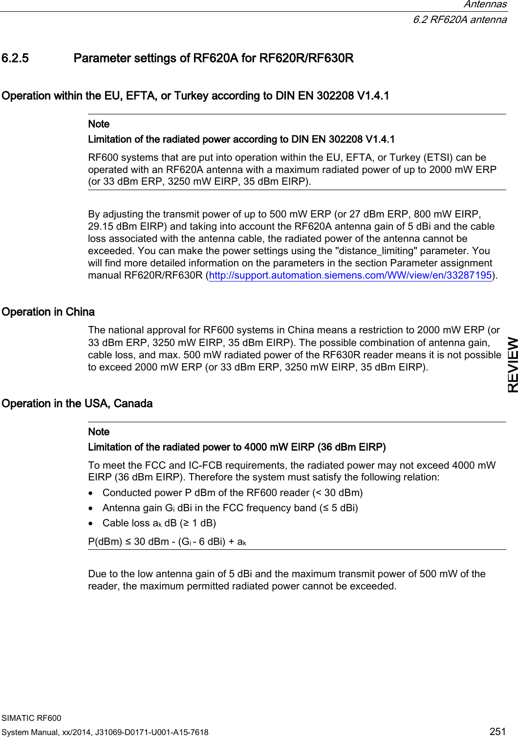
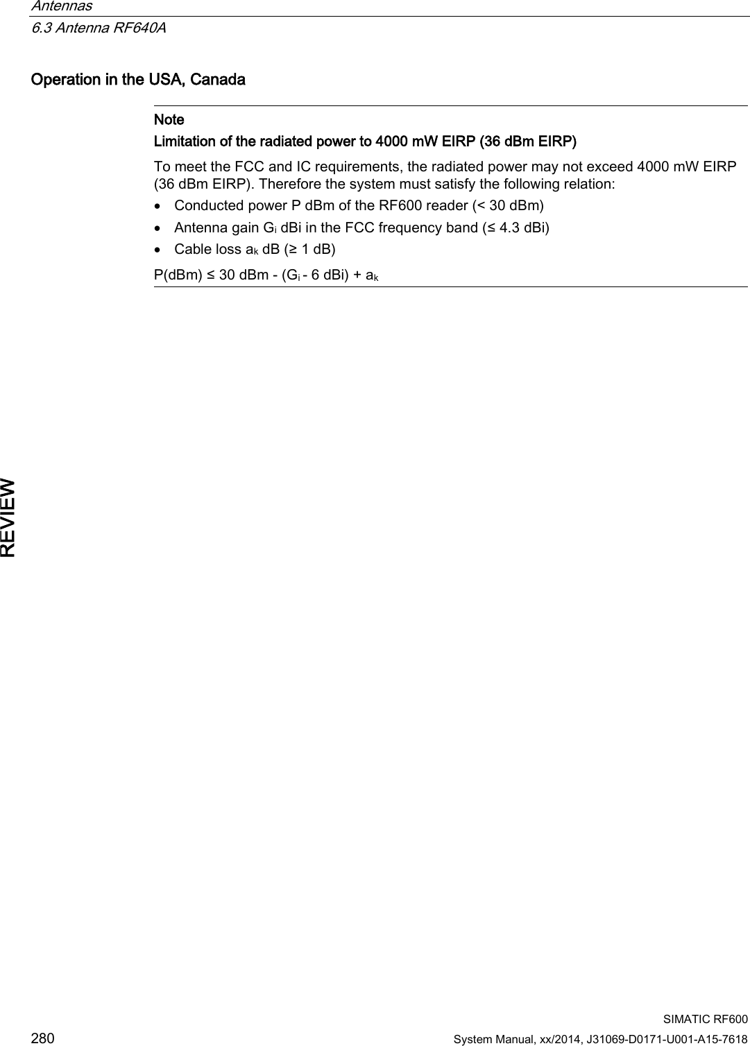
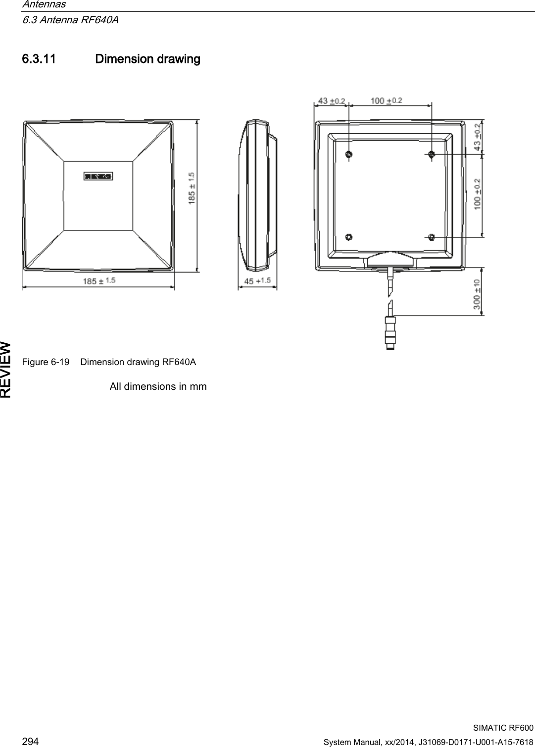
![Antennas 6.3 Antenna RF640A SIMATIC RF600 276 System Manual, xx/2014, J31069-D0171-U001-A15-7618 REVIEW 6.3.4.1 Bending radii and bending cycles of the cable Cable designation Order No. Length [m] Cable loss [dB] Bending radius [mm] Bending cycle RF640A antenna connection Fixed connection to antenna 0.3 - 15 1 Mal Antenna cable 6GT2815-0BH30 3 1 51 1 Mal Antenna cable (suitable for drag chains) 6GT2815-2BH50 5 1,25 48 1) Antenna cable 6GT2815-1BN10 10 2 77 1 Mal Antenna cable 6GT2815-0BN10 10 4 51 1 Mal Antenna cable (suitable for drag chains) 6GT2815-0BN20 15 4 24 1) Antenna cable 6GT2815-0BN20 20 4 77 1 Mal 1) With cables suitable for drag chains, 3 million bending cycles at a bending radius of 6.5 m and bending through ± 180 ° are permitted. 6.3.5 Parameter settings of RF640A for RF620R/RF630R Operation within the EU, EFTA, or Turkey according to DIN EN 302208 V1.4.1 Note Limitation of the radiated power according to DIN EN 302208 V1.4.1 RF600 systems that are put into operation within the EU, EFTA, or Turkey (ETSI) can be operated with an RF640A antenna with a maximum radiated power of up to 2000 mW ERP (or 33 dBm ERP, 3250 mW EIRP, 35 dBm EIRP). By adjusting the transmit power of up to 500 mW ERP (or 27 dBm ERP, 800 mW EIRP, 29.15 dBm EIRP) and taking into account the RF640A antenna gain of 4 dBi (6 dBic) and the cable loss associated with the antenna cable (see table), the radiated power of the antenna cannot be exceeded. You can make the power settings using the "distance_limiting" parameter. You will find more detailed information on the parameters in the section Parameter assignment manual RF620R/RF630R (http://support.automation.siemens.com/WW/view/en/33287195).](https://usermanual.wiki/Siemens/RF600R2.User-Manual-part-1/User-Guide-2334392-Page-276.png)
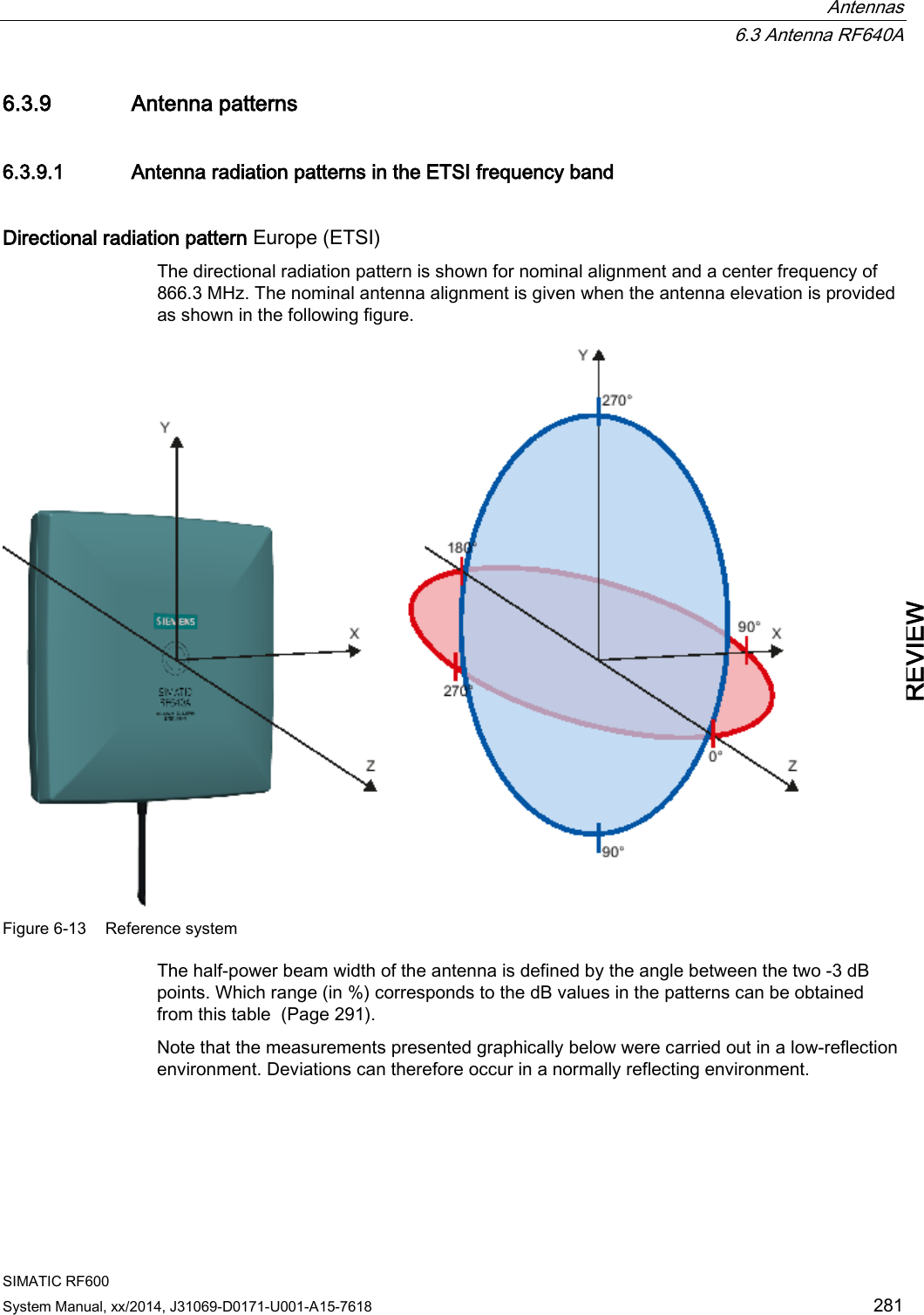
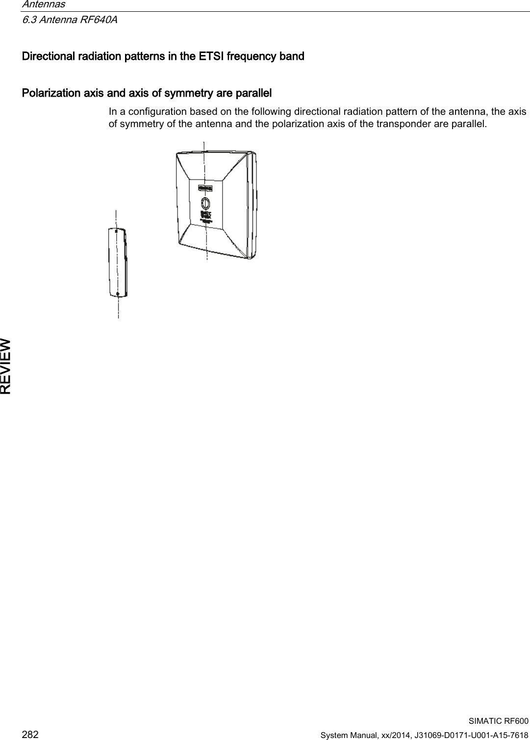
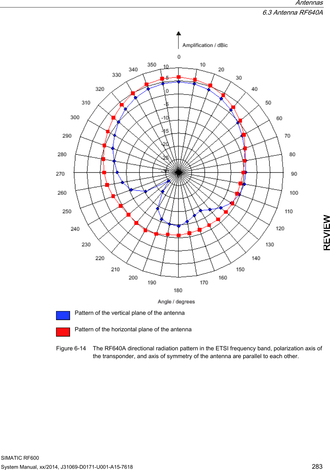
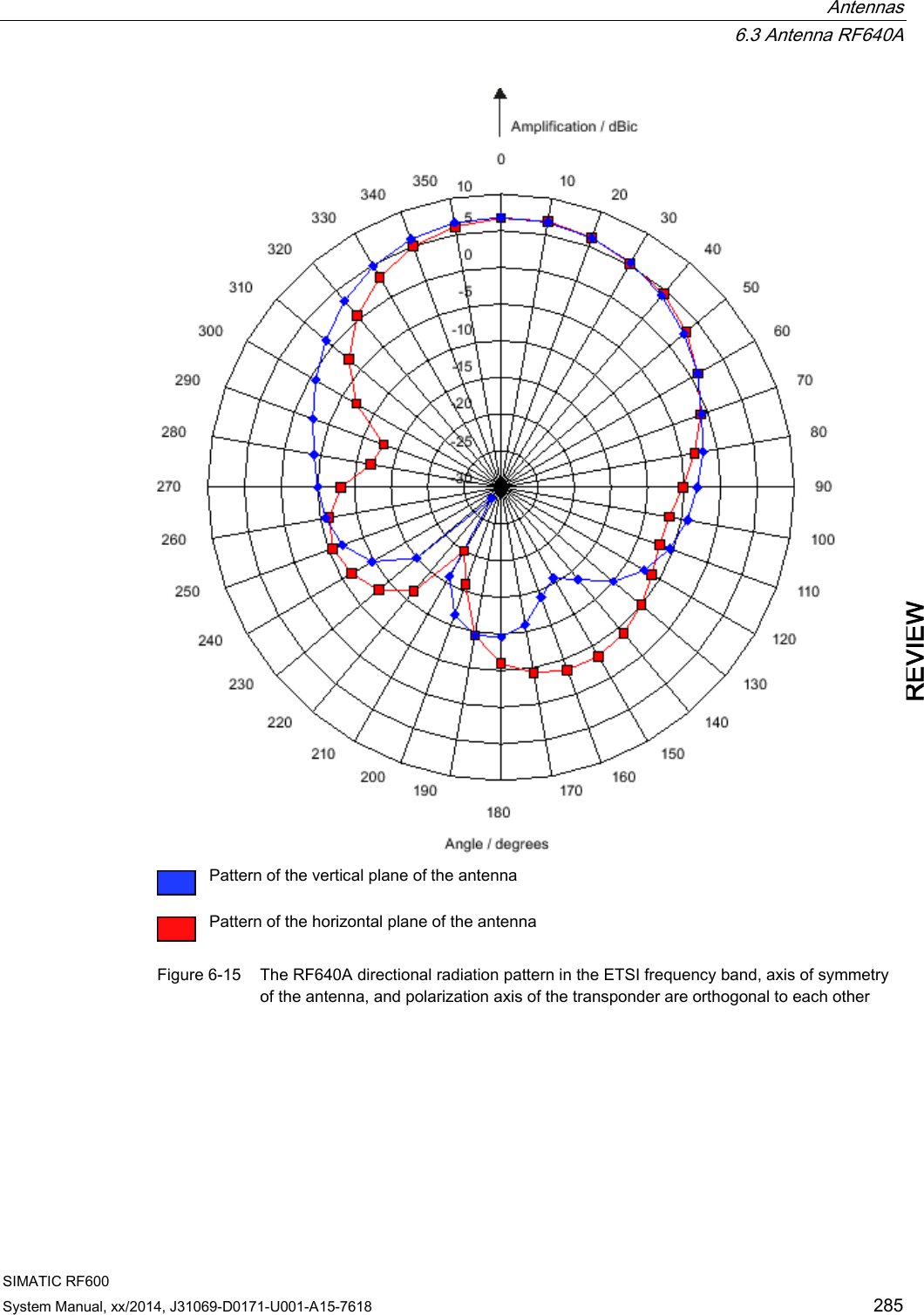
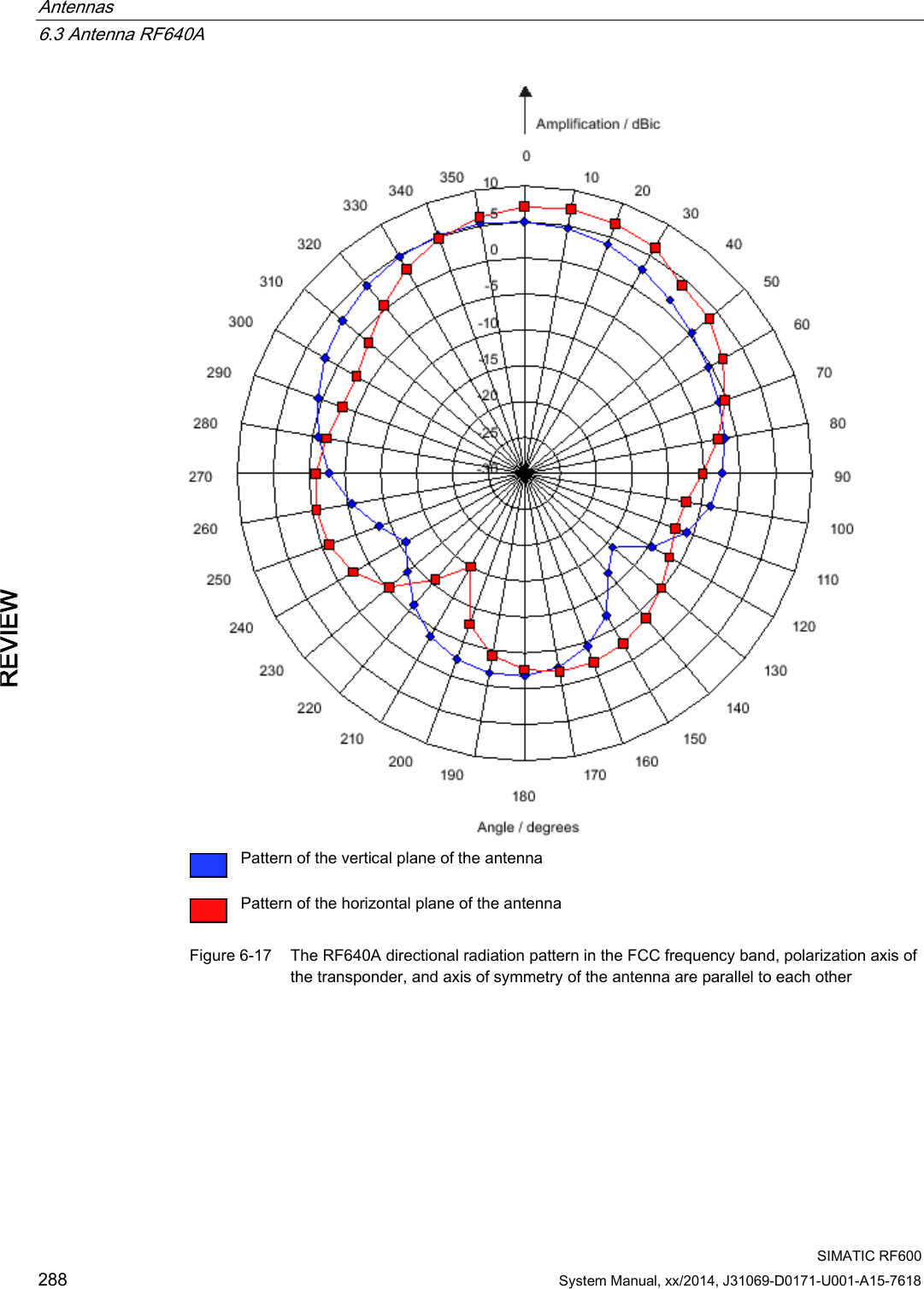

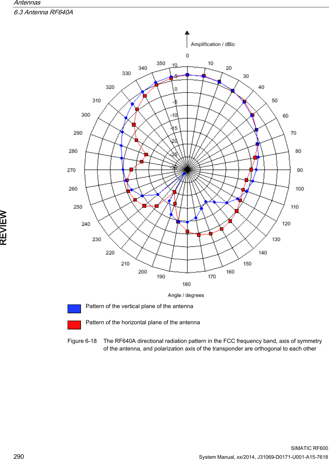
![Antennas 6.3 Antenna RF640A SIMATIC RF600 System Manual, xx/2014, J31069-D0171-U001-A15-7618 291 REVIEW 6.3.9.3 Interpretation of directional radiation patterns The following overview table will help you with the interpretation of directional radiation patterns. The table shows which dBi values correspond to which read/write ranges (in %): You can read the radiated power depending on the reference angle from the directional radiation patterns, and thus obtain information on the read/write range with this reference angle with regard to a transponder. The dBr values correspond to the difference between the maximum dBi/dBic value and a second dBi/dBic value. Deviation from maximum antenna gain [dBr] Read/write range [%] 0 100 -3 70 -6 50 -9 35 -12 25 -15 18 -18 13 Example As can be seen in Directional radiation patterns in the ETSI frequency band (Page 282), the maximum antenna gain in the vertical plane is 3.45 dBi (6.45 dBic). In this plane, and with the polarization axis of the transponder parallel to the axis of symmetry of the antenna, the antenna gain drops to about 0.5 dBic at +50° or 310°. Therefore the dBr value is -6. The antenna range is only 50% of the maximum range at + 50° or 310° from the Z axis within the vertical plane (see values shown in blue in the directional radiation pattern: Characteristic of the vertical plane of the antenna (Page 282) and the associated representation of the reference system (Page 281)).](https://usermanual.wiki/Siemens/RF600R2.User-Manual-part-1/User-Guide-2334392-Page-291.png)
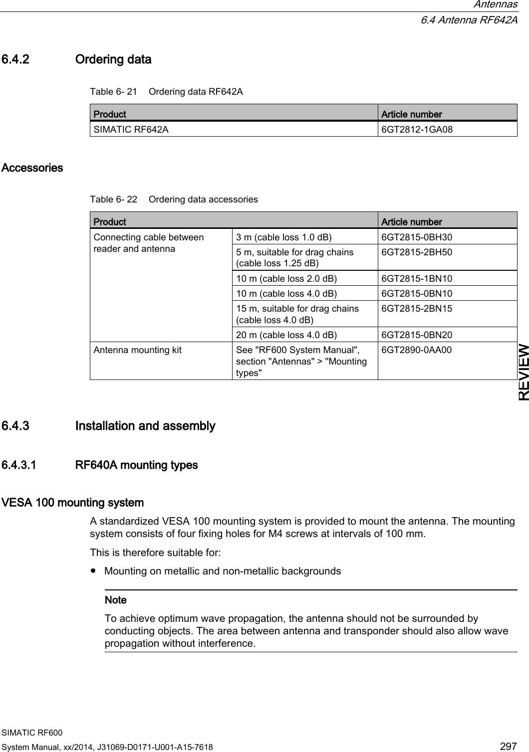
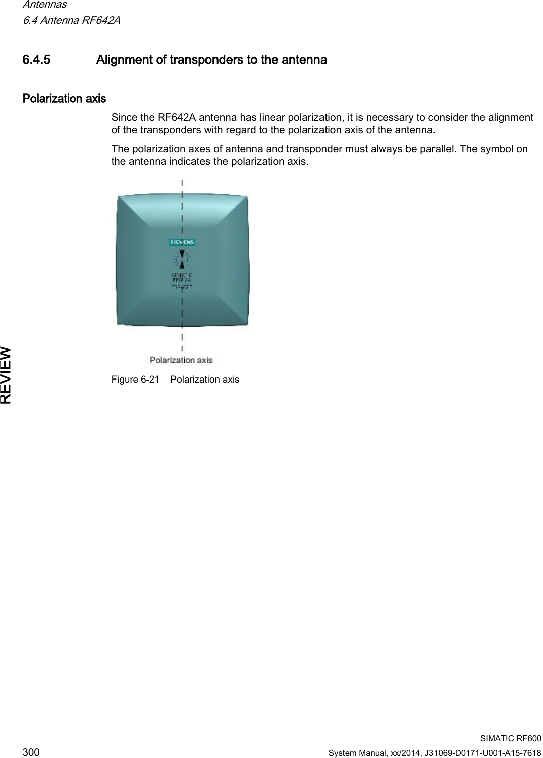
![Antennas 6.4 Antenna RF642A SIMATIC RF600 System Manual, xx/2014, J31069-D0171-U001-A15-7618 299 REVIEW 6.4.4.1 Bending radii and bending cycles of the cable Cable designation Order No. Length [m] Cable loss [dB] Bending radius [mm] Bending cycle RF642A antenna connection Fixed connection to antenna 0,3 - - 1 Mal Antenna cable 6GT2815-0BH30 3 1 51 1 Mal Antenna cable (suitable for drag chains) 6GT2815-2BH50 5 1,25 48 1) Antenna cable 6GT2815-1BN10 10 2 77 1 Mal Antenna cable 6GT2815-0BN10 10 4 51 1 Mal Antenna cable (suitable for drag chains) 6GT2815-0BN20 15 4 24 1) Antenna cable 6GT2815-0BN20 20 4 77 1 Mal 1) With cables suitable for drag chains, 3 million bending cycles at a bending radius of 6.5 m and bending through ± 180 ° are permitted.](https://usermanual.wiki/Siemens/RF600R2.User-Manual-part-1/User-Guide-2334392-Page-299.png)