Siemens RF600R2 RFID UHF Reader RF650R, RF680R, RF685R User Manual SIMATIC RF600
Siemens AG RFID UHF Reader RF650R, RF680R, RF685R SIMATIC RF600
Siemens >
Contents
- 1. User Manual part 1
- 2. User Manual part 2
- 3. User Manual
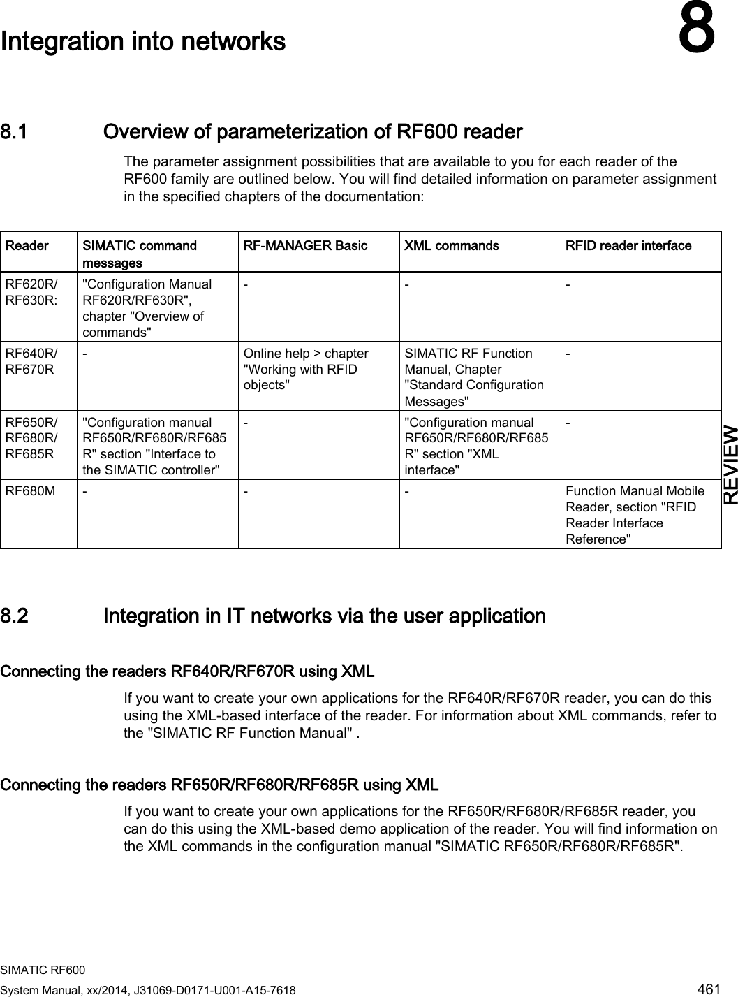
User Manual part 2
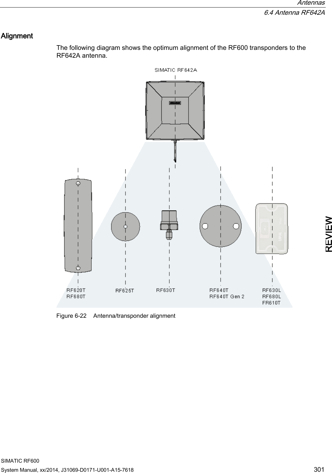
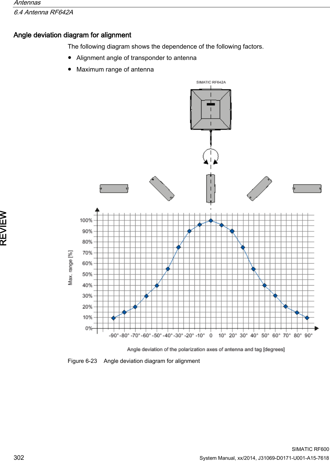

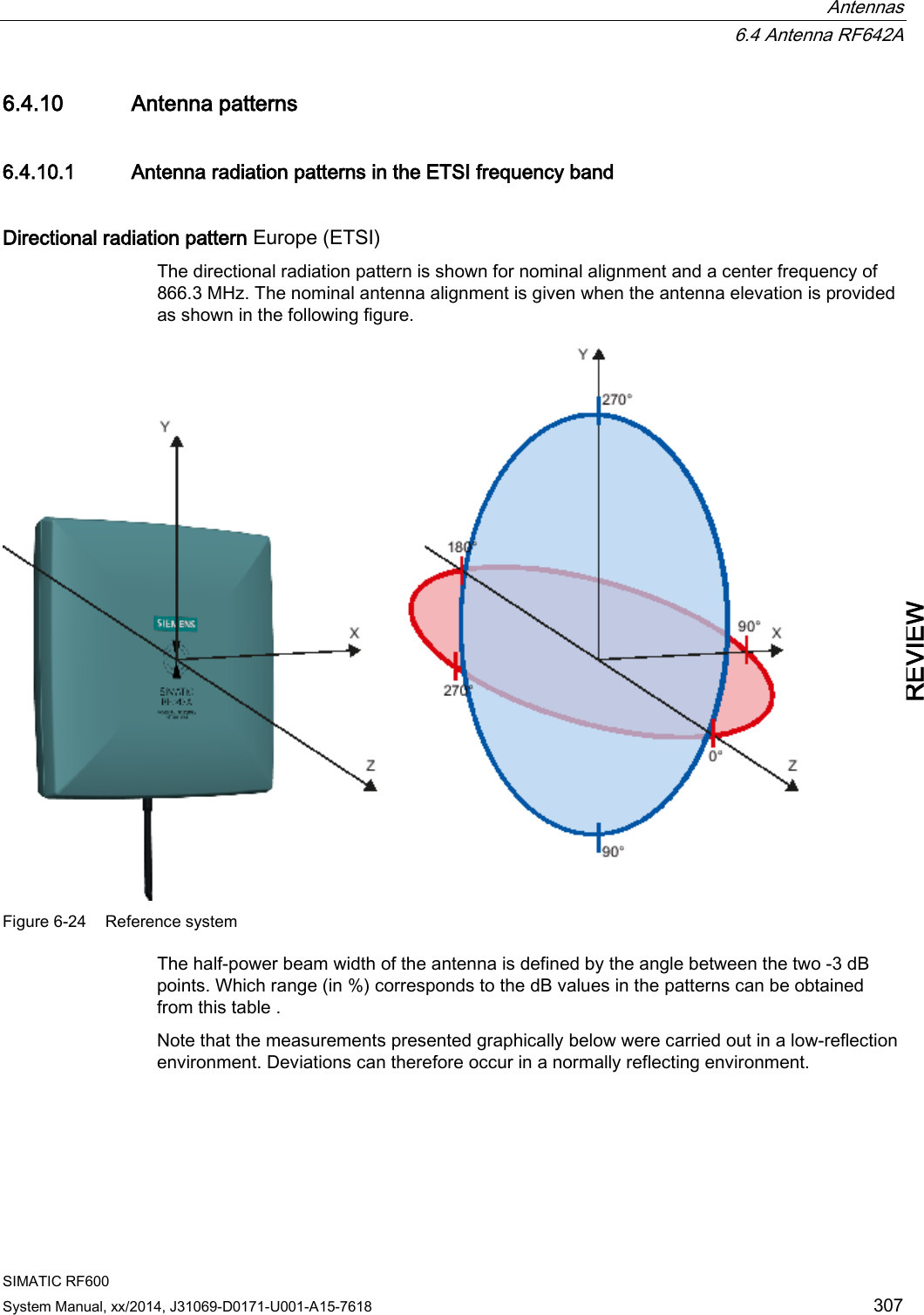
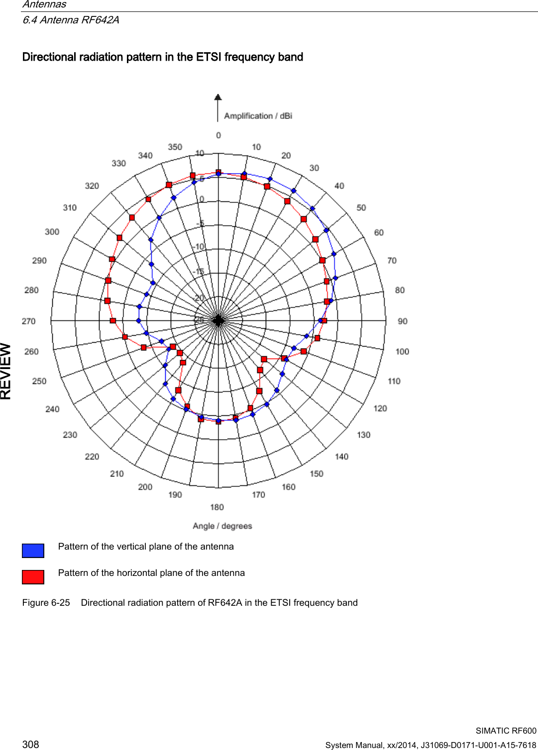
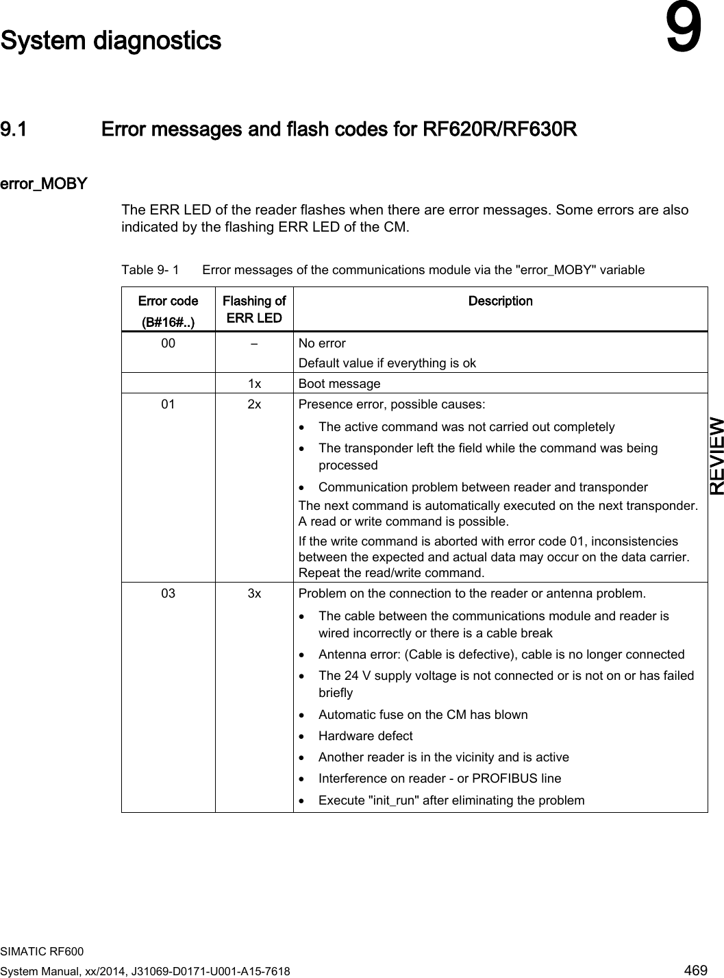
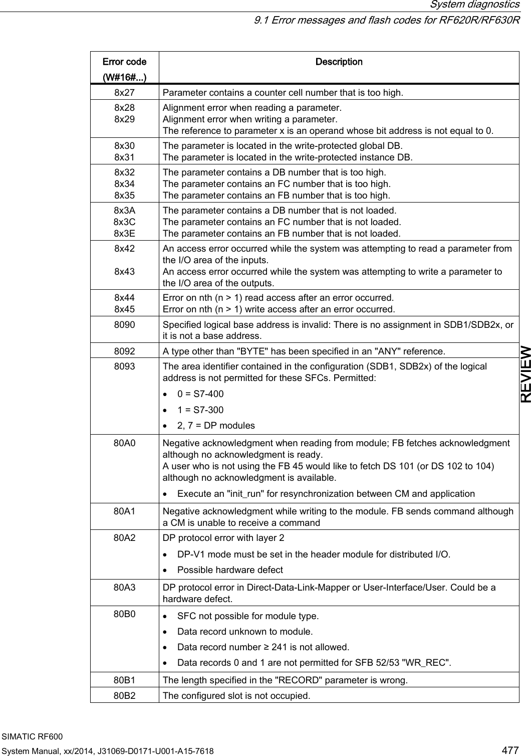
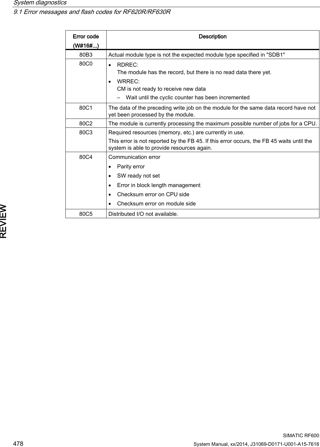
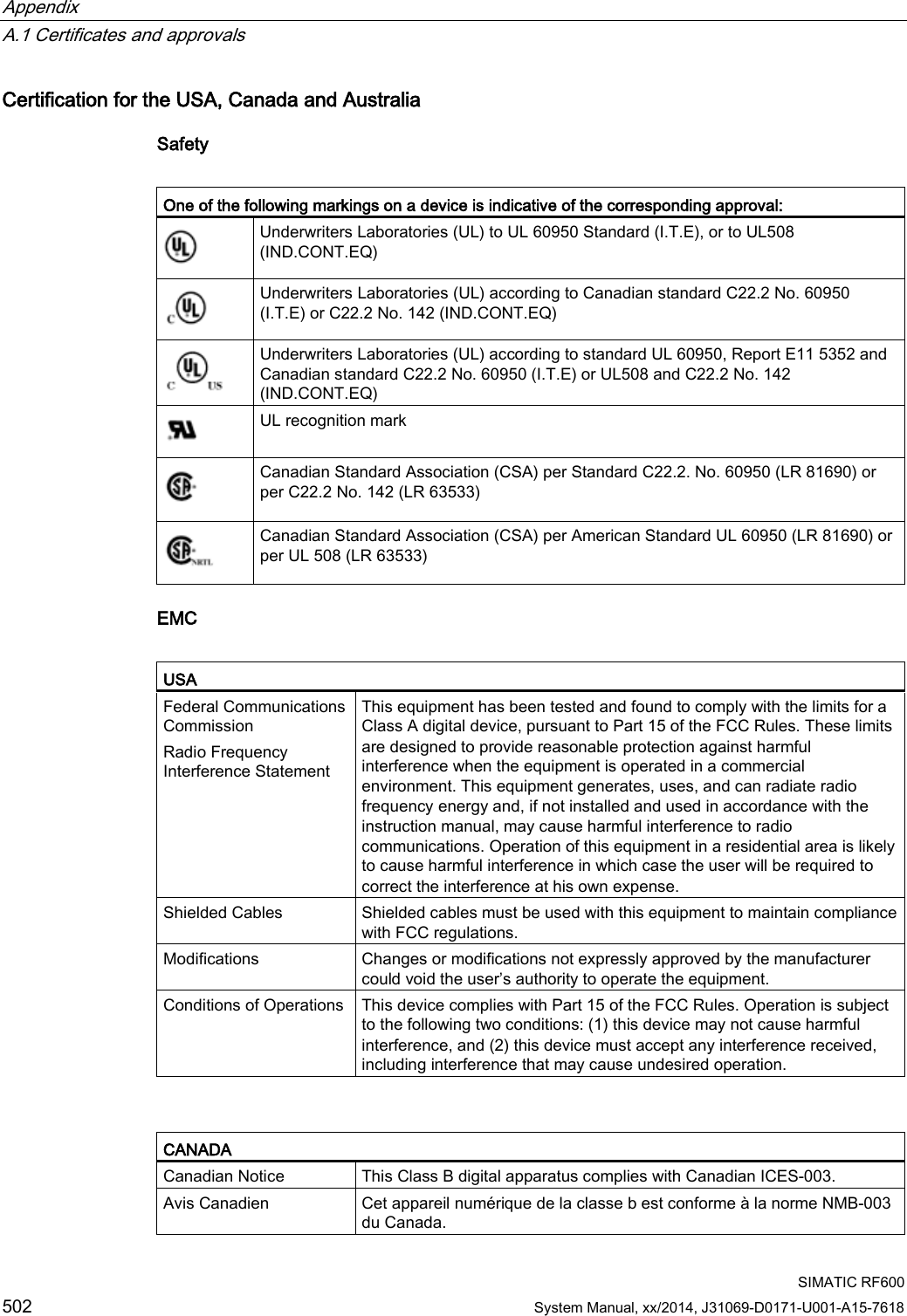
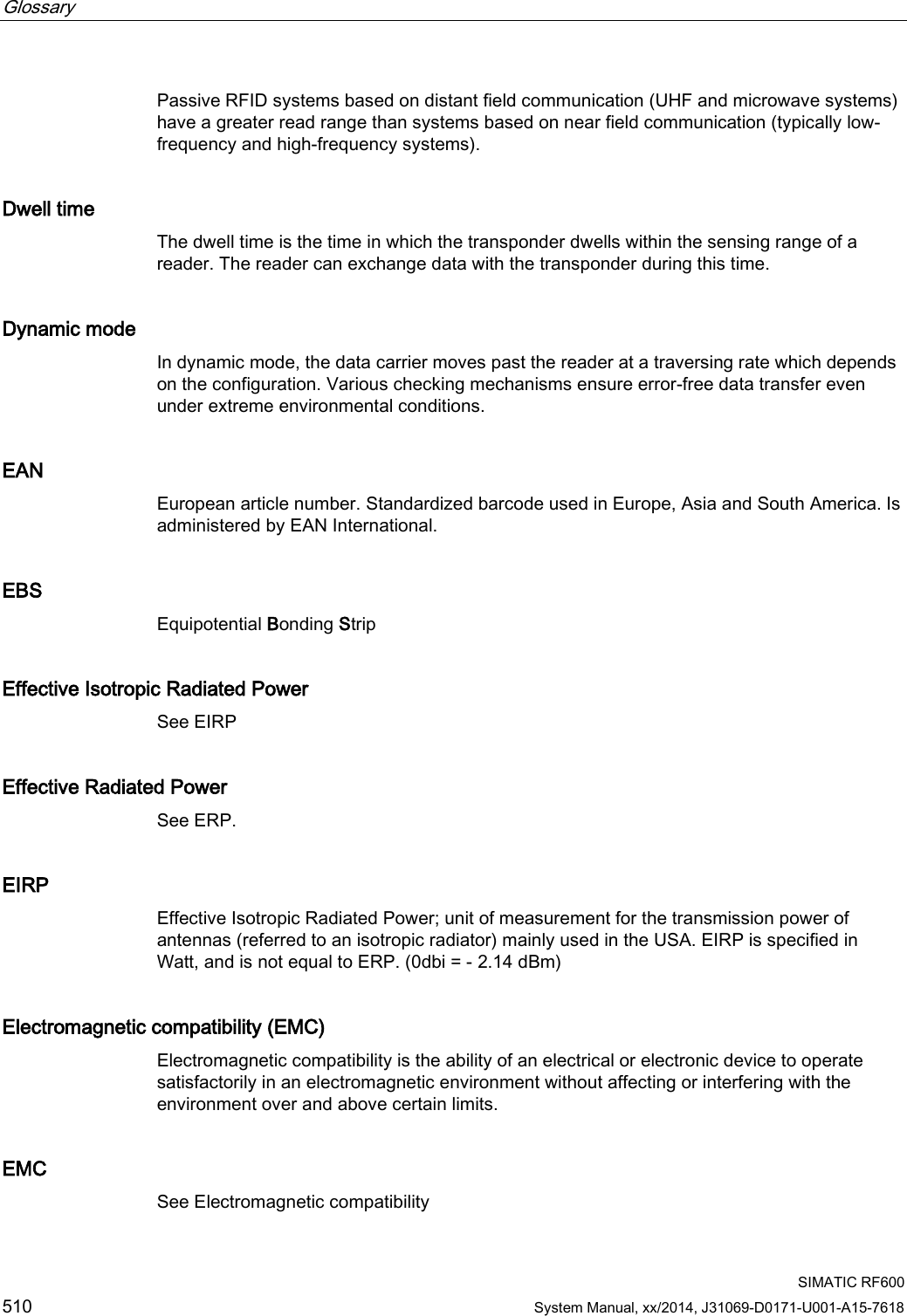
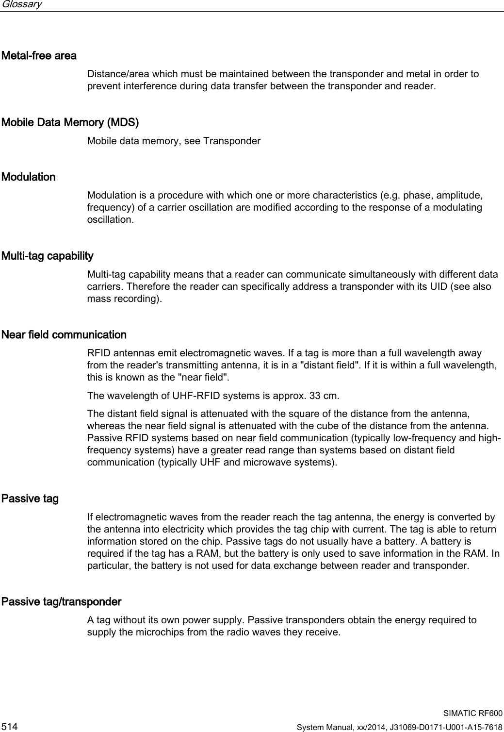
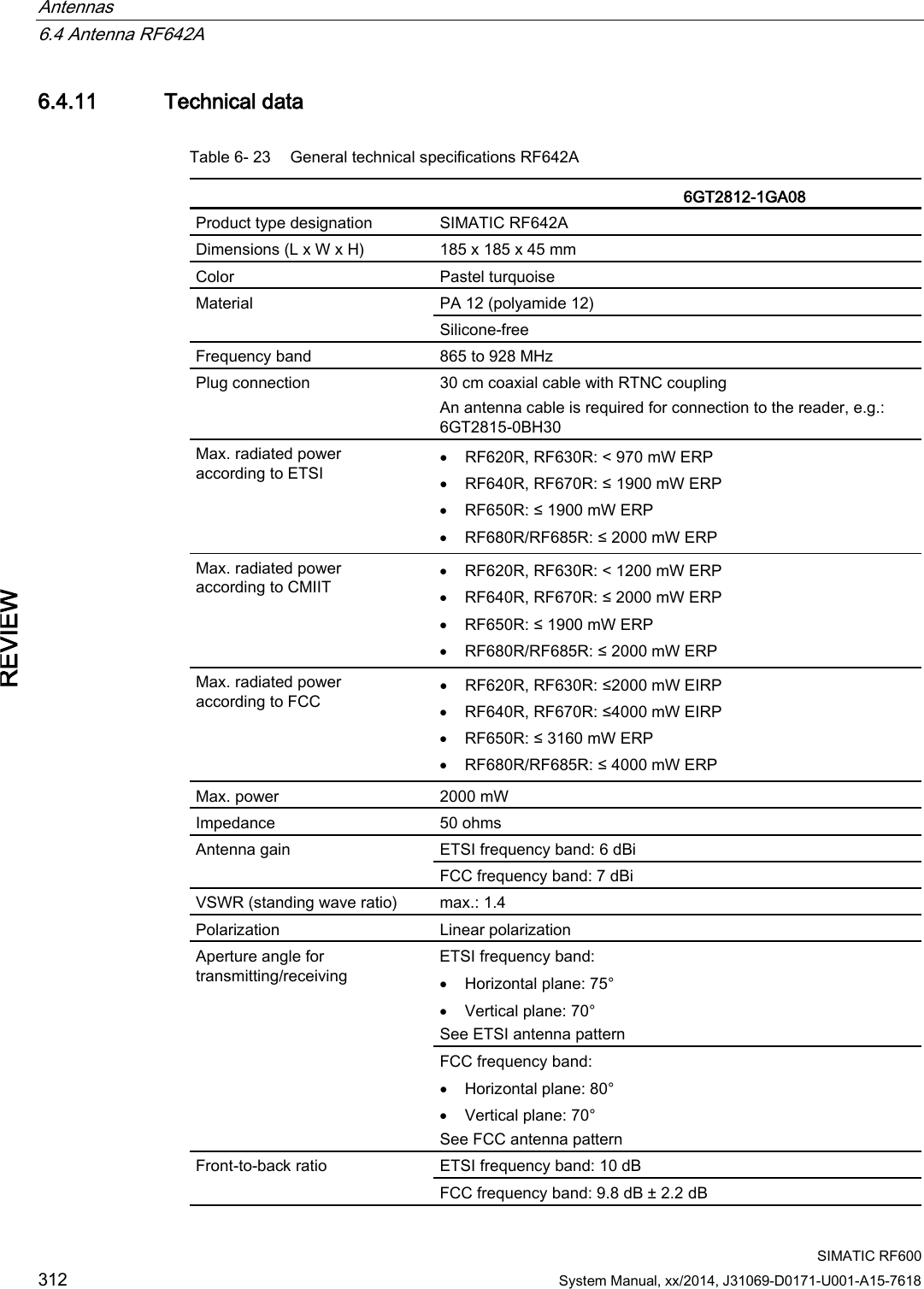
![Antennas 6.4 Antenna RF642A SIMATIC RF600 System Manual, xx/2014, J31069-D0171-U001-A15-7618 311 REVIEW 6.4.10.3 Interpretation of directional radiation patterns The following overview table will help you with the interpretation of directional radiation patterns. The table shows which dBi values correspond to which read/write ranges (in %): You can read the radiated power depending on the reference angle from the directional radiation patterns, and thus obtain information on the read/write range with this reference angle with regard to a transponder. The dBr values correspond to the difference between the maximum dBi value and a second dBi value. Deviation from maximum antenna gain [dBr] Read/write range [%] 0 100 -3 70 -6 50 -9 35 -12 25 -15 18 -18 13 Example As can be seen in Directional radiation pattern in the ETSI frequency band (Page 308), the maximum antenna gain in the horizontal plane is 6 dBi. In this plane and with the parallel polarization axis at +70° or 300°, the antenna gain dropped to about 0 dBi. Therefore the dBr value is 6. The antenna range is only 70° of the maximum range at + 50° or +300° from the Z axis within the horizontal plane (see values shown in red in the directional radiation pattern: Characteristic of the vertical plane of the antenna (Page 307) and the associated representation of the reference system (Page 307)).](https://usermanual.wiki/Siemens/RF600R2.User-Manual-part-2/User-Guide-2334413-Page-11.png)
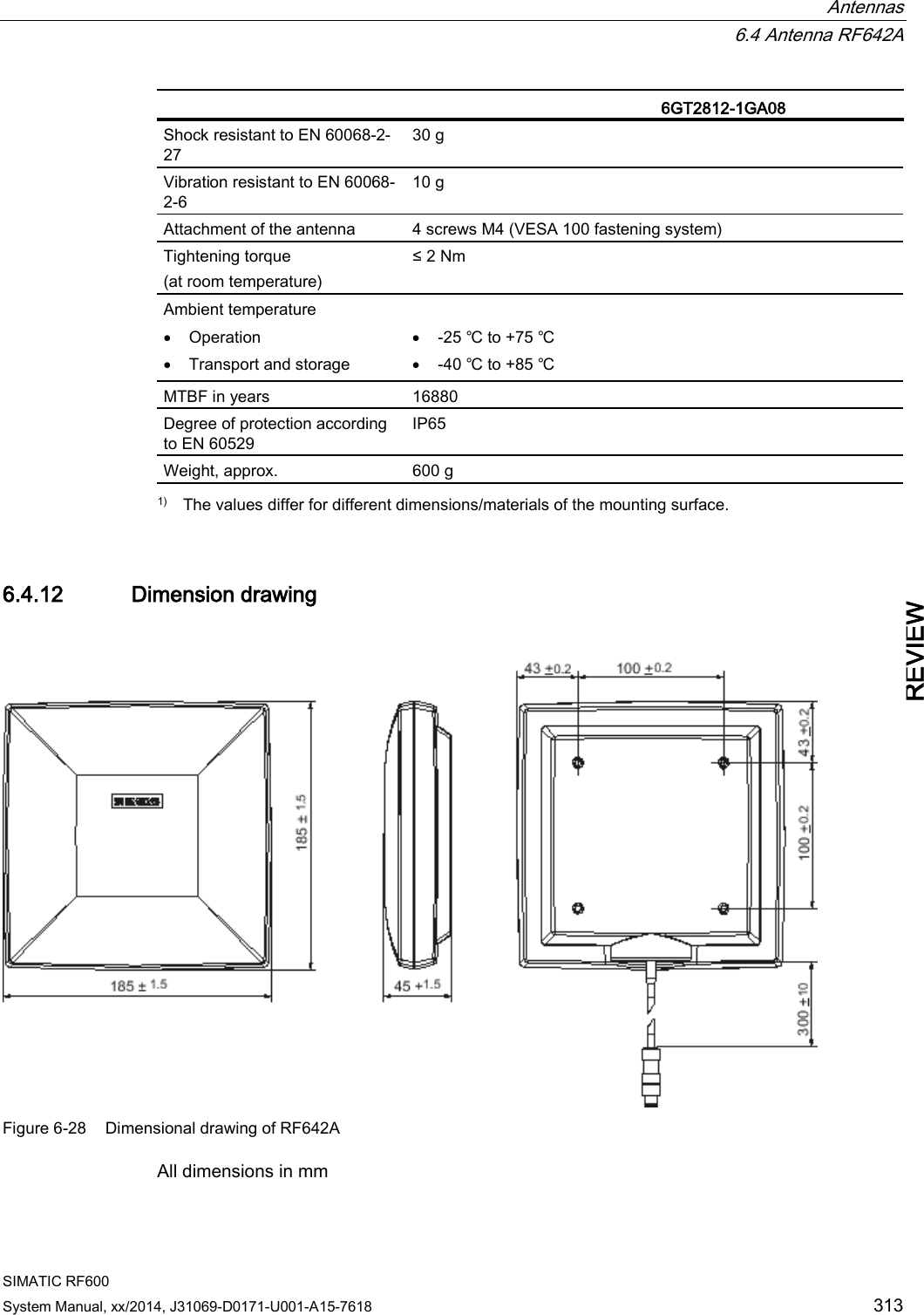
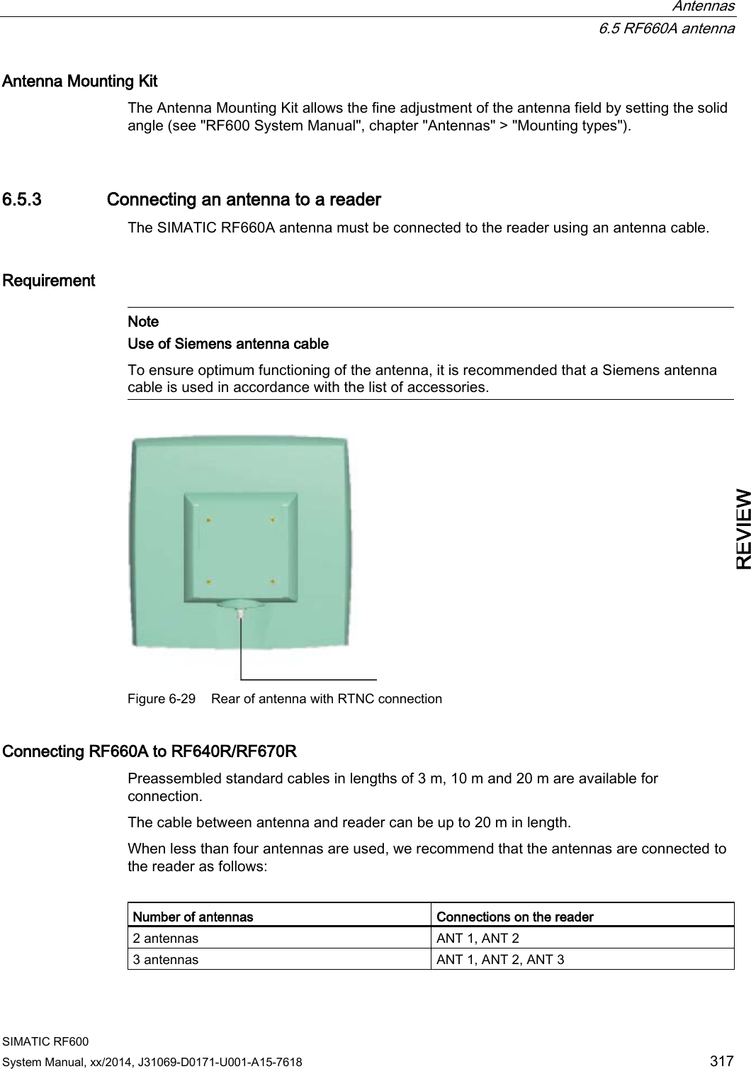
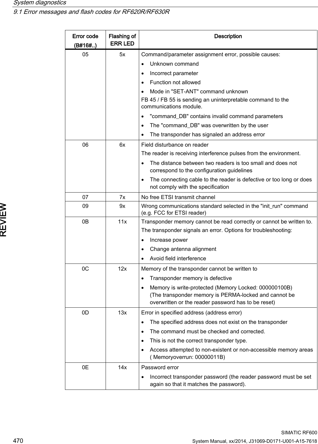
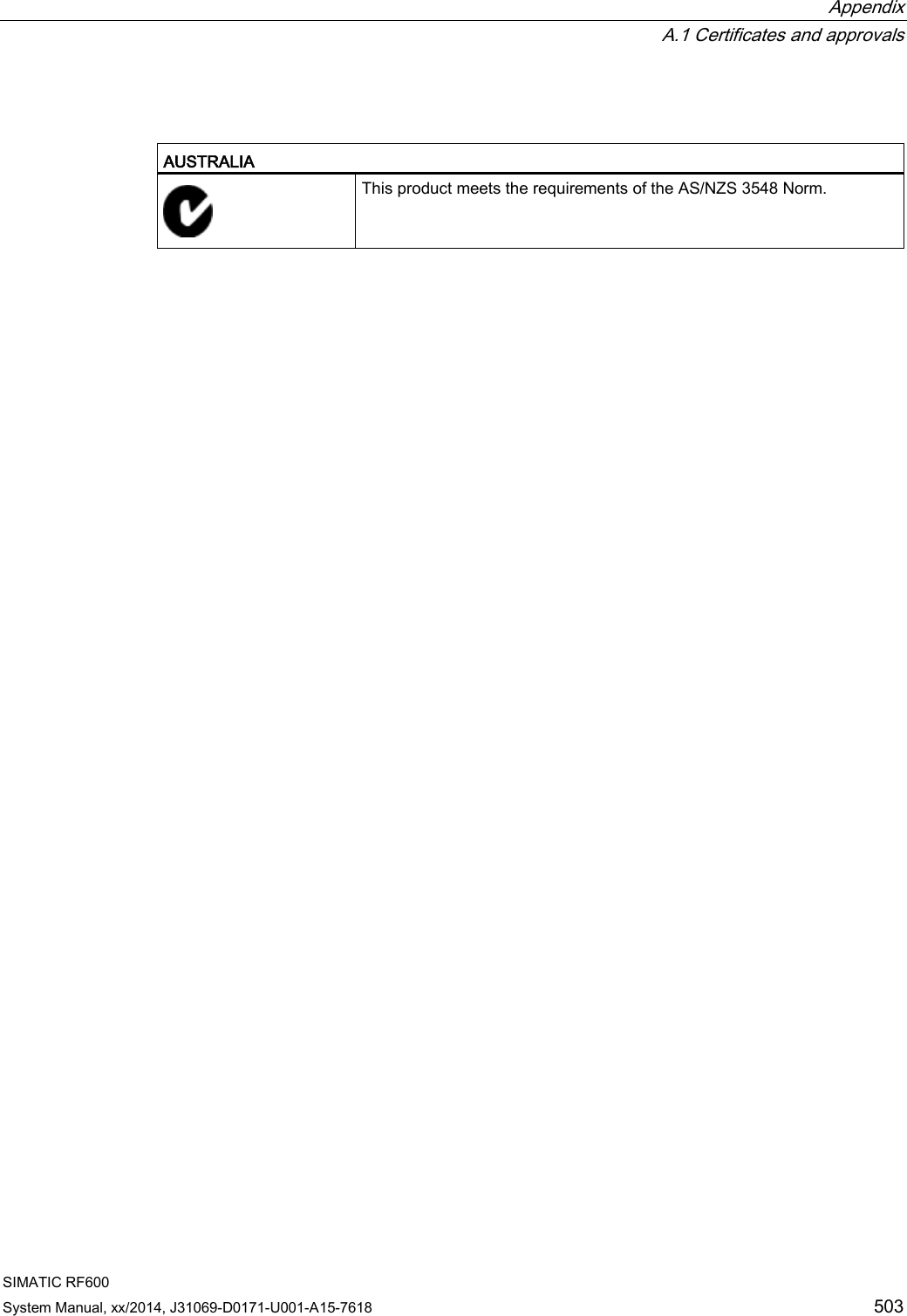
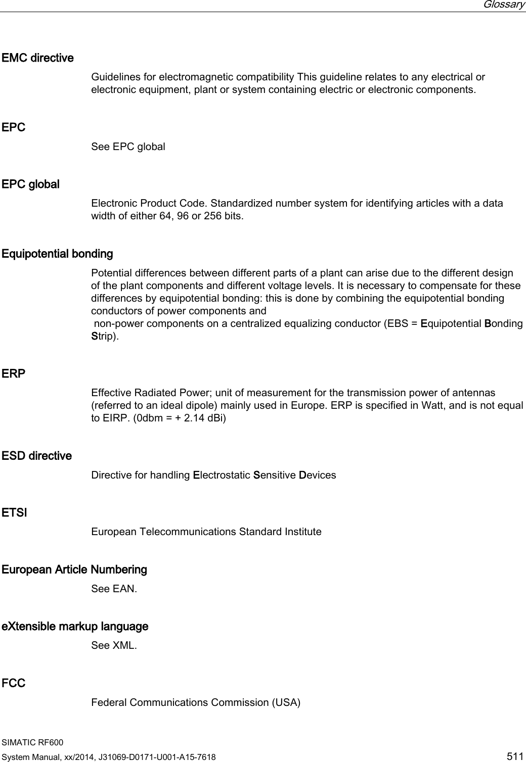
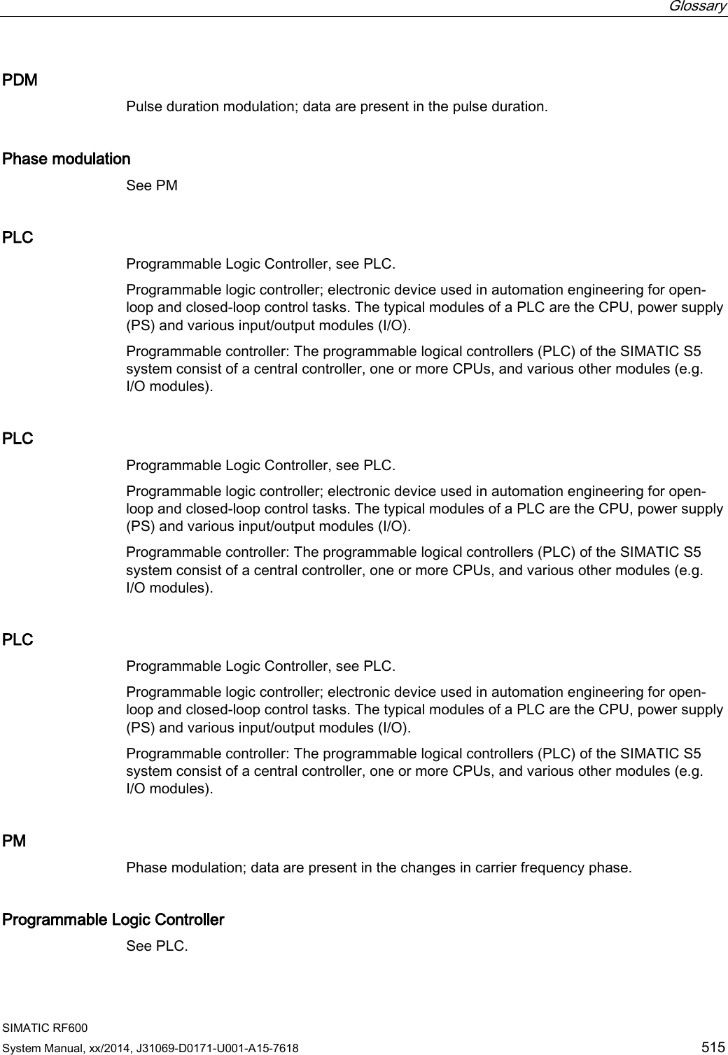
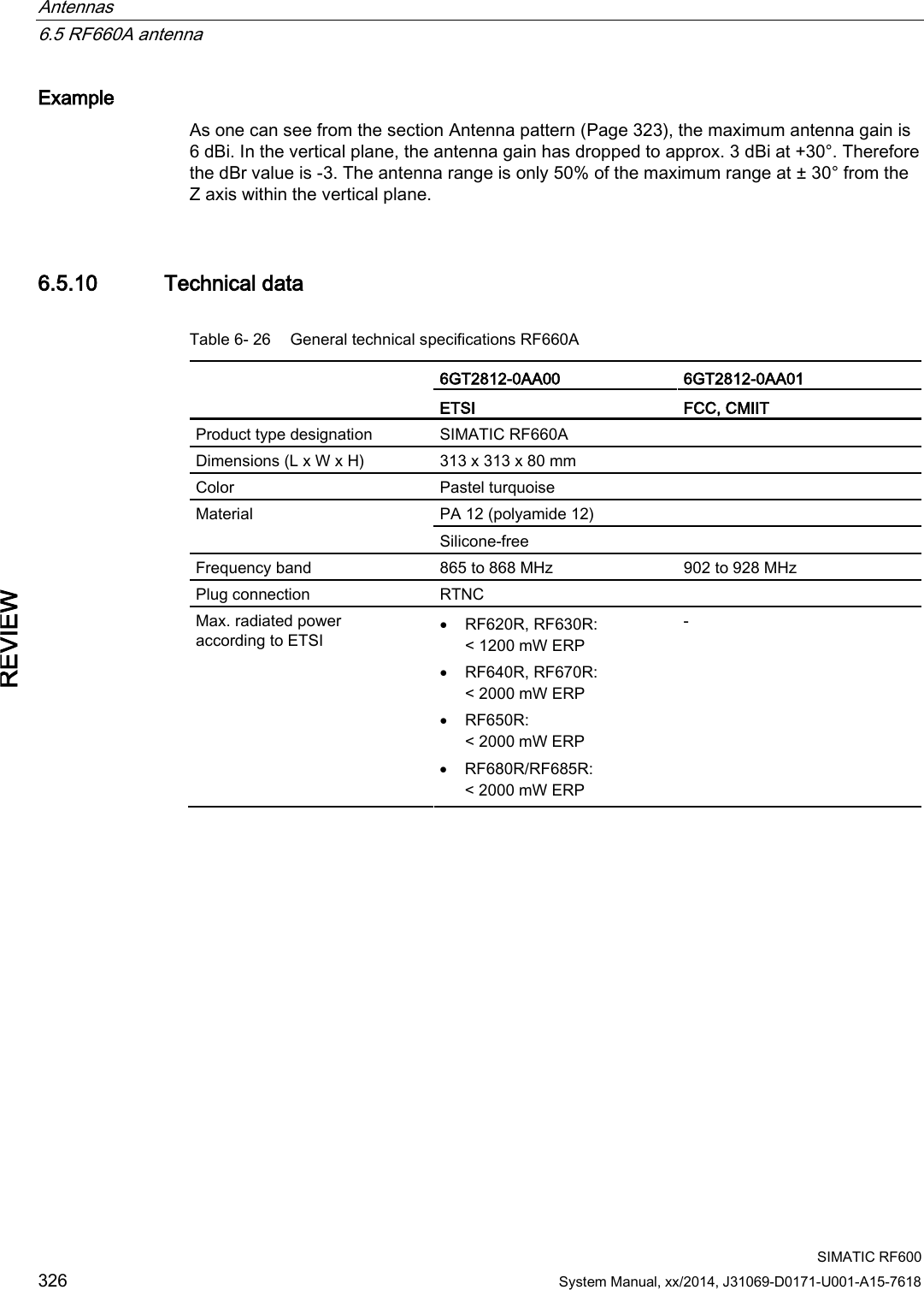
![Antennas 6.5 RF660A antenna SIMATIC RF600 318 System Manual, xx/2014, J31069-D0171-U001-A15-7618 REVIEW Connecting RF660A to RF630R Preassembled standard cables in lengths of 3 m, 10 m and 20 m are available for connection. The cable between antenna and reader can be up to 20 m in length. When one antenna is used, it is recommended that the remaining antenna connection is sealed using the supplied protective cap. 6.5.3.1 Bending radii and bending cycles of the cable Cable designation Order No. Length [m] Cable loss [dB] Bending radius [mm] Bending cycle Antenna cable 6GT2815-0BH30 3 1 51 1 Mal Antenna cable (suitable for drag chains) 6GT2815-2BH50 5 1,25 1) 1) Antenna cable 6GT2815-1BN10 10 2 77 1 Mal Antenna cable 6GT2815-0BN10 10 4 51 1 Mal Antenna cable (suitable for drag chains) 6GT2815-0BN20 15 4 1) 1) Antenna cable 6GT2815-0BN20 20 4 77 1 Mal 1) With cables suitable for drag chains, 3 million bending cycles at a bending radius of 6.5 mm and bending through ± 180° are permitted. 6.5.4 Parameter settings of RF660A for RF620R/RF630R Operation within the EU, EFTA, or Turkey according to DIN EN 302208 V1.4.1 Note Limitation of the radiated power according to EN 302 208 V1.4.1 RF600 systems that are put into operation within the EU, EFTA, or Turkey (ETSI) can be operated with an RF660A antenna with a maximum radiated power of up to 2000 mW ERP (or 33 dBm ERP, 3250 mW EIRP, 35 dBm EIRP). By adjusting the transmit power of up to 500 mW ERP (or 27 dBm ERP, 800 mW EIRP, 29.15 dBm EIRP) and taking into account the RF660A antenna gain of 7 dBi (10 dBic) and the cable loss associated with the antenna cable (see table (Page 318)), the radiated power of the antenna cannot be exceeded. You can make the power settings using the "distance_limiting" parameter. You will find more detailed information on the parameters in](https://usermanual.wiki/Siemens/RF600R2.User-Manual-part-2/User-Guide-2334413-Page-18.png)
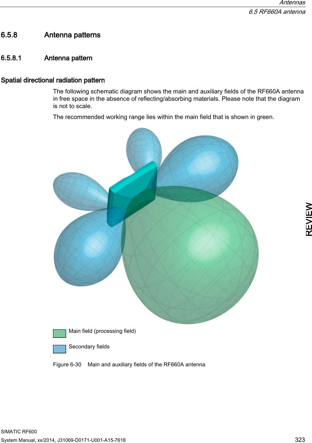
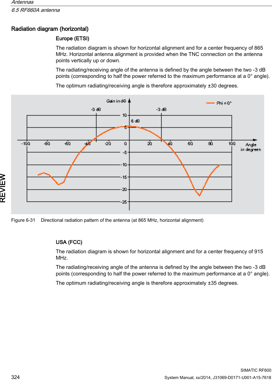
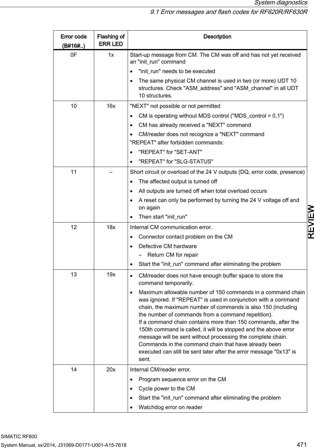
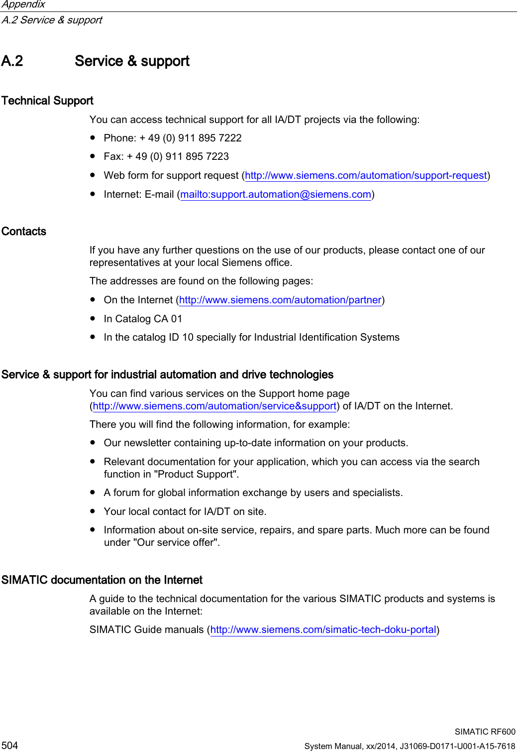
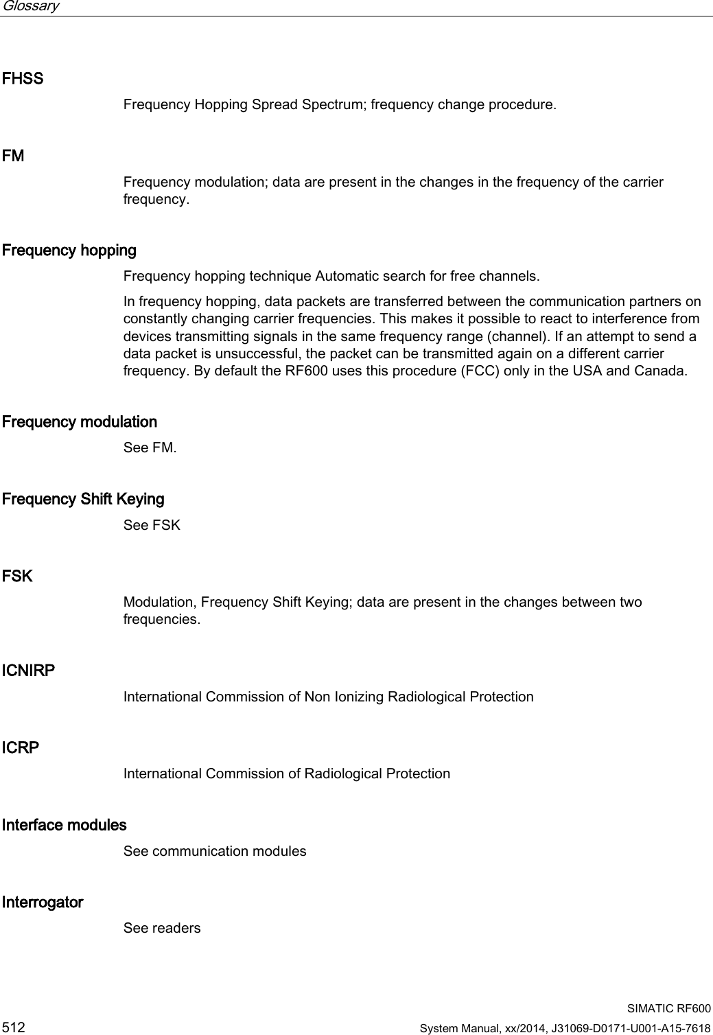
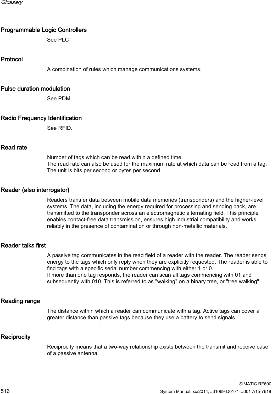
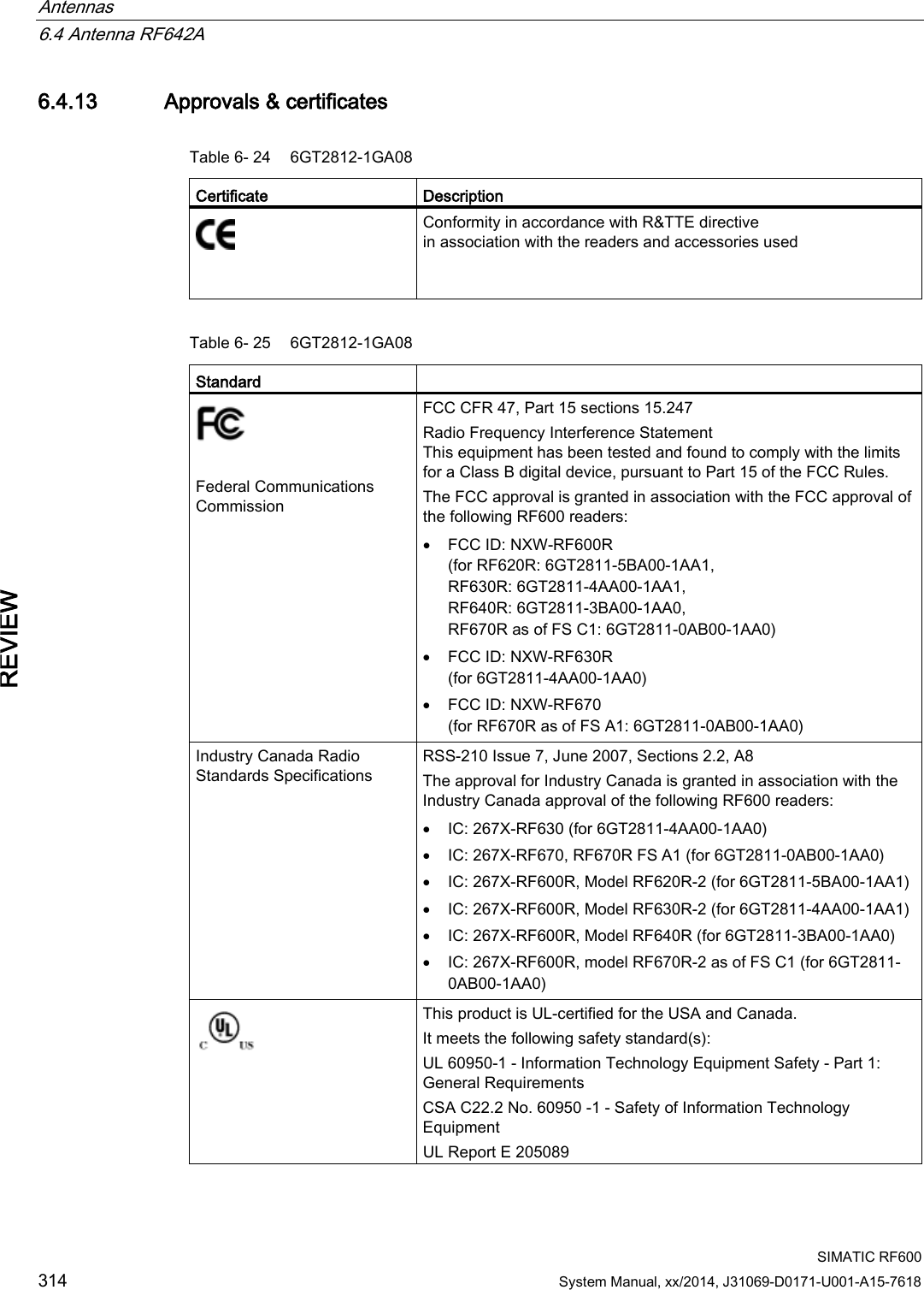
![Antennas 6.5 RF660A antenna SIMATIC RF600 System Manual, xx/2014, J31069-D0171-U001-A15-7618 325 REVIEW Figure 6-32 Directional radiation pattern of the antenna (at 915 MHz, horizontal alignment) 6.5.9 Interpretation of directional radiation patterns The following overview table will help you with the interpretation of directional radiation patterns. The table shows which dBi values correspond to which read/write ranges (in %): You can read the radiated power depending on the reference angle from the directional radiation patterns, and thus obtain information on the read/write range with this reference angle with regard to a transponder. The dBr values correspond to the difference between the maximum dBi value and a second dBi value. Deviation from maximum antenna gain [dBr] Read/write range [%] 0 100 -3 70 -6 50 -9 35 -12 25 -15 18 -18 13](https://usermanual.wiki/Siemens/RF600R2.User-Manual-part-2/User-Guide-2334413-Page-25.png)
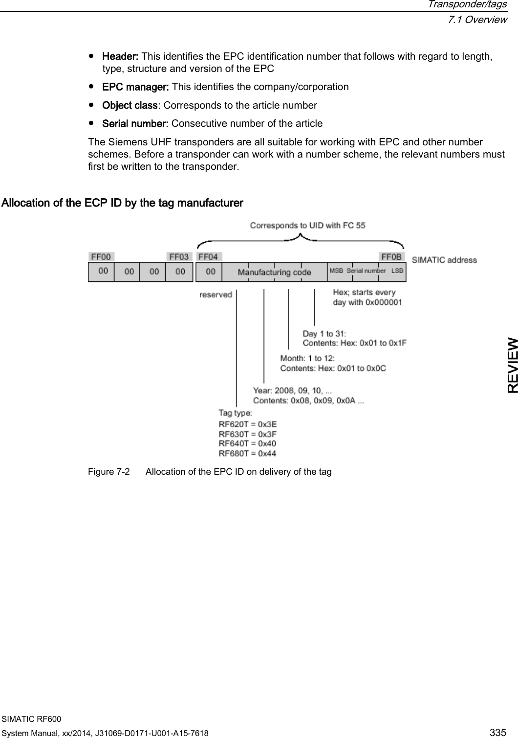
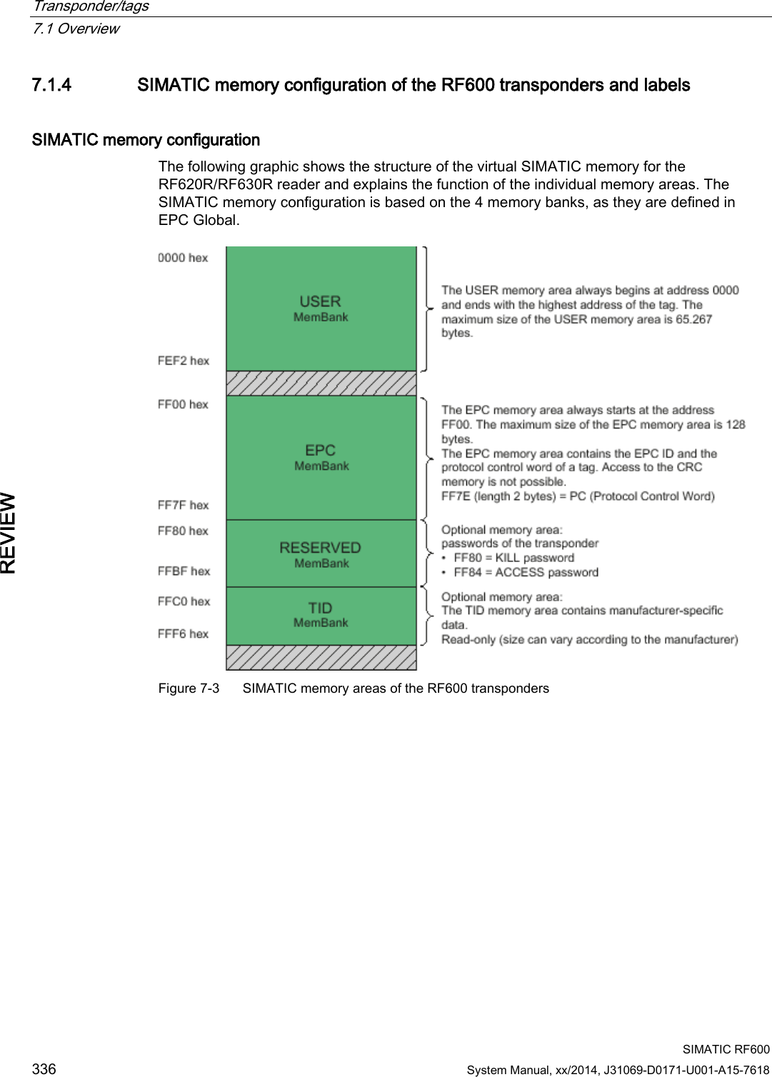
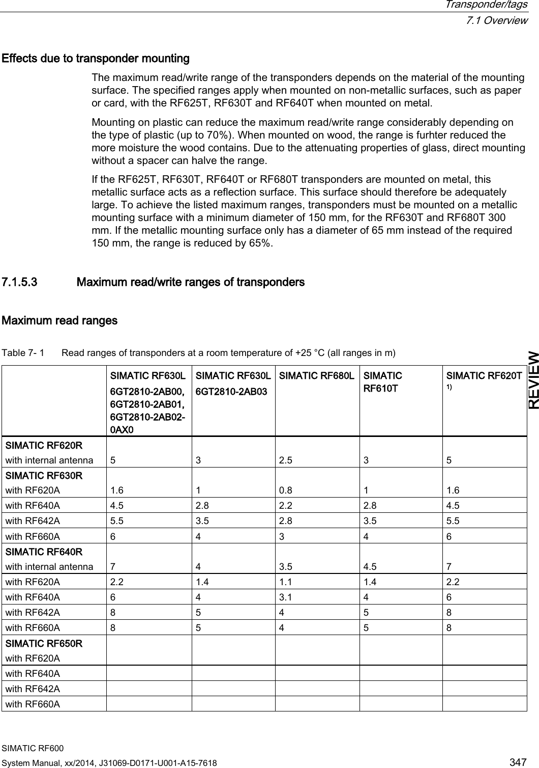
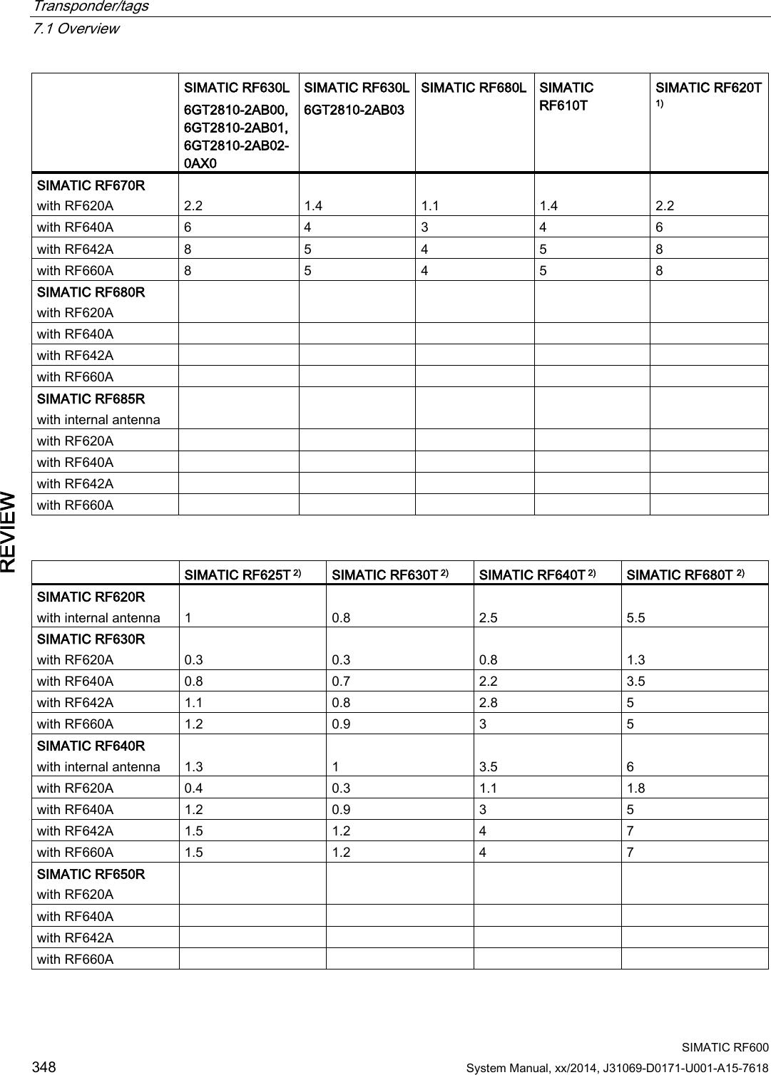
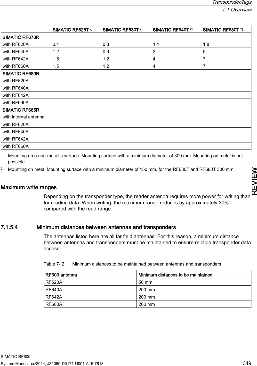
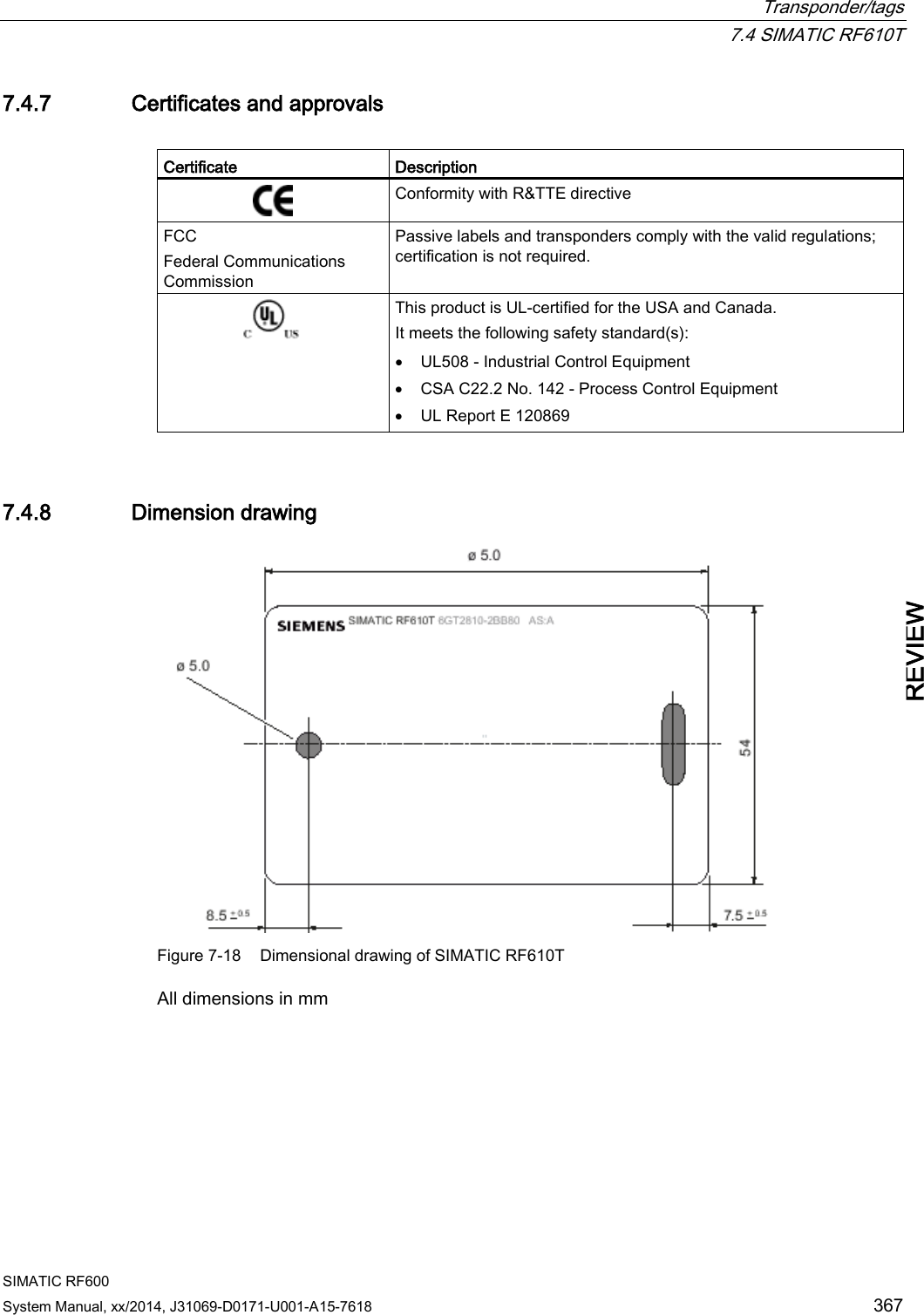
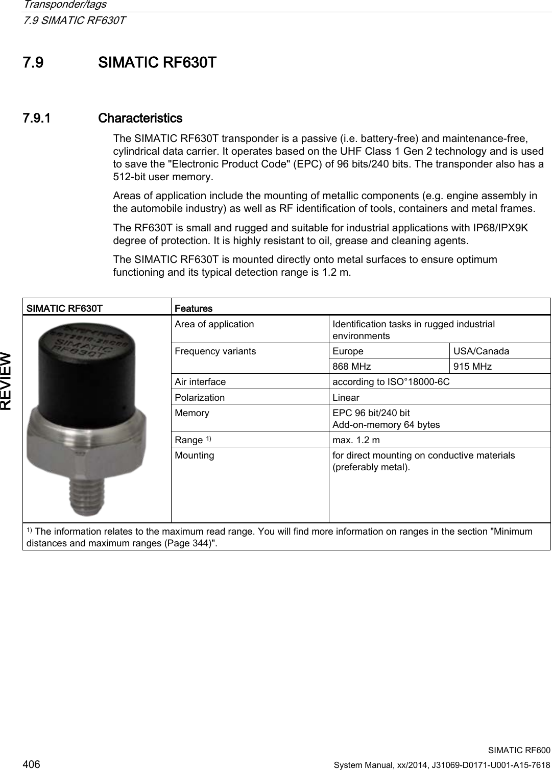
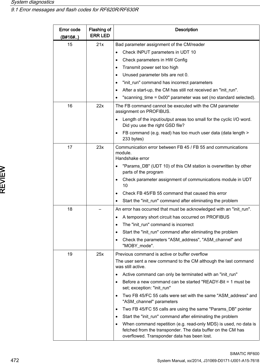
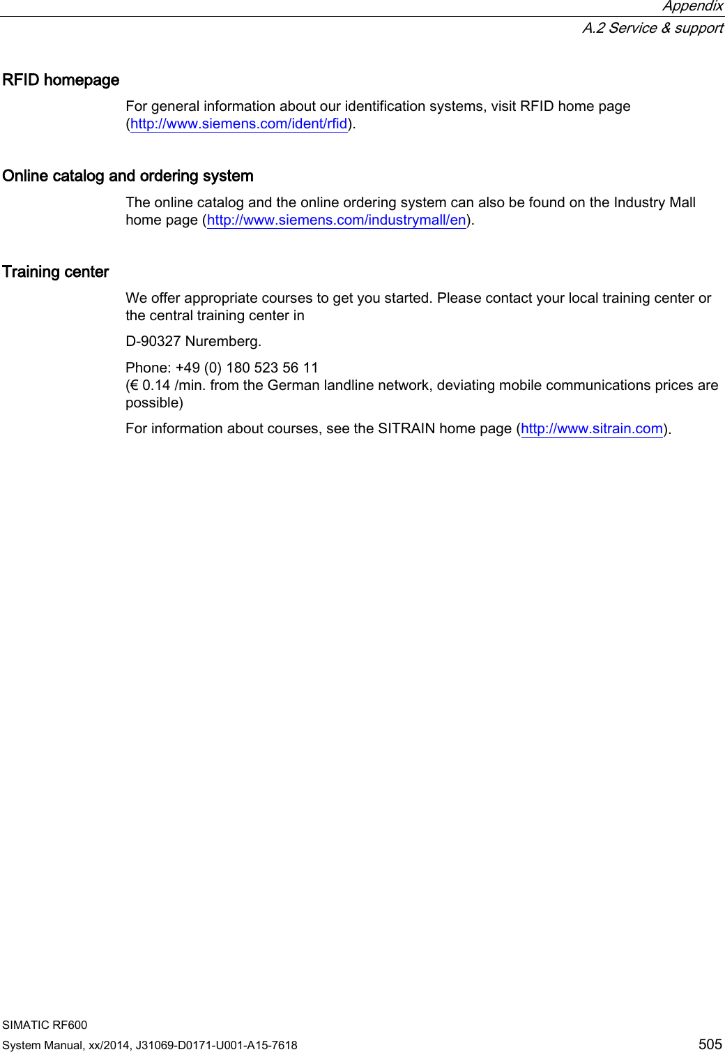
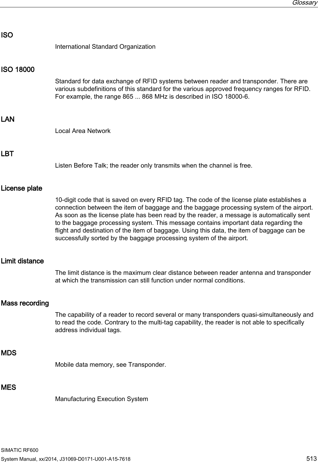
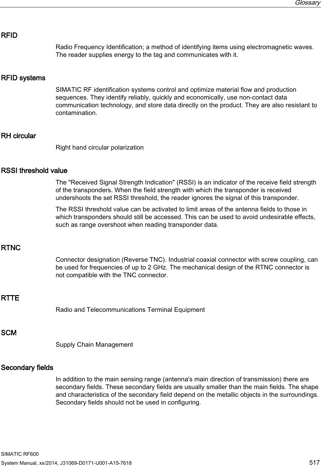
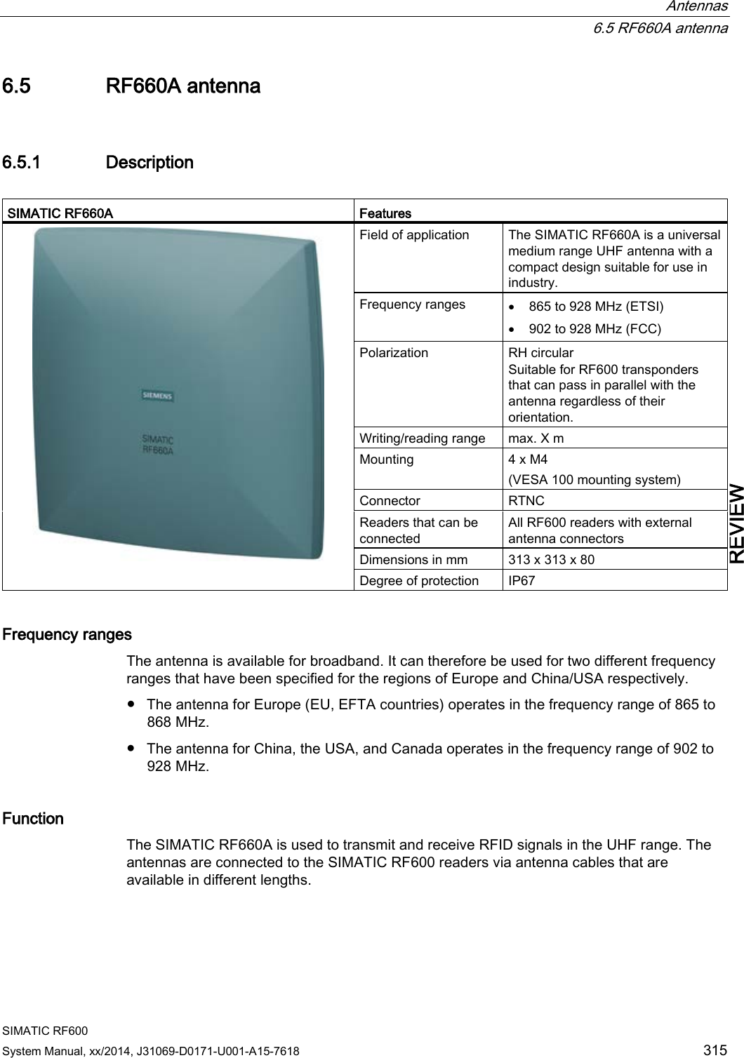
![Transponder/tags 7.1 Overview SIMATIC RF600 System Manual, xx/2014, J31069-D0171-U001-A15-7618 337 REVIEW Special memory configuration of the RF600 transponders and labels Tags Chip type User [hex] EPC TID RESERVED (passwords) Special Range (preset length) Access KILL-PW Lock function RF630L (-2AB00, -2AB01) Impinj Monza 2 - FF00-FF0B (96 bits = FF00-FF0B) read/ write FFC0-FFC7 FF80-FF87 Yes Yes RF630L (-2AB02) Impinj Monza 4QT 1) 00 - 3F FF00-FF0F (96 bits = FF00-FF0B) read/ write FFC0-FFC9 FF80-FF87 Yes Yes RF630L (-2AB03) NXP G2XM 00 - 3F FF00-FF1D (96 bits = FF00-FF0B) read/ write FFC0-FFC7 FF80-FF87 Yes Yes RF680L NXP G2XM 00 - 3F FF00-FF1D (96 bits = FF00-FF0B) read/ write FFC0-FFC7 FF80-FF87 Yes Yes RF610T NXP G2XM 00 - 3F FF00-FF1D (96 bits = FF00-FF0B) read/ write FFC0-FFC7 FF80-FF87 LOCKED Yes RF610T ATEX NXP G2XM 00 - 3F FF00-FF1D (96 bits = FF00-FF0B) read/ write FFC0-FFC7 FF80-FF87 LOCKED Yes RF620T Impinj Monza 4QT 1) 00 - 3F FF00-FF0F (96 bits = FF00-FF0B) read/ write FFC0-FFC9 FF80-FF87 LOCKED Yes RF622T RF625T Impinj Monza 4QT 1) 00 - 3F FF00-FF0F (96 bits = FF00-FF0B) read/ write FFC0-FFC9 FF80-FF87 LOCKED Yes RF630T NXP G2XM 00 - 3F FF00-FF1D (96 bits = FF00-FF0B) read/ write FFC0-FFC7 FF80-FF87 LOCKED Yes RF640T NXP G2XM 00 - 3F FF00-FF1D0B (96 bits = FF00-FF0B) read/ write FFC0-FFC7 FF80-FF87 LOCKED Yes RF680T NXP G2XM 00 - 3F FF00-FF1D (96 bits = FF00-FF0B) read/ write FFC0-FFC7 FF80-FF87 LOCKED Yes 1) Uses User Memory Indicator (UMI).](https://usermanual.wiki/Siemens/RF600R2.User-Manual-part-2/User-Guide-2334413-Page-37.png)