Siemens RF600R2 RFID UHF Reader RF650R, RF680R, RF685R User Manual SIMATIC RF600
Siemens AG RFID UHF Reader RF650R, RF680R, RF685R SIMATIC RF600
Siemens >
Contents
- 1. User Manual part 1
- 2. User Manual part 2
- 3. User Manual
User Manual part 2
Antennas
6.4 Antenna RF642A
SIMATIC RF600
System Manual, xx/2014, J31069-D0171-U001-A15-7618 301
REVIEW
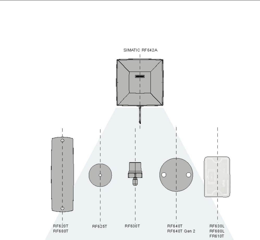
Alignment
The following diagram shows the optimum alignment of the RF600 transponders to the
RF642A antenna.
Figure 6-22 Antenna/transponder alignment
Antennas
6.4 Antenna RF642A
SIMATIC RF600
302 System Manual, xx/2014, J31069-D0171-U001-A15-7618
REVIEW
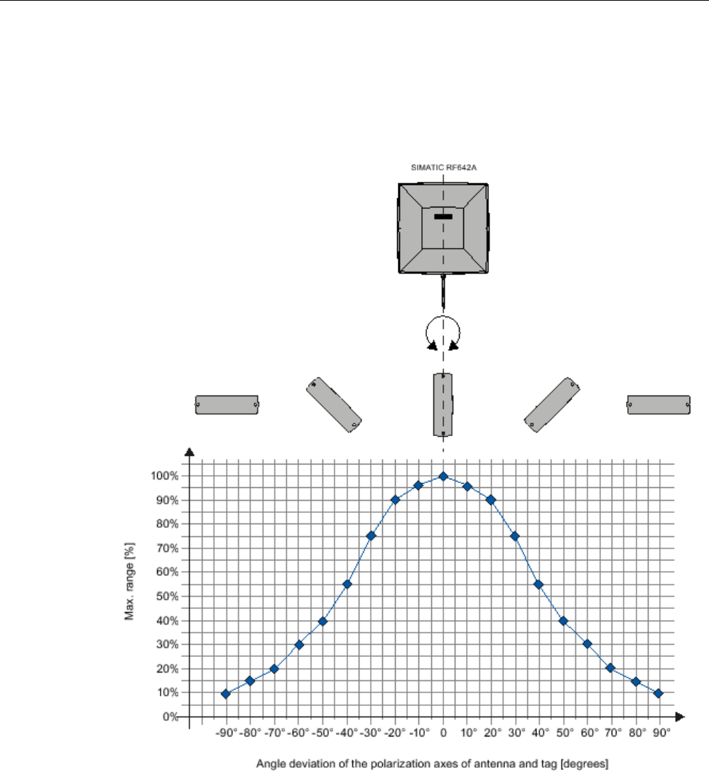
Angle deviation diagram for alignment
The following diagram shows the dependence of the following factors.
● Alignment angle of transponder to antenna
● Maximum range of antenna
Figure 6-23 Angle deviation diagram for alignment

Antennas
6.4 Antenna RF642A
SIMATIC RF600
System Manual, xx/2014, J31069-D0171-U001-A15-7618 303
REVIEW
6.4.6
Parameter settings of RF642A for RF620R/RF630R
Operation within the EU, EFTA, or Turkey according to DIN EN 302208 V1.4.1
Note
Limitation of the radiated power according to DIN EN 302208 V1.4.1
RF600 systems that are put into operation within the EU, EFTA, or Turkey (ETSI) can be
operated with an RF642A antenna with a maximum radiated power
of up to 2000 mW ERP
(or 33 dBm
ERP, 3250 mW EIRP, 35 dBm EIRP).
By adjusting the transmit power of up to 500 mW ERP (or 27 dBm ERP, 800 mW EIRP,
29.15 dBm EIRP) and taking into account the RF642A antenna gain of 6 dBi and the cable
loss associated with the antenna cable (see table), the radiated power of the antenna cannot
be exceeded. You can make the power settings using the "distance_limiting" parameter. You
will find more detailed information on the parameters in the section Parameter assignment
manual RF620R/RF630R (http://support.automation.siemens.com/WW/view/en/33287195).
Operation in China
The national approval for RF600 systems in China means a restriction to 2000 mW ERP (or
33 dBm ERP, 3250 mW EIRP, 35 dBm EIRP). The possible combination of antenna gain (7
dbi), cable loss, and max. 500 mW transmit power of the RF630R reader means it is not
possible to exceed 2000 mW ERP (or 33 dBm ERP, 3250 mW EIRP, 35 dBm EIRP).
Operation in the USA, Canada
Note
Limitation of the radiated power to 4000 mW EIRP (36 dBm EIRP) with an antenna gain of 7
dBi
The antenna must be commissioned by qualified personnel. Antennas with a gain >6
dBi can
be put into operation, as long as the
radiated power of 4000 mW EIRP (36 dBm EIRP) is not
exceeded.
To comply with FCC and IC
-FCB requirements, the system must satisfy the following
relation:
•
Conducted power P dBm of the RF600 reader (< 30 dBm)
•
Antenna gain Gi dBi in the FCC frequency band (≤ 7 dBi)
•
Cable loss ak dB (≥ 1 dB)
P(dBm) ≤ 30
dBm - (Gi - 6 dBi) + ak

Antennas
6.4 Antenna RF642A
SIMATIC RF600
304 System Manual, xx/2014, J31069-D0171-U001-A15-7618
REVIEW
6.4.7
Parameter settings of RF642A for RF640R/RF670R
Operation within the EU, EFTA, or Turkey according to DIN EN 302208 V1.4.1
Note
Limitation of the radiated power according to DIN EN 302208 V1.4.1
RF600 systems that are put into operation within the EU, EFTA, or Turkey (ETSI) can be
operated with an RF642A antenna with a maximum radiated power of 2000
mW ERP (or 33
dBm
ERP, 3250 mW EIRP, 35 dBm EIRP).
By setting the radiated power of up to 2000 mW ERP (or 33 dBm ERP, 3250 mW EIRP,
35 dBm EIRP), an RF642A antenna gain of 6 dBi and taking into account the cable loss
associated with the antenna cable (see table), the radiated power of the reader is correctly
configured and the radiated power at the antenna is not exceeded.
Operation in China
By setting a max. radiated power of 2000 mW ERP (or 33 dBm ERP, 3250 mW EIRP, 35
dBm EIRP), an RF642A antenna gain of 7 dBi and taking into account the cable loss
associated with the antenna cable (see table), the reader's radiated power is correctly
configured.
Operation in the USA, Canada
Note
Limitation of the radiated power to 4000 mW EIRP (36 dBm EIRP) with an antenna gain of 7
dBi
The antenna must be commissioned by qualified personnel.
Antennas with a gain >6
dBi can
be put into operation, as long as the radiated power of 4000
mW EIRP (36 dBm EIRP) is not
exceeded.
To comply with FCC and IC
-FCB requirements, the system must satisfy the following
relation:
•
Conducted power P dBm of the RF600 reader (< 30 dBm)
•
Antenna gain Gi dBi in the FCC frequency band (≤ 7 dBi)
•
Cable loss ak dB (≥ 1 dB)
P(dBm) ≤ 30
dBm - (Gi - 6 dBi) + ak

Antennas
6.4 Antenna RF642A
SIMATIC RF600
System Manual, xx/2014, J31069-D0171-U001-A15-7618 305
REVIEW
6.4.8
Setting RF642A parameters for RF650R
Operation within the EU according to DIN EN 302208 V1.4.1
Note
Limitation of the radiated power according to DIN EN 302208 V1.4.1
RF600 systems that are put into operation within the EU, EFTA, or Turkey (ETSI) can be
operated with an RF642A antenna with a maximum radiated power of 2000
mW ERP (or 33
dBm
ERP, 3250 mW EIRP, 35 dBm EIRP).
By setting the radiated power of up to 2000 mW ERP (or 33 dBm ERP, 3250 mW EIRP,
35 dBm EIRP), an RF642A antenna gain of 6 dBi and taking into account the cable loss
associated with the antenna cable (see table (Page 299)), the radiated power of the reader is
correctly configured and the radiated power at the antenna is not exceeded.
Operation in China
By setting a max. radiated power of 2000 mW ERP (or 33 dBm ERP, 3250 mW EIRP, 35
dBm EIRP), an RF642A antenna gain of 7 dBi and taking into account the cable loss
associated with the antenna cable (see table (Page 299)), the reader's radiated power is
correctly configured.
Operation in the USA, Canada
Note
Limitation of the radiated power to 4000 mW EIRP (36 dBm EIRP) with an antenna gain of 7
dBi
The antenna must be commissioned by qualified personnel. Antennas with a gain >
6
dBi can
be put into operation, as long as the radiated power of 4000
mW EIRP (36 dBm EIRP) is not
exceeded.
To comply with FCC and IC
-FCB requirements, the system must satisfy the following
relation:
•
Conducted power P dBm of the RF600 reader (< 30 dBm)
•
Antenna gain Gi dBi in the FCC frequency band (≤ 7 dBi)
•
Cable loss ak dB (≥ 1 dB)
P(dBm) ≤ 30
dBm - (Gi - 6 dBi) + ak

Antennas
6.4 Antenna RF642A
SIMATIC RF600
306 System Manual, xx/2014, J31069-D0171-U001-A15-7618
REVIEW
6.4.9
Setting RF642A parameters for RF680R/RF685R
Operation within the EU according to DIN EN 302208 V1.4.1
Note
Limitation of the radiated power according to DIN EN 302208 V1.4.1
RF600 systems that are put into operation within the EU, EFTA, or Turkey (ETSI) can be
operated with an RF642A antenna with a maximum radiated power of 2000
mW ERP (or 33
dBm
ERP, 3250 mW EIRP, 35 dBm EIRP).
By setting the radiated power of up to 2000 mW ERP (or 33 dBm ERP, 3250 mW EIRP,
35 dBm EIRP), an RF642A antenna gain of 6 dBi and taking into account the cable loss
associated with the antenna cable (see table (Page 299)), the radiated power of the reader is
correctly configured and the radiated power at the antenna is not exceeded.
Operation in China
By setting a max. radiated power of 2000 mW ERP (or 33 dBm ERP, 3250 mW EIRP, 35
dBm EIRP), an RF642A antenna gain of 7 dBi and taking into account the cable loss
associated with the antenna cable (see table (Page 299)), the reader's radiated power is
correctly configured.
Operation in the USA, Canada
Note
Limitation of the radiated power to 4000 mW EIRP (36 dBm EIRP) with an antenna gain of 7
dBi
The antenna must be commissioned by qualified personnel. Antennas with a gain >6
dBi can
be put into operation, as long as the radiated
power of 4000 mW EIRP (36 dBm EIRP) is not
exceeded.
To comply with FCC and IC
-FCB requirements, the system must satisfy the following
relation:
•
Conducted power P dBm of the RF600 reader (< 30 dBm)
•
Antenna gain Gi dBi in the FCC frequency band (≤ 7 dBi)
•
Cable loss ak dB (≥ 1 dB)
P(dBm) ≤ 30
dBm - (Gi - 6 dBi) + ak
Antennas
6.4 Antenna RF642A
SIMATIC RF600
System Manual, xx/2014, J31069-D0171-U001-A15-7618 307
REVIEW
6.4.10
Antenna patterns
6.4.10.1
Antenna radiation patterns in the ETSI frequency band
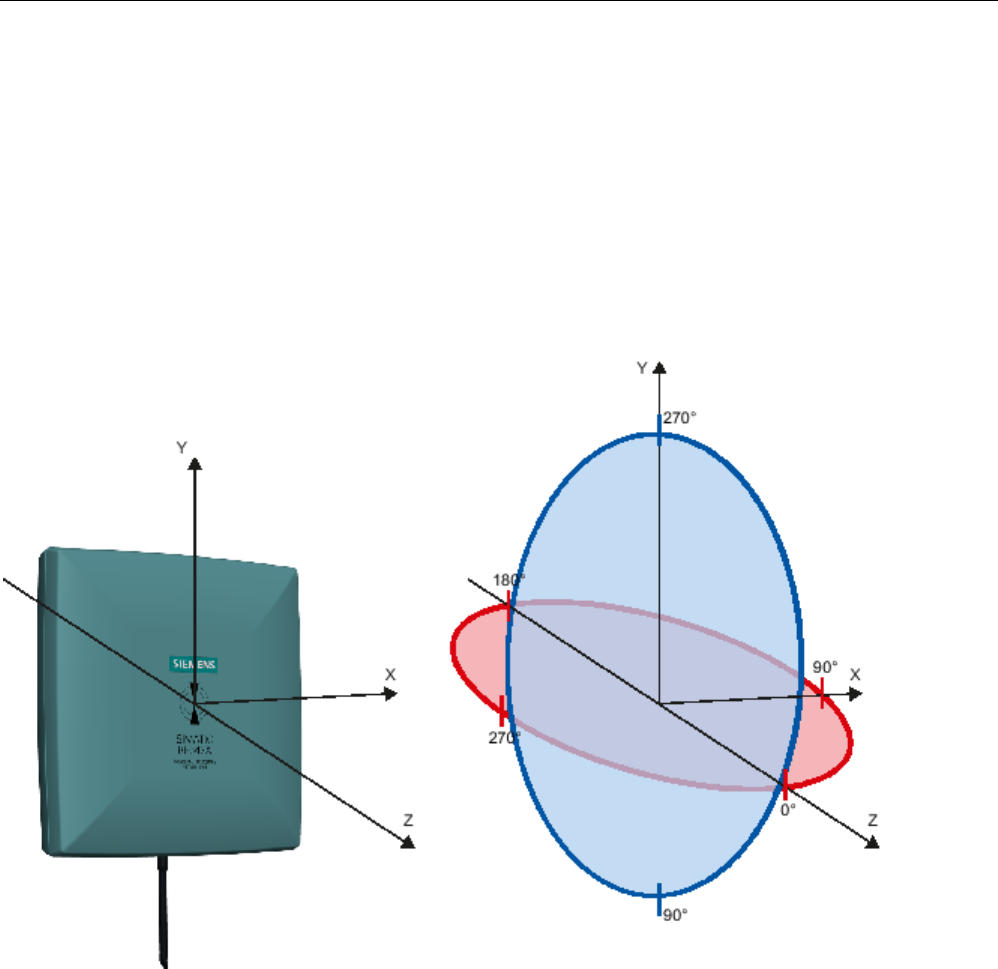
Directional radiation pattern
Europe (ETSI)
The directional radiation pattern is shown for nominal alignment and a center frequency of
866.3 MHz. The nominal antenna alignment is given when the antenna elevation is provided
as shown in the following figure.
Figure 6-24 Reference system
The half-power beam width of the antenna is defined by the angle between the two -3 dB
points. Which range (in %) corresponds to the dB values in the patterns can be obtained
from this table .
Note that the measurements presented graphically below were carried out in a low-reflection
environment. Deviations can therefore occur in a normally reflecting environment.
Antennas
6.4 Antenna RF642A
SIMATIC RF600
308 System Manual, xx/2014, J31069-D0171-U001-A15-7618
REVIEW
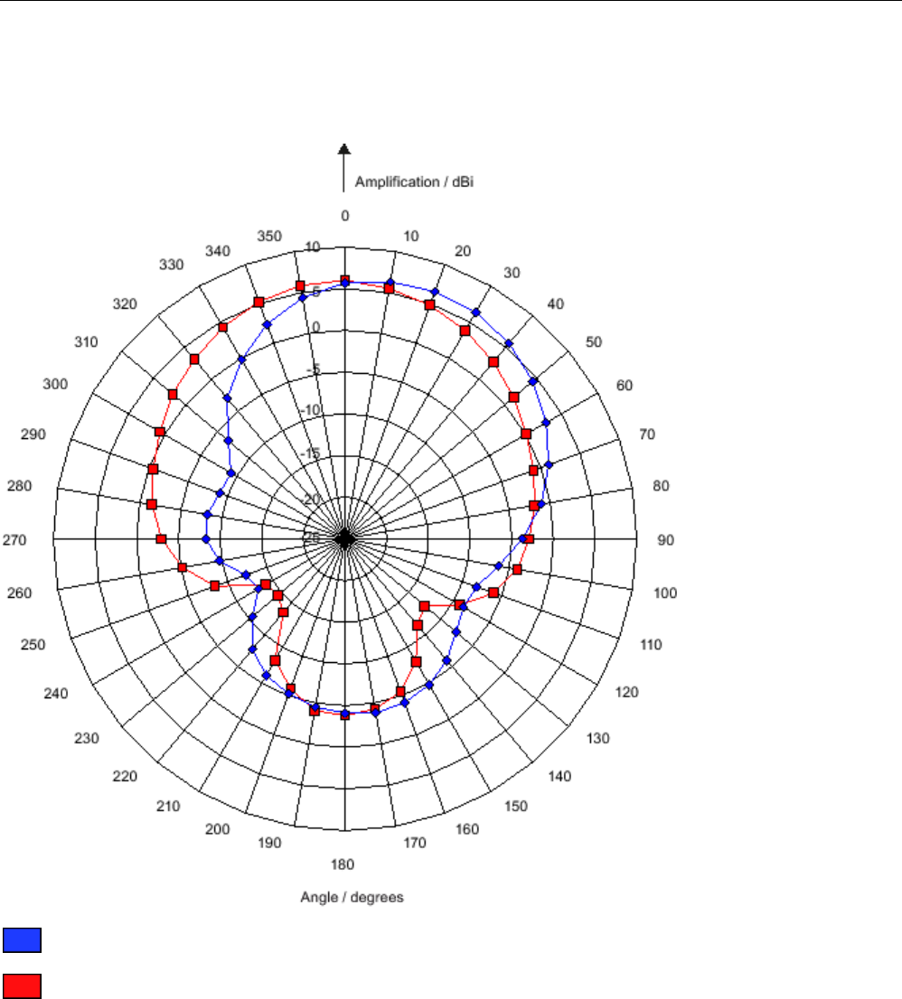
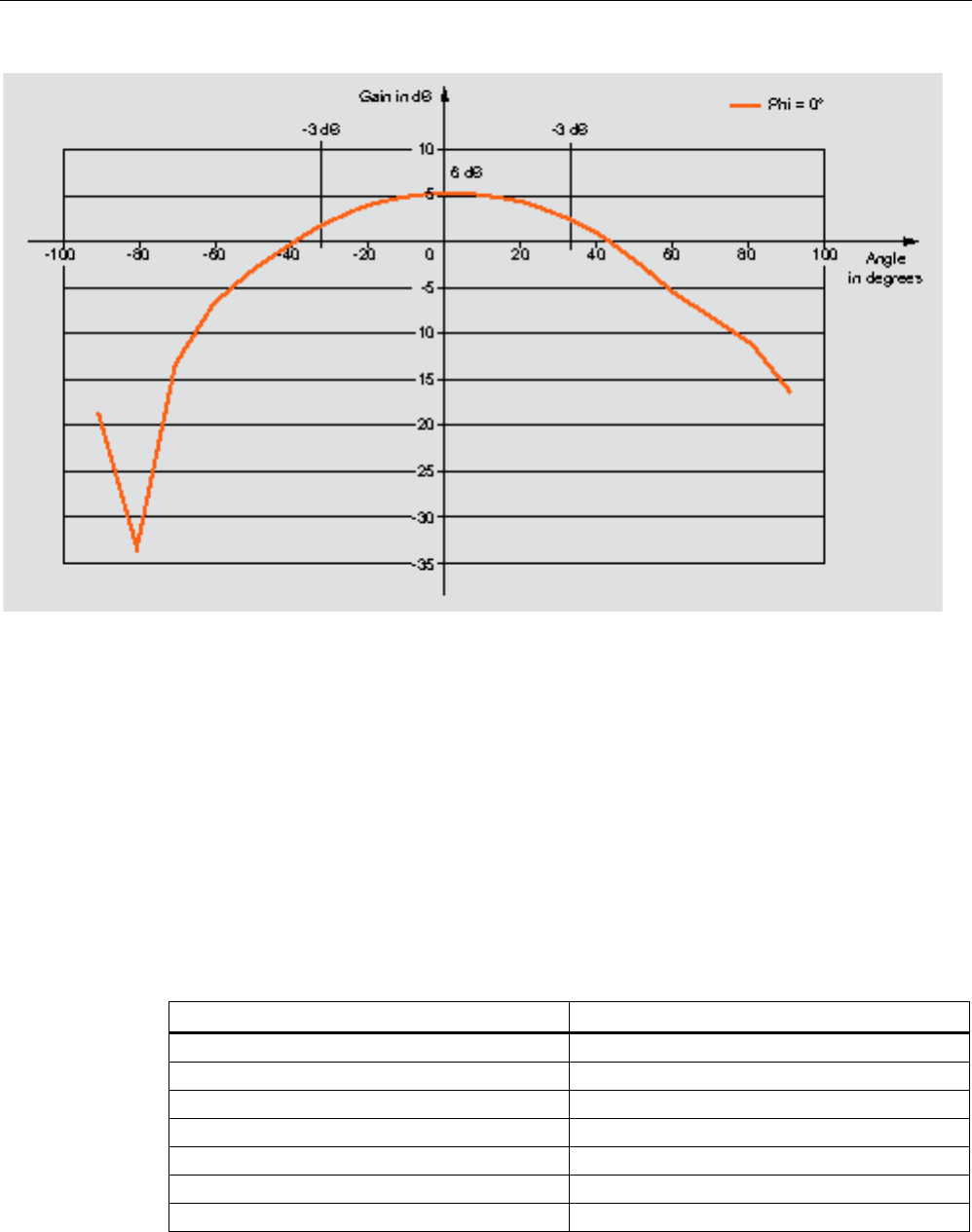
Directional radiation pattern in the ETSI frequency band
Pattern of the vertical plane of the antenna
Pattern of the horizontal plane of the antenna
Figure 6-25 Directional radiation pattern of RF642A in the ETSI frequency band
Antennas
6.4 Antenna RF642A
SIMATIC RF600
System Manual, xx/2014, J31069-D0171-U001-A15-7618 309
REVIEW
6.4.10.2
Antenna radiation patterns in the FCC frequency band
Directional radiation pattern USA (FCC)
The directional radiation pattern is shown for nominal alignment and a center frequency of
915 MHz.
Figure 6-26 Reference system
The half-power beam width of the antenna is defined by the angle between the two -3 dB
points (corresponding to half the power referred to the maximum power). Which range (in %)
corresponds to the dB values in the patterns can be obtained from this table .
Note that the measurements presented graphically below were carried out in a low-reflection
environment. Deviations can therefore occur in a normally reflecting environment.
Antennas
6.4 Antenna RF642A
SIMATIC RF600
310 System Manual, xx/2014, J31069-D0171-U001-A15-7618
REVIEW
Directional radiation pattern of the RF642A in the FCC frequency band
Pattern of the vertical plane of the antenna
Pattern of the horizontal plane of the antenna
Figure 6-27 Directional radiation pattern of the RF642A in the FCC frequency band

Antennas
6.4 Antenna RF642A
SIMATIC RF600
System Manual, xx/2014, J31069-D0171-U001-A15-7618 311
REVIEW
6.4.10.3
Interpretation of directional radiation patterns
The following overview table will help you with the interpretation of directional radiation
patterns.
The table shows which dBi values correspond to which read/write ranges (in %): You can
read the radiated power depending on the reference angle from the directional radiation
patterns, and thus obtain information on the read/write range with this reference angle with
regard to a transponder.
The dBr values correspond to the difference between the maximum dBi value and a second
dBi value.
Deviation from maximum antenna gain [dBr]
Read/write range [%]
0
100
-3
70
-6
50
-9
35
-12
25
-15
18
-18
13
Example
As can be seen in Directional radiation pattern in the ETSI frequency band (Page 308), the
maximum antenna gain in the horizontal plane is 6 dBi. In this plane and with the parallel
polarization axis at +70° or 300°, the antenna gain dropped to about 0 dBi. Therefore the dBr
value is 6. The antenna range is only 70° of the maximum range at + 50° or +300° from the Z
axis within the horizontal plane (see values shown in red in the directional radiation pattern:
Characteristic of the vertical plane of the antenna (Page 307) and the associated
representation of the reference system (Page 307)).

Antennas
6.4 Antenna RF642A
SIMATIC RF600
312 System Manual, xx/2014, J31069-D0171-U001-A15-7618
REVIEW
6.4.11
Technical data
Table 6- 23 General technical specifications RF642A
6GT2812-1GA08
Product type designation
SIMATIC RF642A
Dimensions (L x W x H)
185 x 185 x 45 mm
Color
Pastel turquoise
Material
PA 12 (polyamide 12)
Silicone-free
Frequency band
865 to 928 MHz
Plug connection 30 cm coaxial cable with RTNC coupling
An antenna cable is required for connection to the reader, e.g.:
6GT2815-0BH30
Max. radiated power
according to ETSI
• RF620R, RF630R: < 970 mW ERP
• RF640R, RF670R: ≤ 1900 mW ERP
• RF650R: ≤ 1900 mW ERP
• RF680R/RF685R: ≤ 2000 mW ERP
Max. radiated power
according to CMIIT
• RF620R, RF630R: < 1200 mW ERP
• RF640R, RF670R: ≤ 2000 mW ERP
• RF650R: ≤ 1900 mW ERP
• RF680R/RF685R: ≤ 2000 mW ERP
Max. radiated power
according to FCC
• RF620R, RF630R: ≤2000 mW EIRP
• RF640R, RF670R: ≤4000 mW EIRP
• RF650R: ≤ 3160 mW ERP
• RF680R/RF685R: ≤ 4000 mW ERP
Max. power
2000 mW
Impedance
50 ohms
Antenna gain
ETSI frequency band: 6 dBi
FCC frequency band: 7 dBi
VSWR (standing wave ratio)
max.: 1.4
Polarization
Linear polarization
Aperture angle for
transmitting/receiving
ETSI frequency band:
• Horizontal plane: 75°
• Vertical plane: 70°
See ETSI antenna pattern
FCC frequency band:
• Horizontal plane: 80°
• Vertical plane: 70°
See FCC antenna pattern
Front-to-back ratio
ETSI frequency band: 10 dB
FCC frequency band: 9.8 dB ± 2.2 dB
Antennas
6.4 Antenna RF642A
SIMATIC RF600
System Manual, xx/2014, J31069-D0171-U001-A15-7618 313
REVIEW
6GT2812-1GA08
Shock resistant to EN 60068-2-
27
30 g
Vibration resistant to EN 60068-
2-6
10 g
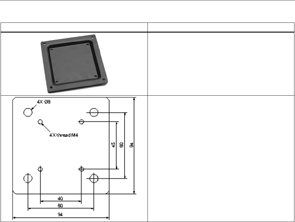
Attachment of the antenna
4 screws M4 (VESA 100 fastening system)
Tightening torque
(at room temperature)
≤ 2 Nm
Ambient temperature
• Operation
• Transport and storage
• -25 ℃ to +75 ℃
• -40 ℃ to +85 ℃
MTBF in years
16880
Degree of protection according
to EN 60529
IP65
Weight, approx.
600 g
1) The values differ for different dimensions/materials of the mounting surface.
6.4.12
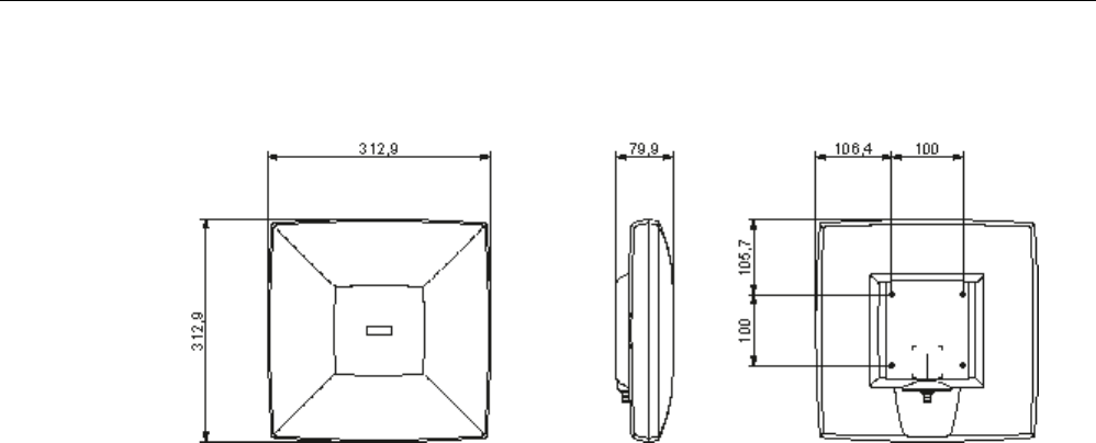
Dimension drawing
Figure 6-28 Dimensional drawing of RF642A
All dimensions in mm

Antennas
6.4 Antenna RF642A
SIMATIC RF600
314 System Manual, xx/2014, J31069-D0171-U001-A15-7618
REVIEW
6.4.13
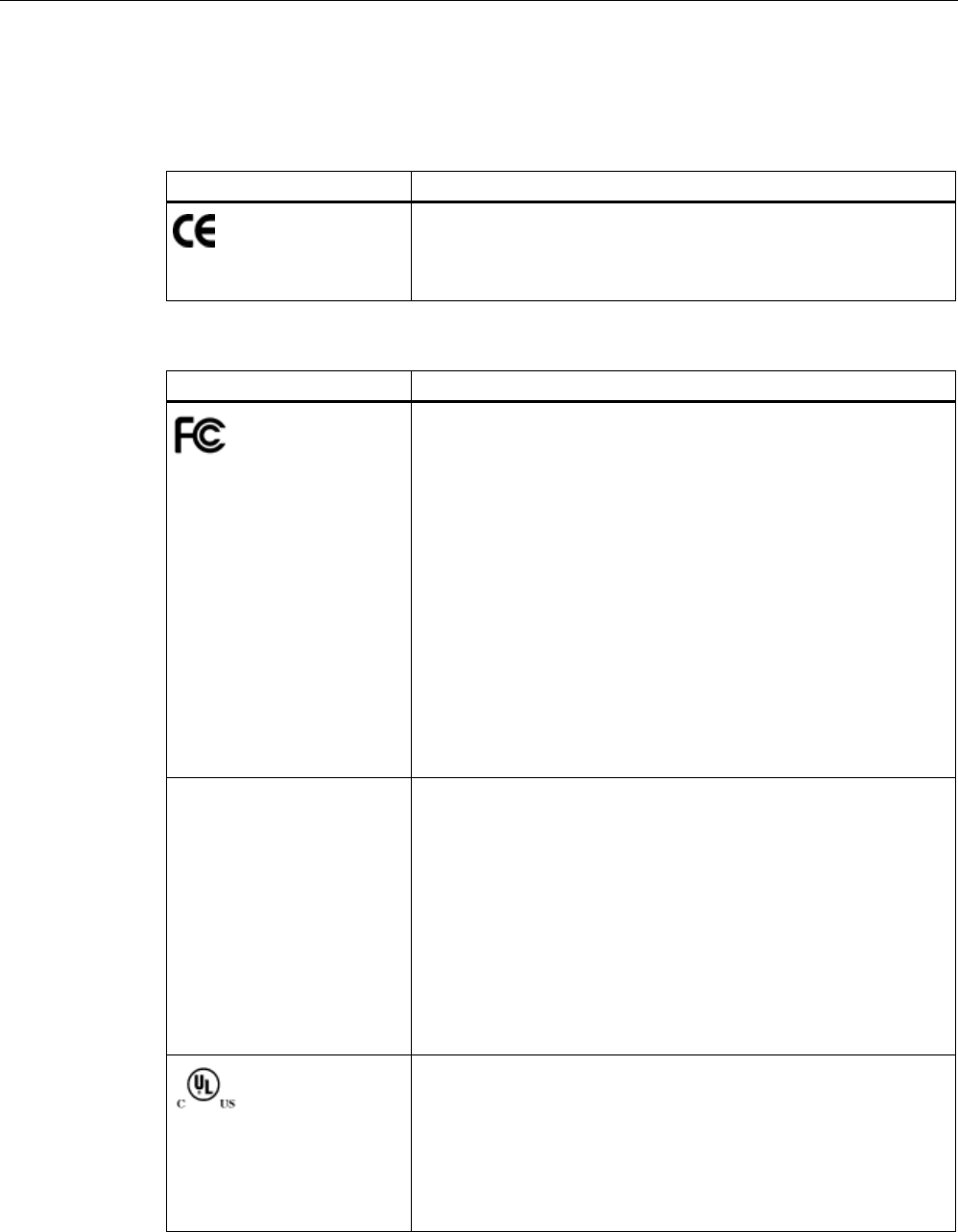
Approvals & certificates
Table 6- 24 6GT2812-1GA08
Certificate
Description
Conformity in accordance with R&TTE directive
in association with the readers and accessories used
Table 6- 25 6GT2812-1GA08
Standard
Federal Communications
Commission
FCC CFR 47, Part 15 sections 15.247
Radio Frequency Interference Statement
This equipment has been tested and found to comply with the limits
for a Class B digital device, pursuant to Part 15 of the FCC Rules.
The FCC approval is granted in association with the FCC approval of
the following RF600 readers:
• FCC ID: NXW-RF600R
(for RF620R: 6GT2811-5BA00-1AA1,
RF630R: 6GT2811-4AA00-1AA1,
RF640R: 6GT2811-3BA00-1AA0,
RF670R as of FS C1: 6GT2811-0AB00-1AA0)
• FCC ID: NXW-RF630R
(for 6GT2811-4AA00-1AA0)
• FCC ID: NXW-RF670
(for RF670R as of FS A1: 6GT2811-0AB00-1AA0)
Industry Canada Radio
Standards Specifications
RSS-210 Issue 7, June 2007, Sections 2.2, A8
The approval for Industry Canada is granted in association with the
Industry Canada approval of the following RF600 readers:
• IC: 267X-RF630 (for 6GT2811-4AA00-1AA0)
• IC: 267X-RF670, RF670R FS A1 (for 6GT2811-0AB00-1AA0)
• IC: 267X-RF600R, Model RF620R-2 (for 6GT2811-5BA00-1AA1)
• IC: 267X-RF600R, Model RF630R-2 (for 6GT2811-4AA00-1AA1)
• IC: 267X-RF600R, Model RF640R (for 6GT2811-3BA00-1AA0)
• IC: 267X-RF600R, model RF670R-2 as of FS C1 (for 6GT2811-
0AB00-1AA0)
This product is UL-certified for the USA and Canada.
It meets the following safety standard(s):
UL 60950-1 - Information Technology Equipment Safety - Part 1:
General Requirements
CSA C22.2 No. 60950 -1 - Safety of Information Technology
Equipment
UL Report E 205089
Antennas
6.5 RF660A antenna
SIMATIC RF600
System Manual, xx/2014, J31069-D0171-U001-A15-7618 315
REVIEW
6.5
RF660A antenna
6.5.1
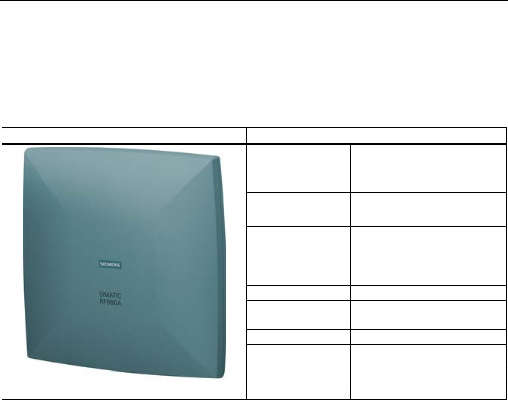
Description
SIMATIC RF660A
Features
Field of application The SIMATIC RF660A is a universal
medium range UHF antenna with a
compact design suitable for use in
industry.
Frequency ranges • 865 to 928 MHz (ETSI)
• 902 to 928 MHz (FCC)
Polarization RH circular
Suitable for RF600 transponders
that can pass in parallel with the
antenna regardless of their
orientation.
Writing/reading range
max. X m
Mounting 4 x M4
(VESA 100 mounting system)
Connector
RTNC
Readers that can be
connected
All RF600 readers with external
antenna connectors
Dimensions in mm
313 x 313 x 80
Degree of protection
IP67
Frequency ranges
The antenna is available for broadband. It can therefore be used for two different frequency
ranges that have been specified for the regions of Europe and China/USA respectively.
● The antenna for Europe (EU, EFTA countries) operates in the frequency range of 865 to
868 MHz.
● The antenna for China, the USA, and Canada operates in the frequency range of 902 to
928 MHz.
Function
The SIMATIC RF660A is used to transmit and receive RFID signals in the UHF range. The
antennas are connected to the SIMATIC RF600 readers via antenna cables that are
available in different lengths.
Antennas
6.5 RF660A antenna
SIMATIC RF600
316 System Manual, xx/2014, J31069-D0171-U001-A15-7618
REVIEW
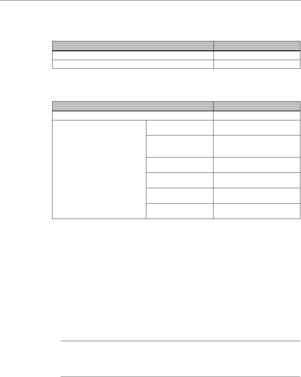
Ordering data
Description
Article number
RF660A antenna for Europe (865-868)
6GT2812-0AA00
RF660A antenna for China and the USA (902-928)
6GT2812-0AA01
Ordering data accessories
Description
Article number
Antenna mounting kit
6GT2890-0AA00
Connecting cable between reader
and antenna
3 m
(1 dB cable attenuation)
6GT2815-0BH30
5 m, suitable for drag
chains (cable loss
1.25 dB)
6GT2815-2BH50
10 m
(2 dB cable attenuation)
6GT2815-1BN10
10 m
(4 dB cable attenuation)
6GT2815-0AN10
15 m, suitable for drag
chains (cable loss 4.0 dB)
6GT2815-2BN15
20 m
(4 dB cable attenuation)
6GT2815-0AN20
6.5.2
Installation and assembly
6.5.2.1
RF660A mounting types
VESA 100 mounting system
A standardized VESA 100 mounting system is provided to mount the antenna. The mounting
system consists of four fixing holes for M4 screws at intervals of 100 mm.
This is therefore suitable for:
● Mounting on metallic and non-metallic backgrounds
Note
To achieve optimum wave propagation, the antenna should not be surrounded by
conducting objects. The area between antenna and transponder should also allow wave
propagation without
interference.
Antennas
6.5 RF660A antenna
SIMATIC RF600
System Manual, xx/2014, J31069-D0171-U001-A15-7618 317
REVIEW
Antenna Mounting Kit
The Antenna Mounting Kit allows the fine adjustment of the antenna field by setting the solid
angle (see "RF600 System Manual", chapter "Antennas" > "Mounting types").
6.5.3
Connecting an antenna to a reader
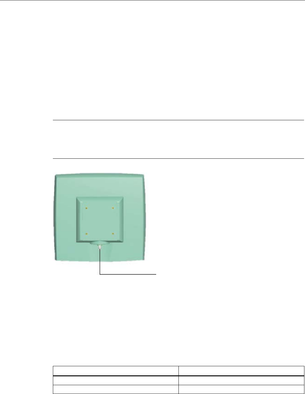
The SIMATIC RF660A antenna must be connected to the reader using an antenna cable.
Requirement
Note
Use of Siemens antenna cable
To ensure optimum functioning of the antenna, it is recommended that a Siemens antenna
cable is used in accordance with the list
of accessories.
Figure 6-29 Rear of antenna with RTNC connection
Connecting RF660A to RF640R/RF670R
Preassembled standard cables in lengths of 3 m, 10 m and 20 m are available for
connection.
The cable between antenna and reader can be up to 20 m in length.
When less than four antennas are used, we recommend that the antennas are connected to
the reader as follows:
Number of antennas
Connections on the reader
2 antennas
ANT 1, ANT 2
3 antennas
ANT 1, ANT 2, ANT 3

Antennas
6.5 RF660A antenna
SIMATIC RF600
318 System Manual, xx/2014, J31069-D0171-U001-A15-7618
REVIEW
Connecting RF660A to RF630R
Preassembled standard cables in lengths of 3 m, 10 m and 20 m are available for
connection.
The cable between antenna and reader can be up to 20 m in length.
When one antenna is used, it is recommended that the remaining antenna connection is
sealed using the supplied protective cap.
6.5.3.1
Bending radii and bending cycles of the cable
Cable
designation
Order No.
Length [m]
Cable loss
[dB]
Bending
radius [mm]
Bending cycle
Antenna cable 6GT2815-
0BH30
3 1 51 1 Mal
Antenna cable
(suitable for drag
chains)
6GT2815-
2BH50
5 1,25 1) 1)
Antenna cable 6GT2815-
1BN10
10 2 77 1 Mal
Antenna cable 6GT2815-
0BN10
10 4 51 1 Mal
Antenna cable
(suitable for drag
chains)
6GT2815-
0BN20
15 4 1) 1)
Antenna cable 6GT2815-
0BN20
20 4 77 1 Mal
1)
With cables suitable for drag chains, 3 million bending cycles at a bending radius of 6.5 mm and
bending through ± 180° are permitted.
6.5.4
Parameter settings of RF660A for RF620R/RF630R
Operation within the EU, EFTA, or Turkey according to DIN EN 302208 V1.4.1
Note
Limitation of the radiated power according to EN 302 208 V1.4.1
RF600 systems that are put into operation within
the EU, EFTA, or Turkey (ETSI) can be
operated with an RF660A antenna with a maximum radiated power of up to 2000
mW ERP
(or 33 dBm
ERP, 3250 mW EIRP, 35 dBm EIRP).
By adjusting the transmit power of up to 500 mW ERP (or 27 dBm ERP, 800 mW EIRP,
29.15 dBm EIRP) and taking into account the RF660A antenna gain of 7 dBi (10 dBic) and
the cable loss associated with the antenna cable (see table (Page 318)), the radiated power
of the antenna cannot be exceeded. You can make the power settings using the
"distance_limiting" parameter. You will find more detailed information on the parameters in

Antennas
6.5 RF660A antenna
SIMATIC RF600
System Manual, xx/2014, J31069-D0171-U001-A15-7618 319
REVIEW
the section Parameter assignment manual RF620R/RF630R
(http://support.automation.siemens.com/WW/view/en/33287195).
Operation in China
The national approval for RF600 systems in China means a restriction to 2000 mW ERP (or
33 dBm ERP, 3250 mW EIRP, 35 dBm EIRP). The possible combination of antenna gain,
cable loss, and max. 500 mW radiated power of the RF620R/RF630R reader means it is not
possible to exceed 2000 mW ERP (or 33 dBm ERP, 3250 mW EIRP, 35 dBm EIRP).
Operation in the USA, Canada
Note
Limitation of the radiated power to 4000 mW EIRP (36 dBm EIRP)
To meet the FCC and IC
-FCB requirements, the radiated power may not exceed 4000 mW
EIRP (36 dBm EIRP).
Therefore the system must satisfy the following relation:
•
Conducted power P dBm of the RF600 reader (< 30 dBm)
•
Antenna gain Gi dBi in the FCC frequency band (≤ 6 dBi)
•
Cable loss ak dB (≥ 1 dB)
P(dBm) ≤ 30
dBm - (Gi - 6 dBi) + ak
6.5.5
Parameter settings of RF660A for RF640R/RF670R
Operation within the EU, EFTA, or Turkey according to DIN EN 302208 V1.4.1
Note
Limitation of the radiated power according to DIN EN 302208 V1.4.1
RF600 systems that are put into operation within the EU, EFTA, or Turkey (ETSI) c
an be
operated with an RF660A antenna with a maximum radiated power of 2000
mW ERP (or 33
dBm
ERP, 3250 mW EIRP, 35 dBm EIRP).
By adjusting the radiated power of up to 1300 mW ERP (or 31.15 dBm ERP,
2140 mW EIRP, 33.3 dBm EIRP), the RF660A antenna gain of 7 dBi (10 dBic) and the cable
loss associated with the antenna cable (see table (Page 318)), the radiated power of the
reader is correctly configured and the radiated power at the antenna is not exceeded.
Operation in China
By setting a max. radiated power of 1300 mW ERP (or 31.15 dBm ERP, 2140 mW EIRP,
33.3 dBm EIRP), the RF660A antenna gain of 6 dBi (9 dBic) and the cable loss associated
with the antenna cable (see table (Page 318)), the radiated power of the reader is correctly
configured.

Antennas
6.5 RF660A antenna
SIMATIC RF600
320 System Manual, xx/2014, J31069-D0171-U001-A15-7618
REVIEW
Operation in the USA, Canada
Note
Limitation of the radiated power to 4000 mW EIRP (36 dBm EIRP)
To meet the FCC and IC requirements, the radiated power may not exceed 4000 mW EIRP
(36 dBm EIRP). Therefore the system must satisfy the following relation:
•
Conducted power P dBm of the RF600 reader (< 30 dBm)
•
Antenna gain Gi dBi in the FCC frequency band (≤ 6 dBi)
•
Cable loss ak dB (≥ 1 dB)
P(dBm) ≤ 30
dBm - (Gi - 6 dBi) + ak
6.5.6
Setting RF660A parameters for RF650R
Operation within the EU according to DIN EN 302208 V1.4.1
Note
Limitation of the radiated power according to DIN EN 302208 V1.4.1
RF600 systems that are put into operation within the EU, EFTA, or Turkey (ETSI) can be
operated with an RF660A antenna with a maximum radiated power of 2000
mW ERP (or 33
dBm
ERP, 3250 mW EIRP, 35 dBm EIRP).
By adjusting the radiated power of up to 1300 mW ERP (or 31.15 dBm ERP,
2140 mW EIRP, 33.3 dBm EIRP), the RF660A antenna gain of 7 dBi (10 dBic) and the cable
loss associated with the antenna cable (see table (Page 318)), the radiated power of the
reader is correctly configured and the radiated power at the antenna is not exceeded.
Operation in China
By setting a max. radiated power of 1300 mW ERP (or 31.15 dBm ERP, 2140 mW EIRP,
33.3 dBm EIRP), the RF660A antenna gain of 6 dBi (9 dBic) and the cable loss associated
with the antenna cable (see table (Page 318)), the radiated power of the reader is correctly
configured.

Antennas
6.5 RF660A antenna
SIMATIC RF600
System Manual, xx/2014, J31069-D0171-U001-A15-7618 321
REVIEW
Operation in the USA, Canada
Note
Limitation of the radiated power to 4000 mW EIRP (36 dBm EIRP)
To meet the FCC and IC requirements, the radiated power may not exceed 4000 mW EIRP
(36 dBm EIRP). Therefore the
system must satisfy the following relation:
•
Conducted power P dBm of the RF600 reader (< 30 dBm)
•
Antenna gain Gi dBi in the FCC frequency band (≤ 6 dBi)
•
Cable loss ak dB (≥ 1 dB)
P(dBm) ≤ 30
dBm - (Gi - 6 dBi) + ak
6.5.7
Setting RF660A parameters for RF680R/RF685R
Operation within the EU according to DIN EN 302208 V1.4.1
Note
Limitation of the radiated power according to DIN EN 302208 V1.4.1
RF600 systems that are put into operation within the EU, EFTA, or Turkey (ETSI) can be
operated with an RF660A
antenna with a maximum radiated power of 2000 mW ERP (or 33
dBm
ERP, 3250 mW EIRP, 35 dBm EIRP).
By adjusting the radiated power of up to 1300 mW ERP (or 31.15 dBm ERP,
2140 mW EIRP, 33.3 dBm EIRP), the RF660A antenna gain of 7 dBi (10 dBic) and the cable
loss associated with the antenna cable (see table (Page 318)), the radiated power of the
reader is correctly configured and the radiated power at the antenna is not exceeded.
Operation in China
By setting a max. radiated power of 2000 mW ERP (or 33 dBm ERP, 3250 mW EIRP,
35 dBm EIRP), the RF660A antenna gain of 6 dBi (9 dBic) and the cable loss associated
with the antenna cable (see table (Page 318)), the radiated power of the reader is correctly
configured.

Antennas
6.5 RF660A antenna
SIMATIC RF600
322 System Manual, xx/2014, J31069-D0171-U001-A15-7618
REVIEW
Operation in the USA, Canada
Note
Limitation of the radiated power to 4000 mW EIRP (36 dBm EIRP)
To meet the FCC and IC requirements, the radiated power may not exceed 4000 mW EIRP
(36 dBm EIRP). Therefore the system must satisfy the following relation:
•
Conducted power P dBm of the RF600 reader (< 30 dBm)
•
Antenna gain Gi dBi in the FCC frequency band (≤ 6 dBi)
•
Cable loss ak dB (≥ 1 dB)
P(dBm) ≤ 30
dBm - (Gi - 6 dBi) + ak
Antennas
6.5 RF660A antenna
SIMATIC RF600
System Manual, xx/2014, J31069-D0171-U001-A15-7618 323
REVIEW
6.5.8
Antenna patterns
6.5.8.1
Antenna pattern
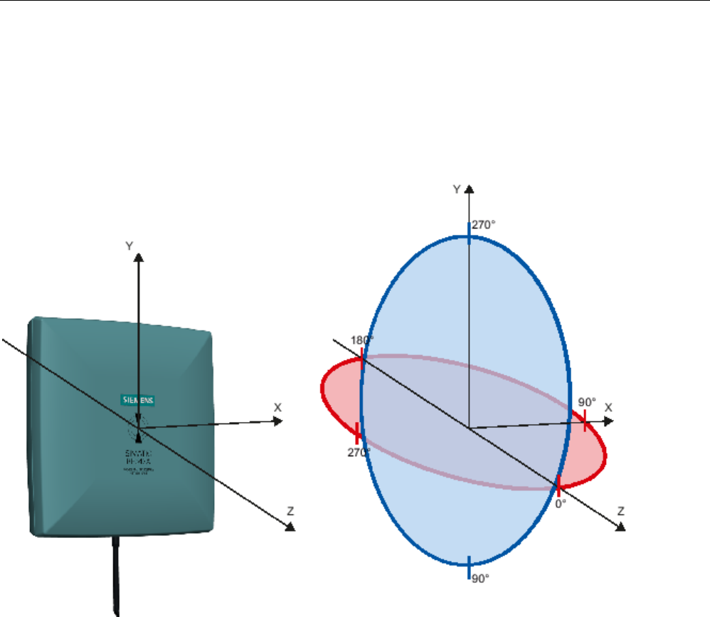
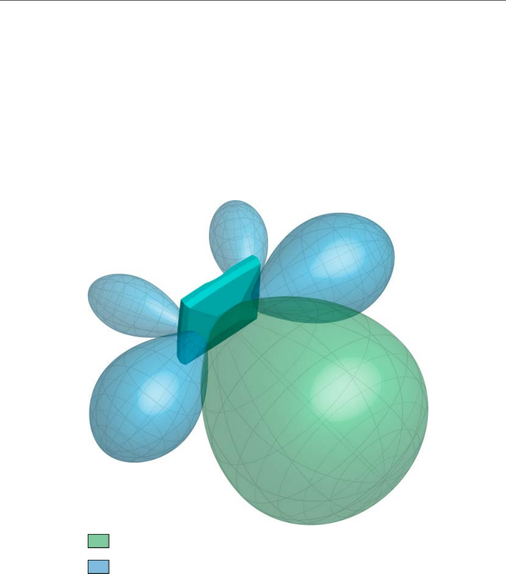
Spatial directional radiation pattern
The following schematic diagram shows the main and auxiliary fields of the RF660A antenna
in free space in the absence of reflecting/absorbing materials. Please note that the diagram
is not to scale.
The recommended working range lies within the main field that is shown in green.
Main field (processing field)
Secondary fields
Figure 6-30 Main and auxiliary fields of the RF660A antenna
Antennas
6.5 RF660A antenna
SIMATIC RF600
324 System Manual, xx/2014, J31069-D0171-U001-A15-7618
REVIEW
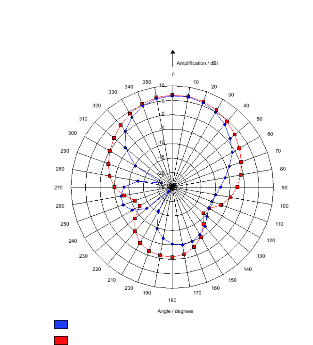
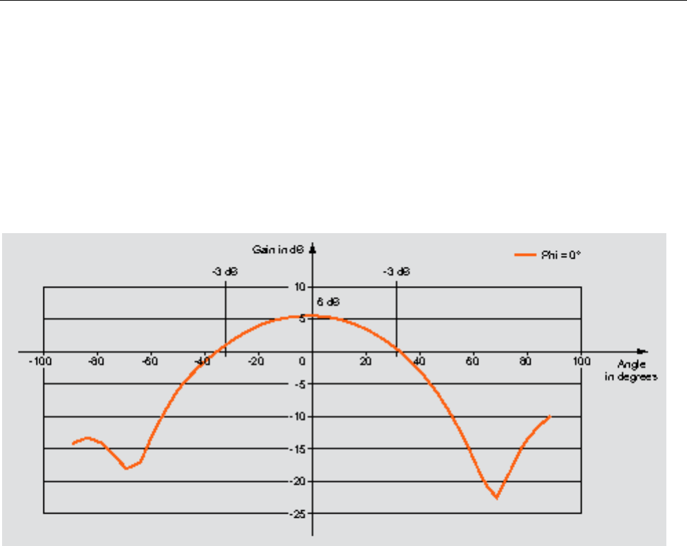
Radiation diagram (horizontal)
Europe (ETSI)
The radiation diagram is shown for horizontal alignment and for a center frequency of 865
MHz. Horizontal antenna alignment is provided when the TNC connection on the antenna
points vertically up or down.
The radiating/receiving angle of the antenna is defined by the angle between the two -3 dB
points (corresponding to half the power referred to the maximum performance at a 0° angle).
The optimum radiating/receiving angle is therefore approximately ±30 degrees.
Figure 6-31 Directional radiation pattern of the antenna (at 865 MHz, horizontal alignment)
USA (FCC)
The radiation diagram is shown for horizontal alignment and for a center frequency of 915
MHz.
The radiating/receiving angle of the antenna is defined by the angle between the two -3 dB
points (corresponding to half the power referred to the maximum performance at a 0° angle).
The optimum radiating/receiving angle is therefore approximately ±35 degrees.
Antennas
6.5 RF660A antenna
SIMATIC RF600
System Manual, xx/2014, J31069-D0171-U001-A15-7618 325
REVIEW
Figure 6-32 Directional radiation pattern of the antenna (at 915 MHz, horizontal alignment)
6.5.9
Interpretation of directional radiation patterns
The following overview table will help you with the interpretation of directional radiation
patterns.
The table shows which dBi values correspond to which read/write ranges (in %): You can
read the radiated power depending on the reference angle from the directional radiation
patterns, and thus obtain information on the read/write range with this reference angle with
regard to a transponder.
The dBr values correspond to the difference between the maximum dBi value and a second
dBi value.
Deviation from maximum antenna gain [dBr]
Read/write range [%]
0
100
-3
70
-6
50
-9
35
-12
25
-15
18
-18
13

Antennas
6.5 RF660A antenna
SIMATIC RF600
326 System Manual, xx/2014, J31069-D0171-U001-A15-7618
REVIEW
Example
As one can see from the section Antenna pattern (Page 323), the maximum antenna gain is
6 dBi. In the vertical plane, the antenna gain has dropped to approx. 3 dBi at +30°. Therefore
the dBr value is -3. The antenna range is only 50% of the maximum range at ± 30° from the
Z axis within the vertical plane.
6.5.10
Technical data
Table 6- 26 General technical specifications RF660A
6GT2812-0AA00
6GT2812-0AA01
ETSI
FCC, CMIIT
Product type designation
SIMATIC RF660A
Dimensions (L x W x H)
313 x 313 x 80 mm
Color
Pastel turquoise
Material
PA 12 (polyamide 12)
Silicone-free
Frequency band
865 to 868 MHz
902 to 928 MHz
Plug connection
RTNC
Max. radiated power
according to ETSI
• RF620R, RF630R:
< 1200 mW ERP
• RF640R, RF670R:
< 2000 mW ERP
• RF650R:
< 2000 mW ERP
• RF680R/RF685R:
< 2000 mW ERP
-

Antennas
6.5 RF660A antenna
SIMATIC RF600
System Manual, xx/2014, J31069-D0171-U001-A15-7618 327
REVIEW
6GT2812-0AA00
6GT2812-0AA01
ETSI
FCC, CMIIT
Max. radiated power
according to CMIIT
- • RF620R, RF630R:
< 1000 mW ERP
• RF640R, RF670R:
< 2000 mW ERP
• RF650R:
< 2000 mW ERP
• RF680R/RF685R:
< 2000 mW ERP
Max. radiated power
according to FCC
- • RF620R, RF630R:
< 1600 mW EIRP
• RF640R, RF670R:
< 4000 mW EIRP
• RF650R:
< 4000 mW EIRP
• RF680R/RF685R:
< 4000 mW EIRP
Max. power
2000 mW
Impedance
50 ohms
Antenna gain
7 dBi (5-7 dBic)
6 dBi (> 6 dBic)
VSWR (standing wave ratio)
Max. 2:1
Polarization
RH circular
Aperture angle for
transmitting/receiving
55° - 60° 60° - 75°
Front-to-back ratio
-
-
Attachment of the antenna
4 screws M4 (VESA 100 mount system)
Tightening torque
(at room temperature)
≤ 2 Nm
Ambient temperature
• Operation
• Transport and storage
• -20 °C to +70 °C
• -40 °C to +85 °C
MTBF in years
2 x 10
9
Degree of protection according
to EN 60529
IP67
Weight, approx. 1.2 kg
Antennas
6.5 RF660A antenna
SIMATIC RF600
328 System Manual, xx/2014, J31069-D0171-U001-A15-7618
REVIEW
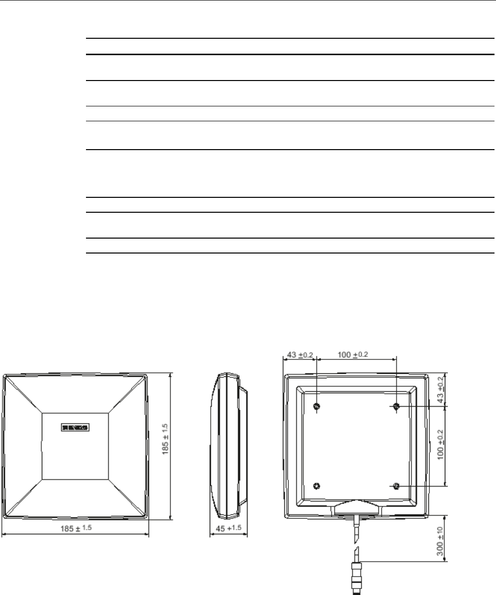
6.5.11
Dimension drawing
Figure 6-33 Dimension drawing RF660A
All dimensions in mm (± 0.5 mm tolerance)
Antennas
6.5 RF660A antenna
SIMATIC RF600
System Manual, xx/2014, J31069-D0171-U001-A15-7618 329
REVIEW
6.5.12
Approvals & certificates
Table 6- 27 6GT2812-0AA00
Certificate
Description
Conformity in accordance with R&TTE directive
in association with the readers and accessories used
Table 6- 28 6GT2812-0AA01
Standard
Federal Communications
Commission
FCC CFR 47, Part 15 sections 15.247
Radio Frequency Interference Statement
This equipment has been tested and found to comply with the limits
for a Class B digital device, pursuant to Part 15 of the FCC Rules.
The FCC approval is granted in association with the FCC approval of
the following RF600 readers:
• FCC ID: NXW-RF600R
(for RF620R: 6GT2811-5BA00-1AA1,
RF630R: 6GT2811-4AA00-1AA1,
RF640R: 6GT2811-3BA00-1AA0,
RF670R as of FS C1: 6GT2811-0AB00-1AA0)
• FCC ID: NXW-RF630R
(for 6GT2811-4AA00-1AA0)
• FCC ID: NXW-RF670
(for RF670R as of FS A1: 6GT2811-0AB00-1AA0)
Industry Canada Radio
Standards Specifications
RSS-210 Issue 7, June 2007, Sections 2.2, A8
The approval for Industry Canada is granted in association with the
Industry Canada approval of the following RF600 readers:
• IC: 267X-RF630 (for 6GT2811-4AA00-1AA0)
• IC: 267X-RF670, RF670R FS A1 (for 6GT2811-0AB00-1AA0)
• IC: 267X-RF600R, Model RF620R-2 (for 6GT2811-5BA00-1AA1)
• IC: 267X-RF600R, Model RF630R-2 (for 6GT2811-4AA00-1AA1)
• IC: 267X-RF600R, Model RF640R (for 6GT2811-3BA00-1AA0)
• IC: 267X-RF600R, model RF670R-2 as of FS C1 (for 6GT2811-
0AB00-1AA0)
This product is UL-certified for the USA and Canada.
It meets the following safety standard(s):
UL 60950-1 - Information Technology Equipment Safety - Part 1:
General Requirements
CSA C22.2 No. 60950 -1 - Safety of Information Technology
Equipment
UL Report E 205089

Antennas
6.6 Mounting types
SIMATIC RF600
330 System Manual, xx/2014, J31069-D0171-U001-A15-7618
REVIEW
6.6
Mounting types
6.6.1
Overview
The following readers and antennas feature a standardized VESA 100 fixing system (4 x
M4):
● SIMATIC RF620R/RF630R/RF640R/RF670R
● SIMATIC RF640A
● SIMATIC RF660A
It is used to fix the above-mentioned antennas in place through a mounting plate or the
antenna mounting kit.
6.6.2
Ordering data
Description
Machine-Readable Product Code
Antenna mounting kit
6GT2890-0AA00
Antennas
6.6 Mounting types
SIMATIC RF600
System Manual, xx/2014, J31069-D0171-U001-A15-7618 331
REVIEW
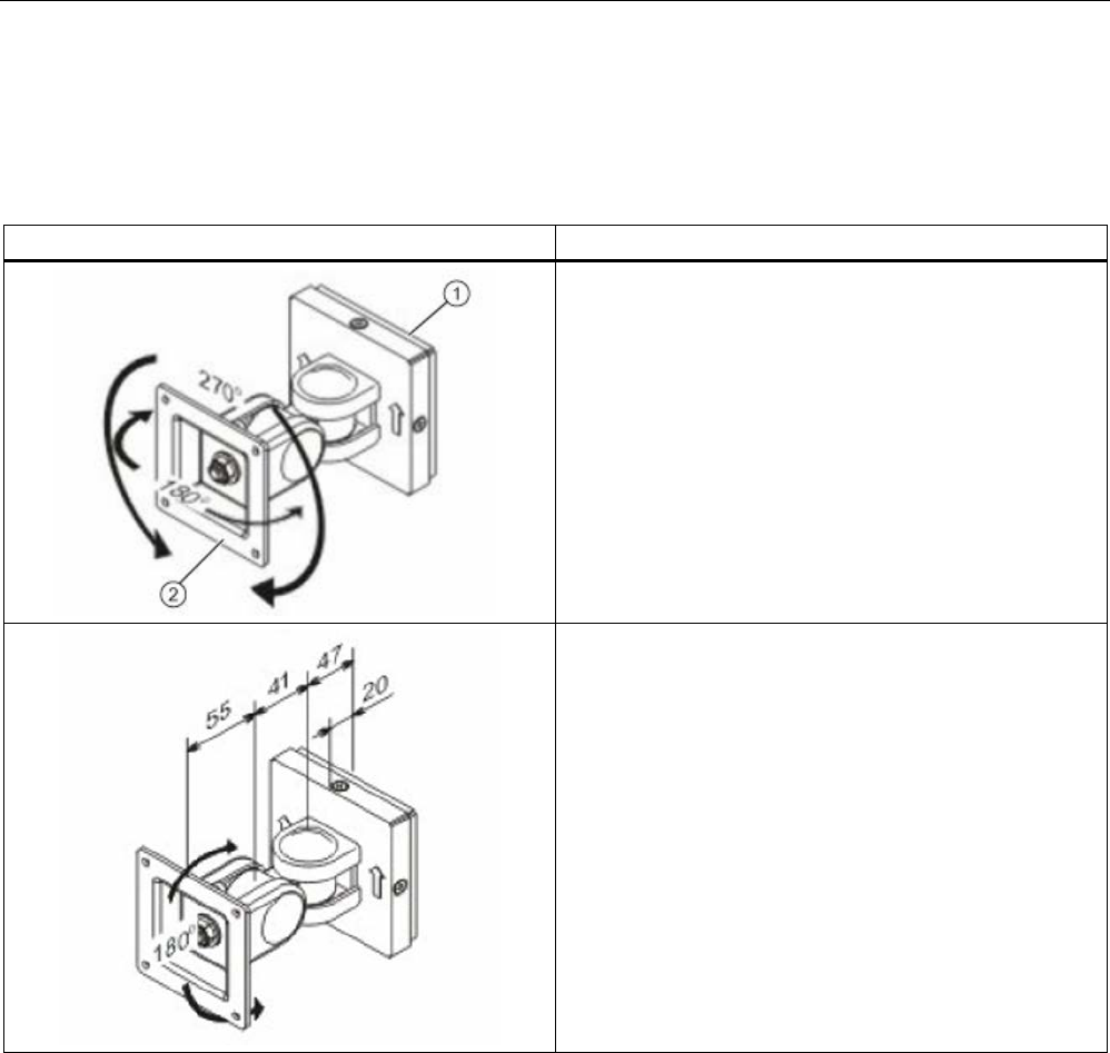
6.6.3
Mounting with antenna mounting kit
Flexible mounting is possible using the antenna mounting kit.
An antenna can then be rotated through any angle in space.
Antenna mounting kit
Description
Swivel range of wall mounting
(1) Wall side
(2) Antenna side
Distances for wall mounting
Antennas
6.6 Mounting types
SIMATIC RF600
332 System Manual, xx/2014, J31069-D0171-U001-A15-7618
REVIEW
Antenna mounting kit
Description
VESA adapter plate
from VESA 75 x 75
to VESA 100 x 100
The VESA adapter plate is required for fixing the antenna to
the antenna mounting kit.
Hole drilling template for fixing the antenna mounting kit to
the wall
SIMATIC RF600
System Manual, xx/2014, J31069-D0171-U001-A15-7618 333
REVIEW
Transponder/tags
7
7.1
Overview
7.1.1
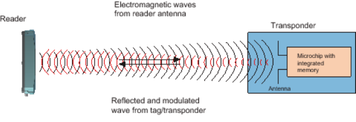
Mode of operation of transponders/tags
The tag/transponder mainly comprises a microchip with an integral memory and a dipole
antenna.
The principle of operation of a passive RFID transponder is as follows:
● Diversion of some of the high-frequency energy emitted by the reader to supply power to
the integral chip
● Commands received from reader
● Responses are transmitted to the reader antenna by modulating the reflected radio waves
(backscatter technique)
Figure 7-1 Mode of operation of transponders
The transmission ranges achieved vary in accordance with the size of the tag and the
corresponding dipole antenna. In general the following rule applies: The smaller the tag and
therefore the antenna, the shorter the range.

Transponder/tags
7.1 Overview
SIMATIC RF600
334 System Manual, xx/2014, J31069-D0171-U001-A15-7618
REVIEW
7.1.2
Transponder classes and generations
The transponder classes are distinguished by the different communication protocols used
between the reader and transponder. Transponder classes are mostly mutually incompatible.
The following transponder classes are supported by the RF 600 system:
● EPC Global Class 1 Gen 2 with full EPC Global Profile (ISO 18000-6C)
Support for protocol types using the RF600
The definition of the transponders/tags according to ISO 18000-6 (corresponds to EPC
Global Class 1 Gen 2) refers to implementation of the air-interface protocols.
EPC Global
RF600 supports the EPCglobal class 1. EPCglobal class 1 includes passive tags with the
following minimum characteristics:
● EPC ID (Electronic Product Code IDentifier)
● Tag ID
● A function which permanently ensures that tags no longer respond.
● Optional use or suppression of tags
● Optional password-protected access control
● Optional USER memory area.
The programming is performed by the customer (cannot be reprogrammed after locking)
7.1.3
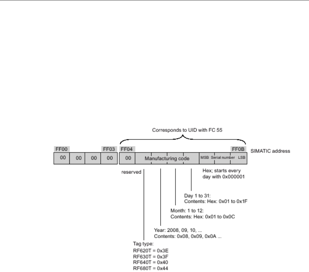
Electronic Product Code (EPC)
The Electronic Product Code (EPC) supports the unique identification of objects (e.g. retail
items, logistical items or transport containers). This makes extremely accurate identification
possible. In practical use, the EPC is stored on a transponder (tag) and scanned by the
reader.
There are different EPC number schemes with different data lengths. Below is the structure
of a GID-96-bit code (EPC Global Tag Data Standards V1.1 Rev. 1.27) :
Transponder/tags
7.1 Overview
SIMATIC RF600
System Manual, xx/2014, J31069-D0171-U001-A15-7618 335
REVIEW
●
Header:
This identifies the EPC identification number that follows with regard to length,
type, structure and version of the EPC
●
EPC manager:
This identifies the company/corporation
●
Object class
: Corresponds to the article number
●
Serial number:
Consecutive number of the article
The Siemens UHF transponders are all suitable for working with EPC and other number
schemes. Before a transponder can work with a number scheme, the relevant numbers must
first be written to the transponder.
Allocation of the ECP ID by the tag manufacturer
Figure 7-2 Allocation of the EPC ID on delivery of the tag
Transponder/tags
7.1 Overview
SIMATIC RF600
336 System Manual, xx/2014, J31069-D0171-U001-A15-7618
REVIEW
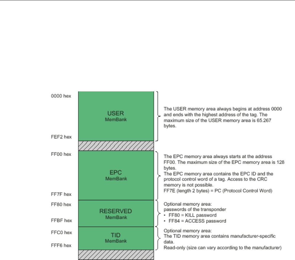
7.1.4
SIMATIC memory configuration of the RF600 transponders and labels
SIMATIC memory configuration
The following graphic shows the structure of the virtual SIMATIC memory for the
RF620R/RF630R reader and explains the function of the individual memory areas. The
SIMATIC memory configuration is based on the 4 memory banks, as they are defined in
EPC Global.
Figure 7-3 SIMATIC memory areas of the RF600 transponders

Transponder/tags
7.1 Overview
SIMATIC RF600
System Manual, xx/2014, J31069-D0171-U001-A15-7618 337
REVIEW
Special memory configuration of the RF600 transponders and labels
Tags
Chip type
User
[hex]
EPC
TID
RESERVED
(passwords)
Special
Range
(preset
length)
Access
KILL-PW
Lock
function
RF630L
(-2AB00,
-2AB01)
Impinj
Monza 2
- FF00-FF0B
(96 bits =
FF00-FF0B)
read/
write
FFC0-FFC7 FF80-FF87 Yes Yes
RF630L
(-2AB02)
Impinj
Monza 4QT
1)
00 - 3F FF00-FF0F
(96 bits =
FF00-FF0B)
read/
write
FFC0-FFC9 FF80-FF87 Yes Yes
RF630L
(-2AB03)
NXP G2XM 00 - 3F FF00-FF1D
(96 bits =
FF00-FF0B)
read/
write
FFC0-FFC7 FF80-FF87 Yes Yes
RF680L
NXP G2XM 00 - 3F FF00-FF1D
(96 bits =
FF00-FF0B)
read/
write
FFC0-FFC7 FF80-FF87 Yes Yes
RF610T
NXP G2XM 00 - 3F FF00-FF1D
(96 bits =
FF00-FF0B)
read/
write
FFC0-FFC7 FF80-FF87 LOCKED Yes
RF610T
ATEX
NXP G2XM 00 - 3F FF00-FF1D
(96 bits =
FF00-FF0B)
read/
write
FFC0-FFC7 FF80-FF87 LOCKED Yes
RF620T
Impinj
Monza 4QT
1)
00 - 3F FF00-FF0F
(96 bits =
FF00-FF0B)
read/
write
FFC0-FFC9 FF80-FF87 LOCKED Yes
RF622T
RF625T
Impinj
Monza 4QT
1)
00 - 3F FF00-FF0F
(96 bits =
FF00-FF0B)
read/
write
FFC0-FFC9 FF80-FF87 LOCKED Yes
RF630T
NXP G2XM 00 - 3F FF00-FF1D
(96 bits =
FF00-FF0B)
read/
write
FFC0-FFC7 FF80-FF87 LOCKED Yes
RF640T
NXP G2XM 00 - 3F FF00-
FF1D0B
(96 bits =
FF00-FF0B)
read/
write
FFC0-FFC7 FF80-FF87 LOCKED Yes
RF680T
NXP G2XM 00 - 3F FF00-FF1D
(96 bits =
FF00-FF0B)
read/
write
FFC0-FFC7 FF80-FF87 LOCKED Yes
1) Uses User Memory Indicator (UMI).

Transponder/tags
7.1 Overview
SIMATIC RF600
338 System Manual, xx/2014, J31069-D0171-U001-A15-7618
REVIEW
Note
Default EPC ID
When an RF610T
-RF680T transponder is supplied, a 12 byte long identifier is assigned by
the manufacturer as the EPC ID according to a number scheme (see
"Assignment of the
ECP ID by the manufacturer").
Transponder/tags
7.1 Overview
SIMATIC RF600
System Manual, xx/2014, J31069-D0171-U001-A15-7618 339
REVIEW
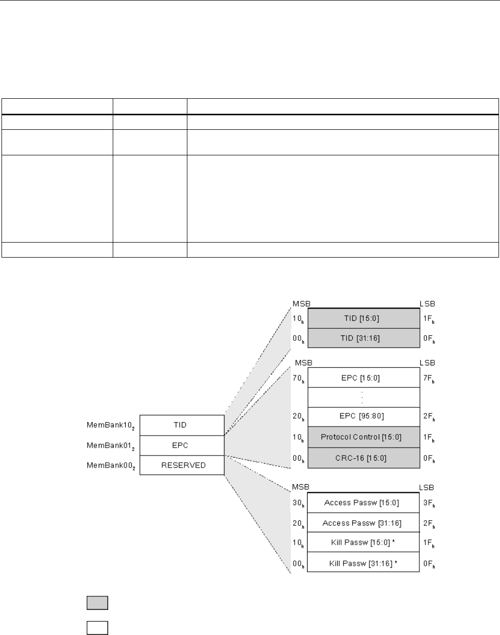
Memory map of the ISO 18000-6C Monza 2 chip according to EPC
The memory of the ISO 18000-6C Monza 2 chip is divided logically into four different
memory banks:
Memory bank (decimal)
Memory type
Description
MemBank 11
2
USER
User-writable USER memory area
MemBank 102 TID Is defined by the manufacturer, contains the class identifier and serial
number of a transponder.
MemBank 012 EPC Contains the EPC UID, the protocol and the CRC of a transponder.
You can write to the EPC memory area. In the delivery condition, the
memory contents can have the following states:
• empty
• containing the same data
• containing different data
MemBank 002
RESERVED
Contains the access and kill password.
The graphic below illustrates the exact memory utilization. Each box in the right part of the
graphic represents one word (16 bits) in the memory.
Color
Mode of access by RF600 reader
Read
Write / read
* Can only be overwritten with RF6xxL transponders.

Transponder/tags
7.1 Overview
SIMATIC RF600
340 System Manual, xx/2014, J31069-D0171-U001-A15-7618
REVIEW
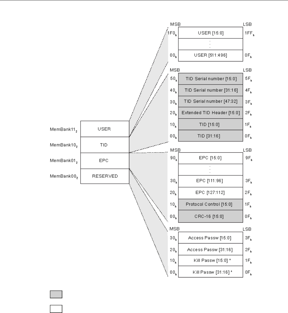
Memory map of the ISO 18000-6C Monza 4QT chip according to EPC
The memory of the ISO 18000-6C Monza 4QT chip is divided logically into four different
memory banks:
Memory bank (decimal)
Memory type
Description
MemBank 11
2
USER
User-writable USER memory area
MemBank 102 TID Is defined by the manufacturer, contains the class identifier and serial
number of a transponder.
MemBank 012 EPC Contains the EPC data, the protocol information and the CRC data of a
transponder.
You can write to the EPC memory area. In the delivery condition, the
memory contents can have the following states:
• containing the same data
• containing different data
MemBank 002
RESERVED
Contains the access and kill password.
The graphic below illustrates the exact memory utilization. Each box in the right part of the
graphic represents one word (16 bits) in the memory.
Transponder/tags
7.1 Overview
SIMATIC RF600
System Manual, xx/2014, J31069-D0171-U001-A15-7618 341
REVIEW
Color
Mode of access by RF600 reader
Read
Write / read
* Can only be overwritten with RF6xxL transponders.

Transponder/tags
7.1 Overview
SIMATIC RF600
342 System Manual, xx/2014, J31069-D0171-U001-A15-7618
REVIEW
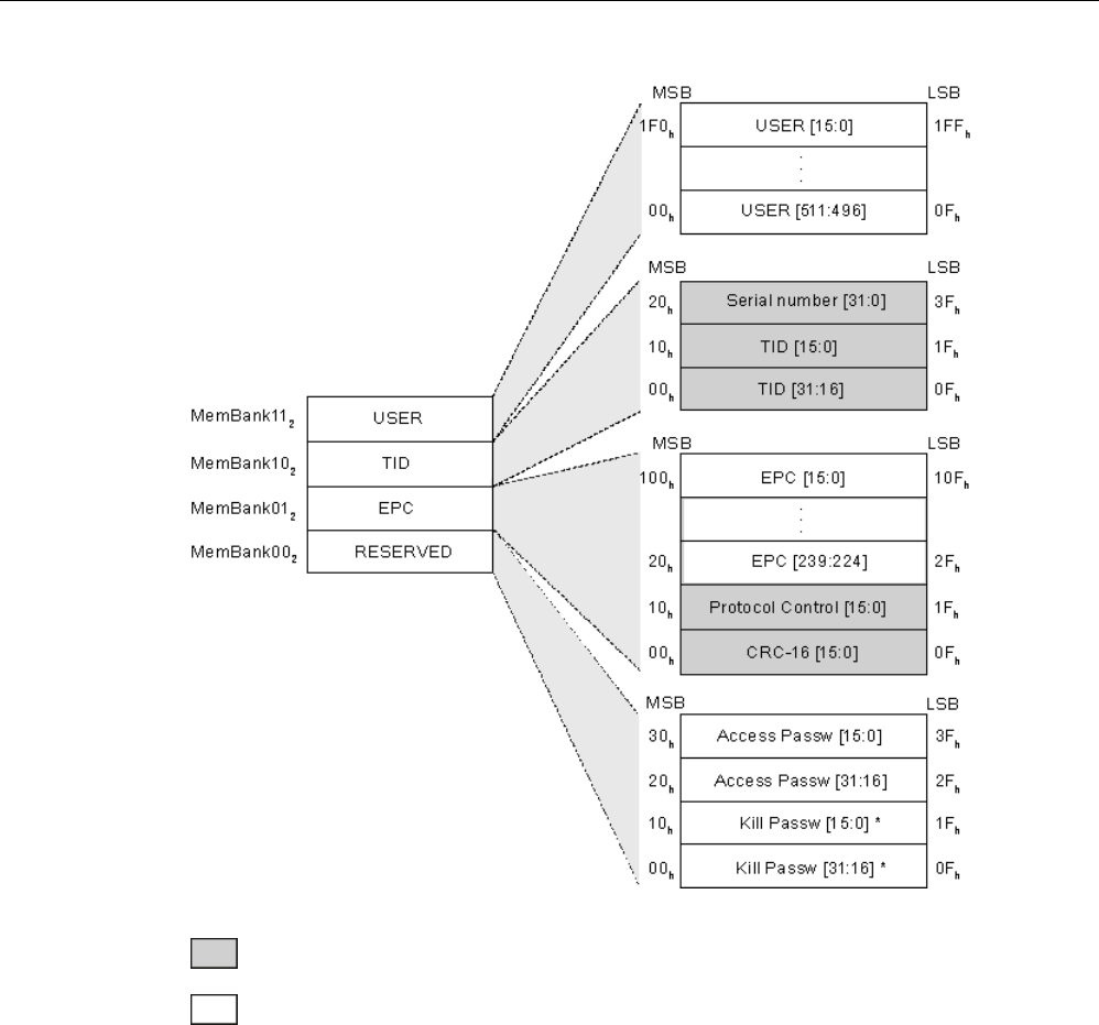
Memory map of the ISO 18000-6C G2XM chip according to EPC
The memory of the ISO 18000-6C G2XM chip is divided logically into four different memory
banks:
Memory bank (decimal)
Memory type
Description
MemBank 11
2
USER
User-writable USER memory area
MemBank 102 TID Is defined by the manufacturer, contains the class identifier and serial
number of a transponder.
MemBank 012 EPC Contains the EPC data, the protocol information and the CRC data of a
transponder.
You can write to the EPC memory area. In the delivery condition, the
memory contents can have the following states:
• containing the same data
• containing different data
MemBank 002
RESERVED
Contains the access and kill password.
The graphic below illustrates the exact memory utilization. Each box in the right part of the
graphic represents one word (16 bits) in the memory.
Transponder/tags
7.1 Overview
SIMATIC RF600
System Manual, xx/2014, J31069-D0171-U001-A15-7618 343
REVIEW
Color
Mode of access by RF600 reader
Read
Write / read
* Can only be overwritten with RF6xxL transponders.
Parameter assignment
Which parameter assignment options available to you for which reader of the RF600 family
is outlined in the section "Overview of parameterization of RF600 reader (Page 461)".
Detailed information on parameter assignment as well as examples for describing and
reading specific memory areas can be found in the referenced sections of the
documentation.

Transponder/tags
7.1 Overview
SIMATIC RF600
344 System Manual, xx/2014, J31069-D0171-U001-A15-7618
REVIEW
7.1.5
Minimum distances and maximum ranges
The following section describes the configuration of the antenna and transponder relative to
each other. The aim of the section is to help you achieve the maximum ranges listed here in
a typical electromagnetic environment. One of the main focuses of the section is the effect of
the mounting surface of the transponder on the write/read distance.
As the requirements for achieving the maximum distances specified here, note the following
points:
● Operate the readers with the maximum possible and permitted transmit power.
● With external antennas, the antenna cable 6GT2815-0BH30 with a length of 3 m and 1
dB cable loss is used.
● The alignment of the transponder and antenna needs to be optimum (see section
"Configurations of antenna and transponder (Page 344)").
● The optimum mounting surface for the transponder has been selected (see section
"Effects of the materials of the mounting surfaces on the range (Page 346)")
● The maximum range shown in the section "Maximum read/write ranges of transponders
(Page 347)" applies only to read operations.
With write operations, the range is reduced as described in the section.
● Effects that reduce read/write ranges have been avoided (see section "Antenna
configurations (Page 43)").
7.1.5.1
Configurations of antenna and transponder
Below, you will find several possible antenna-transponder configurations that are necessary
to achieve the maximum range. With the RF620A and RF642A antennas, the polarization
axes of the antenna and of the transponder must be aligned parallel to each other.
Note
Reduction of the maximum read/write range when using RF620A or RF642A antennas
If the alignment of the polarization axes between the RF620A or RF642A antennas and
transponders is
not parallel, this reduces the read/write range. The reduction in the range
depends on the angular deviation between the polarization axes of the RF620A or RF642A
antenna and the polarization axis of the transponder. You will find further details in the
se
ction "Alignment of transponders to the antenna (Page 254)" or "Alignment of
transponders to the antenna
(Page 300)".
Transponder/tags
7.1 Overview
SIMATIC RF600
System Manual, xx/2014, J31069-D0171-U001-A15-7618 345
REVIEW
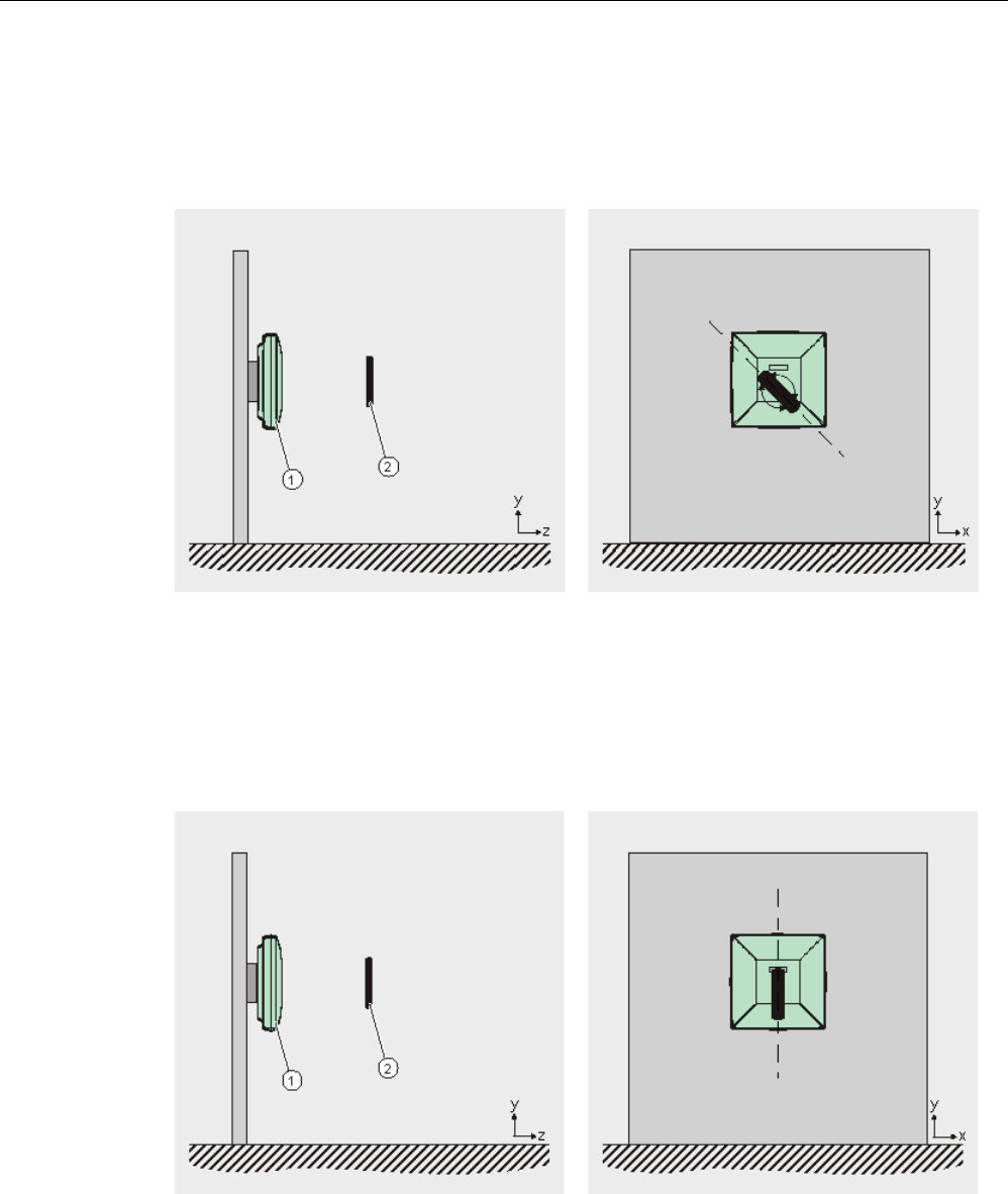
Possible transponder alignments depending on the antenna type
To achieve the maximum read/write range with RF640A or RF660A antennas, make sure
that the planes of the polarization axes have the same alignment. Changing the transponder
angle within the x-y plane has no effect on the range.
①
Antenna RF640A or RF660A
②
Transponder
Figure 7-4 Possible transponder alignment with RF640A or RF660A
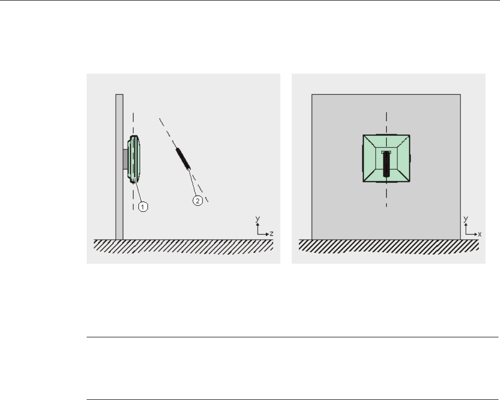
To achieve the maximum range with RF620A or RF642A antennas, make sure that the
polarization axes of the antenna and transponder are parallel to each other. Changing the
transponder angle within the x-y plane leads to a reduction of the range.
①
Antenna RF620A or RF642A
②
Transponder
Figure 7-5 Possible transponder alignment with RF620A or RF642A
Transponder/tags
7.1 Overview
SIMATIC RF600
346 System Manual, xx/2014, J31069-D0171-U001-A15-7618
REVIEW
If the angle is changed within the y-z plane, this causes a reduction in range for all antenna
types.
①
Antenna RF620A, RF640A, RF642A or RF660A
②
Transponder
Figure 7-6 Transponder alignment not allowed
Note
Optimum transponder position/alignment
Depending on the electromagnetic properties of the
environment, the optimum transponder
position and alignment may differ from those shown above.
7.1.5.2
Effects of the materials of the mounting surfaces on the range
Effects due to antenna mounting
For the RF640A, RF642A and RF660A antennas, the antenna gain and therefore the
maximum read/write range does not depend on the selected material of the mounting
surface. In contrast to this, the antenna gain of the RF620A antenna and therefore the
maximum read/write range of transponders does depend on the mounting surface of the
antenna. To achieve the maximum range with an RF620A antenna, the antenna needs to be
mounted on a metallic surface of at least 150 x 150 mm.
You will find more detailed information on antenna gain in the subsections of the section
"Antenna patterns (Page 257)".

Transponder/tags
7.1 Overview
SIMATIC RF600
System Manual, xx/2014, J31069-D0171-U001-A15-7618 347
REVIEW
Effects due to transponder mounting
The maximum read/write range of the transponders depends on the material of the mounting
surface. The specified ranges apply when mounted on non-metallic surfaces, such as paper
or card, with the RF625T, RF630T and RF640T when mounted on metal.
Mounting on plastic can reduce the maximum read/write range considerably depending on
the type of plastic (up to 70%). When mounted on wood, the range is furhter reduced the
more moisture the wood contains. Due to the attenuating properties of glass, direct mounting
without a spacer can halve the range.
If the RF625T, RF630T, RF640T or RF680T transponders are mounted on metal, this
metallic surface acts as a reflection surface. This surface should therefore be adequately
large. To achieve the listed maximum ranges, transponders must be mounted on a metallic
mounting surface with a minimum diameter of 150 mm, for the RF630T and RF680T 300
mm. If the metallic mounting surface only has a diameter of 65 mm instead of the required
150 mm, the range is reduced by 65%.
7.1.5.3
Maximum read/write ranges of transponders
Maximum read ranges
Table 7- 1 Read ranges of transponders at a room temperature of +25 °C (all ranges in m)
SIMATIC RF630L
6GT2810-2AB00,
6GT2810-2AB01,
6GT2810-2AB02-
0AX0
SIMATIC RF630L
6GT2810-2AB03
SIMATIC RF680L
SIMATIC
RF610T
SIMATIC RF620T
1)
SIMATIC RF620R
with internal antenna
5
3
2.5
3
5
SIMATIC RF630R
with RF620A
1.6
1
0.8
1
1.6
with RF640A
4.5
2.8
2.2
2.8
4.5
with RF642A
5.5
3.5
2.8
3.5
5.5
with RF660A
6
4
3
4
6
SIMATIC RF640R
with internal antenna
7
4
3.5
4.5
7
with RF620A
2.2
1.4
1.1
1.4
2.2
with RF640A
6
4
3.1
4
6
with RF642A
8
5
4
5
8
with RF660A
8
5
4
5
8
SIMATIC RF650R
with RF620A
with RF640A
with RF642A
with RF660A

Transponder/tags
7.1 Overview
SIMATIC RF600
348 System Manual, xx/2014, J31069-D0171-U001-A15-7618
REVIEW
SIMATIC RF630L
6GT2810-2AB00,
6GT2810-2AB01,
6GT2810-2AB02-
0AX0
SIMATIC RF630L
6GT2810-2AB03
SIMATIC RF680L
SIMATIC
RF610T
SIMATIC RF620T
1)
SIMATIC RF670R
with RF620A
2.2
1.4
1.1
1.4
2.2
with RF640A
6
4
3
4
6
with RF642A
8
5
4
5
8
with RF660A
8
5
4
5
8
SIMATIC RF680R
with RF620A
with RF640A
with RF642A
with RF660A
SIMATIC RF685R
with internal antenna
with RF620A
with RF640A
with RF642A
with RF660A
SIMATIC RF625T 2)
SIMATIC RF630T 2)
SIMATIC RF640T 2)
SIMATIC RF680T 2)
SIMATIC RF620R
with internal antenna
1
0.8
2.5
5.5
SIMATIC RF630R
with RF620A
0.3
0.3
0.8
1.3
with RF640A
0.8
0.7
2.2
3.5
with RF642A 1.1 0.8 2.8 5
with RF660A
1.2
0.9
3
5
SIMATIC RF640R
with internal antenna
1.3
1
3.5
6
with RF620A
0.4
0.3
1.1
1.8
with RF640A
1.2
0.9
3
5
with RF642A
1.5
1.2
4
7
with RF660A
1.5
1.2
4
7
SIMATIC RF650R
with RF620A
with RF640A
with RF642A
with RF660A

Transponder/tags
7.1 Overview
SIMATIC RF600
System Manual, xx/2014, J31069-D0171-U001-A15-7618 349
REVIEW
SIMATIC RF625T 2)
SIMATIC RF630T 2)
SIMATIC RF640T 2)
SIMATIC RF680T 2)
SIMATIC RF670R
with RF620A
0.4
0.3
1.1
1.8
with RF640A
1.2
0.9
3
5
with RF642A
1.5
1.2
4
7
with RF660A
1.5
1.2
4
7
SIMATIC RF680R
with RF620A
with RF640A
with RF642A
with RF660A
SIMATIC RF685R
with internal antenna
with RF620A
with RF640A
with RF642A
with RF660A
1)
Mounting on a non-metallic surface. Mounting surface with a minimum diameter of 300 mm. Mounting on metal is not
possible.
2) Mounting on metal Mounting surface with a minimum diameter of 150 mm, for the RF630T and RF680T 300 mm.
Maximum write ranges
Depending on the transponder type, the reader antenna requires more power for writing than
for reading data. When writing, the maximum range reduces by approximately 30%
compared with the read range.
7.1.5.4
Minimum distances between antennas and transponders
The antennas listed here are all far field antennas. For this reason, a minimum distance
between antennas and transponders must be maintained to ensure reliable transponder data
access:
Table 7- 2 Minimum distances to be maintained between antennas and transponders
RF600 antenna
Minimum distances to be maintained
RF620A
50 mm
RF640A
200 mm
RF642A
200 mm
RF660A
200 mm
Transponder/tags
7.2 SIMATIC RF630L Smartlabel
SIMATIC RF600
350 System Manual, xx/2014, J31069-D0171-U001-A15-7618
REVIEW
7.2
SIMATIC RF630L Smartlabel
7.2.1
Features
SIMATIC RF630L smart labels are passive, maintenance-free data carriers based on
UHF Class 1 Gen2 technology that are used to store the "Electronic Product Code" (EPC).
Smart labels offer numerous possible uses for a wide range of applications and support
efficient logistics throughout the process chain.
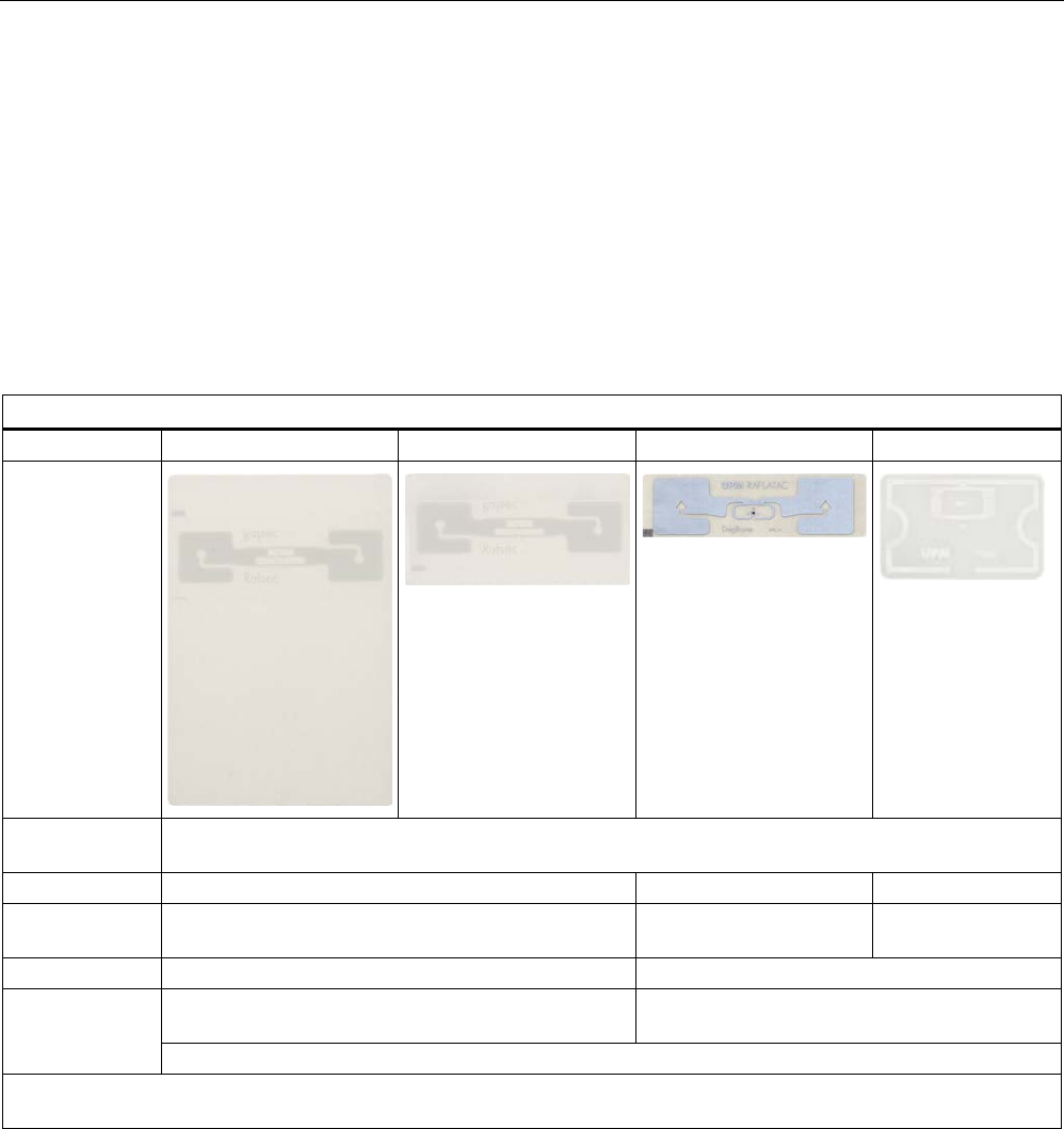
SIMATIC RF630L transponder
6GT2810-2AB00
6GT2810-2AB01
6GT2810-2AB02-0AX0
6GT2810-2AB03
Design
Area of
application
Simple identification such as barcode replacement or supplementation, through warehouse and
distribution logistics, right up to product identification.
Memory
EPC 96 bits
EPC 96/128 bits
EPC 96/240 bits
Additional user
memory
No 64 bytes 64 bytes
Range
1)
max. 8 m
max. 5 m
Mounting Self-adhesive paper labels, for example for attaching
to packaging units, paper or cartons
Self-adhesive plastic labels, for example for
attaching to packaging units, paper or cartons
Not suitable for fixing straight onto metal or onto liquid containers
1) The information relates to the maximum read range. You will find more information on ranges in the section "Minimum
distances and maximum ranges (Page 344)".
Transponder/tags
7.2 SIMATIC RF630L Smartlabel
SIMATIC RF600
System Manual, xx/2014, J31069-D0171-U001-A15-7618 351
REVIEW
7.2.2
Ordering data
RF630L transponder
Article number
Packaging
RF630L transponder,
SmartLabel 101.6 mm x 152.4
mm (4" x 6")
6GT2810-2AB00 Minimum order 1600 items
(800 on one roll)
RF630L transponder,
SmartLabel 101.6 mm x 50.8 mm (4" x 2")
6GT2810-2AB01 Minimum order 1000 items
(1000 on one roll)
RF630L transponder,
SmartLabel 97 mm x 27 mm
6GT2810-2AB02-
0AX0
Minimum order 5000 items
(5000 on one roll)
RF630L transponder,
SmartLabel 54 mm x 34 mm
6GT2810-2AB03 Minimum order 2000 items
(2000 on one roll)
7.2.3
Minimum spacing between labels
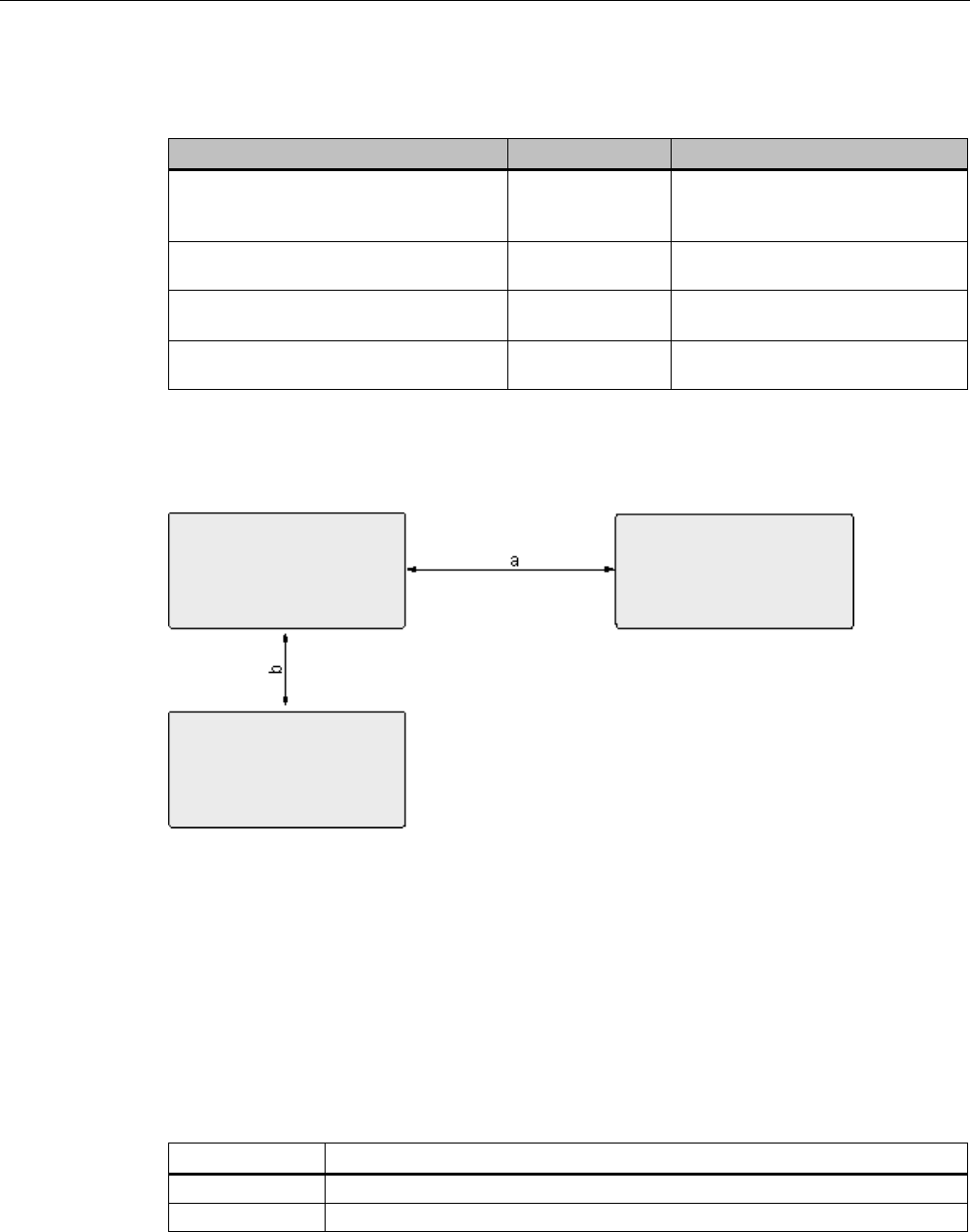
Figure 7-7 Minimum spacing between labels
The specified minimum spacing applies for the SIMATIC RF630L smart labels with the
following order numbers:
● 6GT2810-2AB00
● 6GT2810-2AB01
● 6GT2810-2AB02-0AX0
● 6GT2810-2AB03
Table 7- 3 Minimum spacing
Name
Minimum spacing
a
50 mm
b
50 mm
Transponder/tags
7.2 SIMATIC RF630L Smartlabel
SIMATIC RF600
352 System Manual, xx/2014, J31069-D0171-U001-A15-7618
REVIEW
Please note that smart labels can also be attached one above the other. The spacing
between the labels attached one above the other depends on the damping characteristics of
the carrier material.
7.2.4
Memory configuration of the smart label
The memory configuration of the smart label is described in the section SIMATIC memory
configuration of the RF600 transponders and labels (Page 336).
7.2.5
Technical data
Table 7- 4 Mechanical data
6GT2810-2AB00
6GT2810-2AB01
6GT2810-2AB02-0AX0
6GT2810-2AB03
Dimensions (L x W) 101.6 mm x 152.4 mm
(ca. 4" x 6")
101.6 mm x 50.8 mm
(ca. 4" x 2")
97 mm x 27 mm 54 mm x 34 mm
Design
Paper with integrated antenna
Plastic with integrated antenna
Label type
Paper label
Inlay
Antenna material
Aluminum
Static pressure
10 N/mm
2
Material surface
Paper
Plastic PET
Type of antenna
Shortened dipole
Color
white
Transparent
Printing
Can be printed using heat transfer technique
Mounting Single-sided adhesive (self-adhesive label).
Single-sided adhesive (self-adhesive inlay).
Degree of protection None, the label must be protected against
humidity.
IP65
Weight
approx. 3 g
approx. 2 g
approx. 1 g
Table 7- 5 Electrical data
6GT2810-2AB00
6GT2810-2AB01
6GT2810-2AB02-0AX0
6GT2810-2AB03
Air interface
ISO 18 000-6 Type C
Polarization type
Linear
Polarization direction The polarization
direction is parallel
with the short side of
the paper label
The polarization
direction is parallel
with the long side of
the paper label
The polarization direction is parallel with the
long side of the inlay
Frequency range
860 to 960 MHz
Range
1)
max. 8 m
max. 5 m

Transponder/tags
7.2 SIMATIC RF630L Smartlabel
SIMATIC RF600
System Manual, xx/2014, J31069-D0171-U001-A15-7618 353
REVIEW
6GT2810-2AB00
6GT2810-2AB01
6GT2810-2AB02-0AX0
6GT2810-2AB03
Minimum spacing
between labels
• Vertically
• Horizontally
• 50 mm
• 100 mm
Energy source
Field energy via antenna, without battery
Multitag capability
Yes
1) The information relates to the maximum read range. You will find more information on ranges in the section "Minimum
distances and maximum ranges (Page 344)"
Table 7- 6 Memory specifications
6GT2810-2AB00
6GT2810-2AB01
6GT2810-2AB02-0AX0
6GT2810-2AB03
Type
EPC Class 1 Gen2
Memory organization
EPC 96 bits
EPC 96/128 bits
EPC 96/240 bits
Additional user memory
No
64 bytes
64 bytes
Listing
ISO 18000-6C
Data retention at
+25 °C
10 years
Read cycles
Unlimited
Write cycles
100.000
Anti collision
approx. 100 labels/sec
Table 7- 7 Environmental conditions
6GT2810-2AB00
6GT2810-2AB01
6GT2810-2AB02-0AX0
6GT2810-2AB03
Temperature range
during operation
-40 °C … 65 °C, up to 80 °C (200 cycles)
Temperature range
during storage
The label should be stored in the range of +15°C and +25°C at a humidity of 40% to 60%.
Storage duration
Two years, determined by the shelf life of the adhesive
Torsion and bending
load
Partially permissible
Distance from metal
Not suitable for fixing straight onto metal
Table 7- 8 Identification
6GT2810-2AB00
6GT2810-2AB01
6GT2810-2AB02-0AX0
6GT2810-2AB03
CE
CE approval to R&TTE
FCC
Passive labels or transponders comply with the valid regulations; certification is not required.
Transponder/tags
7.2 SIMATIC RF630L Smartlabel
SIMATIC RF600
354 System Manual, xx/2014, J31069-D0171-U001-A15-7618
REVIEW
7.2.6
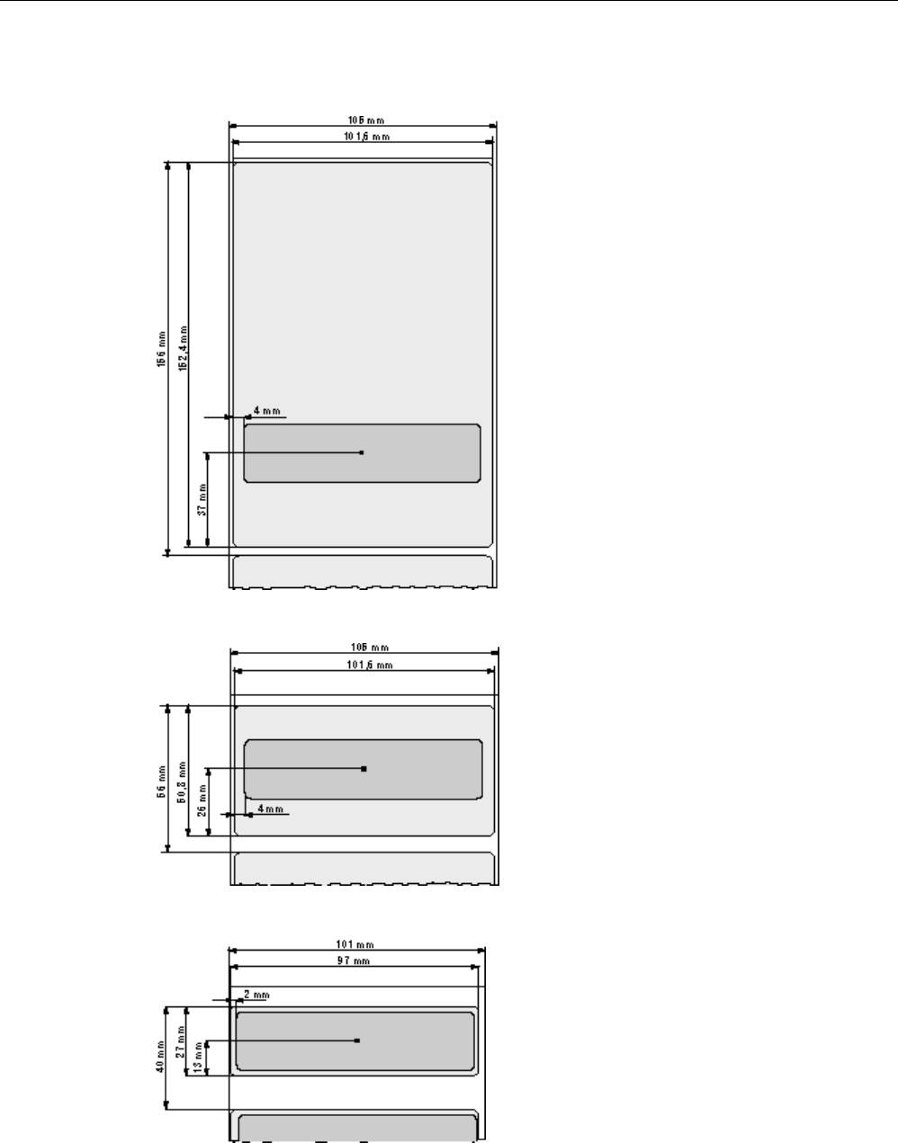
Dimension drawings
Figure 7-8 SIMATIC RF630L 6GT2810-2AB00 dimension drawing
Figure 7-9 SIMATIC RF630L 6GT2810-2AB01 dimension drawing
Figure 7-10 Dimension drawing SIMATIC RF630L 6GT2810-2AB02-0AX0
Transponder/tags
7.2 SIMATIC RF630L Smartlabel
SIMATIC RF600
System Manual, xx/2014, J31069-D0171-U001-A15-7618 355
REVIEW
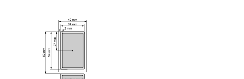
Figure 7-11 SIMATIC RF630L 6GT2810-2AB03 dimension drawing

Transponder/tags
7.3 SIMATIC RF680L Smartlabel
SIMATIC RF600
356 System Manual, xx/2014, J31069-D0171-U001-A15-7618
REVIEW
7.3
SIMATIC RF680L Smartlabel
7.3.1
Features
The SIMATIC RF680L Smartlabel is passive and maintenance-free. It functions based on the
UHF Class 1 Gen 2 technology and is used for saving the electronic product code (EPC) of
96 bits/240 bits. The label also has a 512 bit user memory.
The SIMATIC RF680L is a heat-resistant Smartlabel with a limited service life. Its target use
is the direct identification of objects in high-temperature applications.
Thanks to its antenna geometry, the transponder can be read from any direction. However,
the range is reduced if it is not aligned in parallel with the antenna.
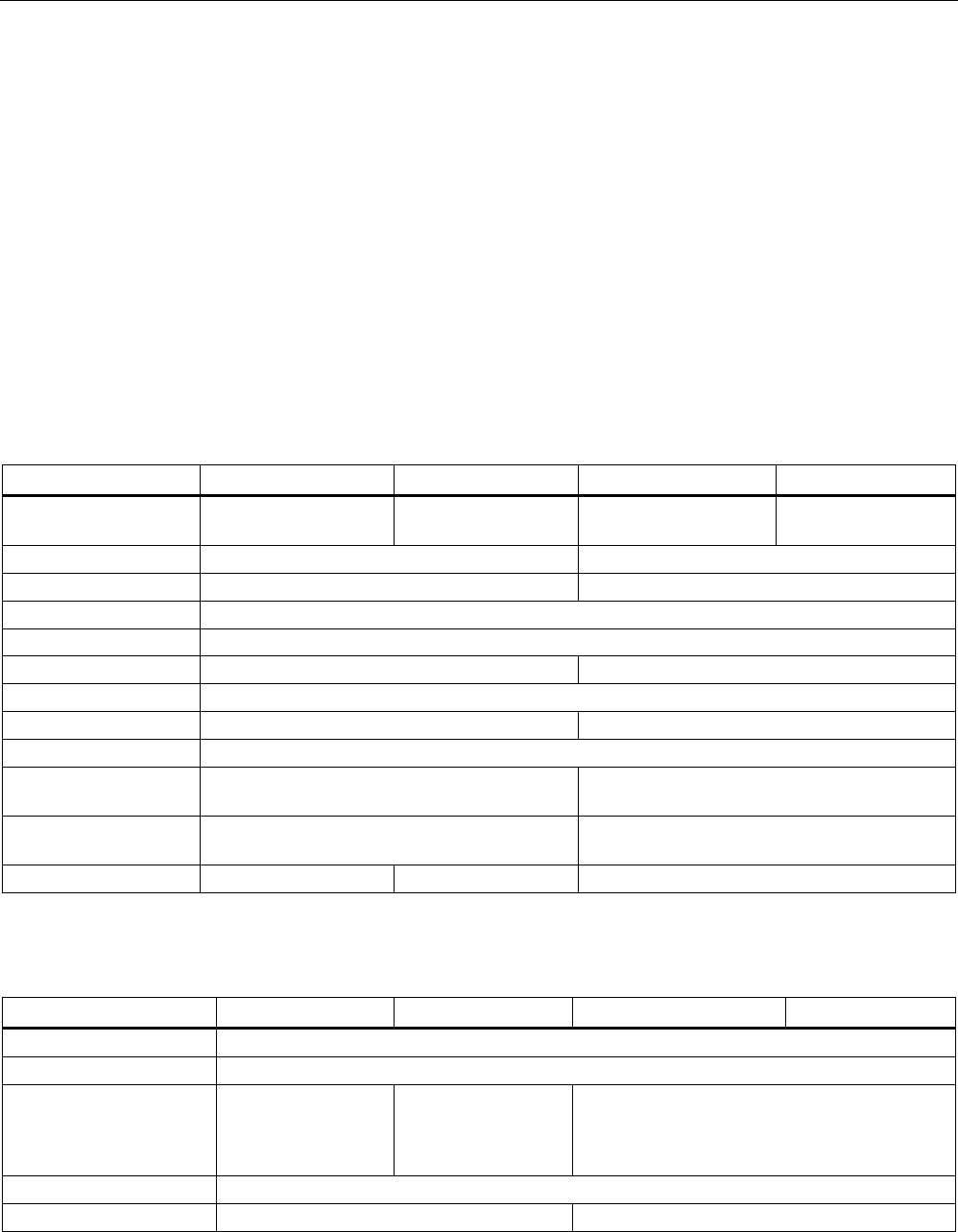
SIMATIC RF680L Smartlabel
Features
Area of application Production logistics applications subject to high
temperatures
Air interface
according to ISO°18000-6C
Memory EPC 96 bit/240 bit
Add-on-memory 64 bytes
Range
1)
max. 4 m
Mounting Via a hole on the narrow side. Can also be
glued by customer.
1) The information relates to the maximum read range. You will find more information on ranges in the section "Minimum
distances and maximum ranges (Page 344)".
Transponder/tags
7.3 SIMATIC RF680L Smartlabel
SIMATIC RF600
System Manual, xx/2014, J31069-D0171-U001-A15-7618 357
REVIEW
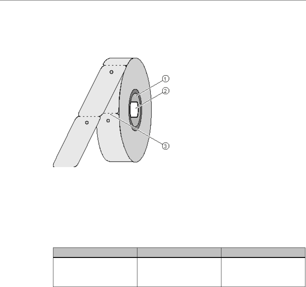
7.3.2
Delivery format
The SIMATIC RF680L is supplied on a roll. One roll always contains 1000 Smartlabels. You
can tear off the Smartlabel from the roll at the perforation.
①
Cardboard tube, inner dia 76 mm
②
Roll label
③
Perforation
Figure 7-12 SIMATIC RF680L roll
7.3.3
Ordering data
Ordering data
Article number
Packaging
SIMATIC RF680L
• Smartlabels 54 x 89 mm
• heat-resistant
6GT2810-2AG80 1,000 units on a roll
Transponder/tags
7.3 SIMATIC RF680L Smartlabel
SIMATIC RF600
358 System Manual, xx/2014, J31069-D0171-U001-A15-7618
REVIEW
7.3.4
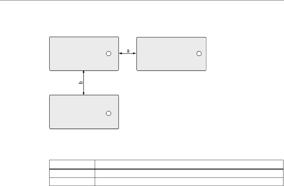
Minimum spacing between labels
Figure 7-13 Minimum spacing between labels
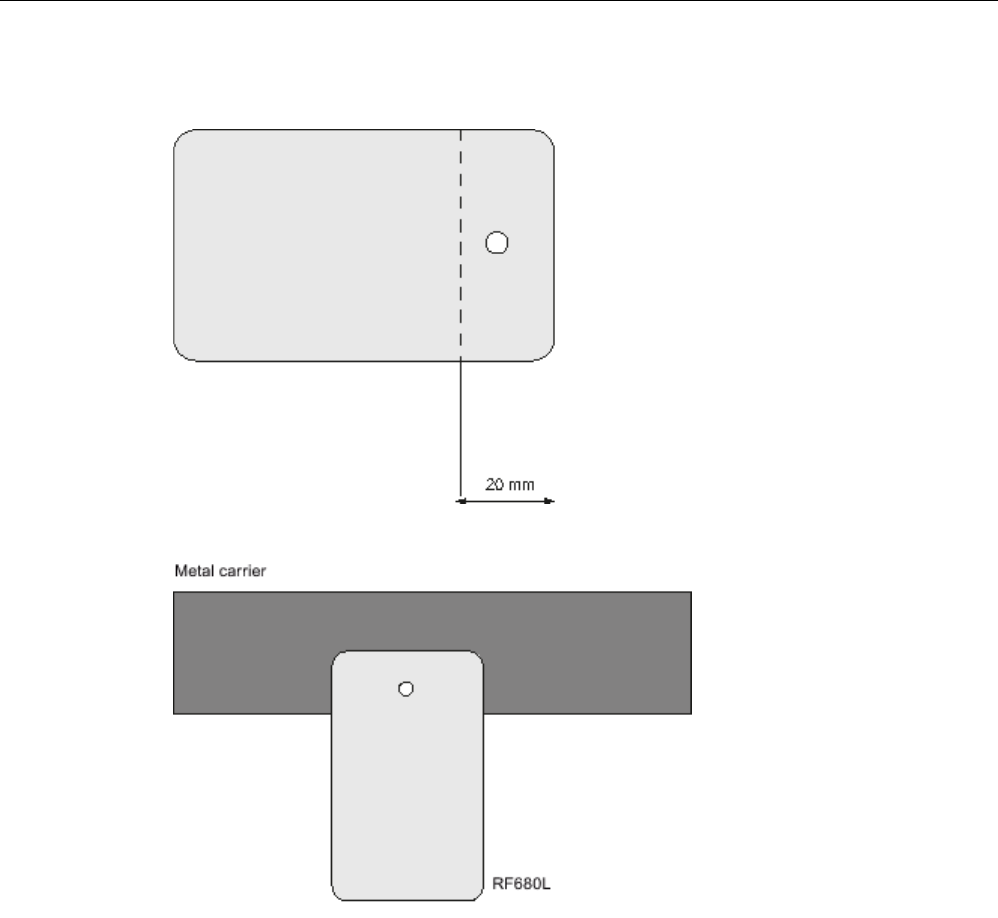
Table 7- 9 Minimum spacing
Minimum spacing
a
20 mm
b
50 mm
7.3.5
Memory configuration of the smart label
The memory configuration of the smart label is described in the section SIMATIC memory
configuration of the RF600 transponders and labels (Page 336).
Transponder/tags
7.3 SIMATIC RF680L Smartlabel
SIMATIC RF600
System Manual, xx/2014, J31069-D0171-U001-A15-7618 359
REVIEW
7.3.6
Mounting on metal
Figure 7-14 Metal mounting surface
Figure 7-15 Mounting on metal

Transponder/tags
7.3 SIMATIC RF680L Smartlabel
SIMATIC RF600
360 System Manual, xx/2014, J31069-D0171-U001-A15-7618
REVIEW
7.3.7
Technical data
7.3.7.1
Mechanical data
Feature
Description
Dimensions (L x W)
156 mm x 40 mm
Thickness of the label
0.4 mm (±25% incl.. chip)
Design
Synthetic paper; PEEK
Antenna material
Copper
Static pressure
10 N/mm
2
Transponder arching
max. 6 mm (see "Dimension drawing")
Silicone-free
Yes
Type of antenna
Shortened dipole
Color
beige
Printing
Yes, customized
Mounting
Via a hole on the narrow side. Can also be glued by customer.
Weight
Approx. 3 g
7.3.7.2
Electrical data
Characteristic
Description
Air interface
According to ISO 18 000-6 C
Polarization type
Linear
Polarization direction
The polarization direction is parallel with the long side of the inlay
Frequency range • Europe 865 to 868 MHz
• USA 902 to 928 MHz
Range
1)
max. 4 m
Minimum spacing between labels
• Vertically
• Horizontally
• 50 mm
• 20 mm
Energy source Field energy via antenna, without battery
Multitag capability
Yes
1) The information relates to the maximum read range. You will find more information on ranges in the section "Minimum
distances and maximum ranges (Page 344)".
Transponder/tags
7.3 SIMATIC RF680L Smartlabel
SIMATIC RF600
System Manual, xx/2014, J31069-D0171-U001-A15-7618 361
REVIEW
7.3.7.3
Memory specifications
Property
Description
Type
EPC Class 1 Gen 2
Memory organization
EPC code
96 bits/240 bits
User memory
64 bytes
TID
64 bits
Reserved (passwords)
64 bits
Protocol
ISO 18000-6C
Data retention time
10 years
Read cycles
Unlimited
Write cycles
Minimum at +22 °C 100 000
7.3.7.4
Environmental conditions
Property
Description
Temperature range during operation -25 °C … +85 °C (permanent)
+200 °C up to six hours
+220 °C up to one hour
+230 °C for a short time
Temperature range during storage
-40 °C … +85 °C
Torsion and bending load
Partially permissible
Distance from metal Whole surface not suitable for fixing straight
onto metal (see chapter Mounting on metal
(Page 359))
7.3.8
Certificates and approvals
Certificate
Description
Conformity with R&TTE directive
FCC
Federal Communications
Commission
Passive labels and transponders comply with the valid regulations;
certification is not required.
RoHS
Compliant according to EU Directive 2002/95/EC

Transponder/tags
7.3 SIMATIC RF680L Smartlabel
SIMATIC RF600
362 System Manual, xx/2014, J31069-D0171-U001-A15-7618
REVIEW
7.3.9
Dimension drawing
Figure 7-16 SIMATIC RF680L
Transponder/tags
7.4 SIMATIC RF610T
SIMATIC RF600
System Manual, xx/2014, J31069-D0171-U001-A15-7618 363
REVIEW
7.4
SIMATIC RF610T
7.4.1
Features
The SIMATIC RF610T is passive and maintenance-free. It operates based on the
UHF Class 1 Gen 2 technology and is used for saving the electronic product code (EPC) of
96 bits / 240 bits. The label also has a 512 bit user memory.
The SIMATIC RF610T offers a host of possible uses for a wide range of applications and
supports efficient logistics throughout the entire process chain.
Thanks to its antenna geometry, the transponder can be read from any direction. However,
the range is reduced if it is not aligned in parallel with the antenna.
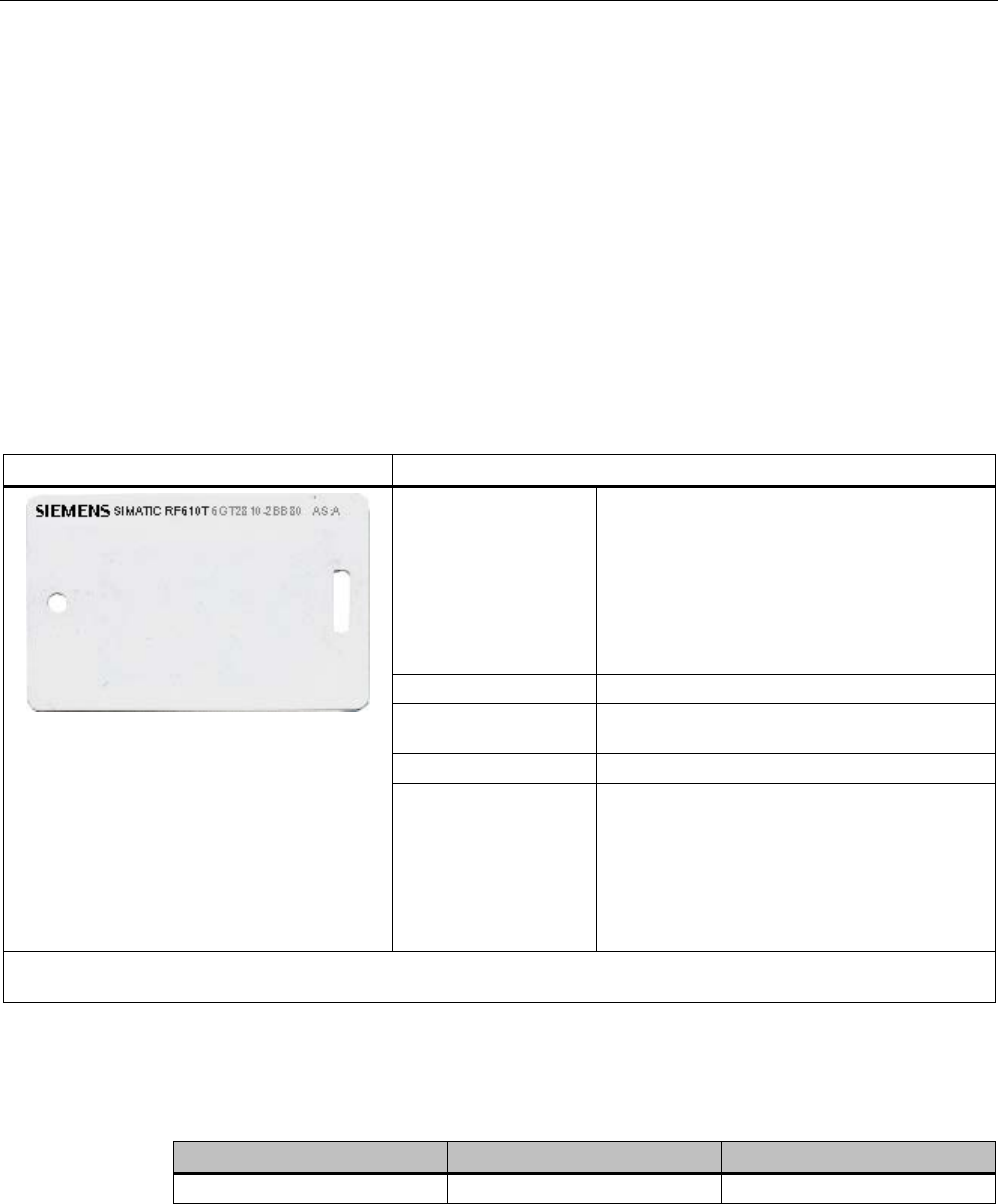
SIMATIC RF610T
Features
Area of application • Simple identification, such as barcode
replacement or barcode supplement
• Warehouse and distribution logistics
• Product identification
For the Food & Beverage sector, a special
version can be supplied on request that is
certified for use in contact with food.
Air interface
according to ISO°18000-6C
Memory EPC 96 bit/240 bit
Add-on-memory 64 bytes
Range
1)
max. 5 m
Mounting • Suspended by means of cable ties, or
similar
• Can also be fixed with screws or glued by
customer.
• Not suitable for mounting straight onto
metal.
1) The information relates to the maximum read range. You will find more information on ranges in the section "Minimum
distances and maximum ranges (Page 344)".
7.4.2
Ordering data
Ordering data
Article number
Packaging
SIMATIC RF610T
6GT2810-2BB80
Min. order quantity 500 units
Transponder/tags
7.4 SIMATIC RF610T
SIMATIC RF600
364 System Manual, xx/2014, J31069-D0171-U001-A15-7618
REVIEW
7.4.3
Safety instructions for the device/system
Note
This device/system may only be used for the applications
described in the catalog and the
technical documentation "System manual MOBY D, RF200, RF300, RF600
(
http://support.automation.siemens.com/WW/view/en/10805817) and only in combination
with third
-party devices and components recommended and/or approved by Siemens.
7.4.4
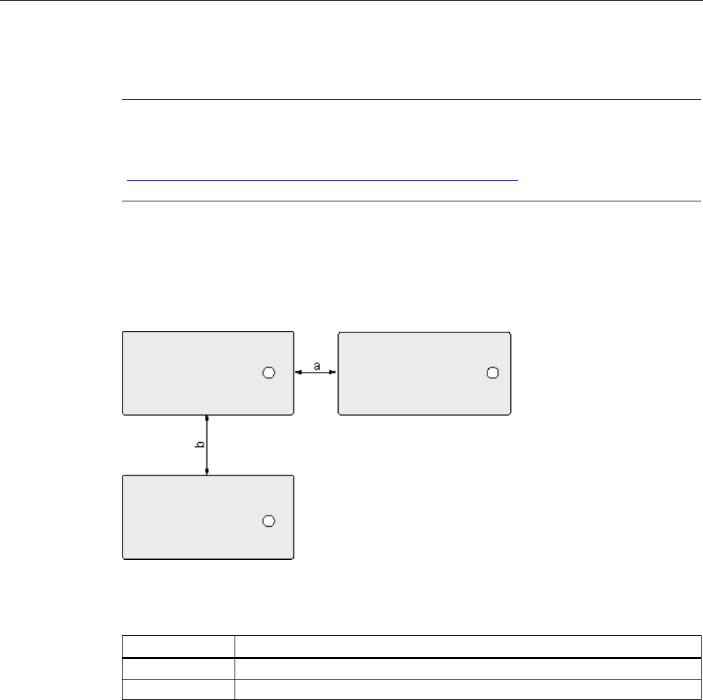
Minimum spacing between labels
Figure 7-17 Minimum spacing between labels
Table 7- 10 Minimum spacing
Minimum spacing
a
20 mm
b
50 mm
7.4.5
Memory configuration of the transponder
The memory configuration of the transponder is described in the section SIMATIC memory
configuration of the RF600 transponders and labels (Page 336).

Transponder/tags
7.4 SIMATIC RF610T
SIMATIC RF600
System Manual, xx/2014, J31069-D0171-U001-A15-7618 365
REVIEW
7.4.6
Technical data
7.4.6.1
Mechanical data
Feature
Description
Dimensions (L x W x H)
86 mm x 54 mm x 0.4 mm
Design
PVC (polyvinyl chloride)
Antenna material
Aluminum
Static pressure
10 N/m
2
Type of antenna
Shortened dipole
Color
white
Printing
Can be printed using heat transfer technique
Mounting • Suspended by means of cable ties, or similar
• Can also be fixed with screws or glued by customer.
• Not suitable for mounting straight onto metal.
Weight
Approx. 3 g
7.4.6.2
Electrical data
Characteristic
Description
Air interface
According to ISO 18 000-6 C
Polarization type
Linear
Polarization direction
The polarization direction is parallel with the long side of the inlay
Frequency range • Europe 865 … 868 MHz
• USA 902 … 928 MHz
Range
1)
max. 5 m
Energy source
Field energy via antenna, without battery
Multitag capability
Yes
1) The information relates to the maximum read range. You will find more information on ranges in the section "Minimum
distances and maximum ranges (Page 344)".
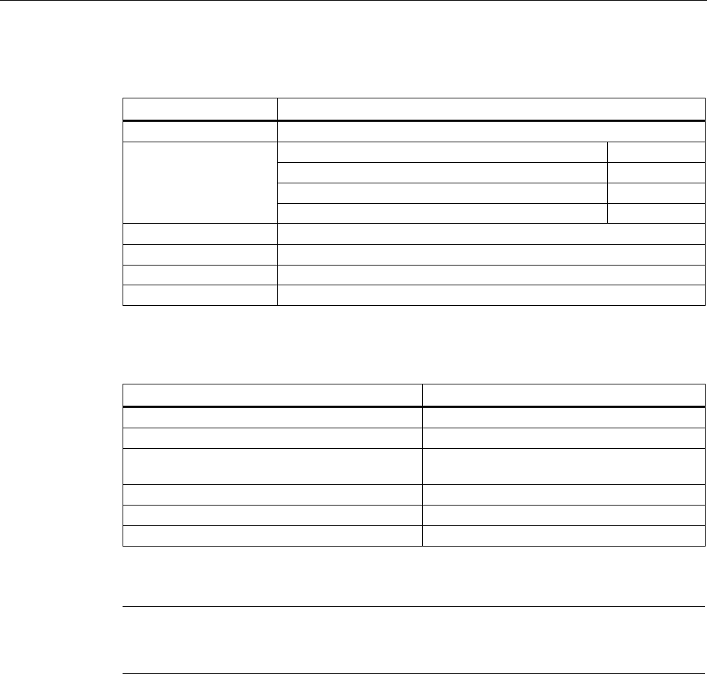
Transponder/tags
7.4 SIMATIC RF610T
SIMATIC RF600
366 System Manual, xx/2014, J31069-D0171-U001-A15-7618
REVIEW
7.4.6.3
Memory specifications
Property
Description
Type
EPC Class 1 Gen 2
Memory organization
EPC code
96 bits/240 bits
User memory
512 bits
TID
64 bits
Reserved (passwords)
64 bits
Protocol
ISO 18000-6C
Data retention time
10 years
Read cycles
Unlimited
Write cycles
Minimum at +22 °C 100 000
7.4.6.4
Environmental conditions
Feature
Description
Temperature range during operation
-25 °C … +85 °C
Temperature range during storage
-40 °C … +85 °C
Shock resistant acc. to EN 60068-2-27
Vibration acc. to EN 60068-2-6
100 g1
50 g
1
Torsion and bending load
Partially permissible
Distance from metal
Not suitable for fixing straight onto metal
Degree of protection
IP67
1) The values for shock and vibration are maximum values and must not be applied
continuously.
Note
Note that in temperature ranges > 70 °C, the transponder can become slightly deformed.
However, this has no effect on the transponder f
unction.
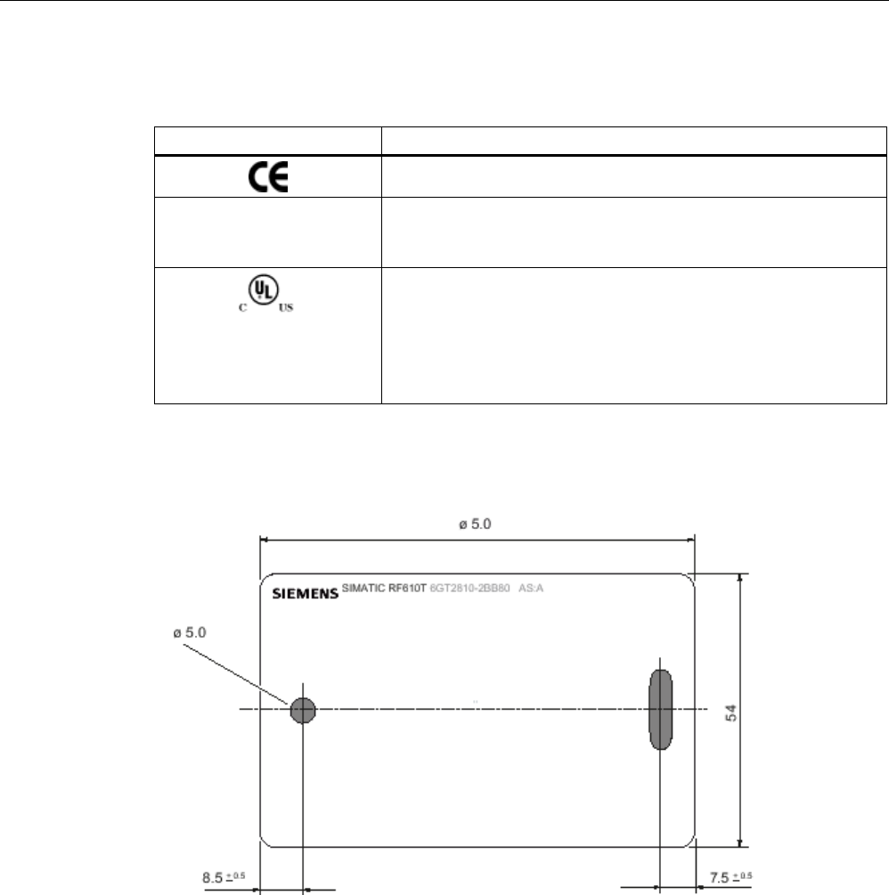
Transponder/tags
7.4 SIMATIC RF610T
SIMATIC RF600
System Manual, xx/2014, J31069-D0171-U001-A15-7618 367
REVIEW
7.4.7
Certificates and approvals
Certificate
Description
Conformity with R&TTE directive
FCC
Federal Communications
Commission
Passive labels and transponders comply with the valid regulations;
certification is not required.
This product is UL-certified for the USA and Canada.
It meets the following safety standard(s):
• UL508 - Industrial Control Equipment
• CSA C22.2 No. 142 - Process Control Equipment
• UL Report E 120869
7.4.8
Dimension drawing
Figure 7-18 Dimensional drawing of SIMATIC RF610T
All dimensions in mm
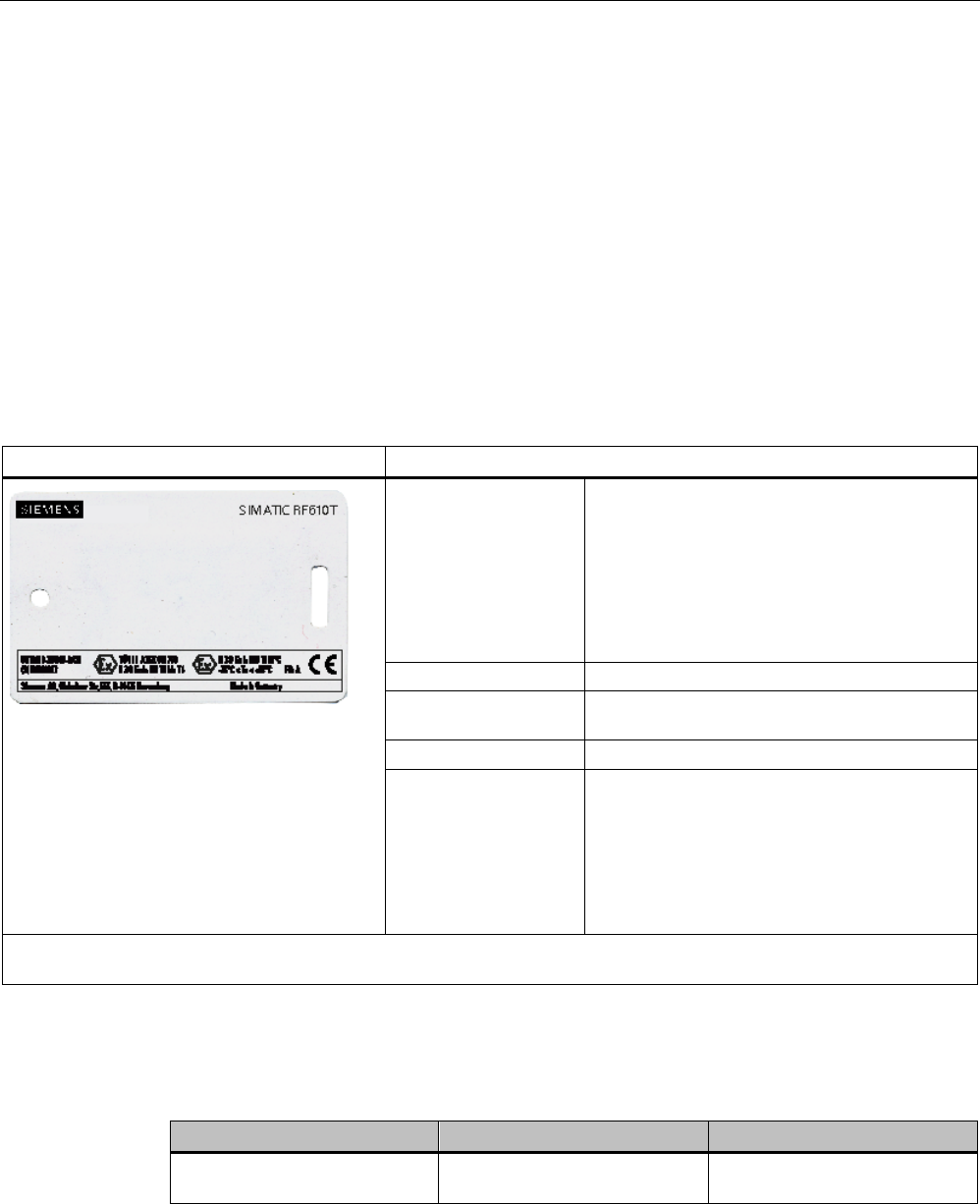
Transponder/tags
7.5 SIMATIC RF610T ATEX
SIMATIC RF600
368 System Manual, xx/2014, J31069-D0171-U001-A15-7618
REVIEW
7.5
SIMATIC RF610T ATEX
7.5.1
Features
The SIMATIC RF610T special variant ATEX is passive and maintenance-free. It operates
based on the UHF Class 1 Gen 2 technology and is used for saving the electronic product
code (EPC) of 96 bits / 240 bits. The label also has a 512 bit user memory.
The SIMATIC RF610T special variant ATEX provides numerous possible uses for a wide
range of applications and allows efficient logistics throughout the entire process chain.
Thanks to its antenna geometry, the transponder can be read from any direction. However,
the range is reduced if it is not aligned in parallel with the antenna.
SIMATIC RF610T
Features
Area of application • Simple identification, such as barcode
replacement or barcode supplement
• Warehouse and distribution logistics
• Product identification
For the Food & Beverage sector, a special
version can be supplied on request that is
certified for use in contact with food.
Air interface
according to ISO°18000-6C
Memory EPC 96 bit/240 bit
Add-on-memory 64 bytes
Range
1)
max. 5 m
Mounting • Suspended by means of cable ties, or
similar
• Can also be fixed with screws or glued by
customer.
• Not suitable for mounting straight onto
metal.
1) The information relates to the maximum read range. You will find more information on ranges in the section "Minimum
distances and maximum ranges (Page 344)".
7.5.2
Ordering data
Ordering data
Article number
Packaging
SIMATIC RF610T
special variant ATEX
6GT2810-2BB80-0AX1 Min. order quantity 500 units
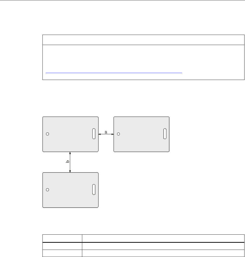
Transponder/tags
7.5 SIMATIC RF610T ATEX
SIMATIC RF600
System Manual, xx/2014, J31069-D0171-U001-A15-7618 369
REVIEW
7.5.3
Safety instructions for the device/system
NOTICE
Approved use
This device/system may only be used for the applications described in the catalog and the
technical documentation "System manual MOBY D, RF200, RF300, RF600
(http://support.automation.siemens.com/WW/view/en/10805817) and only in combination
with third-party devices and components recommended and/or approved by Siemens.
7.5.4
Minimum spacing between labels
Figure 7-19 Minimum spacing between labels
Table 7- 11 Minimum spacing
Minimum spacing
a (horizontal) 20 mm
b (vertical)
50 mm
7.5.5
Memory configuration
The memory configuration of the transponder is described in section SIMATIC memory
configuration of the RF600 transponder and labels (Page 336).

Transponder/tags
7.5 SIMATIC RF610T ATEX
SIMATIC RF600
370 System Manual, xx/2014, J31069-D0171-U001-A15-7618
REVIEW
7.5.6
Technical specifications
7.5.6.1
Mechanical data
Feature
Description
Dimensions (L x W x H)
86 mm x 54 mm x 0.4 mm
Design
PVC (polyvinyl chloride)
Antenna material
Aluminum
Static pressure
10 N/m
2
Type of antenna
Shortened dipole
Color
white
Printing
Can be printed using heat transfer technique
Mounting • Suspended by means of cable ties, or similar
• Can also be fixed with screws or glued by customer.
• Not suitable for mounting straight onto metal.
Weight
Approx. 3 g
7.5.6.2
Electrical data
Characteristic
Description
Air interface
According to ISO 18 000-6 C
Polarization type
Linear
Polarization direction
The polarization direction is parallel with the long side of the inlay
Frequency range Europe: 865 ... 868 MHz
USA: 902 to 928 MHz
Range
1)
max. 5 m
Energy source
Field energy via antenna, without battery
Multitag capability
Yes
1) The information relates to the maximum read range. You will find more information on ranges in the section "Minimum
distances and maximum ranges (Page 344)".
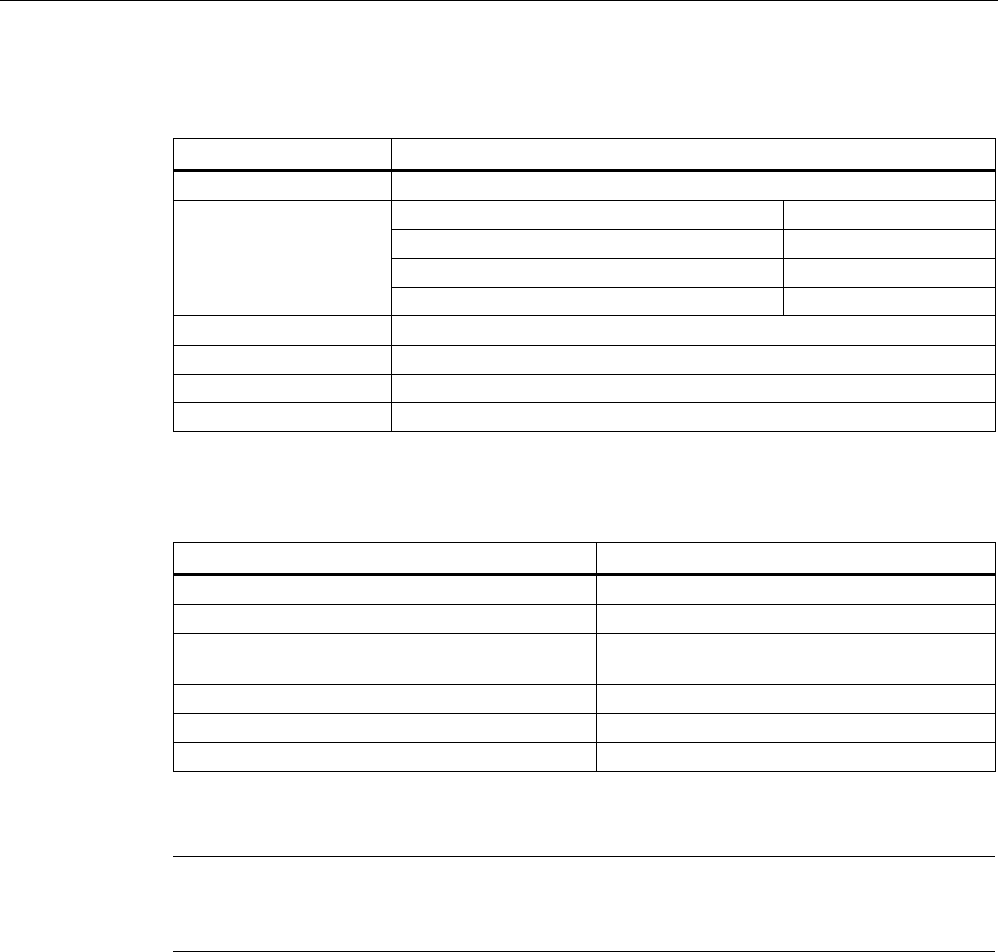
Transponder/tags
7.5 SIMATIC RF610T ATEX
SIMATIC RF600
System Manual, xx/2014, J31069-D0171-U001-A15-7618 371
REVIEW
7.5.6.3
Memory data
Feature
Description
Type
EPC Class 1 Gen 2
Memory organization
EPC code
96 bits/240 bits
User memory
64 bytes
TID
64 bits
Reserved (passwords)
64 bits
Protocol
ISO 18000-6C
Data retention time
10 years
Read cycles
Unlimited
Write cycles
Minimum 100 000 at +22 °C
7.5.6.4
Environmental conditions
Feature
Description
Temperature range during operation
-25 °C … +85 °C
Temperature range during storage
-40 °C … +85 °C
Shock resistant acc. to EN 60068-2-27
Vibration acc. to EN 60068-2-6
100 g 1)
50 g
1)
Torsion and bending load
Partially permissible
Distance from metal
Not suitable for fixing straight onto metal
Degree of protection
IP67
1) The values for shock and vibration are maximum values and must not be applied
continuously.
Note
Note that in temperature ranges > 70 °C, the transponder can become slightly deformed.
However, this has no effect on the transponder function.
7.5.6.5
Use of the transponder in the Ex protection area
In a conformity declaration, TÜV NORD CERT GmbH has confirmed compliance with the
essential health and safety requirements relating to the design and construction of
equipment and protective systems intended for use in potentially explosive areas as per
Annex II of the directive 94/9/EG.
The essential health and safety requirements are satisfied in accordance with standards
EN 60079-0: 2009, EN 60079-11: 2007 and EN 61241-11: 2006.
This allows the RF610T special variant ATEX transponder to be used in hazardous areas for
gases, for the device category 3 G and gas group IIB, or alternatively in hazardous areas for
dusts, for the device category 3 D and group IIIB.
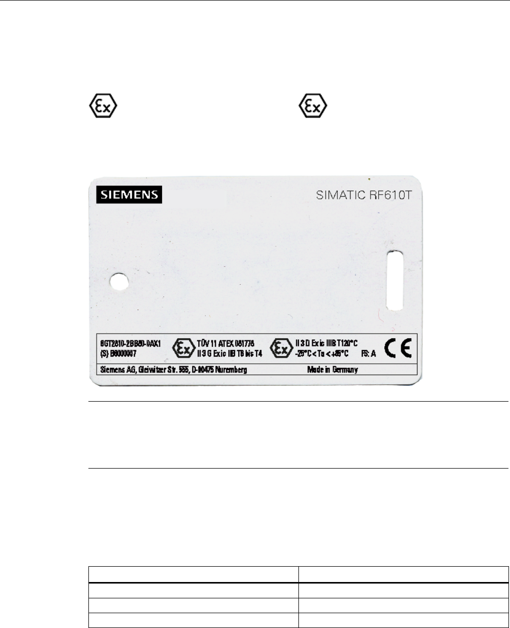
Transponder/tags
7.5 SIMATIC RF610T ATEX
SIMATIC RF600
372 System Manual, xx/2014, J31069-D0171-U001-A15-7618
REVIEW
Identification
The identification is as follows:
II
3 G Ex ic IIB T6 to T4 or
II
3 D Ex ic IIIB T120°C,
-
25 °C < Ta < +85 °C
7.5.6.6
Use of the transponder in hazardous areas for gases
Note
The labeling of the front of the transponder shown above is an example and can vary
between batches produced at different times.
This does not affect the haradous area marking.
Temperature class delineation for gases
The temperature class of the transponder for hazardous areas depends on the ambient
temperature range:
Ambient temperature range
Temperature class
-25 °C to +85 °C
T1 - T4
-25 °C to +65 °C
T5
-25 °C to +50 °C
T6
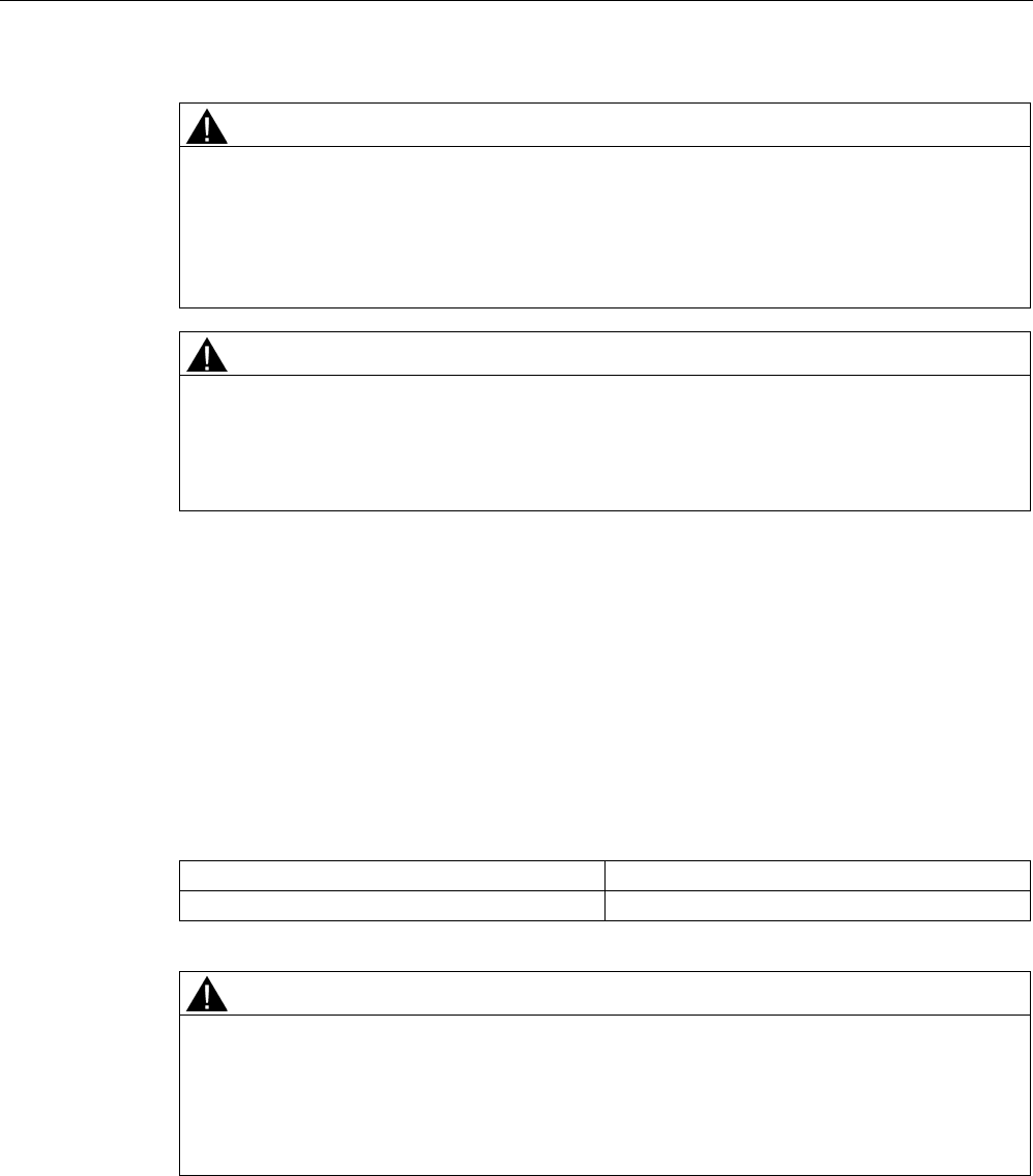
Transponder/tags
7.5 SIMATIC RF610T ATEX
SIMATIC RF600
System Manual, xx/2014, J31069-D0171-U001-A15-7618 373
REVIEW
WARNING
Ignitions of gas-air mixtures
When using the RF610T transponder, check to make sure that the temperature class is
adhered to in keeping with the requirements of the area of application
Non-compliance with the permitted temperature ranges while using the transponder can
lead to ignitions of gas-air mixtures.
WARNING
Ignitions of gas-air mixtures
The maximum radiated power of the transmitter used to operate the transponder must not
exceed 2000 mW ERP.
Non-compliance with the permitted radiated power can lead to ignitions of gas-air mixtures.
7.5.6.7
Use of the transponder in hazardous areas for dusts
The equipment is suitable for dusts whose ignition temperatures for a dust layer of 5 mm are
higher than 190 °C (smoldering temperature). The ignition temperature specified here
according to EN 60079-0 and EN 61241-11 for ignition protection type ic in this case
references the smoldering temperature of a layer of combustible flyings (ic IIIA) or
alternatively non-conductive dusts (ic IIIB).
Temperature class delineation for dusts
Ambient temperature range
Temperature value
-25 °C < Ta < +85 °C
T120 °C
WARNING
Ignitions of dust-air mixtures
When using the RF610T transponder, make sure that the temperature values are adhered
to in keeping with the requirements of the area of application.
Non-compliance with the permitted temperature ranges while using the transponder can
lead to ignitions of dust-air mixtures.
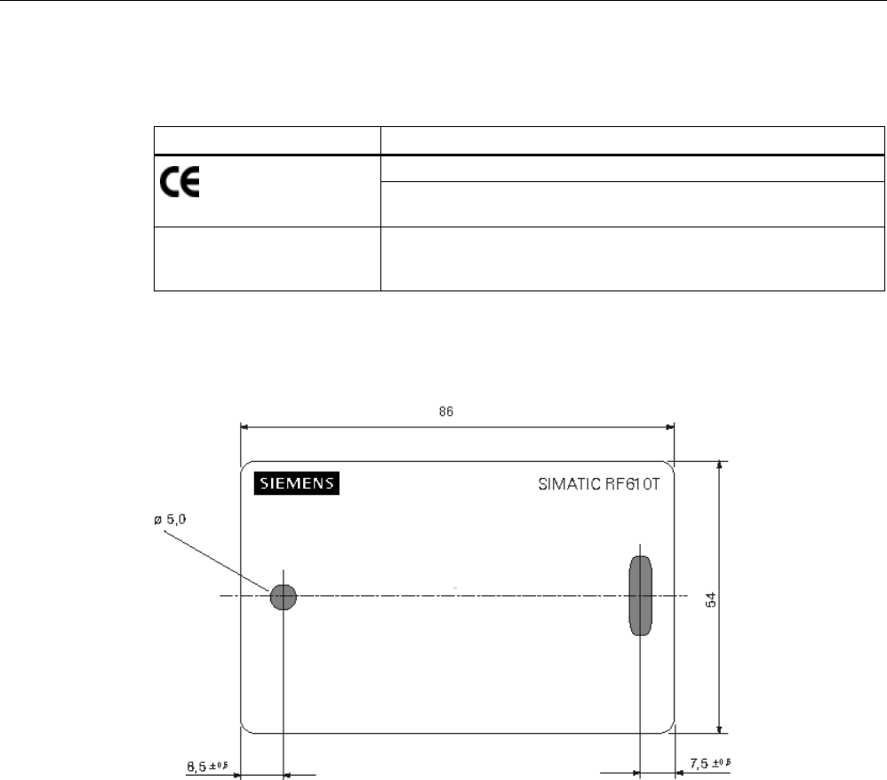
Transponder/tags
7.5 SIMATIC RF610T ATEX
SIMATIC RF600
374 System Manual, xx/2014, J31069-D0171-U001-A15-7618
REVIEW
7.5.7
Certificates and approvals
Certificate
Description
Compatible with R&TTE directive
For directive 94/9/EC:
conformity declaration no. TÜV 11 ATEX 081778
FCC
Federal Communications
Commission
Passive labels and transponders comply with the valid regulations;
certification is not required.
7.5.8
Dimension drawing
Figure 7-20 Dimension drawing SIMATIC RF610T (special variant ATEX)
All dimensions in mm
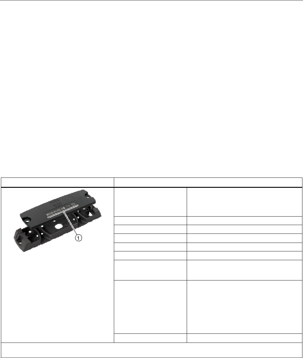
Transponder/tags
7.6 SIMATIC RF620T
SIMATIC RF600
System Manual, xx/2014, J31069-D0171-U001-A15-7618 375
REVIEW
7.6
SIMATIC RF620T
7.6.1
Characteristics
The SIMATIC RF620T Transponder is passive and maintenance-free, based on the UHF
Class 1 Gen2 technology for storing 96-bit/128-bit electronic product codes (EPC).
The transponder also has a 64-byte user memory.
The container tag for industrial applications is rugged and highly resistant to detergents. It is
designed for easy attachment onto plastic, wood, glass, e.g. containers, palettes, and
trolleys
The optimum functionality/range of the RF620T on metal is achieved by means of the
spacer.
Since the plastic is food safe, it is also suitable for use in the food-processing industry.
This container tag is designed for the frequency bands of 860 MHz and 960 MHz and can be
operated in combination with our UHF system RF660.
SIMATIC RF620T Transponder
Features
Area of application Transponder for rugged, industrial
requirements such as RF identification in
warehouses and the logistics and transport
area.
Frequency range
860 to 960 MHz
Polarization
Linear
Memory
EPC 96 bit/128 bit
Additional USER memory
64 bytes
Range
1)
max. 8 m
Mounting • Screw, bond
• On metal by means of spacers
① Labeling area You can inscribe the transponder itself using
laser, or adhere a label to position ①.
Possible types of labeling:
• Barcode
• Inscription in plain text
• Data matrix code
Housing color
Anthracite
1) The information relates to the maximum read range. You will find more information on ranges in the section "Minimum
distances and maximum ranges (Page 344)".
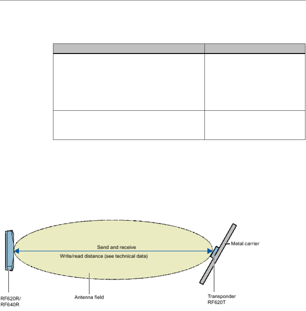
Transponder/tags
7.6 SIMATIC RF620T
SIMATIC RF600
376 System Manual, xx/2014, J31069-D0171-U001-A15-7618
REVIEW
7.6.2
Ordering data
Ordering data
Article number
SIMATIC RF620T
• Frequency 865 MHz to 928 MHz,
• UHF Class 1 Gen2 technology (96 bit/128 bit)
• -25 °C to +85 °C operating temperature
• Dimensions (L x W x H) 127 x 38 x 6 mm
• IP67 degree of protection
6GT2810-2HC81
Spacer for SIMATIC RF620T
• For attaching to metal surfaces
• Dimensions (L x W x H) 155 x 38 x 12 mm
6GT2898-2AA00
7.6.3
Planning the use
7.6.3.1
Optimum antenna/transponder positioning with planar mounting of the transponder on
metal
Figure 7-21 Example of optimum reader-transponder positioning with RF620R and RF640R via the internal reader
antenna.
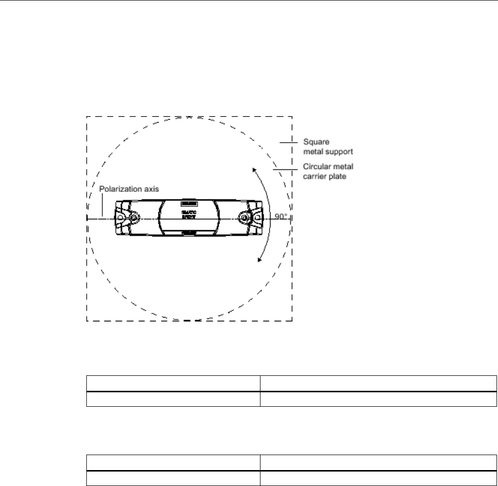
Transponder/tags
7.6 SIMATIC RF620T
SIMATIC RF600
System Manual, xx/2014, J31069-D0171-U001-A15-7618 377
REVIEW
7.6.3.2
Range when mounted on flat metallic carrier plates
The transponder generally has linear polarization. The polarization axis runs as shown in the
diagram below. If the tag is mounted in the center of a flat metal plate, which is either
approximately square or circular, it can be aligned in any direction since the transmitting and
receiving RF660A antennas operate with circular polarization.
Figure 7-22 Optimum positioning of the transponder on a (square or circular) metal surface
Table 7- 12 Range with metallic, flat carriers without spacers
Carrier material
Range
Metal plate at least 300 x 300 mm typically 38%
Table 7- 13 Range with flat metallic carriers with spacers
Carrier material
Range
Metal plate at least 300 x 300 mm
typically 87%
The use of spacers on metallic surfaces is recommended.
On rectangular carrier plates, the range depends on the mounting orientation of the
transponder A 90° rotation of the transponder about the axis of symmetry may result in
greater ranges.
You will find more detailed information on the range in the section "Minimum distances and
maximum ranges (Page 344)".
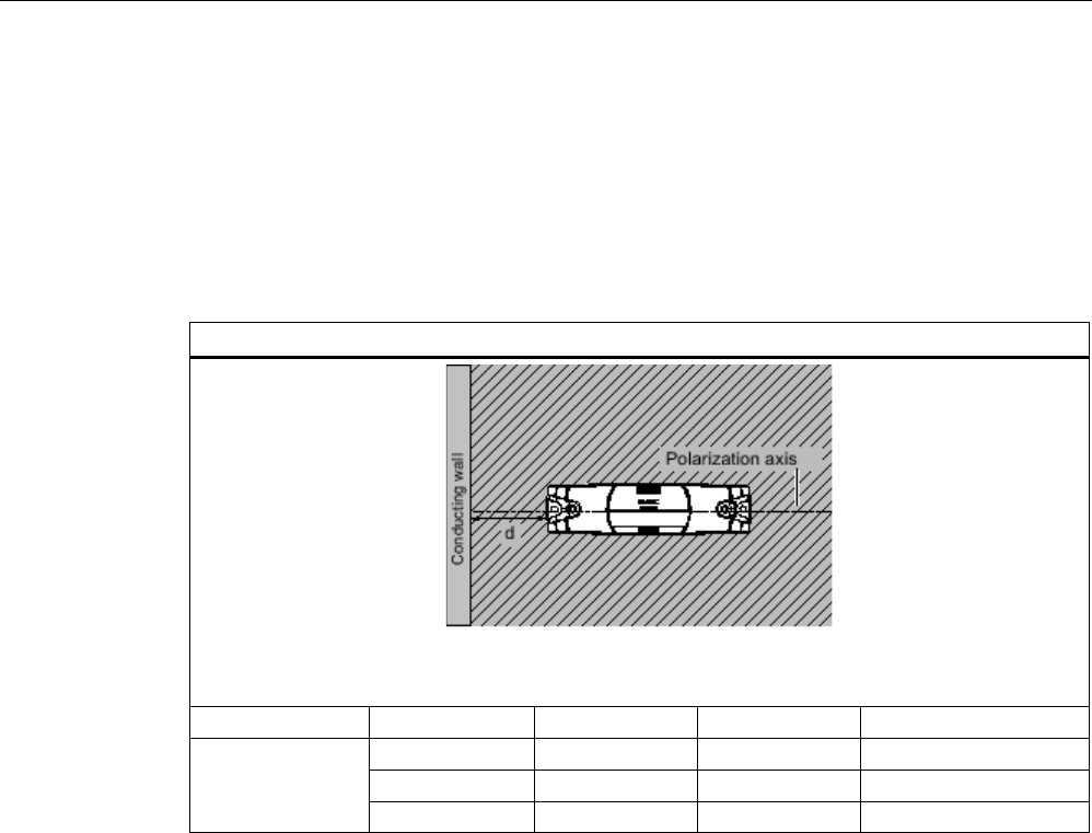
Transponder/tags
7.6 SIMATIC RF620T
SIMATIC RF600
378 System Manual, xx/2014, J31069-D0171-U001-A15-7618
REVIEW
7.6.3.3
Influence of conducting walls on the range
If there are conducting walls or restrictions in the vicinity that could affect the wireless field, a
distance of approx. 10 cm is recommended. In principle, walls have least influence if the
polarization axis is orthogonal to the wall. A spacer must be used in any case.
Range: One conducting wall
Influence on the range when positioned orthogonally to the conducting wall
View from above
Distance d
20 mm
50 mm
100 mm
Range
approx. 100%
approx. 100%
approx. 100%
Wall height 20 mm
approx. 100%
approx. 100%
approx. 100%
Wall height 50 mm
approx. 80%
approx. 100%
approx. 100%
Wall height 100 mm
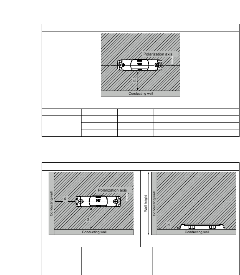
Transponder/tags
7.6 SIMATIC RF620T
SIMATIC RF600
System Manual, xx/2014, J31069-D0171-U001-A15-7618 379
REVIEW
Influence on the range when positioned parallel to the conducting wall
View from above
Distance d
20 mm
50 mm
100 mm
Range
approx. 70%
approx. 100%
approx. 100%
Wall height 20 mm
approx. 60%
approx. 90 %
approx. 100%
Wall height 50 mm
approx. 30%
approx. 70%
approx. 100%
Wall height 100 mm
Range: Two conducting walls
Influence on the range when positioned against two conducting walls
View from above
Side view
Distance d
20 mm
50 mm
100 mm
Range
approx. 70%
approx. 100%
approx. 100%
Wall height 20 mm
approx. 60%
approx. 90 %
approx. 100%
Wall height 50 mm
approx. 30%
approx. 70%
approx. 100%
Wall height 100 mm
The values specified in the tables above are guide values.
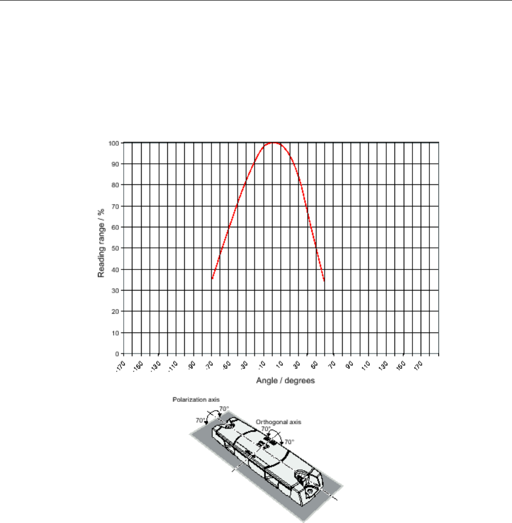
Transponder/tags
7.6 SIMATIC RF620T
SIMATIC RF600
380 System Manual, xx/2014, J31069-D0171-U001-A15-7618
REVIEW
7.6.3.4
Directional radio pattern of the transponder on metallic surfaces
Preferably, align the data carrier parallel to the transmitting antenna. If, however, the data
carrier including the metallic carrier plate is tilted, the reading range will be reduced.
Rotation about the polarization axis or orthogonal to the polarization axis
Figure 7-23 Characteristic of the transponder when rotated about the polarization axis or orthogonally
to the polarization axis
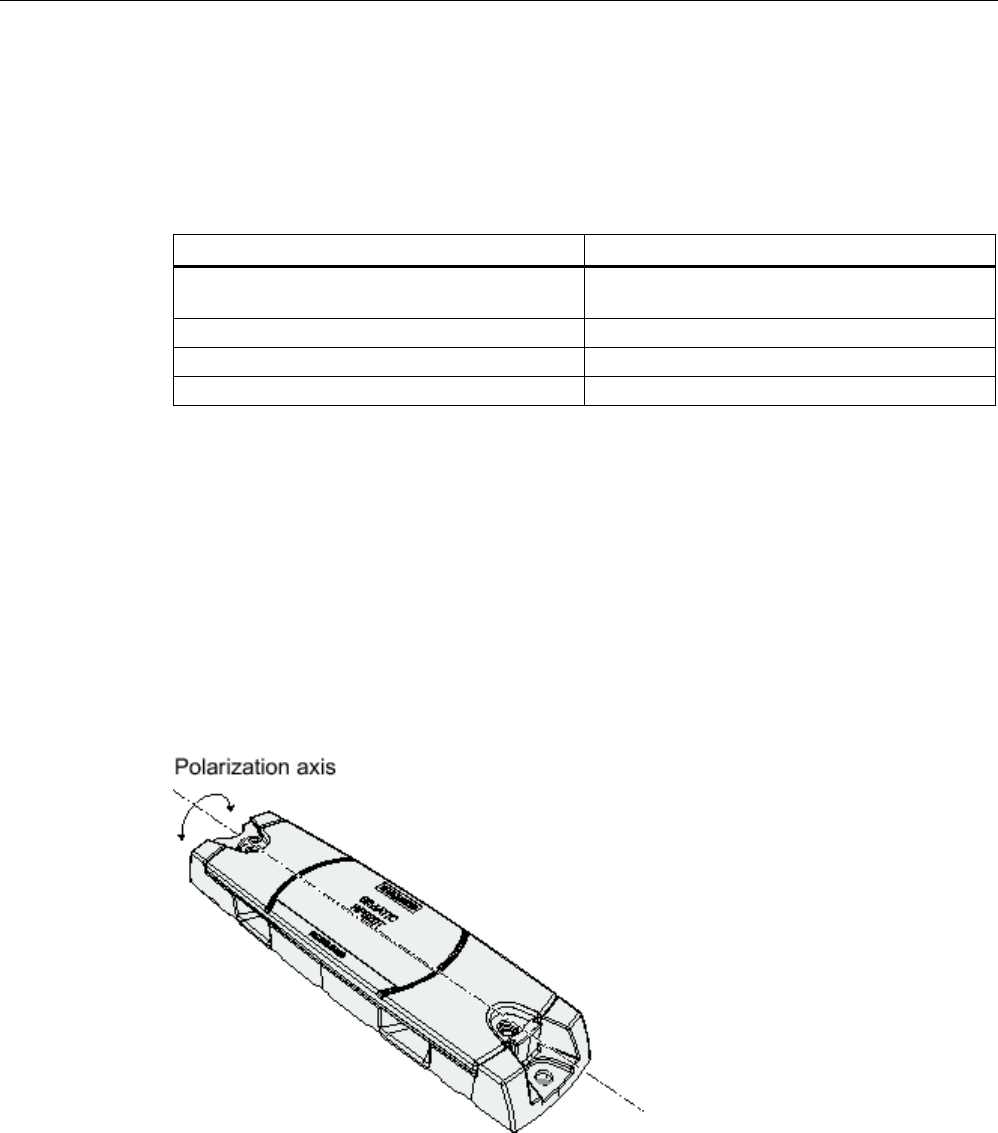
Transponder/tags
7.6 SIMATIC RF620T
SIMATIC RF600
System Manual, xx/2014, J31069-D0171-U001-A15-7618 381
REVIEW
7.6.3.5
Range when mounted on non-metallic carrier materials
The transponder is generally designed for mounting on non-metallic objects which provide
the conditions for the maximum reading ranges
Table 7- 14 Range with non-metallic carriers
Carrier material
Range
Transponder on wooden carrier
(dry, degree of moisture < 15%)
typically 75 %
Transponder on plastic carrier
typically 75 %
Transponder on glass
typically 75 %
Transponder on plastic mineral water bottle
typically 15 %
The maximum range of 100% is achieved by mounting the transponder in a free space with
low reflections on a metal-free carrier with a diameter of at least 300 mm.
You will find more detailed information on the range in the section "Minimum distances and
maximum ranges (Page 344)".
7.6.3.6
Directional radio pattern of the transponder on non-metallic surfaces
Preferably, align the data carrier parallel to the transmitting antenna. If, however, the data
carrier including the metallic carrier plate is tilted, the reading range will be reduced.
Rotation about the polarization axis
Figure 7-24 Rotation of the transponder about the polarization axis
Generally the range does not change when the transponder without carrier material is
rotated about the polarization axis.
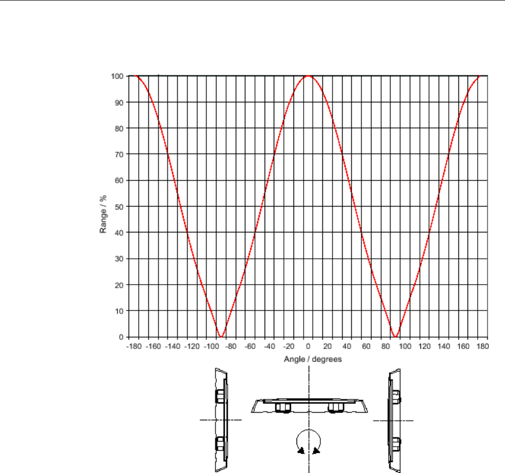
Transponder/tags
7.6 SIMATIC RF620T
SIMATIC RF600
382 System Manual, xx/2014, J31069-D0171-U001-A15-7618
REVIEW
Rotation orthogonal to the polarization axis
Figure 7-25 Transponder characteristics when rotated orthogonally to the polarization axis (within the
tag plane)
If the transponder is positioned orthogonally to the transmitting antenna, it normally cannot
be read. Therefore the data carrier is preferably to be aligned parallel to the transmitting
antenna. The following figure illustrates this situation.
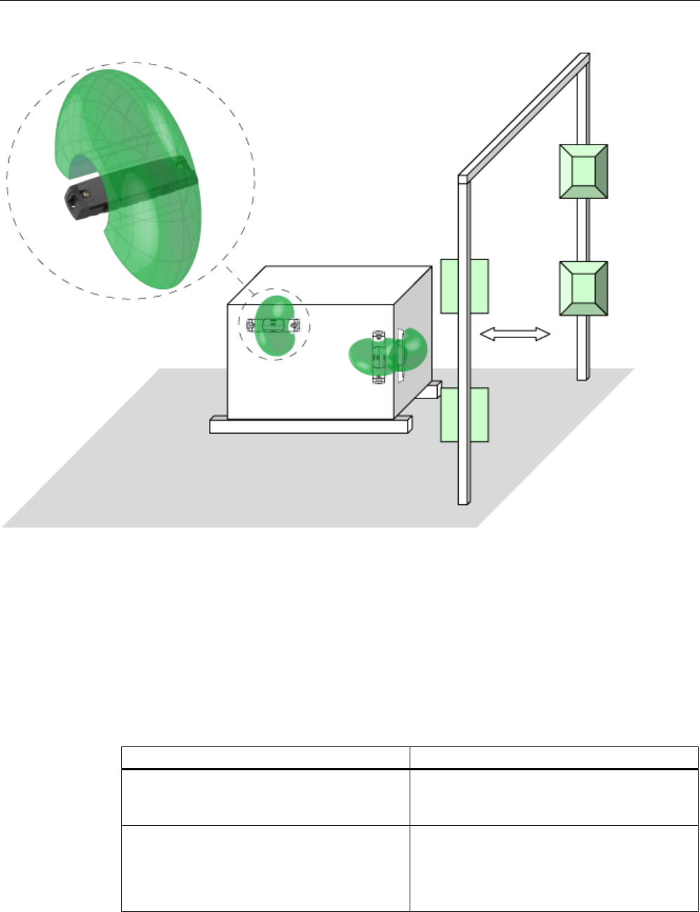
Transponder/tags
7.6 SIMATIC RF620T
SIMATIC RF600
System Manual, xx/2014, J31069-D0171-U001-A15-7618 383
REVIEW
Figure 7-26 Application example for possible orientations of the transponder.
7.6.3.7
Range when mounted on ESD carrier materials
The transponder is generally designed for mounting on non-conductive objects which
provide the conditions for the maximum reading ranges The conductive or dissipative
surface of ESD materials limits the range depending on the surface resistance. Generally,
dissipative materials with a surface resistance of 1 x 10⁵ to 1 x 10¹¹ ohm and conductive
materials with 1 x 10³ to 1 x 10⁵ ohm are available.
Table 7- 15 Limited range with ESD materials
Carrier material
Range
Transponder on electrostatic dissipative
materials, dimensions 60°x°40 cm
(surface resistance 2 x 10
9
ohm)
approx. 50%
Transponder on electrostatically conductive
materials, dimensions 60 x 40 cm
(surface resistance 1 x 10⁴ ohm)
Use of spacers
approx. 12%
approx. 25 %

Transponder/tags
7.6 SIMATIC RF620T
SIMATIC RF600
384 System Manual, xx/2014, J31069-D0171-U001-A15-7618
REVIEW
100% range is achieved when mounted in free space with low reflections. With multitag
capability, the range may be limited further.
Figure 7-27 Schematic representation of how the range depends on the surface resistance of the ESD material
In the figure above, the two reading points are shown illustrating the range as a percentage
dependent on the surface resistance. At the same time a linear dependence between the
reading points is to be expected, however with measurement inaccuracies. The darker the
hatching, the greater the probability that the reading point is found in the hatched area.
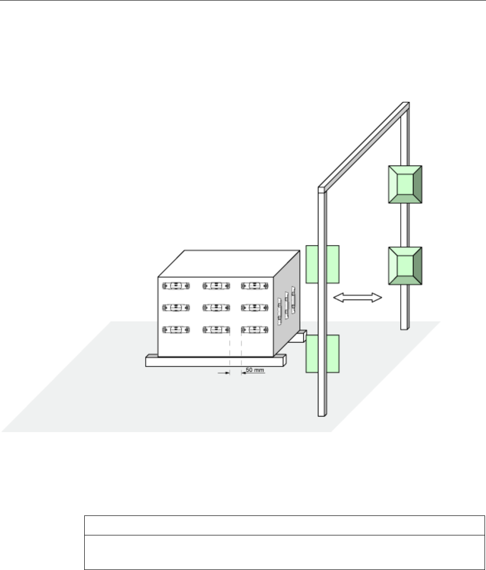
Transponder/tags
7.6 SIMATIC RF620T
SIMATIC RF600
System Manual, xx/2014, J31069-D0171-U001-A15-7618 385
REVIEW
7.6.3.8
Communication with multiple transponders
The RF600 system is multitag-capable. This means that the reader can detect and write to
several transponders almost simultaneously. The minimum distance between the
transponders is ≥ 50 mm.
Figure 7-28 Multitag reading
7.6.4
Mounting instructions
NOTICE
Level mounting
Please note that both the transponder and the spacer must be mounted on a level surface.
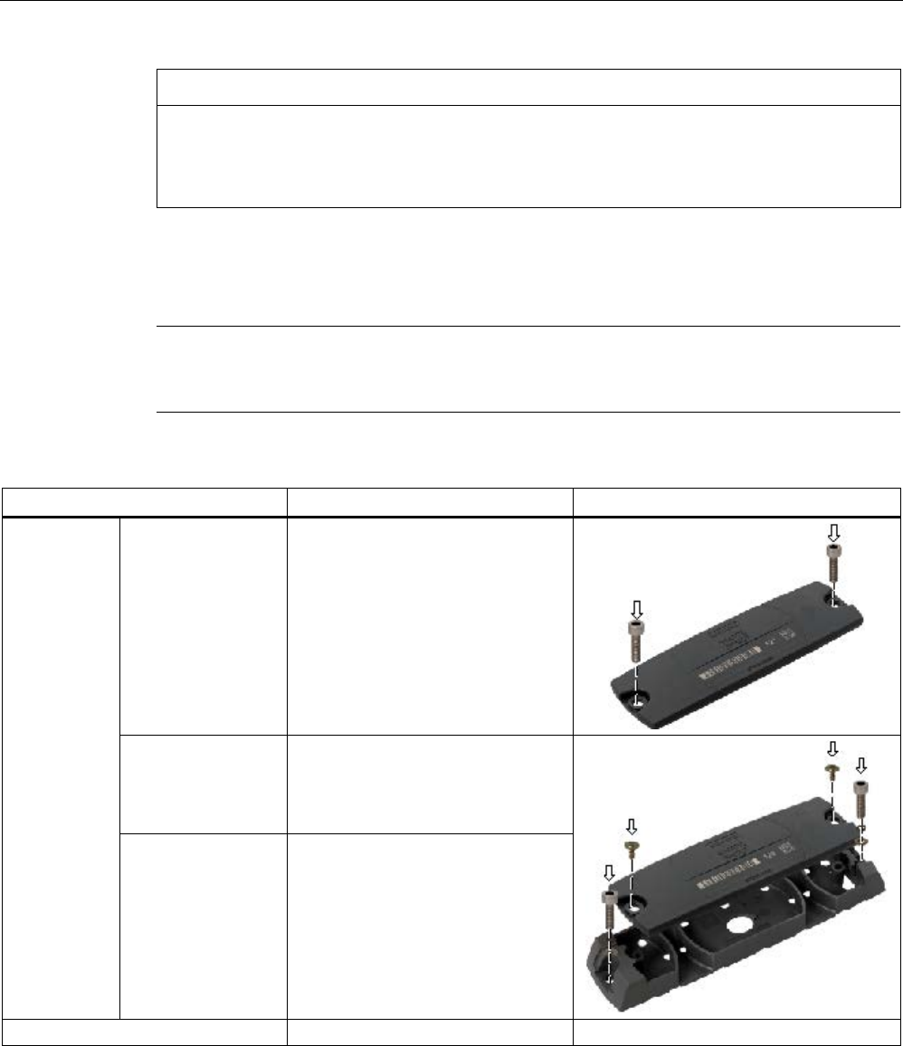
Transponder/tags
7.6 SIMATIC RF620T
SIMATIC RF600
386 System Manual, xx/2014, J31069-D0171-U001-A15-7618
REVIEW
NOTICE
The screw fixing element was tested with the types of screws, spring washers and plain
washers indicated below. Depending on the application area, the user must use similar,
correspondingly certified screws, spring washers and plain washers (e.g. for the food
processing industry).
EJOT screws can be additionally etched and passivated in some areas of the food
processing industry, e.g if they made of stainless steel A2. In other areas without special
requirements, the screws can be, for example, zinc plated and blue passivated.
Note
In case of high
mechanical loads (such as shocks or vibration), the transponder must be
fixed onto the spacer by means of screws.
Properties
Description
Graphics
Mounting type
• Transponder • Screw mounting (e.g. 2 x M4
hexagon socket head cap screws
DIN 6912, spring lock and
grommet DIN 433)
or glued
• Transponder on
spacer
• Clips or screw on the side of the
clip, or 2°x° screws (e.g.
EJOT PT ® WN 5411 35x10 VZ
crosshead screw/torx)
• Spacer • Screw mounting (e.g.°2 x M4
hexagon socket head cap screws
DIN 6912, spring lock and
grommet DIN 433) or glued or
secured with tape
Tightening torque
(at room temperature) < 1.2 Nm
7.6.5
Memory configuration of the transponder
The memory configuration of the transponder is described in the section SIMATIC memory
configuration of the RF600 transponders and labels (Page 336).

Transponder/tags
7.6 SIMATIC RF620T
SIMATIC RF600
System Manual, xx/2014, J31069-D0171-U001-A15-7618 387
REVIEW
7.6.6
Technical Specifications
7.6.6.1
Mechanical data
Property
Description
Dimensions (L x W x H)
• Transponder
• Spacer
• 127 x 38 x 6 mm
• 157 x 39 x 12 mm
Design
Plastic enclosure (PP; food safe), silicon-free
Housing color
Anthracite
Weight
• Transponder
• Spacer
• Transponder with spacer
• Approx. 18 g
• Approx. 22 g
• Approx. 40 g
Mounting on metal
Preferably with spacer
7.6.6.2
Electrical data
Characteristic
Description
Air interface
According to ISO 18 000-6 C
Frequency range
860 ... 960 MHz
Range
1)
max. 8 m
Polarization type
Linear
Energy source
Magnetic energy via antenna, without battery
Multitag capability
Yes, minimum distance between data carriers ≥ 50 mm
1) Mounting on a flat metal-
free carrier with a diameter of at least 300 mm and at room temperature. The information relates
to the maximum read range. You will find more information on ranges in the section "Minimum distances and maximum
ranges (Page 344)".
7.6.6.3
Memory specifications
Characteristic
Description
Type
EPC Class 1 Gen2
Memory organization
EPC code 96/128 bit
User memory 64 byte
Protocol
ISO 18000-6C
Data retention time 10 years
Read cycles
Unlimited
Write cycles
100 000 min.

Transponder/tags
7.6 SIMATIC RF620T
SIMATIC RF600
388 System Manual, xx/2014, J31069-D0171-U001-A15-7618
REVIEW
7.6.6.4
Environmental conditions
Property
Description
Temperature range during operation
-25 °C to +85 °C
Temperature range during storage
-40 °C to +85 °C
Shock
Vibration
compliant with EN 60721-3-7 Class 7 M3
100 g,
50 g
Torsion and bending load
Not permissible
Degree of protection
IP67
7.6.6.5
Chemical resistance of the transponder RF620T
The following table provides an overview of the chemical resistance of the data memory
made of polypropylene.
Concentration
20 °C
50 °C
Emissions
alkaline/containing hydrogen fluoride
/carbon dioxide
Low ○○○○ ○○○○
Emissions containing hydrochloric acid
○○○○
○○○○
Emissions containing sulphuric acid
○○○○
-
Battery acid
38
○○○○
○○○○
Aluminum acetate, w.
○○○○
○○○○
Aluminum chloride
10
○○○○
○○○○
Aluminum nitrate, w.
○○○○
○○○○
Aluminum salts
○○○○
○○○○
Formic acid
50
○○○○
-
Aminoacetic acid (glycocoll, glycine) 10 ○○○○ ○○○○
Ammonia gas
○○○○
○○○○
Ammonia 25 ○○○○ ○○○○
Ammonia, w.
conc.
○○○○
○○○○
10
○○○○
○○○○
Arsenic acid, w.
○○○○
○○○○
Ascorbic acid, w.
○○○○
○○○○
Petroleum spirit
-
-
Benzene
○○
-
Prussic acid, w.
○○○○
○○○○
Sodium hypochlorite solution diluted /
20
○○○○ ○○
50
○○
○○
Borax
○○○○
○○○○
Boric acid, w.
10
○○○○
○○○○
Brake fluid
○○○○
○○○○

Transponder/tags
7.6 SIMATIC RF620T
SIMATIC RF600
System Manual, xx/2014, J31069-D0171-U001-A15-7618 389
REVIEW
Concentration
20 °C
50 °C
Bromine
-
-
Butane, gas, liquid
techn. pure
○○○○
○○○○
Butyl acetate (acetic acid butyl ester)
○○
-
Calcium chloride, w./ alcoholic
○○○○
○○○
Calcium chloride,
○○○○
○○○○
Calcium nitrate, w.
○○○○
○○○○
50
○○○○
○○○○
Chlorine
ᅳ
ᅳ
Chloroacetic acid
○○○○
○○○○
Chloric acid
20
○○○○
-
Chrome baths, tech.
ᅳ
ᅳ
Chromium salts
○○○○
○○○○
Chromic acid
10
○○○○
○○○○
20 / 50
○○
○○
Chromic acid, w
○○○○
○○
Chromosulphuric acid
conc.
-
-
Citric acid 10 ○○○○ ○○○○
Diesel fuel
○○○○
Diesel oil 100 ○○○○
Diglycole acid
30
○○○○
○○○○
Iron salts, w.
k. g.
○○○○
○○○○
Vinegar
○○○○
○○○○
Acetic acid
5 / 50
○○○○
○○○○
Ethanol
50 / 96
○○○○
○○○○
Ethyl alcohol
96 / 40
○○○○
○○○○
Fluoride
○○○○
○○○○
Formaldehyde
10
○○○○
○○○○
40
○○○○
○○○
Formaldehyde solution
30
○○○○
○○○○
Glycerin
any
○○○○
○○○○
Glycol
○○○○
○○○○
Uric acid
○○○○
HD oil, motor oil, without aromatic
compounds
○○○○
Fuel oil
○○○○
Isopropanol
techn. pure
○○○○
○○○○
Potassium hydroxide, w.
○○○○
○○○○
Potassium hydroxide
10 / 50
○○○○
○○○○
Silicic acid
any
○○○○
○○○○
Common salt
○○○○
○○○○
Carbonic acid saturated ○○○○ ○○○○
Lysol
○○○○
○○

Transponder/tags
7.6 SIMATIC RF620T
SIMATIC RF600
390 System Manual, xx/2014, J31069-D0171-U001-A15-7618
REVIEW
Concentration
20 °C
50 °C
Magnesium salts, w.
k. g.
○○○○
○○○○
Magnesium salts
any
○○○○
○○○○
Machine oil
100
○○○○
Sea water
○○○○
○○○○
Methanol
○○○○
○○○○
Methyl alcohol, w.
50
○○○○
○○○○
Lactic acid, w.
○○○○
○○○○
Lactic acid
3 / 85
○○○○
○○○
80
○○○○
○○○○
Engine oil
○○○○
Sodium carbonate, w. (soda)
k. g.
○○○○
○○○○
Sodium carbonate
○○○○
○○○○
Sodium chloride, w.
k. g.
○○○○
○○○○
Sodium hydroxide, w.
○○○○
○○○○
Sodium hydroxide solution, w.
○○○○
○○○○
Sodium hydroxide solution
30 / 45 / 60
○○○○
○○○○
Nickel salts, w. k. g. ○○○○ ○○○○
Nickel salts
saturated
○○○○
○○○○
Nitrobenzol ○○○ ○○
Oxalic acid
○○○○
○○○○
Petroleum
techn. pure
○○○○
Phosphoric acid
1-5 / 30
○○○○
○○○○
85
○○○○
○○○
Phosphoric acid, w
20
○○○○
○○○○
Propane
liquid
○○○○
Propane
gaseous
○○
Mercury
pure
○○○○
○○○○
Crude oil
100
○○○○
○○
Ammonium chloride
100
○○○○
○○○○
Ammonium chloride, w.
○○○○
○○○○
Nitric acid
-
-
50
○○
1-10
○○○○
○○○○
Hydrochloric acid
1-5 / 20
○○○○
○○○○
35
○○○○
○○○
conc.
○○○○
○○○○
Sulphur dioxide
Low
○○○○
○○○○
moist ○○○○ ○○
liquid
-
-
Sulphuric acid
1-6 / 40 / 80
○○○○
○○○○
20
○○○○
○○○
60
○○○○
○○
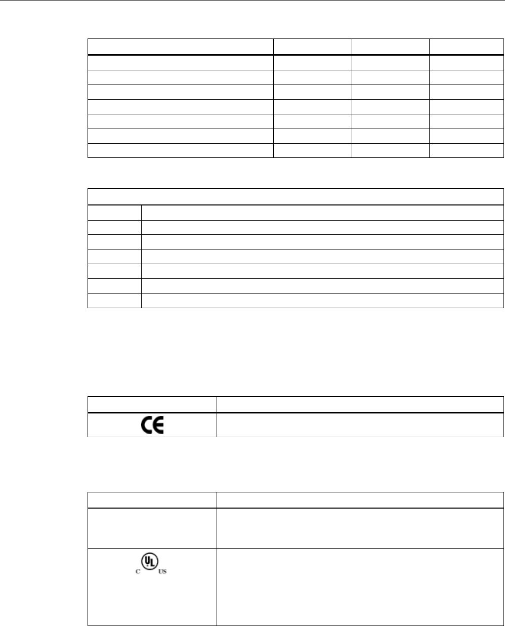
Transponder/tags
7.6 SIMATIC RF620T
SIMATIC RF600
System Manual, xx/2014, J31069-D0171-U001-A15-7618 391
REVIEW
Concentration
20 °C
50 °C
95
○○
-
fuming
-
-
Hydrogen sulphide
Low/saturated
○○○○
○○○○
Detergent
High
○○○○
○○○○
Water
○○○○
○○○○
Hydrogen
techn. pure
○○○○
○○○○
Plasticizer
○○○○
○○
Abbreviations
○○○○
Resistant
○○○
Virtually resistant
○○
Limited resistance
○
Less resistant
ᅳ
Not resistant
w.
Aqueous solution
k. g.
Cold saturated
7.6.7
Certificates and approvals
Table 7- 16 6GT2810-2HC00 - RF620T UHF container tag
Certificate
Description
CE Approval to R&TTE
Table 7- 17 6GT2810-2HC80 - RF620T UHF container tag
Standard
FCC
Federal Communications
Commission
Passive labels or transponders comply with the valid regulations;
certification is not required.
This product is UL-certified for the USA and Canada.
It meets the following safety standard(s):
• UL508 - Industrial Control Equipment
• CSA C22.2 No. 142 - Process Control Equipment
• UL Report E 120869
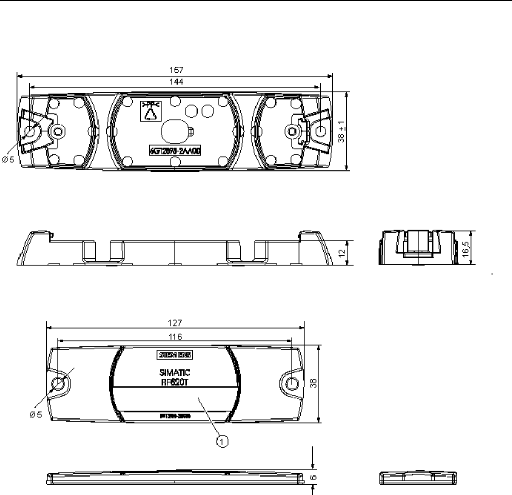
Transponder/tags
7.6 SIMATIC RF620T
SIMATIC RF600
392 System Manual, xx/2014, J31069-D0171-U001-A15-7618
REVIEW
7.6.8
Dimension drawing
Figure 7-29 SIMATIC RF620T UHF container tag
Units of measurement: All dimensions in mm
Tolerances, unless indicated otherwise, are +-0.5 mm.
①
Labeling area, see Section Characteristics (Page 375)
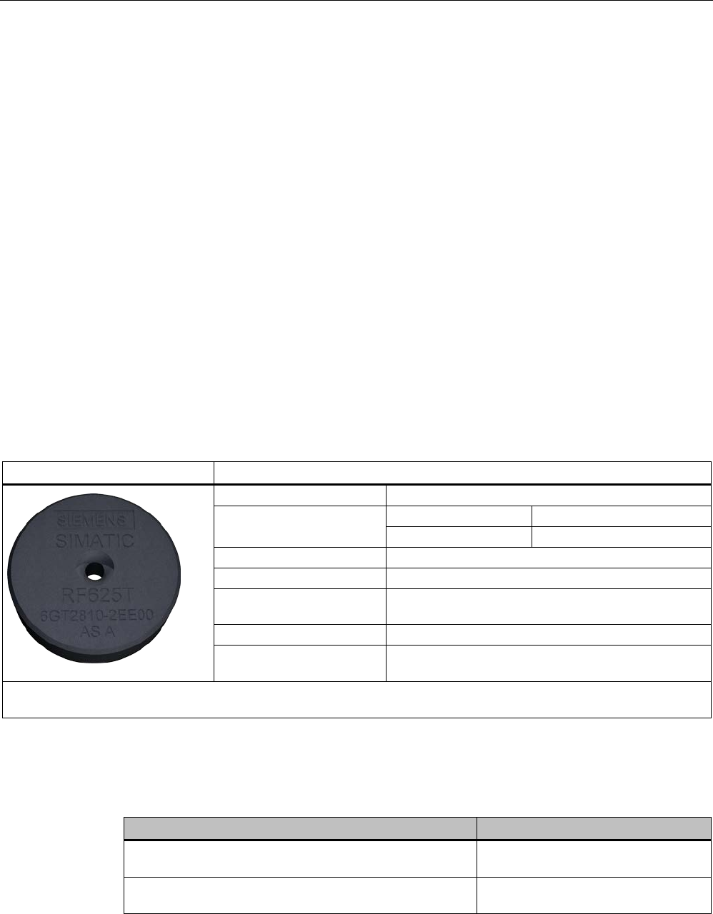
Transponder/tags
7.7 SIMATIC RF622T
SIMATIC RF600
System Manual, xx/2014, J31069-D0171-U001-A15-7618 393
REVIEW
7.7
SIMATIC RF622T
7.8
SIMATIC RF625T
7.8.1
Characteristics
The SIMATIC RF625T transponder is a passive, maintenance-free data carrier with a round
design. It operates based on the UHF Class 1 Gen 2 technology and is used to save the
"Electronic Product Code" (EPC) of 96 bits/128 bits. The transponder also has a 512-bit user
memory.
The areas of application are industrial asset management, RF identification of tools,
containers and metallic equipment.
The Disk Tag is small and rugged and suitable for industrial applications with degree of
protection IP68. It is highly resistant to oil, grease and cleaning agents.
Ideally, the SIMATIC RF625T is mounted directly on a flat metal surface of at least 150 mm
diameter where it achieves a typical sensing distance of 1.5 m.
SIMATIC RF625T
Features
Area of application
Identification tasks in rugged industrial environments
Frequency variants
Europe
USA/Canada
865 MHz ... 868 MHz
902 MHz ... 928 MHz
Air interface
according to ISO°18000-6C
Polarization
Linear
Memory EPC 96 bit/128 bit
Add-on-memory 64 bytes
Range
1)
max. 1.5 m
Mounting for direct mounting on conductive materials (preferably
metal).
1) The information relates to the maximum read range. You will find more information on ranges in the section "Minimum
distances and maximum ranges (Page 344)".
7.8.2
Ordering data
Ordering data
Article number
SIMATIC RF625T (Europe),
frequency range 865 MHz ... 868 MHz
6GT2810-2EE00
SIMATIC RF625T (USA / Canada),
frequency range 902 MHz ... 928 MHz
6GT2810-2EE01
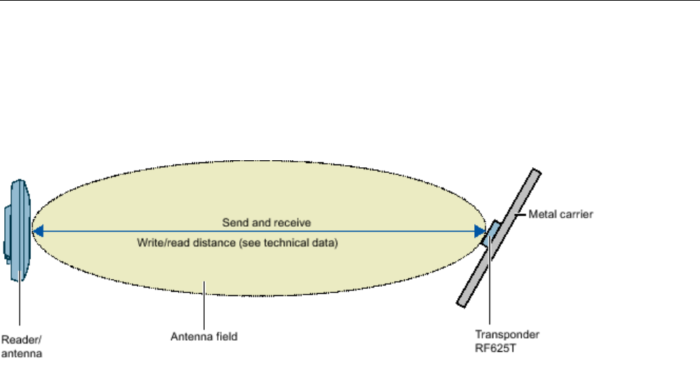
Transponder/tags
7.8 SIMATIC RF625T
SIMATIC RF600
394 System Manual, xx/2014, J31069-D0171-U001-A15-7618
REVIEW
7.8.3
Planning the use
7.8.3.1
Optimum antenna/transponder positioning with planar mounting of the transponder on
metal
Figure 7-30 Example of optimum reader/antenna transponder positioning
The graphic shows an example of optimum positioning of the transponder relative to the
reader or the antenna. This positioning is regardless of whether you are working with the
internal reader antenna or with one of the external RF600 antennas.
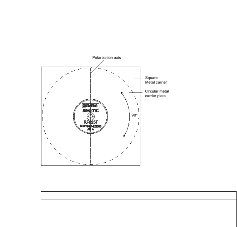
Transponder/tags
7.8 SIMATIC RF625T
SIMATIC RF600
System Manual, xx/2014, J31069-D0171-U001-A15-7618 395
REVIEW
7.8.3.2
Range when mounted on flat metallic carrier plates
The transponder generally has linear polarization. The polarization axis runs as shown in the
diagram below. If the tag is mounted in the center of a flat metal plate, which is either
approximately square or circular, it can be aligned in any direction since the transmitting and
receiving RF660A antennas operate with circular polarization.
Figure 7-31 Optimum positioning of the transponder on a (square or circular) metal surface
Table 7- 18 Range on flat metallic carriers
Carrier material
Range
Metal plate of at least Ø 150 mm
100 %
Metal plate Ø 120 mm
approx. 70%
Metal plate Ø 85 mm
approx. 60%
Metal plate Ø 65 mm
approx. 60%
On rectangular carrier plates, the range depends on the mounting orientation of the
transponder
You will find more detailed information on the range in the section "Minimum distances and
maximum ranges (Page 344)".

Transponder/tags
7.8 SIMATIC RF625T
SIMATIC RF600
396 System Manual, xx/2014, J31069-D0171-U001-A15-7618
REVIEW
7.8.3.3
Range when mounted on non-metallic carrier materials
The transponder is generally designed for mounting on metallic objects which provide the
conditions for the maximum reading ranges
Table 7- 19 Range with non-metallic carriers
Carrier material
Range
Transponder on wooden carrier
approx. 60%
Transponder on plastic carrier
approx. 65 %
Transponder on plastic mineral water bottle
approx. 70%
Transponder without base
approx. 50 %
The maximum range of 100% is achieved by mounting the transponder in a free space with
low reflections on a flat metal carrier with a diameter of at least 150 mm.
You will find more detailed information on the range in the section "Minimum distances and
maximum ranges (Page 344)".
7.8.3.4
Influence of conducting walls on the range
If there are conducting walls or restrictions in the vicinity that could affect the wireless field, a
distance of approx. 10 cm is recommended. In principle, walls have least influence if the
polarization axis is orthogonal to the wall.
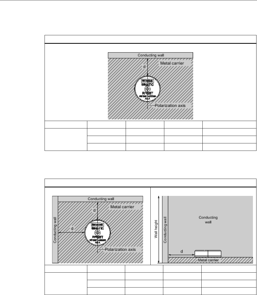
Transponder/tags
7.8 SIMATIC RF625T
SIMATIC RF600
System Manual, xx/2014, J31069-D0171-U001-A15-7618 397
REVIEW
Range: One conducting wall
Influence on range when positioned against one conducting wall
View from above
Distance d
20 mm
50 mm
100 mm
Range
approx. 100%
approx. 100%
approx. 100%
Wall height 20 mm
approx. 100%
approx. 100%
approx. 100%
Wall height 50 mm
approx. 80%
approx. 100%
approx. 100%
Wall height 100 mm
Range: Two conducting walls
Influence on the range when positioned against two conducting walls
View from above
Side view
Distance d
20 mm
50 mm
100 mm
Range
approx. 70%
approx. 75 %
approx. 100%
Wall height 20 mm
approx. 70%
approx. 80%
approx. 100%
Wall height 50 mm
approx. 70% approx. 40% approx. 50 % Wall height 100 mm
The values specified in the tables above are guide values.
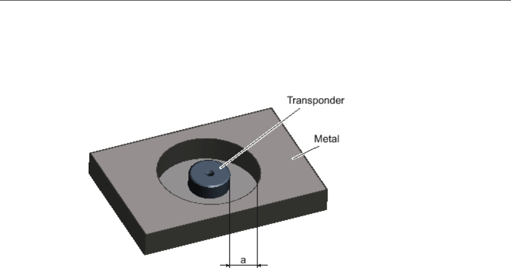
Transponder/tags
7.8 SIMATIC RF625T
SIMATIC RF600
398 System Manual, xx/2014, J31069-D0171-U001-A15-7618
REVIEW
7.8.3.5
Mounting in metal
It is possible to mount the transponder in metal. If there is not enough clearance to the
surrounding metal, this reduces the reading range.
Clearance (all-round)
Reading range
1)
a = 5 mm
Approx. 50 %
a = 10 mm
Approx. 70%
1) The read range information applies when the transponder is mounted on a metallic carrier with a
diameter of at least 150 mm.
Figure 7-32 Flush-mounting of RF625T in metal
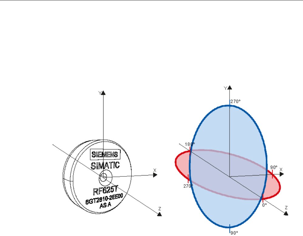
Transponder/tags
7.8 SIMATIC RF625T
SIMATIC RF600
System Manual, xx/2014, J31069-D0171-U001-A15-7618 399
REVIEW
7.8.3.6
Directional radiation pattern of the transponder
Directional diagram in the ETSI frequency band (Europe)
The directional diagram is shown for nominal alignment and a center frequency of 866.3
MHz. The nominal transponder alignment is achieved when the transponder is viewed as
shown in the following figure.
Figure 7-33 Reference system of the RF625T
Ideally, align the data carrier parallel with the transmitting antenna or the reader. If the data
carrier including the (metallic) carrier plate is tilted, the reading range will be reduced. The
following diagrams show the effects on the reading range depending on the carrier material
and the angle of inclination of the transponder.
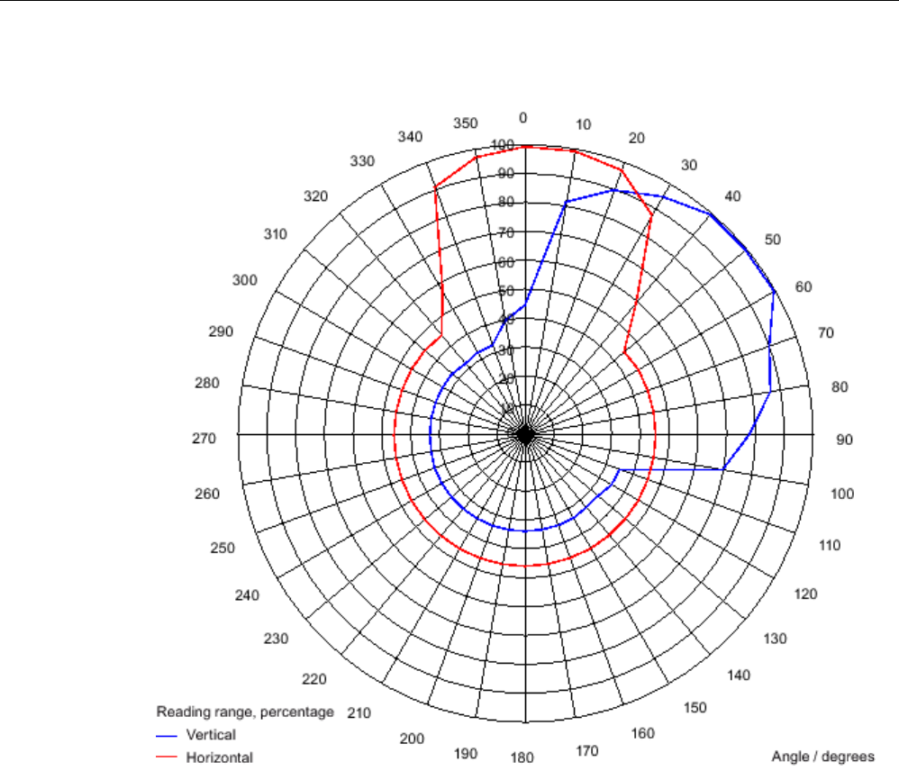
Transponder/tags
7.8 SIMATIC RF625T
SIMATIC RF600
400 System Manual, xx/2014, J31069-D0171-U001-A15-7618
REVIEW
Directional characteristics of the transponder when mounted on a metallic carrier
Figure 7-34 Directional characteristics of the RF625T on a metallic carrier depending on the angle of
inclination in a vertical or horizontal direction
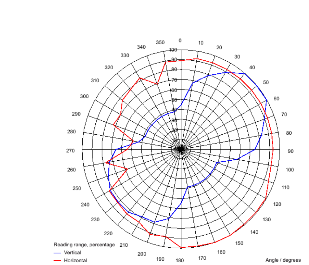
Transponder/tags
7.8 SIMATIC RF625T
SIMATIC RF600
System Manual, xx/2014, J31069-D0171-U001-A15-7618 401
REVIEW
Directional characteristics of the transponder when mounted on a non-metallic carrier
Figure 7-35 Directional characteristics of the RF625T on a non-metallic carrier depending on the
angle of inclination in a vertical or horizontal direction
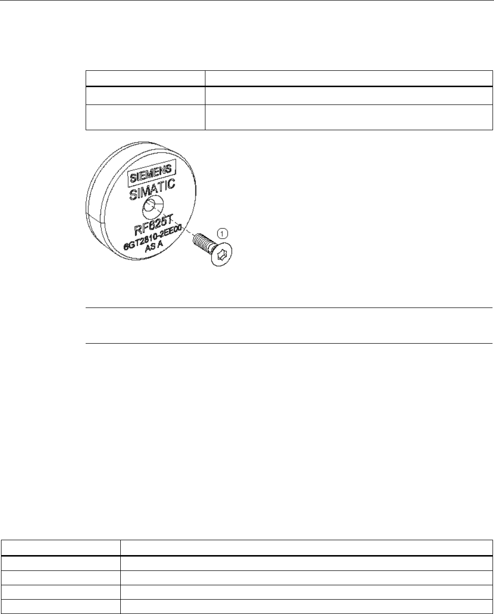
Transponder/tags
7.8 SIMATIC RF625T
SIMATIC RF600
402 System Manual, xx/2014, J31069-D0171-U001-A15-7618
REVIEW
7.8.4
Mounting instructions
Properties
Description
Type of installation Secured with screw
①
, (M3 counter-sunk head screw)
Tightening torque
(at room temperature)
≤ 1.0 Nm
Figure 7-36 Screw mounting
Note
Make sure that the mounting surface is even when mounting the transponder.
7.8.5
Memory configuration of the transponder
The memory configuration of the transponder is described in the section SIMATIC memory
configuration of the RF600 transponders and labels (Page 336).
7.8.6
Technical Specifications
7.8.6.1
Mechanical data
Property
Description
Dimensions (D x H)
30 (+0.5) mm x 8 (+0.5) mm
Design
Plastic housing (PA6.6), silicone-free
Weight
Approx. 6 g
Mounting on metal
directly on metal without spacing
Transponder/tags
7.8 SIMATIC RF625T
SIMATIC RF600
System Manual, xx/2014, J31069-D0171-U001-A15-7618 403
REVIEW
7.8.6.2
Electrical data
Characteristic
Description
Europe
USA/Canada
Air interface
According to ISO 18 000-6 C
According to ISO 18 000-6 C
Frequency range
865 ... 868 MHz
902 ... 928 MHz
1)
Necessary transmit power
2 W (ERP)
4 W (EIRP)
Range
2)
max. 1.5 m
max. 1.5 m
Polarization type
Linear
Linear
Energy source
Field energy via antenna, without battery
Field energy via antenna, without battery
Multitag capability yes, minimum distance between data
carriers ≥ 50 mm
3)
yes, minimum distance between data
carriers ≥ 50 mm
3)
1) Reduction of range to about 70% at the band limits 902 MHz or 928 MHz; acquisition is guaranteed at 915 MHz due to
frequency hopping procedure.
2) Mounting on a flat metal surface with a diameter of at least 150 mm and at room temperature. The information relates to
the maximum read range. You will find more information on ranges in the section "Minimum distances and maximum
ranges (Page 344)".
3) When these minimum distances are not reached, there is a reduction in the maximum possible read and write distances
of the transponder.
7.8.6.3
Information on memory
Property
Description
Type
EPC Class 1 Gen 2
Memory organization
EPC code
96 bits/128 bits
User memory
64 bytes
TID 96 bits
Reserved (passwords)
64 bits
Protocol ISO 18000-6C
Data retention time
10 years
Read cycles
Unlimited
Write cycles
Minimum 100 000, at +22 °C
7.8.6.4
Environmental conditions
Property
Description
Temperature range during operation
-25 °C … +85 °C
Temperature range during storage
-40 °C … +125 °C
Shock resistant to EN 60068-2-27
Vibration to EN 60068-2-6
50 g, 1)
20 g,
1)
Torsion and bending load
Not permissible

Transponder/tags
7.8 SIMATIC RF625T
SIMATIC RF600
404 System Manual, xx/2014, J31069-D0171-U001-A15-7618
REVIEW
Property
Description
Degree of protection IP68 according to EN 60529:
(45 minutes. immersion in water; water depth
1 m from
top edge of housing at +20 °C)
IPx9K to EN 60529:
• Steam blaster nozzle distance 150 mm
• 10 ... 15 l water per minute
• Pressure 100 bar
• Temperature 75 °C
• Test time 30 seconds
MTBF
2 x 10
5
hours
1) The values for shock and vibration are maximum values and must not be applied
continuously.
7.8.6.5
Chemical resistance of the RF625T transponder
The following table provides an overview of the chemical resistance of the data memory
made of polyamide 6.6. It must be emphasized that the plastic housing is extremely resistant
to chemicals in automobiles (e.g.: oil, grease, diesel fuel, gasoline) which are not listed
separately.
Substance
Concentration
Mineral lubricants
■
Aliphatic hydrocarbons
■
Aromatic hydrocarbons
■
Petroleum spirit
■
Weak mineral acids
◪
Strong mineral acids
□
Weak organic acids
◪
Strong organic acids
□
Oxidizing acids
□
Weak alkalis
◪
Strong alkalis
□
Trichloroethylene ■
Perchloroethylene
■
Acetone ■
Alcohols
■
Hot water (hydrolysis resistance)
◪
Abbreviations:
■
Resistant
◪
Limited resistance
□
Not resistant
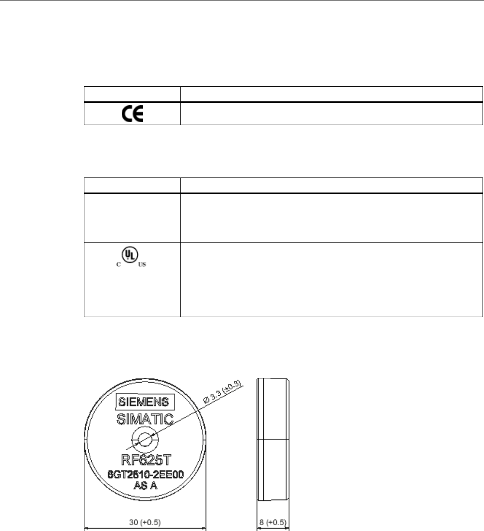
Transponder/tags
7.8 SIMATIC RF625T
SIMATIC RF600
System Manual, xx/2014, J31069-D0171-U001-A15-7618 405
REVIEW
7.8.7
Certificates and approvals
Table 7- 20 SIMATIC RF625T UHF Disk Tag (Europe), 6GT2810-2EE00
Certificate
Description
Conforms to R&TTE directive
Table 7- 21 SIMATIC RF625T UHF Disk Tag (USA/Canada), 6GT2810-2EE01
Standard
FCC
Federal
Communications
Commission
Passive labels or transponders comply with the valid regulations;
certification is not required
This product is UL-certified for the USA and Canada.
It meets the following safety standard(s):
• UL508 - Industrial Control Equipment
• CSA C22.2 No. 142 - Process Control Equipment
• UL Report E 120869
7.8.8
Dimension drawing
Figure 7-37 SIMATIC RF625T UHF Disk Tag
Units of measurement: All dimensions in mm
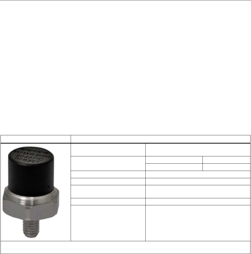
Transponder/tags
7.9 SIMATIC RF630T
SIMATIC RF600
406 System Manual, xx/2014, J31069-D0171-U001-A15-7618
REVIEW
7.9
SIMATIC RF630T
7.9.1
Characteristics
The SIMATIC RF630T transponder is a passive (i.e. battery-free) and maintenance-free,
cylindrical data carrier. It operates based on the UHF Class 1 Gen 2 technology and is used
to save the "Electronic Product Code" (EPC) of 96 bits/240 bits. The transponder also has a
512-bit user memory.
Areas of application include the mounting of metallic components (e.g. engine assembly in
the automobile industry) as well as RF identification of tools, containers and metal frames.
The RF630T is small and rugged and suitable for industrial applications with IP68/IPX9K
degree of protection. It is highly resistant to oil, grease and cleaning agents.
The SIMATIC RF630T is mounted directly onto metal surfaces to ensure optimum
functioning and its typical detection range is 1.2 m.
SIMATIC RF630T
Features
Area of application Identification tasks in rugged industrial
environments
Frequency variants
Europe
USA/Canada
868 MHz
915 MHz
Air interface
according to ISO°18000-6C
Polarization
Linear
Memory EPC 96 bit/240 bit
Add-on-memory 64 bytes
Range
1)
max. 1.2 m
Mounting for direct mounting on conductive materials
(preferably metal).
1) The information relates to the maximum read range. You will find more information on ranges in the section "Minimum
distances and maximum ranges (Page 344)".

Transponder/tags
7.9 SIMATIC RF630T
SIMATIC RF600
System Manual, xx/2014, J31069-D0171-U001-A15-7618 407
REVIEW
7.9.2
Ordering data
Ordering data
Article number
SIMATIC RF630T (Europe)
• For attaching to metal surfaces
• Frequency 865 MHz to 868 MHz
6GT2810-2EC00
SIMATIC RF630T (USA / Canada)
• For attaching to metal surfaces
• Frequency 902 MHz to 928 MHz
6GT2810-2EC10
7.9.3
Planning application
7.9.3.1
Optimum antenna/transponder positioning with plane mounting of the transponder on
metal
The maximum reading range is achieved when the reader antenna is positioned at right
angles to the mounting surface. In the case of parallel mounting directly above the
transponder, detection is not possible.
Positioning of the RF660A antenna with the RF630R/RF670R/RF680R reader
The RF630R, RF670R and RF680R readers can operate with an RF660A antenna which
can be positioned as shown.
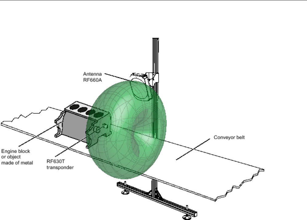
Transponder/tags
7.9 SIMATIC RF630T
SIMATIC RF600
408 System Manual, xx/2014, J31069-D0171-U001-A15-7618
REVIEW
RF630T application example
Figure 7-38 RF630T application example
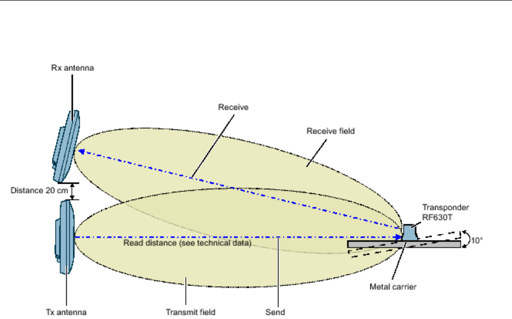
Transponder/tags
7.9 SIMATIC RF630T
SIMATIC RF600
System Manual, xx/2014, J31069-D0171-U001-A15-7618 409
REVIEW
Positioning of two RF660A antennas
Figure 7-39 Example of optimum antenna/transponder positioning
Depending on the design of the metal bracket (surface parallel to the transmitting antenna),
an angle of 10° will have a favorable effect.
Positioning of the RF620R/RF685R reader
The RF620R reader with an integrated circular polarized antenna or the RF685R reader can
be placed in the same position relative to the RF630T transponder as the RF660A antennas.
Please note the different reading ranges for the RF600 readers in the section Electrical data
(Page 414)
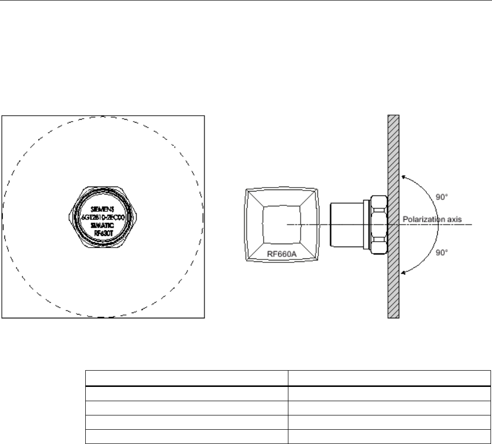
Transponder/tags
7.9 SIMATIC RF630T
SIMATIC RF600
410 System Manual, xx/2014, J31069-D0171-U001-A15-7618
REVIEW
7.9.3.2
Range when mounted on flat metallic carrier plates
The transponder generally has linear polarization. The polarization axis runs as shown in the
diagram below. If the tag is mounted in the center of a flat metal plate, which is either
approximately square or circular, it can be aligned in any direction since the transmitting and
receiving RF660A antennas operate with circular polarization.
Figure 7-40 Optimum positioning of the transponder on a (square or circular) metal surface
Table 7- 22 Range on flat metallic carriers
Carrier material
Range
Metal plate of at least Ø 300 mm
100 %
Metal plate Ø 150 mm
approx. 75 %
Metal plate Ø 120 mm
approx. 50 %
Metal plate Ø 85 mm
approx. 40%
On rectangular carrier plates, the range depends on the mounting orientation of the
transponder
You will find more detailed information on the range in the section "Minimum distances and
maximum ranges (Page 344)".
7.9.3.3
Influence of conducting walls on the range
If there are conducting walls or restrictions in the vicinity that could affect the wireless field, a
distance of approx. 10 cm is recommended. In principle, walls have least influence if the
polarization axis is vertical to the conducting wall.
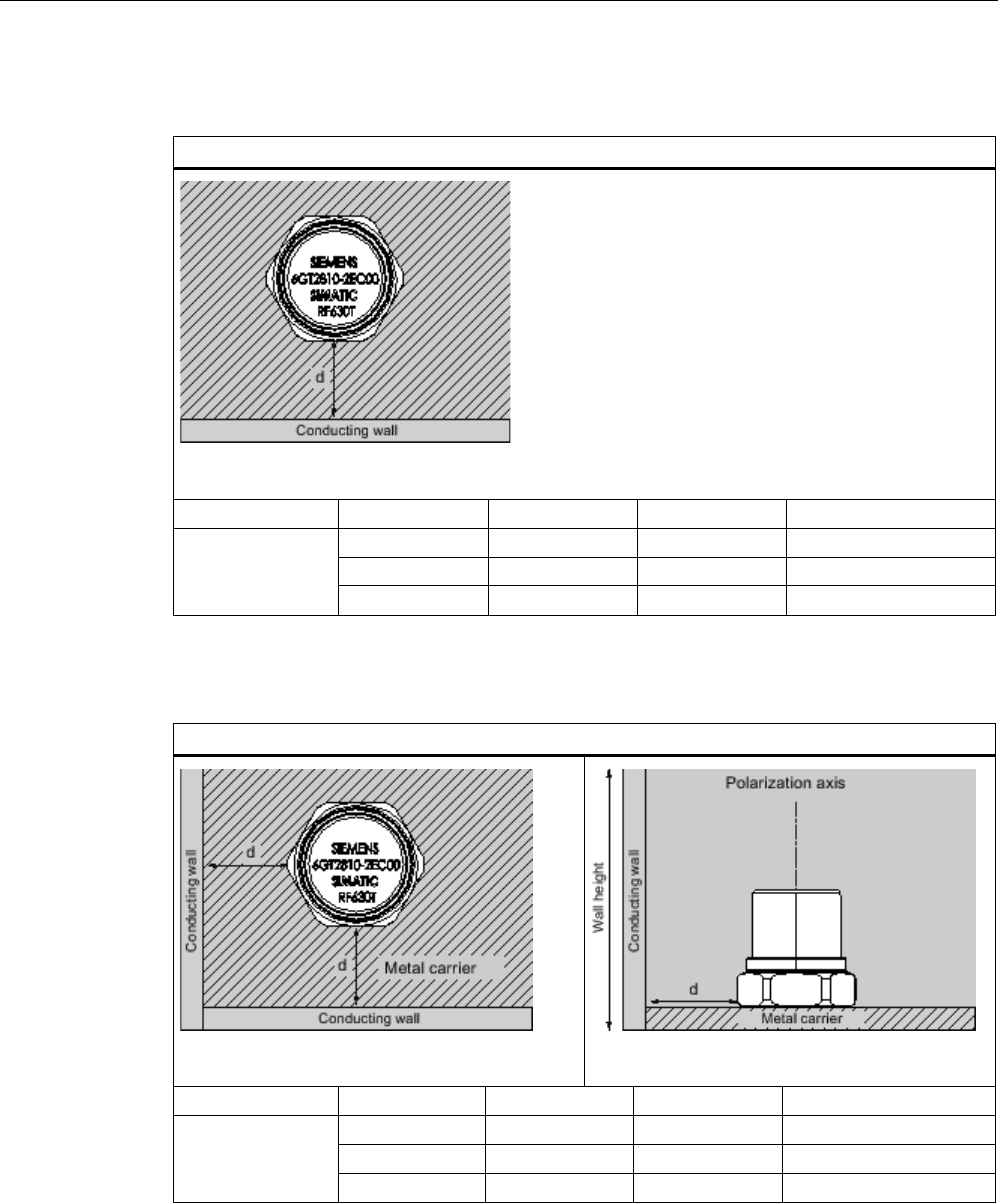
Transponder/tags
7.9 SIMATIC RF630T
SIMATIC RF600
System Manual, xx/2014, J31069-D0171-U001-A15-7618 411
REVIEW
Range: One conducting wall
Influence on range when positioned against one conducting wall
View from above
Distance d
20 mm
50 mm
100 mm
Range
approx. 40%
approx. 40%
approx. 90 %
Wall height 20 mm
approx. 40%
approx. 90 %
approx. 90 %
Wall height 50 mm
approx. 40%
approx. 40%
approx. 90 %
Wall height 100 mm
Range: Two conducting walls
Influence on the range when positioned against two conducting walls
Side view
Distance d
20 mm
50 mm
100 mm
Range
approx. 90 %
approx. 90 %
approx. 90 %
Wall height 20 mm
approx. 25 %
approx. 90 %
approx. 90 %
Wall height 50 mm
approx. 25 %
approx. 90 %
approx. 90 %
Wall height 100 mm
The values specified in the tables above are guide values.
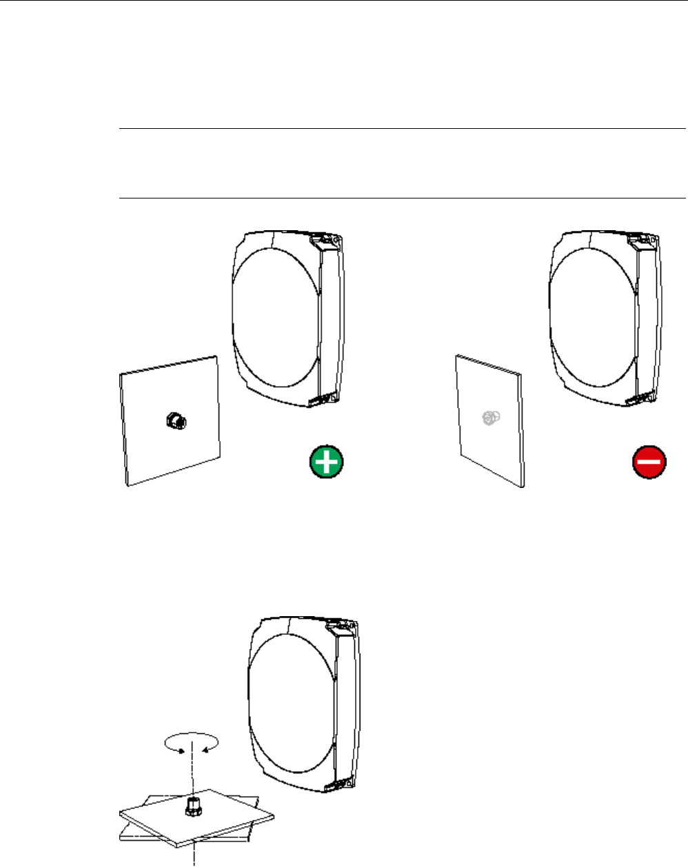
Transponder/tags
7.9 SIMATIC RF630T
SIMATIC RF600
412 System Manual, xx/2014, J31069-D0171-U001-A15-7618
REVIEW
7.9.3.4
Directional radiation pattern of the transponder
Preferably, align the data carrier orthogonal to the transmitting antenna. If, however, the tag
including the metallic carrier plate is tilted, the reading range will be reduced.
Note
Incorrect alignment of the transponder
When you align the transponder in parallel with the transmitting antenna, it cannot be read!
Optimum alignment of the transponder to the
transmitting antenna
Incorrect alignment of the transponder to the
transmitting antenna
Rotation about the polarization axis
If the transponder mounting surface is circular there is almost no change in the reading
range.
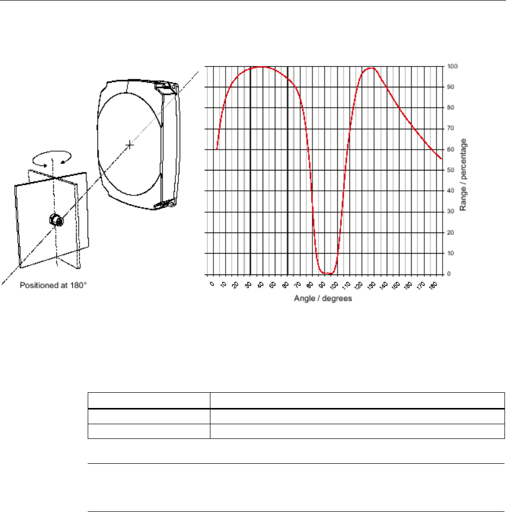
Transponder/tags
7.9 SIMATIC RF630T
SIMATIC RF600
System Manual, xx/2014, J31069-D0171-U001-A15-7618 413
REVIEW
Rotation of the mounting plane
Figure 7-41 Characteristics of the transponder on rotation of the mounting plane
7.9.4
Mounting instructions
Properties
Description
Type of installation
M6 bolt fixing, spanner size 19 mm
Tightening torque
(at room temperature) ≤ 6 Nm
Note
Make sure that the mounting surface is even when mounting the transponder. Electrical
contact between the mounting surface and the transponder is necessary.
Without a metal surface the transponder does not function.
7.9.5
Memory configuration of the transponder
The memory configuration of the transponder is described in the section SIMATIC memory
configuration of the RF600 transponders and labels (Page 336).
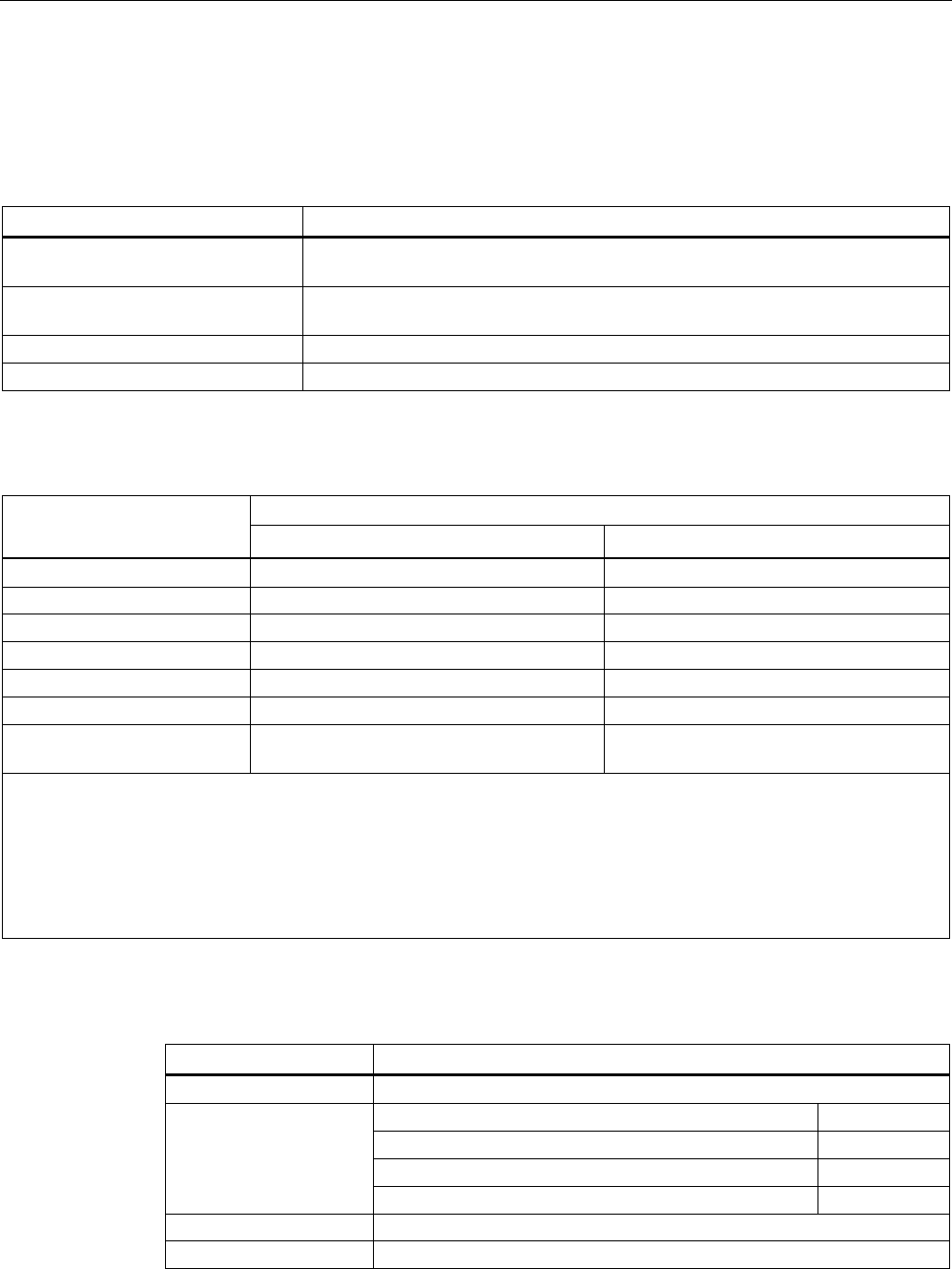
Transponder/tags
7.9 SIMATIC RF630T
SIMATIC RF600
414 System Manual, xx/2014, J31069-D0171-U001-A15-7618
REVIEW
7.9.6
Technical specifications
7.9.6.1
Mechanical data
Property
Description
Dimensions (D x H) 21 mm x 21 mm (without thread), tolerance 1 mm
spanner size 19 mm
Design Plastic enclosure: PA 6.6 GF, silicone-free
Thread: Stainless steel
Weight
approx. 22 g
Installation
directly on metal without spacing
7.9.6.2
Electrical data
Characteristic
Description
Europe
USA/Canada
Air interface
According to ISO 18 000-6 C
According to ISO 18 000-6 C
Frequency range
865 ... 868 MHz
902 ... 928 MHz
1)
Necessary transmit power
2 W (ERP)
4 W (EIRP)
Range
2)
max. 1.5 m
max. 1.5 m
Polarization type
Linear
Linear
Energy source
Field energy via antenna, without battery
Field energy via antenna, without battery
Multitag capability yes, minimum distance between data
carriers ≥ 50 mm
3)
yes, minimum distance between data
carriers ≥ 50 mm
3)
1) Reduction of range to about 70% at the band limits 902 MHz or 928 MHz; detection is guaranteed at 915 MHz due to
frequency hopping procedure.
2) Mounting on a flat metal surface with a diameter of at least 300 mm and at room temperature. The information relates to
the maximum read range. You will find more information on ranges in the section "Minimum distances and maximum
ranges (Page 344)".
3) When these minimum distances are not reached, there is a reduction in the maximum possible read and write distances
of the transponder.
7.9.6.3
Memory specifications
Property
Description
Type
EPC Class 1 Gen 2
Memory organization
EPC code
96 bits/240 bits
User memory
64 bytes
TID
64 bits
Reserved (passwords)
64 bits
Protocol
ISO 18000-6C
Data retention time
10 years

Transponder/tags
7.9 SIMATIC RF630T
SIMATIC RF600
System Manual, xx/2014, J31069-D0171-U001-A15-7618 415
REVIEW
Property
Description
Read cycles
Unlimited
Write cycles
Minimum at +22 °C 100 000
7.9.6.4
Environmental conditions
Property
Description
Temperature range during operation
-25 °C to +85 °C
Temperature range during storage
-40 °C to +125 °C
Shock
Vibration
compliant with EN 60721-3-7 Class 7 M3
100 g, 1)
20 g, 1)
Torsion and bending load
Not permissible
Degree of protection IP68 according to EN 60529:
(45 minutes. Immersion in water; water depth
1 m from
top edge of enclosure at +20 °C)
IPx9K according to DIN 40005-9
(steam jet-air ejector: 150 mm;
10 to 15 l/min; 100 bar; 75 °C)
1) The values for shock and vibration are maximum values and must not be applied continuously.
7.9.6.5
Chemical resistance of the transponder
The following table provides an overview of the chemical resistance of the plastic cap of the
transponder made of PA 6.6 GF. Different values apply to the stainless steel bolt head. It
must be emphasized that the plastic enclosure is extremely resistant to chemicals in
automobiles (e.g.: oil, grease, diesel fuel, gasoline) which are not listed separately.
Concentration
20 °C
60 °C
Ammonia, w.
conc.
+
+
20
+
+
Benzol
+
+
Bleach solution (12.5 % effective chlorine)
-
ᅳ
Butane, gas, liquid + 1) Nothing
specified
Butyl acetate (acetic acid butyl ester) + 1) Nothing
specified
Calcium chloride, saturated 10% solution
+
○
Chlorine
ᅳ
ᅳ
Chrome baths, tech.
ᅳ
ᅳ
Iron salts, w.
k. g.
-
-
Acetic acid, w.
10
○
ᅳ
Ethyl alcohol, w., undenaturated 40 + Nothing
specified

Transponder/tags
7.9 SIMATIC RF630T
SIMATIC RF600
416 System Manual, xx/2014, J31069-D0171-U001-A15-7618
REVIEW
Concentration
20 °C
60 °C
Formaldehyde 30 + Nothing
specified
Formalin + Nothing
specified
Glycerine + Nothing
specified
Isopropanol
+
+
Potassium hydroxide, w. 10-15 % ○ Nothing
specified
Magnesium salts, w. + 1) Nothing
specified
Methyl alcohol, w. 50 + Nothing
specified
Lactic acid, w.
+
ᅳ
Sodium carbonate, w. (soda) + Nothing
specified
Sodium chloride, w. ○ Nothing
specified
Sodium hydroxide 10 % + Nothing
specified
Nitrobenzol ○ 1) Nothing
specified
Phosphoric acid
10
-
-
Propane + Nothing
specified
Nitric acid
10
-
ᅳ
Hydrochloric acid
10
-
ᅳ
Sulphur dioxide Low ○ Nothing
specified
Sulphuric acid
25
-
ᅳ
10
-
ᅳ
Hydrogen sulphide
Dry
+
-
Carbon tetrachloride 1-4 % + Nothing
specified
1) Nothing specified for stainless steel
Abbreviations
+
Resistant
○ Limited resistance
ᅳ Not resistant
w.
Aqueous solution
k. g.
Cold saturated
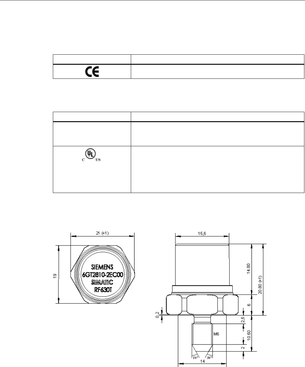
Transponder/tags
7.9 SIMATIC RF630T
SIMATIC RF600
System Manual, xx/2014, J31069-D0171-U001-A15-7618 417
REVIEW
7.9.7
Certificates and approvals
Table 7- 23 6GT2810-2EC00 - RF630T UHF Tool Tag - Europe
Certificate
Description
Conformity with R&TTE directive
Table 7- 24 6GT2810-2EC10 - RF630T Gen 2 UHF Tool Tag - USA / Canada
Standard
FCC
Federal Communications
Commission
Passive labels and transponders comply with the valid regulations;
certification is not required.
This product is UL-certified for the USA and Canada.
It meets the following safety standard(s):
• UL508 - Industrial Control Equipment
• CSA C22.2 No. 142 - Process Control Equipment
• UL Report E 120869
7.9.8
Dimension drawing
Figure 7-42 SIMATIC RF630T
Units of measurement: All dimensions in mm
General tolerances in accordance with DIN ISO 2768f.
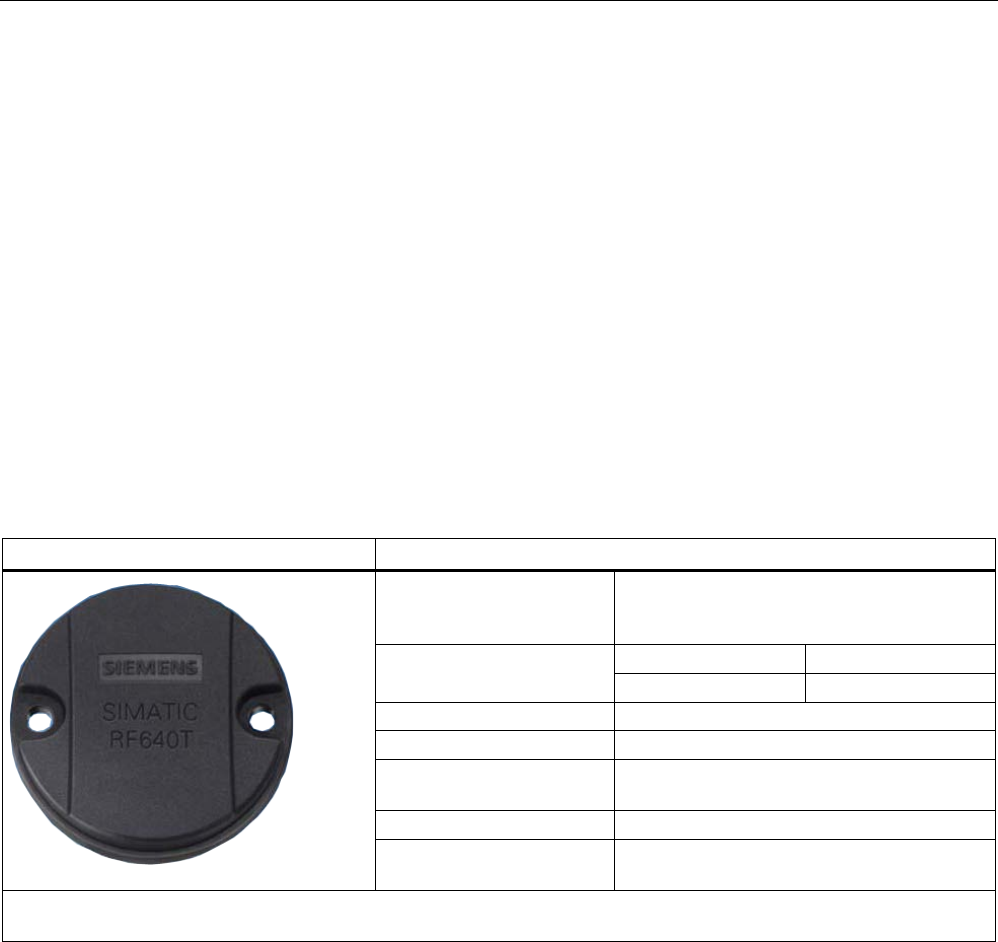
Transponder/tags
7.10 SIMATIC RF640T Gen 2
SIMATIC RF600
418 System Manual, xx/2014, J31069-D0171-U001-A15-7618
REVIEW
7.10
SIMATIC RF640T Gen 2
7.10.1
Characteristics
The SIMATIC RF640T Gen 2 transponder is a passive (i.e. battery-free) and maintenance-
free, round-shaped data carrier. It operates based on UHF Class 1 Gen 2 technology and is
used to save the electronic product code (EPC) of 96 bits/240 bits. The transponder also has
a 512-bit user memory.
The areas of application are industrial asset management, RF identification of tools,
containers and metallic equipment.
The tool tag is small and rugged and suitable for industrial applications with degree of
protection IP68. It is highly resistant to oil, grease and cleaning agents.
Preferably the SIMATIC RF640T is to be mounted direct on a flat metal surface of at least
150 mm diameter where it achieves a typical sensing distance of 4 m.
SIMATIC RF640T Gen 2
Features
Area of application Identification tasks in rugged industrial
environments Suitable for use in hazardous
areas.
Frequency variants
Europe
USA/Canada
868 MHz
915 MHz
Air interface
according to ISO°18000-6C
Polarization
Linear
Memory EPC 96 bit/240 bit
Add-on-memory 64 bytes
Range
1)
max. 4.0 m
Mounting for direct mounting on conductive materials
(preferably metal).
1) The information relates to the maximum read range. You will find more information on ranges in the section "Minimum
distances and maximum ranges (Page 344)".
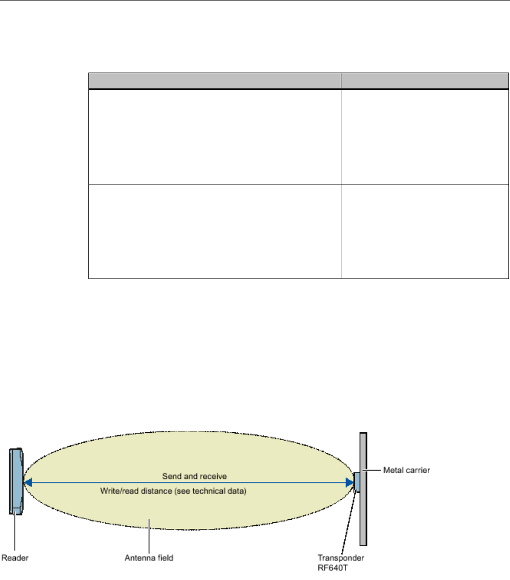
Transponder/tags
7.10 SIMATIC RF640T Gen 2
SIMATIC RF600
System Manual, xx/2014, J31069-D0171-U001-A15-7618 419
REVIEW
7.10.2
Ordering data
Ordering data
Article number
SIMATIC RF640T Gen 2 (Europe)
• Frequency 865 MHz to 868 MHz
• EPC 96 bits/240 bits
• 64-byte user memory
• -25 °C to +85 °C operating temperature
• Dimensions (D x H) 50 mm x 8 mm
6GT2810-2DC00
SIMATIC RF640T Gen 2 (USA/Canada)
• Frequency 902 MHz to 928 MHz
• EPC 96 bits/240 bits
• 64-byte user memory
• -25 °C to +85 °C operating temperature
• Dimensions (D x H) 50 mm x 8 mm
6GT2810-2DC10
7.10.3
Planning the use
7.10.3.1
Optimum antenna/transponder positioning with plane mounting of the transponder on
metal
Example of optimum antenna/transponder positioning
Figure 7-43 Example of optimum antenna/transponder positioning with RF600 readers and an RF600 antenna
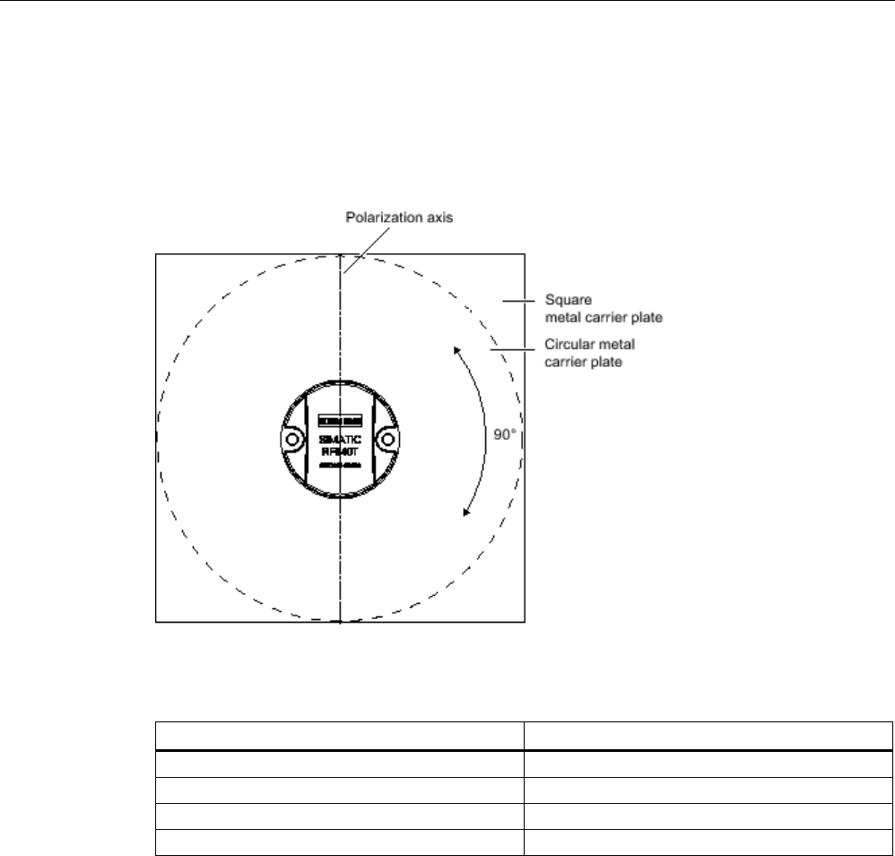
Transponder/tags
7.10 SIMATIC RF640T Gen 2
SIMATIC RF600
420 System Manual, xx/2014, J31069-D0171-U001-A15-7618
REVIEW
7.10.3.2
Range when mounted on flat metallic carrier plates
The transponder generally has linear polarization. The polarization axis runs as shown in the
diagram below. If the tag is mounted in the center of a flat metal plate, which is either
approximately square or circular, it can be aligned in any direction since the transmitting and
receiving RF660A antennas operate with circular polarization.
Figure 7-44 Optimum positioning of the transponder on a (square or circular) metal surface
Table 7- 25 Range on flat metallic carriers
Carrier material
Range
Metal plate of at least Ø 150 mm
100 %
Metal plate Ø 120 mm
approx. 80%
Metal plate Ø 85 mm
approx. 55%
Metal plate Ø 65 mm
approx. 40%
On rectangular carrier plates, the range depends on the mounting orientation of the
transponder
You will find more detailed information on the range in the section "Minimum distances and
maximum ranges (Page 344)".

Transponder/tags
7.10 SIMATIC RF640T Gen 2
SIMATIC RF600
System Manual, xx/2014, J31069-D0171-U001-A15-7618 421
REVIEW
7.10.3.3
Range when mounted on non-metallic carrier materials
The transponder is generally designed for mounting on metallic objects which provide the
conditions for the maximum reading ranges
Table 7- 26 Range with non-metallic carriers
Carrier material
Range
Transponder on wooden carrier
approx. 40%
Transponder on plastic carrier
approx. 35%
Transponder on plastic mineral water bottle
approx. 55%
Transponder without base
approx. 30%
The maximum range of 100% is achieved by mounting the transponder in a free space with
low reflections on a flat metal carrier with a diameter of at least 150 mm.
You will find more detailed information on the range in the section "Minimum distances and
maximum ranges (Page 344)".
7.10.3.4
Influence of conducting walls on the range
If there are conducting walls or restrictions in the vicinity that could affect the wireless field, a
distance of approx. 10 cm is recommended. In principle, walls have least influence if the
polarization axis is orthogonal to the wall.
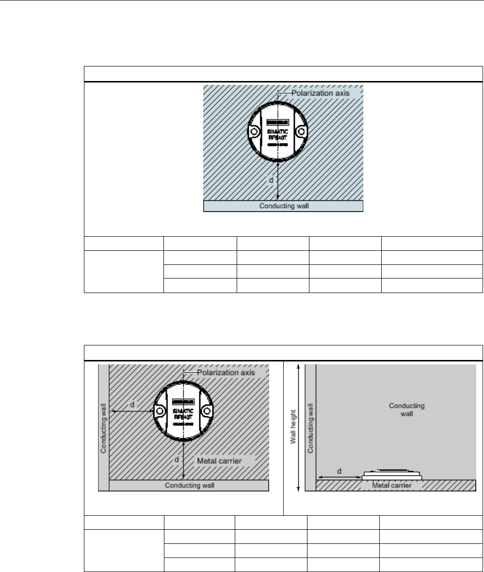
Transponder/tags
7.10 SIMATIC RF640T Gen 2
SIMATIC RF600
422 System Manual, xx/2014, J31069-D0171-U001-A15-7618
REVIEW
Range: One conducting wall
Influence on range when positioned against one conducting wall
View from above
Distance d
20 mm
50 mm
100 mm
Range
approx. 90 %
approx. 90 %
approx. 95 %
Wall height 20 mm
approx. 80%
approx. 90 %
approx. 90 %
Wall height 50 mm
approx. 70%
approx. 75 %
approx. 90 %
Wall height 100 mm
Range: Two conducting walls
Influence on the range when positioned against two conducting walls
View from above
Side view
Distance d
20 mm
50 mm
100 mm
Range
approx. 75 %
approx. 90 %
approx. 90 %
Wall height 20 mm
approx. 50 %
approx. 45 %
approx. 80%
Wall height 50 mm
approx. 40%
approx. 45 %
approx. 75 %
Wall height 100 mm
The values specified in the tables above are guide values.
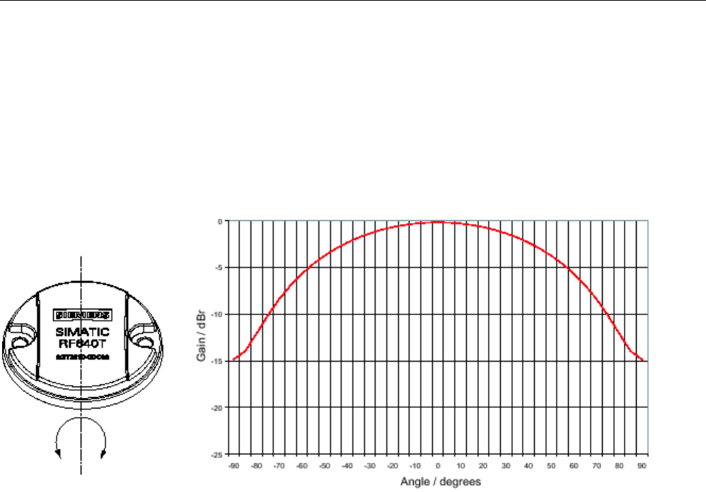
Transponder/tags
7.10 SIMATIC RF640T Gen 2
SIMATIC RF600
System Manual, xx/2014, J31069-D0171-U001-A15-7618 423
REVIEW
7.10.3.5
Directional radiation pattern of the transponder
Preferably, align the tag parallel to the transmitting antenna. If, however, the tag including
the metallic carrier plate is tilted, the reading range will be reduced.
Rotation about the polarization axis
Figure 7-45 Transponder characteristics when rotated about the polarization axis
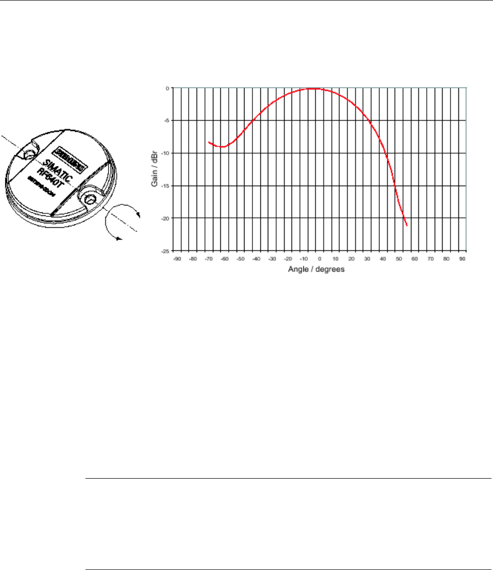
Transponder/tags
7.10 SIMATIC RF640T Gen 2
SIMATIC RF600
424 System Manual, xx/2014, J31069-D0171-U001-A15-7618
REVIEW
Rotation orthogonal to the polarization axis
Figure 7-46 Transponder characteristics when rotated orthogonally to the polarization axis (within the tag plane)
7.10.3.6
Use of the transponder in the Ex protection area
TÜV NORD CERT GmbH, appointed center no. 0044 as per Article 9 of the Directive
94/9/EC of the European Council of 23 March 1994, has confirmed the compliance with the
essential health and safety requirements relating to the design and construction of
equipment and protective systems intended for use in hazardous areas as per Annex II of
the Directive.
The essential health and safety requirements are satisfied in accordance with standards
IEC 60079-0: 2011 and EN 60079-11: 2012.
This allows the RF640T transponder to be used in hazardous areas for gases, for the device
category 2G and gas group IIC, or alternatively in hazardous areas for dusts, for the device
category 2D and group IIIB.
Note
Readability of the serial number on the type plate
When using the transponder, make sure that the serial number
can be read. The serial
number is lasered and can be hidden by paint or other materials making it illegible.
The customer is responsible for making sure that the serial number of a transponder for the
hazardous area can be read at all times.
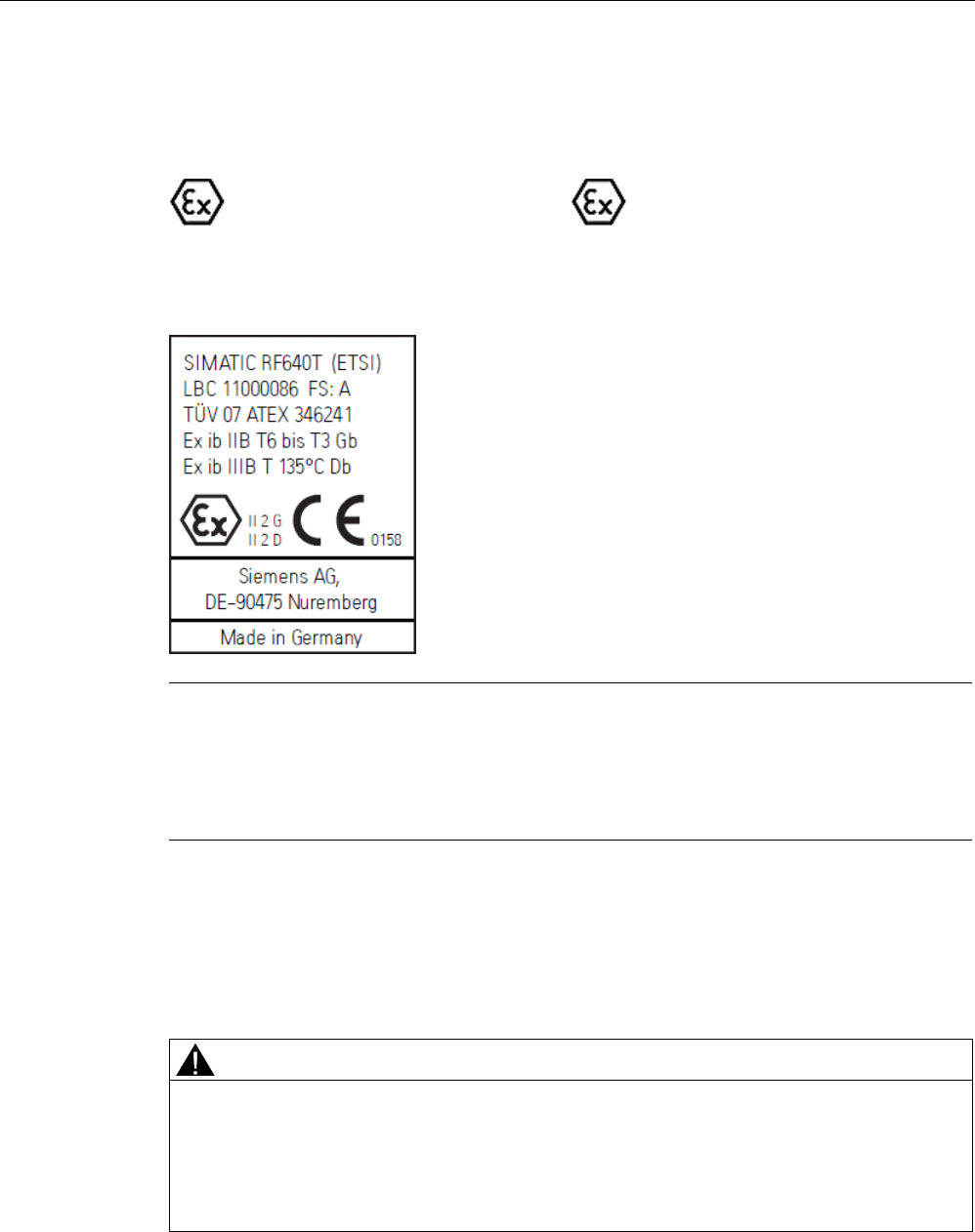
Transponder/tags
7.10 SIMATIC RF640T Gen 2
SIMATIC RF600
System Manual, xx/2014, J31069-D0171-U001-A15-7618 425
REVIEW
Identification
The identification is as follows:
II
2 G Ex ib IIC T6 to T3 GB or
II
2 D Ex ib IIIB T135°C DB
7.10.3.7
Use of the transponder in hazardous areas for gases
Note
Transponder labeling
The labeling of the front of the transponder shown above is an example and can vary
between batches produced at different times.
This does not affect the hazardous area marking.
Temperature class delineation for gases
The temperature class of the transponder for hazardous atmospheres (gases) depends on
the ambient temperature and the radiated power of an antenna in the 865 - 868 MHz
frequency band within the hazardous area.
WARNING
Ignitions of gas-air mixtures
When using the RF640T transponder, check to ensure that the temperature class is
observed in respect of the requirements of the area of application
Non-compliance with the permitted temperature ranges while using the transponder can
lead to ignitions of gas-air mixtures.
Transponder/tags
7.10 SIMATIC RF640T Gen 2
SIMATIC RF600
426 System Manual, xx/2014, J31069-D0171-U001-A15-7618
REVIEW
WARNING
Ignitions of gas-air mixtures
The maximum transmitting power of the transmitter used to operate the transponder must
not exceed 2 W.
Non-compliance with the permissible transmitting power can lead to ignitions of gas-air
mixtures.
Temperature class assignment for gases and a radiated power less than 100 mW ERP
If the radiated power of an antenna radiating into the hazardous area or located in the
hazardous area and operating in the 865 - 868 MHz frequency band cannot exceed the
value 100 mW, the temperature class assignment is as follows:
Ambient temperature range
Temperature class
-25 °C to +85 °C
T5
-25 °C to +76 °C
T6
Temperature class assignment for gases and a radiated power less than 500 mW ERP
If the radiated power of an antenna radiating into the hazardous area or located in the
hazardous area and operating in the 865 - 868 MHz frequency band cannot exceed the
value 500 mW, the temperature class assignment is as follows:
Ambient temperature range
Temperature class
-25 °C to +85 °C
T4
-25 °C to +77 °C
T5
-25 °C to +62 °C
T6
Temperature class assignment for gases and radiated power for 2000 mW ERP
If the radiated power of an antenna radiating into the hazardous area or located in the
hazardous area and operating in the 865 - 868 MHz frequency band cannot exceed the
value 2000 mW, the temperature class assignment is as follows:
Ambient temperature range
Temperature class
-25 °C to +85 °C
T3
-25 °C to +65 °C
T4
-25 °C to +25 °C
T5
-25 °C to +10 °C
T6
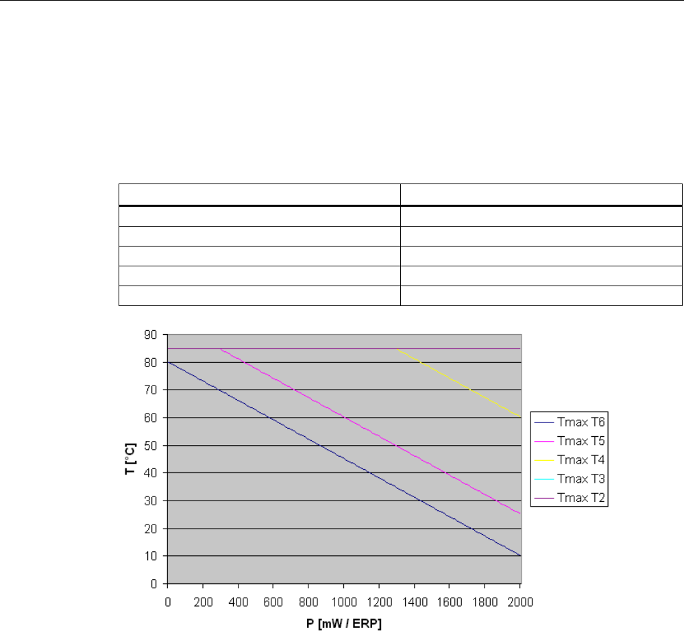
Transponder/tags
7.10 SIMATIC RF640T Gen 2
SIMATIC RF600
System Manual, xx/2014, J31069-D0171-U001-A15-7618 427
REVIEW
Temperature class assignment for gases and a radiated power of 10 mW to 2000 mW ERP
If the radiated power of an antenna radiating into the hazardous area or of an antenna
located in the hazardous area in the 865 - 868 MHz frequency band cannot exceed the
radiated power selected in the following diagram, the maximum permitted ambient
temperature range can be found in the corresponding temperature function of the diagram.
This makes the following temperature class assignment valid:
Ambient temperature range
Temperature class
-25 °C to +85 °C
T2
-25 °C to +85 °C
T3
-25 °C to T
max
(T4) °C
T4
-25 °C to Tmax (T5) °C
T5
-25 °C to T
max
(T6) °C
T6
Figure 7-47 Maximum permitted ambient temperature depending on the radiated power
7.10.3.8
Use of the transponder in hazardous areas for dusts
The equipment is suitable for dusts whose ignition temperatures for a dust layer of 5 mm are
higher than 210 °C (smoldering temperature). The ignition temperature specified here
according to IEC 60079-0: 2011 for ignition protection type ib in this case references the
smoldering temperature of a layer of combustible flyings (ib IIIA) or alternatively non-
conductive dusts (ib IIIB).
Transponder/tags
7.10 SIMATIC RF640T Gen 2
SIMATIC RF600
428 System Manual, xx/2014, J31069-D0171-U001-A15-7618
REVIEW
Temperature class delineation for dusts
WARNING
Ignitions of dust-air mixtures
When using the RF640T transponder, check to ensure that the temperature values are
complied with in connection with the requirements of the application area.
Non-compliance with the permitted temperature ranges while using the transponder can
lead to ignitions of dust-air mixtures.
Temperature class assignment for dusts and a radiated power less than 100 mW ERP
If the radiated power of an antenna radiating into the hazardous area or located in the
hazardous area and operating in the 865 - 868 MHz frequency band cannot exceed the
value 100 mW, the temperature class assignment is as follows:
Ambient temperature range
Temperature value
-25 °C ≤ Ta ≤ +85 ℃
T94 °C
Temperature class assignment for dusts and a radiated power less than 500 mW ERP
If the radiated power of an antenna radiating into the hazardous area or located in the
hazardous area and operating in the 865 - 868 MHz frequency band cannot exceed the
value 500 mW, the temperature class assignment is as follows:
Ambient temperature range
Temperature value
-25 °C ≤ Ta ≤ +85 ℃
T108 °C
Temperature class assignment for dusts and a radiated power less than 1280 mW ERP
If the radiated power of an antenna radiating into the hazardous area or located in the
hazardous area and operating in the 865 - 868 MHz frequency band cannot exceed the
value 1280 mW, the temperature class assignment is as follows:
Ambient temperature range
Temperature value
-25 °C ≤ Ta ≤ +85 ℃
T135 °C
Transponder/tags
7.10 SIMATIC RF640T Gen 2
SIMATIC RF600
System Manual, xx/2014, J31069-D0171-U001-A15-7618 429
REVIEW
Ambient temperature range for dust and radiated power of 2000 mW ERP
If the radiated power of an antenna radiating into the hazardous area or located in the
hazardous area and operating in the 865 - 868 MHz frequency band cannot exceed the
value 2000 mW, the temperature class assignment is as follows:
Ambient temperature range
Temperature value
-25 °C ≤ Ta ≤ +60 ℃
T135 °C
Temperature class assignment for dusts and a radiated power of 10 mW ERP to 2000 mW ERP
If the radiated power of an antenna radiating into the hazardous area or located in the
hazardous area and operating in the 865 - 868 MHz frequency band can be between the
values 10 mW ERP and 1280 mW ERP, the temperature class assignment is as follows:
Ambient temperature range
Temperature value
-25 °C ≤ Ta ≤ +85 ℃
Tvalue °C
1)
1) See diagram, blue line
If the radiated power of an antenna radiating into the hazardous area or located in the
hazardous area and operating in the 865 - 868 MHz frequency band can be between the
values 1280 mW ERP and 2000 mW ERP, the temperature class assignment is as follows:
Ambient temperature range
Temperature value
-25 °C ≤ Ta ≤ Tmax. ambient °C
1)
135°C
1) See diagram, orange line
WARNING
Ignitions of dust-air mixtures
Using the RF640T transponder with radiant power greater than 1280 mW ERP, requires
compliance with the reduced maximum ambient temperature (see diagram) for maintaining
the temperature value to a maximum of 135 °C.
Non-compliance with the permitted temperature ranges while using the transponder can
lead to ignitions of dust-air mixtures.
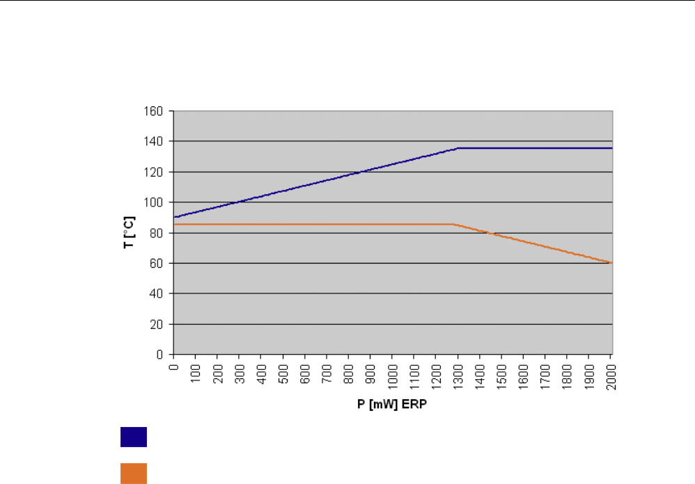
Transponder/tags
7.10 SIMATIC RF640T Gen 2
SIMATIC RF600
430 System Manual, xx/2014, J31069-D0171-U001-A15-7618
REVIEW
The respective temperature value and the maximum allowed ambient temperature in relation
to the radiated power of the antenna is shown in the diagram below:
Temperature value
Ambient temperature
Figure 7-48 Temperature value and maximum permitted ambient temperature in relation to the
radiated power
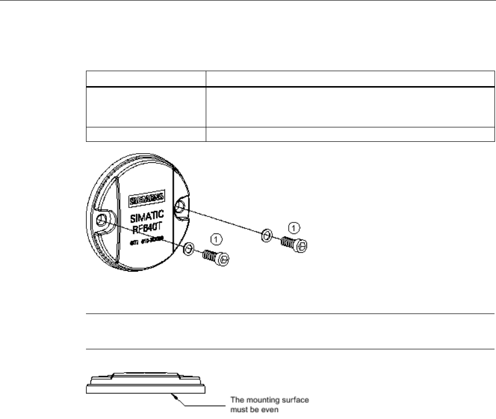
Transponder/tags
7.10 SIMATIC RF640T Gen 2
SIMATIC RF600
System Manual, xx/2014, J31069-D0171-U001-A15-7618 431
REVIEW
7.10.4
Mounting instructions
Properties
Description
Type of installation Screw mounting ①, (M4 screws)
(two DIN 433 washers and two M4 hexagon socket head cap screws
DIN 6912)
Tightening torque
(at room temperature) < 1.2 Nm
Figure 7-49 Screw mounting
Note
Make sure that the
mounting surface is even when mounting the transponder.
7.10.5
Memory configuration of the transponder
The memory configuration of the transponder is described in the section SIMATIC memory
configuration of the RF600 transponders and labels (Page 336).
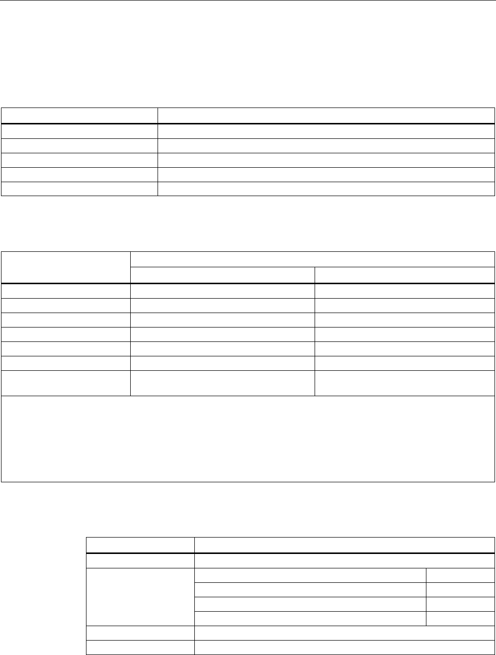
Transponder/tags
7.10 SIMATIC RF640T Gen 2
SIMATIC RF600
432 System Manual, xx/2014, J31069-D0171-U001-A15-7618
REVIEW
7.10.6
Technical Specifications
7.10.6.1
Mechanical data
Property
Description
Dimensions (D x H)
50 mm x 8 mm (+1 mm)
Design
PCB with integrated antenna
Design
Plastic enclosure (PA12), silicone-free
Weight
approx. 13 g
Mounting on metal
directly on metal without spacing
7.10.6.2
Electrical data
Characteristic
Description
Europe
USA/Canada
Air interface
According to ISO 18 000-6 C
According to ISO 18 000-6 C
Frequency range
865 ... 868 MHz
902 ... 928 MHz
1)
Necessary transmit power
2 W (ERP)
4 W (EIRP)
Range
2)
max. 4.0 m
max. 4.0 m
Polarization type
Linear
Linear
Energy source
Field energy via antenna, without battery
Field energy via antenna, without battery
Multitag capability yes, minimum distance between data
carriers ≥ 50 mm
3)
yes, minimum distance between data
carriers ≥ 50 mm
3)
1) Reduction of range to about 70% at the band limits 902 MHz or 928 MHz; acquisition is guaranteed at 915 MHz due to
frequency hopping procedure.
2) Mounting on a flat metal surface with a diameter of at least 150 mm and at room temperature. The information relates to
the maximum read range. You will find more information on ranges in the section "Minimum distances and maximum
ranges (Page 344)".
3) When these minimum distances are not reached, there is a reduction in the maximum possible read and write distances
of the transponder.
7.10.6.3
Memory specifications
Property
Description
Type
EPC Class 1 Gen 2
Memory organization
EPC code
96 bits/240 bits
User memory
64 bytes
TID
64 bits
Reserved (passwords)
64 bits
Protocol
ISO 18000-6C
Data retention time
10 years
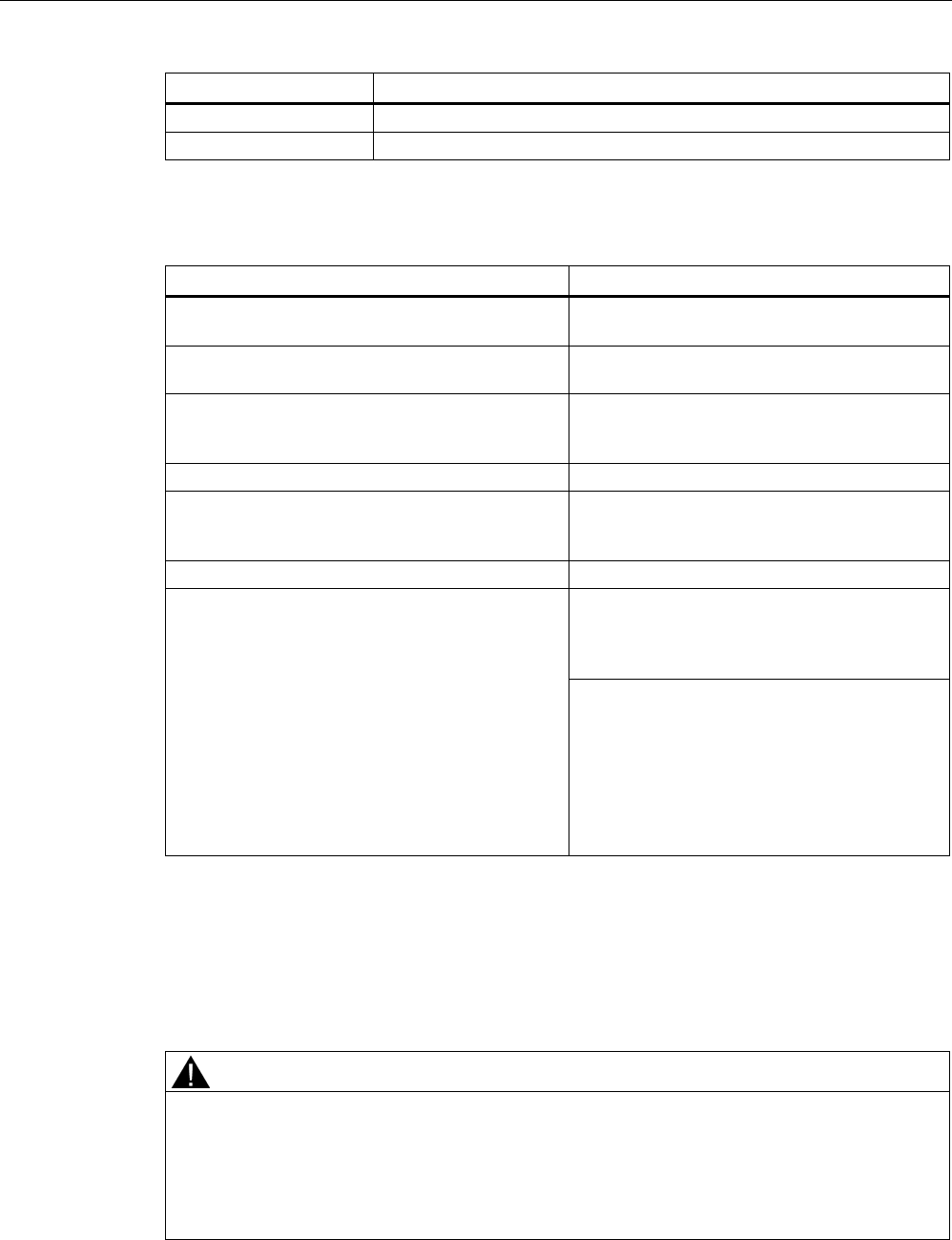
Transponder/tags
7.10 SIMATIC RF640T Gen 2
SIMATIC RF600
System Manual, xx/2014, J31069-D0171-U001-A15-7618 433
REVIEW
Property
Description
Read cycles
Unlimited
Write cycles
Minimum at +22 °C 100 000
7.10.6.4
Environmental conditions
Property
Description
Temperature range when operating in non-
hazardous areas
-25 °C … 85 °C1)
Temperature range when operating in areas at risk
of a gas explosion with temperature class T3-T6
See alsoUse of the transponder in hazardous
areas for gases (Page 425)
2)
Temperature range when operating in areas at risk
of dust explosions with temperature value ≤
T135 °C
See alsoUse of the transponder in hazardous
areas for dusts (Page 427) 2)
Temperature range during storage
-40 °C … 125 °C
1)
Shock
Vibration
compliant with EN 60721-3-7 Class 7 M3
100 g, 3)
20 g, 3)
Torsion and bending load
Not permissible
Degree of protection IP68 according to EN 60529:
(45 minutes. immersion in water; water depth
1 m from
top edge of housing at +20 °C)
IP x9K according to EN 60529:
• Steam blaster nozzle distance 150 mm
• 10 ... 15 l of water per minute
• Pressure 100 bar
• Temperature 75 °C
• Test time 30 seconds
1) At temperatures above 70 °C the casing may distort slightly; this does not however cause
any impairment of function (mechanical or electrical).
2) Directive 94/9/EC of the European Council of 23 March 1994 must be complied with, see
also Chapter "Using the transponder in hazardous areas".
3) The values for shock and vibration are maximum values and must not be applied
continuously.
WARNING
Ignitions of gas-air or dust-air mixtures
When using the RF640T transponder, check to ensure that the temperature values are
observed in respect of the requirements of the hazardous area of application.
Non-compliance with the permitted temperature ranges while using the transponder can
lead to ignitions of gas-air or dust-air mixtures.

Transponder/tags
7.10 SIMATIC RF640T Gen 2
SIMATIC RF600
434 System Manual, xx/2014, J31069-D0171-U001-A15-7618
REVIEW
Note
Damage to the surface of the housing
The values specified for the IP
x9K test are maximum values and must not be applied
continuously.
Protracted loading of the transponder can lead to damage to the surface of the housing due
to high pressures.
7.10.6.5
Chemical resistance of the RF640T transponder
The following table gives an overview of the chemical composition of the data memory made
from polyamide 12. The plastic housing has a notably high resistance to chemicals used in
automobiles (e.g.: oil, grease, diesel fuel, gasoline) which are not listed separately.
Concentration
20 °C
60 °C
Battery acid
30
○○
ᅳ
Ammonia gas
○○○○
○○○○
Ammonia, w.
conc.
○○○○
○○○○
10
○○○○
○○○○
Benzol
○○○○
○○○
Bleach solution (12.5 % effective chlorine)
○○
ᅳ
Butane, gas, liquid
○○○○
○○○○
Butyl acetate (acetic acid butyl ester)
○○○○
○○○○
Calcium chloride, w.
○○○○
○○○
Calcium nitrate, w.
k. g.
○○○○
○○○
Chlorine
ᅳ
ᅳ
Chrome baths, tech. ᅳ ᅳ
Iron salts, w.
k. g.
○○○○
○○○○
Acetic acid, w.
50
ᅳ
ᅳ
Ethyl alcohol, w., undenaturated
96
○○○○
○○○
50
○○○○
○○○○
Formaldehyde, w.
30
○○○
ᅳ
10
○○○○
○○○
Formalin
○○○
ᅳ
Glycerine
○○○○
○○○○
Isopropanol
○○○○
○○○
Potassium hydroxide, w.
50
○○○○
○○○○
Lysol
○○
ᅳ
Magnesium salts, w.
k. g.
○○○○
○○○○
Methyl alcohol, w.
50
○○○○
○○○○
Lactic acid, w.
50
○○
ᅳ
10
○○○
○○
Sodium carbonate, w. (soda)
k. g.
○○○○
○○○○
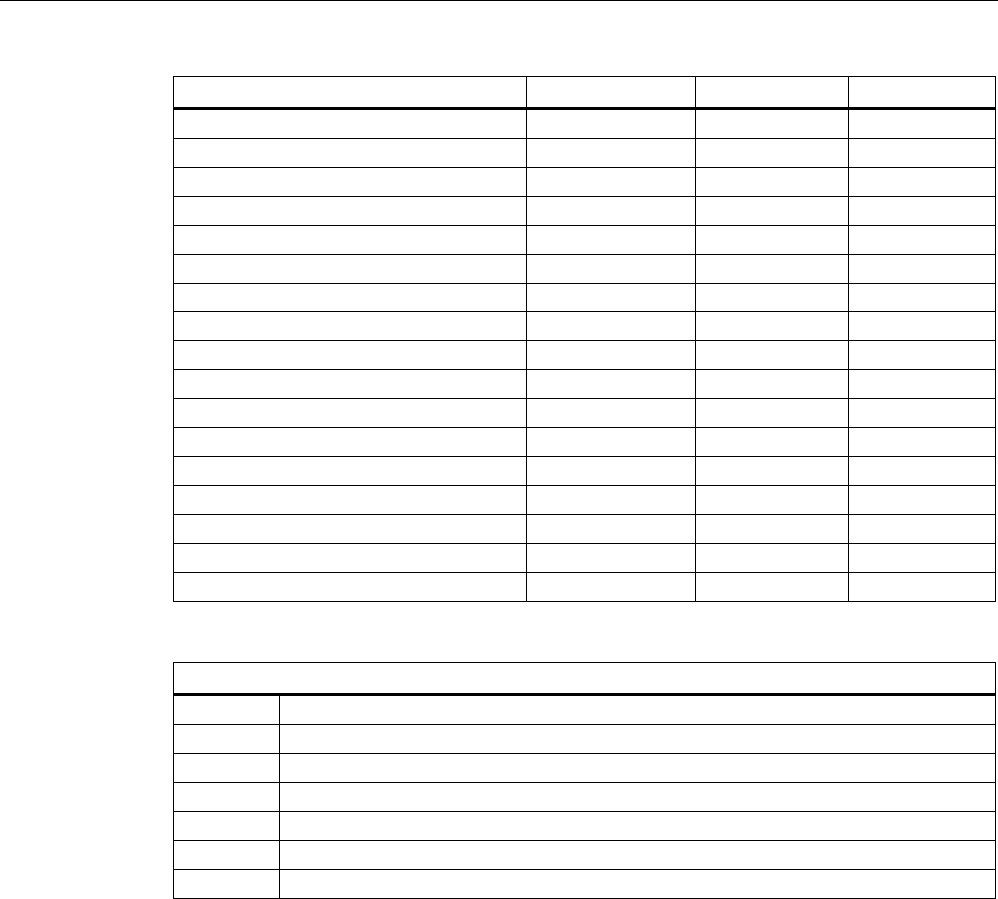
Transponder/tags
7.10 SIMATIC RF640T Gen 2
SIMATIC RF600
System Manual, xx/2014, J31069-D0171-U001-A15-7618 435
REVIEW
Concentration
20 °C
60 °C
Sodium chloride, w.
k. g.
○○○○
○○○○
Sodium hydroxide
○○○○
○○○○
Nickel salts, w.
k. g.
○○○○
○○○○
Nitrobenzol
○○○
○○
Phosphoric acid
10
○
V
Propane
○○○○
○○○○
Mercury
○○○○
○○○○
Nitric acid
10
○
ᅳ
Hydrochloric acid
10
○
ᅳ
Sulphur dioxide
Low
○○○○
○○○○
Sulphuric acid
25
○○
ᅳ
10
○○○
ᅳ
Hydrogen sulphide
Low
○○○○
○○○○
Carbon tetrachloride
○○○○
○○○○
Toluene
○○○○
○○○
Detergent
High
○○○○
○○○○
Plasticizer ○○○○ ○○○○
Abbreviations
○○○○
Resistant
○○○ Virtually resistant
○○
Limited resistance
○ Less resistant
ᅳ
Not resistant
w.
Aqueous solution
k. g.
Cold saturated
Transponder/tags
7.10 SIMATIC RF640T Gen 2
SIMATIC RF600
436 System Manual, xx/2014, J31069-D0171-U001-A15-7618
REVIEW
7.10.7
Certificates and approvals
Table 7- 27 6GT2810-2DC00 - RF640T Gen 2 UHF Tool Tag - Europe
Certificate
Description
CE approval according to R&TTE guideline
For Directive 94/9/EC:
EC type test certification no. TÜV 07 ATEX 346241
Recognition of the quality assurance BVS 11 ATEX ZQS/E111
Table 7- 28 6GT2810-2DC10 - RF640T Gen 2 UHF Tool Tag - USA/Canada
Standard
FCC
Federal Communications
Commission
Passive labels or transponders comply with the valid regulations;
certification is not required.
This product is UL-certified for the USA and Canada.
It meets the following safety standard(s):
UL 60950-1 - Information Technology Equipment Safety - Part 1:
General Requirements
CSA C22.2 No. 60950 -1 - Safety of Information Technology
Equipment
UL Report E 205089
7.10.7.1
EC Declaration of Conformity according to directive 94/9EC RF640T Gen 2 UHF Tool
Tag Version 1
The type test certification for the RF640T Gen 2 UHF Tool Tag Version 1 is stored by TÜV
07 ATEX 346241. On the basis of this certification, the CE declaration by the manufacturer
has been made according to directive 94/9/EC.
The producing factory of the RF640T Gen 2 UHF Tool Tag Version 1 has an ATEX quality
assurance system recognized by the DEKRA EXAM GmbH with certificate number BVS 11
ATEX ZQS/E111.
Manufacturer's address - distributor
Manufacturer's address - factory
Siemens Aktiengesellschaft
Industry Sector (I)
Industry Automation Division (IA)
Sensors and Communication (SC)
Communication and Identification (CI)
Gleiwitzer Str. 555
D-90475 Nürnberg, Germany
Siemens Aktiengesellschaft
Industry Sector (I)
Industry Automation Division (IA)
Control Components and System Engineering
(CE)
Würzburger Straße 121
D-90766 Fürth, Germany
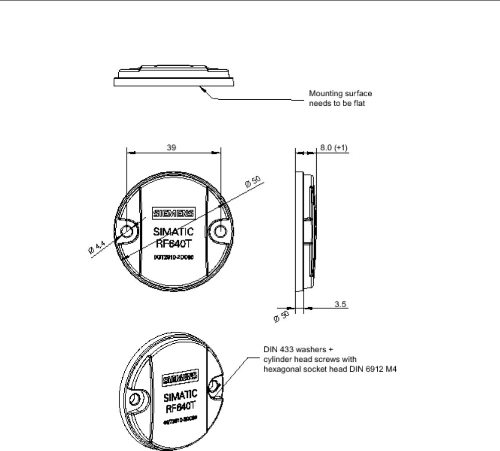
Transponder/tags
7.10 SIMATIC RF640T Gen 2
SIMATIC RF600
System Manual, xx/2014, J31069-D0171-U001-A15-7618 437
REVIEW
7.10.8
Dimension drawing
Figure 7-50 SIMATIC RF640T Gen 2 UHF Tool Tag Version 1
Units of measurement: All dimensions in mm
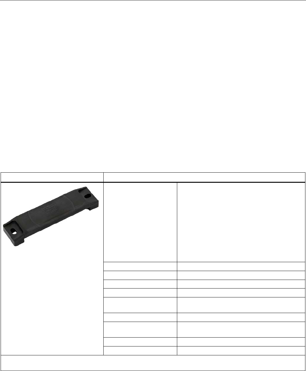
Transponder/tags
7.11 SIMATIC RF680T
SIMATIC RF600
438 System Manual, xx/2014, J31069-D0171-U001-A15-7618
REVIEW
7.11
SIMATIC RF680T
7.11.1
Characteristics
The heat-resistant SIMATIC RF680T transponder is a passive, maintenance-free data
carrier. It operates based on UHF Class 1 Gen 2 technology and is used to save the
"Electronic Product Code" (EPC) of 96 bits/240 bits. The transponder also has a 512-bit user
memory.
These transponders with limited service life are ideally suited to high-temperature
applications
(e.g. the painting of vehicle bodies) as well as applications in production logistics.
The RF680T is rugged and suitable for industrial applications with IP68/IPX9K degree of
protection. It is highly resistant to oil, grease and cleaning agents.
The SIMATIC RF680T is mounted directly onto metal and non-metal carrier plates to ensure
optimum operation and has a typical detection range of 6.7 m.
SIMATIC RF680T
Features
Area of application Applications with high temperatures (up to +220
°C). Suitable for use in hazardous areas.
Typical application areas:
• Paint shops and their preparatory treatments,
incl. drying ovens
• Electrophoretic deposition area
• Primer coat incl. drying oven
• Top coat area incl. drying oven
• Washing areas at temperatures > 85 °C
Frequency range
865 ... 928 MHz (ETSI and FCC)
Air interface
according to ISO°18000-6C
Polarization
Linear
Temperature range
up to 220 °C
Memory EPC 96 bit/240 bit
Add-on-memory 64 bytes
Range
1)
max. 7 m
Mounting Suitable for direct mounting on conductive and
non-conductive materials.
Material
Plastic PPS; silicone-free
Dimensions
130 x 32 x 15 mm
1) The information relates to the maximum read range. You will find more information on ranges in the section "Minimum
distances and maximum ranges (Page 344)".
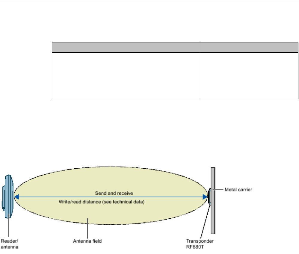
Transponder/tags
7.11 SIMATIC RF680T
SIMATIC RF600
System Manual, xx/2014, J31069-D0171-U001-A15-7618 439
REVIEW
7.11.2
Ordering data
Ordering data
Article number
SIMATIC RF680T
• Frequency 865 MHz to 928 MHz
• EPC 96 bit/240 bit (64 bytes user memory)
• -25 ... +220 °C
• 130 x 32 x 15 mm
6GT2810-2HG80
7.11.3
Planning the use
7.11.3.1
Optimum antenna/transponder positioning with plane mounting of the transponder on
metal
Figure 7-51 Example of optimum antenna/transponder positioning
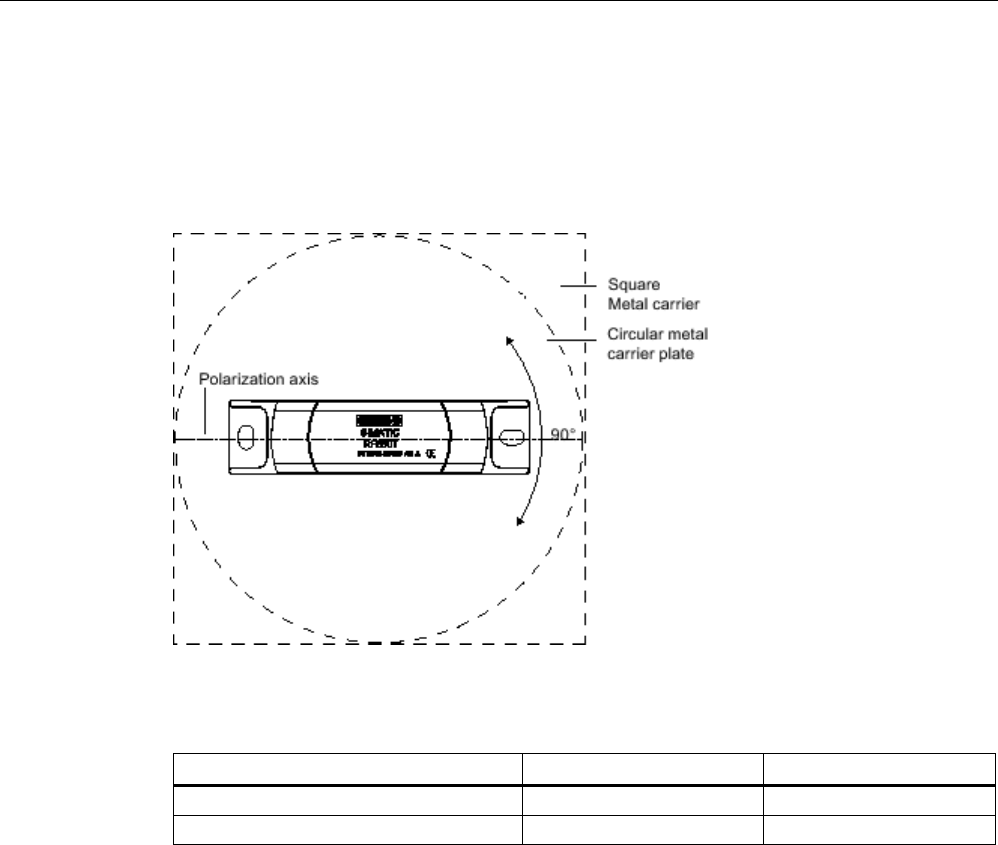
Transponder/tags
7.11 SIMATIC RF680T
SIMATIC RF600
440 System Manual, xx/2014, J31069-D0171-U001-A15-7618
REVIEW
7.11.3.2
Range when mounted on flat metallic carrier plates
The transponder generally has linear polarization. The polarization axis runs as shown in the
diagram below. If the transponder is centrally mounted on a plane metal plate, which may
either be almost square or circular, it can be aligned in any direction if the transmitting and
receiving antennas operate with circular polarization (such as RF660A and RF620R).
Figure 7-52 Optimum positioning of the transponder on a (square or circular) metal surface
Table 7- 29 Range on flat metallic carriers
Carrier material
Range Europe
Range USA
Metal plate 150 x 150 mm typically 50 % typically 50 %
Metal plate 300 x 300 mm
typically 100 %
typically 100 %
On rectangular carrier plates, the range depends on the mounting orientation of the
transponder A 90° rotation of the transponder about the axis of symmetry may result in
greater ranges.
You will find more detailed information on the range in the section "Minimum distances and
maximum ranges (Page 344)".
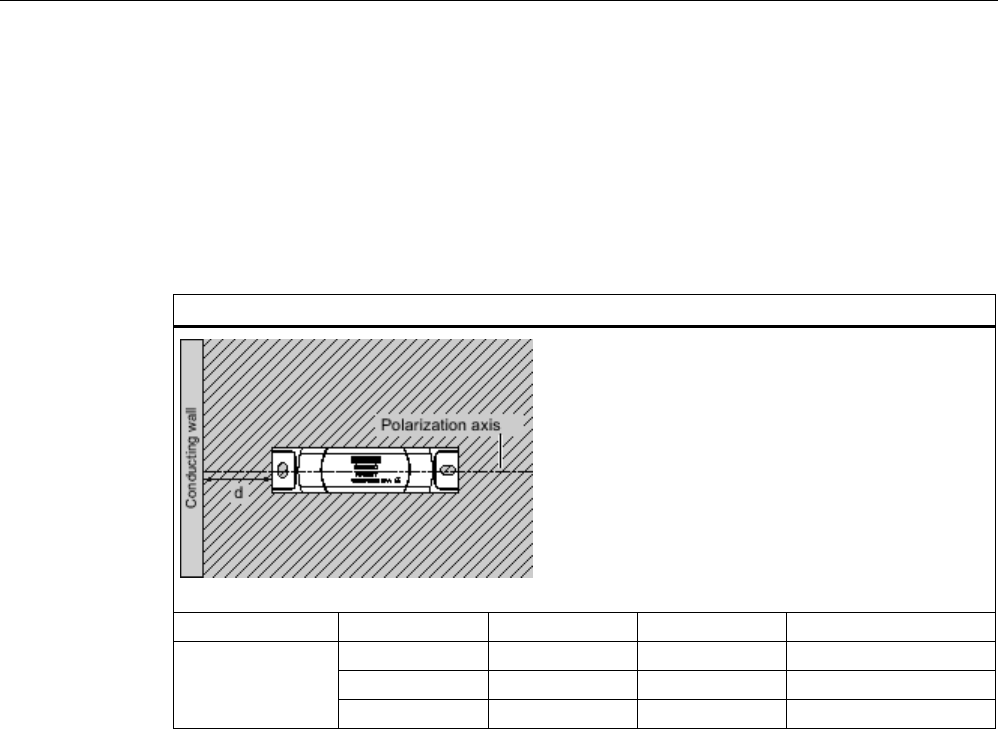
Transponder/tags
7.11 SIMATIC RF680T
SIMATIC RF600
System Manual, xx/2014, J31069-D0171-U001-A15-7618 441
REVIEW
7.11.3.3
Influence of conducting walls on the range
If there are conducting walls or restrictions in the vicinity that shade the radio field, a distance
of approx. 10 cm is recommended between the transponder and the wall. In principle, walls
have least influence if the polarization axis is orthogonal to the wall.
Range: One conducting wall
Influence on the range when positioned orthogonally to the conducting wall
View from above
Distance d
20 mm
50 mm
100 mm
Range
approx. 100%
approx. 100%
approx. 100%
Wall height 20 mm
approx. 100%
approx. 100%
approx. 100%
Wall height 50 mm
approx. 80%
approx. 100%
approx. 100%
Wall height 100 mm
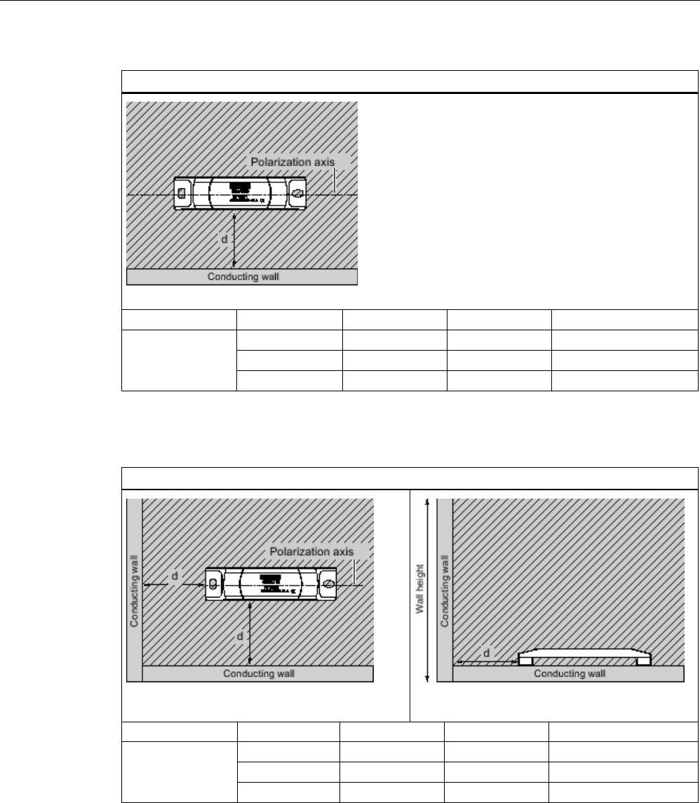
Transponder/tags
7.11 SIMATIC RF680T
SIMATIC RF600
442 System Manual, xx/2014, J31069-D0171-U001-A15-7618
REVIEW
Influence on the range when positioned parallel to the conducting wall
View from above
Distance d
20 mm
50 mm
100 mm
Range
approx. 50%
approx. 70%
approx. 90%
Wall height 20 mm
approx. 40%
approx. 70%
approx. 90%
Wall height 50 mm
approx. 30%
approx. 50%
approx. 90%
Wall height 100 mm
Range: Two conducting walls
Influence on the range when positioned against two conducting walls
Side view
Distance d
20 mm
50 mm
100 mm
Range
approx. 50%
approx. 70%
approx. 90%
Wall height 20 mm
approx. 30%
approx. 60%
approx. 90%
Wall height 50 mm
approx. 25%
approx. 50%
approx. 90%
Wall height 100 mm
The values specified in the tables above are guide values.
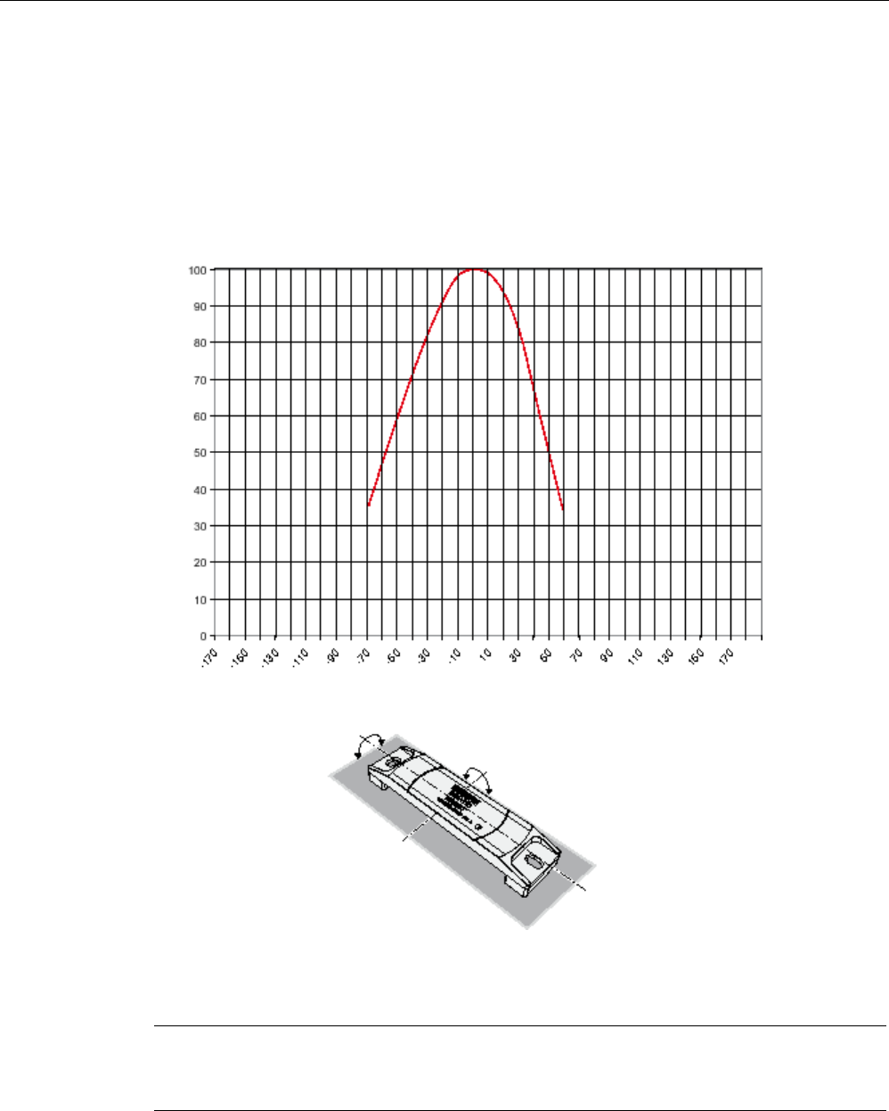
Transponder/tags
7.11 SIMATIC RF680T
SIMATIC RF600
System Manual, xx/2014, J31069-D0171-U001-A15-7618 443
REVIEW
7.11.3.4
Directional radiation pattern of the transponder on metallic surfaces
It is recommendable to align the transponder parallel to the transmitting antenna. If,
however, the transponder including the metallic carrier plate is tilted, the reading range will
be reduced.
Rotation about the polarization axis or orthogonal to the polarization axis
Figure 7-53 Characteristic of the transponder when rotated about the polarization axis or orthogonally
to the polarization axis
Note
Please note that the directional effect is dependent on the size of the metal surface. The
larger the metal surface, the larger the directional effect.
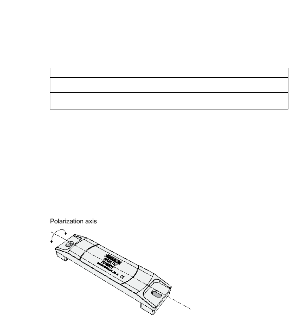
Transponder/tags
7.11 SIMATIC RF680T
SIMATIC RF600
444 System Manual, xx/2014, J31069-D0171-U001-A15-7618
REVIEW
7.11.3.5
Range when mounted on non-metallic carrier materials
The RF680T transponder is a universal transponder for mounting on many different types of
carrier materials.
Table 7- 30 Range for non-metal carriers (RF670R = 2 W ERP;)
Carrier material
Range
Transponder on wooden carrier
(dry, degree of moisture < 15%)
typically 50 %
Transponder on plastic carrier
typically 50 %
Transponder on glass
typically 50 %
The maximum range of 100% is achieved by mounting the transponder in a free space with
low reflections on a flat metal carrier with a diameter of at least 300 mm.
You will find more detailed information on the range in the section "Minimum distances and
maximum ranges (Page 344)".
7.11.3.6
Directional radiation pattern of the transponder on non-metallic surfaces
It is recommendable to align the transponder parallel to the transmitting antenna. If,
however, the transponder including the metallic carrier plate is tilted, the reading range will
be reduced.
Rotation about the polarization axis
Figure 7-54 Rotation of the transponder about the polarization axis
Generally the range does not change when the transponder without carrier material is
rotated about the polarization axis.
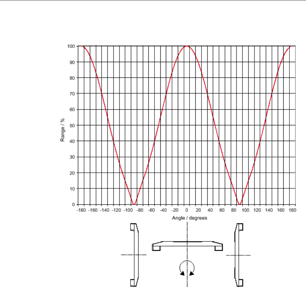
Transponder/tags
7.11 SIMATIC RF680T
SIMATIC RF600
System Manual, xx/2014, J31069-D0171-U001-A15-7618 445
REVIEW
Rotation orthogonal to the polarization axis
Figure 7-55 Transponder characteristics when rotated orthogonally to the polarization axis (within the
tag plane)
If the transponder is positioned orthogonally to the transmitting antenna, it normally cannot
be read. Therefore the transponder is preferably to be aligned parallel to the transmitting
antenna. The following figure illustrates this situation.
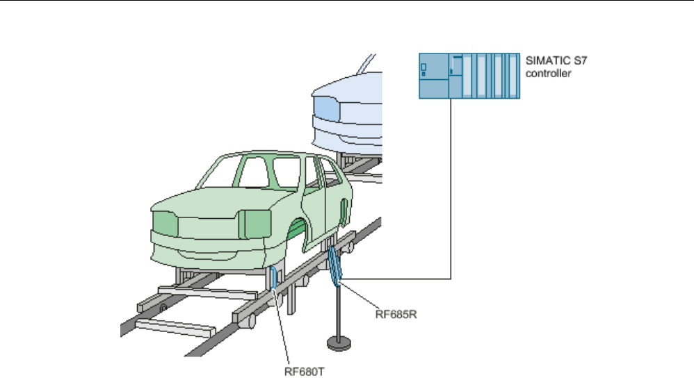
Transponder/tags
7.11 SIMATIC RF680T
SIMATIC RF600
446 System Manual, xx/2014, J31069-D0171-U001-A15-7618
REVIEW
Figure 7-56 Application example
7.11.3.7
Relationship between performance and reading range
The absolute values of the reading ranges specified below refer to a transmit power of
2 W ERP.
When the power is reduced (e.g. when a different reader is used), you will find the
corresponding reduced reading ranges in the following table:
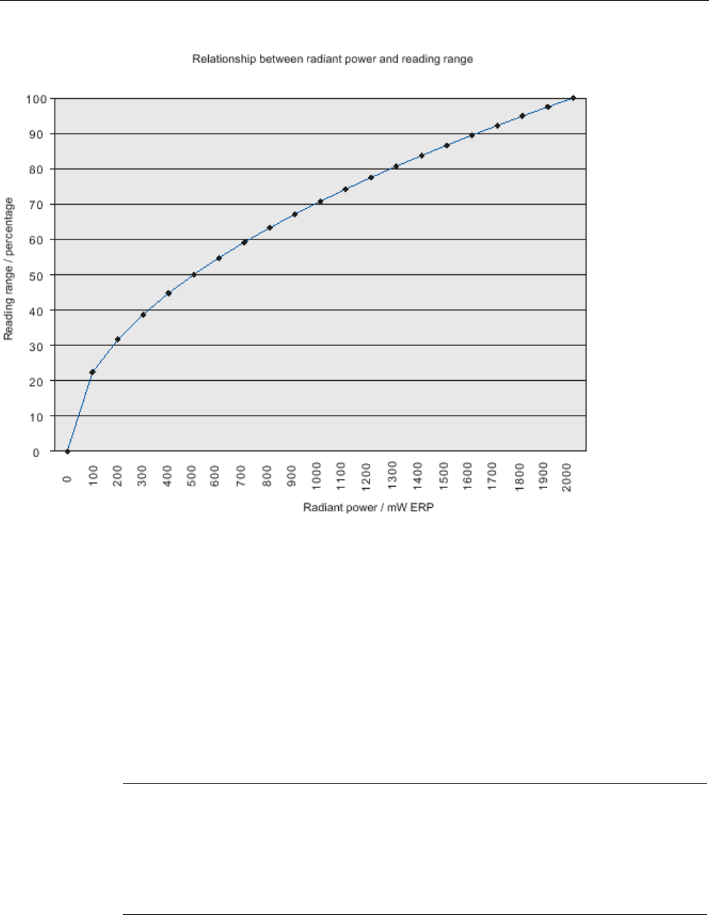
Transponder/tags
7.11 SIMATIC RF680T
SIMATIC RF600
System Manual, xx/2014, J31069-D0171-U001-A15-7618 447
REVIEW
7.11.3.8
Use of the transponder in hazardous areas
TÜV NORD CERT GmbH, appointed center no. 0044 as per Article 9 of the Directive
94/9/EC of the European Council of 23 March 1994, has confirmed the compliance with the
essential health and safety requirements relating to the design and construction of
equipment and protective systems intended for use in hazardous areas as per Annex II of
the Directive.
The essential health and safety requirements are satisfied in accordance with standards
IEC 60079-0:2011 and EN 60079-11:2012.
This allows the RF680T transponder to be used in hazardous areas for gases, for the device
category 2G and gas group IIB, or alternatively in hazardous areas for dusts, for the device
category 2D and group IIIB.
Note
Readability of the serial number on the type plate
When using the transponder, make sure that the serial number can be read. The serial
number is lasered and can be hidden by paint or other materials making it
illegible.
The customer is responsible for making sure that the serial number of a transponder for the
hazardous area can be read at all times.
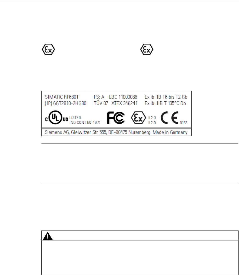
Transponder/tags
7.11 SIMATIC RF680T
SIMATIC RF600
448 System Manual, xx/2014, J31069-D0171-U001-A15-7618
REVIEW
Identification
The identification is as follows:
II
2G Ex ib IIB T6 to T2 Gb or
II
2D Ex ib IIIB T135 °C Db
7.11.3.9
Use of the transponder in hazardous areas for gases
Note
Transponder labeling
The labeling of the front of the transponder shown above is an example and can vary
between batches produced at different times.
This does not affect the hazardous area marking.
Temperature class delineation for gases
The temperature class of the transponder for hazardous atmospheres (gases) depends on
the ambient temperature and the radiated power of an antenna in the 865 - 868 MHz
frequency band within the hazardous area.
WARNING
Ignitions of gas-air mixtures
When using the RF680T transponder, check to make sure that the temperature class is
adhered to in keeping with the requirements of the area of application Non-compliance with
the permitted temperature ranges while using the transponder can lead to ignitions of gas-
air mixtures.
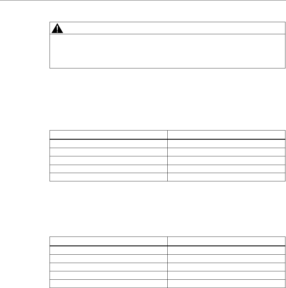
Transponder/tags
7.11 SIMATIC RF680T
SIMATIC RF600
System Manual, xx/2014, J31069-D0171-U001-A15-7618 449
REVIEW
WARNING
Ignitions of gas-air mixtures
The maximum transmitting power of the transmitter used to operate the transponder must
not exceed 2 W. Non-compliance with the permissible transmitting power can lead to
ignitions of gas-air mixtures.
Temperature class assignment for gases and a radiated power less than 100 mW ERP
If the radiated power of an antenna radiating into the hazardous area or located in the
hazardous area and operating in the 865 - 868 MHz frequency band cannot exceed the
value 100 mW, the temperature class assignment is as follows:
Ambient temperature range
Temperature class
-25 °C ... +200 °C
T2
-25 °C ... +190 °C
T3
-25 °C ... +125 °C
T4
-25 °C ... +90 °C
T5
-25 °C ... +75 °C
T6
Temperature class assignment for gases and a radiated power less than 500 mW ERP
If the radiated power of an antenna radiating into the hazardous area or located in the
hazardous area and operating in the 865 - 868 MHz frequency band cannot exceed the
value 500 mW, the temperature class assignment is as follows:
Ambient temperature range
Temperature class
-25 °C ... +220 °C
T2
-25 °C ... +173 °C
T3
-25 °C ... +108 °C
T4
-25 °C ... +73 °C
T5
-25 °C ... +58 °C
T6
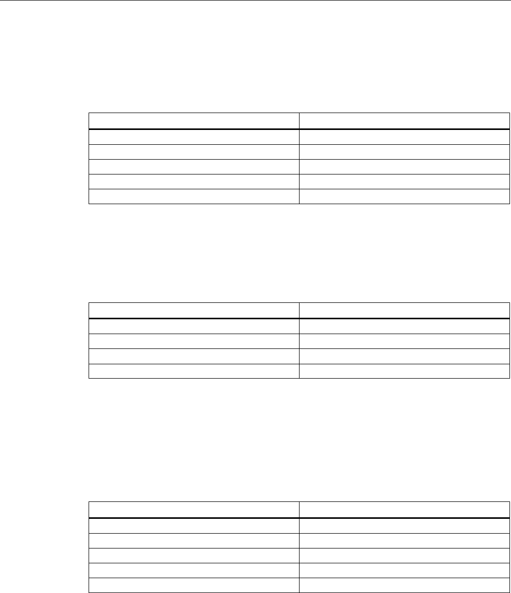
Transponder/tags
7.11 SIMATIC RF680T
SIMATIC RF600
450 System Manual, xx/2014, J31069-D0171-U001-A15-7618
REVIEW
Temperature class assignment for gases and radiated power for 1000 mW ERP
If the radiated power of an antenna radiating into the hazardous area or located in the
hazardous area and operating in the 865 - 868 MHz frequency band cannot exceed the
value 1000 mW, the temperature class assignment is as follows:
Ambient temperature range
Temperature class
-25 °C ... +220 °C
T2
-25 °C ... +151 °C
T3
-25 °C ... +86 °C
T4
-25 °C ... +51 °C
T5
-25 °C ... +36 °C
T6
Temperature class assignment for gases and radiated power for 2000 mW ERP
If the radiated power of an antenna radiating into the hazardous area or located in the
hazardous area and operating in the 865 - 868 MHz frequency band cannot exceed the
value 2000 mW, the temperature class assignment is as follows:
Ambient temperature range
Temperature class
-25 °C ... +208 °C
T2
-25 °C ... +108 °C
T3
-25 °C ... +43 °C
T4
-25 °C ... +8 °C
T5
Temperature class assignment for gases and a radiated power of 10 mW to 2000 mW ERP
If the radiated power of an antenna radiating into the hazardous area or of an antenna
located in the hazardous area in the 865 - 868 MHz frequency band cannot exceed the
radiated power selected in the following diagram, the maximum permitted ambient
temperature range can be found in the corresponding temperature function of the diagram.
This makes the following temperature class assignment valid:
Ambient temperature range
Temperature class
-25 °C ... Tmax (T2) °C
T2
-25 °C ... T
max
(T3) °C
T3
-25 °C ... Tmax (T4) °C
T4
-25 °C ... T
max
(T5) °C
T5
-25 °C ... Tmax (T6) °C
T6
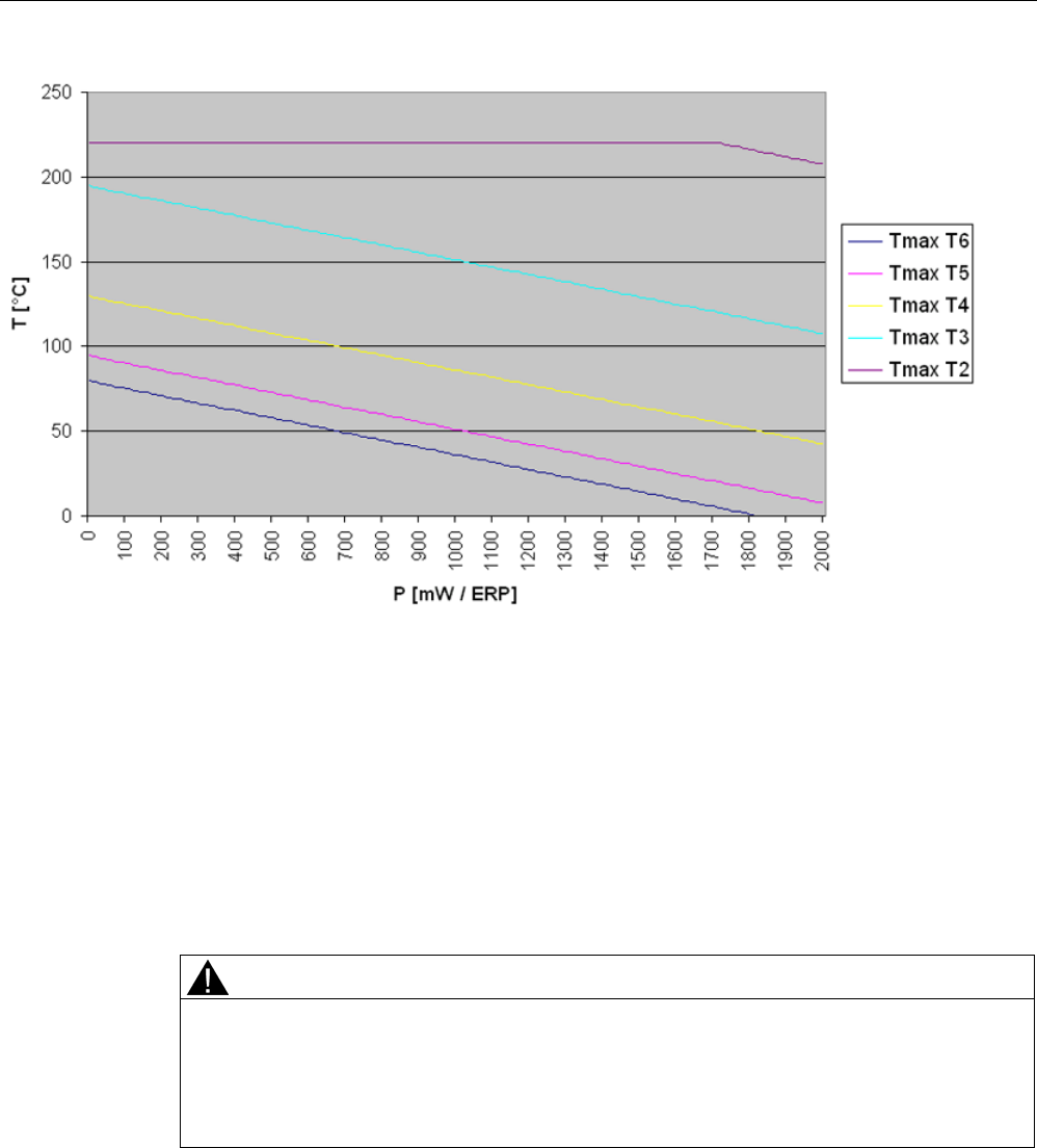
Transponder/tags
7.11 SIMATIC RF680T
SIMATIC RF600
System Manual, xx/2014, J31069-D0171-U001-A15-7618 451
REVIEW
Figure 7-57 Maximum permitted ambient temperature depending on the radiated power
7.11.3.10
Use of the transponder in hazardous areas for dusts
The equipment is suitable for dusts whose ignition temperatures for a dust layer of 5 mm are
higher than 210 °C (smoldering temperature). The ignition temperature specified here
according to IEC 60079-0:2011 for ignition protection type ib in this case references the
smoldering temperature of a layer of combustible flyings (ib IIIA) or alternatively non-
conductive dusts (ib IIIB).
Temperature class delineation for dusts
WARNING
Ignitions of dust-air mixtures
When using the RF680T transponder, check to make sure that the temperature values are
adhered to in keeping with the requirements of the area of application Non-compliance with
the permitted temperature ranges while using the transponder can lead to ignitions of dust-
air mixtures.

Transponder/tags
7.11 SIMATIC RF680T
SIMATIC RF600
452 System Manual, xx/2014, J31069-D0171-U001-A15-7618
REVIEW
Temperature class assignment for dusts and a radiated power less than 100 mW ERP
If the radiated power of an antenna radiating into the hazardous area or located in the
hazardous area and operating in the 865 - 868 MHz frequency band cannot exceed the
value 100 mW, the temperature class assignment is as follows:
Ambient temperature range
Temperature value
-25 °C ≤ Ta ≤ +125 ℃
T135 °C
Temperature class assignment for dusts and a radiated power less than 500 mW ERP
If the radiated power of an antenna radiating into the hazardous area or located in the
hazardous area and operating in the 865 - 868 MHz frequency band cannot exceed the
value 500 mW, the temperature class assignment is as follows:
Ambient temperature range
Temperature value
-25 °C ≤ Ta ≤ +108 ℃
T135 °C
Temperature class assignment for dusts and a radiated power less than 1000 mW ERP
If the radiated power of an antenna radiating into the hazardous area or located in the
hazardous area and operating in the 865 - 868 MHz frequency band cannot exceed the
value 1000 mW, the temperature class assignment is as follows:
Ambient temperature range
Temperature value
-25 °C ≤ Ta ≤ +86 ℃
T135 °C
Ambient temperature range for dust and radiated power of 2000 mW ERP
If the radiated power of an antenna radiating into the hazardous area or located in the
hazardous area and operating in the 865 - 868 MHz frequency band cannot exceed the
value 2000 mW, the temperature class assignment is as follows:
Ambient temperature range
Temperature value
-25 °C ≤ Ta ≤ +43 ℃
T135 °C
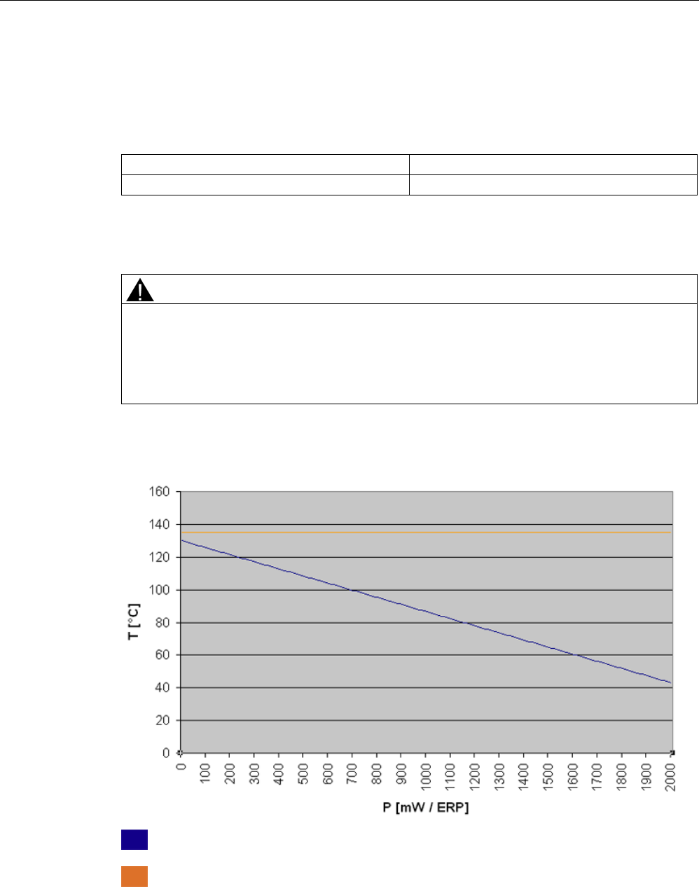
Transponder/tags
7.11 SIMATIC RF680T
SIMATIC RF600
System Manual, xx/2014, J31069-D0171-U001-A15-7618 453
REVIEW
Temperature class assignment for dusts and a radiated power of 10 mW ERP to 2000 mW ERP
If the radiated power of an antenna radiating into the hazardous area or located in the
hazardous area and operating in the 865 - 868 MHz frequency band can be between the
values 10 mW ERP and 2000 mW ERP, the temperature class assignment is as follows:
Ambient temperature range
Temperature value
-25 °C ≤ Ta ≤ T
max. ambient
°C
1)
135°C
2)
1)
See diagram, orange line
2) See diagram, blue line
WARNING
Ignitions of dust-air mixtures
Using the RF680T transponder with radiant power greater than 1280 mW ERP, requires
compliance with the reduced maximum ambient temperature (see diagram) for maintaining
the temperature value to a maximum of 135 °C. Non-compliance with the permitted
temperature ranges while using the transponder can lead to ignitions of dust-air mixtures.
The respective temperature value and the maximum allowed ambient temperature in relation
to the radiated power of the antenna is shown in the diagram below:
Temperature value
Ambient temperature
Figure 7-58 Temperature value and maximum permitted ambient temperature in relation to the
radiated power
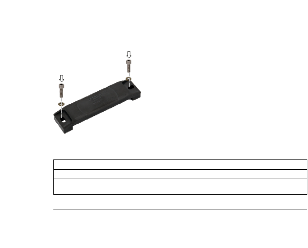
Transponder/tags
7.11 SIMATIC RF680T
SIMATIC RF600
454 System Manual, xx/2014, J31069-D0171-U001-A15-7618
REVIEW
7.11.4
Mounting instructions
Mount the SIMATIC RF680T transponder on the base using two M6 screws.
Figure 7-59 Mounting SIMATIC RF680T
Properties
Description
Type of mounting
M6 screw mounting
Tightening torque
(at room temperature)
≤ 1 Nm (Note the expansion coefficients of the materials used at high
temperatures!)
Note
Reduction of the read/write distance
When mounting on metal or conductive material, ensure that the space below the
transponder remains empty.
7.11.5
Memory configuration of the transponder
The memory configuration of the transponder is described in the section SIMATIC memory
configuration of the RF600 transponders and labels (Page 336).
Transponder/tags
7.11 SIMATIC RF680T
SIMATIC RF600
System Manual, xx/2014, J31069-D0171-U001-A15-7618 455
REVIEW
7.11.6
Technical specifications
7.11.6.1
Mechanical data
Property
Description
Dimensions (L x W x H)
130 x 32 x 15 mm
Design
Plastic housing (PPS)
Housing color
Black
Weight
Approx. 50 g
Mounting on metal
Yes
7.11.6.2
Electrical data
Characteristic
Description
Europe
USA/Canada
Air interface
According to ISO 18 000-6 C
Frequency range
865 ... 868 MHz
915 ... 928 MHz
1)
Necessary transmit power
2 W (ERP)
4 W (EIRP)
Range
2)
max. 7 m
Polarization type
Linear
Energy source
Magnetic energy via antenna, without battery
Multitag capability
yes, minimum distance between data carriers ≥ 50 mm
3)
1) Reduction of range to about 70% at the band limit 928
MHz on metal surfaces; acquisition is guaranteed at 921 MHz due
to the frequency hopping procedure.
2) Mounting on a flat metal surface with a diameter of at least 300 mm and at room temperature. The information relates to
the maximum read range. You will find more information on ranges in the section "Minimum distances and maximum
ranges (Page 344)".
3) When these minimum distances are not reached, there is a reduction in the maximum possible read and write distances
of the transponder.
7.11.6.3
Memory specifications
Property
Description
Type
EPC Class 1 Gen2
Memory organization
96 bits/240 bits EPC code
User memory
64 bytes
Protocol
ISO 18000-6C
Data retention time
10 years
Read cycles
Unlimited
Write cycles
Typ. 1 000 000 (at +40 °C)

Transponder/tags
7.11 SIMATIC RF680T
SIMATIC RF600
456 System Manual, xx/2014, J31069-D0171-U001-A15-7618
REVIEW
7.11.6.4
Environmental conditions
Property
Description
Ambient temperature • Operation
-25 °C ... +100 °C
Permanent
from 100 °C ... +140 °C 20% reduction in the limit
distance
+200 °C 2) Tested up to 5000 hours
or 3000 cycles
+220 °C Tested up to 2000 hours
or 1500 cycles
Temperature range when
operating in areas at risk
of a gas explosion with
temperature class T2-T6
See also Use of the
transponder in hazardous
areas for gases
(Page 448)
3)
Temperature range when
operating in areas at risk
of dust explosions with
T135 °C
See also Use of the
transponder in hazardous
areas for dusts
(Page 451)
3)
• Transport
and storage
-40 °C ... +100 °C
Shock
Vibration
compliant with EN 60721-3-7 Class 7 M3
50 g, 1)
20 g 1)
Torsion and bending load Not permissible
Degree of protection • IP68 according to EN 60529:
(60 minutes. Immersion in cleaning fluids, fluid
depth 5 m top edge of housing)
• Dipping lacquer
• IPx9K
(steam jet: 150 mm; 10 to 15 l/min; 100 bar; 75 °C)
Silicone-free
Yes
MTBF
1,6 · 10
7
h
1) The values for shock and vibration are maximum values and must not be applied
continuously.
2) Note that no processing is possible at temperatures of +140 °C or higher.
3) Directive 94/9/EC of the European Council of 23 March 1994 must be complied with, see
also Chapter "Using the transponder in hazardous areas (Page 447)".

Transponder/tags
7.11 SIMATIC RF680T
SIMATIC RF600
System Manual, xx/2014, J31069-D0171-U001-A15-7618 457
REVIEW
7.11.6.5
Chemical resistance of the RF680T transponder
The following table provides an overview of the chemical resistance of the data memory
made of polypropylene sulfide.
20 °C
65 °C
Ammonia, w. conc.
○
-
Butane gas
+
+
Butyl acetate (acetic acid butyl
ester)
+ +
Calcium chloride
+
+
Chlorine
-
-
Chrome baths, tech.
-
-
Acetic acid, w. 10%
+
+
Ethyl alcohol, w., undenaturated
+
+
Formaldehyde
+
+
Isopropanol
+
+
Methyl alcohol
+
+
Lactic acid, w.
+
+
Sodium carbonate, w. (soda)
+
+
Sodium chloride, w.
+
+
Sodium hydroxide 10%
+
+
Nitrobenzol
○
-
Phosphoric acid
-
-
Propane
+
+
Nitric acid 10% - -
Hydrochloric acid 10%
-
-
Sulfur dioxide, minimal
+
+
Sulfuric acid 25%
-
-
Hydrogen sulfide, dry
+
+
Carbon tetrachloride
○
-
Abbreviations
+
Resistant
○
Limited resistance
ᅳ
Not resistant
Transponder/tags
7.11 SIMATIC RF680T
SIMATIC RF600
458 System Manual, xx/2014, J31069-D0171-U001-A15-7618
REVIEW
7.11.7
Certificates and approvals
Table 7- 31 6GT2810-2HG80 - RF680T - Europe
Certificate
Description
Conformity with R&TTE directive
For Directive 94/9/EC:
EC type test certification no. TÜV 07 ATEX 346241
Recognition of the quality assurance BVS 11 ATEX ZQS/E111
Table 7- 32 6GT2810-2HG80- RF680T - USA / Canada
Standard
FCC
Federal Communications
Commission
Passive labels or transponders comply with the valid regulations;
certification is not required.
This product is UL-certified for the USA and Canada.
It meets the following safety standard(s):
• UL508 - Industrial Control Equipment
• CSA C22.2 No. 142 - Process Control Equipment
• UL Report E 120869
7.11.7.1
EC Declaration of Conformity according to directive 94/9/EG RF680T Version 1
The type test certification for the RF680T Version 1 is stored by TÜV 07 ATEX 346241. On
the basis of this certification, the CE declaration by the manufacturer has been made
according to directive 94/9/EC.
The producing factory of the RF680T Version 1 has an ATEX quality assurance system
recognized by the DEKRA EXAM GmbH with certificate number BVS 11 ATEX ZQS/E111.
Manufacturer's address - distributor
Manufacturer's address - factory
Siemens Aktiengesellschaft
Industry Sector (
I)
Industry Automation Division (IA)
Sensors and Communication (SC)
Communication and Identification (CI)
Gleiwitzer Str. 555
D-90475 Nürnberg, Germany
Siemens Aktiengesellschaft
Industry Sector (I)
Industry Automation Division (IA)
Control Components and System Engineering
(CE)
Würzburger Straße 121
D-90766 Fürth, Germany
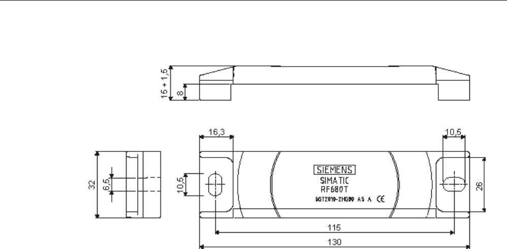
Transponder/tags
7.11 SIMATIC RF680T
SIMATIC RF600
System Manual, xx/2014, J31069-D0171-U001-A15-7618 459
REVIEW
7.11.8
Dimension drawing
Figure 7-60 Dimension drawing of SIMATIC RF680T
Units of measurement: All dimensions in mm
Tolerances, unless indicated otherwise, are +-0.5 mm.

Transponder/tags
7.11 SIMATIC RF680T
SIMATIC RF600
460 System Manual, xx/2014, J31069-D0171-U001-A15-7618
REVIEW

SIMATIC RF600
System Manual, xx/2014, J31069-D0171-U001-A15-7618 461
REVIEW
Integration into networks
8
8.1
Overview of parameterization of RF600 reader
The parameter assignment possibilities that are available to you for each reader of the
RF600 family are outlined below. You will find detailed information on parameter assignment
in the specified chapters of the documentation:
Reader
SIMATIC command
messages
RF-MANAGER Basic
XML commands
RFID reader interface
RF620R/
RF630R:
"Configuration Manual
RF620R/RF630R",
chapter "Overview of
commands"
- - -
RF640R/
RF670R
- Online help > chapter
"Working with RFID
objects"
SIMATIC RF Function
Manual, Chapter
"Standard Configuration
Messages"
-
RF650R/
RF680R/
RF685R
"Configuration manual
RF650R/RF680R/RF685
R" section "Interface to
the SIMATIC controller"
- "Configuration manual
RF650R/RF680R/RF685
R" section "XML
interface"
-
RF680M - - - Function Manual Mobile
Reader, section "RFID
Reader Interface
Reference"
8.2
Integration in IT networks via the user application
Connecting the readers RF640R/RF670R using XML
If you want to create your own applications for the RF640R/RF670R reader, you can do this
using the XML-based interface of the reader. For information about XML commands, refer to
the "SIMATIC RF Function Manual" .
Connecting the readers RF650R/RF680R/RF685R using XML
If you want to create your own applications for the RF650R/RF680R/RF685R reader, you
can do this using the XML-based demo application of the reader. You will find information on
the XML commands in the configuration manual "SIMATIC RF650R/RF680R/RF685R".

Integration into networks
8.3 Integration in SIMATIC networks
SIMATIC RF600
462 System Manual, xx/2014, J31069-D0171-U001-A15-7618
REVIEW
8.3
Integration in SIMATIC networks
Connecting the readers RF620R/RF630R
RF620R and RF630R readers are connected to the SIMATIC controller via the following
communications modules:
● SIMATIC RF170C
● SIMATIC RF180C
● ASM 456
● ASM 475
The RF182C communications module is connected with the PC directly over Ethernet.
Connecting the RF680R/RF685R readers
The RF680R/RF685R readers can be connected to a SIMATIC controller via PROFINET.
Note
Connection to the SIMATIC network planned
A connection via the ASM 456 and RF180C communications modules is currently being
planned. This connection allows operation o
f the devices via PROFINET and PROFIBUS.
With the help of the communications modules, the readers can also be connected in series.
Options for connecting via communications modules
Table 8- 1 Option for connecting the readers via communications modules
Function
blocks
Communications modules
ASM 456
RF170C
1)
RF180C
ASM 475
1)
RF182C
2)
RF160C
1) 2)
RFID 181EIP
2)
FB 45
1 - 2 readers
1 - 2 readers
1 - 2 readers
1 - 2 readers
N/A
N/A
N/A
FB 55
1 - 2 readers
1 - 2 readers
1 - 2 readers
1 - 2 readers
N/A
N/A
N/A
XML
N/A
N/A
N/A
N/A
1 - 2 readers
N/A
N/A
FC 44
N/A
N/A
N/A
N/A
N/A
1 - 2 readers
N/A
Ethernet/IP
N/A
N/A
N/A
N/A
N/A
N/A
1 - 2 readers
With all possible combinations, the input voltage at the
communications module must not be below 21.6 V. The CMs/ASMs
may only be operated in an ambient temperature of maximum 55 °C.
1) If 2 readers are used with a CM/ASM, the CM/ASM may only be operated at a maximum ambient temperature of 35 ℃.
2)
The communications modules do not currently support multitag operation.

Integration into networks
8.3 Integration in SIMATIC networks
SIMATIC RF600
System Manual, xx/2014, J31069-D0171-U001-A15-7618 463
REVIEW
Communications modules and function blocks
Table 8- 2 Properties of the communications modules
ASM/CM
Interfaces to the
application (PLC)
Interfaces to the
reader
Function
blocks
Reader
connections
Dimensions
(W x H x D) in
mm
Temperature
range
Degree
of
protecti
on
ASM 456 PROFIBUS DP-V1 2 x 8-pin
connection socket,
M12
FB 45
FC 55
2 (parallel) 60 x 210 x 54
or 79
0 ... +55 °C IP67
SIMATIC
RF170C
PROFIBUS DP-V1
PROFINET IO
2 x 8-pin
connection socket,
M12
FB 45
FC 55
2 (parallel) 90 x 130 x 60 -25 ... 55° C IP67
SIMATIC
RF180C
PROFINET IO 2 x 8-pin
connection socket,
M12
FB 45 2 (parallel) 60 x 210 54
0 ... +60° C IP67
SIMATIC
RF182C
TCP/IP 2 x 8-pin
connection socket,
M12
- 2 (parallel) 60 x 210 x 54 0 ... +60° C IP67
The following configuration graphics show which readers can be connected to which
interface modules/communications modules.
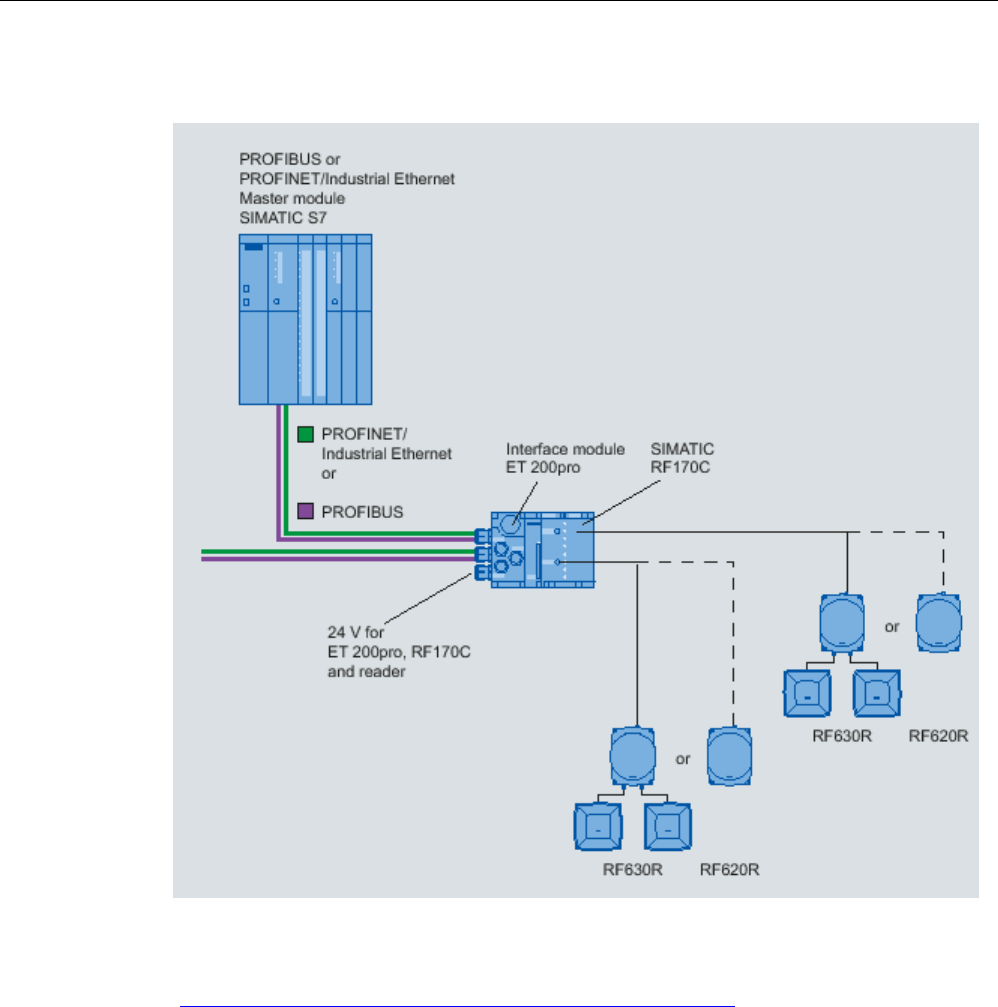
Integration into networks
8.3 Integration in SIMATIC networks
SIMATIC RF600
464 System Manual, xx/2014, J31069-D0171-U001-A15-7618
REVIEW
Configuration with SIMATIC RF170C
Figure 8-1 Configuration with SIMATIC RF170C
For more detailed information, refer to SIMATIC RF170C Operating Instructions
(http://support.automation.siemens.com/WW/view/en/32622825).
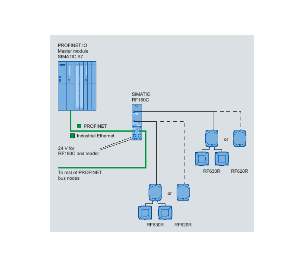
Integration into networks
8.3 Integration in SIMATIC networks
SIMATIC RF600
System Manual, xx/2014, J31069-D0171-U001-A15-7618 465
REVIEW
Configuration with SIMATIC RF180C
Figure 8-2 Configuration with SIMATIC RF180C
For more detailed information, refer to SIMATIC RF180C Operating Instructions
(http://support.automation.siemens.com/WW/view/en/30012157).
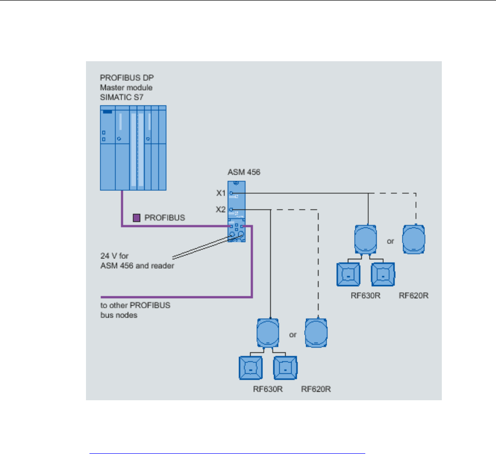
Integration into networks
8.3 Integration in SIMATIC networks
SIMATIC RF600
466 System Manual, xx/2014, J31069-D0171-U001-A15-7618
REVIEW
Configuration with ASM 456
Figure 8-3 Configuration with ASM 456
For more detailed information, refer to ASM 456 Operating Instructions
(http://support.automation.siemens.com/WW/view/en/32629442).
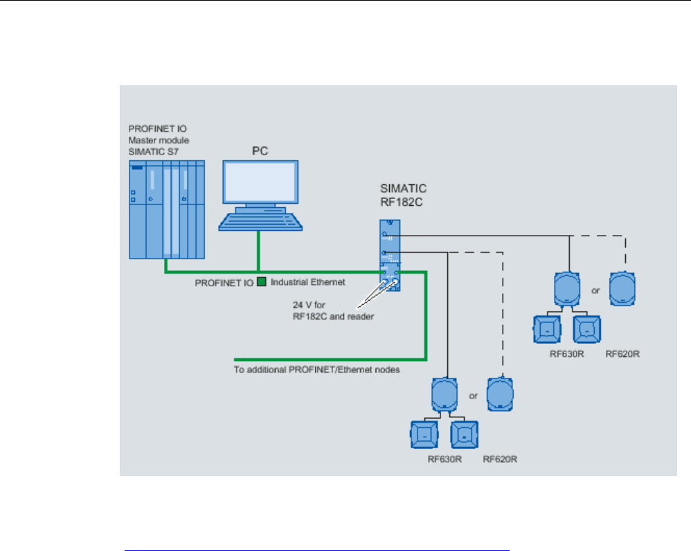
Integration into networks
8.3 Integration in SIMATIC networks
SIMATIC RF600
System Manual, xx/2014, J31069-D0171-U001-A15-7618 467
REVIEW
Configuration with RF182C
Figure 8-4 Configuration with SIMATIC RF182C
For more detailed information, see SIMATIC RF182C Operating Instructions
(http://support.automation.siemens.com/WW/view/en/38507897)

Integration into networks
8.3 Integration in SIMATIC networks
SIMATIC RF600
468 System Manual, xx/2014, J31069-D0171-U001-A15-7618
REVIEW

SIMATIC RF600
System Manual, xx/2014, J31069-D0171-U001-A15-7618 469
REVIEW
System diagnostics
9
9.1
Error messages and flash codes for RF620R/RF630R
error_MOBY
The ERR LED of the reader flashes when there are error messages. Some errors are also
indicated by the flashing ERR LED of the CM.
Table 9- 1 Error messages of the communications module via the "error_MOBY" variable
Error code
(B#16#..)
Flashing of
ERR LED
Description
00 – No error
Default value if everything is ok
1x
Boot message
01 2x Presence error, possible causes:
• The active command was not carried out completely
• The transponder left the field while the command was being
processed
• Communication problem between reader and transponder
The next command is automatically executed on the next transponder.
A read or write command is possible.
If the write command is aborted with error code 01, inconsistencies
between the expected and actual data may occur on the data carrier.
Repeat the read/write command.
03 3x Problem on the connection to the reader or antenna problem.
• The cable between the communications module and reader is
wired incorrectly or there is a cable break
• Antenna error: (Cable is defective), cable is no longer connected
• The 24 V supply voltage is not connected or is not on or has failed
briefly
• Automatic fuse on the CM has blown
• Hardware defect
• Another reader is in the vicinity and is active
• Interference on reader - or PROFIBUS line
• Execute "init_run" after eliminating the problem

System diagnostics
9.1 Error messages and flash codes for RF620R/RF630R
SIMATIC RF600
470 System Manual, xx/2014, J31069-D0171-U001-A15-7618
REVIEW
Error code
(B#16#..)
Flashing of
ERR LED
Description
05 5x Command/parameter assignment error, possible causes:
• Unknown command
• Incorrect parameter
• Function not allowed
• Mode in "SET-ANT" command unknown
FB 45 / FB 55 is sending an uninterpretable command to the
communications module.
• "command_DB" contains invalid command parameters
• The "command_DB" was overwritten by the user
• The transponder has signaled an address error
06 6x Field disturbance on reader
The reader is receiving interference pulses from the environment.
• The distance between two readers is too small and does not
correspond to the configuration guidelines
• The connecting cable to the reader is defective or too long or does
not comply with the specification
07
7x
No free ETSI transmit channel
09 9x Wrong communications standard selected in the "init_run" command
(e.g. FCC for ETSI reader)
0B 11x Transponder memory cannot be read correctly or cannot be written to.
The transponder signals an error. Options for troubleshooting:
• Increase power
• Change antenna alignment
• Avoid field interference
0C 12x Memory of the transponder cannot be written to
• Transponder memory is defective
• Memory is write-protected (Memory Locked: 000000100B)
(The transponder memory is PERMA-locked and cannot be
overwritten or the reader password has to be reset)
0D 13x Error in specified address (address error)
• The specified address does not exist on the transponder
• The command must be checked and corrected.
• This is not the correct transponder type.
• Access attempted to non-existent or non-accessible memory areas
( Memoryoverrun: 00000011B)
0E 14x Password error
• Incorrect transponder password (the reader password must be set
again so that it matches the password).

System diagnostics
9.1 Error messages and flash codes for RF620R/RF630R
SIMATIC RF600
System Manual, xx/2014, J31069-D0171-U001-A15-7618 471
REVIEW
Error code
(B#16#..)
Flashing of
ERR LED
Description
0F 1x Start-up message from CM. The CM was off and has not yet received
an "init_run" command
• "init_run" needs to be executed
• The same physical CM channel is used in two (or more) UDT 10
structures. Check "ASM_address" and "ASM_channel" in all UDT
10 structures.
10 16x "NEXT" not possible or not permitted
• CM is operating without MDS control ("MDS_control = 0,1")
• CM has already received a "NEXT" command
• CM/reader does not recognize a "NEXT" command
"REPEAT" after forbidden commands:
• "REPEAT" for "SET-ANT"
• "REPEAT" for "SLG-STATUS"
11 – Short circuit or overload of the 24 V outputs (DQ, error code, presence)
• The affected output is turned off
• All outputs are turned off when total overload occurs
• A reset can only be performed by turning the 24 V voltage off and
on again
• Then start "init_run"
12 18x Internal CM communication error.
• Connector contact problem on the CM
• Defective CM hardware
– Return CM for repair
• Start the "init_run" command after eliminating the problem
13 19x • CM/reader does not have enough buffer space to store the
command temporarily.
•
Maximum allowable number of 150 commands in a command chain
was ignored. If "REPEAT" is used in conjunction with a command
chain, the maximum number of commands is also 150 (including
the number of commands from a command repetition).
If a command chain contains more than 150 commands, after the
150th command is called, it will be stopped and the above error
message will be sent without processing the complete chain.
Commands in the command chain that have already been
executed can still be sent later after the error message "0x13" is
sent.
14 20x Internal CM/reader error.
• Program sequence error on the CM
• Cycle power to the CM
• Start the "init_run" command after eliminating the problem
• Watchdog error on reader

System diagnostics
9.1 Error messages and flash codes for RF620R/RF630R
SIMATIC RF600
472 System Manual, xx/2014, J31069-D0171-U001-A15-7618
REVIEW
Error code
(B#16#..)
Flashing of
ERR LED
Description
15 21x Bad parameter assignment of the CM/reader
• Check INPUT parameters in UDT 10
• Check parameters in HW Config
• Transmit power set too high
• Unused parameter bits are not 0.
• "init_run" command has incorrect parameters
• After a start-up, the CM has still not received an "init_run".
• "scanning_time = 0x00" parameter was set (no standard selected).
16 22x The FB command cannot be executed with the CM parameter
assignment on PROFIBUS.
• Length of the input/output areas too small for the cyclic I/O word.
Did you use the right GSD file?
• FB command (e.g. read) has too much user data (data length >
233 bytes)
17 23x Communication error between FB 45 / FB 55 and communications
module.
Handshake error
• "Params_DB" (UDT 10) of this CM station is overwritten by other
parts of the program
• Check parameter assignment of communications module in UDT
10
• Check FB 45/FB 55 command that caused this error
• Start the "init_run" command after eliminating the problem
18 – An error has occurred that must be acknowledged with an "init_run".
• A temporary short circuit has occurred on PROFIBUS
• The "init_run" command is incorrect
• Start the "init_run" command after eliminating the problem
• Check the parameters "ASM_address", "ASM_channel" and
"MOBY_mode".
19 25x Previous command is active or buffer overflow
The user sent a new command to the CM although the last command
was still active.
• Active command can only be terminated with an "init_run"
• Before a new command can be started "READY-Bit = 1 must be
set; exception: "init_run"
•
Two FB 45/FC 55 calls were set with the same "ASM_address" and
"ASM_channel" parameters
• Two FB 45/FC 55 calls are using the same "Params_DB" pointer
• Start the "init_run" command after eliminating the problem
• When command repetition (e.g. read-only MDS) is used, no data is
fetched from the transponder. The data buffer on the CM has
overflowed. Transponder data has been lost.

System diagnostics
9.1 Error messages and flash codes for RF620R/RF630R
SIMATIC RF600
System Manual, xx/2014, J31069-D0171-U001-A15-7618 473
REVIEW
Error code
(B#16#..)
Flashing of
ERR LED
Description
1A – PROFIBUS DP error occurred.
• The PROFIBUS DP bus connection was interrupted
– Wire break on the bus
– Bus connector on CM was removed briefly
• PROFIBUS DP master does not address CM anymore
• "init_run" needs to be executed
• The CM has detected a frame interruption on the bus. PROFIBUS
may have been reconfigured (e.g. with HW Config).
This error is only indicated when access monitoring has been enabled
in the PROFIBUS configuration.
1B 27x There is an inconsistency in the parameter assignment of the reader.
Parameters were probably set in the Advanced User Parameter
parameter with which the reader cannot work.
• ETSI performance testing faulty
1C 28x • Antenna is already switched off
• Antenna is already switched on
• Mode in "SET-ANT" unknown.
1D – More transponders are located in the antenna field than can be
processed si
multaneously by the reader. A read or write command was
sent to a transponder (UID) and one of the following conditions was
met at the same time:
• Only 1 transponder at a time can be processed with FB 45.
• With FB 45 and FB 55: there is more than one transponder with the
same EPC-ID in the antenna field of the reader.
Countermeasures:
• with FB 55: Increase the value in multitag or decrease the number
of transponders in the field.
• with FB 55 (with MOBY_mode = 7): There is one or more
transponder in the antenna field for which the content of the "FF00
– FF03" addresses of the EPC-ID does not match (uniqueness
when accessing transponders using a UID with the length of 8
bytes).
• Power supply of the transponder in the limit range:
Due to short-term power shortage, a transponder loses its
communication status (session) and the identical EPC-ID is sent a
second time as soon as power is above the limit value again.
Increase the reader's radiated power and/or reduce the distance
between antenna and transponder until this effect no longer occurs.

System diagnostics
9.1 Error messages and flash codes for RF620R/RF630R
SIMATIC RF600
474 System Manual, xx/2014, J31069-D0171-U001-A15-7618
REVIEW
Error code
(B#16#..)
Flashing of
ERR LED
Description
1E
30x
Wrong number of characters in the command message frame.
1F 31 Active command canceled by "RESET ("init_run" or "cancel") or bus
connector removed
• Communication with the transponder was aborted by "init_run"
• This error can only be reported if there is an "init_run" or "cancel"
*)
You will find the meaning of the error numbers in the EPC Global Class 1 Gen 2 document, Annex
I.
error_FB
Table 9- 2 Error variable "error_FB"
Error code
(B#16#...)
Description
00
No error; default value if everything is ok
01
"Params_DB" is not available in SIMATIC
02 "Params_DB" is too small
• UDT 10/11 was not used during definition
• "Params_DB" must be 300 bytes in length (for each channel)
• "Params_DB", "Params_ADDR" - check that they are correct
03 The DB after the "command_DB_number" pointer is not available in the SIMATIC
controller.
04 The "command_DB" on the SIMATIC controller is too small
• UDT 20/21 was not used during command definition
• The last command in the "command_DB" is a chained command; reset the
chaining bit
• Check the "command_DB_number/command_DB_address" command pointer
05 Invalid command type
• Check the "command_DB_number/command_DB_address" command pointer
• Check the actual values in the "command_DB"
– "init_run" needs to be executed

System diagnostics
9.1 Error messages and flash codes for RF620R/RF630R
SIMATIC RF600
System Manual, xx/2014, J31069-D0171-U001-A15-7618 475
REVIEW
Error code
(B#16#...)
Description
06 Unexpected acknowledgement received. The parameters of the command and
acknowledgement frame do not match ("command", "length", "address_MDS").
• The user changed the "command_DB_number/-_address" pointer during
command execution.
• The user changed the command parameters in the MOBY CMD data block (UDT
20) during command execution.
• Check the parameter assignment of "ASM_address" and "ASM_channel".
"ASM_address" and "ASM_channel" have the same parameter assignment for
different channels.
• The acknowledgement counter and command counter between the CM and FB
are no longer synchronized
– "init_run" needs to be executed
07 The "MOBY_mode" or "MDS_control" parameter (defined in UDT 10) has an invalid
value
08 A bus error has occurred that is signaled by system functions SFB 52/53. More
information on this error is available in the "error_BUS" variable.
• "ASM_address" or "ASM_channel" not available
• "init_run" needs to be executed
09 The CM has failed.
• Loss of power on CM
• PROFIBUS connector removed or PROFIBUS cable interrupted
• "ASM_address" or "ASM_channel" not available
This error is indicated if the "ASM_failure" bit was set in OB 122. OB 122 is called if
FB 45 can no longer access the cyclic word for the CM.
0A Another "init_run" was started while "init_run" was executing without waiting for
"ready"
• "init_run" must not be not set cyclically
• The same physical channel/reader is used in two (or more) UDT 10 structures.
Check "ASM_address" and "ASM_channel" in all UDT 10 structures.
0B "init_run" cannot be executed; cyclic process image for the CM is disrupted; FB 45
reports a timeout of the process image for the CM
The timeout time can be adapted in DBB 47 of UDT 10 if required. The default value
is 50 (dec.) = 2 seconds. Greater values (255 max.) increase the timeout time.
•
"ASM_address" in UDT 10 has bad parameter settings. The "ASM_address" may
be on the wrong module.
• "ASM_channel" setting is ≥16 or ≤0
• CM hardware/firmware is faulty.
• The same physical channel/reader is used in two (or more) UDT 10 structures.
Check "ASM_address" and "ASM_channel" in all UDT 10 structures.

System diagnostics
9.1 Error messages and flash codes for RF620R/RF630R
SIMATIC RF600
476 System Manual, xx/2014, J31069-D0171-U001-A15-7618
REVIEW
Error code
(B#16#...)
Description
0C Area length error on block move for FB 45.
• "DAT_DB" does not exist or is set too small. "DAT_DB_number" and
"DAT_DB_address" in UDT 20 need to be checked
• Write command with length = 0 was sent
• "init_run" needs to be executed
0D An "init_run" was not completed correctly. The process image is inconsistent.
This message is equivalent to a timeout. A timeout is reported 15s after starting
"init_run". This time can be adjusted when necessary in DBW 44.
• Execute "init_run" again
• Turn CM off and on again
• The "RUN-STOP" switch on the CPU was pressed rapidly several times in
succession (particularly with slow PROFIBUS baud rates)
• The same physical channel/reader is used in two (or more) UDT 10 structures.
Check "ASM_address" and "ASM_channel" in all UDT 10 structures.
error_BUS
Note
The following table of bus errors does not claim to be complete. If
you receive any messages
that are not documented here, you will find them in the manual "System and standard
functions S7
-300/400, volume 1/2
(
http://support.automation.siemens.com/WW/view/en/44240604)".
Table 9- 3 Error variable "error_BUS" when operating via PROFIBUS/PROFINET
Error code
(W#16#...)
Description
800A CM is not ready (temporary message)
• This message is received by a user who is not using FB 45 and is querying the
CM acyclically in very quick succession.
8x7F
Internal error in parameter x. Cannot be remedied by the user.
8x22
8x23
Area length error when reading a parameter.
Area length error when writing a parameter.
This error code indicates that parameter x is partially or completely outside the
operand range or the length of a bit array for an "ANY" parameter is not divisible by
8.
8x24
8x25
Area error when reading a parameter.
Area error when writing parameter.
This error code indicates that parameter x is in an area not allowed for the system
function.
8x26
Parameter contains a time cell number that is too high.

System diagnostics
9.1 Error messages and flash codes for RF620R/RF630R
SIMATIC RF600
System Manual, xx/2014, J31069-D0171-U001-A15-7618 477
REVIEW
Error code
(W#16#...)
Description
8x27
Parameter contains a counter cell number that is too high.
8x28
8x29
Alignment error when reading a parameter.
Alignment error when writing a parameter.
The reference to parameter x is an operand whose bit address is not equal to 0.
8x30
8x31
The parameter is located in the write-protected global DB.
The parameter is located in the write-protected instance DB.
8x32
8x34
8x35
The parameter contains a DB number that is too high.
The parameter contains an FC number that is too high.
The parameter contains an FB number that is too high.
8x3A
8x3C
8x3E
The parameter contains a DB number that is not loaded.
The parameter contains an FC number that is not loaded.
The parameter contains an FB number that is not loaded.
8x42
8x43
An access error occurred while the system was attempting to read a parameter from
the I/O area of the inputs.
An access error occurred while the system was attempting to write a parameter to
the I/O area of the outputs.
8x44
8x45
Error on nth (n > 1) read access after an error occurred.
Error on nth (n > 1) write access after an error occurred.
8090 Specified logical base address is invalid: There is no assignment in SDB1/SDB2x, or
it is not a base address.
8092
A type other than "BYTE" has been specified in an "ANY" reference.
8093 The area identifier contained in the configuration (SDB1, SDB2x) of the logical
address is not permitted for these SFCs. Permitted:
• 0 = S7-400
• 1 = S7-300
• 2, 7 = DP modules
80A0 Negative acknowledgment when reading from module; FB fetches acknowledgment
although no acknowledgment is ready.
A user who is not using the FB 45 would like to fetch DS 101 (or DS 102 to 104)
although no acknowledgment is available.
• Execute an "init_run" for resynchronization between CM and application
80A1
Negative acknowledgment while writing to the module. FB sends command although
a CM is unable to receive a command
80A2 DP protocol error with layer 2
• DP-V1 mode must be set in the header module for distributed I/O.
• Possible hardware defect
80A3 DP protocol error in Direct-Data-Link-Mapper or User-Interface/User. Could be a
hardware defect.
80B0 • SFC not possible for module type.
• Data record unknown to module.
• Data record number ≥ 241 is not allowed.
• Data records 0 and 1 are not permitted for SFB 52/53 "WR_REC".
80B1
The length specified in the "RECORD" parameter is wrong.
80B2
The configured slot is not occupied.

System diagnostics
9.1 Error messages and flash codes for RF620R/RF630R
SIMATIC RF600
478 System Manual, xx/2014, J31069-D0171-U001-A15-7618
REVIEW
Error code
(W#16#...)
Description
80B3
Actual module type is not the expected module type specified in "SDB1"
80C0 • RDREC:
The module has the record, but there is no read data there yet.
• WRREC:
CM is not ready to receive new data
– Wait until the cyclic counter has been incremented
80C1 The data of the preceding write job on the module for the same data record have not
yet been processed by the module.
80C2
The module is currently processing the maximum possible number of jobs for a CPU.
80C3 Required resources (memory, etc.) are currently in use.
This error is not reported by the FB 45. If this error occurs, the FB 45 waits until the
system is able to provide resources again.
80C4 Communication error
• Parity error
• SW ready not set
• Error in block length management
• Checksum error on CPU side
• Checksum error on module side
80C5
Distributed I/O not available.

System diagnostics
9.2 Flashing codes RF640R/RF670R
SIMATIC RF600
System Manual, xx/2014, J31069-D0171-U001-A15-7618 479
REVIEW
9.2
Flashing codes RF640R/RF670R
Flashing of ERR LED
Error description
Number
Repetitions
Lit constantly
Permanent
Reader inactive, no configuration data
3
Permanent
Antenna 1 not connected or defective
4
Permanent
Antenna 2 not connected or defective
5
Permanent
Antenna 3 not connected or defective
6
Permanent
Antenna 4 not connected or defective
11
3 times
Reading of user-defined memory has failed
12
3 times
Writing of user-defined memory has failed
13
3 times
The "SendCommand" function has failed
14
3 times
Wrong or missing password
15
3 times
Writing the transponder ID failed
16
3 times
LOCK has failed
17
3 times
KILL has failed
18
3 times
Access to impermissible memory areas
19
3 times
Too many transponders in the antenna field
20
Permanent
General software errors
29 3 times Invalid frame;
Bad frame parameters
30
3 times
Incorrect message frame format
31 3 times The "SetReadProtect" NXP function has failed
32
3 times
The "ResetReadProtect" NXP function has failed
33
3 times
General error during identification of transponders (inventory)
The LED states are described in the section Status display (Page 179).
9.3
Error messages RF640R/RF670R
A description of the RF640R/RF670R error codes can be found in the "SIMATIC RF Function
Manual".
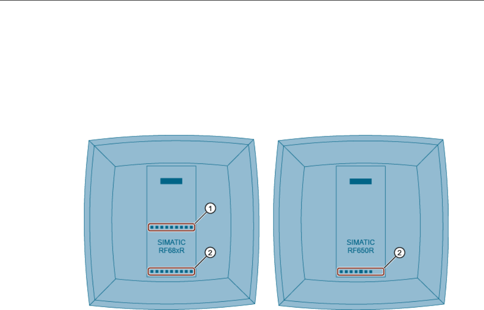
System diagnostics
9.4 LED displays RF650R/RF680R/RF685R
SIMATIC RF600
480 System Manual, xx/2014, J31069-D0171-U001-A15-7618
REVIEW
9.4
LED displays RF650R/RF680R/RF685R
Note that the RF650R reader does not provide an LED status display. With the help of the
LED displays, you can read out the status and the error messages of the RF680R/RF685R
readers.
The LED status display is in the middle on the front of the reader. The LED operating display
is at the bottom on the front of the reader.
①
LED status display (ST1 - ST9) - RF680R/RF685R only
②
LED operating display
• RUN/STOP (R/S) Shows whether the reader is ready for operation.
• ERROR (ER) Indicates whether an error has occurred.
• MAINTENANCE (MAINT) Shows whether the reader needs maintenance.
• POWER (PWR) Shows whether the reader is supplied with power.
• PRESENCE (PRE) -
RF650R only
Shows whether one or several transponders are located in
the antenna field.
• LINK 1 (LK1) Shows that there is a connection via Ethernet interface "1".
• RECEIVE/TRANSMIT 1
(R/T1)
Shows that data is being sent and/or received via Ethernet
interface "1".
• LINK 2 (LK2) -
RF680R/RF685R only
Shows that there is a connection via Ethernet interface "2".
• RECEIVE/TRANSMIT 2
(R/T2) - RF680R/RF685R
only
Shows that data is being sent and/or received via Ethernet
interface "2".
Figure 9-1 LED displays of the reader
With the LED operating display, you can read out the various operating statuses of the
readers. The LED status display of the RF680R and RF685R readers has several functions.
Among other things, the status display provides the following functions:
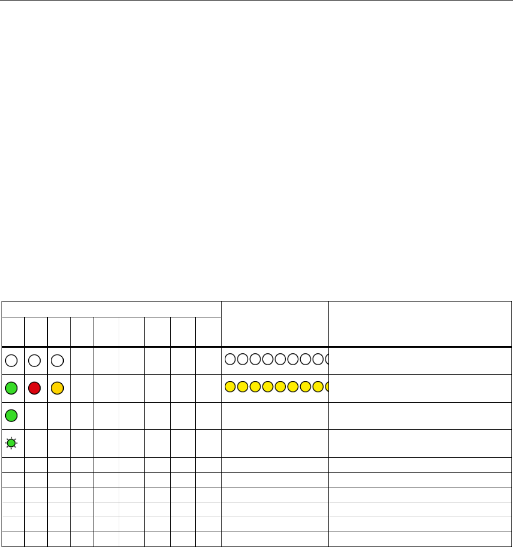
System diagnostics
9.4 LED displays RF650R/RF680R/RF685R
SIMATIC RF600
System Manual, xx/2014, J31069-D0171-U001-A15-7618 481
REVIEW
● Error display
If there is an error, the actual error is indicated by the lighting/flashing pattern. You will
find more information on error messages in the section "xx".
● Display of RF activity
Indicates that one or more transponders were detected. This function is indicated by the
RF650R reader using the PRE LED.
● Indication of the quality of the antenna alignment (RSSI)
When aligning the antenna, the status display indicates the RSSI value with which the
transponder was detected. You will find more information on antenna alignment in the
section "xx".
9.4.1
LED operating display
The LED displays indicate the current reader status according to the following scheme:
Table 9- 4 Display of the reader status with the LEDs
Operating display LEDs
Status display LEDs
Meaning
R/S
ER
MT
P
PR
E
LK1
R/T
1
LK2
R/T
2
Reader turned off
Reader turned on (after startup)
n.
r.
n.
r.
n. r. Reader ready for operation
n.
r.
n.
r.
n. r. Reader working
9.4.2
Error display by LEDs
The display of the error messages using the LEDs is described in the section "Error
messages RF640R/RF670R (Page 479)".

System diagnostics
9.4 LED displays RF650R/RF680R/RF685R
SIMATIC RF600
482 System Manual, xx/2014, J31069-D0171-U001-A15-7618
REVIEW
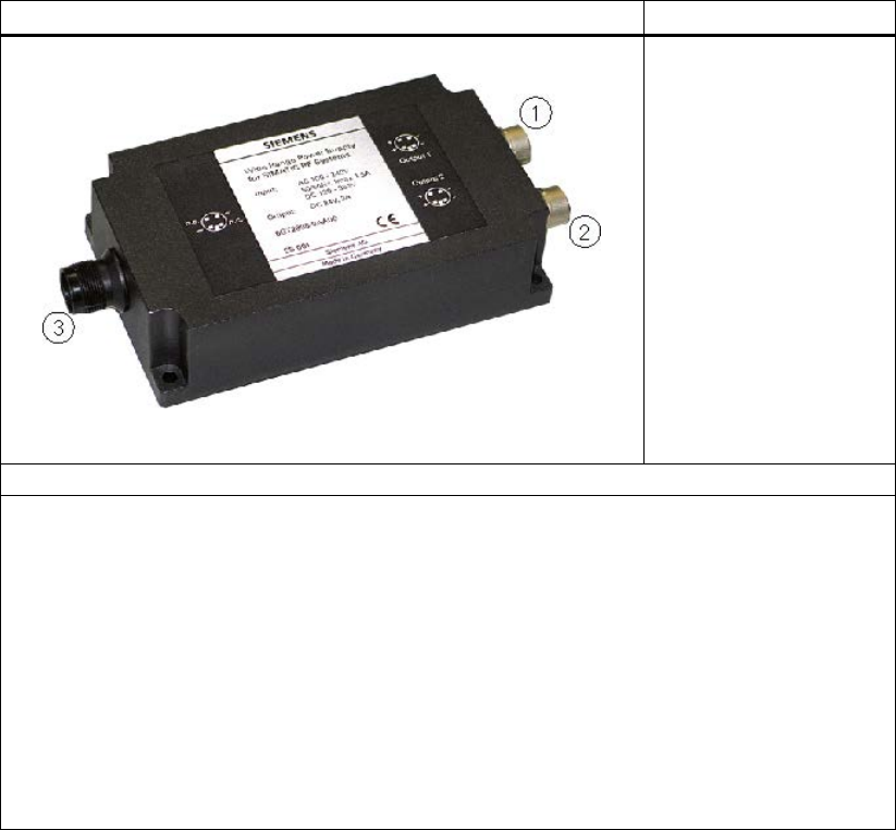
SIMATIC RF600
System Manual, xx/2014, J31069-D0171-U001-A15-7618 483
REVIEW
Accessories
10
10.1
Wide-range power supply unit for SIMATIC RF systems
10.1.1
Features
Wide-range power supply unit for SIMATIC RF systems
(1) DC output 1
(2) DC output 2
(3) Mains connection
Features
• Wide-range input (3) for use worldwide
• Dimensions without mains cable: 175 x 85 x 35 mm
• Dimensions including mains cable: 250 x 85 x 35 mm
• CE-compliant (EU and UK versions)
• UL-certified for US and Canada (US version)
• Mechanically and electrically rugged design
• Secondary side (1), (2): 24 V DC / 3 A
• Short-circuit and no-load stability
• Suitable for frame mounting
• 3 versions for use in the EU, UK, US

Accessories
10.1 Wide-range power supply unit for SIMATIC RF systems
SIMATIC RF600
484 System Manual, xx/2014, J31069-D0171-U001-A15-7618
REVIEW
Description
The wide-range power supply unit for SIMATIC RF systems is a universal compact power
supply and provides the user with an efficient, cost-saving solution for many different mid-
range power supply tasks.
The primary switched power supply is designed for use on single-phase AC systems. The
two DC outputs (sockets) are connected in parallel and protected by a built-in current limiting
circuit against overload and short-circuits.
The device is vacuum-cast and prepared for Safety Class 2 applications. The EU and UK
versions satisfy the low-voltage guideline as well as the current EU standards for CE
conformity. Furthermore, the US version has been UL-certified for the US and Canada.
10.1.2
Scope of supply
● Wide-range power supply unit for SIMATIC RF systems
● 2 m mains cable (country-specific)
● Protective cover for flange outlet
● Operating Instructions
10.1.3
Ordering data
Wide-range power supply unit for SIMATIC RF-systems
(100 - 240 VAC / 24 VDC / 3 A)
with 2 m connecting cable with country-specific plug
EU: 6GT2898-0AA00
UK: 6GT2898-0AA10
US: 6GT2898-0AA20
24 V connecting cable for SIMATIC RF640R/RF670R,
length 5 m
6GT2891-0NH50
Note
Risk of confusion
Note
that you cannot use the 24 V connecting cables of the discontinued RF660R reader for
the RF640R and RF670R readers.
Accessories
10.1 Wide-range power supply unit for SIMATIC RF systems
SIMATIC RF600
System Manual, xx/2014, J31069-D0171-U001-A15-7618 485
REVIEW
10.1.4
Safety Information
WARNING
Danger to life
It is not permitted to open the device or to modify the device.
The following must also be taken into account:
• Failure to observe this requirement shall constitute a revocation of the CE approval, UL
certification for the US and Canada as well as the manufacturer's warranty.
• For installation of the power supply, compliance with the DIN/VDE requirements or the
country-specific regulations is essential.
• The field of application of the power supply is limited to "Information technology in
electrical office equipment" within the scope of validity of the EN 60950/VDE 0805
standard.
• When the equipment is installed, it must be ensured that the mains socket outlet is
freely accessible.
• The housing can reach a temperature of +25 °C during operation without any adverse
consequences. It must, however, be ensured that the power supply is covered in the
case of a housing temperature of more than +25°C to protect persons from contact with
the hot housing. Adequate ventilation of the power supply must be maintained under
these conditions.
Note
The wide
-range power supply unit must only be used for SIMATIC products in the
specifically described operating range and for the documented intended use.
If the wide input range power supply for SIMATIC RF systems is used for an end product
other than the SIMATIC RF600 system, the following must be taken into account:
● The electric strength test of the end product is to be based upon a maximum working
voltage of: Transition from primary to SELV: 353 VDC, 620 Vpk
● The following secondary output circuits are SELV (low voltage; SELV = Safety Extra Low
Voltage): all
● The following secondary output circuits are at non-hazardous energy levels: all
● The power supply terminals and/or connectors are suitable for field wiring if terminals are
provided.
Accessories
10.1 Wide-range power supply unit for SIMATIC RF systems
SIMATIC RF600
486 System Manual, xx/2014, J31069-D0171-U001-A15-7618
REVIEW
● The maximum investigated branch circuit rating is: 20 A
● The investigated pollution degree is: 2
WARNING
If the wide input range power supply for SIMATIC RF systems is connected to an end
product other than end products of the RF600 family, the end user is responsible and
liable for operation of the system or end product that includes the wide input range
power supply for SIMATIC RF systems.
WARNING
Alterations to the SIMATIC RF600 components and devices as well as the use of
SIMATIC RF600 components with third-party RFID devices are not permitted.
Failure to observe this requirement shall constitute a revocation of the radio equipment
approvals, CE approval and manufacturer's warranty. Furthermore, the compliance to
any salient safety specifications of VDE/DIN, IEC, EN, UL and CSA will not be
guaranteed.
Safety notes for the US and Canada
The SIMATIC RF640R/RF670R reader may only be operated with the wide range power
supply unit for SIMATIC RF systems - as an optional component – or with power supply units
that are UL-listed according to the safety standards specified below:
● UL 60950-1 - Information Technology Equipment Safety - Part 1: General Requirements
● CSA C22.2 No. 60950 -1 - Safety of Information Technology Equipment.
WARNING
The compliance of the SIMATIC RF600 system to the safety standards mentioned
above will not be guaranteed if neither the wide-range power supply unit for SIMATIC
RF systems°nor power supplies listed according to the safety standards above are
used.
Accessories
10.1 Wide-range power supply unit for SIMATIC RF systems
SIMATIC RF600
System Manual, xx/2014, J31069-D0171-U001-A15-7618 487
REVIEW
Safety information for Korea
WARNING
The SIMATIC RF640R/RF670R Reader may only be operated with power supplies that
have received KETI approval. There is currently no KETI approval for the wide-range power
supply (6GT2898-0AAx0). This is why the wide-range power supply may not be operated in
South Korea.
To use the SIMATIC RF640R/RF670R Reader in South Korea, you need a power supply
(24 V DC / 3 A). This power supply must meet the requirements of the application field and
have a KETI approval. You also need the connection cable for the SIMATIC
RF640R/RF670R (6GT2891-0NH50).
For the required pin assignments of the DC output for connecting the power supply, see
section Pin assignment of DC outputs and mains connection (Page 490). You can find the
pin assignment of the DC inputs for the reader in sections Pin assignment for power supply
(Page 138) and Pin assignment for power supply (Page 185).
10.1.5
Connecting
● There are three different (country-specific) mains cables for the EU, UK and US.
The appropriate mains cable must be connected to the primary input of the power supply.
Note
It is only permissible to insert or remove the mains cable when the power supply is de
-
energized.
● The wide-range power supply unit has total insulation (Safety Class 2), IP65
● It can be mounted using four fixing holes.

Accessories
10.1 Wide-range power supply unit for SIMATIC RF systems
SIMATIC RF600
488 System Manual, xx/2014, J31069-D0171-U001-A15-7618
REVIEW
10.1.6
Technical specifications
Table 10- 1 General technical specifications
Insulation stability (prim./sec.) Uins p/s
3.3 kVAC
Insulation resistance R
ins
>1 GΩ
Leakage current Ileak
Uin = 230 VAC, f = 50 Hz
< 200 µA
Safety class (SELV)
Designed for installation in devices of Safety Class 2
Mains buffering th
Uin = 230 VAC
≥ 50 ms
Ambient temperature
-25 °C to +55 °C
Surface temperature
Module top, center
Max. 96 °C
Storage temperature
-40 °C to +85 °C
Self-heating on full-load
max. 45 K
Interference immunity
ESD
HF fields
Burst
Surge
HF injection
Mains quality test
EN 61000-4-2,
4-3 up to 4-6, 4-11
Air discharge: 15 kV
10 V/m
symmetrical: 2
Symmetrical: 1
10 Vrms
Cooler
Free convection
Dimensions L x W x H 175 mm x 85 mm x 35 mm
Weight
720 g
Housing / casting
UL 94-V0
Power supply class
according to CSA
Level 3
Degree of protection
IP65
MTBF in years
255
Table 10- 2 Technical specifications for the input
Rated input voltage Uin EN 60950 / UL 60950 100 to 240 VAC
120 to 353 VDC
Input voltage range Uin 94 to 264 VAC
120 to 375 VDC
(UL: 353 VDC)
Input frequency f
in
50/60 Hz
Radio interference level
EN 55011/B
Switching frequency f
sw
approx. 70 kHz typ.
Length of cable
2 m
Table 10- 3 Technical specifications of the output
Output voltage tolerance ∆Uout
Uin = 230 VAC
Uout nom ≤ +2 %/-1 %
Overvoltage protection
U
out nom
+20 % typ.
Noise ∆ULF
Uin = min., BW: 1 MHz
≤ 1 % Uout
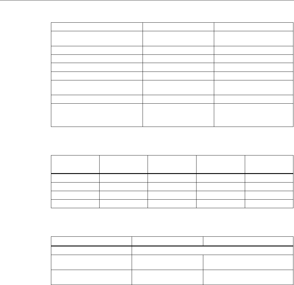
Accessories
10.1 Wide-range power supply unit for SIMATIC RF systems
SIMATIC RF600
System Manual, xx/2014, J31069-D0171-U001-A15-7618 489
REVIEW
Noise ∆UHF
Uin = min., BW: 20 MHz
≤ 2 % Uout
Line Regulation
Load Regulation
Uin = min./max.
I
out
= 10...90...10 %
≤ 1,0 %
≤ 1,0 %
Short-circuit current Imax
Inom = 4 A (+50°C)
105 ... 130 % Inom
Settling time t
R
load variations
I
out
= 10...90...10 %
< 5 ms
Temperature coefficient ε
TA = -25 °C to +70 °C
0.01 %/K
Overload behavior P
over
Constant current
Short-circuit protection/
No-load response
Continuous/no-load stability
Derating
T
A
> +50 °C to +70 °C
max. 2 %/K
Connector type Flanged connector
Binder,
Order no.: 09-3431-90-04
4 pins
Table 10- 4 Output configurations
Input
Outputs
U1 = U2
ILoad =
I1 + I2
Efficiency
(%)
Remarks
110 VAC
24 VDC
0 A
No-load stability
110 VAC
24 VDC
3 A
≥ 88
220 VAC
24 VDC
0 A
No-load stability
220 VAC
24 VDC
3 A
≥ 90
Table 10- 5 Compliance with standards
Designation
Standard
Values
Electrical safety EN 60950 / UL 60950 / CAN/CSA 22.2 950, 3 Edition
Conducted interference EN 61000-6-3
EN 55011
Class B
Emission EN 61000-6-3
EN 55011
Class B
All values are measured at full-load and at an ambient temperature of 25 °C (unless
specified otherwise).
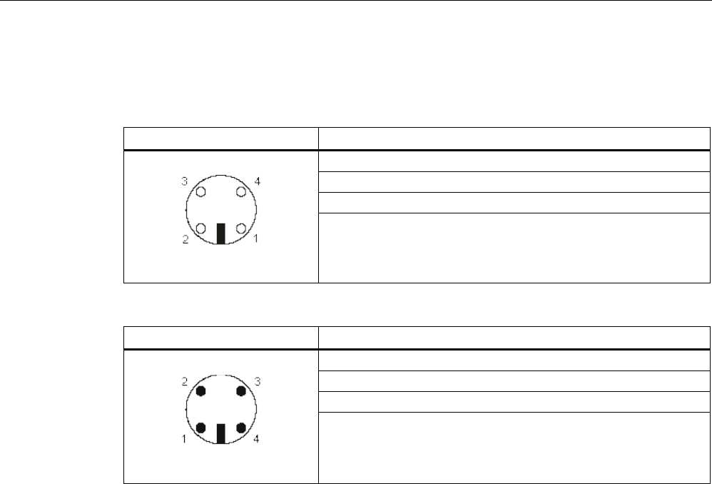
Accessories
10.1 Wide-range power supply unit for SIMATIC RF systems
SIMATIC RF600
490 System Manual, xx/2014, J31069-D0171-U001-A15-7618
REVIEW
10.1.7
Pin assignment of DC outputs and mains connection
DC outputs
Assignment
(1) Ground (0V)
(2) +24 V DC
(3) +24 V DC
(4) Ground (0V)
Mains connection
Assignment
(1) 100 to 240 V AC
(2) n.c.
(3) 100 to 240 V AC
(4) n.c.
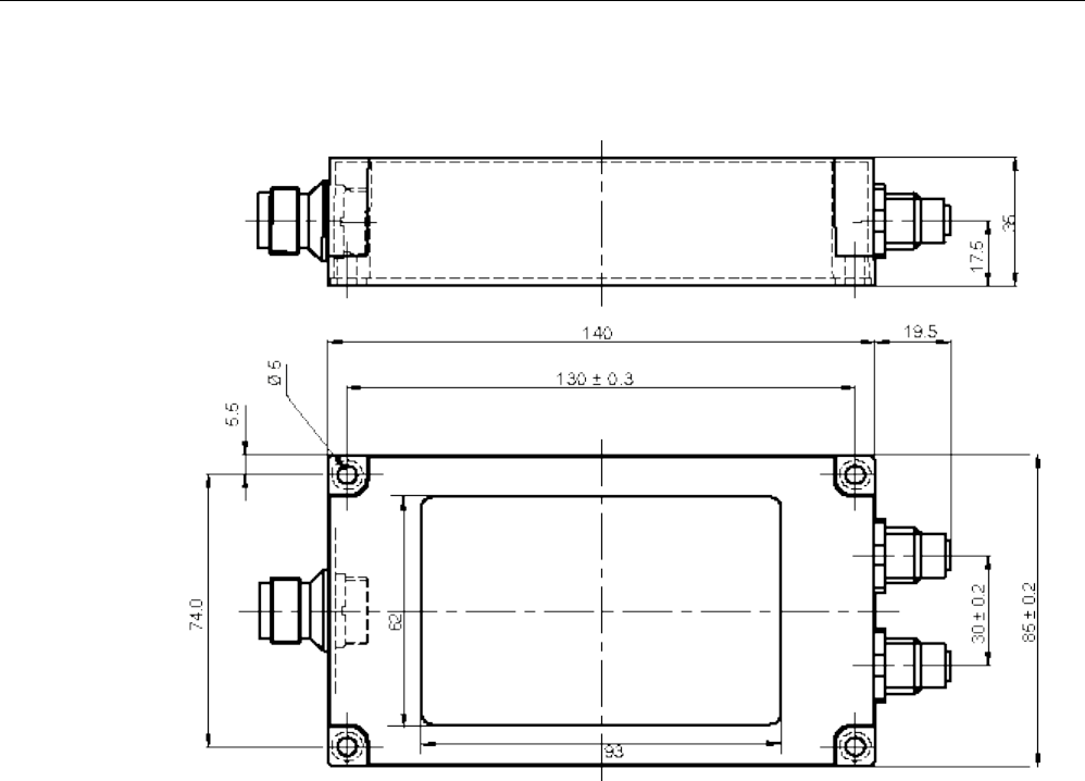
Accessories
10.1 Wide-range power supply unit for SIMATIC RF systems
SIMATIC RF600
System Manual, xx/2014, J31069-D0171-U001-A15-7618 491
REVIEW
10.1.8
Dimension drawing
Units of measurement:
All dimensions in mm
Accessories
10.1 Wide-range power supply unit for SIMATIC RF systems
SIMATIC RF600
492 System Manual, xx/2014, J31069-D0171-U001-A15-7618
REVIEW
10.1.9
Certificates and approvals
Table 10- 6 Wide-range power supply unit for SIMATIC RF systems 6GT2898-0AA00 - Europe,
6GT2898-0AA10 - UK
Certificate
Description
CE approval to
2004/108/EC EMC
73/23/EEC LVD
Table 10- 7 Wide-range power supply unit for SIMATIC RF systems 6GT2898-0AA20 - USA
Standard
This product is UL-certified for the US and Canada.
It meets the following safety standards:
UL 60950-1 - Information Technology Equipment Safety - Part 1:
General Requirements
CSA C22.2 No. 60950 -1 - Safety of Information Technology
Equipment
UL Report E 205089
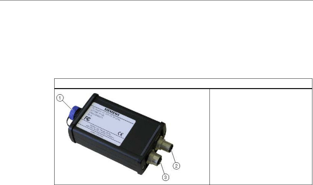
Accessories
10.2 The PC adapter for SIMATIC RF-DIAG
SIMATIC RF600
System Manual, xx/2014, J31069-D0171-U001-A15-7618 493
REVIEW
10.2
The PC adapter for SIMATIC RF-DIAG
10.2.1
Description
PC adapter for SIMATIC RF-DIAG
① USB interface
② RS-422 – CM / wide-range power
supply unit
③ RS-422 – RF reader
The SIMATIC RF-DIAG product consists of a CD with software and documentation and a
hardware packet. The hardware packet consists of a PC adapter for SIMATIC RF-DIAG, a
USB connecting cable and an RS-422 cable.
The PC adapter for SIMATIC RF-DIAG is a converter from USB to RS-422. Communication
between the PC and reader can be established using the PC adapter.
Characteristics
● RS-422 to USB converter for communication with the RF620R and RF630R
● Dimensions without connecting cables: 101 x 63 x 35 mm
● CE-compliant (EU and UK versions)
● FCC-compliant for use in the USA and Canada
● Mechanically and electrically rugged design
● RS-422 interface
– With 24 VDC / 3 A for CM or wide-range power supply unit
– With 24 VDC / 3 A for reader
● Short-circuit proof
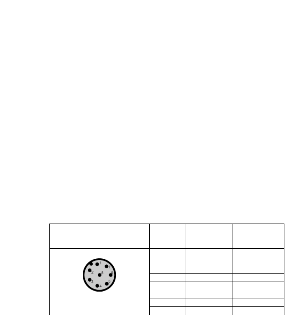
Accessories
10.2 The PC adapter for SIMATIC RF-DIAG
SIMATIC RF600
494 System Manual, xx/2014, J31069-D0171-U001-A15-7618
REVIEW
Highlights
● Diagnostics via a PC with the reader supplied with power from the system
● IP65 degree of protection
● Can be used in high temperature ranges
● Use in productive operation possible
● Switchover to diagnostics mode "on the fly" (parallel to regular operation)
Note
Protection from environmental influences
The IP65 degree of protection of the PC adapter is only valid if the USB protective cap is
fitted and the
corresponding RS-422 cable is connected. During diagnostics, this degree of
protection is not present.
10.2.2
Pin assignment of the RS-422 interface
Pin assignment for connection to the CM or wide-range power supply unit
Pin assignment of the connector for PC adapter and CM or wide-range power supply unit
Table 10- 8 RS-422 interface of the PC adapter (male connector)
Pin
Pin
Device end 8-
pin M12
Assignment for
CM
Assignment for
wide-range power
supply unit
1
+ 24 V
+ 24 V
2
- Transmit
Free
3
0 V
0 V
4
+ Transmit
Free
5
+ Receive
Free
6
- Receive
Free
7
Free
Free
8
Ground (shield)
Ground (shield)
The knurled bolt of the M12 plug does not contact the shield (reader end).
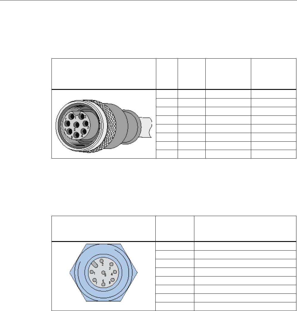
Accessories
10.2 The PC adapter for SIMATIC RF-DIAG
SIMATIC RF600
System Manual, xx/2014, J31069-D0171-U001-A15-7618 495
REVIEW
Pin assignment of the connecting cable between PC adapter and CM or wide-range power
supply unit
Table 10- 9 RS-422 connecting cable
View of M12 socket
M12
pin
Core
color
Pin assignment
for CM
Pin assignment
for wide-range
power supply
unit
1
White
24 VDC
24 VDC
2
Brown
TX neg
Not used
3
green
GND
GND
4
Yellow
TX pos
Not used
5
gray
RX pos
Not used
6
pink
RX neg
Not used
7
Blue
Not used
Not used
8
Red
Ground (shield)
Ground (shield)
Pin assignment for connecting to the RF readers
Pin assignment of the connector for PC adapter and UHF reader
Table 10- 10 RS-422 interface of the PC adapter (female connector)
Pin
Pin
Device end 8-
pin M12
Assignment for the RF readers
1
+ 24 V
2
- Transmit
3
0 V
4
+ Transmit
5
+ Receive
6
- Receive
7
Free
8
Ground (shield)
The knurled bolt of the M12 plug does not contact the shield (reader end).
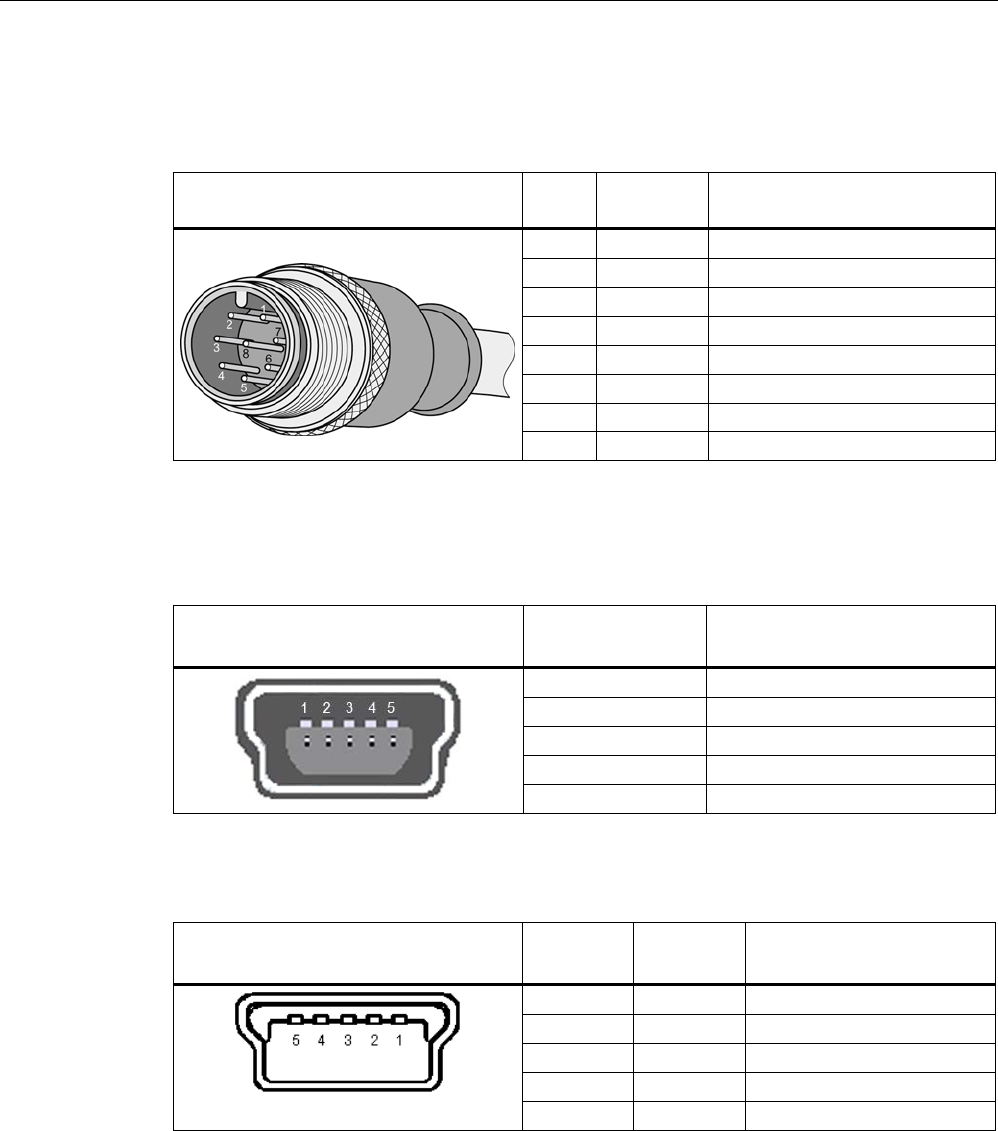
Accessories
10.2 The PC adapter for SIMATIC RF-DIAG
SIMATIC RF600
496 System Manual, xx/2014, J31069-D0171-U001-A15-7618
REVIEW
Pin assignment of the connecting cable between PC adapter and UHF reader
Table 10- 11 RS-422 connecting cable
View of M12 plug
M12
pin
Wire color
Pin assignment
1
White
24 VDC
2
Brown
TX neg
3
green
GND
4
Yellow
TX pos
5
gray
RX pos
6
pink
RX neg
7
Blue
Not used
8
Red
Ground (shield)
Pin assignment for connection to the PC
Table 10- 12 USB 2.0 mini-B connector socket of the PC adapter
View of connection socket
Pin
Device side
Assignment
1
+ 5 V
2
Data -
3
Data +
4
ID (not used)
5
GND
Table 10- 13 USB 2.0 mini-B plug of the connecting cable
View of mini-B plug
Pin
Device side
Wire color
Assignment
1
Red
+ 5 V
2
White
Data -
3
green
Data +
4 - ID (not used)
5
Black
GND

Accessories
10.2 The PC adapter for SIMATIC RF-DIAG
SIMATIC RF600
System Manual, xx/2014, J31069-D0171-U001-A15-7618 497
REVIEW
10.2.3
Technical specifications
Table 10- 14 Mechanical data
Property
Description
Weight
310 g
Dimensions (L x W x H)
101 × 63 × 35 mm
Enclosure material
Aluminum (painted)
Housing color
Black
Installation
No securing aids
Interfaces
RS422 • 1 x pin (8-pin M12, connection to CM/wide-range power supply)
• 1 x socket (8-pin M12, connection to the reader)
USB
USB 2.0 Mini-B
MTBF in years
1.1x10
3
Table 10- 15 Software interfaces
Property
Description
Software – RS-422
SIMATIC S7 / TIA
Software – USB
• RF600
• 3964R & RF-DIAG
Table 10- 16 Electrical data
Property
Description
Power supply of the PC adapter via USB
(during operation)
• Nominal value
• Permitted range
• 5 V DC
• 4.0 to 5.25 VDC
Power supply of the RF readers via RS-422
• Nominal value
• Permitted range
• 24 VDC
• 20 to 30 VDC
Current consumption
• Connection via USB and RS-422
• No connection via USB
• Via 5 VDC, approx. 30 mA; 24 VDC, approx. 15 mA
• Via 24 VDC, ≤ 5 mA
Transmission rates USB / RS-422 • 19.2 Kbps
• 57.6 Kbps
• 115.2 Kbps

Accessories
10.2 The PC adapter for SIMATIC RF-DIAG
SIMATIC RF600
498 System Manual, xx/2014, J31069-D0171-U001-A15-7618
REVIEW
Table 10- 17 Ambient conditions
Property
Description
Temperature range during operation
-25 ℃ to +70 ℃
Temperature range during storage
-40 ℃ to +85 ℃
Shock resistant to EN 60068-2-27
Vibration resistant to EN 60068-2-6
50 g, 1)
20 g,
1)
Degree of protection in accordance with
EN 60529
IP65 2)
1)
The values for shock and vibration are maximum values and must not be applied continuously nor when the USB plug is
plugged in.
2) Only when the USB protective cap is fitted and the corresponding RS-422 cables are connected.
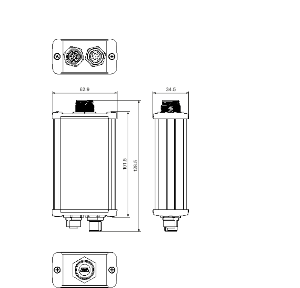
Accessories
10.2 The PC adapter for SIMATIC RF-DIAG
SIMATIC RF600
System Manual, xx/2014, J31069-D0171-U001-A15-7618 499
REVIEW
10.2.4
Dimension drawing
Figure 10-1 Dimension drawing of the PC adapter for SIMATIC RF-DIAG (all dimensions in mm)
When the USB protective cap is screwed on, the length of the adapter is 134 mm. The
tolerances are +/- 1 mm.
Accessories
10.2 The PC adapter for SIMATIC RF-DIAG
SIMATIC RF600
500 System Manual, xx/2014, J31069-D0171-U001-A15-7618
REVIEW
10.2.5
Certificates and approvals
Table 10- 18 Certificates and approvals for the PC adapter
Certificate
Description
CE approval complying with 2004/108/EC EMC
FCC Rules, Part 15, Subpart B, Sections 15.107 and 15.109
Industry Canada Radio
Standards Specifications
CAN/CSA-CISPR 22-10 - Information technology equipment – Radio
disturbance characteristics – Limits and methods of measurement

SIMATIC RF600
System Manual, xx/2014, J31069-D0171-U001-A15-7618 501
Appendix
A
A.1
Certificates and approvals
Notes on CE marking
The following applies to the system described in this documentation:
The CE marking on a device is indicative of the corresponding approval:
DIN ISO 9001 certificate
The quality assurance system for the entire product process (development, production, and
marketing) at Siemens fulfills the requirements of ISO 9001 (corresponds to EN29001:
1987).
This has been certified by DQS (the German society for the certification of quality
management systems).
EQ-Net certificate no.: 1323-01
Table A- 1 FCC IDs: NXW-RF660, NXW-RF620R, NXW-RF630R, IC: 267X-RF620R, IC: 267X-
RF630
Standards
Federal Communications
Commission
FCC Title 47, Part 15.sections 15.247
Radio Frequency Interference Statement
This equipment has been tested and found to comply with the limits
for a Class A digital device, pursuant to Part 15 of the FCC Rules.
Industry Canada Radio
Standards Specifications
RSS-210 Issue 6, Sections 2.2, A8
This product is UL-certified for the USA and Canada.
It meets the following safety standard(s):
UL 60950-1 - Information Technology Equipment Safety - Part 1:
General Requirements
CSA C22.2 No. 60950 -1 - Safety of Information Technology
Equipment
UL Report E 205089
Appendix
A.1 Certificates and approvals
SIMATIC RF600
502 System Manual, xx/2014, J31069-D0171-U001-A15-7618
Certification for the USA, Canada and Australia
Safety
One of the following markings on a device is indicative of the corresponding approval:
Underwriters Laboratories (UL) to UL 60950 Standard (I.T.E), or to UL508
(IND.CONT.EQ)
Underwriters Laboratories (UL) according to Canadian standard C22.2 No. 60950
(I.T.E) or C22.2 No. 142 (IND.CONT.EQ)
Underwriters Laboratories (UL) according to standard UL 60950, Report E11 5352 and
Canadian standard C22.2 No. 60950 (I.T.E) or UL508 and C22.2 No. 142
(IND.CONT.EQ)
UL recognition mark
Canadian Standard Association (CSA) per Standard C22.2. No. 60950 (LR 81690) or
per C22.2 No. 142 (LR 63533)
Canadian Standard Association (CSA) per American Standard UL 60950 (LR 81690) or
per UL 508 (LR 63533)
EMC
USA
Federal Communications
Commission
Radio Frequency
Interference Statement
This equipment has been tested and found to comply with the limits for a
Class A digital device, pursuant to Part 15 of the FCC Rules. These limits
are designed to provide reasonable protection against harmful
interference when the equipment is operated in a commercial
environment. This equipment generates, uses, and can radiate radio
frequency energy and, if not installed and used in accordance with the
instruction manual, may cause harmful interference to radio
communications. Operation of this equipment in a residential area is likely
to cause harmful interference in which case the user will be required to
correct the interference at his own expense.
Shielded Cables
Shielded cables must be used with this equipment to maintain compliance
with FCC regulations.
Modifications Changes or modifications not expressly approved by the manufacturer
could void the user’s authority to operate the equipment.
Conditions of Operations This device complies with Part 15 of the FCC Rules. Operation is subject
to the following two conditions: (1) this device may not cause harmful
interference, and (2) this device must accept any interference received,
including interference that may cause undesired operation.
CANADA
Canadian Notice
This Class B digital apparatus complies with Canadian ICES-003.
Avis Canadien Cet appareil numérique de la classe b est conforme à la norme NMB-003
du Canada.

Appendix
A.1 Certificates and approvals
SIMATIC RF600
System Manual, xx/2014, J31069-D0171-U001-A15-7618 503
AUSTRALIA
This product meets the requirements of the AS/NZS 3548 Norm.

Appendix
A.2 Service & support
SIMATIC RF600
504 System Manual, xx/2014, J31069-D0171-U001-A15-7618
A.2
Service & support
Technical Support
You can access technical support for all IA/DT projects via the following:
● Phone: + 49 (0) 911 895 7222
● Fax: + 49 (0) 911 895 7223
● Web form for support request (http://www.siemens.com/automation/support-request)
● Internet: E-mail (mailto:support.automation@siemens.com)
Contacts
If you have any further questions on the use of our products, please contact one of our
representatives at your local Siemens office.
The addresses are found on the following pages:
● On the Internet (http://www.siemens.com/automation/partner)
● In Catalog CA 01
● In the catalog ID 10 specially for Industrial Identification Systems
Service & support for industrial automation and drive technologies
You can find various services on the Support home page
(http://www.siemens.com/automation/service&support) of IA/DT on the Internet.
There you will find the following information, for example:
● Our newsletter containing up-to-date information on your products.
● Relevant documentation for your application, which you can access via the search
function in "Product Support".
● A forum for global information exchange by users and specialists.
● Your local contact for IA/DT on site.
● Information about on-site service, repairs, and spare parts. Much more can be found
under "Our service offer".
SIMATIC documentation on the Internet
A guide to the technical documentation for the various SIMATIC products and systems is
available on the Internet:
SIMATIC Guide manuals (http://www.siemens.com/simatic-tech-doku-portal)

Appendix
A.2 Service & support
SIMATIC RF600
System Manual, xx/2014, J31069-D0171-U001-A15-7618 505
RFID homepage
For general information about our identification systems, visit RFID home page
(http://www.siemens.com/ident/rfid).
Online catalog and ordering system
The online catalog and the online ordering system can also be found on the Industry Mall
home page (http://www.siemens.com/industrymall/en).
Training center
We offer appropriate courses to get you started. Please contact your local training center or
the central training center in
D-90327 Nuremberg.
Phone: +49 (0) 180 523 56 11
(€ 0.14 /min. from the German landline network, deviating mobile communications prices are
possible)
For information about courses, see the SITRAIN home page (http://www.sitrain.com).

Appendix
A.2 Service & support
SIMATIC RF600
506 System Manual, xx/2014, J31069-D0171-U001-A15-7618
SIMATIC RF600
System Manual, xx/2014, J31069-D0171-U001-A15-7618 507
Glossary
Active field
Area with minimum field strength containing the sensing range. Within this sensing range,
data can be read from the tag or written to the tag.
Active surface
See active field
See active field
Active surface
See active field
See active field
Active tag/transponder
Active transponders are battery-operated, i.e. they obtain the energy required to save data
on the microchip from a built-in battery. They are usually in an idle state and do not transmit
data in order to increase the energy source's service life. The transmitter is only activated
when it receives a special activation signal.
AM
Amplitude modulation; data are present in the changes in carrier frequency amplitude.
Amplitude modulation
See AM
AS
See Automation system
ASM
Interface module, see Communication modules
Automation system (AS)
A programmable logical controller (PLC) of the SIMATIC S7 system, comprising a central
controller, a CPU and various I/O modules.

Glossary
SIMATIC RF600
508 System Manual, xx/2014, J31069-D0171-U001-A15-7618
Battery-free data storage unit
Mobile data storage units which operate without batteries. (See transponder). Power is
supplied to the data storage unit across an electromagnetic alternating field.
Baud
Unit (digits per second).
Baud rate
The baud rate describes the data transmission's digit rate.
Byte
A group of eight bits
CE guidelines
See CE Label
CE Label
Communauté Européenne (product mark of the European Union)
Communication modules
Communication modules are used to integrate the identification systems in SIMATIC or
SINUMERIK systems, or to connect them to PROFIBUS, PROFINET, PC or any other
system. Once supplied with the corresponding parameters and data, they handle data
communication. They then make the corresponding results and data available. Suitable
software blocks (FB/FC for SIMATIC; C libraries for PCs with Windows) ensure easy and
fast integration in the application.
Continuous Wave
See CW
CW
Continuous Wave; data are present in the carrier frequency which is switched on and off.
Data rate
The rate at which data are exchanged between the tag and reader. Typical units are bits per
second or bytes per second.

Glossary
SIMATIC RF600
System Manual, xx/2014, J31069-D0171-U001-A15-7618 509
Data transfer rate
Number of characters which can be transmitted from a tag to a reader within a defined time.
Baud rates are also used to specify how fast a reader can read information.
Data transmission rate
Unit of measurement for the volume of data transmitted within a unit of time, e.g. bytes/s,
see also Baud
dB
See Decibel
dBm
Dimensional unit for the transmitted power in the logarithmic relation to 1 mW (Milliwatt).
0dBm = 1mW, +23dBm = 200mW, +30dBm = 1W.
dBr
dB(relative); a relative difference to a reference value
Decibel (dB)
Unit of measurement for the logarithmic relationship between two variables.
Dense Reader Mode (DRM)
In this mode, tag readability is increased through the application of interference-reducing
measures.
DRM is only defined for Gen 2 and does not function with other tag types.
Detuning
UHF antennas are tuned to receive a particular electromagnetic wavelength from the reader.
If the antenna is too close to metal or a metallic material, it can be detuned, making the
performance deteriorate.
Distant field communication
RFID antennas emit electromagnetic waves. If a tag is more than a full wavelength away
from the reader's transmitting antenna, it is in a "distant field". If it is within a full wavelength,
this is known as the "near field".
The wavelength of UHF-RFID systems is approx. 33 cm.
The distant field signal is attenuated with the square of the distance from the antenna,
whereas the near field signal is attenuated with the cube of the distance from the antenna.

Glossary
SIMATIC RF600
510 System Manual, xx/2014, J31069-D0171-U001-A15-7618
Passive RFID systems based on distant field communication (UHF and microwave systems)
have a greater read range than systems based on near field communication (typically low-
frequency and high-frequency systems).
Dwell time
The dwell time is the time in which the transponder dwells within the sensing range of a
reader. The reader can exchange data with the transponder during this time.
Dynamic mode
In dynamic mode, the data carrier moves past the reader at a traversing rate which depends
on the configuration. Various checking mechanisms ensure error-free data transfer even
under extreme environmental conditions.
EAN
European article number. Standardized barcode used in Europe, Asia and South America. Is
administered by EAN International.
EBS
Equipotential
B
onding
S
trip
Effective Isotropic Radiated Power
See EIRP
Effective Radiated Power
See ERP.
EIRP
Effective Isotropic Radiated Power; unit of measurement for the transmission power of
antennas (referred to an isotropic radiator) mainly used in the USA. EIRP is specified in
Watt, and is not equal to ERP. (0dbi = - 2.14 dBm)
Electromagnetic compatibility (EMC)
Electromagnetic compatibility is the ability of an electrical or electronic device to operate
satisfactorily in an electromagnetic environment without affecting or interfering with the
environment over and above certain limits.
EMC
See Electromagnetic compatibility

Glossary
SIMATIC RF600
System Manual, xx/2014, J31069-D0171-U001-A15-7618 511
EMC directive
Guidelines for electromagnetic compatibility This guideline relates to any electrical or
electronic equipment, plant or system containing electric or electronic components.
EPC
See EPC global
EPC global
Electronic Product Code. Standardized number system for identifying articles with a data
width of either 64, 96 or 256 bits.
Equipotential bonding
Potential differences between different parts of a plant can arise due to the different design
of the plant components and different voltage levels. It is necessary to compensate for these
differences by equipotential bonding: this is done by combining the equipotential bonding
conductors of power components and
non-power components on a centralized equalizing conductor (EBS =
E
quipotential
B
onding
S
trip).
ERP
Effective Radiated Power; unit of measurement for the transmission power of antennas
(referred to an ideal dipole) mainly used in Europe. ERP is specified in Watt, and is not equal
to EIRP. (0dbm = + 2.14 dBi)
ESD directive
Directive for handling
E
lectrostatic
S
ensitive
D
evices
ETSI
European Telecommunications Standard Institute
European Article Numbering
See EAN.
eXtensible markup language
See XML.
FCC
Federal Communications Commission (USA)

Glossary
SIMATIC RF600
512 System Manual, xx/2014, J31069-D0171-U001-A15-7618
FHSS
Frequency Hopping Spread Spectrum; frequency change procedure.
FM
Frequency modulation; data are present in the changes in the frequency of the carrier
frequency.
Frequency hopping
Frequency hopping technique Automatic search for free channels.
In frequency hopping, data packets are transferred between the communication partners on
constantly changing carrier frequencies. This makes it possible to react to interference from
devices transmitting signals in the same frequency range (channel). If an attempt to send a
data packet is unsuccessful, the packet can be transmitted again on a different carrier
frequency. By default the RF600 uses this procedure (FCC) only in the USA and Canada.
Frequency modulation
See FM.
Frequency Shift Keying
See FSK
FSK
Modulation, Frequency Shift Keying; data are present in the changes between two
frequencies.
ICNIRP
International Commission of Non Ionizing Radiological Protection
ICRP
International Commission of Radiological Protection
Interface modules
See communication modules
Interrogator
See readers

Glossary
SIMATIC RF600
System Manual, xx/2014, J31069-D0171-U001-A15-7618 513
ISO
International Standard Organization
ISO 18000
Standard for data exchange of RFID systems between reader and transponder. There are
various subdefinitions of this standard for the various approved frequency ranges for RFID.
For example, the range 865 ... 868 MHz is described in ISO 18000-6.
LAN
Local Area Network
LBT
Listen Before Talk; the reader only transmits when the channel is free.
License plate
10-digit code that is saved on every RFID tag. The code of the license plate establishes a
connection between the item of baggage and the baggage processing system of the airport.
As soon as the license plate has been read by the reader, a message is automatically sent
to the baggage processing system. This message contains important data regarding the
flight and destination of the item of baggage. Using this data, the item of baggage can be
successfully sorted by the baggage processing system of the airport.
Limit distance
The limit distance is the maximum clear distance between reader antenna and transponder
at which the transmission can still function under normal conditions.
Mass recording
The capability of a reader to record several or many transponders quasi-simultaneously and
to read the code. Contrary to the multi-tag capability, the reader is not able to specifically
address individual tags.
MDS
Mobile data memory, see Transponder.
MES
Manufacturing Execution System

Glossary
SIMATIC RF600
514 System Manual, xx/2014, J31069-D0171-U001-A15-7618
Metal-free area
Distance/area which must be maintained between the transponder and metal in order to
prevent interference during data transfer between the transponder and reader.
Mobile Data Memory (MDS)
Mobile data memory, see Transponder
Modulation
Modulation is a procedure with which one or more characteristics (e.g. phase, amplitude,
frequency) of a carrier oscillation are modified according to the response of a modulating
oscillation.
Multi-tag capability
Multi-tag capability means that a reader can communicate simultaneously with different data
carriers. Therefore the reader can specifically address a transponder with its UID (see also
mass recording).
Near field communication
RFID antennas emit electromagnetic waves. If a tag is more than a full wavelength away
from the reader's transmitting antenna, it is in a "distant field". If it is within a full wavelength,
this is known as the "near field".
The wavelength of UHF-RFID systems is approx. 33 cm.
The distant field signal is attenuated with the square of the distance from the antenna,
whereas the near field signal is attenuated with the cube of the distance from the antenna.
Passive RFID systems based on near field communication (typically low-frequency and high-
frequency systems) have a greater read range than systems based on distant field
communication (typically UHF and microwave systems).
Passive tag
If electromagnetic waves from the reader reach the tag antenna, the energy is converted by
the antenna into electricity which provides the tag chip with current. The tag is able to return
information stored on the chip. Passive tags do not usually have a battery. A battery is
required if the tag has a RAM, but the battery is only used to save information in the RAM. In
particular, the battery is not used for data exchange between reader and transponder.
Passive tag/transponder
A tag without its own power supply. Passive transponders obtain the energy required to
supply the microchips from the radio waves they receive.

Glossary
SIMATIC RF600
System Manual, xx/2014, J31069-D0171-U001-A15-7618 515
PDM
Pulse duration modulation; data are present in the pulse duration.
Phase modulation
See PM
PLC
Programmable Logic Controller, see PLC.
Programmable logic controller; electronic device used in automation engineering for open-
loop and closed-loop control tasks. The typical modules of a PLC are the CPU, power supply
(PS) and various input/output modules (I/O).
Programmable controller: The programmable logical controllers (PLC) of the SIMATIC S5
system consist of a central controller, one or more CPUs, and various other modules (e.g.
I/O modules).
PM
Phase modulation; data are present in the changes in carrier frequency phase.
Programmable Logic Controller
See PLC.

Glossary
SIMATIC RF600
516 System Manual, xx/2014, J31069-D0171-U001-A15-7618
Programmable Logic Controllers
See PLC
Protocol
A combination of rules which manage communications systems.
Pulse duration modulation
See PDM
Radio Frequency Identification
See RFID.
Read rate
Number of tags which can be read within a defined time.
The read rate can also be used for the maximum rate at which data can be read from a tag.
The unit is bits per second or bytes per second.
Reader (also interrogator)
Readers transfer data between mobile data memories (transponders) and the higher-level
systems. The data, including the energy required for processing and sending back, are
transmitted to the transponder across an electromagnetic alternating field. This principle
enables contact-free data transmission, ensures high industrial compatibility and works
reliably in the presence of contamination or through non-metallic materials.
Reader talks first
A passive tag communicates in the read field of a reader with the reader. The reader sends
energy to the tags which only reply when they are explicitly requested. The reader is able to
find tags with a specific serial number commencing with either 1 or 0.
If more than one tag responds, the reader can scan all tags commencing with 01 and
subsequently with 010. This is referred to as "walking" on a binary tree, or "tree walking".
Reading range
The distance within which a reader can communicate with a tag. Active tags can cover a
greater distance than passive tags because they use a battery to send signals.
Reciprocity
Reciprocity means that a two-way relationship exists between the transmit and receive case
of a passive antenna.

Glossary
SIMATIC RF600
System Manual, xx/2014, J31069-D0171-U001-A15-7618 517
RFID
Radio Frequency Identification; a method of identifying items using electromagnetic waves.
The reader supplies energy to the tag and communicates with it.
RFID systems
SIMATIC RF identification systems control and optimize material flow and production
sequences. They identify reliably, quickly and economically, use non-contact data
communication technology, and store data directly on the product. They are also resistant to
contamination.
RH circular
Right hand circular polarization
RSSI threshold value
The "Received Signal Strength Indication" (RSSI) is an indicator of the receive field strength
of the transponders. When the field strength with which the transponder is received
undershoots the set RSSI threshold, the reader ignores the signal of this transponder.
The RSSI threshold value can be activated to limit areas of the antenna fields to those in
which transponders should still be accessed. This can be used to avoid undesirable effects,
such as range overshoot when reading transponder data.
RTNC
Connector designation (Reverse TNC). Industrial coaxial connector with screw coupling, can
be used for frequencies of up to 2 GHz. The mechanical design of the RTNC connector is
not compatible with the TNC connector.
RTTE
Radio and Telecommunications Terminal Equipment
SCM
Supply Chain Management
Secondary fields
In addition to the main sensing range (antenna's main direction of transmission) there are
secondary fields. These secondary fields are usually smaller than the main fields. The shape
and characteristics of the secondary field depend on the metallic objects in the surroundings.
Secondary fields should not be used in configuring.

Glossary
SIMATIC RF600
518 System Manual, xx/2014, J31069-D0171-U001-A15-7618
SELV
Safety Extra Low Voltage
Sensing range
Area in which reliable data exchange between transponder and reader is possible due to a
particular minimum field strength.
SSB
Single Sideband Modulation. SSB is similar to AM (amplitude modulation), however, only
one sideband is sent instead of two sidebands. This saves 50% of the spectrum required in
the HF channel without affecting the signal/data rate. For RFID applications, an HF carrier
must also be sent to supply energy to the tag. Sending a carrier is many times not required
for other SSB applications, since the HF carrier itself does not contain any data.
Static mode
In static mode the transponder is positioned at a fixed distance (maximum: limit distance)
exactly above the reader.
Tag
See transponder
Tag talks first
A passive tag communicates in the read field of a reader with the reader. When a tag
reaches the field of a reader, it immediately indicates its presence by reflecting a signal.
TARI
Abbreviation of Type A Reference Interval. Duration (period) for representation of a bit with
content 0.
TCP/IP
Transmission Control Protocol/Internet Protocol
Telegram cycles
A passive tag communicates in the read field of a reader with the reader. When a tag
reaches the field of a reader, it immediately indicates its presence by reflecting a signal.
Transmission of a read or write command is implemented in three cycles. They are called
"Telegram cycles". One or two bytes of user data can be transferred with each command.
The acknowledgment or response transfer (status or read data) takes place in three further
cycles.

Glossary
SIMATIC RF600
System Manual, xx/2014, J31069-D0171-U001-A15-7618 519
TNC
Connector designation (Threaded Neill Concelman).
Industrial coaxial connector with screw coupling, can be used for frequencies of up to 2 GHz.
Transceiver (transmitter/receiver)
Combination of transmitter and receiver. A unit which can both send and receive
electromagnetic waves.
Transmission distance
Distance between communication module and transponder
Transponder
An invented word from transmitter and responder. Transponders are used on the product,
the product carrier, the object, or its transport or packaging unit, and contain production and
manufacturing data, i.e. all application-specific data. They follow the product through
assembly lines, transfer and production lines and are used to control material flow.
Because of their wireless design, transponders can be used, if necessary, at individual work
locations or manufacturing stations, where their data can be read and updated.
Tree walking
See Reader talks first.
UHF
Ultra-high frequency; frequency range from 300 MHz to 3 GHz. UHF RFID tags usually
operate between 866 MHz and 960 MHz. This corresponds to a wavelength of approx. 33
cm.
UID
User IDentifier; the UID is an unambiguous number in the transponder, assigned by the
manufacturer. The UID is unambiguous, and can usually also be used as a fixed code. The
UID is used to specifically address a transponder
Ultra High Frequency
See UHF.
User IDentifier
See UID

Glossary
SIMATIC RF600
520 System Manual, xx/2014, J31069-D0171-U001-A15-7618
VESA
Video Electronics Standards Association (authority that defines standards for the PC
industry)
Walking
See Reader talks first.
WLAN
Wireless LAN
writer
See readers
Writing/reading range
See transmission distance
XML
eXtensible markup language; XML is a language derived from SGML with which other
languages (document types) can be described. In the meantime, XML is a widely used
language for distributing information on the Internet. Data exchange between reader and
read station is carried out using XML commands.
SIMATIC RF600
System Manual, xx/2014, J31069-D0171-U001-A15-7618 521
Index
A
Antenna cable
Connector type, 70
Antenna cables, 70
Bending radius, 70
Antenna configuration, 43
Antenna gain, 61
Cable loss 4 dB, 61
Dependency on plane, 62
FCC, 61
Frequency dependency, 62
Antenna mounting kit
RF620R, 103
RF640R, 148
RF650R, 170
RF670R, 188
RF680R, 209
RF685R, 235
Appearance of resonance, 69
B
Beam angle, 68
Read area, 68
Beam width
Definition, 66
ETSI, 66
Bending radius
Antenna cables, 70
C
Cable
Shielding, 84
Cable loss
Definition, 69
Dependencies, 69
Characteristic impedance
Definition, 69, 69
Circular polarization, 64
Classes, 334
Coaxial antenna cables
Coaxial, 70
Configuration, 103, 119
Antennas, 43
Connector type, 70
R-TNC, 70
Thread, 70
Contacts, 504
Courses, 505
D
Decibel
Calculation example, 60
Definition, 60
Reference variables, 61
Design of the RF640R reader, 129
Design of the RF650R reader, 158
Design of the RF670R reader, 177
Design of the RF680R reader, 198
Design of the RF685R reader, 217
Dimensions
RF620R reader, 108
RF630R reader, 124
RF650R reader, 173
RF670R reader, 193
RF680R reader, 213
RF685R reader, 239
Directional antennas, 58
E
EIRP, 59
Electromagnetic interference, 82
Electromagnetic waves
UHF range, 73
EMC Directives, 502
Propagation of electromagnetic interference, 82
EMC Guidelines
Basic Rules, 80
Cable shielding, 85
Definition, 79
Equipotential bonding, 83
Overview, 79
Equipotential bonding, 83
ERP, 59
Cable loss, 60
Logarithmic, standardized, 59

Index
SIMATIC RF600
522 System Manual, xx/2014, J31069-D0171-U001-A15-7618
F
Front-to-back ratio, 65
Functions
Overview, 244
G
Gate configuration
Application areas, 44
Arrangement of antenna, 44
Generations, 334
I
Identification system
UHF range, 29
Impedance
Definition, 62
Specifications, 62
Influence of
Interference, 73
Liquids, 74
Metals, 74
Non-metallic substances, 74
reflections, 73
Influencing factors, 56
Interfaces, 103, 119
Digital, 132
RS422, 103
Interference, 73
Interference sources
Electromagnetic, 82
Isotropic radiator, 59
Isotropic spherical radiator, 61
L
Linear polarization, 65
M
Main applications
RF600, 31
RF620R, 31
RF630R, 31
RF640R, 31
RF680M, 31
RF-MANAGER, 31
Main beam direction, 65
Minimum spacing
For antennas, 49
Mounting of RF620R
Antenna mounting kit, 103
Mounting of RF670R
Antenna mounting kit, 188
Mounting types of the RF620R reader, 103
Mounting types of the RF630R reader, 119
O
Ordering data for RF670R, 178
Accessories, 178
Ordering data RF640R, 130
Accessories, 130
Ordering data RF650R, 158
Accessories, 159
Ordering data RF680R, 198
Accessories, 199
Ordering data RF685R, 218
Accessories, 218
P
Parameter, 56
Polarization
Circular, 64
Linear, 65
Portal configuration
Application example, 43
Power supply
RF640R, 138
RF670R, 185
R
Reader RF680M
Features, 243
Functions, 244
Reading range
Dependency of the, 52
Reciprocity, 58
reflections, 73
Reflections, 69
Return loss
Definition, 63
RF600
Main applications, 31
RF620A
Technical specifications, 270
RF620R reader
Configuration, 103

Index
SIMATIC RF600
System Manual, xx/2014, J31069-D0171-U001-A15-7618 523
Design, 90
Dimensions, 108
Interfaces, 103
Mounting types,
Status display, 92, 115
RF630R reader
Configuration, 119
Design, 113
Dimensions, 124
Interfaces, 119
Mounting types,
RF640R reader
Design, 129
Digital I/O interface, 132
Interfaces, 132, 138
LEDs, 131
Mounting types,
Power supply, 138
RF650R mounting
Antenna mounting kit, 170
RF650R reader
CE Approval, 174
Design, 158
Digital I/O interface, 160
FCC information, 175
IC-FCB information, 176
LEDs, 160
Mounting types,
RF660A
Technical specifications, 326
RF660A antenna
Radiation/reception characteristic for Europe
(ETSI), 324
Radiation/reception characteristic for USA
(FCC), 324
RF670R reader
CE Approval, 194
Design, 177
Digital I/O interface, 180
FCC information, 196
IC-FCB information, 197
Interfaces, 160, 180, 185
LEDs, 179
Mounting types,
Power supply, 185
RF680R mounting
Antenna mounting kit, 209
RF680R reader
CE Approval, 214
Design, 198
Digital I/O interface, 200
FCC information, 215
IC-FCB information, 216
Interfaces, 200
LEDs, 200
Mounting types,
RF685R mounting
Antenna mounting kit, 235
RF685R reader
Design, 217
Digital I/O interface, 219
FCC information, 241
IC-FCB information, 242
Interfaces, 219
LEDs, 219
Mounting types,
RF-MANAGER
Levels of the automation/IT structure, 29
S
Safety Information, 21
Scalar product, 59
Securing the RF640R
Antenna mounting kit, 148
Shielding, 85
Antenna cables, 70
Spurious lobes, 65
Status display of the RF620R reader, 92, 115
Structure of the RF620R reader, 90
Structure of the RF630R reader, 113
T
Tag standards, 243
Technical documentation
On the Internet, 504
Technical Support, 504
Training, 505
Transponder
Classes, 334
Generations, 334
how it works, 333
Improving detection, 73
U
UHF bands
China, 76
Europe,
USA, 78