Siemens RF600R2 RFID UHF Reader RF650R, RF680R, RF685R User Manual SIMATIC RF600
Siemens AG RFID UHF Reader RF650R, RF680R, RF685R SIMATIC RF600
Siemens >
Contents
- 1. User Manual part 1
- 2. User Manual part 2
- 3. User Manual
User Manual part 1

SIMATIC RF600
___________________
___________________
___________________
___________________
___________________
___________________
___________________
___________________
___________________
___________________
___________________
SIMATIC Ident
RFID systems
SIMATIC RF600
System Manual
xx/2014
J31069
-D0171-U001-A15-7618
Introduction
1
Safety Information
2
System overview of
SIMATIC RF600
3
RF600 system planning
4
Readers
5
Antennas
6
Transponder/tags
7
Integration into networks
8
System diagnostics
9
Accessories
10
Appendix
A
Siemens AG
Industry Sector
Postfach 48 48
90026 NÜRNBERG
GERMANY
Order number: J31069-D0171-U001
Ⓟ
06/2014 Subject to change
Copyright © Siemens AG 2005 - 2014.
All rights reserved
Legal information
Warning notice system
This manual contains notices you have to observe in order to ensure your personal safety, as well as to prevent
damage to property. The notices referring to your personal safety are highlighted in the manual by a safety alert
symbol, notices referring only to property damage have no safety alert symbol. These notices shown below are
graded according to the degree of danger.
DANGER
indicates that death or severe personal injury will result if proper precautions are not taken.
WARNING
indicates that death or severe personal injury may result if proper precautions are not taken.
CAUTION
indicates that minor personal injury can result if proper precautions are not taken.
NOTICE
indicates that property damage can result if proper precautions are not taken.
If more than one degree of danger is present, the warning notice representing the highest degree of danger will
be used. A notice warning of injury to persons with a safety alert symbol may also include a warning relating to
property damage.
Qualified Personnel
The product/system described in this documentation may be operated only by
personnel qualified
for the specific
task in accordance with the relevant documentation, in particular its warning notices and safety instructions.
Qualified personnel are those who, based on their training and experience, are capable of identifying risks and
avoiding potential hazards when working with these products/systems.
Proper use of Siemens products
Note the following:
WARNING
Siemens products may only be used for the applications described in the catalog and in the relevant technical
documentation. If products and components from other manufacturers are used, these must be recommended
or approved by Siemens. Proper transport, storage, installation, assembly, commissioning, operation and
maintenance are required to ensure that the products operate safely and without any problems. The permissible
ambient conditions must be complied with. The information in the relevant documentation must be observed.
Trademarks
All names identified by ® are registered trademarks of Siemens AG. The remaining trademarks in this publication
may be trademarks whose use by third parties for their own purposes could violate the rights of the owner.
Disclaimer of Liability
We have reviewed the contents of this publication to ensure consistency with the hardware and software
described. Since variance cannot be precluded entirely, we cannot guarantee full consistency. However, the
information in this publication is reviewed regularly and any necessary corrections are included in subsequent
editions.
SIMATIC RF600
System Manual, xx/2014, J31069-D0171-U001-A15-7618 5
Table of contents
1 Introduction ........................................................................................................................................... 17
1.1 Preface ......................................................................................................................................... 17
1.2 Abbreviations and naming conventions ....................................................................................... 19
1.3 Navigating in the system manual ................................................................................................. 19
2 Safety Information ................................................................................................................................. 21
2.1 General safety instructions .......................................................................................................... 21
2.2 Safety instructions for third-party antennas as well as for modifications to the RF600
system .......................................................................................................................................... 23
2.3 Safety distance to transmitter antenna ........................................................................................ 24
2.3.1 Safety distance between transmitter antenna and personnel ...................................................... 24
2.3.2 Minimum distance to antenna in accordance with ETSI .............................................................. 25
2.3.3 Minimum distance to antenna in accordance with FCC (USA) .................................................... 27
3 System overview of SIMATIC RF600 .................................................................................................... 29
3.1 Application areas of RF600 .......................................................................................................... 31
3.2 System components (hardware/software) ................................................................................... 32
3.3 Features ....................................................................................................................................... 35
4 RF600 system planning......................................................................................................................... 37
4.1 Overview ...................................................................................................................................... 37
4.2 Possible system configurations .................................................................................................... 37
4.2.1 Scenario for material handling control ......................................................................................... 38
4.2.2 Scenario for workpiece identification ........................................................................................... 39
4.2.3 Scenario for Intra logistics ............................................................................................................ 40
4.2.4 Scenario incoming goods, distribution of goods and outgoing goods ......................................... 42
4.3 Antenna configurations ................................................................................................................ 43
4.3.1 Antenna configuration example ................................................................................................... 43
4.3.2 Possibilities and application areas for antenna configurations .................................................... 44
4.3.3 Transponder orientation in space ................................................................................................ 48
4.3.4 Specified minimum and maximum spacing of antennas ............................................................. 49
4.3.5 Mutual interference of readers (antennas) ................................................................................... 49
4.3.6 Read and write range ................................................................................................................... 52
4.3.7 Static/dynamic mode .................................................................................................................... 53
4.3.8 Operation of several readers within restricted space................................................................... 53
4.3.8.1 Dense Reader Mode .................................................................................................................... 53
4.3.8.2 Optimizing tag reading accuracy.................................................................................................. 54
4.3.8.3 Optimization of robustness of tag data accesses for readers that are operated
simultaneously ............................................................................................................................. 54
4.3.8.4 Frequency hopping ...................................................................................................................... 55
4.3.9 Guidelines for selecting RFID UHF antennas .............................................................................. 55
4.3.9.1 Note safety information ................................................................................................................ 55

Table of contents
SIMATIC RF600
6 System Manual, xx/2014, J31069-D0171-U001-A15-7618
4.3.9.2 Preconditions for selecting RFID UHF antennas ........................................................................ 55
4.3.9.3 General application planning....................................................................................................... 56
4.3.9.4 Antennas ..................................................................................................................................... 58
4.3.9.5 Antenna cables ........................................................................................................................... 69
4.3.9.6 Application example .................................................................................................................... 71
4.4 Environmental conditions for transponders/tags ......................................................................... 73
4.5 The response of electromagnetic waves in the UHF band ......................................................... 73
4.5.1 The effect of reflections and interference .................................................................................... 73
4.5.2 Influence of metals ...................................................................................................................... 74
4.5.3 Influence of liquids and non-metallic substances ....................................................................... 74
4.5.4 Influence of external components ............................................................................................... 74
4.6 Regulations applicable to frequency bands ................................................................................ 75
4.6.1 Overview of the frequency bands ............................................................................................... 75
4.6.2 Regulations for UHF frequency bands in China.......................................................................... 76
4.6.3 Regulations for UHF frequency bands in the USA...................................................................... 78
4.7 Guidelines for electromagnetic compatibility (EMC) ................................................................... 79
4.7.1 Overview ..................................................................................................................................... 79
4.7.2 What does EMC mean? .............................................................................................................. 79
4.7.3 Basic rules ................................................................................................................................... 80
4.7.4 Propagation of electromagnetic interference .............................................................................. 82
4.7.5 Equipotential bonding .................................................................................................................. 83
4.7.6 Cable shielding ............................................................................................................................ 84
5 Readers ................................................................................................................................................ 87
5.1 Overview ..................................................................................................................................... 87
5.2 RF620R reader ........................................................................................................................... 90
5.2.1 Description .................................................................................................................................. 90
5.2.1.1 Ordering data .............................................................................................................................. 91
5.2.1.2 Status display .............................................................................................................................. 91
5.2.1.3 Pin assignment of the RS422 interface ....................................................................................... 92
5.2.1.4 Pin assignment of the connecting cable ..................................................................................... 93
5.2.1.5 Grounding connection ................................................................................................................. 94
5.2.2 Planning application .................................................................................................................... 94
5.2.2.1 Minimum mounting clearances of two readers ........................................................................... 94
5.2.2.2 Antenna diagram for RF620R (ETSI) .......................................................................................... 95
5.2.2.3 Antenna diagram for RF620R (FCC) .......................................................................................... 98
5.2.2.4 Interpretation of directional radiation patterns........................................................................... 101
5.2.2.5 Antenna/read point configurations ............................................................................................ 101
5.2.3 Installing/Mounting .................................................................................................................... 102
5.2.3.1 Mounting/Installing FCC ............................................................................................................ 102
5.2.4 Configuration/integration ........................................................................................................... 103
5.2.4.1 Transmission protocols ............................................................................................................. 104
5.2.5 Technical data ........................................................................................................................... 104
5.2.5.1 Mechanical data ........................................................................................................................ 104
5.2.5.2 Technical data according to EPC and ISO ............................................................................... 106
5.2.5.3 Maximum number of readable tags .......................................................................................... 107
5.2.6 Dimension drawings .................................................................................................................. 108
5.2.7 Certificates and approvals......................................................................................................... 109
5.2.7.1 Country-specific certifications ................................................................................................... 109
5.2.7.2 FCC information ........................................................................................................................ 111

Table of contents
SIMATIC RF600
System Manual, xx/2014, J31069-D0171-U001-A15-7618 7
5.2.7.3 IC-FCB information .................................................................................................................... 112
5.3 RF630R reader .......................................................................................................................... 113
5.3.1 Description ................................................................................................................................. 113
5.3.1.1 Ordering data ............................................................................................................................. 114
5.3.1.2 Status display ............................................................................................................................. 114
5.3.1.3 Pin assignment of the RS422 interface ..................................................................................... 115
5.3.1.4 Pin assignment of the connecting cable .................................................................................... 116
5.3.1.5 Grounding connection ................................................................................................................ 116
5.3.2 Planning application ................................................................................................................... 117
5.3.2.1 Minimum mounting clearances of two antennas of different readers ........................................ 117
5.3.2.2 Antenna/read point configurations ............................................................................................. 117
5.3.3 Installing/Mounting ..................................................................................................................... 118
5.3.3.1 Mounting/Installation .................................................................................................................. 118
5.3.4 Configuration/integration ............................................................................................................ 119
5.3.4.1 Transmission protocols .............................................................................................................. 120
5.3.5 Technical data ............................................................................................................................ 120
5.3.5.1 Mechanical data ......................................................................................................................... 120
5.3.5.2 Technical data according to EPC and ISO ................................................................................ 122
5.3.5.3 Maximum number of readable tags ........................................................................................... 123
5.3.6 Dimension drawings ................................................................................................................... 124
5.3.7 Certificates and approvals ......................................................................................................... 125
5.3.7.1 FCC information ......................................................................................................................... 127
5.3.7.2 IC-FCB information ....................................................................................................................
128
5.4 RF640R reader .......................................................................................................................... 129
5.4.1 Description ................................................................................................................................. 129
5.4.1.1 Overview .................................................................................................................................... 129
5.4.1.2 Ordering data ............................................................................................................................. 130
5.4.1.3 Status display ............................................................................................................................. 131
5.4.1.4 Pin assignment of the digital I/O interface ................................................................................. 132
5.4.1.5 Connection scheme for the digital I/O interface ......................................................................... 133
5.4.1.6 Pin assignment for power supply ............................................................................................... 138
5.4.1.7 Pin assignment for Industrial Ethernet interface ........................................................................ 139
5.4.1.8 Grounding connection ................................................................................................................ 139
5.4.2 Planning the use ........................................................................................................................ 140
5.4.2.1 Selecting the antenna ................................................................................................................ 140
5.4.2.2 Internal antenna ......................................................................................................................... 140
5.4.2.3 External antenna ........................................................................................................................ 148
5.4.3 Installing / mounting ................................................................................................................... 148
5.4.4 Configuration/integration ............................................................................................................ 149
5.4.5 Technical data ............................................................................................................................ 150
5.4.5.1 Mechanical data ......................................................................................................................... 150
5.4.5.2 Technical data according to EPC and ISO ................................................................................ 152
5.4.6 Dimension drawings ................................................................................................................... 153
5.4.7 Certificates and approvals ......................................................................................................... 154
5.4.7.1 FCC information .........................................................................................................................
156
5.4.7.2 IC-FCB information .................................................................................................................... 157
5.5 RF650R reader ..........................................................................................................................
158
5.5.1 Description ................................................................................................................................. 158
5.5.1.1 Overview .................................................................................................................................... 158
5.5.1.2 Ordering data ............................................................................................................................. 158
5.5.1.3 Status display ............................................................................................................................. 160

Table of contents
SIMATIC RF600
8 System Manual, xx/2014, J31069-D0171-U001-A15-7618
5.5.1.4 Pin assignment of the digital I/O interface ................................................................................ 160
5.5.1.5 Connection scheme for the digital I/O interface ........................................................................ 161
5.5.1.6 Pin assignment of the RS-422 interface ................................................................................... 167
5.5.1.7 Pin assignment for Industrial Ethernet interface ....................................................................... 167
5.5.1.8 Grounding connection ............................................................................................................... 168
5.5.2 Planning operation .................................................................................................................... 169
5.5.2.1 Antenna/read point configurations ............................................................................................ 169
5.5.3 Installation/mounting ................................................................................................................. 169
5.5.4 Configuration/integration ........................................................................................................... 170
5.5.5 Technical specifications ............................................................................................................ 171
5.5.6 Dimension drawing .................................................................................................................... 173
5.5.7 Certificates and approvals......................................................................................................... 174
5.5.7.1 FCC information ........................................................................................................................ 175
5.5.7.2 IC-FCB information ................................................................................................................... 176
5.6 RF670R reader ......................................................................................................................... 177
5.6.1 Description ................................................................................................................................ 177
5.6.1.1 Overview ................................................................................................................................... 177
5.6.1.2 Ordering data ............................................................................................................................ 178
5.6.1.3 Status display ............................................................................................................................ 179
5.6.1.4 Pin assignment of the digital I/O interface ................................................................................ 180
5.6.1.5 Connection scheme for the digital I/O interface ........................................................................ 181
5.6.1.6 Pin assignment for power supply .............................................................................................. 185
5.6.1.7 Pin assignment for Industrial Ethernet interface ....................................................................... 186
5.6.1.8 Grounding connection ............................................................................................................... 186
5.6.2 Planning the use ....................................................................................................................... 187
5.6.2.1 Antenna/read point configurations ............................................................................................ 187
5.6.3 Installing / mounting .................................................................................................................. 188
5.6.4 Configuration/integration ........................................................................................................... 189
5.6.5 Technical data ........................................................................................................................... 190
5.6.5.1 Mechanical data ........................................................................................................................ 190
5.6.5.2 Technical data according to EPC and ISO ............................................................................... 192
5.6.6 Dimension drawings .................................................................................................................. 193
5.6.7 Certificates and approvals......................................................................................................... 194
5.6.7.1 FCC information ........................................................................................................................ 196
5.6.7.2 IC-FCB information ................................................................................................................... 197
5.7 RF680R reader ......................................................................................................................... 198
5.7.1 Description ................................................................................................................................ 198
5.7.1.1 Overview ................................................................................................................................... 198
5.7.1.2 Ordering data ............................................................................................................................ 198
5.7.1.3 Status display ............................................................................................................................ 200
5.7.1.4 Pin assignment of the digital I/O interface ................................................................................ 200
5.7.1.5 Connection scheme for the digital I/O interface ........................................................................ 201
5.7.1.6 Pin assignment of the RS-422 interface ................................................................................... 207
5.7.1.7 Pin assignment for Industrial Ethernet interface ....................................................................... 207
5.7.1.8 Grounding connection ............................................................................................................... 207
5.7.2 Planning operation .................................................................................................................... 208
5.7.2.1 Antenna/read point configurations ............................................................................................ 208
5.7.3 Installation/mounting ................................................................................................................. 209
5.7.4 Configuration/integration ........................................................................................................... 210
5.7.5 Technical specifications ............................................................................................................ 211
5.7.6 Dimension drawing .................................................................................................................... 213

Table of contents
SIMATIC RF600
System Manual, xx/2014, J31069-D0171-U001-A15-7618 9
5.7.7 Certificates and approvals ......................................................................................................... 214
5.7.7.1 FCC information ......................................................................................................................... 215
5.7.7.2 IC-FCB information .................................................................................................................... 216
5.8 RF685R reader .......................................................................................................................... 217
5.8.1 Description ................................................................................................................................. 217
5.8.1.1 Overview .................................................................................................................................... 217
5.8.1.2 Ordering data ............................................................................................................................. 218
5.8.1.3 Status display ............................................................................................................................. 219
5.8.1.4 Pin assignment of the digital I/O interface ................................................................................. 219
5.8.1.5 Connection scheme for the digital I/O interface ......................................................................... 220
5.8.1.6 Pin assignment of the RS-422 interface .................................................................................... 226
5.8.1.7 Pin assignment for Industrial Ethernet interface ........................................................................ 226
5.8.1.8 Grounding connection ................................................................................................................ 226
5.8.2 Planning operation ..................................................................................................................... 227
5.8.2.1 Selecting the antenna ................................................................................................................ 227
5.8.2.2 Internal antenna ......................................................................................................................... 227
5.8.2.3 External antenna ........................................................................................................................ 235
5.8.3 Installation/mounting .................................................................................................................. 235
5.8.4 Configuration/integration ............................................................................................................ 236
5.8.5 Technical specifications ............................................................................................................. 237
5.8.6 Dimension drawing .................................................................................................................... 239
5.8.7 Certificates and approvals ......................................................................................................... 240
5.8.7.1 CE mark .....................................................................................................................................
240
5.8.7.2 Country-specific certifications .................................................................................................... 240
5.8.7.3 FCC information ......................................................................................................................... 241
5.8.7.4 IC-FCB information .................................................................................................................... 242
5.9 Reader RF680M......................................................................................................................... 243
5.9.1 Description ................................................................................................................................. 243
5.9.2 Field of application and features ................................................................................................ 243
6 Antennas ............................................................................................................................................ 245
6.1 Overview .................................................................................................................................... 245
6.2 RF620A antenna ........................................................................................................................ 247
6.2.1 Description ................................................................................................................................. 247
6.2.2 Ordering data ............................................................................................................................. 248
6.2.3 Installation and assembly ........................................................................................................... 248
6.2.3.1 RF620A mounting types ............................................................................................................ 248
6.2.4 Connecting an antenna to the reader ........................................................................................ 249
6.2.4.1 Overview .................................................................................................................................... 249
6.2.4.2 Connecting RF620A to an RF600 reader .................................................................................. 250
6.2.5 Parameter settings of RF620A for RF620R/RF630R ................................................................ 251
6.2.6 Parameter settings of RF620A for RF640R/RF670R ................................................................ 252
6.2.7 Setting RF620A parameters for RF650R/RF680R/RF685R ...................................................... 253
6.2.8 Alignment of transponders to the antenna ................................................................................. 254
6.2.9 Antenna patterns ........................................................................................................................ 257
6.2.9.1 Antenna pattern ETSI ................................................................................................................ 257
6.2.9.2 Antenna pattern FCC ................................................................................................................. 260
6.2.9.3 Interpretation of directional radiation patterns ........................................................................... 263
6.2.10 Read/write ranges ...................................................................................................................... 263
6.2.11 Technical data ............................................................................................................................ 270
6.2.12 Dimension drawing .................................................................................................................... 271

Table of contents
SIMATIC RF600
10 System Manual, xx/2014, J31069-D0171-U001-A15-7618
6.2.13 Approvals & certificates ............................................................................................................. 271
6.3 Antenna RF640A ....................................................................................................................... 273
6.3.1 Description ................................................................................................................................ 273
6.3.2 Ordering data ............................................................................................................................ 274
6.3.3 Installation and assembly .......................................................................................................... 274
6.3.3.1 RF640A mounting types ............................................................................................................ 274
6.3.4 Connecting an antenna to the reader ....................................................................................... 275
6.3.4.1 Bending radii and bending cycles of the cable ......................................................................... 276
6.3.5 Parameter settings of RF640A for RF620R/RF630R ............................................................... 276
6.3.6 Parameter settings of RF640A for RF640R/RF670R ............................................................... 277
6.3.7 Setting RF640A parameters for RF650R .................................................................................. 278
6.3.8 Setting RF640A parameters for RF680R/RF685R ................................................................... 279
6.3.9 Antenna patterns ....................................................................................................................... 281
6.3.9.1 Antenna radiation patterns in the ETSI frequency band ........................................................... 281
6.3.9.2 Antenna radiation patterns in the FCC frequency band ............................................................ 286
6.3.9.3 Interpretation of directional radiation patterns........................................................................... 291
6.3.10 Technical data ........................................................................................................................... 292
6.3.11 Dimension drawing .................................................................................................................... 294
6.3.12 Approvals & certificates ............................................................................................................. 295
6.4 Antenna RF642A ....................................................................................................................... 296
6.4.1 Description ................................................................................................................................ 296
6.4.2 Ordering data ............................................................................................................................ 297
6.4.3 Installation and assembly .......................................................................................................... 297
6.4.3.1 RF640A mounting types ............................................................................................................ 297
6.4.4 Connecting an antenna to the reader ....................................................................................... 298
6.4.4.1 Bending radii and bending cycles of the cable ......................................................................... 299
6.4.5 Alignment of transponders to the antenna ................................................................................ 300
6.4.6 Parameter settings of RF642A for RF620R/RF630R ............................................................... 303
6.4.7 Parameter settings of RF642A for RF640R/RF670R ............................................................... 304
6.4.8 Setting RF642A parameters for RF650R .................................................................................. 305
6.4.9 Setting RF642A parameters for RF680R/RF685R ................................................................... 306
6.4.10 Antenna patterns ....................................................................................................................... 307
6.4.10.1 Antenna radiation patterns in the ETSI frequency band ........................................................... 307
6.4.10.2 Antenna radiation patterns in the FCC frequency band ............................................................ 309
6.4.10.3 Interpretation of directional radiation patterns........................................................................... 311
6.4.11 Technical data ........................................................................................................................... 312
6.4.12 Dimension drawing .................................................................................................................... 313
6.4.13 Approvals & certificates ............................................................................................................. 314
6.5 RF660A antenna ....................................................................................................................... 315
6.5.1 Description ................................................................................................................................ 315
6.5.2 Installation and assembly .......................................................................................................... 316
6.5.2.1 RF660A mounting types ............................................................................................................ 316
6.5.3 Connecting an antenna to a reader .......................................................................................... 317
6.5.3.1 Bending radii and bending cycles of the cable ......................................................................... 318
6.5.4 Parameter settings of RF660A for RF620R/RF630R ............................................................... 318
6.5.5 Parameter settings of RF660A for RF640R/RF670R ............................................................... 319
6.5.6 Setting RF660A parameters for RF650R .................................................................................. 320
6.5.7 Setting RF660A parameters for RF680R/RF685R ................................................................... 321
6.5.8 Antenna patterns ....................................................................................................................... 323
6.5.8.1 Antenna pattern ......................................................................................................................... 323
6.5.9 Interpretation of directional radiation patterns........................................................................... 325

Table of contents
SIMATIC RF600
System Manual, xx/2014, J31069-D0171-U001-A15-7618 11
6.5.10 Technical data ............................................................................................................................ 326
6.5.11 Dimension drawing .................................................................................................................... 328
6.5.12 Approvals & certificates ............................................................................................................. 329
6.6 Mounting types ........................................................................................................................... 330
6.6.1 Overview .................................................................................................................................... 330
6.6.2 Ordering data ............................................................................................................................. 330
6.6.3 Mounting with antenna mounting kit .......................................................................................... 331
7 Transponder/tags ................................................................................................................................ 333
7.1 Overview .................................................................................................................................... 333
7.1.1 Mode of operation of transponders/tags .................................................................................... 333
7.1.2 Transponder classes and generations ....................................................................................... 334
7.1.3 Electronic Product Code (EPC) ................................................................................................. 334
7.1.4 SIMATIC memory configuration of the RF600 transponders and labels ................................... 336
7.1.5 Minimum distances and maximum ranges ................................................................................ 344
7.1.5.1 Configurations of antenna and transponder .............................................................................. 344
7.1.5.2 Effects of the materials of the mounting surfaces on the range ................................................ 346
7.1.5.3 Maximum read/write ranges of transponders ............................................................................ 347
7.1.5.4 Minimum distances between antennas and transponders ........................................................ 349
7.2 SIMATIC RF630L Smartlabel .................................................................................................... 350
7.2.1 Features ..................................................................................................................................... 350
7.2.2 Ordering data ............................................................................................................................. 351
7.2.3 Minimum spacing between labels .............................................................................................. 351
7.2.4 Memory configuration of the smart label .................................................................................... 352
7.2.5 Technical data ............................................................................................................................ 352
7.2.6 Dimension drawings ................................................................................................................... 354
7.3 SIMATIC RF680L Smartlabel .................................................................................................... 356
7.3.1 Features ..................................................................................................................................... 356
7.3.2 Delivery format ........................................................................................................................... 357
7.3.3 Ordering data ............................................................................................................................. 357
7.3.4 Minimum spacing between labels .............................................................................................. 358
7.3.5 Memory configuration of the smart label .................................................................................... 358
7.3.6 Mounting on metal ..................................................................................................................... 359
7.3.7 Technical data ............................................................................................................................
360
7.3.7.1 Mechanical data ......................................................................................................................... 360
7.3.7.2 Electrical data ............................................................................................................................. 360
7.3.7.3 Memory specifications ............................................................................................................... 361
7.3.7.4 Environmental conditions ........................................................................................................... 361
7.3.8 Certificates and approvals ......................................................................................................... 361
7.3.9 Dimension drawing .................................................................................................................... 362
7.4 SIMATIC RF610T....................................................................................................................... 363
7.4.1 Features ..................................................................................................................................... 363
7.4.2 Ordering data ............................................................................................................................. 363
7.4.3 Safety instructions for the device/system .................................................................................. 364
7.4.4 Minimum spacing between labels .............................................................................................. 364
7.4.5 Memory configuration of the transponder .................................................................................. 364
7.4.6 Technical data ............................................................................................................................ 365
7.4.6.1 Mechanical data ......................................................................................................................... 365
7.4.6.2 Electrical data ............................................................................................................................. 365
7.4.6.3 Memory specifications ............................................................................................................... 366

Table of contents
SIMATIC RF600
12 System Manual, xx/2014, J31069-D0171-U001-A15-7618
7.4.6.4 Environmental conditions .......................................................................................................... 366
7.4.7 Certificates and approvals......................................................................................................... 367
7.4.8 Dimension drawing .................................................................................................................... 367
7.5 SIMATIC RF610T ATEX ........................................................................................................... 368
7.5.1 Features .................................................................................................................................... 368
7.5.2 Ordering data ............................................................................................................................ 368
7.5.3 Safety instructions for the device/system .................................................................................. 369
7.5.4 Minimum spacing between labels ............................................................................................. 369
7.5.5 Memory configuration ................................................................................................................ 369
7.5.6 Technical specifications ............................................................................................................ 370
7.5.6.1 Mechanical data ........................................................................................................................ 370
7.5.6.2 Electrical data ............................................................................................................................ 370
7.5.6.3 Memory data ............................................................................................................................. 371
7.5.6.4 Environmental conditions .......................................................................................................... 371
7.5.6.5 Use of the transponder in the Ex protection area ..................................................................... 371
7.5.6.6 Use of the transponder in hazardous areas for gases .............................................................. 372
7.5.6.7 Use of the transponder in hazardous areas for dusts ............................................................... 373
7.5.7 Certificates and approvals......................................................................................................... 374
7.5.8 Dimension drawing .................................................................................................................... 374
7.6 SIMATIC RF620T ...................................................................................................................... 375
7.6.1 Characteristics .......................................................................................................................... 375
7.6.2 Ordering data ............................................................................................................................ 376
7.6.3 Planning the use ....................................................................................................................... 376
7.6.3.1 Optimum antenna/transponder positioning with planar mounting of the transponder on
metal .......................................................................................................................................... 376
7.6.3.2 Range when mounted on flat metallic carrier plates ................................................................. 377
7.6.3.3 Influence of conducting walls on the range ............................................................................... 378
7.6.3.4 Directional radio pattern of the transponder on metallic surfaces............................................. 380
7.6.3.5 Range when mounted on non-metallic carrier materials .......................................................... 381
7.6.3.6 Directional radio pattern of the transponder on non-metallic surfaces ..................................... 381
7.6.3.7 Range when mounted on ESD carrier materials....................................................................... 383
7.6.3.8 Communication with multiple transponders .............................................................................. 385
7.6.4 Mounting instructions ................................................................................................................ 385
7.6.5 Memory configuration of the transponder ................................................................................. 386
7.6.6 Technical Specifications ............................................................................................................ 387
7.6.6.1 Mechanical data ........................................................................................................................ 387
7.6.6.2 Electrical data ............................................................................................................................ 387
7.6.6.3 Memory specifications ............................................................................................................... 387
7.6.6.4 Environmental conditions .......................................................................................................... 388
7.6.6.5 Chemical resistance of the transponder RF620T ..................................................................... 388
7.6.7 Certificates and approvals......................................................................................................... 391
7.6.8 Dimension drawing .................................................................................................................... 392
7.7 SIMATIC RF622T ...................................................................................................................... 393
7.8 SIMATIC RF625T ...................................................................................................................... 393
7.8.1 Characteristics .......................................................................................................................... 393
7.8.2 Ordering data ............................................................................................................................ 393
7.8.3 Planning the use ....................................................................................................................... 394
7.8.3.1 Optimum antenna/transponder positioning with planar mounting of the transponder on
metal .......................................................................................................................................... 394
7.8.3.2 Range when mounted on flat metallic carrier plates ................................................................. 395

Table of contents
SIMATIC RF600
System Manual, xx/2014, J31069-D0171-U001-A15-7618 13
7.8.3.3 Range when mounted on non-metallic carrier materials ........................................................... 396
7.8.3.4 Influence of conducting walls on the range ................................................................................ 396
7.8.3.5 Mounting in metal ....................................................................................................................... 398
7.8.3.6 Directional radiation pattern of the transponder ......................................................................... 399
7.8.4 Mounting instructions ................................................................................................................. 402
7.8.5 Memory configuration of the transponder .................................................................................. 402
7.8.6 Technical Specifications ............................................................................................................ 402
7.8.6.1 Mechanical data ......................................................................................................................... 402
7.8.6.2 Electrical data ............................................................................................................................. 403
7.8.6.3 Information on memory .............................................................................................................. 403
7.8.6.4 Environmental conditions ........................................................................................................... 403
7.8.6.5 Chemical resistance of the RF625T transponder ...................................................................... 404
7.8.7 Certificates and approvals ......................................................................................................... 405
7.8.8 Dimension drawing .................................................................................................................... 405
7.9 SIMATIC RF630T....................................................................................................................... 406
7.9.1 Characteristics ........................................................................................................................... 406
7.9.2 Ordering data ............................................................................................................................. 407
7.9.3 Planning application ................................................................................................................... 407
7.9.3.1 Optimum antenna/transponder positioning with plane mounting of the transponder on
metal .......................................................................................................................................... 407
7.9.3.2 Range when mounted on flat metallic carrier plates .................................................................. 410
7.9.3.3 Influence of conducting walls on the range ................................................................................ 410
7.9.3.4 Directional radiation pattern of the transponder ......................................................................... 412
7.9.4 Mounting instructions .................................................................................................................
413
7.9.5 Memory configuration of the transponder .................................................................................. 413
7.9.6 Technical specifications ............................................................................................................. 414
7.9.6.1 Mechanical data ......................................................................................................................... 414
7.9.6.2 Electrical data ............................................................................................................................. 414
7.9.6.3 Memory specifications ............................................................................................................... 414
7.9.6.4 Environmental conditions ........................................................................................................... 415
7.9.6.5 Chemical resistance of the transponder .................................................................................... 415
7.9.7 Certificates and approvals ......................................................................................................... 417
7.9.8 Dimension drawing .................................................................................................................... 417
7.10 SIMATIC RF640T Gen 2 ............................................................................................................ 418
7.10.1 Characteristics ........................................................................................................................... 418
7.10.2 Ordering data ............................................................................................................................. 419
7.10.3 Planning the use ........................................................................................................................ 419
7.10.3.1 Optimum antenna/transponder positioning with plane mounting of the transponder on
metal .......................................................................................................................................... 419
7.10.3.2 Range when mounted on flat metallic carrier plates .................................................................. 420
7.10.3.3 Range when mounted on non-metallic carrier materials ........................................................... 421
7.10.3.4 Influence of conducting walls on the range ................................................................................ 421
7.10.3.5 Directional radiation pattern of the transponder ......................................................................... 423
7.10.3.6 Use of the transponder in the Ex protection area ...................................................................... 424
7.10.3.7 Use of the transponder in hazardous areas for gases ............................................................... 425
7.10.3.8 Use of the transponder in hazardous areas for dusts ................................................................ 427
7.10.4 Mounting instructions .................................................................................................................
431
7.10.5 Memory configuration of the transponder .................................................................................. 431
7.10.6 Technical Specifications ............................................................................................................
432
7.10.6.1 Mechanical data ......................................................................................................................... 432
7.10.6.2 Electrical data ............................................................................................................................. 432

Table of contents
SIMATIC RF600
14 System Manual, xx/2014, J31069-D0171-U001-A15-7618
7.10.6.3 Memory specifications ............................................................................................................... 432
7.10.6.4 Environmental conditions .......................................................................................................... 433
7.10.6.5 Chemical resistance of the RF640T transponder ..................................................................... 434
7.10.7 Certificates and approvals......................................................................................................... 436
7.10.7.1 EC Declaration of Conformity according to directive 94/9EC RF640T Gen 2 UHF Tool
Tag Version 1 ............................................................................................................................ 436
7.10.8 Dimension drawing .................................................................................................................... 437
7.11 SIMATIC RF680T ...................................................................................................................... 438
7.11.1 Characteristics .......................................................................................................................... 438
7.11.2 Ordering data ............................................................................................................................ 439
7.11.3 Planning the use ....................................................................................................................... 439
7.11.3.1 Optimum antenna/transponder positioning with plane mounting of the transponder on
metal .......................................................................................................................................... 439
7.11.3.2 Range when mounted on flat metallic carrier plates ................................................................. 440
7.11.3.3 Influence of conducting walls on the range ............................................................................... 441
7.11.3.4 Directional radiation pattern of the transponder on metallic surfaces ....................................... 443
7.11.3.5 Range when mounted on non-metallic carrier materials .......................................................... 444
7.11.3.6 Directional radiation pattern of the transponder on non-metallic surfaces ............................... 444
7.11.3.7 Relationship between performance and reading range ............................................................ 446
7.11.3.8 Use of the transponder in hazardous areas .............................................................................. 447
7.11.3.9 Use of the transponder in hazardous areas for gases .............................................................. 448
7.11.3.10 Use of the transponder in hazardous areas for dusts .......................................................... 451
7.11.4 Mounting instructions ................................................................................................................ 454
7.11.5 Memory configuration of the transponder ................................................................................. 454
7.11.6 Technical specifications ............................................................................................................ 455
7.11.6.1 Mechanical data ........................................................................................................................ 455
7.11.6.2 Electrical data ............................................................................................................................ 455
7.11.6.3 Memory specifications ............................................................................................................... 455
7.11.6.4 Environmental conditions .......................................................................................................... 456
7.11.6.5 Chemical resistance of the RF680T transponder ..................................................................... 457
7.11.7 Certificates and approvals......................................................................................................... 458
7.11.7.1 EC Declaration of Conformity according to directive 94/9/EG RF680T Version 1 .................... 458
7.11.8 Dimension drawing .................................................................................................................... 459
8 Integration into networks ...................................................................................................................... 461
8.1 Overview of parameterization of RF600 reader ........................................................................ 461
8.2 Integration in IT networks via the user application .................................................................... 461
8.3 Integration in SIMATIC networks .............................................................................................. 462
9 System diagnostics .............................................................................................................................. 469
9.1 Error messages and flash codes for RF620R/RF630R ............................................................ 469
9.2 Flashing codes RF640R/RF670R ............................................................................................. 479
9.3 Error messages RF640R/RF670R ............................................................................................ 479
9.4 LED displays RF650R/RF680R/RF685R .................................................................................. 480
9.4.1 LED operating display ............................................................................................................... 481
9.4.2 Error display by LEDs ............................................................................................................... 481

Table of contents
SIMATIC RF600
System Manual, xx/2014, J31069-D0171-U001-A15-7618 15
10 Accessories ........................................................................................................................................ 483
10.1 Wide-range power supply unit for SIMATIC RF systems .......................................................... 483
10.1.1 Features ..................................................................................................................................... 483
10.1.2 Scope of supply.......................................................................................................................... 484
10.1.3 Ordering data ............................................................................................................................. 484
10.1.4 Safety Information ...................................................................................................................... 485
10.1.5 Connecting ................................................................................................................................. 487
10.1.6 Technical specifications ............................................................................................................. 488
10.1.7 Pin assignment of DC outputs and mains connection ............................................................... 490
10.1.8 Dimension drawing .................................................................................................................... 491
10.1.9 Certificates and approvals ......................................................................................................... 492
10.2 The PC adapter for SIMATIC RF-DIAG ..................................................................................... 493
10.2.1 Description ................................................................................................................................. 493
10.2.2 Pin assignment of the RS-422 interface .................................................................................... 494
10.2.3 Technical specifications ............................................................................................................. 497
10.2.4 Dimension drawing .................................................................................................................... 499
10.2.5 Certificates and approvals ......................................................................................................... 500
A Appendix............................................................................................................................................. 501
A.1 Certificates and approvals ......................................................................................................... 501
A.2 Service & support ....................................................................................................................... 504
Glossary ............................................................................................................................................. 507
Index................................................................................................................................................... 521

Table of contents
SIMATIC RF600
16 System Manual, xx/2014, J31069-D0171-U001-A15-7618
SIMATIC RF600
System Manual, xx/2014, J31069-D0171-U001-A15-7618 17
REVIEW
Introduction
1
1.1
Preface
Purpose of this document
This system manual contains the information needed to plan and configure the RF600
system.
It is intended both for programming and testing/debugging personnel who commission the
system themselves and connect it with other units (automation systems, further
programming devices), as well as for service and maintenance personnel who install
expansions or carry out fault/error analyses.
Scope of this documentation
This documentation is valid for all supplied variants of the SIMATIC RF600 system and
describes the products supplied as of xx 2014. If you are using older firmware versions,
please refer to the 08/2011 edition of the documentation.
Registered trademarks
SIMATIC ® is a registered trademark of the Siemens AG.

Introduction
1.1 Preface
SIMATIC RF600
18 System Manual, xx/2014, J31069-D0171-U001-A15-7618
REVIEW
History
Edition
Comment
11/2005
First edition
03/2006
2. revised edition
04/2006 3. revised and extended edition:
Details in the technical descriptions were revised.
06/2006
4. revised and extended edition
07/2008
5. revised and extended edition
11/2008 6. revised and extended edition:
new RF620R and RF630R readers
07/2009 7. revised and extended edition:
FCC approval RF620R/RF630R
10/2009
8. revised and expanded edition for multitag mode
12/2009
9. revised and extended edition
06/2010
10. revised and extended edition
09/2010
11. revised edition
08/2011 12. revised and expanded edition:
New reader RF640R, new antennas RF640A and RF642A
06/2012 13. revised and extended edition
03/2013
14. revised and extended edition
xx/2014 15. revised and extended edition:
New readers RF650R, RF680R and RF685R
Declaration of conformity
The EC declaration of conformity and the corresponding documentation are made available
to authorities in accordance with EC directives. Your sales representative can provide these
on request.
Observance of installation guidelines
The installation guidelines and safety instructions given in this documentation must be
followed during commissioning and operation.

Introduction
1.2 Abbreviations and naming conventions
SIMATIC RF600
System Manual, xx/2014, J31069-D0171-U001-A15-7618 19
REVIEW
1.2
Abbreviations and naming conventions
The following terms/abbreviations are used synonymously in this document:
Write/read device (SLG)
Reader
Mobile data storage unit (MDS), data
carrier,SmartLabel
Transponder, tag
Interface module (ASM)
Communications module (CM)
1.3
Navigating in the system manual
Structure of contents
Contents
Table of contents
Organization of the documentation, including the index of pages and sections
Introduction
Purpose, layout and description of the important topics.
Safety Information Refers to all the valid technical safety aspects which have to be adhered to while installing,
commissioning and operating the product/system and with reference to statutory
regulations.
System overview
Overview of all RF identification systems, system overview of SIMATIC RF600.
RF600 system planning Information about possible applications of SIMATIC RF600, support for application
planning, tools for finding suitable SIMATIC RF600 components.
Readers
Description of readers which can be used for SIMATIC RF600.
Antennas
Description of antennas which can be used for SIMATIC RF600.
Transponder/tags
Description of transponders which can be used for SIMATIC RF600.
Integration into networks
Integration of the RF600 reader to higher-level systems, control.
System diagnostics
Description of the flash codes and error codes of the reader.
Accessories Connecting cable, wide-range power supply unit, technical data, ordering lists, dimension
drawings
Appendix
Service and support, contact partners, training centers.
List of abbreviations
List of all abbreviations used in the document.

Introduction
1.3 Navigating in the system manual
SIMATIC RF600
20 System Manual, xx/2014, J31069-D0171-U001-A15-7618
REVIEW

SIMATIC RF600
System Manual, xx/2014, J31069-D0171-U001-A15-7618 21
REVIEW
Safety Information
2
2.1
General safety instructions
Note
Heed the safety notices
Please observe the safety instructions on the back cover of this documentation.
SIMATIC RFID products comply with the salient safety specifications to VDE/DIN, IEC, EN,
UL and CSA. If you have questions about the admissibility of the installation in the
designated environment, please contact your service representative.
NOTICE
Alterations not permitted
Alterations to the devices are not permitted.
Failure to observe this requirement shall constitute a revocation of the radio equipment
approval, CE approval and manufacturer's warranty.
Repairs
WARNING
Repairs only by authorized qualified personnel
Repairs may only be carried out by authorized qualified personnel. Unauthorized opening of
and improper repairs to the device may result in substantial damage to equipment or risk of
personal injury to the user.
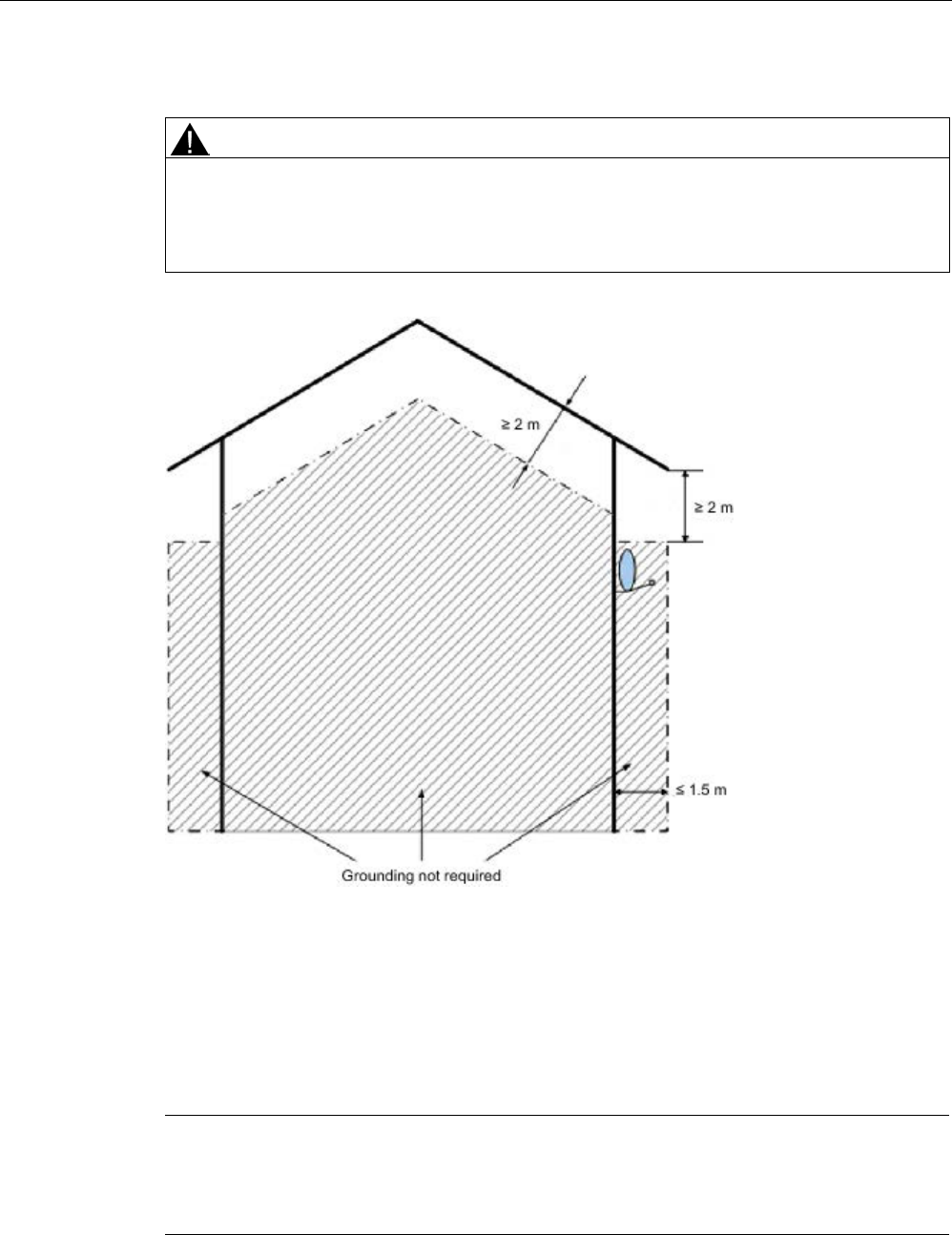
Safety Information
2.1 General safety instructions
SIMATIC RF600
22 System Manual, xx/2014, J31069-D0171-U001-A15-7618
REVIEW
Lightning protection
CAUTION
Installation only in protected areas
The antenna can be installed in the protected part of a building. When implementing your
lightning protection concept, make sure you adhere to the VDE 0182 or IEC 62305
standards.
Figure 2-1 Mounting the reader in protected areas
System expansion
Only install system expansion devices designed for this device. If you install other upgrades,
you may damage the system or violate the safety requirements and regulations for radio
frequency interference suppression. Contact your technical support team or where you
purchased your device to find out which system expansion devices may safely be installed.
Note
Warranty conditions
If you cause system defects by improperly installing or exchanging system expansion
devices, the warranty becomes void.

Safety Information
2.2 Safety instructions for third-party antennas as well as for modifications to the RF600 system
SIMATIC RF600
System Manual, xx/2014, J31069-D0171-U001-A15-7618 23
REVIEW
2.2
Safety instructions for third-party antennas as well as for
modifications to the RF600 system
Always observe the following general safety instructions before selecting a component from
a different vendor:
The manufacturer accepts no responsibility for functional suitability or legal implications for
the installation of third-party components.
Note
Loss of radio equipment approvals
Alterations to the SIMATIC RF600 devices themselves are not permitted. Failure to observe
this requirement shall constitute a
revocation of the CE, FCC, UL, CSA radio equipment
approvals and the manufacturer's warranty.
Modifications to the SIMATIC RF600 system
NOTICE
Damage to the system
If you install unsuitable or unapproved extensions, you may damage the system or violate
the safety requirements and regulations for radio frequency interference suppression.
Contact your technical support team or where you purchased your device to find out which
system extensions may safely be installed.
NOTICE
Loss of warranty
If you cause defects on the SIMATIC RF600 system by improperly installing or exchanging
system expansions, the warranty becomes void.
Note
Loss of validity for type tests and certificates
SIMATIC RFID products comply with the salient safety specificati
ons to VDE/DIN, IEC, EN,
UL and CSA. When using RFID components which do not belong to the RF600 range of
products, the validity of all type tests as well as all certificates relevant to the RF600 are
canceled: CE, FCC, UL, CSA.

Safety Information
2.3 Safety distance to transmitter antenna
SIMATIC RF600
24 System Manual, xx/2014, J31069-D0171-U001-A15-7618
REVIEW
Note
User responsibility for modified product
As a user of the modified product, you accept responsibility for use of the complete RFID
product comprising both SIMATIC RF600 components and third
-party RFID components.
This particularly applies to modification or rep
lacement of:
•
Antennas
•
Antenna cables
•
readers
•
Power supply units with connection cables
2.3
Safety distance to transmitter antenna
2.3.1
Safety distance between transmitter antenna and personnel
For antenna configurations where it is possible to be briefly or constantly within the
transmission range of the antennas, as in loading ramps, for example, minimum distances
must be maintained.
Limits
The ICRP (International Commission of Radiological Protection) has worked out limit values
for human exposure to HF fields that are also recommended by the ICNIRP (International
Commission of Non Ionizing Radiological Protection). In German legislation on emissions
(since 1997), the following limit values apply. These can vary according to frequency:
Frequency f [MHz]
Electrical field strength E [V/m]
Magnetic field strength H [A/m]
10 - 400
27,5
0,073
400 - 2.000
1.375 x f
1/2
0.0037 x f
1/2
2.000 - 300.000
61
0,16
The limit values for the 900 MHz reader antenna alternating field are thus:
Electrical field strength: E = 41.25 V/m
Magnetic field strength: H = 0.111 A/m
HF power density: E x H = 4.57 W/m2
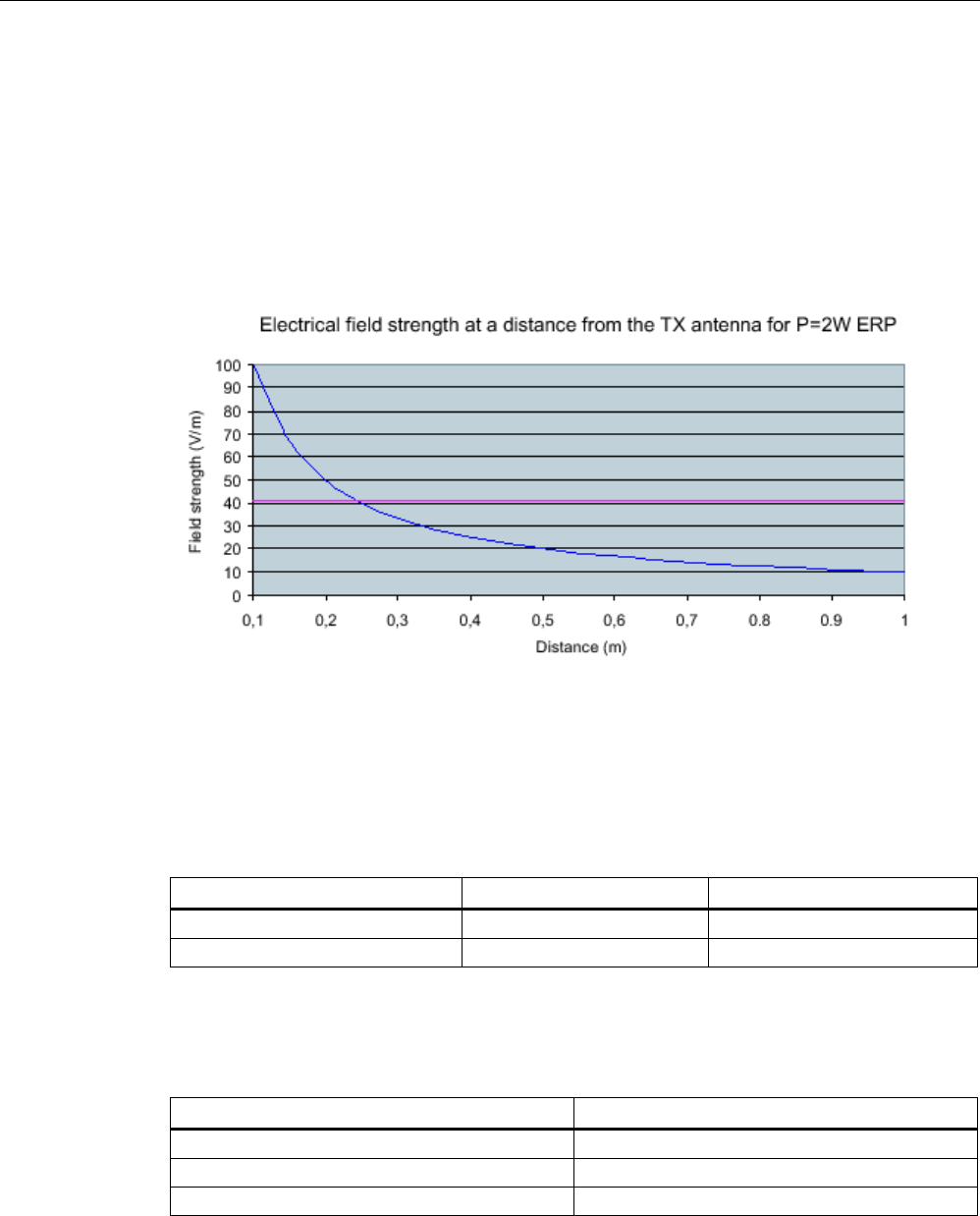
Safety Information
2.3 Safety distance to transmitter antenna
SIMATIC RF600
System Manual, xx/2014, J31069-D0171-U001-A15-7618 25
REVIEW
2.3.2
Minimum distance to antenna in accordance with ETSI
Minimum distance to antenna in accordance with ETSI (EU, EFTA, Turkey)
At a transmission frequency of 900 MHz, the wavelength of the electromagnetic wave λ is
approximately 0.34 m. For distances less than 1 λ in the near field, the electrical field
strength (1/r) diminishes exponentially to the power three over distance, and for distances
greater than 1 λ, it diminishes exponentially to the power two over distance.
The horizontal line at 41.25V/m marks the "safety limit value".
For the maximum permitted transmit power (1/r2) in accordance with ETSI (2 W ERP), the
"safety distance" is d = 0.24 m. This means that personnel should not remain closer than 24
cm to the transmitter antenna for extended periods (for several hours without interruption).
Remaining within the vicinity of the antenna for a brief period, even for repeated periods (at a
distance < 0.24 m), is harmless according to current knowledge.
Distance to transmitter antenna [m]
Feld strength [V/m]
% of limit value
1
10
24
5
2
5
If the transmitter power is set lower than the highest permissible value (2 watts ERP), the
"safety distance" reduces correspondingly.
The values for this are as follows:
Radiated power ERP [W]
Safety distance to transmitter antenna [m]
2.0
0.24
1.0
0.17
0.5
0.12

Safety Information
2.3 Safety distance to transmitter antenna
SIMATIC RF600
26 System Manual, xx/2014, J31069-D0171-U001-A15-7618
REVIEW
RF620R/RF630R-specific notes
Note
Reduced maximum radiated power with RF620R/RF630R readers
The SIMATIC RF620R (ETSI) reader has a maximum radiated power of 0.5
W ERP. The
safety distance is therefore at least 0.12
m.
The SIMATIC RF630R (ETSI) reader has a maximum transmit power of 0.5
W. The radiated
power therefore depends on the antenna cable and the type of antenna used, but cannot
exceed the 2
W ERP.
RF650R/RF680R/RF685R-specific notes
Note
Reduced maximum radiated power with RF650R/RF680R/RF685R readers
The SIMATIC RF650R (ETSI) reader has a maximum transmit power of 1
W. The radiated
power therefore depends on the antenna cable and the type of antenna used, but cannot
exceed the 2
W ERP.
The SIMATIC RF680
R (ETSI) reader has a maximum transmit power of 2 W. The radiated
power therefore depends on the antenna cable and the type of antenna used, but cannot
exceed the 2
W ERP.
The SIMATIC RF685R (ETSI) reader has a maximum radiated power of 2
W ERP. The
safet
y distance is therefore at least 0.12 m.
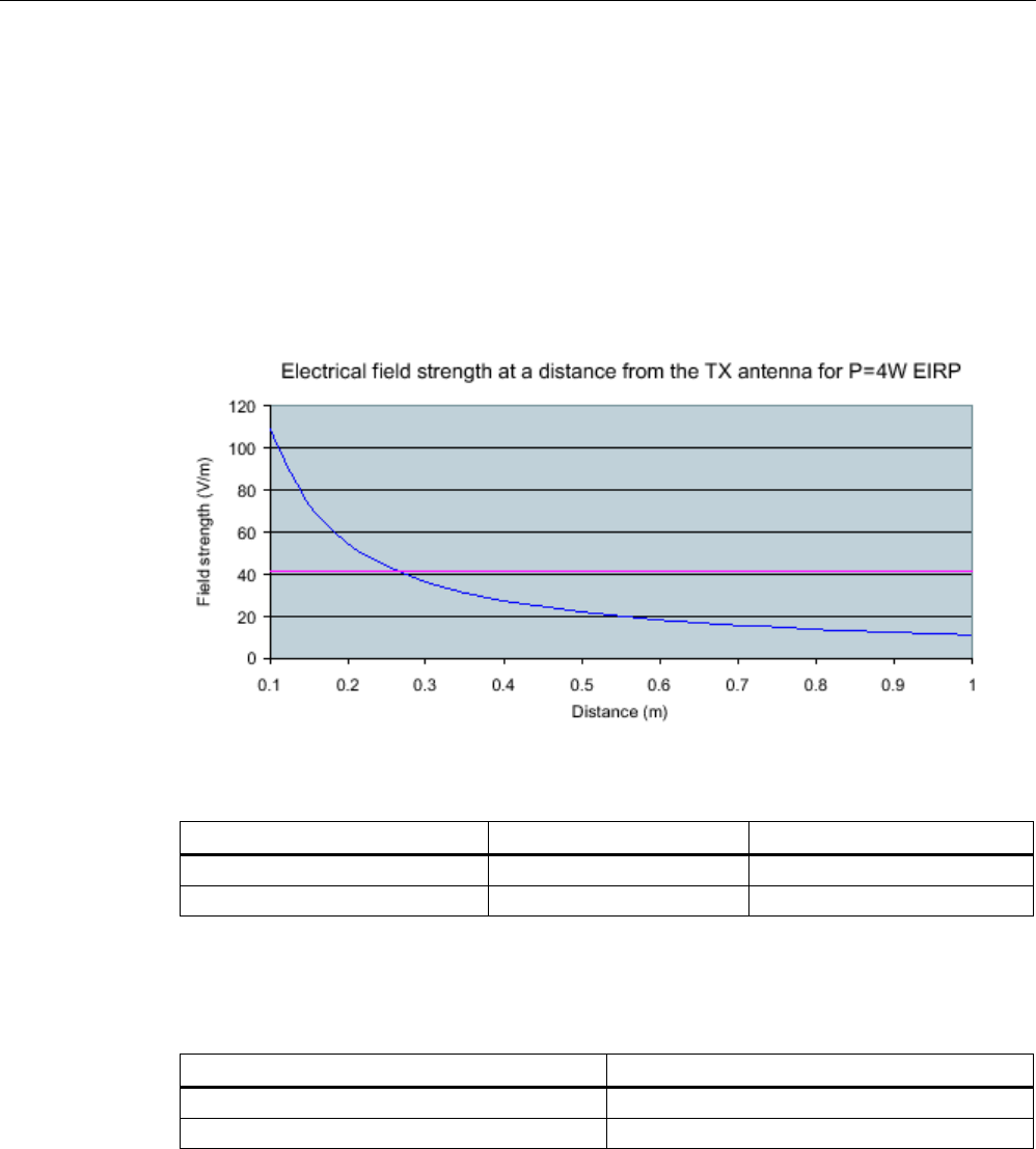
Safety Information
2.3 Safety distance to transmitter antenna
SIMATIC RF600
System Manual, xx/2014, J31069-D0171-U001-A15-7618 27
REVIEW
2.3.3
Minimum distance to antenna in accordance with FCC (USA)
Minimum distance to antenna in accordance with FCC (USA)
For the maximum permitted radiated power in accordance with FCC (4 W EIRP), the "safety
distance" is d = 0.26 m. This means that personnel should not remain closer than 26 cm to
the transmitter antenna for extended periods (several hours without interruption). Remaining
within the vicinity of the antenna for brief period, even repeated periods (at a distance < 0.26
m) is harmless to health according to current knowledge.
The horizontal line at 41.25 V/m marks the "safety limit value".
Distance to transmitter antenna [m]
Feld strength [V/m]
% of limit value
1
10.9
26
5
2.2
5.3
If the transmit power is set lower than the highest permitted value (4 W EIRP), the "safety
distance" reduces correspondingly.
The values for this are as follows:
Radiated power EIRP [W]
Safety distance to transmitter antenna [m]
4.0
0.26
<2.5
>0.20
Generally a safety distance of at least 0.2 m should be maintained.

Safety Information
2.3 Safety distance to transmitter antenna
SIMATIC RF600
28 System Manual, xx/2014, J31069-D0171-U001-A15-7618
REVIEW
RF620R/RF630R-specific notes
Note
Reduced maximum radiated power with RF620R/RF630R readers
The
SIMATIC RF620R (FCC) reader has a maximum transmit power of 0.5 W. This means
that the radiated power of 4 W EIRP cannot be exceeded with the internal antenna.
The SIMATIC RF630R (FCC) reader has a maximum transmit power of 0.5
W. The radiated
power
therefore depends on the antenna cable and the type of antenna used, but cannot
exceed the 4
W EIRP.
RF650R/RF680R/RF685R-specific notes
Note
Reduced maximum radiated power with RF650R/RF680R/RF685R readers
The SIMATIC RF650R (FCC) reader has a maximum transmit power of 1
W. The radiated
power therefore depends on the antenna cable and the type of antenna used, but cannot
exceed the 4
W EIRP.
The SIMATIC RF680R (FCC) reader has a maximum transmit power of 2
W. The radiated
power therefore depends on the antenna cable and the type of antenna used, but cannot
exceed the 4
W EIRP.
The SIMATIC RF685R (CC) reader has a maximum transmit power of 2
W. This means that
the safety distance is at least 0.12 m.
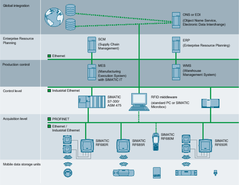
SIMATIC RF600
System Manual, xx/2014, J31069-D0171-U001-A15-7618 29
REVIEW
System overview of SIMATIC RF600
3
SIMATIC RF600 is an identification system that operates in the UHF range. UHF technology
supports large write/read distances with passive transponders.
The SIMATIC RF650R or RF680R readers (write/read devices), fitted for example on the
gates of a warehouse, automatically record every movement of goods, and signal these to
the higher-level systems. The data is filtered and compressed there by data management
software at the control level for example to generate the incoming goods transaction for the
ERP (Enterprise Resource Planning) system at the business administration control level. At
the same time, the delivery can be automatically checked for correctness and completeness
prior to storage by means of the electronic delivery list.
The general automation and IT structure of a company is shown in the following figure. This
comprises several different levels that are described in detail below.
Figure 3-1 System overview SIMATIC RF600 with RF650R, RF680R and RF685R
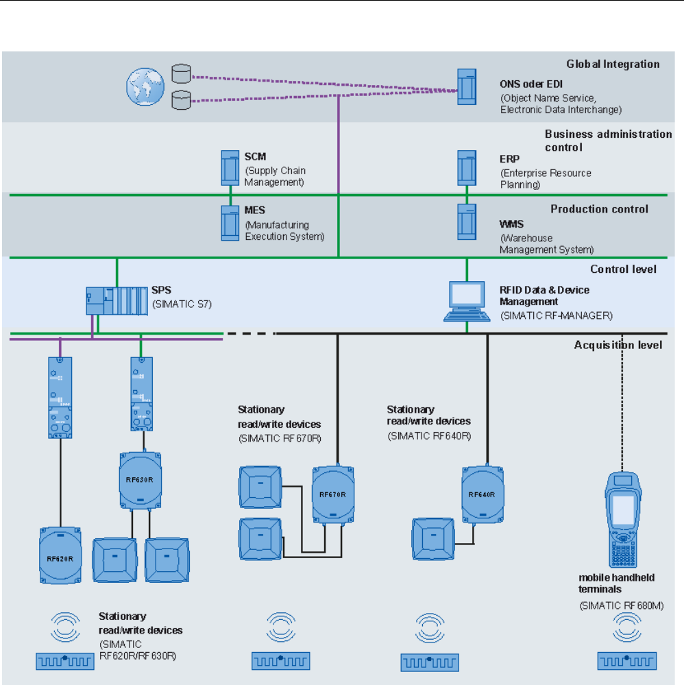
System overview of SIMATIC RF600
2.3 Safety distance to transmitter antenna
SIMATIC RF600
30 System Manual, xx/2014, J31069-D0171-U001-A15-7618
REVIEW
Figure 3-2 System overview SIMATIC RF600 with RF620R, RF630R, RF640R and RF670R
●
Acquisition level
This level contains the RFID readers that read the appropriate transponder data and
transfer it to the next higher level.
●
Control level
At the control level , the RFID data is collected, preprocessed and made available to the
production control and business administration control levels for further processing.

System overview of SIMATIC RF600
3.1 Application areas of RF600
SIMATIC RF600
System Manual, xx/2014, J31069-D0171-U001-A15-7618 31
REVIEW
●
Production control
The Manufacturing Execution System (MES) closes the gap between the data that arises
in the automation environment (control level) and the logistic and commercial processes
of the company (business administration control). MES solutions are used, for example,
for defining and performing production processes.
●
Business administration control
This level covers the planning and control of the equipment used. For this purpose,
Enterprise Resource Planning (ERP) systems and Supply Chain Management (SCM)
systems are used with modules for cost accounting, financial bookkeeping and personnel
management.
●
Global integration
At this level, product information can be exchanged at an inter-company level. This can
be performed over the Internet with the help of special services.
3.1
Application areas of RF600
RFID (radio frequency identification) permits interruption-free tracking and documentation of
all delivered, stocked and shipped goods in the incoming goods, warehouse, production
logistics and distribution departments. A small data medium - referred to as SmartLabel,
transponder or tag - is attached to every item, package or pallet, and contains all important
information. The data medium receives the power it requires via an antenna which is also
used for data transmission.
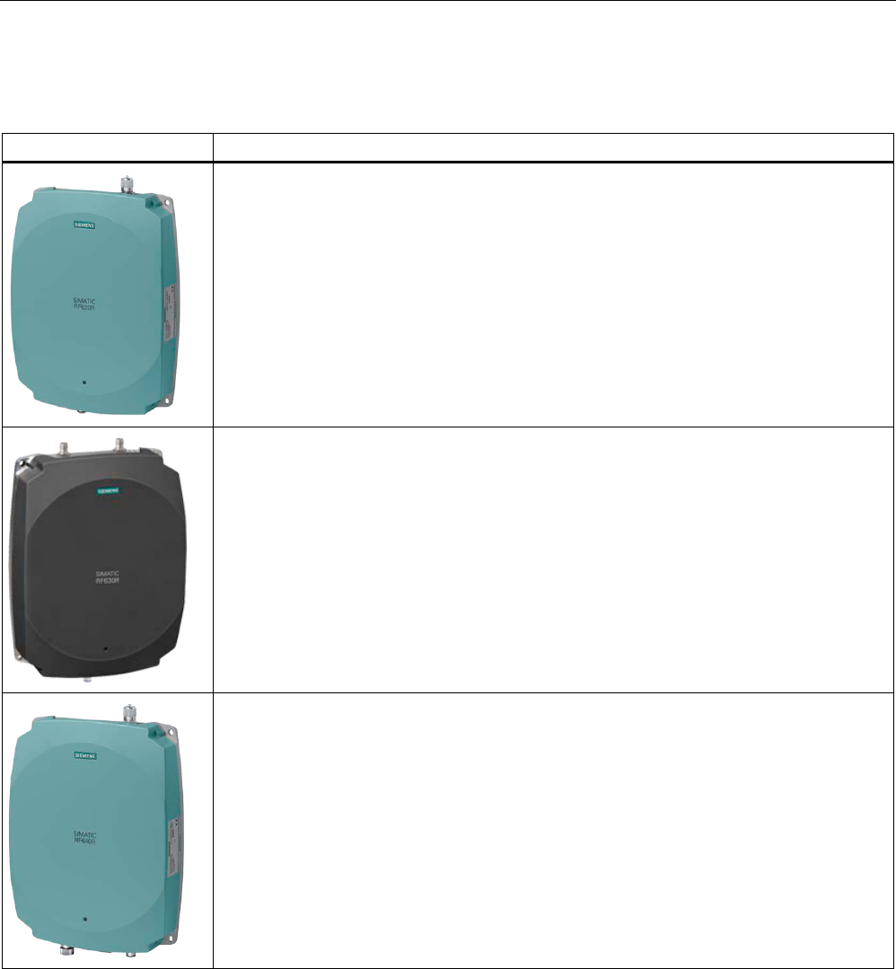
System overview of SIMATIC RF600
3.2 System components (hardware/software)
SIMATIC RF600
32 System Manual, xx/2014, J31069-D0171-U001-A15-7618
REVIEW
3.2
System components (hardware/software)
RF600 products
Description
The RF620R reader creates with its connection to a SIMATIC controller optimum
preconditions for production-related application scenarios and/or production-related logistics
applications by RFID. It has an integrated circular polarized antenna.
The RF630R reader creates with its connection to a SIMATIC controller optimum
preconditions for production-related application scenarios and/or production-related logistics
applications by RFID. It has 2 connections for external antennas.
Due to its compact format and high degree of protection, the RF640R reader is ideally suited
to applications in production logistics and distribution. The integrated data processing makes
it easier to use in complex scenarios and reduces the IT integration costs. Integration is
achieved using an XML protocol, TCP/IP and Ethernet. It has an integrated circular polarized
antenna.
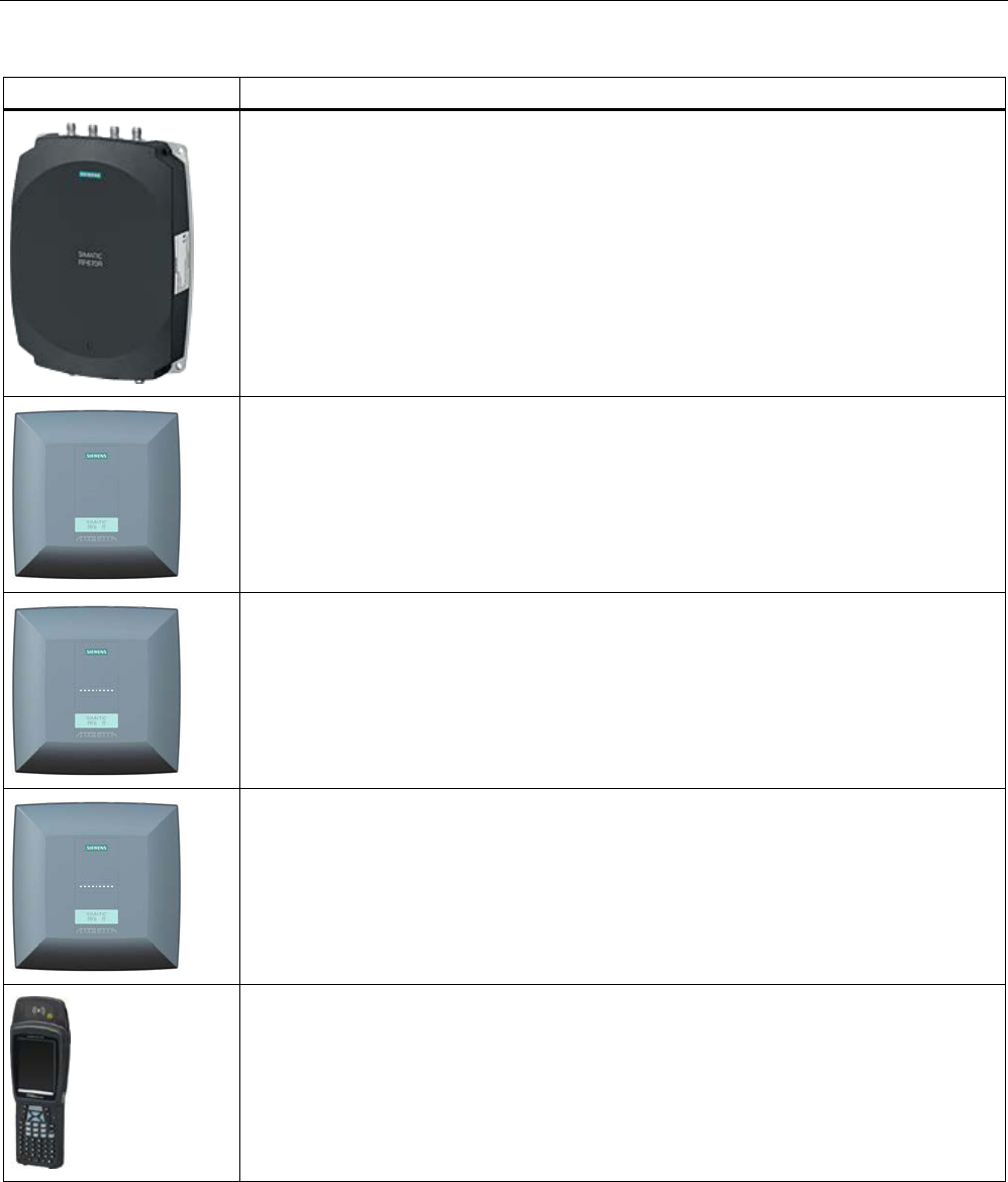
System overview of SIMATIC RF600
3.2 System components (hardware/software)
SIMATIC RF600
System Manual, xx/2014, J31069-D0171-U001-A15-7618 33
REVIEW
RF600 products
Description
Due to its compact format and high degree of protection, the RF670R reader is ideally suited
to applications in production logistics and distribution. The integrated data processing makes
it easier to use in complex scenarios and reduces the IT integration costs. Integration is
achieved using an XML protocol, TCP/IP and Ethernet.
Due to its compact design the RF650R reader is suitable for applications in production
logistics. Integration is achieved using an XML protocol, TCP/IP and Ethernet. It has 4
connectors for external antennas.
Due to its compact design and high degree of protection, the RF680R reader is ideally suited
to applications in production logistics and distribution. Integration is achieved using an XML
protocol, TCP/IP and Ethernet or PROFINET. It has 4 connectors for external antennas.
Due to its compact design and high degree of protection, the RF685R reader is ideally suited
to applications in production logistics and distribution. Integration is achieved using an XML
protocol, TCP/IP and Ethernet or PROFINET. It is equipped with an integrated antenna with
switchable polarization and has a connector for an external antenna.
SIMATIC RF680M expands the RF600 RF identification system with a powerful mobile
reader for applications in the areas of logistics, production and service. In addition, it is an
indispensable aid for startup and testing.
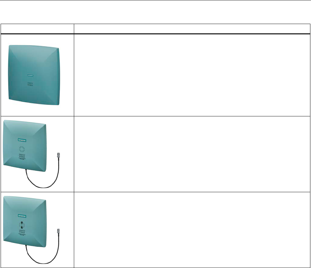
System overview of SIMATIC RF600
3.2 System components (hardware/software)
SIMATIC RF600
34 System Manual, xx/2014, J31069-D0171-U001-A15-7618
REVIEW
RF600 products
Description
SIMATIC RF660A is a circular antenna of medium size for production and logistics
applications.
Up to 4 antennas can be connected to the RF670R reader depending on the application and
up to two can be connected to the RF630R reader. One antenna can be connected to the
RF640R or RF620R readers as an alternative to the internal antenna.
The SIMATIC RF640A is a circular antenna of medium size for universal applications, for
example material flow and logistics systems.
Depending on the application, up to 4 antennas can be connected to the RF670R reader and
up to two antennas can be connected to the RF630R reader. One antenna can be connected
to the RF640R or RF620R reader as an alternative to the internal antenna.
SIMATIC RF642A is a linear antenna of medium size for environments where a lot of metal
occurs.
Depending on the application, up to 4 antennas can be connected to the RF670R reader and
up to two antennas can be connected to the RF630R reader. One antenna can be connected
to the RF640R or RF620R reader as an alternative to the internal antenna.
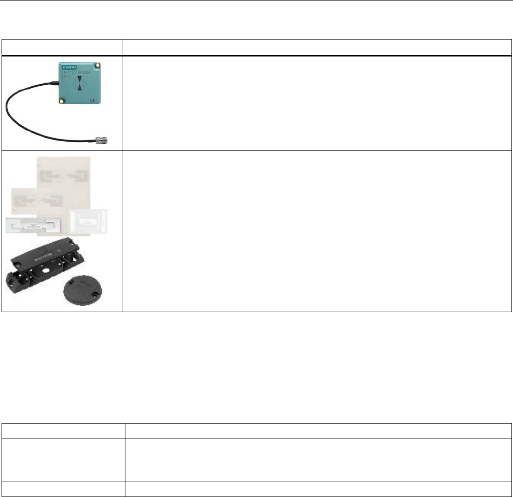
System overview of SIMATIC RF600
3.3 Features
SIMATIC RF600
System Manual, xx/2014, J31069-D0171-U001-A15-7618 35
REVIEW
RF600 products
Description
The SIMATIC RF620A is a linear antenna with a compact design suitable for industry. It is
suitable for UHF transponders with normal (far field) antenna characteristics.
Depending on the application, up to 4 antennas can be connected to the RF670R reader and
up to two antennas can be connected to the RF630R reader. One antenna can be connected
to the RF640R or RF620R reader as an alternative to the internal antenna.
The RF600 transponder family provides the right solution for every location:
The tool tag RF640T for industrial requirements is highly resistant to oils and can be mounted
directly on metal. The container tag RF620T for industrial applications is rugged and highly
resistant to cleaning agents.
The RF630L SmartLabels made of plastic or paper can be used in a wide variety of
applications: The application areas range from simple identification such as electronic
barcode replacement/supplementation, through warehouse and distribution logistics, right up
to product identification
3.3
Features
The RF600 identification system has the following performance features:
Table 3- 1 Features of the RF600 RFID system
Type
Contactless RFID (Radio Frequency IDentification) system in the UHF band
Transmission frequency
865-868 MHz (ETSI: EU, EFTA, Turkey)
902-928 MHz (FCC: USA)
920.125 - 924.875 MHz (CMIIT: CHINA)
Standards
EPCglobal Class 1, Gen 2

System overview of SIMATIC RF600
3.3 Features
SIMATIC RF600
36 System Manual, xx/2014, J31069-D0171-U001-A15-7618
REVIEW
Table 3- 2 Features of the RF600 readers
Reader
Antennas
Write/read distance
Interface
RF620R
1 x internal antenna
1 x antenna connector for
external antennas
Internal antenna: < 2 m
External antenna: < 2.5 m
PROFIBUS, PROFINET
RF630R
2 x antenna connectors for
external antennas
0.1 - 2 m PROFIBUS, PROFINET
RF640R
1 x internal antenna
1 x antenna connector for
external antennas
Internal antenna: < 3.5 m
External antenna: < 4 m
Ethernet, PROFINET
RF670R
4 x antenna connectors for
external antennas
< 4 m Ethernet, PROFINET
RF650R
4 x antenna connectors for
external antennas
< 4 m Ethernet
RF680R
4 x antenna connectors for
external antennas
< 4 m Ethernet, PROFINET
RF685R
1 x internal antenna
1 x antenna connector for
external antennas
Internal antenna: < 3.5 m
External antenna: < 4 m
Ethernet, PROFINET
Table 3- 3 RF680M mobile handheld terminal
Transmission frequency
865-868 MHz (EU, EFTA, Turkey)
902-928 MHz (USA)
Write/read distance
Europe < 2 m
USA < 1 m
Standards
EPCglobal Class 1, Gen 2
Table 3- 4 Transponder
Version
Tags / SmartLabels
Designation
Standards supported
SmartLabels
SmartLabel
RF630L
RF680L
EPCglobal Class 1, Gen 2
ISO card
Container tag
Disc tag
Powertrain tag
Tool tag
Heat-resistant tag
RF610T
RF620T
RF625T
RF630T
RF640T (Gen 2)
RF680T
EPCglobal Class 1, Gen 2
Table 3- 5 Software
RF-MANAGER Basic V2
PC software for assigning parameters to the RF670R and RF640R readers
System requirements:
Windows XP SP2 and higher

SIMATIC RF600
System Manual, xx/2014, J31069-D0171-U001-A15-7618 37
REVIEW
RF600 system planning
4
4.1
Overview
You should observe the following criteria for implementation planning:
● Possible system configurations
● Antenna configurations
● Environmental conditions for transponders
● The response of electromagnetic waves in the UHF band
● Regulations applicable to frequency bands
● EMC Directives
4.2
Possible system configurations
The SIMATIC RF600 system is characterized by a high level of standardization of its
components. This means that the system follows the TIA principle throughout: Totally
Integrated Automation. It provides maximum transparency at all levels with its reduced
interface overhead. This ensures optimum interaction between all system components.
The RF600 system with its flexible components offers many possibilities for system
configuration. This section shows you how you can use the RF600 components on the basis
of various example scenarios.
Note
Readers used in the following scenarios
The scenarios shown in the following sections are
based on the RF650R, RF680R and
RF685R readers. Remember that the individual scenarios can also be implemented with the
RF620R, RF630R, RF640R or RF670R readers.
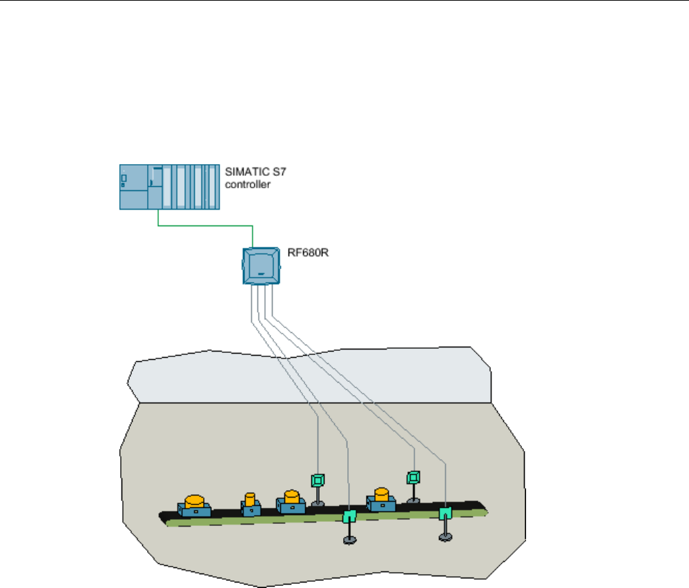
RF600 system planning
4.2 Possible system configurations
SIMATIC RF600
38 System Manual, xx/2014, J31069-D0171-U001-A15-7618
REVIEW
4.2.1
Scenario for material handling control
This scenario shows a possible solution for monitoring and controlling the infeed of material
to a production line. The objective is to provide the right material at the right time. This can
be particularly useful in plants with frequently changing manufacturing scenarios for ensuring
that incorrect infeed and downtimes are minimized.
Features of the scenario
The conveyor moves different transport containers past the readers in an arbitrary alignment.
The RFID transponder is, however, always applied to the transport containers with the same
alignment. The transponders in this scenario are transponders of the type SIMATIC RF680T.
The conveyor belt has a maximum width of approximately 80 cm in this example. The
transport speed is up to 2 m/s. With this arrangement only a single RFID transponder needs
to be detected each time (single-tag).
In this scenario a SIMATIC RF680R is used as the reader. Optimum reading reliability is
ensured by four external SIMATIC RF660A antennas in a portal arrangement. When the
distances to or between metal containers are very limited, the SIMATIC RF620A antenna is
a good alternative. The SIMATIC RF680R reader reads the information of the transponder
on the transport containers and forwards it to the SIMATIC S7 controller that controls the
next actions depending on the transponder information.
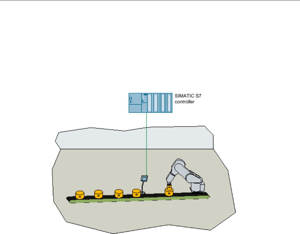
RF600 system planning
4.2 Possible system configurations
SIMATIC RF600
System Manual, xx/2014, J31069-D0171-U001-A15-7618 39
REVIEW
4.2.2
Scenario for workpiece identification
A typical characteristic of modern manufacturing scenarios is their multitude of variations.
The individual data and production steps are stored in the transponder of a tool holder or
product. These data are read by the machining stations during a production process and, if
necessary, tagged with status information. This can be used to dynamically identify which
production step is the next in the series. This has the advantage that the production line can
work automatically without the need to access higher system components. The use of RFID
therefore increases the availability of the plant.
Features of the scenario
RFID tags are attached to workpiece holders. Their spatial orientation is always identical.
With this arrangement, only a single transponder needs to be detected each time (single-
tag). The transponders in this scenario are transponders of the type SIMATIC RF640T.
The SIMATIC RF685R reader reads the information from the transponders with its integrated
antenna and transfers it to the SIMATIC S7 controller. Depending on the stored transponder
information, the SIMATIC S7 controller different control tasks, for example, automatically
providing a suitable tool for an industrial robot at the correct time.
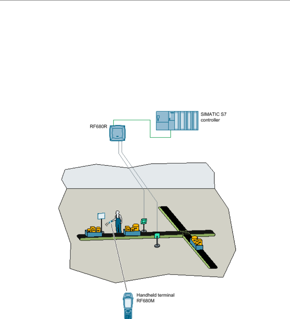
RF600 system planning
4.2 Possible system configurations
SIMATIC RF600
40 System Manual, xx/2014, J31069-D0171-U001-A15-7618
REVIEW
4.2.3
Scenario for Intra logistics
Intra logistics comprises all logistical procedures that are required on a production site as
well as within the overall company. The main task of Intra logistics is to control the
subsequent processes:
● Transporting goods from the incoming goods bay into the warehouse
● Management of stock
● Conveyance of goods from the warehouse for production
● Order picking
● Packing

RF600 system planning
4.2 Possible system configurations
SIMATIC RF600
System Manual, xx/2014, J31069-D0171-U001-A15-7618 41
REVIEW
Features of the scenario
In this example scenario. items must be distributed to the correct storage location in a
transport container via a separating filter. The RFID transponders of the type SIMATIC
RF630L are directly attached to the item. The maximum transport speed of the conveyor belt
is 2 m/s.
In this scenario, bulk acquisition is necessary because several objects must be detected at
the same time.
The SIMATIC RF680R reader uses two external antennas in a portal arrangement to read
the information from the transponders on the passing items and transfers it to the SIMATIC
S7 controller via a communications module. The SIMATIC S7 controls the sorter of the
conveyor system depending on the transponder information.
If only one simple evaluation of the transponder ID is required, and the data will not be
processed any further, the SIMATIC RF680R provides this function without being connected
to the controller.
The SIMATIC RF680M mobile handheld terminal is used in this example for additional
evaluation and visualization of the item data directly on site.
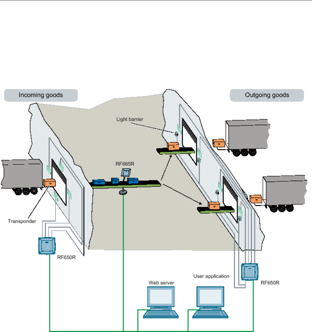
RF600 system planning
4.2 Possible system configurations
SIMATIC RF600
42 System Manual, xx/2014, J31069-D0171-U001-A15-7618
REVIEW
4.2.4
Scenario incoming goods, distribution of goods and outgoing goods
The scenario consists of an RFID system with three readers. The SIMATIC RF650R reader
with its four antennas monitors the incoming goods gate of a factory building hall through
which pallets are delivered. Each pallet is fitted with a transponder. The transponders
contain user data that provides information about the sender and receiver of the goods. This
data is read out and passed on. The goods supplied on the pallets are processed in the
factory and then exit the factory through the outgoing goods gate.

RF600 system planning
4.3 Antenna configurations
SIMATIC RF600
System Manual, xx/2014, J31069-D0171-U001-A15-7618 43
REVIEW
Features of the scenario
in this example, the SIMATIC RF685R reader is controlled by a light barrier and monitors a
conveyor belt; the conveyor belt transports the goods towards two output gates that are
assigned to different recipients. Each item has a transponder that is always fitted at the
same position and with the same alignment on the item. These transponders also contain
user data that provides information about the sender and receiver of the goods. There is a
separator at the end of the conveyor belt that determines the output gate to which the goods
should be directed. The separator is set according to the results from the reader and the
goods are distributed.
After the sorter, the goods are loaded onto pallets - each pallet is fitted with a transponder.
These transponders also contain user data that provides information about the sender and
receiver of the goods. Based on the data read by the SIMATIC RF650R reader, the pallets at
the outgoing goods gate are checked to make sure that they are intended for the receiver to
which the gate is assigned. Light barriers are installed to control the reader. Depending on
the read results of the reader, the outgoing portal opens, or it remains closed.
4.3
Antenna configurations
Note
Validity of antenna configuration
The following information about the antenna configuration only applies to the antennas of the
RF600 family. Refer to the
Guidelines for selecting RFID UHF antennas (Page 55) for
information on the configuration of third
-party antennas.
4.3.1
Antenna configuration example
The following figure shows an example of an application with an antenna configuration of the
RF650R. The antennas are positioned at the height at which the transponders to be
identified are expected. The maximum width of the portal recommended for reliable
operation is 4 m.
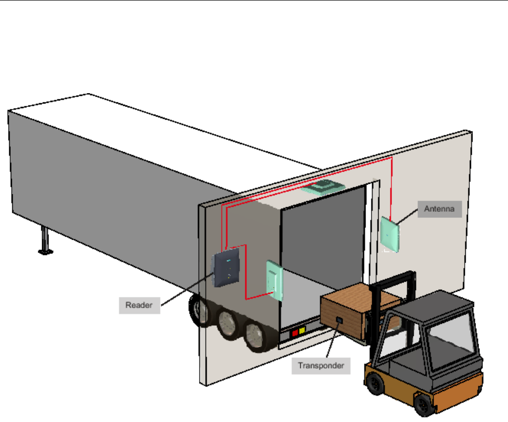
RF600 system planning
4.3 Antenna configurations
SIMATIC RF600
44 System Manual, xx/2014, J31069-D0171-U001-A15-7618
REVIEW
The diagram shows a configuration with three antennas. Up to four antennas can be used
depending on the local conditions.
Figure 4-1 Example of an antenna configuration with three antennas
4.3.2
Possibilities and application areas for antenna configurations
Some basic antenna configurations and possible fields of application are shown below.
With the various configurations, please note that up to four external antennas can be
connected to the RF650R, RF680R and RF670R readers, up to two can be connected to the
RF630R reader and one external antenna can be connected to the RF620R, RF640R and
RF685R readers. The RF620R, RF640R and RF685R readers also have an internal
antenna.
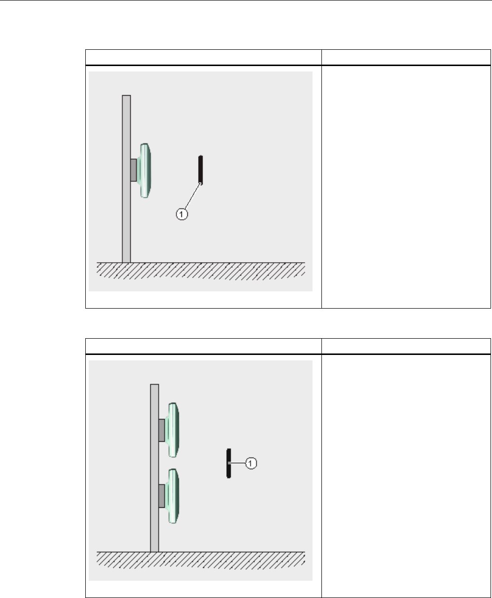
RF600 system planning
4.3 Antenna configurations
SIMATIC RF600
System Manual, xx/2014, J31069-D0171-U001-A15-7618 45
REVIEW
Antenna configuration 1
Description/ application areas
This arrangement of antennas is
appropriate when the transponders to be
read are only located on one side of the
goods to be acquired, for example, if a
conveyor belt with passing goods has to
be monitored during production and it is
precisely defined on which side the
transponders to be read are attached.
① Transponder
Antenna configuration 2
Description/ application areas
This arrangement of antennas is
appropriate when the transponders to be
read are only located on one side of the
items to be identified, e.g. when pallets
are to be identified and it is known on
which side the transponders to be read
are located.
① Transponder
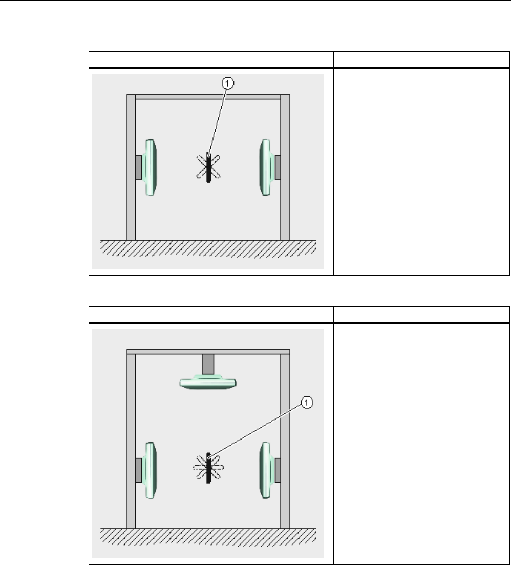
RF600 system planning
4.3 Antenna configurations
SIMATIC RF600
46 System Manual, xx/2014, J31069-D0171-U001-A15-7618
REVIEW
Antenna configuration 3
Description/ application areas
Preferred for the identification of goods
at loading gates: The transponder is
located in the radiation field of two
antennas; for reliable transponder
reading, the height of the transponders
above floor level must therefore be
known with reasonable accuracy.
① Transponder
Antenna configuration 4
Description/ application areas
Preferred for the identification of goods
at loading gates: Similar to configuration
2, but with additional reading reliability
when the transponder is at an angle to
the vertical.
① Transponder
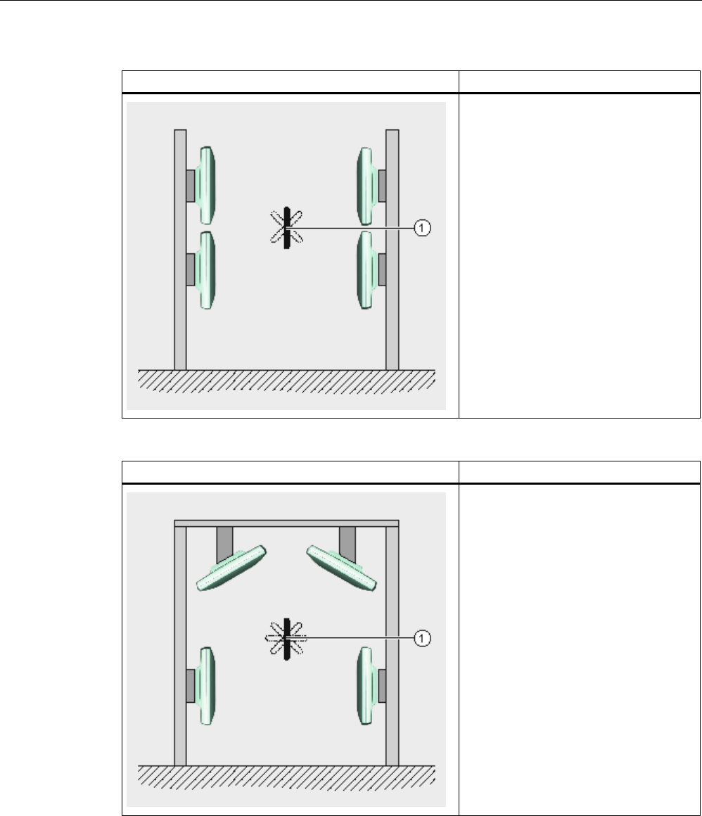
RF600 system planning
4.3 Antenna configurations
SIMATIC RF600
System Manual, xx/2014, J31069-D0171-U001-A15-7618 47
REVIEW
Antenna configuration 5
Description/ application areas
Preferred for the identification of goods
at loading gates: The transponder is
located in the radiation field of all four
antennas, so the transponder position for
reliable tag identification is more flexible
than in configuration 2.
① Transponder
Antenna configuration 6
Description/ application areas
Preferred for the identification of goods
at loading gates: Similar to configuration
4, but the reliability of transponder
identification is improved as a result of
the four antennas at separate locations,
so the transponder position is not critical.
① Transponder
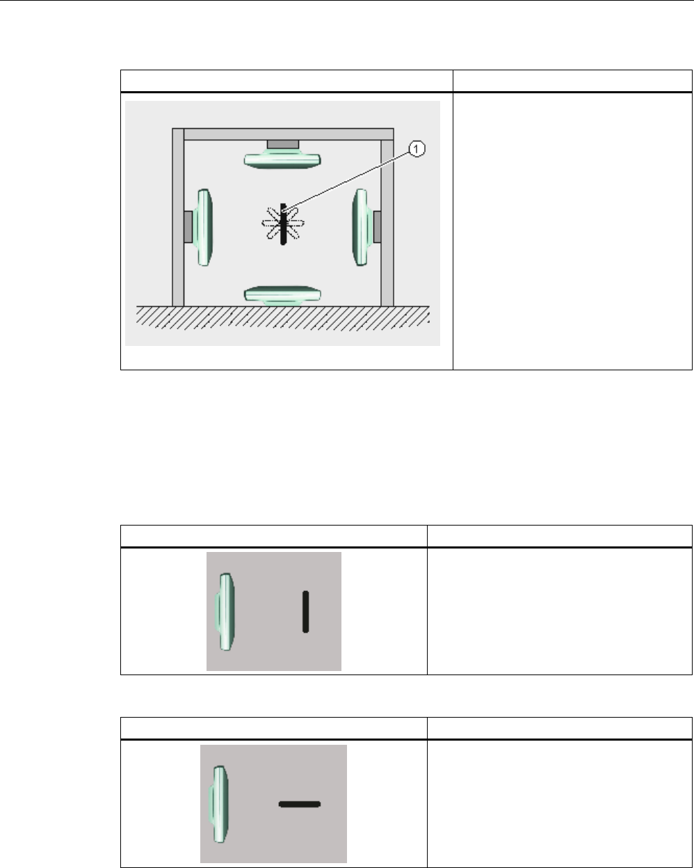
RF600 system planning
4.3 Antenna configurations
SIMATIC RF600
48 System Manual, xx/2014, J31069-D0171-U001-A15-7618
REVIEW
Antenna configuration 7
Description/ application areas
This tunnel configuration is suitable for
conveyor belt applications. The goods
with the transponders to be read are
moving forwards on a conveyor belt but
the alignment of the transponders
relative to the antennas is not clearly
defined. One of the antenna is located
on the floor and radiates vertically
upwards in the direction of the conveyor
belt. A relatively high reading reliability is
achieved due to the use of four
antennas.
① Transponder
4.3.3
Transponder orientation in space
The alignment of the transponder antenna to the antenna of the reader influences the
reading range. For maximum performance and to achieve the maximum read range, the
transponder antenna should therefore be aligned parallel to the reader antenna:
Parallel transponder alignment
Large reading range
The probability of identification of the
transponders is at a maximum.
Vertical transponder alignment
Minimal reading range
The probability of identification of the
transponders is at a minimum.
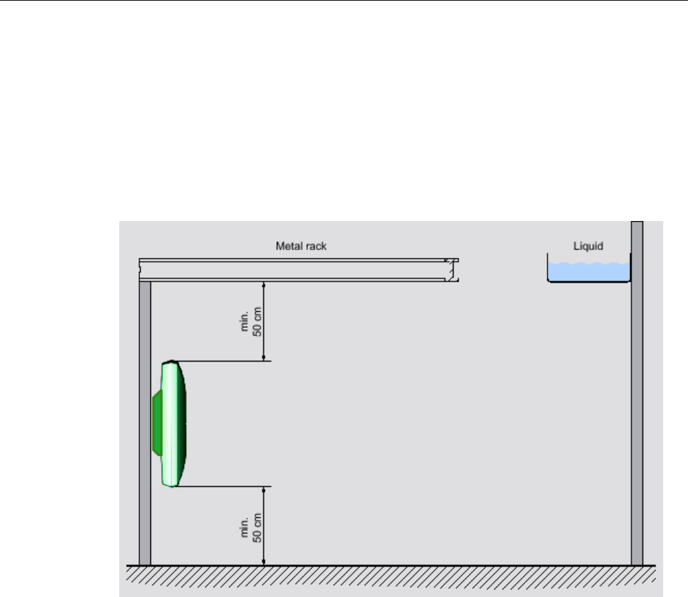
RF600 system planning
4.3 Antenna configurations
SIMATIC RF600
System Manual, xx/2014, J31069-D0171-U001-A15-7618 49
REVIEW
4.3.4
Specified minimum and maximum spacing of antennas
Specified minimum spacing of antennas
The following diagram shows the specified minimum and maximum spacings for mounting
antennas:
Between the antenna and liquids or metals, a minimum distance of 50 cm should be kept to.
The distance between the antenna and the floor should also be at least 50 cm.
Figure 4-2 Minimum distance to the environment
4.3.5
Mutual interference of readers (antennas)
Using more than one reader
When several RFID readers are used, there is a danger that RFID transponders can also be
read out by other readers. Care must therefore be taken to ensure that the transponder can
only be identified by the intended reader.
Technical disruptions between readers then occur particularly when they transmit on the
same channel (on the same frequency). You will find more detailed information in the section
"The response of electromagnetic waves in the UHF band (Page 73)".
To prevent this, readers used in Europe and China must operate on different channels with
"frequency hopping" activated. "Frequency hopping" is permanently set in the USA.
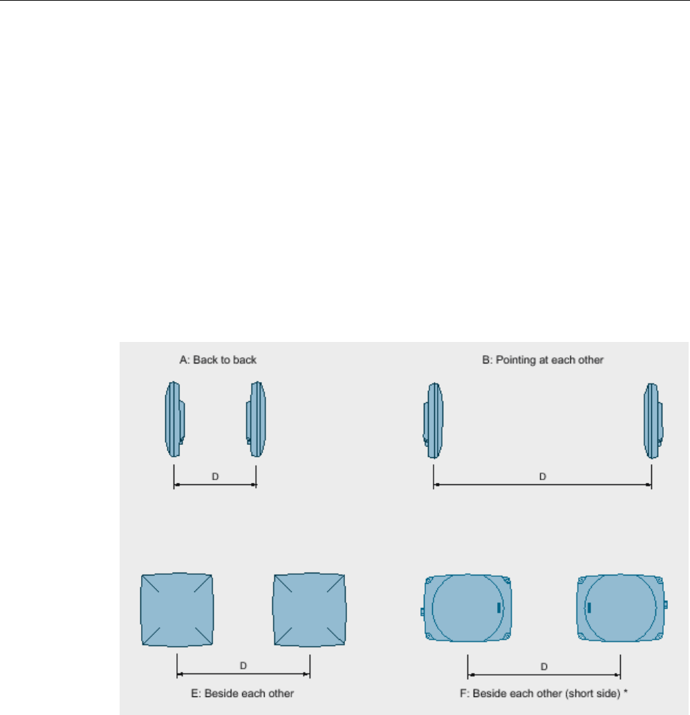
RF600 system planning
4.3 Antenna configurations
SIMATIC RF600
50 System Manual, xx/2014, J31069-D0171-U001-A15-7618
REVIEW
Antenna alignment and antenna spacing with an external antenna
The minimum distance required between antennas that use the same frequency and that are
connected to different readers depends on the set maximum radiated power and the antenna
alignment.
Maximum radiated power of the antennas:
● RF620R/RF630R = 500 mW ERP
● RF620R/RF630R with RF660A = 2000 mW ERP
● RF640R/RF670R with RF660A = 2000 mW ERP
● RF650R with RF660A = 1000 mW ERP
● RF680R with RF660A = 2000 mW ERP
● RF685R = 2000 mW ERP
● RF685R with RF660A = 2000 mW ERP
*
relevant when operating the RF620R and RF640R readers with the internal antenna
Figure 4-3 Antenna spacing for different readers/antennas and identical frequencies

RF600 system planning
4.3 Antenna configurations
SIMATIC RF600
System Manual, xx/2014, J31069-D0171-U001-A15-7618 51
REVIEW
Table 4- 1 Antenna alignment and minimum antenna spacing with external antennas
Antenna
configuration
Antenna alignment
Minimum distance required = D
RF640R/RF670R with
RF660A
RF620R/RF630R with
RF660A
RF650R/RF680R/RF685
R with RF660A
A
Back to back
0.5 m
0.3 m
B
Pointing at each other
6 m
6 m
E
Next to each other
1 m
0.8 m
Table 4- 2 Maximum antenna spacing of the external antennas with a portal configuration
Antenna
configuration
Antenna alignment
Maximum distance = D
RF670R with RF660A
RF630R with RF660A
RF650R/RF680R/RF685
R with RF660A
B
Pointing at each other
8 m
1)
4 m
1) Portal spacing of up to 10 m is possible. The probability of a read must be checked.
Antenna alignment and antenna spacing with the internal antenna (RF620R/RF640R/RF685R)
Table 4- 3 Antenna alignment and minimum antenna spacing with internal antennas
Antenna
configuration
Antenna alignment
Minimum distance required = D
RF620R
RF640R
RF685R
A
Back to back
0.4 m
0.4 m
B
Pointing at each other
5.8 m
4.0 m
E
Side by side (long side)
1.4 m
1.4 m
F
Side by side (short side)
1.8 m
2 m
Optimization of the antenna arrangement
With the RF620R, RF640R, RF685R readers (with the internal antenna)
The RF620R and RF640R readers have an integrated, circular polarized antenna. This
means that the type of antenna cannot be freely selected. This means that the interference
spacing in arrangement E is greater than in arrangement F. The RF685R reader has an
integrated, switchable antenna (linear or circular).
Note
Rotation of the reader through 90° around the z axis
Since the horizontal electrical aperture angle of the RF620R antenna is greater than the
vertical aperture angle, the
effects on adjacent readers can be reduced by using the reader
as shown in arrangement F (see arrangements E and F).

RF600 system planning
4.3 Antenna configurations
SIMATIC RF600
52 System Manual, xx/2014, J31069-D0171-U001-A15-7618
REVIEW
With the RF640A/RF642A/RF660A antenna
The electrical aperture angles (vertical and horizontal) of the RF660A antenna are identical,
with the RF640A/RF642A antennas they are similar. Therefore, the robustness of the
readers' access to transponder data cannot be optimized for the RF660A and with the
RF640A/RF642A it can be optimized only to a limited extent by rotating around the antenna
axis.
4.3.6
Read and write range
The read/write range between the reader/antenna and the transponder is influenced by the
following factors:
The reading range depends on
Description
Transmit power of the reader The higher the transmit power of the reader, the larger the
reading range.
Tag size and type The larger the tag antenna, the larger the power input area
and therefore the larger the reading range.
Absorption factor of the materials The higher the absorption of the surrounding material, the
smaller the reading range.
Production quality of the tag The better the tag has been matched to the operating
frequencies during manufacturing, the greater the reading
range.
Reflection characteristics of the
environment
In a multiple-reflection environment (e.g., in rooms with
reflecting surfaces, machinery, or concrete walls), the
reading range can be significantly higher than in a low-
reflection environment.
Number of transponders in the antenna
field
The typical ranges always relate to a transponder installed
at the maximum possible distance from the antenna.
If there is more than one transponder in the antenna field,
the distance to all other transponders must be less to allow
them to be acquired in the antenna field.
The width and height of the antenna field within which its
transponders can be arranged at a certain distance from
the antenna depend on the following:
• The radiated power,
• Only reading or reading and writing the transponders
(writing requires more power, typically double the
power)
• The aperture angle (horizontal)
• The aperture angle (vertical)
You will find detailed information about the reading range of the individual readers in the
"Technical specifications" in the sections for the various readers.

RF600 system planning
4.3 Antenna configurations
SIMATIC RF600
System Manual, xx/2014, J31069-D0171-U001-A15-7618 53
REVIEW
4.3.7
Static/dynamic mode
Reading or writing can be either static or dynamic.
● Reading/writing is counted as being
static
if the tag does not move in front of the antenna
and is read or written.
● Reading/writing is counted as being
dynamic
if the tag moves past the antenna during
reading/writing.
The following overview shows which environments are suitable for which read or write mode:
Operating mode
Read
Write
Static Recommended in normal UHF
environments
Recommended in normal UHF
environments
Dynamic Recommended under difficult
UHF conditions
Not recommended in difficult
UHF environments
4.3.8
Operation of several readers within restricted space
4.3.8.1
Dense Reader Mode
A special operating mode according to the standard EPC Global Class 1, Gen 2 in Dense
Reader Mode allows several RF600 readers to be operated without interference in close
proximity to each other. All RF600 readers operate in Dense Reader Mode according the
standard EPC Global Class 1, Gen 2.
Dense Reader Mode allows physically adjacent readers to use the same frequency when
Gen 2 transponders are being used.
Special features for ETSI
In accordance with EPC Global as well as ETSI EN 302 208 V1.4.1, the four transmit
channels are used for transmission with the RF670R, with the RF640R as of firmware
version V1.3, and with the RF620R/RF630R and with the RF650R/RF680R/RF685R (see
section Regulations applicable to frequency bands (Page 75)) and the transponder response
appears on the associated neighboring channels. As a result of the large difference in level
between the transmitter channels and the transponder response channels, this technology
provides great advantages for frequency reuse. However, a prerequisite is that a certain
minimum distance, and thus minimum decoupling, is observed between the antennas of
adjacent readers.

RF600 system planning
4.3 Antenna configurations
SIMATIC RF600
54 System Manual, xx/2014, J31069-D0171-U001-A15-7618
REVIEW
4.3.8.2
Optimizing tag reading accuracy
An improvement in the tag reading accuracy in an environment with a high density of readers
can be achieved by aligning the antennas toward the relevant tag field, in other words by
rotating them horizontally and vertically.
In addition, the transmitter power of the readers can be reduced down to the minimum at
which the tags are still just detected accurately.
This greatly reduces the probability of interference.
4.3.8.3
Optimization of robustness of tag data accesses for readers that are operated
simultaneously
Parameter data access reliability
If several readers are to be operated simultaneously in an environment, then the following
settings affect the reliability of the reader's access to transponder data:
● Electromagnetic environment (see section The response of electromagnetic waves in the
UHF band (Page 73))
● Type of transponder (see section Transponder/tags (Page 333))
● Number of transponders to be detected by an antenna at a time
● Type of antenna (see section Antennas (Page 245), section Guidelines for selecting RFID
UHF antennas (Page 55), and section Planning application (Page 94))
● Transponders' distance from and orientation toward antennas (see section
Transponder/tags (Page 333))
● Distances and orientation of antennas of different readers to each other
● Radiated power of antennas
The robustness of tag data accesses is improved for readers whenever distances to
adjacent readers are increased, radiated power is reduced, and a channel plan (for ETSI
readers) is implemented. Adjacent readers are parameterized in the channel plan such that
they cannot use the same channels.
A channel plan can be created for ETSI readers; for FCC readers, it is assumed that the
probability of two readers accidentally using the same channel is very low.
RF600 system planning
4.3 Antenna configurations
SIMATIC RF600
System Manual, xx/2014, J31069-D0171-U001-A15-7618 55
REVIEW
4.3.8.4
Frequency hopping
This technique is intended to prevent mutual interference between readers. The reader
changes its transmission channel in a random or programmed sequence (FHSS).
Procedure for FCC
Frequency hopping is always active with FCC. The 50 available channels mean that the
probability is low that two readers will be operating on the same frequency (refer to the
section Regulations for UHF frequency bands in the USA (Page 78)). In China, one reader
operates on at least 2 channels, e.g. 16 channels of 2 W (refer to the section Regulations for
UHF frequency bands in China (Page 76)).
Procedure for ETSI
Frequency hopping is optional with ETSI. According to ETSI EN 203 208 V1.2.1, frequency
hopping is used in multi-channel operation. Without frequency hopping, only single channel
operation is possible for which the standard specifies a pause of 100 ms after each 4 s of
sending.
4.3.9
Guidelines for selecting RFID UHF antennas
4.3.9.1
Note safety information
WARNING
Before planning how to use third-party components, as the operator of a system that
comprises both RF600 components and third-party components, you must comply with the
safety information in Section Safety instructions for third-party antennas as well as for
modifications to the RF600 system (Page 23).
4.3.9.2
Preconditions for selecting RFID UHF antennas
Target group
This chapter has been prepared for configuration engineers who thoroughly understand and
wish to carry out the selection and installation of an external antenna or an external cable for
the SIMATIC RF600 system. The various antenna and cable parameters are explained, and
information is provided on the criteria you must particularly observe. Otherwise this chapter
is equally suitable for theoretical and practice-oriented users.
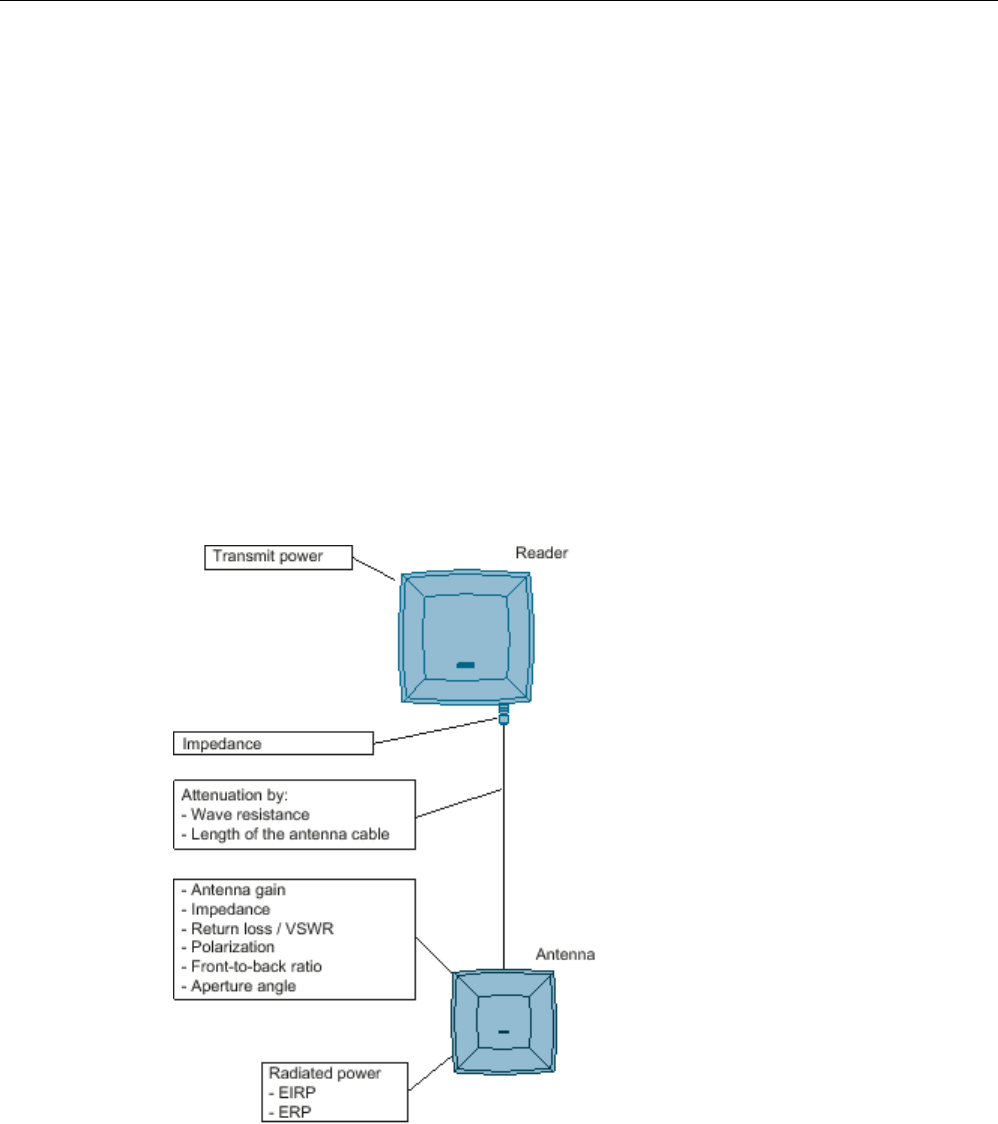
RF600 system planning
4.3 Antenna configurations
SIMATIC RF600
56 System Manual, xx/2014, J31069-D0171-U001-A15-7618
REVIEW
Purpose of this chapter
This chapter enables you to select the appropriate external antenna or cable with
consideration of all important criteria and to carry out the corresponding settings in the
configuration software of the SIMATIC RF600 system. Correct and safe integration into the
SIMATIC RF600 system is only possible following adaptation of all required parameters.
4.3.9.3
General application planning
Overview of the total SIMATIC RF600 system and its influencing factors
The following graphic shows the design of the total SIMATIC RF600 system and the factors
which have an influence on the total system.
You must be aware of these influencing factors and also consider them if you wish to
integrate third-party components such as antennas or cables into the system. These
influencing factors are described in more detail in Sections Antennas (Page 58) and Antenna
cables (Page 69).
Figure 4-4 Overview of total system and influencing factors
When operating the RF600 system, additional influencing factors must also be observed
such as minimum spacing between antennas in the room.

RF600 system planning
4.3 Antenna configurations
SIMATIC RF600
System Manual, xx/2014, J31069-D0171-U001-A15-7618 57
REVIEW
Environmental conditions
NOTICE
Damage to the device
In line with the application, you must take into consideration the mechanical loads (shock
and vibration) as well as environmental demands such as temperature, moisture, UV
radiation.
The device could be damaged if these factors are not considered.
General procedure
Depending on whether you want to use a third-party antenna and/or a third-party antenna
cable with an RF620R, RF630R, RF640R or RF670R reader, you need to select the suitable
components. These instructions will help you to select the components and the settings of
the important parameters in the RF-MANAGER Basic.
There are two different application cases:
● Selection of third-party components:
You want to select suitable third-party components for the SIMATIC RF600 system and
then configure the reader for these components.
● Configuration of existing third-party components:
You already have third-party components (antennas, antenna cables or both) and want to
configure the reader for these components.
Procedure for selecting third-party components
Always proceed in the following order during your considerations and the practical
implementation:
1. Consider which third-party components you wish to use in the SIMATIC RF600 system.
2. Depending on the third-party component required, refer either to section Antennas
(Page 58) or section Antenna cables (Page 69) for the important criteria for selection of
your components. The selection criteria/parameters are sorted in descending relevance.
3. Use the specified equations to calculate your missing parameters, and check whether the
required values are reached (e.g. antenna gain) and that important secondary values
(e.g. cable loss) are not exceeded or undershot.
4. Configure the reader with the parameters of your third-party components. Normally, you
can do this with the RF MANAGER Basic. Depending on the reader, the values can
alternatively also be set via XML protocol or SIMATIC protocol. You will find an overview
of the information for the parameter assignment of all RF600 system readers in the
section Overview of parameterization of RF600 reader (Page 461).

RF600 system planning
4.3 Antenna configurations
SIMATIC RF600
58 System Manual, xx/2014, J31069-D0171-U001-A15-7618
REVIEW
Procedure for configuration of existing third-party components
If you already have third-party components which you wish to integrate into the SIMATIC
RF600 system, proceed as follows:
1. Depending on the third-party component, refer either to Section "Antennas" or Section
"Antenna cables" for the important criteria of your components. The parameters are
sorted in descending relevance.
2. Compare the limits with the data of your antenna or cable vendor.
3. Subsequently proceed exactly as described above in "Procedure for selecting third-party
components" from Paragraph 3. onwards.
4.3.9.4
Antennas
Types of antenna and properties
Basically all types of directional antennas can be considered as third-party antennas for
integration into the SIMATIC RF600 system. Directional antennas have a preferred direction
in which more energy is radiated than in other directions.
RF600 antennas on the other hand, are optimized for operation with RF600 readers and
have all the required approvals.
Antenna parameters
Overview
The properties of an antenna are determined by a large number of parameters. You must be
aware of these properties in order to make the correct selection for your appropriate UHF
antenna. The most important parameters are described below. These important parameters
are described in detail in the following sections. The following parameters describe both the
send and receive functions of the antenna (reciprocity). The antenna is a passive antenna. A
two-way relationship exists.
● Radiated power
● Antenna gain
● Impedance
● Return loss / VSWR
● Power rating
● Polarization
● Front-to-back ratio
● Beam width
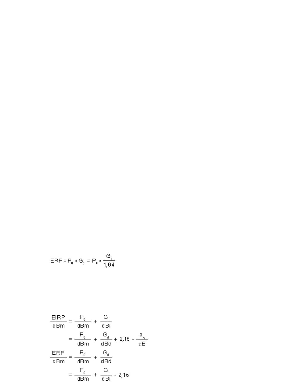
RF600 system planning
4.3 Antenna configurations
SIMATIC RF600
System Manual, xx/2014, J31069-D0171-U001-A15-7618 59
REVIEW
Radiated power
In order to comply with national directives with regard to the radiated power (which differ
depending on the location or country of use), the RF600 readers together with the antenna
cable(s) and antenna(s) must be exactly parameterized or configured.
This means that the product of the transmitted power P0 of the reader and the antenna gain
Gi must always have the correct ratio with regard to the radiated power "EIRP" depending on
the location of use or the permissible frequency band.
Calculation of the radiated power is briefly described below.
Calculation of the radiated power
The radiated power is the total power radiated by the antenna in the room. The isotropic
radiator serves as the physical computing model which uniformly radiates the power into the
room (spherically, i.e. isotropic).
EIRP
Directional antennas combine the radiation, and therefore have a higher power density in the
main beam direction compared to an isotropic radiator. To enable antennas of different
design or Directional characteristic to be compared with one another, the equivalent isotropic
radiated power (EIRP) has been introduced which represents the effective power which must
be applied to an isotropic radiator in order to deliver the same power density in the main
beam direction of the antenna.
"EIRP" is the product of the transmitted power P0 and the antenna gain Gi:
EIRP = P0 * Gi
ERP
Also common is specification of the equivalent radiated power referred to the half-wave
dipole "ERP" (effective radiated power):
Logarithmic and standardized data
Approximate calculations are easier to carry out as additions than as products, therefore the
logarithms are taken for the above equations and the power data standardized to 1 mW and
specified in decibels (dBm or dBi).
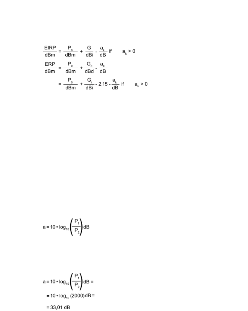
RF600 system planning
4.3 Antenna configurations
SIMATIC RF600
60 System Manual, xx/2014, J31069-D0171-U001-A15-7618
REVIEW
Calculation of the radiated power with consideration of the cable loss ak
If the transmitted power is not applied directly but via a cable with loss aK, this loss should be
compensated such that the same radiated power is obtained.
If the loss is not appropriately compensated, the radiated power is too small.
General preliminary information on the unit "dB"
Requirements
This section provides you with information on the unit "decibel". This knowledge is a
requirement for optimum understanding of the following section. You can ignore this section
if you already have the appropriate knowledge.
Definition
When specifying decibels, the ratios between powers or voltages are not defined directly but
as logarithms. The decibel is therefore not a true unit but rather the information that the
specified numerical value is the decimal logarithm of a ratio of two power or energy variables
P1 and P2 of the same type.
This ratio is defined by the following equation:
Example
If P1 = 200 W and P2 = 100 mW, how large is the ratio a in dB?

RF600 system planning
4.3 Antenna configurations
SIMATIC RF600
System Manual, xx/2014, J31069-D0171-U001-A15-7618 61
REVIEW
Use with other units
As with other units, there are also different versions of the unit for decibel depending on the
reference variable. With this reference, the logarithmic power ratio becomes an absolute
variable. The following table lists the most important combinations in this context with other
units:
Versions of decibel
Description
0 dBm
Power level with the reference variable 1 mW.
dBi Power level with the reference variable on the isotropic spherical
radiator (see also Section Antenna gain (Page 61) ).
The relationship between dBi and dBic is as follows:
dBi = dBic - 3
dBd Power level with the reference variable on the dipole radiator.
The relationship between dBd and dBi is as follows:
dBd = dBi - 2.15
dBic
Power level with the reference variable on the isotropic radiator for
circular antennas.
The relationship between dBi and dBic is as follows:
dBic = dBi + 3
Antenna gain
Definition
The antenna gain specifies the degree to which the antenna outputs or receives its power in
the preferred angle segment.
With this theoretical variable, a comparison is always made with an isotropic spherical
radiator, a loss-free antenna which does not exist in reality. It describes how much power
has to be added to the isotropic spherical radiator so that it outputs the same radiated power
in the preferred direction like the antenna to be considered. The unit for the antenna gain is
therefore specified in dBi (dB isotropic).
The antenna gain is defined for the receive case as the ratio between the power received in
the main beam direction and the received power of the isotropic spherical radiator.
Specifications
You must know the antenna gain in the corresponding frequency band or range. You can
obtain the value of the antenna gain from the technical specifications of your antenna
vendor.
● With a cable loss of 4 dB, a gain ≥ 6 dBi(L) is required since otherwise the maximum
radiated power will not be achieved.
● In the case of antennas used in the FCC area of approval, a gain of at least 6 dBi(L) is
required since otherwise the permissible radiated power of 4 W EIRP will not be reached.
● If the gain is > 6 dBi(L)*, the difference is compensated in accordance with the directives
by reducing the transmitted power.

RF600 system planning
4.3 Antenna configurations
SIMATIC RF600
62 System Manual, xx/2014, J31069-D0171-U001-A15-7618
REVIEW
* (L) is the reference to the linear polarization.
Dependencies
● Frequency dependency:
if a frequency dependency exists in the frequency band used, you must apply the highest
value in each case for the antenna gain. With the cable loss, on the other hand, you must
select the smallest value in each case it frequency dependency exists.
This procedure means that the permissible radiated power will not be exceeded in the
extreme case.
● Dependency on the plane
If the data for the antenna gain are different in the horizontal and vertical planes, you
must use the higher value in each case.
Impedance
Definition
Impedance is understood as the frequency-dependent resistance. The impedances of the
antenna, reader and antenna cables should always be the same. Differences in the
impedance result in mismatching which in turn means that part of the applied signal is
reflected again and that the antenna is not fed with the optimum power.
Specifications
● Only antennas can be used whose connection has a characteristic impedance of Z =
50 Ohm.
● The mechanical design of the coaxial antenna connection is of secondary importance; N,
TNC and SMA plug connectors are usual.
Return loss / VSWR
Definition
Since the impedance at the antenna connection is frequency-dependent, mismatching
automatically occurs with broadband use. This mismatching can be reflected by two
parameters:
● The voltage standing wave ratio VSWR
● The return loss

RF600 system planning
4.3 Antenna configurations
SIMATIC RF600
System Manual, xx/2014, J31069-D0171-U001-A15-7618 63
REVIEW
Voltage standing wave ratio VSWR
The power sent by the transmitter cannot flow unhindered to the antenna and be radiated as
a result of the mismatching described by the VSWR. Part of the power is reflected at the
antenna and returns to the transmitter. The powers in the forward and reverse directions
produce a standing wave which has a voltage maximum and a voltage minimum. The ratio
between these two values is the VSWR (voltage standing wave ratio).
Return loss
The return loss parameter is based on the reflection factor which describes the voltage ratio
between the forward and reverse waves.
Specifications
So that the smallest possible transmitted and received powers are reflected by the antenna
under ideal conditions, you should observe the following data for the VSWR and the return
loss |S11|/ dB in the respective frequency band (865-870 MHz or 902-928 MHz):
● VSWR < 1.24:1 or
● |S11|/ dB ≥ 20 dB
Power rating
Definition
The power rating is understood as the maximum power defined by the vendor with which the
device may be operated.
Specifications
Third-party antennas must be dimensioned for an effective power applied to the antenna
connection of at least 4 Watt.
Polarization
Definition
The polarization parameter describes how the electromagnetic wave is radiated by the
antenna. A distinction is made between linear and circular polarization. With linear
polarization, a further distinction is made between vertical and horizontal polarization.
Specifications
UHF transponders usually have a receive characteristic similar to that of a dipole antenna
which is linearly polarized. Horizontal or vertical polarization is then present depending on
the transponder mounting.
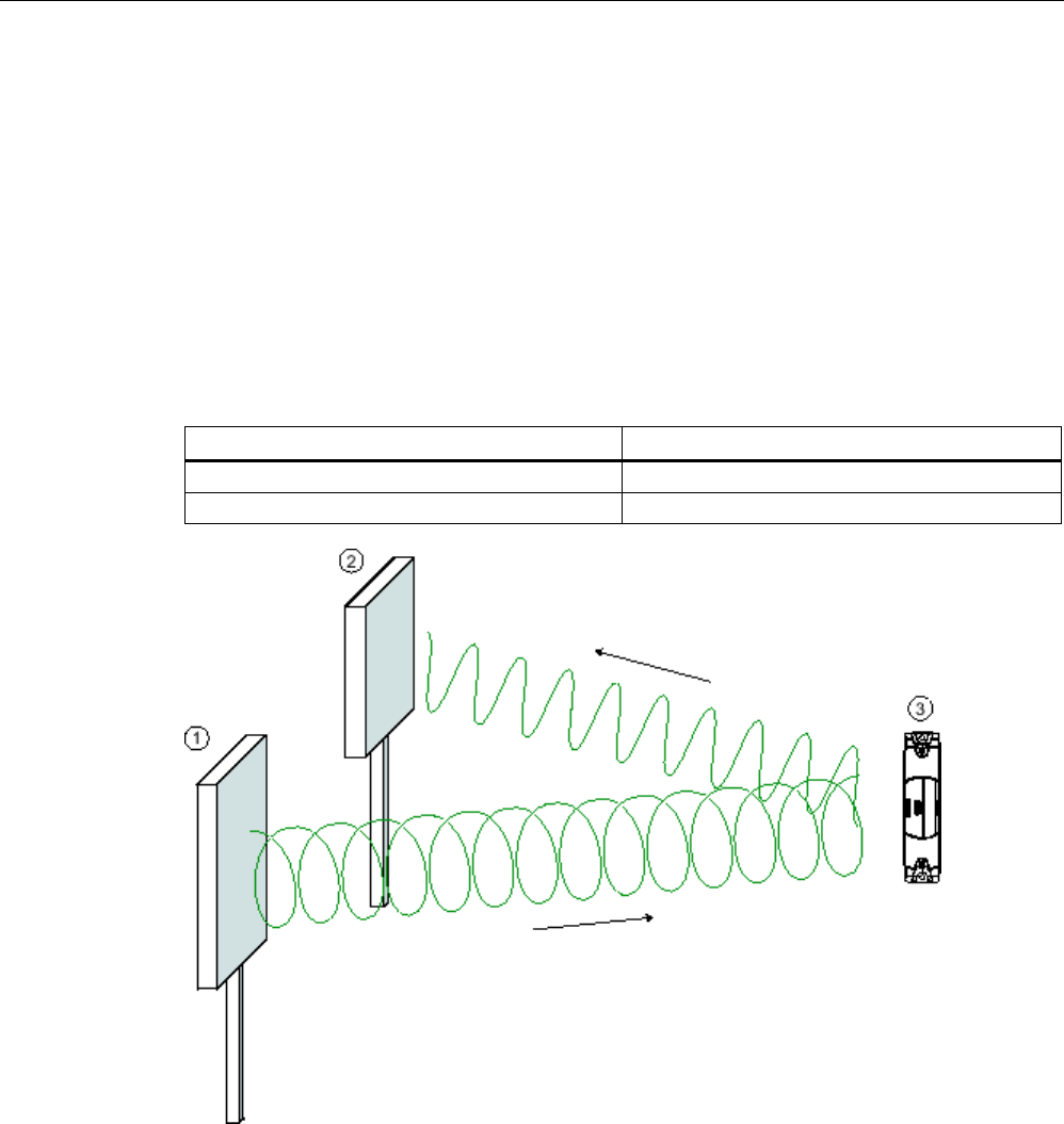
RF600 system planning
4.3 Antenna configurations
SIMATIC RF600
64 System Manual, xx/2014, J31069-D0171-U001-A15-7618
REVIEW
Selection of circular polarized antenna
If the orientation of the transponder is unknown, or if an alternating orientation can be
expected, the transmit and receive antennas must have circular polarization.
When selecting a circular antenna, the polarization purity must be observed in addition to the
polarization direction. A differentiation is made between left-hand and right-hand circular
polarization (LHCP and RHCP). The two types cannot be combined in the same system. On
the other hand, selection of the polarization direction is insignificant if the antenna system of
a transponder is linearly polarized. With actual antennas, elliptical polarization is
encountered rather than the ideal circular polarization. A measure of this is the ratio between
the large and small main axes of the ellipse, the axial ratio (AR), which is frequently specified
as a logarithm.
Axial ratio
AR
Ideal
0 dB
Real
2-3 dB
Figure 4-5 Circular polarization of antenna system and transponder
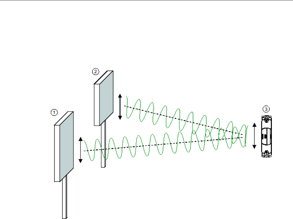
RF600 system planning
4.3 Antenna configurations
SIMATIC RF600
System Manual, xx/2014, J31069-D0171-U001-A15-7618 65
REVIEW
Selection of linear polarized antenna
When using linear polarized antennas, you must always make sure that the transmitter
antenna, receiver antenna and transponder have identical polarizations (vertical or
horizontal). As a result of the principle used, no special requirements need be observed to
suppress the orthogonal components (cross-polarization).
①
Transmitter antenna, vertical polarization
②
Receiver antenna, vertical polarization
③
Transponder dipole
Figure 4-6 Homogenous vertical polarization of antenna system and transponder
Front-to-back ratio
Definition
As a result of their design, directional antennas not only transmit electromagnetic waves in
the main beam direction but also in other directions, particularly in the reverse direction. The
largest possible suppression of these spurious lobes is expected in order to reduce faults
and to keep the influence on other radio fields low. This attenuation of spurious lobes in the
opposite direction to the main beam is called the front-to-back ratio.
Specifications
Requirement: The front-to-back ratio must be ≥ 10 dB. This requirement also applies to
spurious lobes illustrated by the following graphics in Section Half-value width (Page 66).
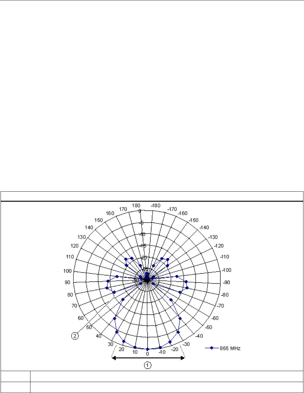
RF600 system planning
4.3 Antenna configurations
SIMATIC RF600
66 System Manual, xx/2014, J31069-D0171-U001-A15-7618
REVIEW
Half-value width
Definition
A further description of the directional characteristic is the beam width. The beam width is
the beam angle at which half the power (-3 dB) is radiated referred to the maximum power.
The antenna gain is directly related to the beam width. The higher the antenna gain, the
smaller the beam angle.
Coupling in ETSI
In ETSI EN 302 208 (release version V1.2.1 2008-06), the radiated power is coupled to the
beam width, i.e.
● Radiated power 500-2000 mW ERP: beam width ≤ 70 degrees
The beam width requirement applies to both the horizontal and vertical planes. The FCC
directives do not envisage coupling with the beam width.
The following graphics show examples of the directional radiation pattern of an antenna in
polar and linear representations for which both the horizontal and vertical planes must be
considered.
Directional radiation pattern in polar representation
① Beam width
②
Spurious lobe
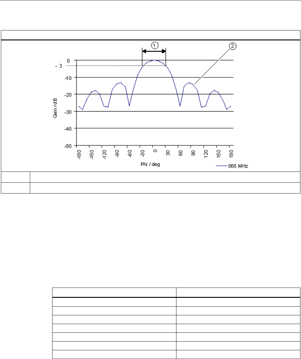
RF600 system planning
4.3 Antenna configurations
SIMATIC RF600
System Manual, xx/2014, J31069-D0171-U001-A15-7618 67
REVIEW
Directional radiation pattern in linear representation
① Beam width
②
Spurious lobe
Interpretation of directional radiation patterns
The following overview table will help you with the interpretation of radiation patterns.
The table shows which dBi values correspond to which read/write ranges (in %): You can
read the radiated power depending on the reference angle from the directional radiation
patterns, and thus obtain information on the read/write range with this reference angle with
regard to a transponder.
The dBr values correspond to the difference between the maximum dBi value and a second
dBi value.
Deviation from maximum antenna gain [dBr]
Read/write range [%]
0
100
-3
70
-6
50
-9
35
-12
25
-15 18
-18
13
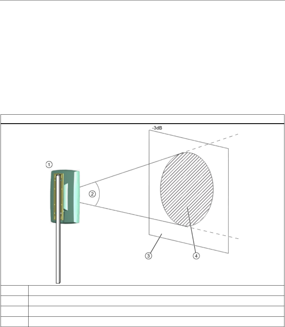
RF600 system planning
4.3 Antenna configurations
SIMATIC RF600
68 System Manual, xx/2014, J31069-D0171-U001-A15-7618
REVIEW
Example
As one can see in the antenna diagrams (polar or linear) above, the maximum antenna gain
0 dB is standardized. The dBr value -3 is shown graphically in both diagrams. At angles of
Phi = ± 35°, the range of the antenna is only 50% of the maximum range.
Specifications
Selection of the beam angle within the approval directives also has effects on the field of
application, since a larger beam angle allows a larger area to be covered by RFID
transponders. The following graphic clarifies the cross-section of the beam cone with the
covered area.
Beam angle: cross-section of the beam cone with the covered area
①
Third-party antenna
②
Beam angle
③
Covered area
④
Activation or reading range
The reading range depends on the horizontal and vertical beam widths in the case of equal
distances from the transmitter antenna. Depending on the mechanical mounting and the ratio
between the vertical beam width ① and the horizontal beam width ②, read areas result as
shown in the following graphic:
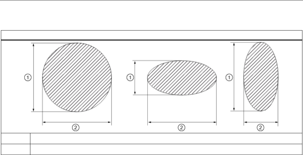
RF600 system planning
4.3 Antenna configurations
SIMATIC RF600
System Manual, xx/2014, J31069-D0171-U001-A15-7618 69
REVIEW
Read area depending on the beam width
①
Vertical beam width
②
Horizontal beam width
4.3.9.5
Antenna cables
Selection criteria
You must observe the criteria listed below when selecting the appropriate antenna cable for
your third-party antenna.
Characteristic impedance
Definition
If the input impedance of a device does not agree with the cable impedance, reflections
occur which reduce the power transmission and can result in the appearance of resonance
and thus to a non-linear frequency response.
Specifications
● You must only use coaxial antenna cables when connecting a third-party antenna.
● This antenna cable must have a nominal characteristic impedance of Z = 50 Ohm.
Antenna cable loss
In order to be able to transmit the available UHF power from the RF600 reader to the
antenna(s), the antenna cable loss must not exceed a value of approx. 4 dB.

RF600 system planning
4.3 Antenna configurations
SIMATIC RF600
70 System Manual, xx/2014, J31069-D0171-U001-A15-7618
REVIEW
Dependency of the cable loss
The cable loss depends on two important factors:
● External characteristics of cable. These includes the cable length, diameter and design.
● As a result of the physical principle, the cable loss is also frequency-dependent, i.e. the
cable loss increases at higher transmitter frequencies. Therefore the cable loss must be
specified in the frequency band from 860 to 960 MHz.
Cable vendors usually provide tables or calculation aids for their types of cable which usually
include the transmitter and receiver frequencies as well as the cable length. Therefore
contact your cable vendor in order to determine the appropriate type of cable using the
approximate value referred to above.
Notes on use
Shielding of the antenna cable
Coaxial antenna cables always have a shielded design and therefore radiate little of the
transmitted power to the environment.
Note
Cable with double shielding
You should therefore preferentially select cable with double shielding since this provides the
best damping.
Bending radius of the antenna cable
The properties of the cable shield are influenced by mechanical loading or bending. You
must therefore observe the static and dynamic bending radii specified by the cable vendor.
Connectors and adapters
You must use connectors and adapters of type "Reverse Polarity R-TNC" (male connector)
for your antenna cables from a third-party supplier in order to ensure correct connection to
the RF600 reader interface.
The figure below shows the standard for a suitable thread:
You can find more information in the catalog data of your cable vendor.

RF600 system planning
4.3 Antenna configurations
SIMATIC RF600
System Manual, xx/2014, J31069-D0171-U001-A15-7618 71
REVIEW
4.3.9.6
Application example
This section contains an example with specific values. Using this example it is possible to
understand how the complete selection procedure for antennas, cables, and adapters as
well as the settings could be carried out on an RF600 system reader.
In the example, it is assumed that you want to use your SIMATIC RF600 system with your
third-party components in Germany (ETSI EN 302 208 V1.4.1).
Procedure
1. Compare the technical specifications of your antenna with the values required by the
SIMATIC RF600 system.
Values
Example antenna
Required values
Values OK?
Frequency range
865 to 870 MHz
865 to 868 MHz
☑
Impedance
50 ohms
50 ohms
☑
VSWR
< 1.5
< 1.24
⃞
Polarization
Circular, right
☑
Antenna gain
8.5 dBi
>6 dBi
☑
Half-value width
horizontal/vertical
63° ≤ 70° ☑
Front-to-back ratio
-18 dB
≥10 dB
☑
Spurious lobe suppression
-16 dB
≥10 dB
☑
Axial ratio
2 dB
≤ 3 dB
☑
Maximum power
6 W
≥4 W
☑
Since the specific VSWR value of the antenna does not agree with the value required by
the system, you must have this value checked. Therefore contact your antenna vendor or
an EMC laboratory.
2. Compare the technical specifications of your cables and connectors with the values
required by the system.
For example, you can use cables of type "LMR-195" from the company "TIMES
MICROWAVE SYSTEMS". Suitable cables have e.g. an outer diameter of 5 mm. The
company offers various designs of cables depending on the requirements. Numerous
connectors are also available for their cables.

RF600 system planning
4.3 Antenna configurations
SIMATIC RF600
72 System Manual, xx/2014, J31069-D0171-U001-A15-7618
REVIEW
Values
Example cable
Required values
Values
OK?
Cable attenuation 36.5 dB / 100 m at 900 MHz
With an assumed length of
10 m, this results in a loss of
3.65 dB.
≤ 4 dB ☑
Impedance
50 ohms
50 ohms
☑
Values
Example connector
Values
OK?
Type of plug on reader side
R-TNC socket
R-TNC plug
☑
Type of plug on antenna side
N socket
N plug
☑
3. Set the following parameter values depending on the reader you are using:
–
Assigning parameters for the RF640R/RF670R using the RF-MANAGER Basic V2
Antenna gain: 8.5 dBi
Cable loss: 4 dB (due to adaptation and attenuation losses of the connectors)
–
Set parameters for the RF640R/RF670R using the XML command "setAntennaConfig"
In the XML command "setAntenneConfig", the following must be set for the antenna
port being used:
(antenna number="1 ... 4"), antenna gain (gain="8.5") and cable loss
(cableLoss="4.0").
Cable loss: 4 dB (due to adaptation and attenuation losses of the connectors)
–
Setting parameters for RF620R/RF630R using SIMATIC commands
Since according to ETSI EN 302 208 V1.4.1 the maximum permissible radiated power
is 2 W ERP, none of the transmit power settings available to the user
(distance_limiting) can cause the required maximum permitted radiated power value to
be exceeded. The exact radiated power of the reader, together with the antenna
cables and antenna used, results from the value used in distance_limiting 0-F and the
calculation in the section "Antenna parameters".
–
Setting parameters for RF650R/RF680R/RF685R with the Web server
Since according to ETSI EN 302 208 V1.4.1 the maximum permissible radiated power
is 2 W ERP, none of the transmit power settings available to the user can cause the
required maximum permitted radiated power value to be exceeded. The exact radiated
power of the reader, together with the antenna cables and antenna used, results from
the value used in and the calculation shown in "Antenna parameters".
4. You then need to have your desired system requirements measured and verified
according to EN 302 308 in an absorber chamber.
You may only use your SIMATIC RF600 system with the new third-party components
when this has been carried out.

RF600 system planning
4.4 Environmental conditions for transponders/tags
SIMATIC RF600
System Manual, xx/2014, J31069-D0171-U001-A15-7618 73
REVIEW
4.4
Environmental conditions for transponders/tags
Basic rules
The transponder/tag must not be placed directly on metal surfaces or on containers of liquid.
For physical reasons, a minimum distance must be maintained between the tag antenna and
conductive material. A minimum distance of 5 cm is recommended. The tag operates better
when the distance is greater (between 5 and 20 cm).
● Tag assembly on non-conductive material (plastic, wood) has a tendency to be less
critical than assembly even on poorly conductive material.
● The best results are achieved on the materials specified by the tag manufacturer.
● You can obtain more detailed information from the tag manufacturer.
4.5
The response of electromagnetic waves in the UHF band
4.5.1
The effect of reflections and interference
Reflections and interference
Electromagnetic waves in the UHF band behave and propagate in a similar manner to light
waves, that is they are reflected from large objects such as ceilings, floors, walls and
windows and interfere with each other. Due to the nature of electromagnetic waves,
interference can lead to wave amplification which can produce an increased reading range.
In the worst case, interference can also result in waves being extinguished which causes
holes in reader coverage.
Reflections can also be beneficial when they cause electromagnetic waves to be routed
around objects to a certain extent (deflection). This can increase the reading probability.
Due to these electromagnetic characteristics, it is extremely difficult in the multiple-reflection
environment that is usually found in the real environment on site, to determine propagation
paths and field strengths for a particular location.
Reducing the effect of reflections/interference on tag identification
● Reducing the transmit power:
To reduce interference to a minimum, we recommend that the transmitter power of the
reader is reduced until it is sufficient for an identification rate of 100%.
● Increasing the number of antennas to 3 or 4:
More antennas in a suitable antenna configuration can prevent gaps in reader coverage.

RF600 system planning
4.5 The response of electromagnetic waves in the UHF band
SIMATIC RF600
74 System Manual, xx/2014, J31069-D0171-U001-A15-7618
REVIEW
4.5.2
Influence of metals
Metal can have an effect on the electromagnetic field depending on the arrangement or
environment. The effect ranges from a hardly determinable influence through to total
blocking of communication. The term metal in this context also includes metallized materials
that are either coated with metal or shot through with metal to such an extent that UHF
radiation cannot penetrate or only to a minimal extent.
The effect of metal on the electromagnetic field can be prevented as follows:
● Do not mount tags on metal.
● Do not place metallic or conducting objects in the propagation field of the antenna and
transponder.
Tags mounted directly onto metal
In general, tags must not be mounted directly onto metallic surfaces. Due to the nature of the
magnetic field, a minimum distance must be maintained between the tag antenna and
conductive materials. For further details on the special case of attaching transponders to
electrically conducting materials, see Section SIMATIC RF620T (Page 375) and
SectionSIMATIC RF640T Gen 2 (Page 418) .
In the case of transponders that are not designed for mounting on metallic materials, the
minimum permissible distance from metal is 5 cm. The larger the distance between the
transponder and the metallic surface, the better the function of the transponder.
4.5.3
Influence of liquids and non-metallic substances
Non-metallic substances can also affect the propagation of electromagnetic waves.
When non-metallic substances or objects are located in the propagation field that can absorb
UHF radiation, these can alter the antenna field depending on their size and distance and
can even extinguish the field entirely.
The high-frequency damping effect of water and materials with a water content, ice and
carbon is high. Electromagnetic energy is partly reflected and absorbed.
Liquids and petroleum-based oils have low HF damping. Electromagnetic waves penetrate
the liquid and are only slightly weakened.
4.5.4
Influence of external components
The R&TTE guideline and the relevant standards govern the electromagnetic compatibility
requirements. This also concerns the external components of the RF600 system. Even
though the requirements for electromagnetic compatibility have been specified, various
components will still interfere with each other.
The performance of the RF600 system is highly dependent on the electromagnetic
environment of the antennas.

RF600 system planning
4.6 Regulations applicable to frequency bands
SIMATIC RF600
System Manual, xx/2014, J31069-D0171-U001-A15-7618 75
REVIEW
Reflections and interference
On the one hand, antenna fields will be weakened by absorbing materials and reflected by
conducting materials. When electromagnetic fields are reflected, the antenna field and
reflecting fields overlap (interference).
External components in the same frequency band
On the other hand, external components can transmit on the same frequency band as the
reader. Or the external components can transmit in different frequency bands with side
bands that overlap with the frequency band of the reader. This results in a reduction of the
"signal-to-noise" ratio which reduces the performance of an RF600 system.
If a DECT station that is transmitting in the 2 GHz band, for example, is located in the
receiving range of an antenna of the RF600 system, the performance of the write and read
accesses to the transponder will be affected.
4.6
Regulations applicable to frequency bands
4.6.1
Overview of the frequency bands
The current country-specific frequency bands and approvals can be found on the Internet
page of EPCglobal®:
EPCglobal (http://www.gs1.org/docs/epcglobal/UHF_Regulations.pdf)
You will find a list of all the country-specific approvals for SIMATIC RFID systems on the
following Internet page:
Wireless approvals of SIMATIC RFID systems (http://www.siemens.com/rfid-approvals)
The following sections describe the specifications of the applicable standard, the precise
channel assignment and the prescribed procedures for the countries/regions China, Europe
and USA in detail.
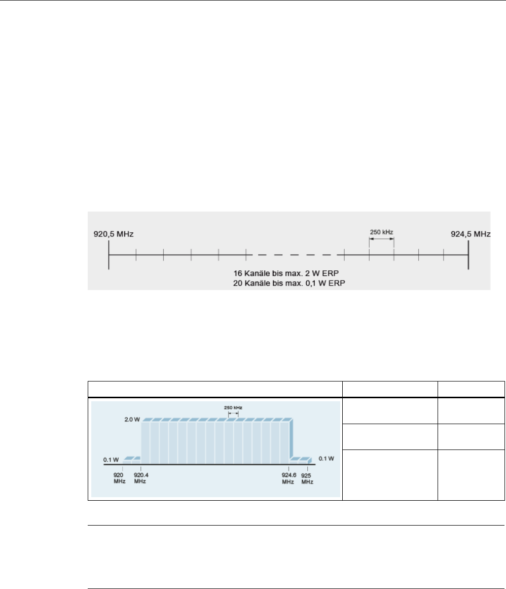
RF600 system planning
4.6 Regulations applicable to frequency bands
SIMATIC RF600
76 System Manual, xx/2014, J31069-D0171-U001-A15-7618
REVIEW
4.6.2
Regulations for UHF frequency bands in China
Regulations for UHF bands
FCC (Federal Communications Commission)
● UHF band: 920.5 to 924.5 MHz
● Radiated power: max. 2 W (ERP)
● Channel spacing: 250 kHz
● Number of channels: 16
● Frequency hopping
Channel assignment
The UHF band from 920.5 to 924.5 MHz with 16 RFID channels occupies:
Table 4- 4 Channel assignment for the UHF band China
Sub bands
Frequency range
Power
920.125 to 920.375
MHz
0.1 W ERP
920.625 to 924.375
MHz
2.0 W ERP
924.625 to 924.875
MHz
0.1 W ERP
Note
Frequency band is restricted
Note that the frequency bands 920.125
to 920.375 MHz and 924.625 to 924.875 MHz are
not available.
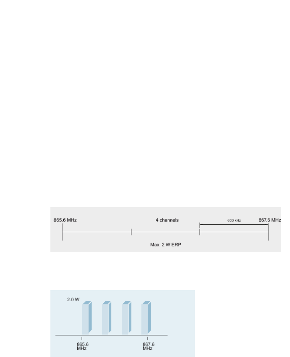
RF600 system planning
4.6 Regulations applicable to frequency bands
SIMATIC RF600
System Manual, xx/2014, J31069-D0171-U001-A15-7618 77
REVIEW
Frequency hopping
This technique is intended to prevent mutual interference between readers. The reader
changes its transmission channel in a random or programmed sequence (FHSS). With 16
available channels that can be used simultaneously at up to 2000 mW (ERP), the probability
of two readers operating on the same frequency is reduced.
This revision of the European standard EN 302208 also supports RFID systems with
numerous readers operating simultaneously. Within the frequency spectrum, 4 exclusive
RFID channels are defined.
Regulations for UHF bands according to EN 302208 as of V1.2.1
ETSI (European Telecommunications Standards Institute)
● UHF band: 865 to 868 MHz
● Radiated power: max. 2 W (ERP)
● Channel bandwidth: 200 KHz, channel spacing: 600 kHz
● Number of channels: 4
– 865.7
– 866.3
– 866.9
– 867.5
Channel assignment
The UHF band from 865 to 868 MHz with 4 RFID channels occupies:
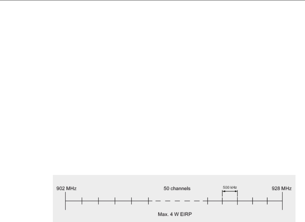
RF600 system planning
4.6 Regulations applicable to frequency bands
SIMATIC RF600
78 System Manual, xx/2014, J31069-D0171-U001-A15-7618
REVIEW
Validity
Note that readers are operated with this setting since November 4, 2008 (publication of the
standard in the Official Journal of the European Union).
4.6.3
Regulations for UHF frequency bands in the USA
Regulations for UHF bands
FCC (Federal Communications Commission)
● UHF band: 902 to 928 MHz
● Radiated power: max. 4 W (EIRP)
● Channel spacing: 500 kHz
● Number of channels: 50
● Frequency hopping
Frequency hopping
This technique is intended to prevent mutual interference between readers. The reader
changes its transmission channel in a random or programmed sequence (FHSS). 50
available channels mean that the probability is low that two readers will be operating on the
same frequency.

RF600 system planning
4.7 Guidelines for electromagnetic compatibility (EMC)
SIMATIC RF600
System Manual, xx/2014, J31069-D0171-U001-A15-7618 79
REVIEW
4.7
Guidelines for electromagnetic compatibility (EMC)
4.7.1
Overview
These EMC Guidelines answer the following questions:
● Why are EMC guidelines necessary?
● What types of external interference have an impact on the system?
● How can interference be prevented?
● How can interference be eliminated?
● Which standards relate to EMC?
● Examples of interference-free plant design
The description is intended for "qualified personnel":
● Project engineers and planners who plan system configurations with RFID modules and
have to observe the necessary guidelines.
● Fitters and service engineers who install the connecting cables in accordance with this
description or who rectify defects in this area in the event of interference.
Note
Failure to observe notices drawn to the reader's attention can result in dangerous
conditions in the plant or the destruction of individual components or the entire plant.
4.7.2
What does EMC mean?
The increasing use of electrical and electronic devices is accompanied by:
● Higher component density
● More switched power electronics
● Increasing switching rates
● Lower power consumption of components due to steeper switching edges
The higher the degree of automation, the greater the risk of interaction between devices.
Electromagnetic compatibility (EMC) is the ability of an electrical or electronic device to
operate satisfactorily in an electromagnetic environment without affecting or interfering with
the environment over and above certain limits.

RF600 system planning
4.7 Guidelines for electromagnetic compatibility (EMC)
SIMATIC RF600
80 System Manual, xx/2014, J31069-D0171-U001-A15-7618
REVIEW
EMC can be broken down into three different areas:
● Intrinsic immunity to interference:
immunity to internal electrical disturbance
● Immunity to external interference:
immunity to external electromagnetic disturbance
● Degree of interference emission:
emission of interference and its effect on the electrical environment
All three areas are considered when testing an electrical device.
The RFID modules are tested for conformity with the limit values required by the CE and
RTTE guidelines. Since the RFID modules are merely components of an overall system, and
sources of interference can arise as a result of combining different components, certain
guidelines have to be followed when setting up a plant.
EMC measures usually consist of a complete package of measures, all of which need to be
implemented in order to ensure that the plant is immune to interference.
Note
The plant manufacturer is responsible for the observance of the EMC guidelines; the plant
operator is responsible for radio interference suppression in the overall plant.
All measures taken when setting up the plant
prevent expensive retrospective modifications
and interference suppression measures.
The plant operator must comply with the locally applicable laws and regulations. They are
not covered in this document.
4.7.3
Basic rules
It is often sufficient to follow a few elementary rules in order to ensure electromagnetic
compatiblity (EMC).
The following rules must be observed:
Shielding by enclosure
● Protect the device against external interference by installing it in a cabinet or housing.
The housing or enclosure must be connected to the chassis ground.
● Use metal plates to shield against electromagnetic fields generated by inductances.
● Use metal connector housings to shield data conductors.

RF600 system planning
4.7 Guidelines for electromagnetic compatibility (EMC)
SIMATIC RF600
System Manual, xx/2014, J31069-D0171-U001-A15-7618 81
REVIEW
Wide-area ground connection
● Plan a meshed grounding concept.
● Bond all passive metal parts to chassis ground, ensuring large-area and low-HF-
impedance contact.
● Establish a large-area connection between the passive metal parts and the central
grounding point.
● Don't forget to include the shielding bus in the chassis ground system. That means the
actual shielding busbars must be connected to ground by large-area contact.
● Aluminium parts are not suitable for ground connections.
Plan the cable installation
● Break the cabling down into cable groups and install these separately.
● Always route power cables, signal cables and HF cables through separated ducts or in
separate bundles.
● Feed the cabling into the cabinet from one side only and, if possible, on one level only.
● Route the signal cables as close as possible to chassis surfaces.
● Twist the feed and return conductors of separately installed cables.
● Routing HF cables:
avoid parallel routing of HF cables.
● Do not route cables through the antenna field.
Shielding for the cables
● Shield the data cables and connect the shield at both ends.
● Shield the analog cables and connect the shield at one end, e.g. on the drive unit.
● Always apply large-area connections between the cable shields and the shielding bus at
the cabinet inlet and make the contact with clamps.
● Feed the connected shield through to the module without interruption.
● Use braided shields, not foil shields.
Line and signal filter
● Use only line filters with metal housings
● Connect the filter housing to the cabinet chassis using a large-area low-HF-impedance
connection.
● Never fix the filter housing to a painted surface.
● Fix the filter at the control cabinet inlet or in the direction of the source.
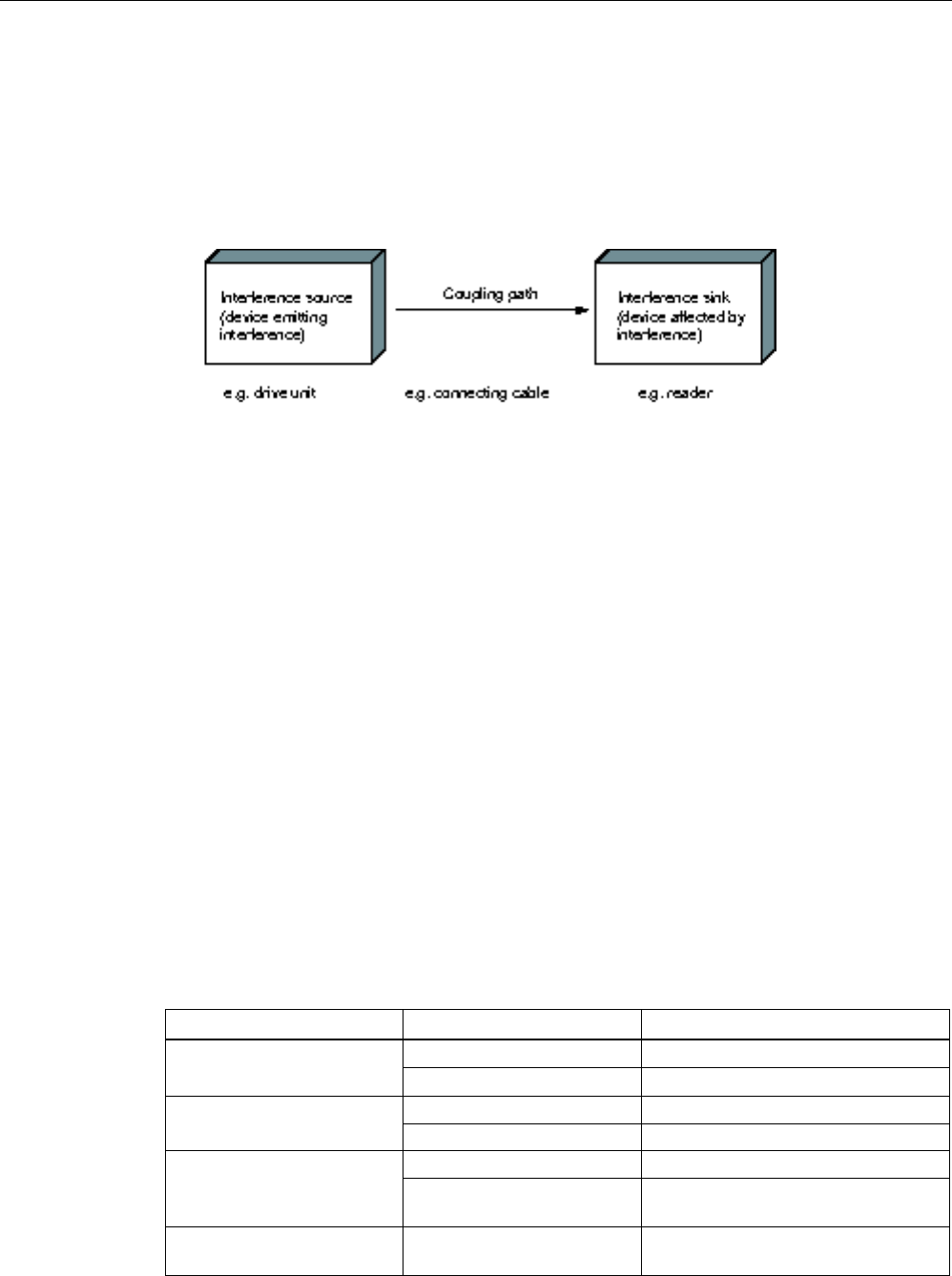
RF600 system planning
4.7 Guidelines for electromagnetic compatibility (EMC)
SIMATIC RF600
82 System Manual, xx/2014, J31069-D0171-U001-A15-7618
REVIEW
4.7.4
Propagation of electromagnetic interference
Three components have to be present for interference to occur in a system:
● Interference source
● Coupling path
● Interference sink
Figure 4-7 Propagation of interference
If one of the components is missing, e.g. the coupling path between the interference source
and the interference sink, the interference sink is unaffected, even if the interference source
is transmitting a high level of noise.
The EMC measures are applied to all three components, in order to prevent malfunctions
due to interference. When setting up a plant, the manufacturer must take all possible
measures in order to prevent the occurrence of interference sources:
● Only devices fulfilling limit class A of VDE 0871 may be used in a plant.
● Interference suppression measures must be introduced on all interference-emitting
devices. This includes all coils and windings.
● The design of the system must be such that mutual interference between individual
components is precluded or kept as small as possible.
Information and tips for plant design are given in the following sections.
Interference sources
In order to achieve a high level of electromagnetic compatibility and thus a very low level of
disturbance in a plant, it is necessary to recognize the most frequent interference sources.
These must then be eliminated by appropriate measures.
Table 4- 5 Interference sources: origin and effect
Interference source
Interference results from
Effect on the interference sink
Contactor,
electronic valves
Contacts
System disturbances
Coils
Magnetic field
Electrical motor
Collector
Electrical field
Winding
Magnetic field
Electric welding device
Contacts
Electrical field
Transformer Magnetic field, system disturbance,
transient currents
Power supply unit, switched-
mode
Circuit Electrical and magnetic field, system
disturbance

RF600 system planning
4.7 Guidelines for electromagnetic compatibility (EMC)
SIMATIC RF600
System Manual, xx/2014, J31069-D0171-U001-A15-7618 83
REVIEW
Interference source
Interference results from
Effect on the interference sink
High-frequency appliances
Circuit
Electromagnetic field
Transmitter
(e.g. professional mobile
radio)
Antenna Electromagnetic field
Ground or reference potential
difference
Voltage difference Transient currents
Operator Static charge
Electrical discharge currents, electrical
field
Power cable Current flow Electrical and magnetic field, system
disturbance
High-voltage cable
Voltage difference
Electrical field
What interference can affect RFID?
Interference source
Cause
Remedy
Switched-mode power supply Interference emitted from the
current infeed
Replace the power supply
Interference injected through
the cables connected in
series
Cable is inadequately
shielded
Better cable shielding
The reader is not connected
to ground.
Ground the reader
HF interference over the
antennas
caused by another reader • Position the antennas further
apart.
• Erect suitable damping materials
between the antennas.
• Reduce the power of the readers.
Please follow the instructions in the
section
Installation guidelines/reducing
the effects of metal
4.7.5
Equipotential bonding
Potential differences between different parts of a plant can arise due to the different design
of the plant components and different voltage levels. If the plant components are connected
across signal cables, transient currents flow across the signal cables. These transient
currents can corrupt the signals.
Proper equipotential bonding is thus essential.
● The equipotential bonding conductor must have a sufficiently large cross section (at least
10 mm2).
● The distance between the signal cable and the associated equipotential bonding
conductor must be as small as possible (antenna effect).
● A fine-strand conductor must be used (better high-frequency conductivity).
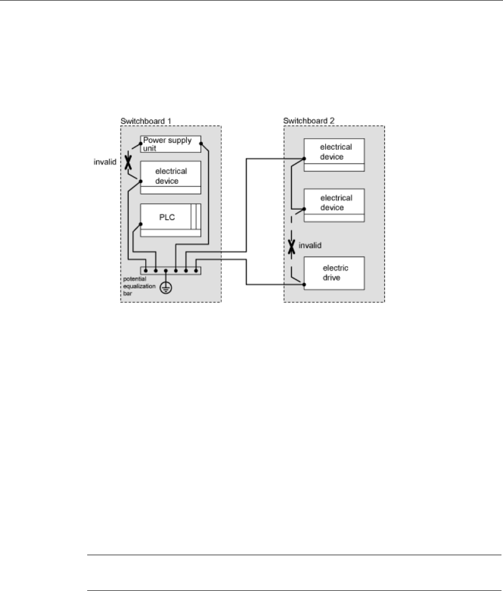
RF600 system planning
4.7 Guidelines for electromagnetic compatibility (EMC)
SIMATIC RF600
84 System Manual, xx/2014, J31069-D0171-U001-A15-7618
REVIEW
● When connecting the equipotential bonding conductors to the centralized equipotential
bonding strip (EBS), the power components and non-power components must be
combined.
● The equipotential bonding conductors of the separate modules must lead directly to the
equipotential bonding strip.
Figure 4-8 Equipotential bonding (EBS = Equipotential bonding strip)
The better the equipotential bonding in a plant, the smaller the chance of interference due to
fluctuations in potential.
Equipotential bonding should not be confused with protective earthing of a plant. Protective
earthing prevents the occurrence of excessive shock voltages in the event of equipment
faults whereas equipotential bonding prevents the occurrence of differences in potential.
4.7.6
Cable shielding
Signal cables must be shielded in order to prevent coupling of interference.
The best shielding is achieved by installing the cables in steel tubes. However, this is only
necessary if the signal cable is routed through an environment prone to particular
interference. It is usually adequate to use cables with braided shields. In either case,
however, correct connection is vital for effective shielding.
Note
An unconnected or incorrectly connected
shield has no shielding effect.
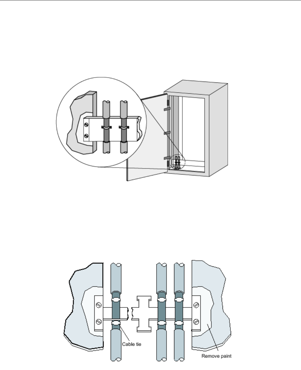
RF600 system planning
4.7 Guidelines for electromagnetic compatibility (EMC)
SIMATIC RF600
System Manual, xx/2014, J31069-D0171-U001-A15-7618 85
REVIEW
As a rule:
● For analog signal cables, the shield should be connected at one end on the receiver side
● For digital signals, the shield should be connected to the enclosure at both ends
● Since interference signals are frequently within the HF range (> 10 kHz), a large-area HF-
proof shield contact is necessary
Figure 4-9 Cable shielding
The shielding bus should be connected to the control cabinet enclosure in a manner allowing
good conductance (large-area contact) and must be situated as close as possible to the
cable inlet. The cable insulation must be removed and the cable clamped to the shielding
bus (high-frequency clamp) or secured using cable ties. Care should be taken to ensure that
the connection allows good conductance.
Figure 4-10 Connection of shielding bus
The shielding bus must be connected to the PE busbar.
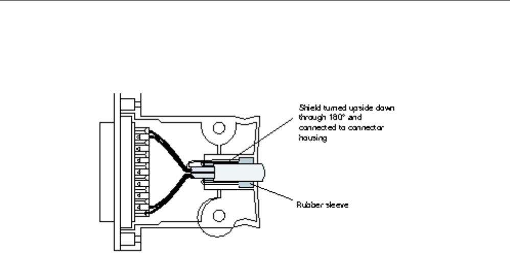
RF600 system planning
4.7 Guidelines for electromagnetic compatibility (EMC)
SIMATIC RF600
86 System Manual, xx/2014, J31069-D0171-U001-A15-7618
REVIEW
If shielded cables have to be interrupted, the shield must be continued via the corresponding
connector housing. Only suitable connectors may be used for this purpose.
Figure 4-11 Interruption of shielded cables
If intermediate connectors, which do not have a suitable shield connection, are used, the
shield must be continued by fixing cable clamps at the point of interruption. This ensures a
large-area, HF-conducting contact.

SIMATIC RF600
System Manual, xx/2014, J31069-D0171-U001-A15-7618 87
REVIEW
Readers
5
5.1
Overview
The following table shows the most important features of the stationary RF600 readers at a
glance:
Table 5- 1 Characteristics of the RF620R, RF630R, RF640R and RF670R readers
Characteristics
SIMATIC RF670R
SIMATIC RF640R
SIMATIC RF630R
SIMATIC RF620R
Air interface / standards
supported
EPCglobal Class 1
Gen 2
EPCglobal Class 1
Gen 2
EPCglobal Class 1
Gen 2
EPCglobal Class 1
Gen 2
ETSI variant
Available
Available
Available
Available
FCC variant
Available
Available
Available
Available
CMIIT variant
Available
Available
Available
Available
LEDs
1
1
1
1
Interfaces
Number of external
antennas via RTNC
4 1 2 1
Available internal
antennas
- 1 - 1
Ethernet 1 x RJ-45 connector
according to
IEC PAS 61076-3-
117
1 x RJ-45 connector
according to
IEC PAS 61076-3-
117
- -
RS-232
-
-
-
-
RS-422 - - 1 x plug
(M12, 8-pin)
1 x plug
(M12, 8-pin)
Digital inputs 4 (M12, 12-pin)
log "0": 0…7 V
log "1": 15…24 V
2 (M12, 8-pin)
log "0": 0…7 V
log "1": 15…24 V
- -
Digital outputs (short-
circuit proof)
4 (M12, 12-pin)
24 V; 0.5 A each
2 (M12, 8-pin)
24 V; 0.5 A each
- -
Power supply 24 VDC (M12, 4-pin)
20 to 30 V (2.2 A)
external
24 VDC (M12, 4-pin)
20 to 30 V (2.2 A)
external
via CM
via CM
Max. radiated power
ETSI and CMIIT
in ERP
2 W ERP 1.6 W ERP 1)
2 W ERP
1.2 W ERP 0.8 W ERP 1)
1.2 W ERP
Max. radiated power
FCC
in EIRP
4 W EIRP 3.3 W EIRP 1)
4 W EIRP
2.0 W EIRP 1.3 W EIRP 1)
2 W EIRP

Readers
5.1 Overview
SIMATIC RF600
88 System Manual, xx/2014, J31069-D0171-U001-A15-7618
REVIEW
Characteristics
SIMATIC RF670R
SIMATIC RF640R
SIMATIC RF630R
SIMATIC RF620R
max. transmit power
ETSI and CMIIT
30 dBm
1 W
30 dBm
1 W
27 dBm
0.5 W
27 dBm
0.5 W
max. transmit power
FCC
31 dBm
1.25 W
31 dBm
1.25 W
27 dBm
0.5 W
27 dBm
0.5 W
max. transmission rate of
the communications
interface
10/100 Mbps 10/100 Mbps 115.2 kbps 115.2 kbps
Max. data rate
reader to transponder
80 kbps (ETSI)
160 kbps (FCC)
80 kbps (ETSI)
160 kbps (FCC)
40 kbps 40 kbps
Max. data rate
transponder to reader
160 kbps (ETSI)
320 kbps (FCC)
160 kbps (ETSI)
320 kbps (FCC)
160 kbps 160 kbps
1) internal antenna
Table 5- 2 Characteristics of the RF650R, RF680R and RF685R readers
Characteristics
SIMATIC RF650R
SIMATIC RF680R
SIMATIC RF685R
Air interface / standards
supported
EPCglobal Class 1
Gen 2
EPCglobal Class 1
Gen 2
EPCglobal Class 1
Gen 2
ETSI variant
Available
Available
Available
FCC variant
Available
Available
Available
CMIIT variant
Available
Available
Available
LEDs
6
17
17
Interfaces
Number of external
antennas via RTNC
4 4 1
Available internal
antennas
- - 1
Ethernet 1 x RJ-45 connector
according to
IEC PAS 61076-3-
117
2 x M12 connector
(4-pin)
2 x M12 connector
(4-pin)
RS-232
-
-
-
RS-422 1 x plug
(M12, 8-pin)
1 x plug
(M12, 8-pin)
1 x plug
(M12, 8-pin)
Digital inputs 4 (M12, 12-pin)
log "0": 0…7 V
log "1": 15…24 V
4 (M12, 12-pin)
log "0": 0…7 V
log "1": 15…24 V
4 (M12, 12-pin)
log "0": 0…7 V
log "1": 15…24 V
Digital outputs (short-
circuit proof)
4 (M12, 12-pin)
24 V; 1.0 A each
4 (M12, 12-pin)
24 V; 1.0 A each
4 (M12, 12-pin)
24 V; 1.0 A each
Power supply 24 VDC (M12, 8-pin)
20 to 30 V (2.2 A)
external
24 VDC (M12, 8-pin)
20 to 30 V (2.2 A)
external
24 VDC (M12, 8-pin)
20 to 30 V (2.2 A)
external

Readers
5.1 Overview
SIMATIC RF600
System Manual, xx/2014, J31069-D0171-U001-A15-7618 89
REVIEW
Characteristics
SIMATIC RF650R
SIMATIC RF680R
SIMATIC RF685R
Max. radiated power
ETSI and CMIIT
in ERP
2 W ERP 2 W ERP 2 W ERP 1)
2 W ERP
Max. radiated power
FCC
in EIRP
3 W EIRP 4 W EIRP 4 W EIRP 1)
4 W EIRP
max. transmit power
ETSI and CMIIT
30 dBm
1 W
33 dBm
2 W
33 dBm
2 W
max. transmit power
FCC
30 dBm
1 W
33 dBm
2 W
33 dBm
2 W
max. transmission rate of
the communications
interface
10/100 Mbps 10/100 Mbps 115.2 kbps
Max. data rate
reader to transponder
300 kbps 300 kbps 300 kbps
Max. data rate
transponder to reader
80 kbps 80 kbps 80 kbps
1) internal antenna
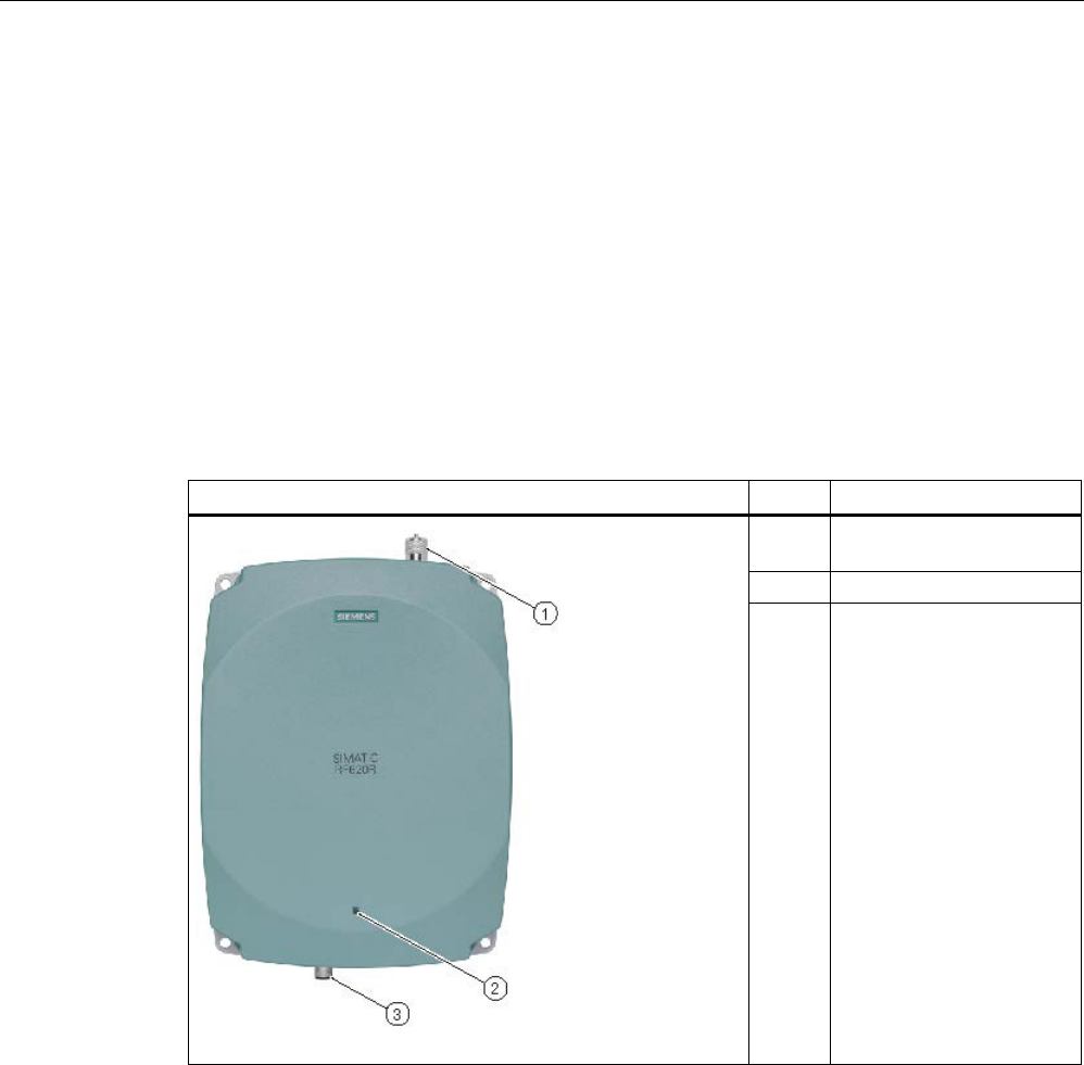
Readers
5.2 RF620R reader
SIMATIC RF600
90 System Manual, xx/2014, J31069-D0171-U001-A15-7618
REVIEW
5.2
RF620R reader
5.2.1
Description
The SIMATIC RF620R is a stationary reader in the UHF frequency band with an integrated
circular polarized antenna. For readers with the new hardware version (MLFB: 6GT2811-
5BA00-xAA1), a maximum of one external UHF RFID antenna can be connected via a TNC
reverse connector as an alternative to the integrated antenna.
The maximum HF power output is 0.5 W at the reader output. The SIMATIC RF620R is
connected to a SIMATIC S7 controller via an ASM interface module. The degree of
protection is IP65.
Pos.
Description
(1) TNC-reverse interface for
connection of ANT
(2)
LED operating display
(3) RS 422 interface
(8-pin M12 connector)

Readers
5.2 RF620R reader
SIMATIC RF600
System Manual, xx/2014, J31069-D0171-U001-A15-7618 91
REVIEW
5.2.1.1
Ordering data
Ordering data RF620R
Product
Article number
RF620R (ETSI) reader for EU, EFTA, Turkey
6GT2811-5BA00-0AA0
RF620R (FCC) reader for North America
6GT2811-5BA00-1AA0
RF620R (CMIIT) reader for China
6GT2811-5BA00-2AA1
Ordering data accessories
Product
Article number
Connecting cable
• RS°422, M12 plug, 8-pin socket: 2 m
• RS°422, M12 plug, 8-pin socket: 5 m
• RS°422, M12 plug, 8-pin socket: 10 m
• RS°422, M12 plug, 8-pin socket: 20 m
• RS°422, M12 plug, 8-pin socket: 50 m
• 6GT2891-0FH20
• 6GT2891-0FH50
• 6GT2891-0FN10
• 6GT2891-0FN20
• 6GT2891-0FN50
Antenna mounting kit
6GT2890-0AA00
Set of protective caps
Contains 3 protective caps for antenna output and one
protective cap for digital I/O interface (required for IP65
degree of protection when some connectors are unused)
6GT2898-4AA00
RFID DVD "Software & Documentation"
6GT2080-2AA20
5.2.1.2
Status display
The device is equipped with a three colored LED. The LED can be lit in green, red or yellow.
The meaning of the indication changes in accordance with the color and state (on, off,
flashing) of the LED:
Green
LED
Red LED
Yellow
LED
Meaning
Off
Off
Off
The device is starting up.
Flashing
Off
Off
The device is ready. The antenna is switched off.
On
Off
Off
The device is ready. The antenna is switched on.
Off Off On "With presence": At least one tag is in the field.
"Without presence": Communication with a tag is active.
Off Flashing Off Reader is not active, a serious error has occurred. In addition, this LED also indicates
the fault status through the number of flashing pulses. Reboot (operating voltage Off
→ On is necessary).
The LED flashes once for the 'INACTIVE' status, rebooting is
not
necessary in this
case.

Readers
5.2 RF620R reader
SIMATIC RF600
92 System Manual, xx/2014, J31069-D0171-U001-A15-7618
REVIEW
For more detailed information on the flash codes of the reader see section Error messages
and flash codes for RF620R/RF630R (Page 469)
Note
LED not lit yellow?
If the LED does not light up yellow even though a tag is located within the field, common
causes are:
•
Incorrect configuration in the init_run command, or init_run command was not executed
(see "Configuration Manual RF620R/RF630R")
•
Parameter assignment is incorrect (black list, RSSI threshold)
•
Antenna is switched off
•
A tag is used, that is not compatible with the reader protocol (EPC Global Class 1 Gen 2).
•
Tag is defective
•
Reader or antenna has a defect
•
Tag is not in the field of radiation of the transmit antenna
5.2.1.3
Pin assignment of the RS422 interface
Pin
Pin
Device end
8-pin M12
Assignment
1
+ 24 V
2
- Transmit
3
0 V
4
+ Transmit
5
+ Receive
6
- Receive
7
Unassigned
8 Earth (shield)
The knurled bolt of the M12 plug is not connected to the shield (on the reader side).
Note
You must therefore not use any SIMATIC connecting cables that use the angled M12 plug.
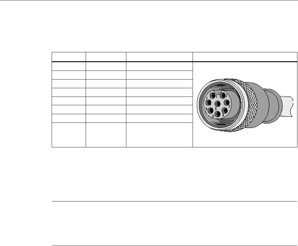
Readers
5.2 RF620R reader
SIMATIC RF600
System Manual, xx/2014, J31069-D0171-U001-A15-7618 93
REVIEW
5.2.1.4
Pin assignment of the connecting cable
Table 5- 3 RS 422 - on reader side
M12 pin
Core color
Pin assignment
View of M12 socket
1
white
24 VDC
2
brown
TX neg
3
green
GND
4
yellow
TX pos
5
Gray
RX pos
6
pink
RX neg
7
blue
Not assigned
8 red Earth (shield)
Comment
This cable has an 8-pin M12 connector at one end and the other cable end is 'open'. There
are 8 color-coded single cores there for connecting to external devices. There are different
cable lengths in the product range (3 m to 50 m). Long cables can be reduced if necessary.
Note
For long cables: Adapt supply voltage and data rate accordingly
Note that with long cables in particular, the supply voltage of 24 V DC must always be
applied. Note also that the data rate on the serial
interface must, if necessary, be reduced.
(See "Configuration Manual RF620R/RF630R")
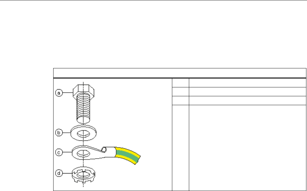
Readers
5.2 RF620R reader
SIMATIC RF600
94 System Manual, xx/2014, J31069-D0171-U001-A15-7618
REVIEW
5.2.1.5
Grounding connection
The RF620R can be electrically connected to the ground potential through a contact washer.
The tightening torque must be increased in this case to ensure that electrical contact is made
(2.7 Nm).
Ground connection
(a)
Hexagon-head screw
(b)
Plain washer
(c)
Cable lugs
(d) Contact washer:
Use contact washers according to the
Siemens standard SN 70093-6-FSt-flNnnc-
480h for ground connection,
Siemens item No.: H70093-A60-Z3
5.2.2
Planning application
5.2.2.1
Minimum mounting clearances of two readers
The RF620R has a circular polarized antenna. At 500 mW ERP radiated power, due to the
opening angle of the antennas, their fields can overlap considerably. It is no longer possible
to clarify in which antenna field access to the data of a tag is performed.
In order to avoid this, always keep a minimum distance of 3 m between two readers with the
maximum radiated power of 500 mW ERP.
Dense Reader Mode (DRM)
The readers can also interfere with each other (secondary fields), if the channels (Reader
TX, Transponder TX) overlap. In order to prevent a transponder channel overlapping with a
reader channel, we recommend that the Dense Reader Mode (DRM) is used.
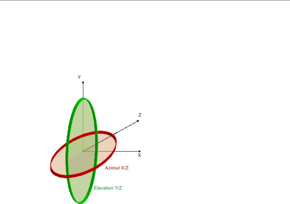
Readers
5.2 RF620R reader
SIMATIC RF600
System Manual, xx/2014, J31069-D0171-U001-A15-7618 95
REVIEW
5.2.2.2
Antenna diagram for RF620R (ETSI)
The following radiation diagrams show the directional radiation pattern of the internal
antenna of the RF620R (ETSI) reader. For the spatial presentation of the directional
characteristics, the vertical plane (Azimuth section) as well as the horizontal plane (elevation
section) must be considered. This results in a spatial image of the directional radiation
pattern of the antenna with its main and auxiliary fields.
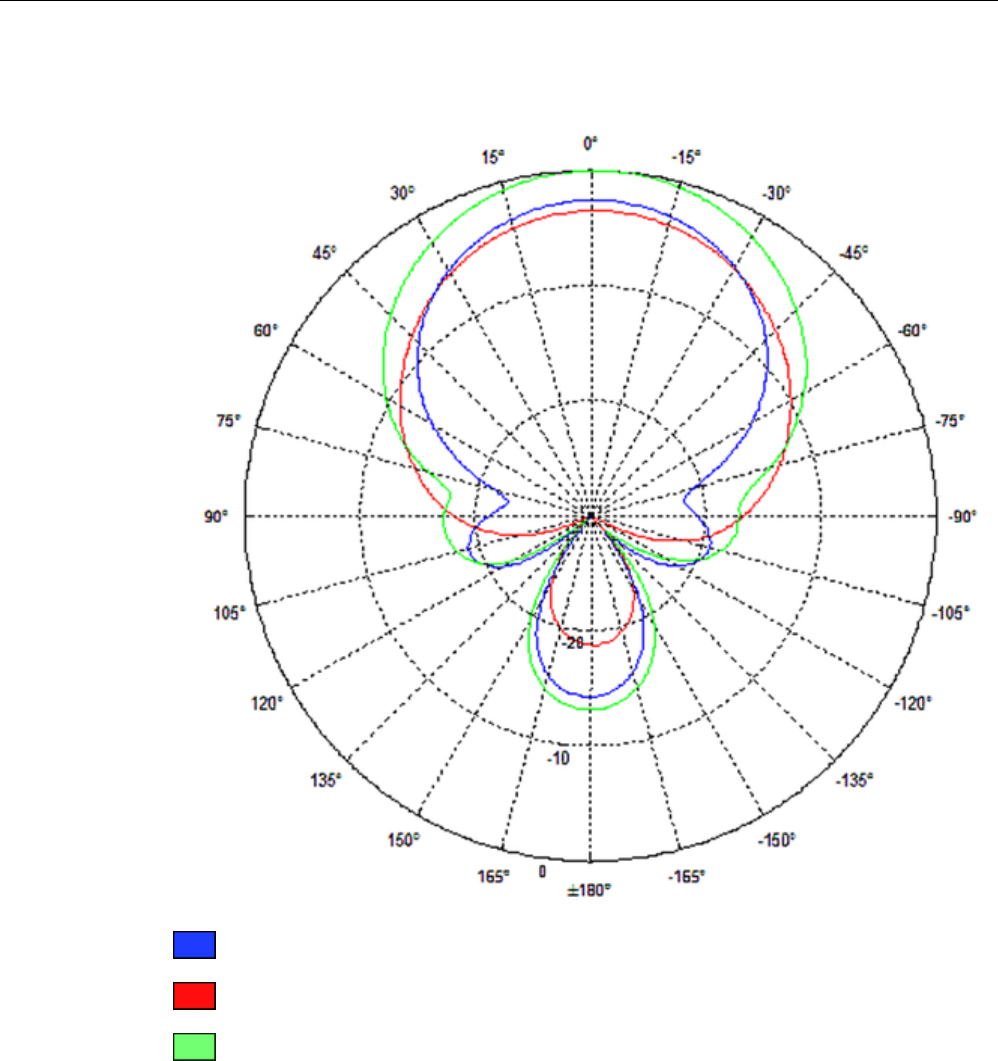
Readers
5.2 RF620R reader
SIMATIC RF600
96 System Manual, xx/2014, J31069-D0171-U001-A15-7618
REVIEW
Radiation diagram (Azimuth section)
Vertical component of the polarization direction of the antenna
Horizontal component of the polarization direction of the antenna
Right circular component of the polarization direction of the antenna
Figure 5-1 Azimuth section
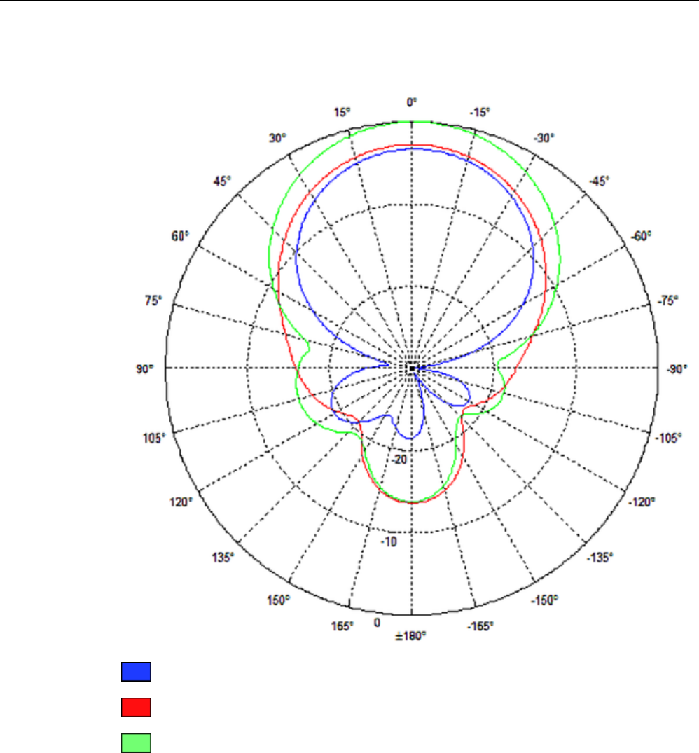
Readers
5.2 RF620R reader
SIMATIC RF600
System Manual, xx/2014, J31069-D0171-U001-A15-7618 97
REVIEW
Radiation diagram (elevation section)
Vertical component of the polarization direction of the antenna
Horizontal component of the polarization direction of the antenna
Right circular component of the polarization direction of the antenna
Figure 5-2 Elevation section

Readers
5.2 RF620R reader
SIMATIC RF600
98 System Manual, xx/2014, J31069-D0171-U001-A15-7618
REVIEW
Overview of the antenna parameters
Table 5- 4 Maximum linear electrical aperture angle at 865 MHz:
Azimuth section
77,7°
Elevation section
66,1°
Typical antenna gain in the frequency range 865
to 868 MHz
4.0 dBi
Antenna axis ratio
0.7 dB
See also section Guidelines for selecting RFID UHF antennas (Page 55)
5.2.2.3
Antenna diagram for RF620R (FCC)
The following radiation diagrams show the directional radiation pattern of the internal
antenna of the RF620R (FCC) reader. For the spatial presentation of the directional
characteristics, the vertical plane (Azimuth section) as well as the horizontal plane (elevation
section) must be considered. This results in a spatial image of the directional radiation
pattern of the antenna with its main and auxiliary fields.
Azimuth
XZ plane
Elevation
YZ plane
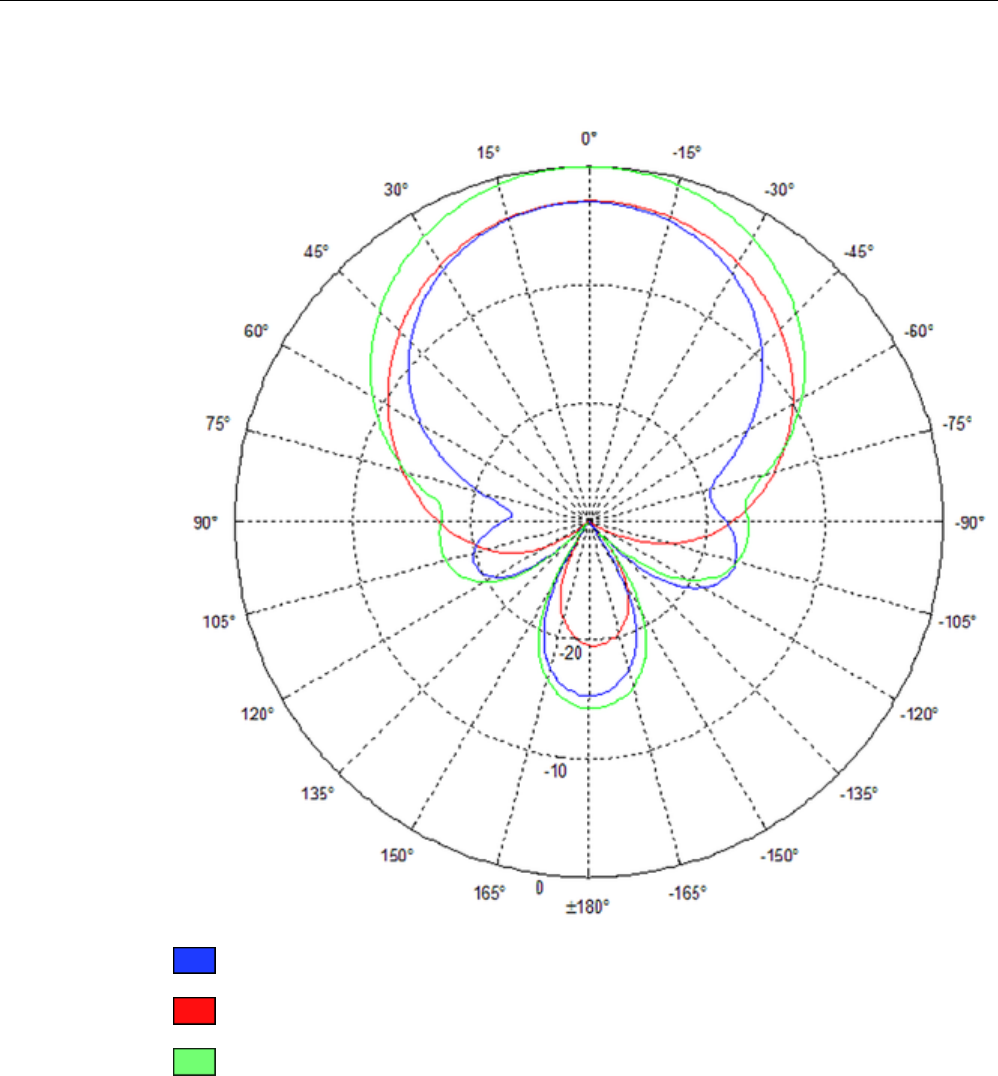
Readers
5.2 RF620R reader
SIMATIC RF600
System Manual, xx/2014, J31069-D0171-U001-A15-7618 99
REVIEW
Radiation diagram (Azimuth section)
Vertical component of the polarization direction of the antenna
Horizontal component of the polarization direction of the antenna
Right circular component of the polarization direction of the antenna
Figure 5-3 Azimuth section

Readers
5.2 RF620R reader
SIMATIC RF600
100 System Manual, xx/2014, J31069-D0171-U001-A15-7618
REVIEW
Radiation diagram (elevation section)
Vertical component of the polarization direction of the antenna
Horizontal component of the polarization direction of the antenna
Right circular component of the polarization direction of the antenna
Figure 5-4 Elevation section
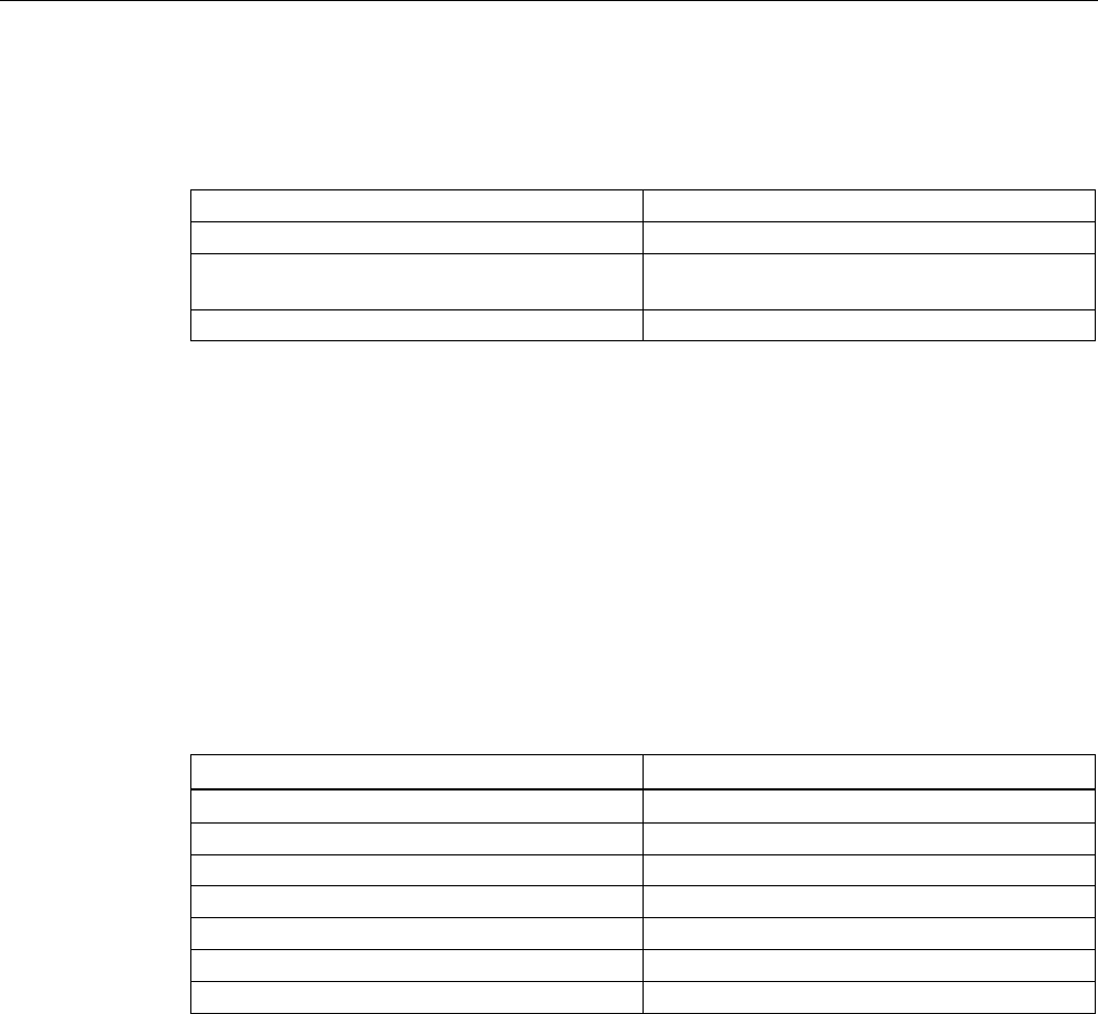
Readers
5.2 RF620R reader
SIMATIC RF600
System Manual, xx/2014, J31069-D0171-U001-A15-7618 101
REVIEW
Overview of the antenna parameters
Table 5- 5 Maximum linear electrical aperture angle at 865 MHz:
Azimuth section
75,4 °
Elevation section
69,1 °
Typical antenna gain in the frequency range 902
to 928 MHz
4.0 dBi ± 0.5 dB
Antenna axis ratio
<1 dB
see also section Guidelines for selecting RFID UHF antennas (Page 55).
5.2.2.4
Interpretation of directional radiation patterns
The following overview table will help you with the interpretation of directional radiation
patterns.
The table shows which dBi values correspond to which read/write ranges (in %): You can
read the radiated power depending on the reference angle from the directional radiation
patterns, and thus obtain information on the read/write range with this reference angle with
regard to a transponder.
The dBr values correspond to the difference between the maximum dBi value and a second
dBi value.
Deviation from maximum antenna gain [dBr]
Read/write range [%]
0
100
-3
70
-6
50
-9
35
-12
25
-15
18
-18
13
Example
As one can see from the section Antenna diagram for RF620R (ETSI) (Page 95), the
maximum antenna gain is 0 dB. In the Azimuth diagram, the antenna gain falls by 3°dB at
approximately ± 39°. Therefore the dBr value is -3. The antenna range is only 50% of the
maximum range at ± 39° from the Z axis within the horizontal plane.
5.2.2.5
Antenna/read point configurations
The RF620R reader has an internal circular polarized antenna. You can cover one read point
with this antenna. When several RF620R readers are used, the readers are addressed via
the SIMATIC level.
Readers
5.2 RF620R reader
SIMATIC RF600
102 System Manual, xx/2014, J31069-D0171-U001-A15-7618
REVIEW
5.2.3
Installing/Mounting
Requirement
WARNING
Make sure that the wall or ceiling can hold four times the total weight of the device.
Note
Close unused connectors
If you do not use connectors on the reader, it is advisable to close the unused connectors
with protective caps. You can order
the protective cap set using the MLFB specified in the
section "Ordering data".
Note
Disregarding FCC RF exposure requirements
Ensure that the following conditions are met before the device is mounted to meet the FCC
RF exposure requirements:
•
The RF620R reader must be installed so that a minimum distance from people of 20 cm
is always observed.
•
The reader may not be installed or operated in the immediate vicinity of another reader or
antenna.
See also section
FCC information (Page 111) RF620R or section FCC information
(Page
127) RF630R.
5.2.3.1
Mounting/Installing FCC
CAUTION
Emitted radiation
The transmitter complies with the requirements of Health Canada and the FCC limit values
for subjecting persons to HF radiation, provided that a minimum spacing of 26 cm exists
between antenna and person. When the antennas are installed, you must therefore ensure
that a minimum spacing of 26 cm is maintained between personnel and antennas.
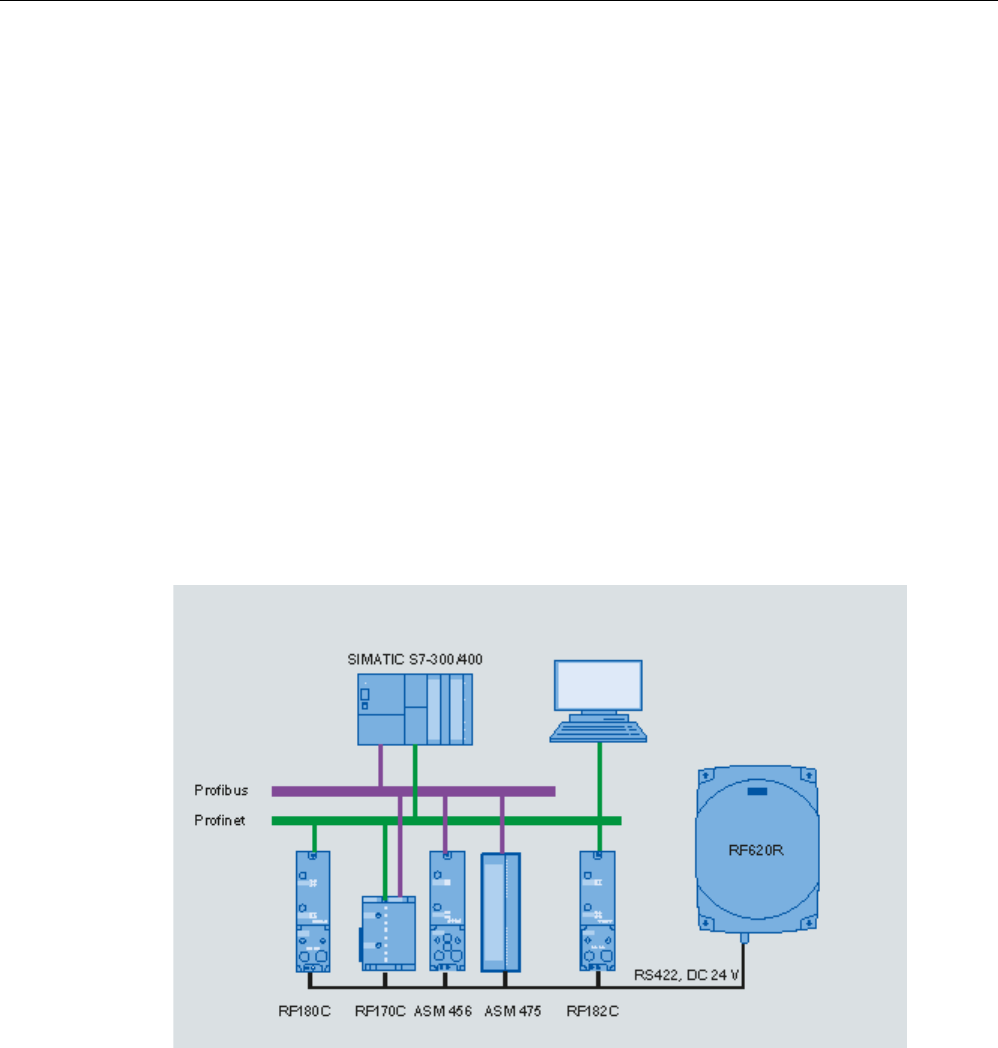
Readers
5.2 RF620R reader
SIMATIC RF600
System Manual, xx/2014, J31069-D0171-U001-A15-7618 103
REVIEW
Mounting/installing the device
You can mount the reader in two different ways:
● Via a standardized VESA 100 mounting system using the Antenna Mounting Kit (see
Chapter Mounting with antenna mounting kit (Page 331)). Tighten the M4 screws on the
rear of the reader using a maximum torque of ≤ 1.3 Nm.
● Directly onto a flat surface.
The positions of the fixing holes for the device are shown in the section Dimension drawings
(Page 108).
5.2.4
Configuration/integration
The RS422 system interface is provided for integrating the device into system
environments/networks. The system interface transfers data to SIMATIC controllers or PCs
with the appropriate interface.
Apart from transmitting communication data from the reader to the controller and vice versa,
the RS422 interface also supplies power to the reader (24 V DC).
Figure 5-5 Overview of configuration of the RF620R reader
The RF620R reader can alternatively be connected to a SIMATIC controller via the ASM
456, ASM 475, RF170C and RF180C interface modules/communication modules.
The RF620R reader can alternatively also be connected directly to the PC via the RF182
communication module.
For further details on the interface modules used, see Chapter Auto-Hotspot .
Further information about commissioning the readers can be found in the configuration
manual "RF620R/RF630R" in the "Commissioning" section.

Readers
5.2 RF620R reader
SIMATIC RF600
104 System Manual, xx/2014, J31069-D0171-U001-A15-7618
REVIEW
5.2.4.1
Transmission protocols
RS 422 communication
3964R protocol
Transmission rates 19.2 kbps
57.6 kbps
115.2 kbps
Start bits
1
Data bits
8
Parity
Odd
Stop bits
1
5.2.5
Technical data
5.2.5.1
Mechanical data
Mechanical data
Weight
1850 g
Dimensions (L x W x H) in mm
252 X 193 x 52 mm, without connections
Material for housing top section
ABS (GF 20), silicone-free
Material for housing bottom section
Aluminum, silicone-free
Color of housing top section
Pastel turquoise
Color of housing bottom section
Silver
Status displays on the device 1 LED
Colors: red, yellow, green
Interfaces
RS422
1 x plug (8-pin M12)
Antenna connectors
1 x RTNC plug
Software
SIMATIC S7
MTBF in years
18.2

Readers
5.2 RF620R reader
SIMATIC RF600
System Manual, xx/2014, J31069-D0171-U001-A15-7618 105
REVIEW
Technical and electrical characteristics
Power supply
• Permitted range
21.6 to 30 VDC 1
Power supply Current consumption
(in standby mode, no
transmit power)
Power consumption (in
standby mode, no transmit
power)
20 V input voltage on the reader, typical
135 mA
2.7 W
24 V input voltage on the reader, typical
115 mA
2.76 W
30 V input voltage on the reader, typical
95 mA
2.85 W
Power supply Current consumption
(at 500 mW ERP)
Power requirement
(at 500 mW ERP)
20 V input voltage on the reader, typical
470 mA
9.4 W
24 V input voltage on the reader, typical
395 mA
9.48 W
30 V input voltage on the reader, typical
320 mA
9.6 W
Ramp-up time, typical
7 s
1)
All supply and signal voltages must be safety extra low voltage (SELV/PELV according to EN 60950)
24 VDC supply: safe (electrical) isolation of extra-low voltage (SELV / PELV acc. to EN 60950)
Mechanical environmental conditions
Shock resistant acc. to EN 60068-2-27
Vibration acc. to EN 60068-2-6
50 g1
20 g
1
Climatic conditions
Ambient temperature during operation -25 °C to +55 °C
(a 10-minute warm-up time must be allowed at an operating
temperature below -20 °C)
Ambient temperature for transport and storage
-40 °C to +85 °C
1) The values for shock and vibration are maximum values and must not be applied continuously.
EMC & approvals/conformity RF620R (ETSI)
Electromagnetic compatibility
ETSI EN 301 489-1 / -3
ETSI EN 302 208 V1.3.1
ETSI EN 302 208 V1.4.1
Approvals/Conformity • Radio acc. to R&TTE guidelines, EN 301 489
• CE
• ETSI EN 302-208 V1.1.1
• ETSI EN 302-208 V1.3.1
• ETSI EN 302-208 V1.4.1
• Reader degree of protection acc. to EN 60529 (IP65)

Readers
5.2 RF620R reader
SIMATIC RF600
106 System Manual, xx/2014, J31069-D0171-U001-A15-7618
REVIEW
EMC & approvals for FCC variant
Electromagnetic compatibility
FCC Part 15
Approvals • FCC, cULus
• IEC60950, including US and Canadian variants of it
• FCC CFR47 Part 15.247
• RoHS-compliant according to EU Directive 2002/95/EC
• Industrial Canada, RSS-210, Issue 7, June 2007
5.2.5.2
Technical data according to EPC and ISO
Technical specifications
Frequency accuracy
max.± 10 ppm
Channel spacing EU, EFTA, Turkey: 600 kHz
US: 500 kHz
China: 250 kHz
Modulation methods ASK: DSB modulation & PR-ASK modulation
Encoding, Manchester or Pulse Interval (PIE)
Effective radiated power with internal antenna
• ETSI/CMIIT:
• FCC
• ≤ 0.8 W ERP
• ≤ 1.3 W EIRP
Effective radiated power with external antenna
• ETSI/CMIIT:
• FCC
• ≤ 1.2 W ERP
• ≤ 2.0 W EIRP
Transmit power
≤ 0.5 W
Reading range
Readers mounted on the same side Max. 2 m (recommended maximum value for configuration;
depending on the transponder)
ETSI frequencies
Frequency range for Europe, EFTA, Turkey, South Africa,
Thailand (ETSI)
ETSI EN 302 208 V1.4.1 (valid since October 23, 2012,
publication in the Official Journal of the European Union)
865.7 ... 867.5 MHz
(4 channels LBT optional at max. 2 W ERP)
Frequency range India
865 ... 867 MHz (10 channels at max. 4 W EIRP)
Frequency range Russia
866.1 ... 867.6 MHz (8 channels at 2 W ERP)
Frequency range Singapore
866 ... 869 MHz (11 channels at 0.5 W ERP)

Readers
5.2 RF620R reader
SIMATIC RF600
System Manual, xx/2014, J31069-D0171-U001-A15-7618 107
REVIEW
FCC frequencies
Frequency range USA; Argentina, Bolivia, Canada, Mexico,
Thailand (FCC)
902 ... 928 MHz (50 channels at max. 4 W EIRP,
frequency hopping)
Frequency range Brazil 915.125 ... 927.875 MHz (52 channels at max. 4 W EIRP,
frequency hopping)
Frequency range South Korea 917.1 ... 920.4 MHz (7-16 channels at max. 4 W EIRP,
frequency hopping)
CMIIT frequencies
Frequency range China
920.625 ... 924.375 MHz (16 subchannels at 2 W ERP)
5.2.5.3
Maximum number of readable tags
The maximum number of readable tags depends on the following parameters:
● Size of the antenna field
● Readability of the tags
For a transmit power of 500 mW ERP, the following is read when the tag RF620T is used:
● Max. 40 tags in the antenna field (tags perpendicular to antenna and 1 m in front)
● Max. 18
tags per second
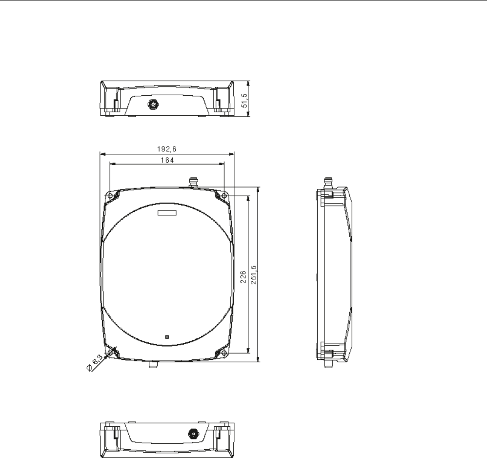
Readers
5.2 RF620R reader
SIMATIC RF600
108 System Manual, xx/2014, J31069-D0171-U001-A15-7618
REVIEW
5.2.6
Dimension drawings
Figure 5-6 Dimension drawing for RF620R
All dimensions in mm (± 0.5 mm tolerance)
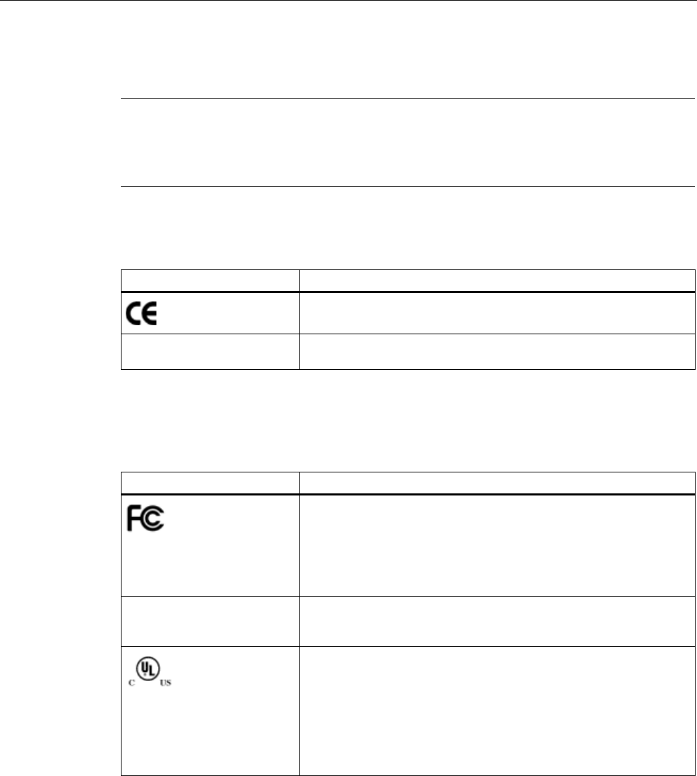
Readers
5.2 RF620R reader
SIMATIC RF600
System Manual, xx/2014, J31069-D0171-U001-A15-7618 109
REVIEW
5.2.7
Certificates and approvals
Note
Marking on the readers according to specific approval
The certificates and approvals listed here apply only if the corresponding mark is found on
the readers.
Table 5- 6 6GT2811-5BA00-0AA0, 6GT2811-5BA00-0AA1
Certificate
Description
Conformity with R&TTE directive
TA-2012/548 South Africa radio approval:
Radio Equipment Type Approval
5.2.7.1
Country-specific certifications
Table 5- 7 6GT2811-5BA00-1AA0, 6GT2811-5BA00-1AA1
Standard
Federal Communications
Commission
FCC CFR 47, Part 15 sections 15.247
Radio Frequency Interference Statement
This equipment has been tested and found to comply with the limits
for a Class B digital device, pursuant to Part 15 of the FCC Rules.
FCC ID: NXW-RF620R (for 6GT2811-5BA00-1AA0)
FCC ID: NXW-RF600R (for 6GT2811-5BA00-1AA1)
Industry Canada Radio
Standards Specifications
RSS-210 Issue 7, June 2007, Sections 2.2, A8
IC: 267X-RF620R (for 6GT2811-5BA00-1AA0)
IC: 267X-RF600R, Model RF620R-2 (for 6GT2811-5BA00-1AA1)
This product is UL-certified for the USA and Canada.
It meets the following safety standard(s):
UL 60950-1 - Information Technology Equipment Safety - Part 1:
General Requirements
CSA C22.2 No. 60950 -1 - Safety of Information Technology
Equipment
UL Report E 205089
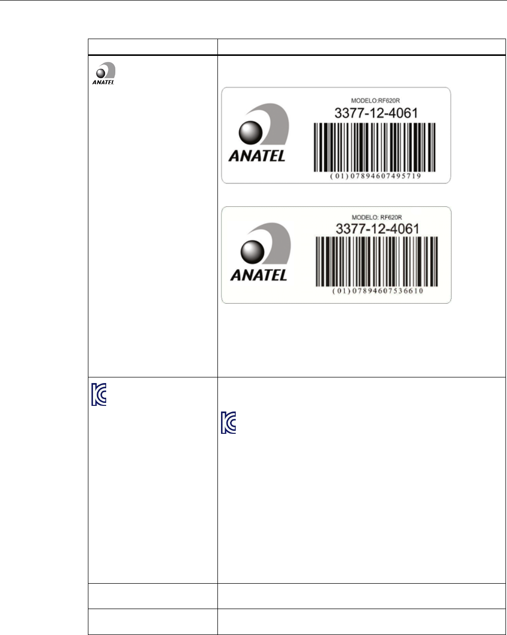
Readers
5.2 RF620R reader
SIMATIC RF600
110 System Manual, xx/2014, J31069-D0171-U001-A15-7618
REVIEW
Standard
Brazil wireless approval
Marking on the reader (6GT2811-5BA00-1AA0):
Marking on the reader (6GT2811-5BA00-1AA1):
Statement about approval:
Este equipamento opera em caráter secundário, isto é, não tem
direito à proteção contra interferência prejudicial, mesmo de
estações do mesmo tipo e não pode causar interferência a sistemas
operando em caráter primário.
Reader certificate: ANATEL 3377-12-4061
KCC Certification
Marking on the reader:
Type of equipment:
A급 기기 (업무용 방송통신기자재)
Class A Equipment (Industrial Broadcasting & Communication
Equipment)
이 기기는 업무용(A급) 전자파적합기기로서 판 매자 또는 사용자는 이
점을 주의하시기 바라 며, 가정외의 지역에서 사용하는 것을 목적으로
합니다.
This equipment is Industrial (Class A) electromagnetic wave
suitability equipment and seller or user should take notice of it, and
this equipment is to be used in the places except for home.
Reader certificate:
KCC-CRM-RF5-RF620R
H-11388 Argentina radio approval:
Registro de la COMISION NACIONAL DE COMUNICACIONES
RCPSIRF12-0772 Mexico radio approval:
CERTIFICADO DE HOMOLOGACION

Readers
5.2 RF620R reader
SIMATIC RF600
System Manual, xx/2014, J31069-D0171-U001-A15-7618 111
REVIEW
Table 5- 8 6GT2811-5BA00-2AA1
Standard
CMIIT Certification China radio approval
Marking on the reader: CMIIT ID: 2012DJ2916
5.2.7.2
FCC information
Siemens SIMATIC RF620R (FCC): 6GT2811-5BA00-1AA0, 6GT2811-5BA00-1AA1
FCC ID: NXW-RF620R (for 6GT2811-5BA00-1AA0)
FCC ID: NXW-RF600R (for 6GT2811-5BA00-1AA1)
This device complies with part 15 of the FCC rules. Operation is subject to the following two
conditions:
(1) This device may not cause harmful interference, and
(2) this device must accept any interference received, including interference that may cause
undesired operation.
Caution
Any changes or modifications not expressly approved by the party responsible for
compliance could void the user's authority to operate the equipment.
Note
This equipment has been tested and found to comply with the limits for a Class B digital
device, pursuant to part 15 of the FCC Rules.
These limits are designed to provide reasonable protection against harmful interference
when the equipment is operated in a commercial environment. This equipment generates,
uses, and can radiate radio frequency energy and, if not installed and used in accordance
with the instruction manual, may cause harmful interference to radio communications.
Operation of this equipment in a residential area is likely to cause harmful interference in
which case the user will be required to correct the interference at his own expense.
FCC Notice
To comply with FCC part 15 rules in the United States, the system must be professionally
installed to ensure compliance with the Part 15 certification.
It is the responsibility of the operator and professional installer to ensure that only certified
systems are deployed in the United States. The use of the system in any other combination
(such as co-located antennas transmitting the same information) is expressly forbidden.
FCC Exposure Information
To comply with FCC RF exposure compliance requirements, the antennas used for this
transmitter must be installed to provide a separation distance of at least 20 cm from all
persons and must not be co-located or operating in conjunction with any other antenna or
transmitter.

Readers
5.2 RF620R reader
SIMATIC RF600
112 System Manual, xx/2014, J31069-D0171-U001-A15-7618
REVIEW
5.2.7.3
IC-FCB information
Siemens SIMATIC RF620R (FCC): 6GT2811-5BA00-1AA0, 6GT2811-5BA00-1AA1
IC: 267X-RF620R (for 6GT2811-5BA00-1AA0)
IC: 267X-RF600R, Model: RF620R-2 (for 6GT2811-5BA00-1AA1)
This device complies with Industry Canada licence-exempt RSS standard(s). Operation is
subject to the following two conditions:
(1) This device may not cause interference, and
(2) this device must accept any interference, including interference that may cause
undesired operation of the device.
Le présent appareil est conforme aux CNR d`Industrie Canada applicables aux appareils
radio exempts de licence. L`exploitation est autorisée aux deux conditions suivantes :
(1) L`appareil ne doit pas produire de brouillage, et
(2) l'utilisateur de l`appareil doit accepter tout brouillage radioélectrique subi, même si le
brouillage est susceptible d`en compromettre le fonctionnement.
Industry Canada Notice
To reduce potential radio interference to other users, the antenna type and its gain should be
so chosen that the equivalent isotropically radiated power (e.i.r.p.) is not more than that
permitted for successful communication.
Transmitter power and antenna information for antennas with a gain less than 6 dBi:
This device has been designed to operate with the SIMATIC RF620A antenna 902-928, the
SIMATIC RF640A antenna 902-928 as well as the SIMATIC RF660A antenna 902-928 listed
below, and having a maximum gain of 5.5 dBi. Arbitrary transmission power settings in
combination with other antennas or antennas having a gain greater than 5.5 dBi are strictly
prohibited for use with this device. The required antenna impedance is 50 Ohms.
Transmitter power and antenna information for antennas with a gain greater 6 dBi:
This device requires professional installation. Antennas with a gain greater 6 dBi may be
used provided the system does not exceed the radiation power of 4000 mW E.I.R.P. This
device has been designed to operate with the SIMATIC RF642A antenna 902-928 exceeding
the maximum gain of 5.5 dBi under the restriction that the RF power at the input of the
antenna must be set to meet the following relation: RF power (dBm) ≤ 30 dBm – (antenna
gain (dBi) – 6 dBi) Other antennas or system configurations for antennas having a gain
greater than 6 dBi are strictly prohibited for use with this device. The required antenna
impedance is 50 Ohms.
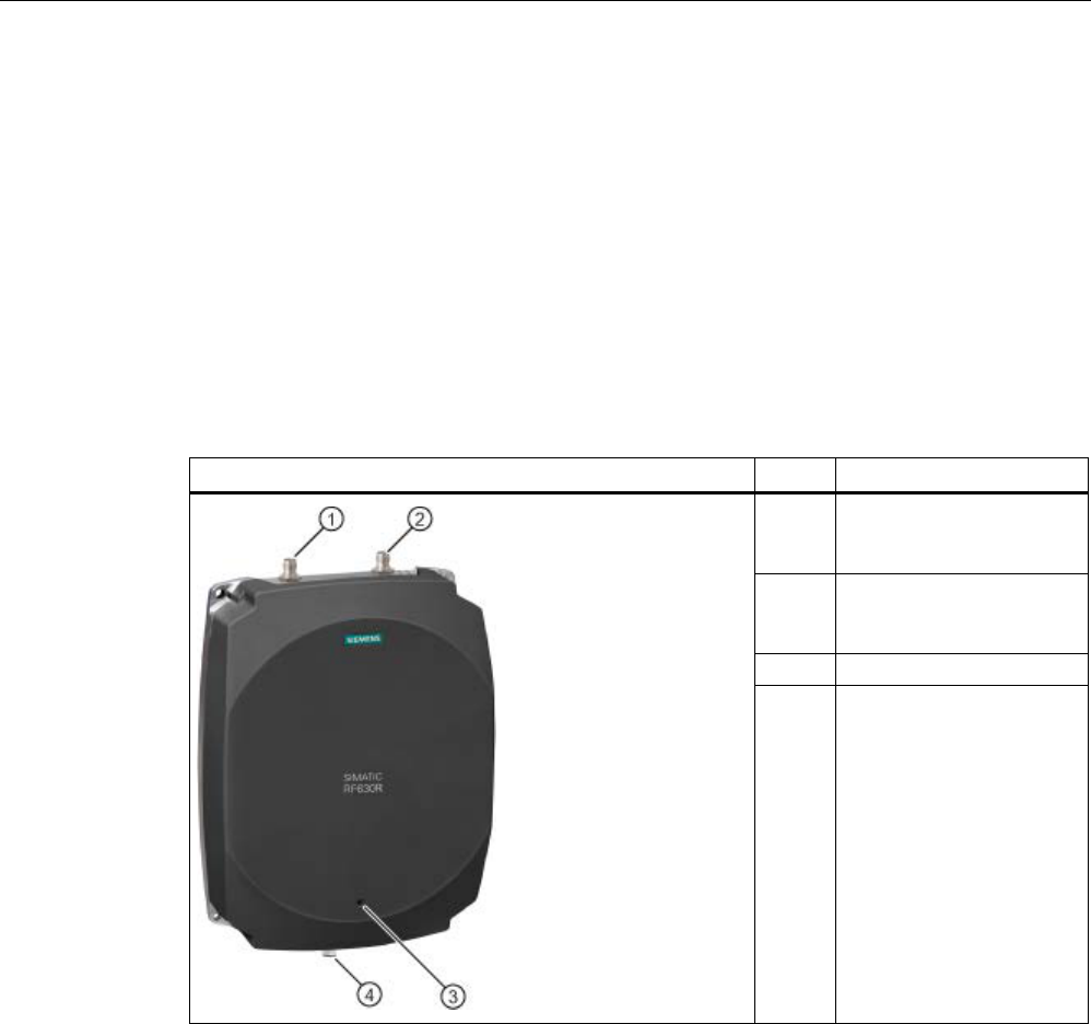
Readers
5.3 RF630R reader
SIMATIC RF600
System Manual, xx/2014, J31069-D0171-U001-A15-7618 113
REVIEW
5.3
RF630R reader
5.3.1
Description
The SIMATIC RF630R is a stationary reader in the UHF frequency band without an
integrated antenna. Up to two external UHF RFID antennas can be connected via TNC
reverse connections.
The maximum RF power output is 0.5°W at the reader output. The SIMATIC RF630R is
connected to a SIMATIC S7 controller via an ASM interface module. The degree of
protection is IP65.
Pos.
Description
(1) TNCreverse interface for
connection of antenna 1
(ANT 1)
(2) TNCreverse interface for
connection of antenna 2
(ANT 2)
(2)
LED operating display
(3) RS 422 interface
(8-pin M12 connector)

Readers
5.3 RF630R reader
SIMATIC RF600
114 System Manual, xx/2014, J31069-D0171-U001-A15-7618
REVIEW
5.3.1.1
Ordering data
Ordering data for RF630R
Product
Article number
RF630R (ETSI) reader for EU, EFTA, Turkey
6GT2811-4AA00-0AA0
RF630R (FCC) reader for the USA
6GT2811-4AA00-1AA0
RF630R (CMIIT) reader for China
6GT2811-4AA00-2AA1
Ordering data accessories
Product
Article number
Connecting cable
• RS°422, M12 plug, 8-pin socket: 2 m
• RS°422, M12 plug, 8-pin socket: 5 m
• RS°422, M12 plug, 8-pin socket: 10 m
• RS°422, M12 plug, 8-pin socket: 20 m
• RS°422, M12 plug, 8-pin socket: 50 m
• 6GT2891-0FH20
• 6GT2891-0FH50
• 6GT2891-0FN10
• 6GT2891-0FN20
• 6GT2891-0FN50
Antenna mounting kit
6GT2890-0AA00
Set of protective caps
Contains 3 protective caps for antenna output and one
protective cap for digital I/O interface (required for IP65
degree of protection when some connectors are unused)
6GT2898-4AA00
RFID DVD "Software & Documentation"
6GT2080-2AA20
5.3.1.2
Status display
The device is equipped with a three colored LED. The LED can be lit in green, red or yellow.
The meaning of the indication changes in accordance with the color and state (on, off,
flashing) of the LED:
Green
LED
Red LED
Yellow
LED
Meaning
Off
Off
Off
The device is starting up.
Flashing
Off
Off
The device is ready. The antenna is switched off.
On
Off
Off
The device is ready. The antenna is switched on.
Off Off On "With presence": At least one tag is in the field.
"Without presence": Communication with a tag is active.
Off Flashing Off Reader is not active, a serious error has occurred. In addition, this LED also indicates
the fault status through the number of flashing pulses. Reboot (operating voltage Off
→ On is necessary).
The LED flashes once for the 'INACTIVE' status, rebooting is
not
necessary in this
case.
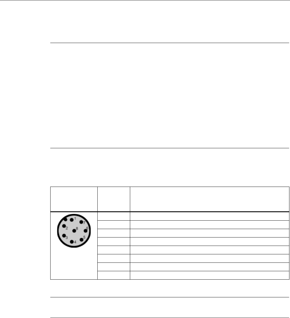
Readers
5.3 RF630R reader
SIMATIC RF600
System Manual, xx/2014, J31069-D0171-U001-A15-7618 115
REVIEW
For more detailed information on the flash codes of the reader see section Error messages
and flash codes for RF620R/RF630R (Page 469)
Note
LED not lit yellow?
If the LED does not light up yellow even though a tag is located within the field, common
causes are:
•
Incorrect configuration in the init_run command, or init_run command was not executed
(see "Configuration Manual RF620R/RF630R")
•
Parameter assignment is incorrect (black list, RSSI threshold)
•
Antenna is switched off
•
A tag is used, that is not compatible with the reader protocol (EPC Global Class 1 Gen 2).
•
Tag is defective
•
Reader or antenna has a defect
•
Tag is not in the field of radiation of the transmit antenna
5.3.1.3
Pin assignment of the RS422 interface
Pin
Pin
Device end
8-pin M12
Assignment
1
+ 24 V
2
- Transmit
3
0 V
4
+ Transmit
5
+ Receive
6
- Receive
7
Unassigned
8 Earth (shield)
The knurled bolt of the M12 plug is not connected to the shield (on the reader side).
Note
You must therefore not use any SIMATIC connecting cables that use the angled M12 plug.
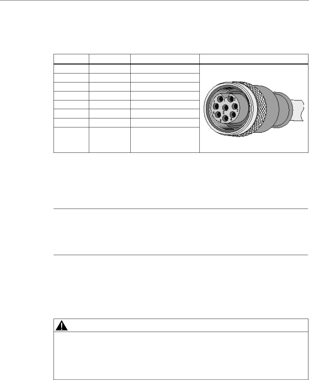
Readers
5.3 RF630R reader
SIMATIC RF600
116 System Manual, xx/2014, J31069-D0171-U001-A15-7618
REVIEW
5.3.1.4
Pin assignment of the connecting cable
Table 5- 9 RS 422 - on reader side
M12 pin
Core color
Pin assignment
View of M12 socket
1
white
24 VDC
2
brown
TX neg
3
green
GND
4
yellow
TX pos
5
Gray
RX pos
6
pink
RX neg
7
blue
Not assigned
8 red Earth (shield)
Comment
This cable has an 8-pin M12 connector at one end and the other cable end is 'open'. There
are 8 color-coded single cores there for connecting to external devices. There are different
cable lengths in the product range (3 m to 50 m). Long cables can be reduced if necessary.
Note
For long cables: Adapt supply voltage and data rate accordingly
Note that with long cables in particular, the supply voltage of 24 V DC must always be
applied. Note also that the data rate on the serial
interface must, if necessary, be reduced.
(See "Configuration Manual RF620R/RF630R")
5.3.1.5
Grounding connection
The RF630R can be electrically connected to the ground potential through a contact washer.
The tightening torque must be increased in this case to ensure that electrical contact is made
(2.7 Nm).
WARNING
Hazardous voltage due to lightning strikes
Death or serious injury may occur as a result of lightning strikes to antennas mounted
outside buildings.
If the reader is operated with antennas mounted outside buildings, it is imperative that the
reader is electrically connected to the ground potential.

Readers
5.3 RF630R reader
SIMATIC RF600
System Manual, xx/2014, J31069-D0171-U001-A15-7618 117
REVIEW
Ground connection
(a)
Hexagon-head screw
(b)
Plain washer
(c)
Cable lug
(d) Contact washer:
Use contact washers according to the
Siemens standard SN 70093-6-FSt-flNnnc-
480h for ground connection,
Siemens item No.: H70093-A60-Z3
5.3.2
Planning application
5.3.2.1
Minimum mounting clearances of two antennas of different readers
At 500 mW ERP radiated power, due to the opening angle of the antennas, their fields can
overlap considerably. It is no longer possible to clarify in which antenna field access to the
data of a tag is performed.
In order to avoid this, always keep a minimum distance of 3 m between two antennas of
different RF630R readers with the maximum radiated power of 500 mW ERP.
Dense Reader Mode (DRM)
The readers can also interfere with each other (secondary fields), if the channels (Reader
TX, Transponder TX) overlap. In order to prevent a transponder channel overlapping with a
reader channel, we recommend that the Dense Reader Mode (DRM) is used.
5.3.2.2
Antenna/read point configurations
You can connect up to two external antennas to the RF630R reader. The standard setting is
that two antennas are connected when the reader is started.
You have 3 possibilities for aligning the antennas and covering the read point.
Readers
5.3 RF630R reader
SIMATIC RF600
118 System Manual, xx/2014, J31069-D0171-U001-A15-7618
REVIEW
One RF630R reader with two antennas and two read points
If you connect two external antennas to the device and align them in different directions, you
can read tags at two different read points. With this technique, a particular antenna must be
switched off application-dependently to be able to establish which tags have been read from
which antenna. Note the minimum distances between the antennas for the antenna
configuration (see section Specified minimum and maximum spacing of antennas (Page 49).
One RF630R reader with two antennas and one read point
If you connect two external antennas to the device and align them in the same direction
(portal configuration), you can read tags at one read point. With this method, the reader
automatically switches between the two antennas while the tags are being read. Note the
minimum distances between the antennas for the antenna configuration (see section
Specified minimum and maximum spacing of antennas (Page 49) .
One RF630R reader with one antenna and one read point
If you connect an external antenna to the device, you can read tags at one read point.
5.3.3
Installing/Mounting
5.3.3.1
Mounting/Installation
Requirement
WARNING
Make sure that the wall or ceiling can hold four times the total weight of the device.
Note
Close unused connectors
If you do not use connectors on the reader, it is advisable to close the unused
connectors
with protective caps. You can order the protective cap set using the MLFB specified in the
section "Ordering data".
CAUTION
Emitted radiation
The transmitter complies with the requirements of Health Canada and the FCC limit values
for subjecting persons to HF radiation, provided that a minimum spacing of 26 cm exists
between antenna and person. When the antennas are installed, you must therefore ensure
that a minimum spacing of 26 cm is maintained between personnel and antennas.
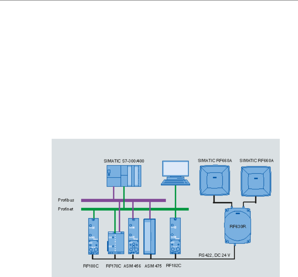
Readers
5.3 RF630R reader
SIMATIC RF600
System Manual, xx/2014, J31069-D0171-U001-A15-7618 119
REVIEW
Mounting/installing the device
You can mount the reader directly onto a flat surface.
The positions of the fixing holes for the device are shown in the section Dimension drawings
(Page 124).
5.3.4
Configuration/integration
The RS422 system interface is provided for integrating the device into system
environments/networks. The system interface transfers data to SIMATIC controllers or PCs
with the appropriate interface.
Apart from transmitting communication data from the reader to the controller and vice versa,
the RS422 interface also supplies power to the reader (24 V DC).
Figure 5-7 Overview of configuration of the RF630R reader
The RF620R reader can alternatively be connected to a SIMATIC controller via the ASM
456, ASM 475, RF170C and RF180C interface modules/communication modules.
The RF620R reader can alternatively also be connected directly to the PC via the RF182
communication module.
For further details on the interface modules used, see Chapter Auto-Hotspot .
Further information about commissioning the readers can be found in the Configuration
Manual "RF620R/RF630R" in the "Commissioning" section.
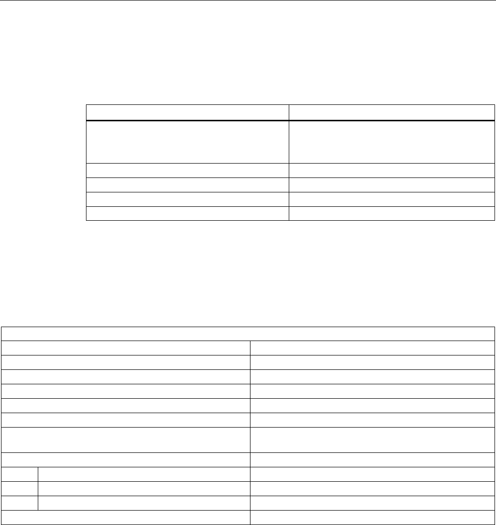
Readers
5.3 RF630R reader
SIMATIC RF600
120 System Manual, xx/2014, J31069-D0171-U001-A15-7618
REVIEW
5.3.4.1
Transmission protocols
RS 422 communication
3964R protocol
Transmission rates 19.2 kbps
57.6 kbps
115.2 kbps
Start bits
1
Data bits
8
Parity
Odd
Stop bits
1
5.3.5
Technical data
5.3.5.1
Mechanical data
Mechanical data
Weight
1640 g
Dimensions (L x W x H) in mm
252 x 193 x 52 mm, without connections
Material for housing top section
ABS (GF 20)
Material for housing bottom section
Aluminum
Color of housing top section
Anthracite
Color of housing bottom section
Silver
Status displays on the device 1 LED
Colors: red, yellow, green
Interfaces
Antenna connectors
2 x RTNC plug
RS422
1 x plug (8-pin M12)
Software
SIMATIC S7
MTBF in years
18.2

Readers
5.3 RF630R reader
SIMATIC RF600
System Manual, xx/2014, J31069-D0171-U001-A15-7618 121
REVIEW
Thermal and electrical properties
Power supply
• Permitted range
21.6 to 30 VDC 1
Power supply Current consumption
(in standby mode, no
transmit power)
Current consumption
(in standby mode, no
transmit power)
20 V input voltage on the reader, typical
135 mA
2.7 W
24 V input voltage on the reader, typical
115 mA
2.76 W
30 V input voltage on the reader, typical
95 mA
2.85 W
Power supply Current consumption
(at 500 mW ERP)
Power requirement
(at 500 mW ERP)
20 V input voltage on the reader, typical
470 mA
9.4 W
24 V input voltage on the reader, typical
395 mA
9.48 W
30 V input voltage on the reader, typical
320 mA
9.6 W
Rampup time
7 s
1)
All supply and signal voltages must be safety extra low voltage (SELV/PELV according to EN 60950)
24 VDC supply: safe (electrical) isolation of extra-low voltage (SELV / PELV acc. to EN 60950)
Mechanical environmental conditions
Shock resistant acc. to EN 60068-2-27
Vibration acc. to EN 60068-2-6
50 g1
20 g
1
Climatic conditions
Ambient temperature during operation -25 °C to +55 °C
(a 10-minute warm-up time must be allowed at an operating
temperature below -20 °C)
Ambient temperature for transport and storage
-40 °C to +85 °C
1) The values for shock and vibration are maximum values and must not be applied continuously.
EMC & approvals/conformity for ETSI variant
Electromagnetic compatibility
ETSI EN 301 489-1 / -3
ETSI EN 302 208 V1.3.1
ETSI EN 302 208 V1.4.1
Approvals/Conformity • Radio acc. to R&TTE guidelines, EN 301 489
• CE
• ETSI EN 302-208 V1.1.1
• ETSI EN 302-208 V1.3.1
• ETSI EN 302-208 V1.4.1
• Reader degree of protection acc. to EN 60529 (IP65)

Readers
5.3 RF630R reader
SIMATIC RF600
122 System Manual, xx/2014, J31069-D0171-U001-A15-7618
REVIEW
EMC & approvals for FCC variant
Electromagnetic compatibility
FCC Part 15
Approvals • FCC, cULus
• IEC60950, including US and Canadian variants of it
• FCC CFR47 Part 15.247
• RoHS-compliant according to EU Directive 2002/95/EC
• Industrial Canada, RSS-210, Issue 7, June 2007
5.3.5.2
Technical data according to EPC and ISO
Technical specifications
Frequency accuracy
max.± 10 ppm
Channel spacing EU, EFTA, Turkey: 600 kHz
US: 500 kHz
China: 250 kHz
Modulation methods ASK: DSB modulation & PR-ASK modulation
Encoding, Manchester or Pulse Interval (PIE)
Effective radiant power
• ETSI/CMIIT:
• FCC:
• < < 1.2 W ERP
• < 2 W EIRP
Transmit power
≤ 0.5 W ERP
Reading range
Antennas mounted on opposing sides
(portal configuration)
3.5 m max. (recommended maximum value for
configuration)
Antennas mounted on the same side Max. 2 m (recommended maximum value for configuration;
depending on the transponder)
ETSI frequencies
Frequency range for Europe, EFTA, Turkey, South Africa,
Thailand (ETSI)
ETSI EN 302 208 V1.4.1 (valid since October 23, 2012,
publication in the Official Journal of the European Union)
865.7 ... 867.5 MHz
(4 channels LBT optional at max. 2 W ERP)
Frequency range India 865 ... 867 MHz (10 channels at max. 4 W EIRP)
Frequency range Russia
866.1 ... 867.6 MHz (8 channels at 2 W ERP)
Frequency range Singapore
866 ... 869 MHz (11 channels at 0.5 W ERP)

Readers
5.3 RF630R reader
SIMATIC RF600
System Manual, xx/2014, J31069-D0171-U001-A15-7618 123
REVIEW
FCC frequencies
Frequency range USA; Argentina, Bolivia, Canada, Mexico,
Thailand (FCC)
902 ... 928 MHz (50 channels at max. 4 W EIRP,
frequency hopping)
Frequency range Brazil 915.125 ... 927.875 MHz (52 channels at max. 4 W EIRP,
frequency hopping)
Frequency range South Korea 917.1 ... 920.4 MHz (7-16 channels at max. 4 W EIRP,
frequency hopping)
CMIIT frequencies
Frequency range China
920.625 ... 924.375 MHz (16 subchannels at 2 W ERP)
5.3.5.3
Maximum number of readable tags
The maximum number of readable tags depends on the following parameters:
● Size of the antenna field
● Readability of the tags
For a transmit power of 500 mW ERP, the following is read when the tag RF620T is used:
● Max. 40 tags in the antenna field (tags perpendicular to antenna at 1 m distance). If 2
antennas are used, up to 80 tags can be recognized.
● Max. 18 tags per second
Note
Operation with 2 antennas
If you have configured 2 antennas as a gate, both antennas must be turned on at the
same time. The reader multiplexes both antennas internally. The multiplexing time is
typically 100 ms (internal read time per antenna).
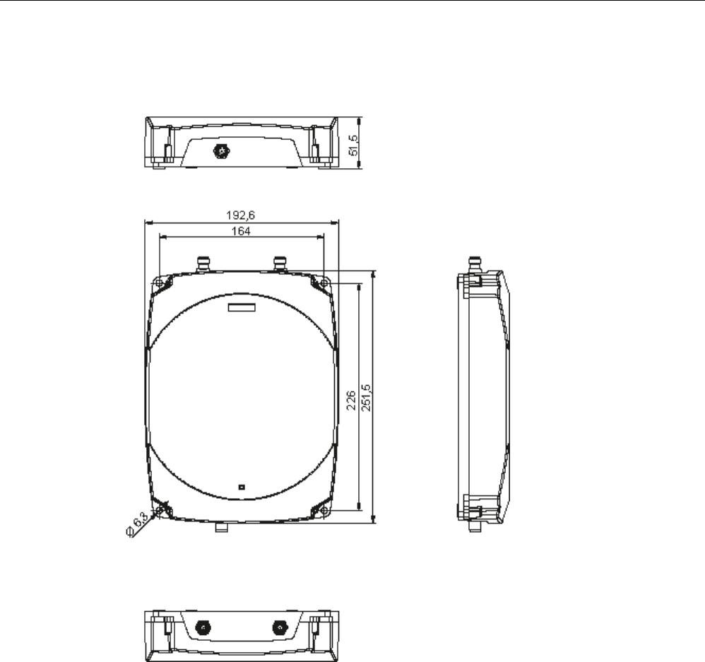
Readers
5.3 RF630R reader
SIMATIC RF600
124 System Manual, xx/2014, J31069-D0171-U001-A15-7618
REVIEW
5.3.6
Dimension drawings
Figure 5-8 Dimension drawing for RF630R
All dimensions in mm (± 0.5 mm tolerance)
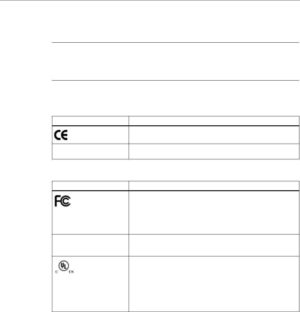
Readers
5.3 RF630R reader
SIMATIC RF600
System Manual, xx/2014, J31069-D0171-U001-A15-7618 125
REVIEW
5.3.7
Certificates and approvals
Note
Marking on the readers according to specific approval
The certificates and approvals listed here apply only if the corresponding mark is found on
the readers.
Table 5- 10 6GT2811-4AA00-0AA0, 6GT2811-4AA00-1AA1
Certificate
Description
Conformity with R&TTE directive
TA-2012/548 South Africa radio approval:
Radio Equipment Type Approval
Table 5- 11 6GT2811-4AA00-1AA0, 6GT2811-4AA00-1AA1
Standard
Federal Communications
Commission
FCC CFR 47, Part 15 sections 15.247
Radio Frequency Interference Statement
This equipment has been tested and found to comply with the limits
for a Class B digital device, pursuant to Part 15 of the FCC Rules.
FCC ID: NXW-RF630R (for 6GT2811-4AA00-1AA0)
FCC ID: NXW-RF600R (for 6GT2811-4AA00-1AA1)
Industry Canada Radio
Standards Specifications
RSS-210 Issue 7, June 2007, Sections 2.2, A8
IC: 267X-RF630 (for 6GT2811-4AA00-1AA0)
IC: 267X-RF600R, Model: RF630R-2 (for 6GT2811-4AA00-1AA1)
This product is UL-certified for the USA and Canada.
It meets the following safety standard(s):
UL 60950-1 - Information Technology Equipment Safety - Part 1:
General Requirements
CSA C22.2 No. 60950 -1 - Safety of Information Technology
Equipment
UL Report E 205089
Readers
5.3 RF630R reader
SIMATIC RF600
126 System Manual, xx/2014, J31069-D0171-U001-A15-7618
REVIEW
Standard
Brazil wireless approval
Marking on the reader (6GT2811-4AA00-1AA0):
Marking on the reader (6GT2811-4AA00-1AA1):
Statement about approval:
Este equipamento opera em caráter secundário, isto é, não tem
direito à proteção contra interferência prejudicial, mesmo de
estações do mesmo tipo e não pode causar interferência a sistemas
operando em caráter primário.
Reader certificate: ANATEL 3377-12-4061
KCC Certification
Marking on the reader:
Type of equipment:
A급 기기 (업무용 방송통신기자재)
Class A Equipment (Industrial Broadcasting & Communication
Equipment)
이 기기는 업무용(A급) 전자파적합기기로서 판 매자 또는 사용자는 이
점을 주의하시기 바라 며, 가정외의 지역에서 사용하는 것을 목적으로
합니다.
This equipment is Industrial (Class A) electromagnetic wave
suitability equipment and seller or user should take notice of it, and
this equipment is to be used in the places except for home.
Reader certificate:
KCC-CRM-RF5-RF630R
H-11409 Argentina radio approval:
Registro de la COMISION NACIONAL DE COMUNICACIONES
RCPSIRF12-0879 Mexico radio approval:
CERTIFICADO DE HOMOLOGACION

Readers
5.3 RF630R reader
SIMATIC RF600
System Manual, xx/2014, J31069-D0171-U001-A15-7618 127
REVIEW
Table 5- 12 6GT2811-4AA00-2AA1
Standard
CMIIT Certification China radio approval
Marking on the reader: CMIIT ID: 2012DJ2917
5.3.7.1
FCC information
Siemens SIMATIC RF630R (FCC): 6GT2811-4AA00-1AA0, 6GT2811-4AA00-1AA1
FCC ID: NXW-RF630R (for 6GT2811-4AA00-1AA0)
FCC ID: NXW-RF600R (for 6GT2811-4AA00-1AA1)
This device complies with part 15 of the FCC rules. Operation is subject to the following two
conditions:
(1) This device may not cause harmful interference, and
(2) this device must accept any interference received, including interference that may cause
undesired operation.
Caution
Any changes or modifications not expressly approved by the party responsible for
compliance could void the user's authority to operate the equipment.
Note
This equipment has been tested and found to comply with the limits for a Class B digital
device, pursuant to part 15 of the FCC Rules.
These limits are designed to provide reasonable protection against harmful interference
when the equipment is operated in a commercial environment. This equipment generates,
uses, and can radiate radio frequency energy and, if not installed and used in accordance
with the instruction manual, may cause harmful interference to radio communications.
Operation of this equipment in a residential area is likely to cause harmful interference in
which case the user will be required to correct the interference at his own expense.
FCC Notice
To comply with FCC part 15 rules in the United States, the system must be professionally
installed to ensure compliance with the Part 15 certification.
It is the responsibility of the operator and professional installer to ensure that only certified
systems are deployed in the United States. The use of the system in any other combination
(such as co-located antennas transmitting the same information) is expressly forbidden.
FCC Exposure Information
To comply with FCC RF exposure compliance requirements, the antennas used for this
transmitter must be installed to provide a separation distance of at least 20 cm from all
persons and must not be co-located or operating in conjunction with any other antenna or
transmitter.

Readers
5.3 RF630R reader
SIMATIC RF600
128 System Manual, xx/2014, J31069-D0171-U001-A15-7618
REVIEW
5.3.7.2
IC-FCB information
Siemens SIMATIC RF630R (FCC): 6GT2811-4AA00-1AA0, 6GT2811-4AA00-1AA1
IC: 267X-RF630 (for 6GT2811-4AA00-1AA0)
IC: 267X-RF600, Model: RF630R-2 (for 6GT2811-4AA00-1AA1)
This device complies with Industry Canada licence-exempt RSS standard(s). Operation is
subject to the following two conditions:
(1) This device may not cause interference, and
(2) this device must accept any interference, including interference that may cause
undesired operation of the device.
Le présent appareil est conforme aux CNR d`Industrie Canada applicables aux appareils
radio exempts de licence. L`exploitation est autorisée aux deux conditions suivantes :
(1) L`appareil ne doit pas produire de brouillage, et
(2) l'utilisateur de l`appareil doit accepter tout brouillage radioélectrique subi, même si le
brouillage est susceptible d`en compromettre le fonctionnement.
Industry Canada Notice
To reduce potential radio interference to other users, the antenna type and its gain should be
so chosen that the equivalent isotropically radiated power (e.i.r.p.) is not more than that
permitted for successful communication.
Transmitter power and antenna information for antennas with a gain less than 6 dBi:
This device has been designed to operate with the SIMATIC RF620A antenna 902-928, the
SIMATIC RF640A antenna 902-928 as well as the SIMATIC RF660A antenna 902-928 listed
below, and having a maximum gain of 5.5 dBi. Arbitrary transmission power settings in
combination with other antennas or antennas having a gain greater than 5.5 dBi are strictly
prohibited for use with this device. The required antenna impedance is 50 Ohms.
Transmitter power and antenna information for antennas with a gain greater 6 dBi:
This device requires professional installation. Antennas with a gain greater 6 dBi may be
used provided the system does not exceed the radiation power of 4000 mW E.I.R.P. This
device has been designed to operate with the SIMATIC RF642A antenna 902-928 exceeding
the maximum gain of 5.5 dBi under the restriction that the RF power at the input of the
antenna must be set to meet the following relation: RF power (dBm) ≤ 30 dBm – (antenna
gain (dBi) – 6 dBi) Other antennas or system configurations for antennas having a gain
greater than 6 dBi are strictly prohibited for use with this device. The required antenna
impedance is 50 Ohms.
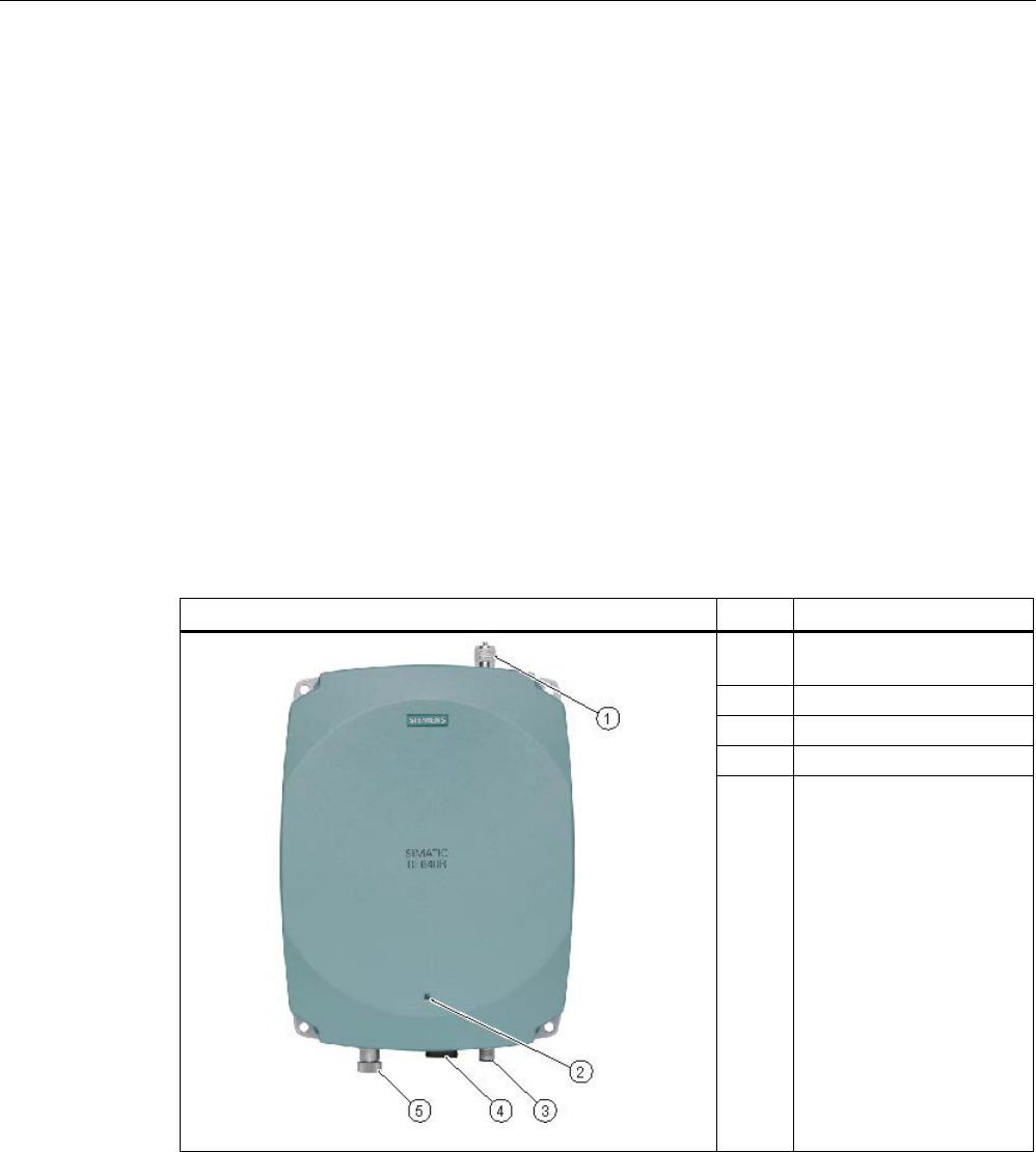
Readers
5.4 RF640R reader
SIMATIC RF600
System Manual, xx/2014, J31069-D0171-U001-A15-7618 129
REVIEW
5.4
RF640R reader
5.4.1
Description
5.4.1.1
Overview
The SIMATIC RF640R is a stationary reader in the UHF frequency band with an integrated
antenna. As an alternative, an external UHF RFID antenna can be connected via a TNC
reverse connector.
The maximum RF power output is 1000°mW at the external reader output. A radiant power
of up to 2000 mW ERP is achieved when the appropriate antennas and antenna cables are
used. The interfaces (Ethernet, M12 power supply, M12 digital I/O interface) are located
along the narrow lower front edge. These interfaces can be used to connect the reader to the
power supply and the PC for parameter assignment.
The degree of protection is IP65.
Pos.
Description
(1) TNC reverse interface for
connecting an antenna
(2)
LED operating display
(3)
24 VDC power supply
(4)
Ethernet interface (TCP/IP)
(5) Digital I/O interface

Readers
5.4 RF640R reader
SIMATIC RF600
130 System Manual, xx/2014, J31069-D0171-U001-A15-7618
REVIEW
5.4.1.2
Ordering data
Ordering data RF640R
Product
Article number
RF640R (ETSI) reader for EU, EFTA, Turkey
6GT2811-3BA00-0AA0
RF640R (FCC) reader for the USA
6GT2811-3BA00-1AA0
RF640R (CHINA) reader for CMIIT
6GT2811-3BA00-2AA0
Ordering data accessories
Product
Article number
Antenna mounting kit
6GT2890-0AA00
Connecting cable and connectors
• Digital I/O, open cable ends, 5 m
• Ethernet: 10 m (crossover cable)
• Ethernet connector on reader
according to IEC PAS 61076-3-117IE
RJ-45 Plug PRO (IP67)
• Ethernet connector, Standard IE FastConnect
RJ-45 Plug 180 (IP20)
• Ethernet cable sold by the meter, green
• 6GT2891-0DH50
• 6GT2891-1HN10
• 6GK1901-1BB10-6AA0
• 6GK1901-1BB10-2AB0
• 6XV1840-2AH10
Wide-range power supply unit for SIMATIC RF systems
• With EU plug
• With UK plug
• With US plug
• 6GT2898-0AA00
• 6GT2898-0AA10
• 6GT2898-0AA20
24 V connecting cable
5 m between reader and power supply
(for RF640R only, pin assignment is PNO-compliant)
6GT2891-0NH50
Set of protective caps
Contains 3 protective caps for antenna output and one
protective cap for digital I/O interface (required for IP65
degree of protection when some connectors are unused)
6GT2898-4AA00
RFID DVD "Software & Documentation"
6GT2080-2AA20

Readers
5.4 RF640R reader
SIMATIC RF600
System Manual, xx/2014, J31069-D0171-U001-A15-7618 131
REVIEW
5.4.1.3
Status display
The device is equipped with a three colored LED. The LED can be lit in green, red or orange.
The meaning of the indication changes in accordance with the color and state (on, off,
flashing) of the LED:
Green
LED
Red LED
Orange LED
Meaning
Off
Off
Off
The device is not connected to a power supply.
Flashing Off Off In normal
operation, no communication with the reader has taken place for a longer
period of time.
On
Off
Off
The device is ready. The connection is established.
Off
Off
Flashing
More than one tag is in the field.
Off Off On The device is starting up. The connection is established.
Exactly one tag is in the field during normal operation.
Off Flashing Off Error states with flash codes (see section Flashing codes RF640R/RF670R
(Page 479))
Off
flashes 2x
Off
At the end of the startup
Note
LED is not lit orange?
If the LED does not light up orange even though a tag is located within the field, common
causes are:
•
Antenna is switched off
•
A tag is used, that is not compatible with the reader protocol (EPC Global Class 1 Gen 2).
•
Tag is defective
•
Reader or antenna has a defect
•
Tag is not in the field of radiation of the transmit antenna
For more detailed information on the flash codes of the reader see section Flashing codes
RF640R/RF670R (Page 479)
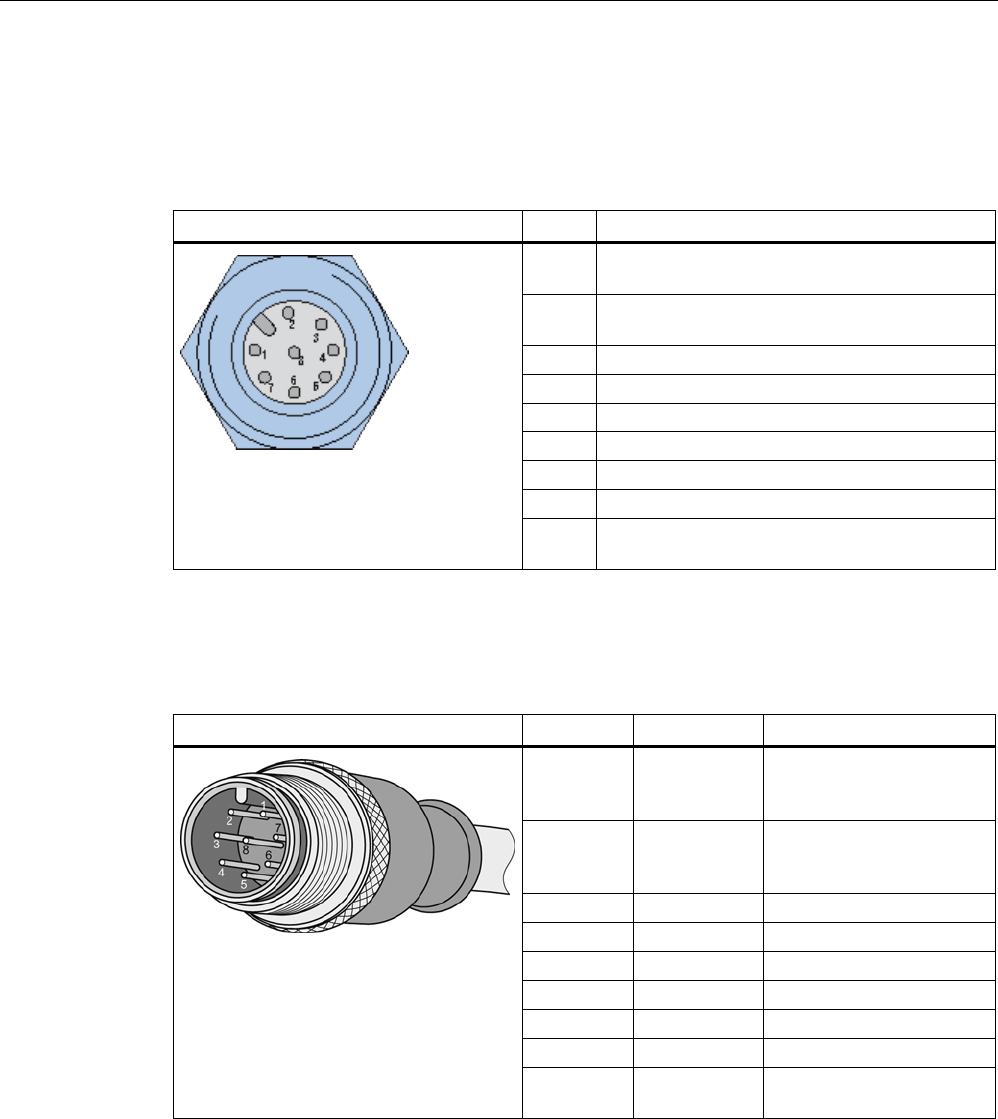
Readers
5.4 RF640R reader
SIMATIC RF600
132 System Manual, xx/2014, J31069-D0171-U001-A15-7618
REVIEW
5.4.1.4
Pin assignment of the digital I/O interface
Pin assignment, socket
Digital I/O socket (on reader side)
Pin
Pin assignment
1 GND (output to supply the digital outputs [not
electrically isolated])
2 VCC (output for supplying the digital outputs
[not RF310M, RF680M electrically isolated])
3
DO common
4
DO 0
5
DO 1
6
DI 0
7
DI common
8
DI 1
Shield is applied to the reader housing so that the
knurled ring is connected to GND of the reader.
View of the connector
Table 5- 13 Digital I/O, for cable with open cable ends
View of M12 connector
M12 pin
Wire color
Pin assignment
1 white GND (output to supply the
digital outputs [not
electrically isolated])
2 brown VCC (output for supplying
the digital outputs [not
electrically isolated])
3
green
DO common
4
yellow
DO 0
5
gray
DO 1
6 pink DI 0
7
blue
DI common
8
red
DI 1
Knurled ring Shield Knurled ring connected to
GND of the reader
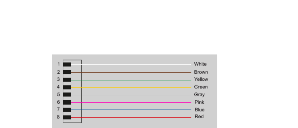
Readers
5.4 RF640R reader
SIMATIC RF600
System Manual, xx/2014, J31069-D0171-U001-A15-7618 133
REVIEW
Wiring diagram M8 plug (cable end)
You will need to assemble your reader cable with a suitable connector that fits the interface
shown above. Keep to the following wiring diagram:
Figure 5-9 Wiring diagram M8 connector
5.4.1.5
Connection scheme for the digital I/O interface
Connection possibilities
You can connect the RF640R reader in different ways. In general, the outputs and inputs
should be connected as follows:
Output Outport (0), (1)
● Each output is rated for 0.5 A current and is electronically protected.
● Two digital outputs can be operated simultaneously each with up to 0.5 A (up to 1.0 A in
total).
● The outputs are optically isolated through optocouplers.
Input Inport (0), (1)
● The inputs are optically isolated through optocouplers.
● Level Low 0 ... 3 V; High 3.6 to 24 V
● Sampling rate < 20 ms
The following diagrams illustrate various connection possibilities.
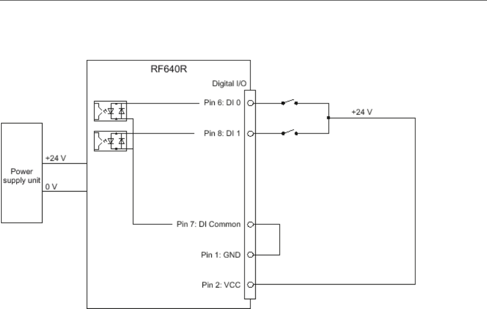
Readers
5.4 RF640R reader
SIMATIC RF600
134 System Manual, xx/2014, J31069-D0171-U001-A15-7618
REVIEW
Voltage infeed through internal source (no electrical isolation)
Figure 5-10 Example circuit 1: Digital inputs
Alternative connection possibilities:
● Pin 2 (VCC) to Pin 9 DI Common
● Pin 1 GND to busbar inputs
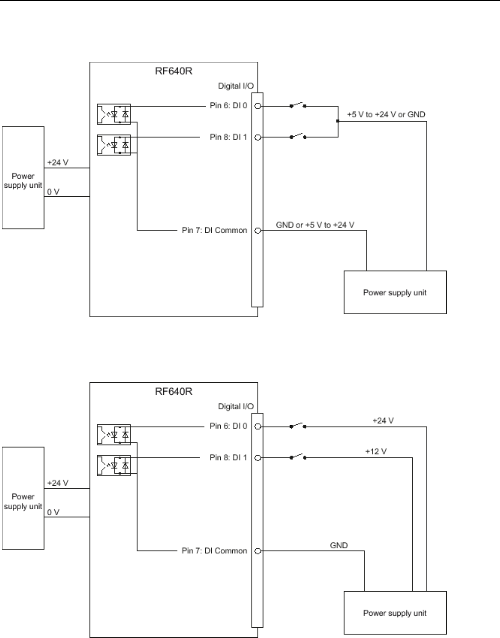
Readers
5.4 RF640R reader
SIMATIC RF600
System Manual, xx/2014, J31069-D0171-U001-A15-7618 135
REVIEW
Voltage infeed through external source
Figure 5-11 Example circuit 2: Digital inputs
Voltage infeed through external source with various voltages
Figure 5-12 Example circuit 3: Digital inputs
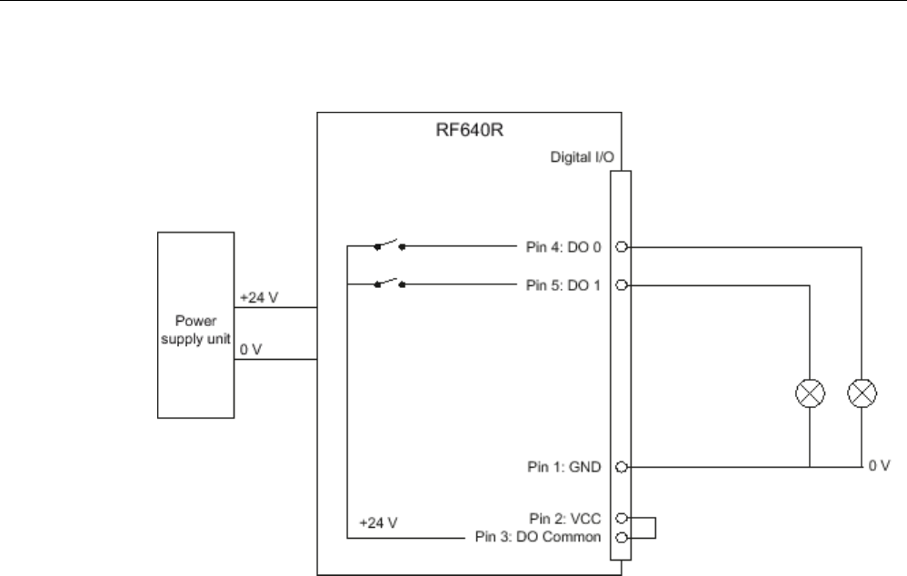
Readers
5.4 RF640R reader
SIMATIC RF600
136 System Manual, xx/2014, J31069-D0171-U001-A15-7618
REVIEW
Voltage infeed through internal source
Figure 5-13 Example circuit 4: Digital outputs
Alternative connection possibilities:
● Pin 1 GND to Pin 3 DO Common
● Pin 2 (VCC) to busbar outputs
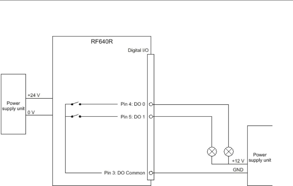
Readers
5.4 RF640R reader
SIMATIC RF600
System Manual, xx/2014, J31069-D0171-U001-A15-7618 137
REVIEW
Voltage infeed through external source
Figure 5-14 Example circuit 5: Digital outputs
Voltage infeed through an external source is shown here for 12°V by way of example. Other
voltages are also permissible.
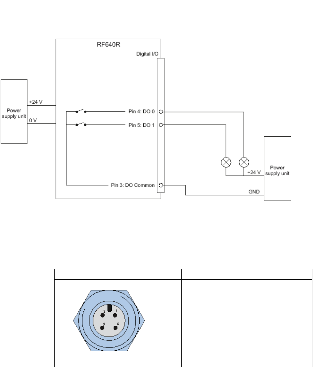
Readers
5.4 RF640R reader
SIMATIC RF600
138 System Manual, xx/2014, J31069-D0171-U001-A15-7618
REVIEW
Voltage infeed through external source with various voltages
Figure 5-15 Example circuit 6: Digital outputs
5.4.1.6
Pin assignment for power supply
Pin assignment of the power connections
Power connector (on reader side)
Pin
Pin assignment
1
2
3
4
24 VDC
Not connected
Ground (0 V)
Not connected
The power connector of the RF640R is conforms with the PNO standard, in other words,
normal PROFINET IO connectors fit this interface.

Readers
5.4 RF640R reader
SIMATIC RF600
System Manual, xx/2014, J31069-D0171-U001-A15-7618 139
REVIEW
5.4.1.7
Pin assignment for Industrial Ethernet interface
Industrial Ethernet (on reader side)
Pin
Pin assignment
1
2
3
4
5
6
7
8
Transmit Data (+)
Transmit Data (-)
Receive Data (+)
Terminated
Terminated
Receive Data (-)
Terminated
Terminated
Note
We recommend that only original Siemens Ethernet crossover cables are used (10 m cable:
Order No. 6GT2891
-1HN10) or the Siemens connector (see Section Ordering data
(Page
130)) for connecting to the Ethernet socket of the reader. If plug-in connectors from
other manufacturers are used, it may be difficult or even im
possible to remove the plug from
the reader
Note
No autocrossover
The RF640R reader does not support autocrossover!
5.4.1.8
Grounding connection
The RF640R can be electrically connected to ground potential by a contact washer. The
tightening torque must be increased in this case to ensure that electrical contact is made (2.7
Nm).
WARNING
Hazardous voltage due to lightning strikes
Death or serious injury may occur as a result of lightning strikes to antennas mounted
outside buildings.
If the reader is operated with antennas mounted outside buildings, it is imperative that the
reader is electrically connected to the ground potential.

Readers
5.4 RF640R reader
SIMATIC RF600
140 System Manual, xx/2014, J31069-D0171-U001-A15-7618
REVIEW
Ground connection
(a)
Hexagon-head screw
(b)
Plain washer
(c)
Cable lug
(d) Contact washer:
Use contact washers according to the
Siemens standard SN 70093-6-FSt-flNnnc-
480h for ground connection,
Siemens item No.: H70093-A60-Z3
5.4.2
Planning the use
5.4.2.1
Selecting the antenna
With the SIMATIC RF640R, there are two ways of using the antenna that are mutually
exclusive:
● Either you use the internal antenna of the reader
● Or you connect an external antenna to the interface of the reader. The internal antenna of
the reader can then, however, not be used at the same time.
You can select the active antenna using the configuration software, "RF-MANAGER Basic
V2".
5.4.2.2
Internal antenna
Minimum mounting clearances of two readers
The RF640R has a circular polarized antenna. At 2000 mW ERP radiated power, due to the
aperture angle of the antennas, their fields can overlap considerably. It is no longer possible
to clarify in which antenna field access to the data of a tag is performed.
In order to avoid this, always keep a minimum distance of 6 m between two readers with the
maximum radiated power of 500 mW ERP.
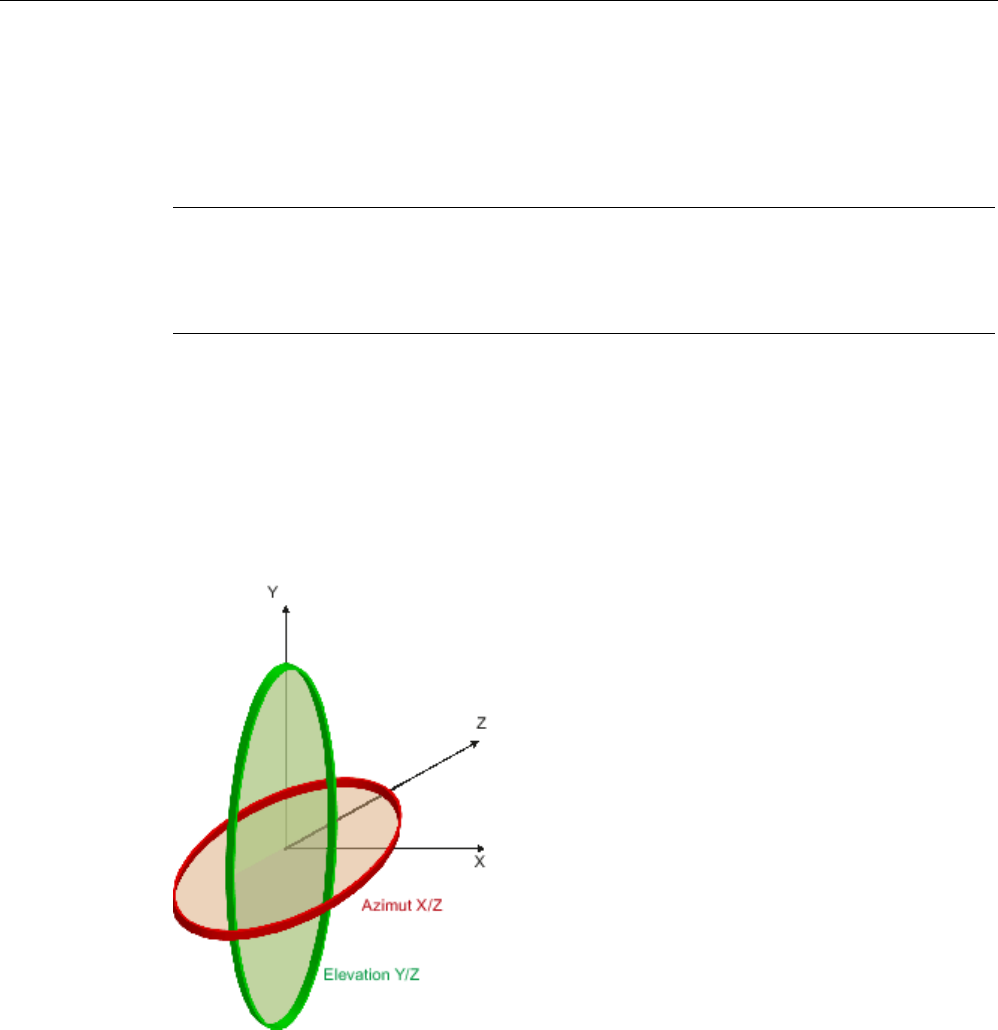
Readers
5.4 RF640R reader
SIMATIC RF600
System Manual, xx/2014, J31069-D0171-U001-A15-7618 141
REVIEW
Dense Reader Mode (DRM)
The readers can also interfere with each other (secondary fields), if the channels (Reader
TX, Transponder TX) overlap. In order to prevent a transponder channel overlapping with a
reader channel, we recommend that the Dense Reader Mode (DRM) is used.
Note
Protective cap
If you use the internal antenna of the reader, we recommend that you close the external,
unused antenna connector on the reader using the supplied protective cap.
Antenna diagram for RF640R (ETSI)
The following radiation diagrams show the directional characteristics of the internal antenna
of the RF640R (ETSI) reader. For the spatial presentation of the directional characteristics,
the vertical plane (Azimuth section) as well as the horizontal plane (elevation section) must
be considered. This results in a spatial image of the directional radiation pattern of the
antenna with its main and auxiliary fields.

Readers
5.4 RF640R reader
SIMATIC RF600
142 System Manual, xx/2014, J31069-D0171-U001-A15-7618
REVIEW
Radiation diagram (Azimuth section)
Vertical component of the polarization direction of the antenna
Horizontal component of the polarization direction of the antenna
Right circular component of the polarization direction of the antenna
Figure 5-16 Azimuth section

Readers
5.4 RF640R reader
SIMATIC RF600
System Manual, xx/2014, J31069-D0171-U001-A15-7618 143
REVIEW
Radiation diagram (elevation section)
Vertical component of the polarization direction of the antenna
Horizontal component of the polarization direction of the antenna
Right circular component of the polarization direction of the antenna
Figure 5-17 Elevation section
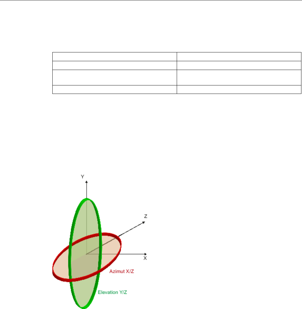
Readers
5.4 RF640R reader
SIMATIC RF600
144 System Manual, xx/2014, J31069-D0171-U001-A15-7618
REVIEW
Overview of the antenna parameters
Table 5- 14 Maximum linear electrical aperture angle at 865 MHz:
Azimuth section
77,7°
Elevation section
66,1°
Typical antenna gain in the frequency range 865
to 868 MHz
4.0 dBi
Antenna axis ratio
0.7 dB
See also section Guidelines for selecting RFID UHF antennas (Page 55)
Antenna diagram for RF640R (FCC)
The following radiation diagrams show the directional characteristics of the internal antenna
of the RF640R (FCC) reader. For the spatial presentation of the directional characteristics,
the vertical plane (Azimuth section) as well as the horizontal plane (elevation section) must
be considered. This results in a spatial image of the directional radiation pattern of the
antenna with its main and auxiliary fields.
Azimuth
XZ plane
Elevation
YZ plane

Readers
5.4 RF640R reader
SIMATIC RF600
System Manual, xx/2014, J31069-D0171-U001-A15-7618 145
REVIEW
Radiation diagram (Azimuth section)
Vertical component of the polarization direction of the antenna
Horizontal component of the polarization direction of the antenna
Right circular component of the polarization direction of the antenna
Figure 5-18 Azimuth section

Readers
5.4 RF640R reader
SIMATIC RF600
146 System Manual, xx/2014, J31069-D0171-U001-A15-7618
REVIEW
Radiation diagram (elevation section)
Vertical component of the polarization direction of the antenna
Horizontal component of the polarization direction of the antenna
Right circular component of the polarization direction of the antenna
Figure 5-19 Elevation section

Readers
5.4 RF640R reader
SIMATIC RF600
System Manual, xx/2014, J31069-D0171-U001-A15-7618 147
REVIEW
Overview of the antenna parameters
Table 5- 15 Maximum linear electrical aperture angle at 865 MHz:
Azimuth section
75,4 °
Elevation section
69,1 °
Typical antenna gain in the frequency range 902
to 928 MHz
4.0 dBi ± 0.5 dB
Antenna axis ratio
<1 dB
see also section Guidelines for selecting RFID UHF antennas (Page 55).
Interpretation of directional radiation patterns
The following overview table will help you with the interpretation of directional radiation
patterns.
The table shows which dBi values correspond to which read/write ranges (in %): You can
read the radiated power depending on the reference angle from the directional radiation
patterns, and thus obtain information on the read/write range with this reference angle with
regard to a transponder.
The dBr values correspond to the difference between the maximum dBi value and a second
dBi value.
Deviation from maximum antenna gain [dBr]
Read/write range [%]
0
100
-3
70
-6
50
-9
35
-12
25
-15
18
-18
13
Example
As one can see from the section Antenna diagram for RF640R (ETSI) (Page 141), the
maximum antenna gain is 0 dB. In the Azimuth diagram, the antenna gain falls by 3°dB at
approximately ± 39°. Therefore the dBr value is -3. The antenna range is only 50% of the
maximum range at ± 39° from the Z axis within the horizontal plane.
Antenna/read point configurations
The RF640R reader has an internal circular polarized antenna. You can cover one read point
with this antenna. When several RF640R readers are used, the readers are addressed via
the SIMATIC level.

Readers
5.4 RF640R reader
SIMATIC RF600
148 System Manual, xx/2014, J31069-D0171-U001-A15-7618
REVIEW
5.4.2.3
External antenna
Preassembled standard cables in lengths of 3 m, 5 m, 15 m and 20 m are available to
connect the antenna.
The read range is limited by the cable loss. The maximum range can be achieved with the
cable 6GT2815-0BH30 (length 3 m), since this has the lowest cable loss.
Examples of possible antenna reading point configurations
● A data source with an external antenna for a reading point.
● As an alternative, a data source with an internal antenna for a reading point.
5.4.3
Installing / mounting
Requirement
WARNING
Make sure that the wall or ceiling can hold four times the total weight of the device.
Note
Close unused connectors
If you do not use connectors on the reader, it is advisable to close the unused connectors
with protective caps. You can order the protective cap set using the MLFB specified in the
section "Ordering data".
CAUTION
Emitted radiation
The transmitter complies with the requirements of Health Canada and the FCC limit values
for subjecting persons to HF radiation, provided that a minimum spacing of 26 cm exists
between antenna and person. When the antennas are installed, you must therefore ensure
that a minimum spacing of 26 cm is maintained between personnel and antennas.
Mounting/installing the device
You can mount the reader in two different ways:
● Via a standardized VESA 100 mounting system using the Antenna Mounting Kit (see
section Mounting with antenna mounting kit (Page 331)). Tighten the M4 screws on the
rear of the reader using a maximum torque of ≤ 1.3 Nm.
● Directly onto a flat surface.
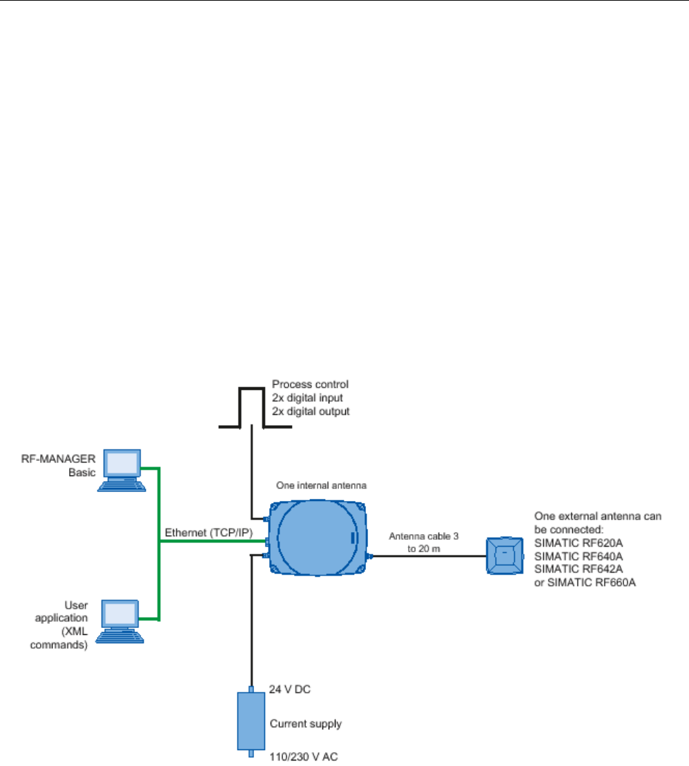
Readers
5.4 RF640R reader
SIMATIC RF600
System Manual, xx/2014, J31069-D0171-U001-A15-7618 149
REVIEW
The positions of the fixing holes for the device are shown in the section Dimension drawings
(Page 153).
5.4.4
Configuration/integration
An Ethernet interface is available for integrating the device into system
environments/networks. Over the Ethernet interface and with a direct connection to the PC,
the RF640R can be configured in two different ways:
● Using RF-MANAGER Basic V2
● Using a user application (XML commands)
The communication interface transfers the data over the RF-MANAGER Basic to the IT, ERP
and SCM systems as well as to SIMATIC controllers. Alternatively the data is transferred to
user applications by means of XML commands.
Simple process controls (e.g. signal lights) can be directly implemented using the write/read
device via two digital inputs and outputs.
Figure 5-20 Overview of configuration of the RF640R reader

Readers
5.4 RF640R reader
SIMATIC RF600
150 System Manual, xx/2014, J31069-D0171-U001-A15-7618
REVIEW
5.4.5
Technical data
5.4.5.1
Mechanical data
Mechanical data
Weight
approx. 1700 g
Housing dimensions (L x W x H)
252 x 193 x 52 mm, without connections
Material for housing top section
ABS (GF 20), silicone-free
Material for housing bottom section
Aluminum
Color of housing top section
Pastel turquoise
Color of housing bottom section
Silver
Status displays on the device 1 LED
Colors: red, yellow, green
Interfaces
Antenna connectors
1 x RTNC plug
Power supply
1 x plug (4-pin M12)
Digital I/O interface
1 x socket (8-pin M12)
Digital inputs
2
Digital outputs
2 (500 mA each; max. 1000 mA in total)
Ethernet
RJ-45 TCP/IP (push-pull) 10/100 Mbps
MTBF in years
14.3
Thermal and electrical properties
Power supply
• Permitted range
20 to 30 VDC 1
Power supply Current consumption
(in standby mode, no
transmit power)
Power requirement
(in standby mode, no
transmit power)
20 V input voltage on the reader, typical
140 mA
2.8 W
24 V input voltage on the reader, typical
120 mA
2.88 W
30 V input voltage on the reader, typical
100 mA
3.0 W
Power supply Current consumption
(at 1000 mW transmit power
/ 1600 mW ERP radiated
power)
Power requirement
(at 1000 mW transmit power
/ 1600 mW ERP radiated
power)
20 V input voltage on the reader, typical
530 mA
10.6 W
24 V input voltage on the reader, typical
450 mA
10.8 W
30 V input voltage on the reader, typical
370 mA
11.1 W
Rampup time
19 s
1)
All supply and signal voltages must be safety extra low voltage (SELV/PELV according to EN 60950)
24 VDC supply: safe (electrical) isolation of extra-low voltage (SELV / PELV acc. to EN 60950)

Readers
5.4 RF640R reader
SIMATIC RF600
System Manual, xx/2014, J31069-D0171-U001-A15-7618 151
REVIEW
Mechanical environmental conditions
Shock resistant acc. to EN 60068-2-27
Vibration acc. to EN 60068-2-6
50 g1
20 g
1
Climatic conditions
Ambient temperature during operation -25 °C to +55 °C
(a 10-minute warm-up time must be allowed at an operating
temperature below -20 °C)
Ambient temperature for transport and storage
-40 °C to +85 °C
1) The values for shock and vibration are maximum values and must not be applied continuously.
EMC & approvals/conformity for ETSI variant
Electromagnetic compatibility ETSI EN 301 489-1 / -3
EN 302 208 V1.3.1
EN 302 208 V1.4.1
Approvals/Conformity • Radio according to the R&TTE directive
• CE
• ETSI EN 302 208 V1.3.1
• ETSI EN 302 208 V1.4.1
• Reader degree of protection acc. to EN 60529 (IP65)
• RoHS-compliant according to EU Directive 2002/95/EC
• Human exposure
EMC & approvals for FCC variant
Electromagnetic compatibility
FCC Part 15
Approvals • FCC, cULus
• IEC60950, including US and Canadian variants of it
• Reader degree of protection acc. to EN 60529 (IP65)
• FCC CFR47 Part 15.247
• RoHS-compliant according to EU Directive 2002/95/EC
• Industrial Canada, RSS-210, Issue 7, June 2007

Readers
5.4 RF640R reader
SIMATIC RF600
152 System Manual, xx/2014, J31069-D0171-U001-A15-7618
REVIEW
5.4.5.2
Technical data according to EPC and ISO
Technical specifications
Frequency accuracy
max.± 10 ppm
Channel spacing EU, EFTA, Turkey: 600 kHz
US: 500 kHz
China: 250 kHz
Modulation methods ASK: DSB modulation & PR-ASK modulation
Encoding, Manchester or Pulse Interval (PIE)
Effective radiated power with internal antenna
• ETSI/CMIIT:
• FCC
• ≤ 1.6 W ERP
• ≤ 3.3 W EIRP
Effective radiated power with external antenna
• ETSI/CMIIT:
• FCC
• ≤ 2.0 W ERP
• ≤ 4.0 W EIRP
Transmit power
• ETSI/CMIIT:
• FCC
• ≤ 1.0 W
• ≤ 1.25 W
Reading range
Antennas mounted on opposing sides
(portal configuration)
max. 10 m
Antennas mounted on the same side
max. 5 m (dependent on transponder)
ETSI frequencies
Frequency range for Europe, EFTA, Turkey, South Africa,
Thailand (ETSI)
ETSI EN 302 208 V1.4.1 (valid since October 23, 2012,
publication in the Official Journal of the European Union)
865.7 ... 867.5 MHz
(4 channels LBT optional at max. 2 W ERP)
Frequency range India
865 ... 867 MHz (10 channels at 4 W EIRP)
Frequency range Russia
866.1 ... 867.6 MHz (8 channels at 2 W ERP)
Frequency range Singapore
866 ... 869 MHz (11 channels at 0.5 W ERP)
FCC frequencies
Frequency range USA; Argentina, Bolivia, Canada, Mexico,
Thailand (FCC)
902 ... 928 MHz (50 channels at max. 4 W EIRP,
frequency hopping)
Frequency range Brazil 915.125 ... 927.875 MHz (52 channels at max. 4 W EIRP,
frequency hopping)
Frequency range South Korea 917.1 ... 920.4 MHz (7-16 channels at max. 4 W EIRP,
frequency hopping)
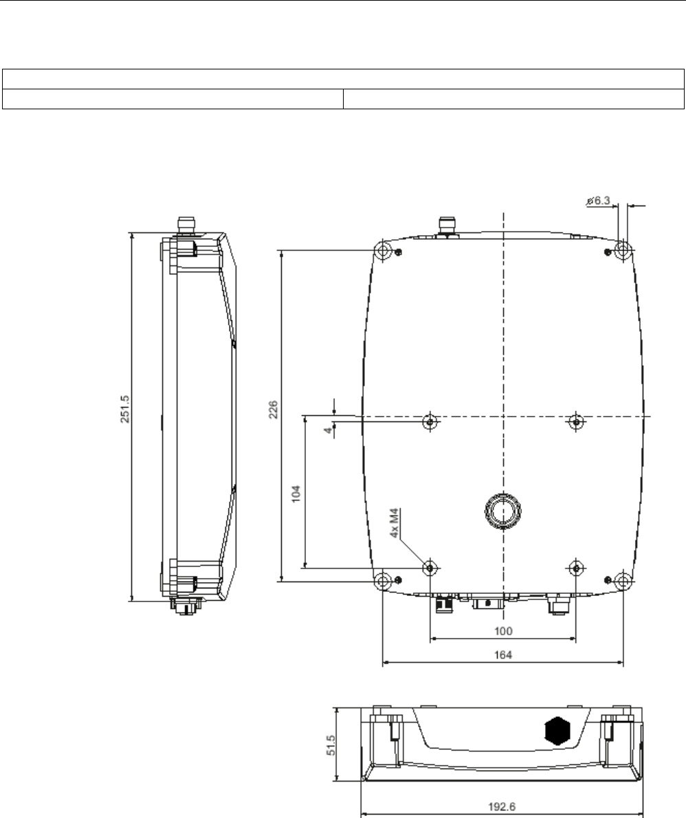
Readers
5.4 RF640R reader
SIMATIC RF600
System Manual, xx/2014, J31069-D0171-U001-A15-7618 153
REVIEW
CMIIT frequencies
Frequency range China
920.625 ... 924.375 MHz (16 subchannels at 2 W ERP)
5.4.6
Dimension drawings
Figure 5-21 Dimensional drawing of RF640R
All dimensions in mm (± 0.5 mm tolerance)
Readers
5.4 RF640R reader
SIMATIC RF600
154 System Manual, xx/2014, J31069-D0171-U001-A15-7618
REVIEW
5.4.7
Certificates and approvals
Note
Marking on the readers according to specific approval
The certificates and approvals listed here apply only if the corresponding mark is found on
the readers.
Table 5- 16 6GT2811-3BA00-0AA0
Certificate
Description
Conformity with R&TTE directive
TA-2012/548 South Africa approval:
Radio Equipment Type Approval
Table 5- 17 6GT2811-3BA00-1AA0
Standard
Federal Communications
Commission
FCC CFR 47, Part 15 sections 15.247
Radio Frequency Interference Statement
This equipment has been tested and found to comply with the limits
for a Class A digital device, pursuant to Part 15 of the FCC Rules.
FCC ID: NXW-RF600R
Industry Canada Radio
Standards Specifications
RSS-210 Issue 6, Sections 2.2, A8
IC: 267X-RF600R, Model RF640R
This product is UL-certified for the USA and Canada.
It meets the following safety standard(s):
UL 60950-1 - Information Technology Equipment Safety - Part 1:
General Requirements
CSA C22.2 No. 60950 -1 - Safety of Information Technology
Equipment
UL Report E 205089
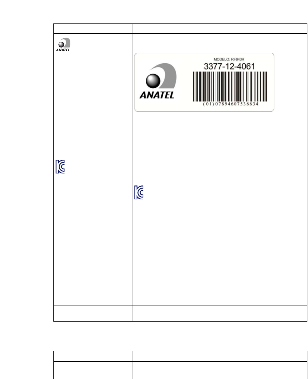
Readers
5.4 RF640R reader
SIMATIC RF600
System Manual, xx/2014, J31069-D0171-U001-A15-7618 155
REVIEW
Standard
Brazil radio approval
Marking on the reader:
Statement about approval:
Este equipamento opera em caráter secundário, isto é, não tem
direito à proteção contra interferência prejudicial, mesmo de
estações do mesmo tipo e não pode causar interferência a sistemas
operando em caráter primário.
Reader certificate: ANATEL 3377-12-4061
KCC Certification
Marking on the reader:
Type of equipment:
A급 기기 (업무용 방송통신기자재)
Class A Equipment (Industrial Broadcasting & Communication
Equipment)
이 기기는 업무용(A급) 전자파적합기기로서 판 매자 또는 사용자는 이
점을 주의하시기 바라 며, 가정외의 지역에서 사용하는 것을 목적으로
합니다.
This equipment is Industrial (Class A) electromagnetic wave
suitability equipment and seller or user should take notice of it, and
this equipment is to be used in the places except for home.
Reader certificate:
KCC-CRM-RF5-RF640R
H-11386 Argentina radio approval:
Registro de la COMISION NACIONAL DE COMUNICACIONES
RCPSIRF12-0880 Mexico radio approval:
CERTIFICADO DE HOMOLOGACION
Table 5- 18 6GT2811-3BA00-2AA1
Standard
CMIIT Certification China radio approval
Marking on the reader: CMIIT ID: 2012DJ2918

Readers
5.4 RF640R reader
SIMATIC RF600
156 System Manual, xx/2014, J31069-D0171-U001-A15-7618
REVIEW
5.4.7.1
FCC information
Siemens SIMATIC RF640R (FCC): 6GT2811-3BA00-1AA0
FCC ID: NXW-RF600R
This device complies with part 15 of the FCC rules. Operation is subject to the following two
conditions:
(1) This device may not cause harmful interference, and
(2) this device must accept any interference received, including interference that may cause
undesired operation.
Caution
Any changes or modifications not expressly approved by the party responsible for
compliance could void the user's authority to operate the equipment.
Note
This equipment has been tested and found to comply with the limits for a Class B digital
device, pursuant to part 15 of the FCC Rules.
These limits are designed to provide reasonable protection against harmful interference
when the equipment is operated in a commercial environment. This equipment generates,
uses, and can radiate radio frequency energy and, if not installed and used in accordance
with the instruction manual, may cause harmful interference to radio communications.
Operation of this equipment in a residential area is likely to cause harmful interference in
which case the user will be required to correct the interference at his own expense.
FCC Notice
To comply with FCC part 15 rules in the United States, the system must be professionally
installed to ensure compliance with the Part 15 certification.
It is the responsibility of the operator and professional installer to ensure that only certified
systems are deployed in the United States. The use of the system in any other combination
(such as co-located antennas transmitting the same information) is expressly forbidden.
FCC Exposure Information
To comply with FCC RF exposure compliance requirements, the antennas used for this
transmitter must be installed to provide a separation distance of at least 20 cm from all
persons and must not be co-located or operating in conjunction with any other antenna or
transmitter.

Readers
5.4 RF640R reader
SIMATIC RF600
System Manual, xx/2014, J31069-D0171-U001-A15-7618 157
REVIEW
5.4.7.2
IC-FCB information
Siemens SIMATIC RF640R (FCC): 6GT2811-3BA00-1AA0
IC: 267X-RF600R, Model RF640R
This device complies with Industry Canada licence-exempt RSS standard(s). Operation is
subject to the following two conditions:
(1) This device may not cause interference, and
(2) this device must accept any interference, including interference that may cause
undesired operation of the device.
Le présent appareil est conforme aux CNR d`Industrie Canada applicables aux appareils
radio exempts de licence. L`exploitation est autorisée aux deux conditions suivantes :
(1) L`appareil ne doit pas produire de brouillage, et
(2) l'utilisateur de l`appareil doit accepter tout brouillage radioélectrique subi, même si le
brouillage est susceptible d`en compromettre le fonctionnement.
Industry Canada Notice
To reduce potential radio interference to other users, the antenna type and its gain should be
so chosen that the equivalent isotropically radiated power (e.i.r.p.) is not more than that
permitted for successful communication.
Transmitter power and antenna information for antennas with a gain less than 6 dBi:
This device has been designed to operate with the SIMATIC RF620A antenna 902-928, the
SIMATIC RF640A antenna 902-928 as well as the SIMATIC RF660A antenna 902-928 listed
below, and having a maximum gain of 5.5 dBi. Arbitrary transmission power settings in
combination with other antennas or antennas having a gain greater than 5.5 dBi are strictly
prohibited for use with this device. The required antenna impedance is 50 Ohms.
Transmitter power and antenna information for antennas with a gain greater 6 dBi:
This device requires professional installation. Antennas with a gain greater 6 dBi may be
used provided the system does not exceed the radiation power of 4000 mW E.I.R.P. This
device has been designed to operate with the SIMATIC RF642A antenna 902-928 exceeding
the maximum gain of 5.5 dBi under the restriction that the RF power at the input of the
antenna must be set to meet the following relation: RF power (dBm) ≤ 30 dBm – (antenna
gain (dBi) – 6 dBi) Other antennas or system configurations for antennas having a gain
greater than 6 dBi are strictly prohibited for use with this device. The required antenna
impedance is 50 Ohms.
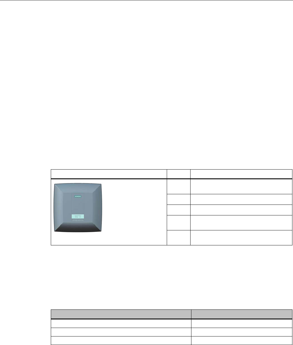
Readers
5.5 RF650R reader
SIMATIC RF600
158 System Manual, xx/2014, J31069-D0171-U001-A15-7618
REVIEW
5.5
RF650R reader
5.5.1
Description
5.5.1.1
Overview
The SIMATIC RF650R is a stationary reader in the UHF frequency band without an
integrated antenna. Up to four external UHF RFID antennas can be connected via TNC
reverse connections.
The maximum RF power output is 1000°mW at the reader output. A radiant power of up to
2000 mW ERP is achieved when the appropriate antennas and antenna cables are used.
The interfaces (Ethernet, M12 power supply, M12 digital I/O interface) are located along the
narrow lower front edge. These interfaces can be used to connect the reader to the power
supply and the PC for parameter assignment.
The degree of protection is IP30.
Pos.
Description
① TNC reserve interfaces for connecting up
to 4 antennas
②
LED operating display
③
Digital I/O interface
④
RS-422 interface
(M12 plug, 8-pin)
⑤ Ethernet interface (TCP/IP)
(RJ-45 plug, 4-pin)
5.5.1.2
Ordering data
Ordering data RF650R
Product
Article number
RF650R (ETSI) reader basic unit for EU, EFTA, Turkey
6GT2811-6AB20-0AA0
RF650R (FCC) reader basic unit for the USA
6GT2811-6AB20-1AA0
RF650R (CMIIT) reader basic unit for China 6GT2811-6AB20-2AA0

Readers
5.5 RF650R reader
SIMATIC RF600
System Manual, xx/2014, J31069-D0171-U001-A15-7618 159
REVIEW
Ordering data accessories
Product
Article number
Antenna mounting kit
6GT2890-0AA00
Connecting cable and connectors
• Digital I/O, open cable ends, 5 m
• Ethernet: 10 m (crossover cable)
• Ethernet connector on reader
according to IEC PAS 61076-3-117IE
RJ-45 Plug PRO (IP67)
• Ethernet connector, Standard IE FastConnect
RJ-45 Plug 180 (IP20)
• Ethernet cable sold by the meter, green
• 6GT2891-0CH50
• 6GT2891-1HN10
• 6GK1901-1BB10-6AA0
• 6GK1901-1BB10-2AB0
• 6XV1840-2AH10
Wide-range power supply unit for SIMATIC RF systems
• With EU plug
• With UK plug
• With US plug
• 6GT2898-0AA00
• 6GT2898-0AA10
• 6GT2898-0AA20
24 V connecting cable
5 m between reader and power supply unit
(for RF670R only, pin assignment is PNO-compliant)
6GT2891-0NH50
Set of protective caps
Contains 3 protective caps for antenna output and one
protective cap for digital I/O interface (required for IP65
degree of protection when some connectors are unused)
6GT2898-4AA00
RFID DVD "Software & Documentation"
6GT2080-2AA20
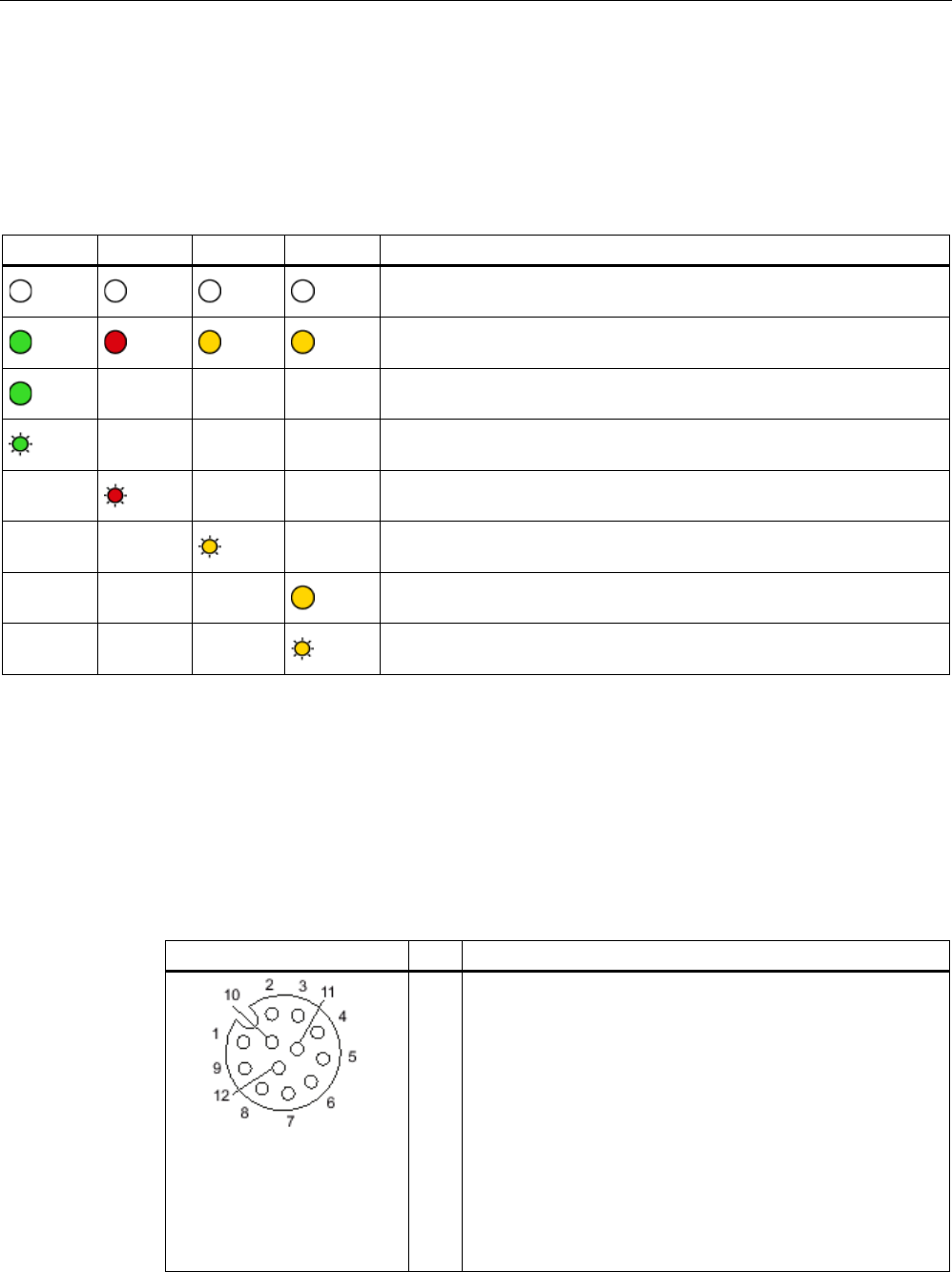
Readers
5.5 RF650R reader
SIMATIC RF600
160 System Manual, xx/2014, J31069-D0171-U001-A15-7618
REVIEW
5.5.1.3
Status display
The device is equipped with 7 three-colored LEDs. The operating statuses of the reader are
displayed by the "RUN/STOP", "ERROR", "MAINT" and "PRESENCE" LEDs. The LEDs can
be lit green, red or orange. The meaning of the display changes according to the color and
status (on, off, flashing) of the LED:
R/S
ERR
MT
PRE
Meaning
The device is turned off.
The device is starting up.
- - - The device is ready for operation. The connection is established.
- - - The device is working. Transponder data can be read or written.
- - - There is an error.
- - - Maintenance work required.
- - - There is transponder in the antenna field.
- - - There are multiple transponders in the antenna field.
For more detailed information on the flash codes of the reader, refer to the section LED
displays RF650R/RF680R/RF685R (Page 480).
5.5.1.4
Pin assignment of the digital I/O interface
View of socket (reader end)
Table 5- 19
M12 socket (reader end)
Pin
Pin assignment
1
2
3
4
5
6
7
8
9
10
11
12
GND (output for supply of digital inputs/outputs [not
electrically isolated])
VCC (output for supply of digital inputs/outputs [not electrically
isolated])
DO Common / Outport Common
DO 0 / Outport 00
DO 1 / Outport 01
DO 2 / Outport 02
DO 3 / Outport 03
DI 0 / Inport 00
DI Common / Inport Common
DI 1 / Inport 01
DI 2 / Inport 02
DI 3 / Inport 03
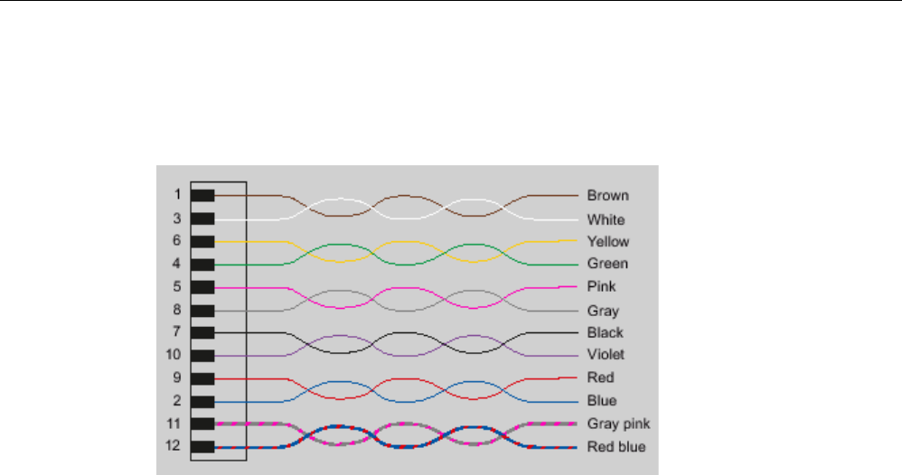
Readers
5.5 RF650R reader
SIMATIC RF600
System Manual, xx/2014, J31069-D0171-U001-A15-7618 161
REVIEW
Wiring diagram M12 connector (cable end)
You will need to assemble your reader cable with a suitable connector that fits the interface
shown above. Keep to the following wiring diagram:
Figure 5-22 M12 connector wiring diagram
5.5.1.5
Connection scheme for the digital I/O interface
Connection possibilities
You can connect the RF650R reader in different ways. In general, the outputs and inputs
should be connected as follows:
Output Outport (0), (1), (2), (3)
● Each output is rated for 0.5 A current and is electronically protected.
● 4 digital outputs can be operated simultaneously each with up to 0.5 A (up to 1.0 A in
total).
● The outputs are optically isolated through optocouplers.
Input Inport (0), (1), (2), (3)
● The inputs are optically isolated through optocouplers.
● Level Low 0 ... 3 V; High 3.6 ... 24 V
● Sampling rate < 20 ms
The following diagrams illustrate various connection possibilities.
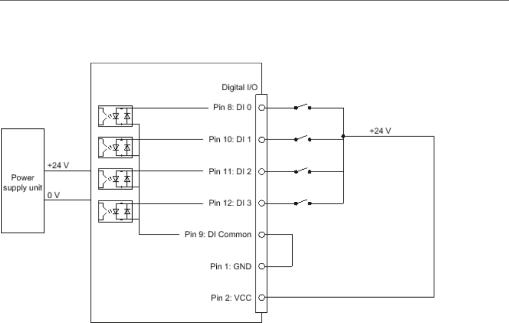
Readers
5.5 RF650R reader
SIMATIC RF600
162 System Manual, xx/2014, J31069-D0171-U001-A15-7618
REVIEW
Voltage infeed from internal source (no electrical isolation)
Figure 5-23 Circuit example 1: Digital inputs
Alternative connection possibilities:
● Pin 2 (VCC) to Pin 9 DI Common
● Pin 1 GND to busbar inputs
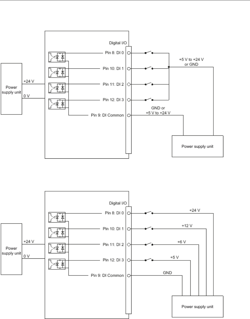
Readers
5.5 RF650R reader
SIMATIC RF600
System Manual, xx/2014, J31069-D0171-U001-A15-7618 163
REVIEW
Voltage infeed from external source
Figure 5-24 Circuit example 2: Digital inputs
Voltage infeed from external source with various voltages
Figure 5-25 Circuit example 3: Digital inputs

Readers
5.5 RF650R reader
SIMATIC RF600
164 System Manual, xx/2014, J31069-D0171-U001-A15-7618
REVIEW
Voltage infeed from internal source
Figure 5-26 Circuit example 4: Digital outputs
Alternative connection possibilities:
● Pin 1 GND to Pin 3 DO Common
● Pin 2 (VCC) to busbar outputs
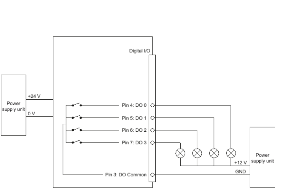
Readers
5.5 RF650R reader
SIMATIC RF600
System Manual, xx/2014, J31069-D0171-U001-A15-7618 165
REVIEW
Voltage infeed from external source
Figure 5-27 Circuit example 5: Digital outputs
Voltage infeed from an external source is shown here for 12°V by way of example. Other
voltages are also permissible.

Readers
5.5 RF650R reader
SIMATIC RF600
166 System Manual, xx/2014, J31069-D0171-U001-A15-7618
REVIEW
Voltage infeed from external source with various voltages
Figure 5-28 Circuit example 6: Digital outputs
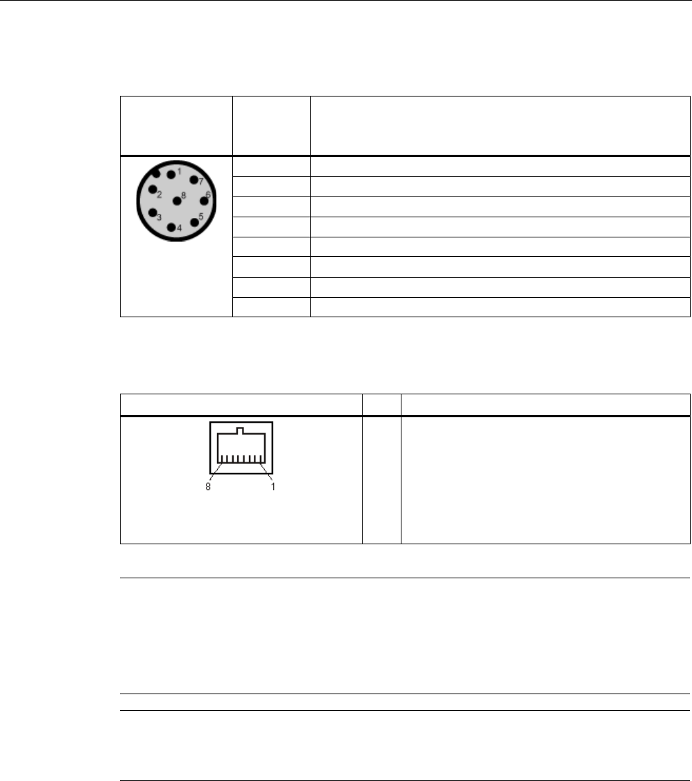
Readers
5.5 RF650R reader
SIMATIC RF600
System Manual, xx/2014, J31069-D0171-U001-A15-7618 167
REVIEW
5.5.1.6
Pin assignment of the RS-422 interface
Pin
Pin
Device end
8-pin M12
Assignment
1
+ 24 V
2
- Transmit
3
0 V
4
+ Transmit
5
+ Receive
6
- Receive
7
Unassigned
8
Earth (shield)
5.5.1.7
Pin assignment for Industrial Ethernet interface
Industrial Ethernet (on reader side)
Pin
Pin assignment
1
2
3
4
5
6
7
8
Transmit Data (+)
Transmit Data (-)
Receive Data (+)
Terminated
Terminated
Receive Data (-)
Terminated
Terminated
Note
We recommend that only original Siemens Ethernet crossover cables are used (10 m cable:
Article number 6GT2891
-1HN10) or the Siemens plug (refer to the section Ordering data
(Pag
e 158)) for connecting to the Ethernet socket of the reader. If plug-in connectors from
other manufacturers are used, it may be difficult or even impossible to remove the plu
g from
the reader.
Note
No autocrossover
The RF650R reader does not support autocrossover!
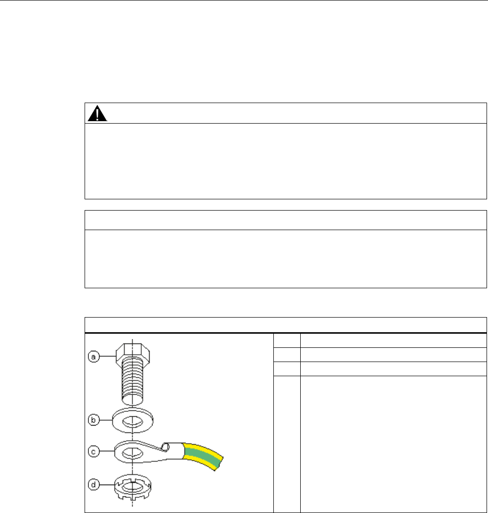
Readers
5.5 RF650R reader
SIMATIC RF600
168 System Manual, xx/2014, J31069-D0171-U001-A15-7618
REVIEW
5.5.1.8
Grounding connection
The RF650R can be electrically connected to the ground potential with a contact washer.
The tightening torque must be increased in this case to ensure that electrical contact is made
(2.7 Nm).
WARNING
Hazardous voltage due to lightning strikes
Death or serious injury may occur as a result of lightning strikes to antennas mounted
outside buildings.
If the reader is operated with antennas mounted outside buildings, it is imperative that the
reader is electrically connected to the ground potential.
NOTICE
Installation only in protected areas
The antenna can be installed in the protected part of a building. When implementing your
lightning protection concept, make sure you adhere to the VDE 0182 or IEC 62305
standards.
Ground connection
(a) Hexagon-head screw
(b)
Flat washer
(c)
Cable lug
(d) Contact washer:
Use contact washers according to the
Siemens standard SN 70093-6-FSt-flNnnc-
480h for ground connection,
Siemens item no.: H70093-A60-Z3
Readers
5.5 RF650R reader
SIMATIC RF600
System Manual, xx/2014, J31069-D0171-U001-A15-7618 169
REVIEW
5.5.2
Planning operation
5.5.2.1
Antenna/read point configurations
You can connect up to four external antennas to the RF650R reader. The standard setting is
that four antennas are connected when the reader is started. When connecting multiple
antennas, note the information in the section "Specified minimum and maximum spacing of
antennas (Page 49)".
With the graphical user interface of the integrated Web server, you can set up various
different configurations of antennas and/or reading points as required. It is possible to find
solutions to many different tasks through the number of data sources and subsequent
assignment of the antennas.
Examples of possible antenna reading point configurations
● Four data sources each with one antenna for four different reading points.
● Two data sources each with two antennas for small portals.
● One data source with 4 antennas for large portals.
You will find further information in the online Help for the products.
5.5.3
Installation/mounting
Requirement
WARNING
Make sure that the wall or ceiling can hold four times the total weight of the device.
Note
Close unused connectors
If you do not use connectors on the reader, it is advisable to close the unused connectors
with protective caps. You can order
the protective cap set using the MLFB specified in the
section "Ordering data".
CAUTION
Emitted radiation
The transmitter complies with the requirements of Health Canada and the FCC limit values
for subjecting persons to HF radiation, provided that a minimum spacing of 26 cm exists
between antenna and person. When the antennas are installed, you must therefore ensure
that a minimum spacing of 26 cm is maintained between personnel and antennas.
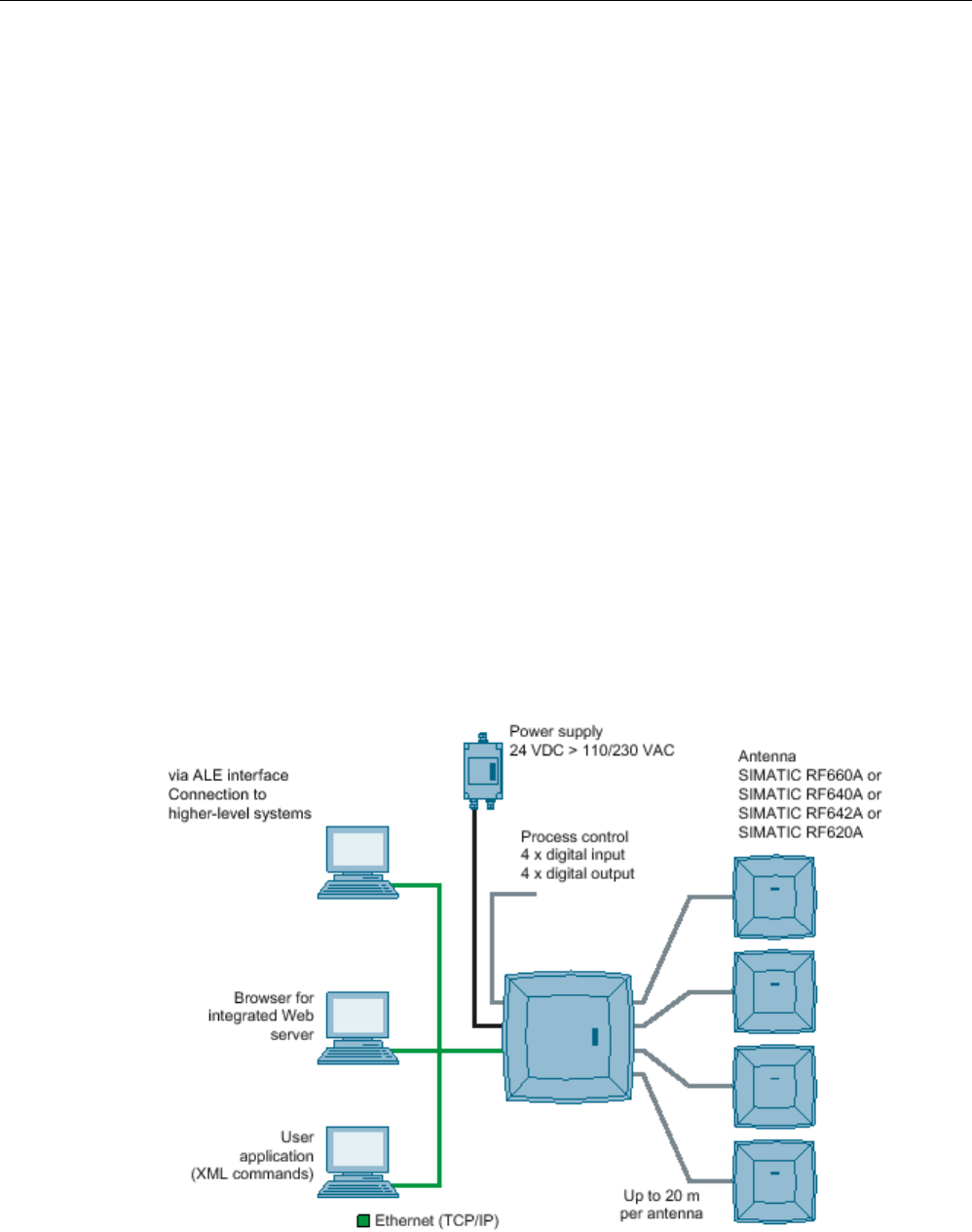
Readers
5.5 RF650R reader
SIMATIC RF600
170 System Manual, xx/2014, J31069-D0171-U001-A15-7618
REVIEW
Mounting/installing the device
You can mount the reader in two different ways:
● Via a standardized VESA 100 mounting system using the Antenna Mounting Kit (refer to
the section Mounting with antenna mounting kit (Page 331)). Tighten the M4 screws on
the rear of the reader using a maximum torque of ≤ 1.3 Nm.
● Directly on a flat surface.
The positions of the mounting holes for the device are shown in the section Dimension
drawing (Page 173).
5.5.4
Configuration/integration
An Ethernet interface is available for integrating the device into system
environments/networks. Over the Ethernet interface and with direct connection to the PC, the
RF650R can be configured in the following ways:
● via the graphical user interface of the integrated Web server
● with XML-based user applications
The communications interface transfers the data via the Web server to the IT, ERP and SCM
systems as well as to SIMATIC controllers. Alternatively the data is transferred to user
applications using XML commands.
Simple process controls (e.g. a traffic signal) can be implemented directly using the
write/read device via four digital inputs and outputs.
Figure 5-29 Overview of configuration of the RF650R reader

Readers
5.5 RF650R reader
SIMATIC RF600
System Manual, xx/2014, J31069-D0171-U001-A15-7618 171
REVIEW
5.5.5
Technical specifications
Table 5- 20 Technical specifications, RF650R
6GT2811-6AB20-xAA0
Product type designation
RF650R
Mechanical specifications
Weight
Dimensions (L x W x H)
Degree of protection
IP30
Material
• Upper part of housing Pocan DP CF 2200
• Lower part of housing Aluminum
Color
• Upper part of housing TI-Grey
• Lower part of housing Silver
Operating displays on the device
6 LEDs
Status display on the device
-
Interfaces
• Antenna connectors 4 x RTNC connector
• Power supply 1 x connector (8-pin M12), RS-422
• Digital I/O interface 1 x socket (12-pin, M12)
• Digital inputs 4
• Digital outputs 4
• Ethernet interface 1 x RJ-45 TCP/IP, 10/100 Mbps
MTBF in years
Electrical specifications
Power supply
20 to 30 VDC
1)
Current consumption (on standby)
• 20 V input voltage on the reader (typical) 220 mA / 4.4 W
• 24 V input voltage on the reader (typical) 190 mA / 4.5 W
• 30 V input voltage on the reader (typical) 150 mA / 4.5 W
Current consumption (at 1000 mW transmit power)
• 20 V input voltage on the reader (typical) 450 mA / 9.0 W
• 24 V input voltage on the reader (typical) 370 mA / 8.9 W
• 30 V input voltage on the reader (typical) 300 mA / 9.0 W

Readers
5.5 RF650R reader
SIMATIC RF600
172 System Manual, xx/2014, J31069-D0171-U001-A15-7618
REVIEW
6GT2811-6AB20-xAA0
Startup time
Electromagnetic compatibility
• ETSI EN 301 489-1/-3, EN 302 208-1/-3 V1.4.1
• FCC FCC CFR 47, Part 15 section 15.247
Permitted ambient conditions
Ambient temperature
• Operation -25 ℃ to +55 ℃
• Transport and storage -40 ℃ to +85 ℃
Shock resistant to EN 60068-2-27
50 g
2)
Vibration resistant to EN 60068-2-26
20 g
2)
1)
All supply and signal voltages must be safety extra-low voltage (SELV/PELV according to EN 60950). All power sources
must meet the requirements for LPS (Limited Power Sources) and NEC Class 2.
2) The values for shock and vibration are maximum values and must not be applied continuously.
Table 5- 21 Technical specifications according to EPC and ISO, RF650R
6GT2811-6AB20-xAA0
Product type designation
RF650R
Frequency accuracy
max.± 10 ppm
Channel spacing • EU, EFTA, Turkey: 600 kHz
• US: 500 kHz
• China: 250 kHz
Modulation methods ASK: DSB modulation & PR-ASK modulation
Encoding, Manchester or Pulse Interval (PIE)
Effective radiated power
• ETSI/CMIIT • ≤ 2 W ERP
• FCC • ≤ 3 W EIRP
Transmit power
• ETSI/CMIIT • ≤ 1 W
• FCC • ≤ 1 W
Reading range
Antennas mounted on opposing sides (portal
configuration)
max. 10 m
Antennas mounted on the same side
max. 5 m (dependent on transponder)
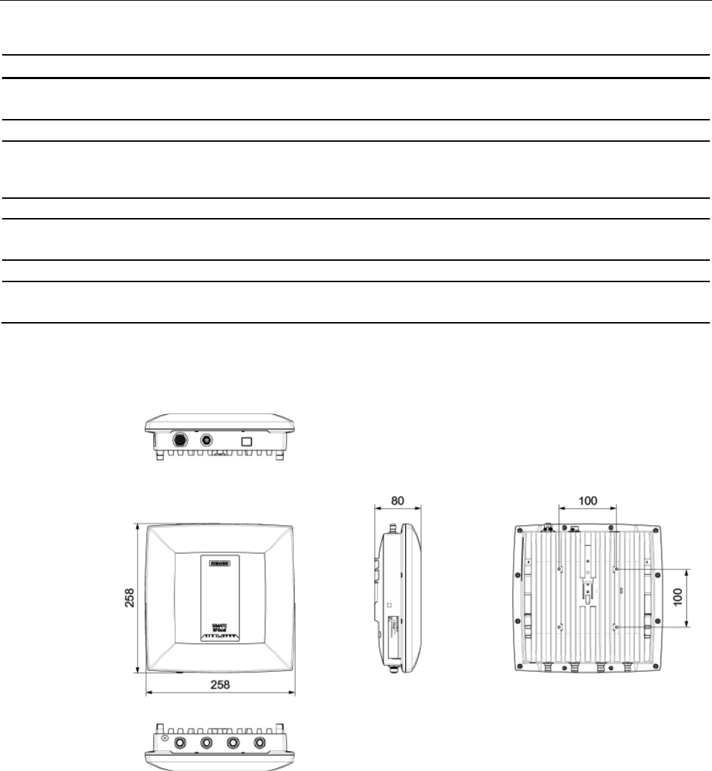
Readers
5.5 RF650R reader
SIMATIC RF600
System Manual, xx/2014, J31069-D0171-U001-A15-7618 173
REVIEW
6GT2811-6AB20-xAA0
Frequencies
ETSI frequencies
European frequency band
ETSI EN 302 208 V1.4.1 (valid since October 23, 2012,
publication in the Official Journal of the European Union)
865.7 ... 867.5 MHz
(4 channels at max. 2 W ERP)
FCC frequencies
Frequency band USA 902 ... 928 MHz
(50 channels at max. 4 W ERP, frequency hopping)
CMIIT frequencies
Frequency range China 920.625 ... 924.375 MHz
(16 subchannels at 2 W ERP)
5.5.6
Dimension drawing
Figure 5-30 Dimension drawing RF650R
All dimensions in mm (± 0.5 mm tolerance)

Readers
5.5 RF650R reader
SIMATIC RF600
174 System Manual, xx/2014, J31069-D0171-U001-A15-7618
REVIEW
5.5.7
Certificates and approvals
Note
Marking on the readers according to specific approval
The certificates and approvals listed here apply only if the corresponding mark is found on
the readers.
Table 5- 22 6GT2811-6AB20-0AA0
Certificate
Description
Conformity with R&TTE directive
Table 5- 23 6GT2811-6AB20-1AA0
Standard
Federal Communications
Commission
FCC CFR 47, Part 15 sections 15.247
Radio Frequency Interference Statement
This equipment has been tested and found to comply with the limits
for a Class B digital device, pursuant to Part 15 of the FCC Rules.
FCC ID: ??????
Industry Canada Radio
Standards Specifications
RSS-210 Issue 7, June 2007, Sections 2.2, A8
IC: ??????
This product is UL-certified for the USA and Canada.
It meets the following safety standard(s):
UL 60950-1 - Information Technology Equipment Safety - Part 1:
General Requirements
CSA C22.2 No. 60950 -1 - Safety of Information Technology
Equipment
UL Report E 205089
Table 5- 24 6GT2811-6AB20-2AA0
Standard
CMIIT Certification China radio approval
Marking on the reader: CMIIT ID: ??????

Readers
5.5 RF650R reader
SIMATIC RF600
System Manual, xx/2014, J31069-D0171-U001-A15-7618 175
REVIEW
5.5.7.1
FCC information
Siemens SIMATIC RF650R (FCC): 6GT2811-6AB20-1AA0
FCC ID:
This device complies with part 15 of the FCC rules. Operation is subject to the following two
conditions:
(1) This device may not cause harmful interference, and
(2) this device must accept any interference received, including interference that may cause
undesired operation.
Caution
Any changes or modifications not expressly approved by the party responsible for
compliance could void the user's authority to operate the equipment.
Note
This equipment has been tested and found to comply with the limits for a Class B digital
device, pursuant to part 15 of the FCC Rules.
These limits are designed to provide reasonable protection against harmful interference
when the equipment is operated in a commercial environment. This equipment generates,
uses, and can radiate radio frequency energy and, if not installed and used in accordance
with the instruction manual, may cause harmful interference to radio communications.
Operation of this equipment in a residential area is likely to cause harmful interference in
which case the user will be required to correct the interference at his own expense.
FCC Notice
To comply with FCC part 15 rules in the United States, the system must be professionally
installed to ensure compliance with the Part 15 certification.
It is the responsibility of the operator and professional installer to ensure that only certified
systems are deployed in the United States. The use of the system in any other combination
(such as co-located antennas transmitting the same information) is expressly forbidden.
FCC Exposure Information
To comply with FCC RF exposure compliance requirements, the antennas used for this
transmitter must be installed to provide a separation distance of at least 20 cm from all
persons and must not be co-located or operating in conjunction with any other antenna or
transmitter.

Readers
5.5 RF650R reader
SIMATIC RF600
176 System Manual, xx/2014, J31069-D0171-U001-A15-7618
REVIEW
5.5.7.2
IC-FCB information
Siemens SIMATIC RF650R (FCC): 6GT2811-6AB20-1AA0
IC:
This device complies with Industry Canada licence-exempt RSS standard(s). Operation is
subject to the following two conditions:
(1) This device may not cause interference, and
(2) this device must accept any interference, including interference that may cause
undesired operation of the device.
Le présent appareil est conforme aux CNR d`Industrie Canada applicables aux appareils
radio exempts de licence. L`exploitation est autorisée aux deux conditions suivantes :
(1) L`appareil ne doit pas produire de brouillage, et
(2) l'utilisateur de l`appareil doit accepter tout brouillage radioélectrique subi, même si le
brouillage est susceptible d`en compromettre le fonctionnement.
Industry Canada Notice
To reduce potential radio interference to other users, the antenna type and its gain should be
so chosen that the equivalent isotropically radiated power (e.i.r.p.) is not more than that
permitted for successful communication.
Transmitter power and antenna information for antennas with a gain less than 6 dBi:
This device has been designed to operate with the SIMATIC RF620A antenna 902-928, the
SIMATIC RF640A antenna 902-928 as well as the SIMATIC RF660A antenna 902-928 listed
below, and having a maximum gain of 5.5 dBi.
Arbitrary transmission power settings in combination with other antennas or antennas having
a gain greater than 5.5 dBi are strictly prohibited for use with this device.
The required antenna impedance is 50 Ohms.
Transmitter power and antenna information for antennas with a gain greater 6 dBi:
This device requires professional installation. Antennas with a gain greater 6 dBi may be
used provided the system does not exceed the radiation power of 4000 mW E.I.R.P. This
device has been designed to operate with the SIMATIC RF642A antenna 902-928 exceeding
the maximum gain of 5.5 dBi under the restriction that the RF power at the input of the
antenna must be set to meet the following relation: RF power (dBm) ≤ 30 dBm – (antenna
gain (dBi) – 6 dBi) Other antennas or system configurations for antennas having a gain
greater than 6 dBi are strictly prohibited for use with this device. The required antenna
impedance is 50 Ohms.
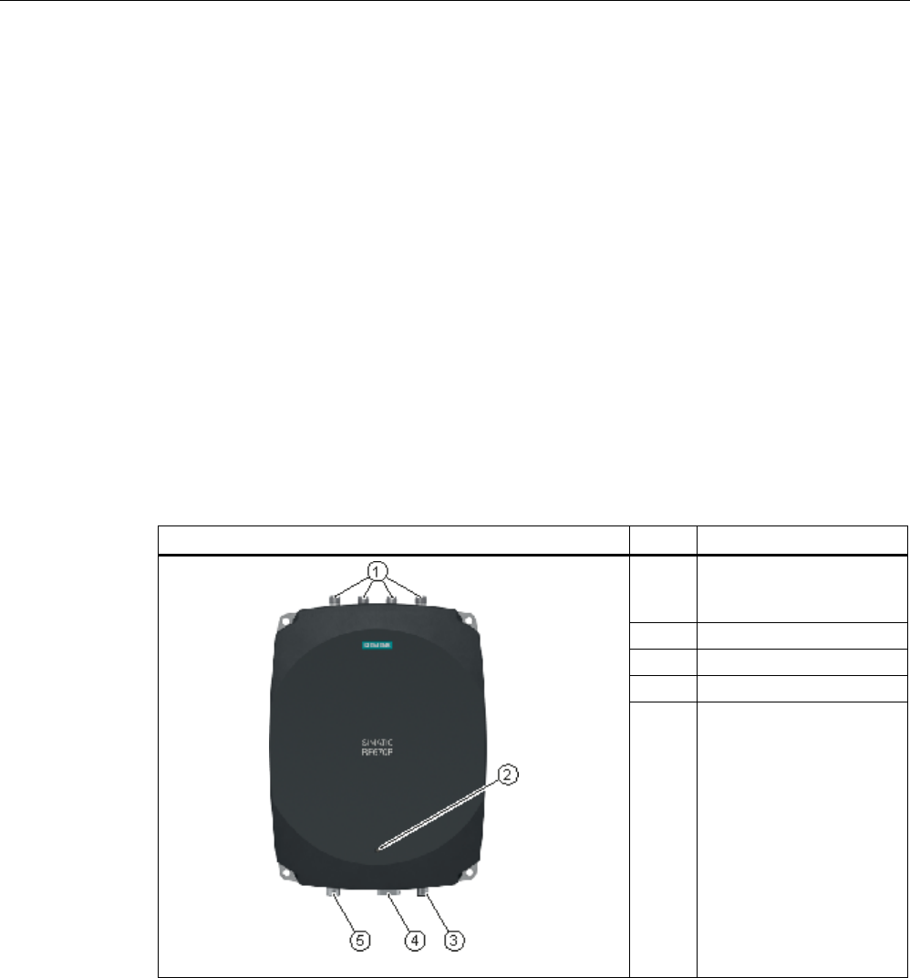
Readers
5.6 RF670R reader
SIMATIC RF600
System Manual, xx/2014, J31069-D0171-U001-A15-7618 177
REVIEW
5.6
RF670R reader
5.6.1
Description
5.6.1.1
Overview
The SIMATIC RF670R is a stationary reader in the UHF frequency band without an
integrated antenna. Up to four external UHF RFID antennas can be connected via TNC
reverse connections.
The maximum RF power output is 1000°mW at the reader output. A radiant power of up to
2000 mW ERP is achieved when the appropriate antennas and antenna cables are used.
The interfaces (Ethernet, M12 power supply, M12 digital I/O interface) are located along the
narrow lower front edge. These interfaces can be used to connect the reader to the power
supply and the PC for parameter assignment.
The degree of protection is IP65.
Pos.
Description
(1) TNC reverse interfaces for
connecting up to four
antennas
(2)
LED operating display
(3)
24 VDC power supply
(4)
Ethernet interface (TCP/IP)
(5) Digital I/O interface

Readers
5.6 RF670R reader
SIMATIC RF600
178 System Manual, xx/2014, J31069-D0171-U001-A15-7618
REVIEW
5.6.1.2
Ordering data
Ordering data for RF670R
Product
Article number
RF670R (ETSI) reader basic unit for EU, EFTA, Turkey
6GT2811-0AB00-0AA0
RF670R (FCC) reader basic unit for the USA
6GT2811-0AB00-1AA0
RF670R (CMIIT) reader basic unit for China
6GT2811-0AB00-2AA0
Ordering data accessories
Product
Article number
Antenna mounting kit
6GT2890-0AA00
Connecting cable and connectors
• Digital I/O, open cable ends, 5 m
• Ethernet: 10 m (crossover cable)
• Ethernet connector on reader
according to IEC PAS 61076-3-117IE
RJ-45 Plug PRO (IP67)
• Ethernet connector, Standard IE FastConnect
RJ-45 Plug 180 (IP20)
• Ethernet cable sold by the meter, green
• 6GT2891-0CH50
• 6GT2891-1HN10
• 6GK1901-1BB10-6AA0
• 6GK1901-1BB10-2AB0
• 6XV1840-2AH10
Wide-range power supply unit for SIMATIC RF systems
• With EU plug
• With UK plug
• With US plug
• 6GT2898-0AA00
• 6GT2898-0AA10
• 6GT2898-0AA20
24 V connecting cable
5 m between reader and power supply unit
(for RF670R only, pin assignment is PNO-compliant)
6GT2891-0NH50
Set of protective caps
Contains 3 protective caps for antenna output and one
protective cap for digital I/O interface (required for IP65
degree of protection when some connectors are unused)
6GT2898-4AA00
RFID DVD "Software & Documentation"
6GT2080-2AA20
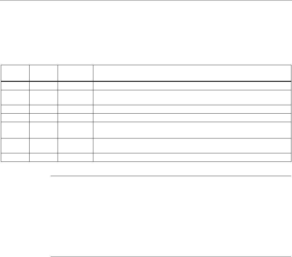
Readers
5.6 RF670R reader
SIMATIC RF600
System Manual, xx/2014, J31069-D0171-U001-A15-7618 179
REVIEW
5.6.1.3
Status display
The device is equipped with a three colored LED. The LED can be lit in green, red or orange.
The meaning of the indication changes in accordance with the color and state (on, off,
flashing) of the LED:
Green
LED
Red LED
Orange LED
Meaning
Off
Off
Off
The device is not connected to a power supply.
Flashing Off Off
In normal operation, no communication with the reader has taken place for a longer
period of time.
On
Off
Off
The device is ready. The connection is established.
Off
Off
Flashing
More than one tag is in the field.
Off Off On The device is starting up. The connection is established.
Exactly one tag is in the field during normal operation.
Off Flashing Off Error states with flash codes (see section Flashing codes RF640R/RF670R
(Page 479))
Off
flashes 2x
Off
At the end of the startup
Note
LED is not lit orange?
If the LED does not light up orange even though a tag is located within the field, common
causes are:
•
Antenna is switched off
•
A tag is used, that is not compatible with the reader protocol (EPC Global Class 1 Gen 2).
•
Tag is defective
•
Reader or antenna has a defect
•
Tag is not in the field of radiation of the transmit antenna
For more detailed information on the flash codes of the reader see section Flashing codes
RF640R/RF670R (Page 479)
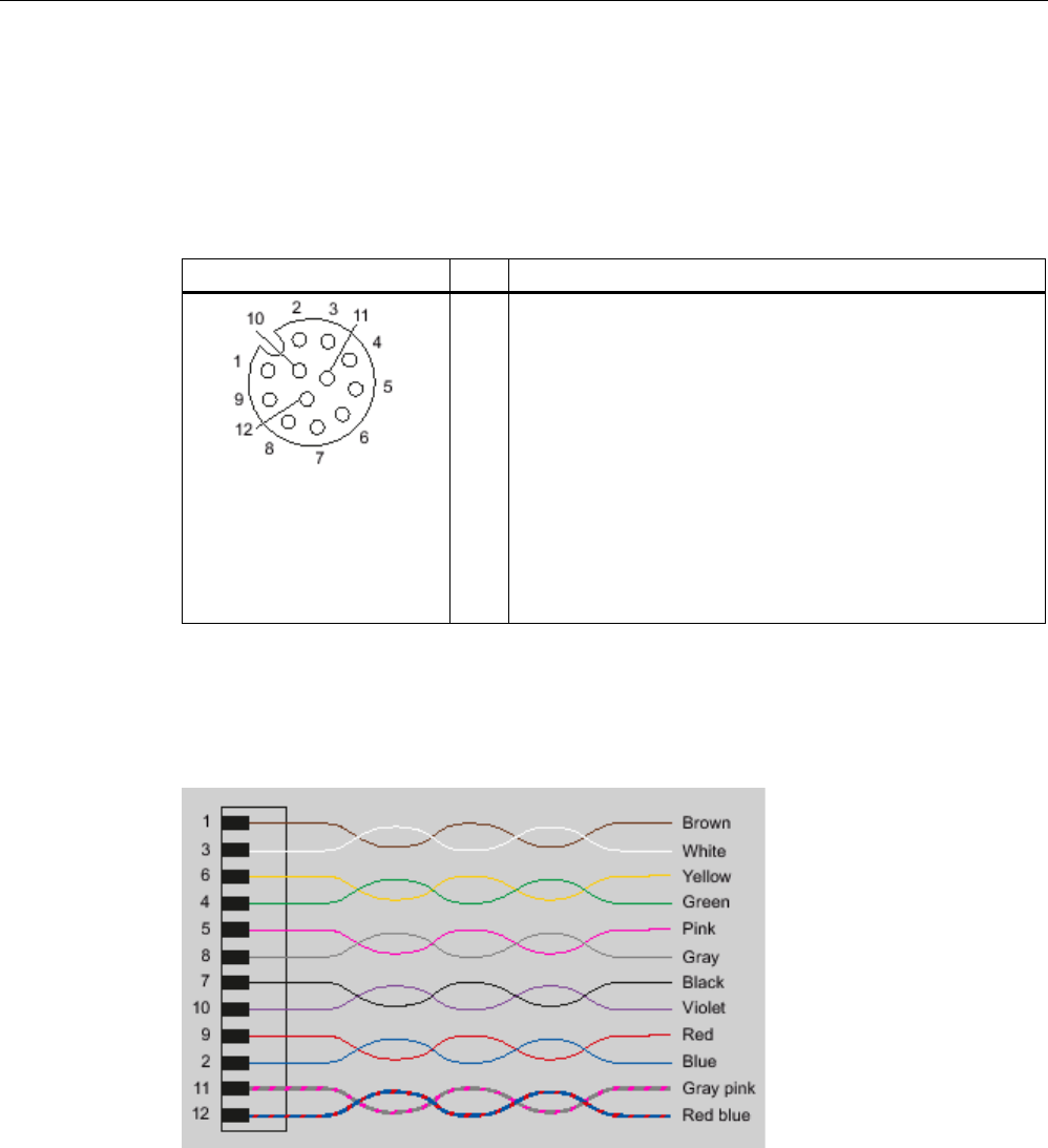
Readers
5.6 RF670R reader
SIMATIC RF600
180 System Manual, xx/2014, J31069-D0171-U001-A15-7618
REVIEW
5.6.1.4
Pin assignment of the digital I/O interface
View of socket (reader end)
Table 5- 25
M12 socket (reader end)
Pin
Pin assignment
1
2
3
4
5
6
7
8
9
10
11
12
GND (output for supply of digital inputs/outputs [not
electrically isolated])
VCC (output for supply of digital inputs/outputs [not electrically
isolated])
DO Common / Outport Common
DO 0 / Outport 00
DO 1 / Outport 01
DO 2 / Outport 02
DO 3 / Outport 03
DI 0 / Inport 00
DI Common / Inport Common
DI 1 / Inport 01
DI 2 / Inport 02
DI 3 / Inport 03
Wiring diagram M12 connector (cable end)
You will need to assemble your reader cable with a suitable connector that fits the interface
shown above. Keep to the following wiring diagram:
Figure 5-31 M12 connector wiring diagram
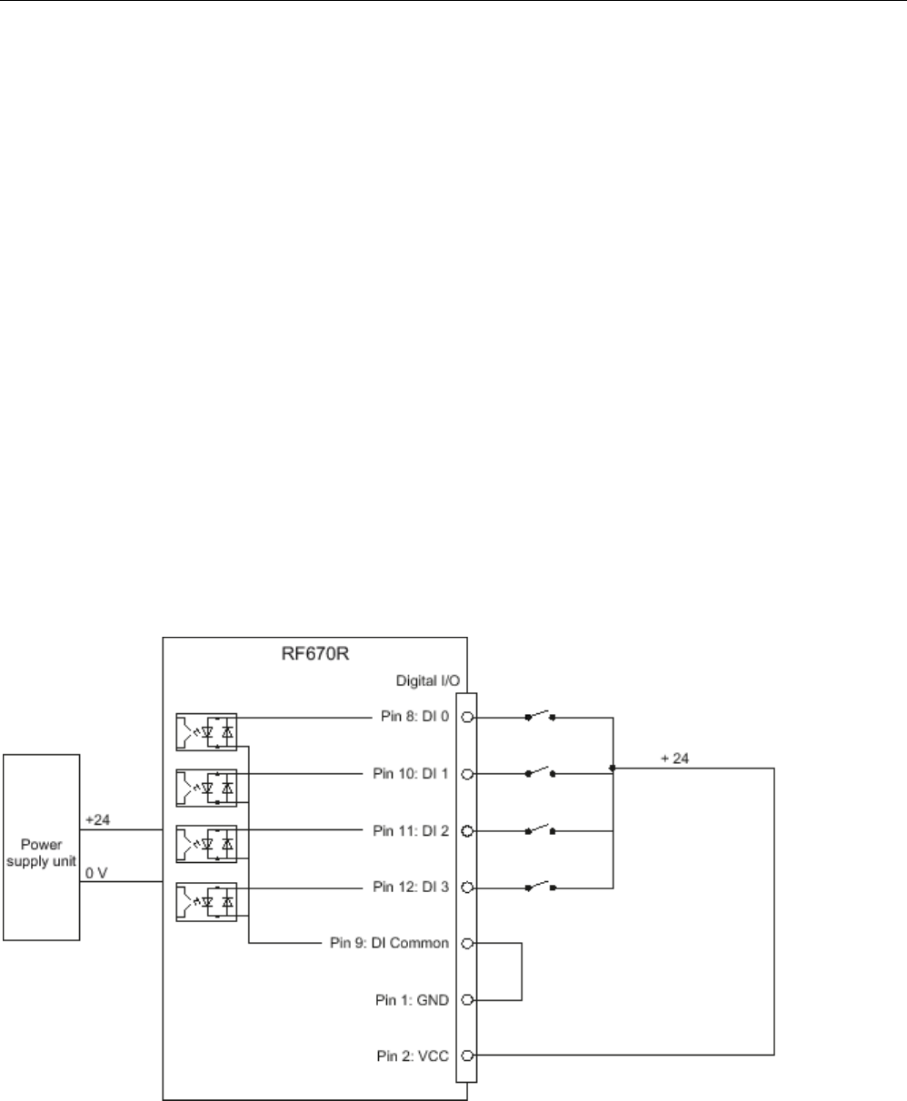
Readers
5.6 RF670R reader
SIMATIC RF600
System Manual, xx/2014, J31069-D0171-U001-A15-7618 181
REVIEW
5.6.1.5
Connection scheme for the digital I/O interface
Connection possibilities
You can connect the RF670R reader in different ways. In general, the outputs and inputs
should be connected as follows:
Output Outport (0), (1), (2), (3)
● Each output is rated for 0.5 A current and is electronically protected.
● Four digital outputs can be operated simultaneously with up to 0.5 A each (up to 1.5 A in
total).
● The outputs are optically isolated through optocouplers.
Input Inport (0), (1), (2), (3)
● The inputs are optically isolated through optocouplers.
● Level Low 0 ... 3 V; High 3,6 ... 24 V
● Sampling rate < 20 ms
The following diagrams illustrate various connection possibilities.
Voltage infeed through internal source (no electrical isolation)
Figure 5-32 Example circuit 1: Digital inputs
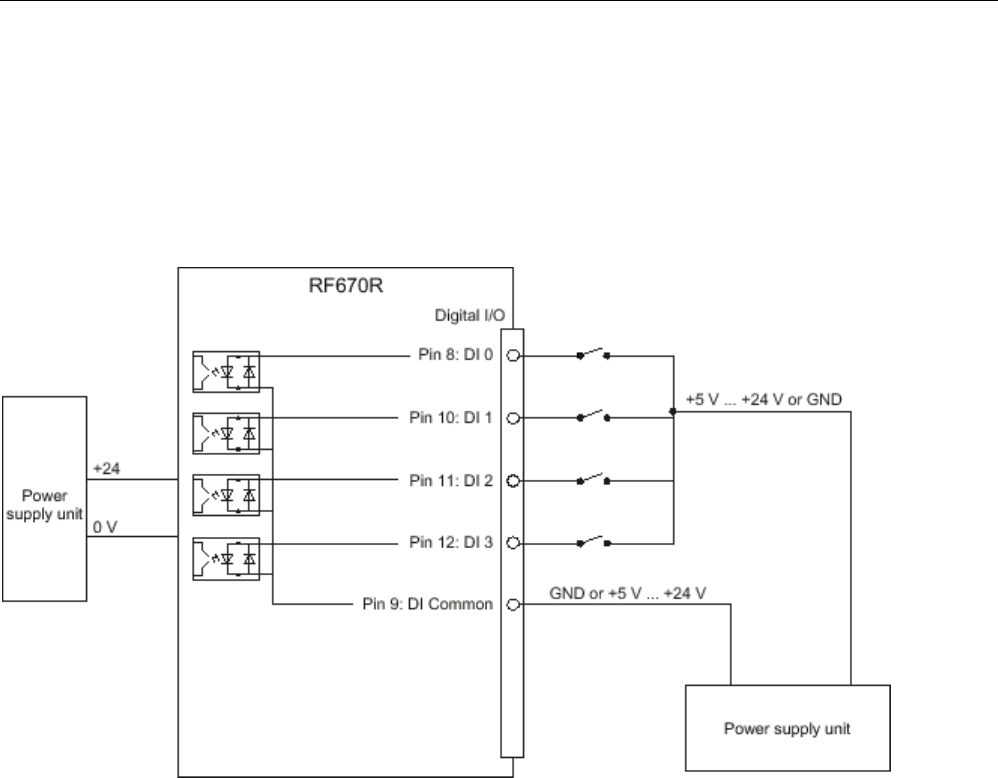
Readers
5.6 RF670R reader
SIMATIC RF600
182 System Manual, xx/2014, J31069-D0171-U001-A15-7618
REVIEW
Alternative connection possibilities:
● Pin 2 (VCC) to Pin 9 DI Common
● Pin 1 GND to busbar inputs
Voltage infeed through external source
Figure 5-33 Example circuit 2: Digital inputs
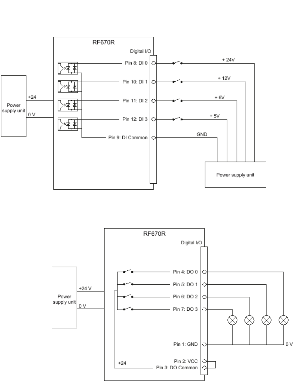
Readers
5.6 RF670R reader
SIMATIC RF600
System Manual, xx/2014, J31069-D0171-U001-A15-7618 183
REVIEW
Voltage infeed through external source with various voltages
Figure 5-34 Example circuit 3: Digital inputs
Voltage infeed through internal source
Figure 5-35 Example circuit 4: Digital outputs
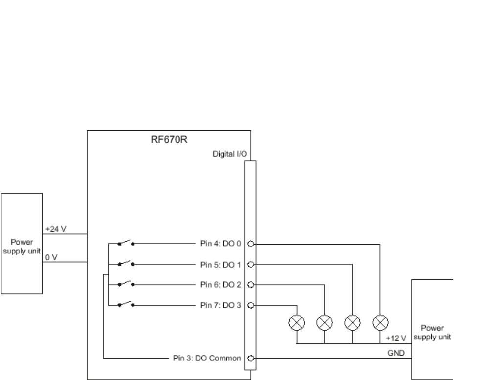
Readers
5.6 RF670R reader
SIMATIC RF600
184 System Manual, xx/2014, J31069-D0171-U001-A15-7618
REVIEW
Alternative connection possibilities:
● Pin 1 GND to Pin 3 DO Common
● Pin 2 (VCC) to busbar outputs
Voltage infeed through external source
Figure 5-36 Example circuit 5: Digital outputs
Voltage infeed through an external source is shown here for 12°V by way of example. Other
voltages are also permissible.
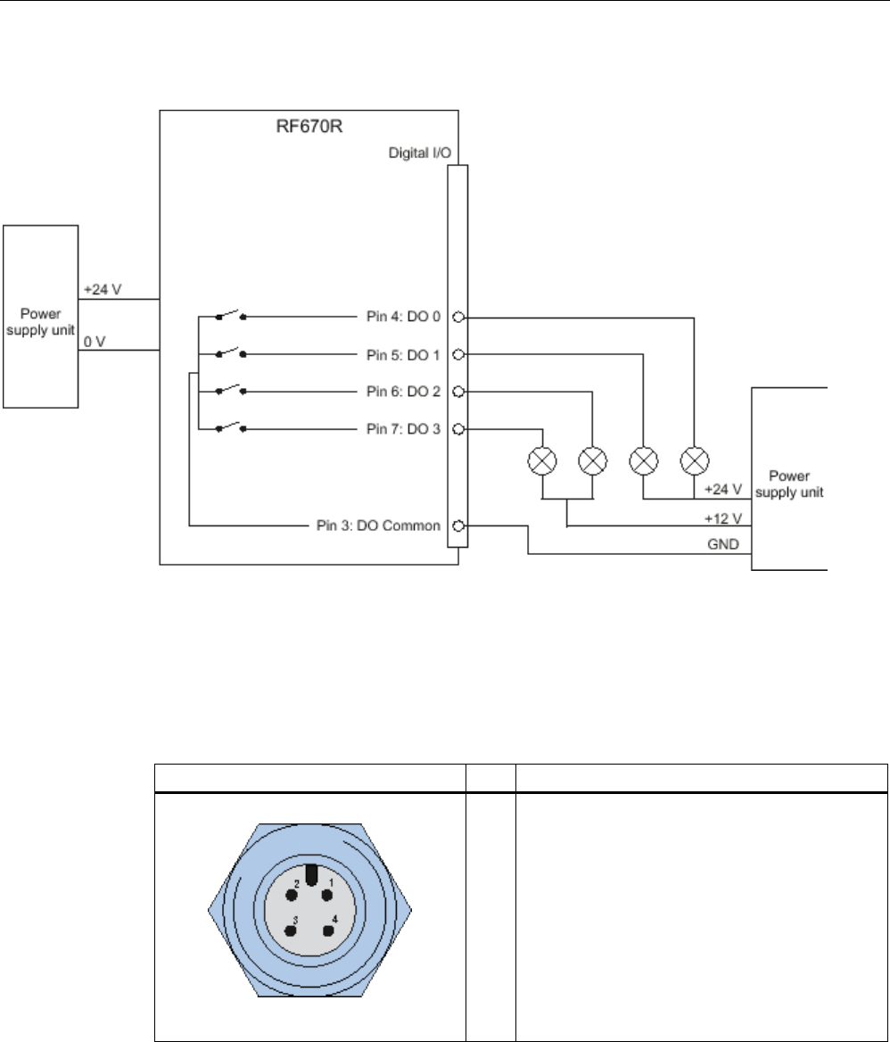
Readers
5.6 RF670R reader
SIMATIC RF600
System Manual, xx/2014, J31069-D0171-U001-A15-7618 185
REVIEW
Voltage infeed through external source with various voltages
Figure 5-37 Example circuit 6: Digital outputs
5.6.1.6
Pin assignment for power supply
Pin assignment of the power connections
Power connector (on reader side)
Pin
Pin assignment
1
2
3
4
24 VDC
Not connected
Ground (0 V)
Not connected
The power connector of the RF670R is PNO compatible, i.e.° normal PROFINET IO
connectors will fit this interface.
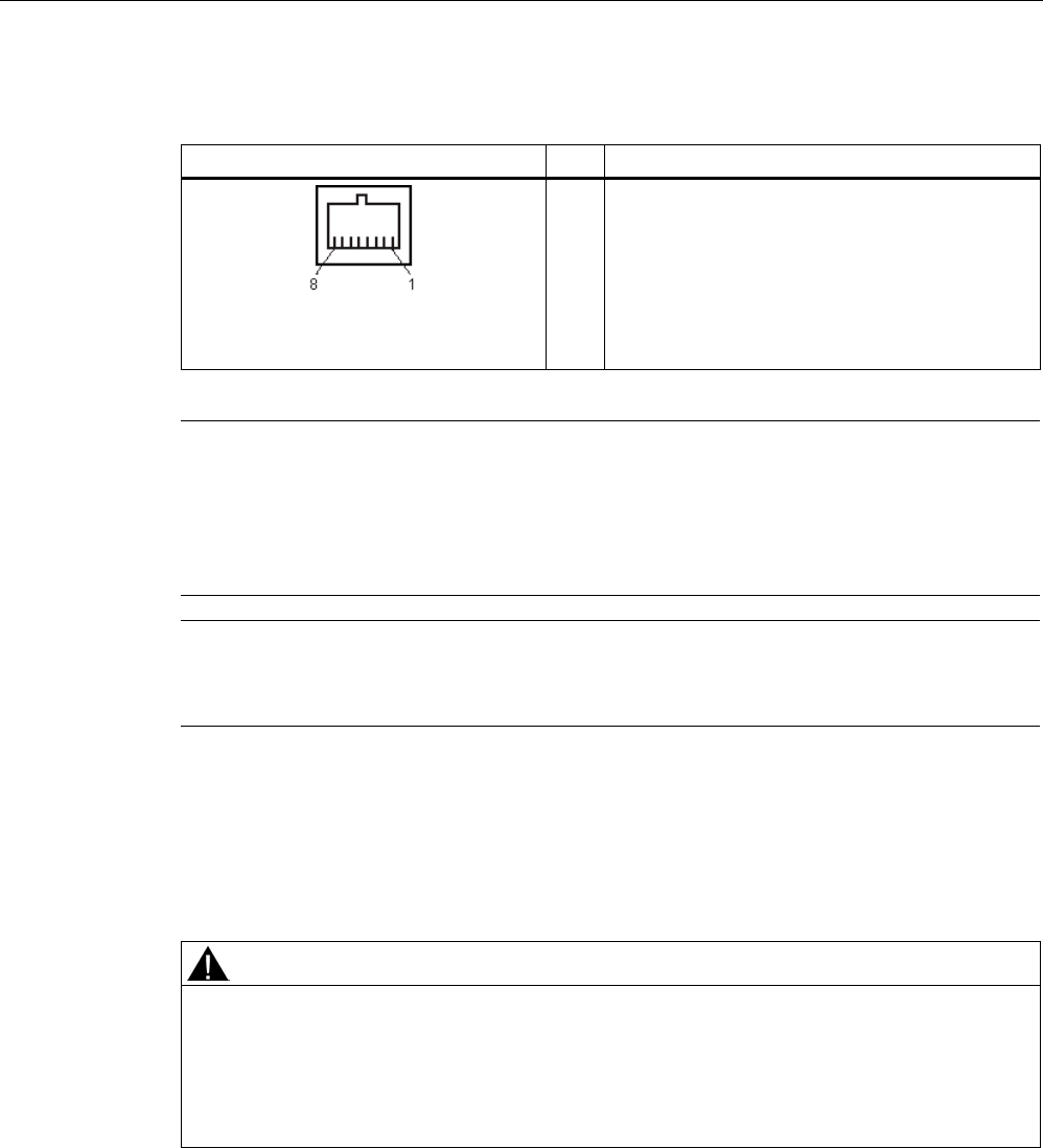
Readers
5.6 RF670R reader
SIMATIC RF600
186 System Manual, xx/2014, J31069-D0171-U001-A15-7618
REVIEW
5.6.1.7
Pin assignment for Industrial Ethernet interface
Industrial Ethernet (on reader side)
Pin
Pin assignment
1
2
3
4
5
6
7
8
Transmit Data (+)
Transmit Data (-)
Receive Data (+)
Terminated
Terminated
Receive Data (-)
Terminated
Terminated
Note
We recommend that only original Siemens Ethernet crossover cables are used (10 m cable:
Order No. 6GT2891
-1HN10) or the Siemens connector (see Section Ordering data
(Page
178)) for connecting to the Ethernet socket of the reader. If plug-in connectors from
other manufacturers are used, it may be difficult or even im
possible to remove the plug from
the reader
Note
No autocrossover
The RF670R reader does not support autocrossover!
5.6.1.8
Grounding connection
The RF670R can be electrically connected to the ground potential through a contact washer.
The tightening torque must be increased in this case to ensure that electrical contact is made
(2.7 Nm).
WARNING
Hazardous voltage due to lightning strikes
Death or serious injury may occur as a result of lightning strikes to antennas mounted
outside buildings.
If the reader is operated with antennas mounted outside buildings, it is imperative that the
reader is electrically connected to the ground potential.
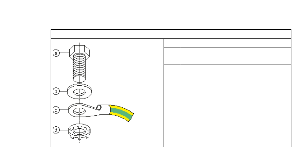
Readers
5.6 RF670R reader
SIMATIC RF600
System Manual, xx/2014, J31069-D0171-U001-A15-7618 187
REVIEW
Ground connection
(a)
Hexagon-head screw
(b)
Plain washer
(c)
Cable lug
(d) Contact washer:
Use contact washers according to the
Siemens standard SN 70093-6-FSt-flNnnc-
480h for ground connection,
Siemens item No.: H70093-A60-Z3
5.6.2
Planning the use
5.6.2.1
Antenna/read point configurations
You can connect up to four external antennas to the RF670R reader. The standard setting is
that four antennas are connected when the reader is started. When connecting multiple
antennas, note the information in the section "Specified minimum and maximum spacing of
antennas (Page 49)".
With RF-MANAGER Basic V2 , you can set up various different configurations of antennas
and/or reading points as required. It is possible to find solutions to many different tasks
through the number of data sources and subsequent assignment of the antennas.
Examples of possible antenna reading point configurations
● Four data sources each with one antenna for four different reading points.
● Two data sources each with two antennas for small portals.
● One data source with 4 antennas for large portals.
You will find further information in the online Help for the products.

Readers
5.6 RF670R reader
SIMATIC RF600
188 System Manual, xx/2014, J31069-D0171-U001-A15-7618
REVIEW
5.6.3
Installing / mounting
Requirement
WARNING
Make sure that the wall or ceiling can hold four times the total weight of the device.
Note
Close unused connectors
If you do not use connectors on the reader, it is advisable to close the unused connectors
with protective caps. You can order
the protective cap set using the MLFB specified in the
section "Ordering data".
CAUTION
Emitted radiation
The transmitter complies with the requirements of Health Canada and the FCC limit values
for subjecting persons to HF radiation, provided that a minimum spacing of 26 cm exists
between antenna and person. When the antennas are installed, you must therefore ensure
that a minimum spacing of 26 cm is maintained between personnel and antennas.
Mounting/installing the device
You can mount the reader in two different ways:
● Via a standardized VESA 100 mounting system using the Antenna Mounting Kit (see
section Mounting with antenna mounting kit (Page 331)). Tighten the M4 screws on the
rear of the reader using a maximum torque of ≤ 1.3 Nm.
● Directly onto a flat surface.
The positions of the fixing holes for the device are shown in the section Dimension drawings
(Page 193).
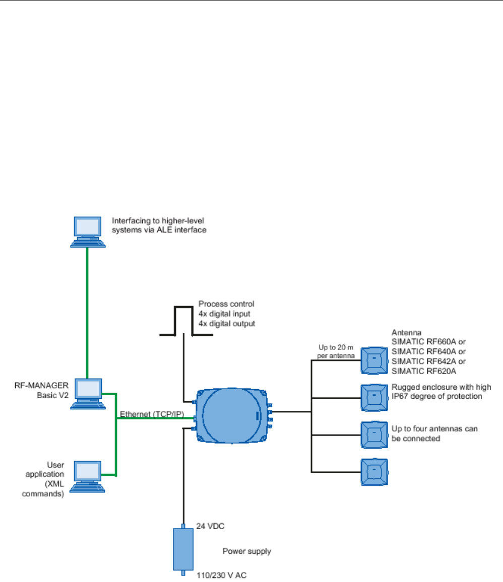
Readers
5.6 RF670R reader
SIMATIC RF600
System Manual, xx/2014, J31069-D0171-U001-A15-7618 189
REVIEW
5.6.4
Configuration/integration
An Ethernet interface is available for integrating the device into system
environments/networks. Over the Ethernet interface and with direct connection to the PC, the
RF670R can be configured in two different ways:
● Using RF-MANAGER Basic V2
● with XML-based user applications
The communication interface transfers the data over the RF-MANAGER Basic to the IT, ERP
and SCM systems as well as to SIMATIC controllers. Alternatively the data is transferred to
user applications using XML commands.
Simple process controls (e.g. a traffic signal) can be implemented directly using the
write/read device via four digital inputs and outputs.
Figure 5-38 Overview of configuration of the RF670R reader

Readers
5.6 RF670R reader
SIMATIC RF600
190 System Manual, xx/2014, J31069-D0171-U001-A15-7618
REVIEW
5.6.5
Technical data
5.6.5.1
Mechanical data
Mechanical data
Weight
approx. 1800 g
Housing dimensions (L x W x H)
252 x 193 x 52 mm, without connections
Material for housing top section
ABS (GF 20)
Material for housing bottom section
Aluminum
Color of housing top section
Anthracite
Color of housing bottom section
Silver
Status displays on the device 1 LED
Colors: red, yellow, green
Interfaces
Antenna connectors
4x RTNC connector
Power supply
1 x plug (4-pin M12)
Digital I/O interface
1 x socket (12-pin M12)
Digital inputs
4
Digital outputs
4 (500 mA each; max. 1500 mA in total)
Ethernet
RJ-45 TCP/IP (push-pull) 10/100 Mbps
MTBF in years
16
Thermal and electrical properties
Power supply
• Permitted range
20 to 30 VDC 1
Power supply Current consumption
(in standby mode, no
transmit power)
Power requirement
(in standby mode, no
transmit power)
20 V input voltage on the reader, typical
140 mA
2.8 W
24 V input voltage on the reader, typical
120 mA
2.88 W
30 V input voltage on the reader, typical
100 mA
3.0 W
Power supply Current consumption
(at 1000 mW transmit power)
Power requirement
(at 1000 mW transmit power)
20 V input voltage on the reader, typical
530 mA
10.6 W
24 V input voltage on the reader, typical
450 mA
10.8 W
30 V input voltage on the reader, typical
370 mA
11.1 W
Rampup time
19 s
1)
All supply and signal voltages must be safety extra low voltage (SELV/PELV according to EN 60950)
24 VDC supply: safe (electrical) isolation of extra-low voltage (SELV / PELV acc. to EN 60950)

Readers
5.6 RF670R reader
SIMATIC RF600
System Manual, xx/2014, J31069-D0171-U001-A15-7618 191
REVIEW
Mechanical environmental conditions
Shock resistant acc. to EN 60068-2-27
Vibration acc. to EN 60068-2-6
50 g1
20 g
1
Climatic conditions
Ambient temperature during operation -25 °C to +55 °C
(a 10-minute warm-up time must be allowed at an operating
temperature below -20 °C)
Ambient temperature for transport and storage
-40 °C to +85 °C
1) The values for shock and vibration are maximum values and must not be applied continuously.
EMC & approvals/conformity for ETSI variant
Electromagnetic compatibility ETSI EN 301 489-1 / -3
EN 302 208 V1.3.1
EN 302 208 V1.4.1
Approvals/Conformity • Radio according to the R&TTE directive
• CE
• ETSI EN 302 208 V1.3.1
• ETSI EN 302 208 V1.4.1
• Reader degree of protection acc. to EN 60529 (IP65)
• RoHS-compliant according to EU Directive 2002/95/EC
• Human exposure
EMC & approvals for FCC variant
Electromagnetic compatibility
FCC Part 15
Approvals • FCC, cULus
• IEC60950, including US and Canadian variants of it
• Reader degree of protection acc. to EN 60529 (IP65)
• FCC CFR47 Part 15.247
• RoHS-compliant according to EU Directive 2002/95/EC
• Industrial Canada, RSS-210, Issue 7, June 2007

Readers
5.6 RF670R reader
SIMATIC RF600
192 System Manual, xx/2014, J31069-D0171-U001-A15-7618
REVIEW
5.6.5.2
Technical data according to EPC and ISO
Technical specifications
Frequency accuracy
max.± 10 ppm
Channel spacing EU, EFTA, Turkey: 600 kHz
US: 500 kHz
China: 250 kHz
Modulation methods ASK: DSB modulation & PR-ASK modulation
Encoding, Manchester or Pulse Interval (PIE)
Effective radiated power
• ETSI/CMIIT:
• FCC:
• ≤ 2 W ERP
• ≤ 4 W EIRP
Transmit power
• ETSI/CMIIT:
• FCC:
• ≤ 1.0 W
• ≤ 1.25 W
Reading range
Antennas mounted on opposing sides
(portal configuration)
max. 10 m
Antennas mounted on the same side
max. 5 m (dependent on transponder)
ETSI frequencies
Frequency range for Europe, EFTA, Turkey, South Africa,
Thailand (ETSI)
ETSI EN 302 208 V1.4.1 (valid since October 23, 2012,
publication in the Official Journal of the European Union)
865.7 ... 867.5 MHz
(4 channels LBT optional at max. 2 W ERP)
Frequency range India 865 ... 867 MHz (10 channels at max. 4 W EIRP)
Frequency range Russia
866.1 ... 867.6 MHz (8 channels at 2 W ERP)
Frequency range Singapore
866 ... 869 MHz (11 channels at 0.5 W ERP)
FCC frequencies
Frequency range USA; Argentina, Bolivia, Canada, Mexico,
Thailand (FCC)
902 ... 928 MHz (50 channels at max. 4 W EIRP,
frequency hopping)
Frequency range Brazil 915.125 ... 927.875 MHz (52 channels at max. 4 W EIRP,
frequency hopping)
Frequency range South Korea 917.1 ... 920.4 MHz (7-16 channels at max. 4 W EIRP,
frequency hopping)
CMIIT frequencies
Frequency range China
920.625 ... 924.375 MHz (16 subchannels at 2 W ERP)
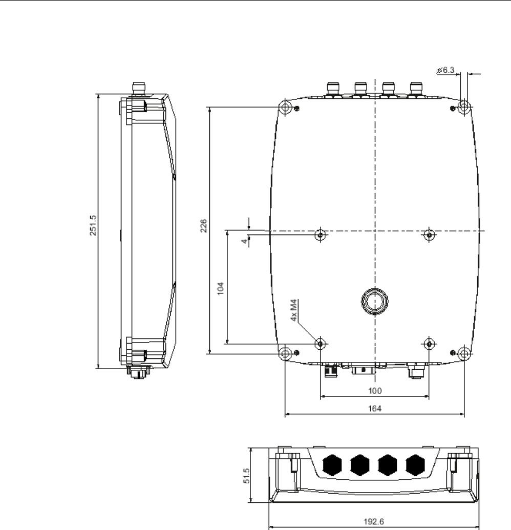
Readers
5.6 RF670R reader
SIMATIC RF600
System Manual, xx/2014, J31069-D0171-U001-A15-7618 193
REVIEW
5.6.6
Dimension drawings
Figure 5-39 Dimension drawing for RF670R
All dimensions in mm (± 0.5 mm tolerance)

Readers
5.6 RF670R reader
SIMATIC RF600
194 System Manual, xx/2014, J31069-D0171-U001-A15-7618
REVIEW
5.6.7
Certificates and approvals
Note
Marking on the readers according to specific approval
The
certificates and approvals listed here apply only if the corresponding mark is found on
the readers.
Table 5- 26 6GT2811-0AB00-0AA0
Certificate
Description
Conformity with R&TTE directive
TA-2012/548 South Africa radio approval:
Radio Equipment Type Approval
Table 5- 27 6GT2811-0AB00-1AA0
Standard
Federal Communications
Commission
FCC CFR 47, Part 15 sections 15.247
Radio Frequency Interference Statement
This equipment has been tested and found to comply with the limits
for a Class B digital device, pursuant to Part 15 of the FCC Rules.
FCC ID: NXW-RF670 (as of FS: A1)
FCC ID: NXW-RF600R (as of FS: C1)
Industry Canada Radio
Standards Specifications
RSS-210 Issue 7, June 2007, Sections 2.2, A8
IC: 267X-RF670 (as of FS: A1)
IC: NXW-RF600R, model RF670R-2 (as of FS: C1)
This product is UL-certified for the USA and Canada.
It meets the following safety standard(s):
UL 60950-1 - Information Technology Equipment Safety - Part 1:
General Requirements
CSA C22.2 No. 60950 -1 - Safety of Information Technology
Equipment
UL Report E 205089
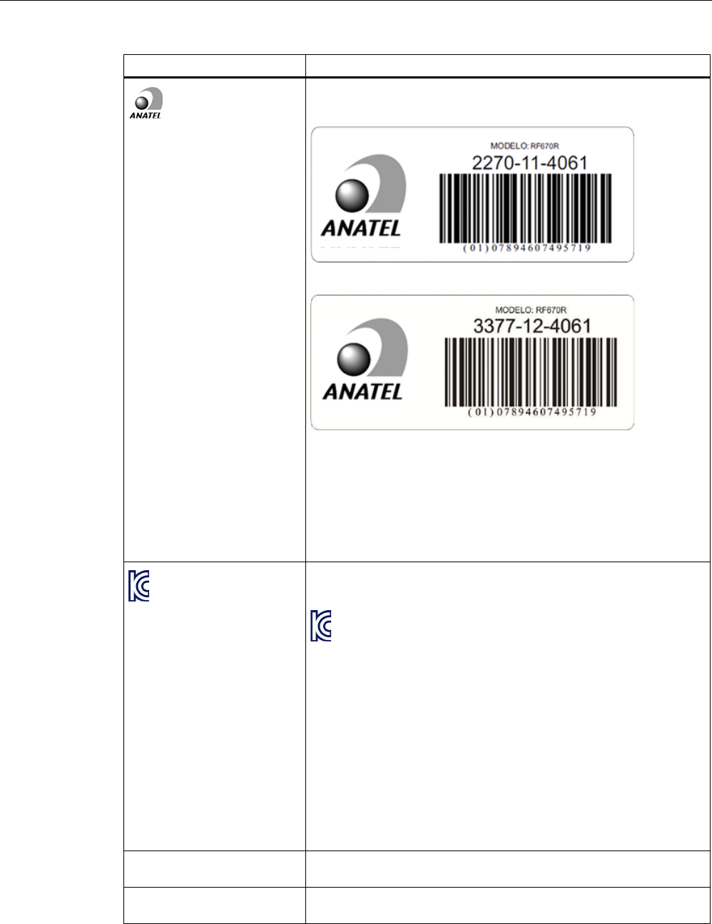
Readers
5.6 RF670R reader
SIMATIC RF600
System Manual, xx/2014, J31069-D0171-U001-A15-7618 195
REVIEW
Standard
Brazil wireless approval
Marking on the reader (as of FS: A):
Marking on the reader (as of FS: B1):
Statement relating to approval:
Este equipamento opera em caráter secundário, isto é, não tem
direito à proteção contra interferência prejudicial, mesmo de
estações do mesmo tipo e não pode causar interferência a sistemas
operando em caráter primário.
Certificate of the reader (as of FS: A): ANATEL 2270-11-4061
Certificate of the reader (as of FS: B1): ANATEL 3377-12-4061
KCC Certification
Marking on the reader:
Type of equipment:
A급 기기 (업무용 방송통신기자재)
Class A Equipment (Industrial Broadcasting & Communication
Equipment)
이 기기는 업무용(A급) 전자파적합기기로서 판 매자 또는 사용자는 이
점을 주의하시기 바라 며, 가정외의 지역에서 사용하는 것을 목적으로
합니다.
This equipment is Industrial (Class A) electromagnetic wave
suitability equipment and seller or user should take notice of it, and
this equipment is to be used in the places except for home.
Reader certificate:
KCC-CRM-RF5-RF670R
H-11390 Argentina radio approval:
Registro de la COMISION NACIONAL DE COMUNICACIONES
RCPSIRF12-0881 Mexico radio approval:
CERTIFICADO DE HOMOLOGACION

Readers
5.6 RF670R reader
SIMATIC RF600
196 System Manual, xx/2014, J31069-D0171-U001-A15-7618
REVIEW
Table 5- 28 6GT2811-0AB00-2AA1
Standard
CMIIT Certification China radio approval
Marking on the reader: CMIIT ID: 2011DJ0748
5.6.7.1
FCC information
Siemens SIMATIC RF670R (FCC): 6GT2811-0AB00-1AA0
FCC ID: NXW-RF670 (as of FS: A1)
FCC ID: NXW-RF600R (as of FS: C1)
This device complies with part 15 of the FCC rules. Operation is subject to the following two
conditions:
(1) This device may not cause harmful interference, and
(2) this device must accept any interference received, including interference that may cause
undesired operation.
Caution
Any changes or modifications not expressly approved by the party responsible for
compliance could void the user's authority to operate the equipment.
Note
This equipment has been tested and found to comply with the limits for a Class B digital
device, pursuant to part 15 of the FCC Rules.
These limits are designed to provide reasonable protection against harmful interference
when the equipment is operated in a commercial environment. This equipment generates,
uses, and can radiate radio frequency energy and, if not installed and used in accordance
with the instruction manual, may cause harmful interference to radio communications.
Operation of this equipment in a residential area is likely to cause harmful interference in
which case the user will be required to correct the interference at his own expense.
FCC Notice
To comply with FCC part 15 rules in the United States, the system must be professionally
installed to ensure compliance with the Part 15 certification.
It is the responsibility of the operator and professional installer to ensure that only certified
systems are deployed in the United States. The use of the system in any other combination
(such as co-located antennas transmitting the same information) is expressly forbidden.
FCC Exposure Information
To comply with FCC RF exposure compliance requirements, the antennas used for this
transmitter must be installed to provide a separation distance of at least 20 cm from all
persons and must not be co-located or operating in conjunction with any other antenna or
transmitter.

Readers
5.6 RF670R reader
SIMATIC RF600
System Manual, xx/2014, J31069-D0171-U001-A15-7618 197
REVIEW
5.6.7.2
IC-FCB information
Siemens SIMATIC RF670R (FCC): 6GT2811-0AB00-1AA0
IC: 267X-RF670 (as of FS: A1)
IC: NXW-RF600R, model: RF670R-2 (as of FS: C1)
This device complies with Industry Canada licence-exempt RSS standard(s). Operation is
subject to the following two conditions:
(1) This device may not cause interference, and
(2) this device must accept any interference, including interference that may cause
undesired operation of the device.
Le présent appareil est conforme aux CNR d`Industrie Canada applicables aux appareils
radio exempts de licence. L`exploitation est autorisée aux deux conditions suivantes :
(1) L`appareil ne doit pas produire de brouillage, et
(2) l'utilisateur de l`appareil doit accepter tout brouillage radioélectrique subi, même si le
brouillage est susceptible d`en compromettre le fonctionnement.
Industry Canada Notice
To reduce potential radio interference to other users, the antenna type and its gain should be
so chosen that the equivalent isotropically radiated power (e.i.r.p.) is not more than that
permitted for successful communication.
Transmitter power and antenna information for antennas with a gain less than 6 dBi:
This device has been designed to operate with the SIMATIC RF620A antenna 902-928, the
SIMATIC RF640A antenna 902-928 as well as the SIMATIC RF660A antenna 902-928 listed
below, and having a maximum gain of 5.5 dBi.
Arbitrary transmission power settings in combination with other antennas or antennas having
a gain greater than 5.5 dBi are strictly prohibited for use with this device.
The required antenna impedance is 50 Ohms.
Transmitter power and antenna information for antennas with a gain greater 6 dBi:
This device requires professional installation. Antennas with a gain greater 6 dBi may be
used provided the system does not exceed the radiation power of 4000 mW E.I.R.P. This
device has been designed to operate with the SIMATIC RF642A antenna 902-928 exceeding
the maximum gain of 5.5 dBi under the restriction that the RF power at the input of the
antenna must be set to meet the following relation: RF power (dBm) ≤ 30 dBm – (antenna
gain (dBi) – 6 dBi) Other antennas or system configurations for antennas having a gain
greater than 6 dBi are strictly prohibited for use with this device. The required antenna
impedance is 50 Ohms.
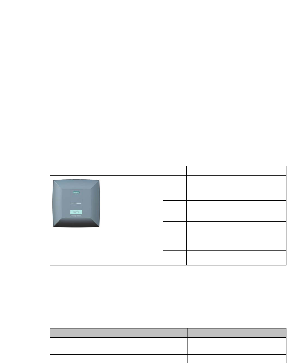
Readers
5.7 RF680R reader
SIMATIC RF600
198 System Manual, xx/2014, J31069-D0171-U001-A15-7618
REVIEW
5.7
RF680R reader
5.7.1
Description
5.7.1.1
Overview
The SIMATIC RF680R is a stationary reader in the UHF frequency band without an
integrated antenna. Up to four external UHF RFID antennas can be connected via TNC
reverse connections.
The maximum RF power output is 2000°W at the reader output. A radiant power of up to
2000 mW ERP is achieved when the appropriate antennas and antenna cables are used.
The interfaces (Ethernet, M12 power supply, M12 digital I/O interface) are located along the
narrow lower front edge. These interfaces can be used to connect the reader to the power
supply and the PC for parameter assignment.
The degree of protection is IP65.
Pos.
Description
① TNC reserve interfaces for connecting up
to 4 antennas
②
LED status display
③
LED operating display
④
Digital I/O interface
⑤
RS-422 interface
(M12 plug, 8-pin)
⑥ Ethernet interface (TCP/IP)
(M12 plug, 4-pin)
⑦
Ethernet interface (TCP/IP)
(M12 plug, 4-pin)
5.7.1.2
Ordering data
Ordering data RF680R
Product
Article number
RF680R (ETSI) reader basic unit for EU, EFTA, Turkey
6GT2811-6AA10-0AA0
RF680R (FCC) reader basic unit for the USA
6GT2811-6AA10-1AA0
RF680R (CMIIT) reader basic unit for China
6GT2811-6AA10-2AA0

Readers
5.7 RF680R reader
SIMATIC RF600
System Manual, xx/2014, J31069-D0171-U001-A15-7618 199
REVIEW
Ordering data accessories
Product
Article number
Antenna mounting kit
6GT2890-0AA00
Connecting cable and connectors
• Digital I/O, open cable ends, 5 m
• Ethernet: 10 m (crossover cable)
• Ethernet connector on reader
according to IEC PAS 61076-3-117IE
RJ-45 Plug PRO (IP67)
• Ethernet connector, Standard IE FastConnect
RJ-45 Plug 180 (IP20)
• Ethernet cable sold by the meter, green
• 6GT2891-0CH50
• 6GT2891-1HN10
• 6GK1901-1BB10-6AA0
• 6GK1901-1BB10-2AB0
• 6XV1840-2AH10
Wide-range power supply unit for SIMATIC RF systems
• With EU plug
• With UK plug
• With US plug
• 6GT2898-0AA00
• 6GT2898-0AA10
• 6GT2898-0AA20
24 V connecting cable
5 m between reader and power supply unit
(for RF670R only, pin assignment is PNO-compliant)
6GT2891-0NH50
Set of protective caps
Contains 3 protective caps for antenna output and one
protective cap for digital I/O interface (required for IP65
degree of protection when some connectors are unused)
6GT2898-4AA00
RFID DVD "Software & Documentation"
6GT2080-2AA20

Readers
5.7 RF680R reader
SIMATIC RF600
200 System Manual, xx/2014, J31069-D0171-U001-A15-7618
REVIEW
5.7.1.3
Status display
The device is equipped with 17 three-colored LEDs. The operating statuses of the reader are
displayed by the "RUN/STOP", "ERROR", "MAINT" and "PRESENCE" LEDs. The LEDs can
be lit green, red or orange. The meaning of the display changes according to the color and
status (on, off, flashing) of the LED:
R/S
ERR
MT
PR
Meaning
The device is turned off.
The device is starting up.
- - - The device is ready for operation. The connection is established.
- - - The device is working. Transponder data can be read or written.
- - - There is an error.
- - - Maintenance work required.
- - - There is transponder in the antenna field.
- - - There are multiple transponders in the antenna field.
For more detailed information on the flash codes of the reader, refer to the section LED
displays RF650R/RF680R/RF685R (Page 480).
5.7.1.4
Pin assignment of the digital I/O interface
View of socket (reader end)
Table 5- 29
M12 socket (reader end)
Pin
Pin assignment
1
2
3
4
5
6
7
8
9
10
11
12
GND (output for supply of digital inputs/outputs [not
electrically isolated])
VCC (outp
ut for supply of digital inputs/outputs [not electrically
isolated])
DO Common / Outport Common
DO 0 / Outport 00
DO 1 / Outport 01
DO 2 / Outport 02
DO 3 / Outport 03
DI 0 / Inport 00
DI Common / Inport Common
DI 1 / Inport 01
DI 2 / Inport 02
DI 3 / Inport 03

Readers
5.7 RF680R reader
SIMATIC RF600
System Manual, xx/2014, J31069-D0171-U001-A15-7618 201
REVIEW
Wiring diagram M12 connector (cable end)
You will need to assemble your reader cable with a suitable connector that fits the interface
shown above. Keep to the following wiring diagram:
Figure 5-40 M12 connector wiring diagram
5.7.1.5
Connection scheme for the digital I/O interface
Connection possibilities
You can connect the RF680R reader in different ways. In general, the outputs and inputs
should be connected as follows:
Output Outport (0), (1), (2), (3)
● Each output is rated for 0.5 A current and is electronically protected.
● 4 digital outputs can be operated simultaneously each with up to 0.5 A (up to 1.0 A in
total).
● The outputs are optically isolated through optocouplers.
Input Inport (0), (1), (2), (3)
● The inputs are optically isolated through optocouplers.
● Level Low 0 ... 3 V; High 3.6 ... 24 V
● Sampling rate < 20 ms
The following diagrams illustrate various connection possibilities.

Readers
5.7 RF680R reader
SIMATIC RF600
202 System Manual, xx/2014, J31069-D0171-U001-A15-7618
REVIEW
Voltage infeed from internal source (no electrical isolation)
Figure 5-41 Circuit example 1: Digital inputs
Alternative connection possibilities:
● Pin 2 (VCC) to pin 9 DI common
● Pin 1 GND to busbar inputs

Readers
5.7 RF680R reader
SIMATIC RF600
System Manual, xx/2014, J31069-D0171-U001-A15-7618 203
REVIEW
Voltage infeed from external source
Figure 5-42 Circuit example 2: Digital inputs
Voltage infeed from external source with various voltages
Figure 5-43 Circuit example 3: Digital inputs
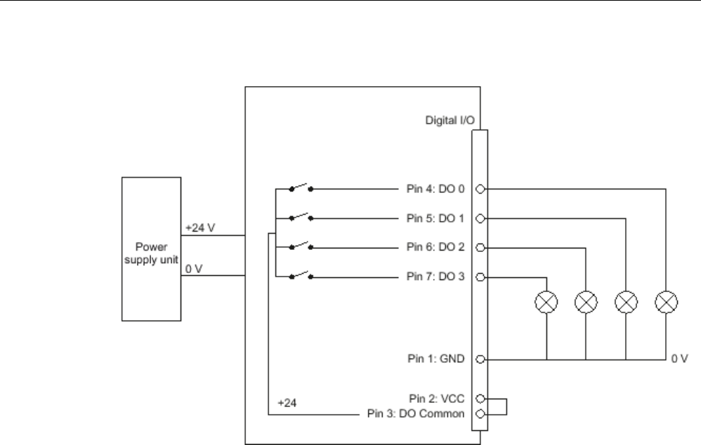
Readers
5.7 RF680R reader
SIMATIC RF600
204 System Manual, xx/2014, J31069-D0171-U001-A15-7618
REVIEW
Voltage infeed from internal source
Figure 5-44 Circuit example 4: Digital outputs
Alternative connection possibilities:
● Pin 1 GND to pin 3 DO common
● Pin 2 (VCC) to busbar outputs

Readers
5.7 RF680R reader
SIMATIC RF600
System Manual, xx/2014, J31069-D0171-U001-A15-7618 205
REVIEW
Voltage infeed from external source
Figure 5-45 Circuit example 5: Digital outputs
Voltage infeed from an external source is shown here for 12°V as an example. Other
voltages are also permissible.
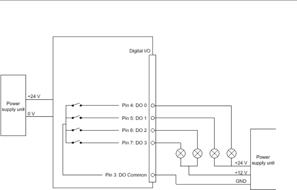
Readers
5.7 RF680R reader
SIMATIC RF600
206 System Manual, xx/2014, J31069-D0171-U001-A15-7618
REVIEW
Voltage infeed from external source with various voltages
Figure 5-46 Circuit example 6: Digital outputs
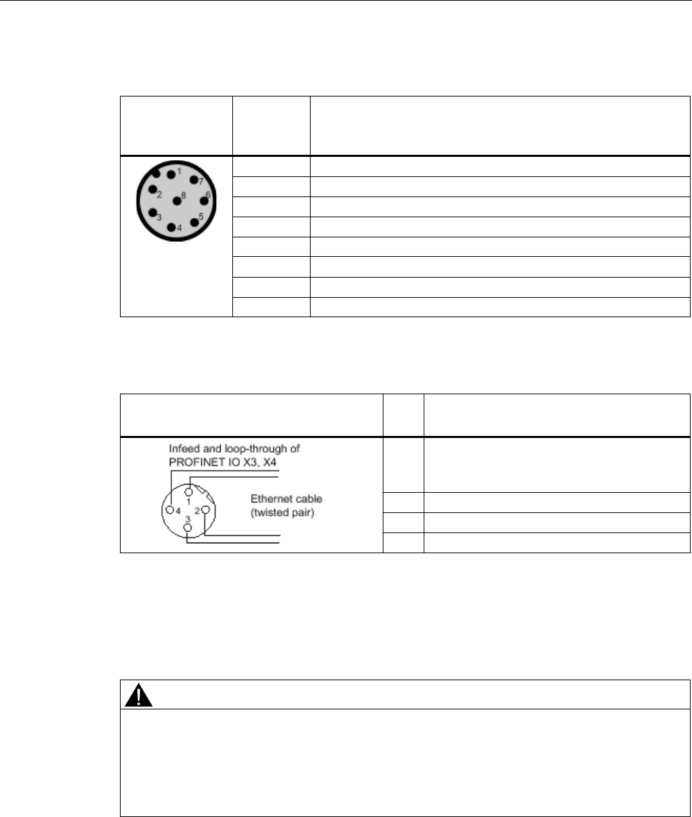
Readers
5.7 RF680R reader
SIMATIC RF600
System Manual, xx/2014, J31069-D0171-U001-A15-7618 207
REVIEW
5.7.1.6
Pin assignment of the RS-422 interface
Pin
Pin
Device end
8-pin M12
Assignment
1
+ 24 V
2
- Transmit
3
0 V
4
+ Transmit
5
+ Receive
6
- Receive
7
Unassigned
8
Earth (shield)
5.7.1.7
Pin assignment for Industrial Ethernet interface
View of M12 plug, 4-pin, D coding
(wiring side)
Pin
Pin assignment
1
Data line TxP
2
Data line RxP
3
Data line TxN
4
Data line RxN
5.7.1.8
Grounding connection
The RF680R can be electrically connected to the ground potential with a contact washer.
The tightening torque must be increased in this case to ensure that electrical contact is made
(2.7 Nm).
WARNING
Hazardous voltage due to lightning strikes
Death or serious injury may occur as a result of lightning strikes to antennas mounted
outside buildings.
If the reader is operated with antennas mounted outside buildings, it is imperative that the
reader is electrically connected to the ground potential.

Readers
5.7 RF680R reader
SIMATIC RF600
208 System Manual, xx/2014, J31069-D0171-U001-A15-7618
REVIEW
NOTICE
Installation only in protected areas
The antenna can be installed in the protected part of a building. When implementing your
lightning protection concept, make sure you adhere to the VDE 0182 or IEC 62305
standards.
Ground connection
(a)
Hexagon-head screw
(b)
Flat washer
(c)
Cable lug
(d) Contact washer:
Use contact washers according to the
Siemens standard SN 70093-6-FSt-flNnnc-
480h for ground connection,
Siemens item no.: H70093-A60-Z3
5.7.2
Planning operation
5.7.2.1
Antenna/read point configurations
You can connect up to four external antennas to the RF680R reader. The standard setting is
that four antennas are connected when the reader is started. When connecting multiple
antennas, note the information in the section "Specified minimum and maximum spacing of
antennas (Page 49)".
With the graphical user interface of the integrated Web server, you can set up various
different configurations of antennas and/or reading points as required. It is possible to find
solutions to many different tasks through the number of data sources and subsequent
assignment of the antennas.
Examples of possible antenna reading point configurations
● Four data sources each with one antenna for four different reading points.
● Two data sources each with two antennas for small portals.
● One data source with 4 antennas for large portals.
You will find further information in the online Help for the products.
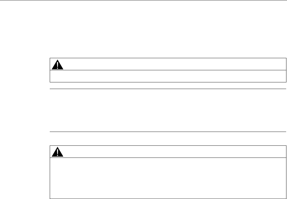
Readers
5.7 RF680R reader
SIMATIC RF600
System Manual, xx/2014, J31069-D0171-U001-A15-7618 209
REVIEW
5.7.3
Installation/mounting
Requirement
WARNING
Make sure that the wall or ceiling can hold four times the total weight of the device.
Note
Close unused connectors
If you do not use connectors on the reader, it is advisable to close the unused connectors
with protective caps. You can order
the protective cap set using the MLFB specified in the
section "Ordering data".
CAUTION
Emitted radiation
The transmitter complies with the requirements of Health Canada and the FCC limit values
for subjecting persons to HF radiation, provided that a minimum spacing of 26 cm exists
between antenna and person. When the antennas are installed, you must therefore ensure
that a minimum spacing of 26 cm is maintained between personnel and antennas.
Mounting/installing the device
You can mount the reader in two different ways:
● Via a standardized VESA 100 mounting system using the Antenna Mounting Kit (refer to
the section Mounting with antenna mounting kit (Page 331)). Tighten the M4 screws on
the rear of the reader using a maximum torque of ≤ 1.3 Nm.
● Directly on a flat surface.
The positions of the mounting holes for the device are shown in the section Dimension
drawing (Page 213).
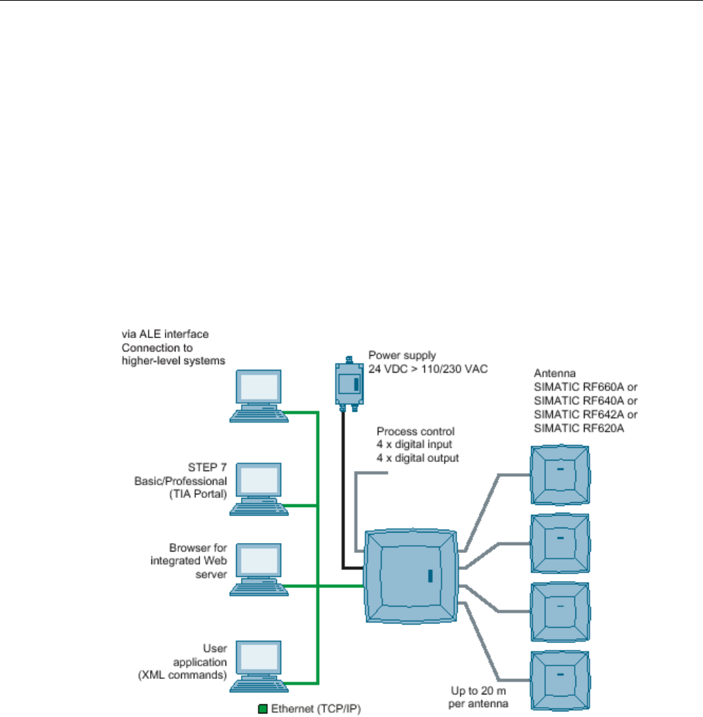
Readers
5.7 RF680R reader
SIMATIC RF600
210 System Manual, xx/2014, J31069-D0171-U001-A15-7618
REVIEW
5.7.4
Configuration/integration
An Ethernet interface is available for integrating the device into system
environments/networks. Over the Ethernet interface and with direct connection to the PC, the
RF680R can be configured in the following ways:
● via the graphical user interface of the integrated Web server
● STEP 7 Basic/Professional (TIA Portal)
● with XML-based user applications
The communications interface transfers the data via the Web server or STEP 7 to the IT,
ERP and SCM systems as well as to SIMATIC controllers. Alternatively the data is
transferred to user applications using XML commands.
Simple process controls (e.g. a traffic signal) can be implemented directly using the
write/read device via four digital inputs and outputs.
Figure 5-47 Overview of configuration of the RF680R reader

Readers
5.7 RF680R reader
SIMATIC RF600
System Manual, xx/2014, J31069-D0171-U001-A15-7618 211
REVIEW
5.7.5
Technical specifications
Table 5- 30 Technical specifications, RF680R
6GT2811-6AA10-xAA0
Product type designation
RF680R
Mechanical specifications
Weight
Dimensions (L x W x H)
Degree of protection
IP65
Material
• Upper part of housing Pocan DP CF 2200
• Lower part of housing Aluminum
Color
• Upper part of housing TI-Grey
• Lower part of housing Silver
Operating displays on the device
8 LEDs
Status display on the device
9 LEDs
Interfaces
• Antenna connectors 4 x RTNC connector
• Power supply 1 x connector (8-pin M12), RS-422
• Digital I/O interface 1 x socket (12-pin, M12)
• Digital inputs 4
• Digital outputs 4
• Ethernet interface 2 x socket (4-pin, M12)
MTBF in years
Electrical specifications
Power supply
20 to 30 VDC
1)
Current consumption (on standby)
• 20 V input voltage on the reader (typical) 200 mA / 4.0 W
• 24 V input voltage on the reader (typical) 170 mA / 4.1 W
• 30 V input voltage on the reader (typical) 140 mA / 4.2 W
Current consumption (at 1000 mW transmit power)
• 20 V input voltage on the reader (typical) 450 mA / 9.0 W
• 24 V input voltage on the reader (typical) 380 mA / 9.1 W
• 30 V input voltage on the reader (typical) 300 mA / 9.6 W

Readers
5.7 RF680R reader
SIMATIC RF600
212 System Manual, xx/2014, J31069-D0171-U001-A15-7618
REVIEW
6GT2811-6AA10-xAA0
Startup time
Electromagnetic compatibility
• ETSI EN 301 489-1/-3, EN 302 208-1/-3 V1.4.1
• FCC FCC CFR 47, Part 15 section 15.247
Permitted ambient conditions
Ambient temperature
• Operation -25 ℃ to +55 ℃
• Transport and storage -40 ℃ to +85 ℃
Shock resistant to EN 60068-2-27
50 g
2)
Vibration resistant to EN 60068-2-26
20 g
2)
1)
All supply and signal voltages must be safety extra-low voltage (SELV/PELV according to EN 60950). All power sources
must meet the requirements for LPS (Limited Power Sources) and NEC Class 2.
2) The values for shock and vibration are maximum values and must not be applied continuously.
Table 5- 31 Technical specifications according to EPC and ISO, RF680R
6GT2811-6AA10-xAA0
Product type designation
RF680R
Frequency accuracy
max.± 10 ppm
Channel spacing • EU, EFTA, Turkey: 600 kHz
• US: 500 kHz
• China: 250 kHz
Modulation methods ASK: DSB modulation & PR-ASK modulation
Encoding, Manchester or Pulse Interval (PIE)
Effective radiated power
• ETSI/CMIIT • ≤ 2 W ERP
• FCC • ≤ 4 W EIRP
Transmit power
• ETSI/CMIIT • ≤ 2 W
• FCC • ≤ 2 W
Reading range
Antennas mounted on opposing sides (portal
configuration)
max. 10 m
Antennas mounted on the same side
max. 5 m (dependent on transponder)
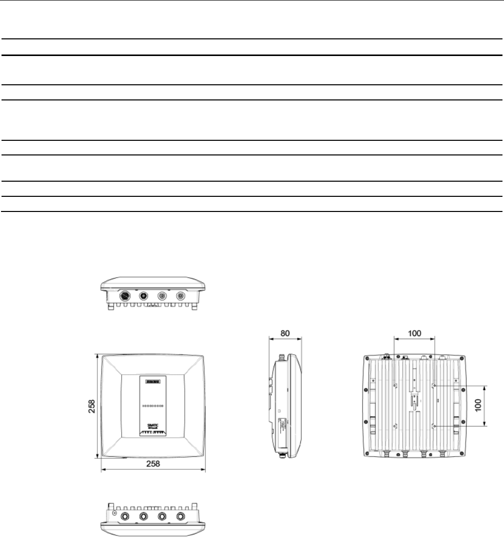
Readers
5.7 RF680R reader
SIMATIC RF600
System Manual, xx/2014, J31069-D0171-U001-A15-7618 213
REVIEW
6GT2811-6AA10-xAA0
Frequencies
ETSI frequencies
European frequency band
ETSI EN 302 208 V1.4.1 (valid since October 23, 2012,
publication in the Official Journal of the European Union)
865,7 ... 867.5 MHz
(4 channels at max. 2 W ERP)
FCC frequencies
Frequency band USA 902 ... 928 MHz
(50 channels at max. 4 W EIRP, frequency hopping)
CMIIT frequencies
Frequency band China
920,625 ... 924.375 MHz (16 subchannels at 2 W ERP)
5.7.6
Dimension drawing
Figure 5-48 Dimension drawing RF680R
All dimensions in mm (± 0.5 mm tolerance)
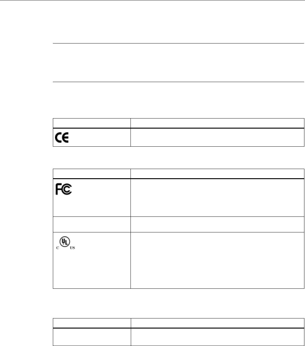
Readers
5.7 RF680R reader
SIMATIC RF600
214 System Manual, xx/2014, J31069-D0171-U001-A15-7618
REVIEW
5.7.7
Certificates and approvals
Note
Marking on the readers according to specific approval
The certificates and approvals listed here apply only if the corresponding mark is found on
the readers.
Table 5- 32 6GT2811-6AA10-0AA0
Certificate
Description
Conformity with R&TTE directive
Table 5- 33 6GT2811-6AA10-1AA0
Standard
Federal Communications
Commission
FCC CFR 47, Part 15 sections 15.247
Radio Frequency Interference Statement
This equipment has been tested and found to comply with the limits
for a Class B digital device, pursuant to Part 15 of the FCC Rules.
FCC ID: ??????
Industry Canada Radio
Standards Specifications
RSS-210 Issue 7, June 2007, Sections 2.2, A8
IC: ??????
This product is UL-certified for the USA and Canada.
It meets the following safety standard(s):
UL 60950-1 - Information Technology Equipment Safety - Part 1:
General Requirements
CSA C22.2 No. 60950 -1 - Safety of Information Technology
Equipment
UL Report E 205089
Table 5- 34 6GT2811-6AA10-2AA0
Standard
CMIIT Certification China radio approval
Marking on the reader: CMIIT ID: ??????

Readers
5.7 RF680R reader
SIMATIC RF600
System Manual, xx/2014, J31069-D0171-U001-A15-7618 215
REVIEW
5.7.7.1
FCC information
Siemens SIMATIC RF680R (FCC): 6GT2811-6AA10-1AA0
FCC ID:
This device complies with part 15 of the FCC rules. Operation is subject to the following two
conditions:
(1) This device may not cause harmful interference, and
(2) this device must accept any interference received, including interference that may cause
undesired operation.
Caution
Any changes or modifications not expressly approved by the party responsible for
compliance could void the user's authority to operate the equipment.
Note
This equipment has been tested and found to comply with the limits for a Class B digital
device, pursuant to part 15 of the FCC Rules.
These limits are designed to provide reasonable protection against harmful interference
when the equipment is operated in a commercial environment. This equipment generates,
uses, and can radiate radio frequency energy and, if not installed and used in accordance
with the instruction manual, may cause harmful interference to radio communications.
Operation of this equipment in a residential area is likely to cause harmful interference in
which case the user will be required to correct the interference at his own expense.
FCC Notice
To comply with FCC part 15 rules in the United States, the system must be professionally
installed to ensure compliance with the Part 15 certification.
It is the responsibility of the operator and professional installer to ensure that only certified
systems are deployed in the United States. The use of the system in any other combination
(such as co-located antennas transmitting the same information) is expressly forbidden.
FCC Exposure Information
To comply with FCC RF exposure compliance requirements, the antennas used for this
transmitter must be installed to provide a separation distance of at least 20 cm from all
persons and must not be co-located or operating in conjunction with any other antenna or
transmitter.

Readers
5.7 RF680R reader
SIMATIC RF600
216 System Manual, xx/2014, J31069-D0171-U001-A15-7618
REVIEW
5.7.7.2
IC-FCB information
Siemens SIMATIC RF680R (FCC): 6GT2811-6AA10-1AA0
IC:
This device complies with Industry Canada licence-exempt RSS standard(s). Operation is
subject to the following two conditions:
(1) This device may not cause interference, and
(2) this device must accept any interference, including interference that may cause
undesired operation of the device.
Le présent appareil est conforme aux CNR d`Industrie Canada applicables aux appareils
radio exempts de licence. L`exploitation est autorisée aux deux conditions suivantes :
(1) L`appareil ne doit pas produire de brouillage, et
(2) l'utilisateur de l`appareil doit accepter tout brouillage radioélectrique subi, même si le
brouillage est susceptible d`en compromettre le fonctionnement.
Industry Canada Notice
To reduce potential radio interference to other users, the antenna type and its gain should be
so chosen that the equivalent isotropically radiated power (e.i.r.p.) is not more than that
permitted for successful communication.
Transmitter power and antenna information for antennas with a gain less than 6 dBi:
This device has been designed to operate with the SIMATIC RF620A antenna 902-928, the
SIMATIC RF640A antenna 902-928 as well as the SIMATIC RF660A antenna 902-928 listed
below, and having a maximum gain of 5.5 dBi.
Arbitrary transmission power settings in combination with other antennas or antennas having
a gain greater than 5.5 dBi are strictly prohibited for use with this device.
The required antenna impedance is 50 Ohms.
Transmitter power and antenna information for antennas with a gain greater 6 dBi:
This device requires professional installation. Antennas with a gain greater 6 dBi may be
used provided the system does not exceed the radiation power of 4000 mW E.I.R.P. This
device has been designed to operate with the SIMATIC RF642A antenna 902-928 exceeding
the maximum gain of 5.5 dBi under the restriction that the RF power at the input of the
antenna must be set to meet the following relation: RF power (dBm) ≤ 30 dBm – (antenna
gain (dBi) – 6 dBi) Other antennas or system configurations for antennas having a gain
greater than 6 dBi are strictly prohibited for use with this device. The required antenna
impedance is 50 Ohms.
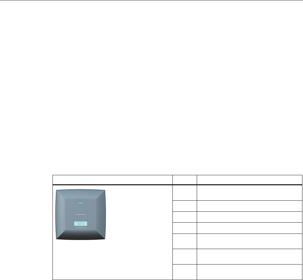
Readers
5.8 RF685R reader
SIMATIC RF600
System Manual, xx/2014, J31069-D0171-U001-A15-7618 217
REVIEW
5.8
RF685R reader
5.8.1
Description
5.8.1.1
Overview
The SIMATIC RF685R is a stationary reader in the UHF frequency band with an integrated
antenna. As an alternative, an external UHF RFID antenna can be connected via a TNC
reverse connector.
The maximum RF power output is 2000°W at the external reader output. A radiant power of
up to 2000 mW ERP is achieved when the appropriate antennas and antenna cables are
used. The interfaces (Ethernet, M12 power supply, M12 digital I/O interface) are located
along the narrow lower front edge. These interfaces can be used to connect the reader to the
power supply and the PC for parameter assignment.
The degree of protection is IP65.
Pos.
Description
① TNC reserve interface for connection of
an antenna
②
LED status display
③
LED operating display
④
Digital I/O interface
⑤
RS-422 interface
(M12 plug, 8-pin)
⑥ Ethernet interface (TCP/IP)
(M12 plug, 4-pin)
⑦
Ethernet interface (TCP/IP)
(M12 plug, 4-pin)

Readers
5.8 RF685R reader
SIMATIC RF600
218 System Manual, xx/2014, J31069-D0171-U001-A15-7618
REVIEW
5.8.1.2
Ordering data
Ordering data RF685R
Product
Article number
RF685R (ETSI) reader basic unit for EU, EFTA, Turkey
6GT2811-6CA10-0AA0
RF685R (FCC) reader basic unit for the USA
6GT2811-6CA10-1AA0
RF685R (CMIIT) reader basic unit for China
6GT2811-6CA10-2AA0
Ordering data accessories
Product
Article number
Antenna mounting kit
6GT2890-0AA00
Connecting cable and connectors
• Digital I/O, open cable ends, 5 m
• Ethernet: 10 m (crossover cable)
• Ethernet connector on reader
according to IEC PAS 61076-3-117IE
RJ-45 Plug PRO (IP67)
• Ethernet connector, Standard IE FastConnect
RJ-45 Plug 180 (IP20)
• Ethernet cable sold by the meter, green
• 6GT2891-0CH50
• 6GT2891-1HN10
• 6GK1901-1BB10-6AA0
• 6GK1901-1BB10-2AB0
• 6XV1840-2AH10
Wide-range power supply unit for SIMATIC RF systems
• With EU plug
• With UK plug
• With US plug
• 6GT2898-0AA00
• 6GT2898-0AA10
• 6GT2898-0AA20
24 V connecting cable
5 m between reader and power supply
(for RF640R only, pin assignment is PNO-compliant)
6GT2891-0NH50
Set of protective caps
Contains 3 protective caps for antenna output and one
protective cap for digital I/O interface (required for IP65
degree of protection when some connectors are unused)
6GT2898-4AA00
RFID DVD "Software & Documentation"
6GT2080-2AA20
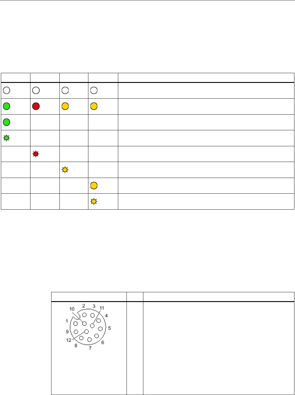
Readers
5.8 RF685R reader
SIMATIC RF600
System Manual, xx/2014, J31069-D0171-U001-A15-7618 219
REVIEW
5.8.1.3
Status display
The device is equipped with 17 three-colored LEDs. The operating statuses of the reader are
displayed by the "RUN/STOP", "ERROR", "MAINT" and "PRESENCE" LEDs. The LEDs can
be lit green, red or orange. The meaning of the display changes according to the color and
status (on, off, flashing) of the LED:
R/S
ERR
MT
PR
Meaning
The device is turned off.
The device is starting up.
- - - The device is ready for operation. The connection is established.
- - - The device is working. Transponder data can be read or written.
- - - There is an error.
- - - Maintenance work required.
- - - There is transponder in the antenna field.
- - - There are multiple transponders in the antenna field.
For more detailed information on the flash codes of the reader, refer to the section LED
displays RF650R/RF680R/RF685R (Page 480).
5.8.1.4
Pin assignment of the digital I/O interface
View of socket (reader end)
Table 5- 35
M12 socket (reader end)
Pin
Pin assignment
1
2
3
4
5
6
7
8
9
10
11
12
GND (output for supply of digital inputs/outputs [not
electrically isolated])
VCC (output for supply of digital inputs/outputs [not electrically
isolated])
DO Common / Outport Common
DO 0 / Outport 00
DO 1 / Outport 01
DO 2 / Outport 02
DO 3 / Outport 03
DI 0 / Inport 00
DI Common / Inport Common
DI 1 / Inport 01
DI 2 / Inport 02
DI 3 / Inport 03

Readers
5.8 RF685R reader
SIMATIC RF600
220 System Manual, xx/2014, J31069-D0171-U001-A15-7618
REVIEW
Wiring diagram M12 connector (cable end)
You will need to assemble your reader cable with a suitable connector that fits the interface
shown above. Keep to the following wiring diagram:
Figure 5-49 M12 connector wiring diagram
5.8.1.5
Connection scheme for the digital I/O interface
Connection possibilities
You can connect the RF680R reader in different ways. In general, the outputs and inputs
should be connected as follows:
Output Outport (0), (1), (2), (3)
● Each output is rated for 0.5 A current and is electronically protected.
● 4 digital outputs can be operated simultaneously each with up to 0.5 A (up to 1.0 A in
total).
● The outputs are optically isolated through optocouplers.
Input Inport (0), (1), (2), (3)
● The inputs are optically isolated through optocouplers.
● Level Low 0 ... 3 V; High 3.6 ... 24 V
● Sampling rate < 20 ms
The following diagrams illustrate various connection possibilities.

Readers
5.8 RF685R reader
SIMATIC RF600
System Manual, xx/2014, J31069-D0171-U001-A15-7618 221
REVIEW
Voltage infeed from internal source (no electrical isolation)
Figure 5-50 Circuit example 1: Digital inputs
Alternative connection possibilities:
● Pin 2 (VCC) to pin 9 DI common
● Pin 1 GND to busbar inputs

Readers
5.8 RF685R reader
SIMATIC RF600
222 System Manual, xx/2014, J31069-D0171-U001-A15-7618
REVIEW
Voltage infeed from external source
Figure 5-51 Circuit example 2: Digital inputs
Voltage infeed from external source with various voltages
Figure 5-52 Circuit example 3: Digital inputs
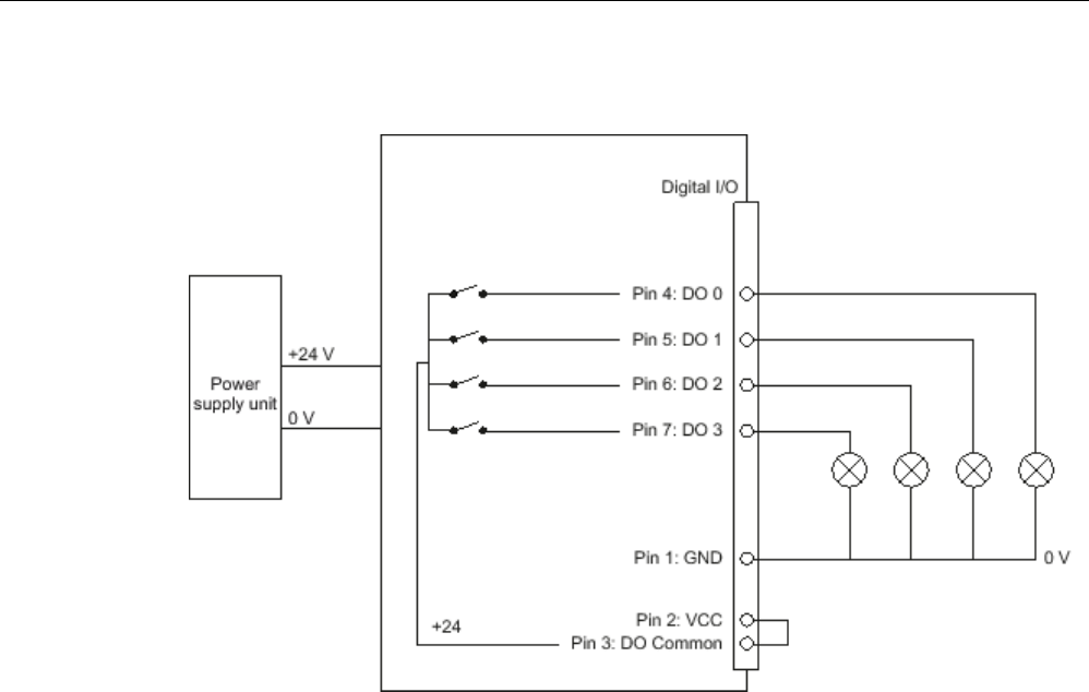
Readers
5.8 RF685R reader
SIMATIC RF600
System Manual, xx/2014, J31069-D0171-U001-A15-7618 223
REVIEW
Voltage infeed from internal source
Figure 5-53 Circuit example 4: Digital outputs
Alternative connection possibilities:
● Pin 1 GND to pin 3 DO common
● Pin 2 (VCC) to busbar outputs
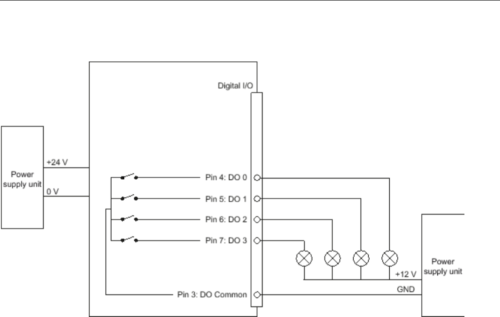
Readers
5.8 RF685R reader
SIMATIC RF600
224 System Manual, xx/2014, J31069-D0171-U001-A15-7618
REVIEW
Voltage infeed from external source
Figure 5-54 Circuit example 5: Digital outputs
Voltage infeed from an external source is shown here for 12°V as an example. Other
voltages are also permissible.
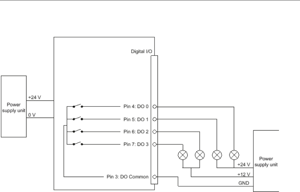
Readers
5.8 RF685R reader
SIMATIC RF600
System Manual, xx/2014, J31069-D0171-U001-A15-7618 225
REVIEW
Voltage infeed from external source with various voltages
Figure 5-55 Circuit example 6: Digital outputs

Readers
5.8 RF685R reader
SIMATIC RF600
226 System Manual, xx/2014, J31069-D0171-U001-A15-7618
REVIEW
5.8.1.6
Pin assignment of the RS-422 interface
Pin
Pin
Device end
8-pin M12
Assignment
1
+ 24 V
2
- Transmit
3
0 V
4
+ Transmit
5
+ Receive
6
- Receive
7
Unassigned
8
Earth (shield)
5.8.1.7
Pin assignment for Industrial Ethernet interface
View of M12 plug, 4-pin, D coding
(wiring side)
Pin
Pin assignment
1
Data line TxP
2
Data line RxP
3
Data line TxN
4
Data line RxN
5.8.1.8
Grounding connection
The RF685R can be electrically connected to the ground potential with a contact washer.
The tightening torque must be increased in this case to ensure that electrical contact is made
(2.7 Nm).
WARNING
Hazardous voltage due to lightning strikes
Death or serious injury may occur as a result of lightning strikes to antennas mounted
outside buildings.
If the reader is operated with antennas mounted outside buildings, it is imperative that the
reader is electrically connected to the ground potential.
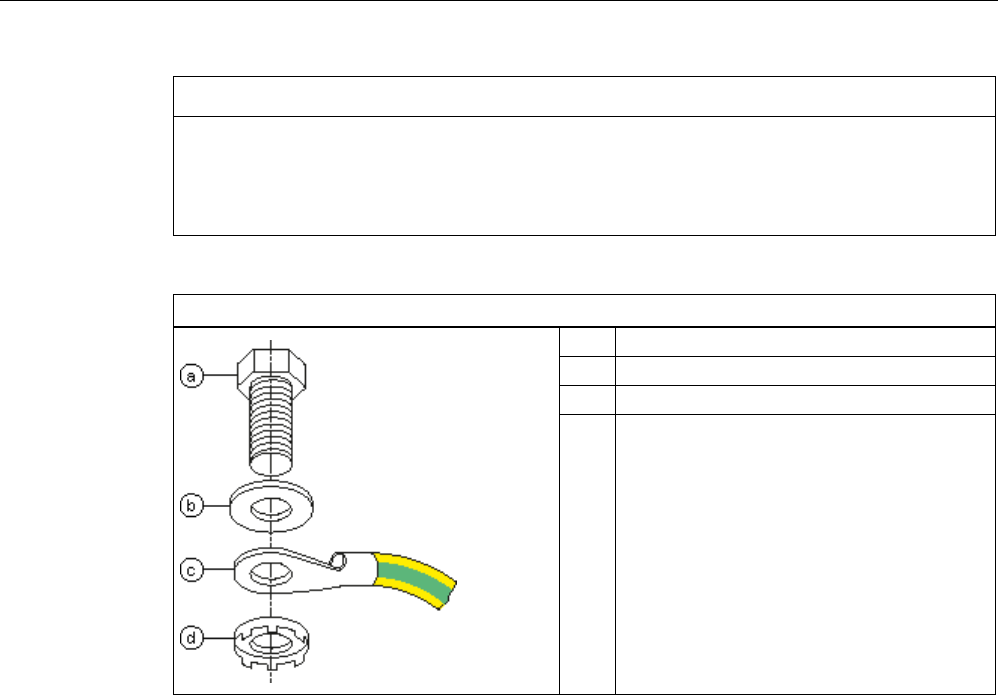
Readers
5.8 RF685R reader
SIMATIC RF600
System Manual, xx/2014, J31069-D0171-U001-A15-7618 227
REVIEW
NOTICE
Installation only in protected areas
The antenna can be installed in the protected part of a building. When implementing your
lightning protection concept, make sure you adhere to the VDE 0182 or IEC 62305
standards.
Ground connection
(a)
Hexagon-head screw
(b)
Flat washer
(c)
Cable lug
(d) Contact washer:
Use contact washers according to the
Siemens standard SN 70093-6-FSt-flNnnc-
480h for ground connection,
Siemens item no.: H70093-A60-Z3
5.8.2
Planning operation
5.8.2.1
Selecting the antenna
With the SIMATIC RF685R, there are two ways of using the antenna that are mutually
exclusive:
● Either you use the internal antenna of the reader
● Or you connect an external antenna to the interface of the reader. The internal antenna of
the reader can then, however, not be used at the same time.
You can select the active antenna using the graphical user interface of the integrated Web
server.
5.8.2.2
Internal antenna
Minimum mounting clearances of two readers
The RF685R has an antenna with switchable polarization. With the internal antenna active
and at 2000 mW ERP radiated power, due to the aperture angle of the antennas, their fields
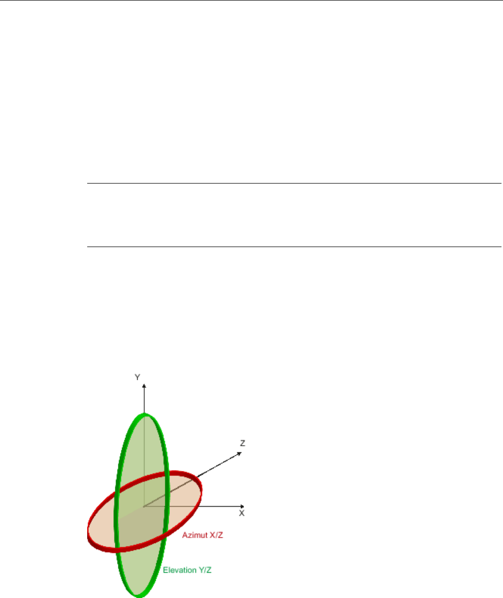
Readers
5.8 RF685R reader
SIMATIC RF600
228 System Manual, xx/2014, J31069-D0171-U001-A15-7618
REVIEW
can overlap considerably. This means it is no longer possible to be sure in which of the
antenna fields the data of a transponder will be accessed.
In order to avoid this, always keep a minimum distance of 6 m between two readers with the
maximum radiated power of 2000 mW ERP.
Dense Reader Mode (DRM)
The readers can also interfere with each other (secondary fields), if the channels (Reader
TX, Transponder TX) overlap. In order to prevent a transponder channel overlapping with a
reader channel, we recommend that the Dense Reader Mode (DRM) is used.
Note
Protective cap
If you use the internal antenna of the
reader, we recommend that you close the external,
unused antenna connector on the reader using the supplied protective cap.
Antenna diagram for RF685R (ETSI)
The following radiation diagrams show the directional characteristics of the internal antenna
of the RF685R (ETSI) reader. For the spatial presentation of the directional characteristics,
the vertical plane (azimuth section) as well as the horizontal plane (elevation section) must
be considered. This results in a spatial image of the directional radiation pattern of the
antenna with its main and secondary fields.

Readers
5.8 RF685R reader
SIMATIC RF600
System Manual, xx/2014, J31069-D0171-U001-A15-7618 229
REVIEW
Radiation diagram (Azimuth section)
Vertical component of the polarization direction of the antenna
Horizontal component of the polarization direction of the antenna
Right circular component of the polarization direction of the antenna
Figure 5-56 Azimuth section

Readers
5.8 RF685R reader
SIMATIC RF600
230 System Manual, xx/2014, J31069-D0171-U001-A15-7618
REVIEW
Radiation diagram (elevation section)
Vertical component of the polarization direction of the antenna
Horizontal component of the polarization direction of the antenna
Right circular component of the polarization direction of the antenna
Figure 5-57 Elevation section

Readers
5.8 RF685R reader
SIMATIC RF600
System Manual, xx/2014, J31069-D0171-U001-A15-7618 231
REVIEW
Overview of the antenna parameters
Table 5- 36 Maximum linear electrical aperture angle at 865 MHz:
Azimuth section
77,7°
Elevation section
66,1°
Typical antenna gain in the frequency band 865
to 868 MHz
4.0 dBi
Antenna axis ratio
0.7 dB
See also section Guidelines for selecting RFID UHF antennas (Page 55)
Antenna diagram for RF685R (FCC)
The following radiation diagrams show the directional characteristics of the internal antenna
of the RF685R (FCC) reader. For the spatial presentation of the directional characteristics,
the vertical plane (azimuth section) as well as the horizontal plane (elevation section) must
be considered. This results in a spatial image of the directional radiation pattern of the
antenna with its main and secondary fields.
Azimuth
XZ plane
Elevation
YZ plane

Readers
5.8 RF685R reader
SIMATIC RF600
232 System Manual, xx/2014, J31069-D0171-U001-A15-7618
REVIEW
Radiation diagram (Azimuth section)
Vertical component of the polarization direction of the antenna
Horizontal component of the polarization direction of the antenna
Right circular component of the polarization direction of the antenna
Figure 5-58 Azimuth section
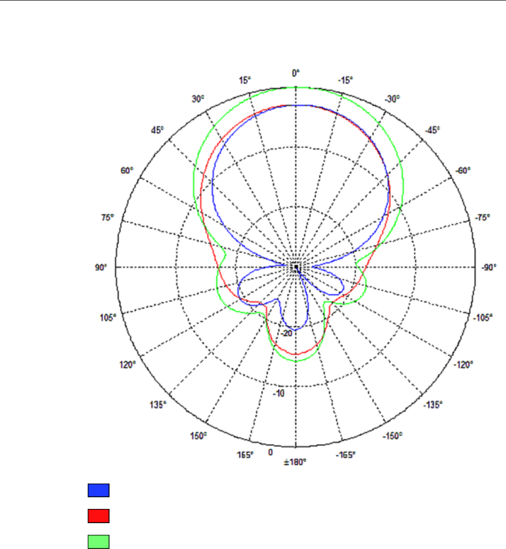
Readers
5.8 RF685R reader
SIMATIC RF600
System Manual, xx/2014, J31069-D0171-U001-A15-7618 233
REVIEW
Radiation diagram (elevation section)
Vertical component of the polarization direction of the antenna
Horizontal component of the polarization direction of the antenna
Right circular component of the polarization direction of the antenna
Figure 5-59 Elevation section

Readers
5.8 RF685R reader
SIMATIC RF600
234 System Manual, xx/2014, J31069-D0171-U001-A15-7618
REVIEW
Overview of the antenna parameters
Table 5- 37 Maximum linear electrical aperture angle at 865 MHz:
Azimuth section
75,4 °
Elevation section
69,1 °
Typical antenna gain in the frequency band 902
to 928 MHz
4.0 dBi ± 0.5 dB
Antenna axis ratio
<1 dB
See also section Guidelines for selecting RFID UHF antennas (Page 55).
Interpretation of directional radiation patterns
The following overview table will help you with the interpretation of directional radiation
patterns.
The table shows which dBi values correspond to which read/write ranges (in %): You can
read the radiated power depending on the reference angle from the directional radiation
patterns, and thus obtain information on the read/write range with this reference angle with
regard to a transponder.
The dBr values correspond to the difference between the maximum dBi value and a second
dBi value.
Deviation from maximum antenna gain [dBr]
Read/write range [%]
0
100
-3
70
-6
50
-9
35
-12
25
-15
18
-18
13
Example
As can be seen in the section Antenna diagram for RF685R (ETSI) (Page 228), the
maximum antenna gain 0 dB is standardized. In the Azimuth diagram, the antenna gain falls
by 3°dB at approximately ± 39°. Therefore the dBr value is -3. The antenna range is only
50% of the maximum range at ± 39° from the Z axis within the horizontal plane.
Antenna/read point configurations
The RF685R reader has a switchable antenna (circular or linear polarization). You can cover
one read point with this antenna. When several RF685R readers are used, the readers are
addressed via the SIMATIC level.
Readers
5.8 RF685R reader
SIMATIC RF600
System Manual, xx/2014, J31069-D0171-U001-A15-7618 235
REVIEW
5.8.2.3
External antenna
Preassembled standard cables in lengths of 3 m, 5 m, 15 m and 20 m are available to
connect the antenna.
The read range is limited by the cable loss. The maximum range can be achieved with the
cable 6GT2815-0BH30 (length 3 m), since this has the lowest cable loss.
Examples of possible antenna reading point configurations
● A data source with an external antenna for a reading point.
● As an alternative, a data source with an internal antenna for a reading point.
5.8.3
Installation/mounting
Requirement
WARNING
Make sure that the wall or ceiling can hold four times the total weight of the device.
Note
Close unused connectors
If you do not use connectors on the reader, it is advisable to close the unused connectors
with protective caps. You can order the protective cap set using the MLFB specified in the
section "Ordering data".
CAUTION
Emitted radiation
The transmitter complies with the requirements of Health Canada and the FCC limit values
for subjecting persons to HF radiation, provided that a minimum spacing of 26 cm exists
between antenna and person. When the antennas are installed, you must therefore ensure
that a minimum spacing of 26 cm is maintained between personnel and antennas.
Mounting/installing the device
You can mount the reader in two different ways:
● Via a standardized VESA 100 mounting system using the Antenna Mounting Kit (refer to
the section Mounting with antenna mounting kit (Page 331)). Tighten the M4 screws on
the rear of the reader using a maximum torque of ≤ 1.3 Nm.
● Directly on a flat surface.
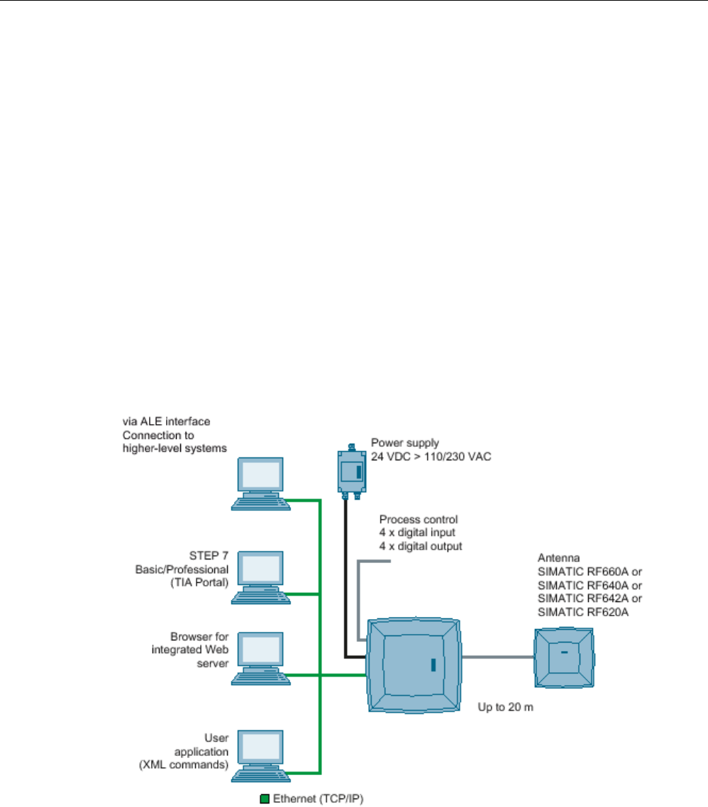
Readers
5.8 RF685R reader
SIMATIC RF600
236 System Manual, xx/2014, J31069-D0171-U001-A15-7618
REVIEW
The positions of the mounting holes for the device are shown in the section Dimension
drawing (Page 239).
5.8.4
Configuration/integration
An Ethernet interface is available for integrating the device into system
environments/networks. Over the Ethernet interface and with direct connection to the PC, the
RF685R can be configured in the following ways:
● via the graphical user interface of the integrated Web server
● STEP 7 Basic/Professional (TIA Portal)
● with XML-based user applications
The communications interface transfers the data via the Web server or STEP 7 to the IT,
ERP and SCM systems as well as to SIMATIC controllers. Alternatively the data is
transferred to user applications using XML commands.
Simple process controls (e.g. a traffic signal) can be implemented directly using the
write/read device via four digital inputs and outputs.
Figure 5-60 Overview of configuration of the RF685R reader

Readers
5.8 RF685R reader
SIMATIC RF600
System Manual, xx/2014, J31069-D0171-U001-A15-7618 237
REVIEW
5.8.5
Technical specifications
Table 5- 38 Technical specifications, RF685R
6GT2811-6CA10-xAA0
Product type designation
RF685R
Mechanical specifications
Weight
Dimensions (L x W x H)
Degree of protection
IP65
Material
• Upper part of housing Pocan DP CF 2200
• Lower part of housing Aluminum
Color
• Upper part of housing TI-Grey
• Lower part of housing Silver
Operating displays on the device
8 LEDs
Status display on the device
9 LEDs
Interfaces
• Antenna connectors 1 x RTNC plug
• Power supply 1 x connector (8-pin M12), RS-422
• Digital I/O interface 1 x socket (12-pin, M12)
• Digital inputs 4
• Digital outputs 4
• Ethernet interface 2 x socket (4-pin, M12)
MTBF in years
Electrical specifications
Power supply
20 to 30 VDC
1)
Current consumption (on standby)
• 20 V input voltage on the reader (typical) 200 mA / 4.0 W
• 24 V input voltage on the reader (typical) 170 mA / 4.1 W
• 30 V input voltage on the reader (typical) 140 mA / 4.2 W
Current consumption (at 1000 mW transmit power)
• 20 V input voltage on the reader (typical) 450 mA / 9.0 W
• 24 V input voltage on the reader (typical) 380 mA / 9.1 W
• 30 V input voltage on the reader (typical) 300 mA / 9.6 W

Readers
5.8 RF685R reader
SIMATIC RF600
238 System Manual, xx/2014, J31069-D0171-U001-A15-7618
REVIEW
6GT2811-6CA10-xAA0
Startup time
Electromagnetic compatibility
• ETSI EN 301 489-1/-3, EN 302 208-1/-3 V1.4.1
• FCC FCC CFR 47, Part 15 section 15.247
Permitted ambient conditions
Ambient temperature
• Operation -25 ℃ to +55 ℃
• Transport and storage -40 ℃ to +85 ℃
Shock resistant to EN 60068-2-27
50 g
2)
Vibration resistant to EN 60068-2-26
20 g
2)
1)
All supply and signal voltages must be safety extra-low voltage (SELV/PELV according to EN 60950). All power sources
must meet the requirements for LPS (Limited Power Sources) and NEC Class 2.
2) The values for shock and vibration are maximum values and must not be applied continuously.
Table 5- 39 Technical specifications according to EPC and ISO, RF685R
6GT2811-6CA10-xAA0
Product type designation
RF685R
Frequency accuracy
max.± 10 ppm
Channel spacing • EU, EFTA, Turkey: 600 kHz
• US: 500 kHz
• China: 250 kHz
Modulation methods ASK: DSB modulation & PR-ASK modulation
Encoding, Manchester or Pulse Interval (PIE)
Effective radiated power (internal antenna)
• ETSI/CMIIT • ≤ 2 W ERP
• FCC • ≤ 4 W EIRP
Effective radiated power (external antenna)
• ETSI/CMIIT • ≤ 2 W ERP
• FCC • ≤ 4 W ERP
Transmit power
• ETSI/CMIIT • ≤ 2 W
• FCC • ≤ 2 W
Reading range
Antennas mounted on opposing sides (portal
configuration)
max. 10 m
Antennas mounted on the same side
max. 5 m (dependent on transponder)
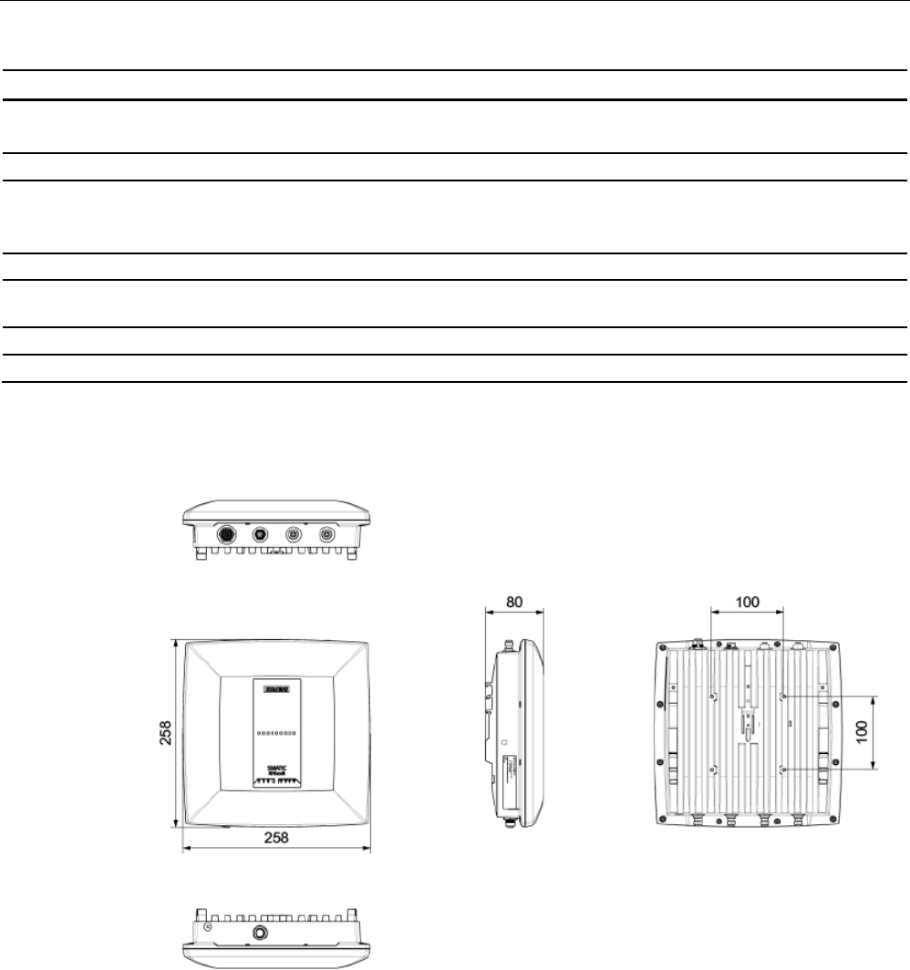
Readers
5.8 RF685R reader
SIMATIC RF600
System Manual, xx/2014, J31069-D0171-U001-A15-7618 239
REVIEW
6GT2811-6CA10-xAA0
Frequencies
ETSI frequencies
European frequency band
ETSI EN 302 208 V1.4.1 (valid since October 23, 2012,
publication in the Official Journal of the European Union)
865,7 ... 867.5 MHz
(4 channels at max. 2 W ERP)
FCC frequencies
Frequency band USA 902 ... 928 MHz
(50 channels at max. 4 W EIRP, frequency hopping)
CMIIT frequencies
Frequency band China
920,625 ... 924.375 MHz (16 subchannels at 2 W ERP)
5.8.6
Dimension drawing
Figure 5-61 Dimension drawing RF685R
All dimensions in mm (± 0.5 mm tolerance)
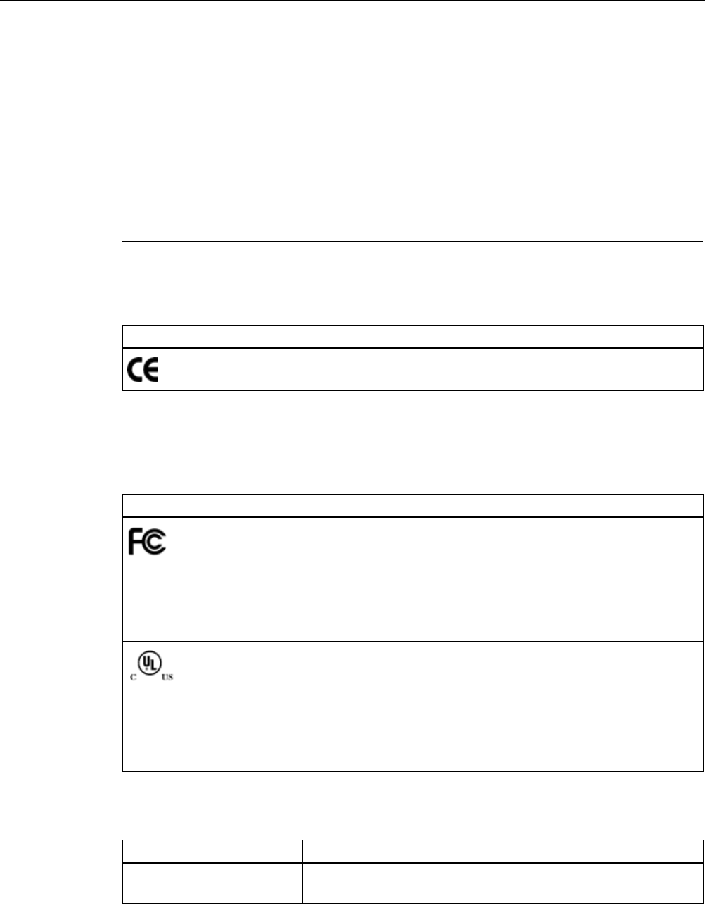
Readers
5.8 RF685R reader
SIMATIC RF600
240 System Manual, xx/2014, J31069-D0171-U001-A15-7618
REVIEW
5.8.7
Certificates and approvals
5.8.7.1
CE mark
Note
Marking on the readers according to specific approval
The certificates and approvals listed here apply only if the corresponding mark is found on
the readers.
Table 5- 40 6GT2811-6CA10-0AA0
Certificate
Description
Conformity with R&TTE directive
5.8.7.2
Country-specific certifications
Table 5- 41 6GT2811-6CA10-1AA0
Standard
Federal Communications
Commission
FCC CFR 47, Part 15 sections 15.247
Radio Frequency Interference Statement
This equipment has been tested and found to comply with the limits
for a Class A digital device, pursuant to Part 15 of the FCC Rules.
FCC ID: ??????
Industry Canada Radio
Standards Specifications
RSS-210 Issue 6, Sections 2.2, A8
IC: ??????
This product is UL-certified for the USA and Canada.
It meets the following safety standard(s):
UL 60950-1 - Information Technology Equipment Safety - Part 1:
General Requirements
CSA C22.2 No. 60950 -1 - Safety of Information Technology
Equipment
UL Report E 205089
Table 5- 42 6GT2811-6CA10-2AA0
Standard
CMIIT Certification China radio approval
Marking on the reader: CMIIT ID: ??????

Readers
5.8 RF685R reader
SIMATIC RF600
System Manual, xx/2014, J31069-D0171-U001-A15-7618 241
REVIEW
5.8.7.3
FCC information
Siemens SIMATIC RF685R (FCC): 6GT2811-6CA10-1AA0
FCC ID:
This device complies with part 15 of the FCC rules. Operation is subject to the following two
conditions:
(1) This device may not cause harmful interference, and
(2) this device must accept any interference received, including interference that may cause
undesired operation.
Caution
Any changes or modifications not expressly approved by the party responsible for
compliance could void the user's authority to operate the equipment.
Note
This equipment has been tested and found to comply with the limits for a Class B digital
device, pursuant to part 15 of the FCC Rules.
These limits are designed to provide reasonable protection against harmful interference
when the equipment is operated in a commercial environment. This equipment generates,
uses, and can radiate radio frequency energy and, if not installed and used in accordance
with the instruction manual, may cause harmful interference to radio communications.
Operation of this equipment in a residential area is likely to cause harmful interference in
which case the user will be required to correct the interference at his own expense.
FCC Notice
To comply with FCC part 15 rules in the United States, the system must be professionally
installed to ensure compliance with the Part 15 certification.
It is the responsibility of the operator and professional installer to ensure that only certified
systems are deployed in the United States. The use of the system in any other combination
(such as co-located antennas transmitting the same information) is expressly forbidden.
FCC Exposure Information
To comply with FCC RF exposure compliance requirements, the antennas used for this
transmitter must be installed to provide a separation distance of at least 20 cm from all
persons and must not be co-located or operating in conjunction with any other antenna or
transmitter.

Readers
5.8 RF685R reader
SIMATIC RF600
242 System Manual, xx/2014, J31069-D0171-U001-A15-7618
REVIEW
5.8.7.4
IC-FCB information
Siemens SIMATIC RF685R (FCC): 6GT2811-6CA10-1AA0
IC:
This device complies with Industry Canada licence-exempt RSS standard(s). Operation is
subject to the following two conditions:
(1) This device may not cause interference, and
(2) this device must accept any interference, including interference that may cause
undesired operation of the device.
Le présent appareil est conforme aux CNR d`Industrie Canada applicables aux appareils
radio exempts de licence. L`exploitation est autorisée aux deux conditions suivantes :
(1) L`appareil ne doit pas produire de brouillage, et
(2) l'utilisateur de l`appareil doit accepter tout brouillage radioélectrique subi, même si le
brouillage est susceptible d`en compromettre le fonctionnement.
Industry Canada Notice
To reduce potential radio interference to other users, the antenna type and its gain should be
so chosen that the equivalent isotropically radiated power (e.i.r.p.) is not more than that
permitted for successful communication.
Transmitter power and antenna information for antennas with a gain less than 6 dBi:
This device has been designed to operate with the SIMATIC RF620A antenna 902-928, the
SIMATIC RF640A antenna 902-928 as well as the SIMATIC RF660A antenna 902-928 listed
below, and having a maximum gain of 5.5 dBi. Arbitrary transmission power settings in
combination with other antennas or antennas having a gain greater than 5.5 dBi are strictly
prohibited for use with this device. The required antenna impedance is 50 Ohms.
Transmitter power and antenna information for antennas with a gain greater 6 dBi:
This device requires professional installation. Antennas with a gain greater 6 dBi may be
used provided the system does not exceed the radiation power of 4000 mW E.I.R.P. This
device has been designed to operate with the SIMATIC RF642A antenna 902-928 exceeding
the maximum gain of 5.5 dBi under the restriction that the RF power at the input of the
antenna must be set to meet the following relation: RF power (dBm) ≤ 30 dBm – (antenna
gain (dBi) – 6 dBi) Other antennas or system configurations for antennas having a gain
greater than 6 dBi are strictly prohibited for use with this device. The required antenna
impedance is 50 Ohms.

Readers
5.9 Reader RF680M
SIMATIC RF600
System Manual, xx/2014, J31069-D0171-U001-A15-7618 243
REVIEW
5.9
Reader RF680M
5.9.1
Description
SIMATIC RF680M expands the RF600 RF identification system with a powerful mobile
reader for applications in the areas of logistics, production and service. In addition, it is an
indispensable aid for startup and testing.
5.9.2
Field of application and features
Device variants for different frequency ranges
The SIMATIC RF680M device is available in two variants:
● For the European frequency ranges
● For the US frequency ranges
Implementation environment, field of application and features
●
Field of application
The SIMATIC RF680M mobile reader can be used in a harsh environment. The device is
extremely rugged and protected against spray water. The backlit display is easy to read
even under unfavorable lighting conditions.
●
RFID system
The SIMATIC RF680M mobile reader is intended especially for the SIMATIC RF600 RFID
system. The device can be used to process all RF600 tags and compatible transponders.
●
Tag standards
It is not possible to edit data memories of other RFID systems. The following tag
standards are supported:
– ISO 18000-6c (EPC Class1 GEN2)
●
API software interface
The SIMATIC RF680M Mobile Reader is supplied with an API software interface that can
be used by customized user programs.
●
Additional functional units for the SIMATIC RF680M mobile reader
All other functional units of SIMATIC RF680M, such as barcode scanners and WLAN can
be accessed via the interfaces supplied by the PSION device manufacturer. The
descriptions and development tools can be obtained from the PSION websites.
You can perform the following functions with the SIMATIC RF680M mobile reader:

Readers
5.9 Reader RF680M
SIMATIC RF600
244 System Manual, xx/2014, J31069-D0171-U001-A15-7618
REVIEW
Functions
● Reading the tag ID
● Reading the data from the tag (data memory)
● Writing the data to the tag
● Reading and displaying the ID number of the tag (Tag/Scan)
● Writing the tag ID to a transponder
● Displaying reader status
● Representing and editing the data in hexadecimal, ASCII and binary format
● Activatable/deactivatable password protection for all write functions and for terminating
the program
● Menu prompting in English and German (switchable)
● Saving of the read-in RF600 data to files in the mobile reader. The mobile reader has
approximately 900 MB available for this purpose.
● Easy creation of your own RFID applications with the Software Application Interface (API)
The RFID read/write unit of RF600 is integrated into the PSION basic unit.
You will find more detailed information on the RF680M mobile reader in the operating
instructions of the SIMATIC RF680M Mobile Reader.

SIMATIC RF600
System Manual, xx/2014, J31069-D0171-U001-A15-7618 245
REVIEW
Antennas
6
6.1
Overview
The following table shows the most important features of the RF600 antennas at a glance:
Table 6- 1 Characteristics of the RF620A and RF660A antennas
Characteristics
RF620A antenna
865-868
RF620A antenna
902-928
RF660A antenna
865-868
RF660A antenna
902-928
Material
PA 12, silicon-free
Frequency band
865-868 MHz
902-928 MHz
865-868 MHz
902-928 MHz
Impedance
50 Ohm nominal
Antenna gain
-10…-5 dBi
7 dBi
6 dBi
VSWR (standing wave ratio)
2:1 max.
Polarization
Linear
RH circular
Radiating/receiving angle
Depending on the mounting surface
55° - 60°
60° - 75°
Connector
RTNC coupling
RTNC
Mounting type
2 x M5 screws
4 screws M4 (VESA 100 mount system)
Degree of protection
IP67
Permitted ambient
temperature
-25 °C to +75 °C
Number of connectable
antennas per reader
RF620R
1 antenna
Max. radiated power
80 mW ERP / 130 mW EIRP
1200 mW ERP
1600 mW EIRP
RF630R
1 or 2 antennas
Max. radiated power
80 mW ERP / 130 mW EIRP
1200 mW ERP
1600 mW EIRP
RF640R
1 antenna
Max. radiated power 100 mW ERP / 300 mW EIRP 2000 mW ERP 4000 mW EIRP
RF670R
1, 2, 3 or 4 antennas
Max. radiated power
100 mW ERP / 300 mW EIRP
2000 mW ERP
4000 mW EIRP
RF650R
1, 2, 3 or 4 antennas
Max. radiated power
80 mW ERP / 130 mW EIRP
2000 mW ERP
3160 mW ERP
RF680R
1, 2, 3 or 4 antennas
Max. radiated power
150 mW ERP / 250 mW EIRP
2000 mW ERP
4000 mW ERP
RF685R
1 antenna
Max. radiated power
150 mW ERP / 250 mW EIRP
2000 mW ERP
4000 mW ERP

Antennas
6.1 Overview
SIMATIC RF600
246 System Manual, xx/2014, J31069-D0171-U001-A15-7618
REVIEW
Table 6- 2 Characteristics of the RF640A and RF642A antennas
Characteristics
RF640A antenna
RF642A antenna
Material
PA 12, silicon-free
Frequency band
865-868 MHz
902-928 MHz
865-868 MHz
902-928 MHz
Impedance
50 Ohm nominal
Antenna gain
4 dBi (7 dBic)
4.3 dBi (7.3 dBic)
6 dBi
7 dBi
VSWR (standing wave ratio)
Max. 1.25
Max. 1.6
Max. 1.4
Polarization
RH circular
Linear
Radiating/receiving angle
Horiz. plane: 80°
Horiz. plane: 75°
Horiz. plane: 75°
Horiz. plane: 80°
Vertic. plane: 75°
Vertic. plane: 85°
Vertic. plane: 70°
Vertic. plane: 70°
Connector
RTNC coupling
RTNC coupling
Mounting type
4 screws M4 (VESA 100 mount system)
Degree of protection
IP67
Permitted ambient
temperature
-25 °C to +75 °C
Number of connectable
antennas per reader
RF620R
1 antenna
Max. radiated power
< 610 mW ERP
≤1070 mW EIRP
< 1000 mW ERP
2000 mW EIRP
RF630R
1 or 2 antennas
Max. radiated power < 610 mW ERP ≤1070 mW EIRP < 1000 mW ERP 2000 mW EIRP
RF640R
1 antenna
Max. radiated power ≤1300 mW ERP ≤2700 mW EIRP 2000 mW ERP 4000 mW EIRP
RF670R
1, 2, 3 or 4 antennas
Max. radiated power
≤1300 mW ERP
≤2700 mW EIRP
2000 mW ERP
4000 mW EIRP
RF650R
1, 2, 3 or 4 antennas
Max. radiated power
1200 mW ERP
2100 mW EIRP
2000 mW ERP
4000 mW EIRP
RF680R
1, 2, 3 or 4 antennas
Max. radiated power
2000 mW ERP
4000 mW EIRP
2000 mW ERP
4000 mW EIRP
RF685R
1 antenna
Max. radiated power
2000 mW ERP
4000 mW EIRP
2000 mW ERP
4000 mW EIRP
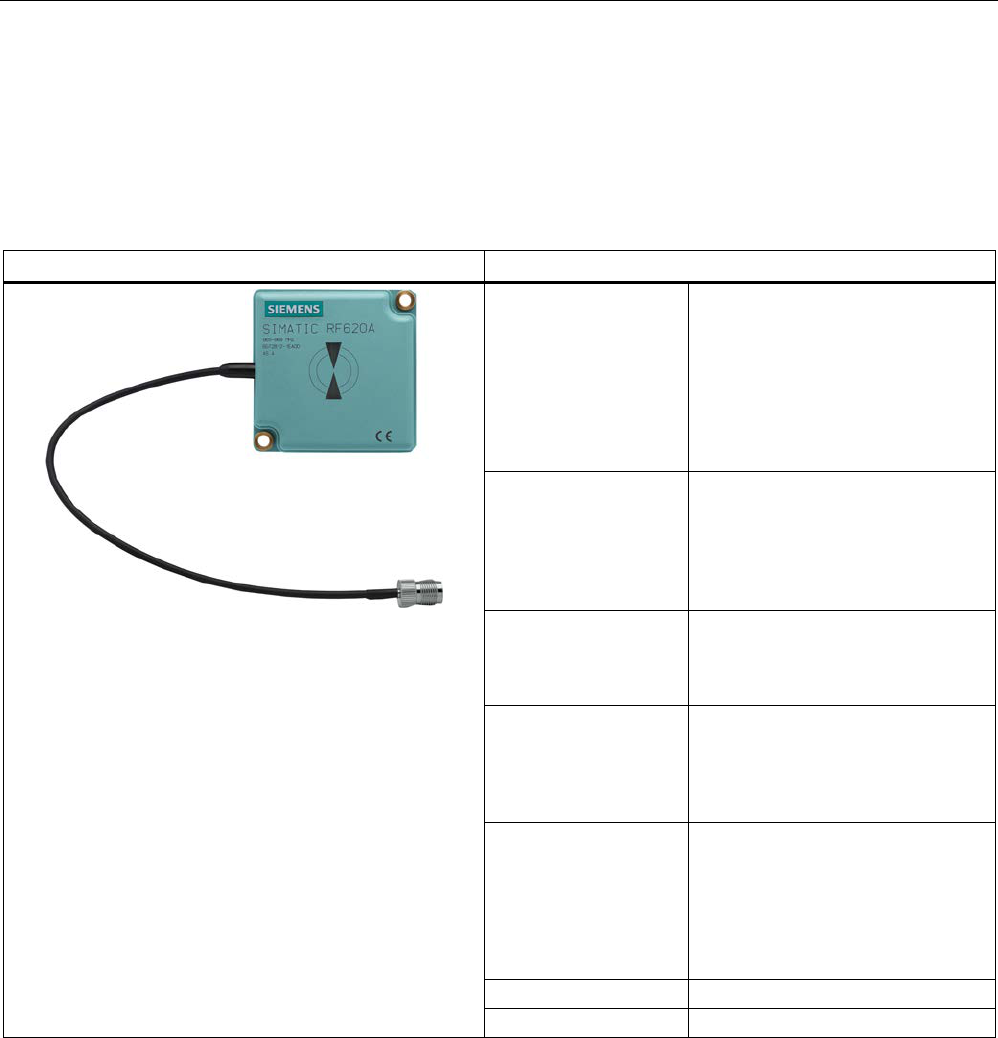
Antennas
6.2 RF620A antenna
SIMATIC RF600
System Manual, xx/2014, J31069-D0171-U001-A15-7618 247
REVIEW
6.2
RF620A antenna
6.2.1
Description
SIMATIC RF620A
Characteristics
Area of application The SIMATIC RF620A is an
antenna with a compact design
suitable for industry.
It is suitable for UHF transponders
with normal (far field) antenna
characteristics, e.g.
SIMATIC RF630L,
SIMATIC RF620T.
Antenna field Designed for transponders that are
uniformly aligned while passing the
antenna.
See also section Alignment of
transponders to the antenna
(Page 254)
Write/read distance Approx. 0.5 m depending on the
transponder
(see section Read/write ranges
(Page 263) )
Connecting cable 30 cm movable connecting cable
and RTNC coupling (an antenna
cable, e.g. 6GT2815-0BH30 is
required for connection to the
reader)
Readers that can be
connected
• RF670R (1 to 4 antennas)
• RF630R (1 or 2 antennas)
• RF650R (1 to 4 antennas)
• RF680R (1 to 4 antennas)
• RF685R (1 antenna)
Polarization
Linear
Degree of protection
IP67
Frequency bands
The antenna is available for two different frequency ranges that have been specified for the
regions of Europe, and China, USA respectively.
● The antenna for Europe operates in the frequency range from 865 to 868 MHz.
● The antenna for China and the USA operates in the frequency range from 902 to 928
MHz.
Antennas
6.2 RF620A antenna
SIMATIC RF600
248 System Manual, xx/2014, J31069-D0171-U001-A15-7618
REVIEW
Function
The SIMATIC RF620A is used for transmitting and receiving RFID signals in the UHF
frequency range. The antennas are connected to the SIMATIC RF600 readers via antenna
cables that are available in different lengths.
6.2.2
Ordering data
Table 6- 3 Ordering data RF620A
Product
Article number
SIMATIC RF620A (ETSI)
6GT2812-1EA00
SIMATIC RF620A (FCC)
6GT2812-1EA01
Accessories
Table 6- 4 Ordering data accessories
Product
Article number
Connecting cable between
reader and antenna
3 m (cable loss 1.0 dB)
6GT2815-0BH30
5 m, suitable for drag chains
(cable loss 1.25 dB)
6GT2815-2BH50
10 m (cable loss 2.0 dB)
6GT2815-1BN10
10 m (cable loss 4.0 dB)
6GT2815-0BN10
15 m, suitable for drag chains
(cable loss 4.0 dB)
6GT2815-2BN15
20 m (cable loss 4.0 dB)
6GT2815-0BN20
6.2.3
Installation and assembly
6.2.3.1
RF620A mounting types
Two holes for M5 screws are provided for mounting the antenna. This is therefore suitable
for:
● Mounting on metallic and non-metallic backgrounds
Note
To achieve optimum wave propagation,
the antenna should not be surrounded by
conducting objects. The area between antenna and transponder should also allow wave
propagation without interference.
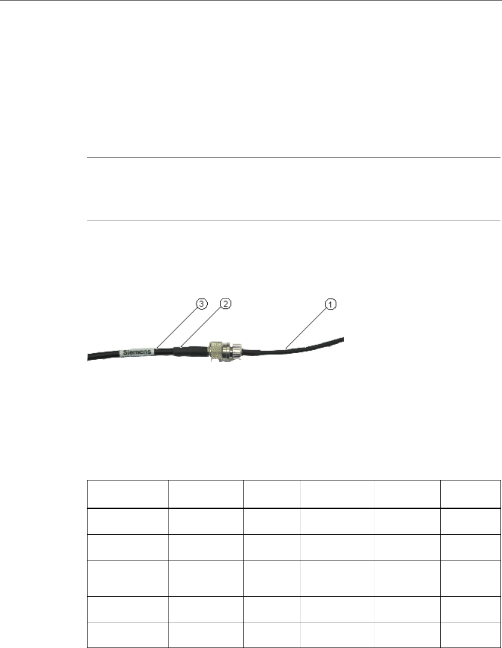
Antennas
6.2 RF620A antenna
SIMATIC RF600
System Manual, xx/2014, J31069-D0171-U001-A15-7618 249
REVIEW
6.2.4
Connecting an antenna to the reader
6.2.4.1
Overview
The SIMATIC RF620A antenna must be connected to the reader using an antenna cable.
Requirement
Note
Use of Siemens antenna cable
To ensure optimum functioning of the antenna, it is recommended that a Siemens antenna
cable is used in accordance with the list of accessories.
Strain relief
The antenna cable is provided with strain relief as shown in the following diagram:
①
RF620A connecting cable
②
RF600 antenna cable
③
Strain relief (should take place at this position)
Figure 6-1 Strain relief
Bending radii and bending cycles of the cable
Cable designation
Order no.
Length [m]
Cable loss [dB]
Bending
radius [mm]
Bending
cycle
RF620A
connecting cable
15 1 Mal
Antenna cable 6GT2815-
0BH30
3 1 51 1 Mal
Antenna cable,
suitable for drag
chains
6GT2815-
2BH50
5 1,25 48 1)
Antenna cable 6GT2815-
1BN10
10 2 77 1 Mal
Antenna cable 6GT2815-
0BN10
10 4 51 1 Mal

Antennas
6.2 RF620A antenna
SIMATIC RF600
250 System Manual, xx/2014, J31069-D0171-U001-A15-7618
REVIEW
Cable designation
Order no.
Length [m]
Cable loss [dB]
Bending
radius [mm]
Bending
cycle
Antenna cable,
suitable for drag
chains
6GT2815-
2BN15
15 4 24 1)
Antenna cable 6GT2815-
0BN20
20 4 77 1 Mal
1)
With cables suitable for drag chains, 3 million bending cycles at a bending radius of 6.5 m and
bending through ± 180 ° are permitted.
6.2.4.2
Connecting RF620A to an RF600 reader
Preassembled standard cables in lengths of 3 m, 5 m, 10 m, 15 m and 20 m are available to
connect the antenna.
The read range is limited by the cable loss. The maximum range can be achieved with the
6GT2815-0BH30 cable (length 3 m) since this has the lowest cable loss.
Connection of one antenna
When one antenna is used, we recommend that you close the remaining antenna connector
on the RF600 reader using the supplied protective cap.
Connection of two antennas
When using two antennas on the RF600 readers, there are no limitations regarding its
positioning.
Note
Protective cap
If you use the
internal antenna of the reader, we recommend that you close the external,
unused antenna connector on the reader using the supplied protective cap.

Antennas
6.2 RF620A antenna
SIMATIC RF600
System Manual, xx/2014, J31069-D0171-U001-A15-7618 251
REVIEW
6.2.5
Parameter settings of RF620A for RF620R/RF630R
Operation within the EU, EFTA, or Turkey according to DIN EN 302208 V1.4.1
Note
Limitation of the radiated power according to DIN EN 302208 V1.4.1
RF600 systems that are put into operation within the EU, EFTA, or Turkey (ETSI) can be
operated with an RF620A antenna with a maximum radiated power of up to
2000 mW ERP
(or 33 dBm
ERP, 3250 mW EIRP, 35 dBm EIRP).
By adjusting the transmit power of up to 500 mW ERP (or 27 dBm ERP, 800 mW EIRP,
29.15 dBm EIRP) and taking into account the RF620A antenna gain of 5 dBi and the cable
loss associated with the antenna cable, the radiated power of the antenna cannot be
exceeded. You can make the power settings using the "distance_limiting" parameter. You
will find more detailed information on the parameters in the section Parameter assignment
manual RF620R/RF630R (http://support.automation.siemens.com/WW/view/en/33287195).
Operation in China
The national approval for RF600 systems in China means a restriction to 2000 mW ERP (or
33 dBm ERP, 3250 mW EIRP, 35 dBm EIRP). The possible combination of antenna gain,
cable loss, and max. 500 mW radiated power of the RF630R reader means it is not possible
to exceed 2000 mW ERP (or 33 dBm ERP, 3250 mW EIRP, 35 dBm EIRP).
Operation in the USA, Canada
Note
Limitation of the radiated power to 4000 mW EIRP (36 dBm EIRP)
To meet the FCC and IC
-FCB requirements, the radiated power may not exceed 4000 mW
EIRP (36 dBm EIRP). Therefore the system must satisfy the following relation:
•
Conducted power P dBm of the RF600 reader (< 30 dBm)
•
Antenna gain Gi dBi in the FCC frequency band (≤ 5 dBi)
•
Cable loss ak dB (≥ 1 dB)
P(dBm) ≤ 30
dBm - (Gi - 6 dBi) + ak
Due to the low antenna gain of 5 dBi and the maximum transmit power of 500 mW of the
reader, the maximum permitted radiated power cannot be exceeded.

Antennas
6.2 RF620A antenna
SIMATIC RF600
252 System Manual, xx/2014, J31069-D0171-U001-A15-7618
REVIEW
6.2.6
Parameter settings of RF620A for RF640R/RF670R
Operation within the EU, EFTA, or Turkey according to DIN EN 302208 V1.4.1
Note
Limitation of the radiated power according to DIN EN 302208 V1.4.1
RF600 systems
that are put into operation within the EU, EFTA, or Turkey (ETSI) can be
operated with an RF620A antenna with a maximum radiated power of up to 2000
mW ERP
(or 33 dBm
ERP, 3250 mW EIRP, 35 dBm EIRP).
By adjusting the radiated power of up to 70 mW ERP (or 18.85 dBm ERP, 120 mW EIRP,
21 dBm EIRP), the RF620A antenna gain of 5 dBi and the cable loss associated with the
antenna cable, the radiated power of the reader is correctly configured and the radiated
power at the antenna is not exceeded.
Operation in China
By setting a max. radiated power of 1300 mW ERP (or 31.15 dBm ERP, 2140 mW EIRP,
33.3 dBm EIRP), an RF620A antenna gain of 4.3 dBi (7.3 dBic) and the cable loss
associated with the antenna cable (see table), the radiated power of the reader is correctly
configured.
Operation in the USA, Canada
Note
Limitation of the radiated power to 4000 mW EIRP (36 dBm EIRP)
To meet the FCC and IC requirements, the radiated power may not exceed 4000 mW EIRP
(36 dBm EIRP). Therefore the system must satisfy the fol
lowing relation:
•
Conducted power P dBm of the RF600 reader (< 30 dBm)
•
Antenna gain Gi dBi in the FCC frequency band (≤ 5 dBi)
•
Cable loss ak dB (≥ 1 dB)
P(dBm) ≤ 30
dBm - (Gi - 6 dBi) + ak
Due to the low antenna gain of 5 dBi and the maximum transmit power of 500 mW of the
reader, the maximum permitted radiated power cannot be exceeded.

Antennas
6.2 RF620A antenna
SIMATIC RF600
System Manual, xx/2014, J31069-D0171-U001-A15-7618 253
REVIEW
6.2.7
Setting RF620A parameters for RF650R/RF680R/RF685R
Operation within the EU according to DIN EN 302208 V1.4.1
Note
Limitation of the radiated power according to DIN EN 302208 V1.4.1
RF600 systems that are put into operation within the EU, EFTA, or Turkey (ETSI) can be
operated with an RF620A antenna with a maximum radiated power of up to 2000
mW ERP
(or 33 dBm
ERP, 3250 mW EIRP, 35 dBm EIRP).
By setting the transmit power of up to 70 mW ERP (or 18.85 dBm ERP, 120 mW EIRP,
21 dBm EIRP) an RF620A antenna gain of 5 dBi and taking into account the cable loss
associated with the antenna cable, the radiated power of the antenna cannot be exceeded.
Operation in China
The national approval for RF600 systems in China means a restriction to 2000 mW ERP (or
33 dBm ERP, 3250 mW EIRP, 35 dBm EIRP). The possible combination of antenna gain,
cable loss, and max. 2000 mW radiated power of the readers means it is not possible to
exceed 2000 mW ERP (or 33 dBm ERP, 3250 mW EIRP, 35 dBm EIRP).
Operation in the USA, Canada
Note
Limitation of the radiated power to 4000 mW EIRP (36 dBm EIRP)
To meet the FCC and IC requirements, the radiated power may not exceed 4000 mW EIRP
(36 dBm EIRP).
Therefore the system must satisfy the following relation:
•
Conducted power P dBm of the RF600 reader (< 30 dBm)
•
Antenna gain Gi dBi in the FCC frequency band (≤ 5 dBi)
•
Cable loss ak dB (≥ 1 dB)
P(dBm) ≤ 30
dBm - (Gi - 6 dBi) + ak
Due to the low antenna gain of 5 dBi and the maximum transmit power of 1000 mW or 2000
mW of the reader, the maximum permitted radiated power cannot be exceeded.
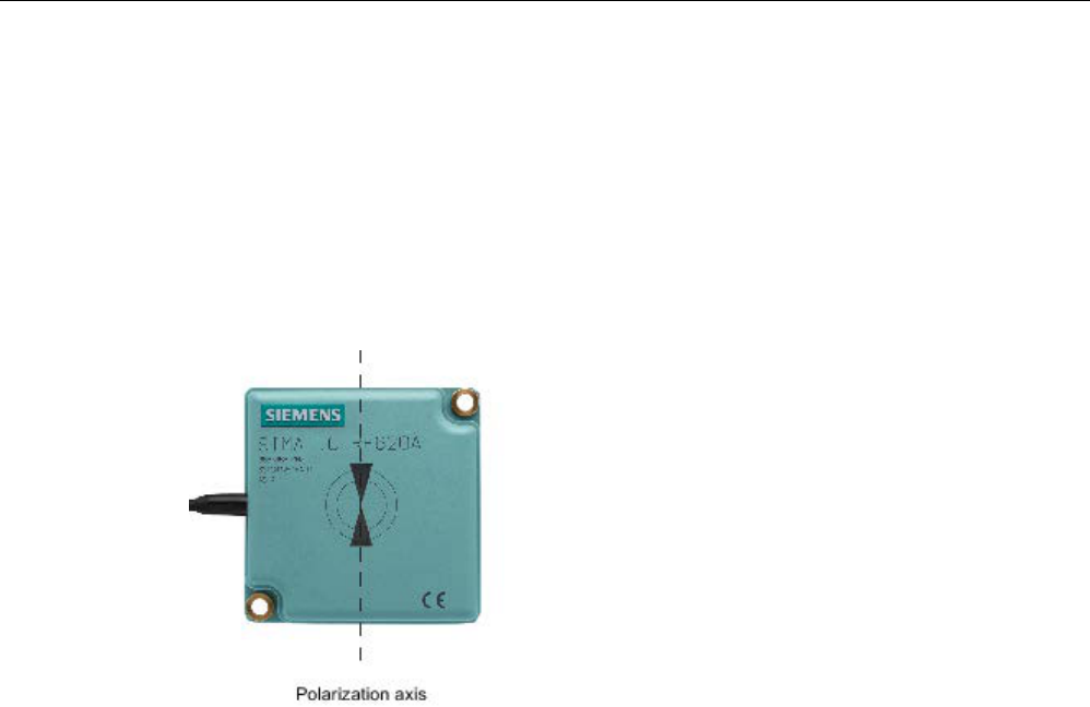
Antennas
6.2 RF620A antenna
SIMATIC RF600
254 System Manual, xx/2014, J31069-D0171-U001-A15-7618
REVIEW
6.2.8
Alignment of transponders to the antenna
Polarization axis
Since the RF620A antenna has linear polarization, it is necessary to consider the alignment
of the transponders with regard to the polarization axis of the antenna.
The polarization axes of antenna and transponder must always be parallel. The symbol on
the antenna indicates the polarization axis.
Figure 6-2 Polarization axis
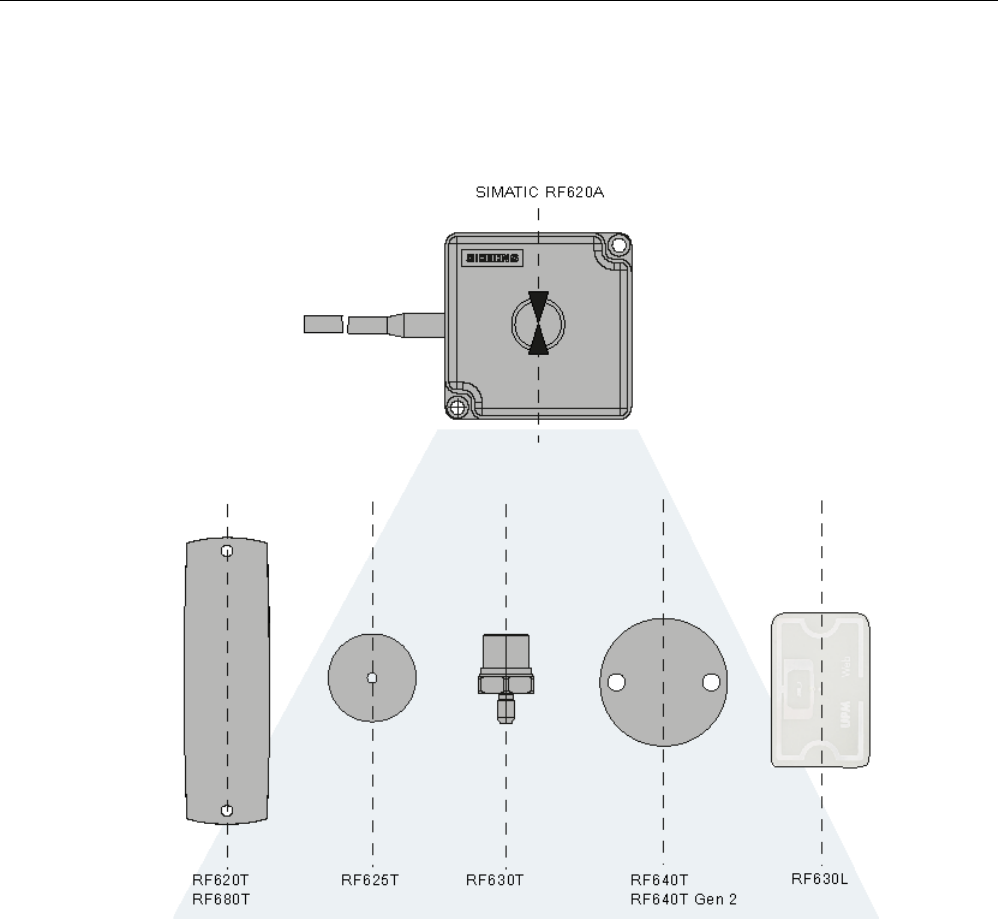
Antennas
6.2 RF620A antenna
SIMATIC RF600
System Manual, xx/2014, J31069-D0171-U001-A15-7618 255
REVIEW
Alignment
The following diagram shows the optimum alignment of the RF600 transponders to the
RF620A antenna.
Figure 6-3 Antenna/transponder alignment
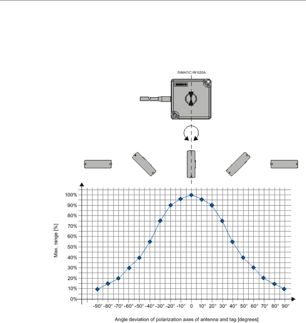
Antennas
6.2 RF620A antenna
SIMATIC RF600
256 System Manual, xx/2014, J31069-D0171-U001-A15-7618
REVIEW
Angle deviation diagram for alignment
The following diagram shows the dependence of the following factors.
● Alignment angle of transponder to antenna
● Maximum range of antenna
Figure 6-4 Angle deviation diagram for alignment
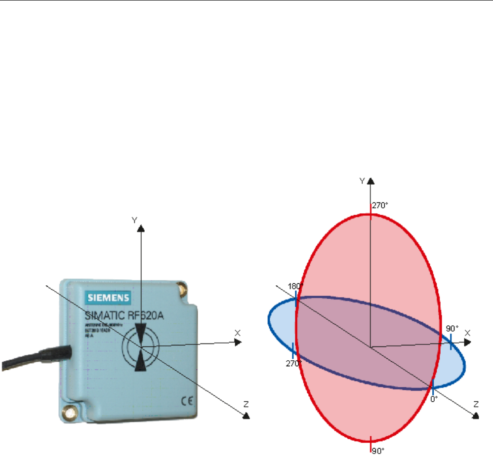
Antennas
6.2 RF620A antenna
SIMATIC RF600
System Manual, xx/2014, J31069-D0171-U001-A15-7618 257
REVIEW
6.2.9
Antenna patterns
6.2.9.1
Antenna pattern ETSI
Directional radiation pattern
Europe (ETSI)
The directional radiation pattern is shown for nominal alignment and a center frequency of
866.3 MHz. The nominal antenna alignment is given when the antenna elevation is provided
as shown in the following figure.
Figure 6-5 Reference system
The half-power beamwidth of the antenna is defined by the angle between the two -3 dB
points. Which range (in %) corresponds to the dB values in the patterns can be obtained
from this table .
Note that the measurements presented graphically below were carried out in a low-reflection
environment. Deviations can therefore occur in a normally reflecting environment.
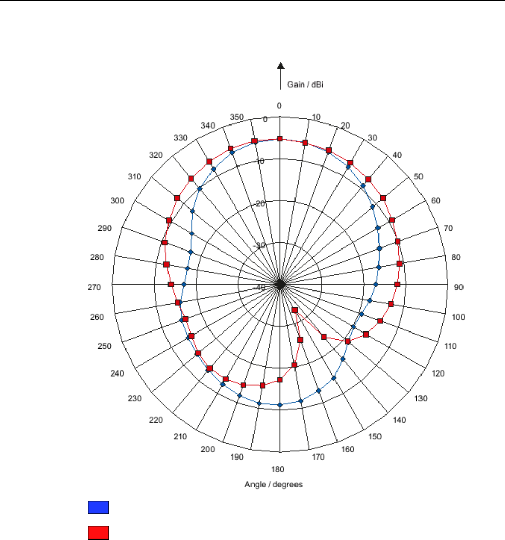
Antennas
6.2 RF620A antenna
SIMATIC RF600
258 System Manual, xx/2014, J31069-D0171-U001-A15-7618
REVIEW
Directional radiation pattern ETSI on metallic mounting surface (15 cm x 15 cm)
Pattern of the vertical plane of the antenna
Pattern of the horizontal plane of the antenna
Figure 6-6 Directional radiation pattern RF620A ETSI on metallic mounting surface
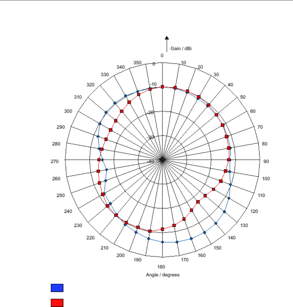
Antennas
6.2 RF620A antenna
SIMATIC RF600
System Manual, xx/2014, J31069-D0171-U001-A15-7618 259
REVIEW
Directional radiation pattern ETSI on non-metallic mounting surface
Pattern of the vertical plane of the antenna
Pattern of the horizontal plane of the antenna
Figure 6-7 Directional radiation pattern RF620A ETSI on non-metallic mounting surface
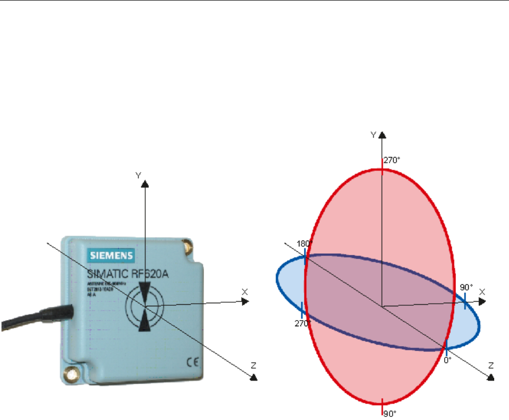
Antennas
6.2 RF620A antenna
SIMATIC RF600
260 System Manual, xx/2014, J31069-D0171-U001-A15-7618
REVIEW
6.2.9.2
Antenna pattern FCC
Directional radiation pattern USA (FCC)
The directional radiation pattern is shown for nominal alignment and a center frequency of
915 MHz.
Figure 6-8 Reference system
The half-power beamwidth of the antenna is defined by the angle between the two -3 dB
points (corresponding to half the power referred to the maximum power). Which range (in %)
corresponds to the dB values in the patterns can be obtained from this table .
Note that the measurements presented graphically below were carried out in a low-reflection
environment. Low deviations can therefore occur in a normally reflecting environment.
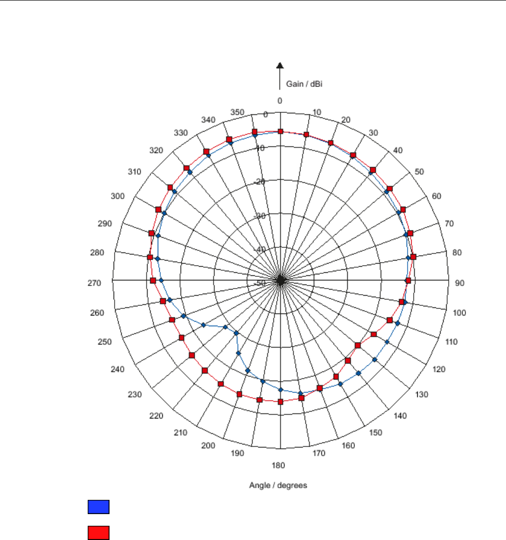
Antennas
6.2 RF620A antenna
SIMATIC RF600
System Manual, xx/2014, J31069-D0171-U001-A15-7618 261
REVIEW
Directional radiation pattern of the RF620A (FCC) on metallic mounting surface (15 cm x 15 cm)
Pattern of the vertical plane of the antenna
Pattern of the horizontal plane of the antenna
Figure 6-9 Directional radiation pattern of the RF620A (FCC) on metallic mounting surface
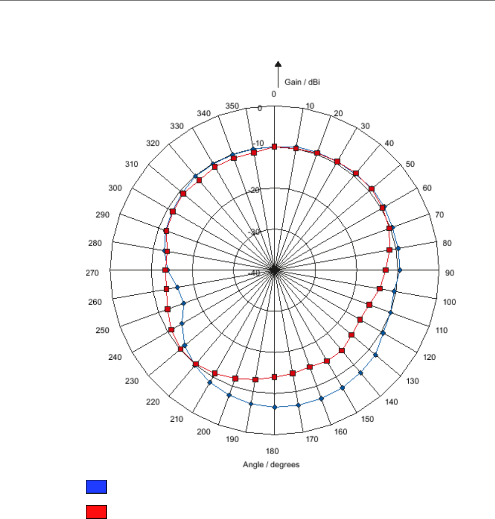
Antennas
6.2 RF620A antenna
SIMATIC RF600
262 System Manual, xx/2014, J31069-D0171-U001-A15-7618
REVIEW
Directional radiation pattern of the RF620A (FCC) on non-metallic mounting surface
Pattern of the vertical plane of the antenna
Pattern of the horizontal plane of the antenna
Figure 6-10 Directional radiation pattern of the RF620A (FCC) on non-metallic mounting surface

Antennas
6.2 RF620A antenna
SIMATIC RF600
System Manual, xx/2014, J31069-D0171-U001-A15-7618 263
REVIEW
6.2.9.3
Interpretation of directional radiation patterns
The following overview table will help you with the interpretation of directional radiation
patterns.
The table shows which dBi values correspond to which read/write ranges (in %): You can
read the radiated power depending on the reference angle from the directional radiation
patterns, and thus obtain information on the read/write range with this reference angle with
regard to a transponder.
The dBr values correspond to the difference between the maximum dBi value and a second
dBi value.
Deviation from maximum antenna gain [dBr]
Read/write range [%]
0
100
-3
70
-6
50
-9
35
-12
25
-15
18
-18
13
Example
As can be seen from the Antenna pattern ETSI (Page 257), the maximum antenna gain is -
5 dBi. In the vertical plane, the antenna gain has dropped to approx. -11 dBi at +40° and
320°. Therefore the dBr value is -6. The antenna range is only 50% of the maximum range at
± 40° from the Z axis within the vertical plane (see values shown in blue in the directional
radiation pattern: Characteristic of the vertical plane of the antenna and the associated
representation of the reference system).
6.2.10
Read/write ranges
The following tables show the typical read/write ranges of RF600 readers which are
connected to the RF620A antenna via the 3 m antenna cable (1 dB loss) and various types
of transponders.
Note
Tolerances
Please note that t
olerances of ±20% are admissible due to production and temperature
conditions.

Antennas
6.2 RF620A antenna
SIMATIC RF600
264 System Manual, xx/2014, J31069-D0171-U001-A15-7618
REVIEW
When using other antenna cables, the ranges listed here are reduced as a result of the
higher antenna cable losses in the following manner:
Cable
designation
Order No.
Length [m]
Cable loss [dB]
Read/write range [%]
Antenna cable
6GT2815-0BH30
3
1
100
Antenna cable,
suitable for drag
chains
6GT2815-2BH50 5 1.25 98
Antenna cable
6GT2815-1BN10
10
2
90
Antenna cable
6GT2815-0BN10
10
4
70
Antenna cable,
suitable for drag
chains
6GT2815-2BN15 15 4 70
Antenna cable
6GT2815-0BN20
20
4
70
The measuring tolerances in the following tables are ±3 cm.
Reading ranges RF620R/RF630R
Table 6- 5 Reading ranges RF620R/RF630R
Transponder
Connection to RF620R/RF630R
RF620A ETSI
on metal [cm]
RF620A ETSI on
non-metal [cm]
RF620A FCC on
metal [cm]
RF620A FCC on
non-metal [cm]
RF630L
(6GT2810-2AB00,
-2AB01, -2AB02-
0AX0)
90 1) 70 1) 60 1) 50 1)
RF630L
(6GT2810-2AB03)
55 50 55 45
RF680L 55 50 55 45
RF610T 55 50 55 45
RF620T 55 45 70 60
RF625T
30
2)
25
2)
45
2)
30
2)
RF630T
25
2)
20
2)
35
2)
25
2)
RF640T Gen 2
55
2)
45
2)
40
2)
35
2)
RF680T
60
50
90
70
1)
Transponder mounted on cardboard
2) Transponder mounted on metal

Antennas
6.2 RF620A antenna
SIMATIC RF600
System Manual, xx/2014, J31069-D0171-U001-A15-7618 265
REVIEW
Writing ranges RF620R/RF630R
Table 6- 6 Writing ranges RF620R/RF630R
Transponder
Connection to RF620R/RF630R
RF620A ETSI
on metal [cm]
RF620A ETSI on
non-metal [cm]
RF620A FCC on
metal [cm]
RF620A FCC on
non-metal [cm]
RF630L
(6GT2810-2AB00,
-2AB01, -2AB02-
0AX0)
45 1) 40 1) 35 1) 30 1)
RF630L
(6GT2810-2AB03)
35 30 20 25
RF680L
35
30
20
25
RF610T
35
30
20
25
RF620T
30
30
40
35
RF625T
20
2)
5
2)
20
2)
10
2)
RF630T
15
2)
5
2)
15
2)
10
2)
RF640T Gen 2
35
2)
20
2)
20
2)
15
2)
RF680T
40
30
40
35
1)
Transponder mounted on cardboard
2) Transponder mounted on metal
Reading ranges RF640R/RF670R
Table 6- 7 Reading ranges RF640R/RF670R
Transponder
Connection to RF640R/RF670R
RF620A ETSI
on metal [cm]
RF620A ETSI on
non-metal [cm]
RF620A FCC on
metal [cm]
RF620A on non-
metal [cm]
RF630L
(6GT2810-2AB00,
-2AB01, -2AB02-
0AX0)
135 1) 120 1) 100 1) 90 1)
RF630L
(6GT2810-2AB03)
85 70 75 65
RF680L
85
70
75
65
RF610T
85
70
75
65
RF620T
85
85
95
95
RF625T
50
2)
45
2)
60
2)
45
2)
RF630T
40
2)
35
2)
50
2)
35
2)
RF640T
40
2)
35
2)
40
2)
30
2)

Antennas
6.2 RF620A antenna
SIMATIC RF600
266 System Manual, xx/2014, J31069-D0171-U001-A15-7618
REVIEW
Transponder
Connection to RF640R/RF670R
RF620A ETSI
on metal [cm]
RF620A ETSI on
non-metal [cm]
RF620A FCC on
metal [cm]
RF620A on non-
metal [cm]
RF640T Gen 2
90
2)
70
2)
70
2)
50
2)
RF680T
90
90
135
95
1)
Transponder mounted on cardboard
2) Transponder mounted on metal
Writing ranges RF640R/RF670R
Table 6- 8 Writing ranges RF640R/RF670R
Transponder
Connection to RF640R/RF670R
RF620A ETSI
on metal
RF620A ETSI on
non-metal
RF620A FCC on
metal
RF620A on non-
metal
RF630L
(6GT2810-2AB00,
-2AB01, -2AB02-
0AX0)
110 1) 90 1) 55 1) 50 1)
RF630L
(6GT2810-2AB03)
75 70 60 55
RF680L
75
70
60
55
RF610T
75
70
60
55
RF620T
60
55
60
45
RF625T
40
2)
30
2)
45
2)
30
2)
RF630T 30 2) 25 2) 35 2) 25 2)
RF640T 35 2) 30 2) 25 2) 25 2)
RF640T Gen 2 70 2) 60 2) 50 2) 40 2)
RF680T
80
75
100
80
1)
Transponder mounted on cardboard
2) Transponder mounted on metal

Antennas
6.2 RF620A antenna
SIMATIC RF600
System Manual, xx/2014, J31069-D0171-U001-A15-7618 267
REVIEW
Read distances RF650R
Table 6- 9 Read distances RF650R
Transponder
Connection to RF650R
RF620A ETSI
on metal [cm]
RF620A ETSI on
non-metal [cm]
RF620A FCC on
metal [cm]
RF620A on non-
metal [cm]
RF630L
(6GT2810-2AB00,
-2AB01, -2AB02-
0AX0)
135 1) 120 1) 100 1) 90 1)
RF630L
(6GT2810-2AB03)
85 70 75 65
RF680L
85
70
75
65
RF610T
85
70
75
65
RF620T
85
85
95
95
RF625T
50
2)
45
2)
60
2)
45
2)
RF630T
40
2)
35
2)
50
2)
35
2)
RF640T
40
2)
35
2)
40
2)
30
2)
RF640T Gen 2
90
2)
70
2)
70
2)
50
2)
RF680T
90
90
135
95
1)
Transponder mounted on cardboard
2) Transponder mounted on metal
Write distances RF650R
Table 6- 10 Write distances RF650R
Transponder
Connection to RF650R
RF620A ETSI
on metal [cm]
RF620A ETSI on
non-metal [cm]
RF620A FCC on
metal [cm]
RF620A on non-
metal [cm]
RF630L
(6GT2810-2AB00,
-2AB01, -2AB02-
0AX0)
110 1) 90 1) 55 1) 50 1)
RF630L
(6GT2810-2AB03)
75 70 60 55
RF680L
75
70
60
55
RF610T
75
70
60
55
RF620T
60
55
60
45
RF625T
40
2)
30
2)
45
2)
30
2)
RF630T
30
2)
25
2)
35
2)
25
2)
RF640T
35
2)
30
2)
25
2)
25
2)

Antennas
6.2 RF620A antenna
SIMATIC RF600
268 System Manual, xx/2014, J31069-D0171-U001-A15-7618
REVIEW
Transponder
Connection to RF650R
RF620A ETSI
on metal [cm]
RF620A ETSI on
non-metal [cm]
RF620A FCC on
metal [cm]
RF620A on non-
metal [cm]
RF640T Gen 2
70
2)
60
2)
50
2)
40
2)
RF680T
80
75
100
80
1)
Transponder mounted on cardboard
2) Transponder mounted on metal
Read distances RF680R/RF685R
Table 6- 11 Read distances RF680R/RF685R
Transponder
Connection to RF680R/RF685R
RF620A ETSI
on metal [cm]
RF620A ETSI on
non-metal [cm]
RF620A FCC on
metal [cm]
RF620A on non-
metal [cm]
RF630L
(6GT2810-2AB00,
-2AB01, -2AB02-
0AX0)
1) 1) 1) 1)
RF630L
(6GT2810-2AB03)
RF680L
RF610T
RF620T
RF625T
2)
2)
2)
2)
RF630T 2) 2) 2) 2)
RF640T 2) 2) 2) 2)
RF640T Gen 2 2) 2) 2) 2)
RF680T
1)
Transponder mounted on cardboard
2) Transponder mounted on metal

Antennas
6.2 RF620A antenna
SIMATIC RF600
System Manual, xx/2014, J31069-D0171-U001-A15-7618 269
REVIEW
Write distances RF680R/RF685R
Table 6- 12 Write distances RF680R/RF685R
Transponder
Connection to RF680R/RF685R
RF620A ETSI
on metal [cm]
RF620A ETSI on
non-metal [cm]
RF620A FCC on
metal [cm]
RF620A on non-
metal [cm]
RF630L
(6GT2810-2AB00,
-2AB01, -2AB02-
0AX0)
1) 1) 1) 1)
RF630L
(6GT2810-2AB03)
RF680L
RF610T
RF620T
RF625T
2)
2)
2)
2)
RF630T
2)
2)
2)
2)
RF640T
2)
2)
2)
2)
RF640T Gen 2
2)
2)
2)
2)
RF680T
1)
Transponder mounted on cardboard
2) Transponder mounted on metal

Antennas
6.2 RF620A antenna
SIMATIC RF600
270 System Manual, xx/2014, J31069-D0171-U001-A15-7618
REVIEW
6.2.11
Technical data
Table 6- 13 General technical specifications RF620A
Feature
SIMATIC RF620A ETSI
SIMATIC RF620A FCC
Dimensions (L x W x H)
75 x 75 x 20 mm
Color
Pastel turquoise
Material
PA 12 (polyamide 12)
Silicone-free
Frequency range
865 to 868 MHz
902 to 928 MHz
Plug connection 30 cm coaxial cable with RTNC coupling
(for connection of antenna cable)
Max. radiated power < 500 mW ERP No limitation
(because antenna gain < 6 dBi)
Max. power
2 W
1 W
Impedance
50 ohms
Antenna gain
-10 dBi ... -5 dBi
Depends on background, refer
to the section Antenna pattern
ETSI (Page 257)
Depends on background, refer
to the section Antenna pattern
FCC (Page 260)
VSWR (standing wave ratio)
Max. 2:1
Polarization
Linear
Beam angle for
sending/receiving
• When mounted on a metal
surface of 15 cm x 15 cm 1)
• Horizontal plane: 100°
• Vertical plane: 75°
See Chapter Antenna pattern
ETSI (Page 257)
• Horizontal plane: 130°
• Vertical plane: 105°
See section Antenna pattern
FCC (Page 260)
Shock resistant to EN 60068-2-
27
50 g
Vibration resistant to EN 60068-
2-6
20 g
Attachment of the antenna
2 x M5 screws
Tightening torque
(at room temperature)
≤ 2 Nm
Ambient temperature
• Operation
• Transport and storage
• -20 °C to +70 °C
• -40 °C to +85 °C
MTBF in years
Degree of protection according
to EN 60529
IP67
Weight, approx.
90 g
1) The values differ for different dimensions/materials of the mounting surface.
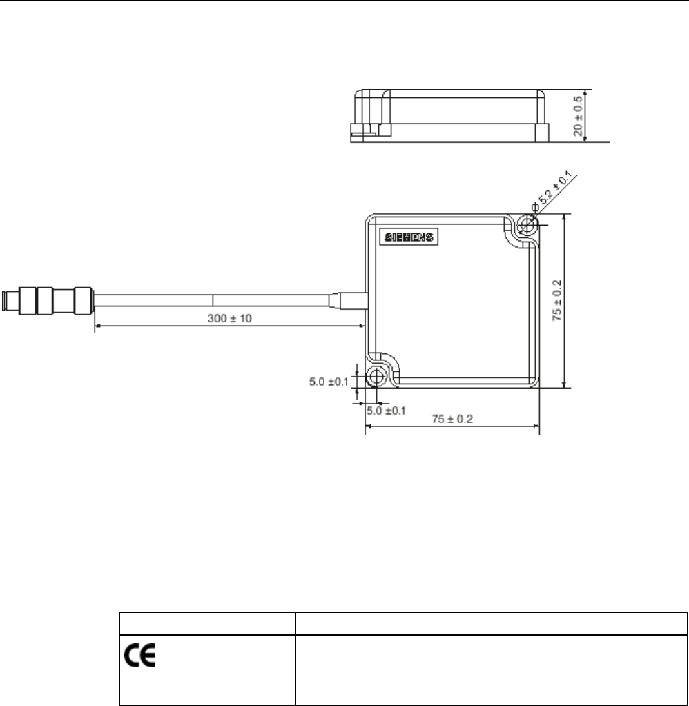
Antennas
6.2 RF620A antenna
SIMATIC RF600
System Manual, xx/2014, J31069-D0171-U001-A15-7618 271
REVIEW
6.2.12
Dimension drawing
Figure 6-11 Dimension drawing RF620A
All dimensions in mm
6.2.13
Approvals & certificates
Table 6- 14 6GT2812-1EA00
Certificate
Designation
Conformity in accordance with R&TTE directive
in association with the readers and accessories used
Antennas
6.2 RF620A antenna
SIMATIC RF600
272 System Manual, xx/2014, J31069-D0171-U001-A15-7618
REVIEW
Table 6- 15 6GT2812-1EA01
Standard
Federal Communications
Commission
FCC CFR 47, Part 15 sections 15.247
Radio Frequency Interference Statement
This equipment has been tested and found to comply with the limits
for a Class B digital device, pursuant to Part 15 of the FCC Rules.
The FCC approval is granted in association with the FCC approval of
the following RF600 readers:
• FCC ID: NXW-RF600R
(for RF620R: 6GT2811-5BA00-1AA1,
RF630R: 6GT2811-4AA00-1AA1,
RF640R: 6GT2811-3BA00-1AA0,
RF670R as of FS C1: 6GT2811-0AB00-1AA0)
• FCC ID: NXW-RF630R
(for 6GT2811-4AA00-1AA0)
• FCC ID: NXW-RF670
(for RF670R as of FS A1: 6GT2811-0AB00-1AA0)
Industry Canada Radio
Standards Specifications
RSS-210 Issue 7, June 2007, Sections 2.2, A8
The approval for Industry Canada is granted in association with the
Industry Canada approval of the following RF600 readers:
• IC: 267X-RF630 (for 6GT2811-4AA00-1AA0)
• IC: 267X-RF670, RF670R FS A1 (for 6GT2811-0AB00-1AA0)
• IC: 267X-RF600R, Model RF620R-2 (for 6GT2811-5BA00-1AA1)
• IC: 267X-RF600R, Model RF630R-2 (for 6GT2811-4AA00-1AA1)
• IC: 267X-RF600R, Model RF640R (for 6GT2811-3BA00-1AA0)
• IC: 267X-RF600R, model RF670R-2 as of FS C1 (for 6GT2811-
0AB00-1AA0)
This product is UL-certified for the USA and Canada.
It meets the following safety standard(s):
UL 60950-1 - Information Technology Equipment Safety - Part 1:
General Requirements
CSA C22.2 No. 60950 -1 - Safety of Information Technology
Equipment
UL Report E 205089
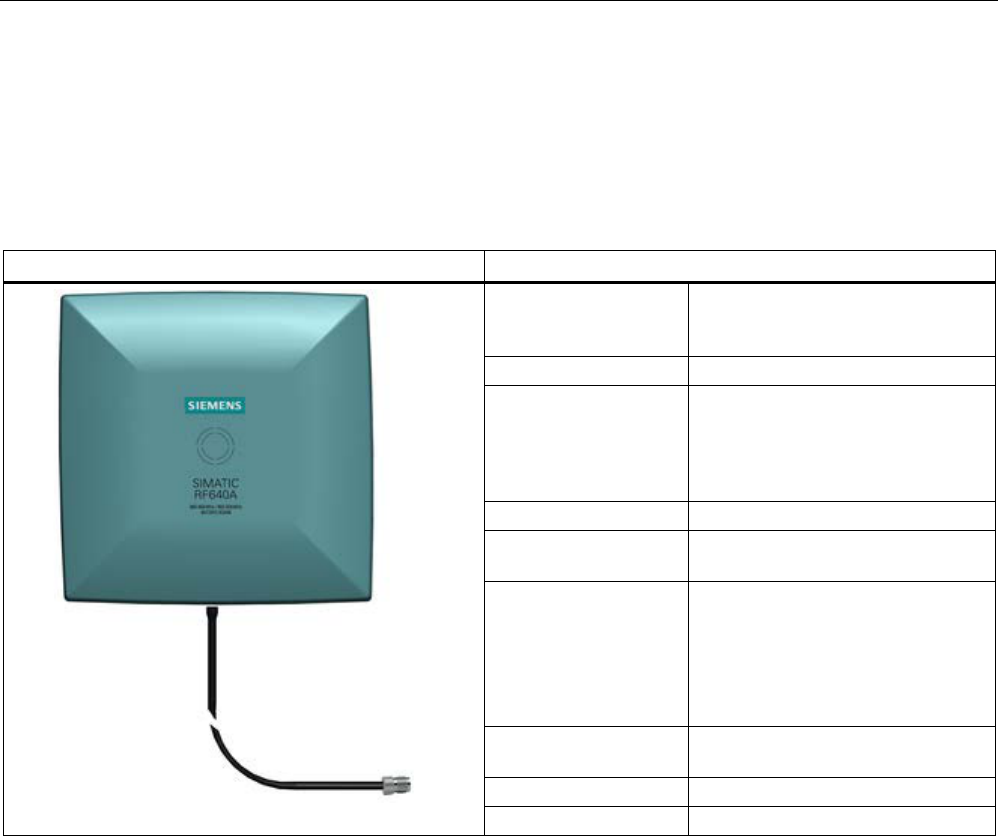
Antennas
6.3 Antenna RF640A
SIMATIC RF600
System Manual, xx/2014, J31069-D0171-U001-A15-7618 273
REVIEW
6.3
Antenna RF640A
6.3.1
Description
SIMATIC RF640A
Features
Field of application The SIMATIC RF640A is a universal
UHF antenna of compact, industry-
standard design with medium range.
Frequency range
865 to 928 MHz
Polarization RH circular
Suitable for RF600 transponders
that can pass in parallel with the
antenna regardless of their
orientation.
Writing/reading range
max. 4.0 m
Mounting 4 x M4
(VESA 100 fixing system)
Connector 30 cm connecting cable (connected
permanently to the antenna) and
RTNC coupling
An antenna cable is required for
connection to the reader, e.g.
6GT2815-0BH30)
Readers that can be
connected
All RF600 readers with external
antenna connectors
Dimensions in mm
185 x 185 x 45
Degree of protection
IP67
Frequency ranges
The antenna is available for broadband. It can therefore be used for two different frequency
ranges that have been specified for the regions of Europe and China/USA respectively.
● The antenna for Europe (EU, EFTA countries) operates in the frequency range from 865
to 868 MHz.
● The antenna for China, the USA, and Canada operates in the frequencyrange from 902 to
928 MHz.
Function
The SIMATIC RF640A is used for transmitting and receiving RFID signals in the UHF
frequency range. The antennas are connected to the SIMATIC RF600 readers via antenna
cables that are available in different lengths.

Antennas
6.3 Antenna RF640A
SIMATIC RF600
274 System Manual, xx/2014, J31069-D0171-U001-A15-7618
REVIEW
6.3.2
Ordering data
Table 6- 16 Ordering data RF640A
Product
Article number
SIMATIC RF640A
6GT2812-0GA08
Accessories
Table 6- 17 Ordering data accessories
Product
Article number
Connecting cable between
reader and antenna
3 m (cable loss 1.0 dB)
6GT2815-0BH30
5 m, suitable for drag chains
(cable loss 1.25 dB)
6GT2815-2BH50
10 m (cable loss 2.0 dB)
6GT2815-1BN10
10 m (cable loss 4.0 dB)
6GT2815-0BN10
15 m, suitable for drag chains
(cable loss 4.0 dB)
6GT2815-2BN15
20 m (cable loss 4.0 dB)
6GT2815-0BN20
Antenna mounting kit See "RF600 System Manual",
section "Antennas" > "Mounting
types"
6GT2890-0AA00
6.3.3
Installation and assembly
6.3.3.1
RF640A mounting types
VESA 100 mounting system
A standardized VESA 100 mounting system is provided to mount the antenna. The mounting
system consists of four fixing holes for M4 screws at intervals of 100 mm.
This is therefore suitable for:
● Mounting on metallic and non-metallic backgrounds
Note
To achieve optimum wave propagation, the antenna should not be surrounded by
conducting objects. The area between antenna and transponder should also allow wave
propagation without interference.
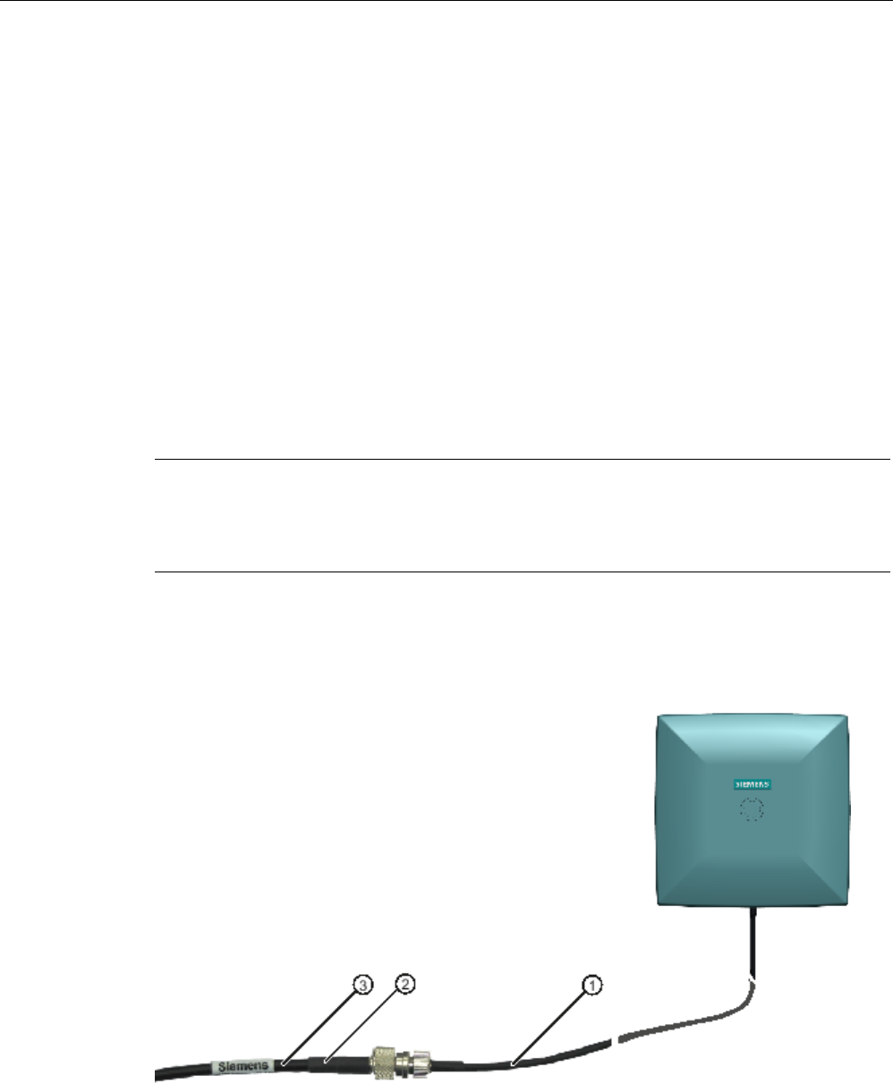
Antennas
6.3 Antenna RF640A
SIMATIC RF600
System Manual, xx/2014, J31069-D0171-U001-A15-7618 275
REVIEW
Antenna Mounting Kit
The Antenna Mounting Kit allows the fine adjustment of the antenna field by setting the solid
angle (see "RF600 System Manual", chapter "Antennas" > "Mounting types").
6.3.4
Connecting an antenna to the reader
The SIMATIC RF640A antenna must be connected to the reader using an antenna cable.
Preassembled standard cables in lengths of 3 m, 10 m, and 20 m are available for the
connection.
The range of the antenna is limited by the cable loss. The maximum range can be achieved
with the cable 6GT2815-0BH30 (length 3 m), since this has the lowest cable loss.
Requirement
Note
Use of Siemens antenna cable
To ensure optimum functioning of the antenna, it is recommended that a Siemens antenna
cable be used in accordance with the list of accessories.
Strain relief
The antenna cable is provided with strain relief as shown in the following diagram:
①
RF640A antenna connection (30 cm connecting cable)
②
RF600 antenna cable
③
Strain relief (should take place at this position)
Figure 6-12 Strain relief

Antennas
6.3 Antenna RF640A
SIMATIC RF600
276 System Manual, xx/2014, J31069-D0171-U001-A15-7618
REVIEW
6.3.4.1
Bending radii and bending cycles of the cable
Cable
designation
Order No.
Length [m]
Cable loss
[dB]
Bending
radius [mm]
Bending cycle
RF640A antenna
connection
Fixed
connection to
antenna
0.3 - 15 1 Mal
Antenna cable 6GT2815-
0BH30
3 1 51 1 Mal
Antenna cable
(suitable for drag
chains)
6GT2815-
2BH50
5 1,25 48 1)
Antenna cable 6GT2815-
1BN10
10 2 77 1 Mal
Antenna cable 6GT2815-
0BN10
10 4 51 1 Mal
Antenna cable
(suitable for drag
chains)
6GT2815-
0BN20
15 4 24 1)
Antenna cable 6GT2815-
0BN20
20 4 77 1 Mal
1)
With cables suitable for drag chains, 3 million bending cycles at a bending radius of 6.5 m and
bending through ± 180 ° are permitted.
6.3.5
Parameter settings of RF640A for RF620R/RF630R
Operation within the EU, EFTA, or Turkey according to DIN EN 302208 V1.4.1
Note
Limitation of the radiated power according to DIN EN 302208 V1.4.1
RF600 systems that are put into operation within the EU, EFTA, or Turkey (ETSI) can be
operated with an RF640A
antenna with a maximum radiated power of up to 2000 mW ERP
(or 33 dBm
ERP, 3250 mW EIRP, 35 dBm EIRP).
By adjusting the transmit power of up to 500 mW ERP (or 27 dBm ERP, 800 mW EIRP,
29.15 dBm EIRP) and taking into account the RF640A antenna gain of 4 dBi (6 dBic) and the
cable loss associated with the antenna cable (see table), the radiated power of the antenna
cannot be exceeded. You can make the power settings using the "distance_limiting"
parameter. You will find more detailed information on the parameters in the section
Parameter assignment manual RF620R/RF630R
(http://support.automation.siemens.com/WW/view/en/33287195).

Antennas
6.3 Antenna RF640A
SIMATIC RF600
System Manual, xx/2014, J31069-D0171-U001-A15-7618 277
REVIEW
Operation in China
The national approval for RF600 systems in China means a restriction to 2000 mW ERP (or
33 dBm ERP, 3250 mW EIRP, 35 dBm EIRP). The possible combination of antenna gain,
cable loss, and max. 500 mW radiated power of the RF630R reader means it is not possible
to exceed 2000 mW ERP (or 33 dBm ERP, 3250 mW EIRP, 35 dBm EIRP).
Operation in the USA, Canada
Note
Limitation of the radiated power to 4000 mW EIRP (36 dBm EIRP)
To meet the FCC and IC
-FCB requirements, the radiated power may not exceed 4000 mW
EIRP (36 dBm EIRP). Therefore the
system must satisfy the following relation:
•
Conducted power P dBm of the RF600 reader (< 30 dBm)
•
Antenna gain Gi dBi in the FCC frequency band (≤ 4.3 dBi)
•
Cable loss ak dB (≥ 1 dB)
P(dBm) ≤ 30
dBm - (Gi - 6 dBi) + ak
6.3.6
Parameter settings of RF640A for RF640R/RF670R
Operation within the EU, EFTA, or Turkey according to DIN EN 302208 V1.4.1
Note
Limitation of the radiated power according to DIN EN 302208 V1.4.1
RF600 systems that are put into operation within the EU, EFTA, or Turkey (ETSI) can be
opera
ted with an RF640A antenna with a maximum radiated power of up to 2000 mW ERP
(or 33 dBm
ERP, 3250 mW EIRP, 35 dBm EIRP).
By setting the radiated power of up to 1300 mW ERP (or 31.15 dBm ERP, 2140 mW EIRP,
33.3 dBm EIRP), an RF640A antenna gain of 4 dBi (7 dBic) and taking into account the
cable loss associated with the antenna cable (see table), the radiated power of the reader is
correctly configured and the radiated power at the antenna is not exceeded.
Operation in China
By setting a max. radiated power of 1300 mW ERP (or 31.15 dBm ERP, 2140 mW EIRP,
33.3 dBm EIRP), the RF640A antenna gain of 4.3 dBi (7.3 dBic) and the cable loss
associated with the antenna cable (see table), the radiated power of the reader is correctly
configured.

Antennas
6.3 Antenna RF640A
SIMATIC RF600
278 System Manual, xx/2014, J31069-D0171-U001-A15-7618
REVIEW
Operation in the USA, Canada
Note
Limitation of the radiated power to 4000 mW EIRP (36 dBm EIRP)
To meet the FCC and IC requirements, the radiated power may not exceed 4000 mW EIRP
(36 dBm EIRP). Therefore the system must satisfy the following relation:
•
Conducted power P dBm of the RF600 reader (< 30 dBm)
•
Antenna gain Gi dBi in the FCC frequency band (≤ 4.3 dBi)
•
Cable loss ak dB (≥ 1 dB)
P(dBm) ≤ 30
dBm - (Gi - 6 dBi) + ak
6.3.7
Setting RF640A parameters for RF650R
Operation within the EU according to DIN EN 302208 V1.4.1
Note
Limitation of the radiated power according to DIN EN 302208 V1.4.1
RF600 systems that are put into operation within the EU, EFTA, or Turkey (ETSI) can be
operated with an RF640A antenna with a maximum radiated power of 2000
mW ERP (or 33
dBm
ERP, 3250 mW EIRP, 35 dBm EIRP).
By setting the radiated power of up to 1300 mW ERP (or 31.15 dBm ERP, 2140 mW EIRP,
33.3 dBm EIRP), an RF640A antenna gain of 4 dBi (7 dBic) and taking into account the
cable loss associated with the antenna cable (see table (Page 276)), the radiated power of
the reader is correctly configured and the radiated power at the antenna is not exceeded.
Operation in China
By setting a max. radiated power of 1300 mW ERP (or 31.15 dBm ERP, 2140 mW EIRP,
33.3 dBm EIRP), an RF640A antenna gain of 4.3 dBi (7.3 dBic) and taking into account the
cable loss associated with the antenna cable (see table (Page 276)), the radiated power of
the reader is correctly configured.

Antennas
6.3 Antenna RF640A
SIMATIC RF600
System Manual, xx/2014, J31069-D0171-U001-A15-7618 279
REVIEW
Operation in the USA, Canada
Note
Limitation of the radiated power to 4000 mW EIRP (36 dBm EIRP)
To meet the FCC and IC requirements, the radiated power may not exceed 4000 mW EIRP
(36 dBm
EIRP). Therefore the system must satisfy the following relation:
•
Conducted power P dBm of the RF600 reader (< 30 dBm)
•
Antenna gain Gi dBi in the FCC frequency band (≤ 4.3 dBi)
•
Cable loss ak dB (≥ 1 dB)
P(dBm) ≤ 30
dBm - (Gi - 6 dBi) + ak
6.3.8
Setting RF640A parameters for RF680R/RF685R
Operation within the EU according to DIN EN 302208 V1.4.1
Note
Limitation of the radiated power according to DIN EN 302208 V1.4.1
RF600 systems that are put into operation within the EU, EFTA, or Turkey (ETSI) can be
operated with an RF640A antenna with a maximum radiated power of 2000
mW ERP (or 33
dBm
ERP, 3250 mW EIRP, 35 dBm EIRP).
By setting the radiated power of up to 1300 mW ERP (or 31.15 dBm ERP, 2140 mW EIRP,
33.3 dBm EIRP), an RF640A antenna gain of 4 dBi (7 dBic) and taking into account the
cable loss associated with the antenna cable (see table (Page 276)), the radiated power of
the reader is correctly configured and the radiated power at the antenna is not exceeded.
Operation in China
By setting a max. radiated power of 2000 mW ERP (or 33 dBm ERP, 2140 mW EIRP,
33.3 dBm EIRP), an RF640A antenna gain of 4.3 dBi (7.3 dBic) and taking into account the
cable loss associated with the antenna cable (see table (Page 276)), the radiated power of
the reader is correctly configured.

Antennas
6.3 Antenna RF640A
SIMATIC RF600
280 System Manual, xx/2014, J31069-D0171-U001-A15-7618
REVIEW
Operation in the USA, Canada
Note
Limitation of the radiated power to 4000 mW EIRP (36 dBm EIRP)
To
meet the FCC and IC requirements, the radiated power may not exceed 4000 mW EIRP
(36 dBm EIRP). Therefore the system must satisfy the following relation:
•
Conducted power P dBm of the RF600 reader (< 30 dBm)
•
Antenna gain Gi dBi in the FCC frequency band (≤ 4.3 dBi)
•
Cable loss ak dB (≥ 1 dB)
P(dBm) ≤ 30
dBm - (Gi - 6 dBi) + ak
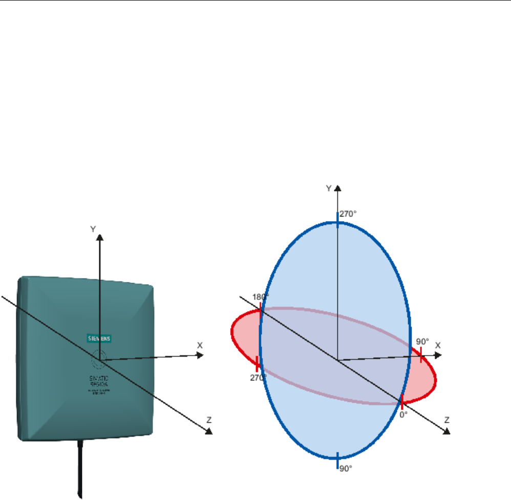
Antennas
6.3 Antenna RF640A
SIMATIC RF600
System Manual, xx/2014, J31069-D0171-U001-A15-7618 281
REVIEW
6.3.9
Antenna patterns
6.3.9.1
Antenna radiation patterns in the ETSI frequency band
Directional radiation pattern
Europe (ETSI)
The directional radiation pattern is shown for nominal alignment and a center frequency of
866.3 MHz. The nominal antenna alignment is given when the antenna elevation is provided
as shown in the following figure.
Figure 6-13 Reference system
The half-power beam width of the antenna is defined by the angle between the two -3 dB
points. Which range (in %) corresponds to the dB values in the patterns can be obtained
from this table (Page 291).
Note that the measurements presented graphically below were carried out in a low-reflection
environment. Deviations can therefore occur in a normally reflecting environment.
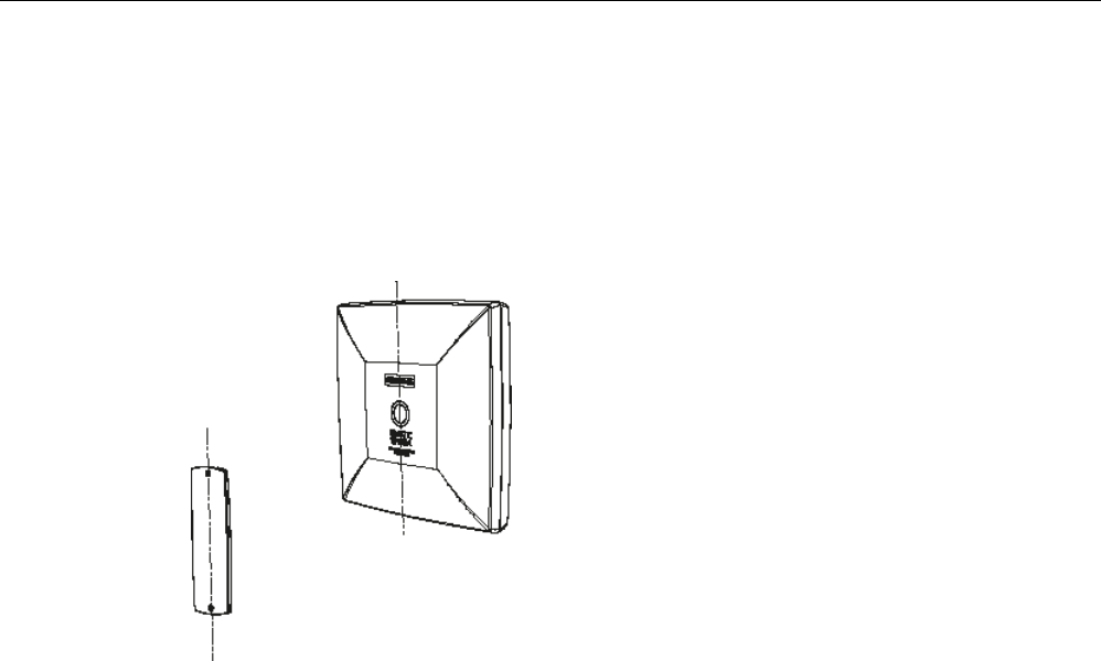
Antennas
6.3 Antenna RF640A
SIMATIC RF600
282 System Manual, xx/2014, J31069-D0171-U001-A15-7618
REVIEW
Directional radiation patterns in the ETSI frequency band
Polarization axis and axis of symmetry are parallel
In a configuration based on the following directional radiation pattern of the antenna, the axis
of symmetry of the antenna and the polarization axis of the transponder are parallel.
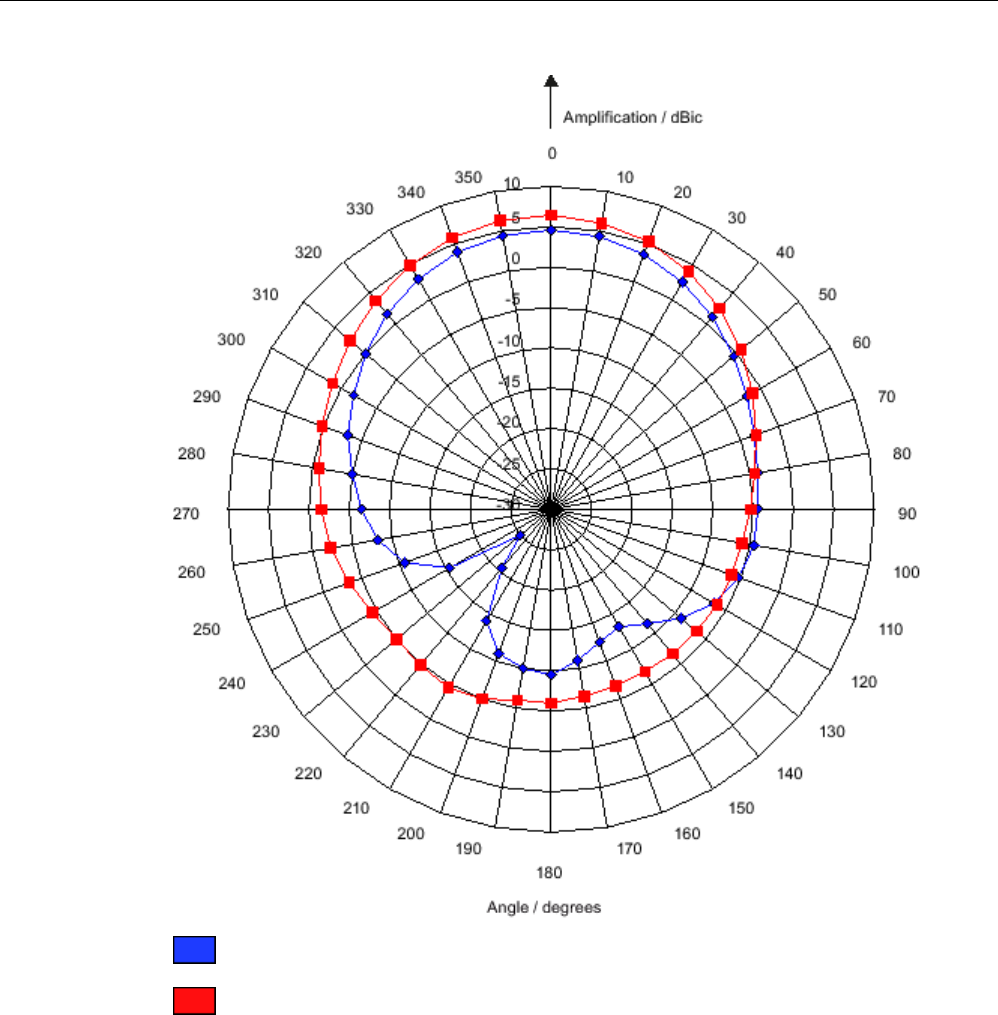
Antennas
6.3 Antenna RF640A
SIMATIC RF600
System Manual, xx/2014, J31069-D0171-U001-A15-7618 283
REVIEW
Pattern of the vertical plane of the antenna
Pattern of the horizontal plane of the antenna
Figure 6-14 The RF640A directional radiation pattern in the ETSI frequency band, polarization axis of
the transponder, and axis of symmetry of the antenna are parallel to each other.
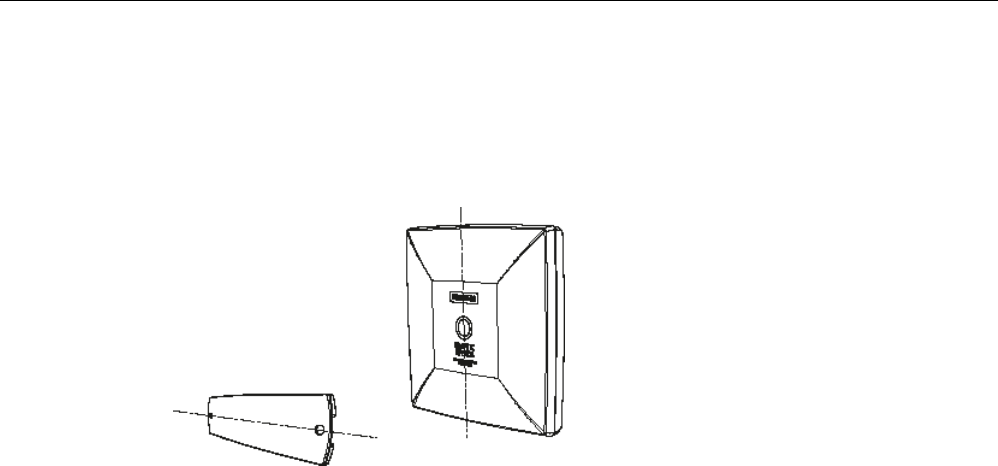
Antennas
6.3 Antenna RF640A
SIMATIC RF600
284 System Manual, xx/2014, J31069-D0171-U001-A15-7618
REVIEW
Polarization axis and axis of symmetry are orthogonal to each other
In a configuration based on the following directional radiation pattern of the antenna, the axis
of symmetry of the antenna and the polarization axis of the transponder are orthogonal to
each other.
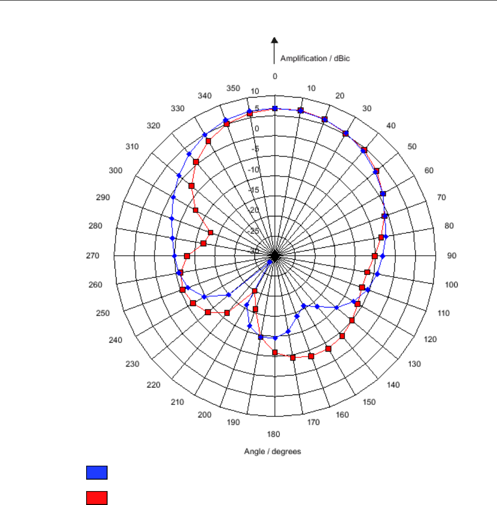
Antennas
6.3 Antenna RF640A
SIMATIC RF600
System Manual, xx/2014, J31069-D0171-U001-A15-7618 285
REVIEW
Pattern of the vertical plane of the antenna
Pattern of the horizontal plane of the antenna
Figure 6-15 The RF640A directional radiation pattern in the ETSI frequency band, axis of symmetry
of the antenna, and polarization axis of the transponder are orthogonal to each other
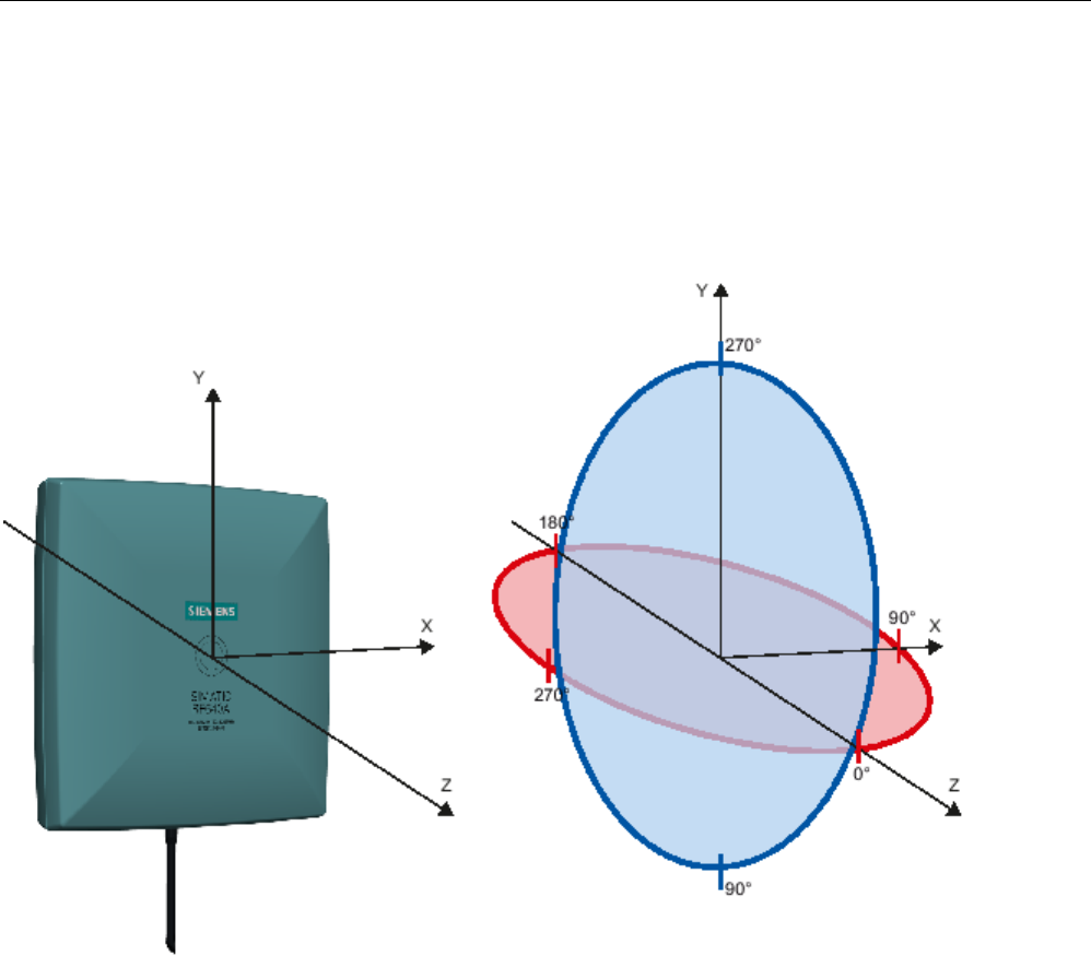
Antennas
6.3 Antenna RF640A
SIMATIC RF600
286 System Manual, xx/2014, J31069-D0171-U001-A15-7618
REVIEW
6.3.9.2
Antenna radiation patterns in the FCC frequency band
Directional radiation pattern USA (FCC)
The directional radiation pattern is shown for nominal alignment and a center frequency of
915 MHz.
Figure 6-16 Reference system
The half-power beam width of the antenna is defined by the angle between the two -3 dB
points (corresponding to half the power referred to the maximum power). Which range (in %)
corresponds to the dB values in the patterns can be obtained from this table (Page 291).
Note that the measurements presented graphically below were carried out in a low-reflection
environment. Deviations can therefore occur in a normally reflecting environment.

Antennas
6.3 Antenna RF640A
SIMATIC RF600
System Manual, xx/2014, J31069-D0171-U001-A15-7618 287
REVIEW
Directional radiation pattern in the FCC frequency band
Polarization axis and axis of symmetry are parallel
In the following directional radiation pattern of the antenna, the axis of symmetry of the
antenna and the polarization axis of the transponder are parallel.
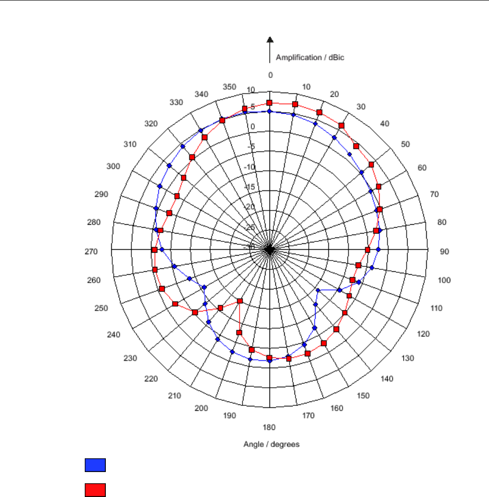
Antennas
6.3 Antenna RF640A
SIMATIC RF600
288 System Manual, xx/2014, J31069-D0171-U001-A15-7618
REVIEW
Pattern of the vertical plane of the antenna
Pattern of the horizontal plane of the antenna
Figure 6-17 The RF640A directional radiation pattern in the FCC frequency band, polarization axis of
the transponder, and axis of symmetry of the antenna are parallel to each other
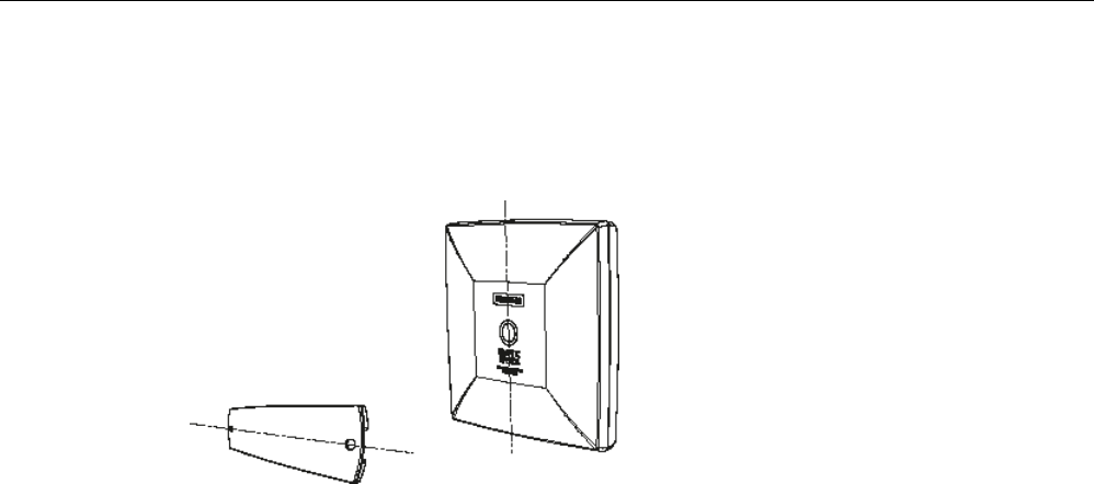
Antennas
6.3 Antenna RF640A
SIMATIC RF600
System Manual, xx/2014, J31069-D0171-U001-A15-7618 289
REVIEW
Polarization axis and axis of symmetry are orthogonal to each other
In the following directional radiation pattern of the antenna, the axis of symmetry of the
antenna and the polarization axis of the transponder are orthogonal to each other.

Antennas
6.3 Antenna RF640A
SIMATIC RF600
290 System Manual, xx/2014, J31069-D0171-U001-A15-7618
REVIEW
Pattern of the vertical plane of the antenna
Pattern of the horizontal plane of the antenna
Figure 6-18 The RF640A directional radiation pattern in the FCC frequency band, axis of symmetry
of the antenna, and polarization axis of the transponder are orthogonal to each other

Antennas
6.3 Antenna RF640A
SIMATIC RF600
System Manual, xx/2014, J31069-D0171-U001-A15-7618 291
REVIEW
6.3.9.3
Interpretation of directional radiation patterns
The following overview table will help you with the interpretation of directional radiation
patterns.
The table shows which dBi values correspond to which read/write ranges (in %): You can
read the radiated power depending on the reference angle from the directional radiation
patterns, and thus obtain information on the read/write range with this reference angle with
regard to a transponder.
The dBr values correspond to the difference between the maximum dBi/dBic value and a
second dBi/dBic value.
Deviation from maximum antenna gain [dBr]
Read/write range [%]
0
100
-3
70
-6
50
-9
35
-12
25
-15
18
-18
13
Example
As can be seen in Directional radiation patterns in the ETSI frequency band (Page 282), the
maximum antenna gain in the vertical plane is 3.45 dBi (6.45 dBic). In this plane, and with
the polarization axis of the transponder parallel to the axis of symmetry of the antenna, the
antenna gain drops to about 0.5 dBic at +50° or 310°. Therefore the dBr value is -6. The
antenna range is only 50% of the maximum range at + 50° or 310° from the Z axis within the
vertical plane (see values shown in blue in the directional radiation pattern: Characteristic of
the vertical plane of the antenna (Page 282) and the associated representation of the
reference system (Page 281)).

Antennas
6.3 Antenna RF640A
SIMATIC RF600
292 System Manual, xx/2014, J31069-D0171-U001-A15-7618
REVIEW
6.3.10
Technical data
Table 6- 18 General technical specifications RF640A
6GT2812-0GA08
Product type designation
SIMATIC RF640A
Dimensions (L x W x H)
185 x 185 x 45 mm
Color
Pastel turquoise
Material
PA 12 (polyamide 12)
Silicone-free
Frequency band
865 to 928 MHz
Plug connection
30 cm antenna connection coaxial cable with RTNC coupling, fixed
connection to antenna
An antenna cable is required for connection to the reader, e.g.:
6GT2815-0BH30
Max. radiated power
according to ETSI
• RF620R, RF630R: < 610 mW ERP
• RF640R, RF670R: ≤ 1300 mW ERP
• RF650R: ≤ 1300 mW ERP
• RF680R/RF685R: ≤ 2000 mW ERP
Max. radiated power
according to CMIIT
• RF620R, RF630R: ≤650 mW ERP
• RF640R, RF670R: ≤ 1300 mW ERP
• RF650R: ≤ 1300 mW ERP
• RF680R/RF685R: ≤ 2000 mW ERP
Max. radiated power
according to FCC
• RF620R, RF630R: ≤ 1070 mW EIRP
• RF640R, RF670R: ≤2700 mW EIRP
• RF650R: ≤ 2000 mW EIRP
• RF680R/RF685R: ≤ 4000 mW EIRP
Max. power
2000 mW
Impedance
50 ohms
Antenna gain
ETSI frequency band: 4 dBi (7 dBic)
FCC frequency band: 4.3 dBi (7.3 dBic)
VSWR (standing wave ratio)
ETSI frequency band: Max. 1.25
FCC frequency band: Max. 1.6
Polarization
RH circular

Antennas
6.3 Antenna RF640A
SIMATIC RF600
System Manual, xx/2014, J31069-D0171-U001-A15-7618 293
REVIEW
6GT2812-0GA08
Aperture angle for
transmitting/receiving
ETSI frequency band:
• Horizontal plane: 80°
• Vertical plane: 75°
See ETSI antenna pattern
FCC frequency band:
• Horizontal plane: 75°
• Vertical plane: 85°
See FCC antenna pattern
Front-to-back ratio ETSI frequency band: 14 dB ± 2.4 dB
(depends on orientation of the transponder)
FCC frequency band: 9 dB ± 2.7 dB
(depends on orientation of the transponder)
Shock resistant to EN 60068-2-
27
30 g
Vibration resistant to EN 60068-
2-6
10 g
Attachment of the antenna
4 screws M4 (VESA 100 fastening system)
Tightening torque
(at room temperature)
≤ 2 Nm
Ambient temperature
• Operation
• Transport and storage
• -25 °C to +75 °C
• -40 °C to +85 °C
MTBF in years
445
Degree of protection according
to EN 60529
IP67
Weight, approx.
600 g
1) The values differ for different dimensions/materials of the mounting surface.
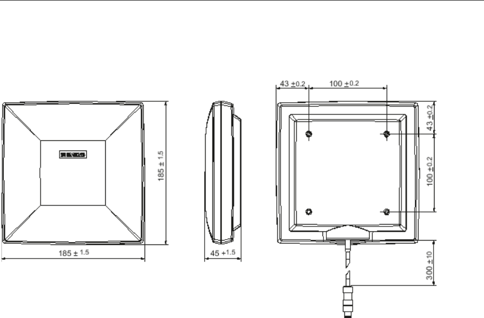
Antennas
6.3 Antenna RF640A
SIMATIC RF600
294 System Manual, xx/2014, J31069-D0171-U001-A15-7618
REVIEW
6.3.11
Dimension drawing
Figure 6-19 Dimension drawing RF640A
All dimensions in mm
Antennas
6.3 Antenna RF640A
SIMATIC RF600
System Manual, xx/2014, J31069-D0171-U001-A15-7618 295
REVIEW
6.3.12
Approvals & certificates
Table 6- 19 6GT2812-0GA08
Certificate
Description
Conformity in accordance with R&TTE directive
in association with the readers and accessories used
Table 6- 20 6GT2812-0GA08
Standard
Federal Communications
Commission
FCC CFR 47, Part 15 sections 15.247
Radio Frequency Interference Statement
This equipment has been tested and found to comply with the limits
for a Class B digital device, pursuant to Part 15 of the FCC Rules.
The FCC approval is granted in association with the FCC approval of
the following RF600 readers:
• FCC ID: NXW-RF600R
(for RF620R: 6GT2811-5BA00-1AA1,
RF630R: 6GT2811-4AA00-1AA1,
RF640R: 6GT2811-3BA00-1AA0,
RF670R FS C1: 6GT2811-0AB00-1AA0)
• FCC ID: NXW-RF630R
(for 6GT2811-4AA00-1AA0)
• FCC ID: NXW-RF670
(for RF670R as of FS A1: 6GT2811-0AB00-1AA0
Industry Canada Radio
Standards Specifications
RSS-210 Issue 7, June 2007, Sections 2.2, A8
The approval for Industry Canada is granted in association with the
Industry Canada approval of the following RF600 readers:
• IC: 267X-RF630 (for 6GT2811-4AA00-1AA0)
• IC: 267X-RF670, RF670R FS A1 (for 6GT2811-0AB00-1AA0)
• IC: 267X-RF600R, Model RF620R-2 (for 6GT2811-5BA00-1AA1)
• IC: 267X-RF600R, Model RF630R-2 (for 6GT2811-4AA00-1AA1)
• IC: 267X-RF600R, Model RF640R (for 6GT2811-3BA00-1AA0)
• IC: 267X-RF600R, model RF670R-2 as of FS C1 (for 6GT2811-
0AB00-1AA0)
This product is UL-certified for the USA and Canada.
It meets the following safety standard(s):
UL 60950-1 - Information Technology Equipment Safety - Part 1:
General Requirements
CSA C22.2 No. 60950 -1 - Safety of Information Technology
Equipment
UL Report E 205089
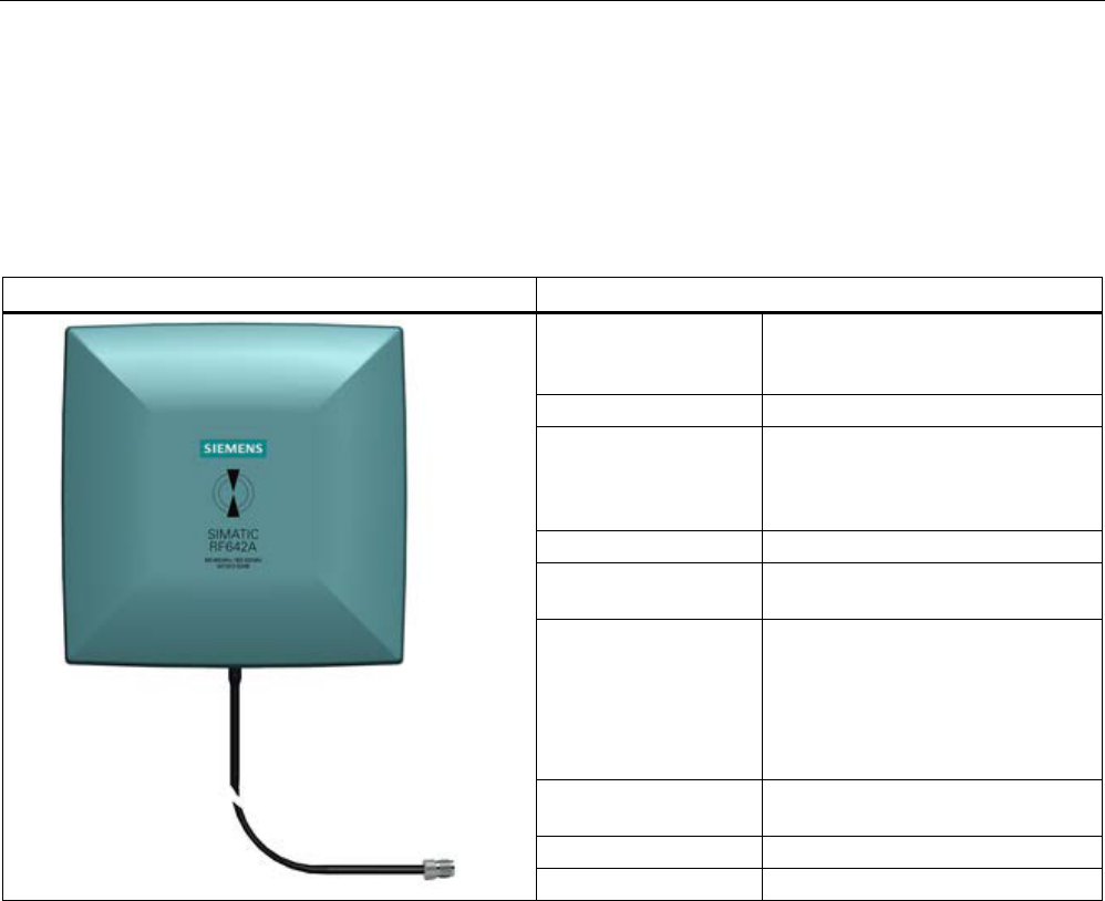
Antennas
6.4 Antenna RF642A
SIMATIC RF600
296 System Manual, xx/2014, J31069-D0171-U001-A15-7618
REVIEW
6.4
Antenna RF642A
6.4.1
Description
SIMATIC RF642A
Features
Field of application The SIMATIC RF642A is a universal
UHF antenna of compact, industry-
standard design with medium range.
Frequency range
865 to 928 MHz
Polarization Linear polarization
Suitable for RF600 transponders
that are uniformly aligned while
directed past the antenna.
Writing/reading range
max. 5.0 m
Mounting 4 x M4
(VESA 100 fixing system)
Connector 30 cm connecting cable (connected
permanently to the antenna) and
RTNC coupling
An antenna cable is required for
connection to the reader, e.g.
6GT2815-0BH30)
Readers that can be
connected
All RF600 readers with external
antenna connectors
Dimensions in mm
185 x 185 x 45
Degree of protection
IP67
Frequency ranges
The antenna is available for broadband. It can therefore be used for two different frequency
ranges that have been specified for the regions of Europe and China/USA respectively.
● The antenna for Europe (EU, EFTA countries) operates in the frequency range of 865 to
868 MHz.
● The antenna for China, the USA, and Canada operates in the frequency range of 902 to
928 MHz.
Function
The SIMATIC RF642A is used for transmitting and receiving RFID signals in the UHF range.
The antennas are connected to the SIMATIC RF600 readers via antenna cables that are
available in different lengths.
Antennas
6.4 Antenna RF642A
SIMATIC RF600
System Manual, xx/2014, J31069-D0171-U001-A15-7618 297
REVIEW
6.4.2
Ordering data
Table 6- 21 Ordering data RF642A
Product
Article number
SIMATIC RF642A
6GT2812-1GA08
Accessories
Table 6- 22 Ordering data accessories
Product
Article number
Connecting cable between
reader and antenna
3 m (cable loss 1.0 dB)
6GT2815-0BH30
5 m, suitable for drag chains
(cable loss 1.25 dB)
6GT2815-2BH50
10 m (cable loss 2.0 dB)
6GT2815-1BN10
10 m (cable loss 4.0 dB)
6GT2815-0BN10
15 m, suitable for drag chains
(cable loss 4.0 dB)
6GT2815-2BN15
20 m (cable loss 4.0 dB)
6GT2815-0BN20
Antenna mounting kit See "RF600 System Manual",
section "Antennas" > "Mounting
types"
6GT2890-0AA00
6.4.3
Installation and assembly
6.4.3.1
RF640A mounting types
VESA 100 mounting system
A standardized VESA 100 mounting system is provided to mount the antenna. The mounting
system consists of four fixing holes for M4 screws at intervals of 100 mm.
This is therefore suitable for:
● Mounting on metallic and non-metallic backgrounds
Note
To achieve optimum wave propagation, the antenna should not be surrounded by
conducting objects. The area between antenna and transponder should also allow wave
propagation without interference.

Antennas
6.4 Antenna RF642A
SIMATIC RF600
298 System Manual, xx/2014, J31069-D0171-U001-A15-7618
REVIEW
Antenna Mounting Kit
The Antenna Mounting Kit allows the fine adjustment of the antenna field by setting the solid
angle (see "RF600 System Manual", chapter "Antennas" > "Mounting types").
6.4.4
Connecting an antenna to the reader
The SIMATIC RF642A antenna must be connected to the reader using an antenna cable.
Preassembled standard cables in lengths of 3 m, 10 m, and 20 m are available for the
connection.
The range of the antenna is limited by the cable loss. The maximum range can be achieved
with the cable 6GT2815-0BH30 (length 3 m), since this has the lowest cable loss.
Requirement
Note
Use of Siemens antenna cable
To ensure optimum functioning of the antenna, it is recommended that a Siemens antenna
cable be used in accordance with the list of accessories.
Strain relief
The antenna cable is provided with strain relief as shown in the following diagram:
①
RF642A antenna connection (30 cm connecting cable)
②
RF600 antenna cable
③
Strain relief (should take place at this position)
Figure 6-20 Strain relief

Antennas
6.4 Antenna RF642A
SIMATIC RF600
System Manual, xx/2014, J31069-D0171-U001-A15-7618 299
REVIEW
6.4.4.1
Bending radii and bending cycles of the cable
Cable
designation
Order No.
Length [m]
Cable loss
[dB]
Bending
radius [mm]
Bending cycle
RF642A antenna
connection
Fixed
connection to
antenna
0,3 - - 1 Mal
Antenna cable 6GT2815-
0BH30
3 1 51 1 Mal
Antenna cable
(suitable for drag
chains)
6GT2815-
2BH50
5 1,25 48 1)
Antenna cable 6GT2815-
1BN10
10 2 77 1 Mal
Antenna cable 6GT2815-
0BN10
10 4 51 1 Mal
Antenna cable
(suitable for drag
chains)
6GT2815-
0BN20
15 4 24 1)
Antenna cable 6GT2815-
0BN20
20 4 77 1 Mal
1)
With cables suitable for drag chains, 3 million bending cycles at a bending radius of 6.5 m and
bending through ± 180 ° are permitted.
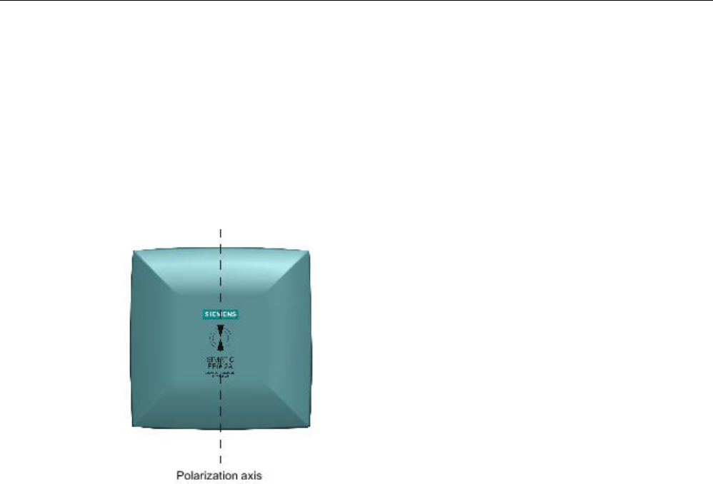
Antennas
6.4 Antenna RF642A
SIMATIC RF600
300 System Manual, xx/2014, J31069-D0171-U001-A15-7618
REVIEW
6.4.5
Alignment of transponders to the antenna
Polarization axis
Since the RF642A antenna has linear polarization, it is necessary to consider the alignment
of the transponders with regard to the polarization axis of the antenna.
The polarization axes of antenna and transponder must always be parallel. The symbol on
the antenna indicates the polarization axis.
Figure 6-21 Polarization axis