Siemens RF660 RFID reader User Manual
Siemens AG RFID reader
UserManual.wiki
>
Siemens
>
RF660 User Manual
>
User manual
Contents
1.
FCC information
2.
User manual
3.
User Manual
User manual
Navigation menu
Upload a User Manual
Namespaces
Wiki Guide
HTML
PDF
Info
Views
User Manual
Discussion / Help
Navigation
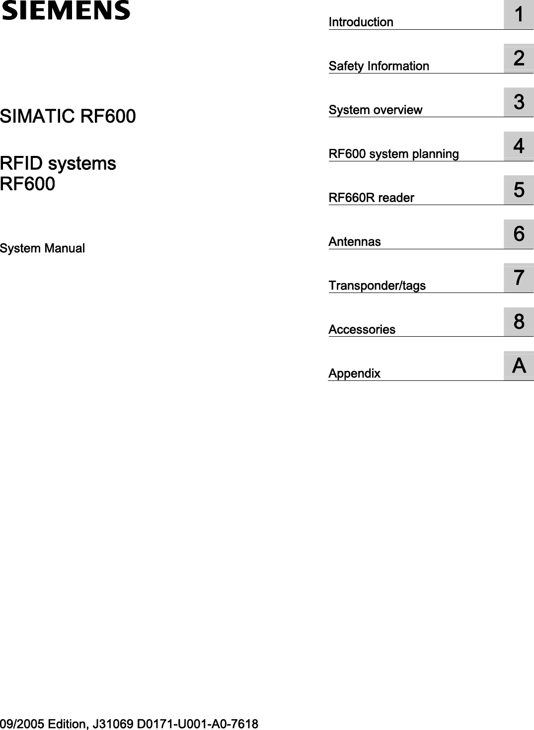
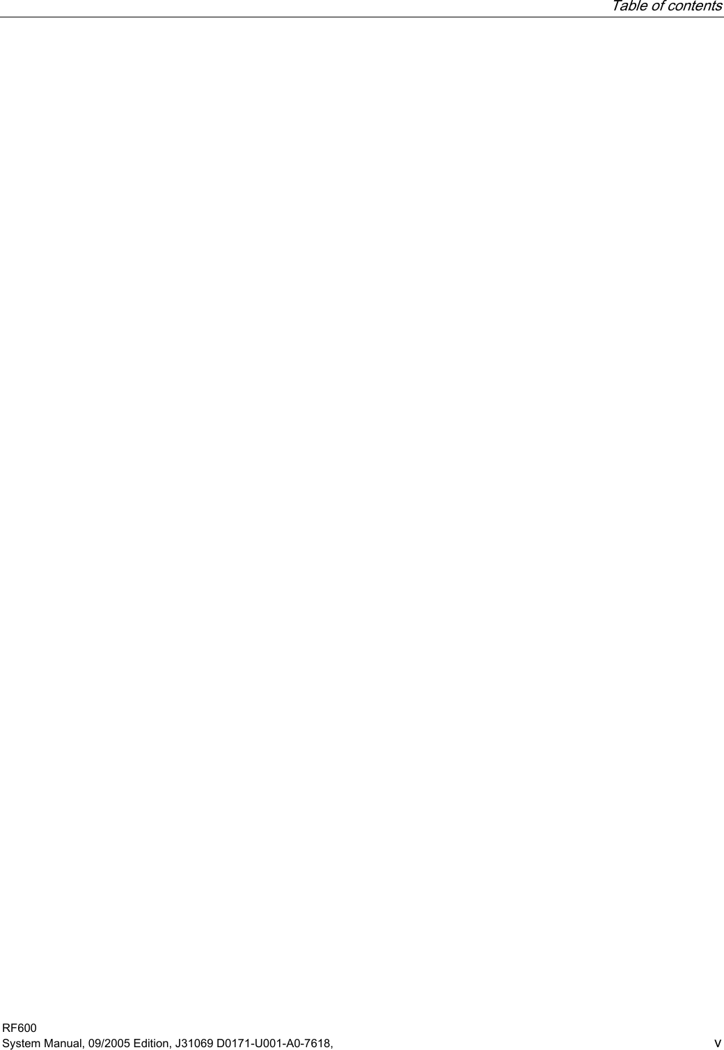
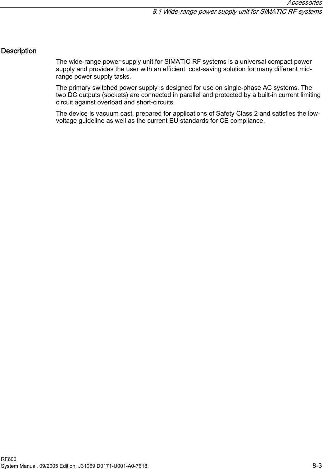
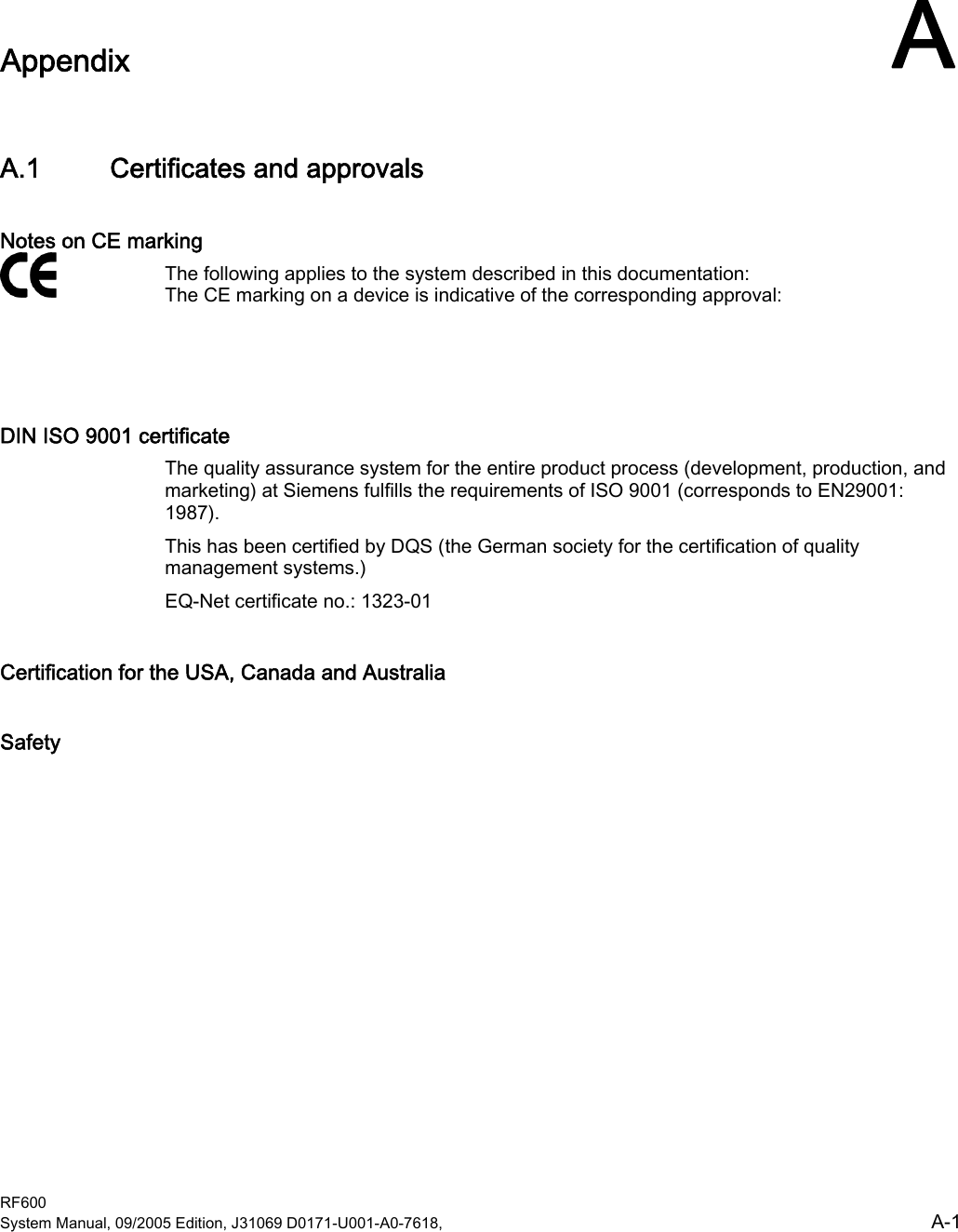
![RF600 system planning 4.5 Regulations applicable to frequency bands RF600 4-16 System Manual, 09/2005 Edition, J31069 D0171-U001-A0-7618, 4.5 Regulations applicable to frequency bands 4.5.1 Regulations for UHF frequency bands in Europe Regulations for frequency bands according to EN 302 208 ETSI (European Telecommunications Standards Institute) Specifications of European standard EN 302 208: • UHF band: 865 to 868 MHz • Radiant power: max. 2 W (ERP) • Channel bandwidth: 200 kHz • Number of channels: 15 • Listen before talk bN+]0+] 0+]FKDQQHOVWR:(53](https://usermanual.wiki/Siemens/RF660.User-manual/User-Guide-598762-Page-32.png)
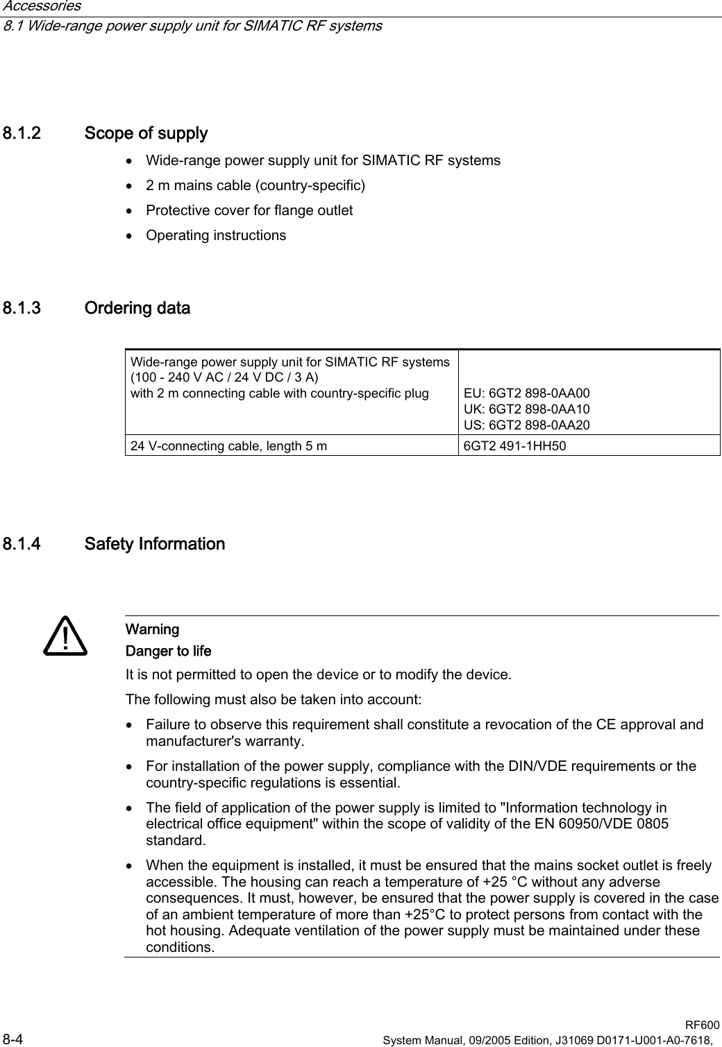
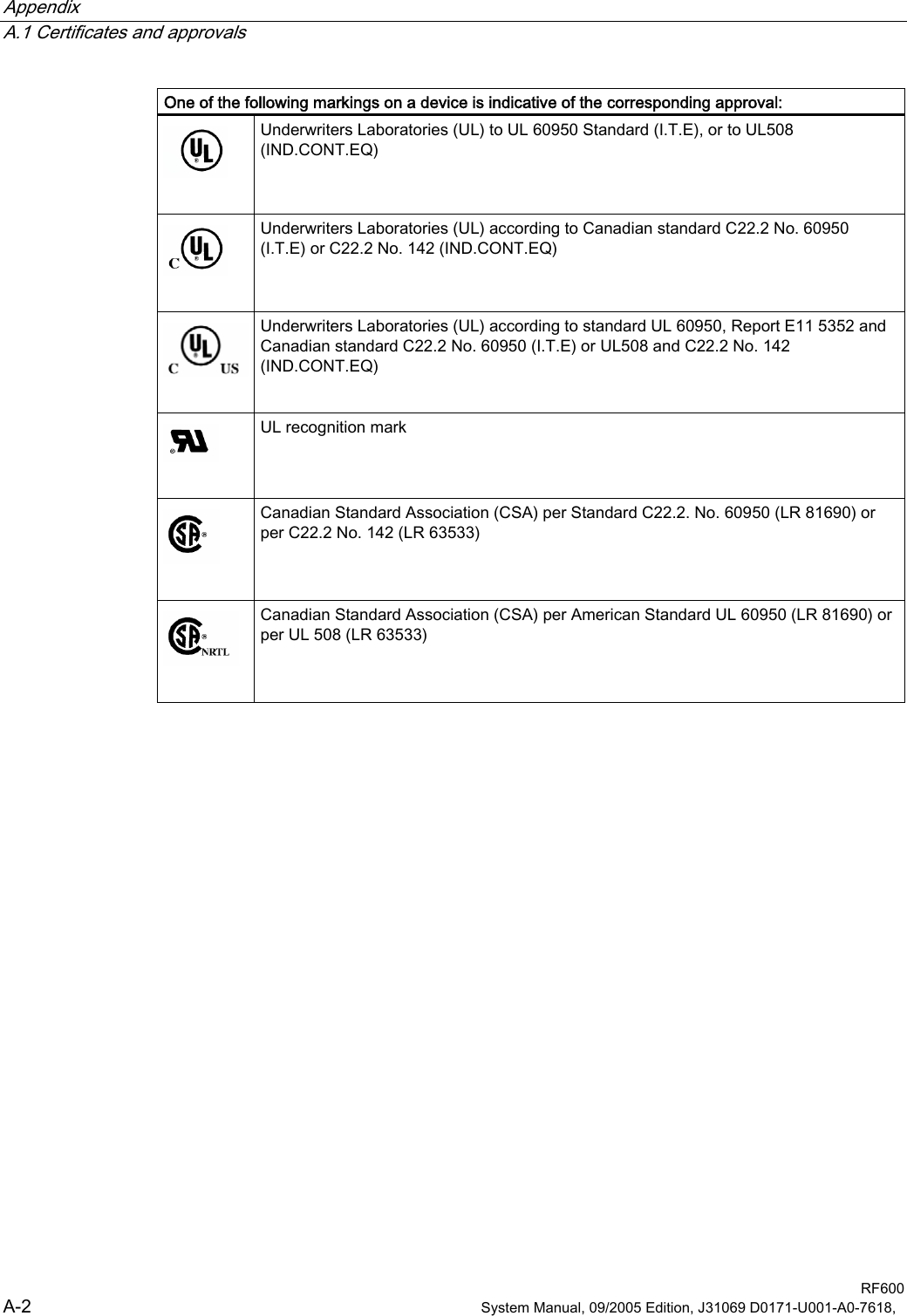
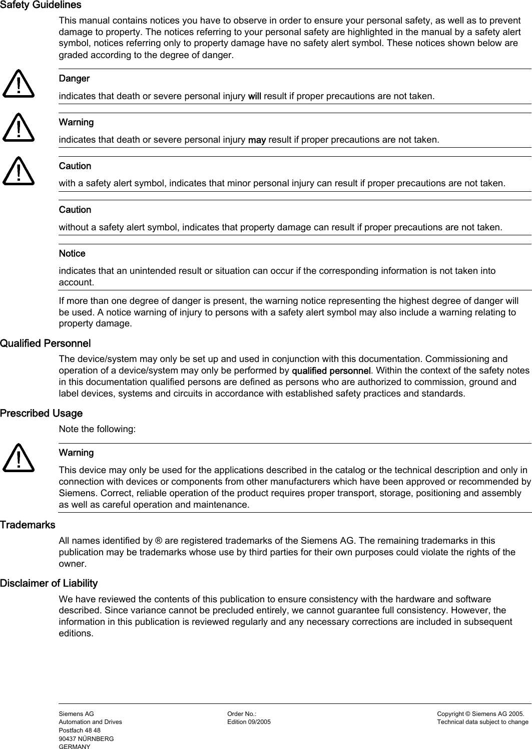
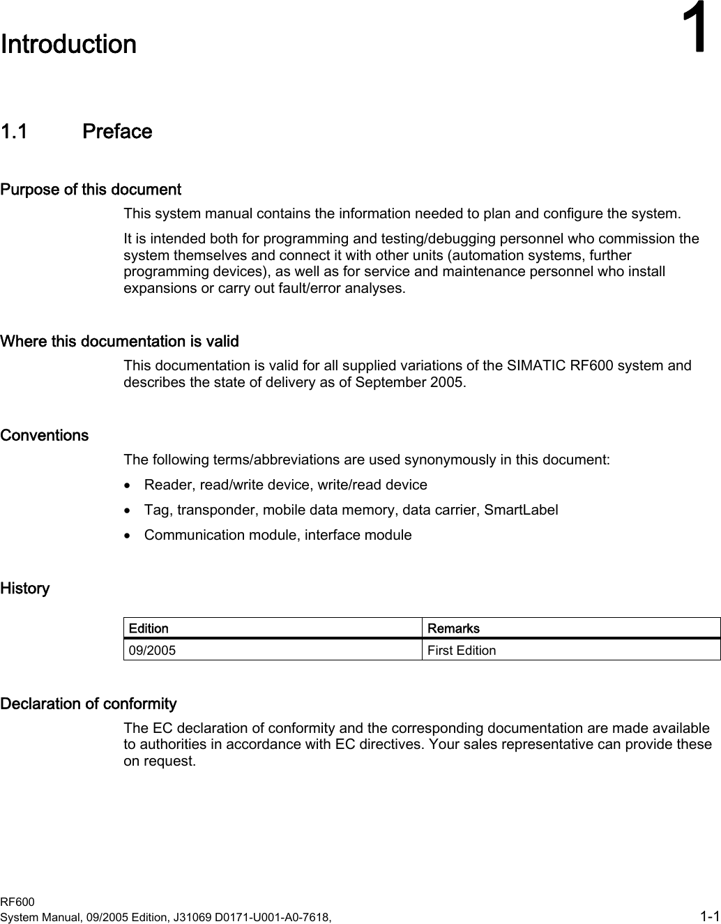
![RF600 system planning 4.5 Regulations applicable to frequency bands RF600 System Manual, 09/2005 Edition, J31069 D0171-U001-A0-7618, 4-17 Channel assignment • The UHF band from 865 to 868 MHz is subdivided into three sub bands: Sub bands Frequency range Output 865.0 to 865.5 MHz 0.1 W ERP 865.6 to 867.6 MHz 2,0 W ERP :::0+]0+]0+]0+] 867.6 to 868.0 MHz 0,5 W ERP Listen before talk With this technique, the reader checks whether a channel is assigned before transmission to prevent collisions. The reader will only transmit when a channel is free. The reader can transmit for up to ?? seconds on this channel and must then pause for at least ?? seconds or jump immediately to an unassigned channel on which it can transmit for a further ?? seconds. Regulations for frequency bands according to EN 300 220 (short range device) For those countries in which the RFID directive according to EN 302 208 has not yet been implemented, this alternative exists which is based on the older "Short range device" directive: EN 300 220 (short range device) Frequency range 865.6 to 868 MHz Number of channels 12 Transmit power Max. 0.5 W ERP Duty cycle (frequency assignment period) 10 % (6 min./h)](https://usermanual.wiki/Siemens/RF660.User-manual/User-Guide-598762-Page-33.png)
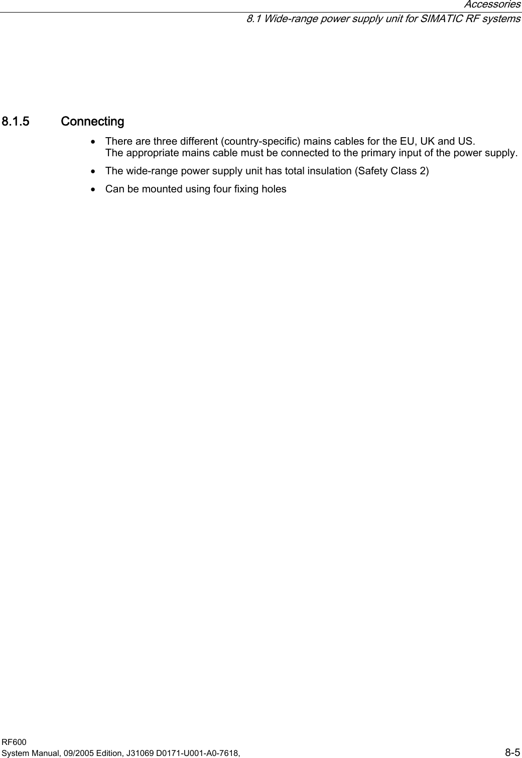
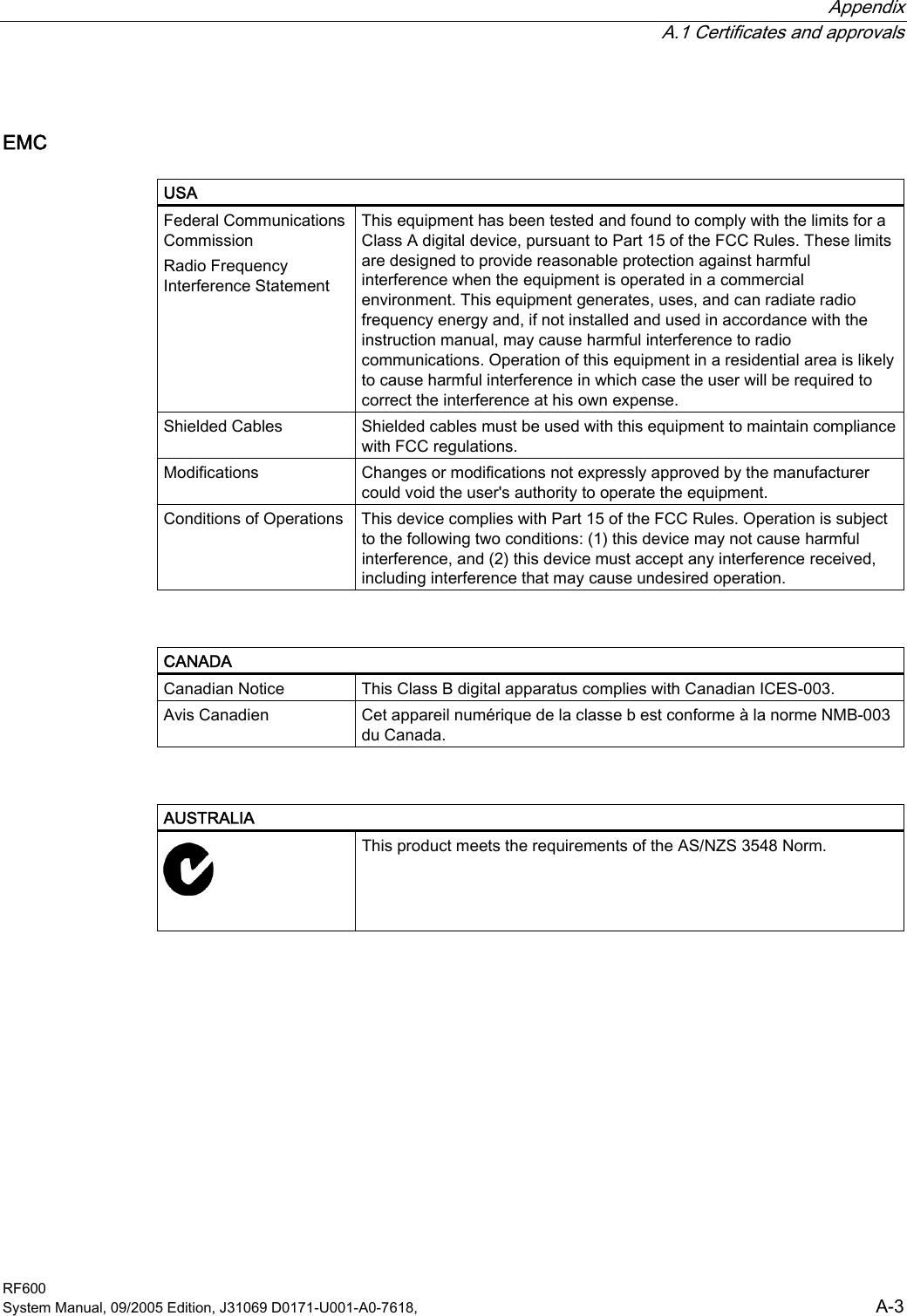
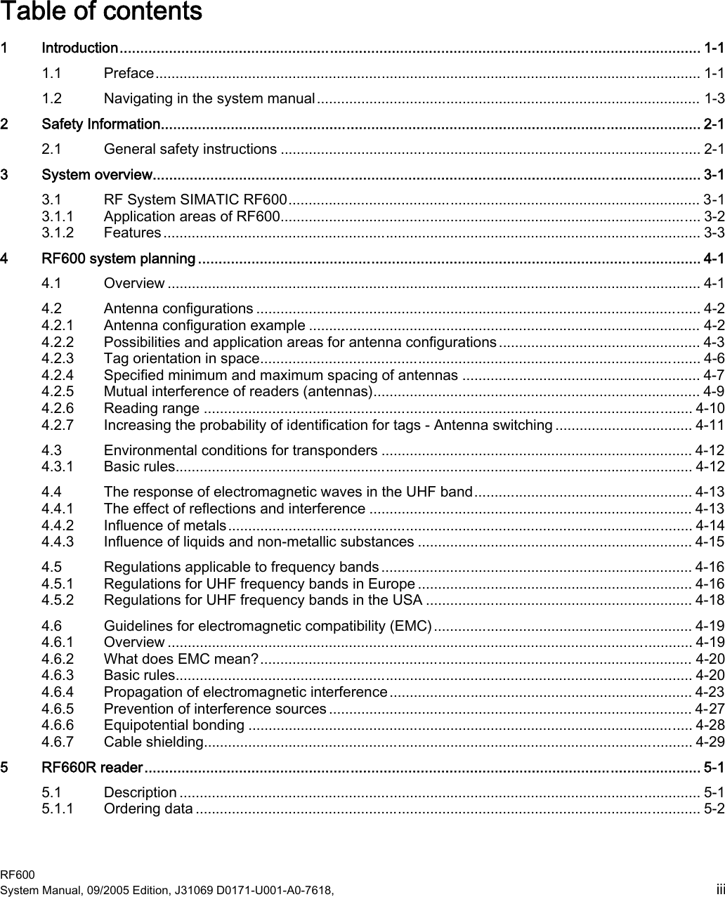
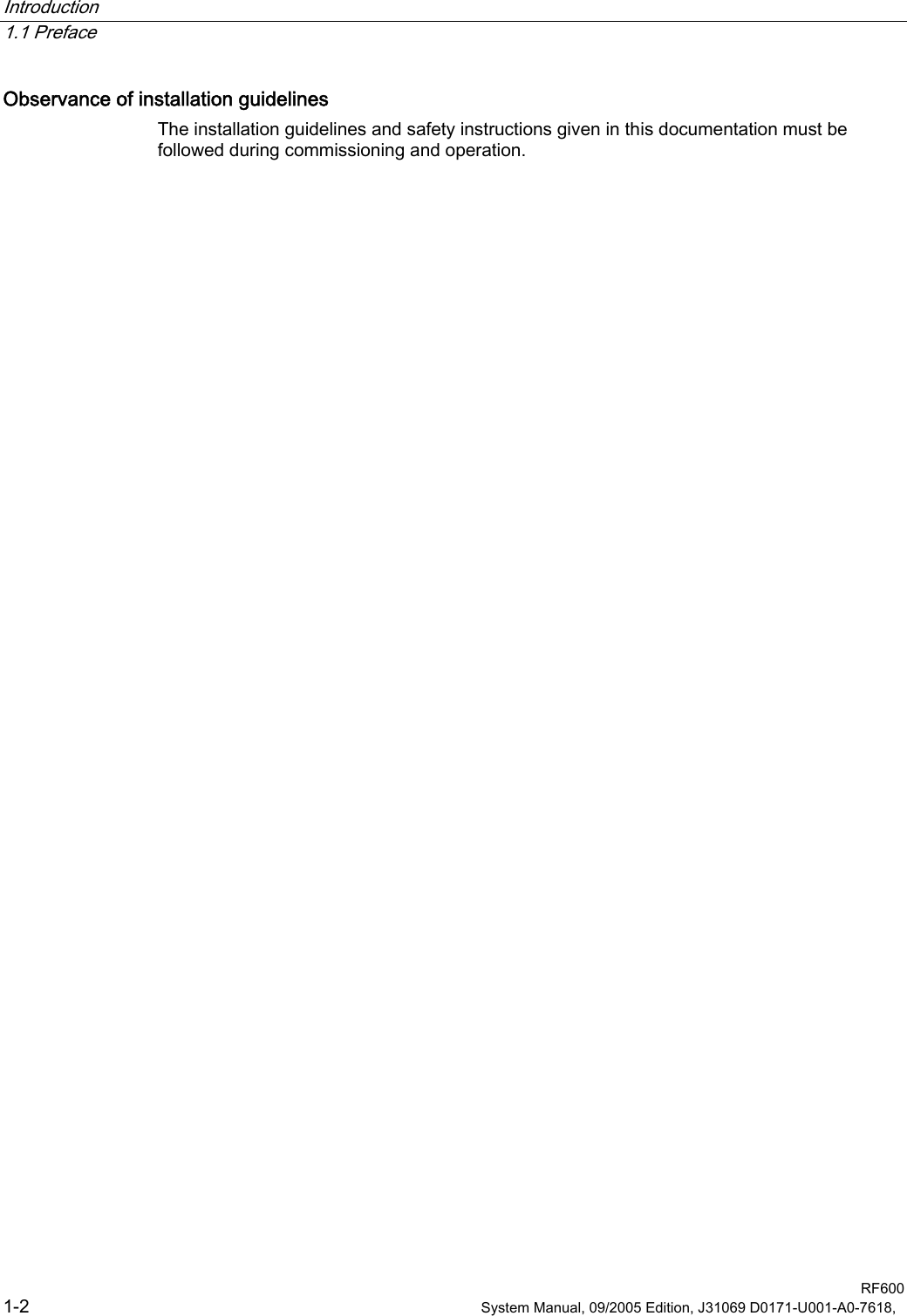
![RF600 system planning 4.5 Regulations applicable to frequency bands RF600 4-18 System Manual, 09/2005 Edition, J31069 D0171-U001-A0-7618, 4.5.2 Regulations for UHF frequency bands in the USA USA FCC (Federal Communications Commission) • UHF band: 902 to 928 MHz • Radiant power: max. 4 W (EIRP) • Number of channels: 50 • Frequency hopping bN+]0+] 0+]FKDQQHOVWR:(53PD[:ZLWKG%DQWHQQD Frequency hopping This technique should prevent mutual interference between readers. The reader changes its transmission channel in a random or programmed sequence (FHSS - Frequency Hopping Spread Spectrum). The 50 available channels mean that the probability is low that two readers will be operating on the same frequency](https://usermanual.wiki/Siemens/RF660.User-manual/User-Guide-598762-Page-34.png)
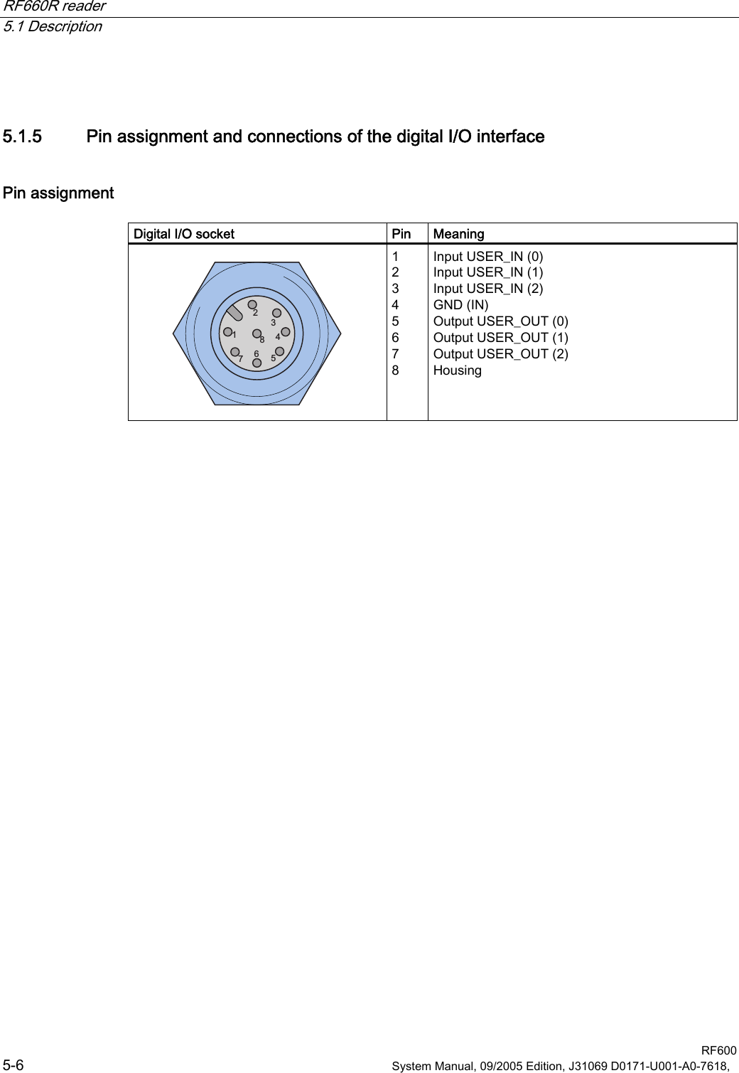
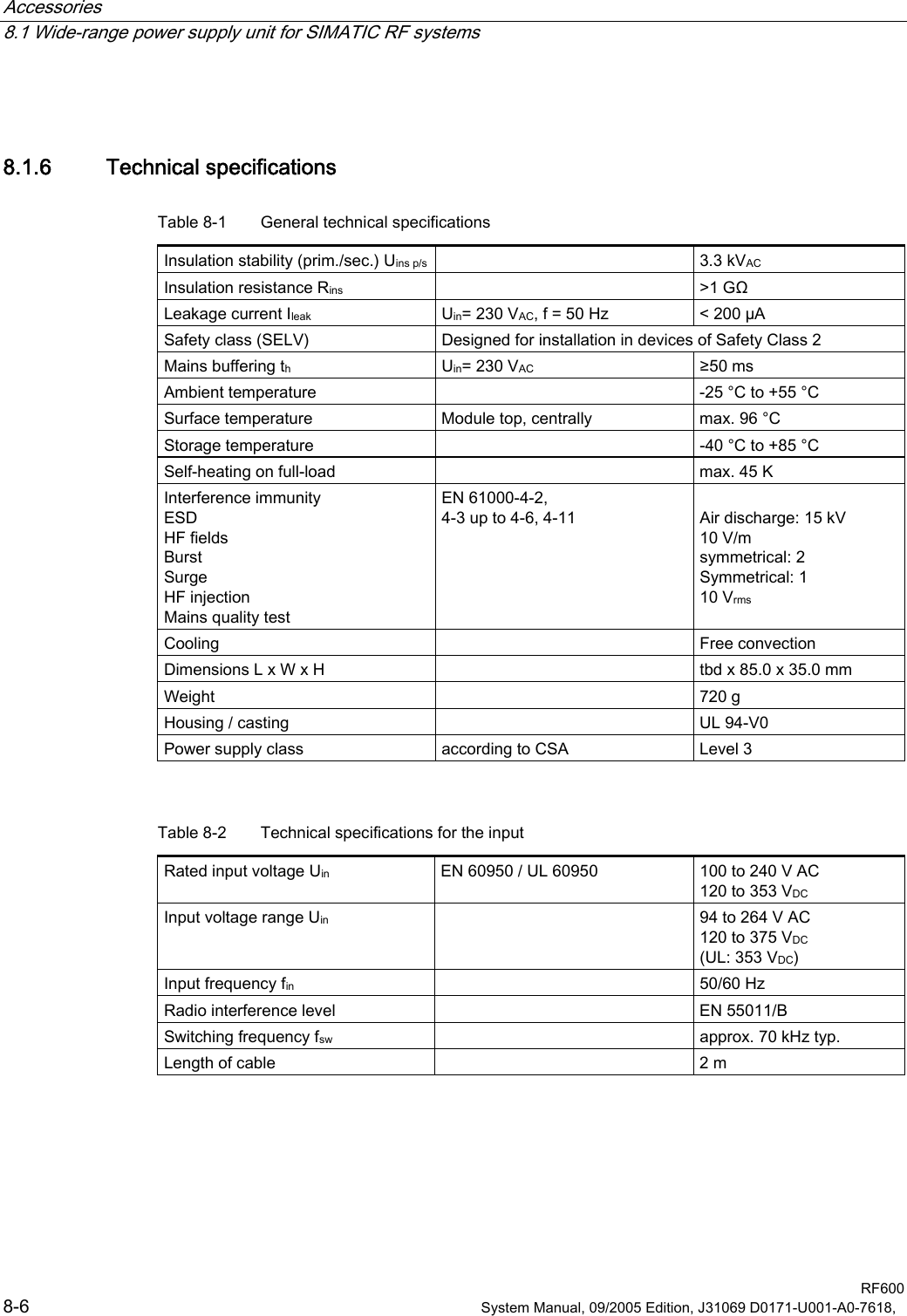
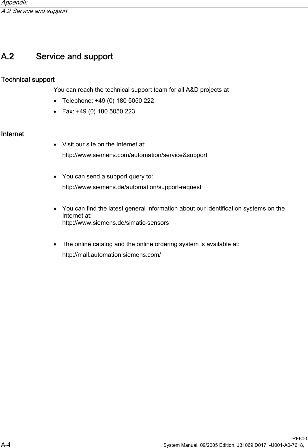
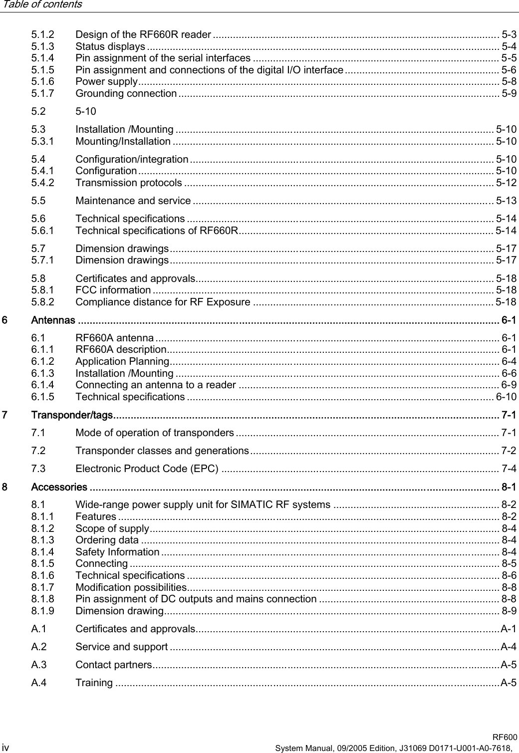
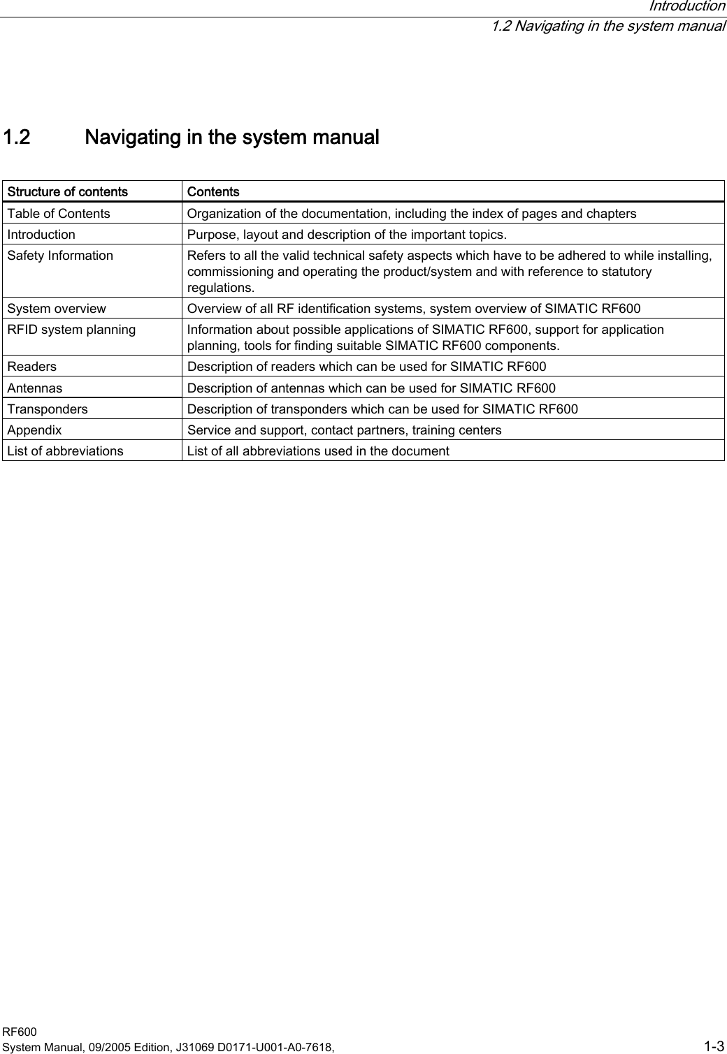
![RF660R reader 5.1 Description RF600 System Manual, 09/2005 Edition, J31069 D0171-U001-A0-7618, 5-7 Connections 95)5'LJLWDO,23LQ86(5B,1B3LQ86(5B,1B3LQ86(5B,1B3LQ86(5B287B3LQ86(5B287B3LQ86(5B287B3LQ*1'991HW]WHLO3LQ*HK¦XVH9HUEUDXFKHU9HUEUDXFKHU9HUEUDXFKHU Figure 5-2 Connections for digital I/O Output USER_OUT (0), (1), (2): (1) These are high-side switches that switch Vcc (+24V) at low resistance ('active high'). (2) Each output is rated for 0.5 A current and is electronically protected. (3) The 0 V rail is Pin 4 (GND). (4) Each pin of the 8-pin connector can carry a load of up to 2 A, this means that three digital outputs can be operated simultaneously with up to 0.5 A.](https://usermanual.wiki/Siemens/RF660.User-manual/User-Guide-598762-Page-53.png)