Siemens RF670 RFID UHF Reader User Manual SIMATIC RF600
Siemens AG RFID UHF Reader SIMATIC RF600
Siemens >
Contents
- 1. User Manual I
- 2. User Manual II
User Manual I
Draft Version 02.06.2010

Draft Version 02.06.2010
SIMATIC Sensors
RFID systems
SIMATIC RF600
System Manual
06/2010
J31069-D0171-U001-A10-7618
Introduction
1
Safety Information
2
System overview
3
RF600 system planning
4
Readers
5
Antennas
6
Transponder/tags
7
Integration into networks
8
System diagnostics
9
Accessories
10
Appendix
A
Draft Version 02.06.2010
Legal information
Warning notice system
This manual contains notices you have to observe in order to ensure your personal safety, as well as to prevent
damage to property. The notices referring to your personal safety are highlighted in the manual by a safety alert
symbol, notices referring only to property damage have no safety alert symbol. These notices shown below are
graded according to the degree of danger.
DANGER
indicates that death or severe personal injury will result if proper precautions are not taken.
WARNING
indicates that death or severe personal injury may result if proper precautions are not taken.
CAUTION
with a safety alert symbol, indicates that minor personal injury can result if proper precautions are not taken.
CAUTION
without a safety alert symbol, indicates that property damage can result if proper precautions are not taken.
NOTICE
indicates that an unintended result or situation can occur if the corresponding information is not taken into account.
If more than one degree of danger is present, the warning notice representing the highest degree of danger will be
used. A notice warning of injury to persons with a safety alert symbol may also include a warning relating to property
damage.
Qualified Personnel
The product/system described in this documentation may be operated only by personnel qualified for the specific
task in accordance with the relevant documentation for the specific task, in particular its warning notices and safety
instructions. Qualified personnel are those who, based on their training and experience, are capable of identifying
risks and avoiding potential hazards when working with these products/systems.
Proper use of Siemens products
Note the following:
WARNING
Siemens products may only be used for the applications described in the catalog and in the relevant technical
documentation. If products and components from other manufacturers are used, these must be recommended or
approved by Siemens. Proper transport, storage, installation, assembly, commissioning, operation and
maintenance are required to ensure that the products operate safely and without any problems. The permissible
ambient conditions must be adhered to. The information in the relevant documentation must be observed.
Trademarks
All names identified by ® are registered trademarks of the Siemens AG. The remaining trademarks in this publication
may be trademarks whose use by third parties for their own purposes could violate the rights of the owner.
Disclaimer of Liability
We have reviewed the contents of this publication to ensure consistency with the hardware and software described.
Since variance cannot be precluded entirely, we cannot guarantee full consistency. However, the information in
this publication is reviewed regularly and any necessary corrections are included in subsequent editions.
Siemens AG
Industry Sector
Postfach 48 48
90026 NÜRNBERG
GERMANY
J31069-D0171-U001-A10-7618
Ⓟ 06/2010
Copyright © Siemens AG 2005,
2010.
Technical data subject to change
Draft Version 02.06.2010

Table of contents
1Introduction.................................................................................................................................................13
1.1 Preface........................................................................................................................................13
1.2 Navigating in the system manual.................................................................................................14
2Safety Information......................................................................................................................................15
2.1 General safety instructions..........................................................................................................15
2.2 Safety instructions for third-party antennas as well as for modifications to the RF600 system...16
2.3 Safety distance to transmitter antenna........................................................................................17
2.3.1 Safety distance between transmitter antenna and personnel.....................................................17
2.3.2 Minimum distance to antenna in accordance with ETSI..............................................................18
2.3.3 Minimum distance to antenna in accordance with FCC (USA)....................................................19
3System overview........................................................................................................................................21
3.1 RF System SIMATIC RF600.......................................................................................................21
3.1.1 Application areas of RF600.........................................................................................................23
3.1.2 System components (hardware/software)...................................................................................23
3.1.3 Features......................................................................................................................................25
4RF600 system planning..............................................................................................................................29
4.1 Overview......................................................................................................................................29
4.2 Possible system configurations...................................................................................................29
4.2.1 Scenario for incoming goods.......................................................................................................29
4.2.2 Scenario for material handling control.........................................................................................31
4.2.3 Scenario for workpiece identification...........................................................................................33
4.2.4 Scenario for Intra logistics...........................................................................................................34
4.2.5 Scenario for outgoing goods........................................................................................................36
4.3 Antenna configurations................................................................................................................38
4.3.1 Antenna configuration example...................................................................................................38
4.3.2 Possibilities and application areas for antenna configurations....................................................39
4.3.3 Tag orientation in space..............................................................................................................43
4.3.4 Specified minimum and maximum spacing of antennas.............................................................44
4.3.5 Mutual interference of readers (antennas)..................................................................................46
4.3.6 Reading range.............................................................................................................................46
4.3.7 Operation of several readers within restricted space..................................................................46
4.3.7.1 Dense Reader Mode...................................................................................................................46
4.3.7.2 Optimizing tag reading accuracy.................................................................................................48
4.3.7.3 Optimization of robustness of tag data accesses for readers that are operated simultaneously 49
4.3.7.4 Frequency hopping......................................................................................................................50
4.3.7.5 Listen before talk.........................................................................................................................51
4.4 Environmental conditions for transponders/tags.........................................................................51
4.4.1 Basic rules...................................................................................................................................51
4.5 The response of electromagnetic waves in the UHF band..........................................................51
SIMATIC RF600
System Manual, 06/2010, J31069-D0171-U001-A10-7618 3
Draft Version 02.06.2010

4.5.1 The effect of reflections and interference....................................................................................51
4.5.2 Influence of metals......................................................................................................................52
4.5.3 Influence of liquids and non-metallic substances........................................................................52
4.5.4 Influence of external components................................................................................................53
4.6 Regulations applicable to frequency bands.................................................................................53
4.6.1 Regulations for UHF frequency bands in Europe........................................................................54
4.6.1.1 Regulations for UHF frequency bands in Europe (ETSI EN 302 208 V1.2.1).............................54
4.6.1.2 Regulations for frequency bands according to EN 300 220 (short range device).......................55
4.6.1.3 Partial abrogation of the regulations for France..........................................................................55
4.6.1.4 Regulations for UHF frequency bands in Europe (ETSI EN 302 208 V1.1.2).............................57
4.6.2 Regulations for UHF frequency bands in China..........................................................................58
4.6.3 Regulations for UHF frequency bands in Thailand......................................................................59
4.6.4 Regulations for UHF frequency bands in the USA......................................................................60
4.7 Operation of RF600 readers according to EN 302208 V1.2.1 and EN 302208 V1.1.1...............60
4.7.1 Validity of the standards..............................................................................................................60
4.7.2 Disturbances when operating readers according to ETSI EN V1.1.1 and V1.2.1 in mixed mode61
4.7.3 Preventing interference in mixed operation.................................................................................62
4.7.3.1 Mixed operation - dense mode....................................................................................................63
4.7.3.2 Preventing interference in mixed operation.................................................................................64
4.7.3.3 Example 1: Recommended channel assignment mixed operation..............................................65
4.7.3.4 Example 2: Recommended channel assignment mixed operation..............................................66
4.7.4 Possible causes of error..............................................................................................................67
4.8 Guidelines for electromagnetic compatibility (EMC)....................................................................69
4.8.1 Overview......................................................................................................................................69
4.8.2 What does EMC mean?..............................................................................................................70
4.8.3 Basic rules...................................................................................................................................71
4.8.4 Propagation of electromagnetic interference...............................................................................72
4.8.5 Prevention of interference sources..............................................................................................75
4.8.6 Equipotential bonding..................................................................................................................76
4.8.7 Cable shielding............................................................................................................................77
5Readers......................................................................................................................................................79
5.1 RF620R reader............................................................................................................................80
5.1.1 Description...................................................................................................................................80
5.1.1.1 Ordering data...............................................................................................................................81
5.1.1.2 Status display..............................................................................................................................82
5.1.1.3 Pin assignment of the RS422 interface.......................................................................................83
5.1.1.4 Pin assignment of the connecting cable......................................................................................83
5.1.1.5 Grounding connection.................................................................................................................84
5.1.2 Planning application....................................................................................................................84
5.1.2.1 Minimum mounting clearances of two readers............................................................................84
5.1.2.2 Antenna diagram for RF620R (ETSI)..........................................................................................85
5.1.2.3 Antenna diagram for RF620R (FCC)...........................................................................................88
5.1.2.4 Interpretation of directional radiation patterns.............................................................................91
5.1.2.5 Antenna/read point configurations...............................................................................................91
5.1.3 Installing/Mounting.......................................................................................................................91
5.1.3.1 Mounting/Installing FCC..............................................................................................................92
5.1.4 Configuration/integration.............................................................................................................93
5.1.4.1 Transmission protocols................................................................................................................94
5.1.5 Technical data.............................................................................................................................94
5.1.5.1 Mechanical data..........................................................................................................................94
Table of contents
SIMATIC RF600
4System Manual, 06/2010, J31069-D0171-U001-A10-7618
Draft Version 02.06.2010

5.1.5.2 Technical data according to EPC and ISO..................................................................................95
5.1.5.3 Maximum number of readable tags.............................................................................................96
5.1.6 Dimension drawings....................................................................................................................97
5.1.7 Certificates and approvals...........................................................................................................97
5.1.7.1 FCC, IC-FCB approval and UL certification.................................................................................98
5.1.7.2 FCC information..........................................................................................................................98
5.2 RF630R reader............................................................................................................................99
5.2.1 Description...................................................................................................................................99
5.2.1.1 Ordering data.............................................................................................................................100
5.2.1.2 Status display............................................................................................................................101
5.2.1.3 Pin assignment of the RS422 interface.....................................................................................102
5.2.1.4 Pin assignment of the connecting cable....................................................................................103
5.2.1.5 Grounding connection...............................................................................................................104
5.2.2 Planning application..................................................................................................................104
5.2.2.1 Minimum mounting clearances of two antennas of different readers........................................104
5.2.2.2 Antenna/read point configurations.............................................................................................104
5.2.3 Installing/Mounting.....................................................................................................................105
5.2.3.1 Mounting/Installation..................................................................................................................105
5.2.4 Configuration/integration...........................................................................................................106
5.2.4.1 Transmission protocols..............................................................................................................107
5.2.5 Technical data...........................................................................................................................107
5.2.5.1 Mechanical data........................................................................................................................107
5.2.5.2 Technical data according to EPC and ISO................................................................................109
5.2.5.3 Maximum number of readable tags...........................................................................................110
5.2.6 Dimension drawings..................................................................................................................111
5.2.7 Certificates and approvals.........................................................................................................112
5.2.7.1 FCC information........................................................................................................................112
5.2.7.2 IC-FCB information....................................................................................................................113
5.3 RF670R reader..........................................................................................................................114
5.3.1 Description.................................................................................................................................114
5.3.1.1 Overview....................................................................................................................................114
5.3.1.2 Ordering data.............................................................................................................................115
5.3.1.3 Status display............................................................................................................................117
5.3.1.4 Pin assignment of the digital I/O interface.................................................................................118
5.3.1.5 Connection scheme for the digital I/O interface.........................................................................118
5.3.1.6 Pin assignment for power supply...............................................................................................123
5.3.1.7 Pin assignment for Industrial Ethernet interface........................................................................124
5.3.1.8 Grounding connection...............................................................................................................125
5.3.2 Planning the use........................................................................................................................125
5.3.2.1 Firmware and software compatibility.........................................................................................125
5.3.2.2 Antenna/read point configurations.............................................................................................126
5.3.3 Installing / mounting...................................................................................................................126
5.3.4 Configuration/integration...........................................................................................................127
5.3.4.1 Configuration.............................................................................................................................127
5.3.5 Technical data...........................................................................................................................128
5.3.5.1 Mechanical data........................................................................................................................128
5.3.5.2 Technical data according to EPC and ISO................................................................................130
5.3.6 Dimension drawings..................................................................................................................131
5.3.6.1 Dimension drawings..................................................................................................................131
5.3.7 Certificates and approvals.........................................................................................................132
5.3.7.1 CE mark.....................................................................................................................................132
Table of contents
SIMATIC RF600
System Manual, 06/2010, J31069-D0171-U001-A10-7618 5
Draft Version 02.06.2010

5.3.7.2 FCC, IC-FCB approval and UL certification...............................................................................132
5.3.7.3 FCC information........................................................................................................................132
5.3.7.4 IC-FCB information....................................................................................................................133
5.4 RF660R reader..........................................................................................................................133
5.4.1 Description.................................................................................................................................133
5.4.1.1 Ordering data.............................................................................................................................134
5.4.1.2 Design of the RF660R reader....................................................................................................136
5.4.1.3 Status displays..........................................................................................................................137
5.4.1.4 Pin assignment of the serial interfaces......................................................................................138
5.4.1.5 Pin assignment and connections of the digital I/O interface......................................................139
5.4.1.6 Pin assignment of the connecting cable....................................................................................140
5.4.1.7 Power supply.............................................................................................................................141
5.4.1.8 Grounding connection...............................................................................................................142
5.4.2 Planning application..................................................................................................................142
5.4.2.1 Increasing the probability of identification for tags - Antenna switching....................................143
5.4.3 Installation /Mounting.................................................................................................................144
5.4.4 Configuration/integration ..........................................................................................................144
5.4.4.1 Configuration.............................................................................................................................144
5.4.4.2 Transmission protocols..............................................................................................................146
5.4.5 Technical specifications.............................................................................................................146
5.4.5.1 Mechanical data........................................................................................................................146
5.4.5.2 Technical data according to EPC and ISO................................................................................147
5.4.6 Dimension drawings..................................................................................................................149
5.4.7 Certificates and approvals.........................................................................................................150
5.4.7.1 CE mark.....................................................................................................................................150
5.4.7.2 FCC information........................................................................................................................150
5.4.7.3 IC-FCB information....................................................................................................................151
6Antennas..................................................................................................................................................153
6.1 Overview....................................................................................................................................153
6.2 RF620A antenna.......................................................................................................................154
6.2.1 Description.................................................................................................................................154
6.2.2 Ordering data.............................................................................................................................155
6.2.3 Installation and assembly..........................................................................................................156
6.2.3.1 RF620A mounting types............................................................................................................156
6.2.4 Connecting an antenna to the reader........................................................................................156
6.2.4.1 Overview....................................................................................................................................156
6.2.4.2 Connecting RF620A to RF670R................................................................................................157
6.2.4.3 Connecting RF620A to RF630R................................................................................................157
6.2.4.4 Connecting RF620A to RF660R................................................................................................158
6.2.5 Alignment of transponders to the antenna.................................................................................158
6.2.6 Parameterization of RF620A for RF660R..................................................................................161
6.2.7 Antenna patterns.......................................................................................................................163
6.2.7.1 Antenna pattern ETSI................................................................................................................163
6.2.7.2 Antenna pattern FCC.................................................................................................................166
6.2.7.3 Interpretation of directional radiation patterns...........................................................................168
6.2.8 Read/write ranges.....................................................................................................................169
6.2.9 Technical data...........................................................................................................................173
6.2.10 Dimension drawing....................................................................................................................174
6.2.11 Approvals & certificates.............................................................................................................174
6.2.11.1 CE mark.....................................................................................................................................174
Table of contents
SIMATIC RF600
6System Manual, 06/2010, J31069-D0171-U001-A10-7618
Draft Version 02.06.2010

6.2.11.2 FCC approvals...........................................................................................................................175
6.3 RF660A antenna.......................................................................................................................175
6.3.1 RF660A description...................................................................................................................175
6.3.2 Antenna pattern.........................................................................................................................177
6.3.3 Interpretation of directional radiation patterns...........................................................................179
6.3.4 Installation and assembly..........................................................................................................180
6.3.5 Connecting an antenna to a reader...........................................................................................180
6.3.6 Technical specifications.............................................................................................................181
6.4 Guidelines for selecting RFID UHF antennas............................................................................181
6.4.1 Note safety information..............................................................................................................181
6.4.2 Preconditions for selecting RFID UHF antennas.......................................................................182
6.4.3 General application planning.....................................................................................................182
6.4.3.1 Overview of the total SIMATIC RF600 system and its influencing factors................................182
6.4.3.2 Environmental conditions..........................................................................................................183
6.4.3.3 General procedure.....................................................................................................................183
6.4.4 Antennas...................................................................................................................................185
6.4.4.1 Types of antenna and properties...............................................................................................185
6.4.4.2 Antenna parameters..................................................................................................................185
6.4.5 Antenna cables..........................................................................................................................196
6.4.5.1 Selection criteria........................................................................................................................196
6.4.5.2 Notes on use.............................................................................................................................197
6.4.6 Overview of parameterization of RF600 reader.........................................................................198
6.4.7 Application example..................................................................................................................198
6.5 Mounting types..........................................................................................................................200
6.5.1 Overview....................................................................................................................................200
6.5.2 Ordering data.............................................................................................................................200
6.5.3 Mounting with antenna mounting plate......................................................................................201
6.5.4 Mounting with antenna mounting kit..........................................................................................203
7Transponder/tags.....................................................................................................................................205
7.1 Overview....................................................................................................................................205
7.1.1 Tags in different sizes and types...............................................................................................205
7.1.2 Mode of operation of transponders/tags....................................................................................205
7.1.3 Transponder classes and generations......................................................................................206
7.1.4 Electronic Product Code (EPC).................................................................................................209
7.2 SIMATIC RF630L Smartlabel....................................................................................................210
7.2.1 Features....................................................................................................................................210
7.2.2 Minimum spacing between labels..............................................................................................211
7.2.3 Memory configuration for smart labels with MLFBs -00, -01, -02..............................................212
7.2.4 Memory configuration................................................................................................................212
7.2.5 Memory configuration for smart labels with MLFB -03..............................................................213
7.2.6 Memory configuration................................................................................................................214
7.2.7 Ordering data.............................................................................................................................216
7.2.8 Technical data...........................................................................................................................216
7.2.9 Dimension drawings..................................................................................................................218
7.3 SIMATIC RF680L Smartlabel....................................................................................................220
7.3.1 Certificates and approvals.........................................................................................................220
7.3.2 Dimension drawing....................................................................................................................220
7.3.3 Features....................................................................................................................................220
7.3.4 Ordering data.............................................................................................................................221
Table of contents
SIMATIC RF600
System Manual, 06/2010, J31069-D0171-U001-A10-7618 7
Draft Version 02.06.2010

7.3.5 Minimum spacing between labels..............................................................................................222
7.3.6 Memory configuration................................................................................................................223
7.3.7 Technical data...........................................................................................................................226
7.3.7.1 Mechanical data........................................................................................................................226
7.3.7.2 Electrical data............................................................................................................................226
7.3.7.3 Memory specifications...............................................................................................................227
7.3.7.4 Environmental conditions..........................................................................................................227
7.4 SIMATIC RF610T......................................................................................................................227
7.4.1 Characteristics...........................................................................................................................227
7.4.2 Ordering data.............................................................................................................................228
7.4.3 Safety instructions for the device/system..................................................................................228
7.4.4 Minimum spacing between labels..............................................................................................229
7.4.5 Memory configuration................................................................................................................230
7.4.6 Technical data...........................................................................................................................233
7.4.6.1 Mechanical data........................................................................................................................233
7.4.6.2 Electrical data............................................................................................................................233
7.4.6.3 Memory specifications...............................................................................................................234
7.4.6.4 Environmental conditions..........................................................................................................234
7.4.7 Certificates and approvals.........................................................................................................234
7.4.8 Dimension drawing....................................................................................................................235
7.5 SIMATIC RF620T......................................................................................................................235
7.5.1 Characteristics...........................................................................................................................235
7.5.2 Ordering data.............................................................................................................................236
7.5.3 Planning the use........................................................................................................................237
7.5.3.1 Reading range when mounted on non-metallic carriers............................................................237
7.5.3.2 Directional radio pattern of the transponder on non-metallic surfaces......................................237
7.5.3.3 Optimum antenna/transponder positioning with plane mounting of the transponder on metal. 240
7.5.3.4 Reading range when mounted on flat metallic carrier plates.....................................................240
7.5.3.5 Influence of conducting walls on the reading range..................................................................241
7.5.3.6 Directional radio pattern of the transponder on metallic surfaces.............................................243
7.5.3.7 Reading range when mounted on ESD carrier materials..........................................................244
7.5.3.8 Communication with multiple transponders...............................................................................246
7.5.4 Mounting instructions.................................................................................................................246
7.5.5 Memory configuration................................................................................................................248
7.5.6 Technical Specifications............................................................................................................249
7.5.6.1 Mechanical data........................................................................................................................249
7.5.6.2 Electrical data............................................................................................................................249
7.5.6.3 Memory specifications...............................................................................................................250
7.5.6.4 Environmental conditions..........................................................................................................250
7.5.6.5 Chemical resistance of the transponder RF620T......................................................................251
7.5.7 Certificates and approvals.........................................................................................................254
7.5.7.1 Certificates and approvals.........................................................................................................254
7.5.8 Dimension drawing....................................................................................................................255
7.6 SIMATIC RF630T......................................................................................................................256
7.6.1 Characteristics...........................................................................................................................256
7.6.2 Ordering data.............................................................................................................................257
7.6.3 Planning application..................................................................................................................257
7.6.3.1 Optimum antenna/transponder positioning with plane mounting of the transponder on metal. 257
7.6.3.2 Reading range when mounted on flat metallic carrier plates.....................................................259
7.6.3.3 Influence of conducting walls on the reading range..................................................................260
7.6.3.4 Directional radiation pattern of the transponder........................................................................262
Table of contents
SIMATIC RF600
8System Manual, 06/2010, J31069-D0171-U001-A10-7618
Draft Version 02.06.2010

7.6.4 Mounting instructions.................................................................................................................263
7.6.5 Memory configuration................................................................................................................264
7.6.6 Technical specifications.............................................................................................................267
7.6.6.1 Mechanical data........................................................................................................................267
7.6.6.2 Electrical data............................................................................................................................267
7.6.6.3 Memory specifications...............................................................................................................268
7.6.6.4 Environmental conditions..........................................................................................................268
7.6.6.5 Chemical resistance of the transponder....................................................................................268
7.6.7 Certificates and approvals.........................................................................................................270
7.6.8 Dimension drawing....................................................................................................................271
7.7 SIMATIC RF640T......................................................................................................................271
7.7.1 Characteristics...........................................................................................................................271
7.7.2 Ordering data.............................................................................................................................272
7.7.3 Planning the use........................................................................................................................273
7.7.3.1 Optimum antenna/transponder positioning with plane mounting of the transponder on metal. 273
7.7.3.2 Reading range when mounted on flat metallic carrier plates.....................................................273
7.7.3.3 Influence of conducting walls on the reading range..................................................................274
7.7.3.4 Directional radiation pattern of the transponder........................................................................276
7.7.3.5 Reading range when mounted on non-metallic carriers............................................................277
7.7.3.6 Use of the transponder in the Ex protection area......................................................................277
7.7.3.7 Use of the transponder in hazardous areas for gases...............................................................278
7.7.3.8 Use of the transponder in hazardous areas for dusts................................................................279
7.7.4 Mounting instructions.................................................................................................................279
7.7.5 Memory configuration................................................................................................................281
7.7.6 Technical Specifications............................................................................................................282
7.7.6.1 Mechanical data........................................................................................................................282
7.7.6.2 Electrical data............................................................................................................................282
7.7.6.3 Memory specifications...............................................................................................................283
7.7.6.4 Environmental conditions..........................................................................................................283
7.7.6.5 Chemical resistance of the RF640T transponder......................................................................284
7.7.7 Certificates and approvals.........................................................................................................286
7.7.7.1 Manufacturer's declaration RF640T UHF Tool Tag Version 1..................................................286
7.7.8 Dimension drawing....................................................................................................................287
7.8 SIMATIC RF640T Gen 2...........................................................................................................287
7.8.1 Characteristics...........................................................................................................................287
7.8.2 Ordering data.............................................................................................................................289
7.8.3 Planning the use........................................................................................................................289
7.8.3.1 Optimum antenna/transponder positioning with plane mounting of the transponder on metal. 289
7.8.3.2 Reading range when mounted on flat metallic carrier plates.....................................................290
7.8.3.3 Reading range when mounted on non-metallic carriers............................................................291
7.8.3.4 Influence of conducting walls on the reading range..................................................................292
7.8.3.5 Directional radiation pattern of the transponder........................................................................293
7.8.3.6 Use of the transponder in the Ex protection area......................................................................295
7.8.3.7 Use of the transponder in hazardous areas for gases...............................................................295
7.8.3.8 Use of the transponder in hazardous areas for dusts................................................................296
7.8.4 Mounting instructions.................................................................................................................297
7.8.5 Memory configuration................................................................................................................298
7.8.6 Technical Specifications............................................................................................................301
7.8.6.1 Mechanical data........................................................................................................................301
7.8.6.2 Electrical data............................................................................................................................301
7.8.6.3 Memory specifications...............................................................................................................302
Table of contents
SIMATIC RF600
System Manual, 06/2010, J31069-D0171-U001-A10-7618 9
Draft Version 02.06.2010

7.8.6.4 Environmental conditions..........................................................................................................302
7.8.6.5 Chemical resistance of the RF640T Gen 2 transponder...........................................................303
7.8.7 Certificates and approvals.........................................................................................................305
7.8.7.1 Manufacturer's declaration RF640T Gen 2 UHF Tool Tag Version 1........................................305
7.8.8 Dimension drawing....................................................................................................................306
7.9 SIMATIC RF680T......................................................................................................................306
7.9.1 Characteristics...........................................................................................................................306
7.9.2 Ordering data.............................................................................................................................307
7.9.3 Planning the use........................................................................................................................308
7.9.3.1 Reading range when mounted on non-metallic carriers............................................................308
7.9.3.2 Directional radiation pattern of the transponder on non-metallic surfaces................................309
7.9.3.3 Optimum antenna/transponder positioning with plane mounting of the transponder on metal. 311
7.9.3.4 Reading range when mounted on plane metallic carrier plates................................................312
7.9.3.5 Influence of conducting walls on the reading range..................................................................312
7.9.3.6 Directional radiation pattern of the transponder on metallic surfaces.......................................314
7.9.4 Mounting instructions.................................................................................................................316
7.9.5 Memory configuration................................................................................................................317
7.9.6 Technical specifications.............................................................................................................320
7.9.6.1 Mechanical data........................................................................................................................320
7.9.6.2 Electrical data............................................................................................................................320
7.9.6.3 Memory specifications...............................................................................................................320
7.9.6.4 Environmental conditions..........................................................................................................321
7.9.6.5 Chemical resistance of the RF680T transponder......................................................................321
7.9.7 Certificates and approvals.........................................................................................................322
7.9.8 Dimension drawing....................................................................................................................323
8Integration into networks..........................................................................................................................325
8.1 Overview of parameterization of RF600 reader.........................................................................325
8.2 Integration in IT networks via RF-MANAGER...........................................................................326
8.2.1 RF-MANAGER and PC integration of the RF600 reader.........................................................326
8.2.1.1 Tasks of RF-MANAGER............................................................................................................326
8.2.1.2 RF-MANAGER components......................................................................................................327
8.2.1.3 Connecting principle..................................................................................................................328
8.2.1.4 Pin assignment for TRP-C06 interface converter......................................................................328
8.2.1.5 Pin assignment connector EX-42054-9-8S interface converter card.........................................329
8.2.1.6 Number of readers.....................................................................................................................330
8.3 Integration in IT networks via the user application....................................................................330
8.3.1 Interfacing with RF670R via XML..............................................................................................330
8.3.2 Interfacing with RF660R via XML..............................................................................................330
8.4 Integration in SIMATIC networks...............................................................................................331
8.4.1 RF620R/RF630R.......................................................................................................................331
9System diagnostics...................................................................................................................................337
9.1 Error messages and flash codes for RF670R...........................................................................337
9.2 Error messages and flash codes for RF660R...........................................................................337
9.3 Error messages and flash codes for RF620R/RF630R.............................................................338
10 Accessories..............................................................................................................................................343
10.1 Wide-range power supply unit for SIMATIC RF systems..........................................................343
Table of contents
SIMATIC RF600
10 System Manual, 06/2010, J31069-D0171-U001-A10-7618
Draft Version 02.06.2010

10.1.1 Features....................................................................................................................................343
10.1.2 Scope of supply.........................................................................................................................344
10.1.3 Ordering data.............................................................................................................................344
10.1.4 Safety Information.....................................................................................................................344
10.1.5 Connecting................................................................................................................................346
10.1.6 Technical specifications.............................................................................................................347
10.1.7 Pin assignment of DC outputs and mains connection...............................................................348
10.1.8 Dimension drawing....................................................................................................................349
10.1.9 Certificates and approvals.........................................................................................................350
AAppendix...................................................................................................................................................351
A.1 Certificates and approvals.........................................................................................................351
A.2 National regulations...................................................................................................................353
A.2.1 Exceptions for certain regions in France...................................................................................353
A.3 Service & Support......................................................................................................................354
Glossary...................................................................................................................................................357
Index.........................................................................................................................................................359
Table of contents
SIMATIC RF600
System Manual, 06/2010, J31069-D0171-U001-A10-7618 11
Draft Version 02.06.2010

Draft Version 02.06.2010

Introduction 1
1.1 Preface
Purpose of this document
This system manual contains the information needed to plan and configure the RF600 system.
It is intended both for programming and testing/debugging personnel who commission the
system themselves and connect it with other units (automation systems, further programming
devices), as well as for service and maintenance personnel who install expansions or carry
out fault/error analyses.
Scope of this documentation
This documentation is valid for all supplied versions of the SIMATIC RF600 system and
describes the state of delivery as of June 2010.
Conventions
The following terms/abbreviations are used synonymously in this document:
● Reader, write/read device
● Tag, transponder, mobile data memory, data carrier, SmartLabel
● Communication module, interface module
Registered trademarks
SIMATIC ® is a registered trademark of the Siemens AG.
History
Edition Comment
11/2005 First edition
03/2006 2. revised edition
04/2006 3. revised and extended edition
Details in the technical descriptions were revised.
06/2006 4. revised and extended edition
07/2008 5. revised and extended edition
11/2008 6. revised and extended edition:
new RF620R and RF630R readers
07/2009 7. 7th revised and extended edition:
FCC approval RF620R/RF630R
SIMATIC RF600
System Manual, 06/2010, J31069-D0171-U001-A10-7618 13
Draft Version 02.06.2010

Edition Comment
10/2009 8th. revised and expanded edition for multitag
mode
12/2009 9. revised and extended edition
06/2010 10. revised and extended edition
Declaration of conformity
The EC declaration of conformity and the corresponding documentation are made available
to authorities in accordance with EC directives. Your sales representative can provide these
on request.
Observance of installation guidelines
The installation guidelines and safety instructions given in this documentation must be followed
during commissioning and operation.
1.2 Navigating in the system manual
Structure of contents Contents
Table of contents Organization of the documentation, including the index of pages and chapters
Introduction Purpose, layout and description of the important topics.
Safety Information Refers to all the valid technical safety aspects which have to be adhered to while installing,
commissioning and operating the product/system and with reference to statutory regulations.
System overview Overview of all RF identification systems, system overview of SIMATIC RF600.
RF600 system planning Information about possible applications of SIMATIC RF600, support for application planning,
tools for finding suitable SIMATIC RF600 components.
Readers Description of readers which can be used for SIMATIC RF600.
Antennas Description of antennas which can be used for SIMATIC RF600.
Transponder/tags Description of transponders which can be used for SIMATIC RF600.
Integration into networks Integration of the RF600 reader to higher-level systems, control.
System diagnostics Description of the flash codes and error codes of the reader.
Accessories Connecting cable, wide-range power supply unit, technical data, ordering lists, dimension
drawings
Appendix Service and support, contact partners, training centers.
List of abbreviations List of all abbreviations used in the document.
Introduction
1.2 Navigating in the system manual
SIMATIC RF600
14 System Manual, 06/2010, J31069-D0171-U001-A10-7618
Draft Version 02.06.2010
Safety Information 2
2.1 General safety instructions
CAUTION
Please observe the safety instructions on the back cover of this documentation.
SIMATIC RFID products comply with the salient safety specifications to VDE/DIN, IEC, EN,
UL and CSA. If you have questions about the admissibility of the installation in the designated
environment, please contact your service representative.
CAUTION
Alterations to the devices are not permitted.
Failure to observe this requirement shall constitute a revocation of the radio equipment
approval, CE approval and manufacturer's warranty.
Repairs
Repairs may only be carried out by authorized qualified personnel.
WARNING
Unauthorized opening of and improper repairs to the device may result in substantial damage
to equipment or risk of personal injury to the user.
System expansion
Only install system expansion devices designed for this device. If you install other upgrades,
you may damage the system or violate the safety requirements and regulations for radio
frequency interference suppression. Contact your technical support team or where you
purchased your device to find out which system expansion devices may safely be installed.
CAUTION
If you cause system defects by improperly installing or exchanging system expansion
devices, the warranty becomes void.
SIMATIC RF600
System Manual, 06/2010, J31069-D0171-U001-A10-7618 15
Draft Version 02.06.2010

2.2 Safety instructions for third-party antennas as well as for modifications
to the RF600 system
Always observe the following general safety instructions before selecting a component from
a different vendor:
The manufacturer accepts no responsibility for functional suitability or legal implications for the
installation of third-party components.
NOTICE
Loss of radio equipment approvals
Alterations to the SIMATIC RF600 devices themselves are not permitted. Failure to observe
this requirement shall constitute a revocation of the CE, FCC, UL, CSA radio equipment
approvals and the manufacturer's warranty.
Modifications to the SIMATIC RF600 system
CAUTION
Damage to the system
If you install unsuitable or unapproved extensions, you may damage the system or violate
the safety requirements and regulations for radio frequency interference suppression.
Contact your technical support team or where you purchased your device to find out which
system extensions may safely be installed.
CAUTION
Loss of warranty
If you cause defects on the SIMATIC RF600 system by improperly installing or exchanging
system expansions, the warranty becomes void.
NOTICE
Loss of validity for type tests and certificates
SIMATIC RFID products comply with the salient safety specifications to VDE/DIN, IEC, EN,
UL and CSA. When using RFID components which do not belong to the RF600 range of
products, the validity of all type tests as well as all certificates relevant to the RF600 are
canceled: CE, FCC, UL, CSA.
Safety Information
2.2 Safety instructions for third-party antennas as well as for modifications to the RF600 system
SIMATIC RF600
16 System Manual, 06/2010, J31069-D0171-U001-A10-7618
Draft Version 02.06.2010

Note
User responsibility for modified product
As a user of the modified product, you accept responsibility for use of the complete RFID
product comprising both SIMATIC RF600 components and third-party RFID components.
This particularly applies to modification or replacement of:
● Antennas
● Antenna cables
● readers
●Power supply units with connection cables
2.3 Safety distance to transmitter antenna
2.3.1 Safety distance between transmitter antenna and personnel
For antenna configurations where it is possible to be briefly or constantly within the
transmission range of the antennas, as in loading ramps, for example, minimum distances
must be maintained.
Limits
The ICRP (International Commission of Radiological Protection) has worked out limit values
for human exposure to HF fields that are also recommended by the ICNIRP (International
Commission of Non Ionizing Radiological Protection). In German legislation on emissions
(since 1997), the following limit values apply. These can vary according to frequency:
Frequency f [MHz] Electrical field strength E [V/m] Magnetic field strength H [A/m]
10 - 400 27,5 0,073
400 - 2.000 1.375 x f1/2 0.0037 x f1/2
2.000 - 300.000 61 0,16
The limit values for the 900 MHz reader antenna alternating field are thus:
Electrical field strength: E = 41.25 V/m
Magnetic field strength: H = 0.111 A/m
HF power density: E x H = 4.57 W/m2
Safety Information
2.3 Safety distance to transmitter antenna
SIMATIC RF600
System Manual, 06/2010, J31069-D0171-U001-A10-7618 17
Draft Version 02.06.2010
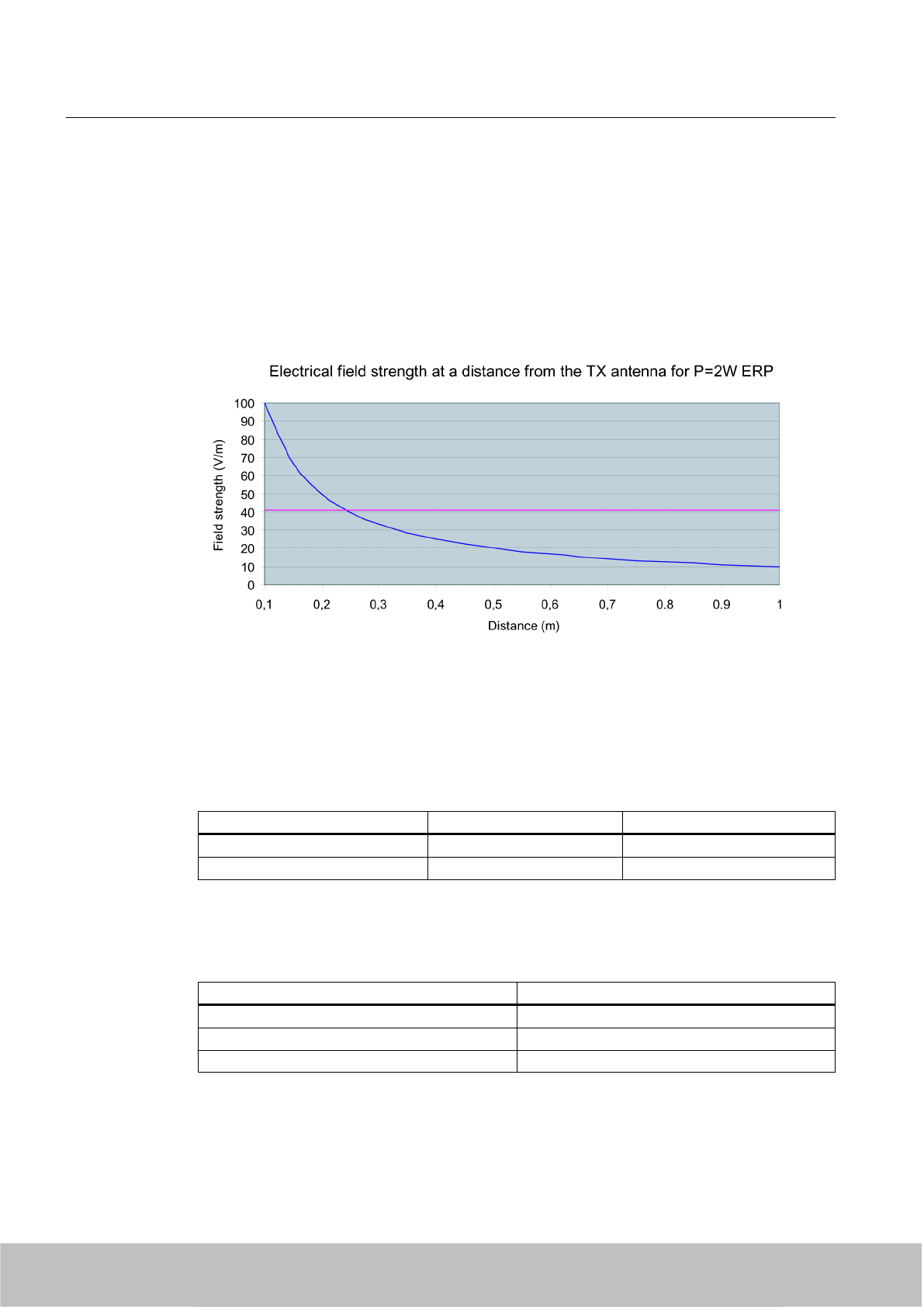
2.3.2 Minimum distance to antenna in accordance with ETSI
Minimum distance to antenna in accordance with ETSI (EU, EFTA, Turkey)
At a transmission frequency of 900 MHz, the wavelength of the electromagnetic wave λ is
approximately 0.34 m. For distances less than 1 λ in the near field, the electrical field strength
diminishes exponentially to the power three over distance, and for distances greater than 1 λ,
it diminishes exponentially to the power two over distance.
The horizontal line at 41.25V/m marks the "safety limit value".
For the maximum permisisble transmission power in accordance with ETSI (2W ERP), the
"safety distance" d = 0.24 m. This means that personnel should not remain closer than 24cm
to the transmitter antenna for extended periods (more than several hours without interruption).
Remaining within the vicinity of the antenna for a brief period, even for repeated periods (at a
distance < 0.24 m), is harmless according to current knowledge.
Distance to transmitter antenna [m] Feld strength [V/m] % of limit value
110 24
5 2 5
If the transmitter power is set lower than the highest permissible value (2 watts ERP), the
"safety distance" reduces correspondingly.
The values for this are as follows:
Radiated power ERP [W] Safety distance to transmitter antenna [m]
2,0 0,24
1,0 0,17
0,5 0,12
Safety Information
2.3 Safety distance to transmitter antenna
SIMATIC RF600
18 System Manual, 06/2010, J31069-D0171-U001-A10-7618
Draft Version 02.06.2010
Note
Reduced maximum radiated power with RF620R/RF630R readers
The SIMATIC RF620R (ETSI) reader has a maximum radiated power of 0.5 W ERP. The
maximum safety distance is therefore 0.12 m.
The SIMATIC RF630R (ETSI) reader has a maximum transmitter power of 0.5 W. The
radiated power therefore depends on the antenna cable and the type of antenna used, but
must not exceed the 2 W ERP.
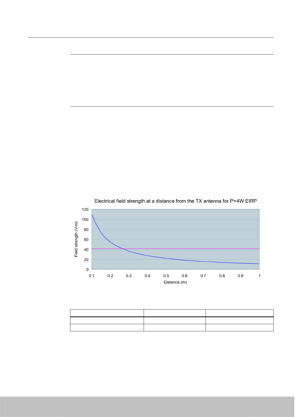
2.3.3 Minimum distance to antenna in accordance with FCC (USA)
Minimum distance to antenna in accordance with FCC (USA)
For the maximum permisisble transmission power in accordance with FCC (4W EIRP), the
"safety distance" d = 0.26 m. This means that personnel should not remain closer than 26cm
to the transmitter antenna for extended periods (more than several hours without interruption).
Remaining within the vicinity of the antenna for brief period, even repeated periods (at a
distance < 0.26 m) is harmless to health according to current knowledge.
The horizontal line at 41.25 V/m marks the "safety limit value".
Distance to transmitter antenna [m] Feld strength [V/m] % of limit value
110,9 26
5 2,2 5,3
If the transmitter power is set lower than the highest permissible value (4 watts ERP), the
"safety distance" reduces correspondingly.
The values for this are as follows:
Safety Information
2.3 Safety distance to transmitter antenna
SIMATIC RF600
System Manual, 06/2010, J31069-D0171-U001-A10-7618 19
Draft Version 02.06.2010

Radiated power ERP [W] Safety distance to transmitter antenna [m]
4,0 0,26
2,0 0,185
0,8 0.1xx
0,5 0,13
Note
Reduced maximum radiated power with RF620R/RF630R readers
The SIMATIC RF620R (FCC) reader has a maximum radiated power of 0.795 W EIRP. The
maximum safety distance is therefore 0.1xx m.
The SIMATIC RF630R (ETSI) reader has a maximum transmitter power of 0.5 W. The
radiated power therefore depends on the antenna cable and the type of antenna used, but
must not exceed the 4 W EIRP.
Safety Information
2.3 Safety distance to transmitter antenna
SIMATIC RF600
20 System Manual, 06/2010, J31069-D0171-U001-A10-7618
Draft Version 02.06.2010

System overview 3
3.1 RF System SIMATIC RF600
SIMATIC RF600 is an identification system that operates in the UHF range. UHF technology
supports large write/read distances with passive tags.
The SIMATIC RF670R reader and RF660R reader (write/read devices), fitted for example on
the gate of a warehouse, automatically record every movement of goods, and signal these to
the host systems. The data are filtered and compressed there by data management software
at the control level in order, for example, to generate the receiving department transaction for
the ERP (Enterprise Resource Planning) system at the business administration control level.
At the same time, the delivery can be automatically checked for correctness and completeness
prior to storage by means of the electronic delivery list.
The general automation and IT structure of a company is shown in the following figure. This
comprises several different levels that are described in detail below.
SIMATIC RF600
System Manual, 06/2010, J31069-D0171-U001-A10-7618 21
Draft Version 02.06.2010
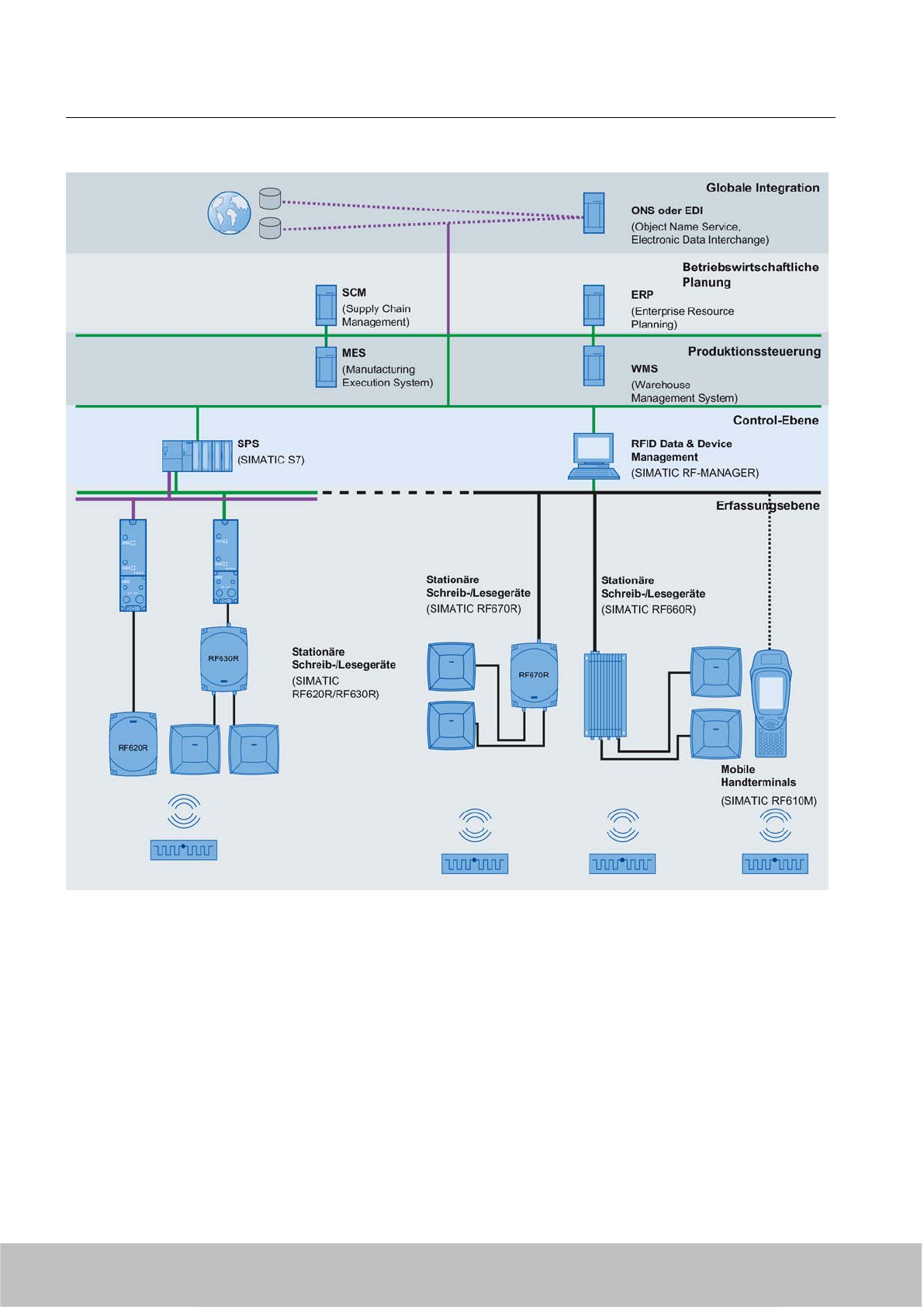
Figure 3-1 System overview of SIMATIC RF600
●Acquisition level
This level contains the RFID readers that read the appropriate tag data and transfer them
to the next highest level.
●Control level
At the control level , the RFID data are collected, preprocessed and presented to the
production control and business administration control levels for further processing.
System overview
3.1 RF System SIMATIC RF600
SIMATIC RF600
22 System Manual, 06/2010, J31069-D0171-U001-A10-7618
Draft Version 02.06.2010
●Production control
The Manufacturing Execution System (MES) closes the gap between the data that arise in
the automation environment (control level) and the logistical and commercial processes of
the company (business administration control). MES solutions are used, for example, for
defining and performing production processes.
●Business administration control
This level covers planning and control of the equipment used. For this purpose, Enterprise
Resource Planning (ERP) systems and Supply Chain Management (SCM) systems are
used with modules for cost accounting, financial bookkeeping and personnel management.
●Global integration
Product information can be exchanged here at an inter-company level. This can be
performed over the Internet with the help of special services.
3.1.1 Application areas of RF600
RFID (radio frequency identification) permits interruption-free tracking and documentation of
all delivered, stocked and shipped goods in the incoming goods, warehouse, production
logistics and distribution departments. A small data medium - referred to as SmartLabel,
transponder or tag - is attached to every item, package or pallet, and contains all important
information. The data medium receives the power it requires via an antenna which is also used
for data transmission.
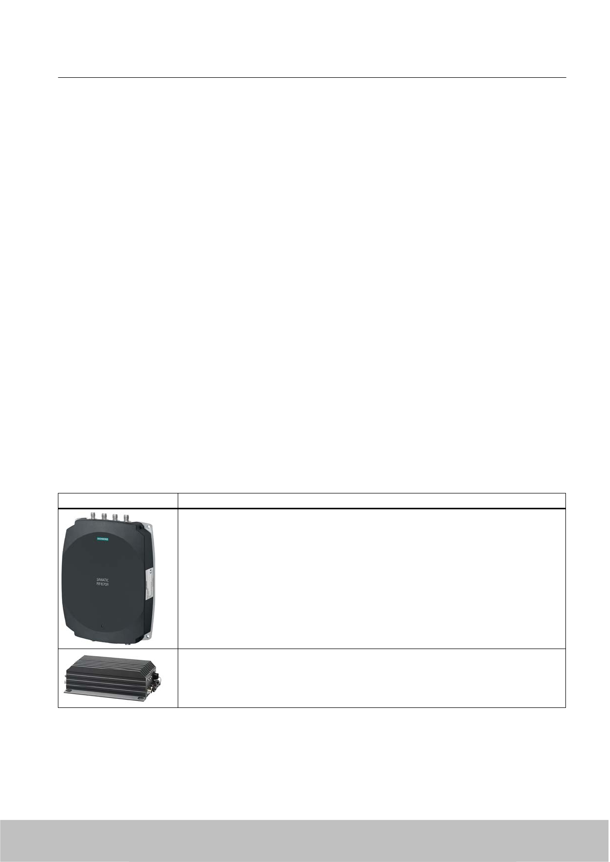
3.1.2 System components (hardware/software)
RF600 products Description
Due to its compact format and high degree of protection, the RF670R reader is ideally suited
to applications in production logistics and distribution. The integrated data processing makes
it easier to use in complex scenarios and reduces the IT integration costs. Integration is
performed using an XML protocol, TCP/IP and Ethernet.
Equipped with a rugged casing to the high IP 65 degree of protection and suitable for use over
a wide range of temperatures, the SIMATIC RF660R reader is also a match for the demands
of harsh industrial conditions in, for example, warehouses or on loading ramps.
System overview
3.1 RF System SIMATIC RF600
SIMATIC RF600
System Manual, 06/2010, J31069-D0171-U001-A10-7618 23
Draft Version 02.06.2010
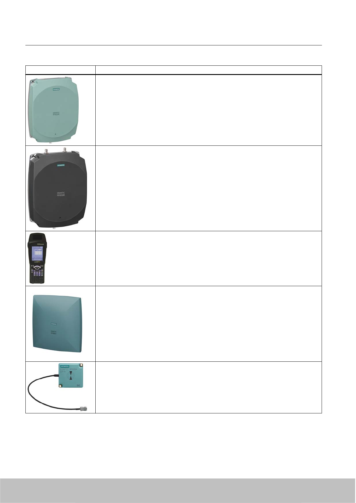
RF600 products Description
The RF620R reader creates with its connection to a SIMATIC controller optimum preconditions
for production-related application scenarios and/or production-related logistics applications by
RFID. It has an integrated circular polarized antenna.
.
The RF630R reader creates with its connection to a SIMATIC controller optimum preconditions
for production-related application scenarios and/or production-related logistics applications by
RFID. It has 2 connections for external antennas.
SIMATIC RF610M expands the RF600 RF identification system with a powerful mobile reader
for applications in the areas of logistics, production and service. In addition, it is an
indispensable aid for startup and testing.
Also the RF660A antennas are equipped for the harsh conditions in production and logistics
environments due to their high IP67 degree of protection.
Up to 4 antennas can be connected to the RF670R and RF660R readers depending on the
application and up to two can be connected to the RF630R reader.
The SIMATIC RF620A is an antenna of compact, industry-standard design. It is suitable for
UHF transponders with normal (far field) antenna characteristics.
System overview
3.1 RF System SIMATIC RF600
SIMATIC RF600
24 System Manual, 06/2010, J31069-D0171-U001-A10-7618
Draft Version 02.06.2010
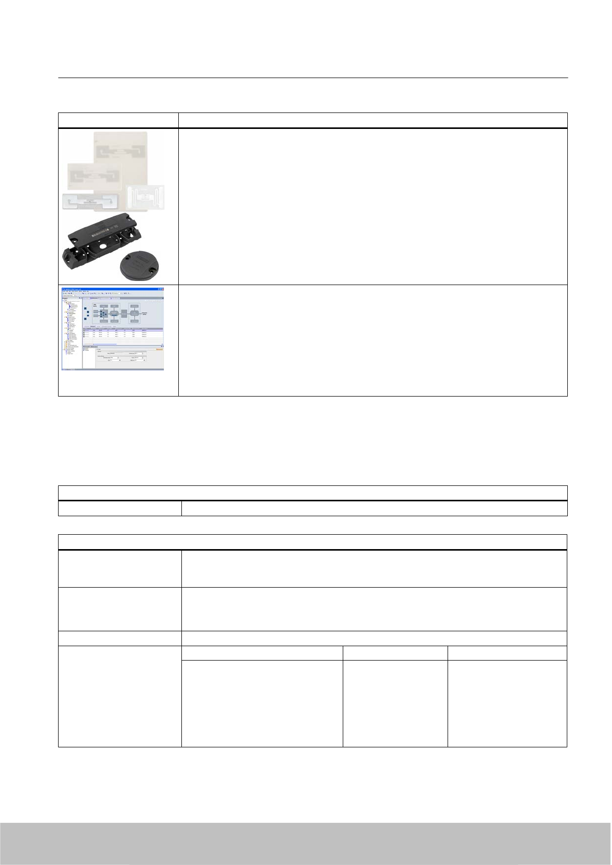
RF600 products Description
The RF600 tag family offers the right solution for every application:
The RF640T tool tag for industrial requirements is highly resistant to oils and can be directly
mounted on metal.
The RF620T container tag for industrial requirements is rugged and highly resistant to
detergents.
The RF630L Smart Labels made of plastic or paper can be used in many different applications:
The application areas range from simple identification such as electronic barcode replacement/
supplementation, through warehouse and distribution logistics, right up to product identification.
SIMATIC RF-MANAGER manages the connected RFID readers, collects the supplied data
and reduces them as required by the higher-level enterprise systems (e.g. MES/ERP).
The SIMATIC RF-MANAGER is used for configuring, commissioning and operating RFID
systems. It allows you to collect RFID data, to process it and to filter it. This data can be
exchanged with an S7 PLC by means of variables or transferred to a higher-level management
system.
The RF-MANAGER supports you with quick and easy creation of RFID solutions as well as
the administration of RFID systems and their hardware components. The application also offers
extensive help with the preprocessing of RFID data.
3.1.3 Features
The RF600 identification system has the following performance features:
RFID system RF600
Type Contactless RFID (Radio Frequency IDentification) system in the UHF band
RF670R reader
Transmission frequency 865-868 MHz (ETSI: EU; EFTA, Turkey)
902-928 MHz (FCC: USA)
920.125 - 924.875 MHz (FCC: CHINA)
Writing/reading range EU, EFTA, Turkey: < X m @@@
USA: < X m
China: < X m
Standards EPCglobal Class 1, Gen 2
Compatible data carriers Tags / Smart Labels Designation Standards supported
Smart Labels
ISO card
Container tag
Powertrain tag
Tool tag
Heat-resistant tag
RF630L
RF610T
RF620T
RF630T
RF640T (Gen 2)
RF680T
EPCglobal Class 1, Gen 2
EPCglobal Class 1, Gen 2
EPCglobal Class 1, Gen 2
EPCglobal Class 1, Gen 2
EPCglobal Class 1, Gen 2
EPCglobal Class 1, Gen 2
System overview
3.1 RF System SIMATIC RF600
SIMATIC RF600
System Manual, 06/2010, J31069-D0171-U001-A10-7618 25
Draft Version 02.06.2010

RF660R reader
Transmission frequency 865-868 MHz (ETSI: EU; EFTA, Turkey)
869.5 MHz (ETSI SRD: EU, EFTA, Turkey)1)
902-928 MHz (FCC: USA)
920.125 - 924.875 MHz (FCC: CHINA)
Writing/reading range EU, EFTA, Turkey: < 3.5 m
USA: < 4 m
China: < 4 m
Standards EPCglobal Class 1, Gen 1
EPCglobal Class 1, Gen 2
ISO 18000-6B
Compatible data carriers Tags / Smart Labels Designation Standards supported
Smart Labels
ISO card
Container tag
Powertrain tag
Tool tag
Tool tag
Heat-resistant tag
RF620L
RF630L
RF610T
RF620T
RF630T
RF640T
RF640T (Gen 2)
RF680T
ISO 18000-6B,
EPCglobal Class 1, Gen 2
EPCglobal Class 1, Gen 2
EPCglobal Class 1, Gen 2
EPCglobal Class 1, Gen 2
ISO 18000-6B
EPCglobal Class 1, Gen 2
EPCglobal Class 1, Gen 2
1) ETSI SRD not supported by Firmware V1.3 upwards
RF620R reader
Transmission frequency 865-868 MHz (EU, EFTA, Turkey)
902-928 MHz (USA)
920.125 - 924.875 MHz (CHINA)
Writing/reading range EU, EFTA, Turkey: 0.1 - 2 m
USA: 0.1 - 2 m
CHINA: 0.1 - 2 m
Standards EPCglobal Class 1, Gen 2
Compatible data carriers Tags / Smart Labels Designation Standards supported
Smart Labels
ISO card
Container tag
Powertrain tag
Tool tag
Heat-resistant tag
RF630L
RF610T
RF620T
RF630T
RF640T (Gen 2)
RF680T
EPCglobal Class 1, Gen 2
EPCglobal Class 1, Gen 2
EPCglobal Class 1, Gen 2
EPCglobal Class 1, Gen 2
EPCglobal Class 1, Gen 2
EPCglobal Class 1, Gen 2
RF630R reader
Transmission frequency 865-868 MHz (EU, EFTA, Turkey)
902-928 MHz (USA)
920.125 - 924.875 MHz (CHINA)
Writing/reading range EU, EFTA, Turkey: 0.1 - 2 m
USA: 0.1 - 2 m
CHINA: 0.1 - 2 m
System overview
3.1 RF System SIMATIC RF600
SIMATIC RF600
26 System Manual, 06/2010, J31069-D0171-U001-A10-7618
Draft Version 02.06.2010
RF630R reader
Standards EPCglobal Class 1, Gen 2
Compatible data carriers Tags / Smart Labels Designation Standards supported
Smart Labels
ISO card
Container tag
Powertrain tag
Tool tag
Heat-resistant tag
RF630L
RF610T
RF620T
RF630T
RF640T (Gen 2)
RF680T
EPCglobal Class 1, Gen 2
EPCglobal Class 1, Gen 2
EPCglobal Class 1, Gen 2
EPCglobal Class 1, Gen 2
EPCglobal Class 1, Gen 2
EPCglobal Class 1, Gen 2
RF610M mobile handheld terminal
Transmission frequency 869.5 MHz (Europe SRD)
912.5-917.4 MHz (USA)
Writing/reading range Europe < 0.75 m
USA < 1 m
Standards EPCglobal Class 1, Gen 2
ISO 18000-6B
Compatible data carriers Tags / Smart Labels Designation Standards supported
Smart Labels
ISO card
Container tag
Powertrain tag
Tool tag
Tool tag
Heat-resistant tag
RF620L
RF630L
RF610T
RF620T
RF630T
RF640T
RF640T (Gen 2)
RF680T
ISO 18000-6B,
EPCglobal Class 1, Gen 2
EPCglobal Class 1, Gen 2
EPCglobal Class 1, Gen 2
EPCglobal Class 1, Gen 2
ISO 18000-6B
EPCglobal Class 1, Gen 2
EPCglobal Class 1, Gen 2
Data carrier/tags
Version Tags / Smart Labels Designation Standards supported
Smart Labels
ISO card
Container tag
Powertrain tag
Tool tag
Tool tag
Heat-resistant tag
RF620L
RF630L
RF610T
RF620T
RF630T
RF640T
RF640T (Gen 2)
RF680T
ISO 18000-6B,
EPCglobal Class 1, Gen 2
EPCglobal Class 1, Gen 2
EPCglobal Class 1, Gen 2
EPCglobal Class 1, Gen 2
ISO 18000-6B
EPCglobal Class 1, Gen 2
EPCglobal Class 1, Gen 2
Standards EPCglobal Class 1, Gen 1
EPCglobal Class 1, Gen 2
ISO 18000-6B
System overview
3.1 RF System SIMATIC RF600
SIMATIC RF600
System Manual, 06/2010, J31069-D0171-U001-A10-7618 27
Draft Version 02.06.2010

Software
RF-MANAGER 2008 PC software for
●System-wide configuration of readers
– RF670R
– RF660R
–RF630R
– RF620R
– RF610M
● Management and configuration of the connected readers
● Preprocessing and evaluation of the RFID data
● Interfacing to the higher-level enterprise system
● Connection to SIMATIC S7 controller
System requirements:
Windows XP / SP2 and higher
RF-MANAGER Basic 2010 PC software for parameterizing the RF670R reader
System requirement:
Windows XP, SP2 and higher
RF660R configuration
software
PC software for parameterizing the RF660R reader
System requirements:
Windows XP / SP1 or SP2
System overview
3.1 RF System SIMATIC RF600
SIMATIC RF600
28 System Manual, 06/2010, J31069-D0171-U001-A10-7618
Draft Version 02.06.2010

RF600 system planning 4
4.1 Overview
You should observe the following criteria for implementation planning:
● Possible system configurations
● Antenna configurations
● Environmental conditions for transponders
●The response of electromagnetic waves in the UHF band
● Regulations applicable to frequency bands
● EMC Directives
4.2 Possible system configurations
The SIMATIC RF600 system is characterized by a high level of standardization of its
components. This means that the system follows the TIA principle throughout: Totally
Integrated Automation. It provides maximum transparency at all levels with its reduced
interface overhead. This ensures optimum interaction between all system components.
The RF600 system with its flexible components offers many possibilities for system
configuration. This chapter shows you how you can use the RF600 components on the basis
of various example scenarios.
4.2.1 Scenario for incoming goods
This example scenario shows the incoming goods bay of a warehouse. Pallets of goods are
delivered through the incoming goods portal of a warehouse. Each pallet is equipped with a
SIMATIC RF600
System Manual, 06/2010, J31069-D0171-U001-A10-7618 29
Draft Version 02.06.2010
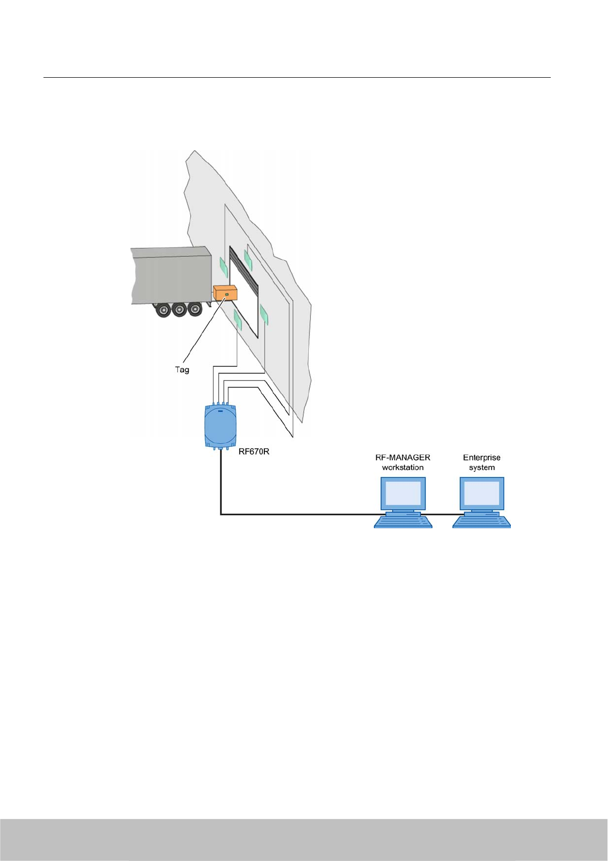
tag. The tags contain user data that provide information about the sender and receiver of the
goods. These data are read out and routed on.
Figure 4-1 Incoming goods bay
Features of the scenario
In this example, the maximum number of 4 antennas of the SIMATIC°RF660A type are
connected to the SIMATIC°RF670R reader. The four antennas are aligned with one read point
and therefore form a portal that is to be monitored. The reading ranges depend on the size of
the portal as well as the density of readers.
The tags in this scenario are Smart Labels of type SIMATIC°RF630L. They are usually attached
to a non-metallic base such as wooden crates or cartons, in which the goods are packed. The
tags can be mounted in almost any position on the packaging or pallet.
The tags are read with the "Bulk reading" procedure in the incoming goods bay, i.e. a large
number of items and many tags can be acquired at once. High read rates can be achieved in
this manner.
RF600 system planning
4.2 Possible system configurations
SIMATIC RF600
30 System Manual, 06/2010, J31069-D0171-U001-A10-7618
Draft Version 02.06.2010
The SIMATIC RF670R reader is connected to an RF‑MANAGER workstation that is connected,
in turn, to an enterprise system through an ALE interface. The tag data can be managed by
means of the enterprise system.
Summary of the features
Note
Note that the following features show sample values for the scenario. The specific data for
your application may deviate from these values.
Feature
Single-tag No
Multi-tag Yes
Read velocity 2 m/s
Tag orientation Not defined
Material characteristics Non-metal
Reading ranges Approx. 3.5°m
Reader density High
Interference High
4.2.2 Scenario for material handling control
This scenario shows a possible solution for monitoring and controlling the infeed of material
to a production line. The objective is to provide the right material at the right time. This can be
RF600 system planning
4.2 Possible system configurations
SIMATIC RF600
System Manual, 06/2010, J31069-D0171-U001-A10-7618 31
Draft Version 02.06.2010
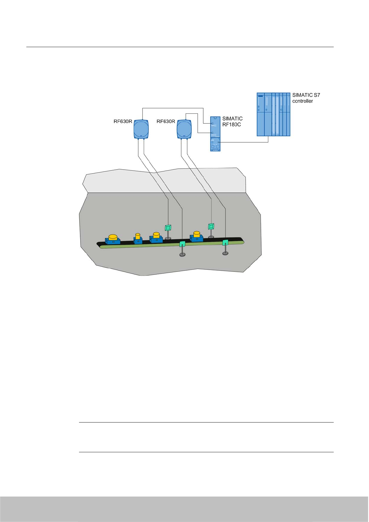
particularly useful in plants with frequently changing manufacturing scenarios for ensuring that
incorrect infeed and downtimes are minimized.
Features of the scenario
The conveyor moves different transport containers past the readers in an arbitrary alignment.
The RFID tag is, however, always applied to the transport containers with the same alignment.
The tags in this scenario are transponders of type SIMATIC RF620T.
The conveyor has a maximum width of 80 cm in this example. The transport velocity is up to
2 m/s. With this arrangement only a single RFID tag has to be detected each time (single-tag).
In this scenario a SIMATIC RF630R is used as the reader. Optimum reading reliability is
ensured by two external SIMATIC RF660A antennas in a portal arrangement. Where the
distances to, or between, the materials containers are extremely short the SIMATIC RF620A
is an excellent alternative. The SIMATIC°RF630R reader reads the information from the tags
on the transport containers and transfers it via a communication module to the SIMATIC S7
controller which controls the process in accordance with the tag information.
Summary of the features
Note
Note that the following features show sample values for the scenario. The specific data for
your application may deviate from these values.
RF600 system planning
4.2 Possible system configurations
SIMATIC RF600
32 System Manual, 06/2010, J31069-D0171-U001-A10-7618
Draft Version 02.06.2010
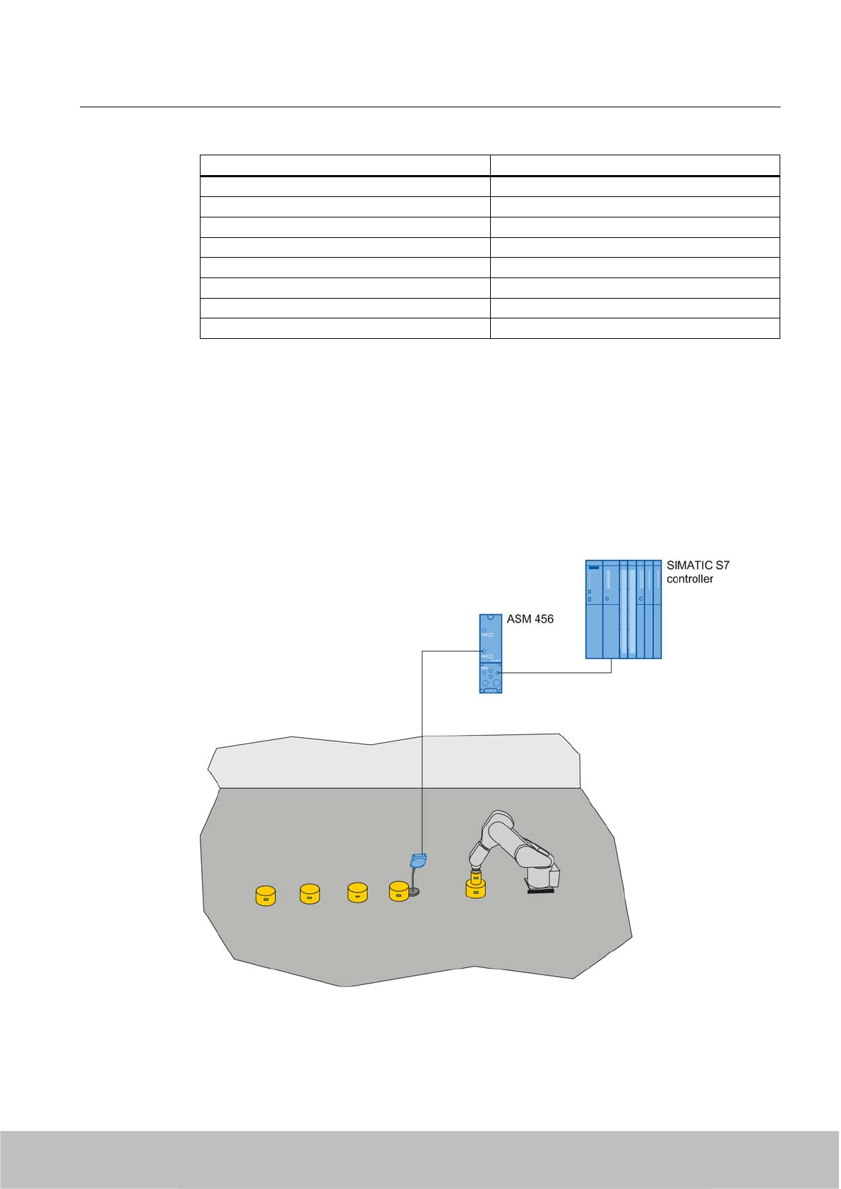
Feature
Single-tag Yes
Multi-tag No
Read velocity Max. 2 m/s
Orientation of the RFID tag Not defined
Carrier material of the tag Metal or non-metal
Reading range Approx. 1 m
Reader density High
Interference High
4.2.3 Scenario for workpiece identification
A typical characteristic of modern manufacturing scenarios is their multitude of variations. The
individual data and production steps are stored in the tag of a toolholder or product. These
data are read by the machining stations during a production process and, if necessary, tagged
with status information. This can be used to dynamically identify which production step is the
next in the series. This has the advantage that the production line can work automatically
without the need to access higher system components. The use of RFID therefore increases
the availability of the plant.
RF600 system planning
4.2 Possible system configurations
SIMATIC RF600
System Manual, 06/2010, J31069-D0171-U001-A10-7618 33
Draft Version 02.06.2010
Features of the scenario
RFID tags are attached to workpiece holders. Their spatial orientation is always identical. With
this arrangement, only a single tag has to be detected each time (single-tag). The tags in this
scenario are transponders of type SIMATIC RF640T.
The SIMATIC RF620R reader reads the information from the tags with its integrated antenna
and transfers it to the SIMATIC S7 controller via a communication module. Depending on the
stored tag information, the SIMATIC-S7 performs different control tasks, for example,
automatically providing a suitable tool for an industrial robot at the correct time.
Summary of the features
Note
Note that the following features show sample values for the scenario. The specific data for
your application may deviate from these values.
Features
Single-tag Yes
Multi-tag No
Reading velocity Not applicable
Orientation of the RFID tag Same alignment for all the tags
Carrier material of the tag Metal
Reading distance Approx. 1 m
Reader density High
Interference High
4.2.4 Scenario for Intra logistics
Intra logistics comprises all logistical procedures that are required on a production site as well
as within the overall company. The main task of Intra logistics is to control the subsequent
processes:
● Transporting goods from the incoming goods bay into the warehouse
● Management of stock
● Conveyance of goods from the warehouse for production
RF600 system planning
4.2 Possible system configurations
SIMATIC RF600
34 System Manual, 06/2010, J31069-D0171-U001-A10-7618
Draft Version 02.06.2010
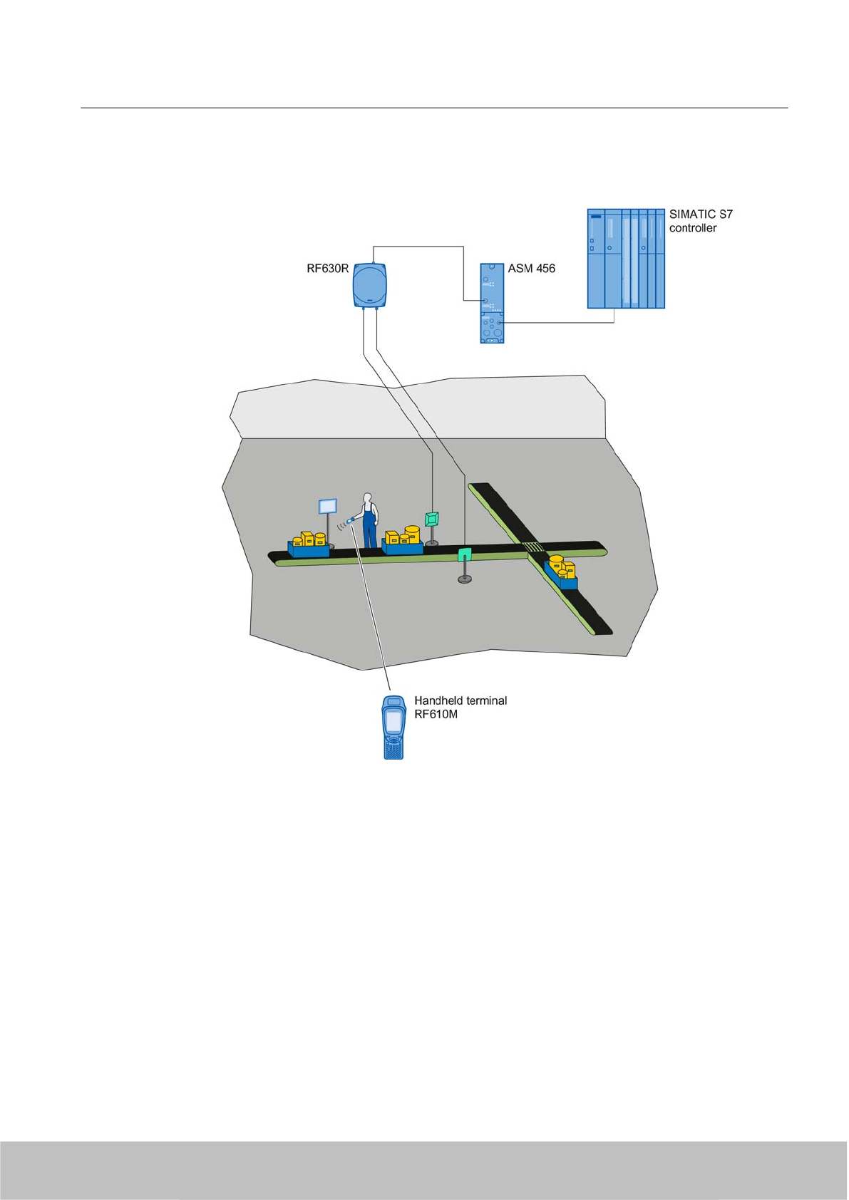
● Order picking
● Packing
Features of the scenario
In this example scenario. items must be distributed to the correct storage location in a transport
container via a separating filter. The RFID tags of type SIMATIC RF630L are directly attached
to the item. The maximum transport velocity of the conveyor is 2 m/s.
In this scenario, bulk acquisition is necessary because several objects must be detected at
the same time.
The SIMATIC RF630R reader uses two external antennas in a portal arrangement to read the
information from the tags on the passing items and transfers it to the SIMATIC S7 controller
via a communication module. The SIMATIC S7 controls the separating filter of the conveyor
system depending on the tag information.
If only one simple evaluation of the tag ID is required, and the data will not undergo further
processing, the SIMATIC RF670R offers this function without interfacing to the controller.
RF600 system planning
4.2 Possible system configurations
SIMATIC RF600
System Manual, 06/2010, J31069-D0171-U001-A10-7618 35
Draft Version 02.06.2010
The SIMATIC RF610M mobile handheld terminal is used in this example for additional analysis
and visualization of the item data directly on-site. The mobile handheld terminal can transfer
the data to SIMATIC RF-MANAGER over the WLAN, and this then controls the separating
filter via the SIMATIC S7 controller.
Summary of the features
Note
Note that the following features show sample values for the scenario. The specific data for
your application may deviate from these values.
Features
Single-tag Yes
Multi-tag No
Reading velocity Max. 2 m/s
Orientation of the RFID tag Same alignment for all the tags
Carrier material of the tag Metal
Reading range Approx. 1 m
Reader density High
Interference High
4.2.5 Scenario for outgoing goods
This example scenario shows the outgoing goods area of a warehouse with two loading gates.
Pallets are dispatched through the outgoing goods portals - each pallet is marked with a tag.
These tags also contain user data that provide information about the sender and receiver of
the goods. The data read by the readers are checked to ensure that the pallets are waiting at
RF600 system planning
4.2 Possible system configurations
SIMATIC RF600
36 System Manual, 06/2010, J31069-D0171-U001-A10-7618
Draft Version 02.06.2010
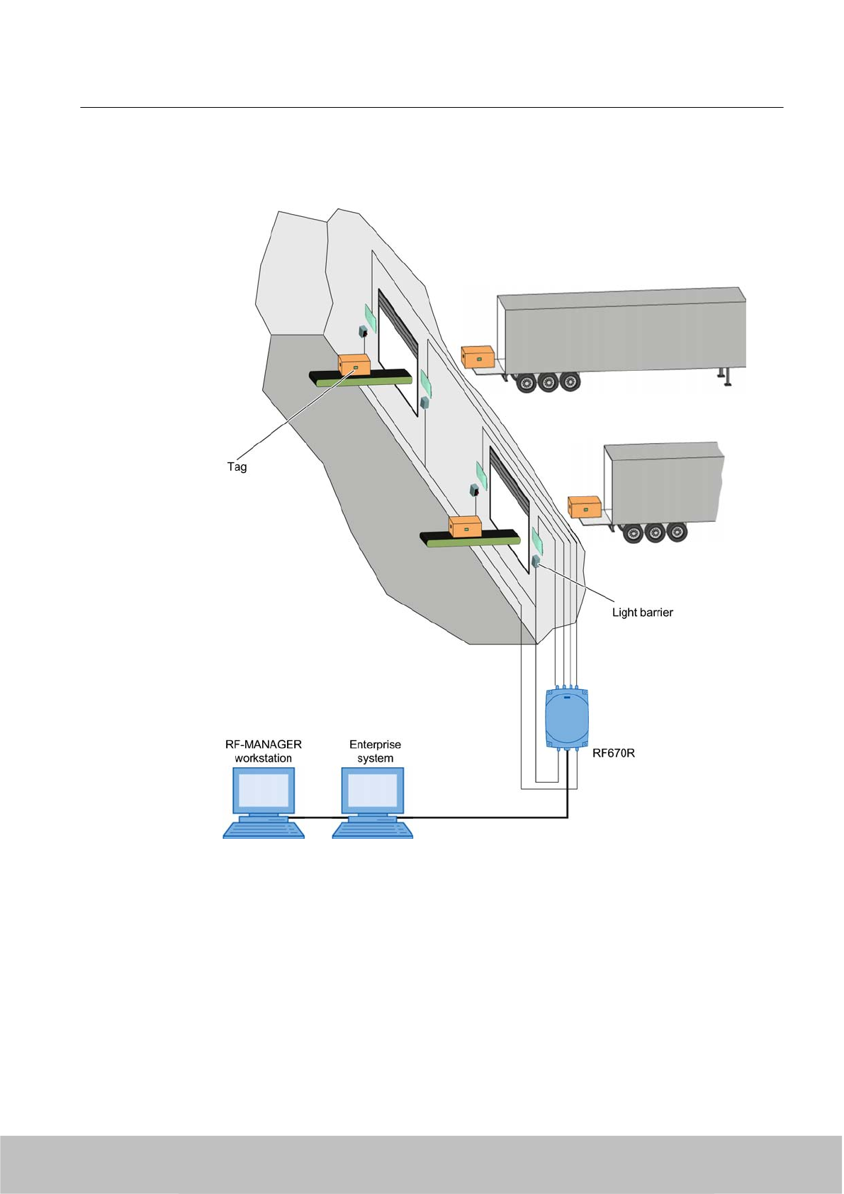
the correct outgoing goods portal. Depending on the read results of the reader, the outgoing
portal opens, or it remains closed.
Figure 4-2 Outgoing goods
In this example, the maximum number of 4 antennas of the SIMATIC°RF660A type are
connected to the SIMATIC°RF670R reader. The four antennas form two different read points
and therefore monitor two loading gates. The reading ranges depend on the size of the portal
as well as the density of readers.
The tags in this scenario are Smart Labels of type SIMATIC°RF630L. They are usually attached
to a non-metallic base such as wooden crates or cartons, in which the goods are packed. The
tags can be mounted in almost any position on the packaging or pallet.
RF600 system planning
4.2 Possible system configurations
SIMATIC RF600
System Manual, 06/2010, J31069-D0171-U001-A10-7618 37
Draft Version 02.06.2010
The tags are read with the "bulk reading" procedure at the outgoing goods gates, i.e. a large
number of items and many tags can be acquired at once. High read rates can be achieved in
this manner.
The SIMATIC RF670R reader is connected to an RF‑MANAGER workstation that is connected,
in turn, to an enterprise system through an ALE interface. The tag data can be managed by
means of the enterprise system.
Summary of the features
Note
Note that the following features show sample values for the scenario. The specific data for
your application may deviate from these values.
Feature
Single-tag No
Multi-tag Yes
Read velocity 2 m/s
Tag orientation Not defined
Material characteristics Non-metal
Reading ranges Approx. 3.5°m
Reader density High
Interference High
4.3 Antenna configurations
Note
Validity of antenna configuration
The following specifications for the antenna configuration only apply to the RF660A antenna.
See Section Guidelines for selecting RFID UHF antennas (Page 181) for specifications for
the configuration of third-party antennas.
4.3.1 Antenna configuration example
The following diagram shows an application example for an antenna configuration of the
RF670R. The antennas are positioned at the height at which the tags are expected which are
to be identified. The maximum width of the portal that is recommended for reliable operation
is 4 m.
RF600 system planning
4.3 Antenna configurations
SIMATIC RF600
38 System Manual, 06/2010, J31069-D0171-U001-A10-7618
Draft Version 02.06.2010
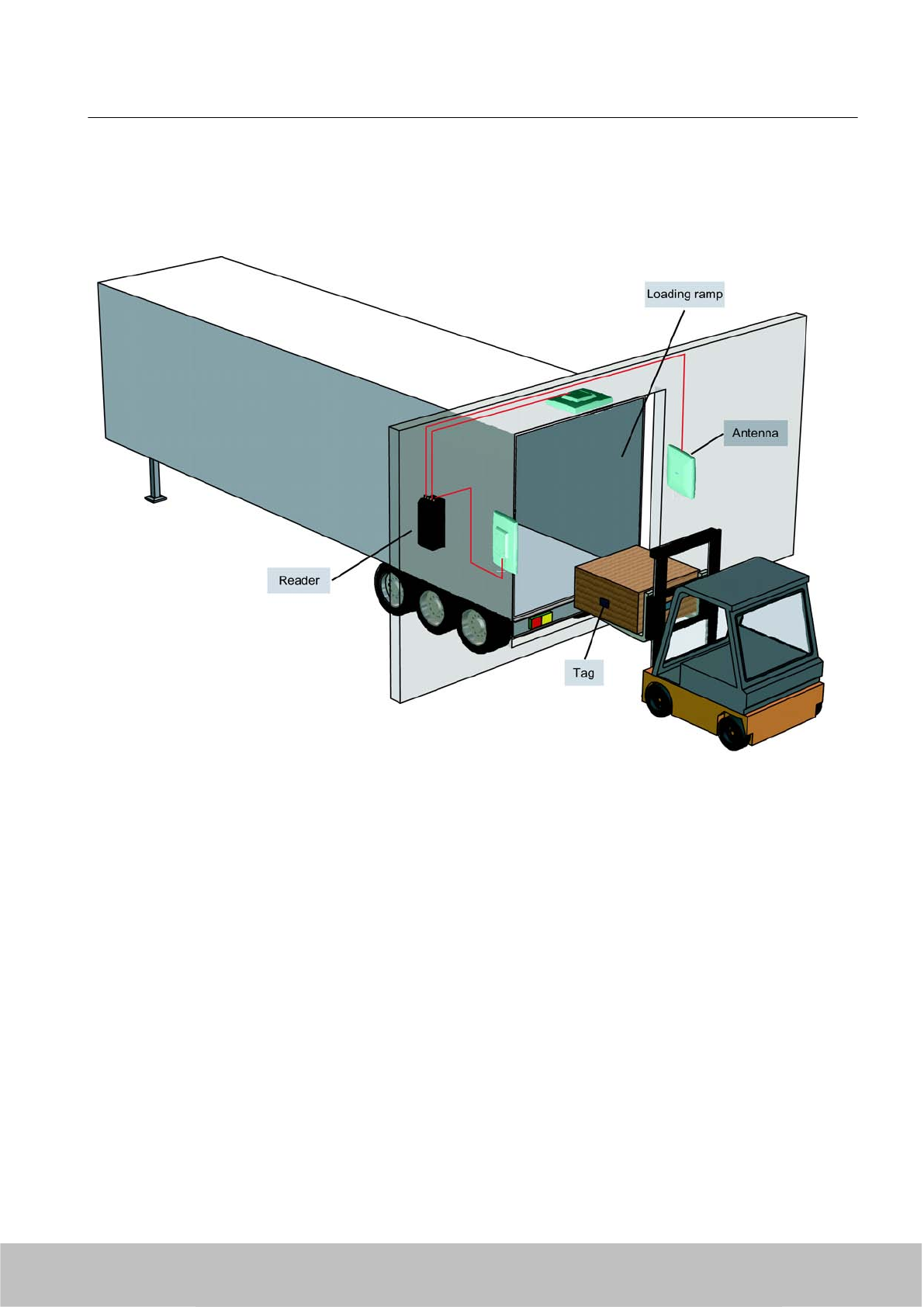
The diagram shows a configuration with three antennas. Up to four antennas can be used
depending on the local conditions.
Figure 4-3 Example of an antenna configuration with three antennas. @@ Grafik wird auf RF670R geändert
4.3.2 Possibilities and application areas for antenna configurations
Some basic antenna configurations and possible fields of application are shown below. Please
note for the possible configurations, that up to four external antennas can be connected to the
RF670R and RF660R readers and up to two external antennas can be connected to the
RF600 system planning
4.3 Antenna configurations
SIMATIC RF600
System Manual, 06/2010, J31069-D0171-U001-A10-7618 39
Draft Version 02.06.2010
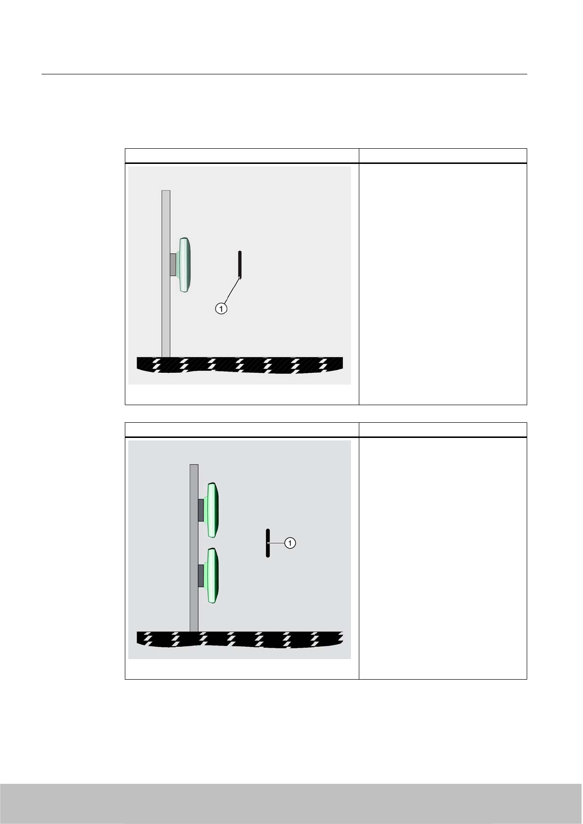
RF630R reader. No external antennas can be connected to the RF620R reader. It has an
integrated antenna.
Antenna configuration 1: Description/ application areas
This arrangement of antennas is
appropriate when the tags to be read are
only located on one side of the goods to
be acquired, for example, if a conveyor
with passing goods has to be monitored
during production and it is precisely
defined on which side the tags to be read
are attached.
① Tag
This antenna configuration is possible
with the following readers:
● RF670R with one antenna
● RF630R with one antenna
● RF620R
Antenna configuration 2: Description/ application areas
This arrangement of antennas is
appropriate when the tags to be read are
only located on one side of the items to
be identified, e.g. when pallets are to be
identified on which the tags to be read
must be on a prespecified side.
① Tag
This antenna configuration is possible
with the following readers:
● RF670R with two antennas
● RF660R with two antennas
● RF630R with two antennas
RF600 system planning
4.3 Antenna configurations
SIMATIC RF600
40 System Manual, 06/2010, J31069-D0171-U001-A10-7618
Draft Version 02.06.2010
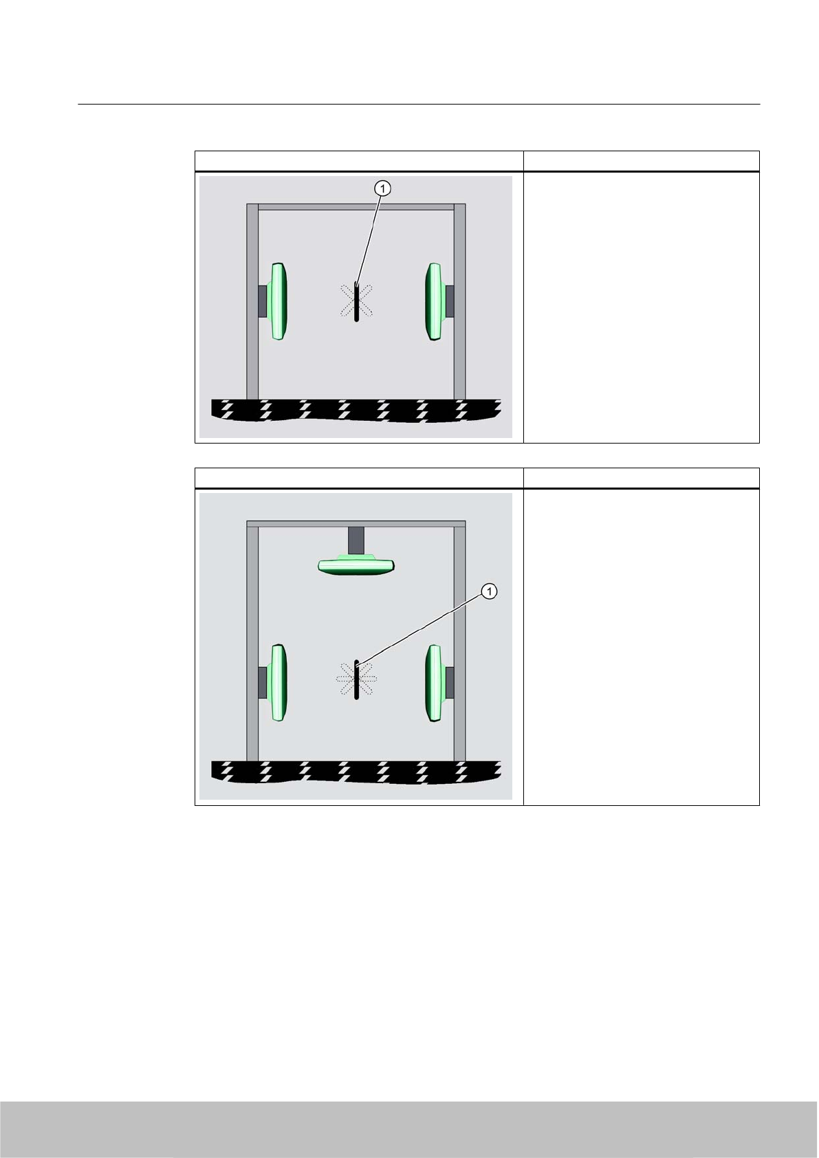
Antenna configuration 3: Description/ application areas
Preferred for the identification of goods at
loading portals: The tag is located in the
field of radiation of two antennas; for
reliable tag reading, the height of the tag
above floor level must therefore be known
with reasonable accuracy.
① Tag
This antenna configuration is possible
with the following readers:
● RF670R with two antennas
● RF660R with two antennas
● RF630R with two antennas
Antenna configuration 4: Description/ application areas
Preferred for the identification of goods at
loading portals: Similar to configuration 2,
but with additional reading reliability when
the tag is at an angle to the vertical.
① Tag
This antenna configuration is possible
with the following readers:
● RF670R with three antennas
● RF660R with three antennas
RF600 system planning
4.3 Antenna configurations
SIMATIC RF600
System Manual, 06/2010, J31069-D0171-U001-A10-7618 41
Draft Version 02.06.2010
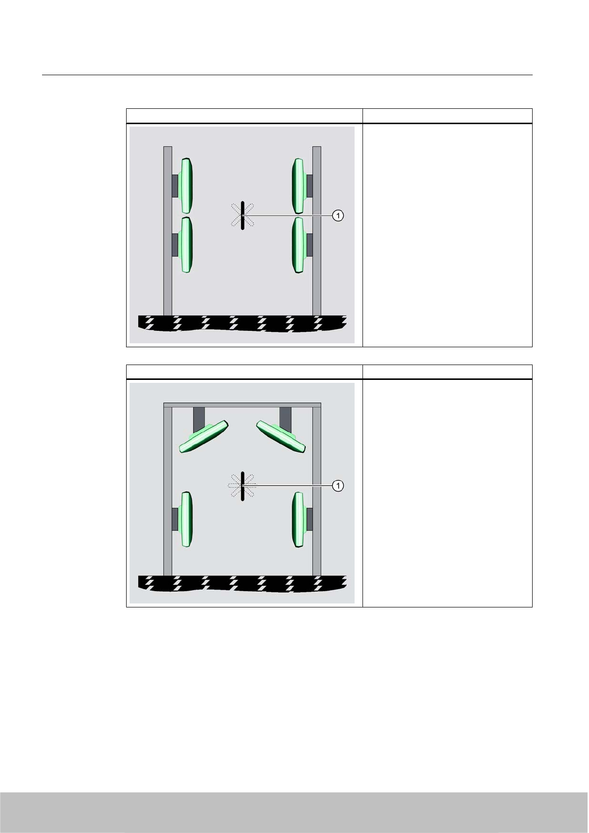
Antenna configuration 5: Description/ application areas
Preferred for the identification of goods at
loading portals: The tag is located in the
field of radiation of all four antennas, so
the tag position can vary more than in
configuration 2 for reliable tag
identification.
① Tag
This antenna configuration is possible
with the following readers:
● RF670R with four antennas
● RF660R with four antennas
Antenna configuration 6: Description/ application areas
Preferred for the identification of goods at
loading portals: Similar to configuration 4,
but the reliability of tag identification is
improved as a result of the four antennas
at separate locations, so the tag position
is not critical.
① Tag
This antenna configuration is possible
with the following readers:
● RF670R with four antennas
● RF660R with four antennas
RF600 system planning
4.3 Antenna configurations
SIMATIC RF600
42 System Manual, 06/2010, J31069-D0171-U001-A10-7618
Draft Version 02.06.2010
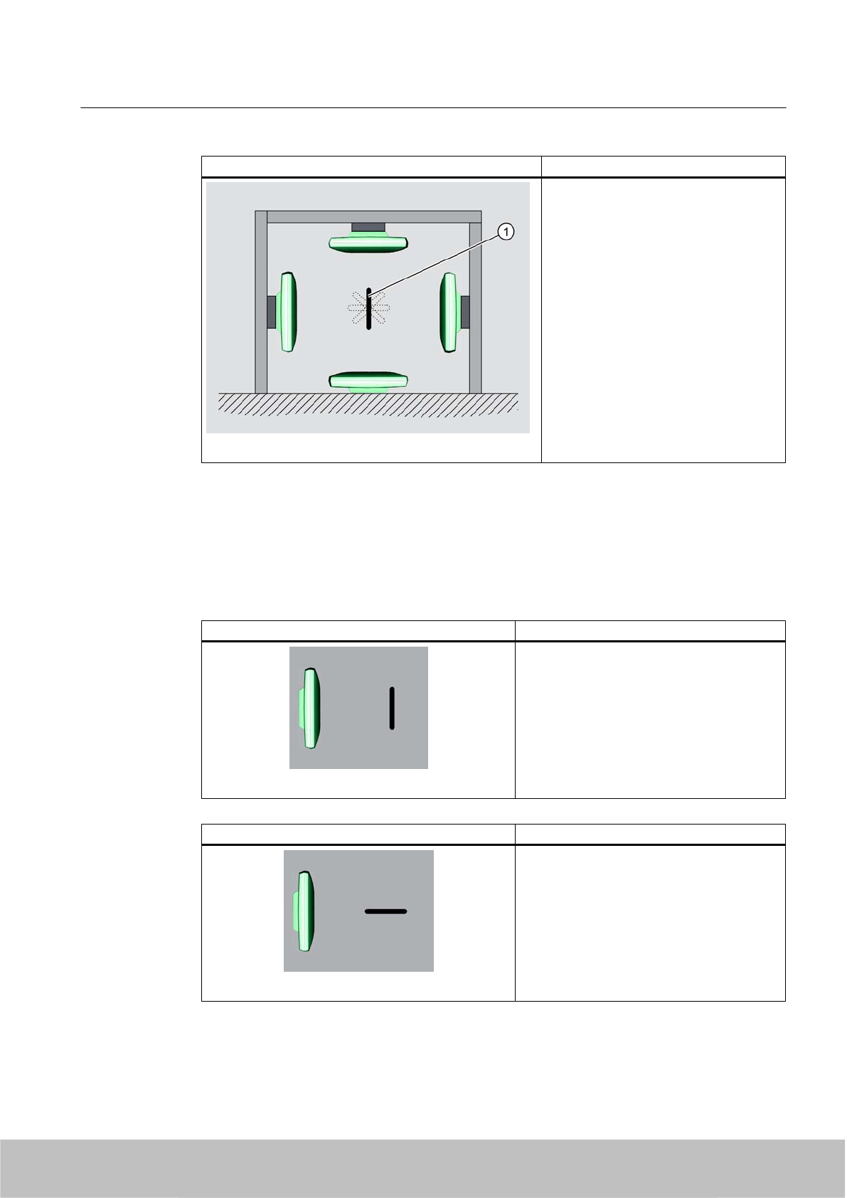
Antenna configuration 7: Description/ application areas
This tunnel configuration is suitable for
conveyor belt applications. The goods
with the tags to be read are moving
forwards on a conveyor belt but the
alignment of the tags relative to the
antennas is not clearly defined. One of the
antenna is located on the floor and
radiates vertically upwards in the
direction of the conveyor belt. A relatively
high reading reliability is achieved due to
the use of four antennas.
① Tag
This antenna configuration is possible
with the following readers:
● RF670R with four antennas
● RF660R with four antennas
4.3.3 Tag orientation in space
The alignment of the tag antenna to the antenna of the reader affects the reading range. For
maximum performance and to achieve the maximum reading range, the tag antenna should
therefore be aligned in parallel with the reader antenna:
Parallel tag alignment Large reading range
Maximum probability of identification of tags.
Vertical tag alignment Minimal reading range
Minimum probability of identification of tags.
RF600 system planning
4.3 Antenna configurations
SIMATIC RF600
System Manual, 06/2010, J31069-D0171-U001-A10-7618 43
Draft Version 02.06.2010
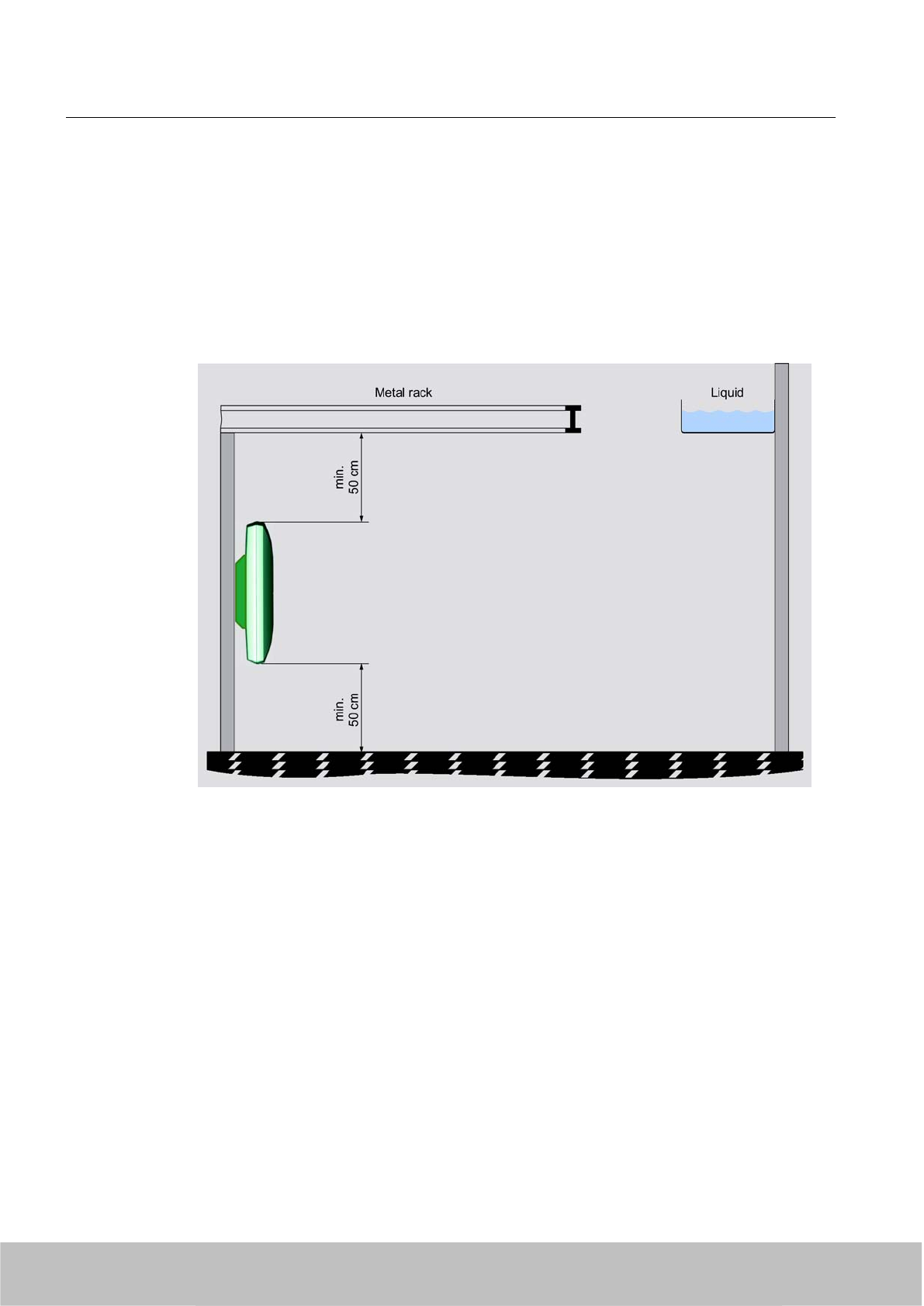
4.3.4 Specified minimum and maximum spacing of antennas
Specified minimum spacing of antennas
The following diagram shows the specified minimum and maximum spacings for mounting
antennas:
A minimum spacing of 50 cm is necessary between the antenna and liquids or metals.
The distance between the antenna and the floor should also be at least 50 cm.
Figure 4-4 Minimum distance to the environment
The distance between two antennas mounted alongside each other or one above the other
should be at least 20 cm, but a distance of more than 50 cm is better.
RF600 system planning
4.3 Antenna configurations
SIMATIC RF600
44 System Manual, 06/2010, J31069-D0171-U001-A10-7618
Draft Version 02.06.2010
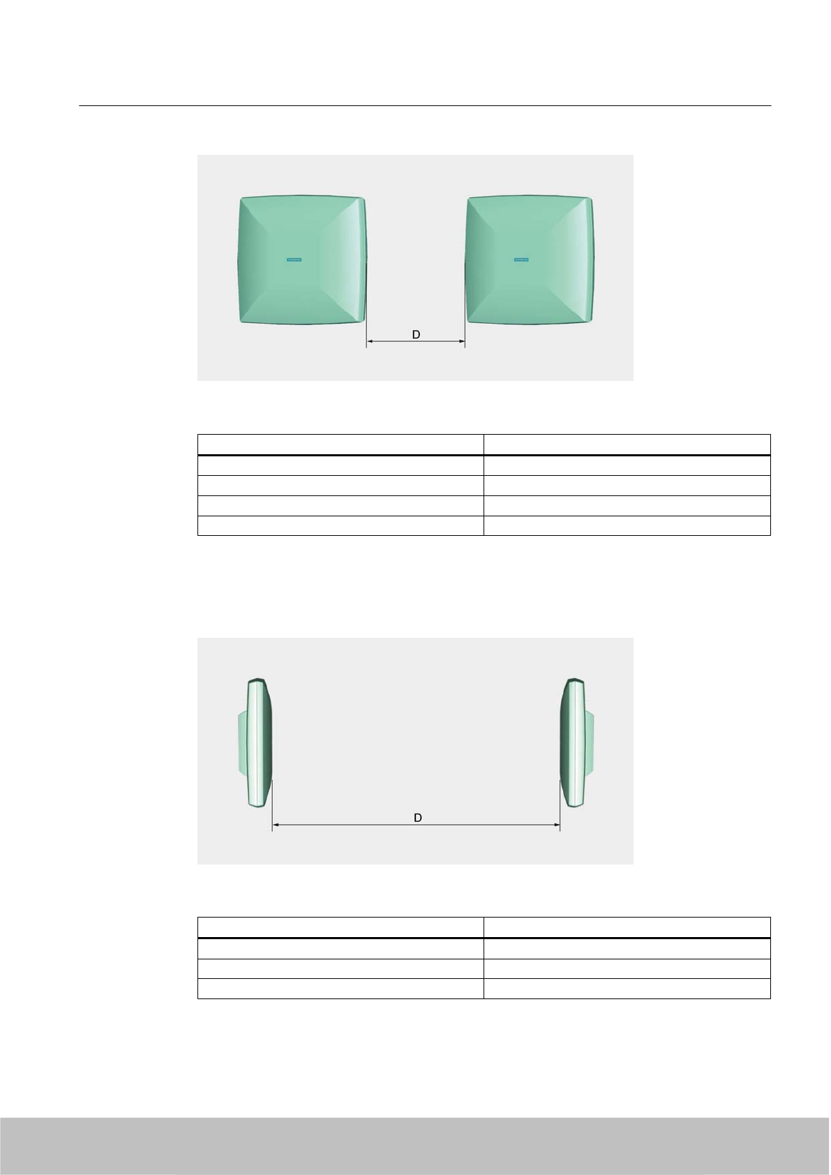
Figure 4-5 Antennas mounted adjacently horizontally or vertically
Readers Minimum spacing D
RF670R with RF660A 20-50 cm
RF660R with RF660A 20-50 cm
RF630R with RF660A 20-50 cm
RF620R 3 m
The minimum distance between antennas mounted alongside each other or one above the
other depends on the transmit power of the reader and the sensing range of the tags.
For a portal configuration, the maximum distance between two antennas that are connected
to the same reader is 8 m.
Figure 4-6 Portal configuration, maximum distance
Readers Maximum distance D
RF670R with RF660A 8 m *
RF660R with RF660A 8 m*
RF630R with RF660A 4 m
*) A portal spacing of up to 10 m is possible. The probability of a read must be checked.
RF600 system planning
4.3 Antenna configurations
SIMATIC RF600
System Manual, 06/2010, J31069-D0171-U001-A10-7618 45
Draft Version 02.06.2010

The specified distances are recommended minimum or maximum values for configuration.
4.3.5 Mutual interference of readers (antennas)
Using more than one reader
When several RFID readers are used, there is a danger that RFID tags can also be read by
other readers. It must be ensured that the tag can only be identified by the appropriate reader.
Technical faults between readers then occur particularly when they transmit on the same
channel (on the same frequency).
To prevent this, readers used in Europe and China must operate on different channels with
"Frequency hopping" activated. "Frequency hopping" is permanently set in the USA.
4.3.6 Reading range
The reading range between the reader (antenna) and the transponder is affected by the
following factors:
The reading range depends on Description
Transmit power of the reader The higher the transmit power of the reader, the larger the
reading range.
Tag size and type The larger the tag antenna, the larger the power input area
and therefore the larger the reading range.
Absorption factor of the materials The higher the absorption of the surrounding material, the
smaller the reading range.
Production quality of the tag The better the tag has been matched to the operating
frequencies during manufacturing, the greater the reading
range.
Reflection characteristics of the
environment
In a multiple-reflection environment (e.g., in rooms with
reflecting surfaces, machinery, or concrete walls), the
reading range can be significantly higher than in a low-
reflection environment.
You will find detailed information about the reading range of the individual readers in the
"Technical specifications" in the sections for the various readers.
4.3.7 Operation of several readers within restricted space
4.3.7.1 Dense Reader Mode
A special operating mode for Gen 2 tags enables several RF600 readers to be operated without
interference in close proximity to each other. This applies to all RF600 readers: RF670R,
RF660R, RF630R and RF620R.
RF600 system planning
4.3 Antenna configurations
SIMATIC RF600
46 System Manual, 06/2010, J31069-D0171-U001-A10-7618
Draft Version 02.06.2010

Dense Reader Mode (DRM)
In this mode, tag readability is increased through the application of interference-reducing
measures.
DRM is only defined for Gen 2 and does not function with other tag types.
Operating principle
Dense Reader Mode allows physically adjacent readers to use the same frequency when Gen
2 tags are being used.
In accordance with EPC Global as well as ETSI EN 302 208 V1.2.1, the four transmit channels
are used for transmission with the RF670R, with the RF660R in Firmware Version V1.3 and
higher, and with the RF620R/RF630R (see Section Regulations for UHF frequency bands in
Europe (ETSI EN 302 208 V1.2.1) (Page 54)) and the tag response appears on the
associated neighboring channels. As a result of the large difference in level between the
transmitter channels and the tag response channels, this technology provides great
advantages for frequency reuse. However, a prerequisite is that a certain minimum distance,
and thus minimum decoupling, is observed between the antennas of adjacent readers.
In accordance with EPC Global as well as ETSI EN 302 208 V1.1.1, only the even channels
are used for transmitting in this mode (communications path Reader -> Tag) with the RF660R
in Firmware Version V1.2 and below; the tag response is on the odd channels as a result of
the frequency offset.
Antenna alignment and distances
The minimum distance required between antennas that use the same frequency and that are
connected to different readers depends on the maximum radiated power set (RF670R with
RF600 system planning
4.3 Antenna configurations
SIMATIC RF600
System Manual, 06/2010, J31069-D0171-U001-A10-7618 47
Draft Version 02.06.2010
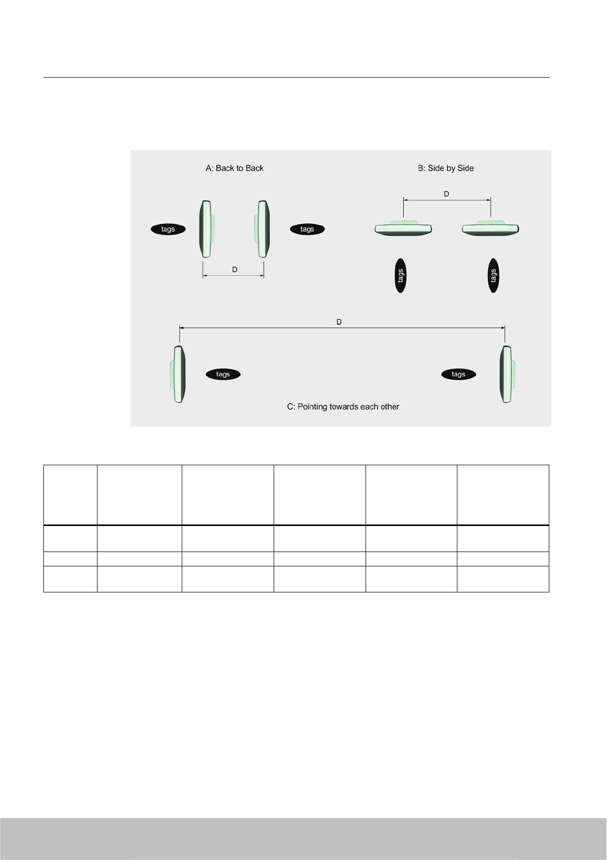
RF660A = 2000 mW ERP; RF660R with RF660A = 2 W ERP; RF620R/RF630R =
500 mW ERP) and the antenna alignment.
Figure 4-7 Antenna distances for different readers and identical frequencies
Antenna
configurati
on
Antenna alignment Minimum
distance required =
D
RF670R with
RF660A
Minimum
distance required =
D
RF660R with
RF660A
Minimum
distance required =
D
RF620R
Minimum
distance required =
D
RF630R with
RF660A
AWith backs to each
other
< 0.5 m 1 m 2 m 4.5 m
B Arranged laterally < 1 m 2 m 1.2 m 1.5 m
C Antennas point
toward each other
< 6 m 5 m 54 m 30 m
4.3.7.2 Optimizing tag reading accuracy
A further improvement in the tag reading accuracy in an environment with a high density of
readers can be achieved by orienting the antennas toward the respective tag field, i.e. by
rotating them horizontally and vertically.
In addition, the transmitter power of the readers can be reduced down to the minimum at which
the tags are still just detected accurately.
This greatly reduces the probability of interference.
RF600 system planning
4.3 Antenna configurations
SIMATIC RF600
48 System Manual, 06/2010, J31069-D0171-U001-A10-7618
Draft Version 02.06.2010

4.3.7.3 Optimization of robustness of tag data accesses for readers that are operated
simultaneously
Parameter data access reliability
If several readers are to be operated simultaneously in an environment, then the following
settings affect the reliability of the reader's access to transponder data:
● Electromagnetic environment (see Chapter The response of electromagnetic waves in the
UHF band (Page 51))
● Type of transponder (see chapter Transponder/tags (Page 205))
● Number of transponders to be detected by an antenna at a time
● Type of antenna (see Chapter Antennas (Page 153), Chapter Guidelines for selecting RFID
UHF antennas (Page 181), and Chapter Planning application (Page 84))
● Transponders' distance from and orientation toward antennas (see Chapter Transponder/
tags (Page 205))
● Distances and orientation of antennas of different readers to each other
● Radiated power of antennas
The robustness of tag data accesses is improved for readers whenever distances to adjacent
readers are increased, radiated power is reduced, and a channel plan (for ETSI readers) is
implemented. Adjacent readers are parameterized in the channel plan such that they cannot
use the same channels.
A channel plan can be created for ETSI readers; for FCC readers, it is assumed that the
probability of two readers accidentally using the same channel is very low.
SIMATIC RF620R reader
The RF620R has an integrated, circular polarized antenna. This means that the type of antenna
cannot be freely selected.
Note
Rotation of the reader through 90° around the z axis
Since the horizontal electrical opening angle of the RF620R antenna is greater than the
vertical electrical opening angle, the effects on adjacent readers can be reduced by rotating
the reader through 90° around the z axis (see coordinate diagram in Chapters Antenna
diagram for RF620R (ETSI) (Page 85) and Antenna diagram for RF620R (FCC)
(Page 88)).
SIMATIC RF670R, RF630R or RF660R reader with SIMATIC RF660A antenna
The electrical opening angles (vertical and horizontal) of the RF660A antenna are identical.
Therefore, the robustness of the readers' access to transponder data cannot be optimized
further by rotating them around the antenna axis.
RF600 system planning
4.3 Antenna configurations
SIMATIC RF600
System Manual, 06/2010, J31069-D0171-U001-A10-7618 49
Draft Version 02.06.2010
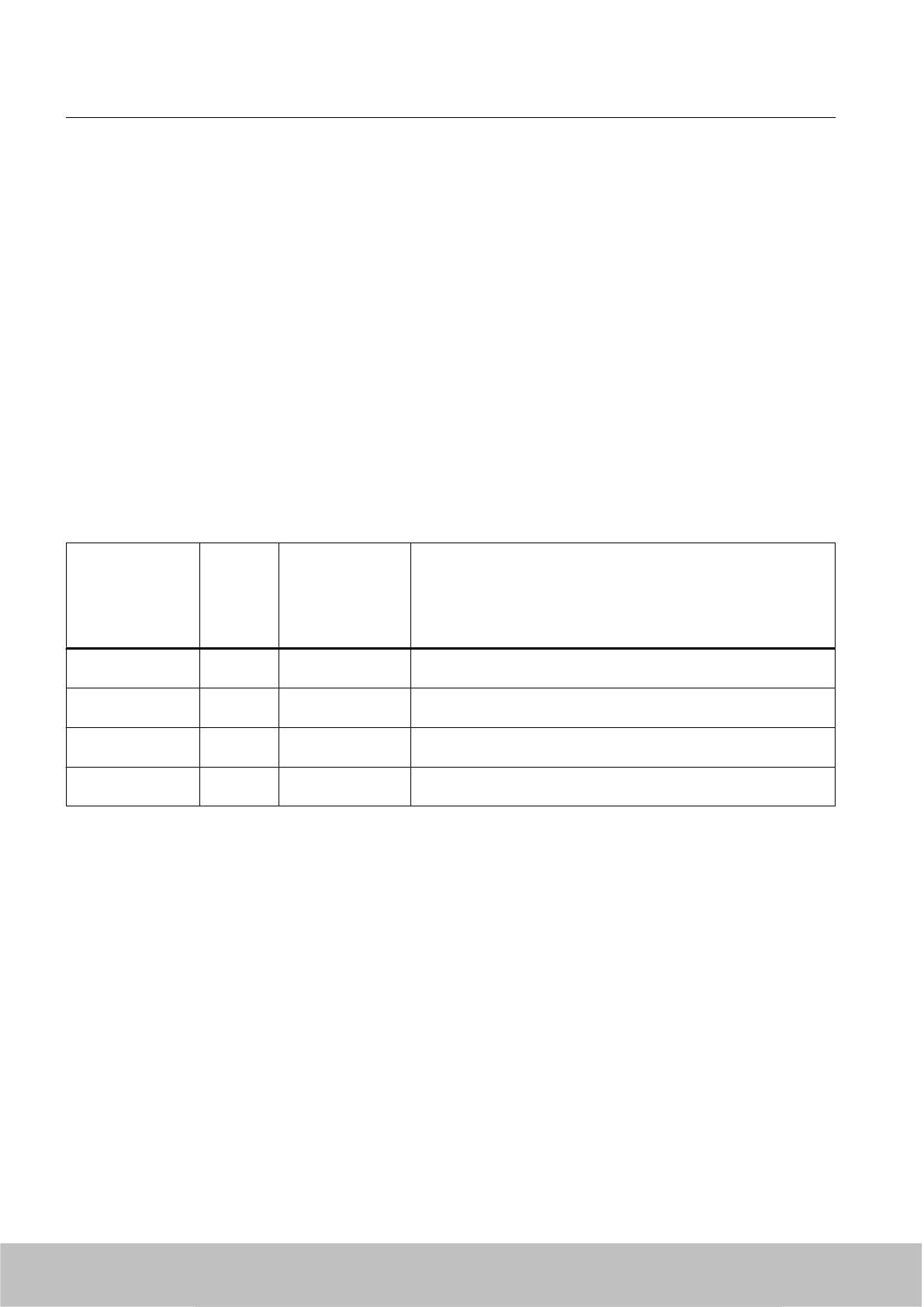
Application example for RF620R/RF630R
The following example explains measures for enhancing the data access security from the
RF620R reader to transponders:
● The antennas are placed next to each other and are aligned in parallel (see arrangement
B in Chapter Dense Reader Mode (Page 46)).
● Radiated power is limited to 27 dBm (ERP) or 500 mW (ERP).
● The RF620R readers have been rotated through 90° around the z axis.
In addition, the following characteristics are to be fulfilled:
● Length of data to be read/written on the transponder: 99,99%
● Length of data to be read/written on the transponder: 512 bits (64 bytes)
● Transponder type RF630L (6GT2810-2AB03)
The table below provides an overview of the minimum distances to be observed depending
on the radiated power and maximum possible number of transponders for the RF620R/
RF630R readers if the above-named requirements must be fulfilled:
Mode Max.
number of
tags
Radiated power
dBm (ERP)/ mW
(ERP)
Min. distance [m] between
- two RF620R readers
- two RF660A antennas operated with RF630R readers
- one RF620R and one RF660A antenna operated with a RF630R
reader
Single tag mode:
Read
1 27 dBm (ERP)/
500 mW (ERP)
3
Single tag mode:
Write
1 27 dBm (ERP)/
500 mW (ERP)
3
Multitag mode:
Read
40 27 dBm (ERP)/
500 mW (ERP)
6
Multitag mode:
Write
10 27 dBm (ERP)/
500 mW (ERP)
6
See also
RF660A antenna (Page 175)
4.3.7.4 Frequency hopping
This technique should prevent mutual interference between readers. The reader changes its
transmission channel in a random or programmed sequence (FHSS).
Procedure for FCC
The 50 available channels mean that the probability is low that two readers will be operating
on the same frequency (see Section Regulations for UHF frequency bands in the USA
(Page 60)). In China, one reader operates on at least 2 channels, e.g. 16 channels of 2 W
(see Section Regulations for UHF frequency bands in China (Page 58)).
RF600 system planning
4.3 Antenna configurations
SIMATIC RF600
50 System Manual, 06/2010, J31069-D0171-U001-A10-7618
Draft Version 02.06.2010

Procedure for ETSI
Frequency hopping is optional here. According to ETSI EN 203 208 V1.2.1, frequency hopping
is however recommended to ensure that the reader does not have to pause for 100 ms after
4 seconds.
4.3.7.5 Listen before talk
With this technique which is only applicable to ETSI, the reader checks whether the relevant
channel is assigned before transmission to prevent collisions. The reader will only transmit
when this channel is free. The reader can transmit for up to 4 seconds on this channel and
must then either pause for at least 100 milliseconds or jump immediately to an unassigned
channel where it can transmit for another 4 seconds.
With the new ETSI EN 302 208 standard V1.2.1 this technique must be not be used (see
Chapter Regulations for UHF frequency bands in Europe (ETSI EN 302 208 V1.1.2)
(Page 57) and Chapter Regulations for UHF frequency bands in Europe (ETSI EN 302 208
V1.2.1) (Page 54) ).
4.4 Environmental conditions for transponders/tags
4.4.1 Basic rules
The transponder/tag must not be placed directly on metal surfaces or on containers of liquid.
For physical reasons, a minimum distance must be maintained between the tag antenna and
conductive material. A minimum distance of 5 cm is recommended. The tag operates better
when the distance is greater (between 5 and 20 cm).
● Tag assembly on non-conductive material (plastic, wood) has a tendency to be less critical
than assembly even on poorly conductive material.
● The best results are achieved on the materials specified by the tag manufacturer.
● You can obtain more detailed information from the tag manufacturer.
4.5 The response of electromagnetic waves in the UHF band
4.5.1 The effect of reflections and interference
Reflections and interference
Electromagnetic waves in the UHF band behave and propagate in a similar manner to light
waves, that is they are reflected from large objects such as ceilings, floors, walls and windows
and interfere with each other. Due to the nature of electromagnetic waves, interference can
lead to wave amplification which can produce an increased reading range. In the worst case,
RF600 system planning
4.5 The response of electromagnetic waves in the UHF band
SIMATIC RF600
System Manual, 06/2010, J31069-D0171-U001-A10-7618 51
Draft Version 02.06.2010

interference can also result in waves being extinguished which causes holes in reader
coverage.
Reflections can also be beneficial when they cause electromagnetic waves to be routed around
objects to a certain extent (deflection). This can increase the reading probability.
Due to these electromagnetic characteristics, it is extremely difficult in the multiple-reflection
environment that is usually found in the real environment on site, to determine propagation
paths and field strengths for a particular location.
Reducing the effect of reflections/interference on tag identification
● Reducing the transmit power:
To reduce interference to a minimum, we recommend that the transmitter power of the
reader is reduced until it is sufficient for an identification rate of 100%.
● Increasing the number of antennas to 3 or 4:
More antennas in a suitable antenna configuration can prevent gaps in reader coverage.
4.5.2 Influence of metals
Metal can have an effect on the electromagnetic field depending on the arrangement or
environment. The effect ranges from a hardly determinable influence through to total blocking
of communication. The term metal in this context also includes metallized materials that are
either coated with metal or shot through with metal to such an extent that UHF radiation cannot
penetrate or only to a minimal extent.
The effect of metal on the electromagnetic field can be prevented as follows:
● Do not mount tags on metal.
● Do not place metallic or conducting objects in the propagation field of the antenna and
transponder.
Tags mounted directly onto metal
In general, tags must not be mounted directly onto metallic surfaces. Due to the nature of the
magnetic field, a minimum distance must be maintained between the tag antenna and
conductive materials. For further details on the special case of attaching transponders to
electrically conducting materials, see Section SIMATIC RF620T (Page 235) and
SectionSIMATIC RF640T (Page 271) .
In the case of transponders that are not designed for mounting on metallic materials, the
minimum permissible distance from metal is 5 cm. The larger the distance between the
transponder and the metallic surface, the better the function of the transponder.
4.5.3 Influence of liquids and non-metallic substances
Non-metallic substances can also affect the propagation of electromagnetic waves.
RF600 system planning
4.5 The response of electromagnetic waves in the UHF band
SIMATIC RF600
52 System Manual, 06/2010, J31069-D0171-U001-A10-7618
Draft Version 02.06.2010

When non-metallic substances or objects are located in the propagation field that can absorb
UHF radiation, these can alter the antenna field depending on their size and distance and can
even extinguish the field entirely.
The high-frequency damping effect of water and materials with a water content, ice and carbon
is high. Electromagnetic energy is partly reflected and absorbed.
Liquids and petroleum-based oils have low HF damping. Electromagnetic waves penetrate the
liquid and are only slightly weakened.
4.5.4 Influence of external components
The R&TTE guideline and the relevant standards govern the electromagnetic compatibility
requirements. This also concerns the external components of the RF600 system. Even though
the requirements for electromagnetic compatibility have been specified, various components
will still interfere with each other.
The performance of the RF600 system is highly dependent on the electromagnetic
environment of the antennas.
Reflections and interference
On the one hand, antenna fields will be weakened by absorbing materials and reflected by
conducting materials. When electromagnetic fields are reflected, the antenna field and
reflecting fields overlap (interference).
External components in the same frequency band
On the other hand, external components can transmit on the same frequency band as the
reader. Or the external components can transmit in different frequency bands with side bands
that overlap with the frequency band of the reader. This results in a reduction of the "signal-to-
noise" ratio which reduces the performance of an RF600 system.
If a DECT station that is transmitting in the 2 GHz band, for example, is located in the receiving
range of an antenna of the RF600 system, the performance of the write and read accesses to
the transponder will be affected.
4.6 Regulations applicable to frequency bands
The following section describes the regulations for frequency bands which apply in different
regions with reference to RFID. It presents the definition of the applicable standard, the precise
channel assignments as well as the applicable technique.
RF600 system planning
4.6 Regulations applicable to frequency bands
SIMATIC RF600
System Manual, 06/2010, J31069-D0171-U001-A10-7618 53
Draft Version 02.06.2010
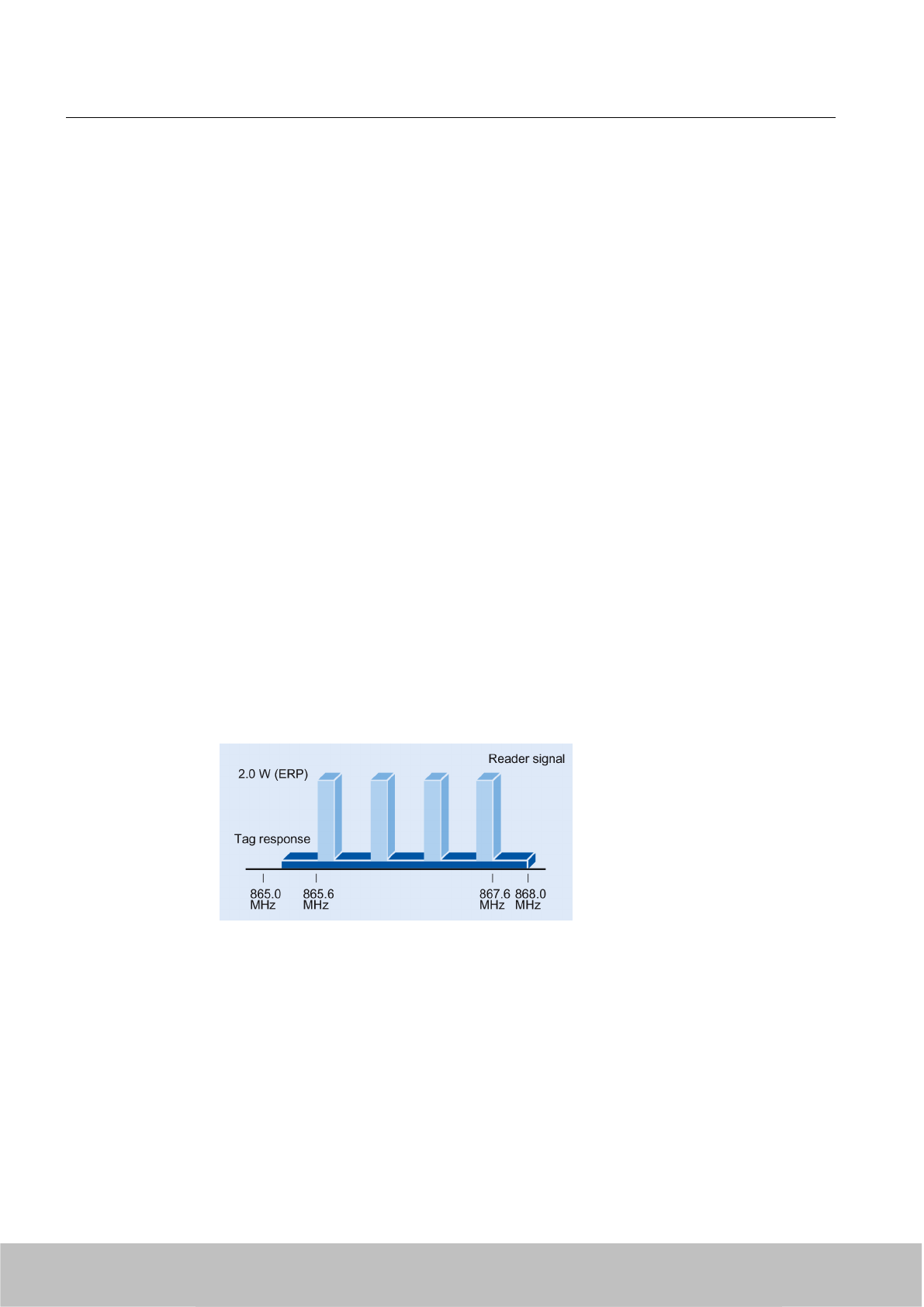
4.6.1 Regulations for UHF frequency bands in Europe
4.6.1.1 Regulations for UHF frequency bands in Europe (ETSI EN 302 208 V1.2.1)
This revision of the standards EN 302 208 also supports RFID systems with many readers that
are operating simultaneously. Within the frequency spectrum, 4 exclusive RFID channels have
been defined. The procedure "Listen Before Talk" must no longer be used.
Regulations for frequency bands according to EN 302 208 V1.2.1
ETSI (European Telecommunications Standards Institute)
Specifications of European standard EN 302 208:
● UHF band: 865…868 MHz
● Radiant power: max. 2 W (ERP)
● Channel bandwidth: 200 KHz, channel spacing 600 kHz
● Number of channels: 4
– 865,7
– 866,3
– 866,9
– 867,5
Channel assignment
● The UHF band from 865 to 868 MHz with 4 RFID channels occupies:
Validity
Note that readers may be operated with this setting since November 4, 2008 (publication of
the standard in the Official Journal of the European Union).
RF600 system planning
4.6 Regulations applicable to frequency bands
SIMATIC RF600
54 System Manual, 06/2010, J31069-D0171-U001-A10-7618
Draft Version 02.06.2010

Note
Availability
Please note that this profile is available for the following readers and firmware versions:
● RF620R/RF630R, firmware V1.0 or higher
● RF660R, firmware V1.3 or higher
● RF670R, firmware V1.0 or higher
4.6.1.2 Regulations for frequency bands according to EN 300 220 (short range device)
For those countries in which the RFID directive according to EN 302 208 has not yet been
implemented, this alternative exists which is based on the older "Short range device" directive:
EN 300 220 (short range device)
Frequency band, assigned 869.4– 869.65 MHz
Frequency used 869.50 MHz
Transmit power Max. 0.5 W ERP
Duty cycle (frequency assignment period) 10% (6 minutes per hour)
Note
Availability
Please note that this profile is available for the following readers and firmware versions:
●RF610M
●RF660R up to firmware V1.2
4.6.1.3 Partial abrogation of the regulations for France
A decision from the European Commission of May 16, 2007 refers to a temporary, partial
abrogation of the regulations for frequency bands in accordance with EN 302 208 that will only
apply until 2010. According to this, the sub frequency band 865.5 MHz – 867.6 MHz will be
limited to a maximum transmitted power of 0.5 W ERP when the RF600 system is operated
within certain zones in France. These zones are defined in the annex to the decision of the
commission and can be referred to in the appendix (Page 353).
RF600 system planning
4.6 Regulations applicable to frequency bands
SIMATIC RF600
System Manual, 06/2010, J31069-D0171-U001-A10-7618 55
Draft Version 02.06.2010
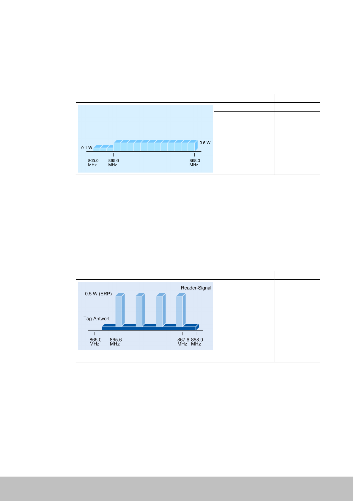
Channel assignment according to ETSI EN 302 208 V1.1.1
The UHF band from 865 to 868 MHz is subdivided into two sub bands:
Sub bands Frequency band Power
865.0 to 865.5 MHz 0.1 W ERP
865.6 to 868.0 MHz 0.5 W ERP
Validity
Note that readers with this setting may only be sold until December 31, 2009. Readers sold
with this setting before December 31, 2009 may continue to be used after that date.
Channel assignment according to ETSI EN 302 208 V1.2.1
The UHF band now only contains four permanently assigned frequencies on which the reader
can transmit as per the 4-channel plan (see Chapter Regulations for UHF frequency bands in
Europe (ETSI EN 302 208 V1.2.1) (Page 54)).
Sub bands Frequency band Power
865,7
866,3
866,9
867,5
0.5 W ERP
Validity
Note that readers may be operated with this setting since November 4, 2008 (publication of
the standard in the Official Journal of the European Union).
RF600 system planning
4.6 Regulations applicable to frequency bands
SIMATIC RF600
56 System Manual, 06/2010, J31069-D0171-U001-A10-7618
Draft Version 02.06.2010
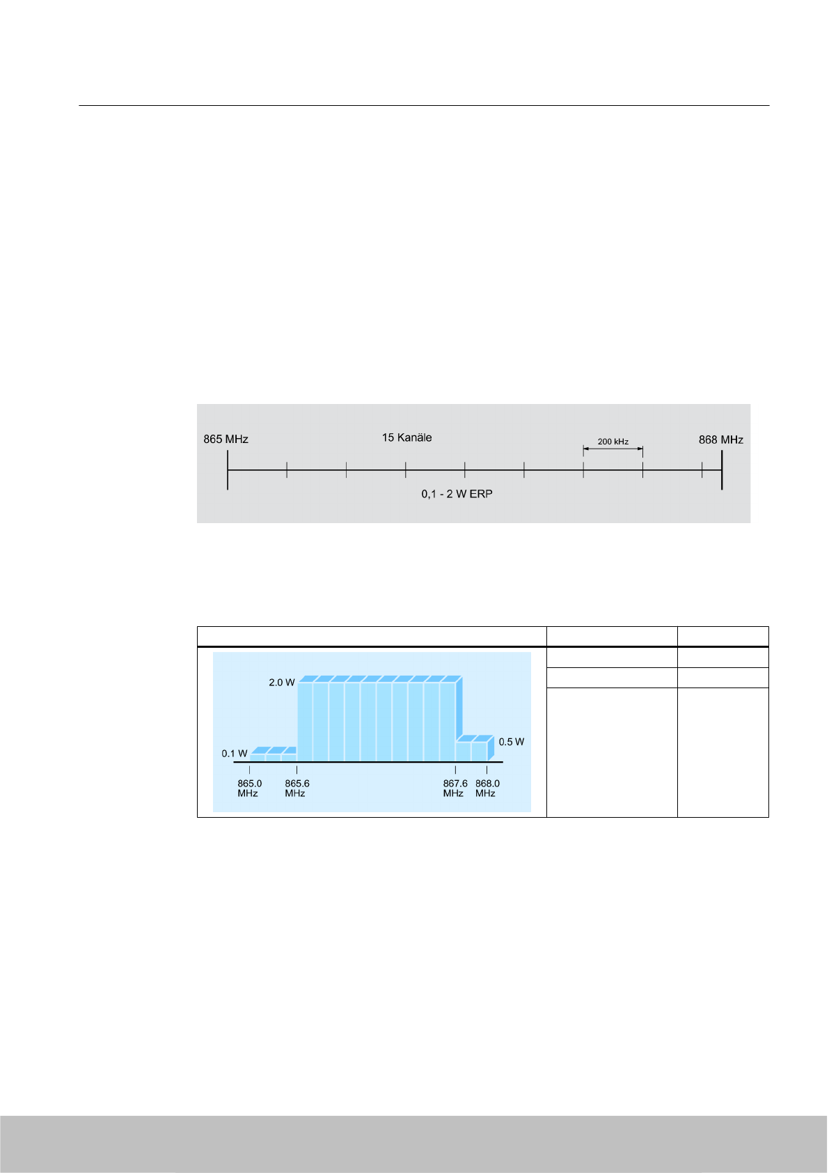
4.6.1.4 Regulations for UHF frequency bands in Europe (ETSI EN 302 208 V1.1.2)
Regulations for frequency bands according to EN 302 208 V1.1.1
ETSI (European Telecommunications Standards Institute)
Specifications of European standard EN 302 208 V1.1.1:
● UHF band: 865…868 MHz
● Radiant power: max. 2 W (ERP)
● Channel bandwidth: 200 kHz
●Number of channels: 15
● Listen Before Talk
Channel assignment
● The UHF band from 865 to 868 MHz is subdivided into three sub bands:
Sub bands Frequency band Power
865.0 to 865.5 MHz 0.1 W ERP
865.6 to 867.6 MHz 2.0 W ERP
867.6 to 868.0 MHz 0.5 W ERP
Validity
Note that readers with this setting may only be sold until December 31, 2009. Readers sold
with this setting before December 31, 2009 may continue to be used after that date.
RF600 system planning
4.6 Regulations applicable to frequency bands
SIMATIC RF600
System Manual, 06/2010, J31069-D0171-U001-A10-7618 57
Draft Version 02.06.2010
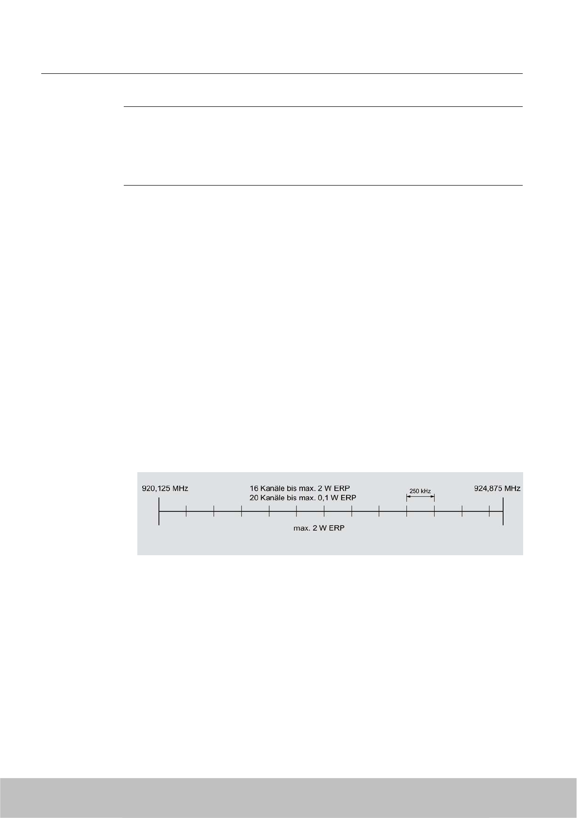
Note
Availability
Please note that this profile is available for the following readers and firmware versions:
● RF620R/RF630R, firmware V1.0 or lower
● RF660R up to firmware V1.2
Listen Before Talk
With this technique, the reader checks whether the relevant channel is assigned before
transmission to prevent collisions. The reader will only transmit when this channel is free. The
reader can transmit for up to 4 seconds on this channel and must then either pause for at least
100 milliseconds or jump immediately to an unassigned channel where it can transmit for
another 4 seconds.
4.6.2 Regulations for UHF frequency bands in China
Regulations for UHF frequency bands in China
FCC (Federal Communications Commission)
● UHF band: 920.125 to 924.875 MHz in 250 kHz channel blocks.
● Radiant power: max. 2 W (ERP)
● Number of channels: 16 to max. 2 W (ERP), 20 to max. 0.1 W (ERP)
● Frequency hopping
RF600 system planning
4.6 Regulations applicable to frequency bands
SIMATIC RF600
58 System Manual, 06/2010, J31069-D0171-U001-A10-7618
Draft Version 02.06.2010
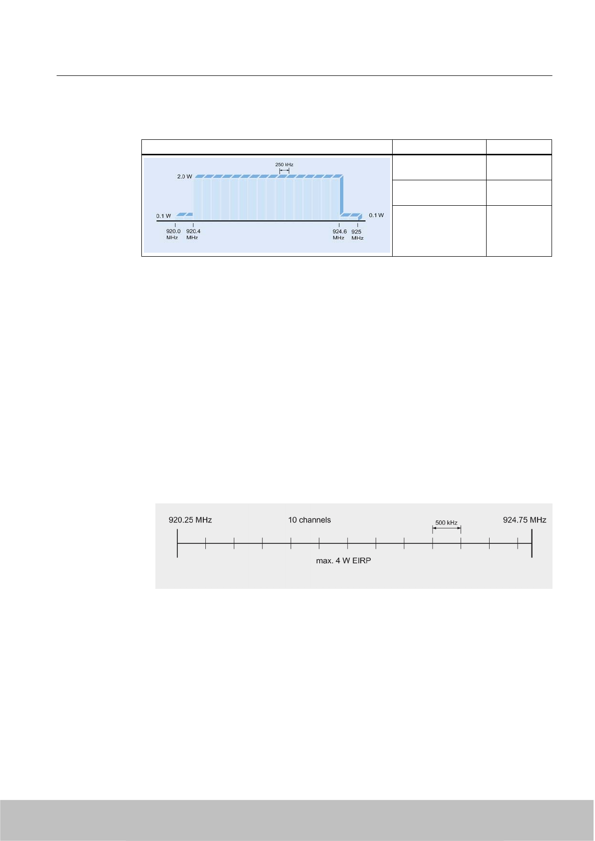
Channel assignment
Sub bands Frequency band Power
920.125 to 920.375
MHz
0.1 W ERP
920.625 to 924.375
MHz
2.0 W ERP
924.625 to 924.875
MHz
0.1 W ERP
Frequency hopping
This technique should prevent mutual interference between readers. The reader changes its
transmission channel in a random or programmed sequence (FHSS). With 16 available
channels that can be used simultaneously at up to 2000 mW (ERP) and with 20 channels that
can be used simultaneously at up to 100 mW, the probability of two readers operating on the
same frequency is reduced.
4.6.3 Regulations for UHF frequency bands in Thailand
FCC (Federal Communications Commission)
● UHF band: 920.25 to 924.75 MHz
● Radiant power: max. 4 W (EIRP)
● Number of channels: 10
● Frequency hopping, dwell time 2 seconds per channel
Frequency hopping
This technique should prevent mutual interference between readers. The reader changes its
transmission channel in a random or programmed sequence (FHSS). 10 available channels
mean that the probability is low that two readers will be operating on the same frequency.
RF600 system planning
4.6 Regulations applicable to frequency bands
SIMATIC RF600
System Manual, 06/2010, J31069-D0171-U001-A10-7618 59
Draft Version 02.06.2010
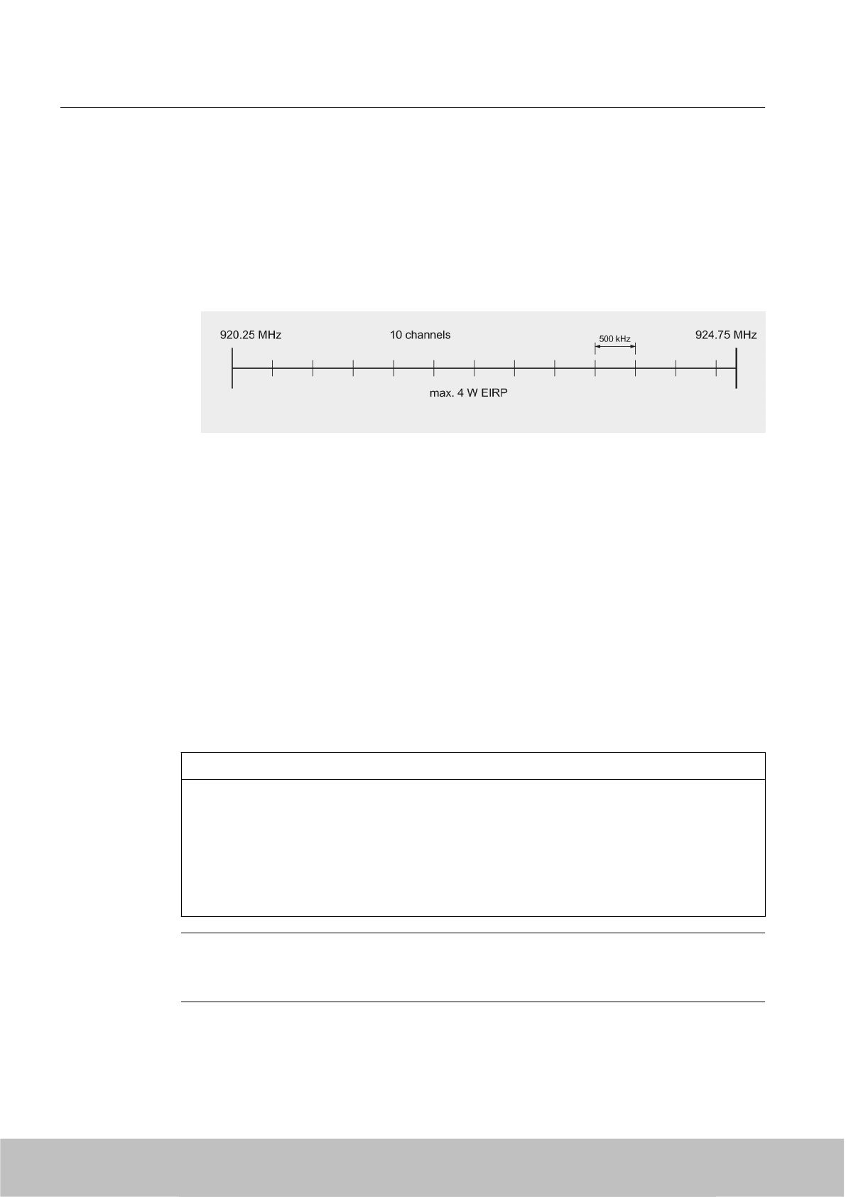
4.6.4 Regulations for UHF frequency bands in the USA
FCC (Federal Communications Commission)
● UHF band: 902 to 928 MHz
● Radiant power: max. 4 W (EIRP)
● Number of channels: 50
●Frequency hopping
Frequency hopping
This technique should prevent mutual interference between readers. The reader changes its
transmission channel in a random or programmed sequence (FHSS). The 50 available
channels mean that the probability is low that two readers will be operating on the same
frequency.
4.7 Operation of RF600 readers according to EN 302208 V1.2.1 and EN
302208 V1.1.1
4.7.1 Validity of the standards
NOTICE
Validity of EN 302208 V1.1.1 and EN 302208 V1.2.1
As of 1 January 2010, RF660R readers that are commissioned within the EU, EFTA or Turkey
may use firmware V1.3 only.
Exception:
Defective RF660R readers which are repaired or replaced can still be used with older
firmware versions.
Note
RF660R readers with firmware version V1.3 no longer support the ETSI radio profile
according to EN 302208 V1.1.1.
RF600 system planning
4.7 Operation of RF600 readers according to EN 302208 V1.2.1 and EN 302208 V1.1.1
SIMATIC RF600
60 System Manual, 06/2010, J31069-D0171-U001-A10-7618
Draft Version 02.06.2010

Note
If an RF660R reader with firmware version V1.3 is to replace a reader commissioned before
1 January 2010, the new reader can also use a firmware version older than V1.3. The
downgrade is described in the "RF660R Configuration Software" configuration manual.
Note
If possible, upgrade all older RF660R readers to the new firmware V1.3.
4.7.2 Disturbances when operating readers according to ETSI EN V1.1.1 and V1.2.1 in
mixed mode
If RF600 readers in the ETSI band (EU, EFTA & Turkey) are operated according to
EN 302 208 V1.1.1 (firmware V1.2) and at the same time to EN 302 208 V1.2.1 (Firmware
V1.3) in close proximity to each other (up to 20 m), these readers might interfere with each
other.
Reasons for interference
The following reasons may cause the interference:
● Only four transmission channels (865.7; 866.3; 866.9; 867.5 MHz) are now available
according to the latest ETSI standard.
● Deactivation of Listen Before Talking (LBT)
● When operating readers in mixed mode according to the old ETSI standard
(EN 302 208 V1.1.1) and the new ETSI standard (EN 302 208 V1.2.1), the transmission
and receive channels may interfere with each other. Tag reading might thus be blocked.
(See Chapter Possible causes of error (Page 67))
RF620R and RF630R
The RF620R (ETSI) and RF630R (ETSI) readers support both ETSI standards
EN 302 208 V1.1.1 and V1.2.1 (max. 4 channels without LBT). As of January 2010, these
readers must be operated using the 4-channel plan and without LBT.
RF660R
RF660R readers V1.2 or earlier firmware versions exclusively use a radio profile according to
EN 302 208 V 1.1.1 (max. 15 channels with LBT).
RF660R readers V1.3 or later firmware versions exclusively use a radio profile according to
EN 302 208 V1.2.1(max. 4 channels without LBT).
RF600 system planning
4.7 Operation of RF600 readers according to EN 302208 V1.2.1 and EN 302208 V1.1.1
SIMATIC RF600
System Manual, 06/2010, J31069-D0171-U001-A10-7618 61
Draft Version 02.06.2010
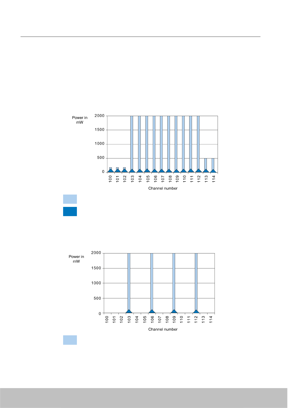
4.7.3 Preventing interference in mixed operation
If the RF660R readers use the air interface standards EPC Global Class 1 Gen 1,
EPC Global Class 1 Gen 2 (no dense mode) or ISO 18000-6B, the the receive channel is
identical to the respective transmission channel of a reader.
Permitted channel assignment according to ETSI EN 302 208 V1.1.1
Send
Receive
Figure 4-8 Channel assignment ETSI EN 302 208 V1.1.1
Permitted channel assignment according to ETSI EN 302 208 V1.2.1
Send
RF600 system planning
4.7 Operation of RF600 readers according to EN 302208 V1.2.1 and EN 302208 V1.1.1
SIMATIC RF600
62 System Manual, 06/2010, J31069-D0171-U001-A10-7618
Draft Version 02.06.2010
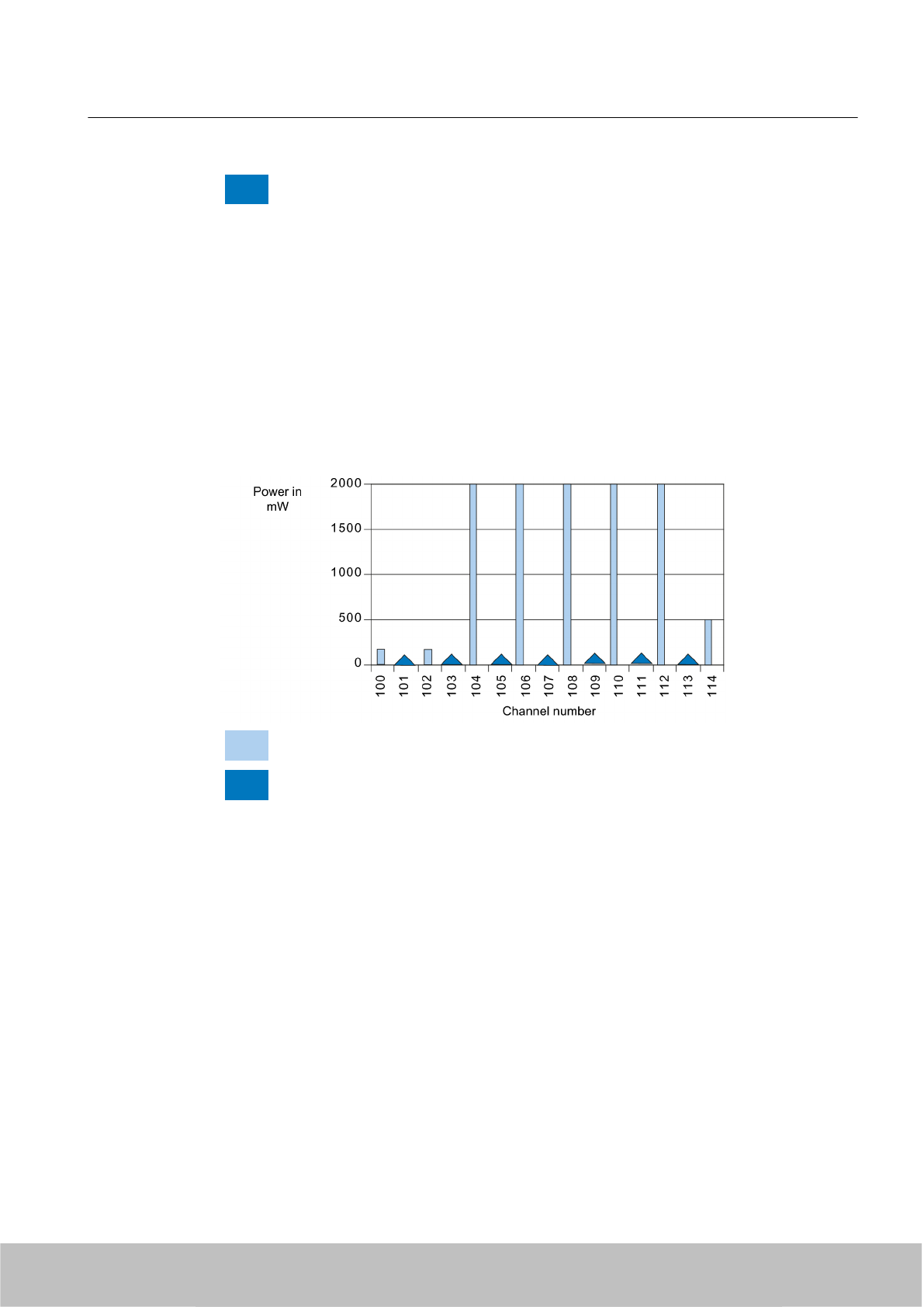
Receive
Figure 4-9 Channel assignment ETSI EN 302 208 V1.2.1
4.7.3.1 Mixed operation - dense mode
If the RF660R readers use the air interface standard EPC Global Class 1 Gen 2 (dense mode),
the receive channel is shifted by a "link frequency" compared to the respective transmission
channel of the reader (e.g. with profile 23 for RF660R, a link frequency of 160 kHz is used).
Thus the performance distribution of the tag responses in dense mode is within the channels
that are right next to a transmission channel.
Permitted channel assignment ETSI EN 302 208 V1.1.1 dense mode
Send
Receive
Figure 4-10 Channel assignment ETSI EN 302 208 V1.1.1 dense mode
RF600 system planning
4.7 Operation of RF600 readers according to EN 302208 V1.2.1 and EN 302208 V1.1.1
SIMATIC RF600
System Manual, 06/2010, J31069-D0171-U001-A10-7618 63
Draft Version 02.06.2010
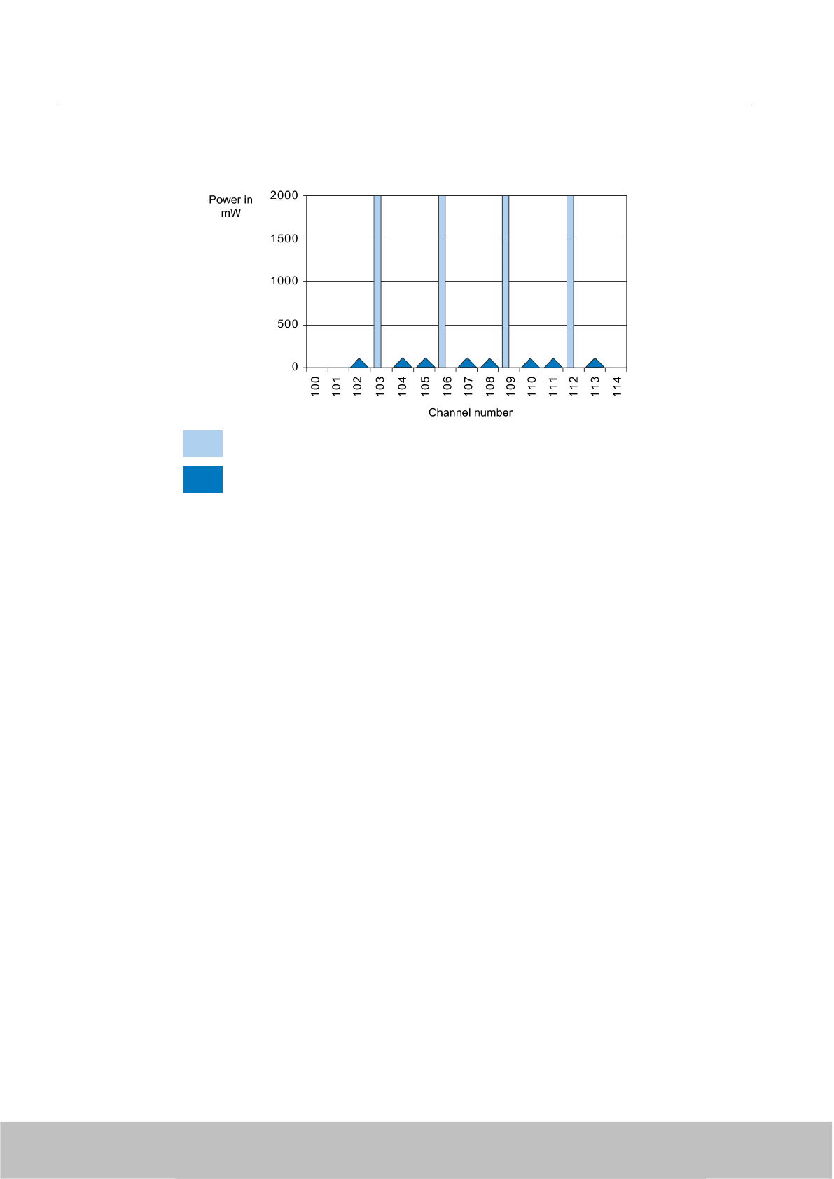
Permitted channel assignment ETSI EN V1.2.1 dense mode
Send
Receive
Figure 4-11 Channel assignment ETSI EN 302 208 V1.2.1 dense mode
4.7.3.2 Preventing interference in mixed operation
You ensure problem-free operation by a strict separation in the assignment of transmission
and receive channels of the RF600 readers according to EN 302 208 V1.1.1 and
EN 302 208 V1.2.1. This means that neither the transmission channels nor the receive
channels of the readers operated according EN 302 208 V1.1.1 must overlap with the
transmission or receive channels of the readers operated according to EN 302 208 V1.2.1.
Procedure
1. In the channel plan, only mark the transmission channels as assigned channels of a reader
for all readers that are not to operated in dense mode (EPC Global Class 1 Gen 1,
EPC Global Class 1 Gen 2 (no dense mode)) or ISO 18000-6B).
2. For all readers that are to operate in dense mode (EPC Global Class 1 Gen 1,
EPC Global Class 1 Gen 2 (dense mode)), mark the transmission channels and the
channels right next to them (receive channels) as assigned channels of a reader.
3. For this purpose, first mark all transmission channels and any adjacent receive channels
in dense mode operation of the R660R readers for V1.3 or later versions in the channel
plan. In mixed operation, the RF660R reader operated according to EN 302 208 V1.1.1
can use more channels than an RF660R reader operated according to EN 302 208 V1.2.1.
4. Then mark all transmission channels and any adjacent receive channels in dense mode
operation of the R660R readers for V1.2 or earlier versions in the channel plan.
RF600 system planning
4.7 Operation of RF600 readers according to EN 302208 V1.2.1 and EN 302208 V1.1.1
SIMATIC RF600
64 System Manual, 06/2010, J31069-D0171-U001-A10-7618
Draft Version 02.06.2010
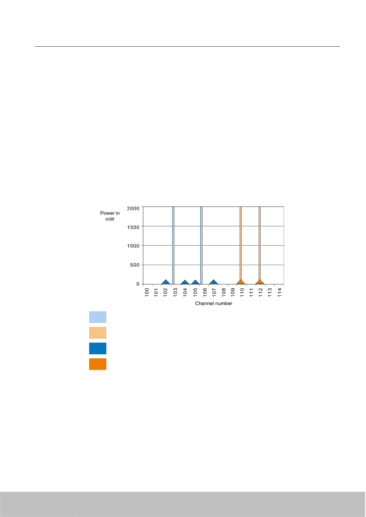
Example of planning a channel plan
Below you will find a concrete example of a channel plan with which you prevent interference:
● New readers operating according to EN 302 208 V1.2.1 must use channels with a channel
number below 107. Dense mode can be activated or deactivated.
● Readers according to the old standard EN 302 208 V1.1.1 can use channels with a channel
number between 109 and 114. If dense mode is activate, only even-numbered channels
can be used.
Such a setting prevents that readers interfere with each other. At which channel number the
separation will be depends on the ratio of readers according to the old standard and new
standard. This limit can be shifted as required.
4.7.3.3 Example 1: Recommended channel assignment mixed operation
This case refers to mixed operation of several readers according to EN 302 208 V1.1.1 with
standard profile and several readers according to EN 302 208 V1.2.1 in dense mode.
Transmission by reader 1 - according to EN 302208 V1.2.1 (4-channel plan, dense mode)
Transmission by reader 2 - according to EN 302208 V1.1.1 (15 channels, LBT)
Receiving by reader 1 - according to EN 302208 V1.2.1 (4-channel plan, dense mode)
Receiving by reader 2 - according to EN 302208 V1.1.1 (15 channels, LBT)
Figure 4-12 Recommended channel assignment mixed operation
RF600 system planning
4.7 Operation of RF600 readers according to EN 302208 V1.2.1 and EN 302208 V1.1.1
SIMATIC RF600
System Manual, 06/2010, J31069-D0171-U001-A10-7618 65
Draft Version 02.06.2010
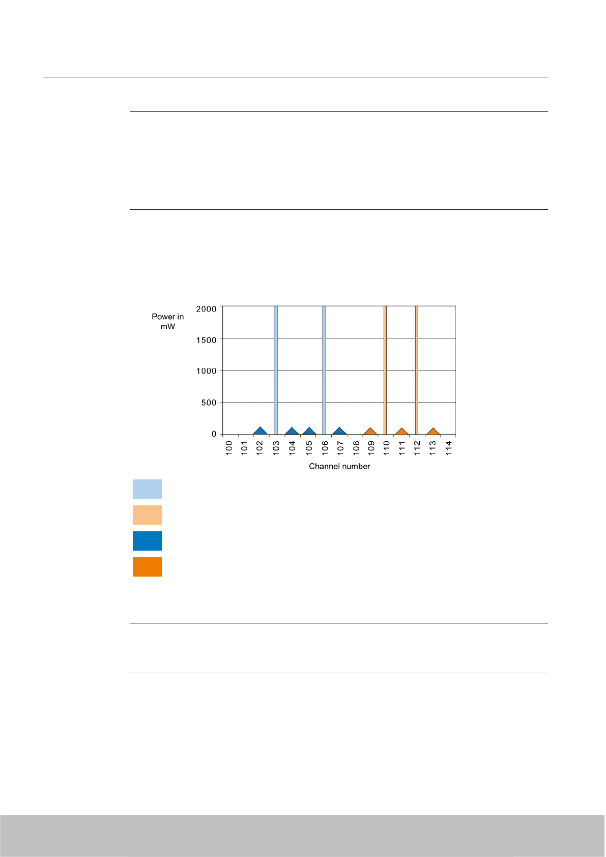
Note
If possible, all older RF660R readers should be upgraded to the new firmware V1.3.
If only a few readers operate according to EN 302 208 V1.1.1, the following channel
distribution is also possible:
● 3 channels for readers according to EN 302 208 V1.2.1
● 2 channels for readers according to EN 302 208 V1.1.1
4.7.3.4 Example 2: Recommended channel assignment mixed operation
This case refers to mixed operation of several readers according to EN 302 208 V1.1.1 in
dense mode and several readers according to EN 302 208 V1.2.1 in dense mode.
Transmission by reader 1 - according to EN 302208 V1.2.1 (4-channel plan, dense mode)
Transmission by reader 2 - according to EN 302208 V1.1.1 (15 channels, LBT, dense mode)
Receiving by reader 1 - according to EN 302208 V1.2.1 (4-channel plan, dense mode)
Receiving by reader 2 - according to EN 302208 V1.1.1 (15 channels, LBT, dense mode)
Figure 4-13 Recommended channel assignment mixed operation dense mode
Note
Readers that operate according to the standard ETSI EN 302 208 V1.1.1 can also use the
top two channels of the channel plan if low performance suffices.
RF600 system planning
4.7 Operation of RF600 readers according to EN 302208 V1.2.1 and EN 302208 V1.1.1
SIMATIC RF600
66 System Manual, 06/2010, J31069-D0171-U001-A10-7618
Draft Version 02.06.2010
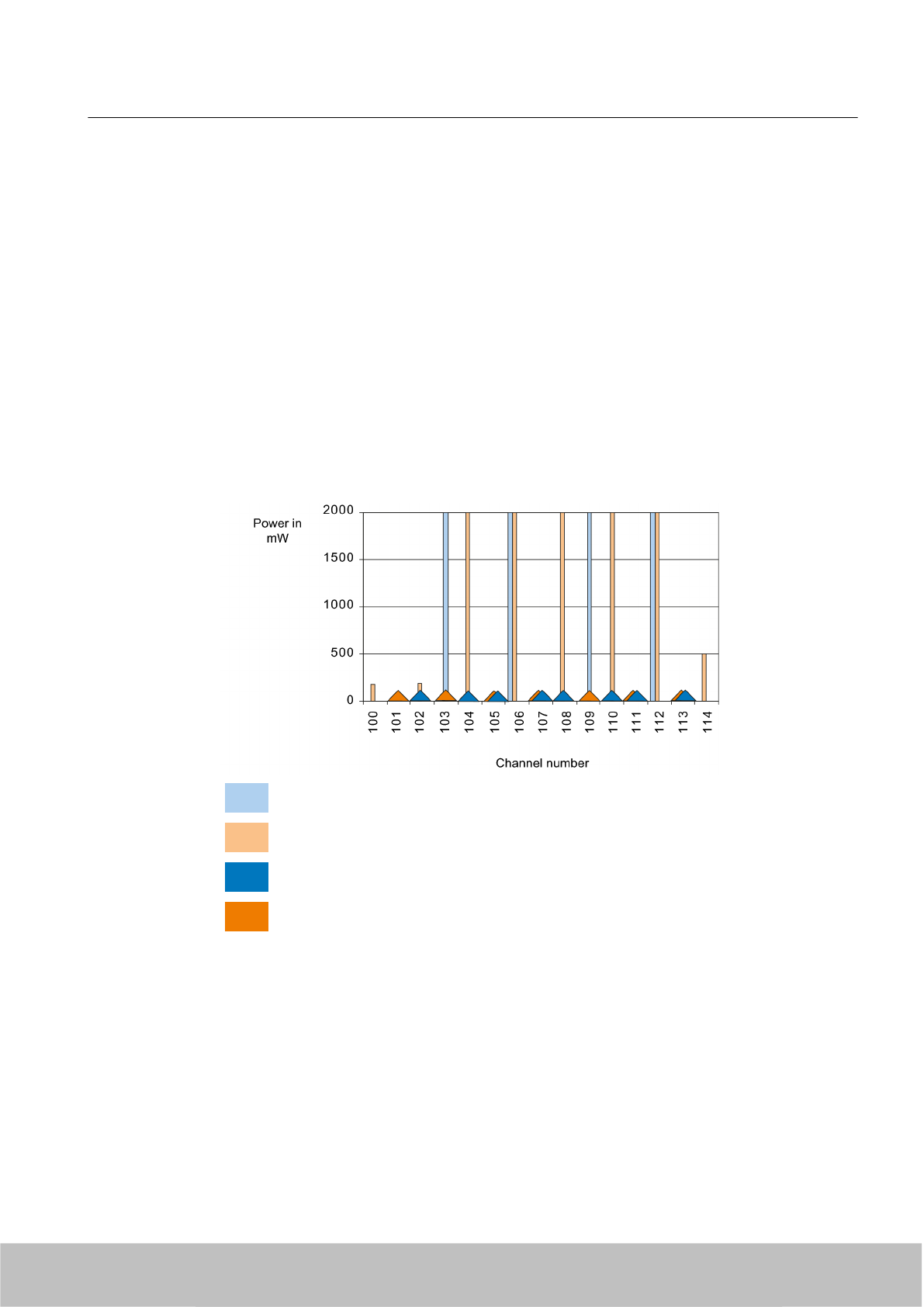
Transmission capability for RF620R/RF630R
The basic setting of the RF620R and RF630R is the 4-channel plan without LBT and dense
mode.
Therefore the following applies:
If you operate the RF620R or RF630R in mixed mode with RF660R EN 302 208 V1.1.1, the
same settings apply as for mixed operation of RF660R according to EN 302 208 V1.2.1 in
dense mode and RF660R according to EN 302 208 V1.1.1.
4.7.4 Possible causes of error
If the channels are not separated in mixed operation, the following can occur:
Transmission by reader 1 - according to EN 302208 V1.2.1 (4-channel plan, dense mode)
Transmission by reader 2 - according to EN 302208 V1.1.1 (15 channels, LBT)
Receiving by reader 1 - according to EN 302208 V1.2.1 (4-channel plan, dense mode)
Receiving by reader 2 - according to EN 302208 V1.1.1 (15 channels, LBT)
Figure 4-14 Interference with adjacent readers in mixed operation
Transmission from readers 2 partially interfere with receiving by readers 1. Since readers 1 do
not have to adhere to LBT, they will block the transmission by readers 2 on these respective
channels. Furthermore, transmission from readers 1 blocks receiving by readers 2.
Other disturbances and causes
The following overview shows possible interference and its causes which can occur if the
channels are not separated in mixed mode.
RF600 system planning
4.7 Operation of RF600 readers according to EN 302208 V1.2.1 and EN 302208 V1.1.1
SIMATIC RF600
System Manual, 06/2010, J31069-D0171-U001-A10-7618 67
Draft Version 02.06.2010

Firmware version V1.2 always refers to firmware version V1.2 or previous firmware versions.
Firmware version V1.3 always refers to firmware version V1.3 or later firmware versions.
RF660R ≥V 1.3 or
RF600 1)
RF660R ≤V1.2
ISO 18000-6B EPC Class 1 Gen 1 EPC Class 1 Gen 2
dense mode
EPC Class 1 Gen 2
no dense mode
ISO 18000-6B RF660R V1.3 uses no
LBT and could interfere
with RF660R V1.2 if
they use the same
channel
RF660R V1.3 uses no
LBT and could interfere
with RF660R V1.2 if
they use the same
channel
RF660R V1.3 uses no
LBT and could interfere
with RF660R V1.2 if
they use the same
transmission channel.
If RF660R V1.3
transmits on a receive
channel of RF660R
V1.2, then the tag
response cannot be
decoded by RF660R
V1.2.
RF660R V1.3 uses no
LBT and could interfere
with RF660R V1.2 if
they use the same
channel
EPC Class 1 Gen 1 RF660R V1.3 uses no
LBT and could interfere
with RF660R V1.2 if
they use the same
channel
RF660R V1.3 uses no
LBT and could interfere
with RF660R V1.2 if
they use the same
channel
RF660R V1.3 uses no
LBT and could interfere
with RF660R V1.2 if
they use the same
transmission channel.
If RF660R V1.3
transmits on a receive
channel of RF660R
V1.2, then the tag
response cannot be
decoded by RF660R
V1.2.
RF660R V1.3 uses no
LBT and could interfere
with RF660R V1.2 if
they use the same
channel
RF600 system planning
4.7 Operation of RF600 readers according to EN 302208 V1.2.1 and EN 302208 V1.1.1
SIMATIC RF600
68 System Manual, 06/2010, J31069-D0171-U001-A10-7618
Draft Version 02.06.2010

RF660R ≥V 1.3 or
RF600 1)
RF660R ≤V1.2
ISO 18000-6B EPC Class 1 Gen 1 EPC Class 1 Gen 2
dense mode
EPC Class 1 Gen 2
no dense mode
EPC Class 1 Gen 2
dense mode
RF660R V1.3 uses no
LBT and could interfere
with RF660R V1.2 if
they use the same
transmission channel.
If RF660R V1.2
transmits on a receive
channel of RF660R
V1.3, then the tag
response cannot be
decoded by RF660R
V1.3.
RF660R V1.3 uses no
LBT and could interfere
with RF660R V1.2 if
they use the same
transmission channel.
If RF660R V1.2
transmits on a receive
channel of RF660R
V1.3, then the tag
response cannot be
decoded by RF660R
V1.3.
RF660R V1.3 uses no
LBT and could interfere
with RF660R V1.2 if
they use the same
transmission channel.
If RF660R V1.2
transmits on a receive
channel of RF660R
V1.3, then the tag
response cannot be
decoded by RF660R
V1.3.
If RF660R V1.3
transmits on a receive
channel of RF660R
V1.2, then the tag
response cannot be
decoded by RF660R
V1.2.
RF660R V1.3 uses no
LBT and could interfere
with RF660R V1.2 if
they use the same
transmission channel.
If RF660R V1.2
transmits on a receive
channel of RF660R
V1.3, then the tag
response cannot be
decoded by RF660R
V1.3.
EPC Class 1 Gen 2
no dense mode
RF660R V1.3 uses no
LBT and could interfere
with RF660R V1.2 if
they use the same
channel
RF660R V1.3 uses no
LBT and could interfere
with RF660R V1.2 if
they use the same
channel
RF660R V1.3 uses no
LBT and could interfere
with RF660R V1.2 if
they use the same
transmission channel.
If RF660R V1.3
transmits on a receive
channel of RF660R
V1.2, then the tag
response cannot be
decoded by RF660R
V1.2.
RF660R V1.3 uses no
LBT and could interfere
with RF660R V1.2 if
they use the same
channel.
1) RF600 readers, except RF660R: RF670R, RF630R and RF620R
4.8 Guidelines for electromagnetic compatibility (EMC)
4.8.1 Overview
These EMC Guidelines answer the following questions:
●Why are EMC guidelines necessary?
●What types of external interference have an impact on the system?
●How can interference be prevented?
●How can interference be eliminated?
RF600 system planning
4.8 Guidelines for electromagnetic compatibility (EMC)
SIMATIC RF600
System Manual, 06/2010, J31069-D0171-U001-A10-7618 69
Draft Version 02.06.2010

● Which standards relate to EMC?
● Examples of interference-free plant design
The description is intended for "qualified personnel":
● Project engineers and planners who plan system configurations with RFID modules and
have to observe the necessary guidelines.
● Fitters and service engineers who install the connecting cables in accordance with this
description or who rectify defects in this area in the event of interference.
NOTICE
Failure to observe notices drawn to the reader's attention can result in dangerous
conditions in the plant or the destruction of individual components or the entire plant.
4.8.2 What does EMC mean?
The increasing use of electrical and electronic devices is accompanied by:
● Higher component density
● More switched power electronics
● Increasing switching rates
●Lower power consumption of components due to steeper switching edges
The higher the degree of automation, the greater the risk of interaction between devices.
Electromagnetic compatibility (EMC) is the ability of an electrical or electronic device to operate
satisfactorily in an electromagnetic environment without affecting or interfering with the
environment over and above certain limits.
EMC can be broken down into three different areas:
● Intrinsic immunity to interference:
immunity to internal electrical disturbance
● Immunity to external interference:
immunity to external electromagnetic disturbance
● Degree of interference emission:
emission of interference and its effect on the electrical environment
All three areas are considered when testing an electrical device.
The RFID modules are tested for conformity with the limit values required by the CE and RTTE
guidelines. Since the RFID modules are merely components of an overall system, and sources
of interference can arise as a result of combining different components, certain guidelines have
to be followed when setting up a plant.
EMC measures usually consist of a complete package of measures, all of which need to be
implemented in order to ensure that the plant is immune to interference.
RF600 system planning
4.8 Guidelines for electromagnetic compatibility (EMC)
SIMATIC RF600
70 System Manual, 06/2010, J31069-D0171-U001-A10-7618
Draft Version 02.06.2010

Note
The plant manufacturer is responsible for the observance of the EMC guidelines; the plant
operator is responsible for radio interference suppression in the overall plant.
All measures taken when setting up the plant prevent expensive retrospective modifications
and interference suppression measures.
The plant operator must comply with the locally applicable laws and regulations. They are
not covered in this document.
4.8.3 Basic rules
It is often sufficient to follow a few elementary rules in order to ensure electromagnetic
compatiblity (EMC).
The following rules must be observed:
Shielding by enclosure
●Protect the device against external interference by installing it in a cabinet or housing. The
housing or enclosure must be connected to the chassis ground.
● Use metal plates to shield against electromagnetic fields generated by inductances.
● Use metal connector housings to shield data conductors.
Wide-area ground connection
●Bond all passive metal parts to chassis ground, ensuring large-area and low-HF-impedance
contact.
● Establish a large-area connection between the passive metal parts and the central
grounding point.
● Don't forget to include the shielding bus in the chassis ground system. That means the
actual shielding busbars must be connected to ground by large-area contact.
● Aluminium parts are not suitable for ground connections.
Plan the cable installation
● Break the cabling down into cable groups and install these separately.
● Always route power cables, signal cables and HF cables through separated ducts or in
separate bundles.
● Feed the cabling into the cabinet from one side only and, if possible, on one level only.
● Route the signal cables as close as possible to chassis surfaces.
● Twist the feed and return conductors of separately installed cables.
RF600 system planning
4.8 Guidelines for electromagnetic compatibility (EMC)
SIMATIC RF600
System Manual, 06/2010, J31069-D0171-U001-A10-7618 71
Draft Version 02.06.2010
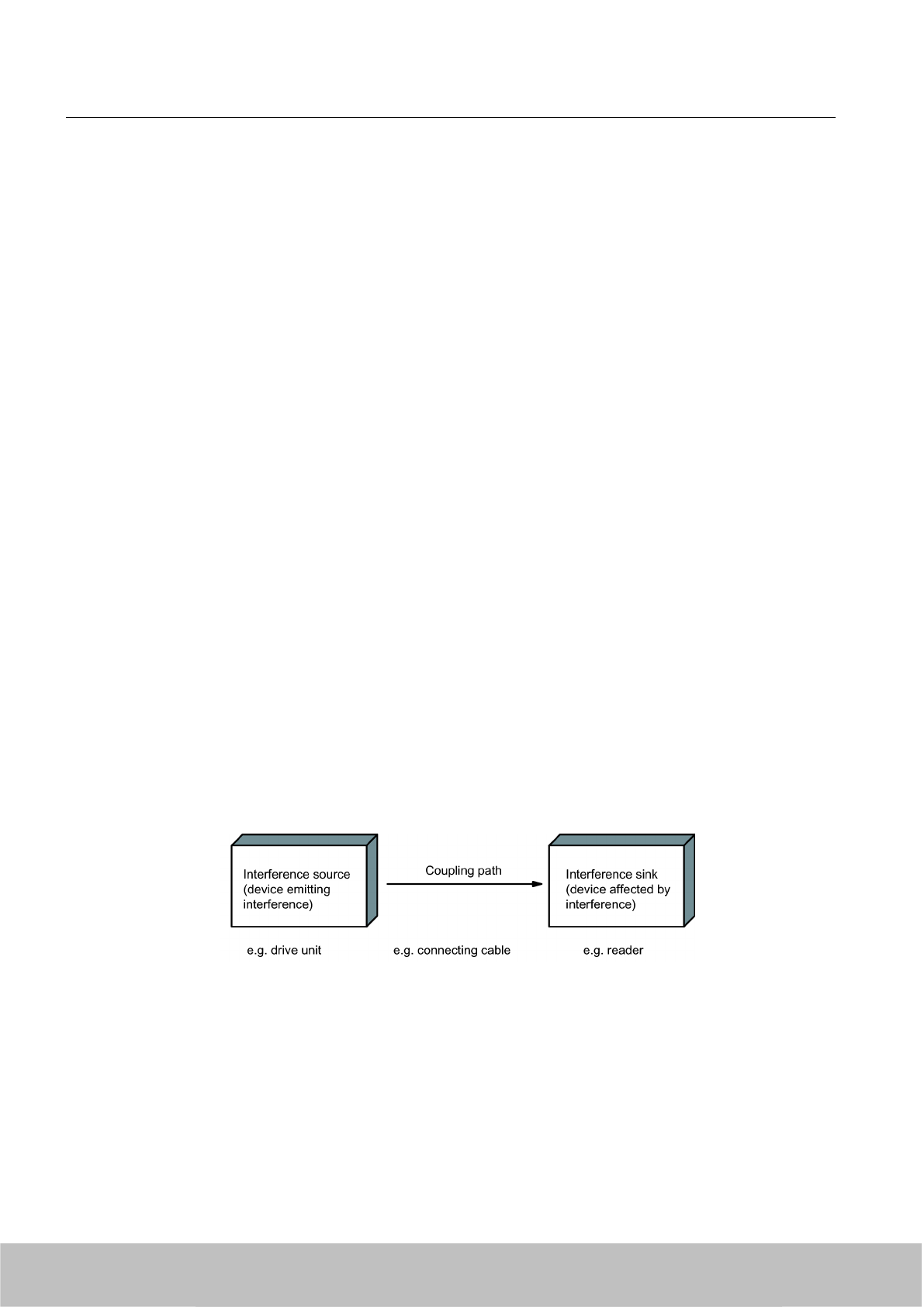
● Routing HF cables:
avoid parallel routing of HF cables.
● Do not route cables through the antenna field.
Shielding for the cables
● Shield the data cables and connect the shield at both ends.
● Shield the analog cables and connect the shield at one end, e.g. on the drive unit.
●Always apply large-area connections between the cable shields and the shielding bus at
the cabinet inlet and make the contact with clamps.
● Feed the connected shield through to the module without interruption.
● Use braided shields, not foil shields.
Line and signal filter
● Use only line filters with metal housings
● Connect the filter housing to the cabinet chassis using a large-area low-HF-impedance
connection.
● Never fix the filter housing to a painted surface.
● Fix the filter at the control cabinet inlet or in the direction of the source.
4.8.4 Propagation of electromagnetic interference
Three components have to be present for interference to occur in a system:
● Interference source
● Coupling path
● Interference sink
Figure 4-15 Propagation of interference
If one of the components is missing, e.g. the coupling path between the interference source
and the interference sink, the interference sink is unaffected, even if the interference source
is transmitting a high level of noise.
The EMC measures are applied to all three components, in order to prevent malfunctions due
to interference. When setting up a plant, the manufacturer must take all possible measures in
order to prevent the occurrence of interference sources:
RF600 system planning
4.8 Guidelines for electromagnetic compatibility (EMC)
SIMATIC RF600
72 System Manual, 06/2010, J31069-D0171-U001-A10-7618
Draft Version 02.06.2010
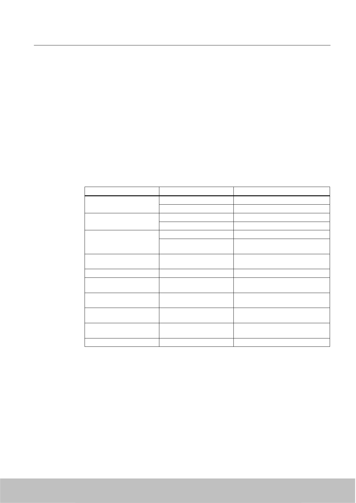
● Only devices fulfilling limit class A of VDE 0871 may be used in a plant.
● Interference suppression measures must be introduced on all interference-emitting
devices. This includes all coils and windings.
● The design of the system must be such that mutual interference between individual
components is precluded or kept as small as possible.
Information and tips for plant design are given in the following sections.
Interference sources
In order to achieve a high level of electromagnetic compatibility and thus a very low level of
disturbance in a plant, it is necessary to recognize the most frequent interference sources.
These must then be eliminated by appropriate measures.
Table 4-1 Interference sources: origin and effect
Interference source Interference results from Effect on the interference sink
Contactors,
electronic valves
Contacts System disturbances
Coils Magnetic field
Electrical motor Collector Electrical field
Winding Magnetic field
Electric welding device Contacts Electrical field
Transformer Magnetic field, system disturbance,
transient currents
Power supply unit, switched-
mode
Circuit Electrical and magnetic field, system
disturbance
High-frequency appliances Circuit Electromagnetic field
Transmitter
(e.g. service radio)
Antenna Electromagnetic field
Ground or reference potential
difference
Voltage difference Transient currents
Operator Static charge Electrical discharge currents, electrical
field
Power cable Current flow Electrical and magnetic field, system
disturbance
High-voltage cable Voltage difference Electrical field
RF600 system planning
4.8 Guidelines for electromagnetic compatibility (EMC)
SIMATIC RF600
System Manual, 06/2010, J31069-D0171-U001-A10-7618 73
Draft Version 02.06.2010
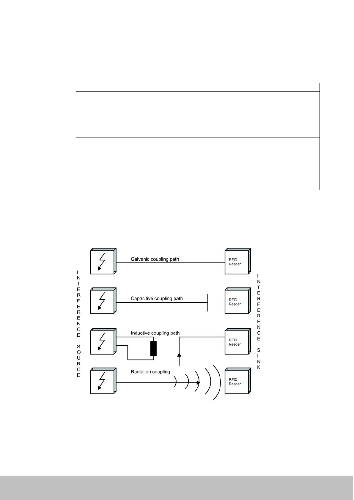
What interference can affect RFID?
Interference source Cause Remedy
Switched-mode power supply Interference emitted from the
current infeed
Replace the power supply
Interference injected through
the cables connected in
series
Cable is inadequately
shielded
Better cable shielding
The reader is not connected
to ground.
Ground the reader
HF interference over the
antennas
caused by another reader ● Position the antennas further apart.
● Erect suitable damping materials
between the antennas.
● Reduce the power of the readers.
Please follow the instructions in the
section
Installation guidelines/
reducing the effects of metal
Coupling paths
A coupling path has to be present before the disturbance emitted by the interference source
can affect the system. There are four ways in which interference can be coupled in:
Figure 4-16 Ways in which interference can be coupled in
RF600 system planning
4.8 Guidelines for electromagnetic compatibility (EMC)
SIMATIC RF600
74 System Manual, 06/2010, J31069-D0171-U001-A10-7618
Draft Version 02.06.2010
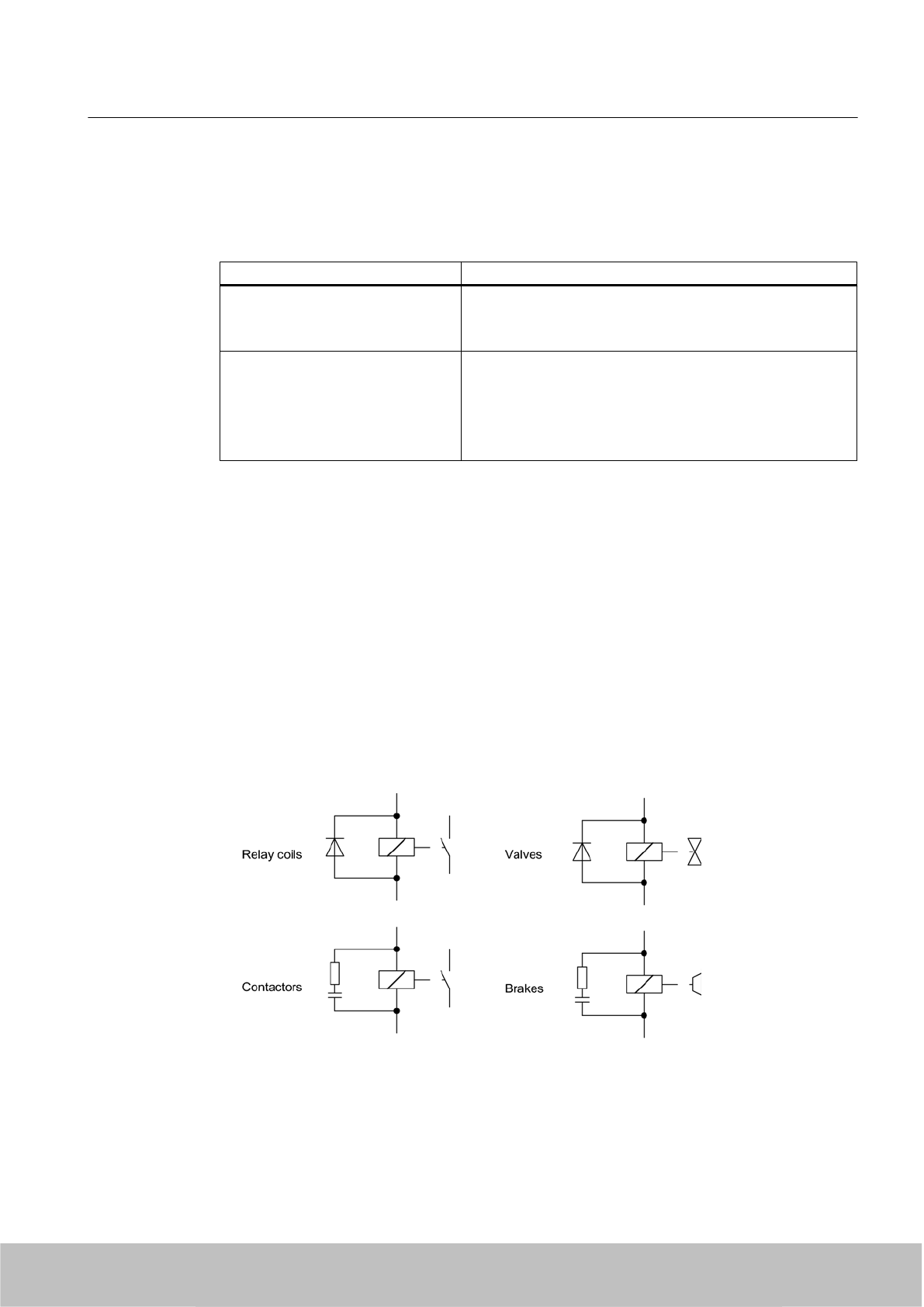
When RFID modules are used, different components in the overall system can act as a coupling
path:
Table 4-2 Causes of coupling paths
Coupling path Invoked by
Conductors and cables ● Incorrect or inappropriate installation
●Missing or incorrectly connected shield
● Inappropriate physical arrangement of cables
Control cabinet or housing ● Missing or incorrectly wired equalizing conductor
● Missing or incorrect earthing
● Inappropriate physical arrangement
● Components not mounted securely
●Unfavorable cabinet configuration
4.8.5 Prevention of interference sources
A high level of immunity to interference can be achieved by avoiding interference sources. All
switched inductances are frequent sources of interference in plants.
Suppression of inductance
Relays, contactors, etc. generate interference voltages and must therefore be suppressed
using one of the circuits below.
Even with small relays, interference voltages of up to 800 V occur on 24 V coils, and
interference voltages of several kV occur on 230 V coils when the coil is switched. The use of
freewheeling diodes or RC circuits prevents interference voltages and thus stray interference
on conductors installed parallel to the coil conductor.
Figure 4-17 Suppression of inductance
RF600 system planning
4.8 Guidelines for electromagnetic compatibility (EMC)
SIMATIC RF600
System Manual, 06/2010, J31069-D0171-U001-A10-7618 75
Draft Version 02.06.2010
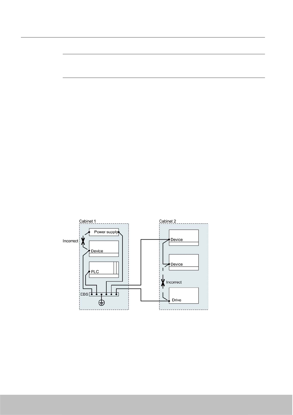
Note
All coils in the cabinet should be suppressed. The valves and motor brakes are frequently
forgotten. Fluorescent lamps in the control cabinet should be tested in particular.
4.8.6 Equipotential bonding
Potential differences between different parts of a plant can arise due to the different design of
the plant components and different voltage levels. If the plant components are connected
across signal cables, transient currents flow across the signal cables. These transient currents
can corrupt the signals.
Proper equipotential bonding is thus essential.
● The equipotential bonding conductor must have a sufficiently large cross section (at least
10 mm2).
● The distance between the signal cable and the associated equipotential bonding conductor
must be as small as possible (antenna effect).
● A fine-strand conductor must be used (better high-frequency conductivity).
● When connecting the equipotential bonding conductors to the centralized equipotential
bonding strip (EBS), the power components and non-power components must be combined.
● The equipotential bonding conductors of the separate modules must lead directly to the
equipotential bonding strip.
Figure 4-18 Equipotential bonding (EBS = Equipotential bonding strip)
The better the equipotential bonding in a plant, the smaller the chance of interference due to
fluctuations in potential.
RF600 system planning
4.8 Guidelines for electromagnetic compatibility (EMC)
SIMATIC RF600
76 System Manual, 06/2010, J31069-D0171-U001-A10-7618
Draft Version 02.06.2010
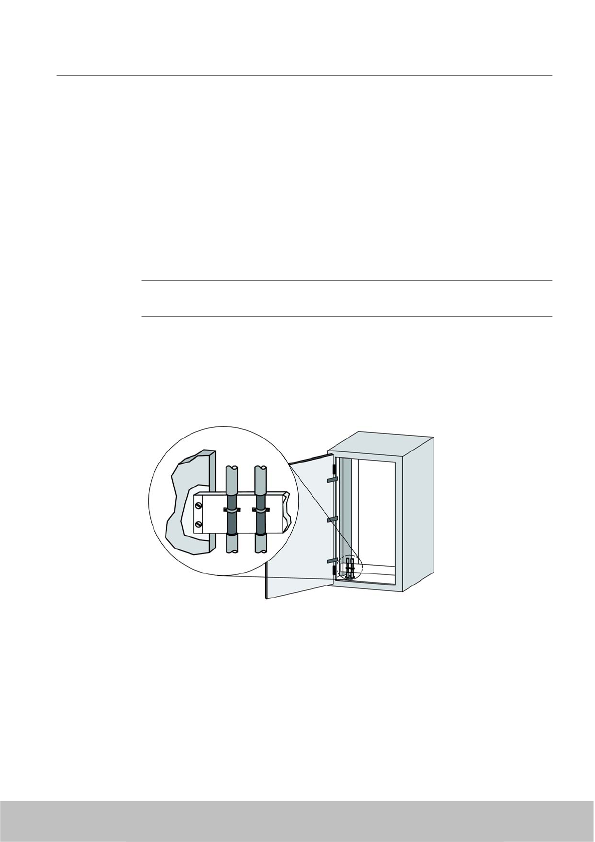
Equipotential bonding should not be confused with protective earthing of a plant. Protective
earthing prevents the occurrence of excessive shock voltages in the event of equipment faults
whereas equipotential bonding prevents the occurrence of differences in potential.
4.8.7 Cable shielding
Signal cables must be shielded in order to prevent coupling of interference.
The best shielding is achieved by installing the cables in steel tubes. However, this is only
necessary if the signal cable is routed through an environment prone to particular interference.
It is usually adequate to use cables with braided shields. In either case, however, correct
connection is vital for effective shielding.
Note
An unconnected or incorrectly connected shield has no shielding effect.
As a rule:
● For analog signal cables, the shield should be connected at one end on the receiver side
● For digital signals, the shield should be connected to the enclosure at both ends
● Since interference signals are frequently within the HF range (> 10 kHz), a large-area HF-
proof shield contact is necessary
Figure 4-19 Cable shielding
The shielding bus should be connected to the control cabinet enclosure in a manner allowing
good conductance (large-area contact) and must be situated as close as possible to the cable
inlet. The cable insulation must be removed and the cable clamped to the shielding bus (high-
frequency clamp) or secured using cable ties. Care should be taken to ensure that the
connection allows good conductance.
RF600 system planning
4.8 Guidelines for electromagnetic compatibility (EMC)
SIMATIC RF600
System Manual, 06/2010, J31069-D0171-U001-A10-7618 77
Draft Version 02.06.2010
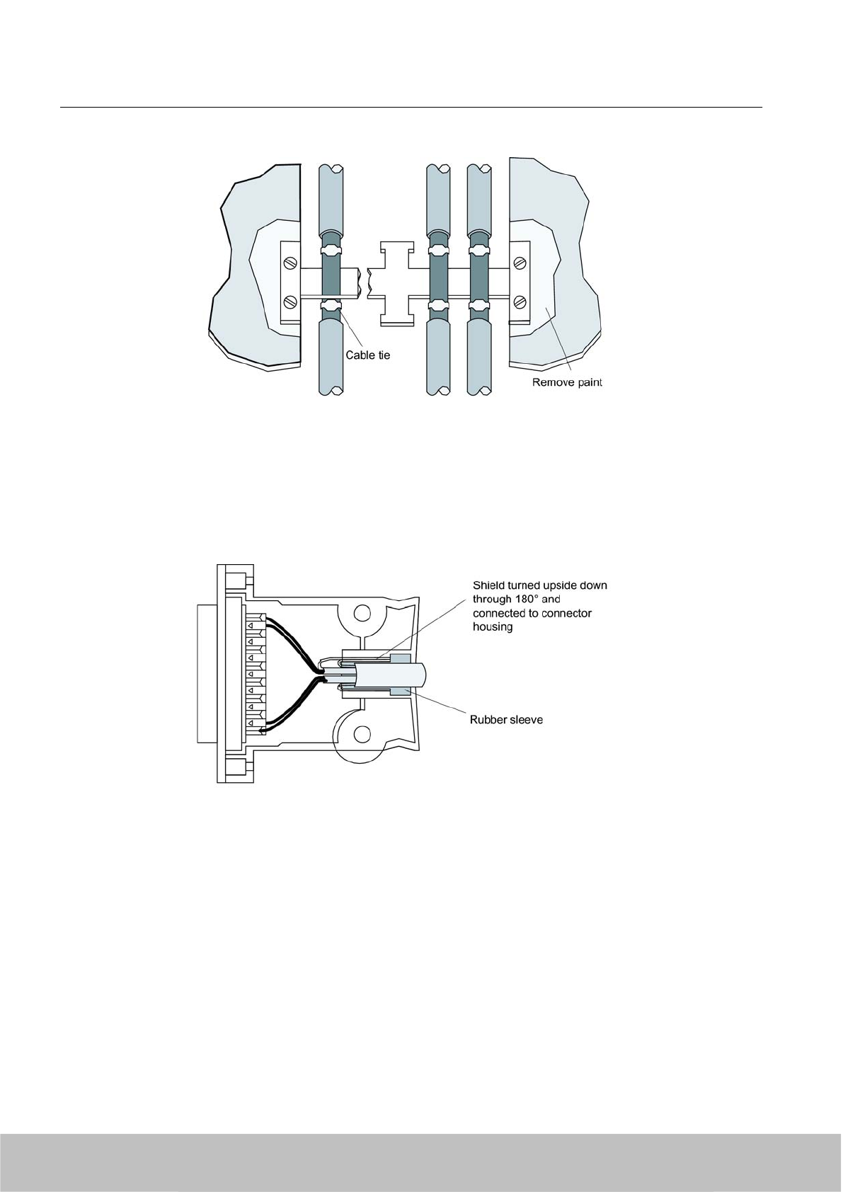
Figure 4-20 Connection of shielding bus
The shielding bus must be connected to the PE busbar.
If shielded cables have to be interrupted, the shield must be continued via the corresponding
connector housing. Only suitable connectors may be used for this purpose.
Figure 4-21 Interruption of shielded cables
If intermediate connectors, which do not have a suitable shield connection, are used, the shield
must be continued by fixing cable clamps at the point of interruption. This ensures a large-area,
HF-conducting contact.
RF600 system planning
4.8 Guidelines for electromagnetic compatibility (EMC)
SIMATIC RF600
78 System Manual, 06/2010, J31069-D0171-U001-A10-7618
Draft Version 02.06.2010

Readers 5
The following table shows the most important features of the stationary RF600 readers at a
glance:
Features SIMATIC RF670R SIMATIC RF660R SIMATIC RF630R SIMATIC RF620R
Air interface / standards
supported
EPCglobal Class 1
Gen 2
EPCglobal Class 1,
Gen 1,
EPCglobal Class 1,
Gen 2,
ISO 18000-6B
EPCglobal Class 1,
Gen 2
EPCglobal Class 1,
Gen 2
ETSI variant Available Available Available Available
FCC variant Available Available Available Available
CHINA variant In preparation Available
LEDs 1 3 1 1
Interfaces
Number of
external antennas
via RTNC
1 through 4 2 through 4 1 through 2 -
Integrated antenna
Ethernet 1x RJ45 connection
according to
IEC PAS 61076-3-117
1x RJ45 connection
according to
IEEE 802.3 and
ISO 8802-3
- -
RS232 - 1x connector (5-pin
M12). Bit rate: 115200
bps
- -
RS422 - - 1 x plug (8-pin M12) 1 x plug (8-pin M12)
Digital inputs 4 (12-pin M12)
log. "0": 0…7 V
log "1": 15…24 V
3 (8-pin M12)
log. "0": 0…7 V
log. "1": 15 to 24 V
- -
Digital outputs
(short-circuit proof)
4 (12-pin M12)
24 V; 0.5 A each
3 (8-pin M12)
24 V; 0.5 A each
- -
Power supply 24 V DC (4-pin M12)
20 to 30 V (2.2 A)
external
24 V DC (4-pin M12)
20 to 30 V (2.2 A)
external Via ASM Via ASM
Max. radiated power
EU, EFTA, Turkey
in ERP
- - - 0.5 W ERP
Max. radiated power
USA/China
in EIRP
- - - 0.795 W EIRP
Max. transmit power
EU, EFTA, Turkey /
China
XXX@@ 0.1 to 2 W 0.5 W -
SIMATIC RF600
System Manual, 06/2010, J31069-D0171-U001-A10-7618 79
Draft Version 02.06.2010
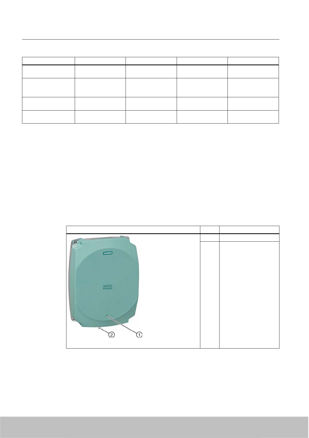
Features SIMATIC RF670R SIMATIC RF660R SIMATIC RF630R SIMATIC RF620R
Max. transmit power
USA
XXX @@@ 0.24 to 2.4 W 0.5 W -
Max. transmission rate
of the communication
interface
XXX @@@ 921 kbps
(max. TCP/IP data
rate)
115.2 kbps 115.2 kbps
Max. data rate
reader-to-tag
XXX @@@ 80 kbps 40 kbps 40 kbps
Max. data rate
tag-to-reader
XXX @@@ 160 kbps 160 kbps 160 kbps
5.1 RF620R reader
5.1.1 Description
The SIMATIC RF620R is an active stationary reader in the UHF frequency range with an
integrated circular polarized antenna.
The SIMATIC RF620R is connected to a SIMATIC S7 controller via an ASM interface module.
The degree of protection corresponds to IP 65.
Item Description
(1) LED status indicator
(2) RS 422 interface
(8-pin M12 socket)
Readers
5.1 RF620R reader
SIMATIC RF600
80 System Manual, 06/2010, J31069-D0171-U001-A10-7618
Draft Version 02.06.2010
Highlights
● The tags are read in accordance with the requirements of the EPCglobal Class 1, Gen 2
and ISO/IEC 18000-6C standards
● Supports low-cost SmartLabels as well as reusable, rugged data media
● High reading speed: Depending on the function block (multitag mode), many tags can be
detected simultaneously (bulk reading), rapidly moving tags are reliably acquired.
●The RF620R (ETSI) "6GT2811-5BA00-0AA0" is suitable for the frequency band 865 to 868
MHz UHF (EU, EFTA, Turkey). The reader supports the ETSI EN 302 208 V1.1.1 standard
as well as the new ETSI EN 302 208 V1.2.1 standard (4-channel plan).
● The RF620R (FCC) "6GT2811-5BA00-1AA0" is suitable for the frequency ranges 920.25
to 924.75 MHz (Thailand) and 902 to 928 MHz (North America).
● The RF620R (CHINA) "6GT2811-5BA00-2AA0" is suitable for the frequency band 920.125
to 924.875 MHz (China)
● IP65 degree of protection for reader
● Can be used for a high temperature range
● Dense Reader Mode (DRM) for environments in which many readers are operated in close
proximity to each other
● TIA system interface:
– RS 422
5.1.1.1 Ordering data
Ordering data RF620R
Product Order No.
RF620R (ETSI) reader basic unit for EU, EFTA,
Turkey
6GT2811-5BA00-0AA0
RF620R (FCC) reader basic unit for North America 6GT2811-5BA00-1AA0
RF620R (CHINA) reader basic unit for China 6GT2811-5BA00-2AA0
Readers
5.1 RF620R reader
SIMATIC RF600
System Manual, 06/2010, J31069-D0171-U001-A10-7618 81
Draft Version 02.06.2010
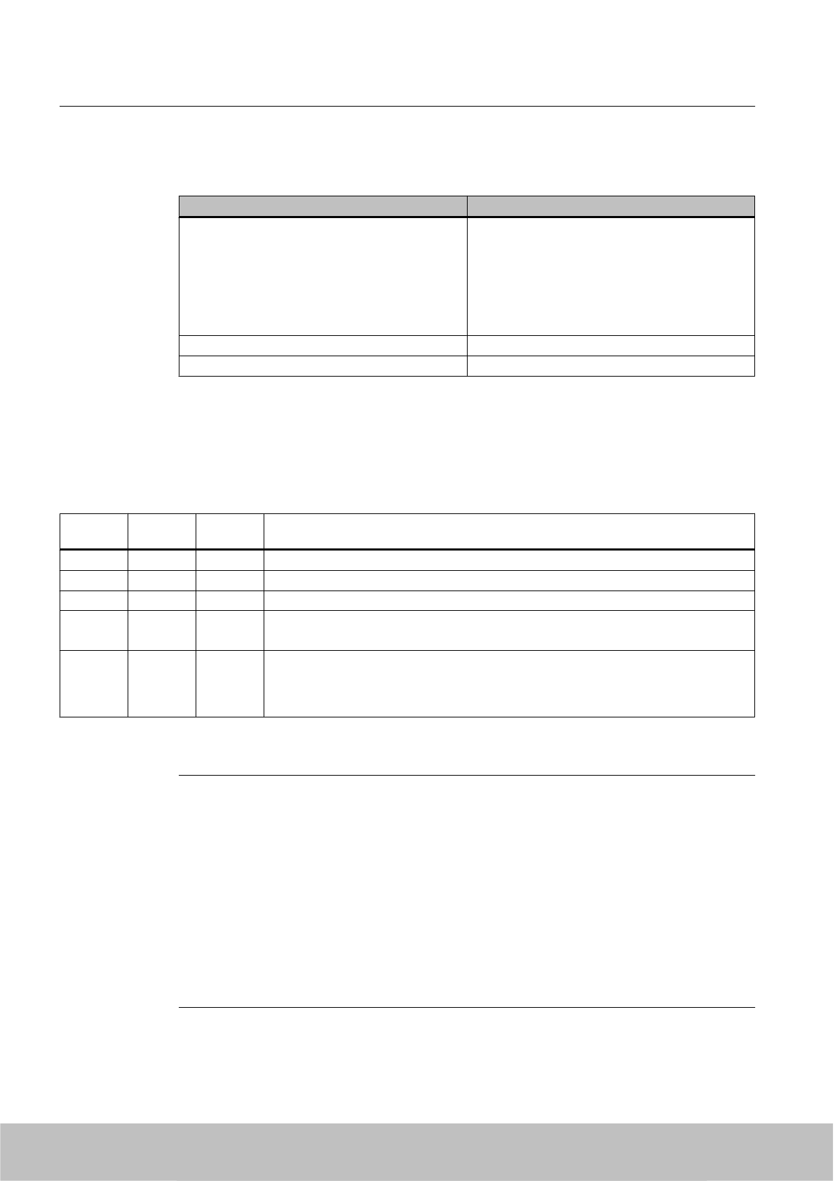
Ordering data (accessories)
Product Order No.
Connecting cable
●RS°422, M12 plug, 8-pin socket: 2 m
● RS°422, M12 plug, 8-pin socket: 5 m
● RS°422, M12 plug, 8-pin socket: 10 m
●RS°422, M12 plug, 8-pin socket: 20 m
● RS°422, M12 plug, 8-pin socket: 50 m
● 6GT2891-0FH20
● 6GT2891-0FH50
● 6GT2891-0FN10
● 6GT2891-0FN20
● 6GT2891-0FN50
Antenna mounting kit 6GT2890-0AA00
CD-ROM Software & Documentation 6GT2080-2AA10
5.1.1.2 Status display
The device is equipped with a three colored LED. The LED can be lit in green, red or yellow.
The meaning of the indication changes in accordance with the color and state (on, off, flashing)
of the LED:
Green
LED
Red LED Yellow
LED
Meaning
Off Off Off The device is starting up.
Flashing Off Off The device is ready. The antenna is switched off.
On Off Off The device is ready. The antenna is switched on.
Off Off On "With presence": At least one tag is in the field.
"Without presence": Communication with a tag is active.
Off Flashing Off Reader is not active, a serious error has occurred. In addition, this LED also indicates
the fault status through the number of flashing pulses. Reboot (operating voltage Off →
On is necessary).
The LED flashes once for the 'INACTIVE' status, rebooting is not necessary in this case.
For more detailed information on the flash codes of the reader see Chapter Error messages
and flash codes for RF620R/RF630R (Page 338)
Note
LED not lit yellow?
If the LED does not light up yellow even though a tag is located within the field, common
causes are:
● Incorrect configuration in the init_run command, or init_run command was not executed
(see "Configuration Manual RF620R/RF630R")
● Antenna is switched off
● A tag is used, that is not compatible with the reader protocol (EPC Global Class 1 Gen 2).
● Tag is defective
● Reader or antenna has a defect
● Tag is not in the field of radiation of the transmit antenna
Readers
5.1 RF620R reader
SIMATIC RF600
82 System Manual, 06/2010, J31069-D0171-U001-A10-7618
Draft Version 02.06.2010
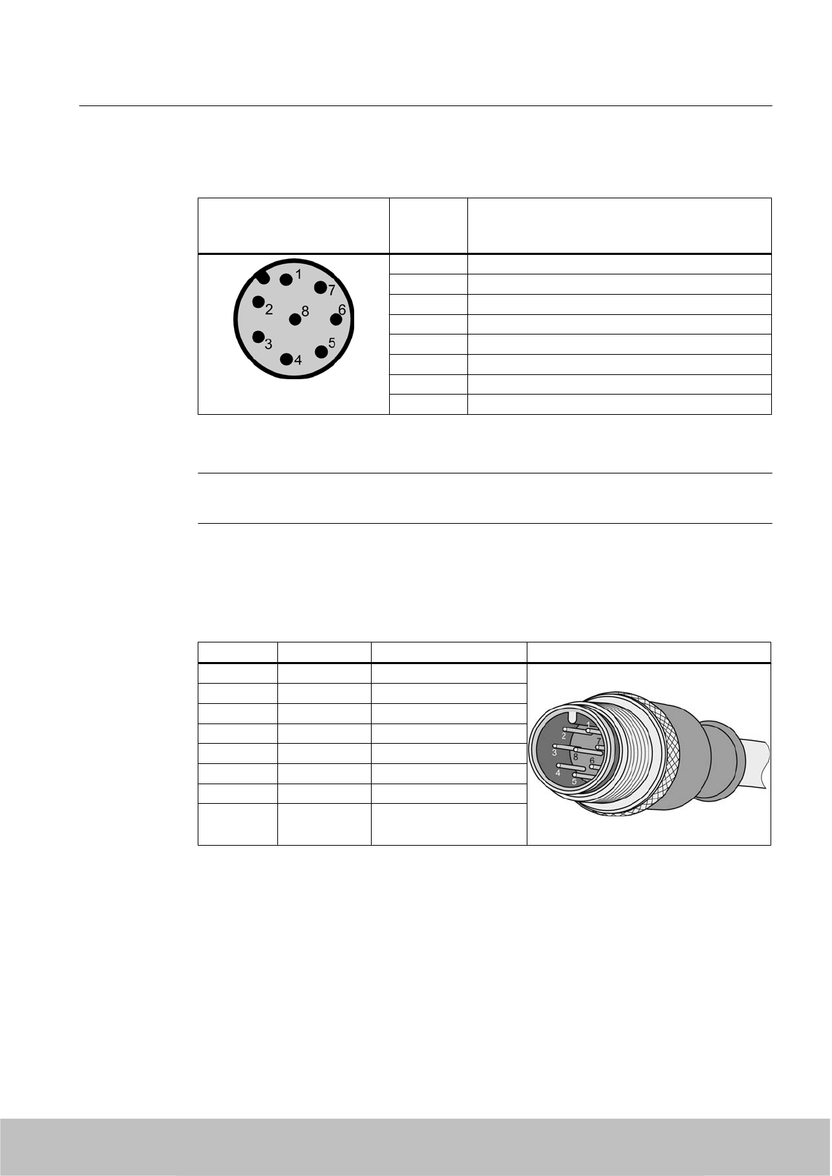
5.1.1.3 Pin assignment of the RS422 interface
Pin Pin
Device end
8-pin M12
Assignment
1+ 24 V
2 - Transmit
3 0 V
4 + Transmit
5 + Receive
6 - Receive
7 Free
8 Earth (shield)
The knurled bolt of the M12 plug is not connected to the shield (on the reader side).
Note
You must therefore not use any SIMATIC connecting cables that use the angled M12 plug.
5.1.1.4 Pin assignment of the connecting cable
Table 5-1 RS 422 - on reader side
M12 pin Core color Pin assignment View of M12 connector
1white 24 VDC
2 brown TX neg
3 green GND
4 yellow TX pos
5 Gray RX pos
6 pink RX neg
7 blue Not assigned
8 red Earth (shield)
Comment
This cable has an 8-pin M12 connector at one end and the other cable end is 'open'. There
are 8 color-coded single cores there for connecting to external devices. There are different
cable lengths in the product range (3 m to 50 m). Long cables can be reduced if necessary.
Readers
5.1 RF620R reader
SIMATIC RF600
System Manual, 06/2010, J31069-D0171-U001-A10-7618 83
Draft Version 02.06.2010
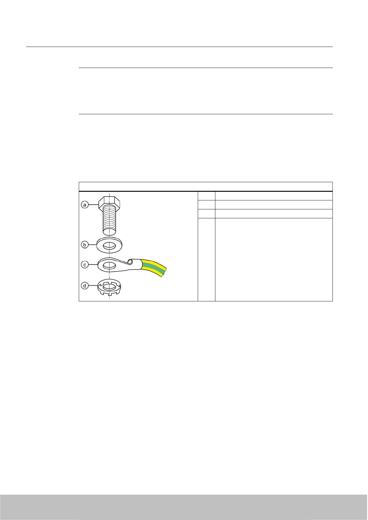
Note
For long cables: Adapt supply voltage and data rate accordingly
Note that with long cables in particular, the supply voltage of 24 V DC must always be applied.
Note also that the data rate on the serial interface must, if necessary, be reduced. (See
"Configuration Manual RF620R/RF630R")
5.1.1.5 Grounding connection
The RF620R/RF630R can be electrically connected to the ground potential through a contact
washer. The tightening torque must be increased in this case to ensure that electrical contact
is made (2.7 Nm).
Ground connection
(a) Hexagon-head screw
(b) Plain washer
(c) Cable lugs
(d) Contact washer:
Use contact washers according to the
Siemens standard SN 70093-6-FSt-
flNnnc-480h for ground connection,
Siemens item No.: H70093-A60-Z3
5.1.2 Planning application
5.1.2.1 Minimum mounting clearances of two readers
The RF620R has a circular polarized antenna. At 500 mW ERP radiated power, due to the
opening angle of the antennas, their fields can overlap considerably. It is no longer possible
to clarify in which antenna field access to the data of a tag is performed.
In order to avoid this, always keep a minimum distance of 3 m between two readers with the
maximum radiated power of 500 mW ERP.
Dense Reader Mode (DRM)
The readers can also interfere with each other (secondary fields), if the channels (Reader TX,
Transponder TX) overlap. In order to prevent a transponder channel overlapping with a reader
channel, we recommend that the Dense Reader Mode (DRM) is used.
Readers
5.1 RF620R reader
SIMATIC RF600
84 System Manual, 06/2010, J31069-D0171-U001-A10-7618
Draft Version 02.06.2010
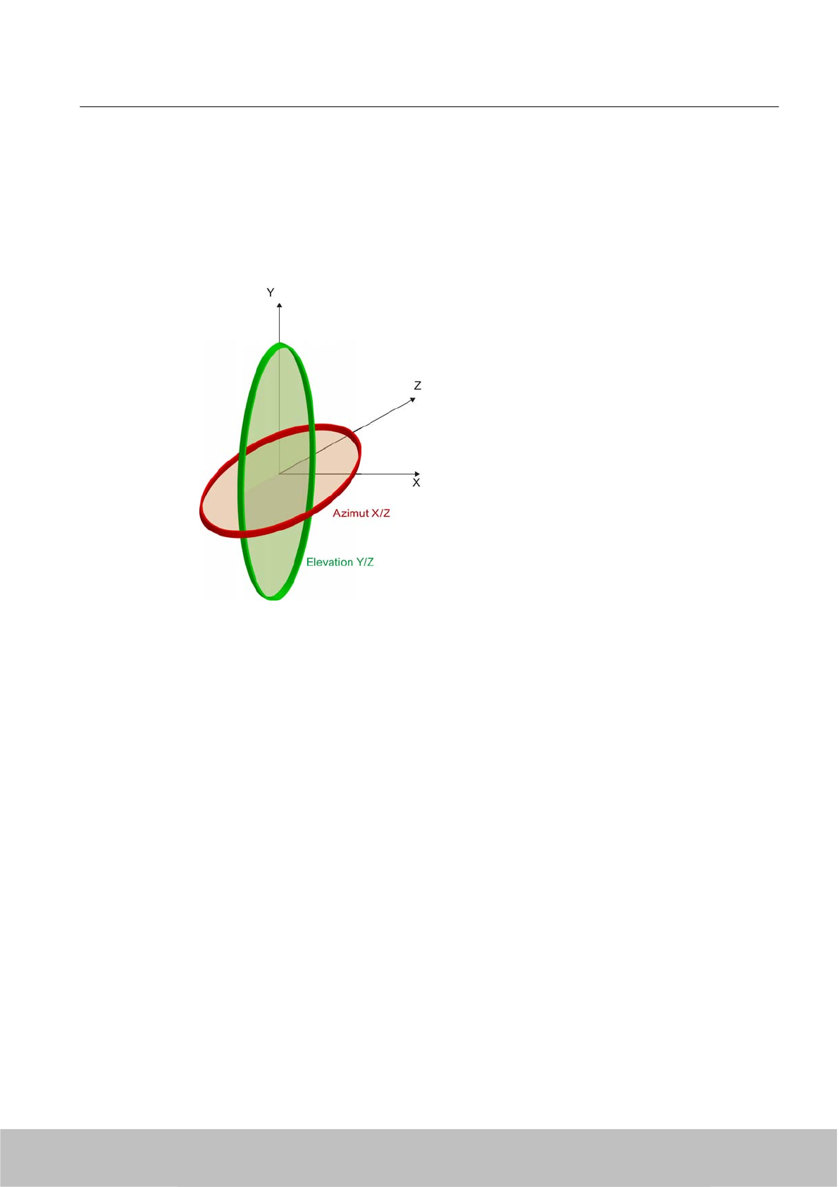
5.1.2.2 Antenna diagram for RF620R (ETSI)
The following radiation diagrams show the directional radiation pattern of the internal antenna
of the RF620R (ETSI) reader. For the spatial presentation of the directional radiation pattern,
the vertical plane in space (Azimuth section) as well as the horizontal plane (elevation section)
must be considered. This results in a spatial image of the directional radiation pattern of the
antenna with its main and auxiliary fields.
Readers
5.1 RF620R reader
SIMATIC RF600
System Manual, 06/2010, J31069-D0171-U001-A10-7618 85
Draft Version 02.06.2010
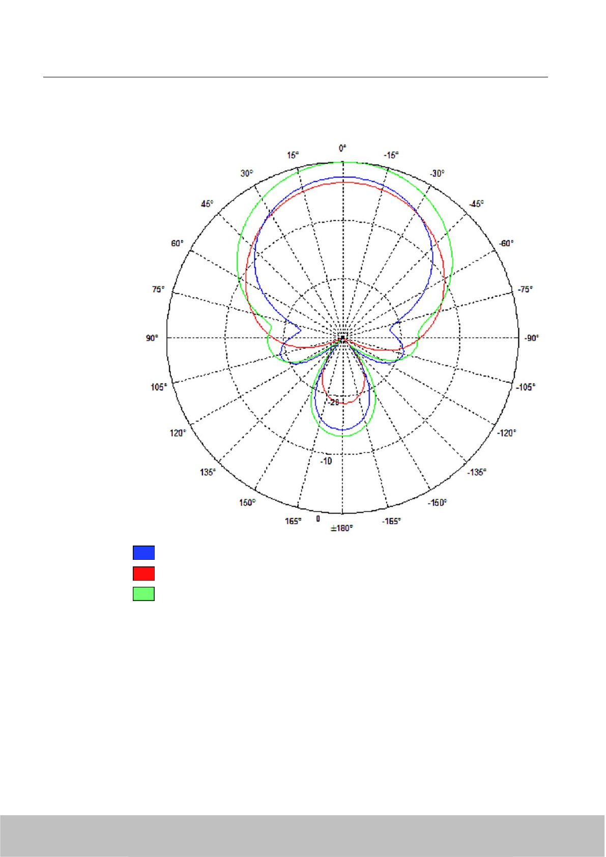
Radiation diagram (Azimuth section)
Vertical component of the polarization direction of the antenna
Horizontal component of the polarization direction of the antenna
Right circular component of the polarization direction of the antenna
Figure 5-1 Azimuth section
Readers
5.1 RF620R reader
SIMATIC RF600
86 System Manual, 06/2010, J31069-D0171-U001-A10-7618
Draft Version 02.06.2010
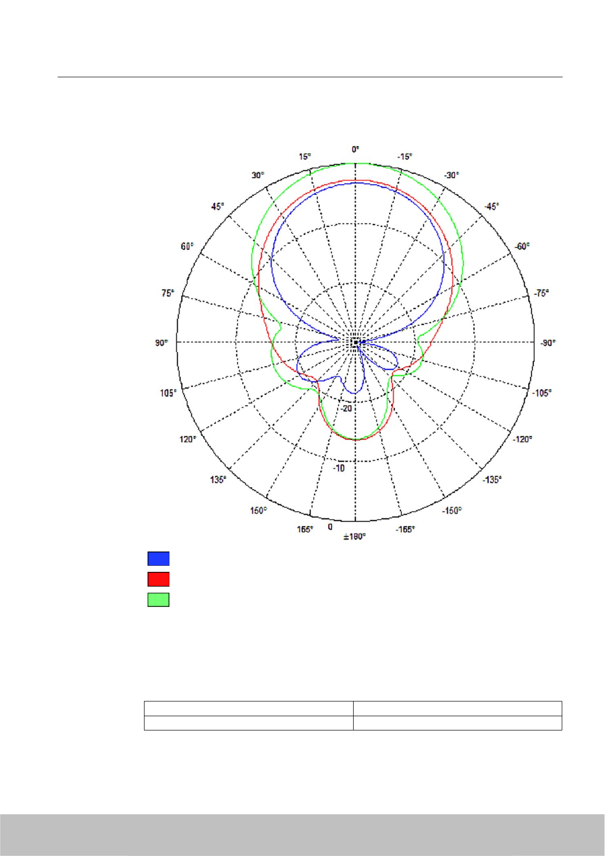
Radiation diagram (elevation section)
Vertical component of the polarization direction of the antenna
Horizontal component of the polarization direction of the antenna
Right circular component of the polarization direction of the antenna
Figure 5-2 Elevation section
Overview of the antenna parameters
Table 5-2 Maximum linear electrical opening angle at 865 MHz:
Azimuth section 77.7°
Elevation section 66.1°
Readers
5.1 RF620R reader
SIMATIC RF600
System Manual, 06/2010, J31069-D0171-U001-A10-7618 87
Draft Version 02.06.2010
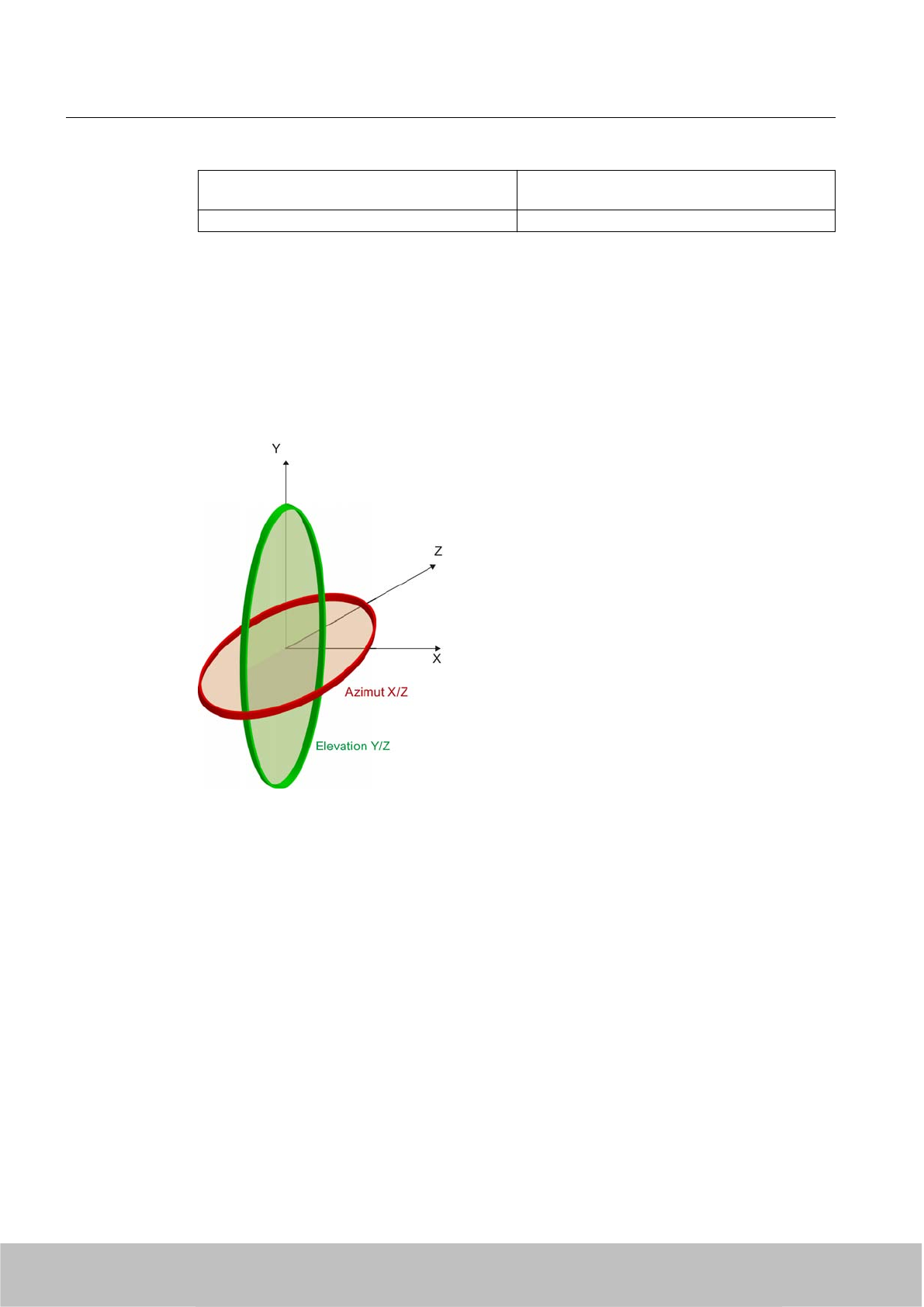
Typical antenna gain in the frequency range 865
to 868 MHz
7.3 dBic
Antenna axis ratio 0.7 dB
See also Chapter Guidelines for selecting RFID UHF antennas (Page 181)
5.1.2.3 Antenna diagram for RF620R (FCC)
The following radiation diagrams show the directional radiation pattern of the internal antenna
of the RF620R (FCC) reader. For the spatial presentation of the directional radiation pattern,
the vertical plane in space (Azimuth section) as well as the horizontal plane (elevation section)
must be considered. This results in a spatial image of the directional radiation pattern of the
antenna with its main and auxiliary fields.
Azimuth XZ plane
Elevation YZ plane
Readers
5.1 RF620R reader
SIMATIC RF600
88 System Manual, 06/2010, J31069-D0171-U001-A10-7618
Draft Version 02.06.2010
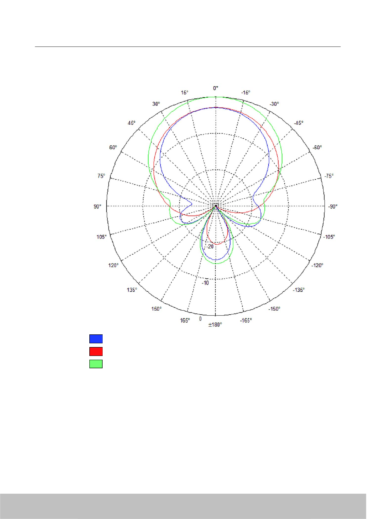
Radiation diagram (Azimuth section)
Vertical component of the polarization direction of the antenna
Horizontal component of the polarization direction of the antenna
Right circular component of the polarization direction of the antenna
Figure 5-3 Azimuth section
Readers
5.1 RF620R reader
SIMATIC RF600
System Manual, 06/2010, J31069-D0171-U001-A10-7618 89
Draft Version 02.06.2010
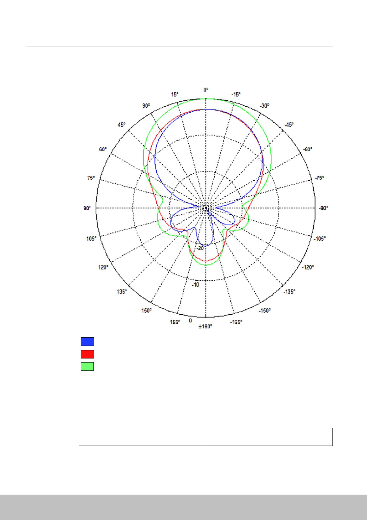
Radiation diagram (elevation section)
Vertical component of the polarization direction of the antenna
Horizontal component of the polarization direction of the antenna
Right circular component of the polarization direction of the antenna
Figure 5-4 Elevation section
Overview of the antenna parameters
Table 5-3 Maximum linear electrical opening angle at 865 MHz:
Azimuth section 75.4 °
Elevation section 69.1 °
Readers
5.1 RF620R reader
SIMATIC RF600
90 System Manual, 06/2010, J31069-D0171-U001-A10-7618
Draft Version 02.06.2010
Typical antenna gain in the frequency range 865
to 868 MHz
7.3 dBic ± 0.5 dB
Antenna axis ratio <1 dB
See also Chapter Guidelines for selecting RFID UHF antennas (Page 181).
5.1.2.4 Interpretation of directional radiation patterns
The following overview table will help you with the interpretation of directional radiation
patterns.
The table shows which dBi values correspond to which read/write ranges (in %): You can read
the radiated power depending on the reference angle from the directional radiation patterns,
and thus obtain information on the read/write range with this reference angle with regard to a
transponder.
The dBr values correspond to the difference between the maximum dBi value and a second
dBi value.
Deviation from maximum antenna gain [dBr] Read/write range [%]
0100
-3 70
-6 50
-9 35
-12 25
-15 18
-18 13
Example
As one can see from the section Antenna diagram for RF620R (ETSI) (Page 85), the maximum
antenna gain is 0 dB. In the Azimuth diagram, the antenna gain falls by 3°dB at approximately
± 39°. Therefore the dBr value is -3. The antenna range is only 50% of the maximum range at
± 39° from the Z axis within the horizontal plane.
5.1.2.5 Antenna/read point configurations
The RF620R reader has an internal circular polarized antenna. You can cover one read point
with this antenna. When several RF620R readers are used, the readers are addressed via the
SIMATIC level.
5.1.3 Installing/Mounting
Requirement
Readers
5.1 RF620R reader
SIMATIC RF600
System Manual, 06/2010, J31069-D0171-U001-A10-7618 91
Draft Version 02.06.2010
WARNING
Ensure that the wall or ceiling can hold four times the total weight of the device.
NOTICE
Disregarding FCC RF exposure requirements
Ensure that the following conditions are met before the device is mounted to meet the FCC
RF exposure requirements:
● The RF620R reader must be installed so that a minimum distance from people of 20 cm
is always observed.
● The reader may not be installed or operated in the immediate vicinity of another reader
or antenna.
See also chapter FCC information (Page 98) RF620R or chapter FCC information
(Page 112) RF630R.
5.1.3.1 Mounting/Installing FCC
CAUTION
Emitted radiation
The transmitter complies with the requirements of Health Canada and the FCC limit values
for subjecting persons to HF radiation, provided that a minimum spacing of 26 cm exists
between antenna and person. When the antennas are installed, you must therefore ensure
that a minimum spacing of 26 cm is maintained between personnel and antennas.
Mounting/installing the device
You can mount the reader in two different ways:
● Via a standardized VESA 100 mounting system using the Antenna Mounting Kit (see
Chapter Mounting with antenna mounting kit (Page 203)). Tighten the M4 screws on the
rear of the reader using a maximum torque of ≤ 1.3 Nm.
● Directly onto a flat surface.
The positions of the fixing holes for the device are shown in the section Dimension drawings
(Page 97).
Readers
5.1 RF620R reader
SIMATIC RF600
92 System Manual, 06/2010, J31069-D0171-U001-A10-7618
Draft Version 02.06.2010
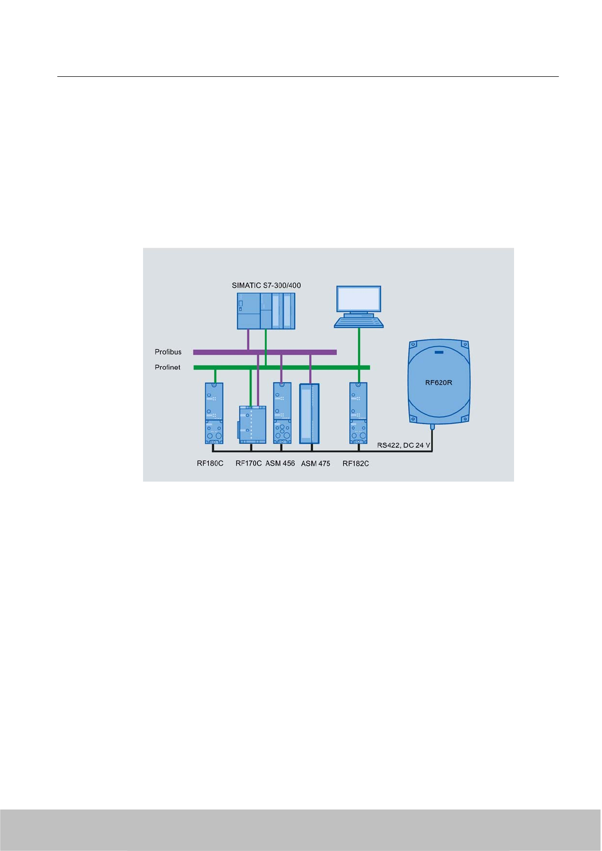
5.1.4 Configuration/integration
The RS422 system interface is provided for integrating the device into system environments/
networks. The system interface transfers data to SIMATIC controllers or PCs with the
appropriate interface.
Apart from transmitting communication data from the reader to the controller and vice versa,
the RS422 interface also supplies power to the reader (24 V DC).
Figure 5-5 Overview of configuration of the RF620R reader
The RF620R reader can alternatively be connected to a SIMATIC controller via the ASM 456,
ASM 475, RF170C and RF180C interface modules/communication modules.
The RF620R reader can alternatively also be connected directly to the PC via the RF182
communication module.
For further details on the interface modules used, see Chapter .
Further information about commissioning the readers can be found in the configuration manual
"RF620R/RF630R" in the "Commissioning" section.
Readers
5.1 RF620R reader
SIMATIC RF600
System Manual, 06/2010, J31069-D0171-U001-A10-7618 93
Draft Version 02.06.2010
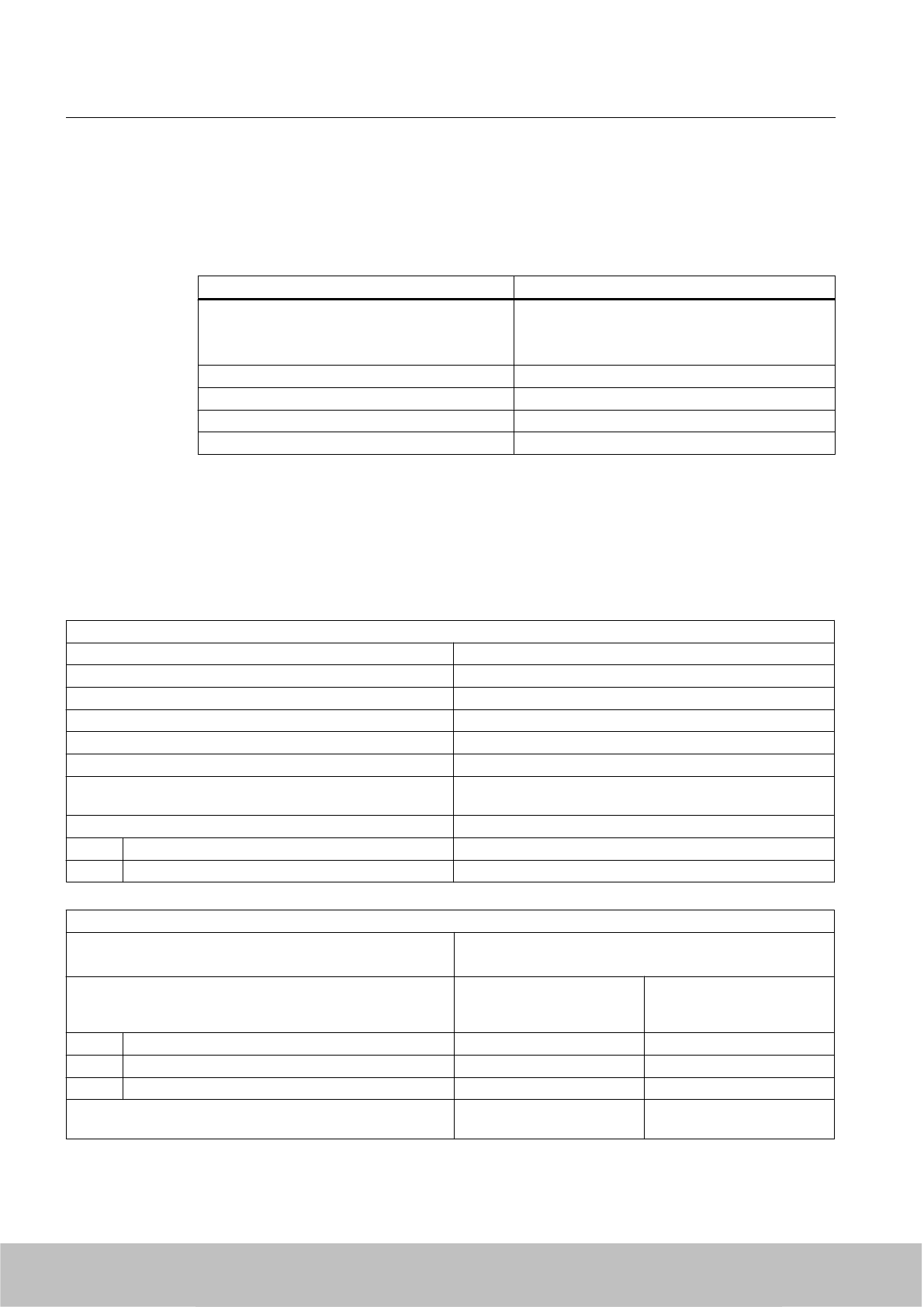
5.1.4.1 Transmission protocols
RS 422 communication
3964R protocol
Transmission rates 19.2 kbps
57.6 kbps
115.2 kbps
Start bits 1
Data bits 8
Parity Odd
Stop bits 1
5.1.5 Technical data
5.1.5.1 Mechanical data
Mechanical data
Weight 1850 g
Dimensions (L x W x H) in mm 252 X 193 x 52 mm, without connections
Material for housing top section ABS (GF 20), silicone-free
Material for housing bottom section Aluminum, silicone-free
Color of housing top section Pastel turquoise
Color of housing bottom section Silver
Status displays on the device 1 LED
Colors: Red, yellow, green
Interfaces
RS422 1 x plug (8-pin M12)
Software SIMATIC S7
Technical and electrical characteristics
Supply voltage
●Permitted range
21.6 to 30 V DC 1
Supply voltage Current consumption
(in standby mode, no
transmit power)
Power consumption (in
standby mode, no transmit
power)
20 V input voltage on the reader, typical 135 mA 2.7 W
24 V input voltage on the reader, typical 115 mA 2.76 W
30 V input voltage on the reader, typical 95 mA 2.85 W
Supply voltage Current consumption
(at 500 mW ERP)
Power requirement
(at 500 mW ERP)
Readers
5.1 RF620R reader
SIMATIC RF600
94 System Manual, 06/2010, J31069-D0171-U001-A10-7618
Draft Version 02.06.2010

20 V input voltage on the reader, typical 470 mA 9.4 W
24 V input voltage on the reader, typical 395 mA 9.48 W
30 V input voltage on the reader, typical 320 mA 9.6 W
Ramp-up time, typical 7 s
1) All supply and signal voltages must be safety extra low voltage (SELV/PELV according to EN 60950)
24 V DC power supply: safe (electrical) isolation of extra-low voltage (SELV / PELV acc. to EN 60950)
Mechanical environmental conditions
Shock resistant to EN 60068-2-27
Vibration EN 60068-2-6
50 g1
20 g1
Climatic Conditions
Ambient temperature during operation -25 °C to +55 °C
(a 10-minute warm-up time must be observed at an operating
temperature below -20 °C)
Ambient temperature for transport and storage -40 °C to +85 °C
1) The values for shock and vibration are maximum values and must not be applied continuously.
EMV & approvals/conformity for RF620R (ETSI)
Electromagnetic compatibility ETSI EN 301 489-1 / -3
ETSI EN 302 208
Approvals/Conformity ● Radio to R&TTE‑ guidelines EN 300 330, EN 301 489
●CE
● ETSI EN 302-208 V1.1.1
● ETSI EN 302-208 V1.2.1
●Reader degree of protection acc. to EN 60529 (IP65)
EMC & approvals for FCC variant
Electromagnetic compatibility FCC Part 15
Approvals ● FCC, cULus
●IEC60950, including US and Canadian variants of it
● FCC CFR47 Part 15.247
● RoHS-compliant according to EU Directive 2002/95/EC
●Industrial Canada, RSS-210, Issue 7, June 2007
5.1.5.2 Technical data according to EPC and ISO
Technical data
Frequency accuracy max.± 10 ppm
Channel spacing EU: 200 kHz
US: 500 kHz
China: 250 kHz
Readers
5.1 RF620R reader
SIMATIC RF600
System Manual, 06/2010, J31069-D0171-U001-A10-7618 95
Draft Version 02.06.2010

Technical data
Modulation methods ASK: DSB modulation & PR-ASK modulation
Encoding, Manchester or Pulse Interval (PIE)
Effective radiant power with integrated antenna
(the radiant power depends on the antennas and cables used,
see Guidelines for selecting RFID UHF antennas
(Page 181) )
≤ 0.5 W ERP
≤ 0.795 W EIRP
Transmitter power
(the radiant power depends on the antennas and cables used,
see Guidelines for selecting RFID UHF antennas
(Page 181) )
≤ 0.5 W
ETSI frequencies
Frequency range EU, EFTA, Turkey
according to ETSI EN 302 208 V1.1.1 (commissioning until
December 31, 2009)
865 to 868 MHz (10 subchannels LBT at 2 W ERP, 12
subchannels at 0.5 W ERP, 15 subchannels LBT at 0.1 W
ERP)
Frequency range EU, EFTA, Turkey
according to ETSI EN 302 208 V1.2.1 (valid since November
4, 2008, publication in the Official Journal of the European
Union)
● 865.7 MHz
● 866.3 MHz
● 866.9 MHz
● 867.5 MHz
(4 channels LBT optional at max. 2 W ERP)
Reading range for EU, EFTA, Turkey / China
Readers mounted on the same side Max. 2 m (recommended maximum value for configuration;
depending on the transponder)
FCC frequencies
North American frequency band 902 ... 928 MHz (50 channels, frequency hopping)
Frequency band for China 920.125 to 924.875 MHz (16 subchannels at 2 W ERP, 20
subchannels at 0.1 W ERP)
Read distance for USA
Readers mounted on the same side max. 2 m (recommended maximum value for configuration)
5.1.5.3 Maximum number of readable tags
The maximum number of readable tags depends on the following parameters:
● Size of the antenna field
● Readability of the tags
For a transmit power of 500 mW ERP, the following is read when the tag RF620T is used:
● Max. 40 tags in the antenna field (tags perpendicular to antenna and 1 m in front)
●Max. 18tags per second
Readers
5.1 RF620R reader
SIMATIC RF600
96 System Manual, 06/2010, J31069-D0171-U001-A10-7618
Draft Version 02.06.2010
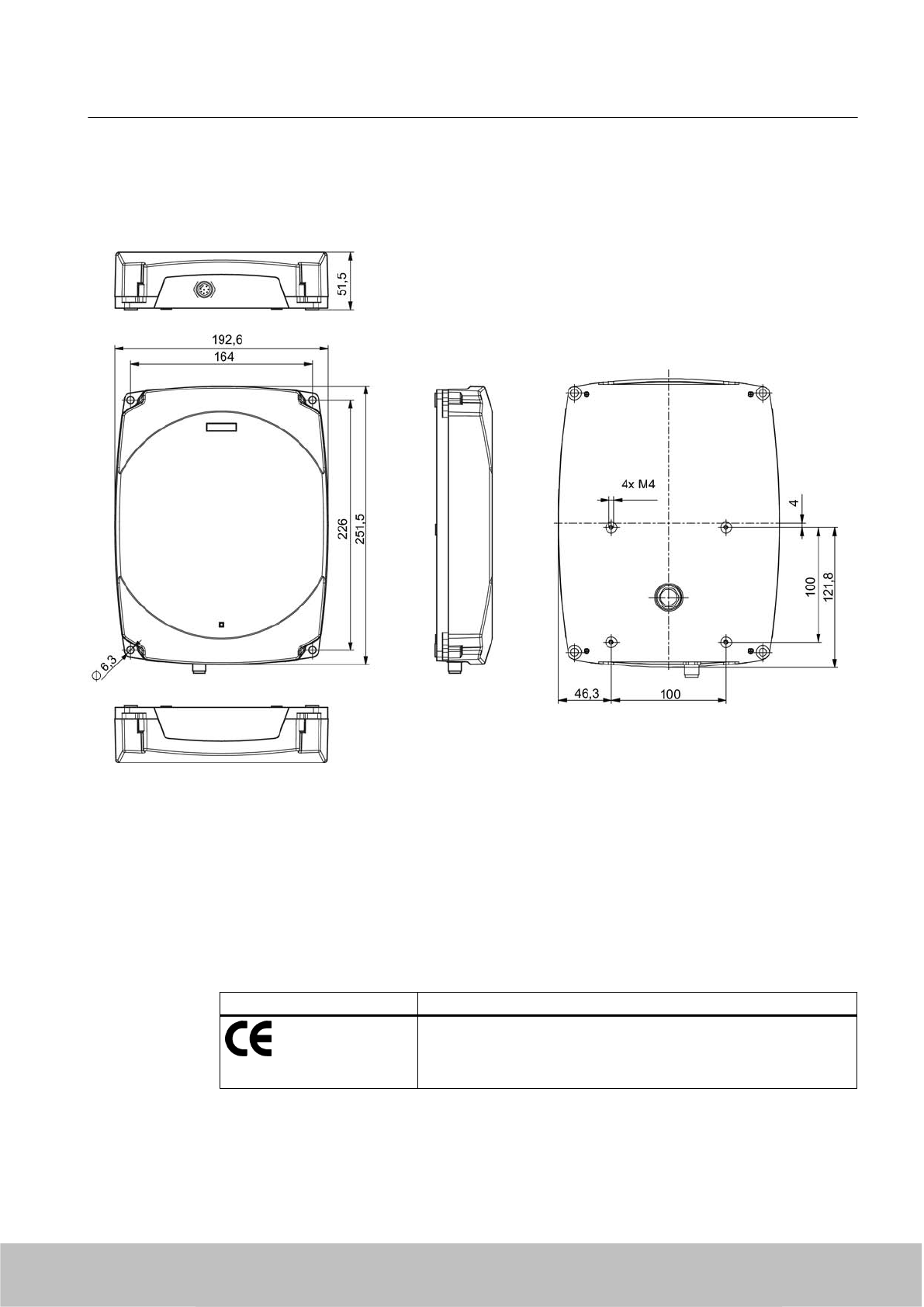
5.1.6 Dimension drawings
Figure 5-6 Dimension drawing for RF620R
All dimensions in mm
5.1.7 Certificates and approvals
Table 5-4 6GT2811-5BA00-0AA0
Certificate Description
Compatible with R&TTE directive
Readers
5.1 RF620R reader
SIMATIC RF600
System Manual, 06/2010, J31069-D0171-U001-A10-7618 97
Draft Version 02.06.2010
5.1.7.1 FCC, IC-FCB approval and UL certification
Table 5-5 6GT2811-5BA00-1AA0
Standard
Federal Communications
Commission
FCC CFR 47, Part 15 sections 15.247
Radio Frequency Interference Statement
This equipment has been tested and found to comply with the limits
for a Class B digital device, pursuant to Part 15 of the FCC Rules.
FCC ID: NXW-RF620R
Industry Canada Radio
Standards Specifications
RSS-210 Issue 7, June 2007 ,Sections 2.2, A8
IC: 267X-RF620R
This product is UL-certified for the USA and Canada.
It meets the following safety standard(s):
UL 60950-1 - Information Technology Equipment Safety - Part 1:
General Requirements
CSA C22.2 No. 60950 -1 - Safety of Information Technology
Equipment
UL Report E 205089
5.1.7.2 FCC information
Siemens SIMATIC RF620R (FCC): 6GT2811-5BA00-1AA0
FCC ID: NXW-RF620R
This device complies with Part 15 of the FCC Rules.
Operation is subject to the following two conditions:
(1) This device may not cause harmful interference, and
(2) This device must accept any interference received, including interference that may cause
undesired operation.
Caution
Any changes or modifications not expressly approved by the party responsible for compliance
could void the user's authority to operate the equipment.
Note
This equipment has been tested and found to comply with the limits for a Class B digital device,
pursuant to Part 15 of the FCC Rules. These limits are designed to provide reasonable
protection against harmful interference when the equipment is operated in a commercial
environment. This equipment generates, uses, and can radiate radio frequency energy and,
if not installed and used in accordance with the instruction manual, may cause harmful
interference to radio communications. Operation of this equipment in a residential area is likely
to cause harmful interference in which case the user will be required to correct the interference
at his own expense.
FCC Notice
To comply with FCC part 15 rules in the United States, the system must be professionally
installed to ensure compliance with the Part 15 certification.
Readers
5.1 RF620R reader
SIMATIC RF600
98 System Manual, 06/2010, J31069-D0171-U001-A10-7618
Draft Version 02.06.2010
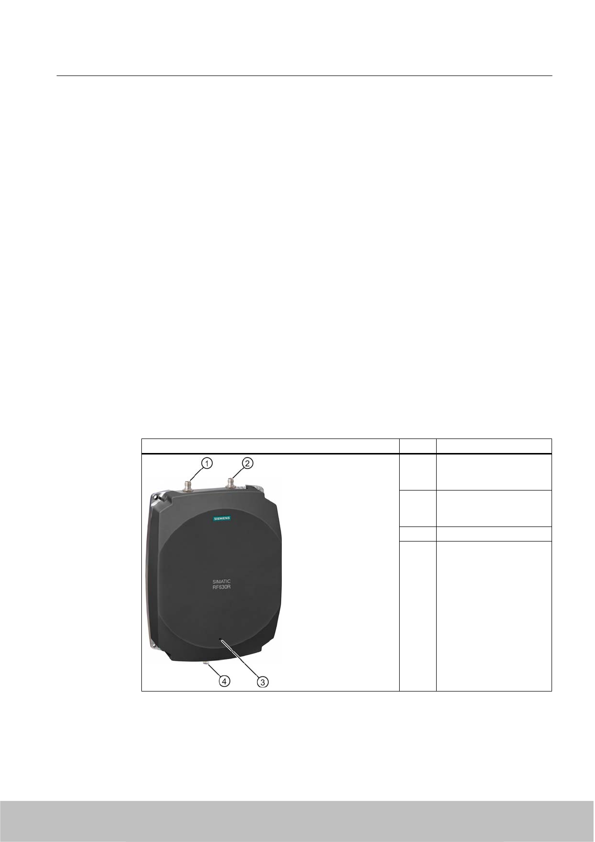
It is the responsibility of the operator and professional installer to ensure that only certified
systems are deployed in the United States. The use of the system in any other combination
(such as co-located antennas transmitting the same information) is expressly forbidden.
FCC Exposure Information
To comply with FCC RF exposure compliance requirements, the RF620R Reader (antenna
and transmitter) must be installed to provide a separation distance of at least 20 cm from all
persons and must not be co-located or operating in conjunction with any other antenna or
transmitter.
5.2 RF630R reader
5.2.1 Description
The SIMATIC RF630R is an active stationary reader in the UHF frequency range without an
integrated antenna. Up to two external UHF RFID antennas can be connected via TNC reverse
connections.
The maximum HF power output is 0.5 W on the reader output. The SIMATIC RF630R is
connected to a SIMATIC S7 controller via an ASM interface module. The degree of protection
is IP65.
Item Description
(1) TNCreverse interface for
connection of antenna 1
(ANT 1)
(2) TNCreverse interface for
connection of antenna 2
(ANT 2)
(2) LED status indicator
(3) RS 422 interface
(8-pin M12 connector)
Readers
5.2 RF630R reader
SIMATIC RF600
System Manual, 06/2010, J31069-D0171-U001-A10-7618 99
Draft Version 02.06.2010

Highlights
● The tags are read in accordance with the requirements of the EPCglobal Class 1, Gen 2
and ISO/IEC 18000-6C standards
● Supports low-cost SmartLabels as well as reusable, rugged data media
● High reading speed: Depending on the function block (multitag mode), many tags can be
detected simultaneously (bulk reading), rapidly moving tags are reliably acquired.
●The RF630R (ETSI) "6GT2811-4AA00-0AA0" is suitable for the frequency band 865 to 868
MHz UHF (EU, EFTA, Turkey). The reader supports the ETSI EN 302 208 V1.1.1 standard
as well as the new ETSI EN 302 208 V1.2.1 standard (4-channel plan).
● The RF630R (FCC) "6GT2811-4AA00-1AA0" is suitable for the frequency bands 920.25 to
924.75 MHz (Thailand) and 902 to 928 MHz (North America).
● The RF630R (CHINA) "6GT2811-4AA00-2AA0" is suitable for the frequency band 920.125
to 924.875 MHz (China)
● Up to 2 external antennas can be connected and configured in operating mode
● IP65 degree of protection for reader
● Can be used for a high temperature range
● Dense Reader Mode (DRM) for environments in which many readers are operated in close
proximity to each other
● TIA system interface:
– RS 422
5.2.1.1 Ordering data
Ordering data for RF630R
Product Order No.
RF630R (ETSI) reader basic unit for EU, EFTA,
Turkey
6GT2811-4AA00-0AA0
RF630R (FCC) reader basic unit for the USA 6GT2811-4AA00-1AA0
Readers
5.2 RF630R reader
SIMATIC RF600
100 System Manual, 06/2010, J31069-D0171-U001-A10-7618
Draft Version 02.06.2010
Ordering data for antennas and antenna cables
Product Order No.
Antennas
●RF620A antenna for EU, EFTA, Turkey (868
MHz)
● RF620A antenna for China and USA (915 MHz)
● RF660A antenna for EU, EFTA, Turkey (868
MHz)
● RF660A antenna for China and USA (915 MHz)
● 6GT2812-1EA00
● 6GT2812-1EA01
● 6GT2812-0AA00
● 6GT2812-0AA01
Antenna cable
● 3 m (cable attenuation: 1.0 dB)
● 10 m (cable attenuation: 2,0 dB)
● 10 m (cable attenuation: 4.0 dB)
●20 m (cable attenuation: 4.0 dB)
● 6GT2815-0BH30
● 6GT2815-1BN10
● 6GT2815-0BN10
● 6GT2815-0BN20
Ordering data (accessories)
Product Order No.
Connecting cable
●RS°422, M12 plug, 8-pin socket: 2 m
● RS°422, M12 plug, 8-pin socket: 5 m
● RS°422, M12 plug, 8-pin socket: 10 m
●RS°422, M12 plug, 8-pin socket: 20 m
● RS°422, M12 plug, 8-pin socket: 50 m
● 6GT2891-0FH20
● 6GT2891-0FH50
● 6GT2891-0FN10
● 6GT2891-0FN20
● 6GT2891-0FN50
CD-ROM Software & Documentation 6GT2080-2AA10
5.2.1.2 Status display
The device is equipped with a three colored LED. The LED can be lit in green, red or yellow.
The meaning of the indication changes in accordance with the color and state (on, off, flashing)
of the LED:
Green
LED
Red LED Yellow
LED
Meaning
Off Off Off The device is starting up.
Flashing Off Off The device is ready. The antenna is switched off.
On Off Off The device is ready. The antenna is switched on.
Off Off On "With presence": At least one tag is in the field.
"Without presence": Communication with a tag is active.
Off Flashing Off Reader is not active, a serious error has occurred. In addition, this LED also indicates
the fault status through the number of flashing pulses. Reboot (operating voltage Off →
On is necessary).
The LED flashes once for the 'INACTIVE' status, rebooting is not necessary in this case.
Readers
5.2 RF630R reader
SIMATIC RF600
System Manual, 06/2010, J31069-D0171-U001-A10-7618 101
Draft Version 02.06.2010
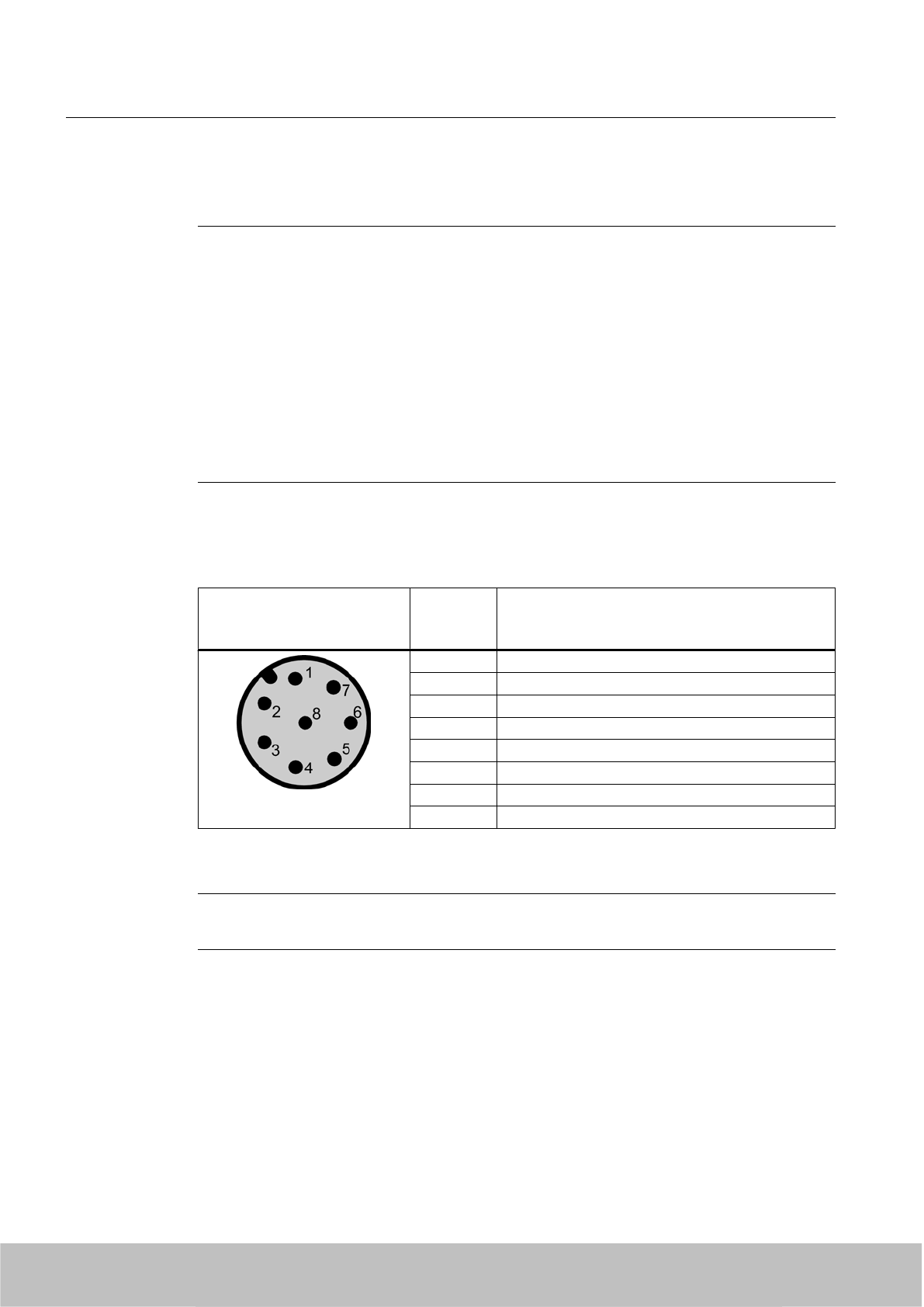
For more detailed information on the flash codes of the reader see Chapter Error messages
and flash codes for RF620R/RF630R (Page 338)
Note
LED not lit yellow?
If the LED does not light up yellow even though a tag is located within the field, common
causes are:
● Incorrect configuration in the init_run command, or init_run command was not executed
(see "Configuration Manual RF620R/RF630R")
● Antenna is switched off
● A tag is used, that is not compatible with the reader protocol (EPC Global Class 1 Gen 2).
● Tag is defective
● Reader or antenna has a defect
● Tag is not in the field of radiation of the transmit antenna
5.2.1.3 Pin assignment of the RS422 interface
Pin Pin
Device end
8-pin M12
Assignment
1+ 24 V
2 - Transmit
3 0 V
4 + Transmit
5 + Receive
6 - Receive
7 Free
8 Earth (shield)
The knurled bolt of the M12 plug is not connected to the shield (on the reader side).
Note
You must therefore not use any SIMATIC connecting cables that use the angled M12 plug.
Readers
5.2 RF630R reader
SIMATIC RF600
102 System Manual, 06/2010, J31069-D0171-U001-A10-7618
Draft Version 02.06.2010
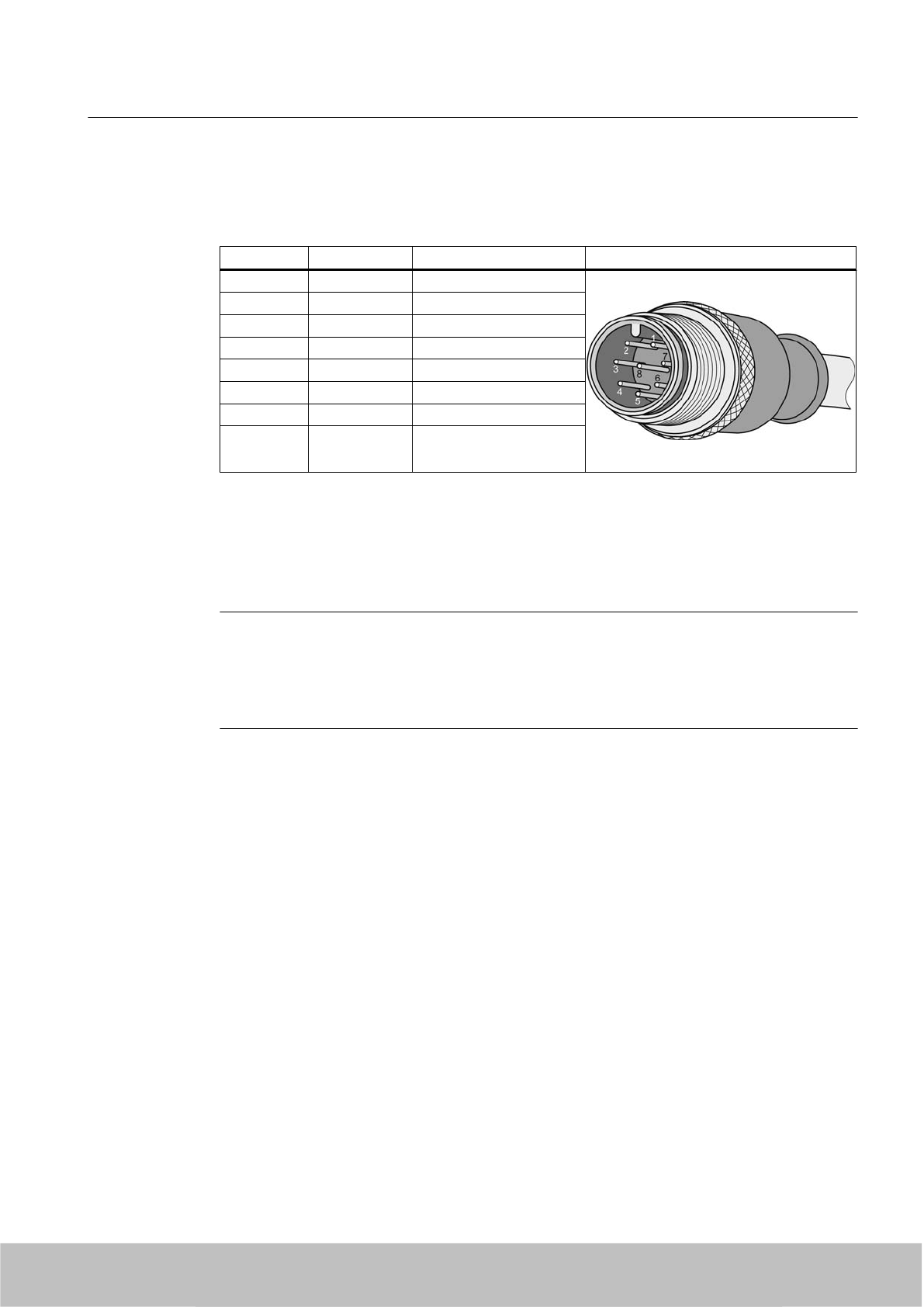
5.2.1.4 Pin assignment of the connecting cable
Table 5-5 RS 422 - on reader side
M12 pin Core color Pin assignment View of M12 connector
1white 24 VDC
2 brown TX neg
3 green GND
4 yellow TX pos
5 Gray RX pos
6 pink RX neg
7 blue Not assigned
8 red Earth (shield)
Comment
This cable has an 8-pin M12 connector at one end and the other cable end is 'open'. There
are 8 color-coded single cores there for connecting to external devices. There are different
cable lengths in the product range (3 m to 50 m). Long cables can be reduced if necessary.
Note
For long cables: Adapt supply voltage and data rate accordingly
Note that with long cables in particular, the supply voltage of 24 V DC must always be applied.
Note also that the data rate on the serial interface must, if necessary, be reduced. (See
"Configuration Manual RF620R/RF630R")
Readers
5.2 RF630R reader
SIMATIC RF600
System Manual, 06/2010, J31069-D0171-U001-A10-7618 103
Draft Version 02.06.2010
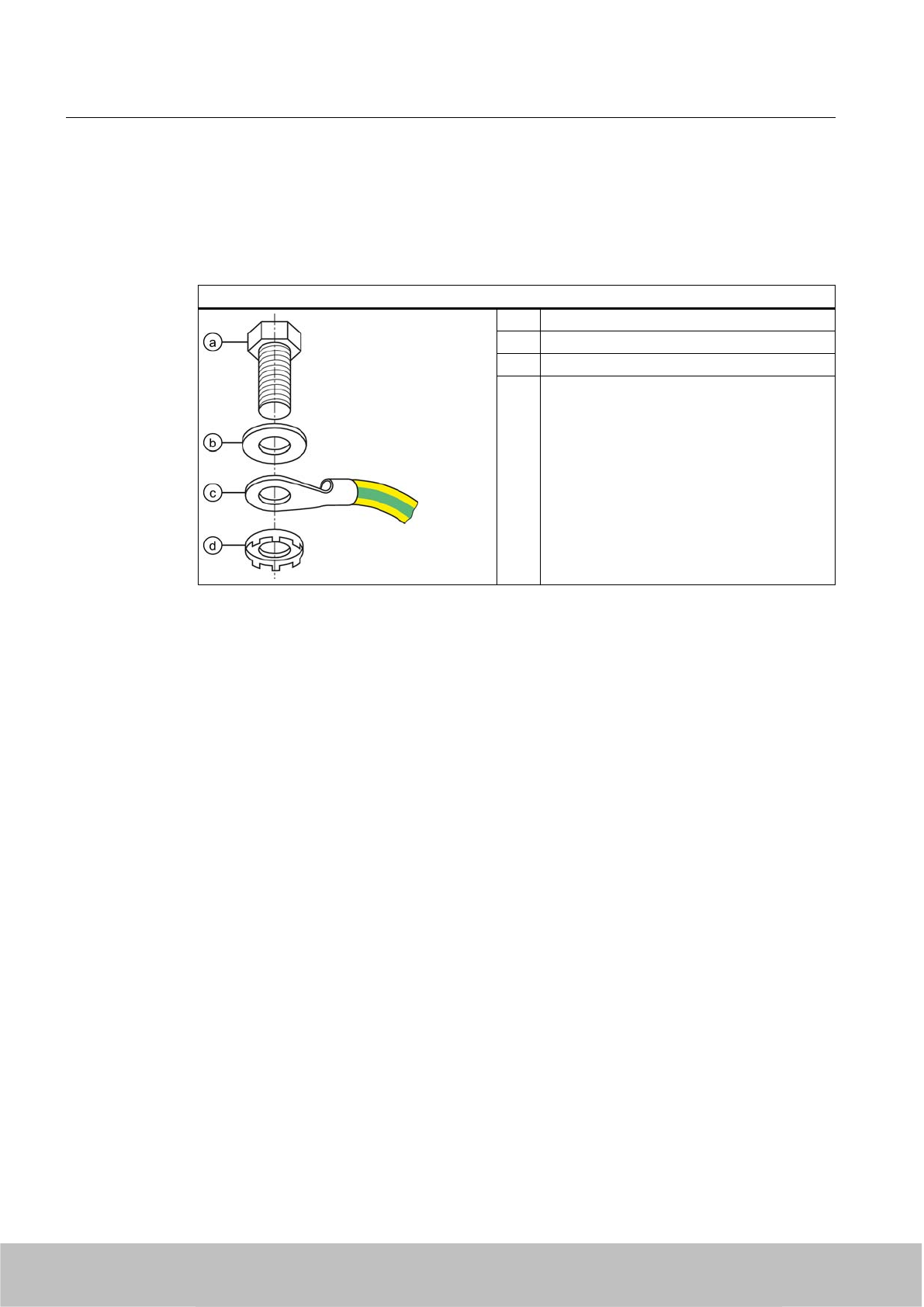
5.2.1.5 Grounding connection
The RF620R/RF630R can be electrically connected to the ground potential through a contact
washer. The tightening torque must be increased in this case to ensure that electrical contact
is made (2.7 Nm).
Ground connection
(a) Hexagon-head screw
(b) Plain washer
(c) Cable lugs
(d) Contact washer:
Use contact washers according to the
Siemens standard SN 70093-6-FSt-
flNnnc-480h for ground connection,
Siemens item No.: H70093-A60-Z3
5.2.2 Planning application
5.2.2.1 Minimum mounting clearances of two antennas of different readers
At 500 mW ERP radiated power, due to the opening angle of the antennas, their fields can
overlap considerably. It is no longer possible to clarify in which antenna field access to the
data of a tag is performed.
In order to avoid this, always keep a minimum distance of 3 m between two antennas of
different RF630R readers with the maximum radiated power of 500 mW ERP.
Dense Reader Mode (DRM)
The readers can also interfere with each other (secondary fields), if the channels (Reader TX,
Transponder TX) overlap. In order to prevent a transponder channel overlapping with a reader
channel, we recommend that the Dense Reader Mode (DRM) is used.
5.2.2.2 Antenna/read point configurations
You can connect up to two external antennas to the RF630R reader. The standard setting is
that two antennas are connected when the reader is started.
You have 3 possibilities for aligning the antennas and covering the read point.
Readers
5.2 RF630R reader
SIMATIC RF600
104 System Manual, 06/2010, J31069-D0171-U001-A10-7618
Draft Version 02.06.2010
One RF630R reader with two antennas and two read points
If you connect two external antennas to the device and align them in different directions, you
can read tags at two different read points. With this technique, a particular antenna must be
switched off application-dependently to be able to establish which tags have been read from
which antenna. The reader also provides a mode for this purpose in which the antennas can
be switched on and off cyclically (both antennas must be connected). Note the minimum
distances between the antennas for the antenna configuration (see Chapter Specified
minimum and maximum spacing of antennas (Page 44) .
One RF630R reader with two antennas and one read point
If you connect two external antennas to the device and align them in the same direction (portal
configuration), you can read tags at one read point. With this method, the reader automatically
switches between the two antennas while the tags are being read. Note the minimum distances
between the antennas for the antenna configuration (see Chapter Specified minimum and
maximum spacing of antennas (Page 44) .
One RF630R reader with one antenna and one read point
If you connect an external antenna to the device, you can read tags at one read point.
5.2.3 Installing/Mounting
5.2.3.1 Mounting/Installation
Requirement
WARNING
Ensure that the wall or ceiling can hold four times the total weight of the device.
CAUTION
Emitted radiation
The transmitter complies with the requirements of Health Canada and the FCC limit values
for subjecting persons to HF radiation, provided that a minimum spacing of 26 cm exists
between antenna and person. When the antennas are installed, you must therefore ensure
that a minimum spacing of 26 cm is maintained between personnel and antennas.
Readers
5.2 RF630R reader
SIMATIC RF600
System Manual, 06/2010, J31069-D0171-U001-A10-7618 105
Draft Version 02.06.2010
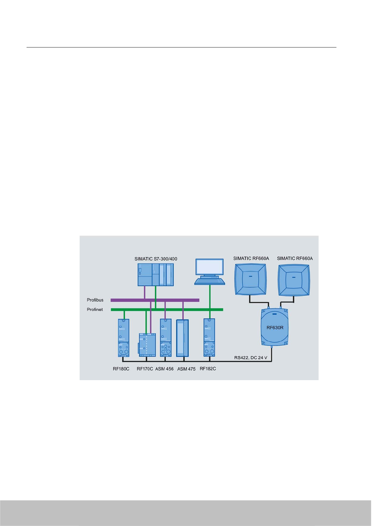
Mounting/installing the device
You can mount the reader directly onto a flat surface.
The positions of the fixing holes for the device are shown in the section Dimension drawings
(Page 111).
5.2.4 Configuration/integration
The RS422 system interface is provided for integrating the device into system environments/
networks. The system interface transfers data to SIMATIC controllers or PCs with the
appropriate interface.
Apart from transmitting communication data from the reader to the controller and vice versa,
the RS422 interface also supplies power to the reader (24 V DC).
Figure 5-7 Overview of configuration of the RF630R reader
The RF620R reader can alternatively be connected to a SIMATIC controller via the ASM 456,
ASM 475, RF170C and RF180C interface modules/communication modules.
The RF620R reader can alternatively also be connected directly to the PC via the RF182
communication module.
For further details on the interface modules used, see Chapter .
Further information about commissioning the readers can be found in the Configuration Manual
"RF620R/RF630R" in the "Commissioning" section.
Readers
5.2 RF630R reader
SIMATIC RF600
106 System Manual, 06/2010, J31069-D0171-U001-A10-7618
Draft Version 02.06.2010
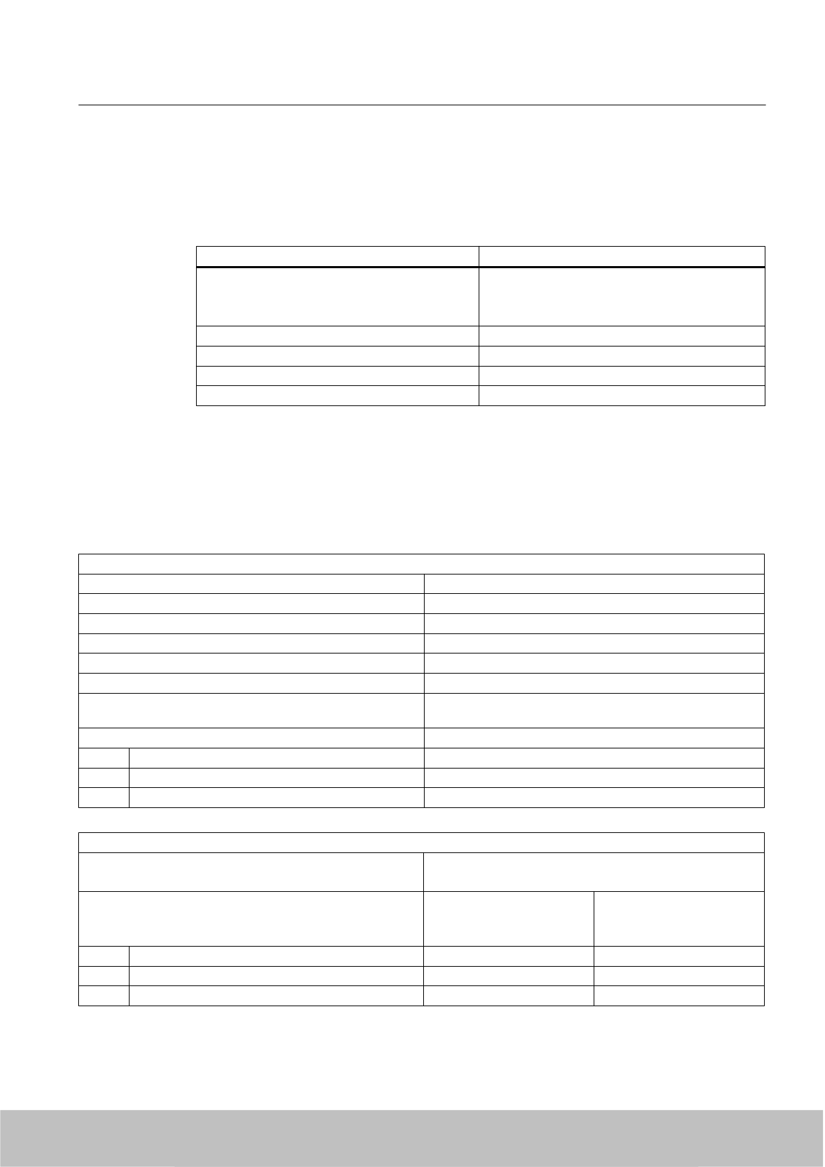
5.2.4.1 Transmission protocols
RS 422 communication
3964R protocol
Transmission rates 19.2 kbps
57.6 kbps
115.2 kbps
Start bits 1
Data bits 8
Parity Odd
Stop bits 1
5.2.5 Technical data
5.2.5.1 Mechanical data
Mechanical data
Weight 1640 g
Dimensions (L x W x H) in mm 252 x 193 x 52 mm, without connections
Material for housing top section ABS (GF 20)
Material for housing bottom section Aluminum
Color of housing top section Anthracite
Color of housing bottom section Silver
Status displays on the device 1 LED
Colors: Red, yellow, green
Interfaces
Antenna connections 2x RTNC plug
RS422 1 x plug (8-pin M12)
Software SIMATIC S7
Thermal and electrical properties
Power supply
● Permitted range
21.6 to 30 V DC 1
Power supply Current consumption
(in standby mode, no
transmit power)
Current consumption
(in standby mode, no
transmit power)
20 V input voltage on the reader, typical 135 mA 2.7 W
24 V input voltage on the reader, typical 115 mA 2.76 W
30 V input voltage on the reader, typical 95 mA 2.85 W
Readers
5.2 RF630R reader
SIMATIC RF600
System Manual, 06/2010, J31069-D0171-U001-A10-7618 107
Draft Version 02.06.2010

Power supply Current consumption
(at 500 mW ERP)
Power requirement
(at 500 mW ERP)
20 V input voltage on the reader, typical 470 mA 9.4 W
24 V input voltage on the reader, typical 395 mA 9.48 W
30 V input voltage on the reader, typical 320 mA 9.6 W
Rampup time 7 s
1) All supply and signal voltages must be safety extra low voltage (SELV/PELV according to EN 60950)
24 V DC power supply: safe (electrical) isolation of extra-low voltage (SELV / PELV acc. to EN 60950)
Mechanical environmental conditions
Shock resistant to EN 60068-2-27
Vibration EN 60068-2-6
50 g1
20 g1
Climatic Conditions
Ambient temperature in operation -25 °C to +55 °C
(a 10-minute warm-up time must be observed at an operating
temperature below -20 °C)
Ambient temperature for transport and storage -40 °C to +85 °C
1) The values for shock and vibration are maximum values and must not be applied continuously.
EMC & approvals/conformity for ETSI variant
Electromagnetic compatibility ETSI EN 301 489-1 / -3
ETSI EN 302 208
Approvals/Conformity ● Radio to R&TTE guidelines EN 300 330, EN 301 489
●CE
● ETSI EN 302-208 V1.1.1
● ETSI EN 302-208 V1.2.1
●Reader degree of protection acc. to EN 60529 (IP65)
EMC & approvals for FCC variant
Electromagnetic compatibility FCC Part 15
Approvals ● FCC, cULus
● IEC60950, including US and Canadian variants of it
● FCC CFR47 Part 15.247
● RoHS-compliant according to EU Directive 2002/95/EC
● Industrial Canada, RSS-210, Issue 7, June 2007
Readers
5.2 RF630R reader
SIMATIC RF600
108 System Manual, 06/2010, J31069-D0171-U001-A10-7618
Draft Version 02.06.2010

5.2.5.2 Technical data according to EPC and ISO
Technical data
Frequency accuracy max.± 10 ppm
Channel spacing EU, EFTA, Turkey: 200 kHz
US: 500 kHz
China: 250 kHz
Modulation methods ASK: DSB modulation & PR-ASK modulation
Encoding, Manchester or Pulse Interval (PIE)
Effective transmitter power
(the radiant power depends on the antennas and cables used,
see Guidelines for selecting RFID UHF antennas
(Page 181))
≤ 0.5 W ERP
ETSI frequencies
Frequency range EU, EFTA, Turkey
according to ETSI EN 302 208 V1.1.1 (commissioning until
December 31, 2009)
865 to 868 MHz (10 subchannels LBT at 2 W ERP, 12
subchannels at 0.5 W ERP, 15 subchannels LBT at 0.1 W
ERP)
Frequency bands for EU, EFTA, Turkey:
according to ETSI EN 302 208 V1.2.1 (valid since November
4, 2008, publication in the Official Journal of the European
Union)
● 865.7 MHz
● 866.3 MHz
● 866.9 MHz
● 867.5 MHz
(4 channels LBT optional at max. 2 W ERP)
Reading range for EU, EFTA, Turkey
Antennas mounted on opposing sides
(portal configuration)
3.5 m max. (recommended maximum value for configuration)
Antennas mounted on the same side Max. 2 m (recommended maximum value for configuration;
depending on the transponder)
FCC frequencies
North American frequency band 902 ... 928 MHz (50 channels, frequency hopping)
Reading range for USA
Antennas mounted on opposing sides
(portal configuration)
3.5 m max. (recommended maximum value for configuration)
Readers mounted on the same side 2 m max. (recommended maximum value for configuration)
FCC frequencies
Frequency band for China 920.125…924.875 MHz (16 subchannels at 2 W ERP,
20 subchannels at 0.1 W ERP
Readers
5.2 RF630R reader
SIMATIC RF600
System Manual, 06/2010, J31069-D0171-U001-A10-7618 109
Draft Version 02.06.2010

Reading range for China
Antennas mounted on opposing sides
(portal configuration)
3.5 m max. (recommended maximum value for configuration)
Readers mounted on the same side 2 m max. (recommended maximum value for configuration)
5.2.5.3 Maximum number of readable tags
The maximum number of readable tags depends on the following parameters:
● Size of the antenna field
● Readability of the tags
For a transmit power of 500 mW ERP, the following is read when the tag RF620T is used:
● Max. 40 tags in the antenna field (tags perpendicular to antenna at 1 m distance). If 2
antennas are used, up to 80 tags can be recognized.
●Max. 18 tags per second
Note for 2-antenna operation
● If 2 antennas are connected to the SIMATIC RF630R, the antennas must be controlled
using the SET-ANT command.
● If 2 antennas are configured as a gate, both antennas should be simultaneously switched
on with the SET-ANT command. The reader multiplexes both antennas internally. The
multiplexing time is 100°ms (internal read time per antenna).
Readers
5.2 RF630R reader
SIMATIC RF600
110 System Manual, 06/2010, J31069-D0171-U001-A10-7618
Draft Version 02.06.2010
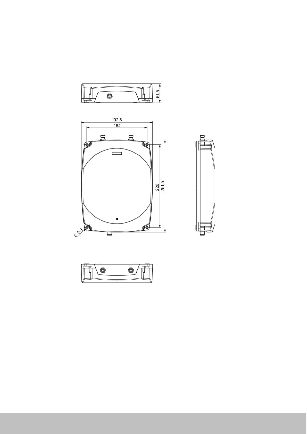
5.2.6 Dimension drawings
Figure 5-8 Dimension drawing for RF630R
All dimensions in mm
Readers
5.2 RF630R reader
SIMATIC RF600
System Manual, 06/2010, J31069-D0171-U001-A10-7618 111
Draft Version 02.06.2010
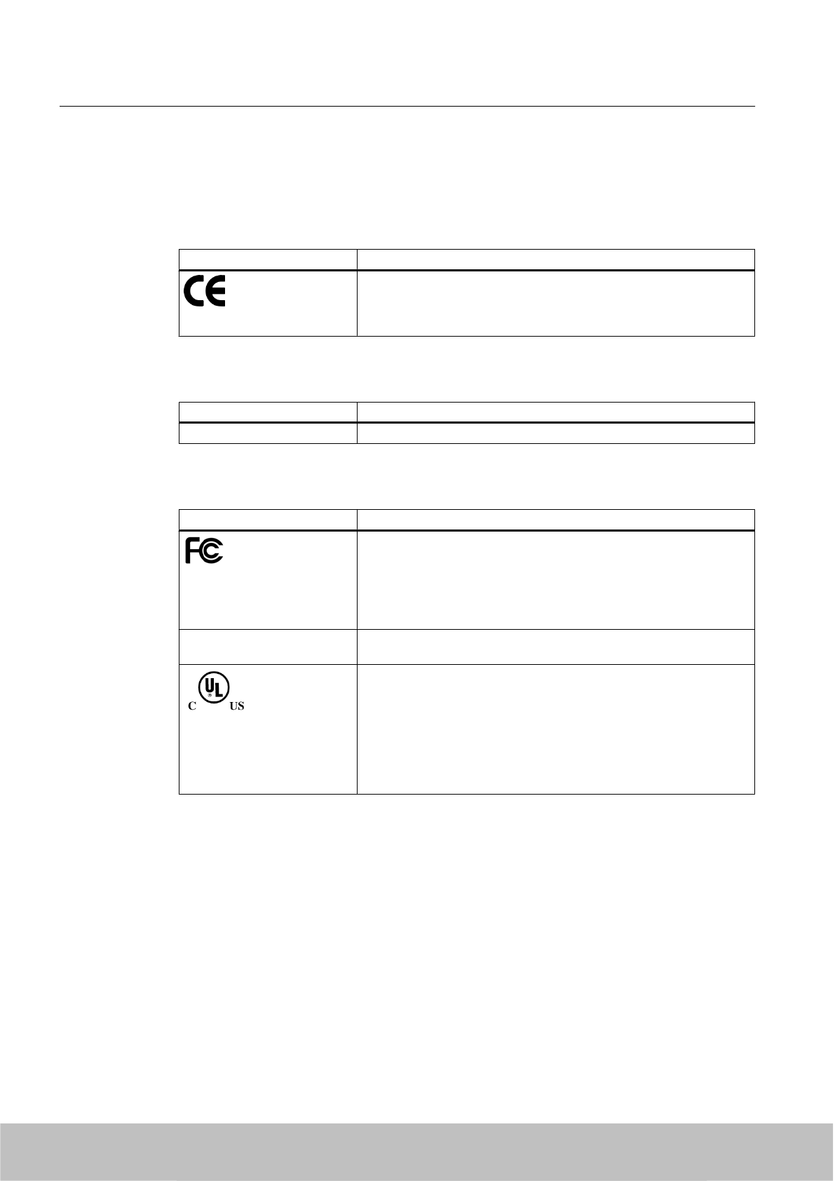
5.2.7 Certificates and approvals
Table 5-6 6GT2811-4AA00-0AA0
Certificate Description
Compatible with R&TTE directive
Table 5-7 6GT2811-4AA00-2AA0
Standard Description
China radio approval
Table 5-7 6GT2811-4AA00-1AA0
Standard
Federal Communications
Commission
FCC CFR 47, Part 15 sections 15.247
Radio Frequency Interference Statement
This equipment has been tested and found to comply with the limits
for a Class B digital device, pursuant to Part 15 of the FCC Rules.
FCC ID: NXW-RF630R
Industry Canada Radio
Standards Specifications
RSS-210 Issue 7, June 2007, Sections 2.2, A8
IC: 267X-RF630
This product is UL-certified for the USA and Canada.
It meets the following safety standard(s):
UL 60950-1 - Information Technology Equipment Safety - Part 1:
General Requirements
CSA C22.2 No. 60950 -1 - Safety of Information Technology
Equipment
UL Report E 205089
5.2.7.1 FCC information
Siemens SIMATIC RF630R (FCC): 6GT2811-4AA00-1AA0
FCC ID: NXW-RF630R
This device complies with part 15 of the FCC rules.
Operation is subject to the following two conditions:
(1) This device may not cause harmful interference, and
(2) This device must accept any interference received, including interference that may cause
undesired operation.
Caution
Readers
5.2 RF630R reader
SIMATIC RF600
112 System Manual, 06/2010, J31069-D0171-U001-A10-7618
Draft Version 02.06.2010

Any changes or modifications not expressly approved by the party responsible for compliance
could void the user's authority to operate the equipment.
Note
This equipment has been tested and found to comply with the limits for a Class B digital device,
pursuant to part 15 of the FCC Rules. These limits are designed to provide reasonable
protection against harmful interference when the equipment is operated in a commercial
environment. This equipment generates, uses, and can radiate radio frequency energy and,
if not installed and used in accordance with the instruction manual, may cause harmful
interference to radio communications. Operation of this equipment in a residential area is likely
to cause harmful interference in which case the user will be required to correct the interference
at his own expense.
FCC NoticeTo comply with FCC part 15 rules in the United States, the system must be
professionally installed to ensure compliance with the Part 15 certification.
It is the responsibility of the operator and professional installer to ensure that only certified
systems are deployed in the United States. The use of the system in any other combination
(such as co-located antennas transmitting the same information) is expressly forbidden.
FCC Exposure InformationTo comply with FCC RF exposure compliance requirements, the
antennas used for this transmitter must be installed to provide a separation distance of at least
20 cm from all persons and must not be co-located or operating in conjunction with any other
antenna or transmitter.
5.2.7.2 IC-FCB information
Siemens SIMATIC RF630R (FCC): 6GT2811-4AA00-1AA0
IC: 267X-RF630
Industry Canada NoticeTo reduce potential radio interference to other users, the antenna type
and its gain should be so chosen that the equivalent isotropically radiated power (e.i.r.p.) is
not more than that permitted for successful communication.
This device has been designed to operate with the SIMATIC RF620A antenna 902-928 as well
as the SIMATIC RF660A antenna 902-928 listed below, and having a maximum gain of 5,5 dBi.
Other antennas or antennas having a gain greater than 5,5 dBi are strictly prohibited for use
with this device.
The required antenna impedance is 50 Ohms.
Readers
5.2 RF630R reader
SIMATIC RF600
System Manual, 06/2010, J31069-D0171-U001-A10-7618 113
Draft Version 02.06.2010
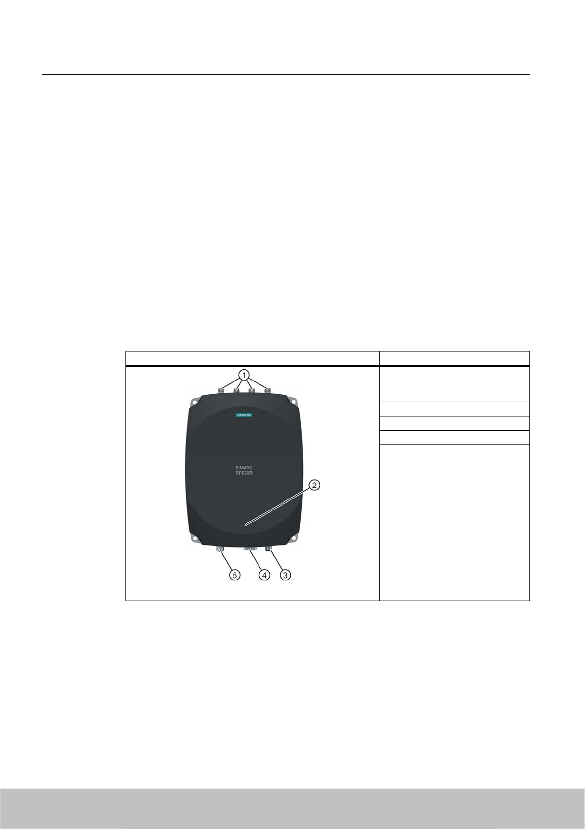
5.3 RF670R reader
5.3.1 Description
5.3.1.1 Overview
The SIMATIC RF670R is an active stationary reader in the UHF frequency range without an
integrated antenna. Up to four external UHF RFID antennas can be connected via TNC reverse
connections.
The maximum HF power output is 1000°W on the reader output. A radiant power of up to
2000 mW ERP is achieved when the appropriate antennas and antenna cables are used. The
interfaces (Ethernet, M12 power supply, M12 digital I/O interface) are located along the narrow
lower edge. These interfaces can be used to connect the reader to the power supply and the
PC for parameterization.
The degree of protection is IP65.
Item Description
(1) TNC reverse interfaces for
connecting up to four
antennas
(2) LED status indicator
(3) 24 V°DC power supply
(4) Ethernet interface (TCP/IP)
(5) Digital I/O interface
Highlights
● The tags are read in accordance with the requirements of the EPC Global Class 1 Gen 2
or ISO/IEC 18000-6C standards
● Supports low-cost SmartLabels as well as reusable, rugged data media
● High reading speed: many tags can be read simultaneously (mass recording), rapidly
moving tags are reliably recorded.
Readers
5.3 RF670R reader
SIMATIC RF600
114 System Manual, 06/2010, J31069-D0171-U001-A10-7618
Draft Version 02.06.2010
● The RF670R (ETSI) "6GT2811-0AB00-0AA0" is suitable for the frequency band 865 to
868°MHz UHF (EU, EFTA, Turkey). The reader supports the current standard
ETSI EN 302 208 V1.2.1 (4-channel plan).
● The RF670R (FCC) "6GT2811-0AB00-1AA0" is suitable for the frequency band 902 to
928°MHz (North America).
● The RF670R (CHINA) "6GT2811-0AB00-2AA0" is suitable for the frequency band 920.125
to 924.875°MHz.
● Up to four external antennas can be connected
● Antennas can be used separately for up to four independent reading points; several
antennas can be combined to form one reading point
● IP65 degree of protection
● Can be used for a high temperature range
● Antenna switching for high tag reader probability
● Dense Reader Mode (DRM) for environments in which many readers are operated in close
proximity to each other.
● System integration over Ethernet (TCP/IP)
● Digital I/Os: Industry-compatible with high output power levels
● Configurable switching of the digital outputs with reader-internal logic
● Data processing in the reader (filtering, smoothing, etc.)
● Additional information for each acquired RFID transponder (RSSI values, time stamp)
5.3.1.2 Ordering data
Ordering data for RF670R
Product Order No.
RF670R (ETSI) reader basic unit for EU, EFTA,
Turkey
6GT2811-0AB00-0AA0
RF670R (FCC) reader basic unit for the USA 6GT2811-0AB00-1AA0
RF670R (CHINA) reader basic unit for China 6GT2811-0AB00-2AA0
Ordering data for antennas and antenna cables
Product Order No.
RF660A antenna for EU, EFTA, Turkey (868 MHz) 6GT2812-0AA00
RF620A antenna for EU, EFTA, Turkey (868 MHz) 6GT2812-1EA00
RF660A antennas for the USA and China
(915°MHz)
6GT2812-0AA01
Readers
5.3 RF670R reader
SIMATIC RF600
System Manual, 06/2010, J31069-D0171-U001-A10-7618 115
Draft Version 02.06.2010

Product Order No.
RF620A antenna for FCC (915 MHz) 6GT2812-1EA01
Antenna cable
●3 m (cable attenuation: 1.0 dB)
● 10 m (cable attenuation: 4.0 dB)
● 10 m (cable attenuation: 2,0 dB)
● 20 m (cable attenuation: 4.0 dB)
● 6GT2815-0BH30
● 6GT2815-0BN10
● 6GT2815-1BN10
● 6GT2815-0BN20
Ordering data (accessories)
Product Order No.
Antenna mounting kit 6GT2890-0AA00
Connecting cable and connectors
●Digital I/O, open cable ends, 5 m
● Ethernet: 10 m (cross cable)
● Ethernet connector on reader
according to IEC PAS 61076-3-117IE
RJ45 Plug PRO (IP67)
●Ethernet connector, Standard IE FastConnect
RJ45 Plug 180 (IP20)
● Ethernet cable sold by the meter, green
● 6GT2891-0CH50
● 6GT2891-1HN10
● 6GK1901-1BB10-6AA0
● 6GK1901-1BB10-2AB0
● 6XV1840-2AH10
Wide-range power supply unit for SIMATIC RF
systems
● With EU plug
● With UK plug
● With US plug
●6GT2898-0AA00
● 6GT2898-0AA10
● 6GT2898-0AA20
24 V connecting cable
5 m between reader and power supply
(for RF670R only, pin assignment is PNO
compatible)
6GT2891-0NH50
Set of protective caps
Contains 3 protective caps for antenna output and
one protective cap for digital I/O
(required for IP65 degree of protection when some
connections are unoccupied)
6GT2898-4AA00
Software and documentation
● RFID CD-ROM Software & Documentation
● RF-MANAGER 2008, incl. SP3 - 1 reader
● RF-MANAGER 2008, incl. SP3 - 5 reader
●RF-MANAGER 2008, incl. SP3 - 20 reader
● RF-MANAGER 2008, incl. SP3 - 50 reader
● RF-MANAGER 2008 SP3 as download
● 6GT2080-2AA10
● 6GT2080-3CA00-?AA5
● 6GT2080-3CA00-?AA5
● 6GT2080-3CA00-?AA5
● 6GT2080-3CA00-?AA5
● Internet
Readers
5.3 RF670R reader
SIMATIC RF600
116 System Manual, 06/2010, J31069-D0171-U001-A10-7618
Draft Version 02.06.2010
5.3.1.3 Status display
The device is equipped with a three colored LED. The LED can be lit in green, red or yellow.
The meaning of the indication changes in accordance with the color and state (on, off, flashing)
of the LED:
Green
LED
Red LED Yellow
LED
Meaning
Off Off Off The device is not connected to a power supply.
Off Off On briefly Status shortly after application of voltage and until start-up begins.
Flashing Off Off The device is starting up. The connection is being established.
In normal operation, no communication with the reader has taken place.
On Off Off The device is ready. The connection is established.
Off Off Flashing "With presence": More than one tag is in the field.
Off Off On "With presence": At least one tag is in the field.
Off Flashing Off Error states with flash codes (see Chapter Error messages and flash codes for
RF670R (Page 337))
Note
LED not lit yellow?
If the LED does not light up yellow even though a tag is located within the field, common
causes are:
● Antenna is switched off
● A tag is used, that is not compatible with the reader protocol (EPC Global Class 1 Gen 2).
● Tag is defective
● Reader or antenna has a defect
● Tag is not in the field of radiation of the transmit antenna
For more detailed information on the flash codes of the reader see Chapter Error messages
and flash codes for RF670R (Page 337)
Readers
5.3 RF670R reader
SIMATIC RF600
System Manual, 06/2010, J31069-D0171-U001-A10-7618 117
Draft Version 02.06.2010
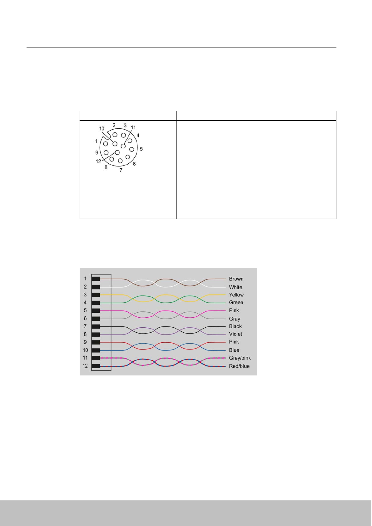
5.3.1.4 Pin assignment of the digital I/O interface
View of socket (reader end)
M12 socket (reader end) Pin Pin assignment
1
2
3
4
5
6
7
8
9
10
11
12
GND (output for supply of digital inputs/outputs [not electrically
isolated])
VCC (output for supply of digital inputs/outputs [not electrically
isolated])
DO Common / Outport Common
DO 0 / Outport 00
DO 1 / Outport 01
DO 2 / Outport 02
DO 3 / Outport 03
DI 0 / Inport 00
DI Common / Inport Common
DI 1 / Inport 01
DI 2 / Inport 02
DI 3 / Inport 03
Wiring diagram M12 connector (cable end)
You must assemble your reader cable with a matching connector that fits the interface shown
above. Adhere to the following wiring diagram:
Figure 5-9 M12 connector wiring diagram
5.3.1.5 Connection scheme for the digital I/O interface
Connection possibilities
You can connect the RF670R reader in different ways. In general, the outputs and inputs should
be connected as follows:
Readers
5.3 RF670R reader
SIMATIC RF600
118 System Manual, 06/2010, J31069-D0171-U001-A10-7618
Draft Version 02.06.2010
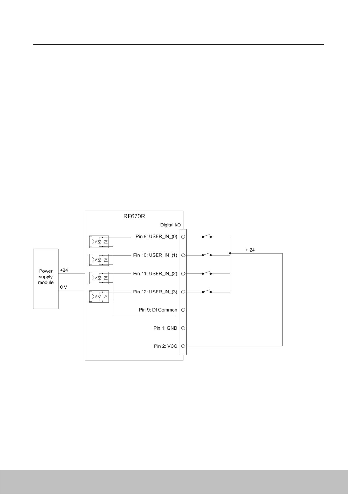
Output Outport (0), (1), (2), (3)
● Each output is rated for 0.5 A current and is electronically protected.
● Four digital outputs can be operated simultaneously with up to 0.5 A each (up to 1.5 A in
total).
● The outputs are optically isolated through optocouplers.
Input Inport (0), (1), (2), (3)
●The inputs are optically isolated through optocouplers.
● The 24 V voltage for the digital inputs (e.g. switches, proximity switches) must be supplied
over a separate cable if electrical isolation is required.
● Level Low 0 ... 3 V; High 3,6 ... 24 V
● Sampling rate < 20 ms
The following diagrams illustrate various connection possibilities.
Voltage infeed through internal source (no electrical isolation)
Figure 5-10 Example circuit 1: Digital inputs
Alternative connection possibilities:
● Pin 2 (VCC) to Pin 9 DI Common
● Pin 1 GND to busbar inputs
Readers
5.3 RF670R reader
SIMATIC RF600
System Manual, 06/2010, J31069-D0171-U001-A10-7618 119
Draft Version 02.06.2010
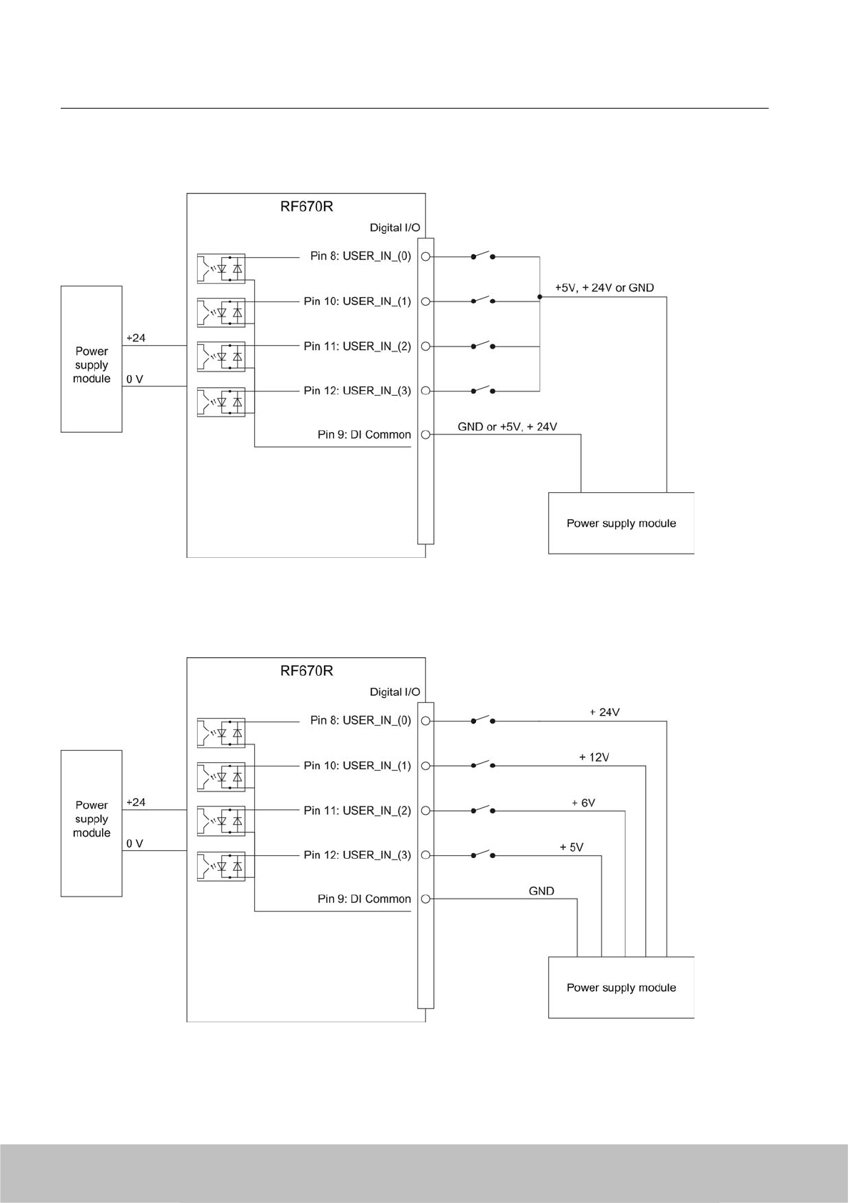
Voltage infeed through external source
Figure 5-11 Example circuit 2: Digital inputs
Voltage infeed through external source with various voltages
Figure 5-12 Example circuit 3: Digital inputs
Readers
5.3 RF670R reader
SIMATIC RF600
120 System Manual, 06/2010, J31069-D0171-U001-A10-7618
Draft Version 02.06.2010
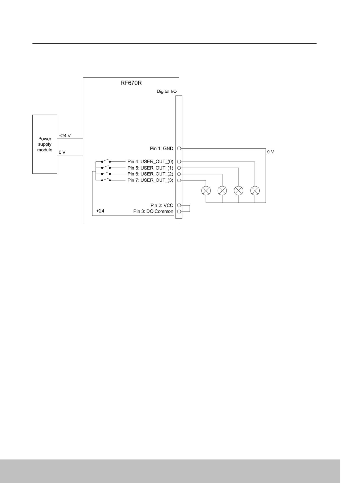
Voltage infeed through internal source
Figure 5-13 Example circuit 4: Digital outputs
Alternative connection possibilities:
● Pin 1 GND to Pin 3 DO Common
● Pin 2 (VCC) to busbar outputs
Readers
5.3 RF670R reader
SIMATIC RF600
System Manual, 06/2010, J31069-D0171-U001-A10-7618 121
Draft Version 02.06.2010
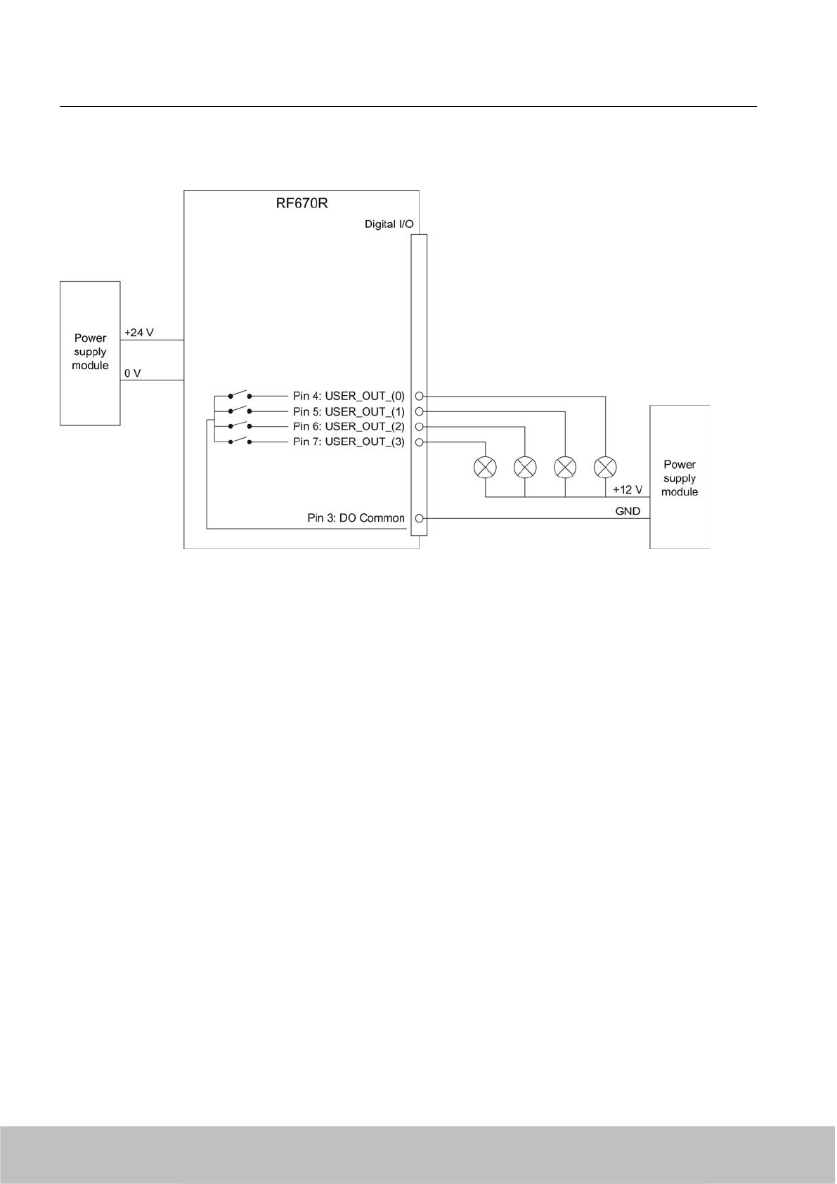
Voltage infeed through external source
Figure 5-14 Example circuit 5: Digital outputs
Voltage infeed through an external source is shown here for 12°V by way of example. Other
voltages are also permissible.
Readers
5.3 RF670R reader
SIMATIC RF600
122 System Manual, 06/2010, J31069-D0171-U001-A10-7618
Draft Version 02.06.2010
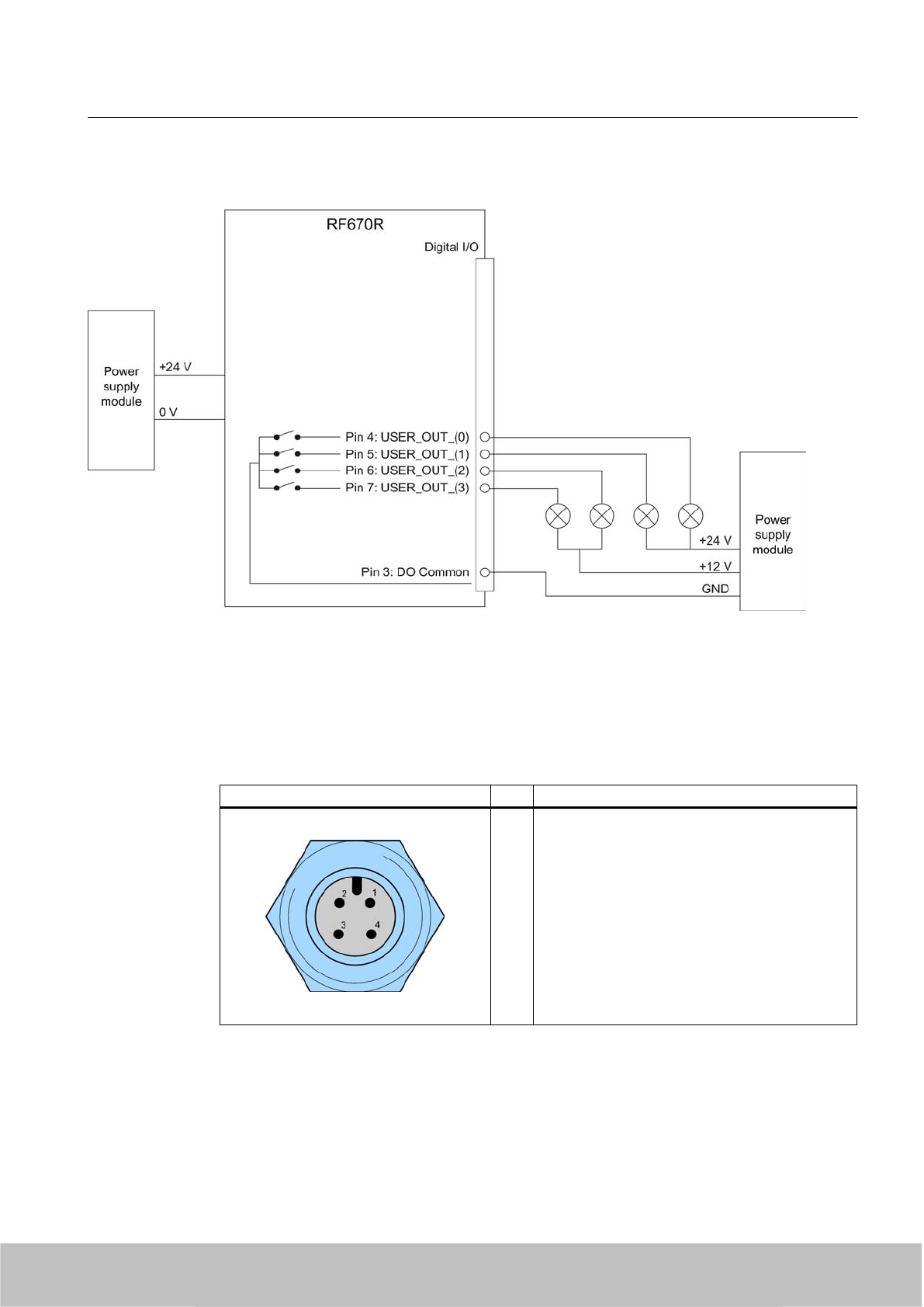
Voltage infeed through external source with various voltages
Figure 5-15 Example circuit 6: Digital outputs
5.3.1.6 Pin assignment for power supply
Pin assignment of the power connections
Power connector (on reader side) Pin Pin assignment
1
2
3
4
24 V°DC
Not connected
Ground (0 V)
Not connected
The power connector of the RF670R is PNO compatible, i.e.° normal PROFINET IO connectors
will fit this interface.
Readers
5.3 RF670R reader
SIMATIC RF600
System Manual, 06/2010, J31069-D0171-U001-A10-7618 123
Draft Version 02.06.2010
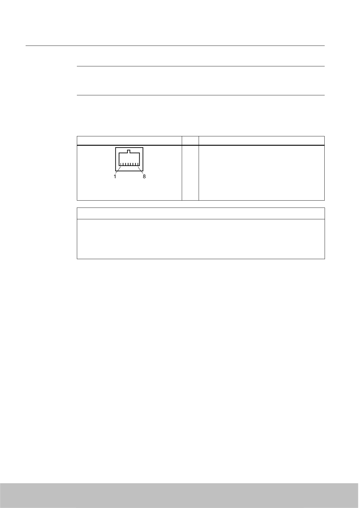
Note
Please note that the pin assignment for the power connection differs between the RF670R
and the RF660R!
5.3.1.7 Pin assignment for Industrial Ethernet interface
Industrial Ethernet (on reader side) Pin Pin assignment
1
2
3
4
5
6
7
8
Transmit Data (+)
Transmit Data (-)
Receive Data (+)
Terminated
Terminated
Receive Data (-)
Terminated
Terminated
NOTICE
We recommend that only original Siemens Ethernet crossover cables are used (10 m cable:
Order No. 6GT2891-1HN10) or the Siemens connector (see Section Ordering data
(Page 115)) for connecting to the Ethernet socket of the reader. If plug-in connectors from
other manufacturers are used, it may be difficult or even impossible to remove the plug from
the reader
Readers
5.3 RF670R reader
SIMATIC RF600
124 System Manual, 06/2010, J31069-D0171-U001-A10-7618
Draft Version 02.06.2010
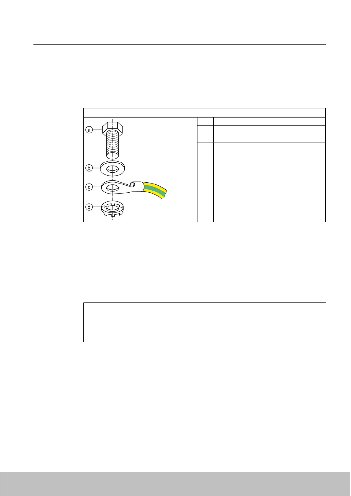
5.3.1.8 Grounding connection
The RF670R can be electrically connected to the ground potential through a contact washer.
The tightening torque must be increased in this case to ensure that electrical contact is made
(2.7 Nm).
Ground connection
(a) Hexagon-head screw
(b) Plain washer
(c) Cable lugs
(d) Contact washer:
Use contact washers according to the
Siemens standard SN 70093-6-FSt-
flNnnc-480h for ground connection,
Siemens item No.: H70093-A60-Z3
5.3.2 Planning the use
5.3.2.1 Firmware and software compatibility
Firmware and software compatibility
NOTICE
Incompatibility between RF670R and RF660R Config Tool
Please note that the RF670R reader cannot be configured using the Config Tool of the
RF660R.
With RF-MANAGER 2008 Service Pack 3 and higher existing projects can be easily adapted
to the RF670R reader by resetting the reader type.
The XML protocol of the RF670R is not compatible with the XML protocol of the RF660R.
The functions that are currently known to be incompatible with RF660R are as follows:
● No radio profile ETSI_SRD or ETSI with LBT
● No transponder with EPC CLASS1 GEN1 and ISO 18000-6B
● No serial interfacing
Readers
5.3 RF670R reader
SIMATIC RF600
System Manual, 06/2010, J31069-D0171-U001-A10-7618 125
Draft Version 02.06.2010
5.3.2.2 Antenna/read point configurations
You can connect up to four external antennas to the RF670R reader. The standard setting is
that four antennas are connected when the reader is started.
With RF-MANAGER Basic 2010 or RF-MANAGER 2008 with SP 3 and higher you can set up
various different configurations of antennas and/or reading points as required. It is possible to
find solutions to many different tasks through the number of data sources and subsequent
assignment of the antennas.
Examples of possible antenna/reading point configurations
● Four data sources each with one antenna for four different reading points.
● Two data sources each with two antennas for small portals.
● One data source with 4 antennas for large portals.
You will find further information in the online Help for the products.
See also
Specified minimum and maximum spacing of antennas (Page 44)
5.3.3 Installing / mounting
Requirement
WARNING
Ensure that the wall or ceiling can hold four times the total weight of the device.
CAUTION
Emitted radiation
The transmitter complies with the requirements of Health Canada and the FCC limit values
for subjecting persons to HF radiation, provided that a minimum spacing of 26 cm exists
between antenna and person. When the antennas are installed, you must therefore ensure
that a minimum spacing of 26 cm is maintained between personnel and antennas.
Readers
5.3 RF670R reader
SIMATIC RF600
126 System Manual, 06/2010, J31069-D0171-U001-A10-7618
Draft Version 02.06.2010

Mounting/installing the device
You can mount the reader in two different ways:
● Via a standardized VESA 100 mounting system using the Antenna Mounting Kit (see
Chapter ). Tighten the M4 screws on the rear of the reader using a maximum torque of ≤
1.3 Nm.
● Directly onto a flat surface.
The positions of the fixing holes for the device are shown in the section Dimension drawings
(Page 131).
5.3.4 Configuration/integration
5.3.4.1 Configuration
An Ethernet interface is available for integrating the device into system environments/networks.
Over the Ethernet interface and with direct connection to the PC, the RF670R can be
configured in two different ways:
● Using RF-MANAGER Basic 2010
● Using RF-MANAGER 2008 Service Pack 3 and higher
The communication interface transfers the data over the RF-MANAGER interface to the IT,
ERP and SCM systems as well as to SIMATIC controllers. Alternatively the data is transferred
to user applications by means of XML commands.
Simple process controls (e.g. a traffic signal) can be directly implemented using the write/read
device via four digital inputs and outputs.
Readers
5.3 RF670R reader
SIMATIC RF600
System Manual, 06/2010, J31069-D0171-U001-A10-7618 127
Draft Version 02.06.2010
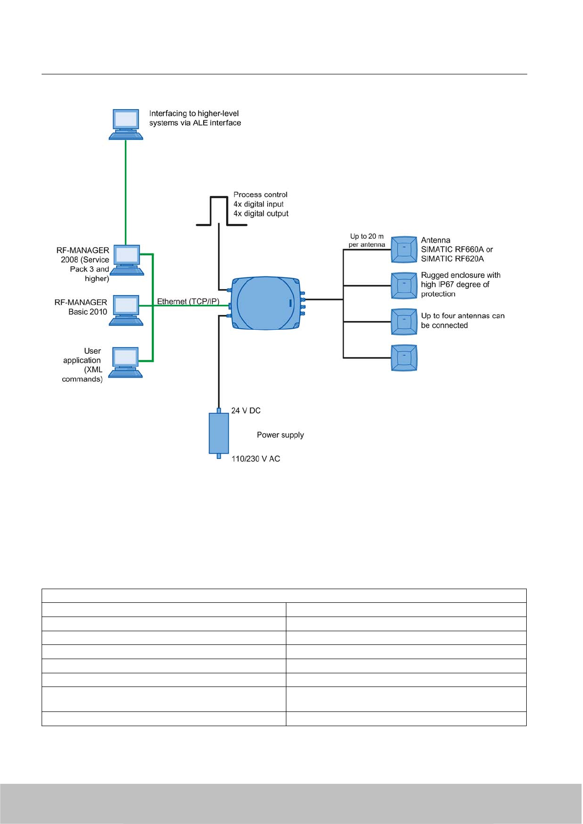
Figure 5-16 Overview of configuration of the RF670R reader
5.3.5 Technical data
5.3.5.1 Mechanical data
Mechanical data
Weight 1800 g
Dimensions (L x W x H) in mm 252 x 193 x 52 mm, without connections
Material for housing top section ABS (GF 20)
Material for housing bottom section Aluminum
Color of housing top section Anthracite
Color of housing bottom section Silver
Status displays on the device 1 LED
Colors: Red, yellow, green
Interfaces
Readers
5.3 RF670R reader
SIMATIC RF600
128 System Manual, 06/2010, J31069-D0171-U001-A10-7618
Draft Version 02.06.2010

Antenna connections 4x RTNC connector
Power supply 1 x plug (4-pin M12)
Digital I/O interface 1 x socket (12-pin M12)
Digital inputs 4
Digital outputs 4 (500 mA each; max. 1500 mA in total)
Ethernet RJ45 TCP/IP (Push-Pull) 10/100 Mbit/s
Thermal and electrical properties
Power supply
●Permitted range
20 V DC... 30 V°DC 1
Power supply Current consumption
(in standby mode, no
transmit power)
Power requirement
(in standby mode, no
transmit power)
20 V input voltage on the reader, typical 140 mA 2.8 W
24 V input voltage on the reader, typical 120 mA 2.88 W
30 V input voltage on the reader, typical 100 mA 3.0 W
Power supply Current consumption
(at 1000 mW ERP)
Power requirement
(at 1000 mW ERP)
20 V input voltage on the reader, typical 530 mA 10.6 W
24 V input voltage on the reader, typical 450 mA 10.8 W
30 V input voltage on the reader, typical 370 mA 11.1 W
Rampup time 19 s
1) All supply and signal voltages must be safety extra low voltage (SELV/PELV according to EN 60950)
24 V DC power supply: safe (electrical) isolation of extra-low voltage (SELV / PELV acc. to EN 60950)
Mechanical environmental conditions
Shock resistant to EN 60068-2-27
Vibration EN 60068-2-6
50 g1
20 g1
Climatic Conditions
Ambient temperature in operation -25 °C to +55 °C
(a 10-minute warm-up time must be observed at an operating
temperature below -20 °C)
Ambient temperature for transport and storage -40 °C to +85 °C
1) The values for shock and vibration are maximum values and must not be applied continuously.
EMC & approvals/conformity for ETSI variant
Electromagnetic compatibility ETSI EN 301 489-1 / -3
Approvals/Conformity ● Radio to R&TTE guideline EN 301 489
●CE
● ETSI EN 302-208 V1.2.1
● Reader degree of protection acc. to EN 60529 (IP65)
●RoHS-compliant according to EU Directive 2002/95/EC
● EN302208 -1 & -2
● Human exposure
Readers
5.3 RF670R reader
SIMATIC RF600
System Manual, 06/2010, J31069-D0171-U001-A10-7618 129
Draft Version 02.06.2010

EMC & approvals for FCC and CHINA variant
Electromagnetic compatibility FCC Part 15
Approvals ● FCC, cULus
● IEC60950, including US and Canadian variants of it
● Reader degree of protection acc. to EN 60529 (IP65)
● FCC CFR47 Part 15.247
● RoHS-compliant according to EU Directive 2002/95/EC
● Industrial Canada, RSS-210, Issue 7, June 2007
● Radio approval for China (mainland)
5.3.5.2 Technical data according to EPC and ISO
Technical data
Frequency accuracy max.± 10 ppm
Channel spacing EU, EFTA, Turkey: 200 kHz
US: 500 kHz
China: 250 kHz
Modulation methods ASK: DSB modulation & PR-ASK modulation
Encoding, Manchester or Pulse Interval (PIE)
Effective radiant power
(the radiant power depends on the antennas and cables used,
see Guidelines for selecting RFID UHF antennas
(Page 181) )
≤ 2 W ERP
ETSI frequencies
Frequency bands for EU, EFTA, Turkey:
according to ETSI EN 302 208 V1.2.1 (valid since November
4, 2008, publication in the Official Journal of the European
Union)
● 865.7 MHz
● 866.3 MHz
● 866.9 MHz
● 867.5 MHz
(4 channels at max. 2 W ERP)
Reading range for EU, EFTA, Turkey
Antennas mounted on opposing sides
(portal configuration)
max. X m @@@
Antennas mounted on the same side max. X m (dependent on transponder) @@@
FCC frequencies
North American frequency band 902 ... 928 MHz (50 channels, frequency hopping)
Frequency band for China 920.125…924.875 MHz (16 subchannels at 2 W ERP, 20
subchannels at 0.1 W ERP
Readers
5.3 RF670R reader
SIMATIC RF600
130 System Manual, 06/2010, J31069-D0171-U001-A10-7618
Draft Version 02.06.2010
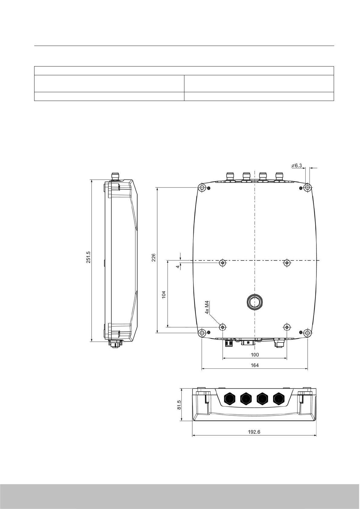
Reading range for USA / China
Antennas mounted on opposing sides
(portal configuration)
max. X m @@@
Readers mounted on the same side max. X m @@@
5.3.6 Dimension drawings
5.3.6.1 Dimension drawings
Figure 5-17 Dimension drawing for RF670R
Readers
5.3 RF670R reader
SIMATIC RF600
System Manual, 06/2010, J31069-D0171-U001-A10-7618 131
Draft Version 02.06.2010
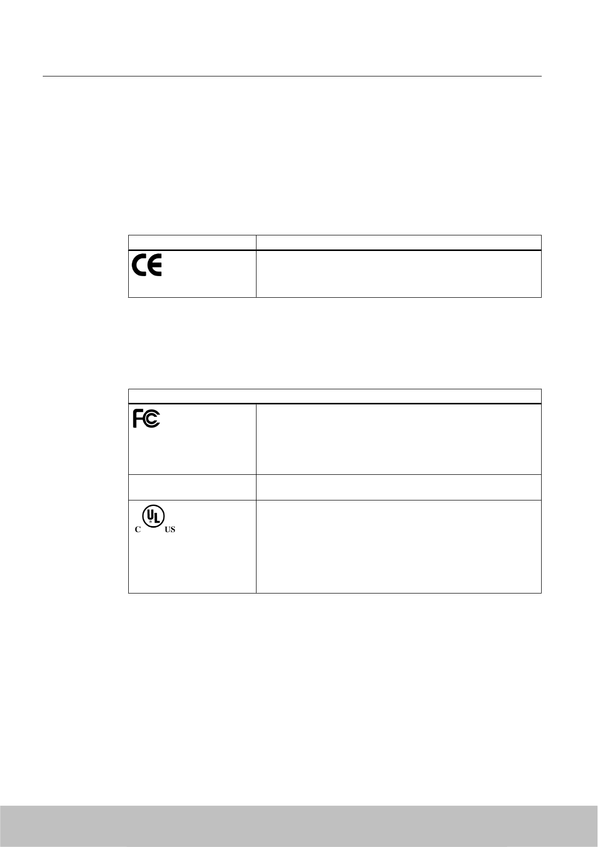
5.3.7 Certificates and approvals
5.3.7.1 CE mark
Table 5-7 6GT2811-0AB00-0AA0
Certificate Description
Compatible with R&TTE directive
5.3.7.2 FCC, IC-FCB approval and UL certification
@ Anpassen an RF670R? ID?
Table 5-8 FCC IDs: NXW-RF660; IC 267X-RF660
Standard
Federal Communications
Commission
FCC Title 47, Part 15.sections 15.247
Radio Frequency Interference Statement
This equipment has been tested and found to comply with the limits
for a Class A digital device, pursuant to Part 15 of the FCC Rules.
Industry Canada Radio
Standards Specifications
RSS-210 Issue 6, Sections 2.2, A8
This product is UL-certified for the USA and Canada.
It meets the following safety standard(s):
UL 60950-1 - Information Technology Equipment Safety - Part 1:
General Requirements
CSA C22.2 No. 60950 -1 - Safety of Information Technology
Equipment
UL Report E 205089
5.3.7.3 FCC information
Siemens SIMATIC RF670R (FCC): 6GT2811-0AB00-1AA0
FCC ID: NXW-? @@@
This device complies with part 15 of the FCC rules.
Operation is subject to the following two conditions:
(1) This device may not cause harmful interference, and
(2) This device must accept any interference received, including interference that may cause
undesired operation.
Readers
5.3 RF670R reader
SIMATIC RF600
132 System Manual, 06/2010, J31069-D0171-U001-A10-7618
Draft Version 02.06.2010
RF670R
FCC ID: NXW-RF670; IC: 267X-RF670
NXW-RF670

Caution
Any changes or modifications not expressly approved by the party responsible for compliance
could void the user's authority to operate the equipment.
Note
This equipment has been tested and found to comply with the limits for a Class B digital device,
pursuant to part 15 of the FCC Rules. These limits are designed to provide reasonable
protection against harmful interference when the equipment is operated in a commercial
environment. This equipment generates, uses, and can radiate radio frequency energy and,
if not installed and used in accordance with the instruction manual, may cause harmful
interference to radio communications. Operation of this equipment in a residential area is likely
to cause harmful interference in which case the user will be required to correct the interference
at his own expense.
FCC NoticeTo comply with FCC part 15 rules in the United States, the system must be
professionally installed to ensure compliance with the Part 15 certification.
It is the responsibility of the operator and professional installer to ensure that only certified
systems are deployed in the United States. The use of the system in any other combination
(such as co-located antennas transmitting the same information) is expressly forbidden.
FCC Exposure InformationTo comply with FCC RF exposure compliance requirements, the
antennas used for this transmitter must be installed to provide a separation distance of at least
20 cm from all persons and must not be co-located or operating in conjunction with any other
antenna or transmitter.
5.3.7.4 IC-FCB information
Siemens SIMATIC RF670R (FCC): 6GT2811-0AB00-1AA0
IC: 26??? @@@
Industry Canada NoticeTo reduce potential radio interference to other users, the antenna type
and its gain should be so chosen that the equivalent isotropically radiated power (e.i.r.p.) is
not more than that permitted for successful communication.
This device has been designed to operate with the SIMATIC RF620A antenna 902-928 as well
as the SIMATIC RF660A antenna 902-928 listed below, and having a maximum gain of 5,5 dBi.
Other antennas or antennas having a gain greater than 5,5 dBi are strictly prohibited for use
with this device.
The required antenna impedance is 50 Ohms.
5.4 RF660R reader
5.4.1 Description
SIMATIC RF660R is a stationary reader for connecting up to 4 external antennas. A rugged
housing with high IP65 degree of protection means that the device is a universal and reliable
Readers
5.4 RF660R reader
SIMATIC RF600
System Manual, 06/2010, J31069-D0171-U001-A10-7618 133
Draft Version 02.06.2010
IC: 267X-RF670
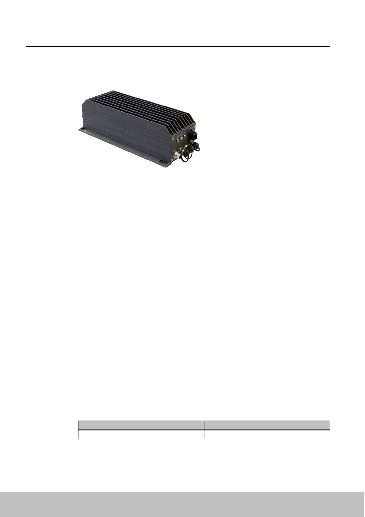
partner in harsh environments such as production plants, conveyor systems, warehouses, or
direct at the loading gate.
Figure 5-18 RF660R reader
Highlights
● The tags are read in accordance with the requirements of the EPCglobal Class 1, Gen 1
and Gen 2, and ISO/IEC 18000-6B standards
● Supports low-cost SmartLabels as well as reusable, rugged data media
● High reading speed: many tags can be read simultaneously (mass recording), rapidly
moving tags are reliably recorded
●Suitable for the 865 to 868 MHz UHF bands in Europe and the 920.125 to 924.875 MHz
band in China as well as the 902 to 928 MHz UHF band in North America
● Up to 4 antennas can be connected and configured in operating mode
● Reader degree of protection IP65, antenna degree of protection IP67
● Can be used for a high temperature range
● Antenna switching for high tag reader probability
● Dense Interrogator Environment mode, (DIE mode) for environments in which many
readers are operated in close proximity to each other
● Flexible system integration:
– Serial (RS 232)
– Ethernet (TCP/IP)
5.4.1.1 Ordering data
Ordering data for RF660R
Product Order No.
RF660R reader basic unit for ETSI and FCC 6GT2811-0AA00
Readers
5.4 RF660R reader
SIMATIC RF600
134 System Manual, 06/2010, J31069-D0171-U001-A10-7618
Draft Version 02.06.2010

Ordering data for antennas and antenna cables
Product Order No.
Antennas
●RF620A for ETSI (868 MHz)
● RF620A for FCC (915 MHz)
● RF660A for ETSI (868 MHz)
●RF660A for FCC (915 MHz)
● 6GT2812-1EA00
● 6GT2812-1EA01
● 6GT2812-0AA00
● 6GT2812-0AA01
Antenna cable
● 3°m (cable attenuation: 1.0 dB)
● 10 m (cable attenuation: 4.0 dB)
● 10°m (cable attenuation: 2.0 dB)
●20 m (cable attenuation: 4.0 dB)
● 6GT2815-0BH30
● 6GT2815-0BN10
● 6GT2815-1BN10
● 6GT2815-0BN20
Ordering data (accessories)
Product Order No.
Connecting cable
●RS 232, 9-pin sub D female connector: 5 m
● RS 232, 9-pin sub D female connector: 10 m
● Digital I/O, M12 socket: 2 m
●Digital I/O, M12 socket: 5 m
● Digital I/O, M12 socket: 10 m
● Digital I/O, M12 socket: 20 m
● Digital I/O, M12 socket: 50 m
● Ethernet: 10 m (only for RF660R)
● Ethernet: 20 m (only for RF660R)
● 6GT2891-0GH50
● 6GT2891-0GN10
● 6GT2891-0FH20
● 6GT2891-0FH50
● 6GT2891-0FN10
● 6GT2891-0FN20
● 6GT2891-0FN50
● 6GT2891-0HN10
● 6GT2891-0HN20
Wide-range power supply unit for SIMATIC RF
systems
● With EU plug
● With UK plug
● With US plug
●6GT2898-0AA00
● 6GT2898-0AA10
● 6GT2898-0AA20
24 V connecting cable
● 5 m between reader and power pack
● 6GT2491-1HH50
CD-ROM Software and Documentation ● 6GT2080-2AA10
NOTICE
Loss of validity for type tests and certificates
Note that when the 3°m antenna cable (6GT2815-0BH30) or the 10 m antenna cable
(6GT2815-1BN10) is used, the certifications for operating the reader outside of the validity
range of ETSI (EU, EFTA, Turkey) become void.
Readers
5.4 RF660R reader
SIMATIC RF600
System Manual, 06/2010, J31069-D0171-U001-A10-7618 135
Draft Version 02.06.2010
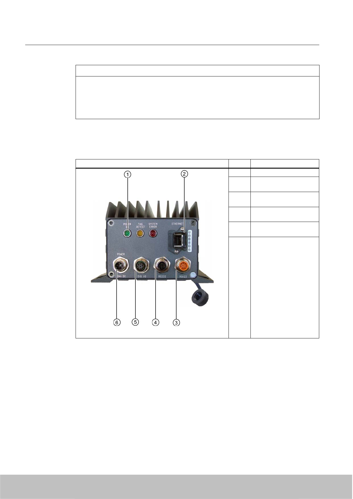
NOTICE
Excessive radiated power
Please note that when the above-mentioned antenna cable is used, unless indicated
otherwise for specific antennas, the cable attenuation must be set in the RF660R to the values
specified for cable attenuation. Otherwise, in the case of high antenna gain (e.g.°SIMATIC
RF660A) the result would be a radiated power that exceeds the permitted range.
5.4.1.2 Design of the RF660R reader
Item Description
(1) Status LED
(2) Industrial Ethernet
(RJ45 socket)
(3) RS 422 interface
(not assigned)
(4) RS 232 interface
(5-pin M12 connector)
(5) Digital I/O
(8-pin M12 connector)
(6) Power, 24 V DC;
(4-pin M12 connector)
Readers
5.4 RF660R reader
SIMATIC RF600
136 System Manual, 06/2010, J31069-D0171-U001-A10-7618
Draft Version 02.06.2010
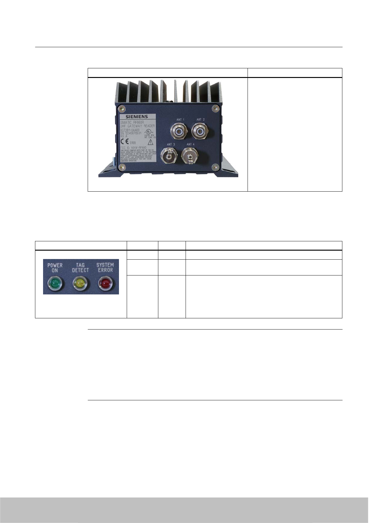
Description
4 antenna connections
ANT 1 to ANT 4
(RTNC plug)
5.4.1.3 Status displays
Status displays LEDs Color Description
Power on Green Power supply ON
Tag Detect Yellow LED lit, as soon as at least one tag with a correct tag ID is
within the field.
System
error
Red Reader is not active, a more or less major fault has occurred
In addition, this LED also indicates the fault status through the
number of flashing pulses. Reboot (operating voltage Off → On
is necessary).
The LED flashes once for the 'INACTIVE' status, rebooting is
not necessary in this case.
Note
If "Tag Detect" is not lit even though a tag is located within the field, common reasons include:
● Tag protocol has been set incorrectly (can be set with Configuration Software)
● Tag is defective
● Reader or antenna has a defect
● Tag is not in the field of radiation of the transmit antenna
Readers
5.4 RF660R reader
SIMATIC RF600
System Manual, 06/2010, J31069-D0171-U001-A10-7618 137
Draft Version 02.06.2010
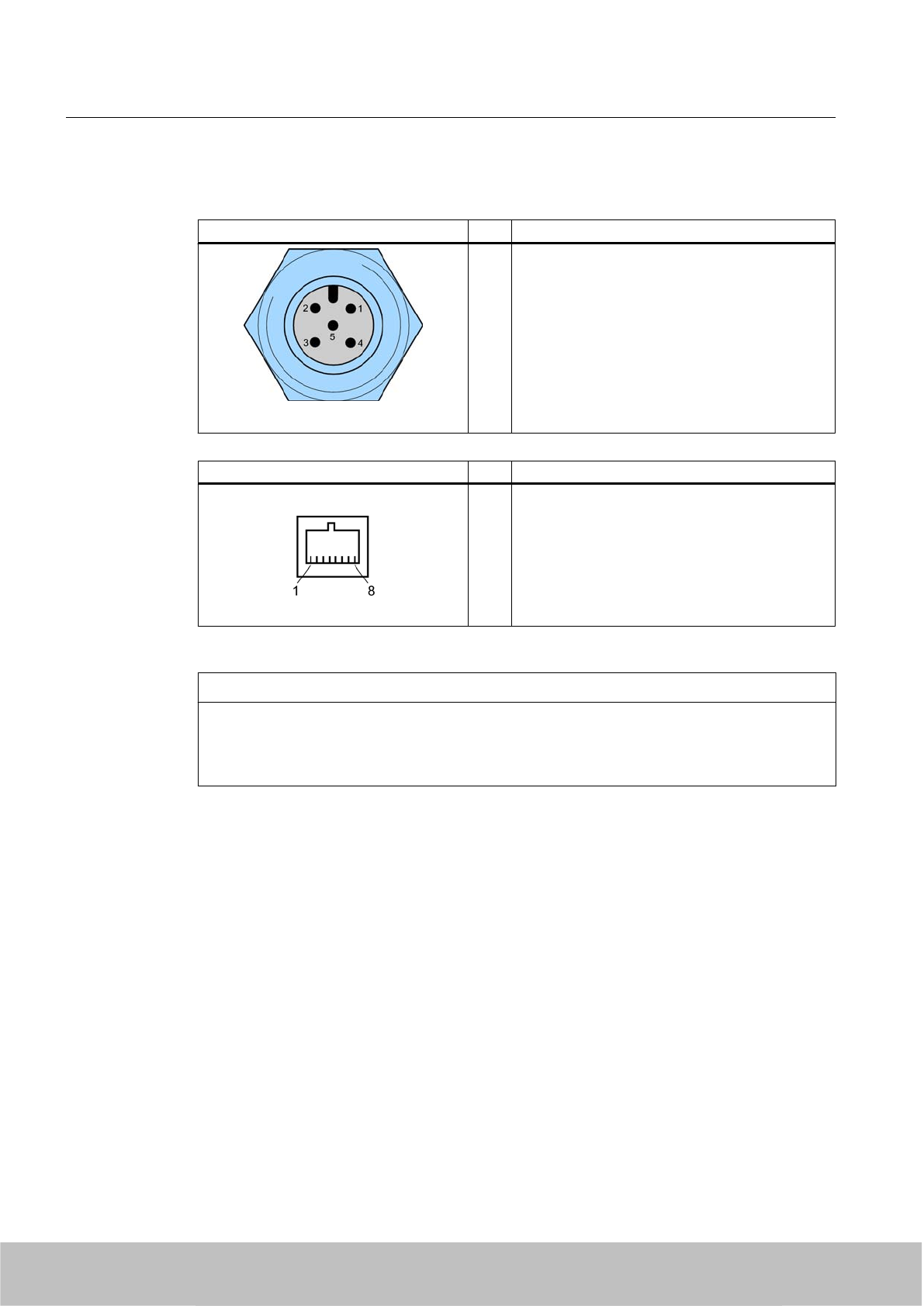
5.4.1.4 Pin assignment of the serial interfaces
RS 232 connector (on reader side) Pin Pin assignment
1
2
3
4
5
RS232_TX
N.C.
N.C.
RS232_RX
GND
Industrial Ethernet (on reader side) Pin Pin assignment
1
2
3
4
5
6
7
8
Transmit Data (+)
Transmit Data (-)
Receive Data (+)
Terminated
Terminated
Receive Data (-)
Terminated
Terminated
NOTICE
We recommend that only original Siemens Ethernet connectors are used (10 m cable: Order
No. 6GT2891-0HN10; 20 m cable: Order No. 6GT2891-0HN20) for connecting to the Ethernet
socket of the reader. If plug-in connectors from other manufacturers are used, it may be
difficult or even impossible to remove the plug from the reader
Readers
5.4 RF660R reader
SIMATIC RF600
138 System Manual, 06/2010, J31069-D0171-U001-A10-7618
Draft Version 02.06.2010
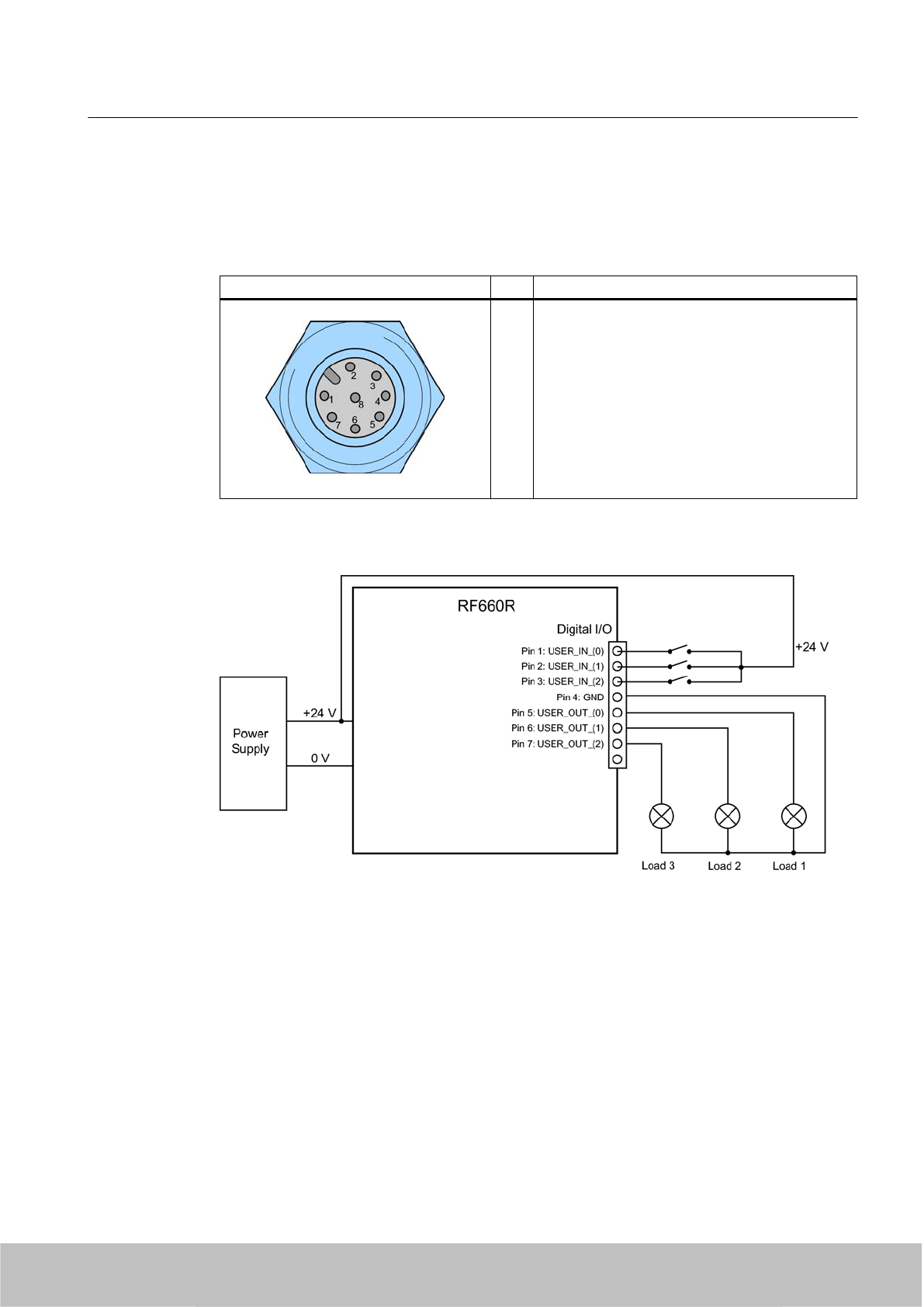
5.4.1.5 Pin assignment and connections of the digital I/O interface
Pin assignment
Digital I/O socket (on reader side) Pin Pin assignment
1
2
3
4
5
6
7
8
Input USER_IN (0)
Input USER_IN (1)
Input USER_IN (2)
GND (IN)
Output USER_OUT (0)
Output USER_OUT (1)
Output USER_OUT (2)
Housing
Connections
Figure 5-19 Connections for digital I/O
Output USER_OUT (0), (1), (2)
● These are high-side switches that connect Vcc (+24 V) to the output ('active high').
● Each output is rated for 0.5 A current and is electronically protected.
● The 0 V rail is Pin 4 (GND).
●Three digital outputs can be operated simultaneously with up to 0.5 A each.
● The outputs are optically isolated through optocouplers.
Readers
5.4 RF660R reader
SIMATIC RF600
System Manual, 06/2010, J31069-D0171-U001-A10-7618 139
Draft Version 02.06.2010
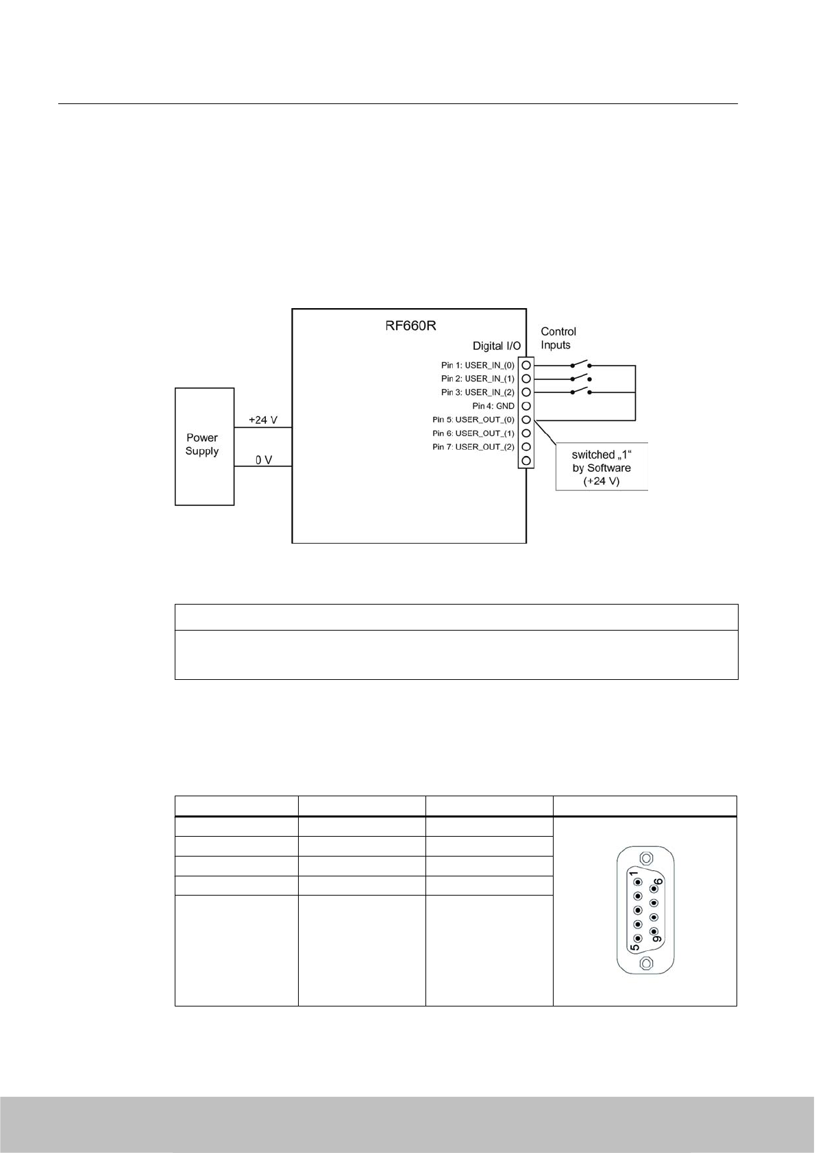
Input USER_IN (0), (1), (2)
● The inputs are optically isolated through optocouplers.
● The 24 V voltage for the digital inputs (e.g. switches, proximity switches) must be supplied
over a separate cable.
● The 24 V voltage for the digital inputs can alternatively be supplied from a digital output
(USER-OUT). In the user program, however, the digital output must be permanently
connected to "1" in this case.
Figure 5-20 RF660R connection diagram
NOTICE
It may be necessary to restart the reader
The length of trigger pulses must be longer than 30 ms.
5.4.1.6 Pin assignment of the connecting cable
Table 5-9 RS 232
Signal M12Pin SUB-D pin Image
TX (reader) 1 2
- 2 -
- 3 -
RX (reader) 4 3
GND 5 5
Readers
5.4 RF660R reader
SIMATIC RF600
140 System Manual, 06/2010, J31069-D0171-U001-A10-7618
Draft Version 02.06.2010
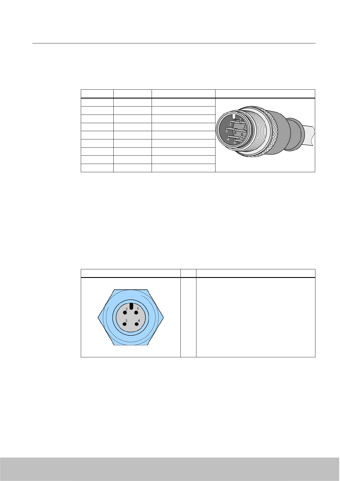
Table 5-10 Digital I/O, for cable with open cable ends
M12 pin Core color Pin assignment View of M12 connector
1white Input USER_IN (0)
2 brown Input USER_IN (1)
3 green Input USER_IN (2)
4 yellow GND
5 Gray Output USER_OUT (0)
6 pink Output USER_OUT (1)
7 blue Output USER_OUT (2)
8 red Housing
Shield Shield
Comment
This cable has an 8-pin M12 connector at one end and the other cable end is 'open'. There
are 8 color-coded single cores there for connecting to external devices. Cable length = 5m.
The cable length can be reduced, if needed.
5.4.1.7 Power supply
Pin assignment of the power connections
Power connector (on reader side) Pin Pin assignment
1
2
3
4
Ground (0 V)
+24 V
+24 V
Ground (0 V)
Readers
5.4 RF660R reader
SIMATIC RF600
System Manual, 06/2010, J31069-D0171-U001-A10-7618 141
Draft Version 02.06.2010
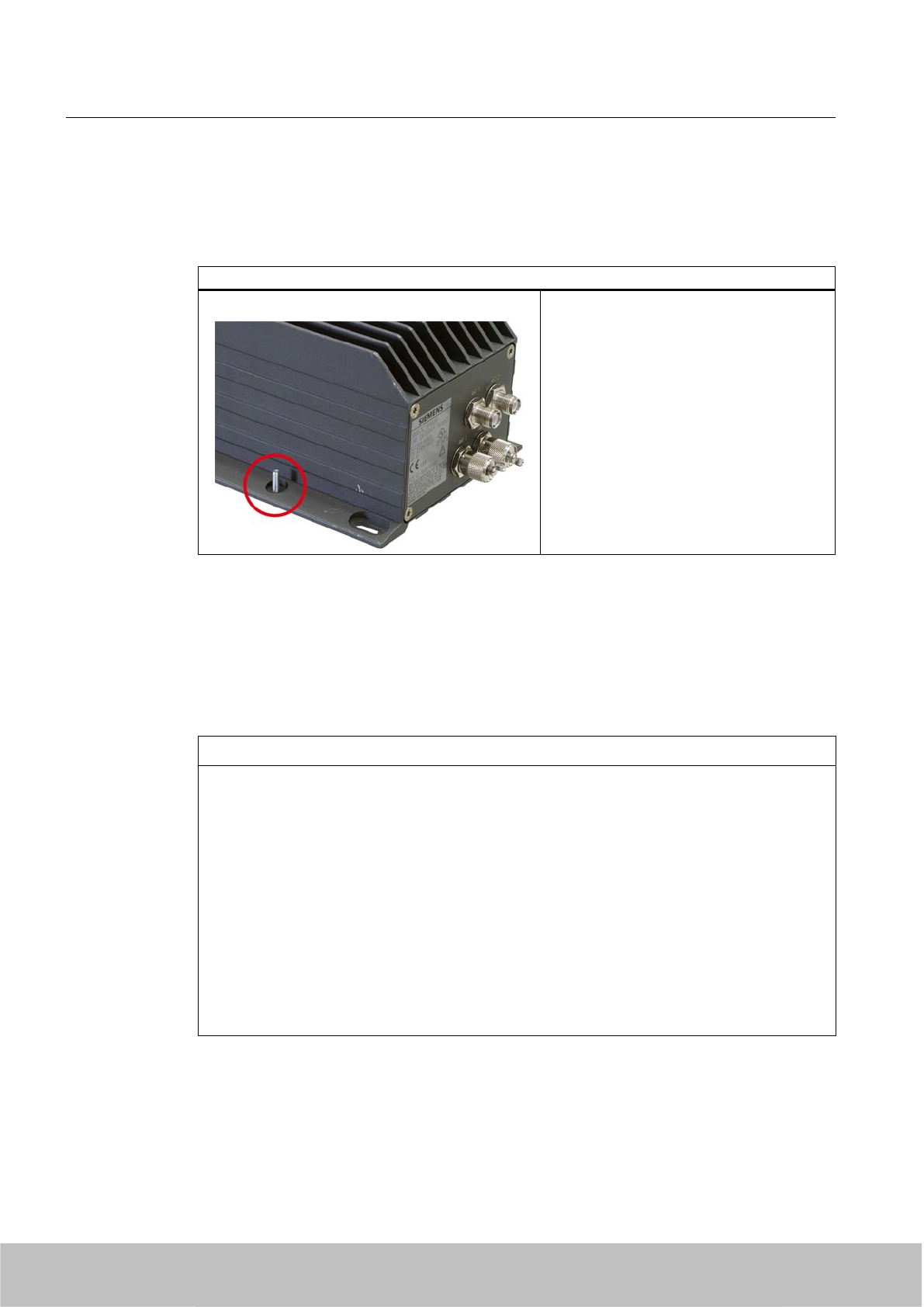
5.4.1.8 Grounding connection
A low-impedance earth connection ensures that interference signals generated, for example,
by external power supply cables or signal cables are safely discharged to earth.
Earthing connection
The ground terminal (M4 threads) on the
device (large surface, large-area contact) has
to be connected with the ground conductor of
the plant or the cabinet in which the reader is
to be installed.
The minimum conductor cross-section may
not be less than 2.5 mm2.
5.4.2 Planning application
Firmware and software compatibility
CAUTION
Damage to the reader
The SIMATIC RF660R reader with firmware version V1.2 must only be configured and
operated with the relevant SIMATIC RF660R Configuration Software V1.2.
The SIMATIC RF660R reader with firmware version V1.3 must only be configured and
operated with the relevant SIMATIC RF660R Configuration Software V1.2 (limited
functionality) or V1.3.
No other combination of firmware and configuration software is permissible. The configuration
software V1.3 recognizes if it has been connected to a SIMATIC RF660R reader with firmware
version V1.3 or version 1.2.
Therefore always refer to the chapter "Firmware/Configuration Software Compatibility" of the
Configuration Manual before you make any changes to the firmware version or the version
of the SIMATIC RF660R Configuration Software.
Readers
5.4 RF660R reader
SIMATIC RF600
142 System Manual, 06/2010, J31069-D0171-U001-A10-7618
Draft Version 02.06.2010
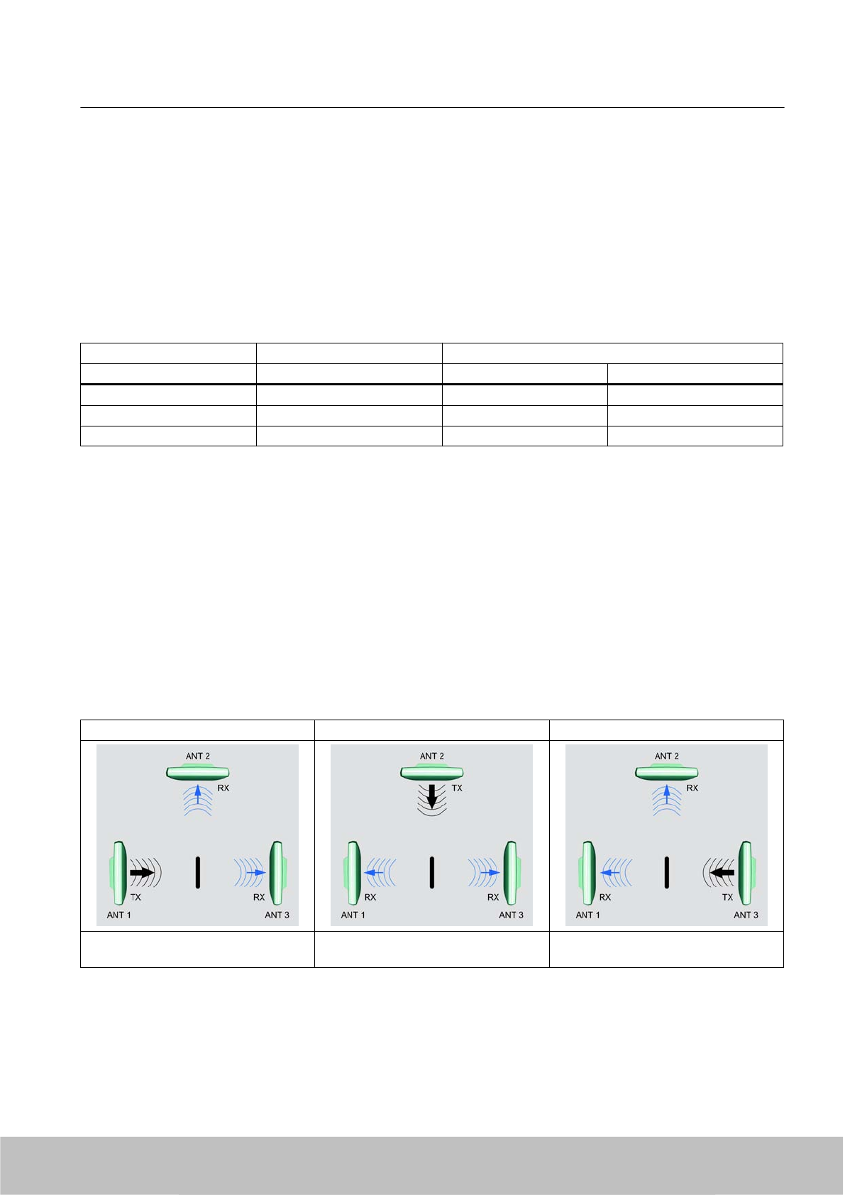
Compatibility RF-MANAGER versions/reader firmware versions
Below you will find an overview of the compatibility of RF-MANAGER versions and RF660R
reader firmware versions.
In RF-MANAGER°2008°Service Pack°2 and higher, you can select the matching ETSI
standard (ETSI standard EN 302 208 V1.1.1 or EN 302 208 V1.2.1) for your reader RF660R
depending on the firmware version.
For detailed information, please refer to the RF-MANAGER documentation. This
documentation can be downloaded via the portal Service & Support (Page 354).
Older RF-MANAGER versions RF-MANAGER 2008 SP2 and higher
Reader firmware version GR_XML_2.0 GR_XML_2.0 GR_XML_3.0
V1.1 X X -
V1.2 Restricted functionality Restricted functionality -
V1.3 X 1) - X
1) No commands may be used that are no longer permitted in firmware V1.3.
5.4.2.1 Increasing the probability of identification for tags - Antenna switching
To achieve a high probability of reading tags, the antenna switching function has been
implemented in the RF660R reader:
During a defined time period, the reader transmits on one antenna and receives on the other.
As long as the antenna is receiving signals from further tags, the reader continues to transmit
on the same transmitter antenna until all responding tags have been identified. Subsequently,
or if no tags respond, the reader activates another antenna as the transmitter antenna. After
all the antenna have transmitted at least once and no tag has responded, or when the settling
time is excessively long, the reader activates frequency hopping (in the USA) or channel
selection (in Europe).
Cycle 1 Cycle 2 Cycle 3
Antenna 1 transmits
Antennas 2 and 3 receive
Antenna 2 transmits
Antennas 1 and 3 receive
Antenna 3 transmits
Antennas 1 and 2 receive
Readers
5.4 RF660R reader
SIMATIC RF600
System Manual, 06/2010, J31069-D0171-U001-A10-7618 143
Draft Version 02.06.2010
5.4.3 Installation /Mounting
Requirement
WARNING
Ensure that the wall or ceiling can hold four times the total weight of the device.
CAUTION
Emitted radiation
The transmitter complies with the requirements of Health Canada and the FCC limit values
for subjecting persons to HF radiation, provided that a minimum spacing of 26 cm exists
between antenna and person. When the antennas are installed, you must therefore ensure
that a minimum spacing of 26 cm is maintained between personnel and antennas.
Mounting/installing the device
The positions of the fixing holes for the device are shown in the section Dimension drawings
(Page 149).
Examples of mounting types
Material Hole diameter Mounting
Concrete 8 mm diameter
60 mm depth
Rawlplug: 8 mm diameter, 50 mm length
Screws: 4 mm diameter, 50 mm length
Plasterboard
(min. 13 mm thick)
14 mm diameter Gravity toggle: 4 mm diameter, 50 mm length
Metal
(min. 2 mm thick)
5 mm diameter M4 metal screws: 4 mm diameter,
15 mm length
5.4.4 Configuration/integration
5.4.4.1 Configuration
Two communication interfaces are available for integrating the device into system
environments/networks:
● Ethernet and
● RS 232
The communication interfaces transfer the data to IT, ERP and SCM systems on SIMATIC
PLCs or PCs (also used for configuration and diagnostics).
Readers
5.4 RF660R reader
SIMATIC RF600
144 System Manual, 06/2010, J31069-D0171-U001-A10-7618
Draft Version 02.06.2010
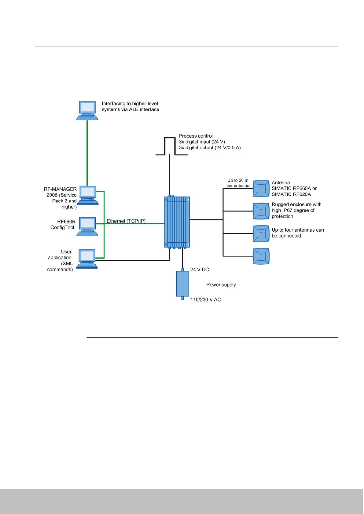
Simple process controls (e.g. a traffic signal) can be directly implemented using the write/read
device via three digital inputs and outputs with 24 V each.
Figure 5-21 Configuration overview of the RF660R reader
Note
Maximum cable length for the RS232 interface
For secure and error-free data transmission, a data transfer rate of 115.2 kbit/s applies:
maximum cable length 10 m.
Readers
5.4 RF660R reader
SIMATIC RF600
System Manual, 06/2010, J31069-D0171-U001-A10-7618 145
Draft Version 02.06.2010
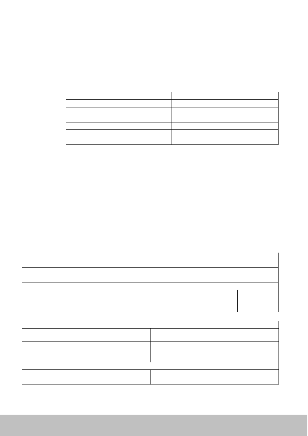
5.4.4.2 Transmission protocols
RS232 communication
XML protocol
Transmission rates 115200 bps
Start bits 1
Data bits 8
Parity None
Flow control Xon/Xoff
Stop bits 1
Ethernet communication
The Ethernet interface offers automatic selection between 10BaseT and 100BaseTX.
Shielded Twisted-Pair patch cables with standard RJ45 connectors are recommended for a
reliable connection.
5.4.5 Technical specifications
5.4.5.1 Mechanical data
Mechanical specification of RF660R
Weight 3.7 kg
Dimensions (L x W x H) in mm 320 x 145 x 100 without connections
Material Aluminum
Color Anthracite
Power consumption, typical 24 V
●At 2 W transmit power
● No digital outputs active
800 mA
Mechanical environmental conditions
Shock ETSI EN 300 019-2-3 V2.1.2
IEC 60068-2-27
Total shock response spectrum Type 3.3
Vibration ETSI EN 300 019-2-3 V2.1.2
IEC 60068-2-64
Climatic Conditions
Ambient temperature during operation -25 °C to +55 °C
Ambient temperature for transport and storage -40 °C to +85 °C
Readers
5.4 RF660R reader
SIMATIC RF600
146 System Manual, 06/2010, J31069-D0171-U001-A10-7618
Draft Version 02.06.2010

Electromagnetic compatibility ETSI EN 301 489-1 / -3
ETSI EN 302 208 V1.2.1
FCC Part 15
Status displays on the device
Power On Green LED
Tag Detect Yellow LED
System error Red LED
Interfaces
Antenna connections 4x RTNC connector
Maximum number of antenna channels operating
independently of each other
2 (with 2 x 2 antennas, tags can be read by a reader at 2 independent
locations)
Ethernet 10BaseT or 100BaseTx 1x RJ45 connection
according to IEEE 802.3 and ISO 8802-3
RS422 Currently unassigned
RS232 1x connector (5-pin M12). Bit rate: 115200 bps
Digital inputs 3 (8-pin M12)
log. "0": 0…7 V
log. "1": 15…24 V
Digital outputs (short-circuit proof) 3 (8-pin M12)
24 V; 0.5 A each
Power supply 24 V DC (4-pin M12) 20 to 30 V (2.2 A)
Approvals/Conformity ● Radio to R&TTE‑ guidelines EN 300 330, EN 301 489
● CE, EMC, FCC, IC, cULus
● IEC60950, including US and Canadian variants of it
● FCC CFR47 Part 15.247
● Industrial Canada, RSS-210, Issue 6, Sept. 2005
● ETSI EN 302-208 V1.2.1
● Reader degree of protection acc. to EN 60529 (IP65)
5.4.5.2 Technical data according to EPC and ISO
Frequencies
European frequency band 865 … 868 MHz (4 channels 865.7 MHz; 866.3 MHz;
866.9 MHz; 867.5 MHz without LBT with up to 2 W ERP)
North American frequency band 902 ... 928 MHz (50 channels, frequency hopping)
Frequency band for China 920.125 to 924.875 MHz (16 subchannels at 2 W ERP, 20
subchannels at 0.1 W ERP)
Frequency accuracy max.± 10 ppm
Readers
5.4 RF660R reader
SIMATIC RF600
System Manual, 06/2010, J31069-D0171-U001-A10-7618 147
Draft Version 02.06.2010

Channel spacing EU: 200 kHz
US: 500 kHz
China: 250 kHz
Modulation methods ASK: DSB modulation & PR-ASK modulation
Encoding, Manchester or Pulse Interval (PIE)
Effective radiated power and reading range with RF620A
Effective radiant power Europe / China USA
Range 0.1 to 2 W ERP 0.4 to 4 W EIRP =
0.24 to 2.4 W ERP
Reading range Europe / China USA
Antennas mounted on opposing sides
(portal configuration)
max. 1 m (recommended
maximum value for
configuration)
max. 1 m (recommended
maximum value for
configuration)
Antennas mounted on the same side max. 1 m (recommended
maximum value for
configuration)
max. 1 m (recommended
maximum value for
configuration)
Note
Reading ranges are highly dependent on the transponder type and mounting surface
The reading ranges recommended above are applicable to the RF630L (6GT2810-2AB00,
-2AB01, -2AB02) on card with a 3 m antenna cable (1 dB cable attenuation) and with the
reader set to the maximum power. The RF620A antenna is mounted on a metal surface.
Effective radiated power and reading range with RF660A
Effective radiant power Europe / China USA
Range 0.1 to 2 W ERP 0.4 to 4 W EIRP =
0.24 to 2.4 W ERP
Reading range Europe / China USA
Antennas mounted on opposing sides
(portal configuration)
max. 10 m (recommended
maximum value for
configuration)
max. 10 m (recommended
maximum value for
configuration)
Antennas mounted on the same side max. 10 m (recommended
maximum value for
configuration)
max. 10 m (recommended
maximum value for
configuration)
Readers
5.4 RF660R reader
SIMATIC RF600
148 System Manual, 06/2010, J31069-D0171-U001-A10-7618
Draft Version 02.06.2010
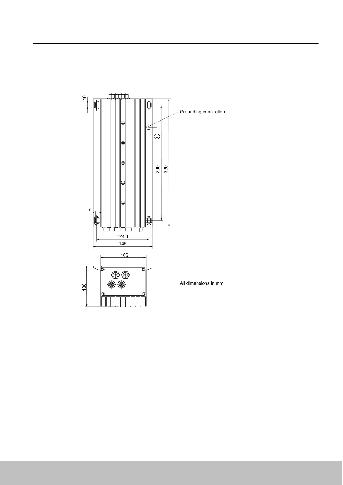
5.4.6 Dimension drawings
Figure 5-22 Dimension drawing of the reader
Readers
5.4 RF660R reader
SIMATIC RF600
System Manual, 06/2010, J31069-D0171-U001-A10-7618 149
Draft Version 02.06.2010
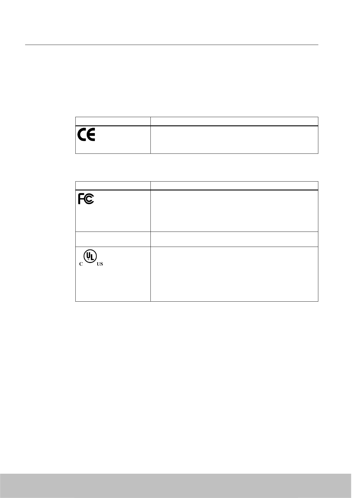
5.4.7 Certificates and approvals
5.4.7.1 CE mark
Table 5-11 6GT2811-0AA00
Certificate Description
Compatible with R&TTE directive
Table 5-12 FCC IDs: NXW-RF660; IC 267X-RF660
Standards Description
Federal Communications
Commission
FCC Title 47, Part 15.sections 15.247
Radio Frequency Interference Statement
This equipment has been tested and found to comply with the limits
for a Class A digital device, pursuant to Part 15 of the FCC Rules.
FCC IDs: NXW-RF660
Industry Canada Radio
Standards Specifications
RSS-210 Issue 6, Sections 2.2, A8
IC: 267X-RF660
This product is UL-certified for the USA and Canada.
It meets the following safety standard(s):
UL 60950-1 - Information Technology Equipment Safety - Part 1:
General Requirements
CSA C22.2 No. 60950 -1 - Safety of Information Technology
Equipment
UL Report E 205089
5.4.7.2 FCC information
Siemens SIMATIC RF660R
FCC ID: NXW-RF660
This device complies with part 15 of the FCC rules.
Operation is subject to the following two conditions:
(1) This device may not cause harmful interference, and
(2) This device must accept any interference received, including interference that may cause
undesired operation.
Caution
Any changes or modifications not expressly approved by the party responsible for compliance
could void the user's authority to operate the equipment.
Readers
5.4 RF660R reader
SIMATIC RF600
150 System Manual, 06/2010, J31069-D0171-U001-A10-7618
Draft Version 02.06.2010

Note
This equipment has been tested and found to comply with the limits for a Class A digital device,
pursuant to part 15 of the FCC Rules. These limits are designed to provide reasonable
protection against harmful interference when the equipment is operated in a commercial
environment. This equipment generates, uses, and can radiate radio frequency energy and,
if not installed and used in accordance with the instruction manual, may cause harmful
interference to radio communications. Operation of this equipment in a residential area is likely
to cause harmful interference in which case the user will be required to correct the interference
at his own expense.
FCC Notice
To comply with FCC part 15 rules in the United States, the system must be professionally
installed to ensure compliance with the Part 15 certification.
It is the responsibility of the operator and professional installer to ensure that only certified
systems are deployed in the United States. The use of the system in any other combination
(such as co-located antennas transmitting the same information) is expressly forbidden.
FCC Exposure Information
To comply with FCC RF exposure compliance requirements, the antennas used for this
transmitter must be installed to provide a separation distance of at least 20 cm from all persons
and must not be co-located or operating in conjunction with any other antenna or transmitter.
5.4.7.3 IC-FCB information
Siemens SIMATIC RF660R: 6GT2811-0AA01
IC: 267X-RF660
Industry Canada NoticeTo reduce potential radio interference to other users, the antenna type
and its gain should be so chosen that the equivalent isotropically radiated power (e.i.r.p.) is
not more than that permitted for successful communication.
This device has been designed to operate with the SIMATIC RF620A antenna 902-928 as well
as the SIMATIC RF660A antenna 902-928 listed below, and having a maximum gain of 5,5 dBi.
Other antennas or antennas having a gain greater than 5,5 dBi are strictly prohibited for use
with this device.
The required antenna impedance is 50 Ohms.
Readers
5.4 RF660R reader
SIMATIC RF600
System Manual, 06/2010, J31069-D0171-U001-A10-7618 151
Draft Version 02.06.2010

Draft Version 02.06.2010

Antennas 6
6.1 Overview
The following table shows the most important features of the RF600 antennas at a glance:
Features RF620A antenna
865-868
RF620A antenna
902-928
RF660A antenna
865-868
RF660A antenna
902-928
Material PA 12, silicon-free
Frequency band 865-868 MHz 902-928 MHz 865-868 MHz 902-928 MHz
Impedance 50 Ohm nominal
Antenna gain -10…-5 dBi 5-7 dBil > 6 dBic
VSWR (standing wave
ratio)
2:1 max.
Polarization Linear RH circular
Radiating/receiving angle Depending on the mounting surface 55°- 60° 60° - 75°
Connector RTNC coupling RTNC
Degree of protection IP67
Permissible ambient
temperature
-25° C to +75° C
Number of connectable
antennas per reader
RF630R 1 or 2 antennas
RF670R 1, 2, 3 or 4 antennas
RF660R 2, 3, or 4 antennas
SIMATIC RF600
System Manual, 06/2010, J31069-D0171-U001-A10-7618 153
Draft Version 02.06.2010
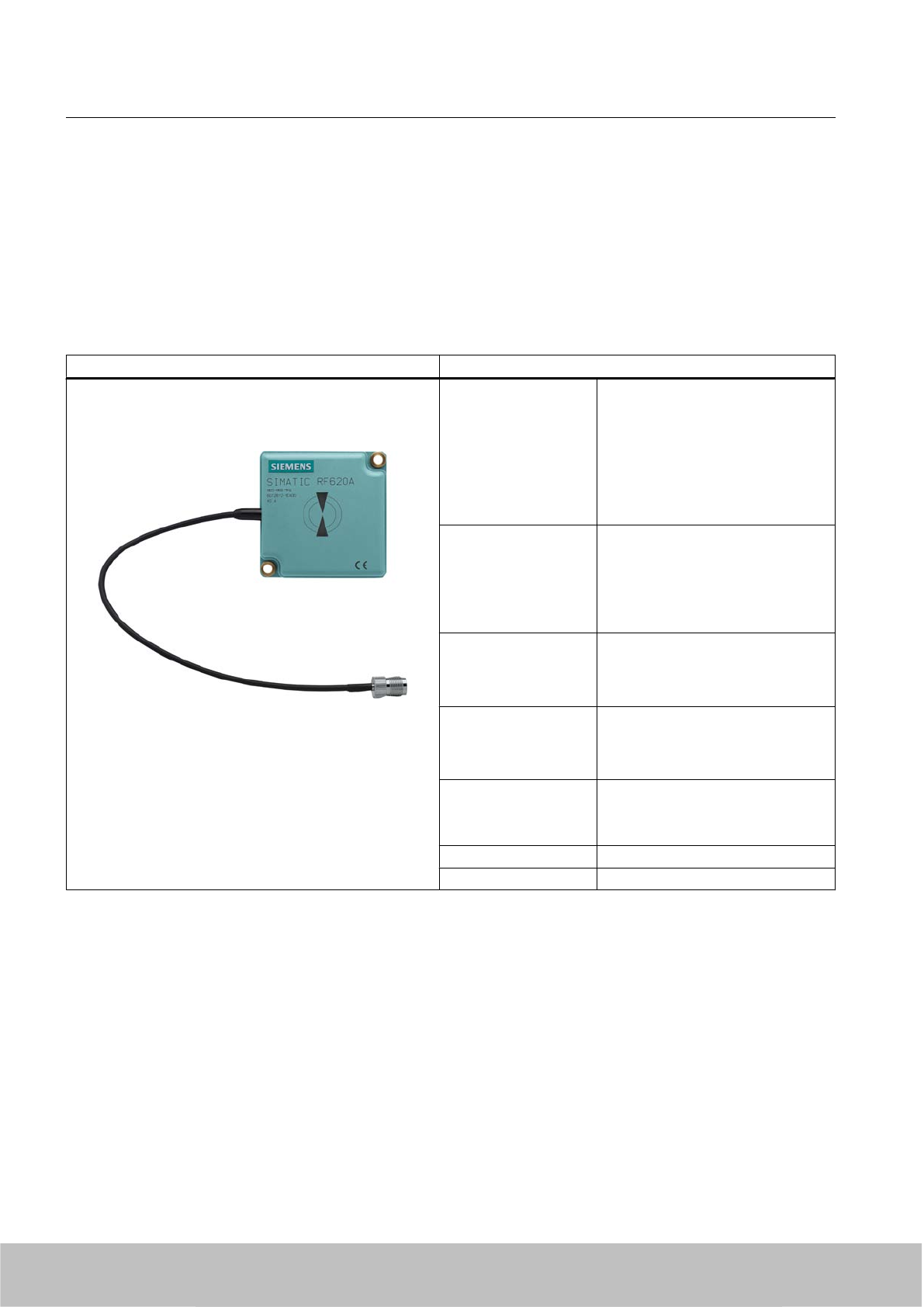
6.2 RF620A antenna
6.2.1 Description
SIMATIC RF620A Features
Field of application The SIMATIC RF620A is an antenna
of compact, industry-standard
design.
It is suitable for UHF transponders
with normal (far field) antenna
characteristics, e.g.
SIMATIC RF630L,
SIMATIC RF620T.
Antenna field Designed for transponders that are
uniformly aligned whilst directed past
the antenna.
See Chapter Alignment of
transponders to the antenna
(Page 158)
Writing/reading range Approx. 0.5 m depending on the
transponder
(see Chapter Read/write ranges
(Page 169) )
Connecting cable 30 cm movable connecting cable and
RTNC coupling (an antenna cable,
e.g. 6GT2815-0BH30 is required for
connection to the reader)
Readers that can be
connected
● RF670R (1 to 4 antennas)
●RF630R (1 or 2 antennas)
● RF660R (at least 2 antennas)
Polarization Linear
Degree of protection IP67
Frequency bands
The antenna is available for two different frequency bands that have been specified for the
regions of Europe, and China, USA respectively.
● The antenna for Europe operates in the frequency band of 865 to 868 MHz.
● The antenna for China and the USA operates in the frequency band of 902 to 928 MHz.
Antennas
6.2 RF620A antenna
SIMATIC RF600
154 System Manual, 06/2010, J31069-D0171-U001-A10-7618
Draft Version 02.06.2010
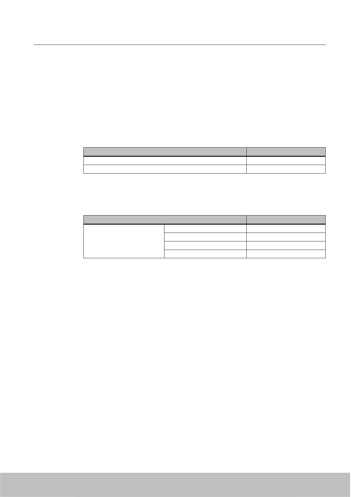
Function
The SIMATIC RF620A is used for transmitting and receiving RFID signals in the UHF frequency
band. The antennas are connected to the SIMATIC RF600 readers via antenna cables that
are available in different lengths.
6.2.2 Ordering data
Table 6-1 Ordering data RF620A
Product Order No.
SIMATIC RF620A (ETSI) 6GT2812-1EA00
SIMATIC RF620A (FCC) 6GT2812-1EA01
Accessories
Table 6-2 Ordering data (accessories)
Product Order No.
Connecting cable between
reader and antenna
3 m (cable loss 1.0 dB) 6GT2815-0BH30
10 m (cable loss 2.0 dB) 6GT2815-1BN10
10 m (cable loss 4.0 dB) 6GT2815-0BN10
20 m (cable loss 4.0 dB) 6GT2815-0BN20
Antennas
6.2 RF620A antenna
SIMATIC RF600
System Manual, 06/2010, J31069-D0171-U001-A10-7618 155
Draft Version 02.06.2010

6.2.3 Installation and assembly
6.2.3.1 RF620A mounting types
Two holes for M5 screws are provided for mounting the antenna. This is therefore suitable for:
● Mounting on metallic and non-metallic backgrounds
Note
To achieve optimum wave propagation, the antenna should not be surrounded by
conducting objects. The area between antenna and transponder should also allow wave
propagation without interference.
6.2.4 Connecting an antenna to the reader
6.2.4.1 Overview
The SIMATIC RF620A antenna must be connected to the reader using an antenna cable.
Requirement
Note
Use of Siemens antenna cable
To ensure optimum functioning of the antenna, it is recommended that a Siemens antenna
cable is used in accordance with the list of accessories.
Strain relief
The antenna cable is provided with strain relief as shown in the following diagram:
①RF620A connecting cable
②RF600 antenna cable
③Strain relief (should take place at this position)
Figure 6-1 Strain relief
Antennas
6.2 RF620A antenna
SIMATIC RF600
156 System Manual, 06/2010, J31069-D0171-U001-A10-7618
Draft Version 02.06.2010

Bending radii of the cables
Cable designation Order No. Length [m] Cable loss [dB] Bending radius
[mm]
RF620A
connecting cable
15
Antenna cable 6GT2815-0BH30 3 1 51
Antenna cable 6GT2815-1BN10 10 2 77
Antenna cable 6GT2815-0BN10 10 4 51
Antenna cable 6GT2815-0BN20 20 4 77
6.2.4.2 Connecting RF620A to RF670R
Preassembled standard cables (Page 155) in lengths of 3 m, 10 m and 20 m are available for
the connection.
The read range is limited by the cable loss. The maximum range can be achieved with the
6GT2815-0BH30 cable (length 3 m) since this has the lowest cable loss.
Connection of one, two or three antennas
When one, two or three antennas are used, we recommend that the remaining antenna
connection on the RF670R reader be sealed using the supplied protective cap.
Connection of four antennas
When using two antennas on the RF670R, there are no limitations to the positioning.
6.2.4.3 Connecting RF620A to RF630R
Preassembled standard cables (Page 155) in lengths of 3 m, 10 m and 20 m are available for
the connection.
The read range is limited by the cable loss. The maximum range can be achieved with the
6GT2815-0BH30 cable (length 3 m) since this has the lowest cable loss.
Connection of one antenna
When one antenna is used, we recommend that the remaining antenna connection on the
RF630R reader be sealed using the supplied protective cap.
Connection of two antennas
When using two antennas on the RF630R, there are no limitations to the positioning.
Antennas
6.2 RF620A antenna
SIMATIC RF600
System Manual, 06/2010, J31069-D0171-U001-A10-7618 157
Draft Version 02.06.2010
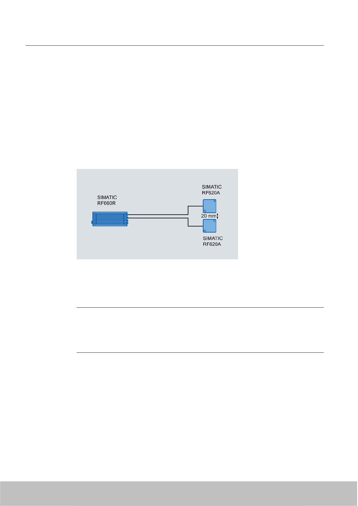
6.2.4.4 Connecting RF620A to RF660R
Preassembled standard cables (Page 155) in lengths of 3 m, 10 m and 20 m are available for
the connection.
The read range is limited by the cable loss. The maximum range can be achieved with the
6GT2815-0BH30 cable (length 3 m) since this has the lowest cable loss.
At least two antennas must be connected in order to guarantee correct functioning.
Connection of two antennas
When two antennas are used, we recommend that the antennas be connected to the reader
as follows:
Figure 6-2 Configuration with RF660R
The RF620A antennas must always be arranged in pairs with the RF660R since one antenna
is needed for transmitting signals to the transponder whereas the other antenna receives the
signals from the transponder.
Note
Operation of the RF660R with more than two RF620A antennas does not offer optimum
performance!
More than two antennas should not be connected due to the functional design of the reader.
The optimum read rates cannot be achieved if you connect more than two RF620A antennas.
6.2.5 Alignment of transponders to the antenna
Polarization axis
Since the RF620A antenna has linear polarization, it is necessary to consider the alignment
of the transponders with regard to the polarization axis of the antenna.
Antennas
6.2 RF620A antenna
SIMATIC RF600
158 System Manual, 06/2010, J31069-D0171-U001-A10-7618
Draft Version 02.06.2010
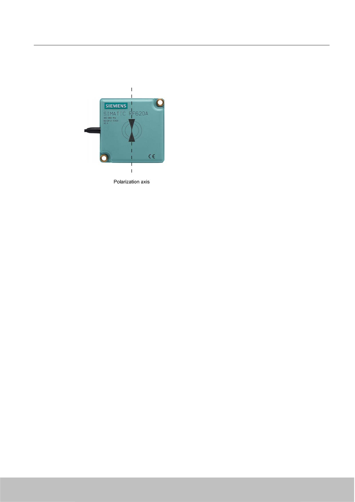
The polarization axes of antenna and transponder must always be parallel. The symbol on the
antenna indicates the polarization axis.
Figure 6-3 Polarization axis
Antennas
6.2 RF620A antenna
SIMATIC RF600
System Manual, 06/2010, J31069-D0171-U001-A10-7618 159
Draft Version 02.06.2010
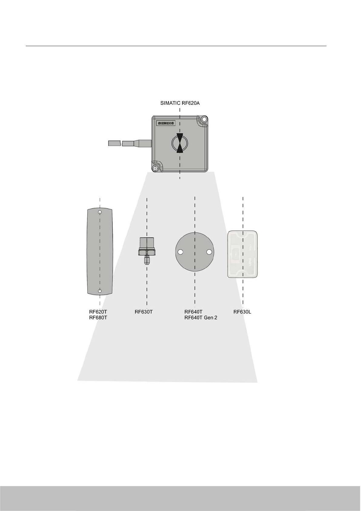
Alignment
The following diagram shows the optimum alignment of the RF600 transponders to the RF620A
antenna.
Figure 6-4 Antenna/transponder alignment
Antennas
6.2 RF620A antenna
SIMATIC RF600
160 System Manual, 06/2010, J31069-D0171-U001-A10-7618
Draft Version 02.06.2010
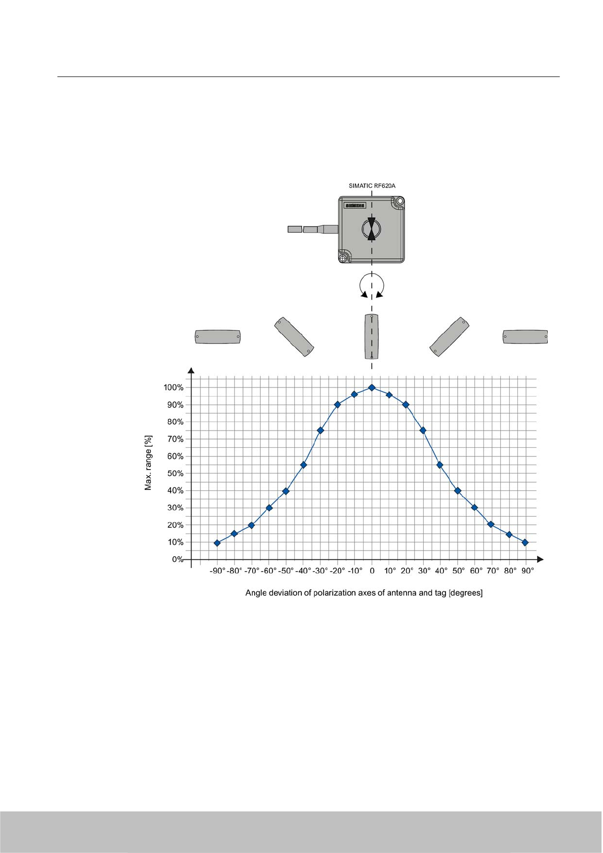
Angle deviation diagram for alignment
The following diagram shows the dependence of the following factors.
● Alignment angle of transponder to antenna
● Maximum range of antenna
Figure 6-5 Angle deviation diagram for alignment
6.2.6 Parameterization of RF620A for RF660R
The procedure for parameterizing the RF620A antenna for the RF660R reader is described
below. This is a special case which is not applicable to the other readers of the RF600 family.
Antennas
6.2 RF620A antenna
SIMATIC RF600
System Manual, 06/2010, J31069-D0171-U001-A10-7618 161
Draft Version 02.06.2010
ETSI antenna
The actual antenna gain for parameterization cannot be directly set.
The maximum range with the SIMATIC RF620A antenna can be achieved with the default
values of 7 dBi antenna gain and 4 dB cable loss. With these settings the RF600 system
complies with the applicable directives and standards.
Antenna cable Order No. Actual cable loss Set cable loss
3 m 6GT2815-0BH30 1 dB 4 dB
10 m 6GT2815-1BN10 2 dB 4 dB
10 m 6GT2815-0BN10 4 dB 4 dB
20 m 6GT2815-0BN20 4 dB 4 dB
NOTICE
The actual cable loss and the set cable loss differ
The maximum range can only be achieved with a 3 m cable with 1 dB loss and setting 4 dB.
FCC antenna and parameterization
Make sure that the values for the actual cable loss are set correctly.
The maximum range with the SIMATIC RF620A antenna can only be achieved with the
following settings. With these settings the RF600 system complies with the applicable
directives and standards.
Antenna cable Order No. Actual cable loss Set cable loss
3 m 6GT2815-0BH30 1 dB 1 dB
10 m 6GT2815-1BN10 2 dB 2 dB
10 m 6GT2815-0BN10 4 dB 4 dB
20 m 6GT2815-0BN20 4 dB 4 dB
Antennas
6.2 RF620A antenna
SIMATIC RF600
162 System Manual, 06/2010, J31069-D0171-U001-A10-7618
Draft Version 02.06.2010
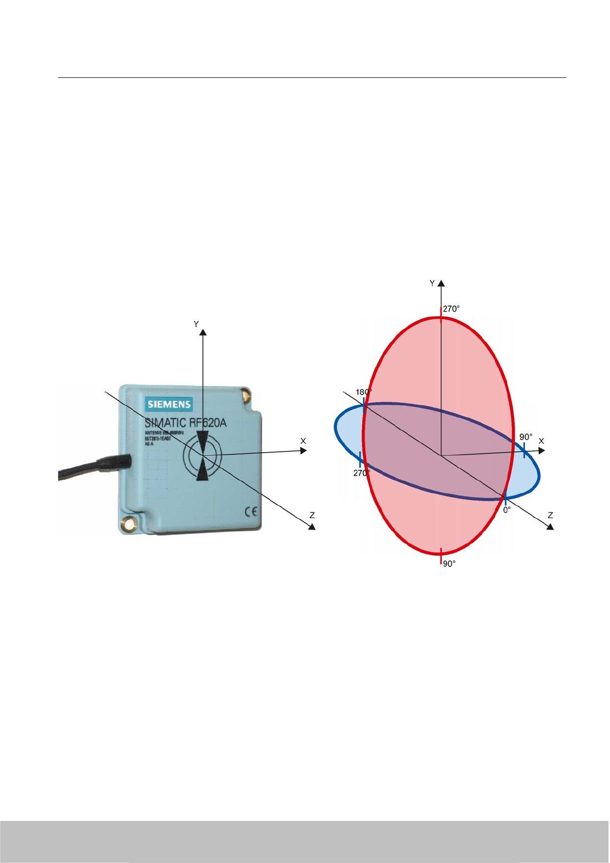
6.2.7 Antenna patterns
6.2.7.1 Antenna pattern ETSI
Directional radiation pattern Europe (ETSI)
The directional radiation pattern is shown for nominal alignment and a center frequency of
866.3 MHz. The nominal antenna alignment is given when the antenna elevation is provided
as shown in the following figure.
Figure 6-6 Reference system
The half-power beamwidth of the antenna is defined by the angle between the two -3 dB points.
Which range (in %) corresponds to the dB values in the patterns can be obtained from this
table (Page 168).
Note that the measurements presented graphically below were carried out in a low-reflection
environment. Deviations can therefore occur in a normally reflecting environment.
Antennas
6.2 RF620A antenna
SIMATIC RF600
System Manual, 06/2010, J31069-D0171-U001-A10-7618 163
Draft Version 02.06.2010
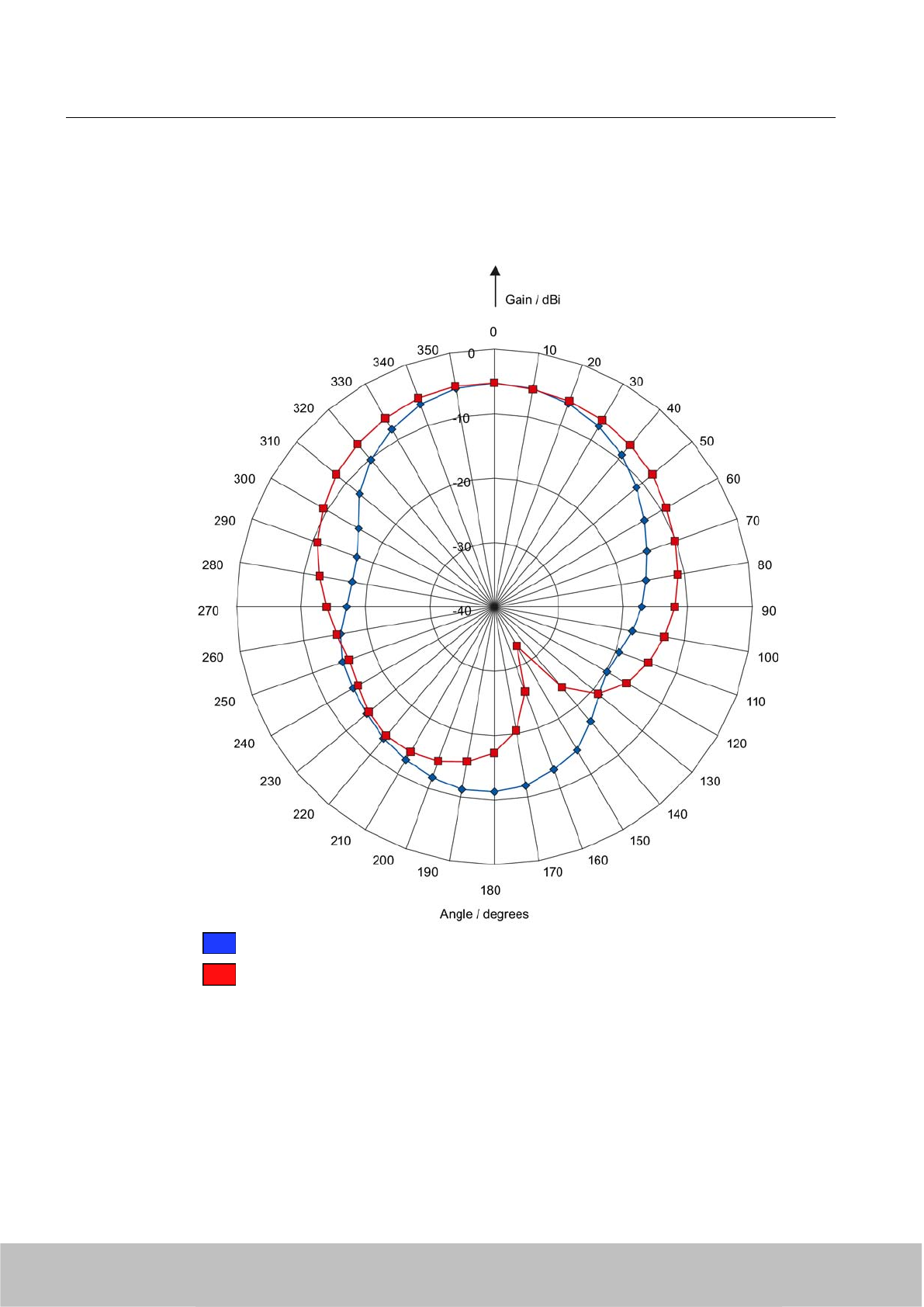
Directional radiation pattern ETSI on metallic mounting surface (15 cm x 15 cm)
Pattern of the vertical plane of the antenna
Pattern of the horizontal plane of the antenna
Figure 6-7 Directional radiation pattern RF620A ETSI on metallic mounting surface
Antennas
6.2 RF620A antenna
SIMATIC RF600
164 System Manual, 06/2010, J31069-D0171-U001-A10-7618
Draft Version 02.06.2010
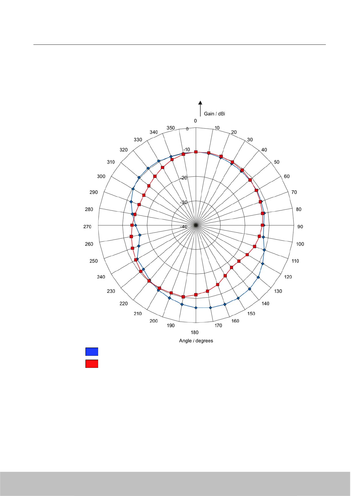
Directional radiation pattern ETSI on non-metallic mounting surface
Pattern of the vertical plane of the antenna
Pattern of the horizontal plane of the antenna
Figure 6-8 Directional radiation pattern RF620A ETSI on non-metallic mounting surface
Antennas
6.2 RF620A antenna
SIMATIC RF600
System Manual, 06/2010, J31069-D0171-U001-A10-7618 165
Draft Version 02.06.2010
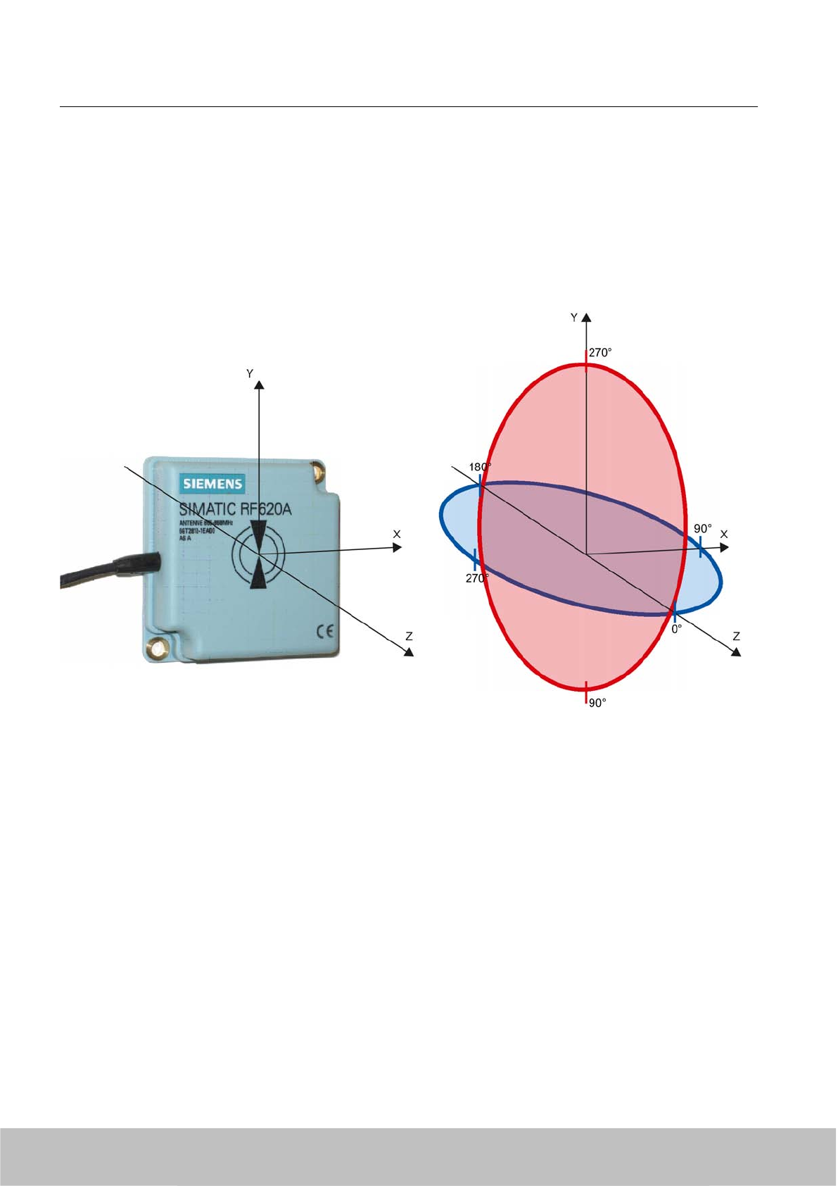
6.2.7.2 Antenna pattern FCC
Directional radiation pattern USA (FCC)
The directional radiation pattern is shown for nominal alignment and a center frequency of 915
MHz.
Figure 6-9 Reference system
The half-power beamwidth of the antenna is defined by the angle between the two -3 dB points
(corresponding to half the power referred to the maximum power). Which range (in %)
corresponds to the dB values in the patterns can be obtained from this table (Page 168).
Note that the measurements presented graphically below were carried out in a low-reflection
environment. Low deviations can therefore occur in a normally reflecting environment.
Antennas
6.2 RF620A antenna
SIMATIC RF600
166 System Manual, 06/2010, J31069-D0171-U001-A10-7618
Draft Version 02.06.2010
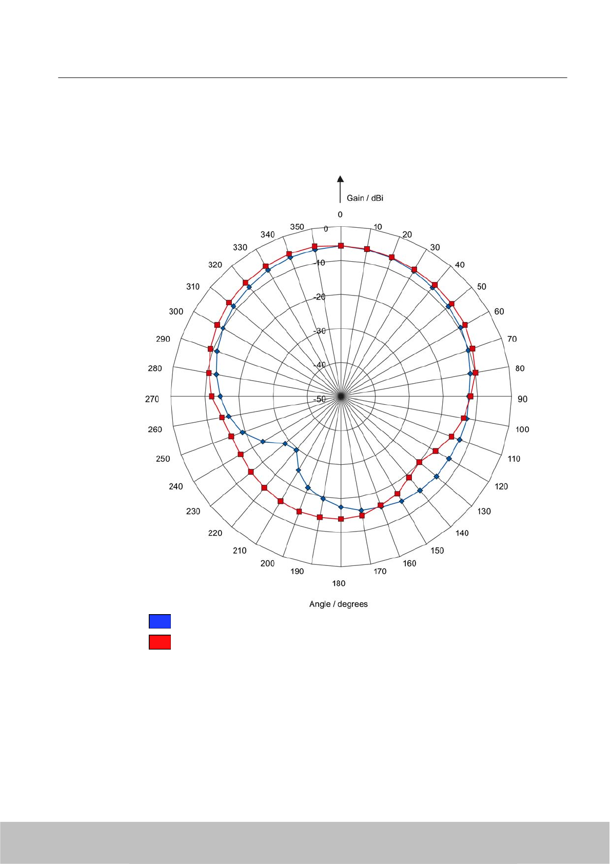
Directional radiation pattern of the RF620A (FCC) on metallic mounting surface (15 cm x 15 cm)
Pattern of the vertical plane of the antenna
Pattern of the horizontal plane of the antenna
Figure 6-10 Directional radiation pattern of the RF620A (FCC) on metallic mounting surface
Antennas
6.2 RF620A antenna
SIMATIC RF600
System Manual, 06/2010, J31069-D0171-U001-A10-7618 167
Draft Version 02.06.2010
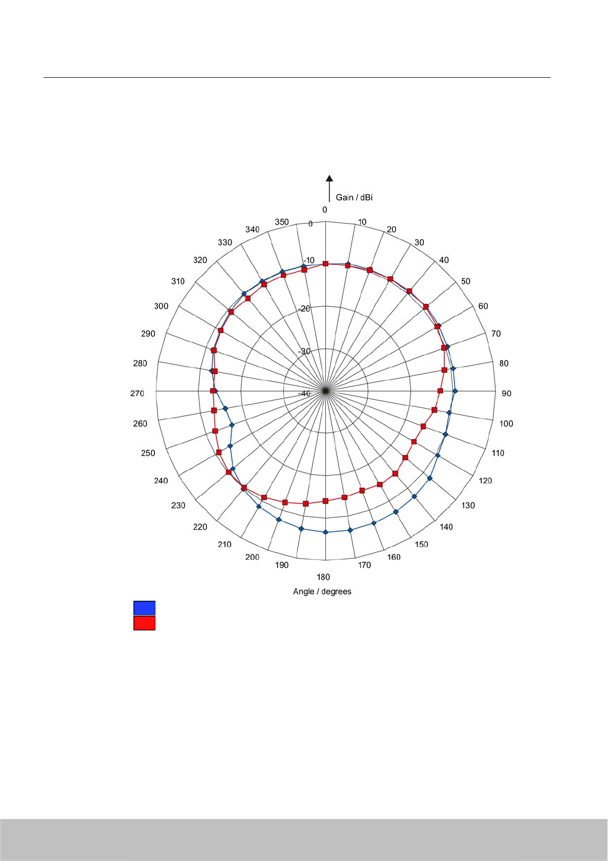
Directional radiation pattern of the RF620A (FCC) on non-metallic mounting surface
Pattern of the vertical plane of the antenna
Pattern of the horizontal plane of the antenna
Figure 6-11 Directional radiation pattern of the RF620A (FCC) on non-metallic mounting surface
6.2.7.3 Interpretation of directional radiation patterns
The following overview table will help you with the interpretation of directional radiation
patterns.
The table shows which dBi values correspond to which read/write ranges (in %): You can read
the radiated power depending on the reference angle from the directional radiation patterns,
Antennas
6.2 RF620A antenna
SIMATIC RF600
168 System Manual, 06/2010, J31069-D0171-U001-A10-7618
Draft Version 02.06.2010
and thus obtain information on the read/write range with this reference angle with regard to a
transponder.
The dBr values correspond to the difference between the maximum dBi value and a second
dBi value.
Deviation from maximum antenna gain [dBr] Read/write range [%]
0100
-3 70
-6 50
-9 35
-12 25
-15 18
-18 13
Example
As one can see from the Antenna pattern ETSI (Page 163), the maximum antenna gain is
-5 dBi. In the vertical plane, the antenna gain has dropped to approx. -11 dBi at +40° and 320°.
Therefore the dBr value is -6. The antenna range is only 50% of the maximum range at ± 40°
from the Z axis within the vertical plane (see values shown in blue in the directional radiation
pattern: characteristic of the vertical plane of the antenna (Page 163) and the associated
representation of the reference system (Page 163)).
6.2.8 Read/write ranges
The following tables show the typical read/write ranges of RF600 readers which are connected
to the RF620A antenna via the 3 m antenna cable (1 dB loss) and various types of tags.
Note
Please note that tolerances of ±20% are admissible due to production and temperature
conditions.
When using other antenna cables, the ranges listed here are reduced as a result of the higher
antenna cable losses in the following manner:
Cable designation Order No. Length [m] Cable loss [dB] Read/write range [%]
Antenna cable 6GT2815-0BH30 3 1 100
Antenna cable 6GT2815-1BN10 10 2 90
Antenna cable 6GT2815-0BN10 10 4 70
Antenna cable 6GT2815-0BN20 20 4 70
The measuring tolerances in the following tables are ±3 cm.
Antennas
6.2 RF620A antenna
SIMATIC RF600
System Manual, 06/2010, J31069-D0171-U001-A10-7618 169
Draft Version 02.06.2010

Read distances RF630R
Table 6-3 Read distances RF630R
Transponder Connection to RF630R
RF620A ETSI
on metal [cm]
RF620A ETSI on
non-metal [cm]
RF620A FCC on
metal [cm]
RF620A FCC on
non-metal [cm]
RF630L
(6GT2810-2AB00,
-2AB01, -2AB02)
90 1) 70 1) 60 1) 50 1)
RF630L
(6GT2810-2AB03)
55 50 55 45
RF680L 55 50 55 45
RF610T 55 50 55 45
RF620T 55 45 70 60
RF630T 25 2) 20 2) 35 2) 25 2)
RF640T Gen 2 55 2) 45 2) 40 2) 35 2)
RF680T 60 50 90 70
1) Transponder mounted on cardboard
2) Transponder mounted on metal
Write distances RF630R
Table 6-4 Write distances RF630R
Transponder Connection to RF630R
RF620A ETSI
on metal [cm]
RF620A ETSI on
non-metal [cm]
RF620A FCC on
metal [cm]
RF620A FCC on
non-metal [cm]
RF630L
(6GT2810-2AB00,
-2AB01, -2AB02)
45 1) 40 1) 35 1) 30 1)
RF630L
(6GT2810-2AB03)
35 30 20 25
RF680L 35 30 20 25
RF610T 35 30 20 25
RF620T 30 30 40 35
RF630T 15 2) 5 2) 15 2) 10 2)
RF640T Gen 2 35 2) 20 2) 20 2) 15 2)
RF680T 40 30 40 35
1) Transponder mounted on cardboard
2) Transponder mounted on metal
Antennas
6.2 RF620A antenna
SIMATIC RF600
170 System Manual, 06/2010, J31069-D0171-U001-A10-7618
Draft Version 02.06.2010

Reading ranges for RF670R @@@ insert values
Table 6-5 Reading ranges for RF670R
Transponder Connection to RF670R
RF620A ETSI
on metal [cm]
RF620A ETSI on
non-metal [cm]
RF620A FCC on
metal [cm]
RF620A on non-
metal [cm]
RF630L
(6GT2810-2AB00,
-2AB01, -2AB02)
RF630L
(6GT2810-2AB03)
RF680L
RF610T
RF620T
RF630T
RF640T
RF640T Gen 2
RF680T
1) Transponder mounted on cardboard
2) Transponder mounted on metal
Writing ranges for RF670R @@@ insert values
Table 6-6 Writing ranges for RF670R
Transponder Connection to RF670R
RF620A ETSI
on metal
RF620A ETSI on
non-metal
RF620A FCC on
metal
RF620A on non-
metal
RF630L
(6GT2810-2AB00,
-2AB01, -2AB02)
RF630L
(6GT2810-2AB03)
RF680L
RF610T
RF620T
RF630T
RF640T
RF640T Gen 2
RF680T
1) Transponder mounted on cardboard
2) Transponder mounted on metal
Antennas
6.2 RF620A antenna
SIMATIC RF600
System Manual, 06/2010, J31069-D0171-U001-A10-7618 171
Draft Version 02.06.2010

Read distances RF660R
Table 6-7 Read distances RF660R
Transponder Connection to RF660R
RF620A ETSI
on metal [cm]
RF620A ETSI on
non-metal [cm]
RF620A FCC on
metal [cm]
RF620A on non-
metal [cm]
RF630L
(6GT2810-2AB00,
-2AB01, -2AB02)
135 1) 120 1) 100 1) 90 1)
RF630L
(6GT2810-2AB03)
85 70 75 65
RF680L 85 70 75 65
RF610T 85 70 75 65
RF620T 85 85 95 95
RF630T 40 2) 35 2) 50 2) 35 2)
RF640T 40 2) 35 2) 40 2) 30 2)
RF640T Gen 2 90 2) 70 2) 70 2) 50 2)
RF680T 90 90 135 95
1) Transponder mounted on cardboard
2) Transponder mounted on metal
Write distances RF660R
Table 6-8 Write distances RF660R
Transponder Connection to RF660R
RF620A ETSI
on metal
RF620A ETSI on
non-metal
RF620A FCC on
metal
RF620A on non-
metal
RF630L
(6GT2810-2AB00,
-2AB01, -2AB02)
110 1) 90 1) 55 1) 50 1)
RF630L
(6GT2810-2AB03)
75 70 60 55
RF680L 75 70 60 55
RF610T 75 70 60 55
RF620T 60 55 60 45
RF630T 30 2) 25 2) 35 2) 25 2)
RF640T 35 2) 30 2) 25 2) 25 2)
RF640T Gen 2 70 2) 60 2) 50 2) 40 2)
RF680T 80 75 100 80
1) Transponder mounted on cardboard
2) Transponder mounted on metal
Antennas
6.2 RF620A antenna
SIMATIC RF600
172 System Manual, 06/2010, J31069-D0171-U001-A10-7618
Draft Version 02.06.2010

6.2.9 Technical data
Table 6-9 General technical data RF620A
Feature SIMATIC RF620A ETSI SIMATIC RF620A FCC
Dimensions in mm (L x W x H) 75 x 75 x 20
Color Pastel turquoise
Material PA 12 (polyamide 12)
Silicone-free
Frequency band 865 to 868 MHz 902 to 928 MHz
Plug connection 30 cm coaxial cable with RTNC coupling
(for connection of antenna cable)
Max. radiated power < 500 mW ERP No limitation
(since antenna gain ≪ 6 dBi)
Max. power 2 W 1 W
Impedance 50 Ohm
Antenna gain -10 dBi ... -5 dBi
Depends on background, see
Chapter Directional radiation
pattern ETSI (Page 163)
Depends on background, see
Chapter Directional radiation
pattern FCC (Page 166)
VSWR (standing wave ratio) Max. 2:1
Polarization Linear
Beam angle for sending/
receiving
●When mounted on a metal
surface of 15 cm x 15 cm 1)
● Horizontal plane: 100°
● Vertical plane: 75°
See Chapter Antenna pattern
ETSI (Page 163)
● Horizontal plane: 130°
● Vertical plane: 105°
See Chapter Directional
Characteristic for FCC
(Page 166).
Shock resistant to EN
60068-2-27
50 g
Vibration resistant to
EN 60068-2-6
20 g
Attachment of the antenna 2 x M5 screws
Tightening torque
(at room temperature)
≤ 2 Nm
Ambient temperature
●Operation
● Transport and storage
● -20 °C to +70 °C
●-40 °C to +85 °C
Degree of protection according
to EN 60529
IP67
Weight, approx. 90 g
1) The values differ for different dimensions/materials of the mounting surface.
Antennas
6.2 RF620A antenna
SIMATIC RF600
System Manual, 06/2010, J31069-D0171-U001-A10-7618 173
Draft Version 02.06.2010
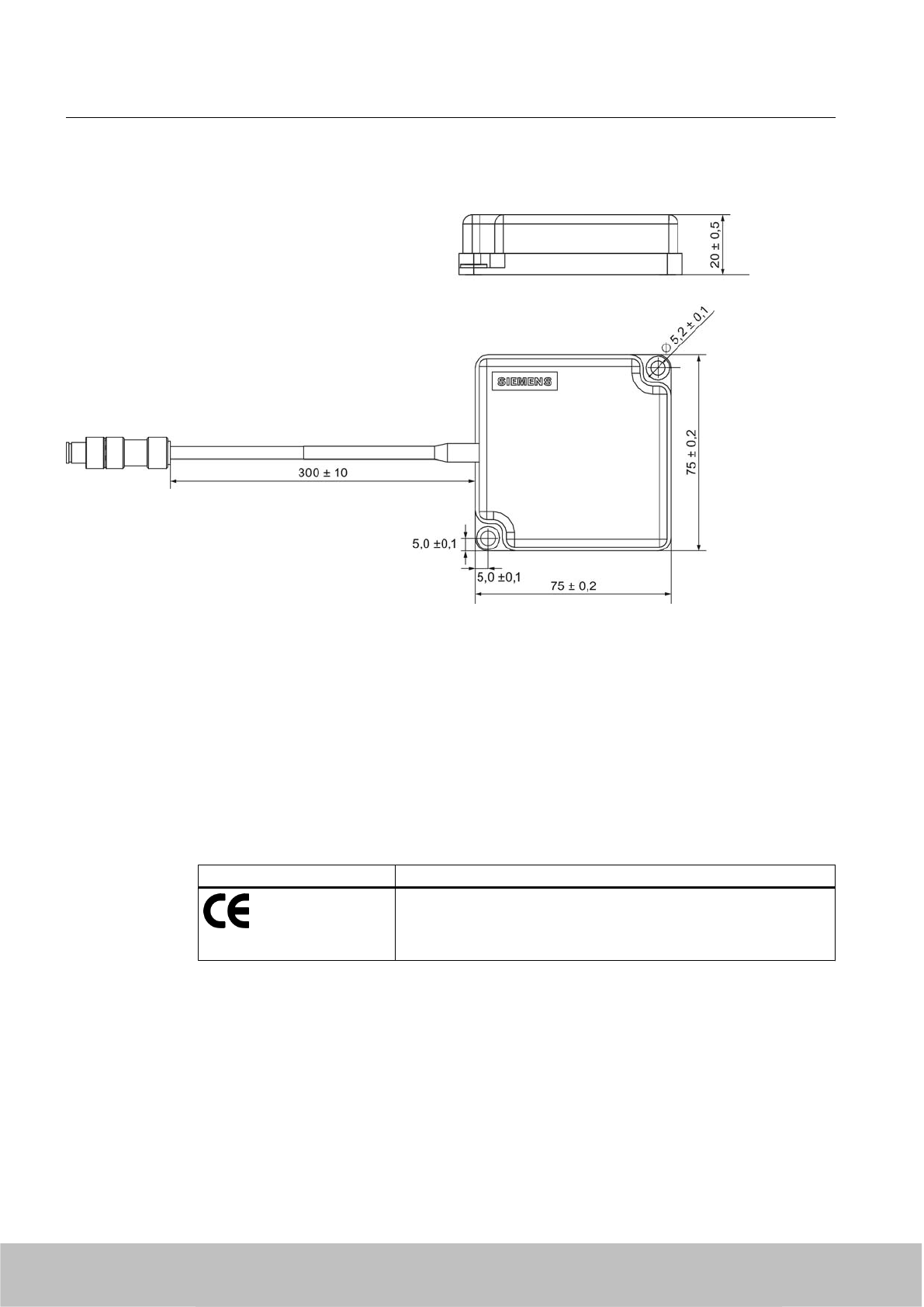
6.2.10 Dimension drawing
Figure 6-12 Dimension drawing RF620A
All dimensions in mm
6.2.11 Approvals & certificates
6.2.11.1 CE mark
Table 6-10 6GT2812-1EA00
Certificate Designation
Conformity in accordance with R&TTE directive
in association with the readers and accessories used
Antennas
6.2 RF620A antenna
SIMATIC RF600
174 System Manual, 06/2010, J31069-D0171-U001-A10-7618
Draft Version 02.06.2010
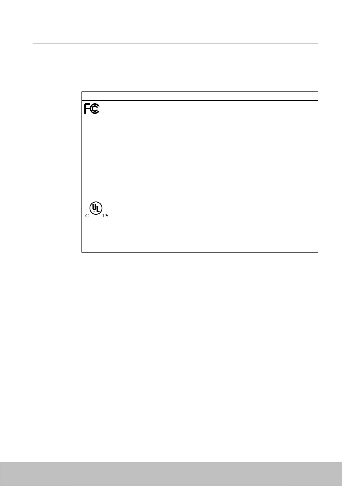
6.2.11.2 FCC approvals
Table 6-11 6GT2812-1EA01
Standard
Federal Communications
Commission
FCC CFR 47, Part 15 sections 15.247
Radio Frequency Interference Statement
This equipment has been tested and found to comply with the limits
for a Class B digital device, pursuant to Part 15 of the FCC Rules.
The FCC approval is granted in association with the FCC approval of
the following RF600 readers:
● FCC ID: NXW-RF630R
● FCC ID: NXW-RF660
Industry Canada Radio
Standards Specifications
RSS-210 Issue 7, June 2007, Sections 2.2, A8
The approval for Industry Canada is granted in association with the
Industry Canada approval of the following RF600 readers:
● IC: 267X-RF630
● IC: 267X-RF660
This product is UL-certified for the USA and Canada.
It meets the following safety standard(s):
UL 60950-1 - Information Technology Equipment Safety - Part 1:
General Requirements
CSA C22.2 No. 60950 -1 - Safety of Information Technology
Equipment
UL Report E 205089
6.3 RF660A antenna
6.3.1 RF660A description
The RF660A is a stationary antenna, specially designed for RF600 systems.
The antenna is available in two different frequency bands that have been specified for the
regions of Europe, China and USA respectively.
Frequency band
● The antenna for Europe operates in the frequency band of 865 to 868 MHz.
● The antenna for China and the USA operates in the frequency band of 902 to 928 MHz.
Antennas
6.3 RF660A antenna
SIMATIC RF600
System Manual, 06/2010, J31069-D0171-U001-A10-7618 175
Draft Version 02.06.2010
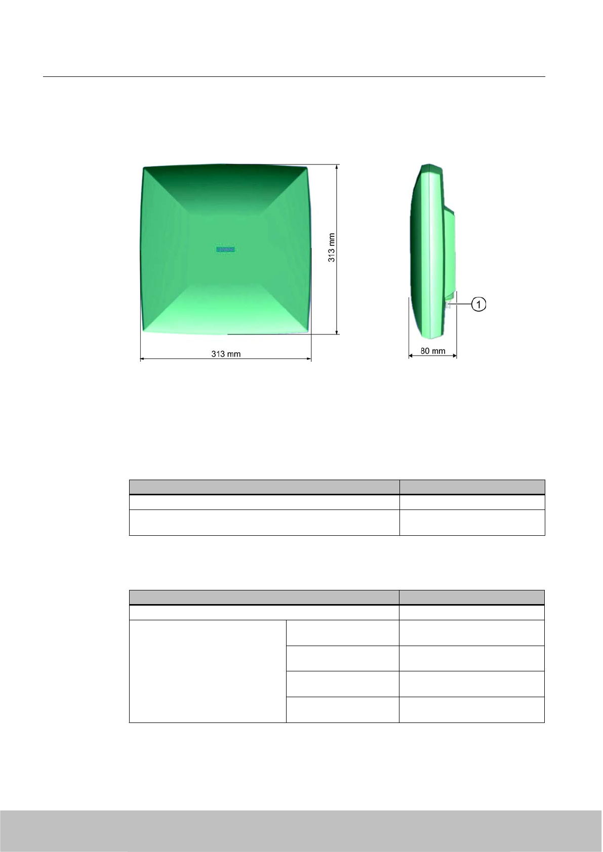
Design of the RF660A
The antenna is installed in a rectangular plastic housing.
Front view
Side view
① RTNC connection
Ordering data
Description Machine-Readable Product Code
RF660A antenna for Europe incl. mounting plate (865-868) 6GT2812-0AA00
RF660A antenna for China and the USA incl. mounting plate
(902-928)
6GT2812-0AA01
Ordering data (accessories)
Description Machine-Readable Product Code
Antenna mounting kit 6GT2890-0AA00
Connecting cable between reader
and antenna
3 m
(1 dB cable attenuation)
6GT2815-0BH30
10 m
(2 dB cable attenuation)
6GT2815-1BN10
10 m
(4 dB cable attenuation)
6GT2815-0AN10
20 m
(4 dB cable attenuation)
6GT2815-0AN20
Antennas
6.3 RF660A antenna
SIMATIC RF600
176 System Manual, 06/2010, J31069-D0171-U001-A10-7618
Draft Version 02.06.2010
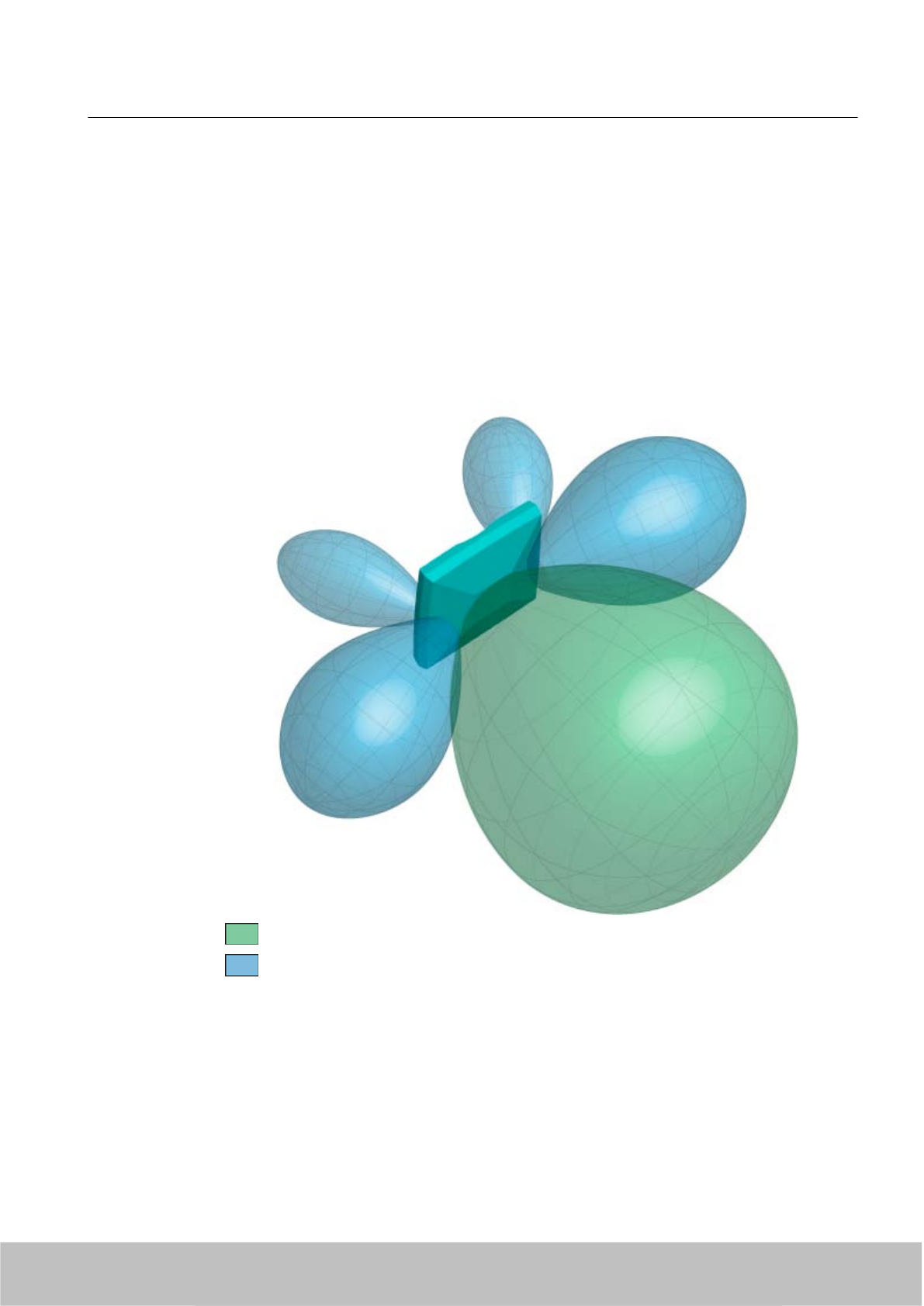
6.3.2 Antenna pattern
Spatial directional radiation pattern
The following schematic diagram shows the main and auxiliary fields of the RF660A antenna
in free space in the absence of reflecting/absorbing materials. Please note that the diagram is
not to scale.
The recommended working range lies within the main field that is shown in green.
Main field (processing field)
Secondary fields
Figure 6-13 Main and auxiliary fields of the RF660A antenna
Radiation diagram (horizontal)
Europe (ETSI)
Antennas
6.3 RF660A antenna
SIMATIC RF600
System Manual, 06/2010, J31069-D0171-U001-A10-7618 177
Draft Version 02.06.2010
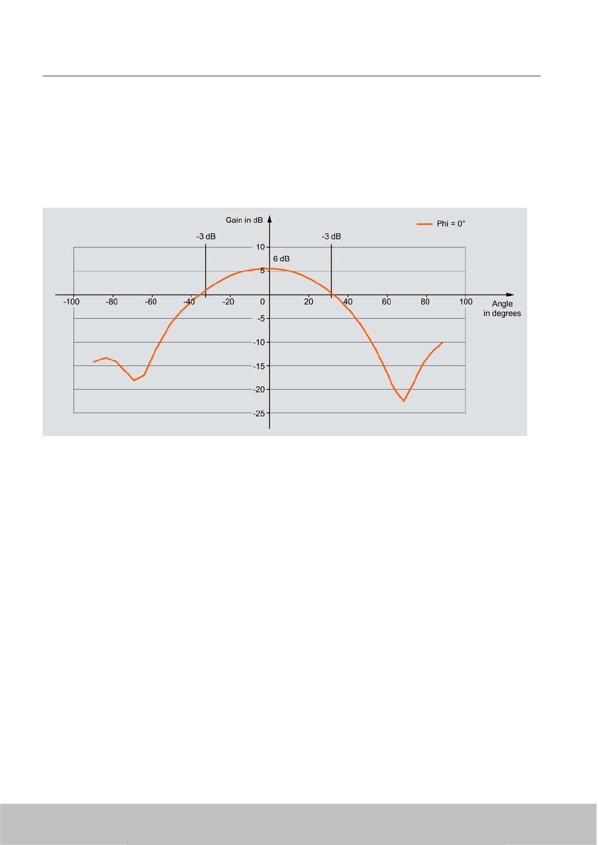
The radiation diagram is shown for horizontal alignment and for a center frequency of 865
MHz. Horizontal antenna alignment is provided when the TNC connection on the antenna
points vertically up or down.
The radiating/receiving angle of the antenna is defined by the angle between the two -3 dB
points (corresponding to half the power referred to the maximum performance at a 0° angle).
The optimum radiating/receiving angle is therefore approximately ±30 degrees.
Figure 6-14 Directional radiation pattern of the antenna (at 865 MHz, horizontal alignment)
USA (FCC)
The radiation diagram is shown for horizontal alignment and for a center frequency of 915
MHz.
The radiating/receiving angle of the antenna is defined by the angle between the two -3 dB
points (corresponding to half the power referred to the maximum performance at a 0° angle).
The optimum radiating/receiving angle is therefore approximately ±35 degrees.
Antennas
6.3 RF660A antenna
SIMATIC RF600
178 System Manual, 06/2010, J31069-D0171-U001-A10-7618
Draft Version 02.06.2010
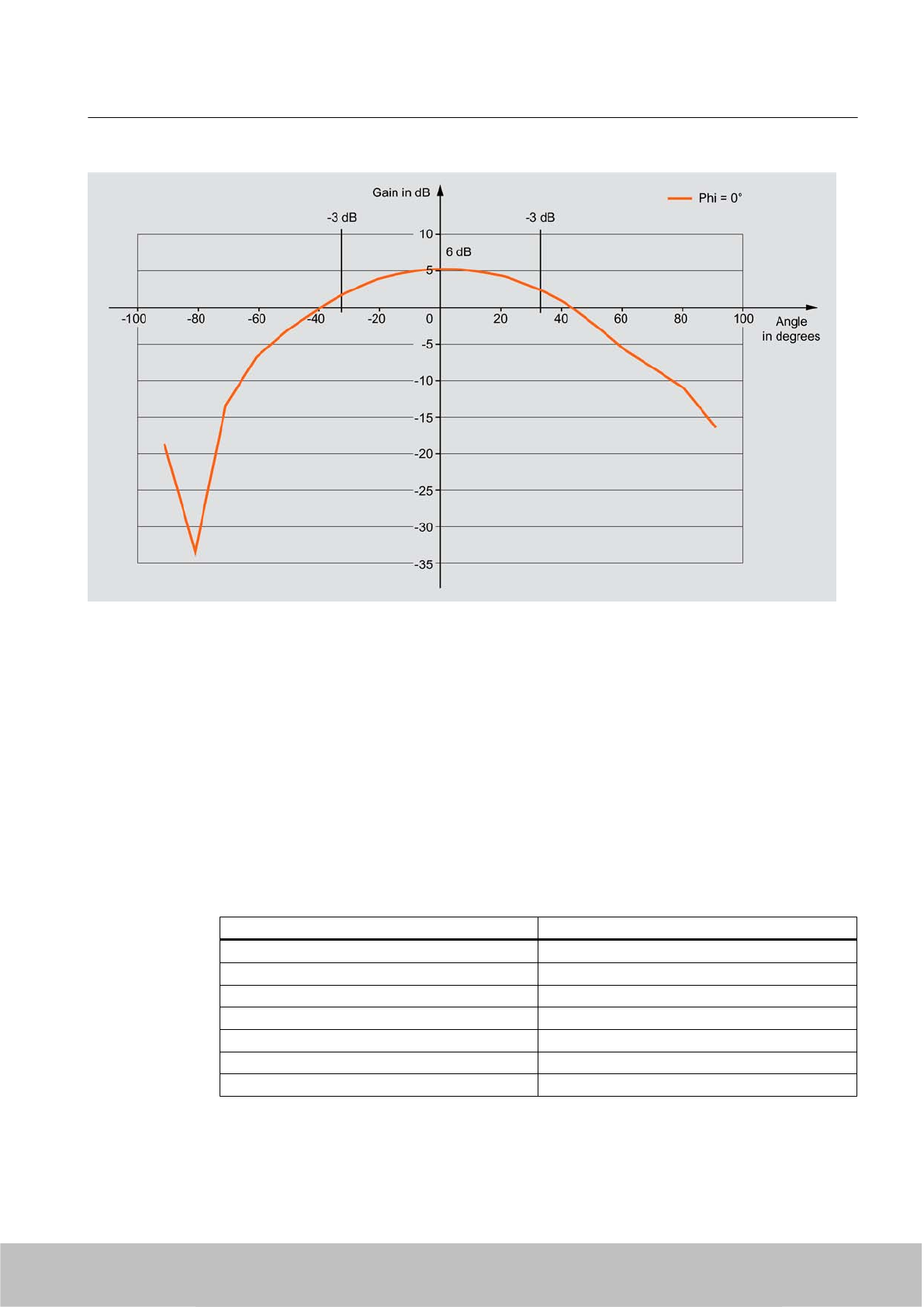
Figure 6-15 Directional radiation pattern of the antenna (at 915 MHz, horizontal alignment)
6.3.3 Interpretation of directional radiation patterns
The following overview table will help you with the interpretation of directional radiation
patterns.
The table shows which dBi values correspond to which read/write ranges (in %): You can read
the radiated power depending on the reference angle from the directional radiation patterns,
and thus obtain information on the read/write range with this reference angle with regard to a
transponder.
The dBr values correspond to the difference between the maximum dBi value and a second
dBi value.
Deviation from maximum antenna gain [dBr] Read/write range [%]
0100
-3 70
-6 50
-9 35
-12 25
-15 18
-18 13
Antennas
6.3 RF660A antenna
SIMATIC RF600
System Manual, 06/2010, J31069-D0171-U001-A10-7618 179
Draft Version 02.06.2010
Example
As one can see from the section Antenna pattern (Page 177), the maximum antenna gain is
6 dBi. In the vertical plane, the antenna gain has dropped to approx. 3 dBi at +30°. Therefore
the dBr value is -3. The antenna range is only 50% of the maximum range at ± 30° from the
Z axis within the vertical plane.
6.3.4 Installation and assembly
The RF660A antenna can be fixed to any firm support.
More information on the types of antenna fixing can be found in section Mounting types
(Page 200).
6.3.5 Connecting an antenna to a reader
NOTICE
Use of Siemens antenna cable
To ensure optimum functioning of the antenna, it is urgently recommended that a Siemens
antenna cable is used in accordance with the list of accessories.
Figure 6-16 Rear of antenna with RTNC connection
Connecting RF660A to RF670R/RF660R
Preassembled standard cables in lengths of 3 m, 10 m and 20 m are available for connection.
The cable between antenna and reader can be up to 20 m in length.
Antennas
6.3 RF660A antenna
SIMATIC RF600
180 System Manual, 06/2010, J31069-D0171-U001-A10-7618
Draft Version 02.06.2010
When less than four antennas are used, we recommend that the antennas are connected to
the reader as follows:
Number of antennas Connections on the reader
2 antennas ANT 1, ANT 2
3 antennas ANT 1, ANT 2, ANT 3
Connecting RF660A to RF630R
Preassembled standard cables in lengths of 3 m, 10 m and 20 m are available for connection.
The cable between antenna and reader can be up to 20 m in length.
When one antenna is used, it is recommended that the remaining antenna connection is sealed
using the supplied protective cap.
6.3.6 Technical specifications
RF660A antenna 865-868 RF660A antenna 902-928
Material Silicone-free Silicone-free
Frequency band 865-868 MHz 902-928 MHz
Impedance 50 Ohm nominal 50 Ohm nominal
Antenna gain 5-7 dBil > 6 dBic
VSWR (standing wave ratio) 2:1 max. 2:1 max.
Polarization RH circular RH circular
Radiating/receiving angle 55°- 60° 60° - 75°
Connector RTNC RTNC
Degree of protection IP67 IP67
Permissible ambient
temperature
-25° C to +75° C -25° C to +75° C
6.4 Guidelines for selecting RFID UHF antennas
6.4.1 Note safety information
WARNING
Before planning how to use third-party components, as the operator of a system that
comprises both RF600 components and third-party components, you must comply with the
safety information in Section Safety instructions for third-party antennas as well as for
modifications to the RF600 system (Page 16).
Antennas
6.4 Guidelines for selecting RFID UHF antennas
SIMATIC RF600
System Manual, 06/2010, J31069-D0171-U001-A10-7618 181
Draft Version 02.06.2010

6.4.2 Preconditions for selecting RFID UHF antennas
Target group
This chapter has been prepared for configuration engineers who thoroughly understand and
wish to carry out the selection and installation of an external antenna or an external cable for
the SIMATIC RF600 system. The various antenna and cable parameters are explained, and
information is provided on the criteria you must particularly observe. Otherwise this chapter is
equally suitable for theoretical and practice-oriented users.
Purpose of this chapter
This chapter enables you to select the appropriate external antenna or cable with consideration
of all important criteria and to carry out the corresponding settings in the configuration software
of the SIMATIC RF600 system. Correct and safe integration into the SIMATIC RF600 system
is only possible following adaptation of all required parameters.
History
Edition Comment
12/2007 First edition
6.4.3 General application planning
6.4.3.1 Overview of the total SIMATIC RF600 system and its influencing factors
The following graphic shows the design of the total SIMATIC RF600 system and the factors
which have an influence on the total system.
You must be aware of these influencing factors and also consider them if you wish to integrate
third-party components such as antennas or cables into the system. These influencing factors
are described in more detail in Sections Antennas (Page 185) and Antenna cables
(Page 196).
Antennas
6.4 Guidelines for selecting RFID UHF antennas
SIMATIC RF600
182 System Manual, 06/2010, J31069-D0171-U001-A10-7618
Draft Version 02.06.2010
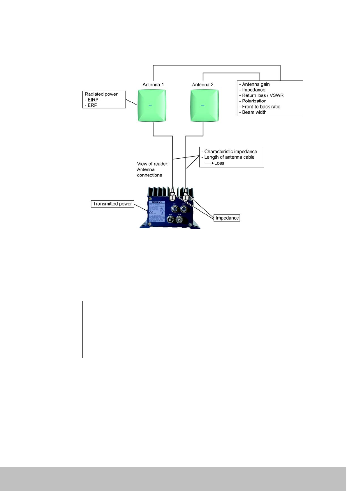
Figure 6-17 Overview of total system and influencing factors
When operating the RF600 system, additional influencing factors must also be observed such
as minimum spacing between antennas in the room. You will find this information in the System
Manual "SIMATIC RF600".
6.4.3.2 Environmental conditions
CAUTION
Damage to the device
In line with the application, you must take into consideration the mechanical loads (shock
and vibration) as well as environmental demands such as temperature, moisture, UV
radiation.
The device could be damaged if these factors are not considered.
6.4.3.3 General procedure
Depending on whether you wish to use a third-party antenna or antenna cable - or both - in
combination with the SIMATIC RF660R reader, these instructions will help you to select the
components and to set the important parameters in the SIMATIC RF660R configuration
software.
There are two different application cases:
Antennas
6.4 Guidelines for selecting RFID UHF antennas
SIMATIC RF600
System Manual, 06/2010, J31069-D0171-U001-A10-7618 183
Draft Version 02.06.2010

● Selection of third-party components:
you wish to select appropriate third-party components for the SIMATIC RF600 system and
to subsequently configure the reader for these components.
● Configuration of existing third-party components:
you already have third-party components (antenna, antenna cable or both) and wish to
appropriately configure the reader for these components.
Procedure for selecting third-party components
Always proceed in the following order during your considerations and the practical
implementation:
1. Consider which third-party components you wish to use in the SIMATIC RF600 system.
2. Depending on the third-party component required, refer either to Section Antennas
(Page 185) or Section Antenna cables (Page 196) for the important criteria for selection
of your components. The selection criteria/parameters are sorted in descending relevance.
3. Use the specified equations to calculate your missing parameters, and check whether the
required values are reached (e.g. antenna gain) and that important secondary values (e.g.
cable loss) are not exceeded or undershot.
4. Configure the reader with the parameters of your third-party components. You can usually
carry this out in the SIMATIC RF660R configuration software. The exact procedure is
described in Section .
5. For advanced users or in exceptional cases, e.g. input of an antenna gain <4.0 dBi), it is
recommendable to carry out the configuration directly using XML commands. For further
information, refer to Section .
Procedure for configuration of existing third-party components
If you already have third-party components which you wish to integrate into the SIMATIC
RF600 system, proceed as follows:
1. Depending on the third-party component, refer either to Section "Antennas" or Section
"Antenna cables" for the important criteria of your components. The parameters are sorted
in descending relevance.
2. Compare the limits with the data of your antenna or cable vendor.
3. Subsequently proceed exactly as described above in "Procedure for selecting third-party
components" from Paragraph 3. onwards.
Antennas
6.4 Guidelines for selecting RFID UHF antennas
SIMATIC RF600
184 System Manual, 06/2010, J31069-D0171-U001-A10-7618
Draft Version 02.06.2010

6.4.4 Antennas
6.4.4.1 Types of antenna and properties
Basically all types of directional antennas can be considered as third-party antennas for
integration into the SIMATIC RF600 system. Directional antennas have a preferred direction
in which more energy is radiated than in other directions.
6.4.4.2 Antenna parameters
Overview
The properties of an antenna are determined by a large number of parameters. You must be
aware of these properties in order to make the correct selection for your appropriate UHF
antenna. The most important parameters are described below. These important parameters
are described in detail in the following sections. The following parameters describe both the
send and receive functions of the antenna (reciprocity). The antenna is a passive antenna. A
two-way relationship exists.
● Radiated power
● Antenna gain
● Impedance
● Return loss / VSWR
● Power rating
● Polarization
● Front-to-back ratio
● Beam width
Radiated power
In order to comply with national directives with regard to the radiated power (which differ
depending on the location or country of use), the RF660R reader together with the antenna
cable(s) and antenna(s) must be exactly parameterized or configured.
This means that the product of the transmitted power P0 of the reader and the antenna gain
G must always have the correct ratio with regard to the radiated power "EIRP" depending on
the location of use or the permissible frequency band.
Calculation of the radiated power is briefly described below.
Calculation of the radiated power
The radiated power is the total power radiated by the antenna in the room. The isotropic radiator
serves as the physical computing model which uniformly radiates the power into the room
(spherically).
Antennas
6.4 Guidelines for selecting RFID UHF antennas
SIMATIC RF600
System Manual, 06/2010, J31069-D0171-U001-A10-7618 185
Draft Version 02.06.2010
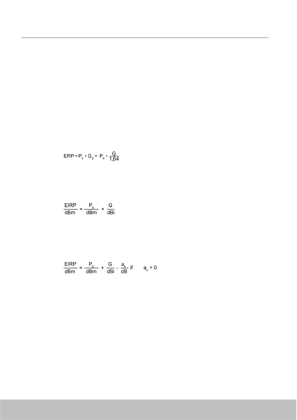
EIRP
Directional antennas combine the radiation, and therefore have a higher power density in the
main beam direction compared to an isotropic radiator. To enable antennas of different design
or Directional characteristic to be compared with one another, the equivalent isotropic radiated
power (EIRP) has been introduced which represents the effective power which must be applied
to an isotropic radiator in order to deliver the same power density in the main beam direction
of the antenna.
EIRP is the product of the transmitted power P0 and the antenna gain G:
EIRP = P0 * G
ERP
Also common is specification of the equivalent radiated power referred to the half-wave dipole
"ERP" (effective radiated power):
Logarithmic and standardized data
Approximate calculations are easier to carry out as additions than as products, therefore the
logarithms are taken for the above equations and the power data standardized to 1 mW and
specified in decibels (dBm or dBi).
Calculation of the radiated power with consideration of the cable loss ak
If the transmitted power is not applied directly but via a cable with loss aK, this loss should be
compensated such that the same radiated power is obtained.
If the loss is not appropriately compensated, the radiated power is too small.
General preliminary information on the unit "dB"
Requirements
This section provides you with information on the unit "decibel". This knowledge is a
requirement for optimum understanding of the following section. You can ignore this section
if you already have the appropriate knowledge.
Antennas
6.4 Guidelines for selecting RFID UHF antennas
SIMATIC RF600
186 System Manual, 06/2010, J31069-D0171-U001-A10-7618
Draft Version 02.06.2010
Definition
When specifying decibels, the ratios between powers or voltages are not defined directly but
as logarithms. The decibel is therefore not a true unit but rather the information that the
specified numerical value is the decimal logarithm of a ratio of two power or energy variables
P1 and P2 of the same type.
This ratio is defined by the following equation:
Example:
If P1 = 200 W and P2 = 100 mW, how large is the ratio a in dB?
Use with other units
As with other units, there are also different versions of the unit for decibel depending on the
reference variable. With this reference, the logarithmic power ratio becomes an absolute
variable. The following table lists the most important combinations in this context with other
units:
Versions of decibel Description
0 dBm Power level with the reference variable 1 mW.
dBi Power level with the reference variable on the isotropic spherical
radiator (see also Section Antenna gain (Page 187) ).
Antenna gain
Definition
The antenna gain specifies the degree to which the antenna outputs or receives its power in
the preferred angle segment.
With this theoretical variable, a comparison is always made with an isotropic spherical radiator,
a loss-free antenna which does not exist in reality. It describes how much power has to be
added to the isotropic spherical radiator so that it outputs the same radiated power in the
preferred direction like the antenna to be considered. The unit for the antenna gain is therefore
specified in dBi (dB isotropic).
Antennas
6.4 Guidelines for selecting RFID UHF antennas
SIMATIC RF600
System Manual, 06/2010, J31069-D0171-U001-A10-7618 187
Draft Version 02.06.2010

The antenna gain is defined for the receive case as the ratio between the power received in
the main beam direction and the received power of the isotropic spherical radiator.
Specifications
You must know the antenna gain in the corresponding frequency band or range. You can obtain
the value of the antenna gain from the technical specifications of your antenna vendor.
● With a cable loss of 4 dB, a gain ≥ 6 dBi(L) is required since otherwise the maximum radiated
power will not be achieved.
● In the case of antennas used in the FCC area of approval, a gain of at least 6 dBi(L) is
required since otherwise the permissible radiated power of 4 W EIRP will not be reached.
● If the gain is > 6 dBi(L)*, the difference is compensated in accordance with the directives
by reducing the transmitted power.
* (L) is the reference to the linear polarization.
Dependencies
● Frequency dependency:
if a frequency dependency exists in the frequency band used, you must apply the highest
value in each case for the antenna gain. With the cable loss, on the other hand, you must
select the smallest value in each case it frequency dependency exists.
This procedure means that the permissible radiated power will not be exceeded in the
extreme case.
● Dependency on the plane
If the data for the antenna gain are different in the horizontal and vertical planes, you must
use the higher value in each case.
Impedance
Definition
Impedance is understood as the frequency-dependent resistance. The impedances of the
antenna, reader and antenna cables should always be the same. Differences in the impedance
result in mismatching which in turn means that part of the applied signal is reflected again and
that the antenna is not fed with the optimum power.
Specifications
● Only antennas can be used whose connection has a characteristic impedance of Z =
50 Ohm.
● The mechanical design of the coaxial antenna connection is of secondary importance; N,
TNC and SMA plug connectors are usual.
Antennas
6.4 Guidelines for selecting RFID UHF antennas
SIMATIC RF600
188 System Manual, 06/2010, J31069-D0171-U001-A10-7618
Draft Version 02.06.2010

Return loss / VSWR
Definition
Since the impedance at the antenna connection is frequency-dependent, mismatching
automatically occurs with broadband use. This mismatching can be reflected by two
parameters:
● The voltage standing wave ratio VSWR
● The return loss
Voltage standing wave ratio VSWR
The power sent by the transmitter cannot flow unhindered to the antenna and be radiated as
a result of the mismatching described by the VSWR. Part of the power is reflected at the
antenna and returns to the transmitter. The powers in the forward and reverse directions
produce a standing wave which has a voltage maximum and a voltage minimum. The ratio
between these two values is the VSWR (voltage standing wave ratio).
Return loss
The return loss parameter is based on the reflection factor which describes the voltage ratio
between the forward and reverse waves.
Specifications
So that the smallest possible transmitted and received powers are reflected by the antenna
under ideal conditions, you should observe the following data for the VSWR and the return
loss |S11|/ dB in the respective frequency band (865-870 MHz or 902-928 MHz):
● VSWR < 1.24:1 or
●|S11|/ dB ≥ 20 dB
Power rating
Definition
The power rating is understood as the maximum power defined by the vendor with which the
device may be operated.
Specifications
Third-party antennas must be dimensioned for an effective power applied to the antenna
connection of at least 4 Watt.
Antennas
6.4 Guidelines for selecting RFID UHF antennas
SIMATIC RF600
System Manual, 06/2010, J31069-D0171-U001-A10-7618 189
Draft Version 02.06.2010
Polarization
Definition
The polarization parameter describes how the electromagnetic wave is radiated by the
antenna. A distinction is made between linear and circular polarization. With linear polarization,
a further distinction is made between vertical and horizontal polarization.
Specifications
UHF transponders usually have a receive characteristic similar to that of a dipole antenna
which is linearly polarized. Horizontal or vertical polarization is then present depending on the
transponder mounting.
Selection of circular polarized antenna
If the orientation of the transponder is unknown, or if an alternating orientation can be expected,
the transmit and receive antennas must have circular polarization.
When selecting a circular antenna, the polarization purity must be observed in addition to the
polarization direction. A differentiation is made between left-hand and right-hand circular
polarization (LHCP and RHCP). The two types cannot be combined in the same system. On
the other hand, selection of the polarization direction is insignificant if the antenna system of
a transponder is linearly polarized. With actual antennas, elliptical polarization is encountered
rather than the ideal circular polarization. A measure of this is the ratio between the large and
small main axes of the ellipse, the axial ratio (AR), which is frequently specified as a logarithm.
Axial ratio AR
Ideal 0 dB
Real 2-3 dB
Antennas
6.4 Guidelines for selecting RFID UHF antennas
SIMATIC RF600
190 System Manual, 06/2010, J31069-D0171-U001-A10-7618
Draft Version 02.06.2010
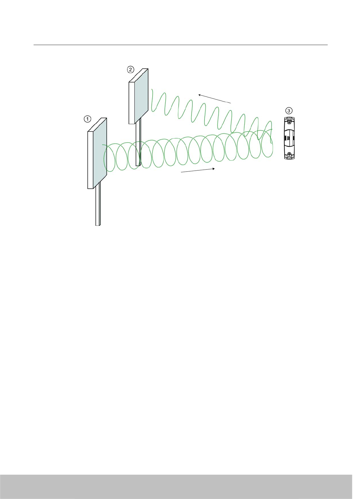
Figure 6-18 Circular polarization of antenna system and transponder
Selection of linear polarized antenna
When using linear polarized antennas, you must always make sure that the transmitter
antenna, receiver antenna and transponder have identical polarizations (vertical or horizontal).
Antennas
6.4 Guidelines for selecting RFID UHF antennas
SIMATIC RF600
System Manual, 06/2010, J31069-D0171-U001-A10-7618 191
Draft Version 02.06.2010
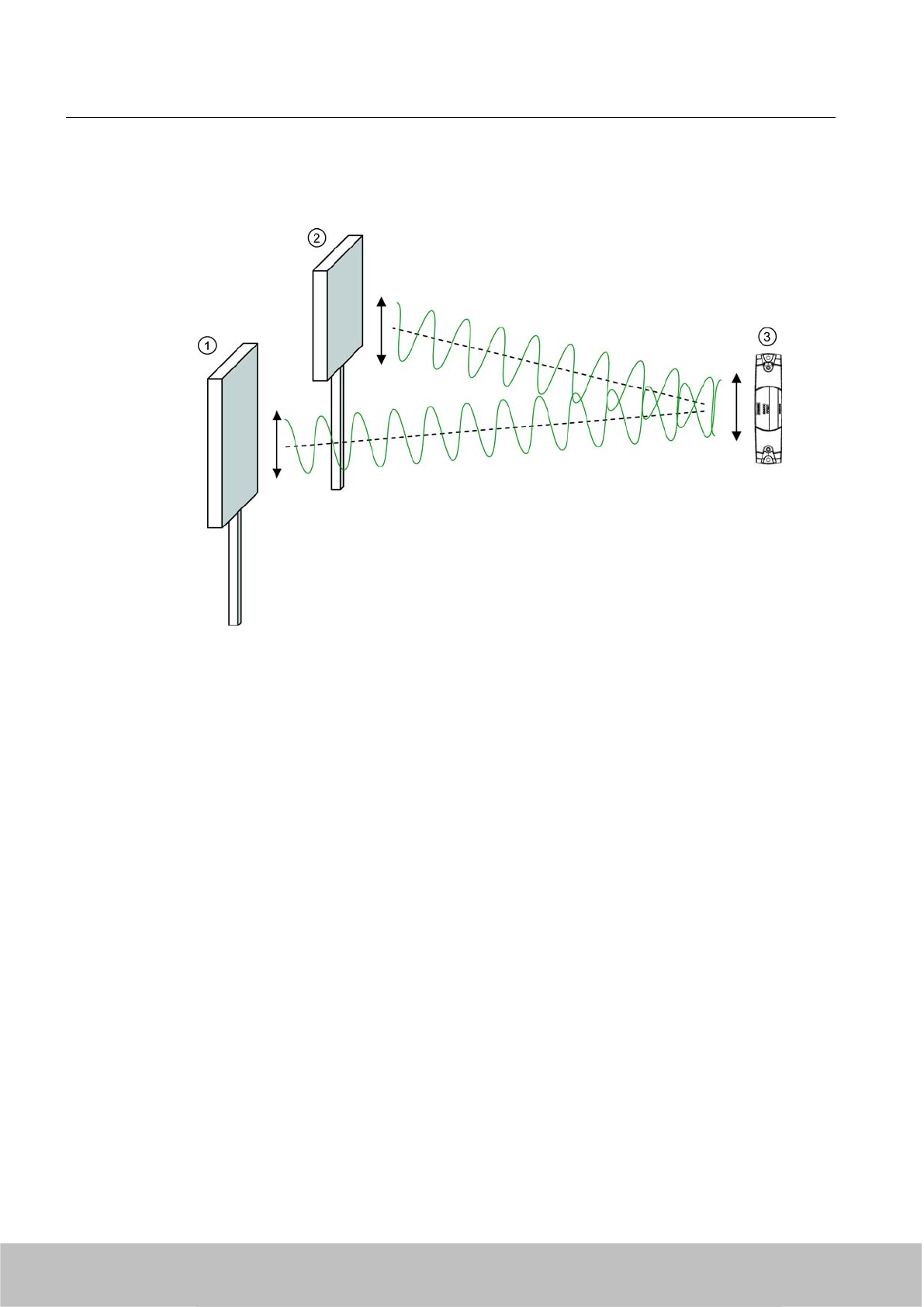
As a result of the principle used, no special requirements need be observed to suppress the
orthogonal components (cross-polarization).
①Transmitter antenna, vertical polarization
②Receiver antenna, vertical polarization
③Transponder dipole
Figure 6-19 Homogenous vertical polarization of antenna system and transponder
Front-to-back ratio
Definition
As a result of their design, directional antennas not only transmit electromagnetic waves in the
main beam direction but also in other directions, particularly in the reverse direction. The largest
possible suppression of these spurious lobes is expected in order to reduce faults and to keep
the influence on other radio fields low. This attenuation of spurious lobes in the opposite
direction to the main beam is called the front-to-back ratio.
Specifications
Requirement: The front-to-back ratio must be ≥ 10 dB. This requirement also applies to
spurious lobes illustrated by the following graphics in Section Half-value width (Page 193).
Antennas
6.4 Guidelines for selecting RFID UHF antennas
SIMATIC RF600
192 System Manual, 06/2010, J31069-D0171-U001-A10-7618
Draft Version 02.06.2010
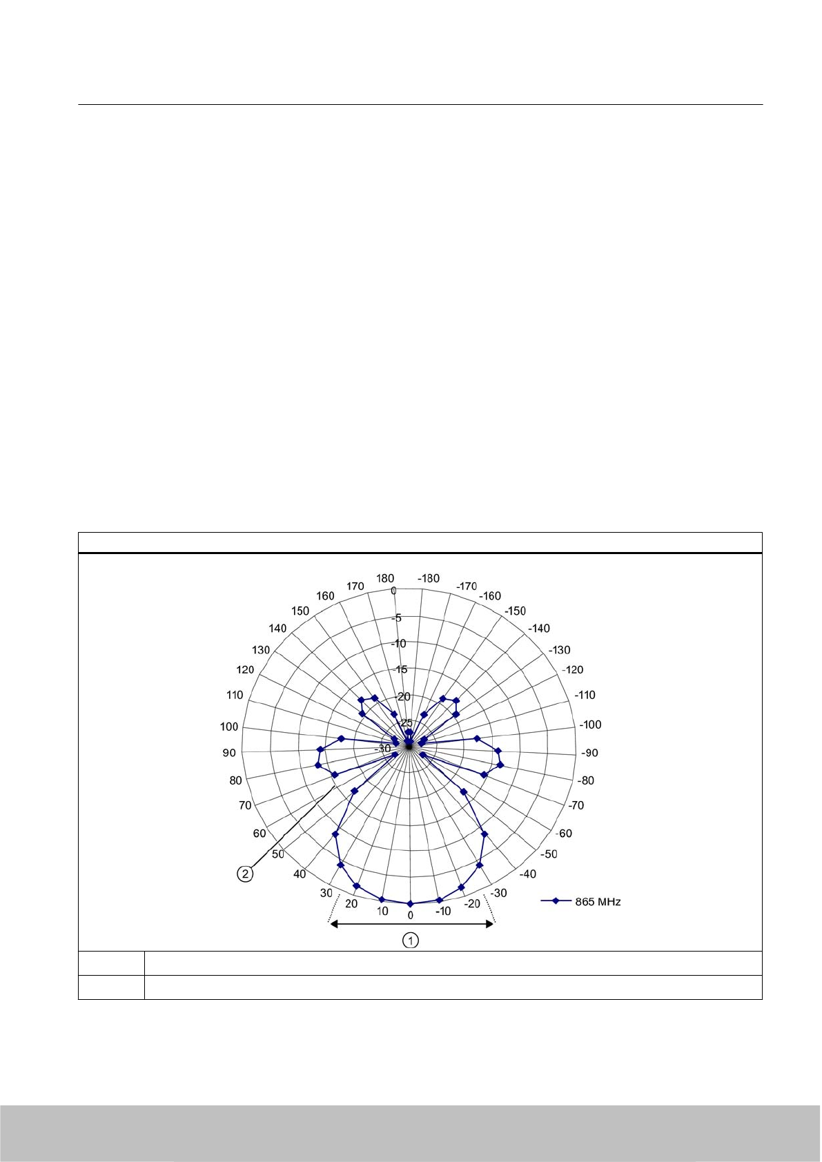
Half-value width
Definition
A further description of the directional characteristic is the beam width. The beam width is the
beam angle at which half the power (-3 dB) is radiated referred to the maximum power. The
antenna gain is directly related to the beam width. The higher the antenna gain, the smaller
the beam angle.
Coupling in ETSI
In ETSI EN 302 208 (release version V1.2.1 2008-06), the radiated power is coupled to the
beam width, i.e.
● Radiated power 500-2000 mW ERP: beam width ≤ 70 degrees
The beam width requirement applies to both the horizontal and vertical planes. The FCC
directives do not envisage coupling with the beam width.
The following graphics show examples of the directional radiation pattern of an antenna in
polar and linear representations for which both the horizontal and vertical planes must be
considered.
Directional radiation pattern in polar representation
①Beam width
②Spurious lobe
Antennas
6.4 Guidelines for selecting RFID UHF antennas
SIMATIC RF600
System Manual, 06/2010, J31069-D0171-U001-A10-7618 193
Draft Version 02.06.2010
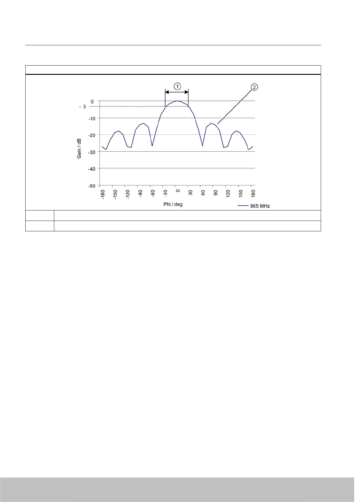
Directional radiation pattern in linear representation
①Beam width
②Spurious lobe
Specifications
Selection of the beam angle within the approval directives also has effects on the field of
application, since a larger beam angle allows a larger area to be covered by RFID
Antennas
6.4 Guidelines for selecting RFID UHF antennas
SIMATIC RF600
194 System Manual, 06/2010, J31069-D0171-U001-A10-7618
Draft Version 02.06.2010
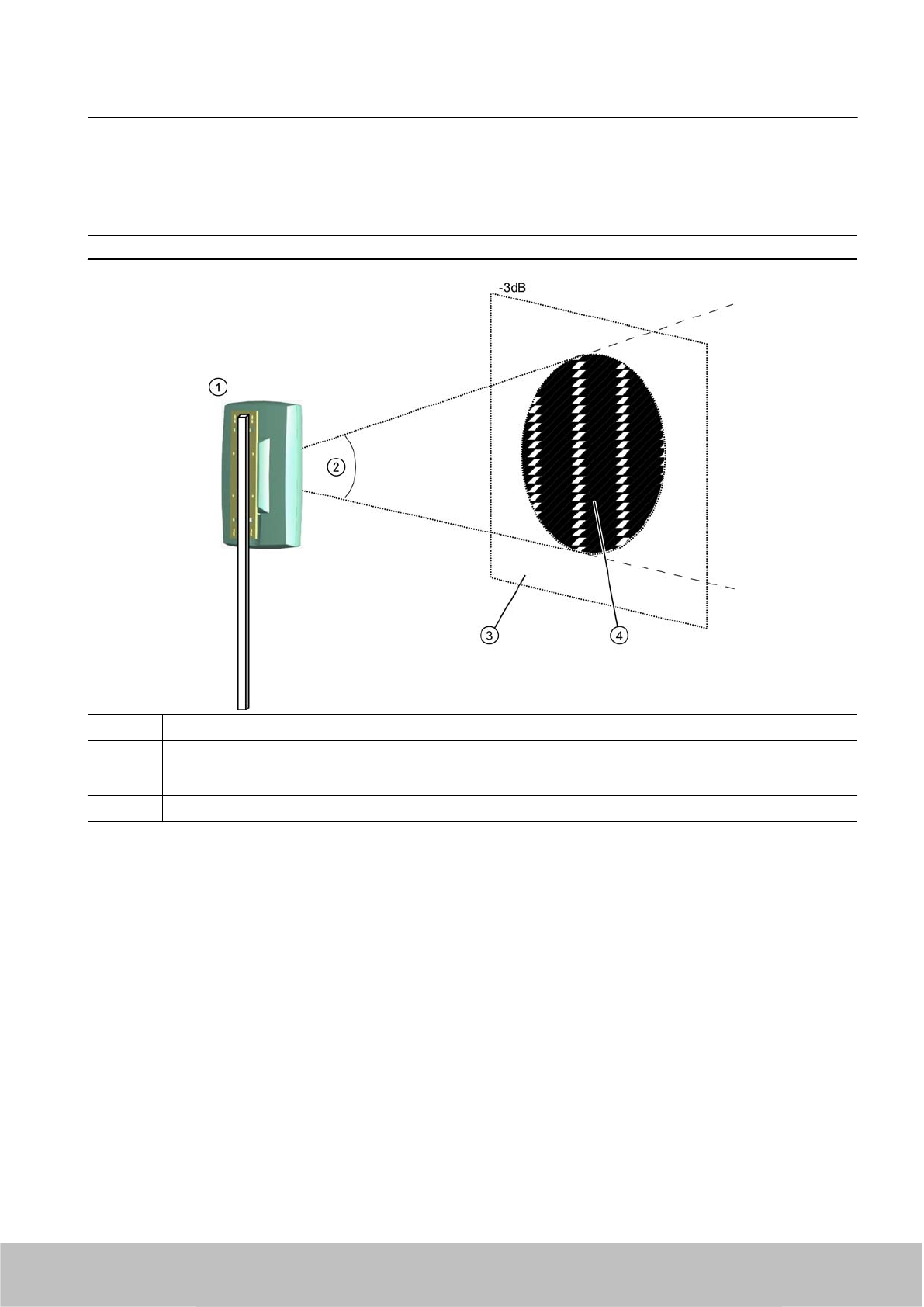
transponders. The following graphic clarifies the cross-section of the beam cone with the
covered area.
Beam angle: cross-section of the beam cone with the covered area
①Third-party antenna
②Beam angle
③Covered area
④Activation or reading range
The reading range depends on the horizontal and vertical beam widths in the case of equal
distances from the transmitter antenna. Depending on the mechanical mounting and the ratio
between the vertical beam width ① and the horizontal beam width ②, read areas result as
shown in the following graphic:
Antennas
6.4 Guidelines for selecting RFID UHF antennas
SIMATIC RF600
System Manual, 06/2010, J31069-D0171-U001-A10-7618 195
Draft Version 02.06.2010
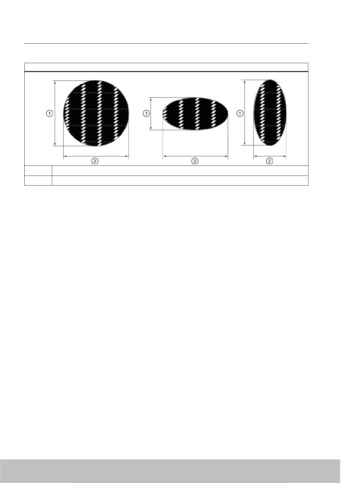
Read area depending on the beam width
①Vertical beam width
②Horizontal beam width
6.4.5 Antenna cables
6.4.5.1 Selection criteria
You must observe the criteria listed below when selecting the appropriate antenna cable for
your third-party antenna.
Characteristic impedance
Definition
If the input impedance of a device does not agree with the cable impedance, reflections occur
which reduce the power transmission and can result in the appearance of resonance and thus
to a non-linear frequency response.
Specifications
● You must only use coaxial antenna cables when connecting a third-party antenna.
● This antenna cable must have a nominal characteristic impedance of Z = 50 Ohm.
Antenna cable loss
In order to be able to transmit the available UHF power from the SIMATIC RF660R reader to
the antenna(s), the antenna cable loss must not exceed a value of approx. 4 dB.
Antennas
6.4 Guidelines for selecting RFID UHF antennas
SIMATIC RF600
196 System Manual, 06/2010, J31069-D0171-U001-A10-7618
Draft Version 02.06.2010

Dependency of the cable loss
The cable loss depends on two important factors:
● External characteristics of cable. These includes the cable length, diameter and design.
● As a result of the physical principle, the cable loss is also frequency-dependent, i.e. the
cable loss increases at higher transmitter frequencies. Therefore the cable loss must be
specified in the frequency band from 860 to 960 MHz.
Cable vendors usually provide tables or calculation aids for their types of cable which usually
include the transmitter and receiver frequencies as well as the cable length. Therefore contact
your cable vendor in order to determine the appropriate type of cable using the approximate
value referred to above.
6.4.5.2 Notes on use
Shielding of the antenna cable
Coaxial antenna cables always have a shielded design and therefore radiate little of the
transmitted power to the environment.
Note
Cable with double shielding
You should therefore preferentially select cable with double shielding since this provides the
best damping.
Bending radius of the antenna cable
The properties of the cable shield are influenced by mechanical loading or bending. You must
therefore observe the static and dynamic bending radii specified by the cable vendor.
Connectors and adapters
You must use connectors and adapters of type "Reverse Polarity R-TNC" (male connector)
for your antenna cables from a third-party supplier in order to guarantee correct connection to
the SIMATIC RF660R reader.
The figure below shows the standard for a suitable thread:
You can find more information in the catalog data of your cable vendor.
Antennas
6.4 Guidelines for selecting RFID UHF antennas
SIMATIC RF600
System Manual, 06/2010, J31069-D0171-U001-A10-7618 197
Draft Version 02.06.2010

6.4.6 Overview of parameterization of RF600 reader
The parameterization possibilities that are available to you for each reader of the RF600 family
are outlined below. You will find detailed information on parameterization in the specified
chapters of the documentation:
Readers RF-
MANAGER 2008
SP 3
SIMATIC
command
messages
RF-MANAGER
Basic 2010
Configuration
software
XML commands RFID reader
interface
RF670R Online-Help >
chapter
"Introduction to RF-
MANAGER >
Overview of the
RFID functions"
Online help >
chapter
"Working with
RFID objects"
Function
Manual
RF670R,
Chapter
"Standard
Configuration
Messages"
RF660R "Configuration
Manual
SIMATIC
RF660R
Configuration
software",
chapter
"Parameterizin
g the RF660R"
Function
Manual
RF660R,
Chapter
"Standard
Configuration
Messages"
RF630R "Configuration
Manual RF620R/
RF630R", chapter
"Overview of
commands"
RF620R "Configuration
Manual RF620R/
RF630R", chapter
"Overview of
commands"
RF610M Function
Manual Mobile
Reader,
chapter"RFID
Reader
Interface
Reference"
6.4.7 Application example
This section contains an example with specific values. Using this example it is possible to
understand how the complete selection procedure for antennas, cables, and adapters as well
as the settings could be carried out on an RF600 system reader.
In the example it is assumed that you wish to use your SIMATIC RF600 system with your third-
party components in Germany (ETSI EN 302 208 V1.2.1).
Antennas
6.4 Guidelines for selecting RFID UHF antennas
SIMATIC RF600
198 System Manual, 06/2010, J31069-D0171-U001-A10-7618
Draft Version 02.06.2010