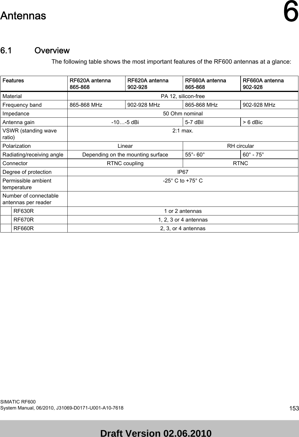
Siemens RF670 RFID UHF Reader User Manual SIMATIC RF600
Siemens AG RFID UHF Reader SIMATIC RF600
UserManual.wiki
>
Siemens
>
RF670 User Manual
>
User Manual I
Contents
1.
User Manual I
2.
User Manual II
User Manual I
Navigation menu
Upload a User Manual
Namespaces
Wiki Guide
HTML
PDF
Info
Views
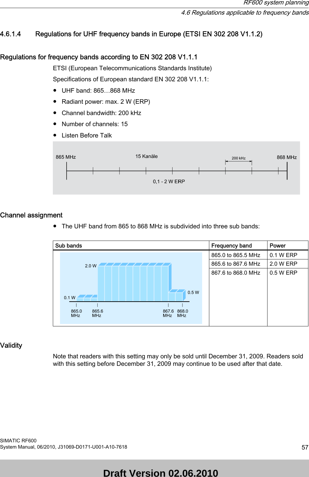
User Manual
Discussion / Help
Navigation
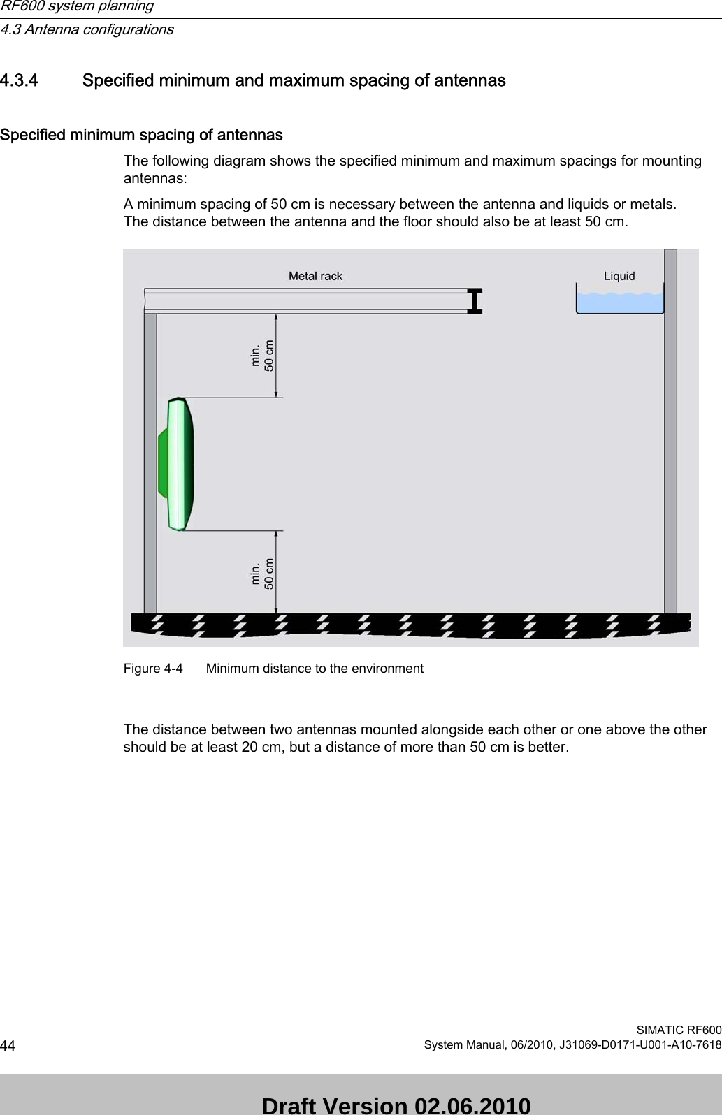
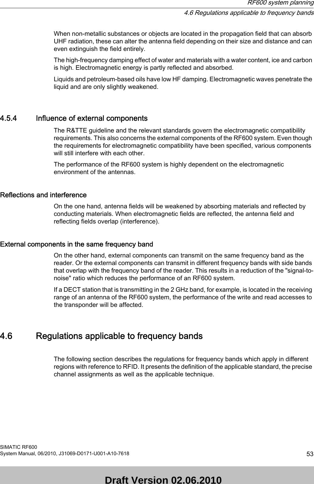
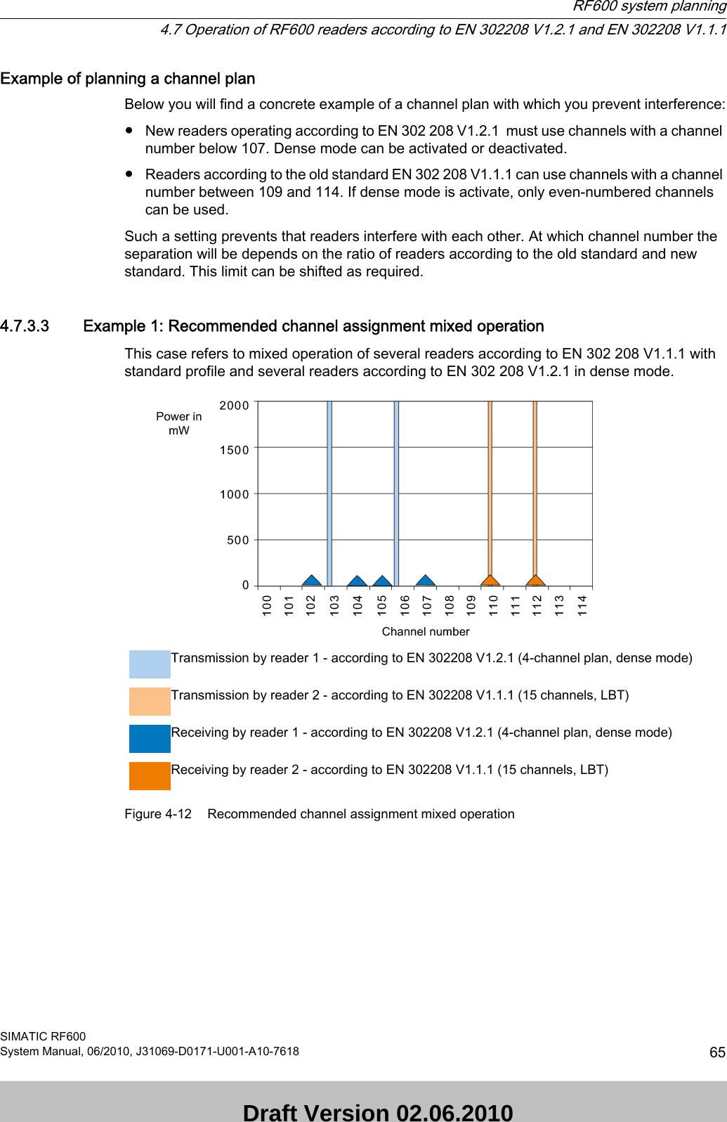
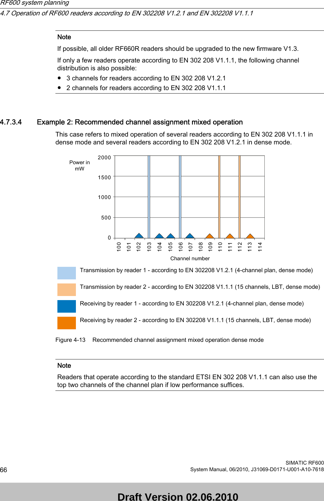
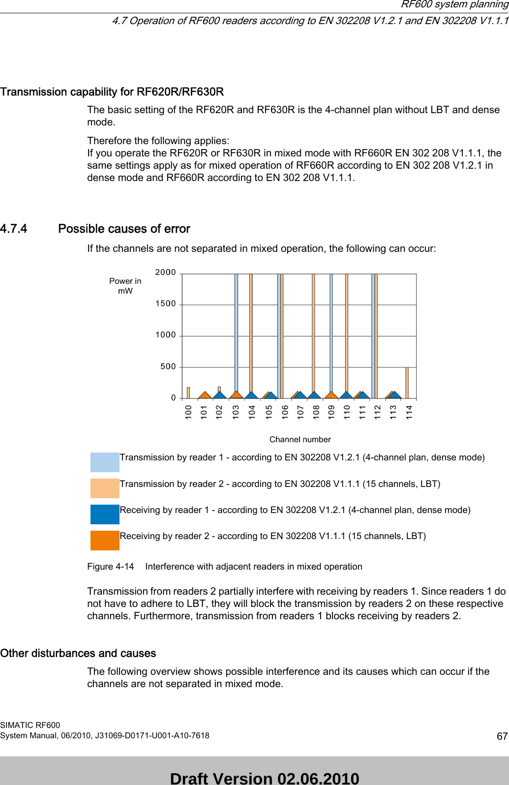
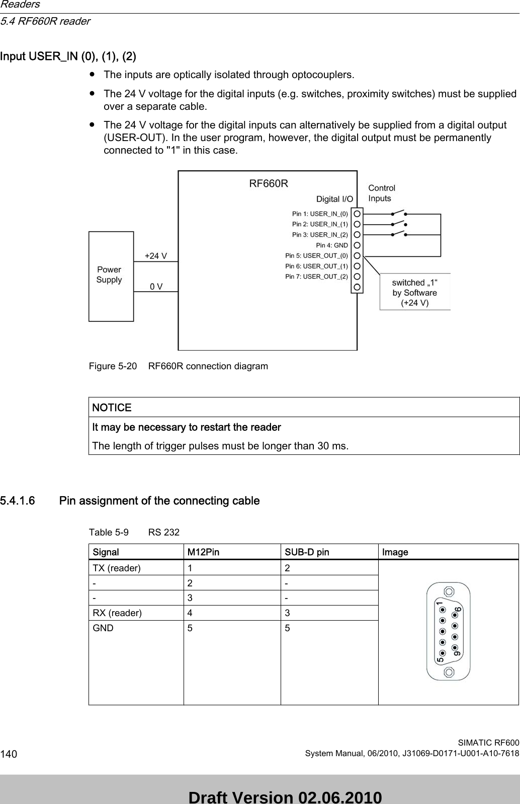
![NoteUser responsibility for modified productAs a user of the modified product, you accept responsibility for use of the complete RFID product comprising both SIMATIC RF600 components and third-party RFID components. This particularly applies to modification or replacement of:● Antennas● Antenna cables● readers●Power supply units with connection cables 2.3 Safety distance to transmitter antenna2.3.1 Safety distance between transmitter antenna and personnelFor antenna configurations where it is possible to be briefly or constantly within the transmission range of the antennas, as in loading ramps, for example, minimum distances must be maintained. LimitsThe ICRP (International Commission of Radiological Protection) has worked out limit values for human exposure to HF fields that are also recommended by the ICNIRP (International Commission of Non Ionizing Radiological Protection). In German legislation on emissions (since 1997), the following limit values apply. These can vary according to frequency:Frequency f [MHz] Electrical field strength E [V/m] Magnetic field strength H [A/m]10 - 400 27,5 0,073400 - 2.000 1.375 x f1/2 0.0037 x f1/22.000 - 300.000 61 0,16 The limit values for the 900 MHz reader antenna alternating field are thus:Electrical field strength: E = 41.25 V/mMagnetic field strength: H = 0.111 A/mHF power density: E x H = 4.57 W/m2Safety Information2.3 Safety distance to transmitter antennaSIMATIC RF600System Manual, 06/2010, J31069-D0171-U001-A10-7618 17 Draft Version 02.06.2010](https://usermanual.wiki/Siemens/RF670.User-Manual-I/User-Guide-1324839-Page-19.png)
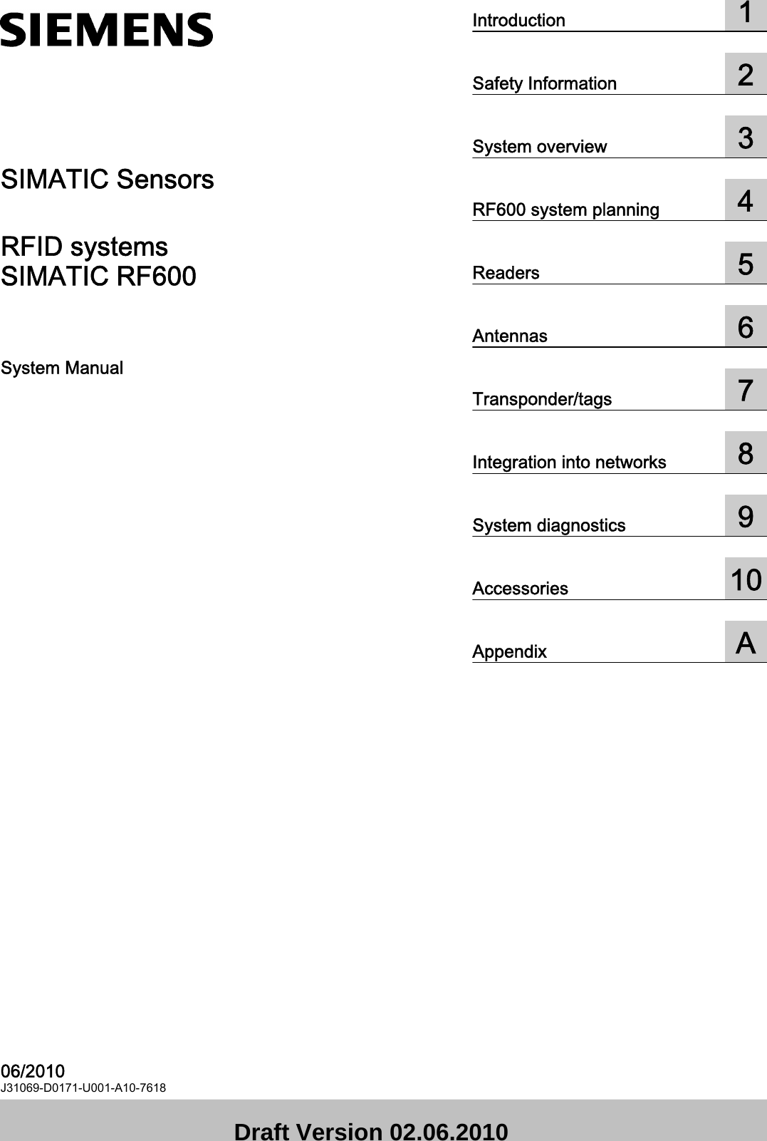
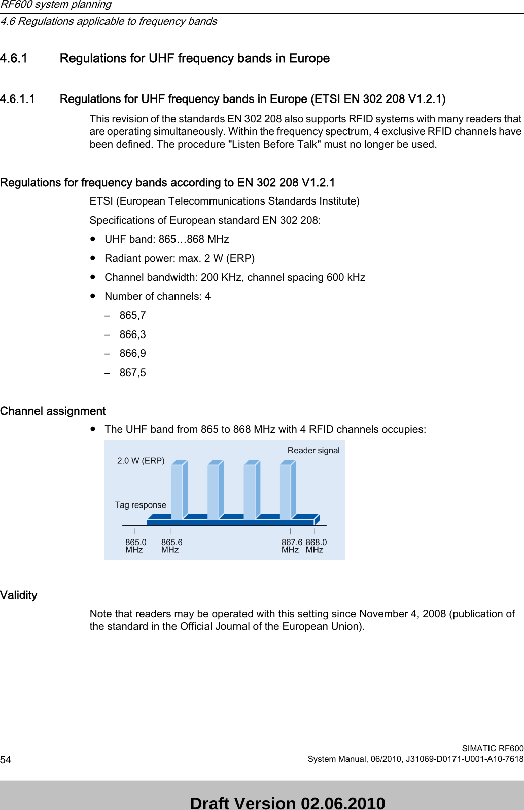
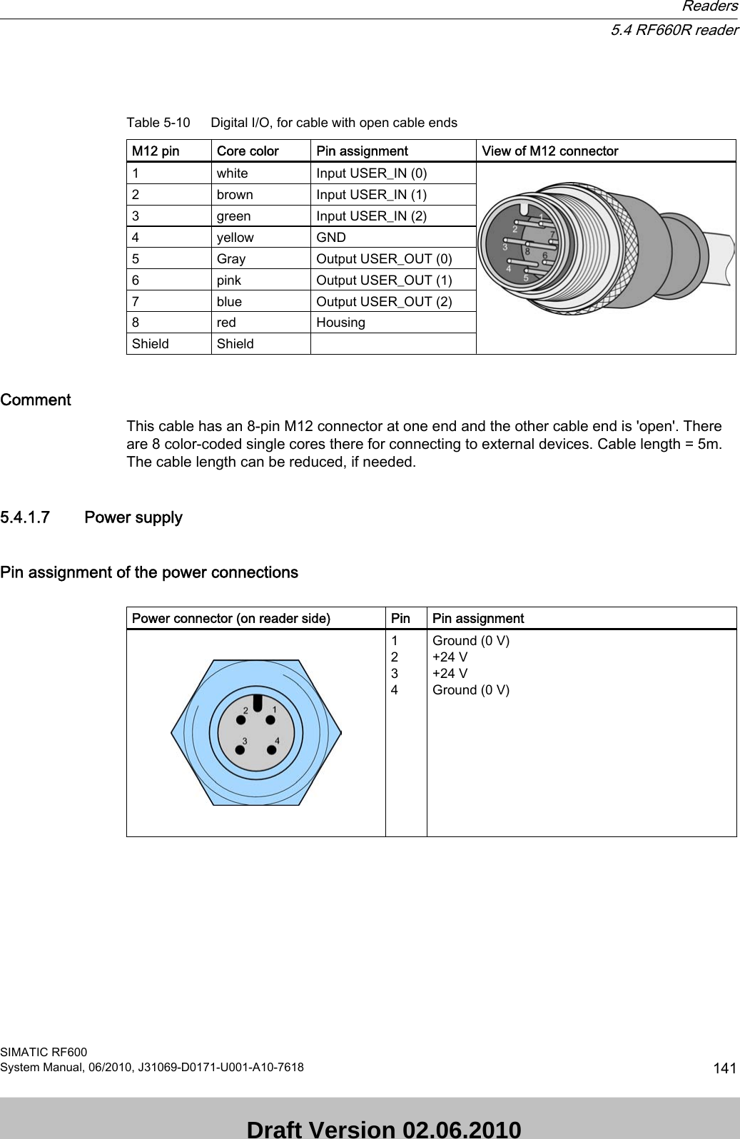
![2.3.2 Minimum distance to antenna in accordance with ETSIMinimum distance to antenna in accordance with ETSI (EU, EFTA, Turkey)At a transmission frequency of 900 MHz, the wavelength of the electromagnetic wave λ is approximately 0.34 m. For distances less than 1 λ in the near field, the electrical field strength diminishes exponentially to the power three over distance, and for distances greater than 1 λ, it diminishes exponentially to the power two over distance. The horizontal line at 41.25V/m marks the "safety limit value".For the maximum permisisble transmission power in accordance with ETSI (2W ERP), the "safety distance" d = 0.24 m. This means that personnel should not remain closer than 24cm to the transmitter antenna for extended periods (more than several hours without interruption). Remaining within the vicinity of the antenna for a brief period, even for repeated periods (at a distance < 0.24 m), is harmless according to current knowledge. Distance to transmitter antenna [m] Feld strength [V/m] % of limit value110 245 2 5If the transmitter power is set lower than the highest permissible value (2 watts ERP), the "safety distance" reduces correspondingly.The values for this are as follows:Radiated power ERP [W] Safety distance to transmitter antenna [m]2,0 0,241,0 0,170,5 0,12 Safety Information2.3 Safety distance to transmitter antennaSIMATIC RF60018 System Manual, 06/2010, J31069-D0171-U001-A10-7618 Draft Version 02.06.2010](https://usermanual.wiki/Siemens/RF670.User-Manual-I/User-Guide-1324839-Page-20.png)
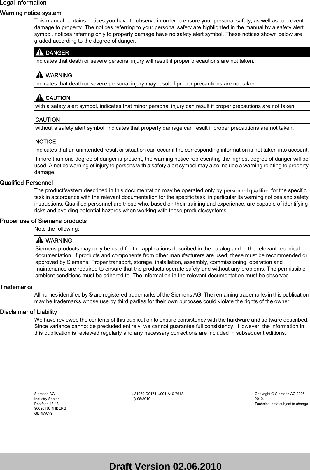
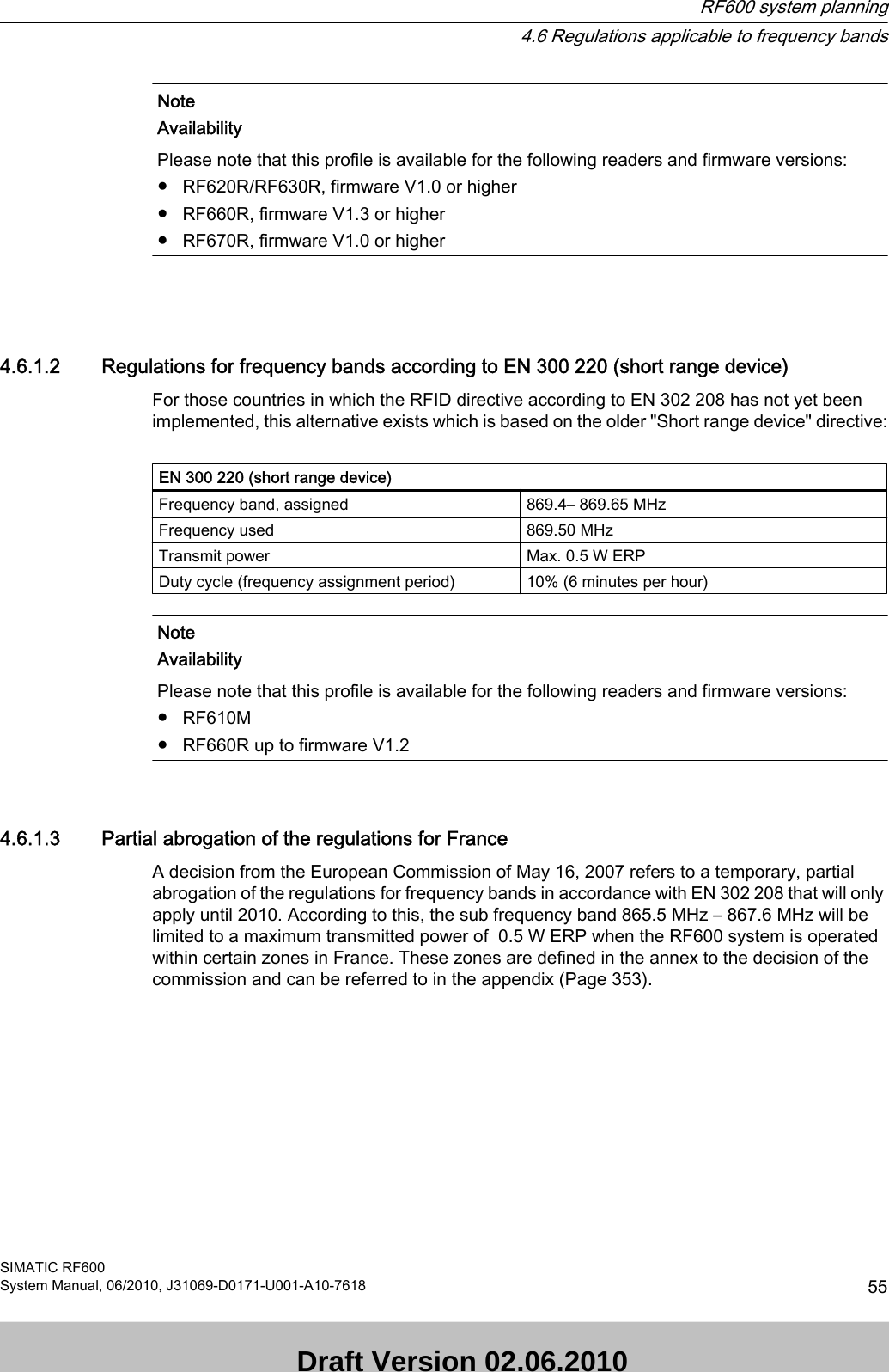
![NoteReduced maximum radiated power with RF620R/RF630R readersThe SIMATIC RF620R (ETSI) reader has a maximum radiated power of 0.5 W ERP. The maximum safety distance is therefore 0.12 m.The SIMATIC RF630R (ETSI) reader has a maximum transmitter power of 0.5 W. The radiated power therefore depends on the antenna cable and the type of antenna used, but must not exceed the 2 W ERP. 2.3.3 Minimum distance to antenna in accordance with FCC (USA)Minimum distance to antenna in accordance with FCC (USA)For the maximum permisisble transmission power in accordance with FCC (4W EIRP), the "safety distance" d = 0.26 m. This means that personnel should not remain closer than 26cm to the transmitter antenna for extended periods (more than several hours without interruption). Remaining within the vicinity of the antenna for brief period, even repeated periods (at a distance < 0.26 m) is harmless to health according to current knowledge. The horizontal line at 41.25 V/m marks the "safety limit value".Distance to transmitter antenna [m] Feld strength [V/m] % of limit value110,9 265 2,2 5,3If the transmitter power is set lower than the highest permissible value (4 watts ERP), the "safety distance" reduces correspondingly. The values for this are as follows:Safety Information2.3 Safety distance to transmitter antennaSIMATIC RF600System Manual, 06/2010, J31069-D0171-U001-A10-7618 19 Draft Version 02.06.2010](https://usermanual.wiki/Siemens/RF670.User-Manual-I/User-Guide-1324839-Page-21.png)
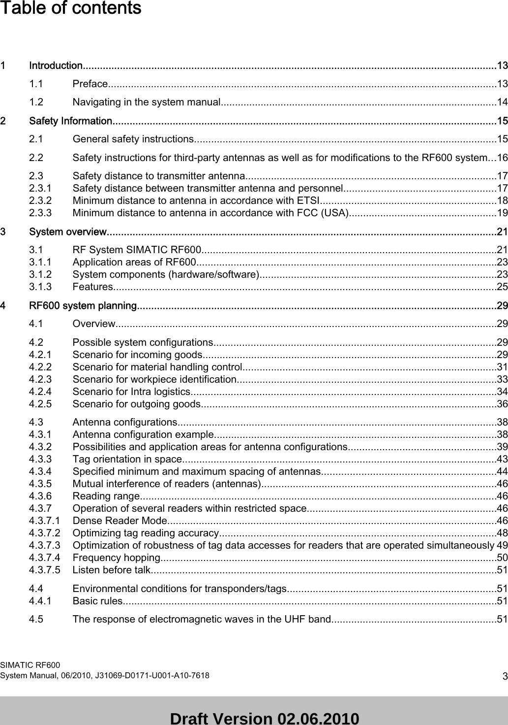
![Radiated power ERP [W] Safety distance to transmitter antenna [m]4,0 0,262,0 0,1850,8 0.1xx0,5 0,13 NoteReduced maximum radiated power with RF620R/RF630R readersThe SIMATIC RF620R (FCC) reader has a maximum radiated power of 0.795 W EIRP. The maximum safety distance is therefore 0.1xx m.The SIMATIC RF630R (ETSI) reader has a maximum transmitter power of 0.5 W. The radiated power therefore depends on the antenna cable and the type of antenna used, but must not exceed the 4 W EIRP. Safety Information2.3 Safety distance to transmitter antennaSIMATIC RF60020 System Manual, 06/2010, J31069-D0171-U001-A10-7618 Draft Version 02.06.2010](https://usermanual.wiki/Siemens/RF670.User-Manual-I/User-Guide-1324839-Page-22.png)
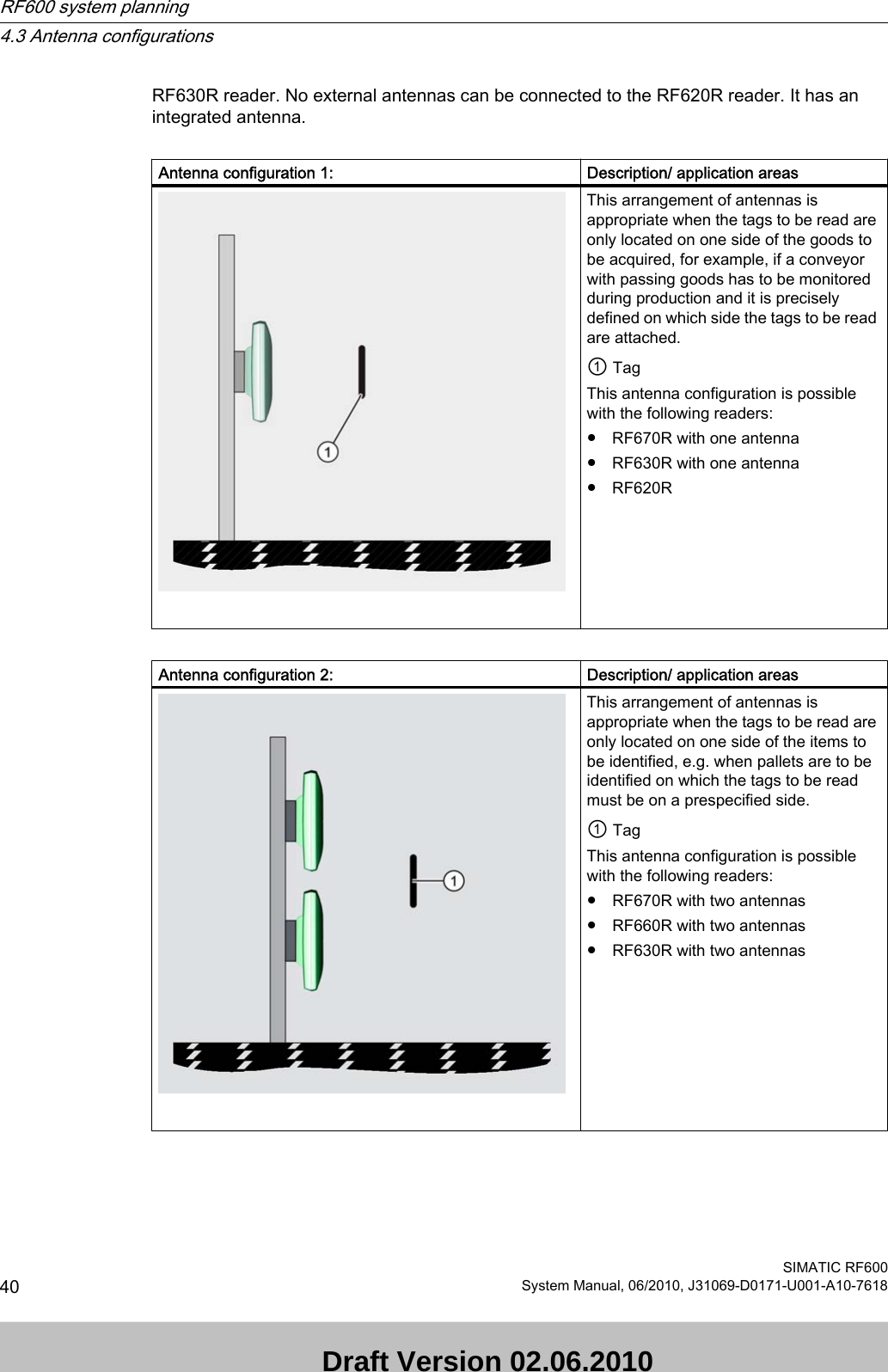
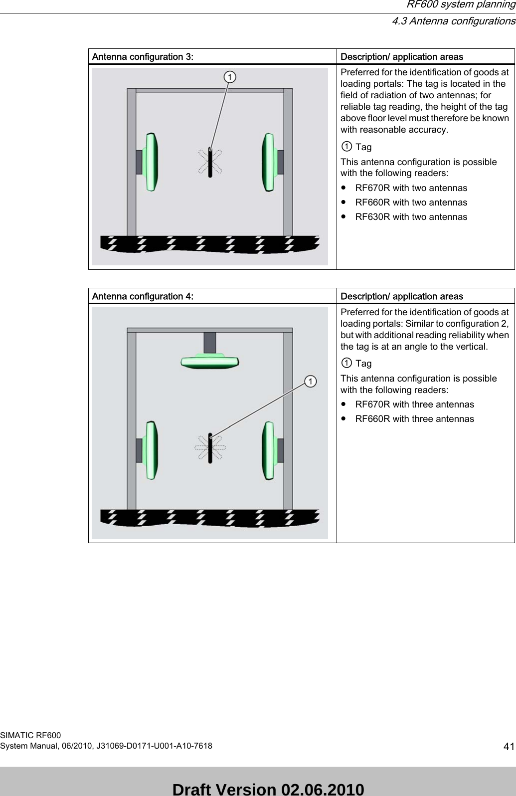
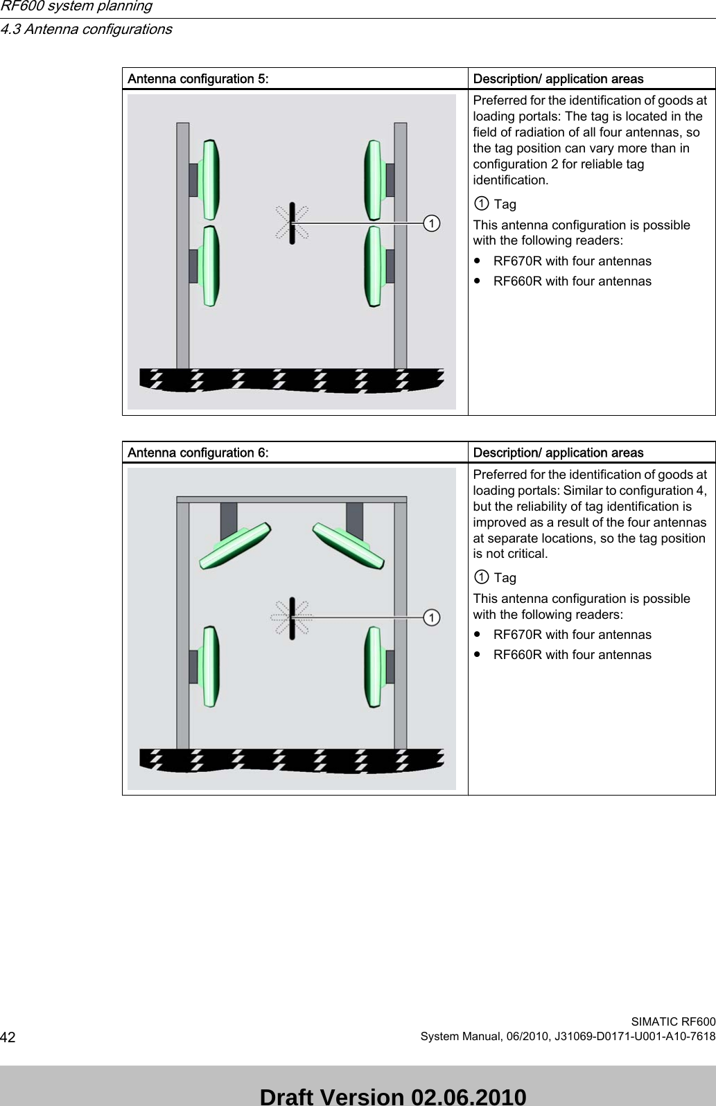
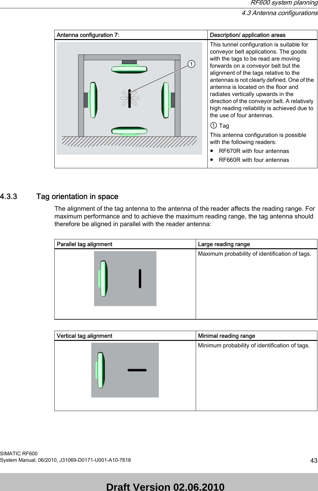
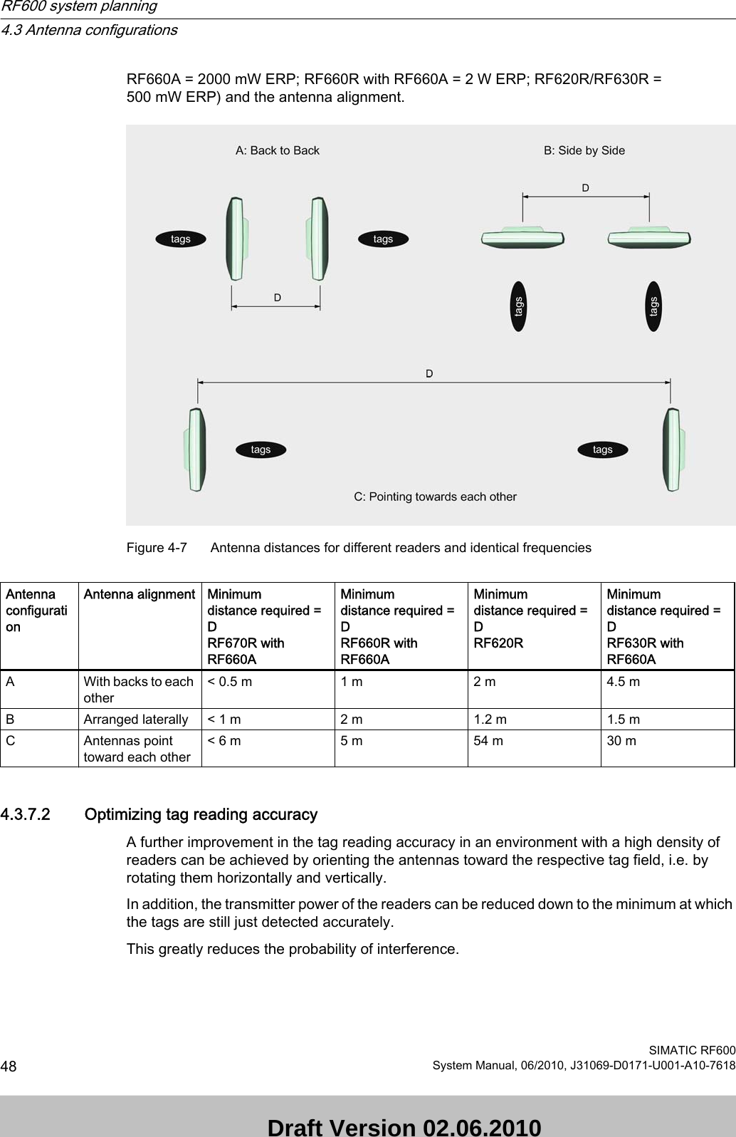
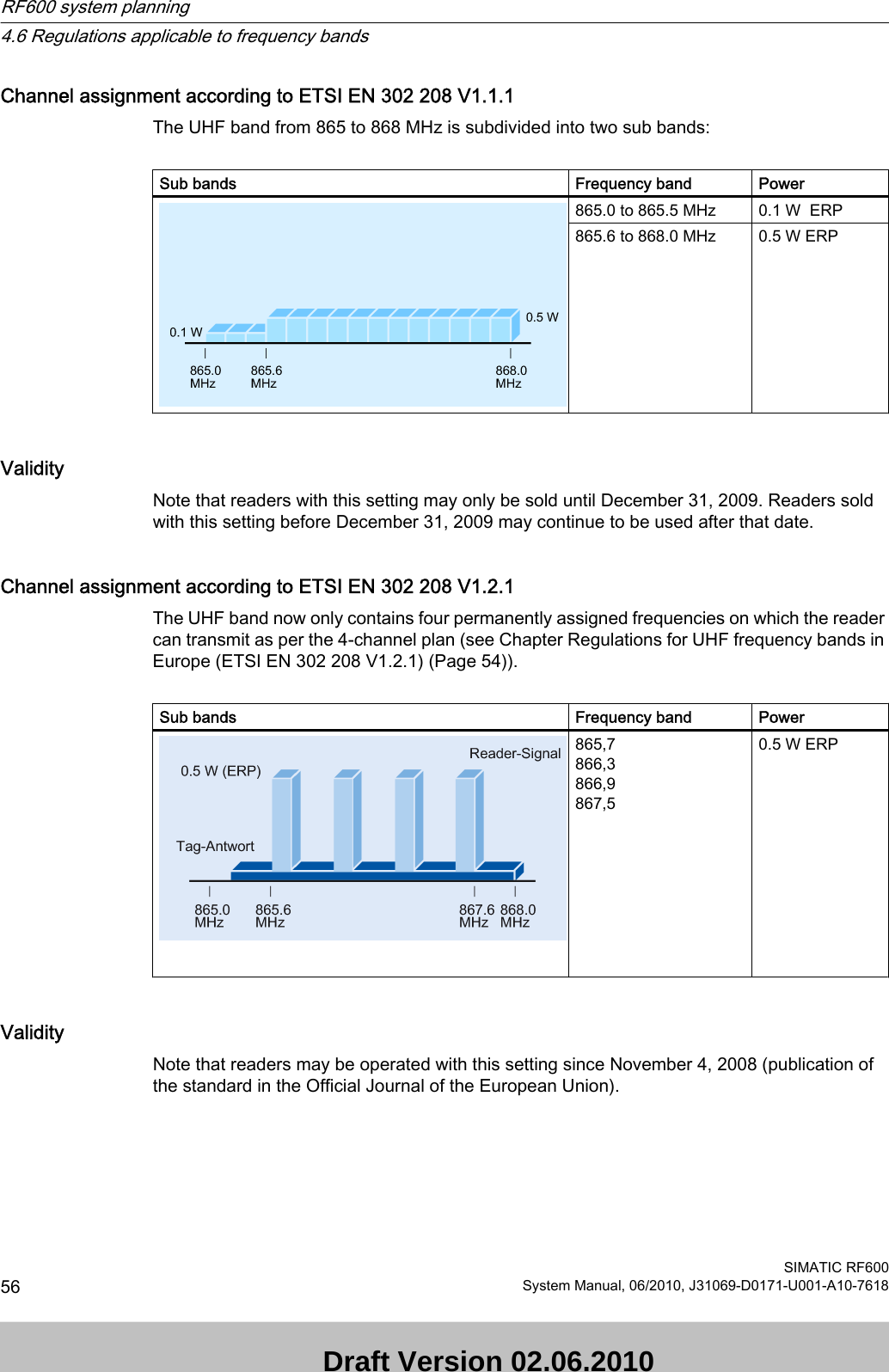
![Application example for RF620R/RF630RThe following example explains measures for enhancing the data access security from the RF620R reader to transponders:● The antennas are placed next to each other and are aligned in parallel (see arrangement B in Chapter Dense Reader Mode (Page 46)).● Radiated power is limited to 27 dBm (ERP) or 500 mW (ERP).● The RF620R readers have been rotated through 90° around the z axis.In addition, the following characteristics are to be fulfilled:● Length of data to be read/written on the transponder: 99,99%● Length of data to be read/written on the transponder: 512 bits (64 bytes)● Transponder type RF630L (6GT2810-2AB03)The table below provides an overview of the minimum distances to be observed depending on the radiated power and maximum possible number of transponders for the RF620R/RF630R readers if the above-named requirements must be fulfilled:Mode Max. number of tagsRadiated powerdBm (ERP)/ mW (ERP)Min. distance [m] between - two RF620R readers - two RF660A antennas operated with RF630R readers - one RF620R and one RF660A antenna operated with a RF630R readerSingle tag mode: Read1 27 dBm (ERP)/ 500 mW (ERP)3Single tag mode: Write1 27 dBm (ERP)/ 500 mW (ERP)3Multitag mode: Read40 27 dBm (ERP)/ 500 mW (ERP)6Multitag mode: Write10 27 dBm (ERP)/ 500 mW (ERP)6See alsoRF660A antenna (Page 175)4.3.7.4 Frequency hoppingThis technique should prevent mutual interference between readers. The reader changes its transmission channel in a random or programmed sequence (FHSS). Procedure for FCCThe 50 available channels mean that the probability is low that two readers will be operating on the same frequency (see Section Regulations for UHF frequency bands in the USA (Page 60)). In China, one reader operates on at least 2 channels, e.g. 16 channels of 2 W (see Section Regulations for UHF frequency bands in China (Page 58)). RF600 system planning4.3 Antenna configurationsSIMATIC RF60050 System Manual, 06/2010, J31069-D0171-U001-A10-7618 Draft Version 02.06.2010](https://usermanual.wiki/Siemens/RF670.User-Manual-I/User-Guide-1324839-Page-52.png)
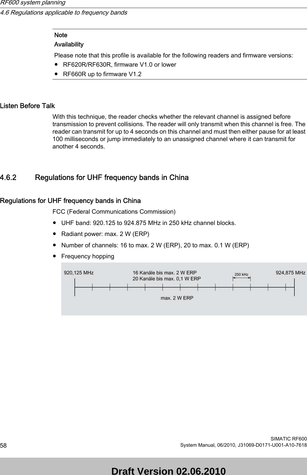
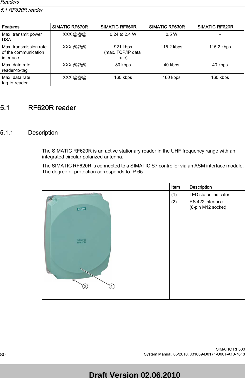
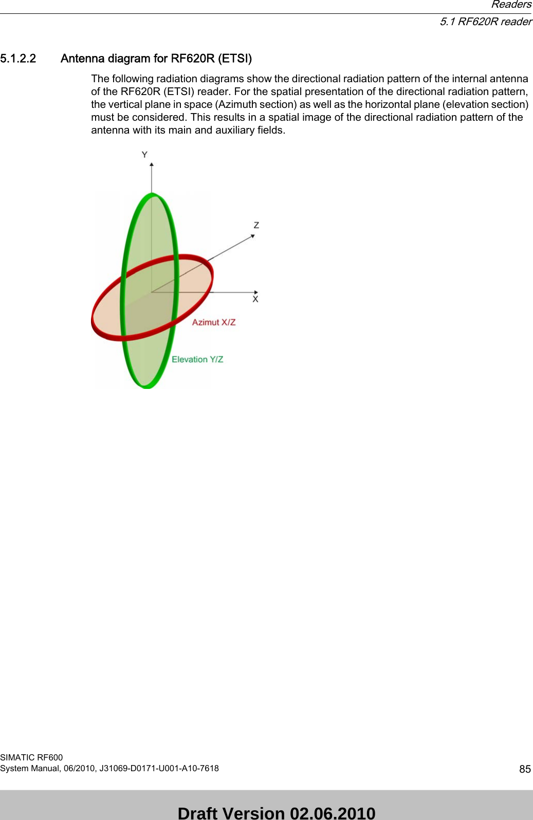
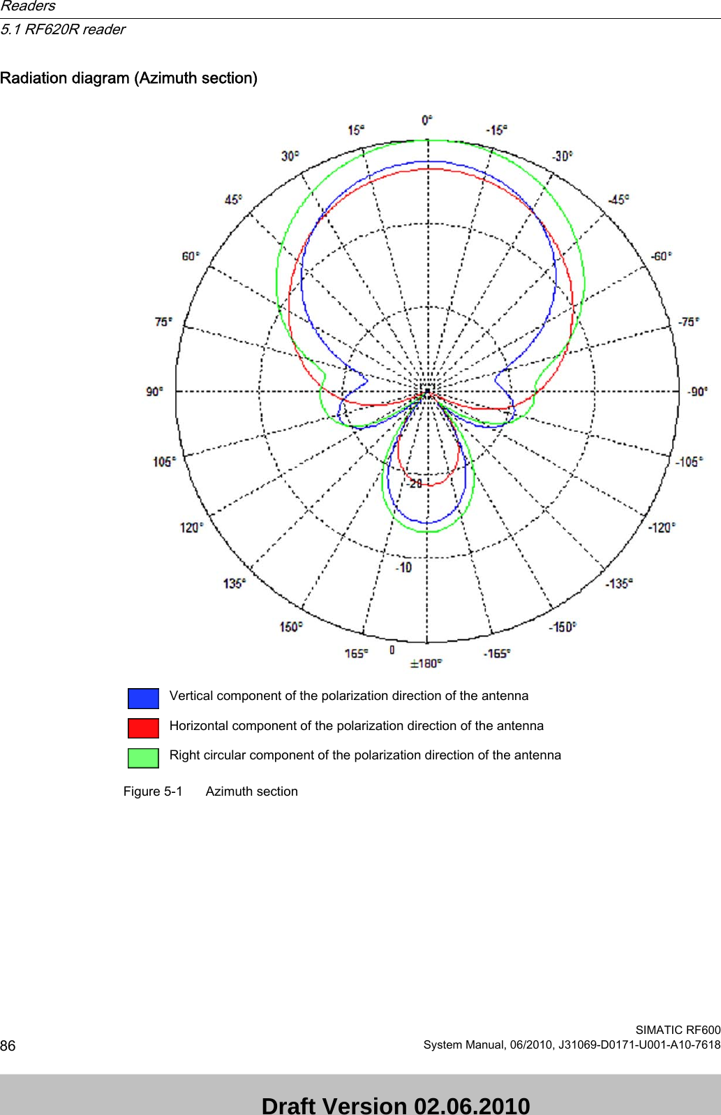
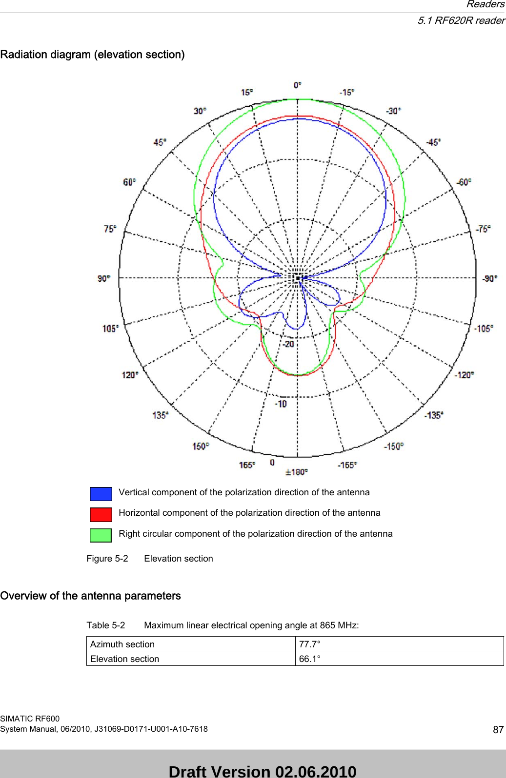
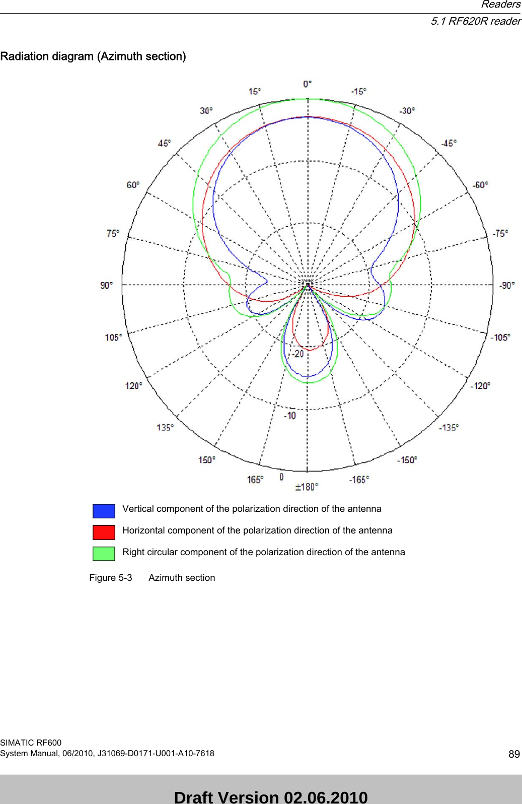
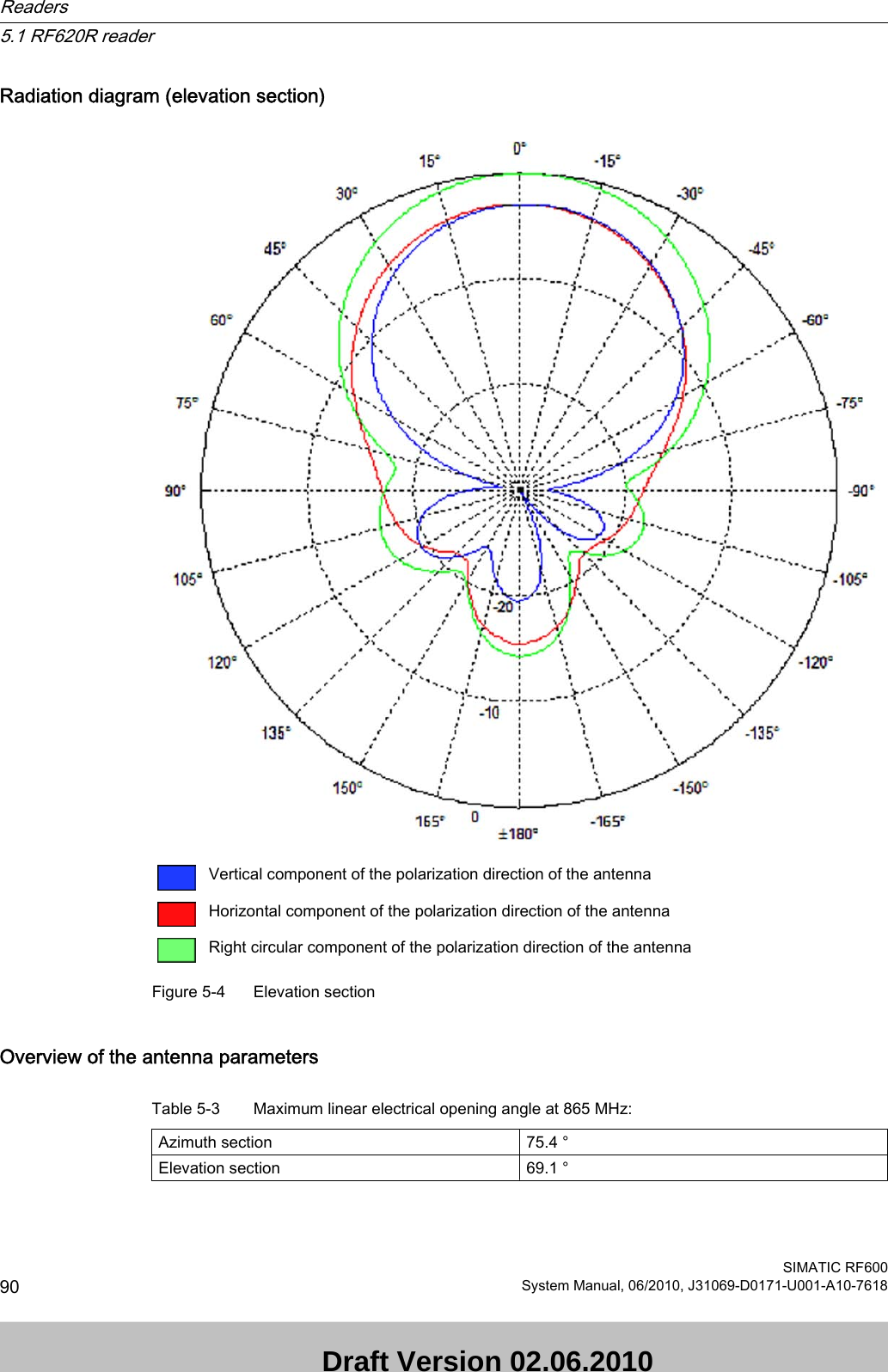
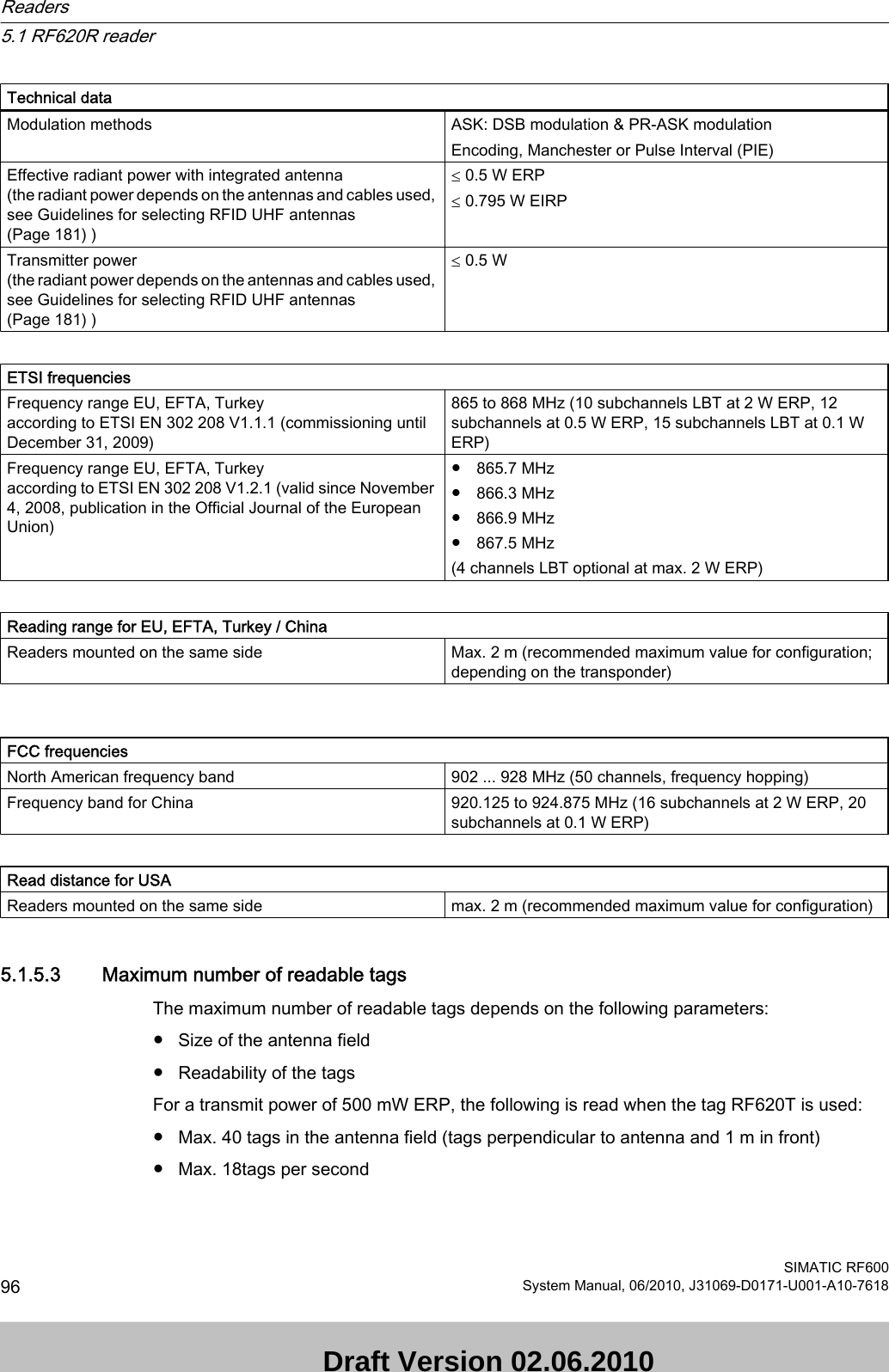
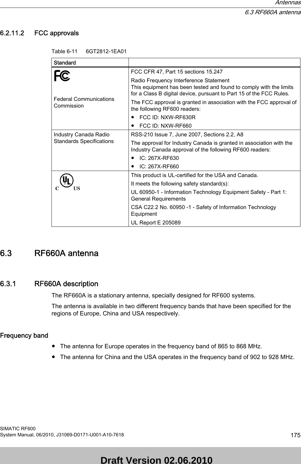
![Typical antenna gain in the frequency range 865 to 868 MHz7.3 dBic ± 0.5 dBAntenna axis ratio <1 dBSee also Chapter Guidelines for selecting RFID UHF antennas (Page 181).5.1.2.4 Interpretation of directional radiation patternsThe following overview table will help you with the interpretation of directional radiation patterns. The table shows which dBi values correspond to which read/write ranges (in %): You can read the radiated power depending on the reference angle from the directional radiation patterns, and thus obtain information on the read/write range with this reference angle with regard to a transponder.The dBr values correspond to the difference between the maximum dBi value and a second dBi value.Deviation from maximum antenna gain [dBr] Read/write range [%]0100-3 70-6 50-9 35-12 25-15 18-18 13ExampleAs one can see from the section Antenna diagram for RF620R (ETSI) (Page 85), the maximum antenna gain is 0 dB. In the Azimuth diagram, the antenna gain falls by 3°dB at approximately ± 39°. Therefore the dBr value is -3. The antenna range is only 50% of the maximum range at ± 39° from the Z axis within the horizontal plane.5.1.2.5 Antenna/read point configurationsThe RF620R reader has an internal circular polarized antenna. You can cover one read point with this antenna. When several RF620R readers are used, the readers are addressed via the SIMATIC level.5.1.3 Installing/Mounting Requirement Readers5.1 RF620R readerSIMATIC RF600System Manual, 06/2010, J31069-D0171-U001-A10-7618 91 Draft Version 02.06.2010](https://usermanual.wiki/Siemens/RF670.User-Manual-I/User-Guide-1324839-Page-93.png)

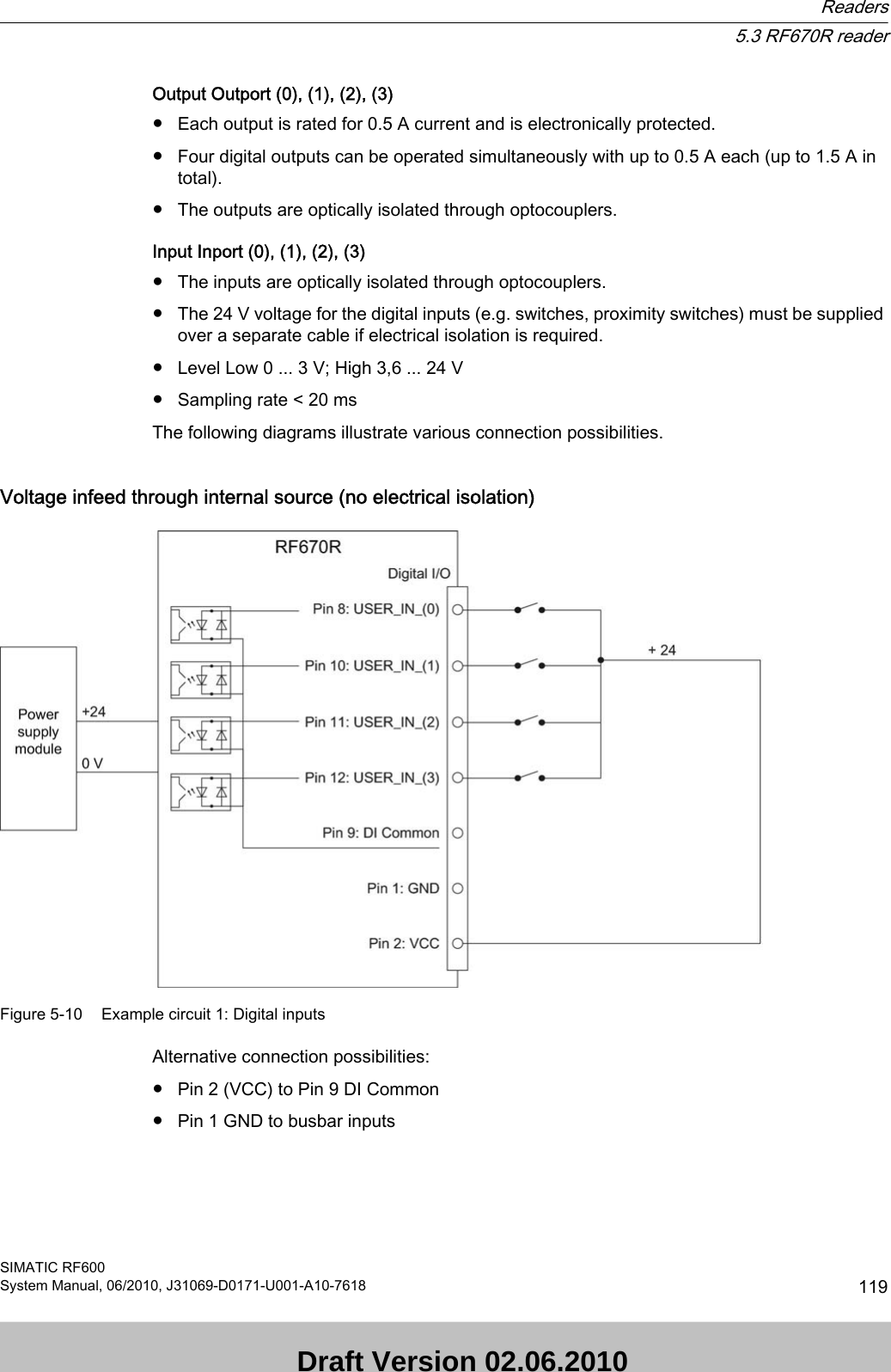
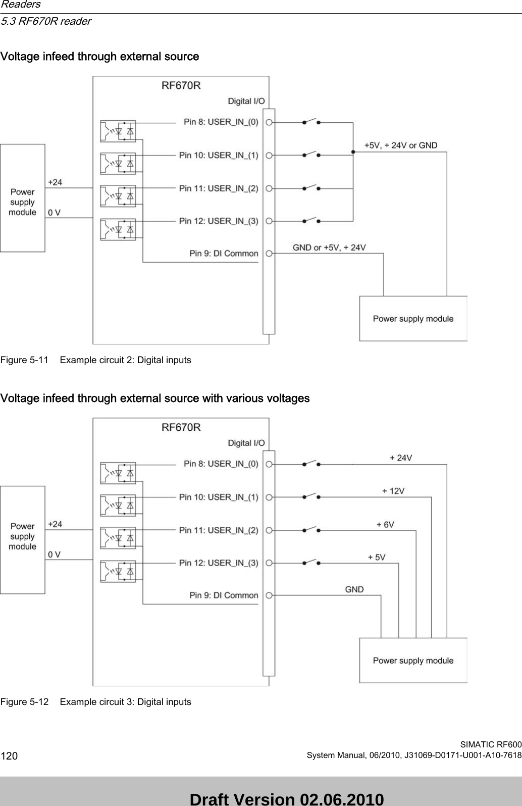
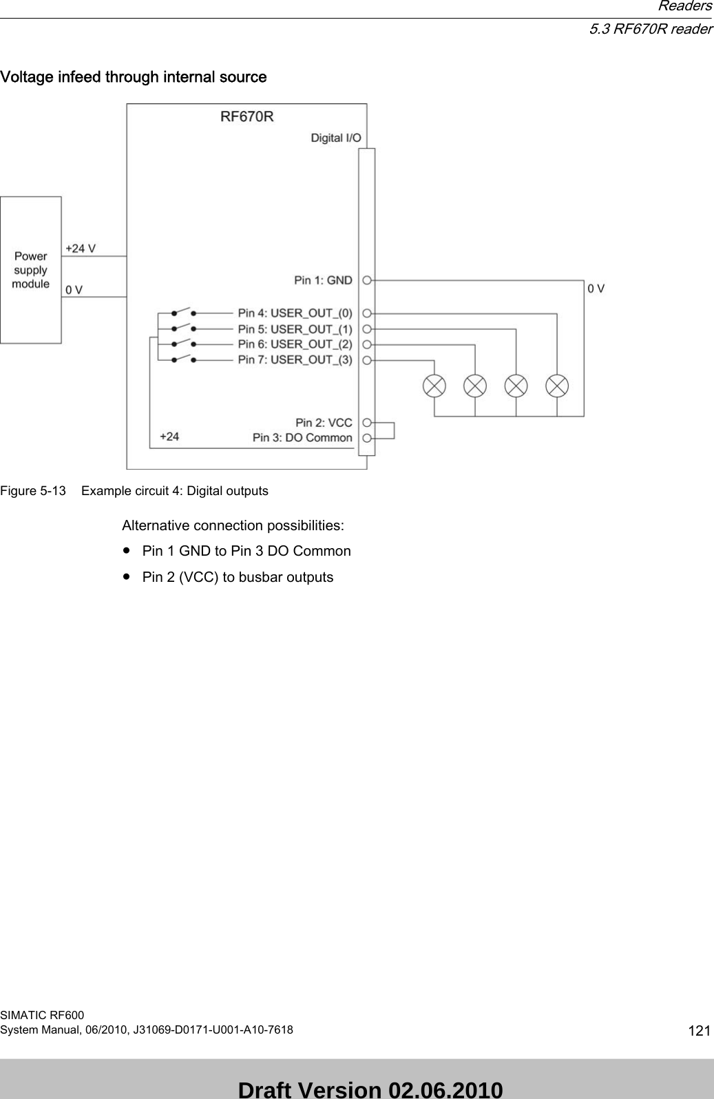
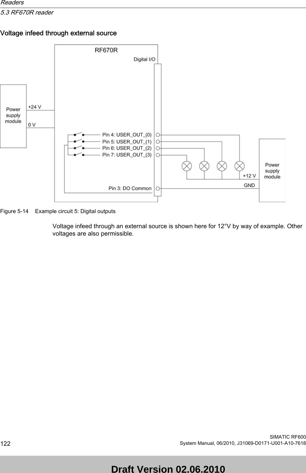
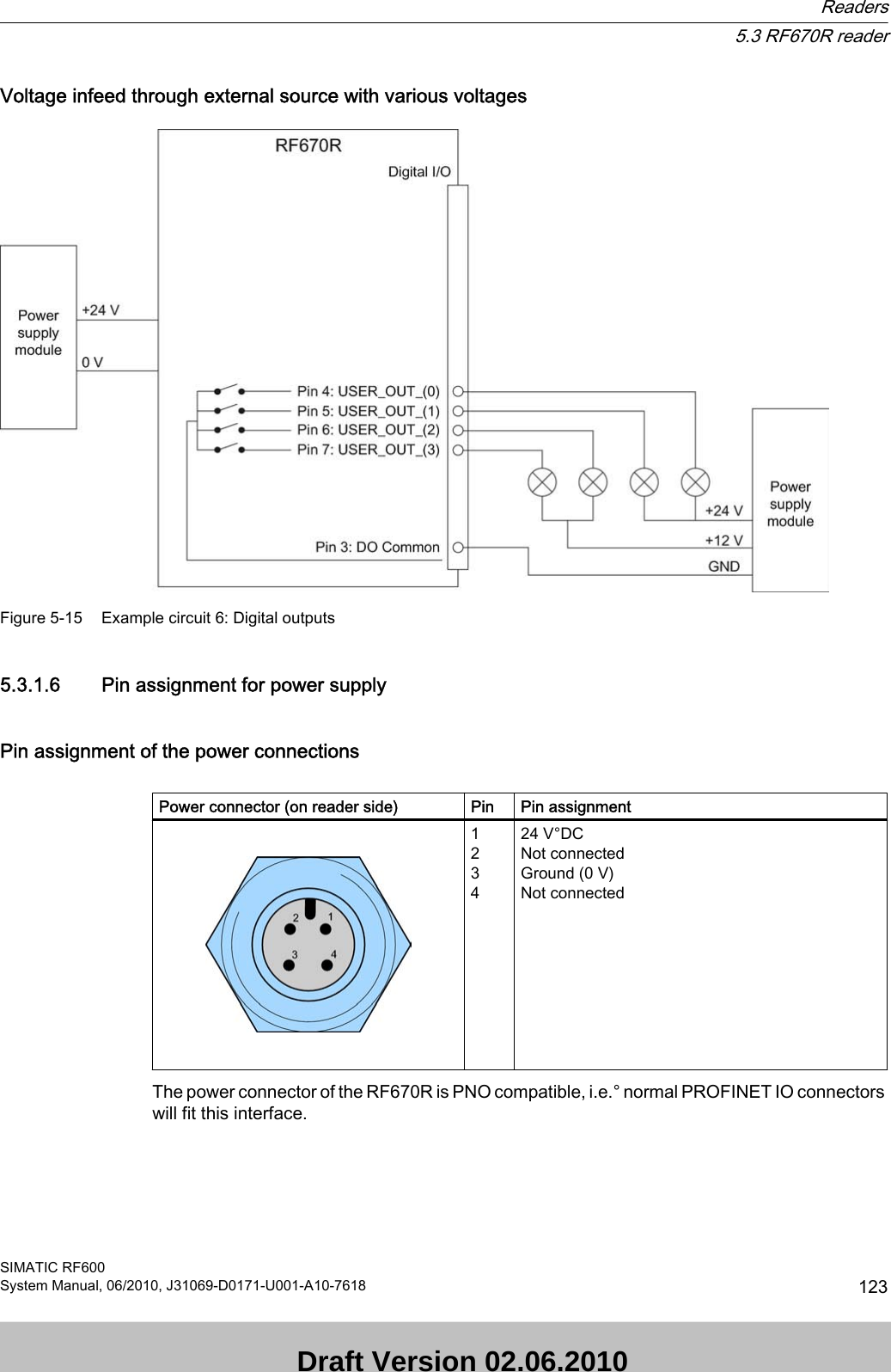
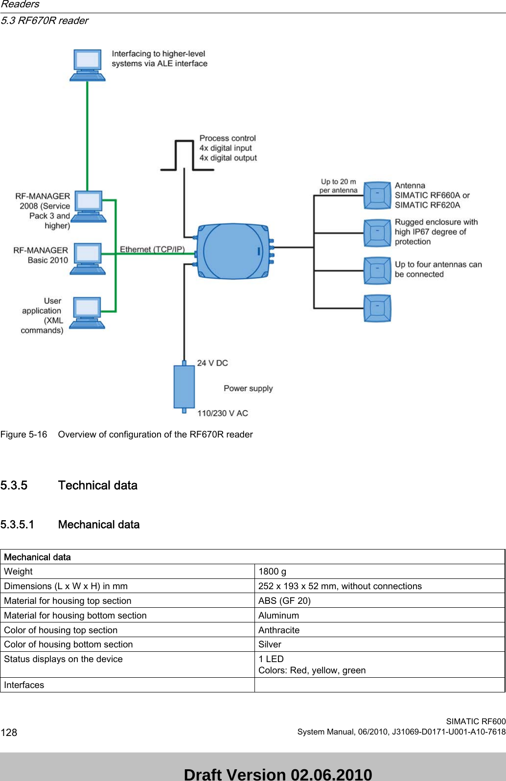
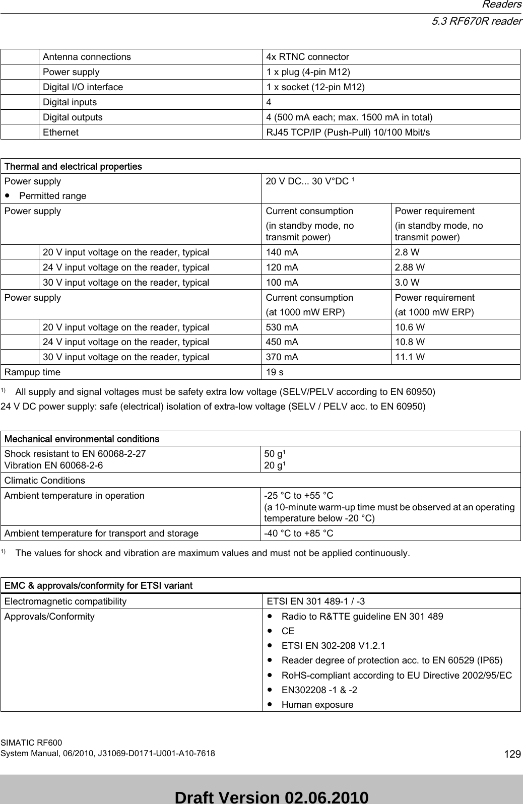
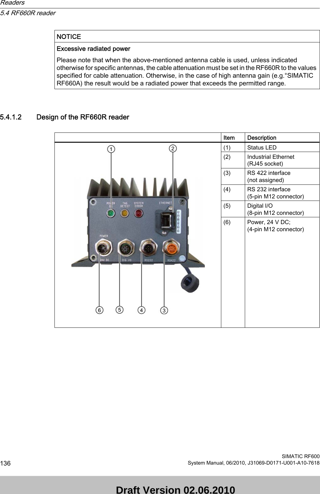
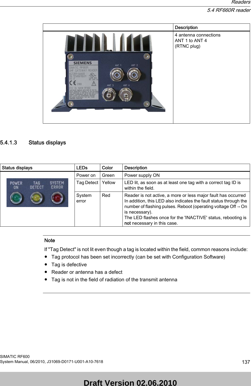
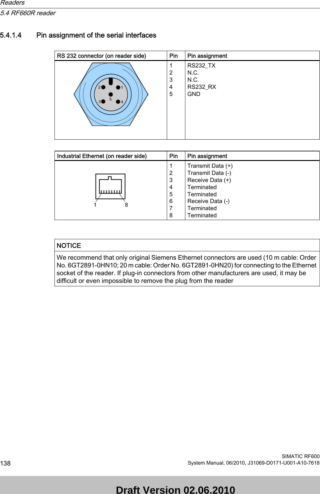
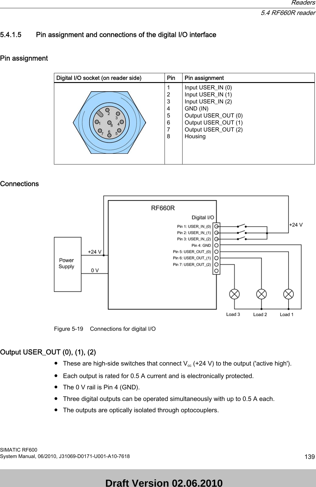
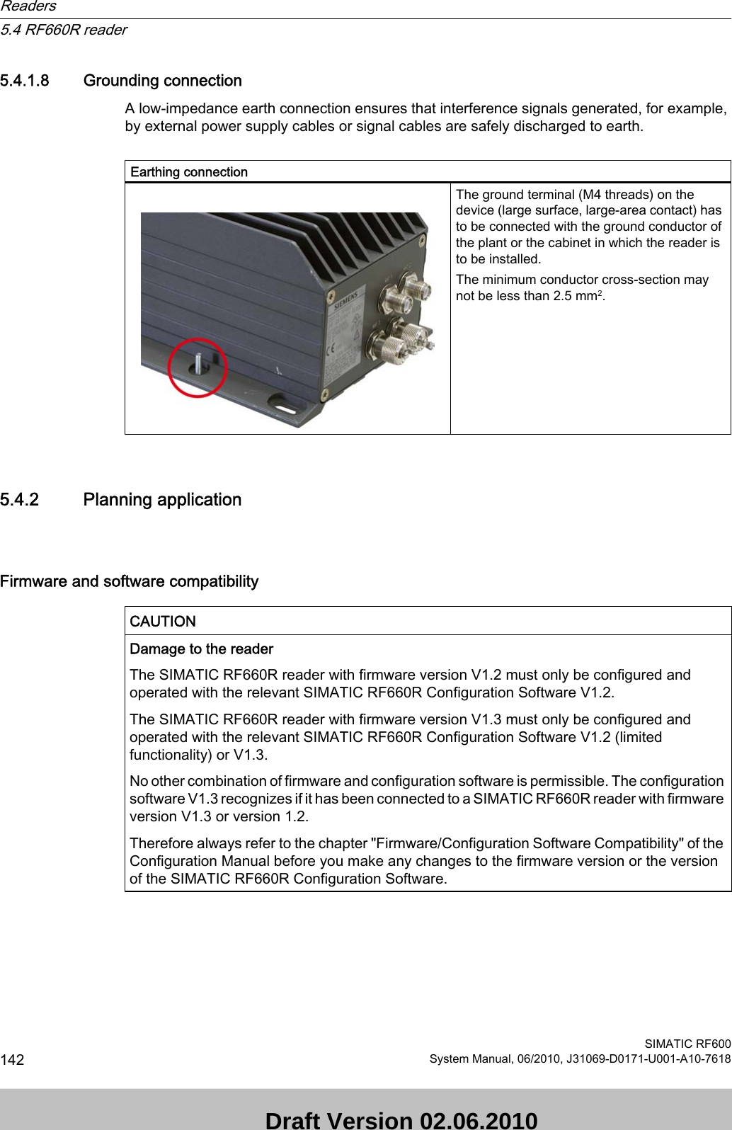
![5.3.1.4 Pin assignment of the digital I/O interfaceView of socket (reader end)M12 socket (reader end) Pin Pin assignment 123456789101112GND (output for supply of digital inputs/outputs [not electrically isolated])VCC (output for supply of digital inputs/outputs [not electrically isolated])DO Common / Outport CommonDO 0 / Outport 00 DO 1 / Outport 01DO 2 / Outport 02DO 3 / Outport 03DI 0 / Inport 00DI Common / Inport CommonDI 1 / Inport 01DI 2 / Inport 02DI 3 / Inport 03Wiring diagram M12 connector (cable end)You must assemble your reader cable with a matching connector that fits the interface shown above. Adhere to the following wiring diagram:Figure 5-9 M12 connector wiring diagram5.3.1.5 Connection scheme for the digital I/O interfaceConnection possibilitiesYou can connect the RF670R reader in different ways. In general, the outputs and inputs should be connected as follows:Readers5.3 RF670R readerSIMATIC RF600118 System Manual, 06/2010, J31069-D0171-U001-A10-7618 Draft Version 02.06.2010](https://usermanual.wiki/Siemens/RF670.User-Manual-I/User-Guide-1324839-Page-120.png)
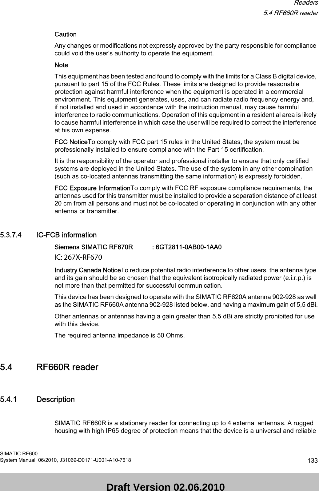

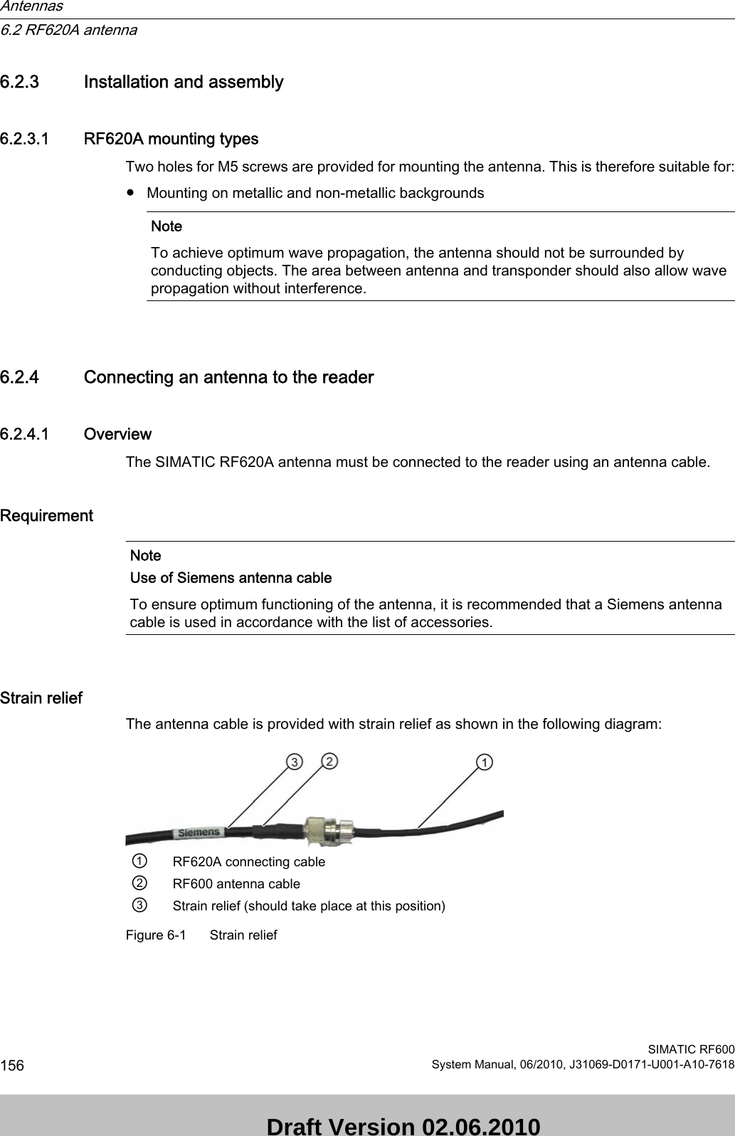
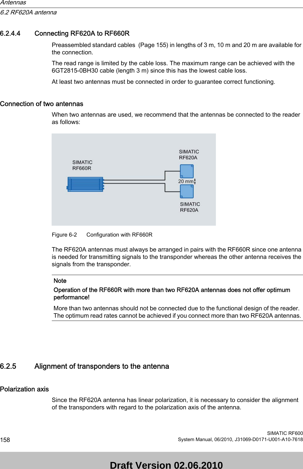
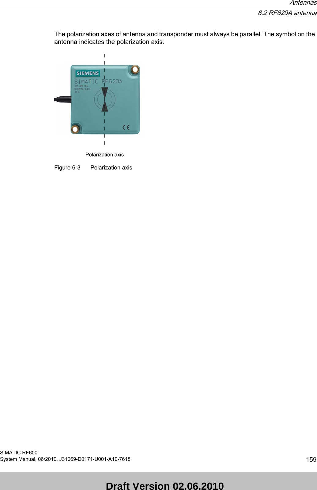
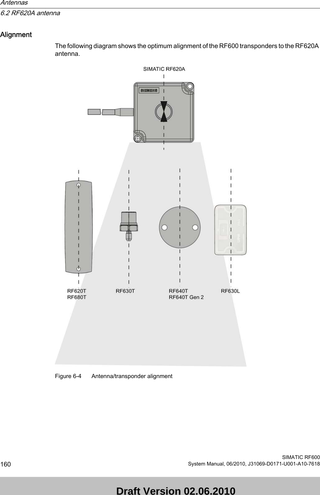
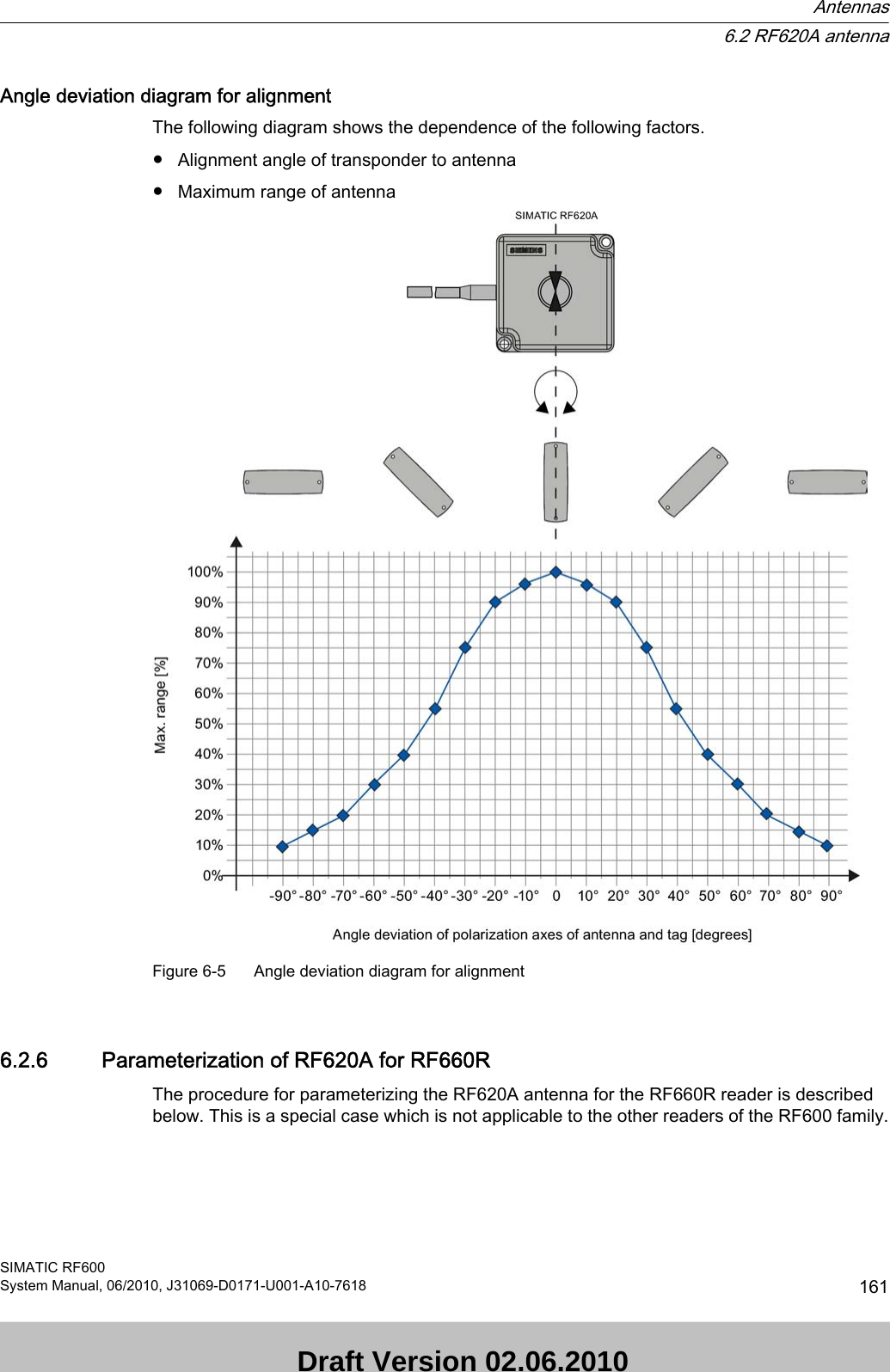
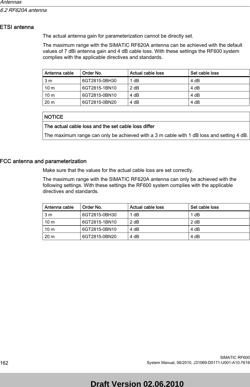
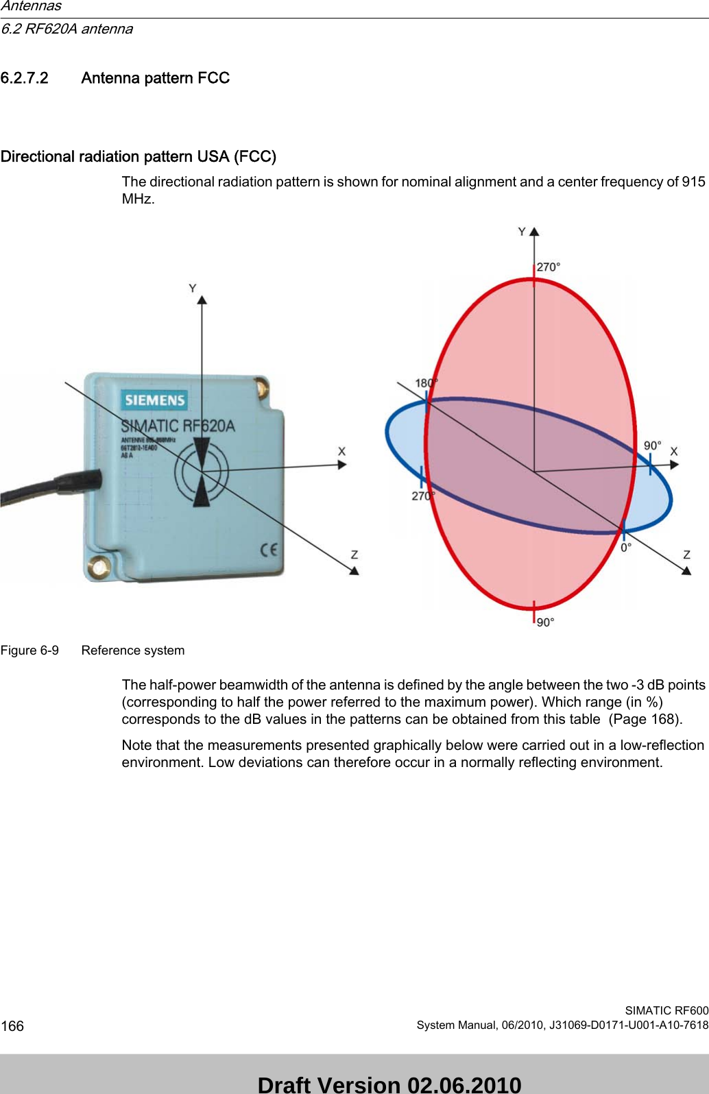
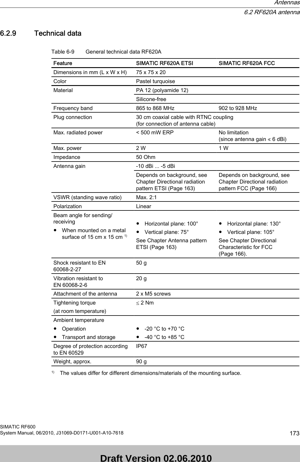
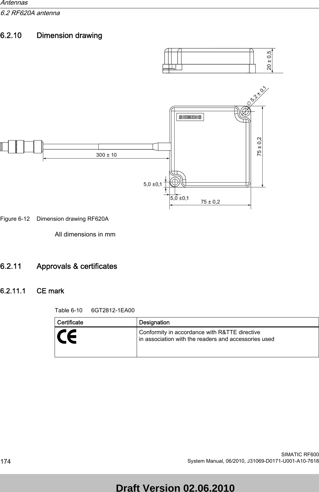
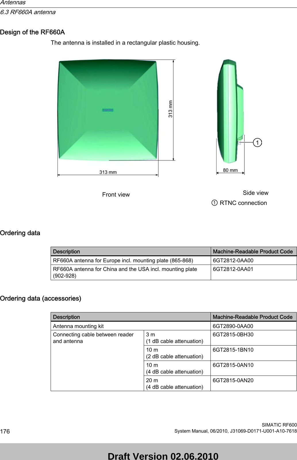
![Bending radii of the cablesCable designation Order No. Length [m] Cable loss [dB] Bending radius [mm]RF620A connecting cable 15Antenna cable 6GT2815-0BH30 3 1 51Antenna cable 6GT2815-1BN10 10 2 77Antenna cable 6GT2815-0BN10 10 4 51Antenna cable 6GT2815-0BN20 20 4 776.2.4.2 Connecting RF620A to RF670RPreassembled standard cables (Page 155) in lengths of 3 m, 10 m and 20 m are available for the connection.The read range is limited by the cable loss. The maximum range can be achieved with the 6GT2815-0BH30 cable (length 3 m) since this has the lowest cable loss.Connection of one, two or three antennasWhen one, two or three antennas are used, we recommend that the remaining antenna connection on the RF670R reader be sealed using the supplied protective cap.Connection of four antennasWhen using two antennas on the RF670R, there are no limitations to the positioning.6.2.4.3 Connecting RF620A to RF630RPreassembled standard cables (Page 155) in lengths of 3 m, 10 m and 20 m are available for the connection.The read range is limited by the cable loss. The maximum range can be achieved with the 6GT2815-0BH30 cable (length 3 m) since this has the lowest cable loss.Connection of one antennaWhen one antenna is used, we recommend that the remaining antenna connection on the RF630R reader be sealed using the supplied protective cap.Connection of two antennasWhen using two antennas on the RF630R, there are no limitations to the positioning.Antennas6.2 RF620A antennaSIMATIC RF600System Manual, 06/2010, J31069-D0171-U001-A10-7618 157 Draft Version 02.06.2010](https://usermanual.wiki/Siemens/RF670.User-Manual-I/User-Guide-1324839-Page-159.png)
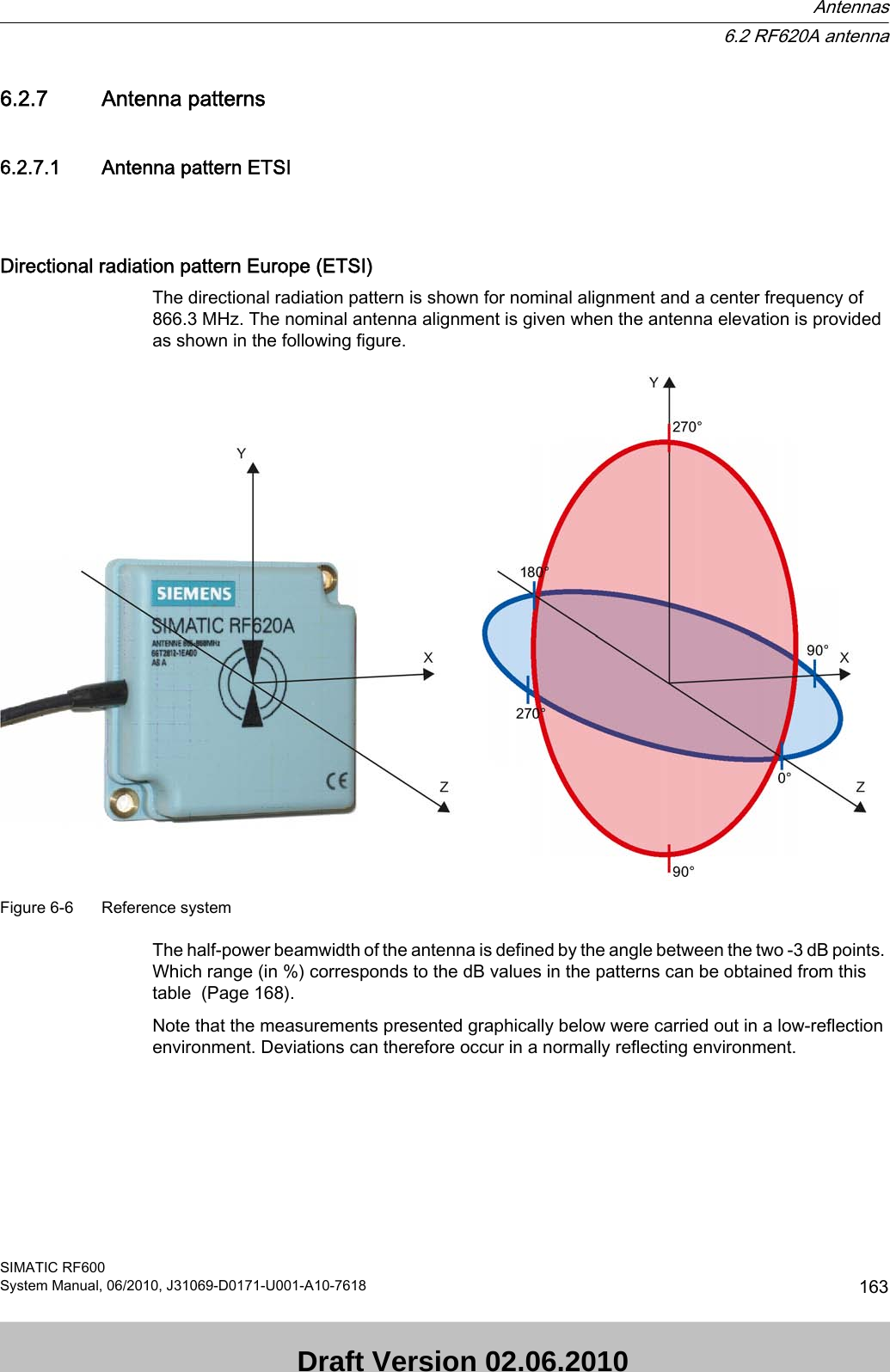
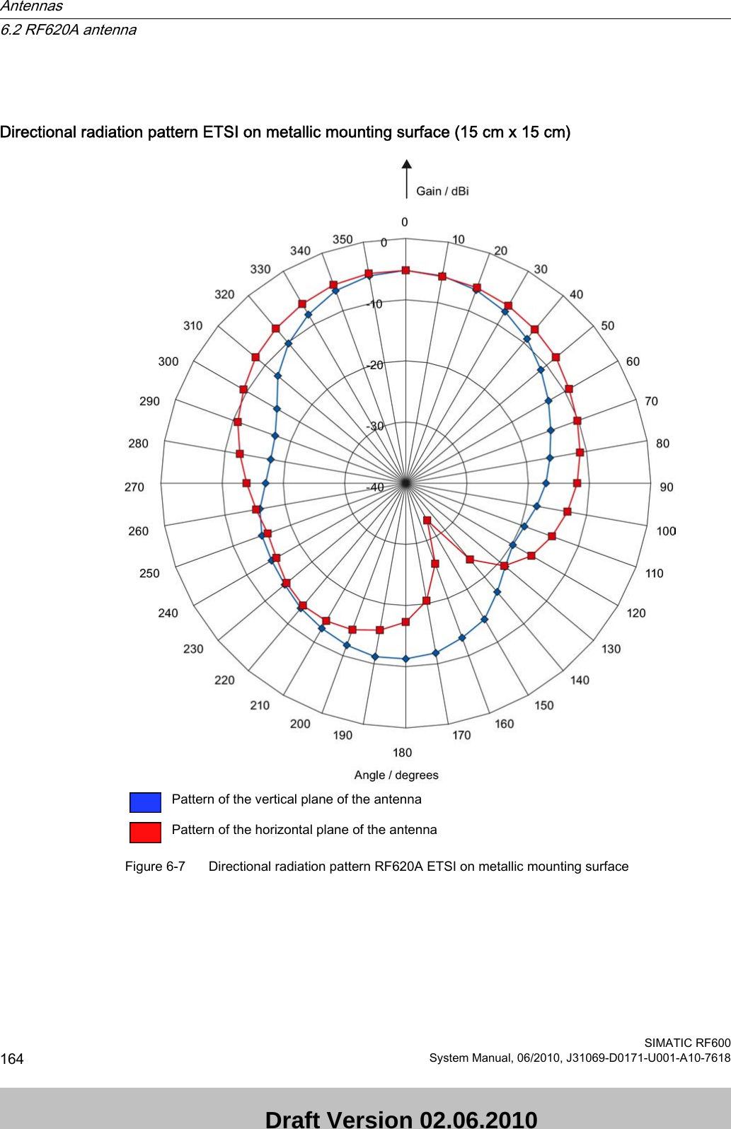
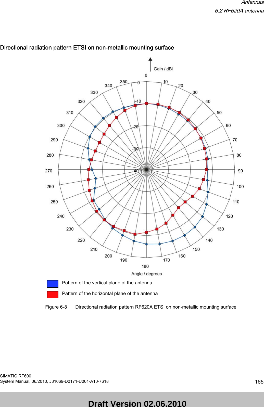
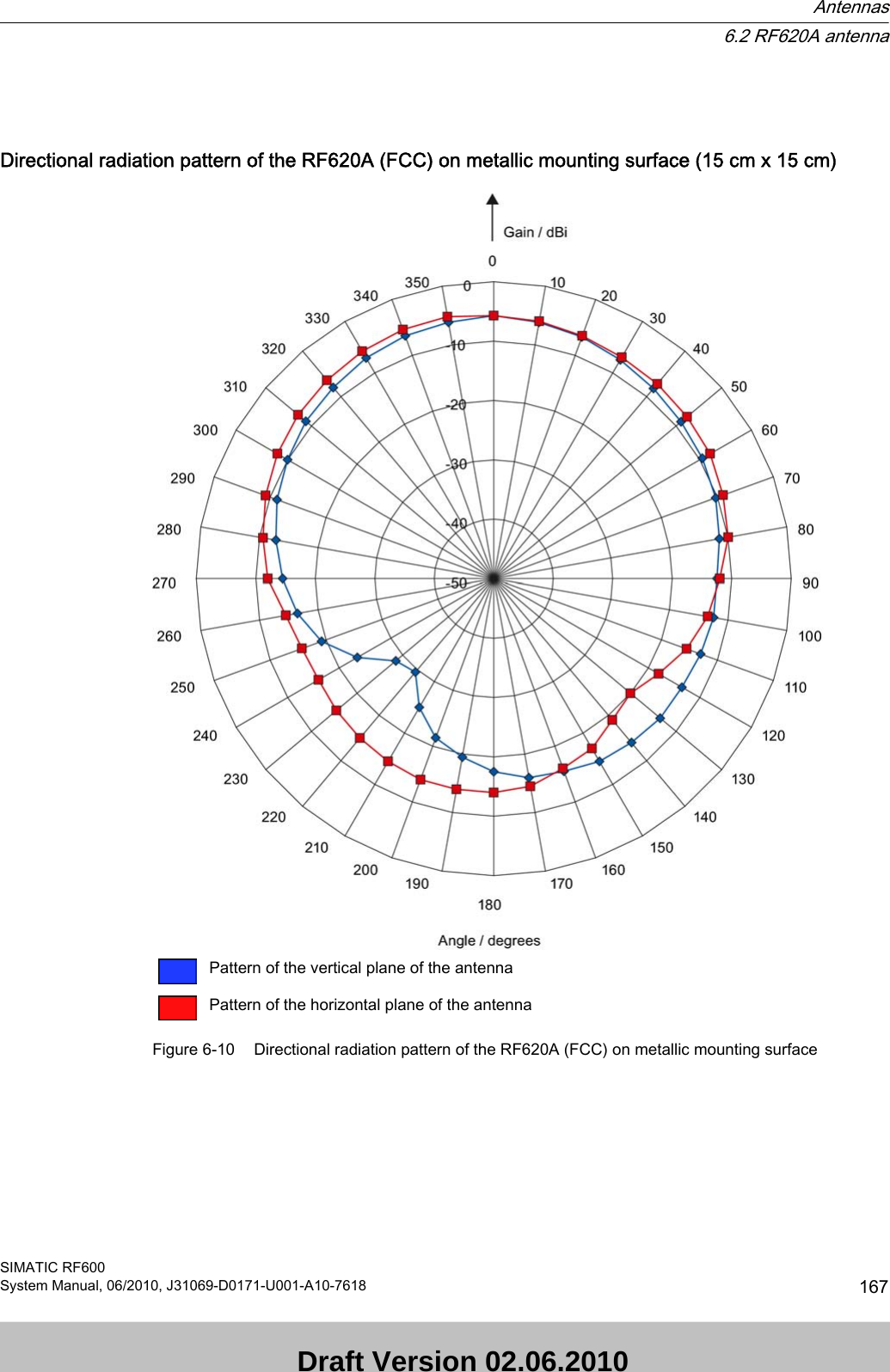
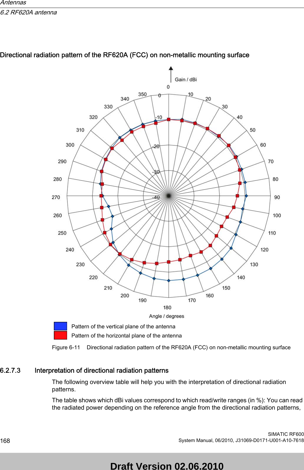
![and thus obtain information on the read/write range with this reference angle with regard to a transponder.The dBr values correspond to the difference between the maximum dBi value and a second dBi value.Deviation from maximum antenna gain [dBr] Read/write range [%]0100-3 70-6 50-9 35-12 25-15 18-18 13ExampleAs one can see from the Antenna pattern ETSI (Page 163), the maximum antenna gain is -5 dBi. In the vertical plane, the antenna gain has dropped to approx. -11 dBi at +40° and 320°. Therefore the dBr value is -6. The antenna range is only 50% of the maximum range at ± 40° from the Z axis within the vertical plane (see values shown in blue in the directional radiation pattern: characteristic of the vertical plane of the antenna (Page 163) and the associated representation of the reference system (Page 163)).6.2.8 Read/write rangesThe following tables show the typical read/write ranges of RF600 readers which are connected to the RF620A antenna via the 3 m antenna cable (1 dB loss) and various types of tags. NotePlease note that tolerances of ±20% are admissible due to production and temperature conditions. When using other antenna cables, the ranges listed here are reduced as a result of the higher antenna cable losses in the following manner:Cable designation Order No. Length [m] Cable loss [dB] Read/write range [%]Antenna cable 6GT2815-0BH30 3 1 100Antenna cable 6GT2815-1BN10 10 2 90Antenna cable 6GT2815-0BN10 10 4 70Antenna cable 6GT2815-0BN20 20 4 70The measuring tolerances in the following tables are ±3 cm.Antennas6.2 RF620A antennaSIMATIC RF600System Manual, 06/2010, J31069-D0171-U001-A10-7618 169 Draft Version 02.06.2010](https://usermanual.wiki/Siemens/RF670.User-Manual-I/User-Guide-1324839-Page-171.png)
![Read distances RF630RTable 6-3 Read distances RF630RTransponder Connection to RF630RRF620A ETSI on metal [cm]RF620A ETSI on non-metal [cm]RF620A FCC on metal [cm]RF620A FCC on non-metal [cm]RF630L (6GT2810-2AB00, -2AB01, -2AB02)90 1) 70 1) 60 1) 50 1)RF630L (6GT2810-2AB03)55 50 55 45RF680L 55 50 55 45RF610T 55 50 55 45RF620T 55 45 70 60RF630T 25 2) 20 2) 35 2) 25 2)RF640T Gen 2 55 2) 45 2) 40 2) 35 2)RF680T 60 50 90 701) Transponder mounted on cardboard2) Transponder mounted on metalWrite distances RF630RTable 6-4 Write distances RF630RTransponder Connection to RF630RRF620A ETSI on metal [cm]RF620A ETSI on non-metal [cm]RF620A FCC on metal [cm]RF620A FCC on non-metal [cm]RF630L (6GT2810-2AB00, -2AB01, -2AB02)45 1) 40 1) 35 1) 30 1)RF630L (6GT2810-2AB03)35 30 20 25RF680L 35 30 20 25RF610T 35 30 20 25RF620T 30 30 40 35RF630T 15 2) 5 2) 15 2) 10 2)RF640T Gen 2 35 2) 20 2) 20 2) 15 2)RF680T 40 30 40 351) Transponder mounted on cardboard2) Transponder mounted on metalAntennas6.2 RF620A antennaSIMATIC RF600170 System Manual, 06/2010, J31069-D0171-U001-A10-7618 Draft Version 02.06.2010](https://usermanual.wiki/Siemens/RF670.User-Manual-I/User-Guide-1324839-Page-172.png)
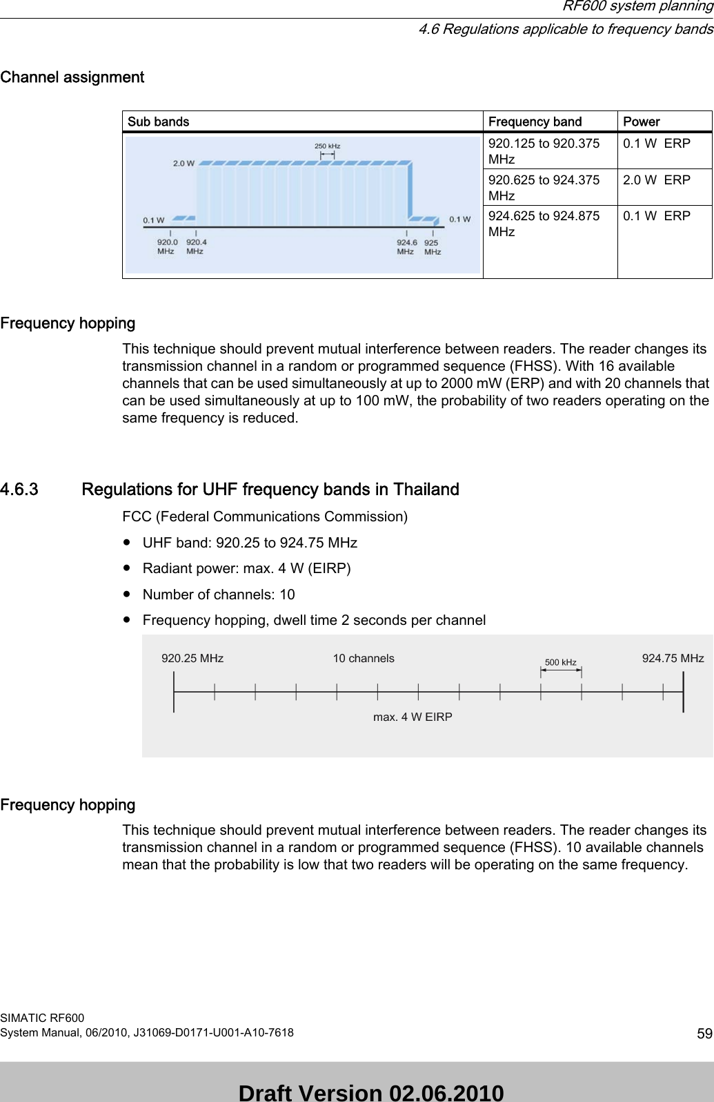
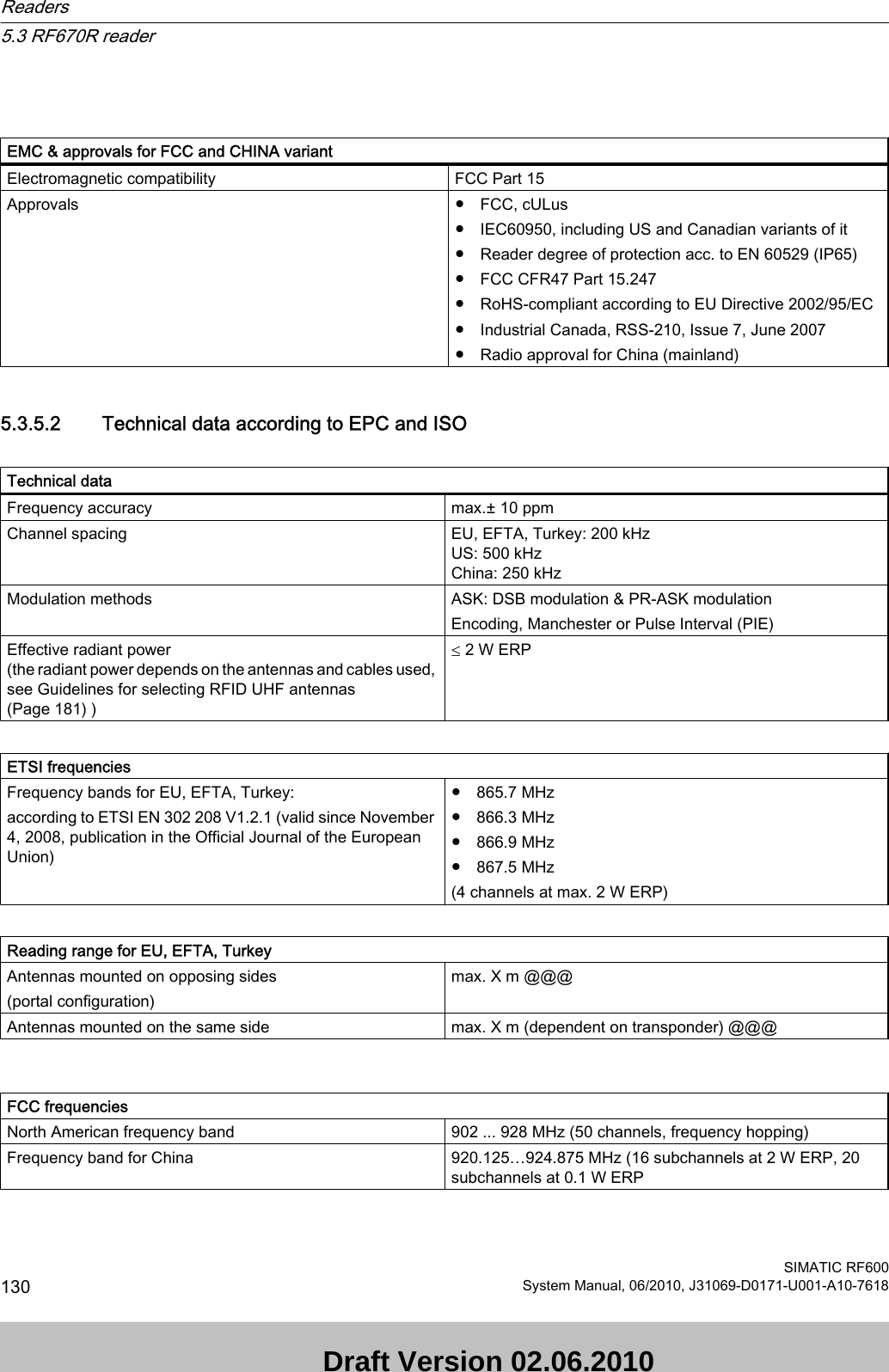
![Reading ranges for RF670R @@@ insert valuesTable 6-5 Reading ranges for RF670RTransponder Connection to RF670RRF620A ETSI on metal [cm]RF620A ETSI on non-metal [cm]RF620A FCC on metal [cm]RF620A on non-metal [cm]RF630L (6GT2810-2AB00, -2AB01, -2AB02) RF630L (6GT2810-2AB03) RF680L RF610T RF620T RF630T RF640T RF640T Gen 2 RF680T 1) Transponder mounted on cardboard2) Transponder mounted on metalWriting ranges for RF670R @@@ insert valuesTable 6-6 Writing ranges for RF670RTransponder Connection to RF670RRF620A ETSI on metalRF620A ETSI on non-metalRF620A FCC on metalRF620A on non-metalRF630L (6GT2810-2AB00, -2AB01, -2AB02) RF630L (6GT2810-2AB03) RF680L RF610T RF620T RF630T RF640T RF640T Gen 2 RF680T 1) Transponder mounted on cardboard2) Transponder mounted on metalAntennas6.2 RF620A antennaSIMATIC RF600System Manual, 06/2010, J31069-D0171-U001-A10-7618 171 Draft Version 02.06.2010](https://usermanual.wiki/Siemens/RF670.User-Manual-I/User-Guide-1324839-Page-173.png)
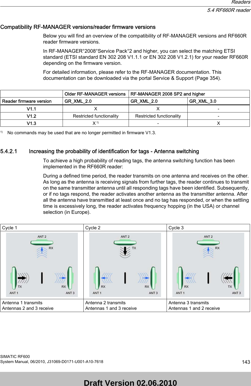
![Read distances RF660RTable 6-7 Read distances RF660RTransponder Connection to RF660RRF620A ETSI on metal [cm]RF620A ETSI on non-metal [cm]RF620A FCC on metal [cm]RF620A on non-metal [cm]RF630L (6GT2810-2AB00, -2AB01, -2AB02)135 1) 120 1) 100 1) 90 1)RF630L (6GT2810-2AB03)85 70 75 65RF680L 85 70 75 65RF610T 85 70 75 65RF620T 85 85 95 95RF630T 40 2) 35 2) 50 2) 35 2)RF640T 40 2) 35 2) 40 2) 30 2)RF640T Gen 2 90 2) 70 2) 70 2) 50 2)RF680T 90 90 135 951) Transponder mounted on cardboard2) Transponder mounted on metalWrite distances RF660RTable 6-8 Write distances RF660RTransponder Connection to RF660RRF620A ETSI on metalRF620A ETSI on non-metalRF620A FCC on metalRF620A on non-metalRF630L (6GT2810-2AB00, -2AB01, -2AB02)110 1) 90 1) 55 1) 50 1)RF630L (6GT2810-2AB03)75 70 60 55RF680L 75 70 60 55RF610T 75 70 60 55RF620T 60 55 60 45RF630T 30 2) 25 2) 35 2) 25 2)RF640T 35 2) 30 2) 25 2) 25 2)RF640T Gen 2 70 2) 60 2) 50 2) 40 2)RF680T 80 75 100 801) Transponder mounted on cardboard2) Transponder mounted on metalAntennas6.2 RF620A antennaSIMATIC RF600172 System Manual, 06/2010, J31069-D0171-U001-A10-7618 Draft Version 02.06.2010](https://usermanual.wiki/Siemens/RF670.User-Manual-I/User-Guide-1324839-Page-174.png)
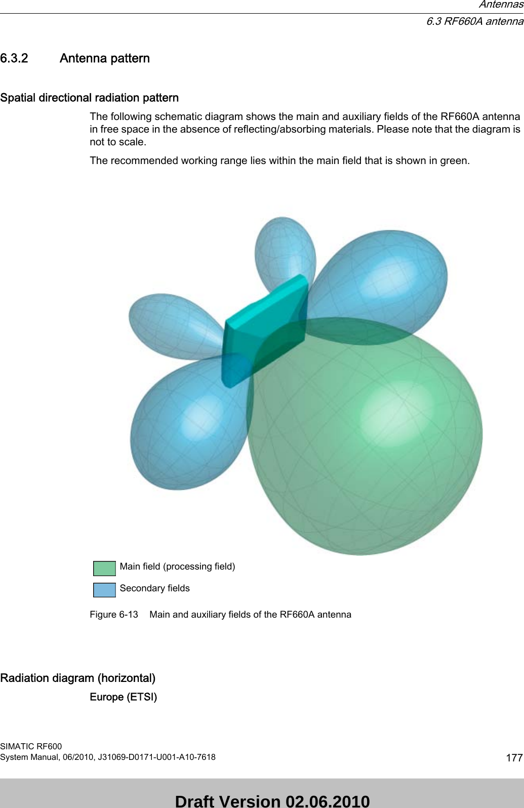
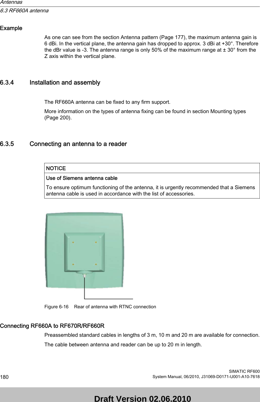
![Figure 6-15 Directional radiation pattern of the antenna (at 915 MHz, horizontal alignment)6.3.3 Interpretation of directional radiation patternsThe following overview table will help you with the interpretation of directional radiation patterns. The table shows which dBi values correspond to which read/write ranges (in %): You can read the radiated power depending on the reference angle from the directional radiation patterns, and thus obtain information on the read/write range with this reference angle with regard to a transponder.The dBr values correspond to the difference between the maximum dBi value and a second dBi value.Deviation from maximum antenna gain [dBr] Read/write range [%]0100-3 70-6 50-9 35-12 25-15 18-18 13Antennas6.3 RF660A antennaSIMATIC RF600System Manual, 06/2010, J31069-D0171-U001-A10-7618 179 Draft Version 02.06.2010](https://usermanual.wiki/Siemens/RF670.User-Manual-I/User-Guide-1324839-Page-181.png)