Siemens RF670 RFID UHF Reader User Manual SIMATIC RF600
Siemens AG RFID UHF Reader SIMATIC RF600
Siemens >
Contents
- 1. User Manual I
- 2. User Manual II
User Manual II
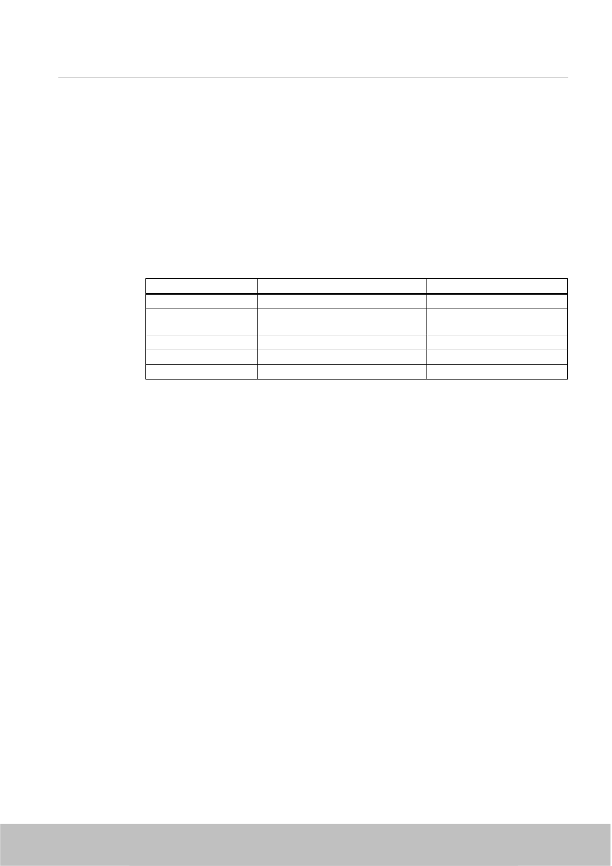
Procedure
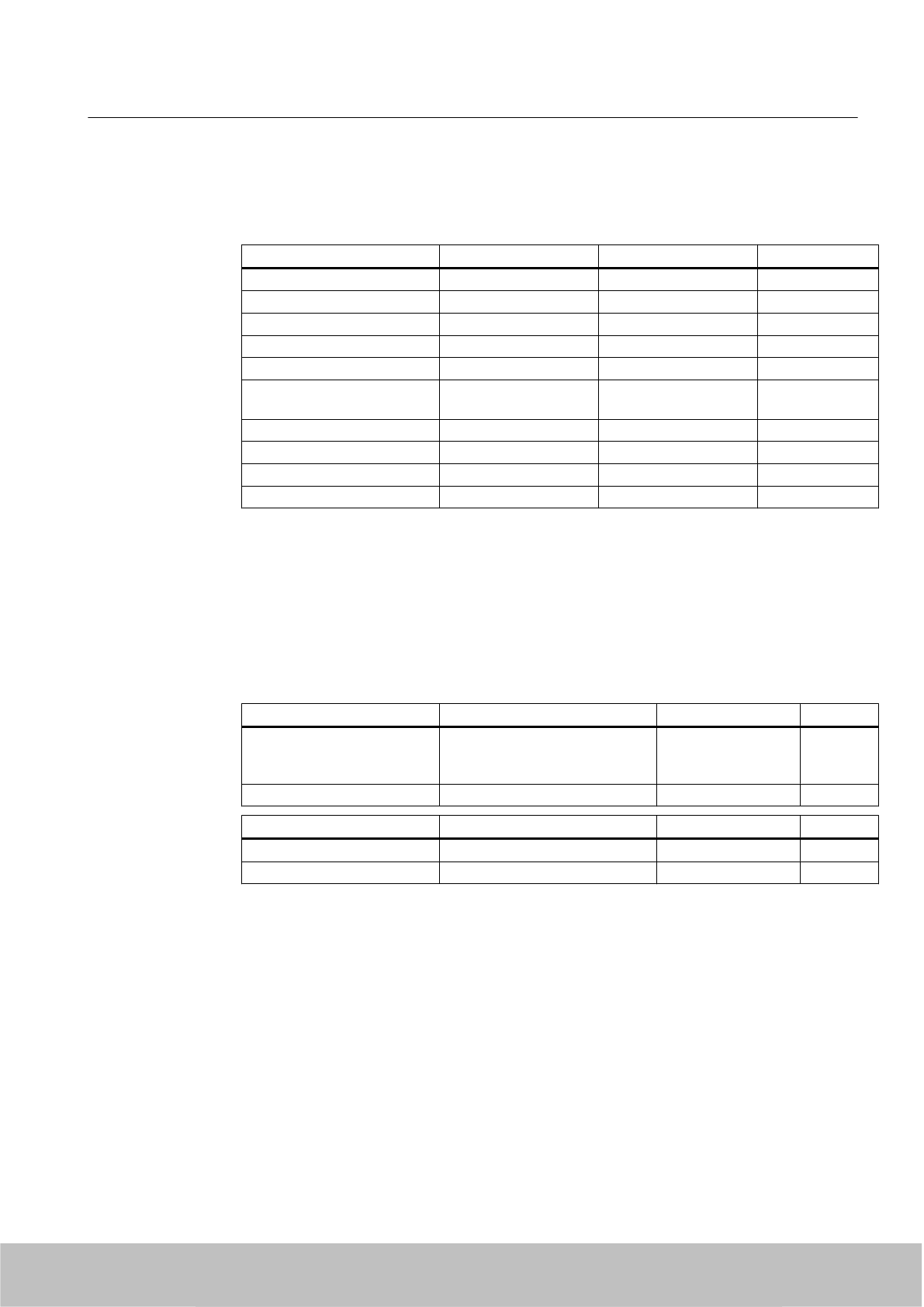
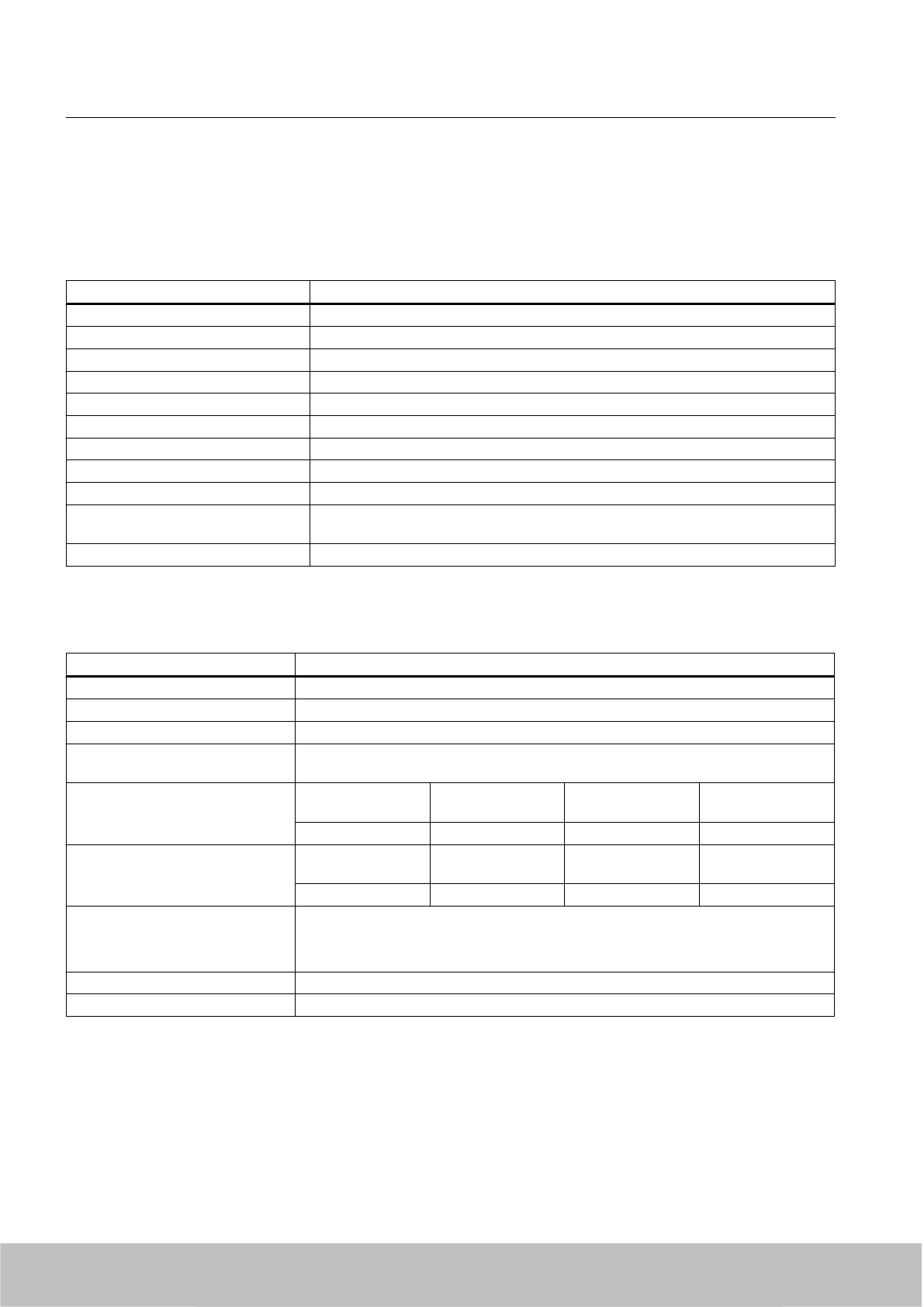
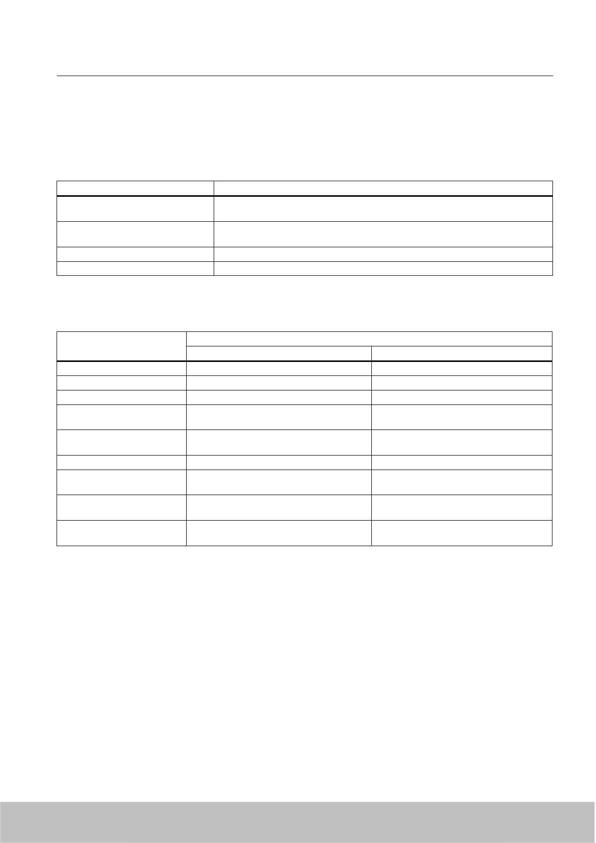
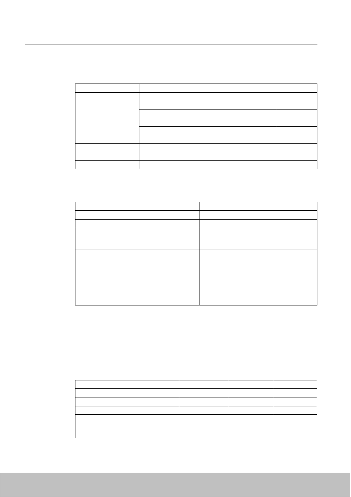
1. Compare the technical specifications of your antenna with the values required by the
SIMATIC RF600 system.
Values Example antenna Required values OK?
Frequency band 865 to 870 MHz 865 to 868 MHz OK
Impedance 50 Ohm 50 Ohm OK
VSWR <1,5 <1,24 Not OK
Polarization Circular, right OK
Antenna gain 8.5 dBi >6 dBi OK
Beam width
horizontal/vertical
63° ≤70° OK
Front-to-back ratio -18 dB ≥10 dB OK
Spurious lobe suppression -16 dB ≥10 dB OK
Axial ratio 2 dB ≤3 dB OK
Maximum power 6 W ≥4 W OK
Since the specific VSWR value of the antenna does not agree with the value required by
the system, you must have this value checked. Therefore contact your antenna vendor or
an EMC laboratory.
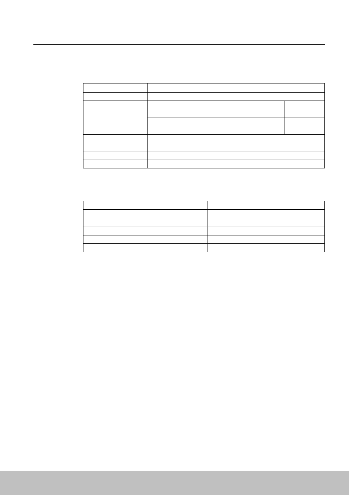
2. Compare the technical specifications of your cables and connectors with the values
required by the system.
For example, you can use cables of type "LMR-195" from the company "TIMES
MICROWAVE SYSTEMS". Suitable cables have e.g. an outer diameter of 5 mm. The
company offers various designs of cables depending on the requirements. Numerous
connectors are also available for their cables.
Values Example cable Required values OK?
Cable attenuation 36.5 dB / 100 m at 900 MHz
With an assumed length of 10 m,
this results in a loss of 3.65 dB.
≤4 dB OK
Impedance 50 Ohm 50 Ohm OK
Values Example connector OK?
Type of plug on reader side R-TNC socket R-TNC plug OK
Type of plug on antenna side N socket N plug OK
Antennas
6.4 Guidelines for selecting RFID UHF antennas
SIMATIC RF600
System Manual, 06/2010, J31069-D0171-U001-A10-7618 199
Draft Version 02.06.2010

3. Parameterize the following values depending on the used reader (see section Overview of
parameterization of RF600 reader (Page 198)):
–Parameterize the RF660R via configuration software
Antenna gain: 8.5 dBi
Cable loss: 4 dB (due to adaptation and damping losses of the connectors)
–Parameterize the RF660R via the XML command "antennaConfig"
In the XML command "antenneConfig", the following must be set for the antenna port
that is used:
(antenna number="1 ... 4"), antenna gain (gain="8.5") and cable loss (cableLoss="4.0").
Cable loss: 4 dB (due to adaptation and damping losses of the connectors)
–Parameterizing RF630R via SIMATIC commands
Since according to ETSI EN 302 208 V1.2.1 the maximum permissible radiated power
is 2 W ERP, none of the transmitting power settings available to the user
(distance_limiting) can lead to the required maximum permissible radiated power value
being exceeded. The exact radiated power of the reader, together with the antenna
cables and antenna used, are the result of the value used in distance_limiting 0-F and
the calculation given in Chapter "Radiated power setting with RF630R".
4. in the configuration software of the RF660R reader:
5. You must subsequently have your desired system requirements measured and verified
according to EN 302 308 in an absorber chamber.
You may only use your SIMATIC RF600 system with the new third-party components when
this has been carried out.
6.5 Mounting types
6.5.1 Overview
The following readers and antennas feature a standardized VESA 100 fixing system (4 x M4):
● SIMATIC RF620R/RF630R/RF670R
● SIMATIC RF660A
It is used to fix the above-mentioned antennas in place through a mounting plate or the antenna
mounting kit.
6.5.2 Ordering data
Description Machine-Readable Product Code
Mounting plate (supplied with RF660A)
Antenna mounting kit 6GT2890-0AA00
Antennas
6.5 Mounting types
SIMATIC RF600
200 System Manual, 06/2010, J31069-D0171-U001-A10-7618
Draft Version 02.06.2010
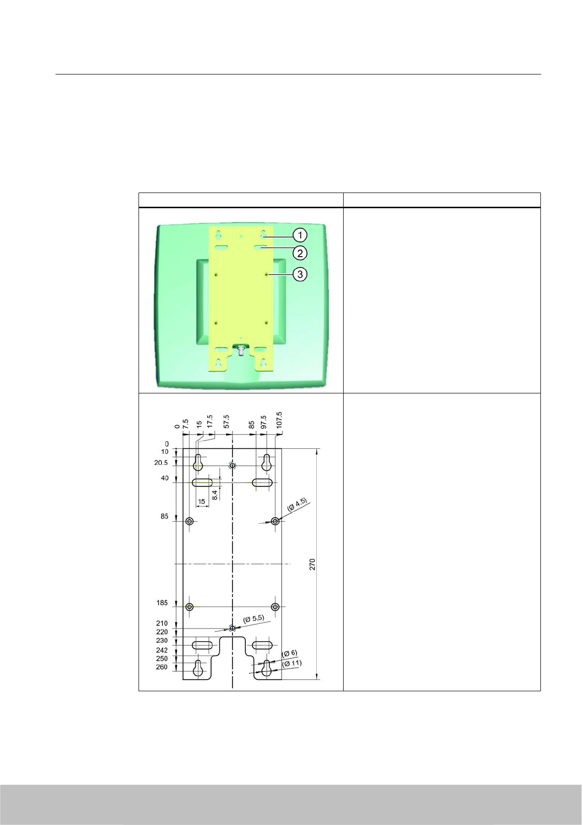
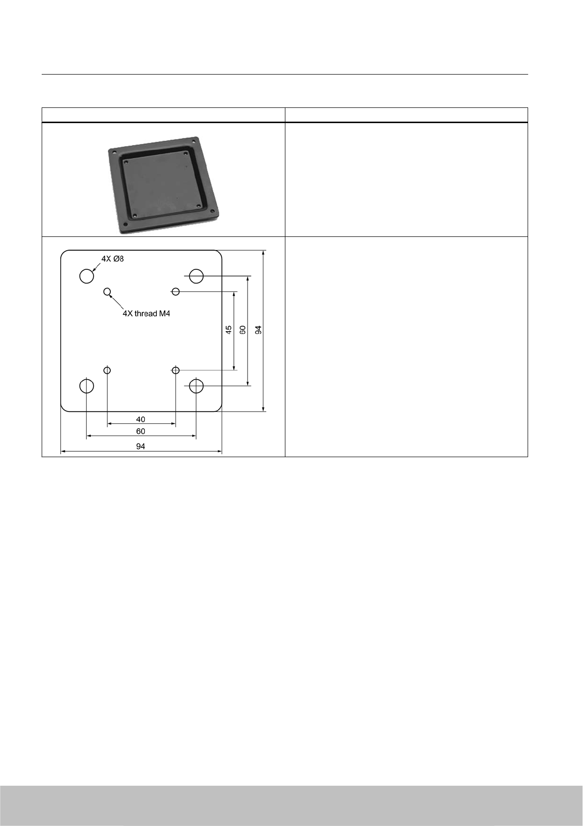
6.5.3 Mounting with antenna mounting plate
Rigid fixing with an antenna mounting plate is suitable for:
● Wall mounting on solid foundations
● Mast mounting
Antenna with antenna mounting plate Description
① Keyhole for wall mounting (4 x)
① Elongated hole for mast mounting (4 x)
③ Standardized VESA 100
fixing holes (4 x M4)
Dimensions for fixing holes
All dimensions in mm
Antennas
6.5 Mounting types
SIMATIC RF600
System Manual, 06/2010, J31069-D0171-U001-A10-7618 201
Draft Version 02.06.2010
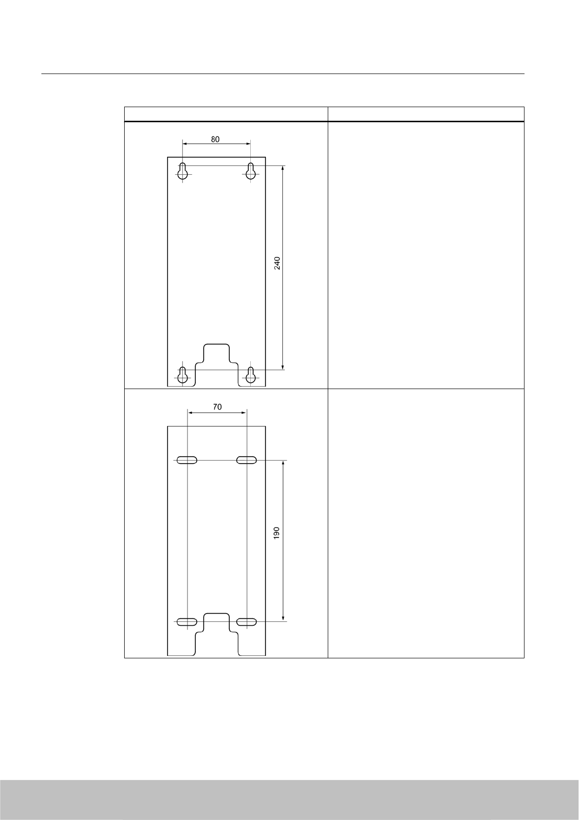
Antenna with antenna mounting plate Description
Template for wall fixing for
M6 bolts
(hexagon bolts are required)
Template for mast mounting
Mast diameter 60 to 80 mm
Antennas
6.5 Mounting types
SIMATIC RF600
202 System Manual, 06/2010, J31069-D0171-U001-A10-7618
Draft Version 02.06.2010
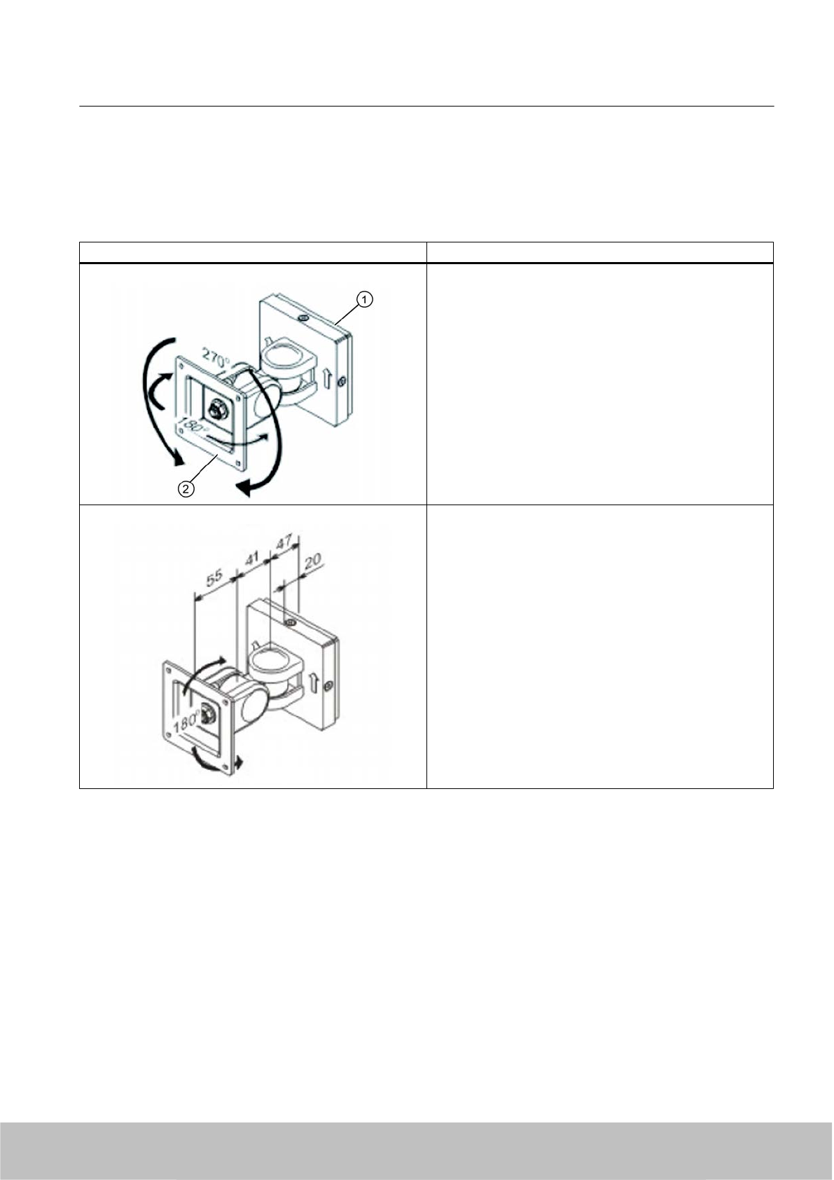
6.5.4 Mounting with antenna mounting kit
Flexible mounting is possible using the antenna mounting kit.
An antenna can then be rotated through any angle in space.
Antenna mounting kit Description
Swivel range of wall mounting
(1) Wall side
(2) Antenna side
Distances for wall mounting
Antennas
6.5 Mounting types
SIMATIC RF600
System Manual, 06/2010, J31069-D0171-U001-A10-7618 203
Draft Version 02.06.2010
Antenna mounting kit Description
VESA adapter plate
from VESA 75 x 75
to VESA 100 x 100
The VESA adapter plate is required for fixing the antenna to
the antenna mounting kit.
Hole drilling template for fixing the antenna mounting kit to
the wall
Antennas
6.5 Mounting types
SIMATIC RF600
204 System Manual, 06/2010, J31069-D0171-U001-A10-7618
Draft Version 02.06.2010
Transponder/tags 7
7.1 Overview
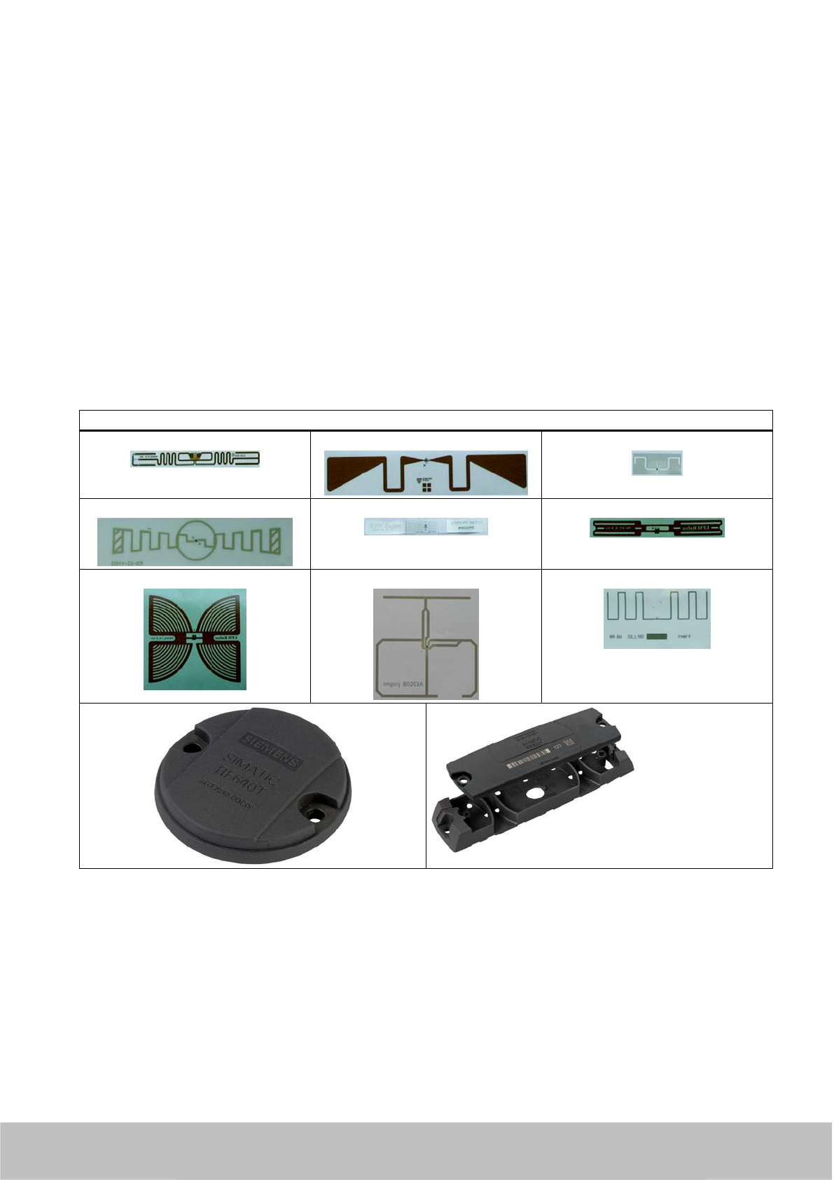
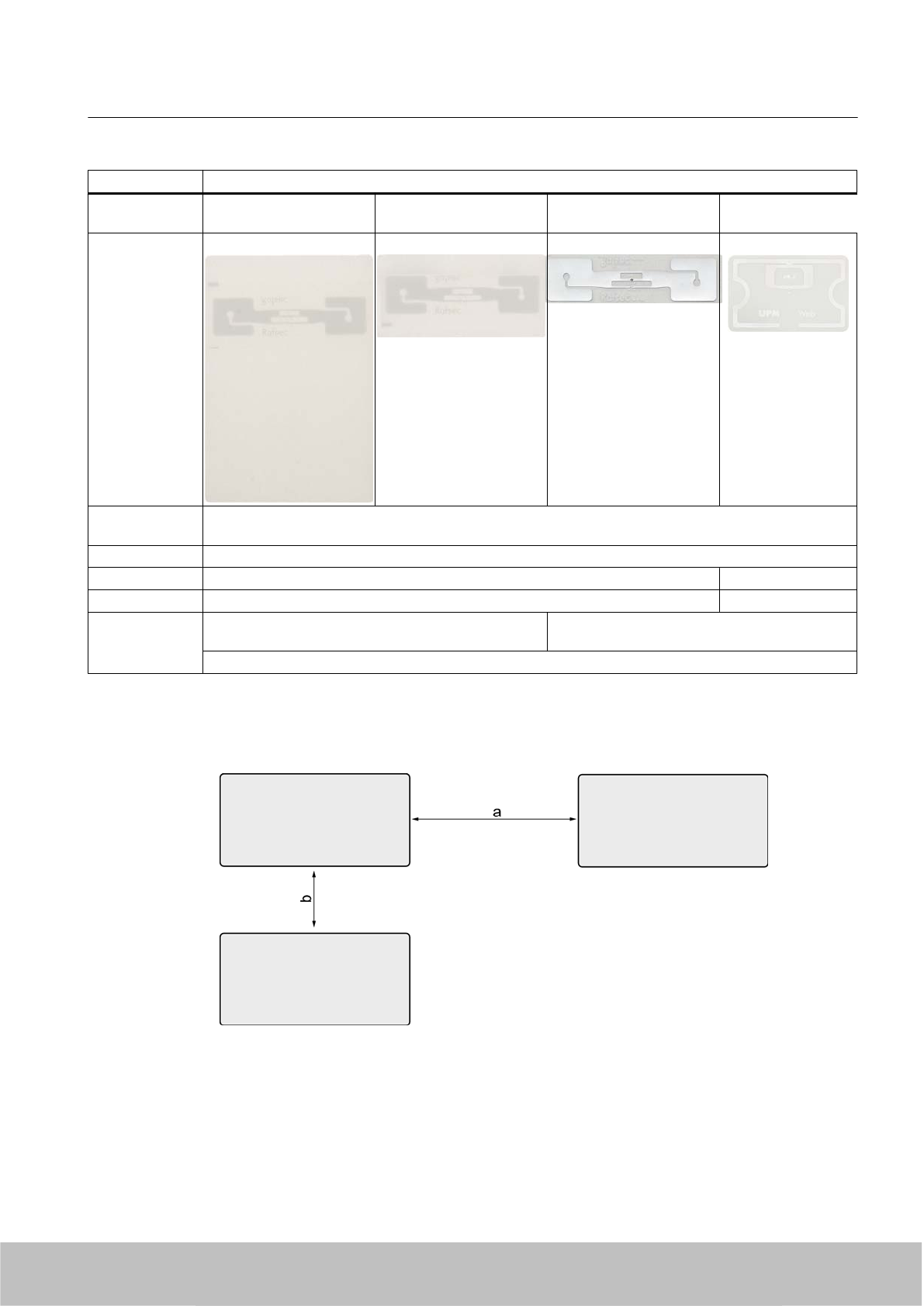
7.1.1 Tags in different sizes and types
Tags/transponders and labels are available in a variety of shapes, sizes and materials. The
pictures below show some examples of tags and labels in different designs.
Tags in different sizes and types
7.1.2 Mode of operation of transponders/tags
The tag/transponder mainly comprises a microchip with an integral memory and a dipole
antenna.
The principle of operation of a passive RFID transponder is as follows:
SIMATIC RF600
System Manual, 06/2010, J31069-D0171-U001-A10-7618 205
Draft Version 02.06.2010
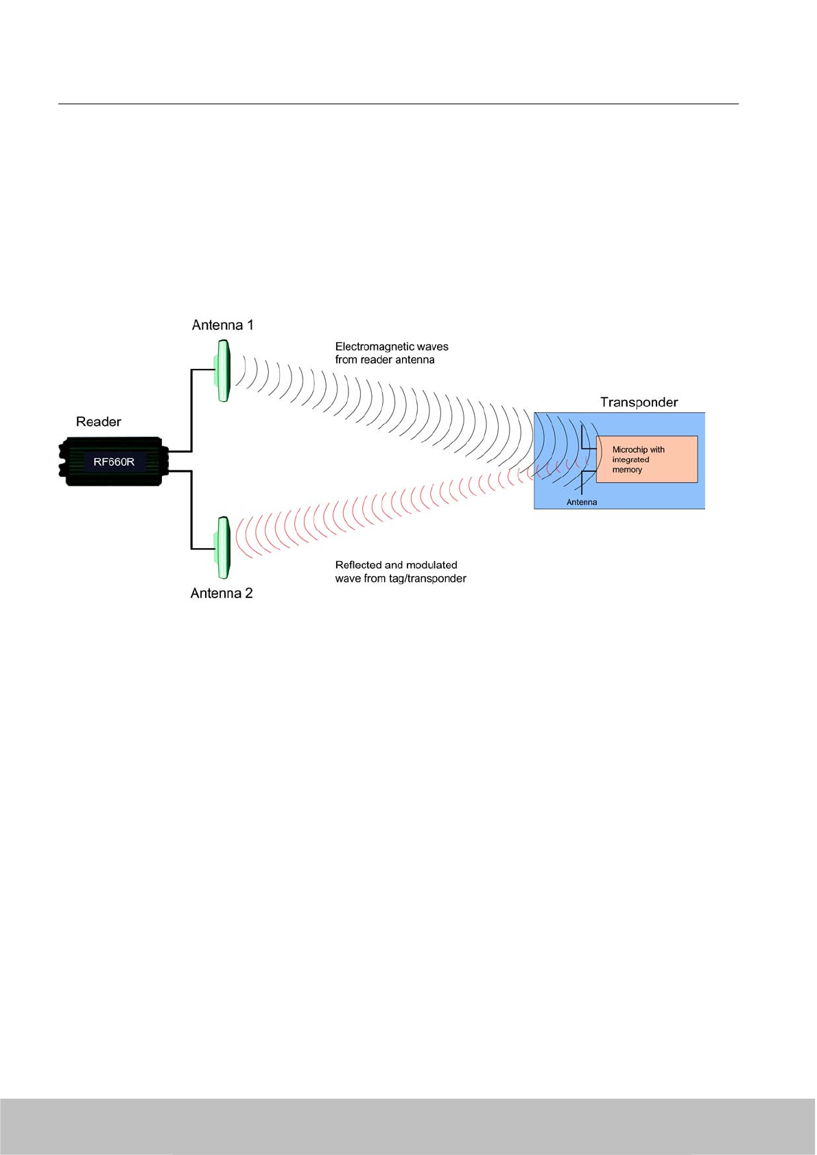
● Diversion of some of the high-frequency energy emitted by the reader to supply power to
the integral chip
● Commands received from reader
● Responses are transmitted to the reader antenna by modulating the reflected radio waves
(backscatter technique)
Figure 7-1 Mode of operation of transponders
The transmission ranges achieved vary in accordance with the size of the tag and the
corresponding dipole antenna. In general the following rule applies: The smaller the tag and
therefore the antenna, the shorter the range.
7.1.3 Transponder classes and generations
The transponder classes are distinguished by the different communication protocols used
between the reader and transponder. Transponder classes are mostly mutually incompatible.
The following transponder classes are supported by the RF 600 system:
● ISO 18000-6B with full ISO profile (RF660R, RF610M)
● EPC Global Class 1, Gen 1 with full EPC Global Profile (RF660R, RF610M)
● EPC Global Class 1 Gen 2 with full EPC Global Profile (ISO 18000-6C)
Transponder/tags
7.1 Overview
SIMATIC RF600
206 System Manual, 06/2010, J31069-D0171-U001-A10-7618
Draft Version 02.06.2010
Support for protocol types using the RF600
Specification of the transponders/tags in accordance with ISO 18000-6 refers to
implementation of the air-interface protocols.
There are three variants:
● ISO 18000-6A: Not supported
● ISO 18000-6B: Supported by RF660R, RF610M
● ISO 18000-6C: Supported by RF670R, RF660R, RF620R, RF630R, RF610M
This variant is identical with EPC Global Class°1 Gen°2 standard.
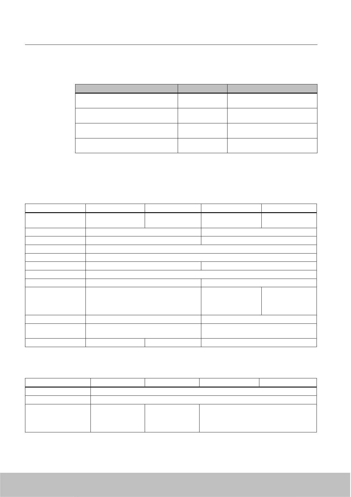
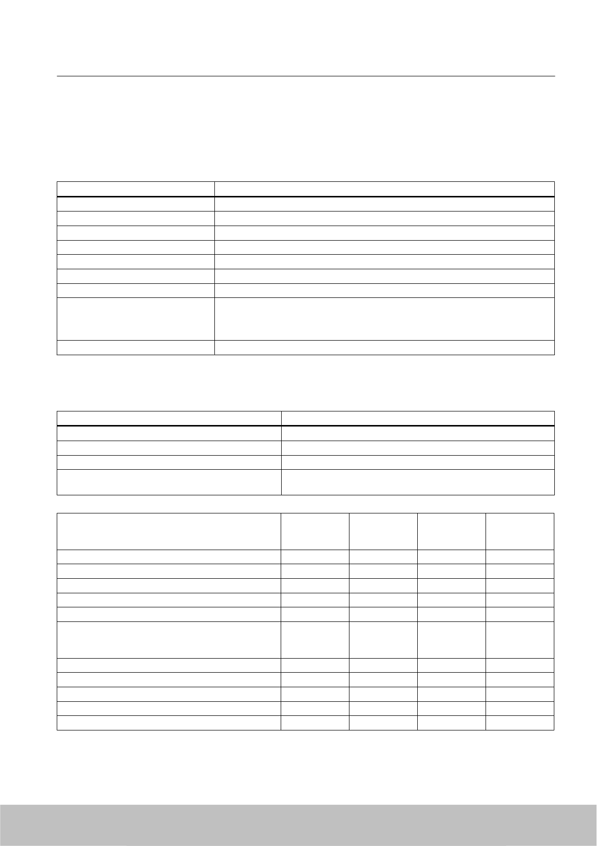
Table 7-1 Comparison of the ISO 18000-6B and ISO 18000-6A protocol types
Type B Type A
Frequency band 860 to 960 MHz 860 to 960 MHz
Transmission procedure Bi-phase modulation and Manchester
encoding
Pulse Interval Encoding (PIE)
Anti-collision techniques Adaptive binary tree technique ALOHA technique
Protocol Reader talks first Reader talks first
Supported in RF600 By RF660R/RF610M No
Transponder/tags
7.1 Overview
SIMATIC RF600
System Manual, 06/2010, J31069-D0171-U001-A10-7618 207
Draft Version 02.06.2010

EPC Global
EPC Class Definition Programming Supported in
RF600
Class 1 Passive tags with the following minimum
features:
● EPC ID (Electronic Product Code
IDentifier)
● Tag ID
● A function which permanently
ensures that tags no longer respond.
●Optional use or suppression of tags
● Optional password-protected access
control
● Optional USER memory area.
Programming by the customer
(cannot be reprogrammed
after locking)
Yes
Class 2 Passive tags with the following additional
features (in comparison with Class 1
tags):
● Extended tag ID,
● Extended USER memory area
● Authenticated ACCESS access
●Additional features
Freely programmable No
Class 3 Passive tags with the following additional
features (in comparison with Class 2
tags):
● Source of energy that supplies power
to the tag or its sensors
● Sensors with optional data logging
No
Class 4 Active tags with the following features:
● EPC ID (Electronic Product Code
IDentifier)
● Extended tag ID
● Authenticated ACCESS access
●A source of energy
● Communication using an
autonomous transmitter
● Optional USER memory area.
● Optional sensors with or without
optional data logging
No
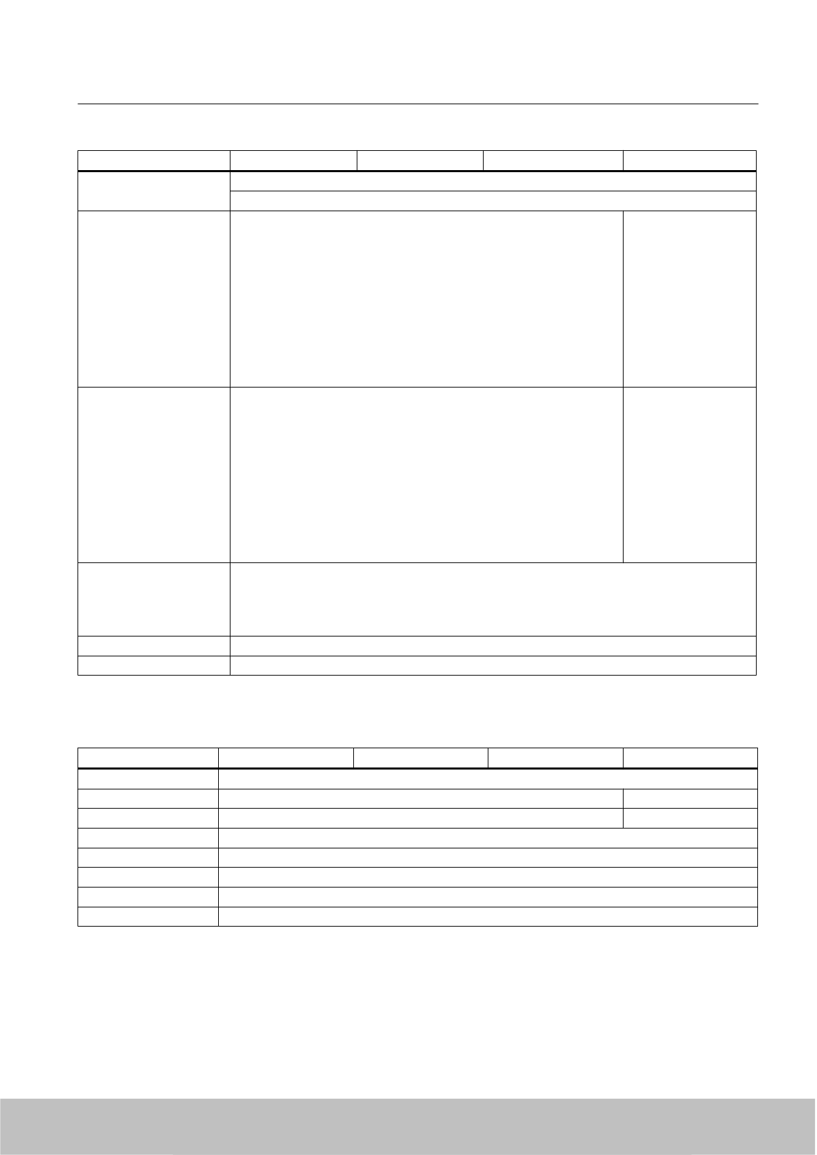
Table 7-2 Comparison of EPC Class 1 Gen 1 and Class 1 Gen 2
Property Class 1 Gen 1 Class 1 Gen 2 =
ISO 18000-6 C
Frequency 860-930 MHz 860-960 MHz
Memory capacity 64 or 96 bits 96-256 bits
Can be programmed on site Yes Yes
Transponder/tags
7.1 Overview
SIMATIC RF600
208 System Manual, 06/2010, J31069-D0171-U001-A10-7618
Draft Version 02.06.2010
Property Class 1 Gen 1 Class 1 Gen 2 =
ISO 18000-6 C
Programming written once; read many times Yes
Other Features _ Reading is faster and more reliable
than for Generation 1.
Enhanced compliance with global
standards.
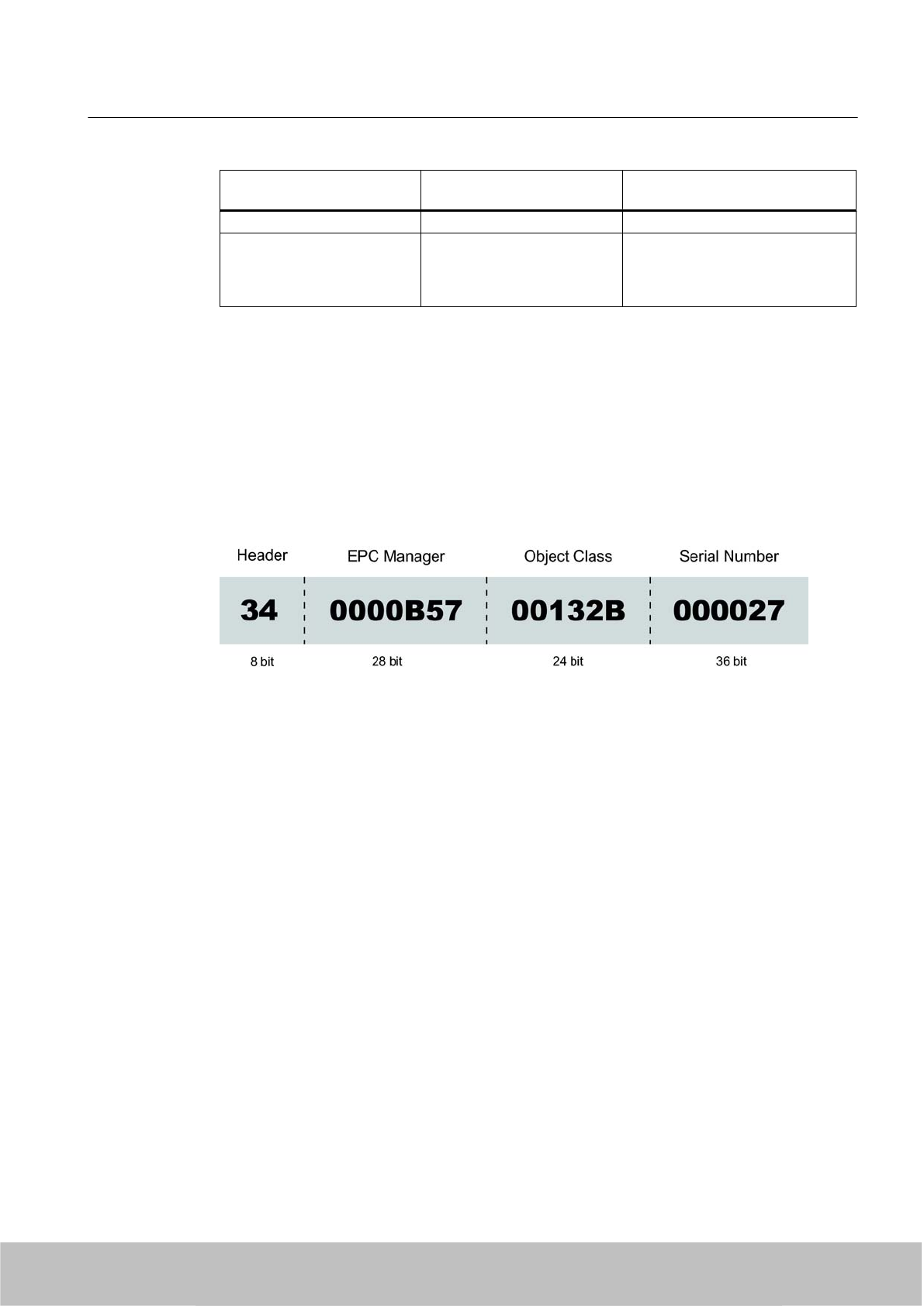
7.1.4 Electronic Product Code (EPC)
The Electronic Product Code (EPC) supports the unique identification of objects (e.g. retail
items, logistical items or transport containers). This makes extremely accurate identification
possible. In practical use, the EPC is stored on a transponder (tag) and scanned by the reader.
There are different EPC number schemes with different data lengths. Below is the structure
of a GID-96-bit code (EPC Global Tag Data Standards V1.1 Rev. 1.27) :
●Header: This identifies the EPC identification number that follows with regard to length,
type, structure and version of the EPC
●EPC manager: This identifies the company/corporation
●Object class: Corresponds to the article number
●Serial number: Consecutive number of the article
The Siemens UHF transponders are all suitable for working with EPC and other number
schemes. Before a transponder can work with a number scheme, the relevant numbers must
first be written to the transponder.
Transponder/tags
7.1 Overview
SIMATIC RF600
System Manual, 06/2010, J31069-D0171-U001-A10-7618 209
Draft Version 02.06.2010
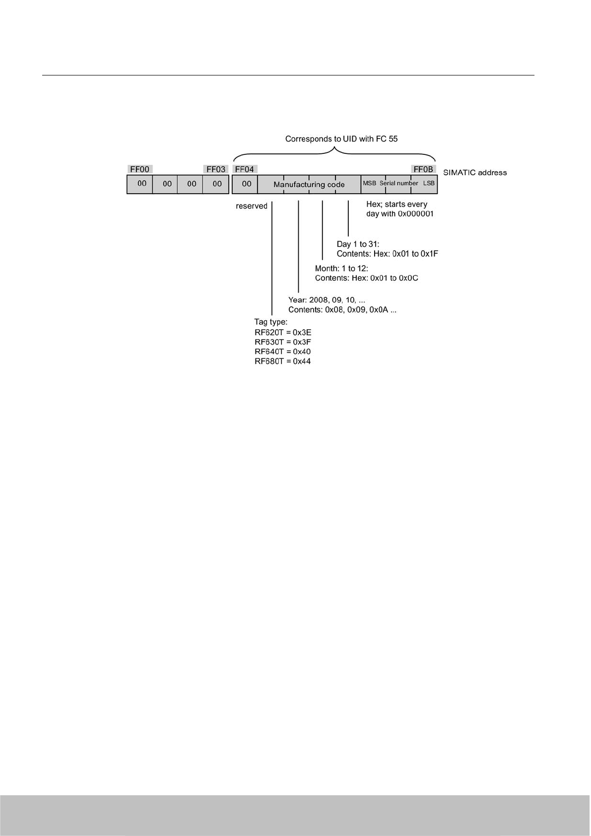
Allocation of the ECP ID by the tag manufacturer
Figure 7-2 Allocation of the EPC ID on delivery of the tag
7.2 SIMATIC RF630L Smartlabel
7.2.1 Features
SIMATIC RF630L smart labels are passive, maintenance-free data carriers based on
UHF Class 1 Gen2 technology that are used to store the "Electronic Product Code" (EPC).
Smart labels offer numerous possible uses for a wide range of applications and support efficient
logistics throughout the process chain.
Transponder/tags
7.2 SIMATIC RF630L Smartlabel
SIMATIC RF600
210 System Manual, 06/2010, J31069-D0171-U001-A10-7618
Draft Version 02.06.2010
SIMATIC RF630L transponder
6GT2810-2AB0
0
6GT2810-2AB01 6GT2810-2AB02 6GT2810-2AB03
Design
Area of
application
Simple identification such as barcode replacement or supplementation, through warehouse and
distribution logistics, right up to product identification.
Memory EPC 96 bits
Write range 0.2 m to 5 m 0.2 m to 5 m
Reading range 0.2 m to 8 m 0.2 m to 5 m
Mounting Self-adhesive paper labels for attaching to packaging
units, paper or cartons, for example.
Self-adhesive plastic labels for attaching to
packaging units, paper or cartons, for example.
Not suitable for fixing straight onto metal or onto liquid containers
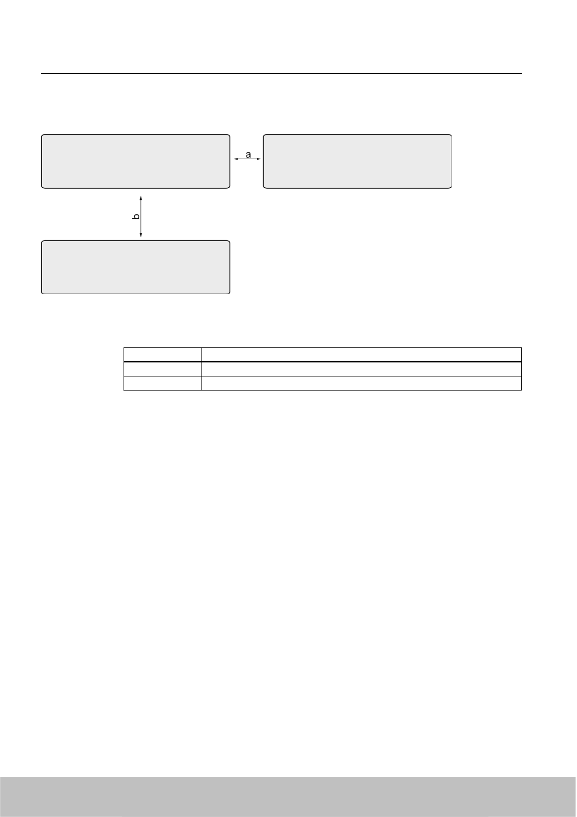
7.2.2 Minimum spacing between labels
Figure 7-3 Minimum spacing between labels
Transponder/tags
7.2 SIMATIC RF630L Smartlabel
SIMATIC RF600
System Manual, 06/2010, J31069-D0171-U001-A10-7618 211
Draft Version 02.06.2010
Table 7-3 Minimum spacing
Minimum spacing 6GT2810-2AB00 6GT2810-2AB01 6GT2810-2AB02 6GT2810-2AB03
a50 mm
b 50 mm
Please note that smart labels can also be attached one above the other. The spacing between
the labels attached one above the other depends on the damping characteristics of the carrier
material.
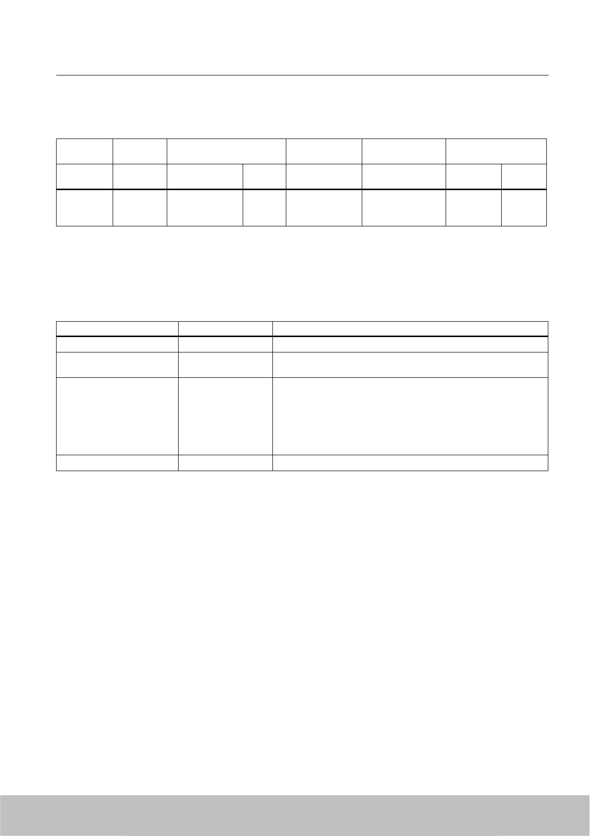
7.2.3 Memory configuration for smart labels with MLFBs -00, -01, -02
Note
Validity of the memory configuration
Please note that the following memory configuration only applies to smart labels with the
following MLFBs:
● 6GT2810-2AB00
● 6GT2810-2AB01
● 6GT2810-2AB02
7.2.4 Memory configuration
Memory banks
The memory is divided logically into three different memory banks:
Memory bank (decimal) Memory type Description
MemBank 102TID Is defined by the manufacturer, contains the class identifier of a tag.
MemBank 012EPC Contains the EPC UID, the protocol and the CRC of a tag
You can write to the EPC memory area. In the delivery condition, the
memory contents can have the following states:
● empty
● containing the same data
● containing different data
MemBank 002RESERVED Contains the access and kill password.
The graphic below illustrates the exact memory utilization: Each box in the right part of the
graphic represents one word (16 bit) in the memory.
Transponder/tags
7.2 SIMATIC RF630L Smartlabel
SIMATIC RF600
212 System Manual, 06/2010, J31069-D0171-U001-A10-7618
Draft Version 02.06.2010
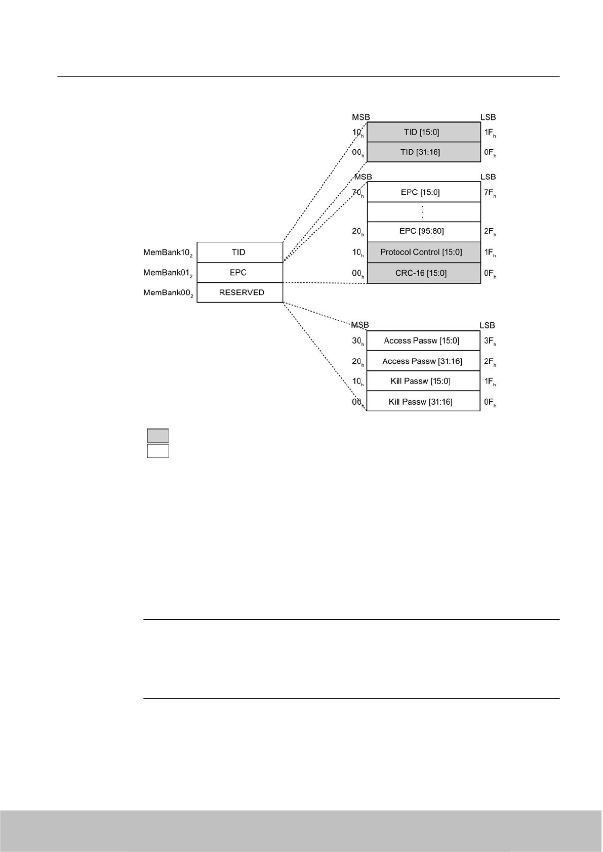
Color Mode of access by SIMATIC RF600 reader
Read
Write / read
Parameterization
The parameterization possibilities that are available to you for each reader of the RF600 family
are outlined in section Overview of parameterization of RF600 reader (Page 325). Detailed
information for parameterization as well as examples for describing and reading specific
memory areas can be found in the referenced chapters of the documentation.
7.2.5 Memory configuration for smart labels with MLFB -03
Note
Validity of the memory configuration
Please note that the following memory configuration only applies to smart labels with the
following MLFB:
● 6GT2810-2AB03
Transponder/tags
7.2 SIMATIC RF630L Smartlabel
SIMATIC RF600
System Manual, 06/2010, J31069-D0171-U001-A10-7618 213
Draft Version 02.06.2010

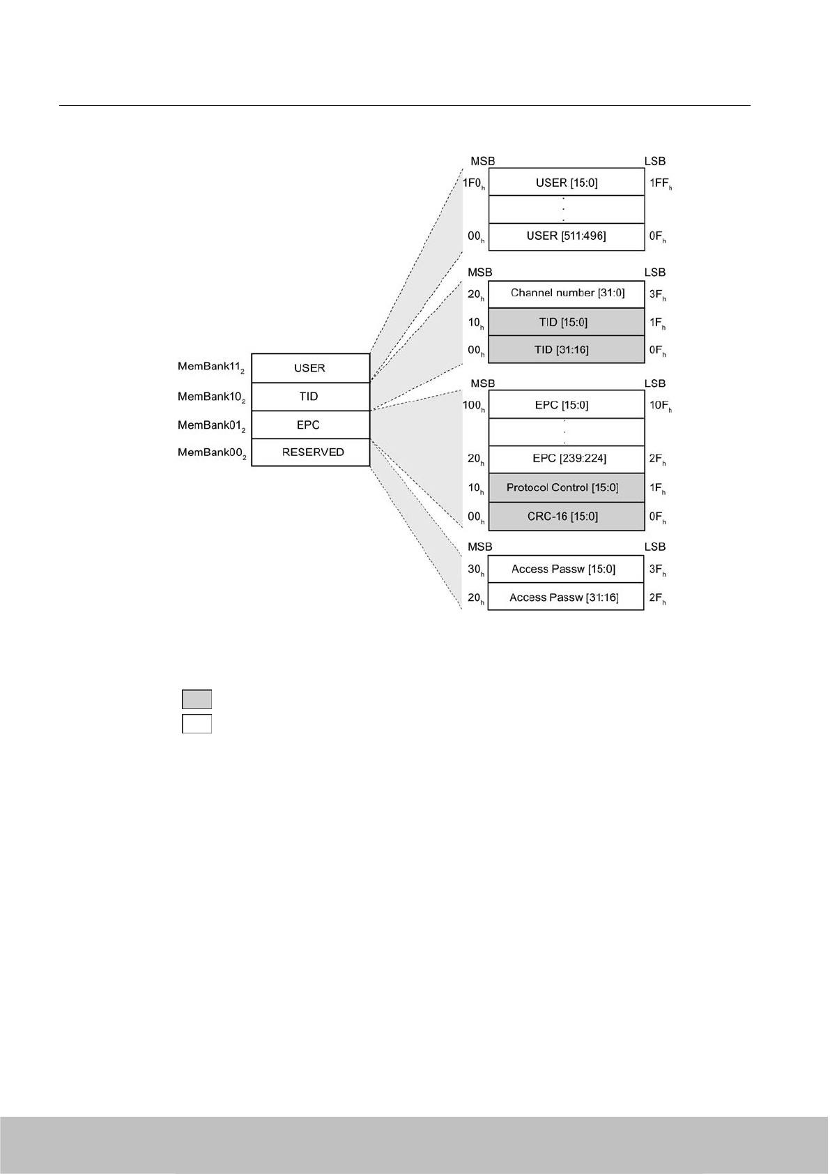
7.2.6 Memory configuration
Memory representation according to EPC
The memory of the ISO 18000-6C G2XM chip is logically divided into four different memory
banks:
Memory bank (decimal) Memory type Description
MemBank 112USER User-writable USER memory area
MemBank 102TID Is defined by the manufacturer, contains the class identifier and serial
number of a tag
MemBank 012EPC Contains the EPC data, the protocol information and the CRC data
of a tag.
You can write to the EPC memory area. In the delivery condition, the
memory contents can have the following states:
● containing the same data
● containing different data
MemBank 002RESERVED Contains the access password.
The graphic below illustrates the exact memory utilization: Each box in the right part of the
graphic represents one word (16 bit) in the memory.
Transponder/tags
7.2 SIMATIC RF630L Smartlabel
SIMATIC RF600
214 System Manual, 06/2010, J31069-D0171-U001-A10-7618
Draft Version 02.06.2010
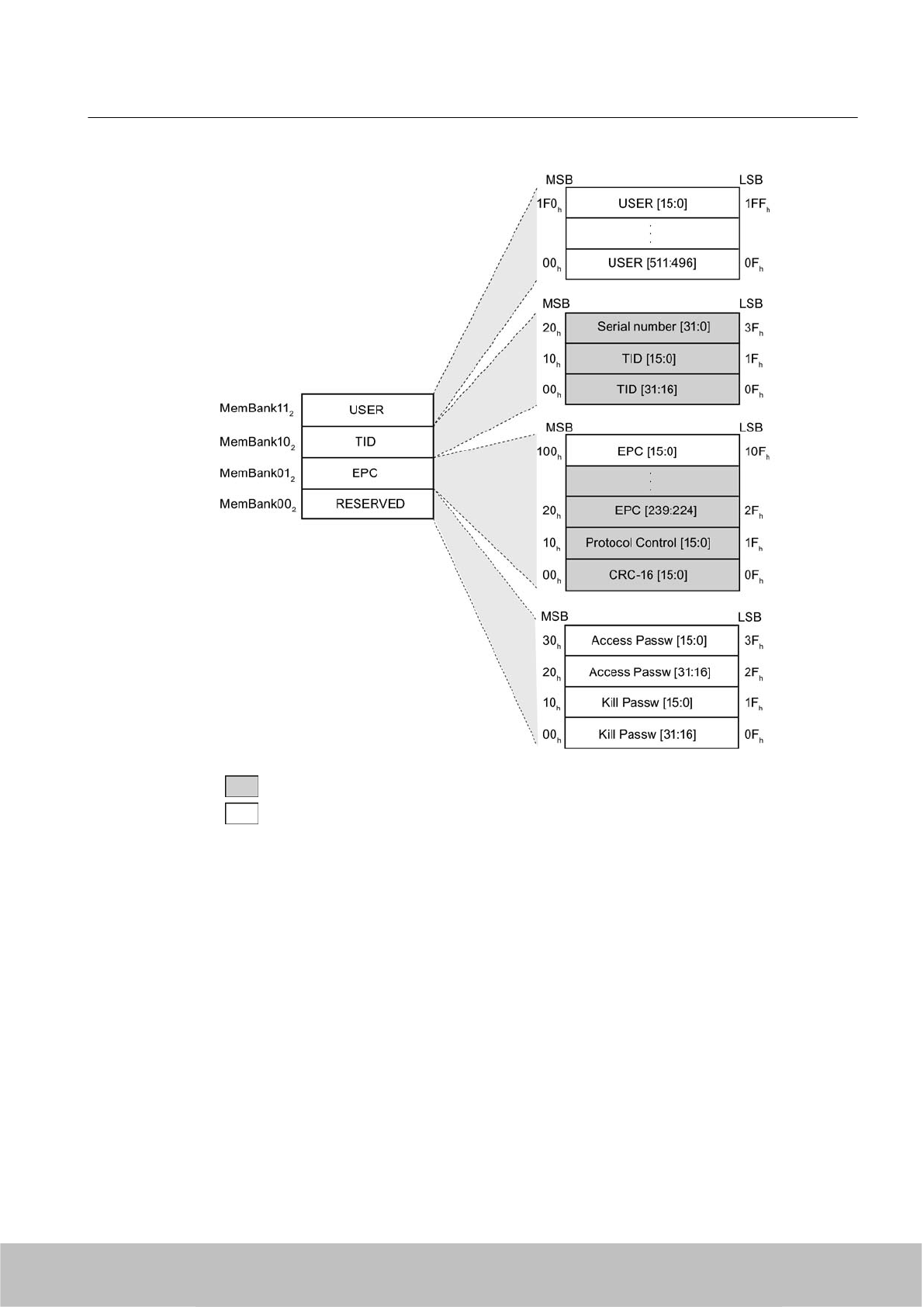
Color Mode of access by SIMATIC RF600 reader
Read
Write / read
Figure 7-4 Representation of the RF630L memory configuration according to EPC (logical memory
map)
Parameterization
The parameterization possibilities that are available to you for each reader of the RF600 family
are outlined in section Overview of parameterization of RF600 reader (Page 325). Detailed
information for parameterization as well as examples for describing and reading specific
memory areas can be found in the referenced chapters of the documentation.
Transponder/tags
7.2 SIMATIC RF630L Smartlabel
SIMATIC RF600
System Manual, 06/2010, J31069-D0171-U001-A10-7618 215
Draft Version 02.06.2010
7.2.7 Ordering data
RF630L transponder Order No. Type of delivery
RF630L transponder,
smart label 101.6 mm x 152.4 mm (4" x 6")
6GT2810-2AB00 Minimum order amount 1600 items
(800 on one roll)
RF630L transponder,
smart label 101.6 mm x 50.8 mm (4" x 2")
6GT2810-2AB01 Minimum order amount 1000 items
(1000 on one roll)
RF630L transponder,
smart label 97 mm x 27 mm
6GT2810-2AB02 Minimum order amount 2000 items
(2000 on one roll)
RF630L transponder,
smart label 54 mm x 34 mm
6GT2810-2AB03 Minimum order amount 2000 items
(2000 on one roll)
7.2.8 Technical data
Table 7-4 Mechanical data
6GT2810-2AB00 6GT2810-2AB01 6GT2810-2AB02 6GT2810-2AB03
Dimensions (L x W) 101.6 mm x 152.4 mm
(ca. 4" x 6")
101.6 mm x 50.8 mm
(ca. 4" x 2")
97 mm x 27 mm 54 mm x 34 mm
Design Paper with integrated antenna Plastic with integrated antenna
Label type Paper label Inlay
Antenna material Aluminum
Static pressure 10 N/mm2
Material surface Paper Plastic PET
Type of antenna Shortened dipole
Color white Transparent
Printing Can be printed using heat transfer technique Printed using heat
transfer technique
(currently only with
Toshiba B-SX4T)
Cannot be printed
Mounting Single-sided adhesive (self-adhesive label). Single-sided adhesive (self-adhesive inlay).
Degree of protection None, the label must be protected against
humidity
IP65
Weight Approx. 3 g Approx. 2 g Approx. 1 g
Table 7-5 Electrical data
6GT2810-2AB00 6GT2810-2AB01 6GT2810-2AB02 6GT2810-2AB03
Air interface ISO 18 000-6 Type C
Polarization type Linear
Polarization direction The polarization
direction is parallel
with the short side of
the paper label
The polarization
direction is parallel
with the long side of
the paper label
The polarization direction is parallel with the long
side of the inlay
Transponder/tags
7.2 SIMATIC RF630L Smartlabel
SIMATIC RF600
216 System Manual, 06/2010, J31069-D0171-U001-A10-7618
Draft Version 02.06.2010
6GT2810-2AB00 6GT2810-2AB01 6GT2810-2AB02 6GT2810-2AB03
Frequency range Europe 865 … 868 MHz
USA 902 … 928 MHz
Typical
read distance
●Paper/cardboard
● Plastic film
● Plastic (boxes,
surface resistance
> 10 MΩ
●Wood (dry, < 30 %
residual humidity)
● Glass
● 0.2 m to 8 m
● 0.2 m to 8 m
● 0.2 m to 4 m
● 0.2 m to 4 m
● 0.2 m to 4 m
● 0.2 m to 5 m
● 0.2 m to 5 m
● 0.2 m to 3 m
● 0.2 m to 3 m
● 0.2 m to 3 m
Typical
write distance
● Paper/cardboard
● Plastic film
● Plastic (boxes,
surface resistance
> 10 MΩ
●Wood (dry, < 30 %
residual humidity)
● Glass
● 0.2 m to 5 m
● 0.2 m to 5 m
● 0.2 m to 2.5 m
● 0.2 m to 2.5 m
● 0.2 m to 2.5 m
● 0.2 m to 3 m
● 0.2 m to 3 m
● 0.2 m to 1 m
● 0.2 m to 1 m
● 0.2 m to 1 m
Minimum spacing
between labels
● tile
● cascade
● 50 mm
●100 mm
Energy source Magnetic energy via antenna, without battery
Multi-tag capability Yes
Table 7-6 Memory specifications
6GT2810-2AB00 6GT2810-2AB01 6GT2810-2AB02 6GT2810-2AB03
Type EPC Class 1 Gen2
Memory organization EPC code 96 bit 96 bits/240 bits
Additional user memory No 64 bytes
Listing ISO 18000-6C
Data retention at +25 °C 10 years
Read cycles Unlimited
Write cycles 100,000
Anti collision Approx. 100 labels/sec.
Transponder/tags
7.2 SIMATIC RF630L Smartlabel
SIMATIC RF600
System Manual, 06/2010, J31069-D0171-U001-A10-7618 217
Draft Version 02.06.2010
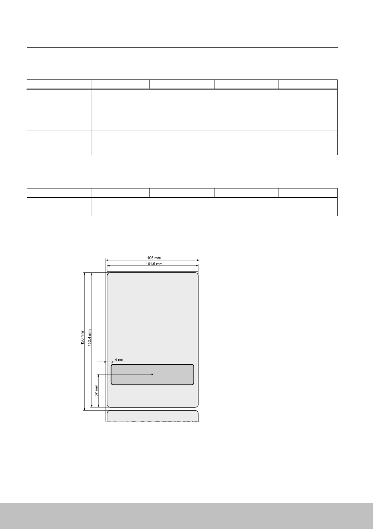
Table 7-7 Environmental conditions
6GT2810-2AB00 6GT2810-2AB01 6GT2810-2AB02 6GT2810-2AB03
Temperature range
during operation
-40 °C … 65 °C, up to 80 °C (200 cycles)
Temperature range
during storage
The label should be stored in the range of +15°C and +25°C at a humidity of 40% to 60%.
Storage duration Two years, determined by the shelf life of the adhesive
Torsion and bending
load
Partially permissible
Distance from metal Not suitable for fixing straight onto metal
Table 7-8 Identification
6GT2810-2AB00 6GT2810-2AB01 6GT2810-2AB02 6GT2810-2AB03
CE CE approval to R&TTE
FCC Passive labels or transponders comply with the valid regulations; certification is not required
7.2.9 Dimension drawings
Figure 7-5 SIMATIC RF630L 6GT2810-2AB00 dimension drawing
Transponder/tags
7.2 SIMATIC RF630L Smartlabel
SIMATIC RF600
218 System Manual, 06/2010, J31069-D0171-U001-A10-7618
Draft Version 02.06.2010
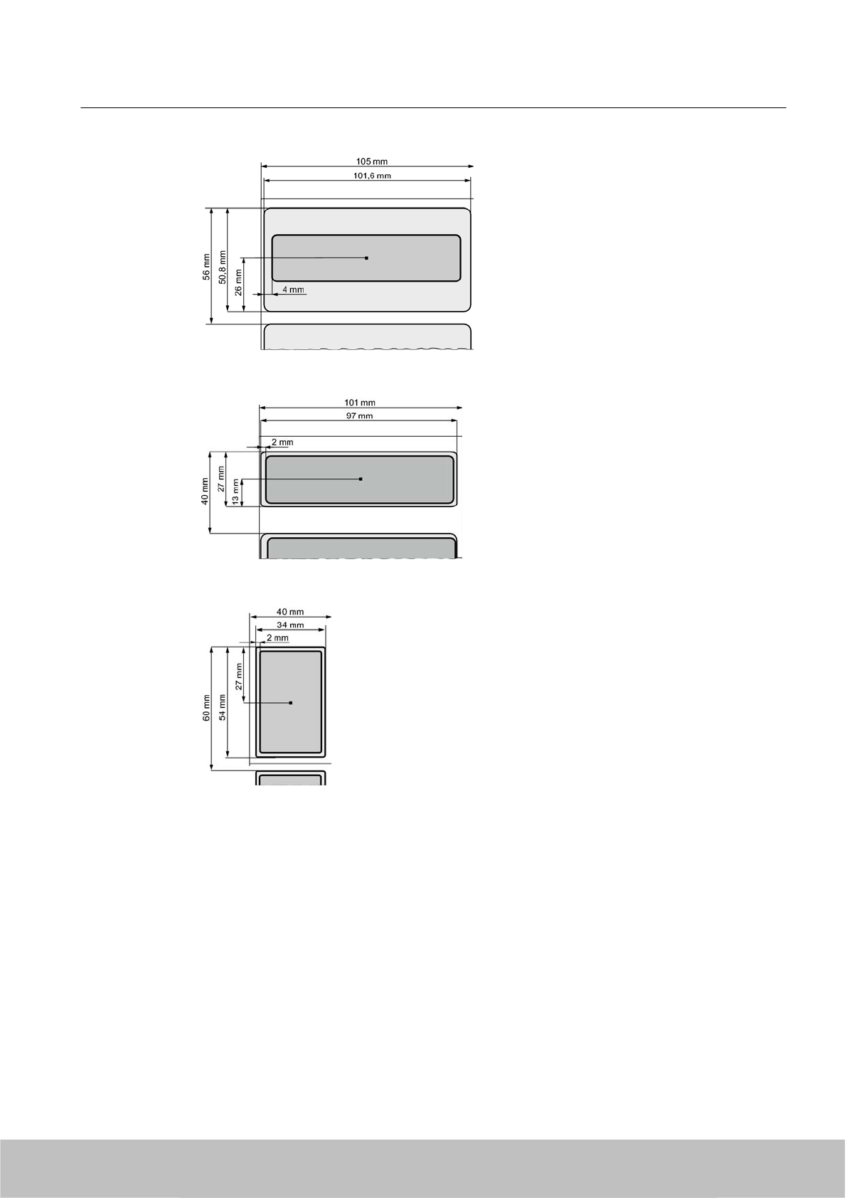
Figure 7-6 SIMATIC RF630L 6GT2810-2AB01 dimension drawing
Figure 7-7 SIMATIC RF630L 6GT2810-2AB02 dimension drawing
Figure 7-8 SIMATIC RF630L 6GT2810-2AB03 dimension drawing
Transponder/tags
7.2 SIMATIC RF630L Smartlabel
SIMATIC RF600
System Manual, 06/2010, J31069-D0171-U001-A10-7618 219
Draft Version 02.06.2010
7.3 SIMATIC RF680L Smartlabel
7.3.1 Certificates and approvals
Certificate Description
Compatible with R&TTE directive
FCC
Federal Communications
Commission
Passive labels and transponders comply with the valid regulations;
certification is not required.
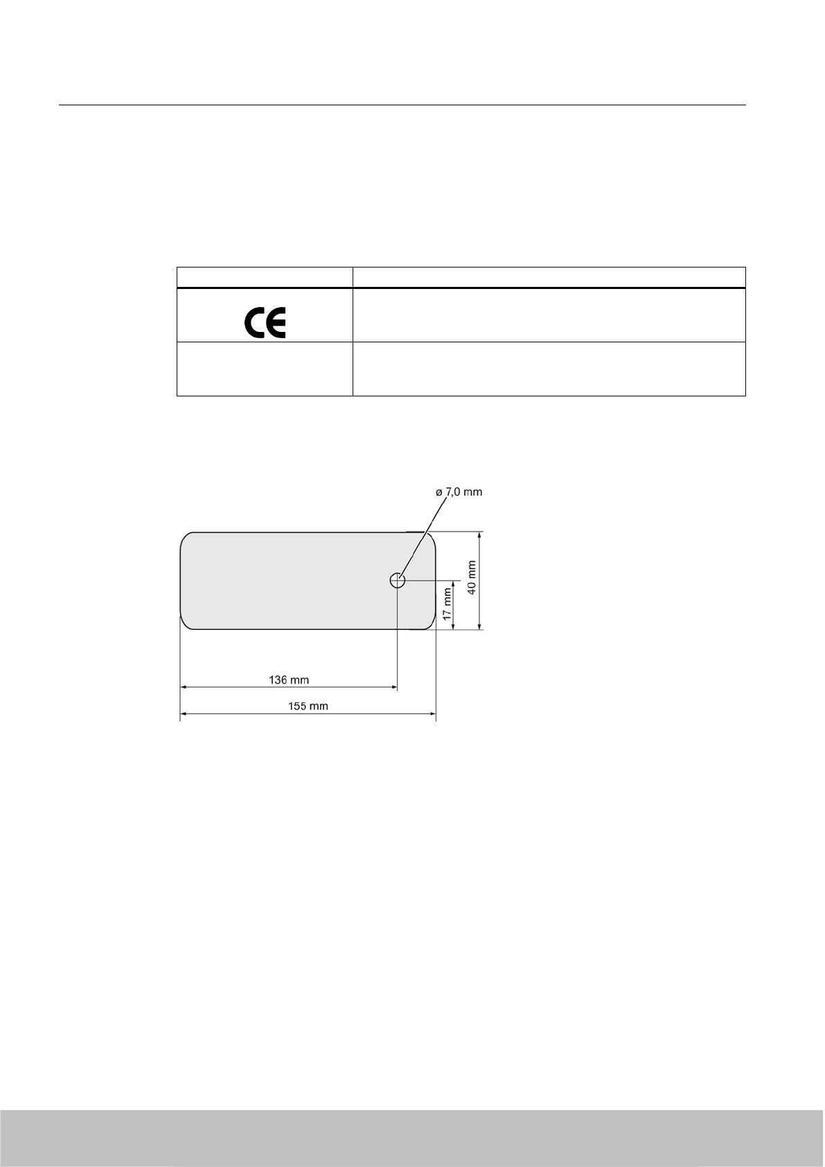
7.3.2 Dimension drawing
Figure 7-9 Dimension drawing for RF680L (special version)
7.3.3 Features
The SIMATIC RF680L Smartlabel is passive and maintenance-free. It functions based on the
UHF Class 1 Gen 2 technology and is used for saving the electronic product code (EPC) of
96 bits/240 bits. The label also has a 512 bit user memory.
The SIMATIC RF680L (special version) is a heat-resistant Smartlabel with a limited service
life. Its target use is the direct identification of objects in high-temperature applications.
Thanks to its antenna geometry, the transponder can be read from any direction. However,
the range is reduced if it is not aligned in parallel with the antenna.
Transponder/tags
7.3 SIMATIC RF680L Smartlabel
SIMATIC RF600
220 System Manual, 06/2010, J31069-D0171-U001-A10-7618
Draft Version 02.06.2010
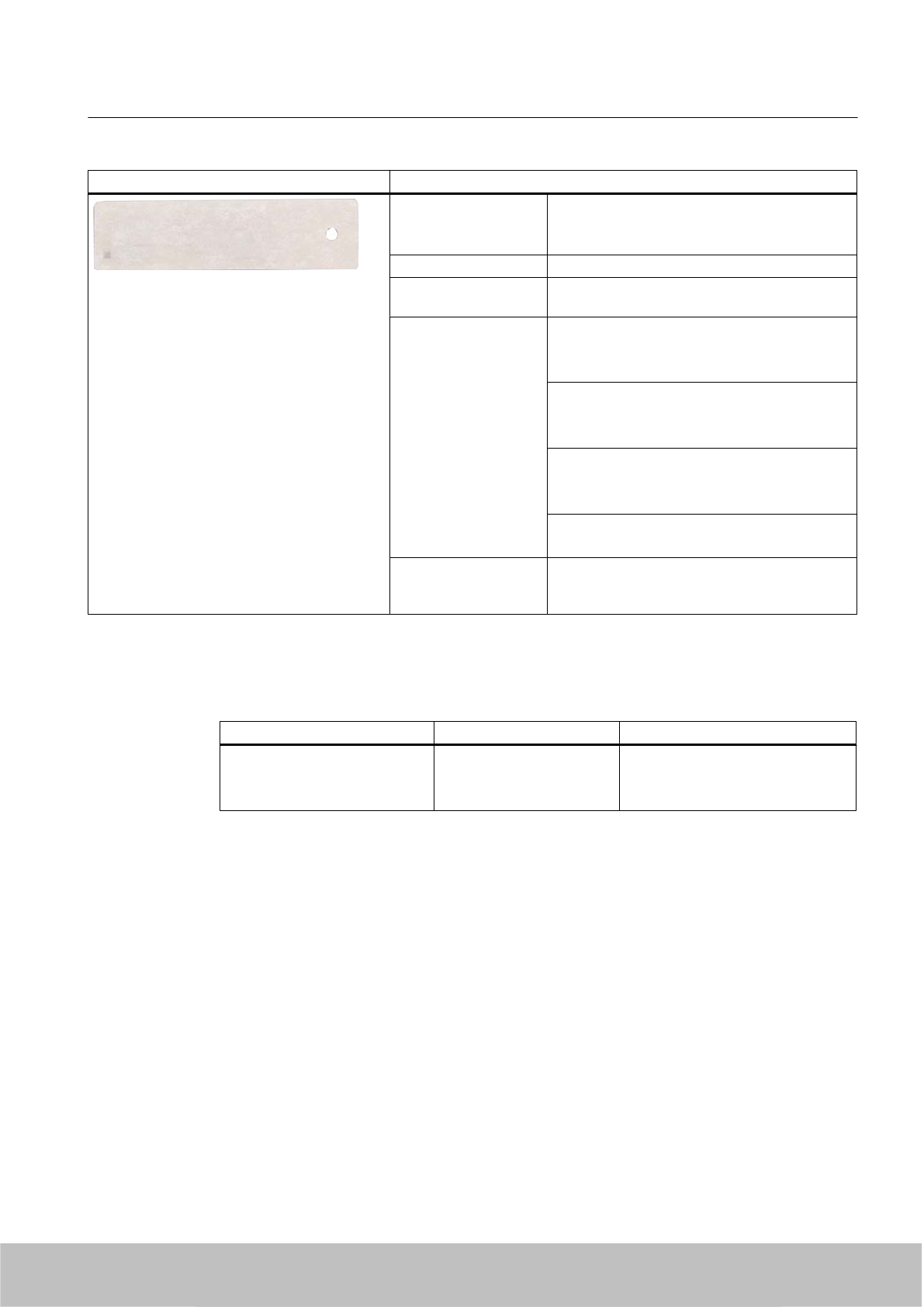
SIMATIC RF680L Smartlabel Features
Application Production logistics applications subject to high
temperatures:
Five hours up to 200 °C
Air interface according to ISO 18000-6C
Memory EPC 96 bit/240 bit
Add-on-memory 64 bytes
Read/write range Typically 5 m in connection with:
●RF660R readers and
● RF660A antennas
Typically 3 m in connection with:
● RF630R readers and
● RF660A antennas
Typically 0.5 m in connection with:
● RF630R reader and
● RF620A antenna
Typically 2 m in connection with:
● RF620R with integrated antenna
Mounting Via a hole on the narrow side. Can also be glued
by customer. Not suitable for mounting straight
onto metal.
7.3.4 Ordering data
Ordering data Order no. Delivery format
SIMATIC RF680L
●Smartlabels 155 x 40 mm
● Heat-resistant up to 200 °C
6GT2810-xxxx Minimum order quantity 1,000 items
Transponder/tags
7.3 SIMATIC RF680L Smartlabel
SIMATIC RF600
System Manual, 06/2010, J31069-D0171-U001-A10-7618 221
Draft Version 02.06.2010
7.3.5 Minimum spacing between labels
Figure 7-10 Minimum spacing between labels
Table 7-9 Minimum spacing
Minimum spacing
a20 mm
b 50 mm
Transponder/tags
7.3 SIMATIC RF680L Smartlabel
SIMATIC RF600
222 System Manual, 06/2010, J31069-D0171-U001-A10-7618
Draft Version 02.06.2010
7.3.6 Memory configuration
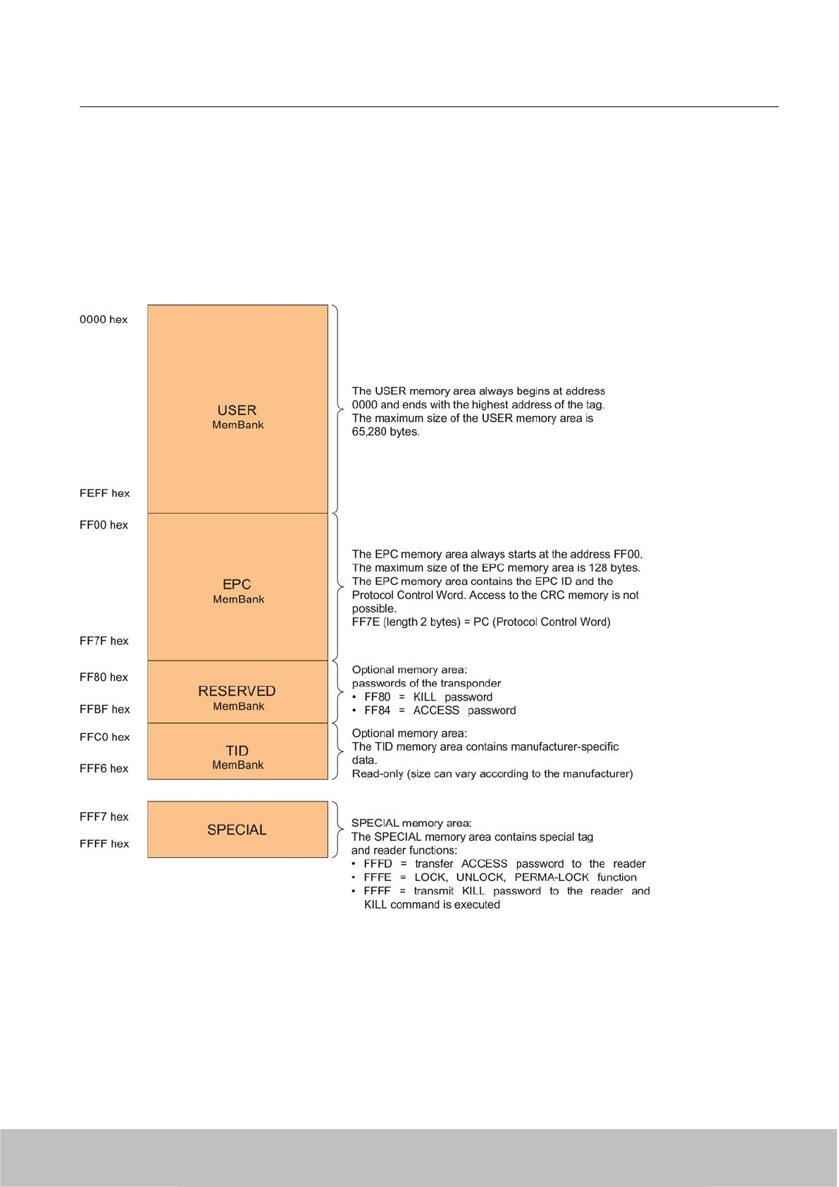
SIMATIC memory configuration
The following graphic shows the structure of the virtual SIMATIC memory for the RF620R/
RF630R reader and explains the function of the individual memory areas. The SIMATIC
memory configuration is based on the 4 memory banks, as they are defined in EPC Global.
Figure 7-11 SIMATIC memory model
Transponder/tags
7.3 SIMATIC RF680L Smartlabel
SIMATIC RF600
System Manual, 06/2010, J31069-D0171-U001-A10-7618 223
Draft Version 02.06.2010
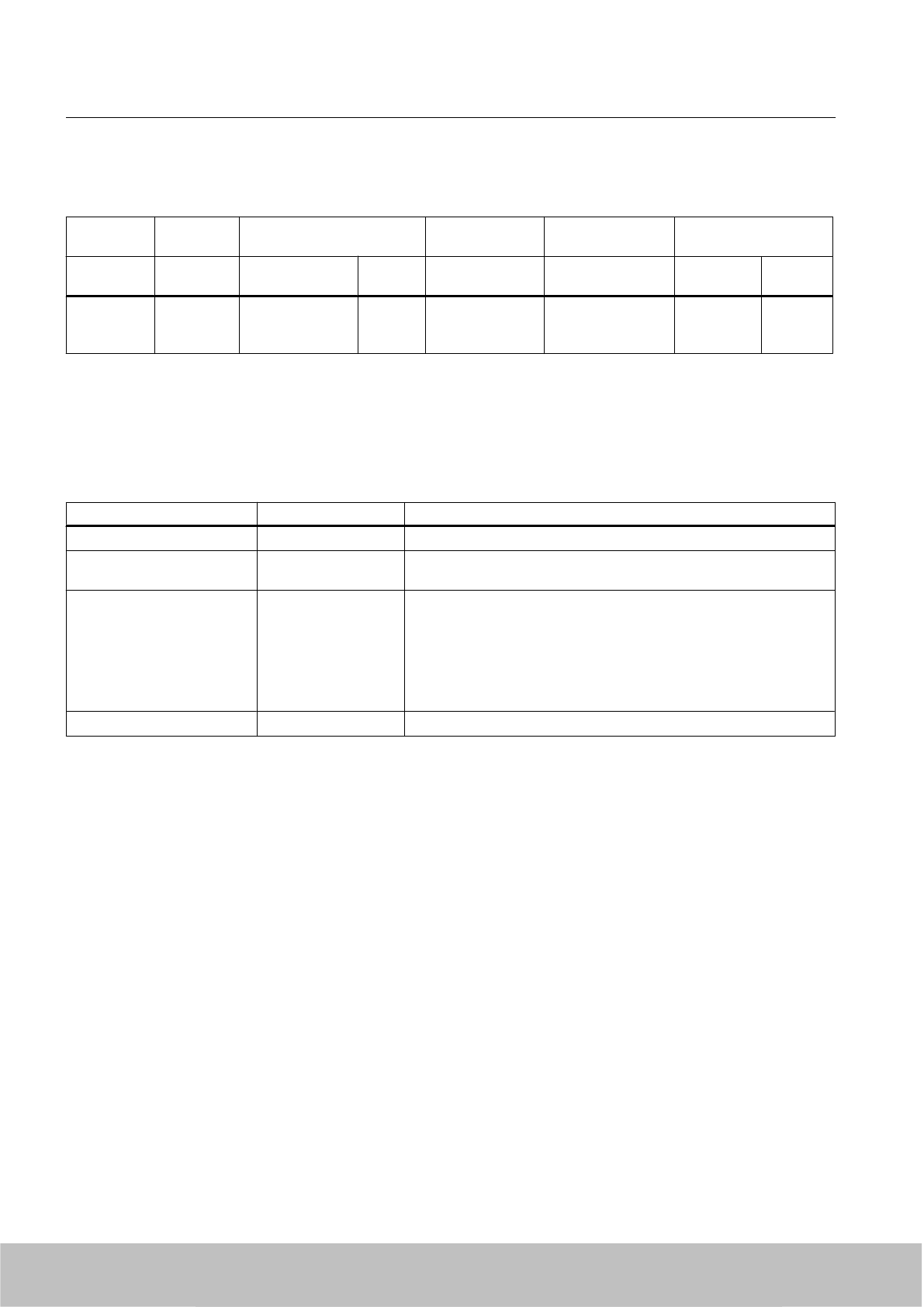
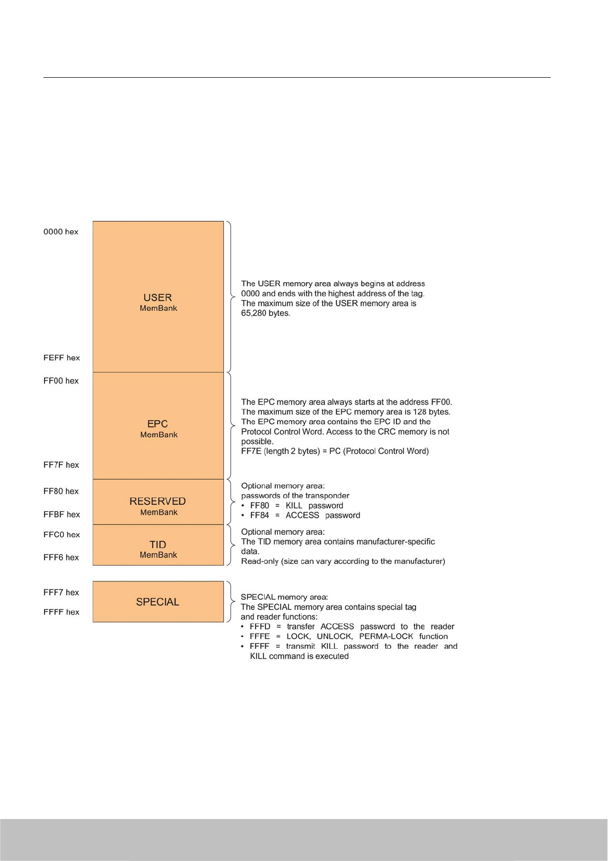
Memory configuration for RF680L (special version)
Tag User
[hex]
EPC TID RESERVED
(passwords)
Special
Range Access KILL‑PW Lock
function
RF680L 00 - 3F FF00-FF0B
(240 bit =
FF00-FF1D)
read/
write
FFC0-FFC7 FF80-FF87 Yes Yes
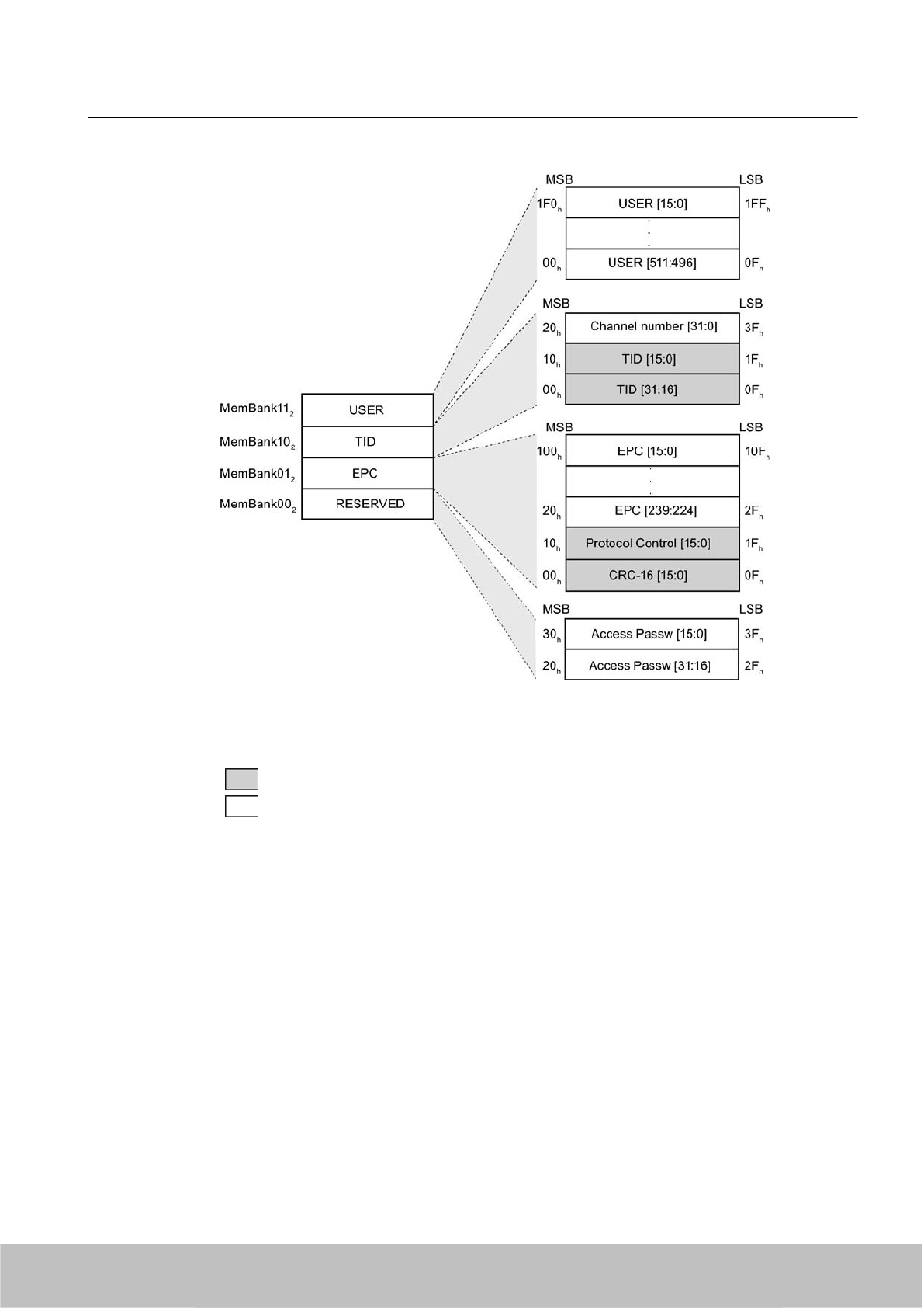
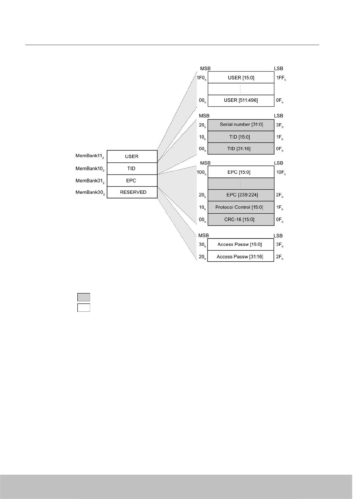
Memory representation according to EPC
The memory of the ISO 18000-6C G2XM chip is logically divided into four different memory
banks:
Memory bank (decimal) Memory type Description
MemBank 112USER User-writable USER memory area
MemBank 102TID Is defined by the manufacturer, contains the class identifier and serial
number of a tag
MemBank 012EPC Contains the EPC data, the protocol information and the CRC data
of a tag.
You can write to the EPC memory area. In the delivery condition, the
memory contents can have the following states:
● containing the same data
● containing different data
MemBank 002RESERVED Contains the access password.
The graphic below illustrates the exact memory utilization: Each box in the right part of the
graphic represents one word (16 bit) in the memory.
Transponder/tags
7.3 SIMATIC RF680L Smartlabel
SIMATIC RF600
224 System Manual, 06/2010, J31069-D0171-U001-A10-7618
Draft Version 02.06.2010
Color Access by SIMATIC RF660R / SIMATIC RF610M
Read
Write / read
Figure 7-12 Representation of the RF680L memory configuration (special version) according to EPC
(logical memory map)
Parameterization
The parameterization possibilities that are available to you for each reader of the RF600 family
are outlined in section Overview of parameterization of RF600 reader (Page 325). Detailed
information for parameterization as well as examples for describing and reading specific
memory areas can be found in the referenced chapters of the documentation.
Transponder/tags
7.3 SIMATIC RF680L Smartlabel
SIMATIC RF600
System Manual, 06/2010, J31069-D0171-U001-A10-7618 225
Draft Version 02.06.2010
7.3.7 Technical data
7.3.7.1 Mechanical data
Property Description
Dimensions (L x W) 155 mm x 40 mm
Thickness of the paper 0.3 mm
Design Synthetic paper
Antenna material Aluminum
Static pressure 10 N/mm2
Silicone-free Yes
Type of antenna Shortened dipole
Color beige
Printing Yes
Mounting Via a hole on the narrow side. Can also be glued by customer. Not suitable for
mounting straight onto metal.
Weight Approx. 3 g
7.3.7.2 Electrical data
Feature Description
Air interface According to ISO 18 000-6 C
Polarization type Linear
Polarization direction The polarization direction is parallel with the long side of the inlay
Frequency band Europe 865…868 MHz
/ USA 902…928 MHz
Reading range
typical
RF660R with
RF660A
RF630R with
RF660A
RF630R with
RF620A
RF620R
0.2 m ... 5.0 m 0.2 m ... 3.0 m 0.2 ... 0.5 m 0.2 m ... 2.0 m
Write range
typical
RF660R with
RF660A
RF630R with
RF660A
RF630R with
RF620A
RF620R
0.2 m ... 3.0 m 0.2 m ... 1.8 m 0.2 m ... 0.3 m 0.2 m ... 0.7 m
Minimum spacing between labels
●Vertically
● Horizontally
● 50 mm
●20 mm
Energy source Energy via electro-magnetic field via antenna, no battery required
Multi-tag capability Yes
Transponder/tags
7.3 SIMATIC RF680L Smartlabel
SIMATIC RF600
226 System Manual, 06/2010, J31069-D0171-U001-A10-7618
Draft Version 02.06.2010
7.3.7.3 Memory specifications
Property Description
Type EPC Class 1 Gen 2
Memory organization EPC code 96 bits/240 bits
User memory 64 bytes
TID 64 bits
Reserved (passwords) 64 bits
Protocol ISO 18000-6C
Data retention time 10 years
Read cycles Unlimited
Write cycles Minimum at +22 °C 100 000
7.3.7.4 Environmental conditions
Feature Description
Temperature range during operation -25 °C…+85 °C (permanent)
+200 °C up to five hours
Temperature range during storage -40 °C … +85 °C
Torsion and bending load Partially permissible
Distance from metal Not suitable for fixing straight onto metal
7.4 SIMATIC RF610T
7.4.1 Characteristics
The SIMATIC RF610T is passive and maintenance-free. It functions based on the
UHF Class 1 Gen 2 technology and is used for saving the electronic product code (EPC) of
96 bits/240 bits. The label also has a 512 bit user memory.
The SIMATIC RF610T offers a host of possible uses for a wide range of applications and
supports efficient logistics throughout the entire process chain.
Thanks to its antenna geometry, the transponder can be read from any direction. However,
the range is reduced if it is not aligned in parallel with the antenna.
Transponder/tags
7.4 SIMATIC RF610T
SIMATIC RF600
System Manual, 06/2010, J31069-D0171-U001-A10-7618 227
Draft Version 02.06.2010
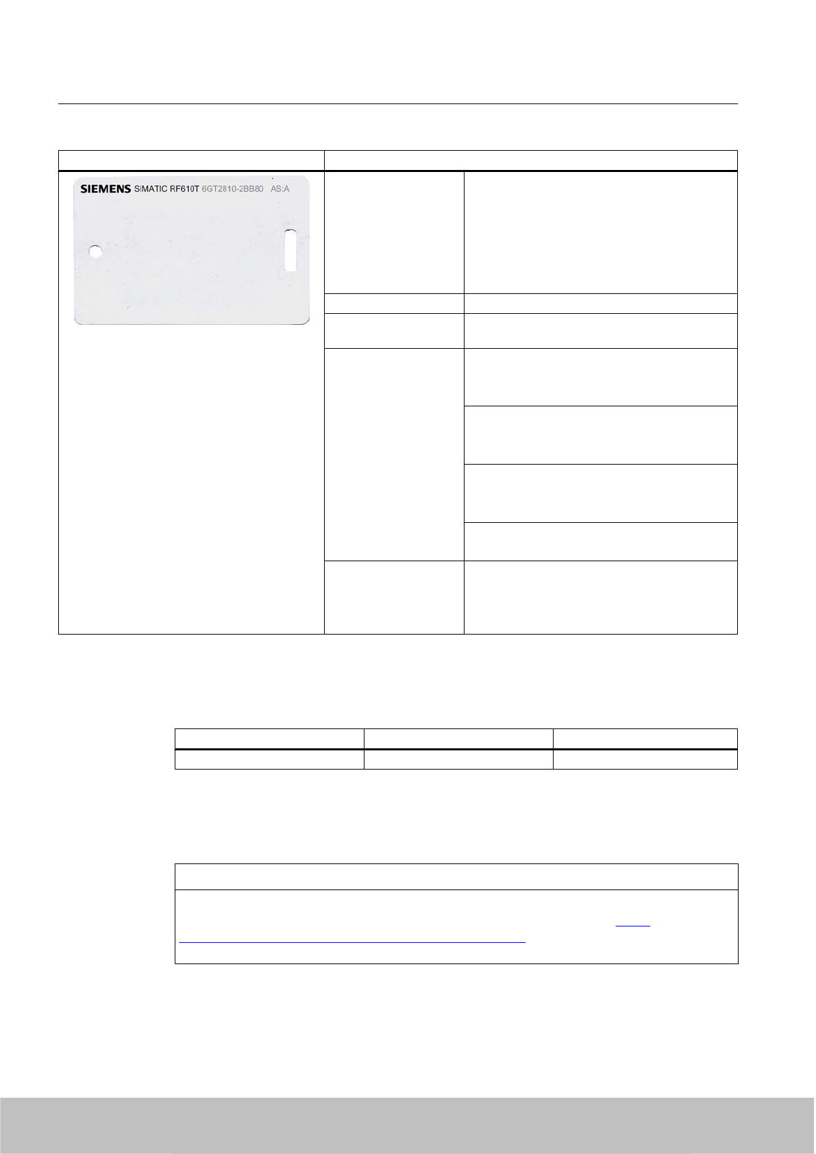
SIMATIC RF610T Features
Application ● Simple identification, such as barcode
replacement or barcode supplement
● Warehouse and distribution logistics
● Product identification
For the Food & Beverage sector, a special
version can be supplied on request that is
certified for use in contact with food.
Air interface according to ISO°18000-6C
Memory EPC 96 bit/240 bit
Add-on-memory 64 bytes
Read/write range Typically X°m in connection with: @@@
●RF670R reader and
●RF660A antennas
Typically 5 m in connection with:
● RF660R readers and
● RF660A antennas
Typically 3 m in connection with:
● RF630R readers and
● RF660A antennas
Typically 2 m in connection with:
● RF620R with integrated antenna
Mounting ● Suspended by means of cable ties, or similar
● Can also be fixed with screws or glued by
customer.
● Not suitable for mounting straight onto metal.
7.4.2 Ordering data
Ordering data Order no. Delivery format
SIMATIC RF610T 6GT2810-2BB80 Min. order quantity 500 units
7.4.3 Safety instructions for the device/system
NOTICE
This device/system may only be used for the application instances that have been described
in the catalog and the technical documentation "RF600 system manual (http://
support.automation.siemens.com/WW/view/en/22437600)", and only in combination with
third-party devices and components recommended and/or approved by Siemens.
Transponder/tags
7.4 SIMATIC RF610T
SIMATIC RF600
228 System Manual, 06/2010, J31069-D0171-U001-A10-7618
Draft Version 02.06.2010
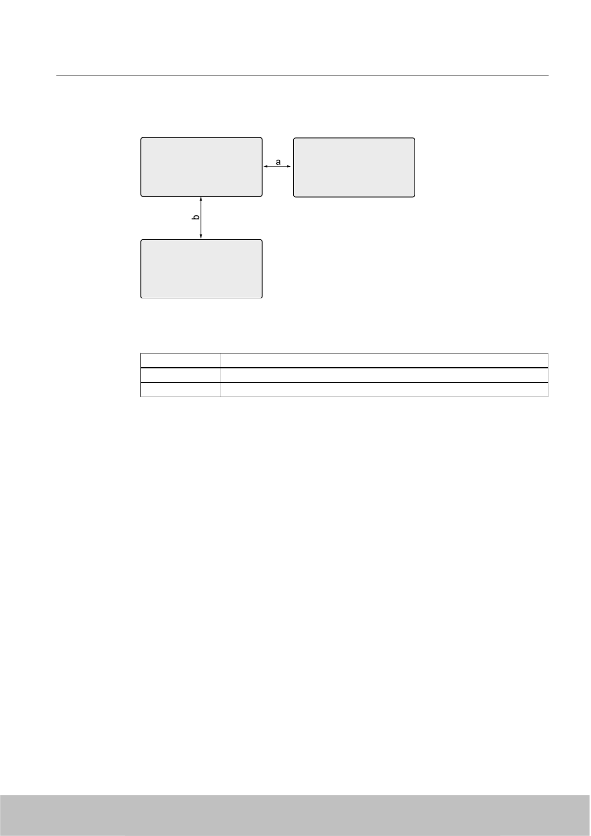
7.4.4 Minimum spacing between labels
Figure 7-13 Minimum spacing between labels
Table 7-10 Minimum spacing
Minimum spacing
a20 mm
b 50 mm
Transponder/tags
7.4 SIMATIC RF610T
SIMATIC RF600
System Manual, 06/2010, J31069-D0171-U001-A10-7618 229
Draft Version 02.06.2010

7.4.5 Memory configuration
SIMATIC memory configuration
The following graphic shows the structure of the virtual SIMATIC memory for the RF620R/
RF630R reader and explains the function of the individual memory areas. The SIMATIC
memory configuration is based on the 4 memory banks, as they are defined in EPC Global.
Figure 7-14 SIMATIC memory model
Transponder/tags
7.4 SIMATIC RF610T
SIMATIC RF600
230 System Manual, 06/2010, J31069-D0171-U001-A10-7618
Draft Version 02.06.2010
Memory configuration for RF610T
Tag User
[hex]
EPC TID RESERVED
(passwords)
Special
Range Access KILL‑PW Lock
function
RF610T 00 - 3F FF00-FF0B
(240 bit =
FF00-FF1D)
read/
write
FFC0-FFC7 FF80-FF87 Yes Yes
Memory representation according to EPC
The memory of the ISO 18000-6C G2XM chip is logically divided into four different memory
banks:
Memory bank (decimal) Memory type Description
MemBank 112USER User-writable USER memory area
MemBank 102TID Is defined by the manufacturer, contains the class identifier and serial
number of a tag
MemBank 012EPC Contains the EPC data, the protocol information and the CRC data
of a tag.
You can write to the EPC memory area. In the delivery condition, the
memory contents can have the following states:
● containing the same data
● containing different data
MemBank 002RESERVED Contains the access password.
The graphic below illustrates the exact memory utilization: Each box in the right part of the
graphic represents one word (16 bit) in the memory.
Transponder/tags
7.4 SIMATIC RF610T
SIMATIC RF600
System Manual, 06/2010, J31069-D0171-U001-A10-7618 231
Draft Version 02.06.2010
Color Mode of access by SIMATIC RF600 reader
Read
Write / read
Figure 7-15 Representation of the RF610T memory configuration according to EPC (logical memory
map)
Parameterization
The parameterization possibilities that are available to you for each reader of the RF600 family
are outlined in section Overview of parameterization of RF600 reader (Page 325). Detailed
information for parameterization as well as examples for describing and reading specific
memory areas can be found in the referenced chapters of the documentation.
Transponder/tags
7.4 SIMATIC RF610T
SIMATIC RF600
232 System Manual, 06/2010, J31069-D0171-U001-A10-7618
Draft Version 02.06.2010
7.4.6 Technical data
7.4.6.1 Mechanical data
Property Description
Dimensions (L x W x H) 86 mm x 54 mm x 0.4 mm
Design PET (polyethylene terephthalate)
Antenna material Aluminum
Static pressure 10 N/m2
Type of antenna Shortened dipole
Color white
Printing Yes
Mounting ● Suspended by means of cable ties, or similar
●Can also be fixed with screws or glued by customer.
● Not suitable for mounting straight onto metal.
Weight Approx. 3 g
7.4.6.2 Electrical data
Property Description
Air interface According to ISO 18 000-6 C
Polarization type Linear
Polarization direction The polarization direction is parallel with the long side of the inlay
Frequency band Europe 865…868 MHz
/ USA 902…928 MHz
Reading range
typical
RF670R with
RF660A
@@@
RF660R with
RF660A
RF630R with
RF660A
RF620R
Paper/cardboard X m ... X,0 m 0.2 m ...5.0 m 0.2 m ...3.0 m 0.2 m ...2.0 m
Plastic film X m ... X,0 m 0.2 m ...5.0 m 0.2 m ...3.0 m 0.2 m ...2.0 m
Plastic X m ... X,0 m 0.2 m ...3.0 m 0.2 m ...2.0 m 0.2 m ...1.5 m
Wood X m ... X,0 m 0.2 m ...3.0 m 0.2 m ...2.0 m 0.2 m ...1.5 m
Glass X m ... X,0 m 0.2 m ...3.0 m 0.2 m ...2.0 m 0.2 m ...1.5 m
Write distance
typical
RF670R with
RF660A
@@@
RF660R with
RF660A
RF630R with
RF660A
RF620R
Paper/cardboard X m ... X,0 m 0.2 m ...3.0 m 0.2 m ...1.8 m 0.2 m ...0.7 m
Plastic film X m ... X,0 m 0.2 m ...3.0 m 0.2 m ...1.8 m 0.2 m ...0.7 m
Plastic X m ... X,0 m 0.2 m ...1.0 m 0.2 m ...0.7 m 0.2 m ...0.5 m
Wood X m ... X,0 m 0.2 m ...1.0 m 0.2 m ...0.7 m 0.2 m ...0.5 m
Glass X m ... X,0 m 0.2 m ...1.0 m 0.2 m ...0.7 m 0.2 m ...0.5 m
Transponder/tags
7.4 SIMATIC RF610T
SIMATIC RF600
System Manual, 06/2010, J31069-D0171-U001-A10-7618 233
Draft Version 02.06.2010
Energy source Energy via electro-magnetic field via antenna, no battery required
Multi-tag capability Yes
7.4.6.3 Memory specifications
Property Description
Type EPC Class 1 Gen 2
Memory organization EPC code 96 bits/240 bits
User memory 512 bytes
TID 64 bits
Reserved (passwords) 64 bits
Protocol ISO 18000-6C
Data retention time 10 years
Read cycles Unlimited
Write cycles Minimum at +22 °C 100 000
7.4.6.4 Environmental conditions
Property Description
Temperature range during operation -25 °C … +85 °C
Temperature range during storage -40 °C … +85 °C
Torsion and bending load Partially permissible
Distance from metal Not suitable for fixing straight onto metal
Degree of protection IP67
7.4.7 Certificates and approvals
Certificate Description
Compatible with R&TTE directive
FCC
Federal Communications
Commission
Passive labels and transponders comply with the valid regulations;
certification is not required.
Transponder/tags
7.4 SIMATIC RF610T
SIMATIC RF600
234 System Manual, 06/2010, J31069-D0171-U001-A10-7618
Draft Version 02.06.2010
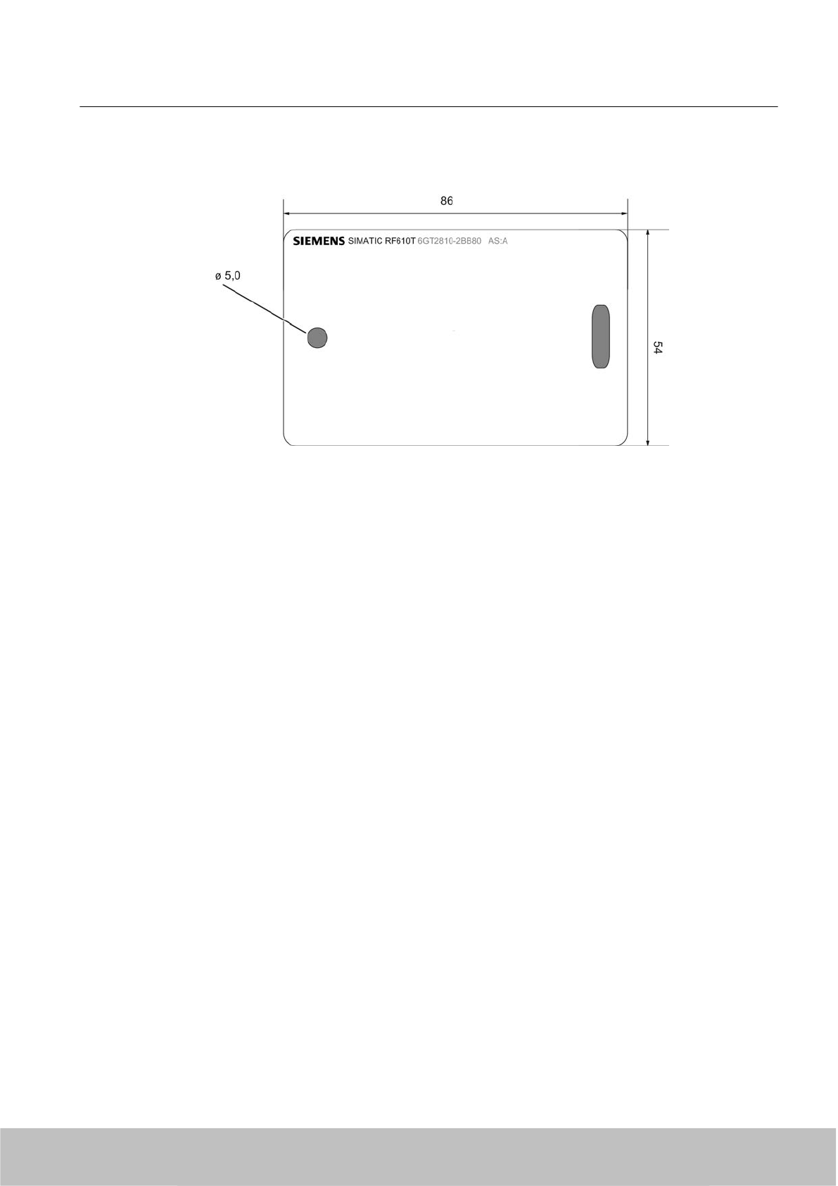
7.4.8 Dimension drawing
Figure 7-16 Dimensional drawing of SIMATIC RF610T
All dimensions in mm
7.5 SIMATIC RF620T
7.5.1 Characteristics
The SIMATIC RF620T Transponder is passive and maintenance-free, based on the UHF Class
1 Gen2 technology for storing 96-bit electronic product codes (EPC)
The container tag for industrial applications is rugged and highly resistant to detergents. It is
designed for easy attachment onto plastic, wood, glass, e.g. containers, palettes, and trolleys
The optimum functionality/range of the RF620T on metal is achieved by means of the spacer.
Since the plastic is food safe, it is also suitable for use in the food-processing industry.
This container tag is designed for the frequency bands 868 MHz (Europe) and 915 MHz (USA)
and can be operated in combination with our UHF system RF660.
Transponder/tags
7.5 SIMATIC RF620T
SIMATIC RF600
System Manual, 06/2010, J31069-D0171-U001-A10-7618 235
Draft Version 02.06.2010
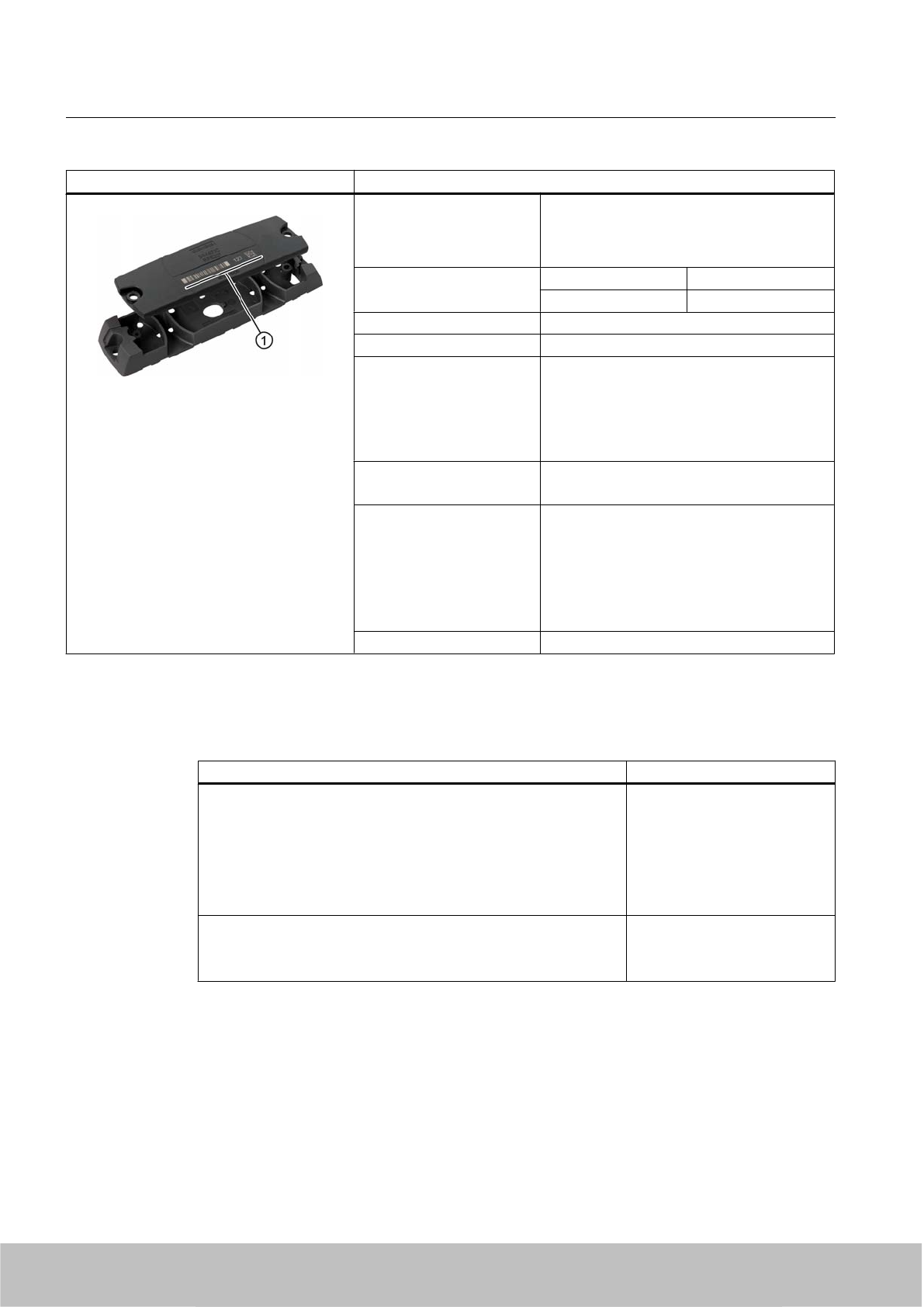
SIMATIC RF620T Transponder Features
Area of application Transponder for rugged, industrial
requirements such as RF identification in
warehouses and the logistics and transport
area.
Frequency versions Europe USA / Canada
868 MHz 915 MHz
Polarization Linear
Memory EPC 96 bit
Read/write range
● with non-metallic carriers
●direct on metallic carriers
● with spacer on metallic
carriers
● typically 0.2 to 6°m
● typically 0.2 to 2°m
● typically 0.2 to 4 m
Mounting ● screw, bond
● on metal by means of spacers
① Labeling area You can inscribe the transponder itself using
laser, or adhere a label to position ①.
Possible types of labeling:
●Barcode
● Inscription in plain text
●Data matrix code
Housing color Anthracite
7.5.2 Ordering data
Ordering data Order No.
SIMATIC RF620T
●Frequency 865 MHz to 928 MHz,
● UHF Class 1 Gen2 technology (96 bit)
● -25 °C to +85 °C operating temperature
●Dimensions (L x W x H) 127 x 38 x 6 mm
● IP 67 degree of protection
6GT2810-2HC80
Spacer for SIMATIC RF620T
● For attaching to metal surfaces
● Dimensions (L x W x H) 155 x 38 x 12 mm
6GT2898-2AA00
Transponder/tags
7.5 SIMATIC RF620T
SIMATIC RF600
236 System Manual, 06/2010, J31069-D0171-U001-A10-7618
Draft Version 02.06.2010
7.5.3 Planning the use
7.5.3.1 Reading range when mounted on non-metallic carriers
The transponder is generally designed for mounting on non-metallic objects which provide the
conditions for the maximum reading ranges
Table 7-11 Reading range on non-metallic carriers
Carrier plate material Reading range
Transponder on wooden carrier
(dry, degree of moisture < 15%)
typ. 6 m
Transponder on plastic carrier typ. 6 m
Transponder on glass typ. 6 m
Transponder on plastic mineral water bottle typ. 1.2 m
100% reading range is achieved when mounted in empty, anechoic rooms.
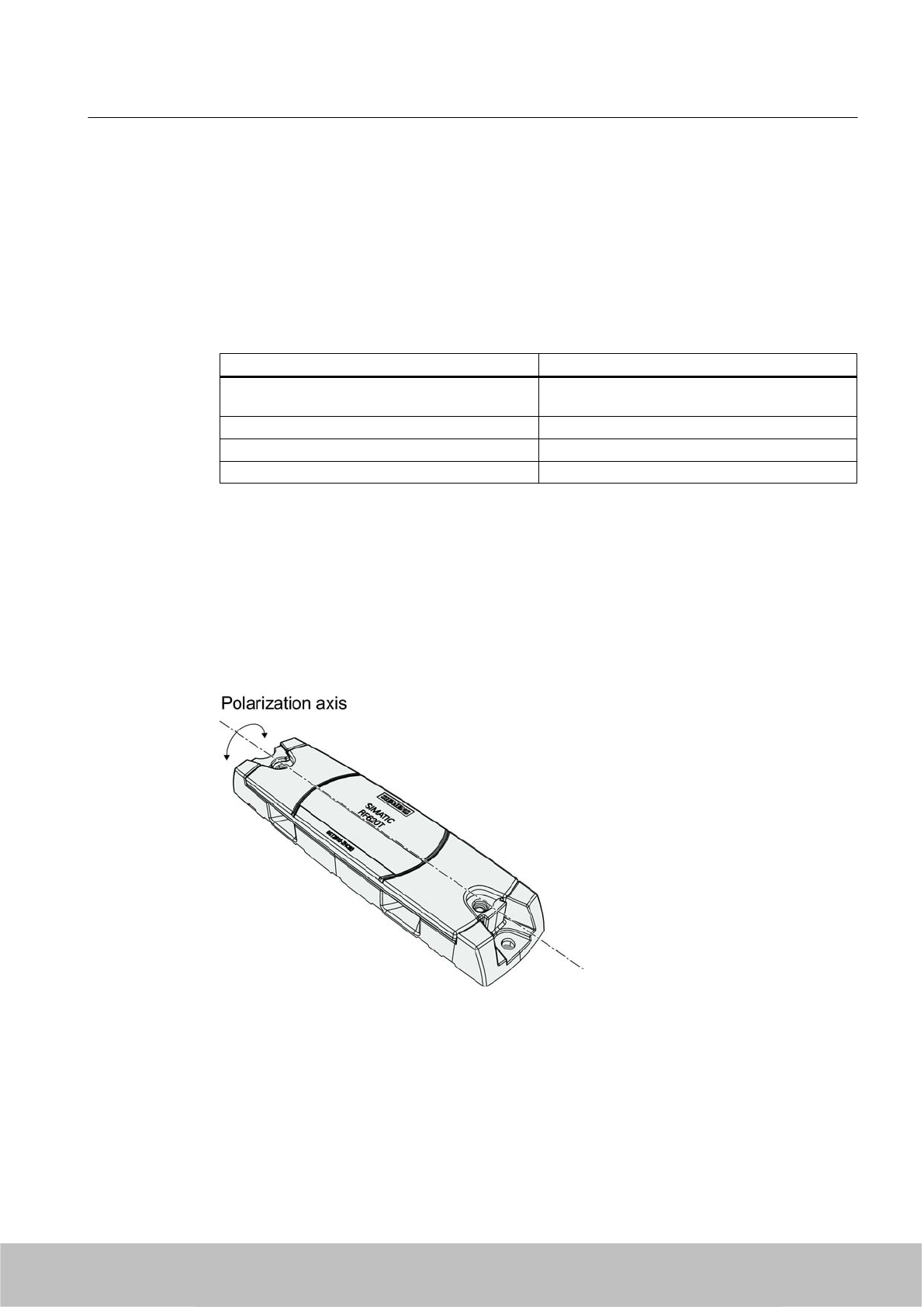
7.5.3.2 Directional radio pattern of the transponder on non-metallic surfaces
Preferably, align the data carrier parallel to the transmitting antenna. If, however, the data
carrier including the metallic carrier plate is tilted, the reading range will be reduced.
Rotation about the polarization axis
Figure 7-17 Rotation of the transponder about the polarization axis
Generally the range does not change when the transponder without carrier material is rotated
about the polarization axis.
Transponder/tags
7.5 SIMATIC RF620T
SIMATIC RF600
System Manual, 06/2010, J31069-D0171-U001-A10-7618 237
Draft Version 02.06.2010
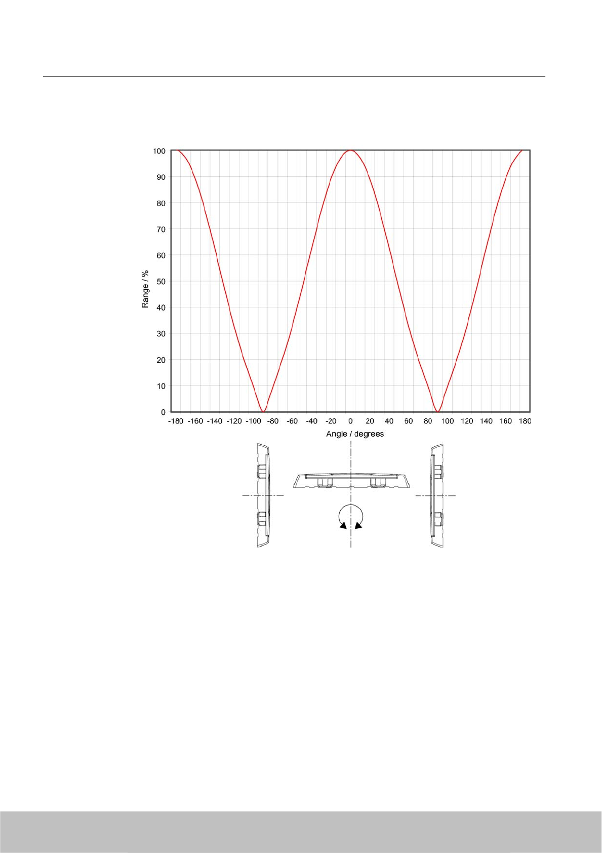
Rotation orthogonal to the polarization axis
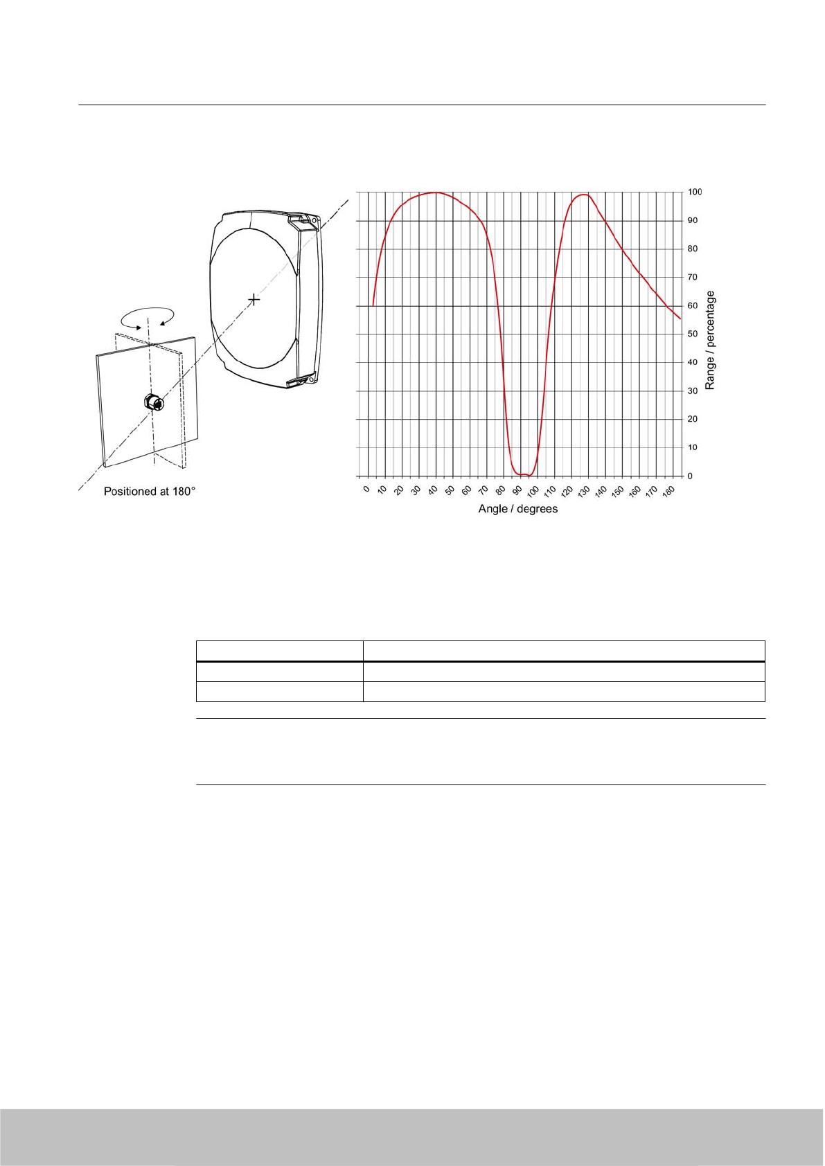
Figure 7-18 Transponder characteristics when rotated orthogonally to the polarization axis (within the
tag plane)
If the transponder is positioned orthogonally to the transmitting antenna, it normally cannot be
read. Therefore the data carrier is preferably to be aligned parallel to the transmitting antenna.
The following figure illustrates this situation.
Transponder/tags
7.5 SIMATIC RF620T
SIMATIC RF600
238 System Manual, 06/2010, J31069-D0171-U001-A10-7618
Draft Version 02.06.2010
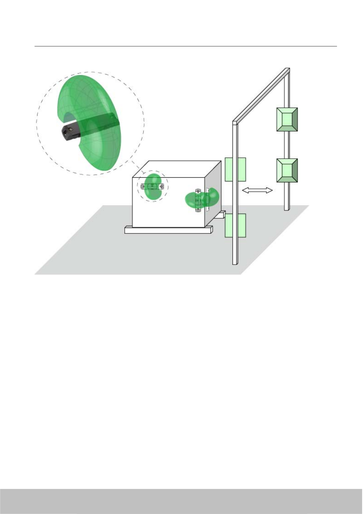
Figure 7-19 Application example for possible orientations of the transponder.
Transponder/tags
7.5 SIMATIC RF620T
SIMATIC RF600
System Manual, 06/2010, J31069-D0171-U001-A10-7618 239
Draft Version 02.06.2010
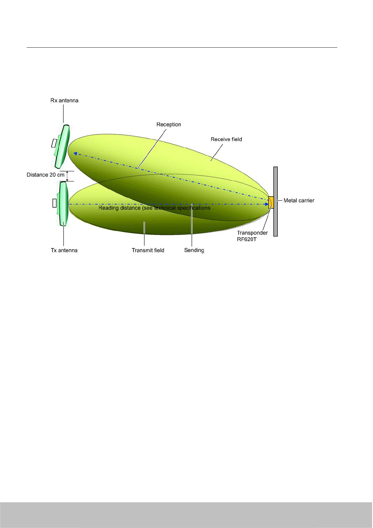
7.5.3.3 Optimum antenna/transponder positioning with plane mounting of the transponder on metal
Figure 7-20 Example of optimum antenna/transponder positioning
7.5.3.4 Reading range when mounted on flat metallic carrier plates
The transponder generally has linear polarization. The polarization axis runs as shown in the
diagram below. If the tag is centrically mounted on a flat metal plate, which may either be
Transponder/tags
7.5 SIMATIC RF620T
SIMATIC RF600
240 System Manual, 06/2010, J31069-D0171-U001-A10-7618
Draft Version 02.06.2010
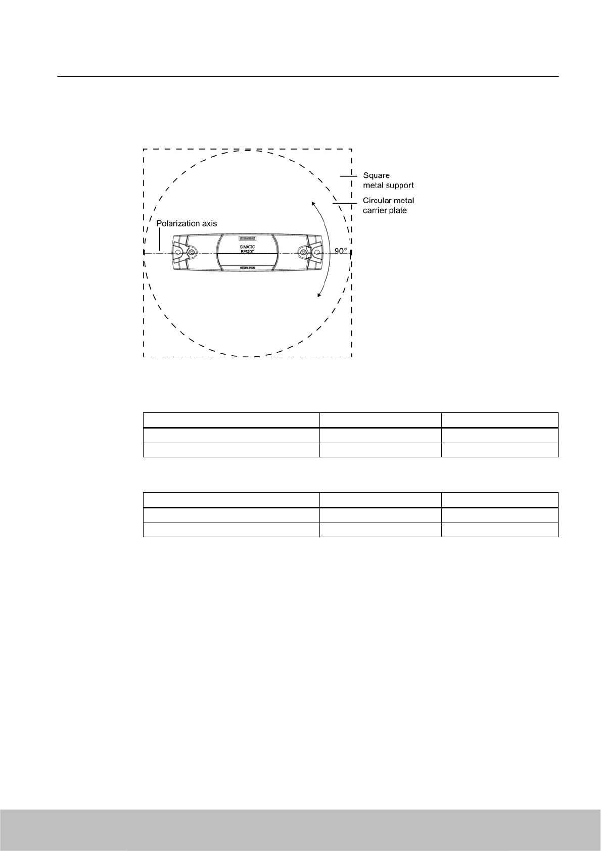
almost square or circular, it can be aligned in any direction since the transmitting and receiving
RF660A antennas operate with circular polarization.
Figure 7-21 Optimum positioning of the transponder on a (square or circular) metal carrier plate
Table 7-12 Reading range with metallic, plane carriers without spacer
Carrier plate material Reading range Europe Reading range USA
Metal plate at least 300 x 300 mm typ. 2 m typ. 1.5 m
Metal plate 150 x 150 mm typ. 1.5 m typ. 1 m
Table 7-13 Reading range with metallic, plane carriers with spacer
Carrier plate material Reading range Europe Reading range USA
Metal plate at least 300 x 300 mm typ. 4 m typ. 6 m
Metal plate 150 x 150 mm typ. 2 m typ. 4.5 m
The use of spacers on metallic surfaces is therefore recommended.
On rectangular carrier plates, the reading distance depends on the mounting orientation of the
transponder A 90° rotation of the transponder about the axis of symmetry may result in greater
reading distances
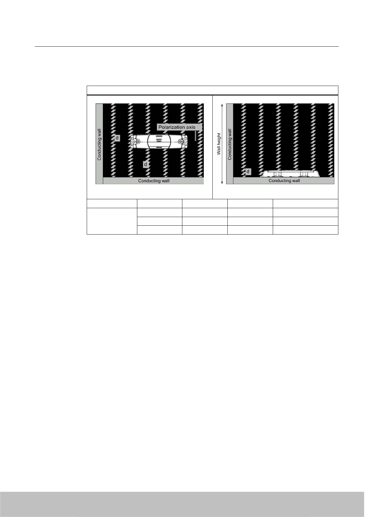
7.5.3.5 Influence of conducting walls on the reading range
If there are conducting walls or restrictions in the vicinity that could shade the radio field, a
distance of approx. 10 cm is recommended between the transponder and the wall In principle,
walls have least influence if the polarization axis is orthogonal to the conducting wall. A spacer
must be used in any case.
Transponder/tags
7.5 SIMATIC RF620T
SIMATIC RF600
System Manual, 06/2010, J31069-D0171-U001-A10-7618 241
Draft Version 02.06.2010
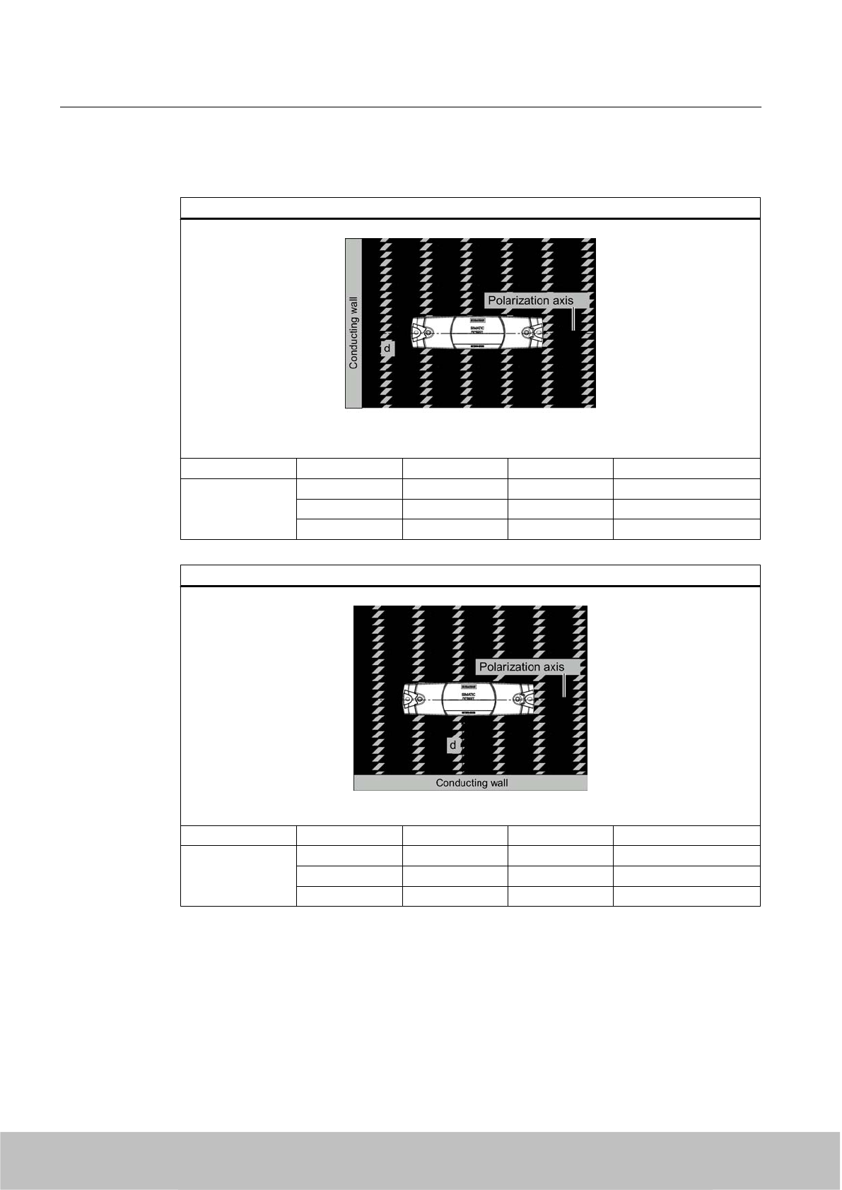
Reading range: One conducting wall
Dependence of the reading distance when positioned orthogonally to the conducting wall
Top view
Distance d 20 mm 50 mm 100 mm
Reading range Approx. 100% Approx. 100% Approx. 100% Wall height 20 mm
Approx. 100% Approx. 100% Approx. 100% Wall height 50 mm
Approx. 80% Approx. 100% Approx. 100% Wall height 100 mm
Dependence of the reading distance when positioned parallel to the conducting wall
Top view
Distance d 20 mm 50 mm 100 mm
Reading range Approx. 70 % Approx. 100% Approx. 100% Wall height 20 mm
Approx. 60 % Approx. 90 % Approx. 100% Wall height 50 mm
Approx. 30 % Approx. 70 % Approx. 100% Wall height 100 mm
Transponder/tags
7.5 SIMATIC RF620T
SIMATIC RF600
242 System Manual, 06/2010, J31069-D0171-U001-A10-7618
Draft Version 02.06.2010
Reading range: Two conducting walls
Influence on reading range when positioned against two conducting walls
Top view Side view
Distance d 20 mm 50 mm 100 mm
Reading range Approx. 70 % Approx. 100% Approx. 100% Wall height 20 mm
Approx. 60 % Approx. 90 % Approx. 100% Wall height 50 mm
Approx. 30 % Approx. 70 % Approx. 100% Wall height 100 mm
The values specified in the tables above are reference values.
7.5.3.6 Directional radio pattern of the transponder on metallic surfaces
Preferably, align the data carrier parallel to the transmitting antenna. If, however, the data
carrier including the metallic carrier plate is tilted, the reading range will be reduced.
Transponder/tags
7.5 SIMATIC RF620T
SIMATIC RF600
System Manual, 06/2010, J31069-D0171-U001-A10-7618 243
Draft Version 02.06.2010
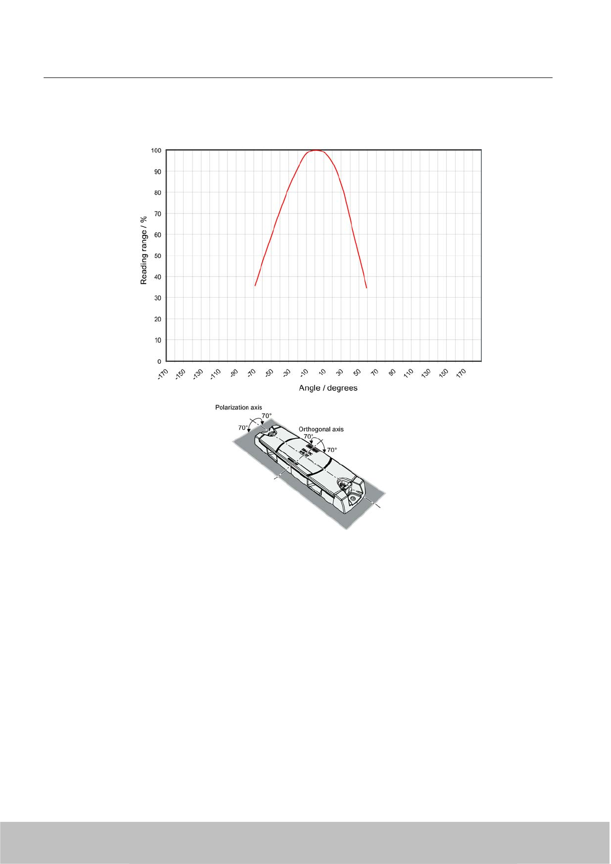
Rotation about the polarization axis or orthogonal to the polarization axis
Figure 7-22 Characteristic of the transponder when rotated about the polarization axis or orthogonally
to the polarization axis
7.5.3.7 Reading range when mounted on ESD carrier materials
The transponder is generally designed for mounting on non-conductive objects which provide
the conditions for the maximum reading ranges The conductive or dissipativesurface of ESD
materials limits the reading range depending on the surface resistance. Generally, dissipative
materials with a surface resistance of 1 x 10⁵ to 1 x 10¹¹ ohm and conductive materials with
1 x 10³ to 1 x 10⁵ ohm are available.
Transponder/tags
7.5 SIMATIC RF620T
SIMATIC RF600
244 System Manual, 06/2010, J31069-D0171-U001-A10-7618
Draft Version 02.06.2010
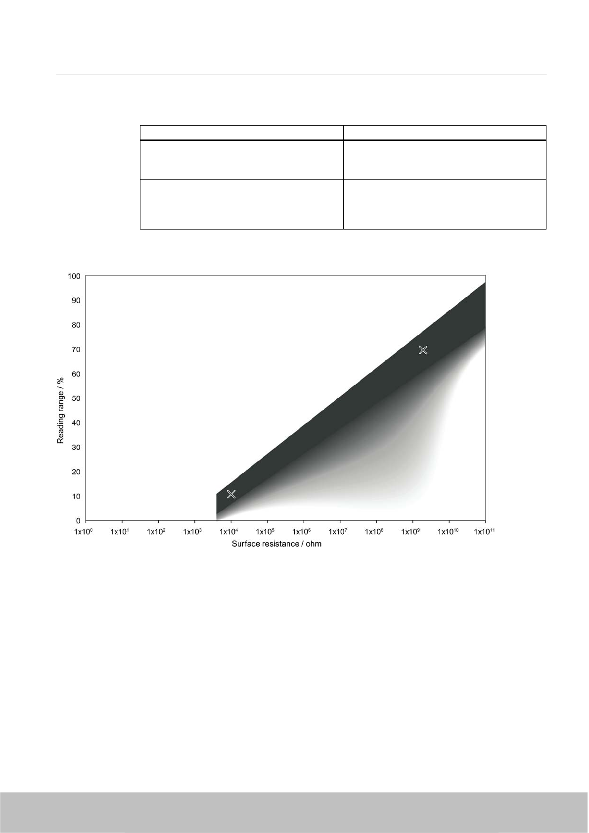
Table 7-14 Limited reading range with ESD materials
Carrier plate material Reading range
Transponder on electrostatic dissipative materials,
dimensions 60°x°40 cm
(surface resistance 2 x 10⁹ ohm)
Approx. 4 m
Transponder on electrostatic conductive
materials, dimensions 60 x 40 cm
(surface resistance 1 x 10⁴ ohm)
Use of spacers
Approx. 1 m
Approx. 2 m
100% reading range is achieved when mounted in empty, anechoic rooms. With multi-tag
capability, limitations may result in the reading range.
Figure 7-23 Schematic representation of how the reading range depends on the surface resistance of the ESD material
In the representation above, the two reading points with regard to the dependence of the
reading range in % on the surface resistance are shown At the same time a linear dependence
between the reading points is to be expected, however with measurement inaccuracies. The
darker the hatching, the greater the probability that the reading point is found in the hatched
area.
Transponder/tags
7.5 SIMATIC RF620T
SIMATIC RF600
System Manual, 06/2010, J31069-D0171-U001-A10-7618 245
Draft Version 02.06.2010
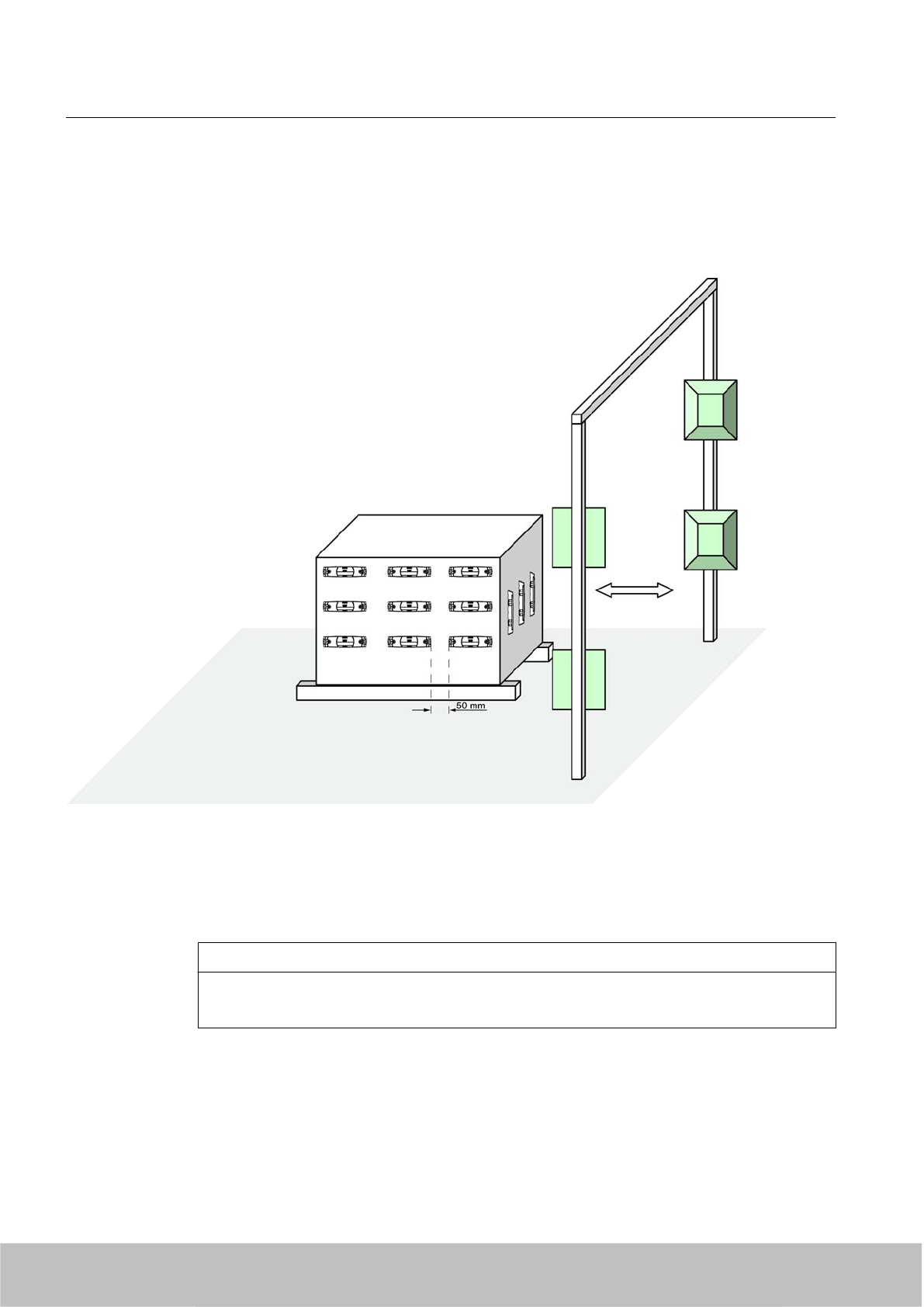
7.5.3.8 Communication with multiple transponders
The RF600 system is multitag-capable. This means that the reader can detect and write to
several transponders almost simultaneously. The minimum distance between the
transponders is ≥ 50 mm.
Figure 7-24 Multitag reading
7.5.4 Mounting instructions
CAUTION
Level mounting
Please note that both the transponder and the spacer must be mounted on a level surface.
Transponder/tags
7.5 SIMATIC RF620T
SIMATIC RF600
246 System Manual, 06/2010, J31069-D0171-U001-A10-7618
Draft Version 02.06.2010
CAUTION
The screw fixing element was tested with the types of screws, spring washers and plain
washers indicated below. Depending on the application area, the user must use similar,
correspondingly certified screws, spring washers and plain washers (e.g. for the food
processing industry).
EJOT screws can be additionally etched and passivated in some areas of the food processing
industry, e.g if they made of stainless steel A2. In other areas without special requirements,
the screws can be, for example, zinc plated and blue passivated.
Note
In case of high mechanical loads (such as shocks or vibration), the transponder must be fixed
onto the spacer by means of screws.
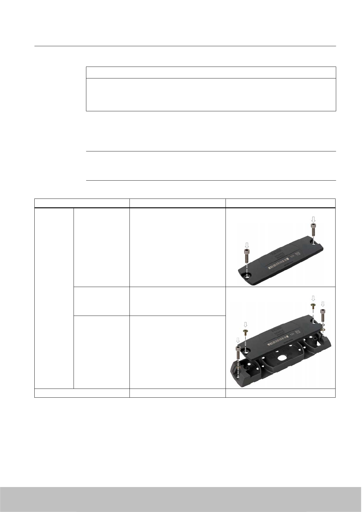
Properties Description Graphics
Mounting type ● Transponder ● Screw mounting (e.g. 2 x M4
hexagon socket head cap screws
DIN 6912, spring lock and
grommet DIN 433)
or glued
● Transponder on
spacer
● Clips or screw on the side of the
clip, or 2°x° screws (e.g.
EJOT PT ® WN 5411 35x10 VZ
crosshead screw/torx)
● Spacer ● Screw mounting (e.g.°2 x M4
hexagon socket head cap screws
ISO 4762. spring lock and
grommet ISO 7092) or glued or
secured with tape
Tightening torque (at room temperature) < 1.2 Nm
Transponder/tags
7.5 SIMATIC RF620T
SIMATIC RF600
System Manual, 06/2010, J31069-D0171-U001-A10-7618 247
Draft Version 02.06.2010
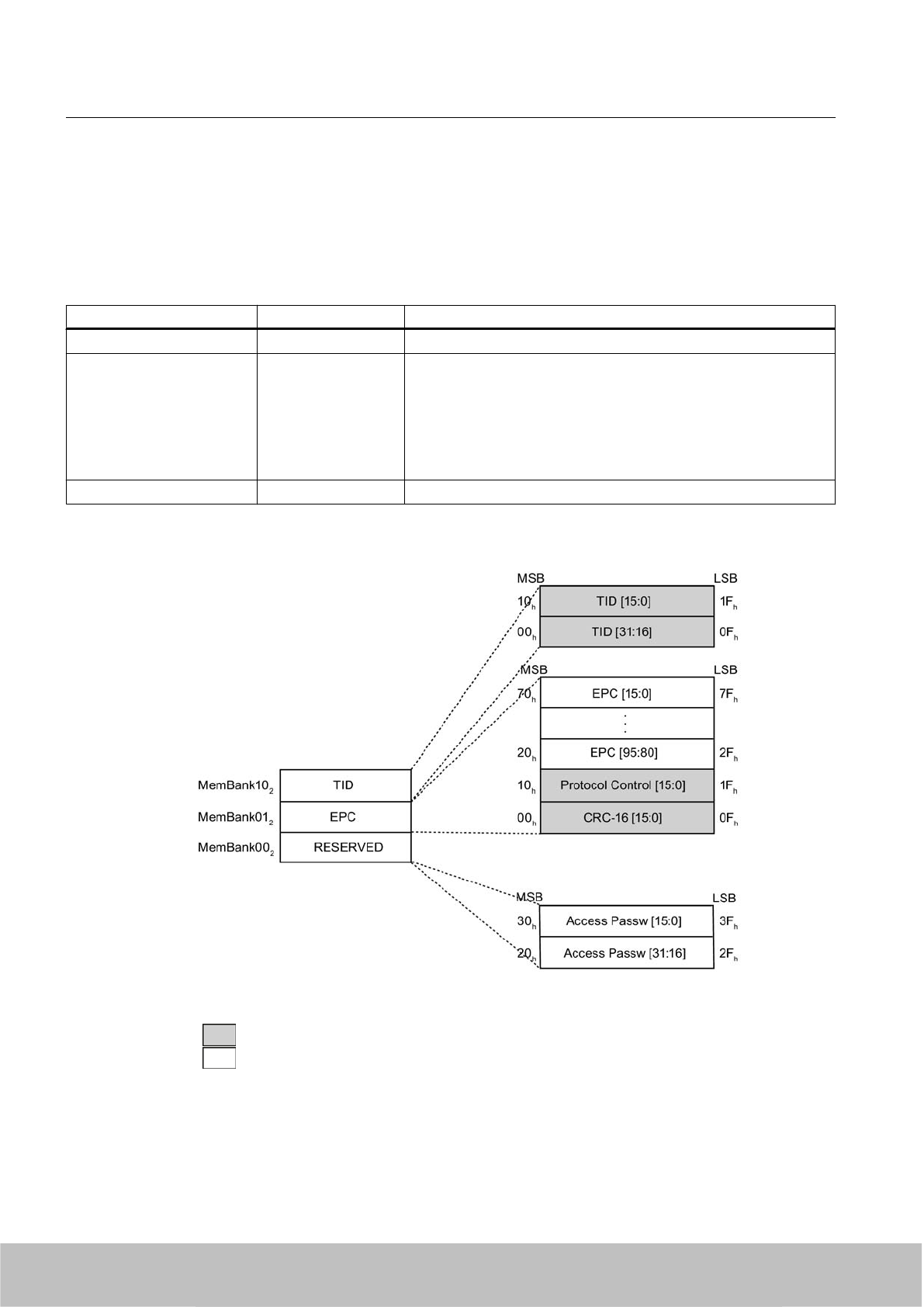
7.5.5 Memory configuration
Memory banks
The memory is divided logically into three different memory banks:
Memory bank (decimal) Memory type Description
MemBank 102TID Is defined by the manufacturer, contains the class identifier of a tag.
MemBank 012EPC Contains the EPC UID, the protocol and the CRC of a tag
You can write to the EPC memory area. In the delivery condition, the
memory contents can have the following states:
● empty
● containing the same data
● containing different data
MemBank 002RESERVED Contains the access and kill password.
The graphic below illustrates the exact memory utilization: Each box in the right part of the
graphic represents one word (16 bit) in the memory.
Color Mode of access by SIMATIC RF600 reader
Read
Write / read
Transponder/tags
7.5 SIMATIC RF620T
SIMATIC RF600
248 System Manual, 06/2010, J31069-D0171-U001-A10-7618
Draft Version 02.06.2010
Parameterization
The parameterization possibilities that are available to you for each reader of the RF600 family
are outlined in section Overview of parameterization of RF600 reader (Page 325). Detailed
information for parameterization as well as examples for describing and reading specific
memory areas can be found in the referenced chapters of the documentation.
7.5.6 Technical Specifications
7.5.6.1 Mechanical data
Property Description
Dimensions (L x W x H)
● Transponder
● Spacer
● 127 x 38 x 6 mm
●157 x 39 x 12 mm
Design Plastic enclosure (PP; food safe), silicon-free
Housing color Anthracite
Weight
●Transponder
● Spacer
● Transponder with spacer
●Approx. 18 g
● Approx. 22 g
● Approx. 40 g
Mounting on metal Preferably with spacer
7.5.6.2 Electrical data
Characteristic Description
Europe USA / Canada
Air interface According to ISO 18 000/ISO -6
Frequency band 865 … 868 MHz 915 MHz
Necessary2) transmit power 2 W (ERP) 4 W (EIRP)
Read distance
●on non-metallic carriers
● on metallic carriers
● on conductive plastic
●on metal using spacers1)
● typ. 6 m
● Typ. 1 m
● typ. 1 m
● typ. 4 m
Write distance
● non-metallic carriers
● on metallic carriers
● on conductive plastic
●on metal using spacers1)
● typ. 4 m
● Typ. 0.7 m
● typ. 0.7 m
● typ. 3 m
Transponder/tags
7.5 SIMATIC RF620T
SIMATIC RF600
System Manual, 06/2010, J31069-D0171-U001-A10-7618 249
Draft Version 02.06.2010
Characteristic Description
Polarization type Linear
Minimum distance to transmitting
antenna
Approx. 0.2 m
Energy source Magnetic energy via antenna, without battery
Multi-tag capability Yes, minimum distance between data carriers ≥ 50 mm
1) Metallic surface approx. 30 x 30 cm
2) For maximum read/write distances
See also
Reading range when mounted on ESD carrier materials (Page 244)
Reading range when mounted on flat metallic carrier plates (Page 240)
Reading range when mounted on non-metallic carriers (Page 237)
7.5.6.3 Memory specifications
Property Description
Type EPC Class 1 Gen2
Memory organization EPC code 96 bit
Protocol ISO 18000-6C
Data retention time 10 years
Read cycles Unlimited
Write cycles 100 000 min.
7.5.6.4 Environmental conditions
Property Description
Temperature range during operation -25 °C to +85 °C
Temperature range during storage -40 °C … +85 °C
Shock
Vibration
compliant with EN 60721-3-7 Class 7 M3
100 g,
50 g
Torsion and bending load Not permissible
Degree of protection IP 67
Transponder/tags
7.5 SIMATIC RF620T
SIMATIC RF600
250 System Manual, 06/2010, J31069-D0171-U001-A10-7618
Draft Version 02.06.2010

7.5.6.5 Chemical resistance of the transponder RF620T
The following table provides an overview of the chemical resistance of the data memory made
of polypropylene.
Concentration 20 °C 50 °C
Emissions
alkaline/containing hydrogen fluoride
/carbon dioxide
Low ○○○○ ○○○○
Emissions containing hydrochloric acid ○○○○ ○○○○
Emissions containing sulphuric acid ○○○○ -
Battery acid 38 ○○○○ ○○○○
Aluminum acetate, w. ○○○○ ○○○○
Aluminum chloride 10 ○○○○ ○○○○
Aluminum nitrate, w. ○○○○ ○○○○
Aluminum salts ○○○○ ○○○○
Formic acid 50 ○○○○ -
Aminoacetic acid (glycocoll, glycine) 10 ○○○○ ○○○○
Ammonia gas ○○○○ ○○○○
Ammonia 25 ○○○○ ○○○○
Ammonia, w. conc. ○○○○ ○○○○
10 ○○○○ ○○○○
Arsenic acid, w. ○○○○ ○○○○
Ascorbic acid, w. ○○○○ ○○○○
Petroleum spirit - -
Benzene ○○ -
Prussic acid, w. ○○○○ ○○○○
Sodium hypochlorite solution diluted /
20
○○○○ ○○
50 ○○ ○○
Borax ○○○○ ○○○○
Boric acid, w. 10 ○○○○ ○○○○
Brake fluid ○○○○ ○○○○
Bromine - -
Butane, gas, liquid techn. pure ○○○○ ○○○○
Butyl acetate (acetic acid butyl ester) ○○ -
Calcium chloride, w./ alcoholic ○○○○ ○○○
Calcium chloride, ○○○○ ○○○○
Calcium nitrate, w. ○○○○ ○○○○
50 ○○○○ ○○○○
Chlorine ᅳ ᅳ
Chloroacetic acid ○○○○ ○○○○
Chloric acid 20 ○○○○ -
Chrome baths, tech. ᅳ ᅳ
Chromium salts ○○○○ ○○○○
Transponder/tags
7.5 SIMATIC RF620T
SIMATIC RF600
System Manual, 06/2010, J31069-D0171-U001-A10-7618 251
Draft Version 02.06.2010

Concentration 20 °C 50 °C
Chromic acid 10 ○○○○ ○○○○
20 / 50 ○○ ○○
Chromic acid, w ○○○○ ○○
Chromosulphuric acid conc. - -
Citric acid 10 ○○○○ ○○○○
Diesel fuel ○○○○
Diesel oil 100 ○○○○
Diglycole acid 30 ○○○○ ○○○○
Iron salts, w. k. g. ○○○○ ○○○○
Vinegar ○○○○ ○○○○
Acetic acid 5 / 50 ○○○○ ○○○○
Ethanol 50 / 96 ○○○○ ○○○○
Ethyl alcohol 96 / 40 ○○○○ ○○○○
Fluoride ○○○○ ○○○○
Formaldehyde 10 ○○○○ ○○○○
40 ○○○○ ○○○
Formaldehyde solution 30 ○○○○ ○○○○
Glycerin any ○○○○ ○○○○
Glycol ○○○○ ○○○○
Uric acid ○○○○
HD oil, motor oil, without aromatic
compounds
○○○○
Fuel oil ○○○○
Isopropanol techn. pure ○○○○ ○○○○
Potassium hydroxide, w. ○○○○ ○○○○
Potassium hydroxide 10 / 50 ○○○○ ○○○○
Silicic acid any ○○○○ ○○○○
Common salt ○○○○ ○○○○
Carbonic acid saturated ○○○○ ○○○○
Lysol ○○○○ ○○
Magnesium salts, w. k. g. ○○○○ ○○○○
Magnesium salts any ○○○○ ○○○○
Machine oil 100 ○○○○
Sea water ○○○○ ○○○○
Methanol ○○○○ ○○○○
Methyl alcohol, w. 50 ○○○○ ○○○○
Lactic acid, w. ○○○○ ○○○○
Lactic acid 3 / 85 ○○○○ ○○○
80 ○○○○ ○○○○
Engine oil ○○○○
Sodium carbonate, w. (soda) k. g. ○○○○ ○○○○
Sodium carbonate ○○○○ ○○○○
Sodium chloride, w. k. g. ○○○○ ○○○○
Transponder/tags
7.5 SIMATIC RF620T
SIMATIC RF600
252 System Manual, 06/2010, J31069-D0171-U001-A10-7618
Draft Version 02.06.2010

Concentration 20 °C 50 °C
Sodium hydroxide, w. ○○○○ ○○○○
Sodium hydroxide solution, w. ○○○○ ○○○○
Sodium hydroxide solution 30 / 45 / 60 ○○○○ ○○○○
Nickel salts, w. k. g. ○○○○ ○○○○
Nickel salts saturated ○○○○ ○○○○
Nitrobenzol ○○○ ○○
Oxalic acid ○○○○ ○○○○
Petroleum techn. pure ○○○○
Phosphoric acid 1-5 / 30 ○○○○ ○○○○
85 ○○○○ ○○○
Phosphoric acid, w 20 ○○○○ ○○○○
Propane liquid ○○○○
Propane gaseous ○○
Mercury pure ○○○○ ○○○○
Crude oil 100 ○○○○ ○○
Ammonium chloride 100 ○○○○ ○○○○
Ammonium chloride, w. ○○○○ ○○○○
Nitric acid - -
50 ○○
1-10 ○○○○ ○○○○
Hydrochloric acid 1-5 / 20 ○○○○ ○○○○
35 ○○○○ ○○○
conc. ○○○○ ○○○○
Sulphur dioxide Low ○○○○ ○○○○
moist ○○○○ ○○
liquid - -
Sulphuric acid 1-6 / 40 / 80 ○○○○ ○○○○
20 ○○○○ ○○○
60 ○○○○ ○○
95 ○○ -
fuming - -
Hydrogen sulphide Low/saturated ○○○○ ○○○○
Detergent High ○○○○ ○○○○
Water ○○○○ ○○○○
Hydrogen techn. pure ○○○○ ○○○○
Plasticizer ○○○○ ○○
Abbreviations
○○○○ Resistant
○○○ Virtually resistant
○○ Limited resistance
○ Less resistant
Transponder/tags
7.5 SIMATIC RF620T
SIMATIC RF600
System Manual, 06/2010, J31069-D0171-U001-A10-7618 253
Draft Version 02.06.2010
Abbreviations
ᅳNot resistant
w. Aqueous solution
k. g. Cold saturated
7.5.7 Certificates and approvals
7.5.7.1 Certificates and approvals
Table 7-15 6GT2810-2HC00 - RF620T UHF container tag
Certificate Description
CE Approval to R&TTE
Table 7-16 6GT2810-2HC00 - RF620T UHF container tag
Standards
FCC
Federal Communications
Commission
Passive labels or transponders comply with the valid regulations;
certification is not required
This product is UL-certified for the USA and Canada.
It meets the following safety standard(s):
UL 60950-1 - Information Technology Equipment Safety - Part 1:
General Requirements
CSA C22.2 No. 60950 -1 - Safety of Information Technology
Equipment
UL Report E 205089
Transponder/tags
7.5 SIMATIC RF620T
SIMATIC RF600
254 System Manual, 06/2010, J31069-D0171-U001-A10-7618
Draft Version 02.06.2010
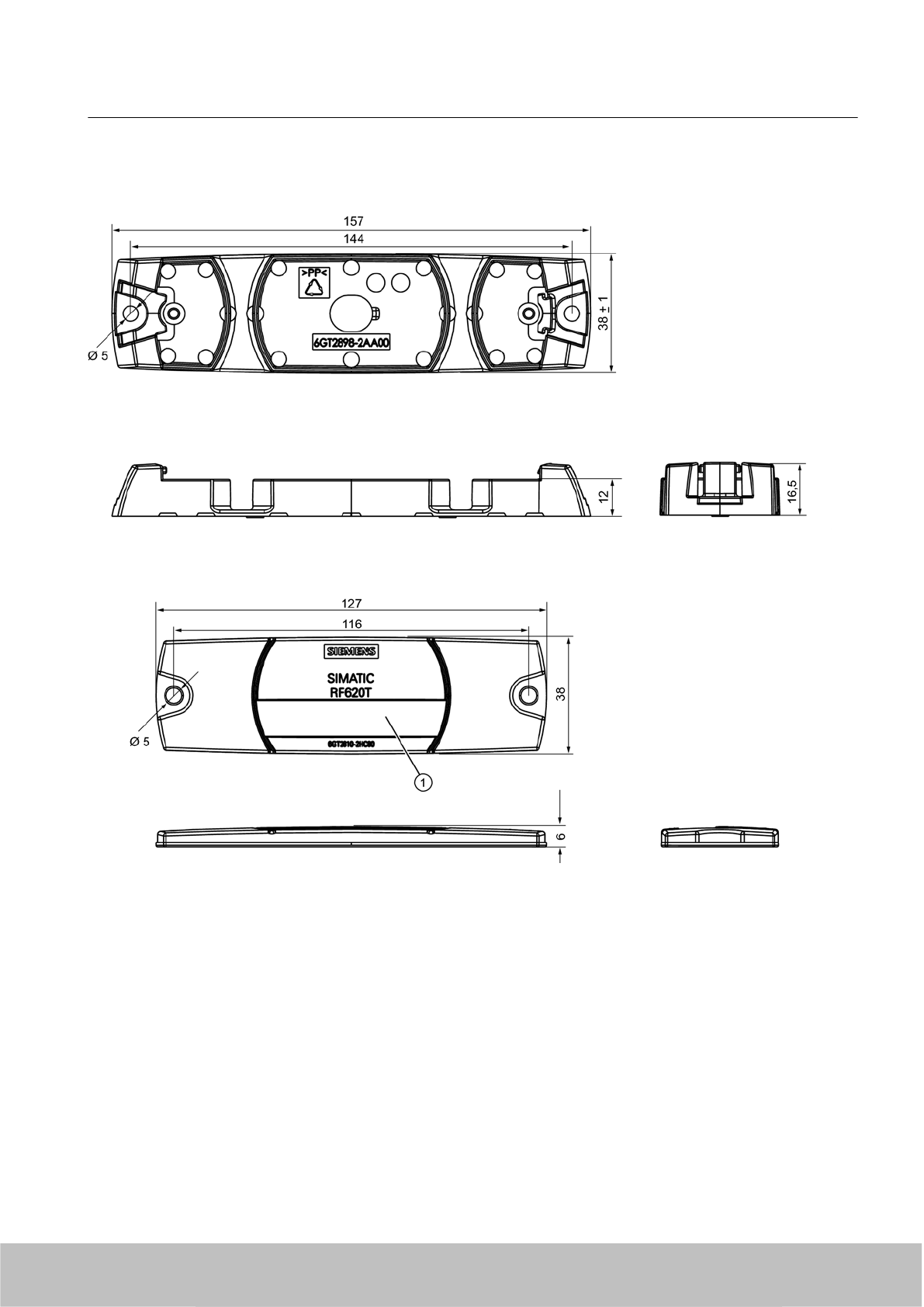
7.5.8 Dimension drawing
Figure 7-25 SIMATIC RF620T UHF container tag
Units of measurement: All dimensions in mm
Tolerances, unless indicated otherwise, are +-0.5 mm.
①Labeling area, see Section Characteristics (Page 235)
Transponder/tags
7.5 SIMATIC RF620T
SIMATIC RF600
System Manual, 06/2010, J31069-D0171-U001-A10-7618 255
Draft Version 02.06.2010
7.6 SIMATIC RF630T
7.6.1 Characteristics
The SIMATIC RF630T transponder is a passive (i.e. battery-free) and maintenance-free,
cylindrical data carrier. It operates on the basis of the UHF Class 1 Gen 2 technology and is
used for storing the electronic product code (EPC) of 96 bits/240 bits. The transponder also
has a 512-bit user memory.
Application areas include the mounting of metallic components (e.g. engine assembly in the
automobile industry) as well as RF identification of tools, containers and metal frames.
The RF630T is small and rugged and suitable for industrial applications with IP68/IPX9K
degree of protection. It is highly resistant to oil, grease and cleaning agents.
The SIMATIC RF630T is mounted directly onto metal surfaces to ensure optimum functioning
and its typical detection range is 1.5 m.
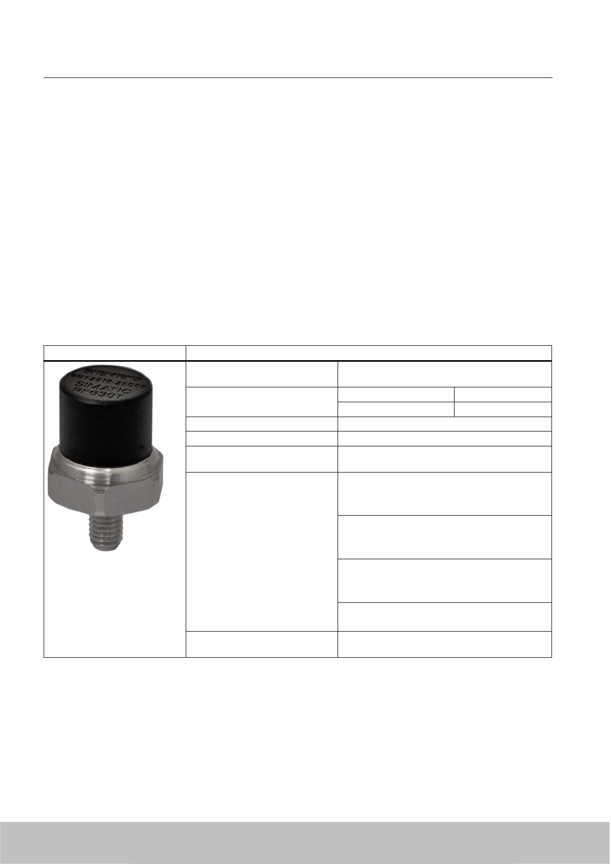
SIMATIC RF630T transponder Features
Application Identification tasks in rugged industrial
environments
Frequency versions Europe USA / Canada
868 MHz 915 MHz
Air interface according to ISO°18000-6C
Polarization Linear
Memory EPC 96 bit/240 bit
Add-on-memory 64 bytes
Read/write range Typically X°m/X°m in connection with: @@@
●RF670R reader and
● RF660A antennas
Typically 1.2 m/1.5 m in connection with:
● RF660R readers and
● RF660A antennas
Typically 0.8 m in connection with:
● RF630R reader and
● RF660A antenna
Typically 0.7 m in connection with:
● RF620R with integrated antenna
Installation Suitable for direct mounting on conductive
materials (preferably metal)
Transponder/tags
7.6 SIMATIC RF630T
SIMATIC RF600
256 System Manual, 06/2010, J31069-D0171-U001-A10-7618
Draft Version 02.06.2010

7.6.2 Ordering data
Ordering data Order no.
SIMATIC RF630T (Europe)
●For attaching to metal surfaces
● Frequency 865 MHz to 868 MHz
6GT2810-2EC00
SIMATIC RF630T (USA / Canada)
● For attaching to metal surfaces
● Frequency 902 MHz to 928 MHz
6GT2810-2EC10
7.6.3 Planning application
7.6.3.1 Optimum antenna/transponder positioning with plane mounting of the transponder on metal
The maximum reading range is achieved when the reader antenna is positioned at right angles
to the mounting surface. In the case of parallel mounting directly above the transponder,
detection is not possible.
Positioning of the RF660A antenna in combination with the RF670R/RF630R reader
The RF670R and RF630R reader can operate with an RF660A antenna which can be
positioned as shown.
Transponder/tags
7.6 SIMATIC RF630T
SIMATIC RF600
System Manual, 06/2010, J31069-D0171-U001-A10-7618 257
Draft Version 02.06.2010
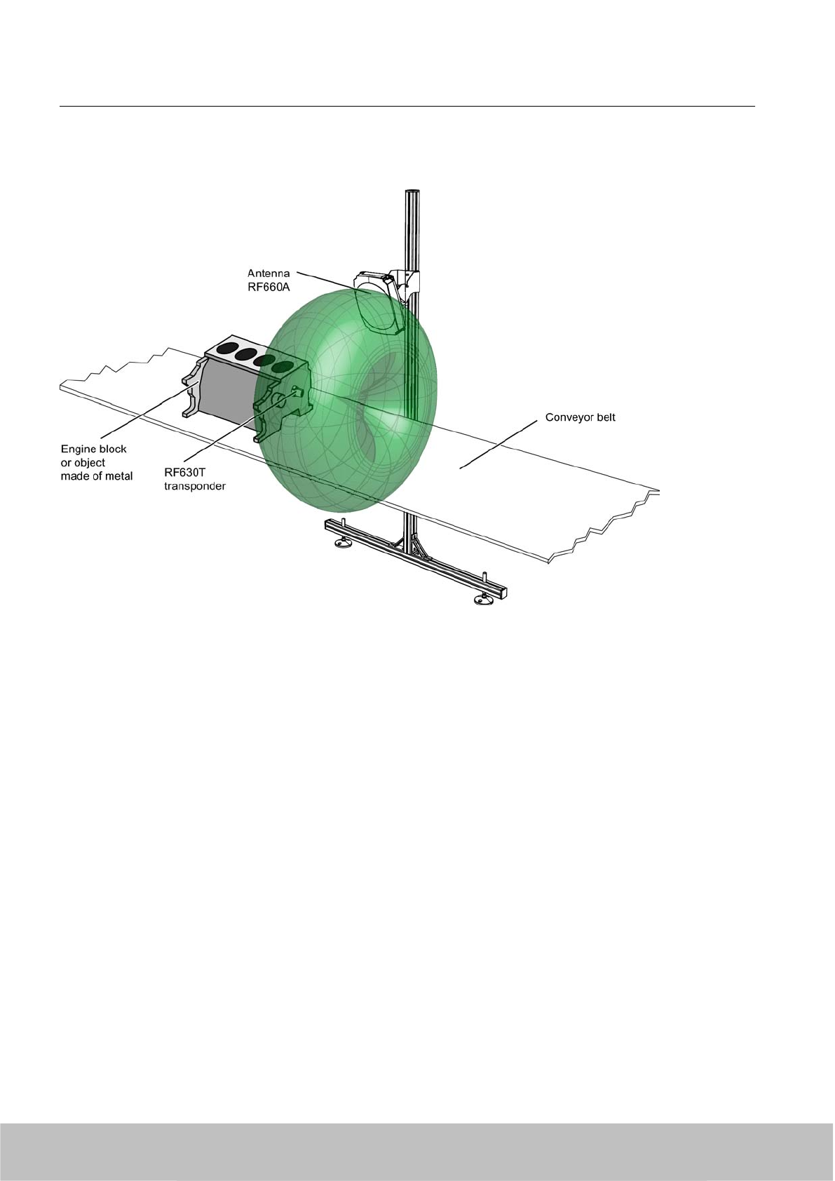
RF630T application example
Figure 7-26 RF630T application example
Transponder/tags
7.6 SIMATIC RF630T
SIMATIC RF600
258 System Manual, 06/2010, J31069-D0171-U001-A10-7618
Draft Version 02.06.2010
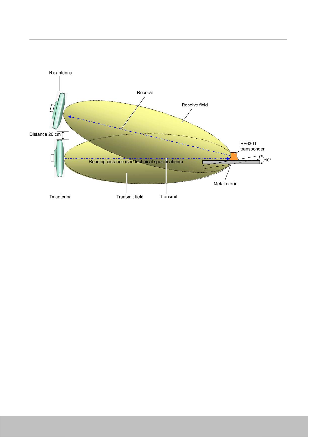
Positioning of two RF660A antennas (RF660R reader)
Figure 7-27 Example of optimum antenna/transponder positioning
Depending on the design of the metal bracket (surface parallel to the transmitting antenna),
an angle of 10 degrees will have a favorable effect.
Positioning of the RF620R reader
The RF620R reader with an integrated circular polarized antenna can be placed in the same
position as the RF660A antennas with reference to the RF630T transponder.
Please note the different reading ranges for the RF600 readers in SectionElectrical data
(Page 267)
7.6.3.2 Reading range when mounted on flat metallic carrier plates
The transponder generally has linear polarization. The polarization axis runs as shown in the
diagram below. If the tag is centrally mounted on a flat metal plate, which may either be almost
Transponder/tags
7.6 SIMATIC RF630T
SIMATIC RF600
System Manual, 06/2010, J31069-D0171-U001-A10-7618 259
Draft Version 02.06.2010
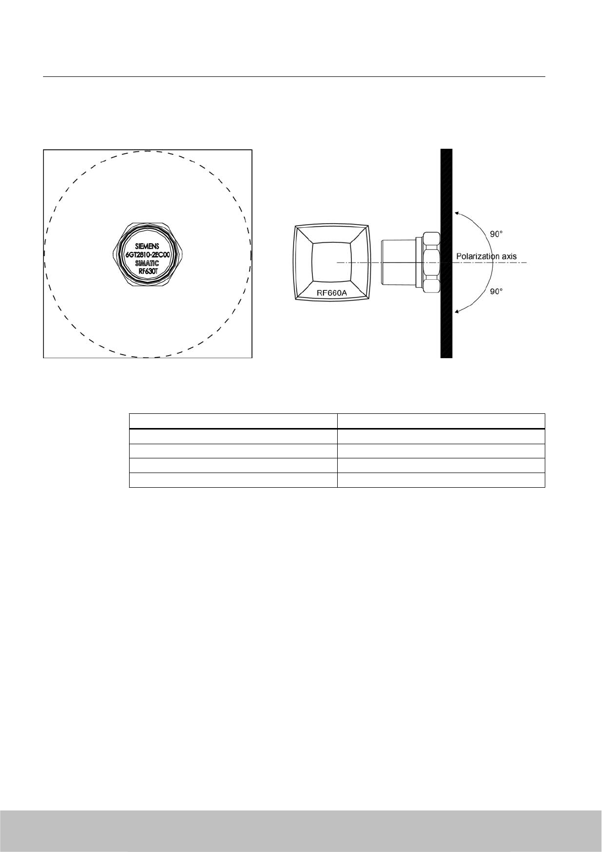
square or circular, it can be aligned in any direction since the transmitting and receiving
RF660A antennas operate with circular polarization.
Figure 7-28 Optimum positioning of the transponder on a (square or circular) metal plate
Table 7-17 Reading range on flat metallic carrier plates
Carrier plate material Reading range
Metal plate of at least Ø 300 mm 100 %
Metal plate Ø 150 mm Approx. 75 %
Metal plate Ø 120 mm Approx. 50 %
Metal plate Ø 85 mm Approx. 40 %
On rectangular carrier plates, the reading distance depends on the mounting orientation of the
transponder
7.6.3.3 Influence of conducting walls on the reading range
If there are conducting walls or restrictions in the vicinity that could shade the radio field, a
distance of approx. 10 cm is recommended between the transponder and the wall. In principle,
walls have least influence if the polarization axis is vertical to the conducting wall.
Transponder/tags
7.6 SIMATIC RF630T
SIMATIC RF600
260 System Manual, 06/2010, J31069-D0171-U001-A10-7618
Draft Version 02.06.2010
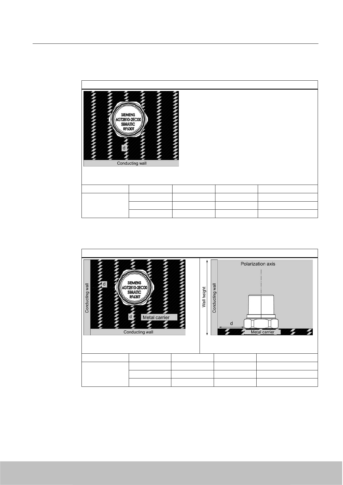
Reading range: One conducting wall
Influence on reading range when positioned against one conducting wall
Top view
Distance d 20 mm 50 mm 100 mm
Reading range Approx. 40 % Approx. 40 % Approx. 90 % Wall height 20 mm
Approx. 40 % Approx. 90 % Approx. 90 % Wall height 50 mm
Approx. 40 % Approx. 40 % Approx. 90 % Wall height 100 mm
Reading range: Two conducting walls
Influence on reading range when positioned against two conducting walls
Side view
Distance d 20 mm 50 mm 100 mm
Reading range Approx. 90 % Approx. 90 % Approx. 90 % Wall height 20 mm
Approx. 25 % Approx. 90 % Approx. 90 % Wall height 50 mm
Approx. 25 % Approx. 90 % Approx. 90 % Wall height 100 mm
The values specified in the tables above must be complied with.
Transponder/tags
7.6 SIMATIC RF630T
SIMATIC RF600
System Manual, 06/2010, J31069-D0171-U001-A10-7618 261
Draft Version 02.06.2010
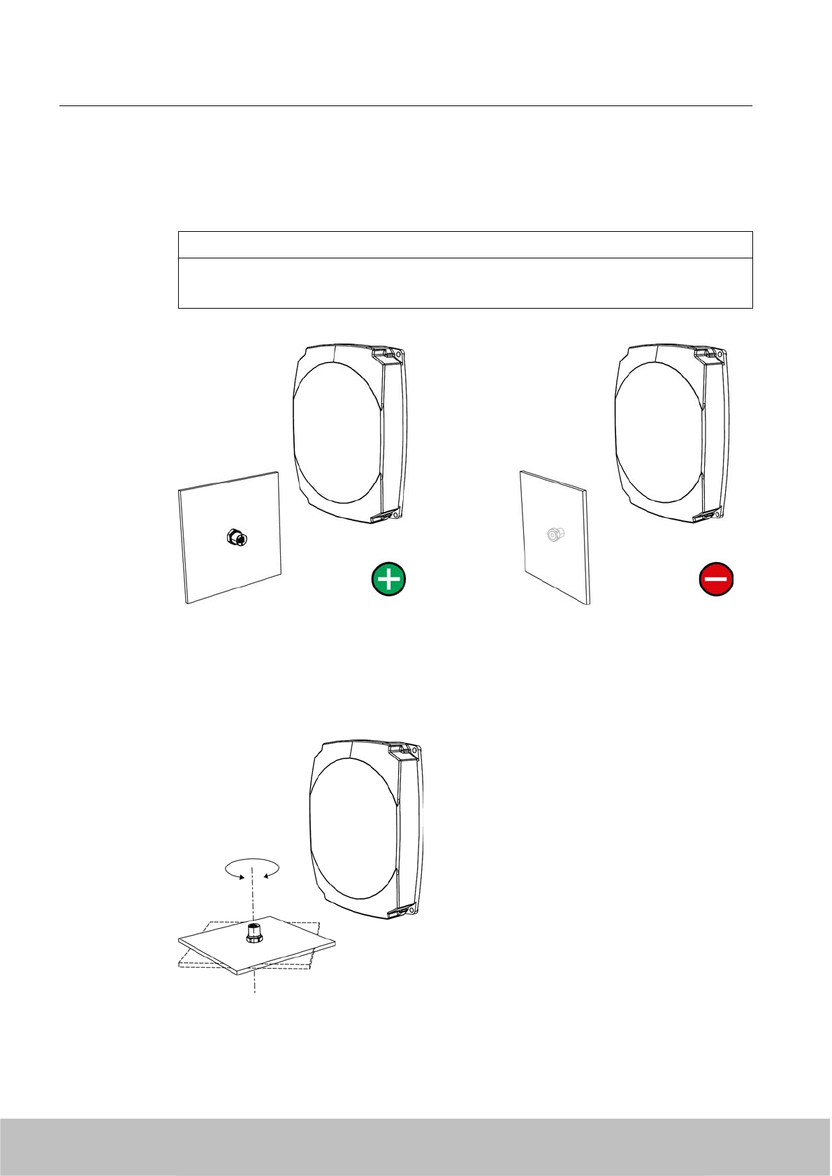
7.6.3.4 Directional radiation pattern of the transponder
Preferably, align the data carrier orthogonal to the transmitting antenna. If, however, the tag
including the metallic carrier plate is tilted, the reading range will be reduced.
NOTICE
Incorrect alignment of the transponder
When you align the transponder in parallel with the transmitting antenna, it cannot be read!
Optimum alignment of the transponder to the
transmitting antenna
Incorrect alignment of the transponder to the
transmitting antenna
Rotation about the polarization axis
If the transponder mounting surface is circular there is almost no change in the reading range.
Transponder/tags
7.6 SIMATIC RF630T
SIMATIC RF600
262 System Manual, 06/2010, J31069-D0171-U001-A10-7618
Draft Version 02.06.2010
Rotation of the mounting plane
Figure 7-29 Characteristics of the transponder on rotation of the mounting plane
7.6.4 Mounting instructions
Properties Description
Type of installation M6 bolt fixing, spanner size 19 mm
Tightening torque (at room temperature) ≤ 6 Nm
Note
Make sure that the mounting surface is even when mounting the transponder. Electrical
contact between the mounting surface and the transponder is necessary.
Without a metal surface the transponder does not function.
Transponder/tags
7.6 SIMATIC RF630T
SIMATIC RF600
System Manual, 06/2010, J31069-D0171-U001-A10-7618 263
Draft Version 02.06.2010
7.6.5 Memory configuration
SIMATIC memory configuration
The following graphic shows the structure of the virtual SIMATIC memory for the RF620R/
RF630R reader and explains the function of the individual memory areas. The SIMATIC
memory configuration is based on the 4 memory banks, as they are defined in EPC Global.
Figure 7-30 SIMATIC memory model
Transponder/tags
7.6 SIMATIC RF630T
SIMATIC RF600
264 System Manual, 06/2010, J31069-D0171-U001-A10-7618
Draft Version 02.06.2010

Memory configuration for RF630T
Tag User
[hex]
EPC TID RESERVED
(passwords)
Special
Range Access KILL‑PW Lock
function
RF630T * 00 - 3F FF00-FF0B
(240 bit =
FF00-FF1D)
read/
write
FFC0-FFC7 FF80-FF87 Yes Yes
Memory representation according to EPC
The memory of the ISO 18000-6C G2XM chip is logically divided into four different memory
banks:
Memory bank (decimal) Memory type Description
MemBank 112USER User-writable USER memory area
MemBank 102TID Is defined by the manufacturer, contains the class identifier and serial
number of a tag
MemBank 012EPC Contains the EPC data, the protocol information and the CRC data
of a tag.
You can write to the EPC memory area. In the delivery condition, the
memory contents can have the following states:
● containing the same data
● containing different data
MemBank 002RESERVED Contains the access password.
The graphic below illustrates the exact memory utilization: Each box in the right part of the
graphic represents one word (16 bit) in the memory.
Transponder/tags
7.6 SIMATIC RF630T
SIMATIC RF600
System Manual, 06/2010, J31069-D0171-U001-A10-7618 265
Draft Version 02.06.2010
Color Mode of access by SIMATIC RF600 reader
Read
Write / read
Figure 7-31 Representation of the RF630T memory configuration according to EPC (logical memory
map)
Parameterization
The parameterization possibilities that are available to you for each reader of the RF600 family
are outlined in section Overview of parameterization of RF600 reader (Page 325). Detailed
information for parameterization as well as examples for describing and reading specific
memory areas can be found in the referenced chapters of the documentation.
Transponder/tags
7.6 SIMATIC RF630T
SIMATIC RF600
266 System Manual, 06/2010, J31069-D0171-U001-A10-7618
Draft Version 02.06.2010
7.6.6 Technical specifications
7.6.6.1 Mechanical data
Property Description
Dimensions (D x H) 21 mm x 21 mm (without thread), tolerance 1 mm
spanner size 19 mm
Design Plastic enclosure: PA 6.6 GF, silicone-free
Thread: Stainless steel
Weight approx. 22 g
Installation directly on metal without spacing
7.6.6.2 Electrical data
Property Description
Europe USA / Canada
Air interface According to ISO 18 000-6 C According to ISO 18 000-6 C
Frequency range 865 … 868 MHz 902 MHz ... 928 MHz 1)
Necessary transmit power 2 W (ERP) 4 W (EIRP)
Reading range
Mounting on metal 2)
at least 1.2 m, typically 1.5 m at least 1.2 m, typically 1.5 m
Writing range
Mounting on metal 2)
at least 0.8 m
typically 1.2 m
at least 0.8 m
typically 1.2 m
Polarization type Linear Linear
Minimum distance to transmit
antenna
Approx. 0.15 m Approx. 0.15 m
Energy source Energy via electro-magnetic field via
antenna, no battery required
Energy via electro-magnetic field via
antenna, no battery required
Multi-tag capability Yes, minimum distance between data
carriers ≥ 50 mm 3)
Yes, minimum distance between data
carriers ≥ 50 mm 3)
1) Reduction of range to about 70% at the band limits 902 MHz or 928 MHz; detection is
guaranteed at 915 MHz due to frequency hopping procedure.
2) Mounting on a flat surface with a diameter of at least 150 mm and at room temperature.
3) When the minimum distances are not reached, there is a reduction in the maximum read
and write distances of the transponder.
Transponder/tags
7.6 SIMATIC RF630T
SIMATIC RF600
System Manual, 06/2010, J31069-D0171-U001-A10-7618 267
Draft Version 02.06.2010
7.6.6.3 Memory specifications
Property Description
Type EPC Class 1 Gen 2
Memory organization EPC code 96 bits/240 bits
User memory 64 bytes
TID 64 bits
Reserved (passwords) 64 bits
Protocol ISO 18000-6C
Data retention time 10 years
Read cycles Unlimited
Write cycles Minimum at +22 °C 100 000
7.6.6.4 Environmental conditions
Feature Description
Temperature range during operation -25 °C … +85 °C
Temperature range during storage -40 °C to +125 °C
Shock
Vibration
compliant with EN 60721-3-7 Class 7 M3
100 g, 1)
20 g, 1)
Torsion and bending load Not permissible
Degree of protection IP 68 according to EN 60529:
(45 minutes. Immersion in water; water depth 1 m
from
top edge of enclosure at +20 °C)
IPx9K according to DIN 40005-9
(steam jet-air ejector: 150 mm;
10 to 15 l/min; 100 bar; 75 °C)
1) The values for shock and vibration are maximum values and must not be applied continuously.
7.6.6.5 Chemical resistance of the transponder
The following table provides an overview of the chemical resistance of the plastic cap of the
transponder made of PA 6.6 GF. Different values apply to the stainless steel bolt head. It must
be emphasized that the plastic enclosure is extremely resistant to chemicals in automobiles
(e.g.: oil, grease, diesel fuel, gasoline) which are not listed separately.
Concentration 20 °C 60 °C
Ammonia, w. conc. + +
20 + +
Benzol + +
Bleach solution (12.5 % effective chlorine) - ᅳ
Butane, gas, liquid + 1) Nothing
specified
Transponder/tags
7.6 SIMATIC RF630T
SIMATIC RF600
268 System Manual, 06/2010, J31069-D0171-U001-A10-7618
Draft Version 02.06.2010

Concentration 20 °C 60 °C
Butyl acetate (acetic acid butyl ester) + 1) Nothing
specified
Calcium chloride, saturated 10% solution + ○
Chlorine ᅳ ᅳ
Chrome baths, tech. ᅳ ᅳ
Iron salts, w. k. g. - -
Acetic acid, w. 10 ○ ᅳ
Ethyl alcohol, w., undenaturated 40 + Nothing
specified
Formaldehyde 30 + Nothing
specified
Formalin + Nothing
specified
Glycerine + Nothing
specified
Isopropanol + +
Potassium hydroxide, w. 10-15 % ○ Nothing
specified
Magnesium salts, w. + 1) Nothing
specified
Methyl alcohol, w. 50 + Nothing
specified
Lactic acid, w. + ᅳ
Sodium carbonate, w. (soda) + Nothing
specified
Sodium chloride, w. ○ Nothing
specified
Sodium hydroxide 10 % + Nothing
specified
Nitrobenzol ○ 1) Nothing
specified
Phosphoric acid 10 - -
Propane + Nothing
specified
Nitric acid 10 - ᅳ
Hydrochloric acid 10 - ᅳ
Sulphur dioxide Low ○ Nothing
specified
Sulphuric acid 25 - ᅳ
10 - ᅳ
Hydrogen sulphide Dry + -
Carbon tetrachloride 1-4 % + Nothing
specified
1) Nothing specified for stainless steel
Transponder/tags
7.6 SIMATIC RF630T
SIMATIC RF600
System Manual, 06/2010, J31069-D0171-U001-A10-7618 269
Draft Version 02.06.2010
Abbreviations
+Resistant
○ Limited resistance
ᅳNot resistant
w. Aqueous solution
k. g. Cold saturated
7.6.7 Certificates and approvals
Table 7-18 6GT2810-2EC00 - RF630T UHF Tool Tag - Europe
Certificate Description
Compatible with R&TTE directive
Table 7-19 6GT2810-2EC10 - RF630T Gen 2 UHF Tool Tag - USA / Canada
Standards
FCC
Federal Communications
Commission
Passive labels and transponders comply with the valid regulations;
certification is not required.
In preparation
Transponder/tags
7.6 SIMATIC RF630T
SIMATIC RF600
270 System Manual, 06/2010, J31069-D0171-U001-A10-7618
Draft Version 02.06.2010
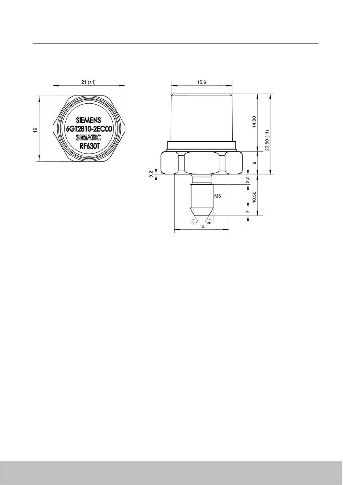
7.6.8 Dimension drawing
Figure 7-32 SIMATIC RF630T
Units of measurement: All dimensions in mm
General tolerances in accordance with DIN ISO 2768f.
7.7 SIMATIC RF640T
7.7.1 Characteristics
The SIMATIC RF640T Transponder is a passive, i.e. battery-free, round-shaped data carrier,
operated in the UHF frequency spectrum on the basis of the UCODE HSL standards.
Fields of application are industrial asset management, RF identification of tools, containers
and metallic equipment.
The tool tag is small, smart, and rugged, suitable for industrial applications with a high degree
of protection (IP68) and is resistant to mineral oils, lubricants and cleaning agents.
The SIMATIC RF640T is preferably to be mounted on a flat metal surface of at least 150 mm
diameter where it has a typical sensing distance of 2 m
Transponder/tags
7.7 SIMATIC RF640T
SIMATIC RF600
System Manual, 06/2010, J31069-D0171-U001-A10-7618 271
Draft Version 02.06.2010
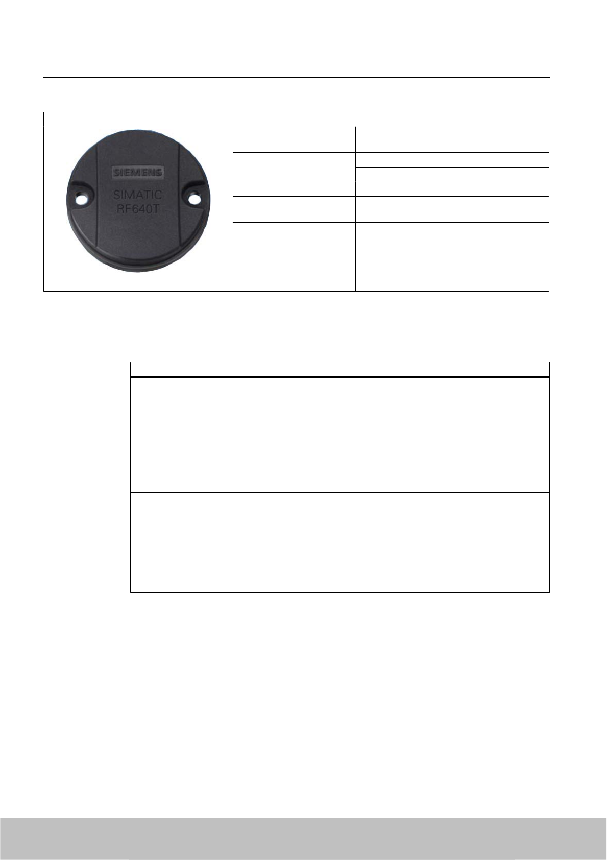
SIMATIC RF640T transponder Characteristics
Application Identification tasks in rugged industrial
environments
Frequency versions Europe USA / Canada
868 MHz 915 MHz
Polarization Linear
Memory 256-byte EEPROM, of which 216 bytes are
user-definable
Read/write range typically 2.0 m in connection with:
●RF660R readers and
●RF660A antennas
Installation Suitable for direct mounting on conductive
materials (preferably metal)
7.7.2 Ordering data
Ordering data Order no.
SIMATIC RF640T (Europe)
●For attaching to metal surfaces
●Frequency 865 MHz to 868 MHz,
●216-byte user memory
●-25 °C to +85 °C operating temperature
● Dimensions 50 mm x 8 mm (DxH)
● IP 68 / IP x9K degree of protection
● ATEX
6GT2810-0DC00
SIMATIC RF640T (USA / Canada)
● For attaching to metal surfaces
● Frequency 915 MHz
● 216-byte user memory
●-25 °C to +85 °C operating temperature
● Dimensions 50 mm x 8 mm (DxH)
● IP 68 / IP x9K degree of protection
6GT2810-0DC10
Transponder/tags
7.7 SIMATIC RF640T
SIMATIC RF600
272 System Manual, 06/2010, J31069-D0171-U001-A10-7618
Draft Version 02.06.2010
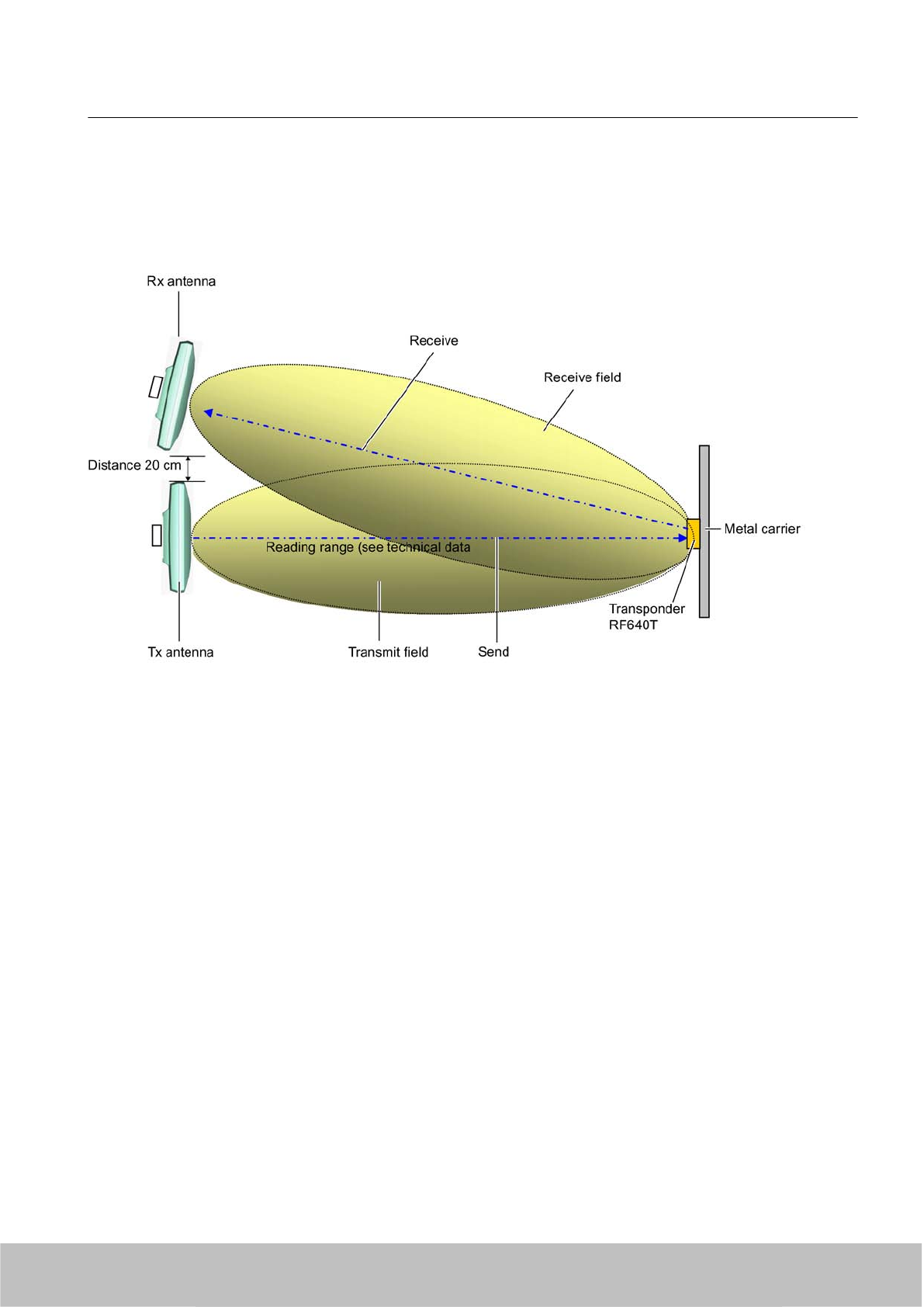
7.7.3 Planning the use
7.7.3.1 Optimum antenna/transponder positioning with plane mounting of the transponder on metal
Figure 7-33 Example of optimum antenna/transponder positioning
7.7.3.2 Reading range when mounted on flat metallic carrier plates
The transponder generally has linear polarization. The polarization axis runs as shown in the
diagram below. If the tag is centrically mounted on a flat metal plate, which may either be
Transponder/tags
7.7 SIMATIC RF640T
SIMATIC RF600
System Manual, 06/2010, J31069-D0171-U001-A10-7618 273
Draft Version 02.06.2010
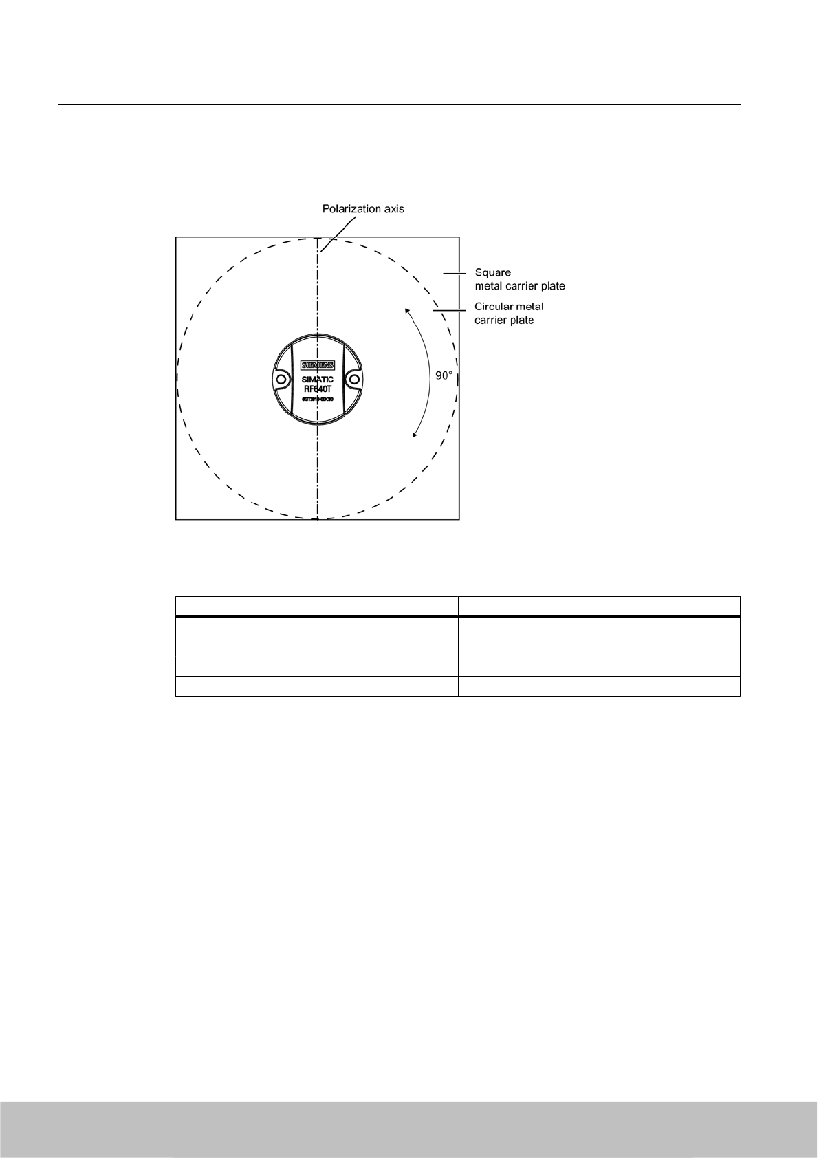
almost square or circular, it can be aligned in any direction since the transmitting and receiving
RF660A antennas operate with circular polarization.
Figure 7-34 Optimum positioning of the transponder on a (square or circular) metal plate
Table 7-20 Reading range on flat metallic carrier plates
Carrier plate material Reading range
Metal plate of at least Ø 150 mm 100 %
Metal plate Ø 120 mm Approx. 80 %
Metal plate Ø 85 mm Approx. 55 %
Metal plate Ø 65 mm Approx. 40 %
On rectangular carrier plates, the reading distance depends on the mounting orientation of the
transponder A 90° rotation of the transponder about the axis of symmetry may result in greater
reading distances
7.7.3.3 Influence of conducting walls on the reading range
If there are conducting walls or restrictions in the vicinity that could shade the radio field, a
distance of approx. 10 cm is recommended between the transponder and the wall In principle,
walls have least influence if the polarization axis is orthogonal to the conducting wall.
Transponder/tags
7.7 SIMATIC RF640T
SIMATIC RF600
274 System Manual, 06/2010, J31069-D0171-U001-A10-7618
Draft Version 02.06.2010
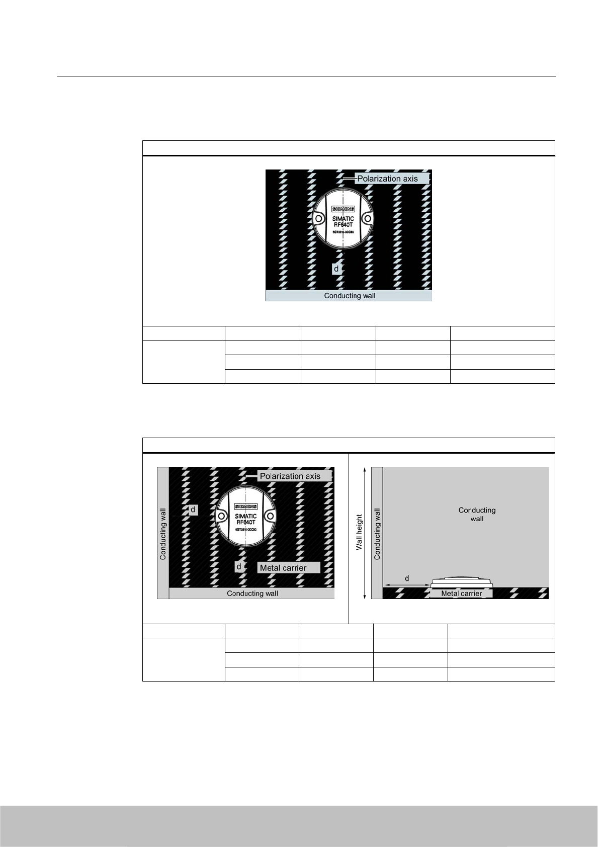
Reading range: One conducting wall
Influence on reading range when positioned against one conducting wall
Top view
Distance d 20 mm 50 mm 100 mm
Reading range Approx. 90 % Approx. 90 % Approx. 95 % Wall height 20 mm
Approx. 80 % Approx. 90 % Approx. 90 % Wall height 50 mm
Approx. 70 % Approx. 75 % Approx. 90 % Wall height 100 mm
Reading range: Two conducting walls
Influence on reading range when positioned against two conducting walls
Top view Side view
Distance d 20 mm 50 mm 100 mm
Reading range Approx. 75 % Approx. 90 % Approx. 90 % Wall height 20 mm
Approx. 50 % Approx. 45 % Approx. 80 % Wall height 50 mm
Approx. 40 % Approx. 45 % Approx. 75 % Wall height 100 mm
The values specified in the tables above must be complied with.
Transponder/tags
7.7 SIMATIC RF640T
SIMATIC RF600
System Manual, 06/2010, J31069-D0171-U001-A10-7618 275
Draft Version 02.06.2010
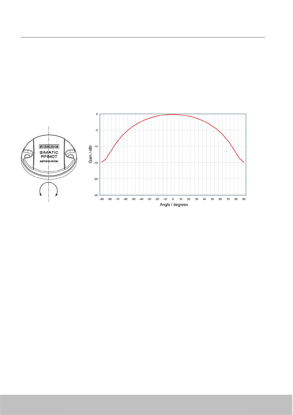
7.7.3.4 Directional radiation pattern of the transponder
Preferably, align the tag parallel to the transmitting antenna. If, however, the tag including the
metallic carrier plate is tilted, the reading range will be reduced.
Rotation about the polarization axis
Figure 7-35 Transponder characteristics when rotated about the polarization axis
Transponder/tags
7.7 SIMATIC RF640T
SIMATIC RF600
276 System Manual, 06/2010, J31069-D0171-U001-A10-7618
Draft Version 02.06.2010
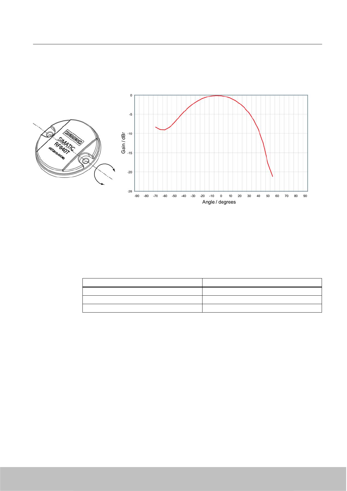
Rotation orthogonal to the polarization axis
Figure 7-36 Transponder characteristics when rotated orthogonally to the polarization axis (within the tag plane)
7.7.3.5 Reading range when mounted on non-metallic carriers
The transponder is generally designed for mounting on metallic objects which provide the
conditions for the maximum reading ranges
Table 7-21 Reading range on non-metallic carriers
Carrier plate material Reading range
Transponder on wooden carrier Approx. 40 %
Transponder on plastic carrier Approx. 35 %
Transponder on plastic mineral water bottle Approx. 55 %
100% reading distance refers to a metal plate of at least 150 mm diameter.
7.7.3.6 Use of the transponder in the Ex protection area
TÜV NORD CERT GmbH, appointed center no. 0044 as per Article 9 of the Directive 94/9/EC
of the European Council of 23 March 1994, has confirmed the compliance with the essential
health and safety requirements relating to the design and construction of equipment and
protective systems intended for use in hazardous areas as per Annex II of the Directive.
The essential health and safety requirements are satisfied in accordance with standards
EN 60079-0: 2004, EN 60079-11: 2007, IEC 61241-0: 2004 and IEC 61241-11: 2005.
Transponder/tags
7.7 SIMATIC RF640T
SIMATIC RF600
System Manual, 06/2010, J31069-D0171-U001-A10-7618 277
Draft Version 02.06.2010
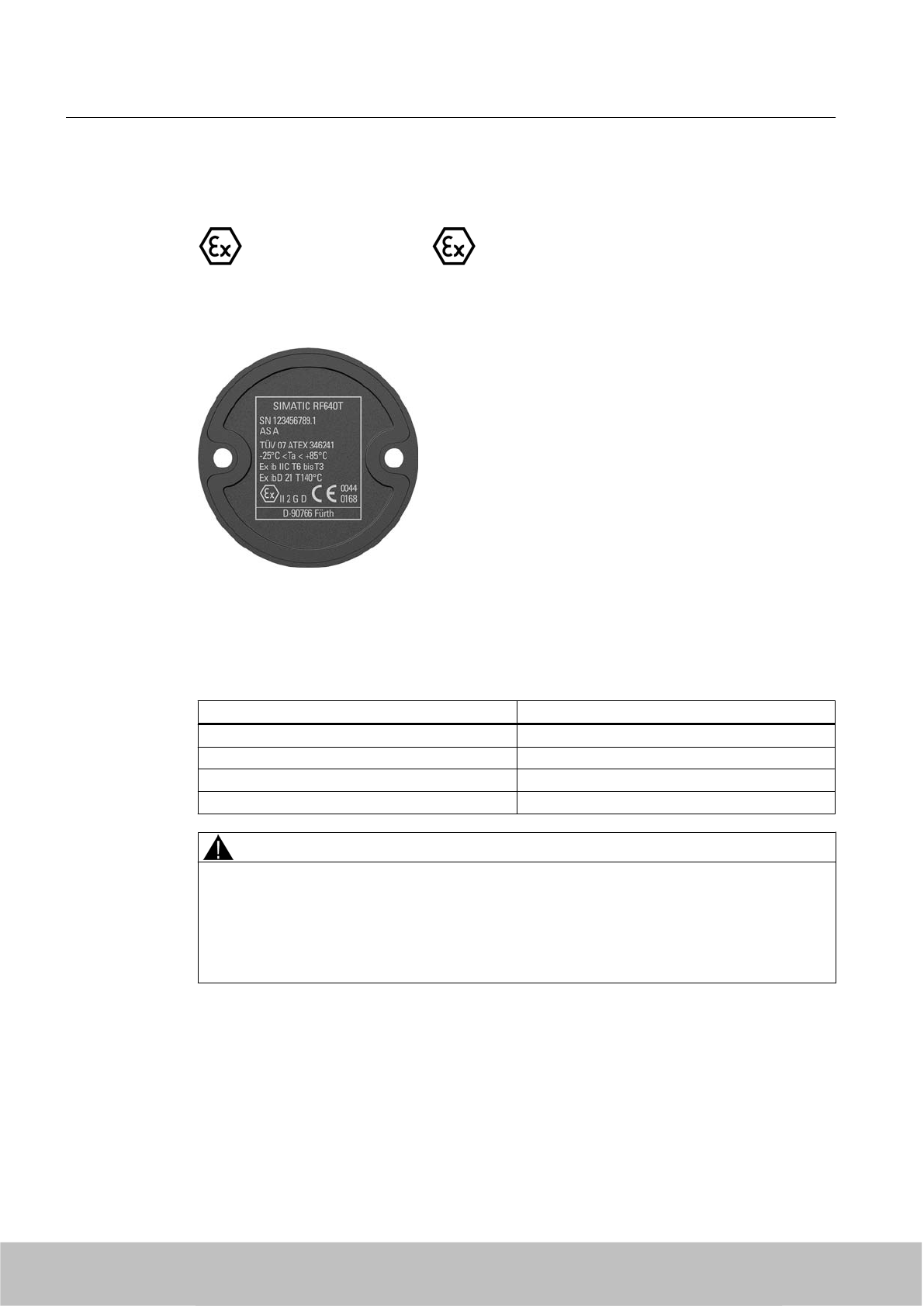
Identification
The identification is as follows:
II 2 G Ex ib IIC T6 to T3 or II 2 D Ex ibD 21 T140°C, -25 °C < Ta°< +85 °C
7.7.3.7 Use of the transponder in hazardous areas for gases
Temperature class delineation for gases
The temperature class of the transponder for hazardous areas depends on the ambient
temperature range:
Ambient temperature range Temperature class
-25 °C to +85 °C T3
-25 °C to +60 °C T4
-25 °C to +40 °C T5
-25 °C to +30 °C T6
WARNING
Ignitions of gas-air mixtures
When using the RF640T transponder, check to ensure that the temperature class is observed
in respect of the requirements of the area of application
Non-compliance with the permitted temperature ranges while using the transponder can lead
to ignitions of gas-air mixtures.
Transponder/tags
7.7 SIMATIC RF640T
SIMATIC RF600
278 System Manual, 06/2010, J31069-D0171-U001-A10-7618
Draft Version 02.06.2010
WARNING
Ignitions of gas-air mixtures
The maximum transmitting power of the transmitter used to operate the transponder must
not exceed 2 W.
Non-compliance with the permissible transmitting power can lead to ignitions of gas-air
mixtures.
7.7.3.8 Use of the transponder in hazardous areas for dusts
The equipment is suitable for dusts whose ignition temperatures for a dust layer of 5 mm are
higher than 210 °C (smoldering temperature). With the ignition temperature specified
according to IEC 61241-0 and IEC 61241-11 according to the type of ignition protection iD,
the smoldering temperature of the dust layer is referenced in this case.
Temperature class delineation for dusts
Ambient temperature range Temperature value
-25 °C < Ta < +85 °C T140 °C
WARNING
Ignitions of dust-air mixtures
When using the RF640T transponder, check to ensure that the temperature values are
complied with in connection with the requirements of the application area.
Non-compliance with the permitted temperature ranges while using the transponder can lead
to ignitions of dust-air mixtures.
7.7.4 Mounting instructions
Properties Description
Type of installation Screw attachment, (M4 screws)
(two grommets DIN 433 and two hexagon M4 socket head cap screws
DIN 6912)
Tightening torque (at room temperature) < 1.2 Nm
Transponder/tags
7.7 SIMATIC RF640T
SIMATIC RF600
System Manual, 06/2010, J31069-D0171-U001-A10-7618 279
Draft Version 02.06.2010
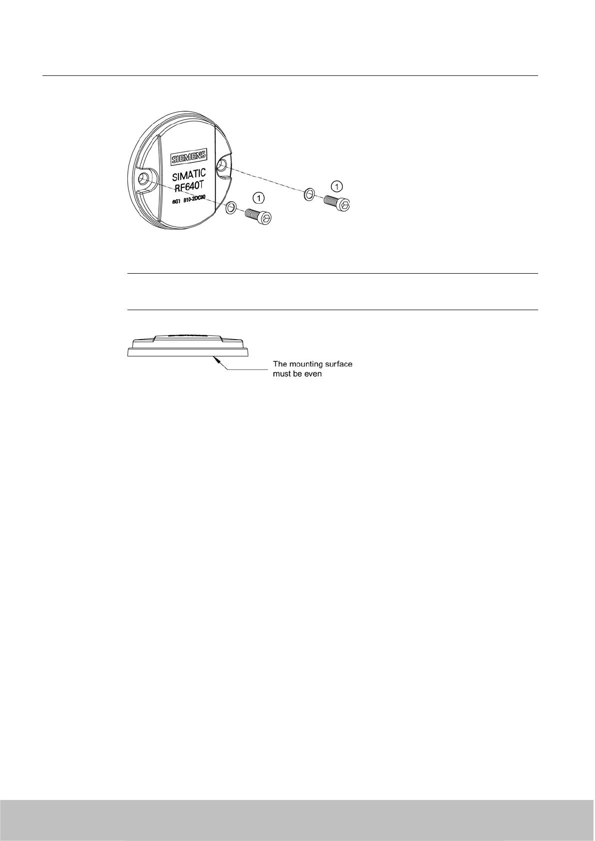
Figure 7-37 Screw mounting
Note
Make sure that the mounting surface is even when mounting the transponder.
Transponder/tags
7.7 SIMATIC RF640T
SIMATIC RF600
280 System Manual, 06/2010, J31069-D0171-U001-A10-7618
Draft Version 02.06.2010
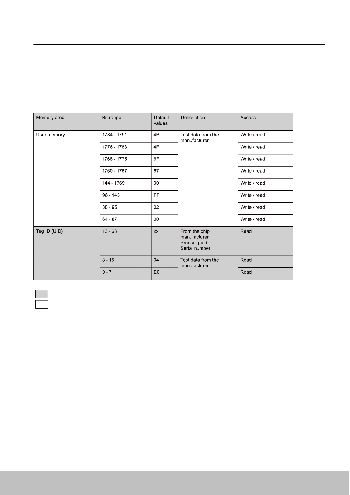
7.7.5 Memory configuration
Memory banks
The memory of the ISO 18000-6B UCODE HSL chip is logically divided into two different areas:
Color Access by SIMATIC RF660R / SIMATIC RF610M
Read
Write / read
Parameterization
The parameterization possibilities that are available to you for each reader of the RF600 family
are outlined in section Overview of parameterization of RF600 reader (Page 325). Detailed
information for parameterization as well as examples for describing and reading specific
memory areas can be found in the referenced chapters of the documentation.
Transponder/tags
7.7 SIMATIC RF640T
SIMATIC RF600
System Manual, 06/2010, J31069-D0171-U001-A10-7618 281
Draft Version 02.06.2010
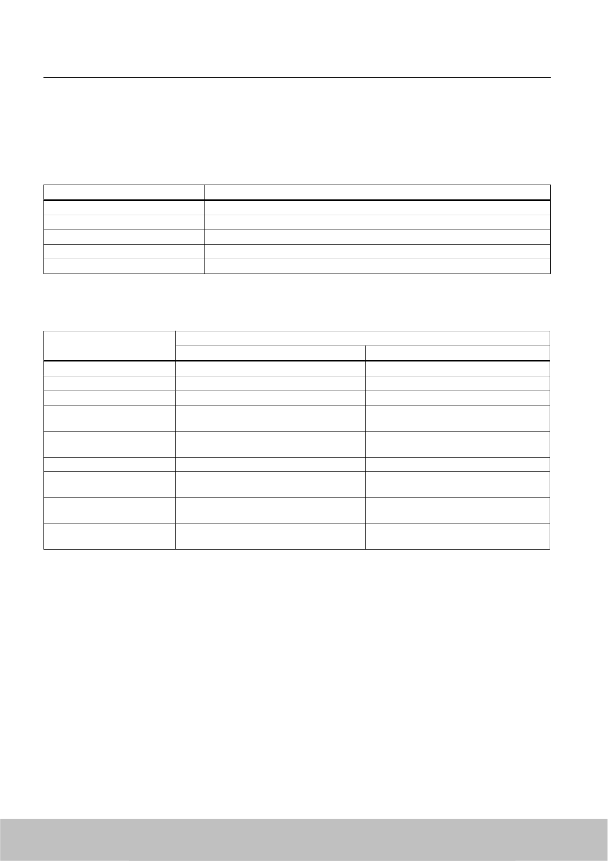
7.7.6 Technical Specifications
7.7.6.1 Mechanical data
Property Description
Dimensions (D x H) 50 mm x 8 mm (+1 mm)
Design PCB with integrated antenna
Design Plastic enclosure (PA12), silicone-free
Weight approx. 13 g
Mounting on metal directly on metal without spacing
7.7.6.2 Electrical data
Property Description
Europe USA / Canada
Air interface to ISO 18 000-6 B to ISO 18 000-6 B
Frequency range 865 … 868 MHz 915 MHz 1)
Necessary transmit power 2 W (ERP) 4 W (EIRP)
Reading range
Mounting on metal 2)
at least 1.5 m
typically 2.0 m
at least 1.5 m
typically 2.0 m
Writing range
Mounting on metal 2)
at least 1.2 m
typically 1.5 m
at least 1.2 m
typically 1.5 m
Polarization type Linear Linear
Minimum distance to transmit
antenna
Approx. 0.2 m Approx. 0.2 m
Energy source Magnetic energy via antenna, without battery Magnetic energy via antenna, without
battery
Multi-tag capability Yes, minimum distance between data
carriers ≥ 50 mm 3)
Yes, minimum distance between data
carriers ≥ 50 mm 3)
1) Reduction of range to about 70 % at the band limits 902 MHz or 928 MHz; recording is
guaranteed at 915 MHz due to frequency hopping procedure.
2) Mounting on a flat surface with a diameter of at least 150 mm
3) When the minimum distances are not reached, there is a reduction in the maximum read
and write distances of the transponder.
See also
Directional radiation pattern of the transponder (Page 276)
Transponder/tags
7.7 SIMATIC RF640T
SIMATIC RF600
282 System Manual, 06/2010, J31069-D0171-U001-A10-7618
Draft Version 02.06.2010
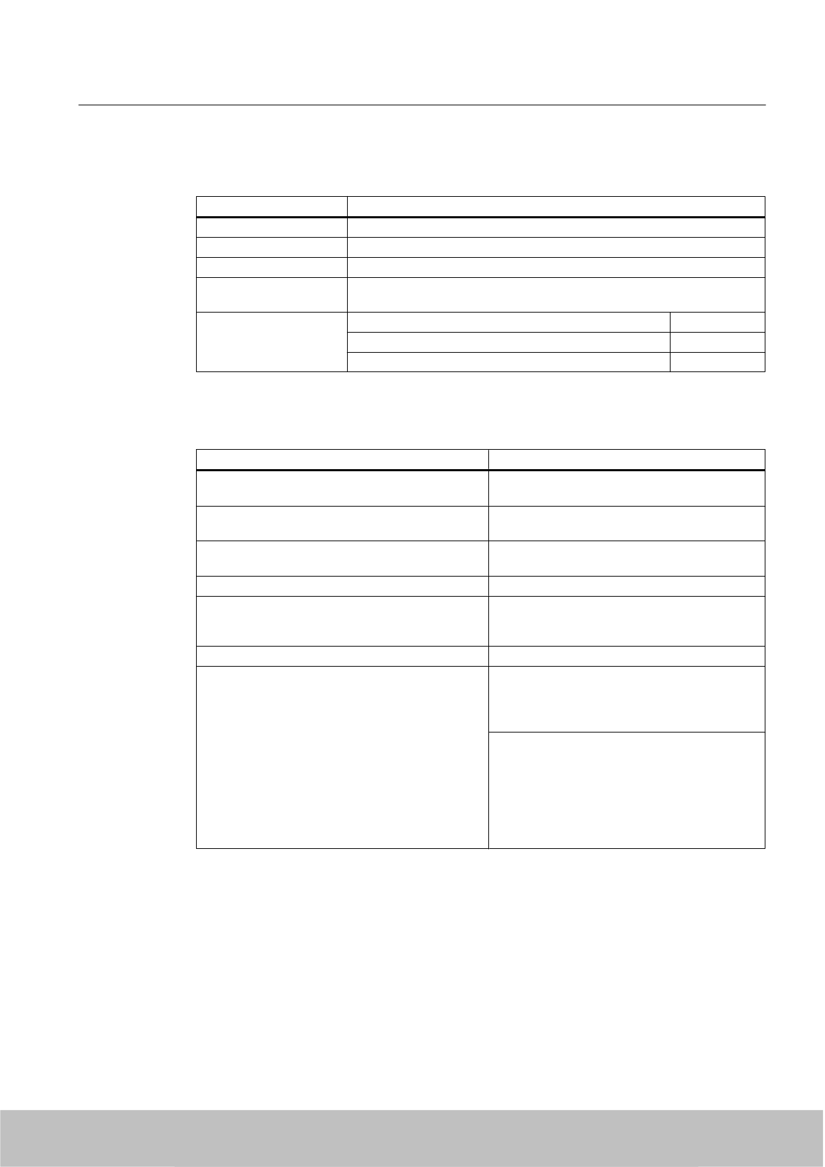
7.7.6.3 Memory specifications
Property Description
Type 256 byte EEPROM
Data retention time 10 years
Read cycles Unlimited
Write cycles Minimum at +22 °C 100 000
Typically at +22 °C 1000 000
Memory organization UID memory (fixed code) (Bytes 0 ... 7) 8 bytes
User memory (Bytes 8 ... 223) 216 bytes
Reserved memory 32 bytes
7.7.6.4 Environmental conditions
Property Description
Temperature range when operating in non-
hazardous areas
-25 °C … 85 °C1)
Temperature range when operating in areas at risk
of a gas explosion with temperature class T3-T6
See alsoUse of the transponder in hazardous
areas for gases (Page 278) 2)
Temperature range when operating in areas at risk
of dust explosions with T140 °C
See alsoUse of the transponder in hazardous
areas for dusts (Page 279) 2)
Temperature range during storage -40 °C … 125 °C1)
Shock
Vibration
compliant with EN 60721-3-7 Class 7 M3
100 g, 3)
20 g, 3)
Torsion and bending load Not permissible
Degree of protection IP 68 according to EN 60529:
(45 minutes. immersion in water; water depth 1 m
from
top edge of housing at +20 °C)
IP x9K according to EN 60529:
● Steam blaster nozzle distance 150 mm
● 10 to 15 l of water per minute
● Pressure 100 bar
●Temperature 75 °C
● Test time 30 seconds
1) At temperatures above 70 °C the casing may distort slightly; this does not however cause
any impairment of function (mechanical or electrical).
2) Directive 94/9/EC of the European Council of 23 March 1994 must be complied with, see
also Chapter "Using the transponder in hazardous areas".
3) The values for shock and vibration are maximum values and must not be applied
continuously.
Transponder/tags
7.7 SIMATIC RF640T
SIMATIC RF600
System Manual, 06/2010, J31069-D0171-U001-A10-7618 283
Draft Version 02.06.2010
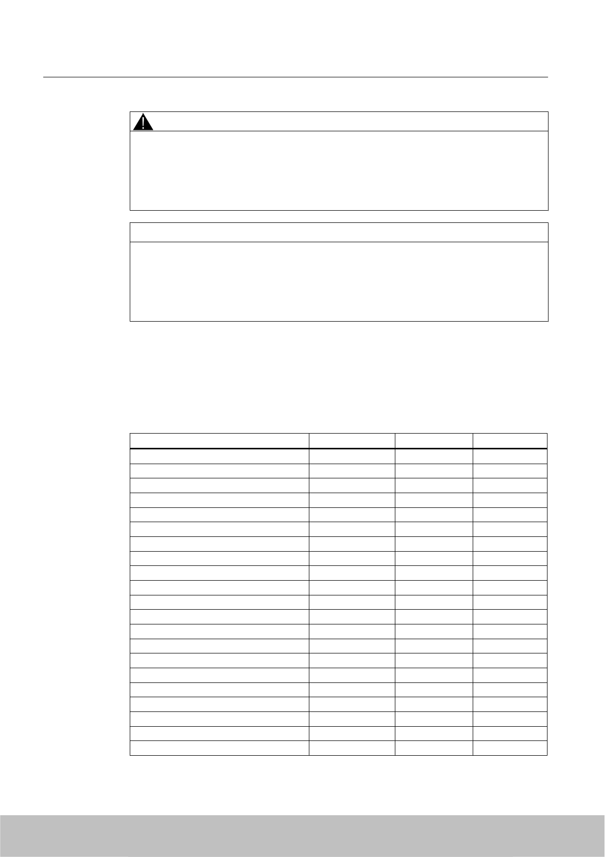
WARNING
Ignitions of gas-air or dust-air mixtures
When using the RF640T transponder, check to ensure that the temperature values are
observed in respect of the requirements of the hazardous area of application.
Non-compliance with the permitted temperature ranges while using the transponder can lead
to ignitions of gas-air or dust-air mixtures.
NOTICE
Damage to the surface of the housing
The values specified for the IP x9K test are maximum values and must not be applied
continuously.
Protracted loading of the transponder can lead to damage to the surface of the housing due
to high pressures.
7.7.6.5 Chemical resistance of the RF640T transponder
The following table gives an overview of the chemical composition of the data memory made
from polyamide 12. The plastic housing has a notably high resistance to chemicals used in
automobiles (e.g.: oil, grease, diesel fuel, gasoline) which are not listed separately.
Concentration 20 °C 60 °C
Battery acid 30 ○○ ᅳ
Ammonia gas ○○○○ ○○○○
Ammonia, w. conc. ○○○○ ○○○○
10 ○○○○ ○○○○
Benzol ○○○○ ○○○
Bleach solution (12.5 % effective chlorine) ○○ ᅳ
Butane, gas, liquid ○○○○ ○○○○
Butyl acetate (acetic acid butyl ester) ○○○○ ○○○○
Calcium chloride, w. ○○○○ ○○○
Calcium nitrate, w. k. g. ○○○○ ○○○
Chlorine ᅳ ᅳ
Chrome baths, tech. ᅳ ᅳ
Iron salts, w. k. g. ○○○○ ○○○○
Acetic acid, w. 50 ᅳ ᅳ
Ethyl alcohol, w., undenaturated 96 ○○○○ ○○○
50 ○○○○ ○○○○
Formaldehyde, w. 30 ○○○ ᅳ
10 ○○○○ ○○○
Formalin ○○○ ᅳ
Glycerine ○○○○ ○○○○
Isopropanol ○○○○ ○○○
Transponder/tags
7.7 SIMATIC RF640T
SIMATIC RF600
284 System Manual, 06/2010, J31069-D0171-U001-A10-7618
Draft Version 02.06.2010

Concentration 20 °C 60 °C
Potassium hydroxide, w. 50 ○○○○ ○○○○
Lysol ○○ ᅳ
Magnesium salts, w. k. g. ○○○○ ○○○○
Methyl alcohol, w. 50 ○○○○ ○○○○
Lactic acid, w. 50 ○○ ᅳ
10 ○○○ ○○
Sodium carbonate, w. (soda) k. g. ○○○○ ○○○○
Sodium chloride, w. k. g. ○○○○ ○○○○
Sodium hydroxide ○○○○ ○○○○
Nickel salts, w. k. g. ○○○○ ○○○○
Nitrobenzol ○○○ ○○
Phosphoric acid 10 ○ V
Propane ○○○○ ○○○○
Mercury ○○○○ ○○○○
Nitric acid 10 ○ ᅳ
Hydrochloric acid 10 ○ ᅳ
Sulphur dioxide Low ○○○○ ○○○○
Sulphuric acid 25 ○○ ᅳ
10 ○○○ ᅳ
Hydrogen sulphide Low ○○○○ ○○○○
Carbon tetrachloride ○○○○ ○○○○
Toluene ○○○○ ○○○
Detergent High ○○○○ ○○○○
Plasticizer ○○○○ ○○○○
Abbreviations
○○○○ Resistant
○○○ Virtually resistant
○○ Limited resistance
○ Less resistant
ᅳNot resistant
w. Aqueous solution
k. g. Cold saturated
Transponder/tags
7.7 SIMATIC RF640T
SIMATIC RF600
System Manual, 06/2010, J31069-D0171-U001-A10-7618 285
Draft Version 02.06.2010
7.7.7 Certificates and approvals
Table 7-22 6GT2810-0DC00 - RF640T UHF Tool Tag - Europe
Certificate Description
CE Approval to R&TTE
For Directive 94/9/EC:
EC type test certification no. TÜV 07 ATEX 346241
Acknowledgement of the quality assurance TÜV 96 ATEX 1125 Q
Table 7-23 6GT2810-0DC10 - RF640T UHF Tool Tag - USA / Canada
Standards
FCC
Federal Communications
Commission
FCC Title 47, Part 15.sections 15.247
Radio Frequency Interference Statement
This equipment has been tested and found to comply with the limits
for a Class A digital device, pursuant to Part 15 of the FCC Rules.
Industry Canada Radio
Standards Specifications
RSS-210 Issue 6, Sections 2.2, A8
This product is UL-certified for the USA and Canada.
It meets the following safety standard(s):
UL 60950-1 - Information Technology Equipment Safety - Part 1:
General Requirements
CSA C22.2 No. 60950 -1 - Safety of Information Technology
Equipment
UL Report E 205089
7.7.7.1 Manufacturer's declaration RF640T UHF Tool Tag Version 1
The plant that manufactured the RF640T UHF Tool Tag Version 1 has an ATEX quality
assurance system recognized by TÜV NORD with notification number TÜV 96 ATEX 1125 Q.
The type test certification for the RF640T UHF Tool Tag Version 1 is stored by
TÜV 07 ATEX 346241.
Manufacturer's address
Siemens AG
Automation and Drives
System Engineering A&D SE
Würzburger Strasse 121
90766 Fürth, Germany.
Transponder/tags
7.7 SIMATIC RF640T
SIMATIC RF600
286 System Manual, 06/2010, J31069-D0171-U001-A10-7618
Draft Version 02.06.2010
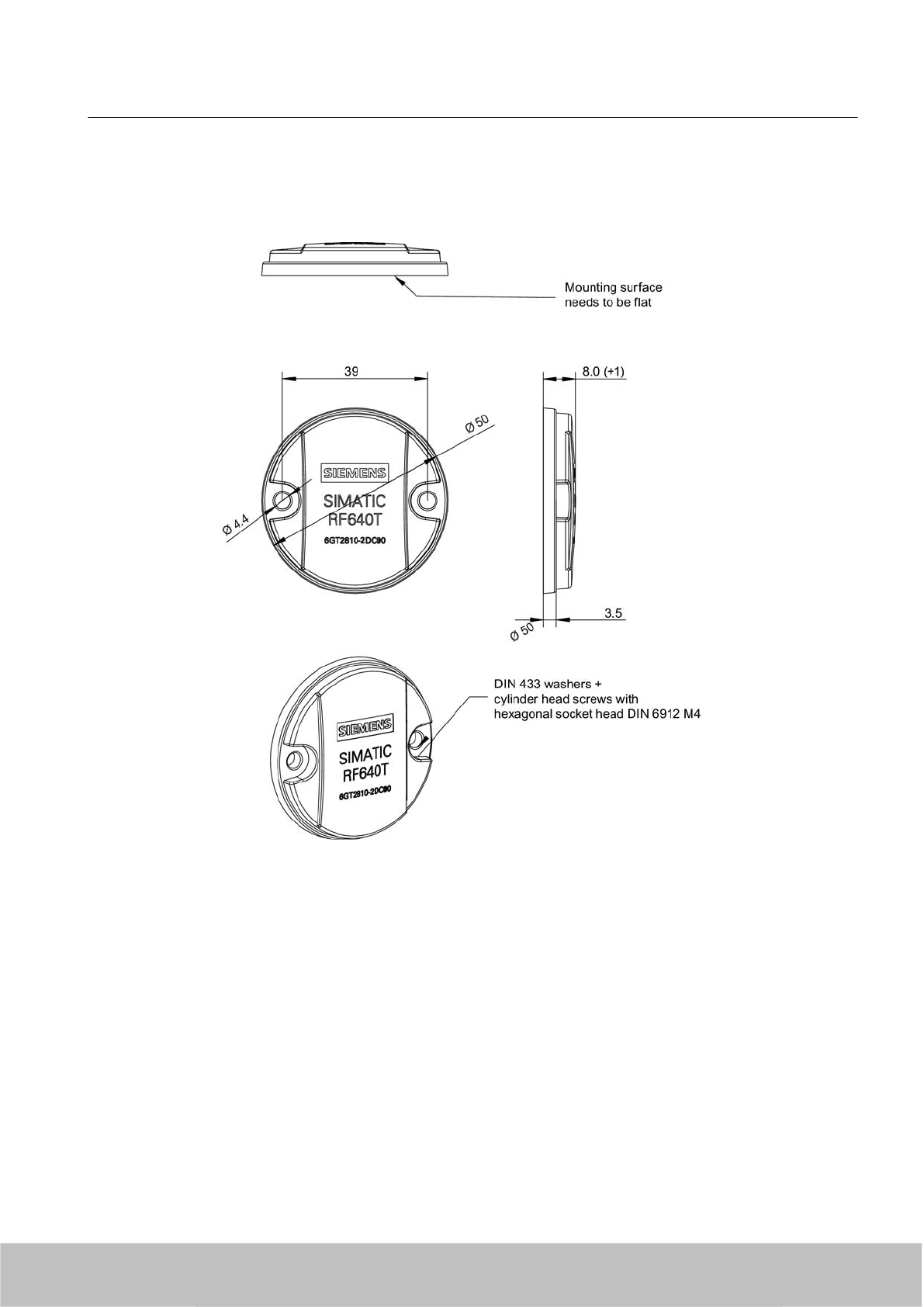
7.7.8 Dimension drawing
Figure 7-38 SIMATIC RF640T UHF Tool Tag Version 1
Units of measurement: All dimensions in mm
7.8 SIMATIC RF640T Gen 2
7.8.1 Characteristics
The SIMATIC RF640T Gen 2 transponder is a passive (i.e. battery-free) and maintenance-
free, round-shaped data carrier. It functions based on the UHF Class 1 Gen 2 technology and
is used for saving the electronic product code (EPC) of 96 bits/240 bits. The transponder also
has a 512-bit user memory.
Transponder/tags
7.8 SIMATIC RF640T Gen 2
SIMATIC RF600
System Manual, 06/2010, J31069-D0171-U001-A10-7618 287
Draft Version 02.06.2010
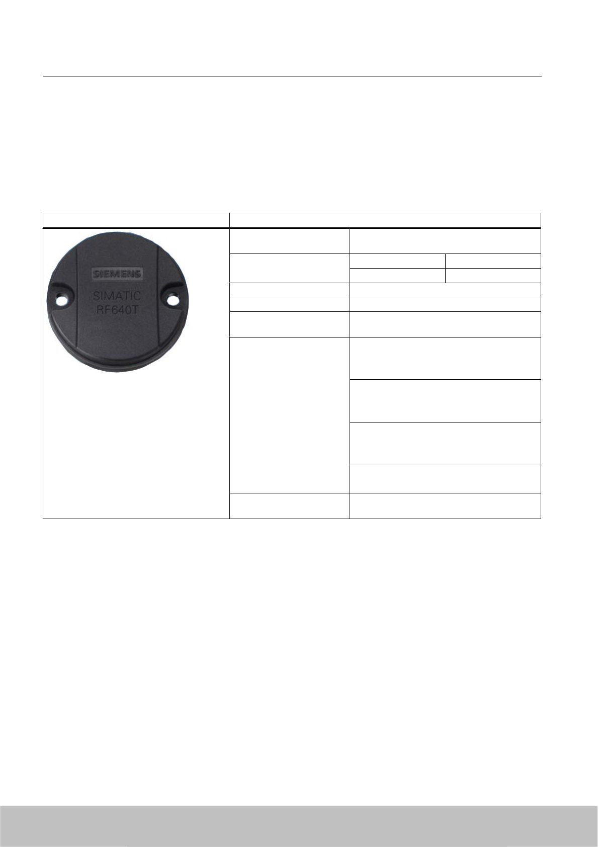
Fields of application are industrial asset management, RF identification of tools, containers
and metallic equipment.
The tool tag is small, smart, and rugged, suitable for industrial applications with degree of
protection IP68. It is resistant to mineral oils, lubricants and detergents.
Preferably the SIMATIC RF640T is to be mounted direct on a flat metal surface of at least
150 mm diameter where it achieves a typical sensing distance of 4 m.
SIMATIC RF640T Gen 2 transponder Features
Application Identification tasks in rugged industrial
environments
Frequency versions Europe USA / Canada
868 MHz 915 MHz
Air interface according to ISO°18000-6C
Polarization Linear
Memory EPC 96 bit/240 bit
Add-on-memory 64 bytes
Read/write range Typically X°m in connection with: @@@
●RF670R reader and
● RF660A antennas
Typically 4.0 m in connection with:
● RF660R readers and
● RF660A antennas
Typically 2 m in connection with:
● RF630R readers and
● RF660A antennas
Typically 2 m in connection with:
● RF620R with integrated antenna
Installation Suitable for direct mounting on conductive
materials (preferably metal)
Transponder/tags
7.8 SIMATIC RF640T Gen 2
SIMATIC RF600
288 System Manual, 06/2010, J31069-D0171-U001-A10-7618
Draft Version 02.06.2010
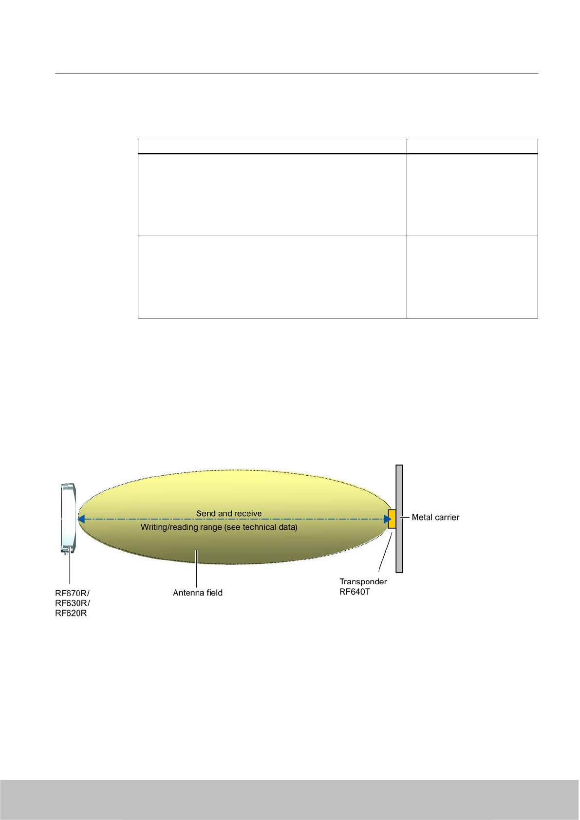
7.8.2 Ordering data
Ordering data Order no.
SIMATIC RF640T Gen 2 (Europe)
●Frequency 865 MHz to 868 MHz
● EPC 96 bits/240 bits
● 64-byte user memory
●-25 °C to +85 °C operating temperature
● Dimensions (D x H) 50 mm x 8 mm
6GT2810-2DC00
SIMATIC RF640T Gen 2 (USA/Canada)
● Frequency 902 MHz to 928 MHz
● EPC 96 bits/240 bits
● 64-byte user memory
●-25 °C to +85 °C operating temperature
● Dimensions (D x H) 50 mm x 8 mm
6GT2810-2DC10
7.8.3 Planning the use
7.8.3.1 Optimum antenna/transponder positioning with plane mounting of the transponder on metal
Example to show optimum antenna/transponder positioning with RF670R, RF630R or RF620R and an
RF600 antenna
Figure 7-39 Example to show optimum antenna/transponder positioning with RF670R, RF630R or RF620R and an RF600
antenna
Transponder/tags
7.8 SIMATIC RF640T Gen 2
SIMATIC RF600
System Manual, 06/2010, J31069-D0171-U001-A10-7618 289
Draft Version 02.06.2010
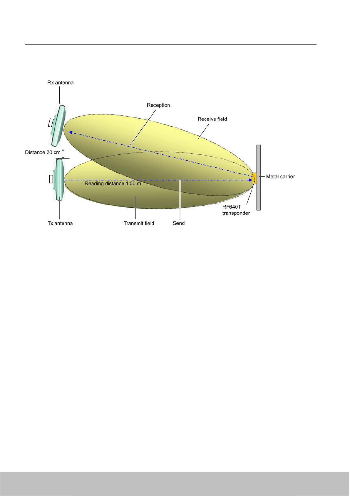
Example of optimum antenna/transponder positioning with RF660R and RF660A antennas
Figure 7-40 Example of optimum antenna/transponder positioning with RF660R and RF660A antennas
7.8.3.2 Reading range when mounted on flat metallic carrier plates
The transponder generally has linear polarization. The polarization axis runs as shown in the
diagram below. If the tag is centrically mounted on a flat metal plate, which may either be
Transponder/tags
7.8 SIMATIC RF640T Gen 2
SIMATIC RF600
290 System Manual, 06/2010, J31069-D0171-U001-A10-7618
Draft Version 02.06.2010
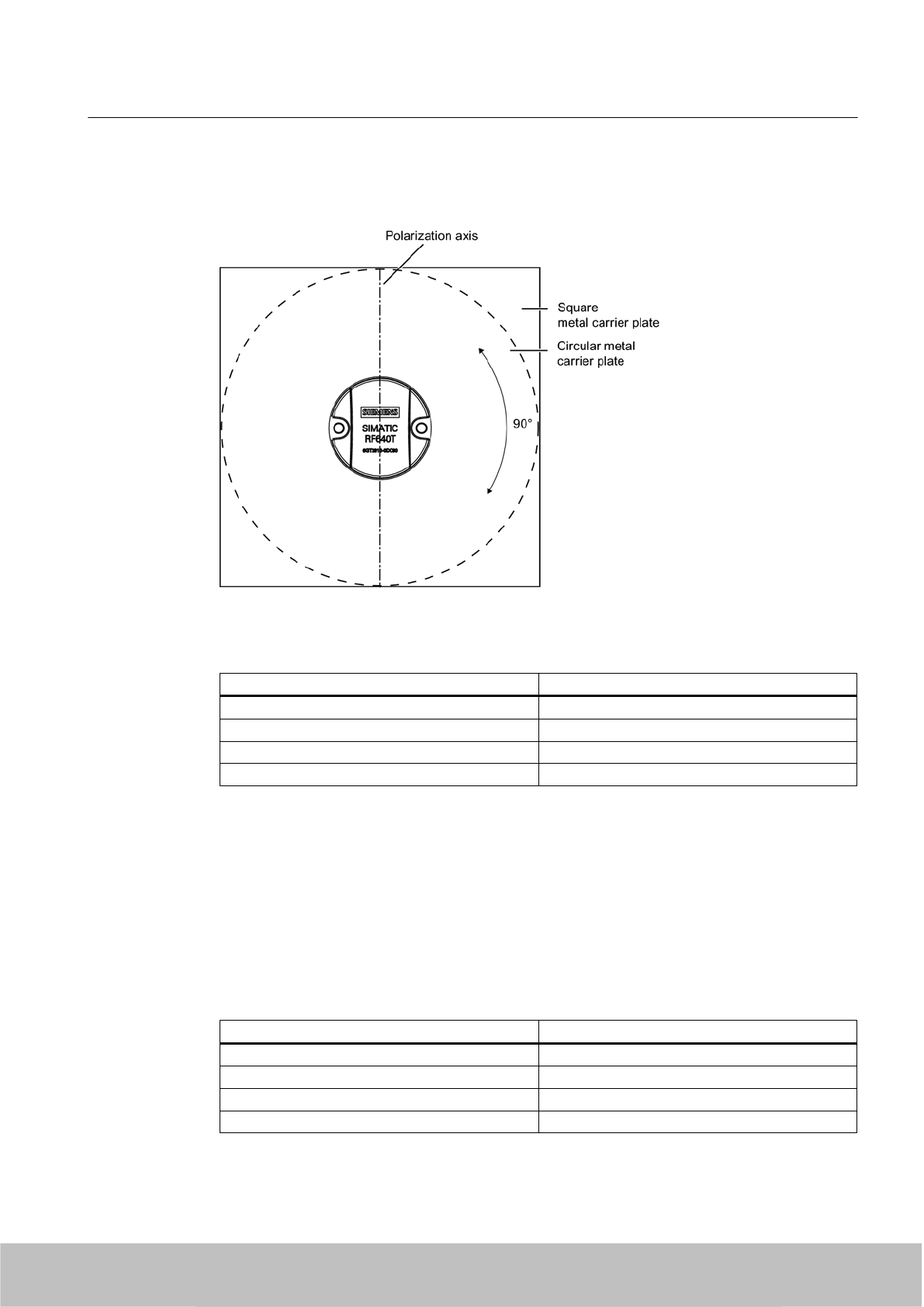
almost square or circular, it can be aligned in any direction since the transmitting and receiving
RF660A antennas operate with circular polarization.
Figure 7-41 Optimum positioning of the transponder on a (square or circular) metal plate
Table 7-24 Reading range on flat metallic carrier plates
Carrier plate material Reading range
Metal plate of at least Ø 150 mm 100%
Metal plate Ø 120 mm Approx. 80%
Metal plate Ø 85 mm Approx. 55%
Metal plate Ø 65 mm Approx. 40%
On rectangular carrier plates, the reading distance depends on the mounting orientation of the
transponder
7.8.3.3 Reading range when mounted on non-metallic carriers
The transponder is generally designed for mounting on metallic objects which provide the
conditions for the maximum reading ranges
Table 7-25 Reading range on non-metallic carriers
Carrier plate material Reading range
Transponder on wooden carrier Approx. 40%
Transponder on plastic carrier Approx. 35%
Transponder on plastic mineral water bottle Approx. 55%
Transponder without base Approx. 30%
Transponder/tags
7.8 SIMATIC RF640T Gen 2
SIMATIC RF600
System Manual, 06/2010, J31069-D0171-U001-A10-7618 291
Draft Version 02.06.2010
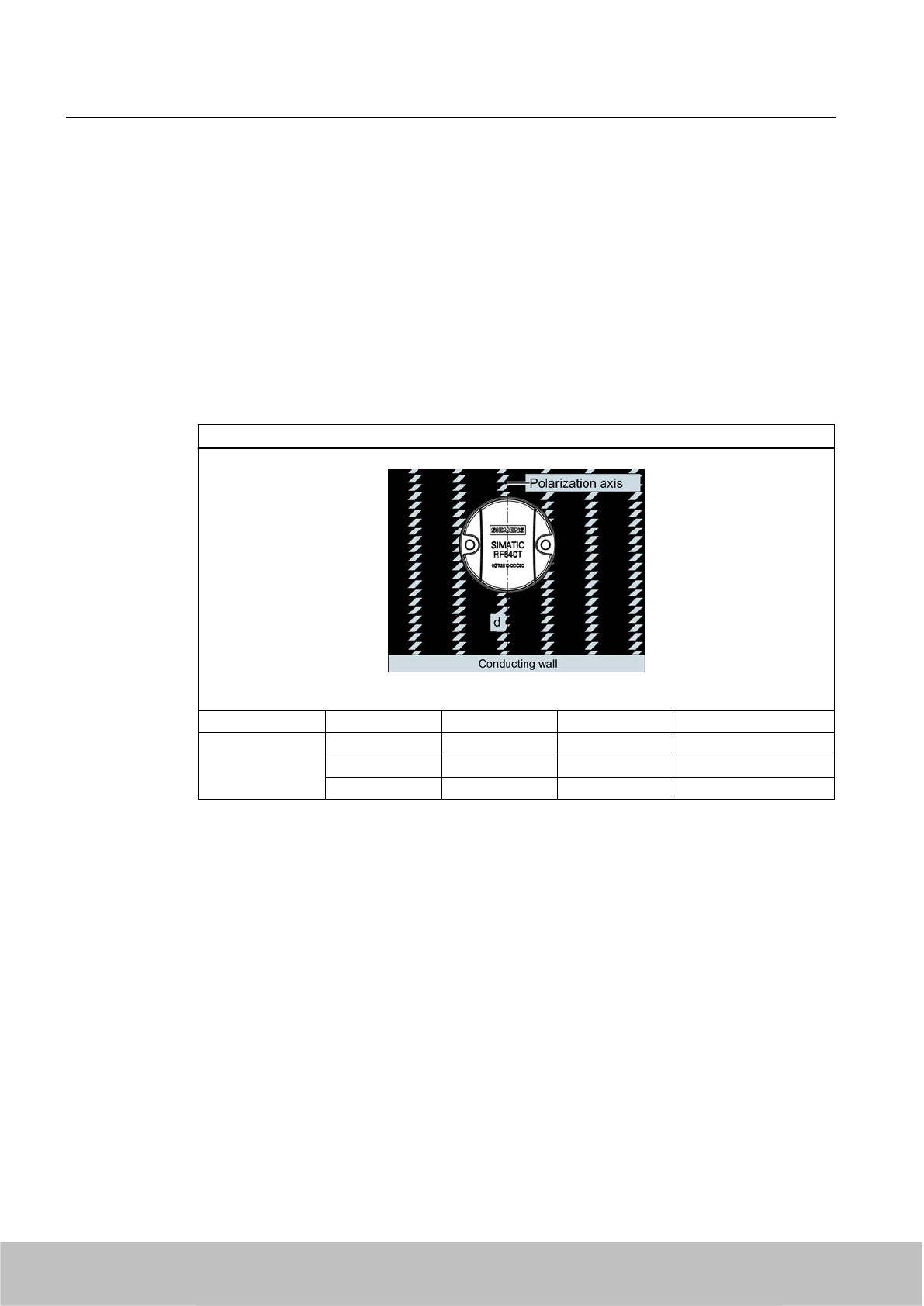
100% reading distance refers to a metal plate of at least 150 mm diameter.
7.8.3.4 Influence of conducting walls on the reading range
If there are conducting walls or restrictions in the vicinity that could shade the radio field, a
distance of approx. 10 cm is recommended between the transponder and the wall In principle,
walls have least influence if the polarization axis is orthogonal to the conducting wall.
Reading range: One conducting wall
Influence on reading range when positioned against one conducting wall
Top view
Distance d 20 mm 50 mm 100 mm
Reading range Approx. 90 % Approx. 90 % Approx. 95 % Wall height 20 mm
Approx. 80 % Approx. 90 % Approx. 90 % Wall height 50 mm
Approx. 70 % Approx. 75 % Approx. 90 % Wall height 100 mm
Transponder/tags
7.8 SIMATIC RF640T Gen 2
SIMATIC RF600
292 System Manual, 06/2010, J31069-D0171-U001-A10-7618
Draft Version 02.06.2010
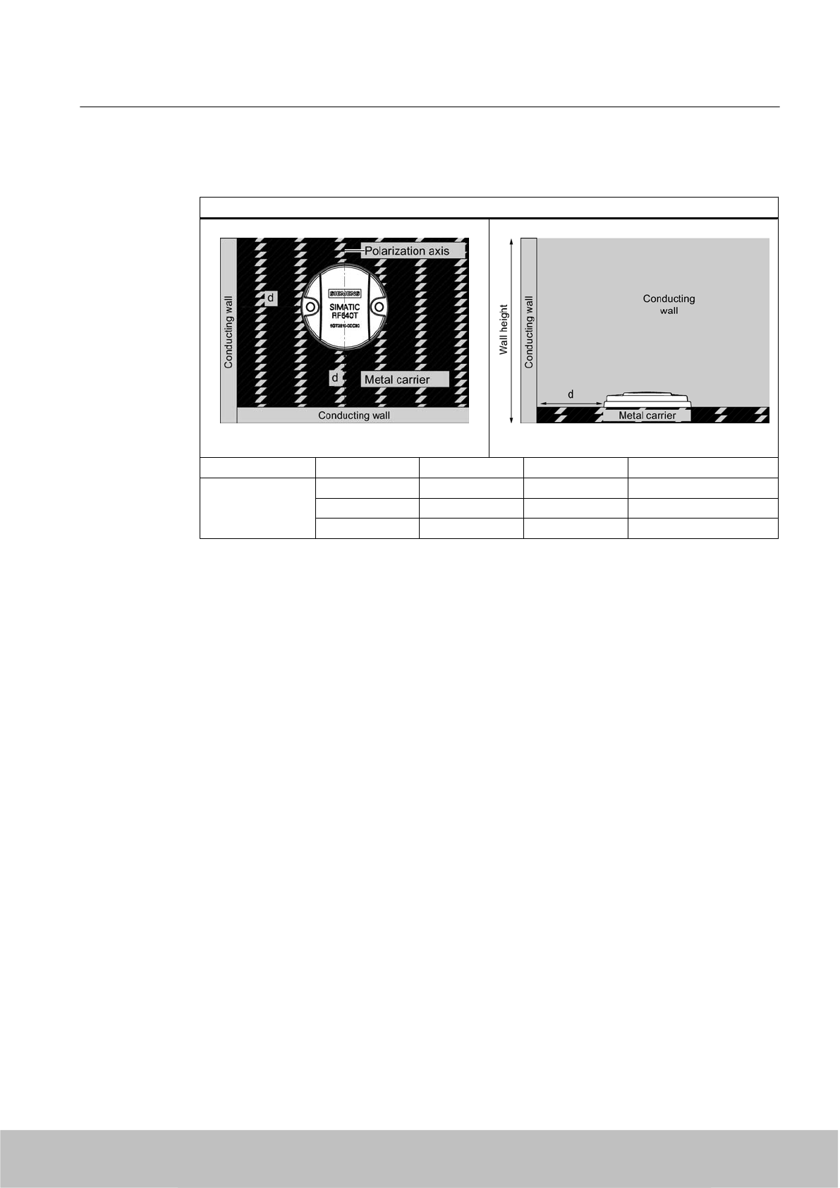
Reading range: Two conducting walls
Influence on reading range when positioned against two conducting walls
Top view
Side view
Distance d 20 mm 50 mm 100 mm
Reading range Approx. 75 % Approx. 90 % Approx. 90 % Wall height 20 mm
Approx. 50 % Approx. 45 % Approx. 80 % Wall height 50 mm
Approx. 40 % Approx. 45 % Approx. 75 % Wall height 100 mm
The values specified in the tables above must be complied with.
7.8.3.5 Directional radiation pattern of the transponder
Preferably, align the tag parallel to the transmitting antenna. If, however, the tag including the
metallic carrier plate is tilted, the reading range will be reduced.
Transponder/tags
7.8 SIMATIC RF640T Gen 2
SIMATIC RF600
System Manual, 06/2010, J31069-D0171-U001-A10-7618 293
Draft Version 02.06.2010
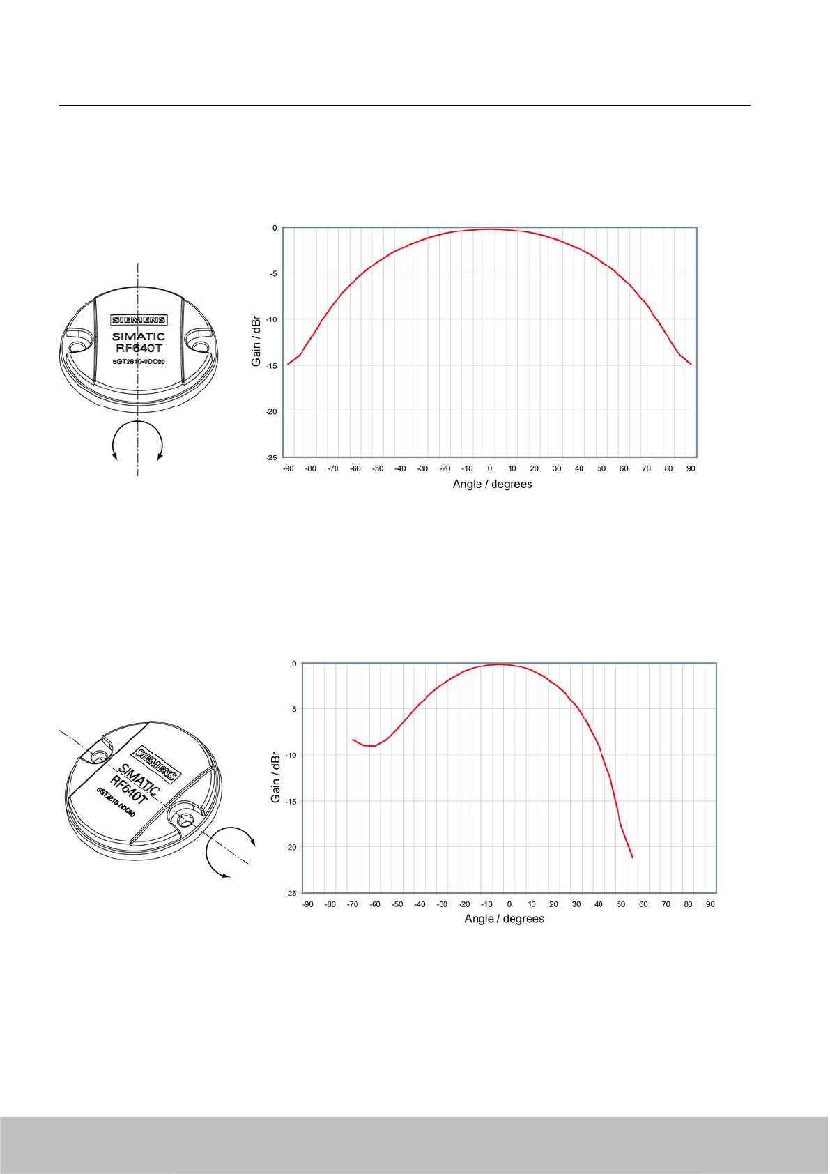
Rotation about the polarization axis
Figure 7-42 Transponder characteristics when rotated about the polarization axis
Rotation orthogonal to the polarization axis
Figure 7-43 Transponder characteristics when rotated orthogonally to the polarization axis (within the tag plane)
Transponder/tags
7.8 SIMATIC RF640T Gen 2
SIMATIC RF600
294 System Manual, 06/2010, J31069-D0171-U001-A10-7618
Draft Version 02.06.2010
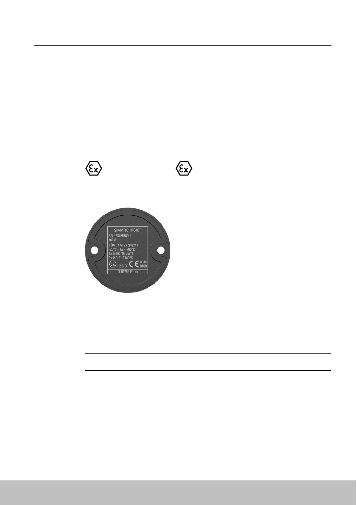
7.8.3.6 Use of the transponder in the Ex protection area
TÜV NORD CERT GmbH, appointed center no. 0044 as per Article 9 of the Directive 94/9/EC
of the European Council of 23 March 1994, has confirmed the compliance with the essential
health and safety requirements relating to the design and construction of equipment and
protective systems intended for use in hazardous areas as per Annex II of the Directive.
The essential health and safety requirements are satisfied in accordance with standards
EN 60079-0: 2004, EN 60079-11: 2007, IEC 61241-0: 2004 and IEC 61241-11: 2005.
Identification
The identification is as follows:
II 2 G Ex ib IIC T6 to T3 or II 2 D Ex ibD 21 T140°C, -25 °C < Ta°< +85 °C
7.8.3.7 Use of the transponder in hazardous areas for gases
Temperature class delineation for gases
The temperature class of the transponder for hazardous areas depends on the ambient
temperature range:
Ambient temperature range Temperature class
-25 °C to +85 °C T3
-25 °C to +60 °C T4
-25 °C to +40 °C T5
-25 °C to +30 °C T6
Transponder/tags
7.8 SIMATIC RF640T Gen 2
SIMATIC RF600
System Manual, 06/2010, J31069-D0171-U001-A10-7618 295
Draft Version 02.06.2010
WARNING
Ignitions of gas-air mixtures
When using the RF640T transponder, check to ensure that the temperature class is observed
in respect of the requirements of the area of application
Non-compliance with the permitted temperature ranges while using the transponder can lead
to ignitions of gas-air mixtures.
WARNING
Ignitions of gas-air mixtures
The maximum transmitting power of the transmitter used to operate the transponder must
not exceed 2 W.
Non-compliance with the permissible transmitting power can lead to ignitions of gas-air
mixtures.
7.8.3.8 Use of the transponder in hazardous areas for dusts
The equipment is suitable for dusts whose ignition temperatures for a dust layer of 5 mm are
higher than 210 °C (smoldering temperature). With the ignition temperature specified
according to IEC 61241-0 and IEC 61241-11 according to the type of ignition protection iD,
the smoldering temperature of the dust layer is referenced in this case.
Temperature class delineation for dusts
Ambient temperature range Temperature value
-25 °C < Ta < +85 °C T140 °C
WARNING
Ignitions of dust-air mixtures
When using the RF640T transponder, check to ensure that the temperature values are
complied with in connection with the requirements of the application area.
Non-compliance with the permitted temperature ranges while using the transponder can lead
to ignitions of dust-air mixtures.
Transponder/tags
7.8 SIMATIC RF640T Gen 2
SIMATIC RF600
296 System Manual, 06/2010, J31069-D0171-U001-A10-7618
Draft Version 02.06.2010
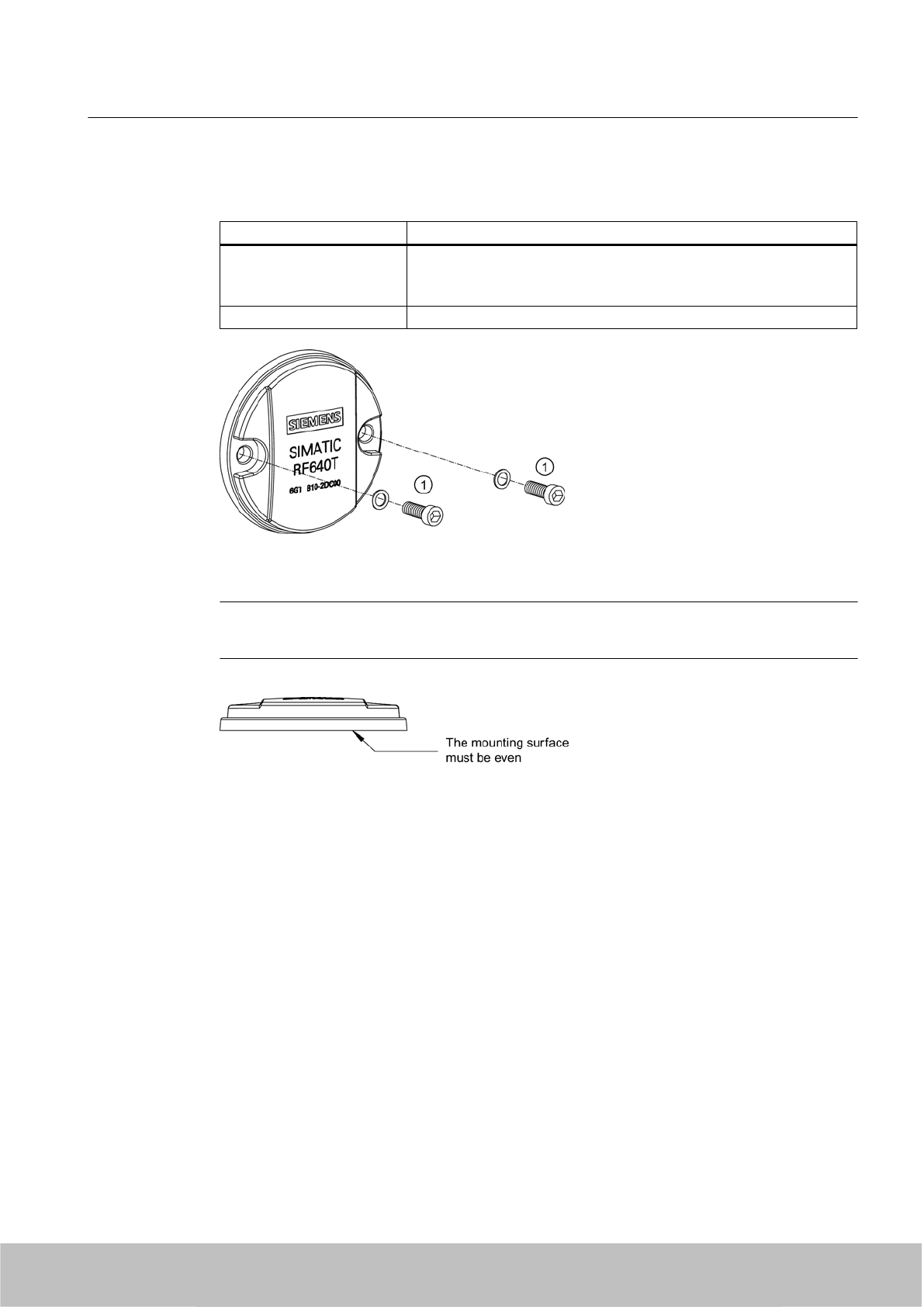
7.8.4 Mounting instructions
Properties Description
Type of installation Screw mounting ①, (M4 screws)
(two DIN 433 washers and two M4 hexagon socket head cap screws
DIN 6912)
Tightening torque (at room temperature) < 1.2 Nm
Figure 7-44 Screw mounting
Note
Make sure that the mounting surface is even when mounting the transponder.
Transponder/tags
7.8 SIMATIC RF640T Gen 2
SIMATIC RF600
System Manual, 06/2010, J31069-D0171-U001-A10-7618 297
Draft Version 02.06.2010
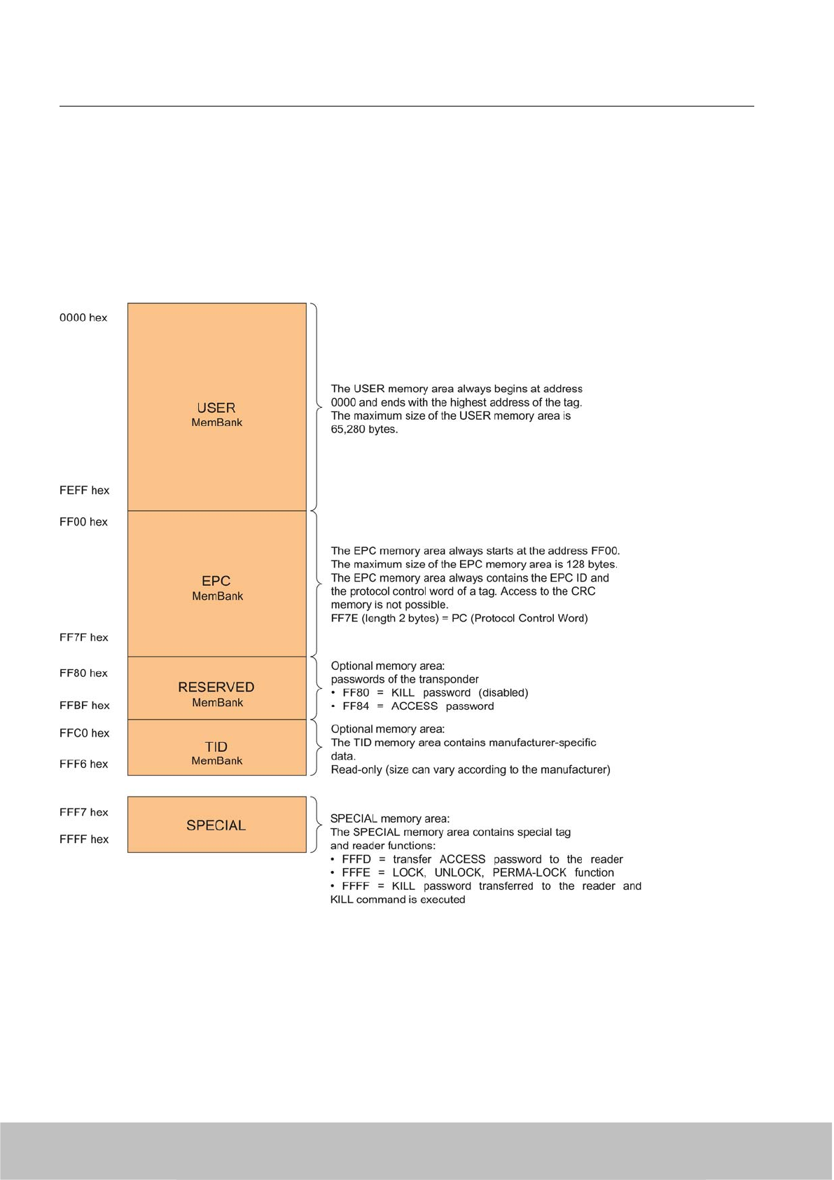
7.8.5 Memory configuration
SIMATIC memory configuration
The following graphic shows the structure of the virtual SIMATIC memory for the RF620R/
RF630R reader and explains the function of the individual memory areas. The SIMATIC
memory configuration is based on the 4 memory banks, as they are defined in EPC Global.
Figure 7-45 SIMATIC memory configuration
Transponder/tags
7.8 SIMATIC RF640T Gen 2
SIMATIC RF600
298 System Manual, 06/2010, J31069-D0171-U001-A10-7618
Draft Version 02.06.2010
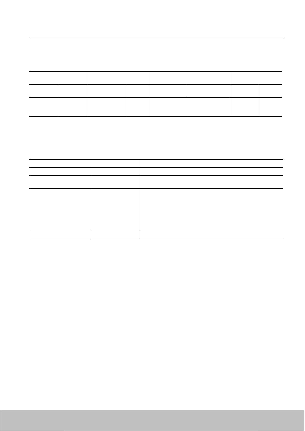
RF640T Gen 2 memory configuration
Tags User
[hex]
EPC TID RESERVED
(passwords)
Special
Range Access KILL‑PW Lock
function
RF640T
Gen 2
00 - 3F FF00-FF0B
(240 bit =
FF00-FF1D)
read/
write
FFC0-FFC7 FF80-FF87 LOCKED Yes
Memory representation according to EPC
The memory of the ISO 18000-6C EPC Class 1 Gen 2 chip is logically divided into four different
memory banks:
Memory bank (decimal) Memory type Description
MemBank 112USER User-writable USER memory area
MemBank 102TID Is defined by the manufacturer, contains the class identifier and serial
number of a tag
MemBank 012EPC Contains the EPC UID, the protocol and the CRC of a tag
You can write to the EPC memory area. In the delivery condition, the
memory contents can have the following states:
● empty
● containing the same data
● containing different data
MemBank 002RESERVED Contains the access and kill password.
The graphic below illustrates the exact memory utilization: Each box in the right part of the
graphic represents one word (16 bit) in the memory.
Transponder/tags
7.8 SIMATIC RF640T Gen 2
SIMATIC RF600
System Manual, 06/2010, J31069-D0171-U001-A10-7618 299
Draft Version 02.06.2010

Color Mode of access by RF600 reader
Read
Write / read
Figure 7-46 Representation of the memory configuration RF640T Gen 2 according to EPC (logical
memory map)
Parameterization
The parameterization possibilities that are available to you for each reader of the RF600 family
are outlined in section Overview of parameterization of RF600 reader (Page 325). Detailed
information for parameterization as well as examples for describing and reading specific
memory areas can be found in the referenced chapters of the documentation.
Transponder/tags
7.8 SIMATIC RF640T Gen 2
SIMATIC RF600
300 System Manual, 06/2010, J31069-D0171-U001-A10-7618
Draft Version 02.06.2010
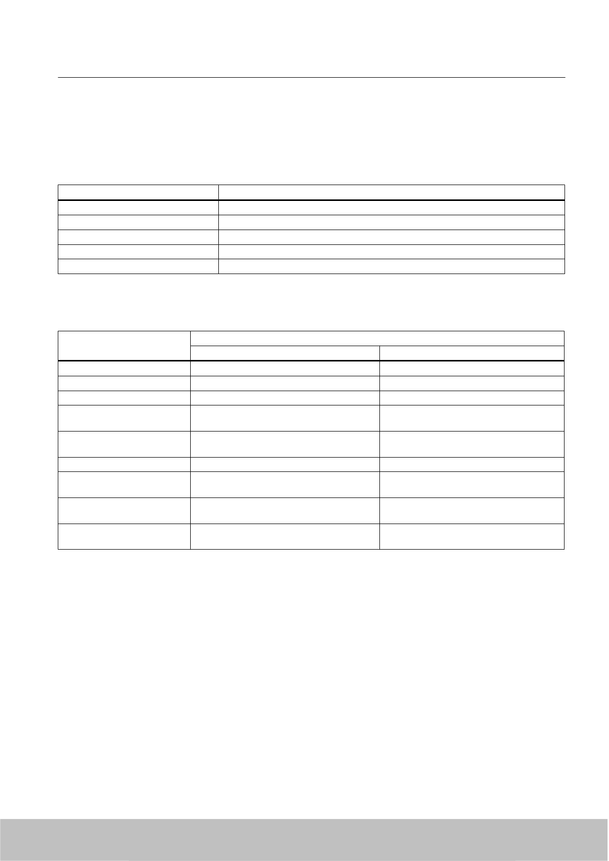
7.8.6 Technical Specifications
7.8.6.1 Mechanical data
Property Description
Dimensions (D x H) 50 mm x 8 mm (+1 mm)
Design PCB with integrated antenna
Design Plastic enclosure (PA12), silicone-free
Weight approx. 13 g
Mounting on metal directly on metal without spacing
7.8.6.2 Electrical data
Property Description
Europe USA / Canada
Air interface According to ISO 18 000-6 C According to ISO 18 000-6 C
Frequency range 865 … 868 MHz 902 MHz ... 928 MHz 1)
Necessary transmit power 2 W (ERP) 4 W (EIRP)
Reading range
Mounting on metal 2)
at least 3 m
typically 4.0 m
at least 3 m
typically 4.0 m
Writing range
Mounting on metal 2)
at least 2 m
typically 3 m
at least 2 m
typically 3 m
Polarization type Linear Linear
Minimum distance to transmit
antenna
Approx. 0.2 m Approx. 0.2 m
Energy source Magnetic energy via antenna, without battery Magnetic energy via antenna, without
battery
Multi-tag capability Yes, minimum distance between data
carriers ≥ 50 mm 3)
Yes, minimum distance between data
carriers ≥ 50 mm 3)
1) Reduction of range to about 70% at the band limits 902 MHz or 928 MHz; recording is
guaranteed at 915 MHz due to frequency hopping procedure.
2) Mounting on a flat surface with a diameter of at least 150 mm
3) When the minimum distances are not reached, there is a reduction in the maximum read
and write distances of the transponder.
See also
Reading range when mounted on flat metallic carrier plates (Page 290)
Directional radiation pattern of the transponder (Page 293)
Transponder/tags
7.8 SIMATIC RF640T Gen 2
SIMATIC RF600
System Manual, 06/2010, J31069-D0171-U001-A10-7618 301
Draft Version 02.06.2010
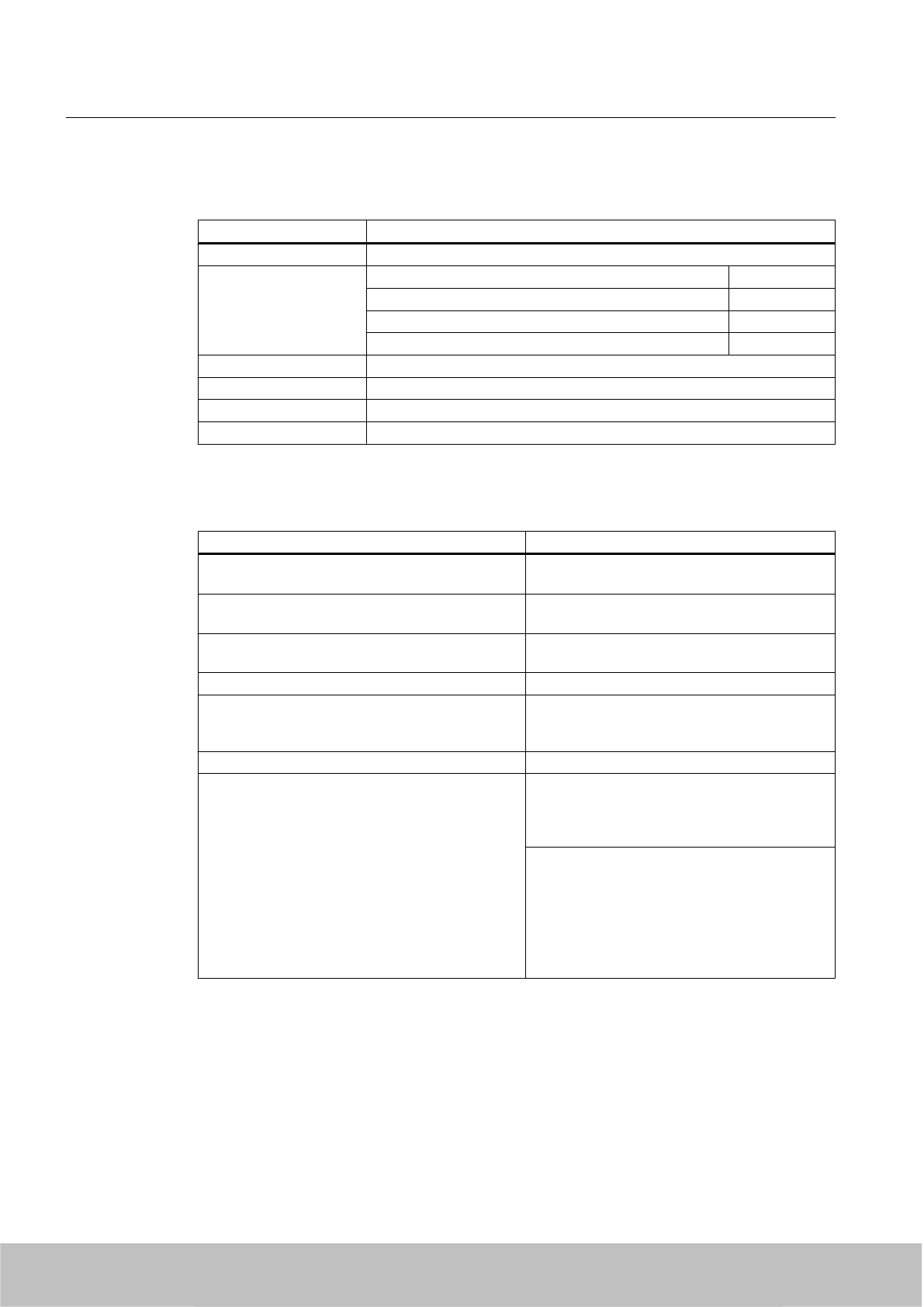
7.8.6.3 Memory specifications
Property Description
Type EPC Class 1 Gen 2
Memory organization EPC code 96 bits/240 bits
User memory 64 bytes
TID 64 bits
Reserved (passwords) 64 bits
Protocol ISO 18000-6C
Data retention time 10 years
Read cycles Unlimited
Write cycles Minimum at +22 °C 100 000
7.8.6.4 Environmental conditions
Property Description
Temperature range when operating in non-
hazardous areas
-25 °C … 85 °C1)
Temperature range when operating in areas at risk
of a gas explosion with temperature class T3-T6
See alsoUse of the transponder in hazardous
areas for gases (Page 295) 2)
Temperature range when operating in areas at risk
of dust explosions with T140 °C
See alsoUse of the transponder in hazardous
areas for dusts (Page 296) 2)
Temperature range during storage -40 °C … 125 °C1)
Shock
Vibration
compliant with EN 60721-3-7 Class 7 M3
100 g, 3)
20 g, 3)
Torsion and bending load Not permissible
Degree of protection IP 68 according to EN 60529:
(45 minutes. immersion in water; water depth 1 m
from
top edge of housing at +20 °C)
IP x9K according to EN 60529:
● Steam blaster nozzle distance 150 mm
● 10 to 15 l of water per minute
● Pressure 100 bar
●Temperature 75 °C
● Test time 30 seconds
1) At temperatures above 70 °C the casing may distort slightly; this does not however cause
any impairment of function (mechanical or electrical).
2) Directive 94/9/EC of the European Council of 23 March 1994 must be complied with, see
also Chapter "Using the transponder in hazardous areas".
3) The values for shock and vibration are maximum values and must not be applied
continuously.
Transponder/tags
7.8 SIMATIC RF640T Gen 2
SIMATIC RF600
302 System Manual, 06/2010, J31069-D0171-U001-A10-7618
Draft Version 02.06.2010
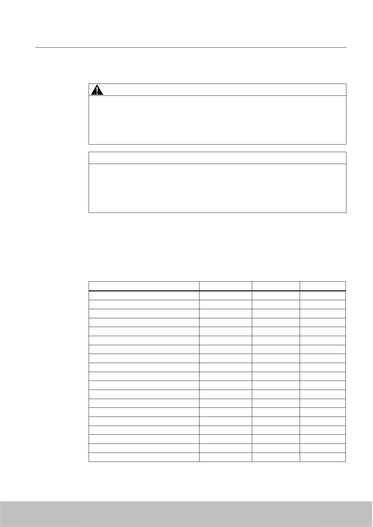
WARNING
Ignitions of gas-air or dust-air mixtures
When using the RF640T transponder, check to ensure that the temperature values are
observed in respect of the requirements of the hazardous area of application.
Non-compliance with the permitted temperature ranges while using the transponder can lead
to ignitions of gas-air or dust-air mixtures.
NOTICE
Damage to the surface of the housing
The values specified for the IP x9K test are maximum values and must not be applied
continuously.
Protracted loading of the transponder can lead to damage to the surface of the housing due
to high pressures.
7.8.6.5 Chemical resistance of the RF640T Gen 2 transponder
The following table gives an overview of the chemical composition of the data memory made
from polyamide 12. The plastic housing has a notably high resistance to chemicals used in
automobiles (e.g.: oil, grease, diesel fuel, gasoline) which are not listed separately.
Concentration 20 °C 60 °C
Battery acid 30 ○○ ᅳ
Ammonia gas ○○○○ ○○○○
Ammonia, w. conc. ○○○○ ○○○○
10 ○○○○ ○○○○
Benzol ○○○○ ○○○
Bleach solution (12.5 % effective chlorine) ○○ ᅳ
Butane, gas, liquid ○○○○ ○○○○
Butyl acetate (acetic acid butyl ester) ○○○○ ○○○○
Calcium chloride, w. ○○○○ ○○○
Calcium nitrate, w. k. g. ○○○○ ○○○
Chlorine ᅳ ᅳ
Chrome baths, tech. ᅳ ᅳ
Iron salts, w. k. g. ○○○○ ○○○○
Acetic acid, w. 50 ᅳ ᅳ
Ethyl alcohol, w., undenaturated 96 ○○○○ ○○○
50 ○○○○ ○○○○
Formaldehyde, w. 30 ○○○ ᅳ
10 ○○○○ ○○○
Formalin ○○○ ᅳ
Transponder/tags
7.8 SIMATIC RF640T Gen 2
SIMATIC RF600
System Manual, 06/2010, J31069-D0171-U001-A10-7618 303
Draft Version 02.06.2010

Concentration 20 °C 60 °C
Glycerine ○○○○ ○○○○
Isopropanol ○○○○ ○○○
Potassium hydroxide, w. 50 ○○○○ ○○○○
Lysol ○○ ᅳ
Magnesium salts, w. k. g. ○○○○ ○○○○
Methyl alcohol, w. 50 ○○○○ ○○○○
Lactic acid, w. 50 ○○ ᅳ
10 ○○○ ○○
Sodium carbonate, w. (soda) k. g. ○○○○ ○○○○
Sodium chloride, w. k. g. ○○○○ ○○○○
Sodium hydroxide ○○○○ ○○○○
Nickel salts, w. k. g. ○○○○ ○○○○
Nitrobenzol ○○○ ○○
Phosphoric acid 10 ○ V
Propane ○○○○ ○○○○
Mercury ○○○○ ○○○○
Nitric acid 10 ○ ᅳ
Hydrochloric acid 10 ○ ᅳ
Sulphur dioxide Low ○○○○ ○○○○
Sulphuric acid 25 ○○ ᅳ
10 ○○○ ᅳ
Hydrogen sulphide Low ○○○○ ○○○○
Carbon tetrachloride ○○○○ ○○○○
Toluene ○○○○ ○○○
Detergent High ○○○○ ○○○○
Plasticizer ○○○○ ○○○○
Abbreviations
○○○○ Resistant
○○○ Virtually resistant
○○ Limited resistance
○ Less resistant
ᅳNot resistant
w. Aqueous solution
k. g. Cold saturated
Transponder/tags
7.8 SIMATIC RF640T Gen 2
SIMATIC RF600
304 System Manual, 06/2010, J31069-D0171-U001-A10-7618
Draft Version 02.06.2010
7.8.7 Certificates and approvals
Table 7-26 6GT2810-2DC00 - RF640T Gen 2 UHF Tool Tag - Europe
Certificate Description
CE approval according to R&TTE guideline
For Directive 94/9/EC:
EC type test certification no. TÜV 07 ATEX 346241
Acknowledgement of the quality assurance TÜV 96 ATEX 1125 Q
Table 7-27 6GT2810-2DC10 - RF640T Gen 2 UHF Tool Tag - USA/Canada
Standard
FCC
Federal Communications
Commission
Passive labels or transponders comply with the valid regulations;
certification is not required
This product is UL-certified for the USA and Canada.
It meets the following safety standard(s):
UL 60950-1 - Information Technology Equipment Safety - Part 1:
General Requirements
CSA C22.2 No. 60950 -1 - Safety of Information Technology
Equipment
UL Report E 205089
7.8.7.1 Manufacturer's declaration RF640T Gen 2 UHF Tool Tag Version 1
The plant that manufactured the RF640T Gen 2 UHF Tool Tag Version 1 has an ATEX quality
assurance system recognized by TÜV NORD with notification number TÜV 96 ATEX 1125 Q.
The type test certification for the RF640T Gen 2 UHF Tool Tag Version 1 is stored by
TÜV 07 ATEX 346241.
Manufacturer's address
Siemens AG
Automation and Drives
System Engineering A&D SE
Würzburger Strasse 121
90766 Fürth, Germany.
Transponder/tags
7.8 SIMATIC RF640T Gen 2
SIMATIC RF600
System Manual, 06/2010, J31069-D0171-U001-A10-7618 305
Draft Version 02.06.2010
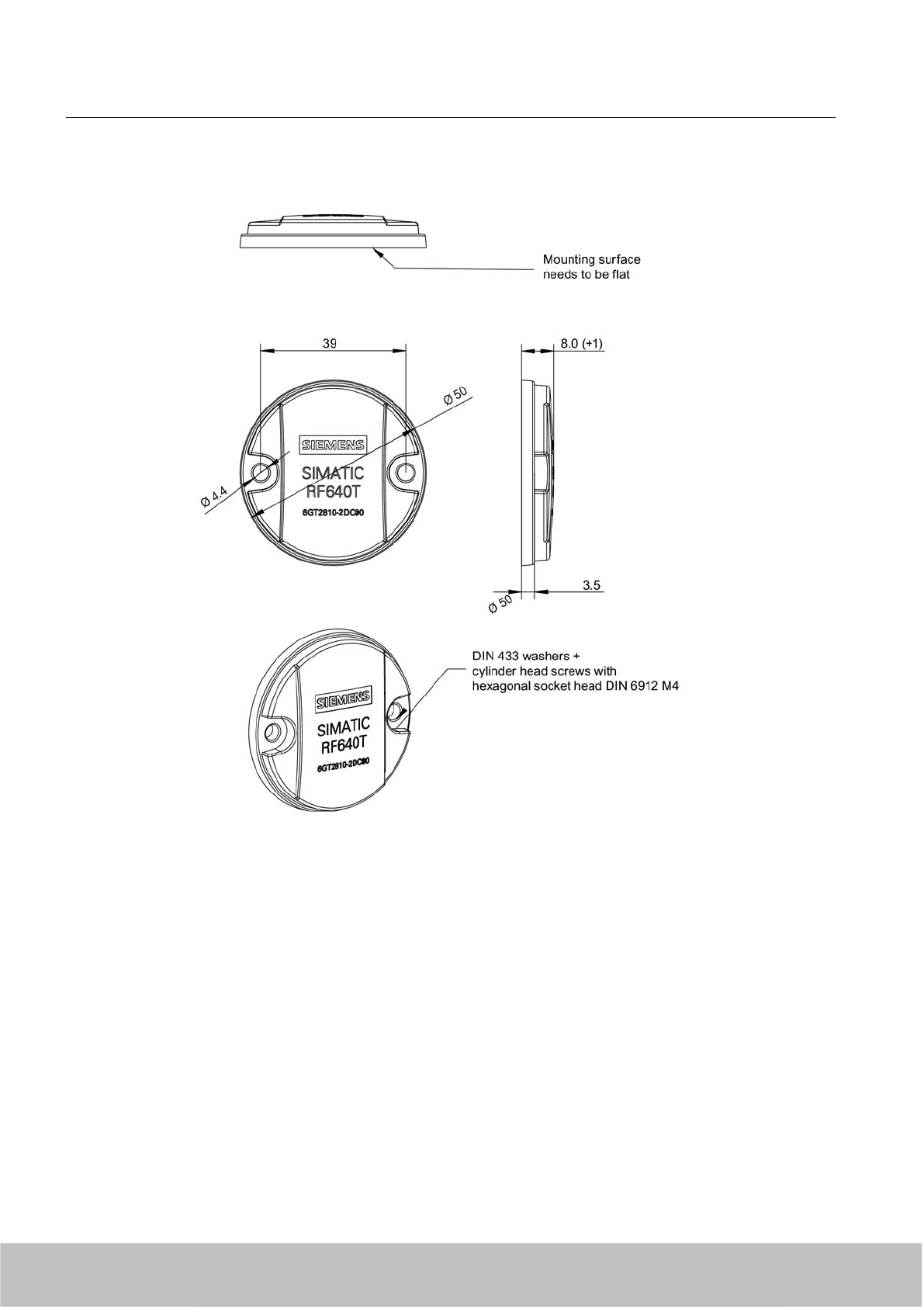
7.8.8 Dimension drawing
Figure 7-47 SIMATIC RF640T Gen 2 UHF Tool Tag Version 1
Units of measurement: All dimensions in mm
7.9 SIMATIC RF680T
7.9.1 Characteristics
The heat-resistant SIMATIC RF680T transponder is a passive, maintenance-free data carrier.
It functions based on the UHF Class 1 Gen 2 technology and is used for saving the electronic
product code (EPC) of 96 bits/240 bits. The transponder also has a 512-bit user memory.
These transponders with limited service life are ideally suited to high-temperature applications
(e.g. the painting of vehicle bodies) as well as applications in production logistics.
Transponder/tags
7.9 SIMATIC RF680T
SIMATIC RF600
306 System Manual, 06/2010, J31069-D0171-U001-A10-7618
Draft Version 02.06.2010
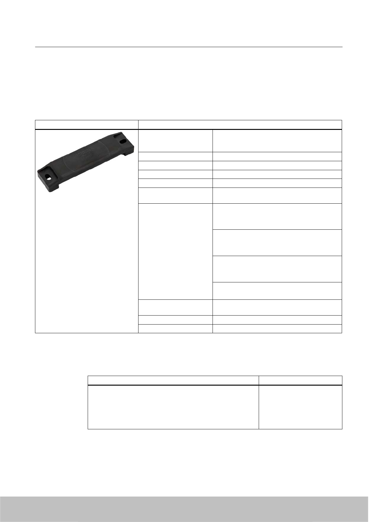
The RF680T is rugged and suitable for industrial applications with IP68/IPX9K degree of
protection.
It is highly resistant to oil, grease and cleaning agents.
The SIMATIC RF680T is mounted directly onto metal and non-metal carrier plates to ensure
optimal operation and has a typical detection range of 4 m.
SIMATIC RF680T transponder Features
Application Applications in production logistics and in assembly
lines subject to high temperatures (up to +220 °C,
e.g. paintshop).
Frequency band 865 ... 928 MHz (ETSI and FCC)
Air interface according to ISO 18000-6C
Polarization Linear
Temperature range up to 220 °C
Memory EPC 96 bit/240 bit
Add-on-memory 64 bytes
Read/write range Typically X°m/X°m in connection with: @@@
●RF670R reader and
● RF660A antenna
Typically 3 m/4 m in connection with:
● RF660R readers and
● RF660A antennas
Typically 1.4 m/2 m in connection with:
● RF630R reader and
● RF660A antenna
Typically 1.4 m/2 m in connection with:
● RF620R with integrated antenna
Installation Suitable for direct mounting on conductive and non-
conductive materials.
Material Plastic PPS; silicone-free
Dimensions 130 x 32 x 15 mm
7.9.2 Ordering data
Ordering data Order no.
SIMATIC RF680T
●Frequency 865 MHz to 928 MHz
● EPC 96 bit/240 bit (64 bytes user memory)
● -25 ... +220 °C
●130 x 32 x 15 mm
6GT2810-2HG80
Transponder/tags
7.9 SIMATIC RF680T
SIMATIC RF600
System Manual, 06/2010, J31069-D0171-U001-A10-7618 307
Draft Version 02.06.2010
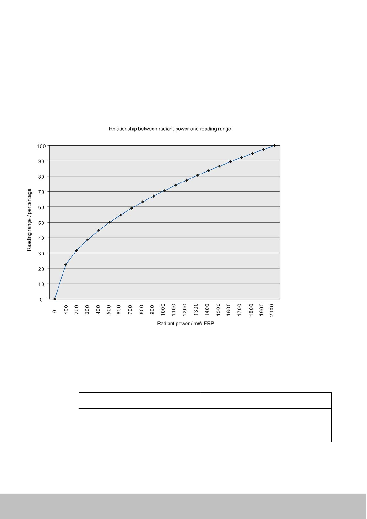
7.9.3 Planning the use
The absolute values of the reading ranges specified below refer to a transmit power of 2 W ERP.
When the power is reduced (e.g. when a different reader is used), you will find the
corresponding reduced reading ranges in the following table:
7.9.3.1 Reading range when mounted on non-metallic carriers
The RF680T transponder is a universal transponder for mounting on many different types of
carrier plate materials.
Table 7-28 Reading ranges for non-metal carriers (RF660R = 2 W ERP; RF670R = @@@ W)
Carrier plate material Reading range for
RF670R
Reading range for
RF660R
Transponder on wooden carrier
(dry, degree of moisture < 15%)
@@@ Typ. 4 m
Transponder on plastic carrier @@@ Typ. 4 m
Transponder on glass @@@ Typ. 4 m
100% reading range is achieved when mounted in empty, anechoic rooms.
Transponder/tags
7.9 SIMATIC RF680T
SIMATIC RF600
308 System Manual, 06/2010, J31069-D0171-U001-A10-7618
Draft Version 02.06.2010
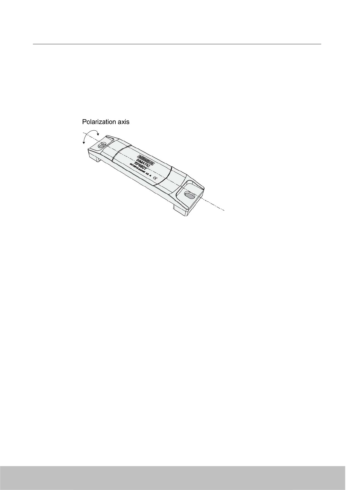
7.9.3.2 Directional radiation pattern of the transponder on non-metallic surfaces
It is recommendable to align the transponder parallel to the transmitting antenna. If, however,
the transponder including the metallic carrier plate is tilted, the reading range will be reduced.
Rotation about the polarization axis
Figure 7-48 Rotation of the transponder about the polarization axis
Generally the range does not change when the transponder without carrier material is rotated
about the polarization axis.
Transponder/tags
7.9 SIMATIC RF680T
SIMATIC RF600
System Manual, 06/2010, J31069-D0171-U001-A10-7618 309
Draft Version 02.06.2010
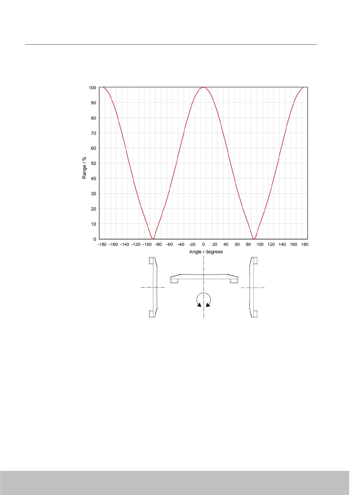
Rotation orthogonal to the polarization axis
Figure 7-49 Transponder characteristics when rotated orthogonally to the polarization axis (within the
tag plane)
If the transponder is positioned orthogonally to the transmitting antenna, it normally cannot be
read. Therefore the transponder is preferably to be aligned parallel to the transmitting antenna.
The following figure illustrates this situation.
Transponder/tags
7.9 SIMATIC RF680T
SIMATIC RF600
310 System Manual, 06/2010, J31069-D0171-U001-A10-7618
Draft Version 02.06.2010
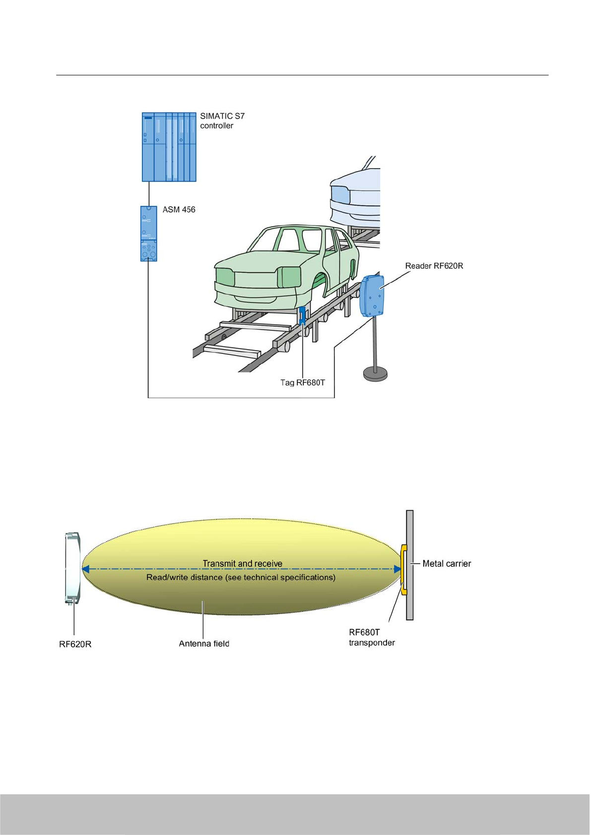
Figure 7-50 Application example
7.9.3.3 Optimum antenna/transponder positioning with plane mounting of the transponder on metal
Figure 7-51 Example of optimum antenna/transponder positioning
Transponder/tags
7.9 SIMATIC RF680T
SIMATIC RF600
System Manual, 06/2010, J31069-D0171-U001-A10-7618 311
Draft Version 02.06.2010
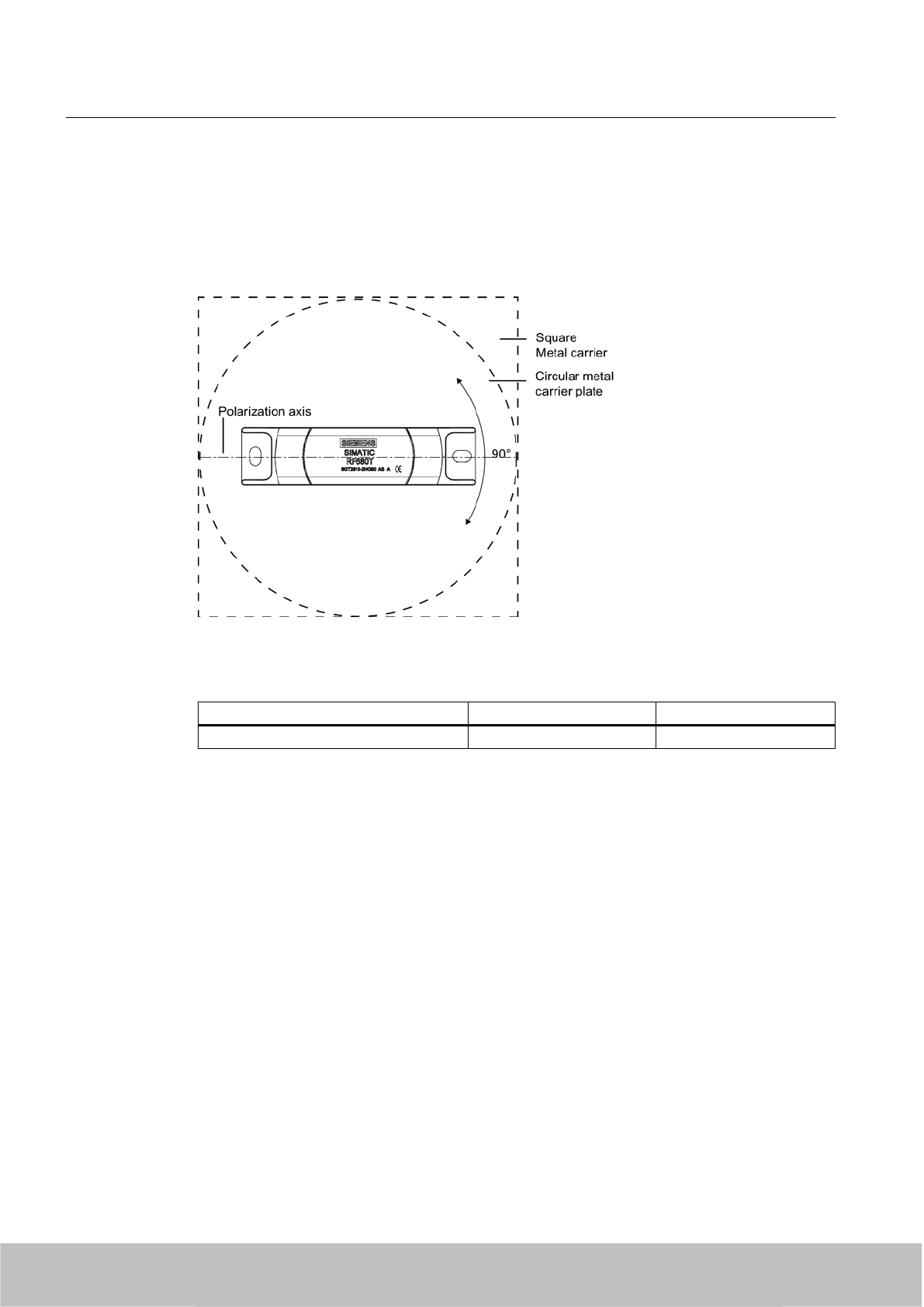
7.9.3.4 Reading range when mounted on plane metallic carrier plates
The transponder generally has linear polarization. The polarization axis runs as shown in the
diagram below. If the transponder is centrally mounted on a plane metal plate, which may
either be almost square or circular, it can be aligned in any direction if the transmitting and
receiving antennas operate with circular polarization (such as RF660A and RF620R).
Figure 7-52 Optimum positioning of the transponder on a (square or circular) metallic carrier plate
Table 7-29 Reading range with metallic, plane carriers with spacer
Carrier plate material Reading range Europe Reading range USA
Metal plate 150 x 150 mm Typ. 4 m Typ. 4 m
On rectangular carrier plates, the reading distance depends on the mounting orientation of the
transponder A 90° rotation of the transponder about the axis of symmetry may result in greater
reading distances
7.9.3.5 Influence of conducting walls on the reading range
If there are conducting walls or restrictions in the vicinity that shade the radio field, a distance
of approx. 10 cm is recommended between the transponder and the wall. In principle, walls
have least influence if the polarization axis is orthogonal to the conducting wall.
Transponder/tags
7.9 SIMATIC RF680T
SIMATIC RF600
312 System Manual, 06/2010, J31069-D0171-U001-A10-7618
Draft Version 02.06.2010
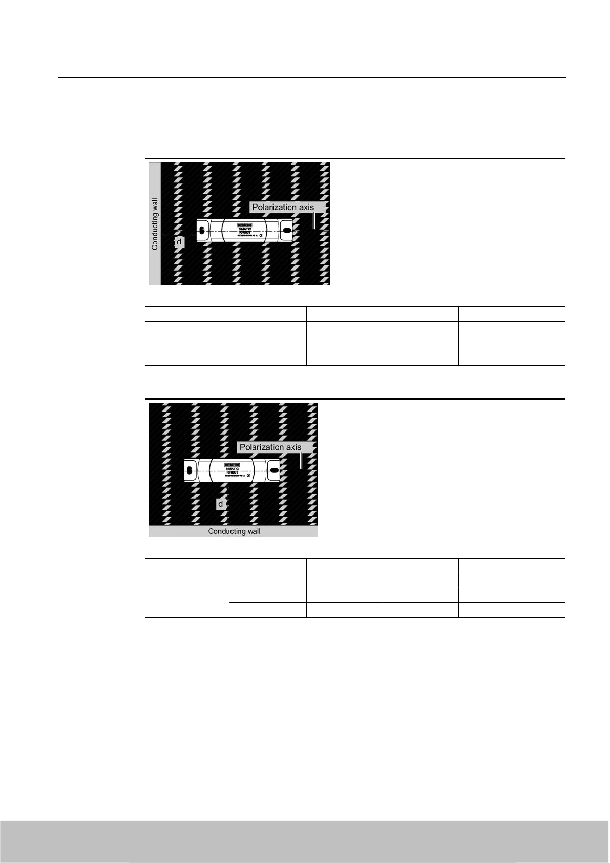
Reading range: One conducting wall
Influence on reading range when positioned orthogonally to the conducting wall
Top view
Distance d 20 mm 50 mm 100 mm
Reading range Approx. 100% Approx. 100% Approx. 100% Wall height 20 mm
Approx. 100% Approx. 100% Approx. 100% Wall height 50 mm
Approx. 80% Approx. 100% Approx. 100% Wall height 100 mm
Influence on reading range when positioned parallel to the conducting wall
Top view
Distance d 20 mm 50 mm 100 mm
Reading range Approx. 50% Approx. 70% Approx. 90% Wall height 20 mm
Approx. 40% Approx. 70% Approx. 90% Wall height 50 mm
Approx. 30% Approx. 50% Approx. 90% Wall height 100 mm
Transponder/tags
7.9 SIMATIC RF680T
SIMATIC RF600
System Manual, 06/2010, J31069-D0171-U001-A10-7618 313
Draft Version 02.06.2010
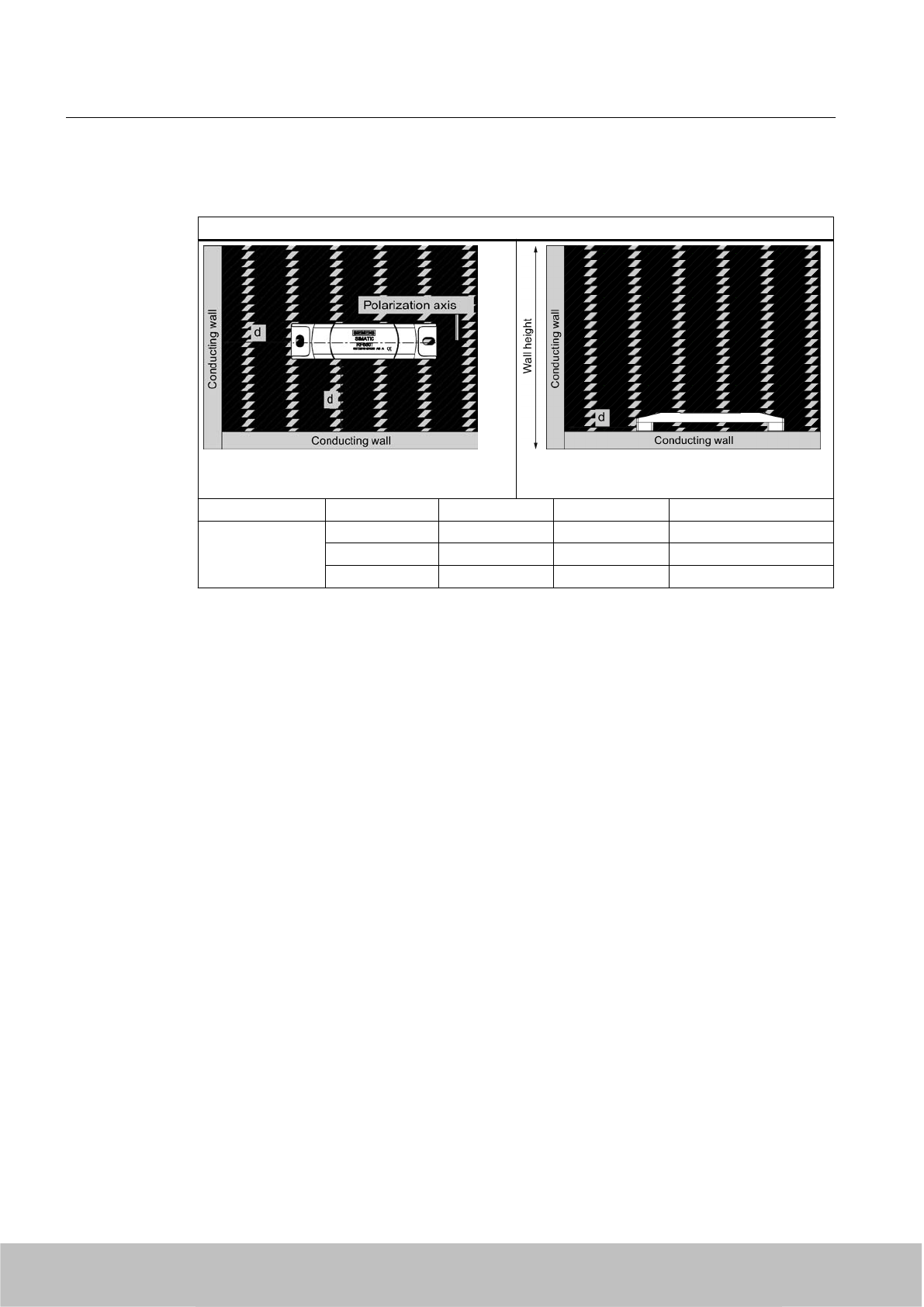
Reading range: Two conducting walls
Influence on reading range when positioned against two conducting walls
Side view
Distance d 20 mm 50 mm 100 mm
Reading range Approx. 50% Approx. 70% Approx. 90% Wall height 20 mm
Approx. 30% Approx. 60% Approx. 90% Wall height 50 mm
Approx. 25% Approx. 50% Approx. 90% Wall height 100 mm
The values specified in the tables above are reference values.
7.9.3.6 Directional radiation pattern of the transponder on metallic surfaces
It is recommendable to align the transponder parallel to the transmitting antenna. If, however,
the transponder including the metallic carrier plate is tilted, the reading range will be reduced.
Transponder/tags
7.9 SIMATIC RF680T
SIMATIC RF600
314 System Manual, 06/2010, J31069-D0171-U001-A10-7618
Draft Version 02.06.2010
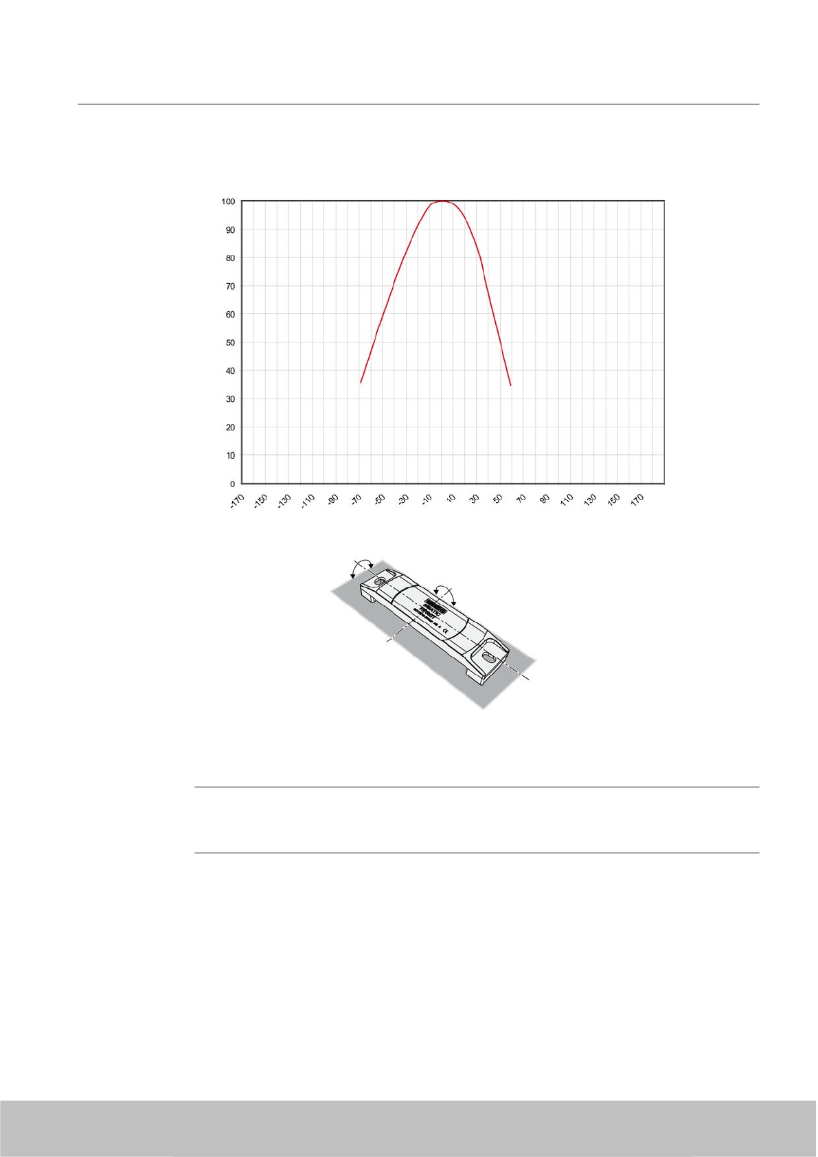
Rotation about the polarization axis or orthogonal to the polarization axis
Figure 7-53 Characteristic of the transponder when rotated about the polarization axis or orthogonally
to the polarization axis
Note
Please note that the directional effect is dependent on the size of the metal surface. The
larger the metal surface, the larger the directional effect.
Transponder/tags
7.9 SIMATIC RF680T
SIMATIC RF600
System Manual, 06/2010, J31069-D0171-U001-A10-7618 315
Draft Version 02.06.2010
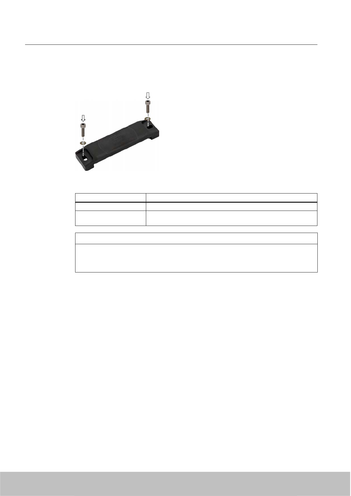
7.9.4 Mounting instructions
Mount the SIMATIC RF680T transponder on the base using two M6 screws.
Figure 7-54 Mounting SIMATIC RF680T
Properties Description
Type of mounting M6 screw mounting
Tightening torque
(at room temperature)
≤ 1 Nm (Note the expansion coefficients of the materials used at high
temperatures!)
NOTICE
Reduction of the read/write distance
When mounting on metal or conductive material, ensure that the space below the transponder
remains empty.
Transponder/tags
7.9 SIMATIC RF680T
SIMATIC RF600
316 System Manual, 06/2010, J31069-D0171-U001-A10-7618
Draft Version 02.06.2010
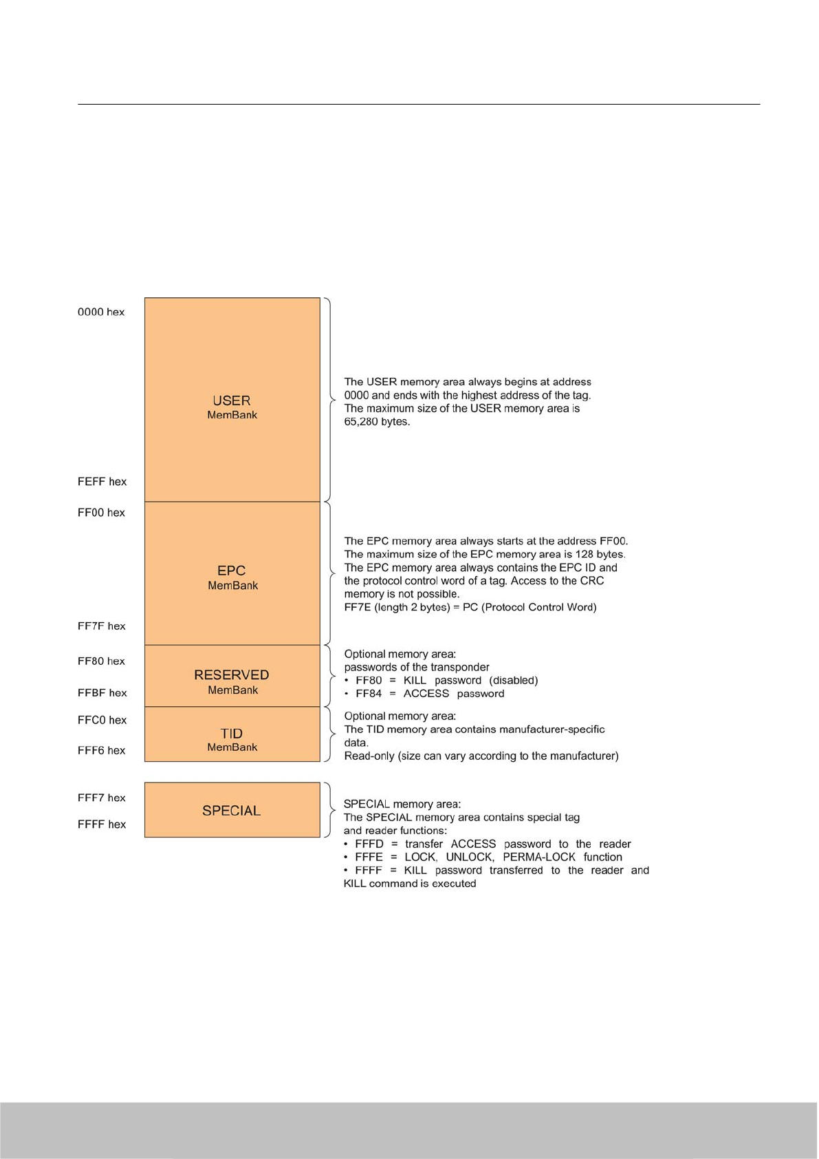
7.9.5 Memory configuration
SIMATIC memory configuration
The following graphic shows the structure of the virtual SIMATIC memory for the RF620R/
RF630R reader and explains the function of the individual memory areas. The SIMATIC
memory configuration is based on the 4 memory banks, as they are defined in EPC Global.
Figure 7-55 SIMATIC memory model
Transponder/tags
7.9 SIMATIC RF680T
SIMATIC RF600
System Manual, 06/2010, J31069-D0171-U001-A10-7618 317
Draft Version 02.06.2010

RF680T memory configuration
Tag User
[hex]
EPC TID RESERVED
(passwords)
Special
Range Access KILL‑PW Lock
function
RF680T 00 - 3F FF00-FF0B
(240 bit =
FF00-FF1D)
read/
write
FFC0-FFC7 FF80-FF87 Locked Yes
Memory banks
The memory of the ISO 18000-6C G2XM chip is logically divided into four different memory
banks:
Memory bank (decimal) Memory type Description
MemBank 112USER User-writable USER memory area
MemBank 102TID Is defined by the manufacturer, contains the class identifier and serial
number of a tag
MemBank 012EPC Contains the EPC data, the protocol information and the CRC data
of a tag.
You can write to the EPC memory area. In the delivery condition, the
memory contents can have the following states:
● containing the same data
● containing different data
MemBank 002RESERVED Contains the access password.
The graphic below illustrates the exact memory utilization: Each box in the right part of the
graphic represents one word (16 bit) in the memory.
Transponder/tags
7.9 SIMATIC RF680T
SIMATIC RF600
318 System Manual, 06/2010, J31069-D0171-U001-A10-7618
Draft Version 02.06.2010
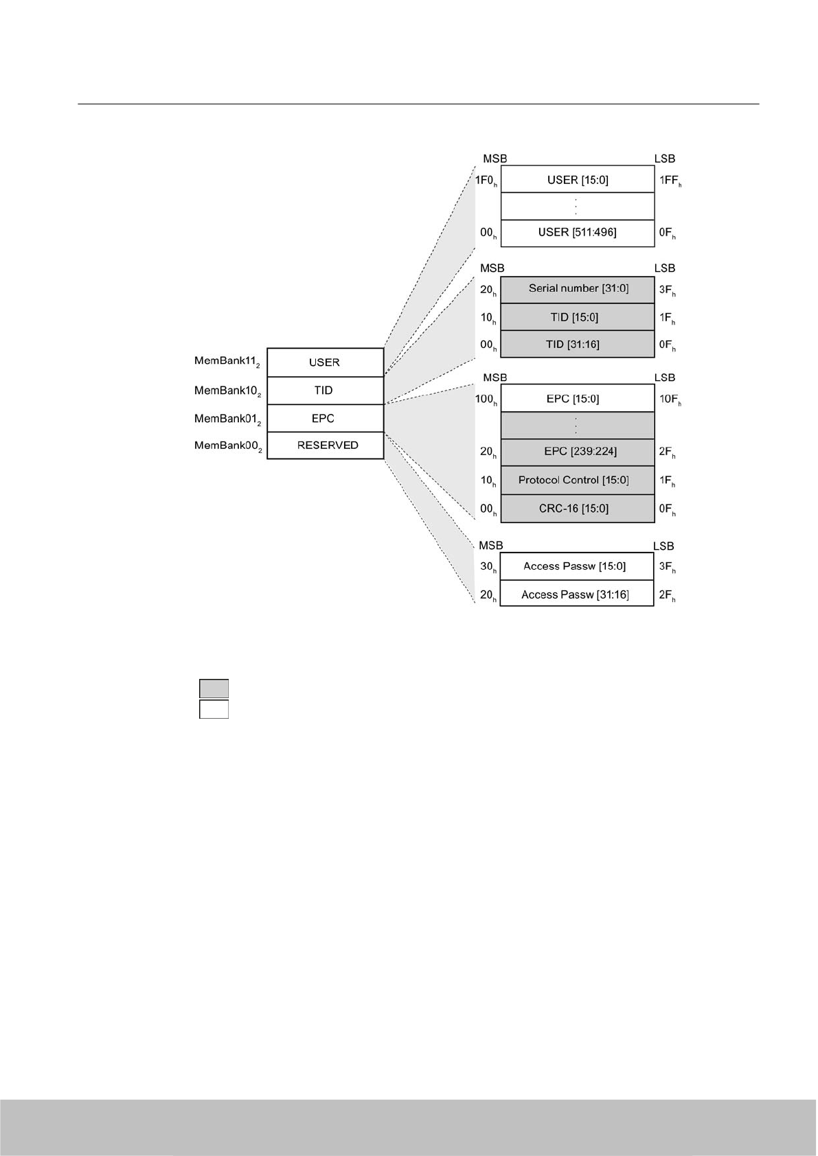
Color Mode of access by RF600 reader
Read
Write / read
Figure 7-56 Memory utilization
Parameterization
The parameterization possibilities that are available to you for each reader of the RF600 family
are outlined in section Overview of parameterization of RF600 reader (Page 325). Detailed
information for parameterization as well as examples for describing and reading specific
memory areas can be found in the referenced chapters of the documentation.
Transponder/tags
7.9 SIMATIC RF680T
SIMATIC RF600
System Manual, 06/2010, J31069-D0171-U001-A10-7618 319
Draft Version 02.06.2010
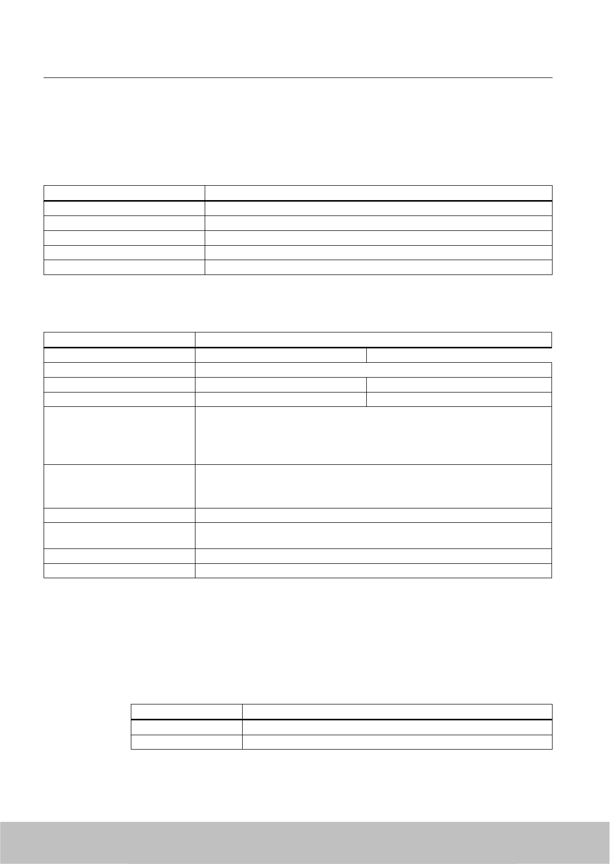
7.9.6 Technical specifications
7.9.6.1 Mechanical data
Property Description
Dimensions (L x W x H) 130 x 32 x 15 mm
Design Plastic housing (PPS)
Housing color Black
Weight Approx. 50 g
Mounting on metal Yes
7.9.6.2 Electrical data
Property Description
Europe USA / Canada
Air interface According to ISO 18 000-6 C
Frequency range 865 … 868 MHz 915 ... 928 MHz
Necessary2) transmit power 2 W (ERP) 4 W (EIRP)
Read distance
●on non-metallic carriers
● On metal1)
● Typ. 4 m
●Typ. 4 m
Write distance
● on non-metallic carriers
● On metal1)
● Typ. 3 m
●Typ. 3 m
Polarization type Linear
Minimum distance to transmitting
antenna
Approx. 0.2 m
Energy source Magnetic energy via antenna, without battery
Multi-tag capability Yes, minimum distance between transponders ≥ 50 mm 3)
1) Plane metal surface 15 x 15 cm, reduction of range to about 70% at the band limit 928 MHz on metal surfaces; detection
is guaranteed at 915 MHz due to frequency hopping procedure.
2) For maximum read/write distances at room temperature
3) When the minimum distances are not reached, there is a reduction in the maximum read and write distances of the
transponders.
7.9.6.3 Memory specifications
Property Description
Type EPC Class 1 Gen2
Memory organization 96 bits/240 bits EPC code
Transponder/tags
7.9 SIMATIC RF680T
SIMATIC RF600
320 System Manual, 06/2010, J31069-D0171-U001-A10-7618
Draft Version 02.06.2010
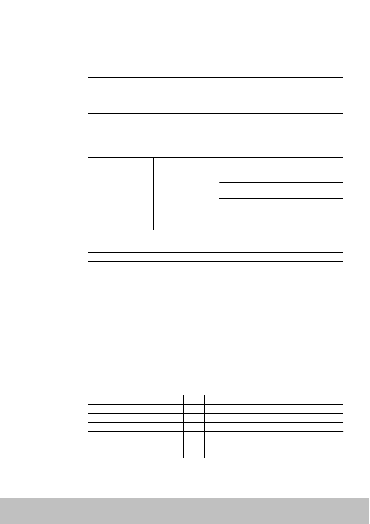
Property Description
Protocol ISO 18000-6C
Data retention time 10 years
Read cycles Unlimited
Write cycles Typ. 1,000,000 (at +40 °C)
7.9.6.4 Environmental conditions
Property Description
Ambient temperature ● Operation -25 °C to +100 °C Permanent
From 100 °C to +140 °C 20% reduction in the
limit distance
+200 °C 2) Tested up to 5000
hours or 3000 cycles
+220 °C Tested up to 2000
hours or 1500 cycles
● Transport and
storage
-40 °C to +100 °C
Shock
Vibration
compliant with EN 60721-3-7 Class 7 M3
50 g, 1)
20 g 1)
Torsion and bending load Not permissible
Degree of protection ● IP 68 according to EN 60529:
(45 minutes immersion in water;
water depth 1 m from top edge of housing at
+20 °C)
● IPx9K
(steam jet: 150 mm; 10 to 15 l/min; 100 bar;
75 °C)
Silicone-free Yes
1) The values for shock and vibration are maximum values and must not be applied continuously.
2) Note that no processing is possible at temperatures of +140 °C or higher.
7.9.6.5 Chemical resistance of the RF680T transponder
The following table provides an overview of the chemical resistance of the data memory made
of polypropylene sulfide.
20 °C 65 °C
Ammonia, w. conc. ○ -
Butane gas + +
Butyl acetate (acetic acid butyl ester) + +
Calcium chloride + +
Chlorine - -
Chrome baths, tech. - -
Transponder/tags
7.9 SIMATIC RF680T
SIMATIC RF600
System Manual, 06/2010, J31069-D0171-U001-A10-7618 321
Draft Version 02.06.2010
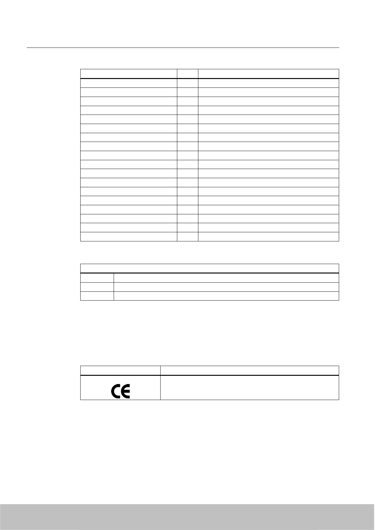
20 °C 65 °C
Acetic acid, w. 10% + +
Ethyl alcohol, w., undenaturated + +
Formaldehyde + +
Isopropanol + +
Methyl alcohol + +
Lactic acid, w. + +
Sodium carbonate, w. (soda) + +
Sodium chloride, w. + +
Sodium hydroxide 10% + +
Nitrobenzol ○ -
Phosphoric acid - -
Propane + +
Nitric acid 10% - -
Hydrochloric acid 10% - -
Sulfur dioxide, minimal + +
Sulfuric acid 25% - -
Hydrogen sulfide, dry + +
Carbon tetrachloride ○ -
Abbreviations
+Resistant
○ Limited resistance
ᅳNot resistant
7.9.7 Certificates and approvals
Table 7-30 6GT2810-2HG80 - RF680T Gen 2 UHF- Europe
Certificate Description
Conformity with R&TTE directive
Transponder/tags
7.9 SIMATIC RF680T
SIMATIC RF600
322 System Manual, 06/2010, J31069-D0171-U001-A10-7618
Draft Version 02.06.2010
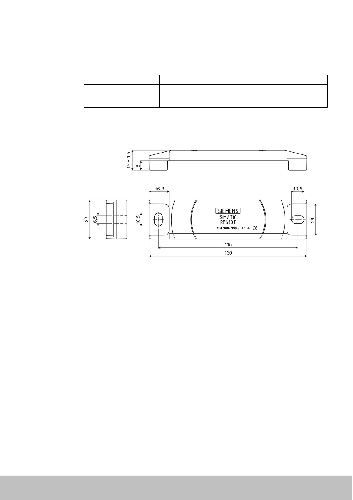
Table 7-31 6GT2810-2HG80- RF680T Gen 2 UHF- USA / Canada
Standard
FCC
Federal Communications
Commission
Passive labels or transponders comply with the valid regulations;
certification is not required
7.9.8 Dimension drawing
Figure 7-57 Dimension drawing of SIMATIC RF680T
Units of measurement: All dimensions in mm
Tolerances, unless indicated otherwise, are +-0.5 mm.
Transponder/tags
7.9 SIMATIC RF680T
SIMATIC RF600
System Manual, 06/2010, J31069-D0171-U001-A10-7618 323
Draft Version 02.06.2010

Draft Version 02.06.2010

Integration into networks 8
8.1 Overview of parameterization of RF600 reader
The parameterization possibilities that are available to you for each reader of the RF600 family
are outlined below. You will find detailed information on parameterization in the specified
chapters of the documentation:
Readers RF-
MANAGER 2008
SP 3
SIMATIC
command
messages
RF-MANAGER
Basic 2010
Configuration
software
XML commands RFID reader
interface
RF670R Online-Help >
chapter
"Introduction to RF-
MANAGER >
Overview of the
RFID functions"
Online help >
chapter
"Working with
RFID objects"
Function
Manual
RF670R,
Chapter
"Standard
Configuration
Messages"
RF660R "Configuration
Manual
SIMATIC
RF660R
Configuration
software",
chapter
"Parameterizin
g the RF660R"
Function
Manual
RF660R,
Chapter
"Standard
Configuration
Messages"
RF630R "Configuration
Manual RF620R/
RF630R", chapter
"Overview of
commands"
RF620R "Configuration
Manual RF620R/
RF630R", chapter
"Overview of
commands"
RF610M Function
Manual Mobile
Reader,
chapter"RFID
Reader
Interface
Reference"
SIMATIC RF600
System Manual, 06/2010, J31069-D0171-U001-A10-7618 325
Draft Version 02.06.2010

8.2 Integration in IT networks via RF-MANAGER
8.2.1 RF-MANAGER and PC integration of the RF600 reader
Fields of application
The RF-MANAGER is used for configuring, commissioning and operating RFID systems. It
allows you to collect RFID data, to process it and to filter it. This data can be exchanged with
an S7 PLC by means of variables or transferred to a higher-level management system.
The RF-MANAGER supports you with quick and easy creation of RFID solutions as well as
the administration of RFID systems and their hardware components. The application also
offers extensive help with the preprocessing of RFID data.
8.2.1.1 Tasks of RF-MANAGER
Tasks of RF-MANAGER
At both the planning level (ERP) and production level (MES), systems are used that generate
a large volume of information that is relevant to production or that has commercial relevance.
To increase productivity and efficiency, the individual levels must communicate with each other
to use all the information that is available optimally. The RF-MANAGER makes an important
contribution to this and is located at the PLC/PC level. It manages the connected RFID readers,
collects the supplied data and reduces them to the accuracy and quantity required by the MES/
ERP level. The most important areas are device management, data management and
business integration. RF‑MANAGER also acts as the interface between RFID data and the
MES/ERP level.
The current RF-MANAGER version supports the following readers of the SIMATIC RF600
system: RF670R, RF660R, RF620R, RF630R, RF610M.
Integration into networks
8.2 Integration in IT networks via RF-MANAGER
SIMATIC RF600
326 System Manual, 06/2010, J31069-D0171-U001-A10-7618
Draft Version 02.06.2010
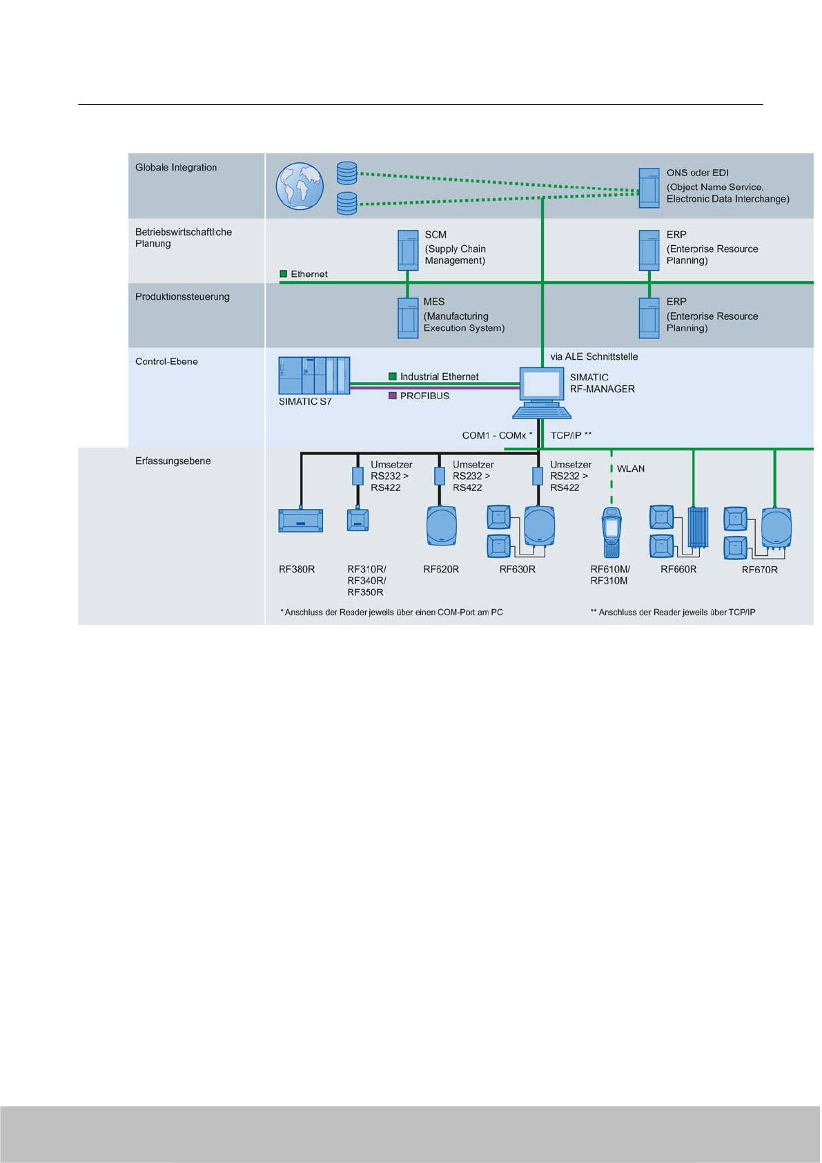
Figure 8-1 System overview
Properties of RF-MANAGER
RF-MANAGER is characterized by the following features:
● Smooth operation and simple diagnostics
● Preparation of data for higher-level systems
● Logical operations on RFID data with automation data (SIMATIC S7):
● Flexibility with the higher-level system
● Comprehensive investment security
8.2.1.2 RF-MANAGER components
The RF-MANAGER comprises the following components:
● RF-MANAGER Engineering System (ES)
● RF-MANAGER Runtime (RT)
Integration into networks
8.2 Integration in IT networks via RF-MANAGER
SIMATIC RF600
System Manual, 06/2010, J31069-D0171-U001-A10-7618 327
Draft Version 02.06.2010

RF-MANAGER Engineering System (ES)
The RF-MANAGER Engineering System is the software for handling all your essential
configuring tasks. You can use ES to create RFID projects on your PC and to parameterize
their components.
RF-MANAGER Runtime (RT)
RF-MANAGER Runtime is the software that is used to operate RFID systems. In Runtime, you
can execute the RFID projects during process operation that you created and parameterized
in the Engineering System. The RT software can run either on the same PC as the ES, or on
another Windows XP-PC of your choice. The SIMATIC Microbox PC 427B is also an option
for runtime. The runtime system can exchange data with an S7 PLC by means of variables.
In accordance with the product version or licensing of RF-MANAGER that you have selected,
you can use the runtime system to address up to 50 RFID readers. Later license extensions
for the Runtime software can also be obtained.
8.2.1.3 Connecting principle
● The RF670R/RF660R UHF reader is connected to the PC via TCP/IP.
● The RF620R and RF630R UHF readers are connected to the PC serially via a COM
interface. For this an RS232 to RS422 interface converter is needed.
● The RF610M mobile handheld terminal is connected to the RF-MANAGER via WLAN.
Tested interface converters for the operation of RF620R/RF630R
The following interface converters were used by Siemens in the test:
● Trycom IP interface converter: "TRP-C06".
● EXSYS GmbH interface converter card: "EX-42054-9-8S" with 8 interfaces.
● EXSYS GmbH interface converter card: "EX-42052-9-2S" with 2 interfaces.
Interface converters that do not work with RS232 but are connected to the PC via, for example,
Ethernet or USB are not recommended. In general, these do not meet the timing requirements
demanded by the protocol.
When using an interface converter, the following pin assignment should be observed.
8.2.1.4 Pin assignment for TRP-C06 interface converter
Pin assignment and wiring diagram for interface converter
Trycom IP interface converter: "TRP-C06" is an external unit to convert RS232 to RS422 and
vice versa. To commission the interface converter, connect the wires of the reader cable (Order
No. 6GT2891-0EH50) to the correct terminals on the interface converter and the power supply/
ground (GND).
The following graphic shows an example of a wiring diagram:
Integration into networks
8.2 Integration in IT networks via RF-MANAGER
SIMATIC RF600
328 System Manual, 06/2010, J31069-D0171-U001-A10-7618
Draft Version 02.06.2010
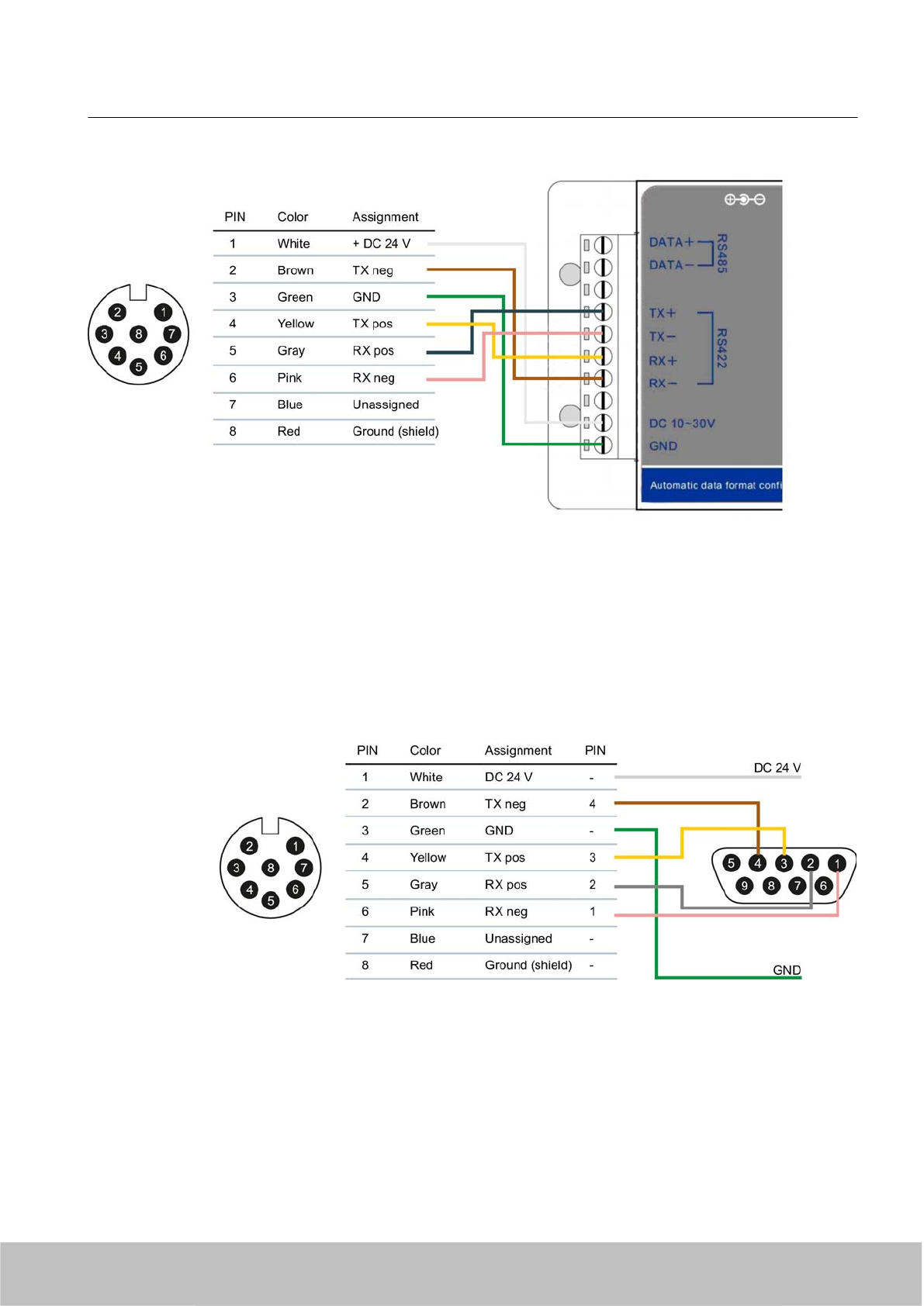
Figure 8-2 TRP-C06 wiring diagram
8.2.1.5 Pin assignment connector EX-42054-9-8S interface converter card
The interface converter card EX-42054-9-8S is installed in the PC. A driver is installed for each
interface so that 8 additional COM ports become available. A connector matching the 8
interfaces must be mounted on the reader cable.
The following figure gives an example of a pin assignment for a connector on an RS422 reader
cable (Order No. 6GT2891-0EH50) as well as the power supply for the reader:
Figure 8-3 Connector pin assignment EX-42054-9-8S and reader power supply
Integration into networks
8.2 Integration in IT networks via RF-MANAGER
SIMATIC RF600
System Manual, 06/2010, J31069-D0171-U001-A10-7618 329
Draft Version 02.06.2010

Note
Same pin assignment for the interface converter card EX-42052-9-2S
For the interface converter card EX-42052-9-2S a connector with the same assignment as
shown above must be installed.
8.2.1.6 Number of readers
The maximum number of readers connected simultaneously to a single computer with serial
communications depends largely on the computer's performance.
In the system test a standard PC (see system requirements) with 8 readers was tested.
Insufficient computer performance can lead to connection interruptions or communication
errors.
On the Microbox with a serial interface, a reader with serial communications was tested.
8.3 Integration in IT networks via the user application
8.3.1 Interfacing with RF670R via XML
If you want to create your own applications for the RF670R reader, you can do this using the
XML-based interface of the reader. For detailed information on configuring the reader using
RF-MANAGER Basic 2010, please refer to the online help for the reader. For information about
XML commands, please refer to the Function Manual "SIMATIC RF670R XML Interface".
8.3.2 Interfacing with RF660R via XML
If you want to create your own applications for the RF660R reader, you can do this using the
XML-based interface of the reader. For detailed information on configuring and operating the
reader using XML commands, please refer to the Function Manual "SIMATIC RF660R XML
Interface".
Integration into networks
8.3 Integration in IT networks via the user application
SIMATIC RF600
330 System Manual, 06/2010, J31069-D0171-U001-A10-7618
Draft Version 02.06.2010
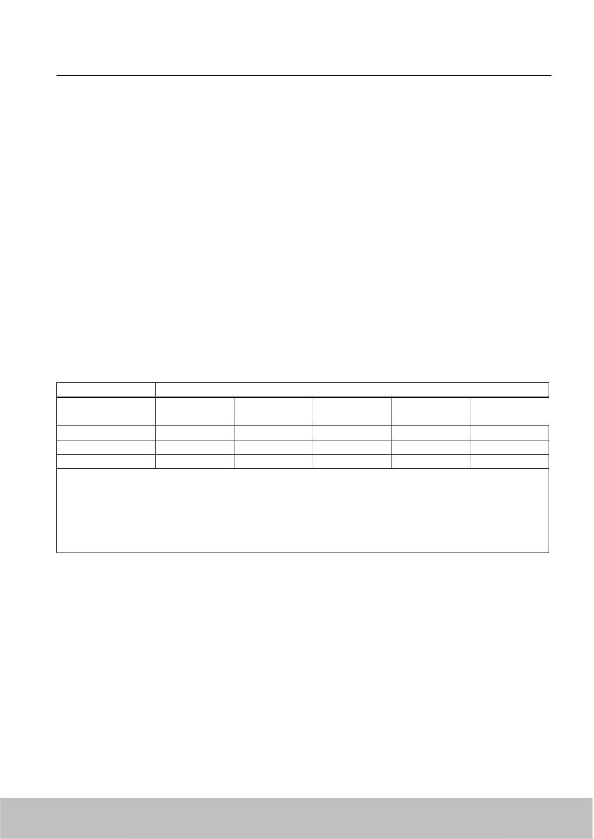
8.4 Integration in SIMATIC networks
8.4.1 RF620R/RF630R
RF620R/RF630R
RF620R and RF630R readers are connected to the controller via the following adapter/
communication modules:
● SIMATIC RF170C
● SIMATIC RF180C
● ASM 456
The RF182C communication module is connected with the PC directly over Ethernet.
Function blocks, interface modules/communication modules and readers
Table 8-1 Table of reader/interface modules
Function blocks Interface modules/communication modules
ASM 456 1) RF170C 1) RF180C RF182C ASM 475
FB 45 1 - 2 readers 1 - 2 readers 1 - 2 readers N/A Not released
FC 55 1 - 2 readers 1 - 2 readers 2) N/A N/A Not released
XML N/A N/A N/A 1 - 2 readers N/A
For all possible combinations, the following restriction applies:
●The input voltage at the communication module is 21.6 V - 30 V
1) If 2 readers are used on one ASM, the following additional restrictions apply:
● The maximum operating temperature is 35 °C (ASM 456)
● The maximum operating temperature is 55 °C (RF170C)
2) No operation is possible with a PROFINET head.
Integration into networks
8.4 Integration in SIMATIC networks
SIMATIC RF600
System Manual, 06/2010, J31069-D0171-U001-A10-7618 331
Draft Version 02.06.2010

Interface modules/communication modules and function blocks
Table 8-2 Overview of interface modules/communication modules
ASM/CM Interfaces to
the
application
(PLC)
Interfaces to the
reader
Function
blocks
Reader
connections
Dimensions
(W x H x D) in
mm
Temperatur
e range
Degree
of
protecti
on
ASM 456 PROFIBUS
DP-V1
2 x 8-pin
connection
socket, M12
FB 45
FC 55
2 (parallel) 60 x 210 x 54
or 79
0 to +55 °C IP 67
SIMATIC
RF170C
PROFIBUS
DP-V1
PROFINET IO
2 x 8-pin
connection
socket, M12
FB 45
FC 55
2 (parallel) 90 x 130 x 60 -25 to +55°
C
IP 67
SIMATIC
RF180C
PROFINET IO 2 x 8-pin
connection
socket, M12
FB 45 2 (parallel) 60 x 210 54
0 to +60° C IP 67
SIMATIC
RF182C
TCP/IP 2 x 8-pin
connection
socket, M12
- 2 (parallel) 60 x 210 x 54 0 to +60 °C IP 67
The following table shows which readers can be connected to which interface modules/
communication modules.
Integration into networks
8.4 Integration in SIMATIC networks
SIMATIC RF600
332 System Manual, 06/2010, J31069-D0171-U001-A10-7618
Draft Version 02.06.2010
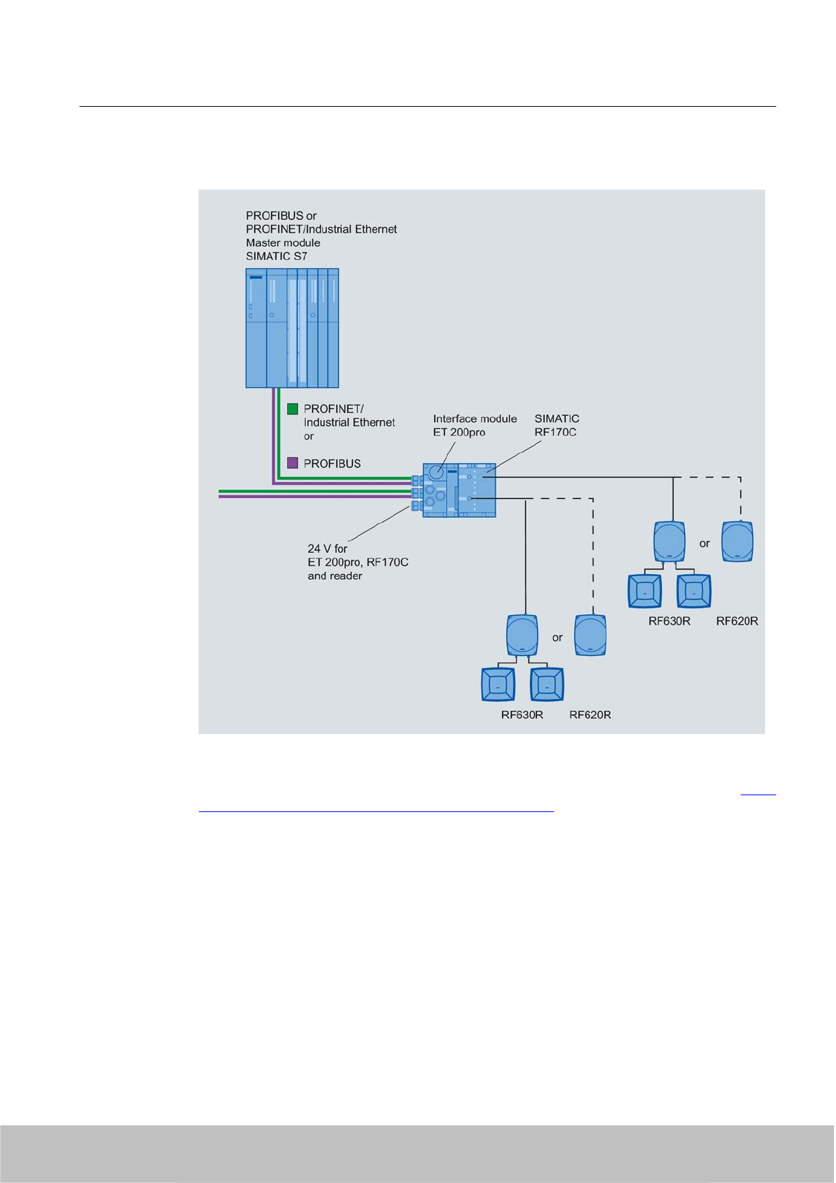
Configuration with SIMATIC RF170C
Figure 8-4 Configuration with SIMATIC RF170C
For more detailed information, please refer to SIMATIC RF170C Operating Instructions (http://
support.automation.siemens.com/WW/view/en/32622825).
Integration into networks
8.4 Integration in SIMATIC networks
SIMATIC RF600
System Manual, 06/2010, J31069-D0171-U001-A10-7618 333
Draft Version 02.06.2010
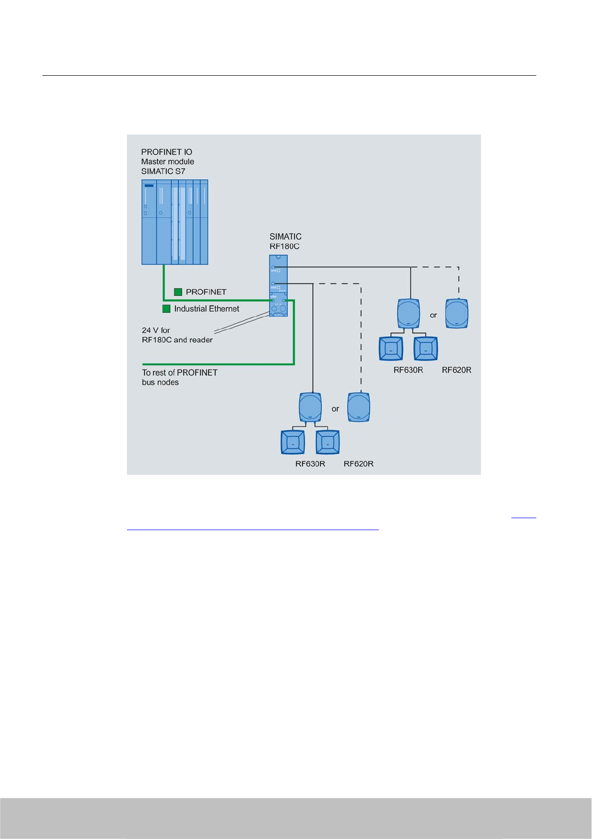
Configuration with SIMATIC RF180C
Figure 8-5 Configuration with SIMATIC RF180C
For more detailed information, please refer to SIMATIC RF180C Operating Instructions (http://
support.automation.siemens.com/WW/view/en/30012157).
Integration into networks
8.4 Integration in SIMATIC networks
SIMATIC RF600
334 System Manual, 06/2010, J31069-D0171-U001-A10-7618
Draft Version 02.06.2010
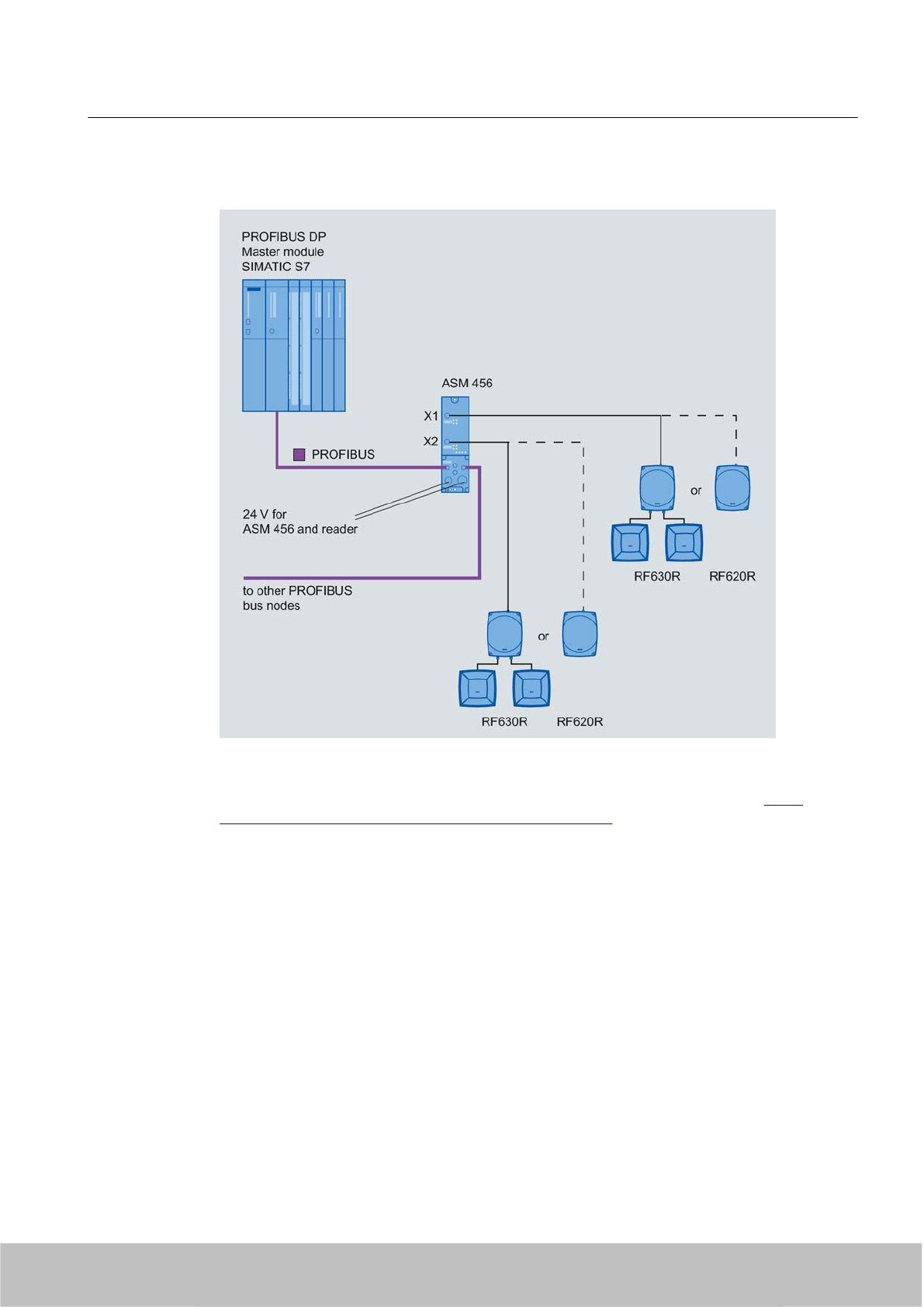
Configured with ASM 456
Figure 8-6 Configured with ASM 456
For more detailed information, please refer to ASM 456 Operating Instructions (http://
support.automation.siemens.com/WW/view/en/32629442).
Integration into networks
8.4 Integration in SIMATIC networks
SIMATIC RF600
System Manual, 06/2010, J31069-D0171-U001-A10-7618 335
Draft Version 02.06.2010
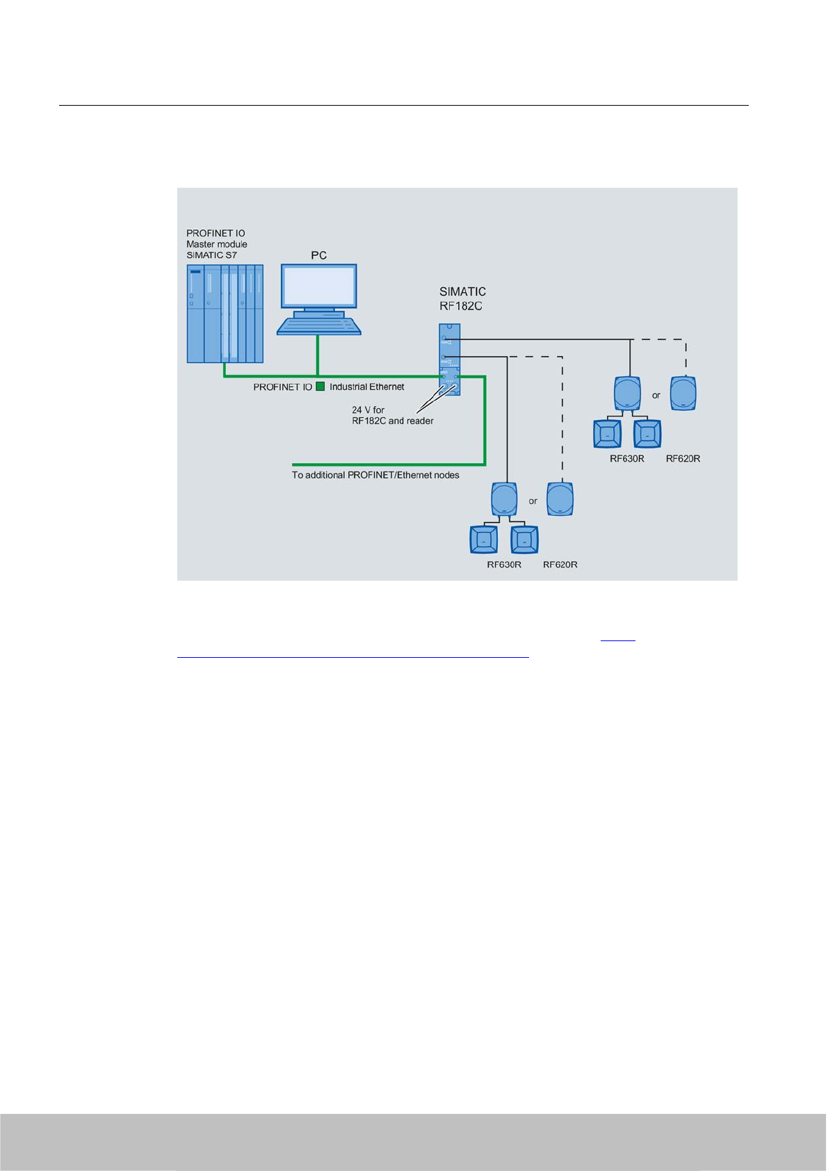
Configuration with RF182C
Figure 8-7 Configuration with SIMATIC RF182C
For more information, see SIMATIC RF182C Operating Instructions (http://
support.automation.siemens.com/WW/view/en/38507897)
Integration into networks
8.4 Integration in SIMATIC networks
SIMATIC RF600
336 System Manual, 06/2010, J31069-D0171-U001-A10-7618
Draft Version 02.06.2010
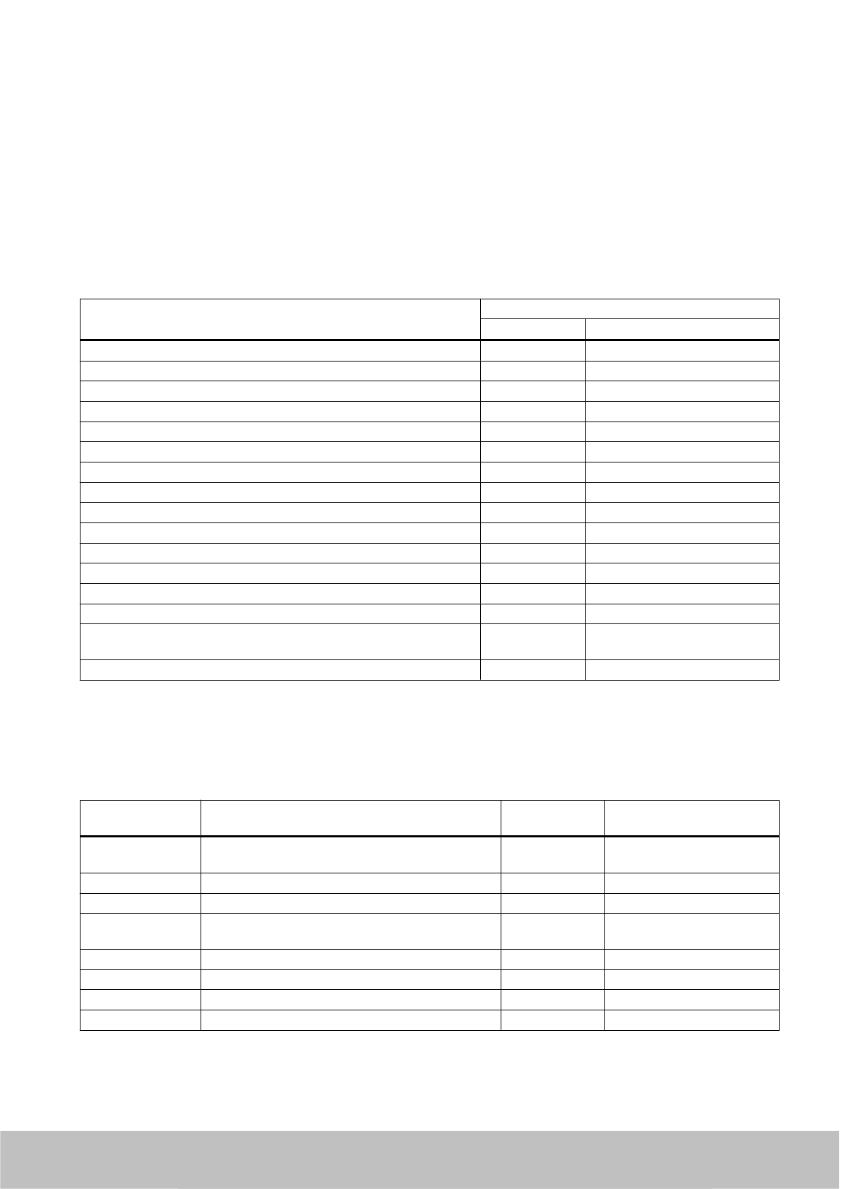
System diagnostics 9
9.1 Error messages and flash codes for RF670R
Error description Flashing of ERR LED
Number Repetitions
Reader inactive, no configuration data 1 Permanent
Antenna 1 not connected or defective 3 Permanent
Antenna 2 not connected or defective 4 Permanent
Antenna 3 not connected or defective 5 Permanent
Antenna 4 not connected or defective 6 Permanent
Writing of the tag ID has failed 10 3 times
Reading of user-defined memory has failed 11 3 times
Writing of user-defined memory has failed 12 3 times
Wrong or missing password 14 3 times
LOCK has failed 16 3 times
KILL has failed 17 3 times
Access to impermissible memory areas 18 3 times
Too many tags in the field 19 3 times
General software errors 20 Permanent
Impermissible message frame;
Impermissible message frame parameter
29 3 times
Incorrect message frame format 30 3 times
1 x flashing of the ERR LED means no error. This means that the reader is not currently active.
9.2 Error messages and flash codes for RF660R
Error code Error description Flashing of ERR
LED
Remark
-Reader is not active 1 Indicates that the reader is
not active
1000 Serious error: Programming of the synthesizer failed 20 Hardware error
1001 Serious error: Antennas connected incorrectly 20 Hardware error
1002 Serious error: Power amplifier could not be
connected
20 Hardware error
1003 Serious error: Tx gain could not be set 20 Hardware error
1004 Serious error: Rx gain could not be set 20 Hardware error
1005 Serious error: Delete FLASH failed 20 Hardware error
1006 Serious error: FLASH write failed 20 Hardware error
SIMATIC RF600
System Manual, 06/2010, J31069-D0171-U001-A10-7618 337
Draft Version 02.06.2010
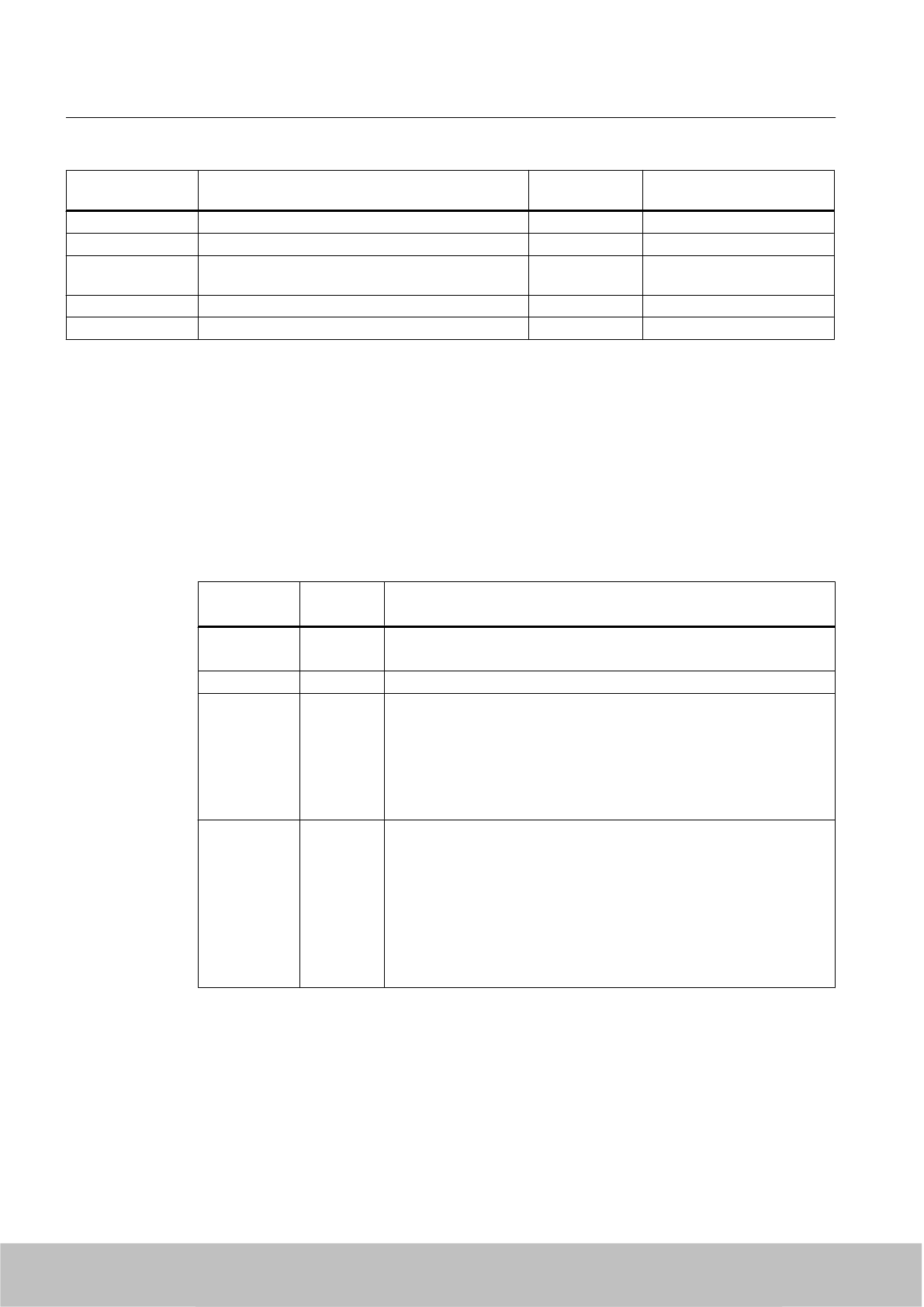
Error code Error description Flashing of ERR
LED
Remark
2000 Serious error: Software errors 20 Software errors
2001 Error: Config rollback error 20 Software errors
2002 Serious error: Saving the default config to FLASH
failed
20 Hardware error
5101 Error: No firmware selected for ramp-up 18 Faulty firmware
5102 Error: Antenna not connected 3 Antenna not connected
1 x flashing of the ERR LED means no error. This means that the reader is not currently active.
9.3 Error messages and flash codes for RF620R/RF630R
error_MOBY
The ERR LED of the reader flashes when the ASM reports error messages.
Table 9-1 Error messages of the MOBY-ASM via the "error_MOBY" variable
Error code
(B#16#..)
Flashing of
ERR LED
Description
00 – No error
Default value if everything is ok.
1x Boot message
01 2x Presence error, possible causes:
●The active command was not carried out completely
● The tag has left the field while the command is being processed
● Communication fault between reader and tag
The next command is automatically executed on the next tag. A read or
write command is possible.
02 2x Presence error: A tag has passed by a reader without being processed
by a MOBY command.
● This error message is not reported immediately. Instead, the ASM
waits for the next command (read, write). This command is
immediately replied to with this error. This means that a read or write
command is not processed. The next command is executed normally
by the ASM again. An init_run from FB 45 also resets this error state.
● Bit 2 is set in parameter "option_1" and no tag is in the transmission
window.
System diagnostics
9.3 Error messages and flash codes for RF620R/RF630R
SIMATIC RF600
338 System Manual, 06/2010, J31069-D0171-U001-A10-7618
Draft Version 02.06.2010

Error code
(B#16#..)
Flashing of
ERR LED
Description
03 3x Error in the connection to the reader. The reader does not answer.
● Cable between MOBY ASM and reader is wired incorrectly or cable
break.
● Antenna error: (Cable is defective), cable is no longer connected
● The 24 V supply voltage is not connected or is not on or has failed
briefly.
● Automatic fuse on the ASM has blown.
● Hardware defect
● Another reader is in the vicinity and is active.
● Interference on reader - or PROFIBUS line
● Execute init_run after error correction
04 4x Error in tag memory
The tag has never been write-accessed or has lost the contents of its
memory due to battery failure.
● Replace tag (if battery bit is set).
● Initialize tag with the STG
● Re-initialize tag
05 5x ● Unknown command
● Incorrect parameter
● Function not allowed
● Mode in SET-ANT command unknown
FB 45/FC 55 is sending an uninterpretable command to the MOBY-ASM.
● Command_DB contains invalid command parameters.
● The command_DB was overwritten by the user
● The MDS reported an address error.
06 6x Field disturbance on reader
The reader is receiving interference pulses from the environment.
● The distance between two readers is too small and does not
correspond to the configuration guidelines
● The connecting cable to the reader is defective or too long or does
not comply with the specification
07 7x No free ETSI transmit channel
09 Wrong communications standard selected in the init_run command (e.g.
FCC in ETSI reader)
0B 11x Tag memory cannot be read correctly or cannot be written.
Tag reports an error:
●Other error (00000000B) *
● Insufficient power (00001011B): Tag is in the limit range *
● Non-specific error (00001111B) *
0C 12x The tag memory cannot be write-accessed.
● Tag memory is defective
● Memory is write-protected (Memory Locked: 000000100B)
(The tag memory is PERMA-locked and cannot be overwritten or the
reader password has to be reset)
System diagnostics
9.3 Error messages and flash codes for RF620R/RF630R
SIMATIC RF600
System Manual, 06/2010, J31069-D0171-U001-A10-7618 339
Draft Version 02.06.2010

Error code
(B#16#..)
Flashing of
ERR LED
Description
0D 13x Error in specified address (address error)
●The specified address does not exist on the tag
● The command must be checked and corrected.
● This is not the correct tag type.
●Access attempted to non-existent or non-accessible memory areas
( Memoryoverrun: 00000011B)
0E 14x Password error
● Incorrect tag password (the reader password must be set again so
that is agrees with the password).
0F 1x Start-up message from ASM. The ASM was off and has not yet received
an init_run command
● Execute an init_run
● The same physical ASM channel is used in two (or more) UDT 10
structures. Check the ASM_address and ASM_channel in
all
UDT
10 structures.
10 16x NEXT command not possible or not permitted
● ASM is operating without MDS control (MDS_control = 0.1)
● ASM has already received a Next command.
● ASM / write/read device doesn't recognize NEXT command.
REPEAT after forbidden commands:
●REPEAT for SET-ANT
● REPEAT for SLG status
11 – Short circuit or overload of the 24 V outputs (DQ, error code, presence)
● The affected output is turned off.
● All outputs are turned off when total overload occurs.
● A reset can only be performed by turning the 24 V voltage off and
on again.
●Then start init_run.
12 18x Internal ASM communication error
● Connector contact problem on the ASM
● Defective ASM hardware
– Return ASM for repair
●Start init_run command after error correction.
13 19x ● ASM/reader does not have enough buffer to store the command
intermediately.
● Maximum allowable number of 150 commands in a command chain
was ignored. If REPEAT is used in connection with a command
chain, the maximum number of commands is also 150 (including the
REPEAT command).
If a command chain contains more than 150 commands, after the
150th command is called, it will be canceled and the above error
message will be sent without processing the complete chain.
Commands in the command chain that have already been executed
can still be sent later after the error message "0x13" is sent.
System diagnostics
9.3 Error messages and flash codes for RF620R/RF630R
SIMATIC RF600
340 System Manual, 06/2010, J31069-D0171-U001-A10-7618
Draft Version 02.06.2010

Error code
(B#16#..)
Flashing of
ERR LED
Description
14 20x Internal ASM / write/read device error
●Program sequence error on the ASM
● Turn power of ASM off and on again.
● Start init_run command after error correction.
●Watchdog error on reader
15 21x Wrong parameterization of the ASM/reader
● Check INPUT parameters in UDT 10
● Check parameters in HW Config
● Transmit power set too high
●Unused parameter bits are not 0.
● init_run command is parameterized incorrectly
● After a start-up, the ASM has still not received an init_run.
● Parameter scanning_time = 0x00 was set (no standard selected).
16 22x The FB command cannot be executed with the ASM parameters on
PROFIBUS.
● Length of the input/output areas too small for the cyclic I/O word.
Did you use the right GSD file?
● FB command (e.g. read) has too much user data (data length > 233
bytes)
17 23x Communication error between FB 45/FC 55 and MOBY-ASM.
Handshake error
● Params_DB (UDT 10) of this ASM station is being overwritten by
other parts of the program
● Check parameters of MOBY-ASM in UDT 10
● Check FB 45/FC 55 command which caused this error.
●Start init_run command after error correction.
18 – An error has occurred which must be acknowledged with an init_run.
● A temporary short circuit has occurred on PROFIBUS.
● The init_run command is faulty
● Start init_run command after error correction.
●Check parameters ASM_address, ASM_channel, and MOBY_mode.
19 25x Previous command is active or buffer overflow.
The user sent a new command to the ASM although the last command
was still active.
● Active command can only be terminated with an init_run.
● Before a new command can be started the READY bit must be 1
(exception: init_run).
● Two FB 45/FC 55 calls were parameterized with the same
parameters "ASM_address" and "ASM_channel"
● Two FB 45/FC 55 calls are using the same Params_DB pointer
● Start init_run command after error correction.
● When command repetition (e.g. read-only MDS) is used, no data are
fetched from the tag. The data buffer on the ASM has overflowed.
Tag data have been lost.
System diagnostics
9.3 Error messages and flash codes for RF620R/RF630R
SIMATIC RF600
System Manual, 06/2010, J31069-D0171-U001-A10-7618 341
Draft Version 02.06.2010

Error code
(B#16#..)
Flashing of
ERR LED
Description
1A – PROFIBUS DP error occurred.
●The PROFIBUS DP bus connection was interrupted
– Wire break on the bus
– Bus connector on ASM was removed briefly
●PROFIBUS DP master no longer addresses the ASM
● Execute an init_run
● The ASM has detected a message frame interruption on the bus.
The PROFIBUS may have been reconfigured (e.g. with HW Config).
This error is only indicated when access monitoring has been enabled
in the PROFIBUS configuration.
1B 27x There is an inconsistency in the parameterization of the reader. In expert
mode, parameters were probably set which the reader cannot use.
● ETSI performance testing faulty
1C 28x ● Antenna is already switched off
●Antenna is already switched on
● Mode in SET-ANT command not recognized.
1D – More MDSes are in the transmission window than the SLG is capable
of processing simultaneously.
●Only 1 MDS can be processed at a time with FB 45.
● With FB 45 and FC 55: there is more than one tag with the same
EPC ID in the antenna field of the reader.
● With FC 55: Increase the value in multitag or decrease the number
of MDSes in the field.
●With FC 55: A read or write command has been sent on a
transponder (UID) and there are one or more transponders in the
antenna field, for which the contents of the addresses FF00 – FF03
of the EPC ID do not agree (unambiguity when transponder is
accessed via 8-byte long UID).
● Power supply of the MDS in the limit range:
Due to short-term power shortage, an MDS loses its communications
status (session), upon which the identical EPC-ID is sent a second
time as soon as the power threshold is exceeded again.
Increase the reader's radiated power and/or reduce the distance
between antenna and MDS until this effect no longer occurs.
1E 30x Wrong number of characters in the command message frame.
1F 31 Running command canceled by RESET (init_run or cancel) or bus
connector removed
●Communication with the tag was terminated by init_run.
● This error can only be reported on init_run or cancel
*) You will find the meaning of the error numbers in the EPC Global Class 1 Gen 2 document, Annex I.
System diagnostics
9.3 Error messages and flash codes for RF620R/RF630R
SIMATIC RF600
342 System Manual, 06/2010, J31069-D0171-U001-A10-7618
Draft Version 02.06.2010
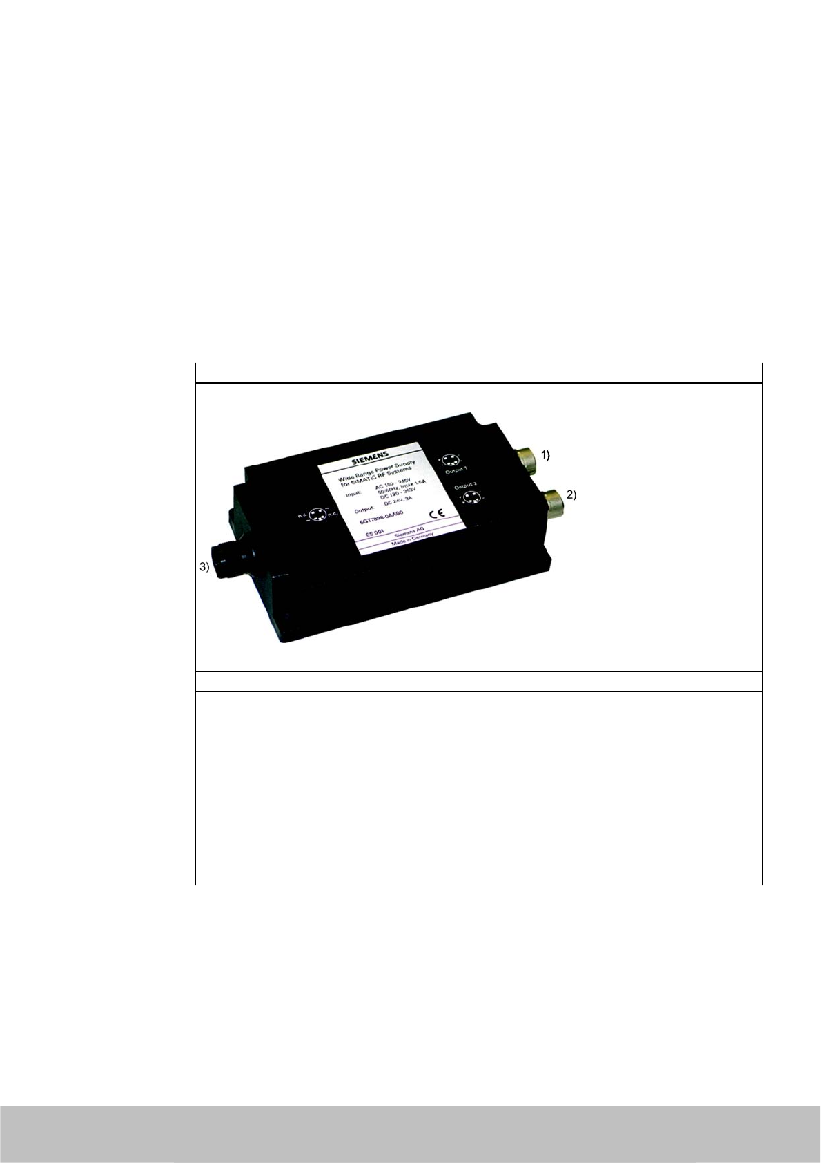
Accessories 10
10.1 Wide-range power supply unit for SIMATIC RF systems
10.1.1 Features
Wide-range power supply unit for SIMATIC RF systems
(1) DC output 1
(2) DC output 2
(3) Mains connection
Features
● Wide-range input (3) for use worldwide
● Dimensions without mains cable: 175 x 85 x 35 mm
● Dimensions including mains cable: 250 x 85 x 35 mm
● CE-compliant (EU and UK versions)
● UL-certified for US and Canada (US version)
● Mechanically and electrically rugged design
● Secondary side (1), (2): 24 V DC / 3 A
● Short-circuit and no-load stability
● Suitable for frame mounting
● 3 versions for use in the EU, UK, US
Description
The wide-range power supply unit for SIMATIC RF systems is a universal compact power
supply and provides the user with an efficient, cost-saving solution for many different mid-range
power supply tasks.
SIMATIC RF600
System Manual, 06/2010, J31069-D0171-U001-A10-7618 343
Draft Version 02.06.2010

The primary switched power supply is designed for use on single-phase AC systems. The two
DC outputs (sockets) are connected in parallel and protected by a built-in current limiting circuit
against overload and short-circuits.
The device is vacuum-cast and prepared for Safety Class 2 applications. The EU and UK
versions satisfy the low-voltage guideline as well as the current EU standards for CE
conformity. Furthermore, the US version has been UL-certified for the US and Canada.
10.1.2 Scope of supply
● Wide-range power supply unit for SIMATIC RF systems
● 2 m mains cable (country-specific)
● Protective cover for flange outlet
● Operating Instructions
10.1.3 Ordering data
Wide-range power supply unit for SIMATIC RF‑systems
(100 - 240 V AC / 24 V DC / 3 A)
with 2 m connecting cable with country-specific plug
EU: 6GT2898‑0AA00
UK: 6GT2898‑0AA10
US: 6GT2898‑0AA20
24 V connecting cable for SIMATIC°RF660R, length 5 m 6GT2491‑1HH50
24 V connecting cable for SIMATIC°RF670R, length 5 m 6GT2891-0NH50
Note
Risk of confusion
Please not that you require different 24°V connecting cables for the RF660R and RF670R
readers.
10.1.4 Safety Information
Accessories
10.1 Wide-range power supply unit for SIMATIC RF systems
SIMATIC RF600
344 System Manual, 06/2010, J31069-D0171-U001-A10-7618
Draft Version 02.06.2010
WARNING
Danger to life
It is not permitted to open the device or to modify the device.
The following must also be taken into account:
● Failure to observe this requirement shall constitute a revocation of the CE approval, UL
certification for the US and Canada as well as the manufacturer's warranty.
● For installation of the power supply, compliance with the DIN/VDE requirements or the
country-specific regulations is essential.
● The field of application of the power supply is limited to "Information technology in electrical
office equipment" within the scope of validity of the EN 60950/VDE 0805 standard.
● When the equipment is installed, it must be ensured that the mains socket outlet is freely
accessible.
● The housing can reach a temperature of +25 °C during operation without any adverse
consequences. It must, however, be ensured that the power supply is covered in the case
of a housing temperature of more than +25°C to protect persons from contact with the hot
housing. Adequate ventilation of the power supply must be maintained under these
conditions.
NOTICE
The wide-range power supply unit must only be used for SIMATIC products in the specifically
described operating range and for the documented intended use.
If the wide input range power supply for SIMATIC RF systems is used for an end product other
than the SIMATIC RF600 system, the following must be taken into account:
● The electric strength test of the end product is to be based upon a maximum working voltage
of: Transition from primary to SELV: 353 V DC, 620 Vpk
● The following secondary output circuits are SELV (low voltage; SELV = Safety Extra Low
Voltage): all
● The following secondary output circuits are at non-hazardous energy levels: all
● The power supply terminals and/or connectors are suitable for field wiring if terminals are
provided.
Accessories
10.1 Wide-range power supply unit for SIMATIC RF systems
SIMATIC RF600
System Manual, 06/2010, J31069-D0171-U001-A10-7618 345
Draft Version 02.06.2010
● The maximum investigated branch circuit rating is: 20 A
● The investigated pollution degree is: 2
WARNING
If the wide input range power supply for SIMATIC RF systems is connected to an end
product other than end products of the RF600 family, the end user is responsible and
liable for operation of the system or end product that includes the wide input range power
supply for SIMATIC RF systems.
WARNING
Alterations to the SIMATIC RF600 components and devices as well as the use of SIMATIC
RF600 components with third-party RFID devices are not permitted.
Failure to observe this requirement shall constitute a revocation of the radio equipment
approvals, CE approval and manufacturer's warranty. Furthermore, the compliance to any
salient safety specifications of VDE/DIN, IEC, EN, UL and CSA will not be guaranteed.
Safety notes for the US and Canada
The SIMATIC RF670R/RF660R reader is only permitted to be operated with the wide input
range power supply for SIMATIC RF systems - as an optional component – or with power
supplies which are UL-listed according to the safety standards specified below:
● UL 60950-1 - Information Technology Equipment Safety - Part 1: General Requirements
● CSA C22.2 No. 60950 -1 - Safety of Information Technology Equipment.
WARNING
The compliance of the SIMATIC RF600 system to the safety standards mentioned above
will not be guaranteed if neither the wide-range power supply unit for SIMATIC RF systems
°nor power supplies listed according to the safety standards above are used.
10.1.5 Connecting
● There are three different (country-specific) mains cables for the EU, UK and US.
The appropriate mains cable must be connected to the primary input of the power supply.
NOTICE
It is only permissible to insert or remove the mains cable when the power supply is de-
energized.
● The wide-range power supply unit has total insulation (Safety Class 2), IP65
●It can be mounted using four fixing holes.
Accessories
10.1 Wide-range power supply unit for SIMATIC RF systems
SIMATIC RF600
346 System Manual, 06/2010, J31069-D0171-U001-A10-7618
Draft Version 02.06.2010
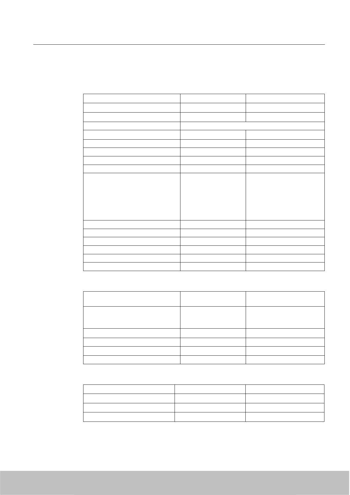
10.1.6 Technical specifications
Table 10-1 General technical specifications
Insulation stability (prim./sec.) Uins p/s 3.3 kVAC
Insulation resistance Rins >1 GΩ
Leakage current Ileak Uin = 230 VAC, f = 50 Hz < 200 µA
Safety class (SELV) Designed for installation in devices of Safety Class 2
Mains buffering thUin = 230 VAC ≥ 50 ms
Ambient temperature -25 °C to +55 °C
Surface temperature Module top, center Max. 96 °C
Storage temperature -40 °C to +85 °C
Self-heating on full-load max. 45 K
Interference immunity
ESD
HF fields
Burst
Surge
HF injection
Mains quality test
EN 61000-4-2,
4-3 up to 4-6, 4-11 Air discharge: 15 kV
10 V/m
symmetrical: 2
Symmetrical: 1
10 Vrms
Cooler Free convection
Dimensions L x W x H 175 mm x 85 mm x 35 mm
Weight 720 g
Housing / casting UL 94-V0
Power supply class according to CSA Level 3
Degree of protection IP 65
Table 10-2 Technical specifications for the input
Rated input voltage Uin EN 60950 / UL 60950 100 to 240 V AC
120 to 353 V DC
Input voltage range Uin 94 to 264 V AC
120 to 375 V DC
(UL: 353 VDC)
Input frequency fin 50/60 Hz
Radio interference level EN 55011/B
Switching frequency fsw approx. 70 kHz typ.
Length of cable 2 m
Table 10-3 Technical specifications of the output
Output voltage tolerance ∆Uout Uin = 230 VAC Uout nom ≤ +2 %/-1 %
Overvoltage protection Uout nom +20 % typ.
Noise ∆ULF Uin = min., BW: 1 MHz ≤ 1 % Uout
Noise ∆UHF Uin = min., BW: 20 MHz ≤ 2 % Uout
Accessories
10.1 Wide-range power supply unit for SIMATIC RF systems
SIMATIC RF600
System Manual, 06/2010, J31069-D0171-U001-A10-7618 347
Draft Version 02.06.2010
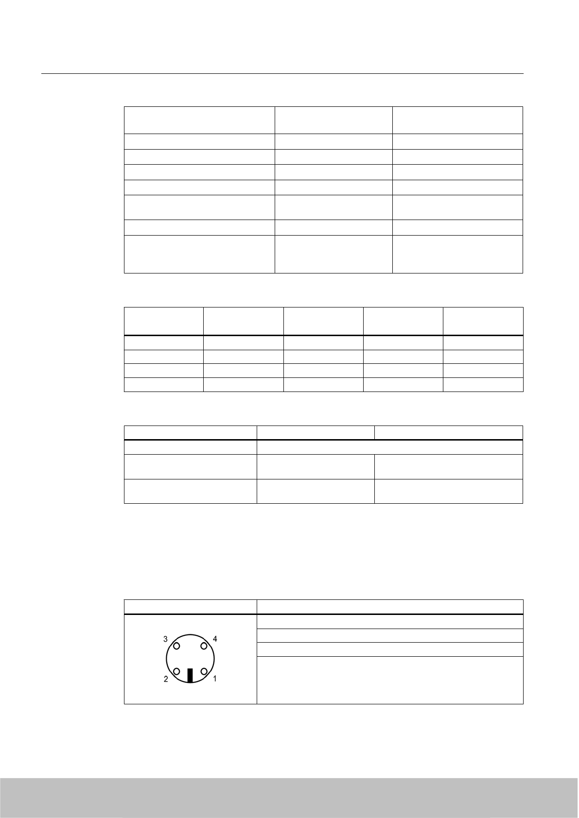
Line Regulation
Load Regulation
Uin = min./max.
Iout = 10...90...10 %
≤ 1,0 %
≤ 1,0 %
Short-circuit current Imax Inom = 4 A (+50°C) 105 up to 130 % Inom
Settling time tR load variations Iout = 10...90...10 % < 5 ms
Temperature coefficient ε TA = -25 °C to +70 °C 0.01 %/K
Overload behavior Pover Constant current
Short-circuit protection/
No-load response
Continuous/no-load stability
Derating TA > +50 °C to +70 °C max. 2 %/K
Connector type Flanged connector
Binder,
Order No.: 09-3431-90-04
4 pins
Table 10-4 Output configurations
Input Outputs
U1 = U2
ILoad =
I1 + I2
Efficiency
(%)
Remarks
110 V AC 24 V DC 0 A No-load stability
110 V AC 24 V DC 3 A ≥ 88
220 V AC 24 V DC 0 A No-load stability
220 V AC 24 V DC 3 A ≥ 90
Table 10-5 Compliance with standards
Designation Standard Values
Electrical safety EN 60950 / UL 60950 / CAN/CSA 22.2 950, 3 Edition
Conducted interference EN 61000-6-3
EN 55011
Class B
Emission EN 61000-6-3
EN 55011
Class B
All values are measured at full-load and at an ambient temperature of 25 °C (unless specified
otherwise).
10.1.7 Pin assignment of DC outputs and mains connection
DC outputs Assignment
(1) Ground (0V)
(2) +24 V DC
(3) +24 V DC
(4) Ground (0V)
Accessories
10.1 Wide-range power supply unit for SIMATIC RF systems
SIMATIC RF600
348 System Manual, 06/2010, J31069-D0171-U001-A10-7618
Draft Version 02.06.2010
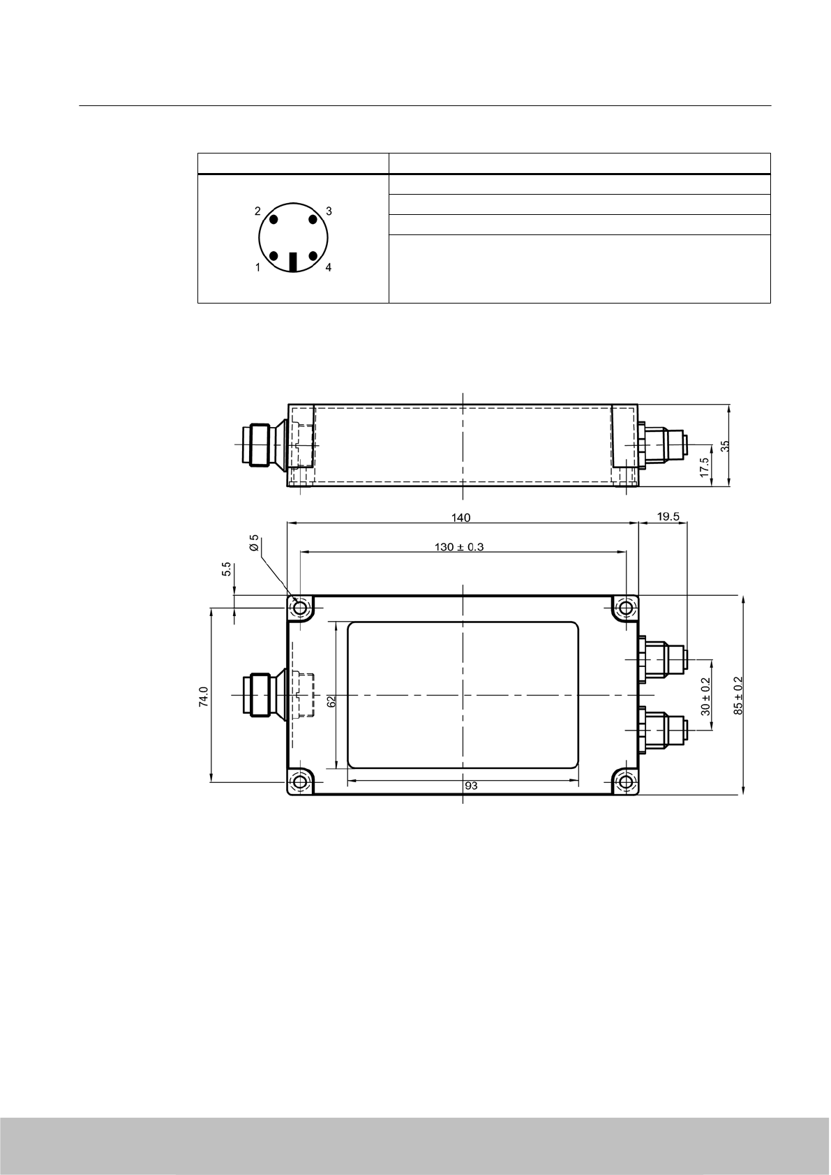
Mains connection Assignment
(1) 100 to 240 V AC
(2) n.c.
(3) 100 to 240 V AC
(4) n.c.
10.1.8 Dimension drawing
Units of measurement:
All dimensions in mm
Accessories
10.1 Wide-range power supply unit for SIMATIC RF systems
SIMATIC RF600
System Manual, 06/2010, J31069-D0171-U001-A10-7618 349
Draft Version 02.06.2010
10.1.9 Certificates and approvals
Table 10-6 Wide-range power supply unit for SIMATIC RF systems 6GT2898-0AA00 - Europe,
6GT2898-0AA10 - UK
Certificate Description
CE approval to
2004/108/EC EMC
73/23/EEC LVD
Table 10-7 Wide-range power supply unit for SIMATIC RF systems 6GT2898-0AA20 - USA
Standard
This product is UL-certified for the US and Canada.
It meets the following safety standards:
UL 60950-1 - Information Technology Equipment Safety - Part 1:
General Requirements
CSA C22.2 No. 60950 -1 - Safety of Information Technology
Equipment
UL Report E 205089
Accessories
10.1 Wide-range power supply unit for SIMATIC RF systems
SIMATIC RF600
350 System Manual, 06/2010, J31069-D0171-U001-A10-7618
Draft Version 02.06.2010
Appendix A
A.1 Certificates and approvals
Notes on CE marking
The following applies to the system described in this documentation:
The CE marking on a device is indicative of the corresponding approval:
DIN ISO 9001 certificate
The quality assurance system for the entire product process (development, production, and
marketing) at Siemens fulfills the requirements of ISO 9001 (corresponds to EN29001: 1987).
This has been certified by DQS (the German society for the certification of quality management
systems).
EQ-Net certificate no.: 1323-01
Table A-1 FCC IDs: NXW-RF660, NXW-RF620R, NXW-RF630R, IC: 267X-RF620R, IC: 267X-
RF630
Standards
Federal Communications
Commission
FCC Title 47, Part 15.sections 15.247
Radio Frequency Interference Statement
This equipment has been tested and found to comply with the limits
for a Class A digital device, pursuant to Part 15 of the FCC Rules.
Industry Canada Radio
Standards Specifications
RSS-210 Issue 6, Sections 2.2, A8
This product is UL-certified for the USA and Canada.
It meets the following safety standard(s):
UL 60950-1 - Information Technology Equipment Safety - Part 1:
General Requirements
CSA C22.2 No. 60950 -1 - Safety of Information Technology
Equipment
UL Report E 205089
SIMATIC RF600
System Manual, 06/2010, J31069-D0171-U001-A10-7618 351
Draft Version 02.06.2010
Certification for the USA, Canada and Australia
Safety
One of the following markings on a device is indicative of the corresponding approval:
Underwriters Laboratories (UL) to UL 60950 Standard (I.T.E), or to UL508
(IND.CONT.EQ)
Underwriters Laboratories (UL) according to Canadian standard C22.2 No. 60950 (I.T.E)
or C22.2 No. 142 (IND.CONT.EQ)
Underwriters Laboratories (UL) according to standard UL 60950, Report E11 5352 and
Canadian standard C22.2 No. 60950 (I.T.E) or UL508 and C22.2 No. 142 (IND.CONT.EQ)
UL recognition mark
Canadian Standard Association (CSA) per Standard C22.2. No. 60950 (LR 81690) or per
C22.2 No. 142 (LR 63533)
Canadian Standard Association (CSA) per American Standard UL 60950 (LR 81690) or
per UL 508 (LR 63533)
EMC
USA
Federal Communications
Commission
Radio Frequency
Interference Statement
This equipment has been tested and found to comply with the limits for a
Class A digital device, pursuant to Part 15 of the FCC Rules. These limits
are designed to provide reasonable protection against harmful interference
when the equipment is operated in a commercial environment. This
equipment generates, uses, and can radiate radio frequency energy and,
if not installed and used in accordance with the instruction manual, may
cause harmful interference to radio communications. Operation of this
equipment in a residential area is likely to cause harmful interference in
which case the user will be required to correct the interference at his own
expense.
Shielded Cables Shielded cables must be used with this equipment to maintain compliance
with FCC regulations.
Modifications Changes or modifications not expressly approved by the manufacturer
could void the user’s authority to operate the equipment.
Conditions of Operations This device complies with Part 15 of the FCC Rules. Operation is subject
to the following two conditions: (1) this device may not cause harmful
interference, and (2) this device must accept any interference received,
including interference that may cause undesired operation.
Appendix
A.1 Certificates and approvals
SIMATIC RF600
352 System Manual, 06/2010, J31069-D0171-U001-A10-7618
Draft Version 02.06.2010
CANADA
Canadian Notice This Class B digital apparatus complies with Canadian ICES-003.
Avis Canadien Cet appareil numérique de la classe b est conforme à la norme NMB-003
du Canada.
AUSTRALIA
This product meets the requirements of the AS/NZS 3548 Norm.
A.2 National regulations
A.2.1 Exceptions for certain regions in France
The following table defines the permitted frequency bands for the ETSI profile which must be
utilized for special regions in France. The
italic
entries show the permitted frequency bands
for transmitting in the EPC Class 1 Gen 2 multi-channel dense interrogator environment. The
EPC Class 1 Gen 2 single-channel regulatory environment can use all frequency bands.
Channel ID Frequency (MHz) Maximum transmit power (W)
100 865.1 0.1
101 865.3 0.1
102 865.5 0.1
103 865.7 0.5
104 865.9
0.5
105 866.1 0.5
106 866.3
0.5
107 866.5 0.5
108 866.7
0.5
109 866.9 0.5
110 867.1
0.5
111 867.3 0.5
112 867.5
0.5
113 867.7 0.5
114 867.9 0.5
Due to a European Commission decision as of 16th May 2007 granting France the derogation
to further limit the emission powers for the use of the frequency band 865.6-867.6 MHz for the
radio frequency identification devices (RFID) operating within certain zones on the territory of
France, the operation of the RF600 system is limited to operate within the power levels
indicated above, when it is inside the following regions:
Appendix
A.2 National regulations
SIMATIC RF600
System Manual, 06/2010, J31069-D0171-U001-A10-7618 353
Draft Version 02.06.2010

Geographic coordinates Region/Department Radius of the region with
max. power of 500 mW ERP
AVON LES ROCHES
(camp Le Ruchard)
47° 12' 04" N-000° 28' 48" E 37 - Indre-et-Loire 20 km
BEIGNON
(camp de COETQUIDAN)
47° 56' 56" N-002° 09' 26" W 56 - Morbihan 15 km
BITCHE 49° 03' 09" N-007° 28' 43" E 57 - Moselle 20 km (only in French
territory)
CAYLUS 44° 16' 42" N-001° 44' 57" E 82 - Tarn-et-Garonne 20 km
LA CAVALERIE
(camp du LARZAC)
44° 00' 40" N-003° 10' 16" E 12 - Aveyron 10 km
LA COURTINE 45° 42' 40" N-002° 15' 18" E 23 - Creuse 20 km
MAILLY LE CAMP 48° 39' 55" N-004° 13' 04" E 10 - Aube 20 km
MONTFERRAT
(camp de CANJUERS)
43° 38' 47" N-006° 28' 05" E 83 - Var 10 km
MOURMELON 49° 07' 30" N-004° 21' 59" E 51 - Marne 15 km
SISSONNE 49° 34' 08" N-003° 54' 57" E 02 - Aisne 20 km
SUIPPES 49° 07' 37" N-004° 33' 05" E 51 - Marne 20 km
VALDAHON LYAUTEY 47° 09' 24" N-006° 19' 25" E 25 - Doubs 20 km
A.3 Service & Support
Technical Support
You can access technical support for all IA/DT projects via the following:
● Phone: + 49 (0) 911 895 7222
● Fax: + 49 (0) 911 895 7223
E-mail (mailto:support.automation@siemens.com)
● Internet: Online support request form: (www.siemens.com/automation/support-request)
Contact partner
If you have any further questions on the use of our products, please contact one of our
representatives at your local Siemens office.
The addresses are found on the following pages:
● On the Internet (www.siemens.com/automation/partner)
● In Catalog CA 01
● In Catalog FS 10 specially for factory automation sensors
Appendix
A.3 Service & Support
SIMATIC RF600
354 System Manual, 06/2010, J31069-D0171-U001-A10-7618
Draft Version 02.06.2010

Service & support for industrial automation and drive technologies
You can find various services on the Support homepage (www.siemens.com/automation/
service&support) of IA/DT on the Internet.
There you will find the following information, for example:
● Our newsletter containing up-to-date information on your products.
● Relevant documentation for your application, which you can access via the search function
in "Product Support".
● A forum for global information exchange by users and specialists.
● Your local contact for IA/DT on site.
● Information about on-site service, repairs, and spare parts. Much more can be found under
"Our service offer".
RFID homepage
For general information about our identification systems, visit RFID homepage
(www.siemens.com/simatic-sensors/rf).
Technical documentation on the Internet
A guide to the technical documentation for the various products and systems is available on
the Internet:
SIMATIC Guide manuals (www.siemens.com/simatic-tech-doku-portal)
Online catalog and ordering system
The online catalog and the online ordering system can also be found on the Industry Mall
Homepage (http://www.siemens.com/industrymall).
Training center
We offer appropriate courses to get you started. Please contact your local training center or
the central training center in
D-90327 Nuremberg.
Phone: +49 (0) 180 523 56 11
(€ 0.14 /min. from the German landline network, deviating mobile communications prices are
possible)
For information about courses, see the SITRAIN homepage (www.sitrain.com).
Appendix
A.3 Service & Support
SIMATIC RF600
System Manual, 06/2010, J31069-D0171-U001-A10-7618 355
Draft Version 02.06.2010

Draft Version 02.06.2010

Glossary
SIMATIC RF600
System Manual, 06/2010, J31069-D0171-U001-A10-7618 357
Draft Version 02.06.2010

Draft Version 02.06.2010

Index
A
Antenna cable
Connector type, 197
Antenna cables, 197
Bending radius, 197
Antenna configuration, 38
Antenna gain, 187
Cable loss 4 dB, 188
Dependency on plane, 188
FCC, 188
Frequency dependency, 188
Antenna mounting kit
RF620R, 92
RF670R, 127
Appearance of resonance, 196
B
Beam angle, 195
Read area, 195
Beam width
Definition, 193
ETSI, 193
Bending radius
Antenna cables, 197
C
Cable
Shielding, 77
Cable loss
Definition, 196
Dependencies, 196
Characteristic impedance
Definition, 196
Circular polarization, 190
Classes, 206
Coaxial antenna cables
Coaxial, 197
Configuration, 93, 106, 144
Antennas, 38
Connector type, 197
R-TNC, 197
Thread, 197
Contact partner, 354
Coupling paths, 74
Courses, 355
D
Decibel
Calculation example, 187
Definition, 187
Reference variables, 187
Design of the RF660R reader, 137
Design of the RF670R reader, 114
Dimensions
RF620R reader, 97
RF630R reader, 111
RF660R reader, 149
RF670R reader, 132
Directional antennas, 185
E
EIRP, 186
Electromagnetic compatibility
Coupling paths, 74
Electromagnetic interference, 72
Electromagnetic waves
UHF range, 51
EMC Directives, 352
Propagation of electromagnetic interference, 72
EMC Guidelines
Avoiding interference, 75
Basic Rules, 71
Cable shielding, 77
Definition, 70
Equipotential bonding, 76
Overview, 69
Equipotential bonding, 76
ERP, 186
Cable loss, 186
Logarithmic, standardized, 186
ETSI frequency bands, 353
F
France
Channel ID, 353
Frequency, 353
Maximum transmit power, 353
France, regions
ETSI frequency bands, 353
SIMATIC RF600
System Manual, 06/2010, J31069-D0171-U001-A10-7618 359
Draft Version 02.06.2010

Frequency hopping, 59
Front-to-back ratio, 192
G
Gate configuration
Application areas, 40
Arrangement of antenna, 40
Generations, 206
I
Identification system
Performance Features, 25
UHF range, 21
Impedance
Definition, 188
Specifications, 188
Influence of
Interference, 51
Liquids, 52
Metals, 52
Non-metallic substances, 52
reflections, 51
Influencing factors, 182
Interfaces, 93, 106, 144
Digital, 139
RS422, 93
Interference, 51
Interference sources
Electromagnetic, 73
Isotropic radiator, 185
Isotropic spherical radiator, 187
L
Linear polarization, 191
M
Main applications
RF600, 23
RF610M, 23
RF620R, 23
RF630R, 23
RF660R, 23
RF-MANAGER, 23
Main beam direction, 192
Minimum distances
For antennas, 44
Mounting of RF620R
Antenna Mounting Kit, 92
Mounting of RF670R
Antenna Mounting Kit, 127
Mounting types of the RF620R reader, 92
Mounting types of the RF630R reader, 106
Mounting types of the RF660R reader, 144
O
Ordering data for RF670R, 115
Accessories, 116
Antennas and antenna cable, 115
P
Parameter, 182
Performance Features
RF600, 25
Polarization
Circular, 190
Linear, 191
Portal configuration
Example application, 38
Power supply, 141
RF670R, 123
R
Reading range
Dependency of the, 46
Reciprocity, 185
reflections, 51
Reflections, 196
Regulations applicable to UHF frequency bands
Europe, 54, 57
Return loss
Definition, 189
RF600
Main applications, 23
Performance Features, 25
RF620A
Technical data, 173
RF620A antenna
Technical data, 154
Index
SIMATIC RF600
360 System Manual, 06/2010, J31069-D0171-U001-A10-7618
Draft Version 02.06.2010

RF620R reader
Mounting types, 92
Configuration, 93
Design, 81
Dimensions, 97
FCC information, 98
Interfaces, 93
Status display, 82, 102
RF630R reader
Mounting types, 106
Accessories, 101
Configuration, 106
Design, 100
Dimensions, 111
FCC information, 112
IC-FCB information, 113
Interfaces, 106
RF660A antenna
Design, 176
Radiation/reception characteristic for Europe
(ETSI), 178
Radiation/reception characteristic for USA (FCC),
178
Technical data, 154, 181
RF660R reader
Configuration, 144
Design, 137
Dimensions, 149
Examples of mounting types, 144
FCC information, 150
IC-FCB information, 151
Interfaces, 139, 141, 144
Power supply, 141
Status displays, 137
RF670R
LEDs, 117
RF670R reader
Mounting types, 127
CE Approval, 132
Design, 114
Digital I/O interface,
Dimensions, 132
FCC approval, 132
FCC information, 132
IC-FCB information, 133
Interfaces, 118, 123
Power supply, 123
RF-MANAGER
Engineering System (ES), 328
Levels of the automation/IT structure, 21
Runtime (RT), 328
RF-MANAGER Runtime (RT)
SIMATIC Microbox PC 427B, 328
S
Safety Information, 15
Scalar product, 185
Shielding, 77
Antenna cables, 197
Spurious lobes, 192
Status display of the RF620R reader, 82, 102
Status LEDS of the RF660R reader, 137
Structure of the RF620R reader, 81
Structure of the RF630R reader, 100
T
Technical data
RF620A antenna, 154
RF660A antenna, 154, 181
Technical documentation
On the Internet, 355
Technical Support, 354
Training, 355
Transponder
Classes, 206
Generations, 206
how it works, 205
Improving detection, 52
U
UHF band
China, 58
V
Voltage standing wave ratio
Definition, 189
VSWR
Definition, 189
W
Wide-range power supply unit
Pin assignment for DC outputs,
Index
SIMATIC RF600
System Manual, 06/2010, J31069-D0171-U001-A10-7618 361
Draft Version 02.06.2010

Draft Version 02.06.2010

Draft Version 02.06.2010
Draft Version 02.06.2010