Siemens SRIF2002 Data Transceiver User Manual
Siemens AG Data Transceiver Users Manual
UserManual.wiki
>
Siemens
>
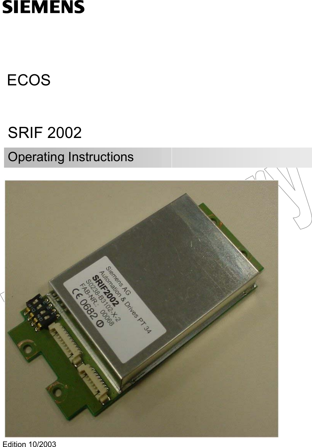
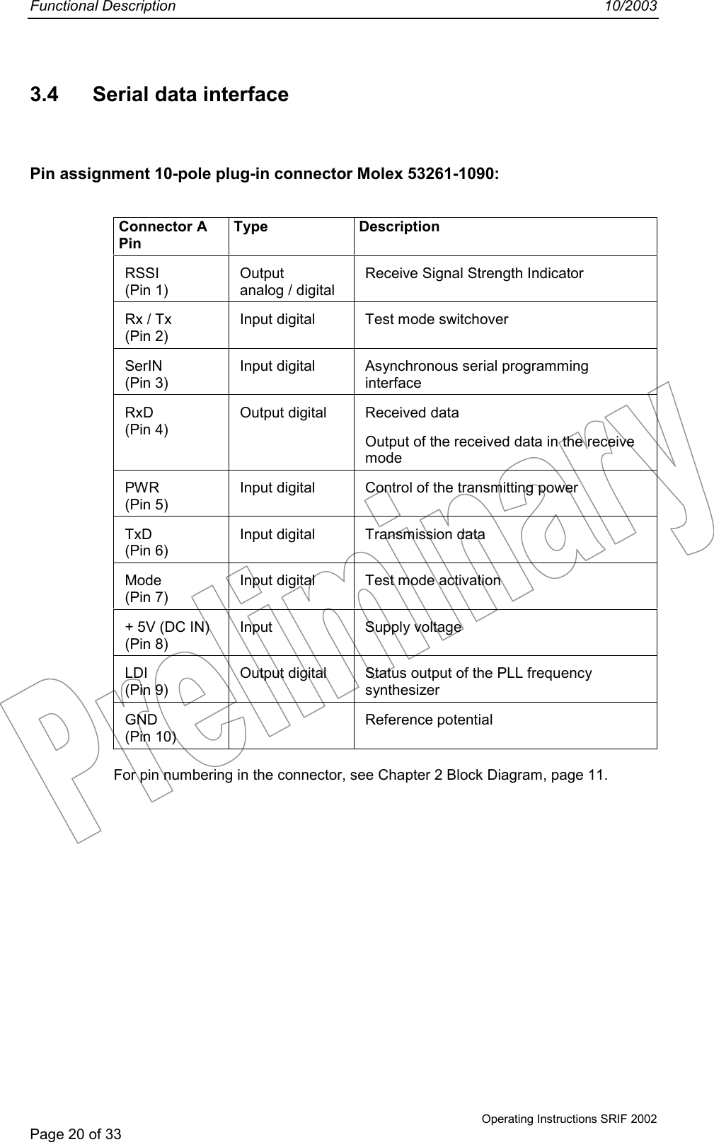
SRIF2002 User Manual
Users Manual
Navigation menu
Upload a User Manual
Namespaces
Wiki Guide
HTML
PDF
Info
Views
User Manual
Discussion / Help
Navigation