Users Manual
ECOS
SRIF 2002
Operating Instructions
Edition 10/2003

Copyright Siemens AG 2003, All rights reserved
This document shall not be transmitted or reproduced, nor shall its
contents be exploited or disclosed to third persons without prio
r
written consent from Siemens. Infringements shall entitle to damage
claims. All rights reserved, in particular in case of a patent grant o
r
utility model registration.
Disclaimer of liability
Although we have carefully checked the contents of this publication
for conformity with the hardware and software described, we cannot
guarantee complete conformity since errors cannot be excluded.
The information provided in this manual is checked at regula
r
intervals and any corrections which might become necessary are
included in the next editions. The contents of this manual are
subject to change without prior notice. Any suggestions fo
r
improvement are welcome.
Siemens AG
Automation & Drives
Business Unit: Automotive Industry Projects, Training
Production Automation, Automotive Industry
P.O. Box 48 48, D-90327 Nuremberg
© Siemens AG 2003
Subject to technical changes.
Siemens Aktiengesellschaft Printed in the Federal Republic of Germany
Safety instructions
This document contains instructions you are strongly advised to observe in order to
guarantee your personal safety and to avoid personal damages. The instructions are
marked by a warning triangle and, depending on the degree of risk, are presented as
follows:
!Warning
means that death or serious physical injuries may be caused if you do not take the
respective precautionary measures.
!Caution
means that minor physical injuries may be caused if you do not take the respective
precautionary measures.
Note
provides important information on the product, the product handling or the respective
part of the documentation which requires special attention and whose observation is
recommendable due to possible advantages.
Use in accordance with specification
Please observe the following:
!Warning
The device may only be used for applications specified in the catalogue and the
technical descriptions. It may further only be used in combination with non-Siemens
devices and components which are recommended or approved by Siemens.
Faultless and safe operation is only ensured if the product is transported, stored,
mounted and installed properly and if the operation and maintenance is carried out
conscientiously.

Operating Instructions SRIF 2002
Page 3 of 33
Table of Contents
1 General............................................................................................................................. 5
1.1 Short description .................................................................................................. 6
1.2 Definition of terms ................................................................................................ 6
1.3 Important instructions........................................................................................... 7
1.3.1 General instructions ............................................................................................. 7
1.3.2 Certificates, guidelines and declarations ............................................................. 8
2 Block Diagram ............................................................................................................... 11
3 Functional Description ................................................................................................. 13
3.1 Radio transmission............................................................................................. 14
3.2 Parameterization via the parallel interface......................................................... 15
3.3 Serial parameterization ...................................................................................... 17
3.4 Serial data interface ........................................................................................... 20
3.5 Notes on the radio operation.............................................................................. 21
4 Settings .......................................................................................................................... 23
4.1 Settings for the DIP switch................................................................................. 24
4.2 Settings for the operation in the MDA / SDA...................................................... 25
4.3 Settings for the operation in the hand-held terminal .......................................... 25
5 Maintenance and Care.................................................................................................. 27
6 Technical Data............................................................................................................... 29
7 Appendix: Channel / Frequency Table ....................................................................... 31

Operating Instructions SRIF 2002
Page 5 of 33
General 1
1.1 Short description .................................................................................................. 6
1.2 Definition of terms ................................................................................................ 6
1.3 Important instructions........................................................................................... 7
1.3.1 General instructions ............................................................................................. 7
1.3.2 Certificates, guidelines and declarations ............................................................. 8

General 10/2003
Operating Instructions SRIF 2002
Page 6 of 33
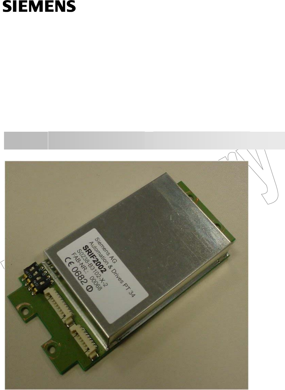
1.1 Short description
The SRIF 2002 is a radio transmitter/receive module (transceiver) for half-duplex
data transmission in the 5.8 GHz ISM range. It transmits digital data with a baud
rate up to 115.2 kBaud. Depending on the antenna, the installation environment
and the frequency band, the transmission range may be up to 15 m, 100 m as a
maximum (comparable to free field).
127 different frequencies (radio channels) can be set and used in the 5.8 GHz ISM
band.
1.2 Definition of terms
BA Battery Adapter
ECOS Electrical Check Out System
ECOS-i Electrical Check Out System intelligent
FCC Federal Communications Commission
FSK Level Frequency Shift Keying
HT Hand-held Terminal
ISM Industrial, Scientific and Medical Applications
LSB Least Significant Bit
MDA Mobile Diagnosis Adapter
MMCX Type: RF connector with latching element
MPS Mobile Test Station
MSB Most Significant Bit
RF Radio Frequency
RSSI Receive Signal Strength Indicator
SDA Stationary Diagnosis Adapter
SMA Type: RF connector with thread
SRIF Serial Radio InterFace
TRX Transmitter Receiver (product from the ECOS
range)
UART Universal Asynchronous Receiver Transmitter

10/2003 General
Operating Instructions SRIF 2002
Page 7 of 33
1.3 Important instructions
1.3.1 General instructions
Transport
We recommend that you only transport the device in its original packaging (shock
and impact protection).
Repairs
Repairing the device is not permitted. Considerable danger may result for the user
if the device is opened without authorisation or repairs are carried out improperly.
ESD guidelines
Modules with ESD (electrostatically sensitive devices) may be marked by the
following label:
If you use modules with ESD, you are urgently required to observe and follow the
following guidelines:
● Before you start to work with modules including ESD, you must discharge
yourself electrostatically (e.g. by touching an earthed object).
● All devices and tools used must be free of static charge.
● Withdraw the power plug prior to plugging in or withdrawing modules with ESD.
● Touch modules with ESD only on the edges.
● Do not touch any terminal pins or conductors on a module with ESD.
● Use only ESD-suitable packaging for shipping.
General 10/2003
Operating Instructions SRIF 2002
Page 8 of 33
1.3.2 Certificates, guidelines and declarations
Notes on the CE certification
The following applies for the product described in these operating instructions:
EC guideline R&TTE 1999/5/EC
The product meets the requirements of the EC guideline R&TTE 1999/5/EC
(Radio Equipment and Telecommunications Terminal Equipment) and the
corresponding harmonized European standards (EN) published in this context.
SRIF 2002 complies with national and international standards. Radio installations
with the SRIF 2002 are ready for approval world-wide.
Any emitted interferences in the transmit and receive mode comply with
EN 300 440 (09.2001).
Note on the Declaration of Conformity
In accordance with the above mentioned EC guideline, the EC conformity
declarations and the accompanying documentation are available for the
responsible authorities at:
SIEMENS AG
Automation and Drives
A & D PT 34
P.O. Box 4848
D – 90327 Nuremberg
Tel.: +49 911 895 3490
Fax.: +49 911 895 3699

10/2003 General
Operating Instructions SRIF 2002
Page 9 of 33
FCC approval
FCC FCC ID:LDS-SRIF2002
The product meets the requirements of FCC guideline CFR47 Part15 chapter 249.
Caution:
Any changes or modifications not expressly approved by the party responsible for
compliance could void the user’s authority to operate the equipment.
Observe installation guidelines
The installation and safety guidelines listed in these Operating Instructions must be
observed for commissioning and operation.
DIN ISO 9001 certificate
The quality management system of our complete product generation process
(development, production and distribution) complies with the DIN ISO 9001
requirements (corresponds to EN29001: 1987).
This device is labelled with an FCC ID number.
If this label is not visible when installed in an end device, the outside of the device
MUST also display a label referring to the enclosed module.
Wording on the label similar to the following shall be used:
This device contains transmitter module FCC ID LDS-SRIF2002
Operating Instructions SRIF 2002
Page 11 of 33
Block Diagram 2
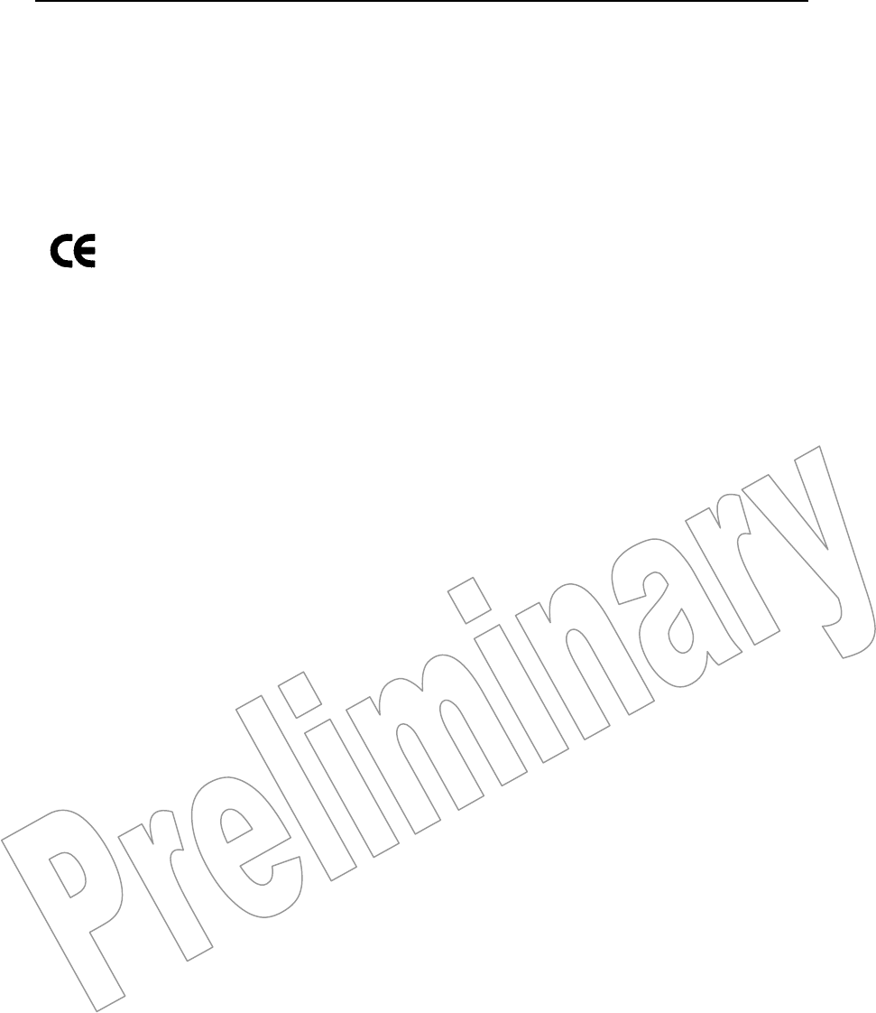
Figure 1: Block diagram of the SRIF 2002
Proces-
sing
HF antenna
terminal
MMCX socket
DIP-
switch
Data
interface
Parallel
parameterization
interface
HF-
transmitter
Para-
meter
PIN 1
PIN 1

Operating Instructions SRIF 2002
Page 13 of 33
Functional Description 3
3.1 Radio transmission............................................................................................. 14
3.2 Parameterization via the parallel interface......................................................... 15
3.3 Serial parameterization ...................................................................................... 17
3.4 Serial data interface ........................................................................................... 20
3.5 Notes on the radio operation.............................................................................. 21
Functional Description 10/2003
Operating Instructions SRIF 2002
Page 14 of 33
3.1 Radio transmission
The SRIF 2002 comprises all necessary functions for the transmission of digital
data in the 5.8 GHz range in transmit and receive mode. It is possible to set 127
frequencies (channels) independent of each other. The channels can either be
programmed via an additional asynchronous interface (UART protocol: 4800 Baud;
8N1) or set via 7 binary-coded parallel control lines. The parallel setting always has
priority, i.e. a serial programming is only possible if the parallel interface is
disconnected or the word “0” is set at the parallel interface (all switches open). The
SRIF 2002 supplies an analog RSSI signal.
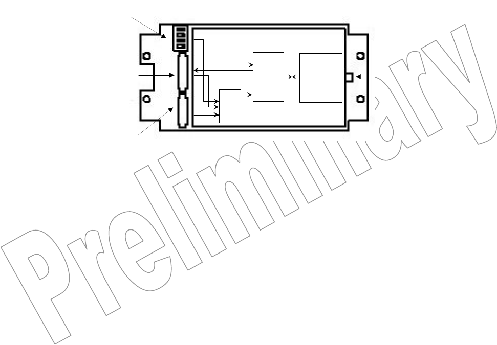
The SRIF 2002 operates in the half duplex mode. The SRIF 2002 is in the receive
mode as a standard. As soon as any transmission data are applied to the data
input (TXD) and the control signal pin2 is set to TX, the module switches to the
transmit mode and transmits the data.
Figure 2: Schematic representation of the radio transmission
Operating modes of the SRIF2002:
● Receive mode The receive mode is the normal operating state of
the module.
● Transmit mode The module automatically changes into the
transmit mode when a valid signal has been
received via the UART and after the completion of
a just received block via the radio path.
● Stand-by mode The stand-by mode is activated at wrong
parameterization.
TxD
RxD
SRIF 2002 SRIF 2002 TxD
RxD
5.8 GHz ISM band

10/2003 Functional Description
Operating Instructions SRIF 2002
Page 15 of 33
The SRIF 2002 communicates via a serial asynchronous interface
(UART protocol). The transfer rate has to be preset by the user. Transfer rates of
9600, 19200, 38400, 57600 and 115200 can be set via the quadruple DIP switch of
the SRIF 2002 (see Figure 1, page 11). Data communication is always 8E1 (8 data
bits, even parity, 1 stop bit).
3.2 Parameterization via the parallel interface
The SRIF 2002 has to be parameterized via the parallel interface, for example if it
is used in the battery adapter (BA) / ammeter or in the TRX245 of the ECOS range.
This presetting can be overwritten with the help of the additional asynchronous
serial interface (UART protocol: 4800 baud; 8N1 (see Chapter 3.3 Serial
parameterization, page 17).
The following settings have to be carried out:
Baud rate setting
The SRIF 2002 carries out the setting of the DIP switch after every power-on reset.
See Chapter 4 Settings, page 23, for a table listing of the settings.
Channel setting
8-pole plug-in connector Molex 53261-0890
Connector B
Pin
Description
GND
(Pin 1)
Reference potential
A0,..., A6
(Pin 2,..., Pin8)
Digital inputs for the parallel channel setting
4V CMOS level binary-coded A0 = 20 and A6 = 26
(for channel numbers, see Chapter 7 Appendix, page 31;
for Pin numbering, see Chapter 2 Block Diagram, page 11)
7 parallel inputs (A0 = LSB, A6 = MSB) and one reference line (GND) are used.
The address lines are equipped with internal pull-up resistances at the radio link
module.

Functional Description 10/2003
Operating Instructions SRIF 2002
Page 16 of 33
The coding switch to be connected short-circuits the selected address lines with
the reference line (inverse logic !).
Due to the missing eighth address line, the settings on the coding switch starting
from 8x are interpreted as entries starting from 0x.

10/2003 Functional Description
Operating Instructions SRIF 2002
Page 17 of 33
3.3 Serial parameterization
For the use of the SRIF 2002 radio link module in the MPS, hand-held terminal,
and MDA devices of the ECOS range, the channel number is set via the serial
interface.
The serial programming is carried out via the additional asynchronous serial
interface (UART protocol: 4800 baud; 8N1) and offers the following options for
setting or polling the SRIF 2002:
• Version and setting inquiry
• Channel setting
• Overwriting the baud rate setting
• Connecting and disconnecting the RSSI extension
The meaning of the settings is explained in the following.
The transmission of the data via the serial interface is carried out in the form of a
string consisting of 4 characters. The first three characters encode the command
(numeric characters only), the fourth character is always “#”. If a valid command
has been detected, the SRIF 2002 responses - unless it is a version inquiry - with
the string sent via the RxD line (pin 4). The response is also carried out with the
UART protocol 4800 baud, 8N1.
Note
Communication via the additional asynchronous serial interface is only possible if
the parallel interface is disconnected or the word “0” is set at the parallel interface
(all switches open).
With the “serial parameterization”, the SRIF 2002 starts in the stand-by mode after
a power-on and waits for a serial channel setting. The SRIF 2002 only changes into
the receive mode after a successful parameterization.
Channel setting
The SRIF 2002 operates with a frequency pattern of 1,173.23 kHz. For optimum
use of the released ISM band (5.725 up to 5.875 GHz), the frequency of
5,726.0866 MHz was set for channel 1.
Example: Setting for channel 04 (hex); corresponds to a frequency of
5,729.6063 MHz: 035#
for the frequency table, see Chapter 7 Appendix, page 31).

Functional Description 10/2003
Operating Instructions SRIF 2002
Page 18 of 33
Baud rate setting
Setting the transfer rate:
Transfer rate (baud) Data string
9,600 991#
19,200 992#
38,400 993#
57,600 994#
115,200 995#
RSSI voltage / RSSI extension
The SRIF 2002 offers two settings for the output of RSSI voltage. With the "RSSI
extension" activated in the delivery state, the SRIF 2002 always raises the RSSI
voltage to a level of approx. 4V if received data are output at pin 4 (RxD).
If the “RSSI extension” is switched off, the RSSI level is not raised to 4 Volt during
the data output.
RSSI extension Data string
ON 997#
OFF 996#

10/2003 Functional Description
Operating Instructions SRIF 2002
Page 19 of 33
Version and setting inquiry
The SRIF 2002 responds to the command 990# (version inquiry) with its soft- and
hardware-dependent version number and its current settings for channel, transfer
rate, status of the RSSI extension. The “Special Channels” switch (SRIF 2000:
998/999) is also output to ensure compatibility with the SRIF2000. This switch has
no function for the SRIF2002.
The version number lies within the range of 200 and 299. The individual pieces of
information are separated from each other by “,” and are contained in the response
string in the above mentioned sequence (202,035,994,997,998#.)
Example response: Data string
Version number 202 =
SRIF2002 / V02
202
Channel 4, 035
Transfer rate 57,600, 994
RSSI extension “ON” 997
Special channels
“OFF”:
998#

Functional Description 10/2003
Operating Instructions SRIF 2002
Page 20 of 33
3.4 Serial data interface
Pin assignment 10-pole plug-in connector Molex 53261-1090:
Connector A
Pin
Type Description
RSSI
(Pin 1)
Output
analog / digital
Receive Signal Strength Indicator
Rx / Tx
(Pin 2)
Input digital Test mode switchover
SerIN
(Pin 3)
Input digital Asynchronous serial programming
interface
RxD
(Pin 4)
Output digital Received data
Output of the received data in the receive
mode
PWR
(Pin 5)
Input digital Control of the transmitting power
TxD
(Pin 6)
Input digital Transmission data
Mode
(Pin 7)
Input digital Test mode activation
+ 5V (DC IN)
(Pin 8)
Input Supply voltage
LDI
(Pin 9)
Output digital Status output of the PLL frequency
synthesizer
GND
(Pin 10)
Reference potential
For pin numbering in the connector, see Chapter 2 Block Diagram, page 11.

10/2003 Functional Description
Operating Instructions SRIF 2002
Page 21 of 33
3.5 Notes on the radio operation
Conditions for the radio path
A radio path usually exists between a stationary unit (e.g. SDA or TRX245) and a
mobile unit (e.g. MPS, HT, MDA, BA).
Various physical quantities influence the signal propagation on the radio path. In
order to achieve a radio transmission which is as interference-free as possible, the
total of all of the physical parameters should be as good as possible. If the
individual conditions become worse, this does not immediately result in faulty radio
traffic. However, if several negative influences add up, this could result in increased
interferences in the radio transmission or it could completely collapse.
Parameters of a radio path:
● Selection of the antennas:
The type of antenna is specified for the respective device used .
If it is necessary to optimize a radio path, it is possible to improve it by selecting
a high-quality antenna. Nevertheless, the fact has to be taken into account that
interfering frequencies might also be increased. An exact examination and
measurement of the radio path is necessary for each application.
● Arrangement of the antenna:
With stationary units, the antenna should be installed in such a way that an
"obstacle-free" radio path can be set up, i.e. there are no fixed and, if possible,
no moving obstacles in the direct radio path.
● Arrangement of several antennas:
Different antennas with different radio paths should be installed as far away
from each other as possible, otherwise interferences could occur. The same is
true regarding the selection of the frequencies. The greater the distance
between the frequencies is, the less interferences occur.
● Radio link modules and frequencies:
When using different radio link modules or radio systems, you should make
sure that they do not send on the same or a similar frequency, but that different
frequency ranges are used; otherwise they could influence each other.

Functional Description 10/2003
Operating Instructions SRIF 2002
Page 22 of 33
● Radio path:
The radio path in open space is the most optimal one.
Stationary obstacles (e.g. walls or metallic objects) limit the transmission range
and movable or smaller objects (also humans) also influence the radio path.
Since the radio transmission in this frequency range is not only carried out
directly, but also via reflexions, other paths are also possible (multipath
propagation).

Operating Instructions SRIF 2002
Page 23 of 33
Settings 4
4.1 Settings for the DIP switch................................................................................. 24
4.2 Settings for the operation in the MDA / SDA...................................................... 25
4.3 Settings for the operation in the hand-held terminal .......................................... 25

Settings 10/2003
Operating Instructions SRIF 2002
Page 24 of 33
4.1 Settings for the DIP switch
The SRIF 2002 communicates via an asynchronous serial interface (UART
interface). The transfer rate has to be preset by the user.
Transfer rates of 9,600, 19,200, 38,400, 57,600 and 115,200 baud can be set via
the quadruple DIP switch of the SRIF 2002. Data communication is always
8E1 (8 data bits, even parity, 1 stop bit).
The SRIF 2002 carries out the setting of the DIP switch after every power-on reset.
Transfer rate (baud) Switch position
S4 S3 S2 S1
9,600 X OFF OFF OFF
19,200 X OFF OFF ON
38,400 X OFF ON OFF
57,600 X OFF ON ON
115,200 X ON X X
(X: Switch position irrelevant)
The typical setting / factory setting is the baud rate 57,600.
Note
This presetting can be overwritten with the help of the additional asynchronous
serial interface (UART protocol: 4800 baud; 8N1). The procedure is described in
Chapter 3.3, page 17).
ECOS products such as the MPS, the hand-held terminal, or similar products use
the serial parameterization to overwrite this switch setting.
The transmitting power of the radio module can be reduced via the S4 switch.
Transmitting power S4 switch
Full transmitting power OFF
Reduced transmitting power ON
Please refer to Technical Data in Chapter 6, page 29, for the corresponding
transmitting power.
The typical setting or factory setting is “Full transmitting power”.

10/2003 Settings
Operating Instructions SRIF 2002
Page 25 of 33
4.2 Settings for the operation in the MDA / SDA
For the operation in the MDA / SDA, both an organization channel (plus stand-by
channel) and a data channel are required. The organization channel is the same
for all MDA /SDA within one spacial area.
The following channel numbers are the standard / factory settings for the
SRIF 2002 module:
Organization channel: 68
Stand-by organization channel: 41
Note
No settings can be carried out on the SRIF! The information given above is only
relevant for MDA applications.
Due to the increased power consumption of the SRIF 2002 module, the increased
power consumption is set for new MDAs in the operating mode “Constant current
control = ON” (MDA 5 = 280 mA and MDA6 = 300 mA).
Please contact your contact partner for more information.
4.3 Settings for the operation in the hand-held terminal
Depending on the version and the equipped firmware in the hand-held terminal, it
is possible that not all of the radio channels can be set and thus used.
Limitations of the radio channels between 1 and 33 and 41 to 73 might occur. This
has to be taken into account when planning the installation.
In the case of older firmware versions, the possible HEX-coded channels cannot be
set either.
The increased power consumption of the SRIF 2002 modules reduces the service
life of the battery-operated handheld terminal.

Operating Instructions SRIF 2002
Page 27 of 33
Maintenance and Care 5
The SRIF 2002 does not require any maintenance or care.

Operating Instructions SRIF 2002
Page 29 of 33
Technical Data 6
● Transmit / receive frequency 5,726.0866 MHz up to
5,873.9134 MHz
also see the frequency table
(Chapter 7, page 31).
● Transmitting power
PWR = open
PWR = GND
+7 dBm up to +13 dBm
–9 dBm up to –2 dBm
● Signal band width normally: 1100 kHz
● FSK frequency shift normally: 120 kHz
● Input sensitivity –96 dBm
● Channel separation 1,173.23 kHz
● Operating voltage 4.5 V up to 5.5 V
● Current consumption
in operation
in stand-by
145 mA up to 210 mA
17 mA up to 23 mA
● Voltage at Rx/Tx, SerIN, TxD, mode -0. 3 V up to +6.5 V
● Voltage at A0..A6, PWR -0.3 V up to +4.5 V
● Operating temperature range -10 °C up to +65 °C
● Storage temperature range -40 °C up to +85 °C
● Size 100 x 47 x 11 mm
Subject to technical changes.

Operating Instructions SRIF 2002
Page 31 of 33
Appendix: Channel / Frequency Table 7
The table shows the channel assignment and the commands for the serial
programming:

Appendix: Channel / Frequency Table 10/2003
Operating Instructions SRIF 2002
Page 32 of 33
C. No.
(hex)
Frequency
(MHz)
Progr.
serial
C. No.
(hex)
Frequency
(MHz)
Progr.
serial
C. No.
(hex)
Frequency
(MHz)
Progr.
serial
01 5,726.0866 005# 2B 5,775.3622 137# 55 5,824.6378 150#
02 5,727.2598 015# 2C 5,776.5354 147# 56 5,825.8110 160#
03 5,728.4330 025# 2D 5,777.7086 157# 57 5,826.9842 170#
04 5,729.6063 035# 2E 5,778.8818 167# 58 5,828.1574 180#
05 5,730.7795 045# 2F 5,780.0551 177# 59 5,829.3307 190#
06 5,731.9527 055# 30 5,781.2283 295# 5A 5,830.5039 062#
07 5,733.1259 065# 31 5,782.4015 305# 5B 5,831.6771 072#
08 5,734.2992 075# 32 5,783.5748 315# 5C 5,832.8504 082#
09 5,735.4724 085# 33 5,784.7480 325# 5D 5,834.0236 092#
0A 5,736.6456 007# 34 5,785.9212 335# 5E 5,835.1968 102#
0B 5,737.8189 017# 35 5,787.0944 345# 5F 5,836.3700 112#
0C 5,738.9921 027# 36 5,788.2677 355# 60 5,837.5433 200#
0D 5,740.1653 037# 37 5,789.4409 365# 61 5,838.7165 210#
0E 5,741.3385 047# 38 5,790.6141 375# 62 5,839.8897 220#
0F 5,742.5118 057# 39 5,791.7874 385# 63 5,841.0629 230#
10 5,743.6850 095# 3A 5,792.9606 187# 64 5,842.2362 240#
11 5,744.8582 105# 3B 5,794.1338 197# 65 5,843.4094 250#
12 5,746.0315 115# 3C 5,795.3070 207# 66 5,844.5826 260#
13 5,747.2047 125# 3D 5,796.4803 217# 67 5,845.7559 270#
14 5,748.3779 135# 3E 5,797.6535 227# 68 5,846.9291 280#
15 5,749.5511 145# 3F 5,798.8267 237# 69 5,848.1023 290#
16 5,750.7244 155# 40 5,800.0000 395# 6A 5,849.2755 122#
17 5,751.8976 165# 41 5,801.1732 010# 6B 5,850.4488 132#
18 5,753.0708 175# 42 5,802.3465 020# 6C 5,851.6220 142#
19 5,754.2441 185# 43 5,803.5196 030# 6D 5,852.7952 152#
1A 5,755.4173 067# 44 5,804.6929 040# 6E 5,853.9685 162#
1B 5,756.5905 077# 45 5,805.8661 050# 6F 5,855.1417 172#
1C 5,757.7637 087# 46 5,807.0393 060# 70 5,856.3149 300#
1D 5,758.9370 097# 47 5,808.2126 070# 71 5,857.4881 310#
1E 5,760.1102 107# 48 5,809.3858 080# 72 5,858.6614 320#
1F 5,761.2834 117# 49 5,810.5590 090# 73 5,859.8346 330#
20 5,762.4567 195# 4A 5,811.7322 002# 74 5,861.0078 340#
21 5,763.6299 205# 4B 5,812.9055 012# 75 5,862.1811 350#
22 5,764.8031 215# 4C 5,814.0787 022# 76 5,863.3543 360#
23 5,765.9763 225# 4D 5,815.2519 032# 77 5,864.5275 370#
24 5,767.1496 235# 4E 5,816.4252 042# 78 5,865.7007 380#
25 5,768.3228 245# 4F 5,817.5984 052# 79 5,866.8740 390#
26 5,769.4960 255# 50 5,818.7716 100# 7A 5,868.0472 182#
27 5,770.6692 265# 51 5,819.9448 110# 7B 5,869.2204 192#
28 5,771.8425 275# 52 5,821.1181 120# 7C 5,870.3937 202#
29 5,773.0157 285# 53 5,822.2913 130# 7D 5,871.5669 212#
2A 5,774.1889 127# 54 5,823.4645 140# 7E 5,872.7402 222#
7F 5,873.9134 232#

Operating Instructions SRIF 2002
Page 33 of 33
- this page is empty -