Siemens Micromaster 440 Users Manual 440_COM_en_1006
440 to the manual b0fb53f8-2043-4551-9341-a4d1dde95ea0
2015-02-05
: Siemens Siemens-Micromaster-440-Users-Manual-410458 siemens-micromaster-440-users-manual-410458 siemens pdf
Open the PDF directly: View PDF ![]() .
.
Page Count: 78
- Warnings, Cautions and Notes
- Contents
- 1 Installation
- 2 Electrical Installation
- 3 Factory setting
- 4 Communications
- BOP / AOP (Option)
- 6 Commissioning
- 6.1 Quick commissioning
- 6.2 Motor data identification
- 6.3 Magnetizing current
- 6.4 Commissioning the application
- 6.4.1 Serial Interface (USS)
- 6.4.2 Selection of command source
- 6.4.3 Digital input (DIN)
- 6.4.4 Digital outputs (DOUT)
- 6.4.5 Selection of frequency setpoint
- 6.4.6 Analog input (ADC)
- 6.4.7 Analog output (DAC)
- 6.4.8 Motor potentiometer (MOP)
- 6.4.9 Fixed frequency (FF)
- 6.4.10 JOG
- 6.4.11 Ramp function generator (RFG)
- 6.4.12 Reference/limit frequencies
- 6.4.13 Inverter protection
- 6.4.14 Motor protection
- 6.4.15 Encoder
- 6.4.16 V/f control
- 6.4.17 Field-orientated control
- 6.4.18 Converter-specific Functions
- 6.4.19 Data sets
- 6.4.20 Diagnostic parameters
- 6.5 Series commissioning
- 6.6 Parameter reset of factory setting
- 7 Displays and messages
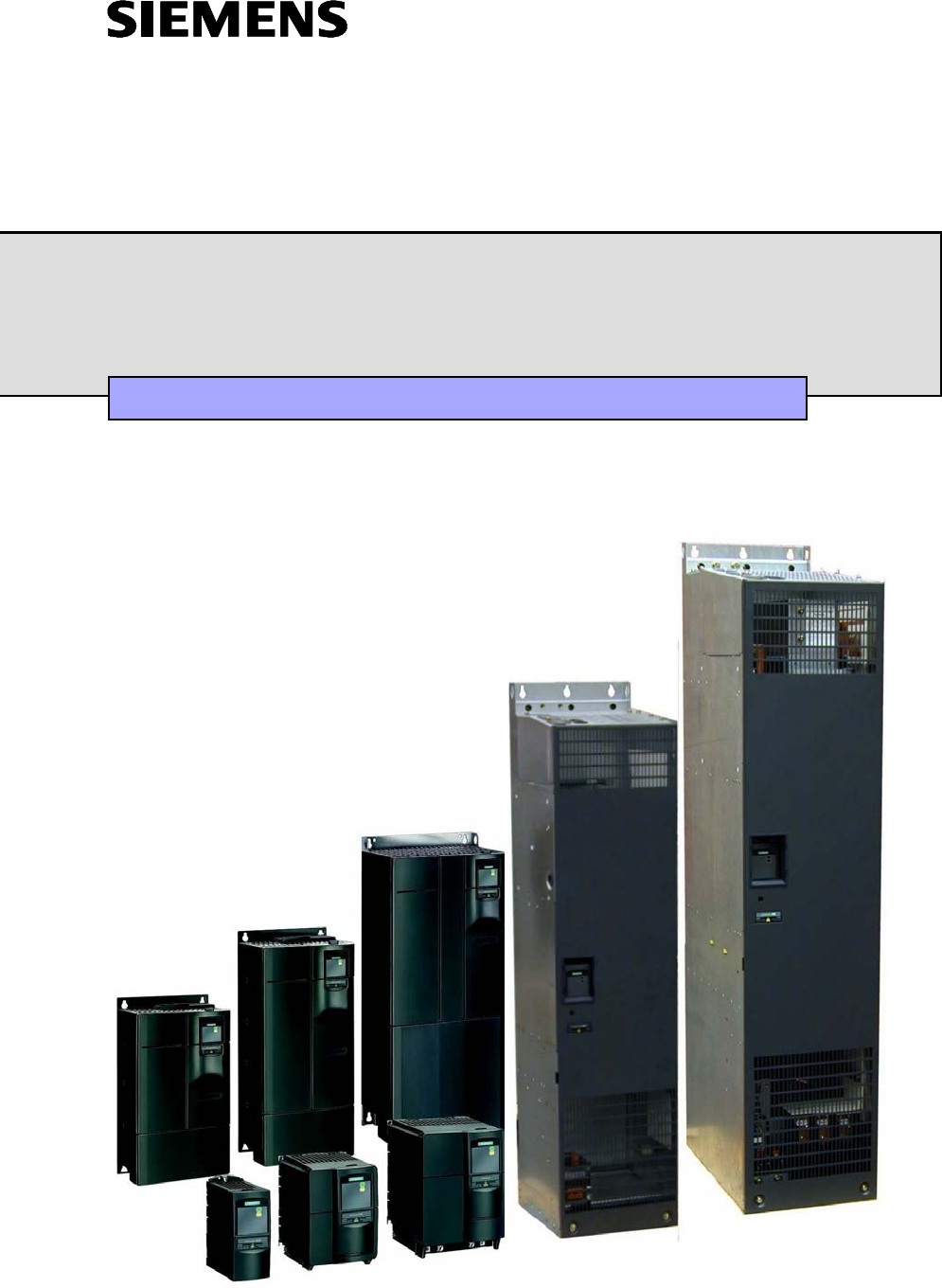
MICROMASTER 440
0,12 kW - 250 kW
Operating Instructions (Compact) Issue 10/06
User Documentation

Warnings, Cautions and Notes Issue 10/06
MICROMASTER 440
2 Operating Instructions (Compact)
Warnings, Cautions and Notes
The following Warnings, Cautions and Notes are provided for your safety and as a
means of preventing damage to the product or components in the machines
connected. Specific Warnings, Cautions and Notes that apply to particular
activities are listed at the beginning of the relevant chapters and are repeated or
supplemented at critical points throughout these sections. Please read the
information carefully, since it is provided for your personal safety and will also help
prolong the service life of your MICROMASTER 440 Inverter and the equipment
you connect to it.
WARNING
¾ This equipment contains dangerous voltages and controls potentially dangerous
rotating mechanical parts. Non-compliance with Warnings or failure to follow
the instructions contained in this manual can result in loss of life, severe
personal injury or serious damage to property.
¾ Only suitable qualified personnel should work on this equipment, and only after
becoming familiar with all safety notices, installation, operation and
maintenance procedures contained in this manual. The successful and safe
operation of this equipment is dependent upon its proper handling, installation,
operation and maintenance.
¾ The DC link capacitors remain charged for five minutes after power has been
removed. It is not permissible to open the equipment until 5 minutes after the
power has been removed. The drive unit discharges itself during this time.
¾ This equipment is capable of providing internal motor overload protection in
accordance with UL508C section 42. Refer to P0610 and P0335, i2t is ON by
default. Motor overload protection can also be provided using an external PTC
or KTY84.
¾ This equipment is suitable for use in a circuit capable of delivering not more
than symmetrical 10 kA (rms) (Frame Sizes A to C) or symmetrical 42 kA (rms)
(Frame Sizes D to GX), for a maximum voltage of 230 V / 460 V / 575 V when
protected by an H, J or K type fuse, a circuit breaker or self-protected
combination motor controller (for more details see Operating Instructions
Appendix F).
¾ Use Class 1 60/75 °C copper wire only with the cross-sections as specified in
the Operating Instructions.
¾ The mains input, DC and motor terminals, can carry dangerous voltages even if
the inverter is inoperative. Always wait 5 minutes to allow the unit to discharge
after switching off before carrying out any installation work.
NOTE
¾ Before installing and commissioning, please read these safety instructions and
warnings carefully and all the warning labels attached to the equipment.
¾ Please ensure that all of the warning labels are kept in a condition so that they
can be easily read and replace missing or damaged labels.
¾ Maximum permissible surrounding ambient temperature is:
− Frame Sizes A-F:
50 °C at constant torque (CT) and 100 % permissible output current
40 °C at variable torque (VT) and 100 % permissible output current
− Frame Sizes FX and GX:
40 °C at 100 % permissible output current

Issue 10/06 Contents
MICROMASTER 440
Operating Instructions (Compact) 3
Contents
1 Installation............................................................................................................... 5
1.1 Clearance distances for mounting ............................................................................ 5
1.2 Mounting dimensions................................................................................................ 5
2 Electrical Installation.............................................................................................. 6
2.1 Technical Specifications ........................................................................................... 6
2.2 Power Terminals..................................................................................................... 13
2.3 Control terminals..................................................................................................... 21
2.4 Block diagram ......................................................................................................... 22
3 Factory setting ...................................................................................................... 23
3.1 50/60 Hz DIP switch................................................................................................ 23
4 Communications................................................................................................... 24
4.1 Establishing communications MICROMASTER 440 ⇔ STARTER........................ 24
4.2 Establishing communications MICROMASTER 440 ⇔ AOP................................. 24
4.3 Bus interface (CB)................................................................................................... 25
5 BOP / AOP (Option) .............................................................................................. 26
5.1 Buttons and their Functions .................................................................................... 26
5.2 Changing parameters using as an example P0004 "Parameter filter function"...... 27
6 Commissioning..................................................................................................... 28
6.1 Quick commissioning.............................................................................................. 28
6.2 Motor data identification.......................................................................................... 32
6.3 Magnetizing current ................................................................................................ 32
6.4 Commissioning the application ............................................................................... 34
6.4.1 Serial Interface (USS)............................................................................................. 34
6.4.2 Selection of command source ................................................................................ 34
6.4.3 Digital input (DIN).................................................................................................... 35
6.4.4 Digital outputs (DOUT) ........................................................................................... 36
6.4.5 Selection of frequency setpoint............................................................................... 37
6.4.6 Analog input (ADC)................................................................................................. 38
6.4.7 Analog output (DAC)............................................................................................... 39
6.4.8 Motor potentiometer (MOP) .................................................................................... 40
6.4.9 Fixed frequency (FF)............................................................................................... 41
6.4.10 JOG......................................................................................................................... 42
6.4.11 Ramp function generator (RFG) ............................................................................. 43
6.4.12 Reference/limit frequencies .................................................................................... 44
6.4.13 Inverter protection................................................................................................... 45
6.4.14 Motor protection...................................................................................................... 45
6.4.15 Encoder................................................................................................................... 47
6.4.16 V/f control................................................................................................................ 48

Contents Issue 10/06
MICROMASTER 440
4 Operating Instructions (Compact)
6.4.17 Field-orientated control ........................................................................................... 50
6.4.17.1 Sensorless vector control (SLVC)........................................................................... 51
6.4.17.2 Vector control with encoder (VC)............................................................................ 53
6.4.18 Converter-specific Functions .................................................................................. 55
6.4.18.1 Flying start .............................................................................................................. 55
6.4.18.2 Automatic restart..................................................................................................... 55
6.4.18.3 Holding brake.......................................................................................................... 56
6.4.18.4 DC brake................................................................................................................. 58
6.4.18.5 Compound braking.................................................................................................. 59
6.4.18.6 Dynamic braking ..................................................................................................... 60
6.4.18.7 Vdc controller.......................................................................................................... 60
6.4.18.8 Load torque monitoring........................................................................................... 61
6.4.18.9 PID controller .......................................................................................................... 63
6.4.18.10 Positioning down ramp ........................................................................................... 66
6.4.18.11 Free function blocks (FFB) ..................................................................................... 67
6.4.19 Data sets................................................................................................................. 69
6.4.20 Diagnostic parameters............................................................................................ 72
6.5 Series commissioning............................................................................................. 75
6.6 Parameter reset of factory setting........................................................................... 75
7 Displays and messages ....................................................................................... 76
7.1 LED status display .................................................................................................. 76
7.2 Fault messages and Alarm messages.................................................................... 77
Issue 10/06 1 Installation
MICROMASTER 440
Operating Instructions (Compact) 5
1 Installation
1.1 Clearance distances for mounting
The inverters can be mounted adjacent to each other. When mounting inverters
one above the other, the specified environmental conditions must not be exceeded.
Independent of this, these minimum distances must be observed.
¾ Frame Size A, B, C above and below 100 mm
¾ Frame Size D, E above and below 300 mm
¾ Frame Size F above and below 350 mm
¾ Frame Size FX, GX above 250 mm
below 150 mm
in front 40 mm (FX), 50 mm (GX)
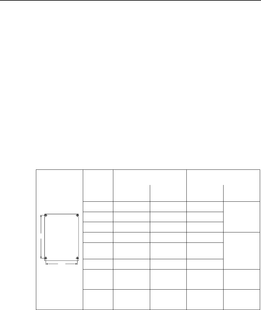
1.2 Mounting dimensions
Frame
Size Drilling Dimensions Tightening Torque
H
mm (Inch)
W
mm (Inch)
Bolts Nm
(lbf.in)
A 160 (6.30) – 2 x M4
B 174 (6.85) 138 (5.43) 4 x M4
C 204 (8.03) 174 (6.85) 4 x M5
2,5
(22.12)
D 486 (19.13) 235 (9.25) 4 x M8
E 616,4
(24.27)
235 (9.25) 4 x M8
F 810 (31.89) 300 (11.81) 4 x M8
3,0
(26.54)
FX 1375,5
(54.14)
250 (9.84) 6 x M8 13,0
(115.02)
H
W
GX 1508,5
(59.38)
250 (9.84) 6 x M8 13,0
(115.02)
Fig. 1-1 Mounting dimensions

2 Electrical Installation Issue 10/06
MICROMASTER 440
6 Operating Instructions (Compact)
2 Electrical Installation
2.1 Technical Specifications
Input voltage range 1 AC 200 V – 240 V, ± 10 %
(Unfiltered and with built in Class A Filter)
2AB Order No
6SE6440- 2UC
11-
2AA1 12-
5AA1 13-
7AA1 15-
5AA1 17-
5AA1 21-
1BA1 21-
5BA1 22-
2BA1 23-
0CA1
Frame Size A B C
[kW] 0,12 0,25 0,37 0,55 0,75 1,1 1,5 2,2 3,0
Output Rating (CT) [hp] 0,16 0,33 0,5 0,75 1,0 1,5 2,0 3,0 4,0
Output Power [kVA] 0,4 0,7 1,0 1,3 1,7 2,4 3,2 4,6 6,0
CT Input Current 1) 1,8 3,2 4,6 6,2 8,2 11,0 14,4 20,2 35,5
CT Output Current [A] 0,9 1,7 2,3 3,0 3,9 5,5 7,4 10,4 13,6
Fuse 10 10 10 16 16 20 20 32 40
Recommended 3NA 3803 3803 3803 3805 3805 3807 3807 3812 3817
for UL specified * * * * * * * * *
[mm2] 1,0 1,0 1,0 1,5 1,5 2,5 2,5 4,0 6,0
Input Cable Min. [AWG] 18 18 18 16 16 14 14 12 10
[mm2] 2,5 2,5 2,5 2,5 2,5 6,0 6,0 6,0 10,0
Input Cable Max. [AWG] 14 14 14 14 14 10 10 10 8
[mm2] 1,0 1,0 1,0 1,0 1,0 1,0 1,0 1,0 1,5
Output Cable Min. [AWG] 18 18 18 18 18 18 18 18 16
[mm2] 2,5 2,5 2,5 2,5 2,5 6,0 6,0 6,0 10,0
Output Cable Max. [AWG] 14 14 14 14 14 10 10 10 8
[kg] 1,3 1,3 1,3 1,3 1,3 3,4 3,4 3,4 5,7 Weight
(with built in filter) [lbs] 2,9 2,9 2,9 2,9 2,9 7,5 7,5 7,5 12,5
[kg] 1,3 1,3 1,3 1,3 1,3 3,3 3,3 3,3 5,5
Weight (unfiltered) [lbs] 2,9 2,9 2,9 2,9 2,9 7,3 7,3 7,3 12,1
[Nm] 1,1 1,5 2,25 Tightening torques for
power terminals [lbf.in] (10) (13,3) (20)
1) Secondary conditions: Input current at the rated operating point - applies for the short-circuit voltage of the line
supply Vk = 2 % referred to the rated drive converter power and a rated line supply voltage
of 240 V without line commutating reactor.
* UL listed fuses such as Class NON from Bussmann are required for use in America

Issue 10/06 2 Electrical Installation
MICROMASTER 440
Operating Instructions (Compact) 7
Input voltage range 3 AC 200 V – 240 V. ± 10 %
(with built in Class A Filter)
Order No. 6SE6440- 2AC23-
0CA1 2AC24-
0CA1 2AC25-
5CA1
Frame Size C
[kW] 3,0 4,0 5,5
Output Rating(CT) [hp] 4,0 5,0 7,5
Output Power [kVA] 6,0 7,7 9,6
CT Input Current 1) [A] 15,6 19,7 26,5
CT-Output Current [A] 13,6 17,5 22,0
VT Input Current 1) [A] - 28,3 34,2
VT-Output Current [A] - 22,0 28,0
Fuse [A] 25 32 35
Recommended 3NA 3810 3812 3814
For UL specified * * *
[mm2] 2,5 4,0 4,0
Input Cable, min. [AWG] 14 12 12
[mm2] 10,0 10,0 10,0
Input Cable, max. [AWG] 8 8 8
[mm2] 1,5 4,0 4,0
Output Cable, min. [AWG] 16 12 12
[mm2] 10,0 10,0 10,0
Output Cable, max. [AWG] 8 8 8
[kg] 5,7 5,7 5,7
Weight [lbs] 12,5 12,5 12,5
[Nm] 2,25 Tightening torques for
power terminals [lbf.in] (20)
1) Secondary conditions: Input current at the rated operating point - applies for the short-circuit voltage of the line
supply Vk = 2 % referred to the rated drive converter power and a rated line supply voltage
of 240 V without line commutating reactor.
* UL listed fuses such as Class NON from Bussmann are required for use in America

2 Electrical Installation Issue 10/06
MICROMASTER 440
8 Operating Instructions (Compact)
Input voltage range 3 AC 200 V – 240 V. ± 10 % (Unfiltered)
Order No. 6SE6440- 2UC11
-2AA1 2UC12
-5AA1 2UC13
-7AA1 2UC15
-5AA1 2UC17
-5AA1 2UC21
-1BA1 2UC21
-5BA1 2UC22
-2BA1 2UC23
-0CA1
Frame Size A B C
[kW] 0,12 0,25 0,37 0,55 0,75 1,1 1,5 2,2 3,0
Output Rating(CT) [hp] 0,16 0,33 0,5 0,75 1,0 1,5 2,0 3,0 4,0
Output Power [kVA] 0,4 0,7 1,0 1,3 1,7 2,4 3,2 4,6 6,0
CT-Input Current 1) [A] 1,1 1,9 2,7 3,6 4,7 6,4 8,3 11,7 15,6
CT-Output Current [A] 0,9 1,7 2,3 3,0 3,9 5,5 7,4 10,4 13,6
Fuse [A] 10 10 10 16 16 20 20 25 25
Recommended 3NA 3803 3803 3803 3805 3805 3807 3807 3810 3810
For UL specified * * * * * * * * *
[mm2] 1,0 1,0 1,0 1,5 1,5 2,5 2,5 2,5 4,0
Input Cable, min. [AWG] 18 18 18 16 16 14 14 14 12
[mm2] 2,5 2,5 2,5 2,5 2,5 6,0 6,0 6,0 10,0
Input Cable, max. [AWG] 14 14 14 14 14 10 10 10 8
[mm2] 1,0 1,0 1,0 1,0 1,0 1,0 1,0 1,0 1,5
Output Cable, min. [AWG] 18 18 18 18 18 18 18 18 16
[mm2] 2,5 2,5 2,5 2,5 2,5 6,0 6,0 6,0 10,0
Output Cable, max. [AWG] 14 14 14 14 14 10 10 10 8
[kg] 1,3 1,3 1,3 1,3 1,3 3,3 3,3 3,3 5,5
Weight [lbs] 2,9 2,9 2,9 2,9 2,9 7,3 7,3 7,3 12,1
[Nm] 1,1 1,5 2,25
Tightening torques
for power terminals [lbf.in] (10) (13,3) (20)
Order No. 6SE6440- 2UC24-
0CA1 2UC25-
5CA1 2UC27-
5DA1 2UC31-
1DA1 2UC31-
5DA1 2UC31-
8EA1 2UC32-
2EA1 2UC33-
0FA1 2UC33-
7FA1 2UC34-
5FA1
Frame Size C D E F
[kW] 4,0 5,5 7,5 11,0 15,0 18,5 22,0 30,0 37,0 45,0
Output Rating(CT) [hp] 5,0 7,5 10,0 15,0 20,0 25,0 30,0 40,0 50,0 60,0
Output Power [kVA] 7,7 9,6 12,3 18,4 23,7 29,8 35,1 45,6 57,0 67,5
CT-Input Current 1) [A] 19,7 26,5 34,2 38,0 50,0 62,0 71,0 96,0 114,0 135,0
CT-Output Current [A] 17,5 22,0 28,0 42,0 54,0 68,0 80,0 104,0 130,0 154,0
VT-Input Current 1) [A] 28,3 34,2 38,0 50,0 62,0 71,0 96,0 114,0 135,0 164,0
VT-Output Current [A] 22,0 28,0 42,0 54,0 68,0 80,0 104,0 130,0 154,0 -
Fuse [A] 32 35 50 80 80 100 125 200 200 250
Recommended 3NA 3812 3814 3820 3824 3824 3830 3832 3140 3142 3144
For UL specified 3NE * * 1817-0 1820-0 1820-0 1021-0 1022-0 1225-0 1225-0 1227-0
[mm2] 4,0 4,0 10,0 16,0 16,0 25,0 25,0 70,0 70,0 95,0
Input Cable, min. [AWG] 12 12 8 6 6 3 3 2/0 2/0 3/0
[mm2] 10,0 10,0 35,0 35,0 35,0 35,0 35,0 150,0 150,0 150,0
Input Cable, max. [AWG] 8 8 2 2 2 2 2 300 300 300
[mm2] 4,0 4,0 10,0 16,0 16,0 25,0 25,0 50,0 70,0 95,0
Output Cable, min. [AWG] 12 12 8 6 6 3 3 1/0 2/0 3/0
[mm2] 10,0 10,0 35,0 35,0 35,0 35,0 35,0 150,0 150,0 150,0
Output Cable, max [AWG] 8 8 2 2 2 2 2 300 300 300
[kg] 5,5 5,5 17,0 16,0 16,0 20,0 20,0 55,0 55,0 55,0
Weight [lbs] 12,1 12,1 37,0 35,0 35,0 44,0 44,0 121,0 121,0 121,0
[Nm] 2,25 10 50
Tightening torques
for power terminals [lbf.in] (20) (89) (445)
1) Secondary conditions: Input current at the rated operating point - applies for the short-circuit voltage of the line
supply Vk = 2 % referred to the rated drive converter power and a rated line supply voltage
of 240 V without line commutating reactor.
* UL listed fuses such as Class NON from Bussmann are required for use in America

Issue 10/06 2 Electrical Installation
MICROMASTER 440
Operating Instructions (Compact) 9
Input voltage range 3 AC 380 V – 480 V. ± 10 %
(with built in Class A Filter)
Order No. 6SE6440- 2AD22-
2BA1 2AD23-
0BA1 2AD24-
0BA1 2AD25-
5CA1 2AD27-
5CA1 2AD31-
1CA1 2AD31-
5DA1
Frame Size B C D
[kW] 2,2 3,0 4,0 5,5 7,5 11,0 15,0
Output Rating(CT) [hp] 3,0 4,0 5,0 7,5 10,0 15,0 20,0
Output Power [kVA] 4,5 5,9 7,8 10,1 14,0 19,8 24,4
CT-Input Current 1) [A] 7,5 10,0 12,8 15,6 22,0 23,1 33,8
CT-Output Current [A] 5,9 7,7 10,2 13,2 18,4 26,0 32,0
VT-Input Current 1) [A] – – – 17,3 23,1 33,8 37,0
VT-Output Current [A] – – – 20,2 29,0 39,0 45,2
Fuse [A] 16 16 20 20 32 35 50
Recommended 3NA 3805 3805 3807 3807 3812 3814 3820
For UL specified 3NE * * * * * * 1817-0
[mm2] 1,5 1,5 2,5 2,5 4,0 6,0 10,0
Input Cable, min. [AWG] 16 16 14 14 12 10 8
[mm2] 6,0 6,0 6,0 10,0 10,0 10,0 35,0
Input Cable, max. [AWG] 10 10 10 8 8 8 2
[mm2] 1,0 1,0 1,0 2,5 4,0 6,0 10,0
Output Cable, min. [AWG] 18 18 18 14 12 10 8
[mm2] 6,0 6,0 6,0 10,0 10,0 10,0 35,0
Output Cable, max. [AWG] 10 10 10 8 8 8 2
[kg] 3,4 3,4 3,4 5,7 5,7 5,7 17,0
Weight [lbs] 7,5 7,5 7,5 12,5 12,5 12,5 37,0
[Nm] 1,1 1,5 2,25
Tightening torques for
power terminals [lbf.in] (10) (13,3) (20)
Order No. 6SE6440- 2AD31-
8DA1 2AD32-
2DA1 2AD33-
0EA1 2AD33-
7EA1 2AD34-
5FA1 2AD35-
5FA1 2AD37-
5FA1
Frame Size D E F
[kW] 18,5 22,0 30,0 37,0 45,0 55,0 75,0
Output Rating(CT) [hp] 25,0 30,0 40,0 50,0 60,0 75,0 100,0
Output Power [kVA] 29,0 34,3 47,3 57,2 68,6 83,8 110,5
CT-Input Current 1) [A] 37,0 43,0 59,0 72,0 87,0 104,0 139,0
CT-Output Current [A] 38,0 45,0 62,0 75,0 90,0 110,0 145,0
VT-Input Current 1) [A] 43,0 59,0 72,0 87,0 104,0 139,0 169,0
VT-Output Current [A] 45,0 62,0 75,0 90,0 110,0 145,0 178,0
Fuse [A] 63 80 100 125 160 200 250
Recommended 3NA 3822 3824 3830 3832 3836 3140 3144
For UL specified 3NE 1818-0 1820-0 1021-0 1022-0 1224-0 1225-0 1227-0
[mm2] 10,0 16,0 25,0 25,0 35,0 70,0 95,0
Input Cable, min. [AWG] 8 6 3 3 2 2/0 3/0
[mm2] 35,0 35,0 35,0 35,0 150,0 150,0 150,0
Input Cable, max. [AWG] 2 2 2 2 300 300 300
[mm2] 10,0 16,0 25,0 25,0 50,0 70,0 95,0
Output Cable, min. [AWG] 8 6 3 3 1/0 2/0 3/0
[mm2] 35,0 35,0 35,0 35,0 150,0 150,0 150,0
Output Cable, max. [AWG] 2 2 2 2 300 300 300
[kg] 17,0 17,0 22,0 22,0 75,0 75,0 75,0
Weight [lbs] 37,0 37,0 48,0 48,0 165,0 165,0 165,0
[Nm] 10 50
Tightening torques for
power terminals [lbf.in] (89) (445)
1) Secondary conditions: Input current at the rated operating point - applies for the short-circuit voltage of the line
supply Vk = 2 % referred to the rated drive converter power and a rated line supply voltage
of 400 V without line commutating reactor.
* UL listed fuses such as Class NON from Bussmann are required for use in America

2 Electrical Installation Issue 10/06
MICROMASTER 440
10 Operating Instructions (Compact)
Input voltage range 3 AC 380 V – 480 V. ± 10 % (Unfiltered)
Order No. 6SE6440- 2UD13
-7AA1 2UD15
-5AA1 2UD17
-5AA1 2UD21
-1AA1 2UD21
-5AA1 2UD22
-2BA1 2UD23
-0BA1 2UD24
-0BA1 2UD25
-5CA1 2UD27
-5CA1
Frame Size A B C
[kW] 0,37 0,55 0,75 1,1 1,5 2,2 3,0 4,0 5,5 7,5
Output Rating(CT) [hp] 0,5 0,75 1,0 1,5 2,0 3,0 4,0 5,0 7,5 10,0
Output Power [kVA] 0,9 1,2 1,6 2,3 3,0 4,5 5,9 7,8 10,1 14,0
CT-Input Current 1) [A] 2,2 2,8 3,7 4,9 5,9 7,5 10,0 12,8 15,6 22,0
CT-Output Current [A] 1,3 1,7 2,2 3,1 4,1 5,9 7,7 10,2 13,2 19,0
VT-Input Current 1) [A] - - - - - - - - 17,3 23,1
VT-Output Current [A] - - - - - - - - 19,0 26,0
Fuse [A] 10 10 10 10 10 16 16 20 20 32
Recommended 3NA 3803 3803 3803 3803 3803 3805 3805 3807 3807 3812
For UL specified * * * * * * * * * *
[mm2] 1,0 1,0 1,0 1,0 1,0 1,5 1,5 2,5 2,5 4,0
Input Cable, min. [AWG] 18 18 18 18 18 16 16 14 14 12
[mm2] 2,5 2,5 2,5 2,5 2,5 6,0 6,0 6,0 10,0 10,0
Input Cable, max. [AWG] 14 14 14 14 14 10 10 10 8 8
[mm2] 1,0 1,0 1,0 1,0 1,0 1,0 1,0 1,0 2,5 4,0
Output Cable, min. [AWG] 18 18 18 18 18 18 18 18 14 12
[mm2] 2,5 2,5 2,5 2,5 2,5 6,0 6,0 6,0 10,0 10,0
Output Cable, max. [AWG] 14 14 14 14 14 10 10 10 8 8
[kg] 1,3 1,3 1,3 1,3 1,3 3,3 3,3 3,3 5,5 5,5
Weight [lbs] 2,9 2,9 2,9 2,9 2,9 7,3 7,3 7,3 12,1 12,1
[Nm] 1,1 1,5 2,25
Tightening torques for
power terminals [lbf.in] (10) (13,3) (20)
Order No. 6SE6440- 2UD31
-1CA1 2UD31
-5DA1 2UD31
-8DA1 2UD32
-2DA1 2UD33
-0EA1 2UD33
-7EA1 2UD34
-5FA1 2UD35
-5FA1 2UD37
-5FA1
Frame Size C D E F
[kW] 11,0 15,0 18,5 22,0 30,0 37,0 45,0 55,0 75,0
Output Rating(CT) [hp] 15,0 20,0 25,0 30,0 40,0 50,0 60,0 75,0 100,0
Output Power [kVA] 19,8 24,4 29,0 34,3 47,3 57,2 68,6 83,8 110,5
CT-Input Current 1) [A] 23,1 33,8 37,0 43,0 59,0 72,0 87,0 104,0 139,0
CT-Output Current [A] 26,0 32,0 38,0 45,0 62,0 75,0 90,0 110,0 145,0
VT-Input Current 1) [A] 33,8 37,0 43,0 59,0 72,0 87,0 104,0 139,0 169,0
VT-Output Current [A] 32,0 38,0 45,0 62,0 75,0 90,0 110,0 145,0 178,0
Fuse [A] 35 50 63 80 100 125 160 200 250
Recommended 3NA
3814 3820 3822 3824 3830 3832 3836 3140 3144
For UL specified 3NE * 1817-0 1818-0 1820-0 1021-0 1022-0 1224-0 1225-0 1227-0
[mm2] 6,0 10,0 10,0 16,0 25,0 25,0 35,0 70,0 95,0
Input Cable, min. [AWG] 10 8 8 6 3 3 2 2/0 3/0
[mm2] 10,0 35,0 35,0 35,0 35,0 35,0 150,0 150,0 150,0
Input Cable, max. [AWG] 8 2 2 2 2 2 300 300 300
[mm2] 6,0 10,0 10,0 16,0 25,0 25,0 35,0 70,0 95,0
Output Cable, min. [AWG] 10 8 8 6 3 3 2 2/0 3/0
[mm2] 10,0 35,0 35,0 35,0 35,0 35,0 150,0 150,0 150,0
Output Cable, max. [AWG] 8 2 2 2 2 2 300 300 300
[kg] 5,5 16,0 16,0 16,0 20,0 20,0 56,0 56,0 56,0
Weight [lbs] 12,1 35,0 35,0 35,0 44,0 44,0 123,0 123,0 123,0
[Nm] 2,25 10 50
Tightening torques for
power terminals [lbf.in] (20) (89) (445)
1) Secondary conditions: Input current at the rated operating point - applies for the short-circuit voltage of the line
supply Vk = 2 % referred to the rated drive converter power and a rated line supply voltage
of 400 V without line commutating reactor.
* UL listed fuses such as Class NON from Bussmann are required for use in America

Issue 10/06 2 Electrical Installation
MICROMASTER 440
Operating Instructions (Compact) 11
Input voltage range 3 AC 380 V – 480 V, ± 10 % (Unfiltered)
Order No. 6SE6440- 2UD38-8FA1 2UD41-1FA1 2UD41-3GA1 2UD41-6GA1 2UD42-0GA1
Frame Size FX GX
[kW] 90 110 132 160 200
Output Rating(CT) [hp] 125 150 200 250 300
Output Power [kVA] 145,4 180 214,8 263,2 339,4
CT-Input Current 1) [A] 169 200 245 297 354
CT-Output Current [A] 178 205 250 302 370
VT-Input Current 1) [A] 200 245 297 354 442
VT-Output Current [A] 205 250 302 370 477
[A] 250 315 400 450 560
Recommended Fuse 3NE 1227-0 1230-0 1332-0 1333-0 1435-0
Pipe cable shoe to
DIN 46235 [mm] 10 10 10 10 10
[mm2] 1 x 95 or
2 x 35
1 x 150 or
2 x 50
1 x 185 or
2 x 70
1 x 240 or
2 x 70 2 x 95
Input Cable, min. [AWG]
or
[kcmil]
1 x 4/0 or
2 x 2
1 x 300 or
2 x 1/0
1 x 400 or
2 x 2/0
1 x 500 or
2 x 2/0 2 x 4/0
[mm2] 1 x 185 or
2 x 120
1 x 185 or
2 x 120 2 x 240 2 x 240 2 x 240
Input Cable, max. [AWG]
or
[kcmil]
1 x 350 or
2 x 4/0
1 x 350 or
2 x 4/0 2 x 400 2 x 400 2 x 400
[mm2] 1 x 95 or
2 x 35
1 x 150 or
2 x 50
1 x 185 or
2 x 70
1 x 240 or
2 x 70 2 x 95
Output Cable, min. [AWG]
or
[kcmil]
1 x 4/0 or
2 x 2
1 x 300 or
2 x 1/0
1 x 400 or
2 x 2/0
1 x 500 or
2 x 2/0 2 x 4/0
[mm2] 1 x 185 or
2 x 120
1 x 185 or
2 x 120 2 x 240 2 x 240 2 x 240
Output Cable, max. [AWG]
or
[kcmil]
1 x 350 or
2 x 4/0
1 x 350 or
2 x 4/0 2 x 400 2 x 400 2 x 400
[kg] 110 110 170 170 170
Weight [lbs] 242 242 418 418 418
[Nm] 25 Tightening torques for
power terminals [lbf.in] (222,5)
1) Secondary conditions: Input current at the rated operating point - applies for the short-circuit voltage of the line
supply Vk ≥ 2.33 % referred to the rated drive converter power and a rated line supply
voltage of 400 V without line commutating reactor.
2 Electrical Installation Issue 10/06
MICROMASTER 440
12 Operating Instructions (Compact)
Input voltage range 3 AC 500 V – 600 V, ± 10 % (Unfiltered)
Order No. 6SE6440- 2UE17-
5CA1 2UE21-
5CA1 2UE22-
2CA1 2UE24-
0CA1 2UE25-
5CA1 2UE27-
5CA1 2UE31-
1CA1 2UE31-
5DA1
Frame Size C D
[kW] 0,75 1,5 2,2 4,0 5,5 7,5 11,0 15,0
Output Rating(CT) [hp] 1,0 2,0 3,0 5,0 7,5 10,0 15,0 20,0
Output Power [kVA] 1,3 2,6 3,7 5,8 8,6 10,5 16,2 21,0
CT-Input Current 1) [A] 2,0 3,7 5,3 8,1 11,1 14,4 21,5 24,9
CT-Output Current [A] 1,4 2,7 3,9 6,1 9,0 11,0 17,0 22,0
VT-Input Current 1) [A] 3,2 4,4 6,9 9,4 12,6 18,1 24,9 30,0
VT-Output Current [A] 2,7 3,9 6,1 9,0 11,0 17,0 22,0 27,0
Fuse [A] 10 10 10 16 16 25 32 35
Recommended 3NA
3803-6 3803-6 3803-6 3805-6 3805-6 3810-6 3812-6 3814-6
For UL specified 3NE * * * * * * * 1803-0
[mm2] 1,0 1,0 1,0 1,5 1,5 2,5 4,0 6,0
Input Cable, min. [AWG] 18 18 18 16 16 14 12 10
[mm2] 10,0 10,0 10,0 10,0 10,0 10,0 10,0 35,0
Input Cable, max. [AWG] 8 8 8 8 8 8 8 2
[mm2] 1,0 1,0 1,0 1,0 1,0 2,5 4,0 4,0
Output Cable, min. [AWG] 18 18 18 18 18 14 12 12
[mm2] 10,0 10,0 10,0 10,0 10,0 10,0 10,0 35,0
Output Cable, max. [AWG] 8 8 8 8 8 8 8 2
[kg] 5,5 5,5 5,5 5,5 5,5 5,5 5,5 16,0
Weight [lbs] 12,1 12,1 12,1 12,1 12,1 12,1 12,1 35,0
[Nm] 2,25 10
Tightening torques for
power terminals [lbf.in] (20) (89)
Order No. 6SE6440- 2UE31-
8DA1 2UE32-
2DA1 2UE33-
0EA1 2UE33-
7EA1 2UE34-
5FA1 2UE35-
5FA1 2UE37-
5FA1
Frame Size D E F
[kW] 18,5 22,0 30,0 37,0 45,0 55,0 75,0
Output Rating(CT) [hp] 25,0 30,0 40,0 50,0 60,0 75,0 100,0
Output Power [kVA] 25,7 30,5 39,1 49,5 59,1 73,4 94,3
CT-Input Current 1) [A] 30,0 35,0 48,0 58,0 69,0 83,0 113,0
CT-Output Current [A] 27,0 32,0 41,0 52,0 62,0 77,0 99,0
VT-Input Current 1) [A] 35,0 48,0 58,0 69,0 83,0 113,0 138,0
VT-Output Current [A] 32,0 41,0 52,0 62,0 77,0 99,0 125,0
Fuse [A] 50 63 80 80 125 160 160
Recommended 3NA
3820-6 3822-6 3824-6 3824-6 3132-6 3136-6 3136-6
For UL specified 3NE 1817-0 1818-0 1820-0 1820-0 1022-0 1224-0 1224-0
[mm2] 10,0 10,0 16,0 25,0 25,0 50,0 50,0
Input Cable, min. [AWG] 8 8 6 3 3 1/0 1/0
[mm2] 35,0 35,0 35,0 35,0 150,0 150,0 150,0
Input Cable, max. [AWG] 2 2 2 2 300 300 300
[mm2] 6,0 10,0 16,0 16,0 25,0 35,0 50,0
Output Cable, min. [AWG] 10 8 6 6 3 2 1/0
[mm2] 35,0 35,0 35,0 35,0 150,0 150,0 150,0
Output Cable, max. [AWG] 2 2 2 2 300 300 300
[kg] 16,0 16,0 20,0 20,0 56,0 56,0 56,0
Weight [lbs] 35,0 35,0 44,0 44,0 123,0 123,0 123,0
[Nm] 10 50
Tightening torques for
power terminals [lbf.in] (89) (445)
1) Secondary conditions: Input current at the rated operating point - applies for the short-circuit voltage of the line
supply Vk = 2 % referred to the rated drive converter power and a rated line supply voltage
of 500 V without line commutating reactor.
* UL listed fuses such as Class NON from Bussmann are required for use in America
Issue 10/06 2 Electrical Installation
MICROMASTER 440
Operating Instructions (Compact) 13
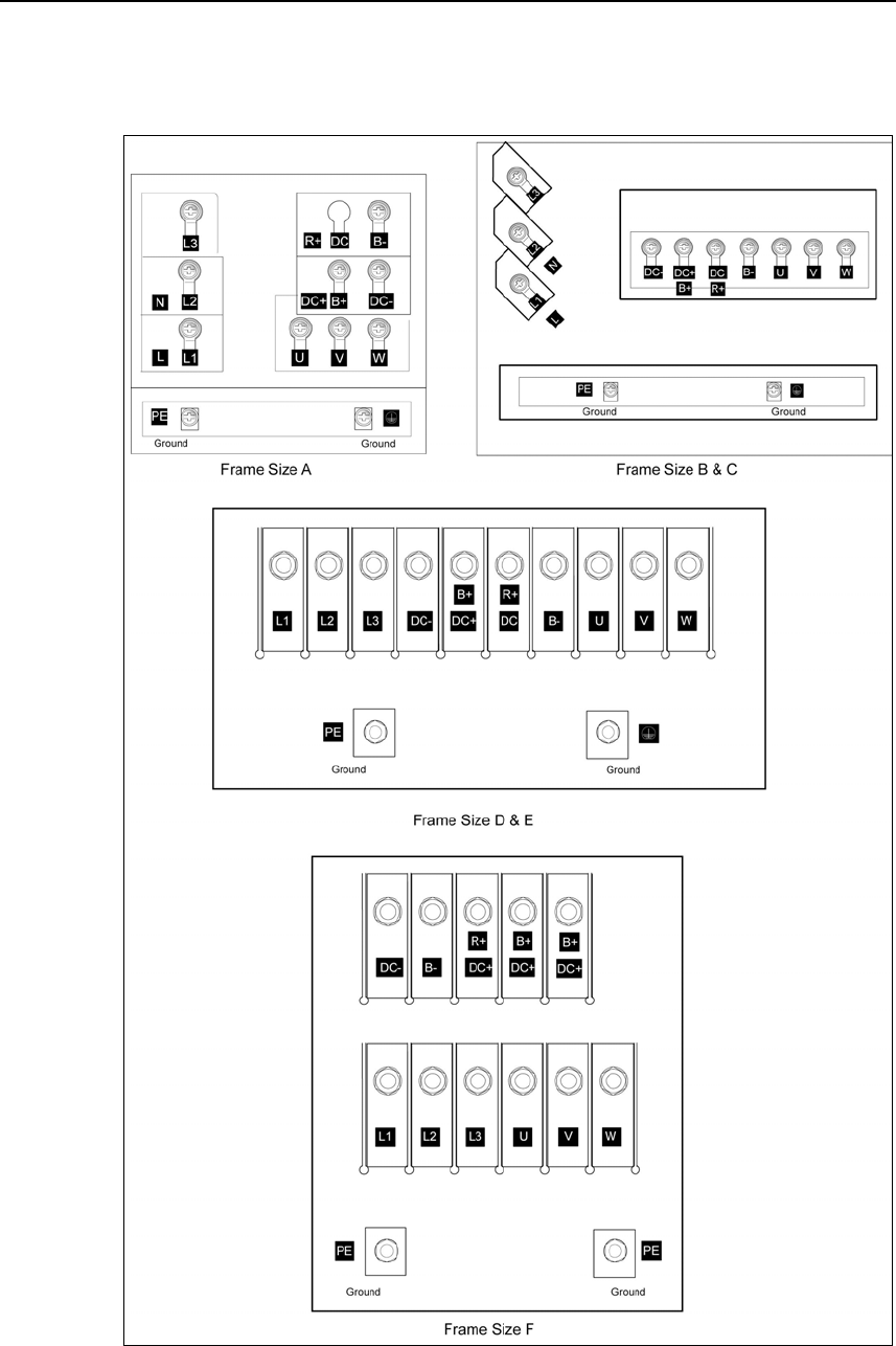
2.2 Power Terminals
You can gain access to the mains and motor terminals by removing the front
covers.
¾ Frame Size A (Fig. 2-1)
¾ Frame Sizes B and C (Fig. 2-2)
¾ Frame sizes D and E (Fig. 2-3)
¾ Frame Size F (Fig. 2-4)
¾ Frame Sizes FX and GX (Fig. 2-5)
¾ Connection terminals for Frame Sizes A - F (Fig. 2-6)
¾ Connection overview for Frame Size FX (Fig. 2-7)
¾ Connection overview for Frame Size GX (Fig. 2-8)
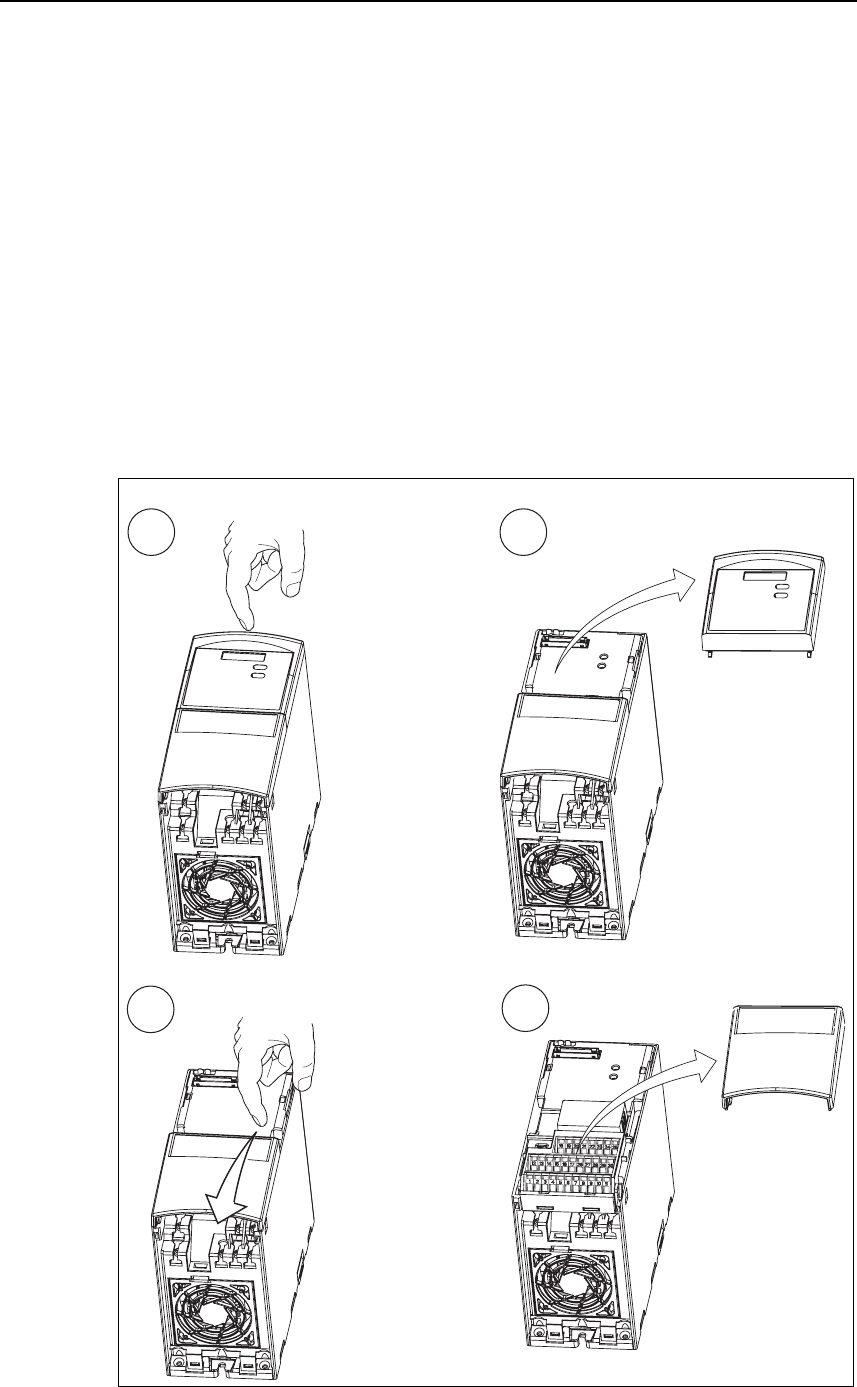
Frame Size A
1 2
34
Fig. 2-1 Removing front covers (Frame Size A)
2 Electrical Installation Issue 10/06
MICROMASTER 440
14 Operating Instructions (Compact)
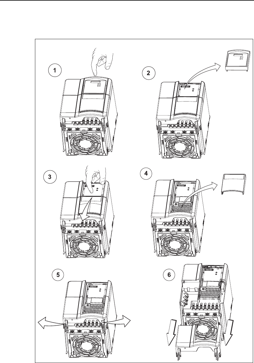
Frame Sizes B and C
Fig. 2-2 Removing front covers (Frame Sizes B and C)
Issue 10/06 2 Electrical Installation
MICROMASTER 440
Operating Instructions (Compact) 15
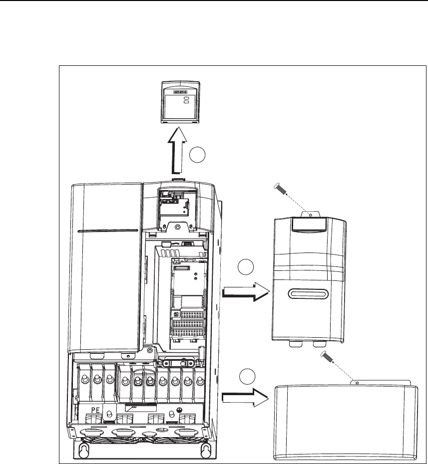
Frame Sizes D and E
1
3
2
Fig. 2-3 Removing front covers (Frame Sizes D and E)
2 Electrical Installation Issue 10/06
MICROMASTER 440
16 Operating Instructions (Compact)
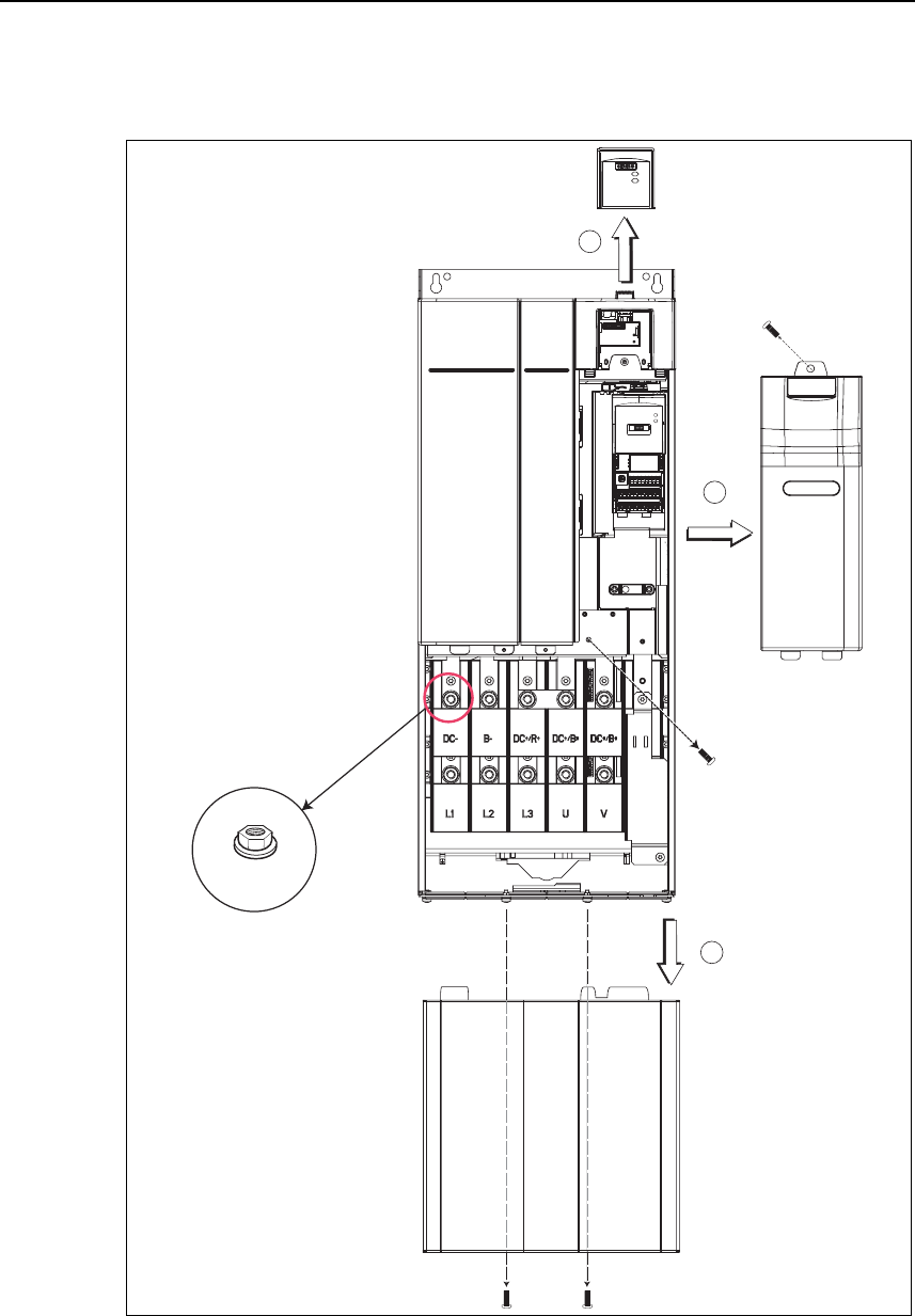
Frame Size F
1
3
2
19 mm AF
Fig. 2-4 Removing front covers (Frame Size F)
Issue 10/06 2 Electrical Installation
MICROMASTER 440
Operating Instructions (Compact) 17
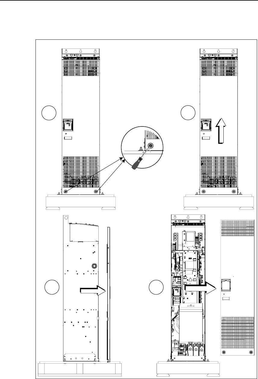
Frame Sizes FX and GX
1
2
34
Fig. 2-5 Removing front covers (Frame Sizes FX and GX)
2 Electrical Installation Issue 10/06
MICROMASTER 440
18 Operating Instructions (Compact)
Access to the power supply and motor terminals is possible by removing the front
covers.
Fig. 2-6 Connection terminals for Frame Sizes A - F
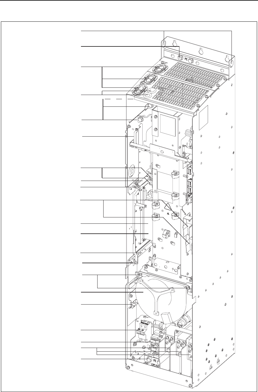
Issue 10/06 2 Electrical Installation
MICROMASTER 440
Operating Instructions (Compact) 19
Shield connection
Mains cable PE
Hoisting eyes
Mains cable
Phase U1/L1, V1/L2, W1/L3
Top adjustment rail
Bottom adjustment rail
Status Display Panel
Shield connection
control leads
Transformer adaption
Motor cable
Phase U2, V2, W2
Motor cable
PE Shield connection
Fan screws
Bottom retaining screw
Elektronic box
Top retaining screw
Connection to
Y-Capacitor
Fan fuses
Cable opening for
mains conection
U1/L1, V1/L2, W1/L3
Fan
Cable opening DCPA, DCNA
for connection of an
external braking unit
Connection DCPA, DCNA
for external braking unit
Connection for dv/dt filter
DCPS, DCNS
Fig. 2-7 Connection overview for Frame Size FX
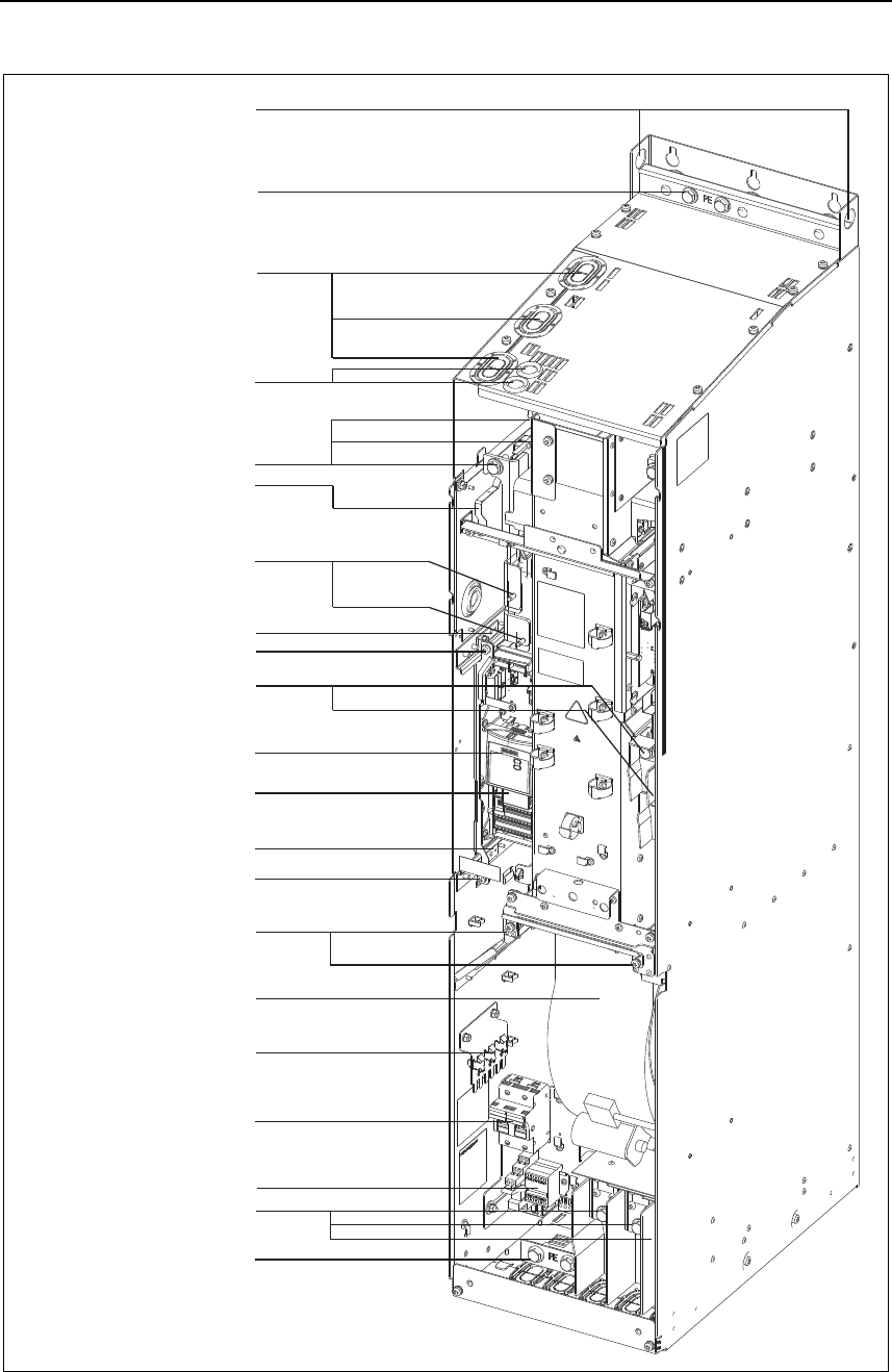
2 Electrical Installation Issue 10/06
MICROMASTER 440
20 Operating Instructions (Compact)
Cable opening for
mains conection
U1/L1, V1/L2, W1/L3
Shield connection
Mains cable PE
Hoisting eyes
C
able opening DCPA, DCNA
for connection of an
external braking unit
Mains cable
Phase U1/L1, V1/L2, W1/L3
Top adjustment rail
Bottom adjustment rail
Status Display Panel
Shield connection
control leads
Transformer adaption
Motor cable
Phase U2, V2, W2
Motor cable
PE Shield connection
Fan screws
Bottom retaining screw
Elektronic box
Top retaining screw
Connection to
Y-Capacitor
Connection DCPA, DCNA
for external braking unit
Fan fuses
Fan
Connection for dv/dt filter
DCPS, DCNS
Fig. 2-8 Connection overview for Frame Size GX
Issue 10/06 2 Electrical Installation
MICROMASTER 440
Operating Instructions (Compact) 21
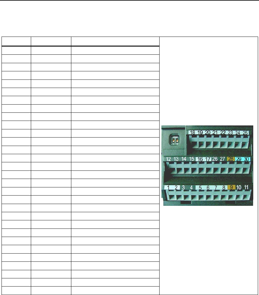
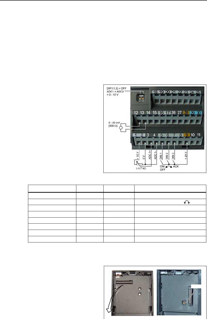
2.3 Control terminals
Terminal Designation Function
1 – Output +10 V
2 – Output 0 V
3 ADC1+ Analog input 1 (+)
4 ADC1– Analog input 1 (–)
5 DIN1 Digital input 1
6 DIN2 Digital input 2
7 DIN3 Digital input 3
8 DIN4 Digital input 4
9 – Isolated output +24 V / max. 100 mA
10 ADC2+ Analog input 2 (+)
11 ADC2– Analog input 2 (–)
12 DAC1+ Analog output 1 (+)
13 DAC1– Analog output 1 (–)
14 PTCA Connection for PTC / KTY84
15 PTCB Connection for PTC / KTY84
16 DIN5 Digital input 5
17 DIN6 Digital input 6
18 DOUT1/NC Digital output 1 / NC contact
19 DOUT1/NO Digital output 1 / NO contact
20 DOUT1/COM Digital output 1 / Changeover contact
21 DOUT2/NO Digital output 2 / NO contact
22 DOUT2/COM Digital output 2 / Changeover contact
23 DOUT3/NC Digital output 3 / NC contact
24 DOUT3/NO Digital output 3 / NO contact
25 DOUT3/COM Digital output 3 / Changeover contact
26 DAC2+ Analog output 2 (+)
27 DAC2– Analog output 2 (–)
28 – Isolated output 0 V / max. 100 mA
29 P+ RS485 port
30 N– RS485 port
Fig. 2-9 Control terminals of MICROMASTER 440
2 Electrical Installation Issue 10/06
MICROMASTER 440
22 Operating Instructions (Compact)
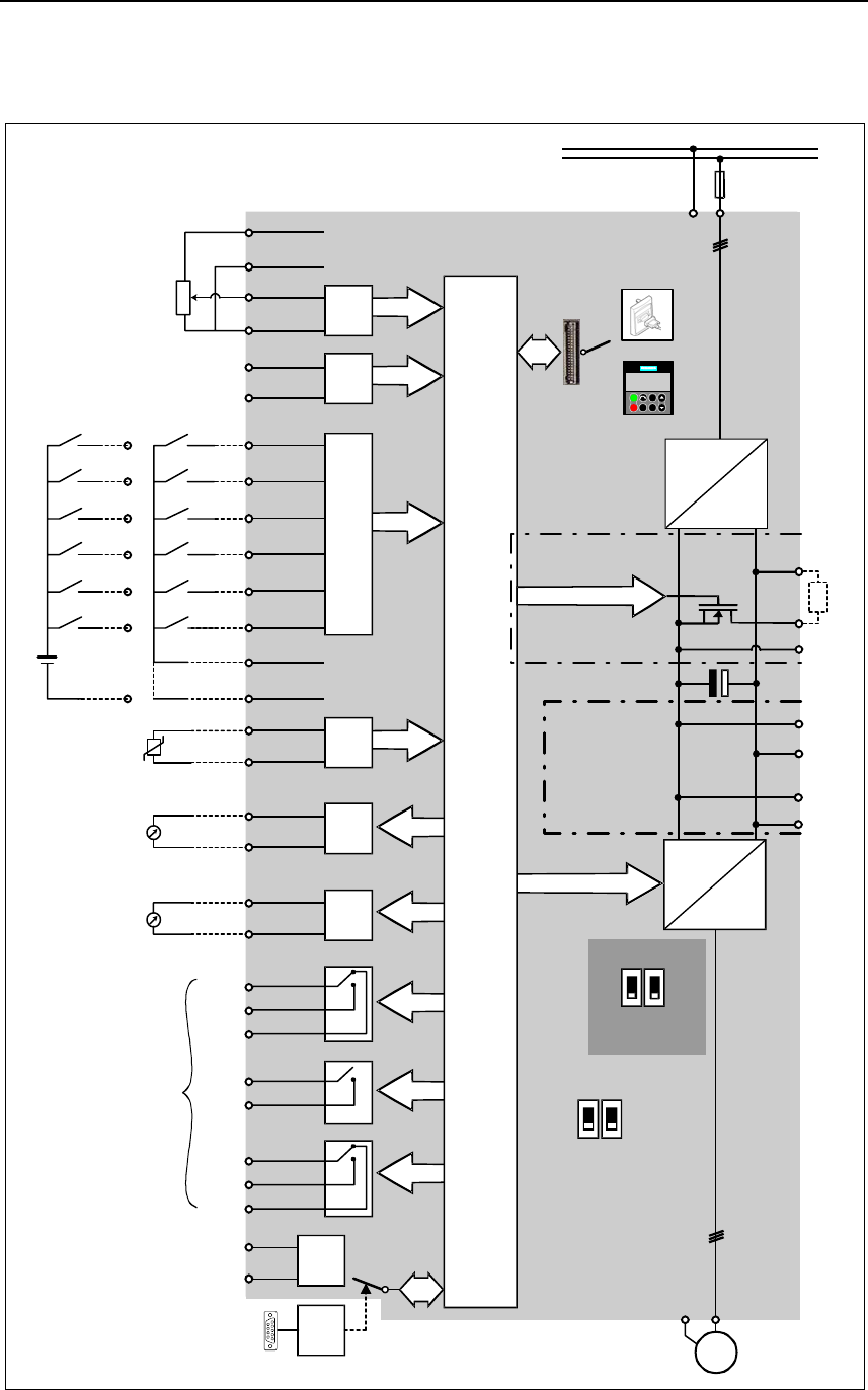
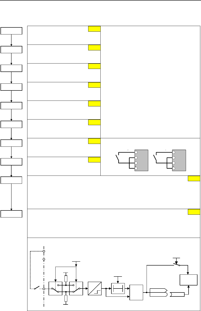
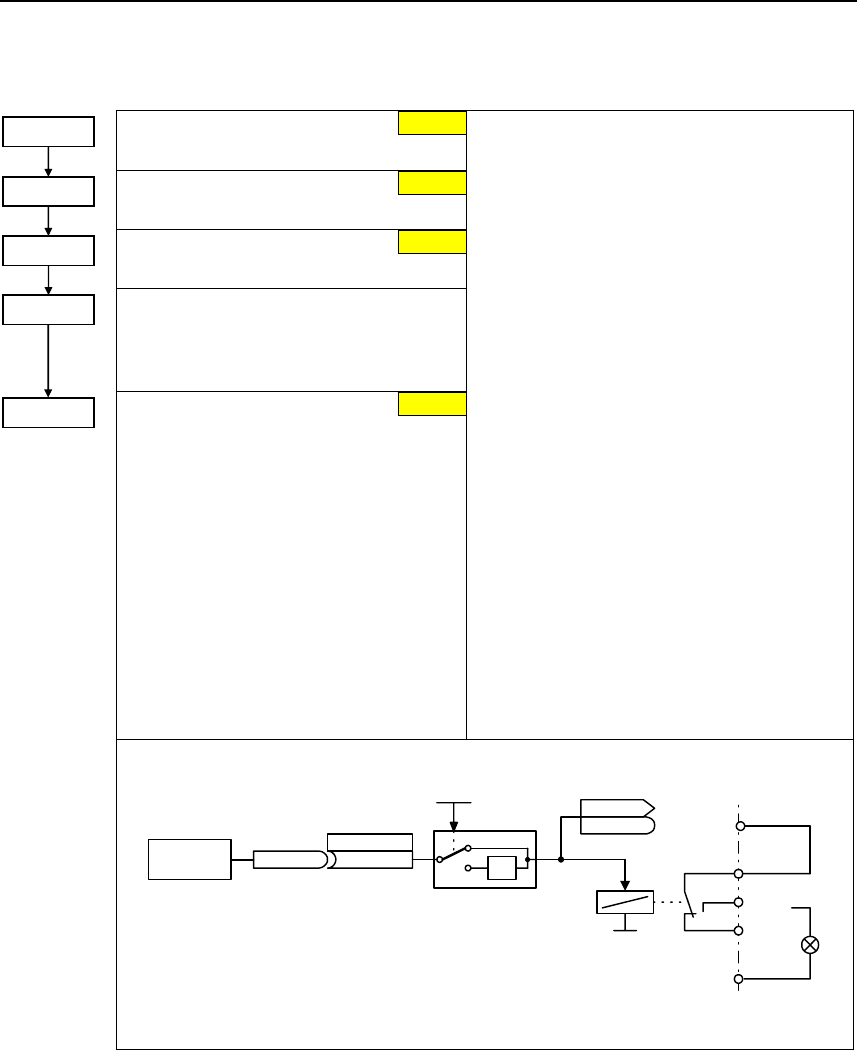
2.4 Block diagram
PE
1/3 AC 200 - 240 V
3 AC 380 - 480 V
3 AC 500 - 600 V
SI
PE L/L1, N/L2
L/L1, N/L2,L3
L1, L2, L3
=
3 ~
PE U,V,W
M
12
ADC
1ADC
2
12
60 Hz
50 Hz
A/D
A/D
+10 V
0 V
0 - 20 mA
max. 500 Ω
NPN
PNP
CPU
RS485
D/A
D/A
DCNA
DCPA
B+/DC+
B-
DC-
~
=
ADC1+
ADC1-
ADC2+
ADC2-
DIN1
DIN2
DIN3
DIN4
DIN5
DIN6
PTCA
PTCB
DAC1+
DAC1-
DAC2+
DAC2-
P+
N-
COM
NC
NO
COM
NC
NO
COM
NO
1
2
3
4
10
11
5
6
7
8
16
17
9
28
14
15
12
13
26
27
29
30
20
18
19
25
23
24
22
21
0 - 20 mA
max. 500 Ω
≥ 4.7 kΩ
Output 0 V
max. 100 mA
(isolated)
or
Motor
PTC
KTY84
30 V DC / 5 A (resistive)
250 V AC / 2 A (inductive)
Relay1
Relay2
Relay3
Frame sizes
A to F
Frame sizes
FX and GX
Output +24 V
max. 100 mA
(isolated)
0 - 20 mA
current
0 - 10 V
voltage
DIP switch
(on I/O Board)
DIP switch
(on Control Board)
Not
used
External braking
module connection
Opto Isolation
or
or
CB
Option automatic
A/D
R
BOP link
COM link
Jog
0
I
P
Fn
Hz
150.00
BOP/AOP
RS232
5
6
7
8
16
17
28
DIN1
DIN2
DIN3
DIN4
DIN5
DIN6
External 24 V
24 V
+
_
DCNS
DCPS
Connection for
dv/dt filter
Fig. 2-10 Block diagram
Issue 10/06 3 Factory setting
MICROMASTER 440
Operating Instructions (Compact) 23
3 Factory setting
The MICROMASTER 440 frequency inverter is set in the factory so that it can be
operated without any additional parameterization. To do this, the motor parameters
set in the factory (P0304, P0305, P0307, P0310), that correspond to a 4-pole 1LA7
Siemens motor, must match the rated data of the connected motor (refer to the
rating plate).
Further factory setting:
¾ Command sources P0700 = 2 (Digital input, see Fig. 3-1)
¾ Setpoint source P1000 = 2 (Analog input, see Fig. 3-1)
Analog output
¾ Motor cooling
P0335 = 0
¾ Motor current limit
P0640 = 150 %
¾ Min. frequency
P1080 = 0 Hz
¾ Max. frequency
P1082 = 50 Hz
¾ Ramp-up time
P1120 = 10 s
¾ Ramp-down time
P1121 = 10 s
¾ Control mode
P1300 = 0
Fig. 3-1 Pre-assignment of the inputs
Input/Output Terminals Parameter Function
Digital input 1 5 P0701 = 1 ON / OFF1 (I/O)
Digital input 2 6 P0702 = 12 Reversing ( )
Digital input 3 7 P0703 = 9 Fault acknowledge (Ack)
Digital input 4 8 P0704 = 15 Fault acknowledge
Digital input 5 16 P0705 = 15 Fixed setpoint (direct)
Digital input 6 17 P0706 = 15 Fixed setpoint (direct)
Digital input 7 Via ADC1 P0707 = 0 Fixed setpoint (direct)
Digital input 8 Via ADC2 P0708 = 0 Digital input disabled
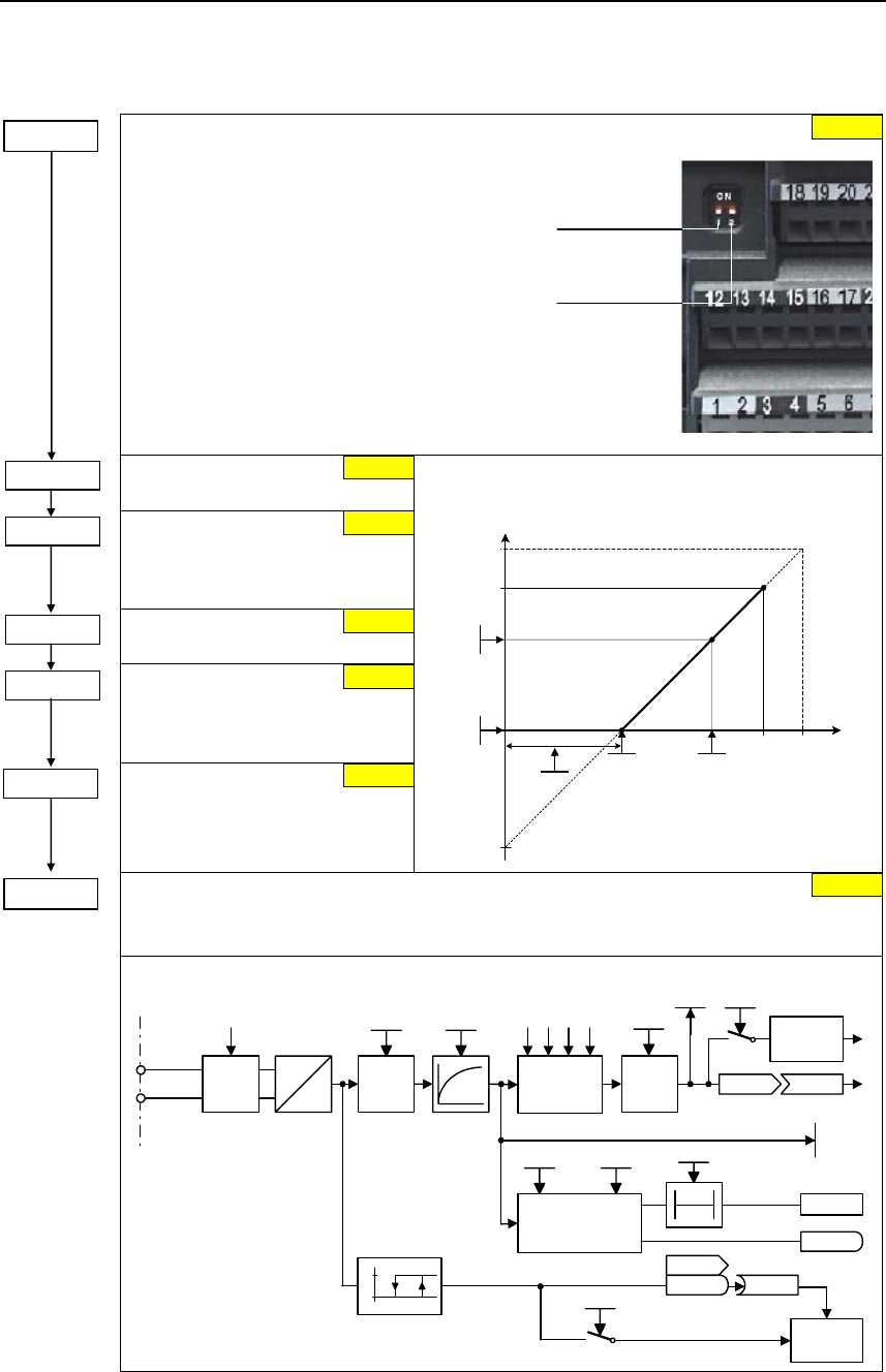
3.1 50/60 Hz DIP switch
The default motor base frequency
of the MICROMASTER inverter is
50 Hz. For motors, which are
designed for a base frequency of
60 Hz, the inverters can be set to
this frequency using the DIP50/60
switch.
¾ OFF position:
European defaults (Rated
motor frequency = 50 Hz,
Power in kW etc.)
¾ ON position:
North American defaults
(Rated motor frequency = 60 Hz, Power in hp etc.)
Remove I/O board
DIP50/60
4 Communications Issue 10/06
MICROMASTER 440
24 Operating Instructions (Compact)
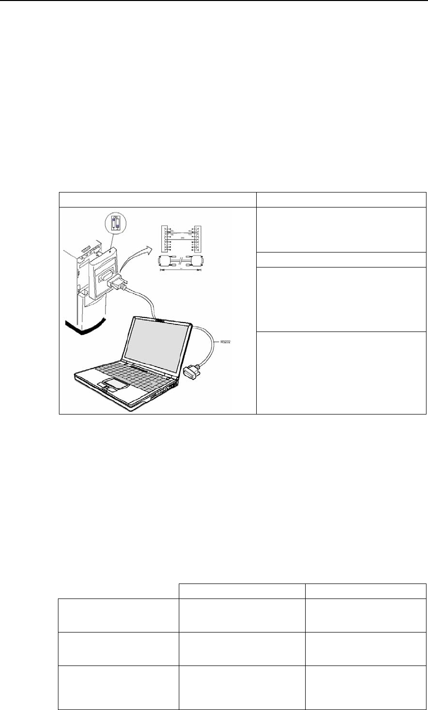
4 Communications
4.1 Establishing communications
MICROMASTER 440 ⇔ STARTER
The following optional components are additionally required in order to establish
communications between STARTER and MICROMASTER 440:
¾ PC <-> frequency inverter connecting set
¾ BOP if the USS standard values (refer to Section 6.4.1 "Serial Interface (USS)")
are changed in the MICROMASTER 440 frequency inverter
PC <-> frequency inverter connecting set MICROMASTER 440
USS settings, refer to 6.4.1 "Serial
Interface (USS)"
STARTER
Menu, Options --> Set PG/PC interface
--> Select "PC COM-Port (USS)" -->
Properties --> Interface "COM1", select
a baud rate
NOTE
The USS parameter settings in the
MICROMASTER 440 frequency inverter
and the settings in STARTER must
match!
4.2 Establishing communications
MICROMASTER 440 ⇔ AOP
¾ Communications between AOP and MM440 are based on the USS protocol,
analog to STARTER and MM440.
¾ Contrary to the BOP, the appropriate communication parameters - both for the
MM440 as well as for AOP - should be set if the automatic interface detection
was not carried-out (refer to Table 4-1).
¾ Using the optional components, the AOP can be connected to the
communication interfaces (refer to Table 4-1).
Table 4-1
AOP at the BOP link AOP at the COM link
MM440 parameters
- baud rate
- bus address
P2010[1]
–
P2010[0]
P2011
AOP parameters
- baud rate
- bus address
P8553
–
P8553
P8552
Options
- direct connection
- indirect connection
No option necessary
BOP/AOP door mounting kit
(6SE6400-0PM00-0AA0)
Not possible
AOP door mounting kit
(6SE6400-0MD00-0AA0)
Issue 10/06 4 Communications
MICROMASTER 440
Operating Instructions (Compact) 25
AOP as control unit
Parameter / Terminal AOP on BOP link AOP on COM link
Command source
/ P0700 4 5
P1000 1
P1035 2032.13 (2032.D) 2036.13 (2036.D)
P1036 2032.14 (2032.E) 2036.14 (2036.E)
Frequency setpoint
(MOP)
Output frequency of the MOP higher
Output frequency of the MOP lower
Acknowledge fault
P2104 2032.7 2036.7
• A fault can be acknowledged via the AOP independently of P0700 or P1000.
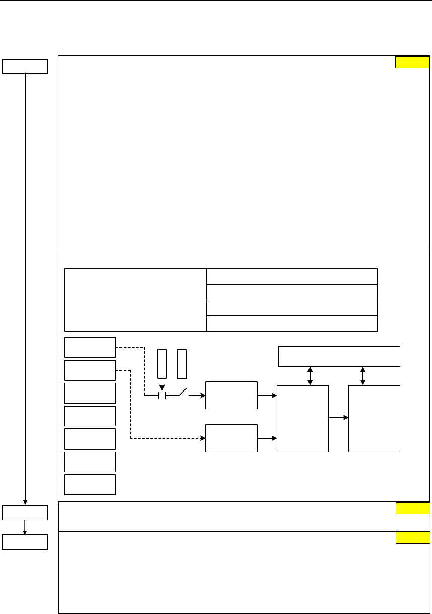
4.3 Bus interface (CB)
DeviceNet
P0918
CANopen
P0918
PROFIBUS
P0918 *)
Bus interface (CB)
P2040 P2040 P2040
P2041 P2041 P2041
P2051 P2051 P2051
Baud rate is
automatically specified
by the master
*) DIP switch for addressing the hardware must be observed
DeviceNet CANopen PROFIBUS
P2041[0] PZD length
Status/actual value
Data transfer type
from T_PD0_1, T_PD0_5
P2041[1] PZD length
control/setpoint
Data transfer type T_PD0_6
R_PD0_1
R_PD0_5
R_PD0_6
P2041[2] Baud rate 0: 125 kbaud
1: 250 kbaud
2: 500 kbaud
Mapping CANopen <--> MM4
P2041[3] Diagnostics Mapping CANopen <--> MM4
P2041[4] _ - response to communication errors
- baud rate
Setting is not
required (only in
special cases).
Refer to the
Operating
Instructions
"PROFIBUS
option module"
5 BOP / AOP (Option) Issue 10/06
MICROMASTER 440
26 Operating Instructions (Compact)
BOP / AOP (Option)
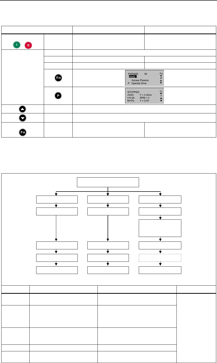
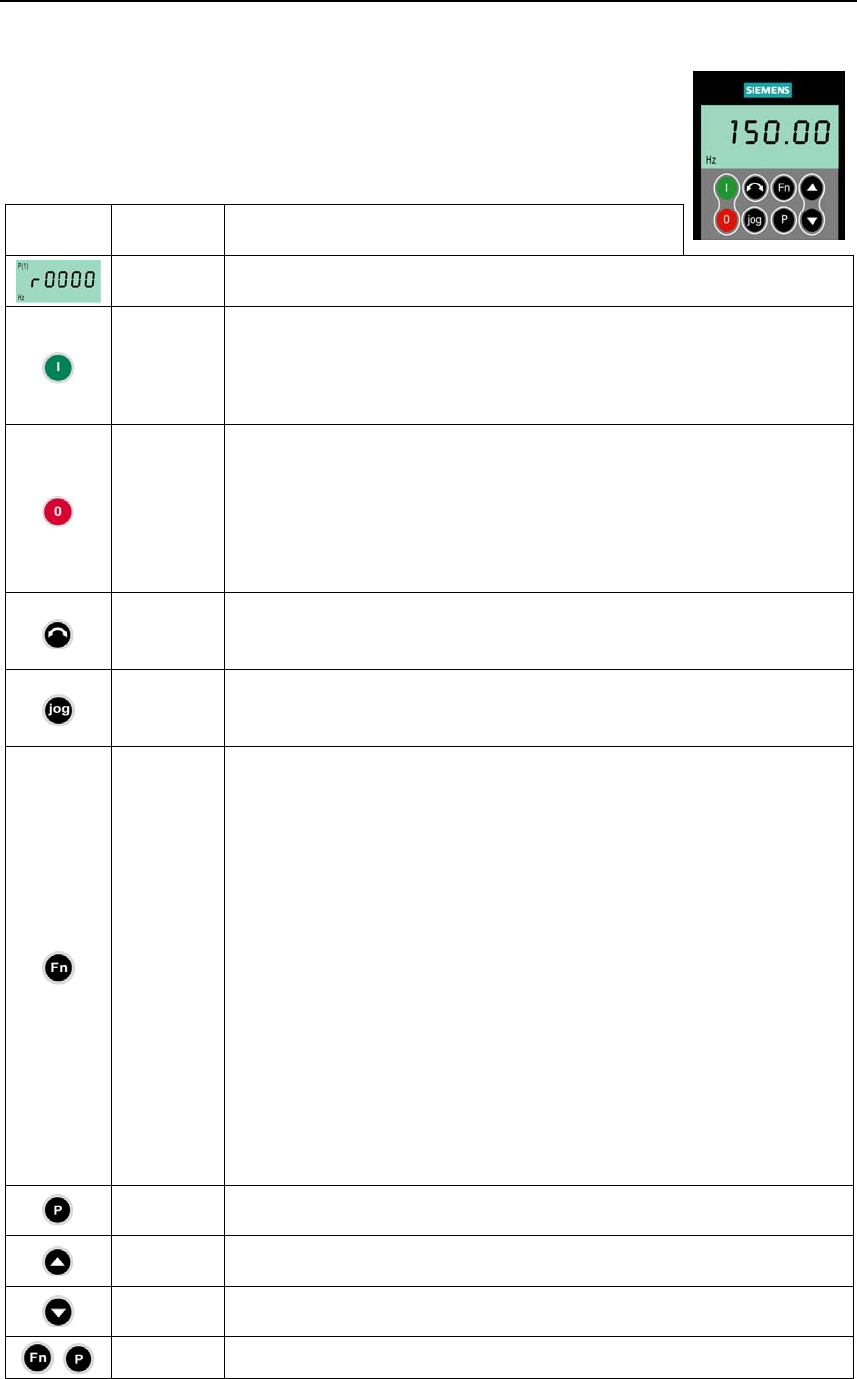
Buttons and their Functions
Panel/
Button Function Effects
Indicates
Status The LCD displays the settings currently used by the converter.
Start
converter
Pressing the button starts the converter. This button is disabled by default.
Activate the button:
BOP: P0700 = 1 or P0719 = 10 ... 16
AOP: P0700 = 4 or P0719 = 40 ... 46 on BOP link
P0700 = 5 or P0719 = 50 ... 56 on COM link
Stop
converter
OFF1 Pressing the button causes the motor to come to a standstill at the
selected ramp down rate.
Activate the button: see button "Start converter"
OFF2 Pressing the button twice (or once long) causes the motor to coast
to a standstill.
BOP: This function is always enabled
(independent of P0700 or P0719).
Change
direction
Press this button to change the direction of rotation of the motor. Reverse is
indicated by a minus (-) sign or a flashing decimal point. Disabled by default.
Activate the button: see button "Start converter".
Jog motor
In the "Ready to power-on" state, when this key is pressed, the motor starts
and rotates with the pre-set jog frequency. The motor stops when the button
is released. Pressing this button when the motor is running has no effect.
Functions
This button can be used to view additional information.
It works by pressing and holding the button. It shows the following, starting
from any parameter during operation:
1. DC link voltage (indicated by d – units V).
2. output current. (A)
3. output frequency (Hz)
4. output voltage (indicated by o – units V).
5. The value selected in P0005 (If P0005 is set to show any of the above
(1 - 4) then this will not be shown again).
Additional presses will toggle around the above displays.
Jump Function
From any parameter (rxxxx or Pxxxx) a short press of the Fn button will
immediately jump to r0000, you can then change another parameter, if
required. Upon returning to r0000, pressing the Fn button will return you to
your starting point.
Acknowledgement
If alarm and fault messages are present, then these can be acknowledged by
pressing key Fn.
Access
parameters Pressing this button allows access to the parameters.
Increase
value Pressing this button increases the displayed value.
Decrease
value Pressing this button decreases the displayed value.
+ AOP menu Calls the AOP menu prompting (this is only available for AOP).

Issue 10/06 5 BOP / AOP (Option)
MICROMASTER 440
Operating Instructions (Compact) 27
5.2 Changing parameters using as an example P0004
"Parameter filter function"
Step Result on the display
1 Press in order to access the parameter
2 Press until P0004 is displayed
3 Press in order to reach the parameter value level
4 Press or in order to obtain the required value
5 Press to acknowledge the value and to save the value
6 The user can only see the command parameters.
6 Commissioning Issue 10/06
MICROMASTER 440
28 Operating Instructions (Compact)
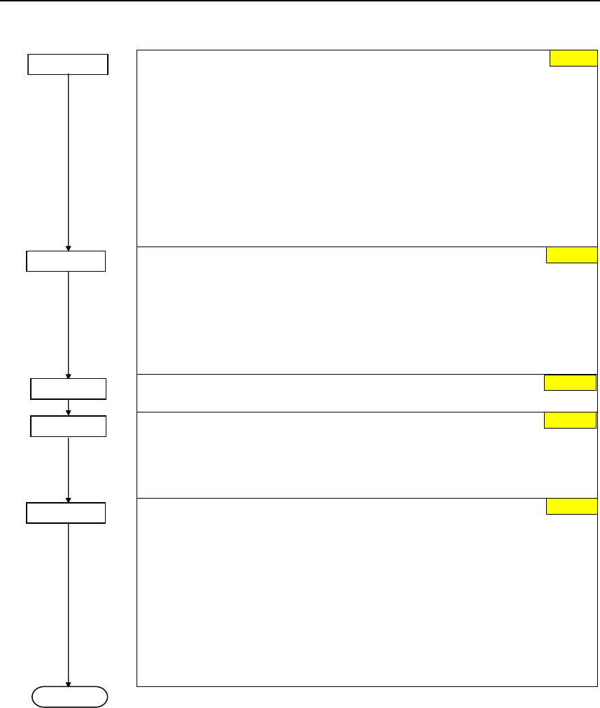
6 Commissioning
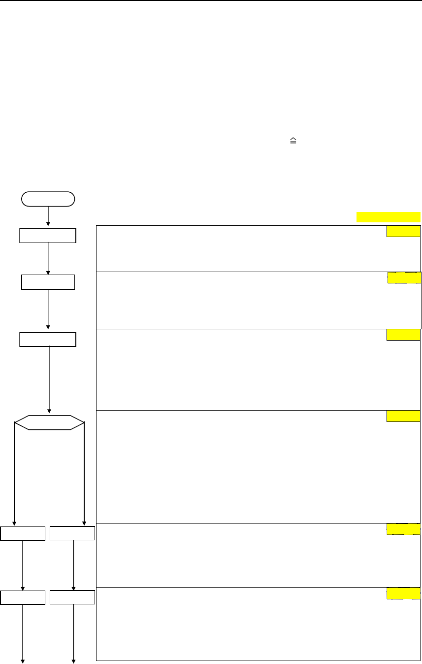
6.1 Quick commissioning
The frequency inverter is adapted to the motor using the quick commissioning
function and important technological parameters are set. The quick commissioning
shouldn't be carried-out if the rated motor data saved in the frequency inverter
(4-pole 1LA Siemens motor, star circuit configuration frequency inverter (FU)-
specific) match the rating plate data.
Parameters, designated with a * offer more setting possibilities than are actually
listed here. Refer to the parameter list for additional setting possibilities.
Factory setting
P0003 = 3
User access level *
1 Standard: Allows access into most frequently used parameters
2 Extended: Allows extended access e.g. to inverter I/O functions
3 Expert (For expert use only)
Parameter filter *
0 All parameters
2 Inverter
3 Motor
4 Speed sensor
P0010 = 1
Commissioning parameter *
0 Ready
1 Quick commissioning
30 Factory setting
NOTE
P0010 should be set to 1 in order to parameterize the data of the motor rating
plate.
P0100 =...
Europe/ North America
(enters the line supply frequency)
0 Europe [kW], frequency default 50 Hz
1 North America [hp], frequency default 60 Hz
2 North America [kW], frequency default 60 Hz
NOTE
For P0100 = 0 or 1, the setting of switch DIP50/60 determines the value of
P0100.
OFF = kW, 50 Hz
ON = hp, 60 Hz
Inverter application (enters the required torque)
0 Constant torque (e.g. compressors, processing machines)
1 Variable torque (e.g. pumps, fans)
NOTE
This parameter is only effective for drive inverters ≥ 5.5 kW / 400 V
Select motor type
1 Asynchronous motor (induction motor)
2 Synchronous motor
NOTE
For P0300 = 2 (synchronous motor), only the V/f control types (P1300 < 20) are
permitted.
P0100 = 1, 2
P0100 = 0
START
P0004 = 0 0
1
0
P0300 =... P0300 =...
P0205 =... P0205 =...
1
0
0
Issue 10/06 6 Commissioning
MICROMASTER 440
Operating Instructions (Compact) 29
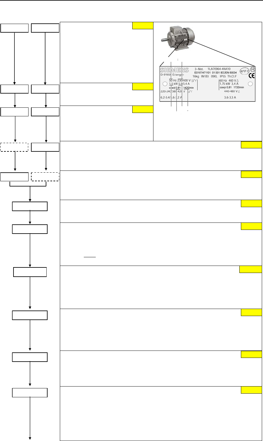
P0304 =... P0304 =... Rated motor voltage
(Nominal motor voltage [V]
from rating plate)
The rated motor voltage on the rating
plate must be checked, regarding the
star/delta circuit configuration to
ensure that it matches with the circuit
connection configured at the motor
terminal board
P0305 =... P0305 =... Rated motor current
(Nominal motor current [A]
from rating plate)
P0307 =... P0307 =... Rated motor power
(Nominal motor power [kW/hp]
from rating plate)
If P0100 = 0 or 2, value will be in kW.
If P0100 = 1, value will be in in hp.
P0304
P0305
P0307
P0308 P0311
P0310
Example of a typical motor rating plate
(data for a delta circuit configuration).
P0308 =...P0308 =... Rated motor cosPhi
(Nominal motor power factor (cos ϕ) from rating plate)
If the setting is 0, the value is automatically calculated
P0100 = 1,2: P0308 no significance, no entry required.
P0309 =...
P0309 =... Rated motor efficiency
(Nominal motor efficiency in [%] from rating plate)
Setting 0 causes internal calculation of value.
P0100 = 0: P0309 no significance, no entry required.
P0310 =... Rated motor frequency
(Nominal motor frequency in [Hz] from rating plate)
Pole pair number recalculated automatically if parameter is changed.
P0311 =...
Rated motor speed
(Nominal motor speed in [rpm] from rating plate)
Setting 0 causes internal calculation of value.
NOTE
An entry must be made for closed-loop Vector control, V/f control with FCC and
for slip compensation.
Motor magnetizing current
(this is entered as a % referred to P0305)
Motor magnetizing current as a % relative to P0305 (rated motor current).
With P0320 = 0, the motor magnetizing current is calculated using P0340 = 1 or
using P3900 = 1 - 3 (end of the quick commissioning) – and is displayed in
parameter r0331.
P0335 =...
Motor cooling
(Selects motor cooling system used)
0 Self-cooled: Using shaft mounted fan attached to motor
1 Force-cooled: Using separately powered cooling fan
2 Self-cooled and internal fan
3 Force-cooled and internal fan
P0640 =...
Motor overload factor
(Motor overload factor in [%] relative to P0305)
This defines the limit of the maximum output current as a % of the rated motor
current (P0305). This parameter is set, using P0205 for constant torque, to
150 %, and for variable torque, to 110 %.
P0700 =...
Selection of command source
(enters the command source)
0 Factory default setting
1 BOP (keypad)
2 Terminal
4 USS on BOP link
5 USS on COM link (control terminals 29 and 30)
6 CB on COM link (CB = communications module)
P0320 = ... 0.0
FU-spec.
FU-spec.
FU-spec.
FU-spec.
FU-spec.
50.00 Hz
FU-spec.
0
150 %
2
6 Commissioning Issue 10/06
MICROMASTER 440
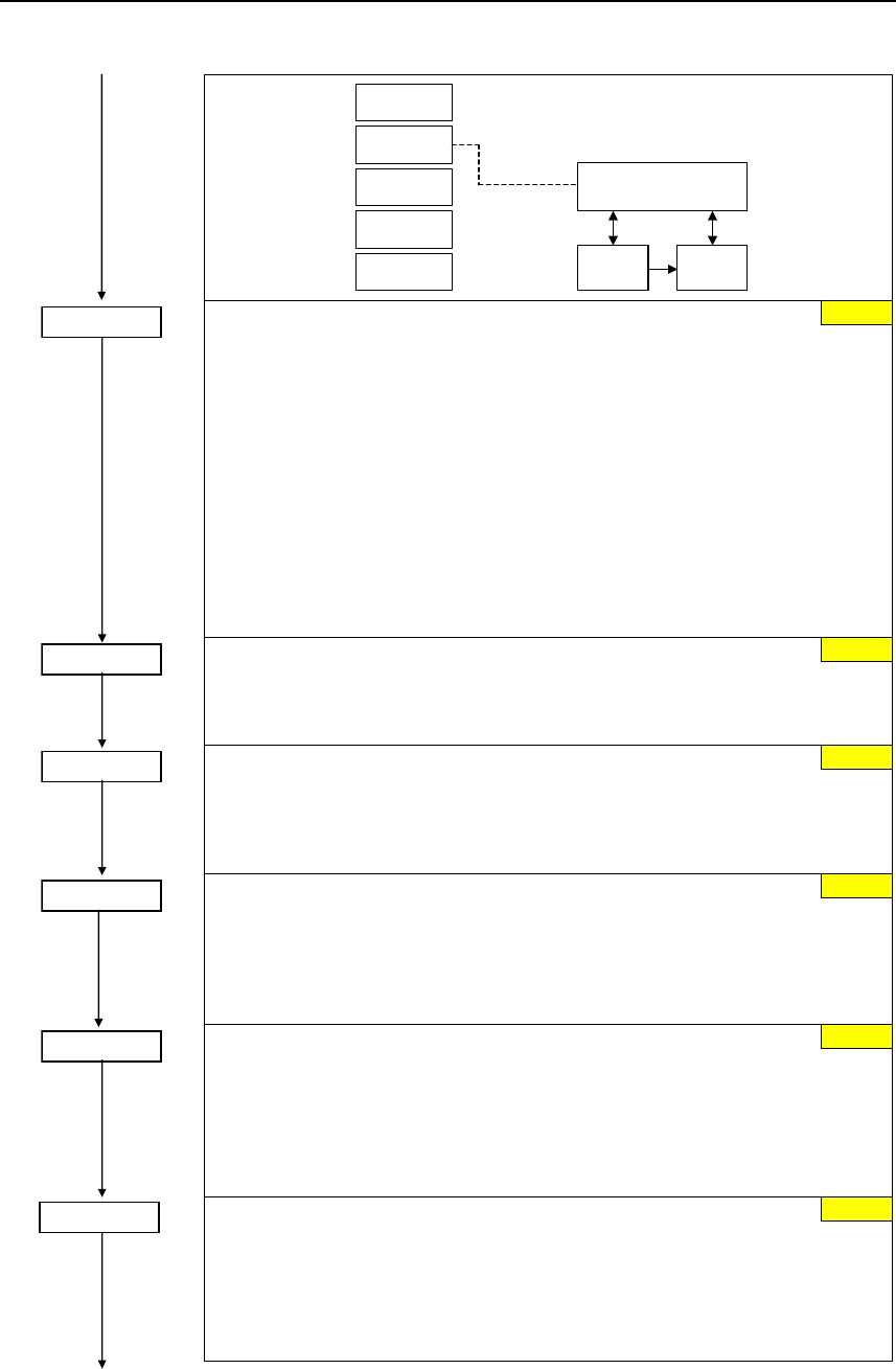
30 Operating Instructions (Compact)
BOP
USS
BOP link
USS
COM link
P0700 = 2
Terminals
CB
COM link
Sequence control
Setpoint
channel Motor
control
P1000 =...
Selection of frequency setpoint *
(enters the frequency setpoint source)
1 MOP setpoint
2 Analog setpoint
3 Fixed frequency
4 USS on BOP link
5 USS on COM link (control terminals 29 and 30)
6 CB on COM link (CB = communications module)
7 Analog setpoint 2
10 No main setpoint + MOP setpoint
11 MOP setpoint + MOP setpoint
12 Analog setpoint + MOP setpoint
...
76 CB on COM link + Analog setpoint 2
77 Analog setpoint 2 + Analog setpoint 2
P1080 =...
Min. frequency
(enters the minimum motor frequency in Hz)
Sets minimum motor frequency at which motor will run irrespective of frequency
setpoint. The value set here is valid for both clockwise and anticlockwise rotation.
P1082 =...
Max. frequency
(enters the maximum motor frequency in Hz)
Sets maximum motor frequency at which motor will run irrespective of the
frequency setpoint. The value set here is valid for both clockwise and
anticlockwise rotation.
P1120 =...
Ramp-up time
(enters the ramp-up time in s)
Time taken for motor to accelerate from standstill up to maximum motor
frequency (P1082) when no rounding is used. If a ramp-up time is parameterized
which is too low, then this can result in alarm A0501 (current limit value) or the
drive inverter being shutdown with fault F0001 (overcurrent).
P1121 =...
Ramp-down time
(enters the deceleration time in s)
Time taken for motor to decelerate from maximum motor frequency (P1082) down
to standstill when no rounding is used. If the ramp-down time is parameterized too
low, then this can result in alarms A0501 (current limit value), A0502 (overvoltage
limit value) or the drive inverter being powered-down with fault F0001
(overcurrent) or F0002 (overvoltage).
OFF3 ramp-down time
(enters the fast stop ramp-down time in s)
Enters the time, for example, with which the motor should be braked from the
maximum frequency P1082 down to standstill for an OFF3 command (fast stop).
If the ramp-down time is parameterized too low, then this can result in alarms
A0501 (current limit value), A0502 (overvoltage limit value) or the drive inverter
being shutdown with fault F0001 (overcurrent) or F0002 (overvoltage).
2
0.00 Hz
50.00 Hz
10.00 s
10.00 s
5.00 s
P1135 =...
Issue 10/06 6 Commissioning
MICROMASTER 440
Operating Instructions (Compact) 31
P1300 =...
Control mode
(enters the required control mode)
0 V/f with linear characteristic
1 V/f with FCC
2 V/f with parabolic characteristic
3 V/f with programmable characteristic
5 V/f for textile applications
6 V/f with FCC for textile applications
19 V/f control with independent voltage setpoint
20 Sensorless Vector control
21 Vector control with sensor
22 Sensorless Vector torque-control
23 Vector torque-control with sensor
Selection of torque setpoint *
(enters the source for the torque setpoint)
0 No main setpoint
2 Analog setpoint
4 USS on BOP link
5 USS on COM link (control terminals 29 and 30)
6 CB on COM link (CB = communications module)
7 Analog setpoint 2
Select motor data identification *
0 Disabled
Speed controller optimization *
0 Inhibited
In order to optimize the speed controller, the closed-loop vector control (P1300 =
20 or 21) must be activated. After the optimization has been selected
(P1960 = 1), Alarm A0542 is displayed.
End of quick commissioning
(start of the motor calculation)
0 No quick commissioning (no motor calculations)
1 Motor calculation and reset of all of the other parameters, which are not
included in the quick commissioning (attribute "QC" = no), to the factory
setting
2 Motor calculation and reset of the I/O settings to the factory setting
3 Only motor calculation. The other parameters are not reset.
NOTE
For P3900 = 1,2,3 → P0340 is internally set to 1 and the appropriate data
calculated.
End of the quick commissioning/drive setting
If additional functions must be implemented at the drive inverter, please use the
Section "Commissioning the application" (refer to Section 6.4). We recommend
this procedure for drives with a high dynamic response.
0
P1500 =...
0
P3900 = 1
P1910 = ...
P1960 = ...
0
0
0
END
6 Commissioning Issue 10/06
MICROMASTER 440
32 Operating Instructions (Compact)
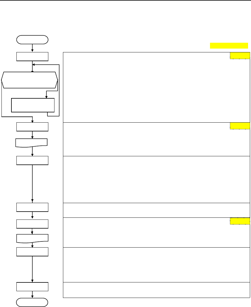
6.2 Motor data identification
Factory setting
Ambient motor temperature (entered in °C)
The motor ambient temperature is entered at the instant that motor data is
being determined (factory setting: 20 °C).
yes no
The difference between the motor temperature and the motor ambient
temperature P0625 must lie in the tolerance range of approx. ± 5 °C. If this is
not the case, then the motor data identification routine can only be carried-out
after the motor has cooled down.
Select motor data identification with P1910 = 1
p1910 = 1: Identifies the motor parameter with parameter change.
These are accepted and applied to the controller.
When p1910 = 1 is selected, Alarm A0541 (motor data identification active)
is output, and internally p0340 is set to 3.
Starts the motor data identification run with p1910 = 1
The measuring operation is initiated with the continuous (steady-state) ON
command. The motor aligns itself and current flows through it. Diagnostics is
possible using r0069 (CO: Phase current).
After the motor data identification routine has been completed, p1910 is reset
(p1910 = 0, motor data identification routine inhibited) and Alarm A0541 is
cleared (deleted).
In order to set the frequency converter into a defined state, an OFF1 command
must be issued before the next step.
Select motor data identification with P1910 = 3
p1910 = 3: Identifies the saturation characteristic with parameter change.
When p1910 = 3 is selected, Alarm A0541 (motor data identification active)
is output and internally, p0340 is set to 2.
Starts the motor data identification run with P1910 = 3
The measuring operation must be started with a continuous ON command.
After the motor identification routine has been completed, p1910 is reset
(p1910 = 0, motor data identification routine inhibited) and Alarm A0541 is
cleared (deleted).
In order to set the frequency converter into a defined state, an OFF1 command
must be issued before the next step.
6.3 Magnetizing current
¾ The value of the magnetizing current r0331/P0320 has a significant influence on
the closed-loop control. This cannot be measured at standstill. This means that
the value is estimated for standard 4-pole 1LA7 Siemens standard using the
automatic parameterization P0340=1 (P0320=0; result in r0331).
¾ If the deviation of the magnetizing current is too high, then the values for the
magnetizing reactance and those of the rotor resistance will not be able to be
accurately determined.
¾ Especially for third-party motors it is important that the magnetizing current
that is determined, is carefully checked and if required, appropriately corrected.
START
P0625 = ? 20 °C
| Motor temp. - P0625|
≤ 5 °C ?
Allow the motor
to cool down
P1910 = 1 0
A0541
ON
OFF1
P1910 = 3 0
A0541
ON
OFF1
END
Issue 10/06 6 Commissioning
MICROMASTER 440
Operating Instructions (Compact) 33
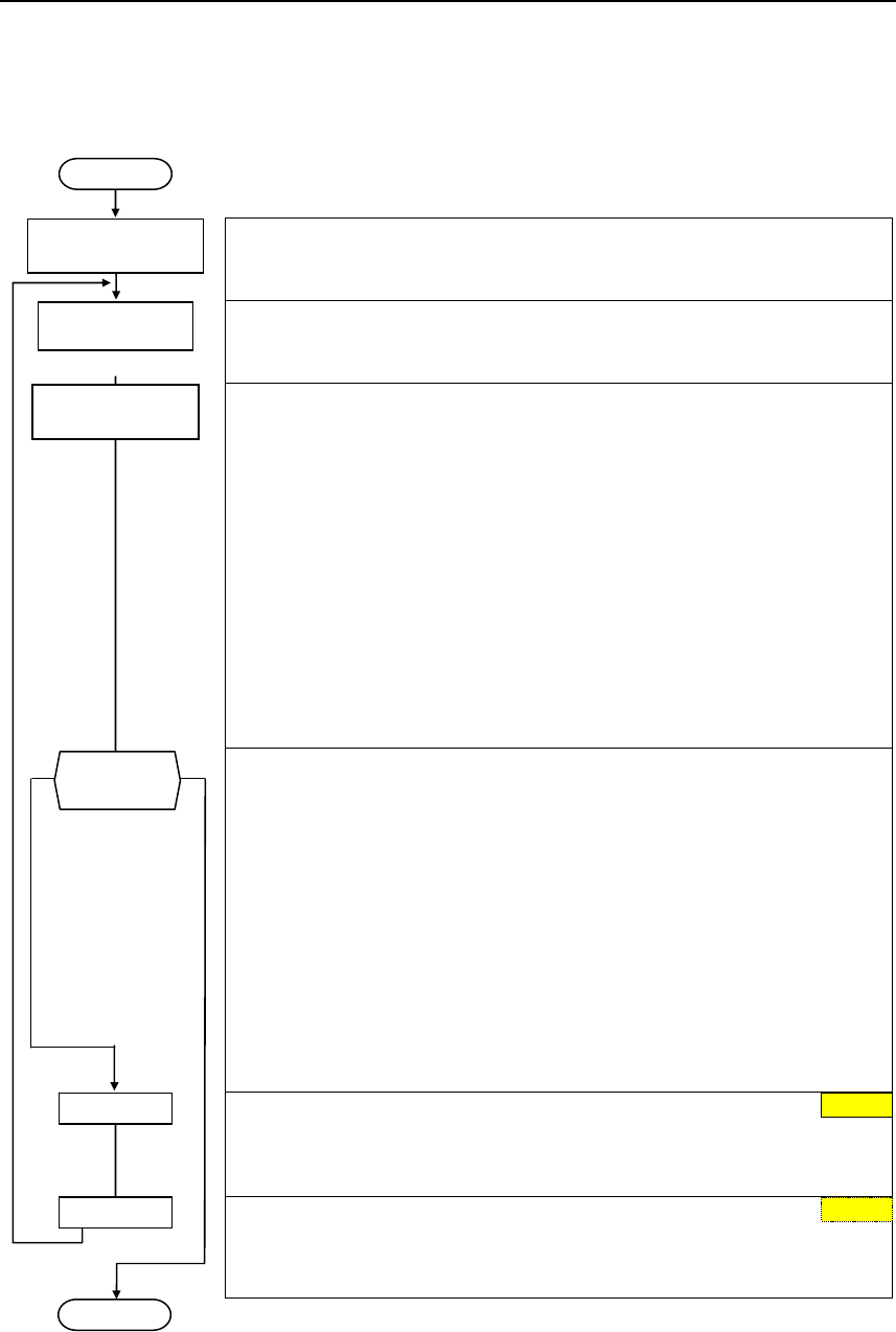
The procedure to manually determine the magnetizing current and to re-calculate
the equivalent circuit diagram data when the drive is operated with closed-loop
vector control (P1300 = 20/21) is shown in the following.
Quick commissioning routine
Using the quick commissioning routine the frequency inverter is adapted to the
motor and important technology parameters are set.
Motor data identification routine
Using the motor data identification routine motor equivalent circuit diagram
data is determined using a measuring technique.
Determining the magnetizing current
In order to determine the magnetizing current (P0320/r0331), the motor should
be accelerated up to approximately 80% of its rated speed under no-load
operating conditions.
In so doing, the following conditions must be carefully maintained:
− the vector control must be activated, P1300 = 20.21
− no field weakening (r0056.8 = 0)
− flux setpoint, r1598 = 100 %
− no efficiency optimization, P1580 = 0 %
No-load operation means that the motor is operated without a load (i.e.
no coupled driven machine).
Under steady-state conditions, a current r0027 is obtained that approximately
corresponds to the rated magnetizing current r0331. (the current is always
less than the no-load current for a pure V/f control).
no yes
Measuring and entering the magnetizing current and therefore the associated
new calculation of the equivalent circuit diagram data of the motor is an
iterative procedure. It must be repeated at least 2-3 times until the following
criteria are fulfilled:
− The more accurate the value of the magnetizing current that was
entered, the better the flux setpoint (r1598=100%) matches the flux
actual value (r0084=96..104%) of the observer model.
− The output Xm adaptation (r1787) of the observer model should be
as low as possible. Good values lie between 1-5%. The less that the
Xh adaptation of the observer must operate, the sensitivity of the motor
parameters after power failures are that much less sensitive.
NOTE
In order to display r0084 at the BOP/AOP, the LEVEL 4 parameters must be
enabled using service parameter P3950=46.
Calculating P0320
Now, the new value can be entered in P0320 from the determined flux-
generating current component r0029 by applying the following equation.
P0320 = r0029 * 100 / P0305
Calculating the motor parameters
The values of the motor equivalent circuit diagram data are calculated from the
entered rating plate data. In addition, the parameters of the controls are pre-set
(subsequently optimized) (P0340 = 3).
START
Quick
commissioning
0
END
Motor data
identification
Operation under
no-load conditions
P0320 = ... 0
P0340 = 1
Criterium
fulfilled ?
6 Commissioning Issue 10/06
MICROMASTER 440
34 Operating Instructions (Compact)
6.4 Commissioning the application
An application is commissioned to adapt/optimize the frequency inverter - motor
combination to the particular application. The frequency inverter offers numerous
functions - but not all of these are required for the particular application. These
functions can be skipped when commissioning the application. A large proportion
of the possible functions are described here; refer to the parameter list for
additional functions.
Parameters, designated with a * offer more setting possibilities than are actually
listed here. Refer to the parameter list for additional setting possibilities.
P0003 = 3
User access level *
1 Standard: Allows access into most frequently used parameters
2 Extended: Allows extended access e.g. to inverter I/O functions
3 Expert (For expert use only)
6.4.1 Serial Interface (USS)
P2010 =... USS baud rate
Sets baud rate for USS communication.
P2011 =... USS address
Sets unique address for inverter.
P2012 =... USS PZD length
Defines the number of 16-bit words in PZD part of USS telegram.
P2013 =... USS PKW length
Defines the number of 16-bit words in PKW part of USS telegram.
Possible
Settings:
4 2400 Baud
5 4800 Baud
6 9600 Baud
7 19200 Baud
8 38400 Baud
9 57600 Baud
10 76800 Baud
11 93750 Baud
12 115200 Baud
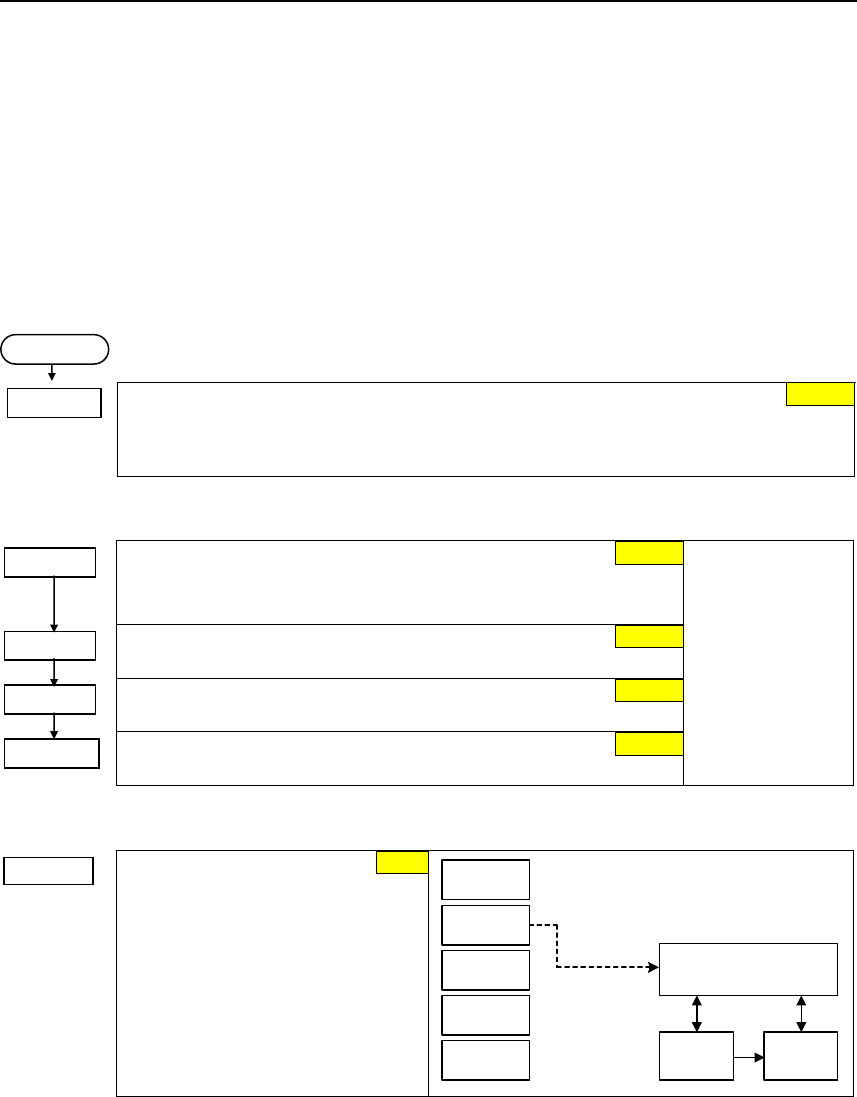
6.4.2 Selection of command source
P0700 =...
Selection of
command source
Selects digital command source.
0 Factory fault setting
1 BOP (keypad)
2 Terminal
4 USS on BOP link
5 USS on COM link
6 CB on COM link
P0700 = 2 Sequence control
Setpoint
channel Motor
control
BOP
USS
BOP link
USS
COM link
Terminals
CB
COM link
START
1
6
0
2
127
2
Issue 10/06 6 Commissioning
MICROMASTER 440
Operating Instructions (Compact) 35
6.4.3 Digital input (DIN)
Function digital input 1
Terminal 5
1 ON / OFF1
Function digital input 2
Terminal 6
12 Reverse
Function digital input 3
Terminal 7
9 Fault acknowledge
Function digital input 4
Terminal 8
15 Fixed setpoint (Direct selection)
Function digital input 5
Terminal 16
15 Fixed setpoint (Direct selection)
Function digital input 6
Terminal 17
15 Fixed setpoint (Direct selection)
Possible Settings:
0 Digital input disabled
1 ON / OFF1
2 ON + Reverse / OFF1
3 OFF2 – coast to standstill
4 OFF3 – quick ramp-down
9 Fault acknowledge
10 JOG right
11 JOG left
12 Reverse
13 MOP up (increase frequency)
14 MOP down (decrease frequency)
15 Fixed setpoint (Direct selection)
16 Fixed setpoint (Direct selection + ON)
17 Fixed setpoint (Binary coded selection + ON)
21 Local/remote
25 DC brake enable
29 External trip
33 Disable additional freq setpoint
99 Enable BICO parameterization
Function digital input 7
Via analog input, Terminal 3
0 Digital input disabled
Function digital input 8
Via analog input, Terminal 10
0 Digital input disabled
DIN8
DIN7
ON > 3,9 V, OFF < 1,7 V
1
2
10
11
1
2
3
4
Debounce time for digital inputs
Defines debounce time (filtering time) used for digital inputs.
0 No debounce time
1 2.5 ms debounce time
2 8.2 ms debounce time
3 12.3 ms debounce time
PNP / NPN digital inputs
Change-over (toggles) between high active (PNP) and low active (NPN). This applies to all
digital inputs simultaneously.
0 NPN mode ==> low active
1 PNP mode ==> high active
DIN channel (e.g. DIN1 - PNP (P0725 = 1))
24 V T0
&
0
1
PNP/NPN DIN
0 ... 1
P0725 (1)
0 V
24 V
Debounce time: DIN
0 ... 3
P0724 (3)
CO/BO: Bin.inp.val
r0722
r0722
.0
Kl.9
P24 (PNP)
Kl.28
0 V (NPN)
Pxxxx BI: ...
P0701
Function
0
1
15
P0706 = ...
15
P0705 = ...
1
12
9
15
P0701 = ...
P0703 = ...
P0702 = ...
P0704 = ...
3
P0724 = ...
P0725 = ... 1
0
P0707 = 0
0
P0708 = 0
6 Commissioning Issue 10/06
MICROMASTER 440
36 Operating Instructions (Compact)
6.4.4 Digital outputs (DOUT)
BI: Function of digital output 1 *
Defines source of digital output 1.
BI: Function of digital output 2 *
Defines source of digital output 2.
BI: Function of digital output 3 *
Defines source of digital output 3.
CO/BO: State of digital outputs
Displays status of digital outputs (also
includes inversion of digital outputs via
P0748).
Invert digital output
Defines high and low states of relay for a
given function.
Common Settings: Closed
52.0 Drive ready 0
52.1 Drive ready to run 0
52.2 Drive running 0
52.3 Drive fault active 0
52.4 OFF2 active 1
52.5 OFF3 active 1
52.6 Switch on inhibit active 0
52.7 Drive warning active 0
52.8 Deviation setpoint/actual value 1
52.9 PZD control (Process Data Control) 0
52.A Maximum frequency reached 0
52.B Warning: Motor current limit 1
52.C Motor holding brake (MHB) active 0
52.D Motor overload 1
52.E Motor running direction right 0
52.F Inverter overload 1
53.0 DC brake active 0
53.1 Act. freq. f_act > P2167 (f_off) 0
53.2 Act. freq. f_act <= P1080 (f_min) 0
53.3 Act. current r0027 > P2170 0
53.4 Act. freq. f_act > P2155 (f_1) 0
53.5 Act. freq. f_act <= P2155 (f_1) 0
53.6 Act. freq. f_act >= setpoint 0
53.7 Act. Vdc r0026 < P2172 0
53.8 Act. Vdc r0026 > P2172 0
53.A PID output
r2294 == P2292 (PID_min) 0
53.B PID output
r2294 == P2291 (PID_max) 0
(52:3)
BI: Fct. of DOUT 1
P0731.C
-1
0
1
Invert DOUTs
0 ... 7
P0748 (0) CO/BO: State DOUTs
r0747
r0747
Kl.20
Kl.18
.0
Function
xxxx.y rxxxx.y
P0731 = xxxx.y
DOUT channel
Relay :
DC 30 V / 5 A
AC 250 V / 2 A
Kl.28
Kl.9
int. 24 V
max. 100 mA
NO
COM
NC
Kl.19
or
Text
max. opening / closing time
5 / 10 ms
52.3
0
P0731 = ...
52.7
0.0
P0748 = ...
P0733 = ...
P0732 = ...
r0747 = ...
Issue 10/06 6 Commissioning
MICROMASTER 440
Operating Instructions (Compact) 37
6.4.5 Selection of frequency setpoint
P1000 =...
Selection of frequency setpoint
0 No main setpoint
1 MOP setpoint
2 Analog setpoint
3 Fixed frequency
4 USS on BOP link
5 USS on COM link
6 CB on COM link
7 Analog setpoint 2
10 No main setpoint + MOP setpoint
11 MOP setpoint + MOP setpoint
12 Analog setpoint + MOP setpoint
...
76 CB on COM link + Analog setpoint 2
77 Analog setpoint 2 + Analog setpoint 2
NOTE
In addition to the main setpoint, a supplementary setpoint can be entered using P1000
P1000 = 12 ⇒ P1070 = 755 P1070 CI: Main setpoint
r0755 CO: Act. ADC after scal. [4000h]
P1000 = 12 ⇒ P1075 = 1050 P1075 CI: Additional setpoint
r1050 CO: Act. Output freq. of the MOP
Example P1000 = 12 :
MOP
ADC
FF
USS
BOP link
USS
COM link
CB
COM link
ADC2
P1000 = 12
P1000 = 12
Sequence control
Main
setpoint
Setpoint
channel Motor
control
Additonal
setpoint
P1074
P1076
x
BI: Disable additional setpoint
Disables additional setpoint (ZUSW).
CI: Additional setpoint scaling
Defines the source to scale the additional setpoint.
Common settings:
1 Scaling of 1.0 (100 %)
755 Analog input setpoint
1024 Fixed frequency setpoint
1050 MOP setpoint
P1074 = ...
P1076 = ...
0:0
1:0
2
6 Commissioning Issue 10/06
MICROMASTER 440
38 Operating Instructions (Compact)
ADC1
ADC2
OFF = [V], 0 - 10 V
ON = [A], 0 - 20 mA
7
OFF = [V], 0 - 10 V
ON = [A], 0 - 20 mA
6.4.6 Analog input (ADC)
ADC type
Defines the analog input type and activates the monitoring
function of the analog input.
0 Unipolar voltage input (0 to +10 V)
1 Unipolar voltage input with monitoring
(0 to 10 V)
2 Unipolar current input (0 to 20 mA)
3 Unipolar current input with monitoring
(0 to 20 mA)
4 Bipolar voltage input (-10 to +10 V)
NOTE
For P0756 to P0760, the following applies:
Index 0 : Analog input 1 (ADC1), terminals 3, 4
Index 1 : Analog input 2 (ADC2), terminals 10, 11
P0757 =... Value x1 of ADC scaling
P0758 =... Value y1 of ADC scaling
This parameter represents the
value of x1 as a % of P2000
(reference frequency).
P0759 =... Value x2 of ADC scaling
P0760 =... Value y2 of ADC scaling
This parameter represents the
value of x2 as a % of P2000
(reference frequency).
Width of ADC deadband
Defines width of deadband on
analog input.
ASPmax
100 %
10 V
20 mA
V
mA
x
100%
%
P0760
P0758
P0759
P0761 > 0
0 < P0758 < P0760
||
0 > P0758 > P0760
ASPmin
P0757
P0761
P0757 = P0761
4000 h
Delay, ADC signal loss
Defines the delay time between the loss of the analog setpoint and fault message F0080
being displayed.
KL4
KL3
DIP switch
A
D
ADC
type
ADC
scaling
P0757
P0758
P0759
P0760
ADC
dead
zone r0755 Pxxxx
r0752
P1000
ADC−
ADC+
r0754
P0761
P0753P0756
ADC
type
Setpoint
ADC channel
Wire
breakage
sensing
P0756 P0761
r0751
F0080
r0722
r0722.6
0
11.7 V
3.9 V P0707 Pxxxx
Function
T0
P0762
P0756 = ... 0
P0762 = ... 10 ms
0 V
0.0 %
10 V
100.0 %
0 V
P0761 =...
Issue 10/06 6 Commissioning
MICROMASTER 440
Operating Instructions (Compact) 39
6.4.7 Analog output (DAC)
CI: DAC
Defines function of the 0 - 20 mA analog output.
21 CO: Output frequency (scaled according to P2000)
24 CO: Frequency inverter output frequency (scaled according to P2000)
25 CO: Output voltage (scaled according to P2001)
26 CO: DC link voltage (scaled according to P2001)
27 CO: Output current (scaled according to P2002)
NOTE
For P0771 to P0781, the following applies:
Index 0 : Analog output 1 (DAC1), terminals 12, 13
Index 1 : Analog output 2 (DAC2), terminals 26, 27
P0773 =... Smooth time DAC
Defines smoothing time [ms] for analog output signal. This parameter enables smoothing
for DAC using a PT1 filter.
Permit absolute value
Decides if the absolute value of the analog output is used. If enabled, this parameter will
take the absolute value of the value to be outputed. If the value was originally negative then
the corresponding bit in r0785 is set, otherwise it is cleared.
0 OFF
1 ON
DAC type
Defines the analog output type.
0 Current output
1 Voltage output
NOTE
• P0776 changes the scaling of r0774 (0 – 20 mA ⇔ 0 – 10 V)
• Scaling parameters P0778, P0780 and the dead zone are always entered in 0 – 20 mA
For the DAC as voltage output, the DAC outputs must be terminated using a 500 Ω resistor
Value x1 of DAC scaling
Defines the output characteristic value
x1 as a %.
This parameter represents the lowest
analog value as a % of P200x
(depending on the setting of P0771).
Value y1 of DAC scaling
This parameter represents the value for
x1 in mA.
Value x2 of DAC scaling
Defines the output characteristic value
x2 as a %.
This parameter represents the lowest
analog value as a % of P200x
(depending on the setting of P0771).
20
P0780
y2
P0778
y1
P0777
x1
P0779
x2
100 %
mA
P0781
%
Value y2 of DAC scaling
This parameter represents the value for x2 in mA.
Width of DAC deadband
Sets width of deadband in [mA] for analog output.
21
P0771 = ...
P0776 = ... 0
0.0 %
0
100.0 %
P0777 = ...
P0778 = ...
P0779 = ...
20
P0780 = ...
0
P0781 = ...
2 ms
P0775 = ...
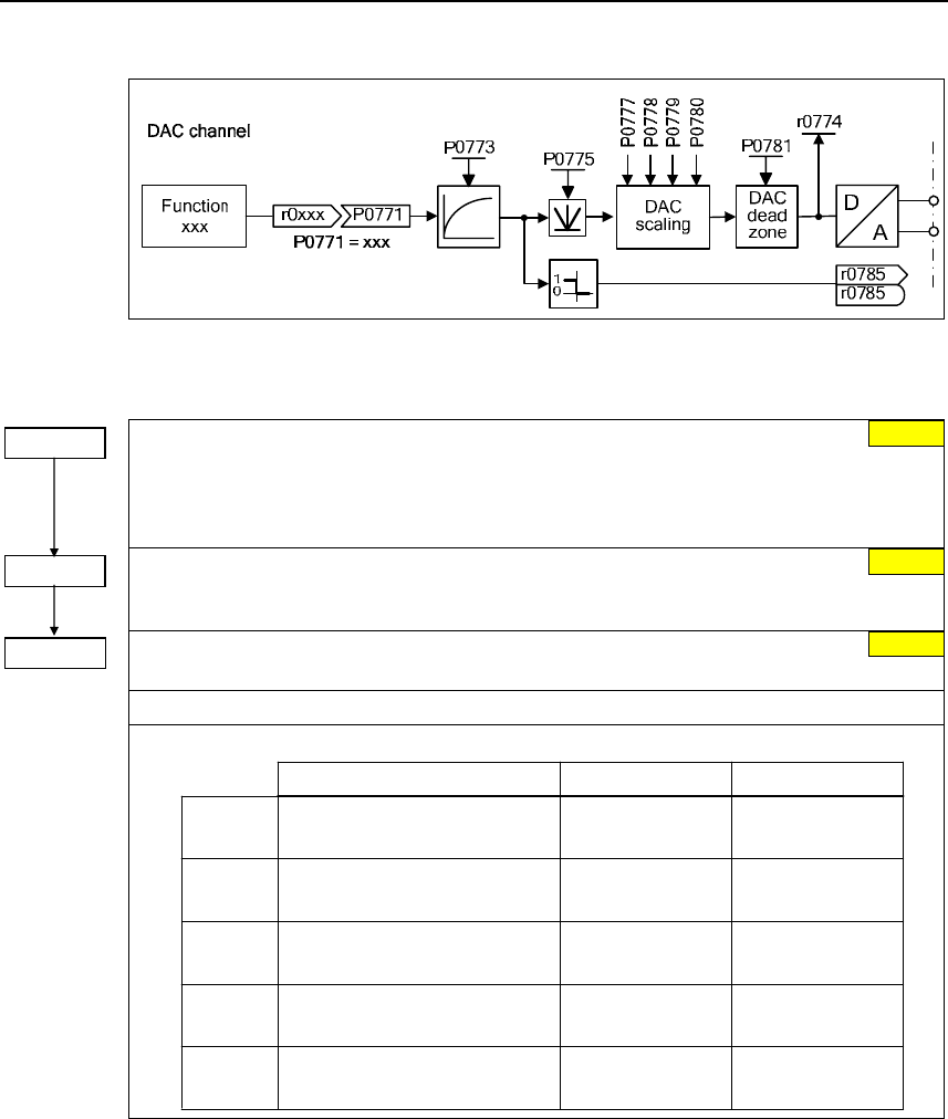
6 Commissioning Issue 10/06
MICROMASTER 440
40 Operating Instructions (Compact)
6.4.8 Motor potentiometer (MOP)
P1031 =...
Setpoint memory of the MOP
Saves last motor potentiometer setpoint (MOP) that was active before OFF command or
power down.
0 MOP setpoint will not be stored
1 MOP setpoint will be stored (P1040 is updated)
P1032 =...
Inhibit negative MOP setpoints
0 Neg. MOP setpoint is allowed
1 Neg. MOP setpoint inhibited
P1040 =... Setpoint of the MOP
Determines setpoint for motor potentiometer control.
MOP ramp-up and ramp-down times are defined by the parameters P1120 and P1121.
Selection
DIN
BOP UP button
USS control word
r2032 Bit13
USS control word
r2032 Bit14
or
P0702 = 13
(DIN2)
P0703 = 14
(DIN3)
P0719 = 0, P0700 = 1, P1000 = 1
MOP up MOP down
P0719 = 1, P0700 = 2
or
P0719 = 0, P0700 = 2, P1000 = 1
P0719 = 11
or
P0719 = 0, P0700 = 4, P1000 = 1
P0719 = 41
DOWN button
Possible parameter settings for the selection of MOP:
USS on
BOP link
USS control word
r2036 Bit13
USS control word
r2036 Bit14
or
P0719 = 0, P0700 = 5, P1000 = 1
P0719 = 51
USS on
COM link
CB control word
r2090 Bit13 r2090 Bit14
or
P0719 = 0, P0700 = 6, P1000 = 1
P0719 = 61
CB CB control word
0
1
5.00 Hz
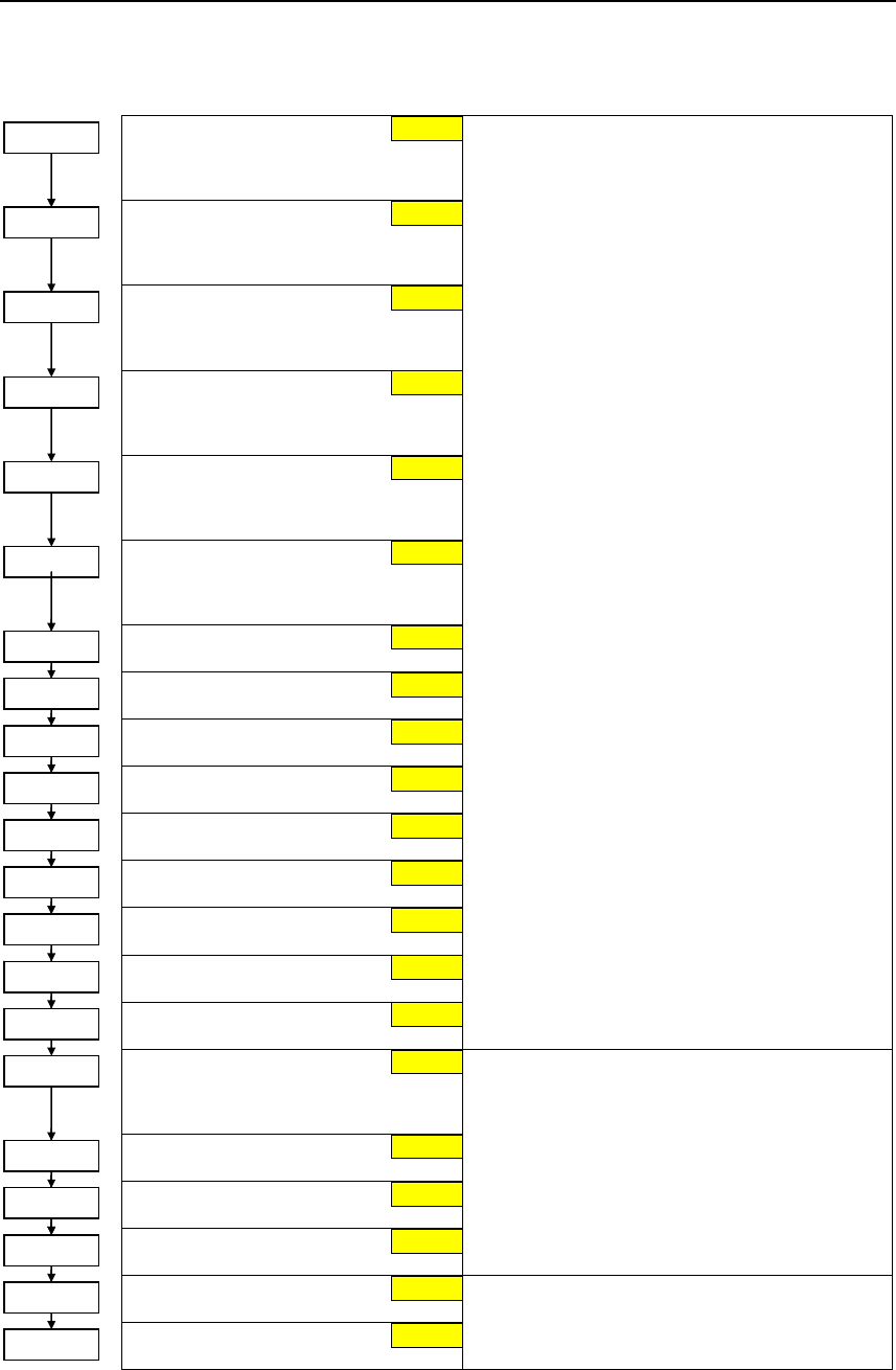
Issue 10/06 6 Commissioning
MICROMASTER 440
Operating Instructions (Compact) 41
6.4.9 Fixed frequency (FF)
Fixed frequency 1
Can be directly selected via DIN1
(P0701 = 15, 16)
Fixed frequency 2
Can be directly selected via DIN2
(P0702 = 15, 16)
Fixed frequency 3
Can be directly selected via DIN3
(P0703 = 15, 16)
Fixed frequency 4
Can be directly selected via DIN4
(P0704 = 15, 16)
Fixed frequency 5
Can be directly selected via DIN5
(P0705 = 15, 16)
Fixed frequency 6
Can be directly selected via DIN6
(P0706 = 15, 16)
Fixed frequency 7
Fixed frequency 8
Fixed frequency 9
Fixed frequency 10
Fixed frequency 11
Fixed frequency 12
Fixed frequency 13
Fixed frequency 14
Fixed frequency 15
When defining the function of the digital inputs
(P0701 to P0703), three different types can be
selected for fixed frequencies:
15 = Direct selection (binary-coded)
In this particular mode, the appropriate
digital input always selects the associated
fixed frequency, e.g.:
Digital input 3 = selects fixed frequency 3.
If several inputs are simultaneously active,
then these are summed. An ON command is
additionally required.
16 = Direct selection + ON command
(binary-coded + On / Off1)
In this mode, the fixed frequencies are
selected as for 15, however these are
combined with an ON command.
17 = Binary coded selection + ON command
(BCD-coded + On/ Off1)
The BCD-coded operating mode is effective for
digital inputs 1 to 3.
Fixed frequency code - Bit 0
Defines the selection method for fixed
frequencies.
Fixed frequency code - Bit 1
Fixed frequency code - Bit 2
Fixed frequency code - Bit 3
1 Direct selection
2 Direct selection + ON command
3 Binary coded selection + ON command
NOTE
For settings 2 and 3, all parameters P1016 to
P1019 must be set to the selected value so that
the drive inverter accepts the ON command.
Fixed frequency code - Bit 4
Fixed frequency code - Bit 5
1 Direct selection
2 Direct selection + ON command
1
1
1
P1016 = ...
P1017 = ...
P1018 = ...
1
P1019 = ...
1
P1025 = ...
1
P1027 = ...
5.00 Hz
10.00 Hz
15.00 Hz
20.00 Hz
25.00 Hz
0.00 Hz
P1001 = ...
P1002 = ...
P1003 = ...
P1004 = ...
P1005 = ...
P1006 = ...
30.00 Hz
P1007 = ...
P1008 = ... 35.00 Hz
P1009 = ... 40.00 Hz
P1010 = ... 45.00 Hz
P1011 = ... 50.00 Hz
P1012 = ... 55.00 Hz
P1013 = ... 60.00 Hz
P1014 = ... 65.00 Hz
P1015 = ... 65.00 Hz
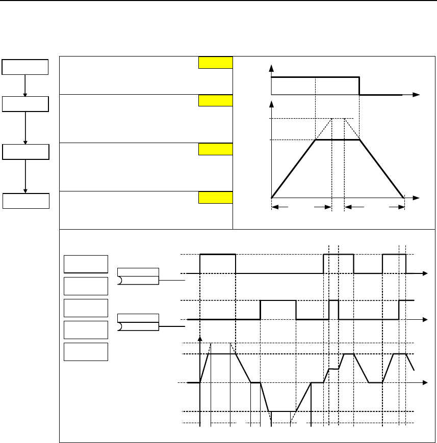
6 Commissioning Issue 10/06
MICROMASTER 440
42 Operating Instructions (Compact)
6.4.10 JOG
JOG frequency right
Frequency in Hz when the motor is
rotating clockwise in the jog mode.
JOG frequency left
Frequency in Hz when the motor is
rotating counter-clockwise in the jog
mode.
JOG ramp-up time
Ramp-up time in s from 0 to the
maximum frequency (p1082). JOG ramp-
up is limited by p1058 or p1059.
JOG ramp-down time
Ramp-down time in s from the maximum
frequency (p1082) to 0.
p1082
(fmax)
p1058
t
p1060 p1061
f
JOG
Tippen rechts
f
P1058
P1059
A0923 A0923
P1060
P1060
(0)
P1055
(0)
P1056
"1"
"0"
"1"
"0"
t
t
t
P1061
DIN
BOP
USS
BOP link
USS
COM link
CB
COM link
Tippen links
P1082
-P1082
P1061
P1058 = ...
P1059 = ...
P1060 = ...
P1061 = ...
5.00 Hz
5.00 Hz
10.00 s
10.00 s
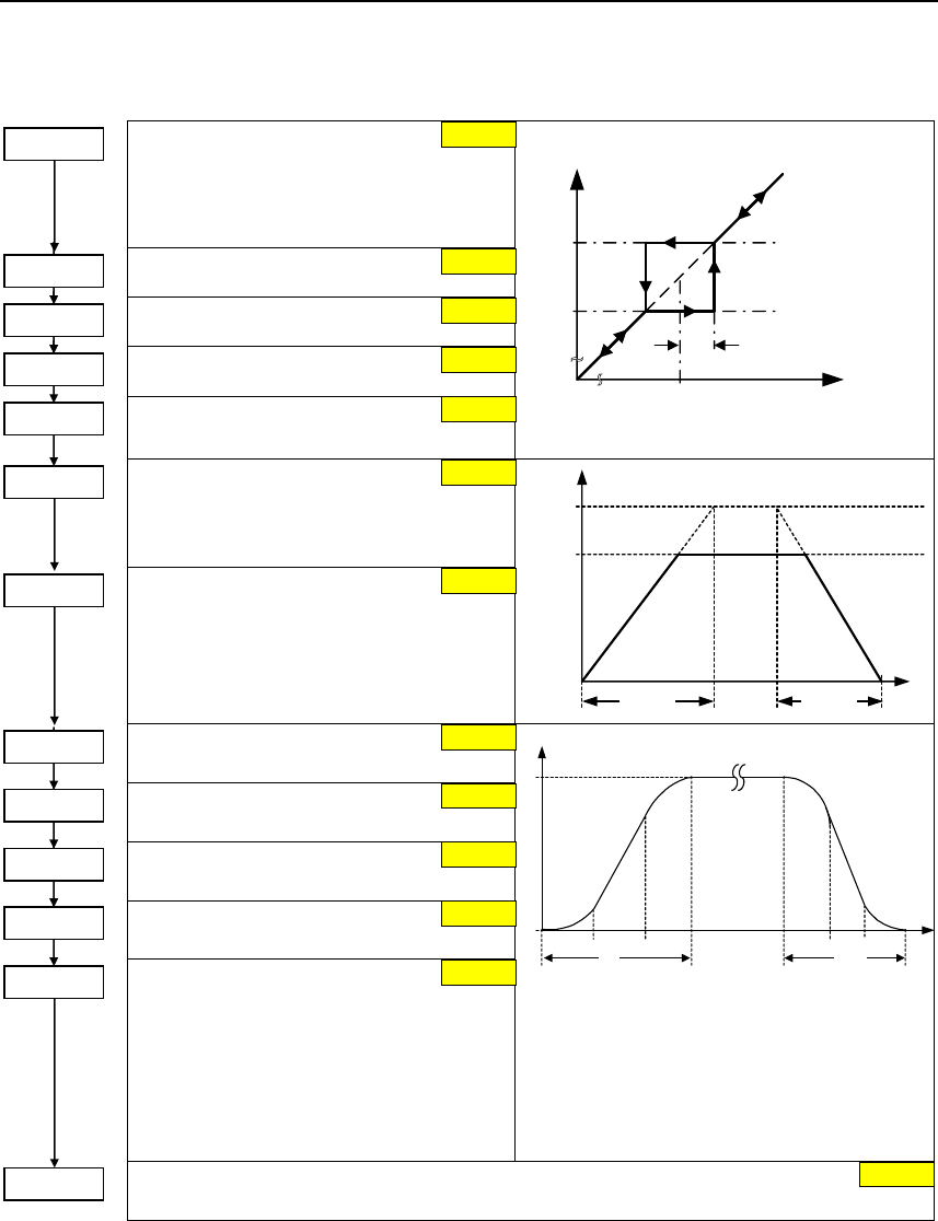
Issue 10/06 6 Commissioning
MICROMASTER 440
Operating Instructions (Compact) 43
6.4.11 Ramp function generator (RFG)
Skip frequency 1 (entered in Hz)
Defines skip frequency 1, which avoids
effects of mechanical resonance and
suppresses frequencies within +/- p1101
(skip frequency bandwidth).
Skip frequency 2
Skip frequency 3
Skip frequency 4
Skip frequency bandwidth
(entered in Hz)
p1101
p1091 fin
fout
Skip frequency
bandwidth
Skip frequency
Ramp-up time
(enters the accelerating time in s)
Ramp-down time
(enters the deceleration time in s)
f
p1082
(fmax)
f1
t
p1120 p1121
Rump-up initial rounding time
(entered in s)
Ramp-up final rounding time
(entered in s)
Rump-down initial rounding time
(entered in s)
Ramp-down final rounding time
(entered in s)
Rounding type
0 Continuous smoothing
1 Discontinuous smoothing
P1133P1132P1131P1130 t
f
f2
f1
tup tdown
The rounding times are recommended as
abrupt responses can be avoided therefore
reducing stress and damage to the mechanical
system.
The ramp-up and ramp-down times are
extended by the component of the rounding
ramps.
OFF3 ramp-down time
Defines ramp-down time from maximum frequency to standstill for OFF3 command.
2.00 Hz
0.00 Hz
0.00 Hz
0.00 Hz
0.00 Hz
P1091 = ...
P1092 = ...
P1093 = ...
P1094 = ...
P1101 = ...
P1120 = ...
P1121 = ...
P1130 = ...
P1131 = ...
P1132 = ...
P1133 = ...
P1134 = ...
P1135 = ...
10.00 s
10.00 s
0.00 s
0.00 s
0.00 s
0
5.00 s
0.00 s
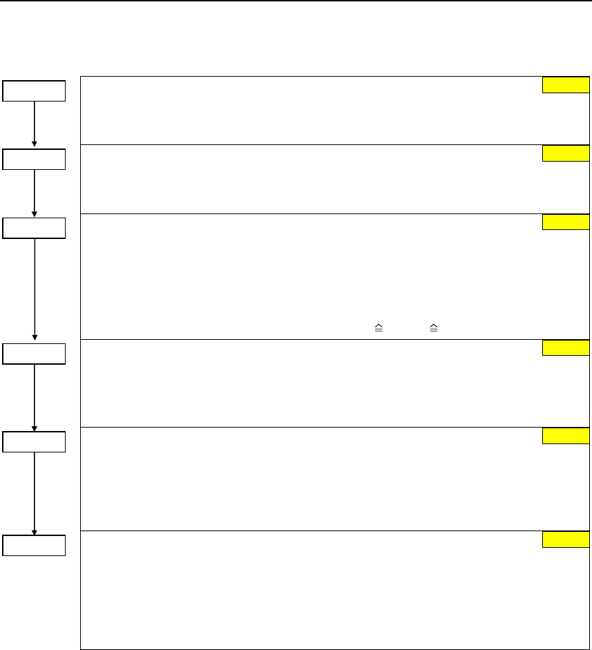
6 Commissioning Issue 10/06
MICROMASTER 440
44 Operating Instructions (Compact)
6.4.12 Reference/limit frequencies
Min. frequency (entered in Hz)
Sets minimum motor frequency [Hz] at which motor will run irrespective of frequency
setpoint. If the setpoint falls below the value of p1080, then the output frequency is set to
p1080 taking into account the sign.
Max. frequency (entered in Hz)
Sets maximum motor frequency [Hz] at which motor will run irrespective of the frequency
setpoint. If the setpoint exceeds the value p1082, then the output frequency is limited. The
value set here is valid for both clockwise and anticlockwise rotation.
Reference frequency (entered in Hz)
The reference frequency in Hertz corresponds to a value of 100 %.
This setting should be changed if a maximum frequency of higher than 50 Hz is required.
It is automatically changed to 60 Hz if the standard 60 Hz frequency was selected using
p0100.
NOTE
This reference frequency effects the setpoint frequency as both the frequency setpoints via
USS as well as via PROFIBUS (FB100) (4000H hex 100 % p2000) refer to this value.
Reference voltage (entered in V)
The reference voltage in Volt (output voltage) corresponds to a value of 100 %.
NOTE
This setting should only be changed if it is necessary to output the voltage with a different
scaling.
Reference current (entered in A)
The reference current in Amps (output current) corresponds to a value of 100 %. Factory
setting = 200 % of the rated motor current (P0305).
NOTE
This setting should only be changed if it is necessary to output the current with a different
scaling.
Reference torque (entered in Nm)
The reference torque in Nm corresponds to a value of 100 %. Factory setting = 200 % of
the rated motor torque at a constant motor torque determined from the appropriate motor
data.
NOTE
This setting should only be changed if it is necessary to output the torque with a different
scaling.
1000 V
P2001 = ...
0.10 A
P2002 = ...
0.12 Mn
P2003 = ...
P2000 = ...
P1082 = ...
P1080 = ... 0.00 Hz
50.00 Hz
50.00 Hz
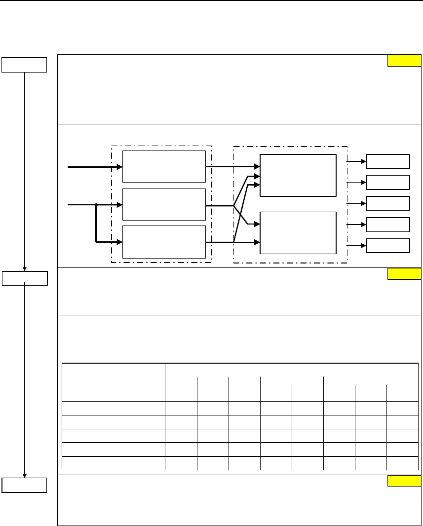
Issue 10/06 6 Commissioning
MICROMASTER 440
Operating Instructions (Compact) 45
6.4.13 Inverter protection
Inverter overload reaction
Selects reaction of inverter to an internal over-temperature.
0 Reduce output frequency
1 Trip (F0004 / F0005)
2 Reduce pulse frequency and output frequency
3 Reduce pulse frequency then trip (F0004)
A0504
A0505
A0506
F0004
F0005
Inverter overload reaction
P0290
f_pulse
control
i_max control
(U/f)
Current control
(SLVC, VC)
r0036
r0037 Heat sink
temperature
P0292
IGBT
temperature
P0292
i2t
P0294
Inverter monitoring
P0292 =...
Inverter temperature warning
Defines the temperature difference (in ºC) between the Overtemperature trip threshold and
the warning threshold of the inverter. The trip threshold is stored internally by the inverter
and cannot be changed by the user.
Temperature MM440, Frame Size
110 °C
140 °C
95 °C
145 °C
A - C D - F
Input rectifier -
Cooling air -
Control board -
80 °C
145 °C
F
600 V
-
-
-
-
-
-
88 °C
150 °C
FX
95 kW
CT
91 °C
150 °C
110 kW
CT
75 °C
55 °C
75 °C
55 °C
65 °C 65 °C
80 °C
145 °C
GX
132 kW
CT
82 °C
147 °C
160 kW
CT
75 °C
55 °C
75 °C
55 °C
65 °C 65 °C
88 °C
150 °C
200 kW
CT
75 °C
50 °C
65 °C
IGBT
Heat sink
trip
T = T - P0292
Temperature warning threshold of inverter T_warn
Temperature shutdown threshold of inverter T_trip
warn
Delay, fan shutdown
This defines the delay time in seconds between powering down the frequency inverter and
then powering-down the fan. A setting of 0 means that the fan is immediately shut down
(powered-down).
6.4.14 Motor protection
In addition to the thermal motor protection, the motor temperature is also included
in the adaptation of the motor equivalent circuit diagram data. Especially for a high
thermal motor load, this adaptation has a significant influence on the degree of
stability of the closed-loop vector control. For MM440 the motor temperature can
only be measured using a KTY84 sensor. For the parameter setting P0601 = 0,1,
the motor temperature is calculated / estimated using the thermal motor model.
If the frequency inverter is permanently supplied with an external 24V voltage, then
the motor temperature is also tracked/corrected using the motor temperature time
constant – even when the line supply voltage is switched-out.
0 s
P0295 = ...
P0290 = ... 0
15 °C
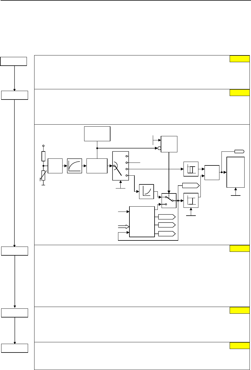
6 Commissioning Issue 10/06
MICROMASTER 440
46 Operating Instructions (Compact)
A high thermal motor load and when the line supply is frequently switched-
out/switched-in requires, for closed-loop vector control
− that a KTY84 sensor is used, or
− an external 24V power supply voltage is connected
Motor cooling (Selects motor cooling system used)
0 Self-cooled: Using shaft mounted fan attached to motor
1 Force-cooled: Using separately powered cooling fan
2 Self-cooled and internal fan
3 Force-cooled and internal fan
Motor temperature sensor
Selects the motor temperature sensor.
0 No sensor
1 PTC thermistor (PTC)
2 KTY84
r0631
ADC
5 V
Signal
loss
detection
T1 = 4 s
2
1
No sensor
PTC
KTY
0
P0604
Fault
F0015 &
P0601 = 2
Thermal
motor
model
r0633
r0632
r0035
1≥Motor
temp.
reaction
P0610
P0601
Equivalent
circuit data
PV,mot
Power dissipation
V
ϑ
0
1
0
1
r0052
Bit13
PTC
KTY
Alarm threshold, motor overtemperature
Defines the alarm threshold for the motor overtemperature protection. This threshold, where
either a shutdown (trip) or Imax reduction is initiated (P0610) always lies 10 % above the
alarm threshold.
ϑwarn :
ϑtrip :Trip threshold (max. permissible temperature)
P0604 1.1 1.1 warntrip ⋅=⋅= ϑϑ Warning threshold (P0604)
The alarm threshold should be at least 40 °C greater than the ambient temperature P0625.
P0604 ≥ P0625 + 40 °C
Inverter temperature reaction
Defines reaction when motor temperature reaches warning threshold.
0 No reaction, warning only
1 Warning and Imax reduction (results in a lower output frequency)
2 Warning and trip (F0011)
Motor overload factor [%]
Defines motor overload current limit in [%] relative to p0305 (rated motor current). Limited to
maximum inverter current or to 400 % of rated motor current (p0305), whichever is the
lower.
2
0
P0601 = ...
P0604 = ... 130.0 °C
P0610 = ...
0
P0335 = ...
P0640 = ... 150.0 %
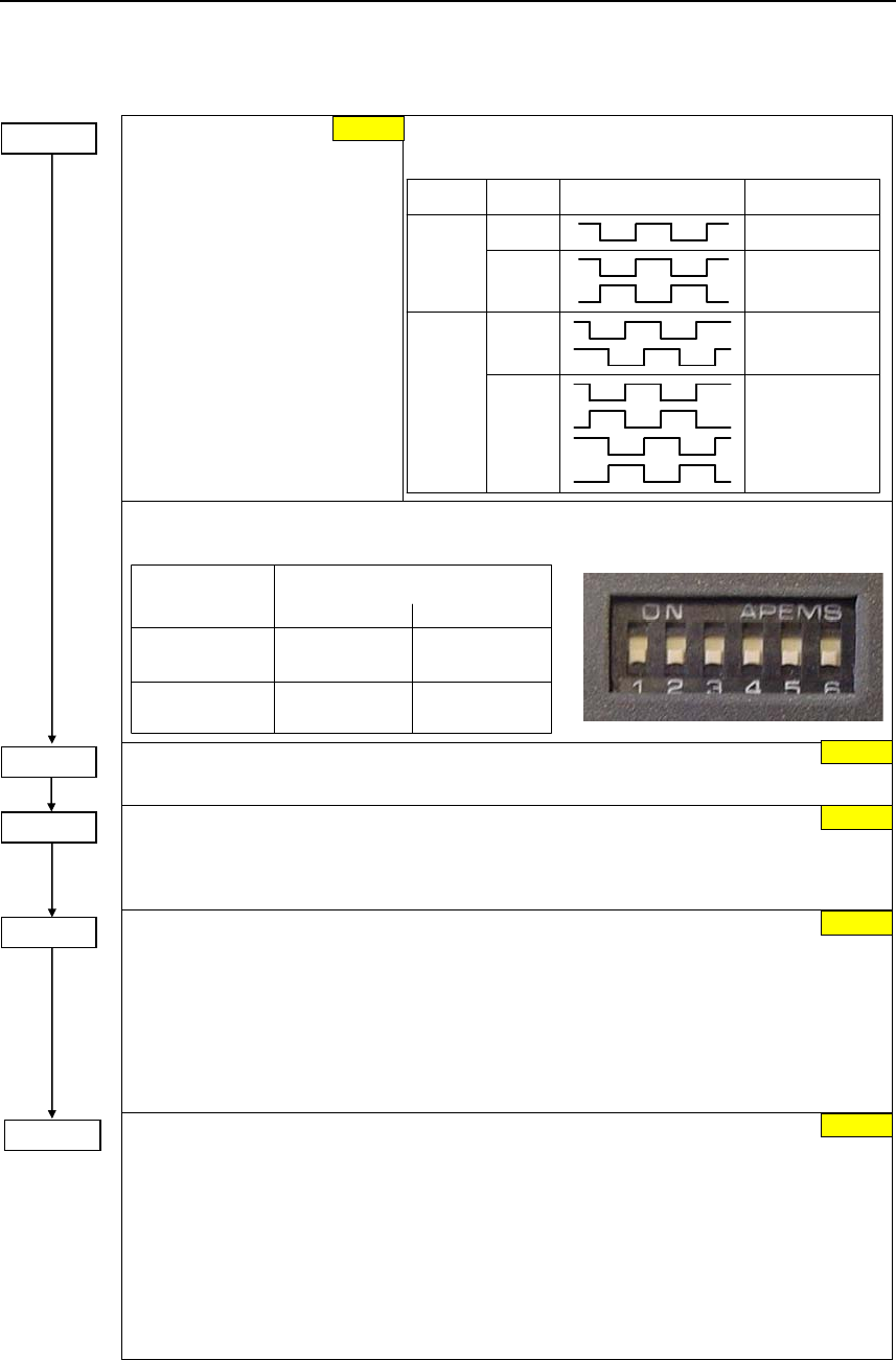
Issue 10/06 6 Commissioning
MICROMASTER 440
Operating Instructions (Compact) 47
6.4.15 Encoder
Select encoder type
Selects the encoder type.
0 Inhibited
1 Single-track pulse encoder
2 Two-track pulse encoder
For hoisting gear applications
(4-quadrant operation!), a
2-track encoder must be used.
The table shows the values of P0400 as a function of the
number of tracks:
Parameter Terminal Track Encoder output
single ended
P0400 = 1 A
differential
A
AN
A
B
A
AN
B
BN
differential
P0400 = 2 single ended
In order to guarantee reliable operation, the DIP switches on the encoder module must be
set as follows depending on the encoder type (TTL, HTL) and encoder output:
Type
differential
TTL
HTL
111111 010101
101010 000000
single ended
Output
(e.g.
(e.g.
1XP8001-1)
1XP8001-2)
Encoder pulses per revolution
Specifies the number of encoder pulses per revolution.
Reaction on speed signal loss
Defines the calculation method.
0 No transition
1 Transition into SLVC
Allowed speed difference
Parameter P0492 defines the frequency threshold for the loss of the encoder signal
(fault F0090).
CAUTION
p0492 = 0 (no monitoring function):
With p0492 = 0, the loss of the encoder signal at high frequency as well as at a low
frequency is de-activated. As a result, the system does not monitor for the loss of the
encoder signal.
P0494 =...
Delay speed loss reaction
P0492 is used to detect the loss of the encoder signal at low frequencies. If the motor
speed is less than the value of P0492, the loss of the encoder signal is determined using an
appropriate algorithm. P0494 defines the delay time between detecting the loss of the
speed signal and initiating the appropriate response.
CAUTION
p0494 = 0 (no monitoring function):
With p0494 = 0, the loss of the encoder signal at low frequencies is de-activated. As a
result, at these frequencies, a loss of the encoder signal is not detected (loss of the
encoder signal at high frequency remains active as long as parameter p0492 > 0).
1024
0
10.00 Hz
10 ms
P0408 =...
P0491 =...
P0492 =...
0
P0400 =...
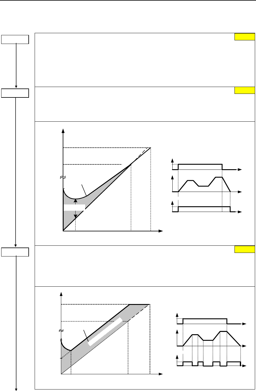
6 Commissioning Issue 10/06
MICROMASTER 440
48 Operating Instructions (Compact)
6.4.16 V/f control
P1300 =...
Control mode
The control type is selected using this parameter. For the "V/f characteristic" control type,
the ratio between the frequency inverter output voltage and the frequency inverter output
frequency is defined.
0 V/f with linear
1 V/f with FCC
2 V/f with parabolic characteristic
3 V/f with programmable characteristic (→ P1320 – P1325)
P1310 =...
Continuous boost (entered in %)
Voltage boost as a % relative to P0305 (rated motor current) and P0350 (stator resistance).
P1310 is valid for all V/f versions (refer to P1300). At low output frequencies, the effective
resistance values of the winding can no longer be neglected in order to maintain the motor
flux.
f
Linear V/f
OFF
ON
t
t
⏐f⏐
P1310 active
t0
1
Validity range
Vmax
Vn
(P0304)
VConBoost,100
0fn
(P0310)
f max
(P1082)
V
fBoost,end
(P1316)
Boost
Output voltage
actual V
Normal V/f
(P1300 = 0)
VConBoost,50
Boost voltage
P1311 =...
Acceleration boost (entered in %)
Voltage boost for accelerating/braking as a % relative to P0305 and P0350. P1311 only
results in a voltage boost when ramping-up/ramp-down and generates an additional torque
for accelerating/braking. Contrary to parameter P1312, that is only active for the 1st
acceleration operation after the ON command, P1311 is effective each time that the drive
accelerates or brakes.
Vmax
Vn
(P0304)
VAccBoost,100
0fn
(P0310)
fmax
(P1082)
f
V
fBoost,end
(P1316)
VAccBoost,50
Boost
U/f normal
(P1300 = 0)
V ist
Ausgangsspannung
OFF
ON
t
t
⏐f⏐
P1311 aktiv
t0
1
Boost-Spannung Gültigkeitsbereich
0
50.00 %
0.0 %
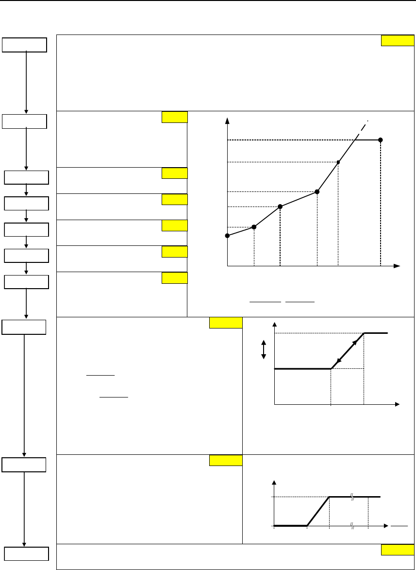
Issue 10/06 6 Commissioning
MICROMASTER 440
Operating Instructions (Compact) 49
P1312 =...
Starting boost (entered in %)
Voltage boost when starting (after an ON command) when using the linear or square-law
V/f characteristic as a % relative to P0305 (rated motor current) or P0350 (stator
resistance). The voltage boost remains active until
1) the setpoint is reached for the first time and
2) the setpoint is reduced to a value that is less than the instantaneous ramp-function
generator output.
P1320 =...
Programmable V/f freq.
coord. 1
Sets V/f coordinates
(P1320/1321 to P1324/1325) to
define V/f characteristic.
P1321 =... Programmable. V/f volt.
coord. 1
P1322 =... Programmable V/f freq.
coord. 2
P1323 =... Programmable V/f volt.
coord. 2
P1324 =... Programmable U/f Freq.
coord. 3
P1325 =... Programmable V/f volt.
coord. 3
]P0304[V
100[%]
r0395[%]
100[%]
P1310[%]
P1310[V] ⋅⋅=
V
P1325
f1
P1320
fmax
P1082
Vmax
r0071
Vn
P0304
P1323
P1321
P1310
f0
0 Hz
f2
P1322
f3
P1324
fn
P0310
f
Vmax = f(Vdc, Mmax)
Starting frequency for FCC
(entered as a %)
Defines the FCC starting frequency as a
function of the rated motor frequency (P0310).
1333P
100
P0310
fFCC ⋅=
()
%61333P
100
P0310
fHysFCC +⋅=
+
NOTE
The constant voltage boost P1310 is
continually decreased analog to switching-in
FCC.
fFCC
f
fFCC+Hys
FCC
V/f
Switch-over
Slip compensation
(entered in %)
Dynamically adjusts output frequency of
inverter so that motor speed is kept constant
independent of motor load.
f
f
N
out
6 % 10 %
P1335
100 %
%
Range of slip compensation :
P1338 =... Resonance damping gain V/f
Defines resonance damping gain for V/f.
P1335 = ... 0.0 %
P1333 = ... 10.0 %
0.0 %
0.0 Hz
0.0 Hz
0.0 Hz
0.0 Hz
0.0 Hz
0.0 Hz
0.00
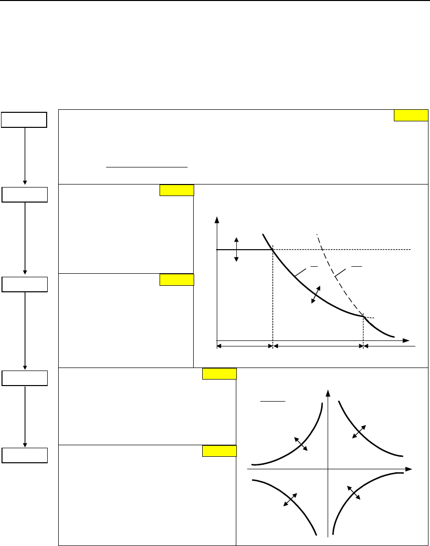
6 Commissioning Issue 10/06
MICROMASTER 440
50 Operating Instructions (Compact)
6.4.17 Field-orientated control
Limitations
To avoid a premature limitation the limits of the torque (P1520, P1521) and power
(P1530, P1531) should be set to the maximum value, if the application allows it.
Motor overload factor [%]
Defines motor overload current limit in [%] relative to p0305 (rated motor current). Limited to
maximum inverter current or to 400 % of rated motor current (p0305), whichever is the
lower.
100
p0305
p0305) 4 (r0209, min
p0640max ⋅
⋅
=
CO: Upper torque limit
Specifies fixed value for upper
torque limitation.
P1520 max
P1520 def r0333 1.5 ⋅=
r0333 4 ⋅±=
CO: Lower torque limit
Enters fixed value of lower
torque limitation.
P1521max
P1521def r0333 1.5 ⋅−=
r0333 4 ⋅±=
f
1
~
Torque limitation
Resultant
torque limit
Power
limitation
|fact
r1526
r1527
Stall
limitation
p1530
p1531
f
1
~ 2
Constant
torque fstall
Constant
power
|
|M|
Stall
power
Motoring power limitation
Defines fixed value for the max. permissible
motoring active power.
P1530 def
P1530 max 0307P3 ⋅=
0307P5.2 ⋅=
Regenerative power limitation
Enters fixed value for the max. permissible
regenerative active power
P1531max P0307 3- ⋅=
P1531def P0307 2.5- ⋅=
M
f
f 2
P
M ⋅π⋅
=
Power limitation (motoring, regenerative)
p1530
p1531
p1530
p1531
p0640 = ... 150.0 %
P1520 = ...
P1521 = ...
P1530 = ...
P1531 = ...
FC-spec.
FC-spec.
FC-spec.
FC-spec.
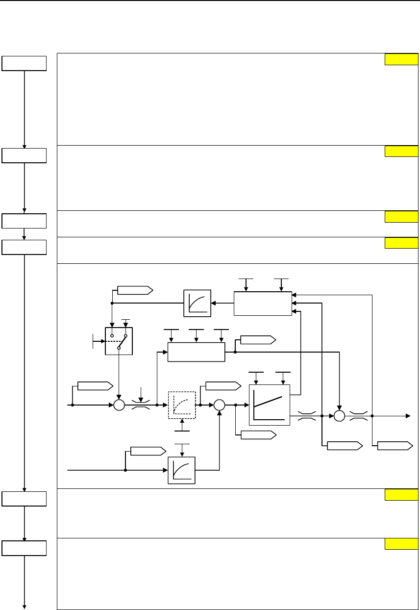
Issue 10/06 6 Commissioning
MICROMASTER 440
Operating Instructions (Compact) 51
6.4.17.1 Sensorless vector control (SLVC)
Control mode
20 Closed-loop Vector control – speed without encoder
SLVC can provide excellent performance for the following types of application:
• Applications which require high torque performance
• Applications which require fast respond to shock loading
• Applications which require torque holding while passing through 0 Hz
• Applications which require very accurate speed holding
• Applications which require motor pull out protection
Filter time for act. freq (SLVC)
Sets time constant of PT1 filter to filter the frequency deviation of speed controller in
operation mode SLVC (sensorless vector control).
Decreasing the value leads to a higher dynamic of the speed regulation. Instability is seen
if the value is to low (or to high). p1452 = 2 can be set for most applications.
Gain speed controller (SLVC)
Enters gain of speed controller for sensorless vector control (SLVC).
Integral time n-ctrl. (SLVC)
Enters integral time of speed controller for sensorless vector control (SLVC).
r1438
r1084
–
Kp Tn
p1470p1472
r0064
p1496p0341p0342
p1489
p1488
p1452
Act. frequency
from observer model
r0063
r1170
–
Precontrol
Freq. setpoint Torque
setpoint
Droop
150 ms
r1518
p1492
r1490
0
1
0
r0079r1508
*)
*) only active, if pre-control is enabled
(p1496 > 0)
Continuous torque boost (SLVC)
Sets continuous torque boost in lower frequency range of SLVC (sensorless vector control).
Value is entered in [%] relative to rated motor torque r0333.
p1610 is only effective in the open-loop mode between 0 Hz and approx. ±p1755.
Acc. torque boost (SLVC)
Sets acceleration torque boost in lower frequency range of SLVC (sensorless vector
control). Value is entered in [%] relative to rated motor torque r0333.
p1611 is only effective in the open-loop mode between 0 Hz and approx. ±p1755.
In opposite to p1610 the acceleration torque boost p1611 is only in operation during
acceleration/deceleration.
0
P1300=20
P1452 = ...
P1470 = ...
P1472 = ...
P1610 = ...
P1611 = ...
4 ms
3.0
400 ms
50.0 %
0.0 %
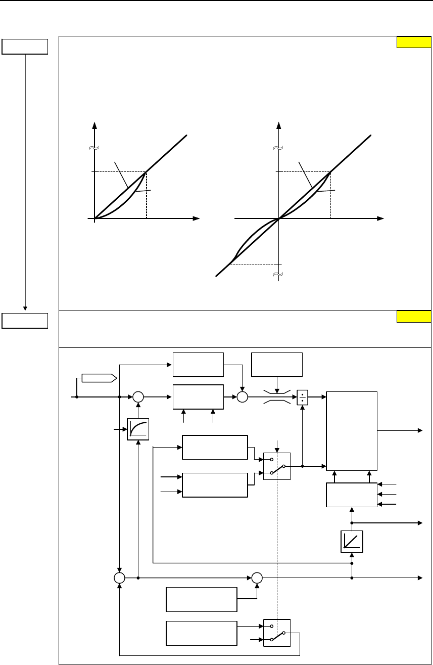
6 Commissioning Issue 10/06
MICROMASTER 440
52 Operating Instructions (Compact)
Control word of motor model
This parameter controls the operation of the sensorless vector control (SLVC) at very low
frequencies. This therefore includes the following conditions:
Bit00 Start SLVC open loop 0 NO 1 YES
(Operation directly after an ON command)
Bit01 Zero crossing SLVC open loop 0 NO 1 YES
(zero crossing)
f
t
p1755
Closed loop
Open loop
Start f
t
Closed loop
Open loop
Zero crossing
p1755
p1755
For most applications the setting of parameter p1750 = 0 gives the best result at low
frequency.
Start-freq. motor model (SLVC)
Enter the start frequency of sensorless vector control (SLVC), thereby SLVC switches over
from open-loop to closed-loop at that frequency.
.
.
r0062
Speed
controller
Pre-
control
Torque
limitation
Current
controller
isq
−
open/closed
loop
Flux setpoint
closed loop
Flux setpoint
open loop
isd
p1610
p1611
−
+
+
0
Act. output
voltage
Act. output
frequency
Act. frequency
Current
measurement
Act. angle
Observer model
closed loop
Slip
Frequency
setpoint
iu
iw
iv
p1452 p1470 p1472
p1750/p1755
P1750 = ...
P1755 = ...
1
5.0 Hz
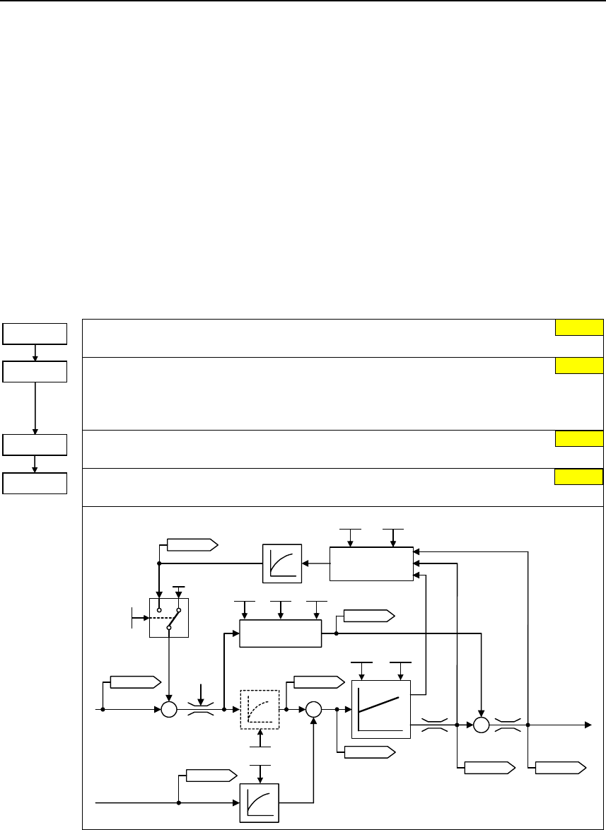
Issue 10/06 6 Commissioning
MICROMASTER 440
Operating Instructions (Compact) 53
6.4.17.2 Vector control with encoder (VC)
¾ First step: Parameterizing the speed encoder (refer to Section 6.4.15)
¾ When commissioning Vector Control with encoder-feedback (VC), the drive
should be configured for V/f mode (see p1300) first. Run the drive and compare
r0061 with r0021 that should agree in:
− sign
− magnitude (with a deviation of only a few percent)
Only if both criteria are fulfilled, change p1300 and select VC (p1300 = 21/23).
¾ Encoder loss detection must be disabled (p0492 = 0) if torque is limited
externally., e.g.:
− closed-loop winder control
− traversing / moving to a fixed endstop
− when using a mechanical brake
Control mode
21 Vector control with sensor
Filter time for act. speed
Sets time constant of PT1 filter to smooth actual speed of speed controller.
Decreasing the value leads to a higher dynamic of the speed regulation. Instability is seen if
the value is to low. p1442 = 2 can be set for most applications.
Gain speed controller
Enters gain of speed controller.
Integral time speed controller
Enters integral time of speed controller.
Precontrol
Freq. setpoint
r1438
r1084
–
Kp Tn
p1460p1462
r0064
Torque
setpoint
p1496p0341p0342
p1442
Act. frequency
from encoder
r0063
r1170
–
p1492
p1489
p1488
Droop
r1490 150 ms
r1518
0
1
0
r0079r1508
*) only active, if pre-control is enabled
(p1496 > 0)
*)
P1300=21 0
4 ms
3.0
P1442 = ...
P1460 = ...
P1462 = ... 400 ms
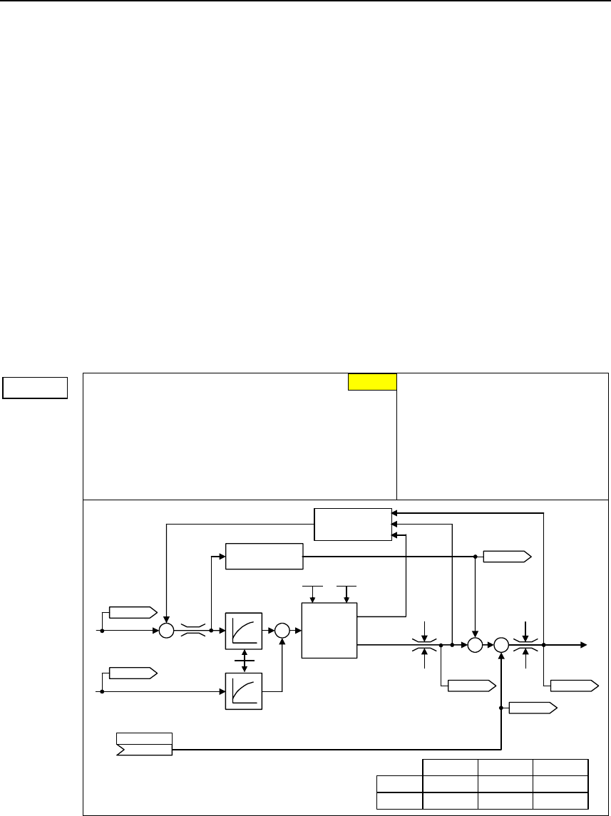
6 Commissioning Issue 10/06
MICROMASTER 440
54 Operating Instructions (Compact)
Supplementary torque setpoint
¾ In the vector mode – with / without encoder – the speed controller can be
subordinate to a constant or variable supplementary torque.
¾ The supplementary setpoint can be used to advantage for hoisting gear with low
intrinsic friction when starting in the vertical direction. The supplementary torque
setpoint must always be impressed in the hoisting (raising) direction (please
observe the sign!). As a result of the supplementary torque, also when lowering,
a slip is immediately established that has a stabilizing effect on the closed-loop
control (there is no significant load sag).
¾ The sign of the supplementary torque setpoint can be determined as follows in
the commissioning phase with the appropriate care and taking into account all
of the relevant safety regulations:
Hoist (raise) a minimum load using the hoisting gear and read-out the sign from
parameter r0079 (the sign of r0079 corresponds to the sign of the
supplementary torque setpoint).
¾ An empirical value of approx. 40 % of the rated motor torque r0333 has lead to
good results for existing hoisting gear
(carefully observe the sign!).
CI: Supplementary torque setpoint
Selects the source of the supplementary torque
setpoint.
Frequent settings:
2889 Fixed setpoint 1 as a %
2890 Fixed setpoint 2 as a %
755.0 Analog input 1
755.1 Analog input 2
2015. 2 USS (BOP link)
2018. 2 USS (COM link)
2050. 2 CB (e.g. PROFIBUS)
–
Torque
setpoint
Droop
Act. frequency
–r1538 r1538
r1539 r1539
CI: Add. trq. setp
(0:0)
P1511.C
Pre-
control
Freq. setpoint
PI
Speed
controller
SLVC:
VC:
P1452
P1442
P1470
P1460
P1472
P1462
Ti
KpTn
TiKpTn
*)
*) only active, if pre-control is enabled
(P1496 > 0)
r0079r1508
r0063
r1170
r1515
r1518
P1511=... 0:0
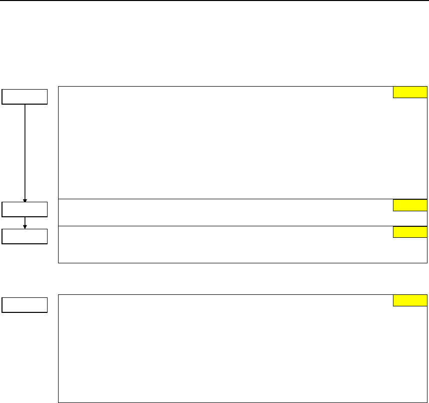
Issue 10/06 6 Commissioning
MICROMASTER 440
Operating Instructions (Compact) 55
6.4.18 Converter-specific Functions
6.4.18.1 Flying start
Flying start
Starts inverter onto a spinning motor by rapidly changing the output frequency of the
inverter until the actual motor speed has been found.
0 Flying start disabled
1 Flying start is always active, start in direction of setpoint
2 Flying start is active if power on, fault, OFF2, start in direction of setpoint
3 Flying start is active if fault, OFF2, start in direction of setpoint
4 Flying start is always active, only in direction of setpoint
5 Flying start is active if power on, fault, OFF2, only in direction of setpoint
6 Flying start is active if fault, OFF2, only in direction of setpoint
Motor-current: Flying start (entered in %)
Defines search current used for flying start.
Search rate: Flying start (entered in %)
Sets factor by which the output frequency changes during flying start to synchronize with
turning motor.
6.4.18.2 Automatic restart
Automatic restart
Configures automatic restart function.
0 Disabled
1 Trip reset after power on
2 Restart after mains blackout
3 Restart after mains brownout or fault
4 Restart after mains brownout
5 Restart after mains blackout and fault
6 Restart after mains brown/blackout or fault
P1210 = ... 1
0
100 %
100 %
P1200 = ...
P1202 = ...
P1203 = ?

6 Commissioning Issue 10/06
MICROMASTER 440
56 Operating Instructions (Compact)
6.4.18.3 Holding brake
¾ Series / commissioning for hazardous loads
− lower the load to the floor
− when replacing the frequency inverter, prevent (inhibit) the frequency
inverter from controlling the motor holding brake (MHB)
− secure the load or inhibit the motor holding brake control (so that the brake
cannot be controlled) and then – and only then – carry-out quick
commissioning / parameter download using the PC-based tool (e.g.
STARTER, AOP)
¾ Parameterize the weight equalization for hoisting gear applications
− magnetizing time P0346 greater than zero
− min. frequency P1080 should approximately correspond to the motor slip
r0330 (P1080 ≈ r0330)
− adapt the voltage boost to the load
a) V/f (P1300 = 0 ...3): P1310, P1311
b) SLVC (P1300 =20): P1610, P1611
¾ It is not sufficient to just select the status signal r0052 bit 12 "motor holding
brake active" in P0731 – P0733. In order to activate the motor holding brake, in
addition, parameter P1215 must be set to 1.
¾ It is not permissible to use the motor holding brake as operating brake. The
reason for this is that the brake is generally only dimensioned/designed for a
limited number of emergency braking operations.
¾ The brake closing / opening times can be taken from the appropriate manual.
The following typical values have been taken from Motor Catalog M11
2003/2004, Page 2/51:
Motor size Brake type Opening time [ms] Closing time [ms]
63 2LM8 005-1NAxx 25 56
71 2LM8 005-2NAxx 25 56
80 2LM8 010-3NAxx 26 70
90 2LM8 020-4NAxx 37 90
100 2LM8 040-5NAxx 43 140
112 2LM8 060-6NAxx 60 210
132 2LM8 100-7NAxx 50 270
160 2LM8 260-8NAxx 165 340
180 2LM8 315-0NAxx 152 410
200
225 2LM8 400-0NAxx 230 390
Holding brake enable
Enables/disables holding brake function (MHB).
0 Motor holding brake disabled
1 Motor holding brake enabled
NOTE
The following must apply when controlling the brake relay via a digital output: P0731 = 52.C
(= 52.12) (refer to Section 6.4.4 "Digital outputs (DOUT)").
0
P1215 =...
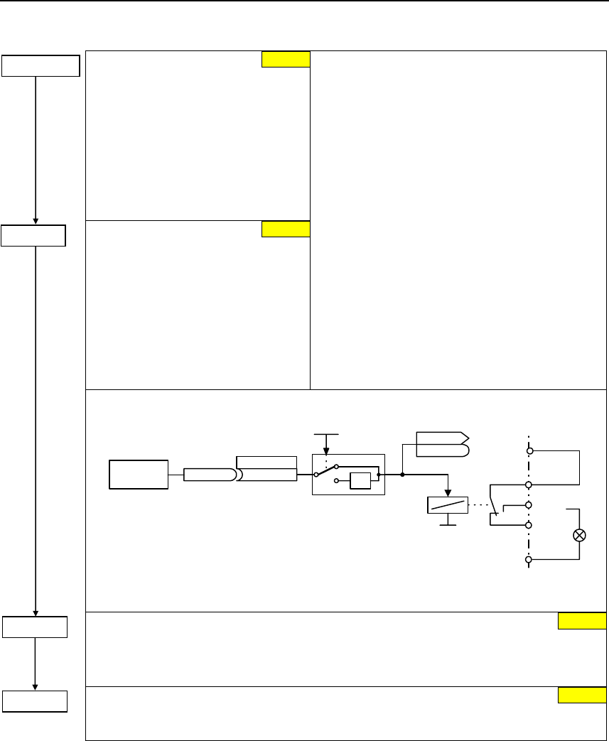
Issue 10/06 6 Commissioning
MICROMASTER 440
Operating Instructions (Compact) 57
BI: Fct digital output 1
Defines the source for digital output 1.
NOTE
The brake relay can also be controlled
from another digital output (if this is
available) or using a distributed I/O
module. Analog to DOUT 1, it should
be guaranteed that the I/Os are
controlled by the status bit “MHB
active”.
Inverting digital
outputs
This parameter allows the signals
to be output to be inverted.
Frequent settings:
52.0 Ready to power-up 0 Closed
52.1 Ready 0 Closed
52.2 Drive operational 0 Closed
52.3 Fault present 0 Closed
52.4 OFF2 active (present) 1 Closed
52.5 OFF3 active (present) 1 Closed
52.6 Power-on inhibit active (present) 0 Closed
52.7 Alarm active (present) 0 Closed
52.8 Deviation, setpoint/actual value 1 Closed
52.9 PZD / PLC control 0 Closed
52.A Maximum frequency reached 0 Closed
52.B Alarm: Motor current limit 1 Closed
52.C Motor holding brake active 0 Closed
52.D Motor overload 1 Closed
52.E Motor dir. of rotation, clockwise 0 Closed
52.F Frequency inverter overload 1 Closed
53.0 DC brake active 0 Closed
53.1 Actual freq. f_act > P2167 (f_off) 0 Closed
:
:
(52:3)
BI: Fct. of DOUT 1
P0731.C
-1
0
1
Invert DOUTs
0 ... 7
P0748 (0) CO/BO: State DOUTs
r0747
r0747
Kl.20
Kl.18
.0
Function
xxxx.y rxxxx.y
P0731 = xxxx.y
DOUT channel
Relay :
DC 30 V / 5 A
AC 250 V / 2 A Kl.28
Kl.9
int. 24 V
max. 100 mA
NO
COM
NC
Kl.19
or
Text
- max. opening / closing time
5 / 10 ms
Holding brake release delay (entered in s)
Defines the time interval during which the frequency inverter runs with the min. frequency
p1080 after magnetizing, before the ramp-up starts.
P1216 ≥ brake opening time + relay opening time
Holding time after ramp-down (entered in s)
Defines time for which inverter runs at minimum frequency (p1080) after ramping down.
P1217 ≥ brake closing time + relay closing time
P1217 = ... 1.0 s
P1216 = ... 1.0 s
0
52.3
P0731=52.C
P0748 = 0

6 Commissioning Issue 10/06
MICROMASTER 440
58 Operating Instructions (Compact)
6.4.18.4 DC brake
BI: Enabling the DC brake
This enables DC braking using a signal that was used from an external source. The
function remains active as long as the external input signal is active. DC braking causes
the motor to quickly stop by injecting a DC current
⏐f⏐
P0347
f*
i
t
t
t
1
0
f_act
DC braking
0
1
DC braking active
r0053
Bit00
t
f_set
(0:0)
P1230.C
BI: Enable DC brk.
Note: DC brake can be applied in drive states r0002 = 1, 4, 5
DC braking current (entered in %)
Defines level of DC current in [%] relative to rated motor current (P0305).
Duration of DC braking (entered in s)
Defines duration for which DC injection braking is to be active following an OFF1 or OFF3
command.
t
P1234
OFF1/OFF3
ON
t
t
⏐f⏐
P1233
1
tt
P0347
OFF2
DC braking
OFF2
0
1
DC braking active
r0053
Bit00
P1230 = ...
100 %
0 s
P1232 =...
P1233 =...
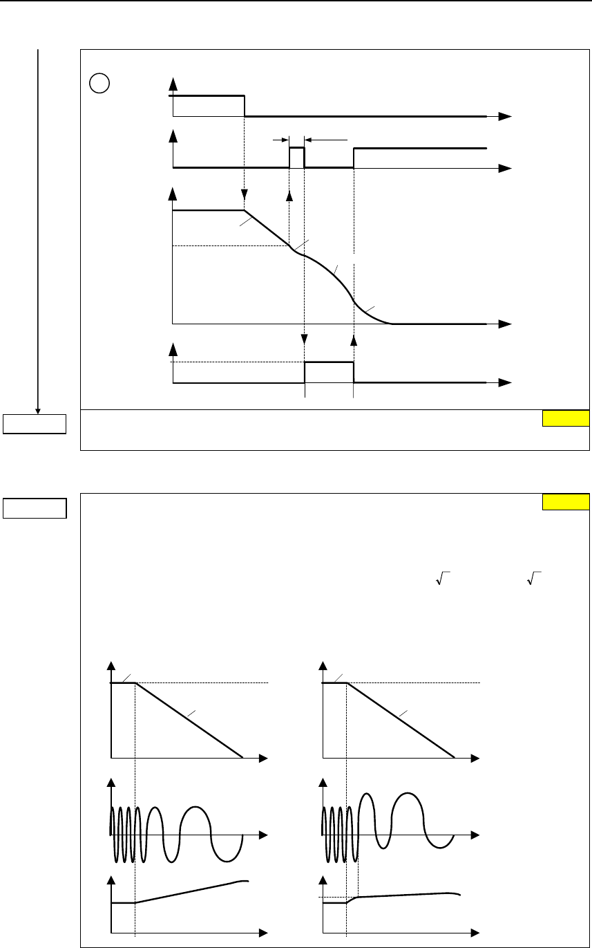
Issue 10/06 6 Commissioning
MICROMASTER 440
Operating Instructions (Compact) 59
t
P1234
OFF1/OFF3
ON
t
t
⏐f⏐
OFF ramp
P1233
2
t
OFF2
t
t
P0347
OFF2
OFF2
DC braking
0
1
DC braking active
r0053
Bit00
P1234 =... DC braking start frequency (entered in Hz)
Sets the start frequency for the DC brake.
6.4.18.5 Compound braking
P1236 =...
Compound braking current (entered in %)
Defines DC level superimposed on AC waveform after exceeding DC-link voltage threshold
of compound braking. The value is entered in [%] relative to rated motor current (P0305).
(see also 6.4.12").
Compound braking switch-on level P0210213.1V21.13 U mains
DC_Comp ⋅⋅=⋅⋅=
If P1254 = 0 :
1242r0.98 UDC_Comp ⋅=
Compound braking switch-on level
otherwise :
⏐f⏐
i
t
t
f_act
f_set
P1236 = 0
Without Compound braking
u
t
⏐f⏐
i
t
t
f_act
f_set
P1236 > 0
With Compound braking
t
DC-link uDC-link
U
DC_Comp
650 Hz
0 %
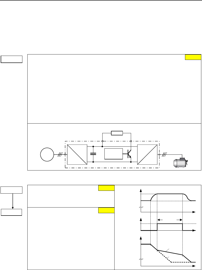
6 Commissioning Issue 10/06
MICROMASTER 440
60 Operating Instructions (Compact)
6.4.18.6 Dynamic braking
The following settings should always be made:
¾ The Vdc_max controller de-activated P1240 = 0 (def.: P1240 = 1)
¾ The compound brake de-activated P1236 = 0 (def.: P1236 = 0)
¾ Resistor brake activated P1237 > 0 (def.: P1237 = 0)
Dynamic braking
Dynamic braking is activated using parameter P1237 – the nominal (rated) duty cycle as
well as the switch-in duration of the braking resistor are also defined.
0 Inhibited
1 Load duty cycle 5 %
2 Load duty cycle 10 %
3 Load duty cycle 20 %
4 Load duty cycle 50 %
5 Load duty cycle 100 %
Using the dynamic brake, the regenerative feedback energy is transferred to the external
braking resistor using the chopper control (braking chopper); it is converted into thermal
energy (heat) in this resistor. This dynamic braking allows the drive to be braked in a
controlled fashion. This function is not available for sizes FX and GX.
Chopper resistor
Chopper
control
B-
=
~~
B+
=
~
MM4
6.4.18.7 Vdc controller
Configuration of Vdc controller
Enables / disables Vdc controller.
0 Vdc controller disabled
1 Vdc-max controller enabled
P1254 =... Auto detect Vdc switch-on levels
Enables/disables auto-detection of switch-on
levels for Vdc control functionalities.
0 Disabled
1 Enabled t
t
⏐f⏐
1
-controller active
VDC_max
t
VDC
0
r0056 Bit14
r1242
A0911
f
fact
set
P1237 = ... 0
1
1
P1240 =...
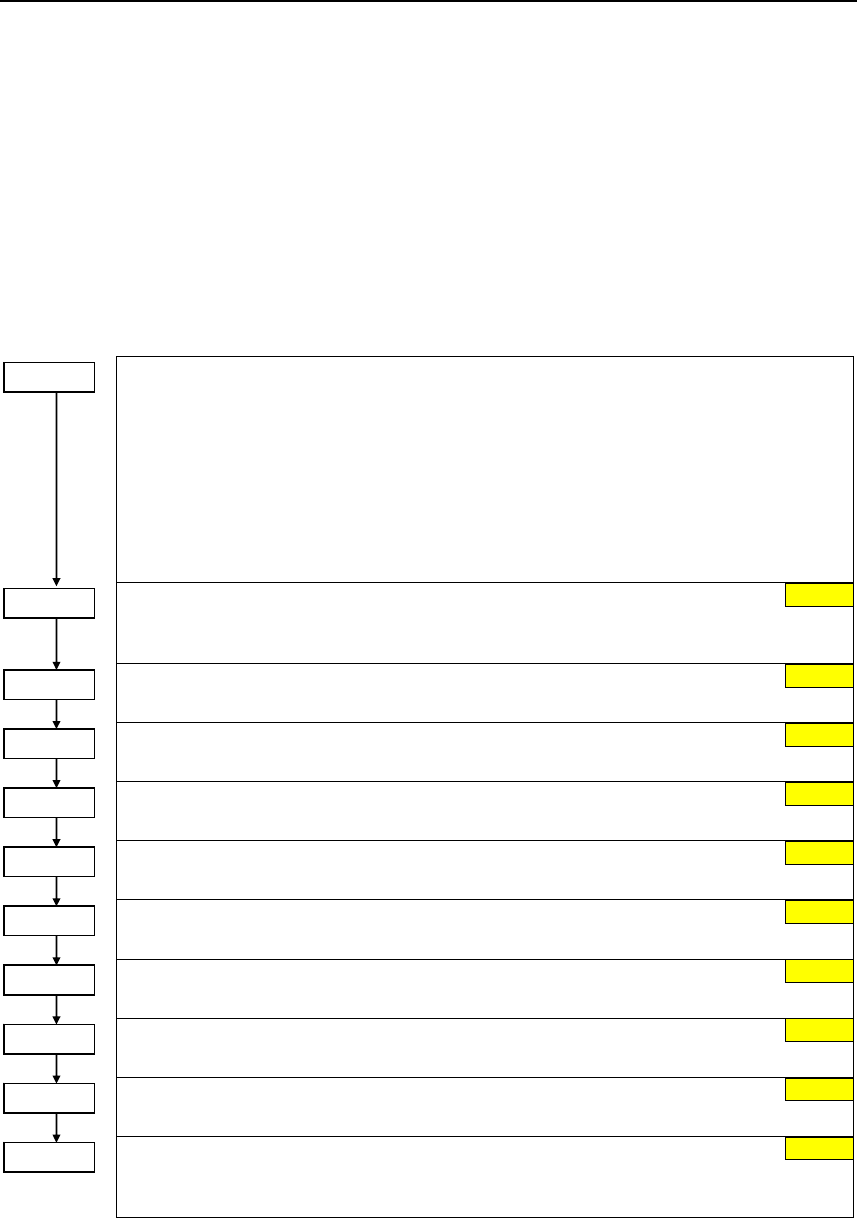
Issue 10/06 6 Commissioning
MICROMASTER 440
Operating Instructions (Compact) 61
6.4.18.8 Load torque monitoring
This function monitors the transmission of force between a motor and driven load
within a defined frequency range. Typical applications include, for example,
detecting when a transmission belt breaks or detecting when a conveyor belt is in
an overload condition.
For the load torque monitoring, the actual frequency/torque actual value is
compared to a programmed frequency/torque characteristic (refer to P2182 –
P2190). Depending on P2181, the system monitors whether the permissible torque
curve is either exceeded or fallen below. If the actual value lies outside the
tolerance bandwidth, then after the delay time P2192 has expired, either alarm
A0952 is output or fault F0452.
Belt failure detection mode
Parameter P2181 activates or de-activates the load torque monitoring and defines the
response to a load torque fault.
0 Belt failure detection disabled
1 Warning: Low torque / frequency
2 Warning: High torque / frequency
3 Warning: High / low torque / frequency
4 Trip: Low torque / frequency
5 Trip: High torque / frequency
6 Trip: High / low torque / frequency
Belt threshold frequency 1
Sets a frequency threshold 1 for comparing actual torque to torque the envelope for belt
failure detection.
Belt threshold frequency 2
Sets a frequency threshold 2.
Belt threshold frequency 3
Sets a frequency threshold 3.
Upper torque threshold 1
Upper limit threshold value 1 for comparing actual torque.
Lower torque threshold 1
Lower limit threshold value 1 for comparing actual torque.
Upper torque threshold 2
Upper limit threshold value 2 for comparing actual torque.
Lower torque threshold 2
Lower limit threshold value 2 for comparing actual torque.
Upper torque threshold 3
Upper limit threshold value 3 for comparing actual torque.
Lower torque threshold 3
Lower limit threshold value 3 for comparing actual torque.
Time delay for belt failure
P2192 defines a delay before warning/trip becomes active. It is used to eliminate events
caused by transient conditions. It is used for both methods of fault detection.
P2181 = ...
P2182 = ... 5.00
P2183 = ... 30.00
P2184 = ... 50.00
P2185 = ... 99999.0
P2186 = ... 0.0
P2187 = ... 99999.0
P2188 = ... 0.0
P2189 = ... 99999.0
P2190 = ... 0.0
P2192 = ... 10
99999.0
99999.0
0.0
0.0
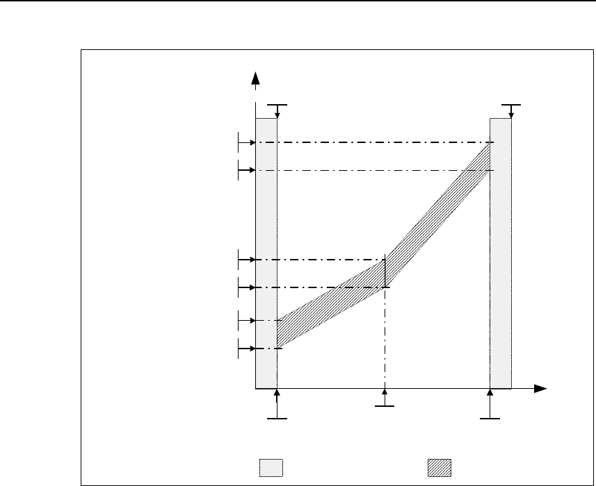
6 Commissioning Issue 10/06
MICROMASTER 440
62 Operating Instructions (Compact)
P2189
Upper torque threshold 3
P2190
Lower torque threshold 3
P2187
Upper torque threshold 2
P2188
Lower torque threshold 2
P2185
Upper torque threshold 1
P2186
Lower torque threshold 1
Boundary zones
De-activated monitoring Envelope curve
Active monitoring
P2182
Threshold frequency 1
P2183
Threshold frequency 2 P2184
Threshold frequency 3
|Torque| [Nm]
|Frequency|
[Hz]
P1082
Max. frequency
P1080
Min. frequency
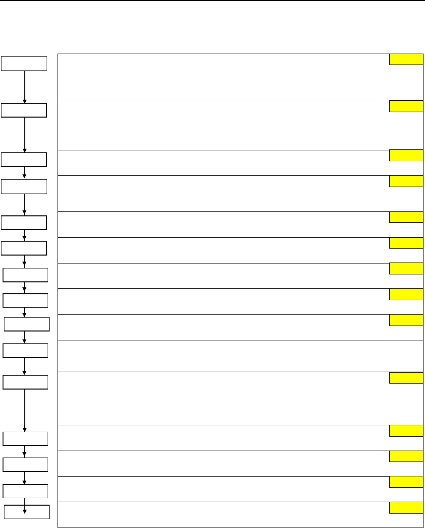
Issue 10/06 6 Commissioning
MICROMASTER 440
Operating Instructions (Compact) 63
6.4.18.9 PID controller
BI: Enable PID controlle
r
PID mode Allows user to enable/disable the PID controller. Setting to 1 enables the PID
controller. Setting 1 automatically disables normal ramp times set in P1120 and P1121 and
the normal fre
q
uenc
y
set
p
oints.
PID mode
Configuration of PID controller.
0 PID as setpoint
1 PID as trim
CI: PID setpoint
Defines set
p
oint source for PID set
p
oint in
p
ut.
CI: PID trim source
Selects trim source for PID setpoint. This signal is multiplied by the trim gain and added to
the PID set
p
oint.
Ramp-up time for PID setpoint
Sets the ram
p
-u
p
time for the PID set
p
oint.
Ramp-down time for PID setpoint
Sets ram
p
-down time for PID set
p
oint.
CI: PID feedback
Selects the source of the PID feedback si
g
nal.
Max. value for PID feedback
Sets the u
pp
er limit for the value of the feedback si
g
nal in
[
%
]
..
P2268 =... Min. value for PID feedback
Sets lower limit for value of feedback si
g
nal in
[
%
]
..
CO: PID error
Displays PID error (difference) signal between setpoint and feedback signals in [%].
PID derivative time
Sets PID derivative time.
P2274 = 0:
The derivative term does not have any effect (it applies a gain of 1).
PID proportional gain
Allows user to set
p
ro
p
ortional
g
ain for PID controller.
PID integral time
Sets inte
g
ral time constant for PID controller.
PID output upper limit
Sets u
pp
er limit for PID controller out
p
ut in
[
%
]
.
P2292 =... PID output lower limit
Sets lower limit for the PID controller output in [%].
0.0
0.0
0.0
1.00 s
1.00 s
755.0
100.00 %
0.00 %
3.000
0.000 s
100.00 %
0.00 %
P2291 =...
P2285 =...
P2280 =...
0
r2251 =...
0.000
P2274 =...
r2273 =...
P2200 =...
P2253 =...
P2254 =...
P2257 =...
P2258 =...
P2264 =...
P2267 =...
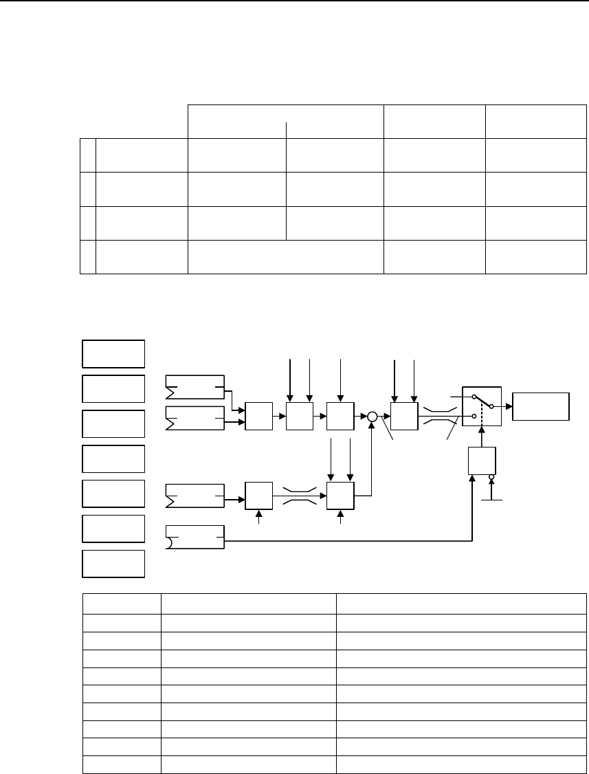
6 Commissioning Issue 10/06
MICROMASTER 440
64 Operating Instructions (Compact)
Controller structures
These structures are selected using parameters P2200 and P2251.
P2200 = 0:0 2)
P2251 = 0
1
P2200 = 1:0 2)
P2251 = 0
2
P2200 = 0:0 1)
P2251 = 1
3
P2200 = 1:0 1)
P2251 = 1
4
−
−
−
ON: active
OFF1/3: active
ON: -
OFF1/3: -
ON: -
OFF1/3: -
SUM PID controller RFG PID-RFG
1) will take change with drive running
2) change only taken when drive stopped
VSD *
Dancer control
ON: active
OFF1/3: active
ON: active
OFF1/3: active
ON: active
OFF1/3: active
ON: active
OFF1/3: -
ON: -
OFF1/3: active
Setpoint via
PID control
VSD *
* Variable speed drive (VSD)
PID control
PID
MOP
ADC
PID
SUM PID
PID
FF
USS
BOP link
USS
COM link
CB
COM link
ADC2
P2254
P2253 PID
RFG
PID
PT1 −
∆PID
P2200
P2264 PID
PT1
PID
SCL
&
P2251
Output
PID
0
1
Motor
control
P2257
P2258
P2261
P2271
P2269
P2270
P2265
P2280
P2285
0
Parameter Parameter text Example
P2200 BI: Enable PID controller P2200 = 1.0 PID controller active
P2253 CI: PID setpoint P2253 = 2224 PID-FF1
P2264 CI: PID feedback P2264 = 755 ADC
P2267 Max. PID feedback P2267 Adapt to the application
P2268 Min. PID feedback P2268 Adapt to the application
P2280 PID proportional gain P2280 Determined by optimizing
P2285 PID integral time P2285 Determined by optimizing
P2291 PID output upper limit P2291 Adapt to the application
P2292 PID output lower limit P2292 Adapt to the application
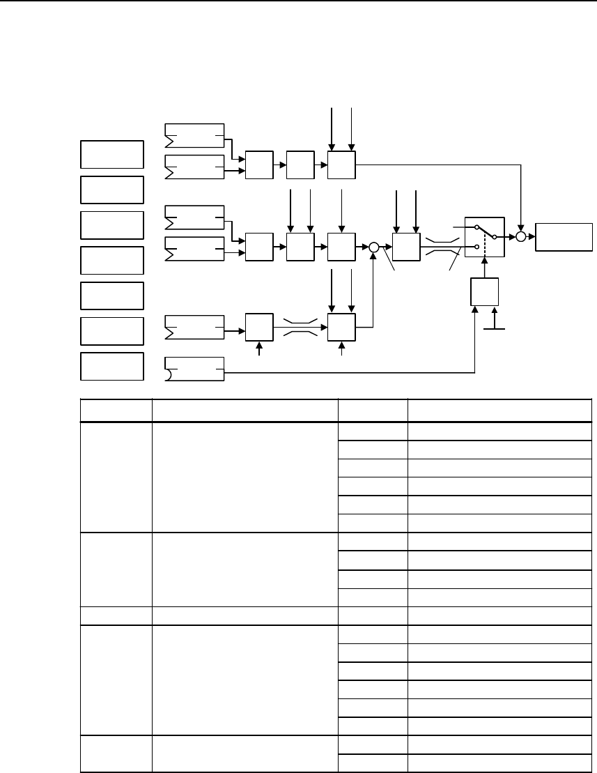
Issue 10/06 6 Commissioning
MICROMASTER 440
Operating Instructions (Compact) 65
PID cancer control
Closed-loop dancer roll control is selected with P2251 = P2200 = 1. Important parameters
and the structure are shown in the following diagrams.
MOP
ADC
PID
SUM PID
FF
USS
BOP link
USS
COM link
CB
COM link
ADC2
P2254
P2253 PID
RFG
PID
PT1 −
∆PID
P2200
P2264 PID
PT1
PID
SCL
&
P2251
= 1
Output
PID
0
1
Motor
control
P2257
P2258
P2261
P2271
P2269
P2270
P2265
P2280
P2285
0
SUM
P1070
P1075 AFM
P1120
P1121
RFG
Parameter Parameter text Setting Meaning
CI: PID setpointP2253 1024 Fixed setpoint (FF)
MOP1050
Analog input 1755.0
USS on BOP link2015.1
USS on COM link2019.1
CB on COM link2050.1
CI: PID feedback
P2264 755.0 Analog input 1
Analog input 2755.1
CI: Main setpointP1070
PID mode
1024 Fixed setpoint (FF)
MOP1050
Analog input 1755.0
USS on BOP link2015.1
USS on COM link2019.1
CB on COM link2050.1
P2251 1 PID as trim
BI: Enable PID controllerP2200 0
PID controller always active
1.0
PID controller de-activated
BICO
Digital input x722.x
BICO parameter
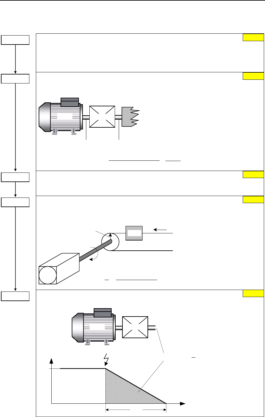
6 Commissioning Issue 10/06
MICROMASTER 440
66 Operating Instructions (Compact)
6.4.18.10 Positioning down ramp
Technological application
Selects technological application. Sets control mode (P1300).
0 Constant torque
1 Pumps and fans
3 Simple Positioning
Gearbox ratio input
Defines the ratio between number of motor shaft revolutions to equal one revolution of the
gearbox output shaft.
n n
Motor Load
Load
Ü
Ü = P2482
P2481
=
Motor revolutions
Load revolutions
Motor Gear
Gearbox ratio output
Defines the ratio between number of motor shaft revolutions to equal one revolution of the
gearbox output shaft.
No. of shaft turns = 1 Unit
Sets the number of rotations of the motor shaft required to represent 1 unit of user
selected units.
== s
U
P2484
Load
Motor
Pulley radius r
No. of revolutions
1 [unit]
U
Distance s
Distance / No. of revolutions
Sets the required distance or number of revolutions (see P2484).
Motor Gear
f⋅== 2
1
P2488 s
t
OFF1
f OFF1 . t P2488
.
tP2488
fOFF1
0
1.00
P0500 = ...
P2481 = ...
1.00
P2482 = ...
1.00
P2484 = ...
1.00
P2488 = ...
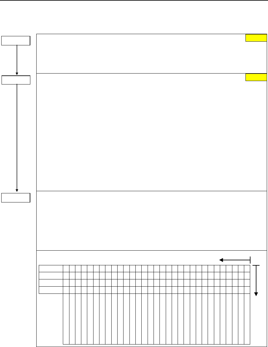
Issue 10/06 6 Commissioning
MICROMASTER 440
Operating Instructions (Compact) 67
6.4.18.11 Free function blocks (FFB)
P2800 =...
Enable FFBs
Parameter P2800 is used to activate all free function blocks (generally, P2800 is set to 1).
Possible settings:
0 Inhibited
1 Enabled
P2801 =... Activate FFBs
Parameter P2801 is used to individually enable (activate) the free function blocks P2801[0]
to P2801[16] (P2801[x] > 0).
Further, parameters P2801 and P2802 are used to define the chronological sequence of
all of the function blocks. The table below indicates that the priority increases from left to
right and from bottom to top.
Possible settings:
0 Inactive
1 Level 1
2 Level 2
3 Level 3
Example:
P2801[3] = 2, P2801[4] = 2, P2802[3] = 3, P2802[4] = 2
FFBs are calculated in the following sequence:
P2802[3], P2801[3] , P2801[4], P2802[4]
The active function blocks are calculated every 132 ms.
P2802 =...
Activate FFBs
Parameter P2802 is used to individually enable (activate) the free function blocks P2802[0]
to P2802[13] (P2802[x] > 0).
Possible settings:
0 Inactive
1 Level 1
2 Level 2
3 Level 3
3
2
1
0
P2802 [13] CMP 2
P2802 [12] CMP 1
P2802 [11] DIV 2
P2802 [10] DIV 1
P2802 [9] MUL 2
P2802 [8] MUL 1
P2802 [7] SUB 2
P2802 [6] SUB 1
P2802 [5] ADD 2
P2802 [4] ADD 1
P2802 [3] Timer 4
P2802 [2] Timer 3
P2802 [1] Timer 2
P2802 [0] Timer 1
P2801 [16] RS-FF 3
P2801 [15] RS-FF 2
P2801 [14] RS-FF 1
P2801 [13] D-FF 2
P2801 [12] D-FF 1
P2801 [11] NOT 3
P2801 [10] NOT 2
P2801 [9] NOT 1
P2801 [8] XOR 3
P2801 [7] XOR 2
P2801 [6] XOR 1
P2801 [5] OR 3
P2801 [4] OR 2
P2801 [3] OR 1
P2801 [2] AND 3
P2801 [1] AND 2
P2801 [0] AND 1
Level
Level
Level
Inactive
low high
Priority 1
Priority 2
low
0
0.0

6 Commissioning Issue 10/06
MICROMASTER 440
68 Operating Instructions (Compact)
FFB Input parameters Output parameters Setting parameters
AND1 P2810[2] BI: AND 1 r2811 BO: AND 1 –
AND2 P2812[2] BI: AND 2 r2813 BO: AND 2 –
AND3 P2814[2] BI: AND 3 r2815 BO: AND 3 –
OR1 P2816[2] BI: OR 1 r2817 BO: OR 1 –
OR2 P2818[2] BI: OR 2 r2819 BO: OR 2 –
OR3 P2820[2] BI: OR 3 r2821 BO: OR 3 –
XOR1 P2822[2] BI: XOR 1 r2823 BO: XOR 1 –
XOR2 P2824[2] BI: XOR 2 r2825 BO: XOR 2 –
XOR3 P2826[2] BI: XOR 3 r2827 BO: XOR 3 –
NOT1 P2828 BI: NOT 1 r2829 BO: NOT 1 –
NOT2 P2830 BI: NOT 2 r2831 BO: NOT 2 –
NOT3 P2832 BI: NOT 3 r2833 BO: NOT 3 –
D-FF1 P2834[4] BI: D-FF 1 r2835 BO: Q D-FF 1
r2836 BO: NOT-Q D-FF 1
–
D-FF2 P2837[4] BI: D-FF 2 r2838 BO: Q D-FF 2
r2839 BO: NOT-Q D-FF 2
–
RS-FF1 P2840[4] BI: RS-FF 1 r2841 BO: Q RS-FF 1
r2842 BO: NOT-Q RS-FF 1
–
RS-FF2 P2843[4] BI: RS-FF 2 r2844 BO: Q RS-FF 2
r2845 BO: NOT-Q RS-FF 2
–
RS-FF3 P2846[4] BI: RS-FF 3 r2847 BO: Q RS-FF 3
r2848 BO: NOT-Q RS-FF 3
–
Timer1 P2849 BI: Timer 1 r2852 BO: Timer 1
r2853 BO: NOT Timer 1
P2850 Delay time of Timer 1
P2851 Mode Timer 1
Timer2 P2854 BI: Timer 2 r2857 BO: Timer 2
r2858 BO: NOT Timer 2
P2855 Delay time of Timer 2
P2856 Mode Timer 2
Timer3 P2859 BI: Timer 3 r2862 BO: Timer 3
r2863 BO: NOT Timer 3
P2860 Delay time of Timer 3
P2861 Mode Timer 3
Timer4 P2864 BI: Timer 4 r2867 BO: Timer 4
r2868 BO: NOT Timer 4
P2865 Delay time of Timer 4
P2866 Mode Timer 4
ADD1 P2869[2] CI: ADD 1 r2870 CO: ADD 1 –
ADD2 P2871[2] CI: ADD 2 r2872 CO: ADD 2 –
SUB1 P2873[2] CI: SUB 1 r2874 CO: SUB 1 –
SUB2 P2875[2] CI: SUB 2 r2876 CO: SUB 2 –
MUL1 P2877[2] CI: MUL 1 r2878 CO: MUL 1 –
MUL2 P2879[2] CI: MUL 2 r2880 CO: MUL 2 –
DIV1 P2881[2] CI: DIV 1 r2882 CO: DIV 1 –
DIV2 P2883[2] CI: DIV 2 r2884 CO: DIV 2 –
CMP1 P2885[2] CI: CMP 1 r2886 BO: CMP 1 –
CMP2 P2887[2] CI: CMP 2 r2888 BO: CMP 2 –
FSW1 – – P2889 CO: FSW 1 in [%]
FSW2 – – P2890 CO: FSW 2 in [%]
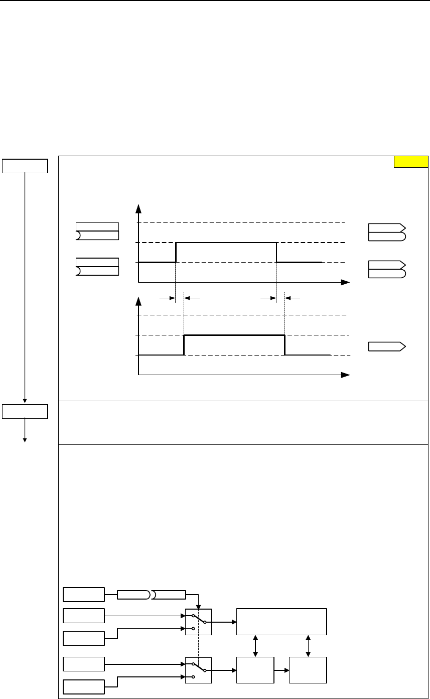
Issue 10/06 6 Commissioning
MICROMASTER 440
Operating Instructions (Compact) 69
6.4.19 Data sets
For many applications it is beneficial to have the possibility to change several
parameter settings simultaneous during operation or in the state ready to run with
an external signal. By indexing it is possible to set a parameter to several values
which can be activated by data set change-over. There are the following data sets:
¾ CDS Command Data Set
¾ DDS Drive Data Set
Command data set (CDS)
P0810 =...
Command data set CDS bit 0 (local / remote)
Selects the command source in which bit 0 should be read-out to select a command data
set (CDS).
t0
1
2
3
(0:0)
BI: CDS b0 loc/rem
P0810
(0:0)
BI: CDS bit 1
P0811
t0
1
2
3
CO/BO: Act CtrlWd2
r0055
r0055
CO/BO: Act CtrlWd1
r0054
r0054
.15
.15
.15
.15
r0050
Active CDS
Selecting CDS
approx. 4 ms approx. 4 ms
r0050
CO: Active CDS
Changeover timeChangeover time
The currently active command data set (CDS) is displayed using parameter r0050.
P0811 =...
BI: CDS bit 1
Selects command source from which to read Bit 1 for selecting a command data set
(see P0810).
Example for CDS changeover:
CDS1: Command source via terminals and setpoint source via analog input (ADC)
CDS2: Command source via BOP and setpoint source via MOP
CDS changeover is realized using digital input 4 (DIN 4)
Steps:
1. Carry-out commissioning for CDS1 (P0700[0] = 2 and P1000[0] = 2)
2. Connect P0810 (P0811 if required) to the CDS changeover source
(P0704[0] = 99, P0810 = 722.3)
3. Copy from CDS1 to CDS2 (P0809[0] = 0, P0809[1] = 1, P0809[2] = 2)
4. Adapt CDS2 parameters (P0700[1] = 1 and P1000[1] = 1)
DIN4
Terminals Sequence control
BOP
P0700[0] = 2
P0700[1] = 1
P0810 = 722.3
ADC Setpoint
channel
MOP
0
1
P1000[0] = 2
P1000[1] = 1
Motor
control
0
1
0
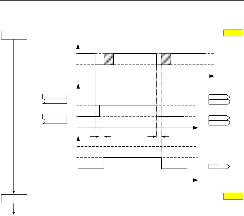
6 Commissioning Issue 10/06
MICROMASTER 440
70 Operating Instructions (Compact)
Drive data set (DDS)
Drive data set (DDS) bit 0
Selects the command source from which bit 0 should be read-out to select a drive data set.
t
0
1
2
3
(0:0)
BI: DDS bit 0
P0820
(0:0)
BI: DDS bit 1
P0821
t0
1
2
3
CO/BO: Act CtrlW d2
r0055
r0055
CO/BO: Act CtrlW d2
r0055
r0055
.04
.04
.05
.05
r0051[1]
Active DDS
Select DDS
approx. 50 ms approx. 50 ms
Changeover timeChangeover time
Operation
Ready
t
r0051 [2]
CO: Active DDS
.01
The currently active drive data set (DDS) is displayed using parameter r0051[1].
BI: DDS bit 1
Selects command source from which Bit 1 for selecting a drive data set is to be read in
(see parameter P0820).
0
P0820 = ...
0:0
P0821 = ...
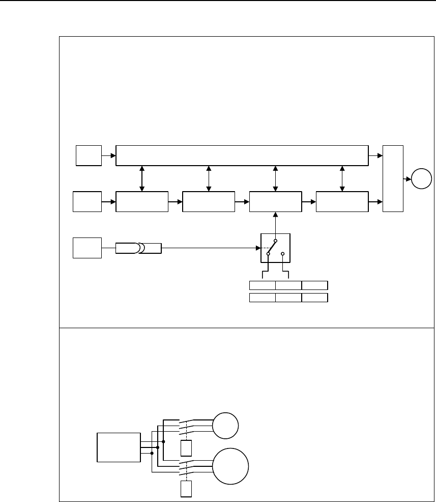
Issue 10/06 6 Commissioning
MICROMASTER 440
Operating Instructions (Compact) 71
Example:
1. Commissioning steps with a motor:
− Carry-out commissioning at DDS1.
− Connect P0820 (P0821 if required) to the DDS changeover source
(e.g. using DIN 4: P0704[0] = 99, P0820 = 722.3).
− Copy DDS1 to DDS2 (P0819[0] = 0, P0819[1] = 1, P0819[2] = 2).
− Adapt DDS2 parameters
(e.g. ramp-up / ramp-down times P1120[1] and P1121[1]).
DIN
ADC
P0820 = 722.3
SUM
setpoint
Sequence control
DIN4
AFM RFG Motor
control
01
P1120
P1121
[0]
DDS1
[1]
DDS2
[2]
DDS3
M
Gating unit
2. Commissioning steps with 2 motors (motor 1, motor 2):
− Commission motor 1; adapt the remaining DDS1 parameters.
− Connect P0820 (P0821 if required) to the DDS changeover source
(e.g. via DIN 4: P0704[0] = 99, P0820 = 722.3).
− Changeover to DDS2 (check using r0051).
− Commission motor 2; adapt the remaining DDS2 parameters.
MM4
M1
K1
M2
K2
Motor 1
Motor 2
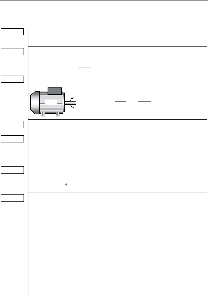
6 Commissioning Issue 10/06
MICROMASTER 440
72 Operating Instructions (Compact)
6.4.20 Diagnostic parameters
r0021 CO: Act. filtered frequency
Displays actual inverter output frequency (r0021) excluding slip compensation, resonance
damping and frequency limitation.
r0022 Act. filtered rotor speed
Displays calculated rotor speed based on inverter output frequency [Hz] x 120 / number of
poles.
r0313
60
[Hz] r0021 [1/min] r0022 ⋅=
r0032 CO: Act. filtered power
Displays motor power (power output at the motor shaft).
Motor
ω, M
M f 2 M Pmech ⋅⋅π⋅=⋅ω=
⇒
[Nm] r0031 [1/min]
60
r0022
π 2
1000
1
[kW] r0032 ⋅⋅⋅⋅=
[kW] r0032 0.75 [hp] r0032 ⋅=
r0035 CO: Motor temperature
Displays the measured motor temperature in °C.
r0036 CO: Frequency inverter utilization
Displays the frequency inverter utilization as a % referred to the overload. In so doing, the
value is calculated using the I2t model.
The I2t actual value relative to the maximum possible I2t value provides the level of
utilization.
r0039 CO: Energy consumpt. meter [kWh]
Displays electrical energy used by inverter since display was last reset.
ist
dtcosiu3dt
P
r0039
00 W⋅ϕ⋅⋅⋅
∫
=⋅
∫
=ist
tt
r0052 CO/BO: Act. status word 1
Displays the first active status word (ZSW) of the frequency inverter (bit format) and can be
used to diagnose the inverter status.
Bit00 Drive ready 0 NO 1 YES
Bit01 Drive ready to run 0 NO 1 YES
Bit02 Drive running 0 NO 1 YES
Bit03 Drive fault active 0 NO 1 YES
Bit04 OFF2 active 0 YES 1 NO
Bit05 OFF3 active 0 YES 1 NO
Bit06 ON inhibit active 0 NO 1 YES
Bit07 Drive warning active 0 NO 1 YES
Bit08 Deviation setpoint / act. value 0 YES 1 NO
Bit09 PZD control 0 NO 1 YES
Bit10 Maximum frequency reached 0 NO 1 YES
Bit11 Warning: Motor current limit 0 YES 1 NO
Bit12 Motor holding brake active 0 NO 1 YES
Bit13 Motor overload 0 YES 1 NO
Bit14 Motor runs right 0 NO 1 YES
Bit15 Inverter overload 0 YES 1 NO
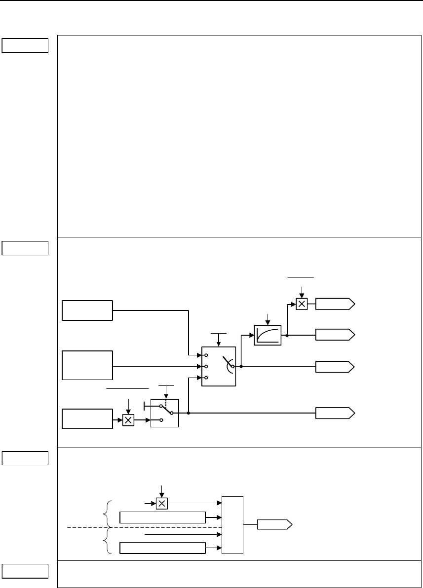
Issue 10/06 6 Commissioning
MICROMASTER 440
Operating Instructions (Compact) 73
r0054 CO/BO: Control word 1
Displays the first control word (STW) of the frequency inverter and can be used to display
the active commands.
Bit00 ON/OFF1 0 NO 1 YES
Bit01 OFF2: Electrical stop 0 YES 1 NO
Bit02 OFF3: Fast stop 0 YES 1 NO
Bit03 Pulse enable 0 NO 1 YES
Bit04 RFG enable 0 NO 1 YES
Bit05 RFG start 0 NO 1 YES
Bit06 Setpoint enable 0 NO 1 YES
Bit07 Fault acknowledge 0 NO 1 YES
Bit08 JOG right 0 NO 1 YES
Bit09 JOG left 0 NO 1 YES
Bit10 Control from PLC 0 NO 1 YES
Bit11 Reverse (setpoint inversion) 0 NO 1 YES
Bit13 Motor potentiometer MOP up 0 NO 1 YES
Bit14 Motor potentiometer MOP down 0 NO 1 YES
Bit15 CDS Bit 0 (Local/Remote) 0 NO 1 YES
r0063 CO: Actual frequency
Displays the actual frequency in Hz.
V/f
0
1,2
SLVC
(observer
model)
Encoder
P0400
P1300
160 ms
Frequency actual values:
Smoothed freq. actual value
Frequency actual value
Freq.act.value fr. the encoder
21,23
20,22
<20
0
P1300 = 21,23 and P0400 = 0 --> F0090
P0408 60
r0313
⋅
Smoothed speed act. value
r0313
60
r0022
r0021
r0063
r0061
r0067 CO: Act. output current limit
Displays valid maximum output current of inverter.
Motor
Inverter
Motor protection
P0640
r0067
P0305
Inverter protection
r0209
Min
r0072 CO: Act. output voltage
Displays output voltage.
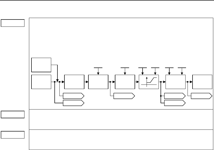
6 Commissioning Issue 10/06
MICROMASTER 440
74 Operating Instructions (Compact)
r1079 CO: Selected frequency setpoint
Displays the selected frequency setpoint.
The following frequency setpoints are displayed:
• r1078 total setpoint (HSW + ZUSW)
• P1058 JOG frequency, clockwise
• P1059 JOG frequency, counter-clockwise.
Motor
control
RFG
Skip
frequency
Inhibit
neg. freq.
setpoint
Reverse
Setpoint
source
r1079 r0020 r1170
P1110 P1091 P1080 P1082 P1120 P1135
. . .
IfI
r1078
JOG
r1114
r1119
r1114 CO: Freq. setpoint after dir. ctrl.
Displays the setpoint (reference) frequency in Hz after the function block to reverse the
direction of rotation.
r1170 CO: : Frequency setpoint after RFG
Displays the total frequency setpoint (reference value) in Hz after the ramp-function
generator.
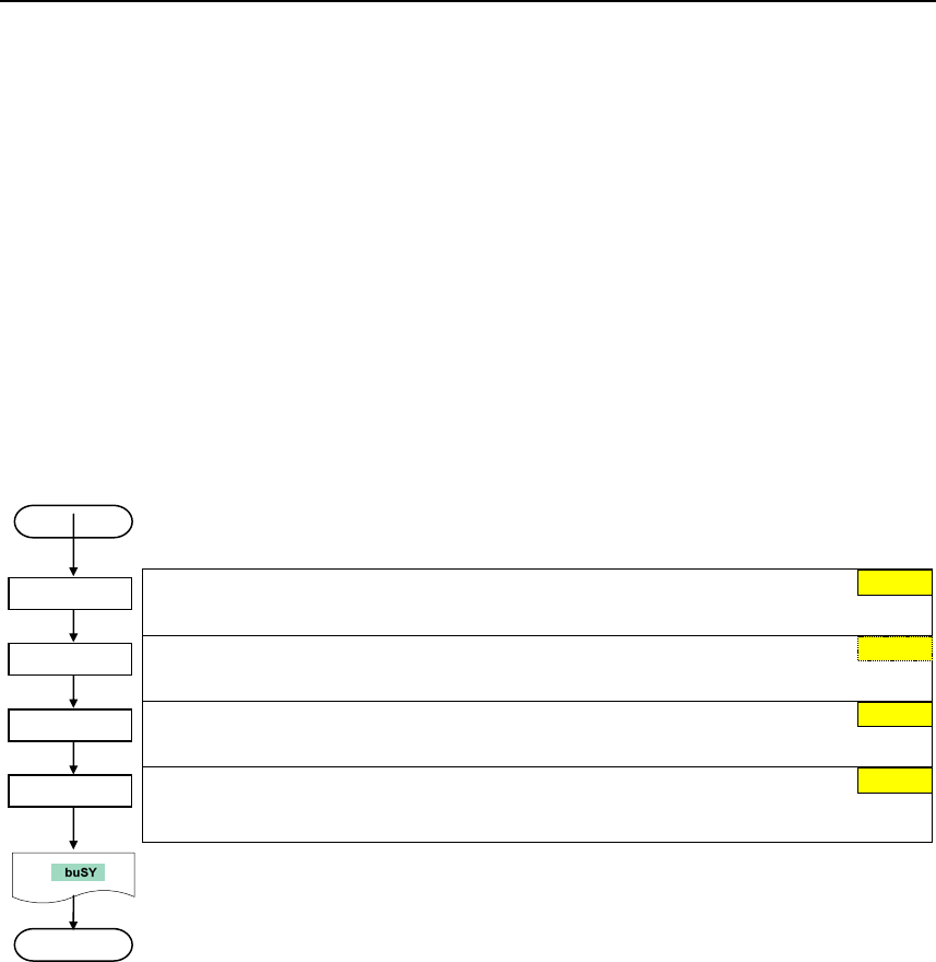
Issue 10/06 6 Commissioning
MICROMASTER 440
Operating Instructions (Compact) 75
6.5 Series commissioning
An existing parameter set can be transferred to a MICROMASTER 440 frequency
inverter using STARTER or DriveMonitor (refer to Section 4.1 "Establishing
communications MICROMASTER 440 ⇔ STARTER").
Typical applications for series commissioning include:
1. If several drives are to be commissioned that have the same configuration and
same functions. A quick / application commissioning (first commissioning) must
be carried-out for the first drive. Its parameter values are then transferred to the
other drives.
2. When replacing MICROMASTER 440 frequency inverters.
6.6 Parameter reset of factory setting
User access level
1 Standard
Parameter filter
0 All parameters
Commissioning parameter
30 Factory setting
Factory reset
0 disabled
1 Parameter reset
The drive inverter carries-out a parameter reset (duration, approx. 10 s) and then
automatically exits the reset menu and sets:
P0970 = 0 : disabled
P0010 = 0 : ready
START
END
P0010 = 30
P0970 = 1
0
0
P0003 = 1
P0004 = 0
1
0
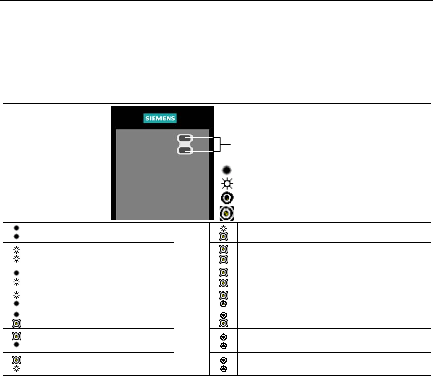
7 Displays and messages Issue 10/06
MICROMASTER 440
76 Operating Instructions (Compact)
7 Displays and messages
7.1 LED status display
LEDs for indicating
the drive state
OFF
ON
approx. 0.3 s, flashing
a
pp
rox. 1 s
,
twinklin
g
Mains not present
Fault inverter temperature
Ready to run
Warning current limit
both LEDs twinkling same time
Inverter fault
other than the ones listed below
Other warnings
both LEDs twinkling alternatively
Inverter running
Undervoltage trip / undervoltage warning
Fault overcurrent
Drive is not in ready state
Fault overvoltage
ROM failure
both LEDs flashing same time
Fault motor overtemperature
RAM failure
both LEDs flashing alternatively

Issue 10/06 7 Displays and messages
MICROMASTER 440
Operating Instructions (Compact) 77
7.2 Fault messages and Alarm messages
Fault Significance Alarm Significance
F0001 Overcurrent A0501 Current Limit
F0002 Overvoltage A0502 Overvoltage limit
F0003 Undervoltage A0503 Undervoltage Limit
F0004 Inverter Overtemperature A0504 Inverter Overtemperature
F0005 Inverter I2t A0505 Inverter I2t
F0011 Motor Overtemperature I2t A0506 Inverter Duty Cycle
F0012 Inverter temp. signal lost A0511 Motor Overtemperature I2t
F0015 Motor temperature signal lost A0520 Rectifier Overtemperature
F0020 Mains Phase Missing A0521 Ambient Overtemperature
F0021 Earth fault A0522 I2C read out timeout
F0022 HW monitoring active A0523 Output fault
F0023 Output fault A0535 Braking Resistor Hot
F0024 Rectifier Over Temperature A0541 Motor Data Identification Active
F0030 Fan has failed A0542 Speed Control Optimization Active
F0035 Auto restart after n A0590 Encoder feedback loss warning
F0040 Automatic Calibration Failure A0600 RTOS Overrun Warning
F0041 Motor Data Identification Failure A0700 - CB warning 1
F0042 Speed Control Optimization Failure
...
...
F0051 Parameter EEPROM Fault A0709 CB warning 9
F0052 Power stack Fault A0710 CB communication error
F0053 IO EEPROM Fault A0711 CB configuration error
F0054 Wrong IO Board A0910 Vdc-max controller de-activated
F0060 Asic Timeout A0911 Vdc-max controller active
F0070 CB setpoint fault A0912 Vdc-min controller active
F0071 USS (BOP link) setpoint fault A0920 ADC parameters not set properly
F0072 USS (COM link) setpoint fault A0921 DAC parameters not set properly
F0080 ADC lost input signal A0922 No load applied to inverter
F0085 External Fault A0923 Both JOG Left and Right are requested
F0090 Encoder feedback loss A0952 Belt Failure Detected
F0101 Stack Overflow A0936 PID Autotuning Active
F0221 PID Feedback below min. value
F0222 PID Feedback above max. value
F0450 BIST Tests Failure
(Service mode only)
F0452 Belt Failure Detected

Siemens AG
Bereich Automation and Drives (A&D)
Geschäftsgebiet Standard Drives (SD)
Postfach 3269, D-91050 Erlangen
Bundesrepublik Deutschland
© Siemens AG, 2005, 2006
subject to change without prior notice
Siemens Aktiengesellschaft Issue 10/06
Information about MICROMASTER 440 is also available from:
Regional Contacts
Please get in touch with your contact for Technical Support in your Region for questions
about services, prices and conditions of Technical Support.
Central Technical Support
The competent consulting service for technical issues with a broad range of
requirements-based services around our products and systems.
Europe / Africa
Tel: +49 (0) 180 5050 222
Fax: +49 (0) 180 5050 223
Email: adsupport@siemens.com
America
Tel: +1 423 262 2522
Fax: +1 423 262 2589
Email: simatic.hotline@sea.siemens.com
Asia / Pacific
Tel: +86 1064 757 575
Fax: +86 1064 747 474
Email: adsupport.asia@siemens.com
Online Service & Support
The comprehensive, generally available information system over the Internet, from
product support to service & support to the support tools in the shop.
http://www.siemens.com/automation/service&support
Internet Address
Customers can access technical and general information under the following address:
http://www.siemens.com/micromaster
