Siemens S5 135U 155U Users Manual 135U/155U
S5-135U155U to the manual 6d40d426-09fc-49c4-a38f-a40c545584f5
2015-02-05
: Siemens Siemens-S5-135U-155U-Users-Manual-410326 siemens-s5-135u-155u-users-manual-410326 siemens pdf
Open the PDF directly: View PDF ![]() .
.
Page Count: 560 [warning: Documents this large are best viewed by clicking the View PDF Link!]
- Title
- Contents
- 1 Notes on Using this Manual andontheCESymbol
- 2 Centralized and Distributed Configuration of a Programmable Controller
- 3 Installation Guidelines
- 3.1 Principles of Installation of Systems for EMC
- 3.1.1 Overview of Possible Types of Interference
- 3.1.2 The Most Important Basic Rules for Ensuring EMC
- 3.2 Installation of Programmable Controllers for EMC
- 3.2.1 Basic Rules for Assembling and Grounding the Inactive Metal Parts
- 3.2.2 Example of Cabinet Assembly for EMC
- 4 Central Controllers and Expansion Units Power Supply Units
- 4.1 S5-135U/155U Central Controller
- 4.1.1 Technical Description
- 4.1.2 Installation
- 4.1.3 Startup
- 4.1.4 Repair Guidelines
- 4.1.5 Technical Specifications
- 4.2 Expansion Units
- 4.2.1 Technical Description of the Expansion Units
- 4.2.2 Installing the Expansion Units
- 4.2.3 Technical Specifications of the Expansion Units
- 4.3 Power Supply Units
- 4.3.1 Product Overview
- 4.3.2 Setting and Connecting the Power Supply Unit
- 4.3.3 Fault Indications/Fault Diagnostics
- 4.3.4 Maintenance and Repairs
- 4.3.5 Description of Internal Sequences in the Power Supply Unit
- 4.3.6 Technical Specifications of the Power Supply Units
- 4.4 6ES5 955-3NA12 Power Supply Unit
- 4.4.1 Technical Description
- 4.4.2 Setting the Power Supply Unit
- 4.4.3 Installation
- 4.4.4 Operation
- 4.4.5 Maintenance
- 4.4.6 Technical Specifications
- 4.5 Fan Submodules
- 4.5.1 Technical Description
- 4.5.2 Setting and Connecting the Fan Submodule
- 4.5.3 Technical Specifications
- 5 CPUs, Memory Cards, Memory Submodules, Interface Submodules
- 5.1 CPU 948B -3UA13 or CPU 948B -3UA23
- 5.1.1 Technical Description
- 5.1.2 Installation and Startup
- 5.1.3 Interfaces of the CPU 948
- 5.1.4 Technical Specifications
- 5.2 CPU 948
- 5.2.1 Technical Description
- 5.2.2 Installation and Startup
- 5.2.3 Interfaces of the CPU 948
- 5.2.4 Technical Specifications
- 5.3 CPU 928B -3UB21
- 5.3.1 Technical Description
- 5.3.2 Installation and Startup
- 5.3.3 Technical Specifications
- 5.4 CPU 928B
- 5.4.1 Technical Description
- 5.4.2 Installation and Startup
- 5.4.3 Technical Specifications
- 5.5 CPU 928 -3UA21
- 5.5.1 Technical Description
- 5.5.2 Installation and Startup
- 5.5.3 Technical Specifications
- 5.6 CPU 928
- 5.6.1 Technical Description
- 5.6.2 Installation and Startup
- 5.6.3 Technical Specifications
- 5.7 CPU 922
- 5.7.1 Technical Description
- 5.7.2 Installation and Startup
- 5.7.3 Technical Specifications
- 5.8 374 Flash EPROM Cards
- 5.8.1 Technical Description
- 5.8.2 Notes on Operation
- 5.8.3 Technical Specifications
- 5.9 376 Memory Submodules
- 5.9.1 Technical Description
- 5.9.2 Notes on Operation
- 5.9.3 Technical Specifications
- 5.10 377 Memory Submodules
- 5.10.1 Technical Description
- 5.10.2 Notes on Operation
- 5.10.3 RAM Submodules with Battery Backup
- 5.10.4 Technical Specifications
- 5.11 Interface Submodules
- 5.11.1 Installing and Removing the Interface Submodules
- 5.11.2 PG Submodule
- 5.11.3 V.24 Submodule
- 5.11.4 TTY Submodule
- 5.11.5 RS422 A/485 Submodule
- 5.11.6 SINEC L1 Submodule
- 5.11.7 Technical Specifications of the Interface Submodules
- 6 Multiprocessor Operation/Coordinators
- 6.1 Introduction
- 6.2 Starting the Multiprocessor Operation
- 6.3 Coordinator Modes
- 6.4 923A Coordinator Module
- 6.4.1 Technical Description
- 6.4.2 Settings on the Coordinator
- 6.5 923C Coordinator Module
- 6.5.1 Technical Description
- 6.5.2 Settings on the Coordinator
- 6.6 Technical Specifications of the Coordinators
- 7 Interface Modules
- 7.1 The 300 and 312 Interface Modules
- 7.1.1 Indicators and Controls
- 7.1.2 Modes/Jumper Assignments of the IM 300
- M1
- P1
- 7.2 The 301 and 310 Interface Modules
- 7.2.1 Indicators and Controls
- 7.2.2 Modes/Jumper Assignments of the IM 301
- 7.3 The 304 and 314 Interface Modules
- 7.3.1 Indicators and Controls
- 7.3.2 Modes/Jumper Assignments of the IM 304
- 7.3.3 Modes/Jumper Assignments of the IM 314
- 7.4 Technical Specifications
- 7.4.1 6ES5 721 Connecting Cable
- 7.4.2 6ES5 7602 Terminator
- 8 Digital Input/Output Modules
- 8.1 Technical Description
- 8.1.1 Design
- 8.1.2 Function of the Enable Inputs
- 8.1.3 Special Features of the 432 Digital Input Module
- 8.1.4 Special Features of the DI/DQ 482
- 8.2 Installation and Startup
- 8.2.1 Setting the Module Address
- 8.2.2 Removing and Inserting Modules
- 8.2.3 Marking of Modules
- 8.2.4 Connecting the Signal Lines
- 8.2.5 Connection of Outputs in Parallel and Switching On the Load via a Contact
- 8.2.6 Short-Circuit Protection and Fusing
- 8.2.7 Arc-Quenching for Inductive Loads
- 8.3 Common Technical Specifications
- 8.4 Specification Sheets for the Modules
- 8.4.1 6ES5 420-4UA13/4UA14 Digital Input Module
- 8.4.2 6ES5 430-4UA13/4UA14 Digital Input Module
- 8.4.3 6ES5 431-4UA12 Digital Input Module
- 8.4.4 6ES5 432-4UA12 Digital Input Module
- 8.4.5 6ES5 434-4UA12 Digital Input Module
- 8.4.6 6ES5 435-4UA12 Digital Input Module
- 8.4.7 6ES5 436-4UA12 Digital Input Module
- 8.4.8 6ES5 436-4UB12 Digital Input Module
- 8.4.9 6ES5 441-4UA13/4UA14 Digital Output Module
- 8.4.10 6ES5 451-4UA13/4UA14 Digital Output Module
- 8.4.11 6ES5 453-4UA12 Digital Output Module
- 8.4.12 6ES5 454-4UA13/4UA14 Digital Output Module
- 8.4.13 6ES5 455-4UA12 Digital Output Module
- 8.4.14 6ES5 456-4UA12 Digital Output Module
- 8.4.15 6ES5 456-4UB12 Digital Output Module
- 8.4.16 6ES5 457-4UA12 Digital Output Module
- 8.4.17 6ES5 458-4UA12 Digital Output Module
- 8.4.18 6ES5 458-4UC11 Digital Output Module
- 8.4.19 6ES5 482-4UA11 Digital Input/Output Module
- 9 Analog Input/Output Modules
- 9.1 Technical Description
- 9.2 Common Technical Specifications
- 9.3 The 460 Analog Input Module
- 9.3.1 Design
- 9.3.2 Function of the Enable Input
- 9.3.3 Special Features of the 460 Analog Input Module
- 9.3.4 Setting the Module Address
- 9.3.5 Removing and Inserting Modules
- 9.3.6 Marking of Modules and Front Connectors
- 9.3.7 Connecting the Signal Lines
- 9.3.8 Connection of Sensors
- 9.3.9 Connecting a Compensating Box for Thermal E.M.F. Measurement
- 9.3.10 Connecting Resistance Thermometers in the Standard Pt 100 Range
- 9.3.11 Connecting Resistance Thermometers in the Extended Pt 100 Range
- 9.3.12 Broken Wire Signal
- 9.3.13 Connecting Transducers
- 9.3.14 Measured-Value Representation
- 9.3.15 Technical Specifications
- 9.4 The 463 Analog Input Module
- 9.4.1 Design
- 9.4.2 Function of the Enable Input
- 9.4.3 Special Features of the 463 Analog Input Module
- 9.4.4 Setting the Module Address
- 9.4.5 Removing and Inserting Modules
- 9.4.6 Marking of Modules and Front Connectors
- 9.4.7 Connecting the Signal Lines
- 9.4.8 Measured-Value Representation
- 9.4.9 Technical Specifications
- 9.5 The 465 Analog Input Module
- 9.5.1 Design
- 9.5.2 Function of the Enable Input
- 9.5.3 Special Features of the 465 Analog Input Module
- 9.5.4 Setting the Module Address
- 9.5.5 Removing and Inserting Modules
- 9.5.6 Marking of Modules and Front Connectors
- 9.5.7 Connecting the Signal Lines
- 9.5.8 Connecting a Compensating Box for Thermal E.M.F. Measurement
- 9.5.9 Connecting Resistance Thermometers to the 465 Analog Input Module
- 9.5.10 Broken Wire Signal for Resistance Thermometers
- 9.5.11 Connecting Transducers
- 9.5.12 Measured-Value Representation
- 9.5.13 Technical Specifications
- 9.6 The 466 Analog Input Module
- 9.6.1 Design
- 9.6.2 Special Features of the 466 Analog Input Module
- 9.6.3 Startup
- 9.6.4 Removing and Inserting Modules
- 9.6.5 Marking of Modules and Front Connectors
- 9.6.6 Connecting the Signal Lines
- 9.6.7 Connecting Sensors to the 466 Analog Input Module
- 9.6.8 Measured-Value Representation
- 9.6.9 Technical Specifications
- 9.7 The 470 Analog Output Module
- 9.7.1 Design
- 9.7.2 Function of the Enable Input
- 9.7.3 Special Features of the 470 Analog Output Module
- 9.7.4 Setting the Module Address
- 9.7.5 Removing and Inserting Modules
- 9.7.6 Marking of Modules and Front Connectors
- 9.7.7 Connecting the Signal Lines
- 9.7.8 Connecting Loads to the 470 Analog Output Module
- 9.7.9 Measured-Value Representation
- 9.7.10 Technical Specifications
- 10 Monitoring Module
- 10.1 Application
- 10.1.1 Design
- 10.1.2 Mode of Operation
- 10.1.3 Block Diagram
- 10.1.4 Fault Detection
- 10.1.5 Resetting
- 10.2 Installation
- 10.2.1 Possible Configurations
- 10.2.2 Removing and Inserting
- 10.2.3 Connecting the RESET Input
- 10.2.4 Switch Positions of the Relay Contact
- 10.2.5 Installation Guidelines
- 10.3 Operation
- 10.3.1 Addressing
- 10.3.2 Setting the Address Switches S1, S2, S3, S4
- 10.3.3 Setting the Switch S5
- 10.4 Technical Specifications
- 10.5 Address Table
- 11 Connector Assignments
- A Appendix
- B Guidelines for Handling Electrostatically Sensitive Devices (ESD)
- Index
- Remarks Form

Contents
Notes on Using this Manual
and on the CE Symbol 1
Centralized and Distributed
Configuration of a Programma-
ble Controller 2
Installation Guidelines 3
Central Controllers and
Expansion Units
Power Supply Units 4
CPUs, Memory Cards,
Memory Submodules,
Interface Submodules 5
Multiprocessor Operation/
Coordinators 6
Interface Modules 7
Digital Input/Output Modules 8
Analog Input/Output Modules 9
Monitoring Module 10
Connector Assignments 11
Appendices
Appendix A
Guidelines for Handling
Electrostatically-Sensitive
Devices (ESD) B
Index
12/98
S5-135U/155U
System Manual
This manual has the
order number:
6ES5998-0SH21
SIMATIC
C79000-G8576-C199
Release 06

ii C7-633, C7-634 Control Systems
C79000G7076C63302
#$.()0'*)/$).)*/$ .2#$#4*0.#*0'*. -1 /* ).0- 4*0-*2)+ -.*)'.! /4.2 ''./*
+-*/ //# +-*0/)*)) / ,0$+( )/# . )*/$ .- #$"#'$"#/ $)/# ()0'42-)$)"
/-$)"' )- (-& .!*''*2.*-$)"/*/# ' 1 '*!)" -
!Warning
$)$/ ./#/ /#. 1 - + -.*)'$)%0-4*-.0./)/$'+-*+ -/4(" )- .0'/$!+-*+ -+- 0/$*).-
)*//& )
Note
-2.4*0-// )/$*)/*+-/$0'-'4$(+*-/)/$)!*-(/$*)*)/# +-*0/#)'$)"/# +-*0/*-/*+-/$0'-
+-/*!/# *0( )//$*)
# 1$ .4./ ((4*)'4 . /0+)*+ -/ $)*)%0)/$*)2$/#/#$.()0'
)'4 .#*0' ''*2 /*$)./'')2*-&*)/#$. ,0$+( )/0'$!$ + -.*).-
!$) .+ -.*).2#*- 0/#*-$5 /**(($..$*)/*"-*0))/*/"$-0$/. ,0$+( )/).4.6
/ (.$)*-) 2$/# ./'$.# .! /4+-/$ .)./)-.
*/ /# !*''*2$)"
!Warning
#$. 1$ )$/.*(+*) )/.(4*)'4 0. !*-/# ++'$/$*). .-$ $)/# /'*"*-/# / #)$'
.-$+/$*))*)'4$)*)) /$*)2$/# 1$ .*-*(+*) )/.!-*(*/# -()0!/0- -.2#$##1 )
++-*1 *-- *(( ) 4$ ( ).
#$.+-*0/)*)'4!0)/$*)*-- /'4).! '4$!$/$./-).+*-/ ./*- . /0+)$)./'' *-- /'4)
*+ -/ )($)/$) .- *(( )
!Caution
!
)" -*! 3+'*.$*)$!// -4$.$)*-- /'4- +' +' *)'42$/#.( *- ,0$1' )//4+
- *(( ) 4/# ()0!/0- -$.+*. *!0. // -$ .*-$)"/*/# ()0!/0- -.$)./-0/$*).
!Warning
6
R)R)R - - "$./ - /- (-&.*!
#$-+-/$ .0.$)"!*-/# $-*2)+0-+*. .)4*/# -)( .$)/#$.*0( )/2#$#- ! -/*/- (-&.($"#/
$)!-$)" 0+*)/# -$"#/.*!/# /- (-&*2) -.
We have checked the contents of this manual for agreement with the
hardware and software described. Since deviations cannot be
precluded entirely, we cannot guarantee full agreement. However,
the data in this manual are reviewed regularly and any necessary
corrections included in subsequent editions. Suggestions for
improvement are welcomed.
E Siemens AG 1993
0% //*#)" 2$/#*0/+-$*-)*/$
Disclaimer of LiabilityCopyright E Siemens AG 1993 All rights reserved
The reproduction, transmission or use of this document or its
contents is not permitted without express written authority.
Offenders will be liable for damages. All rights, including rights
created by patent grant or registration of a utility model or design, are
reserved.
$ ( ).
Bereich Automatisierungs- und Antriebstechnik
Geaschaeftsgebiet Industrie Automatisierungssysteme
Postfach 4848,D-90327 Nuernberg
Siemens Aktiengesellschaft 6ES5998-0SH21
Safety Guidelines
Qualified Personnel
Correct Usage
Trademarks
iii
System Manual
C79000-G8576-C199-06
Contents
1 Notes on Using this Manual and on the CE Symbol 1-1. . . . . . . . . . . . . . . . . . . . . . .
Notes on Using this Manual 1-1. . . . . . . . . . . . . . . . . . . . . . . . . . . . . . . . . . . . . . .
Notes on the CE Symbol 1-4. . . . . . . . . . . . . . . . . . . . . . . . . . . . . . . . . . . . . . . . .
Notes for Machine Manufacturers 1-6. . . . . . . . . . . . . . . . . . . . . . . . . . . . . . . . . .
Safety Notes 1-7. . . . . . . . . . . . . . . . . . . . . . . . . . . . . . . . . . . . . . . . . . . . . . . . . . . .
2 Centralized and Distributed Configuration of a Programmable Controller 2-1. . .
2.1 Application 2-2. . . . . . . . . . . . . . . . . . . . . . . . . . . . . . . . . . . . . . . . . . . . . . . . . . . . .
2.2 Centralized and Distributed Configuration 2-3. . . . . . . . . . . . . . . . . . . . . . . . . . .
2.2.1 Installing a PLC with Centralized Configuration 2-4. . . . . . . . . . . . . . . . . . . . . .
2.2.2 Installing a PLC with Distributed Configuration 2-5. . . . . . . . . . . . . . . . . . . . . . .
2.3 Examples 2-6. . . . . . . . . . . . . . . . . . . . . . . . . . . . . . . . . . . . . . . . . . . . . . . . . . . . . .
3 Installation Guidelines 3-1. . . . . . . . . . . . . . . . . . . . . . . . . . . . . . . . . . . . . . . . . . . . . . . . . .
3.1 Principles of Installation of Systems for EMC 3-2. . . . . . . . . . . . . . . . . . . . . . . .
3.1.1 Overview of Possible Types of Interference 3-2. . . . . . . . . . . . . . . . . . . . . . . . .
3.1.2 The Most Important Basic Rules for Ensuring EMC 3-6. . . . . . . . . . . . . . . . . .
3.2 Installation of Programmable Controllers for EMC 3-8. . . . . . . . . . . . . . . . . . . .
3.2.1 Basic Rules for Assembling and Grounding the Inactive Metal
Parts 3-8. . . . . . . . . . . . . . . . . . . . . . . . . . . . . . . . . . . . . . . . . . . . . . . . . . . . . . . . . .
3.2.2 Example of Cabinet Assembly for EMC 3-9. . . . . . . . . . . . . . . . . . . . . . . . . . . . .
3.2.3 Example of Rack and Wall Mounting for EMC 3-11. . . . . . . . . . . . . . . . . . . . . . .
3.3 Wiring of Programmable Controllers for EMC 3-12. . . . . . . . . . . . . . . . . . . . . . .
3.3.1 Routing of Cables 3-12. . . . . . . . . . . . . . . . . . . . . . . . . . . . . . . . . . . . . . . . . . . . . . .
3.3.2 Equipotential Bonding 3-14. . . . . . . . . . . . . . . . . . . . . . . . . . . . . . . . . . . . . . . . . . . .
3.3.3 Shielding of Cables and Lines 3-15. . . . . . . . . . . . . . . . . . . . . . . . . . . . . . . . . . . . .
3.3.4 Special Measures for Interference-Free Operation 3-17. . . . . . . . . . . . . . . . . . .
3.3.5 Checklist for the Electromagnetically Compatible Installation
of Control Systems 3-19. . . . . . . . . . . . . . . . . . . . . . . . . . . . . . . . . . . . . . . . . . . . . .
3.4 Power Supplies for Programmable Controllers and I/Os 3-20. . . . . . . . . . . . . .
3.4.1 Power Supplies for Control Systems with SIMATIC S5 3-20. . . . . . . . . . . . . . .
3.4.2 Connecting the Programmable Controller and Load Power 3-21. . . . . . . . . . . .
3.4.3 Connecting Non-Floating or Floating Modules 3-26. . . . . . . . . . . . . . . . . . . . . . .
3.5 Interference-Free Installation of Centralized and Distributed
Interface Circuits 3-28. . . . . . . . . . . . . . . . . . . . . . . . . . . . . . . . . . . . . . . . . . . . . . . .
3.5.1 Interference-Free Installation of Centralized Interface Circuits 3-28. . . . . . . . .
3.5.2 Interference-Free Installation of Distributed Interface Circuits 3-28. . . . . . . . . .
3.6 Interference-Free Connection of Monitors 3-30. . . . . . . . . . . . . . . . . . . . . . . . . . .

iv System Manual
C79000-G8576-C199-06
3.6.1 Interference-Free Connection of a Monitor to the CP of the S5
Controller 3-30. . . . . . . . . . . . . . . . . . . . . . . . . . . . . . . . . . . . . . . . . . . . . . . . . . . . . .
3.6.2 Shielding and Grounding 3-31. . . . . . . . . . . . . . . . . . . . . . . . . . . . . . . . . . . . . . . . .
3.7 Selection and Installation of Cabinets with SIMATIC S5 3-33. . . . . . . . . . . . . . .
3.7.1 Types of Cabinet 3-34. . . . . . . . . . . . . . . . . . . . . . . . . . . . . . . . . . . . . . . . . . . . . . . .
3.7.2 Clearances in Cabinets 3-34. . . . . . . . . . . . . . . . . . . . . . . . . . . . . . . . . . . . . . . . . .
3.7.3 Removal of Power Dissipation from Cabinets 3-37. . . . . . . . . . . . . . . . . . . . . . . .
3.7.4 Examples for Determining the Type of Cabinet 3-38. . . . . . . . . . . . . . . . . . . . . .
3.7.5 Determining the Power Dissipation of Modules 3-39. . . . . . . . . . . . . . . . . . . . . .
4 Central Controllers and Expansion Units Power Supply Units 4-1. . . . . . . . . . . . .
4.1 S5-135U/155U Central Controller 4-2. . . . . . . . . . . . . . . . . . . . . . . . . . . . . . . . . .
4.1.1 Technical Description 4-2. . . . . . . . . . . . . . . . . . . . . . . . . . . . . . . . . . . . . . . . . . . .
4.1.2 Installation 4-6. . . . . . . . . . . . . . . . . . . . . . . . . . . . . . . . . . . . . . . . . . . . . . . . . . . . .
4.1.3 Startup 4-10. . . . . . . . . . . . . . . . . . . . . . . . . . . . . . . . . . . . . . . . . . . . . . . . . . . . . . . . .
4.1.4 Repair Guidelines 4-12. . . . . . . . . . . . . . . . . . . . . . . . . . . . . . . . . . . . . . . . . . . . . . .
4.1.5 Technical Specifications 4-13. . . . . . . . . . . . . . . . . . . . . . . . . . . . . . . . . . . . . . . . . .
4.2 Expansion Units 4-15. . . . . . . . . . . . . . . . . . . . . . . . . . . . . . . . . . . . . . . . . . . . . . . . .
4.2.1 Technical Description of the Expansion Units 4-16. . . . . . . . . . . . . . . . . . . . . . . .
4.2.2 Installing the Expansion Units 4-18. . . . . . . . . . . . . . . . . . . . . . . . . . . . . . . . . . . . .
4.2.3 Technical Specifications of the Expansion Units 4-18. . . . . . . . . . . . . . . . . . . . .
4.3 Power Supply Units 4-19. . . . . . . . . . . . . . . . . . . . . . . . . . . . . . . . . . . . . . . . . . . . . .
4.3.1 Product Overview 4-19. . . . . . . . . . . . . . . . . . . . . . . . . . . . . . . . . . . . . . . . . . . . . . .
4.3.2 Setting and Connecting the Power Supply Unit 4-23. . . . . . . . . . . . . . . . . . . . . .
4.3.3 Fault Indications/Fault Diagnostics 4-36. . . . . . . . . . . . . . . . . . . . . . . . . . . . . . . . .
4.3.4 Maintenance and Repairs 4-40. . . . . . . . . . . . . . . . . . . . . . . . . . . . . . . . . . . . . . . .
4.3.5 Description of Internal Sequences in the Power Supply Unit 4-49. . . . . . . . . . .
4.3.6 Technical Specifications of the Power Supply Units 4-51. . . . . . . . . . . . . . . . . .
4.4 6ES5 955-3NA12 Power Supply Unit 4-57. . . . . . . . . . . . . . . . . . . . . . . . . . . . . . .
4.4.1 Technical Description 4-57. . . . . . . . . . . . . . . . . . . . . . . . . . . . . . . . . . . . . . . . . . . .
4.4.2 Setting the Power Supply Unit 4-60. . . . . . . . . . . . . . . . . . . . . . . . . . . . . . . . . . . . .
4.4.3 Installation 4-63. . . . . . . . . . . . . . . . . . . . . . . . . . . . . . . . . . . . . . . . . . . . . . . . . . . . .
4.4.4 Operation 4-64. . . . . . . . . . . . . . . . . . . . . . . . . . . . . . . . . . . . . . . . . . . . . . . . . . . . . .
4.4.5 Maintenance 4-66. . . . . . . . . . . . . . . . . . . . . . . . . . . . . . . . . . . . . . . . . . . . . . . . . . . .
4.4.6 Technical Specifications 4-68. . . . . . . . . . . . . . . . . . . . . . . . . . . . . . . . . . . . . . . . . .
4.5 Fan Submodules 4-70. . . . . . . . . . . . . . . . . . . . . . . . . . . . . . . . . . . . . . . . . . . . . . . .
4.5.1 Technical Description 4-70. . . . . . . . . . . . . . . . . . . . . . . . . . . . . . . . . . . . . . . . . . . .
4.5.2 Setting and Connecting the Fan Submodule 4-72. . . . . . . . . . . . . . . . . . . . . . . .
4.5.3 Technical Specifications 4-74. . . . . . . . . . . . . . . . . . . . . . . . . . . . . . . . . . . . . . . . . .
5 CPUs, Memory Cards, Memory Submodules, Interface Submodules 5-1. . . . . . . .
5.1 CPU 948B -3UA13 or CPU 948B -3UA23 5-2. . . . . . . . . . . . . . . . . . . . . . . . . . .
5.1.1 Technical Description 5-2. . . . . . . . . . . . . . . . . . . . . . . . . . . . . . . . . . . . . . . . . . . .
5.1.2 Installation and Startup 5-3. . . . . . . . . . . . . . . . . . . . . . . . . . . . . . . . . . . . . . . . . . .
5.1.3 Interfaces of the CPU 948 5-13. . . . . . . . . . . . . . . . . . . . . . . . . . . . . . . . . . . . . . . .
5.1.4 Technical Specifications 5-15. . . . . . . . . . . . . . . . . . . . . . . . . . . . . . . . . . . . . . . . . .
5.2 CPU 948 5-17. . . . . . . . . . . . . . . . . . . . . . . . . . . . . . . . . . . . . . . . . . . . . . . . . . . . . . .
5.2.1 Technical Description 5-17. . . . . . . . . . . . . . . . . . . . . . . . . . . . . . . . . . . . . . . . . . . .
5.2.2 Installation and Startup 5-18. . . . . . . . . . . . . . . . . . . . . . . . . . . . . . . . . . . . . . . . . . .
Contents

v
System Manual
C79000-G8576-C199-06
5.2.3 Interfaces of the CPU 948 5-27. . . . . . . . . . . . . . . . . . . . . . . . . . . . . . . . . . . . . . . .
5.2.4 Technical Specifications 5-28. . . . . . . . . . . . . . . . . . . . . . . . . . . . . . . . . . . . . . . . . .
5.3 CPU 928B -3UB21 5-30. . . . . . . . . . . . . . . . . . . . . . . . . . . . . . . . . . . . . . . . . . . . . .
5.3.1 Technical Description 5-30. . . . . . . . . . . . . . . . . . . . . . . . . . . . . . . . . . . . . . . . . . . .
5.3.2 Installation and Startup 5-33. . . . . . . . . . . . . . . . . . . . . . . . . . . . . . . . . . . . . . . . . . .
5.3.3 Technical Specifications 5-40. . . . . . . . . . . . . . . . . . . . . . . . . . . . . . . . . . . . . . . . . .
5.4 CPU 928B 5-42. . . . . . . . . . . . . . . . . . . . . . . . . . . . . . . . . . . . . . . . . . . . . . . . . . . . . .
5.4.1 Technical Description 5-42. . . . . . . . . . . . . . . . . . . . . . . . . . . . . . . . . . . . . . . . . . . .
5.4.2 Installation and Startup 5-45. . . . . . . . . . . . . . . . . . . . . . . . . . . . . . . . . . . . . . . . . . .
5.4.3 Technical Specifications 5-52. . . . . . . . . . . . . . . . . . . . . . . . . . . . . . . . . . . . . . . . . .
5.5 CPU 928 -3UA21 5-54. . . . . . . . . . . . . . . . . . . . . . . . . . . . . . . . . . . . . . . . . . . . . . . .
5.5.1 Technical Description 5-54. . . . . . . . . . . . . . . . . . . . . . . . . . . . . . . . . . . . . . . . . . . .
5.5.2 Installation and Startup 5-56. . . . . . . . . . . . . . . . . . . . . . . . . . . . . . . . . . . . . . . . . . .
5.5.3 Technical Specifications 5-61. . . . . . . . . . . . . . . . . . . . . . . . . . . . . . . . . . . . . . . . . .
5.6 CPU 928 5-62. . . . . . . . . . . . . . . . . . . . . . . . . . . . . . . . . . . . . . . . . . . . . . . . . . . . . . .
5.6.1 Technical Description 5-62. . . . . . . . . . . . . . . . . . . . . . . . . . . . . . . . . . . . . . . . . . . .
5.6.2 Installation and Startup 5-64. . . . . . . . . . . . . . . . . . . . . . . . . . . . . . . . . . . . . . . . . . .
5.6.3 Technical Specifications 5-70. . . . . . . . . . . . . . . . . . . . . . . . . . . . . . . . . . . . . . . . . .
5.7 CPU 922 5-71. . . . . . . . . . . . . . . . . . . . . . . . . . . . . . . . . . . . . . . . . . . . . . . . . . . . . . .
5.7.1 Technical Description 5-71. . . . . . . . . . . . . . . . . . . . . . . . . . . . . . . . . . . . . . . . . . . .
5.7.2 Installation and Startup 5-73. . . . . . . . . . . . . . . . . . . . . . . . . . . . . . . . . . . . . . . . . . .
5.7.3 Technical Specifications 5-79. . . . . . . . . . . . . . . . . . . . . . . . . . . . . . . . . . . . . . . . . .
5.8 374 Flash EPROM Cards 5-80. . . . . . . . . . . . . . . . . . . . . . . . . . . . . . . . . . . . . . . .
5.8.1 Technical Description 5-80. . . . . . . . . . . . . . . . . . . . . . . . . . . . . . . . . . . . . . . . . . . .
5.8.2 Notes on Operation 5-80. . . . . . . . . . . . . . . . . . . . . . . . . . . . . . . . . . . . . . . . . . . . . .
5.8.3 Technical Specifications 5-81. . . . . . . . . . . . . . . . . . . . . . . . . . . . . . . . . . . . . . . . . .
5.9 376 Memory Submodules 5-82. . . . . . . . . . . . . . . . . . . . . . . . . . . . . . . . . . . . . . . .
5.9.1 Technical Description 5-82. . . . . . . . . . . . . . . . . . . . . . . . . . . . . . . . . . . . . . . . . . . .
5.9.2 Notes on Operation 5-82. . . . . . . . . . . . . . . . . . . . . . . . . . . . . . . . . . . . . . . . . . . . . .
5.9.3 Technical Specifications 5-83. . . . . . . . . . . . . . . . . . . . . . . . . . . . . . . . . . . . . . . . . .
5.10 377 Memory Submodules 5-84. . . . . . . . . . . . . . . . . . . . . . . . . . . . . . . . . . . . . . . .
5.10.1 Technical Description 5-84. . . . . . . . . . . . . . . . . . . . . . . . . . . . . . . . . . . . . . . . . . . .
5.10.2 Notes on Operation 5-84. . . . . . . . . . . . . . . . . . . . . . . . . . . . . . . . . . . . . . . . . . . . . .
5.10.3 RAM Submodules with Battery Backup 5-85. . . . . . . . . . . . . . . . . . . . . . . . . . . . .
5.10.4 Technical Specifications 5-90. . . . . . . . . . . . . . . . . . . . . . . . . . . . . . . . . . . . . . . . . .
5.11 Interface Submodules 5-92. . . . . . . . . . . . . . . . . . . . . . . . . . . . . . . . . . . . . . . . . . . .
5.11.1 Installing and Removing the Interface Submodules 5-93. . . . . . . . . . . . . . . . . . .
5.11.2 PG Submodule 5-95. . . . . . . . . . . . . . . . . . . . . . . . . . . . . . . . . . . . . . . . . . . . . . . . .
5.11.3 V.24 Submodule 5-99. . . . . . . . . . . . . . . . . . . . . . . . . . . . . . . . . . . . . . . . . . . . . . . .
5.11.4 TTY Submodule 5-106. . . . . . . . . . . . . . . . . . . . . . . . . . . . . . . . . . . . . . . . . . . . . . . . .
5.11.5 RS422 A/485 Submodule 5-112. . . . . . . . . . . . . . . . . . . . . . . . . . . . . . . . . . . . . . . . .
5.11.6 SINEC L1 Submodule 5-118. . . . . . . . . . . . . . . . . . . . . . . . . . . . . . . . . . . . . . . . . . . .
5.11.7 Technical Specifications of the Interface Submodules 5-122. . . . . . . . . . . . . . . .
Contents

vi System Manual
C79000-G8576-C199-06
6 Multiprocessor Operation/Coordinators 6-1. . . . . . . . . . . . . . . . . . . . . . . . . . . . . . . . . .
6.1 Introduction 6-2. . . . . . . . . . . . . . . . . . . . . . . . . . . . . . . . . . . . . . . . . . . . . . . . . . . . .
6.2 Starting the Multiprocessor Operation 6-3. . . . . . . . . . . . . . . . . . . . . . . . . . . . . .
6.3 Coordinator Modes 6-13. . . . . . . . . . . . . . . . . . . . . . . . . . . . . . . . . . . . . . . . . . . . . .
6.4 923A Coordinator Module 6-15. . . . . . . . . . . . . . . . . . . . . . . . . . . . . . . . . . . . . . . .
6.4.1 Technical Description 6-15. . . . . . . . . . . . . . . . . . . . . . . . . . . . . . . . . . . . . . . . . . . .
6.4.2 Settings on the Coordinator 6-17. . . . . . . . . . . . . . . . . . . . . . . . . . . . . . . . . . . . . . .
6.5 923C Coordinator Module 6-18. . . . . . . . . . . . . . . . . . . . . . . . . . . . . . . . . . . . . . . .
6.5.1 Technical Description 6-18. . . . . . . . . . . . . . . . . . . . . . . . . . . . . . . . . . . . . . . . . . . .
6.5.2 Settings on the Coordinator 6-23. . . . . . . . . . . . . . . . . . . . . . . . . . . . . . . . . . . . . . .
6.6 Technical Specifications of the Coordinators 6-28. . . . . . . . . . . . . . . . . . . . . . . .
7 Interface Modules 7-1. . . . . . . . . . . . . . . . . . . . . . . . . . . . . . . . . . . . . . . . . . . . . . . . . . . . . .
7.1 The 300 and 312 Interface Modules 7-2. . . . . . . . . . . . . . . . . . . . . . . . . . . . . . . .
7.1.1 Indicators and Controls 7-4. . . . . . . . . . . . . . . . . . . . . . . . . . . . . . . . . . . . . . . . . . .
7.1.2 Modes/Jumper Assignments of the IM 300 7-5. . . . . . . . . . . . . . . . . . . . . . . . . .
7.2 The 301 and 310 Interface Modules 7-9. . . . . . . . . . . . . . . . . . . . . . . . . . . . . . . .
7.2.1 Indicators and Controls 7-10. . . . . . . . . . . . . . . . . . . . . . . . . . . . . . . . . . . . . . . . . . .
7.2.2 Modes/Jumper Assignments of the IM 301 7-11. . . . . . . . . . . . . . . . . . . . . . . . . .
7.3 The 304 and 314 Interface Modules 7-13. . . . . . . . . . . . . . . . . . . . . . . . . . . . . . . .
7.3.1 Indicators and Controls 7-14. . . . . . . . . . . . . . . . . . . . . . . . . . . . . . . . . . . . . . . . . . .
7.3.2 Modes/Jumper Assignments of the IM 304 7-15. . . . . . . . . . . . . . . . . . . . . . . . . .
7.3.3 Modes/Jumper Assignments of the IM 314 7-17. . . . . . . . . . . . . . . . . . . . . . . . . .
7.4 Technical Specifications 7-20. . . . . . . . . . . . . . . . . . . . . . . . . . . . . . . . . . . . . . . . . .
7.4.1 6ES5 721 Connecting Cable 7-20. . . . . . . . . . . . . . . . . . . . . . . . . . . . . . . . . . . . . .
7.4.2 6ES5 7602 Terminator 7-22. . . . . . . . . . . . . . . . . . . . . . . . . . . . . . . . . . . . . . . . . . .
8 Digital Input/Output Modules 8-1. . . . . . . . . . . . . . . . . . . . . . . . . . . . . . . . . . . . . . . . . . . .
8.1 Technical Description 8-2. . . . . . . . . . . . . . . . . . . . . . . . . . . . . . . . . . . . . . . . . . . .
8.1.1 Design 8-4. . . . . . . . . . . . . . . . . . . . . . . . . . . . . . . . . . . . . . . . . . . . . . . . . . . . . . . . .
8.1.2 Function of the Enable Inputs 8-5. . . . . . . . . . . . . . . . . . . . . . . . . . . . . . . . . . . . .
8.1.3 Special Features of the 432 Digital Input Module 8-8. . . . . . . . . . . . . . . . . . . . .
8.1.4 Special Features of the DI/DQ 482 8-12. . . . . . . . . . . . . . . . . . . . . . . . . . . . . . . .
8.2 Installation and Startup 8-14. . . . . . . . . . . . . . . . . . . . . . . . . . . . . . . . . . . . . . . . . . .
8.2.1 Setting the Module Address 8-14. . . . . . . . . . . . . . . . . . . . . . . . . . . . . . . . . . . . . . .
8.2.2 Removing and Inserting Modules 8-18. . . . . . . . . . . . . . . . . . . . . . . . . . . . . . . . . .
8.2.3 Marking of Modules 8-20. . . . . . . . . . . . . . . . . . . . . . . . . . . . . . . . . . . . . . . . . . . . . .
8.2.4 Connecting the Signal Lines 8-21. . . . . . . . . . . . . . . . . . . . . . . . . . . . . . . . . . . . . .
8.2.5 Connection of Outputs in Parallel and Switching On
the Load via a Contact 8-22. . . . . . . . . . . . . . . . . . . . . . . . . . . . . . . . . . . . . . . . . . .
8.2.6 Short-Circuit Protection and Fusing 8-24. . . . . . . . . . . . . . . . . . . . . . . . . . . . . . . .
8.2.7 Arc-Quenching for Inductive Loads 8-25. . . . . . . . . . . . . . . . . . . . . . . . . . . . . . . .
8.3 Common Technical Specifications 8-28. . . . . . . . . . . . . . . . . . . . . . . . . . . . . . . . .
8.4 Specification Sheets for the Modules 8-30. . . . . . . . . . . . . . . . . . . . . . . . . . . . . . .
8.4.1 6ES5 420-4UA13/4UA14 Digital Input Module 8-30. . . . . . . . . . . . . . . . . . . . . . .
8.4.2 6ES5 430-4UA13/4UA14 Digital Input Module 8-32. . . . . . . . . . . . . . . . . . . . . . .
Contents

vii
System Manual
C79000-G8576-C199-06
8.4.3 6ES5 431-4UA12 Digital Input Module 8-34. . . . . . . . . . . . . . . . . . . . . . . . . . . . .
8.4.4 6ES5 432-4UA12 Digital Input Module 8-36. . . . . . . . . . . . . . . . . . . . . . . . . . . . .
8.4.5 6ES5 434-4UA12 Digital Input Module 8-39. . . . . . . . . . . . . . . . . . . . . . . . . . . . .
8.4.6 6ES5 435-4UA12 Digital Input Module 8-42. . . . . . . . . . . . . . . . . . . . . . . . . . . . .
8.4.7 6ES5 436-4UA12 Digital Input Module 8-44. . . . . . . . . . . . . . . . . . . . . . . . . . . . .
8.4.8 6ES5 436-4UB12 Digital Input Module 8-46. . . . . . . . . . . . . . . . . . . . . . . . . . . . .
8.4.9 6ES5 441-4UA13/4UA14 Digital Output Module 8-48. . . . . . . . . . . . . . . . . . . . .
8.4.10 6ES5 451-4UA13/4UA14 Digital Output Module 8-50. . . . . . . . . . . . . . . . . . . . .
8.4.11 6ES5 453-4UA12 Digital Output Module 8-52. . . . . . . . . . . . . . . . . . . . . . . . . . . .
8.4.12 6ES5 454-4UA13/4UA14 Digital Output Module 8-54. . . . . . . . . . . . . . . . . . . . .
8.4.13 6ES5 455-4UA12 Digital Output Module 8-56. . . . . . . . . . . . . . . . . . . . . . . . . . . .
8.4.14 6ES5 456-4UA12 Digital Output Module 8-58. . . . . . . . . . . . . . . . . . . . . . . . . . . .
8.4.15 6ES5 456-4UB12 Digital Output Module 8-60. . . . . . . . . . . . . . . . . . . . . . . . . . . .
8.4.16 6ES5 457-4UA12 Digital Output Module 8-62. . . . . . . . . . . . . . . . . . . . . . . . . . . .
8.4.17 6ES5 458-4UA12 Digital Output Module 8-64. . . . . . . . . . . . . . . . . . . . . . . . . . . .
8.4.18 6ES5 458-4UC11 Digital Output Module 8-67. . . . . . . . . . . . . . . . . . . . . . . . . . . .
8.4.19 6ES5 482-4UA11 Digital Input/Output Module 8-69. . . . . . . . . . . . . . . . . . . . . . .
9 Analog Input/Output Modules 9-1. . . . . . . . . . . . . . . . . . . . . . . . . . . . . . . . . . . . . . . . . . .
9.1 Technical Description 9-2. . . . . . . . . . . . . . . . . . . . . . . . . . . . . . . . . . . . . . . . . . . .
9.2 Common Technical Specifications 9-3. . . . . . . . . . . . . . . . . . . . . . . . . . . . . . . . .
9.3 The 460 Analog Input Module 9-4. . . . . . . . . . . . . . . . . . . . . . . . . . . . . . . . . . . . .
9.3.1 Design 9-4. . . . . . . . . . . . . . . . . . . . . . . . . . . . . . . . . . . . . . . . . . . . . . . . . . . . . . . . .
9.3.2 Function of the Enable Input 9-4. . . . . . . . . . . . . . . . . . . . . . . . . . . . . . . . . . . . . .
9.3.3 Special Features of the 460 Analog Input Module 9-8. . . . . . . . . . . . . . . . . . . .
9.3.4 Setting the Module Address 9-10. . . . . . . . . . . . . . . . . . . . . . . . . . . . . . . . . . . . . . .
9.3.5 Removing and Inserting Modules 9-13. . . . . . . . . . . . . . . . . . . . . . . . . . . . . . . . . .
9.3.6 Marking of Modules and Front Connectors 9-15. . . . . . . . . . . . . . . . . . . . . . . . . .
9.3.7 Connecting the Signal Lines 9-16. . . . . . . . . . . . . . . . . . . . . . . . . . . . . . . . . . . . . .
9.3.8 Connection of Sensors 9-17. . . . . . . . . . . . . . . . . . . . . . . . . . . . . . . . . . . . . . . . . . .
9.3.9 Connecting a Compensating Box for Thermal E.M.F. Measurement 9-19. . . .
9.3.10 Connecting Resistance Thermometers in the Standard Pt 100 Range 9-20. .
9.3.11 Connecting Resistance Thermometers in the Extended Pt 100 Range 9-21. .
9.3.12 Broken Wire Signal 9-22. . . . . . . . . . . . . . . . . . . . . . . . . . . . . . . . . . . . . . . . . . . . . .
9.3.13 Connecting Transducers 9-23. . . . . . . . . . . . . . . . . . . . . . . . . . . . . . . . . . . . . . . . .
9.3.14 Measured-Value Representation 9-24. . . . . . . . . . . . . . . . . . . . . . . . . . . . . . . . . . .
9.3.15 Technical Specifications 9-29. . . . . . . . . . . . . . . . . . . . . . . . . . . . . . . . . . . . . . . . . .
9.4 The 463 Analog Input Module 9-35. . . . . . . . . . . . . . . . . . . . . . . . . . . . . . . . . . . . .
9.4.1 Design 9-35. . . . . . . . . . . . . . . . . . . . . . . . . . . . . . . . . . . . . . . . . . . . . . . . . . . . . . . . .
9.4.2 Function of the Enable Input 9-35. . . . . . . . . . . . . . . . . . . . . . . . . . . . . . . . . . . . . .
9.4.3 Special Features of the 463 Analog Input Module 9-39. . . . . . . . . . . . . . . . . . . .
9.4.4 Setting the Module Address 9-39. . . . . . . . . . . . . . . . . . . . . . . . . . . . . . . . . . . . . . .
9.4.5 Removing and Inserting Modules 9-42. . . . . . . . . . . . . . . . . . . . . . . . . . . . . . . . . .
9.4.6 Marking of Modules and Front Connectors 9-44. . . . . . . . . . . . . . . . . . . . . . . . . .
9.4.7 Connecting the Signal Lines 9-45. . . . . . . . . . . . . . . . . . . . . . . . . . . . . . . . . . . . . .
9.4.8 Measured-Value Representation 9-46. . . . . . . . . . . . . . . . . . . . . . . . . . . . . . . . . . .
9.4.9 Technical Specifications 9-47. . . . . . . . . . . . . . . . . . . . . . . . . . . . . . . . . . . . . . . . . .
9.5 The 465 Analog Input Module 9-50. . . . . . . . . . . . . . . . . . . . . . . . . . . . . . . . . . . . .
9.5.1 Design 9-50. . . . . . . . . . . . . . . . . . . . . . . . . . . . . . . . . . . . . . . . . . . . . . . . . . . . . . . . .
9.5.2 Function of the Enable Input 9-50. . . . . . . . . . . . . . . . . . . . . . . . . . . . . . . . . . . . . .
Contents

viii System Manual
C79000-G8576-C199-06
9.5.3 Special Features of the 465 Analog Input Module 9-54. . . . . . . . . . . . . . . . . . . .
9.5.4 Setting the Module Address 9-56. . . . . . . . . . . . . . . . . . . . . . . . . . . . . . . . . . . . . . .
9.5.5 Removing and Inserting Modules 9-59. . . . . . . . . . . . . . . . . . . . . . . . . . . . . . . . . .
9.5.6 Marking of Modules and Front Connectors 9-61. . . . . . . . . . . . . . . . . . . . . . . . . .
9.5.7 Connecting the Signal Lines 9-62. . . . . . . . . . . . . . . . . . . . . . . . . . . . . . . . . . . . . .
9.5.8 Connecting a Compensating Box for Thermal E.M.F. Measurement 9-63. . . .
9.5.9 Connecting Resistance Thermometers to the 465 Analog Input Module 9-64.
9.5.10 Broken Wire Signal for Resistance Thermometers 9-66. . . . . . . . . . . . . . . . . . .
9.5.11 Connecting Transducers 9-67. . . . . . . . . . . . . . . . . . . . . . . . . . . . . . . . . . . . . . . . .
9.5.12 Measured-Value Representation 9-68. . . . . . . . . . . . . . . . . . . . . . . . . . . . . . . . . . .
9.5.13 Technical Specifications 9-72. . . . . . . . . . . . . . . . . . . . . . . . . . . . . . . . . . . . . . . . . .
9.6 The 466 Analog Input Module 9-77. . . . . . . . . . . . . . . . . . . . . . . . . . . . . . . . . . . . .
9.6.1 Design 9-77. . . . . . . . . . . . . . . . . . . . . . . . . . . . . . . . . . . . . . . . . . . . . . . . . . . . . . . . .
9.6.2 Special Features of the 466 Analog Input Module 9-77. . . . . . . . . . . . . . . . . . . .
9.6.3 Startup 9-77. . . . . . . . . . . . . . . . . . . . . . . . . . . . . . . . . . . . . . . . . . . . . . . . . . . . . . . . .
9.6.4 Removing and Inserting Modules 9-84. . . . . . . . . . . . . . . . . . . . . . . . . . . . . . . . . .
9.6.5 Marking of Modules and Front Connectors 9-86. . . . . . . . . . . . . . . . . . . . . . . . . .
9.6.6 Connecting the Signal Lines 9-87. . . . . . . . . . . . . . . . . . . . . . . . . . . . . . . . . . . . . .
9.6.7 Connecting Sensors to the 466 Analog Input Module 9-88. . . . . . . . . . . . . . . . .
9.6.8 Measured-Value Representation 9-91. . . . . . . . . . . . . . . . . . . . . . . . . . . . . . . . . . .
9.6.9 Technical Specifications 9-95. . . . . . . . . . . . . . . . . . . . . . . . . . . . . . . . . . . . . . . . . .
9.7 The 470 Analog Output Module 9-98. . . . . . . . . . . . . . . . . . . . . . . . . . . . . . . . . . .
9.7.1 Design 9-98. . . . . . . . . . . . . . . . . . . . . . . . . . . . . . . . . . . . . . . . . . . . . . . . . . . . . . . . .
9.7.2 Function of the Enable Input 9-98. . . . . . . . . . . . . . . . . . . . . . . . . . . . . . . . . . . . . .
9.7.3 Special Features of the 470 Analog Output Module 9-102. . . . . . . . . . . . . . . . . .
9.7.4 Setting the Module Address 9-102. . . . . . . . . . . . . . . . . . . . . . . . . . . . . . . . . . . . . . .
9.7.5 Removing and Inserting Modules 9-105. . . . . . . . . . . . . . . . . . . . . . . . . . . . . . . . . .
9.7.6 Marking of Modules and Front Connectors 9-107. . . . . . . . . . . . . . . . . . . . . . . . . .
9.7.7 Connecting the Signal Lines 9-108. . . . . . . . . . . . . . . . . . . . . . . . . . . . . . . . . . . . . .
9.7.8 Connecting Loads to the 470 Analog Output Module 9-109. . . . . . . . . . . . . . . . .
9.7.9 Measured-Value Representation 9-111. . . . . . . . . . . . . . . . . . . . . . . . . . . . . . . . . . .
9.7.10 Technical Specifications 9-112. . . . . . . . . . . . . . . . . . . . . . . . . . . . . . . . . . . . . . . . . .
10 Monitoring Module 10-1. . . . . . . . . . . . . . . . . . . . . . . . . . . . . . . . . . . . . . . . . . . . . . . . . . . . .
10.1 Application 10-2. . . . . . . . . . . . . . . . . . . . . . . . . . . . . . . . . . . . . . . . . . . . . . . . . . . . .
10.1.1 Design 10-2. . . . . . . . . . . . . . . . . . . . . . . . . . . . . . . . . . . . . . . . . . . . . . . . . . . . . . . . .
10.1.2 Mode of Operation 10-3. . . . . . . . . . . . . . . . . . . . . . . . . . . . . . . . . . . . . . . . . . . . . .
10.1.3 Block Diagram 10-3. . . . . . . . . . . . . . . . . . . . . . . . . . . . . . . . . . . . . . . . . . . . . . . . . .
10.1.4 Fault Detection 10-4. . . . . . . . . . . . . . . . . . . . . . . . . . . . . . . . . . . . . . . . . . . . . . . . . .
10.1.5 Resetting 10-5. . . . . . . . . . . . . . . . . . . . . . . . . . . . . . . . . . . . . . . . . . . . . . . . . . . . . . .
10.2 Installation 10-6. . . . . . . . . . . . . . . . . . . . . . . . . . . . . . . . . . . . . . . . . . . . . . . . . . . . .
10.2.1 Possible Configurations 10-6. . . . . . . . . . . . . . . . . . . . . . . . . . . . . . . . . . . . . . . . . .
10.2.2 Removing and Inserting 10-6. . . . . . . . . . . . . . . . . . . . . . . . . . . . . . . . . . . . . . . . . .
10.2.3 Connecting the RESET Input 10-7. . . . . . . . . . . . . . . . . . . . . . . . . . . . . . . . . . . . .
10.2.4 Switch Positions of the Relay Contact 10-7. . . . . . . . . . . . . . . . . . . . . . . . . . . . . .
10.2.5 Installation Guidelines 10-7. . . . . . . . . . . . . . . . . . . . . . . . . . . . . . . . . . . . . . . . . . . .
10.3 Operation 10-8. . . . . . . . . . . . . . . . . . . . . . . . . . . . . . . . . . . . . . . . . . . . . . . . . . . . . .
10.3.1 Addressing 10-10. . . . . . . . . . . . . . . . . . . . . . . . . . . . . . . . . . . . . . . . . . . . . . . . . . . . .
10.3.2 Setting the Address Switches S1, S2, S3, S4 10-12. . . . . . . . . . . . . . . . . . . . . . .
10.3.3 Setting the Switch S5 10-13. . . . . . . . . . . . . . . . . . . . . . . . . . . . . . . . . . . . . . . . . . . .
Contents

ix
System Manual
C79000-G8576-C199-06
10.4 Technical Specifications 10-14. . . . . . . . . . . . . . . . . . . . . . . . . . . . . . . . . . . . . . . . . .
10.5 Address Table 10-16. . . . . . . . . . . . . . . . . . . . . . . . . . . . . . . . . . . . . . . . . . . . . . . . . .
11 Connector Assignments 11-1. . . . . . . . . . . . . . . . . . . . . . . . . . . . . . . . . . . . . . . . . . . . . . . .
A Appendix A-1. . . . . . . . . . . . . . . . . . . . . . . . . . . . . . . . . . . . . . . . . . . . . . . . . . . . . . . . . . . . . .
B Guidelines for Handling Electrostatically Sensitive Devices (ESD) B-1. . . . . . . . .
B.1 What is ESD? B-2. . . . . . . . . . . . . . . . . . . . . . . . . . . . . . . . . . . . . . . . . . . . . . . . . . .
B.2 Electrostatic Charging of Persons B-3. . . . . . . . . . . . . . . . . . . . . . . . . . . . . . . . .
B.3 General Protective Measures Against Electrostatic Discharge Damage B-4.
Index Index-1. . . . . . . . . . . . . . . . . . . . . . . . . . . . . . . . . . . . . . . . . . . . . . . . . . . . . . . . . . . . . . . .
Contents

xSystem Manual
C79000-G8576-C199-06
Contents

1-1
System Manual
C79000-G8576-C199-06
Notes on Using this Manual
and on the CE Symbol
Notes on Using this Manual
The S5-135U/155U PLC is a member of the family of SIMATIC S5
programmable (logic) controllers. The controller can be used in single and in
multiprocessor operation with up to four CPUs. In multiprocessor operation,
each CPU processes its individual user program independently of the other
CPUs (multicomputing).
The following are available as CPUs:
CPU 948 for fast word and binary signal processing especially
fast double-word and floating point processing and for
large programs with a high storage requirement;
programming in STEP 5.
When you use a CPU 948 you have an S5-155U PLC.
CPU 928B for fast word and binary signal processing and for
communication; programming in STEP 5.
CPU 928 for fast binary signal processing and for word
processing; programming in STEP 5.
CPU 922
(R processor) for word processing (computing controlling
monitoring signaling); programming in STEP 5.
You can combine the CPUs arbitrarily at the CPU slots in the central
controller:
CPU Slot Requirement
CPU 948/CPU 928B/CPU 928 2 slots
CPU 922/CPU 928-3UA21/
CPU 928B-3UB21
CPU 948B-3UA13/ -3UA23
1 slot
CPUs Available
Slots
1

1-2 System Manual
C79000-G8576-C199-06
Given as a guide in the following are pointers on how this manual is
organized; they will assist you when using your S5-135U/155U
programmable controller.
At the start of this manual you will find the “Safety-Related Guidelines”
and the “ESD Guidelines.” You must observe these to the letter and
follow them during the entire time you are working with the
S5-135U/155U PLC. If your PLC requires repair, you must observe the
Repair Guidelines in Section 4.1.4.
Chapter 3 contains the Installation Guidelines with information on
interference-free installation of the S5-135U/155U PLC.
Which of the remaining chapters of this manual you may require when
working with your PLC will depend on the extent of your automation task
and on the configuration of your PLC.
For a basic configuration in single-processor operation without expansion
units, you will need the following chapters:
Chapter 4 describes the central controller (CC) in Section 4.1. Described
are the technical features, installation, startup and maintenance of the CC.
Section 4.3 describes the power supply units. You will find a separate
description of the 6ES5 955-3NA12 power supply unit in Section 4.5.
Both sections describe the installation and startup as well as the necessary
maintenance on the power supply units. The 24 V/4 A load power supply
is described in Section 4.4.
Chapter 5 contains the instructions for the individual CPUs. Described
here are the technical features, installation and startup of the individual
CPUs. The various methods of operating the CPUs are also described, as
are the CPU statuses where they can be directly indicated by the LEDs on
the module. If you use memory submodules or memory cards (CPU 948),
you can look up the necessary information in Sections 5.7 to 5.9.
Chapter 8 and Chapter 9 describe the digital and analog I/O modules.
Described here are the installation, wiring and operation of these
modules. Individual I/O modules exhibit specific features which are
discussed in separate chapters.
To configure your PLC with expansion units (EUs) you will need the
following chapters:
Chapter 2 shows how you can configure a PLC with expansion units in a
centralized or distributed arrangement.
Described in Chapter 4, Section 4.2, are the EU 183U, EU 184U, EU
185U and EU 187U. Those EUs which operate with their own power
supply unit are described in Section 4.3.
Chapter 7 describes the interface modules (IMs) which serve for data
communication between central controllers and expansion units.
How the Manual is
Organized
Notes on Usin
g
this Manual and on the CE S
y
mbol

1-3
System Manual
C79000-G8576-C199-06
To operate two or more CPUs in multiprocessor mode in your PLC, you will
need Chapter 6.
Chapter 6 describes multiprocessor operation. This chapter contains all
the measures you must take for startup of the PLC in multiprocessor
operation. Described in Sections 6.5 and 6.6 are the 923C and 923A
coordinators.
In Chapter 11 are the connector assignments of the individual modules and
subracks.
The Appendix contains the ordering data for the products described in this
manual, references to further reading and the index of keywords in this
manual.
Notes on Usin
g
this Manual and on the CE S
y
mbol

1-4 System Manual
C79000-G8576-C199-06
Notes on the CE Symbol
The following applies to the SIMATIC products described in this manual:
Products which carry the CE symbol fulfil the requirements for the EC
Directive 89/336/EEC on “electromagnetic compatibility.”
The EC declarations of conformity and the documentation relating to this are
available to the authorities concerned, according to the above EC Directive,
Article 10 (2), from:
Siemens Aktiengesellschaft
Automation Group
A&D AS E48
Postfach 1963
D-92209 Amberg
Products which do not carry the CE symbol meet the requirements and
standards given in this manual under the respective “Technical
Specifications” sections.
For SIMATIC S5, the following fields of application apply according to this
CE symbol:
Field of Application Requirement for
Emitted Interference Noise Immunity
Industry EN 50081-2: 1993 EN 50082-2: 1995
The installation guidelines and safety-related guidelines given in this manual
must be observed during startup and when operating SIMATIC S5 devices.
Moreover, the following rules must be observed when using certain modules.
Programmable controllers of the type SIMATIC S5-135U/S5-155U must be
installed in metal cabinets according to these installation guidelines.
To protect the modules from static discharge, the user must discharge his
body’s electrostatic charge before opening a cabinet.
EC Directive on
EMC 89/336/EEC
Fields of
Application
Observing the
Installation
Guidelines
Installing the
Devices
Working on
Cabinets
Notes on Usin
g
this Manual and on the CE S
y
mbol

1-5
System Manual
C79000-G8576-C199-06
Additional measures are required when using the following modules.
A shielded signal cable is required for the following modules:
Order Number Module
6ES5 432-4UA12 Digital input module 432
6ES5 453-4UA12 Digital output module 453-4
6ES5 457-4UA12 Digital output module 457-4
6ES5 482-4UA12 Digital I/O module 482-4 for IP 257
A filter (SIFI C B841213-C-B30 or equivalent) is required in the 230 V AC load voltage supply
for the following modules:
Order Number Module
6ES5 436-4UA12 Digital input module 436-4
6ES5 436-4UB12 Digital input module 436-4
6ES5 456-4UA12 Digital output module 456-4
6ES5 456-4UB12 Digital output module 456-4
A filter (SIFI C, B841213-C-B30 or equivalent) is required in the 24 V DC load voltage supply
for the following modules:
Order Number Module
6ES5 261-4UA11Proportioning module IP 261
6ES5 432-4UA12 Digital input module 432
6ES5 453-4UA12 Digital output module 453-4
6ES5 457-4UA12 Digital output module 457-4
6ES5 465-4UA12 Analog input module 465-4
6ES5 470-4UB12 Analog output module 470-4
Notes on
Individual Modules
Notes on Using this Manual and on the CE Symbol

1-6 System Manual
C79000-G8576-C199-06
Notes for Machine Manufacturers
The SIMATIC programmable controller is not a machine in the sense of the
EC Directive on machines. Therefore, there is no declaration of conformity
for SIMATIC as regards the EC Directive 89/392/EEC on machines.
The EC Directive 89/392/EEC on machines controls machine requirements.
Here, a machine is understood to be the entire sum of devices or parts
involved (see also EN 292-1, paragraph 3.1).
SIMATIC is part of the electrical equipment for a machine and must
therefore be included in the procedure for checking conformity by the
machine manufacturer.
The EN 60204-1 standard (machine safety, general requirements for the
electrical equipment for machines) applies to the electrical equipment for
machines.
The following table should help you with the declaration of conformity and
shows which criteria apply to EN 60204-1 (as at June 1993) for SIMATIC.
EN 60204-1 Subject/Criterion Remarks
Para. 4 General requirements Requirements are fulfilled if the machines are
assembled/installed according to the
installation guidelines.
See also the explanations on the previous
pages.
Para. 11.2 Digital I/O interfaces Requirements are fulfilled.
Para. 12.3 Programmable equipment Requirements are fulfilled if the machines are
installed in lockable cabinets to protect them
from memory modifications by unauthorized
persons.
Para. 20.4 Voltage tests Requirements are fulfilled.
Introduction
EC Directive
89/392/EEC on
Machines
Electrical
Equipment for
Machines to EN
60204
Notes on Usin
g
this Manual and on the CE S
y
mbol

1-7
System Manual
C79000-G8576-C199-06
Safety Notes
Risks Involved in the Use of So-Called SIMATIC-Compatible Modules of
Non-Siemens Manufacture
“The manufacturer of a product (SIMATIC in this case) is under the general
obligation to give warning of possible risks attached to his product. This
obligation has been extended in recent court rulings to include parts supplied
by other vendors. Accordingly, the manufacturer is obliged to observe and
recognize such hazards as may arise when a product is combined with
products of other manufacture.
For this reason, we feel obliged to warn our customers who use SIMATIC
products not to install so-called SIMATIC-compatible modules of other
manufacture in the form of replacement or add-on modules in SIMATIC
systems.
Our products undergo a strict quality assurance procedure. We have no
knowledge as to whether outside manufacturers of so-called
SIMATIC-compatible modules have any quality assurance at all or one that is
nearly equivalent to ours. These so-called SIMATIC-compatible modules are
not marketed in agreement with Siemens; we have never recommended the
use of so-called SIMATIC-compatible modules of other manufacture. The
advertising of these other manufacturers for so-called SIMATIC-compatible
modules wrongly creates the impression that the subject advertised in
periodicals, catalogs, or at exhibitions had been agreed with us. Where
so-called SIMATIC-compatible modules of non-Siemens manufacture are
combined with our SIMATIC automation systems, we have a case of our
product being used contrary to recommendations. Because of the variety of
applications of our SIMATIC automation systems and the large number of
these products marketed worldwide, we cannot give a concrete description
specifically analyzing the hazards created by these so-called
SIMATIC-compatible modules. It is beyond the manufacturer’s capabilities
to have all these so-called SIMATIC-compatible modules checked for their
effect on our SIMATIC products. If the use of so-called SIMATIC-compatible
modules leads to defects in a SIMATIC automation system, no warranty for
such systems will be given by Siemens.
In the event of product liability damages due to the use of so-called
SIMATIC-compatible modules, Siemens are not liable since we took timely
action in warning users of the potential hazards involved in so-called
SIMATIC-compatible modules.”
Notes on Usin
g
this Manual and on the CE S
y
mbol

1-8 System Manual
C79000-G8576-C199-06
Notes on Usin
g
this Manual and on the CE S
y
mbol

2-1
System Manual
C79000-G8576-C199-06
Centralized and Distributed Configuration
of a Programmable Controller
This chapter contains an overview of the methods of configuring an
S5-135U/155U PLC. You will find a description of the types of
communication between a central controller and the expansion units, and an
overview of the interface modules required for the different types of
communication.
Section Contents Page
2.1 Application 2-2
2.2 Centralized and Distributed Configuration 2-3
2.3 Examples 2-6
Chapter
Overview
2

2-2 System Manual
C79000-G8576-C199-06
2.1 Application
The S5-135U/155U programmable controllers comprise a central controller
(CC) and, if required, one or more expansion units (EUs). You need EUs
when there are insufficient slots in the CC for the modules to be used.
Various interface modules (IMs) are available for communication between
the CC and the EUs and between the EUs. It is therefore possible to install an
EU or EUs in the immediate vicinity of the CC (centralized configuration) or
at some distance (distributed configuration). A combination of both types of
configuration is also possible by connecting additional EUs in a centralized
configuration with a distributed EU (see Figure 2-5).
This is clarified on the following pages.
Centralized and Distributed Confi
g
uration of a Pro
g
rammable Controller
2-3
System Manual
C79000-G8576-C199-06
2.2 Centralized and Distributed Configuration
You can install a PLC in centralized or distributed configuration according to
your application.
IF ... THEN ...
you wish to position the modules as closely as
possible to the CC and can accept longer cable runs to
the process,
choose the
centralized
configuration
you wish to position the I/O modules as closely as
possible to the process and can accept longer cable
runs to the CC,
choose the
distributed
configuration
With the centralized configuration, you can install the CC and EUs in the
same cabinet or in adjacent cabinets. Data transmission is parallel. Shown in
the following figure is a centralized configuration.
EU
EU
CC
Load Power Supply
Figure 2-1 Centralized Configuration
Centralized and Distributed Confi
g
uration of a Pro
g
rammable Controller

2-4 System Manual
C79000-G8576-C199-06
With the distributed configuration, a distinction is made between parallel and
serial communication. The main features of these types of communication
are as follows:
SParallel fast data transmission line length of up to 600 m
SSerial slower data transmission line length of up to 3000 m
2.2.1 Installing a PLC with Centralized Configuration
The following table shows which interface modules and connecting cables
can be used for connecting the various expansion units to the CC in a
centralized configuration.
Interface Module
in the CC Expansion Unit Interface Module
in the EU Connecting Cable
Max. Distance
IM 300-3
6ES5 300-3AB11
IM 301-3 1)
6ES5 301-3AB13
EU 183U
EU 185U
(I/O mod. only)
EU 183U
EU 185U
(I/O mod. only)
IM 312-3 2)
6ES5 312-3AB11
IM 312-3 2)
6ES5 312-3AB31
fixed to the IM 312 module
0.5 m; 0.95 m
fixed to the IM 312 module
0.5 m; 0.95 m
IM 300-5
6ES5 300-5CA11
IM 301-5 1)
6ES5 301-5CA12
EU 184U
EU 187U
EU 184U
EU 187U
IM 312-5
6ES5 312-5CA11
IM 312-5
6ES5 312-5CA21
fixed to the IM 312 module
0.5 m; 1.5 m
fixed to the IM 312 module
0.5 m; 1.5 m
IM 300-5
6ES5 300-5LB11 ER 701-1 IM 306
6ES5 306-7LA11 6ES5 705-0xxxx
0.5 m to 2,5 m
1) This IM has a second interface for distributed communication.
2) The last IM 312-3 always requires a 6ES5 760-0AB11 terminator.
To install a PLC in a centralized configuration, you must observe the
following conditions:
SA centralized configuration is generally only suitable for connecting I/O
modules (DI, DO, AI, AO) and some intelligent I/O modules (IPs) in the
EU (see the Configuring Aids in the catalog and Chapter 4).
SThe line length between the IM in the CC and the last IM in the EU must
not exceed 2 m.
Centralized and Distributed Confi
g
uration of a Pro
g
rammable Controller

2-5
System Manual
C79000-G8576-C199-06
2.2.2 Installing a PLC with Distributed Configuration
To install a PLC in a distributed configuration, you have a choice of
parallel/symmetrical and serial communication. The following table shows
which interfaces and connecting cables can be used to connect the various
expansion units (EUs/ERs) to the CC in a distributed configuration.
Interface Module
in the CC Expansion Unit Interface Module in
the EU Connecting Cable
Max. Permiss. Line Length
IM 301-3
6ES5 301-3AB13
(not for S5-155H)
IM 301-5
6ES5 301-5CA12
EU 183U
ER 701-2
ER 701-3
EU 183U
EU 185U
IM 310 1)
6ES5 310-3AB11
IM 310 1)
6ES5 310-3AB11
6ES5 721-0xxxx
1 m to 200 m
IM 304
6ES5 304-3UB11 ER 701-2
ER 701-3
EU 183U
EU 185U
IM 314 1)
6ES5 314-3UA11 6ES5 721-0xxxx
1 m to 600 m
IM 308
6ES5 308-3UA12 ER 701-2
ER 701-3
EU 183U
EU 185U
IM 318-3
6ES5 318-3UA11 6ES5 707-5AA00
V45551-F21-B5
up to 3000 m
ET 100U
(Catalog ST 52.1) IM 318-8
6ES5 318-8MA12
ICM 560 –
IM 308-B
6ES5 308-3UB11 ET 200 IM 318-B
6ES5 318-8MB11 Cable connection
IM 307
6ES5 307-3UA11 ER 701-2
ER 701-3 IM 317
6ES5 317-3UA11 6ES5 722-2xxxx
Fiber optic cable up to 1500 m
EU 183U
EU 185U IM 317
6ES5 317-3UA11
pp
1) The last IM 310 or IM 314 always requires a 6ES5 760-1AA11 terminator.
The ER 701-2 and ER 701-3 always additionally require an IM 306 for
communication via an IM 304, IM 307 or IM 308.
To install a PLC in a distributed configuration, you must observe the
following conditions:
SWith the IM 301/IM 310 pair of interface modules, you can only use I/O
modules (DI, DO, AI, AO) and IPs without page addressing in the EUs.
SWith the IM 304/314 pair of interface modules, you can use all IPs, CPs
and I/O modules in the EU 185U.
Note
The IM 307/317, IM 308/318 and IM 308-B/318-B each have their own
manual (see catalog).
Centralized and Distributed Confi
g
uration of a Pro
g
rammable Controller
2-6 System Manual
C79000-G8576-C199-06
2.3 Examples
Given in the following are some examples of centralized and distributed
configuration of various SIMATIC S5 components.
EU 184U
EU 184U
EU 184U
EU183U
EU183U
CC S5-135U/155U
IM 312-5
IM 312-5
IM 300-5
IM 312-5
6ES5 760-0AB11
IM 312-3
IM 312-3
IM 300-3
3 EUs max.
4 EUs max.
CC S5-135U/155U
Figure 2-2 Centralized Configuration of an S5-135U/155U with the IM 300
and IM 312
IM 306
IM 300-5LB
IM 306
IM 306
3 ERs max.
ER 701-1
CC S5-135U/155U
ER 701-1
ER 701-1
Figure 2-3 Centralized Configuration of an S5-135U/155U with ER 701s
Centralized and Distributed Confi
g
uration of a Pro
g
rammable Controller
2-7
System Manual
C79000-G8576-C199-06
IM 304
IM 314
IM 314
IM 314
IM314
EU185U
600m max.
6ES5 760-1AA11
6ES5 760-1AA11
CC S5-135U/155U
6ES5 721-0xxx0
EU 185U
EU185U EU 185U
4 EUs max.
4 EUs max.
6ES5 721-0xxx0
Figure 2-4 Distributed Configuration of an S5-135U/155U with the IM 304 and IM 314
IM 312-3 IM 312-3 IM312-3
EU 183U
EU 183U
EU 183U
EU 183U
EU 183U
EU 183U
EU 183U
EU 183U
EU 183U
EU 183U EU 183U
IM 310-3 IM 310-3
IM 300-3
CC S5-135U/155U
IM 300-3
IM 301-3
6ES5 760-0AB11 6ES5 760-0AB11 6ES5760-0AB11
6ES5 760-0AA11
6ES5 721-0xxx0
Figure 2-5 Distributed Configuration of an S5-135U/155U with Expansion Units in Centralized Configuration
Centralized and Distributed Confi
g
uration of a Pro
g
rammable Controller

2-8 System Manual
C79000-G8576-C199-06
Centralized and Distributed Confi
g
uration of a Pro
g
rammable Controller

3-1
System Manual
C79000-G8576-C199-06
Installation Guidelines
The Installation Guidelines provide you with information for the
interference-free installation of the SIMATIC S5-135U/155U programmable
controllers.
This chapter describes the following:
Paths which serve for interference pickup in programmable controllers,
and five rules for ensuring electromagnetic compatibility (EMC)
Interference-free installation of the programmable controllers
Cable routing, the connecting of cable shields and equipotential bonding
between equipment
The power supplies for control and load circuits, and the different
grounding concepts
Shielding and grounding for the connection of centralized and distributed
expansions and monitors to programmable controllers
The selection and design of cabinets
Section Description Page
3.1 Principles of Installation of Systems for EMC 3-2
3.2 Installation of Programmable Controllers for EMC 3-8
3.3 Wiring of Programmable Controllers for EMC 3-12
3.4 Power Supplies for Programmable Controllers and I/Os 3-20
3.5 Interference-Free Installation of Centralized and
Distributed Interface Circuits 3-28
3.6 Interference-Free Connection of Monitors 3-30
3.7 Selection and Installation of Cabinets with SIMATIC S5 3-33
Chapter
Overview
3
3-2 System Manual
C79000-G8576-C199-06
3.1 Principles of Installation of Systems for EMC
Electromagnetic compatibility (EMC) is understood to mean the capability of
electrical equipment to operate correctly in a defined electromagnetic
environment, without being affected by the environment and without
affecting the environment to an unacceptable degree.
All SIMATIC S5 products have been developed for applications in harsh
industrial environments and meet high requirements for EMC. Before
installing the control system, however, you should still carry out EMC
planning and involve possible interference sources in the assessment.
Described in the following chapter are
the various paths over which interference can be picked up in the PLC,
typical interference sources and their coupling mechanisms,
basic rules for ensuring EMC.
3.1.1 Overview of Possible Types of Interference
Electromagnetic interference can be picked up over different paths by the
programmable controller:
SINEC Bus System
Power Supply
Protective Conductor
I/O Signal Lines
Fields
Programmable
Controller
Figure 3-1 Electromagnetic Interference with Programmable Controllers
What Does EMC
Mean?
Installation Guidelines

3-3
System Manual
C79000-G8576-C199-06
Depending on the propagation medium (conducted or non-conducted
interference) and distance from the source, interference can be picked up by
the programmable controller via different coupling mechanisms.
A distinction is made between the following:
Direct coupling
Capacitive coupling
Inductive coupling
Radiated interference
Installation Guidelines
3-4 System Manual
C79000-G8576-C199-06
Shown in the following table are the four different coupling mechanisms,
their causes, and possible interference sources.
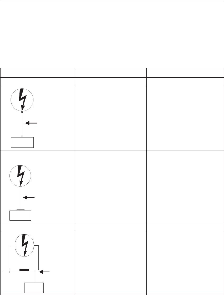
Coupling Mechanism Cause Typical Interference Sources
Direct Coupling Direct or metallic coupling
lhii
Switched devices (supply
ff d b i d
SIMATIC S5
Interference
Direct Coupling
Path
always occurs when two circuit
s
have a common conductor
affected by inverters and
external power supply units)
Motors being started
Different potentials of
component cases with a
common power supplys
Static discharges
Capacitive Coupling Capacitive or electrical couplin
g
bd
Interference pickup via
ll l i l bl
SIMATIC S5
Interference
Capacitive Coupling
Path
occurs between conductors
which are at different potentials.
The degree of coupling is
proportional to the voltage
variation as a function of time.
parallel signal cables
Static discharge of the
operator
Contactors
Inductive Coupling Inductive or magnetic coupling
bd
Transformers, motors,
li ld
SIMATIC S5
Interference
Inductive
Coupling Path
Signal
occurs between two conductor
loops through which current is
flowing. Interference voltages
are induced by the magnetic
fluxes associated with the
currents. The degree of couplin
g
is proportional to the current
variation as a function of time.
electric welders
Parallel AC supply cables
Cables whose currents are
switched⁄
Signal cables with a high
frequency
Unconnected coils
Coupling
Mechanisms and
Typical
Interference
Sources at a
Glance
Installation Guidelines
3-5
System Manual
C79000-G8576-C199-06
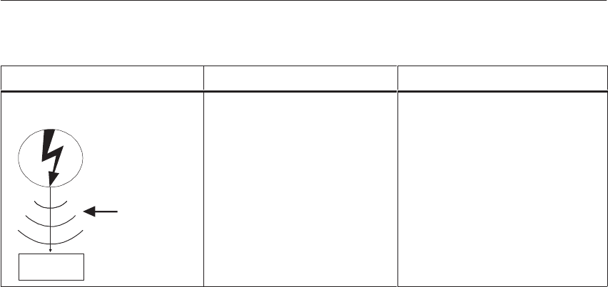
Coupling Mechanism Typical Interference SourcesCause
Radiated Interference There is a radiation path when a
d i bj d
Local transmitters
(di)
SIMATIC S5
Interference
Radiation Path
conductor is subjected to an
electromagnetic wave.
Impinging of the wave results i
n
induced currents and voltages.
(e.g. two-way radios)
Spark gaps (spark plugs,
collectors in electric motors,
welders)
Installation Guidelines

3-6 System Manual
C79000-G8576-C199-06
3.1.2 The Most Important Basic Rules for Ensuring EMC
It is often sufficient to comply with a few elementary rules for ensuring
EMC. When installing the control system, therefore, observe the following
five basic rules.
When installing the programmable controllers, provide large-area good
quality grounding of the inactive metal parts (see Section 3.2).
Make a large-area low-impedance interconnection of all inactive metal
parts.
For screw connections on painted and anodized metal parts, either use
special contact washers or remove the insulating protective layers.
If possible, do not use aluminum parts. Aluminum oxidizes easily and is
therefore less suitable for grounding.
Make a central connection between the chassis ground and the
ground/protective ground conductor system.
Ensure proper routing of lines when wiring (see Sections 3.3.1 and 3.3.2).
Arrange the cabling in line groups. (AC power cable, power supply lines,
signal lines, data lines)
Always install AC power cables and signal or data lines in separate ducts
or bunches.
Route the signal and data lines as closely as possible to grounded surfaces
such as cabinet elements, metal bars and cabinet panels.
Ensure that cable shields are properly secured (see Section 3.3.3).
Data lines must be shielded. The shield should be connected at both ends.
Analog lines must be shielded. For the transfer of signals with low
amplitudes, it may be advisable to connect the shield at only one end.
Provide the line shields with a large-area connection to a shield/protective
conductor bar immediately after the cabinet inlet, and secure the shields
with cable clamps. Route the grounded shield as far as the module
without interruption, but do not connect the shield there again.
Ensure that the shield/protective ground bar has a low-impedance
connection to the cabinet.
Use metal or metallized connector cases for shielded data lines.
Installation Guidelines

3-7
System Manual
C79000-G8576-C199-06
Employ special EMC measures for particular applications (see
Section 3.3.4).
Fit quenching elements to all inductances which are not controlled by
SIMATIC S5 modules.
Use incandescent bulbs for illuminating cabinets, and avoid fluorescent
lamps.
Create a standard reference potential; ground all electrical apparatus if
possible (see Sections 3.4 and 3.5).
Use specific grounding measures. Grounding of the control system is a
protective and functional measure.
System parts and cabinets with central controllers and expansion units
should be connected to the ground/protective conductor system in star
configuration. This serves to avoid the creation of ground loops.
In the case of potential differences between system parts and cabinets,
install equipotential bonding conductors of sufficient rating.
Installation Guidelines

3-8 System Manual
C79000-G8576-C199-06
3.2 Installation of Programmable Controllers for EMC
Measures for suppressing interference voltages are often applied only when
the control system is already operational and proper reception of a useful
signal is impaired. The reason for such interference is usually inadequate
reference potentials caused by mistakes in equipment assembly. Described in
the following sections are:
Basic rules for grounding the inactive metal parts
Examples of cabinet assembly for EMC
Example of rack and wall mounting for EMC
3.2.1 Basic Rules for Assembling and Grounding the Inactive Metal
Parts
Ensure wide-area chassis grounding of the inactive metal parts when
mounting the equipment. Properly implemented grounding creates a uniform
reference potential for the control system, and reduces the effects of
picked-up interference.
Chassis grounding is understood to mean the electrical connection of all
inactive parts. The entirety of all interconnected inactive parts is the chassis
ground.
Inactive parts are conductive parts which are electrically isolated from active
parts by basic insulation, and can only develop a voltage in the event of a
fault.
The chassis ground must not develop a dangerous touch voltage, even in
the event of a fault. The ground must therefore be connected to the protective
ground conductor. To prevent ground loops, locally separated ground
elements such as cabinets, structural and machine parts, must always be
connected to the protective ground system in star configuration.
Ensure the following when chassis grounding:
Connect the inactive metal parts with the same degree of care as the
active parts.
Ensure low-impedance metal-to-metal connections, e.g. with large-area
good quality contact.
When you are incorporating painted or anodized metal parts in the
grounding, these insulating protective layers must be penetrated. Use
special contact washers or remove the insulating layer.
Protect the connection points from corrosion, e.g. with grease.
Movable grounded parts such as cabinet doors must be connected via
flexible grounding strips. The grounding strips should be short and have a
large surface because the surface is decisive in providing a path to ground
for high-frequency interference.
Installation Guidelines
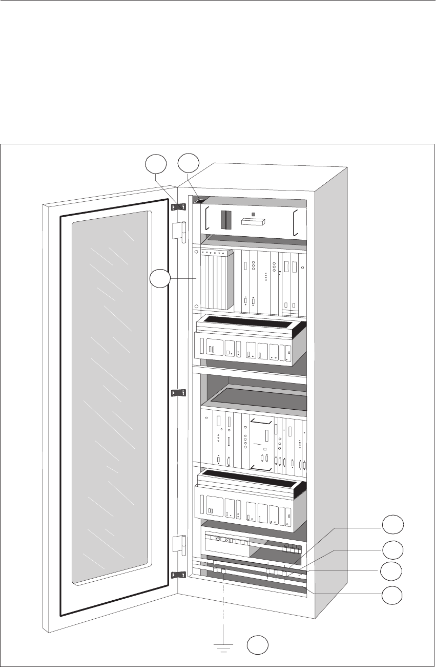
3-9
System Manual
C79000-G8576-C199-06
3.2.2 Example of Cabinet Assembly for EMC
The example of cabinet assembly in the figure shows the various measures,
the grounding of inactive metal parts and the connection of shielded cables.
This example applies only to grounded operation. Follow the points
numbered in the figure during assembly.
2
1
7
6
5
4
8
3
Figure 3-2 Example of Cabinet Assembly for EMC
Installation Guidelines

3-10 System Manual
C79000-G8576-C199-06
ÀGrounding strips
If there are no large-area metal-to-metal connections, you must
connect inactive metal parts such as cabinet doors and supports
with grounding strips. These should be short and have a large surface.
ÁCabinet members
The cabinet members should have a large-area connection to the
cabinet housing (metal-to-metal connection).
ÂMounting bracket for subrack
There must be a large-area metal-to-metal connection between
cabinet member and mounting bracket.
ÃSignal lines
With shielded signal lines, the shield must be secured to the
protective conductor bar or an additionally fitted shield bar using
large-area cable clamps.
ÄCable clamp
The cable clamp must enclose and make contact with the shield braid
over a large area.
ÅShield bar
This bar must have a large-area connection to the cabinet members
(metal-to-metal connection). It serves for grounding the cable shields.
ÆProtective conductor bar
The protective conductor bar must have a large-area connection to
the cabinet members (metal-to-metal connection). The protective
conductor bar must be connected to the protective conductor system
via an external conductor (at least 10 mm2 ). This is essential for
providing a reliable path to ground for fault currents and interference
currents.
ÇConductor to the protective conductor system (ground point)
The conductor must have a large-area connection to the protective
conductor system (ground point).
Installation Guidelines
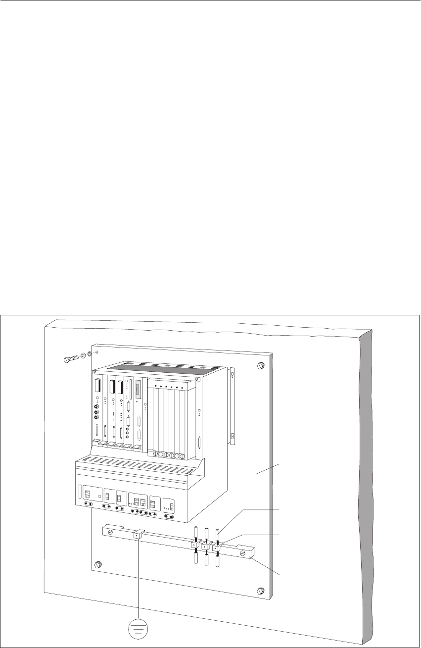
3-11
System Manual
C79000-G8576-C199-06
3.2.3 Example of Rack and Wall Mounting for EMC
To operate your control system in a low-interference environment whilst
observing the permissible ambient conditions (see “Technical
Specifications”), you can mount the programmable controllers on racks or
directly on walls.
Picked-up interference should be given a path to large metal surfaces. You
should therefore secure standard sectional rails, shield and protective
conductor bars to metal structural elements. For wall mounting in particular,
installation on reference potential surfaces made of sheet steel has proved
advantageous.
When installing shielded cables, provide a shield bar for connecting the cable
shields. The shield bar can also be the protective conductor bar.
Ensure the following for rack and wall mounting:
SSuitable contacting aids should be used on painted and anodized metal
parts. Use special contact washers or remove the insulating protective
layers.
SProvide large-area, low-impedance metal-to-metal connections when
securing the shield/protective conductor bar.
SAC conductors must be covered.
Shield/Protective
Conductor Bar
Cable Clamp for
Shield Contact
Shielded Signal
Line
Reference Potential
Surface
Connection to
P. Ground: 10 mm@
Figure 3-3 Wall Mounting of an S5-135/155U PLC
Installation Guidelines

3-12 System Manual
C79000-G8576-C199-06
3.3 Wiring of Programmable Controllers for EMC
The following section describes:
Routing of cables within and outside cabinets
Equipotential bonding between devices
Single and double-ended connection of cable shields
Checklist for electromagnetically compatible installation
3.3.1 Routing of Cables
This section covers the routing of bus, signal and supply lines. The purpose
cable routing is to suppress crosstalk between cables laid in parallel.
For electromagnetically compatible routing of cables and lines, it is
expedient to subdivide the lines into the following line groups and lay the
groups separately.
Shielded bus and data lines (for programmer, OP, SINEC L1, SINEC L2,
printer, etc.)
Shielded analog lines
Unshielded lines for DC voltage v 60 V
Unshielded lines for AC voltage v 25 V
Coaxial cables for monitors
Unshielded lines for DC voltage > 60V and v 400V
Unshielded lines for AC voltage > 25V and v 400V
Unshielded lines for DC and AC voltage > 400V
Lines for SINEC H1
From the combination of individual groups in the following table, you can
read off the conditions for laying the line groups.
Group A Group B Group C Group D
Group A
Group B
Group C
Group D
Routing of Cables
Within and
Outside Cabinets
Group A
Group B
Group C
Group D
Installation Guidelines
3-13
System Manual
C79000-G8576-C199-06
Legend for the table
Lines can be laid in common bundles or cable ducts.
Lines must be laid in separate bundles or cable ducts (without
minimum clearance).
Lines within cabinets must be laid in separate bundles or cable
ducts; outside the cabinets but within buildings, they must be laid
over separate cable routes with a clearance of at least 10 cm.
Lines must be laid in separate bundles or cable ducts with a
clearance of at least 50 cm.
Outside buildings, lay the lines on metal cable trays if possible. Provide the
joints between cable trays with an electrical connection and ground the cable
trays.
When laying lines outside buildings, you must observe the valid lightning
protection and grounding measures. The following applies in general:
!Caution
Where cables and lines for SIMATIC S5 controllers are to be laid
outside buildings, you must apply measures for internal and external
lightning protection.
Outside the buildings, lay your lines either
in metal conduit grounded at both ends,
or
in concreted cable ducts with continuously connected reinforcement.
Protect the signal lines from overvoltages by means of
varistors
or
inert gas-filled surge diverters.
Fit these protective devices at the cable entry into the building.
Note
Lightning protection measures always require an individual assessment of
the entire installation. For clarification, please consult your Siemens regional
office or a company specializing in lightning protection.
Ensure adequate equipotential bonding between the connected equipment
(see Section 3.3.2).
Routing of Cables
Outside Buildings
Lightning
Protection
Equipotential
Bonding
Installation Guidelines

3-14 System Manual
C79000-G8576-C199-06
3.3.2 Equipotential Bonding
Between separate sections of an installation, potential differences can
develop if
Sprogrammable controllers and I/O devices are connected via a
non-floating link, or
Scable shields are connected at both ends and are grounded at different
parts of the system.
Different AC supplies, for example, can cause potential differences. These
differences must be reduced by installing equipotential bonding conductors to
ensure functioning of the electronic components.
The following points must be observed for equipotential bonding:
SThe lower the impedance of the equipotential bonding conductor, the
greater is the effectiveness of equipotential bonding.
SWhere shielded signal lines are laid between the relevant sections of the
system and connected at both ends to the ground/protective conductor, the
impedance of the additional equipotential bonding conductor must not
exceed 10 % of the shield impedance.
SThe cross-section of the equipotential bonding conductor must be rated
for the maximum circulating current. The following cross-sections of
copper have proved to be satisfactory in practice:
–16 mm@ of copper for equipotential bonding conductors
of up to 200 m in length
–25 mm@ of copper for equipotential bonding conductors
of more than 200 m in length.
SUse copper or zinc-plated steel for equipotential bonding conductors.
They must be given a large-area connection to the ground/protective
conductor and protect it from corrosion.
SThe equipotential bonding conductor should be laid so that the smallest
possible areas are enclosed between the equipotential bonding conductor
and signal lines.
Equipotential Bonding Conductor
Signal Line
Figure 3-4 Routing of Equipotential Bonding Conductor and Signal Line
Installation Guidelines

3-15
System Manual
C79000-G8576-C199-06
3.3.3 Shielding of Cables and Lines
Shielding is a method of attenuating magnetic, electrical or electro-magnetic
interference fields. Interference currents on cable shields are given a path to
ground via the shield bar which is electrically connected to the housing. A
low-impedance connection to the protective conductor is particularly
important so that these interference currents themselves do not become an
interference source.
Where possible, only use lines with a braided shield. The coverage density of
the shield should be more than 80 %. Avoid lines with a foil shield because
the foil can be very easily damaged by tensile strain and compression during
fitting; this results in reduced effectiveness of the shield.
As a rule, line shields should always be connected at both ends. This is the
only way to achieve a good degree of interference suppression in the higher
frequency region.
Only in exceptional cases should the shield be connected at one end only, as
this only achieves attenuation of the low frequencies. Single-ended shield
connection may be more advantageous when:
an equipotential bonding conductor cannot be laid;
analog signals (of a few mV or mA) are to be transmitted;
foil (static) shields are used.
With data lines for serial communication, always use metal or metallized
connectors. Secure the shield of the data line to the connector case. Do not
connect the shield to Pin 1 of the connector.
For stationary operation, it is advisable to fully strip the insulation from the
shielded cable and connect it to the shield/protective conductor bar.
Note
In the event of potential differences between ground points, a circulating
current may flow through the shield connected at both ends. In this case,
install an additional equipotential bonding conductor (see Section 3.3.2).
Installation Guidelines

3-16 System Manual
C79000-G8576-C199-06
Please observe the following points when connecting the shield:
Use metal cable clamps for securing the braided shield. The clamps must
enclose the shield over a large area and provide a good contact.
Connect the shield to a shield bar immediately after the cable entry into
the cabinet. Route the shield as far as the module but do not connect it
there again.
Figure 3-5 Example of Securing Shielded Lines with Cable Clamps
Installation Guidelines
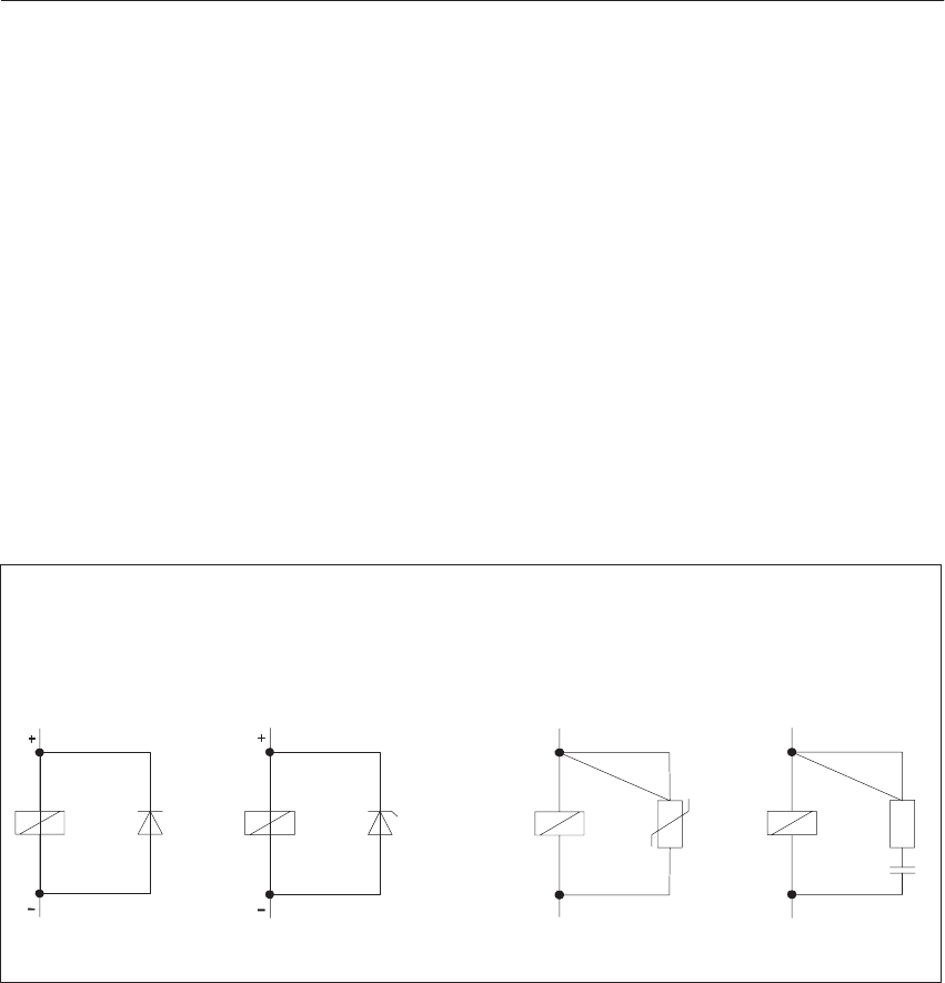
3-17
System Manual
C79000-G8576-C199-06
3.3.4 Special Measures for Interference-Free Operation
As a rule, inductances such as contactor or relay coils controlled by
SIMATIC S5 do not require external quenching elements in the circuit,
because the quenching elements are already integrated in the modules.
Inductances should only be fitted with quenching elements
when SIMATIC S5 output currents can be switched off by additionally
fitted contacts, such as relay contacts. In this case the integrated
quenching elements in the modules are no longer effective;
if they are not controlled by SIMATIC S5 modules.
You can place freewheel diodes, varistors or RC networks in circuit with
inductances.
Circuitry for DC-Operated
Inductances
With Diode With Zener Diode With Varistor With RC Network
Circuitry for AC-Operated
Inductances
Figure 3-6 Quenching Circuits for Inductances
Fitting Quenching
Elements to
Inductances
Installation Guidelines
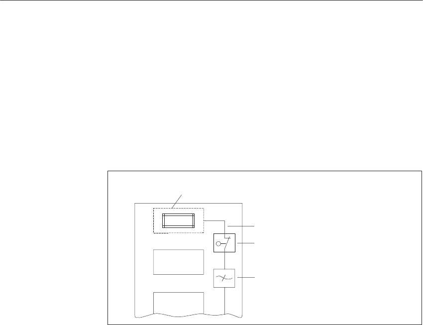
3-18 System Manual
C79000-G8576-C199-06
A power socket should be fitted in each cabinet for the AC supply to
programmers. The sockets should be powered from the distribution system to
which the protective conductor for the cabinet is also connected.
Use incandescent bulbs, such as LINESTRA lamps, for cabinet lighting.
Avoid using fluorescent lamps because they generate interference fields. If
the use of fluorescent lamps cannot be avoided, apply the measures shown in
the following figure.
Shielded Cable
Screen Over the Lamp
Metal-Enclosed Switch
AC Filter or
Shielded Power Cable
Figure 3-7 Measures for Interference Suppression of Fluorescent Lamps in a
Cabinet
AC Power
Connection for
Programmers
Cabinet Lighting
Installation Guidelines

3-19
System Manual
C79000-G8576-C199-06
3.3.5 Checklist for the Electromagnetically Compatible Installation of
Control Systems
EMC Measures Notes
Connection of inactive parts (Section 3.2)
Check, in particular, the connections on:
Subracks
Cabinet members
Shield and protective conductor bars
Do all inactive metal parts have a large-area, low-impedance
interconnection and ground?
Is there a satisfactory connection to the ground/protective conductor
system?
Have insulating layers on painted and anodized surfaces been
removed, or have special contact washers been used for the
connections?
Are connections protected from corrosion, e.g. by grease?
Are cabinet doors connected to the cabinet element with grounding
strips?
Routing of cables (Section 3.3.1)
Cabling subdivided into line groups?
Supply cables (230 to 400 V) and signal lines laid in separate ducts or
bundles?
Equipotential bonding (Section 3.3.2)
With a separate arrangement, check that the equipotential bonding
conductor has been correctly laid.
Shielding of cables (Section 3.3.3)
Have metal connectors been used throughout?
Are all analog and data lines shielded?
Are line shields connected to the shield or protective conductor bar at
the cabinet entry?
Are line shields secured with cable clamps over a large area and at
low impedance?
Are line shields connected at both ends where possible?
Inductances (Section 3.3.4)
Are contactor coils which are switched via contacts, fitted with
quenching elements?
Installation Guidelines

3-20 System Manual
C79000-G8576-C199-06
3.4 Power Supplies for Programmable Controllers and I/Os
This section describes:
Which circuits you must distinguish in the control system and which
demands are made on the power supply.
Connection and grounding concept with higher-level infeed from
grounded, centrally grounded and ungrounded supplies.
Connecting the power supply to non-isolated and isolated modules.
3.4.1 Power Supplies for Control Systems with SIMATIC S5
For control systems with SIMATIC S5, you will need:
A power supply for the internal PLC circuits (control power supply)
and a load power supply for the input and output circuits.
The power supply for the internal PLC circuits powers the CPU and the
modules used.
Note
Ensure that the control power supply is not overloaded. Make a current
addition and estimate the current drawn by all modules.
The load power supply feeds the input and output circuits (load circuits) as
well as sensors and actuators. Only a power supply which offers safe
electrical isolation from the AC system may be used for the 24 V DC supply.
!Caution
Only safety-separated low voltage DC v 60 V may be used for the 24 V DC
supply. The safety separation can be implemented according to the
requirements of, amongst other sources, VDE 0100, Part 410/HD
384-4-41/IEC 364-4-41 (functional extra-low voltage with safety separation)
or VDE 0805/EN 60950/IEC 950 (safety extra-low voltage SELV) or VDE
0106, Part 101.
Power Supply for
the PLC Circuits
Load Power
Supply for the I/Os
Installation Guidelines

3-21
System Manual
C79000-G8576-C199-06
The electronic short-circuit protection of digital output modules only
responds when 3-times the rated current is exceeded. You should therefore so
design the load power supply units that the unit can supply the current
required for shutting down in the event of a short-circuit at one output.
In the event of short-circuits at digital outputs, if the load power supply is not
adequately rated, a current which is higher than the rated current can flow for
a longer period without responding of the electronic short-circuit protection
of the DQ module. Operation in the overload region can destroy the module.
If you use non-floating modules, you must create a common reference
potential for the internal control circuits of the PLC and for the load circuits.
The reference potential of the load power supply should therefore be
connected to the ground terminal of the PLC (PE or protective conductor
terminal). The ground terminal is permanently connected to the internal
reference potential of the controller.
Note
If you use switched-mode power supply units for floating analog modules
and BEROs, you must fit an AC system filter to the input of the power
supply.
3.4.2 Connecting the Programmable Controller and Load Power
Each of the following figures shows a circuit example for connecting the
control and load power supplies as well as the grounding concept for
operation from:
Grounded supplies
Centrally grounded supplies
Ungrounded supplies
When assembling the control system, observe the following explanations.
The text contains identification numbers relating to Figures 3-8 to 3-10.
For the programmable controller, sensors and actuators, you must fit a
main switch to DIN VDE 0113, Part 1, or an isolating device to DIN
VDE 0100, Part 460. If an AC plug is used as the isolating device, the
socket must be in the vicinity of the central controller and must be easily
accessible (VDE 0805, 1.7.2). These devices are not required in the case
of a subsystem where the appropriate devices are fitted at a higher level.
The circuits for sensors and actuators can be given group protection for
short-circuit and/or overload . According to VDE 0100, Part 725,
single-phase protection is required; and all-phase protection to DIN VDE
0113, Part 1.
Ratings of Load
Power Supplies
Load Power
Supply for
Non-Floating
Modules
Load Power
Supply for
Floating Modules
Main Switch and
Protection
Installation Guidelines

3-22 System Manual
C79000-G8576-C199-06
For 24 V DC load circuits, you require a load power supply unit with
safety separation. If an AC plug is used as the isolating device, the socket
must be in the vicinity of the central controller and easily accessible
(VDE 0805, 1.7.2).
Unregulated load power supply units require a reservoir capacitor
(rated at 200 mF per 1 A load current). Connect the capacitor in parallel
with the output terminals of the load power supply.
According to DIN VDE 0113, Part 1, control systems with more than five
items of electromagnetic apparatus require isolation by a transformer;
according to DIN VDE 0100, Part 725, it is recommended .
Load power supplies should be grounded if possible . Provide a
detachable connection to the protective conductor at the load power
supply unit (terminal L- or M) or on the secondary side of the isolating
transformer.
!Caution
For ungrounded power supplies, you must provide insulation monitoring if⁄
hazardous system states can be caused by double faults;
there is no safety separation;
circuits are operated with voltages of more than 120 V DC;
circuits are operated with voltages of more than 50 V AC.
Load Power
Supply
Grounding
Installation Guidelines
3-23
System Manual
C79000-G8576-C199-06
Operation from grounded power supplies offers the best rejection of
interference.
Cabinet
Control Power Supply
L+
L–
L1
N
L+/L1
L–/N
PE
PE
AC
DC
AC
AC
AC
DC
AC
DC
Non-Float-
ing Output
Non-Float-
ing Input
Floating
Output
Floating
Input
L1
L2
L3
N
PE
Programmable Controller
Low-Voltage Distribution
e.g. TN-S System
Protective Conductor Bar
in Cabinet
24 to 230 V AC Load Supply
for AC Modules
5 to 60 V DC Load Supply for
Non-Floating DC Modules
5 to 60 V DC Load Supply
for Floating DC Modules
Process I/Os
PS CPU
U
0 V
int
Figure 3-8 Operating a Programmable Controller with Process I/Os from a Grounded Supply
Operating a
Programmable
Controller with
Process I/Os from
a Grounded
Supply
Installation Guidelines
3-24 System Manual
C79000-G8576-C199-06
In systems with their own transformers or generators, the PLC is connected
to the central ground. A detachable connection should be provided so that
ground faults can be measured.
The PLC should be insulated from cabinet/protective conductor potential. To
maintain this isolated arrangement, all connected devices must be operated
with capacitive grounding or ungrounded. For this reason, programmers
should only be powered via an isolating transformer.
Cabinet
Control Power Supply
L+
L-
L1
L1 L2 L3
N
N
L+/L1
L–/N
PE
PE
AC
DC
AC
AC
AC
DC
AC
DC
Non-Float-
ing Input
L1
L2
L3
Programmable Controller, Insulated Arrangement
Higher-Level Supply
Protective Conductor Bar in Cabinet,
Insulated Arrangement
24 to 230 V AC Load Supply for AC Modules
5 to 60 V DC Load Supply for Non-Floating DC Modules
5 to 60 V DC Load Supply for Floating DC Modules
Process I/Os
Central Ground,
e.g. Foundation
Ground
Detachable Con-
nection for
Measurement
Purposes
PS CPU
U
0 V
int
Non-Float-
ing Output Floating
Input Floating
Output
Figure 3-9 Operating a Programmable Controller with Process I/Os from a Centrally Grounded Supply
Operating a
Programmable
Controller with
Process I/Os from
a Centrally
Grounded Supply
Installation Guidelines
3-25
System Manual
C79000-G8576-C199-06
In cases in which the higher-level power supply is not grounded, you must
connect the programmable controller to a separate protective
conductor/ground (e.g. foundation ground). Operation of the PLC with
non-floating power supplies is not allowed.
When connecting the power supplies, please note:
In 3 x 230 V systems, you may connect the power supply directly to two
phases.
Schrank
Control Power Supply
L+
L–
L1
L2
PE
L+/L1
L–/L2
PE
AC
DC
AC
AC
AC
DC
AC
DC
Non-Float-
ing Input
L1
L2
L3
PE
e.g. IT System (3 X 230V)
Programmable Controller
Protective Conductor Bar
in Cabinet
Low-Voltage Distribution,
24 to 230 V AC Load Supply
for AC Modules
5 to 60 V DC Load Supply
for Non-Floating DC Modules
Process I/Os
Protective
Conductor
Grounding
PS CPU
U
0 V
int
Non-Float-
ing Output Floating
Input Floating
Output
5 to 60 V DC Load Supply
for Floating DC Modules
Figure 3-10 Operating a Programmable Controller with Process I/Os from an Ungrounded Supply
In 3 x 400 V systems, a connection between phase and neutral conductor is
not allowed (excessively high voltage in the event of a ground fault).
Intermediate transformers should be used in these systems.
Operating a
Programmable
Controller with
Process I/Os from
an Ungrounded
Supply
Installation Guidelines
3-26 System Manual
C79000-G8576-C199-06
3.4.3 Connecting Non-Floating or Floating Modules
Shown in the following sections are the specical features when installing
non-floating and floating modules.
In an installation with non-floating modules, the reference potentials of the
control circuit (0 Vint) and load circuits (0 Vext) are electrically connected.
The reference potential of the control circuit (0 Vint) is given by the PE or
protective conductor terminal and must be connected to the reference
potential of the load circuit via an externally laid conductor.
Shown in the following figure is a simplified installation with non-floating
modules. The arrangement is independent of the grounding concept. The
connections for grounding are therefore not drawn.
1L+
1L–
PE
Control Power
Supply
2L+
2L–
DC 24 V Load Power Supply
External Connection for a
Standard Reference Potential
PS CPU DI DQ
Data
0 V
Uint
Figure 3-11 Simplified Representation of an Installation with Non-Floating Modules
The voltage drop on line must not exceed 1 V. Otherwise there will be a
shift in reference potentials resulting in module malfunctions.
Installation with
Non-Floating
Modules
Installation Guidelines
3-27
System Manual
C79000-G8576-C199-06
Note
For 24 V DC digital output modules with electronic short-circuit protection,
you must ensure that the reference potential of the load power supply is
connected to terminal L- of the module. If this connection is missing (e.g.
open-circuit), a typical current of 15 mA can flow at the outputs. This output
circuit is sufficient
to prevent energized contactors or relays from being released
and to energize high-resistance loads (e.g. miniature relays).
With floating modules the control circuit and load circuit are metallically
isolated.
An arrangement with floating modules is required
for all AC load circuits and
for DC load circuits which cannot be coupled. The reasons are, for
example, different reference potentials of the sensors or grounding of the
positive terminal of a battery.
Shown in the following figure is a simplified installation with floating
modules. The arrangement is independent of the grounding concept. The
connections for grounding are therefore not drawn.
1L+
1L–
PE
24 V DC Control Power Supply
2L+
2L–
24 V DC Load Power Supply
PS CPU DI DQ
Data
0 V
Uint
L1
N
230 V AC Load Power Supply
Figure 3-12 Simplified Representation of an Arrangement with Floating Modules
Installation with
Floating Modules
Installation Guidelines

3-28 System Manual
C79000-G8576-C199-06
3.5 Interference-Free Installation of Centralized and Distributed
Interface Circuits
Subjects described in the following sections are the shielding and grounding
concept with centralized and distributed interface circuits.
Information on component selection, the mechanical arrangement and wiring
can be found in the appropriate reference manuals for the interface modules.
Note
If you use components which are not approved for the installation of a
centralized or distributed interface circuit, interference rejection may be
impaired.
3.5.1 Interference-Free Installation of Centralized Interface Circuits
When you connect the central controller and expansion unit centrally via
suitable interface modules, no particular shielding and grounding measures
are required. Ensure, however, that
all subracks are interconnected at a low resistance;
the subracks in a grounded arrangement have star-configuration
grounding;
the contact springs of the modules are clean and not bent, which could
affect the path to ground for interference currents.
3.5.2 Interference-Free Installation of Distributed Interface Circuits
If you interconnect the central controller and expansion unit in a distributed
arrangement using suitable interface modules, no particular shielding and
grounding measures are usually required. Only in industrial environments
with an extremely high level of interference is there a need for special
shielding and grounding.
In these cases, please observe the following points:
Cable shields should be connected to the shield bar in the cabinet,
immediately after the cable inlet;
- insulation is fully stripped from the cable for the purpose;
- braided shields are secured to the shield bar with as large an area as
possible (e.g. with metal ties which enclose the shield over a large
area).
Shield bars should be connected to the frame or cabinet panel over a large
area.
Cable shields should be connected to the cabinet conductor.
Installation Guidelines
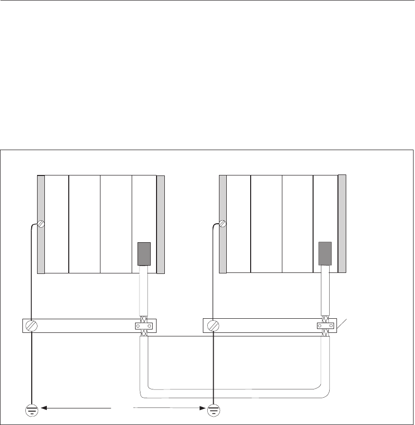
3-29
System Manual
C79000-G8576-C199-06
With distributed interfacing (IM 304/IM 314 and IM 301/IM 310), ensure
that the VDE specifications for laying the protective ground are complied
with; distributed interfacing is non-floating.
The measures described above are shown in the following figure. If the
permissible potential difference between ground points can be exceeded, you
must install an equipotential bonding conductor (cross-section w 16 mm2 of
copper).
Shield/Protective
Conductor Bar
< 7 V
CC EU
IM 304 IM 314
Figure 3-13 Shielding and Grounding the Connecting Cable
With distributed interfacing, you must use the prefabricated connecting
cables. You may have excess lengths of up to 100 m when installing the
connecting cable. These excess lengths must be bifilar-wound and deposited
at a point which is protected from electromagnetic interference.
Special Features
Installation Guidelines

3-30 System Manual
C79000-G8576-C199-06
3.6 Interference-Free Connection of Monitors
These sections cover the following topics:
Floating connection of cables at video inputs
Shielding and grounding concept
Information on selecting the components can be found in Catalog ST80.
3.6.1 Interference-Free Connection of a Monitor to the CP of the S5
Controller
Operator control and process monitoring systems from the COROS product
family can be used with monitor connections. The physical arrangement of
apparatus and the interference level of the environment are important for the
interference-free connection of monitors to SIMATIC S5 control systems.
The choice of monitor and video cables is governed by the following:
Whether the monitor and PLC are to be operated under low-interference
conditions or
under industrial conditions.
Where the monitor and PLC are installed under low-interference
environmental conditions and operated over short distances, the monitor and
PLC are at almost the same ground potentials. Interference and ground loop
disturbances are therefore not expected.
In these cases, you can drive the monitor both via TTL signals and via analog
signals. Digital cables or single-shielded coaxial cables can be used to
transmit the video signals. Note that the braided shield of the coaxial cable
serves as the return conductor and must not be connected to the shield bar.
The monitor and communication processor (CP) are interconnected without
additional shielding and grounding.
Where the monitor and PLC are installed under harsh industrial conditions
and operated over great distances, the devices may be at different ground
potentials. These different ground potentials may cause interference and
ground loop disturbances.
Operation of the
Monitor and PLC
under
Low-Interference
Conditions
Operation of the
Monitor and PLC
under Industrial
Conditions
Installation Guidelines

3-31
System Manual
C79000-G8576-C199-06
In these cases, double-shielded coaxial cables (triaxial cables) must be used
to transmit the video signals. The inner braided shield of the coaxial cable
serves as the return conductor and must not be connected to the shield bar.
The outer braided shield provides a path to ground for interference currents
and must be incorporated in the shielding and grounding measures.
To avoid ground loops, the electronics ground and housing ground of the
monitor must be independent. This requirement is met when:
The electronics and housing grounds of the monitor are metallically
isolated,
or the electronics and housing grounds are connected via a
voltage-dependent resistor (VDR) fitted by the manufacturer of the
monitor.
3.6.2 Shielding and Grounding
If the monitor and PLC are used under harsh industrial conditions, you must
ensure the following at the PLC end:
Cables shields should be connected to the shield bar in the cabinet,
immediately after the cable inlet;
- the video cables should be fully stripped;
- the outer braided shield should be secured to the shield bar of the
PLC over as large an area as possible (e.g. with metal ties which
enclose the shield or with cable clamps).
Shield bars should be connected to the frame or cabinet panel over a large
area.
Shield bars should be connected to the ground point of the cabinet.
You must ensure the following at the monitor end:
Separate the electronics ground and housing ground.
- Remove the jumper at the monitor to separate the two grounds.
- Fit touch protection at the video sockets because hazardous touch
voltages of more than 40 V may be present at the sockets after
separation of the grounds.
Connect the ground clamp of the monitor to the protective conductor.
Connect the cable shields to the ground clamp of the monitor;
- fully strip the video cables;
- secure the outer braided shield to the ground clamp of the
monitor over a large area.
Installation Guidelines

3-32 System Manual
C79000-G8576-C199-06
Shown in the following figure is a simplified representation of the shielding
and grounding measures for installing the monitor and PLC.
Shield/
Protective
Conductor
Bar
External Shield
Connected to
Ground Clamp
Monitor with
Separate
Electronics and
Housing Grounds
CP
Figure 3-14 Shielding and Grounding for a Distributed Arrangement of Monitor and PLC
Installation Guidelines

3-33
System Manual
C79000-G8576-C199-06
3.7 Selection and Installation of Cabinets with SIMATIC S5
The following criteria must be observed when selecting and dimensioning a
cabinet:
Ambient conditions at the point of installation of the cabinet
Clearances for power supplies and subracks
Total power dissipation of components in the cabinet
The ambient conditions at the point of installation of the cabinet
(temperature, humidity, dust, effects of chemicals) govern the required
degree of protection of the cabinet (IP XX) as shown in the following figure.
Further information on types of protection can be found in IEC 529.
Installation Guidelines
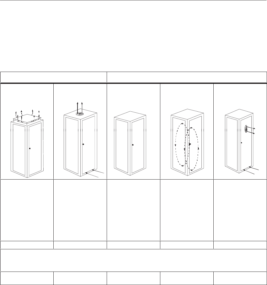
3-34 System Manual
C79000-G8576-C199-06
3.7.1 Types of Cabinet
The following table provides on overview of the most common types of
cabinet. It also shows the principle of heat removal, as well as the estimated,
maximum achievable power loss removal and the type of protection* .
Open Cabinets Closed Cabinets
Through-ventilation by
natural convection Increased
through-ventilation Natural convection Forced circulation
using fan assembly,
enhanced natural
convection
Forced circulation
using heat exchanger,
external ventilation
inside and outside
Heat removal primarily
by natural thermal
convection, small
portion via the cabinet
wall
Increased heat removal
through increased air
movement
Heat removal only
through the cabinet
wall; only low power
dissipation permissible.
Heat accumulation
usually occurs in the
top of the cabinet.
Heat removal only via
the cabinet wall. Forced
ventilation of the
internal air results in
improved heat removal
and prevention of heat
accumulation.
Heat removal through
exchange between
heated internal air and
cool outside air. The
increased surface of the
folded-area sectional
wall of the heat
exchanger and forced
circulation of internal
and external air permit
good heat output.
Type of protect. IP 20 Type of protect. IP 20 Type of protect. IP 54 Type of protect. IP 54 Type of protect. IP 54
Typical removable power dissipation under the following boundary conditions:
Cabinet size 2200 x 600 x 600 mm
Temperature difference between external and internal temperature of the cabinet: 20 °C**
Up to 700 W Up to 2700 W (1400 W
with very fine filter) Up to 260 W Up to 360 W Up to 1700 W
*The location and ambient conditions are decisive for selection of the type of cabinet protection
( see IEC 529 and DIN 40050).
** For other temperature differences, refer to the temperature characteristics of the cabinet
manufacturer.
3.7.2 Clearances in Cabinets
You must first define the components to be fitted in the cabinet. Then
calculate the total power dissipation of the individual components. The
following stipulations must be observed:
The expansion units can be accommodated with the respective central
controller in one cabinet, or in two or more cabinets (centralized or
distributed).
On account of the required clearances and maximum permissible
installation height for control elements, a maximum of three SIMATIC S5
devices can be arranged one above the other.
Installation Guidelines
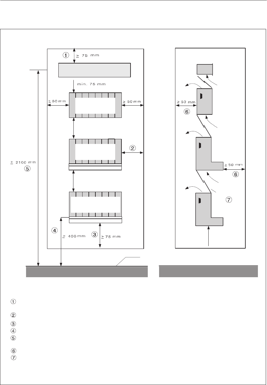
3-35
System Manual
C79000-G8576-C199-06
Maximum installation height for control elements: 2100 mm to DIN VDE 0106, Part 100,
2000 mm to DIN VDE 0113.
Space for air circulation (400 mm deep cabinets are sufficient).
75 mm min., smaller clearances are possible with a closed cabinet roof and an additional, separate ventilation
roof.
75 mm min. from obstructions (large apparatus) in the air inlet area.
A maximum clearance of 400 mm is possible (50 mm min.) when devices are connected next to one another.
400 mm minimum installation height above access level for control elements, 200 mm for connections.
Baffles are recommended to improve the air supply.
&#
&#
&#
+
!!(#&""*
%#
)&$%
#
)&$%
#
)&$%
#
%#
%#
%#
$$'
!## $
!## $
Figure 3-15 Clearances in the Cabinet
Installation Guidelines

3-36 System Manual
C79000-G8576-C199-06
Where subracks (CC and EU) are arranged one above the other, the
installation clearances in the following table must be observed.
Upper Subrack Lower Subrack Min. Clearances Max. Clearances
S5-135U/ 155U
or
S5-115U
S5-135U 75 mm
87 mm if baffle
is used
The maximum clearance
is limited by the lengths
of connecting cables for
hi f dl
or
S5
-
90U/ 95U/ 100U
S5-115U with fan 60 mm
g
the interface modules.
S5
-
90U/
95U/
100U
S5-115U without fan 100 mm
S5-90U/ 95U/ 100U 75 mm
The following two points should be observed to improve the air circulation
within the cabinet:
The expansion unit with the greatest power dissipation to be removed
should be the upper unit.
If subracks of the S5-135U/155U series are installed together with
subracks of the S5-90U to 115U series in one cabinet, the rear panels of
all subracks must be at the same distance from the rear wall of the
cabinet.
Installation Guidelines
3-37
System Manual
C79000-G8576-C199-06
3.7.3 Removal of Power Dissipation from Cabinets
The power dissipation that can be removed from a cabinet is governed by the
cabinet design, its ambient temperature and the arrangement of equipment in
the cabinet.
Shown in the following figure is a diagram with guide values for the
permissible ambient temperature of a cabinet measuring 600 x 600 x 2200
mm, as a function of power dissipation. These values only apply to the
arrangement of equipment in the cabinet as given in Section 3.6.2. Further
details can be found in Catalogs NV21 and ET1.
20
30
40
50
55
200 400 600 800 1000 1200 1400 W
Power Dissipation
Ambient Temperature
in oC
1
2
3
1 Closed cabinet with heat exchanger of size 11/6 (920 x 460 x 111 mm)
2 Cabinet with through-ventilation by natural convection
3 Closed cabinet with natural convection and forced circulation using fan
Figure 3-16 Maximum Cabinet Ambient Temperature as a Function of Power Dissipation
Note
When fitting the subracks of the S5-135U/155U series, the maximum power
dissipation which can be removed by the fans must not be exceeded. The
maximum removable power dissipation per unit with a supply air
temperature of 55 °C is 250 W. This value is increased by 20 W for each
reduction in supply air temperature by 1 °C.
Installation Guidelines
3-38 System Manual
C79000-G8576-C199-06
!Caution
Modules with a hard disk drive can only be used at an ambient temperature
of up to 50 °C.
3.7.4 Examples for Determining the Type of Cabinet
The following example shows the maximum permissible ambient
temperature with various cabinet types and the same power dissipation.
Example
The following equipment configuration is given:
1 Central controller 200 W
2 Expansion units, 250 W power dissipation each 500 W
1 Load PS, 24 V/40 A, 6EV1 362-5BK00 (full load) 200 W
Total power disspation 900 W
From Figure 3-16, with a total power dissipation of 900 W, the maximum
ambient temperatures given by the table are as follows:
Cabinet Design Max. Permissible Ambient
Temperature
Closed, with natural convection and forced
circulation (Curve 3) (Operation not possible)
Open with through-ventilation (Curve 2) Approx. 33 °C
Closed, with heat exchanger (Curve 1) Approx. 42 °C
Installation Guidelines

3-39
System Manual
C79000-G8576-C199-06
3.7.5 Determining the Power Dissipation of Modules
The power dissipation of the modules can be found in the technical
specifications of the catalogs or manuals. If these values are not yet
incorporated in the technical specifications, they can be easily calculated
from the current consumption. The value of current consumption must be
multiplied by the corresponding voltage value.
Examples
CPU 928B Current
consumption 5A/5V
Power dissipation = 25 W
CP 143 Current
consumption 4A/5V
0.5A/15V
0.04A/24V
Power dissipation
approx. 21 W
IM 304 Current
consumption 1.5A/5V
Power dissipation = 7.5 W
Installation Guidelines

3-40 System Manual
C79000-G8576-C199-06
Installation Guidelines

4-1
System Manual
C79000-G8576-C199-06
Central Controllers and Expansion Units
Power Supply Units
The S5-135U/155U programmable controller comprises a central controller
(CC) and, depending on the configuration, one or more expansion units
(EUs). Expansion units are connected when there are unsufficient central
controller slots, or when you wish to position I/O modules as closely to the
process as possible (see also Chapter 2).
With the central controllers and some expansion units, the modules are
directly powered and cooled via the integrated power supply plug-in module.
With all other expansion units, power is supplied via the IMs from the CC
(see also Chapter 7).
Section Description Page
4.1 S5-135U/155U Central Controller 4-2
4.2 Expansion Units 4-15
4.3 Power Supply Units 4-19
4.4 6ES5 955-3NA12 Power Supply Unit 4-57
4.5 Fan Submodules 4-70
Chapter
Overview
4
4-2 System Manual
C79000-G8576-C199-06
4.1 S5-135U/155U Central Controller
This description applies to the S5-135U/155U CC with the following power
supply units.
Order No. of the CC With Power Supply Unit Input Voltage
6ES5 188-3UA12 6ES5 955-3LC42 120 V/230 V AC, 18 A
6ES5 188-3UA22 6ES5 955-3LF42 120 V/230 V AC, 40 A
6ES5 188-3UA32 6ES5 955-3NC42 24 V DC, 18 A
6ES5 188-3UA52 6ES5 955-3NF42 24 V DC, 40 A
6ES5 135-3UA42 6ES5 955-3NA12 24 V DC, 10 A
4.1.1 Technical Description
The S5-135U/155U CC consists of a housing with backplane bus to accept
the individual modules, and a power supply unit with fans to power and cool
the modules. Shown in the following figure are the most important parts of a
central controller.
1)
2) 3)
4)
5)
6)
7)
9)
10)
8)
Figure 4-1 Assembly of a Central Controller
1. Housing with 21 slots for modules
2. Power supply unit with fans
3. Battery compartment
4. Cable duct
5. Locking bar
6. Mounting bracket
7. Sectional rail for individually locking the modules
8. Backplane bus
9. Filter subdrawer (optional)
10. Rechargeable battery
Assembly of a
Central Controller
Central Controllers and Expansion Units Power Suppl
y
Unit
s
4-3
System Manual
C79000-G8576-C199-06
The housing consists of bolted sheet-steel sections with ventilation openings
at the top and bottom. The housing contains the bus PCB for electrical and
logical interconnection of the modules. All the slots have guiderails which
accept the modules. Male and female connectors are thus precisely
positioned. There is a locking bar at the top of the housing to prevent the
modules from becoming accidentally detached. Modules with individual
locking are secured in the lower sectional rail. There is a cable duct for
incoming and outgoing cables at the front of the housing.
The power supply unit with the fans is situated in the lower part of the central
controller frame. Depending on the type of power supply, the input voltage is
either 24 V DC or 230/120 V AC. The AC version can be adjusted to the
required AC voltage with a selector switch.
The following table shows which modules can be inserted at which slots.
Slot No. 311 19 27 35 43 51 59 67 75 83 91 99 107 115 123 131 139 147 155 163
Module Type
923 coordinator
CPU 922/
CPU 928-3UA21/
CPU 928B-3UB21
CPU 928, CPU 928B
CPU 948
CP 5XX, CP 143,
CP 5430, CP 5431 1)
IM 300-5
IM 301-5 2)
IM 300-3, IM 301-3
IM 304, IM 308, IM 308B
IM 307 1) 3)
DI, DQ,
AI, AQ 1)
IP 241USW, IP 244,
IP 246, IP 247, IP 252 1)
IP 240, IP 241, IP 242,
IP 242A, IP 242B, IP 243,
IP 281 1) 4) 5)
IP 245
IP 257 6)
IP 260,
IP 261
Load power supply
-951 1)
Electrical connection Mechanical width
Housing
Power Supply Unit
Modules and Slot
Assignments in
the S5-135U/155U
CC
Central Controllers and Expansion Units Power Suppl
y
Unit
s
4-4 System Manual
C79000-G8576-C199-06
1) Allow for particular module widths; additional slots to the right may be occupied (see Catalog ST 54.1).
2) In the CC with Order No. 6ES5 135-3UA41, only at Slot 163
3) Observe jumper setting on the IM 307; interrupt transmission is only possible at Slots 107 to 131.
4) Operation at Slots 27, 43, 59, 139, 147 is only possible with severely restricted functions, because no interrupts are wired.
5) IP 243 without D/A or A/D converter can be used at Slots 27, 43, 59, 139 and 147.
6) Allow 1 to 4 slots for the DI/DQ 482 to the right of the IP 257.
!Caution
Do not insert modules at slots which are not intended for them, otherwise
these or other modules may be destroyed.
The following table shows which slots have particular characteristics. The
manuals for the individual modules explain how these characteristics can be
utilized.
Slot No. 311 19 27 35 43 51 59 67 75 83 91 99 107 115 123 131 139 147 155 163
Characteristic
PG Mux
possible 1) 0 1 2 3 4 5 6 7
Interrupt source
(process interrupt)
Battery backup
24 V supply
15 V supply
1) The numbers indicate the station numbers for programmer (PG) communication via PG multiplexers
of the COR 923C.
Central Controllers and Expansion Units Power Suppl
y
Unit
s

4-5
System Manual
C79000-G8576-C199-06
The modular packaging technique allows variable configuration of a CC with
modules and its adaptation to the particular automation task.
The various modules carry out the following tasks:
SCPU
The CPU processes the input signals of the PLC according to the user
program, and emits the results as output signals. The following CPUs can
be used in the S5-135U/155U PLC
– CPU 948
– CPU 928B
– CPU 928
– CPU 922
SCoordinators
By using a coordinator, you can configure the S5-135U/155U as a
multiprocessor controller with up to four task-oriented CPUs in different
combinations. Each CPU processes its program independently of the
others.
SI/O modules
The I/O modules provide the link to the process.
SIP module
The intelligent I/O modules (signal pre-processing modules) off-load the
CPU by independently executing compute-intensive tasks such as
controlling, counting and positioning.
SInterface modules (IMs)
If your CC has insufficient slots to insert all the modules required for your
automation task, you can increase the number of modules with expansion
units. The IM modules provide the link between central controller and
expansion units.
SCP module
CP modules allow point-to-point communication for data interchange
between two PLCs, between one PLC and an external unit, between one
PLC and a SINEC bus system or between one PLC and the COROS
operator control and process monitoring system. You can use additional
CP modules, such as the CP 581, CP 516, for the acquisition, storage,
administration and preprocessing of large volumes of data.
SVP module
VP modules enable the local acquisition and displaying (visualization) of
process data of a PLC of the SIMATIC S5.
Central Controllers and Expansion Units Power Suppl
y
Unit
s
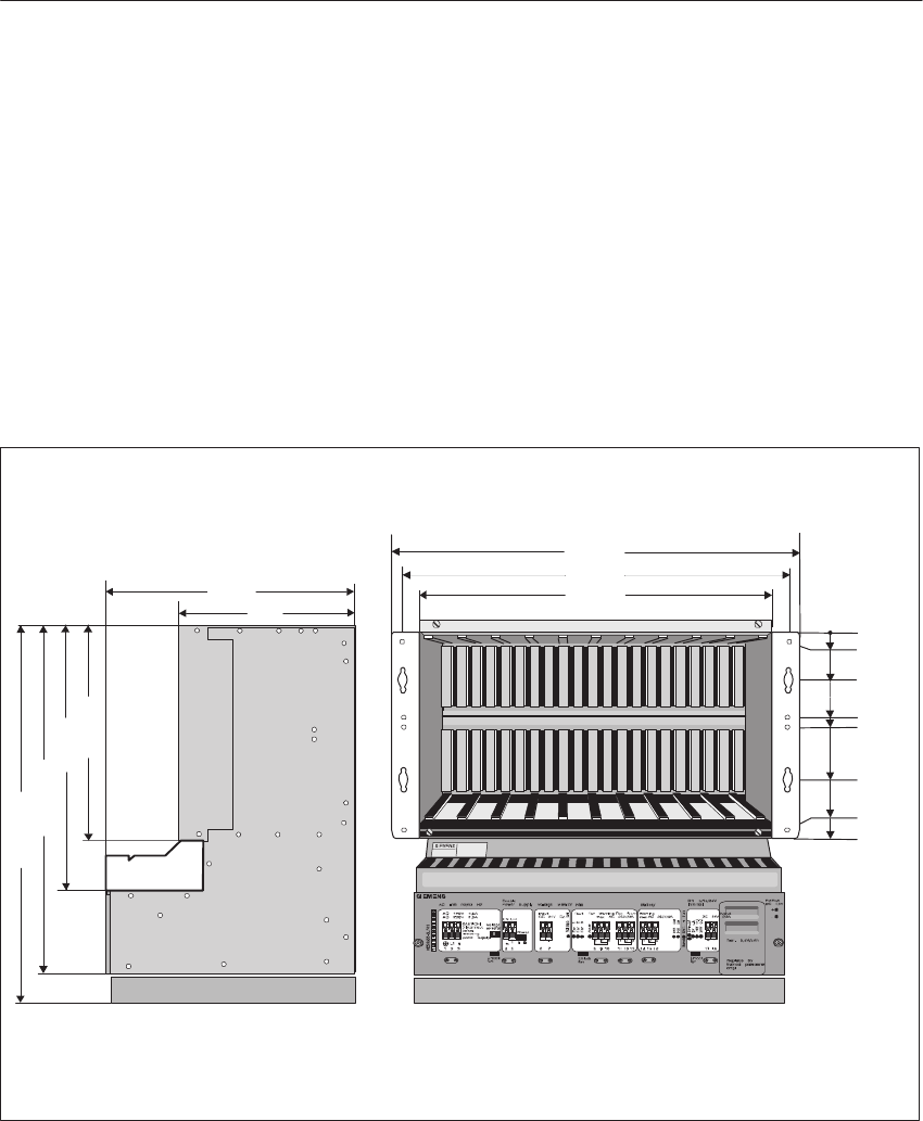
4-6 System Manual
C79000-G8576-C199-06
4.1.2 Installation
The S5-135U/155U CC is designed for installation in cabinets, on racks and
walls. The S5-135/155U CC must only be accessible from the front for
connection and maintenance work.
Consult the Installation Guidelines in Chapter 4 for planning and
implementing the installation with respect to EMC.
Shown in the following figures are the important dimensions in mm for
installation of a CC.
SIMATICS5135U
SIMATICS5 SIEMENS
440
265.9
5
221.8
44
260.9
127.5
138.4
0
465
482.6
310
225
266.35
328
432
459
Filter Subdrawer
Figure 4-2 Mounting Dimensions of an S5-135U/155U Central Controller
Installing the
Central Controller
Central Controllers and Expansion Units Power Suppl
y
Unit
s
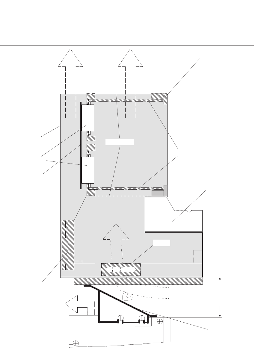
4-7
System Manual
C79000-G8576-C199-06
An air supply as shown in the following illustration must be ensured.
+
+
+
Heat Sink
Exhaust air
Additional PLC or EU Baffle
Rear Panel
Bus Connector
Bus PCB
Guide Rail
d1)
Supply air
Locking Bar
Cable
Duct
Fan
Shield
Filter Subdrawer
Exhaust
air
+
Exhaust
air
Figure 4-3 Air Supply to the Central Controller
1) d: Clearance > 87 mm when a baffle is used
d: Clearance > 89 mm when a filter subdrawer is fitted
d: Clearance > 75 mm without filter subdrawer
Central Controllers and Expansion Units Power Suppl
y
Unit
s
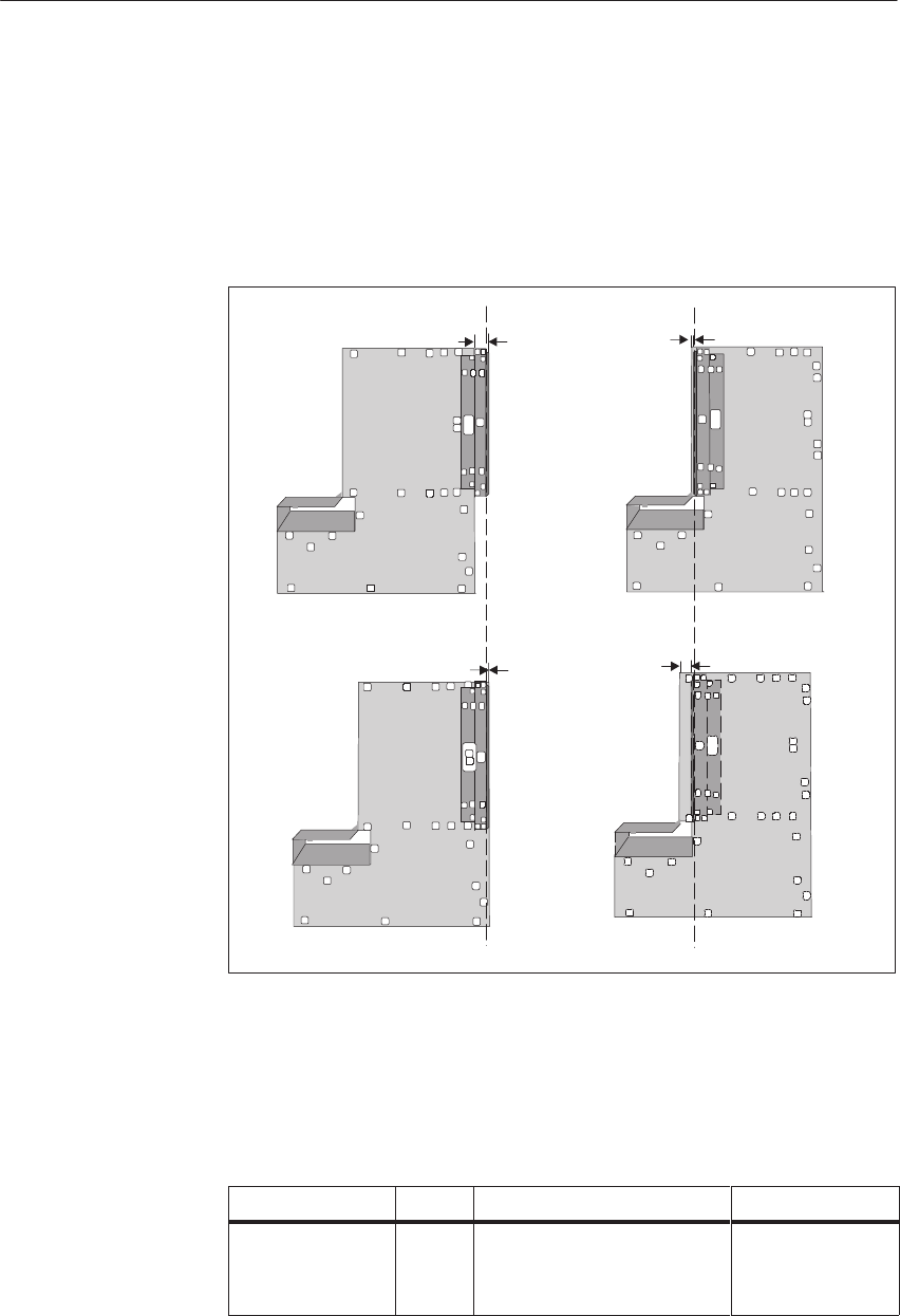
4-8 System Manual
C79000-G8576-C199-06
You can use the mounting brackets on the subrack for installation in cabinets,
on racks and walls. Use M6 bolts or, for wall mounting, screws of suitable
size.
One person can carry out the installation work.
The mounting brackets can be fitted to the housing in the following ways:
Flush 16
5
32
Figure 4-4 Methods of Fitting the Mounting Brackets
The dimensions of the modules for the S5-135U/155U PLC comply with the
double-height Eurocard format (h x d = 233.4 x 160 mm).
There are modules with different mounting width. For example:
Slots Occupied SPS 1) Front Plate Width in mm Example
1 1 1/3 20.3 CPU 922
2 2 2/3 40.6 CPU 948
4 5 1/3 81.3 CP 580
1) SPS standard-plug-in station: 1 SPS = 15.24 mm
Fitting the
Modules
Central Controllers and Expansion Units Power Suppl
y
Unit
s

4-9
System Manual
C79000-G8576-C199-06
Proceed as follows to fit the modules:
Step Action
1Disconnect the CC from system power.
2Slacken the two screws with which the locking bar is fixed to the subrack.
3Pull the locking bar forward to its end stop.
– The rail swivels up.
4If there is a locking pin on the lower part of the module, turn it to the
horizontal position.
5Grasp the module at the front plate, insert it into the lower and upper
guide rails and push it in.
– The connectors at the rear will engage in the sockets on the
backplane bus, and the release lever on the lower part of the
module will be horizontal.
6If a locking pin is fitted, push it in and rotate it 90 degrees.
– If you have correctly fitted the module so far, it should no longer
be possible to pull it out of the subrack.
7Swivel the locking bar down and push it back into the subrack.
8Retighten the two screws on the locking bar.
Some I/O modules can also be fitted or removed during operation. Consult
the reference manuals for the I/O modules, under “Release circuit.”
Free slots can be covered with dummy front plates. This improves the flow of
cooling air in the unit. See the ordering information for order numbers.
The connecting cables of CPUs, communication processors and EU interface
modules are connected with metal front connectors.
There are two types of metal front connector:
A metal front connector with slide lock is secured after plugging it in,
by sliding the lock downward.
A metal front connector with milled screws is secured to the unit with
the screws.
Note
Ensure that the connectors are assigned to the correct modules to avoid
damage.
The connection of signal lines for the I/O modules is described in Chapters 8
and 9.
Connections of
CPUs, CPs and
IMs
Central Controllers and Expansion Units Power Suppl
y
Unit
s

4-10 System Manual
C79000-G8576-C199-06
4.1.3 Startup
Start up the CC in the sequence of steps given here. This will take you up to
the first trial run of the CPU. Given in parentheses are references to the
chapters of the manual in which the subject is explained in detail.
To ensure a straightforward sequence for the startup, commence with one
CPU and no EUs.
Proceed according to the following steps to place the CC in operation:
Step Action
1Install the PLC so that the supply of air and exhaust air are unimpeded. If
you fit two or more units (CC and EU) in one cabinet, observe the
clearances and use baffles where necessary (see Chapter 3).
2Fit a lithium battery (see Sections 4.3 and 4.4) or connect an external
backup battery and connect the rechargeable battery.
3Fit the CPU and set the mode switch to STOP.
4Connect the power supply and connect the 24 V DC load supply to the
monitoring input. Check the setting of the voltage selector switch (on 230/
120 VAC power supplies). Fit a protective cover over the AC terminals.
5Switch on the power and, if present, the 24 V load supply.
Position the “Power” switch I.
Reaction: Green LED “Power Supply ok” in the “DC 5 V” field and in the
“DC 15/24 V” field light up.
6Hold the CPU switch in the OVERALL RESET position and move the
switch from STOP to RUN.
Reaction: The “Stop” LED flashes rapidly.
7Repeat Step 6.
Reaction: The “Stop” LED lights up constantly.
8Keep the pushbutton in the RESET position and move the switch from
STOP to RUN.
Reaction: Green “Run” LED lights up, “BASP” LED (output inhibit) goes
off.
Central Controllers and Expansion Units Power Suppl
y
Unit
s

4-11
System Manual
C79000-G8576-C199-06
The following flowchart provides an overview of the sequence for startup
and validity check of a CC with CPU inserted and with no user program. For
the CPU 948, all steps relating to the memory submodule are skipped.
No
No
No
No
No
No
No
Connect power supply unit
Switch on supply voltage
CPU:
LED “BASP” on
LED “STOP” flashing fast
all others off
PS:
Correctly wired?
Voltage Present?
LED “Fan
Fault” on
LED
“Voltage
Low” on
Check load
voltage
connection
Check
Fan
CPU:
LED “STOP” on
LED “BASP” on
CPU:
LED ”BASP” on
LED “STOP” flashing fast
all others
off
Replace PS
Unit O.K.
Replace memory submodule
Reset CPU: Set to “Reset,”
switch from “STOP” to “RUN”
CPU:
LED “RUN” on,
LED “BASP” off
Memory
submodule:
correctly inserted?
Insert memory
submodule correctly
CPU general reset
PS:
LED “DC5V”
and “DC 24V” on, all
others off
Insert memory submodule in
CPU (not with the CPU 948)
CPU at “STOP”
Replace CPU
or
repeat startup
LED “MB
Low” on
LED “RB
Low” on
Check backup bty
and replace
if necessary
Replace
rechargeable
battery
Replace bty
compartment
Fault
corrected
No
No
No
No
Yes
Yes
Yes Yes
Yes
Yes
Yes
Yes Yes
Yes
Yes
Press
RESET
LED off
all others off
Press
RESET
LED off
Fault
corrected
Figure 4-5 Startup
Startup and
Validity Check
Central Controllers and Expansion Units Power Suppl
y
Unit
s

4-12 System Manual
C79000-G8576-C199-06
4.1.4 Repair Guidelines
If measurements or testing become necessary whilst the unit is operational,
accident prevention regulations VBG 4.0 must be observed, especially the
permissible actions when working on active parts.
Only use tools that are suitable and approved for working on electrical
equipment.
SRepair of an automation system may only be carried out by the
SIEMENS customer service or by qualified personnel (see above).
SAlways disconnect the AC power plug or open the isolating switch before
opening the unit. Wait at least 8 minutes before pulling out and opening a
power supply unit (see Section 4.2.3).
SParts or components of a central controller may only be replaced by types
listed in Catalog ST 54.1 or in the appendix to this manual.
SFuses may only be replaced by the same type.
SInstructions for maintenance of the individual components can be found
in the relevant chapters of this manual.
!Warning
Unauthorized opening and improper repairs can result in death or serious
personal injury as well as considerable damage.
Central Controllers and Expansion Units Power Suppl
y
Unit
s

4-13
System Manual
C79000-G8576-C199-06
4.1.5 Technical Specifications
Important for the USA and Canada
The following approvals have been granted for the central controllers and
expansion units:
SUL Listing Mark
Underwriters Laboratories (UL) to
Standard UL 508, Report E85972
SCSA Certification Mark
Canadian Standards Association (CSA) to Standard
C 22.2 No. 142, Report LR 63533C
Unit safety
The unit complies with: VDE 0160, IEC 1131-2
Protection against overvoltage
Overvoltage Class 2 (not with PS -3NA12) VDE 0160 A1
Class of protection I
Type of protection
(when empty slots are covered by dummy front plates) IP 20 to IEC 529/DIN 40050
Climatic ambient conditions (tested to DIN IEC 68-2/-1/2/3)
Ambient temperature in operation
(supply air measured at lower air inlet of the unit) 0 to 55 °C
Transportation and storage temperature - 40 to 70 °C
Temperature variation:
in operation
during transportation and storage
(when delivered at less than 0 oC, at least 3 h
acclimatization because of possible
condensation)
10 K/h max.
20 K/h max.
Relative humidity: in operation, during transportation and
storage
95% max. at 25 °C, no condensation
Altitude: in operation
during transportation and storage
- 1000 m to + 1500 m above sea level
(1080 hPa to 860 hPa)
- 1000 m bis + 3500 m above sea level
(1080 hPa to 660 hPa)
Pollutants:
SO2
H2S
0,5 cm 3 / m 3, 4 days
0,1 cm 3 / m 3, 4 days
Mechanical ambient conditions (tested to DIN IEC 68-2-6)
Vibration during operation 10 to58 Hz (const. amplitude 0.075 mm)
58 to 500 HZ (const. acceleration 1g)
Central Controllers and Expansion Units Power Suppl
y
Unit
s

4-14 System Manual
C79000-G8576-C199-06
Noise immunity, electromagnetic compatibility (EMC)
RFI suppression Limit value class To EN 55011
A 2)
Conducted interference on AC supply lines (230 V AC)
to EN 61000-4-4 / IEC 1000-4-4 (burst)
to IEC 1000-4-5
between two lines (ms pulses)
between line and ground (ms pulses)
2 kV
1 kV
2 kV
DC supply lines (24 V supply) to EN 61000-4-4 / IEC 1000-4-4
(burst) 2 kV
Signal lines to EN 61000-4-4 / IEC 1000-4-4 (burst) 2 kV 1)
Immunity to discharge of static electricity to EN 61000-4-2 /
IEC 1000-4-2 (ESD) 2) Immunity of 4 kV contact discharge
(8 kV air discharge) is ensured with proper
installation (see Chapter 3).
Immunity to electromagnetic RF field 2)
amplitude modulated to ENV 50140 / IEC 1004-4-3 80 to 1000 MHz
10 V/m
80% AM (1 kHz)
Immunity to electromagnetic RF field 2)
pulse-modulated to ENV 50204 900 MHz
10 V/m
50% ED
Immunity to high-frequency sinusoidal to ENV 50141 0.15 to 80 MHz
10 V
80% AM
Mechanical data
Mechanical requirements Installation in stationary equipment, subject to
vibration; installation on ships and in vehicles if
special installation rules are observed, but not on
the engine.
Weight approx. 14 kg
Dimensions (W x H x D) 482.6 x 432 x 310 mm
1) Signal lines which do not serve to control the process, for example connections to the external I/O etc.: 1 kV
2) When cabinet door is closed.
Central Controllers and Expansion Units Power Suppl
y
Unit
s
4-15
System Manual
C79000-G8576-C199-06
4.2 Expansion Units
This chapter contains information on the application, installation and
operation of the following expansion units.
Order No. of Expansion Unit Power Supply or Fan Subassembly
6ES5 183-3UA13
6ES5 183-3UA22 6ES5 955-3LC42
6ES5 955-3NC42
6ES5 184-3UA11
6ES5 184-3UA21 230/120 V AC fan subassembly
24 V DC fan subassembly
6ES5 185-3UA13
6ES5 185-3UA23
6ES5 185-3UA33
6ES5 185-3UA43
6ES5 955-3LC42
6ES5 955-3NC42
6ES5 955-3LF42
6ES5 955-3NF42
6ES5 187-5UA11 –
Various interface modules (IMs) are available for communication between
the CC and EUs and between EUs. Data transmission between CC and EU,
and therefore between CPU and I/O module, is governed by the IM. A
description of interface modules is given in Chapter 7.
The following table contains information on available types of expansion unit
with their main features.
EU Type EU 183 EU 184 EU 185 EU 187
Version
Own power supply yes no yes no
With fan yes yes yes no
With cable duct yes yes yes no
Number of slots 21 21 21 11
Pluggable modules:
DI/DQ
AI/AQ
IP without page
IP with page
CP
yes
yes
yes
no
no
yes
yes
yes
no
no
yes
yes
yes
yes
yes
yes
yes
no
no
no
With interrupt processing no no no no
Interface Modules
Central Controllers and Expansion Units Power Suppl
y
Unit
s
4-16 System Manual
C79000-G8576-C199-06
4.2.1 Technical Description of the Expansion Units
The design of the EUs is comparable to that of the CC: they comprise a
compact housing with a type-dependant number of slots for modules and,
according to the type of EU, a cable duct, an integral power supply unit or
fan subassembly.
The mounting dimensions of the EU 183U, EU 184U and EU 185U are the
same as those of the 135U/155U CC (see Figs. 4-3 and 4-4). The EU 187U
has neither power supply unit nor cable duct. Its overall height and depth are
therefore different from those mounting dimensions of the other EUs.
SIMATICS5135U
440
225
266
Figure 4-6 Mounting Dimensions of the EU 187U
The following tables show which modules can be inserted at which slots.
Modules and slot assignments of the EU 183U
Slot No. 311 19 27 35 43 51 59 67 75 83 91 99 107 115 123 131 139 147 155 163
Module type
IM 300
IM 310, IM 314,
IM 318
IM 317
IM 312-3
DI, DQ,
AI, AQ
Signal pre-processing
modules (IPs) See current Catalog ST 54.1 for slot numbers
Monitoring
module 313
Modules and Slot
Assignments of
the Expansion
Units
Central Controllers and Expansion Units Power Suppl
y
Unit
s
4-17
System Manual
C79000-G8576-C199-06
Modules and slot assignments of the EU 184U
Slot No. 311 19 27 35 43 51 59 67 75 83 91 99 107 115 123 131 139 147 155 163
Module type
IM 312-5
DI, DQ,
AI, AQ
Signal pre-processing
modules (IPs) See current catalog ST 54.1 for slot numbers
Monitoring
module 313
Modules and slot assignments of the EU 185U
Slot No. 311 19 27 35 43 51 59 67 75 83 91 99 107 115 123 131 139 147 155 163
Module type
Coordinator 923 C
Communikation
processors (CPs)
IM 314 R
IM 300
IM 310, IM 134
IM 318
IM 317
IM 308
DI, DQ,
AI, AQ
Signal pre-processing
modules (IPs) See current catalog ST 54.1 for slot numbers
Monitoring
module 313
Slots 19 to 75 are programmer MUX-capable
Modules and slot assignments of the EU 187U
Slot No. 319 35 51 67 83 99 115 131 147 163
Module type
IM 312-5
DI, DQ,
AI, AQ
Monitoring
module 313
Central Controllers and Expansion Units Power Suppl
y
Unit
s

4-18 System Manual
C79000-G8576-C199-06
4.2.2 Installing the Expansion Units
Like a CC, the EUs are designed for installation in cabinets, in racks and on
walls. To install an expansion unit, therefore, refer to the description for the
CC and Chapter 3.
4.2.3 Technical Specifications of the Expansion Units
SThe technical specifications of the expansion units are the same as those
of the central controller except for the following (see Section 4.1.5).
SWeight EU 183U: approx. 14 kg
EU 184U: approx. 13 kg
EU 185U: approx. 14 kg
EU 187U: approx. 11 kg
SDimensions: EU 187U: 440 x 266 x 225 mm
Central Controllers and Expansion Units Power Suppl
y
Unit
s

4-19
System Manual
C79000-G8576-C199-06
4.3 Power Supply Units
Power supply units are part of the S5-135U/155U central controllers and of
the EU 183 and EU 185 expansion units.
4.3.1 Product Overview
The following section provides an overview of power supply types, their
functions, LEDs and controls and their inputs and outputs.
Your CC/EU contains one of the following power supply units (PSUs):
Type of PSU
(Designation) Input
Voltage Output Voltage Application
6ES5 955-3LC42 120 V AC
230 V AC
(selectable)
5V/18A DC
15V/0.5A DC
24V/1A DC
Central controller
6ES5 188-3UA12
Expansion units
6ES5 183-3UA13
6ES5 185-3UA13
6ES5 955-3LF42 120 V AC
230 V AC
(selectable)
5V/40A DC
15V/2A DC
24V/2.8A DC
Central controller
6ES5 188-3UA22
Expansion units
6ES5 185-3UA33
6ES5 955-3NC42 24 V DC 5V/18A DC
15V/0.5A DC
24V/1A DC
Central controller
6ES5 188-3UA32
Expansion units
6ES5 183-3UA22
6ES5 185-3UA23
6ES5 955-3NF42 24 V DC 5V/40A DC
15V/2A DC
24V/2.8A DC
Central controller
6ES5 188-3UA52
Expansion units
6ES5 185-3UA43
The 5 V and 15 V output voltages are regulated; the 24 V output voltage has
coarse stabilization.
All four power supply units have safe electrical separation according to
VDE 0805/EN 60950.
Note
Power supply units are exclusively adapted to operation with CCs/EUs.
Power Supply
Types
Central Controllers and Expansion Units Power Suppl
y
Unit
s

4-20 System Manual
C79000-G8576-C199-06
The power supply units offer the following functions:
SSystem power supply
All the system voltages required for operation of the modules in a CC or
EU are supplied.
SPower supply for backup (in the CC and EU 185):
A lithium battery or an external battery ensure data backup when the
system voltage is switched off or fails.
– The lithium battery remains in the CC/EU and ensures backup, even
during replacement of the power supply unit
– Instead of the lithium battery, an external battery can be connected for
data backup purposes. Situated on the front plate of the power supply
unit are two sockets to connect an external battery.
The rechargeable battery (in the power supply) continues to back up while
either the lithium battery or external battery is being replaced or fails,
ensuring that no data are lost.
SHeat removal
Three independent fans which are individually replaceable during
operation remove the dissipated power. If a fan fails, the supply voltage
for this fan is switched off and the other two fans continue operation at
increased speed.
The power supply units contain monitoring functions to detect the following
faults:
SFailure of system voltage
SFailure of output voltages
SFailure of an externally applied 24 V DC load voltage (voltage monitor)
SFan failure or inadequate air flow
SLithium battery failure
SRechargeable battery failure
In this context, a voltage failure is equivalent to a drop of the monitored
voltage below a preset limit (see Section 4.3.6 of the Technical
Specifications).
The failure of a monitored function is signaled by the power supply units:
Svia LED indicators on the front plate;
Svia relays with which signaling circuits can be switched;
Svia signals to the S5 bus.
Basic Functions
Monitoring
Functions
Signaling
Functions
Central Controllers and Expansion Units Power Suppl
y
Unit
s
4-21
System Manual
C79000-G8576-C199-06
Based on the example of the 6ES5 955-3LF41 power supply unit, the
following figure shows the arrangement of inputs and outputs on the front
plate of the power supply units:
6ES5955-3LF42
L1 N
12345 67 8
910 11 14
12 1513 16 17 18
+
+
+
+
–
–
–
–
AC120V4,5A
AC230V2,6A
CAUTION!
Disconnect
before
removing
power supply!
Voltage
selector
Unlock
Fan 1
Unlock
Fan2
Unlock
Fan3/Res.Batt
.
Input
DC 24V Ext.
AC line 50/60 Hz Enable
Power supply Voltage Monitor Fan Battery Ext.Batt.
DC 4,5V
Fault Warning Alarm Warning
max. AC 250V/3A
max. AC 250 V/ 3A
Voltage low
Fan1
MB low
Fan2
RB low
5Vo.k.
Fan3
Reset
Alarm
EN UH
Power
I
I
12345678910
Batt. 3,6V/5Ah
Replace by
trained personnel
only!
Use battery holder
C98100-A1155-B21
only!
SIEMENS
Output
DC 24V 2,8A
DC 5/15/24V
Internal
3V=40A
15Vo.k.
24Vo.k.
Batt.+Fan
The following table provides an overview of the labelling and purpose of the
inputs and outputs:
ID Label Element Purpose
AAC 120V 4.5A
AC 230V 2.6A Screw terminals
1, 2, 3 AC connection and protective conductor
B EN Screw terminal 4 Enable Power Supply
Control input for power supply
C UHScrew terminal 5 Supply for EN
D Input
DC 24V Ext. Screw terminals
6 and 7 Voltage Monitor
Monitors 24 V load voltage for > 16 V
EFan Warning
max. 250V/3A Screw terminals
8, 9, 10 (relay) Indicates failure of a fan
FFan Alarm
max. 250V/3A Screw terminals
11, 12, 13
(relay)
Indicates failure of at least two fans and
inadequate air flow; if jumper set
accordingly, output enable is the second
signal source
G Battery
Warning
max. 250V/3A
Screw terminals
14, 15, 16
(relay)
Indicates that lithium battery or
rechargeable battery has dropped below
limit
H3V = 40A 2 test sockets Current measurement sockets for test
purposes only; no continuous operation;
linearity range 0.5 V/6.6 A to 3 V/40 A
I Output
DC 24V 2.8A Screw terminals
17, 18 Enable voltage for I/O modules
J Ext.Batt.
DC 4.5V 2 input sockets Input for an external 4.5 V backup
voltage
Inputs and
Outputs
Central Controllers and Expansion Units Power Suppl
y
Unit
s
4-22 System Manual
C79000-G8576-C199-06
Apart from the jumpers, the LEDs and controls of the power supply unit are
fitted on the front plate. The following figure shows their locations:
6ES5955-3LF42
L1 N
12345 67 8
910 11 1412 1513 16 17 18
+
+
+
+
–
–
–
–
AC120V4,5A
AC230V2,6A
CAUTION!
Disconnect
before
removing
power supply!
Voltage
selector
Unlock
Fan 1
Unlock
Fan2
Unlock
Fan3/Res.Batt
.
Input
DC 24V Ext.
AC line 50/60 Hz Enable
Power supply Voltage Monitor Fan Battery Ext.Batt.
DC 4,5V
Fault Warning Alarm Warning
max. AC 250V/3A
max. AC 250 V/ 3A
Voltage low
Fan1
MB low
Fan2
RB low
5Vo.k.
Fan3
Reset
Alarm
EN UH
Power
I
I
123456789
10
Batt. 3,6V/5Ah
Replace by
trained personnel
only!
Use battery holder
C98100-A1155-B21
only!
SIEMENS
Output
DC 24V 2,8A
DC 5/15/24V
Internal
3V=40A
15Vo.k.
24Vo.k.
Batt.+Fan
G
D
AH
IF
BCL
K
JM
E
The labelling and purpose of the LEDs and controls are given in the
following table:
ID Label Element Purpose
A Voltage
selector 1) Switch Voltage selector switch:
choice of 120 V or 230 V
B Power Switch Standby On/Off switch (not system
On/Off switch)
CVoltage low Red LED Low voltage at load voltage monitor input
DFan 1 Red LED Failure of Fan 1
EFan 2 Red LED Failure of Fan 2
FFan 3 Red LED Failure of Fan 3
G Alarm Red LED Indicates failure of at least two fans of
insufficient air flow
HMB low Yellow LED Lithium battery/external battery voltage
below preset limit (3V)
IRB low Yellow LED Rechargeable battery voltage below preset
limit (3V)
JReset Batt.+Fan Pushbutton Reset of LEDs D, E, F, G, H, I when fault
cleared
K5V o.k. Green LED Lights up to indicate output voltage
within permissible range
L15V o.k. Green LED Lights up to indicate output voltage
within permissible range
M24V o.k. Green LED Lights up to indicate output voltage
within permissible range
1) Only on the 6ES5 955-3LC42 and 6ES5 955-3LF42
LEDs and Controls
Central Controllers and Expansion Units Power Suppl
y
Unit
s

4-23
System Manual
C79000-G8576-C199-06
4.3.2 Setting and Connecting the Power Supply Unit
Before starting up your power supply unit, you must carry out certain steps
according to your requirements with respect to power supply behavior in the
event of a fault.
Power supply units are delivered in the following state:
SFitted in the CC or EU frame which you ordered
SWith preset jumpers
SAC line voltage set to 230 V (-3LC42, -3LF42)
If you wish to retain this setting, you can skip Steps 2 to 4 and 9.
If you do not wish to fit a filter subdrawer, skip step 8.
Step Action
1Check the setting and cabling
2Remove the power supply unit If required
3Set the jumpers If required
4Fit the power supply unit If required
5Wire the power supply unit to the installation (including
fitting an isolating device to disconnect the AC line
voltage)
6Fit the lithium battery
7Remove the right-hand fan and connect the rechargeable
battery
8Fit the filter subdrawer If required
9Set the voltage selector switch If required
10 Switch the PSU on for the first time
Central Controllers and Expansion Units Power Suppl
y
Unit
s

4-24 System Manual
C79000-G8576-C199-06
The following table shows the procedure for placing the power supply unit
(PSU) in operation without changing the jumper setting:
Stage Description
1Fit the PLC, allowing for clearances for access in the event of repairs
and for adequate ventilation. Observe chassis grounding.
2Fit the lithium battery (if available) in the battery compartment on the
right front of the power supply unit (ensure correct polarity).
Hinweis: Die Lithium-Batterie müssen Sie getrennt bestellen (siehe
Bestellhinweise).
3Remove the right-hand fan subassembly, plug in the red positive lead of
its rechargeable battery and reinsert the fan.
4Check that the voltage selector switch is set to your desired voltage.
5Connect the 24 V load voltage leads to the “Voltage Monitor” terminals.
6When connecting the AC leads, fit an isolating device to isolate the
power supply unit from the AC line voltage.
7Connect the primary voltage leads and the protective conductor.
8Switch on the primary voltage and the 24 V load voltage.
9Use the “Power” switch to switch on the power supply unit.
10 If the required basic load is in circuit, no red LED lights up and the
power supply unit is operational.
All activities relating to startup of the power supply units are described in
detail on the following pages.
Brief Instructions
for Startup
Central Controllers and Expansion Units Power Suppl
y
Unit
s

4-25
System Manual
C79000-G8576-C199-06
The power supply unit is delivered with the settings shown in bold print in
the following table.
Mark your chosen settings in the right-hand column and use this chart for the
subsequent implementation.
Function Selection Jumper Setting Application/Note (X)
Battery monitor
– switched on for
rechargeable battery and battery MM - NN
MA - NA closed
closed Redundant backup
– switched on for battery and
off for rechargeable battery MM - NN
MA - NA closed
open If, for example, no redundance is
required in backup, i.e. the rechargeable
battery is missing
– switched off MM - NN
MA - NA open
irrelevant For example, monitoring is not needed
for EU without backup
Reaction of battery monitoring
following battery failure
– /BAU signal active following
return of line voltage MB - NB open
– /BAU signal active following
return of line voltage and during
operation
MB - NB closed The possibility of evaluating the battery
monitoring during operation is
dependent on the CPU in use
After failure of more than one fan or
inadequate air flow
– PSU shutdown F-R closed
– No PSU shutdown F-R open Caution: To prevent overheating of
modules, the PSU must be shut down
after 60 s at the latest (for example, by
time relay)
Voltage monitor
– switched off BA-EX closed Monitoring of load voltage input
switched off
– switched on BA-EX open Monitoring of load voltage input
switched on
Relay alarm Fault message initiated by fan
f il / i hibi i b
– driven by fan monitor and
output inhibit BB-AA closed
gy
failure/output inhibit active; can be
signaled to control room, for example.
– driven only by fan monitor BB-AA open Fault message initiated by fan failure;
can be signaled to control room, for
example.
Establishing the
Jumper Settings
Central Controllers and Expansion Units Power Suppl
y
Unit
s
4-26 System Manual
C79000-G8576-C199-06
Function Selection (X)Application/NoteSettingJumper
Mains buffering
FX-VA
6-22 closed
closed A stored energy time of 5 to 10 ms is
guaranteed in the event of a power
failure.
The stored energy time is dependent on
the input voltage and the load.
FX-VA
6-22 closed
open A stored energy time of 20 to 30 ms is
guaranteed in the event of a power
failure.
The stored energy time is not dependent
on the input voltage and the load.
FX-VA
6-22 open
irrelevant A stored energy time of w 20 ms is
guaranteed in the event of a power
failure.
The stored energy time is dependent on
the input voltage and the load.
If your selection is the same as all the settings marked in bold print, you need
not change the jumper settings.
Wiring of the power supply unit must be planned within the scope of wiring
of the entire control system. The information required for the purpose and
decision-making aids, for example, for local or central grounding, can be
found in Chapter 3: Installation Guidelines.
Three relay outputs allow you to install additional external signaling circuits
for fault states, for example, to connect a cabinet lamp or horn.
The following table contains the information required on the relay states:
Relay
(Normal Operational State) (Fault State/Idle State)
Warning All fans are in order. One or more fans have failed.
Alarm Adequate air flow, at least two fans are running. Inadequate air flow or at least two fans have
failed.
BatteryWarn
ing Lithium battery and rechargeable battery are in
order (Ubatt ext not connected). Lithium battery or rechargeable battery has failed
(no Ubatt ext ).
Establishing the
Wiring
Establishing the
Signaling Circuits
Central Controllers and Expansion Units Power Suppl
y
Unit
s

4-27
System Manual
C79000-G8576-C199-06
The following applies to input EN (Enable Power Supply):
SInput EN monitors the voltage for < 3.6 V; it enables the output voltage at
3.2 V.
SIf two or more units are to be controlled jointly, connect input EN of the
PSU in the central controller to the EN inputs of the PSUs in the
expansion unit. Connect the auxiliary voltage UH, for example, to these
inputs. In the event of failure of the PSU in the central controller, all units
will then be switched off with the appropriate jumper settings.
Not more than 7 EN inputs may be connected to one UH output (front
terminal).
The following applies to selecting the cables for the terminals:
Terminals Cabling Max. Permissible Conductor Cross-Sections
Power supply
AC line
DC line
Phase L 1
Neutral N
Protective cond. PE
Positive L +
Chassis 0 V M
Protective cond. PE
4 mm2 solid or 2.5 mm2 flexible
4 mm2 solid or 2.5 mm2 flexible
4 mm2 solid or 2.5 mm2 flexible
4 mm2 solid or 2.5 mm2 flexible
4 mm2 solid or 2.5 mm2 flexible
4 mm2 solid or 2.5 mm2 flexible
Load voltage input (Voltage
monitor, Ext. 24 V DC) 24 V input (may be omitted if jumper
BA-EX is closed) 4 mm2 solid or 2.5 mm2 flexible
Enable power supply Set jumper from EN-UH or apply
w 3.2 V voltage at EN, with respect
to output chassis ground
4 mm2 solid or 2.5 mm2 flexible
Relay terminals, also
suitable to 230 V AC / 3 A 4 mm2 solid or 2.5 mm2 flexible
Monitor output for 24 V 4 mm2 solid or 2.5 mm2 flexible
Note
A voltage of more than 50 V must not develop between the output voltages
and the protective conductor potential.
Setting up the
Control Input for
the Power Supply
Establishing the
Cables
Central Controllers and Expansion Units Power Suppl
y
Unit
s
4-28 System Manual
C79000-G8576-C199-06
You must remove the power supply unit if you:
Schange the jumper settings
Ssend the power supply unit in for repair.
!Caution
Power supply units may only be removed when power is switched off.
If 230 V I/O modules are fitted, you must ensure before removing the power
supply unit that the subrack is grounded when the PSU is removed, or the
230 V supply for these modules is switched off.
When the power supply unit is removed, the connection between backup
battery and backplane bus remains; this ensures backup of the user program.
Proceed according to the following steps to remove the power supply unit:
Step Action
1Switch the Power switch off
(standby On/Off).
2Disconnect the power supply unit form the AC line voltage.
3Detach the connections of all leads from the front terminals.
4Important
!
p
Before pulling out the PSU, wait at least 8 minutes after switching off the
power so that the electrolytic capacitors can discharge.
5Slacken the fixing screws on the left and right of the PSU.
6Pull the PSU out.
There are grips to pull it out under the unlock fan openings.
Removing the
Power Supply Unit
When to Remove
the PSU
How to Remove
the PSU
Central Controllers and Expansion Units Power Suppl
y
Unit
s
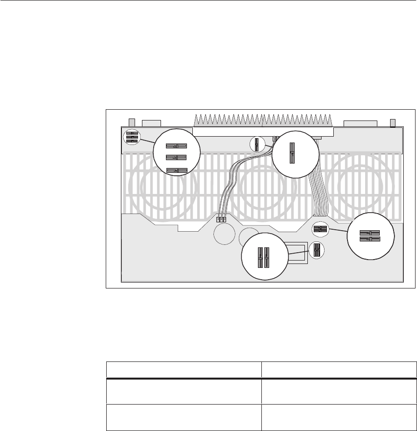
4-29
System Manual
C79000-G8576-C199-06
The jumper locations are given in the following figure:
NB MB
MA NA
NN MM
F
R
BB AA
BAEX
BB AA
BAEX
FX
VA22
6
To change the jumper settings, it is best to use pincers or a fine screwdriver.
Proceed as follows to change the jumper settings:
IF... THEN...
You wish to open the jumper, press the flexible jumper wire down and
pull it out.
You wish to close the jumper, press the flexible jumper wire down and
insert it.
Setting the
Jumpers
Locations of
Jumpers
Setting the
Jumpers
Central Controllers and Expansion Units Power Suppl
y
Unit
s
4-30 System Manual
C79000-G8576-C199-06
!Caution
For safety reasons, the power supply unit may only be operated in the
housing provided for the purpose.
The protective conductor must always be connected.
After carrying out setting, installation and repair work, proceed according to
the following steps to refit the power supply unit in the frame:
Step Action
1Push the PSU into the guide rails until it locks in place. You can use one
hand to support the PSU from below; this facilitates fitting in the guide
rails.
2Secure the PSU with the fixing screws on the left and right of the unit.
!
Caution
Since the fixing screws also provide the protective conductor connection to
the subrack, they must be tightened before the power cable is connected.
Wiring of the PSU is carried out within the scope of overall wiring for your
controller, according to your requirements and the section entitled
“Establishing the settings and cabling.”
Terminals with dangerous touch-voltages must be covered with caps. Use
only the original self-tapping screws provided when you fit the caps for the
first time.
Fitting the Power
Supply Unit
How to Fit the PSU
Wiring the Power
Supply Unit
How to Wire
the PSU
Central Controllers and Expansion Units Power Suppl
y
Unit
s
4-31
System Manual
C79000-G8576-C199-06
Whether or not you require a lithium battery depends on what type of backup
you require for your system. The following table will help you to decide.
IF... THEN...
You require long backup times and do not want to
supply an external backup voltage, you need a lithium battery.
You require redundant backup and do not want to
supply an external backup voltage, you need a lithium battery.
Short backup times are sufficient, you do not need a lithium
battery.
You do not require redundant backup, you do not need a lithium
battery.
The lithium battery must be ordered separately (see Ordering Information).
The backup battery (type C) contains lithium (more than 0.5 g) and is
delivered separately from the power supply unit, because of special shipping
regulations.
Depending on the manufacturer, the battery’s plus pole may have a protective
cover. You must remove this cover before you place the battery in the battery
compartment.
!Caution
Improper replacement of the battery can result in the danger of explosion.
If should only be replaced by the same type or an equivalent one
recommended by the manufacturer. Used batteries should be disposed of
according to the manufacturer’s instructions.
The backup battery must be fitted before the programmable controller is
started up. Without a backup voltage, the PLC will remain in the Stop state
after system voltage is switched on.
Only use battery compartments marked -A1155-B21 (red label).
Fit the lithium battery in the following steps:
Step Action
1Slide the battery compartment cover (A) downwards.
2Pull the battery compartment (B) out.
3Insert the lithium battery in the battery compartment.
Important: Ensure correct polarity.
4Slide the battery compartment in.
5Close the cover.
Starting up with a
Lithium Battery
When do you
Require a Lithium
Battery?
Notes Relating to
the Lithium Battery
How to Fit the
Lithium Battery
Central Controllers and Expansion Units Power Suppl
y
Unit
s
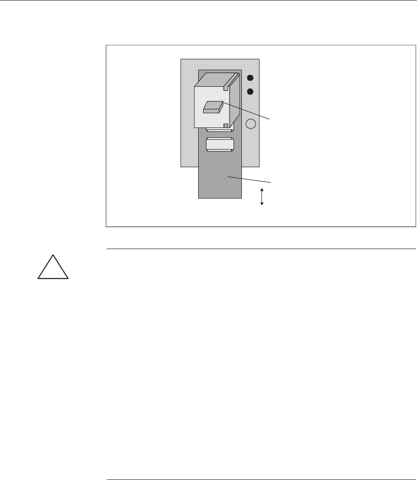
4-32 System Manual
C79000-G8576-C199-06
Cover (A)
Battery Compartment (B)
*
+
!Warning
Risk of danger to persons and property, danger of giving off harmful
substances.
If handled incorrectly, a lithium battery can explode. If disposed of
incorrectly, old lithium batteries can release harmful substances. You must
therefore observe the following guidelines:
SDo not throw new or discharged batteries onto a fire and do not solder
onto the body of the cell (max. temperature 100 °C (212 5F)). Do not
recharge them. Order your replacement battery from Siemens only (for
order number see ordering instructions). This ensures that you only use a
short-circuit-protected type.
SThe lithium battery is subject to regulations for hazardous materials. You
should observe these regulations when you ship the battery, for example,
by using the original packaging.
Used batteries should be returned to the manufacturer or a recycling
station if possible or disposed of as hazardous waste. The guidelines for
transporting hazardous materials should be observed.
If you want to start up one of the central controllers or expansion units
without a battery, you can do either of the following:
SYou can connect only the rechargeable battery, or
SYou can supply an external backup voltage.
Apply a backup voltage of 4.5 V DC via the input sockets labelled “Ext.Batt.
DC 4.5 V.” The input sockets are situated on the front panel of the power
supply. Ensure that you have the correct polarity.
Starting Up
without a Lithium
Battery
Supplying an
External Backup
Voltage
Central Controllers and Expansion Units Power Suppl
y
Unit
s
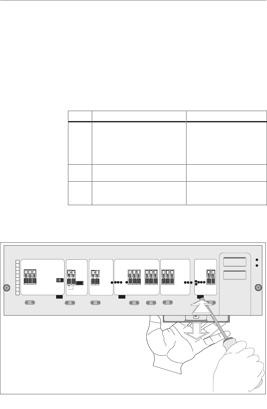
4-33
System Manual
C79000-G8576-C199-06
The three fans are situated under the power supply unit. The rechargeable
battery is fitted in the right-hand fan subassembly.
Proceed according to the following steps:
Step Action Result
1Place one hand under the right-hand
fan; with the other hand, insert a
screwdriver (DIN 5265, blade width
3.5-6.5 mm) into the right-hand unlock
fan opening.
When the screwdriver is pulled
out, the snap hook is released. By
pulling on the round hole on the
underside of the fan subassembly
it swings down and can be pulled
out.
2Connect the red connecting cable to the
battery. The battery is connected.
3Insert the fan subassembly in the
housing with the tab situated at the rear,
and swivel it up.
The fan subassembly locks in
place.
The following figure shows how to release the fan lock:
Unlock
fan
Unlock
fan UnlockfanUnlockfan Replace by
trained personnel
only!
Batt.3,6V/5Ah
SIEMENS
Use battery holder
C98100-A1155-B21
only!
123456789
10
Removing the
Right-Hand Fan
and Connecting
the Rechargeable
Battery
Location of Fans
and Rechargeable
Battery
How to Connect
the Rechargeable
Battery
Releasing the Fan
Lock
Central Controllers and Expansion Units Power Suppl
y
Unit
s

4-34 System Manual
C79000-G8576-C199-06
The filter subdrawer with fixing grid, two plug-in guide rails and the
corresponding filter mats are available as an option (see the ordering
instructions for the order numbers).
To insert a filter, you must secure the filter subdrawer to the lower side of the
power supply unit housing.
Proceed as follows:
Step Action
1Install the guide rails in such a way that the round tabs fit into the
corresponding openings on the lower side of the PSU.
2Insert a filter mat in the filter subdrawer and secure it with the enclosed
fixing grid.
3Position the filter subdrawer in the guide rails, push it back and swivel it up
so that it locks in place.
On the AC power supply units, the voltage selector switch is situated on the
front plate and marked Voltage Selector. You can select a voltage of 120 V or
230 V. The factory setting is 230 V.
Set the voltage according to your requirements
Step Action
1Disconnect the power supply unit from the line voltage.
2Use a screwdriver to remove the transparent cover.
3Set the voltage selector switch to your required voltage.
4Refit the transparent cover.
Fitting the Filter
Subdrawer
Option
Where to Fit the
Filter Subdrawer
How to Fit the
Filter Subdrawer
Setting the Voltage
Selector Switch
How to Set the
Voltage Selector
Switch
Central Controllers and Expansion Units Power Suppl
y
Unit
s
4-35
System Manual
C79000-G8576-C199-06
!Caution
If you have set the voltage selector switch to 120 V, but the actual voltage
value is 230 V, the power supply unit may be damaged when line voltage is
switched on.
When you have made all the settings, switch the power supply unit on as
follows:
Step Action Result
1Switch the power supply unit
on with the Power switch.
2Switch the system voltage on. If the required basic load (see Section
4.4.6, Technical Specifications) is in
circuit, the power supply unit will start.
The green LEDs “5V o.k.”
“15V o.k.”
“24V o.k.” light up.
The fans run.
After a maximum of 6 minutes, the rechargeable battery has been charged
sufficiently for you to be able to start up the central controller or the
expansion unit.
The charge time for the rechargeable battery can be up to 46 hours,
depending on how low the battery was. Note that during this time, backup
using the rechargeable battery is restricted.
Once the rechargeable battery is fully charged, the following load-dependent
backup times apply:
Ibackup mA 0.25 1 2 3 4 5
Backup time in weeks 18.8 6.3 3.4 2.3 1.7 1.4
Switching on the
Power Supply Unit
for the First Time
How to Switch On
the Power Supply
Unit
Central Controllers and Expansion Units Power Suppl
y
Unit
s

4-36 System Manual
C79000-G8576-C199-06
4.3.3 Fault Indications/Fault Diagnostics
This section explains where and how faults are indicated, and how to
interpret the LEDs.
Faults of the system power supply, load power supply, battery supply and
fans are indicated by LEDs on the front plate of the power supply unit.
When all monitoring circuits are switched on (jumper settings), the following
indications can appear:
LED Indication Cause Action
“Voltage low” LED lights
up. The voltage at the voltage monitor is
less than 14 V.
“MB low” LED lights up. The lithium battery has failed or the
battery compartment is faulty.
(Precondition: no external bty voltage
is present).
Replace backup
battery or battery
compartment
“RB low” LED lights up. The rechargeable battery has failed. Replace
rechargeable
battery
“Fan 1” LED lights up. The speed of Fan 1 has dropped or
Fan 1 has stopped. Replace fan
“Fan 2” LED lights up. The speed of Fan 2 has dropped or
Fan 2 has stopped. Replace fan
“Fan 3” LED lights up. The speed of Fan 3 has dropped or
Fan 3 has stopped. Replace fan
At least 2 “Fan” LEDs light
up as well as the “Alarm”
LED.
At least 2 fans have failed. Replace fan
All 3 “Fan” LEDs flash and
the “Alarm” LED lights up. The air flow is inadequate. Replace filter
mat
The fan error is indicated approximately 6 s after the monitoring circuits are
switched on or 6 s after a reset is performed.
Where are Faults
Indicated?
How are Faults
Indicated and
Interpreted?
Central Controllers and Expansion Units Power Suppl
y
Unit
s

4-37
System Manual
C79000-G8576-C199-06
Other faults can be indicated by the green LEDs on the front plate going off.
LEDs Possible Cause Action
Green LEDs go off
and the power
lfil
The Enable jumper is
out of place Check the jumper.
supply fails. Latching Off-switching
by overvoltage at
output
Switch the supply voltage off and on
again. If this does not clear the fault,
there is an internal fault.
Internal fault in the
PSU Send in the PSU for repair.
Base load too low Increase the base load
Other Faults
Central Controllers and Expansion Units Power Suppl
y
Unit
s
4-38 System Manual
C79000-G8576-C199-06
The following table contains several examples.
Requirement:
Enable EN present, jumper F - R closed
Causes LED Indication Relay Reaction
Fans Air filter/
air flow Fan1 to Fan3 Alarm Fan
Warning Fan
Alarm
All fans in
order In order All LEDs dark Dark - – 5 V, 15 V, 24 V present,
fans 1 to 3 running
One fan
failed In order Corresponding
LED lit Dark Active –5 V, 15 V, 24 V present,
faulty fan switched off, the other two
fans running at increased speed
Two fans
failed In order Corresponding
LEDs lit Lit Active Active Power supply switches off
All fans in
order Dirty/halved All LEDs
flashing Lit – Active Power supply switches off
Requirement:
Enable EN present, jumper F - R open
Causes LED Indication Relay Reaction
Fans Air filter/
air flow Fan1 to Fan3 Alarm Fan
Warning Fan
Alarm
All fans in
order In order All LEDs dark Dark – – 5 V, 15 V, 24 V present,
fans 1 to 3 running
One fan
failed In order Corresponding
LED lit Dark Active –5 V, 15 V, 24 V present,
faulty fan switched off, the other two
fans running at increased speed
Two fans
failed In order Corresponding
LEDs lit Lit Active Active 5 V, 15 V, 24 V present,
faulty fans switched off, one fan
running at increased speed
All fans in
order Dirty/halved All LEDs
flashing Lit – Active 5 V, 15 V, 24 V present,
fans 1 to 3 running
Note:
When the jumper “BB - AA” is closed the relay “Fan Alarm” is also
activated by the “output inhibit” signal (BASP via BASPA).
Fans and Fan
Monitoring
Central Controllers and Expansion Units Power Suppl
y
Unit
s

4-39
System Manual
C79000-G8576-C199-06
The following table contains several examples.
Causes Relay LED Indication
Rechargeable
Battery Battery or external
supply Jumpers Battery
Warning RB MB /BAU
In Order In Order MA-NA closed
MM-NN closed
MB-NB open
– Dark Dark Inactive
Faulty In Order MA-NA closed
MM-NN closed
MB-NB open
Active Lit Dark Inactive
In Order Faulty MA-NA closed
MM-NN closed
MB-NB open
Active Dark Lit Inactive
Faulty Faulty MA-NA offen
MM-NN closed
MB-NB open
Active Lit Lit Active
Not monitored In Order MA-NA open
MM-NN closed
MB-NB open
– Dark Dark Inactive
Not monitored Faulty MA-NA open
MM-NN closed
MB-NB open
Active Dark Lit Active
Not monitored Not monitored MA-NA irrelevant
MM-NN open
MB-NB open
– Dark Dark Inactive
Note:
Jumper MB - NB open: when line voltage returns the signal /BAU (battery
failure) is activated by a corresponding error.
Jumper MB - NB closed: when line voltage returns and during operation the
signal /BAU (battery failure) is activated by a corresponding error.
Rechargeable
Battery and
Battery Monitoring
Central Controllers and Expansion Units Power Suppl
y
Unit
s

4-40 System Manual
C79000-G8576-C199-06
4.3.4 Maintenance and Repairs
The lithium battery should be replaced when a battery failure is indicated.
The backup times of the lithium battery are given in the following table:
Ibackup mA 0.25 12345
New battery,
backup time in weeks 81.5 27.4 14.5 9.9 7.5 6.0
Battery 3 years old,
backup time in weeks 64.2 21.6 11.5 7.8 5.9 4.8
If a fan fails, replace it as quickly as possible. The behavior of the power
supply in the event of fan failure is described in Section 4.3.5.
The rechargeable battery should be replaced at regular intervals (service life
of 6 years at 40 oC (104 oF) ambient temperature). With a failed power
supply and failed battery, the backup times of the rechargeable battery are as
follows:
Ibackup mA 0.25 12345
Backup time in weeks 18.8 6.3 3.4 2.3 1.7 1.4
The replacement intervals for the filter mat (with the air filter option) depend
on the ambient conditions under which the power supply unit is in operation.
Lithium Battery
Fans
Rechargeable
Battery
Filter Mat
Central Controllers and Expansion Units Power Suppl
y
Unit
s

4-41
System Manual
C79000-G8576-C199-06
The lithium battery can be replaced without memory loss if the PSU is
switched on, the rechargeable battery is in order or you apply an external
(4.5 V) voltage to the “Ext.Batt.” terminals.
Replace the lithium battery in the following steps:
Step Action
1Slide the battery compartment cover down.
2Pull the battery compartment out.
3Remove the old lithium battery from the battery compartment by inserting a
screwdriver through a hole in the compartment base to push the battery
upwards.
4Insert the new lithium battery in the battery compartment
Important:
Ensure correct polarity.
5Slide the battery compartment in.
6Close the cover.
7Press the Reset button.
Result (only with PSU on):
– “MB low” LED goes off.
– Contacts 14 and 15 of the
Battery Warning relay are bridged.
The three fans are situated at the bottom of the power supply unit and can be
individually replaced during operation.
If you operate your power supply with a filter, you must first release the filter
subdrawer and pull it out before you can replace a fan (see Section entitled
“Replacing the Filter Mat”).
Replacing the
Lithium Battery
How to Replace
the Lithium Battery
Replacing a Fan
Location of the
Fans
Before
Replacement
Central Controllers and Expansion Units Power Suppl
y
Unit
s
4-42 System Manual
C79000-G8576-C199-06
The following steps are necessary to replace a fan:
Step Action Result
1Place one hand under the fan
you wish to replace, and use the
other hand to insert a
screwdriver (DIN 5265, blade
width 3.5-6.5 mm) into the
unlock fan opening.
When the screwdriver is pulled
out, the snap hook is released.
By pulling on the round hole on
the underside of the fan sub-
assembly it swings down and
can be pulled out.
2 – If this is not the right-hand fan subassembly, go directly to
Step 3 after removing the old fan subassembly.
– If this is the right-hand fan subassembly, proceed as follows:
Step Action
2a Unscrew the rechargeable bty from below.
2b Disconnect the connecting cable.
2c Insert the rechargeable bty in the new fan
subassembly (see section entitled “Replacing the
rechargeable battery”) and reconnect the
connecting cable.
Important:
Ensure correct polarity.
3Insert the new fan subassembly
with the tab at the rear into the
housing, and swivel it up.
The fan subassembly locks in
place.
How to Replace a
Fan
Central Controllers and Expansion Units Power Suppl
y
Unit
s

4-43
System Manual
C79000-G8576-C199-06
The following figure shows how to release the fan lock:
Unlock
fan
Unlock
fan UnlockfanUnlockfan Replace by
trained personnel
only!
Batt.3,6V/5Ah
SIEMENS
Use battery holder
C98100-A1155-B21
only!
123456789
10
After replacement, press the Reset button, the monitor will become active 6
secs after the Reset button is pressed.
IF... THEN...
the relevant “Fan” LED goes off, the fan is correctly installed.
the relevant “Fan” LED does not go off, the fan is incorrectly installed. Make a
step-by-step check to ensure correct
replacement.
the relevant “Fan” LED goes off but the
“Warning” relay does not pick up, another fan has failed and another “Fan”
LED lights up. Replace the second fan
also.
Releasing the Fan
Lock
After Replacement
Central Controllers and Expansion Units Power Suppl
y
Unit
s

4-44 System Manual
C79000-G8576-C199-06
The rechargeable battery is situated in the right-hand fan subassembly.
!Caution
Do not place the rechargeable battery in contact with fire or heat and do not
short-circuit it.
The rechargeable battery must not be destroyed or disassembled!
Nickel-cadmium batteries contain an alkali electrolyte which can harm the
skin and damage clothing.
If your skin or your eyes make contact with the electrolyte, rinse
immediately with clean water and consult a doctor.
If you operate your power supply with a filter, you must first release the filter
subdrawer and pull it out before dismantling the right-hand fan and replacing
the rechargeable battery (see section entitled “Replacing the Filter Mat.”
The rechargeable battery can be replaced during operation. Proceed as
follows:
Step Action
1Insert a screwdriver (DIN 5265, blade width 3.5-6.5 mm) into the
right-hand unlock fan opening.
2Swing the right-hand fan subassembly out (by placing your finger in the
round opening on the underside at the front and pulling downwards).
Result: “Fan 3” LED indicates failure of the right-hand fan and
the other two fans operate at increased speed.
3Slacken the screws on the bottom of the fan subassembly and pull out the
rechargeable battery.
4Disconnect the connecting cable of the rechargeable battery.
5Connect the cable to the new rechargeable battery.
Important:
Ensure correct polarity (red terminal on plus, black terminal on minus, see
figure “Replacing the rechargeable battery in the fan subassembly”).
6Insert the new rechargeable battery pack in the left-front part of the fan
subassembly (plus pole to the right). Ensure that the black connecting cable
is lying on the floor of the battery compartment when you insert the battery.
Secure it with the screws from below.
7Insert the fan subassembly with the tab at the rear into the housing and
swivel it up until it locks in place.
8Press the Reset button.
With a fully discharged battery, the message can only be acknowledged
after at least 6 minutes.
Replacing the
Rechargeable
Battery
Location of the
Rechargeable
Battery
Before
Replacement
How to Replace
the Rechargeable
Battery
Central Controllers and Expansion Units Power Suppl
y
Unit
s

4-45
System Manual
C79000-G8576-C199-06
The recharging time for the battery may be up to 46 hours, depending on its
state of charge. Please note that backup via the battery is only possible within
limits during this time.
If the rechargeable battery does not work after replacement, there may be the
following faults:
IF... THEN...
“RB low” LED does not go off after
6 minutes, the rechargeable battery is incorrectly connected
or faulty or the charging circuit in the PSU is
faulty.
“RB low” LED goes off but the
relay does not pick up, the battery has failed and the yellow “MB low”
LED lights up or the battery compartment is
faulty.
red
black
Hole
Fan
sub-
assembly
Rechargeable
battery
After Replacement
Replacing the
Rechargeable
Battery in the Fan
Subassembly
Central Controllers and Expansion Units Power Suppl
y
Unit
s

4-46 System Manual
C79000-G8576-C199-06
If the filter mat is clogged and the power supply unit no longer receives
sufficient air, the “Alarm” LED lights up, LEDs for “Fan 1,” “Fan 2” and
“Fan 3” flash and the “Alarm” relay picks up. The fault can be cleared by
replacing the filter mat (see ordering information for the order number).
Correct the fault in the following steps:
Step Action
1Release the filter subdrawer.
2Swivel the filter subdrawer downwards and pull it forwards and out.
3Remove the old filter mat.
4Insert a new filter mat in the filter subdrawer.
5Place the distance grid on the new filter mat.
6Insert the filter subdrawer in the guide rails, slide it back and swivel it up so
that it locks in place.
7Press the Reset button.
Result: – Fault LEDs for “Alarm,” “Fan 1,” “Fan 2” and
“Fan 3” go off.
– Contacts 11 and 12 are closed in the “Alarm” relay.
Replacing the
Filter Mat
Inadequate Air
Flow
How to Replace
the Filter Mat
Central Controllers and Expansion Units Power Suppl
y
Unit
s

4-47
System Manual
C79000-G8576-C199-06
If it should be necessary to replace the power supply unit in a system during
commissioning or during operation, we recommend you proceed as follows:
Requirement:
Redundant backup, “Spare power supply” without rechargeable battery
(standard spare part).
The lithium battery in the rack is in full working order.
Step Action
1Disconnect the faulty power supply from the system voltage and remove it.
2Set the jumpers on the spare power supply according to your needs.
3Push the spare power supply into the rack and screw it in place.
4Remove the right-hand fan subassembly from the defective power supply.
5Remove the rechargeable battery from the fan sub- assembly.
6Replace the right-hand fan subassembly in the defective power supply.
7Remove the right-hand fan subassembly from the spare power supply.
8Connect up the spare power supply.
9Switch on the system voltage and the power supply in any order.
Reaction:
– The system runs up
– Both fans run at an increased speed
– The LEDs “Fan 3” and “RB low” light up.
10 Insert the rechargeable battery in the fan subassembly and connect it up.
11 Reinsert the right-hand fan subassembly.
12 After the system has run up, press the reset switch on the spare power
supply.
Reaction:
– The LED “Fan 3” goes out
– The fans run at their normal speed again
– The LED “RB low” shows the charge state of the rechargeable battery.
Replacing a Power
Supply Unit
Central Controllers and Expansion Units Power Suppl
y
Unit
s
4-48 System Manual
C79000-G8576-C199-06
Requirement:
Redundant backup, “Spare power supply” with rechargeable battery. The
lithium battery in the rack in in full working order.
Step Action
1Disconnect the faulty power supply from the system voltage and remove it.
2Set the jumpers on the spare power supply according to your needs.
3Push the spare power supply into the rack and screw it in place.
4Remove the right-hand fan subassembly from the spare power supply.
5Connect up the replacement power supply.
6Switch on the system voltage and the power supply in any order.
Reaction:
– The system runs up
– Both fans run at an increased speed
– The LEDs “Fan 3” and “RB low” light up.
7Reinsert the right-hand fan subassembly.
8After the system has run up, press the reset switch on the spare power
supply.
Reaction:
– The LED “Fan 3” goes out
– The fans run at their normal speed again
– The LED “RB low” shows the battery charge state.
Requirement:
No backup
Step Action
1Disconnect the faulty power supply from the system voltage and remove it.
2Set the jumpers on the spare power supply according to your needs.
3Push the spare power supply into the rack and screw it in place.
4Connect up the spare power supply.
5Switch on the system voltage and the power supply in any order.
Reaction:
– The system runs up.
Central Controllers and Expansion Units Power Suppl
y
Unit
s

4-49
System Manual
C79000-G8576-C199-06
4.3.5 Description of Internal Sequences in the Power Supply Unit
Given in this section is background information on internal sequences in the
power supply unit.
The behavior of the power supply unit after a system supply failure is
governed by the duration of the failure:
IF the system supply failure... THEN...
is shorter than the stored energy time
for power failure the PSU output voltages are within tolerance
ranges; no indication appears on the front plate
and no signal is sent to the S5 bus.
is longer than the stored energy time
for power failure a data save routine is initiated on the
CPU/CPUs and an output inhibit is issued.
To ensure data backup, your CC and EU 185 are provided with a lithium
battery, and the power supply unit with a rechargeable battery.
In the event of system supply failure or switch-off, data backup is provided
by the lithium battery and, in the event of battery failure, by the rechargeable
battery which is permanently recharged to remain constantly operative.
After replacement of a defective lithium battery, the new one resumes data
backup and you must acknowledge the fault LED on the front panel.
As the rechargeable battery is withdrawn during the replacement of a power
supply unit, data backup is temporarily performed by the lithium battery.
Behavior Upon
Failure of the
System Supply
When the System
Supply Fails
Redundant Data
Backup
Central Controllers and Expansion Units Power Suppl
y
Unit
s
4-50 System Manual
C79000-G8576-C199-06
If a fan fails (its speed decreases) a fault is indicated, i.e. the red LED
assigned to the fan lights up:
“Fan 1” LED = left fan failed
“Fan 2” LED = middle fan failed
“Fan 3” LED = right fan failed
If a fan fails, the following takes place:
Stage Description
1A fan fails.
Result: – The red LED assigned to the fan lights up.
2Contacts 9 and 10 in the “Warning” relay are closed.
3The faulty fan is switched off.
4The other two fans operate at increased voltage and an audibly higher
speed.
If another fan fails, the following takes place:
Stage Description
5Another fan fails.
Result: – The red LED assigned to the fan lights up.
6Contacts 12 and 13 in the “Alarm” relay are closed.
Result: – “Alarm” LED lights up.
– Two “Fan”-red LEDs light up.
7A data save routine is started and, with the appropriate jumper setting, an
output inhibit is issued.
8The power supply switches off, with the appropriate jumper setting.
When the fault has been cleared (faulty fan replaced, filter mat replaced),
you can reset the fault messages by pressing the Reset button.
!Caution
You can suppress the shutdown of the power supply by opening jumper F-R.
In this case, you must ensure that the power supply is switched off after 60
secs at the latest. This can be achieved with a time relay, for example. This
prevents modules from overheating and being damaged.
Behavior Upon
Failure of Fans
Failure Indication
If a Fan Fails
If Another Fan
Fails
Resetting the Fault
Message
Central Controllers and Expansion Units Power Suppl
y
Unit
s

4-51
System Manual
C79000-G8576-C199-06
4.3.6 Technical Specifications of the Power Supply Units
Important for the USA and Canada
The following approval has been obtained:
UL-Recognition-Mark (for USA)
Underwriters Laboratories (UL) to
Standard UL 508, Report E 143289
CUL-Recognition-Mark (for Canada) to
Canadian National Standard C 22.2, No. 142, Report E 143289
6ES5 955-3LC42 6ES5 955-3LF42
Safety Specifications The power supply units comply with safety specifications VDE 0805 /
EN 60950 / IEC 950 / VDE 0160 and VDE 0106 Part 101.
Shock protection only insured in the installed state
Data for EMC in the installed state see technical specifications of the S5-135U/155U CC
Safe isolation is ensured.
Input
Rated input voltage 120 V (93-132 V) AC
230 V (187-264 V) AC 120 V (93-132 V) AC
230 V (187-264 V) AC
Rated input frequency 50/60 Hz (47-63 Hz) 50/60 Hz (47-63 Hz)
Input current Ii/p
at rated loed and rated Vi/p = 120V
= 230V 2.5 Arms
1.5 Arms
4.5 Arms
2.6 Arms
Peak inrush current I i/p max 26 A for 2 s, otherwise < 5 A
(repetition rate 100 secs) 25 A for 2 ms
(repetition rate 100 secs)
I@t value of inrush current 4 A@s5.2 A@s
Efficiency at rated load (with fans) and Vi/p
¢ 230/120 V AC > 0.63 > 0.68
Max. heat dissipation at rated load at
Vo/p1, Vo/p2, Vo/p3 (with fans) 80 W 147 W
Efficiency at rated load (without fans) and
Vi/p ¢ 230/120 V AC 0.70 0.71
Max. heat dissipation (without fans) 53 W 123 W
Stored energy time during power failure at
rated load and
Vi/p ¢ 187/93 V AC (adjustable)
>20 ms
20 ms
5 ms
>20 ms
20 ms
5 ms
Input fuse Wickmann G 19343-T4A/250V,
500 A@sWickmann G 19340-8A/250V,
200 A@s
External battery supply 4.5 V 4.5 V
Central Controllers and Expansion Units Power Suppl
y
Unit
s

4-52 System Manual
C79000-G8576-C199-06
6ES5 955-3LF426ES5 955-3LC42
Output 1
Rated output voltage Vo/pN1 5.1 V DC $ 1.2% 5.1 V DC $ 1.2%
Rated output current Io/pN1 18 A 40 A
Basic load 0.5 A 1.6 A (typical)
3.1 A (worst case)
Ripple v 1% of Vo/p1 v 1% of Vo/p1
Spikes v 4% of Vo/p1 v 4% of Vo/p1
Static voltage tolerances
– at 95% load variation
– at 15% variation of Vi/p
– at temperature variation / 1K
v 0.005% of Vo/p1
v 0.0005% of Vo/p1
v 0.02% of Vo/p1
v 0.08% of Vo/p1
v 0.0005% of Vo/p1
v 0.02% of Vo/p1
Dynamic voltage tolerances
at load surge 50% to 100% Ii/oN
– overshoot
– settling time
v 3% of Vo/p1
v 5 ms
v 3% of Vo/p1
v 5 ms
Maximum permitted capacity 100 mF 750 mF
Protection and monitoring
Voltage Monitor Monitors voltage for
< 14 V and > 16 V Monitors voltage for
< 14 V and > 16 V
Overvoltage shutdown Vo/p1 6V $ 5% 6V $ 5%
Undervoltage signal Vo/p1 4.75 V + 3% 4.75 V + 3%
Current limiting for overload 1.0 to 1.2 Io/pN1 1.0 to 1.2 Io/pN1
Test sockets for Io/p1 On front plate (3 V ¢ 18 A)
linearity range:
0.5 V/2.8 A to 3 V/18 A
On front plate (3 V ¢ 40 A)
linearity range:
0.5 V/6.6 A bis 3 V/40 A
Signaling section Signals for SIMATIC S5,
relays “Fan Warning, Fan Alarm,
Warning” 250V/3A
Signals for SIMATIC S5,
relays “Fan Warning, Fan Alarm,
Warning” 250V/3A
Green LED: “5V o.k.” for Vo/p1 LED lights up if
4.75 V < Vo/p1
LED lights up if
4.75 V < Vo/p1
Output 2
Rated output voltage Vo/pN2 DC 24 V (+ 25%, -12.5%) DC 24 V (+ 25%, -12.5%)
Rated output current Io/pN2 1 A 2.8 A
Total current X2 and front terminals 1 A max. 2.8 A max.
Ripple v 1% of Vo/p2 v 1% of Vo/p2
Spikes v 2% of Vo/p2 v 2% of Vo/p2
Protection and monitoring
Current limiting for overload 1 to 1.3 Io/pN2 1 to 1.3 Io/pN2
Green LED “24V o.k.” for Vo/p2 LED lights up if
Vo/p2 > 19.9 V to 21.1 V LED lights up if
Vo/p2 > 19.9 V to 21.1 V
Maximum permitted capacity 0.2 mF 0.8 mF
Central Controllers and Expansion Units Power Suppl
y
Unit
s

4-53
System Manual
C79000-G8576-C199-06
6ES5 955-3LF426ES5 955-3LC42
Output 3
Rated output voltage Vo/pN3 15 V DC ($ 5%) 15 V DC ($ 5%)
Rated output current Io/pN3 0.5 A 2 A
Ripple v 1% of Vo/p3 v 1% of Vo/p3
Spikes v 3% of Vo/p2 v 3% of Vo/p2
Protection and monitoring
Overvoltage shutdown Vo/p3 17 V $ 5% 17 V $ 5%
Current limiting for overload 1 to 1.5 Io/pN3
During startup 4 IAN3 for 40 ms 1 to 1.5 Io/pN3
Green LED “15V o.k.” for Vo/p3 LED lights up if
14.2 to 14.7 V < UA3< 16.1 to
17.9 V
LED lights up if 14.2 to 14.7 V <
UA3< 16.1 to 17.9 V
Maximum permitted capacity 10 mF 10 mF
Backup battery
Type
Capacity
No-load voltage
Voltage under load
Storage life
Service life in operation
(see Section 4.3.4 for backup times)
Lithium thionyl chloride
5 Ah
3.6 V
3.4 V
approx. 10 years
3 years max.
Rechargeable battery
Type
Capacity
Rated voltage
Service life in operation
(see Section 4.3.4 for backup times)
Protection against exhaustive discharge
Nickel cadmium
1.2 Ah
3.6 V
6 years at 40°C (104 °F)
yes
Service life of fans approx. 50.000 h at 40°Capprox. 50.000 h at 40°C
Weight approx. 5.8 kg approx. 5.8 kg
Noise emission 58 dBA 58 dBA
Environmental data See technical specifications of the S5-135U/155U CC
Central Controllers and Expansion Units Power Suppl
y
Unit
s

4-54 System Manual
C79000-G8576-C199-06
6ES5 955-3NC42 6ES5 955-3NF42
Safety Specifications The power supply units comply with safety specifications VDE 0805 /
EN 60950 / IEC 950 / VDE 0160 and VDE 0106 Part 101.
Shock protection only ensured in the installed state.
Data for EMC in the installed state See technical specifications of the S5-135U/155U CC
Safe electrical separation is ensured. 1)
Input
Rated input voltage
(including ripple) 24 V DC (19.2 - 33 V) 24 V DC (19.2 - 33 V)
Input current Ii/p
at rated load and rated Vi/p = 24 V 9.5 A 20 A
Polarity reversal protection yes yes
Reak inrush current I i/pmax 100 A for 1 ms200 A for 1 ms
I@t value of inrush current 2.7 A@s18 A@s
Efficiency at rated load (with fans) and
Vi/p ¢ 24V 0.60 0.67
Max. heat dissipation at rated load
(with fans) at Vo/p1, Vo/p2, Vo/p3
90 W 153 W
Efficiency at rated load (without fans) and
Vi/p ¢ 230/120 V AC 0.65 0.70
Max. heat dissipation (without fans) 66 W 129 W
Stored energy time during power failure
at rated load and Vi/p ¢ 19.2 V DC
(adjustable)
>20 ms
20 ms
5 ms
>20 ms
20 ms
5 ms
Input fuse Littlefuse 322020, 220 A@sLittlefuse 322030, 620 A@s
Extenal battery supply 4.5 V 4.5 V
Output 1
Rated output voltage Vo/pN1 5.1 V DC $ 1.2% 5.1 V DC $ 1.2%
Rated output current Io/pN 18 A 40 A
Basic load 0.5 A 1.6 A (typical)
3.1 A (worst case)
Ripple v 1% of Vo/p1 v 1% of Vo/p1
Spikes v 4% of Vo/p1 v 4% of Vo/p1
Static voltage tolerances
– at 95% load variation
– at 15% variation of Vi/p
– at temperature variation / 1K
v 0.08% of Vo/p1
v 0.0005% of Vo/p1
v 0.02% of Vo/p1
v 0.08% of Vo/p1
v 0.0005% of Vo/p1
v 0.02% of Vo/p1
Dynamic voltage tolerances
at load surge from 50% to 100% Io/pN
– overshoot
– settling time*
v 3% of Vo/p1
v 5 ms
v 3% of Vo/p1
v 5 ms
1) These power supply units have a separation between the input circuit (24 VDC) and the secondary circuit which fulfills the
requirements for 230 VAC.
Central Controllers and Expansion Units Power Suppl
y
Unit
s

4-55
System Manual
C79000-G8576-C199-06
6ES5 955-3NF426ES5 955-3NC42
Protection and monitoring
Voltage Monitor Monitors voltage for
<14 V and >16 V Monitors voltage for
<14 V and >16 V
Overvoltage shutdown Vo/p1 6 V $ 5% 6 V $ 5%
Undervoltage signal Vo/p1 4.75 V + 3% 4.75 V + 3%
Current limiting for overload 1.0 to 1.2 Io/pN1 1.0 to 1.2 Io/pN1
Test sockets for Io/p1 on front plate (3 V ¢ 18 A)
linearity range 0.5 V/2.8 A
to 3 V/18 A
(3 V ¢ 40 A)
linearity range 0.5 V/6.6 A
to 3 V/40 A
Signaling section Signals for SIMATIC S5,
relays “Fan Warning, Fan Alarm,
Warning” 250 V/3 A
Signals for SIMATIC S5,
relays “Fan Warning, Fan Alarm,
Warning” 250 V/3 A
Green LED: “5V o.k.” for Vo/p1 LED lights up if
4.75 V < Vo/p1
LED lights up if
4.75 V < Vo/p1
Output 2
Rated output voltage Vo/pN2 DC 24 V (+ 25%, -12.5%) DC 24 V (+ 25%, -12.5%)
Rated output current Io/pN2 1 A 2.8 A
Total current X2 and front terminals 1 A max. 2.8 A max.
Ripple v 1% of Vo/p2 v 1% of Vo/p2
Spikes v 2% of Vo/p2 v 2% of Vo/p2
Protection and monitoring
Current limiting for overload 1 to 1.3 Io/pN2 1 to 1.3 Io/pN2
Green LED: “24V o.k.” for Vo/p2 LED lights up if
Vo/p2 > 19.9 V to 21.1 V LED lights up if
Vo/p2 > 19.9 V to 21.1 V
Maximum permitted capacity 0.2 mF 0.8 mF
Output 3
Rated output voltage Vo/pN3 DC 15 V ($ 5%) DC 15 V ($ 5%)
Rated output current Io/pN3 0.5 A 2 A
Ripple v 1% of Vo/p3 v 1% of Vo/p3
Spikes v 3% of Vo/p2 v 3% of Vo/p2
Maximum permitted capacity 100 mF 750 mF
Protection and monitoring
Overvoltage shutdown Vo/p1 17 V $ 5% 17 V $ 5%
Current limiting for overload 1 to 1.5 IAN3
During startup 4 IAN3 for 40 ms 1 to 1.5 IAN3
Green LED: “15V o.k.” for Vo/p3 LED lights up if 14.2 to 14.7 V <
Vo/p3 < 16.1 to 17.9 V LED lights up if 14.2 to 14.7 V <
Vo/p3 < 16.1 to 17.9 V
Maximum permitted capacity 10 mF 10 mF
Central Controllers and Expansion Units Power Suppl
y
Unit
s
4-56 System Manual
C79000-G8576-C199-06
6ES5 955-3NF426ES5 955-3NC42
Backup battery
Type
Capacity
No-load voltage
Voltage under load
Storage life
Service life in operation
(see Section 4.3.4 for backup times)
Lithium thionyl chloride
5 Ah
3.6 V
3.4 V
approx. 10 years
3 years max.
Rechargeable battery
Type
Capacity
Rated voltage
Service life in operation
(see Section 4.3.4 for backup times)
Protection against exhaustive discharge
Nickel cadmium
1.2 Ah
3.6 V
6 years at 40 °C (104 °F)
yes
Service life of fans approx. 50.000 h at 40 °Capprox. 50.000 h at 40 °C
Weight approx. 5.8 kg approx. 5.8 kg
Noise emission 58 dBA 58 dBA
Environmental data See technical specifications of the S5-135U/155U CC
Central Controllers and Expansion Units Power Suppl
y
Unit
s

4-57
System Manual
C79000-G8576-C199-06
4.4 6ES5 955-3NA12 Power Supply Unit
Your 135U central controller (6ES5 135-3UA41) contains the following
power supply unit (PSU):
Type of PSU
Designation Input Voltage Output Voltage
6ES5 955-3NA12
(primary/secondary,
non-floating)
24 V DC 5 V/10 A DC
permissible range 0 to 10 A
24 V/0.8 A DC
permissible range 0 to 0.8 A
4.4.1 Technical Description
The power supply unit offers the following functions:
SSystem power supply
All system voltages needed to operate the CC are supplied. The 15 V
supply needed to operate the SINEC H1 system can be incorporated in the
power supply unit by fitting an auxiliary submodule.
SData backup
A lithium battery ensures data backup when power is switched off or
fails.
SHeat dissipation
The power dissipation is removed by fans.
Central Controllers and Expansion Units Power Suppl
y
Unit
s
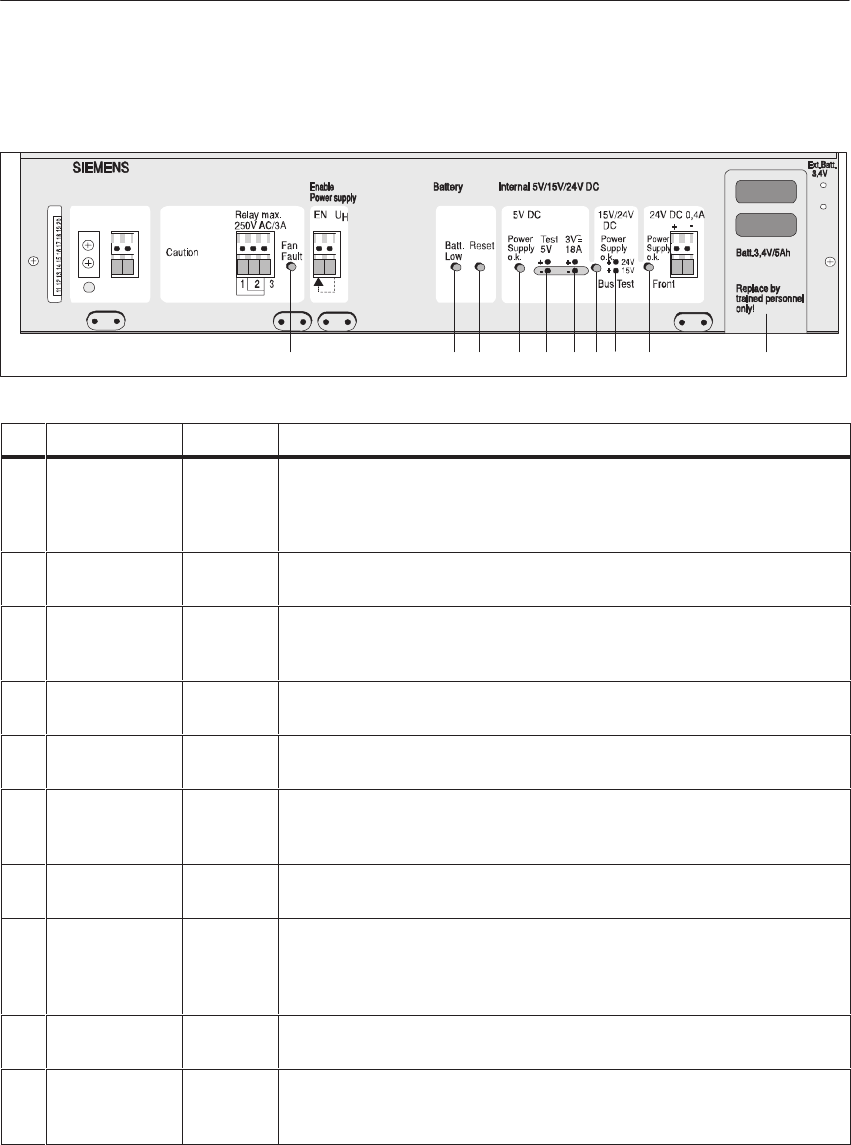
4-58 System Manual
C79000-G8576-C199-06
The following indicators and controls are arranged on the front plate:
12345678910
DC Line Monitor Output
24V DC
+ -
L+ M
Disconnect
before removing
power supply!
ID Label Element Purpose
1Fan Fault Red LED The LED lights up to indicate a fan fault. The PSU then switches off (jumper
F-R closed). If, for technical reasons, you cannot immediately switch off the
PLC, you must open jumper F-R. However, switch off the PLC after 60 s at
the latest (overheating of modules).
2Batt. Low Yellow
LED The LED lights up if the battery voltage has dropped below 2.7 V; the data
stored in the RAM may be lost after “Power OFF/ON.”
3 Reset Button If the PLC is in the “Power OFF” state, the battery must be replaced after
“Power ON” when the “Batt. Low” LED is lit. You must press the Reset
button after changing the battery.
4Power Supply
o.k. Green
LED The LED lights up when the 5 V output voltage is present.
5Test 5 V Test socket To measure output voltage Vo/p1
(standard setting: 5.1 V DC $ 0.5%)
63 V = 10 A Test socket To measure output Io/p1
(3 V = max. output current of the PSU)
linearity range 0.5 V/1.6 A to 3 V/40 A
7Power Supply
o.k. (Bus) Green
LED The LED lights up to indicate presence of the 15 V output voltage (if the 15
V auxiliary submodule is fitted) and 24 V output voltage
8DC 15V/24V
(Bus) Test
sockets a) To measure output voltage Vo/p2
(24 V DC +25 %/-24 %)
b) To measure output voltage Vo/p3
(15 V DC $ 5 %, provided that 15 V aux. submodule is fitted)
9Power Supply
o.k. (terminal) LED The green LED lights up to indicate presence of the output voltage at the “DC
24 V” terminal for the enable supply.
10 Batt. 3.4V/5Ah Battery
drawer The backup battery is arranged so that it can be replaced during operation and
the PSU can be replaced during battery backup without the backup voltage
being interrupted.
LEDs and Controls
Central Controllers and Expansion Units Power Suppl
y
Unit
s

4-59
System Manual
C79000-G8576-C199-06
12 2 2 2
3456
7
DC Line Monitor Output
24V DC
+ -
L+M
Disconnect
before removing
power supply!
ID Label Element Purpose
1Protective conductor terminal for PSU module and housing.
2Strain reliefs for connecting cables, with metal contact surface for cable
shields.
3DC Line Screw
terminals System connection, 24 V input voltage
4Monitor Output Relay
output Standstill of one or both fans is signaled via LED and relay contact, and
results in shutdown of output voltages (can be shut down via jumper F-R of
the PSU; then only relay signal and LED indication).
5Enable Power
supply Input/
output No voltage at the EN input results in shutdown of the PSU. Not more than
7 EN inputs may be driven with one UH output (front terminal).
6DC 24 V; 0.4 A Output This output can be used to power the enable inputs of the U Periphery.
7Ext.Batt. 3.4 V Sockets Sockets for external 3.4 V backup voltage.
!Caution
Observe the appropriate VDE specifications, especially VDE 0100. The
terminals at the front are suitable for a conductor cross-section of up to
4 mm2, solid, or 2.5 mm2, flexible. Ensure adequate strain relief of the
connections.
You can add a 15 V auxiliary submodule to the 6ES5 955-3NA12 power
supply unit (for example, if you wish to use SINEC H1). The auxiliary
submodule produces a stabilized 15 V output voltage from the 24 V output
voltage. The auxiliary submodule is short-circuit protected. The output
voltage is monitored. If the voltage is too low, the green “15/24 V o.k.” LED
on the front plate goes off. If the voltage is too high, the output is
short-circuited by a thyristor.
Terminals
15 V Auxiliary
Submodule
Central Controllers and Expansion Units Power Suppl
y
Unit
s
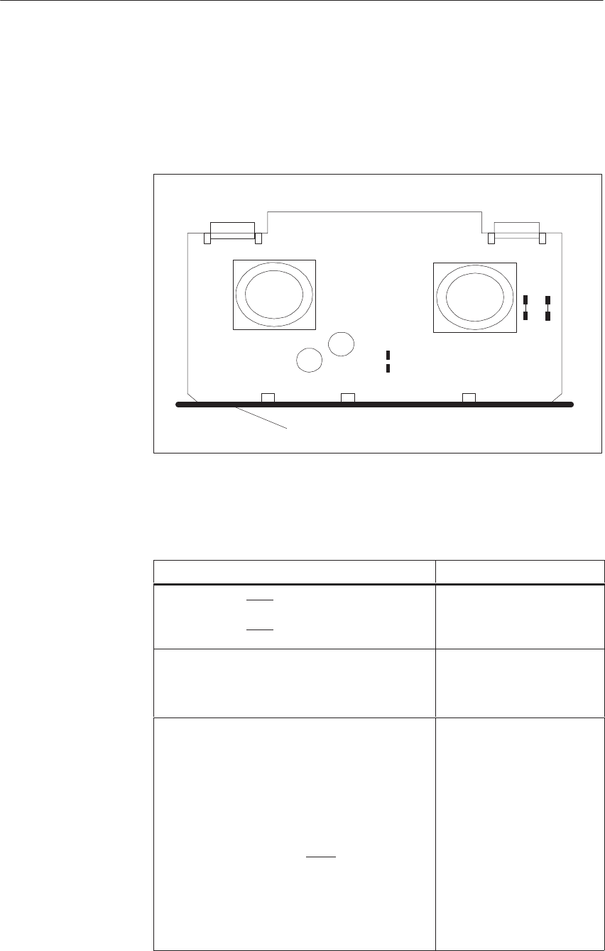
4-60 System Manual
C79000-G8576-C199-06
4.4.2 Setting the Power Supply Unit
The figure shows the jumper settings when the unit is delivered.
Connector
X1 Connector
X2
RR
Front Plate
LL
MM
NN
R
F
The jumper settings in bold print indicate the status when the unit is
delivered.
Function Jumpers
Battery monitor (BAU) On
Battery monitor (BAU) Off
NN-MM closed
NN-MM open
PSU shutdown after fan fault
No PSU shutdown after fan fault (only LED
indication, relay signal)
F-R closed
F-R open
Battery fault will be indicated by fault state of the
signaling relay (contacts 2-3 closed).
Battery undervoltage (< 2.7V)
results in battery fault signal (jumper
MM-NN). Apart from “Batt. Low” LED
and output of signal BAU, the signaling
relay can be activated as of Version 6 of the
PSU
Battery fault will not be indicated by fault state of the
signaling relay
RR-LL closed
RR-LL open
Locations of
Jumpers
Functions of the
Jumpers
Central Controllers and Expansion Units Power Suppl
y
Unit
s

4-61
System Manual
C79000-G8576-C199-06
You can set jumper F-R on the power supply units to choose whether or not
the air flow monitor should switch off the internal supply voltage Vo/p (5 V)
when a fan fails.
SJumper F-R closed: Vo/p shutdown (signaled by contact)
SJumper F-R open: no Vo/p shutdown (signaled by contact)
If one or both fans are at standstill, the signaling relay drops out (monitor
output). The “Fan Fault” LED lights up simultaneously.
SRelay contacts 2-1 closed: fan running
SRelay contacts 2-3 closed: fan failure
Relay contacts 2-3 closed; this is also the normally closed contact during
power OFF (failsafe).
!Caution
If an immediate shutdown is not possible, jumper F-R must be opened. In
this case you must ensure that the power supply is switched off after 60 s at
the latest. This can be achieved with a time relay, for example. It avoids
overheating and destruction of modules.
Setting the Fan
Monitor
Central Controllers and Expansion Units Power Suppl
y
Unit
s

4-62 System Manual
C79000-G8576-C199-06
As of Version 6 of PSU 6ES5 955-3NA12, you can set jumper RR-LL to
choose whether the signaling relay (monitor output) should switch in the
event of battery failure as well as fan failure:
SJumper RR-LL open (state when delivered): relay will signal only a fan
failure
SJumper RR-LL closed: relay will signal a fan and battery failure.
If the backup voltage fails or a fan is at standstill, or in both cases, the
signaling relay will drop out (monitor output). The “Batt. Low” LED will
also light up.
SRelay contacts 2-1 closed: battery backup voltage in order and fan
running
SRelay contacts 2-3 closed: backup voltage under 2.7 V or fan failure
Note
The signaling relay in the power supply unit will drop out in the event of a
fan fault or backup battery fault. The user’s circuitry for the signaling relay
must therefore be suitable for both types of fault.
If the signaling relay drops out because of a backup battery fault and the
programmable controller is therefore switched off, the program in the main
memory may be lost. Loss of program can be avoided if an external backup
voltage (3.4 V) is present at the sockets on the front plate of the power
supply unit during shutdown of the programmable controller.
Setting the Backup
Battery Monitor
Central Controllers and Expansion Units Power Suppl
y
Unit
s
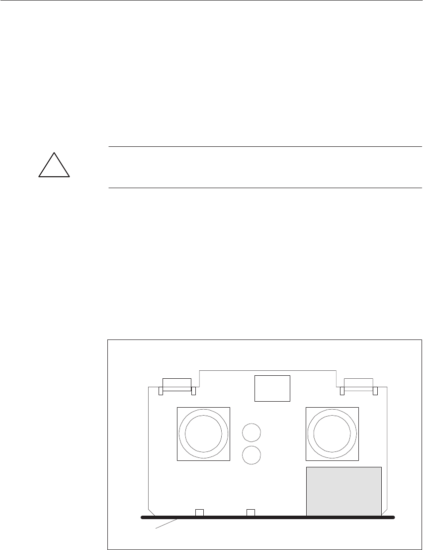
4-63
System Manual
C79000-G8576-C199-06
4.4.3 Installation
To install the power supply unit, push it into the rack. Press it in firmly until
the front plate is at the rack. The spring pressure of the contact elements must
be overcome. Then tighten the two screws to the left and right of the front
plate in the rack. The protective conductor jumper on the left must be
permanently connected to the front plate terminal and the central rack.
!Caution
Power supply units may only be removed when no power is applied.
When the power supply unit is pulled out, the connection between backup
battery and backplane bus is retained; the backup supply for the modules is
thus ensured.
The auxiliary submodule (see ordering information for order number) may
only be inserted when the power is off.
Remove the power supply unit, fit the 15 V auxiliary submodule at the
location shown in the following figure.
Connector
X1 Connector
X2
BB
RR
AA
LL
Front Plate
Trans-
former
Space for
Auxiliary
Submodule
Installing the 15 V
Auxiliary
Submodule
Central Controllers and Expansion Units Power Suppl
y
Unit
s

4-64 System Manual
C79000-G8576-C199-06
4.4.4 Operation
Before placing the power supply unit in operation, please comply with the
following.
SThis power supply unit does not have potential isolation between its
primary and secondary circuits.
SNo voltage of more than 50 V may develop between the power supply
outputs and the protective conductor of the power supply unit.
SThe protective conductor must always be connected, as must the jumper
between CC rack and front plate of the power supply unit.
SIn the event of overvoltage of the internal DC supply voltages
Vo/p1 = +5 V and Vo/p3 = +15 V, the power supply unit is switched off
retentively. There is a voltage of v0.5 V at Vo/p1 and Vo/p3 in the Off
state (see Section 4.4.6, Technical Specifications, for overvoltage
shutdown).
The storage flip-flop is reset by switching the external supply voltage off
and on again, and the power supply unit is again operational if the
overvoltage was not the result of an internal fault.
SYou can insert an air filter with filter holder in the bottom of the housing
of the power supply unit.
SObserve the voltage level of 3.4 V and correct polarity when applying an
external backup voltage.
SBefore startup, a lithium backup battery must be fitted or an external
backup battery with a voltage level of 3.4 V DC must be connected.
Without a backup battery, the programmable controller will remain in the
Stop state when system voltage has been switched on. The backup battery
must be fitted for startup. Press the RESET button, then perform an
OVERALL RESET.
SThe jumper from terminals UH to EN will enable the power supply. You
can lock out the PLC in the event of a fault by means of suitable circuitry
between the monitoring outputs and the EN inputs.
General Notes on
the Power Supply
Unit
Central Controllers and Expansion Units Power Suppl
y
Unit
s
4-65
System Manual
C79000-G8576-C199-06
Power supply faults are indicated via relay contacts and LEDs.
The following table shows when the relay contacts are open or closed:
Power Supply Relay Contacts 1-2 Relay Contacts 2-3
Switched off Open Closed
In normal operation Closed Open
During fault Open Closed
The LEDs indicate the following faults:
LED Cause Action
“Fan Fault” LED
lights up. A fan fault has occurred. Replace fan
“Batt. low” LED
lights up. The battery voltage has dropped below
2.7 V. Replace backup
battery
Fault Indications/
Diagnostics
Central Controllers and Expansion Units Power Suppl
y
Unit
s
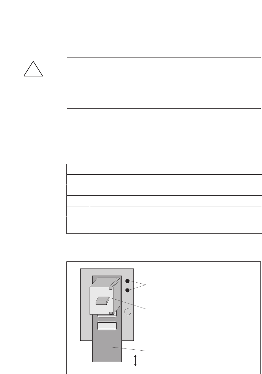
4-66 System Manual
C79000-G8576-C199-06
4.4.5 Maintenance
!Caution
Incorrect replacement of the battery can result in the danger of explosion.
It should only be replaced by the same type or an equivalent type
recommended by the manufacturer. Used batteries should be disposed of
according to the manufacturer’s instructions.
You can replace the backup battery without loss of data if the power supply
unit is switched on, or if you apply an external voltage (3.4 V) at the “Ext.
Batt.” sockets. The backup battery must be replaced every 3 years at the
latest, irrespective of memory configuration and backup operation. Replace
the battery as follows:
Step Action
1Pull the cover downwards.
2Pull the battery submodule forwards and out, and remove it.
3Replace the battery.
4Ensure correct polarity.
5Once the new battery is fitted and system voltage is On, press the Reset
button on the power supply unit.
Cover
Battery Submodule
Sockets for External
Backup Voltage
*
+
Only use battery submodules with the order number 6XG3 400-2CK00.
Replacing the
Lithium Battery
Battery
Submodule
Central Controllers and Expansion Units Power Suppl
y
Unit
s

4-67
System Manual
C79000-G8576-C199-06
!Caution
Ensure correct polarity when inserting the battery or applying backup
voltage.
!Warning
Risk of danger to persons and property, danger of giving off harmful
substances.
If handled incorrectly, a lithium battery can explode. If disposed of
incorrectly, old lithium batteries can release harmful substances. You must
therefore observe the following guidelines:
SDo not throw new or discharged batteries onto a fire and do not solder
onto the body of the cell (max. temperature 100 °C (212 °F)). Do not
recharge them. Order your replacement battery from Siemens only (for
order number see ordering instructions). This ensures that you only use a
short-circuit-protected type.
SThe lithium battery is subject to regulations for hazardous materials. You
should observe these regulations when you shipthe battery, for example,
by using the original packaging. Used batteries should be returned to the
manufacturer or a recycling station if possible or disposed of as
hazardous waste. The guidelines for transporting hazardous materials
should be observed.
The expected service life of the fans (see Technical Specifications) depends
on their operating time, ambient temperature and ambient conditions. In the
event of fan failure during operation, subsequent damage to modules, for
example, is avoided by the activated fan monitor (jumper F-R closed); the
power supply unit is switched off.
In individual cases, a preventive replacement of fans at suitable intervals may
be advisable. Proceed as follows to replace the fans:
Step Action
1Disconnect power from the power supply.
2Remove the power supply.
3Slacken the fixing screws of the fans.
4Pull off the plug-in contacts of the fan supply.
5Connect the plug-in contacts of the new fans.
6Tighten the fixing screws of the fans.
7Refit the power supply.
8Switch the power supply on.
The order numbers for the backup battery and fan unit can be found in the
ordering information.
Replacing the
Fans
Central Controllers and Expansion Units Power Suppl
y
Unit
s

4-68 System Manual
C79000-G8576-C199-06
4.4.6 Technical Specifications
Important for the USA and Canada
The following approvals habe been obtained:
SUL-Recognition-Mark
Underwriters Laboratories (UL) to
Standard UL 508, Report E 116536
SCSA-Certification-Mark
Canadian Standard Association (CSA) to
Standard C 22.2 No. 142, Report LR 63534
Safety Specifications The power supply unit complies with safety specifications
VDE 0805 / EN 60950 / IEC 950 / VDE 0160 and VDE
0106 Part 101.
Input
Rated input voltageVi/pN DC 24 V +25% / -16.66%
Undervoltage signal Vi/p v 20 V DC
Input current Ii/pN
at rated load and Vi/pN = 24 V DC 4.8 A
Inrush current peak Ii/pmax 100 A
I@t value of inrush current 20 A@s
Efficiency at rated load and Vi/pN = 20 V
without fan
with fan 0.71 typical
0.60 typical
Stored energy time for power failure > 5 ms
Input fuse 6 A fast; 250 V; 6.3 x 32 mm
Output 1
Rated output voltage Vo/pN1 5.1 V DC $ 0.5%
Rated output current Io/pN1 10 A
Ripple v 1% of Vo/p1
Static voltage tolerances
at 10% load variation
at 5% variation of UE
at temperature variation /1 K
v 0.02% of Vo/p1
v 0.04% of Vo/p1
v 0.02% of Vo/p1
Dynamic voltage tolerances
at load surge from 50 % to 100 %
overshoot
settling time
v 5% of Vo/p1
v 5 ms
Protection and monitoring
Overvoltage shutdown Vo/p1
Undervoltage signal Vo/p1
Current limiting for overload
6 V $ 5%
4.75 V + 5%
1.05 to 1.15 Io/pN1
Test sockets for
Vo/p1
Io/p1
On front plate
On front plate (3 V ¢ 10 A)
Linearity range 0.5 V/1.6 A to 3 V/10 A
Signaling section Signals for SIMATIC S5
Central Controllers and Expansion Units Power Suppl
y
Unit
s

4-69
System Manual
C79000-G8576-C199-06
Output 2 (bus)
Rated output voltage Vo/p2 24 V DC +25% / -20%
Rated output current Io/p2 0.8 A
Total current rating
24V-/ 15V output
v 0.8 A
Ripple Input voltage ripple
Protection and monitoring
Fuse for overcurrent protection
Test sockets for Vo/p2
– green LED 15V/24V o.k. for Vo/p2 (fuse monitor)
1.5 A fast; 250 V; 6.3 x 32 mm
on front plate (24 V test)
The LED lights up when Vo/p2 > 17.9 to 18.5 V
Output 2 (front)
Rated output voltage Vo/pN4 24 V DC +25% / -24%
Rated output current Io/pN4 0.4 A
– Capacitive load < 100 nF
Protection and monitoring
Overcurrent protection by current limiting Io/p4
Test sockets for Vo/p2
– green LED 24V o.k. for Vo/p4
> 0.44 A
on front plate (24 V test)
The LED lights up when Vo/p4 > 16 V $ 20%
Total current rating of 24 V voltages (bus and front) must not exceed 0.8 A
Output 3 with 15 V auxiliary submodule
Rated output voltage Vo/pN3 15 V DC $ 5%
Rated output current Io/pN3 0.5 A
Ripple v 5% of Vo/pN3
Protection and monitoring
Overvoltage protection (output is short-circuited
at Vo/p3)
Undervoltage signal (LED 15V/24V o.k.
on front plate goes off at)
Overcurrent protection Io/p3 by current limiting
Test socket for Vo/p3
w 18.5 V
v 14 V $ 3%
> 0.5 to 1.5 A
on front plate (15 V test)
Fans
Fan type 2 axial fans
Input voltage 24 V DC
Flow rate per fan 160 m3/h (no-load value)
Fan monitoring Air flow monitoring with PTC thermistors as sensors;
stoppage of one or both fans is detected and signaled to the
exterior via Fan Fault LED and relay contacts, and results
in shutdown of output voltage (switched off via jumper
F-R).
Expected service life of a fan 30 000 to 40 000 h typical at 55 oC;
40 000 to 50 000 h typical at 30 oC;
Isolation primary/sekondary
and test voltages No
Weight 3.75 kg
Environmental data See technical specifications of the S5-135U/155U CC
RFI suppression DIN VDE 0871, A
Central Controllers and Expansion Units Power Suppl
y
Unit
s
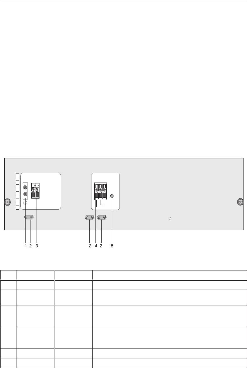
4-70 System Manual
C79000-G8576-C199-06
4.5 Fan Submodules
4.5.1 Technical Description
The fan submodule variants 6ES5 988-3LA11 (230 V AC) and
6ES5 988-3NA11 (24 V DC) are described in the following section.
A fan submodule has the following function:
SHeat dissipation
The fan submodule dissipates any excess heat created in the central
controller or expansion unit.
The following terminals and LEDs are fitted on the front plate (the front
plate of the -3LA11 is shown as an example):
6ES5 988-3LA11
AC 230V
CAUTION!
Disconnect
before
removing
Voltage selector
inside the unit!
AC line
L1 N
SIEMENS
Monitor Output
Use copper wire 60/75° C only!
Tightening torque: terminals 0,8Nm/ 1,8 Nm
Fan
Fault
Relay max.
250V AC/3A
132
power supply!
12345678910
ID Label Element Purpose
1Protective conductor terminal for fan submodule and housing.
2ZStrain reliefs for connecting cables, with metal contact surface for cable
shields.
3230V AC Screw
terminals
L1, N
AC connection
(details for -3LA11)
24V DC Screw
terminals + – 24 V DC supply
(details for -3NA11)
4Monitor Output Relay output Standstill of one or both fans is signaled via LED and relay contact.
5Fan Fault Red LED The LED lights up to indicate a fan fault.
Connections and
LEDs
Central Controllers and Expansion Units Power Suppl
y
Unit
s
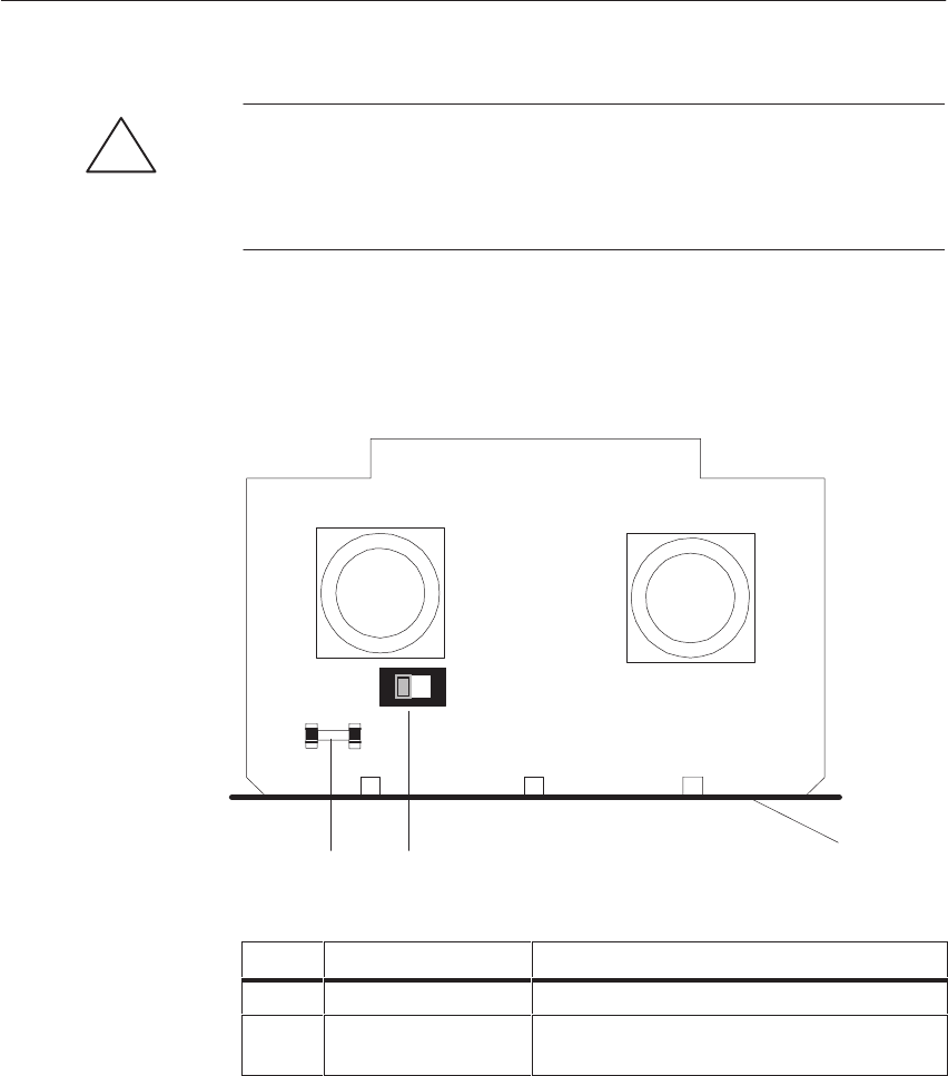
4-71
System Manual
C79000-G8576-C199-06
!Caution
Observe the appropriate VDE specifications, especially VDE 0100. The
terminals at the front are suitable for a conductor cross-section of 4 mm2
solid or 2.5 mm2 flexible. Ensure adequate strain relief for the connections.
DThe figure shows the setting of the voltage selector switch when delivered
(230 V).
Front plate
21
F12 S13
230V
ID Element Purpose
1Fuse F12 Protecting the fan submodule against overload
2Voltage selector switch
S13 (-3LA11 only) Setting the fan submodule -3LA11 for the
available line voltage: (115 V or 120 V or 230 V)
Position of the
Voltage Selector
Switch and the
Fuse
Central Controllers and Expansion Units Power Suppl
y
Unit
s

4-72 System Manual
C79000-G8576-C199-06
4.5.2 Setting and Connecting the Fan Submodule
Before starting up your fan submodule, you must perform certain steps
according to your requirements with respect to fan submodule behavior in the
event of a fault.
The fan submodule is delivered in the following state:
SFitted in the CC or EU frame you ordered
SAC line voltage set to 230 V
If you wish to retain this setting, you can skip Steps 2 to 5.
Step Action
1Check the setting and cabling
2Remove the fan submodule If required
3Fit the fan submodule If required
4Wire the fan submodule to the installation (including fitting
an isolating device to disconnect the AC line voltage)
5On the -3LA11 set the voltage selector switch (factory
setting 230 V) If required
6Switch on the fan submodule for the first time
Wiring of the fan submodule must be planned within the scope of wiring the
entire control system. The information required for the purpose and
decision-making aids (for example, for local or central grounding) can be
found in Chapter 3, Installation Guidelines.
Two relay outputs allow you to install additional external signaling circuits
for fault states, for example, to connect a cabinet lamp or horn.
Establishing the
Wiring
Establishing the
Signaling Circuits
Central Controllers and Expansion Units Power Suppl
y
Unit
s
4-73
System Manual
C79000-G8576-C199-06
The following applies to selecting the cables for the terminals:
Terminals Cabling Max. Permissible Cable
Cross-Sections
Power supply AC line Phase L 1 4 mm2 solid or 2.5 mm2
flexible
Neutral N 4 mm2 solid or 2.5 mm2
flexible
Protective conductor 4 mm2 solid or 2.5 mm2
flexible
Relay terminals, also suitable
to 230 V AC / 3 A 4 mm2 solid or 2.5 mm2
flexible
For installing and removing the fan submodule, refer to the instructions in
Section 4.3.2 on the power supply unit. These also apply in principle here.
FFor wiring up the fan submodule, refer to the instructions in Section 4.3.2
on the power supply unit. These also apply in principle here.
The fan submodule is switched on when the line voltage for the central
controller or expansion unit is switched on.
!Caution
If you have set the voltage selector switch on the -3LA11 to 120 V, but the
actual voltage value is 230 V, the fan submodule may be damaged when line
voltage is switched on.
Fan submodule faults are indicated via relay contacts (“Monitor Output”) and
an LED.
The following table shows when the relay contacts are open or closed:
Fan Submodule Relay Contact 1-2 Relay contact 2-3
Switched off open closed
In normal operation closed open
During fault open closed
In the case of a fault, the red LED “Fan Fault” lights up.
Selecting Cables
Installing and
Removing the Fan
Submodule
Wiring up the Fan
Submodule
Switching on the
Fan Submodule
for the First Time
Fault Indications/
Fault Diagnostics
Central Controllers and Expansion Units Power Suppl
y
Unit
s

4-74 System Manual
C79000-G8576-C199-06
4.5.3 Technical Specifications
Important for the USA and Canada
The following approvals have been obtained:
SUL-Recognition-Mark
Underwriters Laboratories (UL) to
Standard UL 508, Report E 116536
SCSA-Certification-Mark
Canadian Standard Association (CSA) to
Standard C 22.2 No. 142, Report LR 63534
6ES5 988-3LA11 6ES5 988-3NA11
Safety Specifications The power supply units comply with safety specifications
VDE 0805 / EN 60950 / IEC 950 / VDE 0160 and VDE
0106 Part 101.
Shock protection Only ensured in the installed state.
Data for EMC in the installed state See technical specifications of the S5-135U/155U CC
Safe isolation Is ensured.
Input
Rated input voltage 110 V AC (93.5-121 V),
220 V AC (187-242 V) 24 V DC (20 - 30 V)
Input frequency 50/60 Hz (48-63 Hz) –
Input current Ii/pN approx. 0.48 A
(and Vi/pN = 120 V)
approx. 0.24 A
(and Vi/pN = 230 V)
approx. 1 A
Peak inrush current Ii/pmax < 5 A < 10 A
Max. heat dissipation at rated load (with fans) approx. 52 W approx. 24 W
Max. heat dissipation at rated load (without fans) approx. 12 W approx. 9 W
Stored energy time during power failure > 20 ms
Input fuse 1.5 A fast; 250 V; 2.4 A2s
Service life approx. 42.000 h at 40 oC
Weight approx. 4 kg
Environmental data See technical specifications of the S5-135U/155U CC
Central Controllers and Expansion Units Power Suppl
y
Unit
s

5-1
System Manual
C79000-G8576-C199-06
CPUs, Memory Cards, Memory
Submodules, Interface Submodules
This chapter contains information on the CPUs, memory cards, modules and
submodules which you can use in your programmable controller.
The following CPUs may be fitted in an S5-135U/155U central controller:
CPU 948
CPU 928B
CPU 928
CPU 922.
A programmable controller containing a CPU 948 is known as an S5-155U
PLC. A programmable controller containing CPUs 928B, 928 and/or 922
(and not the CPU 948) is known as an S5-135U PLC.
You can fit a flash EPROM memory card containing your user program in the
CPU 948, 928B -3UA21 and 928 -3UA21. For the CPUs 928B, 928 and 922,
there are RAM or EPROM submodules for the purpose.
CPUs 948 and 928B have, apart from the programmer interface, a second
serial interface. An interface submodule is required for physical adaptation.
Section Description Page
5.1 CPU 948B -3UA13 or CPU 948B -3UA23 5-2
5.2 CPU 948 5-17
5.3 CPU 928B -3UB21 5-30
5.4 CPU 928B 5-42
5.5 CPU 928 -3UA21 5-54
5.6 CPU 928 5-62
5.7 CPU 922 5-71
5.8 374 Flash EPROM Cards 5-80
5.9 376 Memory Submodules 5-82
5.10 377 Memory Submodules 5-84
5.11 Interface Submodules 5-92
Chapter
Contents
5

5-2 System Manual
C79000-G8576-C199-06
5.1 CPU 948B -3UA13 or CPU 948B -3UA23
This section contains the hardware description and technical specifications of
the CPU 948B -3UA13 or the CPU 948B -3UA23.
Details on programming the CPU 948 can be found in the CPU 948
Programming Guide.
5.1.1 Technical Description
This section contains information on the application, design and structure of
the CPU 948.
You can use the CPU 948 in single and multiprocessor operation in the
S5-135U/155U central controller (see Chapter 6).
There are two versions of CPU 948:
The CPU 948-1 offers 640 Kbytes of internal user memory (RAM).
The CPU 948-2 offers 1664 Kbytes of internal user memory (RAM).
As an external memory medium, you can use a memory card 374.
The following program processing levels are possible:
Cyclic
Time-controlled (9 different timebases, real-time controlled, timeout)
Interrupt-driven from the S5 bus (8 process interrupts at block boundaries
via IB0 or, alternatively, 4 system interrupts)
Soft STOP.
The electronic circuitry of the CPU 948B is on one PCB in the double
Eurocard format. The front plate width is 1 1/3 standard plug-in stations, i.e.
20 mm. In the central controller rack, the CPU 948B -3UA13 or the
CPU 948B -3UA23 occupies one slot.
Application
Design
CPUs, Memor
y
Cards, Memor
y
Submodules, Interface Submodules

5-3
System Manual
C79000-G8576-C199-06
5.1.2 Installation and Startup
There are four system interrupts for interrupt-driven program processing with
the CPU 948:
INTA/B/C/D (depending on the CPU slot, see also Section 4.1.1)
INTE
INTF
INTG.
The interrupts you wish to use must be enabled by inserting the jumper plugs
provided. The jumper socket is situated on the basic board above the
receptacle for the memory card. The exact location is given in Figure 5-1:
Figure 5-1 Location of Jumper Socket
If you want to operate an IM308C in the IM3/IM4 area and additional digital
or analog modules in the central controller, you must insert the jumper shown
in Figure 5-1.
Jumper Settings
CPUs, Memor
y
Cards, Memor
y
Submodules, Interface Submodules
5-4 System Manual
C79000-G8576-C199-06
Note
All other jumpers on the CPU 948B -3UA13 or the CPU 948B -3UA23 are
required for quality testing by the manufacturer. You must not change these
jumper settings.
!Caution
Switch off the power supply before removing or inserting the module.
Proceed as follows to insert the CPU in the central controller:
Step Action
1Release the upper locking bar of the central controller and ensure
that the locking pin for the module is correctly positioned with the
slot-head horizontal.
2Select the correct slot (based on the labelling of the locking bar).
Insert the CPUs in the S5-135U/155U CC from slot 11.
3Push the module evenly into the guide rail until the lever over the
locking pin is horizontal.
4Press the locking pin inwards on the bottom of the module and
rotate it 90 clockwise.
5Secure the upper locking bar.
Note
If you install the CPU 948 -3UA13 or the CPU 948 -3UA23 as the
replacement for a double-width CPU 948, you must cover the slot which has
been freed up with a blanking plate.
Removing and
Inserting the
Module
Insertion
CPUs, Memor
y
Cards, Memor
y
Submodules, Interface Submodules

5-5
System Manual
C79000-G8576-C199-06
Proceed as follows to remove the CPU:
Step Action
1Release the upper locking bar of the central controller.
2Release the locking pin of the module.
3Press the release lever downwards and pull the module forwards
and out of the central controller.
Note
Only operate the CPU 948 -3UA13 or the CPU 948 -3UA23 with the
submodule receptacle closed. You close it either by fitting an interface
submodule or with the cover supplied.
Removal
CPUs, Memor
y
Cards, Memor
y
Submodules, Interface Submodules
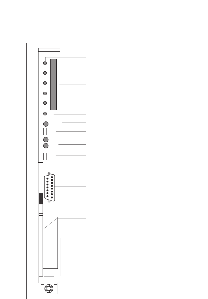
5-6 System Manual
C79000-G8576-C199-06
The controls and indicators are arranged on the front plate of the CPU
module:
CPU 948U
QVZ
ADF
ZYK
BASP
RUN
STOP
RESET
SI2
OV-
RESET
SIEMENS 6ES5948-3UA13
SI1
S–F
Receptacle for
User Memory Submodule
Momentary-Contact Mode Switch
Mode Switch
RUN LED (green)
STOP LED (red)
Fault Indicator LED (red)
PG Interface, 15-Pin
Interface SI1
Release Lever
Locking Pin
Order Number and Version
SYS FAULT LED (red)
SI1 Interface Fault Indicator LED (red)
SI2 Interface Fault Indicator LED (red)
Figure 5-2 Front Plate of the CPU 948-3UA13 or the CPU 948-3UA23
Controls and
Indicators
CPUs, Memor
y
Cards, Memor
y
Submodules, Interface Submodules

5-7
System Manual
C79000-G8576-C199-06
The mode switch has two settings:
In the RUN setting, the CPU 948 processes the user program when the green
RUN LED is lit.
The CPU 948 goes to the stop state when you switch from RUN to STOP.
The red STOP LED then lights up.
You can initiate the Overall Reset, Reset and Restart functions with the
momentary-contact mode switch:
Momentary-contact switch down
With an overall reset, all RAM areas are erased and initialized (both on the
CPU and on a RAM submodule).
Momentary-contact switch up
During a reset, all flags, timers, counters and the process image will be
erased. OB 20 will be invoked. Processing of the user program will start from
the beginning again.
Momentary-contact switch at midpoint
With a restart, processing of the user program will continue from the point of
interruption. The statuses of flags, timers, counters, and the process image
are retained during stoppage of the CPU.
Mode Switch
RUN
STOP
Momentary-
Contact Mode
Switch
OVERALL RESET
RESET
Restart
CPUs, Memor
y
Cards, Memor
y
Submodules, Interface Submodules

5-8 System Manual
C79000-G8576-C199-06
Given in the following overview are the functions of the RUN, STOP and
SYS FAULT status LEDs.
The STOP LED indicates a soft stop; the SYS FAULT LED indicates a hard
STOP.
The CPU 948 can process a user program (OB 39) cyclically at the soft
STOP, but the digital outputs remain inhibited. At the hard STOP, no program
can run and the CPU has “stopped.” This state can only be exited by
switching the system voltage off and on again.
RUN
LED STOP
LED SYS
FAULT
LED
Status
on off off The CPU is in the RUN state (cyclic
operation).
on on on Appears briefly after power-up of the unit.
off off off CPU is in the initial start or program check
state.
off on off CPU is in the soft STOP state.
off rapid
flashing off CPU is in the soft STOP state.
Overall reset has been requested by switch or
from the operating system.
off slow
flashing off CPU is in the soft STOP state. An error has
occurred; see the CPU 948 Programming
Guide for possible causes.
off off on CPU is in the hard STOP state. No program
processing is taking place. You can only exit
from this state by switching the system
voltage off and on again.
Status Indicators
CPUs, Memor
y
Cards, Memor
y
Submodules, Interface Submodules

5-9
System Manual
C79000-G8576-C199-06
Given in the following overview are the causes for LEDs lighting up:
QVZ LED
on A module addressed by the program no longer acknowledges
although/because
it either acknowledged in single-processor operation upon
restart of the CPU 948 in the area of the process image
(IB0 to 127, QB0 to 127) and has been entered as present
in the so-called 9th track;
or it has been entered in multi or single-processor
operation in DB 1 (address list) and has been recognized
as present during the restart;
or it was addressed in direct access by operations LPY,
LPW, TPY, TPW, LOY, LOW, TOY, TOW;
or the data handling blocks cannot access the module.
Possible causes:
Module failure
Module removed during operation, in the STOP state or in
the Off state without subsequent restart.
A timeout occurred during access to the user memory.
ADF LED
on The user program has referred to an address in the process
image under which no module was inserted in the I/Os or was
not entered in DB 1 during the last restart.
ZYK LED
on The preset cycle time monitor has responded and cyclic
program processing is interrupted.
BASP LED
on Command output is inhibited and the digital outputs will be
directly switched to the safe state (0).
A detailed description of interrupt and error handling can be found in the
CPU 948 Programming Guide.
LEDs for Fault
Indication and
Signaling
CPUs, Memor
y
Cards, Memor
y
Submodules, Interface Submodules

5-10 System Manual
C79000-G8576-C199-06
LEDs SI1 and SI2 indicate faults in communication via interfaces SI1
and SI2:
LED SI1 LED SI2 Cause
on on Communication is not possible at both interfaces.
Internal fault.
on off SI1:
No communication possible.
Internal fault.
SI2:
Interface is initialized and ready.
LED SI2 is always off if no interface module is
inserted.
off on SI1:
Interface is initialized and ready.
SI2:
No communication possible. Wrong module
inserted or internal fault.
off off Both interfaces are initialized and ready.
LED SI2 is always off if no interface module is
inserted.
Fault LEDs SI1
and SI2
CPUs, Memor
y
Cards, Memor
y
Submodules, Interface Submodules

5-11
System Manual
C79000-G8576-C199-06
The module must be inserted at the correct slot in the central controller. The
backup battery must be fitted and in order for the CPU to start.
Proceed as follows:
Step Action Result
1Set the mode switch to STOP
2Switch the system voltage on. The following LEDs must light
up on the CPU:
– Red STOP LED
(flashing rapidly)
– Red BASP 2) LED
3Hold the MC 1) switch in the
OVERALL RESET setting
and simultaneously set the
mode switch from STOP to
RUN.
The red STOP LED is now
permanently lit.
1) MC: Momentary-contact
2) BASP: Command output inhibit
If the red SYS FAULT LED also lights up, an error has occurred during
overall reset. In this case the measures described must be repeated. If
necessary, switch the system voltage off and on again. If the LED is still lit,
the module is faulty.
Continue as follows:
Step Action Result
1Set the mode switch to STOP.
2Hold the MC switch in the
RESET setting and
simultaneously set the mode
switch from STOP to RUN.
– Red STOP LED goes off
– Green RUN LED lights up
– Red BASP LED goes off
The CPU is now in the RUN state
but still has no user program.
Startup
Overall Reset
Reset
CPUs, Memor
y
Cards, Memor
y
Submodules, Interface Submodules

5-12 System Manual
C79000-G8576-C199-06
You can also carry out a manual restart of the CPU 948 with the mode
switch. The CPU 948 Programming Guide will indicate when a manual
restart is permissible.
Step Action Result
1Set the mode switch from
STOP to RUN – Red STOP LED goes off
– RUN LED lights up
– Red BASP LED goes off
For maintenance purposes or in the event of a fault, this startup without user
program in single-processor operation can serve to establish whether the CPU
is operating without errors.
Restart
CPUs, Memor
y
Cards, Memor
y
Submodules, Interface Submodules

5-13
System Manual
C79000-G8576-C199-06
5.1.3 Interfaces of the CPU 948
This section contains information on the interfaces of the CPU 948.
You can use the PG interface on the CPU 948 either via the front connector
or via the 923C coordinator module and the S5 bus.
Note
Simultaneous operation of the PG interface via the front connector of the
CPU 948 and via the 923C coordinator is not possible. Switching the PG
online without a job request is already sufficient to operate the interface.
Electrically, it is merely a PG interface which can be operated via two
different terminals.
The connection to the PG can be established in every operational state of the
CPU.
You can optionally use the second interface of the CPU 948 -3UA13 or the
CPU 948 -3UA23 as:
A PG interface (for PG and operator panels)
Interface for the RK 512 computer link
Interface for data transmission with procedures 3964/3964R
Interface for data transmission with the “open driver”
Interface for data transmission via the SINEC L1 bus.
To utilize the second interface as the PG interface, you need the
PG submodule.
You need one of the following interface submodules for the RK 512
computer link, for data transmission with procedures 3964/3964R and for
data transmission with the “open driver”:
V.24 submodule (RS 232C)
TTY submodule
RS422 A/485 submodule (only in the RS422 A module).
To utilize the second interface for data transmission via the SINEC L1 bus,
you need the
SINEC L1 submodule.
The CPU 948 -3UA13 or the CPU 948 -3UA23 is delivered without an
interface submodule. You can operate the CPU 948 -3UA13 or the CPU 948
-3UA23 without an integral interface submodule. The opening to accept a
submodule in the front plate is closed by a cover. Only remove the cover to
fit an interface submodule.
A description of interface submodules can be found in Section 5.11, and the
order numbers in the ordering information.
A detailed description of the second interface can be found in the
CPU 928B/CPU 948 Communication Manual.
PG interface SI1
Second Interface
SI2
CPUs, Memor
y
Cards, Memor
y
Submodules, Interface Submodules

5-14 System Manual
C79000-G8576-C199-06
A PG-PLC link via SINEC H1 allows very advanced communication
between the partners. For example, the user software can be loaded into the
CPU 948 up to eight-times faster than with serial communication.
For this link you will need, in addition to the CPU 948, a CPU 143 (Version
w 2.1) in the PLC and a PG7xx with SINEC H1 connection and the STEP 5
single-tasking software from Version 6.0 or multi-tasking from Version 2.0.
Note
You cannot implement communication via SINEC H1 in parallel with the
serial interfaces.
Communication via SINEC H1 is described in detail in the CPU 948
Programming Guide.
Communication
via Backplane Bus
with SINEC H1
CPUs, Memor
y
Cards, Memor
y
Submodules, Interface Submodules

5-15
System Manual
C79000-G8576-C199-06
5.1.4 Technical Specifications
Important for the USA and Canada
The following approvals have been obtained:
SUL Listing Mark
Underwriters Laboratories (UL) to Standard UL 508, Report E 85972
SCSA Certification Mark
Canadian Standard Association (CSA) to Standard C 22.2 No. 142,
Report LR 63533
Degree of protection IP 00
Climatic ambient conditions See Technical Specifications of the S5-135U/155U CC
Mechanical ambient conditions See Technical Specifications of the S5-135U/155U CC
Noise immunity, electromagnetic
compatibility (EMC) See Technical Specifications of the S5-135U/155U CC
Supply voltage 5 V $ 5 %
24 V + 25 %/ –17 %
Current consumption at 5 V 1.5 A typical
Backup voltage 3.4 V
Backup current 20 mA typical (at 25 _C)
P area O area IM3 area IM4 area Total
Digital inputs with process image
Digital inputs without process image
or analog inputs
1024 max.
1024 max.
64 max.
–
2048 max.
128 max.
–
2048 max.
128 max.
–
2048 max.
128 max.
1024 max.
7168 max.
448 max.
Digital outputs with process image
Digital outputs without process image
or analog outputs
1024 max.
1024 max.
64 max.
–
2048 max.
128 max.
–
2048 max.
128 max.
–
2048 max.
128 max.
1024 max.
7168 max.
448 max.
Flags 2048
S flags 32768
Timers 256
Counters 256
Size of user memory 64 x 2!) bytes max., RAM
Transmission rate of the serial PG interface 9600 bps
Program blocks PB 256
Sequence blocks SB 256
Function blocks FB 256
Function blocks FX 256
CPUs, Memor
y
Cards, Memor
y
Submodules, Interface Submodules

5-16 System Manual
C79000-G8576-C199-06
Data blocks DB 256, of which 253 are freely available
Data blocks DX 256, of which 253 are freely available
Organization blocks OB OB 1 to 39 (interfaces for operating system)
Integrated special function organization
blocks OB OB 121, 122, 124-126, 131-133, 141-143, 150, 151, 153, 200,
202-205, 222, 223, 254, 255
Integrated serial interface PG interface
Optional serial interface Via interface submodules, optionally as V.24, TTY, RS422 A/485
submodule, SINEC L1 or PG interface
Backplane bus S5 bus
Dimensions (w x h x d) 20.32 x 233.4 x 160 mm
Weight Approx. 0.6 kg
CPUs, Memor
y
Cards, Memor
y
Submodules, Interface Submodules

5-17
System Manual
C79000-G8576-C199-06
5.2 CPU 948
This section contains the hardware description and the technical
specifications of the CPU 948.
Details on programming the CPU 948 can be found in the CPU 948
Programming Guide.
5.2.1 Technical Description
This section contains information on the application, design and structure of
the CPU 948.
You can use the CPU 948 in single and multiprocessor operation in the
S5-135U/155U central controller (see Chapter 6).
There are two versions of CPU 948:
The CPU 948-1 offers 640 Kbytes of internal user memory (RAM).
The CPU 948-2 offers 1664 Kbytes of internal user memory (RAM).
A SIMATIC S5 flash EPROM memory card (known as a memory card for
short in the following) can be inserted in the CPU 948 as the storage medium
for user program and user data. The contents of the memory card are copied
into the internal RAM of the CPU upon overall reset.
The programming language is STEP 5 (LAD, CSF, STL, SCL). The CPU 948
processes all STEP 5 operations at very high speed, and uses fast
floating-point arithmetic.
The following program processing levels are possible:
Cyclic
Time-controlled (9 different timebases, real-time controlled, timeout)
Interrupt-driven from the S5 bus (8 process interrupts at block boundaries
via IB0 or, alternatively, 4 system interrupts)
Soft STOP.
The electronic circuitry of the CPU 948, including the RAM, is on two PCBs
of double Eurocard format which are screwed to each other. The two PCBs
must not be separated. The front plate width of the module is 2 2/3 standard
plug-in stations, i.e. 40 mm. In the central controller rack, the CPU 948
occupies two slots.
Application
Design
CPUs, Memor
y
Cards, Memor
y
Submodules, Interface Submodules
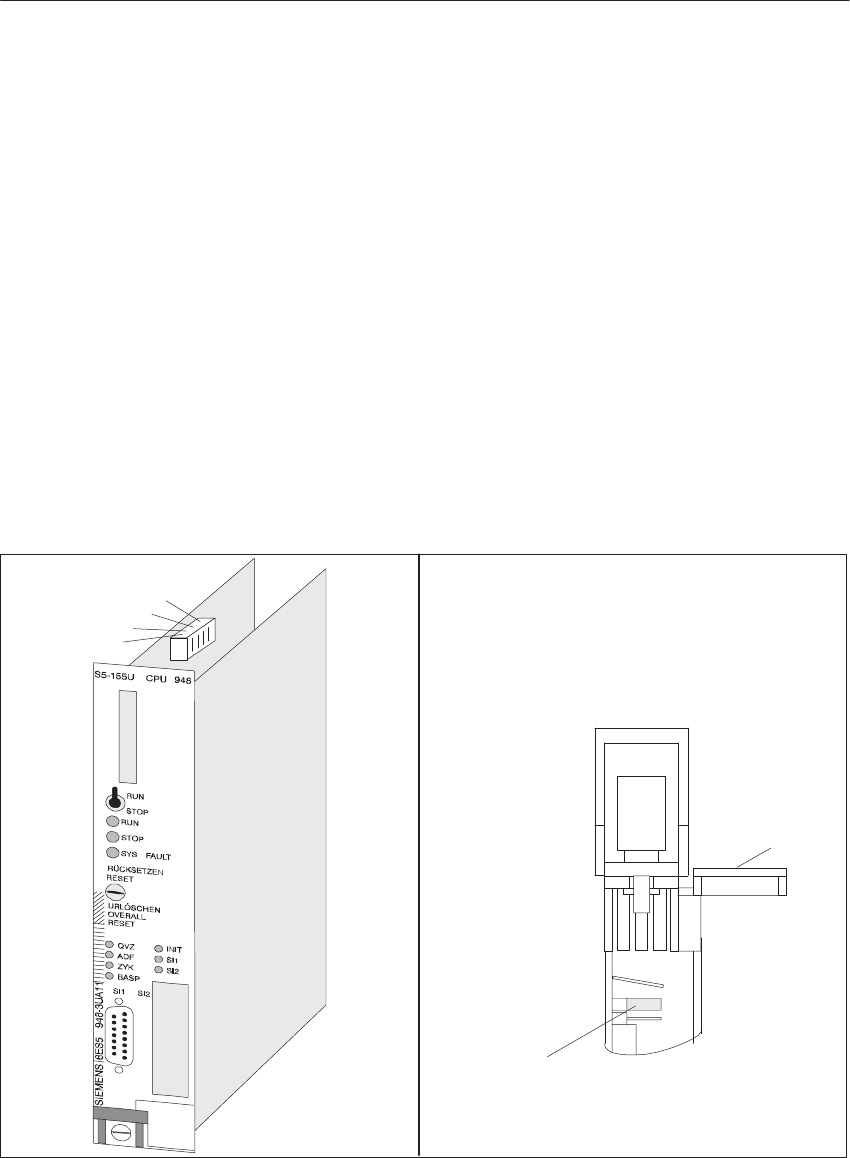
5-18 System Manual
C79000-G8576-C199-06
5.2.2 Installation and Startup
This section explains the installation and removal of the module in the CC,
controls and indicators on the front plate of the CPU, and the procedure for
module startup.
There are four system interrupts for interrupt-driven program processing with
the CPU 948:
INTA/B/C/D (depending on the CPU slot, see also Section 4.1.1)
INTE
INTF
INTG.
The interrupts you wish to use must be enabled by inserting the jumper plugs
provided. The jumper socket is situated on the basic board above the
receptacle for the memory card. The exact location is given in Figure 5-3:
INTF
INTG
INTE
INTA/B/C/D
View of underside of module
Jumper
Front panel
Figure 5-3 Location of Jumper Socket Location of an Additional Jumper for the
Functions Described Below
If you want to operate an IM308C in the IM3/IM4 area and additional digital
or analog modules in the central controller, you must insert the jumper shown
in Figure 5-3.
Jumper Settings
CPUs, Memor
y
Cards, Memor
y
Submodules, Interface Submodules
5-19
System Manual
C79000-G8576-C199-06
Note
All other jumpers are required for quality testing by the manufacturer. You
must not change these jumper settings.
!Caution
Switch off the power supply before removing or inserting the module.
The basic board and expansion board of the CPU 948 are one unit and must
not be separated.
Proceed as follows to insert the CPU in the central controller:
Step Action
1Release the upper locking bar of the central controller and ensure
that the locking pin for the module is correctly positioned with the
slot-head horizontal.
2Select the correct slot (based on the labelling of the locking bar).
Insert the CPUs in the S5-135U/155U PLC from the extreme left
at slot 11.
3Push the module evenly into the guide rail until the lever over the
locking pin is horizontal.
4Press the locking pin inwards on the bottom of the module and
rotate it 90 clockwise.
5Secure the upper locking bar.
Proceed as follows to remove the CPU:
Step Action
1Release the upper locking bar of the central controller.
2Release the locking pin of the module.
3Press the release lever downwards and pull the module forwards
and out of the central controller.
Removing and
Inserting the
Module
Insertion
Removal
CPUs, Memor
y
Cards, Memor
y
Submodules, Interface Submodules
5-20 System Manual
C79000-G8576-C199-06
The controls and indicators are arranged on the front plate of the CPU
module:
SIEMENS 6ES5948–3UA11
RUN
STOP
RUN
STOP
SYS FAULT
RESET
RÜCKSETZEN
URLÖSCHEN
OVERALL
RESET
QVZ
ADF
ZYK
BASP
INIT
SI1
SI2
Receptacle for
S5-155U CPU948
Memory Card
Mode Switch
LED (green)
LED (red)
LED (red)
Momentary-Contact Mode Switch
Fault Indicator LEDs (red)
Fault Indicator LED (red)
Interface Fault Indicator LEDs (red)
Oder Number and Version
Interface SI1
PG Interface, 15-Pin
Release Lever
Locking Pin
SI1 SI2
Second Serial Interface SI2
Receptacle for Interface Module
Figure 5-4 Controls and Indicators of the CPU 948
Controls and
Indicators
CPUs, Memor
y
Cards, Memor
y
Submodules, Interface Submodules

5-21
System Manual
C79000-G8576-C199-06
The mode switch has two settings:
In the RUN setting, the CPU 948 processes the user program when the green
RUN LED is lit.
The CPU 948 will go to a soft STOP when you switch over from RUN to
STOP. The red STOP LED will then light up.
You can initiate the Overall Reset, Reset and Restart functions with the
momentary-contact mode switch and the mode changeover switch:
Momentary-contact switch down
During an overall reset, the internal RAM is re-initialized, i.e. existing data
will be erased and the contents of the memory card, if present, will be copied
into the internal RAM.
Momentary-contact switch up
During a reset, all flags, timers, counters and the process image will be
erased. OB 20 will be invoked. Processing of the user program will start from
the beginning again.
Momentary-contact switch at midpoint
With a restart, processing of the user program will continue from the point of
interruption. The statuses of flags, timers, counters and the process image are
retained during stoppage of the CPU.
Mode Switch
RUN
STOP
Momentary-
Contact Mode
Switch
OVERALL RESET
Reset
Restart
CPUs, Memor
y
Cards, Memor
y
Submodules, Interface Submodules

5-22 System Manual
C79000-G8576-C199-06
Given in the following overview are the functions of the RUN, STOP and
SYS FAULT status LEDs.
The STOP LED indicates a soft stop; the SYS FAULT LED indicates a hard
STOP.
The CPU 948 can process a user program (OB 39) cyclically at the soft
STOP, but the digital outputs remain inhibited. At the hard STOP, no program
can run and the CPU has “stopped.” This state can only be exited by
switching the system voltage off and on again.
RUN
LED STOP
LED SYS
FAULT
LED
Status
on off off The CPU is in the RUN state (cyclic
operation).
on on on Appears briefly after power-up of the unit.
off off off CPU is in the initial start or program check
state.
off on off CPU is in the soft STOP state.
off rapid
flashing off CPU is in the soft STOP state.
Overall reset has been requested by switch or
from the operating system.
off slow
flashing off CPU is in the soft STOP state. An error has
occurred; see the CPU 948 Programming
Guide for possible causes.
off off on CPU is in the hard STOP state. No program
processing is taking place. You can only exit
from this state by switching the system
voltage off and on again.
Status Indicators
CPUs, Memor
y
Cards, Memor
y
Submodules, Interface Submodules
5-23
System Manual
C79000-G8576-C199-06
Given in the following overview are the causes for LEDs lighting up:
QVZ LED
on A module addressed by the program no longer acknowledges
although/because
it either acknowledged in single-processor operation upon
restart of the CPU 948 in the area of the process image
(IB0 to 127, QB0 to 127) and has been entered as present
in the so-called 9th track;
or it has been entered in multi or single-processor
operation in DB 1 (address list) and has been recognized
as present during the restart;
or it was addressed in direct access by operations LPY,
LPW, TPY, TPW, LOY, LOW, TOY, TOW;
or the data handling blocks cannot access the module.
Possible causes:
Module failure
Module removed during operation, in the STOP state or in
the Off state without subsequent restart.
A timeout occurred during access to the user memory.
ADF LED
on The user program has referred to an address in the process
image under which no module was inserted in the I/Os or was
not entered in DB 1 during the last restart.
ZYK LED
on The preset cycle time monitor has responded and cyclic
program processing is interrupted.
BASP LED
on Command output is inhibited and the digital outputs will be
directly switched to the safe state (0).
INIT LED
on This LED is continuously lit for a short time during
initialization after power ON and during operation in the
event of system faults.
A detailed description of interrupt and error handling can be found in the
CPU 948 Programming Guide.
LEDs for Fault
Indication and
Signaling
CPUs, Memor
y
Cards, Memor
y
Submodules, Interface Submodules

5-24 System Manual
C79000-G8576-C199-06
LEDs SI1 and SI2 indicate faults in communication via interfaces SI1
and SI2:
LED SI1 LED SI2 Cause
on on Communication is not possible at both interfaces.
Internal fault.
on off SI1:
No communication possible.
Internal fault.
SI2:
Interface is initialized and ready.
LED SI2 is always off if no interface module is
inserted.
off on SI1:
Interface is initialized and ready.
SI2:
No communication possible. Wrong module
inserted or internal fault.
off off Both interfaces are initialized and ready. LED SI2
is always off if no interface module is inserted.
Fault LEDs SI1
and SI2
CPUs, Memor
y
Cards, Memor
y
Submodules, Interface Submodules

5-25
System Manual
C79000-G8576-C199-06
The modules must be inserted at the correct slots in the central controller.
The backup battery must be fitted and in order for the CPU to start.
Proceed as follows:
Step Action Resultat
1Set the mode switch to STOP.
2Switch the system voltage on. The following LEDs must light
up on the CPU:
– Red STOP LED (flashing
rapidly)
– Red INIT LED, briefly
– Red BASP 2) LED
3Hold the MC 1) switch in the
OVERALL RESET setting
and simultaneously set the
mode switch from STOP to
RUN.
Die rote LED “STOP” zeigt nun
Dauerlicht.
1) MC: Momentary-contact
2) BASP: Command output inhibit
If the red SYS FAULT LED also lights up, an error has occurred during
overall reset. In this case the measures described must be repeated. If
necessary, switch the system voltage off and on again.
If the LED is still lit, the module is faulty.
Continue as follows:
Step Action Result
4Set the mode switch to STOP.
5Hold the MC switch in the
RESET setting and
simultaneously set the mode
switch from STOP to RUN.
– Red STOP LED goes off
– Green RUN LED lights up
– Red BASP LED goes off
The CPU is now in the RUN state
but still has no user program.
Startup
Overall Reset
Reset
CPUs, Memor
y
Cards, Memor
y
Submodules, Interface Submodules

5-26 System Manual
C79000-G8576-C199-06
You can also carry out a manual restart of the CPU 948 with the mode
switch. The CPU 948 Programming Guide will indicate when a manual
restart is permissible.
Step Action Result
1Set the mode switch from
STOP to RUN – Red STOP LED goes off
– RUN LED lights up
– Red BASP LED goes off
For maintenance purposes or in the event of a fault, this startup without user
program in single-processor operation can serve to establish whether the CPU
is operating without errors.
Restart
CPUs, Memor
y
Cards, Memor
y
Submodules, Interface Submodules

5-27
System Manual
C79000-G8576-C199-06
5.2.3 Interfaces of the CPU 948
This section contains information on the interfaces of the CPU 948.
You can use the PG interface on the CPU 948 either via the front connector
or via the 923C coordinator module and the S5 bus.
Note
Simultaneous operation of the PG interface via the front connector of the
CPU 948 and via the 923C coordinator is not possible. Switching the PG
online without a job request is already sufficient to operate the interface.
Electrically, it is merely a PG interface which can be operated via two
different terminals.
The connection to the PG can be established in every operational state of the
CPU.
You can also use the second interface of the CPU 948 as a PG interface.
Physical adaptation is achieved with a PG module (see also Section 5.9,
Interface Submodules).
A detailed description of PG interfaces can be found in the CPU 948
Programming Guide.
A PG-PLC link via SINEC H1 allows very advanced communication
between the partners. For example, the user software can be loaded into the
CPU 948 up to eight-times faster than with serial communication.
For this link you will need, in addition to the CPU 948, a CPU 143 (Version
w 2.1) in the PLC and a PG7xx with SINEC H1 connection and the STEP 5
single-tasking software from Version 6.0 or multi-tasking from Version 2.0.
Note
You cannot implement communication via SINEC H1 in parallel with the
serial interfaces.
Communication via SINEC H1 is described in detail in the CPU 948
Programming Guide.
PG Interface SI1
Interface SI2
Communication
via Parallel
Backplane Bus
with SINEC H1
CPUs, Memor
y
Cards, Memor
y
Submodules, Interface Submodules

5-28 System Manual
C79000-G8576-C199-06
5.2.4 Technical Specifications
Important for the USA and Canada
The following approvals have been obtained:
UL Listing Mark
Underwriters Laboratories (UL) to Standard UL 508, Report E 85972
CSA Certification Mark
Canadian Standard Association (CSA) to Standard C 22.2 No. 142,
Report LR 63533
Degree of protection IP 00
Climatic ambient conditions See Technical Specifications of the S5-135U/155U CC
Mechanical ambient conditions See Technical Specifications of the S5-135U/155U CC
Noise immunity, electromagnetic
compatibility (EMC) See Technical Specifications of the S5-135U/155U CC
Supply voltage 5 V " 5 %
Current consumption at 5 V 3.6 A typical
Backup voltage 3.4 V
Backup current 10 mA typical (at 25 °C)
P area O area IM3 area IM4 area Total
Digital inputs with process image
Digital inputs without process image or
analog inputs
1024 max.
1024 max.
64 max.
–
2048 max.
128 max.
–
2048 max.
128 max.
–
2048 max.
128 max.
1024 max.
7168 max.
448 max.
Digital outputs with process image
Digital outputs without process image or
analog outputs
1024 max.
1024 max.
64 max.
–
2048 max.
128 max.
–
2048 max.
128 max.
–
2048 max.
128 max.
1024 max.
7168 max.
448 max.
Flags 2048
S flags 32768
Timers 256
Counters 256
Size of user memory 640 or 1664 Kbyte RAM
Transmission rate of serial PG interface 9600 bps
Program blocks PB 256
Sequence blocks SB 256
Function blocks FB 256
Function blocks FX 256
CPUs, Memor
y
Cards, Memor
y
Submodules, Interface Submodules

5-29
System Manual
C79000-G8576-C199-06
Data blocks DB 256, of which 253 are freely available
Data blocks DX 256, of which 253 are freely available
Organization blocks OB OB 1 to 39
(interfaces for operating system)
Integrated special function organization
blocks OB OB 121, 122, 124-126, 131-133, 141-143, 150, 151, 153, 200,
202-205, 222, 223, 254, 255
Integrated serial interface PG interface
Optional serial interface PG interface with PG submodule
Backplane bus S5 bus
Dimensions (w x h x d) 40.6 x 233.4 x 160 mm
Weight Approx. 1 kg
CPUs, Memor
y
Cards, Memor
y
Submodules, Interface Submodules

5-30 System Manual
C79000-G8576-C199-06
5.3 CPU 928B -3UB21
This section contains the hardware description and technical specifications of
the CPU 928B -3UB21.
Details on programming the CPU 928B -3UB21 can be found in the
CPU 928B -3UB21 Programming Guide.
5.3.1 Technical Description
You can use the CPU 928B in single and multiprocessor operation in the
S5-135U/155U central controller (see Chapter 6). Up to four CPUs can be
used.
The CPU 928B is universally applicable, ensuring both very fast bit
processing and very fast word processing.
The following program processing levels are possible:
Cyclic
Time-controlled (9 different timebases)
Real-time controlled
Interrupt-driven (hardware interrupt)
Delayed
The programming language is STEP 5.
The electronic circuitry of the CPU 928B is on one PCB in the double
Eurocard format. The board provides the connection to the S5 bus via two
backplane connectors.
The front plate width is 1 1/3 standard plug-in stations.
Application
Design
CPUs, Memor
y
Cards, Memor
y
Submodules, Interface Submodules

5-31
System Manual
C79000-G8576-C199-06
For storage of your program, user memory in the form of RAM is integrated
on the board. You can store up to 64 x 210 bytes of code and data blocks here.
For data blocks, the CPU 928B additionally has an integrated DB RAM of
46 3/4 x 210 bytes.
As an external memory medium for user programs and user data, you can use
a memory card 374 with Flash EPROM.
There are two independent interfaces on the front of the CPU 928B.
You can connect programmers and OPs to the first interface. This PG
interface SI1 is permanently installed on the CPU.
You can use PG interface SI1 either via the front connector of the CPU 928B
or via the front connector of the 923C coordinator module.
Note
Simultaneous operation of PG interface SI1 via the front connector of the
CPU 928B and of the coordinator is not possible. Electrically, it is merely a
PG interface which can be operated via two different terminals. Switching
the programmer online without a job request is already sufficient to operate
the interface. If you wish to utilize a second PG interface for connection of a
PG or OP, the connection must be made via the second PG interface with the
PG submodule.
Apart from PG interface SI1, the second interface SI2 can also be used as a
PG interface in parallel with the first one. You can only use the second PG
interface via the front connector of the PG submodule on the CPU 928B.
A detailed description of operations with the two PG interfaces can be found
in the CPU 928B -3UB21 Programming Guide.
The connection to the PG can be established with the CPU in any operational
state.
User Memory
Memory Card
PG Interface SI1
CPUs, Memor
y
Cards, Memor
y
Submodules, Interface Submodules

5-32 System Manual
C79000-G8576-C199-06
You can optionally use the second interface of the CPU 928B as:
A PG interface (for PG and operator panels)
Interface for the RK 512 computer link
Interface for data transmission with procedures 3964/3964R
Interface for data transmission with the “open driver”
Interface for data transmission via the SINEC L1 bus (from Version 6ES5
928-3UB12).
To utilize the second interface as the PG interface, you need the
RG submodule
You need one of the following interface submodules for the RK 512
computer link, for data transmission with procedures 3964/3964R and for
data transmission with the “open driver”:
V.24 submodule (RS 232C)
TTY submodule
RS422 A/485 submodule (only in the RS422 A mode).
To utilize the second interface for data transmission via the SINEC L1 bus,
you need the
SINEC L1 submodule (from Version 6ES5 928-3UB12).
The CPU 928B is delivered without an interface submodule. You can operate
the CPU 928B without an integral interface submodule. The opening to
accept a submodule in the front plate is closed by a cover. Only remove the
cover to fit an interface submodule.
A description of interface submodules can be found in Section 5.11, and the
order numbers in the ordering information.
A detailed description of the second interface can be found in the
CPU 928B/CPU 948 Communication Manual.
There is an interrupt line in the PLC for each CPU. It can be used when the
reaction to an event must occur with higher priority than the reaction to other
events.
To process an interrupt, cyclic program processing is interrupted and the
program stored in OB 2 (OB for interrupt processing) is inserted (refer to the
CPU 928B -3UB21 Programming Guide for further details).
This interrupt-driven program processing is only possible using an
interrupt-capable digital input module or a suitable operating CP/IP module.
No jumper setting on the CPU 928B is required. Please note, however, that
the usable interrupt line on the backplane bus depends on the CPU slot and
must be set accordingly on the I/O module (see Section 4.1).
Second Interface
SI2
Process Interrupt
Processing
CPUs, Memor
y
Cards, Memor
y
Submodules, Interface Submodules
5-33
System Manual
C79000-G8576-C199-06
5.3.2 Installation and Startup
Note
All jumpers on the CPU 928B are required by the manufacturer for quality
testing. You must not change the jumper settings.
!Caution
Switch off the power supply before removing or inserting the module.
Proceed as follows to insert the CPU in the central controller:
Step Action
1Release the upper locking bar of the central controller and ensure
that the locking pin for the module is correctly positioned with the
slot-head horizontal.
2Select the correct slot (based on the labelling of the locking bar).
Insert the CPUs in the S5-135U/155U from slot 11.
3Push the module evenly into the guide rail until the lever over the
locking pin is horizontal.
4Press the locking pin inwards on the bottom of the module and
rotate it 90 clockwise.
5Secure the upper locking bar.
Note
If you install the CPU 928B -3UB21 as the replacement for a double-width
CPU 928 or 928B, you must cover the slot which has been freed up with a
blanking plate.
Jumper Settings
Removing and
Inserting the
Module
Insertion
CPUs, Memor
y
Cards, Memor
y
Submodules, Interface Submodules

5-34 System Manual
C79000-G8576-C199-06
Proceed as follows to remove the CPU:
Step Action
1Release the upper locking bar of the central controller.
2Release the locking pin of the module.
3Press the release lever downwards and pull the module forwards
and out of the central controller.
Note
Only operate the CPU 928B with the submodule receptacle closed. You
close it either by fitting an interface submodule or with the cover supplied.
Removal
CPUs, Memor
y
Cards, Memor
y
Submodules, Interface Submodules
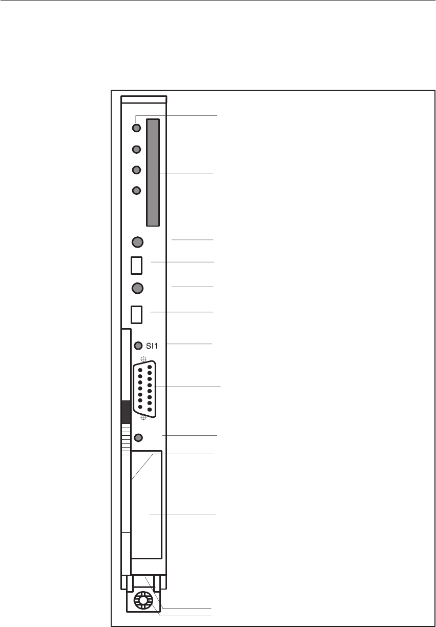
5-35
System Manual
C79000-G8576-C199-06
The controls and indicators are arranged on the front plate of the CPU
module:
CPU 928B
QVZ
ADF
ZYK
BASP
RUN
STOP
RESET
SI2
OVERALL
RESET
Receptacle for
User Memory Submodule
Momentary-Contact Mode Switch
Mode Switch
LEDs (green)
LED (red)
Fault Indicator LEDs (red)
PG Interface, 15-Pin
Interface SI 1
Release Lever
Locking Pin
Order Number and Version
SIEMENS 6ES5928-3UB21
Interface Fault Indicator LED (red)
Interface Fault Indicator LED (red)
Interface 1
Interface 2
Receptacle for Interface Submodule
Interface SI 2
Figure 5-5 Front Plate of the CPU 928B-3UB21
Controls and
Indicators
CPUs, Memor
y
Cards, Memor
y
Submodules, Interface Submodules

5-36 System Manual
C79000-G8576-C199-06
The mode switch has two settings:
In the RUN setting, the CPU 928B processes the user program when the
green RUN LED is lit.
The CPU 928B goes to the stop state when you switch from RUN to STOP.
The red STOP LED then lights up.
You can initiate the Overall Reset, Reset and Restart functions with the
momentary-contact mode switch:
Momentary-contact switch down
With an overall reset, all RAM areas are erased and initialized (both on the
CPU and on a RAM submodule).
Momentary-contact switch up
During a reset, all flags, timers, counters and the process image will be
erased. OB 20 will be invoked. Processing of the user program will start from
the beginning again.
Momentary-contact switch at midpoint
With a restart, processing of the user program will continue from the point of
interruption. The statuses of flags, timers, counters and the process image are
retained during stoppage of the CPU.
Mode Switch
RUN
STOP
Momentary-
Contact Mode
Switch
OVERALL RESET
Reset
Restart
CPUs, Memor
y
Cards, Memor
y
Submodules, Interface Submodules

5-37
System Manual
C79000-G8576-C199-06
RUN
LED STOP
LED Status
on off The CPU is in the RUN state.
off on The CPU is in the STOP state. After a stop
request by switch or PG function, the STOP LED
is continuously lit because the transition to the
STOP state was requested by the user or, in
multiprocessor operation, by another CPU, and
was not caused by the CPU itself.
off off The CPU is in the INITIAL START or program
check state.
off slow
flashing The CPU is in the STOP state. The CPU has
caused a transition to the STOP state (possibly
also for the other CPUs). If you set the mode
switch to STOP, the flashing LED becomes
continuously lit.
off rapid
flashing The CPU is in the STOP state. An overall reset
has been requested. This request can be initiated
by the CPU itself or by operator action.
QVZ LED
on During direct access or process image update, a module
addressed by the program no longer acknowledges although
either it has acknowledged in single-processor operation
upon reset of the CPU 928B in the area of the process
image (IB 0 to 127, QB 0 to 127) and has been entered as
present in the “9th track” (see Programming Guide,
CPU 928B -3UB21),
it h b t d i DB 1 ( dd li t) i
or it has been entered in DB 1 (address list) in
multiprocessor or single-processor operation and has been
recognized as present during the reset.
Possible causes
Module failure.
Module was pulled out during operation, in the STOP
state or in the Off state without a subsequent reset.
Status Indicators
LEDs for Fault
Indication and
Signaling
CPUs, Memor
y
Cards, Memor
y
Submodules, Interface Submodules
5-38 System Manual
C79000-G8576-C199-06
ADF LED
on The user program has referenced an I/O address in the
process image under which no module is inserted.
ZYK LED
on The maximum cycle monitoring time has been exceeded.
BASP LED
on Command output is inhibited and the digital outputs will be
directly switched to the safe state.
A detailed description of interrupt and error handling can be found in the
CPU 928B -3UB21 Programming Guide.
LED SI1 LED SI2 Cause
on on No communication possible at both interfaces.
Internal error.
on off SI1:
No communication possible.
Internal error.
SI2:
If used, interface is initialized and ready.
off on SI1:
Interface is initialized and ready.
SI2:
No communication possible.
Wrong interface submodule inserted or wrong
parameters for interface or internal error.
off off First interface and, if used, second interface are
initialized and ready.
CPUs, Memor
y
Cards, Memor
y
Submodules, Interface Submodules
5-39
System Manual
C79000-G8576-C199-06
The modules must be inserted at the correct slots in the central controller.
The backup battery must be fitted and in order for the CPU to start.
Step Action Result
1Set the mode switch to STOP
2Switch the system voltage on. The following LEDs must light
up on the CPU:
– Red STOP LED
(flashing rapidly)
– Red BASP2) LED
3Hold the MC1) switch in the
OVERALL RESET setting
and simultaneously set the
mode switch from STOP to
RUN.
The red STOP LED is now
permanently lit.
1) MC: Momentary-contact
2) BASP: Command output inhibit
Step Action Result
1Set the mode switch to STOP.
2Hold the MC switch in the
RESET setting and
simultaneously set the mode
switch from STOP to RUN.
– Red STOP LED goes off
– Green RUN LED lights up
– Red BASP LED goes off
The CPU is now in the RUN state
but still has no user program.
You can also carry out a manual restart of the CPU 928B with the mode
switch. The CPU 928B -3UB21 Programming Guide will indicate when a
manual restart is permissible.
Step Action Result
3Set the mode switch from
STOP to RUN. – Red STOP LED goes off
– Green RUN LED lights up
– Red BASP LED goes off
For maintenance purposes or in the event of a fault, this startup without user
program in single-processor operation can serve to establish whether the CPU
is operating without errors.
Startup
Overall Reset
Reset
Restart
CPUs, Memor
y
Cards, Memor
y
Submodules, Interface Submodules

5-40 System Manual
C79000-G8576-C199-06
5.3.3 Technical Specifications
Important for the USA and Canada
The following approvals have been obtained:
SUL Listing Mark
Underwriters Laboratories (UL) to Standard UL 508, Report E 85972
SCSA Certification Mark
Canadian Standard Association (CSA) to Standard C 22.2 No. 142,
Report LR 63533
Degree of protection IP 00
Climatic ambient conditions See Technical Specifications of the S5-135U/155U CC
Mechanical ambient conditions See Technical Specifications of the S5-135U/155U CC
Noise immunity, electromagnetic
compatibility (EMC) See Technical Specifications of the S5-135U/155U CC
Supply voltage 5 V $ 5 %
24 V + 25 %/ –17 %
Current consumption at 5 V 0.5 A typical
Current consumption at 24 V 760 mA max.
Backup voltage 3.4 V
Backup current 20 mA typical (at 25 _C)
P area O area IM3 area IM4 area Total
Digital inputs with process image
Digital inputs without process image
or analog inputs
1024 max.
1024 max.
64 max.
–
2048 max.
128 max.
–
2048 max.
128 max.
–
2048 max.
128 max.
1024 max.
7168 max.
448 max.
Digital outputs with process image
Digital outputs without process image
or analog outputs
1024 max.
1024 max.
64 max.
–
2048 max.
128 max.
–
2048 max.
128 max.
–
2048 max.
128 max.
1024 max.
7168 max.
448 max.
Flags 2048
S flags 8192
Timers 256
Counters 256
Size of user memory 64 x 2!) bytes max., RAM
DB RAM 46 x 2!) bytes
Transmission rate of the serial PG interface 9600 bps
Program blocks PB 256
Sequence blocks SB 256
Function blocks FB 256
Function blocks FX 256
Data blocks DB 256, of which 253 are freely available
Data blocks DX 256, of which 253 are freely available
CPUs, Memor
y
Cards, Memor
y
Submodules, Interface Submodules

5-41
System Manual
C79000-G8576-C199-06
Organization blocks OB OB 1 to 39 (interfaces for operating system)
Integrated special function organization
blocks OB See Pocket Guide
Integrated serial interface PG interface
Optional serial interface Via interface submodules, optionally as V.24, TTY, RS 422A/485 or
PG interface,
SINEC L1 interface from Version 6ES5 928-3UB12
Backplane bus S5 bus
Dimensions (w x h x d) 20.32 x 233.4 x 160 mm
Weight Approx. 0.6 kg
CPUs, Memor
y
Cards, Memor
y
Submodules, Interface Submodules

5-42 System Manual
C79000-G8576-C199-06
5.4 CPU 928B
This section contains the hardware description and technical specifications of
the CPU 928B.
Details on programming the CPU 928B can be found in the CPU 928B
Programming Guide.
5.4.1 Technical Description
You can use the CPU 928B in single and multiprocessor operation in the
S5-135U/155U central controller (see Chapter 6). Up to four CPUs can be
used.
The CPU 928B is universally applicable, ensuring both very fast bit
processing and very fast word processing:
Cyclic
Time-controlled (9 different timebases)
Real-time controlled
Interrupt-driven (hardware interrupt)
Delayed (from Version 6ES5 928-3UB12)
The programming language is STEP 5.
The electronic circuitry of the CPU 928B is on two PCBs (basic and
expansion boards) in the double Eurocard format. Both PCBs are screwed
together, linked via connectors, and must not be separated. The basic board
provides the connection to the S5 bus via two backplane connectors.
The front plate width is 2 2/3 standard plug-in stations.
Application
Design
CPUs, Memor
y
Cards, Memor
y
Submodules, Interface Submodules

5-43
System Manual
C79000-G8576-C199-06
You require a user memory submodule (RAM or EPROM) for storage of your
program. You can store up to 64 x 210 bytes of code and data blocks here. For
data blocks, the CPU 928B additionally has an integrated DB RAM of 46 x
210 bytes.
A description of the memory submodules can be found in Sections 5.9 and
5.10; order numbers are given in the ordering information.
There are two independent interfaces on the front of the CPU 928B.
You can connect programmers and OPs to the first interface. This PG
interface SI1 is permanently installed on the CPU.
You can use PG interface SI1 either via the front connector of the CPU 928B
or via the front connector of the 923C coordinator module.
Note
Simultaneous operation of PG interface SI1 via the front connector of the
CPU 928B and of the coordinator is not possible. Electrically, it is merely a
PG interface which can be operated via two different terminals. Switching
the programmer online without a job request is already sufficient to operate
the interface. If you wish to utilize a second PG interface for connection of a
PG or OP, the connection must be made via the second PG interface with the
PG submodule.
Apart from PG interface SI1, the second interface SI2 can also be used as a
PG interface in parallel with the first one. You can only use the second PG
interface via the front connector of the PG submodule on the CPU 928B.
A detailed description of operations with the two PG interfaces can be found
in the CPU 928B Programming Guide.
The connection to the PG can be established with the CPU in any operational
state.
User Memory
PG Interface SI1
CPUs, Memor
y
Cards, Memor
y
Submodules, Interface Submodules

5-44 System Manual
C79000-G8576-C199-06
You can optionally use the second interface of the CPU 928B as:
A PG interface (for PG and operator panels)
Interface for the RK 512 computer link
Interface for data transmission with procedures 3964/3964R
Interface for data transmission with the “open driver”
Interface for data transmission via the SINEC L1 bus (from Version 6ES5
928-3UB12).
To utilize the second interface as the PG interface, you need the
PG submodule.
You need one of the following interface submodules for the RK 512
computer link, for data transmission with procedures 3964/3964R and for
data transmission with the “open driver”:
V.24 submodule (RS 232C)
TTY submodule
RS422 A/485 submodule (only in the RS422 A module).
To utilize the second interface for data transmission via the SINEC L1 bus,
you need the
SINEC L1 submodule (from Version 6ES5 928-3UB12).
The CPU 928B is delivered without an interface submodule. You can operate
the CPU 928B without an integral interface submodule. The opening to
accept a submodule in the front plate is closed by a cover. Only remove the
cover to fit an interface submodule.
A description of interface submodules can be found in Section 5.11, and the
order numbers in the ordering information.
A detailed description of the second interface can be found in the CPU 928B
Communication Manual.
There is an interrupt line in the PLC for each CPU. It can be used when the
reaction to an event must occur with higher priority than the reaction to other
events.
To process an interrupt, cyclic program processing is interrupted and the
program stored in OB 2 (OB for interrupt processing) is inserted.
(Refer to the CPU 928B Programming Guide for further details.)
This interrupt-driven program processing is only possible using an
interrupt-capable digital input module or a suitable operating CP/IP module.
No jumper setting on the CPU 928B is required. Please note, however, that
the usable interrupt line on the backplane bus depends on the CPU slot and
must be set accordingly on the I/O module (see Section 4.1).
Second Interface
SI2
Process Interrupt
Processing
CPUs, Memor
y
Cards, Memor
y
Submodules, Interface Submodules

5-45
System Manual
C79000-G8576-C199-06
5.4.2 Installation and Startup
Note
All jumpers on the CPU 928B are required by the manufacturer for quality
testing. You must not change the jumper settings.
!Caution
Switch off the power supply before removing or inserting the module. The
basic board and expansion board of the CPU 928B are one unit and must not
be separated.
Proceed as follows to insert the CPU in the central controller:
Step Action
1Release the upper locking bar of the central controller and ensure
that the locking pin for the module is correctly positioned with the
slot-head horizontal.
2Select the correct slot (based on the labelling of the locking bar).
Insert the CPUs in the S5-135U/155U from slot 11.
3Push the module evenly into the guide rail until the lever over the
locking pin is horizontal.
4Press the locking pin inwards on the bottom of the module and
rotate it 90o clockwise.
5Secure the upper locking bar.
Jumper Settings
Removing and
Inserting the
Module
Insertion
CPUs, Memor
y
Cards, Memor
y
Submodules, Interface Submodules

5-46 System Manual
C79000-G8576-C199-06
Proceed as follows to remove the CPU:
Step Action
1Release the upper locking bar of the central controller.
2Release the locking pin of the module.
3Press the release lever downwards and pull the module forwards
and out of the central controller.
Note
Only operate the CPU 928B with the submodule receptacle closed. You
close it either by fitting an interface submodule or with the cover supplied.
Removal
CPUs, Memor
y
Cards, Memor
y
Submodules, Interface Submodules
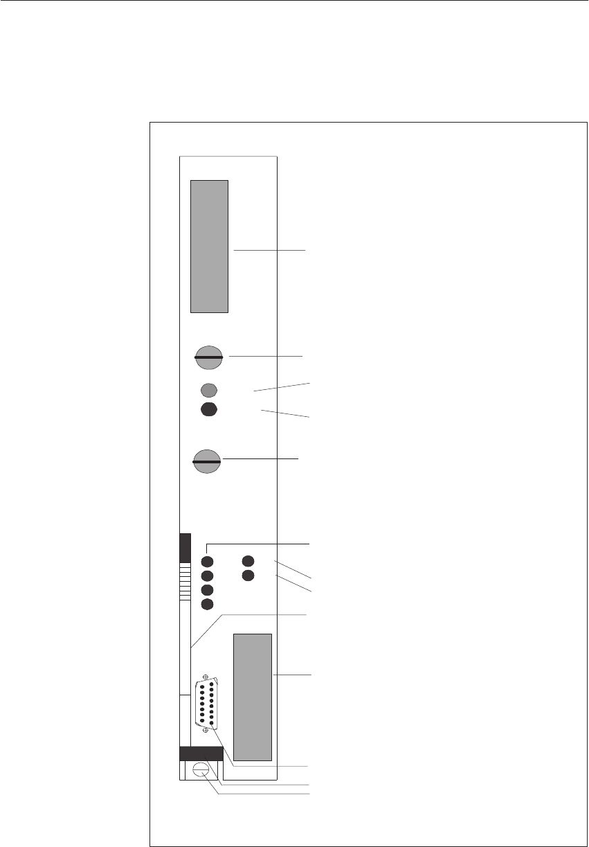
5-47
System Manual
C79000-G8576-C199-06
The controls and indicators are arranged on the front plate of the CPU
module:
SIEMENS
Receptacle for
User Memory Submodule
Mode Switch
LED (green)
LED (red)
Momentary-Contact Mode Switch
Fault Indicator LEDs (red)
PG Interface, 15-Pin
Interface SI 1
Release Lever
Locking Pin
Interface Fault Indicator LEDs (red)
Interface 1
Interface 2
RUN
STOP
RUN
STOP
RÜCKSETZEN
RESET
URLÖSCHEN
OVERALLRESET
SI1
SI2
QVZ
ADF
ZYK
BASP
Order Number and Release
Receptacle for Interface Submodule
Interface SI 2
SI2
SI1
6ES5928-3UB12
CPU 928B
Figure 5-6 Front Plate of the CPU 928B
Controls and
Indicators
CPUs, Memor
y
Cards, Memor
y
Submodules, Interface Submodules

5-48 System Manual
C79000-G8576-C199-06
The mode switch has two settings:
In the RUN setting, the CPU 928B processes the user program when the
green RUN LED is lit.
The CPU 928B goes to the stop state when you switch from RUN to STOP.
The red STOP LED then lights up.
You can initiate the Overall Reset, Reset and Restart functions with the
momentary-contact mode switch:
Momentary-contact switch down
With an overall reset, all RAM areas are erased and initialized (both on the
CPU and on a RAM submodule).
Momentary-contact switch up
During a reset, all flags, timers, counters and the process image will be
erased. OB 20 will be invoked. Processing of the user program will start from
the beginning again.
Momentary-contact switch at midpoint
With a restart, processing of the user program will continue from the point of
interruption. The statuses of flags, timers, counters and the process image are
retained during stoppage of the CPU.
Mode Switch
RUN
STOP
Momentary-
Contact Mode
Switch
OVERALL RESET
RESET
Restart
CPUs, Memor
y
Cards, Memor
y
Submodules, Interface Submodules
5-49
System Manual
C79000-G8576-C199-06
RUN
LED STOP
LED Status
on off The CPU is in the RUN state.
off on The CPU is in the STOP state. After a stop
request by switch or PG function, the STOP LED
is continuously lit because the transition to the
STOP state was requested by the user or, in
multiprocessor operation, by another CPU, and
was not caused by the CPU itself.
off off The CPU is in the INITIAL START or program
check state.
off slow
flashing The CPU is in the STOP state. The CPU has
caused a transition to the STOP state (possibly
also for the other CPUs). If you set the mode
switch to STOP, the flashing LED becomes
continuously lit.
off rapid
flashing The CPU is in the STOP state. An overall reset
has been requested. This request can be initiated
by the CPU itself or by operator action.
QVZ LED
on During direct access or process image update, a module
addressed by the program no longer acknowledges although
either it has acknowledged in single-processor operation
upon reset of the CPU 928B in the area of the process
image (IB 0 to 127, QB 0 to 127) and has been entered as
present in the “9th track” (see Programming Guide, CPU
928B),
it h b t d i DB 1 ( dd li t) i
or it has been entered in DB 1 (address list) in
multiprocessor or single-processor operation and has been
recognized as present during the reset.
Possible causes
Module failure.
Module was pulled out during operation, in the STOP
state or in the Off state without a subsequent reset.
Status Indicators
LEDs for Fault
Indication and
Signaling
CPUs, Memor
y
Cards, Memor
y
Submodules, Interface Submodules
5-50 System Manual
C79000-G8576-C199-06
ADF LED
on The user program has referenced an I/O address in the
process image under which no module is inserted.
ZYK LED
on The maximum cycle monitoring time has been exceeded.
BASP LED
on Command output is inhibited and the digital outputs will be
directly switched to the safe state.
A detailed description of interrupt and error handling can be found in the
CPU 928B Programming Guide.
LED SI1 LED SI2 Cause
on on No communication possible at both interfaces.
Internal error.
on off SI1:
No communication possible. Internal error.
SI2:
If used, interface is initialized and ready.
off on SI1:
Interface is initialized and ready.
SI2:
No communication possible.
Wrong interface submodule inserted or wrong
parameters for interface or internal error.
off off First interface and, if used, second interface are
initialized and ready.
CPUs, Memor
y
Cards, Memor
y
Submodules, Interface Submodules
5-51
System Manual
C79000-G8576-C199-06
The modules must be inserted at the correct slots in the central controller.
The backup battery must be fitted and in order for the CPU to start.
Step Action Result
1Set the mode switch to STOP.
2Switch the system voltage on. The following LEDs must light
up on the CPU:
– Red STOP LED (flashing
rapidly)
– Red BASP2) LED
3Hold the MC1) switch in the
OVERALL RESET setting
and simultaneously set the
mode switch from STOP to
RUN.
The red STOP LED is now
permanently lit.
1) MC: Momentary-contact
2) BASP: Command output inhibit
Step Action Result
1Set the mode switch to STOP.
2Hold the MC switch in the
RESET setting and
simultaneously set the mode
switch from STOP to RUN.
– Red STOP LED goes off
– Green RUN LED lights up
– Red BASP LED goes off
The CPU is now in the RUN state
but still has no user program.
You can also carry out a manual restart of the CPU 928B with the mode
switch. The CPU 928B Programming Guide will indicate when a manual
restart is permissible.
Step Action Result
3Set the mode switch from
STOP to RUN. – Red STOP LED goes off
– Green RUN LED lights up
– Red BASP LED goes off
For maintenance purposes or in the event of a fault, this startup without user
program in single-processor operation can serve to establish whether the CPU
is operating without errors.
Startup
Overall Reset
Reset
Restart
CPUs, Memor
y
Cards, Memor
y
Submodules, Interface Submodules

5-52 System Manual
C79000-G8576-C199-06
5.4.3 Technical Specifications
Important for the USA and Canada
The following approvals have been obtained:
SUL Listing Mark
Underwriters Laboratories (UL) to Standard UL 508, Report E 85972
SCSA Certification Mark
Canadian Standard Association (CSA) to Standard C 22.2 No. 142,
Report LR 63533
Degree of protection IP 00
Climatic ambient conditions See Technical Specifications of the S5-135U/155U CC
Mechanical ambient conditions See Technical Specifications of the S5-135U/155U CC
Noise immunity, electromagnetic
compatibility (EMC) See Technical Specifications of the S5-135U/155U CC
Supply voltage 5 V $ 5 %
24 V + 25 %/ -17 %
Current consumption at 5 V 5 A typical
Current consumption at 24 V 760 mA max.
Backup voltage 3.4 V
Backup current 20 mA typical (at 25 _C)
P area O area IM3 area IM4 area Total
Digital inputs with process image
Digital inputs without process image
or analog inputs
1024 max.
1024 max.
64 max.
–
2048 max.
128 max.
–
2048 max.
128 max.
–
2048 max.
128 max.
1024 max.
7168 max.
448 max.
Digital outputs with process image
Digital outputs without process image
or analog outputs
1024 max.
1024 max.
64 max.
–
2048 max.
128 max.
–
2048 max.
128 max.
–
2048 max.
128 max.
1024 max.
7168 max.
448 max.
Flags 2048
S flags 8192
Timers 256
Counters 256
Size of user memory 64 x 2!) bytes max., EPROM or RAM
DB RAM 46 x 2!) byte
Transmission rate of the serial PG interface 9600 bps
Program blocks PB 256
Sequence blocks SB 256
Function blocks FB 256
Function blocks FX 256
Data blocks DB 256, of which 253 are freely available
Data blocks DX 256, of which 253 are freely available
CPUs, Memor
y
Cards, Memor
y
Submodules, Interface Submodules

5-53
System Manual
C79000-G8576-C199-06
Organization blocks OB OB 1 to 39 (interfaces for operating system)
Integrated special function organization
blocks OB See Pocket Guide
Integrated serial interface PG interface
Optional serial interface Via interface submodules, optionally as V.24, TTY, RS 422A/485 or
PG interface
SINEC L1 interface from Version 6ES5 928-3UB12
Backplane bus S5 bus
Dimensions (w x h x d) 40.64 x 233.4 x 160 mm
Weight Approx. 1 kg
CPUs, Memor
y
Cards, Memor
y
Submodules, Interface Submodules

5-54 System Manual
C79000-G8576-C199-06
5.5 CPU 928 -3UA21
This section contains the hardware description and technical specifications of
the CPU 928 -3UA21.
Details on programming the CPU 928 can be found in the CPU 928
Programming Guide.
5.5.1 Technical Description
You can use the CPU 928 in single and multiprocessor operation in the
S5-135U/155U central controller (see Chapter 6). Up to four CPUs can be
used.
The CPU 928 is universally applicable, ensuring both very fast bit processing
(optimized for open-loop tasks) and word processing (optimized for
closed-loop tasks).
The following program processing levels are possible:
Cyclical
Time-controlled (9 different timebases)
Interrupt-driven (hardware interrupt)
The programming language is STEP 5.
The electronic circuitry of the CPU 928 is on one PCB in the double
Eurocard format. The board provides the connection to the S5 bus via two
backplane connectors.
The front plate width is 1 1/3 standard plug-in stations.
Application
Design
CPUs, Memor
y
Cards, Memor
y
Submodules, Interface Submodules

5-55
System Manual
C79000-G8576-C199-06
For storage of your program, user memory in the form of RAM is integrated
on the board. You can store up to 64 x 210 bytes of code and data blocks here.
For data blocks, the CPU 928 additionally has an integrated DB RAM of 46 x
210 bytes.
Note
The DB RAM is loaded with DB/DX blocks when the user memory is full.
There is an interrupt line (IR) in the PLC for each CPU. It can be used when
the reaction to one or more events must occur with higher priority than the
reaction to other events.
To process a process interrupt, cyclic program processing is interrupted and
the program stored in OB 2 (OB for interrupt processing) is inserted. (Refer
to the CPU 928 Programming Guide for further details.)
This interrupt-driven program processing is only possible using an
interrupt-capable digital input module (e.g. 6ES5 432-...) or a CP/IP module
which operates in this way.
User Memory
Process Interrupt
Processing
CPUs, Memor
y
Cards, Memor
y
Submodules, Interface Submodules

5-56 System Manual
C79000-G8576-C199-06
5.5.2 Installation and Startup
!Caution
Switch off the power supply before removing or inserting the module.
Proceed as follows to insert the CPU in the central controller:
Step Action
1Release the upper locking bar of the central controller and ensure
that the locking pin for the module is correctly positioned with the
slot-head horizontal.
2Select the correct slot (based on the labelling of the locking bar).
Insert the CPUs in the S5-135U/155U from slot 11.
3Push the module evenly into the guide rail until the lever over the
locking pin is horizontal.
4Press the locking pin inwards on the bottom of the module and
rotate it 90o clockwise.
5Secure the upper locking bar.
Note
If you install the CPU 928 -3UA21 as the replacement for a double-width
CPU, you must cover the slot which has been freed up with a blanking plate.
Proceed as follows to remove the CPU:
Step Action
1Release the upper locking bar of the central controller.
2Release the locking pin of the module.
3Press the release lever downwards and pull the module forwards
and out of the central controller.
Removing and
Inserting the
Module
Insertion
Removal
CPUs, Memor
y
Cards, Memor
y
Submodules, Interface Submodules
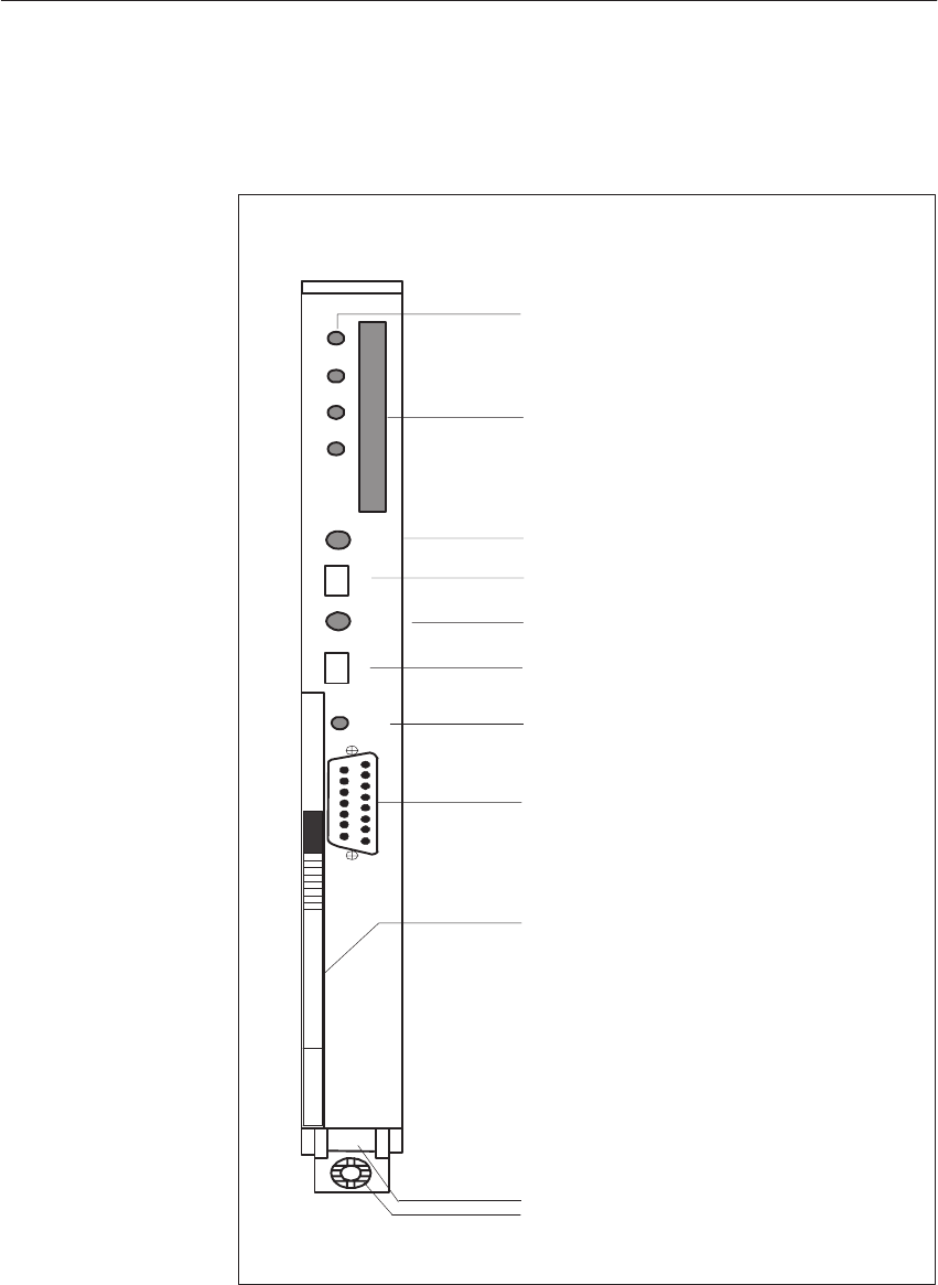
5-57
System Manual
C79000-G8576-C199-06
The controls and indicators are arranged on the front plate of the CPU
module:
CPU 928A
QVZ
ADF
ZYK
BASP
RUN
STOP
RESET
SI1
OVERALL
RESET
Receptacle for
User Memory Submodule
Momentary-Contact Mode Switch
Mode Switch
LED (green)
LED (red)
Fault Indicator LEDs (red)
PG Interface, 15-Pin
Release Lever
Locking Pin
Order Number and Version
SIEMENS ES5928-3UA21
Interface Fault Indicator LED (red)
Figure 5-7 Front Plate of the CPU 928 -3UA21
Controls and
Indicators
CPUs, Memor
y
Cards, Memor
y
Submodules, Interface Submodules

5-58 System Manual
C79000-G8576-C199-06
The mode switch has two settings:
In the RUN setting, the CPU 928-3UA21 processes the user program when
the green RUN LED is lit.
The CPU 928-3UA21 goes to the stop state when you switch from RUN to
STOP. The red STOP LED then lights up.
You can initiate the Overall Reset, Reset and Restart functions with the
momentary-contact mode switch:
Momentary-contact switch down
With an overall reset, all RAM areas are erased and initialized.
Momentary-contact switch up
During a reset, all flags, timers, counters and the process image will be
erased. OB 20 will be invoked. Processing of the user program will start from
the beginning again.
Momentary-contact switch at midpoint
With a restart, processing of the user program will continue from the point of
interruption. The statuses of flags, timers, counters and the process image are
retained during stoppage of the CPU.
RUN
LED STOP
LED Status
on off The CPU is in the RUN state.
off on The CPU is in the STOP state. After a stop
request by switch or PG function, the STOP LED
is continuously lit because the transition to the
STOP state was requested by the user or, in
multiprocessor operation, by another CPU, and
was not caused by the CPU itself.
off off The CPU is in the INITIAL START or program
check state.
off slow
flashing The CPU is in the STOP state. The CPU has
caused a transition to the STOP state (possibly
also for the other CPUs). If you set the mode
switch to STOP, the flashing LED becomes
continuously lit.
off rapid
flashing The CPU is in the STOP state. An overall reset
has been requested. This request can be initiated
by the CPU itself or by operator action.
Mode Switch
RUN
STOP
Momentary-
Contact Mode
Switch
OVERALL RESET
RESET
Restart
Status Indicators
CPUs, Memor
y
Cards, Memor
y
Submodules, Interface Submodules

5-59
System Manual
C79000-G8576-C199-06
QVZ LED
on During direct access or process image update, a module
addressed by the program no longer acknowledges although
either it has acknowledged in single processor operation
upon reset of the CPU 928 in the area of the process
image (IB 0 to 127, QB 0 to 127) and has been entered as
present in the “9th track” (see Programming Guide,
CPU 928),
it h b t d i DB 1 ( dd li t) i
or it has been entered in DB 1 (address list) in
multiprocessor or single-processor operation and has been
recognized as present during the reset.
Possible causes
Module failure.
Module was pulled out during operation, in the stop state
or in the Off state without a subsequent reset.
ADF LED
on The user program has referenced an I/O address under which
no module is inserted.
ZYK LED
on The maximum cycle time has been exceeded.
BASP LED
on Command output is inhibited and the digital outputs will be
directly switched to the safe state.
A detailed description of interrupt and error handling can be found in the
CPU 928 Programming Guide.
LEDs for Fault
Indication and
Signaling
CPUs, Memor
y
Cards, Memor
y
Submodules, Interface Submodules

5-60 System Manual
C79000-G8576-C199-06
The module must be inserted at the correct slot in the central controller. The
backup battery must be fitted and in order for the CPU to start.
Step Action Result
1Set the mode switch to STOP
2Switch the system voltage on. The following LEDs must light
up on the CPU:
– Red STOP LED (flashing
rapidly)
– Red BASP LED
3Hold the MC1) switch in the
OVERALL RESET setting
and simultaneously set the
mode switch from STOP to
RUN.
The red STOP LED is now
permanently lit.
1) MC: Momentary-contact
Step Action Result
1Set the mode switch to STOP.
2Hold the MC switch in the
RESET setting and
simultaneously set the mode
switch from STOP to RUN.
– Red STOP LED goes off
– Green RUN LED lights up
– Red BASP LED goes off
The CPU is now in the RUN state
but still has no user program.
You can also carry out a manual restart of the CPU 928-3UA21 with the
mode switch. The CPU 928 Programming Guide will indicate when a manual
restart is permissible.
Step Action Result
1Set the mode switch from
STOP to RUN. – Red STOP LED goes off
– Green RUN LED lights up
– Red BASP LED goes off
For maintenance purposes or in the event of a fault, this startup without user
program in single-processor operation can serve to establish whether the CPU
is operating without errors.
Startup
Overall Reset
Reset
Restart
CPUs, Memor
y
Cards, Memor
y
Submodules, Interface Submodules

5-61
System Manual
C79000-G8576-C199-06
5.5.3 Technical Specifications
Important for the USA and Canada
The following approvals have been obtained:
SUL Listing Mark
Underwriters Laboratories (UL) to Standard UL 508, Report E 85972
SCSA Certification Mark
Canadian Standard Association (CSA) to Standard C 22.2 No. 142,
Report LR 63533
Degree of protection IP 00
Climatic ambient conditions See Technical Specifications of the S5-135U/155U CC
Mechanical ambient conditions See Technical Specifications of the S5-135U/155U CC
Noise immunity, electromagnetic
compatibility (EMC) See Technical Specifications of the S5-135U/155U CC
Supply voltage 5 V $ 5 %
Current consumption at 5 V 0.5 A typical
Backup voltage 3.4 V
Backup current 20 mA typical (at 25 _C)
P area O area IM3 area IM4 area Total
Digital inputs with process image
Digital inputs without process image
or analog inputs
1024 max.
1024 max.
64 max.
–
2048 max.
128 max.
–
2048 max.
128 max.
–
2048 max.
128 max.
1024 max.
7168 max.
448 max.
Digital outputs with process image
Digital outputs without process image
or analog outputs
1024 max.
1024 max.
64 max.
–
2048 max.
128 max.
–
2048 max.
128 max.
–
2048 max.
128 max.
1024 max.
7168 max.
448 max.
Flags 2048
Timers 256
Counters 256
Size of user memory max. of 64 x 210 words, RAM
DB RAM 46 x 210 bytes
Transmission rate of serial PG interface 9600 bps
Program blocks PB 256
Sequence blocks SB 256
Function blocks FB 256
Function blocks FX 256
Data blocks DB 256, of which 253 are freely available
Data blocks DX 256, of which 253 are freely available
Organization blocks OB OB 1 to 39 (interfaces for operating system)
Integrated special function organization
blocks OB See Pocket Guide
Dimensions (w x h x d) 20.32 x 233.4 x 160 mm
Weight Approx. 0.6 kg
CPUs, Memor
y
Cards, Memor
y
Submodules, Interface Submodules

5-62 System Manual
C79000-G8576-C199-06
5.6 CPU 928
This section contains the hardware description and technical specifications of
the CPU 928.
Details on programming the CPU 928 can be found in the CPU 928
Programming Guide.
5.6.1 Technical Description
You can use the CPU 928 in single and multiprocessor operation in the
S5-135U/155U central controller (see Chapter 6). Up to four CPUs can be
used.
The CPU 928 is universally applicable, ensuring both very fast bit processing
(optimized for open-loop tasks) and word processing (optimized for
closed-loop tasks).
The following program processing levels are possible:
Cyclical
Time-controlled (9 different timebases)
Interrupt-driven (hardware interrupt)
The programming language is STEP 5.
The CPU 928 comprises two PCBs (PCB 1 and PCB 2) in the double
Eurocard format, in a sandwich assembly. The two PCBs have plug-in
interconnections and are bolted together as a unit when delivered. PCB 2
serves as the basic board which provides the connection to the S5 bus via two
backplane connectors.
The front plate width is 2 2/3 standard plug-in stations.
Application
Design
CPUs, Memor
y
Cards, Memor
y
Submodules, Interface Submodules

5-63
System Manual
C79000-G8576-C199-06
You require a user memory submodule (RAM or EPROM) for storage of your
program. You can store up to 64 x 210 bytes of code and data blocks here. For
data blocks, the CPU 928 additionally has an integrated DB RAM of 46 x 210
bytes.
Note
The DB RAM is loaded with DB/DX blocks when the RAM submodule is
full or an EPROM submodule is plugged in.
A description of the memory submodules can be found in Sections 5.9 and
5.10; order numbers are given in the ordering information.
There is an interrupt line (IR) in the PLC for each CPU. It can be used when
the reaction to one or more events must occur with higher priority than the
reaction to other events.
o process an interrupt, cyclic program processing is interrupted and the
program stored in OB 2 (OB for interrupt processing) is inserted.
(Refer to the CPU 928 Programming Guide for further details.)
This interrupt-driven program processing is only possible using an
interrupt-capable digital input module (e.g. 6ES5 432-...) or a CP/IP module
which operates in this way.
User Memory
Process Interrupt
Processing
CPUs, Memor
y
Cards, Memor
y
Submodules, Interface Submodules

5-64 System Manual
C79000-G8576-C199-06
5.6.2 Installation and Startup
!Caution
Switch off the power supply before removing or inserting the module.
The basic board and expansion board of the CPU 928 are one unit and must
not be separated.
Proceed as follows to insert the CPU in the central controller:
Step Action
1Release the upper locking bar of the central controller and ensure
that the locking pin for the module is correctly positioned with the
slot-head horizontal.
2Select the correct slot (based on the labelling of the locking bar).
Insert the CPUs in the S5-135U/155U from slot 11.
3Push the module evenly into the guide rail until the lever over the
locking pin is horizontal.
4Press the locking pin inwards on the bottom of the module and
rotate it 90o clockwise.
5Secure the upper locking bar.
Proceed as follows to remove the CPU:
Step Action
1Release the upper locking bar of the central controller.
2Release the locking pin of the module.
3Press the release lever downwards and pull the module forwards
and out of the central controller.
Removing and
Inserting the
Module
Insertion
Removal
CPUs, Memor
y
Cards, Memor
y
Submodules, Interface Submodules
5-65
System Manual
C79000-G8576-C199-06
The controls and indicators are arranged on the front plate of the CPU
module:
SIEMENS
Receptacle for
User Memory Submodule
Mode Switch
LED (green)
LED (red)
Momentary-Contact Mode Switch
Fault Indicator LEDs (red)
PG Interface, 15-Pin
Release Lever
Locking Pin
RUN
STOP
RUN
STOP
RÜCKSETZEN
RESET
URLÖSCHEN
OVERALL
RESET
QVZ
ADF
ZYK
BASP Order Number and Version
6ES5928-3UA12
Figure 5-8 Front Plate of the CPU 928
Controls and
Indicators
CPUs, Memor
y
Cards, Memor
y
Submodules, Interface Submodules

5-66 System Manual
C79000-G8576-C199-06
The mode switch has two settings:
In the RUN setting, the CPU 928 processes the user program when the green
RUN LED is lit.
The CPU 928 goes to the stop state when you switch from RUN to STOP.
The red STOP LED then lights up.
You can initiate the Overall Reset, Reset and Restart functions with the
momentary-contact mode switch:
Momentary-contact switch down
With an overall reset, all RAM areas are erased and initialized (both on the
CPU and on a RAM submodule).
Momentary-contact switch up
During a reset, all flags, timers, counters and the process image will be
erased. OB 20 will be invoked. Processing of the user program will start from
the beginning again.
Momentary-contact switch at midpoint
With a restart, processing of the user program will continue from the point of
interruption. The statuses of flags, timers, counters and the process image are
retained during stoppage of the CPU.
Mode Switch
RUN
STOP
Momentary-
Contact Mode
Switch
OVERALL RESET
RESET
Restart
CPUs, Memor
y
Cards, Memor
y
Submodules, Interface Submodules

5-67
System Manual
C79000-G8576-C199-06
RUN
LED STOP
LED Status
on off The CPU is in the RUN state.
off on The CPU is in the STOP state. After a stop
request by switch or PG function, the STOP LED
is continuously lit because the transition to the
STOP state was requested by the user or, in
multiprocessor operation, by another CPU, and
was not caused by the CPU itself.
off off The CPU is in the INITIAL START or program
check state.
off slow
flashing The CPU is in the STOP state. The CPU has
caused a transition to the STOP state (possibly
also for the other CPUs). If you set the mode
switch to STOP, the flashing LED becomes
continuously lit.
off rapid
flashing The CPU is in the STOP state. An overall reset
has been requested. This request can be initiated
by the CPU itself or by operator action.
Status Indicators
CPUs, Memor
y
Cards, Memor
y
Submodules, Interface Submodules

5-68 System Manual
C79000-G8576-C199-06
QVZ LED
on During direct access or process image update, a module
addressed by the program no longer acknowledges although
either it has acknowledged in single processor operation
upon reset of the CPU 928 in the area of the process
image (IB 0 to 127, QB 0 to 127) and has been entered as
present in the “9th track” (see Programming Guide,
CPU 928),
it h b t d i DB 1 ( dd li t) i
or it has been entered in DB 1 (address list) in
multiprocessor or single-processor operation and has been
recognized as present during the reset.
Possible causes
Module failure.
Module was pulled out during operation, in the stop state
or in the Off state without a subsequent reset.
ADF LED
on The user program has referenced an I/O address under which
no module is inserted.
ZYK LED
on The maximum cycle time has been exceeded.
BASP LED
on Command output is inhibited and the digital outputs will be
directly switched to the safe state.
A detailed description of interrupt and error handling can be found in the
CPU 928 Programming Guide.
LEDs for Fault
Indication and
Signaling
CPUs, Memor
y
Cards, Memor
y
Submodules, Interface Submodules

5-69
System Manual
C79000-G8576-C199-06
The modules must be inserted at the correct slots in the central controller.
The backup battery must be fitted and in order for the CPU to start.
Step Action Result
1Set the mode switch to STOP
2Switch the system voltage on. The following LEDs must light
up on the CPU:
– Red STOP LED (flashing
rapidly)
– Red BASP LED
3Hold the MC1) switch in the
OVERALL RESET setting
and simultaneously set the
mode switch from STOP to
RUN.
The red STOP LED is now
permanently lit.
1) MC: Momentary-contact
Step Action Result
1Set the mode switch to STOP.
2Hold the MC switch in the
RESET setting and
simultaneously set the mode
switch from STOP to RUN.
– Red STOP LED goes off
– Green RUN LED lights up
– Red BASP LED goes off
The CPU is now in the RUN state
but still has no user program.
You can also carry out a manual restart of the CPU 928 with the mode
switch. The CPU 928 Programming Guide will indicate when a manual
restart is permissible.
Step Action Result
1Set the mode switch from
STOP to RUN. – Red STOP LED goes off
– Green RUN LED lights up
– Red BASP LED goes off
For maintenance purposes or in the event of a fault, this startup without user
program in single-processor operation can serve to establish whether the CPU
is operating without errors.
Startup
Overall Reset
Reset
Restart
CPUs, Memor
y
Cards, Memor
y
Submodules, Interface Submodules

5-70 System Manual
C79000-G8576-C199-06
5.6.3 Technical Specifications
Important for the USA and Canada
The following approvals have been obtained:
SUL Listing Mark
Underwriters Laboratories (UL) to Standard UL 508, Report E 85972
SCSA Certification Mark
Canadian Standard Association (CSA) to Standard C 22.2 No. 142,
Report LR 63533
Degree of protection IP 00
Climatic ambient conditions See Technical Specifications of the S5-135U/155U CC
Mechanical ambient conditions See Technical Specifications of the S5-135U/155U CC
Noise immunity, electromagnetic
compatibility (EMC) See Technical Specifications of the S5-135U/155U CC
Supply voltage 5 V $ 5 %
Current consumption at 5 V 3.5 A typical
Backup voltage 3.4 V
Backup current without user RAM
submodule 20 mA typical (at 25 _C)
P area O area IM3 area IM4 area Total
Digital inputs with process image
Digital inputs without process image
or analog inputs
1024 max.
1024 max.
64 max.
–
2048 max.
128 max.
–
2048 max.
128 max.
–
2048 max.
128 max.
1024 max.
7168 max.
448 max.
Digital outputs with process image
Digital outputs without process image
or analog outputs
1024 max.
1024 max.
64 max.
–
2048 max.
128 max.
–
2048 max.
128 max.
–
2048 max.
128 max.
1024 max.
7168 max.
448 max.
Flags 2048
Timers 256
Counters 256
Size of user memory max. of 64 x 210 words, EPROM or RAM
DB RAM 46 x 210 bytes
Transmission rate of serial PG interface 9600 bps
Program blocks PB 256
Sequence blocks SB 256
Function blocks FB 256
Function blocks FX 256
Data blocks DB 256, of which 253 are freely available
Data blocks DX 256, of which 253 are freely available
Organization blocks OB OB 1 to 39 (interfaces for operating system)
Integrated special function Organization
blocks OB See Pocket Guide
Dimensions (w x h x d) 40.64 x 233.4 x 160 mm
Weight Approx. 1 kg
CPUs, Memor
y
Cards, Memor
y
Submodules, Interface Submodules

5-71
System Manual
C79000-G8576-C199-06
5.7 CPU 922
This section contains the hardware description and technical specifications of
the CPU 922 (also known as the R processor).
Details on programming can be found in the CPU 922 Programming Guide.
5.7.1 Technical Description
You can use the CPU 922 in single and multiprocessor operation in the
S5-135U/155U CC (see Chapter 6). Up to four CPUs can be used.
The CPU 922 is particularly suitable for word processing (closed-loop
control and arithmetic calculation). Binary signal processing is also possible.
The following program processing levels are possible:
Cyclic
Time-controlled (1 timebase)
Interrupt-driven (hardware interrupt).
The programming language is STEP 5.
The module is designed as a plug-in PCB of double Eurocard format. The
module provides the connection to the S5 bus via two backplane connectors.
The front plate width is 1 1/3 standard plug-in stations.
Application
Design
CPUs, Memor
y
Cards, Memor
y
Submodules, Interface Submodules

5-72 System Manual
C79000-G8576-C199-06
You require a user memory submodule (RAM or EPROM) for storage of your
program. You can store up to 64 x 210 bytes of code and data blocks here.
For data blocks, the CPU 922 additionally has an integrated DB RAM of
22 x 210 bytes.
Note
The DB RAM is only loaded with DB/DX blocks when the RAM submodule
is full or an EPROM submodule is inserted.
A description of the memory submodules can be found in Sections 5.9 and
5.10; order numbers are given in the ordering information.
There is an interrupt line (IR) in the S5-135U/155U PLC for each CPU. It
can be used when the reaction to one or more events must occur with higher
priority than the reaction to other events.
To process an interrupt, cyclic program processing is interrupted and the
program stored in OB 2 is inserted. Refer to the CPU 922 Programming
Guide for further details.
This interrupt-driven program processing is only possible using an
interrupt-capable digital input module (e.g. 6ES5 432-...) or a suitably
operating CP/IP module.
User Memory
Process Interrupt
Processing
CPUs, Memor
y
Cards, Memor
y
Submodules, Interface Submodules
5-73
System Manual
C79000-G8576-C199-06
5.7.2 Installation and Startup
!Caution
Switch off the power supply before removing or inserting the module.
Proceed as follows to insert the CPU in the central controller:
Step Action
1Release the upper locking bar of the central controller.
2Select the correct slot (based on the labelling of the locking bar).
Insert the CPUs in the S5-135U/155U from slot 11.
3Push the module evenly into the guide rail.
4Secure the upper locking bar.
Proceed as follows to remove the CPU:
Step Action
1Release the upper locking bar of the central controller.
2Use the grips and gentle upward and downward motion to pull the
CPU forwards out of the CC.
Removing and
Inserting the
Module
Insertion
Removal
CPUs, Memor
y
Cards, Memor
y
Submodules, Interface Submodules

5-74 System Manual
C79000-G8576-C199-06
The controls and indicators are arranged on the front plate of the CPU
module:
SIEMENS
Receptacle for
User Memory Submodule
Mode Switch
LED (green)
LED (red)
Momentary-Contact Mode Switch
Fault Indicator LEDs (red)
PG Interface, 15-Pin
RUN
STOP
RUN
RESET
STOP
RÜCKSETZEN
URLÖSCHEN
OVERALL
RESET
QVZ
ADF
ZYK
BASP
Order Number and Version
Grip
Grip
6ES5922-3UA11
Figure 5-9 Front Plate of the CPU 922
Controls and
Indicators
CPUs, Memor
y
Cards, Memor
y
Submodules, Interface Submodules

5-75
System Manual
C79000-G8576-C199-06
The mode switch has two settings:
In the RUN setting, the CPU 922 processes the user program when the green
RUN LED is lit.
The CPU 922 goes to the stop state when you switch from RUN to STOP.
The red STOP LED then lights up.
You can initiate the Overall Reset, Reset and Restart functions with the
momentary-contact mode switch:
Momentary-contact switch down
With an overall reset, all RAM areas are erased and initialized (both on the
CPU and on a RAM submodule).
Momentary-contact switch up
During a reset, all flags, timers, counters and the process image will be
erased. OB 20 will be invoked. Processing of the user program will start from
the beginning again.
Momentary-contact switch at midpoint
With a restart, processing of the user program will continue from the point of
interruption. The statuses of flags, timers, counters and the process image are
retained during stoppage of the CPU.
Mode Switch
RUN
STOP
Momentary-
Contact Mode
Switch
OVERALL RESET
Reset
Restart
CPUs, Memor
y
Cards, Memor
y
Submodules, Interface Submodules

5-76 System Manual
C79000-G8576-C199-06
RUN
LED STOP
LED Status
on off The CPU is in the RUN state.
off on The CPU is in the STOP state. After a stop
request by switch or PG function, the STOP LED
is continuously lit because the transition to the
STOP state was requested by the user or, in
multiprocessor operation, by another CPU, and
was not caused by the CPU itself.
off off The CPU is in the INITIAL START or program
check state.
off slow
flashing The CPU is in the STOP state. The CPU has
caused a transition to the STOP state (possibly
also for the other CPUs). If you set the mode
switch to STOP, the flashing LED becomes
continuously lit.
off rapid
flashing The CPU is in the STOP state. An overall reset
has been requested. This request can be initiated
by the CPU itself or by operator action.
Status Indicators
CPUs, Memor
y
Cards, Memor
y
Submodules, Interface Submodules

5-77
System Manual
C79000-G8576-C199-06
QVZ LED
on During direct access or process image update, a module
addressed by the program no longer acknowledges although
either it has acknowledged in single processor operation
upon reset of the CPU 922 in the area of the process
image (IB 0 to 127, QB 0 to 127) and has been entered as
present in the “9th track” (see Programming Guide,
CPU 922),
it h b t d i DB 1 ( dd li t) i
or it has been entered in DB 1 (address list) in
multiprocessor or single-processor operation and has been
recognized as present during the reset.
Possible causes
Module failure.
Module was pulled out during operation, in the stop state
or in the Off state without a subsequent reset.
ADF LED
on The user program has referenced an I/O address under which
no module is inserted.
ZYK LED
on The maximum cycle time has been exceeded.
BASP LED
on Command output is inhibited and the digital outputs will be
directly switched to the safe state.
A detailed description of interrupt and error handling can be found in the
CPU 922 Programming Guide.
LEDs for Fault
Indication and
Signaling
CPUs, Memor
y
Cards, Memor
y
Submodules, Interface Submodules
5-78 System Manual
C79000-G8576-C199-06
The modules must be inserted at the correct slots in the central controller.
The backup battery must be fitted and in order for the CPU to start.
Step Action Result
1Set the mode switch to STOP
2Switch the system voltage on. The following LEDs must light
up on the CPU:
– Red STOP LED (flashing
rapidly)
– Red BASP LED
3Hold the MC1) switch in the
OVERALL RESET setting
and simultaneously set the
mode switch from STOP to
RUN.
The red STOP LED is now
permanently lit.
1) MC: Momentary-contact
Step Action Result
1Set the mode switch to STOP.
2Hold the MC switch in the
RESET setting and
simultaneously set the mode
switch from STOP to RUN.
– Red STOP LED goes off
– Green RUN LED lights up
– Red BASP LED goes off
The CPU is now in the RUN state
but still has no user program.
You can also carry out a manual restart of the CPU 922 with the mode
switch. The CPU 922 Programming Guide will indicate when a manual
restart is permissible.
Step Action Result
1Set the mode switch from
STOP to RUN. – Red STOP LED goes off
– Green RUN LED lights up
– Red BASP LED goes off
For maintenance purposes or in the event of a fault, this startup without user
program in single-processor operation can serve to establish whether the CPU
is operating without errors.
Startup
Overall Reset
Reset
Restart
CPUs, Memor
y
Cards, Memor
y
Submodules, Interface Submodules

5-79
System Manual
C79000-G8576-C199-06
5.7.3 Technical Specifications
Important for the USA and Canada
The following approvals have been obtained:
SUL Listing Mark
Underwriters Laboratories (UL) to Standard UL 508, Report E 85972
SCSA Certification Mark
Canadian Standard Association (CSA) to Standard C 22.2 No. 142,
Report LR 63533
Degree of protection IP 00
Climatic ambient conditions See Technical Specifications of the S5-135U/155U CC
Mechanical ambient conditions See Technical Specifications of the S5-135U/155U CC
Noise immunity, electromagnetic
compatibility (EMC) See Technical Specifications of the S5-135U/155U CC
Supply voltage 5 V $ 5 %
Current consumption at 5 V 2.2 A typical
Backup voltage 3.4 V
Backup current without user RAM
submodule 20 mA typical (at 25 _C)
P area O area IM3 area IM4 area Total
Digital inputs with process image
Digital inputs without process image
or analog inputs
1024 max.
1024 max.
64 max.
–
2048 max.
128 max.
–
2048 max.
128 max.
–
2048 max.
128 max.
1024 max.
7168 max.
448 max.
Digital outputs with process image
Digital outputs without process image
or analog outputs
1024 max.
1024 max.
64 max.
–
2048 max.
128 max.
–
2048 max.
128 max.
–
2048 max.
128 max.
1024 max.
7168 max.
448 max.
Flags 2048
Timers 128
Counters 128
Size of user memory max. of 64 x 210 words, EPROM or RAM
DB RAM 22 x 210 bytes
Transmission rate of serial PG interface 9600 bps
Program blocks PB 256
Sequence blocks SB 256
Function blocks FB 256
Function blocks FX 256
Data blocks DB 256, of which 253 are freely available
Data blocks DX 256, of which 253 are freely available
Organization blocks OB OB 1 to 39 (interfaces for operating system)
Integrated special function
Organization blocks OB See Pocket Guide
Dimensions (w x h x d) 20.32 x 233.4 x 160 mm
Weight Approx. 0.5 kg
CPUs, Memor
y
Cards, Memor
y
Submodules, Interface Submodules

5-80 System Manual
C79000-G8576-C199-06
5.8 374 Flash EPROM Cards
This section provides a summary
of the use of the 374 flash EPROM cards (known as the 374 memory
cards in the following) in the CPU 948, CPU 928B-3UB21 and
CPU 928-3UA21
and of the technical specifications.
5.8.1 Technical Description
The 374 memory card serves as a storage medium for user programs and user
data. It contains electrically erasable flash EPROMs.
The 374 memory card is available in the following capacities:
256 Kbytes
512 Kbytes
1024 Kbytes
2048 Kbytes
4096 Kbytes
The order numbers for the SIMATIC S5 memory cards can be found in the
ordering information.
5.8.2 Notes on Operation
You can program and erase the 374 memory card off-line on the SIMATIC S5
programmers. The link to the PG is provided by a special connector or
programming adapter, into which the memory card is inserted. A description
of EPROM programming can be found in the STEP 5 manual.
Memory cards can be inserted and removed at any time, even whilst the CPU
is running, as long as they are not being accessed (see the CPU 948
Programming Guide).
The contents of the memory cards are only copied automatically into the
internal RAM of the CPU upon overall reset of the CPU.
Memory cards are electrically erasable.
Ordering
Information
Programming a
Memory Card
Inserting and
Removing a
Memory Card
Loading Data
Erasing a Memory
Card
CPUs, Memor
y
Cards, Memor
y
Submodules, Interface Submodules

5-81
System Manual
C79000-G8576-C199-06
5.8.3 Technical Specifications
Important for the USA and Canada
The following approvals have been obtained:
UL Listing Mark
Underwriters Laboratories (UL) to Standard UL 508, Report E 85972
CSA Certification Mark
Canadian Standard Association (CSA) to Standard C 22.2 No. 142,
Report LR 63533
Supply voltage during a read operation +5 V $ 5 %
Current consumption during a read
operation (at 5 V) 200 mA max.
Access time tACC 200 ns
Operating temperature 0 to 55 °C
Storage temperature – 40 °C to 70 °C
Relative humidity Up to 95 % at 25 °C, no condensation
Number of programming cycles 10,000
Dimensions (H x D x W) 54 x 85 x 5 mm
Weight Approx. 50 g
CPUs, Memor
y
Cards, Memor
y
Submodules, Interface Submodules

5-82 System Manual
C79000-G8576-C199-06
5.9 376 Memory Submodules
This section provides a summary
of the use of the 376 memory submodules in the 928B (up to -3UB12),
928 (up to -3UA12) and 922 CPUs,
and of the technical specifications.
Note
You cannot use the memory submodule 376 for the CPU 928B from version
3UB21, nor for the CPU 928 from version 3UA21.
5.9.1 Technical Description
The 376 memory submodules serve as a storage medium for user programs
and user data. They contain UV-erasable CMOS EPROMs. 376 memory
submodules are available in the following capacities:
16 Kbytes
32 Kbytes
64 Kbytes
The order numbers for the SIMATIC S5 memory submodules can be found in
the ordering information.
5.9.2 Notes on Operation
You program the 376 memory submodules off-line on the SIMATIC S5
programmers. The link to the PG is provided by the EPROM programming
interface integrated in the PG.
A description of EPROM programming can be found in the STEP 5 manual.
Use an adhesive label to cover the EPROM window (erasing window) after
programming.
!Caution
CMOS memory submodules are destroyed by programming with the wrong
programming number. A list of valid order numbers (MLFBs) and
programming numbers can be found in your STEP 5 software in the EPROM
package.
Before inserting a 376 memory submodule in the module receptacle of the
CPU,
set the CPU mode switch to STOP
and switch off the PLC (Power Off).
376 memory submodules can be erased with a UV eraser. Before erasing,
remove the plastic cover and the adhesive label from the erasing window.
Ordering
Information
Programming
the Memory
Submodules
Inserting a
Memory
Submodule
Erasing a Memory
Submodule
CPUs, Memor
y
Cards, Memor
y
Submodules, Interface Submodules

5-83
System Manual
C79000-G8576-C199-06
5.9.3 Technical Specifications
Important for the USA and Canada
The following approvals have been obtained:
UL Listing Mark
Underwriters Laboratories (UL) to Standard UL 508, Report E 85972
CSA Certification Mark
Canadian Standard Association (CSA) to Standard C 22.2 No. 142,
Report LR 63533
Supply voltage during a read operation +5 V " 5 %
Current consumption during a read
operation (at 5 V) 200 mA max.
Access time tACC 250 ns
Operating temperature 0 to 55 °C
Storage temperature – 40 °C to 70 °C
Relative humidity Up to 95 % at 25 °C, no condensation
Number of programming cycles 10,000
Dimensions (H x D x W) 54 x 58 x 14 mm
Weight Approx. 40 g
CPUs, Memor
y
Cards, Memor
y
Submodules, Interface Submodules

5-84 System Manual
C79000-G8576-C199-06
5.10 377 Memory Submodules
This section provides a summary
of the use of the 377 memory submodules in the 928B (up to -3UB12),
928 (up to -3UA12) and 922 CPUs,
and of the technical specifications.
Note
You cannot use the memory submodule 377 for the CPU 928B from version
3UB21, nor for the CPU 928 from version 3UA21.
5.10.1 Technical Description
377 memory submodules (RAM submodules) are available with or without
battery backup in the following capacities:
Without Battery Backup With Battery Backup
16 Kbytes 64 Kbytes
32 Kbytes
64 Kbytes
The order numbers for the 377 memory submodules can be found in the
ordering information.
5.10.2 Notes on Operation
377 memory submodules are loaded online (from the PG) in the CPU. A
description of loading the individual submodules or the entire program can
be found in the STEP 5 manual.
Loading RAM
Submodules
CPUs, Memor
y
Cards, Memor
y
Submodules, Interface Submodules

5-85
System Manual
C79000-G8576-C199-06
5.10.3 RAM Submodules with Battery Backup
RAM submodules with battery backup are used when the contents of the
memory submodules must be retained even outside the CPU. You can then
remove the battery-backed 377 memory submodule from the CPU without
loss of data. An integral battery protects the submodule from data loss, and
ensures that the data will be retained until the RAM submodule is used again.
Note
The RAM submodule with battery backup is not a substitute for an EPROM
submodule. The contents can be overwritten by a STEP 5 program. The
battery can discharge if the submodule is at standby for a long time. This can
result in the loss of data.
To protect the battery, the 377 memory submodule has a cover on both sides.
The button cell battery with terminal lugs is secured on the submodule with
screws on two holders. When the grip is swivelled in, you can see the battery
fault LED.
There are three different operational states for the RAM submodule with
battery backup:
In this state
the battery-backed RAM submodule is in the CPU;
the programmable controller (PLC) is switched on (Power On);
and neither the backup battery of the PLC nor the battery of the RAM
submodule is supplying power.
Note
The RAM submodule must not be inserted or removed during the RUN state;
this can result in data corruption, loss of data or CPU malfunctions.
Operational States
Normal Operation
CPUs, Memor
y
Cards, Memor
y
Submodules, Interface Submodules

5-86 System Manual
C79000-G8576-C199-06
In this standby state of the unit
the battery-backed RAM submodule is in the CPU;
the PLC is switched off (Power Off);
the backup battery of the PLC is providing backup of the RAM
submodule;
the submodule battery is not supplying power.
Note
It is only possible to insert and remove the RAM submodule in this state
without data corruption.
If the backup battery in the PLC fails in this state, the submodule battery
provides backup of the RAM submodule. This prevents loss of data.
In this standby state of the submodule
the RAM submodule has been removed from the CPU;
the submodule battery is providing backup of the RAM submodule;
the contents of the battery-backed RAM are retained.
The battery of the battery-backed RAM submodule is monitored. When the
RAM submodule goes to normal operation (battery-backed RAM is in the
CPU, supply voltage of the PLC is switched on), the battery monitor on the
submodule detects the following faults:
Submodule battery is not present.
Submodule battery is faulty (voltage less than 2.6 V).
The red battery fault LED on the front of the submodule is continuously lit.
Note
A temporary voltage drop of the submodule battery in the standby state, e.g.
caused by storage below 0 oC or a battery change, is not detected by the
battery monitor if the voltage dip is corrected by plugging in the RAM
submodule and switching on the PLC. However, the voltage dip may have
led to a loss or corruption of RAM submodule data.
Standby Operation
Submodule
Standby
Battery Monitoring
and Battery Fault
CPUs, Memor
y
Cards, Memor
y
Submodules, Interface Submodules

5-87
System Manual
C79000-G8576-C199-06
Before the RAM submodule with battery backup is started for the first time,
you must insert the battery provided. This is delivered separately to protect it
from premature discharge. Proceed according to the following steps:
Step Action
1Open the upper side of the cover by releasing the snap-on catch.
Grasp the cover within the clearance from the PCB and pull it up.
2Insert the submodule battery and secure it with a screw on the left
and on the right. Ensure correct polarity (+/-).
3Close the cover again.
Battery
M 2.5 Screw
Grip
Battery
Fault LED
Figure 5-10 Mounting Location for Backup Battery
!Caution
Improper replacement of the battery can result in explosion hazard.
It should only be replaced by the same type or an equivalent one
recommended by the manufacturer. Used batteries should be disposed of
according to the manufacturer’s instructions.
Inserting or
Replacing the
Backup Battery
CPUs, Memor
y
Cards, Memor
y
Submodules, Interface Submodules

5-88 System Manual
C79000-G8576-C199-06
Proceed as follows to replace the submodule battery:
Step Action
1Open the upper side of the cover by releasing the snap-on catch.
2Slacken the screws on the left and right of the battery.
3Replace the submodule battery and secure the new battery with
screws, observing the polarity.
4Close the cover again.
!Caution
EPROM-battery-backed RAM submodules must not be programmed via the
EPROM interface of the PG, otherwise they can be destroyed.
Before inserting or removing the RAM submodule into or out of the CPU,
switch the PLC power supply off: this is to ensure that data of the RAM
submodule are not corrupted.
Initial situation:
The CPU is in the programmable controller.
The power supply of the PLC is switched off.
The mode switch of the CPU is at STOP.
Step Action
1First insert the battery in the RAM submodule.
2Insert the RAM submodule in the CPU.
3Switch the power supply of the programmable controller on.
4Carry out an overall reset.
5Connect your programmer (PG) to the CPU.
6When the user program has been loaded into the RAM
submodule, reset the CPU.
Using the RAM
Submodule with
Battery Backup
Inserting
Unprogrammed
Memory
Submodules
CPUs, Memor
y
Cards, Memor
y
Submodules, Interface Submodules
5-89
System Manual
C79000-G8576-C199-06
Since the contents of the inserted RAM submodule are erased with each
overall reset, proceed as follows when using programmed RAM submodules
whose contents are not to be erased:
Initial situation:
The CPU is in the programmable controller.
The power supply of the PLC is switched off.
The mode switch of the CPU is at STOP.
Step Action
1Insert another, unprogrammed memory submodule in the CPU.
2Switch the power supply on.
3Carry out an overall reset.
4Switch the power supply off.
5Remove the unprogrammed memory submodule.
6Insert the programmed memory submodule.
7Switch the power supply on.
8Carry out a reset.
Before removing the RAM submodule, check whether the battery is still in
order: if the battery fault LED on the RAM submodule is lit whilst the PLC
supply voltage is switched on, the contents of the RAM submodule will be
lost when it is removed.
Initial situation:
The CPU is in the RUN state.
Step Action
1Set the CPU mode switch to STOP.
2Switch the power supply off.
3Remove the memory submodule.
Inserting
Programmed
Memory
Submodules
Removing Memory
Submodules
CPUs, Memor
y
Cards, Memor
y
Submodules, Interface Submodules
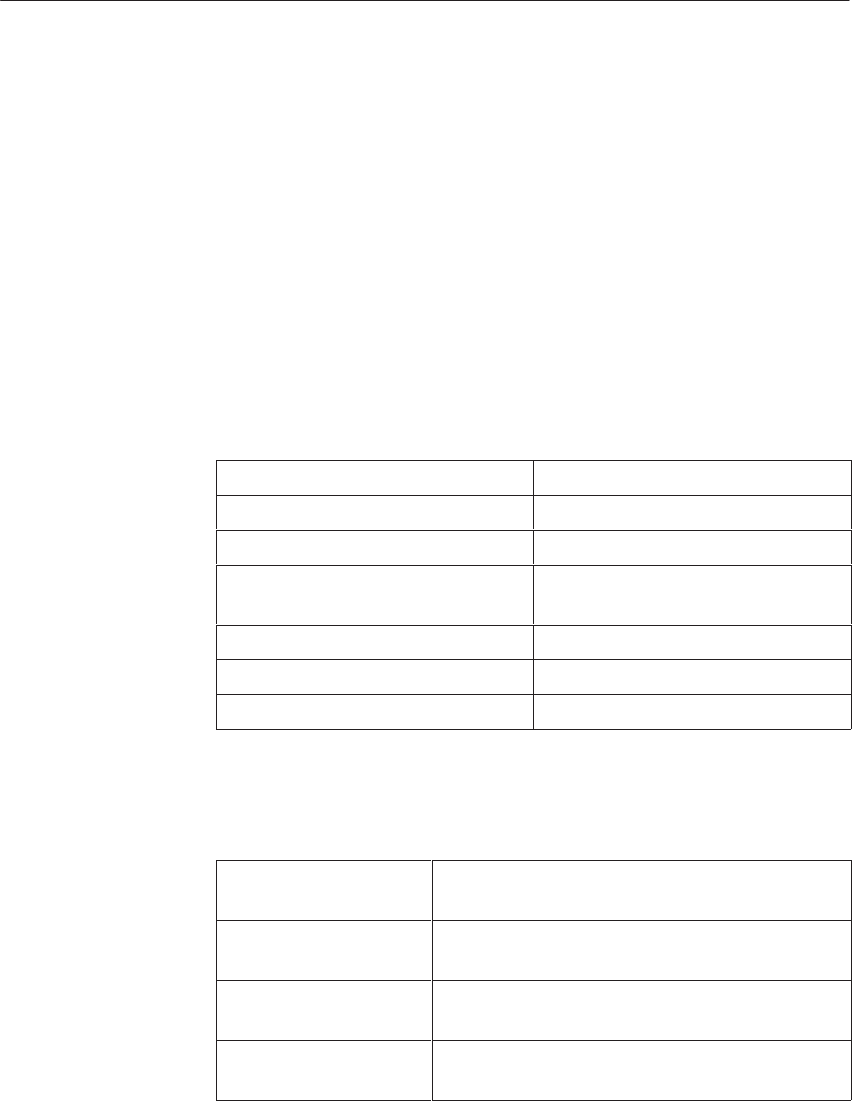
5-90 System Manual
C79000-G8576-C199-06
5.10.4 Technical Specifications
Important for the USA and Canada
The following approvals have been obtained:
UL Listing Mark
Underwriters Laboratories (UL) to Standard UL 508, Report E 85972
CSA Certification Mark
Canadian Standard Association (CSA) to Standard C 22.2 No. 142,
Report LR 63533
Supply voltage +5 V 5 %
Operating temperature 0 to 55 °C
Storage temperature – 40 °C to 70 °C
Relative humidity Up to 95 % at 25 °C, no
condensation
Number of programming cycles 10,000
Dimensions (H x D x W) 54 x 58 x 14 mm
Weight Approx. 40 g / 60 g
Current consumption
(at 5 V) 100 mA max. (16/64 Kbytes)
200 mA max. (32 Kbytes)
Backup current/standby Approx. 20 mA typ. (16/64 Kbytes)
Approx. 40 mA typ. (32 Kbytes)
Backup voltage/
UCMOS 2.7 V to 3.6 V
Access time tACC 150 ns (16/64 Kbytes)
200 ns (32 Kbytes)
All 377 Memory
Submodules
Submodules
without Battery
Backup
CPUs, Memor
y
Cards, Memor
y
Submodules, Interface Submodules

5-91
System Manual
C79000-G8576-C199-06
Current consumption
(at 5 V) 140 mA max.
Backup current 13 mA typ.
Backup voltage/
UCMOS 2.7 V to 3.6 V
Submodule battery Lithium button cell 3 V/200 mAh Type CR 2430
(LF-1/2W) from VARTA
Backup time 1 year min. at 25 oC
Access time tACC 150 ns
Submodules with
Battery Backup
CPUs, Memor
y
Cards, Memor
y
Submodules, Interface Submodules

5-92 System Manual
C79000-G8576-C199-06
5.11 Interface Submodules
The second serial interface of the CPU 928B can be optionally used as:
A PG interface (for PG and operator panels)
An interface for the RK 512 computer link
An interface for data transmission with procedures 3964/3964R
An interface for data transmission with the “open driver”
An interface for data transmission via the SINEC L1 bus (from Version
6ES5 928-3UB12)
The second serial interface of the CPU 948 can be used as:
A PG interface (for PG and operator panels)
To use the second interface as ... ... you require ...
a PG interface the PG submodule
an interface for data transmission
with
RK 512 computer link,
procedures 3964/3964R
or “open driver”
the V.24 (RS 232C)
or TTY
or RS 422 A/485 submodule
(only in RS 422 A mode)
an interface for data transmission
via the SINEC L1 bus the SINEC L1 submodule
Using the Interface
Submodules
CPUs, Memor
y
Cards, Memor
y
Submodules, Interface Submodules
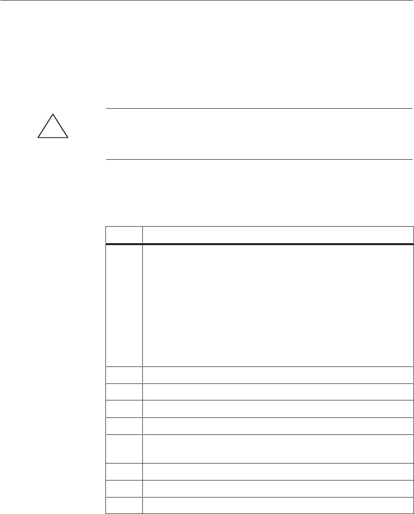
5-93
System Manual
C79000-G8576-C199-06
5.11.1 Installing and Removing the Interface Submodules
To use an interface submodule, you must first install it in the CPU (outside
the central controller).
!Caution
Switch off the power supply of the programmable controller before
removing the CPU.
Install your interface submodule in the following steps:
Step Action
1Check the jumper settings of your interface submodule:
PG submodule See Section 5.11.2
V.24 submodule See Section 5.11.3
TTY submodule See Section 5.11.4
RS422 A/485 submodule See Section 5.11.5
SINEC L1 submodule See Section 5.11.6.
When the interface submodule is delivered, the jumpers are
already set so that you can usually fit it immediately.
2Switch off the power supply of your PLC.
3Remove the CPU.
4Remove both screws on the submodule slot.
5Remove the coverplate.
6Insert the interface submodule through the front plate into the
plug-in connector (components in the same direction as the CPU).
7Secure the submodule with the two screws (see step 4).
8Insert the CPU in the central rack.
9Switch on the power supply of your PLC again.
Installation
CPUs, Memor
y
Cards, Memor
y
Submodules, Interface Submodules

5-94 System Manual
C79000-G8576-C199-06
Remove your interface submodule in the following steps:
Step Action
1Switch off the power supply of your PLC.
2Remove the CPU from the central controller.
3Slacken the two locking screws of the submodule and pull it out
of the receptacle.
4Fit another submodule (as already described) or close the
receptacle with its cover. Use the fixing screws of the submodule.
5Insert the CPU in the central controller.
6Switch the power supply of your PLC on again.
Note
Since the interface module is secured to the CPU with screws, interference
pulses are given a path to ground via the shield of the CPU.
Removal
CPUs, Memor
y
Cards, Memor
y
Submodules, Interface Submodules
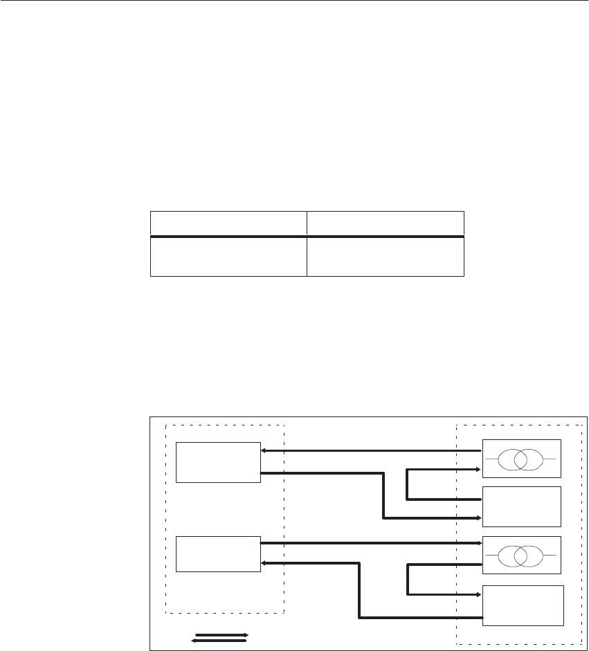
5-95
System Manual
C79000-G8576-C199-06
5.11.2 PG Submodule
By means of the PG submodule, you can use the second interface of the CPU
as the PG interface and equally privileged with the first interface.
The PG submodule can be inserted in the following CPUs:
Interface Submodule For Use With
PG submodule CPU 928B
CPU 948
The PG submodule is equipped with a transmitter and a receiver for 20 mA
current loop signals. The loop current is always fed in from the PG. The
following figure shows the circuitry for current loop signals of the standard
cable:
Transmitter
–
+
+
–
–
Receiver
Current Direction Arrows
CPU with
PG
+
Receiver
+
–
Transmitter
PG Module
–
+
–
+
Figure 5-11 PG Submodule: Loop Current Direction
The rate for data transmission via the PG interface is always 9600 bps.
Application
Circuitry
Data Transmission
Rate
CPUs, Memor
y
Cards, Memor
y
Submodules, Interface Submodules

5-96 System Manual
C79000-G8576-C199-06
Given in the following table are the pin assignments of the 15-pin
subminiature D-type connector in the front plate of the PG submodule:
Pin Designation Current
Direction Remarks
1 Housing/GND/GNDext
2– RxD ³
8
15
3VPG + 5 V_
15
4+ 24 V from bus
50 V GND/GNDint
6+ TxD ²
7– TxD ³
9
8 Housing/GND/GNDext
919+ RxD ²
10 24 V GND ²Current return
11 20 mA ³Current source, transmitter
12 GND/GNDint
13 20 mA ³Current source, receiver
14 VPG + 5 V_
15 0 V GND/GNDint
²: From partner to CPU
³: From CPU to partner
Pin Assignments
of the PG
Submodule
CPUs, Memor
y
Cards, Memor
y
Submodules, Interface Submodules
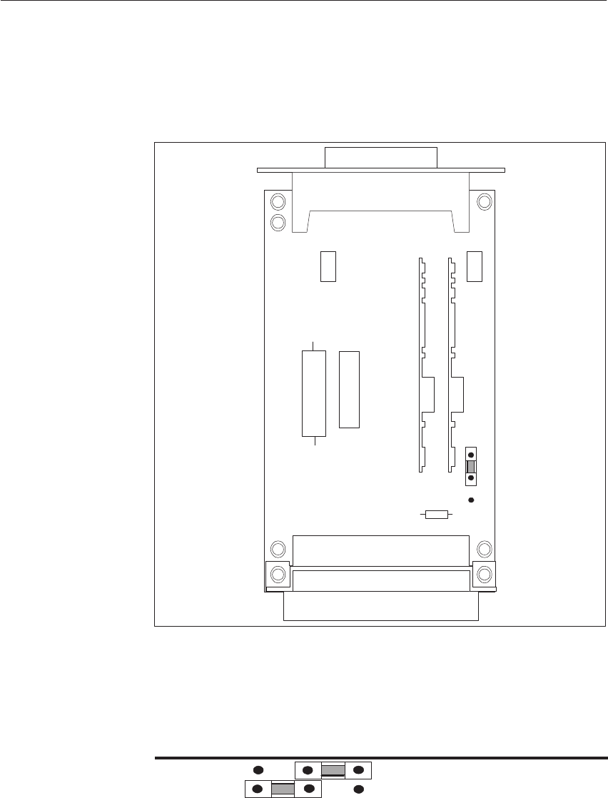
5-97
System Manual
C79000-G8576-C199-06
When the PG submodule is delivered, the jumpers are set as shown in the
following figure. As a rule, therefore, you can use the PG submodule
immediately.
Backplane Connector
Front Connector
15-Pin Sub. D-Type
J1
3
2
1
Figure 5-12 PG Submodule: Jumper Settings when Delivered
J1 is set to select whether the PG submodule is to be operated in the
CPU 928B/CPU 948 or in the CPU 945:
123
J1 Operation in CPU 928B/CPU 948
Operation in CPU 945
Jumper Settings
on the PG
Submodule
CPUs, Memor
y
Cards, Memor
y
Submodules, Interface Submodules

5-98 System Manual
C79000-G8576-C199-06
Standard cables for connecting the PG submodule in the CPU to the PG are
available from Siemens in various lengths, up to 1000 m.
Order numbers and lengths can be found in the ordering information.
Connecting cable: CPU - PG
Housing, GND
1 Shield
Housing, GND
8 24
25
9
2
+ RxD
– RxD
Receiver 10
22
+ TxD6
12
23 –12V
Transmitter
20
6+12V
– TxD
Transmitter 7
8
21
Receiver
–12V
+12V
17
4
3
2
+ 20 mA
+ TxD
– TxD
– 20 mA
+ 20 mA
+ RxD
– RxD
– 20 mA
K1
K2
K3
Transmission
Rate Setting
CPU SI1 or
SI2 with PG Submodule PG 675/685 or
Adapter to PG 7xx
Figure 5-13 PG Submodule: Standard Connecting Cable
Standard
Connecting Cable
for the PB
Submodule
CPUs, Memor
y
Cards, Memor
y
Submodules, Interface Submodules
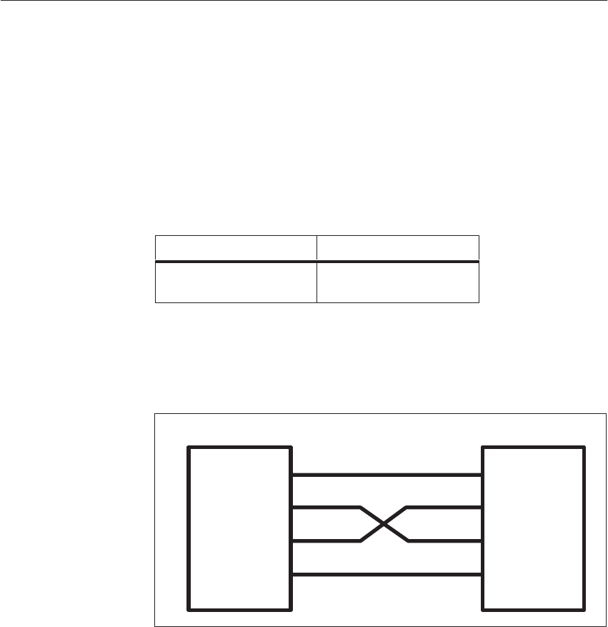
5-99
System Manual
C79000-G8576-C199-06
5.11.3 V.24 Submodule
The V.24 submodule is used with the RK 512 computer link, data
transmission with procedures 3964/3964R, data transmission with the “open
driver.”
The V.24 submodule can be inserted in the following CPU:
Interface Submodule... For use With ...
V.24 submodule CPU 928B
CPU 948
The following figure shows the circuitry for the V.24 interface (transmit and
receive lines):
Device 1
GND
TxD
RxD
Shield
Device 2
GND
TxD
RxD
Shield
Figure 5-14 V.24 Interface
Apart from the transmit and receive lines, the V.24 submodule has a number
of control and signaling lines to CCITT Recommendation V.24/V.28.
However, these control signals are not needed and not used for the standard
procedures of communication types RK 512, 3964/3964R and “open driver.”
(Exception: RTS/CTS with the “open driver”).
The following applies to V.24 signals:
Logic 0 is represented by a voltage U w + 3 V
Logic 1 is represented by a voltage U v – 3 V
If you fabricate the connecting cables yourself, note that unused inputs at the
partner station may have to be connected to quiescent potential. Further
details can be found in the appropriate manuals and in CCITT
Recommendations V.24/V.28.
Application
Circuitry
CPUs, Memor
y
Cards, Memor
y
Submodules, Interface Submodules
5-100 System Manual
C79000-G8576-C199-06
A maximum of 19200 bps is permissible for data transmission with the V.24
submodule.
The following table shows the pin assignments of the 25-pin subminiature
D-type connector in the front plate of the V.24 submodule:
Pin Des. to
DIN
66020
Des. to
CCITT
V.24
Int. Abbre-
viation Input/
Output Remarks
25
13 1 Shield
25 2 D1 103 TxD Output
3 D2 104 RxD Input
4 S2 105 RTS Output
5M2 106 CTS Input
6M1 107 DSR Input
7 E2 102 GND
8M5 109 DCD Input
18 PS3 141 Output Not supported
14
1
20 S1.2 108.2 DTR Output
122 M2 125 RI Input
23 S4 111 Output
25 PM1 142 Input Not supported
The signal numbering complies with DIN 66020 (V.24/RS 232C); the signal
designations are the abbreviations used internationally (RS 232C).
Data Transmission
Rate
Pin Assignments
of the V.24
Submodule
CPUs, Memor
y
Cards, Memor
y
Submodules, Interface Submodules

5-101
System Manual
C79000-G8576-C199-06
When the V.24 submodule is delivered, the jumpers are set as shown in the
following figure. As a rule, you can therefore use the V.24 submodule
immediately.
Backplane Connector
Front Connector
25-Pin Sub. D-Type
J2
J1
J3
J4
Br5
Br6
Br8
Br9
Br7
Figure 5-15 V.24 Submodule: Jumper Settings when Delivered
You can change over the polarity of the transmit and receive data with
jumpers J3 and J5.
123
J3 Transmit data in normal polarity
Transmit data negated
J5 Receive data in normal polarity
Received data negated
Jumper Settings of
the V.24
Submodule
CPUs, Memor
y
Cards, Memor
y
Submodules, Interface Submodules

5-102 System Manual
C79000-G8576-C199-06
With jumper J6, you can set all V.24 receivers so that you only require
positive-going signals (positive voltage region).
123
J6 All received signals must be at
V.24 signal level.
All received signals can be in the
positive voltage region.
With the submodule 0AA23, bridge 6 has no function; all signals can lie in
the positive range (corresponds to bridge setting 2-3).
With jumper J9, CTS can be set permanently to quiescent potential, i.e.
switched through from the front connector.
123
J9 CTS at quiescent potential CTS at
pin 5
Standard cables for connecting the V.24 submodule of the CPU to the partner
station are available from Siemens in various lengths, up to16 m.
Order numbers and lengths can be found in the ordering information.
Connecting cable for CPU, CP 524, CP 525, CP 544
CPU, CP524/525, CP544
RxD
7
Shield
2
7
TxD
Receiver Transmitter
TxD
23
RxD ReceiverTransmitter
Housing, GND Housing, GND
3
11
CPU, CP524/525, CP544
Figure 5-16 V.24 Submodule: Connecting Cable for CPU, CP 524, CP 525, CP 544
Standard Connect-
ing Cables of the
V.24 Submodule
CPUs, Memor
y
Cards, Memor
y
Submodules, Interface Submodules
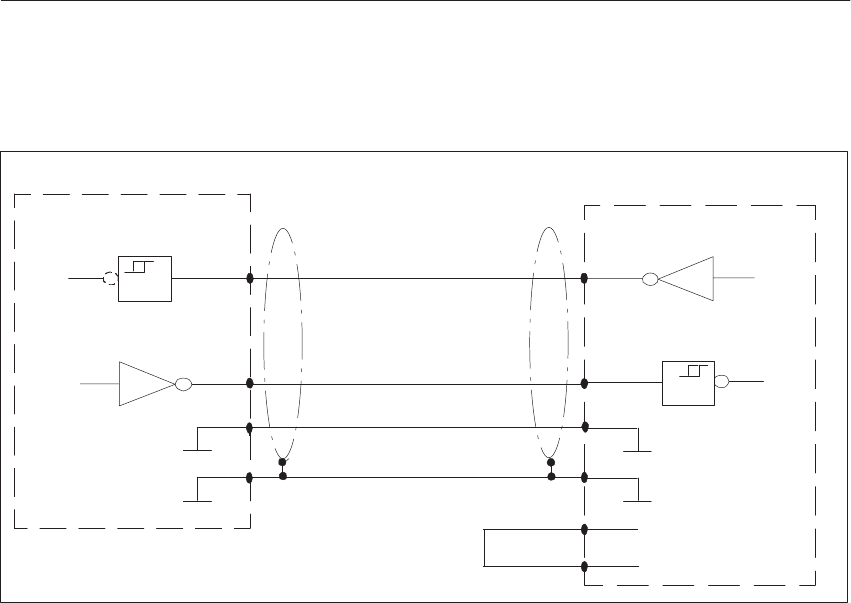
5-103
System Manual
C79000-G8576-C199-06
Connecting cable: CPU - N10 modem
CPU Modem N10
RxD
7
Shield
33
7
1
TxD
Receiver Transmitter
TxD
22
RxD ReceiverTransmitter
RTS
CTS
4
5
Housing,GND 1
Figure 5-17 V.24 Submodule: Connecting Cable for CPU - N10 Modem
CPUs, Memor
y
Cards, Memor
y
Submodules, Interface Submodules

5-104 System Manual
C79000-G8576-C199-06
Connecting cable: CPU - DR 210/211, DR 230/231
You can use this connecting cable both with the V.24 and with the TTY
submodule. Ensure that you have the same type of interface in the CPU and
in the printer.
13
14
1
10
19
7
Shield
32
7
1
Receiver Transmitter
9
10
18
21
Housing
23
ReceiverTransmitter
525
Housing, GND
CPU DR 210/211, DR 230/231
RxD
TxD
CTS
TxD
RxD
Busy
TTY Assignments TTY Assignments
Figure 5-18 V.24 Submodule: Connecting Cable for CPU - DR 210/211, DR 230/231
CPUs, Memor
y
Cards, Memor
y
Submodules, Interface Submodules
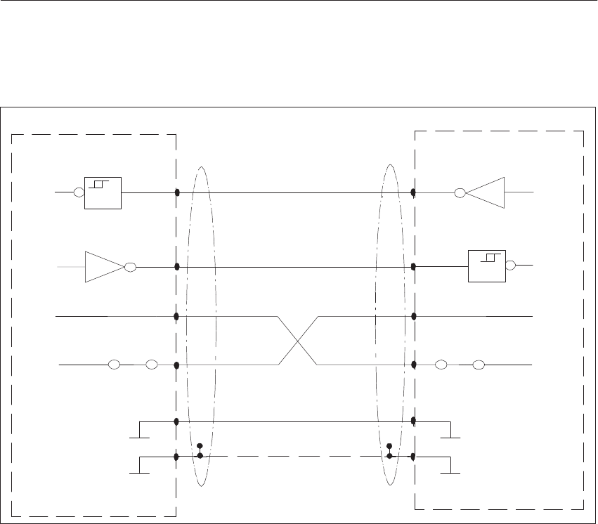
5-105
System Manual
C79000-G8576-C199-06
Wiring of a connecting cable for RTS/CTS flow control
CPU
RxD
7
32
7
TxD
Receiver Transmitter
TxD
2RxD
ReceiverTransmitter
Shield 1
RTS
CTS
Housing, GND 1
3
RTS
CTS
Housing, GND
4
5
4
5
CPU
Figure 5-19 Example of a Connecting Cable: CPU - CPU for RTS/CTS Flow Control
CPUs, Memor
y
Cards, Memor
y
Submodules, Interface Submodules

5-106 System Manual
C79000-G8576-C199-06
5.11.4 TTY Submodule
The TTY submodule is for use with the RK 512 computer link, data
transmission with procedures 3964/3964R, data transmission with the “open
driver.”
The TTY submodule complies with DIN 66 258, Part 1.
The TTY submodule can be inserted in the following CPU:
Interface Submodule ... For Use With ...
TTY submodule CPU 928B
CPU 948
The TTY submodule is equipped with a transmitter and receiver for 20 mA
current loop signals. Shown in the following figure is the typical circuitry for
current loop signals.
Current Direction Arrows
Transmitter
–
Transmitter
–
+
+
–
+
Receiver
–
Receiver
–
–
+
+
+
Figure 5-20 TTY Submodule: Loop Current Direction
The loop current can be fed in both by the TTY submodule and by the
partner station. Only the side supplying the current is non-floating.
!Caution
With longer line lengths, you should arrange your line so that the transmitter
always supplies the current.
Application
Circuitry
CPUs, Memor
y
Cards, Memor
y
Submodules, Interface Submodules
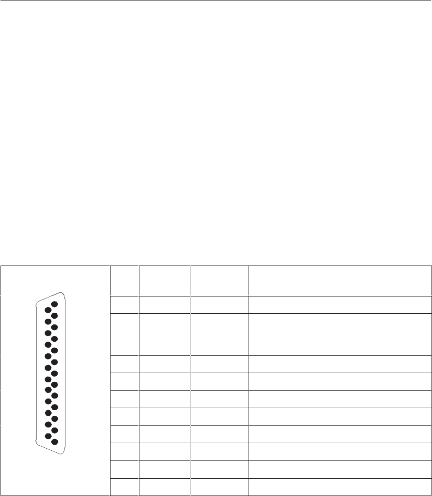
5-107
System Manual
C79000-G8576-C199-06
The TTY submodule feeds in the current (20 mA) via jumpers in the
connector of the standard connecting cable. The 24 V required for generation
of loop current is taken from the power supply of the PLC. In the quiescent
state, with a correct loop current connection, there should be a flow of 20 mA
(= logic 1). When the current is interrupted there is a logic 0.
The following applies to the TTY signals:
Logic 0 is represented by: no current
Logic 1 is represented by: current (20 mA)
A maximum of 9600 bps is permissible for data transmission with the TTY
submodule.
Shown in the figure are the pin assignments of the 25-pin subminiature
D-type connector in the front plate of the TTY submodule:
13
Pin Designa-
tion Current
direction Remarks
25 13 1 Shield
924 V
external This connection is changed over between
24 V internal and 24 V external with
jumper J3 (see next page).
10 + TxD ²
12 + 20 mA ³Current source, transmitter
13 + RxD ²
14 – RxD ³
14
1
16 + 20 mA ³Current source, receiver
119 – TxD ³
21 – 20 mA ²Current return
24 – 20 mA ²Current return
² : Input
³ : Output
Data Transmission
Rate
Pin Assignments
of the TTY
Submodule
CPUs, Memor
y
Cards, Memor
y
Submodules, Interface Submodules
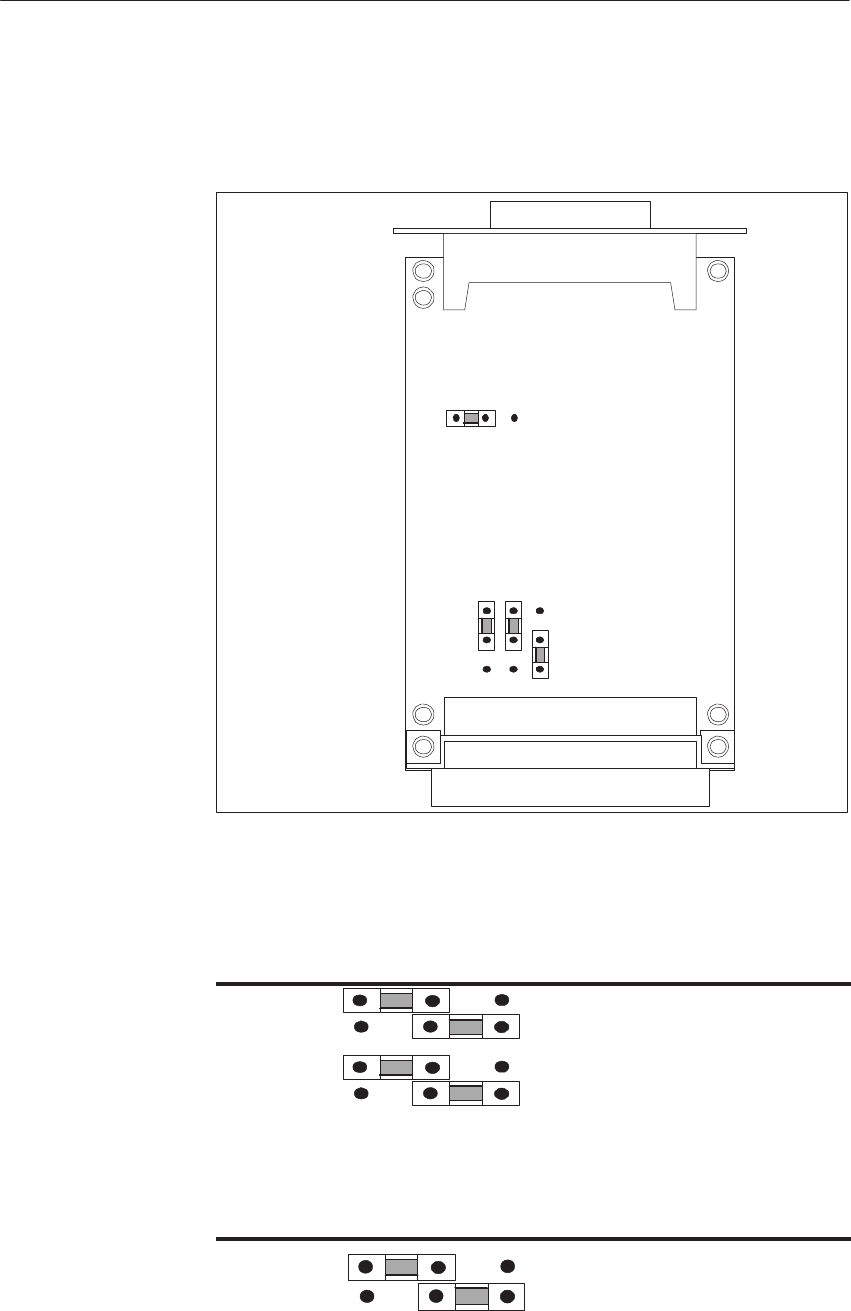
5-108 System Manual
C79000-G8576-C199-06
When the TTY submodule is delivered, the jumpers are set as shown in the
following figure. As a rule, therefore, you can use the TTY submodule
immediately.
Backplane Connector
J3
J4 J2 J1
123
Front Connector
25-Pin Sub. D-Type
1
2
3
Figure 5-21 TTY Submodule: Jumper Settings when Delivered
The polarity of the transmit and receive data is changed over with jumpers J1
and J2:
123
J1 Transmit data negated
Transmit data in normal polarity
J2 Receive data in normal polarity
Receive data negated
The 24 V source voltage for generation of the loop current can be allocated
with jumper J3:
123
J3 24 V will be applied from Pin 9 of
the sub. D connector
24 V will be applied from the
backplane connector (internally)
Jumper Settings
on the TTY
Submodule
CPUs, Memor
y
Cards, Memor
y
Submodules, Interface Submodules

5-109
System Manual
C79000-G8576-C199-06
Standard cables for connecting the TTY submodule in the CPU to the partner
station are available from Siemens in various lengths, up to 1000 m.
Order numbers and lengths can be found in the ordering information.
Connecting cable for CPU, CP 524, CP 525, CP 544
CPU, CP 524/525, CP544
Transmitter
+24V
+24V
Transmitter
Shield
+RxD
–RxD
+20mA
+TxD
–TxD13
14
21
10
19
1
+RxD
–RxD
–20mA
+TxD
–TxD
–20mA
12 +20mA
Receiver
Receiver
Housing, GND Housing, GND
1
19
10
12
14
13
21
CPU, CP 524/525, CP 544
Figure 5-22 TTY Submodule: Connecting cable for CPU, CP 524, CP 525, CP 544
Standard Connect-
ing Cables for the
TTY Submodule
CPUs, Memor
y
Cards, Memor
y
Submodules, Interface Submodules
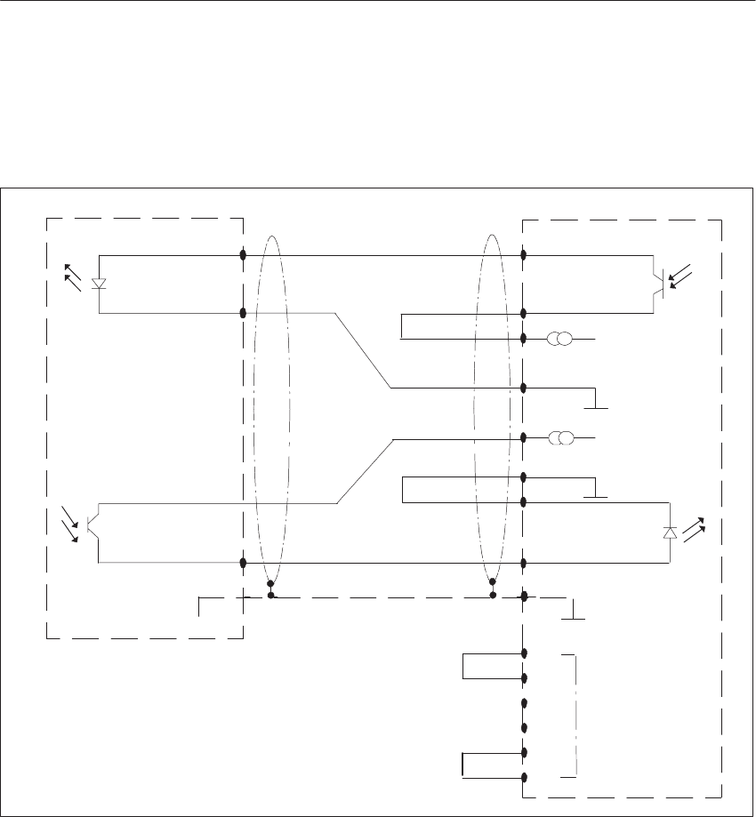
5-110 System Manual
C79000-G8576-C199-06
Connecting Cable: CPU - IM 512
To generate loop current, the IM 512 must be supplied with 24 V at the
subminiature D-type connector in the front plate.
Shield
CPU
Transmitter
13
Receiver 14 Transmitter
+ 24 V
+ 24 V
IM 512
12
13
23
11
24
25
Device ID
1
Receiver
19
10
Housing, GND Housing
0
14
5
2
17
6
18
15
3
2
2
+ RxD
– RxD
+ TxD
– TxD
+ 20mA
– 20mA
– RxD
+ 20mA
+ TxD
– TxD
– 20mA
+ RxD
2
Figure 5-23 TTY Submodule: Connecting Cable CPU - IM 512
CPUs, Memor
y
Cards, Memor
y
Submodules, Interface Submodules
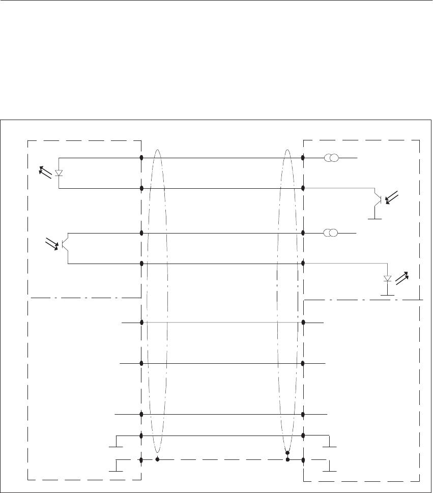
5-111
System Manual
C79000-G8576-C199-06
Connecting cable: CPU - DR 210/211, DR 230/231
You can use this connecting cable with both the TTY and the V.24
submodule. Ensure that you have the same type of interface in the CPU and
in the printer.
13
14
Receiver
1
Transmitter
+24V
+24V
Receiver
Transmitter
10
19
7
Shield
32
7
1
9
10
18
21
Housing
23
525
Housing,GND
CPU
+RxD
–RxD
+TxD
–TxD
+20mA
+20mA
+TxD
+RxD
V.24 Assignments
V.24 Assignments
DR 210/211, DR 230/231
Figure 5-24 TTY Submodule: Connecting Cable CPU - DR 210/211, DR 230/231
CPUs, Memor
y
Cards, Memor
y
Submodules, Interface Submodules
5-112 System Manual
C79000-G8576-C199-06
5.11.5 RS422 A/485 Submodule
The RS422 A/485 submodule is for use exclusively in the RS422 A mode
with the RK 512 computer link, data transmission with procedures
3964/3964R, data transmission with the “open driver.”
The RS422 A/485 submodule can be inserted in the following CPU:
Interface Submodule ... For Use With ...
RS422 A/485 submodule CPU 928B
CPU 948
With the above types of communication, the RS422 A/485 submodule can
only be used in full duplex operation implemented by hardware.
The electrical characteristics are governed by EIA Standard RS422 A
(CCITT Recommendation V.11).
Shown in the following figure is the circuitry for the interface (transmit and
receive lines):
Device 1
GND
Device 2
GND
Shield Shield
T(A)
T(B)
R(A)
R(A)
R(B)
T(A)
T(B)
R(B)
Figure 5-25 RS422 A/485 Submodule: Full Duplex Operation
Apart from the transmit and receive lines, the RS422 A/485 submodule has a
number of control and signaling lines to CCITT Recommendation X.24 and
ISO 8481. In association with the above types of communication, however,
these control and message signals are not required and need therefore not be
wired. The RS422 A/485 is a differential voltage interface and therefore
exhibits higher rejection of interference than a TTY or V.24 interface.
The following applies to the signals to EIA Standard RS422 A (V.11):
Logic 0 (ON) corresponds to: VA > VB
Logic 1 (OFF) corresponds to: VA < VB
In the RS422 A/485 submodule, the interface signals are isolated from the
supply voltage of the PLC.
Application
Circuitry
CPUs, Memor
y
Cards, Memor
y
Submodules, Interface Submodules
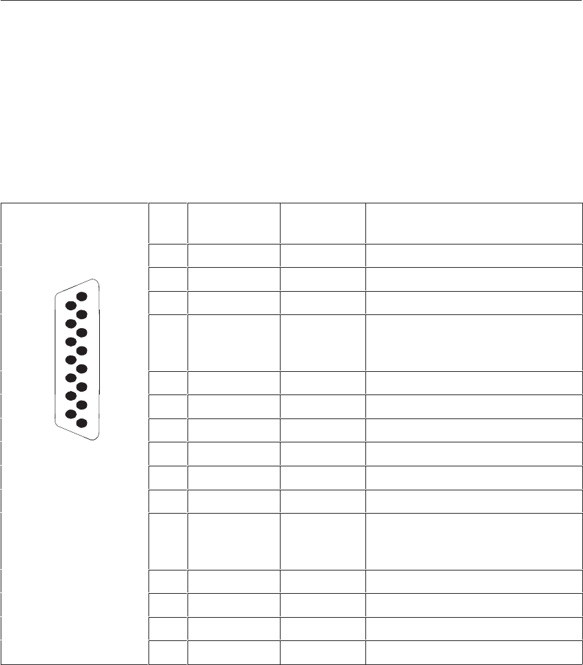
5-113
System Manual
C79000-G8576-C199-06
A maximum of 19200 bps is permissible for data transmission with the
RS422 A/485 submodule when used in a CPU.
Shown in the following figure are the pin assignments of the 15-pin
subminiature D-type connector in the front plate of the RS422 A/485
submodule:
Pin Des. to
CCITT V.24 Input/
Output Remarks
1 Shield
8
2 T(A) Output
8
15 3 C(A) Output
4 R(A) Input/Output In full duplex operation, only data
can be received on this two-wire
line.
5 I(A) Input
9
6 S(A) Input
9
17 B(A) Output
8 GND
9 T(B) Output
10 C(B) Output
11 R(B) Input/Output In full duplex operation, only data
can be received on this two-wire
line.
12 I(B) Input
13 S(B) Input
14 B(B) Output
15 X(B) Input
Data Transmission
Rate
Pin Assignments
of the RS422 A/485
Submodule
CPUs, Memor
y
Cards, Memor
y
Submodules, Interface Submodules
5-114 System Manual
C79000-G8576-C199-06
When the submodule is delivered, the jumpers are set as shown in the
following figure. As a rule, therefore, you can use the RS 422 A/485
submodule immediately.
Front Connector
X4
X3
119
111
220
212
Figure 5-26 RS422-A/485 Submodule: Jumper Settings when Delivered
With the jumpers on the switch row X3 you can remove the preset for
recognizing a break state from the two-wire line R.
When delivered, the two-wire line R is preset with the jumpers 12-14 and 4-6
so that the break state can be recognized. Pin 4 (R(A)) of the front connector
lies above a resistance on +5 V. Pin 11 (R(B)) of the front connector lies
above a resistance on ground.
If you replug the jumpers on 10-12 and 6-8, the two-wire line R is preset as
follows: pin 4 (R(A)) of the front connector lies above a resistance on
ground. Pin 11 (R(B)) of the front connector lies above a resistance on +5 V.
The break state cannot be recognized.
Jumper Settings
on the
RS422 A/485
Submodule
CPUs, Memor
y
Cards, Memor
y
Submodules, Interface Submodules
5-115
System Manual
C79000-G8576-C199-06
If you unplug the jumpers 12-14 and 4-6, the two-wire line R is not preset
and the break state cannot be recognized clearly.
With the following jumper setting you can switch over the data direction on
the two-wire line R:
Jumper 16-18: setting for full duplex operation. Data can only be received
on the two-wire line R (default).
Jumper 18-20: setting for half duplex operation. Data can be transmitted or
received on the two-wire line R (special driver required).
With the following jumper setting you can switch the two-wire line B as an
input or an output.
Jumper 17-19: two-wire line B is switched as an output. The line X(B) can
be used as an input. X(A) is connected to ground (default).
Jumper 15-17: two-wire line B is switched as an input. The line X(B) cannot
be used.
With the following jumper setting you can either place the signal /PS3 or the
internal transmitting frequency (TxCint) on the two-wire line B. The
two-wire line B must be switched as an output.
Jumper 2-4: the signal /PS3 can be transmitted via the two-wire line B
(default).
Jumper 4-6: the internal transmitting frequency TxCint can be transmitted
via the two-wire line B.
CPUs, Memor
y
Cards, Memor
y
Submodules, Interface Submodules
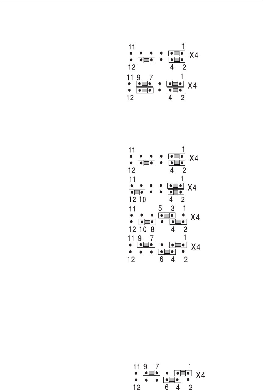
5-116 System Manual
C79000-G8576-C199-06
With the following jumper setting you can use the frequency transmitted via
the two-wire line S as the receive frequency.
Jumper 7-9 removed: frequency on input S is not used as the receive
frequency (default).
Jumper 7-9 plugged: frequency on input S is used as the receive frequency.
With the following jumper setting you can switch the transmit and receive
frequencies.
Jumpers 8-10, 1-3: the internal transmit frequency (TxCint) is used as the
transmit and receive frequency (default).
Jumpers 10-12, 1-3: the internal transmit frequency (TxCint) is used as the
transmit frequency and the internal receive frequency (RxCint) is used as the
receive frequency.
Jumpers 8-10, 3-5: the frequency transmitted via the two-wire line S is used
as the transmit and receive frequency.
Jumpers 10-12, 3-5: the frequency transmitted via the two-wire line S is
used as the transmit frequency, the internal receive frequency (RxCint) is
used as the receive frequency. With the following jumper setting you can set
the submodule for synchronous transmission with frequency control
according to the DIN draft ISO 8481. The two-wire line B (identifier X to
ISO 8481) must be switched as an output.
Jumpers 1-3, 4-6, 7-9: the internal transmit frequency (TxCint) is used as
the transmit frequency. The internal transmit frequency is simultaneously
transmitted on the two-wire line B.
CPUs, Memor
y
Cards, Memor
y
Submodules, Interface Submodules
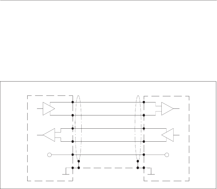
5-117
System Manual
C79000-G8576-C199-06
Standard cables for connecting the RS422 A/485 submodule in the CPU
to the partner station are available from Siemens in various lengths, up to
1200 m.
The order numbers and lengths can be found in the ordering information.
Connecting cable for CPU, CP 524, CP 544
T(A) R(A)
T(B) R(B)
2
9
4
11
R(A) T(A)
R(B) T(B)
GG
4
11
2
9
88
Shield
11
Housing, GND Housing, GND
Receiver
Receiver
Transmitter
CPU, CP 524, CP 544
Transmitter
GND GND
CPU, CP 524, CP 544
Figure 5-27 RS422-A/485 Submodule: Connecting Cable for CPU, CP 524, CP 544
Standard
Connecting Cables
for the
RS422-A/485
Submodule
CPUs, Memor
y
Cards, Memor
y
Submodules, Interface Submodules
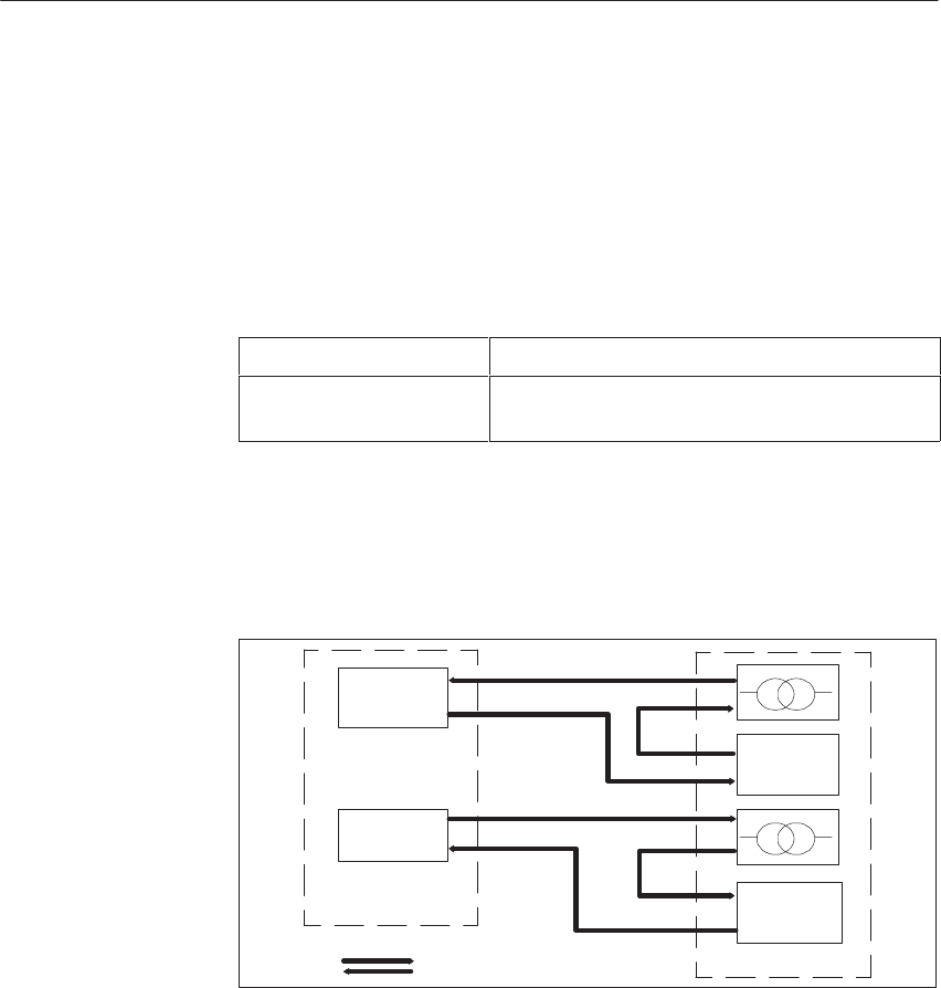
5-118 System Manual
C79000-G8576-C199-06
5.11.6 SINEC L1 Submodule
The SINEC L1 submodule is for use with data transmission via the
SINEC L1 bus.
The SINEC L1 submodule can be inserted in the following CPU:
Interface Submodule ... For Use With ...
SINEC L1 submodule CPU 928B, from Version 6ES5 928-3UB12
CPU 948
The SINEC L1 submodule is equipped with a transmitter and a receiver for
20 mA current loop signals. Shown in the following figure is the circuitry for
the current loop signals:
Transmitter
–
+
+
–
–
Receiver
Current Direction Arrows Partner
+
Receiver
+
–
Transmitter
CPU with
SINEC L1
Submodule
–
+
–
+
Figure 5-28 SINEC L1 Submodule: Loop Current Direction
Data transmission via the SINEC L1 interface always takes place at
9600 bps.
Application
Circuitry
Data Transmission
Rate
CPUs, Memor
y
Cards, Memor
y
Submodules, Interface Submodules
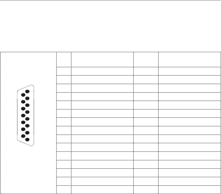
5-119
System Manual
C79000-G8576-C199-06
Shown in the following figure are the pin assignments of the 15-pin
subminiature D-type connector in the front plate of the SINEC L1
submodule:
Pin Designation Current
Direction Remarks
1 Housing/GND/GNDext
2– RxD ³
8
15
3VPG + 5 V_
8
15 4+ 24 V from bus
524 V ground
6+ TxD ²
7– TxD ³
8 Housing/GND/GNDext
9
1
9+ RxD ²
1
10 24 V ground ²Current return
11 20 mA ³Current source, transmitter
12 24 V ground
13 20 mA ³Current source, receiver
14 VPG + 5 V_
15 24 V ground
²: from partner to CPU
³: from CPU to partner
Pin Assignments
of the SINEC L1
Submodules
CPUs, Memor
y
Cards, Memor
y
Submodules, Interface Submodules
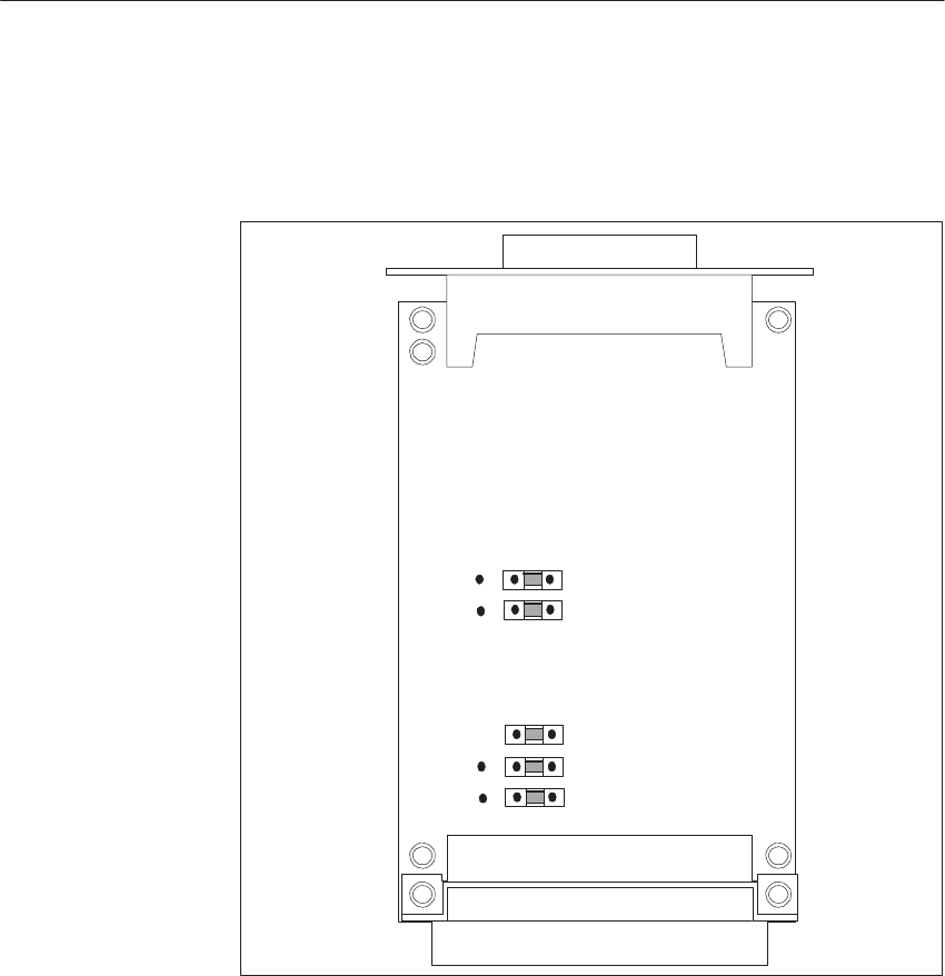
5-120 System Manual
C79000-G8576-C199-06
When the SINEC L1 submodule is delivered, the jumpers are set as shown in
the following figure. As a rule, therefore, you can use the SINEC L1
submodule immediately.
Backplane Connector
Front Connector
15-Pin Sub. D-Type
X8
X7
X10
X9
X6
132
Figure 5-29 SINEC L1 Submodule: Jumper Settings when Delivered
The connection to the SINEC L1 bus system is provided by the BT 777 bus
terminal. A detailed description of the bus terminal can be found in the
manual entitled “SINEC L1 Bus System,” 6ES5 998-7LA11).
The order number can be found in the ordering information.
Jumper Settings
on the SINEC L1
Submodule
BT 777 Bus
Terminal
CPUs, Memor
y
Cards, Memor
y
Submodules, Interface Submodules
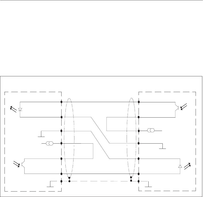
5-121
System Manual
C79000-G8576-C199-06
If the CPU communicates as master in a point-to-point link with a slave, a
connecting cable can be used instead of the bus terminal.
Shown in the following figure is connecting cable for point-to-point
communication from the SINEC L1 submodule in the CPU to a partner.
Connecting cable: CPU - partner (point-to-point communication)
e.g. CPU 928B, 941...945
Transmitter
+ 24V + 24V
Transmitter
Shield
+ RxD
– RxD
+ 20 mA
+ TxD
– TxD
9
2
6
7
1
+ RxD
– RxD
M
+ TxD
– TxD
M
11 + 20 mA
Receiver
Receiver
Housing, GND Housing, GND
1
7
6
11
2
9
15
CPU 928B CPU 102, 103, AG 90U/95U
15
Figure 5-30 SINEC L1 Submodule: Connecting Cable for Point-to-Point Communication via the SINEC L1
Submodule
Connecting Cable
for Point-to-Point
Communication
CPUs, Memor
y
Cards, Memor
y
Submodules, Interface Submodules

5-122 System Manual
C79000-G8576-C199-06
5.11.7 Technical Specifications of the Interface Submodules
Important for the USA and Canada
The following approvals have been obtained:
UL Listing Mark
Underwriters Laboratories (UL) to Standard UL 508, Report E 85972
CSA Certification Mark
Canadian Standard Association (CSA) to Standard C 22.2 No. 142,
Report LR 63533
Degree of protection IP 00
Ambient temperature
in operation
for transporation and storage 0 to +55 °C
– 40 to +70 °C
Relative humidity 95% max. at 25 °C, no condensation
Supply voltage 5V $ 5%
24V + 25%/– 17%
Transmission rate
PG submodule
V.24 submodule
TTY submodule
RS422-A/485 submodule
SINEC L1 submodule
9 600 bps fixed
19 200 bps max.
9600 bps max.
19 200 bps max.
(when submodule is used in a CPU)
9600 bps fixed
Front connector, female
PG, RS422 A/485, SINEC L1
submodule
V.24, TTY submodule
15-pin Cannon
25-pin Cannon
Transmission cable Shielded four-wire line (five-wire line for
RS422 A) with braided shield and metal
housing on connector, grounding required at
both ends.
Line length
PG submodule
V.24 submodule
TTY submodule
RS422 A/485 submodule
SINEC L1 submodule
1000 m max.
16 m max.
1000 m max.
1200 m max.
1000 m max.
Current consumption at 5 V/24 V 5 V 24 V
PG submodule
V.24 submodule
TTY submodule
RS422 A/485 submodule
SINEC L1 submodule
40 mA max.
0.2 A max.
0.1 A max.
0.5 A max.
170 mA max.
380 mA
–
60 mA
–
100 mA
Design
Dimensions (WxHxD) 16.3 mm x 60 mm x 102.7 mm
Weight
per interface submodule Approx. 0.1 kg
CPUs, Memor
y
Cards, Memor
y
Submodules, Interface Submodules

6-1
System Manual
C79000-G8576-C199-06
Multiprocessor Operation/Coordinators
This chapter explains how to install multiprocessor operation in the
S5-135U/155U programmable controller and start operations.
You will require the 923A or 923C coordinator module. The technical
functions of these modules are described.
Section Description Page
6.1 Introduction 6-2
6.2 Starting the Multiprocessor Operation 6-3
6.3 Coordinator Modes 6-13
6.4 923A Coordinator Module 6-15
6.5 923C Coordinator Module 6-18
6.6 Technical Specifications of the Coordinators 6-28
Chapter
Overview
6

6-2 System Manual
C79000-G8576-C199-06
6.1 Introduction
The S5-135U/155U is a member of the SIMATIC S5 family of programmable
(logic) controllers. The PLC can be used both in single and in multiprocessor
operation with up to four CPUs.
You can arbitrarily combine the CPUs in the central controller at the CPU
slots.
CPU Slot Requirement
CPU 948/CPU 928B/CPU 928 2 slots
CPU 922 1 slot
In multiprocessor operation, each CPU processes its individual user program
independently of the other CPUs.
The common S5 bus serves for data interchange with I/O modules, CPs, IPs
and other CPUs. In multiprocessor operation, access of the CPUs to the S5
bus is controlled by a coordinator. The functioning of this module is
described in Sections 6.5 and 6.6.
For an explanation of data interchange between CPUs in multiprocessor
operation and the arrangement of your STEP 5 program, please consult the
Programming Guide for your CPU.
A coordinator is required in multiprocessor operation. The following are
available for the S5-135U/155U PLC:
923A coordinator (COR A)
and
923C coordinator (COR C).
The coordinator allocates to the CPUs the time divisions in which they can
access the S5 bus (bus enable time), and contains the global memory for data
interchange between the CPUs via communication flags. Additionally, the
COR C contains another memory with four pages for the “multiprocessor
communication” function as well as a serial PG interface with PG
multiplexer function (PG MUX).
Slots Occupied
Coordinator
Multiprocessor Operation/Coordinators
6-3
System Manual
C79000-G8576-C199-06
6.2 Starting the Multiprocessor Operation
This section guides you through the installation and startup of multiprocessor
operation; the following is assumed:
You are familiar with the use and programming of individual modules in
single-processor operation. If this is not the case, please consult the
relevant chapters in this manual and in the appropriate Programming
Guides.
Note
As soon as a coordinator is inserted in the S5-135U/155U central controller,
all CPUs are automatically in multiprocessor operation irrespective of the
number of inserted CPUs. Even if the coordinator is only operated with one
CPU, the conditions for multiprocessor operation apply to this CPU (DB 1
required, DX 0 possibly required, etc.).
You can use up to four CPUs in the S5-135U/155U programmable controller.
The permissible slots are indicated in Chapter 4.
Startup can be subdivided into the following steps:
Step Action
1Set the number of CPUs (inserted from the left) on the
coordinator.
2If you use communication flags on CPs: Mask out the
communication flag areas on the coordinator.
3Insert the CPUs and the coordinator in the slots provided in the
central controller. The CC must be disconnected from system
voltage.
4Switch on the system voltage and Power switch on the power
supply unit.
5Execute an OVERALL RESET on all CPUs.
6Load your STEP 5 user programs in all CPUs (including DB 1,
additionally DX 0 for the CPU 948).
7Execute a RESET on all CPUs.
8Set the mode switch of the coordinator from the STOP to RUN or
TEST setting.
Procedure,
Overview
Multiprocessor Operation/Coordinators

6-4 System Manual
C79000-G8576-C199-06
Shown in Figures 6-1 and 6-2 are the locations of jumpers and switches on
the modules, at which the settings required for startup must be made.
Note
The settings of jumpers which are not described in the following text must
not be changed.
X1
X2
EP 2
EP 7
EP 63 EP 62
EP 43
EP 45
J2
J1
Mode Switch
(RUN,STOP,TEST)
16 9
8
1
16 9
8
1
1
16 9
8
16 9
8
1
16 9
8
1
8
16 9
1
Figure 6-1 Location of Jumpers on the 923A Coordinator (when Delivered)
Setting the
Jumpers
Multiprocessor Operation/Coordinators
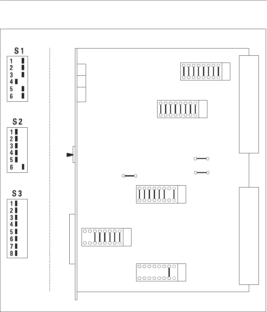
6-5
System Manual
C79000-G8576-C199-06
X1
X2
EP 60
16
9
81
(JR)
EP 61
16
9
81
(JX)
S1
Mode Switch
(RUN,STOP,TEST)
S2
S3
X4
EP 64
169
81
(JU)
X6
X5
EP 62
169
81
(JY)
EP 63
169
81
(JZ)
Front View
S1, S2, S3
on off
off on
off on
Figure 6-2 Location of Jumper Sockets and Switches on the 923A Coordinator and Front View of Switches S1 to
S3 (when Delivered)
Multiprocessor Operation/Coordinators
6-6 System Manual
C79000-G8576-C199-06
The individual actions are explained in more detail in the following.
Setting the number of occupied CPU slots on the coordinator:
923A Coordinator
Number of CPUs used Jumper(s) at EP 62
27 - 10; 8 - 9 1)
37 -10
48 - 9
923C Coordinator
Coded by inserting only one DIL switch S1.4, S1.5 or S1.6 in the front
plate recess: (see Figure 6-2)
DIL S. on off Effect
S1.1
S1.2
S1.3
S1.4
S1.5
S1.6
x
x
x
x
x
x
–
–
Enable test mode
No. of occupied CPU slots = 2 1)
No. of occupied CPU slots = 3
No. of occupied CPU slots = 4
1) Setting when delivered
Setting the communication flag areas:
IF ... THEN ...
you use
communication flag
areas on CPs (please
consult the relevant
manuals),
you must mask out these areas (blocks) on the
coordinator without fail, to avoid duplicated
addressing of the communication memory.
The 256 communication flag bytes can be masked
out in groups of 32. You do this by removing
jumpers at coding socket EP 7 on Coordinator A
(see Figure 6-1 for location) or EP 60 on
Coordinator C (see Figure 6-2).
Step 1
Step 2
Multiprocessor Operation/Coordinators

6-7
System Manual
C79000-G8576-C199-06
16
1
EP 7 EP 60
9
8
8
91
16
When the unit is delivered, all communication flag areas are activated
(see above):
On Coordinator A by jumpers at EP 7
On Coordinator C by jumpers at EP 60
Jumper Comm. Flag Byte Address
8 - 9
7 - 10
6 - 11
5 - 12
4 - 13
3 - 14
2 - 15
1 - 16
0 to 31
32 to 63
64 to 95
96 to 127
128 to 159
160 to 191
192 to 223
224 to 255
F200H to F21FH
F220H to F23FH
F240H to F25FH
F260H to F27FH
F280H to F29FH
F2A0H to F2BFH
F2C0H to F2DFH
F2E0H to F2FFH
Jumper inserted: area activated (coordinator
acknowledges in this area)
Jumper not inserted: area masked out (coordinator
does not acknowledge in this area)
You wish to mask out the four communication flag areas with the highest
addresses on COR A:
18
916
EP7
Address F200H to F27FH
Activated (Jumper Inserted)
Address F280H to F2FFH
Masked Out (Jumper Open)
Figure 6-3 Example of Addressing the Communication Memory on COR A
Examples
Multiprocessor Operation/Coordinators
6-8 System Manual
C79000-G8576-C199-06
You wish to mask out the four communication flag areas with the highest
addresses on COR C:
1
8
916
EP 60
Address F200H to F27FH
Activated (Jumper Inserted)
Address F280H to F2FFH
Masked Out (Jumper Open)
Figure 6-4 Example of Addressing the Communication Memory on COR C
Inserting CPUs and coordinator in the central controller:
Precondition: The central controller is not yet switched off.
Substep Action Reaction
3a Insert the CPUs and coordinator
in the relevant slots. none
3b Insert all EPROM or RAM sub-
modules in the CPUs according
to the configuration. The
EPROM submodules must have
been previously programmed
with a PG.
none
3c Set all mode switches on the
CPUs and on the coordinator to
STOP. none
Step 3
Multiprocessor Operation/Coordinators

6-9
System Manual
C79000-G8576-C199-06
Action Reaction
Switch the supply voltage on. 1. The red STOP LEDs flash
rapidly on all CPUs to indicate:
Overall reset requested.
2. If the test mode is not set at the
coordinator (see Section 6.3)
and the mode switch is not at
the TEST setting:
The red BASP (output inhibit)
LED is permanently lit to
indicate: Digital outputs are
inhibited.
Symptom:
On some CPUs the STOP LED is not lit; the other CPUs are requesting
OVERALL RESET. All CPUs are emitting the BASP (output inhibit) signal.
Remedy:
Check the setting for the number of occupied CPU slots on the coordinator.
Are the CPUs inserted at suitable slots?
Executing an OVERALL RESET on all CPUs:
Ensure that the mode switch on the coordinator is set to STOP. (Precondition:
Steps 3 and 4 have been fully executed.
Action Reaction
Execute the OVERALL RESET for
each individual CPU:
Hold the MC 1) mode switch in the
OVERALL RESET setting; simulta-
neously set the mode switch from
STOP to RUN and back to STOP.
The red STOP LEDs on the CPUs at
which the OVERALL RESET was
executed, light up continuously.
Each CPU additionally emits the
output inhibit signal (BASP LED
continuously lit).
1) MC: Momentary-contact
Step 4
Possible Faults
Step 5
Multiprocessor Operation/Coordinators
6-10 System Manual
C79000-G8576-C199-06
Loading STEP 5 user programs in all CPUs:
Recommended precondition: The programs of the individual CPUs have
already been tested in single-processor operation.
For details of loading STEP 5 blocks and using the different types of
memory, please consult the relevant Programming Guides of the CPUs and
your PG Manual.
Prerequisites
What? Where?
Data block DB 1 must be present for I/O allocation. in all
CPUs 1)
Data block DX 0 must additionally be present at
CPU 948.
The mode for “Process interrupts via IB 0 = off” must
be set in DX 0.
only in
CPU 948
To start multiprocessor operation immediately with all
CPU programs, you must now load your programs into
the individual CPUs.
After completing these steps, however, you can load
individual programs into certain CPUs.
into the
desired
CPU 1)
1. You must only load the blocks for CPUs with RAM operations; for EPROM operation, the
inserted EPROMs must contain your user program with DB 1 (DX 0).
Data blocks which you have provided for dynamic data storage must be copied after a
RESET by program into the RAM.
Reaction
There is no change in the reactions of Step 4 (each CPU still emits the
output inhibit signal: the BASP LED is continuously lit).
Step 6
Multiprocessor Operation/Coordinators

6-11
System Manual
C79000-G8576-C199-06
Executing a RESET at all CPUs:
Action Reaction
Execute a RESET at each individual
CPU:
Hold the MC 1) mode switch at the
RESET setting; simultaneously set the
mode switch from STOP to RUN.
The red STOP LED on each CPU
is continuously lit; each CPU
emits the output inhibit signal.
The CPUs are in the wait state.
1) MC: Momentary-contact
Symptom 1:
The STOP LED of one CPU flashes slowly. When the control bits of this
CPU are read out with the programmer, “DB 1 error” is marked in addition to
the usual information. There is no output of an ISTACK.
Remedy:
Check whether data block DB1 in the CPU was correctly loaded and
programmed.
Symptom 2:
After execution of a RESET:
Undefined states or faults occur at the CPUs (e.g. after a RESTART at
CPU 922, it goes to the RUN state although the other CPUs are still at
STOP).
Remedy:
Verify the following points:
Is the coordinator inserted?
Are all modules correctly inserted (engaged)?
Are all modules at the correct slots?
Step 7
Possible Faults
Multiprocessor Operation/Coordinators

6-12 System Manual
C79000-G8576-C199-06
Setting the coordinator mode switch to RUN or TEST:
IF ... THEN ... Reaction
You do not wish to
work in the test mode 1) Set the coordinator
mode switch from
STOP to RUN.
The green RUN LEDs
of all CPUs are
continuously lit. All
CPUs simultaneously
go into the cycle. The
output inhibit signal is
not emitted (BASP
LED = off).
You wish to work in the
test mode (it must be
enabled on the
coordinator) 1)
Set the coordinator
mode switch from
STOP to TEST.
Set the coordinator
mode switch from
STOP to TEST.
1) Test mode and setting: see Section 6.3
Symptom:
All CPUs remain in the Stop state.
Remedy:
Check whether the mode switches of all CPUs are set to RUN.
A subsequent start of individual CPUs is not possible. Switch the coordinator
back to STOP. Execute a RESET at all CPUs and then switch the coordinator
to RUN again.
Note
During the starting phase (processing of the start OBs) the STOP and RUN
LEDs remain off at all CPUs. The RUN LED only lights up continuously
when the CPUs go over to cyclic program processing.
When the coordinator is switched from STOP to TEST, only the CPUs
whose switches are at the RUN setting will operate in the test mode.
If the 923C coordinator is used and the PG interface on the front plate is
not connected to the PG and switched online, the IF FAULT LED lights
up on the 923C coordinator. The indicator can be ignored in this case.
Step 8
Possible Faults
Notes Relating to
Multiprocessor
Start
Multiprocessor Operation/Coordinators

6-13
System Manual
C79000-G8576-C199-06
6.3 Coordinator Modes
If, when the supply voltage is switched on, the coordinator mode switch is at
STOP or another stop request is pending, the CPUs remain in the Stop state.
AUTOMATIC RESET or
AUTOMATIC RESTART
If, when the supply voltage is switched on, the coordinator mode switch is at
RUN, an AUTOMATIC RESET or AUTOMATIC RESTART (depending on
DX 0 setting) will take place as long as the mode switches of the CPUs are
also at RUN and the PLC was previously in cyclic operation.
MANUAL START
When you set the coordinator mode switch from STOP to RUN, the CPUs
will execute a start if this was already prepared at all CPUs by appropriate
switch actuation, i.e. the CPUs are in the wait state. As required by the user,
the type of start can be the same for all CPUs or arbitrarily different.
After the start synchronization by the system programs, the CPUs
simultaneously go to RUN (cyclic operation).
The transition of individual CPUs is synchronized - as long as the preset
“start synchronization” in the relevant CPUs has not been changed by DX 0
programming - i.e. only when each CPU has ended its start do all CPUs
jointly go to cyclic program processing.
If the coordinator mode switch is at the RUN setting and one CPU goes to
the Stop state, all the other CPUs also go to the Stop state. The red STOP
LED(s) on the CPU(s) causing the Stop state flash slowly; the STOP LEDs of
the other CPUs are continuously lit.
Apart from any indication with fault LEDs on the CPU which is the cause, all
CPUs emit the BASP (output inhibit) signal.
The Stop State
Startup
Normal Operation
and Stop in the
Event of Faults
Multiprocessor Operation/Coordinators
6-14 System Manual
C79000-G8576-C199-06
!Warning
Since, in the test mode, no CPU can emit a BASP (output inhibit) in the
event of a fault, the test mode must be switched to the inactive state
without fail after completion of startup to avoid a critical or even
hazardous system state.
Before you can go into the test mode with the TEST switch, you have to
enable it on the module. This is achieved differently with the 923A and 923C
coordinators.
Insert jumper 3 - 14 on coding socket EP 45 as shown in the following
sketch.
14
16
8
9
13
EP 45 923A Coordinator
Set DIL switch S1.3 from Off to On (the following table shows the DIL
switches as delivered; see also Figure 6-2).
DIL S. on off Effect
S1.1
S1.2
S1.3
S1.4
S1.5
S1.6
x
x
x
x
x
x
–
–
Test mode
No. of occupied CPU slots = 2
No. of occupied CPU slots = 3
No. of occupied CPU slots = 4
When the coordinator mode switch is set from STOP to TEST, the CPUs can
be started individually. There is therefore no synchronized transition to
cyclic program processing. The output of signal BASP is suppressed on all
CPUs, even if there is an error.
f an error occurs with a CPU switched to RUN, only this one goes to the Stop
state in the test mode. The error is indicated by slow flashing of the CPU’s
STOP LED. The error at this CPU does not affect other CPUs.
If the test mode is not activated, a changeover from STOP to TEST does not
result in any reaction of the CPUs.
Test Mode
Enabling the Test
Mode with the
923A
Enabling the Test
Mode with the
923C
Reaction of the
CPUs
Multiprocessor Operation/Coordinators

6-15
System Manual
C79000-G8576-C199-06
6.4 923A Coordinator Module
6.4.1 Technical Description
This section contains information on the application, design and principle of
operation of the 923A coordinator.
The 923A coordinator module is intended for operation in the S5-135U/155U
PLC. It is required in multiprocessor operation and has the following
functions:
Bus arbitration
To coordinate multiprocessor operation, i.e. the simultaneous use of two
to four CPUs (CPU 928B, CPU 928 or CPU 922).
Communication memory
for the interchange of data between CPUs via communication flags.
Note
The 923A coordinator module cannot be used in multiprocessor operation if
a CPU 948 is fitted in the 135U/155U PLC. If you execute global memory
access in multiprocessor operation (I/O area with addresses 0000H-EFFFH)
with the CPU 928B and/or the CPU 928, you must use the COR 923C as the
coordinator.
The COR 923A is designed as a plug-in PCB of double Eurocard format.
Two 48-way Series 2 blade connectors serve to connect the PCB to the S5
bus in the subrack.
The front plate width is 1 1/3 standard plug-in stations.
A three-position mode switch is fitted in the front plate for operator
functions.
Application
Design
Multiprocessor Operation/Coordinators
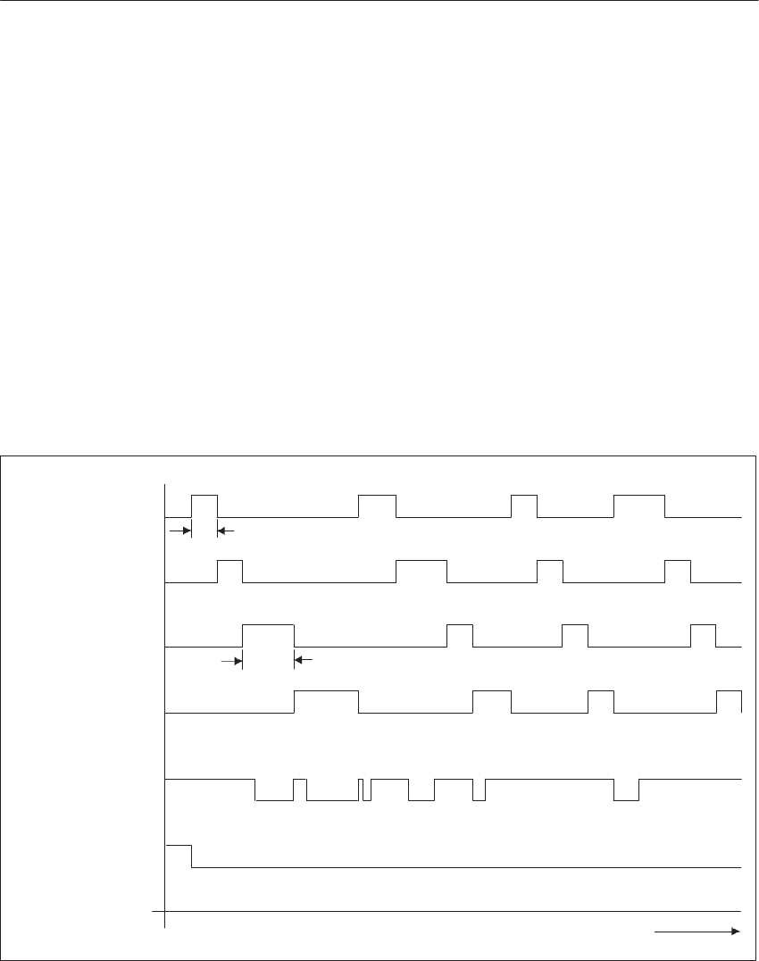
6-16 System Manual
C79000-G8576-C199-06
Bus arbitration
The COR 923A cyclically allocates a bus enable signal to each of the two to
four CPUs in the S5-135U/155U PLC. Only during this time can the relevant
CPU utilize the common S5 bus.
The assignment of bus enable signals takes place in time-division multiplex
operation. On the COR 923A, you set the number of CPUs with jumpers. The
enable time for access to the S5 bus is preset at 2 ms for all CPUs. If the bus
enable signal has been emitted by the coordinator for a CPU, this CPU can
extend the enable time with the bus lock signal. However, the user has no
influence on this.
The bus enable assignment sequence begins with CPU 1 after the
Reset signal is removed by the power supply, and enables the CPUs
in the following order according to the preset number of CPUs:
CPU 1, CPU 2, CPU 3, CPU 4, CPU 1, CPU 2 etc. (see Figure 6-5)
CPUs in Operation
CPU1
CPU2
CPU3
CPU4
Bus Lock
Reset
Bus Enable for:
Time
Bus Lock
2µs
2µs +
Figure 6-5 Timing Sequences of the Bus Signals
Communication memory
The communication memory comprises a central battery-backed RAM in the
PLC. It has two areas: the communication flags and the semaphores.
The communication flags on the COR 923A allow the cyclic interchange of
data between the CPUs. The semaphores are mainly used to coordinate the
exchange of data in the I/O area.
Principle of
Operation
Multiprocessor Operation/Coordinators
6-17
System Manual
C79000-G8576-C199-06
Please consult the Programming Guides of the CPUs to program these
functions.
6.4.2 Settings on the Coordinator
A three-stage mode switch on the front plate serves for user control; it has the
settings RUN, STOP and TEST.
The functions of the mode switch and its use are explained in Sections 6.2
and 6.3.
Mode switch for
RUN, STOP and TEST
Figure 6-6 Front Plate of the COR 923 A
User Control
Multiprocessor Operation/Coordinators

6-18 System Manual
C79000-G8576-C199-06
6.5 923C Coordinator Module
6.5.1 Technical Description
This section contains information on the application, design and principle of
operation of the 923C coordinator.
The 923C coordinator module can be used in the S5-135U/155U
programmable controller and in the EU S5-185U expansion unit. There are
three main task areas which are, to some extent, independent:
Bus arbitration (only in the central controller)
To coordinate multiprocessor operation, i.e. the simultaneous use of two
to four CPUs (CPU 948, CPU 928B, CPU 928, CPU 922).
Communication memory (only in the central controller)
For the interchange of data between CPUs via communication flags and
data blocks.
Central programmer connection (PG MUX)
For the programming and startup of up to 8 modules via one PG
connection.
To program a programmable controller via the SINEC H1 or SINEC
L1/L2 bus, connect the SINEC CP to the PG connection of the COR C
using the 725 cable (“swing” cable).
Application
Multiprocessor Operation/Coordinators

6-19
System Manual
C79000-G8576-C199-06
The COR 923C is designed as a plug-in PCB in double Eurocard format.
Two 48-way Series 2 blade connectors serve to connect the module to the S5
bus in the subrack.
The front plate width is 1 1/3 standard plug-in stations.
A mode switch with three settings is fitted in the front plate for other
operator functions.
Faults are indicated by five small red LEDs.
There is a recess with cover in the upper third of the front plate. By removing
the cover, you can operate the DIL switches to set parameters for the module.
You can connect the COR 923C via a 15-pin front connector to a
programmer, OP, operator control panel or the CP 530 and CP 143.
The COR 923C cyclically allocates a bus enable signal to each of the two to
four CPUs in the S5-135U/155U PLC. Only during this time can the relevant
CPU utilize the common S5 bus.
The assignment of bus enable signals takes place in time-division multiplex
operation. On the COR 923C, you set the number of CPUs with DIL
switches. The enable time for access to the S5 bus is preset at 2 ms for all
CPUs. If the bus enable signal has been emitted by the coordinator for a
CPU, this CPU can extend the enable time with the bus lock signal. However,
the user has no influence on this.
The bus enable assignment sequence begins with CPU 1 after the Reset
signal is removed by the power supply, and enables the CPUs in the
following order according to the preset number of CPUs:
CPU 1, CPU 2, CPU 3, CPU 4, CPU 1, CPU 2 etc. (see Figure 6-7)
Design
Principle of
Operation
Multiprocessor Operation/Coordinators
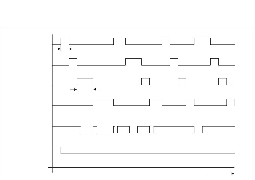
6-20 System Manual
C79000-G8576-C199-06
CPUs in Operation
CPU1
CPU2
CPU3
CPU4
Bus Lock
Reset
Bus Enable for:
Time
Bus Lock
2µs
2µs +
Figure 6-7 Timing Sequences of the Bus Control Signals
Monitoring for continuous bus assignment
The bus lock signal can only be emitted by the CPU which has already
received a bus enable signal from the COR 923C. The bus enable time is
extended by the duration of the bus lock signal for the CPU (see Figure 6-7).
The factory setting for monitoring of the bus lock signal is 2 ms. If the signal
remains active for a longer duration, the COR 923C emits a signal which
results in a Stop of all CPUs.
The CPU which emitted the bus lock signal for too long a duration, is marked
by the CPU in a readable register under address FEFFH (fault register, see
Figure 6-8). The assigned BUS FAULT LED in the front plate of the COR
923C lights up. The register is cleared and the LED goes off again when the
signal which led to the Stop state becomes inactive.
Communication memory
The communication memory comprises a central battery-backed RAM in the
PLC. It has three areas: 1) the communication flags (256 bytes), 2) the
semaphores (32), and 3) four memory pages.
The communication flags are located in memory area F200H to F2FFH. The
communication flags enable the cyclic interchange of small volumes of data
between the CPUs in the S5-135U/155U PLC. The four memory pages serve
for the exchange of data blocks between CPUs.
Please consult the Programming Guides of the CPUs to program these two
functions.
Multiprocessor Operation/Coordinators

6-21
System Manual
C79000-G8576-C199-06
The semaphores are used to coordinate the CPUs for access to the same I/O
address (see Programming Guides, operations SES and SEF).
Page Memory for
Data Blocks
Vector Register for
Page Selection,
Fault Register
Synchronization Area
for Operating Systems
Communication Flags
FEFFH
F7FFH
F400H
F300H
F200H
Page
No. 253
Page
No. 254
Page
No. 255
Page
No. 252
Figure 6-8 Areas of the Communication Memory on the S5 Bus
Addressing method for the page memory (vector register)
The vector register serves to form subaddresses of several memories in a
common address area. The register is an 8-bit register which is written to
under address FEFFH. It cannot be read out.
The page memory contains four pages of 1 Kbyte. An identification number
is assigned to each page. These are the numbers 252, 253, 254 and 255.
These numbers are permanently set on the COR 923C and cannot be
changed. You must not use these numbers on other modules (CP, IP) in the
same PLC otherwise double addressing will occur.
When the supply voltage is switched on, the vector register is cleared. The
vector register then has the number 0H.
The transfer of data to and from this memory is implemented with special
functions of the CPU. You can find these functions in the appropriate
Programming Guides.
The PG interface of the COR 923C can be switched over to eight different
serial interfaces via the path selection of the PG software.
The multiplex interfaces have TTL level and are wired to the other modules
via the backplane connector and backplane.
PG Multiplexer
Multiprocessor Operation/Coordinators

6-22 System Manual
C79000-G8576-C199-06
Station numbers are assigned to all the modules to be served by the
multiplexer in the unit. These numbers must be within the range 1 to 31
(decimal). You set the lowest of these numbers, the base address, with DIL
switch S2 in binary code. The maximum of eight numbers are allocated to
the slots of the PLC (see following table).
All eight numbers or slots are assigned to switch S3: the lowest number to
switch S3.1, and the highest number to switch S3.8. The setting of station
numbers and the base address are described in more detail in Section 6.5.2.
Switch Slot Station No.
S3.1
S3.2
S3.3
S3.4
S3.5
S3.6
S3.7
S3.8
11
27
43
59
75
83
91
99
Base address
Base address + 1
Base address + 2
Base address + 3
Base address + 4
Base address + 5
Base address + 6
Base address + 7
If slots are not occupied or if you wish to operate modules via their own front
connectors, you must delete the numbers assigned to the corresponding slots
with switch S3.
Note
For a module operated via the multiplexer, the front connector of the PG
interface of the CPU must not be plugged in. With CPUs 948 and 928B,
this only applies to the integrated PG interface SI 1.
Selection Method
for the Serial
Interfaces
Multiprocessor Operation/Coordinators
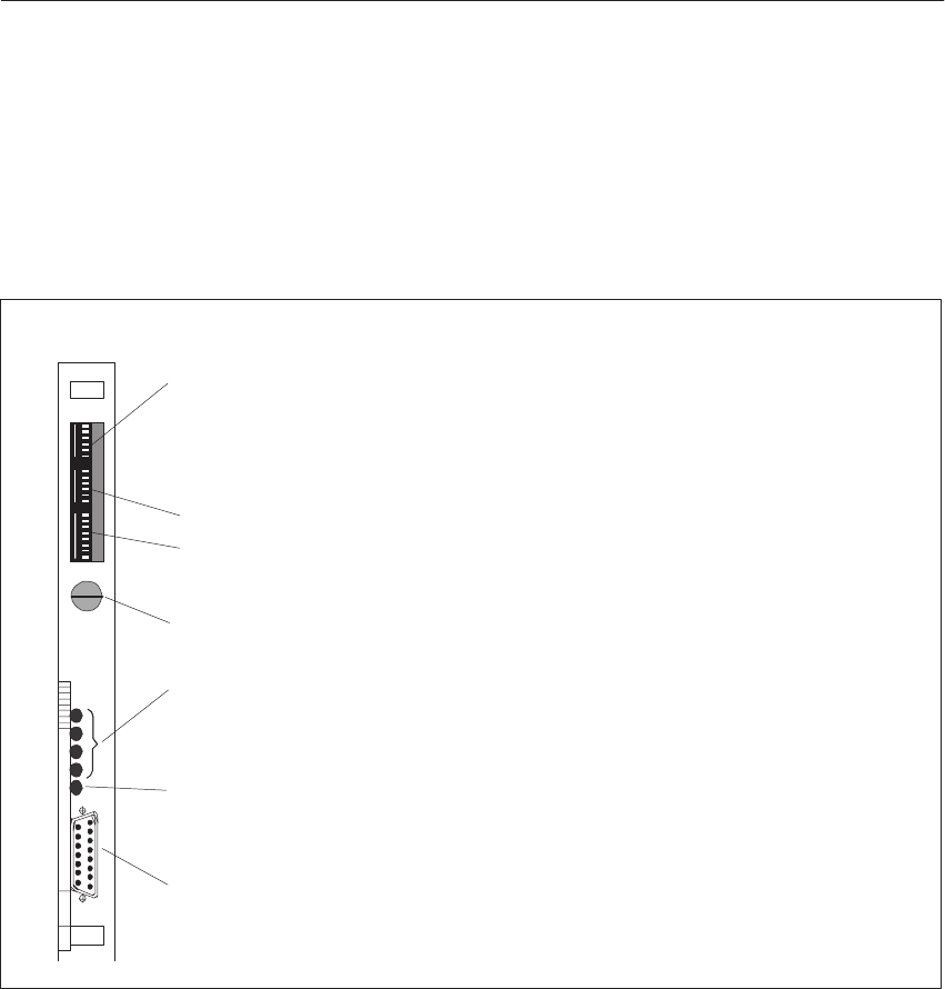
6-23
System Manual
C79000-G8576-C199-06
6.5.2 Settings on the Coordinator
Shown in Figure 6-9 are all the indicators and controls on the front plate of
the COR 923C.
Setting the PG Multiplexer:
S1.3 to enable/lock out the “Test” mode
S1.4 to S1.6 to set the number of CPUs
Setting the Coordination Section:
S2.2 to S2.6: Base address
S3.1 to S3.8: Activating the slots to be served by the COR923C
Mode switch for RUN, STOP and TEST
PG interface, 15-pin
“IF FAULT” LED
indicates fault at the serial interface.
If the interface is not in use, the LED is permanently lit.
“BUS FAULT” LEDs
These are allocated to the relevant CPUs and light up when the max. value of
monitored bus access time is exceeded.
Figure 6-9 Front plate of the COR 923C
The mode switch on the front plate can be set to RUN, STOP and TEST.
Please refer to Sections 6.2 and 6.3 for its functions and use.
Indicators and
Controls
Mode Switch
Multiprocessor Operation/Coordinators

6-24 System Manual
C79000-G8576-C199-06
Note
On switch S1, the On position is on the left; on switches S2 and S3, however,
it is on the right (see Figure 6-10).
on off
on
on
off
off
Figure 6-10 DIL Switches on the COR 923C (Settings when Delivered)
You set the number of CPUs present in the PLC with the 3 DIL switches S1.4
to S1.6. You may only set one switch.
The factory setting is “Number of CPUs = 2” (see below).
Factory setting:
Switch Setting Meaning
on off
S1.1 x –
S1.2 x –
S1.3 x Test mode (see also Sec. 6.3)
S1.4 xNumber of CPUs = 2
S1.5 xNumber of CPUs = 3
S1.6 xNumber of CPUs = 4
Setting the DIL
Switches
Coordination
Section (Number
of CPUs)
Multiprocessor Operation/Coordinators

6-25
System Manual
C79000-G8576-C199-06
You set a base address from 1 to 31 with DIL switch S2. You can reference
the modules selected by the multiplexer under this address and the following
seven addresses. The base address results from the sum of binary
significances activated by the On setting of the switch.
Factory setting:
Switch Setting Meaning
off on
’0’ ’1’
S2.1 x –
S2.2 x Significance 16
S2.3 xSignificance 8
S2.4 xSignificance 4
S2.5 xSignificance 2
S2.6 x Significance 1 (base address = 1)
You use switch S3 to activate the numbers and slots to be reached via the
COR 923C.
Factory setting:
Switch Setting Meaning Slot No. in the
S5 135U/155U
off on S5-135U/155U
S3.1 xBase address + 0 11
S3.2 xBase address + 1 27
S3.3 xBase address + 2 43
S3.4 xBase address + 3 59
S3.5 xBase address + 4 75
S3.6 xBase address + 5 83
S3.7 xBase address + 6 91
S3.8 xBase address + 7 99
An example for setting the PG multiplexer is given on the following page.
PG Multiplexer:
Base Address
PG Multiplexer:
Activating
Addesses
Multiprocessor Operation/Coordinators
6-26 System Manual
C79000-G8576-C199-06
You wish to reference modules at Slots 11, 59, 75 and 99 in the
S5-135U/155U PLC via the COR 923C, from base address 10.
Setting the base address:
Switch Setting Meaning
off on
Base address:
S2.1 x –
S2.2 x Significance 16
S2.3 xSignificance 8 8
S2.4 x Significance 4
S2.5 xSignificance 2 +2
S2.6 x Significance 1
=10
Activating the required slots for the S5-135U/155U PLC:
Switch Setting Meaning Slot No. in the
S5-135U/155U Operable Slots End
Address
off on
S3.1 xBase address + 0 11 11 10
S3.2 xBase address + 1 27
S3.3 xBase address + 2 43
S3.4 xBase address + 3 59 59 13
S3.5 xBase address + 4 75 75 14
S3.6 xBase address + 5 83
S3.7 xBase address + 6 91
S3.8 xBase address + 7 99 99 17
Example of
Address Activation
Multiprocessor Operation/Coordinators

6-27
System Manual
C79000-G8576-C199-06
All the output signals required for coordination (arbitration) can be
interrupted by removing a jumper plug. This is necessary to operate the COR
923C as a PG multiplexer in the EU S5-185U.
Coordination Section
in operation out of operation
All jumpers of EP 61 closed All jumpers of EP 61 open
18
EP 61
916
When the unit is delivered, all jumpers are closed.
The fault register is an 8-bit register and is readable by the CPU under
address FEFFH. The register is written to by the bus monitor in the event of a
bus error. Each CPU is assigned one bit of the fault register which is set to 1
in the event of an error. The register is cleared each time the Stop signal
becomes inactive.
Fault register FEFFH
Bit = 1: Bus error from CPU 1
Bit = 2: Bus error from CPU 2
Bit = 3: Bus error from CPU 3
Bit = 4: Bus error from CPU 4
7 4 3210
Not assigned
The fault register can be read by all CPUs, allowing central functions to be
initiated.
Note
The fault register and the page register are at address FEFFH (FFEFFH with
the CPU 948). The page register is addressed by writing to FEFFH, and the
fault register is addressed by reading out FEFFH.
Jumpers to
Switch off the
Coordination
Signals
Fault Register
Multiprocessor Operation/Coordinators

6-28 System Manual
C79000-G8576-C199-06
6.6 Technical Specifications of the Coordinators
Important for the USA and Canada
The following approvals have been obtained:
SUL Listing Mark
Underwriters Laboratories (UL) to Standard UL 508, Report E 85972
SCSA Certification Mark
Canadian Standard Association (CSA) to Standard C 22.2 No. 142,
Report LR 63533
923A Coordinator 923C Coordinator
Degree of protection IP 00
Operating temperature 0 to +55 _C
Transportation and storage
temperature 40 to +70 _C
Relative humidity 95% max. at +25 _C, no condensation
Operating altitude 3500 m max. above sea level
Supply voltage 5 V $ 5% 5 V $ 5%
24 V +25%/ –15%
Current consumption at 5 V 0.5 A typical 1.1 A typical
Current consumption at 24 V –60 mA
Minimum backup voltage 2.7 V
Backup current 100 nA typical 2 mA typical
Acknowledgement time for
access to communication
memory via S5 Bus
320 ns typical
Transmission rate of the serial
interface –9600 bps
Transmission cable –Shielded 4-wire line, PG
connecting cable
Transmission range –1 km max. at 9600 bps
Weight Approx. 0.3 kg
Dimensions (W x H x D) 20.32 x 233.4 x 160 mm
Multiprocessor Operation/Coordinators

7-1
System Manual
C79000-G8576-C199-06
Interface Modules
Various interface modules (IMs) are available for communication between a
central controller and expansion units, and between expansion units.
Interface modules in the central controller are known as EU interface
modules; those inserted in an EU are known as CC interface modules.
This chapter describes the EU interface modules:
IM 300-3, IM 300-5, IM 301-3, IM 301-5 and IM 304
as well as the CC interface modules:
IM 312-3, IM 312-5, IM 310 and IM 314
Other IMs such as the IM 307-IM 317 and the IM 308-IM 318 are described
in separate manuals (see Catalog ST 54.1). The IM 306 CC interface module
is described in the S5-115U PLC manual.
A general overview of the applications of individual IMs can be found in
Chapter 2: “Centralized and Distributed Configuration of a Programmable
Controller.”
Section Description Page
7.1 The 300 and 312 Interface Modules 7-2
7.2 The 301 and 310 Interface Modules 7-9
7.3 The 304 and 314 Interface Modules 7-13
7.4 Technical Specifications 7-20
Chapter
Overview
7

7-2 System Manual
C79000-G8576-C199-06
7.1 The 300 and 312 Interface Modules
The 300 and 312 interface modules are used for centralized connection of
I/O modules and signal preprocessing modules (IPs) to a CC via the
following expansion units (allowing for possible configurations):
EU 183U
EU 184U
EU 185U (only input/output modules)
EU 187U
ER 701-1
Additionally, you can utilize these IMs for secondary communication, i.e.
additional EUs can be connected in a centralized arrangement to an EU 183U
or EU 185U in distributed configuration. Up to four IM 300s can be used in
one CC, up to two of which may be IM 300-5s. You can use one IM 300 in
an EU 183U or EU 185U.
An IM 300 EU interface module is complemented by an IM 312 or
IM 306 CC interface module. Use the following IMs, depending on the
connected EU:
EU Interface Module EU Type CC Interface Module
IM 300-5 C
(6ES5 300-5CA11) EU 184U, EU 187U IM 312-5
IM 300-3
(6ES5 300-3AB11) EU 183U
EU 185U (only I/O
modules)
IM 312-3
IM 300-5 L
(6ES5 300-5LB11) ER 701-1 IM 306
There are two versions of IM 312-3 and IM 312-5. They differ in the length
of permanently connected cable:
Order No. Cable Length
6ES5 312-5CA1X
6ES5 312-5CA2X 0.5 m
1.5 m
6ES5 312-3AB1X
6ES5 312-3AB3X 0.5 m
0.95 m
Application of the
IM 300 and IM 312
Interface Modules

7-3
System Manual
C79000-G8576-C199-06
For one IM 300-5, you can connect up to three EUs to a CC or EU in
distributed arrangement (see Figures 7-5 and 7-6). The EUs are supplied with
operating voltage via the IMs. Any free connections on the IM 300-5 and the
last IM 312-5 require no terminator.
Note
The maximum permissible current over each connection of the
IM 300-5CA11 is 5 A.
You can connect up to four EUs to each IM 300-3. The last IM 312-3
requires a terminator.
You can connect up to three ERs to each IM 300-5L (-5LB11). The ERs are
supplied with operating voltage via the IMs.
Note
The maximum permissible current over each connection of the
IM 300-5LB11 is 2 A.
The connection of central controller and expansion unit to the IM 300-5LB11
is provided exclusively by the 705-0 connecting cable. It is available in two
lengths: 0.5 m and 1.5 m (refer to the ordering information for order
numbers).
When the IM 300s are used in the S5-135U/155U PLC, the input/output
modules can be addressed in the normal (P) and extended (O) areas.
You may only set module addresses in the EU which are not used in the CC.
This applies to both areas.
Connecting the
EU 184U and
EU 187U
Connecting the
EU 183U, EU 185U
Connecting the
ER 701-1
Addressing
Interface Modules
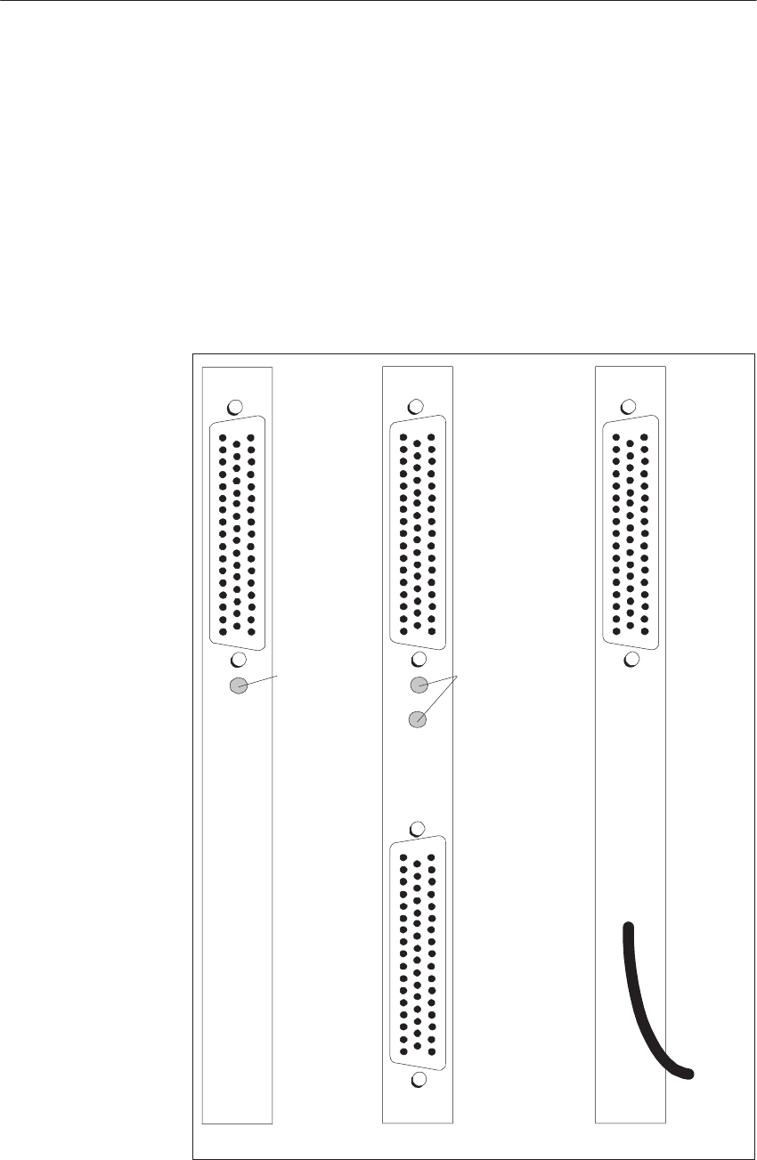
7-4 System Manual
C79000-G8576-C199-06
7.1.1 Indicators and Controls
IM 300-3:
I/O Module Failure LED
This LED lights up if the supply of power to the connected EUs has failed
and/or the connecting cable is open-circuit.
IM 300-5 (-5CA11):
I/O Module Failure LEDs
LEDs LD1 and/or LD2 light up if a module inserted in the EU no longer
responds to an access by the CPU.
The IM 312 has no indicators or controls.
50
34 18
33 17
1
IM312
Fault
50
34 18
33 17
1
50 33 17
34 18 1
IM300-5
Fault
I/O Module
Fault
50
34 18
33 17
1
IM300-3
Failure I/O Module
Failure
Figure 7-1 Front Plates of the IM 300 and IM 312
Interface Modules
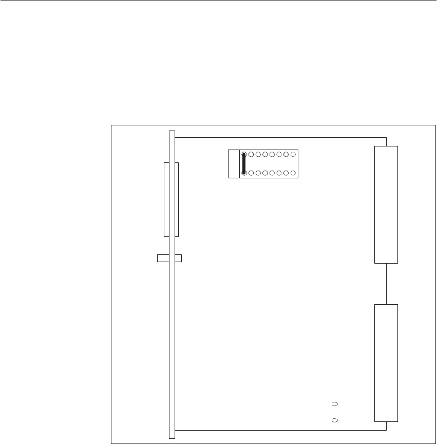
7-5
System Manual
C79000-G8576-C199-06
7.1.2 Modes/Jumper Assignments of the IM 300
IM 300-3
X1
X2
12
16 9
8
1
J1
X3
LED 1
Figure 7-2 Location of Jumpers on the IM 300-3 (when Delivered)
You must insert an additional jumper 4-13 at location 12 for address setting
in the extended I/O area (O area).
Jumper 1 is open and has no function for operation in the S5-135U/155U
PLC.
Jumper
Assignments
Purpose of the
Jumpers
Interface Modules
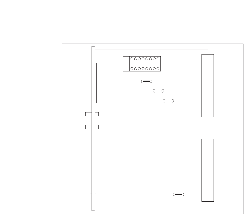
7-6 System Manual
C79000-G8576-C199-06
IM 300-5 (-5CA11)
X1
X2
4
16 9
8
1
J2
J1
J3
J8
X3
X4
LED1
LED2
Figure 7-3 Location of Jumpers on the IM 300-5 (-5LB11) (when Delivered)
You must insert jumper 8-9 at location 4 for address setting in the extended
I/O area (O area). All other jumpers must remain in their factory settings.
Jumper
Assignments
Interface Modules
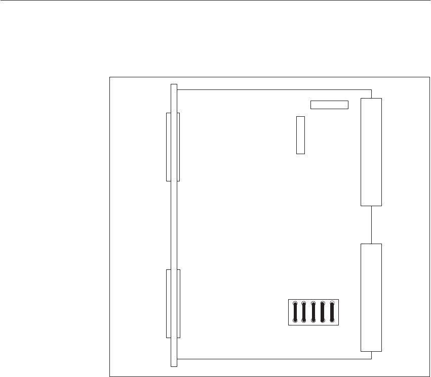
7-7
System Manual
C79000-G8576-C199-06
IM 300-5 (-LB11)
X1
X2
X3
X4
M1
P1
Q1 Q2 Q3 Q4 Q5
Figure 7-4 Location of Jumpers on the IM 300-5 (-5LB11) (when Delivered)
You must insert jumpers Q1 to Q4 for addressing in the normal (P) area.
If you insert jumper Q5, the “I/Os not ready” message will be relayed to the
CPU.
All other jumpers must remain in their factory settings.
Shown in the following figures is the centralized communication between
central controller and expansion units, with and without supply of power via
the IM 300 and IM 312.
Jumper
Assignments
Interface Modules

7-8 System Manual
C79000-G8576-C199-06
IM 300-3
EU183U IM 312-3
EU183U IM 312-3
EU183U IM 312-3
EU183U IM 312-3
S5-135U/155U
CC
Terminator
Total Length of Lines 2 m max.
Figure 7-5 Centralized Communication Between Central Controller and Expansion Units with a Power Supply
Unit
IM300-5S5-135U/155U
CC
IM312-5
IM312-5
IM312-5
(1.5m)
IM 312-5
EU 184U
EU 187U
EU 184U
EU 187U
EU 184U
EU 187U
EU 184U
EU 187U
EU 184U
EU 187U
IM 312-5
(0.5m)
With this arrangement, the two
cabinets must be electrically
interconnected.
5 A max.
5 A max.
Total Length of Lines 2 m max.
Figure 7-6 Centralized Communication Between Central Controller and Expansion Units without a Power Supply
Unit
The EU with the highest current consumption should be positioned as closely
as possible to the CC.
Interface Modules

7-9
System Manual
C79000-G8576-C199-06
7.2 The 301 and 310 Interface Modules
The IM 301 is used to connect I/O modules and signal preprocessing modules
(IPs) to a CC in a distributed arrangement (allowing for possible
configurations) via an
EU 183U
EU 185U (only input/output modules)
expansion unit.
You can connect up to four EUs to a CC in distributed arrangement via the
IM 301. If you use the 721 connecting cable, the total cable length from the
CC to the last EU may be up to 200 m. The distributed connection is made
via the lower front connector of the module. Use the IM 310 interface
module in the EU to be connected in a distributed arrangement:
EU Interface Module EU Type CC Interface Module
IM 301 EU 183U,
EU 185U (only I/O
modules)
IM 310
Apart from the distributed EUs, you can connect the following expansion
units in a centralized arrangement:
EU 183U
EU 184U
EU 187U
The centralized connection is made via the upper front connector of the
module. Use the following interface modules, according to the EU to be
connected in a centralized arrangement:
EU Interface Module EU Type CC Interface Module
IM 301-5 EU 184U, EU 187U IM 312-5
IM 301-3 EU 183U IM 312-3
Unused centralized connections of the IM 301-3 and unused distributed
connections of the IM 301-3 and IM 301-5 must be terminated with
terminators. The same applies to the last IM 310.
You may only set module addresses in the EU which you are not yet using in
the CC. This applies to the normal (P) and extended (O) areas.
Interface Modules
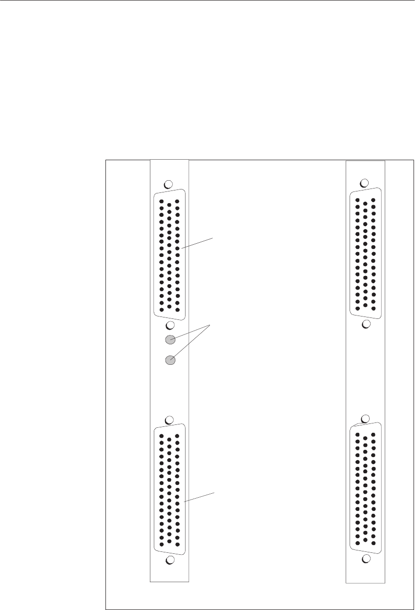
7-10 System Manual
C79000-G8576-C199-06
7.2.1 Indicators and Controls
IM 301:
Fault LEDs
When the CPU is restarted, the red LED 1 and/or LED 2 lights up if the
internal supply voltage (5 V DC) or external load voltage (24 V DC) fails.
The IM 310 has no indicators or controls.
Fault
Fault
50
34 18
33 17
1
50 33 17
34 18 1
50
34 18
33 17
1
50 33 17
34 18 1
IM 301 IM 310
Fault
Centralized
Connection
Distributed
Connection
Figure 7-7 Front Plate of the IM 301 and IM 310
Interface Modules
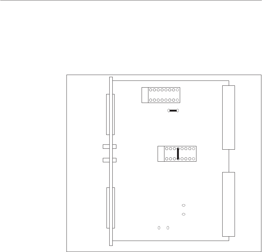
7-11
System Manual
C79000-G8576-C199-06
7.2.2 Modes/Jumper Assignments of the IM 301
X1
X2
7
16 9
8
1
J3
J1
X3
X4
LED1
LED2
27
16 9
8
1
J4 *)
*) Not on the IM 301-5
Figure 7-8 Location of Jumpers on the IM 301 (when Delivered)
You must insert jumper 8-9 at location 7 for address setting on the extended
I/O area (O area). All other jumpers must remain in the factory settings.
Jumper
Assignments
Interface Modules

7-12 System Manual
C79000-G8576-C199-06
The following figures show distributed communication between central
controller and expansion units via the IM 301 and IM 310.
Terminator
760–0AB11
IM301–3
EU 183U
CC
S5–135U/155U
To Additional Expansion Cabinets
(up to 4 per IM 301)
IIM312–3
200m max.
EU183U
EU 183U
IIM312–3
IM300–3
IM 310
EU 184U
EU 183U
IM 312–5
IM 300–5
IM 310
EU 187U
All 721 Connecting Cables
Additional EU 184U, EU 187U
(Centralized)
Additional EU 183U
(Centralized)
760–0AA11 Terminator
Figure 7-9 Connection of EU 183Us to the Central Controller via the IM-301-3
IM 301–5
EU 184U
CC
S5–135U/155U
IM 312–5
EU 187U
Additional EU 184U, EU 187U
(Centralized)
to Additional Expansion Cabinets
(up to 4 per IM 301)
760–0AA11
Terminator
EU 183U
EU 183U
IM 312–3
IM 300–3
IM 310
EU 184U
EU 183U
IM 312–5
IM 300–5
IM 310
EU 187U
All 721 Connecting Cables
Additional EU 184U, EU187U
(Centralized)
760–0AA11 Terminator
Figure 7-10 Connection of EU 184/EU 187 U to the Central Controller via the M 301-5
Interface Modules

7-13
System Manual
C79000-G8576-C199-06
7.3 The 304 and 314 Interface Modules
The IM 304 and IM 314 are used to connect I/O modules, signal
preprocessing modules (IPs) and communication processors (CPs) to a CC in
a distributed arrangement via the
EU 185U
ER 701-3
expansion units.
You can also use the IM 304 and IM 314 to connect I/O modules to a CC in a
distributed arrangement via the
EU 183U
ER 701-2
expansion units.
You can connect up to two-times four EUs in a distributed arrangement via
one IM 304. If you utilize the 721 connecting cable, the total line length from
the CC to the last EU may be 600 m per run. You can connect additional EUs
in a centralized arrangement to the distributed EUs.
You can insert up to four IM 304s in one CC.
The IM 304 EU interface module is complemented by the IM 314 CC
interface module. In fault-tolerant systems, you must use the IM 314R CC
interface module together with the IM 304 (refer to the S5-155H manual).
EU Type EU Interface Module CC Interface Module
EU 183U
EU 185U
ER 701-2
ER 701-3
IM 304 IM 314
You may only set module addresses in the EU which you do not use in
the CC. This also applies when the EU is addressed in the extended (O) area,
IM3 area or IM4 area.
Line Length
Interface Modules
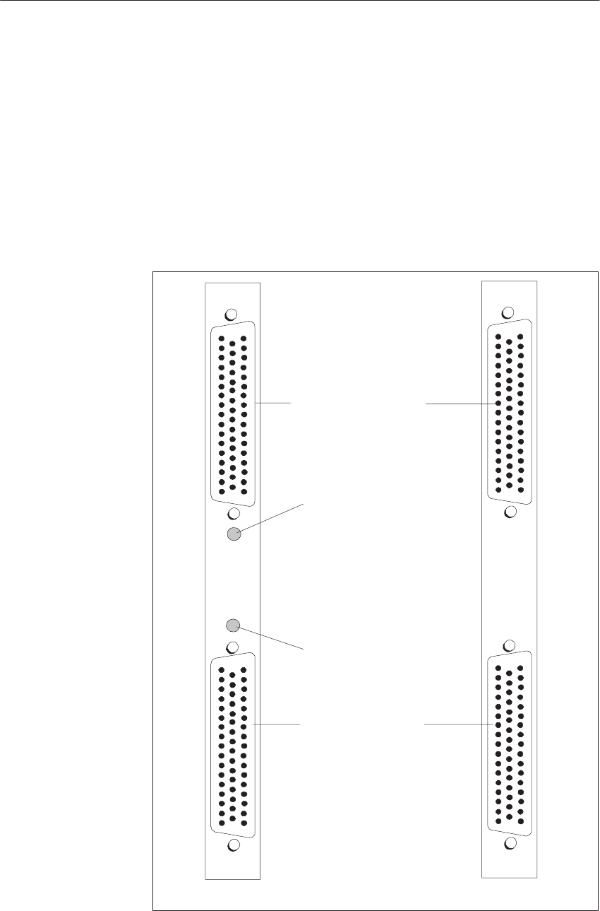
7-14 System Manual
C79000-G8576-C199-06
7.3.1 Indicators and Controls
Fault LEDs
A FAULT LED lights up
if the power supply fails in an expansion unit;
if there is no terminator at the last IM 314;
in the event of a cable open-circuit or wrong setting of DIL switch S3 for
the IM 304;
or if an EU which is ready and operational is connected to an interface
which is switched off.
Interface (X3)
Interface(X4)
Interface (X4) Faulty
Fault Signal:
Interface (X3) Faulty
Fault Signal:
Fault
Fault
50
34 18
33 17
1
5033 17
34 18 1
50
34 18
33 17
1
50 33 17
34 18 1
IM 304 IM 314
Figure 7-11 Front Plates of the IM 304 and IM 314
Interface Modules
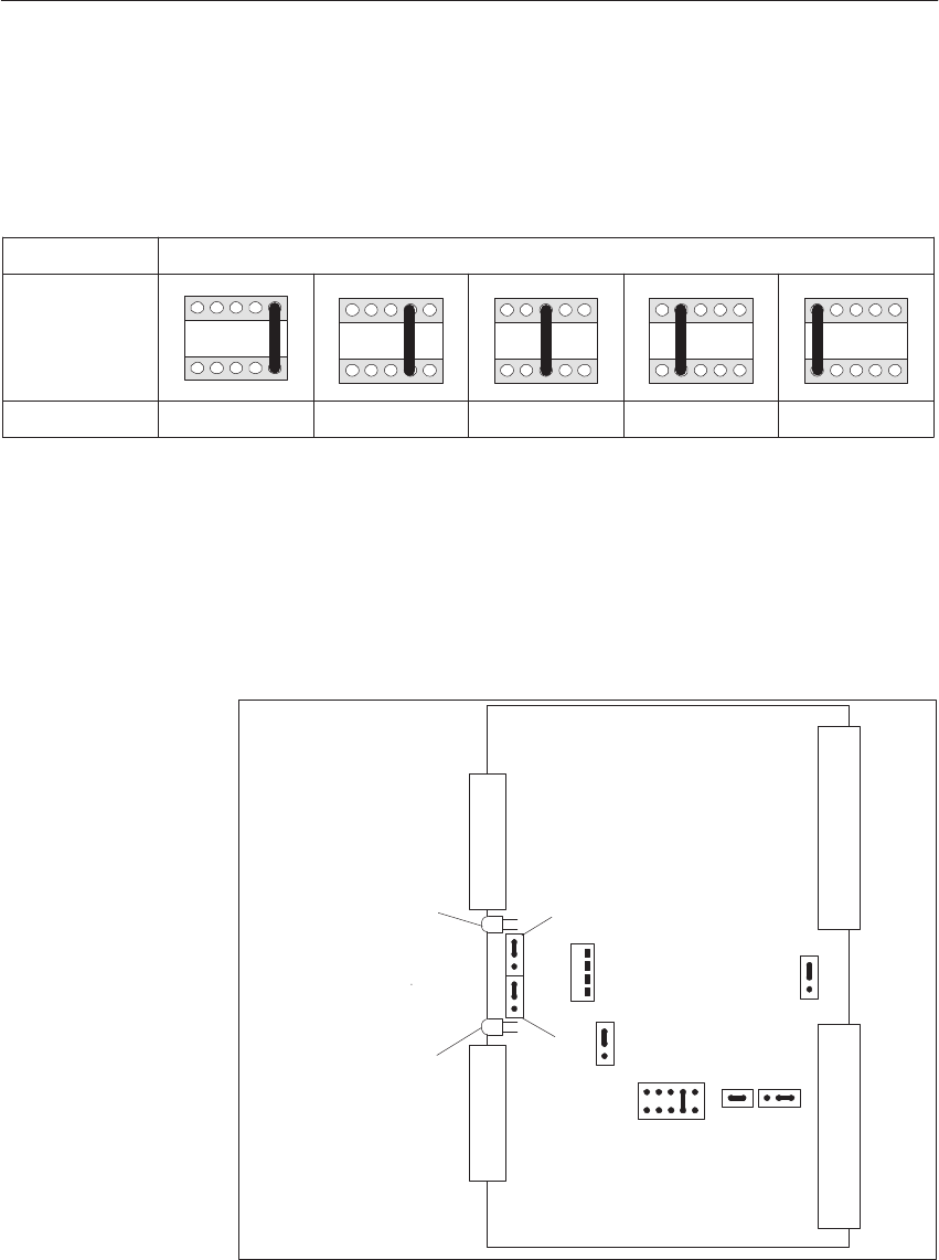
7-15
System Manual
C79000-G8576-C199-06
7.3.2 Modes/Jumper Assignments of the IM 304
You must match the IM 304 to the cable length with jumper X11.
Cable Length 10m max. 100m max. 100 to 250m 250 to 450m 450 to 600m
Jumper
Location
Jumper Plug X11
9 7 5 3 1
10 8 6 4 2
*)
9 7 5 3 1
10 8 6 4 2
9 7 5 3 1
10 8 6 4 2
9 7 5 3 1
10 8 6 4 2
9 7 5 3 1
10 8 6 4 2
*) This setting is only permissible for IM 304 - IM 324R communication in the S5-155H PLC.
The longest communication path, i.e. the sum of cable lengths at interface of
X3 or X4, is governed by the location of jumper X11.
X3
X4
X1
X2
LED2
LED1
S3
X14
X15
X12
X11
X13
X21
X22
ON
OFF
ON
OFF
Jumper X21/X22
set to OFF if no
expansion unit is
connected. 1
2
3
1
2
3
3 2 1
1
2
3
4
5
6
7
8
9
10
ON
OFF
Figure 7-12 Location of Jumpers on the IM 304 (when Delivered)
Jumper
Assignments
Interface Modules

7-16 System Manual
C79000-G8576-C199-06
Function Jumper Settings
Interface X3/X4
– Switched on
– Switched off 1) X22/X21 at “ON”
X22/X21 at “OFF”
ON
OFF
ON
OFF
“I/Os not ready” message relayed
– no
– yes X15 no jumpers
X15 jumper 1-2
1
2
3
1
2
3
“I/Os not ready” message when
– 1 interface not ready
– 2 interfaces not ready X14 jumper 1-2
X14 jumper 2-3
1
2
3
1
2
3
Set cable length between 304 / 314
– 0 to 100 m
– 100 to 250 m
– 250 to 450 m
– 450 to 600 m
X11
Jumper 3-4
Jumper 5-6
Jumper 7-8
Jumper 9-10
9 7 5 3 1
10 8 6 4 2
1) Jumper X22 is assigned to interface X3.
Jumper X21 is assigned to interface X4
All other jumpers and switches must remain at the factory settings.
Purpose of the
Jumpers
Interface Modules
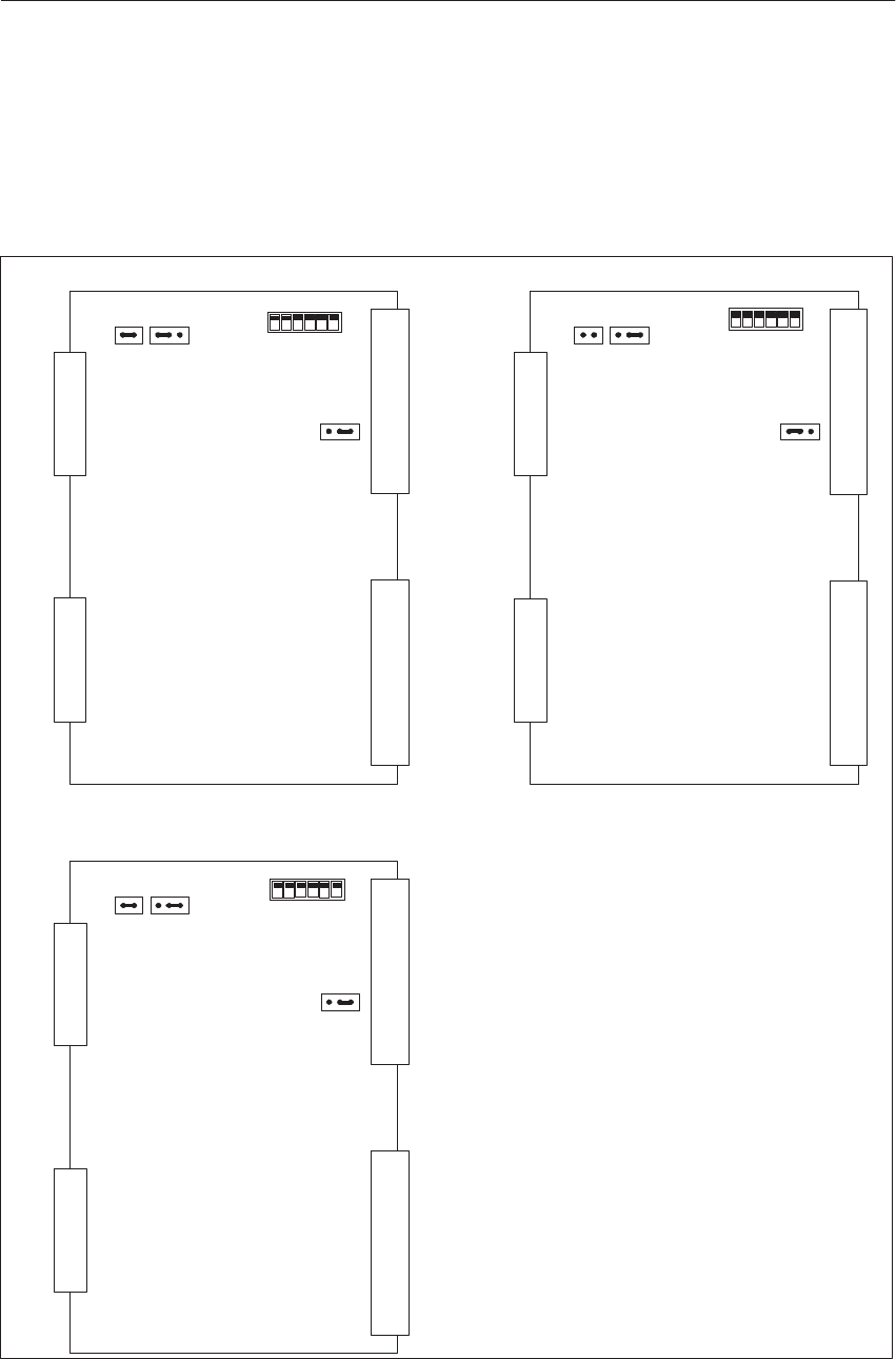
7-17
System Manual
C79000-G8576-C199-06
7.3.3 Modes/Jumper Assignments of the IM 314
Set the jumpers according to the expansion unit in use.
X3
X4
X1
X2
12312
1
23
J1 J2
J3
Operation in the EU1 83U
X3
X4
X1
X2
1
23
1
2
123
J1 J2
J3
Operation in the EU 185U
X3
X4
X1
X2
12312
1
23
J1 J2
J3
Operation in the ER 701-2, ER 701-3 (S5-115U)
off
S1 on
off
S1 on
off
S1 on
Figure 7-13 Location of Jumpers on the IM 314
Jumper
Assignments
Interface Modules
7-18 System Manual
C79000-G8576-C199-06
I/O Area Address Switch Setting
0 = OFF, 1 = ON
P area: F000 - F0FF S1: 0000 *)
OFF
n
i
irrelevant
O area: F100 - F1FF 0001
OFF
ON
i
c
h
t
r
IM3 area:FC00 - FCFF 1100
r
e
l
e-
v
IM4 area:FD00 - FDFF 1101
v
a
n
t
*) Factory setting
The I/O area address is set on the IM 314. This setting applies only to the
digital and analog I/O modules.
Address areas P, O, IM3 and IM4 are available. To address the digital and
analog I/O modules in these areas, set the switches by depressing the
individual rockers.
In the STEP 5 standard operation set, you only address the P and O areas.
Module addresses used in the CC cannot be used in the EU in the P area, O
area, IM3 area and IM4 area.
If you do not insert I/O modules in the central controller, an address space of
256 bytes is available in each I/O area for input/output addresses.
The following figure shows communication between the central controller
and expansion units via the IM 304 and IM 314.
Setting the
Addresses
Interface Modules

7-19
System Manual
C79000-G8576-C199-06
(up to 4 per IM 304)
600m max.
IM304
To Additional Expansion Cabinets (Distributed)
EU 183U
EU 183U
IM 312–3
IM 300–3
IM314
EU 184U
EU 183U
IM 312–5
IM 300–5
IM 314
EU 187U
All 721 Connecting Cables
760–1AA11 Terminator
CC
S5–135U/155U EU 185U EU 185U
IM 300–3
IM 312–3
EU 183U
IM 312–3
IM 300–3
EU 184U
EU 183U
IM 312–5
IM 300–5
IM 314
EU 187U
Additional EU 184U, EU 187U
(Centralized)
760–1AA11 Terminator
EU 183U
EU 183U
EU 183U
EU 185U EU 185U EU 185U
IM 314
IIM 314
All 721 Connecting Cables
Figure 7-14 Communication Between Central Controller and Expansion Units via the IM 304/IM 314
Interface Modules

7-20 System Manual
C79000-G8576-C199-06
7.4 Technical Specifications
Important for the USA and Canada
The following approvals have been obtained:
UL Listing Mark
Underwriters Laboratories (UL) to
Standard UL 508, Report E85972 and E116536 for the IM 300-5LB11
CSA Certification Mark
Canadian Standard Association (CSA) to Standard C 22.2 No. 142,
Report LR 63533C and LR 48323 for the IM 300-5LB11
Given in the following are the technical specifications of the IMs and pin
assignments of the connecting cable and terminator.
General Specifications
Degree of protection IP 20
Insulation class C to VDE 0160
Operating temperature 0 to 55 oC
Transportation and storage temperature – 40 to 70 oC
Relative humidity 95 % max. at 25 oC, no condensation
Mechanical requirements see description of central controllers
Supply voltage (internal) 5 V + 5 %
Specifications for Specific IMs
Interface
module IM 300 IM 300
(-5CA) IM 300
(-5LB) IM 301
(-5CA) IM 301
(-3AB) IM 304 IM 310 IM 312 IM 314
Max. cur-
rent con-
sumption
0.6 A 0.6 A 50 mA 0.75 A 0.75 A 1.2 A 0.7 A 0.2 A 1.0 A
Max. cur-
rent per in-
terface
– 5 A 2 A 5 A – – – – –
Weight,
approx. 0.35 kg 0.35 kg 0.25 kg 0.3 kg 0.3 kg 0.35 kg 0.3 kg 0.35 kg 0.3 kg
7.4.1 6ES5 721 Connecting Cable
The 6ES5 721-xxx connecting cable is intended for interconnection of the
CC/EUs. Refer to the catalog for the SIMATIC length codes.
Interface Modules
7-21
System Manual
C79000-G8576-C199-06
.34
.150 .
17 .1.
34 .
.17
.50
Shield
6rd
5wh
4wh
3wh
2gn
1rd
Red
No. 16
Green
No. 17
Yellow
No.18
Brown
No.19
Black
No.20
Blue
No.21
Connector
50-Way Terminal Bundle
ID Sheath ID Foil
20
21
4
5
18
19
2
3
24
25
8
9
22
23
6
7
26
27
10
11
42
43
44
45
28
29
12
13
46
47
30
31
34
35
36
37
38
39
40
41
48
49
14
15
32
33
Connector
50polig Terminal
Core
Color
wh
br
gn
ye
gr
pk
bl
rd
wh
br
gn
ye
gr
pk
bl
rd
wh
br
gn
ye
gr
pk
bl
rd
wh
br
gn
ye
gr
pk
bl
rd
wh
br
gn
ye
gr
pk
bl
rd
wh
br
gn
ye
gr
pk
21
4
5
18
19
2
3
24
25
8
9
22
23
6
7
26
27
10
11
42
43
44
45
28
29
12
13
46
47
30
31
34
35
36
37
38
39
40
41
48
49
14
15
32
33
20
–
–
Figure 7-15 Conductor Assignments of the 721 Connecting Cable
Interface Modules
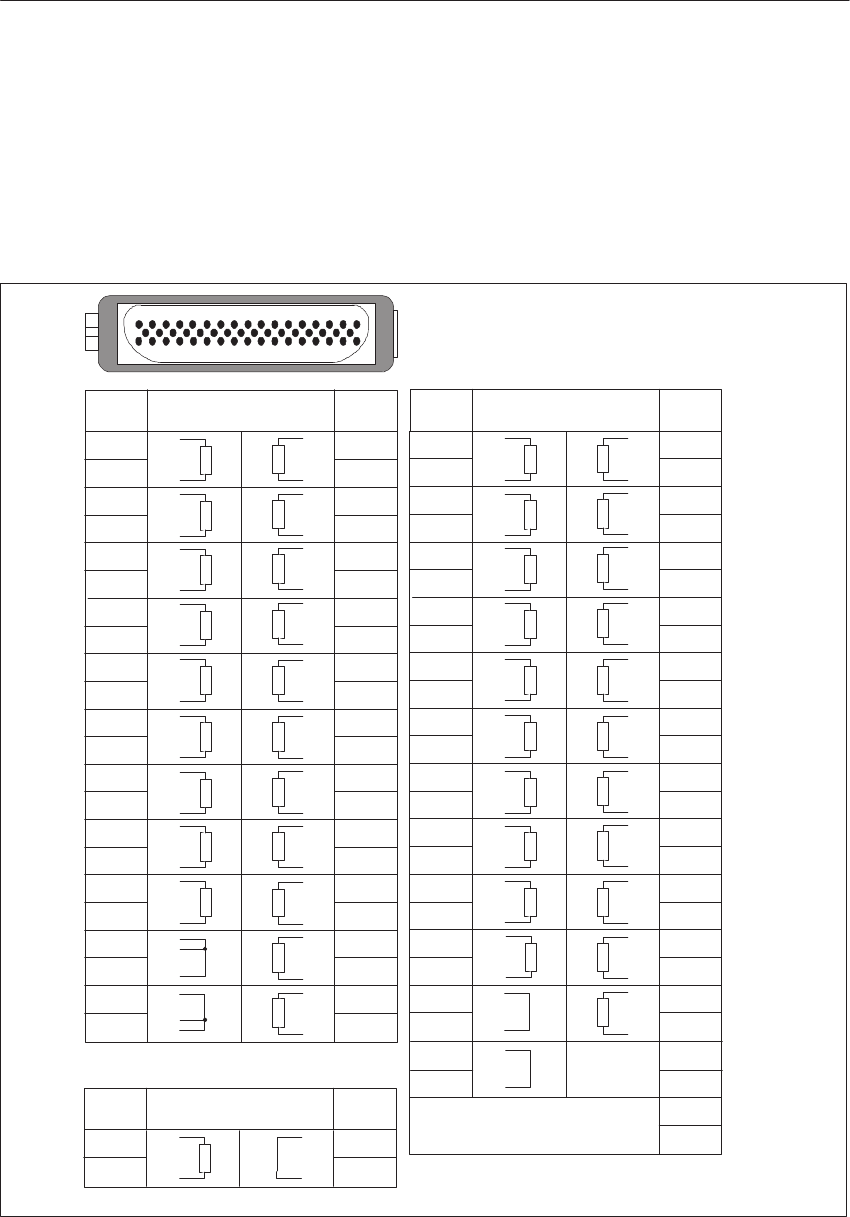
7-22 System Manual
C79000-G8576-C199-06
7.4.2 6ES5 7602 Terminator
The IM 314 of the last expansion unit of each run is terminated with the
6ES5 760-1AA11 terminator. The IM 312 and IM 301-3 (with a free
centralized connection) is terminated with the 6ES5 760-0AB11 terminator.
The IM 301-3 (with a free distributed connection) is terminated with the
6ES5 760-0AA11 terminator.
117
34 50
6
22
5
12
6ES5 760–0AB11
6ES5 760–0AA11
Connector
Pin
8
9
6
7
4
5
2
3
24
25
22
23
20
21
18
19
12
13
10
11
30
31
180-ohm-Resistor
or Jumper
28
29
26
27
46
47
44
45
42
43
38
39
34
35
36
37
40
41
14 / 48
16
50
15 / 49
6ES5 760–1AA11
8
9
6
7
4
5
2
3
24
25
22
23
20
21
18
19
12
13
10
11
30
31
28
29
26
27
46
47
44
45
42
43
38
39
34
35
36
37
40
41
48
49
15
16
14
50
1)
1)
1)
1)
2)
1)100 ohms
2)200 ohms
Connector
Pin Connector
Pin Connector
Pin
180-ohm-Resistor
or Jumper
Connector
Pin 180-ohm-Resistor
or Jumper Connector
Pin
Figure 7-16 Pin Assignments of the 760 Terminator
Interface Modules

8-1
System Manual
C79000-G8576-C199-06
Digital Input/Output Modules
Described in this chapter are the installation, wiring and operation of digital
input modules and digital output modules. The 432 digital input module and
the 482 digital input/output module have special features. These are
discussed in separate sections. The technical specifications and front
connector assignments for the individual modules are shown at the end of
this chapter.
Section Description Page
8.1 Technical Description 8-2
8.2 Installation and Startup 8-14
8.3 Common Technical Specifications 8-28
8.4 Specification Sheets for the Modules 8-30
Chapter
Overview
8
8-2 System Manual
C79000-G8576-C199-06
8.1 Technical Description
The description below applies to the following modules:
Type of Modules Inputs/Outputs Input/Output
Ct
Isolation/ Groups *)
Number Rated Voltage Current
Digital input modules
6ES5 420-4UA13/14
6ES5 430-4UA13/14
6ES5 431-4UA12
6ES5 432-4UA12
6ES5 434-4UA12
6ES5 435-4UA12
6ES5 436-4UA12
6ES5 436-4UB12
32
32
16
32
32
16
16
8
24 V DC
24 V DC
24 to 60 V DC
24 V DC/alarm
5 to 15 V DC
24 to 60 V AC
115 to 230 V AC
115 to 230 V AC
8.5 mA
7.0 mA
4.5 to 7.5 mA
8.5 mA
1.3 mA
15 to 25 mA
15 to 25 mA
15 to 25 mA
no
yes
yes
yes
yes
yes
yes
yes
–
1
16
4
1
2
2
8
Digital output modules
6ES5 441-4UA13/14
6ES5 451-4UA13/14
6ES5 453-4UA12
6ES5 454-4UA13/14
6ES5 455-4UA12
6ES5 456-4UA12
6ES5 456-4UB12
6ES5 457-4UA12
6ES5 458-4UA12
6ES5 458-4UC11
32
32
16
16
16
16
8
16
16
16
24 V DC
24 V DC
24 V DC
24 V DC
24 to 60 V AC
115 to 230 V AC
115 to 230 V AC
24 to 60 V DC
60 V relay
250 V AC relay
0.5 A
0.5 A
2.0 A
2.0 A
2.0 A
2.0 A
2.0 A
0.5 A
0.5 A
5 A
no
yes
yes
yes
yes
yes
yes
yes
yes
yes
–
1
16
1
2
2
8
16
16
2
Digital input/output modules
6ES5 482-4UA11 16 inputs and
16 outputs or
24 inputs and
8 outputs
24 V DC 8.5 mA (inputs)
0.5 A (outputs) yes 1
*) All inputs and outputs having a common 0 V ground form a group.
Technical specifications which are common to all modules are given in
Section 8.3. The special technical specifications for all modules can be found
in Section 8.4.
Digital input and digital output modules are I/O modules which allow the
processing of widely differing process signals with the S5-135U/155U
programmable controller. They can also be used via an adapter casing in the
S5-115U PLC.
I/O Modules
Di
g
ital Input/Output Modules

8-3
System Manual
C79000-G8576-C199-06
A digital input module converts the process signals to the internal signal
level in the module. Interference is suppressed by the input circuitry, and the
logic states at the inputs are indicated with LEDs on the front strip of the
module. With most digital input modules (except the 420), the signals are
isolated from the central ground point when received. Inputs relating to the
same group are isolated from inputs of another group, but not from each
other.
The control signals processed in the PLC are output via digital output
modules at a signal level suitable for the actuator, e.g. contactor, solenoid
valve, etc. For the voltages and currents required in the process, modules
with appropriate output circuitry are available.
With most digital output modules (except the 441), the signals are isolated
from the central ground point when relayed to the outputs. Outputs relating to
the same group are isolated from outputs of another group, but not from each
other.
If a digital output module receives a “command output inhibit” (BASP, cf.
Programming Guide and Chapter 4) from the CPU, the outputs are set to
zero.
When the supply voltage of the central controller or expansion unit has been
switched on or when the CPU is at STOP, the outputs are set to zero.
Signal output H+ on digital output modules for direct voltage emits a signal
when a short-circuit to ground (L-) or overcurrent has been detected at one or
more outputs currently at logic 1. Only short-circuits which are effective for
more than 0.5 to 1 s are detected. Short-circuits are only detected at
connected outputs. The signal outputs are decoupled by diodes. Up to 16
outputs can be connected in parallel. Ensure that isolation is not defeated by
the parallel connection of outputs.
To ensure functioning of the signal output, you must connect terminal 1L+ to
24 V on the 441, 451 and 454 modules. On the 453 and 457 modules, the
floating signal output must be powered separately.
Digital Input
Modules
Digital Output
Modules
BASP
Signal Output,
Short-Circuit
Detection
Di
g
ital Input/Output Modules
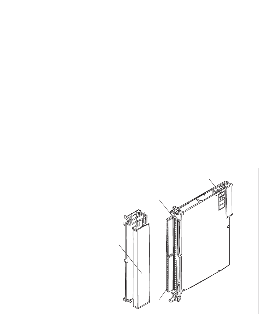
8-4 System Manual
C79000-G8576-C199-06
8.1.1 Design
The modules are designed as plug-in PCBs for central controllers and
expansion units with backplane connector and with a blade connector to
accept a plug-in front connector. The front connector has screw or crimp
terminals and is available separately; you can connect the process signal lines
to it directly.
Fitted to each module is a strip with green LEDs to indicate the logic states
of inputs or outputs. The LEDs are arranged in bytes and marked bit 0 to 7.
Output modules for direct voltage additionally have red LEDs to indicate
short-circuits between output lines and ground (L-) within a group. Output
modules for alternating voltage have red LEDs to indicate a fuse failure.
Fitted on each module is an addressing switch with six, seven or eight
rockers to set the module address.
The modules are protected on both sides by covers.
Front Connector
LEDs
Blade Connector
Addressing Switch
Figure 8-1 Digital Input Module
LED Indicators
Addressing Switch
Di
g
ital Input/Output Modules

8-5
System Manual
C79000-G8576-C199-06
8.1.2 Function of the Enable Inputs
The digital input/output modules have an enable circuit. You can use the
enable inputs to implement electrical interlocks for certain modules or switch
off individual modules, whilst the PLC is in operation.
This means that:
The module can no longer be addressed by the user program.
All outputs of digital output modules are set to zero.
Modules which are switched off can be removed or inserted during operation.
If this is not necessary, operate the module with the enable input switched
off.
On digital input/output modules with DC voltage inputs or outputs, the
enable circuit requires that enable inputs F+ and F- be wired in the front
connector. Enabling is achieved by applying an external voltage to inputs
F+/F-. Modules for AC voltage have a wire jumper in the front connector.
When the front connector is swivelled away from the front strip of the
module, the supply of power to the enable input is interrupted, i.e. the wire
jumper in the front connector is removed; the module is switched off and can
no longer be addressed by the user program.
When the front connector is swivelled away, i.e. the voltage is removed from
the enable inputs, a timeout (QVZ) occurs at the CPU (see the Programming
Guide for the particular CPU).
Apart from the 6ES5 458-4UC11 digital output module, all digital
input/output modules additionally offer the facility for changing the enable
mode. The modules have a jumper accessible from above in the vicinity of
the addressing switch (see Figure 8-2).
Enable Jumper
Figure 8-2 Location of the Enable Jumper
With an Active
Enable Input
Di
g
ital Input/Output Modules
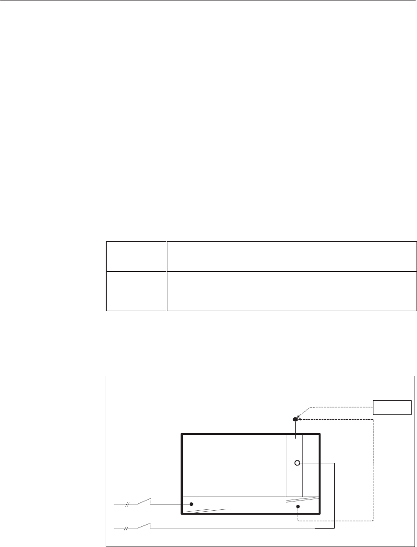
8-6 System Manual
C79000-G8576-C199-06
Jumper inserted: Enable input (F+/F-) active (factory setting)
Jumper open: Enable input (F+/F-) switched off
If removal and insertion of modules during operation is not required, you
must remove the plug-in jumper for changeover of the enable mode. Wiring
of the enable inputs (F+/F-) can then be dispensed with.
Almost power-free shutdown of individual subprocesses, i.e. outputs of
various modules can be operated from a common load supply and yet
activated separately.
The load voltage of each individual module can be monitored without
additional circuitry. Any reactions to failure of the load voltage can be
programmed in the QVZ (timeout) organization block.
You must observe the following when configuring systems:
Switching on At the latest 100 ms after power-up of the PLC, the voltage must be
present at the enable inputs of the I/O modules.
Switching off When the PLC has been switched off, the voltage at the enable in-
puts of the I/O modules must still be present as long as voltage is
applied to the CC/EU.
You should observe the following instructions for switching off PLCs and
equipment for supplying power to the enable inputs:
24 V supply for CC/EU and I/Os
F+
L+
I/O Modules
24 V DC
b)
a)
CC/EU
L+
Battery
24V Power Supply
Enable supply from:
a) Battery
b) Terminals for 24 V on the front plate of the power supply
With Enable Input
Switched Off
Examples of
Functioning of the
Enable Inputs
Di
g
ital Input/Output Modules

8-7
System Manual
C79000-G8576-C199-06
When there is a need to switch off the load power supply separately without
affecting the enabling of modules, there are the following possibilities for
producing the enable voltage. These exist even when the power supply is
used without an additional capacitor and common shutdown.
230 V AC supply for CC/EU and load power supply
F+
L+
I/O Modules
230V AC
CC/EU
–951
a)
c)
b) Battery
L+
Power Supply
Load Power Supply 24V
Enable supply from:
a) 6ES5 951-4LB11 load power supply
b) Battery
c) Terminals for 24 V on the front plate of the power supply
Proper functioning is ensured if the 24 V load power supply has an output
capacitance of at least 4700 mF per 10 A of load current.
Other units (load power supply for 20 or 40 A) which do not meet this
condition can be adapted to this requirement by connecting a 10000 mF/40 V
capacitor in parallel.
10000µF/
40V
CC/EU F+
L+
230V AC
I/O Modules
Load Power Supply 24V
Power Supply
Separate or
Common
Shutdown of the
CC/EU and Load
Power Supply
Common
Shutdown of the
CC/EU and Load
Power Supply with
a 230 V AC Supply
Di
g
ital Input/Output Modules

8-8 System Manual
C79000-G8576-C199-06
8.1.3 Special Features of the 432 Digital Input Module
The 432 digital input module accepts 32 process signals and emits a process
alarm if the logic state at one of its inputs changes.
You can operate the module in the following modes:
without process alarm (“normal” digital input module)
with initiation of a process alarm via interrupt
with initiation of a process alarm via IB 0 (only in conjunction with
CPU 948)
To operate the module with process alarm via IB 0, you must address it in the
normal (P) area from byte 128 because
the automatic updating of the process image might acknowledge a process
alarm without the system program having detected and interpreted this
alarm;
only modules addressed in the normal (P) area can initiate a process
alarm via IB 0.
The time for reaction of the module to a process alarm is mainly determined
by the input circuitry. You can set the reaction time to one of the values
0.3 ms, 1 ms or 3 ms with switch S5. Note that the filtering effect decreases
with shorter reaction times, and interference may be received as useful
signals (effect of the line length, see the technical specifications).
To operate the module without process alarm, you can insert it at any slot for
I/O modules and address it in the entire I/O area. If you address it in the area
PB/PY 0 to PB/PY 124, it will be within the automatic updating of the
process image.
Make the following settings on the module to operate it without process
alarm:
Step Action
1Open jumpers X3 and X4
2Set switch rows S1 and S2 to Off
S1
33Bit 3IR-D
44Bit 4
IR-E
55Bit 5IR-F
66Bit 6
IR-G
77Bit 7INT
00Bit 0
IR-A
11Bit 1IR-B
22Bit 2IR-C
:OFF
:ON
S2
Figure 8-3 Switch Settings for Operation without Process Alarm
The setting for switch row S3 is arbitrary in this mode.
Modes
Reaction Time
Operation without
Process Alarm
Settings on the
Module
Di
g
ital Input/Output Modules

8-9
System Manual
C79000-G8576-C199-06
To operate the 432 digital input module with process alarm via an interrupt,
you must either operate it in the CC where only certain slots have interrupt
lines (see Chapter 4), or in an interrupt-capable EU connected to the CC with
IM 307 - IM 317 interfacing (see also the IM 307 - IM 317 manual). In the
CC, you may only operate the module in this mode at slots with an interrupt
line (interrupt source).
So that the module can initiate a process alarm for a change of logic state, the
alarm must be processed by an alarm routine (alarm OB) in the user program,
with automatic acknowledgement of the alarm. To avoid loss of an alarm, it
must not be possible for the alarm OB to be interrupted by process alarms.
The CPU must process the process alarms with level triggering (see
Programming Guide of the CPU).
Example:
Program the following operations in the corresponding alarm OB:
L PW132 (load I/O word)
T FW10 (transfer flag word)
L PW134 etc.
TFW12
Only the flag word may be accessed during the cyclic program.
Accessing the I/O bytes in the process image will result in alarm loss.
Addressing of the module must therefore be above address 127. Double
accessing of I/O bytes, even from different CPUs, is not permissible (alarm
loss).
The four I/O bytes of a module must be scanned successively and in
ascending order. The scanning of byte n inhibits all input circuits of the
module, and the scanning of byte (n + 3) enables them again.
Make the following settings on the module to operate it with a process alarm
via interrupt:
Step Action
1Open jumper X4 and close jumper X3.
2Set the interrupt line at switch row S1: the switch relating to the
desired interrupt line should be set to On. Set all other switches
to Off. You can set the same interrupt line on several modules.
3Set switch row S2 to Off.
4Set switch row S3 to choose whether the interrupt is to be initi-
ated with a positive-going (leading) or negative-going (trailing)
edge. The setting of a pair of switches applies to an entire byte.
Operation with
Process Alarm via
Interrupt
Scanning the
Process Inputs
Settings on the
Module
Di
g
ital Input/Output Modules
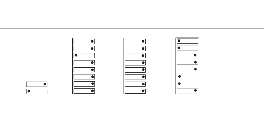
8-10 System Manual
C79000-G8576-C199-06
S1
333
Bit 3
IR-D
444
Bit 4IR-E
555
Bit 5
IR-F
666
Bit 6IR-G
777
Bit 7INT
000
Bit 0IR-A
111
Bit 1
IR-B
222
Bit 2
IR-C
Process Interrupt via IR-C Byte 0: Positive-Going Edge
Byte 1: Negative-Going Edge-
Byte 2: Both Edges
Byte 3: No Process Interrupt
Byte 0
Byte 1
Byte 2
Byte 3
S2 S3
}
}
}
}
: OFF
: ON
Figure 8-4 Switch Settings for Operation with Process Alarm via Interrupt (Example)
In this mode, a process alarm is initiated via input byte IB 0. This mode is
only possible in conjunction with a CPU 948 in single-processor operation.
To operate the 432 digital input module with process alarm via IB 0, you can
insert it at any I/O slot.
When you use the module in the CC, you must not set any other input
module to address 0 (i.e. neither in the normal (P) nor in the extended (O)
area).
If you use the module in an EU which is addressed in the normal area, you
must not set any other input module in the EU to address 0 in the normal
area.
So that the module can initiate a process alarm for a change of logic state, the
alarm must be processed by an alarm routine (alarm OB) in the user program,
with automatic acknowledgement of the alarm. To avoid loss of an alarm, it
must not be possible for the alarm OB to be interrupted by process alarms.
The CPU must process the process alarms with level triggering (see
Programming Guide of the CPU).
Example:
Program the following in the alarm OB which you have preset with byte IB 0
and switch S2:
L PW128 (load I/O word)
T FW0 (transfer flag word)
L PW130 etc.
TFW2
Operation with
Process Alarm
via IB 0
Scanning the
Process Inputs
Di
g
ital Input/Output Modules
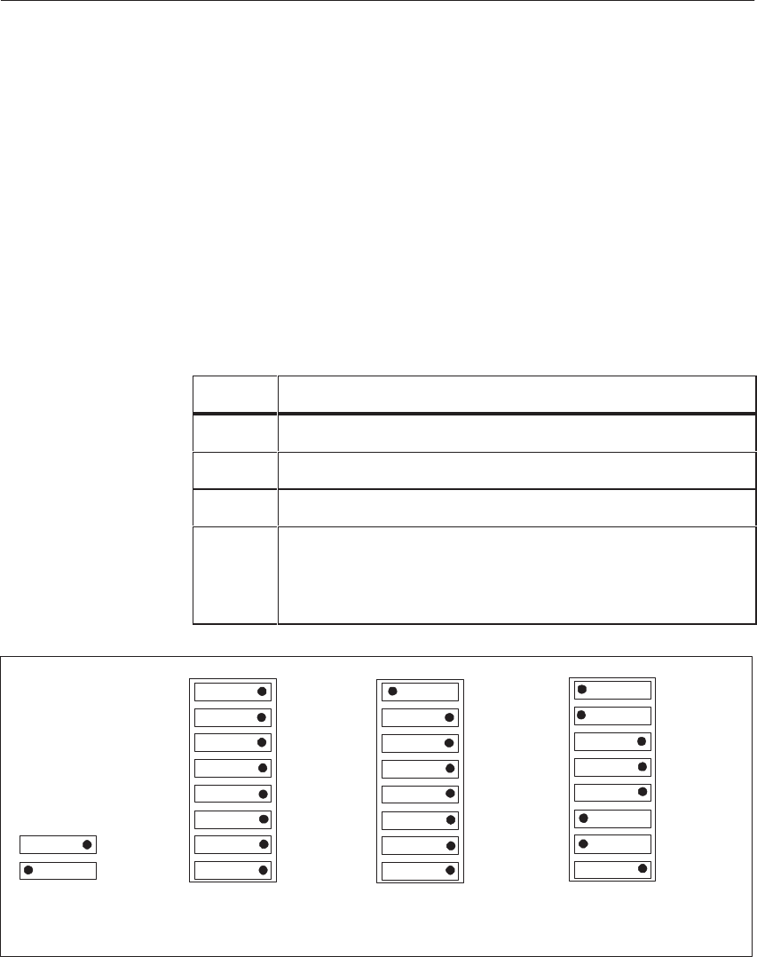
8-11
System Manual
C79000-G8576-C199-06
Only the flag word (FW) may be accessed during the cyclic program.
Accessing the I/O bytes in the process image will result in alarm loss.
Addressing of the module must therefore be above address 127. Double
accessing of I/O bytes, even from different CPUs, is not permissible (alarm
loss).
The four I/O bytes of a module must be scanned successively and in
ascending order. The scanning of byte n inhibits the input circuit of the
module, and the scanning of byte (n + 3) enables them again.
Make the following settings on the module to operate it with a process alarm
via IB 0:
Step Action
1Insert jumpers X3 and X4
2Set switch row S1 to Off.
3Set bit 0 on switch row S2 to On, and all other switches to Off.
4Set switch row S3 to choose whether the interrupt is to be initi-
ated with a positive-going (leading) or negative-going (trail-
ing) edge. The setting of a pair of switches applies to an entire
byte.
S1
333
Bit 3
IR-D
444
Bit 4
IR-E
555
Bit 5IR-F
666
Bit 6IR-G
777
Bit 7INT
000
Bit 0IR-A
111
Bit 1IR-B
222
Bit 2IR-C
S2 S3
Byte 0
Byte 1
Byte 2
Byte 3
}
}
}
}
:OFF
:ON
Byte 0: Positive-Going Edge
Byte 1: Negative-Going Edge-
Byte 2: Both Edges
Byte 3: No Process Interrupt
Figure 8-5 Switch Settings for Operation with Process Alarm via IB 0 (Example)
Settings on the
Module
Di
g
ital Input/Output Modules

8-12 System Manual
C79000-G8576-C199-06
You can use up to eight 432 digital input modules with process alarm via
IB 0 in one PLC. The modules must all be inserted in the CC or in the same
EU for error-free acknowledgement of address 0. Each module reserves one
bit in IB 0. You must set one module to bit 0 on switch row S2; on the other
modules you must remove jumper X3 and set one of the other bits 2 to 8.
The module you have set to bit 0 is known as the master, and the other
modules are slaves. On the master module, you must additionally set the
number of slave modules on switch row S2. Refer to the labeling on the
module cover.
You can also use the 432 digital input module with process alarm together
with other alarm-generating modules.
To operate the module with process alarm via interrupt, you must observe the
following:
f a process alarm is generated via an interrupt, the I/O words of all 432
digital input modules involved in this process alarm must be read in the
alarm-processing OB; with IPs, the process alarms must be acknowledged
(refer to the manuals of the IPs).
The modules must be inserted at interrupt-capable slots (see Chapter 4).
To operate the module with process alarm via IB 0, you must observe the
following:
You may use up to eight alarm-generating modules.
The modules must all be inserted in the CC or all in the same EU.
You must operate the 432 module as the master. If you use two or more
432 digital input modules with other alarm-generating modules, you must
operate one 432 as the master and all others as slaves.
8.1.4 Special Features of the DI/DQ 482
The DI/DQ 482 digital input/output module is an I/O module which allows
the processing of process signals in conjunction with the IP 257, with the
S5-135U/155U PLC and the EU 185U (see the IP 257 manual). Described in
the following is the operation of the DI/DQ 482 without IP 257.
The DI/DQ 482 has 32 channels which are jointly isolated, i.e. there is no
subdivision into groups in the module. Channels 0.0 to 0.7 are digital outputs,
Channels 2.0 to 3.7 are digital inputs; Channels 1.0 to 1.7 can be optionally
and individually operated as inputs or outputs.
Using Two or More
432 Digital Input
Modules with
Process Alarm
via IB 0
Using the 432
Digital Input
Module with other
Alarm-
Generating
Modules
Di
g
ital Input/Output Modules
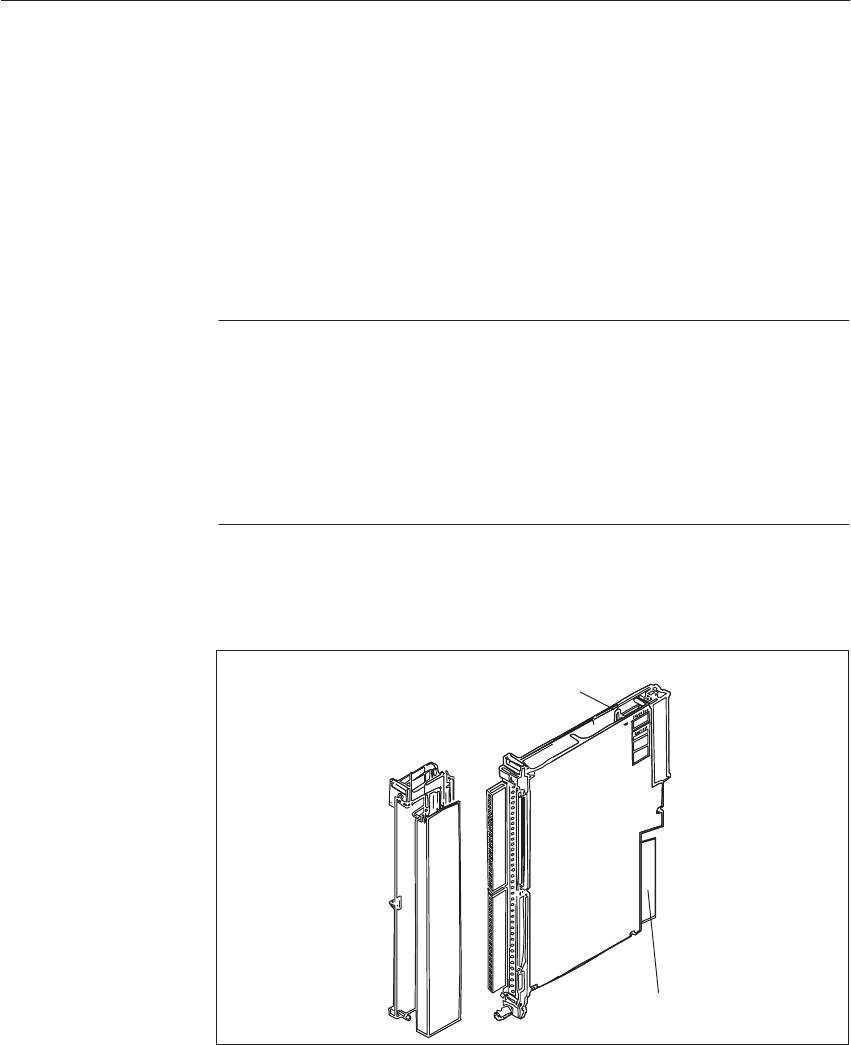
8-13
System Manual
C79000-G8576-C199-06
The operation of Channels 1.0 to 1.7 as inputs or outputs merely depends on
the user program. You define the byte as an input with a read access to the
DI/DQ; you define the byte as an output with a write access. The
double-function of the byte also allows the output byte to be read out.
Unused channels should not be wired nor addressed by program. When these
channels are used as inputs, it should be noted that the corresponding bits in
the output register remain at logic 0. This resetting of output registers is
executed automatically after power-up of the PLC or EU.
Note
When at least one of Channels 1.0 to 1.7 is operated as an input, the
connected sensors and the 1L+ terminal must have the same power supply. If
this is not the case, the input voltage acts on the 1L+ terminal. The resultant
supply to the output amplifiers of Channels 0.0 to 1.7 causes currents to be
drawn via the wired input terminal; these currents may assume different
values, depending on the control states of the outputs.
With the DI/DQ 482, you must set slide switch S2 to setting 1 for operation
without the IP 257.
Local Bus Interface
Slide Switch S2
Figure 8-6 Slide Switch S2 on the DI/DQ 482
Changeover of the
I/O byte
Di
g
ital Input/Output Modules

8-14 System Manual
C79000-G8576-C199-06
8.2 Installation and Startup
This section describes how to prepare digital input/output modules for
installation, and how to install and wire them.
8.2.1 Setting the Module Address
You set the module address on the addressing switch. This also establishes
the necessary assignments between user program and process connection.
The address of the digital input modules (input bytes IB 0 to 255 or 252 for
the DI/DQ 482) and digital output modules (output bytes QB 0 to 255 or 252
for the DI/DQ 482) is the sum of the binary significances established by
depressing the individual rockers in the On setting ().
The modules are addressed by the STEP 5 program under their parameters
(byte address).
You can affix the adhesive label with the desired module address on a
labeling field under the addressing switch. Suitable labels are supplied with
the CC.
The switch rockers with which the module address (IB n or QB n) is
specified as a decimal number, are marked by dots on the label.
Do not use a pencil to set the addressing switch.
Labeling Field
Di
g
ital Input/Output Modules
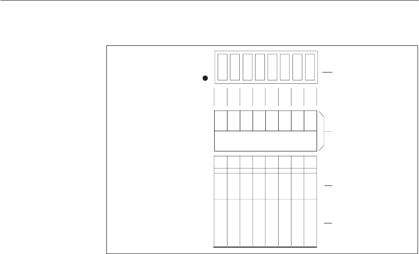
8-15
System Manual
C79000-G8576-C199-06
On Setting
(Switch Pressed)
Addressing Switch
Address Bit
Binary Significance
of the Address Bit
Labeling Field for the
Module Address and
Marked Switch Settings
Address (Decimal)
128
64
32
16
8
4
2
1
ADB7
ADB6
ADB5
ADB4
ADB3
ADB2
ADB1
ADB0
Figure 8-7 Labeling of the Addressing Switch (Extract from Module Labeling)
The address byte under which the module is referenced by the STEP 5
program is independent of the slot.
For modules with 16 or 32 inputs or outputs, i.e. 2 or 4 bytes, only the lowest
address (start address) is set for the first byte. The addresses of the following
bytes of the same module are decoded on the module.
If, for example, the address 20 is set for a 16-bit module (2 bytes), the
following address 21 is decoded internally and is no longer available. The
next free address would be 22.
For a 32-bit module (4 bytes) with start address 20, addresses 21, 22 and 23
would be decoded internally. The next free address would be 24.
Addresses already assigned must not be set again.
However, digital input and output modules may be given the same address
because they are referenced by different commands in the user program.
Start Address
Di
g
ital Input/Output Modules
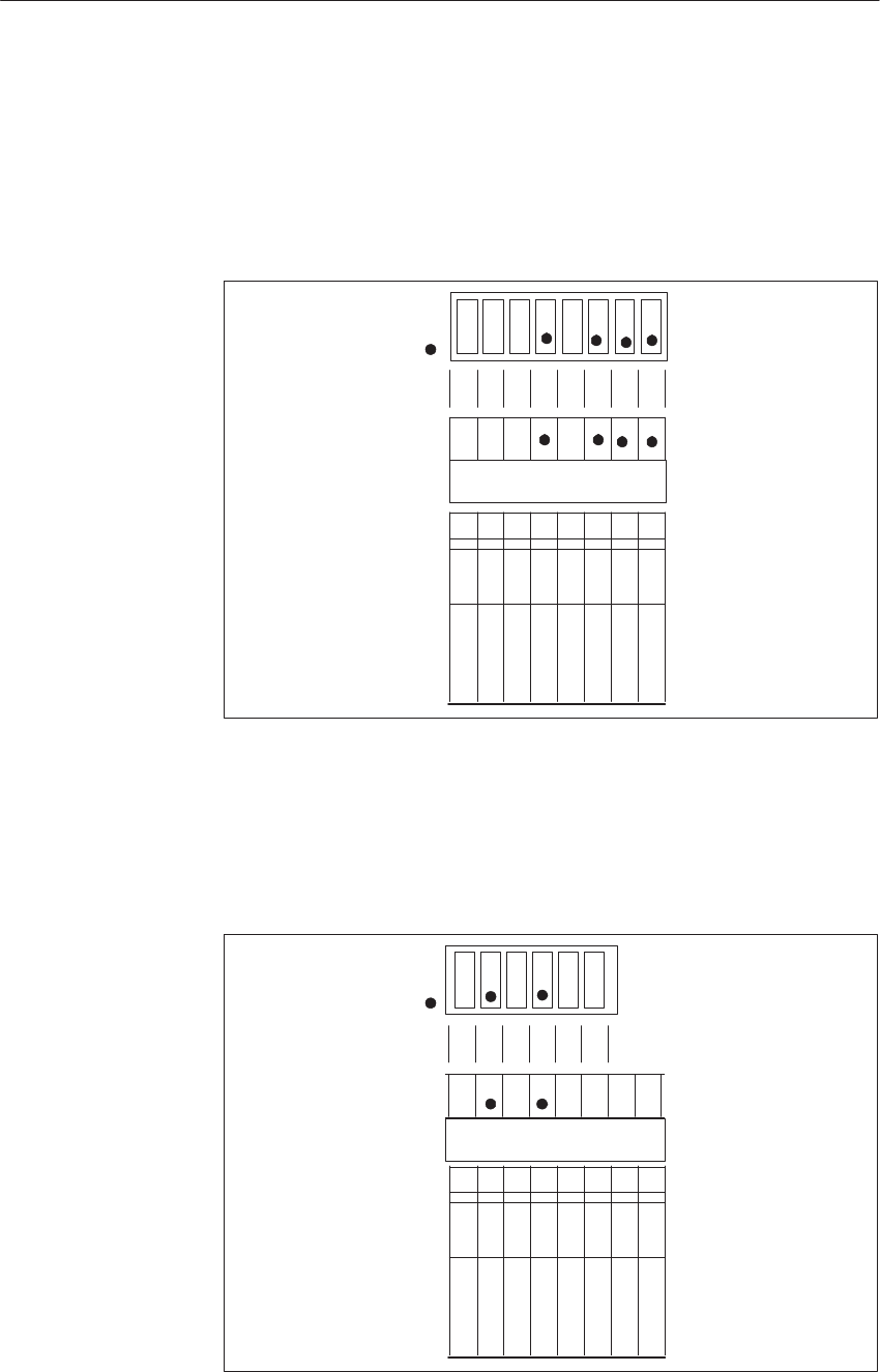
8-16 System Manual
C79000-G8576-C199-06
Example
Digital input module with 8 inputs (IB 23) or
digital output module with 8 outputs (QB 23).
The address is the sum of binary significances set with the individual coding
switches:
23 = 1 + 2 + 4 + 16 = 20 + 21 + 22 + 24
On Setting
(Switch Pressed)
IB 23 (or QB 23)
128
64
32
16
8
4
2
1
ADB7
ADB6
ADB5
ADB4
ADB3
ADB2
ADB1
ADB0
Example
Digital input module with 32 inputs (IB 80) or
digital output module with 32 outputs (QB 80).
The address is the sum of binary significances set with the individual coding
switches:
80 = 16 + 64 = 24 + 26
On Setting
(Switch Pressed)
128
64
32
16
8
4
2
1
ADB7
ADB6
ADB5
ADB4
ADB3
ADB2
ADB1
ADB0
IB 80 (or QB 80)
Di
g
ital Input/Output Modules
8-17
System Manual
C79000-G8576-C199-06
The following table is an overview of settings for addressing digital
input/output modules.
Significance Byte Address
8 Channels xxxxxxxxxxxxxxxx
xxxxxxxx
xxxx
1
2
4
8
1)
128
64
32
16
16
32
48
64
80
96
112
128
144
160
176
192
208
224
01
17
33
49
65
81
97
113
129
145
161
177
193
209
225
241240
2
18
34
50
66
82
98
114
130
146
162
178
194
210
226
242
3
19
35
51
67
83
99
115
131
147
163
179
195
211
227
243
4
20
36
52
68
84
100
116
132
148
164
180
196
212
228
244
5
21
37
53
69
85
101
117
133
149
165
181
197
213
229
245
6
22
38
54
70
86
102
118
134
150
166
182
198
214
230
246
7
23
39
55
71
87
103
119
135
151
167
183
199
215
231
247
8
24
40
56
72
88
104
120
136
152
168
184
200
216
232
248
9
25
41
57
73
89
105
121
137
153
169
185
201
217
233
249
10
26
42
58
74
90
106
122
138
154
170
186
202
218
234
250
11
27
43
59
75
91
107
123
139
155
171
187
203
219
235
251
12
28
44
60
76
92
108
124
140
156
172
188
204
220
236
252
13
29
45
61
77
93
109
125
141
157
173
189
205
221
237
253
14
30
46
62
78
94
110
126
142
158
174
190
206
222
238
254
15
31
47
63
79
95
111
127
143
159
175
191
207
223
239
255
1) Address range for digital input and digital output modules
whose signals are not routed via the process image.
Switch Setting
On
Significance
128
64
32
16
8
4
2
1
16 Channels
32 Channels
Di
g
ital Input/Output Modules
8-18 System Manual
C79000-G8576-C199-06
8.2.2 Removing and Inserting Modules
!Warning
When removing and inserting the front connector during operation,
hazardous voltages of more than 25 V AC or 60 V DC may be present at the
module pins. When this is the case at the front connector, live modules may
only be replaced by electrical specialists or trained personnel in such a way
that the module pins are not touched. During operation, the front connector
and module must not be removed or inserted without the enable jumper or
active enable circuit.
Install a digital input/output module as follows:
Step Action
1Release the upper locking bar on the subrack and swivel it up-
wards and out.
2Insert the module at the desired slot in the subrack and push it
back in the guides.
3Latch the module by rotating the locking pin by 90° at the
lower end of the module.
4Engage the front connector on the support pin of the module
and swivel it up. The width of the support pin also provides
keying to prevent front connectors from being fitted to the
wrong modules (e.g. 230 V AC front connector on 24 V DC
modules).
5Tighten the screw in the upper part of the front connector.
Di
g
ital Input/Output Modules

8-19
System Manual
C79000-G8576-C199-06
Remove a digital input/output module as follows:
Step Action
1Release the upper locking bar on the subrack and swivel it up-
wards and out.
2Slacken the screw in the upper part of the front connector.
This causes the front connector to be pressed out of the female
connector of the module. Contacts F+ and F- of the enable in-
put at the upper end of the front connector are thus opened first.
3Swing the front connector out and lift it away from the support
pin of the module.
4Release the module, if necessary, by rotating the locking pin by
90o. You can pull the module out of the subrack with a grip
which swivels outwards.
1
2
3
5
6
4
Module
Front Connector
Support Mount
Support Pin
Figure 8-8 Module with Front Connector
1 Screw
2 Locking pin
3 Support mount
4 Support pin
5 Grip
6 Backplane connector
Comply with VDE Specifications 0100 and 0160 to carry out the wiring of
the supply and signal lines which are to be connected to the programmable
controllers and front connectors of the modules. Detailed information on the
supply of power, cabinet assembly, cabinet ventilation, cabinet wiring and
protective measures can be found in Chapter 3.
Wiring
Di
g
ital Input/Output Modules
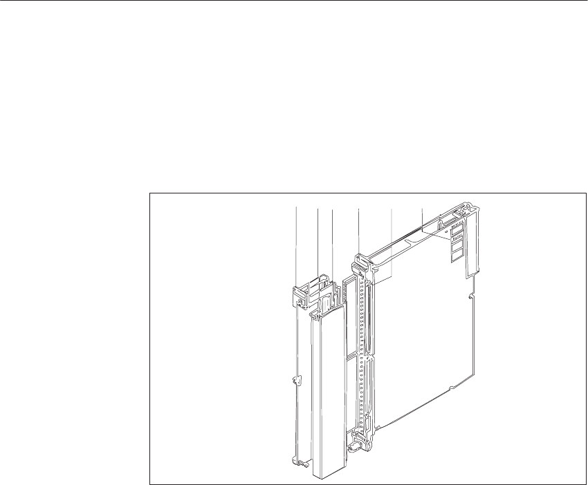
8-20 System Manual
C79000-G8576-C199-06
8.2.3 Marking of Modules
For the marking of modules and front connectors, a set of labels is supplied
with the modules for the labeling, and a set of labels with the addresses is
supplied with the central controller. Figure 8-9 shows the locations of the
labels. The self-adhesive address label is pre-printed. You can mark the strips
to identify the signal line terminals.
5
1
13
4
2
Figure 8-9 Marking and Labeling of Modules
1 Address label with the module address (output byte QB n or input byte IB n) under
which the module is addressed by the STEP 5 program (address labels are supplied
with the PLC), and for marking the addressing switch settings
2 Labeling strip with the product designation which is color-coded to distinguish
between the various module types, as well as fields to mark the version and for
user-related labeling of channels.
Color codes:
Digital inputs for DC voltage blue
Digital inputs for AC voltage red
Digital outputs for DC voltage green
Digital outputs for AC voltage orange
Update the version when replacing modules!
3 Label with module address and marking of the required settings for the addressing
switch
4 Labeling strip for terminal designations or connection diagrams for the front connector
5 Name plate
Di
g
ital Input/Output Modules

8-21
System Manual
C79000-G8576-C199-06
8.2.4 Connecting the Signal Lines
The modules have 20 or 42-way blade connectors with contact blades
measuring 2.4 x 0.8 mm. Front connectors for 20 and 40 mm mounting width
with crimp connection and 40 mm mounting width with screw connection are
provided to connect the signal lines (screwdriver blade width: 3.5 mm,
maximum torque: 0.8 Nm).
Use stranded conductor to facilitate handling of the front connector.
When the crimp contact is inserted in the plastic body of the front connector,
a click can clearly be heard. This indicates that the contact is engaged. For
jumpering or to correct the wiring, you can remove the contacts with a
releasing tool (see ordering information) without having to pull out the front
connector.
Ferrules are not required for screw connections, because the screw terminals
are provided with wire protection. You can use ferrules of 7 mm in length to
DIN 46228. The maximum terminal area is 2 x 2.5 mm2.
Terminal
Type
Connector
Type 6ES5
Max.
No of
Cross-Sec. of
Signal or Sup
-Connector for
Rated Voltage
Front
Con
-Module 6ES5-
T
ype
T
ype
6ES5
497-
N
o. o
f
Con-
Si
gna
l
or
S
up-
ply Conductor
R
a
t
e
d
V
o
lt
age
C
on-
nector For Operation
497
Con
tacts
ply
Conductor
nector
Width With Fan Without Fan
Crimp
Connec-
tion
4UA12 42 0.5 to 1.5 mm25 to 60 V DC 20 mm 420. 430.
431, 432.
434, 441,
451, 454-14,
458
–
4UA22 42 0.5 to 1.5 mm25 to 60 V DC 40 mm 453, 454, 457 420. 430.
431, 432.
434, 441,
451, 453,
454, 457,
458
4UA42 20 0.5 to 1.5 mm224 to 230 V AC 40 mm 435, 436, 455, 456
Screw
Connec-
tion
4UB12
4UB32 42 0.5 to
2 x 2.5 mm25 to 60 V DC 40 mm
20 mm 420. 430. 431, 432. 434, 441,
451, 453, 454, 457, 458
ti
on 4UB22 25 0.5 to
2 x 2.5 mm25 to 60 V DC 40 mm 454
4UB42 20 0.5 to
2 x 2.5 mm224 to 230 V AC 40 mm 435, 436, 455, 456
!Caution
Only extra-low voltage v 60 V DC with safety separation from system
voltage may be used for the 24 V DC supply and for the 24 V DC input
signals. Safety separation can be implemented to the requirements of,
amongst other sources, VDE 0100 Part 410/HD 384-4-41/IEC 364-4-41
(as functional extra-low voltage with safety separation) or
VDE 0805/EN 60950/IEC 950 (as safety extra-low voltage SELV) or
VDE 0106 Part 101.
Di
g
ital Input/Output Modules
8-22 System Manual
C79000-G8576-C199-06
8.2.5 Connection of Outputs in Parallel and Switching On the Load via
a Contact
!Caution
The parallel connection of outputs to increase the load is not permissible.
Outputs of modules with the same load voltage supply may be connected in
parallel without additional circuitry.
An external diode must be fitted to the output lines of modules fed from
different load voltage supplies (exception: 453, 457). In the case of different
logic states of the two outputs, the maximum permissible output current
corresponds to that of the lower stage.
The contact (e.g. for manual operation) is connected to one of the two L+.
2L+
Output 2
2L–
Load
Manual
A1 A2 1L+
1L–
Output 1
Figure 8-10 Parallel Connection of Outputs for DC Voltage Outputs
Outputs can be connected in parallel without increasing the load if they are
connected to the same phase (L) and the same neutral conductor (N).
The load must be at least 50 mA per output to keep to the permissible
residual voltage at logic 0. The maximum switching current of 2 A per load
must not be exceeded.
Digital Output
Modules for DC
Voltage
Digital Output
Modules for AC
Voltage
Di
g
ital Input/Output Modules
8-23
System Manual
C79000-G8576-C199-06
The load can also be switched via a contact.
Output 1 Output 2
ELR
Phase (L)
Load Neutral (N)
ELR = Electronic Load Relay
ELR Manual
Figure 8-11 Parallel Connection of Outputs for AC Voltage Outputs
Given here are two examples of the feeding of inputs and outputs of different
modules from two power supply units.
With non-floating input/output modules, the negative terminals (L-) of the
power supply units are connected to reference potential (PE) because the
inputs of the 420 module are referred to chassis ground.
Reference Potential
+
+
DQ
e.g. 441
0 V
++
DQ
e.g. 441
0 V0 V
e.g. 420
DI
0 V
e.g. 420
DI
2L+
1L+
II II III II
AC
230V
DC
24V
+
_
+
_
AC
230V
DC
24V
L_
QLQLQQQQLQQL
Central Ground Point
or Rack or the CC/EU
and Connection
to Protective
Conductor (PE)
Figure 8-12 Feeding of Non-Floating Input/Output Modules from Two Power Supply Units
Connection of
Input/Output
Modules to Two
Power Supply Units
Di
g
ital Input/Output Modules
8-24 System Manual
C79000-G8576-C199-06
With isolated input/output modules the supply voltage is applied separately
to the individual modules.
DQe.g.453 0 VDQe.g.451 0 V
0 Ve.g.430 DI 0 V
e.g.431 DI
1L+
L
+L
_
II III IIL
_L
_L
_L
_L
_
1L_
2L+
2L_
QQQQL
+
QL
+L
_Q
LQLQ
LQL
++ ++
AC
230V
DC
24V
AC
230V
DC
24V
+
_
+
_
Reference Potential
and Connection
to Protective
Conductor (PE)
Figure 8-13 Feeding of Isolated Input/Output Modules from Two Power Supply Units
With isolated modules, the inputs or outputs can be fed from two separate
power supply units in isolation groups created by the internal distribution in
the module.
Note that when inputs or outputs from two isolated groups are connected to
one power supply unit, isolation between the groups is defeated.
8.2.6 Short-Circuit Protection and Fusing
With digital output modules for DC voltage, fuses are provided on the
module, in addition to the electronic short-circuit protection, for the wiring
cables and to protect the module. The fuses also provide protection against
reversal of supply voltage connections and can only be replaced at the
factory.
The electronic short-circuit protection guaranteed in the technical
specifications applies to a resistance which is lower than the specified,
maximum permissible line resistance.
In the event of a short-circuit, two to three-times the rated output current
flows briefly at the output before the switched electronic short-circuit
protection becomes effective. When selecting the load power supply units,
therefore, allow for the increased short-circuit current as well as all
connected output loads (observe the coincidence factor). With unregulated
load power supplies, this overcurrent is generally ensured. With regulated
load power supplies, especially at low output power levels (up to 20 A), you
must allow for a corresponding overcurrent.
Di
g
ital Input/Output Modules
8-25
System Manual
C79000-G8576-C199-06
8.2.7 Arc-Quenching for Inductive Loads
Note
Digital output modules have integrated circuits on the module to quench
inductive loads (refer to the technical specifications of the output modules).
Exception: The 458 digital output module allows the switching of inductive
loads with contact protection submodules.
The integrated circuits on the modules for quenching inductive loads are
disabled if the load circuits are interrupted, either
operationally by contacts and switches,
or by fuses in the event of a fault.
This can result in excessive, inductive breaking voltages which put fault-free
operation at risk.
You can prevent this with additional, external quenching circuitry for the
inductive loads.
L– N
Digital Output Digital Output
AC Voltage
DC Voltage L+ L
Contact, Switch
Contactor,
Solenoid Valve, etc.
Quenching Device
(Diode, Zener Diode, R/C Network or Varistor)
ELR
ELR
ELR
Figure 8-14 Quenching of Inductive Loads when the Load Circuit is Opened
Di
g
ital Input/Output Modules

8-26 System Manual
C79000-G8576-C199-06
External quenching circuitry is needed when
the switching frequency of an output is greater than that specified in the
technical specifications (thermal stress of the integrated circuit for
quenching inductive loads);
disconnection of output lines can be expected;
disconnection of the supply line can be expected.
When selecting or designing the quenching circuitry, the technical
specifications for the digital output should be taken into account. These are:
The permissible overvoltage for the supply voltage (see Section 8.3
“Common Technical Specifications”)
Inductive breaking voltage of the output (see Section 8.4 “Description of
Individual Modules”)
An external quenching circuit only provides thermal relief if its quenching
voltage is lower than the breaking voltage specified for the module, allowing
for unfavorable supply voltage conditions.
Example: 453 digital output
Inductive breaking voltage L+ - 47 V (tech. specifications)
Max. supply voltage L+ = 30 V
Quenching voltage referred to L- (0 V ground) is - 17 V
The quenching device must be rated at approximately 15 V and the switched
load current, e.g. 1 A.
A quenching device rated for the induced breaking current must be provided
at the load (see Figure 8-14).
The quenching voltage at the load is independent of the module. The
quenching devices must also ensure that the overvoltages at the switch and in
the wiring do not exceed the disturbance voltage and voltage hazard limits
permissible to VDE/IEC.
The following applies to digital outputs for DC voltage:
In general, load power supplies should be switched on the primary side to
utilize the low-resistance secondary winding and smoothing capacitors of the
power supply for energy compensation in the dropping of inductive loads.
The load power supply switch should only be considered as a circuit breaker.
With switched-through digital outputs and disconnection of the supply line
L+, the output current is maintained during the quenching time by capacitors
and the reverse voltage protection diode on the module. This severe electrical
stress of the module should be avoided during operations, because it can
result in a fault in the long term.
External
Quenching
Circuitry
Switching
Frequency of the
Output is Higher
than the
Permissible Value
Disconnecting the
Load Circuit
Disconnecting the
Supply Line L+
and L
Switched-Through
Outputs
Di
g
ital Input/Output Modules
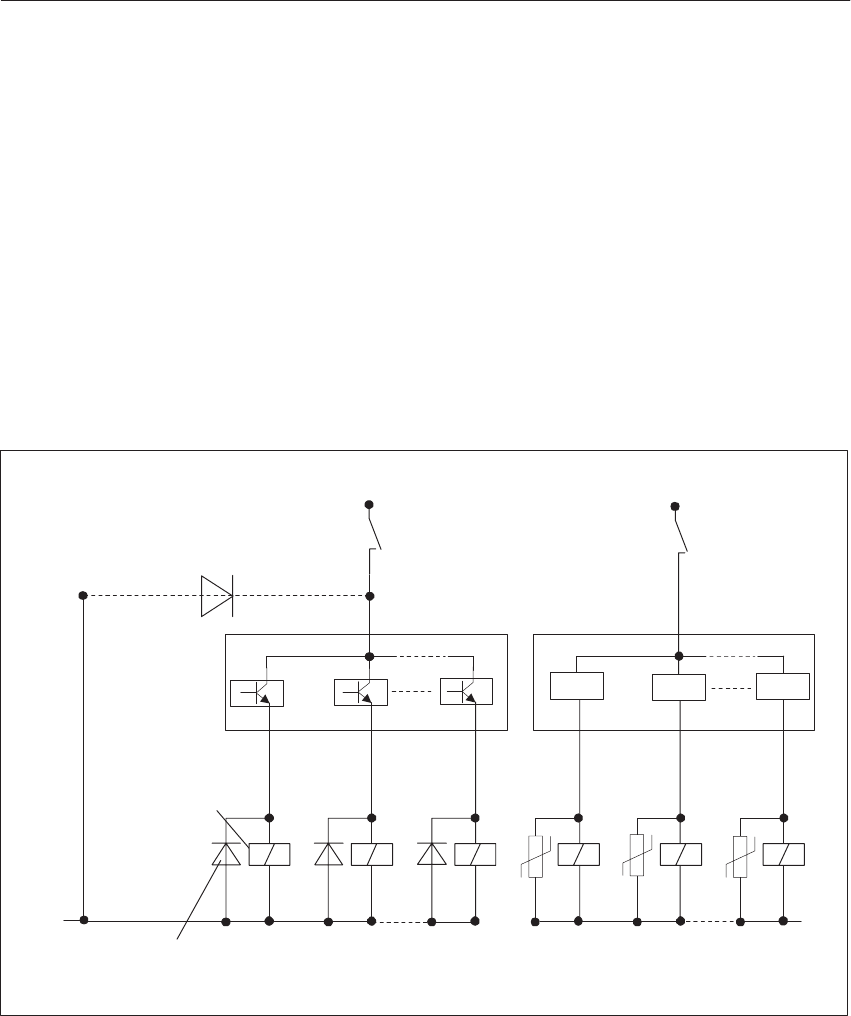
8-27
System Manual
C79000-G8576-C199-06
With two-wire switches and AC voltage outputs:
Disconnection of the supply voltage during operation is not permissible
without additional protective circuitry. Quenching of the inductive load is
achieved here via the load power supply unit or system. Since, as two-wire
switches, the outputs have no L-/N (0 V ground) terminal, the inductive load
cannot be quenched on the module when the supply line is disconnected.
With the 453 and 457 modules using two-wire switches, the overvoltages can
result in destruction of the module.
If the load voltage must be switched for safety reasons, you must provide
external quenching circuitry at each inductive load (see Figure 8-15).
Instead, with the 453 and 457 modules using two-wire switches, you can
insert a quenching device (diode) with adequate ratings after contact K from
the L+ line to L-.
Digital Output
DC Voltage
Digital Output
AC Voltage
L+ L
N
L–
Contact, Switch
Contactor,
Solenoid Valve, etc.
Quenching Device
(Diode, Zener Diode, R/C Network or Varistor)
Common Diode
only on 453/457
ELR
ELR
ELR
Figure 8-15 Quenching of Inductive Loads when Switching the Supply Line L+ and L
Two-Wire Switches
Di
g
ital Input/Output Modules

8-28 System Manual
C79000-G8576-C199-06
8.3 Common Technical Specifications
Important for the USA and Canada
The following approvals have been obtained for all the modules listed in this
chapter:
UL Listing Mark
Underwriters Laboratories (UL) to Standard UL 508, Report E 85972
CSA Certification Mark
Canadian Standard Association (CSA) to
Standard C 22.2 No. 142, Report LR 63533
Valid safety specifications VDE 0160
Class of protection I
Degree of protection IP 20 to IEC 529/DIN 40050 when empty slots are covered
by dummy front plates
Climatic ambient conditions
Operation in equipment with fan 0 to 55C
Operation in equipment without fan (module clear-
ance: 40 mm) 0 to 55C
Supply air measured at lower inlet of power supply; for a
cabinet assembly, note that the removable power dissipation
depends on the cabinet design, its ambient temperature and
arrangement of equipment.
Transportation and storage temperature –40 to 70C
Temperature variation
in operation
transportation and storage 10 K/h max.
20 K/h max.
(When delivered under 0 oC, allow 3 h min. settling time on
account of possible condensation)
Relative humidity
in operation
transportation and storage 95 % max. at 25 oC, no condensation
95 % max. at 25 oC, no condensation
Site altitude
in operation
transportation and storage
–1000 m to +1500 m
–1000 m to +3500 m
Polluants S02
H2S0.5 ppm max. (rel. humidity under 60 %)
0.1 ppm max. (rel. humidity under 60 %)
Mechanical ambient conditions
Vibration in operation 10 to 58 Hz (const. amplitude 0.15 mm)
58 to 500 Hz (const. acceleration 2 g)
Mechanical requirements Installation in stationary equipment which is not free from
vibrations; installation on ships and vehicles, allowing for
special installation specifications, but not on the engine
Operand identifiers
for inputs I = Input
for outputs Q = Output
Parameters 0.0 to 255.7
Di
g
ital Input/Output Modules

8-29
System Manual
C79000-G8576-C199-06
Terminals
Rated DC voltage of module L+
Reference potential for DC voltage L–
Rated AC voltage of module L
Reference potential for AC voltage N
Permissible line length for digital output modules Allow for the line resistance and tolerance of the supply
voltage for the relevant output current.
Enable inputs F+
F–
(Enable voltage according to the rated voltage of the mod-
ule)
Short-circuit signaling output (only when the short-
circuited output is at logic 1) H+
(Supply for 1L+, referred to L- of the module)
Max. permissible supply voltage
for rated voltage 24 V DC (L+/L-) 1)
for rated voltage 60 V DC (L+/L-) 1)
for rated voltage 115 V/230 V AC (L/N)
36 V DC for 100 ms
90 V DC for 100 ms
276 V AC for 100 ms
Supply voltage ripple Vpp referred to rated DC vol-
tage
15 % max. 2)
Interference suppression at digital inputs v 1.5 ms 3)
Interference pulse length at digital outputs v 1.5 ms 3) 4)
Circuitry for inductive loads: Protective devices to limit the breaking voltage are provided
on the digital output modules. Additional protective cir-
cuitry for the load is only required in exceptional cases.
Exception: 458 digital output module
Switching of capacitive loads: 50 nF max. at full load
Safety tests
Surge voltage test to IEC 255-4 DC: Input/output to L-: Vp = 1 kV, 1.2/50 ms
AC: Input/output to L-: Vp = 2.5 kV, 1.2/50 ms
RFI test to IEC 255-4 DC: Input/output to L-: Vp = 1 kV, 1 MHz
AC: Input/output to L-: Vp = 2.5 kV, 1 MHz
Safety test for the -4UA13/-4UA14 modules
Immunity from conducted interference on signal
line 1 kV to IEC 801-4 (burst) for -4UA13 module
2 kV to IEC 801-4 (burst) for -4UA14 module
Immunity from discharge of static electricity 8 kV discharge in air to IEC 801-2, equivalent to 4 kV con-
tact discharge (see Chap. 3 and page 4-16)
6 kV contact discharge for -4UA14 module
1) Supply and signal voltages must be produced as functional voltage with safety separation.
2) The supply voltage range values are limit values. They include ripple.
3) If not otherwise specified
4) Must be bridged by the signal receiver
Di
g
ital Input/Output Modules

8-30 System Manual
C79000-G8576-C199-06
8.4 Specification Sheets for the Modules
The common technical specifications are given in Section 8.3.
8.4.1 6ES5 420-4UA13/4UA14 Digital Input Module
–4UA13 –4UA14
Rated input voltage 24 V DC
Number of inputs 32
Isolation no
Input voltage
for logic 0
for logic 1 –33 to 5 V
13 to 33 V
Rated input current 8.5 mA
Input frequency 100 Hz max.
Delay time 3 ms typical (1.4 to 5 ms)
Input resistance 2.8 kilohms typical
Coincidence factor (total load capability) 100 %
Permissible line length 600 m max., unshielded;
1000 m max., shielded
Power supply
Digital section from system bus 5 V, 80 mA typical 5 V, 30 mA typical
Supply voltage for 2-wire BERO 22 to 33 V
Power dissipation (rated operation) 7.0 W
Enable input (F+/F–)
Rated input voltage 24 V DC
Input voltage
for logic 0
for logic 1 –33 to 5 V
13 to 33 V
Rated input current 5 mA
Permissible line length 200 m max.
Mechanical specifications
Dimensions (W x H x D) 20 mm x 255 mm x 195 mm
Weight Approx. 0.4 kg
Di
g
ital Input/Output Modules
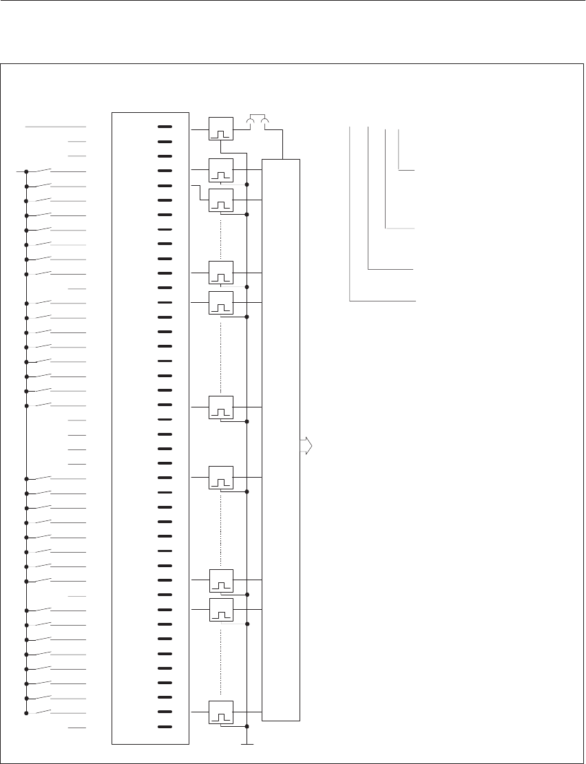
8-31
System Manual
C79000-G8576-C199-06
1I0.0
1I0.1
1I0.3
1I0.4
1I0.5
1I0.6
1I0.7
1I0.2
1I1.0
1I1.1
1I1.2
1I1.3
1I1.4
1I1.5
1I1.6
1I1.7
1I2.0
1I2.1
1I2.2
1I2.3
1I2.4
1I2.5
1I2.6
1I2.7
1I3.0
1I3.1
1I3.2
1I3.3
1I3.4
1I3.5
1I3.6
1I3.7
F+ 1
2
3
4
5
6
7
8
9
10
11
12
13
14
15
16
17
18
19
20
21
22
23
24
25
26
27
28
29
30
31
32
33
34
35
36
37
38
39
40
41
42
g
g
g
g
g
g
g
g
g
g
g
g
g
g
g
g
g
g
g
g
g
g
g
g
g
g
g
g
g
g
g
t
2)
2)
2)
2)
2)
2)
2)
2)
t
t
t
g
t
t
t
t
t
t
(L–)
Data Memory and S5 Bus Control
1)
x20
M
ext. Mext.
Front Strip
LED Pin
L+
Connection of
Process Signal
Lines
Example of connection designation
for an input:
Input 5 (5th bit);
0 to 7 possible
Address of input byte
(1st byte);
0 to 255 possible
I = Input
1st group (not specified
in the address)
(1) I1.5
Block Diagram of
Module Inputs
g = Green LED (status indicator)
F+ = Enable input
Connect L- of the power supply unit to the reference potential (PE).
1) Changeover of enable mode with jumper X20:
Jumper inserted = Enable input active (factory setting)
Jumper open = Enable input inactive.
2) The terminal is not connected internally. Even when this terminal is connected to input voltages, the clearances in air
and leakage paths remain adequate to UL, CSA and VDE.
Di
g
ital Input/Output Modules

8-32 System Manual
C79000-G8576-C199-06
8.4.2 6ES5 430-4UA13/4UA14 Digital Input Module
–4UA13 –4UA14
Rated input voltage 24 V DC
Number of inputs 32
Isolation Yes, 1 group with 32 inputs
Input voltage
for logic 0
for logic 1 1)
–3 to 7 V
13 to 33 V
–33 to 7 V
13 to 33 V
Rated input current 7.0 mA
Input frequency 100 Hz max.
Delay time 4 ms typical (2.5 to 6.5 ms) 3 ms typical (1.4 to 5.0 ms)
Input resistance 3.3 kilohms typical
Coincidence factor (total load capability) 100 %
Permissible line length 600 m max., unshielded;
1000 m max., shielded
Power supply
Digital section from system bus 5 V, 100 mA typical 5 V, 30 mA typical
Supply voltage for 2-wire BERO 22 to 33 V
Supply voltage L+/L– 24 V (20 to 30 V) L+ to terminal 3 not re-
quired
Current consumption from L+/L– Approx. 100 mA L+ not required
Power dissipation (rated operation) 8.3 W 5.6 W
Enable input (F+/F–)
Rated input voltage 24 V DC
Input voltage
for logic 0
for logic 1
–33 to 5 V
13 to 33 V
Rated input current 5 mA
Permissible line length 200 m max.
Voltage test to VDE 0160 Between group and ground point: 1250 V AC
Mechanical specifications
Dimensions (W x H x D) 20 mm x 255 mm x 195 mm
Weight Approx. 0.4 kg
1) Polarity reversal for up to 8 inputs per module is permissible.
Di
g
ital Input/Output Modules
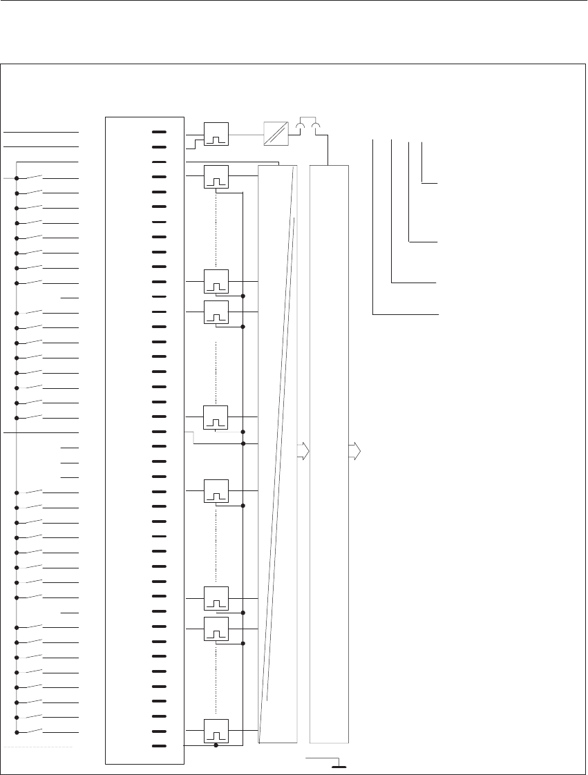
8-33
System Manual
C79000-G8576-C199-06
1I0.0
1I0.1
1I0.3
1I0.4
1I0.5
1I0.6
1I0.7
1I0.2
1I1.0
1I1.1
1I1.2
1I1.3
1I1.4
1I1.5
1I1.6
1I1.7
1I2.0
1I2.1
1I2.2
1I2.3
1I2.4
1I2.5
1I2.6
1I2.7
1I3.0
1I3.1
1I3.2
1I3.3
1I3.4
1I3.5
1I3.6
1I3.7
L+
F+
L+
L–
L+
F–
L–
L–3)
4)
1
2
3
4
5
6
7
8
9
10
11
12
13
14
15
16
17
18
19
20
21
22
23
24
25
26
27
28
29
30
31
32
33
34
35
36
37
38
39
40
41
42
g
g
g
g
g
g
g
g
g
g
g
g
g
g
g
g
g
g
g
g
g
g
g
g
g
g
g
g
g
g
g
t
2)
2)
2)
2)
2)
t
t
g
t
t
t
t
t
t
L–
1)
LED Pin
L–
x20
Shield
Isolation
L+
(1) I3.5
Front StripConnection of
Process Signal
Lines
Example of connection designation
for an input:
Input 5 (5th bit);
0 to 7 possible
Address of input byte
(3rd byte);
0 to 255 possible
I = Input
1st group (not specified
in the address)
Block Diagram of
Module Inputs
Data Memory and S5 Bus Control
g = Green LED (status indicator)
F+/F- = Enable input
1) Changeover of enable mode with jumper X20:
Jumper inserted = Enable input active (factory setting)
Jumper open = Enable input inactive.
2) The terminal is not connected internally. Even when this terminal is connected to input voltages, the clearances in air and
leakage paths remain adequate to UL, CSA and VDE.
3) By connecting L- to pin 42, a leading and trailing connection to ground is established on the module when it is plugged in
and removed.
4) L+ to terminal 3 is not required for -4UA14.
Di
g
ital Input/Output Modules

8-34 System Manual
C79000-G8576-C199-06
8.4.3 6ES5 431-4UA12 Digital Input Module
Rated input voltage 24 to 60 V DC
Number of inputs 16
Isolation Yes, 16 inputs
Input voltage
for logic 0
for logic 1
–33 to 8 V
13 to 72 V
Rated input current 4.5 to 7.5 mA (24 to 60 V DC)
Input frequency 100 Hz max.
Delay time 3 ms typical (1.4 to 5 ms)
Coincidence factor (total load capability) 100 %
Permissible line length 400 m max. unshielded;
1000 m max. shielded
Power supply
Digital section from system bus 5 V, 90 mA typical
Supply voltage for 2-wire BERO 22 to 72 V
Power dissipation (rated operation) 2.2 to 7.7 W (24 to 60 V)
Enable input (F+/F–)
Rated input voltage 24 to 60 V DC
Input voltage
for logic 0
for logic 1
–72 to 8 V
13 to 72 V
Rated input current 5 mA (at 48 V DC)
Permissible line length 200 m max.
Voltage test to VDE 0160 Between two groups: 1250 V AC
Between group and ground point: 1250 V AC
Mechanical specifications
Dimensions (W x H x D) 20 mm x 255 mm x 195 mm
Weight Approx. 0.4 kg
Di
g
ital Input/Output Modules
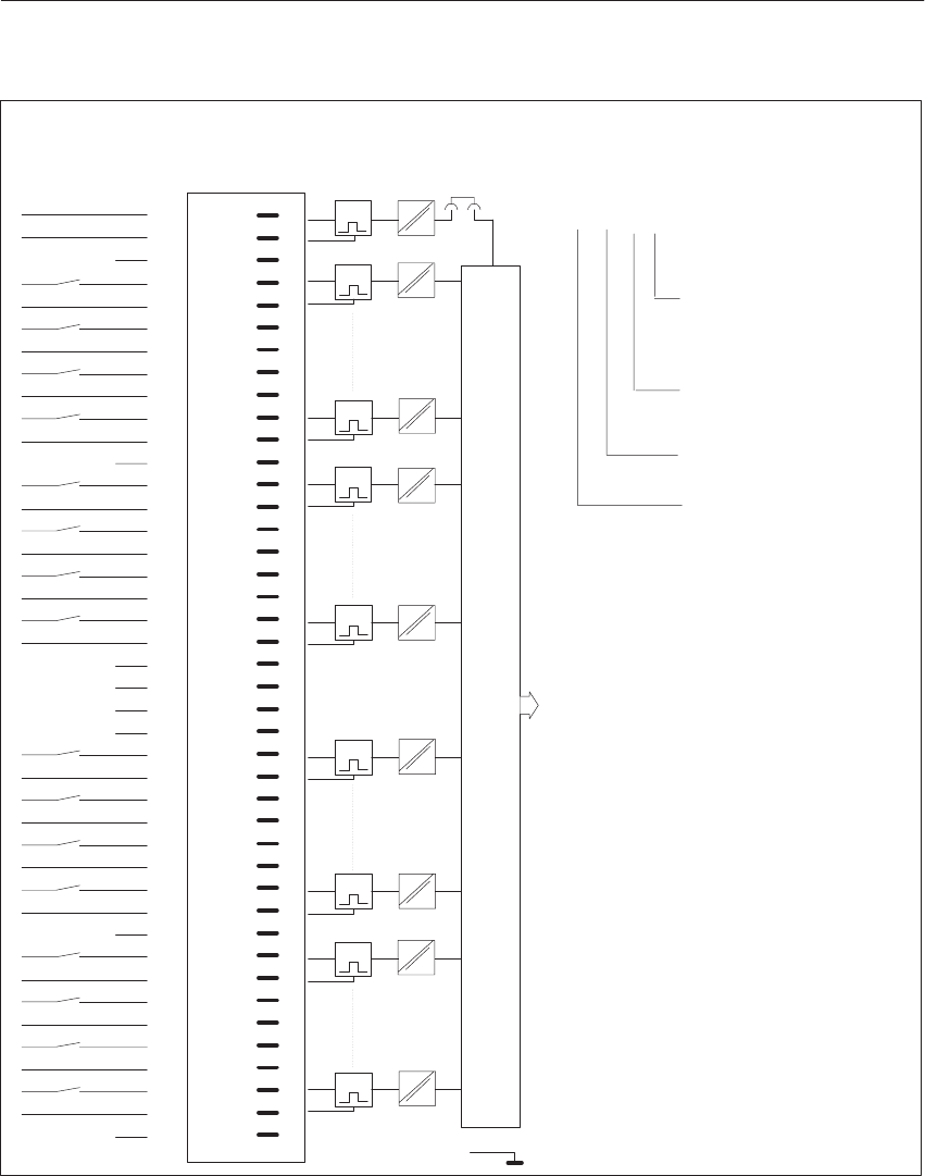
8-35
System Manual
C79000-G8576-C199-06
F+ 1
2
3
4
5
6
7
8
9
10
11
12
13
14
15
16
17
18
19
20
21
22
23
24
25
26
27
28
29
30
31
32
33
34
35
36
37
38
39
40
41
42
g
g
g
g
g
g
g
g
g
g
g
g
g
g
g
g
LED Pin
1L+
1L–
2L+
2L–
3L+
3L–
4L+
4L–
5L+
5L–
6L+
6L–
7L+
7L–
8L+
8L–
9L+
9L–
10L+
10L–
11L+
11L–
12L+
12L–
13L+
13L–
14L+
14L–
15L+
15L–
16L+
16L–
F–
L+
L–
2)
t
2)
2)
2)
3)
3)
2)
2)
t
t
t
t
t
t
t
t
1)
Shield
x20
1I0.0
1I0.0
2I0.1
3I0.2
3I0.2
4I0.3
4I0.3
2I0.1
5I0.4
5l0.4
6I0.5
6I0.5
7I0.6
7I0.6
8I0.7
8I0.7
9I1.0
9I1.0
10I1.1
10I1.1
11I1.2
11I1.2
12I1.3
12I1.3
13I1.4
13I1.4
14I1.5
14I1.5
15I1.6
15I1.6
16I1.7
16I1.7
+
–
+
–
+
–
+
–
+
–
+
–
+
–
+
–
+
–
+
–
+
–
+
–
+
–
+
–
+
–
+
–
(8) I0.7
Front StripConnection of
Process Signal
Lines
Example of connection designation
for an input:
Input 7 (7th bit);
0 to 7 possible
Address of input byte
(byte 0);
0 to 255 possible
I = Input
8th group (not specified
in the address)
Block Diagram of
Module Inputs
Data Memory and S5 Bus Control
g = Green LED (status indicator)
F+/F- = Enable input
1) Changeover of enable mode with jumper X20:
Jumper inserted = Enable input active (factory setting)
Jumper open = Enable input inactive.
2) The terminal is not connected internally. When this terminal is connected to the input voltages, the clearances in air and
leakage paths are no longer adequate to UL and CSA, but comply with VDE.
3) The terminal is not connected internally. When this terminal is connected to the input voltages, the clearances in the air and
leakage paths remain adequate to UL, CSA and VDE.
Di
g
ital Input/Output Modules

8-36 System Manual
C79000-G8576-C199-06
8.4.4 6ES5 432-4UA12 Digital Input Module
Rated input voltage 24 V DC
Number of inputs 32
Isolation Yes, 4 groups of 8 inputs
Input voltage
for logic 0
for logic 1
–33 to 5 V
13 to 33 V
Rated input current 8.5 mA
Input frequency 100 Hz / 300 Hz / 1 kHz max.
Delay time 1) 3 ms / 1 ms / 0.3 ms typical
(1.5 to 4.8 ms/0.5 to 1.6 ms/0.15 to 0.48 ms)
Input resistance 2.8 kilohms typical
Coincidence factor (total load capability) 100 %
Permissible line length 600 m max. unshielded (3 ms);
200 m max. unshielded (1 ms);
50 m max. unshielded (0.3 ms)
Power supply
Digital section from system bus 5 V, 200 mA typical
Supply voltage for 2-wire BERO 22 to 33 V
Power dissipation (rated operation) 7.5 W
Enable input (F+/F–)
Rated input voltage 24 V DC
Input voltage
for logic 0
for logic 1
–33 to 5 V
13 to 33 V
Rated input current 5 mA
Permissible line length 200 m max.
Voltage test to VDE 0160 Between two groups: 1250 V AC
Between group and ground point: 1250 V AC
Mechanical specifications
Dimensions (W x H x D) 20 mm x 255 mm x 195 mm
Weight Approx. 0.55 kg
1) Selectable in bytes with switch S5
Di
g
ital Input/Output Modules
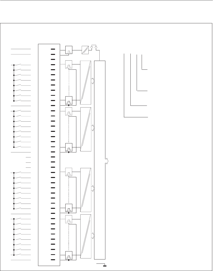
8-37
System Manual
C79000-G8576-C199-06
1I0.0
1I0.1
1I0.3
1I0.4
1I0.5
1I0.6
1I0.7
1I0.2
2I1.0
2I1.1
2I1.2
2I1.3
2I1.4
2I1.5
2I1.6
2I1.7
3I2.0
3I2.1
3I2.2
3I2.3
3I2.4
3I2.5
3I2.6
3I2.7
4I3.0
4I3.1
4I3.2
4I3.3
4I3.4
4I3.5
4I3.6
4I3.7
1
2
3
4
5
6
7
8
9
10
11
12
13
14
15
16
17
18
19
20
21
22
23
24
25
26
27
28
29
30
31
32
33
34
35
36
37
38
39
40
41
42
g
g
g
g
g
g
g
g
g
g
g
g
g
g
g
g
g
g
g
g
g
g
g
g
g
g
g
g
g
g
g
3)
3)
4)
3)
g
LED Pin
F+L+
F–L–
1L+
1L–
2L+
2L–
3L+
3L–
4L+
4L–
t
t
t
t
t
t
t
t
t
1)
x20
Shield
(4) I3.5
Front StripConnection of
Process Signal
Lines
Example of connection designation
for an input:
Input 5 (5th bit);
0 to 7 possible
Address of input byte
(3rd byte);
0 to 255 possible
I = Input
4th group (not speci-
fied in the address)
Block Diagram of
Module Inputs
Data Memory and S5 Bus Control
g = Green LED (status indicator)
F+/F- = Enable input
1) Changeover of enable mode with jumper X20:
Jumper inserted = Enable input active (factory setting)
Jumper open = Enable input inactive.
2) Only 128 to 255 permissible with group signal and interrupt.
3) The terminal is not connected internally. When this terminal isconnected to the input voltages, the clearances in air and
leakage paths are no longer adequate to UL and CSA, but comply with VDE.
4) The terminal is not connected internally. When this terminal is connected to the input voltages, the clearances in air and
leakage paths remain adequate to UL, CSA and VDE.
Di
g
ital Input/Output Modules
8-38 System Manual
C79000-G8576-C199-06
Labeling for module cover:
Mark the switch settings in the free fields.
X3
Master (on)
Slave (off)
Delay-Time X4
Byte 3 ms 1 ms 0.3 ms S5 Group Signal
3
active (on)
3 inactive (off)
2
2
1
1
0
0
Edge Trigger S3
3
S1 Interrupt
3 IRA
2
IRB
2 IRC
1
IRD
1 IRE
0
IRF
0 IRG
Byte INT
Group Signal
Master submodule (Jumper X3 on) Slave submodule (Jumper X3 off)
Data-
bit without
Slave 1
Slave 2
Slave 3
Slave 4
Slave 5
Slave 6
Slave 7
Slave 1.Slave
o.1 2.Slave
0.2 3.Slave
0.3 4.Slave
0.4 5.Slave
0.5 6.Slave
0.6 7.Slave
0.7 S2
0
1
2
3
4
5
6
7
Di
g
ital Input/Output Modules

8-39
System Manual
C79000-G8576-C199-06
8.4.5 6ES5 434-4UA12 Digital Input Module
Rated input voltage (LH+) DC 5 to 15 V
Rated input voltage (L+) DC 12 to 24 V (NAMUR) 1)
Number of inputs 32
Isolation Yes, 1 group of 32 inputs
Input voltage TTL: for logic 0 for logic 1
CMOS: for logic 0
for logic 1
0 to 0.8 V
2.4 to 5.0 V
0 V to 0.3 x LH+
0.7 V x LH+ to 1 x LH+
Rated input current TTL: for logic 0
for logic 1
CMOS: for logic 0
for logic 1
NAMUR: for logic 0
for logic 1
–1 mA
0.1 mA or open input
–1 to –3 mA (5 to 15 V)
0.1 to 0.3 mA (5 to 15 V)
v 1.2 mA
w 2.1 mA
Internal resistance 1 kilohm typical
Line resistance 50 ohms max.
Input frequency 100 Hz max.
Delay time
for positive-going edge
for negative-going edge
3 ms typical (1.4 to 5 ms)
3 ms typical (1.4 to 5 ms)
Coincidence factor (total load capability) 100 %
Permissible line length TTL/CMOS
NAMUR 200 m max. unshielded
600 m max. unshielded
Power supply
Digital section from system bus 5 V, 80 mA typical
Supply voltage L+/L– 24 V (20 to 30 V)
Current consumption at L+/L– 100 mA each
Current consumption at LH+/LH– 150 mA each at 15 V input voltage
Current output from LH+/LH– 120 mA each at 8.5 V sensor supply (NAMUR) 2)
Power dissipation (rated operation) 5.5 W
Enable input (F+/F–)
Rated input voltage 5/ 15/ 24 V DC
Input voltage for logic 0
for logic 1 –15 to 2 V
4 to 33 V
Rated input current 5 mA
Permissible line length 100 m max.
Voltage test to VDE 0160 Between group and ground point: 1250 V AC
Mechanical specifications
Dimensions (W x H x D) 20 mm x 255 mm x 195 mm
Weight Approx. 0.45 kg
1) NAMUR = Sensor with current output to DIN 19234, Standards Committee for Measurement and Control.
However, the module is not intrinsically safe.
2) The current consumption from L+/L- increases accordingly.
Di
g
ital Input/Output Modules

8-40 System Manual
C79000-G8576-C199-06
Connection for supply voltage,
jumpers and sensor supply in groups of 2 bytes
(16 inputs each)
Byte 0 + 1
Byte 2 + 3 1L+ Terminal 3
2L+ Terminal 24 1LH+ Terminal 12
2LH+ Terminal 33 1LH– Terminal 22
2LH– Terminal 23
y
Type of
Sensor
NAMUR Connect to L+
(24 V supply) Output for sensor
supply Jumper to L–
Terminal 21
CMOS open Connect to 5 to 15 V
supply open
TTL open Connect to 5 V supply open
The types of sensor can be arbitrarily mixed in groups of 16 inputs.
With CMOS TTL sensors, open inputs are at logic 1 (LED is lit).
Di
g
ital Input/Output Modules
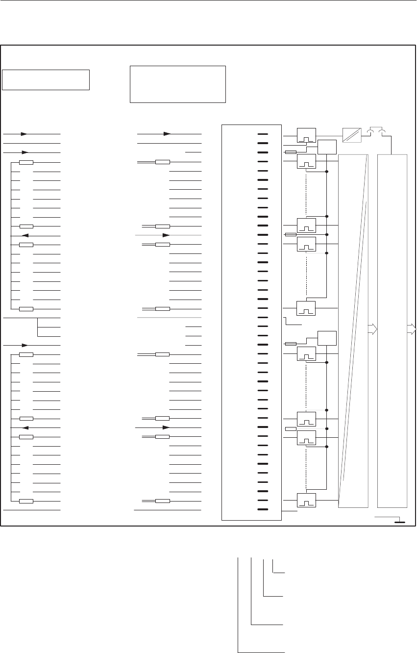
8-41
System Manual
C79000-G8576-C199-06
1
2
3
4
5
6
7
8
9
10
11
12
13
14
15
16
17
18
19
20
21
22
23
g
g
g
g
g
g
g
g
g
g
g
g
g
g
g
g
g
g
g
g
g
g
g
g
g
g
g
g
g
g
g
t
t
t
g
t
t
t
t
t
t
L–
1)
Front Strip
LED Pin
L–
x20
Shield
Isolation
24
25
26
27
28
29
30
31
32
33
34
35
36
37
38
39
40
41
42
.
.
.
.
.
.
.
.
.
.
.
LH+
L–
L–
TTL/CMOS
.
.
.
.
.
.
.
.
.
.
.
1LH+
Q
Q
Q
Q
Q
Q
Q
Q
TTL/CMOS
LH+
LH+
Sensors with TTL- and/or
CMOS Outputs
Sensor Supply +/–
L– = 0V
TTL LH+ = 5V:
CMOS : LH+ = 5...15V
L– = 0V
+
_
+
_
+
_
+
_
+
_
+
_
+
_
+
_
L–
1
2
3
4
5
6
7
8
9
10
11
12
13
14
15
16
17
18
19
20
21
22
23
L+
L–
L+
L–
NAMUR
L–
1LH–
2LH–
1I0.0
1I0.1
1I0.3
1I0.4
1I0.5
1I0.6
1I0.7
1I0.2
1I1.0
1I1.1
1I1.2
1I1.3
1I1.4
1I1.5
1I1.6
1I1.7
F+
F–
1L+
1LH+
Sensor Supply LH+
from L+ = 24V
24
25
26
27
28
29
30
31
32
33
34
35
36
37
38
39
40
41
42
NAMUR
2L+
1I2.0
1I2.1
1I2.2
1I2.3
1I2.4
1I2.5
1I2.6
1I2.7
1I3.0
1I3.1
1I3.2
1I3.3
1I3.4
1I3.5
1I3.6
1I3.7
2LH+
L–
L+
NAMUR–
and
TIL/CMOS
Sensors
(can be
connected
.
.
.
.
.
.
.
.
.
.
.
.
.
.
.
.
.
.
.
.
.
.
Connection of NAMUR Sensors
in groups of 16)
Data Memory and S5 Bus Control
1I2.0
1I2.1
1I2.2
1I2.3
1I2.4
1I2.5
1I2.6
1I2.7
1I3.0
1I3.1
1I3.2
1I3.3
1I3.4
1I3.5
1I3.6
1I3.7
2LH+
L–
1I0.0
1I0.1
1I0.3
1I0.4
1I0.5
1I0.6
1I0.7
1I0.2
1I1.0
1I1.1
1I1.2
1I1.3
1I1.4
1I1.5
1I1.6
1I1.7
F+
F–
(1) I3.5
g = Green LED (status indicator)
F+/F- = Enable input
1) Changeover of enable mode with jumper X20:
Jumper inserted = Enable input active (factory setting)
Jumper open = Enable input inactive.
Connection of
Process Signal
Lines Block Diagram of
Module Inputs
Connection of
Process Signal Lines
Example of connection designation for an input:
Input 5 (5th bit);
0 to 7 possible
Address of input byte
(1st byte);
0 to 255 possible
I = Input
1st group (not speci-
fied in the address)
Di
g
ital Input/Output Modules

8-42 System Manual
C79000-G8576-C199-06
8.4.6 6ES5 435-4UA12 Digital Input Module
Rated input voltage 24 to 60 V AC (47 to 63 Hz)
Number of inputs 16
Isolation Yes, 2 groups of 8 inputs
Input voltage
for logic 0
for logic 1
0 to 15 V AC
20 to 72 V AC
Rated input current
bei AC 48 V
bei AC 60 V
15 mA typical
20 mA typical
Input current for 2-wire BERO
for logic 0
for logic 1
v 5 mA
w 10 mA
Input frequency 20 Hz max. as pulse train
Delay time
for positive-going edge
for negative-going edge
5 ms typical (2 to 15 ms)
20 ms typical (10 to 25 ms)
Input resistance 3 kilohms typical
Coincidence factor (total load capability)
ventilated
not ventilated
100 %
75 % at 60 V;
100 % at 35 o C;
100 % at 30 V
Permissible line length 600 m max. unshielded
1000 m max. shielded
Power supply
Digital section from system bus 5 V, 100 mA typical
Power dissipation (rated operation) 3.5 W at 24 V, 18.0 W at 60 V
Enable input (F+/F–) Jumper in front connector
Voltage test to VDE 0160 Between two groups: 2000 V AC;
Between group and ground point: 1500 V AC
Mechanical specifications
Dimensions (W x H x D) 40 mm x 255 mm x 195 mm
Weight Approx. 0.55 kg
Di
g
ital Input/Output Modules
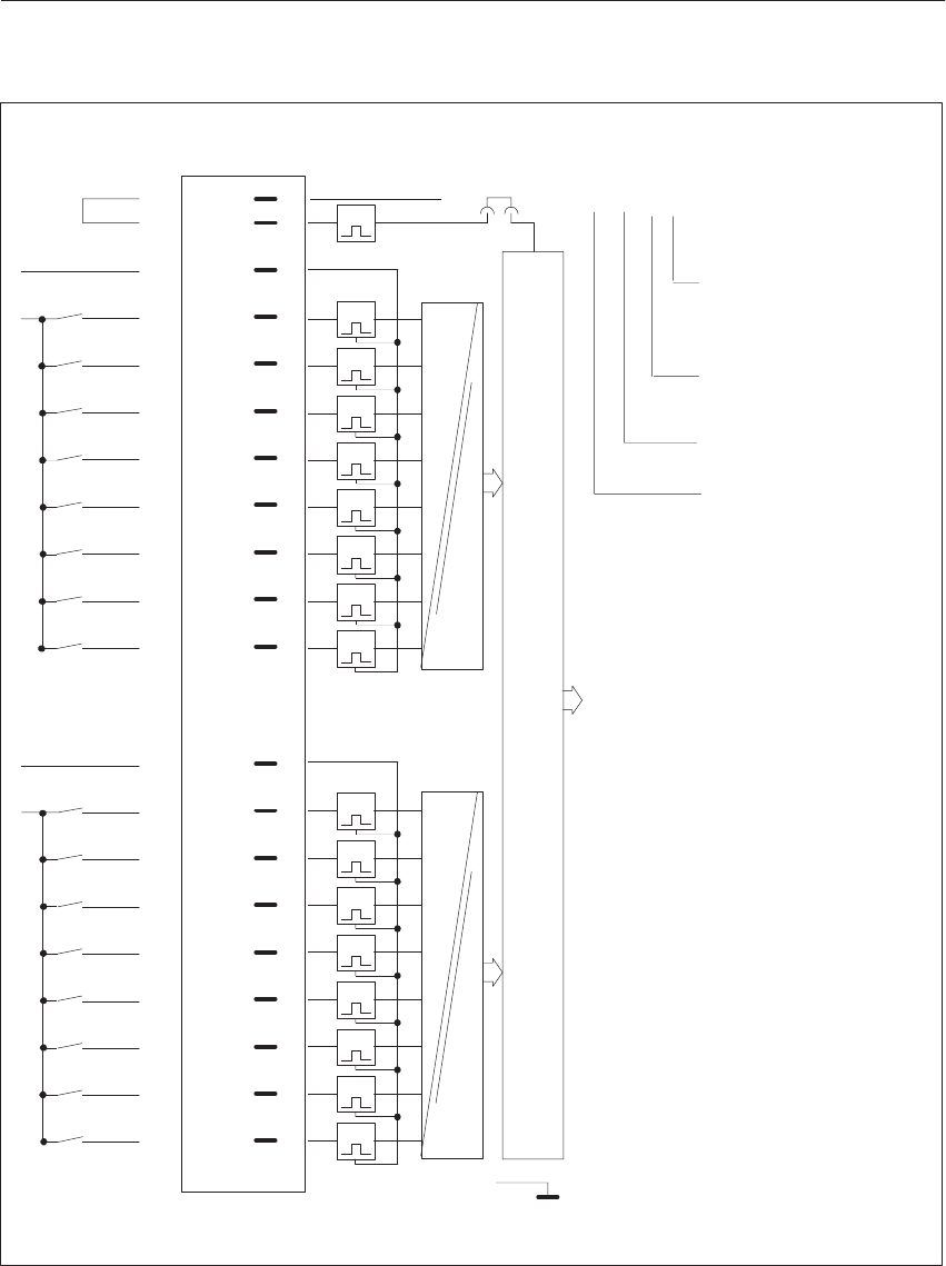
8-43
System Manual
C79000-G8576-C199-06
1N
1I0.1
1I0.2
1I0.0
1I0.4
1I0.5
1I0.6
1I0.7
2N
2I1.0
2I1.1
2I1.2
2I1.4
2I1.5
2I1.6
2I1.7
2L
F+
F– 1
2
4
6
8
10
12
14
16
18
20
25
27
29
31
33
35
37
39
41
g
g
g
g
g
g
g
g
g
g
g
g
g
g
g
g
LED Pin
Shield
1N
1I0.3
2I1.3
2N
t
t
t
t
t
t
t
t
t
t
t
t
t
t
t
t
Isolation
Isolation
1)
x20
t
+5V (2) I1.2
Front StripConnection of
Process Signal
Lines
Example of connection designation for
an input:
Input 2 (2nd bit);
0 to 7 possible
Address of input byte
(1st byte);
0 to 255 possible
I = Input
2nd group (not specified
in the address)
Block Diagram of
Module Inputs
Data Memory and S5 Bus Control
g = Green LED (status indicator)
F+/F- = Enable input (jumper in front connector)
1) Changeover of enable mode with jumper X20:
Jumper inserted = Enable input active (factory setting)
Jumper open = Enable input inactive.
Di
g
ital Input/Output Modules

8-44 System Manual
C79000-G8576-C199-06
8.4.7 6ES5 436-4UA12 Digital Input Module
Rated input voltage 115 to 230 V AC (47 to 63 Hz)
Number of inputs 16
Isolation Yes, 2 groups of 8 inputs
Input voltage
for logic 0
for logic 1
0 to 60 V AC
90 to 264 V AC
Rated input current
at 115 V AC
at 230 V AC
15 mA typical
25 mA typical
(2-wire-BERO can be connected)
Input frequency 20 Hz max. as pulse train
Delay time
for positive-going edge
for negative-going edge
5 ms typical (2 to 15 ms)
20 ms typical (10 to 25 ms)
Input resistance 10 kilohms typical
Coincidence factor (total load capability)
ventilated
not ventilated
100 %
75 % at 230 V AC;
100 % at 35 oC;
100 % at 115 V AC
Permissible line length 600 m max. unshielded
1000 m max. shielded
Power supply
Digital section from system bus 5 V, 100 mA typical
Power dissipation (rated operation) 3.5 W at 115 V, 17.0 W at 230 V
Enable input (F+/F–) Jumper in front connector
Voltage test to VDE 0160 Between two groups: 2000 V AC;
Between group and ground point: 1500 V AC
Mechanical specifications
Dimensions (W x H x D) 40 mm x 255 mm x 195 mm
Weight Approx. 0.55 kg
Di
g
ital Input/Output Modules
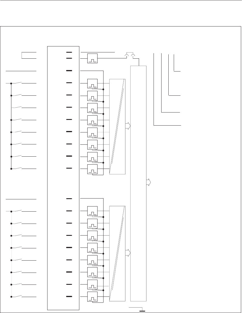
8-45
System Manual
C79000-G8576-C199-06
1N
1I0.1
1I0.2
1I0.0
1I0.4
1I0.5
1I0.6
1I0.7
2N
2I1.0
2I1.1
2I1.2
2I1.4
2I1.5
2I1.6
2I1.7
1L
F+
F– 1
2
4
6
8
10
Shield
1N
1I0.3
2I1.3
2N
t
t
t
t
t
t
t
12
14
16
18
20
25
27
29
31
33
35
37
39
41
g
g
g
g
g
g
g
g
g
g
g
g
g
g
g
g
LED Pin
t
t
t
t
t
t
t
t
t
Isolation
Isolation
1)
x20
t
+5V
2L
(1) I0.4
Front StripConnection of
Process Signal
Lines
Example of connection designation for
an input:
Input 4 (4th bit);
0 to 7 possible
Address of input byte
(byte 0);
0 to 255 possible
I = Input
1st group (not speci-
fied in the address)
Block Diagram of
Module Inputs
Data Memory and S5 Bus Control
g = Green LED (status indicator)
F+/F- = Enable input (jumper in front connector)
1) Changeover of enable mode with jumper X20:
Jumper inserted = Enable input active (factory setting)
Jumper open = Enable input inactive.
Di
g
ital Input/Output Modules

8-46 System Manual
C79000-G8576-C199-06
8.4.8 6ES5 436-4UB12 Digital Input Module
Rated input voltage 115 to 230 V AC (47 to 63 Hz)
Number of inputs 8
Isolation Yes, 8 inputs
Input voltage
for logic 0
for logic 1
0 to 60 V AC
90 to 264 V AC
Rated input current
at 115 V AC
at 230 V AC
15 mA typical
25 mA typical
(2-wire-BERO can be connected)
Input frequency 20 Hz max. as pulse train
Delay time
for positive-going edge
for negative-going edge
5 ms typical (2 to 15 ms)
20 ms typical (10 to 25 ms)
Input resistance 10 kilohms typical
Coincidence factor (total load capability) 100 %
Permissible line length 600 m max. unshielded
1000 m max. shielded
Power supply
Digital section from system bus 5 V, 80 mA typical
Power dissipation (rated operation) 2.0 W at 115 V, 8.5 W at 230 V
Enable input (F+/F–) Jumper in front connector
Voltage test to VDE 0160 Between two groups: 2000 V AC;
Between group and ground point: 1500 V AC
Mechanical specifications
Dimensions (W x H x D) 40 mm x 255 mm x 195 mm
Weight Approx. 0.5 kg
Di
g
ital Input/Output Modules
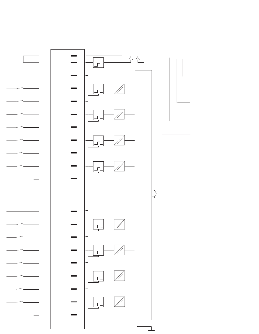
8-47
System Manual
C79000-G8576-C199-06
F+
F– 1
2
4
6
8
10
12
14
16
18
20
25
27
29
31
33
35
37
39
41
g
g
g
g
g
g
g
g
LED Pin
Shield
t
t
t
t
t
t
t
t
t
+5V
1N1N
2N2N
3N3N
4N4N
1I0.0
1L
2I0.1
2L
3I0.2
3L
4I0.3
4L
1)
x20
2)
5N5N
6N6N
7N7N
8N8N
5I0.45L
6I0.56L
7I0.67L
8I0.78L
2)
(6) I0.5
Front StripConnection of
Process Signal
Lines
Example of connection designation for
an input:
Input 5 (5th bit);
0 to 7 possible
Address of input byte
(byte 0);
0 to 255 possible
I = Input
6th group (not speci-
fied in the address)
Block Diagram of
Module Inputs
Data Memory and S5 Bus Control
g = Green LED (status indicator)
F+/F- = Enable input (jumper in front connector)
1) Changeover of enable mode with jumper X20:
Jumper inserted = Enable input active (factory setting)
Jumper open = Enable input inactive.
2) The terminal is not connected internally. When this terminal is connected to input voltages, the clearances in air and
leakage paths remain adequate to UL, CSA and VDE.
Di
g
ital Input/Output Modules

8-48 System Manual
C79000-G8576-C199-06
8.4.9 6ES5 441-4UA13/4UA14 Digital Output Module
–4UA13 –4UA14
Rated supply voltage L+ 24 V DC
Number of outputs 32, short-circuit protected 1)
Isolation no
Range for supply voltage 20 to 30 V DC
Fusing 6.3 A slow,
1 fuse per 8 outputs 7 A, fast, 1 fuse per 8 out-
puts
Output voltage
for logic 1
for logic 0
L+ -1.5 V min.
3 V max.
Switching current (resistive, inductive load) 5 mA to 0.5 A
Residual current at logic 0 0.5 mA max.
Switching current for lamps 0.22 A max. (5 W)
Switching frequency
with resistive load
with inductive load
100 Hz max.
2 Hz max. at 0.3 A, 0.5 Hz max. at 0.5 A
Breaking voltage (inductive) Limited to L+ – 47 V Limited to L+ –55 V
Total switching current 4 A max. per 8 outputs
Coincidence factor (total load capability)
ventilated
not ventilated
100 %
50 %; 100 % up to 35 oC
Permissible line length 400 m max. unshielded
Power supply
Digital section from system bus 5 V, 80 mA typical
Current consumption from L+/L– 24 V, 150 mA typical 24 V, 200 mA typical
Power dissipation (rated operation) 17.0 W 6.4 W
Enable input (F+/F–)
Rated input voltage 24 V DC
Input voltage
for logic 1
for logic 0
13 to 33 V
– 33 to 5 V
Rated input current 5 mA
Permissible line length 200 m max.
Short-circuit monitoring
Indicator for signaling output (H+) Red LED for every 8 outputs
Output voltage
referred to L– (with feed at 1L+)
for logic 1
for logic 0
1L+ – 5 V min.
3 V max.
1L+ –1.5 V min.
3 V max.
Switching current 10 mA max., limited
Mechanical specifications
Dimensions (W x H x D) 20 mm x 255 mm x 195 mm
Weight Approx. 0.45 kg
1) Short-circuit protection responds with line resistance v 15 ohms, irrelevant for the –4UA14 .
Di
g
ital Input/Output Modules
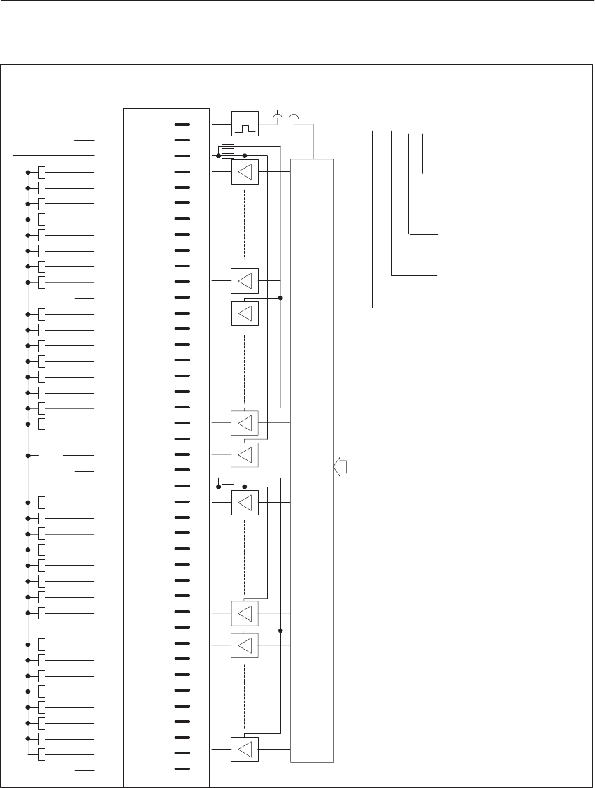
8-49
System Manual
C79000-G8576-C199-06
(2) Q2.6
1Q0.0
1Q0.1
1Q0.3
1Q0.4
1Q0.5
1Q0.6
1Q0.7
1Q0.2
1Q1.0
1Q1.1
1Q1.2
1Q1.3
1Q1.4
1Q1.5
1Q1.6
1Q1.7
2Q2.0
2Q2.1
2Q2.2
2Q2.3
2Q2.4
2Q2.5
2Q2.6
2Q2.7
2Q3.0
2Q3.1
2Q3.2
2Q3.3
2Q3.4
2Q3.5
2Q3.6
2Q3.7
F+ 1
2
3
4
5
6
7
8
9
10
11
12
13
14
15
16
17
18
19
20
21
22
23
24
25
26
27
28
29
30
31
32
33
34
35
36
37
38
39
40
41
42
g
g
g
g
g
g
g
g
g
g
g
g
g
g
g
g
g
g
g
g
g
g
g
g
g
g
g
g
g
g
g
2)
2)
2)
2)
2)
g
1)
x20
M
ext.
LED Pin
L–
L+
L+ 1L+ r
H– H+
L+ 2L+
r
r
r
t
Short-
Circuit
F1
F2
F3
F4
Data Memory and S5 Bus Control
Front StripConnection of
Process Signal
Lines
Example of connection designation
for an output:
Output 6 (6th bit);
0 to 7 possible
Address of output byte
(2nd byte);
0 to 255 possible
Q = Output
2nd terminal L+ (not
specified in the ad-
dress)
Block Diagram of
Module Inputs
g = Green LED (status indicator)
r = Red LED (short-circuit indicator)
F+ = Enable input, referred to 0 V ground
Connect L- of the power supply unit to the reference potential (PE).
1) Changeover of enable mode with jumper X20:
Jumper inserted = Enable input active (factory setting)
Jumper open = Enable input inactive.
2) The terminal is not connected internally. When this terminal is connected to the output voltages, the clearances in air
and leakage paths are no longer adequate to UL and CSA, but comply with VDE.
Di
g
ital Input/Output Modules

8-50 System Manual
C79000-G8576-C199-06
8.4.10 6ES5 451-4UA13/4UA14 Digital Output Module
–4UA13 –4UA14
Rated supply voltage L+ 24 V DC
Number of outputs 32, short-circuit protected 1)
Isolation Yes, 1 group of 32 outputs
Range for supply voltage 20 to 30 V DC
Fusing 6.3 A slow
1 fuse per 8 outputs 7 A fast
1 fuse per 8 outputs
Output voltage
for logic 1
for logic 0
L+ – 1,5 V min.
3 V max.
Switching current
(resistive, inductive load)
5 mA to 0.5 A
Residual current at logic 0 0.5 mA max.
Switching current for lamps 0.22 A max. (5 W)
Switching frequency
with resistive load
with inductive load
100 Hz max.
2 Hz max. at 0.3 A; 0.5 Hz max. at 0.5 A
Breaking voltage (inductive) Limited to L+ – 47 V Limited to L+ –55 V
Total switching current 4 A max. per 8 outputs
Coincidence factor (total load capability)
ventilated
not ventilated
100 %
50 %; 100 % up to 35 oC
Permissible line length 400 m max. unshielded
Power supply
Digital section from system bus 5 V, 80 mA typical
Current consumption from L+/L– 24 V, 150 mA typical 24 V, 200 mA typical
Power dissipation (rated operation) 17.0 W 6.4 W
Enable input (F+/F–),
Rated input voltage 24 V DC
Input voltage
for logic 1
for logic 0
13 to 33 V
– 33 to 5 V
Rated input current 5 mA
Permissible line length 200 m max.
Short-circuit monitoring
Indicator for signaling output (H+) Red LED for every 8 outputs
Output voltage
referred to L– (with feed at 1L+)
for logic 1
for logic 0
1L+ – 5 V min.
3 V max.
1L+ –1,5 V min.
3 V max.
Switching current 10 mA max. limited
Voltage test to VDE 0160 Between group and ground point: 1250 V AC
Mechanical specifications
Dimensions (W x H x D) 20 mm x 255 mm x 195 mm
Weight Approx. 0.45 kg
1) Short-circuit protection responds with line resistance v 15 ohms, irrelevant for the –4UA14 .
Di
g
ital Input/Output Modules
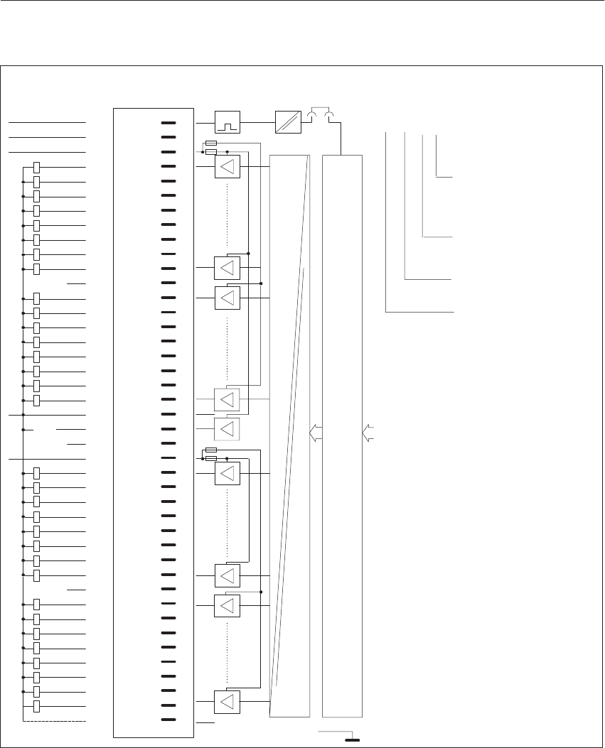
8-51
System Manual
C79000-G8576-C199-06
x20
1Q0.0
1Q0.1
1Q0.3
1Q0.4
1Q0.5
1Q0.6
1Q0.7
1Q0.2
1Q1.0
1Q1.1
1Q1.2
1Q1.3
1Q1.4
1Q1.5
1Q1.6
1Q1.7
2Q2.0
2Q2.1
2Q2.2
2Q2.3
2Q2.4
2Q2.5
2Q2.6
2Q2.7
2Q3.0
2Q3.1
2Q3.2
2Q3.3
2Q3.4
2Q3.5
2Q3.6
2Q3.7
F+ 1
2
3
4
5
6
7
8
9
10
11
12
13
14
15
16
17
18
19
20
21
22
23
24
25
26
27
28
29
30
31
32
33
34
35
36
37
38
39
40
41
42
g
g
g
g
g
g
g
g
g
g
g
g
g
g
g
g
g
g
g
g
g
g
g
g
g
g
g
g
g
g
g
2)
2)
2)
g
LED Pin
L+
L+ 1L+ r
H– H+
L+ 2L+
r
r
r
t
F1
F2
F3
F4
F–L–
L–
L–
3) L–
L–
1)
Shield
Isolation
(1) Q1.6
Short-
Circuit
Data Memory and S5 Bus Control
Front StripConnection of
Process Signal
Lines
Example of connection designation
for an output:
Output 6 (6th bit);
0 to 7 possible
Address of output byte
(1st byte);
0 to 255 possible
Q = Output
1st terminal L+ (not
specified in the ad-
dress)
Block Diagram of
Module Inputs
g = Green LED (status indicator)
r = Red LED (short-circuit indicator)
F+/F- = Enable input
1) Changeover of enable mode with jumper X20:
Jumper inserted = Enable input active (factory setting)
Jumper open = Enable input inactive.
2) The terminal is not connected internally. When this terminal is connected to the output voltages, the clearances in air
and leakage paths are no longer adequate to UL and CSA, but comply with VDE.
3) By connecting L- to pin 42, a leading and trailing connection to 0 V ground is created on the module when it is inserted
and removed.
Di
g
ital Input/Output Modules

8-52 System Manual
C79000-G8576-C199-06
8.4.11 6ES5 453-4UA12 Digital Output Module
Rated supply voltage L+ 24 V DC
Number of outputs (decoupled via diodes) 16, short-circuit protected 1)
Isolation Yes, 16 outputs
Range for supply voltage 20 to 30 V DC
Fusing 16 x 2.5 A, slow
Output voltage for logic 1: (L+)-Switch
(L–)-Switch
for logic 0: (L+)-Switch
(L–)-Switch
L+ – 2.5 V min.
2.5 V max.
3 V max.
L+ – 3 V min.
Switching current (resistive, inductive load) 10 mA to 2.0 A 2)
Residual current at logic 0 1 mA max.
Switching current for lamps 0.45 A max. (10 W)
Switching frequency with resistive load
with inductive load 100 Hz max.
0.2 Hz max. at 1 A; 0.1 Hz at 2 A
Breaking voltage (inductive) Limited to L+ – 47 V
Total switching current 4 A max. 8 outputs
Coincidence factor (total load capability)
ventilated
not ventilated
100 %
25 %; 50 % to 20 oC
Permissible line length 400 m max., unshielded
Power supply
Digital section from system bus 5 V, 120 mA typical
Power dissipation (rated operation) 49.0 W
Enable input (F+/F–)
Rated input voltage 24 V DC
Input voltage for logic 1
for logic 0 13 to 33 V
– 33 to 5 V
Rated input current 5 mA
Permissible line length 200 m max.
Short-circuit monitoring
Indicator for signaling output (H+, H–), floating Red LED for 16 outputs
Output voltage as L+ switch
for logic 1
for logic 0
L+ – 5 V min.
3 V max.
Switching current 10 mA max., short-circuit protected
Voltage test to VDE 0160 Between two groups: 1250 V AC
Between group and ground point: 1250 V AC
Mechanical specifications
Dimensions (W x H x D) 40 mm x 255 mm x 195 mm
Weight Approx. 0.6 kg
1) Short-circuit protection responds with line resistance v 3.6 ohms.
2) One digital input is permissible as minimum load.
Di
g
ital Input/Output Modules
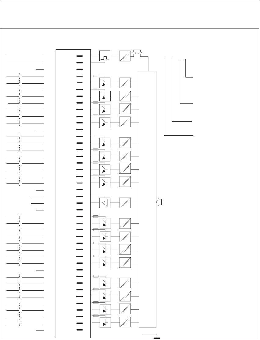
8-53
System Manual
C79000-G8576-C199-06
F+ 1
2
3
4
5
6
7
8
9
10
11
12
13
14
15
16
17
18
19
20
21
22
23
24
25
26
27
28
29
30
31
32
33
34
35
36
37
38
39
40
41
42
g
g
g
g
g
g
g
g
g
g
g
g
g
g
g
g
2)
L+
r
H
F–L–
H
+
–
13L+
F1
2)
F5
2)
2)
F9
2)
F13
2)
Short-circuit
t
1L+
1L–
2L+
2L–
3L+
3L–
4L+
4L–
5L+
5L–
6L+
6L–
7L+
7L–
8L+
8L–
9L+
9L–
10L+
10L–
11L+
11L–
12L+
12L–
14L+
14L–
15L+
15L–
16L+
16L–
13L–
+
–
+
–
+
–
+
–
1Q0.0
1Q0.0
2Q0.1
3Q0.2
3Q0.2
4Q0.3
4Q0.3
2Q0.1
+
–
+
–
+
–
+
–
5Q0.4
5Q0.4
6Q0.5
6Q0.5
7Q0.6
7Q0.6
8Q0.7
8Q0.7
9Q1.0
9Q1.0
10Q1.1
10Q1.1
11Q1.2
11Q1.2
12Q1.3
12Q1.3
+
–
+
–
+
–
+
–
14Q1.5
14Q1.5
15Q1.6
15Q1.6
16Q1.7
16Q1.7
+
–
+
–
+
–
13Q1.4+
13Q1.4–
1)
x20
Shield
LED Pin
(7) Q0.6
Data Memory and S5 Bus Control
Front StripConnection of
Process Signal
Lines
Example of connection designation
for an output:
Output 6 (6th bit);
0 to 7 possible
Address of output byte
(byte 0);
0 to 255 possible
Q = Output
7th terminal L+ (not
specified in the ad-
dress)
Block Diagram of
Module Inputs
g = Green LED (status indicator)
r = Red LED (short-circuit indicator)
F+/F- = Enable input
1) Changeover of enable mode with jumper X20:
Jumper inserted = Enable input active (factory setting)
Jumper open = Enable input inactive.
2) The terminal is not connected internally. When this terminal is connected to the output voltages, the clearances in air and
leakage paths are no longer adequate to UL and CSA, but comply with VDE.
Di
g
ital Input/Output Modules

8-54 System Manual
C79000-G8576-C199-06
8.4.12 6ES5 454-4UA13/4UA14 Digital Output Module
–4UA13 –4UA14
Rated supply voltage L+ 24 V DC
Number of outputs 16, short-circuit protected 1)
Isolation Yes, 1 group of 16 outputs
Range for supply voltage 20 to 30 V DC
Fusing 6.3 A, slow
1 fuse per 4 outputs 7 A, fast
1 fuse per 4 outputs
Output voltage for logic 1
for logic 0 L+ – 2 V min.
3 V max.
Switching current (resistive, inductive load) 10 mA to 2 A 2)
Residual current at logic 0 1 mA max.
Switching current for lamps 0.45 A max. (10 W)
Switching frequency with resistive load
with inductive load 100 Hz max.
0.2 Hz max. at 1 A; 0.1 Hz at 2 A
Breaking voltage (inductive) Limited to L+ – 47 V Limited to L+ –55 V
Total switching current 4 A max. per 4 outputs
Coincidence factor (total load capability) 50 %
Permissible line length 400 m max., unshielded
Power supply
Digital section from system bus 5 V, 100 mA typical
Current consumption from L+/L– 24 V, 100 mA typical 24 V, 120 mA typical
Power dissipation (rated operation) 17.5 W 10 W
Enable input (F+/F–)
Rated input voltage 24 V DC
Input voltage for logic 1
for logic 0 13 to 33 V
– 33 to 5 V
Rated input current 5 mA
Permissible line length 200 m max.
Short-circuit monitoring
Indicator for signaling output (H+) Red LED for 4 outputs
Output voltage , referred to L–
(with feed at 1L+) for logic 1
for logic 0
1L+ – 5 V min.
3 V max.
1L+ –1,5 V min.
Switching current 10 mA max., limited
Voltage test to VDE 0160 Between group and ground point: 1250 V AC
Mechanical specifications
Dimensions (W x H x D) 40 mm x 255 mm x 195 mm 20 mm x 255 mm x 195 mm
Weight Approx. 0.55 kg
1) Short-circuit protection responds with line resistance v 4,75 ohmd, irrelevant for the –4UA14.
2) One digital input is permissible as minimum load.
Di
g
ital Input/Output Modules
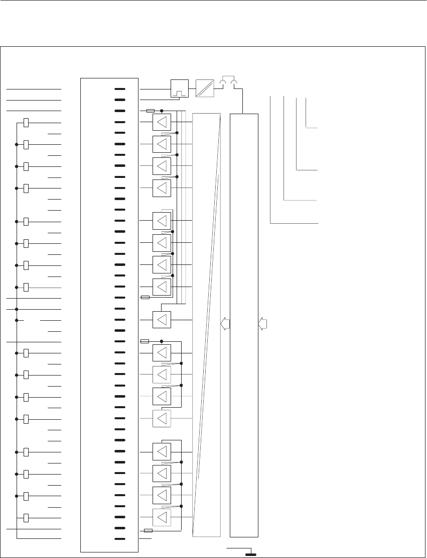
8-55
System Manual
C79000-G8576-C199-06
x20
1Q0.0
1Q0.2
1Q0.3
1Q0.1
2Q0.4
2Q0.5
2Q0.6
2Q0.7
2L+
3Q1.0
3Q1.1
3Q1.2
3Q1.3
4Q1.4
4Q1.5
4Q1.6
4Q1.7
4L+
F+ 1
2
3
4
5
6
7
8
9
10
11
12
13
14
15
16
17
18
19
20
21
22
23
24
25
26
27
28
29
30
31
32
33
34
35
36
37
38
39
40
41
42
g
g
g
g
g
g
g
g
g
g
g
g
g
g
g
g
2)
2)
2)
2)
LED Pin
L+
L+ 1L+ r
H– H+
L+ 3L+
r
r
r
F–L–
L–
1)
Shield
Isolation
L+
L– L–
L+
2)
2)
2)
2)
2)
2)
F1
F2
F3
Short-
Circuit
2)
2)
2)
2)
2)
2)
2)
2)
F4
t(4) Q1.6
Data Memory and S5 Bus Control
Front StripConnection of
Process Signal
Lines
Example of connection designation
for an output:
Output 6 (6th bit);
0 to 7 possible
Address of output byte
(1st byte);
0 to 255 possible
Q = Output
4th terminal L+ (not
specified in the ad-
dress)
Block Diagram of
Module Inputs
g = Green LED (status indicator)
r = Red LED (short-circuit indicator)
F+/F- = Enable input
1) Changeover of enable mode with jumper X20:
Jumper inserted = Enable input active (factory setting)
Jumper open = Enable input inactive.
2) The terminal is not connected internally. When this terminal is connected to the output voltages, the clearances in air and
leakage paths are no longer adequate to UL and CSA, but comply with VDE.
Di
g
ital Input/Output Modules

8-56 System Manual
C79000-G8576-C199-06
8.4.13 6ES5 455-4UA12 Digital Output Module
Rated supply voltage L 24 to 60 V AC (47 to 63 Hz)
Number of outputs 16, conditional short-circuit protection 1)
Isolation Yes, 2 groups of per 8 outputs
Range for supply voltage 20 to 72 V AC
Fusing 6.3 A, fast; 1 fuse per 4 outputs
Output voltage
for logic 1
for logic 0
L– 1.5 V min.
7.5 V max.
Residual current at logic 0 5 mA max.
Switching current (resistive, inductive load)
ventilated
not ventilated
40 mA to 2 A; 6 A max. per 4 outputs
40 mA to 1 A; 4 A max. per 4 outputs
Switching current for lamps
ventilated
not ventilated
40 mA to 2 A; 2.5 A max. per 4 outputs
40 mA to 1 A; 2.5 A max. per 4 outputs
Max. inrush current for
≤ 3 ms
≤ 20 ms
≤ 50 ms
25 A/group
15 A/group
13 A/group
Permissible line length 300 m max. unshielded
Power supply
Digital section from system bus 5 V, 100 mA typical
Power dissipation (rated operation) 39.0 W
Enable input (F+/F–) Jumper in front connector
Voltage test to VDE 0160 Between two groups: 2000 V AC
Between group and ground point: 1500 V AC
Mechanical specifications
Dimensions (W x H x D) 40 mm x 255 mm x 195 mm
Weight Approx. 0.7 kg
1) Protected by a fuse.
Di
g
ital Input/Output Modules
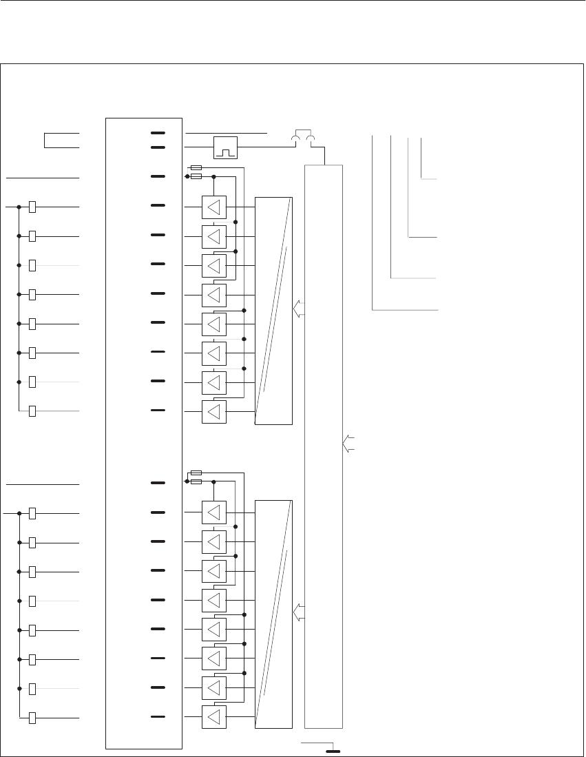
8-57
System Manual
C79000-G8576-C199-06
1L
1Q0.1
1Q0.2
1Q0.0
1Q0.4
1Q0.5
1Q0.6
1Q0.7
2L
2Q1.0
2Q1.1
2Q1.2
2Q1.4
2Q1.5
2Q1.6
2Q1.7
1N
F+
F– 1
2
4
6
8
10
12
14
16
18
20
25
27
29
31
33
35
37
39
41
g
g
g
g
g
g
g
r
g
g
g
g
g
g
g
g
g
LED Pin
Shield
1L
1Q0.3
2Q1.3
2L
Isolation
Isolation
1)
x20
t
+5V
2N
F2
F1
F4
F3
r
r
r
(2) Q1.2
Front StripConnection of
Process Signal
Lines
Example of connection designation
for an output:
Output 2 (2nd bit);
0 to 7 possible
Address of output byte
(1st byte);
0 to 255 possible
Q = Output
2nd terminal L+ (not
specified in the ad-
dress)
Block Diagram of
Module Inputs
Data Memory and S5 Bus Control
g = Green LED (status indicator)
r = Red LED (short-circuit indicator)
F+/F– = Enable input
1) Changeover of enable mode with jumper X20:
Jumper inserted = Enable input active (factory setting)
Jumper open = Enable input inactive.
Di
g
ital Input/Output Modules

8-58 System Manual
C79000-G8576-C199-06
8.4.14 6ES5 456-4UA12 Digital Output Module
Rated supply voltage L 115 to 230 V AC (47 to 63 Hz)
Number of outputs 16, conditional short-circuit protection 1)
Isolation Yes, 2 groups of 8 outputs
Range for supply voltage 88 to 264 V AC
Fusing 6.3 A fast; 1 fuse per 4 outputs
Output voltage
for logic 1
for logic 0
L– 1.5 V min.
30 V max.
Residual current at logic 0 5 mA max.
Switching current (resistive, inductive load)
ventilated
not ventilated
40 mA to 2 A; 2) 6 A max. per 4 outputs
40 mA to 1 A; 2) 4 A max. per 4 outputs
Switching current for lamps
ventilated
not ventilated
40 mA to 2 A; 2.5 A max. per 4 outputs
40 mA to 1 A; 2.5 A max. per 4 outputs
Contactor size
per fuse group
for all outputs
0 (Type 3TB40) to 14 (Type 3TB58) at 230 V AC;
00 (Type 3TJ ..) to 10 (Type 3TB54) at 115 V AC;
0 (Type 3TB40) to 8 (Type 3TB52) at 230 V AC;
00 (Type 3TJ ..) to 4 (Type 3TB48) at 115 V AC;
Max. inrush current for
≤ 3 ms
≤ 20 ms
≤ 50 ms
25 A/group
15 A/group
13 A/group
Permissible line length 300 m max. unshielded
Power supply
Digital section from system bus 5 V, 100 mA typical
Power dissipation (rated operation) 39.0 W
Enable input (F+/F–) Jumper in front connector
Voltage test to VDE 0160 Between two groups: 2000 V AC
Between group and ground point: 1500 V AC
Mechanical specifications
Dimensions (W x H x D) 40 mm x 255 mm x 195 mm
Weight Approx. 0.7 kg
1) Protected by a fuse
2) Contactors of Series 3TJ can only be operated at 115 V AC.
Di
g
ital Input/Output Modules

8-59
System Manual
C79000-G8576-C199-06
1L
1Q0.1
1Q0.2
1Q0.0
1Q0.4
1Q0.5
1Q0.6
1Q0.7
2L
2Q1.0
2Q1.1
2Q1.2
2Q1.4
2Q1.5
2Q1.6
2Q1.7
1N
F+
F–
1
2
4
6
8
10
12
14
16
18
20
25
27
29
31
33
35
37
39
41
g
g
g
g
g
g
g
g
g
g
g
g
g
g
g
g
LED Pin
Shield
1L
1Q0.3
2Q1.3
2L
Isolation
Isolation
1)
x20
t
+5V
2N
F2
F1
F4
F3
r
r
r
r
(2) Q1.6
Data Memory and S5 Bus Control
Front StripConnection of
Process Signal
Lines
Example of connection designation
for an output:
Output 6 (6th bit);
0 to 7 possible
Address of output byte
(1st byte);
0 to 255 possible
Q = Output
2nd terminal L+ (not
specified in the ad-
dress)
Block Diagram of
Module Inputs
g = Green LED (status indicator)
r = Red LED (short-circuit indicator)
F+/F– = Enable input
1) Changeover of enable mode with jumper X20:
Jumper inserted = Enable input active (factory setting)
Jumper open = Enable input inactive.
Di
g
ital Input/Output Modules

8-60 System Manual
C79000-G8576-C199-06
8.4.15 6ES5 456-4UB12 Digital Output Module
Rated supply voltage L 115 to 230 V AC (47 to 63 Hz)
Number of outputs 8, conditional short-circuit protection 1)
Isolation Yes, 8 outputs
Range for supply voltage 88 to 264 V AC
Fusing 3.5 A fast; 1 fuse per output
Output voltage
for logic 1
for logic 0
L– 1.5 V min.
30 V max.
Residual current at logic 0 5 mA max.
Switching current (resistive, inductive load)
ventilated
not ventilated
40 mA to 2 A; 2)
40 mA to 1 A; 2)
Switching current for lamps
ventilated
not ventilated
40 mA to 2 A;
40 mA to 1 A;
Contactor size 0 (Type 3TB40) to 14 (Type 3TB58) at 230 V AC;
00 (Type 3TJ ..) to 8 (Type 3TB52) at 115 V AC;
Max. inrush current for
≤ 3 ms
≤ 20 ms
≤ 50 ms
16 A
8 A
6.5 A
Switching capacity per module
for UL
for CSA
1440 VA max.
2000 VA max.
Permissible line length 300 m max. unshielded
Power supply
Digital section from system bus 5 V, 100 mA typical
Power dissipation (rated operation) 18.0 W
Enable input (F+/F–) Jumper in front connector
Voltage test to VDE 0160 Between two groups: 2000 V AC
Between group and ground point: 1500 V AC
Mechanical specifications
Dimensions (W x H x D) 40 mm x 255 mm x 195 mm
Weight Approx. 0.6 kg
1) Protected by a fuse.
2) Contactors of Series 3TJ can only be operated at 115 V AC.
Di
g
ital Input/Output Modules
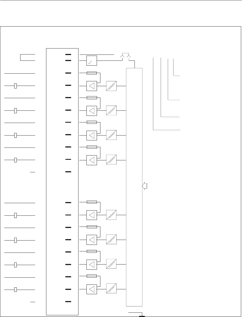
8-61
System Manual
C79000-G8576-C199-06
F+
F– 1
2
4
6
8
10
12
14
16
18
20
25
27
29
31
33
35
37
39
41
g
g
g
g
g
g
g
g
LED Pin
Shield
t
+5V
1L1L
2L2L
3L3L
4L4L
1Q0.0
1N
2Q0.1
2N
3Q0.2
3N
4Q0.3
4N
1)
x20
2)
5L5L
6L6L
7L7L
8L8L
5Q0.45N
6Q0.56N
7Q0.67N
8Q0.78N
2)
r
r
r
r
r
r
r
r
F1
F5
F8
(3) Q0.2
Data Memory and S5 Bus Control
Front StripConnection of
Process Signal
Lines
Example of connection designation
for an output:
Output 2 (2nd bit);
0 to 7 possible
Address of output byte
(byte 0);
0 to 255 possible
Q = Output
3rd terminal L+ (not
specified in the ad-
dress)
Block Diagram of
Module Inputs
g = Green LED (status indicator)
r = Red LED (short-circuit indicator)
F+/F– = Enable input (jumper in front connector)
1) Changeover of enable mode with jumper X20:
Jumper inserted = Enable input active (factory setting)
Jumper open = Enable input inactive.
2) The terminal is not connected internally. If this terminal is connected to the output voltage, the clearances in air and
leakage paths remain adequate to UL, CSA and VDE.
Di
g
ital Input/Output Modules

8-62 System Manual
C79000-G8576-C199-06
8.4.16 6ES5 457-4UA12 Digital Output Module
Rated supply voltage L+ 24 to 60 V DC
Number of outputs (decoupled via diodes) 16, short-circuit protected 1)
Isolation Yes, 16 outputs
Range for supply voltage 20 to 72 V DC
Fusing 16 x 1 A, slow
Output voltage for logic 1: (L+)-Switch
(L–)-Switch
for logic 0: (L+)-Switch
(L–)-Switch
L+ – 2.5 V min.
2.5 V max.
3 V max.
L+ – 3 V min.
Switching current (resistive, inductive load) 5 mA to 0.5 A 2)
Residual current at logic 0 1 mA max.
Switching current for lamps 0.22 A max. (5 W)
Switching frequency with resistive load
with inductive load 100 Hz max.
2 Hz max. at 0.5 A
Breaking voltage (inductive) Limited to L+ – 75 V 3)
Coincidence factor (total load capability)
ventilated
not ventilated
100 %
50 %; 100 % up to 35 oC
Permissible line length 400 m max. unshielded
Power supply
Digital section from system bus 5 V, 120 mA typical
Power dissipation (rated operation) 13.0 W
Enable input (F+/F–)
Rated input voltage 24 to 60 V DC
Input voltage for logic 1
for logic 0 13 to 72 V
– 72 to 8 V
Rated input current at 24 V DC
at 48 V DC
at 60 V DC
2.5 mA
5 mA
6.5 mA
Permissible line length 200 m max.
Short-circuit monitoring
Indicator for signaling output (H+, H–) Red LED for 16 outputs
Output voltage as L+ switch
for logic 1
for logic 0
L+ – 5 V min.
3 V max.
Switching current 10 mA max., short-circuit protected
Voltage test to VDE 0160 Between two groups: 1250 V AC;
Between group and ground point: 1250 V AC
Mechanical specifications
Dimensions (W x H x D) 40 mm x 255 mm x 195 mm
Weight Approx. 0.6 kg
1) Short-circuit protection responds with line resistance 9 ohms at 24 V DC, 30 ohms at 60 V DC.
2) One digital input is permissible as minimum load.
3) At L+ voltages of more than 72 V, the logic 0 of the output can rise to 13 V. A digital input follower will interpret this signal
as a logic 1 (possible fault).
Di
g
ital Input/Output Modules
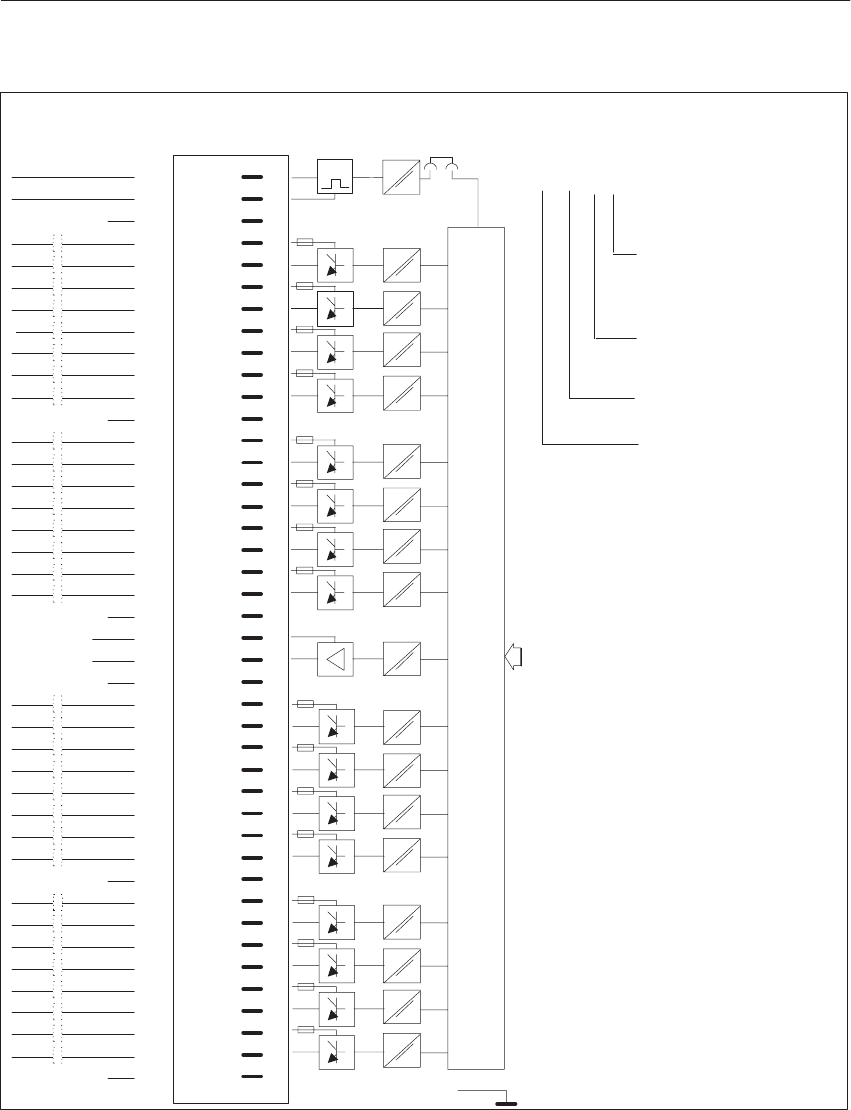
8-63
System Manual
C79000-G8576-C199-06
F+ 1
2
3
4
5
6
7
8
9
10
11
12
13
14
15
16
17
18
19
20
21
22
23
24
25
26
27
28
29
30
31
32
33
34
35
36
37
38
39
40
41
42
g
g
g
g
g
g
g
g
g
g
g
g
g
g
g
g
2)
L+
r
H
F–L–
H
+
–
13L+
F1
2)
F5
2)
2)
F9
2)
F13
2)
Short-Circuit
t
1L+
1L–
2L+
2L–
3L+
3L–
4L+
4L–
5L+
5L–
6L+
6L–
7L+
7L–
8L+
8L–
9L+
9L–
10L+
10L–
11L+
11L–
12L+
12L–
14L+
14L–
15L+
15L–
16L+
16L–
13L–
+
–
+
–
+
–
+
–
1Q0.0
1Q0.0
2Q0.1
3Q0.2
3Q0.2
4Q0.3
4Q0.3
2Q0.1
+
–
+
–
+
–
+
–
5Q0.4
5Q0.4
6Q0.5
6Q0.5
7Q0.6
7Q0.6
8Q0.7
8Q0.7
9Q1.0
9Q1.0
10Q1.1
10Q1.1
11Q1.2
11Q1.2
12Q1.3
12Q1.3
+
–
+
–
+
–
+
–
14Q1.5
14Q1.5
15Q1.6
15Q1.6
16Q1.7
16Q1.7
+
–
+
–
+
–
13Q1.4+
13Q1.4–
1)
x20
Shield
LED Pin
(7) Q0.6
Data Memory and S5 Bus Control
Front StripConnection of
Process Signal
Lines
Example of connection designation
for an output:
Output 6 (6th bit);
0 to 7 possible
Address of output byte
(byte 0);
0 to 255 possible
Q = Output
7th terminal L+ (not
specified in the ad-
dress)
Block Diagram of
Module Inputs
g = Green LED (status indicator)
r = Red LED (short-circuit indicator)
F+ = Enable input)
1) Changeover of enable mode with jumper X20:
Jumper inserted = Enable input active (factory setting)
Jumper open = Enable input inactive.
2) The terminal is not connected internally. When this terminal is connected to the output voltages, the clearances in air
and leakage paths are no longer adequate to UL and CSA, but comply with VDE.
Di
g
ital Input/Output Modules

8-64 System Manual
C79000-G8576-C199-06
8.4.17 6ES5 458-4UA12 Digital Output Module
Rated supply voltage L 24 V DC
Number of outputs 16
Isolation Yes, 16 outputs
Range for supply voltage 20 to 30 V DC
Fusing 16 x 1 A, slow 1)
Output Relay contacts
Service life of contacts 108 cycles
Switching capacity with resistive load
with RC element module
without RC element module
60 V DC/48 V AC, 0.5 A 2)
60 V DC/48 V AC, 70 mA
Switching current with inductive load
with RC element module and external
suppressor circuit
0.5 A max.
Switching current for lamps 0.1 A max. with RC element module
Switching frequency with resistive load
with inductive load 100 Hz max. (pick-up 1 ms, drop-out 1 ms)
10 Hz max. up to 50 mA,
2 Hz max. up to 0.3 A,
0.5 Hz max. up to 0.5 A
Coincidence factor (total load capability) 100 %
Permissible line length 400 m max., unshielded
Power supply
Digital section from system bus 5 V, 80 mA typical
Current consumption from L+/L– 200 mA typical
Power dissipation (rated operation) 5.2 W
Enable input (F+/F–)
Rated input voltage 24 V DC
Input voltage
for logic 1
for logic 0
13 to 33 V
–33 to 5 V
Rated input current 5 mA
Permissible line length 200 m max.
Voltage test to VDE 0160 Between two groups: 500 V AC
Between group and ground point: AC 500 V
Mechanical specifications
Dimensions (W x H x D) 20 mm x 255 mm x 195 mm
Weight Approx. 0.45 kg
1) The fuse does not protect the contacts. The relay must be replaced after an overload.
2) 50 V/0.5 A max. resistive load for UL
Di
g
ital Input/Output Modules
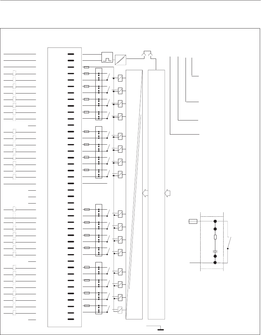
8-65
System Manual
C79000-G8576-C199-06
Shield
Isolation
1)
x35
1
2
3
4
5
6
7
8
9
10
11
12
13
14
15
16
17
18
19
20
21
22
23
24
25
26
27
28
29
30
31
32
33
34
35
36
37
38
39
40
41
42
g
g
g
g
g
g
g
g
g
g
g
g
g
g
g
g
LED Pin
F–L–
1L
1L
2L
2L
3L
3L
4L
4L
5L
5L
6L
6L
7L
7L
8L
8L
9L
9L
10L
10L
11L
11L
12L
12L
14L
14L
15L
15L
16L
16L
13L
13L
F2
2)
F6
2)
2)
F10
2)
F14
2)
F1
L– L–
3)
F+L+
L+L+
498
498
498
498
+
–
+
–
+
–
+
–
+
–
+
–
+
–
+
–
+
–
+
–
+
–
+
–
+
+
–
+
–
+
–
–
14Q1.5
14Q1.5
15Q1.6
15Q1.6
16Q1.7
16Q1.7
13Q1.4
13Q1.4
5Q0.4
5Q0.4
6Q0.5
6Q0.5
7Q0.6
7Q0.6
8Q0.7
8Q0.7
1Q0.0
1Q0.0
2Q0.1
3Q0.2
3Q0.2
4Q0.3
4Q0.3
2Q0.1
9Q1.0
9Q1.0
10Q1.1
10Q1.1
11Q1.2
11Q1.2
12Q1.3
12Q1.3
R
C
47R
47NF
F498
4x
t(7) Q0.6
Data Memory and S5 Bus Control
Front StripConnection of
Process Signal
Lines
Example of connection designation
for an output:
Output 6 (6th bit);
0 to 7 possible
Address of output byte
(byte 0);
0 to 255 possible
Q = Output
7th terminal L+ (not
specified in the ad-
dress)
Block Diagram of
Module Inputs
g = Green LED (status indicator)
r = Red LED (short-circuit indicator)
F+ = Enable input
1) Changeover of enable mode with jumper X35:
Jumper inserted = Enable input active (factory setting)
Jumper open = Enable input inactive.
2) The terminal is not connected internally. When this terminal is connected to the output voltages, the clearances in air and
leakage paths are no longer adequate to UL and CSA, but comply with VDE.
3) The terminal is not connected internally. If this terminal isconnected to the output voltages, the clearances in air and
leakage paths remain adequate to UL, CSA and VDE.
Di
g
ital Input/Output Modules

8-66 System Manual
C79000-G8576-C199-06
Load
60V DC max.
Front Strip
For DC Voltage:
Current Sinking
Switching to P
For AC Voltage:
498
Load
Load
L+
L–
Z. Diode 82V, 5W
60 V DC max.
48 Vms max.
L+
L–
L
N
Diodew100V,1A
498-1AB11
RC Element Module
Diodew100V,1A
External Suppressor
Circuitry for
Inductive Load
Di
g
ital Input/Output Modules

8-67
System Manual
C79000-G8576-C199-06
8.4.18 6ES5 458-4UC11 Digital Output Module
Rated supply voltage L 24 V DC (pins 22, 23)
Number of outputs 16
Isolation Yes, 2 groups of 8 outputs
Range for supply voltage of the relays 20 to 30 V DC
Ausgang Relay contacts
Service life of contacts Approx. 105 cycles at 230 V AC/5A
Approx. 107 cycles mechanical
Switching capacity of the contacts
with resistive load
with inductive load
5.0 A at 250 V AC
5.0 A at 30 V DC
0.3 A at 115 V DC
1.5 A at 250 V AC
1.0 A at 30 V DC
0.08 A at 115 V DC
Max. rating per group P0/P1 8.0 A
Switching frequency
with resistive load
with inductive load
10 Hz max.
2 Hz max.
Permissible line length 400 m max., unshielded
Power supply
Digital section from system bus 5 V, 120 mA typical (all outputs active)
Current consumption from L+/L– 250 mA typical (all outputs active)
Power dissipation (rated operation) 6.6 W
Enable input (F+/F–)
Rated input voltage 24 V DC
Input voltage
for logic 1
for logic 0
13 to 33 V
–33 to 5 V
Rated input current 5 mA
Permissible line length 200 m max.
Voltage test to VDE 0160 Between two groups: 2000 V AC
Between group and ground point: 1500 V AC
Mechanical specifications
Dimensions (W x H x D) 20 mm x 255 mm x 195 mm
Weight Approx. 0.7 kg
Di
g
ital Input/Output Modules
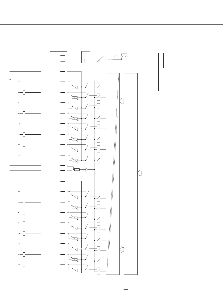
8-68 System Manual
C79000-G8576-C199-06
1Q0.0
1Q0.2
1Q0.3
1Q0.1
1Q0.4
1Q0.5
1Q0.6
1Q0.7
F+ 1
2
4
6
8
10
12
14
16
18
20
22
23
25
27
29
31
33
35
37
39
41
g
g
g
g
g
g
g
g
g
g
g
g
g
g
g
g
LEDPin
L+
F– t
L–
P0
M0
2Q1.2
2Q1.3
2Q1.1
2Q1.4
2Q1.5
2Q1.6
2Q1.7
M1
L+
L–
L+
L–
P1
2Q1.0
F1
Shield
Isolation
1)
x2
3 2 1(2)Q1.6
Data Memory and S5 Bus Control
Front StripConnection of
Process Signal
Lines
Example of connection designation
for an output:
Output 6 (6th bit);
0 to 7 possible
Address of output
byte (1st byte);
0 to 255 possible
Q = Output
2nd terminal L+ (not
specified in the ad-
dress)
Block Diagram of
Module Inputs
g = Green LED (status indicator)
F+/F-= Enable input
P0/M0 = Group of 8/load supply voltage (1st group)
P1/M1 = Group of 8/load supply voltage (2nd group)
L+/L-= Relay supply voltage (24 V DC)
1) Changeover of enable mode with jumper X2: 1 - 2
Jumper inserted = Enable input active (factory setting)
Jumper open = Enable input inactive.
Digital Input/Output Modules

8-69
System Manual
C79000-G8576-C199-06
8.4.19 6ES5 482-4UA11 Digital Input/Output Module
Rated supply voltage L+ 24 V DC
Rated input voltage 24 V DC
Inputs
Number of inputs 16 min., 24 max.
Isolation Yes, 1 group of 32 inputs/outputs
Input voltage
for logic 0
for logic 1
–33 to 5 V
13 to 33 V
Rated input current 8.5 mA typical
Delay time 0.3 ms typical
Input resistance 2.8 kilohms typical
Coincidence factor (total load capability) 100 %
Permissible line length 50 m max.
Supply voltage for 2-wire BERO 22 V to 33 V
Power supply
Digital section from system bus 5 V, 80 mA typical
Outputs
Number of outputs 8 min., 16 max., short-circuit protected 1)
Isolation Yes
Fusing 6.3 A slow;
1 fuse per 8 outputs
Output voltage
for logic 1
for logic 0
L+ – 1.5 V min.
3 V max.
Switching current
(resistive, inductive load)
5 mA to 0.5 A
Switching frequency
with resistive load
with inductive load
120 Hz max.
2 Hz max. at 0.3 A; 0.5 Hz max. at 0.5 A
Breaking voltage (inductive) Limited to L+ and – 27 V
Total switching current 4 A max. per 8 outputs
Coincidence factor (total load capability)
ventilated
not ventilated
100 %
50 %; 100 % up to 35 oC
Permissible line length 400 m max.
Current consumption from L+/L– 24 V, 150 mA typical
Short-circuit monitoring
Indicator for signaling output (H+) Red LED for every 8 outputs
Output voltage referred to L– (with feed at 1L+)
for logic 1
for logic 0 1L+ – 5 V min.
3 V max.
Switching current 10 mA max. current limiting
Enable input (F+/F–) Jumper in front connector
Voltage test to VDE 0160 Between group and ground point: 1250 V AC
Mechanical specifications
Dimensions (W x H x D) 20 mm x 255 mm x 195 mm
Weight Approx. 0.4 kg
1) Short-circuit protection responds at line resistance v 15 ohms
Di
g
ital Input/Output Modules
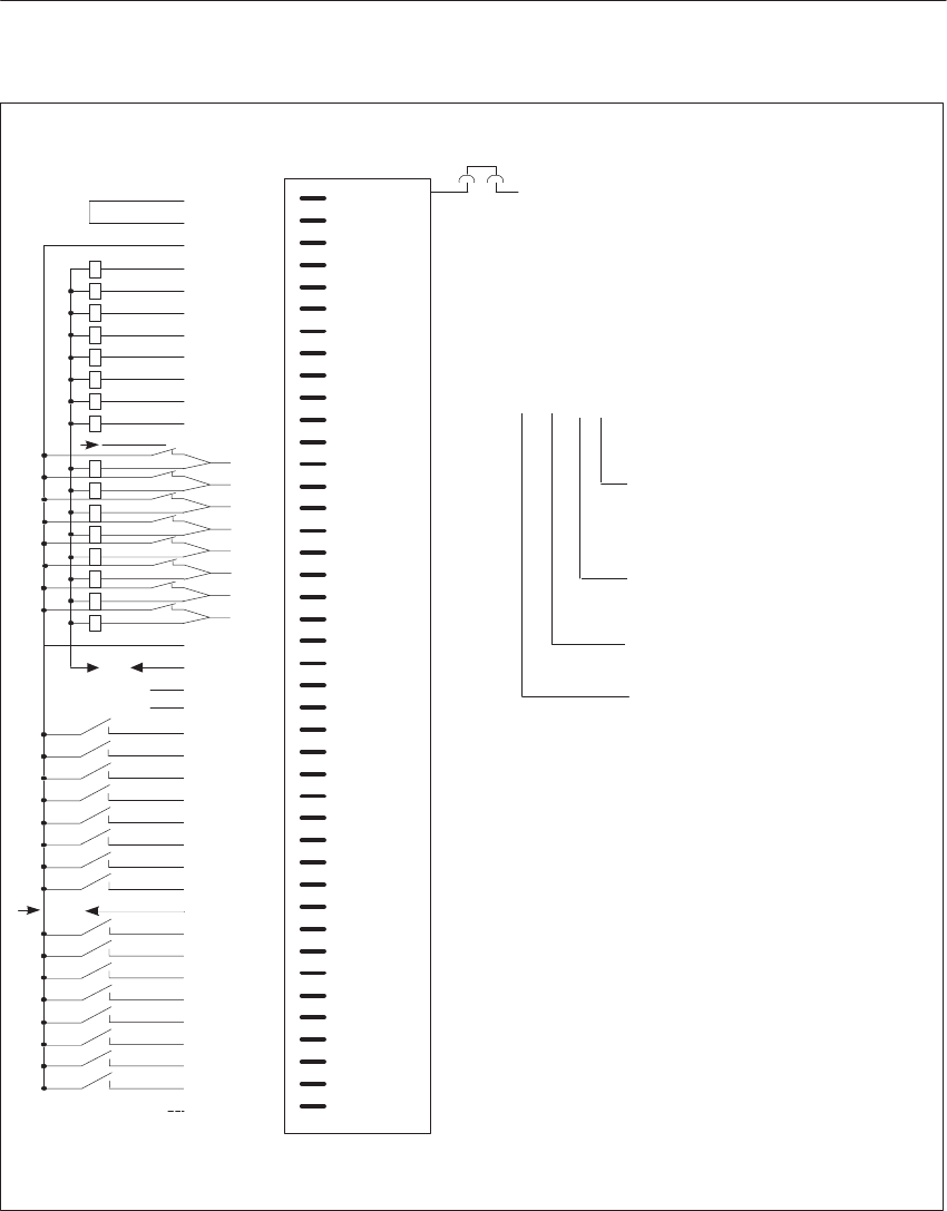
8-70 System Manual
C79000-G8576-C199-06
1Q0.0
1Q0.1
1Q0.3
1Q0.4
1Q0.5
1Q0.6
1Q0.7
1Q0.2
1Q1.0
1Q1.1
1Q1.2
1Q1.3
1Q1.4
1Q1.5
1Q1.6
1Q1.7
SYNIN
SYNOUT
1I2.0
1I2.1
1I2.2
1I2.3
1I2.4
1I2.5
1I2.6
1I2.7
1I3.0
1I3.1
1I3.2
1I3.3
1I3.4
1I3.5
1I3.6
1I3.7
F+ 1
2
3
4
5
6
7
8
9
10
11
12
13
14
15
16
17
18
19
20
21
22
23
24
25
26
27
28
29
30
31
32
33
34
35
36
37
38
39
40
41
42
Pin
L+ L+
H+
F–
L–
L–
L–
Connection of Process Signal Lines
1)
x20
(1) Q1.6
Example of connection designation
for an output:
Output 6 (6th bit);
0 to 7 possible
Address of output byte
(1st byte);
0 to 255 possible
Q = Output
1st terminal L+ (not
specified in the ad-
dress)
SYSNIN, SYNOUT only relevant for operation with the IP 257
F+/F- = Enable input
1) Changeover of enable mode with jumper X20:
Jumper inserted = Enable input active (factory setting)
Jumper open = Enable input inactive.
Switch S2 must be at setting 1.
Di
g
ital Input/Output Modules

9-1
System Manual
C79000-G8576-C199-06
Analog Input/Output Modules
Described in this chapter are the installation, wiring and operation of analog
input modules and analog output modules. The individual modules have
special features. These are discussed in separate sections.
Section Description Page
9.1 Technical Description 9-2
9.2 Common Technical Specifications 9-3
9.3 The 460 Analog Input Module 9-4
9.4 The 463 Analog Input Module 9-35
9.5 The 465 Analog Input Module 9-50
9.6 The 466 Analog Input Module 9-77
9.7 The 470 Analog Output Module 9-98
Chapter
Overview
9

9-2 System Manual
C79000-G8576-C199-06
9.1 Technical Description
The description below applies to the following modules:
Analog Input Modules and Cards
Order No. of the
Module No. of
Inputs Isolation/Groups Range Card (4 Channels) Order No. of the
Range Card
6ES5 460-4UA13
6ES5 465-4UA12
8
16/8
Yes/8 inputs isolated from
0 V and from each other
No/none
$12.5/50/500 mV/Pt 100
$ 50/500 mV/Pt 100
$ 1 V
$10 V
$20 mA
4 to 20 mA/4-wire trans.
$5 V
4 to 20 mA/4-wire trans.
6ES5 498-1AA11
6ES5 498-1AA11
6ES5 498-1AA21
6ES5 498-1AA31
6ES5 498-1AA41
6ES5 498-1AA51
6ES5 498-1AA61
6ES5 498-1AA71
Analog Input Modules
Order No. of the
Module No. of
Inputs Isolation/Groups Measuring Range
6ES5 463-4UA12
6ES5 463-4UB12,
6ES5 466-3LA11
4
16/8
Yes/4 inputs isolated from
0 V and from each other
Yes
1 V, 10 V, 20 mA,
4 to 20 mA
1.25 V, 2.5 V, 5 V, 10 V
20 mA, 4 to 20 mA
Analog Output Modules
Order No. of the
Module No. of
Inputs Isolation/Groups Output Range
6ES5 470-4UA12
6ES5 470-4UB12
6ES5 470-4UC12
8
8
8
Yes/8 outputs from 0 V
Yes/8 outputs from 0 V
Yes/8 outputs from 0 V
$10 V/0 to 20 mA
$10 V
$1 to 5 V/4 to 20 mA
Analog input and analog output modules are I/O modules for the input/output
of widely differing, analog process signals for the S5-135U/155U
programmable (logic) controller.
These I/O modules allow the creation of control systems which require the
processing of analog measured variables or continuous input to actuators.
I/O Modules
Analo
g
Input/Output Modules

9-3
System Manual
C79000-G8576-C199-06
9.2 Common Technical Specifications
Important for the USA and Canada
The following approvals have been issued:
UL Listing Mark
Underwriters Laboratories (UL) to Standard UL 508, Report E 85972 and
E116536 for the 466-7LA11 analog input module
CSA Certification Mark
Mark Canadian Standard Association (CSA) to Standard C 22.2 No. 142,
Report LR 63533C and LR 48323 for the 466-7LA11 analog input
module
Address range 128 to 255 (0 to 255)
Supply voltage L+
rated value
ripple Vpp
permissible range (including ripple)
reference potential
24 V
3.6 V
20 to 30 V
L–= Mext = 0 V
Voltage for the isolated enable inputs (only required when enable
jumper is inserted) F+ = + 24 V
F– = 0 V
Line lengths for
Analog input modules with rated input range of
$ 12.5 m, $ 50 mV and Pt 100 50 m max. for shielded cables laid separately
from power system cables (see Chapter 3)
Analog input modules with rated input range of $ 500 mV /
$ 1 / $ 5 / $ 10 V / $ 20 mA, 4 to 20 mA and Pt 100 200 m max., shielded
Analog output modules 200 m max., shielded
Temperature range
in operation
for storage ans transportation
0 to 55 oC
– 40 to 70 oC
Relative humidity 95 % max. at 25 oC, no condensation
Site altitude 3500 m max. above sea level
Dimensions (W x H x D) 20 x 255 x 195 mm
Weight Approx. 0.4 kg
Analo
g
Input/Output Modules
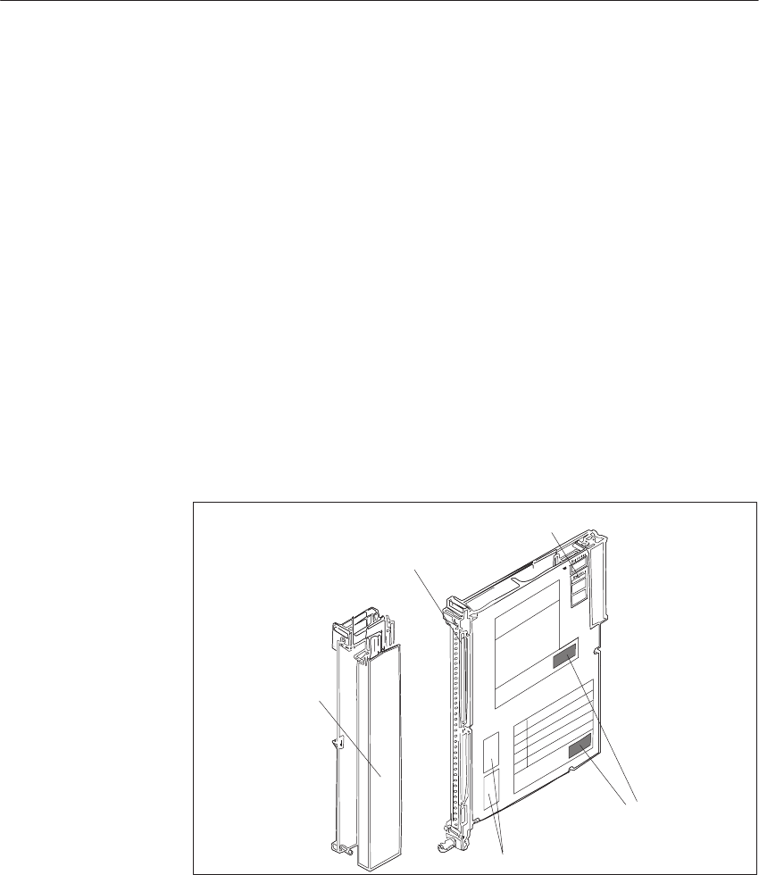
9-4 System Manual
C79000-G8576-C199-06
9.3 The 460 Analog Input Module
9.3.1 Design
The modules are designed as plug-in PCBs for central controllers and
expansion units with a backplane connector and with a blade connector to
accept a plug-in front connector. You can directly connect the process signal
lines to the front connector, which is available separately, with screw or
crimp terminals.
Situated on each module is an addressing switch with six rockers to set the
module address. Analog input modules also have two switches on the side
with eight rockers for setting the mode, and receptacles for range cards.
The modules are protected by covers on both sides.
Blade Connector
Addressing Switch
Mode Switches
Range Cards
Front Connector
Figure 9-1 Analog Input Module
9.3.2 Function of the Enable Input
The 460 module has an enable circuit. You can use the enable inputs to
switch off individual modules whilst the PLC is in operation. This means
that:
The module can no longer be addressed by the user program.
Modules which are switched off can be removed or inserted during operation.
If this is not necessary, operate the module with the enable input switched
off.
Addressing
Switch, Mode
Switches
Analog Input/Output Modules
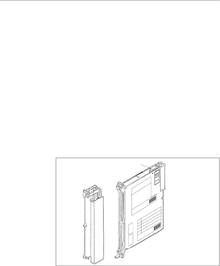
9-5
System Manual
C79000-G8576-C199-06
The enable circuit requires an external 24 V voltage at enable inputs F+/F- in
the front connector. If there is no voltage at F+/F-, the modules will not
acknowledge.
When the front connector is swivelled away from the front strip of the
module, the supply of power to the enable input is interrupted, i.e. the
module is switched off and can no longer be addressed by the user program: a
timeout (QVZ) occurs in the CC.
The 460 module additionally offers the facility for changing the enable
mode. The module has a jumper accessible from above in the vicinity of the
addressing switch.
When the enable jumper is inserted, you can define the behaviour of the 460
analog input module as follows:
When the enable voltage and load voltage are obtained from the same
load supply, a shutdown of the 24 V load voltage will result in a timeout.
When the enable voltage and load voltage are obtained from different
load supplies, a shutdown of the 24 V load voltage will not result in a
timeout. (With the 460-4UA11/12 modules, a shutdown of the load
voltage will result in a timeout.)
Enable Jumper
Figure 9-2 Enable Input and Enable Jumper
Jumper inserted: Enable input (F+/F-) active (factory setting)
Jumper open: Enable input (F+/F-) switched off
Examples of functioning of the enable inputs:
To switch off individual subprocesses, i.e. outputs of various modules can
be operated from a common load supply and yet activated separately.
The load voltage of individual modules can be monitored without
additional circuitry. Any reactions to failure of the load voltage can be
programmed in the QVZ (timeout) organization block.
Enable Input
Switching Off the
Enable Input
Analo
g
Input/Output Modules
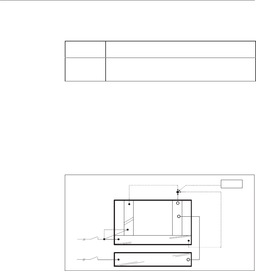
9-6 System Manual
C79000-G8576-C199-06
You must observe the following when configuring systems:
Switching on At the latest 100 ms after power-up of the PLC, the voltage
must be present at the enable inputs of the I/O modules.
Switching off When the PLC has been switched off, the voltage at the
enable inputs of the I/O modules must still be present as
long as the internal 5 V voltage is present.
You should observe the following instructions for switching off CCs and
equipment for supplying power to the enable inputs.
When there is a need to switch off the load power supply separately without
affecting the enabling of modules, there are the following possibilities for
producing the enable voltage. These exist even when the load power supply
is used without an additional capacitor and common shutdown.
230 V AC supply for CC/EU and load power supply
F+
L+
I/O Modules
230 V AC
CC/EU
–951
a)
c)
b) Battery
L+
Power Supply
Load Power Supply 24V
Supply for the enable inputs from:
a) 6ES5 951-4LB11 load power supply
b) Battery
c) Terminals for 24 V on the front plate of the power supply
Configuring
Switching off the
CC
Separate or
Common
Shutdown of the
CC/EU and Load
Power Supply
Analo
g
Input/Output Modules

9-7
System Manual
C79000-G8576-C199-06
24 V supply for CC/EU and I/Os
F+
L+
I/O Modules
24 V DC
b)
a)
CC/EU
L+
Battery
Power Supply 24V
Supply for the enable inputs from:
a) Battery
b) Terminals for 24 V on the front plate of the power supply
Proper functioning is ensured if the 24 V load power supply has an output
capacitance of at least 4700 mF per 10 A of load current. Other units which
do not meet this condition can be adapted to this requirement by connecting a
10000 mF / 40 V capacitor in parallel.
10000µF/
40V
CC/EU F+
L+
230 V AC
I/O Modules
Load Power Supply 24V
Power Supply
Common
Shutdown of the
CC/EU and Load
Power Supply with
a 230 V AC Supply
Analo
g
Input/Output Modules

9-8 System Manual
C79000-G8576-C199-06
9.3.3 Special Features of the 460 Analog Input Module
The 460 analog input module executes integrating processing of the digital
input signals; periodic system interference is thus suppressed.
You can adapt the process signals, according to the application, to the input
level of the analog-to-digital converter of the module with plug-in range
cards (resistor dividers or shunt resistors).
To monitor the sensors connected to the inputs, you can use the
6ES5 498-1AA11 range card (through-connection card) to implement the
“broken wire detection” mode. You can activate broken wire detection for 4
or 8 inputs.
Each time the input value is about to be encoded, a constant current is briefly
(1.6 ms) switched to the input terminals and the resultant current is checked
for a limit value. If a digital voltmeter is used to measure the signal at the
input, these current pulses may appear to indicate fluctuation of the signal.
The encoded value, however, is not affected.
If these apparent fluctuations of the signal are disturbing, e.g. during startup,
you can switch the tripping current to the inactive state on the 460 analog
input module: apply + 24 V to pin 24 of the front connector, and 0 V to L-.
You must additionally set the mode switch to “without broken wire
detection.”
In the event of open-circuit of the sensor or its line, the voltage exceeds the
limit and a broken wire is indicated (bit 1 in data byte 1). The
analog-to-digital converter encodes the value 0.
A broken wire signal is only useful when the 6ES5 498-1AA11
through-connection card is used. With all other measurement cards, a broken
wire signal will result in incorrect reactions. Further details relating to the
broken wire signal can be found in Section 9.3.12.
If the measuring range is exceeded, the overflow bit (bit 2<M>0 of the low
byte) is set.
You have a choice of the cyclic sampling and selective sampling modes.
In the cyclic sampling mode, the module continuously encodes all measured
values. The digitized measured values are stored under the channel-related
address on the module (the high byte under this address, and the low byte
under the next higher address). The measured values can then be read by the
module at any time without waiting. When you operate the module in this
mode, you can set a module address from 0 to 255.
Broken Wire
Signal
Switching the
Tripping Current to
the Inactive State
Measuring Range
Exceeded
Cyclic Sampling
Analo
g
Input/Output Modules

9-9
System Manual
C79000-G8576-C199-06
In the selective sampling mode, a measured value is encoded on the central
initiative of the CPU. At the start of conversion, the module must be
addressed once with a write operation (T PW) by the user program. An active
bit (T = 1) is set during encoding.
With the transition to T = 0, the measured value becomes valid. With
non-constant cycle times, there may be non-periodic measured value
aquisition. If you operate the module in this mode, you must set a module
address from 128 to 255. You can also use the address range from 0 to 127
for selective sampling after appropriate programming in DB 1 of the user
program.
Another method is that of time-controlled program processing. With this
method, certain program segments (e.g. FB 13) are automatically inserted
into program processing at the 100 ms rate by a time-
controlled block (OB 13). A constant timebase is thus achieved.
FB 13 SPRM-B LEN=22 ABS
SHEET 1
SEGMENT 1
NAME: SELSAMPL EXAMPLE OF SELECTIVE SAMPLING
0005 :
0006 :
0007 :L PW128 READ ANALOG VALUE
0008 :T MW128 IN TO AUX: FLAG FW 128
0009 :A M 129.2 SCAN ACTIVITY =1?
000A :JC = END IF = 1, JUMP TO END
000B :T FW10 IF = 0, MEASURED VALUE IN FW 10
000C :T PB128 INITIATE SAMPLING
000D END : (1ST VALUE INVALID AFTER START)
000E
000F :
0010 :BE
You can read analog values of analog input modules with a function block
from the “basic functions” package.
The BASP signal is not interpreted by the 460 analog input module.
Selective Sampling
Time-Controlled
Program
Processing
Function Block
BASP (Output
Inhibit)
Analo
g
Input/Output Modules

9-10 System Manual
C79000-G8576-C199-06
9.3.4 Setting the Module Address
You set the module address on the addressing switch. This also establishes
the necessary assignments between user program and process connection.
The module address is the sum of the decimal significances of the switch
rockers in the On setting (Ĥ).
One data word = two data bytes is required to process an input or an output.
A module with 16 inputs therefore reserves 32 byte addresses, and a module
with 8 inputs or outputs reserves 16 byte addresses.
You can affix the adhesive label with the desired module address on a free
labeling field under the addressing switch.
The switch rockers to be set for the module address specified as a decimal
number (address bit ADB) are marked by dots on the label.
Press the individual rockers of the addressing switch downwards with a
ballpoint pen or similar object, but not a pencil.
On Setting
(Switch Pressed) Addressing Switch
Address Bit
Decimal Signification of
the Address Bit
Free Field for Label with
Module Address and
marked Switch Settngs
Address (Decimal)
128
64
32
16
8
4
2
1
ADB7
ADB6
ADB5
ADB4
ADB3
ADB2
ADB2 is not connected
ADB1
ADB0
ADB0 and ADB1 are not assigned
Figure 9-3 Labeling of the Addressing Switch
The address under which the module is referenced by the STEP 5 program is
independent of the slot.
For analog input and analog output modules (8 inputs) only the lowest
address (start address) is set. Other addresses (subaddresses) are decoded on
the module.
Labeling Field
Start Address,
Subaddress
Analo
g
Input/Output Modules

9-11
System Manual
C79000-G8576-C199-06
Note
The start address of the analog module must be a multiple of the double
channel number.
4 channels : 0, 8, 16, 24, ... 248
8 channels : 0, 16, 32, 48, ... 240
If one of the inputs or outputs (Channel 0 to 7) of a module is to be
addressed, the relevant subaddress must be specified in the program.
The subaddress of the input or output, based on the start address of the
module, is given by:
Start address + 2 x channel no. = subaddress
Example:
Analog input module with 8 inputs
The address is the sum of the significances set with the individual coding
switches.
160 = 128 + 32 = 27 + 25
On Setting
(Switch Pressed)
IB 160
128
64
32
16
8
4
2
1
ADB7
ADB6
ADB5
ADB4
ADB3
ADB2
ADB1
ADB0
A module with 8 inputs (Channel 0 to 7) and start address 160 reserves the
address range from
160 to address 160 + 7 x 2 = 174
In this example, the next free address for another module is 176.
Addresses already assigned must not be set again.
Analo
g
Input/Output Modules

9-12 System Manual
C79000-G8576-C199-06
However, analog input modules and analog output modules may be given the
same address with cyclic sampling because they are distinguished by the user
program. This is not possible with selective sampling.
For cyclic sampling, you can address the module in the address range from 0
to 255, and for selective sampling from 128 to 255. For selective sampling,
you can also use the address range from 0 to 127 after appropriate
programming in DB 1 of the user program.
Example:
On an analog input module with start address 160 (IB 160 = input byte 160),
input channel 3 is to be scanned by the program.
Step Action
1Affix the self-adhesive label with address 160 on the free field under the
addressing switch on the module. ADB 5 and ADB 7 are marked on the
label.
2Press the appropriate rockers of the addressing switch down on the side
marked by a dot on the module cover. Set the other rockers to the opposite
setting. This way sets the start address of the module.
ADB 5 and ADB 7 results in 25 + 27 = 32 + 128 = 160
3Enter the address 160 + 3 x 2 = 166 in the program for input channel 3.
Addressing for
Cyclic/Selective
Sampling
Analo
g
Input/Output Modules

9-13
System Manual
C79000-G8576-C199-06
9.3.5 Removing and Inserting Modules
!Warning
When removing and inserting the front connector during operation,
hazardous voltages of more than 25 V AC or 60 V DC may be present at the
module pins. When this is the case at the front connector, live modules may
only be replaced by electrical specialists or trained personnel in such a way
that the module pins are not touched.
During operation, the front connector and module must not be removed or
inserted without the enable jumper or active enable circuit.
Install an analog input/output module as follows:
Step Action
1Release the upper locking bar on the subrack and swivel it upwards and
out.
2Insert the module at the desired slot in the subrack and push it back in the
guides.
3Latch the module by rotating the locking pin by 90o at the lower end of
the module. It must no longer be possible to pull the module forwards.
4Engage the front connector on the support pin of the module.
The width of the support pin also provides keying to prevent front con-
nectors from being fitted to the wrong modules (e.g. front connectors with
115/230 V AC wiring cannot be plugged into analog modules).
5Tighten the screw in the upper part of the front connector.
Analo
g
Input/Output Modules

9-14 System Manual
C79000-G8576-C199-06
Remove an analog input/output module as follows:
Step Action
1Release the upper locking bar on the subrack and swivel it upwards and
out.
2Slacken the screw in the upper part of the front connector. This causes the
front connector to be pressed out of the female connector of the module.
Contacts F+ and F- of the enable input at the upper end of the front con-
nector are thus opened first. If the enable input is active, power is removed
from the outputs and the module is isolated from the S5 bus.
3Swing the front connector out and lift it away from the support pin of the
module.
4Release the module by rotating the locking pin by 90o at the lower end of
the module. You can pull the module out of the subrack with a grip with
swivels outwards.
1
2
3
5
6
4
Module
Front
Connector
Support Mount
Support Pin
Figure 9-4 Module with Front Connector
1 Screw
2 Locking pin
3 Support mount
4 Support pin
5 Grip
6 Backplane connector
Comply with VDE Specifications 0110 and 0160 to carry out the wiring of
supply and signal lines which are to be connected to the programmable
controllers and front connectors of the modules.
Detailed information on cabinet assembly, cabinet ventilation and protective
measures can be found in Chapter 3.
Analo
g
Input/Output Modules

9-15
System Manual
C79000-G8576-C199-06
9.3.6 Marking of Modules and Front Connectors
For the marking of modules and front connectors, labels are supplied with the
module and central controller; they are affixed as shown in Figure 9-5.
11 23
45
Figure 9-5 Marking and Labeling of Modules
1 Label with the module address under which the module is referenced by the STEP 5 program
2 Labeling strip with the product designation for the module; space to mark the module version
and label the channels
3 Label with module address and marking of the required settings for the addressing switch
4 Labeling strip for terminal designations or connection diagrams (strip in the cover of the
front connector)
5 Name plate
Analo
g
Input/Output Modules
9-16 System Manual
C79000-G8576-C199-06
9.3.7 Connecting the Signal Lines
For connection of the signal lines, front connectors for 20 and 40 mm
mounting width with crimp connection and 40 mm mounting width with
screw connection are available (screwdriver blade width: 3.5 mm, maximum
torque: 0.8 Nm).
Use stranded conductor to facilitate handling of the front connector. Ferrules
are not required for screw connections, because the screw terminals are
provided with wire protection.
When the crimp contact is inserted in the plastic body of the front connector,
a click can clearly be heard. This indicates that the contact is engaged. For
jumpering or to correct the wiring, you can remove the contacts with a
releasing tool (see ordering information) without having to pull out the front
connector.
Ferrules are not required for screw connections, because the screw terminals
are provided with wire protection. You can use ferrules of 7 mm in length to
DIN 46228. The maximum terminal area is 2 x 2.5 mm2.
Terminal
T
Connector
T
Max.
Nf
Cross-Section Connector for
RtdVlt
Mounting Width
fM d l
Type Type
6ES 497- No. of
Contact
s
Signal or Supply
Conductor Aux. Jumper
in Connector
1)
Rated Voltage of Module
Crimp con-
nection -4UA12 2) 42 0.5 mm 20.5 mm 25 to 60 V DC 20 mm Operation
with fan
-4UA22 2) 42 0.5 mm 20.5 mm 25 to 60 V DC 40 mm
Oti
Screw con-
ti
-4UB12 42 0.5 to 2.5 mm 20.5 to 1.0 mm 25 to 60 V DC 40 mm Operation
without fan
nection -4UB31 42 0.5 to 1.5 mm 20.5 to 1.0 mm 25 to 60 V DC 20 mm
without
fan
1) To multiply the supply and 0 V ground terminals, and to connect the enable input
2) The crimp contacts must be ordered separately for these types of connector.
!Caution
Only extra-low voltage 60 V DC with safety separation from system voltage
may be used for the 24 V DC supply and for the 24 V DC input signals.
Safety separation can be implemented to the requirements of, amongst other
sources, VDE 0100 Part 410/HD 384-4-41/IEC 364-4-41 (as functional
extra-low voltage with safety separation) or VDE 0805/EN 60950/IEC 950
(as safety extra-low voltage SELV) or VDE 0106 Part 101.
Analo
g
Input/Output Modules
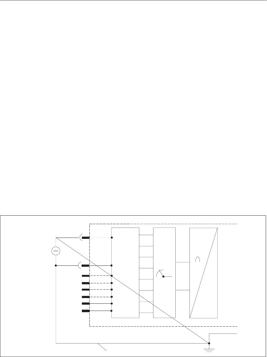
9-17
System Manual
C79000-G8576-C199-06
9.3.8 Connection of Sensors
Observe the following information when connecting the sensors.
With isolated sensors, it is possible for the measuring circuit to develop a
potential with respect to ground which exceeds the permissible potential
difference U<M>CM (see maximum values of the individual modules). To
prevent this, you must connect the negative potential of the sensor to the
reference potential of the module (0 V bus).
Example:
Temperature measurement on a busbar with insulated thermocouples
In the worst case, the measuring circuit can develop an excessively high
potential on account of a static charge or contact resistances. This must be
prevented with an equipotential bonding conductor.
The permissible potential difference (UCM) between the inputs and the 0V
bus must not be exceeded.
Depending on the system or type of sensor, the potential difference must be
kept in the permissible region with epuipotential bonding.
Equipotential Bonding Conductor
0 V Bus
+
–
UE
A
D
Analog Input Module
Sensor, Isolated
MUX
M+
M–
#
Range
Card for
4 Inputs
Figure 9-6 Measuring Circuit with Equipotential Bonding Conductor for the 460 Analog Input Module
Connection of
Current or Voltage
Sensors
Equipotential
Bonding
Analog Input/Output Modules
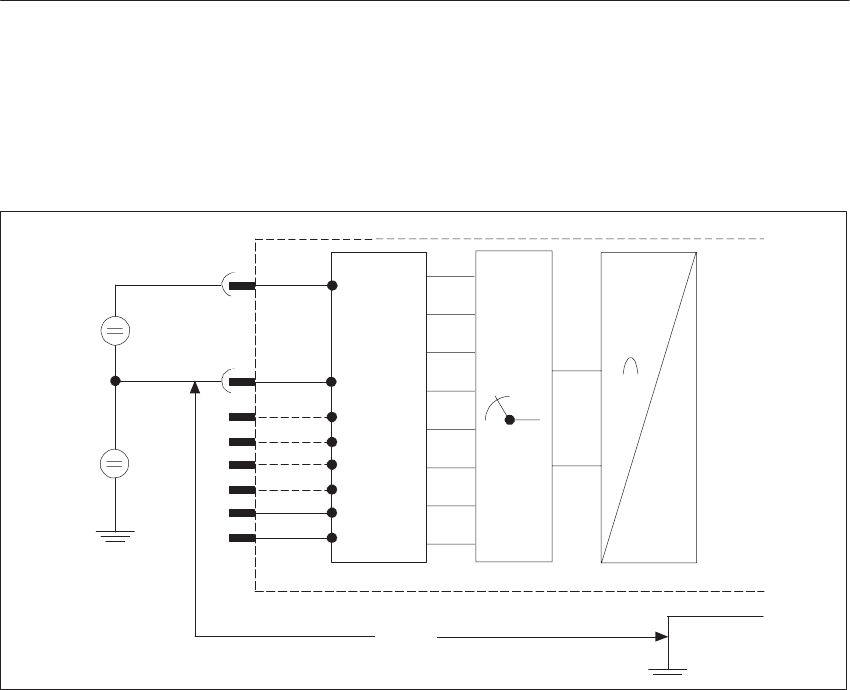
9-18 System Manual
C79000-G8576-C199-06
Example:
(Special case) The temperature of the busbar of an electroplating bath is to be
measured with an uninsulated thermocouple.
+
–UE
+
–UCM
A
D
MUX
M+
M–
UCM
#
0 V Bus
Analog Input Module
Sensor,
Not Isolated
Range
Card for
4 Inputs
Figure 9-7 Measuring Circuit without Equipotential Bonding Conductor for the 460 Analog Input Module
The potential of the busbar with respect to the reference potential of the
module is, for example, 24 V DC. A 460 analog input module with isolated
input is used (UCM = 60 V AC/75 V DC). An equipotential bonding
conductor must not be laid here because it would short-circuit the busbar.
Analo
g
Input/Output Modules
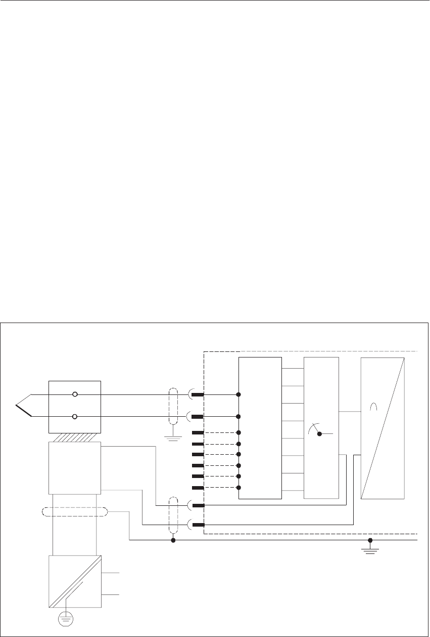
9-19
System Manual
C79000-G8576-C199-06
9.3.9 Connecting a Compensating Box for Thermal E.M.F.
Measurement
If the room temperature fluctuations at the reference point (e.g. in the
terminal box) affect the measurement result and you do not wish to use a
thermostat, you can compensate for the effect of temperature on the reference
point with a compensating box. Between - 10 and + 70 oC, it compensates for
the change in thermal e.m.f. cause by temperature deviation (compensating
box, see Catalog MP 11). Ensure that the compensating box has thermal
contact with the terminals.
If the compensating box is aligned at 20 oC, this must be taken into account
in temperature evaluation (20 oC measuring point temperature = 0 mV).
Pins 22 and 23 are extended on analog input modules as an input for the
compensating voltage. You must select a common input loop for all inputs on
mode switch 2.
The compensating box must be connected in a floating circuit. The power
supply unit of the compensating box must have a grounded shield winding to
avoid AC system interference being picked up. A separate compensating box
with its special power supply unit is required for each analog input module.
22–
A
D
Analog Input Module
MUX
M–
23+
0 V Bus
M+
–
+
Power
Supply
for Com-
pensat-
ing Box
Thermocouple
Terminal Box
~
=
#
Range
Card for
4 Inputs
6ES5 498-
-1AA11
Compen-
sating
Box
Figure 9-8 Connecting a Compensating Box
Analo
g
Input/Output Modules
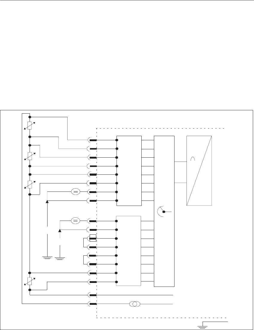
9-20 System Manual
C79000-G8576-C199-06
9.3.10 Connecting Resistance Thermometers in the Standard Pt 100
Range
The series-connected resistance thermometers (up to 8 Pt 100s) are fed with a
current of 2.5 mA (IC+/IC-) by a constant current generator. The voltage at the
Pt 100’s is picked off at measurement inputs M+ and M-. In this mode, the
whole temperature range of the Pt 100 (-200 °C to +840 °C) is available. The
mode is printed on the cover of the module as follows:
“resistance thermometer uncompensated full range.” Other voltage sensors
can be connected in a floating circuit at the M+/M- inputs of a card which are
not assigned to resistance thermometers (voltage range 500 mV).
Pt 100
–
+
MUX
Card 1
460 Analog Input Module
#
D
A
CH0
CH2
CH1
CH3
M–
M +
Card 2
CH4
0...500 mV
UCM
2)
1)
CH7
IC–
L –
L +
0 V Bus
2.5 mA
const.
Pt 100
Pt 100
Pt 100
IC+
UCM
0...500 mV
Range
Card for
4 Inputs
6ES5 498-
-1AA11
Range
Card for
4 Inputs
6ES5 498-
-1AA11
Figure 9-9 Connecting Resistance Thermometers in the Standard Pt 100 Range
1) If no Pt 100 is connected to CH4 to CH7, other voltages and currents can be measured at these channels with cards
6ES5 498-1AA21, 6ES5 498-1AA31, 6ES5 498-1AA41, 6ES5 498-1AA51, 6ES5 498-1AA61, 6ES5 498-1AA71.
2) When cards 6ES5 498-1AA41, 6ES5 498-1AA51 or 6ES5 498-1AA71 are used, a short-circuit jumper is not required.
Analo
g
Input/Output Modules
9-21
System Manual
C79000-G8576-C199-06
9.3.11 Connecting Resistance Thermometers in the Extended Pt 100
Range
The series-connected resistance thermometers (up to 8 Pt 100s) are fed with a
current of 2.5 mA (IC+/IC-) by a constant current generator. The voltage at the
Pt 100s is picked off at measurement inputs M+ and M-.
In this mode, the temperature range of approximately -100 °C to +100 °C has
a more accurate resolution. The mode is printed on the cover of the module
as follows: “resistance thermometer compensated low range.”You should
only use the 6ES5 498-1AA11 range card (" 50 mV / 500 mV).
Unused inputs must be connected in parallel to a wired input. In the
following figure, for example, these are the inputs CH4 to CH7.
M+
M–
Ch0
M+
M–
Ch1
M+
M–
Ch2
M+
M–
Ch3
M+
M–
Ch4
M+
M–
Ch5
M+
M–
Ch6
M+
M–
Ch7
Ic–
Ic+
L+
L–
6ES5498-
1AA11
6ES5498-
1AA11
24V
M24V
2.5mA
Figure 9-10 Connecting Resistance Thermometers in the Extended Pt 100 Range
Analo
g
Input/Output Modules

9-22 System Manual
C79000-G8576-C199-06
9.3.12 Broken Wire Signal
An open-circuit in the lines to a resistance thermometer is indicated as
follows:
Broken Wire at Module Reaction, Encoded Value Error Bit E
M+
M–
Pt 100
IC+
IC–
0
0
0 1)
0
0
1
1
1
0
0
1) With the 460 analog input module, the value 0 is also encoded for the intact Pt 100 resistances
because the auxiliary circuit is interrupted; the error bit will not be set for these channels.
If the mode “without broken wire signal” is selected on the module, an
open-circuit of the resistance thermometer is indicated with an overflow.
Unassigned channels can be used for voltage or current measurement.
If a line of the auxiliary circuit (IC+, IC-) is interrupted, the “negative range
limit” is encoded for all inputs and the overflow bit is set to “1.” In the event
of a sensor or measuring line open-circuit, the error bit is additionally set to
“1” for the relevant channel.
Broken Wire
Signal in the
Standard Pt 100
Range
Broken Wire
Signal in the
Extended Pt 100
Range
Analo
g
Input/Output Modules

9-23
System Manual
C79000-G8576-C199-06
9.3.13 Connecting Transducers
Two-wire transducer (short-circuit protected supply voltage via the range
card of the analog input module)
A
D
Analog Input Module
MUX
M–
0 V Bus
M+
+
–
4...20 mA
L+ L–
#
Range
Card for
4 Inputs
6ES5-498-
-1AA51
Four-wire transducer (with separate supply voltage)
A
D
Analog Input Module
MUX
M–
0 V Bus
M+
+
–
+4...20 mA
230 V AC
Do not exceed max. permissible potential difference!
#
6ES5-498-
-1AA71
Range
Card for
4 Inputs
Four-wire transducer with a two-wire transducer card
A
D
Analog Input Module
MUX
M–
0 V Bus
M+
+
–
0...20 mA
230 V AC
L+ L–
L– (0 Vext)
#
6ES5-498-
-1AA71
Range
Card for
4 Inputs
Analo
g
Input/Output Modules

9-24 System Manual
C79000-G8576-C199-06
9.3.14 Measured-Value Representation
(rated input range $ 50 mV)
Units Input Volt-
iV
Byte 0 Byte 1
age in mV 7
212 6
211 5
210 4
29 3
282
27 1
26 0
25 7
24 6
235
22 4
21 3
20 2
A 1
E 0
OV
w4096 100.0 0 1 1 1 1 1 1 1 1 1 1 1 1 0/1 0/1 1 Overflow
4095
2049 99.976
50.024 0
0 1
1 1
0 1
0 1
0 1
0 1
0 1
0 1
0 1
0 1
0 1
0 1
1 0/1
0/1 0/1
0/1 0
0Overrange
2048
2047 50.0
49.976 0
0 1
0 0
1 0
1 0
1 0
1 0
1 0
1 0
1 0
1 0
1 0
1 0
1 0/1
0/1 0/1
0/1 0
0
1024
1023 25.0
23.976 0
0 0
0 1
0 0
1 0
1 0
1 0
1 0
1 0
1 0
1 0
1 0
1 0
1 0/1
0/1 0/1
0/1 0
0
1
0
–1
0.024
0.0
–0.024
0
0
1
0
0
1
0
0
1
0
0
1
0
0
1
0
0
1
0
0
1
0
0
1
0
0
1
0
0
1
0
0
1
0
0
1
1
0
1
0/1
0/1
0/1
0/1
0/1
0/1
0
0
0
Rated
range
–1023
–1024 – 24.976
– 25.0 1
1 1
1 1
1 0
0 0
0 0
0 0
0 0
0 0
0 0
0 0
0 0
0 1
0 0/1
0/1 0/1
0/1 0
0
–2047
–2048 – 49.976
– 50.0 1
1 1
1 0
0 0
0 0
0 0
0 0
0 0
0 0
0 0
0 0
0 0
0 1
0 0/1
0/1 0/1
0/1 0
0
–2049
–4095 – 50.024
– 99.976 1
1 0
0 1
0 1
0 1
0 1
0 1
0 1
0 1
0 1
0 1
0 1
0 1
1 0/1
0/1 0/1
0/1 0
0 Overrange
–4096 –100.0 1 0 0 0 0 0 0 0 0 0 0 0 1 0/1 0/1 1 Overflow
A = Active bit
E = Error bit
OV = Overflow bit
Digital
Measured-Value
Representation as
Two’s Complement
Analo
g
Input/Output Modules

9-25
System Manual
C79000-G8576-C199-06
(rated input range $ 50 mV)
Units Input Volt-
iV
Byte 0 Byte 1
age in mV 7
S 6
211 5
210 4
29 3
282
27 1
26 0
25 7
24 6
235
22 4
21 3
20 2
A 1
E 0
OV
w4096 100.0 0 1 1 1 1 1 1 1 1 1 1 1 1 0/1 0/1 1 Overflow
4095
2049 99.976
50.024 0
0 1
1 1
0 1
0 1
0 1
0 1
0 1
0 1
0 1
0 1
0 1
0 1
1 0/1
0/1 0/1
0/1 0
0 Overrange
2048
2047 50.0
49.976 0
0 1
0 0
1 0
1 0
1 0
1 0
1 0
1 0
1 0
1 0
1 0
1 0
1 0/1
0/1 0/1
0/1 0
0
1024
1023 25.0
23.976 0
0 0
0 1
0 0
1 0
1 0
1 0
1 0
1 0
1 0
1 0
1 0
1 0
1 0/1
0/1 0/1
0/1 0
0
1
0
–0
–1
0.024
0.0
0.0
–0.024
0
0
1
1
0
0
0
0
0
0
0
0
0
0
0
0
0
0
0
0
0
0
0
0
0
0
0
0
0
0
0
0
0
0
0
0
0
0
0
0
0
0
0
0
0
0
0
0
1
0
0
1
0/1
0/1
0/1
0/1
0/1
0/1
0/1
0/1
0
0
0
0
Rated
range
–1023
–1024 – 24.976
– 25.0 1
1 0
0 0
1 1
0 1
0 1
0 1
0 1
0 1
0 1
0 1
0 1
0 1
0 0/1
0/1 0/1
0/1 0
0
–2047
–2048 – 49.976
– 50.0 1
1 0
1 1
0 1
0 1
0 1
0 1
0 1
0 1
0 1
0 1
0 1
0 1
0 0/1
0/1 0/1
0/1 0
0
–2049
–4095 – 50.024
– 99.976 1
1 1
1 0
1 0
1 0
1 0
1 0
1 0
1 0
1 0
1 0
1 0
1 1
1 0/1
0/1 0/1
0/1 0
0 Overrange
–4096 –100.0 1 1 1 1 1 1 1 1 1 1 1 1 1 0/1 0/1 1 Overflow
A = Active bit
E = Error bit
OV = Overflow bit
Bit 212 is interpreted as the sign.
Digital
Measured-Value
Representation as
Value and Sign
Analo
g
Input/Output Modules

9-26 System Manual
C79000-G8576-C199-06
The resolution with Pt 100 resistance thermometers is approximately 0.25 oC.
1 ohm 10 units
Units Resistance in
ohms
Temper-
ature in
Byte 0 Byte 1
ohms ature in
oC 7
S 6
211 5
210 4
29 3
28 2
27 1
26 0
25 7
24 6
23 5
22 4
21 3
20 2
A 1
E0
OV
4096 400.0 – 0 1 1 1 1 1 1 1 1 1 1 1 1 0/1 0/1 1 Overflow
4095
2049 399.90
200.98 – 269.1 0
0 1
1 1
0 1
0 1
0 1
0 1
0 1
0 1
0 1
0 1
0 1
0 1
1 0/1
0/1 0/1
0/1 0
0 Overrange
2048
2047 200.0
199.90 266.5
266.0 0
0 1
0 0
1 0
1 0
1 0
1 0
1 0
1 0
1 0
1 0
1 0
1 0
1 0/1
0/1 0/1
0/1 0
0
1024
1023 100.00
99.90 0
–0.2 0
0 0
0 1
0 0
1 0
1 0
1 0
1 0
1 0
1 0
1 0
1 0
1 0
1 0/1
0/1 0/1
0/1 0
0 Rated range
1
0 0.098
0.0 –
– 0
0 0
0 0
0 0
0 0
0 0
0 0
0 0
0 0
0 0
0 0
0 0
0 1
0 0/1
0/1 0/1
0/1 0
0
A = Active bit
E = Error bit
OV = Overflow bit
S = Sign
When Pt 100 resistance thermometers are connected, the maximum
temperature in the rated range is 266 oC. If it can be ensured that the
temperature does not exceed 850 oC, the input value may extend into the
overrange. The resolution is then 4095 units. Unused inputs can be utilized
for voltage measurements in the 500 mV range (see front connector
assignments).
In addition to the standard Pt 100 range, there is an extended Pt 100 range on
the 460 analog input module. You can select this with the mode switch.
The following is printed on the cover of the module to set the Pt 100 mode:
Standard range: “resistance thermometer uncompensated full range”
Extended range: “resistance thermometer compensated low range”
In this range, the basic resistance of the Pt 100 at 0 oC (100 ohms) is
compensated for on the module. As in the standard range, the Pt 100 is fed
with a constant current of 2.5 mA. Using the overrange (- 100 mV to + 100
mV), this results in a temperature range of approx. -100 °C to + 100 °C.
This measuring range of 200 °C is resolved to 8192 units with the correct
sign for the temperature. One unit thus corresponds to approximately 0.025
°C. If you select the extended Pt 100 range, you can use all 8 analog inputs in
this range only.
You should only use the 6ES5 498-1AA11 range card ($ 50 mV/500 mV).
Measured-Value
Representation for
Resistance
Thermometers in
the Standard Pt
100 Range
Extended Pt 100
Range
Analo
g
Input/Output Modules

9-27
System Manual
C79000-G8576-C199-06
Units Pt 100/ohms Temperat
u
ioC
Byte 0 Byte 1
in oC 7
S 6
211 5
210 4
29 3
28 2
27 1
26 0
25 7
24 6
23 5
22 4
21 3
20 2
A 1
E0
OV
>4095 w 140.0 0 1 1 1 1 1 1 1 1 1 1 1 1 0 0 1 Overflow
4095
2049 139.99
120.01 103.74
51.61 0
0 1
1 1
0 1
0 1
0 1
0 1
0 1
0 1
0 1
0 1
0 1
0 1
1 0
0 0
00
0Overrange
2048
+1
0
–1
–2048
120.0
100.01
100.0
99.99
80
51.58
0.026
0
–0.026
–50.78
0
0
0
1
1
1
0
0
1
1
0
0
0
1
0
0
0
0
1
0
0
0
0
1
0
0
0
0
1
0
0
0
0
1
0
0
0
0
1
0
0
0
0
1
0
0
0
0
1
0
0
0
0
1
0
0
0
0
1
0
0
1
0
1
0
0
0
0
0
0
0
0
0
0
0
0
0
0
0
0
Rated range
–2049
–4095 79.99
60.01 –50.81
–100.60 1
1 0
0 1
0 1
0 1
0 1
0 1
0 1
0 1
0 1
0 1
0 1
0 1
1 0
0 0
00
0Overrange
<–4095 v 60 1 0 0 0 0 0 0 0 0 0 0 0 1 0 0 1 Overflow
Broken wire
–4095 Arbitrary Arbitrary 1 0 0 0 0 0 0 0 0 0 0 0 1 0 0 1Broken wire
Ic+/Ic-2)
–4095 Arbitrary Arbitrary 1 0 0 0 0 0 0 0 0 0 0 0 1 0 1 1Broken wire
Sensor
Measuring
line 1)
1) Only with broken wire monitor activated, error bit = 1 only for faulty
channel; for sensor broken wire, overflow bit = 1 for all channels
2) On account of the Pt 100 series circuit, this bit combination always
appears for all channels if the supply line is open-circuit.
A = Active bit
E = Error bit
OV = Overflow bit
S = Sign
Measured-Value
Representation in
the Extended Pt
100 Measuring
Range (Two’s
Complement)
Analo
g
Input/Output Modules

9-28 System Manual
C79000-G8576-C199-06
Measuring range 500 mV; card with 31.25 ohm shunt
(6ES5 498-1AA51/AA71)
The 4 to 20 mA range is resolved to 2048 units at an interval of 512 to 2560.
If you require a representation from 0 to 2048, you must subtract 512 units by
software. Please note the following:
A broken wire signal cannot be emitted.
Detection of the overrange can be achieved by scanning bits 29 and 211.
A broken wire can be detected with currents < 3 mA.
If you short-circuit the positive and negative terminals of the transducer
when using the 6ES5 498-1AA51 range card (for a two-wire transducer),
the current is limited to about 28 mA. Until the thermal current limiting
circuit responds in the range card (about 3 s), a short-circuit current of
approximately 250 mA flows; this sets the overflow bit for this duration
at all channels.
Units Input Cur-
ti A
Byte 0 Byte 1
rent in mA 7
S 6
211 5
210 4
29 3
28 2
27 1
26 0
25 7
24 6
23 5
22 4
21 3
20 2
A 1
E 0
OV
w 4096 w 32.000 0 1 1 1 1 1 1 1 1 1 1 1 1 0/1 0 1 Overflow
4095
3072
3071
2561
31.992
24.0
23.992
20.008
0
0
0
0
1
1
1
1
1
1
0
0
1
0
1
1
1
0
1
0
1
0
1
0
1
0
1
0
1
0
1
0
1
0
1
0
1
0
1
0
1
0
1
0
1
0
1
0
1
0
1
1
0/1
0/1
0/1
0/1
0
0
0
0
0
0
0
0
Overrange
Short-circuit with two-
wire transducer
2560
2048
512
20.0
16.0
4.0
0
0
0
1
1
0
0
0
0
1
0
1
0
0
0
0
0
0
0
0
0
0
0
0
0
0
0
0
0
0
0
0
0
0
0
0
0
0
0
0/1
0/1
0/1
0
0
0
0
0
0
Rated range
511
384
383
3.992
3.0
2.992
0
0
0
0
0
0
0
0
0
0
0
0
1
1
1
1
1
0
1
0
1
1
0
1
1
0
1
1
0
1
1
0
1
1
0
1
1
0
1
0/1
0/1
0/1
0
0
0
0
0
0
Range
underflow
0 0 0 0 0 0 0 0 0 0 0 0 0 0 0 0/1 0 0 Broken wire
A = Active bit
E = Error bit
OV = Overflow bit
S = Sign
Measured-Value
Representation for
Current Measuring
Ranges from 4 to
20 mA
Current Limiting
Analo
g
Input/Output Modules

9-29
System Manual
C79000-G8576-C199-06
9.3.15 Technical Specifications
6ES5 460-4UA13 Analog Input Module
Rated input ranges with cards for every 4 channels
– 6ES5 498-1AA11
– 6ES5 498-1AA21
– 6ES5 498-1AA31
– 6ES5 498-1AA41
– 6ES5 498-1AA51
– 6ES5 498-1AA61
– 6ES5 498-1AA71
$ 12.5 mV/$50 mV/$500 mV/Pt 100
$ 1 V
$ 10 V
$ 5 mA/$ 20 mA
4 to 20 mA for two-wire transducer
$ 5 V
4 to 20 mA for four-wire transducer
Number of inputs 8 voltage/current inputs or
8 resistance inputs (Pt 100)
Measured-value representation 13 bits (two’s complement) or 12 bits + sign;
$ 2048 units in rated range;
512 to 2560 units for 4 to 20 mA
Measuring principle Integrating
Isolation Yes
8 inputs tested with respect to 0 V at 500 V AC
Permissible potential difference between reference potentials
of sensors and the module (UCM) and between sensors (chan-
nels)
25 V AC/60 V DC max.
Power Supply
– digital section from system bus
– analog section from load voltage
– enabling for module F+/F-
– tripping current L+
5 V $ 5 %; 130 mA typical
24 V; approx. 50 mA 1)
24 V; approx. 5 mA
24 V; approx. 5 mA
Constant current source for Pt 100 connection IC+/IC- 2.5 mA; TC = $ 5 x 10⁻⁵/K
Integration time 20 ms at 50 Hz; 16 2/3 ms at 60 Hz
Encoding time per measured value 60 ms at 50 Hz; 50 ms at 60 Hz
1) Plus 20 mA max. per connected two-wire transducer.
Analo
g
Input/Output Modules

9-30 System Manual
C79000-G8576-C199-06
Cycle time for 8 measured values with 2048 units
(max. delay time for measured-value acquisition) Approx. 0.48 s at 50 Hz
Input resistance (with card) for input ranges:
$12.5 mV/$50 mV/$500 mV/Pt 100
$1 V
$5 V/$10 V
$5 V/$20 mA
4 to 20 mA
w 10 MW
90 kW
50 kW
25 W
31.25 W
Measuring point-related error signal
– for overflow
– for broken wire
Yes
Yes, configurable
(at $12.5 mV, $ 50 mV $ 500 mV and Pt 100 1) )
Max. permissible input voltage without destruction $18 V; 75 V for 1 ms max. and duty ratio 1:20
Interference suppression for f = n x (50/60 Hz $1 %)
– with common-mode interference
– with differential-mode interference
w 100 dB
w 40 dB, interference voltage amplitude
but 100 % max. of measuring range referred to peak value
Error referred to rated value
– linearity
– tolerance
at w50 mV
at $ 12.5 mV
– polarity reversal error
at w 50 mV
at $12.5 mV
– temperature error
$ 1 unit
$ 1 unit
$ 3 units
$ 1 unit
$ 2 units
1 x 10 –4 /K
Error caused by modules with input range
$ 1 V/$ 5 V /$ 10 V
$ 20 mA/4 to 20 mA
2 x 10 –3; TC = $ 10 x 10 –5 /K
10 –3; TC = $ 5 x 10 –5 /K
Voltage test to VDE 0160 Between inputs and ground point
tested at 500 V AC
Surge voltage test to IEC 255-4 Between inputs and L-:
Vp = 1 kV, 1.2/50 µs
Extended Pt 100 measuring range
Measuring range including overrange
Resolution
Basic error at T = 25 oC
Operational error at T = 0 to 65 oC
Range card
Approx. - 100 oC to + 100 oC
0.025 oC per unit
$0.2 oC max.
$0.5 oC max.
6ES5 498-1AA11
Environmental specifications See technical specifications of the S5-135U/155U CC
1) In the event of open-circuit of the live IC+ and IC- lines, the digital value 0 is indicated.
Analo
g
Input/Output Modules
9-31
System Manual
C79000-G8576-C199-06
You select the desired mode of the analog input module by setting mode
switches I and II according to the following table.
Please note that all switch rockers marked with a dot must be set on both
mode switches. To set the desired mode, press the rockers downwards on the
side marked with a dot in the table.
Mode Mode Switch I
(Digital Section) Mode Switch II
(Digital Section)
Without reference point compensation
With reference point compensation
Measuring range
Extended Pt 100 measuring range
500 mV; mA (standard Pt 100 measuring
range)
50 mV
Value and sign
Two’s complement
Gain x 1
(normal setting)
Gain x4
Sampling
selective
cyclic
Line frequency
50 Hz
60 Hz
Channels 0 to 3
with broken wire signal
Channels 4 to 7
Channels 0 to 3
without broken wire signal
Channels 4 to 7
X = Switch is not assigned; any switch setting.
Ĥ = Switch setting
Setting the Mode
Analo
g
Input/Output Modules
9-32 System Manual
C79000-G8576-C199-06
Labeling of switches on the module cover:
line frequency 50 Hz
result and sign
two‘s complement
normal mode (gain*1)
special mode (gain*4)
singlescanning
mark selected switch
positions here
mark selected switch
positions here
broken wire detection
channel 0...3 without
compensation
with
compensation
resistance thermometer
compensated low range
500 mV V...ma
resistance thermometer
uncompensated full range
broken wire detection
channel 4...7
without broken
wire detection
SI
SII
line frequency 60 Hz 50mV
=press
cyclicscanning
VOLTAGE
COMPENS.
INPUT RANGE
DATA
FORMAT
GAIN
submodule1
(ch. 0...3)
submodule 2
(ch. 4...7)
On one 460 analog input module, you can insert two cards to connect four
inputs each, and secure them with a srew. There are voltage divider, shunt
and through-connection cards for the various ranges.
Circuit of the
cards, 4x
Mode
50 mV
+ Gain x 1
Mode
500 mV/ mA
Pt 100
+ Gain x 1
-1AA11 -1AA21 -1AA31 -1AA41 -1AA51 -1AA61 -1AA71
M+
M–
M+
M–
M+
M–
M+
M–
M+
M–
M+
M– M–
L+
L–
Range Card Type 6ES5 498–
M+
" 500 mV
Pt 100
"1 V " 10 V " 5 V4...20mA
2-wire trans-
ducer
" 20 mA 4...20mA
4-wire trans-
ducer
– (" 100 mV)" 50 mV (" 1 V) (" 2 mA) (" 500 mV) –
Mode
500 mV/ mA
+ Gain x 4
Mode
50 mV
+ Gain x 4
(" 125 mV)
(" 25 mV)(" 12.5 mV)
(" 1.25 V)
(" 5 mA)(" 2.5 V)(" 250 mV)
–
– –
–
–
–
–
Inserting Range
Cards
Analo
g
Input/Output Modules

9-33
System Manual
C79000-G8576-C199-06
For a defined mode (50 mV or 500 mV) you can insert cards with different
ranges for four inputs, e.g. for the 500 mV mode:
4 inputs, range $ 500 mV; 1 card 6ES5 498-1AA11
4 inputs, range $ 10 V; 1 card 6ES5 498-1AA31
Analo
g
Input/Output Modules
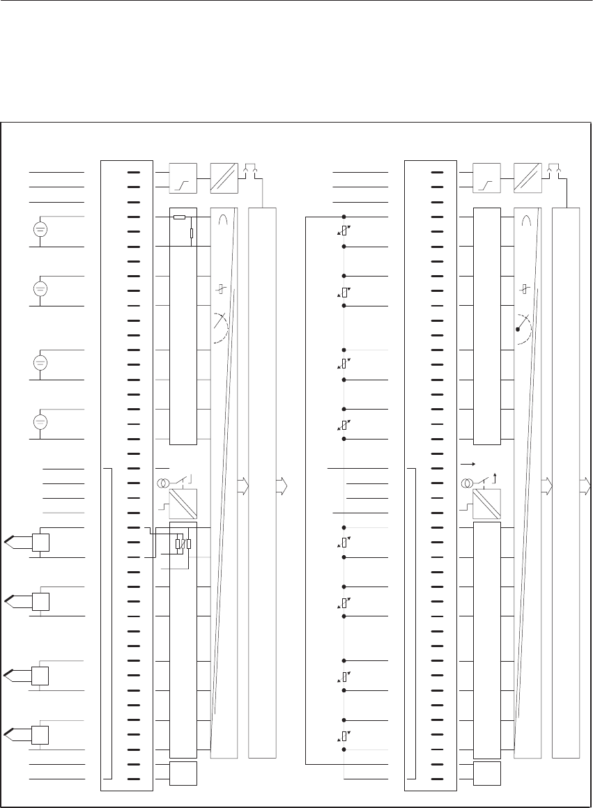
9-34 System Manual
C79000-G8576-C199-06
Voltage or current-input resistance thermometer or connection of two-wire
transducer
I
const.
1
2
3
4
6
8
10
13
15
17
19
21
22
23
25
27
29
31
34
36
38
40
41
42
F+
L+
F–
L–
Ch.0
Ch.1
Ch.2
Ch.3
Comp.–
Comp.+
Ch.4
Ch.5
Ch.6
Ch.7
Data Memory and S5 Bus Control
ADU
t
Range Card 2 Range Card 1
Ic+
c–
I
L– Itrip
24
L+ 3)
4)
#
Front Strip
Pin
L–
L–
L+
I
const.
Connection of
Process Signal
Lines
1
2
3
4
6
8
10
13
15
17
19
21
22
23
25
27
29
31
34
36
38
40
41
42
F+
L+
1)
F–
L–
Ch.0
1)
+
–Ch.1
1)
+
–Ch.2
1)
4)
+
–Ch.3
Comp.–
Comp.+
I+
c
I–
c
T
T
T
T
1)
1)
1)
1)
+
–
+
–
2)Ch.4
+
–
+
–
+
–
2)Ch.5
2)Ch.6
2)Ch.7
ADU
t
Range Card 2 Range Card 1
6ES5 498–1AA51
Itrip
L+
3) 24
#
Front Strip
Pin
Connection of
Process Signal
Lines
Block Diagram
of the Modules
Block Diagram
of the Modules
Data Memory and S5 Bus Control
Figure 9-11 Front Connector Assignments
1) Observe permissible potential difference between sensor ground and reference potential of modules or between
sensor grounds.
2) Two-wire transducer
3) Only required to switch off the tripping current without broken wire detection; 0 V at L-.
4) Connect L- to the central ground point (reference potential).
Front Connector
Assignments
Analo
g
Input/Output Modules
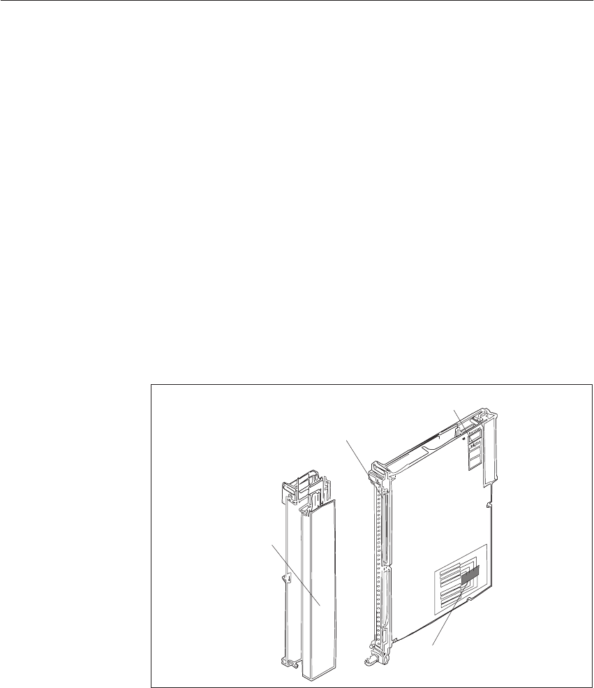
9-35
System Manual
C79000-G8576-C199-06
9.4 The 463 Analog Input Module
9.4.1 Design
The modules are designed as plug-in PCBs for central controllers and
expansion units with a backplane connector and with a blade connector to
accept a plug-in front connector. You can directly connect the process signal
lines to the front connector, which is available separately, with screw or
crimp terminals.
Situated on each module is an addressing switch with six rockers to set the
module address. Analog input modules also have two switches on the side
with eight rockers for setting the mode, and receptacles for range cards.
The modules are protected by covers on both sides.
Blade Connector
Addressing Switch
Mode Switch
Front Connector
Figure 9-12 Analog Input Module
9.4.2 Function of the Enable Input
The 463 module has an enable circuit. You can use the enable inputs to
switch off individual modules whilst the PLC is in operation. This means
that:
The module can no longer be addressed by the user program.
Modules which are switched off can be removed or inserted during operation.
If this is not necessary, operate the module with the enable input switched
off.
Addressing
Switch, Mode
Switches
Analo
g
Input/Output Modules
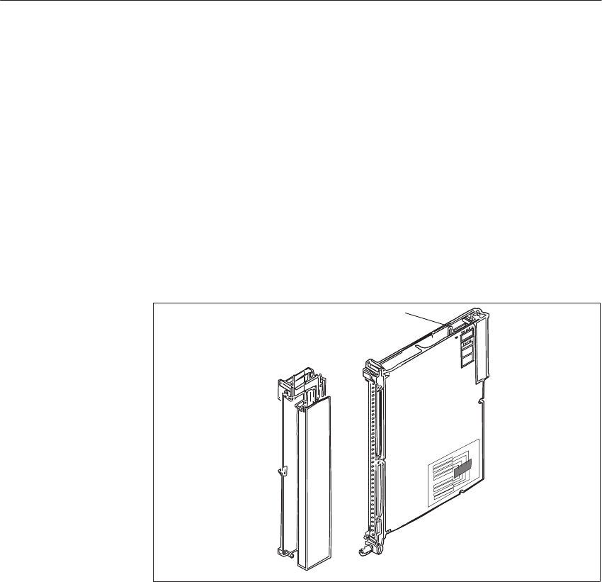
9-36 System Manual
C79000-G8576-C199-06
The enable circuit requires an external 24 V voltage at enable inputs F+/F- in
the front connector. If there is no voltage at F+/F-, the modules will not
acknowledge.
When the front connector is swivelled away from the front strip of the
module, the supply of power to the enable input is interrupted, i.e. the
module is switched off and can no longer be addressed by the user program: a
timeout (QVZ) occurs in the CC.
The -4Ux12 type modules additionally offer the facility for changing the
enable mode. The modules have a jumper accessible from above in the
vicinity of the addressing switch.
Enable Jumper
Figure 9-13 Enable Input and Enable Jumper
Jumper inserted: Enable input (F+/F-) active (factory setting)
Jumper open: Enable input (F+/F-) switched off
Examples of functioning of the enable inputs:
To switch off individual subprocesses, i.e. outputs of various modules can
be operated from a common load supply and yet activated separately.
The load voltage of individual modules can be monitored without
additional circuitry. Any reactions to failure of the load voltage can be
programmed in the QVZ (timeout) organization block.
Enable Input
Switching off the
Enable Input
Analo
g
Input/Output Modules
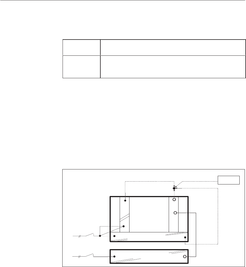
9-37
System Manual
C79000-G8576-C199-06
You must observe the following when configuring systems:
Switching on At the latest 100 ms after power-up of the PLC, the voltage
must be present at the enable inputs of the I/O modules.
Switching off When the PLC has been switched off, the voltage at the
enable inputs of the I/O modules must still be present as
long as the internal 5 V voltage is present.
You should observe the following instructions for switching off CCs and
equipment for supplying power to the enable inputs.
When there is a need to switch off the load power supply separately without
affecting the enabling of modules, there are the following possibilities for
producing the enable voltage. These exist even when the load power supply
is used without an additional capacitor and common shutdown.
230 V AC supply for CC/EU and load power supply
F+
L+
I/O Modules
230 V AC
CC/EU
–951
a)
c)
b) Battery
L+
Power Supply
Load Power Supply 24V
Supply for the enable inputs from:
a) 6ES5 951-4LB11 load power supply
b) Battery
c) Terminals for 24 V on the front plate of the power supply
Configuring
Switching off the
CC
Separate or
Common
Shutdown of the
CC/EU and Load
Power Supply
Analo
g
Input/Output Modules
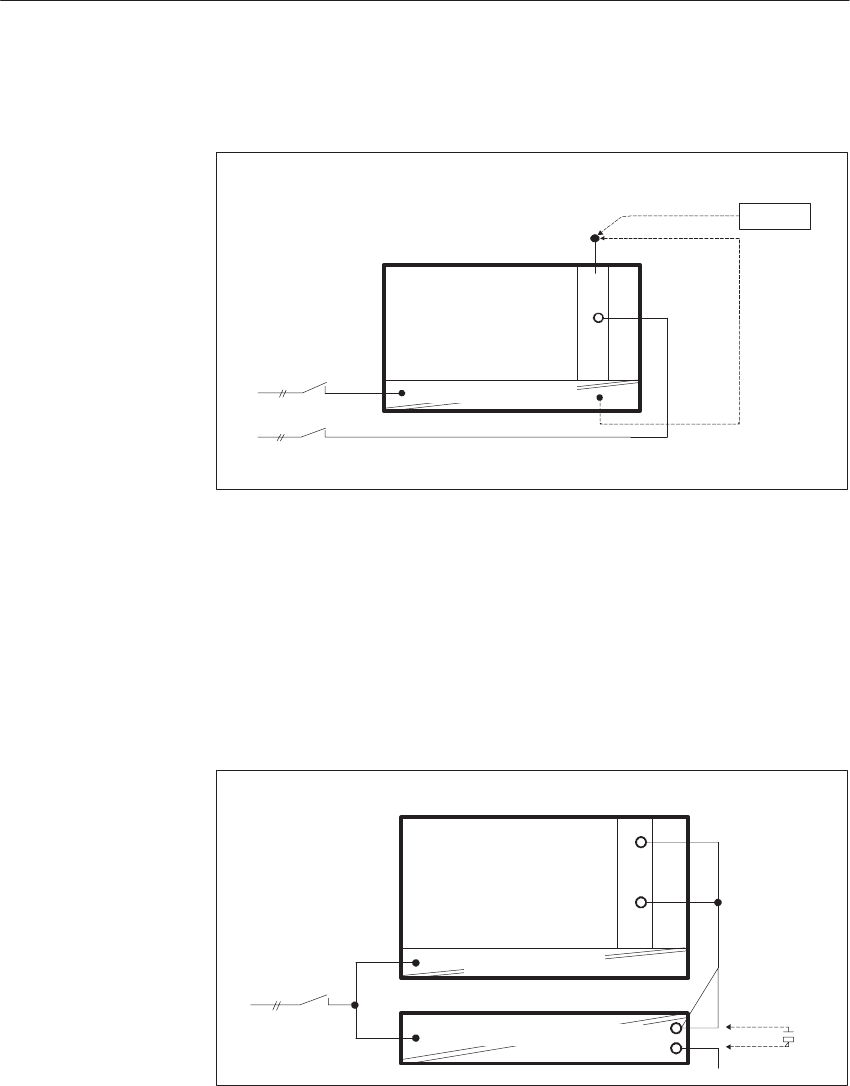
9-38 System Manual
C79000-G8576-C199-06
24 V supply for CC/EU and I/Os
F+
L+
I/O Modules
24 V DC
b)
a)
CC/EU
L+
Battery
Power Supply 24V
Supply for the enable inputs from:
a) Battery
b) Terminals for 24 V on the front plate of the power supply
Proper functioning is ensured if the 24 V load power supply has an output
capacitance of at least 4700 mF per 10 A of load current. Other units which
do not meet this condition can be adapted to this requirement by connecting a
10000 mF /40 V capacitor in parallel.
10000µF/40V
CC/EU F+
L+
230 V AC
I/O Modules
Load Power Supply 24V
Power Supply
Common
Shutdown of the
CC/EU and Load
Power Supply with
a 230 V AC Supply
Analo
g
Input/Output Modules

9-39
System Manual
C79000-G8576-C199-06
9.4.3 Special Features of the 463 Analog Input Module
The 463 analog input module executes integrating processing of the digital
input signals; periodic system interference is thus suppressed.
The measuring range for each channel is adapted by appropriately connecting
the sensors and with jumpers in the front connector of the module (see the
front connector assignments).
Note
The ohmic resistance of the jumper with which the measuring range is set is
also measured. As the resistance of this jumper is not inconsiderable (0.5 to
0.7 ohms in relation to the measuring shunt of 50 ohms) when I/O module
cables with integral connectors and subsequent wiring blocks are used, the
measurement result may be corrupted accordingly.
9.4.4 Setting the Module Address
You set the module address on the addressing switch. This also establishes
the necessary assignments between user program and process connection.
The module address is the sum of the decimal significances of the switch
rockers in the On setting (Ĥ).
One data word = two data bytes is required to process an input or an output.
A module with 4 inputs therefore reserves 8 byte addresses.
You can affix the adhesive label with the desired module address on a free
labeling field under the addressing switch.
The switch rockers to be set for the module address specified as a decimal
number (address bit ADB) are marked by dots on the label. The unmarked
switches should be switched off.
Adaptation of the
Measuring Range
Labeling Field
Analo
g
Input/Output Modules
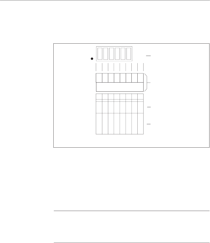
9-40 System Manual
C79000-G8576-C199-06
Press the individual rockers of the addressing switch downwards with a
ballpoint pen or similar object, but not a pencil.
On Setting
(Switch Pressed) Addressing Switch
Address Bit
Decimal Significance of
the Address Bit
Adresse (dezimal)
ADB2 is not connected
ADB0 and ADB1 are not assigned
128
64
32
16
8
4
2
1
ADB7
ADB6
ADB5
ADB4
ADB3
ADB2
ADB1
ADB0
Free Field for Label with
Module Address and
marked Switch Settings
Figure 9-14 Labeling of the Addressing Switch
The address under which the module is referenced by the STEP 5 program is
independent of the slot.
For analog input and analog output modules (4 inputs) only the lowest
address (start address) is set. Other addresses (subaddresses) are decoded on
the module.
Note
The start address of the analog module must be a multiple of the double
channel number.
4 channels : 0, 8, 16, 24, ... 248
If one of the inputs or outputs (Channel 0 to 3) of a module is to be
addressed, the relevant subaddress must be specified in the program.
The subaddress of the input or output, based on the start address of the
module, is given by:
Start address + 2 x channel no. = subaddress
Start Address,
Subaddress
Analo
g
Input/Output Modules
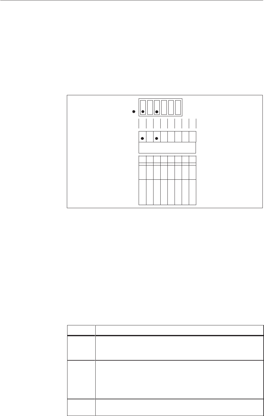
9-41
System Manual
C79000-G8576-C199-06
Example:
Analog input module with 4 inputs
The address is the sum of the significances set with the individual coding
switches.
160 = 128 + 32 = 27 + 25
IB 160
128
64
32
16
8
4
2
1
ADB7
ADB6
ADB5
ADB4
ADB3
ADB2
ADB1
ADB0
On Setting
(Switch Pressed)
A module with 4 inputs (Channel 0 to 3) and start address 160 reserves the
address range from
160 to address 160 + 3 x 2 = 166
In this example, the next free address for another module is 168.
Addresses already assigned must not be set again.
Example:
On an analog input module with start address 160 (IB 160 = input byte 160),
input channel 3 is to be scanned by the program.
Step Action
1 Affix the self-adhesive label with address 160 on the free field
under the addressing switch on the module. ADB 5 and ADB 7
are marked on the label.
2 Press the appropriate rockers of the addressing switch down on
the side marked by a dot on the module cover. Set the other
rockers to the opposite setting. This way sets the start address of
the module.
ADB 5 and ADB 7 results in 25 + 27 = 32 + 128 = 160
3 Enter the address 160 + 3 x 2 = 166 in the program for input
channel 3.
Analo
g
Input/Output Modules
9-42 System Manual
C79000-G8576-C199-06
9.4.5 Removing and Inserting Modules
!Warning
When removing and inserting the front connector during operation,
hazardous voltages of more than 25 V AC or 60 V DC may be present at the
module pins. When this is the case at the front connector, live modules may
only be replaced by electrical specialists or trained personnel in such a way
that the module pins are not touched.
During operation, the front connector and module must not be removed or
inserted without the enable jumper or active enable circuit.
Install an analog input/output module as follows:
Step Action
1Release the upper locking bar on the subrack and swivel it up-
wards and out.
2Insert the module at the desired slot in the subrack and push it
back in the guides.
3Latch the module by rotating the locking pin by 90o at the
lower end of the module. It must no longer be possible to pull
the module forwards.
4Engage the front connector on the support pin of the module.
The width of the support pin also provides keying to prevent
front connectors from being fitted to the wrong modules (e.g.
front connectors with 115/230 V AC wiring cannot be plugged
into analog modules).
5Tighten the screw in the upper part of the front connector.
Analo
g
Input/Output Modules
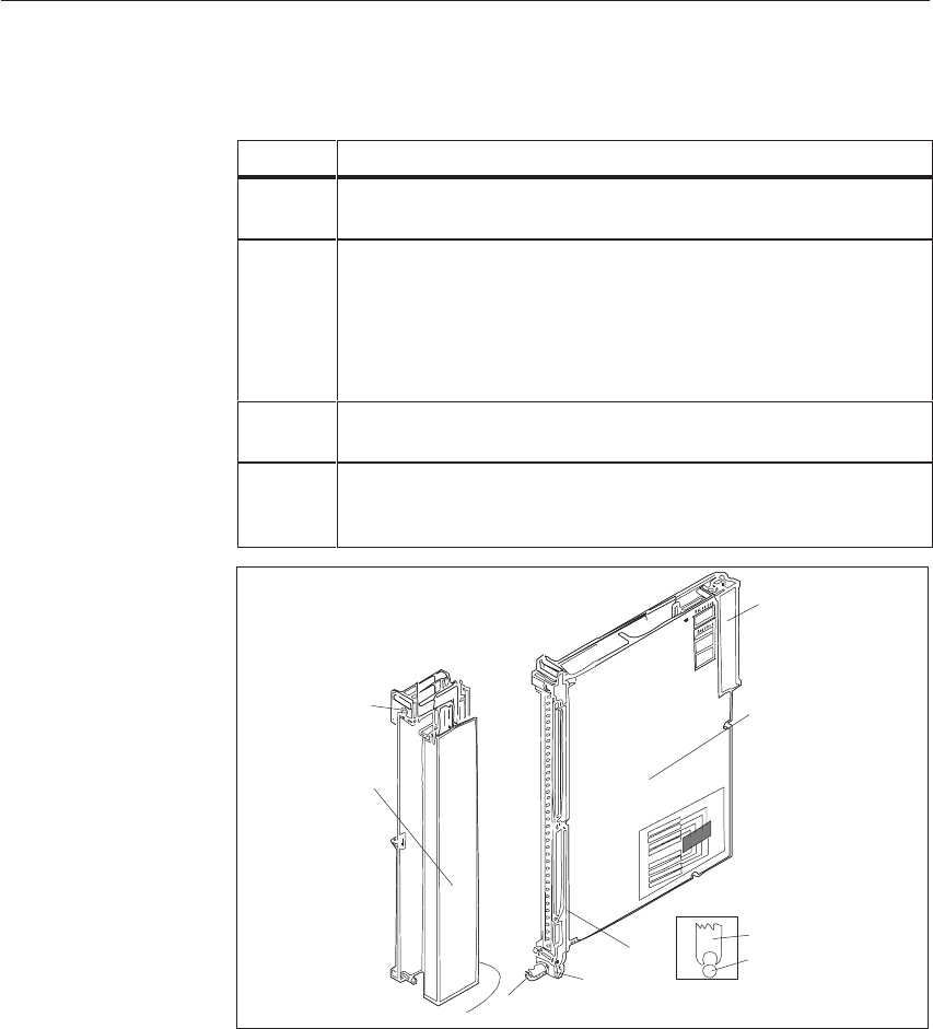
9-43
System Manual
C79000-G8576-C199-06
Remove an analog input/output module as follows:
Step Action
1Release the upper locking bar on the subrack and swivel it up-
wards and out.
2Slacken the screw in the upper part of the front connector. This
causes the front connector to be pressed out of the female con-
nector of the module. Contacts F+ and F- of the enable input at
the upper end of the front connector are thus opened first. If the
enable input is active, power is removed from the outputs and
the module is isolated from the S5 bus.
3Swing the front connector out and lift it away from the support
pin of the module.
4Release the module by rotating the locking pin by 90 at the
lower end of the module. You can pull the module out of the
subrack with a grip with swivels outwards.
1
2
3
5
6
4
Module
Front
Connector
Support Mount
Support Pin
Figure 9-15 Module with Front Connector
1 Screw
2 Locking pin
3 Support mount
4 Support pin
5 Grip
6 Backplane connector
Comply with VDE Specifications 0110 and 0160 to carry out the wiring of
supply and signal lines which are to be connected to the programmable
controllers and front connectors of the modules.
Detailed information on cabinet assembly, cabinet ventilation and protective
measures can be found in Chapter 3.
Analo
g
Input/Output Modules
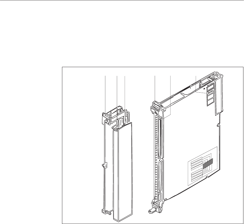
9-44 System Manual
C79000-G8576-C199-06
9.4.6 Marking of Modules and Front Connectors
For the marking of modules and front connectors, labels are supplied with the
module and central controller; they are affixed as shown in Figure 9-16.
11 23
45
Figure 9-16 Marking and Labeling of Modules
1 Label with the module address under which the module is referenced by the STEP 5 program
2 Labeling strip with the product designation for the module; space to mark the module version
and label the channels
3 Label with module address and marking of the required settings for the addressing switch
4 Labeling strip for terminal designations or connection diagrams (strip in the cover of the
front connector)
5 Name plate
Analo
g
Input/Output Modules
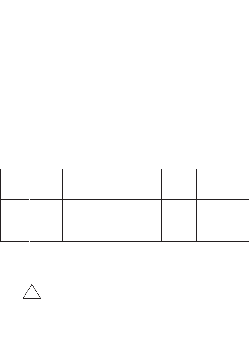
9-45
System Manual
C79000-G8576-C199-06
9.4.7 Connecting the Signal Lines
For connection of the signal lines, front connectors for 20 and 40 mm
mounting width with crimp connection and 40 mm mounting width with
screw connection are available (screwdriver blade width: 3.5 mm, maximum
torque: 0.8 Nm).
Use stranded conductor to facilitate handling of the front connector. Ferrules
are not required for screw connections, because the screw terminals are
provided with wire protection.
When the crimp contact is inserted in the plastic body of the front connector,
a click can clearly be heard. This indicates that the contact is engaged. For
jumpering or to correct the wiring, you can remove the contacts with a
releasing tool (see ordering information) without having to pull out the front
connector.
Ferrules are not required for screw connections, because the screw terminals
are provided with wire protection. You can use ferrules of 7 mm in length to
DIN 46228. The maximum terminal area is 2 x 2.5 mm2.
Terminal
T
Connector
T
Max.
Nf
Cross-Section Connector for
RtdVlt
Mounting Width of
Mdl
Type Type
6ES 497- No. of
Contact
s
Signal or Supply
Conductor Aux. Jumper
in Connector
1)
Rated Voltage Module
Crimp con-
nection -4UA12 2) 42 0.5 mm 20.5 mm 25 to 60 V DC 20 mm Operation
with fan
-4UA22 2) 42 0.5 mm 20.5 mm 25 to 60 V DC 40 mm
Oti
Screw con-
ti
-4UB12 42 0.5 to 2.5 mm 20.5 to 1.0 mm 25 to 60 V DC 40 mm Operation
without fan
nection -4UB31 42 0.5 to 1.5 mm 20.5 to 1.0 mm 25 to 60 V DC 20 mm
without
fan
1) To multiply the supply and 0 V ground terminals, and to connect the enable input
2) The crimp contacts must be ordered separately for these types of connector.
!Caution
Only extra-low voltage 60 V DC with safety separation from system voltage
may be used for the 24 V DC supply and for the 24 V DC input signals.
Safety separation can be implemented to the requirements of, amongst other
sources, VDE 0100 Part 410/HD 384-4-41/IEC 364-4-41 (as functional
extra-low voltage with safety separation) or VDE 0805/EN 60950/IEC 950
(as safety extra-low voltage SELV) or VDE 0106 Part 101.
Analo
g
Input/Output Modules

9-46 System Manual
C79000-G8576-C199-06
9.4.8 Measured-Value Representation
(rated input ranges 0 to 1 V, 0 to 10 V, 0 to 20 mA, 4 to 20 mA)
Units Rated Range Byte 0 Byte 1
0...10
V
0...1 V
mV
0... 20
mA
4...20
mA 1) 4...20
mA 2) 7
211 6
210 5
29 4
28 3
272
26 1
25 0
24 7
23 6
225
21 4
20 3
0
2
0
1
0
0
OV
2047
1536 19.99
15.00 1999
1500 39.98
30.00 35.98
28.00 31.98
24.00 0
0 1
11
11
01
01
01
01
01
01
01
01
00
00
00
01
1
3)
1535
1280
1025
14.99
10.01
1499
1001
29.98
20.02
27.98
20.02
23.98
20.00
16.02
0
0
0
1
1
1
0
0
0
1
1
0
1
0
0
1
0
0
1
0
0
1
0
0
1
0
0
1
0
0
1
0
0
1
0
1
0
0
0
0
0
0
0
0
0
0
0
0
4)
1024
1023
512
511
256
1
0
– 1
– 51
10.00
9.99
5.00
4.99
0.098
0
–
0.098
– 0.5
1000
999.02
500.00
499.00
0.976
0
–
0.976
–50
20.00
19.98
10.00
9.98
0.02
0
–0.02
–1
20.00
19.98
12.00
11.98
4.0156
4
3.9844
3.184
16.00
15.98
8.00
7.98
4.00
0.0156
0
–0.015
6
–0.816
0
0
0
0
0
0
0
1
1
1
0
0
0
0
0
0
1
1
0
1
1
0
0
0
0
1
1
0
1
0
1
1
0
0
1
1
0
1
0
1
0
0
0
1
1
0
1
0
1
0
0
0
1
1
0
1
0
1
0
0
0
1
0
0
1
0
1
0
0
0
1
0
0
1
0
1
0
0
0
1
1
0
1
0
1
0
0
0
1
1
0
1
0
1
0
0
0
1
0
0
1
0
1
0
1
0
1
1
0
0
0
0
0
0
0
0
0
0
0
0
0
0
0
0
0
0
0
0
0
0
0
0
0
0
0
0
0
0
0
0
0
0
0
0
5)
1) With data format setting 0 to 1023 (switch on module)
2) With data format setting 256 to 1279 (switch on module)
3) Overflow
4) Overrange
5) Rated range
OV = Overflow bit
A 50 ohm shunt resistor is used for the 0 to 20 mA range; for 4 to 20 mA,
the resistor value is 62.5 ohms.
The shunt resistors are permanently fitted to the 463 analog input module.
Broken wire detection is not possible.
For the 4 to 20 mA current measuring range, a broken wire can be detected
with currents > 3 mA.
If the positive and negative terminals of the transducer are short-circuited
when two-wire transducers are used (4 to 20 mA), the current is limited to
approximately 28 mA. Until the thermal current limiting circuit responds
(about 3 s) a short-circuit current of about 250 mA flows; this sets the
overflow bit for the short-circuited channel for this duration.
The failure of the load voltage can be detected from the result of encoding
(values < -51 units).
Measured-Value
Representation as
Value and Sign
Shunt Resistor
Current Limiting
Load Voltage
Analo
g
Input/Output Modules

9-47
System Manual
C79000-G8576-C199-06
9.4.9 Technical Specifications
6ES5 463-4UA12 and 6ES5 463-4UB12 Analog Input Modules
Rated input ranges
(selectable at front connector) - 0.05 to + 1 V
- 0.5 to + 10 V
-1 to + 20 mA
+ 4 to 20 mA for 2-wire transducer
+ 4 to 20 mA for 4-wire transducer
Number of inputs 4 voltage/current inputs
Measured value representation 11 bits (two’s complement)
1024 units in rated range
Overrange 50 % (with full accuracy)
Error signal for overflow Yes (upward of 50 % overrange)
Measuring principle Integrating
Conversion principle Voltage-frequency conversion
Isolation Yes, 4 inputs with respect to 0 V and each other
Permissible potential difference between ref. potentials of
sensors and module (UCM) and between sensors (chan-
nels)
25 V AC/60 V DC max.
Power Supply
– digital section from system bus
– analog section from load voltage
– enabling of module F+/F-
5 V $ 5 %; 150 mA typical
24 V; approx. 150 mA
24 V; approx. 7 mA
Integration time
– 463-4UA12
– 463-4UB12
20 ms at 50 Hz
16 2/3 ms at 60 Hz
Encoding time per measured value
– 463-4UA12
– 463-4UB12
20 ms at 50 Hz
16 2/3 ms at 60 Hz
Cycle time for 4 measured values (max. delay time of
measured value acquisition)
– 463-4UA12
– 463-4UB12
20 ms at 50 Hz
16 2/3 ms at 60 Hz
Input resistance for input ranges
1 V
10 V
20 mA
4 to 20 mA
> 10 MW
90 kW
50 W
62.5 W
Max. permissible input voltage without destruction $ 30 V; 75V for 1 ms max. and duty ratio 1:10
Interference suppression
– with common-mode interference
– with differential-mode interference
> 80 dB (f = 0 to 50 kHz)
> 40 dB (Vnoise v 0.1 UN)
Error, referred to
– rated value
– linearity
– tolerance
– temperature error
$ 5 x 10⁻⁴
$ 1 unit
$ 3 units
0.6 x 10⁻⁴/K
Voltage test to VDE 0160 Between inputs and ground point, and between 2 inputs;
tested at 500 V AC
Surge voltage test to IEC 255-4 Between inputs and L-: Vp = 1kV; 1.2/50 µs
Analo
g
Input/Output Modules

9-48 System Manual
C79000-G8576-C199-06
When using the 4 to 20 mA inputs, you can select data representation of 0 to
1023 bits or 256 to 1279 bits by pressing the appropriate switch. You can
choose different data formats for all four input channels.
When the voltage or 0 to 20 mA inputs are used, the relevant switches remain
at the opposite settings.
Labeling of the switch on the module cover:
range 4...20 mA
0...1023
range 4...20 mA
256...1279
otherranges
0...1023
channel 2
channel 0
channel 1
channel 2
channel 3
channel 3
channel 1
channel 0
1)
1) It is advisable to mark the selected switch setting in these fields.
Transducers are connected to the analog input module via shielded cables of
up to 200 m in length. When they are laid separately from power system
cables, distances of up to 500 m are possible.
An arbitrary mixture of voltage sensor, current sensor, two-wire and
four-wire transducers can be connected. For two-wire transducers, there are
four short-circuit protected supply terminals at the front connector.
!Caution
To use two-wire transducers, the reference potential (common input) of these
channels must be connected to L-. This defeats the isolation between the
channels and the supply voltage L+/L-.
Note that the bus interface of the module is activated with 24 V via enable
lines F+ and F- at the front connector.
Setting the Data
Format for the 4 to
20 mA Range
Connecting
Transducers
Analo
g
Input/Output Modules

9-49
System Manual
C79000-G8576-C199-06
F+
L+
F–
+
–
+
–
+
–
+
–
F+
L+
F–
F+
L+
F–
F+
L+
F–
F+
L+
F– 1
2
3
4
6
8
10
13
15
17
19
21
22
23
25
27
29
31
34
36
38
40
41
42
5
7
9
11
12
16
14
18
20
24
28
32
33
26
30
37
35
39
–
7
+
–
6
7
+
–
5
7
+
–
6
7
+4
6
–16
+
–
15
16
+
–
14
16
+
–
15
16
+13
15
L–
L– L– L– L–
–
28
+25
27
+
–
27
28
+
–
26
28
+
–
27
28
–
37
+34
36
+
–
36
37
+
–
35
37
+
–
36
37
Range
4–20mA
Range
0–1V Range
0–10V Range
0–20mA Range
4–20mA
(2–wiretransd.) (4–wire ransd.)
Block Diagram
of the Module
Front Strip
Pin
Busansteuerung
t
Data Memory
L–
L+
+
+10V
+1V
Common
Common
0–10V
0–20mA
4–20mA
+10V
+1V
Common
Common
0–10V
0–20mA
4–20mA
Ch.0 Ch.1 Ch.2 Ch.3
4x 15V
+
–
+10V
+1V
Common
Common
0–10V
0–20mA
4–20mA
+10V
+1V
Common
Common
0–10V
0–20mA
4–20mA
15V
+
–
+
+
+
MU
MU
MU
MU
Data MemoryData MemoryData Memory
Figure 9-17 Front Connector Assignments, Sensor Connection, Range Selection
Front Connector
Assignments
Analo
g
Input/Output Modules
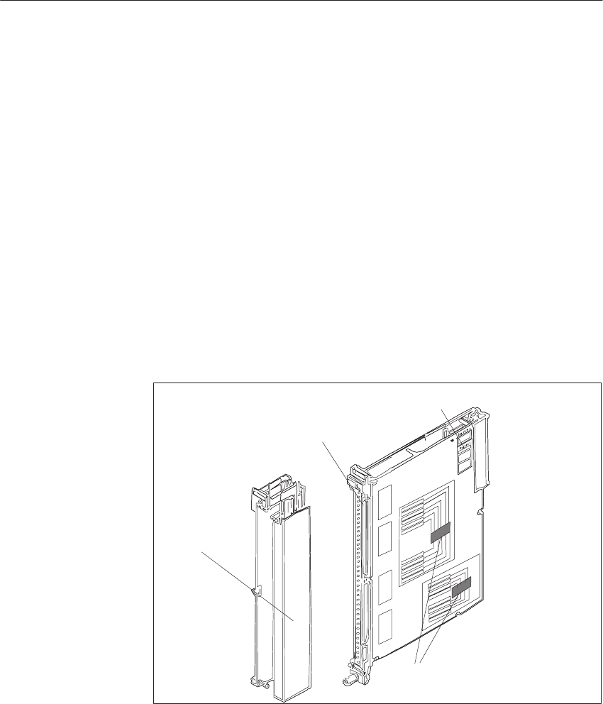
9-50 System Manual
C79000-G8576-C199-06
9.5 The 465 Analog Input Module
9.5.1 Design
The modules are designed as plug-in PCBs for central controllers and
expansion units with a backplane connector and with a blade connector to
accept a plug-in front connector. You can directly connect the process signal
lines to the front connector, which is available separately, with screw or
crimp terminals.
Situated on each module is an addressing switch with six rockers to set the
module address. Analog input modules also have two switches on the side
with eight rockers for setting the mode, and receptacles for range cards.
The modules are protected by covers on both sides.
Blade Connector
Addressing Switch
Mode Switch
Front Connector
Figure 9-18 Analog Input Module
9.5.2 Function of the Enable Input
The 465 module has an enable circuit. You can use the enable inputs to
switch off individual modules whilst the PLC is in operation. This means
that:
The module can no longer be addressed by the user program.
Modules which are switched off can be removed or inserted during operation.
If this is not necessary, operate the module with the enable input switched
off.
Addressing
Switch, Mode
Switches
Analo
g
Input/Output Modules
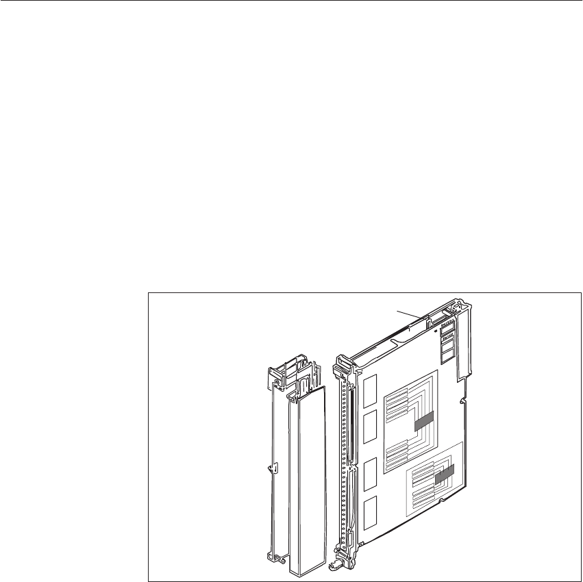
9-51
System Manual
C79000-G8576-C199-06
The enable circuit requires an external 24 V voltage at enable inputs F+/F- in
the front connector. If there is no voltage at F+/F-, the modules will not
acknowledge.
When the front connector is swivelled away from the front strip of the
module, the supply of power to the enable input is interrupted, i.e. the
module is switched off and can no longer be addressed by the user program: a
timeout (QVZ) occurs in the CC.
The 465 module additionally offers the facility for changing the enable
mode. The module has a jumper accessible from above in the vicinity of the
addressing switch.
Enable Jumper
Figure 9-19 Enable Input and Enable Jumper
Jumper inserted: Enable input (F+/F-) active (factory setting)
Jumper open: Enable input (F+/F-) switched off
Examples of functioning of the enable inputs:
To switch off individual subprocesses, i.e. outputs of various modules can
be operated from a common load supply and yet activated separately.
The load voltage of individual modules can be monitored without
additional circuitry. Any reactions to failure of the load voltage can be
programmed in the QVZ (timeout) organization block.
Enable Input
Switching Off the
Enable Input
Analo
g
Input/Output Modules
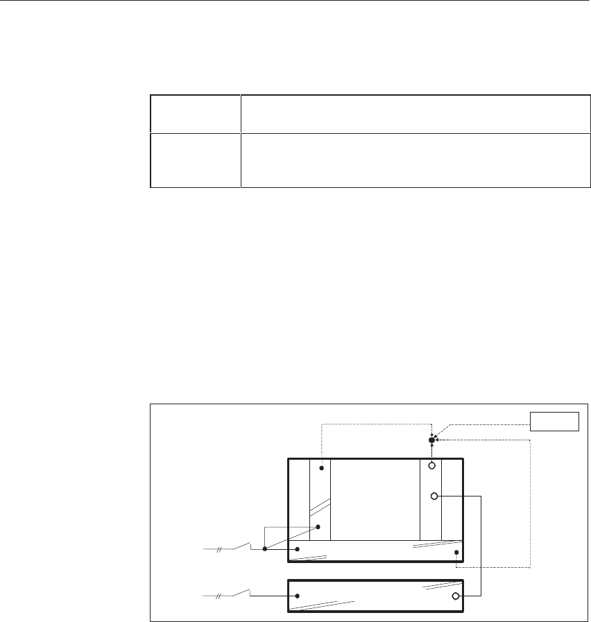
9-52 System Manual
C79000-G8576-C199-06
You must observe the following when configuring systems:
Switching on At the latest 100 ms after power-up of the PLC, the voltage
must be present at the enable inputs of the I/O modules.
Switching off When the PLC has been switched off, the voltage at the
enable inputs of the I/O modules must still be present as
long as the internal 5 V voltage is present.
You should observe the following instructions for switching off CCs and
equipment for supplying power to the enable inputs.
When there is a need to switch off the load power supply separately without
affecting the enabling of modules, there are the following possibilities for
producing the enable voltage. These exist even when the load power supply
is used without an additional capacitor and common shutdown.
230 V AC supply for CC/EU and load power supply
F+
L+
I/O Modules
230 V AC
CC/EU
–951
a)
c)
b) Battery
L+
Power Supply
Load Power Supply 24V
Supply for the enable inputs from:
a) 6ES5 951-4LB11 load power supply
b) Battery
c) Terminals for 24 V on the front plate of the power supply
Configuring
Switching off the
CC
Separate or
Common
Shutdown of the
CC/EU and Load
Power Supply
Analo
g
Input/Output Modules
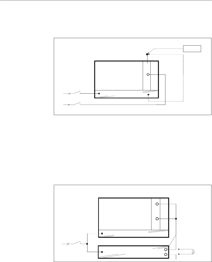
9-53
System Manual
C79000-G8576-C199-06
24 V supply for CC/EU and I/Os
F+
L+
I/O Modules
24 V DC
b)
a)
CC/EU
L+
Battery
Power Supply 24V
Supply for the enable inputs from:
a) Battery
b) Terminals for 24 V on the front plate of the power supply
Proper functioning is ensured if the 24 V load power supply has an output
capacitance of at least 4700 mF per 10 A of load current. Other units which
do not meet this condition can be adapted to this requirement by connecting a
10000 mF / 40 V capacitor in parallel.
10000µF/40V
CC/EU F+
L+
230 V AC
I/O Modules
Load Power Supply 24V
Power Supply
Common
Shutdown of the
CC/EU and Load
Power Supply with
a 230 V AC Supply
Analo
g
Input/Output Modules

9-54 System Manual
C79000-G8576-C199-06
9.5.3 Special Features of the 465 Analog Input Module
The 465 analog input module executes integrating processing of the digital
input signals; periodic system interference is thus suppressed.
You can adapt the process signals, according to the application, to the input
level of the analog-to-digital converter of the module with plug-in range
cards (resistor dividers or shunt resistors).
To monitor the sensors connected to the inputs, you can use the
6ES5 498-1AA11 range card (through-connection card) to implement the
“broken wire detection” mode. You can activate broken wire detection for 8
or 16 inputs in 16-channel operation, and for 4 or 8 inputs in 8-channel
operation.
Each time the input value is about to be encoded, a constant current is briefly
(1.6 ms) switched to the input terminals and the resultant current is checked
for a limit value. If a digital voltmeter is used to measure the signal at the
input, these current pulses may appear to indicate fluctuation of the signal.
The encoded value, however, is not affected.
If these apparent fluctuations of the signal are disturbing, e.g. during startup,
you can switch the tripping current to the inactive state on the 465 analog
input modules: apply + 24 V to pin 24 of the front connector, and 0 V to L-.
You must additionally set the mode switch to “without broken wire
detection.”
In the event of open-circuit of the sensor or its line, the voltage exceeds the
limit and a broken wire is indicated (bit 1 in data byte 1). The
analog-to-digital converter encodes the value 0.
A broken wire signal is only useful when the 6ES5 498-1AA11
through-connection card is used. With all other measurement cards, a broken
wire signal will result in incorrect reactions. Further details relating to the
broken wire signal can be found in Section 9.5.10.
If the measuring range is exceeded, the overflow bit (bit 20 of the low byte)
is set.
You have a choice of the cyclic sampling and selective sampling modes.
In the cyclic sampling mode, the module continuously encodes all measured
values. The digitized measured values are stored under the channel-related
address on the module (the high byte under this address, and the low byte
under the next higher address). The measured values can then be read by the
module at any time without waiting. When you operate the module in this
mode, you can set a module address from 0 to 255.
Broken Wire
Signal
Switching the
Tripping Current to
the Inactive State
Measuring Range
Exceeded
Cyclic Sampling/
Selective Sampling
Analo
g
Input/Output Modules

9-55
System Manual
C79000-G8576-C199-06
In the selective sampling mode, a measured value is encoded on the central
initiative of the CPU. At the start of conversion, the module must be
addressed once with a write operation (T PW) by the user program. An active
bit (T = 1) is set during encoding.
With the transition to T = 0, the measured value becomes valid. With
non-constant cycle times, there may be non-periodic measured value
aquisition. If you operate the module in this mode, you must set a module
address from 128 to 255. You can also use the address range from 0 to 127
for selective sampling after appropriate programming in DB 1 of the user
program.
Another method is that of time-controlled program processing. With this
method, certain program segments (e.g. FB 13) are automatically inserted
into program processing at the 100 ms rate by a time-
controlled block (OB 13). A constant timebase is thus achieved.
FB 13 SPRM-B LEN=22 ABS
SHEET 1
SEGMENT 1
NAME: SELSAMPL EXAMPLE OF SELECTIVE SAMPLING
0005 :
0006 :
0007 :L PW128 READ ANALOG VALUE
0008 :T FW128 IN TO AUX: FLAG 128
0009 :S F 129.2 SCAN ACTIVITY=1?
000A :JC = END IF = 1, JUMP TO END
000B :T FW10 IF = 0, MEASURED VALUE IN FW 10
000C :T PB128 INITIATE SAMPLING
000D END : (1ST VALUE INVALID AFTER START)
000E
000F :
0010 :BE
You can read analog values of analog input modules with a function block
from the “basic functions” package.
The BASP signal is not interpreted by the 460 analog input module.
Time-Controlled
Program
Processing
Function Block
BASP (Output
Inhibit)
Analo
g
Input/Output Modules
9-56 System Manual
C79000-G8576-C199-06
9.5.4 Setting the Module Address
You set the module address on the addressing switch. This also establishes
the necessary assignments between user program and process connection.
The module address is the sum of the decimal significances of the switch
rockers in the On setting (Ĥ).
One data word = two data bytes is required to process an input. A module
with 8 inputs therefore reserves 16 byte addresses, and a module with 16
inputs or outputs reserves 32 byte addresses.
You can affix the adhesive label with the desired module address on a free
labeling field under the addressing switch.
The switch rockers to be set for the module address specified as a decimal
number (address bit ADB) are marked by dots on the label.
Press the individual rockers of the addressing switch downwards with a
ballpoint pen or similar object, but not a pencil.
On Setting
(Switch Pressed) Addressing Switch
Address Bit
Decimal Signification of
the Address Bit
Free Field for Label with
Module Address and
marked Switch Settngs
Address (Decimal)
128
64
32
16
8
4
2
1
ADB7
ADB6
ADB5
ADB4
ADB3
ADB2
ADB2 is not connected
ADB1
ADB0
ADB0 and ADB1 are not assigned
Figure 9-20 Labeling of the Addressing Switch
The address under which the module is referenced by the STEP 5 program is
independent of the slot.
For analog input and analog output modules (8 or 16 inputs) only the lowest
address (start address) is set. Other addresses (subaddresses) are decoded on
the module.
Labeling Field
Start Address,
Subaddress
Analo
g
Input/Output Modules
9-57
System Manual
C79000-G8576-C199-06
Note
The start address of the analog module must be a multiple of the double
channel number.
8 channels : 0, 16, 32, 48, ... 240
16 channels : 0, 32, 64, 96, ... 224
If one of the inputs or outputs (Channel 0 to 7 or 0 to 15) of a module is to be
addressed, the relevant subaddress must be specified in the program.
The subaddress of the input or output, based on the start address of the
module, is given by:
Start address + 2 x channel no. = subaddress
Example:
Analog input module with 8 or 16 inputs
The address is the sum of the significances set with the individual coding
switches.
160 = 128 + 32 = 27 + 25
On Setting
(Switch Pressed)
IB 160
128
64
32
16
8
4
2
1
ADB7
ADB6
ADB5
ADB4
ADB3
ADB2
ADB1
ADB0
A module with 8 or 16 inputs (Channel 0 to 7 or 0 to 15) and start address
160 reserves the address range from
160 to address 160 + 7 x 2 = 174
160 to address 160 + 15 x 2 = 190
In this example, the next free address for another module is 176 or 192.
With the 465 analog input module, the size of the address range depends on
the number of channels set (8 or 16).
Addresses already assigned must not be set again.
Analo
g
Input/Output Modules

9-58 System Manual
C79000-G8576-C199-06
However, analog input modules and analog output modules may be given the
same address with cyclic sampling because they are distinguished by the user
program. This is not possible with selective sampling.
For cyclic sampling, you can address the module in the address range from 0
to 255, and for selective sampling from 128 to 255. For selective sampling,
you can also use the address range from 0 to 127 after appropriate
programming in DB 1 of the user program.
Example:
On an analog input module with start address 160 (IB 160 = input byte 160),
input channel 3 is to be scanned by the program.
Step Action
1Affix the self-adhesive label with address 160 on the free field under the
addressing switch on the module. ADB 5 and ADB 7 are marked on the
label.
2Press the appropriate rockers of the addressing switch down on the side
marked by a dot on the module cover. Set the other rockers to the opposite
setting. This way sets the start address of the module.
ADB 5 and ADB 7 results in 25 + 27 = 32 + 128 = 160
3Enter the address 160 + 3 x 2 = 166 in the program for input channel 3.
Addressing for
Cyclic/Selective
Sampling
Analo
g
Input/Output Modules

9-59
System Manual
C79000-G8576-C199-06
9.5.5 Removing and Inserting Modules
!Warning
When removing and inserting the front connector during operation,
hazardous voltages of more than 25 V AC or 60 V DC may be present at the
module pins. When this is the case at the front connector, live modules may
only be replaced by electrical specialists or trained personnel in such a way
that the module pins are not touched.
During operation, the front connector and module must not be removed or
inserted without the enable jumper or active enable circuit.
Install an analog input/output module as follows:
Step Action
1Release the upper locking bar on the subrack and swivel it upwards and
out.
2Insert the module at the desired slot in the subrack and push it back in the
guides.
3Latch the module by rotating the locking pin by 90o at the lower end of
the module. It must no longer be possible to pull the module forwards.
4Engage the front connector on the support pin of the module. The width
of the support pin also provides keying to prevent front connectors from
being fitted to the wrong modules (e.g. front connectors with 115/230 V
AC wiring cannot be plugged into analog modules).
5Tighten the screw in the upper part of the front connector.
Analo
g
Input/Output Modules
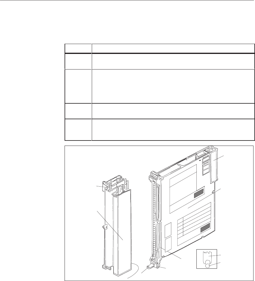
9-60 System Manual
C79000-G8576-C199-06
Remove an analog input/output module as follows:
Step Action
1Release the upper locking bar on the subrack and swivel it upwards and
out.
2Slacken the screw in the upper part of the front connector. This causes the
front connector to be pressed out of the female connector of the module.
Contacts F+ and F- of the enable input at the upper end of the front con-
nector are thus opened first. If the enable input is active, power is removed
from the outputs and the module is isolated from the S5 bus.
3Swing the front connector out and lift it away from the support pin of the
module.
4Release the module by rotating the locking pin by 90o at the lower end of
the module. You can pull the module out of the subrack with a grip with
swivels outwards.
1
2
3
5
6
4
Module
Front
Connector
Support Mount
Support Pin
Figure 9-21 Module with Front Connector
1 Screw
2 Locking pin
3 Support mount
4 Support pin
5 Grip
6 Backplane connector
Comply with VDE Specifications 0110 and 0160 to carry out the wiring of
supply and signal lines which are to be connected to the programmable
controllers and front connectors of the modules.
Detailed information on cabinet assembly, cabinet ventilation and protective
measures can be found in Chapter 3.
Analo
g
Input/Output Modules
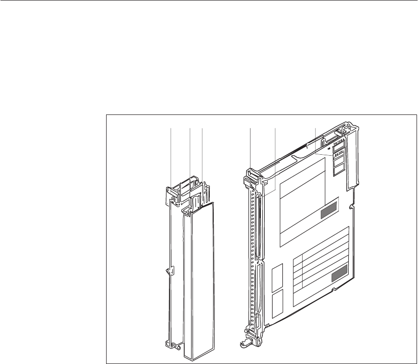
9-61
System Manual
C79000-G8576-C199-06
9.5.6 Marking of Modules and Front Connectors
For the marking of modules and front connectors, labels are supplied with the
module and central controller; they are affixed as shown in Figure 9-5.
11 23
45
Figure 9-22 Marking and Labeling of Modules
1 Label with the module address under which the module is referenced by the STEP 5 program
2 Labeling strip with the product designation for the module; space to mark the module version
and label the channels
3 Label with module address and marking of the required settings for the addressing switch
4 Labeling strip for terminal designations or connection diagrams (strip in the cover of the
front connector)
5 Name plate
Analo
g
Input/Output Modules

9-62 System Manual
C79000-G8576-C199-06
9.5.7 Connecting the Signal Lines
For connection of the signal lines, front connectors for 20 and 40 mm
mounting width with crimp connection and 40 mm mounting width with
screw connection are available (screwdriver blade width: 3.5 mm, maximum
torque: 0.8 Nm).
Use stranded conductor to facilitate handling of the front connector. Ferrules
are not required for screw connections, because the screw terminals are
provided with wire protection.
When the crimp contact is inserted in the plastic body of the front connector,
a click can clearly be heard. This indicates that the contact is engaged. For
jumpering or to correct the wiring, you can remove the contacts with a
releasing tool (see ordering information) without having to pull out the front
connector.
Ferrules are not required for screw connections, because the screw terminals
are provided with wire protection. You can use ferrules of 7 mm in length to
DIN 46228. The maximum terminal area is 2 x 2.5 mm2.
Terminal
T
Connector
T
Max.
Nf
Cross-Section Connector for
RtdVlt
Mounting Width of Mo
d
l
Type Type
6ES 497- No. of
Contact
s
Signal or Supply
Conductor Aux. Jumper
in Connector
1)
Rated Voltage ule
Crimp con-
nection -4UA12 2) 42 0.5 mm 20.5 mm 25 to 60 V DC 20 mm Operation
with fan
-4UA22 2) 42 0.5 mm 20.5 mm 25 to 60 V DC 40 mm
Oti
Screw con-
ti
-4UB12 42 0.5 to 2.5 mm 20.5 to 1.0 mm 25 to 60 V DC 40 mm Operation
without fan
nection -4UB31 42 0.5 to 1.5 mm 20.5 to 1.0 mm 25 to 60 V DC 20 mm
without
fan
1) To multiply the supply and 0 V ground terminals, and to connect the enable input
2) The crimp contacts must be ordered separately for these types of connector.
!Caution
Only extra-low voltage 60 V DC with safety separation from system voltage
may be used for the 24 V DC supply and for the 24 V DC input signals.
Safety separation can be implemented to the requirements of, amongst other
sources, VDE 0100 Part 410/HD 384-4-41/IEC 364-4-41 (as functional
extra-low voltage with safety separation) or VDE 0805/EN 60950/IEC 950
(as safety extra-low voltage SELV) or VDE 0106 Part 101.
Analo
g
Input/Output Modules

9-63
System Manual
C79000-G8576-C199-06
9.5.8 Connecting a Compensating Box for Thermal E.M.F.
Measurement
If the room temperature fluctuations at the reference point (e.g. in the
terminal box) affect the measurement result and you do not wish to use a
thermostat, you can compensate for the effect of temperature on the reference
point with a compensating box. Between - 10 and + 70 oC, it compensates for
the change in thermal e.m.f. cause by temperature deviation (compensating
box, see Catalog MP 11). Ensure that the compensating box has thermal
contact with the terminals.
If the compensating box is aligned at 20 oC, this must be taken into account
in temperature evaluation (20 oC measuring point temperature = 0 mV).
Pins 22 and 23 are extended on analog input modules as an input for the
compensating voltage. You must select a common input loop for all inputs on
mode switch 2.
The compensating box must be connected in a floating circuit. The power
supply unit of the compensating box must have a grounded shield winding to
avoid AC system interference being picked up. A separate compensating box
with its special power supply unit is required for each analog input module.
22–
A
D
Analog Input Module
MUX
M–
23+
0 V Bus
M+
–
+
Power
Supply
for Com-
pensat-
ing Box
Thermocouple
Terminal Box
~
=
#
Range
Card for
4 Inputs
6ES5 498-
-1AA11
Compen-
sating
Box
Figure 9-23 Connecting a Compensating Box
Analo
g
Input/Output Modules

9-64 System Manual
C79000-G8576-C199-06
9.5.9 Connecting Resistance Thermometers to the 465 Analog Input
Module
The relevant resistance thermometer is fed with a current of 2.5 mA (IC+/IC-)
by a constant current generator via a 6ES5 498-1AA11 card. The voltage at
the Pt 100 is picked off at measurement inputs M+ and M-.
If only inputs 0 to 3 are assigned to resistance thermometers, you can connect
other current and voltage sensors to inputs 4 to 7 by means of a coding key. If
you use the Pt 100 for measurement, you cannot utilize channels 12 to 15.
Channels 8 to 11 supply the resistance thermometers which are connected at
inputs 0 to 3.
Note that the mode of the module is set to the 500 mV voltage range.
Analo
g
Input/Output Modules
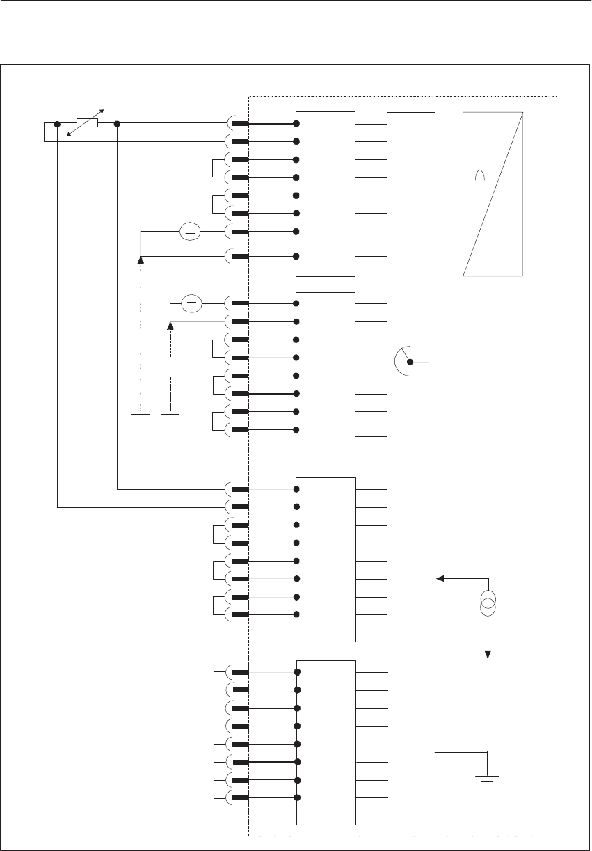
9-65
System Manual
C79000-G8576-C199-06
465 Analog Input Module
+
MUX
A
D
–Card 1
UCM
UCM
Pt100
0...500mV
IC+
IC–
CH0
CH3
CH4
Card 2
U/I
Iconst.
CH7
6ES5498-
Range
Card for
4 Inputs
6ES5-498-
-1AA11
-1AA11
-1AA21
-1AA31
-1AA41
-1AA51
-1AA61
-1AA71
1)
1)
Card 3
2.5mA
Iconst.
+5V
Current Source for
Pt 100 Operation
Card 4
2)
2)
2)
2)
2)
2)
2)
2)
2)
2)
2)
2)
2)
M+
M–
M+
M–
#
Range
Card for
4 Inputs
6ES5-498-
-1AA11
Range
Card for
4 Inputs
6ES5-498-
-1AA11
-1AA41
-1AA71
Figure 9-24 Connecting a Pt 100
1) When cards 6ES5 498-1AA21, 6ES5 498-1AA31 or 6ES5 498-1AA61 are used, no broken wire signal may be activated for this
group of channels (CH4 to CH7).
2) If cards 6ES5 498-1AA41 or 6ES5 498-1AA71 are used, a short-circuit jumper is not required.
Analo
g
Input/Output Modules

9-66 System Manual
C79000-G8576-C199-06
9.5.10 Broken Wire Signal for Resistance Thermometers
An open-circuit in the lines to a resistance thermometer is indicated as
follows:
Broken Wire at Module Reaction, Encoded Value Error Bit E
M+
M–
Pt 100
IC+
IC–
0
0
0
0
0
1
1
1
1
1
If the mode “without broken wire signal” is selected on the module, an
open-circuit of the resistance thermometer is indicated with an overflow.
Unassigned channels can be used for voltage or current measurement if the
current flow outputs relating to the particular measuring channel are shorted
with a wire jumper. Without this jumper, the error bit would be set for this
channel and the value 0 would be encoded.
When set to “resistance thermometer,” switch 7 of mode switch I of the 465
analog input module allows broken wire monitoring of the IC+ lines to the
resistance thermometer (Pt 100 constant current supply). In the event of
open-circuit of this line, the error bit is set as for the other lines.
At the “voltage/current” (mV/mA) setting, the IC+ lines are not monitored for
broken wire. (The error bit is not set for an open-circuit of this line.) You
should choose this switch setting if you exclusively measure voltages or
currents.
Broken Wire
Monitoring
Analo
g
Input/Output Modules
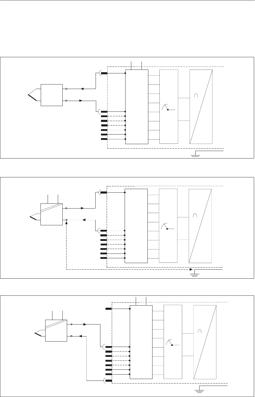
9-67
System Manual
C79000-G8576-C199-06
9.5.11 Connecting Transducers
Two-wire transducer (short-circuit protected supply voltage via the range
card of the analog input module)
A
D
Analog Input Module
MUX
M–
0 V Bus
M+
+
–
4...20 mA
L+ L–
#
Range
Card for
4 Inputs
6ES5-498-
-1AA51
Four-wire transducer (with separate supply voltage)
A
D
Analog Input Module
MUX
M–
0 V Bus
M+
+
–
+4...20 mA
230 V AC
Do not exceed max. permissible potential difference!
#
6ES5-498-
-1AA71
Range
Card for
4 Inputs
Four-wire transducer with a two-wire transducer card
A
D
Analog Input Module
MUX
M–
0 V Bus
M+
+
–
0...20 mA
230 V AC
L+ L–
L– (0 Vext)
#
6ES5-498-
-1AA71
Range
Card for
4 Inputs
Analo
g
Input/Output Modules

9-68 System Manual
C79000-G8576-C199-06
9.5.12 Measured-Value Representation
(rated input range $ 50 mV)
Units Input Volt-
iV
Byte 0 Byte 1
age in mV 7
212 6
211 5
210 4
29 3
282
27 1
26 0
25 7
24 6
235
22 4
21 3
20 2
A 1
E 0
OV
w4096 100.0 0 1 1 1 1 1 1 1 1 1 1 1 1 0/1 0/1 1 Overflow
4095
2049 99.976
50.024 0
0 1
1 1
0 1
0 1
0 1
0 1
0 1
0 1
0 1
0 1
0 1
0 1
1 0/1
0/1 0/1
0/1 0
0Overrange
2048
2047 50.0
49.976 0
0 1
0 0
1 0
1 0
1 0
1 0
1 0
1 0
1 0
1 0
1 0
1 0
1 0/1
0/1 0/1
0/1 0
0
1024
1023 25.0
23.976 0
0 0
0 1
0 0
1 0
1 0
1 0
1 0
1 0
1 0
1 0
1 0
1 0
1 0/1
0/1 0/1
0/1 0
0
1
0
–1
0.024
0.0
–0.024
0
0
1
0
0
1
0
0
1
0
0
1
0
0
1
0
0
1
0
0
1
0
0
1
0
0
1
0
0
1
0
0
1
0
0
1
1
0
1
0/1
0/1
0/1
0/1
0/1
0/1
0
0
0
Rated
range
–1023
–1024 – 24.976
– 25.0 1
1 1
1 1
1 0
0 0
0 0
0 0
0 0
0 0
0 0
0 0
0 0
0 1
0 0/1
0/1 0/1
0/1 0
0
–2047
–2048 – 49.976
– 50.0 1
1 1
1 0
0 0
0 0
0 0
0 0
0 0
0 0
0 0
0 0
0 0
0 1
0 0/1
0/1 0/1
0/1 0
0
–2049
–4095 – 50.024
– 99.976 1
1 0
0 1
0 1
0 1
0 1
0 1
0 1
0 1
0 1
0 1
0 1
0 1
1 0/1
0/1 0/1
0/1 0
0 Overrange
–4096 –100.0 1 0 0 0 0 0 0 0 0 0 0 0 1 0/1 0/1 1 Overflow
A = Active bit
E = Error bit
OV = Overflow bit
Digital
Measured-Value
Representation as
Two’s Complement
Analo
g
Input/Output Modules

9-69
System Manual
C79000-G8576-C199-06
(rated input range $ 50 mV)
Units Input Volt-
iV
Byte 0 Byte 1
age in mV 7
S 6
211 5
210 4
29 3
282
27 1
26 0
25 7
24 6
235
22 4
21 3
20 2
A 1
E 0
OV
w4096 100.0 0 1 1 1 1 1 1 1 1 1 1 1 1 0/1 0/1 1 Overflow
4095
2049 99.976
50.024 0
0 1
1 1
0 1
0 1
0 1
0 1
0 1
0 1
0 1
0 1
0 1
0 1
1 0/1
0/1 0/1
0/1 0
0 Overrange
2048
2047 50.0
49.976 0
0 1
0 0
1 0
1 0
1 0
1 0
1 0
1 0
1 0
1 0
1 0
1 0
1 0/1
0/1 0/1
0/1 0
0
1024
1023 25.0
23.976 0
0 0
0 1
0 0
1 0
1 0
1 0
1 0
1 0
1 0
1 0
1 0
1 0
1 0/1
0/1 0/1
0/1 0
0
1
0
–0
–1
0.024
0.0
0.0
–0.024
0
0
1
1
0
0
0
0
0
0
0
0
0
0
0
0
0
0
0
0
0
0
0
0
0
0
0
0
0
0
0
0
0
0
0
0
0
0
0
0
0
0
0
0
0
0
0
0
1
0
0
1
0/1
0/1
0/1
0/1
0/1
0/1
0/1
0/1
0
0
0
0
Rated
range
–1023
–1024 – 24.976
– 25.0 1
1 0
0 0
1 1
0 1
0 1
0 1
0 1
0 1
0 1
0 1
0 1
0 1
0 0/1
0/1 0/1
0/1 0
0
–2047
–2048 – 49.976
– 50.0 1
1 0
1 1
0 1
0 1
0 1
0 1
0 1
0 1
0 1
0 1
0 1
0 1
0 0/1
0/1 0/1
0/1 0
0
–2049
–4095 – 50.024
– 99.976 1
1 1
1 0
1 0
1 0
1 0
1 0
1 0
1 0
1 0
1 0
1 0
1 1
1 0/1
0/1 0/1
0/1 0
0 Overrange
–4096 –100.0 1 1 1 1 1 1 1 1 1 1 1 1 1 0/1 0/1 1 Overflow
A = Active bit
E = Error bit
OV = Overflow bit
Bit 212 is interpreted as the sign.
Digital
Measured-Value
Representation as
Value and Sign
Analo
g
Input/Output Modules

9-70 System Manual
C79000-G8576-C199-06
The resolution with Pt 100 resistance thermometers is approximately 0.25 oC.
1 ohm 10 units
Units Resistance in
ohms 1)
Temper-
ature in
Byte 0 Byte 1
ohms
1)
ature in
oC 7
S 6
211 5
210 4
29 3
28 2
27 1
26 0
25 7
24 6
23 5
22 4
21 3
20 2
A 1
E0
OV
4096 400.0 – 0 1 1 1 1 1 1 1 1 1 1 1 1 0/1 0/1 1 Overflow
4095
2049 399.90
200.98 – 269.1 0
0 1
1 1
0 1
0 1
0 1
0 1
0 1
0 1
0 1
0 1
0 1
0 1
1 0/1
0/1 0/1
0/1 0
0 Overrange
2048
2047 200.0
199.90 266.5
266.0 0
0 1
0 0
1 0
1 0
1 0
1 0
1 0
1 0
1 0
1 0
1 0
1 0
1 0/1
0/1 0/1
0/1 0
0
1024
1023 100.00
99.90 0
–0.2 0
0 0
0 1
0 0
1 0
1 0
1 0
1 0
1 0
1 0
1 0
1 0
1 0
1 0/1
0/1 0/1
0/1 0
0 Rated range
1
0 0.098
0.0 –
– 0
0 0
0 0
0 0
0 0
0 0
0 0
0 0
0 0
0 0
0 0
0 0
0 1
0 0/1
0/1 0/1
0/1 0
0
1) Resistance value PT 100
A = Active bit
E = Error bit
OV = Overflow bit
S = Sign
When Pt 100 resistance thermometers are connected, the maximum
temperature in the rated range is 266 oC. If it can be ensured that the
temperature does not exceed 850 oC, the input value may extend into the
overrange. The resolution is then 4095 units. Unused inputs can be utilized
for voltage measurements in the 500 mV range (see front connector
assignments).
Measured-Value
Representation for
Pt 100 Resistance
Thermometers
Analo
g
Input/Output Modules

9-71
System Manual
C79000-G8576-C199-06
Measuring range 500 mV; card with 31.25 ohm shunt
(6ES5 498-1AA51/AA71)
The 4 to 20 mA range is resolved to 2048 units at an interval of 512 to 2560.
If you require a representation from 0 to 2048, you must subtract 512 units by
software. Please note the following:
A broken wire signal cannot be emitted.
Detection of the overrange can be achieved by scanning bits 29 and 211.
A broken wire can be detected with currents < 3 mA.
If you short-circuit the positive and negative terminals of the transducer
when using the 6ES5 498-1AA51 range card (for a two-wire transducer),
the current is limited to about 28 mA. Until the thermal current limiting
circuit responds in the range card (about 3 s), a short-circuit current of
approximately 250 mA flows; this sets the overflow bit for this duration
at all channels.
Units Input Cur-
ti A
Byte 0 Byte 1
rent in mA 7
S 6
211 5
210 4
29 3
28 2
27 1
26 0
25 7
24 6
23 5
22 4
21 3
20 2
A 1
E 0
OV
w 4096 w 32.000 0 1 1 1 1 1 1 1 1 1 1 1 1 0/1 0 1 Overflow
4095
3072
3071
2561
31.992
24.0
23.992
20.008
0
0
0
0
1
1
1
1
1
1
0
0
1
0
1
1
1
0
1
0
1
0
1
0
1
0
1
0
1
0
1
0
1
0
1
0
1
0
1
0
1
0
1
0
1
0
1
0
1
0
1
1
0/1
0/1
0/1
0/1
0
0
0
0
0
0
0
0
Overrange
Short-circuit with two-
wire transducer
2560
2048
512
20.0
16.0
4.0
0
0
0
1
1
0
0
0
0
1
0
1
0
0
0
0
0
0
0
0
0
0
0
0
0
0
0
0
0
0
0
0
0
0
0
0
0
0
0
0/1
0/1
0/1
0
0
0
0
0
0
Rated range
511
384
383
3.992
3.0
2.992
0
0
0
0
0
0
0
0
0
0
0
0
1
1
1
1
1
0
1
0
1
1
0
1
1
0
1
1
0
1
1
0
1
1
0
1
1
0
1
0/1
0/1
0/1
0
0
0
0
0
0
Range
underflow
0 0 0 0 0 0 0 0 0 0 0 0 0 0 0 0/1 0 0 Broken wire
A = Active bit
E = Error bit
OV = Overflow bit
S = Sign
Measured-Value
Representation for
Current Measuring
Ranges from 4 to
20 mA
Current Limiting
Analo
g
Input/Output Modules

9-72 System Manual
C79000-G8576-C199-06
9.5.13 Technical Specifications
6ES5 465-4UA12 Analog Input Module
Rated input ranges with cards for every 4 channels
– 6ES5 498-1AA11
– 6ES5 498-1AA21
– 6ES5 498-1AA31
– 6ES5 498-1AA41
– 6ES5 498-1AA51
– 6ES5 498-1AA61
– 6ES5 498-1AA71
$ 50 mV/$500 mV/Pt 100
$ 1 V
$ 10 V
$ 20 mA
4 to 20 mA for two-wire transducer
$ 5 V
4 to 20 mA for four-wire transducer
Number of inputs 16 voltage/current inputs or
8 resistance inputs (Pt 100)
Measured-value representation 13 bits (two’s complement) or 12 bits + sign;
$ 2048 units in rated range;
512 to 2560 units for 4 to 20 mA
Measuring principle Integrating
Isolation No
Permissible potential difference between reference potentials
of sensors and the module (UCM) and between sensors (chan-
nels)
$ 1 V max.
Power Supply
– digital section from system bus
– analog section from load voltage
– enabling for module F+/F-
– tripping current L+
5 V $ 5 %; 150 mA typical
24 V
24 V; approx. 5 mA
24 V; approx. 5 mA
Constant current source for Pt 100 connection IC+/IC- 2.5 mA; TC = $ 5 x 10⁻⁵/K
Integration time 20 ms at 50 Hz; 16 2/3 ms at 60 Hz
Encoding time per measured value 60 ms at 50 Hz; 50 ms at 60 Hz
Cycle time for 8 measured values with 2048 units
(max. delay time for measured-value acquisition) Approx. 0.48 s at 50 Hz
Approx. 0.48 s at 50 Hz
Input resistance (with card) for input ranges:
$50 mV/$500 mV/Pt 100
$1 V
$5 V/$10 V
$20 mA
4 to 20 mA
w 10 MW
90 kW
50 kW
25 W
31.25 W
Analo
g
Input/Output Modules

9-73
System Manual
C79000-G8576-C199-06
Measuring point-related error signal
– for overflow
– for broken wire
Yes
Yes, configurable
(at $ 50 mV, $ 500 mV and Pt 100)
Max. permissible input voltage without destruction $18 V; 75 V for 1 ms max. and duty ratio 1:20
Interference suppression for f = n x (50/60 Hz $1 %)
– with common-mode interference
– with differential-mode interference
w 86 dB, but $1 V max.
w 40 dB, noise voltage amplitude
but 100 % max. of measuring range
referred to peak value
Error referred to rated value
– linearity
– tolerance
– polarity reversal error
– temperature error
$ 1 unit
$ 1 unit
$ 1 unit
1 x 10 –4 /K
Error caused by cards with input range
$ 1 V/$ 5 V /$ 10 V
$ 20 mA/4 to 20 mA
2 x 10 –3; TC = $ 10 x 10 –5 /K
10 –3; TC = $ 5 x 10 –5 /K
You select the desired mode of the analog input module by setting mode
switches I and II according to the following table.
Note that all the rockers of both mode switches marked with a dot must be
set, and some functions are defined by several rockers (e.g. 8- to 16-channel
operation, broken wire signal for 8 or 16 channels).
To activate the desired modes, press the rockers down on the side marked
with a dot.
Setting the Mode
Analo
g
Input/Output Modules
9-74 System Manual
C79000-G8576-C199-06
Mode Mode Switch I
(Digital Section) Mode Switch II
(Digital Section)
Without reference point compensation
With reference point compensation
Measuring range
50 mV
500 mV; Pt 100
Current or
voltage measurement, 16 channels
Pt 100 in 4-wire circuit
8 channels
Current or
voltage measurement, 8 channels
Sampling
selective
cyclic
Line frequency
50 Hz
60 Hz
8 channels
16 channels
Two’s complement
Value and sign
Channels 4 ... 7 (with 8 channels)
Channels 8 ... 15 (with 16 channels)
with broken wire signal
Channels 0 ... 3 (with 8 channels)
Channels 0 ... 7 (with 16 channels)
Channels 0 ... 3 (with 8 channels)
Channels 0 ... 7 (with 16 channels)
without broken wire signal
Channels 4 ... 7 (with 8 channels)
Channels 8 ... 15 (with 16 channels)
mV/mA
Pt 100
x = Switch is not assigned, any switch setting
Ĥ = Switch setting
Analo
g
Input/Output Modules
9-75
System Manual
C79000-G8576-C199-06
Labeling of switches on the module cover:
II.
1)
resistance thermometer
16 channels ...mV/ ...mA
50 mV
without compensation
voltage/current
8 channels ...mV/ ...mA/ resist. therm.
500 mV/ ...mA/ resistance thermometer
with compensation
channel 4–7
I.
1)
*
*
8 channels
16 channels channel 8–15
8channels
16channels channel0–3
channel0–7
with
broken wire
detection
two’s complement
8 channels/resistance thermom.; mV/mA
line frequency 50 CPS
single scanning
channel 4–7
8 channels
16 channels
channel 8–15
8 channels
16 channels
channel 0–3
channel 0–7
with out
broken wire
detection
result and sign
16 channels mV; mA
line frequency 60 CPS
cyclics canning
resistance thermometer
consider instruction manual
voltage/current
1) It is advisable to mark the selected switch setting in these fields.
On one 465 analog input module, you can insert four cards for the connection
of four inputs each, and secure them with a screw. There are voltage divider,
shunt and through-connection cards for the various ranges.
Circuit of the
cards 4x
Mode 50 mV
Mode
500 mV/ mA
Pt 100
-1AA11 -1AA21 -1AA31 -1AA41 -1AA51 -1AA61 -1AA71
M+
M–
M+
M–
M+
M–
M+
M–
M+
M–
M+
M– M–
L+
L–
Range Card Type 6ES5 498–
M+
" 500 mV
Pt 100
"1 V " 10 V
– (" 100 mV)" 50 mV
" 5 V4...20mA
2-wire trans.
" 20 mA 4...20mA
4-wire trans.
(" 1 V) (" 2 mA) (" 500 mV) –
For a defined mode (50 mV or 500 mV), you can insert cards with different
ranges for every four inputs, e.g. for the 500 mV mode:
4 inputs, range $ 500 mV; 1 card 6ES5 498-1AA11
8 inputs, range $ 20 mV; 2 cards 6ES5 498-1AA41
Unused inputs must be short-circuited (with Pt 100 operation, this also
applies to the unused current outputs).
Note that the bus interface of the module is activated with 24 V via enable
lines F+ and F- at the front connector.
Inserting Range
Cards
Analo
g
Input/Output Modules
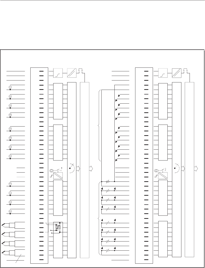
9-76 System Manual
C79000-G8576-C199-06
Voltage or current input
or connection of two-wire transducer Resistance thermometer
Block Diagram
of the Module
Front Strip
Pin
Connection of
Process Signal
Lines
1
2
3
4
6
8
10
13
15
17
19
20
22
23
25
27
29
31
34
36
38
40
41
F+
L+
F–
Comp.–
Comp.+
MU +
–
2)
Datenspeicher und S5–Busansteuerung
ADU
t
Range Card 1
5
Range Card 2Range Card 3
Range Card 4
6ES5 498–1AA51
7
9
11
14
16
18
26
28
30
32
35
37
39
CH.15
MU +
–
2)
MU +
–
2)
MU +
–
2)
L–
L+
+
–
1) +
–
1) +
–
1) +
–
1) +
–
+
–
+
–
+
–
CH.0
+
–
1)
1)
1)
1)
1)
1) +
–
1) –
+
1) –
+
Itrip
24
3)L+
1
2
3
4
6
8
10
13
15
17
19
20
22
23
25
27
29
31
34
36
38
40
41
42
42
F+
L+
L–L–
F–
Comp.–
Comp.+
Data Memory and S5 Bus Control
ADU
t
5
7
9
11
14
16
18
26
28
30
32
35
37
39
CH.7
CH.0
CH.6
CH.5
CH.4
CH.3
CH.2
CH.1
CH.0
CH.1
CH.2
CH.3
CH.4
CH.5
CH.6
CH.7
Measuring Voltage Inputs
Constant Power Supply
I
24
3) L+
0 Vgnd (L–)
Connection of
Process Signal
Lines
Front Strip
Pin
Block Diagram
of the Module
Range Card 1
Range Card 2Range Card 3Range Card 4
trip
0 Vgnd (L–)
Figure 9-25 Front Connector Assignments
Two-wire transducers can only be connected in the 500 mV mode.
Connect L- to the central ground point (reference potential).
1) Observe permissible potential difference between sensor and reference potential of modules
or between sensors.
2) Two-wire transducer
3) Only required to switch off the tripping current without broken wire detection;
(0 V at common ground point with L-).
Front Connector
Assignments
Analo
g
Input/Output Modules
9-77
System Manual
C79000-G8576-C199-06
9.6 The 466 Analog Input Module
9.6.1 Design
The module is designed as a plug-in PCB for central controllers and
expansion units with a backplane connector and with a blade connector to
accept a plug-in front connector. You can directly connect the process signal
lines to the front connector, which is available separately, with screw or
crimp terminals.
9.6.2 Special Features of the 466 Analog Input Module
The 466 analog input module processes the digital input signals by encoding
the instantaneous value; periodic system interference is therefore not
suppressed.
You select the measuring ranges with a switch setting for every four
channels.
9.6.3 Startup
The mode of the 466 analog input module must be set exclusively via
switches on the board. Figure 9-26 shows the designations and locations of
switches on the board.
Front
Backplane Connector for S5 I/O Bus
S9
S6
S5S7
S8
S2
S1
Figure 9-26 Locations of Mode Switches on the 466 Analog Input Module
Note
The following 43-pin K-type front connectors are required:
6xx3 068 for crimp connection
6xx3 081 for srew connection
Measuring Range
Introduction
Analo
g
Input/Output Modules
9-78 System Manual
C79000-G8576-C199-06
Measurement with respect to ground/differential measurement
The type of measurement (with respect to ground or differential
measurement) is set with switch S9. The switch settings relate to the
locations on the module shown in Figure 9-26:
Type of Measurement Switch Setting S9
Measurement with respect to ground ON
OFF
19
Differential measurement
1 9
ON
OFF
If you have preset differential measurement on switch S9, two channel
groups of four channels each are available. You can configure each channel
group separately for current or voltage measurement.
You set this with switches S5, S6, S7 and S8. Switches S5 and S7 allow three
settings (left, midpoint and right); switches S6 and S8 allow two settings (left
and right). The switch settings relate to the locations on the module shown in
Figure 9-26:
Setting the current/voltage measurement for channel group I
Channel Group I
(Channels 0 to 3) Switch S5 Switch S6
Current
Voltage
Setting the current/voltage measurement for channel group II
Channel Group II
(Channels 4 to 7) Switch S7 Switch S8
Current
Voltage
Setting the Type of
Measurement
Current/Voltage
Measurement for
Individual Channel
Groups
Analo
g
Input/Output Modules
9-79
System Manual
C79000-G8576-C199-06
If you have preset measurement with respect to ground on switch S9, four
channel groups of four channels each are available. You can configure each
channel group separately for current or voltage measurement.
This is set with switches S5, S6, S7 and S8. Switches S5 and S7 allow three
settings (left, midpoint and right); switches S6 and S8 allow two settings (left
and right). The switch settings relate to the locations on the module shown in
Figure 9-26:
Setting the current/voltage measurement for channel group I
Channel Group I
(Channels 0 to 3) Switch S5
Current
Voltage
Setting the current/voltage measurement for channel group II
Channel Group II
(Channels 4 to 7) Switch S7
Current
Voltage
Setting the current/voltage measurement for channel group III
Channel Group III
(Channels 8 to 11) Switch S6
Current
Voltage
Setting the current/voltage measurement for channel group IV
Channel Group IV
(Channels 12 to 15) Switch S8
Current
Voltage
Analo
g
Input/Output Modules
9-80 System Manual
C79000-G8576-C199-06
The 466 analog input module has 12 measuring ranges. For each channel
group (i.e. for every four inputs), you can select a range which is independent
of the other channel groups. You set the ranges with switches S1 and S2.
Channel Group I
(Channel 0...3) Channel Group II
(Channel 4...7) Channel Group III
(Channel 8...11)
Channel Group IV
(Channel 12...15)
ON
OFF
1234 5678
S1 1234 5678
S2
Figure 9-27 Assignment of Channel Groups to Switches S1 / S2
The same measuring range coding is valid for each channel group. Given in
the following table, therefore, is the setting of the measuring range for only
one channel group. The switch settings relate to the locations on the module
shown in Figure 9-27.
Note that you must additionally set the type of measurement
(current/voltage) with switches S5 to S8!
Setting the measuring range for a channel group (4 channels each)
Range Switch Setting
0 - 20 mA ON
OFF
0 - 1.25 V
0 - 2.5 V
0 - 5 V
0 - 10 V
$ 20 mA
$ 1.25 V
$ 2.5 V
$ 5 V
$ 10 V
4 - 20 mA
1 - 5 V
Setting the
Measuring Range
Analo
g
Input/Output Modules
9-81
System Manual
C79000-G8576-C199-06
Set the data format by means of switch S9:
Two’s complement
12-bit two’s complement representation
(Range: 0 ... 4095 units (unipolar) or - 2048 ... + 2047 units (bipolar))
Value and sign
11-bit value and 1 sign bit
(Range: 0 ... 4095 units (unipolar) or - 2048 ... + 2047 units (bipolar))
Binary
12-bit binary number
(Range: 0 ... 4095 units for both unipolar and bipolar measured variables)
Data Format S9 Switch Setting
Two’s complement
19
ON
OFF
Value and sign
19
ON
OFF
Binary
1 9ON
OFF
Setting the Data
Format
Analo
g
Input/Output Modules
9-82 System Manual
C79000-G8576-C199-06
Before starting up, first indicate via switch S9 whether you intend to use the
466 analog input module with a central controller (CC) or with an expansion
unit (EU).
Refer to the following table:
Setting the module start address (1)
466-3LA11 Module S9 Switch Setting
Operation in CC
1
ON
OFF
9
Operation in EU with IM 300/312
1
ON
OFF
9
Operation in EU with IM 301/310
1
ON
OFF
9
Operation in EU with IM 304/314
1
ON
OFF
9
Operation in EU with IM 307/317
1
ON
OFF
9
Operation in EU with IM 308/318
1
ON
OFF
9
Setting the Module
Start Address
Analo
g
Input/Output Modules
9-83
System Manual
C79000-G8576-C199-06
Set the exact start address of the module as shown in the following table.
Setting the module start address (2)
Module Address S9 Switch Setting
000
19
ON
OFF
016*
19
ON
OFF
032
19
ON
OFF
048*
1 9
ON
OFF
064
19
ON
OFF
080*
1 9
ON
OFF
096
1 9
ON
OFF
112*
19ON
OFF
128
19
ON
OFF
144*
1 9ON
OFF
160
19
ON
OFF
176*
19
ON
OFF
192
1 9
ON
OFF
208*
1 9
ON
OFF
224
1 9
ON
OFF
240*
19
ON
OFF
* can only be set for differential measurement
Analo
g
Input/Output Modules
9-84 System Manual
C79000-G8576-C199-06
9.6.4 Removing and Inserting Modules
!Warning
When removing and inserting the front connector during operation,
hazardous voltages of more than 25 V AC or 60 V DC may be present at the
module pins. When this is the case at the front connector, live modules may
only be replaced by electrical specialists or trained personnel in such a way
that the module pins are not touched.
During operation, the front connector and module must not be removed or
inserted without the enable jumper or active enable circuit.
Install an analog input/output module as follows:
Step Action
1Release the upper locking bar on the subrack and swivel it upwards and
out.
2Insert the module at the desired slot in the subrack and push it back in the
guides.
3Latch the module by rotating the locking pin by 90o at the lower end of
the module. It must no longer be possible to pull the module forwards.
4Engage the front connector on the support pin of the module. The width
of the support pin also provides keying to prevent front connectors from
being fitted to the wrong modules (e.g. front connectors with 115/230 V
AC wiring cannot be plugged into analog modules).
5Tighten the screw in the upper part of the front connector.
Analo
g
Input/Output Modules
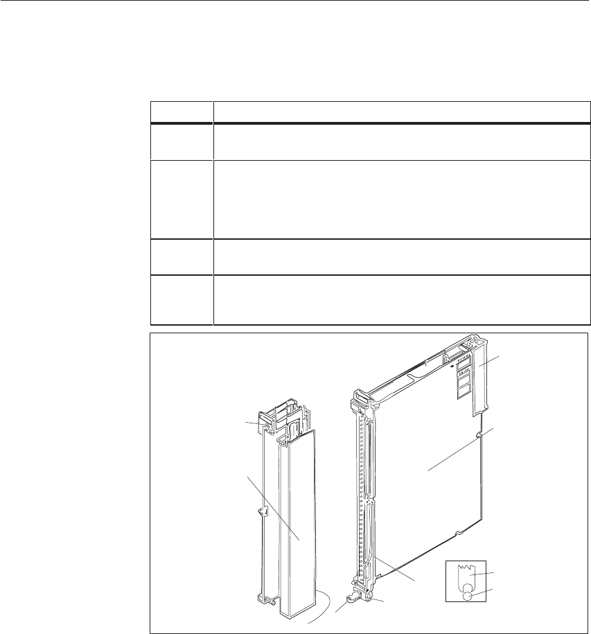
9-85
System Manual
C79000-G8576-C199-06
Remove an analog input/output module as follows:
Step Action
1Release the upper locking bar on the subrack and swivel it upwards and
out.
2Slacken the screw in the upper part of the front connector. This causes the
front connector to be pressed out of the female connector of the module.
Contacts F+ and F- of the enable input at the upper end of the front
connector are thus opened first. If the enable input is active, power is
removed from the outputs and the module is isolated from the S5 bus.
3Swing the front connector out and lift it away from the support pin of the
module.
4Release the module by rotating the locking pin by 90o at the lower end of
the module. You can pull the module out of the subrack with a grip with
swivels outwards.
1
2
3
5
6
4
Module
Front
Connector
Support Mount
Support Pin
Figure 9-28 Module with Front Connector
1 Screw
2 Locking pin
3 Support mount
4 Support pin
5 Grip
6 Backplane connector
Comply with VDE Specifications 0110 and 0160 to carry out the wiring of
supply and signal lines which are to be connected to the programmable
controllers and front connectors of the modules.
Detailed information on cabinet assembly, cabinet ventilation and protective
measures can be found in Chapter 3.
Analo
g
Input/Output Modules

9-86 System Manual
C79000-G8576-C199-06
9.6.5 Marking of Modules and Front Connectors
For the marking of modules and front connectors, labels are supplied with the
module and central controller; they are affixed as shown in Figure 9-29.
5
1
13
42
Figure 9-29 Marking and Labeling of Modules
1 Label with the module address under which the module is referenced by the STEP 5 program
2 Labeling strip with the product designation for the module; space to mark the module version
and label the channels
3 Label with module address and marking of the required settings for the addressing switch
4 Labeling strip for terminal designations or connection diagrams (strip in the cover of the
front connector)
5 Name plate
Analo
g
Input/Output Modules

9-87
System Manual
C79000-G8576-C199-06
9.6.6 Connecting the Signal Lines
For connection of the signal lines, front connectors for 20 and 40 mm
mounting width with crimp connection and 40 mm mounting width with
screw connection are available (screwdriver blade width: 3.5 mm, maximum
torque: 0.8 Nm).
Use stranded conductor to facilitate handling of the front connector. Ferrules
are not required for screw connections, because the screw terminals are
provided with wire protection.
When the crimp contact is inserted in the plastic body of the front connector,
a click can clearly be heard. This indicates that the contact is engaged. For
jumpering or to correct the wiring, you can remove the contacts with a
releasing tool (see ordering information) without having to pull out the front
connector.
Ferrules are not required for screw connections, because the screw terminals
are provided with wire protection. You can use ferrules of 7 mm in length to
DIN 46228. The maximum terminal area is 2 x 2.5 mm2.
!Caution
Only extra-low voltage 60 V DC with safety separation from system voltage
may be used for the 24 V DC supply and for the 24 V DC input signals.
Safety separation can be implemented to the requirements of, amongst other
sources, VDE 0100 Part 410/HD 384-4-41/IEC 364-4-41 (as functional
extra-low voltage with safety separation) or VDE 0805/EN 60950/IEC 950
(as safety extra-low voltage SELV) or VDE 0106 Part 101.
Analo
g
Input/Output Modules

9-88 System Manual
C79000-G8576-C199-06
9.6.7 Connecting Sensors to the 466 Analog Input Module
The connections for the 466 analog input module depend on the type of
measurement (with respect to ground or differential measurement).
For measurement with respect to ground, all signal lines have a common
reference point. This is achieved by connecting all the M inputs in use to one
point. Since this type of measurement is susceptible to interference, the
signal sources should be arranged in the vicinity of the 466 analog input
module.
16 channels are available; unused channels must be shorted (jumper between
M+ and M-).
The channels have the following designations on the module:
Channel 0: M0 +
M0 –
Channel 1: M1 +
M1 –
: :
Channel 15 M15 +
M15 –
Channels are arranged in groups of four, for which you can set separate
measuring ranges:
Channel group I: Channels 0 to 3
Channel group II: Channels 4 to 7
Channel group III: Channels 8 to 11
Channel group IV: Channels 12 to 15
Measurement with
Respect to Ground
Analo
g
Input/Output Modules
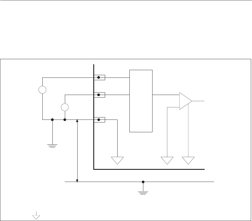
9-89
System Manual
C79000-G8576-C199-06
The following figure shows the connection of sensors to the module. For
measurement with respect to ground, all the M- connection points are
interconnected internally on the module.
UE2
UE1
Analog Input Module
M+
M–
+
–
+
–
M+
UISO
MUX
0 V Bus
UE1/2: Input Voltage
UISO: Potential Difference
: Equipotential; this potential is established by the sensor reference potential
(external reference potential)
Figure 9-30 Connecting Sensors to the 466 Analog Input Module (Measurement with Respect to Ground)
The differential measurement is a method of compensating for interference
on the line. Each signal source is assigned its own signal reference line. The
differential measurement between signal line and signal reference line thus
compensates for the interference acting on both lines.
You must also short-circuit the unused channels with this measuring method
(jumper between M+ and M-).
Differential measurement is required:
if the sensors are at different potentials;
if various signal sources are not close to each other;
if there is a need to measure signals with high precision;
and when a high level of interference is expected.
Differential
Measurement
Analo
g
Input/Output Modules

9-90 System Manual
C79000-G8576-C199-06
The channels have the following designations on the module:
Channel 0: M0 +
M0 –
Channel 1: M1 +
M1 –
: :
Channel 7: M7 +
M7 –
Channels are arranged in groups of four, for which you can set separate
measuring ranges:
Channel group I: Channels 0 to 3
Channel group II: Channels 4 to 7
The following figure shows the connection of sensors to the module.
You must observe the following condition:
UE + UCM < 12 V
(i.e. the sum of the set voltage range and common-mode voltage must be less
than 12 V; current measuring ranges correspond to a voltage of 2.5 V).
M+
M–
M+
UISO
MUX
0 V Bus
+
–
+
–
UE2
UCM2 +
–
+
–
UCM1
M–
0 Vext
UE1
Analog Input Module
UE1/2: Input Voltage
UISO: Potential Difference
: Equipotential; this potential is established by the sensor reference potential
(external reference potential)
UCM1/2: Common-Mode Voltage
Figure 9-31 Connecting Sensors to the 466 Analog Input Module (Differential Measurement)
Analo
g
Input/Output Modules

9-91
System Manual
C79000-G8576-C199-06
9.6.8 Measured-Value Representation
After conversion, the digital result is stored in the module’s RAM.
The bits in both bytes have the following significance:
Byte 0
7654321
07654321
0
212 222 222222222
11 10 95
731
84
620AEOV
Byte 1
Binary Value
is not assigned
is set in case of internal error;
in this case, the measured value
is not valid
(is set if the range limit is reached)
Active Bit;
Error Bit;
Overflow Bit;
Figure 9-32 Digital Result Representation
Bits 0 to 2 in byte 1 have no influence on the measured value, they only give
information on measured-value representation. The following table describes
their significance in more detail.
Bit Significance Signal Status Meaning of the
Signal Status
OV Overflow bit 1 Range exceeded *
E Error bit 1 Broken wire
A Active bit 0 Not used
*A measuring-point overflow does not affect the overflow bits of the other channels;
i.e. the measured values of unaffected channels are correct and can be evaluated.
Please note the following special features:
Bit 7 in the high byte (212) indicates the sign for bipolar measured-value
representation (two’s complement and value with sign).
Bit 6 in the high byte (211) is not used in the case of bipolar
measured-value representation (no overrange).
The 466 module has no overrange.
Selective sampling is not possible with the 466 module
(active bit is not set).
Measured-Value
Representation
with Various
Ranges
Analo
g
Input/Output Modules

9-92 System Manual
C79000-G8576-C199-06
Shown in the following tables is the representation of the measured value as
a function of the selected measuring range.
Units Measured
Value in V
Measured
Value in V
Measured
Value in V
Byte 0 * Byte 1 *
Value in V
(0 - 5 V) Value in V
(0 - 10 V) Value in V
(0 - 20 mA) 7
212 6
211 5
210 4
29 3
282
27 1
26 0
25 7
24 6
23 5
22 4
21 3
20 2
A
1
E
0
O
4095
4094
:
0001
0000
4.9988
4.9976
:
0.0012
0.0000
9.9976
9.9951
:
0.0024
0.0000
19.9951
19.9902
:
0.00488
0.00000
0
0
0
0
1
1
0
0
1
1
0
0
1
1
:
0
0
1
1
0
0
1
1
0
0
1
1
0
0
1
1
0
0
1
1
0
0
1
1
0
0
1
1
0
0
1
1
0
0
1
0
:
1
0
0
0
0
0
0
0
0
0
1
0
0
1
*Same representation for the data formats:
two’s complement, value and sign, binary representation.
A = Active bit
E = Error bit
O = Overflow bit
Units Measured
Value in V
Measured
Value in V
Measured
Value in V
Byte 0 * Byte 1 *
Value in V
($5 V)
Value in V
($10 V)
Value in V
($20 mA) 7
212 6
211 5
210 4
29 3
282
27 1
26 0
25 7
24 6
23 5
22 4
21 3
20 2
A
1
E
0
O
2047
2046
:
0001
0000
–0001
:
–2047
–2048
4.9976
4.9951
:
0.0024
0.0000
–0.0024
:
–4.9976
–5.0000
9.9951
9.9902
:
0.0049
0.0000
–0.0049
:
–9.9951
–10.000
19.9902
19.9804
:
0.00976
0.00000
–0.00976
:
–19.9902
–20.0000
0
0
0
0
1
1
1
0
0
0
0
1
1
1
1
1
0
0
1
0
0
1
1
:
0
0
1
:
0
0
1
1
0
0
1
0
0
1
1
0
0
1
0
0
1
1
0
0
1
0
0
1
1
0
0
1
0
0
1
1
0
0
1
0
0
1
1
0
0
1
0
0
1
1
0
0
1
0
0
1
1
0
0
1
0
0
1
0
:
1
0
1
:
1
0
0
0
0
0
0
0
0
0
0
0
0
0
0
0
1
0
0
0
0
0
1
A = Active bit
E = Error bit
O = Overflow bit
Measuring Range
0-20 mA, 0-5 V and
0-10 V; Unipolar
Two’s
Complement;
Measuring Range
5 V, 20 mA
and 10 V;
Bipolar
Analo
g
Input/Output Modules

9-93
System Manual
C79000-G8576-C199-06
Value and sign; measuring range $ 5 V, $ 20 mA and $ 10 V; bipolar
Units Measured
Value in V
Measured
Value in V
Measured
Value in V
Byte 0 * Byte 1 *
Value in V
($5 V)
Value in V
($10 V)
Value in V
($20 mA) 7
212 6
211 5
210 4
29 3
282
27 1
26 0
25 7
24 6
23 5
22 4
21 3
20 2
A
1
E
0
O
2047
2046
:
0001
0000
–0001
:
–2047
–2048
4.9976
4.9951
:
0.0024
0.0000
–0.0024
:
–4.9976
–5.0000
9.9951
9.9902
:
0.0049
0.0000
–0.0049
:
–9.9951
–10.000
19.9902
19.9804
:
0.00976
0.00000
–0.00976
:
–19.9902
–20.0000
0
0
0
0
1
1
1
0
0
0
0
0
0
1
1
1
0
0
0
1
0
1
1
:
0
0
0
:
1
0
1
1
0
0
0
1
0
1
1
0
0
0
1
0
1
1
0
0
0
1
0
1
1
0
0
0
1
0
1
1
0
0
0
1
0
1
1
0
0
0
1
0
1
1
0
0
0
1
0
1
1
0
0
0
1
0
1
0
:
1
0
1
:
1
0
0
0
0
0
0
0
0
0
0
0
0
0
0
0
1
0
0
0
0
0
1
A = Active bit
E = Error bit
O = Overflow bit
Binary; measuring range $ 5 V, $ 20 mA and $ 10 V; bipolar
Units Measured
Value in V
Measured
Value in V
Measured
Value in V
Byte 0 * Byte 1 *
Value in V
($5 V)
Value in V
($10 V)
Value in V
($20 mA) 7
212 6
211 5
210 4
29 3
282
27 1
26 0
25 7
24 6
23 5
22 4
21 3
20 2
A
1
E
0
O
4095
4094
:
2049
2048
2047
:
0001
0000
4.9976
4.9951
:
0.0024
0.0000
–0.0024
:
–4.9976
–5.0000
9.9951
9.9902
:
0.0049
0.0000
–0.0049
:
–9.9951
–10.000
19.9902
19.9804
:
0.00976
0.00000
–0.00976
:
–19.9902
–20.0000
0
0
0
0
0
0
0
1
1
1
1
0
0
0
1
1
0
0
1
0
0
1
1
:
0
0
1
:
0
0
1
1
0
0
1
0
0
1
1
0
0
1
0
0
1
1
0
0
1
0
0
1
1
0
0
1
0
0
1
1
0
0
1
0
0
1
1
0
0
1
0
0
1
1
0
0
1
0
0
1
1
0
0
1
0
0
1
0
:
1
0
1
:
1
0
0
0
0
0
0
0
0
0
0
0
0
0
0
0
1
0
0
0
0
0
1
A = Active bit
E = Error bit
O = Overflow bit
Measuring range 0-1.25 V and 0-2.5 V; unipolar
Units Measured
Value in V
Measured
Value in V
Byte 0 Byte 1
Value in V
(0 - 1.25 V) Value in V
(0 - 2.5 V) 7
212 6
211 5
210 4
29 3
282
27 1
26 0
25 7
24 6
235
224
21 3
20 2
A 1
E 0
O
4095
4094
:
0001
0000
1.2497
1.2494
:
0.0003
0.0000
2.4994
2.4988
:
0.0006
0.0000
0
0
0
0
1
1
0
0
1
1
0
0
1
1
:
0
0
1
1
0
0
1
1
0
0
1
1
0
0
1
1
0
0
1
1
0
0
1
1
0
0
1
1
0
0
1
1
0
0
1
0
:
1
0
0
0
0
0
0
0
0
0
1
0
0
1
*Same representation for the data formats:
two’s complement, value and sign, binary representation.
A = Active bit
E = Error bit
O = Overflow bit
Analo
g
Input/Output Modules

9-94 System Manual
C79000-G8576-C199-06
Two’s complement; measuring range $ 1.25 V and $ 2.5 V; bipolar
Units Measured
Value in V
Measured
Value in V
Byte 0 Byte 1
Value in V
($ 1.25 V) Value in V
($ 2.5 V) 7
212 6
211 5
210 4
29 3
282
27 1
26 0
25 7
24 6
235
224
21 3
20 2
A 1
E 0
O
2047
2046
:
0001
0000
–0001
:
–2047
–2048
1.2494
1.2488
:
0.0006
0.0000
–0.0006
:
–1.2494
–1.2500
2.4988
2.4975
:
0.0012
0.0000
–0.0012
:
–2.4988
–2.5000
0
0
0
0
1
1
1
0
0
0
0
1
1
1
1
1
0
0
1
0
0
1
1
:
0
0
1
:
0
0
1
1
0
0
1
0
0
1
1
0
0
1
0
0
1
1
0
0
1
0
0
1
1
0
0
1
0
0
1
1
0
0
1
0
0
1
1
0
0
1
0
0
1
1
0
0
1
0
0
1
1
0
0
1
0
0
1
0
:
1
0
1
1
0
0
0
0
0
0
0
0
0
0
0
0
0
:
0
0
1
0
0
0
0
0
1
A = Active bit
E = Error bit
O = Overflow bit
Value and sign; measuring range $ 1.25 V and $ 2.5 V; bipolar
Units Measured
Value in V
Measured
Value in V
Byte 0 Byte 1
Value in V
($ 1.25 V) Value in V
($ 2.5 V) 7
212 6
211 5
210 4
29 3
282
27 1
26 0
25 7
24 6
235
224
21 3
20 2
A 1
E 0
O
2047
2046
:0001
0000
–0001
:–2047
–2048
1.2494
1.2488
:
0.0006
0.0000
–0.0006
:
–1.2494
–1.2500
2.4988
2.4975
:
0.0012
0.0000
–0.0012
:
–2.4988
–2.5000
0
0
0
0
1
1
1
0
0
0
0
0
0
1
1
1
0
0
0
1
0
1
1
:
0
0
0
:
1
0
1
1
0
0
0
1
0
1
1
0
0
0
1
0
1
1
0
0
0
1
0
1
1
0
0
0
1
0
1
1
0
0
0
1
0
1
1
0
0
0
1
0
1
1
0
0
0
1
0
1
1
0
0
0
1
0
1
0
:
1
0
0
1
0
0
0
0
0
0
0
0
0
0
0
0
0
:
0
0
1
0
0
0
0
0
1
A = Active bit
E = Error bit
O = Overflow bit
Binary; measuring range $ 1.25 V and $ 2.5 V; bipolar
Units Measured Measured Byte 0 Byte 1
Value in V
($ 1.25 V) Value in V
($ 2.5 V) 7
212 6
211 5
210 4
29 3
282
27 1
26 0
25 7
24 6
235
224
21 3
20 2
A 1
E 0
OV
4095
4094
:2049
2048
2047
:0001
0000
1.2494
1.2488
:
0.0006
0.0000
–0.0006
:
–1.2494
–1.2500
2.4988
2.4975
:
0.0012
0.0000
–0.0012
:
–2.4988
–2.5000
0
0
0
0
0
0
0
1
1
1
1
0
0
0
1
1
0
0
1
0
0
1
1
:
0
0
1
0
0
1
1
0
0
1
0
0
1
1
0
0
1
0
0
1
1
0
0
1
0
0
1
1
0
0
1
0
0
1
1
0
0
1
0
0
1
1
0
0
1
0
0
1
1
0
0
1
0
0
1
1
0
0
1
0
0
1
0
:
1
0
1
:
1
0
0
0
0
0
0
0
0
0
0
0
0
0
0
0
1
0
0
0
0
0
1
*Same representation for the data formats:
two’s complement, value and sign, binary representation.
A = Active bit
E = Error bit
O = Overflow bit
Analo
g
Input/Output Modules

9-95
System Manual
C79000-G8576-C199-06
9.6.9 Technical Specifications
6ES5 466-3LA11 Analog Input Modules
Input ranges 0-20 mA; 4-20 mA; "20 mA;
0-1.25 V; 0-2.5 V; 0-5 V;
1-5 V; 0-10 V;
"1.25 V; "2.5 V; "5 V; "10 V
Number of inputs 16 single or 8 differential inputs in groups of
4 or 2 channels (selectable)
voltage or current measurement
Measuring principle Instantaneous value encoding
Conversion time 25 ms typical (per channel)
Isolation Yes
Permissible isolation between sensor ref. potential and
central ground point 25 V AC/60 V DC max.
Supply voltage
internal
external + 5 V +/- 5 %
None
Current consumption, internal 0.7 A typical
Encoding time per measured value 250 ms
Duration of cyclic sampling
(cycle time)
for 8 measured values
for 16 measured values 2 ms max.
4 ms max.
Input resistance
voltage measuring range
current measuring range
w 10 M W
125 W
Type of circuit for sensors Two-wire circuit
Digital representation of the input signal Selectable, following types of representation:
– 12-bit two’s complement
– 11-bit value with sign
– 12-bit binary
Max. permissible input voltage without destruction $ 30 V max. (static) or
$ 75 V (pulse for 1 ms max. and duty ratio 1:20)
Interference voltage suppression common-mode interfer-
ence (Vpp = 1 V) 70 dB min.
Basic error limits
– voltage ranges except for 0-1.25 V; $1.25 V
– current ranges and 0-1.25 V; $1.25 V 0.1 %
0.2 %
Analo
g
Input/Output Modules

9-96 System Manual
C79000-G8576-C199-06
Operational error limit (0 oC ... 60 oC)
– voltage ranges except for 0-1.25 V, $1.25 V
– current ranges and 0-1.25 V, $1.25 V 0.2 %
0.2 %
Error signal
for overflow
for internal error Yes (overflow bit set)
Yes (error bit (= E bit) set)
Single error
linearity
tolerance
polarity reversal error
0.02 %
0.05 %
0.05 %
Temperature error 0.005 %/K
Insulation rating To VDE 0160
Line length
- shielded 200 m max.
Front connector 43-way
Power dissipation of module 3.5 W typical
Weight Approx. 0.4 kg
Rated insulation voltage
(between channels and ground point) tested at 500 V
Analo
g
Input/Output Modules

9-97
System Manual
C79000-G8576-C199-06
Voltage-to-ground measurement Differential measurement
Front Strip
Pin
1
2
3
4
6
8
10
13
15
17
19
20
22
23
25
27
29
31
34
36
38
40
41
5
7
9
11
14
16
18
26
28
30
32
35
37
39
M8– Mext
Mext
Mext
Mext
Mext
Mext
Mext
Mext
M9–
M13–
M10–
M14–
M11–
M15–
M12–
M0+ M0+
M4+
M2+
M6+
M1+
M5+
M3+
M7+
M1+
M5+
M2+
M6+
M3+
M7+
M4+
M0– Mext
Mext
Mext
Mext
Mext
Mext
Mext
Mext
M1–
M5–
M2–
M6–
M3–
M7–
M4–
24
42
33
21
12
M8+ M0–
M4–
M2–
M6–
M1–
M5–
M3–
M7–
M9+
M13+
M10+
M14+
M11+
M15+
M12+
1
2
3
4
6
8
10
13
15
17
19
20
22
23
25
27
29
31
34
36
38
40
41
5
7
9
11
14
16
18
26
28
30
32
35
37
39
24
42
33
21
12
Front Strip
Pin
Figure 9-33 Front Connector Assignments
Front Connector
Assignments
Analo
g
Input/Output Modules
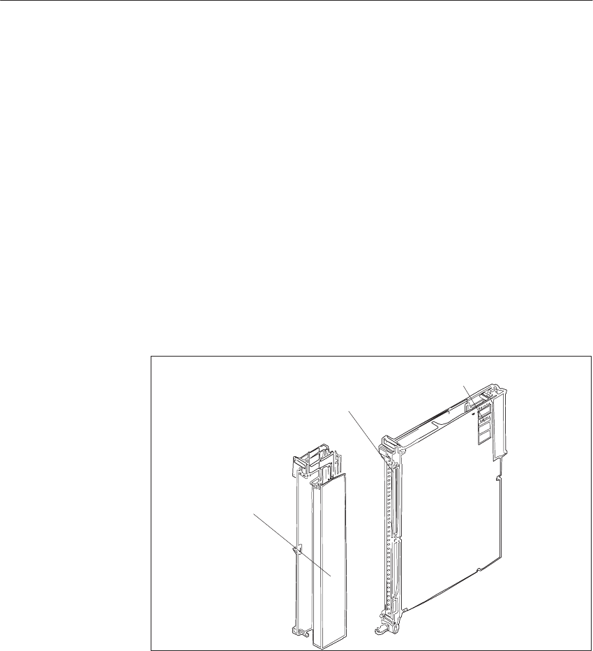
9-98 System Manual
C79000-G8576-C199-06
9.7 The 470 Analog Output Module
9.7.1 Design
The module is designed as a plug-in PCB for central controllers and
expansion units with a backplane connector and with a blade connector to
accept a plug-in front connector. You can directly connect the process signal
lines to the front connector, which is available separately, with screw or
crimp terminals.
Situated on each module is an addressing switch with six rockers to set the
module address.
The modules are protected by covers on both sides.
Blade Connector
Addressing Switch
Front Connector
Figure 9-34 Analog Output Module
9.7.2 Function of the Enable Input
The 470 module has an enable circuit. You can use the enable inputs to
switch off individual modules whilst the PLC is in operation. This means
that:
The module can no longer be addressed by the user program.
On analog output modules, the last analog value to be output is retained.
Modules which are switched off can be removed or inserted during operation.
If this is not necessary, operate the module with the enable input switched
off.
Addressing
Switch, Mode
Switches
Analo
g
Input/Output Modules
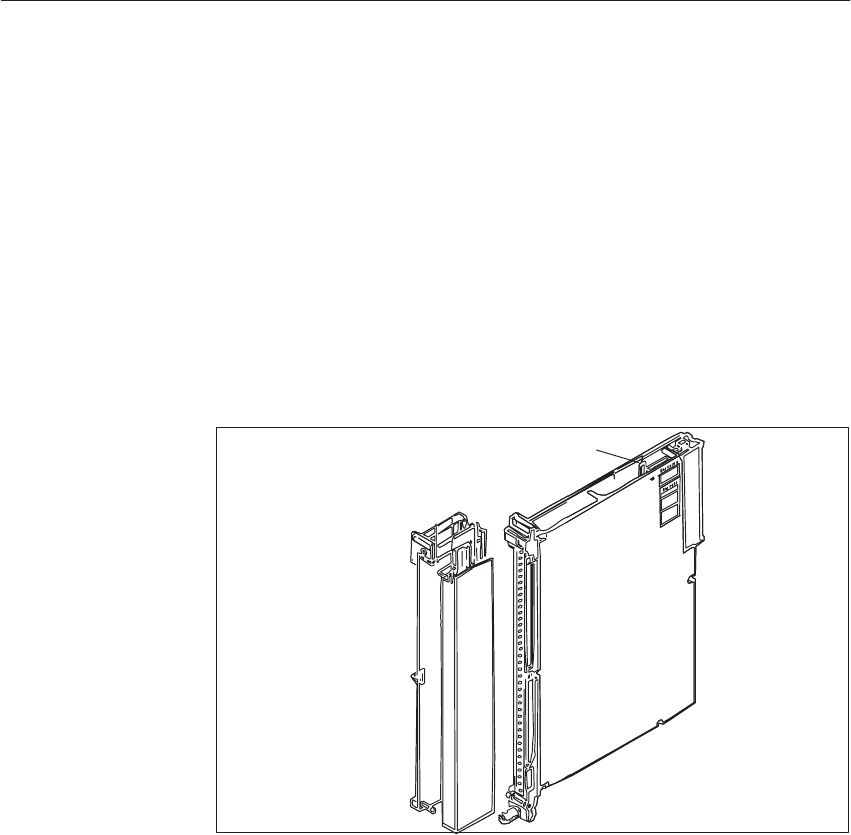
9-99
System Manual
C79000-G8576-C199-06
The enable circuit requires an external 24 V voltage at enable inputs F+/F- in
the front connector. If there is no voltage at F+/F-, the modules will not
acknowledge.
When the front connector is swivelled away from the front strip of the
module, the supply of power to the enable input is interrupted, i.e. the
module is switched off and can no longer be addressed by the user program: a
timeout (QVZ) occurs in the CC.
The -4Ux12-type modules additionally offer the facility for changing the
enable mode. The modules have a jumper accessible from above in the
vicinity of the addressing switch.
Enable Jumper
Figure 9-35 Enable Input and Enable Jumper
Jumper inserted: Enable input (F+/F-) active (factory setting)
Jumper open: Enable input (F+/F-) switched off
Examples of functioning of the enable inputs:
To switch off individual subprocesses, i.e. outputs of various modules can
be operated from a common load supply and yet activated separately.
The load voltage of individual modules can be monitored without
additional circuitry. Any reactions to failure of the load voltage can be
programmed in the QVZ (timeout) organization block.
Enable Input
Switching Off the
Enable Input
Analo
g
Input/Output Modules
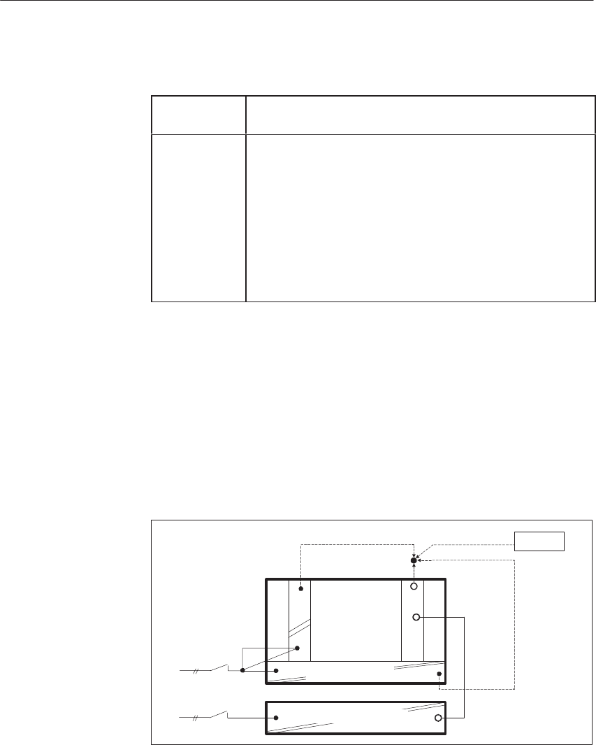
9-100 System Manual
C79000-G8576-C199-06
You must observe the following when configuring systems:
Switching on At the latest 100 ms after power-up of the PLC, the voltage
must be present at the enable inputs of the I/O modules.
Switching off When the PLC has been switched off, the voltage at the
enable inputs of the I/O modules must still be present as
long as the internal 5 V voltage is present.
However, you must ensure that the 24 V load supply for
analog output modules is switched off together with the
PLC. If the supply voltage is still present at the modules
and the PLC is switched off, the output values can drift.
(The analog holding elements for the outputs will no lon-
ger be refreshed with the current value, because there is no
5 V supply to the modules from the bus.)
You should observe the following instructions for switching off CCs and
equipment for supplying power to the enable inputs.
When there is a need to switch off the load power supply separately without
affecting the enabling of modules, there are the following possibilities for
producing the enable voltage. These exist even when the load power supply
is used without an additional capacitor and common shutdown.
230 V AC supply for CC/EU and load power supply
F+
L+
I/O Modules
230 V AC
CC/EU
–951
a)
c)
b) Battery
L+
Power Supply
Load Power Supply 24V
Supply for the enable inputs from:
a) 6ES5 951-4LB11 load power supply
b) Battery
c) Terminals for 24 V on the front plate of the power supply
Configuring
Switching Off the
CC
Separate or
Common
Shutdown of the
CC/EU and Load
Power Supply
Analo
g
Input/Output Modules
9-101
System Manual
C79000-G8576-C199-06
24 V supply for CC/EU and I/Os
F+
L+
I/O Modules
24 V DC
b)
a)
CC/EU
L+
Battery
Power Supply 24V
Supply for the enable inputs from:
a) Battery
b) Terminals for 24 V on the front plate of the power supply
Proper functioning is ensured if the 24 V load power supply has an output
capacitance of at least 4700 mF per 10 A of load current. Other units which
do not meet this condition can be adapted to this requirement by connecting a
10000 mF / 40 V capacitor in parallel.
10000µF/
40V
CC/EU F+
L+
230 V AC
I/O Modules
Load Power Supply 24V
Power Supply
Common
Shutdown of the
CC/EU and Load
Power Supply with
a 230 V AC Supply
Analo
g
Input/Output Modules
9-102 System Manual
C79000-G8576-C199-06
9.7.3 Special Features of the 470 Analog Output Module
The BASP signal is not interpreted by the 470 analog output module. Once
output, a value is retained.
You can output analog values to the process via analog output modules with a
function block from the “basic functions” package.
9.7.4 Setting the Module Address
You set the module address on the addressing switch. This also establishes
the necessary assignments between user program and process connection.
The module address is the sum of the decimal significances of the switch
rockers in the On setting (Ĥ).
One data word = two data bytes is required to process an input or an output.
A module with 8 inputs or outputs reserves 16 byte addresses.
You can affix the adhesive label with the desired module address on a free
labeling field under the addressing switch.
The switch rockers to be set for the module address specified as a decimal
number (address bit ADB) are marked by dots on the label.
Press the individual rockers of the addressing switch downwards with a
ballpoint pen or similar object, but not a pencil.
On Setting
(Switch Pressed) Addressing Switch
Address Bit
Decimal Signification of
the Address Bit
Free Field for Label with
Module Address and
marked Switch Settngs
Address (Decimal)
128
64
32
16
8
4
2
1
ADB7
ADB6
ADB5
ADB4
ADB3
ADB2
ADB2 is not connected
ADB1
ADB0
ADB0 and ADB1 are not assigned
Figure 9-36 Labeling of the Addressing Switch
The address under which the module is referenced by the STEP 5 program is
independent of the slot.
BASP (Output
Inhibit)
Function Block
Labeling Field
Analo
g
Input/Output Modules
9-103
System Manual
C79000-G8576-C199-06
For analog output modules ( 8 outputs) only the lowest address (start address)
is set. Other addresses (subaddresses) are decoded on the module.
Note
The start address of an analog module must be a multiple of the double
channel number.
8 channels : 0, 16, 32, 48, ... 240
If one of the outputs (Channel 0 to 7) of a module is to be addressed, the
relevant subaddress must be specified in the program.
The subaddress of the output, based on the start address of the module, is
given by:
Start address + 2 x channel no. = subaddress
Example:
Analog output module with 8 outputs
The address is the sum of the significances set with the individual coding
switches.
160 = 128 + 32 = 27 + 25
On Setting
(Switch Pressed)
IB 160
128
64
32
16
8
4
2
1
ADB7
ADB6
ADB5
ADB4
ADB3
ADB2
ADB1
ADB0
A module with 8 outputs (Channel 0 to 7) and start address 160 reserves the
address range from
160 to address 160 + 7 x 2 = 174
In this example, the next free address for another module is 176.
Addresses already assigned must not be set again.
Start Address,
Subaddress
Analo
g
Input/Output Modules

9-104 System Manual
C79000-G8576-C199-06
However, analog input modules and analog output modules may be given the
same address with cyclic sampling because they are distinguished by the user
program. This is not possible with selective sampling.
For cyclic sampling, you can address the module in the address range from 0
to 255, and for selective sampling from 128 to 255. For selective sampling,
you can also use the address range from 0 to 127 after appropriate
programming in DB 1 of the user program.
Example:
On an analog output module with 8 outputs with start address 144 (IB 144 =
output byte 144), output channel 7 is to be scanned by the program.
Step Action
1Affix the self-adhesive label with address 160 on the free field under the
addressing switch on the module. ADB 4 and ADB 7 are marked on the
label.
2Press the appropriate rockers of the addressing switch down on the side
marked by a dot on the module cover. Set the other rockers to the opposite
setting. This sets the start address of the module.
ADB 4 and ADB 7 results in 24 + 27 = 16 + 128 = 144
3Enter the address 144 + 7 x 2 = 158 in the program for input channel 7.
Addressing for
Cyclic/Selective
Sampling
Analo
g
Input/Output Modules
9-105
System Manual
C79000-G8576-C199-06
9.7.5 Removing and Inserting Modules
!Warning
When removing and inserting the front connector during operation,
hazardous voltages of more than 25 V AC or 60 V DC may be present at the
module pins. When this is the case at the front connector, live modules may
only be replaced by electrical specialists or trained personnel in such a way
that the module pins are not touched.
During operation, the front connector and module must not be removed or
inserted without the enable jumper or active enable circuit.
Install an analog output module as follows:
Step Action
1Release the upper locking bar on the subrack and swivel it upwards and
out.
2Insert the module at the desired slot in the subrack and push it back in the
guides.
3Latch the module by rotating the locking pin by 90o at the lower end of
the module. It must no longer be possible to pull the module forwards.
4Engage the front connector on the support pin of the module.
The width of the support pin also provides keying to prevent front con-
nectors from being fitted to the wrong modules (e.g. front connectors with
115/230 V AC wiring cannot be plugged into analog modules).
5Tighten the screw in the upper part of the front connector.
Analo
g
Input/Output Modules
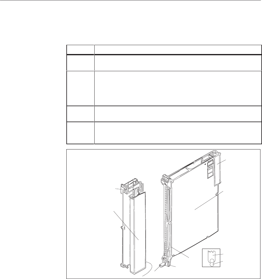
9-106 System Manual
C79000-G8576-C199-06
Remove an analog output module as follows:
Step Action
1Release the upper locking bar on the subrack and swivel it upwards and
out.
2Slacken the screw in the upper part of the front connector. This causes the
front connector to be pressed out of the female connector of the module.
Contacts F+ and F- of the enable input at the upper end of the front con-
nector are thus opened first. If the enable input is active, power is removed
from the outputs and the module is isolated from the S5 bus.
3Swing the front connector out and lift it away from the support pin of the
module.
4Release the module by rotating the locking pin by 90o at the lower end of
the module. You can pull the module out of the subrack with a grip with
swivels outwards.
1
2
3
5
6
4
Module
Front
Connector
Support Mount
Support Pin
Figure 9-37 Module with Front Connector
1 Screw
2 Locking pin
3 Support mount
4 Support pin
5 Grip
6 Backplane connector
Comply with VDE Specifications 0110 and 0160 to carry out the wiring of
supply and signal lines which are to be connected to the programmable
controllers and front connectors of the modules.
Detailed information on cabinet assembly, cabinet ventilation and protective
measures can be found in Chapter 3.
Analo
g
Input/Output Modules
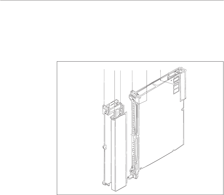
9-107
System Manual
C79000-G8576-C199-06
9.7.6 Marking of Modules and Front Connectors
For the marking of modules and front connectors, labels are supplied with the
module and central controller; they are affixed as shown in Figure 9-38.
5
1
13
4
2
Figure 9-38 Marking and Labeling of Modules
1 Label with the module address under which the module is referenced by the STEP 5 program
2 Labeling strip with the product designation for the module; space to mark the module version
and label the channels
3 Label with module address and marking of the required settings for the addressing switch
4 Labeling strip for terminal designations or connection diagrams (strip in the cover of the
front connector)
5 Name plate
Analo
g
Input/Output Modules

9-108 System Manual
C79000-G8576-C199-06
9.7.7 Connecting the Signal Lines
For connection of the signal lines, front connectors for 20 and 40 mm
mounting width with crimp connection and 40 mm mounting width with
screw connection are available (screwdriver blade width: 3.5 mm, maximum
torque: 0.8 Nm).
Use stranded conductor to facilitate handling of the front connector. Ferrules
are not required for screw connections, because the screw terminals are
provided with wire protection.
When the crimp contact is inserted in the plastic body of the front connector,
a click can clearly be heard. This indicates that the contact is engaged. For
jumpering or to correct the wiring, you can remove the contacts with a
releasing tool (see ordering information) without having to pull out the front
connector.
Ferrules are not required for screw connections, because the screw terminals
are provided with wire protection. You can use ferrules of 7 mm in length to
DIN 46228. The maximum terminal area is 2 x 2.5 mm2.
Terminal
T
Connector
T
Max.
Nf
Cross-Section Connector for
RtdVlt
Mounting Width of
Mdl
Type Type
6ES 497- No. of
Contact
s
Signal or Supply
Conductor Aux. Jumper
in Connector
1)
Rated Voltage Module
Crimp con-
nection -4UA12 2) 42 0.5 mm 20.5 mm 25 to 60 V DC 20 mm Operation
with fan
-4UA22 2) 42 0.5 mm 20.5 mm 25 to 60 V DC 40 mm
Oti
Screw con-
ti
-4UB12 42 0.5 to 2.5 mm 20.5 to 1.0 mm 25 to 60 V DC 40 mm Operation
without fan
nection -4UB31 42 0.5 to 1.5 mm 20.5 to 1.0 mm 25 to 60 V DC 20 mm
without
fan
1) To multiply the supply and 0 V ground terminals, and to connect the enable input
2) The crimp contacts must be ordered separately for these types of connector.
!Caution
Only extra-low voltage 60 V DC with safety separation from system voltage
may be used for the 24 V DC supply and for the 24 V DC input signals.
Safety separation can be implemented to the requirements of, amongst other
sources, VDE 0100 Part 410/HD 384-4-41/IEC 364-4-41 (as functional
extra-low voltage with safety separation) or VDE 0805/EN 60950/IEC 950
(as safety extra-low voltage SELV) or VDE 0106 Part 101.
Analo
g
Input/Output Modules
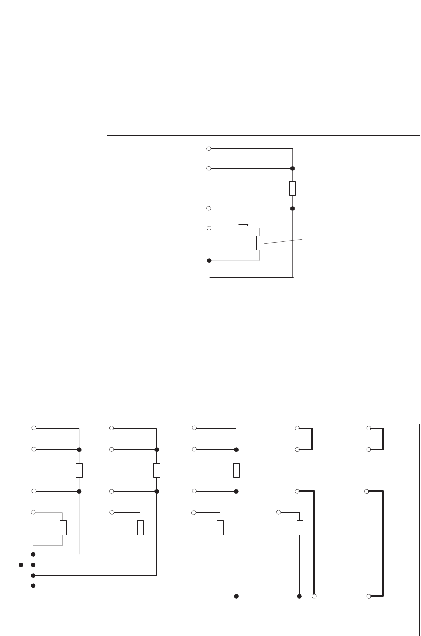
9-109
System Manual
C79000-G8576-C199-06
9.7.8 Connecting Loads to the 470 Analog Output Module
The voltage at the load is measured at a high resistance via the sensor lines
(S+/S-) of voltage output QV, so that voltage drops on the load lines do not
falsify the load voltages. Lines S+(x) and S-(x) should therefore be directly
connected to the load (four-wire circuit). The voltage drops on the lines from
QV(x) to the load and from the load to MANA must not exceed 3 V.
+
–
Load (Voltage)
+
–
Load (Current)
QV(x)
S+(x)
S – (x)
QI (x) I
M
ANA
Figure 9-39 Connecting Loads
QV(x) Voltage output, voltage on Channels 0 to 7
QI(x) Current output, current on Channels 0 to 7
S+(x) Sensor line (+) for Channels 0 to 7
S- (x) Sensor line (-) for Channels 0 to 7
MANA Ground terminal for the analog section
When current and voltage outputs are used on the 470-4UA/-4UC... analog
output modules, connect the loads as follows:
+
–
+
–
QV0
MANA
S+0
S–0
QI0
+
–
+
–
+
–
+
–
+
–
MANA MANA
Current
Output
Only
Jumper
Jumper
QV1
S+1
S–1
QI1
QV2
S+2
S–2
QI2
QV3
S+3
S–3
QI3
QV4
S+4
S–4
QI4 _
Jumper
Jumper
Not Current
and Not Voltage
Output
Figure 9-40 Connecting Loads
Connecting Loads
to Current and
Voltage Outputs
Analo
g
Input/Output Modules

9-110 System Manual
C79000-G8576-C199-06
If, with voltage outputs, an excessively great voltage drop must be expected
on the lines to the load, you must route the sensor lines S+(x) and S-(x) to the
load.
When voltage outputs are not used, the S+(x) sensor lines in the front
connector must be connected to the corresponding voltage output terminals
(QV(x)) with wire jumpers. The S-(x) sensor lines must be connected to
MANA with wire jumpers.
You must also insert the same jumpers if only current outputs are used.
Unused current outputs may remain open.
The maximum load for the current outputs including line resistance, must not
exceed 300 ohms.
The voltage outputs of the 470 analog output module are wired as follows:
+
–
QV0
S+0
S–0
+
–
+
–
MANA
No Load at QV3
Jumper
Jumper
QV1
S+1
S–1
QV2
S+2
S–2
QV3
S+3
S–3
MANA
Figure 9-41 Connecting Loads
The S+(x) and S-(x) sensor lines must be routed to the load (four-wire
circuit) if the voltage drop on the lines to the load is not negligible. The
common connection for the voltage outputs is MANA. If the voltage drop on
lines to the load is negligible, you can connect S+(x) to QV(x) and S-(x) to
MANA in the front connector.
When voltage outputs are unused, you must insert jumpers in the front
connector, e.g. QV(3) to S+(3) and S-(3) to MANA for unused voltage output
3 (see previous section).
Connecting Loads
to Voltage Outputs
Four-Wire Circuit
Analo
g
Input/Output Modules

9-111
System Manual
C79000-G8576-C199-06
9.7.9 Measured-Value Representation
Units Output Voltage or Current of the
470 Analog Output Module Byte 0 Byte 1
-4UA/B12 -4UA12 -4UC12 7
211 6
210 5
29 4
28 3
27 2
26 1
25 0
24 7
23 6
22 5
21 4
20 3
x 2
x 1
x 0
x
1280
1025 12.5 V
10.0098 V 25.0 mA
20.0195mA 6.0 V 24.0 mA
5.004 V 20.016 mA 0
0 1
1 0
0 1
0 0
0 0
0 0
0 0
0 0
0 0
0 0
0 0
1Overrange
1024
1023
512
256
128
64
1
0
– 1
– 64
– 128
– 256
– 512
–1024
10.0 V
9.99 V
5.0 V
2.5 V
1.25 V
0.625 V
9.8 mV
0 V
– 9.8 mV
– 0.625 V
– 1.25 V
– 2.5 V
– 5.0 V
– 10.0 V
20.0 mA
19.98 mA
10.0 mA
5.0 mA
2.5 mA
1.25 mA
19.5 mA
0 mA
0 mA
0 mA
0 mA
0 mA
0 mA
0 mA
5.0 V 20.0 mA
4.995 V 19.98 mA
3.0 V 12.0 mA
2.0 V 8.0 mA
1.5 V 6.0 mA
1.25 V 5.0 mA
1.004 V 4.016 mA
1.0 V 4.0 mA
0.996 V 3.984 mA
0.75 V 3.0 mA
0.5 V 2.0 mA
0 V 0 mA
– 1 V 0 mA
– 3.0 V 0 mA
0
0
0
0
0
0
0
0
1
1
1
1
1
1
1
0
0
0
0
0
0
0
1
1
1
1
1
1
0
1
1
0
0
0
0
0
1
1
1
1
1
0
0
1
0
1
0
0
0
0
1
1
1
1
0
0
0
1
0
0
1
0
0
0
1
1
1
0
0
0
0
1
0
0
0
1
0
0
1
1
0
0
0
0
0
1
0
0
0
0
0
0
1
0
0
0
0
0
0
1
0
0
0
0
0
0
1
0
0
0
0
0
0
1
0
0
0
0
0
0
1
0
0
0
0
0
0
1
0
0
0
0
0
0
1
0
0
0
0
0
0
1
0
0
0
0
0
0
1
0
0
0
0
0
0
1
0
0
0
0
1
0
1
0
0
0
0
0
Rated Range
–1025
–1280
–10.0098V
–12.5 V 0 mA
0 mA – 3.004V0 mA
– 5.0 V 0 mA 1
1 0
01
11
11
01
01
01
01
01
01
01
0Overrange
Digital
Measured-Value
Representation as
Two’s Complement
Analo
g
Input/Output Modules

9-112 System Manual
C79000-G8576-C199-06
9.7.10 Technical Specifications
6ES5 470-4UA12, 6ES5 470-4UB12 and 6ES5 470-4UC12 Analog Output
Modules
Rated output ranges
– 6ES5 470-4UA12
– 6ES5 470-4UB12
– 6ES5 470-4UC12
0 to $10 V and 0 to 20 mA parallel for $1024 units
$10 V for $1024 units
1 to 5 V and 4 to 20 mA parallel for 0 to 1024 units
Number of outputs 8 voltage and current outputs each,
no-load and short-circuit-proof
Isolation Yes 8 outputs with respect to Mext , M and L+/L–
Measured value representation 12-bit (two’s complement)
Linearity in the range of $1024 units $ 2 LSB = $ 0.2 %
Operational error limits (0 to 60 oC) $ 0.6 %
Temperature coefficient for voltage and current outputs 1 x 10⁻⁴/K
Permissible overrange Approx. 25 % ($ 1024 to $ 1272 units)
Fault current at voltage output Approx. 25 mA
No-load voltage at current output Approx. 18 V
Load impedance
– at voltage output
– at current output
w 3.3 kW
v 300 W
Delay between data transfer and analog value output
to > 99% v 5ms
Capacitive load including line capacity
for -4UA12 from version 03 and
for -4UB12 and -4UC12 from version 04:
100 nF max.
1 mF max.
Permissible voltage drop on voltage output lines $ 0.3 V at maximum output voltage
Power supply
– Digital section from system bus
– Analog section from load voltage
– Enabling for module, F+/F-
5 V $ 5 %; approx. 250 mA
24 V; 200 to 400 mA
24 V; approx. 7 mA
Permissible potential difference between reference poten-
tial of the load and housing (UCM)
25 V AC / 60 V DC max.
Voltage test to VDE 0160 Between outputs and housing
tested at 500 V AC
Surge voltage test to IEC 255-4 Between outputs and L–: Vp = 1 kV; 1,2/50 ms
Analo
g
Input/Output Modules
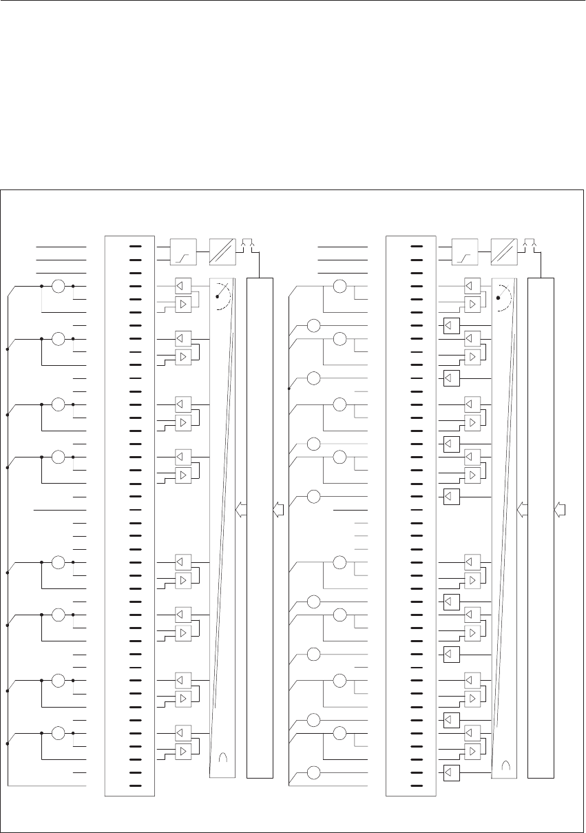
9-113
System Manual
C79000-G8576-C199-06
470-4UB 470-4UA
470-4UC
Connection of
Process Signal
Lines
1
2
3
4
6
8
10
13
15
17
19
20
22
23
25
27
29
31
34
36
38
40
41
F+
L+
F–
Data Mamory and S5 Bus Control
DAU
t
5
7
9
11
14
16
18
26
28
30
32
35
37
39
CH.7
QV0
24
U
42
33
v
21
12
L–
CH.6 v
v
CH.5
CH.4 v
v
CH.3
v
CH.2
v
v
CH.1
CH.0 S+0
S–0
QV1
S+1
S–1
U
U
U
U
U
U
U
MANA
QV2
S+2
S–2
QV3
S+3
S–3
QV4
S+4
S–4
QV5
S+5
S–5
QV6
S+6
S–6
QV7
S+7
S–7
#
Front Strip
Pin
1
2
3
4
6
8
10
13
15
17
19
20
22
23
25
27
29
31
34
36
38
40
41
F+
L+
F–
DAU
t
5
7
9
11
14
16
18
26
28
30
32
35
37
39
CH.7
QV0
24
U
42
33
v
21
12
L–
CH.6
v
v
CH.5
CH.4 v
v
CH.3
v
CH.2
v
v
CH.1
CH.0 S+0
S–0
QV1
S+1
S–1
U
MANA
QV2
S+2
S–2
QV3
S+3
S–3
QV4
S+4
S–4
QV5
S+5
S–5
QV6
S+6
S–6
QV7
S+7
S–7
I
I
I
I
I
I
I
I
QI0
QI1
QI2
QI3
QI4
QI5
QI6
QI7
I
I
U
U
I
I
U
U
I
I
U
U
I
I
#
Front Strip
Pin
Connection of
Process Signal
Lines
Block Diagram
of the Module
Block Diagram
of the Module
Data Mamory and S5 Bus Control
Figure 9-42 Front Connector Assignments
Front Connector
Assignments
Analo
g
Input/Output Modules

9-114 System Manual
C79000-G8576-C199-06
Analo
g
Input/Output Modules

10-1
System Manual
C79000-G8576-C199-06
Monitoring Module
This chapter describes the installation, the wiring and the operation of the
monitoring module 6ES5 313-3AA12.
Section Description Page
10.1 Application 10-2
10.2 Installation 10-6
10.3 Operation 10-8
10.4 Technical Specifications 10-14
10.5 Address Table 10-16
Chapter
Overview
10
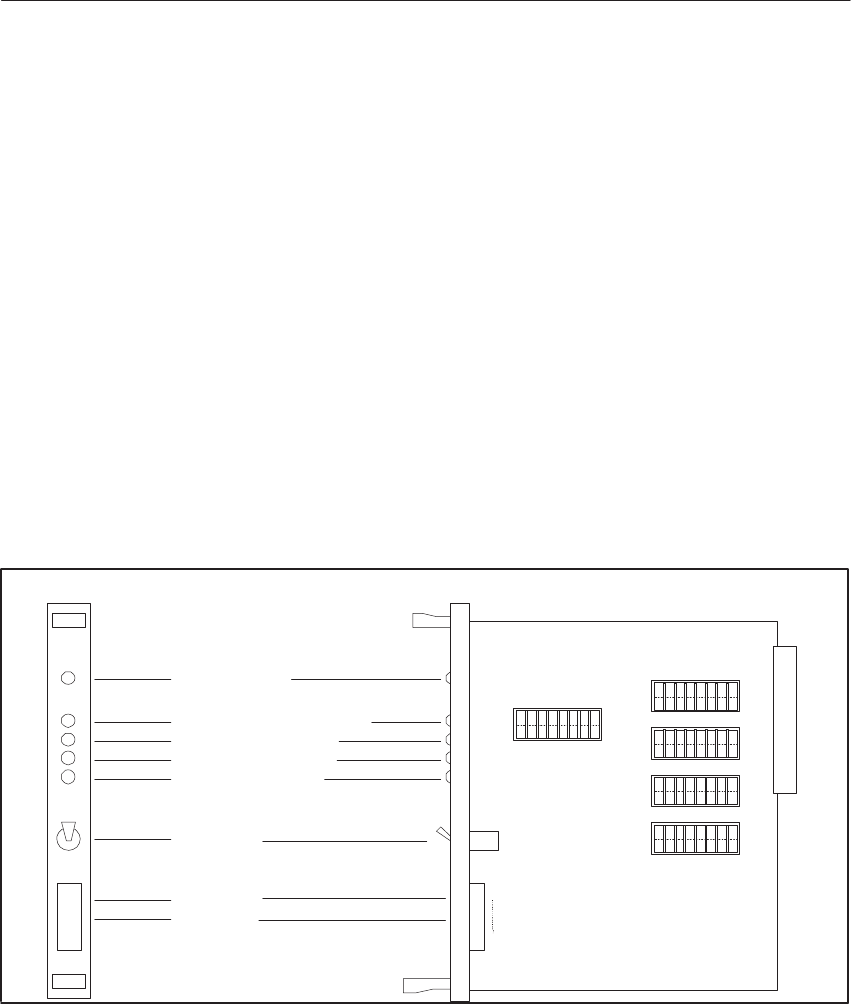
10-2 System Manual
C79000-G8576-C199-06
10.1 Application
The monitoring module can be used in the expansion units of the
programmable controllers S5-115U, S5-135U and S5-155U.
The module monitors the data bus, the address bus and the control signals
MEMW/, MEMR/ and RDY/. Faults are displayed via four red LEDs on the
front panel. A group signal is output at the same time via a floating contact.
Following a fault, the module can be reset by means of the RESET key on
the front panel or the RESET input (see Section 10.2.3).
10.1.1 Design
The monitoring module is designed as a plug-in PCB in double Euroformat
with a 32-pin backplane connector for the S5 bus.
A connector for the relay contact and RESET input as well as one green
LED, four red LEDs and a RESET key are located on the front panel.
Operation (green LED)
Command output inhibit (red LED)
Control signal fault (red LED)
Address bus fault (red LED)
Data bus fault (red LED)
RESET input
Relay contact
RESET key
RUN
BASP
R/W
ADB
DB
12345678
S1
S2
S3
S4
S5
12345678
12345678
12345678
12345678
X4
1
6
Bus
PESP
QVZ
125ms
250ms
500ms
1s
1
2
4
8
16
32
64
128
ON
OFF ON
OFF
ON
OFF
ON
OFF
ON
OFF
Figure 10-1 Location of the Coding Switches
Monitorin
g
Module
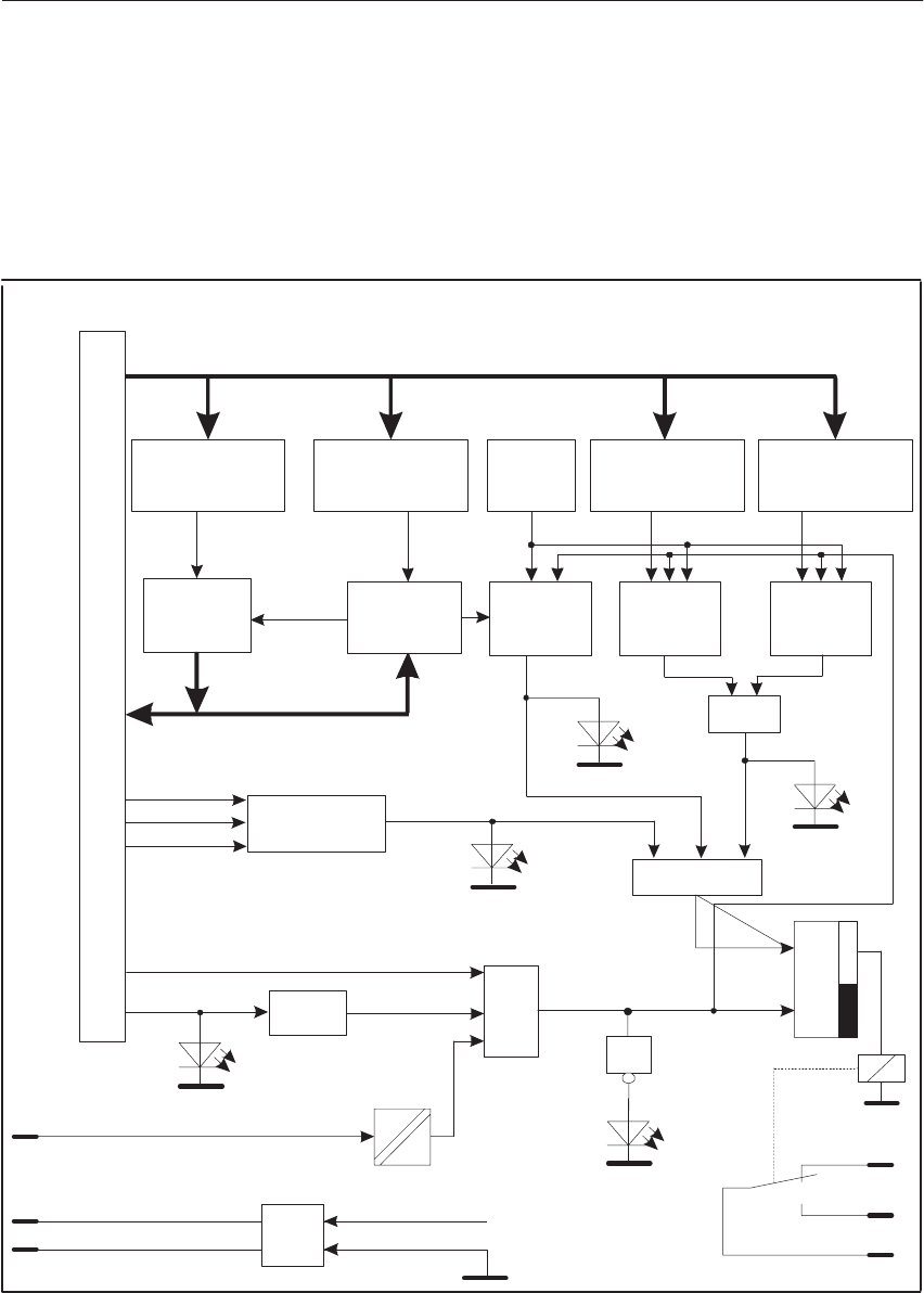
10-3
System Manual
C79000-G8576-C199-06
10.1.2 Mode of Operation
10.1.3 Block Diagram
Address comparison
Control signal
monitoring
MEMR
MEMW
RDY
Edge
BASP
R/W
DB
ADB
CPKL S
R
RUN
Presel-
ection
of time
Address
comparison
Read and
compare
data
Bit
inversion
Daten
ausgeben
S5 Bus
Address bus
Data bus
Address
comparison S1 S2 S3 S4
X4/5
X4/6
X4/4 RESET input
L+ (24V)
L–
internal +5V
internal 0V
X4/3
X4/2
X4/1
Relay contact
w1
Time
moni-
toring
Time
moni-
toring
Time
moni-
toring
Address
comparison
Address
comparison
w1
w1
Figure 10-2 Block Diagram
Monitorin
g
Module

10-4 System Manual
C79000-G8576-C199-06
10.1.4 Fault Detection
From an address which has been set at switch S1, the data (55H or AAH) is
read by the CPU from the monitoring module. This data is to be written back
by the CPU to the address set at switch S2. The module inverts the accurate
incoming data bit by bit (from 55H to AAH or vice versa) which is read
again in the next cycle from the address set at S1.
If the data which has been set on the monitoring module is not returned
within the set monitoring time, the module signals a data bus fault.
Detectable faults
Interruptions of the data lines, short circuits to ground and + 5V, short
circuits between adjacent data lines, e.g. DB0-DB1, DB1-DB2 etc.
Non-detectable faults
Short circuits between even data lines DB0-DB2-DB4-DB6 and between odd
data lines DB1-DB3-DB5-DB7.
The addresses which have been set at switches S3 and S4 are only “listened
to” by the monitoring module, i.e. they do not output an acknowledgement
signal (RDY/) and are not active on the data bus. If one or both addresses are
not accessed again within the monitoring time, the monitoring module
signals an address bus fault.
Detectable / non-detectable faults
The same as for the data bus, if the inverse addresses 85 (55H) and 170
(AAH) have been set at the addressing switches S3 and S4 of all monitoring
modules.
Data Bus Faults
Address Bus
Faults
Monitorin
g
Module

10-5
System Manual
C79000-G8576-C199-06
A control line fault (R/W) occurs if
– the write signal (MEMW/) and the read signal (MEMR/) are active
simultaneously,
– the acknowledgement signal (RDY/) is active without a (MEMW/) or
(MEMR/) signal and
– the address line ’peripheral memory’ (PESP’) has not changed from
status “1” to “0.”
Evaluation of the control signal (PESP’) can be turned off with the S5/7
switch. If the module is used in a programmable controller into which only
I/O modules may be inserted (i.e. no memory modules or CPs), this switch
must always be turned off. In this configuration, only I/O accesses to the bus
are performed and the PESP‘ signal always has the status “1.” It should also
be turned off when using the IM 301, IM 302 1), IM 304 and IM 308
interface modules for expansion units since a permanent PESP‘ signal can be
applied to them.
If a command output inhibit (BASP) is active, the “BASP” LED is lit.
If one or more faults occur, the corresponding LEDs are lit, the relay contact
commutes and the module no longer acknowledges with the RDY/ signal.
This timeout can be suppressed by opening the S5/8 switch.
10.1.5 Resetting
There are several ways of resetting the module:
– CPKL/ signal = “1” (when the PLC is switched on);
– Trailing edge of the BASP signal (during startup of the PLC or
following return of the load voltage);
– Applying 24 V to the front connector X4 between connections 4
(RESET input) and 6 (L-);
– Linking connections 4 (RESET input) and 5 (L+) with connector X4.
1) In the S5-115U, the monitoring module cannot be used together with the IM 302 / 311 link.
Control Line
Faults
BASP
Messages
Monitorin
g
Module
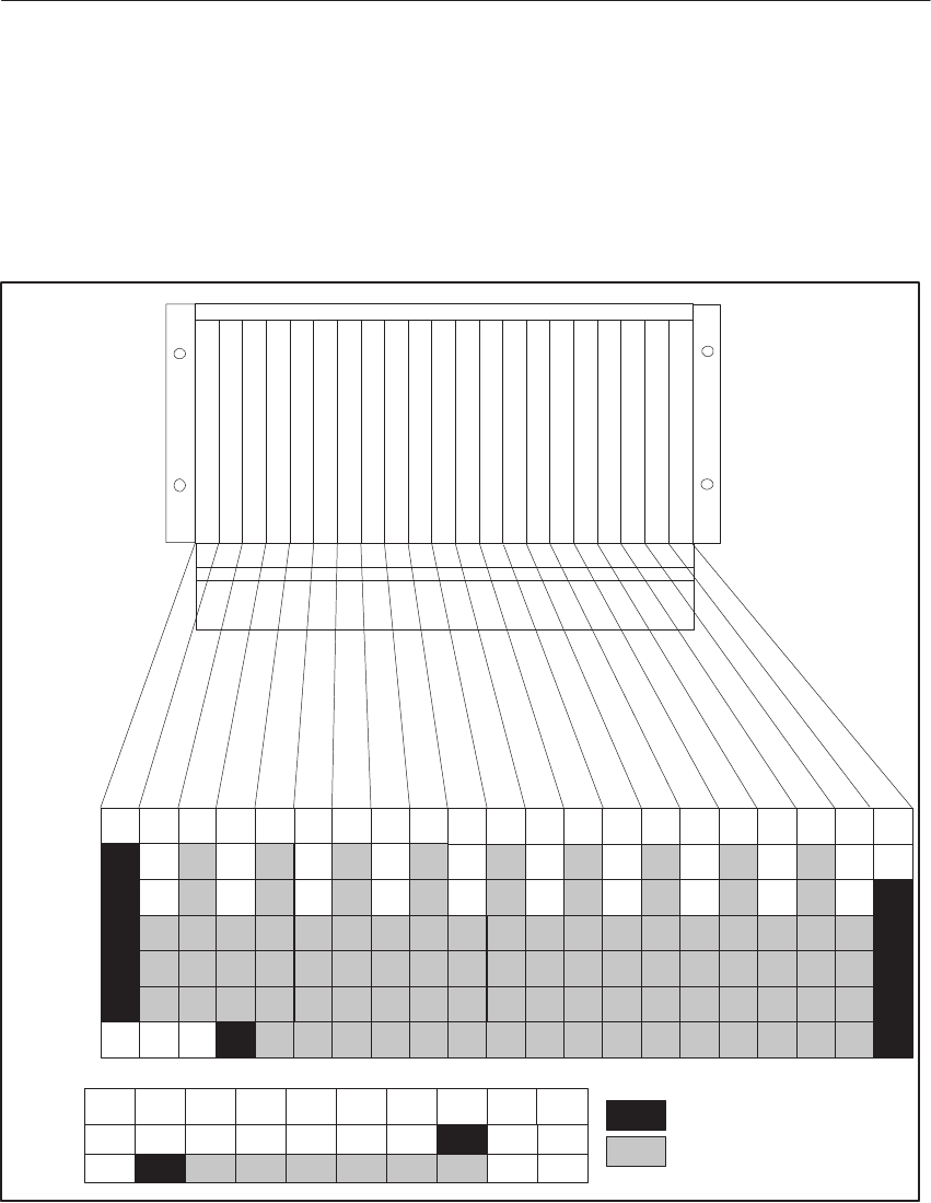
10-6 System Manual
C79000-G8576-C199-06
10.2 Installation
10.2.1 Possible Configurations
Recommended slots
Possible slots
ER 2
PS0 12345 67IM
ER 3
EU 187
EU 186
EU 185
EU 183
EU 184
EU 182
67311192735435159 75 83 91 107115 123 13914715516399 131
10.2.2 Removing and Inserting
The module is pulled out by holding the handles and gently lifting and
lowering while pulling towards you. The monitoring module may only be
removed or inserted if the expansion unit is switched off.
Monitorin
g
Module
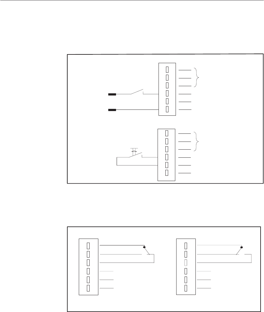
10-7
System Manual
C79000-G8576-C199-06
10.2.3 Connecting the RESET Input
4
5
6
3
2
1
Relay contact
RESET input
L+ (24V)
L–
L+
L–
4
5
6
3
2
1
Relay contact
RESET input
L+ (24V)
L–
RESET input (floating) with external 24-V supply
RESET input (floating) with internal 24-V suppy
10.2.4 Switch Positions of the Relay Contact
4
5
6
3
2
1
4
5
6
3
2
1
Contact not actuated (idle) or fault
Contact 1-3 closed Contact 1-2 closed
Contact actuated (operational)
10.2.5 Installation Guidelines
The module is to be wired according to the VDE regulations 0100, 0110 and
0160.
Detailed information on power supply, cabinet design, cabinet ventilation,
cabinet wiring and protective measures can be found in Chapter 3.
Monitorin
g
Module

10-8 System Manual
C79000-G8576-C199-06
10.3 Operation
The addresses set at these switches are acknowledged by the monitoring
module with RDY/ and are therefore not to be used again for inputs and
outputs in this programmable controller (double addressing is not allowed).
No acknowledgement signal (RDY/) is returned by the monitoring module to
the addresses set the switches S3 and S4. These addresses must be accessed
by the programmable controller as input or output addresses. This means that
they must be occupied by I/O modules or by one monitoring module at
switches S1 and S2. These modules must have been inserted into the last
expansion unit.
To achieve optimum address bus monitoring, inverse addresses should be
used [e.g. 85 (55H) 2) and 170 (AAH)]. It is advisable to make sure that the
setting of switches S3 and S4 is the same on all monitoring modules used.
The setting of switches S1and S2 as well S3 and S4 should be the same on
the monitoring module in the last expansion unit.
Switch Input address
can be accessed
using MEMR/
(READ)
Output address can be ac-
cessed using MEMW/
(WRITE)
Acknowl-
edged by
module with
RDY/
S1 * *
S2 * *
S3 * *
S4 * *
1) Select addresses 213 (D5H) and 170 (AAH) when using the module in the S5-115U.
For exceptions refer to page 10 - 13.
Switch S1 (Read)
and S2 (Write)
Switch S3 (Listen)
and S4 (Listen)
Monitorin
g
Module
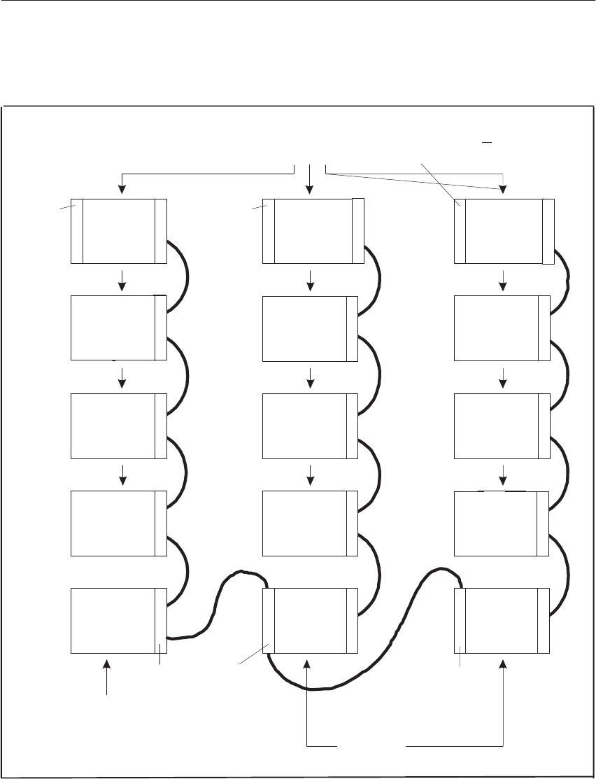
10-9
System Manual
C79000-G8576-C199-06
IM 300
CC 115U
CC 135U
CC 155U
IM 312 IM 312 IM 312
IM 312
IM 312
IM 312
IM 310
IM 314
IM 318
IM 310
IM 314
IM 318
IM 301
IM 304
IM 308
IM 300
MM 313
MM 313
MM 313
2nd MM
313
1st MM
313
EU183U
EU185U
EU183U
EU184U
EU187U
3rd monitoring module 313
in the last expansion unit
IM 312
IM 312
IM 312
IM 312
IM 312
IM 312
Expansion units
Central
controllers
Example:
Monitorin
g
Module

10-10 System Manual
C79000-G8576-C199-06
10.3.1 Addressing
S5-130K, S5-135U or S5-155U
1st MM 2nd MM 3rd MM in the
last EU
S1 e.g. 127 (7FH) 3) e.g. 126 (7EH) 3) 85 (55H) 4)
S2 e.g. 127 (7FH) 3) e.g. 126 (7EH) 3) 170 (AAH) 4)
S3 85 (55H) 5) 85 (55H) 5) 85 (55H) 5)
S4 170 (AAH) 5) 170 (AAH) 5) 170 (AAH) 5)
User program in OB 1 or FB 0
without S5-DOS with S5-DOS
L EB 127 L PY 127
T AB 127 T PY 127
L EB 126 L PY 126
T AB 126 T PY 126
L EB 85 L PY 85
T PB 170 T PY 170
BE BE
3) Possible addresses 0 (00H) to 255 (FFH)
4) To achieve optimum fault detection, set the inverse addresses 85 (55H) and 170 (AAH) at S1 and S2.
5) Since the addresses of the monitoring module switches S3 and S4 are not acknowledged, this must be done by the
monitoring module contained in the last expansion unit (the most remote from the central controller). The addresses
85 (55H) or 170 (AAH) of this monitoring module must be coded at switches S1 or S2, respectively.
These addresses may no longer be occupied for I/O tasks.
Example 1
Monitorin
g
Module

10-11
System Manual
C79000-G8576-C199-06
S5-115U
S1 e.g. 128 (80H) 6) e.g. 129 (81H) 6) 213 (D5H) 6)
S2 e.g. 128 (80H) 6) e.g. 129 (81H) 6) 170 (AAH) 6)
S3 213 (D5H) 7)
8) 213 (D5H) 7)8) 213 (D5H) 7)8)
S4 170 (AAH) 7) 170 (AAH) 7) 170 (AAH) 7)
User program in OB 1 or FB 0
without S5-DOS with S5-DOS
L PB 128 L PY 128
T PB 128 T PY 128
L PB 129 L PY 129
T PB 129 T PY 129
L PB 213 8) L PY 213 8)
T PB 170 T PY 170
BE BE
6) When using the monitoring module in the S5-115U, always select addresses > 127 since that is the only way to address
byte to byte.
7) To achieve maximum fault detection, select inverse addresses > 127, e.g. 213 (D5H) and 170 (AAH). In this combination,
the address bit ADB 7 is not monitored.
8) If ADB 7 is also to be monitored, the address 84/85 (54H/55H) in the last expansion unit must be occupied by an input or
output module and cyclically accessed by the user program. Set address 85 (55H) in place of 213 (D5H) at switch S3 of all
monitoring modules. Select any address between 128 (80H) and 255 (FFH) for switch S1 of the monitoring module in the
last expansion unit. As an alternative, you may access the address at S1 of the monitoring module in the last expansion unit via
direct access (without process image) using L PB 85 or L PY 85. Then, the addresses 84 and 85 (54H) and (55H) in the process
image may no longer be used by other inputs. The address at S3 of all monitoring modules is then also to be set to 85 (55H).
Example 2
Monitorin
g
Module
10-12 System Manual
C79000-G8576-C199-06
10.3.2 Setting the Address Switches S1, S2, S3, S4
The addresses are set as one-byte addresses as in the case of I/O modules.
ADB 7 Significance 128
ADB 0 Significance 1
ADB 5 Significance 32
ADB 6 Significance 64
ADB 4 Significance 16
ADB 1 Significance 2
ADB 2 Significance 4
ADB 3 Significance 8
12345678
ON
OFF
The significance of the rockers pressed down to ON at the switches must be
added.
Address 85 is to be set.
rockers to be pressed down to ON Significance
1 (ADB 0) 1
3 (ADB 2) 4
5 (ADB 4) 16
7 (ADB 6) 64
85
1234567
8
ON
OFF
Example
Monitorin
g
Module
10-13
System Manual
C79000-G8576-C199-06
10.3.3 Setting the Switch S5
ON: PESP‘ monitoring on
Monitoring time
RDY/ is suppressed in case of fault
RDY/ is also output in case of fault
ON:
OFF:
When BASP is active (“1” signal)
RDY/ is always output
125ms
500ms
250ms
1s
12345678
ON
OFF
Select the monitoring time (between 125 ms and 1 s) by switching one of the
switches S5/1 to S5/4 to ON. If none of the four switches S5/1 to S5/4 is in
the ON position, for safety reasons the monitoring time has been set to 1 s.
If serial interface modules and the link between IM 304 and IM 314 are used,
the PESP‘ monitoring is to be switched off (see Section 10.1.4: Control line
faults).
Should the acknowledgement signal (RDY/) not be suppressed in the event of
a fault, the switch S5/8 must be in the OFF position.
When a BASP signal is active, the RDY/ signal will always be output.
Monitorin
g
Module

10-14 System Manual
C79000-G8576-C199-06
10.4 Technical Specifications
Power supply
Supply voltage of the system bus
Power consumption + 5 V 5 %
450 mA max.
RESET input
Rated input voltage
Electrical isolation
Input voltage
for signal 0
for signal 1
Input current
Permissible cable length
24 V DC
Yes
–33 to + 5 V DC
or input open
+13 to + 33 V DC
8.5 mA
100 m max. unscreened
Sensor supply for RESET input
Rated output voltage
Electrical isolation
Output voltage
Output current
24 V DC
Yes
20 to 30 V DC
short-circuit proof to L–
20 mA max.
Relay contact
Loading of contact with resistive load
or inductive load
30 V DC/ 1 A max.
Safety test
Voltage test acc. to VDE 0160
Relay contacts referred to internal
RESET input referred to internal
RESET input referred to relay contacts
Surge voltage test acc. to IEC 255-4
Input referred to ground
500 r.m.s.
500 r.m.s.
500 r.m.s.
1kV; 1.2/50 ms
Interference test
Radio interference test acc. to IEC 255-4
Radio interference test acc. to IEC 65 (Co) 39 Input referred to ground: 1 kV; 1 MHz
Input referred to ground: 1 kV; burst
Mechanical data
Dimensions (w x h x d)
Weight 20 mm x 243 mm x 193 mm
270g
Monitorin
g
Module

10-15
System Manual
C79000-G8576-C199-06
Ambient conditions
Operating temperature
Storage and transportation temperature
Relative humidity
Operating altitude
Vibration acc. to IEC 68-2-6
Shock acc. to IEC 68-2-27
0 to + 60 oC
–25 to + 70 oC
max. 95 % at 25 oC; no condensation
max. 3500 m above sea level
10 to 57 Hz, 0.15 mm; 57 to 500 Hz, 2 g
12 shocks, half-sine; 15 g / 11 ms
Pin assignment of bus connector X1
b z
2
4
6
8
10
12
14
16
18
20
22
24
26
28
30
32
0 V
PESP’
ADB 0
ADB 1
ADB 2
ADB 3
ADB 4
ADB 5
ADB 6
ADB 7
–
–
–
–
BASP
0 V
5 V
–
CPKL/
MEMR/
MEMW/
RDY/
DB 0
DB 1
DB 2
DB 3
DB 4
DB 5
DB 6
DB 7
–
0 V
Monitorin
g
Module
10-16 System Manual
C79000-G8576-C199-06
10.5 Address Table
16
32
64
128
12
28
44
60
76
92
108
124
140
156
172
188
204
220
236
252
13
29
45
61
77
93
109
125
141
157
173
189
205
221
237
253
14
30
46
62
78
94
110
126
142
158
174
190
206
222
238
254
15
31
47
63
79
95
111
127
143
159
175
191
207
223
239
255
0
16
32
48
64
80
96
112
128
144
160
176
192
208
224
240
2
18
34
50
66
82
98
114
130
146
162
178
194
210
226
242
4
20
36
52
68
84
100
116
132
148
164
180
196
212
228
244
5
21
37
53
69
85
101
117
133
149
165
181
197
213
229
245
6
22
38
54
70
86
102
118
134
150
166
182
198
214
230
246
7
23
39
55
71
87
103
119
135
151
167
183
199
215
231
247
8
24
40
56
72
88
104
120
136
152
168
184
200
216
232
248
9
25
41
57
73
89
105
121
137
153
169
185
201
217
233
249
10
26
42
58
74
90
106
122
138
154
170
186
202
218
234
250
11
27
43
59
75
91
107
123
139
155
171
187
203
219
235
251
1
17
33
49
65
81
97
113
129
145
161
177
193
209
225
241
3
19
35
51
67
83
99
115
131
147
163
179
195
211
227
243
128
64
32
16
8
4
2
1
Switch position
ON
1
2
4
8
Significance Byte address
Monitorin
g
Module
11-1
System Manual
C79000-G8576-C199-06
Connector Assignments
In this chapter are the connector assignments of the
backplane for the central controllers and expansion units
power supplies
backplane connectors and front connectors of the CPUs, coordinators
and IMs.
11
11-2 System Manual
C79000-G8576-C199-06
Connector assignments of the backplane of the S5-135U/155U CC
Slot 3,
COR, I/O Slot 11, 27, 43, 59
CPU, CP, I/O, IP
Back-
l
Pin
N
Rin Row Pin
N
Rin Row
plane
conn. 1 No. z b d No. z b d
conn
.
1
2
4
6
8
10
12
14
16
18
20
22
24
26
28
30
32
P5 V
PL
RESET
MEMR
MEMW
RDY
DB 0
DB 1
DB 2
DB 3
DB 4
DB 5
DB 6
DB 7
PL
M5 V
PESP
ADB 0
ADB 1
ADB 2
ADB 3
ADB 4
ADB 5
ADB 6
ADB 7
ADB 8
ADB 9
ADB 10
ADB 11
BASP
M5 V
UBAT
ADB 12
ADB 13
ADB 14
ADB 15
PL
PL
PL
PL
PL
PL
PL
DSI
PL
BASPA
2
4
6
8
10
12
14
16
18
20
22
24
26
28
30
32
P5 V
PL
RESET
MEMR
MEMW
RDY
DB 0
DB 1
DB 2
DB 3
DB 4
DB 5
DB 6
DB 7
PL
PL
M5 V
PESP
ADB 0
ADB 1
ADB 2
ADB 3
ADB 4
ADB 5
ADB 6
ADB 7
ADB 8
ADB 9
ADB 10
ADB 11
BASP
M5 V
UBAT
ADB 12
ADB 13
ADB 14
ADB 15
IRx 1)
IRE
IRF
IRG
DSI
PL
BASPA
Back-
plane
conn. 2
2
4
6
8
10
12
14
16
18
20
22
24
26
28
30
32
P5 V
DB 12
DB 13
DB 14
DB 15
NAU
BAU
RESETA
PEU
GEP
PL
M24 V 2)
P24 V
M5 V
DB 8
DB 9
DB 10
DB 11
PL
PL
PL
PL
PL
PL
PL
PL
PL
M24 V 2)
M5 V
PL
PL
PL
PL
PL
PL
PL
PL
PL
PL
PL
PL
PL
PL
M24 V 2)
P15 V
2
4
6
8
10
12
14
16
18
20
22
24
26
28
30
32
P5 V
DB 12
DB 13
DB 14
DB 15
M5 V
NAU
BAU
PEU
GEP
PL
M24 V 2)
P24 V
M5 V
DB 8
DB 9
DB 10
DB 11
PL
PL
M5 V
PL
PL
M5 V
PL
PL
M24 V 2)
M5 V
M5 V
PL
PL
PL
M24 V 2)
P15 V
Abbreviations:
IM-V – IM slot with additional power supply output
IRQ – Interrupt source (module which generates the interrupt)
PL – Private line
1) See pin designations for the interrupt signals
2) M24 V also serves as the return line for P15 V.
Connector Assi
g
nments
11-3
System Manual
C79000-G8576-C199-06
Slot 19, 35, 51, 67, 75, 83, 91, 99
CP, IP, I/O, IRQ Slot 107, 115, 123, 131
CP, IP, I/O, IM307 (IRQ)
Back-
l
Pin-
N
Pin Row Pin-
N
Pin Row
plane
conn. 1 No. z b d No. z b d
conn
.
1
2
4
6
8
10
12
14
16
18
20
22
24
26
28
30
32
P5 V
PL
RESET
MEMR
MEMW
RDY
DB 0
DB 1
DB 2
DB 3
DB 4
DB 5
DB 6
DB 7
PL
M5 V
PESP
ADB 0
ADB 1
ADB 2
ADB 3
ADB 4
ADB 5
ADB 6
ADB 7
ADB 8
ADB 9
ADB 10
ADB 11
BASP
M5 V
UBAT
ADB 12
ADB 13
ADB 14
ADB 15
IRA
IRB
IRC
IRD
IRE
IRF
IRG
DSI
BASPA
2
4
6
8
10
12
14
16
18
20
22
24
26
28
30
32
P5 V
PL
RESET
MEMR
MEMW
RDY
DB 0
DB 1
DB 2
DB 3
DB 4
DB 5
DB 6
DB 7
PL
M5 V
PESP
ADB 0
ADB 1
ADB 2
ADB 3
ADB 4
ADB 5
ADB 6
ADB 7
ADB 8
ADB 9
ADB 10
ADB 11
BASP
M5 V
UBAT
ADB 12
ADB 13
ADB 14
ADB 15
IRA
IRB
IRC
IRD
IRE
IRF
IRG
DSI
BASPA
Back-
plane
conn. 2
2
4
6
8
10
12
14
16
18
20
22
24
26
28
30
32
P5 V
DB 12
DB 13
DB 14
DB 15
NAU
BAU
GEP
PL
M24 V 1)
P24 V
M5 V
DB 8
DB 9
DB 10
DB 11
PL
PL
PL
PL
PL *
PL
M24 V 1)
M5 V
PL *
PL
PL
M24 V 1)
P15 V
2
4
6
8
10
12
14
16
18
20
22
24
26
28
30
32
P5 V
DB 12
DB 13
DB 14
DB 15
NAU
BAU
RESETA
GEP
PL
M24 V 1)
P24 V
M5 V
DB 8
DB 9
DB 10
DB 11
PL
PL
PEU
PL
PL
PL
M24 V 1)
M5 V
PL
PL
M24 V 1)
P15 V
PL * = Only at slots 75, 83, 91 and 99
2) M24 V also serves as the return line for P15 V.
Connector Assi
g
nments
11-4 System Manual
C79000-G8576-C199-06
Slot 139, 147
I/O, IM, IP without page addressing Slot 155, 163
I/O, IM
Back-
plane
Pin-
No
Pin Row Pin-
No
Pin Row
p
l
ane
conn. 1
N
o. z b d
N
o. z b d
2
4
6
8
10
12
14
16
18
20
22
24
26
28
30
32
P5 V
PL
RESET
MEMR
MEMW
RDY
DB 0
DB 1
DB 2
DB 3
DB 4
DB 5
DB 6
DB 7
M5 V
PESP
ADB 0
ADB 1
ADB 2
ADB 3
ADB 4
ADB 5
ADB 6
ADB 7
ADB 8
ADB 9
ADB 10
ADB 11
BASP
M5 V
ADB 12
ADB 13
ADB 14
ADB 15
M5 V
M5 V
M5 V
M5 V
M5 V
M5 V
M5 V
BASPA
2
4
6
8
10
12
14
16
18
20
22
24
26
28
30
32
P5 V
PL
RESET
MEMR
MEMW
RDY
DB 0
DB 1
DB 2
DB 3
DB 4
DB 5
DB 6
DB 7
M5 V
PESP
ADB 0
ADB 1
ADB 2
ADB 3
ADB 4
ADB 5
ADB 6
ADB 7
ADB 8
ADB 9
ADB 10
ADB 11
BASP
M5 V
P5 V
ADB 12
ADB 13
ADB 14
ADB 15
P5 V
P5 V
M5 V
M5 V
M5 V
M5 V
M5 V
M5 V
M5 V
BASPA
Back-
plane
conn. 2
2
4
6
8
10
12
14
16
18
20
22
24
26
28
30
32
P5 V
DB 12
DB 13
DB 14
DB 15
RESETA
M5 V
M5 V
M5 V
M5 V
M5 V
M5 V
M5 V
DB 8
DB 9
DB 10
DB 11
PEU
M5 V
M5 V
M5 V
M5 V
M5 V
M5 V
2
4
6
8
10
12
14
16
18
20
22
24
26
28
30
32
P5 V
DB 12
DB 13
DB 14
DB 15
P5 V
P5 V
P5 V
RESETA
M5 V
M5 V
M5 V
M5 V
M5 V
M5 V
M5 V
DB 8
DB 9
DB 10
DB 11
P5 V
P5 V
P5 V
PEU
M5 V
M5 V
M5 V
M5 V
M5 V
M5 V
Pin designation of the interrupt signals on the backplane
Interrupt Sink Interrupt Source
Module CPU 1 CPU 2 CPU 3 CPU 4 I/Os/CP/IP
Slot No. 11 27 43 59 19, 35, 51, 67-131
Signal
IRA
IRB
IRC
IRD
IRE (CPU 948 only)
IRF (CPU 948 only)
IRG (CPU 948 only)
1d 14
1d 22
1d 24
1d 26
1d 14
1d 22
1d 24
1d 26
1d 14
1d 22
1d 24
1d 26
1d 14
1d 22
1d 24
1d 26
1d 14
1d 16
1d 18
1d 20
1d 22
1d 24
1d 26
Connector Assi
g
nments
11-5
System Manual
C79000-G8576-C199-06
Connector assignments of the backplane for the EU 183U, 184U, 187 U
I/O Modules IM 312-5
EU Slot EU Slot
183U
184U
187U
11 to 155
3 to 155
3 to 147
184U
187U 163
Backplane
1
Pin
N
Pin Row Pin
N
Pin Row
p
conn. 1No. z b No. z b d
2
4
6
8
10
12
14
16
18
20
22
24
26
28
30
32
+ 5V
–
CPKL
MEMR
MEMW
RDY
DB0
DB1
DB2
DB3
DB4
DB5
DB6
DB7
–
–
0V
PESP
ADB0
ADB1
ADB2
ADB3
ADB4
ADB5
ADB6
ADB7
0V
0V
0V
0V
BASP
0V
2
4
6
8
10
12
14
16
18
20
22
24
26
28
30
32
+ 5V
–
CPKL
MEMR
MEMW
RDY
DB0
DB1
DB2
DB3
DB4
DB5
DB6
DB7
–
0V
0V
PESP
ADB0
ADB1
ADB2
ADB3
ADB4
ADB5
ADB6
ADB7
0V
0V
0V
0V
BASP
0V
Shield
+5V
+5V
+5V
+5V
+5V
+5V
+5V
0V
0V
0V
0V
0V
0V
0V
0V
IM 300-3 and -5 / 312-3 IM 310, IM 314, IM 317, IM 318
EU Slot EU Slot
183U 163 183U 3
Backplane
1
Pin-
N
Pin Row Pin-
N
Pin Row
p
conn. 1No. z b d No. z b d
2
4
6
8
10
12
14
16
18
20
22
24
26
28
30
32
+ 5V
–
CPKL
MEMR
MEMW
RDY
DB0
DB1
DB2
DB3
DB4
DB5
DB6
DB7
EANK
–
0V
PESP
ADB0
ADB1
ADB2
ADB3
ADB4
ADB5
ADB6
ADB7
0V
0V
0V
0V
BASP
0V
Shield
+5V
–
–
–
–
+5V
+5V
0V
0V
0V
0V
0V
0V
0V
BASPA
2
4
6
8
10
12
14
16
18
20
22
24
26
28
30
32
+ 5V
Takt
CPKL
MEMR
MEMW
RDY
DB0
DB1
DB2
DB3
DB4
DB5
DB6
DB7
–
–
0V
PESP
ADB0
ADB1
ADB2
ADB3
ADB4
ADB5
ADB6
ADB7
0V
0V
0V
0V
BASP
0V
Shield
+5V
–
–
–
–
+5V
+5V
0V
0V
0V
0V
0V
0V
0V
BASPA
Backplane
conn. 22
4
6
8
10
12
14
16
18
20
22
24
26
28
30
32
+ 5V
–
–
–
–
+5V
+5V
+5V
CPKLA
–
0V
0V
0V
0V
0V
0V
0V
–
–
–
–
+5V
+5V
+5V
NAU
–
0V
0V
0V
0V
0V
0V
–
0V
–
–
–
+5V
+5V
+5V
–
–
–
–
–
–
–
–
2
4
6
8
10
12
14
16
18
20
22
24
26
28
30
32
+ 5V
–
–
–
–
+5V
+5V
+5V
CPKLA
–
0V
0V
0V
0V
0V
0V
0V
–
–
–
–
+5V
+5V
+5V
NAU
–
0V
0V
0V
0V
0V
0V
–
0V
–
–
–
+5V
+5V
+5V
–
–
–
–
–
–
–
–
Connector Assi
g
nments
11-6 System Manual
C79000-G8576-C199-06
Connector assignments of the backplane for the EU 185U
IM 310 and IM 314
I/O Module
Slot 3
923C Coordinator
I/O Module
Slot 11
Pin- Pin Row Pin- Pin Row
No. z b d No. z b d
Backplane
conn. 12
4
6
8
10
12
14
16
18
20
22
24
26
28
30
32
+ 5 V
RESET
MEMR
MEMW
RDY
DB0
DB1
DB2
DB3
DB4
DB5
DB6
DB7
DSI
0 V
PESP
ADB0
ADB1
ADB2
ADB3
ADB4
ADB5
ADB6
ADB7
ADB8
ADB9
ADB10
ADB11
BASP
0 V
ADB12
ADB13
ADB14
ADB15
0 V
0 V
0 V
0 V
0 V
0 V
0 V
BASPA
2
4
6
8
10
12
14
16
18
20
22
24
26
28
30
32
+ 5 V
RESET
MEMR
MEMW
RDY
DB0
DB1
DB2
DB3
DB4
DB5
DB6
DB7
0 V
PESP
ADB0
ADB1
ADB2
ADB3
ADB4
ADB5
ADB6
ADB7
ADB8
ADB9
ADB10
ADB11
BASP
0 V
UBAT
ADB12
ADB13
ADB14
ADB15
DSI
BASPA
Backplane
conn. 22
4
6
8
10
12
14
16
18
20
22
24
26
28
30
32
+ 5 V
DB12
DB13
DB14
DB15
RESETA
0 V
0 V
0 V
0 V
0 V
0 V
0 V
DB8
DB9
DB10
DB11
+ 5V
+ 5V
+ 5V
NAU
0 V
0 V
0 V
0 V
0 V
0 V
0 V
RESET
2
4
6
8
10
12
14
16
18
20
22
24
26
28
30
32
+ 5 V
DB12
DB13
DB14
DB15
NAU
BAU
RESETA
PEU
GEP
M2
+ 24V
0 V
DB8
DB9
DB10
DB11
RxDS6
TxDS6
RxDS4
TxDS4
RxDS2
TxDS2
M2
0 V
RxDS8
TxDS8
RxDS7
TxDS7
RxDS5
TxDS5
RxDS3
TxDS3
RxDS1
TxDS1
SPRxD
M2
+ 15 V
Connector Assi
g
nments
11-7
System Manual
C79000-G8576-C199-06
Communication Processor
Intelligent I/Os
I/O Module
Slots 19 to 75
Communication Processor
Intelligent I/Os
I/O Module
Slots 83 to 139
Pin- Pin Row Pin- Pin Row
No. z b d No. z b d
Backplane
conn. 1 2
4
6
8
10
12
14
16
18
20
22
24
26
28
30
32
+ 5 V
RESET
MEMR
MEMW
RDY
DB0
DB1
DB2
DB3
DB4
DB5
DB6
DB7
0 V
PESP
ADB0
ADB1
ADB2
ADB3
ADB4
ADB5
ADB6
ADB7
ADB8
ADB9
ADB10
ADB11
BASP
0 V
UBAT
ADB12
ADB13
ADB14
ADB15
DSI
BASPA
2
4
6
8
10
12
14
16
18
20
22
24
26
28
30
32
+ 5 V
RESET
MEMR
MEMW
RDY
DB0
DB1
DB2
DB3
DB4
DB5
DB6
DB7
0 V
PESP
ADB0
ADB1
ADB2
ADB3
ADB4
ADB5
ADB6
ADB7
ADB8
ADB9
ADB10
ADB11
BASP
0 V
UBAT
ADB12
ADB13
ADB14
ADB15
DSI
BASPA
Backplane
conn. 22
4
6
8
10
12
14
16
18
20
22
24
26
28
30
32
+ 5 V
DB12
DB13
DB14
DB15
NAU
BAU
PEU
GEP
M2
+ 24 V
0 V
DB8
DB9
DB10
DB11
RxDSn
M2
0 V
TxDSn
SPRxD
M2
+15 V
2
4
6
8
10
12
14
16
18
20
22
24
26
28
30
32
+ 5 V
DB12
DB13
DB14
DB15
NAU
BAU
PEU
GEP
M2
+ 24 V
0 V
DB8
DB9
DB10
DB11
M2
0 V M2
+ 15 V
Connector Assi
g
nments
11-8 System Manual
C79000-G8576-C199-06
IM 314 R
I/O Module
Slot 147, 155
IM 300
I/O Module
Slot 163
Pin- Pin Row Pin- Pin Row
No. z b d No. z b d
Backplane
conn. 12
4
6
8
10
12
14
16
18
20
22
24
26
28
30
32
+ 5 V
RESET
MEMR
MEMW
RDY
DB0
DB1
DB2
DB3
DB4
DB5
DB6
DB7
0 V
0 V
PESP
ADB0
ADB1
ADB2
ADB3
ADB4
ADB5
ADB6
ADB7
ADB8
ADB9
ADB10
ADB11
BASP
0 V
Shield
ADB12
ADB13
ADB14
ADB15
0 V
BASPA
2
4
6
8
10
12
14
16
18
20
22
24
26
28
30
32
+ 5 V
RESET
MEMR
MEMW
RDY
DB0
DB1
DB2
DB3
DB4
DB5
DB6
DB7
0 V
PESP
ADB0
ADB1
ADB2
ADB3
ADB4
ADB5
ADB6
ADB7
ADB8
ADB9
ADB10
ADB11
BASP
0 V
+ 5 V
ADB12
ADB13
ADB14
ADB15
+ 5 V
+ 5 V
0 V
0 V
0 V
0 V
0 V
0 V
0 V
BASPA
Backplane
conn. 22
4
6
8
10
12
14
16
18
20
22
24
26
28
30
32
+ 5 V
NA0
NA1
NA2
NA3
RESETA
0 V
0 V
0 V
0 V
0 V
0 V
0 V
SA0
SA1
SA2
SA3
NAU
0 V
0 V
0 V
0 V
0 V
0 V
0 V
RESET
2
4
6
8
10
12
14
16
18
20
22
24
26
28
30
32
+ 5 V
+ 5 V
+ 5 V
+ 5 V
RESETA
0 V
0 V
0 V
0 V
0 V
0 V
0 V
+ 5 V
+ 5 V
+ 5 V
NAU
0 V
0 V
0 V
0 V
0 V
0 V
Connector Assi
g
nments

11-9
System Manual
C79000-G8576-C199-06
Connector assignments of the power supply units
The terminals for the supply lines between the power supply unit and the
backplane are in an 8-way connector (Connector X1) at the rear of the unit.
The following figures show the connector assignments.
5V/18A power supply units
Pins 4 to 6 are not fitted.
12345678
M2 (0V) 5V/18A
5V/40A power supply units
12345678
M2 (0V) 5V/40A
The signal terminals of the power supply unit are in a 37-way connector
(Connector X2) at the rear of the unit.
The following figure shows the connector assignments. Pins 8 and 9 are
reserved.
M2 (0V)
12345678
91011121314 15 16 17 18 19
RESETA DSI GEP
NAU
24V
BASPA
U-BATT
RESET
20 21 22 23 24 25 26 27 28 29 30 31 32 33 34 35 36 37
+15V
BAU
reserved
Connector X1
Connector X2
Connector Assi
g
nments

11-10 System Manual
C79000-G8576-C199-06
Connector assignments of the 6ES5 955-3NA12 power supply unit
The terminals of the supply lines between the power supply unit and the
backplane are in an 8-way connector (subminiature, fitted with 8 high-current
contacts, Series D to MIL-C24308).
12345678
M2 (0V) 5V/10A
The signal terminals of the power supply unit are in a 37-way connector
(plug connector, 37-way, Series D to MIL-C24308).
BASP M2 (0V)
12345678910111213
14 15 16 17 18 19
DSI GEP
+15 V 24V/0.8A
BASP A U BATT
CPKL BAU
20 21 22 23 24 25 26 27 28 29 30 31 32 33 34 35 36 37
–15V
RLSA
RESET
RESET A
DS NAU HOLD
unas-
signed
RESIN
IR
Connector X1
Connector X2
Connector Assi
g
nments
11-11
System Manual
C79000-G8576-C199-06
Assignments of the backplane connector CPU 948
Pin
N
Pin Row
No. z b d
Backplane
conn. 12
4
6
8
10
12
14
16
18
20
22
24
26
28
30
32
+ 5 V
RESET
MEMR
MEMW
RDY
DB0
DB1
DB2
DB3
DB4
DB5
DB6
DB7
HALT
M 5 V
PESP
ADB 0
ADB 1
ADB 2
ADB 3
ADB 4
ADB 5
ADB 6
ADB 7
ADB 8
ADB 9
ADB 10
ADB 11
BASP
M 5 V
UBAT
ADB 12
ADB 13
ADB14
ADB 15
IR
IRE
IRF
IRG
DSI
BUSEN
BASPA
Backplane
conn. 22
4
6
8
10
12
14
16
18
20
22
24
26
28
30
32
+ 5 V
DB 12
DB 13
DB 14
DB 15
M 5 V
NAU
BAU
+5V
PEU
GEP
M 24 V
+ 24 V
M 5 V
DB8
DB9
DB 10
DB 11
PGBUSX
PGBUSY
M 5 V
STEU
STOPPA
M 5 V
R x D
PERO
M 24 V
M 5 V
M 5 V
T x D
TEST
M 24V
Connector Assi
g
nments

11-12 System Manual
C79000-G8576-C199-06
Assignments of the backplane connector CPU 928B
Pin
N
Pin Row
No. z b d
Backplane
conn. 1 2
4
6
8
10
12
14
16
18
20
22
24
26
28
30
32
+ 5 V
CPKL
MEMR
MEMW
RDY
DB0
DB1
DB2
DB3
DB4
DB5
DB6
DB7
HALT
M 5 V
PESP
ADB 0
ADB 1
ADB 2
ADB 3
ADB 4
ADB 5
ADB 6
ADB 7
ADB 8
ADB 9
ADB 10
ADB 11
BASP
M 5 V
UBAT
ADB 12
ADB 13
ADB14
ADB 15
IR
DSI
BUSEN
BASPA
Backplane
conn. 2 2
4
6
8
10
12
14
16
18
20
22
24
26
28
30
32
+ 5 V
DB 12
DB 13
DB 14
DB 15
M 5 V
NAU
BAU
+5V
PEU
GEP
M 24 V
+ 24 V
M 5 V
DB8
DB9
DB 10
DB 11
M 5 V
STEU
STOPPA
M 5 V
R x D
PERO
M 24 V
M 5 V
M 5 V
T x D
TEST
Connector Assi
g
nments
11-13
System Manual
C79000-G8576-C199-06
Assignments of the backplane connectorCPU 928
Pin
N
Pin Row
No. z b d
Backplane
conn. 1 2
4
6
8
10
12
14
16
18
20
22
24
26
28
30
32
+ 5 V
CPKL
MEMR
MEMW
RDY
DB0
DB1
DB2
DB3
DB4
DB5
DB6
DB7
HALT
M 5 V
PESP
ADB 0
ADB 1
ADB 2
ADB 3
ADB 4
ADB 5
ADB 6
ADB 7
ADB 8
ADB 9
ADB 10
ADB 11
BASP
M 5 V
UBAT
ADB 12
ADB 13
ADB14
ADB 15
IR
DSI
BUSEN
BASPA
Backplane
conn. 2 2
4
6
8
10
12
14
16
18
20
22
24
26
28
30
32
+ 5 V
DB 12
DB 13
DB 14
DB 15
M 5 V
NAU
BAU
+5V
PEU
GEP
M 24 V
+ 24 V
M 5 V
DB8
DB9
DB 10
DB 11
M 5 V
STEU
STOPPA
M 5 V
R x D
PERO
M 24 V
M 5 V
M 5 V
T x D
TEST
Connector Assi
g
nments
11-14 System Manual
C79000-G8576-C199-06
Assignments of the backplane connector CPU 922
Pin
N
Pin Row
No. z b d
Backplane
conn. 1 2
4
6
8
10
12
14
16
18
20
22
24
26
28
30
32
+ 5 V
CPKL
MEMR
MEMW
RDY
DB0
DB1
DB2
DB3
DB4
DB5
DB6
DB7
QUITT
HALT
M 5 V
PESP
ADB 0
ADB 1
ADB 2
ADB 3
ADB 4
ADB 5
ADB 6
ADB 7
ADB 8
ADB 9
ADB 10
ADB 11
BASP
M 5 V
UBAT
ADB 12
ADB 13
ADB14
ADB 15
IR
DSI
BUSEN
BASPA
Backplane
conn. 2 2
4
6
8
10
12
14
16
18
20
22
24
26
28
30
32
+ 5 V
M 5 V
NAU
BAU
PEU
GEP
M 24 V
+ 24 V
M 5 V
M 5 V
STEU
STOPPA
M 5 V
R x D
PERO
M 24 V
M 5 V
M 5 V
T x D
TEST
Connector Assi
g
nments

11-15
System Manual
C79000-G8576-C199-06
Assignments of the CPU front connector (PG interface)
Pin No. Designation
1
2
3
4
5
6
7
8
9
10
11
12
13
14
15
Housing/0 V/0Vext
R x D
VPG + 5 V DC
+ 24 V from bus
0 V/0 Vint
TxD
TxD
Housing/0 V/0Vext
R x D
24 V ground
20 mA/transmitter
0 V/0 Vint
20 mA/receiver
VPG + 5 V DC
0 V/0 Vint
Connector Assi
g
nments
11-16 System Manual
C79000-G8576-C199-06
Assignments of the backplane connector: 923A coordinator
Pin
N
Pin Row
No. z b d
Backplane
conn. 1 2
4
6
8
10
12
14
16
18
20
22
24
26
28
30
32
+ 5 V
RESET
MEMR
MEMW
RDY
DB 0
DB 1
DB 2
DB 3
DB 4
DB 5
DB 6
DB 7
HALT
M 5 V
ADB 0
ADB 1
ADB 2
ADB 3
ADB 4
ADB 5
ADB 6
ADB 7
ADB 8
ADB 9
ADB 10
ADB 11
M 5 V
UBAT
BUSEN 1
BUSEN 2
BUSEN 3
BUSEN 4
DSI
Backplane
conn. 2 2
4
6
8
10
12
14
16
18
20
22
24
26
28
30
32
+ 5 V
NAU
M 5 V
STEU
STOPPA
PERO
M 5 V
TEST
Connector Assi
g
nments

11-17
System Manual
C79000-G8576-C199-06
Assignments of the backplane connector: 923C coordinator
Pin
N
Pin Row
No. z b d
Backplane
conn. 1 2
4
6
8
10
12
14
16
18
20
22
24
26
28
30
32
+ 5 V
RESET
MEMR
MEMW
RDY
DB 0
DB 1
DB 2
DB 3
DB 4
DB 5
DB 6
DB 7
HALT
M 5 V
ADB 0
ADB 1
ADB 2
ADB 3
ADB 4
ADB 5
ADB 6
ADB 7
ADB 8
ADB 9
ADB 10
ADB 11
M 5 V
UBAT
ADB 12
ADB 13
ADB 14
ADB 15
BUSEN 1
BUSEN 2
BUSEN 3
BUSEN 4
DSI
Backplane
conn. 2 2
4
6
8
10
12
14
16
18
20
22
24
26
28
30
32
+ 5 V
NAU
M 24 V
M 5 V
M 5 V
RxD 6
TxD 6
RxD 4
TxD 4
STEU
STOPPA
PERO
M 5 V
RxD 8
TxD 8
RxD 7
TxD 7
RxD 5
TxD 5
RxD 3
TxD 3
RxD 1
TxD 1
TEST
Connector Assi
g
nments

11-18 System Manual
C79000-G8576-C199-06
Assignments of the front connector for the coordinators
Pin No. Designation
1
2
3
4
5
6
7
8
9
10
11
12
13
14
15
Housing/0 V/0Vext
Receiver TTY(-)
Private line
+24 V
Private line
Transmitter TTY (+)
Transmitter TTY (-)
Housing/0 V/0Vext
Receiver TTY (+)
24 V ground (20 mA (-) current sources)
20 mA (+) current source
Private line
20 mA (+) current source
Private line
Private line
Connector Assi
g
nments
11-19
System Manual
C79000-G8576-C199-06
Assignments of the backplane connectors of the IMs
IM 300-3
IM 300-5
IM 300-5L
IM 301-3
Pin
Pin Row
zb d
Pin Row
zb d
Pin Row
zb d
Pin Row
zb d
B
a
c
k-
p
l
a
n
e
c
o
n
n
1
2
4
6
8
10
12
14
16
18
20
22
24
26
28
30
32
+5V 0V Shield
– PESP –
CPKL ADB0 –
MEMR ADB1 –
MEMWADB2 –
RDY ADB3 –
DB0 ADB4 –
DB1 ADB5 –
DB2 ADB6 0V
DB3 ADB7 0V
DB4 0V 0V
DB5 0V 0V
DB6 0V 0V
DB7 0V 0V
– BASP 0V
–0V–
+5V 0V Shield
– PESP +5V
CPKL ADB0 –
MEMR ADB1 –
MEMWADB2 –
RDY ADB3 –
DB0 ADB4 +5V
DB1 ADB5 +5V
DB2 ADB6 0V
DB3 ADB7 0V
DB4 ADB 8 0V
DB5 ADB 9 0V
DB6 ADB 10 0V
DB7 ADB 11 0V
– BASP 0V
0V 0V –
+5V M –
– PESP –
RESET ADB1 –
MRD ADB2 –
MWR ADB3 –
RDY ADB4 –
DB0 ADB5 –
DB1 ADB6 –
DB2 ADB7 –
DB3 ADB8 –
DB4 ADB9 –
DB5 ADB10 –
DB6 ADB11 –
DB7 BASP –
–M–
–– –
+5V 0V Shield
– PESP –
CPKL ADB0 –
MEMR ADB1 –
MEMWADB2 –
RDY ADB3 –
DB0 ADB4 –
DB1 ADB5 –
DB2 ADB6 0V
DB3 ADB7 0V
DB4 ADB 8 0V
DB5 ADB 9 0V
DB6 ADB 10 0V
DB7 ADB 11 0V
– BASP 0V
–0V–
B
a
c
k-
p
l
a
n
e
c
o
n
n
2
2
4
6
8
10
12
14
16
18
20
22
24
26
28
30
32
+5V – –
–– –
–– –
–– –
–– –
–– –
–– –
–– –
– NAU –
–– –
0V 0V –
0V 0V –
0V 0V –
0V 0V –
0V 0V –
0V 0V –
+5V – –
–– –
–– –
–– –
–– –
+5V +5V –
+5V +5V –
+5V +5V –
–– –
–– –
0V 0V –
0V 0V –
0V 0V –
0V 0V –
0V 0V –
0V 0V –
+5V M –
–– –
–– –
–– –
–– –
–– –
–– –
–– –
– PEU –
–– –
–– –
–– –
–– –
–– –
–– –
–M–
+5V – –
–– –
–– –
–– –
–– –
+5V +5V –
+5V +5V –
+5V +5V –
– NAU –
–– –
0V 0V –
0V 0V –
0V 0V –
0V 0V –
0V 0V –
0V 0V –
Connector Assi
g
nments
11-20 System Manual
C79000-G8576-C199-06
IM 301-5 IM 304
Pin Row Pin Row
Pin z bd z b d
B
a
c
k-
p
l
a
n
e
c
o
n
n
1
2
4
6
8
10
12
14
16
18
20
22
24
26
28
30
32
+5V 0V Shield
– PESP +5V
CPKL ADB0 –
MEMR ADB1 –
MEMW ADB2 –
RDY ADB3 –
DB0 ADB4 +5V
DB1 ADB5 +5V
DB2 ADB6 0V
DB3 ADB7 0V
DB4 ADB 8 0V
DB5 ADB 9 0V
DB6 ADB 10 0V
DB7 ADB 11 0V
– BASP 0V
0V 0V –
+5V M –
–––
CPKL ADB0 ADB 12
MEMR ADB1 ADB 13
MEMW ADB2 ADB14
RDY ADB3 ADB15
DB0 ADB4 –
DB1 ADB5 –
DB2 ADB6 –
DB3 ADB7 –
DB4 ADB8 –
DB5 ADB9 –
DB6 ADB10 –
DB7 ADB11 –
– BASP –
–M–
B
a
c
k-
p
l
a
n
e
c
o
n
n
2
2
4
6
8
10
12
14
16
18
20
22
24
26
28
30
32
+5V – –
–––
–––
–––
–––
+5V +5V –
+5V +5V –
+5V +5V –
– NAU –
–––
0V 0V –
0V 0V –
0V 0V –
0V 0V –
0V 0V –
0V 0V –
+5V M –
DB12 DB8 –
DB13 DB9 –
DB14 DB10 –
DB15 DB11 –
– – –
PEU * ––
– – –
– PEU *–
–––
–––
–––
–––
–––
–––
–M–
Connector Assi
g
nments
11-21
System Manual
C79000-G8576-C199-06
IM 310-3
IM 312-3
IM 312-5
IM 314
Pin
Pin Row
zbd
Pin Row
zbd
Pin Row
zbd
Pin Row
zbd
B
a
c
k-
p
l
a
n
e
c
o
n
n
1
2
4
6
8
10
12
14
16
18
20
22
24
26
28
30
32
+5V 0V Shield+
– PESP +5V
CPKL ADB0 –
MEMRA DB1 –
MEMW ADB2 –
RDY ADB3 –
DB0 ADB4 +5V
DB1 ADB5 +5V
DB2 ADB6 0V
DB3 ADB7 0V
DB4 – 0V
DB5 – 0V
DB6 – 0V
DB7 – 0V
– BASP 0V
–0V–
+5V 0V –
– PESP +5V
CPKL ADB0 +5V
MEMR ADB1 +5V
MEMW ADB2 +5V
RDY ADB3 +5V
DB0 ADB4 +5V
DB1 ADB5 +5V
DB2 ADB6 0V
DB3 ADB7 0V
DB4 – 0V
DB5 – 0V
DB6 – 0V
DB7 – 0V
NAU BASP 0V
– 0V BASPA
+5V 0V –+
– PESP +5V
CPKL ADB0 +5V
MEMR ADB1 +5V
MEMW ADB2 +5V
RDY ADB3 +5V
DB0 ADB4 +5V
DB1 ADB5 +5V
DB2 ADB6 0V
DB3 ADB7 0V
DB4 – 0V
DB5 – 0V
DB6 – 0V
DB7 – 0V
– BASP 0V
–0V–
+5V M –
– PESP +5V
CPKLa ADB0 ADB12
MEMR ADB1 ADB13
MEMW ADB2 ADB14
RDY ADB3 ADB15
DB0 ADB4 –
DB1 ADB5 –
DB2 ADB6 –
DB3 ADB7 –
DB4 ADB8 –
DB5 ADB9 –
DB6 ADB10–
DB7 ADB11–
DSI BASP –
–M–
B
a
c
k-
p
l
a
n
e
c
o
n
n
2
2
4
6
8
10
12
14
16
18
20
22
24
26
28
30
32
+5V 0V –
––US
–––
–––
–––
– – +5V
– – +5V
– – +5V
CPKLA NAU –
–––
0V 0V –
0V 0V –
0V 0V –
0V 0V –
0V 0V –
0V 0V –
+5V M –
DB12 DB8 –
DB13 DB9 CPKLe
DB14 DB10 –
DB15 DB11 –
– +5V –
– +5V –
– +5V –
CPKLA NAU –
–––
MM–
MM–
MM–
MM–
MM–
MM–
Connector Assi
g
nments

11-22 System Manual
C79000-G8576-C199-06
Assignments of the front blade connectors
IM 300-3 IM 300-5C IM 300-5L IM 301 IM 304
Pin
No. Blade Con-
nector 3 Blade Con-
nector 3 Blade Con-
nector 4 Blade Con-
nector 3, 4 Blade Con-
nector 3 Blade Con-
nector 4 Blade Con-
nector 3 Blade Con-
nector 4
1
2
3
4
5
6
7
8
9
10
11
12
13
14
15
16
17
18
19
20
21
22
23
24
25
26
27
28
29
30
31
32
33
34
35
36
37
38
39
40
41
42
43
44
45
46
47
48
49
50
Shield
–
–
–
+PEU
– PEU
ADB1
ADB4
ADB7
DB1
DB4
0V
0V
0V
0V
0V
Shield
–
–
–
+ ZGU
– ZGU
ADB0
ADB3
ADB6
0V
DB3
DB6
0V
0V
0V
0V
0V
–
–
CPKL
MEMR
MEMW
PESP
ADB2
ADB5
DB0
DB2
DB5
DB7
RDY
BASP
–
0V
0V
0Vext
+ 5V
+ 5V
+ 5V
+ 5V
+ 5V
ADB 1
ADB 4
ADB 7
DB 1
DB 4
0V
0V
0V
0V
0V
0Vext
+ 5V
+ 5V
+ 5V
+ 5V
+ 5V
ADB 0
ADB 3
ADB 6
0V
DB 3
DB 6
0V
0V
0V
0V
0V
+5V
FAKT
CPKL
MEMR
MEMW
PESP
ADB 2
ADB 5
DB 0
DB 2
DB 5
DB 7
RDY
BASP
EANK
0V
0V
0Vext
+ 5V
+ 5V
+ 5V
+ 5V
+ 5V
ADB 1
ADB 4
ADB 7
DB 1
DB 4
0V
0V
0V
0V
0V
0Vext
+ 5V
+ 5V
+ 5V
+ 5V
+ 5V
ADB 0
ADB 3
ADB 6
0V
DB 3
DB 6
0V
0V
0V
0V
0V
+5V
FAKT
CPKL
MEMR
MEMW
PESP
ADB 2
ADB 5
DB 0
DB 2
DB 5
DB 7
RDY
BASP
EANK
0V
0V
Shield
+ 5 V
+ 5 V
+ 5 V
PEU1
PEU2
ADB1
ADB4
ADB7
DB1
DB4
M
M
M
M
M
Shield
+ 5 V
+ 5 V
+ 5 V
+ 5 V
+ 5 V
ADB0
ADB3
ADB6
M
DB3
DB6
M
M
M
M
M
+ 5 V
RESET
MRD
MWR
PESP
ADB2
ADB5
DB0
DB2
DB5
DB7
RDY
BASP
M
M
Shield
–
–
–
+PEU
– PEU
ADB1
ADB4
ADB7
DB1
DB4
0V
0V
0V
0V
0V
Shield
–
–
–
– ZGU
+ ZGU
ADB0
ADB3
ADB6
0V
DB3
DB6
0V
0V
0V
0V
0V
–
–
CPKL
MEMR
MEMW
PESP
ADB2
ADB5
DB0
DB2
DB5
DB7
RDY
BASP
–
0V
0V
Shield
+ ADB 4
– ADB 4
+ ADB 5
– ADB 5
+ ADB 6
– ADB 6
+ ADB 7
– ADB 7
+ DB 6
– DB 6
+ DB 7
– DB 7
+ PEU
– PEU
Rg 0
Shield
+ ADB 0
– ADB 0
+ ADB 1
– ADB 1
+ ADB 2
– ADB 2
+ ADB 3
– ADB 3
+ DB 3
– DB 3
+ DB 4
– DB 4
+ DB 5
– DB 5
+ ZGU
– ZGU
+ MEMR
– MEMR
+ MEMW
– MEMW
+ PESP
– PESP
+ BASP
– BASP
+ DB 0
– DB 0
+ DB 1
– DB 1
+ DB 2
– DB 2
+ RDY
– RDY
0V
+ AD 12
– AD 12
+ AD 13
– AD 13
+ AD 14
– AD 14
+ AD 15
– AD 15
+ AD 6
– AD 6
+ AD 7
– AD 7
+ PEU
– PEU
–
–
+ AD 8
– AD 8
+ AD 9
– AD 9
+ AD 10
– AD 10
+ AD 11
– AD 11
+ AD 3
– AD 3
+ AD 4
– AD 4
+ AD 5
– AD 5
+ ZGU
– ZGU
+ MEMR
– MEMR
+ MEMW
– MEMW
+ ALE
– ALE
+ BASP
– BASP
+ AD0
– AD 0
+ AD 1
– AD 1
+ AD 2
– AD 2
+ RDY
– RDY
–
+ AD 12
– AD 12
+ AD 13
– AD 13
+ AD 14
– AD 14
+ AD 15
– AD 15
+ AD 6
– AD 6
+ AD 7
– AD 7
+ PEU **
– PEU **
0V
–0V
+ AD 8
– AD 8
+ AD 9
– AD 9
+ AD 10
– AD 10
+ AD 11
– AD 11
+ AD 3
– AD 3
+ AD 4
– AD 4
+ AD 5
– AD 5
(ZGU/
PAR) *
+ MEMR
– MEMR
+ MEMW
– MEMW
+ ALE
– ALE
(BASP/
PAF) *
+ AD0
– AD 0
+ AD 1
– AD 1
+ AD 2
– AD 2
+ RDY
– RDY
–
* For parallel communication with the IM 324U
** No signal in parallel communication
Connector Assi
g
nments

11-23
System Manual
C79000-G8576-C199-06
Pin
No. IM 310-3 IM 312-3 IM 312-5C IM 314
Blade Con-
nector 3 Blade Con-
nector 4 Blade Con-
nector 3 Blade Con-
nector 3 Blade Con-
nector 4 Blade Con-
nector 3 Blade Con-
nector 4
1
2
3
4
5
6
7
8
9
10
11
12
13
14
15
16
17
18
19
20
21
22
23
24
25
26
27
28
29
30
31
32
33
34
35
36
37
38
39
40
41
42
43
44
45
46
47
48
49
50
0Vext
+ ADB 4
– ADB 4
+ ADB 5
– ADB 5
+ ADB 6
– ADB 6
+ ADB 7
– ADB 7
+ DB 6
– DB 6
+ DB 7
– DB 7
+ PEU
– PEU
–
0Vext
+ ADB 0
– ADB 0
+ ADB 1
– ADB 1
+ ADB 2
– ADB 2
+ ADB 3
– ADB 3
+ DB 3
– DB 3
+ DB 4
– DB 4
+ DB 5
– DB 5
+ ZGU
– ZGU
+ MEMR
– MEMR
+ MEMW
– MEMW
+ PESP
– PESP
+ BASP
– BASP
+ DB 0
– DB 0
+ DB 1
– DB 1
+ DB 2
– DB 2
+ RDY
– RDY
–
0Vext
+ ADB 4
– ADB 4
+ ADB 5
– ADB 5
+ ADB 6
– ADB 6
+ ADB 7
– ADB 7
+ DB 6
– DB 6
+ DB 7
– DB 7
+ PEU
– PEU
5V
0Vext
+ ADB 0
– ADB 0
+ ADB 1
– ADB 1
+ ADB 2
– ADB 2
+ ADB 3
– ADB 3
+ DB 3
– DB 3
+ DB 4
– DB 4
+ DB 5
– DB 5
+ ZGU
– ZGU
+ MEMR
– MEMR
+ MEMW
– MEMW
+ PESP
– PESP
+ BASP
– BASP
+ DB 0
– DB 0
+ DB 1
– DB 1
+ DB 2
– DB 2
+ RDY
– RDY
0V
Shield
–
–
–
+ PEU
– PEU
ADB1
ADB4
ADB7
DB1
DB4
0V
0V
0V
0V
0V
Shield
–
–
–
– ZGU
+ ZGU
ADB0
ADB3
ADB6
0V
DB3
DB6
0V
0V
0V
0V
0V
–
–
CPKL
MEMR
MEMW
PESP
ADB2
ADB5
DB0
DB2
DB5
DB7
RDY
BASP
–
0V
0V
0Vext
+ 5V
+ 5V
+ 5V
+ 5V
+ 5V
ADB 1
ADB 4
ADB 7
DB 1
DB 4
0V
0V
0V
0V
0V
0Vext
+ 5V
+ 5V
+ 5V
+ 5V
+ 5V
ADB 0
ADB 3
ADB 6
0V
DB 3
DB 6
0V
0V
0V
0V
0V
+5V
–
CPKL
MEMR
MEMW
PESP
ADB 2
ADB 5
DB 0
DB 2
DB 5
DB 7
RDY
BASP
–
0V
0V
0Vext
+ 5V
+ 5V
+ 5V
+ 5V
+ 5V
ADB 1
ADB 4
ADB 7
DB 1
DB 4
0V
0V
0V
0V
0V
0Vext
+ 5V
+ 5V
+ 5V
+ 5V
+ 5V
ADB 0
ADB 3
ADB 6
0V
DB 3
DB 6
0V
0V
0V
0V
0V
+5V
–
CPKL
MEMR
MEMW
PESP
ADB 2
ADB 5
DB 0
DB 2
DB 5
DB 7
RDY
BASP
–
0V
0V
+ AD 12
– AD 12
+ AD 13
– AD 13
+ AD 14
– AD 14
+ AD 15
– AD 15
+ AD 6
– AD 6
+ AD 7
– AD 7
PEUa
PEUa
–
–
+ AD 8
– AD 8
+ AD 9
– AD 9
+ AD 10
– AD 10
+ AD 11
– AD 11
+ AD 3
– AD 3
+ AD 4
– AD 4
+ AD 5
– AD 5
ZGUe
ZGUe
+ MEMR
– MEMR
+ MEMW
– MEMW
+ ALE
– ALE
+ BASP
– BASP
+ AD0
– AD 0
+ AD 1
– AD 1
+ AD 2
– AD 2
+ RDY
– RDY
–
+ AD 12
– AD 12
+ AD 13
– AD 13
+ AD 14
– AD 14
+ AD 15
– AD 15
+ AD 6
– AD 6
+ AD 7
– AD 7
PEUe
PEUe
0V
0V
+ AD 8
– AD 8
+ AD 9
– AD 9
+ AD 10
– AD 10
+ AD 11
– AD 11
+ AD 3
– AD 3
+ AD 4
– AD 4
+ AD 5
– AD 5
ZGUa
ZGUa
+ MEMR
– MEMR
+ MEMW
– MEMW
+ ALE
– ALE
+ BASP
– BASP
+ AD0
– AD 0
+ AD 1
– AD 1
+ AD 2
– AD 2
+ RDY
– RDY
+5V
Connector Assi
g
nments

11-24 System Manual
C79000-G8576-C199-06
Connector Assi
g
nments
A-1
System Manual
C79000-G8576-C199-06
Appendix
Given in the Appendix are the
Ordering Information on products mentioned in this manual
References for further reading
A

A-2 System Manual
C79000-G8576-C199-06
Ordering Information
Given in this section are the order numbers for the products mentioned and/or
described in the System Manual. The order numbers are arranged according
to the chapters in which the corresponding products are mentioned.
Central Controllers
with power supply unit
6ES5 955-3LC42
6ES5 955-3LF42
6ES5 955-3NC42
6ES5 955-3NF42
6ES5 188-3UA12
6ES5 188-3UA22
6ES5 188-3UA32
6ES5 188-3UA51
with power supply unit
6ES5 955-3NA12
6ES5 135-3UA42
Expansion Units
with power supply unit
6ES5 955-3LC42
6ES5 183-3UA13
6ES5 185-3UA13
with power supply unit
6ES5 955-3LF42
6ES5 185-3UA33
with power supply unit
6ES5 955-3NC42
6ES5 183-3UA22
6ES5 185-3UA23
with power supply unit
6ES5 955-3NF42
6ES5 185-3UA43
with fan module
230/120V AC
24V DC
6ES5 184-3UA11
6ES5 184-3UA21
without power supply or fan module 6ES5 187-5UA11
Baffle 6ES5 981-0DA11
Dummy front plates
width 1 slot
width 2 slots
6XF2 008-6KB00
6XF2 016-6KB00
For Chapter 4
Appendix

A-3
System Manual
C79000-G8576-C199-06
Power Supply Units
230/120 V AC, isolated, 5 V DC/18 A
230/120 V AC, isolated, 5 V DC/40 A
24 V DC, isolated, 5 V DC/18 A
24 V DC, isolated, 5 V DC/40 A
6ES5 955-3LC42
6ES5 955-3LF42
6ES5 955-3NC42
6ES5 955-3NF42
Lithium backup battery 3.6 V 6EW1 000-7AA (with
EWK LZ S2)
Rechargeable battery with two screws 6ES5 980-0NC11
(with EWK LZ S2)
Fan subassembly with fan and
terminals for rechargeable battery 6ES5 988-3NB41
(with WKF RZF)
Filter holder, guides, 10 filter mats 6ES5 981-0FA41 (with
WKF RZF)
Filter mats (10) 6ES5 981-0EA41
(with WKF RZF)
Battery compartment
Battery compartment holder
C98130-A1155-B21
(with WKF RZF)
C98130-A1155-B20
(with WKF RZF)
Battery compartment and battery
compartment holder C98130-A1155-A7
(with WKF RZF)
Fuses for 3LC41 4 A, slow, 250 V
Fuses for 3LF41 8 A, fast, 250 V
Fuses for 3NC41 20 A, super-fast, 65 V
Fuses for 3NF41 30 A, super-fast, 65 V
C97327-Z1006-C130
C98327-S1001-C23
C98327-S1001-C19
C98327-S1001-C24
(with WKF RZF)
Caps for terminals (4) C98130-A1102-C49
(with WKF RZF)
951 load power supply module
230/120 V AC, isolated, 24 V/4 A
6ES5 951-4LB11
Fuse, 1 A slow
Fuse, 2 A slow
Front connector, 20-way
for crimp connection, 40 mm
Spring contacts
Front connector, 20-way
for screw connection, 40 mm
W79054-L4011-T100
W79054-L4011-T200
6ES5 497-4UA42
6XX3 070
6ES5 497-4UB42
24V DC, not isolated, 10A 6ES5 955-3NA12
15 V auxiliary submodule
Battery module
Fan unit
Backup battery
6ES5 956-0AA12
6XG3 400-2CK00
6ES5 988-3NA11
6EW1 000-7AA
Appendix
A-4 System Manual
C79000-G8576-C199-06
CPUs
CPU 948-1 (640 Kbyte user memory)
CPU 948-2 (1664 Kbyte user memory) 6ES5 948-3UA11
6ES5 948-3UA21
CPU 928B 6ES5 928-3UB12
6ES5 928-3UB21
CPU 928 6ES5 928-3UA12
6ES5 928-3UA21
CPU 922 6ES5 922-3UA11
374 Memory Cards
256 Bbytes
512 Bbytes
1028 Bbytes
2048 Bbytes
4112 Bbytes
6ES5 374-2FH21
6ES5 374-2FJ21
6ES5 374-2FK21
6ES5 374-2FL21
6ES5 374-2FM21
376 Memory Cards
16 Bbytes
32 Bbytes
64 Bbytes
6ES5 376-0AA11
6ES5 376-0AA21
6ES5 376-0AA31
377 Memory Cards
16 Bbytes
32 Bbytes
64 Bbytes
64 Kbytes (with backup battery)
Backup battery
6ES5 377-0AA11
6ES5 377-0AA21
6ES5 377-0AA32
6ES5 377-0BA31
6ES5 980-0DA11
Interface Submodules
PG submodule
TTY submodule for 20 mA current loop
V.24 (RS-232C) submodule
RS422-A/485 submodule
SINEC L1 submodule
6ES5 752-0AA53
6ES5 752-0AA12
6ES5 752-0AA22
6ES5 752-0AA42
6ES5 752-0AA62
Cover for submodule receptacle C79458-L957-B51
BT 777 bus terminal 6ES5 777-xxx00
Standard connecting cables
CPU 948/928B - PG 7xx
CPU 928B - CP 544/525/524
(RS422-A/485)
CPU 928B - CP 544/525/524 (TTY)
CPU 928B - CP 544/525/524 (V.24)
CPU 928B - DR 210/DR 211
DR 230/DR 231
(TTY/V.24)
6ES5 734-2xxx0
6ES5 725-7xxx0
6ES5 726-1xxx0
6ES5 726-8xxx0
6ES5 726-5xxx0
(xxx = SIMATIC length code, see Catalog)
For Chapter 5
Appendix
A-5
System Manual
C79000-G8576-C199-06
Coordinators
923A coordinator 6ES5 923-3UA11
923C coordinator 6ES5 923-3UC11
Coding plug
Front cover
Connecting cable for CP 530, 143 and 5430
0.9 m
2.5 m
C79334-A3011-B12
C79451-A3079-C251
6ES5 725-0AK00
6ES5 725-0BC50
Interface Modules
IM 300-3 6ES5 300-3AB11
IM 300-5C 6ES5 300-5CA11
IM 300-5L 6ES5 300-5LB11
IM 301-3 6ES5 301-3AB13
IM 301-5 6ES5 301-5CA12
IM 304 6ES5 304-3UB11
IM 310 6ES5 310-3AB11
IM 312-3 (0.5 m)
IM 312-3 (0.95 m) 6ES5 312-3AB11
6ES5 312-3AB31
IM 312-5 (0.5 m)
IM 312-5 (1.5 m) 6ES5 312-5CA11
6ES5 312-5CA21
IM 314 6ES5 314-3UA11
IM 314R 6ES5 314-3UR11
Connecting cable
(xxx = SIMATIC length code,
see Catalog)
6ES5-721-0xxx
Connecting cable for IM 300-5LB11
Length 0.5 m
Length 1.5 m
6ES5 705-0AF00
6ES5 705-0BB0
Terminator
for IM 314
for IM 312 and IM 301-3
for IM 301-3
6ES5 760-1AA11
6ES5 760-0AB11
6ES5 760-0AA11
For Chapter 6
For Chapter 7
Appendix
A-6 System Manual
C79000-G8576-C199-06
Digital Input/Output Modules
Modules Adhesive Label
6ES5 420-4UA13
6ES5 430-4UA13
6ES5 431-4UA12
6ES5 432-4UA12
6ES5 434-4UA12
6ES5 435-4UA12
6ES5 436-4UA12
6ES5 436-4UB12
6ES5 441-4UA13
6ES5 451-4UA13
6ES5 453-4UA12
6ES5 454-4UA13
6ES5 455-4UA12
C79451-A3079-C751
C79451-A3079-C752
C79451-A3079-C732
C79451-A3079-C733
C79451-A3079-C734
C79451-A3079-C735
C79451-A3079-C736
C79451-A3079-C737
C79451-A3079-C753
C79451-A3079-C755
C79451-A3079-C740
C79451-A3079-C756
C79451-A3079-C742
6ES5 456-4UA12
6ES5 456-4UB12
6ES5 457-4UA12
6ES5 458-4UA12
6ES5 458-4UC11
6ES5 482-4UA11
C79451-A3079-C743
C79451-A3079-C744
C79451-A3079-C727
C79451-A3079-C745
E89100-B2749-C100
C79451-A3079-C749
Front Connectors
Crimp terminals, single-width, 42-way
Crimp terminals, double-width, 42-way
Crimp terminals, double-width, 20-way
Screw terminals, single-width, 42-way
Screw terminals, double-width, 42-way
Screw terminals, double-width, 25-way
Screw terminals, double-width, 20-way
6ES5 497-4UA12
6ES5 497-4UA22
6ES5 497-4UA42
6ES5 497-4UB31
6ES5 497-4UB12
6ES5 497-4UB22
6ES5 497-4UB42
IP 257 6ES5 257-4UA11
Local bus for DI/DQ 482 6ES5 751-2AA11
Mini spring contacts (250 single contacts) 6XX3070
Crimping tool 6XX3071
Ferrules to DIN 46228
Extraction (releasing) tool 6ES5 497-4UC11
Set of labels for addresses 6ES5 497-4UD11
Coding jumper (to change over the enable mode) W79070-G2602-N2
Fuse for 6ES5 456-4UB12
3.5 A, fast/250 V UL/CSA W79054-L1021-F350
For Chapter 8
Appendix
A-7
System Manual
C79000-G8576-C199-06
Fuse for 6ES5 455-4UA12 and 6ES5 455-4UA12
6.3 A, fast/250 V W79054-L1011-F630
Fuse for 6ES5 482-4UA11
6.3 A/125 V W79054-M1041-T630
Light guide K for front connector with crimp ter-
minal 6ES5 497-4UL11
Light guide S for front connector with screw ter-
minal 6ES5 497-4UL21
Analog Input/Output Modules
Modules Adhesive Labels
6ES5 460-4UA13
6ES5 463-4UA12
6ES5 465-4UA12
6ES5 470-4UA12
6ES5 470-4UB12
6ES5 470-4UC12
C79451-A3079-C723
C79451-A3079-C746
C79451-A3079-C748
C79451-A3079-C724
C79451-A3079-C725
C79451-A3079-C726
Front Connectors
Crimp terminals, single-width, 42-way
Crimp terminals, double-width, 42-way
Crimp terminals, double-width, 20-way
Screw terminals, single-width, 42-way
Screw terminals, double-width, 42-way
Screw terminals, double-width, 25-way
Screw terminals, double-width, 20-way
6ES5 497-4UA12
6ES5 497-4UA22
6ES5 497-4UA42
6ES5 497-4UB31
6ES5 497-4UB12
6ES5 497-4UB22
6ES5 497-4UB42
Mini spring contacts (250 single contacts) 6XX3070
Crimping tool 6XX3071
Ferrules to DIN 46228
Extraction (releasing) tool 6ES5 497-4UC11
Set of labels for addresses 6ES5 497-4UD11
For Chapter 9
Appendix

A-8 System Manual
C79000-G8576-C199-06
Range Cards
Modules Features Range Card
6ES5 460-4UA13
6ES5 465-4UA12
$ 12.5/50/500mV/Pt 100
$ 50/500mV/Pt 100
$ 1V
$ 5V
$ 10V
$ 20mA
4 to 20mA/2-wire
transducer
4 to 20mA/4-wire
transducer
6ES5 498-1AA11
6ES5 498-1AA11
6ES5 498-1AA21
6ES5 498-1AA61
6ES5 498-1AA31
6ES5 498-1AA41
6ES5 498-1AA51
6ES5 498-1AA71
Appendix

A-9
System Manual
C79000-G8576-C199-06
Further Reading
Hans Berger:
Automating with the SIMATIC S5-135U
Siemens AG A19100-L531-F505-X-7600
Hans Berger:
Automating with the SIMATIC S5-155U
Siemens AG A19100-L531-F177-X-7600
Catalog ST 54.1 Programmable Controllers
S5-135U, S5-155U and S5-155H
Catalog ST 50 SIMATIC S5
Programmable Controllers
Catalog ST 59 SIMATIC S5
Programmers
Catalogs ET 1.4 and ET 3 6EV1 Power Supply Units
Guidelines for Handling
Electrostatically Sensitive Devices:
at the end of this manual
S5-155U Programmable Controller
CPU 948
Programming Guide
6ES5 998-3PR21
Appendix

A-10 System Manual
C79000-G8576-C199-06
S5-135U Programmable Controller
CPU 928B
Programming Guide
6ES5 998-2PR21
S5-135U Programmable Controller
CPU 928B
Communication
6ES5 998-2UL22
S5-135U Programmable Controller
CPU 928
Programming Guide
6ES5 998-1PR21
S5-135U Programmable Controller
CPU 922
Programming Guide
6ES5 998-0PR21
STEP 5
C79000-G8576-C140
IP 257
6ES5 998-2EA21
Appendix


B-2 System Manual
C79000-G8576-C199-06
B.1 What is ESD?
All electronic modules are equipped with large-scale integrated ICs or
components. Due to their design, these electronic elements are very sensitive
to overvoltages and thus to any electrostatic discharge.
These Electrostatically-Sensitive Devices are commonly referred to by the
abbreviation ESD.
Electrostatically-sensitive devices are labeled with the following symbol:
!Caution
Electrostatically-sensitive devices are subject to voltages that are far below the voltage
values that can still be perceived by human beings. These voltages are present if you
touch a component or the electrical connections of a module without previously being
electrostatically discharged. In most cases, the damage caused by an overvoltage is not
immediately noticeable and results in total damage only after a prolonged period of
operation.
Definition
Guidelines for Handlin
g
Electrostaticall
y
-Sensitive Devices
(
ESD
)
B-3
System Manual
C79000-G8576-C199-06
B.2 Electrostatic Charging of Persons
Every person with a non-conductive connection to the electrical potential of
its surroundings can be charged electrostatically.
Figure B-1 shows you the maximum values for electrostatic voltages which
can build up on a person coming into contact with the materials indicated in
the figure. These values are in conformity with the specifications of
IEC 801-2.
Voltage in kV
1
2
3
4
5
6
7
8
9
10
11
12
13
14
15
16
(kV)
51020 30 40 50 60 70 80 90 100 Relative air humidity in %
1
3
1Synthetic material
2Wool
3Antistatic material, for
example, wood, or
concrete
2
Figure B-1 Electrostatic Voltages which can Build up on a Person
Charging
Guidelines for Handlin
g
Electrostaticall
y
-Sensitive Devices
(
ESD
)

B-4 System Manual
C79000-G8576-C199-06
B.3 General Protective Measures Against Electrostatic Discharge
Damage
Make sure that the personnel, working surfaces, and packaging are
sufficiently grounded when handling electrostatically-sensitive devices.
You thus avoid electrostatic charging.
You should touch electrostatically-sensitive devices only if it is unavoidable
(for example, during maintenance work). Hold modules without touching the
pins of components or printed conductors. In this way, the discharged energy
cannot affect the sensitive devices.
If you have to carry out measurements on a module, you must discharge your
body before you start the measurement by touching grounded metallic parts.
Use grounded measuring devices only.
Ensure Sufficient
Grounding
Avoid Direct
Contact
Guidelines for Handlin
g
Electrostaticall
y
-Sensitive Devices
(
ESD
)
Index-1
System Manual
C79000-G8576-C199-06
Index
A
Address label, 8-20
Addressing
cyclic sampling, 9-12, 9-58, 9-104
selective sampling, 9-12, 9-58, 9-104
Addressing switch
analog input/output modules, 9-4, 9-35,
9-50, 9-98
digital input/output modules, 8-4
Air filter, 4-64
Application
COR 923A, 6-15
COR 923C, 6-18
CPU 922, 5-71
CPU 928, 5-62
CPU 928 -3UA21, 5-54
CPU 928B, 5-42
CPU 928B -3UB21, 5-30
CPU 948, 5-17
CPU 948 -3UA13, 5-2
CPU 948 -3UA23, 5-2
Auxiliary submodule, 15 V, 4-63
B
Backup battery
power supply units, 4-31
PSU 6ES5 955-3NA12, 4-66
RAM submodules 377, 5-87
Base address, 6-25
setting, 6-22
Basic functions, power supply units, 4-20
BASP
analog input modules, 9-9, 9-55, 9-102
digital input modules, 8-3
digital output modules, 8-3
BASP signal, 6-14
Battery voltage
power supply units, 4-21
PSU 6ES5 955-3NA12, 4-58, 4-70
Broken wire monitoring, extended Pt 100
measuring range, 9-22, 9-66
Broken wire signal, 9-8, 9-54
Bus arbitration, 6-15, 6-16, 6-18, 6-19
Bus enable, 6-16, 6-19
Bus enable assignment, 6-16
sequence, 6-19
Bus enable signal, 6-16, 6-19
Bus lock signal, 6-20
Bus PCB, 4-3
C
Cabinet assembly, for EMC, 3-8
Cable clamps, 3-15
Cable duct, 4-3
Cables, power supply units, 4-27
Cabling, fan submodule, 4-73
Central controller, installing, 4-6
Central grounding, 3-23
Central programmer connection, 6-18
Centrally grounded supply, 3-23
Checklist, EMC measures, 3-18
Communication flag area, 6-7
Communication flag areas, setting, 6-6
Communication flags, 6-15, 6-16, 6-20
Communication memory, 6-15, 6-16, 6-18
addressing, 6-6, 6-7
Compensating box, connection, 9-19, 9-63
Connecting loads, 9-109, 9-110
Connector assignment
6ES5 955-3NA12 power supply unit, 11-10
coordinator 923 A, 11-16
coordinator 923 C, 11-17
CPU 922, 11-14
CPU 928, 11-13
CPU 928B, 11-12
CPU 948, 11-11
front connector of the CPUs (PG interface),
11-15
front connectors of the coordinators, 11-18
IMs, 11-19
power supply units, 11-9
PSU 6ES5 955-3NA12, 11-10

Index-2 System Manual
C79000-G8576-C199-06
Connector assignments, power supply units,
11-9
Connector assignments of the backplane
EU 183U, EU 184U, EU 187U, 11-5
EU 185U, 11-6
S5-135U/155U CC, 11-2
Controls and indicators
COR 923C, 6-23
CPU 922, 5-74
CPU 928, 5-65
CPU 928 -3UA21, 5-57
CPU 928B, 5-35, 5-47
CPU 948, 5-20
CPU 948 -3UA13, 5-6
CPU 948 -3UA23, 5-6
IM 300, 7-4
IM 301, 7-10
IM 304, 7-14
PSU 6ES5 955-3NA12, 4-58
Coordinator
location of jumper sockets, 6-4
modes, 6-13
normal operation, 6-13
stop in the event of fault, 6-13
test mode, 6-14
COR 923A, 6-6
application, 6-15
design, 6-15
mode switch, 6-17
principle of operation, 6-16
COR 923C, 6-6, 6-12, 6-15
activating addresses, 6-25
application, 6-18
controls, 6-23
design, 6-19
indicators, 6-23
principle of operation, 6-19
setting the coordination section, 6-24
setting the DIL switches, 6-24
setting the PG multiplexer, 6-25
switching off the coordination signal, 6-27
Coupling
capacitive coupling, 3-4
direct coupling, 3-4
inductive coupling, 3-4
mechanisms, 3-3
radiated interference, 3-4
Current limiting, two-wire transducers, 9-46
Current sensors, connection, 9-17
Current/voltage measurement, 9-78
Cyclic program processing, 6-13, 6-14
Cyclic sampling, 9-8, 9-54
D
Data format, setting, 9-48, 9-81
Design
COR 923A, 6-15
COR 923C, 6-19
CPU 922, 5-71
CPU 928, 5-62
CPU 928 -3UA21, 5-54
CPU 928B, 5-42
CPU 928B -3UB21, 5-30
CPU 948, 5-17
CPU 948 -3UA13, 5-2
CPU 948 -3UA23, 5-2
Differential measurement, 9-78, 9-89
Distributed arrangement of monitor and PLC,
3-30
Double addressing, 6-6, 6-21
E
Electrical connection with process I/Os, 3-22
Electromagnetic compatibility, 3-2
EMC, basic rules, 3-5
EMC measures, specific, 3-16
Enable, switching off, 9-5
Enable circuit, digital input/output modules, 8-5
Enable input, 9-5, 9-36, 9-51, 9-99
switching off, 9-99
Enable inputs, functioning, 8-6
Enable switching off, 9-36, 9-51
Enable time, 6-16, 6-19
Equipotential bonding conductor, 3-13, 9-17
Example of an electrical installation, 3-22
F
Fan, 4-3
failure, 4-50
removing, 4-33
replacing, 4-41, 4-67
Fan lock, releasing, 4-33
Fan submodule
connecting, 4-72
setting, 4-72
Fault detection, monitoring module, 10-4
Fault indications
power supply units, 4-36
PSU 6ES5 955-3NA12, 4-65
Fault LEDs, fan submodule 6ES5 988-3LA11,
4-73
Index

Index-3
System Manual
C79000-G8576-C199-06
Fault register, 6-27
FB 40 function block, 9-9, 9-55, 9-102
Filter mat, replacing, 4-46
Filter subdrawer, fitting, 4-34
Floating modules, 3-26
Four-wire circuit, 9-110
Front connector, 4-9, 6-19
463 analog input module, 9-49
466 analog input module, 9-97
470 analog input module, 9-98
Front panel, monitoring module, 10-2
Front plate, 6-19
CPU 922, 5-74
CPU 928, 5-65
CPU 928 -3UA21, 5-57
CPU 928B, 5-47
CPU 928B -3UB21, 5-35
CPU 948, 5-20
fan submodule 6ES5 998-3LA11, 4-70
power supply units, 4-21
PSU 6ES5 955-3NA12, 4-58
Front plate width, 6-15, 6-19
Full duplex operation, RS422 A/485 submodule,
5-112
Fusing, 3-20, 8-24
G
Global memory access, 6-15
Grounding
distributed arrangement of monitor and PLC,
3-30
inactive metal parts, 3-5, 3-7
PLCs, 3-22
I
I/O byte, changeover, DI/DQ 482, 8-13
I/O modules, 8-2
analog input/output modules, 9-2
digital input/output modules, 8-2
Individual locking, 4-3
Inductive loads, 8-25
Inputs/outputs
fan submodule 6ES5 988-3LA11, 4-70
power supply units, 4-21
PSU 6ES5 955-3NA12, 4-59
Installing, monitoring, 10-2
Interchange of data, 6-15
Interface submodules
installing, 5-93
PG submodule, 5-95
removing, 5-94
RS422 A/485 submodule, 5-112
SINEC L1 submodule, 5-118
TTY submodule, 5-106
use, 5-92
V.24 submodule, 5-99
Interfaces
CPU 928B, 5-43
CPU 928B -3UB21, 5-31
CPU 948, 5-13, 5-27
CPU 948 -3UA13, 5-13
CPU 948 -3UA23, 5-13
Interference, 3-2
measures for interference-free operation,
3-16
Interference source, 3-4
Interference-free installation
centralized interface circuits, 3-27
distributed interface circuits, 3-27
J
Jumper settings
COR 923A, 6-4
COR 923C, 6-4, 6-27
CPU 928B, 5-33, 5-45
CPU 948, 5-18
CPU 948 -3UA13, 5-3
CPU 948 -3UA23, 5-3
IM 300-3, 7-5
IM 300-5, 7-6, 7-7
IM 301, 7-11
IM 304, 7-15
IM 314, 7-17
PG submodule, 5-97
power supply units, 4-25
PSU 6ES5 955-3NA12, 4-60
RS422 A/485 submodule, 5-114
SINEC L1 submodule, 5-120
TTY submodule, 5-108
V.24 submodule, 5-101
L
Labeling field, 8-14, 9-10, 9-39, 9-56, 9-102
Index

Index-4 System Manual
C79000-G8576-C199-06
LEDs
COR 923C, 6-23
CPU 922, 5-76
CPU 928 , 5-67
CPU 928 -3UA21, 5-58
CPU 928B, 5-37, 5-49
CPU 948, 5-23
CPU 948 -3UA13, 5-9
CPU 948 -3UA23, 5-9
digital input/output modules, 8-4
fan submodule 6ES5 99-3LA11, 4-70
monitoring module, 10-2
power supply units, 4-36
PSU 6ES5 955-3NA12, 4-65
LEDs and controls, power supply units, 4-22
LEDs for fault indication and signaling
CPU 922, 5-77
CPU 928, 5-68
CPU 928B, 5-49
CPU 928 -3UA21, 5-59
CPU 928B -3UB21, 5-37
CPU 948, 5-23
CPU 948 -3UA13, 5-9
CPU 948 -3UA23, 5-9
Lightning protection, 3-12
Lithium battery
fitting in PSU, 4-31
replacing, 4-41
Load circuit, disconnecting, 8-26
Load power supply, 3-19
Load voltage, 9-46
Loads, connection, 9-109
Location of jumpers
power supply units, 4-29
PSU 6ES5 955-3NA12, 4-60
Locking bar, 4-3
M
Main switch, 3-20
Measured-value representation
current measuring range 4 to 20 mA, 9-28,
9-71
different measuring ranges, 9-91
output current/voltage, 9-111
Pt 100, 9-26, 9-70
two’s complement, 9-24, 9-68
Measurement with respect to ground, 9-78, 9-88
Measuring range
466 analog input module, 9-77
setting, 9-80
Measuring range exceeded, 9-8, 9-54
Memory cards 374, 5-80
erasing, 5-80
inserting, 5-80
programming, 5-80
Memory page, 6-20
Memory submodules 376, 5-82
erasing, 5-82
inserting, 5-82
programming, 5-82
Memory submodules 377, 5-84
backup battery, 5-87
inserting, 5-88
programming, 5-84
removing, 5-89
with battery backup, 5-85
Mode, setting, 9-31, 9-73
Mode switch, 6-17, 6-23, 9-4, 9-35, 9-50, 9-98
coordinator, 6-13
COR 923A, 6-17
COR 923C, 6-23
CPU 922, 5-75
CPU 928 , 5-66
CPU 928 -3UA21, 5-58
CPU 928B , 5-48
CPU 928B -3UB21, 5-36
CPU 948, 5-21
CPU 948 -3UA13, 5-7
CPU 948 -3UA23, 5-7
Module, mounting width, 4-8
Momentary-contact mode switch
CPU 922, 5-75
CPU 928 , 5-66
CPU 928B, 5-48
CPU 928 -3UA21, 5-58
CPU 928B -3UB21, 5-36
CPU 948, 5-21
CPU 948 -3UA13, 5-7
CPU 948 -3UA23, 5-7
Monitor connection, 3-29
Monitoring for bus assignment, 6-20
Monitoring function, power supply units, 4-20
Mounting in cabinets, 3-8
Mounting on racks, 3-10
Mounting on walls, 3-10
Multiplex interface, 6-21
Multiprocessor operation, 1-1, 6-2, 6-15
starting, 6-3
startup phase, 6-12
N
Non-floating modules, 3-25
Index

Index-5
System Manual
C79000-G8576-C199-06
O
Operator functions, 6-15
Outputs, 8-22
parallel connection, 8-22
Overall reset
CPU 922, 5-75, 5-78
CPU 928, 5-69
CPU 928 , 5-66
CPU 928B, 5-48
CPU 928B , 5-51
CPU 928 -3UA21, 5-58, 5-60
CPU 928B -3UB21, 5-36, 5-39
CPU 948, 5-21, 5-25
CPU 948 -3UA13, 5-7, 5-11
CPU 948 -3UA23, 5-7, 5-11
P
Page memory, 6-21
PG interfaces
CPU 928B, 5-31, 5-43
CPU 948, 5-27
CPU 948 -3UA13, 5-13
CPU 948 -3UA23, 5-13
PG multiplexer, of COR 923C, 6-21
PG MUX, 6-27
PG submodule, 5-95
Pin assignments
PG submodule, 5-96
RS422 A/485 submodule, 5-113
SINEC L1 submodule, 5-119
TTY submodule, 5-107
V.24 submodule, 5-100
Power dissipation, in cabinets, 3-35
Power supplies
AC, 3-21
centrally grounded, 3-23
control circuits, 3-19
grounded, 3-22
load circuits, 3-19
ungrounded, 3-24
Power supply
failure, 4-49
for programmable controllers, 3-17
types, 4-19
Power supply unit, 4-3
connecting, 4-23
fitting, 4-30
removing, 4-28
setting, 4-23
switching on, 4-35
Process inputs, scanning, 8-9, 8-10
Process interrupt processing
CPU 922, 5-72
CPU 928, 5-63
CPU 928 -3UA21, 5-55
CPU 928B, 5-44
CPU 928B -3UB21, 5-32
Processing levels
CPU 922, 5-71
CPU 928, 5-62
CPU 928 -3UA21, 5-54
CPU 928B, 5-30, 5-42
CPU 948, 5-17
CPU 948 -3UA13, 5-2
CPU 948 -3UA23, 5-2
Programmable controller
power supply, 3-17, 3-23
validity check, 4-11
Protection, 3-20
Pt 100, connection, 9-65
Pt 100 measuring range, 9-26
Q
Quenching circuitry, 8-25
Quenching devices, selection, connection, 8-26
R
Radiated interference, 3-4
Rechargeable battery, connecting, 4-33
Reference potential, 3-6
Index

Index-6 System Manual
C79000-G8576-C199-06
Removing and inserting
CPU 922 , 5-73
CPU 928 -3UA21, 5-56
CPU 928 , 5-64
CPU 928B, 5-45
CPU 928B -3UB21, 5-33
CPU 948, 5-19
CPU 948 -3UA13, 5-4
CPU 948 -3UA23, 5-4
modules, 8-18, 9-13, 9-42, 9-59, 9-84, 9-105
monitoring module, 10-6
Replacing the battery
power supply units, 4-41
PSU 6ES5 955-3NA12, 4-66
RESET
automatic, 6-13
CPU 948, 5-21
Reset
CPU 922, 5-75, 5-78
CPU 928, 5-69
CPU 928 , 5-66
CPU 928 -3UA21, 5-58, 5-60
CPU 928B, 5-48
CPU 928B -3UB21, 5-36, 5-39, 5-51
CPU 948 -3UA13, 5-7, 5-11
CPU 948 -3UA23, 5-7, 5-11
Resistance thermometers, connection, 9-20
Restart, 5-51
automatic, 6-13
CPU 922, 5-75, 5-78
CPU 928, 5-69
CPU 928 , 5-66
CPU 928B, 5-48
CPU 928 -3UA21, 5-58
CPU 928B -3UB21, 5-36, 5-39
CPU 948, 5-21, 5-25
CPU 948 -3UA13, 5-7, 5-12
CPU 948 -3UA23, 5-7, 5-12
Routing of lines, 3-5
RS422 A/485 submodule, 5-112
Rules for ensuring EMC, 3-5
S
S5 bus, 6-16
Selective sampling, 9-9, 9-54
Semaphores, 6-16, 6-20
Sensors, connection, 9-48, 9-89
Serial interface, 6-21
selection method, 6-22
Shielding, 3-14
distributed arrangement of monitor and PLC,
3-30
Shielding of cables/lines, 3-14
Short-circuit protection, 8-24
Signal lines, connection, 8-21, 9-16, 9-45, 9-62,
9-87, 9-108
Signal output, 8-3
Signaling circuits
fan submodule, 4-72
of the power supply units, 4-26
Signaling function, power supply units, 4-20
SINEC H1 LAN, routing of cables, 3-11
SINEC L1 LAN, routing of cables, 3-11
SINEC L1 submodule, 5-118
SINEC L2 LAN, routing of cables, 3-11
Slot, 6-22
setting the number of CPU slots, 6-6
Slots, slots required by CPU, 1-1, 6-2
Standard connecting cables
PG submodule, 5-98
RS422 A/485 submodule, 5-117
TTY submodule, 5-109
V.24 submodule, 5-102
Start, 6-13
manual, 6-13
Start address, 8-15
Start address, subaddress, analog input/output
modules, 9-10, 9-40, 9-56, 9-103
Startup
CPU 922, 5-78
CPU 928 , 5-69
CPU 928 -3UA21, 5-60
CPU 928B, 5-39, 5-51
CPU 948, 5-25
CPU 948 -3UA13, 5-11
CPU 948 -3UA23, 5-11
Startup of CC, brief instructions, 4-10
Startup of the programmable controller, 4-10
Station number, 6-22
Status indicators
CPU 922, 5-76
CPU 928 , 5-67
CPU 928B, 5-49
CPU 928 -3UA21, 5-58
CPU 928B -3UB21, 5-37
CPU 948, 5-22
CPU 948 -3UA13, 5-8
CPU 948 -3UA23, 5-8
Stop state, 6-13
Index

Index-7
System Manual
C79000-G8576-C199-06
Supply line L+ and L, disconnecting, 8-26
Systems, installation to EMC requirements, 3-2
T
Technical specifications
374 memory cards, 5-81
376 memory submodules, 5-83
377 memory submodules, 5-90
420 digital input module, 8-30
430 digital input module, 8-32
431 digital input module, 8-34
432 digital input module, 8-36
434 digital input module, 8-39
435 digital input module, 8-42
436-4UA12 digital input module, 8-44
436-4UB12 digital input module, 8-46
441 digital output module, 8-48
451 digital output module, 8-50
453 digital output module, 8-52
454 digital output module, 8-54
455 digital output module, 8-56
456-4UA12 digital output module, 8-58
456-4UB12 digital output module, 8-60
457 digital output module, 8-62
458-4UA12 digital output module, 8-64
458-4UC11 digital output module, 8-67,
8-69
coordinators, 6-28
CPU 922, 5-79
CPU 928, 5-70
CPU 928 -3UA21, 5-61
CPU 928B, 5-40, 5-52
CPU 948, 5-28
CPU 948 -3UA13, 5-15
CPU 948 -3UA23, 5-15
expansion units, 4-18
fan submodule 6ES5 998-3LA11, 4-74
interface modules, 7-20
interface submodules, 5-122
monitoring module, 10-14
power supply units, 4-51
PSU 6ES5 955-3NA12, 4-68
Time-controlled program processing, 9-9, 9-55
Time-division multiplex operation, 6-16, 6-19
Transducers, connection, 9-23, 9-67
Tripping current, 9-8, 9-54
TTY submodule, 5-106
Two-wire switches, 8-27
V
V.24 interface, 5-99
V.24 submodule, 5-99
Vector register, 6-21
Voltage selector switch, setting, 4-34
Voltage sensors, connection, 9-17
W
Wall mounting, 3-10
Wiring, 8-19
Index

Index-8 System Manual
C79000-G8576-C199-06
Index

System Manual
6ES5998-0SH21-06 1
Siemens AG
A&D AS E 81
Oestliche Rheinbrueckenstr. 50
D-76181 Karlsruhe
Federal Republic of Germany
Please check any industry that applies to you:
Automotive
Chemical
Electrical Machinery
Food
Instrument and Control
Nonelectrical Machinery
Petrochemical
Pharmaceutical
Plastic
Pulp and Paper
Textiles
Transportation
Other___________
From:
Your Name:_____________________________
Your Title:_____________________________
Company Name: __________________________
Street: __________________________
City, Zip Code__________________________
Country: __________________________
Phone: __________________________

2System Manual
6ES5998-0SH21-06
Additional comments:
___________________________________
___________________________________
___________________________________
___________________________________
___________________________________
___________________________________
___________________________________
___________________________________
___________________________________
___________________________________
___________________________________
___________________________________
Remarks Form
Your comments and recommendations will help us to improve the quality and usefulness
of our publications. Please take the first available opportunity to fill out this questionnaire
and return it to Siemens.
Please give each of the following questions your own personal mark within the range
from 1 (very good) to 5 (poor).
1. Do the contents meet your requirements?
2. Is the information you need easy to find?
3. Is the text easy to understand?
4. Does the level of technical detail meet your requirements?
5. Please rate the quality of the graphics/tables:
