Siemens Simatic M7 400 Users Manual S7 400, Programmable Controllers Module Specifications
M7-400 to the manual cdc910eb-576a-4305-af7e-d7218d6d8ec7
2015-02-05
: Siemens Siemens-Simatic-M7-400-Users-Manual-410117 siemens-simatic-m7-400-users-manual-410117 siemens pdf
Open the PDF directly: View PDF ![]() .
.
Page Count: 638 [warning: Documents this large are best viewed by clicking the View PDF Link!]
- Title
- Preface
- Contents
- 1 General Technical Specifications
- 1.1 Standards and Approvals
- 1.2 Electromagnetic Compatibility
- 1.3 Shipping and Storage Conditions for Modules and Backup Batteries
- 1.4 Mechanical and Ambient Climatic Conditions for Operating the S7-400/M7-400
- 1.5 Information on Insulation Tests, Protection Class and Degree of Protection
- 1.6 Using S7-400 in a zone 2 explosion–risk area
- 2 Racks
- 3 Power Supply Modules
- 3.1 Common Characteristics of the Power Supply Modules
- 3.2 Redundant Power Supply Modules
- 3.3 Backup Battery (Option)
- 3.4 Controls and Indicators
- 3.5 Fault/Error Messages via LEDs
- 3.6 Power Supply Module PS 407 4A; (6ES7407-0DA00-0AA0)
- 3.7 Power Supply Module PS 407 4A; (6ES7407-0DA01-0AA0)
- 3.8 Power Supply Modules PS 407 10A; (6ES7407-0KA01-0AA0) and PS 407 10A R; (6ES7407-0KR00-0AA0)
- 3.9 Power Supply Module PS 407 20A; (6ES7407-0RA00-0AA0)
- 3.10 Power Supply Module PS 407 20A; (6ES7407-0RA00-0AA0)
- 3.11 Power Supply Module PS 405 4A; (6ES7405-0DA00-0AA0)
- 3.12 Power Supply Module PS 405 4A; (6ES7405-0DA01-0AA0)
- 3.13 Power Supply Module PS 405 10A; (6ES7405-0KA00-0AA0)
- 3.14 Power Supply Modules PS 405 10A; (6ES7405-0KA01-0AA0) and PS 405 10A R; (405-0KR00-0AA0)
- 3.15 Power Supply Module PS 405 20A; (6ES7405-0RA00-0AA0)
- 3.16 Power Supply Module PS 405 20A; (6ES7405-0RA01-0AA0)
- 4 Digital Modules
- 4.1 Module Overview
- 4.2 Sequence of Steps from Choosing to Commissioning
- 4.3 Digital Module Parameter Assignment
- 4.4 Diagnostics of the Digital Modules
- 4.5 Interrupts of the Digital Modules
- 4.6 Input Characteristic Curve for Digital Inputs
- 4.7 Digital Input Module SM 421; DI 32 x 24 VDC (6ES7421-1BL00-0AA0)
- 4.8 Digital Input Module SM 421; DI 32 x 24 VDC; (6ES7421-1BL01-0AA0)
- 4.9 Digital Input Module SM 421; DI 16 x 24 VDC; (6ES7421-7BH00-0AB0)
- 4.10 Digital Input Module SM 421; DI 16 x 24 VDC; (6ES7421-7BH01-0AB0)
- 4.11 Digital Input Module SM 421; DI 16 x 120 VAC; (6ES7421-5EH00-0AA0)
- 4.12 Digital Input Module SM 421; DI 16 x 24/60 VUC; (6ES7 421-7DH00-0AB0)
- 4.13 Digital Input Module SM 421; DI 16 x 120/230 VUC; (6ES7 421-1FH00-0AA0)
- 4.14 Digital Input Module SM 421; DI 16 x 120/230 VUC; (6ES7421-1FH20-0AA0)
- 4.15 Digital Input Module SM 421; DI 32 x 120 VUC; (6ES7421-1EL00-0AA0)
- 4.16 Digital Output Module SM 422; DO 16 x 24 VDC/2 A; ( 6ES7422- 1BH10- 0AA0)
- 4.17 Digital Output Module SM 422; DO 16 x 24 VDC/2 A; ( 6ES7422- 1BH11- 0AA0)
- 4.18 Digital Output Module SM 422; DO 16 x 20-125 VDC/1.5 A; (6ES7422-5EH10-0AB0)
- 4.19 Digital Output Module SM 422; DO 32 x 24 VDC/0.5 A; (6ES7422-1BL00-0AA0)
- 4.20 Digital Output Module SM 422; DO 32 x 24 VDC/0.5 A; (6ES7422-7BL00-0AB0)
- 4.21 Digital Output Module SM 422; DO 8 x 120/230 VAC/5 A; (6ES7422-1FF00-0AA0)
- 4.22 Digital Output Module SM 422; DO 16 x 120/ 230 VAC/ 2 A; (6ES7422-1FH00-0AA0)
- 4.23 Digital Output Module SM 422; DO 16 x 20-120 VAC/2 A; (6ES7422-5EH00-0AB0)
- 4.24 Relay Output Module SM 422; DO 16 x 30/ 230 VUC/ Rel. 5 A; (6ES7422-1HH00-0AA0)
- 5 Analog Modules
- 5.1 Module Overview
- 5.2 Sequence of Steps from Choosing to Commissioning the Analog Modules
- 5.3 Analog Value Representation
- 5.4 Setting the Measuring Method and Measuring Ranges of the Analog Input Channels
- 5.5 Behavior of the Analog Modules
- 5.6 Conversion, Cycle, Setting and Response Time of Analog Modules
- 5.7 Analog Module Parameter Assignment
- 5.8 Connecting Sensors to Analog Inputs
- 5.9 Connecting Voltage Sensors
- 5.10 Connecting Current Sensors
- 5.11 Connecting Resistance Thermometers and Resistors
- 5.12 Connecting Thermocouples
- 5.13 Connecting Loads/Actuators to Analog Outputs
- 5.14 Connecting Loads/Actuators to Voltage Outputs
- 5.15 Connecting Loads/Actuators to Current Outputs
- 5.16 Diagnostics of the Analog Modules
- 5.17 Analog Module Interrupts
- 5.18 Analog Input Module SM 431; AI 8 x 13 Bit; (6ES7431-1KF00-0AB0)
- 5.19 Analog Input Module SM 431; AI 8 x 14 Bit; (6ES7 431-1KF10-0AB0)
- 5.20 Analog Input Module SM 431; AI 8 x 14 Bit; (6ES7431-1KF20-0AB0)
- 5.21 Analog Input Module SM 431; AI 16 x 13 Bit;
- 5.22 Analog Input Module SM 431; AI 16 x 16 Bit; (6ES7431-7QH00-0AB0)
- 5.23 Analog Input Module SM 431; AI 8 x RTD x 16 Bit; (6ES7 431-7KF10-0AB0)
- 5.24 Analog Input Module SM 431; AI 8 x 16 Bit; (6ES7431-7KF00-0AB0)
- 5.25 Analog Output Module SM 432; AO 8 x 13 Bit; (6ES7432-1HF00-0AB0)
- 6 Interface Modules
- 6.1 Common Features of the Interface Modules
- 6.2 The Interface Modules IM 460-0; (6ES7460-0AA00-0AB0, 6ES7460-0AA01-0AB0) and IM 461-0; (6ES7461-0AA00-0AA0, 6ES7461-0AA01-0AA0)
- 6.3 The Interface Modules IM 460-1; (6ES7460-1BA00-0AB0, 6ES7460-1BA01-0AB0) and IM 461-1; (6ES7461-1BA00-0AA0, 6ES7461-1BA01-0AA0)
- 6.4 The Interface Modules IM 460-3; ( 6ES7460- 3AA00- 0AB0, 6ES7460-3AA01-0AB0) and IM 461-3; (6ES7461-3AA00-0AA0, 6ES7461-3AA01-0AA0)
- 6.5 The Interface Modules IM 460-4; ( 6ES7460- 4AA01- 0AB0) and IM 461-4; (6ES7461-4AA01-0AA0)
- 7 IM 463-2
- 7.1 Using SIMATIC S5 Expansion Units in an S7-400
- 7.2 Rules for Connecting S5 Expansion Units
- 7.3 Operator Controls and Indicators
- 7.4 Installing and Connecting the IM 463-2
- 7.5 Setting the Operating Modes of the IM 314
- 7.6 Configuring S5 Modules for Operation in the S7-400
- 7.7 Pin Assignments of the 721 Connecting Cable
- 7.8 Terminating Connector for IM 314
- 7.9 Technical Specifications (6ES7463–2AA00–0AA0)
- 8 PROFIBUS DP Master Interface IM 467/ IM 467 FO
- 9 Cable Duct and Fan Subassemblies
- 10 RS 485 Repeater
- 11 CPUs for M7-400
- 11.1 Performance Features
- 11.2 Technical Specifications
- 11.3 Function Elements
- 11.4 The BIOS Setup
- 11.4.1 BIOS Power Up
- 11.4.2 BIOS Hot Keys
- 11.4.3 Operator Inputs in the BIOS Setup
- 11.4.4 Opening and Exiting the BIOS Setup
- 11.4.5 Setup Page “User Help”
- 11.4.6 Setup Page “IF modules”
- 11.4.7 Setup Page “Timeout Function”
- 11.4.8 Setup Page “Security”
- 11.4.9 Setup Page “Date and Time”
- 11.4.10 “Hard Disk” Setup Page
- 11.4.11 Setup Page “Floppy/Card”
- 11.4.12 Setup Page “Boot Options”
- 11.4.13 Setup Page “System”
- 11.5 I/O Addresses, Main Memory and Interrupt Assignments
- 12 M7-400 Expansions
- 13 Interface Submodules
- 13.1 Interface Submodules Overview
- 13.2 Submodule IDs and Insertion Rules
- 13.3 IF 962-VGA Interface Submodule for M7-300/400; (6ES7962-1BA00-0AC0)
- 13.4 IF 962-COM Interface Submodule for M7-300/400; (6ES7962-3AA00-0AC0)
- 13.5 IF 962-LPT Interface Submodule for M7-300/400; (6ES7962-4AA00-0AC0)
- 13.6 IF 961-DIO Interface Submodule for M7-300/400; (6ES7961-1AA00-0AC0)
- 13.7 IF 961-AIO Interface Submodule for M7-300/400; (6ES7961-2AA00-0AC0)
- 13.7.1 Pin Assignments and Terminal Connection Diagram
- 13.7.2 Connecting Measured Value Sensors to Analog Inputs
- 13.7.3 Connecting Loads/Actuators to Analog Outputs
- 13.7.4 Conversion Time and Cycle Time of the Analog Input Channels
- 13.7.5 Conversion Time, Cycle Time, Settling Time, and Response Time of the Analog Output Channels
- 13.7.6 Starting Up the IF 961-AIO Interface Submodule
- 13.7.7 Addressing
- 13.7.8 Analog Output Function
- 13.7.9 Analog Input Function
- 13.7.10 Analog Value Representation for the Measuring Ranges of the Analog Inputs
- 13.7.11 Analog Value Representation for the Measuring Ranges of the Analog Outputs
- 13.7.12 Diagnostics, Interrupts, and Submodule ID
- 13.7.13 Technical Specifications
- 13.8 IF 961-CT1 Interface Submodule for M7-300/400; (6ES7961-3AA00-0AC0)
- 13.9 IF 964-DP Interface Submodule for S7-400 and M7-400
- A Parameter Sets for Signal Modules
- B Diagnostic Data of the Signal Modules
- B.1 Evaluating the Diagnostic Data of the Signal Modules in the User Program
- B.2 Structure and Contents of Diagnostic Data Bytes 0 and 1
- B.3 Diagnostic Data of the Digital Input Modules as of Byte 2
- B.4 Diagnostic Data of the Digital Output Modules as of Byte 2
- B.5 Diagnostic Data of the Analog Input Modules as of Byte 2
- C Spare Parts ans Accessories
- D Guidelines for Handling Electrostatic Sensitive Devices ( ESD)
- E List of Abbreviations
- Glossary
- Index

Preface, Contents
General Technical Specifications 1
Racks 2
Power Supply Modules 3
Digital Modules 4
Analog Modules 5
Interface Modules 6
IM 463-2 7
PROFIBUS DP Master Interface
IM 467/IM 467 FO 8
Cable Duct and Fan
Subassemblies 9
RS 485 Repeater 10
CPUs for M7-400 11
M7-400 Expansions 12
Interface Submodules 13
Appendices LEERE
Parameter Sets for
Signal Modules A
Diagnostic Data of the
Signal Modules B
Spare Parts and Accessories C
Guidelines for Handling Electro-
static Sensitive Devices (ESD) D
List of Abbreviations E
Glossary, Index
S7-400, M7-400 Programmable
Controllers
Module Specifications
Reference Manual
SIMATIC
This manual is part of the documentation
package with the order number:
6ES7498-8AA03-8BA0
Edition 09/2003
A5E00069467-07
!Danger
indicates that death, severe personal injury or substantial property damage will result if proper precau-
tions are not taken.
!Warning
indicates that death, severe personal injury or substantial property damage can result if proper
precautions are not taken.
!Caution
indicates that minor personal injury can result if proper precautions are not taken.
Caution
indicates that property damage can result if proper precautions are not taken.
Notice
draws your attention to particularly important information on the product, handling the product, or to a
particular part of the documentation.
Qualified Personnel
Only qualified personnel should be allowed to install and work on this equipment. Qualified persons
are defined as persons who are authorized to commission, to ground and to tag circuits, equipment, and
systems in accordance with established safety practices and standards.
Correct Usage
Note the following:
!Warning
This device and its components may only be used for the applications described in the catalog or the
technical description, and only in connection with devices or components from other manufacturers
which have been approved or recommended by Siemens.
This product can only function correctly and safely if it is transported, stored, set up, and installed
correctly, and operated and maintained as recommended.
Trademarks
SIMATIC, SIMATIC HMI and SIMATIC NET are registered trademarks of SIEMENS AG.
Third parties using for their own purposes any other names in this document which refer to trademarks
might infringe upon the rights of the trademark owners.
Safety Guidelines
This manual contains notices intended to ensure personal safety, as well as to protect the products and
connected equipment against damage. These notices are highlighted by the symbols shown below and
graded according to severity by the following texts:
We have checked the contents of this manual for agreement
with the hardware and software described. Since deviations
cannot be precluded entirely, we cannot guarantee full
agreement. However, the data in this manual are reviewed
regularly and any necessary corrections included in
subsequent editions. Suggestions for improvement are
welcomed.
Disclaim of Liability
Copyright W Siemens AG 1999-2003 All rights reserved
The reproduction, transmission or use of this document or its
contents is not permitted without express written authority.
Offenders will be liable for damages. All rights, including
rights created by patent grant or registration of a utility model
or design, are reserved.
Siemens AG
Bereich Automation and Drives
Geschaeftsgebiet Industrial Automation Systems
Postfach 4848, D- 90327 Nuernberg Siemens AG 1999-2003
Technical data subject to change.
Siemens Aktiengesellschaft A5E000069467-07

iii
S7-400, M7-400 Programmable Controllers Module Specifications
A5E00069467-07
Preface
Purpose of the Manual
The manual contains reference information on operator actions, descriptions of
functions and technical specifications of the central processing units, power supply
modules and interface modules of the S7-400.
How to configure, assemble and wire these modules in an S7-400 or M7-400
system is described in the installation manuals for each system.
Required Basic Knowledge
You will need a general knowledge of automation to understand this manual.
In addition, you are required to know how to use computers or devices with similar
functions (e. g. programming devices) under Windows 95/98/2000 or NT operating
systems. Since S7-400 is configured with the STEP 7 basic software, you have to
have a good working knowledge of the software. You can acquire this knowledge in
the manual “Programming with STEP 7”. Read the notes on the safety of electronic
controllers in the appendix of the Installation manual – especially when using a
S7-400 in safety–relevant areas.
Target Group
This manual is aimed at people with the required qualifications to commission,
operate and maintain the products described.
Where is this Manual valid?
The manual is valid for the S7-400, M7-400 programmable controller.

Preface
iv S7-400, M7-400 Programmable Controllers Module Specifications
A5E00069467-07
Changes Compared to the Previous Version
Since the previous version of the “Module Specifications” reference manual, the
following changes have been made:
•The descriptions of the CPU and the CPU relevant products and topics have
been put together in one manual, “CPU Specifications”.
•The descriptions of the H CPUs and their associated products and topics have
been moved to the manual “S7–400 H Programmable Controller, Redundant
Systems”
Note: The previous version of this “Module Specifications” reference manual can
be recognized by the number in the footer: A5E00069467-06.
The current number is: A5E00069467-07.
Certification
The SIMATIC S7-400 product range has the following certificates:
•Underwriters Laboratories, Inc.: UL 508 (Industrial Control Equipment)
•Canadian Standards Association: CSA C22.2 Nummer 142 (Process Control
Equipment)
•Factory Mutual Research: Approval Standard Class Number 3611.
You can find details on the certificates and approvals in the reference manual
“Module Specifications”.
CE Labeling
The SIMATIC S7-400 product range complies with the requirements and protection
objectives of the following EU directives:
•EC low voltage directive 73/23/EEC
•EC electromagnetic compatibility directive 89/336/EEC
C-Tick Mark
The SIMATIC S7-400 product range complies with the requirements of the
AS/NZS 2064 standard (Australia and New Zealand).
Standards
The SIMATIC S7-400 product range complies with the requirements and criteria of
the IEC 61131-2.
Place of this Documentation in the Information Environment
This manual forms part of the S7-400 and M7-400 documentation.

Preface
v
S7-400, M7-400 Programmable Controllers Module Specifications
A5E00069467-07
System Documentation Package
S7-400/M7-400 •S7-400, M7-400 Programmable Controllers; Hardware and
Installation
•S7-400, M7-400 Programmable Controllers; Module Specifications
•Automation System S7-400 CPU Data
•S7-400 Instruction List
Finding Your Way
To help you find special information quickly, the manual contains the following
access aids:
•At the start of the manual you will find a complete table of contents and a list of
the diagrams and tables that appear in the manual.
•An overview of the contents of each section is provided in the left column on
each page of each chapter.
•You will find a glossary in the appendix at the end of the manual. The glossary
contains definitions of the main technical terms used in the manual.
•At the end of the manual you will find a comprehensive index which gives you
rapid access to the information you need.

Preface
vi S7-400, M7-400 Programmable Controllers Module Specifications
A5E00069467-07
Specific Information for S7-400
You require the following manuals and manual packages in order to program and
commission an S7-400:
Manual/
Manual Package Contents
Standard Software
for S7 and M7
STEP 7 Basic
Information
•Installing and starting up STEP 7 on a programming device / PC
•Working with STEP 7 with the following contents:
Managing projects and files
Configuring and assigning parameters to the S7-400 configuration
Assigning symbolic names for user programs
Creating and testing a user program in STL/LAD
Creating data blocks
Configuring the communication between two or more CPUs
Loading, storing and deleting user programs in the CPU / programming device
Monitoring and controlling user programs
Monitoring and controlling the CPU
•Guide for efficiently implementing the programming task with the programming
device / PC and STEP 7
•How the CPUs work (for example, memory concept, access to inputs and
outputs, addressing, blocks, data management)
•Description of STEP 7 data management
•Using data types of STEP 7
•Using linear and structured programming
•Using block call instructions
•Using the debug and diagnostic functions of the CPUs in the user program (for
example, error OBs, status word)
STEP 7 Reference
Information
Statement List (STL)
for S7-300 and
S7-400
Ladder Logic (LAD)
for S7-300 and
•Basic procedure for working with STL, LAD, or FBD (for example, structure of
STL, LAD, or FBD, number formats, syntax)
•Description of all instructions in STEP 7 (with program examples)
•Description of the various addressing methods in STEP 7 (with examples)
•Description of all functions integrated in the CPUs
•Description of the internal registers in the CPU
f
or
S7
-
300
an
d
S7-400
Function Block
Diagram (FBD) for
S7-300 and S7-400
System and
Standard Functions
Description of the internal registers in the CPU
•Description of all system functions integrated in the CPUs
•Description of all organization blocks integrated in the CPUs
Manual
PG 7xx
•Description of the programming device hardware
•Connecting a programming device to various devices
•Starting up a programming device

Preface
vii
S7-400, M7-400 Programmable Controllers Module Specifications
A5E00069467-07
Specific Information for M7-400
This documentation package describes the hardware of the M7-400. You will need
the following additional documentation for programming and starting up an M7-400:
Documentation Contents Order No.
System Software for
M7-300/400 Program Design
Programming Manual
Designing, writing and testing a C program
for M7 CPU/FM modules with the M7 SYS
programming package, using the M7 SYS
functions
6ES7802-0FA14-0BA0
System Software for
M7-300/400 System and
Standard Functions
Reference Manual
Detailed description of the M7 SYS functions
and data structures, listing of messages
types
System Software for
M7-300/400 Installation and
Operation
User Manual
Installing and configuring the operating
system and system software
Recycling and Disposal
The S7-400 is environmentally friendly and can thus recyclable. Consult a certified
disposal agency for electronics junk to recycle and dispose of your old equipment
in an environmentally friendly manner.
Further Support
If you have any technical questions, please get in touch with your Siemens
representative or agent responsible.
http://www.siemens.com/automation/partner
Training Centers
Siemens offers a number of training courses to familiarize you with the SIMATIC S7
automation system. Please contact your regional training center or our central
training center in D 90327 Nuremberg, Germany for details:
Telephone: +49 (911) 895-3200.
Internet: http://www.sitrain.com

Preface
viii S7-400, M7-400 Programmable Controllers Module Specifications
A5E00069467-07
A&D Technical Support
Worldwide, available 24 hours a day:
Johnson City
Nuernberg
Beijing
Technical Support
Worldwide (Nuernberg)
Technical Support
24 hours a day, 365 days a year
Phone: +49 (180) 5050-222
Fax: +49 (180) 5050-223
E-Mail: adsupport@
siemens.com
GMT: +1:00
Europe / Africa (Nuernberg)
Authorization
Local time: Mon.-Fri.
8:00 AM to 5:00 PM
Phone: +49 (180) 5050–222
Fax: +49 (180) 5050-223
E-Mail: adsupport@
siemens.com
GMT: +1:00
United States (Johnson City)
Technical Support and
Authorization
Local time: Mon.-Fri.
8:00 AM to 500 PM
Phone: +1 (423) 262 2522
Fax: +1 (423) 262 2289
E-Mail: simatic.hotline@
sea.siemens.com
GMT: –5:00
Asia / Australia (Beijing)
Technical Support and
Authorization
Local time: Mon.-Fri.
8:00 AM to 5:00 PM
Phone: +86 10 64 75 75 75
Fax: +86 10 64 74 74 74
E-Mail: adsupport.asia@
siemens.com
GMT: +8:00
The languages of the SIMATIC Hotlines and the authorization hotline are generally German and English.

Preface
ix
S7-400, M7-400 Programmable Controllers Module Specifications
A5E00069467-07
Service & Support on the Internet
In addition to our documentation, we offer our Know-how online on the internet at:
http://www.siemens.com/automation/service&support
where you will find the following:
•The newsletter, which constantly provides you with up–to–date information on
your products.
•The right documents via our Search function in Service & Support.
•A forum, where users and experts from all over the world exchange their
experiences.
•Your local representative for Automation & Drives via our representatives
database.
•Information on field service, repairs, spare parts and more under “Services”.

Preface
xS7-400, M7-400 Programmable Controllers Module Specifications
A5E00069467-07

xi
S7-400, M7-400 Programmable Controllers Module Specifications
A5E00069467-07
Contents
1 General Technical Specifications 1-1. . . . . . . . . . . . . . . . . . . . . . . . . . . . . . . . . . . . . . . . .
1.1 Standards and Approvals 1-2. . . . . . . . . . . . . . . . . . . . . . . . . . . . . . . . . . . . . . . . .
1.2 Electromagnetic Compatibility 1-9. . . . . . . . . . . . . . . . . . . . . . . . . . . . . . . . . . . . .
1.3 Shipping and Storage Conditions for Modules and Backup Batteries 1-12. . . .
1.4 Mechanical and Ambient Climatic Conditions for Operating
the S7-400/M7-400 1-14. . . . . . . . . . . . . . . . . . . . . . . . . . . . . . . . . . . . . . . . . . . . . . .
1.5 Information on Insulation Tests, Protection Class and
Degree of Protection 1-18. . . . . . . . . . . . . . . . . . . . . . . . . . . . . . . . . . . . . . . . . . . . .
1.6 Using S7-400 in a zone 2 explosion–risk area 1-19. . . . . . . . . . . . . . . . . . . . . . .
2 Racks 2-1. . . . . . . . . . . . . . . . . . . . . . . . . . . . . . . . . . . . . . . . . . . . . . . . . . . . . . . . . . . . . . . . . .
2.1 Function and Structure of the Racks 2-2. . . . . . . . . . . . . . . . . . . . . . . . . . . . . . . .
2.2 The Racks UR1; (6ES7400-1TA01-0AA0) and
UR2; (6ES7400-1JA01-0AA0) 2-3. . . . . . . . . . . . . . . . . . . . . . . . . . . . . . . . . . . . .
2.3 The Rack UR2-H; (6ES7400-2JA00-0AA0) 2-5. . . . . . . . . . . . . . . . . . . . . . . . . .
2.4 The Rack CR2; (6ES7401-2TA01-0AA0) 2-7. . . . . . . . . . . . . . . . . . . . . . . . . . . .
2.5 The Rack CR3; (6ES7401-2TA01-0AA0) 2-8. . . . . . . . . . . . . . . . . . . . . . . . . . . .
2.6 The Racks ER1; (6ES7403-1TA01-0AA0)
and ER2; (6ES7403-1JA01-0AA0) 2-9. . . . . . . . . . . . . . . . . . . . . . . . . . . . . . . . .
3 Power Supply Modules 3-1. . . . . . . . . . . . . . . . . . . . . . . . . . . . . . . . . . . . . . . . . . . . . . . . . .
3.1 Common Characteristics of the Power Supply Modules 3-2. . . . . . . . . . . . . . .
3.2 Redundant Power Supply Modules 3-4. . . . . . . . . . . . . . . . . . . . . . . . . . . . . . . . .
3.3 Backup Battery (Option) 3-6. . . . . . . . . . . . . . . . . . . . . . . . . . . . . . . . . . . . . . . . . .
3.4 Controls and Indicators 3-8. . . . . . . . . . . . . . . . . . . . . . . . . . . . . . . . . . . . . . . . . . .
3.5 Fault/Error Messages via LEDs 3-13. . . . . . . . . . . . . . . . . . . . . . . . . . . . . . . . . . . .
3.6 Power Supply Module PS 407 4A; (6ES7407-0DA00-0AA0) 3-19. . . . . . . . . . .
3.7 Power Supply Module PS 407 4A; (6ES7407-0DA01-0AA0) 3-21. . . . . . . . . . .
3.8 Power Supply Modules
PS 407 10A; (6ES7407-0KA01-0AA0) and
PS 407 10A R; (6ES7407-0KR00-0AA0) 3-23. . . . . . . . . . . . . . . . . . . . . . . . . . . .
3.9 Power Supply Module PS 407 20A; (6ES7407-0RA00-0AA0) 3-26. . . . . . . . . .
3.10 Power Supply Module PS 407 20A; (6ES7407-0RA01-0AA0) 3-28. . . . . . . . . .
3.11 Power Supply Module PS 405 4A; (6ES7405-0DA00-0AA0) 3-30. . . . . . . . . . .

Contents
xii S7-400, M7-400 Programmable Controllers Module Specifications
A5E00069467-07
3.12 Power Supply Module PS 405 4A; (6ES7405-0DA01-0AA0) 3-32. . . . . . . . . . .
3.13 Power Supply Module PS 405 10A; (6ES7405-0KA00-0AA0) 3-34. . . . . . . . . .
3.14 Power Supply Modules
PS 405 10A; (6ES7405-0KA01-0AA0) and
PS 405 10A R; (405-0KR00-0AA0) 3-36. . . . . . . . . . . . . . . . . . . . . . . . . . . . . . . . .
3.15 Power Supply Module PS 405 20A; (6ES7405-0RA00-0AA0) 3-38. . . . . . . . . .
3.16 Power Supply Module PS 405 20A; (6ES7405-0RA01-0AA0) 3-40. . . . . . . . . .
4 Digital Modules 4-1. . . . . . . . . . . . . . . . . . . . . . . . . . . . . . . . . . . . . . . . . . . . . . . . . . . . . . . . .
4.1 Module Overview 4-3. . . . . . . . . . . . . . . . . . . . . . . . . . . . . . . . . . . . . . . . . . . . . . . .
4.2 Sequence of Steps from Choosing to Commissioning the Digital Module 4-5
4.3 Digital Module Parameter Assignment 4-6. . . . . . . . . . . . . . . . . . . . . . . . . . . . . .
4.3.1 Parameters of the Digital Input Modules 4-7. . . . . . . . . . . . . . . . . . . . . . . . . . . . .
4.3.2 Parameters of the Digital Output Modules 4-8. . . . . . . . . . . . . . . . . . . . . . . . . . .
4.4 Diagnostics of the Digital Modules 4-9. . . . . . . . . . . . . . . . . . . . . . . . . . . . . . . . . .
4.5 Interrupts of the Digital Modules 4-13. . . . . . . . . . . . . . . . . . . . . . . . . . . . . . . . . . . .
4.6 Input Characteristic Curve for Digital Inputs 4-15. . . . . . . . . . . . . . . . . . . . . . . . . .
4.7 Digital Input Module SM 421; DI 32 24 VDC
(6ES7421-1BL00-0AA0) 4-17. . . . . . . . . . . . . . . . . . . . . . . . . . . . . . . . . . . . . . . . . .
4.8 Digital Input Module SM 421; DI 32 24 VDC;
(6ES7421-1BL01-0AA0) 4-20. . . . . . . . . . . . . . . . . . . . . . . . . . . . . . . . . . . . . . . . . .
4.9 Digital Input Module SM 421; DI 16 24 VDC;
(6ES7421-7BH00-0AB0) 4-23. . . . . . . . . . . . . . . . . . . . . . . . . . . . . . . . . . . . . . . . . .
4.9.1 Assigning Parameters to the SM 421; DI 16 24 VDC 4-27. . . . . . . . . . . . . . .
4.9.2 Behavior of the SM 421; DI 16 24 VDC 4-29. . . . . . . . . . . . . . . . . . . . . . . . . .
4.10 Digital Input Module SM 421; DI 16 24 VDC;
(6ES7421-7BH00-0AB0) 4-32. . . . . . . . . . . . . . . . . . . . . . . . . . . . . . . . . . . . . . . . . .
4.10.1 Assigning Parameters to the SM 421; DI 16 24 VDC 4-36. . . . . . . . . . . . . . .
4.10.2 Behavior of the SM 421; DI 16 24 VDC 4-38. . . . . . . . . . . . . . . . . . . . . . . . . . . .
4.11 Digital Input Module SM 421; DI 16 120 VAC;
(6ES7421-5EH00-0AA0) 4-41. . . . . . . . . . . . . . . . . . . . . . . . . . . . . . . . . . . . . . . . . .
4.12 Digital Input Module SM 421; DI 16 24/60 VUC;
(6ES7 421-7DH00-0AB0) 4-44. . . . . . . . . . . . . . . . . . . . . . . . . . . . . . . . . . . . . . . . .
4.12.1 Assigning Parameters to the SM 421; DI 16 24/60 VUC 4-47. . . . . . . . . . . .
4.13 Digital Input Module SM 421; DI 16 120/230 VUC;
(6ES7 421-1FH00-0AA0) 4-50. . . . . . . . . . . . . . . . . . . . . . . . . . . . . . . . . . . . . . . . .
4.14 Digital Input Module SM 421; DI 16 120/230 VUC;
(6ES7421-1FH20-0AA0) 4-53. . . . . . . . . . . . . . . . . . . . . . . . . . . . . . . . . . . . . . . . . .
4.15 Digital Input Module SM 421; DI 32 120 VUC;
(6ES7421-1EL00-0AA0) 4-56. . . . . . . . . . . . . . . . . . . . . . . . . . . . . . . . . . . . . . . . . .
4.16 Digital Output Module SM 422;
DO 16 24 VDC/2 A; (6ES7422-1BH10-0AA0) 4-59. . . . . . . . . . . . . . . . . . . . .

Contents
xiii
S7-400, M7-400 Programmable Controllers Module Specifications
A5E00069467-07
4.17 Digital Output Module SM 422;
DO 16 24 VDC/2 A; (6ES7422-1BH11-0AA0) 4-62. . . . . . . . . . . . . . . . . . . . .
4.18 Digital Output Module SM 422; DO 16 0-125 VDC/1.5 A;
(6ES7422-5EH10-0AB0) 4-65. . . . . . . . . . . . . . . . . . . . . . . . . . . . . . . . . . . . . . . . . .
4.18.1 Assigning Parameters to the SM 422; DO 16 20-125 VDC/1.5 A 4-69. . . .
4.19 Digital Output Module SM 422; DO 32 24 VDC/0.5 A;
(6ES7422-1BL00-0AA0) 4-70. . . . . . . . . . . . . . . . . . . . . . . . . . . . . . . . . . . . . . . . . .
4.20 Digital Output Module SM 422; DO 32 24 VDC/0.5 A;
(6ES7422-7BL00-0AB0) 4-73. . . . . . . . . . . . . . . . . . . . . . . . . . . . . . . . . . . . . . . . . .
4.20.1 Assigning Parameters to the SM 422; DO 32 24 VDC/0.5 A 4-77. . . . . . . .
4.20.2 Behavior of the SM 422; DO 32 24 VDC/0.5 A 4-78. . . . . . . . . . . . . . . . . . . .
4.21 Digital Output Module SM 422; DO 8 120/230 VAC/5 A;
(6ES7422-1FF00-0AA0) 4-79. . . . . . . . . . . . . . . . . . . . . . . . . . . . . . . . . . . . . . . . . .
4.22 Digital Output Module SM 422; DO 16 120/230 VAC/2 A;
(6ES7422-1FH00-0AA0) 4-83. . . . . . . . . . . . . . . . . . . . . . . . . . . . . . . . . . . . . . . . . .
4.23 Digital Output Module SM 422; DO 16 20-120 VAC/2 A;
(6ES7422-5EH00-0AB0) 4-87. . . . . . . . . . . . . . . . . . . . . . . . . . . . . . . . . . . . . . . . . .
4.23.1 Assigning Parameters to the SM 422; DO 16 20-120 VAC/2 A 4-90. . . . . .
4.24 Relay Output Module SM 422; DO 16 30/230 VUC/Rel. 5 A;
(6ES7422-1HH00-0AA0) 4-91. . . . . . . . . . . . . . . . . . . . . . . . . . . . . . . . . . . . . . . . . .
5 Analog Modules 5-1. . . . . . . . . . . . . . . . . . . . . . . . . . . . . . . . . . . . . . . . . . . . . . . . . . . . . . . . .
5.1 Module Overview 5-3. . . . . . . . . . . . . . . . . . . . . . . . . . . . . . . . . . . . . . . . . . . . . . . .
5.2 Sequence of Steps from Choosing to Commissioning
the Analog Modules 5-5. . . . . . . . . . . . . . . . . . . . . . . . . . . . . . . . . . . . . . . . . . . . . .
5.3 Analog Value Representation 5-6. . . . . . . . . . . . . . . . . . . . . . . . . . . . . . . . . . . . . .
5.3.1 Analog Value Representation for Analog Input Channels 5-7. . . . . . . . . . . . . .
5.3.2 Analog Value Representation for Analog Output Channels 5-22. . . . . . . . . . . . .
5.4 Setting the Measuring Method and Measuring Ranges
of the Analog Input Channels 5-27. . . . . . . . . . . . . . . . . . . . . . . . . . . . . . . . . . . . . .
5.5 Behavior of the Analog Modules 5-30. . . . . . . . . . . . . . . . . . . . . . . . . . . . . . . . . . .
5.5.1 Effect of Supply Voltage and Operating Mode 5-30. . . . . . . . . . . . . . . . . . . . . . . .
5.5.2 Effect of Range of Values of the Analog Values 5-31. . . . . . . . . . . . . . . . . . . . . .
5.5.3 Effect of Operational Limit and Basic Error Limit 5-32. . . . . . . . . . . . . . . . . . . . . .
5.6 Conversion, Cycle, Setting and Response Time of Analog Modules 5-34. . . . .
5.7 Analog Module Parameter Assignment 5-38. . . . . . . . . . . . . . . . . . . . . . . . . . . . . .
5.7.1 Parameters of the Analog Input Modules 5-39. . . . . . . . . . . . . . . . . . . . . . . . . . . .
5.7.2 Parameters of the Analog Output Modules 5-41. . . . . . . . . . . . . . . . . . . . . . . . . .
5.8 Connecting Sensors to Analog Inputs 5-42. . . . . . . . . . . . . . . . . . . . . . . . . . . . . . .
5.9 Connecting Voltage Sensors 5-45. . . . . . . . . . . . . . . . . . . . . . . . . . . . . . . . . . . . . . .
5.10 Connecting Current Sensors 5-46. . . . . . . . . . . . . . . . . . . . . . . . . . . . . . . . . . . . . . .
5.11 Connecting Resistance Thermometers and Resistors 5-49. . . . . . . . . . . . . . . . .
5.12 Connecting Thermocouples 5-52. . . . . . . . . . . . . . . . . . . . . . . . . . . . . . . . . . . . . . .

Contents
xiv S7-400, M7-400 Programmable Controllers Module Specifications
A5E00069467-07
5.13 Connecting Loads/Actuators to Analog Outputs 5-58. . . . . . . . . . . . . . . . . . . . . .
5.14 Connecting Loads/Actuators to Voltage Outputs 5-59. . . . . . . . . . . . . . . . . . . . . .
5.15 Connecting Loads/Actuators to Current Outputs 5-61. . . . . . . . . . . . . . . . . . . . . .
5.16 Diagnostics of the Analog Modules 5-62. . . . . . . . . . . . . . . . . . . . . . . . . . . . . . . . .
5.17 Analog Module Interrupts 5-66. . . . . . . . . . . . . . . . . . . . . . . . . . . . . . . . . . . . . . . . .
5.18 Analog Input Module SM 431; AI 8 13 Bit; (6ES7431-1KF00-0AB0) 5-69. .
5.18.1 Commissioning the SM 431; AI 8 13 Bit 5-73. . . . . . . . . . . . . . . . . . . . . . . . . .
5.18.2 Measuring Methods and Measuring Ranges of the SM 431; AI 8 13 Bit 5-74.
5.19 Analog Input Module SM 431; AI 8 14 Bit; (6ES7 431-1KF10-0AB0) 5-76.
5.19.1 Commissioning the SM 431; AI 8 14 Bit 5-82. . . . . . . . . . . . . . . . . . . . . . . . . .
5.19.2 Measuring Methods and Measuring Ranges of the SM 431; AI 8 14 Bit 5-84.
5.20 Analog Input Module SM 431; AI 8 4 Bit; (6ES7431-1KF20-0AB0) 5-89. . .
5.20.1 Commissioning the SM 431; AI 8 14 Bit 5-93. . . . . . . . . . . . . . . . . . . . . . . . . .
5.20.2 Measuring Methods and Measuring Ranges
of the SM 431; AI 8 14 Bit 5-95. . . . . . . . . . . . . . . . . . . . . . . . . . . . . . . . . . . . . .
5.21 Analog Input Module SM 431; AI 16 13 Bit; (6ES7431-0HH00-0AB0) 5-98
5.21.1 Commissioning the SM 431; AI 16 13 Bit 5-103. . . . . . . . . . . . . . . . . . . . . . . . .
5.21.2 Measuring Methods and Measuring Ranges
of the SM 431; AI 16 13 Bit 5-104. . . . . . . . . . . . . . . . . . . . . . . . . . . . . . . . . . . . .
5.22 Analog Input Module SM 431; AI 16 16 Bit; (6ES7431-7QH00-0AB0) 5-106
5.22.1 Commissioning the SM 431; AI 16 16 Bit 5-114. . . . . . . . . . . . . . . . . . . . . . . . .
5.22.2 Measuring Methods and Measuring Ranges
of the SM 431; AI 16 16 Bit 5-117. . . . . . . . . . . . . . . . . . . . . . . . . . . . . . . . . . . . .
5.23 Analog Input Module SM 431; AI 8 RTD 16 Bit;
(6ES7 431-7KF10-0AB0) 5-122. . . . . . . . . . . . . . . . . . . . . . . . . . . . . . . . . . . . . . . . . .
5.23.1 Commissioning the SM 431; AI 8 RTD 16 Bit 5-126. . . . . . . . . . . . . . . . . .
5.23.2 Measuring Methods and Measuring Ranges
of the SM 431; AI 8 RTD 16 Bit 5-129. . . . . . . . . . . . . . . . . . . . . . . . . . . . . .
5.24 Analog Input Module SM 431; AI 8 16 Bit;
(6ES7431-7KF00-0AB0) 5-130. . . . . . . . . . . . . . . . . . . . . . . . . . . . . . . . . . . . . . . . . .
5.24.1 Commissioning the SM 431; AI 8 16 Bit 5-135. . . . . . . . . . . . . . . . . . . . . . . . . .
5.24.2 Measuring Methods and Measuring Ranges of the SM 431;
AI 8 16 Bit 5-139. . . . . . . . . . . . . . . . . . . . . . . . . . . . . . . . . . . . . . . . . . . . . . . . . . .
5.25 Analog Output Module SM 432; AO 8 13 Bit;
(6ES7432-1HF00-0AB0) 5-141. . . . . . . . . . . . . . . . . . . . . . . . . . . . . . . . . . . . . . . . . .
5.25.1 Commissioning the SM 432; AO 8 13 Bit 5-145. . . . . . . . . . . . . . . . . . . . . . . . .
5.25.2 Output Ranges of the Analog Output Module SM 432;
AO 8 13 Bit 5-145. . . . . . . . . . . . . . . . . . . . . . . . . . . . . . . . . . . . . . . . . . . . . . . . . .

Contents
xv
S7-400, M7-400 Programmable Controllers Module Specifications
A5E00069467-07
6 Interface Modules 6-1. . . . . . . . . . . . . . . . . . . . . . . . . . . . . . . . . . . . . . . . . . . . . . . . . . . . . . .
6.1 Common Features of the Interface Modules 6-2. . . . . . . . . . . . . . . . . . . . . . . . .
6.2 The Interface Modules
IM 460-0; (6ES7460-0AA00-0AB0, 6ES7460-0AA01-0AB0)
and IM 461-0; (6ES7461-0AA00-0AA0, 6ES7461-0AA01-0AA0) 6-7. . . . . . .
6.3 The Interface Modules
IM 460-1; (6ES7460-1BA00-0AB0, 6ES7460-1BA01-0AB0)
and IM 461-1; (6ES7461-1BA00-0AA0, 6ES7461-1BA01-0AA0) 6-10. . . . . . .
6.4 The Interface Modules
IM 460-3; (6ES7460-3AA00-0AB0, 6ES7460-3AA01-0AB0)
and IM 461-3; (6ES7461-3AA00-0AA0, 6ES7461-3AA01-0AA0) 6-14. . . . . . .
6.5 The Interface Modules
IM 460-4; (6ES7460-4AA01-0AB0) and
IM 461-4; (6ES7461-4AA01-0AA0) 6-18. . . . . . . . . . . . . . . . . . . . . . . . . . . . . . . . .
7 IM 463-2 7-1. . . . . . . . . . . . . . . . . . . . . . . . . . . . . . . . . . . . . . . . . . . . . . . . . . . . . . . . . . . . . . . .
7.1 Using SIMATIC S5 Expansion Units in an S7-400 7-2. . . . . . . . . . . . . . . . . . . .
7.2 Rules for Connecting S5 Expansion Units 7-3. . . . . . . . . . . . . . . . . . . . . . . . . . .
7.3 Operator Controls and Indicators 7-4. . . . . . . . . . . . . . . . . . . . . . . . . . . . . . . . . . .
7.4 Installing and Connecting the IM 463-2 7-6. . . . . . . . . . . . . . . . . . . . . . . . . . . . .
7.5 Setting the Operating Modes of the IM 314 7-8. . . . . . . . . . . . . . . . . . . . . . . . . .
7.6 Configuring S5 Modules for Operation in the S7-400 7-10. . . . . . . . . . . . . . . . . .
7.7 Pin Assignments of the 721 Connecting Cable 7-11. . . . . . . . . . . . . . . . . . . . . . .
7.8 Terminating Connector for IM 314 7-13. . . . . . . . . . . . . . . . . . . . . . . . . . . . . . . . . .
7.9 Technical Specifications (6ES7463–2AA00–0AA0) 7-14. . . . . . . . . . . . . . . . . . .
8 PROFIBUS DP Master Interface IM 467/IM 467 FO 8-1. . . . . . . . . . . . . . . . . . . . . . . . . .
8.1 PROFIBUS DP Master Interface IM 467/IM 467 FO 8-2. . . . . . . . . . . . . . . . . .
8.1.1 Indicators and the Mode Selector 8-4. . . . . . . . . . . . . . . . . . . . . . . . . . . . . . . . . .
8.2 Configuration 8-6. . . . . . . . . . . . . . . . . . . . . . . . . . . . . . . . . . . . . . . . . . . . . . . . . . . .
8.3 Connection to PROFIBUS DP 8-8. . . . . . . . . . . . . . . . . . . . . . . . . . . . . . . . . . . . .
8.3.1 Bus Connector 8-8. . . . . . . . . . . . . . . . . . . . . . . . . . . . . . . . . . . . . . . . . . . . . . . . . . .
8.3.2 Optical Connection to PROFIBUS DP 8-9. . . . . . . . . . . . . . . . . . . . . . . . . . . . . . .
8.3.3 Connecting a Fiber-Optic Cable to the IM 467 FO 8-10. . . . . . . . . . . . . . . . . . . .
8.4 Technical Specifications 8-12. . . . . . . . . . . . . . . . . . . . . . . . . . . . . . . . . . . . . . . . . . .
8.4.1 Technical Specifications of the IM 467 8-12. . . . . . . . . . . . . . . . . . . . . . . . . . . . . .
8.4.2 Technical Specifications of the IM 467 FO 8-13. . . . . . . . . . . . . . . . . . . . . . . . . . .
9 Cable Duct and Fan Subassemblies 9-1. . . . . . . . . . . . . . . . . . . . . . . . . . . . . . . . . . . . . .
9.1 Fan Monitoring in the Fan Subassemblies 9-2. . . . . . . . . . . . . . . . . . . . . . . . . . .
9.2 Cable Duct; (6ES7408-0TA00-0AA0) 9-4. . . . . . . . . . . . . . . . . . . . . . . . . . . . . . .
9.3 The 120/230 VAC Fan Subassembly; (6ES7408-1TB00-0XA0) 9-5. . . . . . . . .
9.4 The 24 VDC Fan Subassembly; (6ES7408-1TA00-0XA0) 9-7. . . . . . . . . . . . . .

Contents
xvi S7-400, M7-400 Programmable Controllers Module Specifications
A5E00069467-07
10 RS 485 Repeater 10-1. . . . . . . . . . . . . . . . . . . . . . . . . . . . . . . . . . . . . . . . . . . . . . . . . . . . . . . . .
10.1 Application and Characteristics (6ES7972-0AA01-0XA0) 10-2. . . . . . . . . . . . . .
10.2 Appearance of the RS 485 Repeater; (6ES7972-0AA01-0XA0) 10-3. . . . . . . .
10.3 RS 485 Repeater in Ungrounded and Grounded Operation 10-4. . . . . . . . . . . .
10.4 Technical Specifications 10-6. . . . . . . . . . . . . . . . . . . . . . . . . . . . . . . . . . . . . . . . . . .
11 CPUs for M7-400 11-1. . . . . . . . . . . . . . . . . . . . . . . . . . . . . . . . . . . . . . . . . . . . . . . . . . . . . . . .
11.1 Performance Features 11-2. . . . . . . . . . . . . . . . . . . . . . . . . . . . . . . . . . . . . . . . .
11.2 Technical Specifications 11-3. . . . . . . . . . . . . . . . . . . . . . . . . . . . . . . . . . . . . . . . . . .
11.3 Function Elements 11-4. . . . . . . . . . . . . . . . . . . . . . . . . . . . . . . . . . . . . . . . . . . . . . .
11.3.1 Status and Fault LEDs 11-6. . . . . . . . . . . . . . . . . . . . . . . . . . . . . . . . . . . . . . . . . . . .
11.3.2 Memory Cards 11-8. . . . . . . . . . . . . . . . . . . . . . . . . . . . . . . . . . . . . . . . . . . . . . . . . . .
11.3.3 Mode Selector Switch 11-9. . . . . . . . . . . . . . . . . . . . . . . . . . . . . . . . . . . . . . . . . . . .
11.3.4 Submodule Receptacles for Interface Submodules 11-11. . . . . . . . . . . . . . . . . . .
11.3.5 Memory Submodules Suitable for the Main Memory 11-13. . . . . . . . . . . . . . . . . .
11.3.6 Expansion Socket 11-14. . . . . . . . . . . . . . . . . . . . . . . . . . . . . . . . . . . . . . . . . . . . . . . .
11.3.7 Multipoint Interface (MPI) 11-15. . . . . . . . . . . . . . . . . . . . . . . . . . . . . . . . . . . . . . . . .
11.4 The BIOS Setup 11-16. . . . . . . . . . . . . . . . . . . . . . . . . . . . . . . . . . . . . . . . . . . . . . . . .
11.4.1 BIOS Power Up 11-17. . . . . . . . . . . . . . . . . . . . . . . . . . . . . . . . . . . . . . . . . . . . . . . . . .
11.4.2 BIOS Hot Keys 11-19. . . . . . . . . . . . . . . . . . . . . . . . . . . . . . . . . . . . . . . . . . . . . . . . . .
11.4.3 Operator Inputs in the BIOS Setup 11-20. . . . . . . . . . . . . . . . . . . . . . . . . . . . . . . . .
11.4.4 Opening and Exiting the BIOS Setup 11-23. . . . . . . . . . . . . . . . . . . . . . . . . . . . . . .
11.4.5 Setup Page “User Help” 11-25. . . . . . . . . . . . . . . . . . . . . . . . . . . . . . . . . . . . . . . . . . .
11.4.6 Setup Page “IF modules” 11-26. . . . . . . . . . . . . . . . . . . . . . . . . . . . . . . . . . . . . . . . . .
11.4.7 Setup Page “Timeout Function” 11-30. . . . . . . . . . . . . . . . . . . . . . . . . . . . . . . . . . . .
11.4.8 Setup Page “Security” 11-31. . . . . . . . . . . . . . . . . . . . . . . . . . . . . . . . . . . . . . . . . . . .
11.4.9 Setup Page “Date and Time” 11-33. . . . . . . . . . . . . . . . . . . . . . . . . . . . . . . . . . . . . .
11.4.10 “Hard Disk” Setup Page 11-34. . . . . . . . . . . . . . . . . . . . . . . . . . . . . . . . . . . . . . . . . . .
11.4.11 Setup Page “Floppy/Card” 11-36. . . . . . . . . . . . . . . . . . . . . . . . . . . . . . . . . . . . . . . . .
11.4.12 Setup Page “Boot Options” 11-37. . . . . . . . . . . . . . . . . . . . . . . . . . . . . . . . . . . . . . . .
11.4.13 Setup Page “System” 11-39. . . . . . . . . . . . . . . . . . . . . . . . . . . . . . . . . . . . . . . . . . . . .
11.5 I/O Addresses, Main Memory and Interrupt Assignments 11-41. . . . . . . . . . . . . .
12 M7-400 Expansions 12-1. . . . . . . . . . . . . . . . . . . . . . . . . . . . . . . . . . . . . . . . . . . . . . . . . . . . . .
12.1 Overview 12-2. . . . . . . . . . . . . . . . . . . . . . . . . . . . . . . . . . . . . . . . . . . . . . . . . . . . . . .
12.2 EXM 478 Expansion Module; (6ES7 478-2AC00-0AC0) 12-6. . . . . . . . . . . . . . .
12.2.1 Addressing the EXM 478 Expansion Module 12-7. . . . . . . . . . . . . . . . . . . . . . . . .
12.2.2 Interrupt Assignments, Signal Switching EXM 478 12-13. . . . . . . . . . . . . . . . . . . .
12.2.3 Technical Specifications of the EXM 478 Expansion Module 12-14. . . . . . . . . . .
12.3 ATM 478 AT Adapter Module; (6ES7 478-2CA00-0AC0) 12-15. . . . . . . . . . . . . .
12.3.1 Pin Assignments of the AT Module 12-16. . . . . . . . . . . . . . . . . . . . . . . . . . . . . . . . .
12.3.2 Technical Specifications of the ATM 478 AT Adapter Module 12-19. . . . . . . . . . .
12.4 MSM 478 Mass Storage Module; (6ES7 478-2BA00-0AC0) 12-22. . . . . . . . . . . .
12.4.1 LPT1 Parallel Port 12-23. . . . . . . . . . . . . . . . . . . . . . . . . . . . . . . . . . . . . . . . . . . . . . . .
12.4.2 Technical Specifications of the MSM 478 Mass Storage Module 12-25. . . . . . . .

Contents
xvii
S7-400, M7-400 Programmable Controllers Module Specifications
A5E00069467-07
13 Interface Submodules 13-1. . . . . . . . . . . . . . . . . . . . . . . . . . . . . . . . . . . . . . . . . . . . . . . . . . .
13.1 Interface Submodules Overview 13-2. . . . . . . . . . . . . . . . . . . . . . . . . . . . . . . . . . .
13.2 Submodule IDs and Insertion Rules 13-4. . . . . . . . . . . . . . . . . . . . . . . . . . . . . . . .
13.3 IF 962-VGA Interface Submodule for M7-300/400;
(6ES7962-1BA00-0AC0) 13-5. . . . . . . . . . . . . . . . . . . . . . . . . . . . . . . . . . . . . . . . . .
13.3.1 Pin Assignments 13-6. . . . . . . . . . . . . . . . . . . . . . . . . . . . . . . . . . . . . . . . . . . . . . . . .
13.3.2 Addressing, Interrupts, and Submodule ID 13-7. . . . . . . . . . . . . . . . . . . . . . . . . .
13.3.3 Technical Specifications 13-8. . . . . . . . . . . . . . . . . . . . . . . . . . . . . . . . . . . . . . . . . . .
13.4 IF 962-COM Interface Submodule for M7-300/400;
(6ES7962-3AA00-0AC0) 13-10. . . . . . . . . . . . . . . . . . . . . . . . . . . . . . . . . . . . . . . . . .
13.4.1 Pin Assignments 13-11. . . . . . . . . . . . . . . . . . . . . . . . . . . . . . . . . . . . . . . . . . . . . . . . .
13.4.2 Addressing and Interrupts 13-12. . . . . . . . . . . . . . . . . . . . . . . . . . . . . . . . . . . . . . . . .
13.4.3 Technical Specifications 13-15. . . . . . . . . . . . . . . . . . . . . . . . . . . . . . . . . . . . . . . . . . .
13.5 IF 962-LPT Interface Submodule for M7-300/400;
(6ES7962-4AA00-0AC0) 13-16. . . . . . . . . . . . . . . . . . . . . . . . . . . . . . . . . . . . . . . . . .
13.5.1 Pin Assignments 13-17. . . . . . . . . . . . . . . . . . . . . . . . . . . . . . . . . . . . . . . . . . . . . . . . .
13.5.2 Addressing and Interrupts 13-18. . . . . . . . . . . . . . . . . . . . . . . . . . . . . . . . . . . . . . . . .
13.5.3 Technical Specifications 13-22. . . . . . . . . . . . . . . . . . . . . . . . . . . . . . . . . . . . . . . . . . .
13.6 IF 961-DIO Interface Submodule for M7-300/400;
(6ES7961-1AA00-0AC0) 13-23. . . . . . . . . . . . . . . . . . . . . . . . . . . . . . . . . . . . . . . . . .
13.6.1 Pin Assignments 13-24. . . . . . . . . . . . . . . . . . . . . . . . . . . . . . . . . . . . . . . . . . . . . . . . .
13.6.2 Addressing and Interrupts 13-26. . . . . . . . . . . . . . . . . . . . . . . . . . . . . . . . . . . . . . . . .
13.6.3 Technical Specifications 13-31. . . . . . . . . . . . . . . . . . . . . . . . . . . . . . . . . . . . . . . . . . .
13.7 IF 961-AIO Interface Submodule for M7-300/400;
(6ES7961-2AA00-0AC0) 13-33. . . . . . . . . . . . . . . . . . . . . . . . . . . . . . . . . . . . . . . . . .
13.7.1 Pin Assignments and Terminal Connection Diagram 13-34. . . . . . . . . . . . . . . . . .
13.7.2 Connecting Measured Value Sensors to Analog Inputs 13-37. . . . . . . . . . . . . . . .
13.7.3 Connecting Loads/Actuators to Analog Outputs 13-42. . . . . . . . . . . . . . . . . . . . . .
13.7.4 Conversion Time and Cycle Time of the Analog Input Channels 13-44. . . . . . . .
13.7.5 Conversion Time, Cycle Time, Settling Time,
and Response Time of the Analog Output Channels 13-45. . . . . . . . . . . . . . . . . .
13.7.6 Starting Up the IF 961-AIO Interface Submodule 13-46. . . . . . . . . . . . . . . . . . . . .
13.7.7 Addressing 13-46. . . . . . . . . . . . . . . . . . . . . . . . . . . . . . . . . . . . . . . . . . . . . . . . . . . . . .
13.7.8 Analog Output Function 13-47. . . . . . . . . . . . . . . . . . . . . . . . . . . . . . . . . . . . . . . . . . .
13.7.9 Analog Input Function 13-48. . . . . . . . . . . . . . . . . . . . . . . . . . . . . . . . . . . . . . . . . . . .
13.7.10 Analog Value Representation for the Measuring Ranges
of the Analog Inputs 13-51. . . . . . . . . . . . . . . . . . . . . . . . . . . . . . . . . . . . . . . . . . . . . .
13.7.11 Analog Value Representation for the Measuring Ranges
of the Analog Outputs 13-52. . . . . . . . . . . . . . . . . . . . . . . . . . . . . . . . . . . . . . . . . . . .
13.7.12 Diagnostics, Interrupts, and Submodule ID 13-53. . . . . . . . . . . . . . . . . . . . . . . . . .
13.7.13 Technical Specifications 13-54. . . . . . . . . . . . . . . . . . . . . . . . . . . . . . . . . . . . . . . . . . .
13.8 IF 961-CT1 Interface Submodule for M7-300/400;
(6ES7961-3AA00-0AC0) 13-56. . . . . . . . . . . . . . . . . . . . . . . . . . . . . . . . . . . . . . . . . .
13.8.1 What Can the IF961-CT1 Interface Submodule Do? 13-57. . . . . . . . . . . . . . . . . .
13.8.2 Addressing and Interrupts 13-59. . . . . . . . . . . . . . . . . . . . . . . . . . . . . . . . . . . . . . . . .
13.8.3 Technical Specifications 13-60. . . . . . . . . . . . . . . . . . . . . . . . . . . . . . . . . . . . . . . . . . .

Contents
xviii S7-400, M7-400 Programmable Controllers Module Specifications
A5E00069467-07
13.9 IF 964-DP Interface Submodule for S7-400 and M7-400 13-61. . . . . . . . . . . . . .
13.9.1 Pin Assignments 13-63. . . . . . . . . . . . . . . . . . . . . . . . . . . . . . . . . . . . . . . . . . . . . . . . .
13.9.2 Addressing and Interrupts 13-64. . . . . . . . . . . . . . . . . . . . . . . . . . . . . . . . . . . . . . . . .
13.9.3 Technical Specifications 13-65. . . . . . . . . . . . . . . . . . . . . . . . . . . . . . . . . . . . . . . . . . .
A Parameter Sets for Signal Modules A-1. . . . . . . . . . . . . . . . . . . . . . . . . . . . . . . . . . . . . . .
A.1 How to Assign the Parameters for Signal Modules in the User Program A-2.
A.2 Parameters of the Digital Input Modules A-4. . . . . . . . . . . . . . . . . . . . . . . . . . . . .
A.3 Parameters of the Digital Output Modules A-7. . . . . . . . . . . . . . . . . . . . . . . . . . .
A.4 Parameters of the Analog Input Modules A-10. . . . . . . . . . . . . . . . . . . . . . . . . . . .
B Diagnostic Data of the Signal Modules B-1. . . . . . . . . . . . . . . . . . . . . . . . . . . . . . . . . . . .
B.1 Evaluating the Diagnostic Data of the Signal Modules
in the User Program B-2. . . . . . . . . . . . . . . . . . . . . . . . . . . . . . . . . . . . . . . . . . . . . .
B.2 Structure and Contents of
Diagnostic Data Bytes 0 and 1 B-3. . . . . . . . . . . . . . . . . . . . . . . . . . . . . . . . . . . . .
B.3 Diagnostic Data of the Digital Input Modules
as of Byte 2 B-4. . . . . . . . . . . . . . . . . . . . . . . . . . . . . . . . . . . . . . . . . . . . . . . . . . . . .
B.4 Diagnostic Data of the Digital Output Modules
as of Byte 2 B-8. . . . . . . . . . . . . . . . . . . . . . . . . . . . . . . . . . . . . . . . . . . . . . . . . . . . .
B.5 Diagnostic Data of the Analog Input Modules
as of Byte 2 B-14. . . . . . . . . . . . . . . . . . . . . . . . . . . . . . . . . . . . . . . . . . . . . . . . . . . . .
C Spare Parts and Accessories C-1. . . . . . . . . . . . . . . . . . . . . . . . . . . . . . . . . . . . . . . . . . . . .
D Guidelines for Handling Electrostatic Sensitive Devices (ESD) D-1. . . . . . . . . . . . . .
D.1 What is ESD? D-2. . . . . . . . . . . . . . . . . . . . . . . . . . . . . . . . . . . . . . . . . . . . . . . . . . .
D.2 Electrostatic Charging of Persons D-3. . . . . . . . . . . . . . . . . . . . . . . . . . . . . . . . . .
D.3 General Protective Measures Against Electrostatic Discharge Damage D-4.
E List of Abbreviations E-1. . . . . . . . . . . . . . . . . . . . . . . . . . . . . . . . . . . . . . . . . . . . . . . . . . . .
Glossary Glossary-1. . . . . . . . . . . . . . . . . . . . . . . . . . . . . . . . . . . . . . . . . . . . . . . . . . . . .
Index Index-1. . . . . . . . . . . . . . . . . . . . . . . . . . . . . . . . . . . . . . . . . . . . . . . . . . . . . . . .

Contents
xix
S7-400, M7-400 Programmable Controllers Module Specifications
A5E00069467-07
Figures
1-1 Power supply to the backup battery 1-6. . . . . . . . . . . . . . . . . . . . . . . . . . . . . . . . .
2-1 Structure of a Rack with 18 Slots 2-2. . . . . . . . . . . . . . . . . . . . . . . . . . . . . . . . . . .
2-2 Dimensions of the UR1 18-Slot or UR2 9-Slot Rack 2-3. . . . . . . . . . . . . . . . . .
2-3 Rack Dimensions 2-5. . . . . . . . . . . . . . . . . . . . . . . . . . . . . . . . . . . . . . . . . . . . . . . .
2-4 CR2 Rack 2-7. . . . . . . . . . . . . . . . . . . . . . . . . . . . . . . . . . . . . . . . . . . . . . . . . . . . . . .
2-5 CR3 Rack 2-8. . . . . . . . . . . . . . . . . . . . . . . . . . . . . . . . . . . . . . . . . . . . . . . . . . . . . . .
2-6 ER1 Rack with 18 Slots and ER2 Rack with 9 Slots 2-10. . . . . . . . . . . . . . . . . . .
3-1 Controls and Indicators on the PS 407 20A Power Supply Module 3-8. . . . . .
3-2 Controls and Indicators of the PS 407 4A 3-19. . . . . . . . . . . . . . . . . . . . . . . . . . .
3-3 Controls and Indicators of the PS 407 4 A 3-21. . . . . . . . . . . . . . . . . . . . . . . . . . .
3-4 Controls and Displays of the PS 407 10A and PS 407 10A R 3-23. . . . . . . . . .
3-5 Controls and Displays of the PS 407 20A 3-25. . . . . . . . . . . . . . . . . . . . . . . . . . . .
3-6 Controls and Indicators of the PS 407 20 A 3-27. . . . . . . . . . . . . . . . . . . . . . . . . .
3-7 Controls and Indicators of the PS 405 4 A 3-29. . . . . . . . . . . . . . . . . . . . . . . . . . .
3-8 Controls and Indicators of the PS 405 4 A 3-31. . . . . . . . . . . . . . . . . . . . . . . . . . .
3-9 Controls and Indicators of the PS 405 10 A 3-33. . . . . . . . . . . . . . . . . . . . . . . . . .
3-10 Controls and Displays of the PS 405 10A and PS 405 10A R 3-35. . . . . . . . . .
3-11 Controls and Indicators of the PS 405 20 A 3-37. . . . . . . . . . . . . . . . . . . . . . . . . .
3-12 Controls and Indicators of the PS 405 20 A 3-39. . . . . . . . . . . . . . . . . . . . . . . . . .
4-1 Input Characteristic Curve for Digital Inputs 4-16. . . . . . . . . . . . . . . . . . . . . . . . . .
4-2 Terminal Assignment and Block Diagram of the SM 421; DI 32 x 24 VDC 4-18
4-3 Terminal Assignment and Block Diagram of the SM 421; DI 32 x 24 VDC 4-21
4-4 Terminal Assignment and Block Diagram of the SM 421; DI 16 x 24 VDC 4-24
4-5 Terminal Assignment Diagram for the Redundant Supply
of Sensors of the
SM 421; DI 16 x 24 VDC 4-25. . . . . . . . . . . . . . . . . . . . . . . . . . . . . . . . . . . . . . . . . .
4-6 Terminal Assignment and Block Diagram of the SM 421;
DI 16 x 24 VDC 4-33. . . . . . . . . . . . . . . . . . . . . . . . . . . . . . . . . . . . . . . . . . . . . . . . . .
4-7 Terminal Assignment Diagram for the Redundant Supply
of Sensors of the
SM 421; DI 16 x 24 VDC 4-34. . . . . . . . . . . . . . . . . . . . . . . . . . . . . . . . . . . . . . . . . .
4-8 Terminal Assignment Diagram of the SM 421; DI 16 120 VDC 4-42. . . . . . . .
4-9 Terminal Assignment and Block Diagram of the SM 421;
DI 16 x 24/60 VUC 4-45. . . . . . . . . . . . . . . . . . . . . . . . . . . . . . . . . . . . . . . . . . . . . . .
4-10 Circuit as for Active High or Active Low Input 4-49. . . . . . . . . . . . . . . . . . . . . . . .
4-11 Terminal Assignment and Block Diagram of the SM 421;
DI 16 x 120/230 VUC 4-51. . . . . . . . . . . . . . . . . . . . . . . . . . . . . . . . . . . . . . . . . . . . .
4-12 Terminal Assignment and Block Diagram of the SM 421;
DI 16 x 120/230 VUC 4-54. . . . . . . . . . . . . . . . . . . . . . . . . . . . . . . . . . . . . . . . . . . . .
4-13 Terminal Assignment and Block Diagram of the SM 421;
DI 32 x 120 VUC 4-57. . . . . . . . . . . . . . . . . . . . . . . . . . . . . . . . . . . . . . . . . . . . . . . . .
4-14 Terminal Assignment and Block Diagram of the SM 422;
DO 16 x 24 VDC/2 A 4-60. . . . . . . . . . . . . . . . . . . . . . . . . . . . . . . . . . . . . . . . . . . . .
4-15 Terminal Assignment and Block Diagram of the SM 422;
DO 16 x 24 VDC/2 A 4-63. . . . . . . . . . . . . . . . . . . . . . . . . . . . . . . . . . . . . . . . . . . . .
4-16 Terminal Assignment Diagram of the SM 422;
DO 16 x 20-125 VDC/1.5 A 4-66. . . . . . . . . . . . . . . . . . . . . . . . . . . . . . . . . . . . . . . .
4-17 Terminal Assignment and Block Diagram of the SM 422;
DO 32 x 24 VDC/0.5 A 4-71. . . . . . . . . . . . . . . . . . . . . . . . . . . . . . . . . . . . . . . . . . . .
4-18 Terminal Assignment and Block Diagram of the SM 422;
DO 32 x 24 VDC/0.5 A 4-74. . . . . . . . . . . . . . . . . . . . . . . . . . . . . . . . . . . . . . . . . . . .

Contents
xx S7-400, M7-400 Programmable Controllers Module Specifications
A5E00069467-07
4-19 Terminal Assignment and Block Diagram of the SM 422;
DO 8 x 120/230 VAC/5 A 4-80. . . . . . . . . . . . . . . . . . . . . . . . . . . . . . . . . . . . . . . . . .
4-20 Terminal Assignment and Block Diagram of the SM 422;
DO 16 x 120/230 VAC/2 A 4-84. . . . . . . . . . . . . . . . . . . . . . . . . . . . . . . . . . . . . . . . .
4-21 Terminal Assignment Diagram of the SM 422;
DO 16 x 20-120 VAC/2 A 4-88. . . . . . . . . . . . . . . . . . . . . . . . . . . . . . . . . . . . . . . . . .
4-22 Terminal Assignment and Block Diagram of the SM 422;
DO 16 x 30/230 VUC/Rel. 5 A 4-92. . . . . . . . . . . . . . . . . . . . . . . . . . . . . . . . . . . . .
5-1 Levering the Measuring Range Module out of the Analog Input Module 5-29.
5-2 Inserting the Measuring Range Module into the Analog Input Module 5-30. . .
5-3 Example of the Relative Error of an Analog Output Module 5-34. . . . . . . . . . . .
5-4 Scan Time of an Analog Input or Output Module 5-35. . . . . . . . . . . . . . . . . . . . .
5-5 Example of the Influence of Smoothing on the Step Response 5-37. . . . . . . . .
5-6 Settling and Response Times of the Analog Output Channels 5-38. . . . . . . . . .
5-7 Connecting Isolated Sensors to an Isolated AI 5-44. . . . . . . . . . . . . . . . . . . . . . .
5-8 Connecting Non-Isolated Sensors to an Isolated AI 5-45. . . . . . . . . . . . . . . . . . .
5-9 Connecting Voltage Sensors to an AI 5-46. . . . . . . . . . . . . . . . . . . . . . . . . . . . . . .
5-10 Connecting Two-Wire Transmitters to an Isolated AI 5-48. . . . . . . . . . . . . . . . . .
5-11 Connecting Two-Wire Transmitters to an SM 431; 8 x 13 Bit 5-48. . . . . . . . . . .
5-12 Connecting Four-Wire Transmitters to an AI 5-49. . . . . . . . . . . . . . . . . . . . . . . . .
5-13 Connecting Four-Wire Transmitters to an SM 431; 8 x 13 Bit 5-49. . . . . . . . . . .
5-14 Four-Conductor Connection of Resistance Thermometers on an AI 5-51. . . . .
5-15 Three-Wire Connection of Resistance Thermometers to an AI 5-52. . . . . . . . .
5-16 Two-Wire Connection of Resistance Thermometers to an AI 5-52. . . . . . . . . . .
5-17 Design of Thermocouples 5-53. . . . . . . . . . . . . . . . . . . . . . . . . . . . . . . . . . . . . . . . .
5-18 Connection of Thermocouples without Compensation
or Using the Reference Temperature Value to an Isolated AI 5-56. . . . . . . . . . .
5-19 Connection of a Thermocouple with Reference Junction (Order No.
M72166-xxx00) to an Isolated AI 5-57. . . . . . . . . . . . . . . . . . . . . . . . . . . . . . . . . . .
5-20 Connection of Thermocouples of the Same Type
with External Compensation by Means of a Resistance Thermometer,
Connected to Channel 0 5-58. . . . . . . . . . . . . . . . . . . . . . . . . . . . . . . . . . . . . . . . . .
5-21 Connecting Loads to a Voltage Output of an Isolated AO
over a Four-Conductor Connection 5-61. . . . . . . . . . . . . . . . . . . . . . . . . . . . . . . . .
5-22 Two-Conductor Connection of Loads to a Voltage Output
of an Isolated AO 5-61. . . . . . . . . . . . . . . . . . . . . . . . . . . . . . . . . . . . . . . . . . . . . . . .
5-23 Connecting Loads to a Current Output of an Isolated AO 5-62. . . . . . . . . . . . . .
5-24 Start Information of OB 40: Which Event Triggered
the Hardware Interrupt at the Limit Value 5-68. . . . . . . . . . . . . . . . . . . . . . . . . . . .
5-25 Block Diagram of the SM 431; AI 8 x 13 Bit 5-71. . . . . . . . . . . . . . . . . . . . . . . . . .
5-26 Terminal Assignment Diagram of the SM 431; AI 8 x 13 Bit 5-72. . . . . . . . . . . .
5-27 Block Diagram of the SM 431; AI 8 x 14 Bit 5-77. . . . . . . . . . . . . . . . . . . . . . . . . .
5-28 Terminal Assignment Diagram of the SM 431; AI 8 x 14 Bit 5-78. . . . . . . . . . . .
5-29 Step Response of the SM 431; AI 8 x 14 Bit 5-84. . . . . . . . . . . . . . . . . . . . . . . . .
5-30 Block Diagram of the SM 431; AI 8 x 14 Bit 5-90. . . . . . . . . . . . . . . . . . . . . . . . . .
5-31 Terminal Assignment Diagram of the SM 431; AI 8 x 14 Bit 5-91. . . . . . . . . . . .
5-32 Step Response of the SM 431; AI 8 x 14 Bit (6ES7 431-1KF20-0AB0) 5-96. .
5-33 Block Diagram of the SM 431; AI 16 x 13 Bit 5-100. . . . . . . . . . . . . . . . . . . . . . . . .
5-34 Terminal Assignment Diagram of the SM 431; AI 16 x 13 Bit 5-101. . . . . . . . . . .
5-35 Block Diagram of the SM 431; AI 16 x 16 Bit 5-108. . . . . . . . . . . . . . . . . . . . . . . . .
5-36 Terminal Assignment Diagram of the SM 431; AI 16 x 16 Bit 5-109. . . . . . . . . . .
5-37 Step Response of the SM 431; AI 16 x 16 Bit (6ES7431-7QH00-0AB0) 5-116.

Contents
xxi
S7-400, M7-400 Programmable Controllers Module Specifications
A5E00069467-07
5-38 Block Diagram of the SM 431; AI 8 x RTD x 16 Bit 5-123. . . . . . . . . . . . . . . . . . . .
5-39 Terminal Assignment Diagram of the SM 431; AI 8 x RTD x 16 Bit 5-124. . . . . .
5-40 Step Response of the SM 431; AI 8 x RTD x 16 Bit 5-127. . . . . . . . . . . . . . . . . . .
5-41 Block Diagram of the SM 431; AI 8 x 16 Bit 5-131. . . . . . . . . . . . . . . . . . . . . . . . . .
5-42 Terminal Assignment Diagram SM 431; AI 8 x 16 Bit 5-132. . . . . . . . . . . . . . . . . .
5-43 Step Response at 10 Hz Interference Frequency Suppression
of the SM 431; AI 8 x 16 Bit 5-137. . . . . . . . . . . . . . . . . . . . . . . . . . . . . . . . . . . . . . .
5-44 Step Response at 50 Hz Interference Frequency Suppression
of the SM 431; AI 8 x 16 Bit 5-137. . . . . . . . . . . . . . . . . . . . . . . . . . . . . . . . . . . . . . .
5-45 Step Response at 60 Hz Interference Frequency Suppression
of the SM 431; AI 8 x 16 Bit 5-138. . . . . . . . . . . . . . . . . . . . . . . . . . . . . . . . . . . . . . .
5-46 Step Response at 400 Hz Interference Frequency Suppression
of the SM 431; AI 8 x 16 Bit 5-138. . . . . . . . . . . . . . . . . . . . . . . . . . . . . . . . . . . . . . .
5-47 Block Diagram of the SM 432; AO 8 x 13 Bit 5-141. . . . . . . . . . . . . . . . . . . . . . . . .
5-48 Terminal Assignment Diagram of the SM 432; AO 8 x 13 Bit 5-142. . . . . . . . . . .
6-1 Example: Configuration with Send IMs, Receive IMs and Terminators 6-5. . .
6-2 Position of the Operator Controls and Indicators of the IM 460-0
and IM 461-0 6-7. . . . . . . . . . . . . . . . . . . . . . . . . . . . . . . . . . . . . . . . . . . . . . . . . . . .
6-3 Position of the Operator Controls and Indicators of the IM 460-1
and IM 461-1 6-10. . . . . . . . . . . . . . . . . . . . . . . . . . . . . . . . . . . . . . . . . . . . . . . . . . . .
6-4 Position of the Operator Controls and Indicators of the IM 460-3
and IM 461-3 6-14. . . . . . . . . . . . . . . . . . . . . . . . . . . . . . . . . . . . . . . . . . . . . . . . . . . .
6-5 Position of the Operator Controls and Indicators of the IM 460-4
and IM 461-4 6-18. . . . . . . . . . . . . . . . . . . . . . . . . . . . . . . . . . . . . . . . . . . . . . . . . . . .
7-1 Layout of the Controls and Indicators of the IM 463-2 7-4. . . . . . . . . . . . . . . . .
7-2 Settings of the IM 314 with Expansion Units 7-8. . . . . . . . . . . . . . . . . . . . . . . . .
7-3 Connection Variant for CCs and EUs via the IM 463-2 and IM 314 7-10. . . . . .
8-1 Configuration of the IM 467/467 FO 8-3. . . . . . . . . . . . . . . . . . . . . . . . . . . . . . . .
8-2 LEDs of the IM 467/467 FO 8-4. . . . . . . . . . . . . . . . . . . . . . . . . . . . . . . . . . . . . . .
8-3 Connecting the Bus Connector to the IM 467 8-8. . . . . . . . . . . . . . . . . . . . . . . .
8-4 Connector Pin Assignment 8-9. . . . . . . . . . . . . . . . . . . . . . . . . . . . . . . . . . . . . . . .
8-5 Optical Connection to PROFIBUS DP 8-9. . . . . . . . . . . . . . . . . . . . . . . . . . . . . . .
8-6 Installing the Connector 8-10. . . . . . . . . . . . . . . . . . . . . . . . . . . . . . . . . . . . . . . . . . .
8-7 Inserting the Fiber-Optic Cables into the IM 467 FO 8-11. . . . . . . . . . . . . . . . . .
9-1 Example of a Message Concept 9-3. . . . . . . . . . . . . . . . . . . . . . . . . . . . . . . . . . .
9-2 Front View of the Cable Channel 9-4. . . . . . . . . . . . . . . . . . . . . . . . . . . . . . . . . . .
9-3 Controls and Indicators of the Fan Subassembly 120/230 VAC
(6ES7408-1TB00-0XA0) 9-5. . . . . . . . . . . . . . . . . . . . . . . . . . . . . . . . . . . . . . . . . .
9-4 Controls and Indicators of the Fan Subassembly 24 VDC
(6ES7408-1TA00-0XA0) 9-7. . . . . . . . . . . . . . . . . . . . . . . . . . . . . . . . . . . . . . . . . .
10-1 RC Network with 10 MW for Configuration with
Ungrounded Reference Potential 10-5. . . . . . . . . . . . . . . . . . . . . . . . . . . . . . . . . . .
10-2 Isolation Between the Bus Segments 10-5. . . . . . . . . . . . . . . . . . . . . . . . . . . . . . .
10-3 Block Diagram of the RS 485 Repeater 10-7. . . . . . . . . . . . . . . . . . . . . . . . . . . . .
11-1 Front and Rear View of a CPU 486-3 and CPU 488-3
without Covering Flap 11-4. . . . . . . . . . . . . . . . . . . . . . . . . . . . . . . . . . . . . . . . . . . .
11-2 Status and Fault LEDs on the CPU 486-3 and CPU 488-3 11-6. . . . . . . . . . . . .
11-3 Mode Selector Switch 11-9. . . . . . . . . . . . . . . . . . . . . . . . . . . . . . . . . . . . . . . . . . . .
11-4 Position of the Receptacles for Interface Submodules
on the CPU 486-3 and CPU 488-3 11-11. . . . . . . . . . . . . . . . . . . . . . . . . . . . . . . . .
11-5 Submodule Receptacle Numbers on the CPU486-3/CPU488-3
and EXM478 11-12. . . . . . . . . . . . . . . . . . . . . . . . . . . . . . . . . . . . . . . . . . . . . . . . . . . .

Contents
xxii S7-400, M7-400 Programmable Controllers Module Specifications
A5E00069467-07
11-6 POST Window for a CPU 488-3 11-17. . . . . . . . . . . . . . . . . . . . . . . . . . . . . . . . . . . .
11-7 Warm Restart Window for a CPU 11-18. . . . . . . . . . . . . . . . . . . . . . . . . . . . . . . . . .
11-8 Context-Sensitive Help Window 11-22. . . . . . . . . . . . . . . . . . . . . . . . . . . . . . . . . . . .
11-9 Setup Menu 11-23. . . . . . . . . . . . . . . . . . . . . . . . . . . . . . . . . . . . . . . . . . . . . . . . . . . . .
11-10 “Setup Exit” Dialog Box 11-24. . . . . . . . . . . . . . . . . . . . . . . . . . . . . . . . . . . . . . . . . . .
11-11 “User Help” Setup Page 11-25. . . . . . . . . . . . . . . . . . . . . . . . . . . . . . . . . . . . . . . . . . .
11-12 “IF Modules” Setup Page 11-26. . . . . . . . . . . . . . . . . . . . . . . . . . . . . . . . . . . . . . . . . .
11-13 Setup Page “Timeout Function” 11-30. . . . . . . . . . . . . . . . . . . . . . . . . . . . . . . . . . . .
11-14 “Security” Setup Page 11-31. . . . . . . . . . . . . . . . . . . . . . . . . . . . . . . . . . . . . . . . . . . .
11-15 “Date and Time” Setup Page (Default) 11-33. . . . . . . . . . . . . . . . . . . . . . . . . . . . . .
11-16 “Hard Disk” Setup Page with only the Master Hard Disk Present 11-34. . . . . . .
11-17 “Floppy/Card” Setup Page 11-36. . . . . . . . . . . . . . . . . . . . . . . . . . . . . . . . . . . . . . . . .
11-18 “Boot Options” Setup Page 11-37. . . . . . . . . . . . . . . . . . . . . . . . . . . . . . . . . . . . . . . .
11-19 “System” Setup Page 11-39. . . . . . . . . . . . . . . . . . . . . . . . . . . . . . . . . . . . . . . . . . . . .
12-1 Positions of Expansion Socket and Expansion Connector 12-3. . . . . . . . . . . . .
12-2 Maximum Expansion with Expansion Modules 12-4. . . . . . . . . . . . . . . . . . . . . . .
12-3 EXM 478 Expansion Module 12-6. . . . . . . . . . . . . . . . . . . . . . . . . . . . . . . . . . . . . . .
12-4 Submodule Receptacle Numbers for the FM 456-4 and EXM 478 12-8. . . . . .
12-5 Submodule Receptacle Numbers for the CPU 486-3, CPU 488-3,
and EXM 478 12-9. . . . . . . . . . . . . . . . . . . . . . . . . . . . . . . . . . . . . . . . . . . . . . . . . . .
12-6 Base Addresses of the Expansion Modules
and the Interface Submodules 12-10. . . . . . . . . . . . . . . . . . . . . . . . . . . . . . . . . . . . .
12-7 ATM 478 AT Adapter Module 12-15. . . . . . . . . . . . . . . . . . . . . . . . . . . . . . . . . . . . . .
12-8 ATM 478 AT Adapter Module, 98-Pin Standard Direct Connector 12-16. . . . . . .
12-9 Dimension Specifications for AT Modules to be Installed in an ATM 478 12-21.
12-10 MSM 478 Mass Storage Module 12-22. . . . . . . . . . . . . . . . . . . . . . . . . . . . . . . . . . .
13-1 IF 962-VGA Interface Submodule 13-5. . . . . . . . . . . . . . . . . . . . . . . . . . . . . . . . . .
13-2 X2 Socket, Keyboard Plug Connection IF 961-VGA
(6-Pin Mini DIN Socket Connector) 13-6. . . . . . . . . . . . . . . . . . . . . . . . . . . . . . . . .
13-3 IF 962-COM Interface Submodule 13-10. . . . . . . . . . . . . . . . . . . . . . . . . . . . . . . . . .
13-4 IF 962-LPT Interface Submodule 13-16. . . . . . . . . . . . . . . . . . . . . . . . . . . . . . . . . . .
13-5 IF 961-DIO Interface Submodule 13-23. . . . . . . . . . . . . . . . . . . . . . . . . . . . . . . . . . .
13-6 X1 Socket Assignments, IF 961-DIO (25-Pin Sub D Connector) 13-24. . . . . . . .
13-7 Circuit Block Diagram and Terminal Connection Diagram
for Wiring the Digital Inputs 13-25. . . . . . . . . . . . . . . . . . . . . . . . . . . . . . . . . . . . . . . .
13-8 Circuit Block Diagram and Terminal Connection Diagram
for Wiring the Digital Outputs 13-25. . . . . . . . . . . . . . . . . . . . . . . . . . . . . . . . . . . . . .
13-9 IF 961-AIO Interface Submodule 13-33. . . . . . . . . . . . . . . . . . . . . . . . . . . . . . . . . . .
13-10 X1 Socket Assignments (25-Pin Sub D Connector)
and Terminal Connection Diagram of the IF 961-AIO 13-34. . . . . . . . . . . . . . . . . .
13-11 Circuit Block Diagram of the IF 961-AIO Interface Submodule 13-35. . . . . . . . . .
13-12 Grounding the Analog Inputs/Outputs of the
Interface Submodule IF 961-AIO 13-36. . . . . . . . . . . . . . . . . . . . . . . . . . . . . . . . . . .
13-13 Connection of Isolated Measured Value Sensors 13-38. . . . . . . . . . . . . . . . . . . . .
13-14 Connection of Non-Isolated Measured Value Sensors 13-39. . . . . . . . . . . . . . . . .
13-15 Connection of Voltage Sensors 13-39. . . . . . . . . . . . . . . . . . . . . . . . . . . . . . . . . . . .
13-16 Connection of Two-Wire Transducers 13-40. . . . . . . . . . . . . . . . . . . . . . . . . . . . . . .
13-17 Connection of Four-Wire Transducers 13-40. . . . . . . . . . . . . . . . . . . . . . . . . . . . . .
13-18 Four-Wire Connection of Resistance Thermometers/Resistances
with One Constant Current Source Each 13-41. . . . . . . . . . . . . . . . . . . . . . . . . . . .
13-19 Four-Wire Connection of Resistance Thermometers/Resistances
with a Common Constant Current Source 13-41. . . . . . . . . . . . . . . . . . . . . . . . . . .

Contents
xxiii
S7-400, M7-400 Programmable Controllers Module Specifications
A5E00069467-07
13-20 Connecting Loads/Actuators via a Two-Wire Connection
to a Current Output 13-42. . . . . . . . . . . . . . . . . . . . . . . . . . . . . . . . . . . . . . . . . . . . . . .
13-21 Connecting Loads/Actuators via a Three-Wire Connection
to a Voltage Output 13-43. . . . . . . . . . . . . . . . . . . . . . . . . . . . . . . . . . . . . . . . . . . . . . .
13-22 Cycle Time of the Analog Input Module 13-44. . . . . . . . . . . . . . . . . . . . . . . . . . . . .
13-23 Response Time of the Analog Output Channels 13-45. . . . . . . . . . . . . . . . . . . . . .
13-24 IF 961-CT1 Interface Submodule 13-56. . . . . . . . . . . . . . . . . . . . . . . . . . . . . . . . . . .
13-25 IF 964-DP Interface Submodule 13-61. . . . . . . . . . . . . . . . . . . . . . . . . . . . . . . . . . . .
A-1 Data Record 1 of the Parameters of the Digital Input Modules A-5. . . . . . . . . .
A-2 Data Record 1 for Parameters of the Digital Input Modules A-6. . . . . . . . . . . .
A-3 Data Record 1 for Parameters of the Digital Output Modules A-8. . . . . . . . . . .
A-4 Data Record 1 for Parameters of the Digital Output Modules A-9. . . . . . . . . . .
A-5 Data Record 1 for Parameters of the Analog Input Modules A-11. . . . . . . . . . . .
B-1 Bytes 0 and 1 of the Diagnostic Data B-3. . . . . . . . . . . . . . . . . . . . . . . . . . . . . . .
B-2 Bytes 2 and 3 of the Diagnostic Data of the SM 421; DI 16 x 24 VDC B-4. . .
B-3 Bytes 4 to 8 of the Diagnostic Data of the SM 421; DI 16 x 24 VDC B-5. . . . .
B-4 Diagnostic Byte for a Channel of the SM 421; DI 16 x 24 VDC B-5. . . . . . . . .
B-5 Bytes 2 and 3 of the Diagnostic Data of the SM 421; DI 16 x 24/60 VUC B-6
B-6 Bytes 4 to 8 of the Diagnostic Data of the SM 421; DI 16 x 24/60 VUC B-6. .
B-7 Diagnostic Byte for a Channel of the SM 421; DI 16 x 24/60 VUC B-7. . . . . .
B-8 Bytes 2 and 3 of the Diagnostic Data of the SM 422;
DO 16 x 20-125 VDC/1.5 A B-8. . . . . . . . . . . . . . . . . . . . . . . . . . . . . . . . . . . . . . .
B-9 Bytes 4 to 8 of the Diagnostic Data of the SM 422;
DO 16 x 20-125 VDC/1.5 A B-9. . . . . . . . . . . . . . . . . . . . . . . . . . . . . . . . . . . . . . . .
B-10 Diagnostic Byte for a Channel of the SM 422;
DO 16 x 20-125 VDC/1.5 A B-9. . . . . . . . . . . . . . . . . . . . . . . . . . . . . . . . . . . . . . . .
B-11 Bytes 2 and 3 of the Diagnostic Data of the SM 422;
DO 32 x 24 VDC/0.5 A B-10. . . . . . . . . . . . . . . . . . . . . . . . . . . . . . . . . . . . . . . . . . . .
B-12 Bytes 4 to 10 of the Diagnostic Data of the SM 422;
DO 32 x 24 VDC/0.5 A B-11. . . . . . . . . . . . . . . . . . . . . . . . . . . . . . . . . . . . . . . . . . .
B-13 Diagnostic Byte for a Channel of the SM 422; DO 32 x 24 VDC/0.5 A B-12. . .
B-14 Bytes 2 and 3 of the Diagnostic Data of the SM 422;
DO 16 x 20-120 VAC/2 A B-12. . . . . . . . . . . . . . . . . . . . . . . . . . . . . . . . . . . . . . . . . .
B-15 Bytes 4 to 8 of the Diagnostic Data of the SM 422;
DO 16 x 20-120 VAC/2 A B-13. . . . . . . . . . . . . . . . . . . . . . . . . . . . . . . . . . . . . . . . . .
B-16 Diagnostic Byte for a Channel of the SM 422; DO 16 x 20-120 VAC/2 A B-13.
B-17 Bytes 2 and 3 of the Diagnostic Data of the SM 431; AI 16 x 16 Bit B-14. . . . .
B-18 Bytes 4 to 8 of the Diagnostic Data of the SM 431; AI 16 x 16 Bit B-15. . . . . . .
B-19 Diagnostic Byte for a Channel of the SM 431; AI 16 x 16 Bit B-15. . . . . . . . . . .
B-20 Bytes 2 and 3 of the Diagnostic Data of the SM 431; AI 8 x RTD x 16 Bit B-16
B-21 Bytes 4 to 7 of the Diagnostic Data of the SM 431; AI 8 x RTD x 16 Bit B-16. .
B-22 Even Diagnostic Byte for a Channel of the SM 431; AI 8 x RTD x 16 Bit B-17.
B-23 Odd Diagnostic Byte for a Channel of the SM 431; AI 8 x RTD x 16 Bit B-17. .
B-24 Bytes 2 and 3 of the Diagnostic Data of the SM 431; AI 8 x 16 Bit B-18. . . . . .
B-25 Bytes 4 to 7 of the Diagnostic Data of the SM 431; AI 8 x 16 Bit B-18. . . . . . . .
B-26 Even Diagnostic Byte for a Channel of the SM 431; AI 8 x 16 Bit B-19. . . . . . .
B-27 Odd Diagnostic Byte for a Channel of the SM 431; AI 8 x 16 Bit B-19. . . . . . . .
D-1 Electrostatic Voltages which Can Build up on a Person D-3. . . . . . . . . . . . . . . .

Contents
xxiv S7-400, M7-400 Programmable Controllers Module Specifications
A5E00069467-07
Tables
1-1 Use in an Industrial Environment 1-2. . . . . . . . . . . . . . . . . . . . . . . . . . . . . . . . . .
1-2 Products that Fulfill the Requirements of the Low-Voltage Directive 1-3. . . .
1-3 Power Supply Modules 1-8. . . . . . . . . . . . . . . . . . . . . . . . . . . . . . . . . . . . . . . . . . .
1-4 Pulse-Shaped Interference 1-10. . . . . . . . . . . . . . . . . . . . . . . . . . . . . . . . . . . . . . . .
1-5 Sinusoidal Interference 1-10. . . . . . . . . . . . . . . . . . . . . . . . . . . . . . . . . . . . . . . . . . .
1-6 Interference emission of electromagnet fields 1-11. . . . . . . . . . . . . . . . . . . . . . .
1-7 Interference emission via the mains AC power supply 1-11. . . . . . . . . . . . . . .
1-8 Power Supply Modules that Comply with System Perturbation Standards 1-11
1-9 Shipping and Storage Conditions for Modules 1-12. . . . . . . . . . . . . . . . . . . . . . .
1-10 Mechanical Conditions 1-14. . . . . . . . . . . . . . . . . . . . . . . . . . . . . . . . . . . . . . . . . . . .
1-11 Ambient Mechanical Conditions for the MSM 478 Mass Storage Module in
Operation 1-15. . . . . . . . . . . . . . . . . . . . . . . . . . . . . . . . . . . . . . . . . . . . . . . . . . . . . . .
1-12 Ambient Mechanical Conditions Test 1-15. . . . . . . . . . . . . . . . . . . . . . . . . . . . . . . .
1-13 Ambient Climatic Conditions for the S7-400 1-15. . . . . . . . . . . . . . . . . . . . . . . . .
1-14 Power Supply Modules for Use at up to + 1500 m 1-16. . . . . . . . . . . . . . . . . . . .
1-15 Ambient Climatic Conditions for the M7-400 1-17. . . . . . . . . . . . . . . . . . . . . . . . .
1-16 Test Voltages 1-18. . . . . . . . . . . . . . . . . . . . . . . . . . . . . . . . . . . . . . . . . . . . . . . . . . . .
3-1 Compliance with the NAMUR recommendation 3-3. . . . . . . . . . . . . . . . . . . . . .
3-2 Redundant power supply modules 3-4. . . . . . . . . . . . . . . . . . . . . . . . . . . . . . . .
3-3 INTF, DC 5V, DC 24 V LEDs 3-9. . . . . . . . . . . . . . . . . . . . . . . . . . . . . . . . . . . . . . .
3-4 BAF, BATTF LEDs 3-9. . . . . . . . . . . . . . . . . . . . . . . . . . . . . . . . . . . . . . . . . . . . . . .
3-5 BAF, BATT1F, BATT2F LEDs 3-9. . . . . . . . . . . . . . . . . . . . . . . . . . . . . . . . . . . . . .
3-6 Function of the operator controls of the power supply modules 3-11. . . . . . . .
3-7 Error messages of the power supply modules 3-13. . . . . . . . . . . . . . . . . . . . . . .
3-8 INTF, DC5V, DC24V LEDs 3-13. . . . . . . . . . . . . . . . . . . . . . . . . . . . . . . . . . . . . . . .
3-9 BAF, BATTF; BATT INDIC LEDs on BATT 3-16. . . . . . . . . . . . . . . . . . . . . . . . . . .
3-10 BAF, BATT1F, BATT2F; BATT INDIC LEDs on 1BATT 3-17. . . . . . . . . . . . . . . . .
3-11 BAF, BATT1F, BATT2F; BATT INDIC LEDs on 2BATT 3-18. . . . . . . . . . . . . . . . .
4-1 Digital Input Modules: Characteristics at a Glance 4-3. . . . . . . . . . . . . . . . . . . .
4-2 Digital Output Modules: Characteristics at a Glance 4-4. . . . . . . . . . . . . . . . . .
4-3 Relay Output Module: Characteristics at a Glance 4-4. . . . . . . . . . . . . . . . . . . .
4-4 Sequence of Steps from Choosing to Commissioning the Digital Module 4-5
4-5 Static and dynamic parameters of the digital modules 4-6. . . . . . . . . . . . . . . .
4-6 Parameters of the Digital Input Modules 4-7. . . . . . . . . . . . . . . . . . . . . . . . . . . .
4-7 Parameters of the Digital Output Modules 4-8. . . . . . . . . . . . . . . . . . . . . . . . . . .
4-8 Diagnostic Messages of the Digital Modules 4-10. . . . . . . . . . . . . . . . . . . . . . . . .
4-9 Diagnostic Messages of the Digital Modules,
Causes of Errors and Remedial Measures 4-11. . . . . . . . . . . . . . . . . . . . . . . . . .
4-10 Parameters of the SM 421; DI 16 24 VDC 4-27. . . . . . . . . . . . . . . . . . . . . . . .
4-11 How the Input Values Depend on the Operating Mode
of the CPU and on the Supply Voltage L+ of the SM 421;
DI 16 24 VDC 4-29. . . . . . . . . . . . . . . . . . . . . . . . . . . . . . . . . . . . . . . . . . . . . . . .
4-12 How the Input Values Are Affected by Faults and by
the Parameter Assignment of the
SM 421; DI 16 24 VDC 4-30. . . . . . . . . . . . . . . . . . . . . . . . . . . . . . . . . . . . . . . .
4-13 Parameters of the SM 421; DI 16 24 VDC 4-36. . . . . . . . . . . . . . . . . . . . . . . .
4-14 How the Input Values Depend on the Operating Mode of the CPU
and on the Supply Voltage L+ of the SM 421; DI 16 24 VDC 4-38. . . . . . . .
4-15 How the Input Values Are Affected by Faults and by the
Parameter Assignment of the SM 421; DI 16 24 VDC 4-39. . . . . . . . . . . . .
4-16 Parameters of the SM 421; DI 16 24/60 VUC 4-47. . . . . . . . . . . . . . . . . . . . .

Contents
xxv
S7-400, M7-400 Programmable Controllers Module Specifications
A5E00069467-07
4-17 Parameters of the SM 422; DO 16 20-125 VDC/1.5 A 4-69. . . . . . . . . . . . . .
4-18 Parameters of the SM 422; DO 32 24 VDC/0.5 A
(6ES7422-7BL00-0AB0) 4-77. . . . . . . . . . . . . . . . . . . . . . . . . . . . . . . . . . . . . . . . . .
4-19 Dependence of the Output Values on the Operating Mode of the CPU
and on the Supply Voltage L+ of the SM 422; DO 32 24 VDC/0.5 A 4-78.
4-20 Parameters of the SM 422; DO 16 20-120 VAC/2 A 4-90. . . . . . . . . . . . . . . .
5-1 Analog Input Modules: Characteristics at a Glance 5-3. . . . . . . . . . . . . . . . . . .
5-2 Analog Output Modules: Characteristics at a Glance 5-4. . . . . . . . . . . . . . . . . .
5-3 Sequence of Steps from Choosing to Commissioning the Analog Module 5-6
5-4 Example: Bit Pattern of a 16-Bit and a 13-Bit Analog Value 5-8. . . . . . . . . . . .
5-5 Possible Resolutions of the Analog Values 5-9. . . . . . . . . . . . . . . . . . . . . . . . . .
5-6 Bipolar Input Ranges 5-10. . . . . . . . . . . . . . . . . . . . . . . . . . . . . . . . . . . . . . . . . . . . .
5-7 Unipolar Input Ranges 5-10. . . . . . . . . . . . . . . . . . . . . . . . . . . . . . . . . . . . . . . . . . .
5-8 Life-Zero Input Ranges 5-11. . . . . . . . . . . . . . . . . . . . . . . . . . . . . . . . . . . . . . . . . . .
5-9 Analog Value Representation in
Voltage Measuring Ranges + 10 V to + 1 V 5-11. . . . . . . . . . . . . . . . . . . . . . . . . .
5-10 Analog Value Representation in
the Voltage Measuring Ranges + 500 mV to + 25 mV 5-12. . . . . . . . . . . . . . . . .
5-11 Analog Value Representation in
the Voltage Measuring Ranges 1 to 5 V and 0 to 10 V 5-12. . . . . . . . . . . . . . . .
5-12 Analog Value Representation in
the Current Measuring Ranges + 20 mA to + 3.2 mA 5-13. . . . . . . . . . . . . . . . .
5-13 Analog Value Representation in Current Measuring Ranges 0 to 20 mA 5-13.
5-14 Analog Value Representation in Current Measuring Ranges 4 to 20 mA 5-14.
5-15 Analog Value Representation for Resistance-Type Sensors
from 48 W to 6 kW 5-14. . . . . . . . . . . . . . . . . . . . . . . . . . . . . . . . . . . . . . . . . . . . . . .
5-16 Analog Value Representation for
Resistance Thermometers Pt 100, 200, 500,1000 5-15. . . . . . . . . . . . . . . . . . . .
5-17 Analog Value Representation for
Resistance Thermometers Pt 100, 200, 500,1000 5-15. . . . . . . . . . . . . . . . . . . .
5-18 Analog Value Representation for
Resistance Thermometers Ni100, 120, 200, 500, 1000 5-16. . . . . . . . . . . . . . . .
5-19 Analog Value Representation for
Resistance Thermometers Ni 100, 120, 200, 500, 1000 5-16. . . . . . . . . . . . . . .
5-20 Analog Value Representation for Resistance Thermometers Cu 10 5-17. . . . .
5-21 Analog Value Representation for Resistance Thermometers Cu 10 5-17. . . . .
5-22 Analog Value Representation for Thermocouple Type B 5-18. . . . . . . . . . . . . . .
5-23 Analog Value Representation for Thermocouple Type E 5-18. . . . . . . . . . . . . . .
5-24 Analog Value Representation for Thermocouple Type J 5-19. . . . . . . . . . . . . . .
5-25 Analog Value Representation for Thermocouple Type K 5-19. . . . . . . . . . . . . . .
5-26 Analog Value Representation for Thermocouple Type L 5-20. . . . . . . . . . . . . . .
5-27 Analog Value Representation for Thermocouple Type N 5-20. . . . . . . . . . . . . . .
5-28 Analog Value Representation for Thermocouple Types R, S 5-21. . . . . . . . . . .
5-29 Analog Value Representation for Thermocouple Type T 5-21. . . . . . . . . . . . . . .
5-30 Analog Value Representation for Thermocouple Type U 5-22. . . . . . . . . . . . . . .
5-31 Bipolar Output Ranges 5-23. . . . . . . . . . . . . . . . . . . . . . . . . . . . . . . . . . . . . . . . . . .
5-32 Unipolar Output Ranges 5-24. . . . . . . . . . . . . . . . . . . . . . . . . . . . . . . . . . . . . . . . . .
5-33 Life-Zero Output Ranges 5-25. . . . . . . . . . . . . . . . . . . . . . . . . . . . . . . . . . . . . . . . . .
5-34 Analog Value Representation in Output Range + 10 V 5-26. . . . . . . . . . . . . . . .
5-35 Analog Value Representation in Output Ranges 0 to 10 V and 1 to 5 V 5-26. .
5-36 Analog Value Representation in Output Range + 20 mA 5-27. . . . . . . . . . . . . . .

Contents
xxvi S7-400, M7-400 Programmable Controllers Module Specifications
A5E00069467-07
5-37 Analog Value Representation in Output Ranges 0 and 20 mA
and 4 to 20 mA 5-27. . . . . . . . . . . . . . . . . . . . . . . . . . . . . . . . . . . . . . . . . . . . . . . . . .
5-38 Dependencies of the Analog Input/Output Values
on the Operating Mode of the CPU and the Supply Voltage L+ 5-31. . . . . . . .
5-39 Behavior of the Analog Input Modules as a Function of the Position
of the Analog Value Within the Range of Values 5-32. . . . . . . . . . . . . . . . . . . . . .
5-40 Behavior of the Analog Output Modules as a Function of the Position
of the Analog Value Within the Range of Values 5-33. . . . . . . . . . . . . . . . . . . . .
5-41 Static and dynamic parameters of the analog groups 5-39. . . . . . . . . . . . . . . . .
5-42 Parameters of the Analog Input Modules 5-40. . . . . . . . . . . . . . . . . . . . . . . . . . .
5-43 Parameters of the Analog Output Modules 5-42. . . . . . . . . . . . . . . . . . . . . . . . . .
5-44 Options for Compensation of the Reference Junction Temperature 5-54. . . . .
5-45 Ordering Data of the Comparison Point 5-57. . . . . . . . . . . . . . . . . . . . . . . . . . . . .
5-46 Diagnostic Messages of the Analog Input Modules 5-64. . . . . . . . . . . . . . . . . . .
5-47 Diagnostics Messages of the Analog Input Modules,
Causes of Errors and Remedial Measures 5-65. . . . . . . . . . . . . . . . . . . . . . . . . .
5-48 Parameters of the SM 431; AI 8 x 13 Bit 5-74. . . . . . . . . . . . . . . . . . . . . . . . . . . .
5-49 Channels for Resistance Measurement of the SM 431; AI 8 x 13 Bit 5-75. . . .
5-50 Measuring Ranges of the SM 431; AI 8 x 13 Bit 5-76. . . . . . . . . . . . . . . . . . . . . .
5-51 Parameters of the SM 431; AI 8 x 14 Bit 5-83. . . . . . . . . . . . . . . . . . . . . . . . . . . .
5-52 Selection of the Measuring Method for Channel n and Channel n+1
of the SM 431; AI 8 x 14 Bit 5-85. . . . . . . . . . . . . . . . . . . . . . . . . . . . . . . . . . . . . . .
5-53 Channels for Resistance and Temperature Measurement
with the SM 431; AI 8 x 14 Bit 5-86. . . . . . . . . . . . . . . . . . . . . . . . . . . . . . . . . . . . . .
5-54 Thermocouple with Reference Junction Compensation via RTD
on Channel 0 5-86. . . . . . . . . . . . . . . . . . . . . . . . . . . . . . . . . . . . . . . . . . . . . . . . . . . .
5-55 Measuring Ranges of the SM 431; AI 8 x 14 Bit 5-87. . . . . . . . . . . . . . . . . . . . .
5-56 Parameters of the SM 431; AI 8 x 14 Bit (6ES7431-1KF20-0AB0) 5-94. . . . . .
5-57 Interference Frequency Suppression and Filter Settling Time
with Smoothing of the SM 431; AI 8 x 14 Bit (6ES7431-1KF20-0AB0) 5-95. . .
5-58 Selection of the Measuring Method for Channel n and Channel n+1
of the SM 431; AI 8 x 14 Bit (6ES7 431-1KF20-0AB0) 5-97. . . . . . . . . . . . . . . . .
5-59 Channels for Resistance Measurement of the SM 431; AI 8 x 14 Bit
(6ES7431-1KF20-0AB0) 5-97. . . . . . . . . . . . . . . . . . . . . . . . . . . . . . . . . . . . . . . . . .
5-60 Measuring Ranges of the SM 431; AI 8 x 14 Bit (6ES7431-1KF20-0AB0) 5-98
5-61 Parameters of the SM 431; AI 16 x 13 Bit 5-104. . . . . . . . . . . . . . . . . . . . . . . . . . .
5-62 Selection of the Measuring Method for Channel n and Channel n+1
of the SM 431; AI 16 x 13 Bit 5-105. . . . . . . . . . . . . . . . . . . . . . . . . . . . . . . . . . . . . .
5-63 Measuring Ranges of the SM 431; AI 16 x 13 Bit 5-106. . . . . . . . . . . . . . . . . . . . .
5-64 Parameters of the SM 431; AI 16 x 16 Bit 5-114. . . . . . . . . . . . . . . . . . . . . . . . . . .
5-65 Diagnostic Information of the SM 431; AI 16 x 16 Bit 5-116. . . . . . . . . . . . . . . . . .
5-66 Selection of the Measuring Method for Channel n and Channel n+1
of the SM 431; AI 16 x 16 Bit 5-117. . . . . . . . . . . . . . . . . . . . . . . . . . . . . . . . . . . . . .
5-67 Channels for Resistance and Temperature Measurement
of the SM 431; AI 16 x 16 Bit 5-118. . . . . . . . . . . . . . . . . . . . . . . . . . . . . . . . . . . . . .
5-68 Reference Junction Compensation via RTD on Channel 0
of the SM 431; AI 16 x 16 Bit 5-118. . . . . . . . . . . . . . . . . . . . . . . . . . . . . . . . . . . . . .
5-69 Measuring Ranges of the SM 431; AI 16 x 16 Bit 5-119. . . . . . . . . . . . . . . . . . . .
5-70 Points to Note when Checking for “Underflow” 5-121. . . . . . . . . . . . . . . . . . . . . . .
5-71 Parameters of the SM 431; AI 8 x RTD x 16 Bit 5-126. . . . . . . . . . . . . . . . . . . . .
5-72 Diagnostic Information of the SM 431; AI 8 x RTD x 16 Bit 5-128. . . . . . . . . . . .
5-73 Measuring Ranges of the SM 431; AI 8 x RTD x 16 Bit 5-129. . . . . . . . . . . . . . . .

Contents
xxvii
S7-400, M7-400 Programmable Controllers Module Specifications
A5E00069467-07
5-74 Parameters of the SM 431; AI 8 x 16 Bit 5-135. . . . . . . . . . . . . . . . . . . . . . . . . . . .
5-75 How Response Times Depend on the
Parameterized Interference Frequency Suppression
and Smoothing of the SM 431; AI 8 x 16 Bit 5-136. . . . . . . . . . . . . . . . . . . . . . . . .
5-76 Diagnostic Information of the SM 431; AI 8 x 16 Bit 5-139. . . . . . . . . . . . . . . . . . .
5-77 Measuring Ranges of the SM 431; AI 8 x 16 Bit 5-140. . . . . . . . . . . . . . . . . . . . . .
5-78 Output Ranges of the Analog Output Module SM 432; AO8 x 13 Bit 5-145. . . .
6-1 Interface Modules of the S7-400 6-2. . . . . . . . . . . . . . . . . . . . . . . . . . . . . . . . . . .
6-2 Terminators for the Receive IMs 6-4. . . . . . . . . . . . . . . . . . . . . . . . . . . . . . . . . . . .
6-3 Connecting Cable for Interface Modules 6-5. . . . . . . . . . . . . . . . . . . . . . . . . . . .
7-1 S5 Interface Modules 7-2. . . . . . . . . . . . . . . . . . . . . . . . . . . . . . . . . . . . . . . . . . . . .
7-2 LEDs of the IM 4632 7-5. . . . . . . . . . . . . . . . . . . . . . . . . . . . . . . . . . . . . . . . . . . . . .
7-3 LEDs of the IM 463-2 7-5. . . . . . . . . . . . . . . . . . . . . . . . . . . . . . . . . . . . . . . . . . . . .
7-4 Switch Position: Interface Selector of the IM 463-2 7-5. . . . . . . . . . . . . . . . . . .
7-5 Settings Address Areas on the IM 314 7-9. . . . . . . . . . . . . . . . . . . . . . . . . . . . . .
7-6 Assignment of the Connecting Cable 721 7-11. . . . . . . . . . . . . . . . . . . . . . . . . . .
7-7 Assignment of the Terminator 760-1AA11 7-13. . . . . . . . . . . . . . . . . . . . . . . . . . .
8-1 Operating Modes of the IM 467/467 FO 8-4. . . . . . . . . . . . . . . . . . . . . . . . . . . . .
8-2 CPU and IM 467/467 FO 8-7. . . . . . . . . . . . . . . . . . . . . . . . . . . . . . . . . . . . . . . . . .
9-1 Function of Fan Monitoring 9-2. . . . . . . . . . . . . . . . . . . . . . . . . . . . . . . . . . . . . . . .
10-1 Maximum Cable Length of a Segment 10-2. . . . . . . . . . . . . . . . . . . . . . . . . . . . . .
10-2 Maximum Cable Length between Two RS 485 Repeaters 10-2. . . . . . . . . . . . .
10-3 Description and Functions of the RS 485 Repeater 10-3. . . . . . . . . . . . . . . . . . .
11-1 Performance Features of the CPUs 11-2. . . . . . . . . . . . . . . . . . . . . . . . . . . . . . . . .
11-2 Technical Specifications of the CPUs 11-3. . . . . . . . . . . . . . . . . . . . . . . . . . . . . . .
11-3 Elements of the CPU 486-3 and CPU 488-3 11-5. . . . . . . . . . . . . . . . . . . . . . . . .
11-4 Meaning of the Status and Fault LEDs on the CPU 486-3 and CPU 488-3 11-7
11-5 Positions of the Mode Selector Switch 11-9. . . . . . . . . . . . . . . . . . . . . . . . . . . . . .
11-6 Main Memory Expansion Possibilities 11-13. . . . . . . . . . . . . . . . . . . . . . . . . . . . . .
11-7 BIOS Hot Keys with German and English Key Assignments 11-19. . . . . . . . . . .
11-8 Main Memory Assignment 11-41. . . . . . . . . . . . . . . . . . . . . . . . . . . . . . . . . . . . . . . . .
11-9 Interrupt Assignment 11-43. . . . . . . . . . . . . . . . . . . . . . . . . . . . . . . . . . . . . . . . . . . . .
12-1 Expansion Possibilities of the CPU 486-3, CPU 488-3, or FM 456 12-5. . . . . .
12-2 Division of Addresses Within an Expansion Module 12-11. . . . . . . . . . . . . . . . . . .
12-3 Base Addresses of the Interface Submodules with FM 456-4 12-12. . . . . . . . . .
12-4 Base Addresses of the Expansion Modules with CPU 486-3, CPU 488-3 12-12
12-5 Pin Assignments of the 98-Pin Standard Direct Connector
(ATConnector) 12-17. . . . . . . . . . . . . . . . . . . . . . . . . . . . . . . . . . . . . . . . . . . . . . . . . .
12-6 Calculation Example for Total Power Losses of an ATM 478
with AT Module 12-20. . . . . . . . . . . . . . . . . . . . . . . . . . . . . . . . . . . . . . . . . . . . . . . . . .
12-7 MSM 478 Parallel Port, Socket X1 (25-Pin Sub D Socket) 12-24. . . . . . . . . . . .
13-1 Format of the Interrupt Entry in the BIOS Setup
of the Interface Submodule 13-3. . . . . . . . . . . . . . . . . . . . . . . . . . . . . . . . . . . . . . . .
13-2 Overview of the Submodule IDs for the Interface Submodules 13-4. . . . . . . . .
13-3 Insertion Rules for Interface Submodules
that Cannot be Used in All Receptacles 13-4. . . . . . . . . . . . . . . . . . . . . . . . . . . . .
13-4 Socket X1, VGA Screen Connection IF 962-VGA
(15-Pin High-Density Sub D Socket Connector) 13-6. . . . . . . . . . . . . . . . . . . . . .
13-5 X2 Socket, Keyboard Plug Connection IF 961-VGA
(6-Pin Mini DIN Socket Connector) 13-6. . . . . . . . . . . . . . . . . . . . . . . . . . . . . . . . .
13-6 Interrupt Assignments of the IF 962-VGA Interface Submodule 13-7. . . . . . . . .
13-7 Video Modes of the IF 962-VGA Interface Submodule 13-9. . . . . . . . . . . . . . . .

Contents
xxviii S7-400, M7-400 Programmable Controllers Module Specifications
A5E00069467-07
13-8 Socket X1, X2 IF 962-COM (9-Pin Sub D Plug Connector) 13-11. . . . . . . . . . . .
13-9 Addressing the COM Ports in the AT-Compatible Address Area 13-12. . . . . . . .
13-10 Offset Address Assignments for the IF 962-COM Interface Submodule 13-13. .
13-11 Offset Address for the Configuration Register (IF 962-COM) 13-13. . . . . . . . . . .
13-12 Meaning of the Data Bits in the Configuration Register (IF 962-COM) 13-13. . .
13-13 Meaning of the Addressing Type Bits in the Configuration Register
(IF 962-COM) 13-14. . . . . . . . . . . . . . . . . . . . . . . . . . . . . . . . . . . . . . . . . . . . . . . . . . .
13-14 Interrupt Assignments of the IF 962-COM Interface Submodule 13-15. . . . . . . .
13-15 Socket X1, IF 962-LPT (25-Pin Sub D Socket Connector) 13-17. . . . . . . . . . . . .
13-16 Addressing the LPT Ports 13-18. . . . . . . . . . . . . . . . . . . . . . . . . . . . . . . . . . . . . . . . .
13-17 Offset Address Assignments for the IF 962-LPT Interface Submodule 13-19. . .
13-18 Offset Address for the Configuration Register (IF 962-LPT) 13-20. . . . . . . . . . . .
13-19 Meaning of the Data Bits in the Configuration Register (IF 962-LPT) 13-20. . . .
13-20 Meaning of the Addressing Type Bits in the
Configuration Register (IF 962-LPT) 13-21. . . . . . . . . . . . . . . . . . . . . . . . . . . . . . .
13-21 Offset Address Assignments for the IF 961-DIO Interface Submodule 13-26. . .
13-22 Offset Address for the Digital Input Function (IF 961-DIO) 13-26. . . . . . . . . . . . .
13-23 Assignment of the Digital Input (DI) Channels to the Bits (IF 961-DIO) 13-26. .
13-24 Offset Address for the Digital Output Function (IF 961-DIO) 13-27. . . . . . . . . . . .
13-25 Assignment of the Digital Output (DO) Channels to the Bits (IF 961-DIO) 13-27
13-26 Offset Address for the Acknowledgment Register (IF 961-DIO) 13-27. . . . . . . . .
13-27 Meaning of the Bits in the Acknowledgment Register (IF 961-DIO) 13-27. . . . . .
13-28 Offset Address for the Interrupt Register (IF 961-DIO) 13-28. . . . . . . . . . . . . . . .
13-29 Meaning of the Bits in the Interrupt Register (IF 961-DIO) 13-28. . . . . . . . . . . . .
13-30 Offset Address for the Interrupt Enable Register (IF 961-DIO) 13-28. . . . . . . . . .
13-31 Meaning of the Bits in the Interrupt Enable Register (IF 961-DIO) 13-28. . . . . . .
13-32 Offset Address for the Selection Register Rising Edge (IF 961-DIO) 13-29. . . .
13-33 Meaning of the Bits in the Selection Register Rising Edge (IF 961-DIO) 13-29.
13-34 Offset Address for the Selection Register Falling Edge (IF 961-DIO) 13-29. . . .
13-35 Meaning of the Bits in the Selection Register Falling Edge (IF 961-DIO) 13-29.
13-36 Offset Address for the Mode Register (IF 961-DIO) 13-30. . . . . . . . . . . . . . . . . . .
13-37 Meaning of the Bits in the Mode Register (IF 961-DIO) 13-30. . . . . . . . . . . . . . . .
13-38 Meaning of the Signals of the X1 Socket
of the IF 961-AIO Interface Submodule 13-35. . . . . . . . . . . . . . . . . . . . . . . . . . . . .
13-39 Offset Address Assignments for the IF 961-AIO Interface Submodule 13-46. . .
13-40 Meaning of the Data Bits in the Analog Output Function (IF 961-AIO) 13-47. . .
13-41 Meaning of the Input Bits in the Analog Input Function (IF 961-AIO) 13-48. . . .
13-42 Meaning of the Control Bits in the Analog Input Function (IF 961-AIO) 13-49. .
13-43 Representation of the Digitized Measured Value
for the Analog Input Function (Voltage and Current Measuring Range) 13-51. .
13-44 Representation of the Analog Output Ranges
(Voltage and Current Output Ranges) 13-52. . . . . . . . . . . . . . . . . . . . . . . . . . . . . . .
13-45 X1 Socket, IF 964-DP (9-Pin Sub D Connector) 13-63. . . . . . . . . . . . . . . . . . . . . .
A-1 SFCs for assigning Parameters to Signal Modules A-2. . . . . . . . . . . . . . . . . . .
A-2 Parameters of the Digital Input Modules A-4. . . . . . . . . . . . . . . . . . . . . . . . . . . .
A-3 Parameters of the Digital Output Modules A-7. . . . . . . . . . . . . . . . . . . . . . . . . .
A-4 Parameters of the Analog Input Modules A-10. . . . . . . . . . . . . . . . . . . . . . . . . . .
B-1 Codes of the Module Types B-3. . . . . . . . . . . . . . . . . . . . . . . . . . . . . . . . . . . . . . .
1-1
S7-400, M7-400 Programmable Controllers Module Specifications
A5E00069467-07
General Technical Specifications
What are General Technical Specifications?
General technical specifications include the following:
•The standards and test specifications complied with and met by the modules of
the S7-400/M7-400 programmable controllers
•The test criteria against which the S7-400/M7-400 modules were tested
Chapter Overview
Section Description Page
1.1 Standards and Approvals 1-2
1.2 Electromagnetic Compatibility 1-9
1.3 Shipping and Storage Conditions for Modules and Backup Batteries 1-12
1.4 Mechanical and Ambient Climatic Conditions for Operating the
S7-400/M7-400 1-14
1.5 Information on Insulation Tests, Protection Class and Degree of
Protection 1-18
1.6 Using S7-400 in a zone 2 explosion–risk area 1-19
1
General Technical Specifications
1-2 S7-400, M7-400 Programmable Controllers Module Specifications
A5E00069467-07
1.1 Standards and Approvals
Note
You will find the current approvals on the identification label of the respective
products.
IEC 61131-2
The S7-400/M7-400 programmable controller satisfies the requirements and
criteria of the IEC 61131-2 standard (programmable controllers, part 2 on
equipment requirements and tests).
CE Mark
Our products satisfy the requirements and protection objectives of the EC
Directives listed below and comply with the harmonized European
standards (EN) promulgated in the Official Journals of the European Community for
programmable controllers:
•73/23/EEC “Electrical Equipment Designed for Use between Certain Voltage
Limits” (Low-Voltage Directive)
•89/336/EEC “Electromagnetic Compatibility” (EMC Directive)
•94/9/EG “Devices and protection systems to be used as prescribed in potentially
explosive areas (Guidelines for Explosion Protection)”
The declarations of conformity are held at the disposal of the competent authorities
at the address below:
Siemens Aktiengesellschaft
Bereich Automation and Drives
A&D AS RD 42
Postfach 1963
D-92209 Amberg
EMC Directive
SIMATIC products have been designed for use in industrial environments.
Table 1-1 Use in an Industrial Environment
EMC Directive Requirements in respect of:
Emitted interference Immunity
Industry EN 61000-6-4 : 001 EN 61000-6-2 : 001
General Technical Specifications
1-3
S7-400, M7-400 Programmable Controllers Module Specifications
A5E00069467-07
Low Voltage Directive
The products listed in the table below fulfill the requirements of EU low-voltage
directive (73/23/EEC). Adherence to this EU directive was tested in accordance
with IEC 61131-2.
Table 1-2 Products that Fulfill the Requirements of the Low-Voltage Directive
Name Order number
Digital Input Module SM 421; DI 32 x 120 VUC 6ES7421-1EL00-0AA0
Digital Input Module SM 421; DI 16 x 120/230 VUC 6ES7421-1FH00-0AA0
Digital Output Module SM 422; DO 8 x 120/230 VAC/5 A 6ES7422-1FF00-0AA0
Digital Output Module SM 422; DO 16 x 120/230 VAC/2 A 6ES7422-1FH00-0AB0
Relay Output Module SM 422; DO 16 x 30/230 VUC/Rel5A 6ES7422-1HH00-0AA0
Digital input module SM 421; DI 16 UC 120/230 V 6ES7421-1FH20-0AA0
The 120/230 VAC Fan Subassembly 6ES7408-1TB00-0XA0
PS 407 4A 6ES7407-0DA00-0AA0
6ES7407-0DA01-0AA0
PS 407 10A 6ES7407-0KA00-0AA0
6ES7407-0KA01-0AA0
PS 407 20A 6ES7407-0RA00-0AA0
6ES7407-0RA01-0AA0
PS 407 10AR 6ES7407-0KR00-0AA0
Note
In the new releases, some of the devices listed above fulfil the requirements of the
explosion protection guidelines instead of that of the low-voltage directive. Please
note the information on the identification label.
Explosion Protection Guidelines
According to EN 50021 (Electrical apparatus for potentially explosive
atmospheres; Type of protection “n”)
II 3 G EEx nA II T3..T6
General Technical Specifications
1-4 S7-400, M7-400 Programmable Controllers Module Specifications
A5E00069467-07
Mark for Australia and New Zealand
Our products satisfy the requirements of Standard AS/NZS 2064 (Class A).
Note
You will recognize the approval assigned to your product from the mark on the
identification label. The opprovals are listed below UL/CSA or cULus.
UL Approval
UL recognition mark
Underwriters Laboratories (UL) to the UL 508 Standard:
•Report E 85972
•Report 143289 for the modules in Table 1-3
CSA Approval
CSA certification mark
Canadian Standard Association (CSA) to Standard C 22.2 No. 142:
•Certification Record 212191-0-000
•Report 111 879 for the modules in Table 1-3
or
cULus Approval
Underwriters Laboratories Inc. nach
UL 508 (Industrial Control Equipment)
CSA C22.2 No. 142 (Pocess Control Equipment)

General Technical Specifications
1-5
S7-400, M7-400 Programmable Controllers Module Specifications
A5E00069467-07
or
cULus Approval, Hazardous Location
CULUS Listed 7RA9 INT. CONT. EQ. FOR HAZ. LOC.
Underwriters Laboratories Inc. nach
UL 508 (Industrial Control Equipment)
CSA C22.2 No. 142 (Pocess Control Equipment)
UL 1604 (Hazardous Location)
CSA-213 (Hazardous Location)
APPROVED for Use in
Cl. 1, Div. 2, GP. A, B, C, D T4A
Cl. 1, Zone 2, GP. IIC T4
Please read the notes below.
or
cULus Approvals, Hazardous Location for Relay Modules
CULUS Listed 7RA9 INT. CONT. EQ. FOR HAZ. LOC.
Underwriters Laboratories Inc. nach
UL 508 (Industrial Control Equipment)
CSA C22.2 No. 142 (Pocess Control Equipment)
UL 1604 (Hazardous Location)
CSA-213 (Hazardous Location)
APPROVED for Use in
Cl. 1, Div. 2, GP. A, B, C, D T4A
Cl. 1, Zone 2, AEx nC IIC T4
Cl. 1, Zone 2, Ex nC IIC T4
Please read the notes below.
Note
This plant has to be mounted according to the NEC (National Electric Code)
stipulations.
When used in environments according to class I, division 2 (see above) , S7-400
must be mounted in a housing that corresponds to at least IP54 according to EN
60529.
HAZ. LOC.
HAZ. LOC.
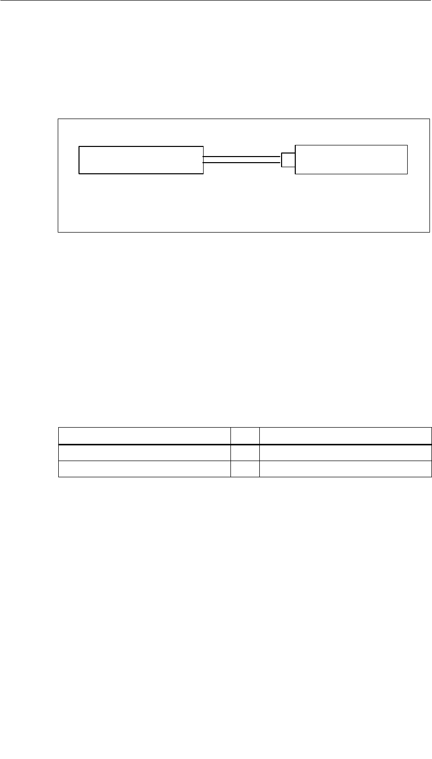
General Technical Specifications
1-6 S7-400, M7-400 Programmable Controllers Module Specifications
A5E00069467-07
cuULu requirements on hazardous location on the battery power supply for
CPUs
The power supply to the backup battery of a CPU must be via a non–incendive
plug. The figure below portrays the concept of such connection.
Battery or
Power supply unit
CPU with connector
“ext. batt.”
Cc = Cable capacity
Lc = Cable inductance
Figure 1-1 Power supply to the backup battery
The following conditions apply to the performance characteristics of this
connection:
Voc (no load voltage) = 15V Vmax = 15V
Isc (short–circuit current )= 50 mA Imax = 50 mA
Ca = Battery capacity/ Ci = 25 nF maximum
power supply
La= Battery inductance/ Li = 2 mH maximum
power supply
The battery/power supply which supplies the non–ingnitable connection must have
the following values:
Battery/Power supply CPU iput “Ext. Batt.” incl. cabel
Voc ≤Vmax (15V)
Isc ≤Imax (50 mA)

General Technical Specifications
1-7
S7-400, M7-400 Programmable Controllers Module Specifications
A5E00069467-07
Battery/Power supply CPU iput “Ext. Batt.” incl. cable
Ca ≥Ci + Cc (25nF + Cc)
La ≥Li + Lc (2mH + Lc)
The batteries used must have the following properties:
•Battery technology: Li/SOCL2
•Model: AA
•Voltage: 3.6 V
The batteries stipulated by Siemens fulfil requirements that go beyond the ones
mentioned above.
You may only use batteries approved by Siemens !
Note
If you do not know the capacity and inductance of the cable, you can use the
following values:
Cc = 197 pF/m (60 pF/ft.), Lc = 0.66 pF/m (0.2 mH/ft)
Example
The battery of type 4022 from Varta together with a 1.5 m long cable and a plug
connection of type 02–02.1500 from Leonhardy meet these conditions.
General Technical Specifications
1-8 S7-400, M7-400 Programmable Controllers Module Specifications
A5E00069467-07
FM Approval
Factory Mutual Approval Standard Class Number 3611, Class I, Division 2, Group
A, B, C, D.
Temperature class: T4 at 60 °C ambient temperature
Exception:
The following applies to the power supply modules in Table 1-3:
•Temperature class T3C at 60 °C ambient temperature
•Temperature class T4 at 40 °C ambient temperature
In the case of the modules in Table 1-3 the T4 temperature class is achieved for
the whole system if the ambient temperature does not exceed 40 °C during
operation. There are also certain additional requirements that you can comply
with by installing the system in cabinets.
Table 1-3 Power Supply Modules
Name Order number
PS 407 4 A Power Supply Module 6ES7 407-0DA00-0AA0
PS 407 10 A Power Supply Module 6ES7 407-0KA00-0AA0
PS 407 20 A Power Supply Module 6ES7 407-0RA00-0AA0
PS 405 4 A Power Supply Module 6ES7 405-0DA00-0AA0
PS 405 10 A Power Supply Module 6ES7 405-0KA00-0AA0
PS 405 20 A Power Supply Module 6ES7 405-0RA00-0AA0
!Warning
Personal injury or property damage can result.
In hazardous areas, personal injury or property damage can result if you create or
break an electrical circuit during operation of an S7-400/M7-400 (for example, by
means of plug-in connections, fuses, switches).
Do not create or break live electric circuits unless you are certain there is no
danger of explosion.
If you use S7-400 under FM conditions, it has to be mounted in a housing, which
at least corresponds to IP54 in accordance with EN 60529.

General Technical Specifications
1-9
S7-400, M7-400 Programmable Controllers Module Specifications
A5E00069467-07
Safety Requirements for Installation
The S7-400/M7-400 programmable controllers are “open type” equipment to the
IEC 61131-2 standard and therefore adhere to the EU directive 73/23/EEC
“Low-Voltage Directive” and are UL/CSA certified as such.
To fulfill requirements for safe operation with regard to mechanical stability, flame
retardance, stability, and shock-hazard protection, the following alternative types of
installation are specified:
•Installation in a suitable cabinet
•Installation in a suitable housing
•Installation in a suitably equipped, enclosed operating area.
1.2 Electromagnetic Compatibility
Introduction
In this section you will find information on the noise immunity of S7-400/M7-400
modules and on radio interference suppression.
All the components of S7-400/M7-400 systems meet the requirements of the
standards that apply in Europe provided they are installed in accordance with all
the appropriate regulations (see Installation Manual, Chapters 2 and 4).
Definition of “EMC”
Electromagnetic compatibility (EMC) is the ability of an electrical installation to
function satisfactorily in its electromagnetic environment without interfering with
that environment.
!Warning
Personal injury or property damage can result.
Installation of expansions that have not been approved for the S7-400/M7-400 can
result in violations of the requirements and regulations for safety and
electromagnetic compatibility.
Use only expansions that have been approved for the system.
General Technical Specifications
1-10 S7-400, M7-400 Programmable Controllers Module Specifications
A5E00069467-07
Pulse-Shaped Interference
The following table shows the electromagnetic compatibility of modules when there
are pulse-shaped disturbance variables. A requirement for this is that the
S7-400/M7-400 system complies with the relevant requirements and guidelines on
electric design.
Table 1-4 Pulse-Shaped Interference
Pulse-Shaped Interference Test Voltage Degree of
Severity
Electrostatic discharge
To IEC 61000-4-2 Discharge to air: ±8 kV
Contact discharge: ±6 kV 3
Bursts (fast transient interference in accor-
dance with IEC 61000-4-4) 2 kV (power supply line)
2 kV (signal line > 30 m)
1 kV (signal line < 30 m)
3
Energy-rich single impulse (surge) to IEC 61000-4-5 3
•Asymmetrical coupling 2 kV (supply line) DC voltage with
protective elements
2 kV (signal line/data line > 30 m only),
possibly with protective elements
•Symmetrical coupling 1 kV (supply line) DC voltage with
protective elements
1 kV (signal line > 30 m only), possibly
with protective elements
Sinusoidal Interference
The following table shows you the EMC behavior of the S7-400/M7-400 modules
when there is sinusoidal interference.
Table 1-5 Sinusoidal Interference
Sinusoidal Interference Test Values Degree of
Severity
RF irradiation (electromagnetic fields)
To IEC 61000-4-3
To IEC 61000-4-3
10 V/m with 80% amplitude modulation of
1 kHz over the range from 80 MHz to
1000 MHz
10 V/m with 50% pulse modulation at 900 MHz
3
RF conductance on cables and cable
shields to IEC 61000-4-6 Test voltage 10 V with 80% amplitude
modulation of 1 kHz over the range from 9 MHz
to 80 MHz
3
General Technical Specifications
1-11
S7-400, M7-400 Programmable Controllers Module Specifications
A5E00069467-07
Emission of Radio Interference
Interference emission of electromagnetic fields in accordance with EN 55011: Limit
value class A, Group 1.
Table 1-6 Interference emission of electromagnet fields
Frequency Range Limit Value
From 20 to 230 MHz 30 dB (V/m)Q
From 230 to 1000 MHz 37 dB (V/m)Q
Measured at a distance of 30 m (98.4 ft.)
Emitted interference via the mains AC power supply in accordance with EN 55011:
Limit value class A, group 1.
Table 1-7 Interference emission via the mains AC power supply
Frequency Range Limit Value
From 0.15 to 0.5 MHz 79 dB (V)Q
66 dB (V)M
From 0.5 to 5 MHz 73 dB (V)Q
60 dB (V)M
From 5 to 30 MHz 73 dB (V)Q
60 dB (V)M
System Perturbation
The products listed in the table below fulfill the requirements of the following
standards for system perturbation:
Harmonic currents: EN 61000-3-2
Voltage fluctuations and flickering EN 61000-3-3
Table 1-8 Power Supply Modules that Comply with System Perturbation
Standards
Name Order Number
PS 407 4 A Power Supply Module 6ES7407-0DA01-0AA0
PS 407 10 A Power Supply Module 6ES7407-0KA01-0AA0
PS 407R 10 A Redundant Power Supply Module 6ES7422-0KR00-0AA0
PS 407 20 A Power Supply Module 6ES7407-0RA01-0AA0
General Technical Specifications
1-12 S7-400, M7-400 Programmable Controllers Module Specifications
A5E00069467-07
Additional Measures
If you want to connect an S7-400 or M7-400 system to the public power system,
you must ensure compliance with limit value class B in accordance with
EN 55022.
Suitable additional measures must be taken, if you need to enhance the noise
immunity of the system as a result of high external noise levels.
1.3 Shipping and Storage Conditions for Modules and
Backup Batteries
Shipping and Storage of Modules
S7-400/M7-400 modules surpass the requirements of IEC 61131-2 in respect of
shipping and storage requirements. The following details apply to modules shipped
and/or stored in their original packing.
The climatic conditions conform to IEC 60721, Part 3-3, Class 3K7 for storage and
IEC 60721, Part 3-2, Class 2K4 for transport.
The mechanical conditions conform to IEC 60721, Part 3-2, Class 2M2.
Table 1-9 Shipping and Storage Conditions for Modules
Permitted Range
Free fall ≤ 1 m (up to 10 kg)
Temperature –40 °C to +70 °(C
Atmospheric pressure 1080 to 660 hPa (corresponds to a height of -1000 to
3500 m)
Relative humidity
(at +25 °C) 5 to 95 %, without condensation
Sinusoidal oscillations
to IEC 60068-2-6 5 to 9 Hz: 3.5 mm
9 to 500 Hz: 9.8 m/s2
Shock to IEC 60068-2-29 250 m/s2, 6 ms, 1000 shocks
Shipping of Backup Batteries
Wherever possible, transport backup batteries in their original packing. No special
measures are required for the transport of the backup batteries used in the
S7-400/M7-400 systems. The lithium component of the backup battery is less than
0.5 g.

General Technical Specifications
1-13
S7-400, M7-400 Programmable Controllers Module Specifications
A5E00069467-07
Storing Backup Batteries
Backup batteries must be stored in a cool, dry place. The maximum storage time is
10 years.
!Warning
Improper handling of backup batteries can cause injury and material damage. If
backup batteries are not treated properly, they can explode and cause severe
burning.
Please observe the following rules when handling backup batteries used in the
S7-400/M7-400 programmable controllers:
•never charge them
•never heat them
•never throw them in the fire
•never damage them mechanically (drill, squeeze, etc.)

General Technical Specifications
1-14 S7-400, M7-400 Programmable Controllers Module Specifications
A5E00069467-07
1.4 Mechanical and Ambient Climatic Conditions for
Operating the S7-400/M7-400
Operating Conditions
The S7-400/M7-400 is designed for weather-protected use as a permanent
installation. The S7-400/M7-400 fulfills the requirements for use in accordance with
IEC 60721-3-3:
•Class 3M3 (mechanical requirements)
•Class 3K3 (ambient climatic conditions)
Use with Additional Measures
The S7-400/M7-400, for example, must not be used without taking additional
measures:
•In locations exposed to a high degree of ionizing radiation
•In hostile environments caused, for instance, by
– Dust accumulation
– Corrosive vapors or gases
– Strong electric or magnetic fields
•In installations requiring special monitoring, for example
– Elevators
– Electrical installations in particularly hazardous areas
An additional measure might be, for instance, installation of the S7-400/M7-400 in
a cabinet or in a housing.
Ambient Mechanical Conditions
The ambient mechanical conditions for S7-400/M7-400 modules are listed in the
following table in the form of sinusoidal oscillations.
Table 1-10 Mechanical Conditions
Frequency Range in Hz Test Values
10 ≤ f < 58 0.075 mm amplitude
58 ≤ f < 500 1 g constant acceleration
General Technical Specifications
1-15
S7-400, M7-400 Programmable Controllers Module Specifications
A5E00069467-07
Table 1-11 Ambient Mechanical Conditions for the MSM 478 Mass Storage Module in
Operation
Frequency Range in Hz Test Values
10 ≤ f < 58 0.035 mm amplitude
10 ≤ f < 58
58 ≤ f < 500
0.035 mm amplitude
0.5 g constant acceleration
Shock Semi-sinusoidal 5 g, 11 ms
Reducing Vibrations
If the S7-400/M7-400 is subject to high levels of shock or vibration, you must take
suitable measures to reduce the acceleration or amplitude.
We recommend that you install the S7-400/M7-400 on vibration-damping materials
(for example, rubber-metal antivibration mountings).
Tests for Ambient Mechanical Conditions
The following table contains important information on the type and scope of tests
for ambient mechanical conditions.
Table 1-12 Ambient Mechanical Conditions Test
Test ... Test Standard Remarks
Vibrations Vibration test in
accordance with
IEC 60068-2-6
(sinusoidal)
Type of oscillation: frequency sweeps with a
rate of change of 1 octave/minute.
10 Hz ≤( f < 58 Hz, constant amplitude
0.075 mm
58 Hz ≤( f < 500 Hz, constant acceleration 1
g
Duration of oscillation: 10 frequency sweeps
per axis in each of three axes perpendicular
to each other
Shock Shock test in
accordance with
IEC 60068-2-29
Type of shock: half-sine
Severity of shock: 10 g peak value, 6 ms
duration
Direction of shock: 100 shocks in each of the
3 axes arranged vertically to each other
Ambient Climatic Conditions for the S7-400
You can use the S7-400 under the following ambient climatic conditions:
Table 1-13 Ambient Climatic Conditions for the S7-400
Climatic Conditions Permitted Range Remark
Temperature 0 to +60 °C
Temperature change Max. 10 °C/h
General Technical Specifications
1-16 S7-400, M7-400 Programmable Controllers Module Specifications
A5E00069467-07
Table 1-13 Ambient Climatic Conditions for the S7-400
Climatic Conditions RemarkPermitted Range
Relative humidity Max. 95 % at +25 °CNo condensation,
corresponds to RH
stressing level 2 in
accordance with
IEC 61131-2
Atmospheric pressure 1080 to 795 hPa (corresponds to
a height of -1000 to 2000 m) The power supply modu-
les in Table 1-12
achieve the following va-
lues:
1080 to 869 hPa (corres-
ponds to a level of
–1000 to 1500 m)
Concentration of
contaminants SO2: < 0.5 ppm;
RH < 60 %, no condensation
H2S: < 0.1 ppm;
RH < 60 %, no condensation
Test: 10 ppm; 4 days
Test: 1 ppm; 4 days
Table 1-14 Power Supply Modules for Use at up to + 1500 m
Name Order number
Power supply module PS 407 4A 6ES7407-0DA00-0AA0
Power supply module PS 407 10A 6ES7407-0KA00-0AA0
Power supply module PS 407 20A 6ES7407-0RA00-0AA0
Power supply module PS 405 4A 6ES7405-0DA00-0AA0
Power supply module PS 405 10A 6ES7405-0KA00-0AA0
Power supply module PS 405 20A 6ES7405-0RA00-0AA0

General Technical Specifications
1-17
S7-400, M7-400 Programmable Controllers Module Specifications
A5E00069467-07
Ambient Climatic Conditions for the M7-400
The M7-400 may be used under the following ambient climatic conditions:
Table 1-15 Ambient Climatic Conditions for the M7-400
Climatic Condi-
tions Permitted Range Remark
Temperature 0 to +60°C
5 to +55°C
5 to +40°C
When using a CPU 486-3 or 488-3
When using an MSM 478 without
diskette operation but with ventila-
tion
When using an MSM 478 with
diskette operation or without
ventilation
(when using an ATM 478, the
permissible temperature range is
restricted by the AT module used)
Relative
humidity Max. 95 % No condensation, corresponds to
RH stressing level 2 in accordance
with IEC 61131-2
Atmospheric
pressure 1080 to 795 kPa (corresponds to
a height of -1000 to 2000 m) Note the restriction on the power
supply in Table 1-12.
Concentration of
contaminants SO2: < 0.5 ppm;
RH < 60 %, no condensation)
H2S: < 0.1 ppm;
RH < 60 %, no condensation)
Test:
10 ppm; 4 days
1 ppm; 4 days

General Technical Specifications
1-18 S7-400, M7-400 Programmable Controllers Module Specifications
A5E00069467-07
1.5 Information on Insulation Tests, Protection Class and
Degree of Protection
Test Voltages
Insulation resistance was demonstrated in routine testing with the following test
voltages in accordance with IEC 61131-2:
Table 1-16 Test Voltages
Circuits with Rated Voltage Ue to Other Circuits or
Ground Test Voltage
0 V < Ue ≤ 50 V 350 V
50 V < Ue ≤ 100 V 700 V
100 V < Ue ≤ 150 V 1300 V
150 V < Ue ≤ 300 V 2200 V
Protection Class
Safety class I to IEC 60536 (VDE 0106, Part 1). In other words, a connection is
required from the protective conductor to the power supply module.
Protection Against Ingress of Foreign Bodies and Water
Degree of protection IP 20 to IEC 60529. In other words, there is protection against
contact with standard probes.
There is no special protection against the ingress of water.

General Technical Specifications
1-19
S7-400, M7-400 Programmable Controllers Module Specifications
A5E00069467-07
1.6 Using S7-400 in a zone 2 explosion–risk area
You will find important information in different languages in the chapters below.
Chapter overview
Chapter Thema
1.6.1 Einsatz der S7-400 im explosionsgefährdeten Bereich Zone 2
1.6.2 Use of the S7-400 in a Zone 2 Hazardous Area
1.6.3 Utilisation de la S7-400 dans un environnement à risque d’explosion en zone 2
1.6.4 Aplicación del S7-400 en áreas con peligro de explosión, zona 2
1.6.5 Impiego dell’ S7-400 nell’area a pericolo di esplosione zona 2
1.6.6 Gebruik van de S7-400 in het explosieve gebied zone 2
1.6.7 Brug af S7-400 i det eksplosionsfarlige område zone 2
1.6.8 S7-400:n käyttö räjähdysvaarannetuilla alueilla, vyöhyke 2
1.6.9 Användning av S7-400 i explosionsriskområde zon 2
1.6.10 Uso do S7-400 em área exposta ao perigo de explosão, zona 2
1.6.11 p S
General Technical Specifications
S7-400, M7-400 Programmable Controllers Module Specifications
1-20 A5E00069467-07
1.6.1 Einsatz der S7-400 im explosionsgefährdeten Bereich Zone 2
Zone 2
Explosionsgefährdete Bereiche werden in Zonen eingeteilt. Die Zonen werden
nach der Wahrscheinlichkeit des Vorhandenseins einer explosionsfähigen
Atmosphäre unterschieden.
Zone Explosionsgefahr Beispiel
2 explosive Gasatmosphäre tritt
nur selten und kurzzeitig auf
Bereiche um Flanschverbindungen mit
Flachdichtungen bei Rohrleitungen in
geschlossenen Räumen
sicherer
Bereich
nein • außerhalb der Zone 2
• Standardanwendungen von
dezentraler Peripherie
Nachfolgend finden Sie wichtige Hinweise für die Installation der SIMATIC S7-400
im explosionsgefährdeten Bereich.
Weitere Informationen
Weitere Informationen zu den verschiedenen S7-400-Baugruppen finden Sie im
Handbuch.
Fertigungsort
Siemens AG, Bereich A&D
Östliche Rheinbrückenstraße 50
76187 Karlsruhe
Germany
Zulassung
II 3 G EEx nA II T3 .. T6 nach EN 50021 : 1999
Prüfnummer: KEMA 03ATEX1125 X
Hinweis
Baugruppen mit der Zulassung II 3 G EEx nA II T3 .. T6 dürfen nur in
Automatisierungssystemen SIMATIC S7-400 der Gerätekategorie 3 eingesetzt
werden.

General Technical Specifications
S7-400, M7-400 Programmable Controllers Module Specifications
A5E00069467-07 1-21
Instandhaltung
Für eine Reparatur muss die betroffene Baugruppe an den Fertigungsort geschickt
werden. Nur dort darf die Reparatur durchgeführt werden.
Besondere Bedingungen
1. Die SIMATIC S7-400 muss in einen Schaltschrank oder ein metallisches
Gehäuse eingebaut werden. Diese müssen mindestens die Schutzart IP 54
(nach EN 60529) gewährleisten. Dabei sind die Umgebungsbedingungen zu
berücksichtigen, in denen das Gerät installiert wird. Für das Gehäuse muss
eine Herstellererklärung für Zone 2 vorliegen (gemäß EN 50021).
2. Wenn am Kabel bzw. an der Kabeleinführung dieses Gehäuses unter Betriebs-
bedingungen eine Temperatur > 70 °C erreicht wird oder wenn unter Betriebs-
bedingungen die Temperatur an der Aderverzweigung > 80 °C sein kann,
müssen die Temperatureigenschaften der Kabel mit den tatsächlich
gemessenen Temperaturen übereinstimmen.
3. Die eingesetzten Kabeleinführungen müssen der geforderten IP-Schutzart und
dem Abschnitt 7.2 (gemäß EN 50021) entsprechen.
4. Alle Geräte, einschließlich Schalter etc., die an den Ein- und Ausgängen von
S7-400-Systemen angeschlossen werden, müssen für den Explosionsschutz
Typ EEx nA oder EEx nC genehmigt sein.
5. Es müssen Maßnahmen getroffen werden, dass die Nennspannung durch
Transienten um nicht mehr als 40 % überschritten werden kann.
6. Umgebungstemperaturbereich: 0° C bis 60° C
7. Innerhalb des Gehäuses ist an einem nach dem Öffnen gut sichtbaren Platz ein
Schild mit folgender Warnung anzubringen:
Warnung
Das Gehäuse darf nur kurze Zeit geöffnet werden, z. B. für visuelle Diagnose.
Betätigen Sie dabei keine Schalter, ziehen oder stecken keine Baugruppen und
trennen keine elektrischen Leitungen (Steckverbindungen).
Diese Warnung kann unberücksichtigt bleiben, wenn bekannt ist, dass keine
explosionsgefährdete Atmosphäre herrscht.
Liste der zugelassenen Baugruppen
Die Liste mit den zugelassenen Baugruppen finden Sie im Internet:
http://www4.ad.siemens.de/view/cs/
unter der Beitrags-ID 13702947
General Technical Specifications
S7-400, M7-400 Programmable Controllers Module Specifications
1-22 A5E00069467-07
1.6.2 Use of the S7-400 in a Zone 2 Hazardous Area
Zone 2
Hazardous areas are divided up into zones. The zones are distinguished according
to the probability of the existence of an explosive atmosphere.
Zone Explosion Hazard Example
2 Explosive gas atmosphere
occurs only seldom and for a
short time
Areas around flange joints with flat
gaskets in pipes in enclosed spaces
Safe area No • Outside zone 2
• Standard distributed I/O
applications
Below you will find important information on the installation of the SIMATIC S7-400
in a hazardous area.
Further Information
You will find further information on the various S7-400 modules in the manual.
Production Location
Siemens AG, Bereich A&D
Östliche Rheinbrückenstraße 50
76187 Karlsruhe
Germany
Certification
II 3 G EEx nA II T3 .. T6 in accordance with EN 50021 : 1999
Test number: KEMA 03ATEX1125 X
Note
Modules with II 3 G EEx nA II T3 .. T6 certification can only be used in
SIMATIC S7-400 automation systems belonging to equipment category 3.

General Technical Specifications
S7-400, M7-400 Programmable Controllers Module Specifications
A5E00069467-07 1-23
Maintenance
If repair is necessary, the affected module must be sent to the production location.
Repairs can only be carried out there.
Special Conditions
1. The SIMATIC S7-400 must be installed in a cabinet or metal housing. These
must comply with the IP 54 (in accordance with EN 60529) degree of protection
as a minimum. The environmental conditions under which the equipment is
installed must be taken into account. There must be a manufacturer's
declaration for zone 2 available for the housing (in accordance with EN 50021).
2. If a temperature of > 70 °C is reached in the cable or at the cable entry of this
housing under operating conditions, or if a temperature of > 80 °C can be
reached at the junction of the conductors under operating conditions, the
temperature-related properties of the cables must correspond to the
temperatures actually measured.
3. The cable entries used must comply with the required IP degree of protection
and Section 7.2 (in accordance with EN 50021).
4. All devices (including switches, etc.) that are connected to the inputs and
outputs of S7-400 systems must be approved for EEx nA or EEx nC explosion
protection.
5. Steps must be taken to ensure that the rated voltage through transients cannot
be exceeded by more than 40 %.
6. Ambient temperature range: 0° C to 60° C
7. A sign containing the following warning must be put up inside the housing in an
easily visible position when the housing is opened:
Warning
The housing can only be opened for a short time (e.g. for visual diagnostics). If
you do this, do not operate any switches, remove or install any modules or
disconnect any electrical cables (plug-in connections).
You can disregard this warning if you know that the atmosphere is not
hazardous (i.e. there is no risk of explosion).
List of Approved Modules
You will find the list of approved modules under the ID 13702947 on the Internet:
http://www4.ad.siemens.de/view/cs/.
General Technical Specifications
S7-400, M7-400 Programmable Controllers Module Specifications
1-24 A5E00069467-07
1.6.3 Utilisation du S7-400 dans un environnement à risque
d'explosion en zone 2
Zone 2
Les environnements à risque d'explosion sont répartis en zones. Les zones se
distinguent par la probabilité de présence d'une atmosphère explosive.
Zone Risque d'explosion Exemple
2 Formation rare et brève d'une
atmosphère gazeuse explosive
Environnement de raccords à joints plats
dans le cas de conduites dans des locaux
fermés
Zone sûre Non • A l'extérieur de la zone 2
• Utilisation standard de périphérie
décentralisée
Vous trouverez ci-après des remarques importantes pour l'installation du
SIMATIC S7-400 dans un environnement présentant un risque d'explosion.
Informations complémentaires
Des informations complémentaires sur les divers modules S7-400 se trouvent dans
le manuel.
Lieu de production
Siemens AG, Bereich A&D
Östliche Rheinbrückenstraße 50
76187 Karlsruhe
Germany
Homologation
II 3 G EEx nA II T3 .. T6 selon EN 50021 : 1999
Numéro de contrôle : KEMA 03ATEX1125 X
Nota
Les modules homologués II 3 G EEx nA II T3 .. T6 ne peuvent être utilisés
que dans des automates SIMATIC S7-400 de catégorie 3.

General Technical Specifications
S7-400, M7-400 Programmable Controllers Module Specifications
A5E00069467-07 1-25
Entretien
Si une réparation est nécessaire, le module concerné doit être expédié au lieu de
production. La réparation ne doit être effectuée qu'en ce lieu.
Conditions particulières
1. Le SIMATIC S7-400 doit être installé dans une armoire ou un boîtier métallique.
Ceux-ci doivent assurer au moins l'indice de protection IP 54. Il faut alors tenir
compte des conditions d'environnement dans lesquelles l'appareil est installé.
Le boîtier doit faire l’objet d’une déclaration de conformité du fabricant pour la
zone 2 (selon EN 50021).
2. Si dans les conditions d’exploitation, une température > 70 °C est atteinte au
niveau du câble ou de l’entrée du câble dans ce boîtier, ou bien si la
température au niveau de la dérivation des conducteurs peut être > 80 °C, les
capacités de résistance thermique des câbles doivent corespondre aux
températures effectivement mesurées.
3. Les entrées de câbles utilisées doivent avoir le niveau de protection IP exigé et
être conformes au paragraphe 7.2 (selon EN 50021).
4. Tous les appareillages (y compris les interrupteurs, etc.) raccordés aux entrées
et sorties de modules de signaux à sécurité intrinsèque doivent être
homologués pour la protection antidéflagrante type EEx nA ou EEx nC.
5. Il faut prendre des mesures pour que la tension nominale ne puisse pas être
dépassée de plus de 40% sous l’influence de transitoires.
6. Plage de température ambiante : 0° C à 60° C
7. A l’intérieur du boîtier, il faut placer, à un endroit bien visible après ouverture,
une plaquette comportant l’avertissement suivant :
Avertissement
Ouvir le boîtier le moins longtemps possible, par exemple pour effectuer un
diagnostic visuel. Ce faisant, n’actionnez aucun commutateur, ne déconnectez
aucun module et ne débanchez pas de câbles électriques (connexions).
Le respect de cet avertissement n’est pas impératif s’il est certain que
l’environnement ne présente pas de risque d’explosion.
Liste des modules homologués
Vous trouverez sur Internet la liste des modules homologués :
http://www4.ad.siemens.de/view/cs/
référence ID 13702947
General Technical Specifications
S7-400, M7-400 Programmable Controllers Module Specifications
1-26 A5E00069467-07
1.6.4 Aplicación de la S7-400 en áreas con peligro de explosión,
zona 2
Zona 2
Las áreas con peligro de explosión se clasifican en zonas. Las zonas se
diferencian según la probabilidad de la existencia de una atmósfera capaz de sufrir
una explosión.
Zona Peligro de explosión Ejemplo
2 La atmósfera explosiva de gas
sólo se presenta rara vez y muy
brevemente
Áreas alrededor de uniones abridadas con
juntas planas en tuberías en locales
cerrados
Área segura No • Fuera de la zona 2
• Aplicaciones estándar de la
periferia descentralizada
A continuación encontrará importantes informaciones para la instalación del
SIMATIC S7-400 en áreas con peligro de explosión.
Otras informaciones
Encontrará otras informaciones relativas a los distintos módulos S7-400 en el
Manual.
Lugar de fabricación
Siemens AG, Bereich A&D
Östliche Rheinbrückenstraße 50
76187 Karlsruhe
Germany
Homologación
II 3 G EEx nA II T3 .. T6 según norma EN 50021 : 1999
Número de comprobación: KEMA 03ATEX1125 X
Nota
Los módulos con la homologación II 3 G EEx nA II T3 .. T6 pueden utilizarse
únicamente en los autómatas programables SIMATIC S7-400 de la categoría de
equipo 3.

General Technical Specifications
S7-400, M7-400 Programmable Controllers Module Specifications
A5E00069467-07 1-27
Mantenimiento
Para una reparación se ha de remitir el módulo afectado al lugar de fabricación.
Sólo allí se puede realizar la reparación.
Condiciones especiales
1. El SIMATIC S7-400 se ha de montar en un armario eléctrico de distribución o
en una carcasa metálica. Éstos deben garantizar como mínimo el grado de
protección IP 54 (conforme a EN 60529). Para ello se han de tener en cuenta
las condiciones ambientales, en las cuales se instala el equipo. La caja deberá
contar con una declaración del fabricante para la zona 2 (conforme a
EN 50021).
2. Si durante la operación se alcanzara una temperatura > 70° C en el cable o la
entrada de cables de esta caja o bien una temperatura > 80° C en la
bifurcación de hilos, deberán adaptarse las propiedades térmicas de los cables
a las temperaturas medidas efectivamente.
3. Las entradas de cable utilizadas deben cumplir el grado de protección IP
exigido y lo expuesto en el apartado 7.2 (conforme a EN 50021).
4. Todos los dispositivos –inclusive interruptores, etc.– conectados a las entradas
y salidas sistemas S7-400 deben estar homologados para la protección contra
explosiones del tipo EEx nA o EEx nC.
5. Es necesario adoptar las medidas necesarias para evitar que la tensión
nominal se pueda rebasar en más del 40 % debido a efectos transitorios.
6. Margen de temperatura ambiente: 0° C hasta 60° C
7. Dentro de la caja deberá colocarse en un lugar perfectamente visible tras su
apertura un rótulo con la siguiente advertencia:
Precaución
Abrir la caja sólo brevemente, p.ej. para el diagnóstico visual. Durante este
tiempo Ud. no deberá activar ningún interruptor, desenchufar o enchufar
módulos ni separar conductores eléctricos (conexiones enchufables).
Esta advertencia puede ignorarse si Ud. sabe que en la atmósfera existente no
hay peligro de explosión.
Lista de los módulos homologados
En internet hallará Ud. una lista con los módulos homologados:
http://www4.ad.siemens.de/view/cs/
bajo el ID de asignación 13702947
General Technical Specifications
S7-400, M7-400 Programmable Controllers Module Specifications
1-28 A5E00069467-07
1.6.5 Impiego dell'S7-400 nell'area a pericolo di esplosione zona 2
Zona 2
Le aree a pericolo di esplosione vengono suddivise in zone. Le zone vengono
distinte secondo la probabilità della presenza di un'atmosfera esplosiva.
Zona Pericolo di esplosione Esempio
2 L'atmosfera esplosiva si
presente solo raramente e
brevemente
Aree intorno a collegamenti a flange con
guarnizioni piatte nelle condotte in
ambienti chiusi
Area sicura No • Al di fuori della zona 2
• Applicazioni standard di periferia
decentrata
Qui di seguito sono riportate delle avvertenze importanti per l'installazione del
SIMATIC S7-400 nell'area a pericolo di esplosione.
Ulteriori informazioni
Ulteriori informazioni sulle diverse unità S7-400 si trovano nel manuale.
Luogo di produzione
Siemens AG, Bereich A&D
Östliche Rheinbrückenstraße 50
76187 Karlsruhe
Germany
Autorizzazione
II 3 G EEx nA II T3 .. T6 secondo EN 50021 : 1999
Numero di controllo: KEMA 03ATEX1125 X
Avvertenza
Le unità con l'autorizzazione II 3 G EEx nA II T3 .. T6 possono essere
impiegate solo nei sistemi di controllori programmabili SIMATIC S7-400 della
categoria di apparecchiature 3.

General Technical Specifications
S7-400, M7-400 Programmable Controllers Module Specifications
A5E00069467-07 1-29
Manutenzione
Per una riparazione, l'unità interessata deve essere inviata al luogo di produzione.
La riparazione può essere effettuata solo lì.
Condizioni particolari
1. Il SIMATIC S7-400 deve essere montato in un armadio elettrico o in un
contenitore metallico. Questi devono assicurare almeno il tipo di protezione
IP 54 (secondo EN 60529). In questo caso bisogna tenere conto delle
condizioni ambientali nelle quali l'apparecchiatura viene installata. Per il
contenitore deve essere presente una dichiarazione del costruttore per la
zona 2 (secondo EN 50021).
2. Se nei cavi o nel loro punto di ingresso in questo contenitore viene raggiunta in
condizioni di esercizio una temperatura > 70 °C o se in condizioni di esercizio la
temperatura nella derivazione dei fili può essere > 80 °C, le caratteristiche di
temperatura dei cavi devono essere conformi alla temperatura effettivamente
misurata.
3. Gli ingressi dei cavi usati devono essere conformi al tipo di protezione IP
richiesto e alla sezione 7.2 (secondo EN 50021).
4. Tutte le apparecchiature, inclusi interruttori, ecc. che vengono collegati a
ingressi/uscite di sistemi S7-400, devono essere stati omologati per la
protezione da esplosione tipo EEx nA o EEx nC.
5. Devono essere prese delle misure per evitare che la tensione nominale possa
essere superata per più del 40% da parte di transienti.
6. Campo termico ambientale: da 0° C a 60° C
7. All’interno del contenitore va apportata, in un luogo ben visibile dopo l’apertura,
una targhetta con il seguente avvertimento:
Attenzione
Il contenitore può rimanere aperto solo per breve tempo, ad esempio per una
diagnostica a vista. In tal caso non azionare alcun interruttore, non disinnestare
o innestare unità e non staccare connessioni elettriche (connettori).
Non è necessario tenere conto di questo avvertimento se è noto che non c’è
un’atmosfera a rischio di esplosione.
Elenco delle unità omologate
La lista con le unità omologate si trova in Internet al sito:
http://www4.ad.siemens.de/view/cs/
all’ID di voce 13702947
General Technical Specifications
S7-400, M7-400 Programmable Controllers Module Specifications
1-30 A5E00069467-07
1.6.6 Gebruik van de S7-400 in het explosief gebied zone 2
Zone 2
Explosieve gebieden worden ingedeeld in zones. Bij de zones wordt
onderscheiden volgens de waarschijnlijkheid van de aanwezigheid van een
explosieve atmosfeer.
Zone Explosiegevaar Voorbeeld
2 Een explosieve gasatmosfeer
treedt maar zelden op en voor
korte duur
Gebieden rond flensverbindingen met
pakkingen bij buisleidingen in gesloten
vertrekken
Veilig
gebied
Neen • Buiten de zone 2
• Standaardtoepassingen van
decentrale periferie
Hierna vindt u belangrijke aanwijzingen voor de installatie van de SIMATIC S7-400
in het explosief gebied.
Verdere informatie
In het handboek vindt u verdere informatie over de verschillende S7-400-modulen.
Productieplaats
Siemens AG, Bereich A&D
Östliche Rheinbrückenstraße 50
76187 Karlsruhe
Germany
Vergunning
II 3 G EEx nA II T3 .. T6 conform EN 50021 : 1999
Keuringsnummer: KEMA 03ATEX1125 X
Opmerking
Modulen met de vergunning II 3 G EEx nA II T3 .. T6 mogen slechts worden
gebruikt in automatiseringssystemen SIMATIC S7-400 van de
apparaatcategorie 3.

General Technical Specifications
S7-400, M7-400 Programmable Controllers Module Specifications
A5E00069467-07 1-31
Instandhouding
Voor een reparatie moet de betreffende module naar de plaats van vervaardiging
worden gestuurd. Alleen daar mag de reparatie worden uitgevoerd.
Speciale voorwaarden
1. Het SIMATIC S7-400 moet worden ingebouwd in een schakelkast of in een
behuizing van metaal. Deze moeten minstens de veiligheidsgraad IP 54
(volgens EN 60529) waarborgen. Hierbij dient rekening te worden gehouden
met de omgevingsvoorwaarden waarin het apparaat wordt geïnstalleerd. Voor
de behuizing dient een verklaring van de fabrikant voor zone 2 te worden
ingediend (volgens EN 50021).
2. Als aan de kabel of aan de kabelinvoering van deze behuizing onder
bedrijfsomstandigheden een temperatuur wordt bereikt > 70 °C of als onder
bedrijfsomstandigheden de temperatuur aan de adervertakking > 80 °C kan
zijn, moeten de temperatuureigenschappen van de kabel overeenstemmen met
de werkelijk gemeten temperaturen.
3. De aangebrachte kabelinvoeringen moeten de vereiste IP-veiligheidsgraad
hebben en in overeenstemming zijn met alinea 7.2 (volgens EN 50021).
4. Alle apparaten, schakelaars enz. inbegrepen, die worden aangesloten op de in-
en uitgangen van S7-400 systemen, moeten zijn goedgekeurd voor de
explosiebeveiliging type EEx nA of EEx nC.
5. Er dienen maatregelen te worden getroffen, zodat de nominale spanning door
transiënten met niet meer dan 40 % kan worden overschreden.
6. Omgevingstemperatuurbereik: 0° C tot 60° C
7. Binnen de behuizing dient op een na het openen goed zichtbare plaats een
bord te worden aangebracht met de volgende waarschuwing:
Waarschuwing
De behuizing mag slechts voor korte tijd worden geopend, bijv. voor een visuele
diagnose. Bedien hierbij geen schakelaar, trek of steek geen modulen en
ontkoppel geen elektrische leidingen (steekverbindingen).
Deze waarschuwing kan buiten beschouwing blijven, indien bekend is dat er
geen explosieve atmosfeer heerst.
Lijst van de toegelaten modulen
De lijst met de toegelaten modulen vindt u in het internet:
http://www4.ad.siemens.de/view/cs/
onder de bijdrage-ID 13702947
General Technical Specifications
S7-400, M7-400 Programmable Controllers Module Specifications
1-32 A5E00069467-07
1.6.7 Brug af S7-400 i det eksplosionfarlige område zone 2
Zone 2
Eksplosionsfarlige områder inddeles i zoner. Zonerne adskiller sig indbyrdes efter
hvor sandsynligt det er, at der er en eksplosiv atmosfære.
Zone Eksplosionsfare Eksempel
2 Eksplosiv gasatmosfære
optræder kun sjældent og varer
kort
Områder rundt om flangeforbindelser med
flade pakninger ved rørledninger i lukkede
rum
Sikkert
område
Nej • Uden for zone 2
• Standardanvendelser decentral
periferi
I det følgende findes vigtige henvisninger vedr. installation af SIMATIC S7-400 i det
eksplosionfarlige område.
Yderligere informationer
Yderligere informationer om de forskellige S7-400-komponenter findes i manualen.
Produktionssted
Siemens AG, Bereich A&D
Östliche Rheinbrückenstraße 50
76187 Karlsruhe
Germany
Godkendelse
II 3 G EEx nA II T3 .. T6 efter EN 50021 : 1999
Kontrolnummer: KEMA 03ATEX1125 X
Bemærk
Komponenter med godkendelsen II 3 G EEx nA II T3 .. T6 må kun monteres i
automatiseringssystemer SIMATIC S7-400 - udstyrskategori 3.

General Technical Specifications
S7-400, M7-400 Programmable Controllers Module Specifications
A5E00069467-07 1-33
Vedligeholdelse
Skal den pågældende komponent repareres, bedes De sende den til
produktionsstedet. Reparation må kun udføres der.
Særlige betingelser
1. SIMATIC S7-400 skal monteres i et kontrolskab eller et metalkabinet. Disse skal
mindst kunne sikre beskyttelsesklasse IP 54. I denne forbindelse skal der tages
højde for de omgivelsestemperaturer, i hvilke udstyret er installeret. Der skal
være udarbejdet en erklæring fra fabrikanten for kabinettet for zone 2 (iht.
EN 50021).
2. Hvis kablet eller kabelindføringen på dette hus når op på en temperatur på
> 70 °C under driftsbetingelser eller hvis temperaturen på åreforegreningen kan
være > 80 °C under driftsbetingelser, skal kablernes temperaturegenskaber
stemme overens med de temperaturer, der rent faktisk måles.
3. De benyttede kabelindføringer skal være i overensstemmelse med den
krævede IP-beskyttelsestype og afsnittet 7.2 (iht. EN 50021).
4. Alle apparater, inkl. kontakter osv., der forbindes med ind- og udgangene på
S7-400 systemer, skal være godkendt til eksplosionsbeskyttelse af type EEx nA
eller EEx nC.
5. Der skal træffes foranstaltninger, der sørger for, at den nominelle spænding via
transienter ikke kan overskrides mere end 40 %.
6. Omgivelsestemperaturområde: 0° C til 60° C
7. I kabinettet skal der anbringes et skilt, der skal kunne ses, når kabinettet åbnes.
Dette skilt skal have følgende advarsel:
Advarsel
Kabinettet må kun åbnes i kort tid, f.eks. til visuel diagnose. Tryk i denne
forbindelse ikke på kontakter, træk eller isæt ikke komponenter og afbryd ikke
elektriske ledninger (stikforbindelser).
Denne advarsel skal der ikke tages højde for, hvis man ved, at der ikke er
nogen eksplosionsfarlig atmosfære.
Liste over godkendte komponenter
Listen med de godkendte komponenter findes på internettet:
http://www4.ad.siemens.de/view/cs/
under bidrags-ID 13702947
General Technical Specifications
S7-400, M7-400 Programmable Controllers Module Specifications
1-34 A5E00069467-07
1.6.8 S7-400:n käyttö räjähdysvaarannetuilla alueilla, vyöhyke 2
Vyöhyke 2
Räjähdysvaarannetut alueet jaetaan vyöhykkeisiin. Vyöhykkeet erotellaan
räjähdyskelpoisen ilmakehän olemassa olon todennäköisyyden mukaan.
Vyöhyke Räjähdysvaara Esimerkki
2 Räjähtävä kaasuilmakehä
ilmaantuu vain harvoin ja
lyhytaikaisesti
Alueet putkistojen lattatiivisteillä varustuilla
laippaliitoksilla suljetuissa tiloissa
turvallinen
alue
Ei • vyöhykkeen 2 ulkopuolella
• Hajautetun ulkopiirin
vakiosovellukset
Seuraavasta löydätte tärkeitä ohjeita
SIMATIC S7-400 asennukseen räjähdysvaarannetuilla alueilla.
Lisätietoja
Lisätietoja erilaisiin S7-400-rakenneryhmiin löydätte ohjekirjasta.
Valmistuspaikka
Siemens AG, Bereich A&D
Östliche Rheinbrückenstraße 50
76187 Karlsruhe
Germany
Hyväksyntä
II 3 G EEx nA II T3 .. T6 EN 50021 mukaan: 1999
Tarkastusnumero: KEMA 03ATEX1125 X
Ohje
Rakenneryhmät hyväksynnän II 3 G EEx nA II T3 .. T6 kanssa saadaan
käyttää ainoastaan laitekategorian 3 automatisointijärjestelmissä SIMATIC S7-400.

General Technical Specifications
S7-400, M7-400 Programmable Controllers Module Specifications
A5E00069467-07 1-35
Kunnossapito
Korjausta varten täytyy kyseinen rakenneryhmä lähettää valmistuspaikkaan.
Korjaus voidaan suorittaa ainoastaan siellä.
Erityiset vaatimukset
1. SIMATIC S7-400 täytyy asentaa kytkentäkaappiin tai metalliseen koteloon.
Näiden täytyy olla vähintään kotelointiluokan IP 54 mukaisia. Tällöin on
huomioitava ympäristöolosuhteet, johon laite asennetaan. Kotelolle täytyy olla
valmistajaselvitys vyöhykettä 2 varten (EN 50021 mukaan).
2. Kun johdolla tai tämän kotelon johdon sisäänviennillä saavutetaan > 70 °C
lämpötila tai kun käyttöolosuhteissa lämpötila voi piuhajaotuksella olla > 80 °C,
täytyy johdon lämpötilaominaisuuksien vastata todellisesti mitattuja lämpötiloja.
3. Käytettyjen johtojen sisäänohjauksien täytyy olla vaaditun IP-kotelointiluokan ja
kohdan 7.2 (EN 50021 mukaan) mukaisia.
4. Kaikkien laitteiden, kytkimet jne. mukaan lukien, jotka liitetään virheiltä
suojattujen signaalirakenneryhmien tuloille ja lähdöille, täytyy olla hyväksyttyjä
tyypin EEx nA tai EEx nC räjähdyssuojausta varten.
5. Toimenpiteet täytyy suorittaa, ettei nimellisjännite voi transienttien kautta ylittyä
enemmän kuin 40 %.
6. Ympäristölämpötila-alue: 0° C ... 60° C
7. Kotelon sisälle, avauksen jälkeen näkyvälle paikalle, on kiinnitettävä kilpi, jossa
on seuraava varoitus:
Varoitus
Kotelo saadaan avata ainoastaan lyhyeksi ajaksi, esim. visuaalista diagnoosia
varten. Älä tällöin käytä mitään kytkimiä, vedä tai liitä mitään rakenneryhmiä,
äläkä erota mitään sähköjohtoja (pistoliittimiä).
Tätä varoitusta ei tarvitse huomioida, kun on tiedossa, että minkäänlaista
räjähdysvaarannettua ilmakehää ei ole olemassa.
Hyväksyttyjen rakenneryhmien lista
Lista hyväksiytyistä rakennesarjoista löytyy internetistä osoitteesta:
http://www4.ad.siemens.de/view/cs/
käyttäjätunnuksella 13702947
General Technical Specifications
S7-400, M7-400 Programmable Controllers Module Specifications
1-36 A5E00069467-07
1.6.9 Användning av S7-400 i explosionsriskområde zon 2
Zon 2
Explosionsriskområden delas in i zoner. Zonerna delas in enligt sannolikheten att
en atmosfär med explosionsfara föreligger.
Zon Explosionsfara Exempel
2 Explosiv gasatmosfär uppstår
endast sällan eller kortvarigt
Områden kring flänsförbindelser med
packningar vid rörledningar i slutna
utrymmen
Säkert
område
Nej • Utanför zon 2
• Standardanvändning av
decentral periferi
Nedan följer viktiga anvisningar om installationen av SIMATIC S7-400 i ett
explosionsriskområde.
Ytterligare information
Ytterligare information om de olika S7-400-komponentgrupperna finner du i
handboken.
Tillverkningsort
Siemens AG, Bereich A&D
Östliche Rheinbrückenstraße 50
76187 Karlsruhe
Germany
Godkännande
II 3 G EEx nA II T3 .. T6 enligt EN 50021 : 1999
Kontrollnummer: KEMA 03ATEX1125 X
Anvisning
Komponentgrupper med godkännande II 3 G EEx nA II T3 .. T6 får endast
användas i automatiseringssystemen SIMATIC S7-400 från apparatgrupp 3.

General Technical Specifications
S7-400, M7-400 Programmable Controllers Module Specifications
A5E00069467-07 1-37
Underhåll
Vid reparation måste den aktuella komponentgruppen insändas till tillverkaren.
Reparationer får endast genomföras där.
Särskilda villkor
1. SIMATIC S7-400 måste monteras i ett kopplingsskåp eller metallhus. Dessa
måste minst vara av skyddsklass IP 54. Därvid ska omgivningsvillkoren där
enheten installeras beaktas. För kåpan måste en tillverkardeklaration för zon 2
föreligga (enligt EN 50021).
2. Om en temperatur på > 70°C uppnås vid husets kabel resp kabelinföring under
driftvillkor eller om temperaturen vid trådförgreningen kan vara > 80°C under
driftvillkor, måste kabelns temperaturegenskaper överensstämma med den
verkligen uppmätta temperaturen.
3. De använda kabelinföringarna måste uppfylla kraven i det krävda IP-
skyddsutförandet och i avsnitt 7.2 (enligt EN 50021).
4. Alla apparater, inklusive brytare osv, som ansluts S7 400 systemens in- och
utgångar, måste vara godkända för explosionsskydd av typ EEx nA eller
EEx nC.
5. Åtgärder måste vidtas så, att märkspänningen ej kan överskridas med mer än
40 % genom transienter.
6. Omgivningstemperatur: 0° C till 60° C
7. När huset öppnats ska en skylt med följande varning monteras på ett tydligt
synligt ställe huset:
Varning
Huset får endast öppnas under kort tid, t ex för visuell diagnos. Använd därvid
inga brytare, lossa eller anslut inga enheter och frånskilj inga elektriska
ledningar (insticksanslutningar).
Ingen hänsyn måste tas till denna varning om det är säkert att det inte råder
någon explosionsfarlig atmosfär.
Lista över godkända komponentgrupper
Lista över godkända enheter återfinns i Internet:
http://www4.ad.siemens.de/view/cs/
under bidrags-ID 13702947
General Technical Specifications
S7-400, M7-400 Programmable Controllers Module Specifications
1-38 A5E00069467-07
1.6.10 Uso do S7-400 em área exposta ao perigo de explosão 2
Zona 2
As áreas expostas ao perigo de explosão são divididas em zonas. As zonas são
diferenciadas de acordo com a probabilidade da existência de uma atmosfera
explosiva.
Zona Perigo de explosão Exemplo
2 Só raramente e por um breve
período de tempo surgem
atmosferas explosivas
Áreas em torno de ligações flangeadas
com vedações chatas em tubulações em
recintos fechados
Área segura Não • fora da zona 2
• Aplicações padrão de periferia
descentralizada
A seguir, o encontrará avisos importantes para a instalação do SIMATIC S7-400
em área exposta ao perigo de explosão.
Mais informações
Para obter mais informações sobre os diversos componentes S7-400, consulte o
manual.
Local de produção
Siemens AG, Bereich A&D
Östliche Rheinbrückenstraße 50
76187 Karlsruhe
Germany
Licença
II 3 G EEx nA II T3 .. T6 seg. EN 50021 : 1999
Número de ensaio: KEMA 03ATEX1125 X
Aviso
Componentes com a licença II 3 G EEx nA II T3 .. T6 só podem ser
aplicados em sistemas de automação SIMATIC S7-400 da categoria de
aparelho 3.

General Technical Specifications
S7-400, M7-400 Programmable Controllers Module Specifications
A5E00069467-07 1-39
Reparo
Os componente em questão deve ser remetido para o local de produção a fim de
que seja realizado o reparo. Apenas lá deve ser efetuado o reparo.
Condições especiais
1. O SIMATIC S7-400 deve ser montado em um armário de distribuição ou em
uma caixa metálica. Estes devem garantir no mínimo o tipo de proteção IP 54.
Durante este trabalho deverão ser levadas em consideração as condições
locais, nas quais o aparelho será instalado. Para a caixa deverá ser
apresentada uma declaração do fabricante para a zona 2 (de acordo com
EN 50021).
2. Caso no cabo ou na entrada do cabo desta caixa sob as condições
operacionais seja atingida uma temperatura de > 70 °C ou caso sob condições
operacionais a temperatura na ramificação do fio possa atingir > 80 °C, as
caraterísticas de temperatura deverão corresponder às temperaturas realmente
medidas.
3. As entradas de cabo utilizadas devem corresponder ao tipo exigido de
proteção IP e à seção 7.2 (de acordo com o EN 50021).
4. Todos os aparelhos, inclusive as chaves, etc., que estejam conectadas em
entradas e saídas dos sistemas do S7;400 devem possuir a licença para a
proteção de explosão do tipo EEx nA ou EEx nC.
5. Precisam ser tomadas medidas para que a tensão nominal através de
transitórios não possa ser ultrapassada em mais que 40 %.
6. Área de temperatura ambiente: 0° C até 60° C
7. No âmbito da caixa deve ser colocada em um ponto bem visível após a sua
abertura uma placa com a seguinte advertência:
Advertência
A carcaça deve ser aberta apenas por um breve período de tempo, por ex. para
diagnóstico visual. Não acione nenhum interruptor, não retire ou conecte
nenhum componente e não separe nenhum fio elétrico (ligações de tomada).
Esta advertência poderá ser ignorada caso se saiba que não há atmosfera
alguma sujeita ao perigo de explosão.
Lista dos componentes autorizados
A lista com os componentes autorizados encontram-se na Internet:
http://www4.ad.siemens.de/view/cs/
sob o número de ID 13702947
General Technical Specifications
S7-400, M7-400 Programmable Controllers Module Specifications
1-40 A5E00069467-07
1.6.11 Χρήση της συσκευής S7-400 σε επικίνδυνη για έκρηξη περιοχή,
ζώνη 2
Ζώνη 2
Οι επικίνδυνες για έκρηξη περιοχές χωρίζονται σε ζώνες. Οι ζώνες διαφέρουν
σύµφωνα µε την πιθανότητα ύπαρξης ενός ικανού για έκρηξη περιβάλλοντος.
Ζώνη Κίνδυνος έκρηξης Παράδειγµα
2 Εκρηκτικό περιβάλλον αερίου
παρουσιάζεται µόνο σπάνια και
για σύντοµο χρονικό διάστηµα
Περιοχές γύρω από φλαντζωτές
συνδέσεις µε τσιµούχες σε σωληνώσεις σε
κλειστούς χώρους
Ασφαλής
περιοχή
Όχι • Εκτός της ζώνης 2
• Τυπικές εφαρµογές
αποκεντρωµένης περιφέρειας
Στη συνέχεια θα βρείτε σηµαντικές υποδείξεις για την εγκατάσταση του δοµικού
συγκροτήµατος SIMATIC S7-400 σε επικίνδυνη για έκρηξη περιοχή.
Επιπλέον πληροφορίες
Επιπλέον πληροφορίες για τα διάφορα δοµικά συγκροτήµατα (ενότητες) S7-400 θα
βρείτε στο εγχειρίδιο.
Τόπος κατασκευής
Siemens AG, Bereich A&D
Östliche Rheinbrückenstrasse 50
76187 Karlsruhe
Germany
Άδεια
II 3 G EEx nA II T3 .. T6 σύµφωνα µε το πρότυπο
EN 50021 : 1999
Αριθµός ελέγχου: KEMA 03ATEX1125 X
Υπόδειξη
Τα δοµικά συγκροτήµατα µε την άδεια II 3 G EEx nA II T3 .. T6 επιτρέπεται να
τοποθετηθούν µόνο σε συστήµατα αυτοµατισµού SIMATIC S7-400 της κατηγορίας
συσκευής 3.

General Technical Specifications
S7-400, M7-400 Programmable Controllers Module Specifications
A5E00069467-07 1-41
Συντήρηση
Για µια επισκευή πρέπει να σταλθεί το αντίστοιχο δοµικό συγκρότηµα στον τόπο
κατασκευής. Μόνο εκεί επιτρέπεται να γίνει η επισκευή.
Ιδιαίτερες προϋποθέσεις
1. To δοµικό συγκρότηµα SIMATIC S7-400 πρέπει να ενσωµατωθεί σε ένα
ερµάριο ζεύξης ή σε ένα µεταλλικό περίβληµα. Αυτά πρέπει να εξασφαλίζουν το
λιγότερο το βαθµό προστασίας IP 54. Σε αυτήν την περίπτωση πρέπει να
ληφθούν υπόψη οι περιβαλλοντικές συνθήκες, στις οποίες θα εγκατασταθεί η
συσκευή. Για το περίβληµα πρέπει να προβλέπεται δήλωση του κατασκευαστή
για τη ζώνη 2 (σύµφωνα µε το πρότυπο EN 50021).
2. Εάν στο καλώδιο ή στην είσοδο του καλωδίου αυτού του περιβλήµατος κάτω
από συνθήκες λειτουργίας η θερµοκρασία ξεπεράσει τους 70 °C ή όταν κάτω
από συνθήκες λειτουργίας η θερµοκρασία στη διακλάδωση του σύρµατος
µπορεί να είναι µεγαλύτερη από 80 °C, πρέπει οι θερµοκρασιακές ιδιότητες των
καλωδίων να ταυτίζονται µε τις πραγµατικά µετρηµένες θερµοκρασίες.
3. Οι χρησιµοποιούµενες εισόδοι καλωδίων πρέπει να συµµορφώνονται µε το
βαθµό προστασίας IP 54 στην ενότητα 7.2 (σύµφωνα µε το πρότυπο
EN 50021).
4. Όλες οι συσκευές, συµπεριλαµβανοµένων διακοπτών κ.α., που συνδέονται στις
εισόδους και εξόδους των συστηµάτων S7-400, πρέπει να φέρουν εγκριµένη
προστασία κατά έκρηξης τύπου EEx nA ή EEx nC.
5. Πρέπει να ληφθούν µέτρα, να µην µπορεί να γίνει υπέρβαση της ονοµαστικής
τάσης µέσω αιφνίδιας µεταβολής της τάσης πάνω από 40 %.
6. Περιοχή θερµοκρασίας περιβάλλοντος: 0° C έως 60° C
7. Πρέπει να τοποθετηθεί µέσα στο περίβληµα σε ευδιάκριτο σηµείο µετά το
άνοιγµα µία πινακίδα µε την ακόλουθη προειδοποίηση:
Προειδοποίηση
Το περίβληµα επιτρέπεται να ανοίγει µόνο για µικρό χρονικό διάστηµα, π.χ. για
τη διενέργεια οπτικής διάγνωσης. Μην κάνετε χρήση διακοπτών, µην τραβάτε ή
εµβυσµατώνετε δοµικά συγκροτήµατα και µη διαχωρίζετε ηλεκτροφόρους
αγωγούς (εµβσυµατώσιµες συνδέσεις).
Η προειδοποίηση αυτή δε χρειάζεται να ληφθεί υπ’ όψιν, εάν είναι γνωστό ότι
δεν υφίσταται ατµόσφαιρα παρουσιάζουσα κίνδυνο έκρηξης.
Κατάλογος των εγκεκριµένων δοµικών συγκροτηµάτων
Η λίστα µε τα εγκριµένα δοµικά συγκροτήµατα υπάρχει στο διαδίκτυο:
http://www4.ad.siemens.de/view/cs/
µε τον κωδικό συνδροµής 13702947

General Technical Specifications
S7-400, M7-400 Programmable Controllers Module Specifications
1-42 A5E00069467-07

Racks
2-1
S7-400, M7-400 Programmable Controllers Module Specifications
A5E00069467-07
Racks
Chapter Overview
Section Description Page
2.1 Function and Structure of the Racks 2-2
2.2 The Racks UR1; (6ES7400-1TA01-0AA0) and
UR2; (6ES7400-1JA01-0AA0) 2-3
2.3 The Rack UR2-H; (6ES7400-2JA00-0AA0) 2-5
2.4 The Rack CR2; (6ES7401-2TA01-0AA0) 2-7
2.5 The Rack CR3; (6ES7401-2TA01-0AA0) 2-8
2.6 The Racks ER1; (6ES7403-1TA01-0AA0) and
ER2; (6ES7403-1JA01-0AA0) 2-9
2
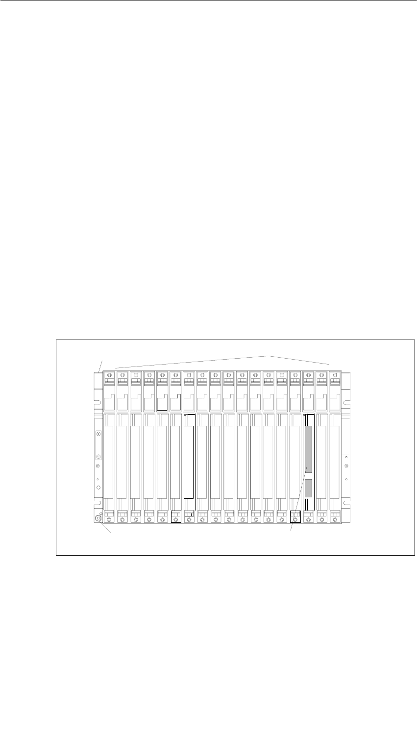
Racks
2-2 S7-400, M7-400 Programmable Controllers Module Specifications
A5E00069467-07
2.1 Function and Structure of the Racks
Introduction
The racks in the S7-400 have the following tasks:
•They hold the modules
•They supply the modules with operating voltage
•They connect the individual modules to each other via the signal buses
Structure of the Racks
A rack consists of the following elements:
•Mounting rail with threaded bolts for fixing the modules and lateral cutouts for
mounting the rack
•Plastic parts that function, among other things, as guides when swinging the
modules into place.
•A backplane bus, an I/O bus and, if necessary, a communication bus with bus
connector
•Connection for local ground
Figure 2-1 shows the mechanical configuration of a rack (UR1).
Aluminum carrier Plastic parts
Connection for local ground Bus connector (covered when shipped)
1 2 3 4 5 6 7 8 9 101112131415161718
Figure 2-1 Structure of a Rack with 18 Slots
UL/CSA Note
Special requirements should be taken into consideration in the area of influence of
the UL/CSA; these may be fulfilled by installing the system in a cabinet.
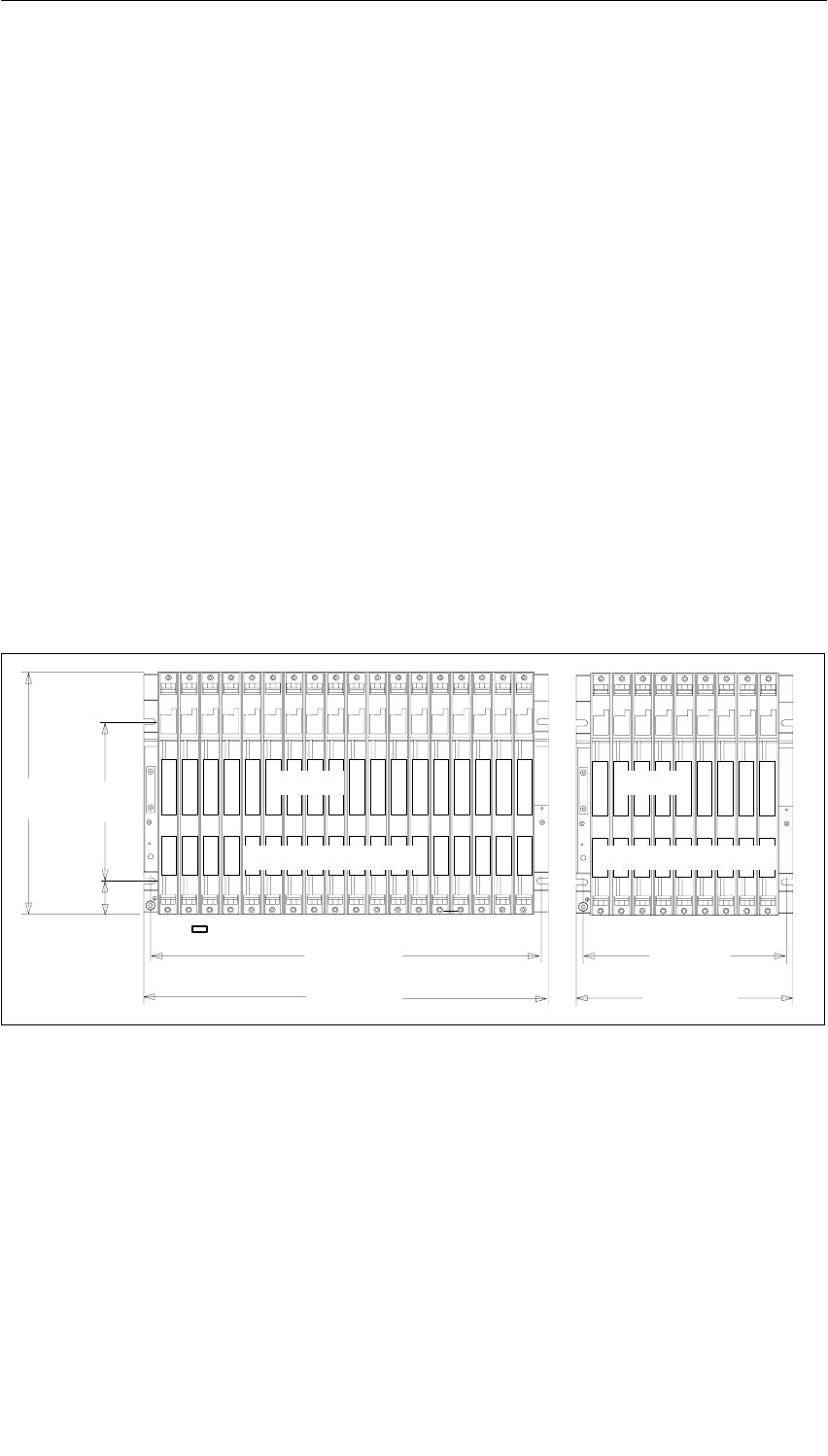
Racks
2-3
S7-400, M7-400 Programmable Controllers Module Specifications
A5E00069467-07
2.2 The Racks UR1; (6ES7400-1TA01-0AA0) and
UR2; (6ES7400-1JA01-0AA0)
Introduction
The UR1 and UR2 racks are used for assembling central racks and expansion
racks. The UR1 and UR2 racks have both an I/O bus and a communication bus.
Suitable Modules for UR1 and UR2
You can use the following modules in the UR1 and UR2 racks:
•When the UR1 or UR2 is used as a central rack:
All S7-400 modules with the exception of receive IMs
•When the UR1 or UR2 is used as an expansion rack:
All S7-400 modules with the exception of CPUs and send IMs
Special case: Power supply modules cannot be used in conjunction with the
IM 461-1 receive IM.
Structure of the UR1 and UR2
465 mm 240 mm
482.5 mm 257.5 mm
290 mm 190 mm
40 mm
1 2 3 4 5 6 7 8 9 101112131415161718 123456789
123456789101112131415161718 123456789
I/O bus
Communication bus
I/O bus
Communication bus
Figure 2-2 Dimensions of the UR1 18-Slot or UR2 9-Slot Rack

Racks
2-4 S7-400, M7-400 Programmable Controllers Module Specifications
A5E00069467-07
Technical Specifications of the UR1 and UR2 Racks
Rack UR1 UR2
Number of single-width slots 18 9
Dimensions W x H x D (in mm) 482.5 x 290 x 27.5 257.5 x 290 x 27.5
Weight (in kg) 3
4.1 as of version 03 1.5
2.15 as of version 04
Buses I/O bus and communication bus
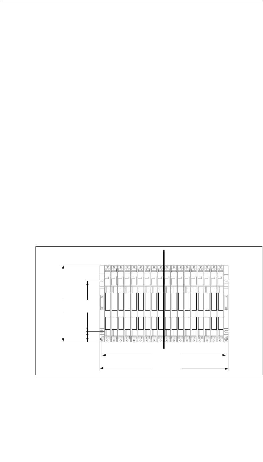
Racks
2-5
S7-400, M7-400 Programmable Controllers Module Specifications
A5E00069467-07
2.3 The Rack UR2-H; (6ES7400-2JA00-0AA0)
Introduction
The UR2-H rack is used for assembling two central racks or expansion racks in
one rack. The UR2-H rack essentially represents two electrically isolated UR2
racks on the same rack profile. The main area of application of the UR2-H is in the
compact structure of redundant S7-400H systems (two subracks or subsystems in
one rack).
Suitable Modules for the UR2-H
You can use the following modules in the UR2-H rack:
When the UR2-H is used as a central rack:
•All S7-400 modules with the exception of receive IMs
When the UR2-H is used as an expansion rack:
•All S7-400 modules apart from CPUs, send IMs, the IM 463-2, and the adapter
module
Special case: Power supply modules cannot be used in conjunction with the
IM 461-1 receive IM.
Structure of the UR2-H
Figure 2-3 shows the structure of the UR2-H rack with 2 x 9 slots.
465 mm
482.5 mm
290 mm 190 mm
40 mm
123456789123456789
Division I Division II
Figure 2-3 Rack Dimensions
Racks
2-6 S7-400, M7-400 Programmable Controllers Module Specifications
A5E00069467-07
!Caution
Danger of damage to equipment.
If you insert a power supply module in a slot that is not permitted for power supply
modules, the module may be damaged. Slots 1 to 4 are permitted, whereby power
supply modules starting from slot 1 must be inserted without leaving gaps.
Make sure that power supply modules are only inserted in permitted slots. Take
particular notice of the option of swapping modules in slot 1 on subrack II and slot
9 on subrack I.
Technical Specifications of the UR2-H Rack
Rack UR2-H
Number of single-width slots 2 x 9
Dimensions W x H x D (in mm) 482.5 x 290 x 27.5
Weight (in kg) 3
4.1 as of version 03
Buses Segmented I/O bus,
segmented communication bus
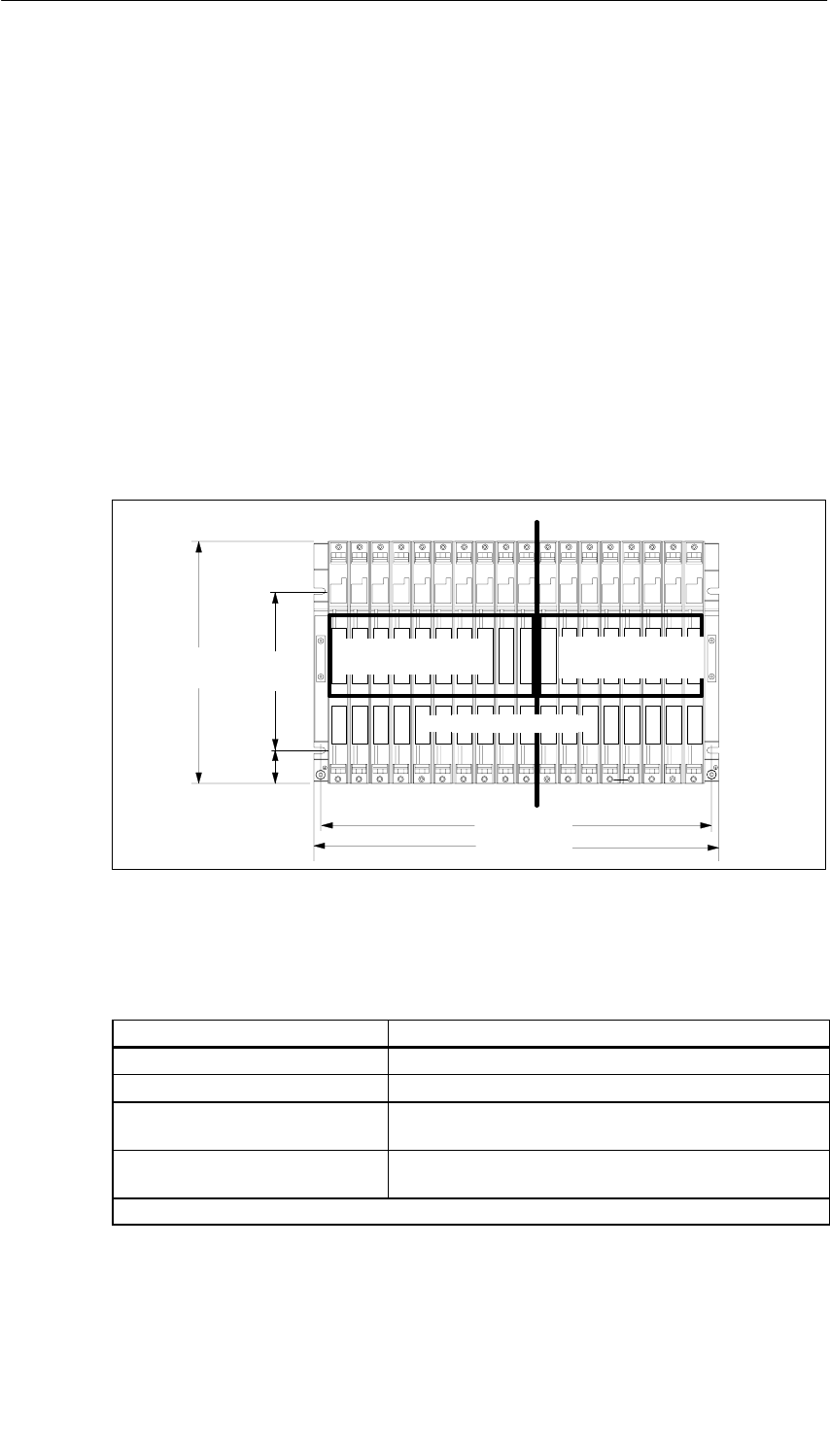
Racks
2-7
S7-400, M7-400 Programmable Controllers Module Specifications
A5E00069467-07
2.4 The Rack CR2; (6ES7401-2TA01-0AA0)
Introduction
The CR2 rack is used for assembling segmented central racks. The CR2 has both
an I/O bus and a communication bus. The I/O bus is split into two local bus
segments with 10 or 8 slots.
Suitable Modules for the CR2
You can use the following modules in the CR2 rack:
•All S7-400 modules with the exception of receive IMs
Structure of the CR2
465 mm
482.5 mm
290 mm 190 mm
40 mm
123456789123456789
123456789101112131415161718
Segment 1 Segment 2
I/O bus
Segment 1 I/O bus
Segment 2
Communication bus
Figure 2-4 CR2 Rack
Technical Specifications of the CR2 Rack
Rack CR2
Number of single-width slots 18
Dimensions W x H x D (in mm) 482.5 x 290 x 27.5
Weight 3 kg
4.1 as of version 03
Busses Segmented I/O bus,
continuous communication bus
Only one power supply module required
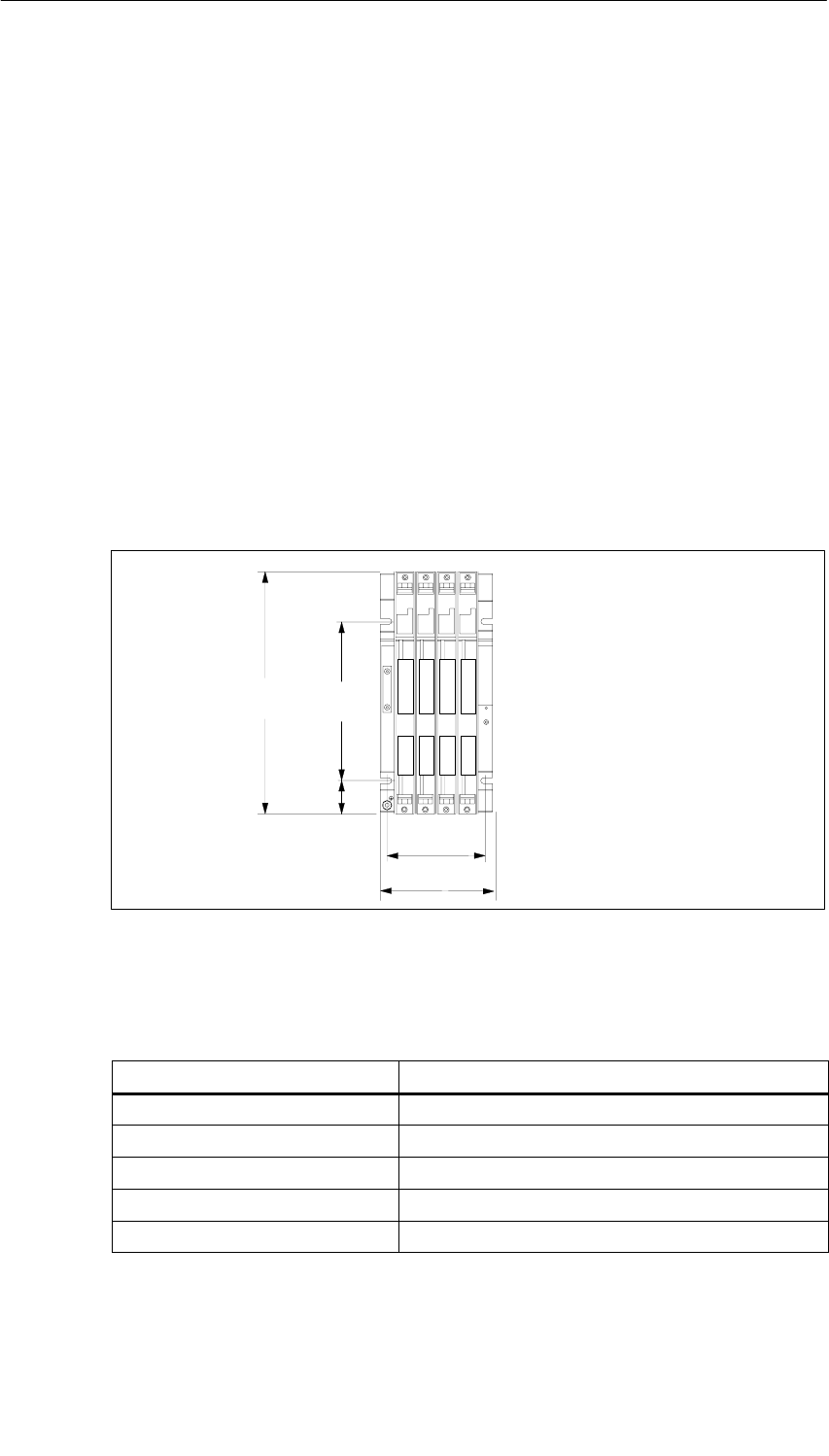
Racks
2-8 S7-400, M7-400 Programmable Controllers Module Specifications
A5E00069467-07
2.5 The Rack CR3; (6ES7401-2TA01-0AA0)
Introduction
The CR3 rack is used for the assembly of CRs in standard systems (not in
fault-tolerant systems). The CR3 has an I/O bus and a communication bus.
Suitable Modules for CR 3
You can use the following modules in CR3:
•All S7-400 modules with the exception of receive IMs
•You can only use the CPU 414-4H and CPU 417-4H in stand-alone operation.
Structure of the CR3
190 mm
40 mm
1234
1234
115 mm
132 mm
Figure 2-5 CR3 Rack
Technical Specifications of the CR3 Rack
Rack CR3
Associated programming package As of STEP7 V 5.1; ServicePack 3
Number of single-width slots 4
Dimensions W x H x D (in mm) 122.5 x 290 x 27.5
Weight (in kg) 0.75
Buses I/O bus and communication bus

Racks
2-9
S7-400, M7-400 Programmable Controllers Module Specifications
A5E00069467-07
2.6 The Racks ER1; (6ES7403-1TA01-0AA0)
and ER2; (6ES7403-1JA01-0AA0)
Introduction
The ER1 and ER2 racks are used for assembling expansion racks.
The ER1 and ER2 racks have only one I/O bus with the following restrictions:
•Interrupts from modules in the ER1 or ER2 have no effect since there are no
interrupt lines provided.
•Modules in the ER1 or ER2 are not supplied with 24 V. Modules requiring a
24 V supply are not provided for use in the ER1 or ER2.
•Modules in the ER1 or ER2 are not backed up either by the battery in the power
supply module or by the voltage supplied externally to the CPU or the receive
IM (EXT.-BATT. socket).
There is therefore no advantage in using backup batteries in the power supply
modules in ER1 and ER2.
Battery faults and backup voltage faults are not reported to the CPU.
The battery monitoring function of a power supply module installed in the ER1
or ER2 should therefore always be switched off.
Suitable Modules for ER1 and ER2
You can use the following modules in the ER1 and ER2 racks:
•All power supply modules
•Receive IMs
•All signal modules provided the above-mentioned restrictions are observed.
However: Power supply modules cannot be used in conjunction with the IM 461-1
receive IM.
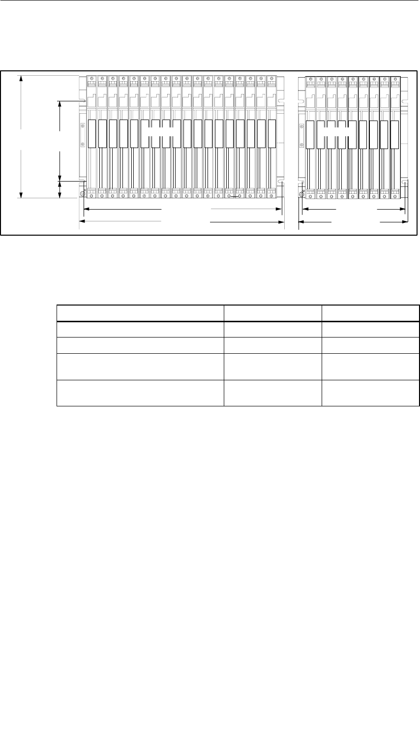
Racks
2-10 S7-400, M7-400 Programmable Controllers Module Specifications
A5E00069467-07
Structure of ER1 and ER2
465 mm 240 mm
482.5 mm 257.5 mm
290 mm 190 mm
40 mm
1 2 3 4 5 6 7 8 9 101112131415161718 123456789
1 2 3 4 5 6 7 8 9 101112131415161718 123456789
I/O bus I/O bus
Figure 2-6 ER1 Rack with 18 Slots and ER2 Rack with 9 Slots
Technical Specifications of the ER1 and ER2 Racks
Rack ER1 ER2
Number of single-width slots 18 9
Dimensions W x H x D (in mm) 482.5 x 290 x 27.5 257.5 x 290 x 27.5
Weight (in kg) 2.5
3.8 as of version 03 1.25
2.0 as of version 03
Busses Restricted
I/O bus Restricted
I/O bus
3-1
S7-400, M7-400 Programmable Controllers Module Specifications
A5E00069467-07
Power Supply Modules
Chapter Overview
Section Description Page
3.1 Common Characteristics of the Power Supply Modules 3-2
3.2 Redundant Power Supply Modules 3-4
3.3 Backup Battery (Option) 3-6
3.4 Controls and Indicators 3-8
3.5 Fault/Error Messages via LEDs 3-13
3.6 Power Supply Module
PS 407 4A; (6ES7407-0DA00-0AA0) 3-19
3.7 Power Supply Module
PS 407 4A; (6ES7407-0DA01-0AA0) 3-21
3.8 Power Supply Modules
PS 407 10A; (6ES7407-0KA01-0AA0) and
PS 407 10A R; (6ES7407-0KR00-0AA0)
3-23
3.9 Power Supply Module
PS 407 20A; (6ES7407-0RA00-0AA0) 3-26
3.10 Power Supply Module
PS 407 20A; (6ES7407-0RA01-0AA0) 3-28
3.11 Power Supply Module
PS 405 4A; (6ES7405-0DA00-0AA0) 3-30
3.12 Power Supply Module
PS 405 4A; (6ES7405-0DA01-0AA0) 3-32
3.13 Power Supply Module
PS 405 10A; (6ES7405-0KA00-0AA0) 3-34
3.14 Power Supply Modules
PS 405 10A; (6ES7405-0KA01-0AA0) and
PS 405 10A R; (6ES7405-0KR00-0AA0)
3-36
3.15 Power Supply Module
PS 405 20A; (6ES7405-0RA00-0AA0) 3-38
3.16 Power Supply Module
PS 405 20A; (6ES7405-0RA01-0AA0) 3-40
3

Power Supply Modules
3-2 S7-400, M7-400 Programmable Controllers Module Specifications
A5E00069467-07
3.1 Common Characteristics of the Power Supply Modules
Tasks of the Power Supply Modules
The power supply modules of the S7-400 supply the other modules in the rack with
their operating voltages via the backplane bus. They do not provide load voltages
for the signal modules.
Common Characteristics of the Power Supply Modules
The power supply modules share certain common characteristics in addition to
their special technical specifications. The most important common characteristics
are:
•Encapsulated design for use in mounting racks of the S7-400 system
•Cooling via natural convection
•Plug-in connection of the supply voltage with AC - DC coding
•Protection class I (with protective conductor) in accordance with IEC 60536;
VDE 0106, Part 1
•Limitation of making current in accordance with NAMUR recommendation part 1
of August 1998
•Short circuit-proof outputs
•Monitoring of both output voltages. If one of these voltages fails, the power
supply module signals a fault to the CPU.
•Both output voltages (5 VDC and 24 VDC) share a common ground.
•Primary clocked
•Battery backup as option. The parameters set and the memory contents (RAM)
are backed up via the backplane bus in the CPUs and programmable modules.
In addition, the backup battery enables you to carry out a restart of the CPU.
Both the power supply module and the backed up modules monitor the battery
voltage.
•Operating and fault/error LEDs on the front plate.
Warning
A mains disconnecting device must be provided when installing AC power supply
modules.
Power Supply Modules
3-3
S7-400, M7-400 Programmable Controllers Module Specifications
A5E00069467-07
Switching the Line Voltage Off/On
The power supply modules have a making-current limiter in accordance with
NAMUR.
Power Supply Module in Invalid Slot
If you insert the power supply module of a rack in an invalid slot, it will not power
up. In this case, proceed as follows to start up the power supply module correctly:
1. Disconnect the power supply module from the mains (not just the standby
switch).
2. Remove the power supply module.
3. Install the power supply module in slot 1.
4. Wait at least 1 minute and then switch the line voltage on again.
!Caution
Damage can result.
If you insert the power supply module in a slot that is not intended for power
supply modules, the module may be damaged. Slots 1 to 4 are permissible as long
as you start at slot 1 and leave no gaps.
Make sure that power supply modules are only inserted in permissible slots.
Compliance with the NAMUR Recommendation
If you use one of the modules listed below, you can achieve mains buffering in
accordance with the NAMUR recommendation with a central power supply in
accordance with NAMUR or an uninterrupted power supply.
Table 3-1 Compliance with the NAMUR recommendation
Name Order number
Power Supply Module PS 407 4 A 6ES7407-0DA00-0AA0
Power Supply Module PS 407 20 A 6ES7407-0RA00-0AA0
Power Supply Module PS 405 4 A 6ES7405-0DA00-0AA0
Power Supply Module PS 405 10 A 6ES7405-0KA00-0AA0
Power Supply Module PS 405 20 A 6ES7405-0RA00-0AA0

Power Supply Modules
3-4 S7-400, M7-400 Programmable Controllers Module Specifications
A5E00069467-07
3.2 Redundant Power Supply Modules
Order Numbers and Function
Table 3-2 Redundant power supply modules
Type Order Number Input Voltage Output Voltage See
Section
PS 407 10A R 6ES7407-0KR00-0AA0 85 VAC to 264 VAC or
88 VDC to 300 VDC 5 VDC/10 A and
24 VDC/1 A 3.8
PS 405 10A R 6ES7405-0KR00-0AA0 19.2 VDC to 72 VDC 5 VDC/10 A and
24 VDC/1 A 3.14
Redundant Operation
If you use two power supply modules of type PS 407 10A R or PS 405 10A R, you
can install a redundant power supply on a mounting rack. We recommend this if
you want to increase the availability of your programmable controller, particularly if
you are operating it on an unreliable power system.
Configuring a Redundant Power Supply
Redundant operation is possible with any of the S7 CPUs and racks described in
this manual. STEP 7 as of V4.02 is also required.
To set up a redundant power supply, insert a power supply module in slots 1 and 3
of the rack. You can then insert as many modules as can be supplied by a single
power supply module. In other words, in redundant operation all the modules can
only draw a total of 10 A.

Power Supply Modules
3-5
S7-400, M7-400 Programmable Controllers Module Specifications
A5E00069467-07
Characteristics
The redundant power supply of an S7-400 has the following characteristics:
•The power supply module delivers a making current in accordance with
NAMUR.
•Each of the power supply modules can take over the supply of power to the
whole rack if the other one fails. There is no loss of operation.
•Each of the power supply modules can be exchanged while the system is in
operation. No loss of power and no peak stress occurs with the effective
voltages when the modules are removed or inserted.
•Each of the power supply modules monitors its function and sends a message if
it fails.
•Neither of the power supply modules can generate an error which affects the
output voltage of the other power supply module.
•A redundant battery concept (backup concept) is only provided when two
backup batteries are used in each of the power supply modules. If only one
battery is used in each module, only non-redundant backup is possible, since
both batteries are being used at the same time.
•The failure of a power supply module is registered via a plug and remove
interrupt (default STOP). Only if used in the second segment of the CR 2 is no
message sent if the power supply module fails.
•If two power supply modules are inserted but only one is switched on, there is a
power-up delay of up to one minute when the line voltage is switched on.
Note
The check box “Startup if preset configuration not equal to actual configuration”
should be activated in the “Properties” dialog box of the CPU.

Power Supply Modules
3-6 S7-400, M7-400 Programmable Controllers Module Specifications
A5E00069467-07
3.3 Backup Battery (Option)
Introduction
The power supply modules of the S7-400 have a battery compartment for one or
two backup batteries. Use of these batteries is optional.
Function of the Backup Batteries
If backup batteries have been installed, the parameters set and the memory
contents (RAM) will be backed up via the backplane bus in CPUs and
programmable modules if the supply voltage fails. The battery voltage must be
within the tolerance range.
In addition, the backup battery enables you to carry out a restart of the CPU after
power-on.
Both the power supply module and the backed up modules monitor the battery
voltage.
Power Supply Modules With Two Backup Batteries:
Some power supply modules contain a battery compartment for two batteries. If
you use two batteries and set the switch to 2BATT, the power supply module
defines one of the two batteries as the backup battery. This assignment remains in
force until the battery is empty. When the backup battery is completely discharged,
the system switches to the reserve battery which is then in turn used as the backup
battery for the duration of its life. The status “backup battery” is also stored in the
event of a power failure.
Battery Type
Only batteries approved by Siemens must be used (see Appendix C: Spare Parts)
The batteries can form a passivation layer. Depassivation takes place when the
batteries are inserted in the power supply module.
Technical Specifications of the Backup Battery
Backup Battery
Order number 6ES7971-0BA00
Type 1 x lithium AA
Rated voltage 3.6 V
Rated capacity 1.9 Ah

Power Supply Modules
3-7
S7-400, M7-400 Programmable Controllers Module Specifications
A5E00069467-07
Backup Times
The maximum backup time is based on the capacity of the backup batteries used
and the backup current in the rack. The backup current is the sum of all individual
currents of the inserted backed-up modules as well as the requirements of the
power supply module when the power is switched off.
Example for the Calculation of Backup Times
The capacity of the batteries is listed in the technical specifications of the power
supply. The typical and maximum backup current of the backed-up module is listed
in the technical specifications of the module.
The typical backup current of a CPU is an empirically determined value. The
maximum backup current is a worst-case value that is calculated based on the
corresponding manufacturer specifications for the memory blocks.
The following technical specifications produce backup times for a CR with a PS
407 4A and a CPU 417-4 as the only backed-up module:
Capacity of the backup battery: 1.9 Ah
Maximum backup current (including own requirement at power off) of the power
supply:100 µA
Typical backup current of the CPU 417-4: 75 µA
A rated capacity of less than 100% is to be assumed when calculating the backup
time because the backup battery is also affected at power on by the regular
depassivation.
A battery capacity of 63% of the rated capacity produces the following values:
Backup time = 1.9 Ah * 0.63 / (100 + 75)µA = (1.197 / 175) * 1 000 000 = 6840 h
This produces a maximum backup time of 285 days.
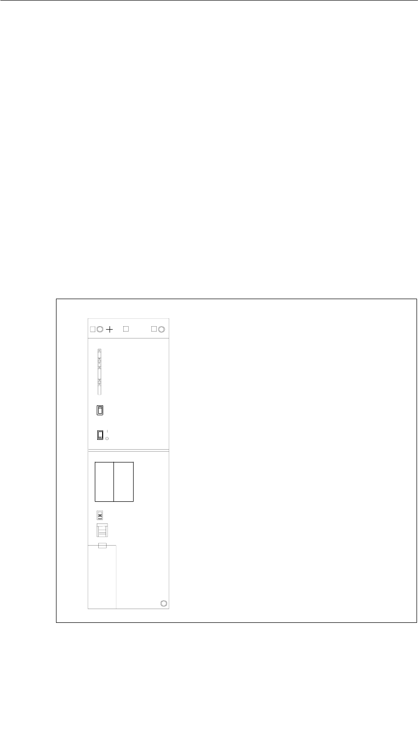
Power Supply Modules
3-8 S7-400, M7-400 Programmable Controllers Module Specifications
A5E00069467-07
3.4 Controls and Indicators
Introduction
The power supply modules of the S7-400 have essentially the same controls and
indicators.The main differences are:
•Not all the power supply modules have a voltage selector.
•Power supply modules with a backup battery have an LED (BATTF) that
indicates an empty, defective, or missing backup battery.
Power supply modules with two redundant backup batteries have two LEDs
(BATT1F and BATT2F) to indicate empty, defective or missing backup batteries.
Operator Controls and Indicators
Figure 3-1 shows you an example of a power supply module (PS 407 20A) with two
(redundant) backup batteries. The LEDs are at the top left of the module front
plate.
•FMR pushbutton (Failure Message Reset)
•Standby switch (does not cut off mains)
•Switches BATT. INDIC.
2 BATT, OFF, 1 BATT
•Voltage selector (if present)
•Battery compartment
•3-pin plug-in power connector
•Fixing screw
•Fixing screws
•LEDs INTF,
BAF, BATT1F, BATT2F, 5 VDC, 24 VDC
5 VDC, 24 VDC
PS 407 20A
407-0RA00-0AA0
X2
34
1
FMR
BATT. INDIC.
2 BATT
230
VOLTAGE
1 BATT
OFF
INTF
BAF
BATTF
5 VDC
24 VDC
BATTF
23
BATT.1 BATT.2
+
–
+
–
Under cover
Figure 3-1 Controls and Indicators on the PS 407 20A Power Supply Module
Power Supply Modules
3-9
S7-400, M7-400 Programmable Controllers Module Specifications
A5E00069467-07
Meaning of the LEDs
The meaning of the LEDs on the power supply modules is described in the tables
below. Section 3.5 contains a list of the faults indicated by these LEDs and notes
on how to acknowledge the faults.
INTF, 5 VDC, 24 VDC
Table 3-3 INTF, DC 5V, DC 24 V LEDs
LED Color Meaning
INTF red Lights up in the event of an internal fault
5 VDC green Lights up as long as the 5 V voltage is within the tolerance limits
24 VDC green Lights up as long as the 24 V voltage is within the tolerance
limits
BAF, BATTF
Power supply modules with a backup battery have the following indicators:
Table 3-4 BAF, BATTF LEDs
LED Color Meaning
BAF Red Lights up if the battery voltage on the backplane bus is too low
and the BATT INDIC switch is at the BATT position
BATTF Yellow Lights up if the battery is empty, if the polarity is reversed, or if
the battery is missing, and the BATT INDIC switch is at the BATT
position
BAF, BATT1F, BATT2F
Power supply modules with two backup batteries have the following indicators:
Table 3-5 BAF, BATT1F, BATT2F LEDs
LED Color Meaning
BAF Red Lights up if the battery voltage on the backplane bus is too low
and the BATT INDIC switch is at the 1 BATT or 2 BATT position
BATTF Yellow Lights up if battery 1 is empty or if the polarity is reversed or if
the battery is missing, and the BATT INDIC switch is at the
1 BATT or 2 BATT position
BATTF Yellow Lights up if battery 2 is empty or if the polarity is reversed, or if
the battery is missing, and the BATT INDIC switch is at the
2 BATT position

Power Supply Modules
3-10 S7-400, M7-400 Programmable Controllers Module Specifications
A5E00069467-07
Battery Voltage on the Backplane Bus
The battery voltage is either supplied by the backup battery or externally into the
CPU or receive IM. In its normal state, the level of the battery voltage is between
2.7 V and 3.6 V.
The battery voltage is monitored for the lower limit. Violation of the lower limit is
indicated by the BAF LED and reported to the CPU.
BAF lights up if the battery voltage on the backplane bus is too low. Possible
causes of this include:
•Battery (batteries) empty or battery polarity has been reversed.
•External supply via CPU or receive IM is defective or supply from secondary
power supply module is defective or missing.
•Short circuit or overload on the battery voltage.
Note
Due to internal capacities, if you remove the battery or switch off the external
supply, some time may elapse before BAF, BATT1F, or BATT2F lights up.

Power Supply Modules
3-11
S7-400, M7-400 Programmable Controllers Module Specifications
A5E00069467-07
Function of the Operator Controls
Table 3-6 Function of the operator controls of the power supply modules
FMR momentary-
contact pushbut-
ton
For acknowledging and resetting a fault indicator after correcting the
fault
Standby switch Switches the output voltages (5 VDC/24 VDC) to 0 V by intervening in
the control loop (no mains disconnection).
• I : Output voltages at rated value
• : Output voltages 0 V
BATT INDIC
switch Used for setting LEDs and battery monitoring
Where one battery can be used (PS 407 4A, PS 405 4A):
•OFF: LEDs and monitor signals inactive
•BATT: BAF/BATTF LEDs and monitor signals active
Where two batteries can be used (PS 407 10A, PS 407 20A, PS
405 10A, PS 405 20A):
•OFF: LEDs and monitor signals inactive
•1 BATT: Only BAF/BATT1F LEDs (for battery 1) active.
•2 BATT: BAF/BATT1F/BATT2F LEDs (for batteries 1 and 2) active.
Voltage selector
(if present) For setting the primary voltage (120 VAC or 230 VAC), protected by its
own cover.
(Please note the following information)
Battery compart-
ment For backup battery (batteries)
Power connec-
tion 3-pin connector for line voltage connection (do not plug in or remove
when power is on).
!Caution
One of the following power supply modules could be damaged:
Power supply module PS 407 4A (6ES7407-0DA00-0AA0)
Power supply module PS 407 20A (6ES7407-0RA00-0AA0)
If you set the voltage selector to 120 V on these AC power supply modules and
connect the power supply modules to a 230 V power system, it might damage the
power supply modules. Warranty is excluded in such a case.
Set the voltage selector on these AC power supply modules to the line voltage.

Power Supply Modules
3-12 S7-400, M7-400 Programmable Controllers Module Specifications
A5E00069467-07
Cover
The battery compartment, battery selector switch, voltage selector switch and
power connection are housed under one cover. The cover must remain closed
during operation in order to protect these operator controls and to prevent static
electricity from affecting the battery connections.
If you have to carry out measurements on a module, you must discharge your body
before you start the measurement by touching grounded metallic parts. Use
grounded measuring devices only.
Power Supply Modules
3-13
S7-400, M7-400 Programmable Controllers Module Specifications
A5E00069467-07
3.5 Fault/Error Messages via LEDs
Introduction
The power supply modules of the S7-400 indicate module faults and backup
battery faults via LEDs on the front plate.
Overview of the Fault/Error Messages
Table 3-7 Error messages of the power supply modules
Type of Fault/Error LEDs
Module fault INTF
5 VDC
24 VDC
Backup battery fault Power supplies with 1 backup battery:
BAF
BATTF
Power supplies with 2 backup batteries:
BAF
BATT1F
BATT2F
INTF, 5 VDC, 24 VDC
The following table shows the faults indicated by the INTF, 5 VDC, and 24 VDC
LEDs and lists how to remedy the faults.
The status of the BAF, BATTF, BATT1F, and BATT2F LEDs is not relevant here.
Table 3-8 INTF, DC5V, DC24V LEDs
LED
INTF DC5V DC24V Cause of Fault Remedy
D D D Standby switch in position Set standby switch to the I position
Line voltage missing Check line voltage
Internal fault, power supply module
defective Replace power supply module
Cutoff after overvoltage on 5 V or illegal
external supply Disconnect from mains and reconnect
after approximately 1 minute; if
necessary, remove external supply
Power supply module operated in
wrong slot Install the power supply module in the
correct slot (slot 1)
Short circuit or overload on 5 V Switch off the power supply module,
remove the source of the short circuit;
after approximately 3 seconds, the
power supply module can be switched
on with the standby switch or via the
power system.*
D H D Overvoltage on 24 V Check if the supply is external; if not,
replace power supply module
Power Supply Modules
3-14 S7-400, M7-400 Programmable Controllers Module Specifications
A5E00069467-07
Table 3-8 INTF, DC5V, DC24V LEDs, continued
LED
INTF RemedyCause of Fault
DC24VDC5V
H D* D Short circuit or overload on 5 V and
24 V Check load on the power supply
module.
Possibly remove modules
H D* H/D ** Short circuit or overload on 5 V Check load on the power supply
module. Possibly remove modules
H H D If the standby switch is at the
position, illegal external supply on 5 V
Remove all modules.
Determine which module is faulty
If the standby switch is at the I
position, short-circuit or overload on
24 V
Check load on the power supply
module.
Possibly remove modules
D B H Voltage restored after short circuit or
overload on 5 V if faults occur in
operation
Press FMR momentary-contact
pushbutton:
Flashing light changes to constant light
Dynamic overload on 5 V Check load on the power supply
module.
Possibly remove modules
D H B Voltage restored after short-circuit or
overload on 24 V if faults occur in
operation
Press FMR momentary-contact
pushbutton:
Flashing light changes to constant light
Dynamic overload on 24 V Check load on the power supply
module.
Possibly remove modules
D B B Voltage restored after short circuit or
overload on 5 V and 24 V if faults occur
in operation
Press FMR momentary-contact
pushbutton:
Flashing light changes to constant light
D B B Dynamic overload on 5 V and 24 V Check load on the power supply
module.
Possibly remove modules
D = LED is dark; L = LED lights up; F = LED flashing;
* If the power supply module does not start up again after a few seconds once the
overload has been removed, remove power to the module for 5 minutes and then
switch it on again. If the module stills does not start up, you must replace it. This
applies to 6ES7407-0KA01-0AA0, release 3 and for 6ES7407-0KR00-0AA0,
release ≤ 5.
** Depending on the short-circuit resistance
If either the 5 VDC or 24 VDC LEDs remains dark after switching on, the system
has not powered up.
If either of the 5 VDC or 24 VDC LEDs of the PS 407 10AR remains dark for longer
than 1 or 2 seconds after it is switched on, the power supply module will not start
up.

Power Supply Modules
3-15
S7-400, M7-400 Programmable Controllers Module Specifications
A5E00069467-07
The following power supply modules will switch off in the event of a short circuit or
overload after 1 s to 3 s. The module will try to restart after no more than 3 s. If the
error has been eliminated by then, the module will start up. This applies to the
following modules:
PS 405 4A (6ES7405-0DA01-0AA0) PS 407 4A (6ES7407-0DA01-0AA0)
PS 405 10A (6ES7405-0KA01-0AA0) PS 407 10A (6ES7407-0KA01-0AA0),
release ≥5
PS 405 10A R (6ES7405-0KR00-0AA0) PS 407 10A R (6ES7407-0KR00-0AA0),
release ≥7
PS 405 20A (6ES7405-0RA01-0AA0) PS 407 20A (6ES7407-0RA01-0AA0)
Overload at 24 V
In the event of overload at 24 V the output current is electronically limited to a value
between 100% and 150% of the rated value. If the voltage then goes below the
undervoltage threshold of 19.2 V (–0/+ 5% corresponds to 19.2 V to 20.16 V), the
modules respond as follows:
•In the case of power supply modules with 4 A/0.5 A output current, the 24 V
voltage is disconnected and reconnected at a repeat rate of approx. 0.5 s to 1 s
until there is an output voltage that exceeds the undervoltage threshold.
•In the case of power supply modules with 10 A/1 A or 20 A/1 A output current,
the voltage depends on the load impedance, and the module runs in
characteristic curve mode.
After the overload has been eliminated, the voltage returns to the rated range and
the green 24 V LED flashes. The CPU sets the EXTF LED (external fault) and
saves the fault in the diagnostic buffer. You can trigger other responses, such as
CPU STOP or a message to a control room, in OB 81 (power supply error). If OB
81 is not parameterized, the CPU continues as normal.
Overload at 5 V
In the event of an overload at 5V, the power supply modules with 10 A or 20 A
output current can retain an output current of 16 A or 26 A for 300ms. The power
supply modules with 4 A output current can retain an output current of 8 A for 300
ms. The CPU will then go to DEFECT afterwards. If the LED DC 5 V flashes on the
power supply and is resettable with the FMR button, you will be able to perform a
restart. The CPU will remain in STOP afterwards and will then require a memory
reset.
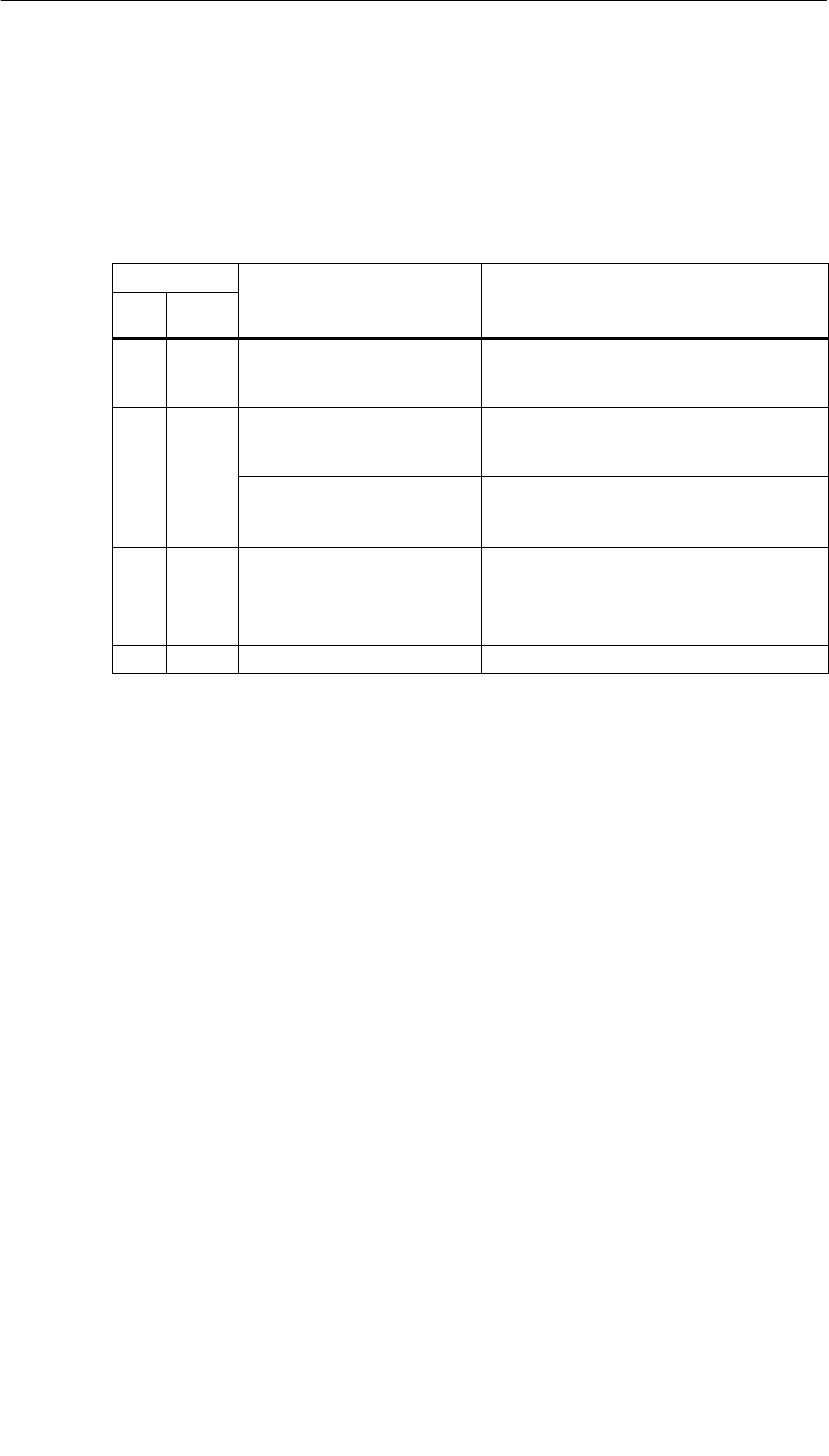
Power Supply Modules
3-16 S7-400, M7-400 Programmable Controllers Module Specifications
A5E00069467-07
BAF, BATTF
The following table applies to power supply modules with one battery if the BATT
INDIC switch is in the BATT position. It shows the faults indicated and lists how to
remedy the faults.
Table 3-9 BAF, BATTF; BATT INDIC LEDs on BATT
LED Cause of Fault Remedy
BAF BATT
F
H H Battery empty or missing
No backup voltage available Insert new battery.
Press FMR momentary-contact
pushbutton
D H Battery empty or missing Insert new battery.
Press FMR momentary-contact
pushbutton
Battery has been stored for
too long
Depassivate battery
(see Installation Manual Chapter 7)
t
oo
l
ong
(
see
I
ns
t
a
ll
a
ti
on
M
anua
l
,
Ch
ap
t
er
7)
H D Battery in order
No backup voltage available
(short circuit)
•Fault after plugging in a module:
Plugged-in module defective
•Fault after switching on: Remove all
modules and plug in individually
D D Battery in order –
D = LED is dark; L = LED lights up;

Power Supply Modules
3-17
S7-400, M7-400 Programmable Controllers Module Specifications
A5E00069467-07
BAF, BATT1F, BATT2F
The following table applies to power supply modules with two batteries if the BATT
INDIC switch is in the 1BATT position. It shows the faults indicated and lists how to
remedy the faults.
Nothing is indicated about the condition of any second battery that may be in use.
Table 3-10 BAF, BATT1F, BATT2F; BATT INDIC LEDs on 1BATT
LED Cause of Fault Remedy
BAF BATT1F BATT2F
H H D Battery 1 empty or missing
No backup voltage available Insert new battery in
compartment 1.
Press FMR
momentary-contact
pushbutton
D H D Battery 1 empty or missing Insert new battery in
compartment 1.
Press FMR
momentary-contact
pushbutton
Battery has been stored for
too long Depassivate battery
(see Installation Manual,
Chapter 7)
H D D Battery 1 in order
No backup voltage available
(short circuit)
•Fault after plugging in a
module: Plugged-in
module defective
•Fault after switching on:
Remove all modules and
plug in individually
D D D Battery 1 in order –
D = LED is dark; L = LED lights up;

Power Supply Modules
3-18 S7-400, M7-400 Programmable Controllers Module Specifications
A5E00069467-07
The following table applies to power supply modules with two batteries if the BATT
INDIC switch is in the 2BATT position. It shows the faults indicated and lists how to
remedy the faults.
Table 3-11 BAF, BATT1F, BATT2F; BATT INDIC LEDs on 2BATT
LED Cause of Fault Remedy
BAF BATT1F BATT2F
H H H Both batteries are empty or
missing.
No backup voltage available
Insert new batteries in compartments 1
and 2
Press FMR momentary-contact
pushbutton
D H H Both batteries empty or missing Insert new batteries in compartments 1
and 2
Press FMR momentary-contact
pushbutton
H H D Battery 1 empty or missing Insert new battery in compartment 1.
Press FMR momentary-contact
pushbutton
No backup voltage available
(short circuit or overload) •Fault after plugging in a module:
Plugged-in module defective
•Fault after switching on: Remove all
modules and plug in individually
D H D Battery 1 empty or missing Insert new battery in compartment 1.
Press FMR momentary-contact
pushbutton
Battery has been stored for too
long Depassivate battery
(see Installation Manual, Chapter 7)
H D H Battery 2 empty or missing Insert new battery in compartment 2.
Press FMR momentary-contact
pushbutton
No backup voltage available
(short-circuit or overload) •Fault after plugging in a module:
Plugged-in module defective
•Fault after switching on: Remove all
modules and plug in individually
D D H Battery 2 empty or missing Insert new battery in compartment 2.
Press FMR momentary-contact
pushbutton
Battery has been stored for too
long Depassivate battery
(see Installation Manual, Chapter 7)
H D D Both batteries in order.
No backup voltage available
(short circuit)
•Fault after plugging in a module:
Plugged-in module defective
•Fault after switching on: Remove all
modules and plug in individually
D D D Both batteries in order. –
D = LED is dark; L = LED lights up;
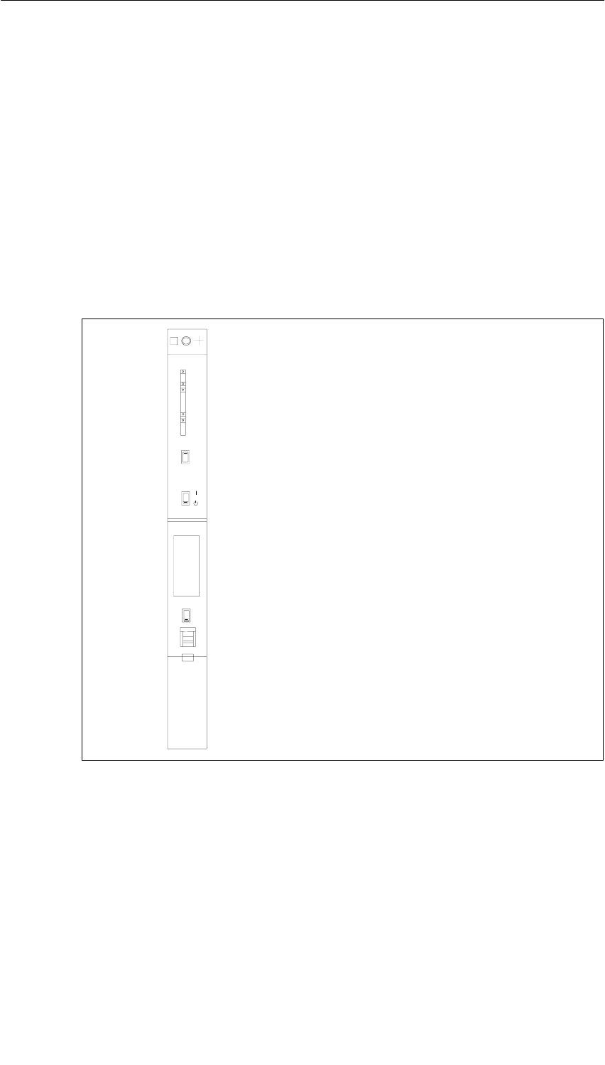
Power Supply Modules
3-19
S7-400, M7-400 Programmable Controllers Module Specifications
A5E00069467-07
3.6 Power Supply Module PS 407 4A;
(6ES7407-0DA00-0AA0)
Function
The PS 407 4 A power supply module is designed for connecting to an AC line
voltage of 120/230 VAC and supplies 5 VDC/4 A and 24 VDC/0.5 A on the
secondary side.
Controls and Indicators of the PS 407 4A
•LEDs INTF,
BAF, BATTF,
5 VDC, 24 VDC
•FMR pushbutton (Failure Message Reset)
•Standby switch (does not cut off mains)
•Switches BATT. INDIC.
BATT, OFF
•Voltage selector switch
•Battery compartment
•3-pin plug-in power connector
•Fixing screw
PS 407 4A
1X2
34
407-0DA00-0AA0
FMR
BATT. INDIC.
BATT
OFF
230
INTF
BAF
BATTF
5 VDC
24 VDC
VOLTAGE
Under cover
•Fixing screw
Figure 3-2 Controls and Indicators of the PS 407 4A

Power Supply Modules
3-20 S7-400, M7-400 Programmable Controllers Module Specifications
A5E00069467-07
Technical Specifications of the PS 407 4A
Programming Package
Associated programming
package As of STEP7 V 2.0
Dimensions, Weight, and Cable Cross-Sections
Dimensions WxHxD (mm)
Weight
25x290x217
0.78 kg
g
Cable cross-section
g
3x1.5 mm 2 (litz wire
with wire end ferrule
with insulating collar;
w
ith i
nsu
l
a
ti
ng
co
ll
ar;
use only flexible
sheath cable)
Cable diameter 3 to 9 mm
Input Rating
Input voltage
•Rated value
•Permitted range
120/230 VAC
85 to 132 VAC /
170 to 264 VAC
System frequency
•Rated value
•Permitted range
50 / 60 Hz
47 to 63 Hz
Rated input current
•At 120 VAC
•At 230 VAC
0.55 A
0.31 A
Inrush current
•With rated voltage of 264 V
•With rated voltage of 132 V
Peak value 15 A
Half-value width 2 ms
Peak value 18 A
Half-value width 2 ms
Leakage current < 3.5 mA
Overvoltage resistance In accordance with DIN
VDE 0160, curve W2
Output Variables
Output voltages
•Rated values 5.1 VDC /24 VDC
Output currents
•Rated values 5 VDC: 4 A
24 VDC: 0.5 A
Max. residual ripple 5 VDC: 50 mVSS
24 VDC: 200 mVSS
Max. switching peaks 5 VDC: 150 mVS
24 VDC: 500 mVS
Idle conditions 5 VDC: 100 mA Base
load required
24 VDC: Idling-proof
(no base load required)
Other Parameters
Protection class in accordance
with IEC 60536 I, with protective
grounding conductor
Overvoltage category II
Pollution severity 2
Rated voltage Ue
0 < Ue ≤ 50 V
150 V < Ue ≤ 300 V
Test Voltage
700 VDC
(secondary <–> PE)
2200 VDC
(primary <–> PE)
Buffering of power failures:
•At 50 Hz
•At 60 Hz
4.5 ms to 7.5 ms
6.5 ms to 8.5 ms
Power input 46.5 W
Power loss 13.9 W
Backup current Max. 100 µA at power
off
Backup battery (option) 1 x Lithium AA, 3.6 V /
1.9 Ah
Protective separation
to IEC 61131-2 Yes
Power Supply Modules
3-21
S7-400, M7-400 Programmable Controllers Module Specifications
A5E00069467-07
3.7 Power Supply Module PS 407 4A;
(6ES7407-0DA01-0AA0)
Function
The PS 407 4A power supply module is designed for connecting to either an AC
line voltage of 85 to 264 V or a DC line voltage of 88 to 300 V and
supplies 5 VDC/4 A and 24 VDC/0.5 A on the secondary side.
Controls and Indicators of the PS 407 4 A
•LEDs INTF,
BAF, BATTF,
DC 5 V, DC 24 V
•FMR pushbutton (Failure Message Reset)
•Standby switch (does not cut off mains)
•Switches BATT. INDIC.
BATT, OFF
•Battery compartment
•3-pin plug-in power connector
•Fixing screw
PS 407 4A
1X2
34
FMR
BATT. INDIC.
BATT
OFF
INTF
BAF
BATTF
5 VDC
24 VDC
Under cover
•Fixing screw
407-0DA01-0AA0
Figure 3-3 Controls and Indicators of the PS 407 4 A
Power connection
In contrast to the instructions on installing a power supply module in the “S7-400,
M7-400 Programmable Controllers, Hardware and Installation” manual, an AC
power connector is used for connecting the PS 407 4A to both an AC and DC
supply.
Power Supply Modules
3-22 S7-400, M7-400 Programmable Controllers Module Specifications
A5E00069467-07
Polarity Reversal of L+ and L-
The polarity reversal of L+ and L- with supply voltages of between 88 VDC
and 300 VDC has no effect on the function of the power supply. The connection
should be made as described in the instructions in the Installation Manual,
Chapter 6.
Technical Specifications of the PS 407 4 A
Dimensions, Weight, and Cable Cross-Sections
Dimensions WxHxD (mm)
Weight
25x290x217
0.76 kg
g
Cable cross-section
g
3x1.5 mm 2 (litz wire
with wire end ferrule
with insulating collar;
w
ith i
nsu
l
a
ti
ng
co
ll
ar;
use only flexible
sheath cable)
Cable diameter 3 to 9 mm
Input Rating
Input voltage
•Rated value
•Permitted range
110/230 VDC
120/230 VAC
88 to 300 VDC,
85 to 264 VAC
(long-range input)
System frequency
•Rated value
•Permitted range
50 / 60 Hz
47 to 63 Hz
Rated input current
•At 120 VAC
•At 120 VDC
•At 240 VAC
•At 240 VDC
0.38 A
0.37 A
0.22 A
0.19 A
Leakage current < 3.5 mA
Overvoltage resistance In accordance with DIN
VDE 0160, curve W2
Output Rating
Output voltages
•Rated values 5.1 VDC /24 VDC
Output currents
•Rated values 5 VDC: 4 A
24 VDC: 0.5 A
Max. residual ripple 5 VDC: 50 mVSS
24 VDC: 200 mVSS
Max. switching peaks 5 VDC: 150 mVS
24 VDC: 500 mVS
Idle conditions 5 VDC: 100 mA Base
load required
24 VDC: Idling-proof
(no base load required)
Other Parameters
Protection class in accordance
with IEC 60536 I, with protective
grounding conductor
Overvoltage category II
Pollution severity 2
Rated voltage Ue
0 < Ue ≤ 50 V
150 V < Ue ≤ 300 V
Test Voltage
700 VDC
(secondary <–> PE)
2200 VDC
(primary <–> PE)
Buffering of power failures: >20 ms
Complies with the
NAMUR
recommendation NE
21 of August 1998 at a
repeat rate of 1 s
Power consumption 240 VDC 52 W
Power loss 20 W
Backup current Max. 100 µA at power
off
Backup battery (option) 1 x Lithium AA, 3.6 V /
1.9 Ah
Protective separation
to IEC 61131-2 Yes
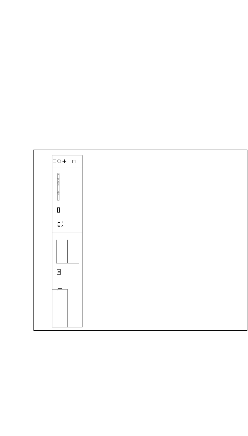
Power Supply Modules
3-23
S7-400, M7-400 Programmable Controllers Module Specifications
A5E00069467-07
3.8 Power Supply Modules
PS 407 10A; (6ES7407-0KA01-0AA0) and
PS 407 10A R; (6ES7407-0KR00-0AA0)
Function
The power supply modules PS 407 10A (standard) and PS 407 10A R
(redundancy-capable, see Section 3.2) are designed for connection to an AC line
voltage of 85 to 264 V or DC line voltage of 88 to 300 V and supply 5 VDC/10 A
and 24 VDC/1 A on the secondary side.
Controls and Displays of the PS 407 10A and thge PS 407 10A R
•FMR pushbutton (Failure Message Reset)
•Standby switch (does not cut off mains)
•Switches BATT. INDIC.
2 BATT, OFF, 1 BATT
•Battery compartment
•3-pin plug-in power connector
•Fixing screw
•LEDs INTF,
BAF, BATT1F, BATT2F,
5 VDC, 24 VDC
PS 407 10A
407-0KR00-0AA0
X2
34
1
FMR
BATT. INDIC.
2 BATT
1 BATT
OFF
+
–
+
–
2
INTF
BAF
BATTF
5 VDC
24 VDC
BATTF
BATT.1 BATT.2 Under cover
•Fixing screw
Figure 3-4 Controls and Displays of the PS 407 10A and PS 407 10A R

Power Supply Modules
3-24 S7-400, M7-400 Programmable Controllers Module Specifications
A5E00069467-07
Power Connection
In contrast to the instructions on installing a power supply module described in the
“S7-400, M7-400 Programmable Controllers, Hardware and Installation” manual,
an AC connector is used for connecting the PS 407 10A and the PS 407 10A R to
both an AC and a DC supply.
Polarity Reversal of L+ and L-
The polarity reversal of L+ and L- with supply voltages of between 88 VDC
and 300 VDC has no effect on the function of the power supply. The connection
should be made as described in the instructions in the Installation Manual,
Chapter 6.
Power Supply Modules
3-25
S7-400, M7-400 Programmable Controllers Module Specifications
A5E00069467-07
Technical Specifications of the PS 407 10A and the PS 407 10A R
Dimensions, Weight, and Cable Cross-Sections
Dimensions WxHxD (mm)
Weight
Cable cross-section
50x290x217
1.36 kg
3 x 1.5 mm2 (litz wire
with wire end ferrule
with insulating collar;
use only flexible
sheath cable)
Cable diameter 3 to 9 mm
Input Rating
Input voltage
•Rated value
•Permitted range
110/230 VDC
120/230 VAC
88 to 300 VDC,
85 to 264 VAC
(long-range input)
System frequency
•Rated value
•Permitted range
50 / 60 Hz
47 to 63 Hz
Rated input current
•At 120 VAC
•At 110 VDC
•At 230 VAC
•At 230 VDC
1.2 A (0.9 A*)
1.2 A (1.0 A*)
0.6 A (0.5 A*)
0.6 A (0.5 A*)
Starting current inrush
•At 230 VAC Peak value 230 A,
half-value width 200 µs
Peak value 63 A*,
half-value width 1 ms*
•At 300 VDC Peak value 230 A,
half-value width 200 µs
Peak value 58 A*,
half-value width 1 ms
Leakage current < 3.5 mA
Overvoltage resistance In accordance with DIN
VDE 0160, curve W2
* PS 407 10A: As of version 5
* PS 407 10A R: As of version 7
Output Variables
Output voltages
•Rated values 5.1 VDC /24 VDC
Output currents
•Rated values 5 VDC: 10 A
24 VDC: 1.0 A
Max. residual ripple 5 VDC: 50 mVSS
24 VDC: 200 mVSS
Max. switching peaks 5 VDC: 150 mVS
24 VDC: 500 mVS
Idle conditions 5 VDC: 200 mA base
load required
24 VDC: Idling-proof
(no base load required)
Other Parameters
Protection class in accordance
with IEC 60536 I, with protective
grounding conductor
Overvoltage category II
Pollution severity 2
Rated voltage Ue
0 < Ue ≤ 50 V
150 V < Ue ≤ 300 V
Test Voltage
700 VDC
(secondary <–> PE)
2300 VDC
(primary <–> PE)
Buffering of power failures: > 20 ms
Complies with the
NAMUR
recommendation NE
21 of August 1998 at a
repeat rate of 1 s
Power input 105 W*
Power loss 29.7 W
Backup current Max. 100 µA at power
off
Backup batteries (optional) 2 x Lithium AA, 3.6 V /
1.9 Ah
Protective separation
to IEC 61131-2 Yes
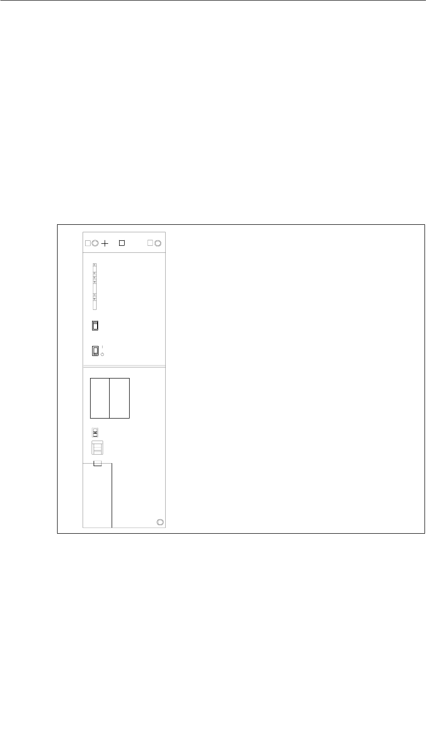
Power Supply Modules
3-26 S7-400, M7-400 Programmable Controllers Module Specifications
A5E00069467-07
3.9 Power Supply Module PS 407 20A;
(6ES7407-0RA00-0AA0)
Function
The PS 407 20 A power supply module is designed for connecting to an AC line
voltage of 120/230 VAC and supplies 5 VDC/20 A and 24 VDC/1 A on the
secondary side.
Controls and Indicators of the PS 407 20 A
•FMR pushbutton (Failure Message Reset)
•Standby switch (does not cut off mains)
•Switches BATT. INDIC.
2 BATT, OFF, 1 BATT
•Voltage selector switch
•Battery compartment
•3-pin plug-in power connector
•Fixing screw
•Fixing screws
•LEDs INTF,
BAF, BATT1F, BATT2F, 5 VDC, 24 VDC
PS 407 20A
407-0RA00-0AA0
X2
34
1
FMR
BATT. INDIC.
2 BATT
230
VOLTAGE
1 BATT
OFF
INTF
BAF
BATTF
5 VDC
24 VDC
BATTF
23
BATT.1 BATT.2
+
–
+
–
Under cover
Figure 3-5 Controls and Displays of the PS 407 20A
Power Supply Modules
3-27
S7-400, M7-400 Programmable Controllers Module Specifications
A5E00069467-07
Technical Specifications of the PS 407 20 A
Programming Package
Associated programming
package As of STEP7 V 2.0
Dimensions, Weight, and Cable Cross-Sections
Dimensions WxHxD (mm)
Weight
Cable cross-section
75x290x217
1.93 kg
3x1.5 mm 2 (litz wire
with wire end ferrule
with wire end ferrule
with insulating collar;
use only flexible
sheath cable)
Cable diameter 3 to 9 mm
Input Rating
Input voltage
•Rated value
•Permitted range
120/230 VAC
85 to 132 VAC /
170 to 264 VAC
System frequency
•Rated value
•Permitted range
50 / 60 Hz
47 to 63 Hz
Rated input current
•At 120 VAC
•At 230 VAC
1.87 A
1 A
Starting current inrush
•Rated input current 264 V
•Rated input current 132 V
Peak value 70 A
Half-value width 2 ms
Peak value + 110 A/ –
65 A
Half-value width
1.5 ms
Leakage current < 3.5 mA
Overvoltage resistance In accordance with DIN
VDE 0160, curve W2
Output Rating
Output voltages
•Rated values 5.1 VDC /24 VDC
Output currents
•Rated values 5 VDC: 20 A
24 VDC: 1.0 A
Max. residual ripple 5 VDC: 50 mVSS
24 VDC: 200 mVSS
Max. switching peaks 5 VDC: 150 mVS
24 VDC: 500 mVS
Idle conditions 5 VDC: 200 mA base
load required
24 VDC: Idling-proof
(no base load required)
Other Parameters
Protection class in accordance
with IEC 60536 I, with protective
grounding conductor
Overvoltage category II
Pollution severity 2
Rated voltage Ue
0 < Ue ≤ 50 V
150 V < Ue ≤ 300 V
Test Voltage
700 VDC
(secondary <–> PE)
2200 VDC
(primary <–> PE)
Buffering of power failures:
•At 50 Hz
•At 60 Hz 4.5 ms to 7.5 ms
6.5 ms to 8.5 ms
Power input 162 W
Power loss 35.6 W
Backup current Max. 100 µA at power
off
Backup batteries (optional) 2 x Lithium AA, 3.6 V /
1.9 Ah
Protective separation
to IEC 61131-2 Yes
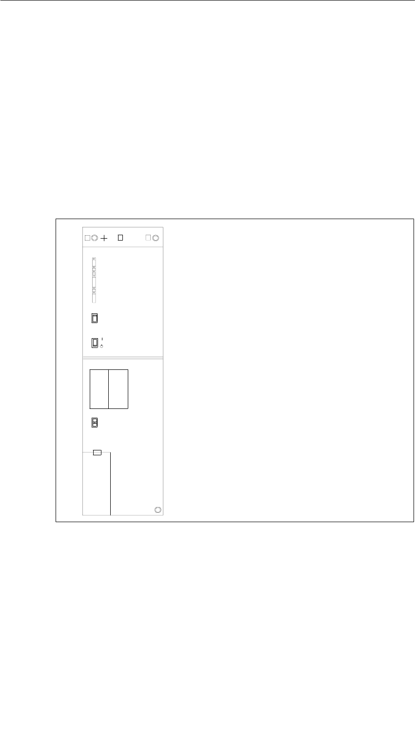
Power Supply Modules
3-28 S7-400, M7-400 Programmable Controllers Module Specifications
A5E00069467-07
3.10 Power Supply Module PS 407 20A;
(6ES7407-0RA01-0AA0)
Function
The PS 407 20 A power supply module is designed for connecting to either an AC
line voltage of 85 to 264 VAC or a DC line voltage of 88 to 300 VDC and
supplies 5 VDC/20 A and 24 VDC/1 A on the secondary side.
Controls and Indicators of the PS 407 20 A
•FMR pushbutton (Failure Message Reset)
•Standby switch (does not cut off mains)
•Switches BATT. INDIC.
2 BATT, OFF, 1 BATT
•Battery compartment
•3-pin plug-in power connector
•Fixing screw
•Fixing screws
•LEDs INTF,
BAF, BATT1F, BATT2F, 5 VDC, 24 VDC
PS 407 20A
407-0RA01-0AA0
X2
34
1
FMR
BATT. INDIC.
2 BATT
1 BATT
OFF
INTF
BAF
BATTF
5 VDC
24 VDC
BATTF
23
BATT.1 BATT.2
+
–
+
–
Under cover
Figure 3-6 Controls and Indicators of the PS 407 20 A
Power Connection
In contrast to the instructions on installing a power supply module in the “S7-400,
M7-400 Programmable Controllers, Hardware and Installation” manual, an AC
power connector is used for connecting the PS 407 20A to both an AC and DC
supply.
Power Supply Modules
3-29
S7-400, M7-400 Programmable Controllers Module Specifications
A5E00069467-07
Polarity Reversal of L+ and L-
The polarity reversal of L+ and L- with supply voltages of between 88 VDC
and 300 VDC has no effect on the function of the power supply. The connection
should be made as described in the instructions in the Installation Manual,
Chapter 6.
Technical Specifications of the PS 407 20 A
Dimensions, Weight, and Cable Cross-Sections
Dimensions WxHxD (mm)
Weight
Cable cross-section
75x290x217
2.2 kg
3x1.5 mm 2 (litz wire
ith ire end ferr le
with wire end ferrule
with insulating collar;
use only flexible
sheath cable)
Cable diameter 3 to 9 mm
Input Rating
Input voltage
•Rated value
•Permitted range
110/230 VDC
120/230 VAC
88 to 300 VDC,
85 to 264 VAC
(long-range input)
System frequency
•Rated value
•Permitted range
50 / 60 Hz
47 to 63 Hz
Rated input current
•At 120 VAC / 110 VDC
•At 230 VAC / 230 VDC
1.5 A
0.8 A
Starting current inrush Peak value 88 A
half-value width 1.1 ms
Leakage current < 3.5 mA
Overvoltage resistance In accordance with DIN
VDE 0160, curve W2
Output Rating
Output voltages
•Rated values 5.1 VDC /24 VDC
Output currents
•Rated values 5 VDC: 20 A
24 VDC: 1.0 A
Max. residual ripple 5 VDC: 50 mVSS
24 VDC: 200 mVSS
Max. switching peaks 5 VDC: 150 mVS
24 VDC: 500 mVS
Idle conditions 5 VDC: 200 mA base
load required
24 VDC: Idling-proof
(no base load required)
Other Parameters
Protection class in accordance
with IEC 60536 I, with protective
grounding conductor
Overvoltage category II
Pollution severity 2
Rated voltage Ue
0 < Ue ≤ 50 V
150 V < Ue ≤ 300 V
Test Voltage
700 VDC
(secondary <–> PE)
2300 VDC
(primary <–> PE)
Buffering of power failures: > 20 ms
Complies with the
NAMUR
recommendation NE
21 of August 1998 at a
repeat rate of 1 s
Power input 168 W
Power loss 44 W
Backup current Max. 100 µA at power
off
Backup batteries (optional) 2 x Lithium AA,
3.6 V / 1.9 Ah
Protective separation
to IEC 61131-2 Yes
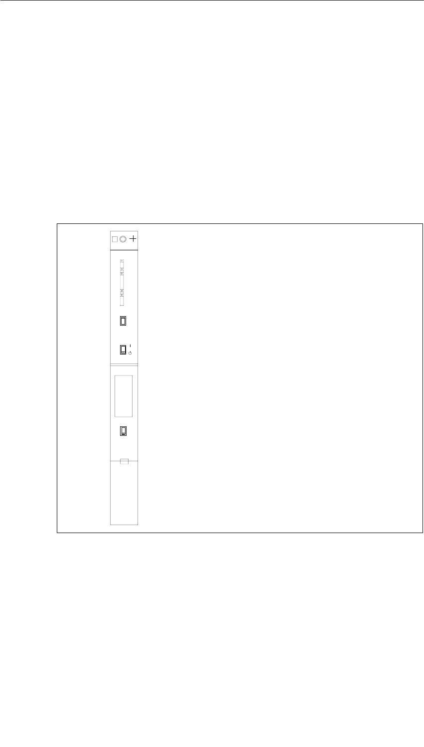
Power Supply Modules
3-30 S7-400, M7-400 Programmable Controllers Module Specifications
A5E00069467-07
3.11 Power Supply Module PS 405 4A;
(6ES7405-0DA00-0AA0)
Function
The PS 405 4 A power supply module is designed for connecting to a DC line
voltage of 24 VDC and supplies 5 VDC/4 A and 24 VDC/0.5 A on the secondary
side.
Controls and Indicators of the PS 405 4 A
•FMR pushbutton (Failure Message Reset)
•Standby switch
•Switches BATT. INDIC.
BATT, OFF
•Battery compartment
•3-pin plug-in power connector
•Fixing screw
•LEDs INTF,
BAF, BATTF,
5 VDC, 24 VDC
PS 405 4A
405-0DA00-0AA0
X2
34
1
INTF
BAF
BATTF
5 VDC
24 VDC
FMR
BATT. INDIC.
BATT
OFF
Under cover
•Fixing screw
Figure 3-7 Controls and Indicators of the PS 405 4 A

Power Supply Modules
3-31
S7-400, M7-400 Programmable Controllers Module Specifications
A5E00069467-07
Technical Specifications of the PS 405 4 A
Programming Package
Associated programming
package As of STEP7 V 2.0
Dimensions, Weight, and Cable Cross-Sections
Dimensions WxHxD (mm)
Weight
25x290x217
0.8 kg
g
Cable cross-section
g
3 x 1.5 mm2 (litz wire
with wire end ferrule,
use component
use
componen
t
conductor or flexible
sheath cable)
Cable diameter 3 to 9 mm
Input Rating
Input voltage
•Rated value
•Permitted range
24 VDC
Static:
19.2 VDC to 30 VDC
Dynamic:
18.5 VDC to 30.2 VDC
Rated input current 2 A
Starting current inrush Peak value 27 A
Half-value width 10 ms
Overvoltage resistance In accordance with DIN
VDE 0160, curve B2
Output Rating
Output voltages
•Rated values 5.1 VDC /24 VDC
Output currents
•Rated values 5 VDC: 4 A
24 VDC: 0.5 A
Max. residual ripple 5 VDC: 50 mVSS
24 VDC: 200 mVSS
Max. switching peaks 5 VDC: 150 mVS
24 VDC: 500 mVS
Idle conditions 5 VDC: 100 mA Base
load required
24 VDC: Idling-proof
(no base load required)
Other Parameters
Protection class in accordance
with IEC 60536 I, with protective
grounding conductor
Overvoltage category II
Pollution severity 2
Rated voltage Ue
0 < Ue ≤ 50 V
150 V < Ue ≤ 300 V
Test Voltage
700 VDC
(secondary <–> PE)
2200 VDC
(primary <–> PE)
Buffering of power failures: 4 ms to 5 ms
Power input 48 W
Power loss 16 W
Backup current Max. 100 µA at power
off
Backup battery (option) 1 x Lithium AA, 3.6 V /
1.9 Ah
Protective separation
to IEC 61131-2 Yes

Power Supply Modules
3-32 S7-400, M7-400 Programmable Controllers Module Specifications
A5E00069467-07
3.12 Power Supply Module PS 405 4A;
(6ES7405-0DA01-0AA0)
Function
The PS 405 4A power supply module is designed for connection to a DC line
voltage of 19.2 to 72 VDC and supplies 5 VDC/4 A and 24 VDC/0.5 A on the
secondary side.
Controls and Indicators of the PS 405 4 A
•FMR pushbutton (Failure Message Reset)
•Standby switch
•Switches BATT. INDIC.
BATT, OFF
•Battery compartment
•3-pin plug-in power connector
•Fixing screw
•LEDs INTF,
BAF, BATTF,
5 VDC, 24 VDC
PS 405 4A X2
34
1
INTF
BAF
BATTF
5 VDC
24 VDC
FMR
BATT. INDIC.
BATT
OFF
Under cover
•Fixing screw
405-0DA01-0AA0
Figure 3-8 Controls and Indicators of the PS 405 4 A
Power Supply Modules
3-33
S7-400, M7-400 Programmable Controllers Module Specifications
A5E00069467-07
Technical Specifications of the PS 405 4 A
Dimensions, Weight, and Cable Cross-Sections
Dimensions WxHxD (mm)
Weight
25x290x217
0.76 kg
g
Cable cross-section
g
3 x 1.5 mm2 (litz wire
with wire end ferrule;
use component
use
componen
t
conductor or flexible
sheath cable)
Cable diameter 3 to 9 mm
Input Rating
Input voltage
•Rated value
•Permitted range
24/48/60 VDC
Static:
19.2 VDC to 72 VDC
Dynamic:
18.5 VDC to 75.5 VDC
Rated input current 2 A/1 A/0.8 A
Overvoltage resistance In accordance with DIN
VDE 0160, curve B2
Output Rating
Output voltages
•Rated values 5.1 VDC /24 VDC
Output currents
•Rated values 5 VDC: 4 A
24 VDC: 0.5 A
Max. residual ripple 5 VDC: 50 mVSS
24 VDC: 200 mVSS
Max. switching peaks 5 VDC: 150 mVS
24 VDC: 500 mVS
Idle conditions 5 VDC: 100 mA Base
load required
24 VDC: Idling-proof
(no base load required)
Other Parameters
Protection class in accordance
with IEC 60536 I, with protective
grounding conductor
Overvoltage category II
Pollution severity 2
Rated voltage Ue
0 < Ue ≤ 50 V
150 V < Ue ≤ 300 V
Test Voltage
700 VDC
(secondary <–> PE)
2200 VDC
(primary <–> PE)
Buffering of power failures: > 20 ms
Complies with the
NAMUR
recommendation NE
21 of August 1998 at a
repeat rate of 1 s
Power consumption (24 VDC) 48 W
Power loss 16 W
Backup current Max. 100 µA at power
off
Backup battery (option) 1 x Lithium AA, 3.6 V /
1.9 Ah
Protective separation
to IEC 61131-2 Yes
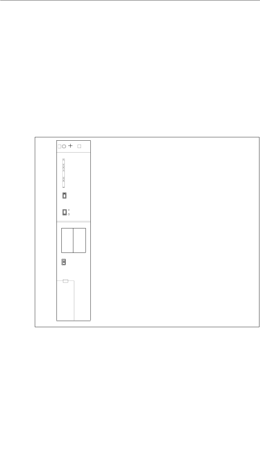
Power Supply Modules
3-34 S7-400, M7-400 Programmable Controllers Module Specifications
A5E00069467-07
3.13 Power Supply Module PS 405 10A;
(6ES7405-0KA00-0AA0)
Function
The PS 405 10A power supply module is designed for connection to a DC line
voltage of 24 VDC and supplies 5 VDC/10 A and 24 VDC/1 A on the secondary
side.
Controls and Indicators of the PS 405 10 A
•LEDs INTF,
BAF, BATT1F, BATT2F,
5 VDC, 24 VDC
•FMR pushbutton (Failure Message Reset)
•Standby switch
•Switches BATT. INDIC.
2 BATT, OFF, 1 BATT
•Battery compartment
•Fixing screw
•3-pin plug-in power connector
PS 405 10 A
405-0KA00-0AA0
X2
34
1
FMR
2
INTF
BAF
BATTF
5 VDC
24 VDC
BATTF
BATT. INDIC.
2 BATT
1 BATT
OFF
BATT.1 BATT.2
+
–
+
–
Under cover
•Fixing screw
Figure 3-9 Controls and Indicators of the PS 405 10 A

Power Supply Modules
3-35
S7-400, M7-400 Programmable Controllers Module Specifications
A5E00069467-07
Technical Specifications of the PS 405 10 A
Programming Package
Associated programming
package As of STEP7 V 2.0
Dimensions, Weight, and Cable Cross-Sections
Dimensions WxHxD (mm)
Weight
50x290x217
1 4 kg
W
e
i
g
h
t
Cable cross-section
1
.4
k
g
3x1.5 mm2 (litz wire
ith i d f l
(
with wire end ferrule;
use component
d t fl ibl
p
conductor or flexible
sheath cable)
Cable diameter 3 to 9 mm
Input Rating
Input voltage
•Rated value
•Permitted range
24 VDC
Static:
19.2 VDC to 30 VDC
Dynamic:
18.5 VDC to 30.2 VDC
Rated input current 4.5 A
Starting current inrush Peak value 44 A
Half-value width 20 ms
Overvoltage resistance In accordance with DIN
VDE 0160, curve B2
Output Rating
Output voltages
•Rated values 5.1 VDC /24 VDC
Output currents
•Rated values 5 VDC: 10 A
24 VDC: 1.0 A
Max. residual ripple 5 VDC: 50 mVSS
24 VDC: 200 mVSS
Max. switching peaks 5 VDC: 150 mVS
24 VDC: 500 mVS
Idle conditions 5 VDC: 200 mA base
load required
24 VDC: Idling-proof
(no base load required)
Other Parameters
Protection class in accordance
with IEC 60536 I, with protective
grounding conductor
Overvoltage category II
Pollution severity 2
Rated voltage Ue
0 < Ue ≤ 50 V
150 V < Ue ≤ 300 V
Test Voltage
700 VDC
(secondary <–> PE)
2200 VDC
(primary <–> PE)
Buffering of power failures: 4 ms to 5 ms
Power input 108 W
Power loss 33 W
Backup current Max. 100 µA at power
off
Backup batteries (optional) 2 x Lithium AA, 3.6 V /
1.9 Ah
Protective separation
to IEC 61131-2 Yes
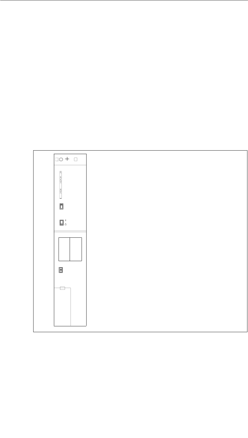
Power Supply Modules
3-36 S7-400, M7-400 Programmable Controllers Module Specifications
A5E00069467-07
3.14 Power Supply Modules
PS 405 10A; (6ES7405-0KA01-0AA0) and
PS 405 10A R; (405-0KR00-0AA0)
Function
The power supply modules PS 405 10A (standard) and PS 405 10A R
(redundancy-capable, see Section 3.2) are designed for connection to a DC line
voltage of 19.2 VDC to 72 VDC and supply 5 VDC/10 A and 24 VDC/1 A on the
secondary side.
Controls and Displays of the PS 405 10A and the PS 405 10A R
•LEDs INTF,
BAF, BATT1F, BATT2F,
5 VDC, 24 VDC
•FMR pushbutton (Failure Message Reset)
•Standby switch
•Switches BATT. INDIC.
2 BATT, OFF, 1 BATT
•Battery compartment
•Fixing screw
•3-pin plug-in power connector
PS 405 10 A
405-0KA01-0AA0
X2
34
1
FMR
2
INTF
BAF
BATTF
5 VDC
24 VDC
BATTF
BATT. INDIC.
2 BATT
1 BATT
OFF
BATT.1 BATT.2
+
–
+
–
Under cover
•Fixing screw
Figure 3-10 Controls and Displays of the PS 405 10A and PS 405 10A R

Power Supply Modules
3-37
S7-400, M7-400 Programmable Controllers Module Specifications
A5E00069467-07
Technical Specifications of the PS 405 10A and the PS 405 10A R
Dimensions, Weight, and Cable Cross-Sections
Dimensions WxHxD (mm)
Weight
50x290x217
1 4 kg
W
e
i
g
h
t
Cable cross-section
1
.4
k
g
3 x 1.5 mm2 (litz wire
ith i d f l
(
with wire end ferrule,
use component
d t fl ibl
p
conductor or flexible
sheath cable)
Cable diameter 3 to 9 mm
Input Rating
Input voltage
•Rated value
•Permitted range
24/48/60 VDC
Static:
19.2 VDC to 72 VDC
Dynamic:
18.5 VDC to 75.5 VDC
Rated input current 4.3 A/2.1 A/1.7 A
Starting current inrush Peak value 18 A
Half-value width 20 ms
Overvoltage resistance In accordance with DIN
VDE 0160, curve B2
Output Rating
Output voltages
•Rated values 5.1 VDC/24 VDC
Output currents
•Rated values 5 VDC: 10 A
24 VDC: 1.0 A
Max. residual ripple 5 VDC: 50 mVSS
24 VDC: 200 mVSS
Max. switching peaks 5 VDC: 150 mVS
24 VDC: 500 mVS
Idle conditions 5 VDC: 200 mA base
load required
24 VDC: Idling-proof
(no base load required)
Other Parameters
Protection class in accordance
with IEC 60536 I, with protective
grounding conductor
Overvoltage category II
Pollution severity 2
Rated voltage Ue
0 < Ue ≤ 50 V
150 < Ue ≤ 300 V
Test Voltage
700 VDC
(secondary <–> PE)
2300 VDC
(primary <–> PE)
Buffering of power failures: > 20 ms
Complies with the
NAMUR
recommendation NE
21 of August 1998 at a
repeat rate of 1 s
Power input 104 W
Power loss 29 W
Backup current Max. 100 µA at power
off
Backup batteries (optional) 2 x Lithium AA, 3.6 V /
1.9 Ah
Protective separation
to IEC 61131-2 Yes

Power Supply Modules
3-38 S7-400, M7-400 Programmable Controllers Module Specifications
A5E00069467-07
3.15 Power Supply Module PS 405 20A;
(6ES7405-0RA00-0AA0)
Function
The PS 405 20 A power supply module is designed for connecting to a DC line
voltage of 24 VDC and supplies 5 VDC/20 A and 24 VDC/1 A on the secondary
side.
Controls and Indicators of the PS 405 20 A
•FMR pushbutton (Failure Message Reset)
•Standby switch
•Switches BATT. INDIC.
2 BATT, OFF, 1 BATT
•Battery compartment
•Fixing screws
•3-pin plug-in power connector
•LEDs INTF,
BAF, BATT1F, BATT2F,
5 VDC, 24 VDC
PS 405 20A
405-0RA00-0AA0
X2
34
1
FMR
23
INTF
BAF
BATTF
5 VDC
24 VDC
BATTF
BATT. INDIC.
2 BATT
1 BATT
OFF
BATT.1 BATT.2
+
–
+
–
Under cover
•Fixing screws
Figure 3-11 Controls and Indicators of the PS 405 20 A
Power Supply Modules
3-39
S7-400, M7-400 Programmable Controllers Module Specifications
A5E00069467-07
Technical Specifications of the PS 405 20 A
Programming Package
Associated programming
package As of STEP7 V 2.0
Dimensions, Weight, and Cable Cross-Sections
Dimensions WxHxD (mm)
Weight
75x290x217
2 2 kg
W
e
i
g
h
t
Cable cross-section
2
.
2 k
g
3x1.5 mm2 (litz wire
ith i d f l
(
with wire end ferrule;
use component
d t fl ibl
p
conductor or flexible
sheath cable)
Cable diameter 3 to 9 mm
Input Rating
Input voltage
•Rated value
•Permitted range
24 VDC
Static:
19.2 VDC to 30 VDC
Dynamic:
18.5 VDC to 30.2 VDC
Rated input current 7.2 A
Starting current inrush Peak value 48 A
Half-value width 25 ms
Overvoltage resistance In accordance with DIN
VDE 0160, curve B2
Output Rating
Output voltages
•Rated values 5.1 VDC/24 VDC
Output currents
•Rated values 5 VDC: 20 A
24 VDC: 1.0 A
Max. residual ripple 5 VDC: 50 mVSS
24 VDC: 200 mVSS
Max. switching peaks 5 VDC: 150 mVS
24 VDC: 500 mVS
Idle conditions 5 VDC: 200 mA base
load required
24 VDC: Idling-proof
(no base load required)
Other Parameters
Protection class in accordance
with IEC 60536 I, with protective
grounding conductor
Overvoltage category II
Pollution severity 2
Rated voltage Ue
0 < Ue ≤ 50 V
150 V < Ue ≤ 300 V
Test Voltage
700 VDC
(secondary <–> PE)
2200 VDC
(primary <–> PE)
Buffering of power failures: 4 ms to 5 ms
Power input 172.8 W
Power loss 46.8 W
Backup current Max. 100 µA at power
off
Backup batteries (optional) 2 x Lithium AA, 3.6 V /
1.9 Ah
Protective separation
to IEC 61131-2 Yes
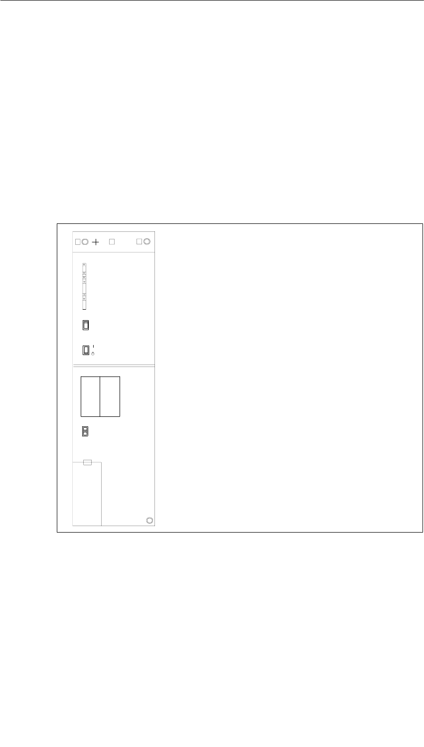
Power Supply Modules
3-40 S7-400, M7-400 Programmable Controllers Module Specifications
A5E00069467-07
3.16 Power Supply Module PS 405 20A;
(6ES7405-0RA01-0AA0)
Function
The PS 405 20A power supply module is designed for connection to a DC line
voltage of 19.2 VDC to 72 VDC and supplies 5 VDC/20 A and 24 VDC/1 A on the
secondary side.
Controls and Indicators of the PS 405 20 A
•FMR pushbutton (Failure Message Reset)
•Standby switch
•Switches BATT. INDIC.
2 BATT, OFF, 1 BATT
•Battery compartment
•Fixing screws
•3-pin plug-in power connector
•LEDs INTF,
BAF, BATT1F, BATT2F,
5 VDC, 24 VDC
PS 405 20A
405-0RA00-0AA0
X2
34
1
FMR
23
INTF
BAF
BATTF
5 VDC
24 VDC
BATTF
BATT. INDIC.
2 BATT
1 BATT
OFF
BATT.1 BATT.2
+
–
+
–
Under cover
•Fixing screws
Figure 3-12 Controls and Indicators of the PS 405 20 A
Power Supply Modules
3-41
S7-400, M7-400 Programmable Controllers Module Specifications
A5E00069467-07
Technical Specifications of the PS 405 20 A
Dimensions, Weight, and Cable Cross-Sections
Dimensions WxHxD (mm)
Weight
75x290x217
2 2 kg
W
e
i
g
h
t
Cable cross-section
2
.
2 k
g
3x1.5 mm2 (litz wire
ith i d f l
(
with wire end ferrule;
use component
d t fl ibl
p
conductor or flexible
sheath cable)
Cable diameter 3 to 9 mm
Input Rating
Input voltage
•Rated value
•Permitted range
24/48/60 VDC
Static:
19.2 VDC to 72 VDC
Dynamic:
18.5 VDC to 75.5 VDC
Rated input current 7.3 A/3.45 A/2.75 A
Starting current inrush Peak value 56 A
half-value width 1.5 ms
Overvoltage resistance In accordance with DIN
VDE 0160, curve B2
Output Rating
Output voltages
•Rated values 5.1 VDC/24 VDC
Output currents
•Rated values 5 VDC: 20 A
24 VDC: 1.0 A
Max. residual ripple 5 VDC: 50 mVSS
24 VDC: 200 mVSS
Max. switching peaks 5 VDC: 150 mVS
24 VDC: 500 mVS
Idle conditions 5 VDC: 200 mA base
load required
24 VDC: Idling-proof
(no base load required)
Other Parameters
Protection class in accordance
with IEC 60536 I, with protective
grounding conductor
Overvoltage category II
Pollution severity 2
Rated voltage Ue
0 < Ue ≤ 50 V
150 V < Ue ≤ 300 V
Test Voltage
700 VDC
(secondary <–> PE)
2300 VDC
(primary <–> PE)
Buffering of power failures: > 20 ms
Complies with the
NAMUR
recommendation NE
21 of August 1998 at a
repeat rate of 1 s
Power input 175 W
Power loss 51 W
Backup current Max. 100 µA at power
off
Backup batteries (optional) 2 x Lithium AA, 3.6 V /
1.9 Ah
Protective separation
to IEC 61131-2 Yes

Power Supply Modules
3-42 S7-400, M7-400 Programmable Controllers Module Specifications
A5E00069467-07

4-1
S7-400, M7-400 Programmable Controllers Module Specifications
A5E00069467-07
Digital Modules
Structure of the Chapter
The present chapter is subdivided into the following subjects:
1. Overview containing the modules that are available here and a description
2. Information that is generally valid – in other words, relating to all digital modules
(for example, parameter assignment and diagnostics)
3. Information that refers to specific modules (for example, characteristics,
diagram of connections and block diagram, technical specifications and special
characteristics of the module):
a) for digital input modules
b) for digital output modules
Additional Information
Appendix A describes the structure of the parameter records (data records 0, 1 and
128) in the system data. You must be familiar with this structure if you want to
modify the parameters of the modules in the STEP 7 user program.
Appendix B describes the structure of the diagnostic data (data records 0, 1) in the
system data. You must be familiar with this structure if you want to evaluate the
diagnostic data of the modules in the STEP 7 user program.
4
Digital Modules
4-2 S7-400, M7-400 Programmable Controllers Module Specifications
A5E00069467-07
Chapter Overview
Section Description Page
4.1 Module Overview 4-3
4.2 Sequence of Steps from Choosing to Commissioning the Digital
Module 4-5
4.3 Digital Module Parameter Assignment 4-6
4.4 Diagnostics of the Digital Modules 4-9
4.5 Interrupts of the Digital Modules 4-13
4.6 Input Characteristic Curve for Digital Inputs 4-15
4.7 Digital Input Module SM 421; DI 32 24 VDC;
(6ES7421-1BL00-0AA0) 4-17
4.8 Digital Input Module SM 421; DI 32 24 VDC;
(6ES7421-1BL01-0AA0) 4-20
4.9 Digital Input Module SM 421; DI 16 24 VDC;
(6ES7421-7BH00-0AB0) 4-23
4.10 Digital Input Module SM 421; DI 16 24 VDC;
(6ES7421-7BH01-0AB0) 4-32
4.11 Digital Input Module SM 421; DI 16 120 VAC;
(6ES7421-5EH00-0AA0) 4-41
4.12 Digital Input Module SM 421; DI 16 24/60 VUC;
(6ES7421-7DH00-0AB0) 4-44
4.13 Digital Input Module SM 421; DI 16 120/230 VUC;
(6ES7421-1FH00-0AA0) 4-50
4.14 Digital Input Module SM 421; DI 16 120/230 VUC;
(6ES7421-1FH20-0AA0) 4-53
4.15 Digital Input Module SM 421; DI 32 120 VUC;
(6ES7421-1EL00-0AA0) 4-56
4.16 Digital Output Module SM 422; DO 16 24 VDC/2 A;
(6ES7422-1BH10-0AA0) 4-59
4.17 Digital Output Module SM 422; DO 16 24 VDC/2 A;
(6ES7422-1BH11-0AA0) 4-62
4.18 Digital Output Module SM 422; DO 16 20-125 VDC/1.5 A;
(6ES7422-5EH10-0AB0) 4-65
4.19 Digital Output Module SM 422; DO 32 24 VDC/0.5 A;
(6ES7422-1BL00-0AA0) 4-70
4.20 Digital Output Module SM 422; DO 32 24 VDC/0.5 A;
(6ES7422-7BL00-0AB0) 4-73
4.21 Digital Output Module SM 422; DO 8 120/230 VAC/5 A;
(6ES7422-1FF00-0AA0) 4-79
4.22 Digital Output Module SM 422; DO 16 120/230 VAC/2 A;
(6ES7422-1FH00-0AA0) 4-83
4.23 Digital Output Module SM 422;
DO 16 20-120 VAC/2 A; (6ES7422-5EH00-0AB0) 4-87
4.24 Relay Output Module SM 422;
DO 16 30/230 VUC/Rel. 5 A; (6ES7422-1HH00-0AA0) 4-91
Digital Modules
4-3
S7-400, M7-400 Programmable Controllers Module Specifications
A5E00069467-07
4.1 Module Overview
Introduction
The following tables summarize the most important characteristics of the digital
modules. This overview is intended to make it easy to choose the suitable module
for your task.
Table 4-1 Digital Input Modules: Characteristics at a Glance
Module
Characteristics
SM 421;
DI 32 24
VDC
(-1BL0x-)
SM 421;
DI 1624
VDC
(-7BH00-)
SM 421;
DI 16120
VAC
(-5EH00-)
SM 421;
DI 1624/
60 VUC
(-7DH00-)
SM 421;
DI 16120
/230 VUC
(-1FH00-)
SM 421;
DI 16120
/230 VUC
(-1FH20-)
SM 421;
DI 32120
VUC
(-1EL00-)
Number of
inputs 32 DI;
isolated in
groups of
32
16 DI;
isolated in
groups of 8
16 DI;
isolated in
groups of 1
16 DI;
isolated in
groups of 1
16 DI;
isolated in
groups of 4
16 DI;
isolated in
groups of 4
32 DI;
isolated in
groups of 8
Rated input
voltage 24 VDC 24 VDC 120 VAC 24 VUC to
60 VUC 120 VAC/
230 VDC 120/230
VUC 120 VAC/
VDC
Suitable for... Switches
Two-wire proximity switches (BEROs)
Programmable
diagnostics No Yes No Yes No No No
Diagnostic
Interrupt No Yes No Yes No No No
Hardware
interrupt upon
edge change
No Yes No Yes No No No
Adjustable input
delays No Yes No Yes No No No
Substitute value
output –Yes – – – – –
Special Features High
packaging
density
Quick and
with
interrupt
capability
Channel-
specific
isolation
Interrupt
capability
with low,
variable
voltages
For high,
variable
voltages
For high,
variable
voltages
Input
characterist
ic curve to
IEC
61131-2
High
packaging
density
Digital Modules
4-4 S7-400, M7-400 Programmable Controllers Module Specifications
A5E00069467-07
Table 4-2 Digital Output Modules: Characteristics at a Glance
Module
Characte-
ristics
SM 422;
DO 16 24
VDC/2 A
(-1BH1x)
SM 422;
DO
16 20-125
VDC/1.5 A
(-5EH10)
SM 422;
DO
32 24
VDC/ 0.5 A
(-1BL00)
SM 422;
DO 32 24
VDC/0.5 A
(-7BL00)
SM 422;
DO
8 120/230
VAC/5 A
(-1FF00)
SM 422; DO
16 120/230
VAC/2 A
(-1FH00)
SM 422;
DO
16 20-120
VAC/2 A
(-5EH00)
Number of
outputs 16 DO;
isolated in
groups of 8
16 DO;
isolated
and reverse
polarity
protection
in groups of
8
32 DO;
isolated in
groups of
32
32 DO;
isolated in
groups of 8
8 DO;
isolated in
groups of 1
16 DO;
isolated in
groups of 4
16 DO;
isolated in
groups of 1
Output current 2 A 1.5 A 0.5 A 0.5 A 5 A 2 A 2 A
Rated load
voltage 24 VDC 20 to 125
VDC 24 VDC 24 VDC 120/
230 VAC 120/
230 VAC 20 to
120 VAC
Programmable
diagnostics No Yes No Yes No No Yes
Diagnostic
Interrupt No Yes No Yes No No Yes
Substitute
value output No Yes No Yes No No Yes
Special
Features For high
currents For variable
voltages High
packaging
density
Particularly
quick and
with
interrupt
capability
For high
currents
with
channel-
specific
isolation
–For variable
currents
with
channel-
specific
isolation
Table 4-3 Relay Output Module: Characteristics at a Glance
Module
Characteristics
SM 422; DO 16 30/230 VUC/Rel. 5 A
(-1HH00)
Number of Outputs 16 outputs, isolated in groups of 8
Load Voltage 125 VDC
230 VAC
Special Features –
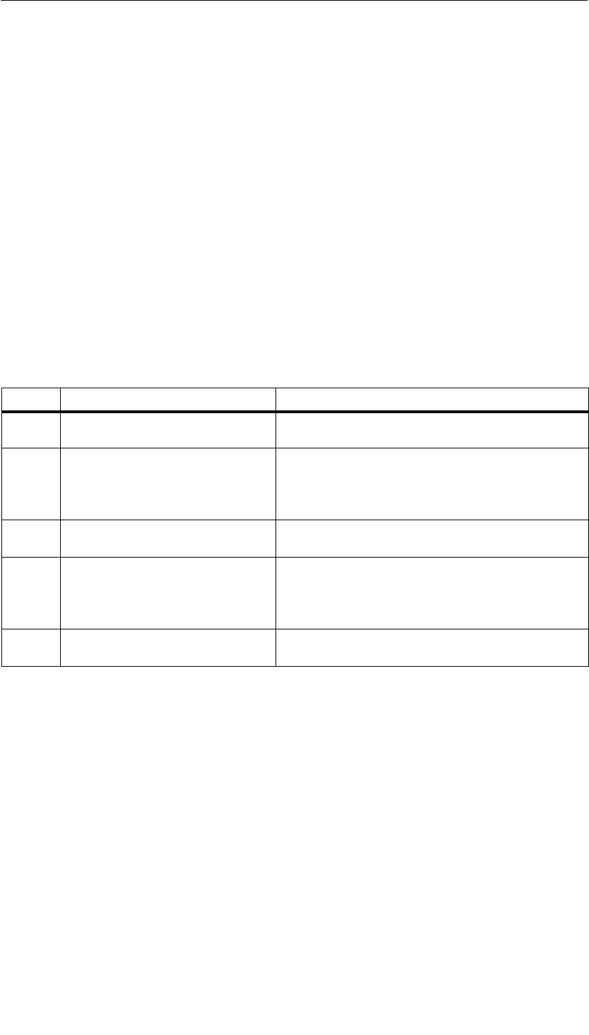
Digital Modules
4-5
S7-400, M7-400 Programmable Controllers Module Specifications
A5E00069467-07
4.2 Sequence of Steps from Choosing to Commissioning
the Digital Module
Introduction
The following table contains the tasks that you have to perform one after the other
to commission digital modules successfully.
The sequence of steps is a suggestion, but you can perform individual steps either
earlier or later (for example, assign parameters to the module) or install other
modules or install, commission etc. other modules in between times.
Sequence of Steps
Table 4-4 Sequence of Steps from Choosing to Commissioning the Digital Module
Step Procedure Refer To...
1. Select the module Section 4.1 and specific module section from
Section 4.8
2. Install the module in the SIMATIC S7
network “Installation” section in the manual for the
programmable controller being used:
•S7-400/M7-400 Programmable Controllers,
Hardware and Installation
3. Assign parameters to module Section 4.3 and, if necessary, the specific module
section as of Section 4.7
4. Commission configuration Section on commissioning in the manual for the
programmable controller being used:
•S7-400/M7-400 Programmable Controllers,
Hardware and Installation
5. If commissioning was not successful,
diagnose configuration Section 4.4

Digital Modules
4-6 S7-400, M7-400 Programmable Controllers Module Specifications
A5E00069467-07
4.3 Digital Module Parameter Assignment
Introduction
Digital modules can have different characteristics. You can set the characteristics
of dome modules by means of parameter assignment.
Tools for Parameter Assignment
You assign parameters to digital modules in STEP 7. You must perform parameter
assignment in STOP mode of the CPU.
When you have set all the parameters, download the parameters from the
programming device to the CPU. When there is a transition from STOP to RUN
mode, the CPU transfers the parameters to the individual digital modules.
Static and dynamic parameters
The parameters are divided into static and dynamic parameters.
Set the static parameters in STOP mode of the CPU, as described above.
In addition, you can modify the dynamic parameters in the current user program in
an S7 programmable controller by means of SFCs. Note, however, that after a
change from RUN ³ STOP, STOP ³ RUN of the CPU, the parameters set in
STEP 7 apply again. You will find a description of the parameter assignment of
modules in the user program in Appendix A.
Table 4-5 Static and dynamic parameters of the digital modules
Parameter Settable with CPU Operating
Mode
Static PG (STEP 7 HWCONFIG) STOP
Dynamic PG (STEP 7 HWCONFIG) STOP
SFC 55 in the user program RUN

Digital Modules
4-7
S7-400, M7-400 Programmable Controllers Module Specifications
A5E00069467-07
4.3.1 Parameters of the Digital Input Modules
The parameterized digital input modules use a subset of the parameters and
ranges of values listed in the table below, depending on functionality. Refer to the
section on a particular digital module, starting from Section 4.7, to find out which
subset it is capable of using.
Don’t forget that some digital modules have different time delays after parameter
assignment.
The default settings apply if you have not performed parameter assignment in
STEP 7.
Table 4-6 Parameters of the Digital Input Modules
Parameter Value Range Default2Parameter
Type Scope
Enable
•Diagnostic interrupt1)
•Hardware interrupt1) Yes/no
Yes/no No
No Dynamic Module
•Destination CPU for
interrupt 1 to 4 –Static Module
Diagnostics
•Wire break
•No load voltage
L+/sensor supply
Yes/no
Yes/no No
No Static Channel
Trigger for hardware
interrupt
No
Dynamic
Channel
•Rising (positive) edge
•Falling (negative) edge
Yes/no
Yes/no
No
No Dynamic Channel
Input delay 0.1 ms (DC)
0.5 ms (DC)
3 ms (DC)
20 ms (DC/AC)
3 (DC) Static Channel
Reaction to error Substitutea value (SV)
Keep last value (KLV) SV Dynamic Module
Substitute“1” Yes/no No Dynamic Channel
1) If you use the module in ER-1/ER-2, you must set this parameter to “No” because the interrupt lines are
not available in ER-1/ER-2.
2) Only in the CC (central controller) is It possible to start up the digital modules with the default settings and
without HWCONFIG support.
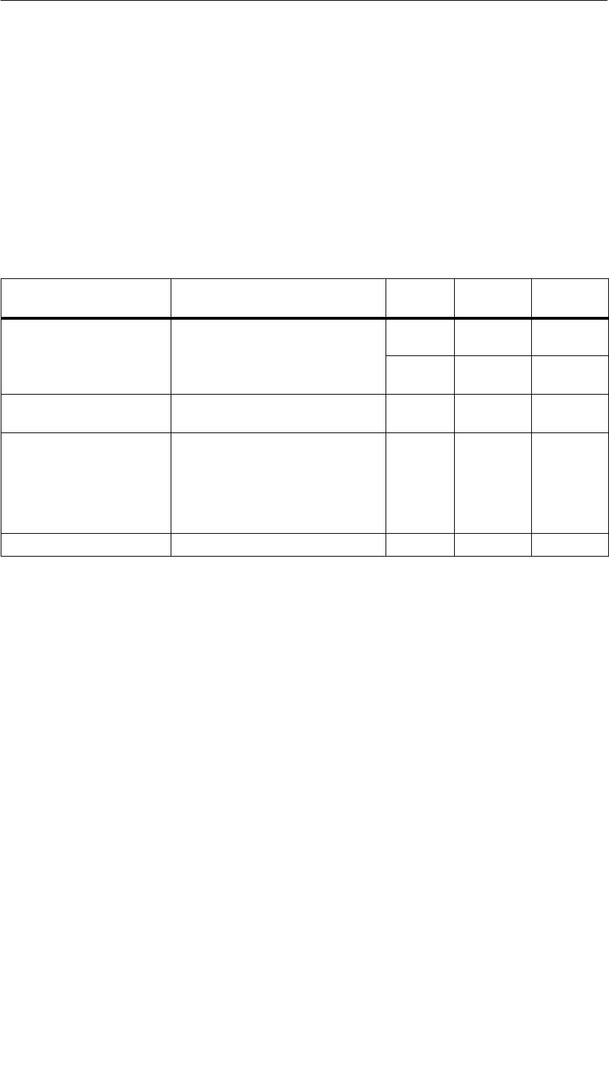
Digital Modules
4-8 S7-400, M7-400 Programmable Controllers Module Specifications
A5E00069467-07
4.3.2 Parameters of the Digital Output Modules
The parameterized digital output modules use a subset of the parameters and
ranges of values listed in the table below, depending on the functionality. Refer to
the section on the relevant digital module, starting from Section 4.16, to find out
which subset it is capable of using.
The default settings apply if you have not performed parameter assignment in
STEP 7.
Table 4-7 Parameters of the Digital Output Modules
Parameter Value Range Default2) Parameter
Type Scope
Enable
•Diagnostic interrupt1) Yes/no No Dynamic Module
•Destination CPU for
interrupt 1 to 4 –Static Module
Reaction to CPU-STOP Substitute a value (SV)
Keep last value (KLV) SV Dynamic Module
Diagnostics
•Wire break
•No load voltage L+
•Short circuit to M
•Short circuit to L+
•Fuse blown
Yes/no
Yes/no
Yes/no
Yes/no
Yes/no
No
No
No
No
No
Static Channel
Substitute “1” Yes/no No Dynamic Channel
1) If you use the module in ER-1/ER-2, you must set this parameter to “No” because the interrupt lines are
not available in ER-1/ ER-2.
2) Only in the CC (central controller) is it possible to start up the digital modules with the default settings and
without support from HWCONFIG.

Digital Modules
4-9
S7-400, M7-400 Programmable Controllers Module Specifications
A5E00069467-07
4.4 Diagnostics of the Digital Modules
Programmable and Non-Programmable Diagnostic Messages
In diagnostics, we make a distinction between programmable and
non-programmable diagnostic messages.
You obtain programmable diagnostic messages only if you have enabled
diagnostics by parameter assignment. You perform parameter assignment in the
”Diagnostics” parameter block in STEP 7 (refer to Section 5.7).
Non-programmable diagnostic messages are always made available by the digital
module irrespective of diagnostics being enabled.
Actions Following Diagnostic Message in STEP 7
Each diagnostic message leads to the following actions:
•The diagnostic message is entered in the diagnostics of the digital module,
forwarded to the CPU and can be read out by the user program.
•The fault LED on the digital module lights up.
•If you have parameterized “Enable Diagnostic Interrupt” in STEP 7, a diagnostic
interrupt is triggered and OB 82 is called (refer to Section 4.5).
Reading Out Diagnostic Messages
You can read out detailed diagnostic messages by means of SFCs in the user
program (refer to the Appendix “Diagnostic Data of Signal Modules”).
You can view the cause of the error in STEP 7 in the module diagnosis
(refer to the STEP 7 online help system).
Diagnostics Using the INTF and EXTF LEDs
Some digital modules indicate faults by means of their two fault LEDs INTF
(internal fault) and EXTF (external fault). The LEDs go out when all the internal and
external faults have been eliminated.
Refer to the technical specifications of the modules, starting at Section 4.7, to find
out which digital modules have these fault LEDs.
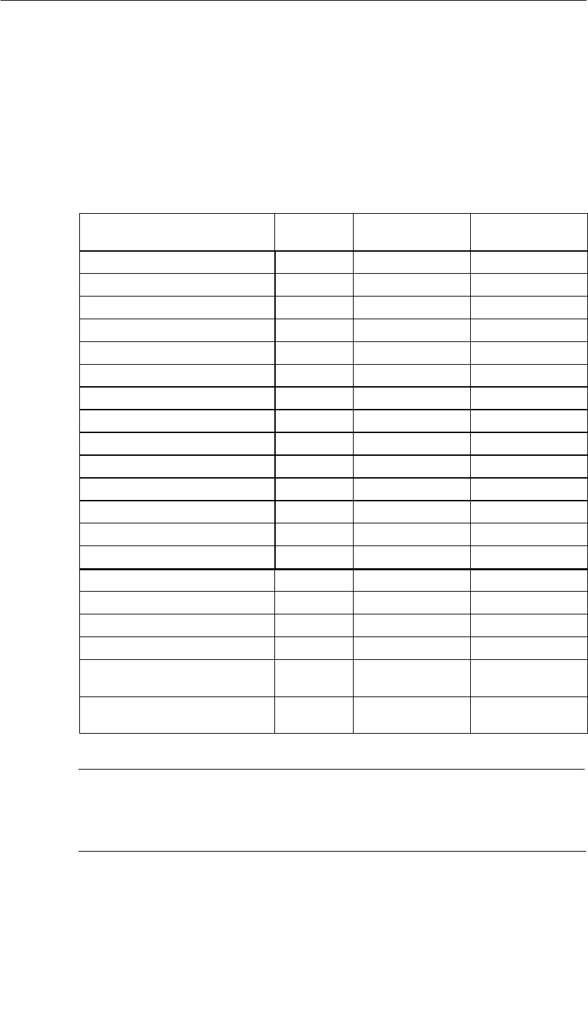
Digital Modules
4-10 S7-400, M7-400 Programmable Controllers Module Specifications
A5E00069467-07
Diagnostic Messages of the Digital Modules
The table below gives an overview of the diagnostic messages for the digital
modules with diagnostics capability.
You can find out which diagnostic message each module is capable of in the
Appendix entitled “Diagnostic Data of the Signal Modules”.
Table 4-8 Diagnostic Messages of the Digital Modules
Diagnostic Message LED Scope of the
Diagnosis Parameters Can
Be Assigned
Module problem INTF/EXTF Module No
Internal malfunction INTF Module No
External malfunction EXTF Module No
Channel error present INTF/EXTF Module No
External auxiliary supply missing EXTF Module No
Front connector missing EXTF Module No
Module not parameterized. INTF Module No
Wrong parameters INTF Module No
Channel information available INTF/EXTF Module No
STOP mode – Module No
Internal voltage failure INTF Module No
EPROM error INTF Module No
Hardware interrupt lost INTF Module No
Parameter assignment error INTF Channel No
Short-circuit to M EXTF Channel Yes
Short-circuit to L+ EXTF Channel Yes
Wire break EXTF Channel Yes
Fuse blown INTF Channel Yes
Sensor supply missing EXTF Channel/channel
group Yes
No load voltage L+ EXTF Channel/channel
group Yes
Note
A prerequisite for detecting the errors indicated by programmable diagnostic
messages is that you have assigned parameters to the digital module accordingly
in STEP 7.

Digital Modules
4-11
S7-400, M7-400 Programmable Controllers Module Specifications
A5E00069467-07
Causes of Errors and Remedial Measures for Digital Modules
Table 4-9 Diagnostic Messages of the Digital Modules, Causes of Errors and Remedial
Measures
Diagnostic Message Possible Error Cause Remedy
Module malfunction An error detected by the module
has occurred -
Internal malfunction The module has detected an error
within the programmable controller -
External malfunction The module has detected an error
outside the programmable controller -
There is a channel
error Indicates that only certain channels
are faulty -
No external auxiliary
voltage Voltage required to operate the
module is missing (load voltage,
sensor supply)
Supply missing voltage
No front connector Jumper between connections 1 and
2 in the front connector missing Install jumper
Parameters have not
been assigned to the
module
The module requires the information
as to whether it should work with
system default parameters or with
your parameters
Message queued after power-on until
parameter transmission by the CPU has
been completed; parameterize the
module, as required
Wrong parameters One parameter or the combination
of parameters is not plausible Reassign module parameter
Channel information
available Channel error present; the module
can supply additional channel
information
-
Operating mode
STOP Module was not parameterized and
the first module cycle has not been
completed
If after rebooting the CPU all the input
values are in the intermediate memory,
this message is reset
Internal voltage failure Module is defective Replace module
EPROM error Module is defective Replace module
Hardware interrupt lost The module cannot send an
interrupt, since the previous
interrupt was not acknowledged;
configuration error possible
Change the interrupt handling in the CPU
(change priority for interrupt OB; shorten
interrupt program)
Parameter assignment
error Incorrect parameters transferred to
the module (for example, impossible
input delay); the corresponding
channel is deactivated
Reassign module parameter
Short circuit to M Overload of output Eliminate overload
Short-circuit of output to M Check the wiring of the outputs
Short circuit to L+ Short circuit of output to L+ Check the wiring of the outputs

Digital Modules
4-12 S7-400, M7-400 Programmable Controllers Module Specifications
A5E00069467-07
Table 4-9 Diagnostic Messages of the Digital Modules, Causes of Errors and Remedial
Measures, continued
Diagnostic Message RemedyPossible Error Cause
Wire break Lines interrupted Close circuit
No external sensor supply Wire sensors with 10 to 18 k
Channel not connected (open) Disable the “Diagnostics – Wire Break”
parameter for the channel in STEP 7
Connect channel
Fuse blown One or more fuses on the module
has blown and caused this fault. Remove the overload and replace the
fuse
No sensor supply Overload of sensor supply Eliminate overload
Short circuit of sensor supply to M Eliminate short circuit
No
l d lt L
Power supply L+ to module missing Feed in supply voltage L+
load voltage L+ Fuse in module is defective Replace module

Digital Modules
4-13
S7-400, M7-400 Programmable Controllers Module Specifications
A5E00069467-07
4.5 Interrupts of the Digital Modules
Introduction
This section describes the interrupt behavior of the digital modules. The following
interrupts exist:
•Diagnostic Interrupt
•Hardware interrupt
Note that not all digital modules have interrupt capability or they are only capable of
a subset of the interrupts described here. Refer to the technical specifications of
the modules, starting at Section 4.7, to find out which digital modules have interrupt
capability.
The OBs and SFCs mentioned below can be found in the online help system for
STEP 7, where they are described in greater detail.
Enabling Interrupts
The interrupts are not preset – in other words, they are inhibited without
appropriate parameter assignment. You enable the interrupts in STEP 7
(refer to Section 5.7).
Special Feature: The Module is Inserted in ER-1/ER-2
Note
If you use the digital module in ER-1/ER-2, you must set the parameters for
enabling all the interrupts to “No” because the interrupt lines are not available in
ER-1/ER-2.
Diagnostic Interrupt
If you have enabled diagnostic interrupts, then active error events (initial
occurrence of the error) and departing error events (message after troubleshooting)
are reported by means of an interrupt.
The CPU interrupts the execution of the user program and processes the
diagnostic interrupt block (OB 82).
In the user program, you can call SFC 51 or SFC 59 in OB 82 to obtain more
detailed diagnostic information from the module.
The diagnostic information is consistent until such time as OB 82 is exited. When
OB 82 is exited, the diagnostic interrupt is acknowledged on the module.

Digital Modules
4-14 S7-400, M7-400 Programmable Controllers Module Specifications
A5E00069467-07
Hardware Interrupt
A digital input module can trigger a hardware interrupt for each channel at a rising
or falling edge, or both, of a signal status change.
You perform parameter assignment for each channel separately. It can be modified
at any time (in RUN mode using the user program).
Pending hardware interrupts trigger hardware interrupt processing in the CPU
(OB 40 to OB 47). The CPU interrupts the execution of the user program or of the
priority classes with low priority.
In the user program of the hardware interrupt OB (OB 40 to OB 47) you can specify
how the programmable controller is to respond to an edge change. When the
hardware interrupt OB is exited, the hardware interrupt is acknowledged on the
module.
For each channel the digital input module can buffer an interrupt that has not been
triggered. If no higher priority run-time levels are waiting to be processed, the
buffered interrupts (of all modules) are serviced one after the other by the CPU
according to the order in which they occurred.
Hardware Interrupt Lost
In an interrupt has been buffered for a channel and another interrupt occurs on that
channel before it has been processed by the CPU, a diagnostic interrupt “hardware
interrupt lost” is triggered.
More interrupts on this channel are not acquired until processing of the interrupt
buffered on this channel has been executed.
Interrupt-Triggering Channels
The interrupt-triggering channels are stored in the local data of the hardware
interrupt OBs (in the start information of the corresponding OB). The start
information is two words long (bits 0 to 31). The bit number is the channel number.
Bits 16 to 31 are not assigned.

Digital Modules
4-15
S7-400, M7-400 Programmable Controllers Module Specifications
A5E00069467-07
4.6 Input Characteristic Curve for Digital Inputs
IEC 61131, Type 1 and Type 2
The IEC 61131 standard requires the following for the input current:
•In the case of type 2, an input current of y 2 mA already at + 5 V
•In the case of type 1, an input current of y 0.5 mA already at + 5 V
EN 60947-5-2, Two-Wire BEROs
The standard for BEROs (EN 60947-5-2) specifies that there can be a current of v
1.5 mA for BEROs in the “0” signal state.
The input current of the module in the ”0” signal state is decisive for the operation
of two-wire BEROs. This must be in accordance with BERO requirements.
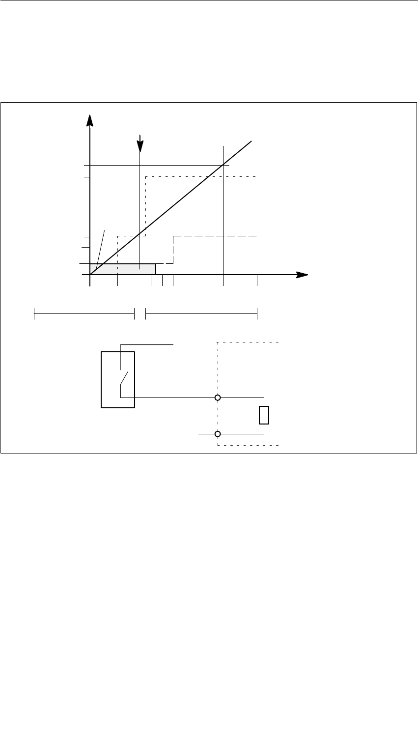
Digital Modules
4-16 S7-400, M7-400 Programmable Controllers Module Specifications
A5E00069467-07
Input Characteristic Curve for Digital Inputs
As long as the current flowing into the module remains v 1.5 mA, the module
recognizes this as a “0” signal.
0.5
1.5
2
6
7
0 5 11 1315 24 30
I min to IEC 61131; type 2
I min to IEC 61131; type 1
Typ. switching threshold
(9.5 V) Resistance characteristic
curve
L+ (V)
– 30 V
I E (mA)
“0” “1”
1
0
L+
M
I v 1.5 mA --> “0” signal
PLC
input resistance
2-Wire BERO
BERO
standard
I v 1.5 mA
Figure 4-1 Input Characteristic Curve for Digital Inputs
IEC 61131, Type 1 in the Case of the Digital Input Module (6ES7421-1BL01-0AA0)
The input current in the case of the digital input module (6ES7421-1BL01-0AA0)
reaches 1.5 mA only above the +5 V switching threshold but under the switching
threshold of the module (typ. 9.5 V). Therefore only type 1 can be specified with the
IEC 61131 standard.

Digital Modules
4-17
S7-400, M7-400 Programmable Controllers Module Specifications
A5E00069467-07
4.7 Digital Input Module SM 421; DI 32 24 VDC
(6ES7421-1BL00-0AA0)
Characteristics
The SM 421;DI 32 x 24 VDC is a digital input module with the following features:
•32 inputs, isolated in a group of 32. In other words, all inputs share the same
chassis ground.
•Rated load voltage: 24 VDC
•Suitable for switches and 2-wire proximity switches
(BEROs, IEC 61131; type 2).
The status LEDs indicate the process status.
Functional Expansion as of Version 03
The lower limit of the rated input range is increased at signal “0” from –3 to –30 V.
The rated input voltage for signal “0” is thus: –30 V to 5 V
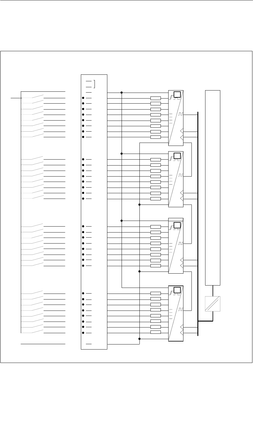
Digital Modules
4-18 S7-400, M7-400 Programmable Controllers Module Specifications
A5E00069467-07
Terminal Assignment and Block Diagram of the Digital Input Module SM 421;
DI 32 x 24 VDC
1
2
3
4
5
6
7
8
9
10
11
12
13
14
15
16
17
18
19
20
21
22
23
24
25
26
27
28
29
30
31
32
33
34
35
36
37
38
39
40
41
42
43
44
45
46
47
48
1
2
3
4
5
6
7
L+
0
M
1
2
3
4
5
6
7
0
1
2
3
4
5
6
7
0
1
2
3
4
5
6
7
0
M
L+
Process
t
t
t
t
Data register and bus control
Module
Figure 4-2 Terminal Assignment and Block Diagram of the SM 421; DI 32 24 VDC

Digital Modules
4-19
S7-400, M7-400 Programmable Controllers Module Specifications
A5E00069467-07
Technical Specifications of the SM 421; DI 32 x 24 VDC
Programming package
Associated programming
package As of STEP 7 V 2.0
Dimensions and Weight
Dimensions W H D
(in millimeters) 25 290 210
Weight Approx. 600 g
Data for Specific Module
Number of inputs 32
Length of cable
•Unshielded
•Shielded
Max. 600 m
Max. 1000 m
Voltages, Currents, Potentials
Power rated voltage of the
electronics L+ 24 VDC
•Reverse polarity protection Yes
•Power failure buffering None
Number of inputs that can be
triggered simultaneously 32
Isolation
•Between channels and
backplane bus Yes
•Between channels and
power supply of the
electronics
No
•Between the channels No
Permitted potential difference
•Between the different
circuits 75 VDC / 60 VAC
Insulation tested with
•Channels against
backplane bus and load
voltage L+
500 VDC
Current consumption
•From the backplane bus Max. 30 mA
•From supply voltage L+ Max. 30 mA
Power dissipation of the
module Typ. 6 W
Status, Interrupts, Diagnostics
Status display Green LED per
channel
Interrupts None
Diagnostic functions None
Substitute value can be applied No
Sensor Selection Data
Input voltage
•Rated value
•For signal “1”
•For signal “0”
24 VDC
11 V to 30 V
–3 V to 5 V
–30 V to 5 V as of
version 03
Input current
•At signal “1” 6 mA to 8 mA
Input delay
•At “0” to “1”
•At “1” to “0”
1.2 ms to 4.8 ms
1.2 ms to 4.8 ms
Input characteristic curve To IEC 61131; type 2
Connection of two-wire BEROs Possible
•Permitted bias current Max. 2.5 mA

Digital Modules
4-20 S7-400, M7-400 Programmable Controllers Module Specifications
A5E00069467-07
4.8 Digital Input Module SM 421; DI 32 24 VDC;
(6ES7421-1BL01-0AA0)
Characteristics
The digital input module SM 421; DI 32 24 VDC has the following features:
•32 inputs, isolated in a group of 32
•24 VDC rated input voltage
•Suitable for switches and two/three/four-wire proximity switches (BEROs,
IEC 61131; type 1)
The status LEDs indicate the process status.
Notice
If you use the module with the order number 6ES7421-1BL01-0AA0 as a
replacement for the module with the order number 6ES7421-1BL00-0AA0, you can
leave PIN 3 wired. If you run modules 6ES7421-1BL00-0AA0 and
6ES7421-1BL01-0AA0 involved in mutual exchange, you have to wire and supply
PIN 3 as described in Section 4.7.
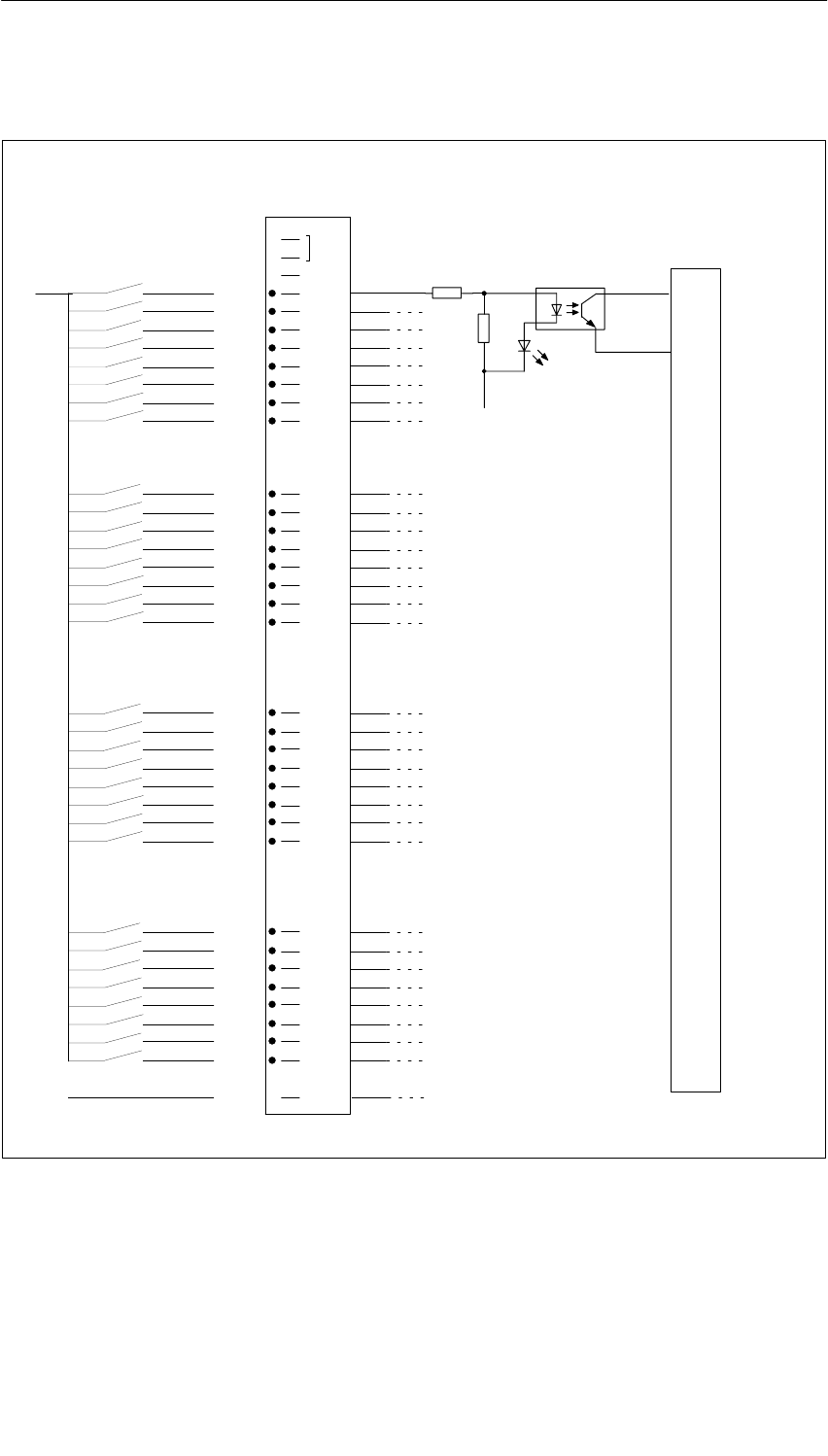
Digital Modules
4-21
S7-400, M7-400 Programmable Controllers Module Specifications
A5E00069467-07
Terminal Assignment and Block Diagram of the SM 421; DI 32 24 VDC
1
2
3
4
5
6
7
8
9
10
11
12
13
14
15
16
17
18
19
20
21
22
23
24
25
26
27
28
29
30
31
32
33
34
35
36
37
38
39
40
41
42
43
44
45
46
47
48
1
2
3
4
5
6
7
0
M
1
2
3
4
5
6
7
0
1
2
3
4
5
6
7
0
1
2
3
4
5
6
7
0
M
L+
Process
Data register and bus control
Module
M
Figure 4-3 Terminal Assignment and Block Diagram of the SM 421; DI 32 24 VDC

Digital Modules
4-22 S7-400, M7-400 Programmable Controllers Module Specifications
A5E00069467-07
Technical Specifications of the SM 421; DI 32 x 24 VDC
Dimensions and Weight
Dimensions W H D
(in millimeters) 25 290 210
Weight Approx. 500 g
Data for Specific Module
Number of inputs 32
Length of cable
•Unshielded
•Shielded
Max. 600 m
Max. 1000 m
Voltages, Currents, Potentials
Power rated voltage of the
electronics L+ Not required
Number of inputs that can be
triggered simultaneously 32
Isolation
•Between channels and
backplane bus Yes
•Between the channels No
Permitted potential difference
•Between the different
circuits 75 VDC / 60 VAC
Insulation tested with
•Channels against
backplane bus and load
voltage L+
500 VDC
Current consumption
•From the backplane bus Max. 20 mA
Power dissipation of the
module Typ. 6 W
Status, Interrupts, Diagnostics
Status display Green LED per
channel
Interrupts None
Diagnostic functions None
Substitute value can be applied No
Data for Selecting a Sensor
Input voltage
•Rated value
•For signal “1”
•For signal “0”
24 VDC
13 V to 30 V
-30 V to 5 V
Input current
•At signal “1” 7 mA
Input delay
•At “0” to “1”
•At “1” to “0”
1.2 ms to 4.8 ms
1.2 ms to 4.8 ms
Input characteristic curve To IEC 61131; type 1
Connection of two-wire BEROs Possible
•Permitted bias current Max. 1.5 mA

Digital Modules
4-23
S7-400, M7-400 Programmable Controllers Module Specifications
A5E00069467-07
4.9 Digital Input Module SM 421; DI 16 24 VDC;
(6ES7421-7BH00-0AB0)
Characteristics
The digital input module SM 421; DI 16 24 VDC has the following features:
•16 inputs, isolated in 2 groups of 8
•24 VDC rated input voltage
•Suitable for switches and two/three/four-wire proximity switches
(BEROs, IEC 61131; type 2)
•2 short-circuit-proof sensor supplies for 8 channels each
•External redundant power supply possible to supply sensors
•“Sensor supply (Vs) O.K.” status display
•Group error display for internal faults (INTF) and external faults (EXTF)
•Programmable diagnostics
•Programmable diagnostic interrupt
•Programmable hardware interrupt
•Programmable input delays
•Parameterizable substitute values in the input range
The status LEDs indicate the process status.
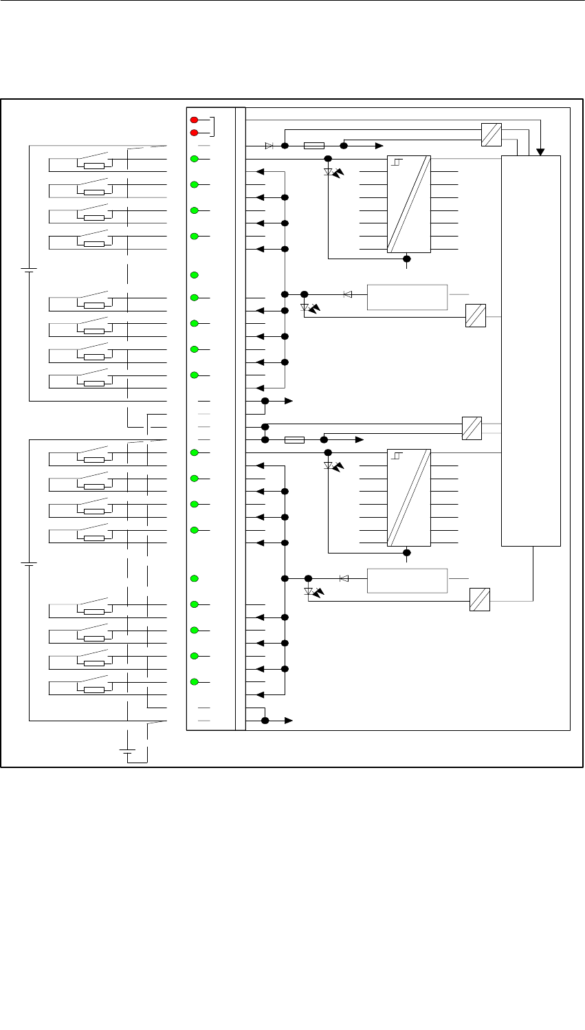
Digital Modules
4-24 S7-400, M7-400 Programmable Controllers Module Specifications
A5E00069467-07
Terminal Assignment and Block Diagram of the SM 421; DI 16 24 VDC
INT
F
EXTF
1L+
0
1
2
3
1Vs
4
5
6
7
1M
1M
2L+
2L+
0
1
2
3
2Vs
4
5
6
7
2M
2M
1L+
2M
2L+
1M
ML+
1L+
1L+
2L+
1M
2M
2M
1M
Backplane bus interface
24 V
24 V
24 V
Front connector monitoring
Monitoring of external auxiliary supply 1L+
Monitoring of internal voltage
Monitoring of sensor supply 1Vs
2L+
Monitoring of external auxiliary supply 2L+
Monitoring of internal voltage
Monitoring of sensor supply 2Vs
1
2
3
4
5
6
7
8
9
10
11
12
13
14
15
16
17
18
19
20
21
22
23
24
25
26
27
28
29
30
31
32
33
34
35
36
37
38
39
40
41
42
43
44
45
46
47
48
Short-circuit
protection
Short-circuit
protection
Figure 4-4 Terminal Assignment and Block Diagram of the SM 421; DI 16 24 VDC
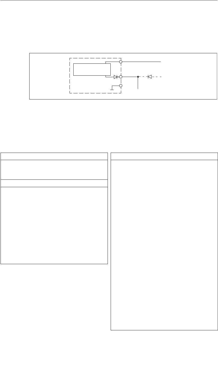
Digital Modules
4-25
S7-400, M7-400 Programmable Controllers Module Specifications
A5E00069467-07
Terminal Assignment Diagram for Redundant Supply of Sensors
The figure below shows how sensors can additionally be supplied by means of Vs
with a redundant voltage source – for example, via another module).
Vs
M
L+ 1 L+
2 L+
to the sensors
±
Digital input
module
Short-circuit-
proof driver
Figure 4-5 Terminal Assignment Diagram for the Redundant Supply of Sensors of the
SM 421; DI 16 24 VDC
Technical Specifications of the SM 421; DI 16 24 VDC
Dimensions and Weight
Dimensions W H D
(in millimeters) 25 290 210
Weight Approx. 600 g
Data for Specific Module
Number of inputs 16
Length of cable
•Unshielded
input delay
– 0.1 ms
– 0.5 ms
– 3 ms
Max. 20 m
Max. 50 m
Max. 600 m
•Shielded
input delay
– 0.1 ms
– 0.5 ms
– 3 ms
Max. 30 m
Max. 70 m
Max. 1000 m
Voltages, Currents, Potentials
Rated supply voltage of the
electronics and sensor L+ 24 VDC
•Reverse polarity protection Yes
Number of inputs that can be
triggered simultaneously 16
Isolation
•Between channels and
backplane bus Yes
•Between channels and
power supply of the
electronics
No
•Between the channels Yes
– In groups of 2
Permitted potential difference
•Between the different
circuits 75 VDC, 60 VAC
Insulation tested with
•Channels against
backplane bus and load
voltage L+
500 VDC
•Channel groups between
themselves 500 VDC
Current consumption
•From the backplane bus
•From the power supply L+
Max. 130 mA
Max. 120 mA
Power dissipation of the
module Typ. 5 W

Digital Modules
4-26 S7-400, M7-400 Programmable Controllers Module Specifications
A5E00069467-07
Status, Interrupts, Diagnostics
Status display Green LED per
channel
Interrupts
•Hardware interrupt
•Diagnostic Interrupt
Parameters can be
assigned
Parameters can be
assigned
Diagnostic functions
•Monitoring of the power
supply voltage of the
electronics
Yes
•Load voltage monitor Green LED per group
•Group error display
– For internal fault
– For external fault
Red LED (INTF)
Red LED (EXTF)
•Channel error display (F) None
•Diagnostic information can
be displayed Yes
Monitoring for
•Wire break I < 1 mA
Substitute value can be applied Yes
Sensor Power Supply Outputs
Number of outputs 2
Output voltage
•with load Min. L+(–2.5 V)
Output current
•Rated value
•Permitted range
120 mA
0 to 150 mA
Additional (redundant) supply Possible
Short-circuit protection Yes, electronic
Data for Selecting a Sensor
Input voltage
•Rated value
•For signal “1”
•For signal “0”
24 VDC
11 V to 30 V
-30 V to 5 V
Input current
•At signal “1”
•At signal “0”
6 mA to 12 mA
< 6 mA
Input characteristic curve To IEC 61131;
type 2
Connection of two-wire BEROs
•Permitted bias current
Possible
Max. 3 mA
Time, Frequency
Internal preparation time for
•Only hardware interrupt
enable
– Input delay the same
for both channel
groups
Max. 70 s
– Input delay not the
same for both channel
groups
Max. 120 s
•Enable hardware and
diagnostic interrupts Max. 5 ms
Input delay
•Parameters can be
assigned Yes
•Rated value 0.1/0.5/3 ms
•Input frequency
(with a time delay of
0.1 ms)
< 2 kHz
Both values go into cycle and response times.
Sensor Circuit
Resistance circuit of the sensor
for wire break monitoring 10 to 18 kΩ

Digital Modules
4-27
S7-400, M7-400 Programmable Controllers Module Specifications
A5E00069467-07
4.9.1 Assigning Parameters to the SM 421; DI 16 24 VDC
Parameter Assignment
You will find a description of the general procedure for assigning parameters to
digital modules in Section 5.7.
Parameters of the SM 421; DI 16 24 VDC
You will find an overview of the parameters you can set and their default settings
for the SM 421; DI 16 24 VDC in the table below.
Table 4-10 Parameters of the SM 421; DI 16 24 VDC
Parameter Value Range Default2) Parameter
Type Scope
Enable
•Diagnostic interrupt1)
•Hardware interrupt1) Yes/no
Yes/no No
No Dynamic Module
•Destination CPU for
interrupt 1 to 4 –Static Module
Diagnostics
•Wire break
•No load voltage
L+/sensor supply
Yes/no
Yes/no No
No Static Channel
Channel
group
Trigger for hardware
interrupt
Dynamic
Channel
•Rising edge
•Falling edge
Yes/no
Yes/no
– Dynamic Channel
Input delay 3 ms (DC)
0.1 ms (DC)
0.5 ms (DC/AC)
3 (DC) Static Channel
group
Reaction to Error Substitute a Value (SV)
Keep Last Value (KLV) SV Dynamic Module
Enable substitute value “1” Yes/no No Dynamic Channel
1) If you use the module in ER-1/ER-2, you must set this parameter to “No” because the interrupt lines are not
available in ER-1/ER-2.
2) Only in the CC (central controller) is it possible to start up the digital modules with the default settings.
Assignment of the Encoder Supplies to Channel Groups
The two encoder supplies of the module are used to supply two channel groups:
inputs 0 to 7 and inputs 8 to 15. In these two channel groups, you parameterize the
diagnostics for the encoder supply, too.

Digital Modules
4-28 S7-400, M7-400 Programmable Controllers Module Specifications
A5E00069467-07
Ensuring a Wire Break Check Is Carried Out
To ensure that a wire break check is carried out, you require an external sensor
circuit using a resistor of 10 to 18 k The resistor should be connected parallel to
the contact and should be arranged as closely as possible to the sensor.
This additional resistor is not required in the following cases:
•If two-wire BEROs are used
•If you don’t parameterize the “Wire Break” diagnosis
Setting the Input Delay for Channel Groups
You can only set the input delay for each group of channels. In other words, the
setting for channel 0 applies to inputs 0 to 7 and the setting for channel 8 applies to
inputs 8 to 15.
Note
The parameters that are entered for the remaining channels (1 to 7 and 9 to 15)
must be equal to the value 0 or 8, otherwise those channels will be reported as
being incorrectly parameterized.
Any hardware interrupts that have occurred in the meantime will be reported after
acknowledgement.
Optimum Signal Propagation Delay
You can achieve the fastest signal propagation delay with the following settings:
•Both channel groups are parameterized with an input delay of 0.1 ms
•All the diagnoses (load voltage error, wire break) are deactivated
•Diagnostic interrupt is not enabled

Digital Modules
4-29
S7-400, M7-400 Programmable Controllers Module Specifications
A5E00069467-07
4.9.2 Behavior of the SM 421; DI 16 24 VDC
Effect of Operating Mode and Supply Voltage on the Input Values
The input values of the SM 421; DI 16 24 DC depend on the operating mode of
the CPU and on the supply voltage of the module.
Table 4-11 How the Input Values Depend on the Operating Mode of the CPU and on the
Supply Voltage L+ of the SM 421; DI 16 24 VDC
CPU Operating Mode Power Supply L+
to Digital Module Input Value of Digital Module
POWER ON RUN L+ exists Process value
L+ missing 0 signal *
STOP L+ exists Process value
L+ missing 0 signal*
POWER
OFF
–L+ exists –
OFF L+ missing –
*Depends on the parameter assignment (see Table 4–12 )
Behavior upon Failure of the Supply Voltage
Failure of the supply voltage of the SM 421; DI 16 24 DC is always indicated by
the EXTF LED on the module. Furthermore, this information is made available on
the module (entry in diagnosis).
Triggering of the diagnostic interrupt depends on the parameter assignment (see
Section 4.9.1).
Short-Circuit of Sensor Supply Vs
Irrespective of the parameter assignment, the corresponding Vs LED goes out if a
short-circuit of the encoder supply Vs occurs.

Digital Modules
4-30 S7-400, M7-400 Programmable Controllers Module Specifications
A5E00069467-07
Effect of Errors and Parameter Assignment on the Input Values
The input values of the SM 421; DI 16 24 DC are affected by certain errors and
the parameter assignment of the module. The following table lists the effects on the
input values.
You will find more diagnostic messages of the module in the Appendix entitled
“Diagnostic Data of the Signal Modules”.
Table 4-12 How the Input Values Are Affected by Faults and by the Parameter Assignment of the
SM 421; DI 16 24 VDC
Diagnostic Message “Diagnostics”
Parameter “Reaction to
Error”
Parameter
Input Value of Digital Module
Module not
parameterized Cannot be
disabled Not relevant 0 signal (all channels)
No front connector SV Parameterized substitute value
KLV Last read, valid value
Incorrect parameters
(module/channel) Cannot be
disabled Not relevant 0 signal (module/all incorrectly
parameterized channels)
STOP operating mode Cannot be
disabled –Process value (not updated)
Internal voltage failure Cannot be
di bl d
SV Parameterized substitute value
disabled KLV Last read, valid value
Hardware interrupt lost Cannot be
disabled Not relevant Current process value
Wire break (for each
hl)
Deactivated – 0 signal
channel) Activated SV Parameterized substitute value
KLV Last read, valid value
Sensor supply missing
(l ti td i ”N
Deactivated – 0 signal
(also activated via ”No
Load Volta
g
e L+”
)
Activated SV Parameterized substitute value
Load Voltage L+ )
KLV Last read, valid value
No load voltage L+ (for
each channel group) Deactivated – 0 signal, if the contact is connected via the
sensor supply; process value for the
external sensor supply
Activated SV Parameterized substitute value
KLV Last read, valid value

Digital Modules
4-31
S7-400, M7-400 Programmable Controllers Module Specifications
A5E00069467-07
Behavior when the Input Delay Equals 0.1 ms and an Error Occurs
If you have parameterized the following:
•An input delay of 0.1 ms
•KLV or SV as the response to an error
•Substitute “1”
In the event of a fault on a channel that has a 1 signal, the following could occur
before the last valid value or the substitute value ”1” is output:
•An 0 signal may be briefly output
•If parameterized, a hardware interrupt may be generated

Digital Modules
4-32 S7-400, M7-400 Programmable Controllers Module Specifications
A5E00069467-07
4.10 Digital Input Module SM 421; DI 16 24 VDC;
(6ES7421-7BH01-0AB0)
Characteristics
The digital input module SM 421; DI 16 24 VDC has the following features:
•16 inputs, isolated in 2 groups of 8
•24 VDC rated input voltage
•Suitable for switches and two/three/four-wire proximity switches
(BEROs, IEC 61131; type 2)
•2 short-circuit-proof sensor supplies for 8 channels each
•External redundant power supply possible to supply sensors
•“Sensor supply (Vs) O.K.” status display
•Group error display for internal faults (INTF) and external faults (EXTF)
•Programmable diagnostics
•Programmable diagnostic interrupt
•Programmable hardware interrupt
•Programmable input delays
•Parameterizable substitute values in the input range
The status LEDs indicate the process status.
Note
The spare parts of this module is compatible with SM 421; DI 16 DC 24 V;
(6ES7 421-7BH00-0AB0).
To be able to use the new function “input delay 50 s”, you require STEP 7 V 5.2.
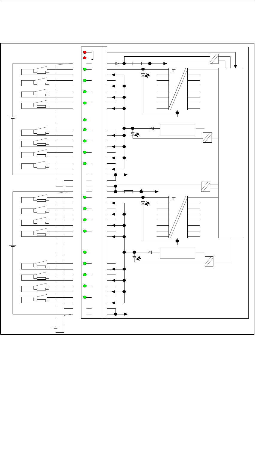
Digital Modules
4-33
S7-400, M7-400 Programmable Controllers Module Specifications
A5E00069467-07
Terminal Assignment and Block Diagram of the SM 421; DI 16 24 VDC
INT
F
EXTF
1L+
0
1
2
3
1Vs
4
5
6
7
1M
1M
2L+
2L+
0
1
2
3
2Vs
4
5
6
7
2M
2M
1L+
2M
2L+
1M
ML+
1L+
1L+
2L+
1M
2M
2M
1M
Backplane bus interface
24 V
24 V
24 V
Front connector monitoring
Monitoring of external auxiliary supply 1L+
Monitoring of internal voltage
Monitoring of sensor supply 1Vs
2L+
Monitoring of external auxiliary supply 2L+
Monitoring of internal voltage
Monitoring of sensor supply 2Vs
1
2
3
4
5
6
7
8
9
10
11
12
13
14
15
16
17
18
19
20
21
22
23
24
25
26
27
28
29
30
31
32
33
34
35
36
37
38
39
40
41
42
43
44
45
46
47
48
Short-circuit
protection
Short-circuit
protection
Figure 4-6 Terminal Assignment and Block Diagram of the SM 421; DI 16 24 VDC
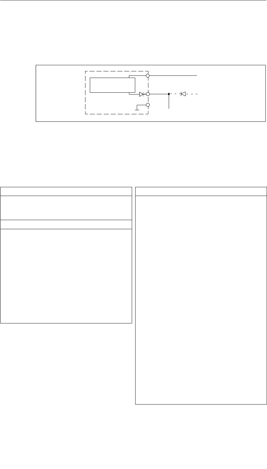
Digital Modules
4-34 S7-400, M7-400 Programmable Controllers Module Specifications
A5E00069467-07
Terminal Assignment Diagram for Redundant Supply of Sensors
The figure below shows how sensors can additionally be supplied by means of Vs
with a redundant voltage source – for example, via another module).
Vs
M
L+ 1 L+
2 L+
to the sensors
±
Digital input
module
Short-circuit-
proof driver
Figure 4-7 Terminal Assignment Diagram for the Redundant Supply of Sensors of the
SM 421; DI 16 24 VDC
Technical Specifications of the SM 421; DI 16 24 VDC
Dimensions and Weight
Dimensions W H D
(in millimeters) 25 290 210
Weight Approx. 600 g
Data for Specific Module
Number of inputs 16
Length of cable
•Unshielded
input delay
– 0.1 ms
– 0.5 ms
– 3 ms
Max. 20 m
Max. 50 m
Max. 600 m
•Shielded
input delay
– 0.1 ms
– 0.5 ms
– 3 ms
Max. 30 m
Max. 70 m
Max. 1000 m
Voltages, Currents, Potentials
Rated supply voltage of the
electronics and sensor L+ 24 VDC
•Reverse polarity protection Yes
Number of inputs that can be
triggered simultaneously 16
Isolation
•Between channels and
backplane bus Yes
•Between channels and
power supply of the
electronics
No
•Between the channels Yes
– In groups of 2
Permitted potential difference
•Between the different
circuits 75 VDC, 60 VAC
Insulation tested with
•Channels against
backplane bus and load
voltage L+
500 VDC
•Channel groups between
themselves 500 VDC
Current consumption
•From the backplane bus
•From the power supply L+
Max. 130 mA
Max. 120 mA
Power dissipation of the
module Typ. 5 W

Digital Modules
4-35
S7-400, M7-400 Programmable Controllers Module Specifications
A5E00069467-07
Status, Interrupts, Diagnostics
Status display Green LED per
channel
Interrupts
•Hardware interrupt
•Diagnostic Interrupt
Parameters can be
assigned
Parameters can be
assigned
Diagnostic functions
•Monitoring of the power
supply voltage of the
electronics
Yes
•Load voltage monitor Green LED per group
•Group error display
– For internal fault
– For external fault
Red LED (INTF)
Red LED (EXTF)
•Channel error display (F) None
•Diagnostic information can
be displayed Yes
Monitoring for
•Wire break I < 1 mA
Substitute value can be applied Yes
Sensor Power Supply Outputs
Number of outputs 2
Output voltage
•with load Min. L+(–2.5 V)
Output current
•Rated value
•Permitted range
120 mA
0 to 150 mA
Additional (redundant) supply Possible
Short-circuit protection Yes, electronic
Data for Selecting a Sensor
Input voltage
•Rated value
•For signal “1”
•For signal “0”
24 VDC
11 V to 30 V
-30 V to 5 V
Input current
•At signal “1”
•At signal “0”
6 mA to 12 mA
< 6 mA
Input characteristic curve To IEC 61131;
type 2
Connection of two-wire BEROs
•Permitted bias current
Possible
Max. 3 mA
Time, Frequency
Internal preparation time 1) for
•only status recognition
– Input delay of the
channel groups
0.05 ms/0.05 ms
max. 50 s
– Input delay of the
channel groups
0.05 ms/0.1 ms or 0.1
ms/0.1 ms
max. 70 s
– Input delay of the
channel groups
>= 0.5 ms
max. 180 s
•Status recognition and
enable process interrupt
– Input delay of the
channel groups
0.05 ms/0.05 ms 2)
max. 60 s
– Input delay for the
channel groups
0.05 ms/0.1 ms or 0.1
ms/0.1 ms
max. 80 s
– Input delay of the
channel groups
>= 0.5 ms
max. 190 s
Internal preparation time for
diagnostics/diagnostic interrupt
Input delay
max. 5 ms
•Parameters can be
assigned Yes
•Rated value 0.1/0.5/3 ms
•Input frequency
(with a time delay of
0.1 ms)
< 2 kHz
Values go into cycle and response times.
Sensor Circuit
Resistance circuit of the sensor
for wire break monitoring 10 to 18 kΩ
1) The filter times are added to the overall runtime of the
selected input delay.
2) Substitute functionality; diagnostics and diagnostic
interrupt are not to be selected.

Digital Modules
4-36 S7-400, M7-400 Programmable Controllers Module Specifications
A5E00069467-07
4.10.1 Assigning Parameters to the SM 421; DI 16 24 VDC
Parameter Assignment
You will find a description of the general procedure for assigning parameters to
digital modules in Section 5.7.
Parameters of the SM 421; DI 16 24 VDC
You will find an overview of the parameters you can set and their default settings
for the SM 421; DI 16 24 VDC in the table below.
Table 4-13 Parameters of the SM 421; DI 16 24 VDC
Parameter Value Range Default2) Parameter
Type Scope
Enable
•Diagnostic interrupt1)
•Hardware interrupt1) Yes/no
Yes/no No
No Dynamic Module
•Destination CPU for
interrupt 1 to 4 –Static Module
Diagnostics
•Wire break
•No load voltage
L+/sensor supply
Yes/no
Yes/no No
No Static Channel
Channel
group
Trigger for hardware
interrupt
Dynamic
Channel
•Rising edge
•Falling edge
Yes/no
Yes/no
– Dynamic Channel
Input delay 3 ms (DC)
0.1 ms (DC)
0.5 ms (DC/AC)
3 Static Channel
group
Reaction to Error Substitute a Value (SV)
Keep Last Value (KLV) SV Dynamic Module
Enable substitute value “1” Yes/no No Dynamic Channel
1( If you use the module in ER-1/ER-2, you must set this parameter to “No” because the interrupt lines are not
available in ER-1/ER-2.
2( Only in the CC (central controller) is it possible to start up the digital modules with the default settings.
Assignment of the Encoder Supplies to Channel Groups
The two encoder supplies of the module are used to supply two channel groups:
inputs 0 to 7 and inputs 8 to 15. In these two channel groups, you parameterize the
diagnostics for the encoder supply, too.

Digital Modules
4-37
S7-400, M7-400 Programmable Controllers Module Specifications
A5E00069467-07
Ensuring a Wire Break Check Is Carried Out
To ensure that a wire break check is carried out, you require an external sensor
circuit using a resistor of 10 to 18 k The resistor should be connected parallel to
the contact and should be arranged as closely as possible to the sensor.
This additional resistor is not required in the following cases:
•If two-wire BEROs are used
•If you don’t parameterize the “Wire Break” diagnosis
Setting the Input Delay for Channel Groups
You can only set the input delay for each group of channels. In other words, the
setting for channel 0 applies to inputs 0 to 7 and the setting for channel 8 applies to
inputs 8 to 15.
Note
The parameters that are entered for the remaining channels (1 to 7 and 9 to 15)
must be equal to the value 0 or 8, otherwise those channels will be reported as
being incorrectly parameterized.
Any hardware interrupts that have occurred in the meantime will be reported after
acknowledgement.
Optimum Signal Propagation Delay
You can achieve the fastest signal propagation delay with the following settings:
•Both channel groups are parameterized with an input delay of 0.1 ms
•All the diagnoses (load voltage error, wire break) are deactivated
•Diagnostic interrupt is not enabled

Digital Modules
4-38 S7-400, M7-400 Programmable Controllers Module Specifications
A5E00069467-07
4.10.2 Behavior of the SM 421; DI 16 24 VDC
Effect of Operating Mode and Supply Voltage on the Input Values
The input values of the SM 421; DI 16 24 DC depend on the operating mode of
the CPU and on the supply voltage of the module.
Table 4-14 How the Input Values Depend on the Operating Mode of the CPU and on the
Supply Voltage L+ of the SM 421; DI 16 24 VDC
CPU Operating Mode Power Supply L+
to Digital Module Input Value of Digital Module
POWER ON RUN L+ exists Process value
L+ missing 0 signal *
STOP L+ exists Process value
L+ missing 0 signal*
POWER
OFF
–L+ exists –
OFF L+ missing –
*Depends on the parameter assignment (see Table 4-13 )
Behavior upon Failure of the Supply Voltage
Failure of the supply voltage of the SM 421; DI 16 24 DC is always indicated by
the EXTF LED on the module. Furthermore, this information is made available on
the module (entry in diagnosis).
Triggering of the diagnostic interrupt depends on the parameter assignment
(see Section 4.9.1).
Short-Circuit of Sensor Supply Vs
Irrespective of the parameter assignment, the corresponding Vs LED goes out if a
short-circuit of the encoder supply Vs occurs.
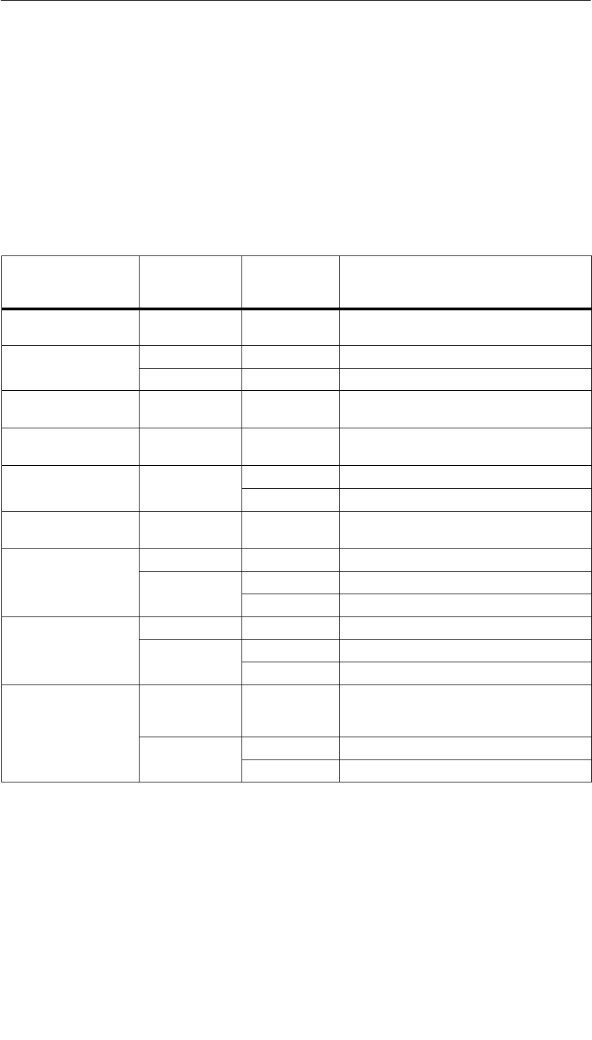
Digital Modules
4-39
S7-400, M7-400 Programmable Controllers Module Specifications
A5E00069467-07
Effect of Errors and Parameter Assignment on the Input Values
The input values of the SM 421; DI 16 24 DC are affected by certain errors and
the parameter assignment of the module. The following table lists the effects on the
input values.
You will find more diagnostic messages of the module in the Appendix entitled
“Diagnostic Data of the Signal Modules”.
Table 4-15 How the Input Values Are Affected by Faults and by the Parameter Assignment of the
SM 421; DI 16 24 VDC
Diagnostic Message “Diagnostics”
Parameter “Reaction to
Error”
Parameter
Input Value of Digital Module
Module not
parameterized Cannot be
disabled Not relevant 0 signal (all channels)
No front connector SV Parameterized substitute value
KLV Last read, valid value
Incorrect parameters
(module/channel) Cannot be
disabled Not relevant 0 signal (module/all incorrectly
parameterized channels)
STOP operating mode Cannot be
disabled –Process value (not updated)
Internal voltage failure Cannot be
di bl d
SV Parameterized substitute value
disabled KLV Last read, valid value
Hardware interrupt lost Cannot be
disabled Not relevant Current process value
Wire break (for each
hl)
Deactivated – 0 signal
channel) Activated SV Parameterized substitute value
KLV Last read, valid value
Sensor supply missing
(l ti td i ”N
Deactivated – 0 signal
(also activated via ”No
Load Volta
g
e L+”
)
Activated SV Parameterized substitute value
Load Voltage L+ )
KLV Last read, valid value
No load voltage L+ (for
each channel group) Deactivated – 0 signal, if the contact is connected via the
sensor supply; process value for the
external sensor supply
Activated SV Parameterized substitute value
KLV Last read, valid value

Digital Modules
4-40 S7-400, M7-400 Programmable Controllers Module Specifications
A5E00069467-07
Behavior when the Input Delay Equals 0.1 ms and an Error Occurs
If you have parameterized the following:
•An input delay of 0.1 ms or 0.05 ms
•KLV or SV as the response to an error
•Substitute “1”
In the event of a fault on a channel that has a 1 signal, the following could occur
before the last valid value or the substitute value ”1” is output:
•An 0 signal may be briefly output
•If parameterized, a hardware interrupt may be generated

Digital Modules
4-41
S7-400, M7-400 Programmable Controllers Module Specifications
A5E00069467-07
4.11 Digital Input Module SM 421; DI 16 120 VAC;
(6ES7421-5EH00-0AA0)
Characteristics
The SM 421; DI 16 120 VAC has the following features:
•16 inputs, isolated
•120 VAC rated input voltage
•Suitable for switches and two-wire proximity switches
(BEROs, IEC 61131; type 2)
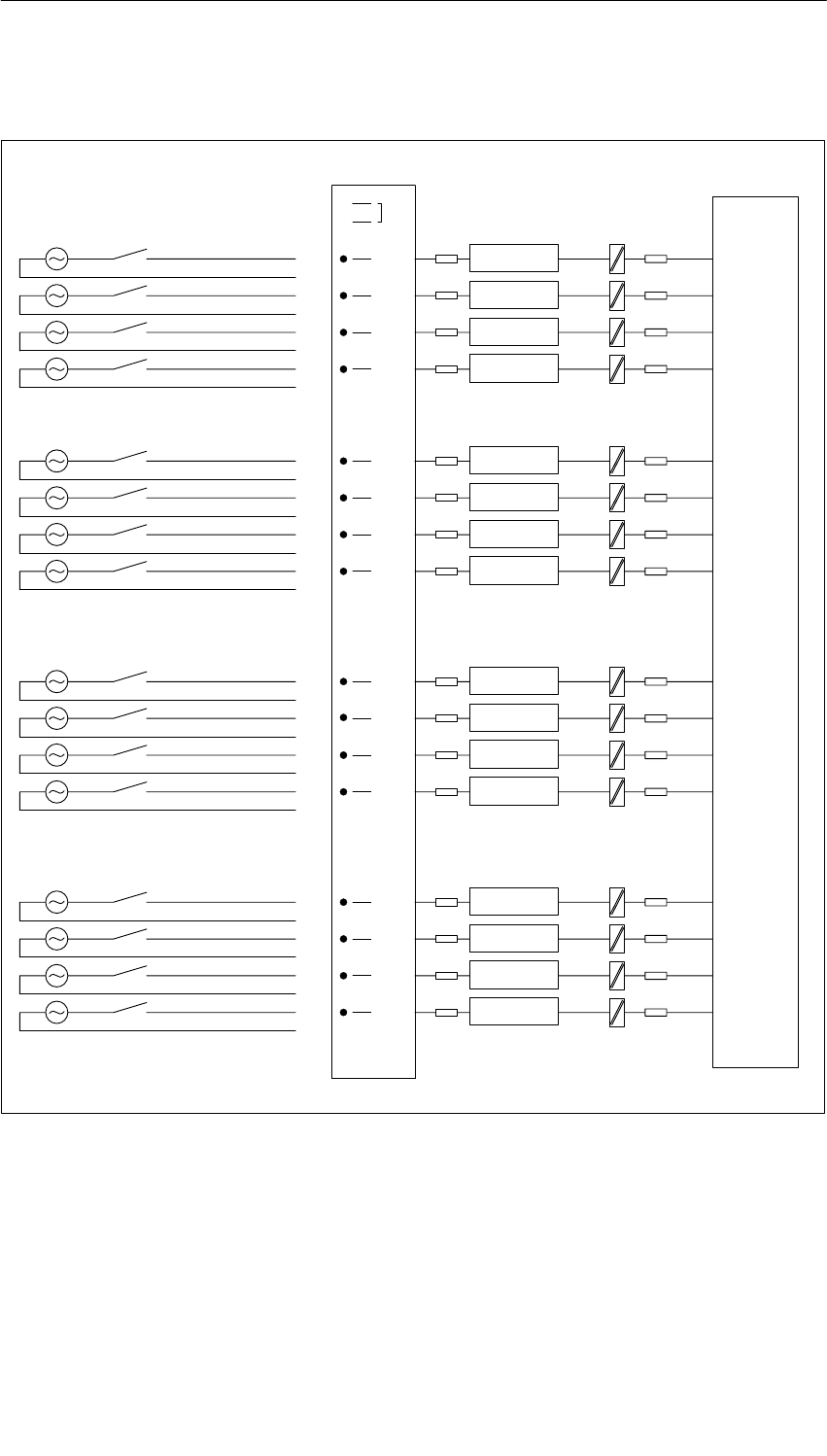
Digital Modules
4-42 S7-400, M7-400 Programmable Controllers Module Specifications
A5E00069467-07
Terminal Assignment Diagram of the SM 421; DI 16 120 VAC
1
2
3
40
Byte 0
5
61
7
82
9
10 3
11
13
1N
12
14
15 4
16
17 5
18
19 6
20
21 7
22
24
23
26
27
28
29
30
31
32
33
34
36
35
38
39
40
41
42
43
44
45
46
48
47
25
37
0
1
2
3
4
5
6
7
2N
3N
4N
5N
6N
7N
8N
9N
10N
11N
12N
13N
14N
15N
16N
Byte 1
Adaptation
Process Module
Data register and bus control
Adaptation
Adaptation
Adaptation
Adaptation
Adaptation
Adaptation
Adaptation
Adaptation
Adaptation
Adaptation
Adaptation
Adaptation
Adaptation
Adaptation
Adaptation
Figure 4-8 Terminal Assignment Diagram of the SM 421; DI 16 120 VDC

Digital Modules
4-43
S7-400, M7-400 Programmable Controllers Module Specifications
A5E00069467-07
Technical Specifications of the SM 421; DI 16 120 VAC
Dimensions and Weight
Dimensions W H D
(in millimeters) 25 290 210
Weight Approx. 650 g
Data for Specific Module
Number of inputs 16
Length of cable
•Unshielded
•Shielded
600 m
1000 m
Voltages, Currents, Potentials
Number of inputs that can be
triggered simultaneously 16
Isolation
•Between channels and
backplane bus Yes
•Between the channels Yes
– In groups of 1
Permitted potential difference
•Between Minternal and the
inputs 120 VAC
•Between the inputs of the
different groups 250 VAC
Insulation tested with 1500 VAC
Current consumption
•From the backplane bus Max. 0.1 A
Power dissipation of the
module Typ. 3.0 W
Status, Interrupts, Diagnostics
Status display Green LED per
channel
Interrupts None
Diagnostic functions None
Sensor Selection Data
Input voltage
•Rated value
•For signal “1”
•For signal “0”
•Frequency range
120 V
72 to 132 VAC
0 to 20 V
47 to 63 Hz
Input current
•At signal “1”
•At signal “0”
6 to 20 mA
0 to 4 mA
Input delay
•At “0” to “1”
•At “1” to “0”
2 to 15 ms
5 to 25 ms
Input characteristic curve To IEC 61131; type 2
Connection of two-wire BEROs
•Permitted bias current
Possible
Max. 4 A

Digital Modules
4-44 S7-400, M7-400 Programmable Controllers Module Specifications
A5E00069467-07
4.12 Digital Input Module SM 421; DI 16 24/60 VUC;
(6ES7 421-7DH00-0AB0)
Characteristics
The SM 421; DI 16 24/60 VUC is characterized by the following features:
•16 inputs, individually isolated
•Rated input voltage 24 VUC to 60 VUC
•Suitable for switches and two-wire proximity switches (BEROs)
•Suitable as active high and active low input
•Group error display for internal faults (INTF) and external faults (EXTF)
•Programmable diagnostics
•Programmable diagnostic interrupt
•Programmable hardware interrupt
•Programmable input delays
The status LEDs indicate the process status.
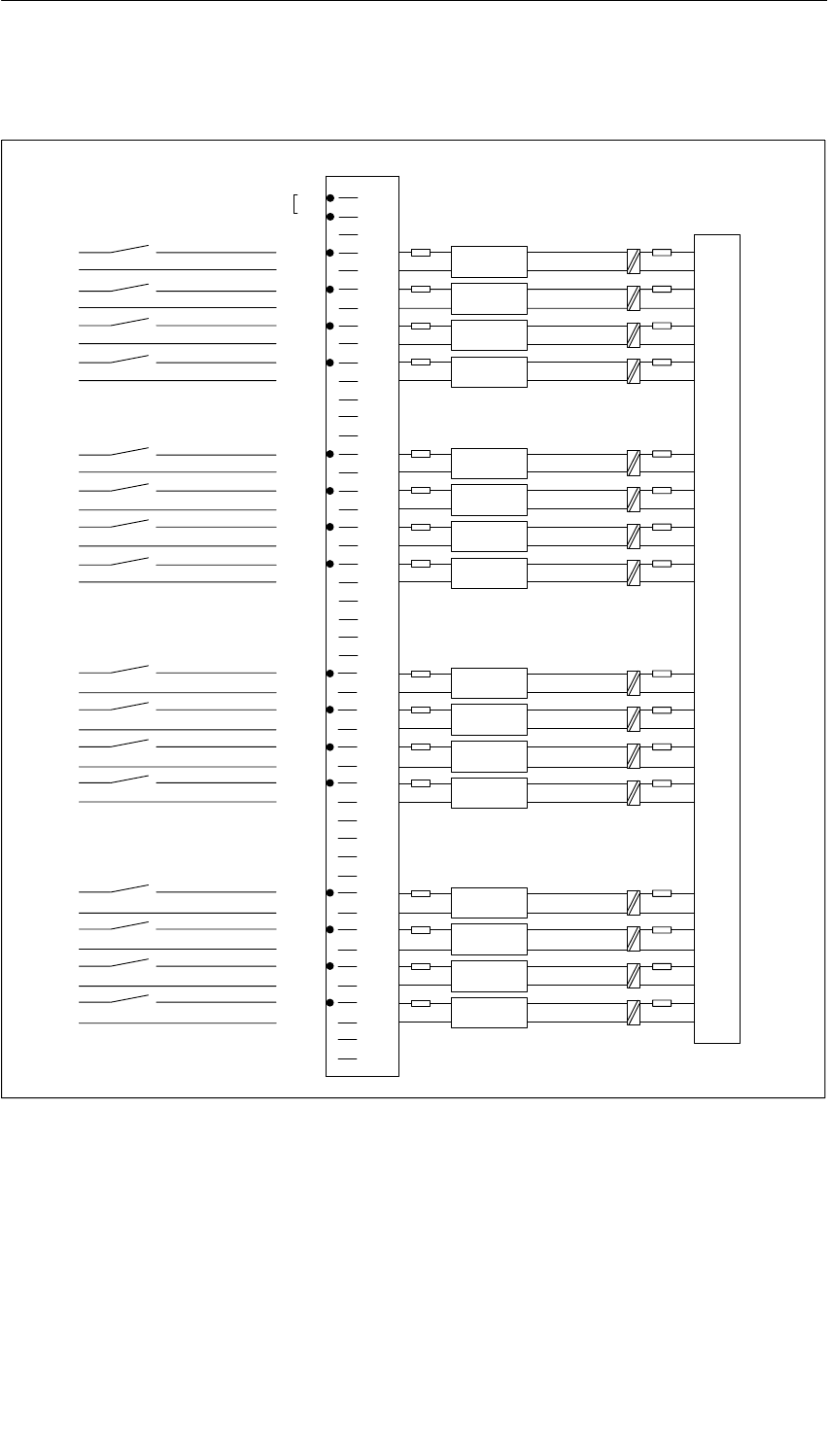
Digital Modules
4-45
S7-400, M7-400 Programmable Controllers Module Specifications
A5E00069467-07
Terminal Assignment and Block Diagram of the SM 421; DI 16 24/60 VUC
L
N
1
2
3
4
5
6
7
8
9
10
11
12
13
14
15
16
17
18
19
20
21
22
23
24
25
26
27
28
29
30
31
32
33
34
35
36
37
38
39
40
41
42
43
44
45
46
47
48
1 N
1
2
4 N
4
5
6
0
2 N
3 N
3
5 N
6 N
7 N
7
8 N
0
9 N
1
10 N
2
11 N
3
12 N
4
13 N
5
14 N
6
15 N
7
16 N
INTF
EXTF
N
L
N
L
N
L
N
L
N
L
N
L
N
L
N
L
N
L
N
L
N
L
N
L
N
L
N
L
N
L
Input
Diagnostics
Adaptation
Adaptation
Adaptation
Adaptation
Adaptation
Adaptation
Adaptation
Adaptation
Adaptation
Adaptation
Adaptation
Adaptation
Adaptation
Adaptation
Adaptation
Input
Diagnostics
Diagnostics
Input
Diagnostics
Input
Input
Diagnostics
Input
Diagnostics
Diagnostics
Input
Diagnostics
Input
Input
Diagnostics
Input
Diagnostics
Diagnostics
Input
Diagnostics
Input
Input
Diagnostics
Input
Diagnostics
Diagnostics
Input
Diagnostics
Input
Data register and bus control
Adaptation
Process
Front connector jumper
Module
Figure 4-9 Terminal Assignment and Block Diagram of the SM 421; DI 16 24/60 VUC

Digital Modules
4-46 S7-400, M7-400 Programmable Controllers Module Specifications
A5E00069467-07
Technical Specifications of the SM 421; DI 16 24/60 VUC
Programming package
Associated programming
package As of STEP 7 V 2.0
Dimensions and Weight
Dimensions W H D
(in millimeters) 25 290 210
Weight Approx. 600 g
Data for Specific Module
Number of inputs 16
Length of cable
•Unshielded
input delay
– 0.5 ms
– 3 ms
– 10 / 20 ms
Max. 100 m
Max. 600 m
Max. 600 m
•Shielded line length 1000 m
Voltages, Currents, Potentials
Number of inputs that can be
triggered simultaneously 16
Isolation
•Between channels and
backplane bus Yes
•Between the channels Yes
– In groups of 1
Permitted potential difference
•Between the different
circuits 75 VDC, 60 VAC
Insulation tested with
•Channels against
backplane bus and load
voltage L+
1500 VAC
•Channels among one
another 1500 VAC
Current consumption
•From the backplane bus Max.150 mA
Power dissipation of the
module Typ. 8 W
Status, Interrupts, Diagnostics
Status display Green LED per
channel
Interrupts
•Hardware interrupt
•Diagnostic Interrupt
Parameters can be
assigned
Parameters can be
assigned
Diagnostic functions Parameters can be
assigned
•Group error display
– For internal fault Red LED (INTF)
– For external fault Red LED (EXTF)
•Channel error display (F) None
•Diagnostic information can
be displayed Possible
Monitoring for
•Wire break I > 0.7 mA
Substitute value can be applied No
Sensor Selection Data
Input voltage
•Rated value 24 VUC to 60 VUC
•For signal “1” 15 to 72 VDC
-15 VDC to -72 VDC
15 to 60 VAC
•For signal “0” -6 VDC to +6 VDC
0 VAC to 5 VAC
Frequency range 47 DC/AC to 63 Hz
Input current
•At signal “1” Typ. 4 mA to 10 mA
Input characteristic curve Similar to IEC 61131 1)
Connection of two-wire BEROs
•Permitted bias current
Possible
Max. 0.5 mA to 2 mA2)
Time, Frequency
Internal preparation time for
•Only hardware interrupt
enable Max. 450 s
•Enable hardware and
diagnostic interrupts Max. 2 ms
Input delay
•Parameters can be
assigned Yes
•Rated value 0.5/3/10/20 ms
Values go into cycle and response times.
Sensor Circuit
Resistance circuit of the sensor
for wire break monitoring
•Rated voltage 24 V
(15 V to 35 V)
•Rated voltage 48 V
(30 V to 60 V)
•Rated voltage 60 V
(50 V to 72V)
18 kΩ
39 kΩ
56 kΩ
1) IEC 61131 does not specify any data for UC
modules. The values have been adapted as much
as possible to IEC 61131.
2) Minimum closed-circuit current is required for wire
break monitoring.

Digital Modules
4-47
S7-400, M7-400 Programmable Controllers Module Specifications
A5E00069467-07
4.12.1 Assigning Parameters to the SM 421; DI 16 24/60 VUC
Parameter Assignment
You will find a description of the general procedure for assigning parameters to
digital modules in Section 4.3.
Parameters of the SM 421; DI 16 24/60 VUC
The following table contains an overview of the parameters you can set and their
default settings for the SM 421; DI 16 24/60 VUC.
Table 4-16 Parameters of the SM 421; DI 16 24/60 VUC
Parameter Value Range Default2) Parameter
Type Scope
Enable
•Diagnostic interrupt1)
•Hardware interrupt1) Yes/no
Yes/no No
No Dynamic Module
•Destination CPU for interrupt 1 to 4 – Static Module
Diagnostics
•Wire break Yes/no No Static Channel
Trigger for hardware interrupt
•Rising (positive) edge
•Falling (negative) edge
Yes/no
Yes/no
– Dynamic Channel
Input delay3) 0.5 ms (DC)
3 ms (DC)
20 ms (DC/AC)
3 (DC) Static Channel group
1) If you use the module in ER-1/ER-2, you must set this parameter to “No” because the interrupt lines are
not available in ER-1/ER-2.
2) Only in the CC (central controller) is it possible to start up the digital modules with the default settings.
3) If you assign 0.5 ms , then you should not parameterize a diagnosis because the internal processing time
for diagnostic functions can be > 0.5 ms.
Ensuring a Wire Break Check Is Carried Out
To ensure that a wire break check is carried out, you require an external sensor
circuit using a resistor of 18 to 56 k The resistor should be connected parallel to
the contact and should be arranged as closely as possible to the sensor.
This additional resistor is not required in the following cases:
•If two-wire BEROs are used
•If you don’t parameterize the “Wire Break” diagnosis

Digital Modules
4-48 S7-400, M7-400 Programmable Controllers Module Specifications
A5E00069467-07
Setting the Input Delay for Channel Groups
You can only set the input delay for each group of channels. In other words, the
setting for channel 0 applies to inputs 0 to 7 and the setting for channel 8 applies to
inputs 8 to 15.
Note
The parameters that are entered for the remaining channels (1 to 7 and 9 to 15)
must be equal to the value 0 or 8, otherwise those channels will be reported as
being incorrectly parameterized.
Any hardware interrupts that have occurred in the meantime will be reported after
acknowledgement.
Optimum Signal Propagation Delays
You can achieve the fastest signal propagation delay with the following settings:
•Both channel groups are parameterized with an input delay of 0.5 ms
•The Diagnostics parameter is disabled
•The Diagnostic Interrupt parameter is disabled

Digital Modules
4-49
S7-400, M7-400 Programmable Controllers Module Specifications
A5E00069467-07
Circuit as for active high or active low input
”1”
”0”
0V
– L+
U_s
”1”
U_s
DI_x
”1”
”0”
0V
L+
– L+
U_s
DI_xN
Channel x of the
DI 421 16 x 24/60 VUC
L+
U_s
Input threshold
Active high Active low
Figure 4-10 Circuit as for Active High or Active Low Input

Digital Modules
4-50 S7-400, M7-400 Programmable Controllers Module Specifications
A5E00069467-07
4.13 Digital Input Module SM 421; DI 16 120/230 VUC;
(6ES7 421-1FH00-0AA0)
Characteristics
The SM 421; DI 16 120/230 VUC is characterized by the following features:
•16 inputs, isolated
•Rated input voltage 120/230 VAC/VDC
•Suitable for switches and two-wire proximity switches
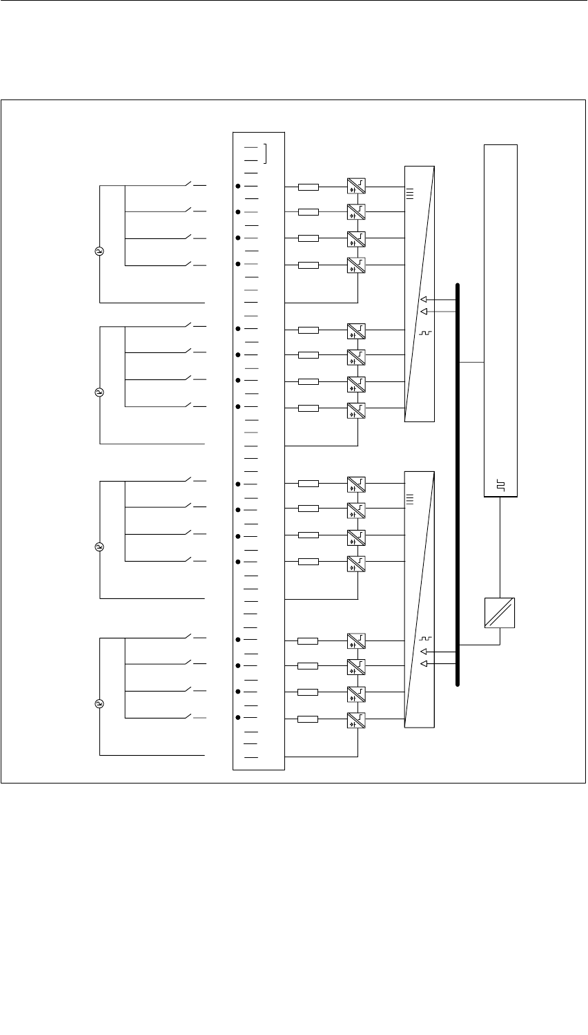
Digital Modules
4-51
S7-400, M7-400 Programmable Controllers Module Specifications
A5E00069467-07
Terminal Assignment and Block Diagram of the SM 421; DI 16 120/230 VUC
1
2
3
4
5
6
7
8
9
10
11
12
13
14
15
16
17
18
19
20
21
22
23
24
25
26
27
28
29
30
31
32
33
34
35
36
37
38
39
40
41
42
43
44
45
46
47
48 4 N
3 N
1
2
0
3
5
6
4
7
5
6
4
7
1
2
0
3
1N
2N
Data register and bus control
Process Module
Figure 4-11 Terminal Assignment and Block Diagram of the SM 421; DI 16 120/230 VUC

Digital Modules
4-52 S7-400, M7-400 Programmable Controllers Module Specifications
A5E00069467-07
Technical Specifications of the SM 421; DI 16 120/230 VUC
Programming package
Associated programming
package As of STEP 7 V 2.0
Dimensions and Weight
Dimensions W H D
(in millimeters) 25 290 210
Weight Approx. 650 g
Data for Specific Module
Number of inputs 16
Length of cable
•Unshielded
•Shielded
600 m
1000 m
Voltages, Currents, Potentials
Number of inputs that can be
triggered simultaneously 16 at 120 V
8 at 240 V
16 with fan
subassembly
Isolation
•Between channels and
backplane bus Yes
•Between the channels Yes
– In groups of 4
Permitted potential difference
•Between Minternal and the
inputs 230 VAC
•Between the inputs of the
different groups 500 VAC
Insulation resistance 4000 VAC
Current consumption
•From the backplane bus Max. 0.1 A
Power dissipation of the
module Typ. 3.5 W
Status, Interrupts, Diagnostics
Status display Green LED per
channel
Interrupts None
Diagnostic functions None
Data for Selecting a Sensor
Input voltage
•Rated value
•For signal “1”
•For signal “0”
120/230 VUC
79 to 264 VAC
80 to 264 VDC
0 VUC to 40 VUC
•Frequency range 47 to 63 Hz
Input current
•At signal “1”
•At signal “0”
2 mA to 5 mA
0 to 1 mA
Input delay
•At “0” to “1”
•At “1” to “0”
5 to 25 ms
5 to 25 ms
Input characteristic curve To IEC 61131; type 1
Connection of two-wire BEROs
•Permitted bias current
Possible
Max. 1 mA

Digital Modules
4-53
S7-400, M7-400 Programmable Controllers Module Specifications
A5E00069467-07
4.14 Digital Input Module SM 421; DI 16 120/230 VUC;
(6ES7421-1FH20-0AA0)
Characteristics
The SM 421; DI 16 120/230 VUC is characterized by the following features:
•16 inputs, isolated in groups of 4
•Rated input voltage 120/230 VUC
•Input characteristic curve to IEC 61131; type 2
•Suitable for switches and two-wire proximity switches (BEROs)
The status LEDs indicate the process status.
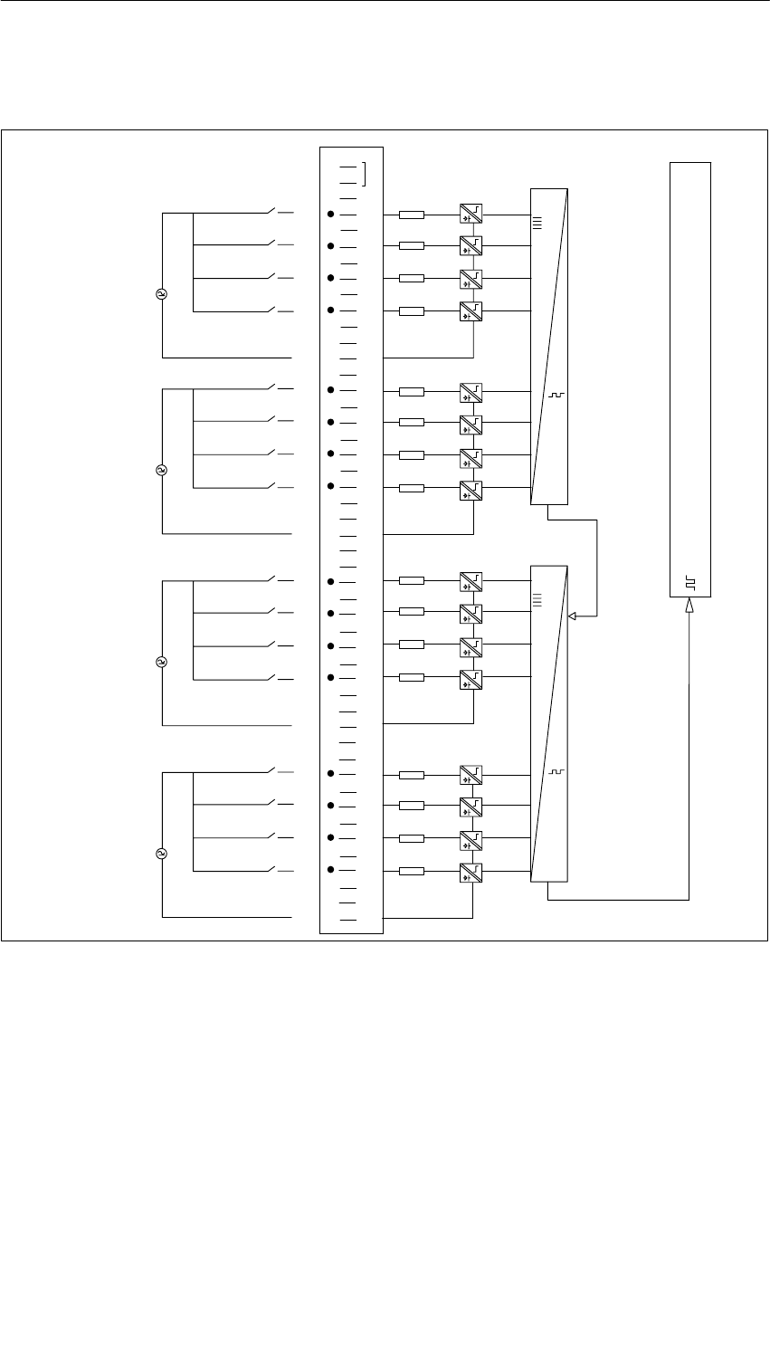
Digital Modules
4-54 S7-400, M7-400 Programmable Controllers Module Specifications
A5E00069467-07
Terminal Assignment and Block Diagram of the SM 421; DI 16 120/230 VUC
1
2
3
4
5
6
7
8
9
11
12
13
14
15
16
17
18
19
20
21
22
23
24
25
26
27
28
29
30
31
32
33
34
35
36
37
38
39
40
41
42
43
44
45
46
47
48
1
2
0
3
5
6
4
7
5
6
4
7
1
2
0
3
4N
1N
Data register and bus control
10
2N
3N
Process Module
Figure 4-12 Terminal Assignment and Block Diagram of the SM 421; DI 16 120/230 VUC
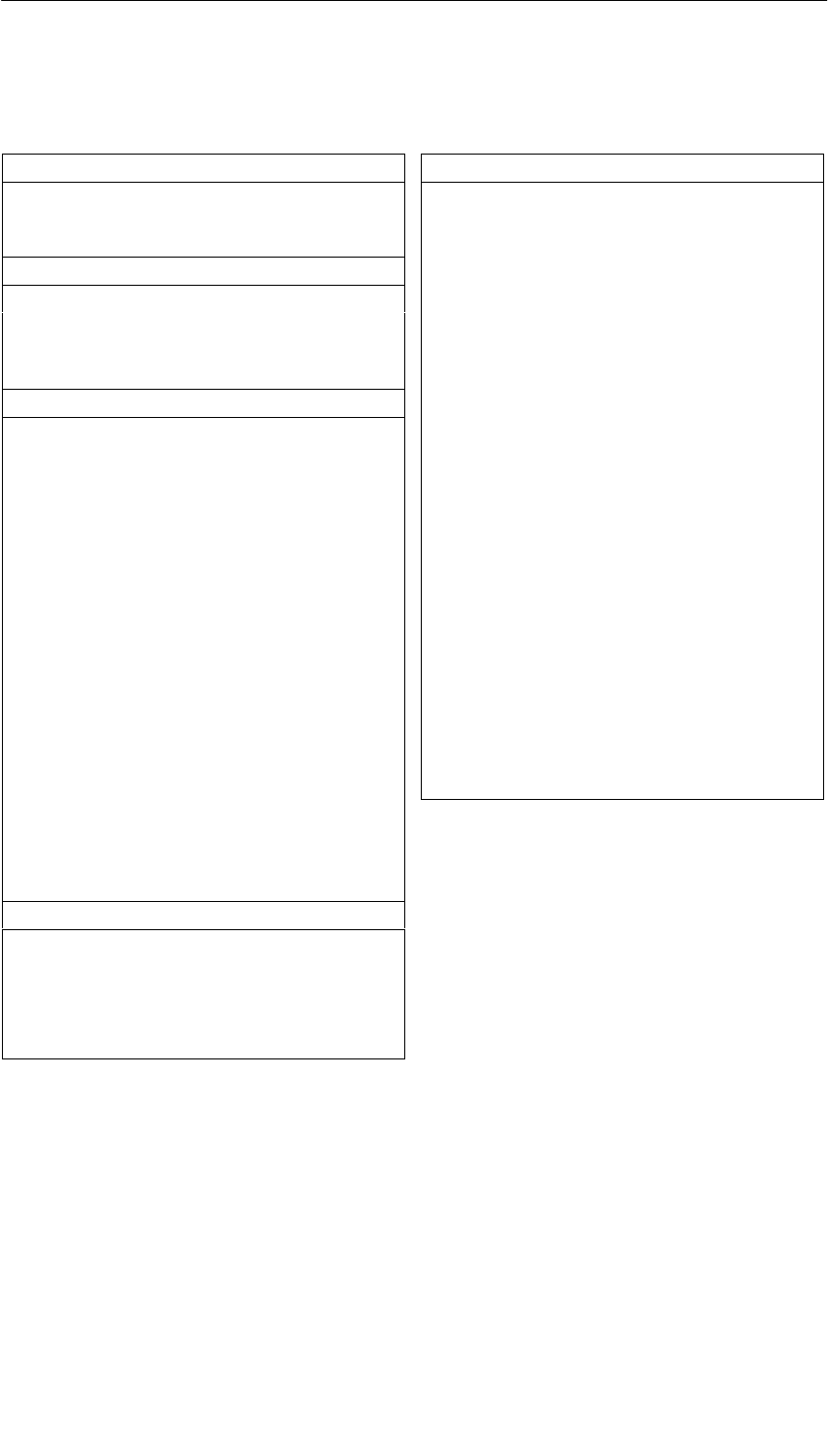
Digital Modules
4-55
S7-400, M7-400 Programmable Controllers Module Specifications
A5E00069467-07
Technical Specifications of the SM 421; DI 16 x 120/230 VUC
Dimensions and Weight
Dimensions W H D
(in millimeters) 25 290 210
Weight Approx. 650 g
Data for Specific Module
Number of inputs 16
Length of cable
•Unshielded
•Shielded
600 m
1000 m
Voltages, Currents, Potentials
Power rated voltage of the
electronics L+ None
Number of inputs
that can be triggered
simultaneously
16
Isolation
•Between channels and
backplane bus Yes
•Between the channels Yes
– In groups of 4
Permitted potential difference
•Between Minternal and the
inputs 250 VAC
•Between the inputs of the
different groups 500 VAC
Insulation resistance 4000 VAC
Current consumption
•From the backplane bus Max. 80 mA
Power dissipation of the
module Typ. 12 W
Status, Interrupts, Diagnostics
Status display Green LED per
channel
Interrupts None
Diagnostic functions None
Substitute value can be applied No
Data for Selecting a Sensor
Input voltage
•Rated value
•For signal “1”
120/230 VUC
74 to 264 VAC
80 to 264 VDC
–80 to –264 VDC
•For signal “0” 0 to 40 VAC
–40 to +40 VDC
Frequency range 47 to 63 Hz
Input current
•At signal ”1” (120 V) Typ. 10 mA AC
Typ. 1.8 mA DC
•At signal ”1” (230 V) Typ. 14 mA AC
Typ. 2 mA DC
•At signal “0” 0 to 6 mA AC
0 to 2 mA DC
Input delay
•At “0” to “1” Max. 20 ms AC
Max. 15 ms DC
•At “1” to “0” Max. 30 ms AC
Max. 25 ms DC
Input characteristic curve To IEC 61131;
type 2
Connection of two-wire BEROs
•Permitted bias current
Possible
Max. 5 mA AC

Digital Modules
4-56 S7-400, M7-400 Programmable Controllers Module Specifications
A5E00069467-07
4.15 Digital Input Module SM 421; DI 32 120 VUC;
(6ES7421-1EL00-0AA0)
Characteristics
The SM 421; DI 32 120 VUC is characterized by the following features:
•32 inputs, isolated
•Rated input voltage 120 VAC/VDC
•Suitable for switches and two-wire proximity switches
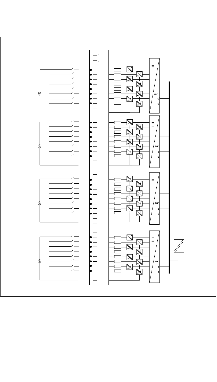
Digital Modules
4-57
S7-400, M7-400 Programmable Controllers Module Specifications
A5E00069467-07
Terminal Assignment and Block Diagram of the SM 421; DI 32 120 VUC
1
2
3
4
5
6
7
8
9
10
11
12
13
14
15
16
17
18
19
20
21
22
23
24
25
26
27
28
29
30
31
32
33
34
35
36
37
38
39
40
41
42
43
44
45
46
47
48
1
2
3
4
5
6
7
0
4N
1
2
3
4
5
6
7
0
1
2
3
4
5
6
7
0
1
2
3
4
5
6
7
0
3N
2N
1N
Data register and bus control
Process Module
Figure 4-13 Terminal Assignment and Block Diagram of the SM 421; DI 32 120 VUC

Digital Modules
4-58 S7-400, M7-400 Programmable Controllers Module Specifications
A5E00069467-07
Technical Specifications of the SM 421; DI 32 120 VUC
Dimensions and Weight
Dimensions W H D (mm) 25 290 210
Weight Approx. 600 g
Data for Specific Module
Number of inputs 32
Length of cable
•Unshielded
•Shielded
600 m
1000 m
Voltages, Currents, Potentials
Rated load voltage L+ 79 to 132 VAC
80 to 132 VDC
•Reverse polarity protection Yes
Number of inputs that can be
triggered simultaneously 32
Isolation
•Between channels and
backplane bus Yes
•Between the channels Yes
– In groups of 8
Permitted potential difference
•Between Minternal and the
inputs 120 VAC
•Between the inputs of the
different groups 250 VAC
Insulation tested with 1500 VAC
Current consumption
•From the backplane bus Max. 0.2 A
Power dissipation of the
module Typ. 6.5 W
Status, Interrupts, Diagnostics
Status display Green LED per
channel
Interrupts None
Diagnostic functions None
Data for Selecting a Sensor
Input voltage
•Rated value
•For signal “1”
•For signal “0”
120 VUC
79 to 132 VAC
80 VDC to 132 VDC
0 to 20 V
•Frequency range 47 to 63 Hz
Input current
•At signal “1”
•At signal “0”
2 mA to 5 mA
0 to 1 mA
Input delay
•At “0” to “1”
•At “1” to “0”
5 to 25 ms
5 to 25 ms
Input characteristic curve To IEC 61131; type 1
Connection of two-wire BEROs
•Permitted bias current
Possible
Max.1 mA

Digital Modules
4-59
S7-400, M7-400 Programmable Controllers Module Specifications
A5E00069467-07
4.16 Digital Output Module SM 422;
DO 16 24 VDC/2 A; (6ES7422-1BH10-0AA0)
Characteristics
The digital output module SM 422; DO 16 24 VDC/2 A has the following
features.
•16 outputs, isolated in two groups of 8
•2 A output current
•24 VDC rated load voltage
The status LEDs also indicate the system status even when the front connector is
not inserted.
!Caution
To commission the module, the rated load voltage must be applied at least once to
each group of 8 outputs (e.g. connection of 1L and 3L). If voltage is not applied to
a group due, for example, to 1L and 2L failing, all the outputs switch off, even
those in the second group. The status LED continues to function in the same way.
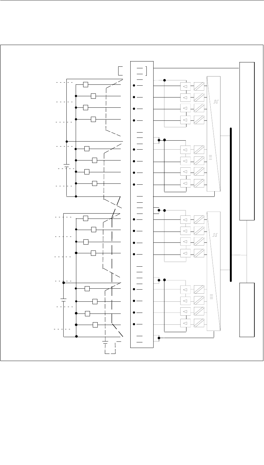
Digital Modules
4-60 S7-400, M7-400 Programmable Controllers Module Specifications
A5E00069467-07
Terminal Assignment and Block Diagram of the SM 422; DO 16 24 VDC/2 A
Data register and bus control
LED control
1
2
3
4
5
6
7
8
9
11
12
13
14
15
16
17
18
19
20
21
22
23
24
25
26
27
28
29
30
31
32
33
34
35
36
37
38
39
40
41
42
43
44
45
46
47
48
1
2
0
3
1L+
5
6
4
7
5
6
4
7
1
2
0
3
2M
2L+
2L+
1M
3L+
3L+
2M
4L+
4L+
Process Module
1st supply group
2nd supply group
3rd supply group
4th supply group
5th supply group
6th supply group
7th supply group
8th supply group
Figure 4-14 Terminal Assignment and Block Diagram of the SM 422; DO 16 24 VDC/2 A
Digital Modules
4-61
S7-400, M7-400 Programmable Controllers Module Specifications
A5E00069467-07
Technical Specifications of the SM 422; DO 16 24 VDC/2 A
Programming package
Associated programming
package As of STEP 7 V 2.0
Dimensions and Weight
Dimensions W H D
(in millimeters) 25 290 210
Weight Approx. 600 g
Data for Specific Module
Number of outputs 16
Length of cable
•Unshielded
•Shielded
600 m
1000 m
Voltages, Currents, Potentials
Power rated voltage of the
electronics L+ 24 VDC
Rated load voltage L+ 24 VDC
Aggregate current of
the outputs (two outputs
per supply group)
Up to 40 C
Up to 60 C
Max. 3 A
Max. 2 A
Isolation
•Between channels and
backplane bus Yes
•Between the channels
In groups of
Yes
8
Permitted potential difference
•Between the different
circuits 75 VDC / 60 VAC
Insulation tested with
•Channels against
backplane bus and load
voltage L+
500 VDC
•Between the outputs of the
different groups 500 VDC
Current consumption
•From the backplane bus
•Power supply and load
voltage L+ (no load)
Max. 160 mA
Max. 30 mA
Power dissipation of the
module Typ. 5 W
Status, Interrupts, Diagnostics
Status display Green LED per
channel
Interrupts None
Diagnostic functions None
Data for Selecting an Actuator
Output voltage
•At signal “1” Min. L+ (-0,5 V)
Output current
•At signal “1”
Rated value 2A
Permitted range 5 mA to 2.4 A
•At signal “0” (leakage
current) Max. 0.5 mA
Output delay (for resistive load)
•From “0” to “1” Max. 1 ms
•At “1” to “0” Max. 1 ms
Load resistor range 12 to 4 k
Lamp load Max. 10 W
Parallel connection of 2
outputs
•For redundant triggering of
a load Possible (only outputs
of the same group)
•To increase performance Not possible
Triggering a digital input Possible
Switch rate
•For resistive load
•For inductive load to IEC
947-51, DC 13
100 Hz
0.2 Hz at 1 A
0.1 Hz at 2A
•For lamp load Max. 10 Hz
Limit (internal) of the inductive
circuit interruption voltage up to Max. -30 V
Short-circuit protection
of output1
•Threshold on
Electronically cyclic1)
2.8 to 6A
1) A supply group always consists of two adjacent
channels starting with channel 0. Channels 0 and 1, 2
and 3 and so on up to 14 and 15 therefore form one
supply group.
2) Following a short circuit, reclosing under a full load is
not guaranteed. To prevent this, you can do one of the
following things:
•Change the signal at the output
•Interrupt the load voltage of the module, or
•Briefly disconnect the load from the output

Digital Modules
4-62 S7-400, M7-400 Programmable Controllers Module Specifications
A5E00069467-07
4.17 Digital Output Module SM 422;
DO 16 24 VDC/2 A; (6ES7422-1BH11-0AA0)
Characteristics
The digital output module SM 422; DO 16 24 VDC/2 A has the following
features.
•16 outputs, isolated in two groups of 8
•2 A output current
•24 VDC rated load voltage
The status LEDs also indicate the system status even when the front connector is
not inserted.
A Note about Commissioning
The following technical feature applies to the digital output module SM 422;
DO 16 24 VDC/2 A with the order number 6ES7 422-1BH11-0AA0 but not to the
digital output module SM 422; DO 16 24 VDC/2 A with the order number
6ES7 422-1BH10-0AA0:
To commission the module, it is no longer necessary to apply load voltage (1L+
and 3L+, for example,) to each group of 8 outputs. The module is fully operative
even if only one group is supplied with L+.
Note
It is no longer possible to switch off all the outputs by disconnecting a single L+
supply as might have been the case with the previous module
(6ES7 422-1BH10-0AA0)L+.
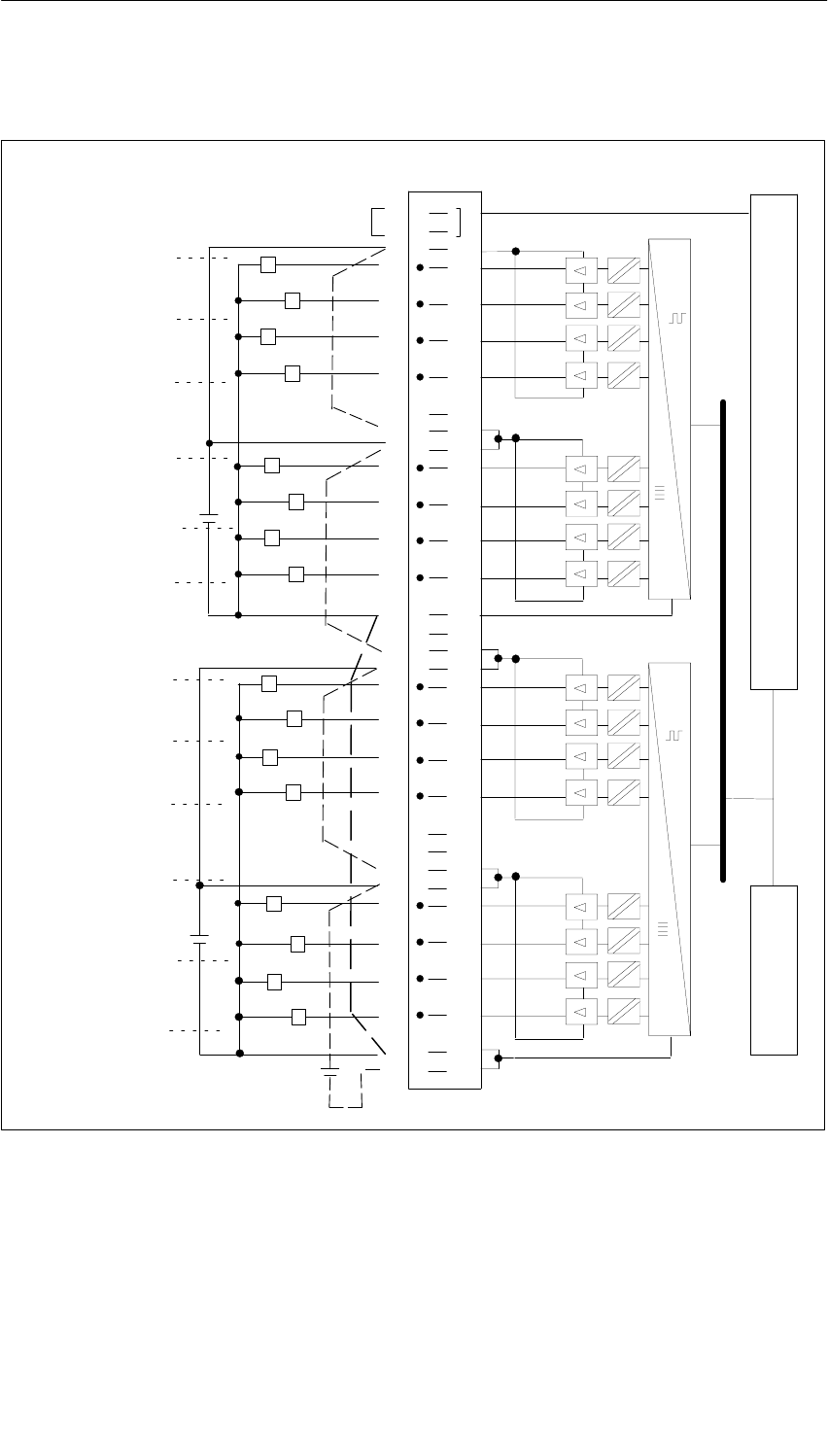
Digital Modules
4-63
S7-400, M7-400 Programmable Controllers Module Specifications
A5E00069467-07
Terminal Assignment and Block Diagram of the SM 422; DO 16 24 VDC/2 A
Data register and bus control
LED control
1
2
3
4
5
6
7
8
9
11
12
13
14
15
16
17
18
19
20
21
22
23
24
25
26
27
28
29
30
31
32
33
34
35
36
37
38
39
40
41
42
43
44
45
46
47
48
1
2
0
3
1L+
5
6
4
7
5
6
4
7
1
2
0
3
2M
2L+
2L+
1M
3L+
3L+
2M
4L+
4L+
Process Module
1st supply group
2nd supply group
3rd supply group
4th supply group
5th supply group
6th supply group
7th supply group
8th supply group
Figure 4-15 Terminal Assignment and Block Diagram of the SM 422; DO 16 24 VDC/2 A

Digital Modules
4-64 S7-400, M7-400 Programmable Controllers Module Specifications
A5E00069467-07
Technical Specifications of the SM 422; DO 16 24 VDC/2 A
Dimensions and Weight
Dimensions W H D
(in millimeters) 25 290 210
Weight Approx. 600 g
Data for Specific Module
Number of outputs 16
Length of cable
•Unshielded
•Shielded
600 m
1000 m
Voltages, Currents, Potentials
Power rated voltage of the
electronics L+ 24 VDC
Rated load voltage L+ 24 VDC
Aggregate current of
the outputs (two outputs
per supply group 1))
Up to 40 C
Up to 60 C
Max. 3 A
Max. 2 A
Isolation
•Between channels and
backplane bus Yes
•Between the channels
In groups of
Yes
8
Permitted potential difference
•Between the different
circuits 75 VDC / 60 VAC
Insulation tested with
•Channels against
backplane bus and load
voltage L+
500 VDC
•Between the outputs of the
different groups 500 VDC
Current consumption
•From the backplane bus
• Power supply and load
voltage L+ (no load)
Max. 160 mA
Max. 30 mA
Power dissipation of the
module Typ. 5 W
Status, Interrupts, Diagnostics
Status display Green LED per
channel
Interrupts None
Diagnostic functions None
Data for Selecting an Actuator
Output voltage
•At signal “1” Min. L+ (-0,5 V)
Output current
•At signal “1”
Rated value 2A
Permitted range 5 mA to 2.4 A
•At signal “0” (leakage
current) Max. 0.5 mA
Output delay (for resistive load)
•From “ 0” to “1” Max. 1 ms
•At “1” to “0” Max. 1 ms
Load resistor range 24 to 4 k
Lamp load Max. 10 W
Parallel connection of 2
outputs
•For redundant triggering of
a load Possible (only outputs
of the same group)
•To increase performance Not possible
Triggering a digital input Possible
Switch rate
•For resistive load
•For inductive load to IEC
947-51, DC 13
100 Hz
0.2 Hz at 1 A
0.1 Hz at 2A
•For lamp load Max. 10 Hz
Limit (internal) of the inductive
circuit interruption voltage up to Max. -30 V
Short-circuit protection
of output1
•Threshold on
Electronically cyclic2)
2.8 A to 6 A
1) A supply group always consists of two adjacent
channels starting with channel 0. Channels 0 and 1, 2
and 3 and so on up to 14 and 15 therefore form one
supply group.
2) Following a short circuit, reclosing under a full load is
not guaranteed. To prevent this, you can do one of the
following things:
•Change the signal at the output, or
•Interrupt the load voltage of the module
•Briefly disconnect the load from the output

Digital Modules
4-65
S7-400, M7-400 Programmable Controllers Module Specifications
A5E00069467-07
4.18 Digital Output Module
SM 422; DO 16 20-125 VDC/1.5 A;
(6ES7422-5EH10-0AB0)
Characteristics
The SM 422; DO 16 20-125 VDC/1.5 A has the following features:
•16 outputs, each channel is fused; reverse polarity protection and isolated in
groups of 8
•1.5 A output current
•Rated load voltage 20 to 125 VDC
•Group error display for internal faults (INTF) and external faults (EXTF)
•Programmable diagnostics
•Programmable diagnostic interrupt
•Programmable substitute value output
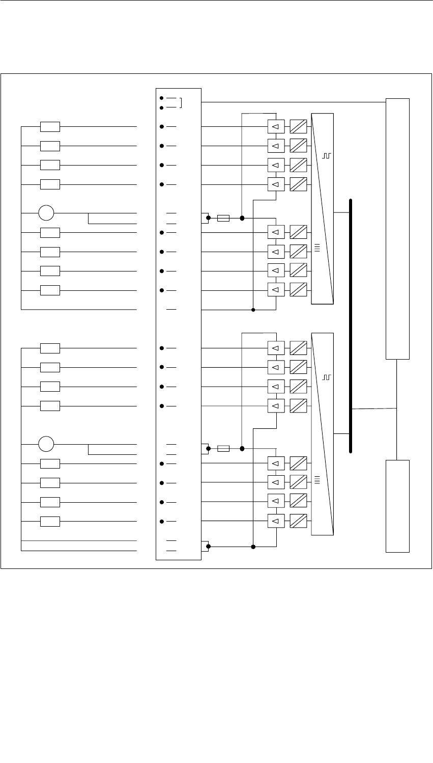
Digital Modules
4-66 S7-400, M7-400 Programmable Controllers Module Specifications
A5E00069467-07
Terminal Assignment Diagram of the SM 422; DO 16 20-125 VDC/1.5 A
1
2
3
40
Byte 0
5
61
7
82
9
10 3
11
13 L1+
12
14
15 4
16
17 5
18
19 6
20
21 7
22
24
23
26
27
28
29
30
31
32
33
34
36
35
38
39
40
41
42
43
44
45
46
48
47
25
37
0
1
2
3
4
5
6
7
M1
–+
L1+
Byte 1
L2+
M2
–+
L2+
M2
Process Module
Data register and bus control
LED control
Figure 4-16 Terminal Assignment Diagram of the SM 422; DO 16 20-125 VDC/1.5 A

Digital Modules
4-67
S7-400, M7-400 Programmable Controllers Module Specifications
A5E00069467-07
Technical Specifications of the SM 422; DO 16 20-125 VDC/1.5 A
Dimensions and Weight
Dimensions W H D
(in millimeters) 25 290 210
Weight Approx. 800 g
Data for Specific Module
Number of outputs 16
Length of cable
•Unshielded
•Shielded
Max. 600 m
Max. 1000 m
Voltages, Currents, Potentials
Rated load voltage L1
•Reverse polarity protection
20 VDC to 138 VDC
Yes, with fuse
Total current of the outputs 1)
Up to 40 C
Up to 60 C
With fan subassembly
Max. 16 A 21 A
Max. 8 A 14 A
Isolation
•Between channels and
backplane bus Yes
•Between the channels
In groups of
Yes
8
Permitted potential difference
•Between the outputs of the
different groups 250 VAC
Insulation tested with 1500 VAC
Current consumption
•From the backplane bus
•From load voltage L +
(without load)
Max. 700 mA
Max. 2 mA
Power dissipation of the
module Typ. 10 W
Status, Interrupts, Diagnostics
Status display Green LED per
channel
Interrupts
•Diagnostic Interrupt Parameters can be
assigned
Diagnostic functions Parameters can be
assigned
•Group error display
– For internal fault Red LED (INTF)
– For external fault Red LED (EXTF)
•Diagnostic information
readable Yes
Substitute value can be applied Yes, programmable
Data for Selecting an Actuator
Output voltage
•At signal “1” Min. L+ (–1,0 V)
Output current
•At signal “1”
Rated value 1.5 A
Permitted range 10 mA to 1.5 A
Permitted surge current Max. 3 A
(for 10 ms)
•At signal “0” (leakage
current) Max. 0.5 mA
Output delay (for resistive load)
•From “ 0” to “1” Max. 2 ms
•At “1” to “0” Max. 13 ms
Parallel connection of 2
outputs
•For redundant triggering of
a load Possible (only outputs
of the same group)
•To increase performance Possible (only outputs
of the same group)
Triggering a digital input Possible
Switch rate
•For resistive load Max. 10 Hz
•For inductive load
to IEC 947-5-1, DC 13 Max. 0.5 Hz
Short-circuit protection
of output Electronically
protected2)
•Threshold on Typ. 04 A to 5 A
Replacement fuses Fuse, 8 A/250 V, quick
blow
1) To achieve maximum performance capability,
distribute the high-current load between the two
groups.
2) To reset a deactivated output,
first set the output signal to 0 and then to 1.
If output signal 1 is written to a deactivated
output and the short circuit remains, additional
interrupts are generated (provided the diagnostic
interrupt parameter was set).

Digital Modules
4-68 S7-400, M7-400 Programmable Controllers Module Specifications
A5E00069467-07
Note
If the power supply is switched on by means of a mechanical contact, a voltage
pulse may occur at the outputs. The transient pulse lasts a maximum of 0.5 ms.
Changing Fuses
!Warning
This can result in injury.
If you change a fuse without removing the front connector of the module, you could
be injured by an electric shock.
Consequently, always remove the front connector before you change the fuse.
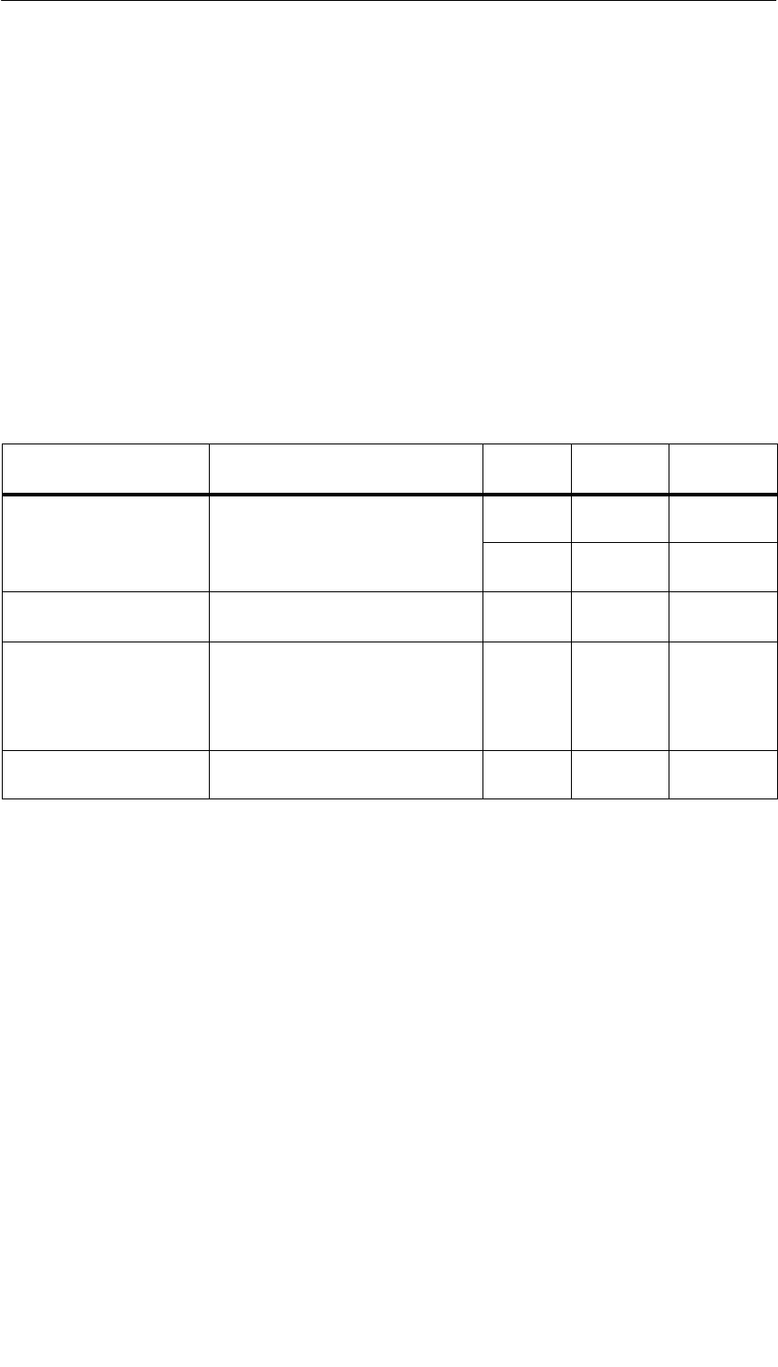
Digital Modules
4-69
S7-400, M7-400 Programmable Controllers Module Specifications
A5E00069467-07
4.18.1 Assigning Parameters to the SM 422; DO 16 20-125 VDC/1.5 A
Parameter Assignment
You will find a description of the general procedure for assigning parameters to
digital modules in Section 5.7.
Parameters of the SM 421; DO 16 20-125 VDC/1.5 A
You will find an overview of the parameters you can set and their default settings
for the SM 422; DO 16 20-125 VDC/1.5 A in the following table.
Table 4-17 Parameters of the SM 422; DO 16 20-125 VDC/1.5 A
Parameter Value Range Default2) Parameter
Type Scope
Enable
•Diagnostic interrupt1) Yes/no No Dynamic Module
•Destination CPU for
interrupt 1 to 4 –Static Module
Reaction to CPU-STOP Substitute a value (SV)
Keep last value (KLV) SV Dynamic Module
Diagnostics
•No load voltage L+
•Short circuit to M Yes/no
Yes/no
No
No Static Channel
group
Channel
Enable substitute value
“1” Yes/no No Dynamic Channel
1) If you use the module in ER-1/ER-2, you must set this parameter to “No” because the interrupt lines are
not available in ER-1/ER-2.
2) Only in the CC (central controller) is it possible to start up the digital modules with the default settings.
Assigning the “No Load Voltage L+” Diagnosis to Channel Groups
You can only set the “No Load Voltage L+” diagnosis separately for each channel
group. In other words, the setting for channel 0 applies to inputs 0 to 7, and the
setting for channel 8 applies to inputs 8 to 15.

Digital Modules
4-70 S7-400, M7-400 Programmable Controllers Module Specifications
A5E00069467-07
4.19 Digital Output Module SM 422; DO 32 24 VDC/0.5 A;
(6ES7422-1BL00-0AA0)
Characteristics
The SM 422; DO 32 x 24 VDC/0.5 A has the following features:
•32 outputs, isolated in a group of 32
•Power is supplied to 8 channels in groups.
•A supply group always consists of eight adjacent channels starting with channel
0. Channels 0 to 7, 8 to 15, 16 to 23 and 24 to 32 therefore form one supply
group
•Each of these supply groups can be switched off separately by isolating L+,
however you have to take note of the common ground connection.
•0.5 A output current
•24 VDC rated load voltage
The status LEDs also indicate the system status even when the front connector is
not inserted.
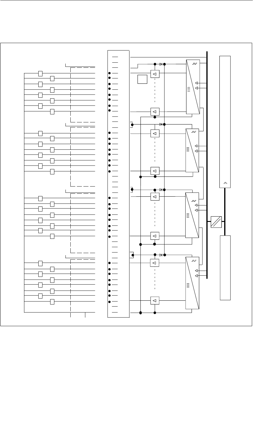
Digital Modules
4-71
S7-400, M7-400 Programmable Controllers Module Specifications
A5E00069467-07
Terminal Assignment and Block Diagram of the SM 422; DO 32 24 VDC/0.5 A
L+
1
2
3
4
5
6
7
8
9
11
12
13
14
15
16
17
18
19
20
21
22
23
24
25
26
27
28
29
30
31
32
33
34
35
36
37
38
39
40
41
42
43
44
45
46
47
48
1
2
4
7
0
3
5
6
1
2
4
7
0
3
5
6
1
2
4
7
0
3
5
6
1
2
4
7
0
3
5
6
M
1L+
2L+
2L+
3L+
3L+
4L+
4L+
3L+
2L+
4L+
1L+
M
Data register and bus control
LED control
Process Module
Figure 4-17 Terminal Assignment and Block Diagram of the SM 422; DO 32 24 VDC/0.5 A

Digital Modules
4-72 S7-400, M7-400 Programmable Controllers Module Specifications
A5E00069467-07
Technical Specifications of the SM 422; DO 32 24 VDC/0.5 A
Programming package
Associated programming
package As of STEP 7 V 2.0
Dimensions and Weight
Dimensions W H D
(in millimeters) 25 290 210
Weight Approx. 600 g
Data for Specific Module
Number of outputs 32
Length of cable
•Unshielded
•Shielded
600 m
1000 m
Voltages, Currents, Potentials
Power rated voltage of the
electronics L+ 24 VDC
Rated load voltage L+ 24 VDC
Aggregate current of
the outputs (per supply group
of 8 outputs)
Up to 40 C
Up to 60 C
Max. 4 A
Max. 2 A
Isolation
•Between channels and
backplane bus Yes
•Between the channels No
Permitted potential difference
•Between the different
circuits 75 VDC / 60 VAC
Insulation tested with
•Channels against
backplane bus and load
voltage L+
500 VDC
•Load voltage L+ against
backplane bus 500 VDC
Current consumption
•From the backplane bus
•Power supply and load
voltage L+ (no load)
Max. 200 mA
Max. 30 mA
Power dissipation of the
module Typ. 4 W
Status, Interrupts, Diagnostics
Status display Green LED per channel
Interrupts None
Diagnostic functions None
Data for Selecting an Actuator
Output voltage
•At signal “1” Min. L+ (-0,3 V)
Output current
•At signal “1”
Rated value
Permitted range
0.5 A
5 mA to 0.6 A
•At signal “0” (leakage
current) Max. 0.3 mA
Output delay (for resistive
load)
•From “ 0” to “1” Max. 1 ms
•At “1” to “0” Max. 1 ms
Load resistor range 48 to 4 k
Lamp load Max. 5 W
Parallel connection of 2
outputs
•For redundant triggering of
a load Possible (only outputs
of the same group)
•To increase performance Possible (only outputs
of the same group)
Triggering a digital input Possible
Switch rate
•For resistive load Max. 100 Hz
•For inductive load
to IEC 947-5-1, DC 13 Max. 2 Hz at 0.3 A
Max. 0.5 Hz at 0.5 A
•For lamp load Max. 10 Hz
Limit (internal) of the inductive
circuit interruption voltage up
to
Typ. – 27 V
Short-circuit protection of the
output
•Threshold on
Electronically cyclic
Typ. 0.7 A to 1.5 A
1) A supply group always consists of eight adjacent
channels starting with channel 0. Channels 0 to 7, 8 to
15, 16 to 23 and 24 to 32 therefore form one supply
group.

Digital Modules
4-73
S7-400, M7-400 Programmable Controllers Module Specifications
A5E00069467-07
4.20 Digital Output Module SM 422; DO 32 24 VDC/0.5 A;
(6ES7422-7BL00-0AB0)
Characteristics
The digital output module SM 422; DO 32 24 VDC/0.5 A has the following
features:
•32 outputs, fused and isolated in groups of 8
•0.5 A output current
•24 VDC rated load voltage
•Group error display for internal faults (INTF) and external faults (EXTF)
•Programmable diagnostics
•Programmable diagnostic interrupt
•Programmable substitute value output
The status LEDs also indicate the system status even when the front connector is
not inserted.
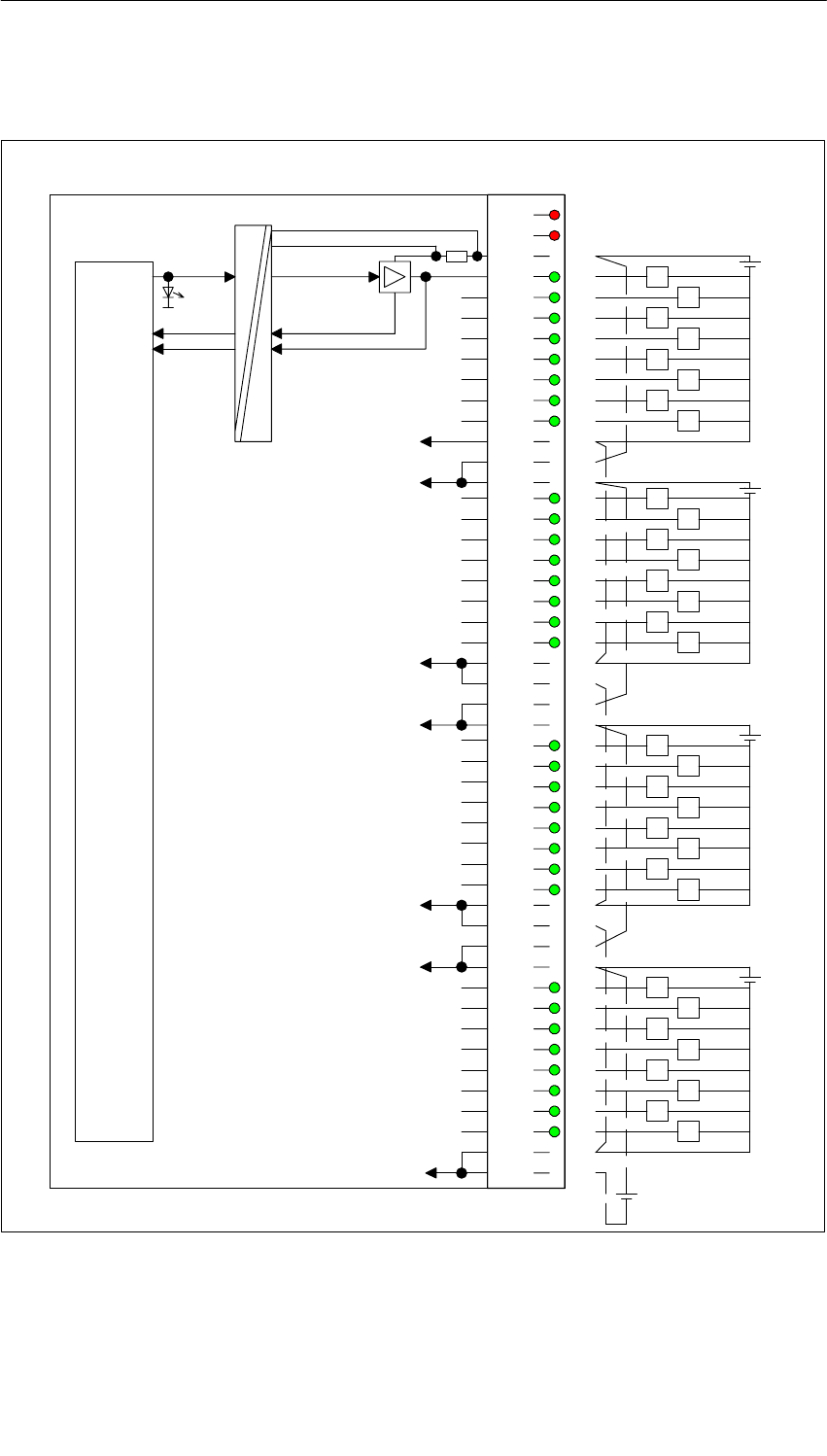
Digital Modules
4-74 S7-400, M7-400 Programmable Controllers Module Specifications
A5E00069467-07
Terminal Assignment and Block Diagram of the SM 422; DO 32 24 VDC/0.5 A
INTF
EXTF
1L+
0
1
2
3
4
5
6
7
1M
2L+
2L+
0
1
2
3
4
5
6
7
2M
2M
3L+
3L+
0
1
2
3
4
5
6
7
3M
3M
4L+
4L+
0
1
2
3
4
5
6
7
4M
4M
1L+
1L+
2L+
Backplane bus interface
1M
2L+
3L+
4L+
3M
4M
2M
1M
+
+
+
+
3L+
4L+
Control
Diagnostics
Output status
1L+ – monitoring
Monitoring of internal voltage
Control
Channel
status
LED
L+
24 V
1
2
3
4
5
6
7
8
9
10
11
12
13
14
15
16
17
18
19
20
21
22
23
24
25
26
27
28
29
30
31
32
33
34
35
36
37
38
39
40
41
42
43
44
45
46
47
48
Process
Module
Figure 4-18 Terminal Assignment and Block Diagram of the SM 422; DO 32 24 VDC/0.5 A

Digital Modules
4-75
S7-400, M7-400 Programmable Controllers Module Specifications
A5E00069467-07
Technical Specifications of the SM 422; DO 32 24 VDC/0.5 A
Dimensions and Weight
Dimensions W H D
(in millimeters) 25 290 210
Weight Approx. 600 g
Data for Specific Module
Number of outputs 32
Length of cable
•Unshielded
•Shielded
600 m
1000 m
Voltages, Currents, Potentials
Power rated voltage of the
electronics L+ 24 VDC
Rated load voltage L+ 24 VDC
Total current of the outputs (per
group)
Up to 40 C
Up to 60 C
Max. 4 A
Max. 2 A
Isolation
•Between channels and
backplane bus Yes
•Between the channels
In groups of
Yes
8
Permitted potential difference
•Between the different
circuits 75 VDC, 60 VAC
Insulation tested with
•Channels against
backplane bus and load
voltage L+
500 VDC
•Between the outputs of the
different groups 500 VDC
Current consumption
•From the backplane bus
•Power supply and load
voltage L+ (no load)
Max. 200 mA
Max. 120 mA
Power dissipation of the
module Typ. 8 W
Status, Interrupts, Diagnostics
Status display Green LED per
channel
Interrupts
•Diagnostic Interrupt
•Hardware interrupt
Parameters can be
assigned
Parameters can be
assigned
Diagnostic functions
•Monitoring of the load
voltage Yes
•Group error display
– For internal fault Red LED (INTF)
– For external fault Red LED (EXTF)
•Diagnostic information
readable Yes
Monitoring for
•Short circuit > 1 A (typ.)
•Wire break < 0.15 mA
Substitute value can be applied Yes
Data for Selecting an Actuator
Output voltage
•At signal “1” Min. L + (– 0.8 V)
Output current
•At signal “1”
Rated value
Permitted range
0.5 A
5 mA to 0.6 A
•At signal “0” (leakage
current) Max. 0.5 mA
Load resistor range 48 to 4 k
Parallel connection of 2
outputs
•For redundant triggering of
a load Possible (only outputs
of the same group)
•To increase performance Possible (only outputs
of the same group)
Triggering a digital input Possible
Switch rate
•For resistive load Max. 100 Hz
•For inductive load
to IEC 947-5-1, DC 13 Max. 2 Hz
•For lamp load Max. 2 Hz
Limit (internal) of the inductive
circuit interruption voltage up to Typ. L + (– 45 V)
Short-circuit protection of the
output
•Threshold on
Electronically cyclic
Typ. 0.75 A to 1.5 A

Digital Modules
4-76 S7-400, M7-400 Programmable Controllers Module Specifications
A5E00069467-07
Time, Frequency
Internal preparation time
between backplane bus and
input of the output driver1)
Up to hardware release 03
•independent of enable
diagnostics/diagnostic
interrupt/ substitute value
max. 100 s
Up to hardware release 04
•without enable diagnostics/
diagnostic interrupt/
substitute value
•with enable diagnostics/
diagnostic interrupt/
substitute value
max. 60 s
max. 100 s
1) The switching time of the output driver is added to the
overall runtime on the module (< 100 s for
resistive load)

Digital Modules
4-77
S7-400, M7-400 Programmable Controllers Module Specifications
A5E00069467-07
4.20.1 Assigning Parameters to the SM 422; DO 32 24 VDC/0.5 A
Parameter Assignment
You will find a description of the general procedure for assigning parameters to
digital modules in Section 5.7.
Parameters of the SM 422; DO 32 24 VDC/0.5 A
You will find an overview of the parameters that you can set and their default
settings for the SM 422; DO 32 24 VDC/0.5 A in the table below.
Table 4-18 Parameters of the SM 422; DO 32 24 VDC/0.5 A (6ES7422-7BL00-0AB0)
Parameter Value Range Default2) Parameter
Type Scope
Enable
•Diagnostic interrupt1) Yes/no No Dynamic Module
•Destination CPU for
interrupt 1 to 4 –Static Module
Reaction to CPU-STOP Substitute a value (SV)
Keep last value (KLV) SV Dynamic Module
Diagnostics
•Wire break
•No load voltage
L+/sensor supply
•Short circuit to M
•Short circuit to L+
Yes/no
Yes/no
Yes/no
Yes/no
No
no
No
No
Static
Channel
Channel
group
Channel
Channel
Substitute “1” Yes/no No Dynamic Channel
1) If you use the module in ER-1/ER-2, you must set this parameter to “No” because the interrupt lines are
not available in ER-1/ER-2.
2) Only in the CC (central controller) is it possible to start up the digital modules with the default settings.

Digital Modules
4-78 S7-400, M7-400 Programmable Controllers Module Specifications
A5E00069467-07
4.20.2 Behavior of the SM 422; DO 32 24 VDC/0.5 A
Effect of Operating Mode and Supply Voltage on the Output Values
The output values of the SM 422; DO 32 24 VDC/0.5 A depend on the
operating mode of the CPU and on the supply voltage of the module.
Table 4-19 Dependence of the Output Values on the Operating Mode of the CPU and on
the Supply Voltage L+ of the SM 422; DO 32 24 VDC/0.5 A
CPU Operating Mode Power Supply L+
to Digital Module Output Value of Digital
Module
POWER ON RUN L+ exists CPU value
L+ missing 0 signal
STOP L+ exists Substitute value/last value (0
signal preset)
L+ missing 0 signal
POWER
OFF
–L+ exists 0 signal
OFF L+ missing 0 signal
Behavior in the Event of Failure of the Supply Voltage
The failure of the supply voltage of the SM 422; DO 32 24VDC/0.5 A is always
indicated by the EXTF LED on the module. Furthermore, this information is made
available on the module (entry in diagnosis).
Triggering of the diagnostic interrupt depends on the parameter assignment (see
Section 4.20.1).

Digital Modules
4-79
S7-400, M7-400 Programmable Controllers Module Specifications
A5E00069467-07
4.21 Digital Output Module SM 422;
DO 8 120/230 VAC/5 A; (6ES7422-1FF00-0AA0)
Characteristics
The SM 422; DO 8 120/230 VAC/5 A has the following features:
•8 outputs, isolated in groups of 1
•Output current 5 A
•120/230 VAC rated load voltage
The status LEDs also indicate the system status even when the front connector is
not inserted.
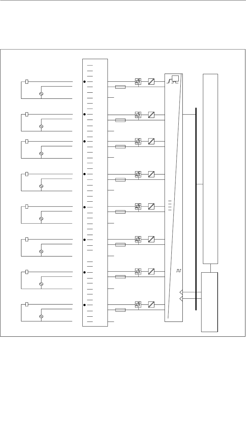
Digital Modules
4-80 S7-400, M7-400 Programmable Controllers Module Specifications
A5E00069467-07
Terminal Assignment and Block Diagram of the SM 422;
DO 8 120/230 VAC/5 A
1
2
3
4
5
6
7
8
9
10
11
12
13
14
15
16
17
18
19
20
21
22
23
24
25
26
27
28
29
30
31
32
33
34
35
36
37
38
39
40
41
42
43
44
45
46
47
48
1L
1N
1
2L
0
7L
7N
7
8L
6
3L
3N
3
4L
2
5L
5N
5
6L
4
Data register and bus control
LED control
t
F100
F200
F300
F400
F500
F600
F700
F800
6N
8N
2N
4N
INFT
EXTF
Process Module
Figure 4-19 Terminal Assignment and Block Diagram of the SM 422; DO 8 120/230 VAC/5 A

Digital Modules
4-81
S7-400, M7-400 Programmable Controllers Module Specifications
A5E00069467-07
Technical Specifications of the SM 422; DO 8 120/230 VAC/5 A
Programming package
Associated programming
package As of STEP 7 V 2.0
Dimensions and Weight
Dimensions W H D
(in millimeters) 25 290 210
Weight Approx. 800 g
Data for Specific Module
Number of outputs 8
Length of cable
•Unshielded
•Shielded
600 m
1000 m
Voltages, Currents, Potentials
Rated load voltage L1
Permitted frequency range
79 to 264 VAC
47 to 63 Hz
Total current of the outputs
Up to 40 C
Up to 60 C
With fan subassembly
Max. 16 A 24 A
Max. 8 A 20 A
Isolation
•Between channels and
backplane bus Yes
•Between the channels
In groups of
Yes
1
Permitted potential difference
•Between the outputs of the
different groups 500 VAC
Insulation resistance 4000 VAC
Current consumption
•From the backplane bus
•From load voltage L +
(without load)
Max. 250 mA
Max. 1.5 mA
Power dissipation of the
module Typ. 16 W
Status, Interrupts, Diagnostics
Status display Green LED per
channel
Interrupts None
Diagnostic functions Parameters cannot be
assigned
•Group error display
– For internal fault Red LED (INTF)
failed fuse
– For external fault Red LED (EXTF)
failed load voltage
Data for Selecting an Actuator
Output voltage
•At signal “1” At maximum current
min. L1 (–1.5 Vrms)
At maximum current
min. L1 (–10.7 Vrms)
Output current
•At signal “1”
Rated value 5 A
Permitted range 10 mA to 5 A
Permitted surge current
(per group) Max. 50 A per cycle
•At signal “0” (leakage
current) Max. 3.5 mA
Output delay (for resistive load)
•From “ 0” to “1” Not more than 1 AC
scan cycle
•At “1” to “0” Not more than 1 AC
scan cycle
Minimum load current 10 mA
Zero cross inhibit voltage Max. 55 V
Size of the motor starter Max. size 5 to NEMA
Lamp load Max. 100 W
Parallel connection of 2
outputs
•For redundant triggering of
a load Possible (only outputs
connected to the same
load)
Triggering a digital input Possible
Switch rate
•For resistive load Max. 10 Hz
•For inductive load
to IEC 947-5-1, DC 13 Max. 0.5 Hz
•For lamp load 1 Hz
Short-circuit protection of the
output Fuse, 8 A, 250 V (per
output)
•Min. current required for
fuse to blow Min. 100 A
•Max. response time Max. 100 ms
Replacement fuses
•Wickmann
•Schurter
•Littelfuse
Fuse, 8 A, quick-acting
194-1800-0
SP001.1013
217.008

Digital Modules
4-82 S7-400, M7-400 Programmable Controllers Module Specifications
A5E00069467-07
Changing Fuses
!Warning
This can result in injury.
If you change a fuse without removing the front connector of the module, you could
be injured by an electric shock.
Consequently, always remove the front connector before you change the fuse.

Digital Modules
4-83
S7-400, M7-400 Programmable Controllers Module Specifications
A5E00069467-07
4.22 Digital Output Module SM 422; DO 16 120/230 VAC/2 A;
(6ES7422-1FH00-0AA0)
Characteristics
The SM 422; DO 16 120/230 VAC/2 A has the following features:
•16 outputs, isolated in groups of 4
•2 A output current
•120/230 VAC rated load voltage
The status LEDs also indicate the system status even when the front connector is
not inserted.
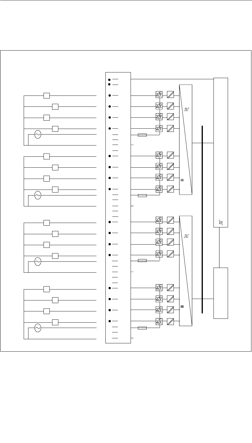
Digital Modules
4-84 S7-400, M7-400 Programmable Controllers Module Specifications
A5E00069467-07
Terminal Assignment and Block Diagram of the SM 422;
DO 16 120/230 VAC/2 A
Byte 0
16 digital outputs (4 chassis grounds)
Byte 1
11
12
13
14
15
16
17
18
19
20
21
22
23
24
25
26
27
28
29
30
31
32
33
34
35
36
37
38
39
40
41
42
43
44
45
47
46
48
Data register and bus control
10
LED control
F1
F2
F3
F4
1
2
3
4
5
6
7
8
9
1
2
0
3
5
6
4
7
5
6
4
7
1
2
0
3
4N
1N
1L
2L
3L
2N
4L
3N
INTF
EXTF
Process Module
Figure 4-20 Terminal Assignment and Block Diagram of the SM 422; DO 16 120/230 VAC/2 A

Digital Modules
4-85
S7-400, M7-400 Programmable Controllers Module Specifications
A5E00069467-07
Technical Specifications of the SM 422; DO 16 120/230 VAC/2 A
Programming package
Associated programming
package As of STEP 7 V 2.0
Dimensions and Weight
DimensionsW H D
(in millimeters) 25 290 210
Weight Approx. 800 g
Data for Specific Module
Number of outputs 16
Length of cable
•Unshielded
•Shielded
600 m
1000 m
Voltages, Currents, Potentials
Rated load voltage L1
Permitted frequency range
79 to 264 VAC
47 to 63 Hz
Total current of the outputs (per
group)
Up to 40 C
Up to 60 C
With fan subassembly
Max. 4 A 6 A
Max. 2 A 5 A
Isolation
•Between channels and
backplane bus Yes
•Between the channels
In groups of
Yes
4
Permitted potential difference
•Between the outputs of the
different groups 500 VAC
Insulation resistance 4000 VAC
Current consumption
•From the backplane bus
•From load voltage L +
(without load)
Max. 400 mA
1.5 mA
Power dissipation of the
module Typ. 16 W
Status, Interrupts, Diagnostics
Status display Green LED per
channel
Interrupts None
Diagnostic functions Parameters cannot be
assigned
•Group error display
– For internal fault Red LED (INTF)
failed fuse
– For external fault Red LED (EXTF)
failed load voltage
Data for Selecting an Actuator
Output voltage
•At signal “1” At maximum current
min. L1 (–1.3 Vrms)
At minimum current
min. L1 (–18.1 Vrms)
Output current
•At signal “1”
Rated value 2 A
Permitted range 10 mA to 2 A
Permitted surge current
(per group) Max. 50 A per cycle
•At signal “0” (leakage
current) Max. 2.6 mA
Output delay (for resistive load)
•From “ 0” to “1” Max. 1 ms
•At “1” to “0” Not more than 1 AC
scan cycle
Minimum load current 10 mA
Zero cross inhibit voltage Non-zero cross outputs
Size of the motor starter Max. size 5 to NEMA
Lamp load Max. 50 W
Parallel connection of 2
outputs
•For redundant triggering of
a load Possible (only outputs
connected to the same
load)
Triggering a digital input Possible
Switch rate
•For resistive load Max. 10 Hz
•For inductive load, to
IEC 947-5-1, AC 15 Max. 0.5 Hz
•For lamp load 1 Hz
Short-circuit protection of the
output Fuse, 8 A, 250 V (per
group)
•Min. current required for
fuse to blow Min. 100 A
•Max. response time Max. 100 ms
Replacement fuses
•Wickmann
•Schurter
•Littelfuse
Fuse, 8 A, quick-acting
194-1800-0
SP001.1013
217.008

Digital Modules
4-86 S7-400, M7-400 Programmable Controllers Module Specifications
A5E00069467-07
Changing Fuses
!Warning
This can result in injury.
If you change a fuse without removing the front connector of the module, you could
be injured by an electric shock.
Consequently, always remove the front connector before you change the fuse.

Digital Modules
4-87
S7-400, M7-400 Programmable Controllers Module Specifications
A5E00069467-07
4.23 Digital Output Module SM 422;
DO 16 20-120 VAC/2 A; (6ES7422-5EH00-0AB0)
Characteristics
The SM 422; DO 16 20-120 VAC/2 A has the following features:
•16 outputs, isolated in groups of 1
•2 A output current
•Rated load voltage 20 VAC to 120 VAC
•Group error display for internal faults (INTF) and external faults (EXTF)
•Programmable diagnostics
•Programmable diagnostic interrupt
•Programmable substitute value output
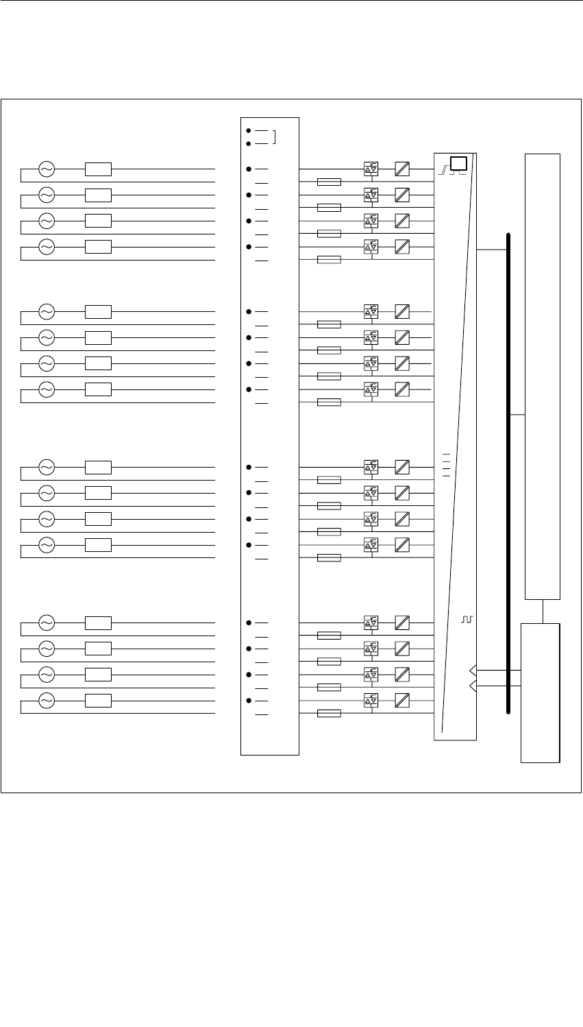
Digital Modules
4-88 S7-400, M7-400 Programmable Controllers Module Specifications
A5E00069467-07
Terminal Assignment Diagram of the SM 422; DO 16 20-120 VAC/2 A
1
2
3
40
Byte 0
5
61
7
82
9
10 3
11
13
1L1
12
14
15 4
16
17 5
18
19 6
20
21 7
22
24
23
26
27
28
29
30
31
32
33
34
36
35
38
39
40
41
42
43
44
45
46
48
47
25
37
0
1
2
3
4
5
6
7
2L1
3L1
4L1
5L1
6L1
7L1
8L1
9L1
10L1
11L1
12L1
13L1
14L1
15L1
16L1
Byte 1
INTF
EXTF
t
Process Module
Data register and bus control
LED control
Figure 4-21 Terminal Assignment Diagram of the SM 422; DO 16 20-120 VAC/2 A

Digital Modules
4-89
S7-400, M7-400 Programmable Controllers Module Specifications
A5E00069467-07
Technical Specifications of the SM 422; DO 16 20-120 VAC/2 A
Dimensions and Weight
Dimensions W H D
(in millimeters) 25 290 210
Weight Approx. 800 g
Data for Specific Module
Number of outputs 16
Length of cable
•Unshielded
•Shielded
Max. 600 m
Max. 1000 m
Voltages, Currents, Potentials
Rated load voltage L+ 20 to 132 VAC
•Permitted frequency range 47 Hz to 63 Hz
Total current of the outputs
Up to 40 C
Up to 60 C
With fan subassembly
Max. 16 A 24 A
Max. 7 A 16 A
Isolation
•Between channels and
backplane bus Yes
•Between the channels
In groups of
Yes
1
Permitted potential difference
•Between Minternal and the
outputs 120 VAC
•Between the outputs of the
different groups 250 VAC
Insulation tested with 1500 VDC
Current consumption
•From the backplane bus
•From load voltage L +
(without load)
Max. 600 mA
Max. 0 mA
Power dissipation of the
module Typ. 20 W
Status, Interrupts, Diagnostics
Status display Green LED per
channel
Interrupts
•Diagnostic Interrupt Parameters can be
assigned
Diagnostic functions Parameters can be
assigned
•Group error display
– For internal fault Red LED (INTF)
– For external fault Red LED (EXTF)
•Diagnostic
information readable Possible
Substitute value can be applied Yes, programmable
Data for Selecting an Actuator
Output voltage
•At signal “1” L1 (–1.5 Vrms)
Output current
•At signal “1”
Rated value
Permitted range
2 A
100 mA to 2 A
Permitted surge current
(per group) Max. 20 A/2 cycles
•At signal “0” (leakage
current) Max. 2.5 mA at 30 V
Max. 4.5 mA at 132 V
Output delay (for resistive load)
•From “ 0” to “1” 1 ms
•At “1” to “0” 1 AC cycle
Zero cross inhibit voltage Non-zero cross outputs
Size of the motor starter Max. size 5 to NEMA
Lamp load Max. 50 W
Parallel connection of 2
outputs
•For redundant triggering of
a load Possible (only outputs
of the same group)
•To increase performance Not possible
Triggering a digital input Possible
Switch rate
•For resistive load Max. 10 Hz
•For inductive load
to IEC 947-5-1, DC 13 Max. 0.5 Hz
•For lamp load 1 Hz
Short-circuit protection of the
output
•Min. current required for
fuse to blow
Fuse 8A/125 V 2AG
(per output)
Min. 40 A
•Max. response time Typ. 33 ms
Replacement fuses
•Littelfuse
Fuse, 8 A, quick-acting
225.008
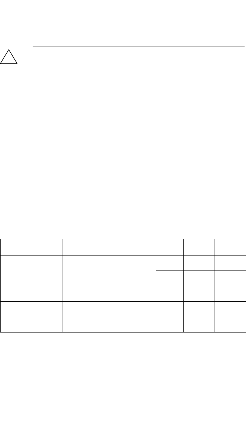
Digital Modules
4-90 S7-400, M7-400 Programmable Controllers Module Specifications
A5E00069467-07
Changing Fuses
!Warning
This can result in injury.
If you change a fuse without removing the front connector of the module, you could
be injured by an electric shock.
Consequently, always remove the front connector before you change the fuse.
4.23.1 Assigning Parameters to the SM 422; DO 16 20-120 VAC/2 A
Parameter Assignment
You will find a description of the general procedure for assigning parameters to
digital modules in Section 5.7.
Parameters of the SM 422; DO 16 20-120 VAC/2 A
You will find an overview of the parameters you can set and their default settings
for the SM 422; DO 16 20-120 VAC/2 A in the following table.
Table 4-20 Parameters of the SM 422; DO 16 20-120 VAC/2 A
Parameter Value Range Default2) Parameter
Type Scope
Enable
•Diagnostic interrupt1) Yes/no No Dynamic Module
•Destination CPU for
interrupt 1 to 4 –Static Module
Reaction to CPU STOP Substitute a value (SV)
Keep last value (KLV) SV Dynamic Module
Diagnostics
•Fuse blown Yes/no No Static Channel
Enable substitute value
“1” Yes/no No Dynamic Channel
1) If you use the module in ER-1/ER-2, you must set this parameter to “No” because the interrupt lines are
not available in ER-1/ER-2.
2) Only in the CC (central controller) is it possible to start up the digital modules with the default settings.

Digital Modules
4-91
S7-400, M7-400 Programmable Controllers Module Specifications
A5E00069467-07
4.24 Relay Output Module SM 422;
DO 16 30/230 VUC/Rel. 5 A; (6ES7422-1HH00-0AA0)
Characteristics
The SM 422; DO 16 30/230 VUC/Rel. 5 A has the following features:
•16 outputs, isolated in 8 groups of 2
•Output current 5 A
•Rated load voltage 230 VAC/ 125 VDC
The status LEDs also indicate the system status even when the front connector is
not inserted.
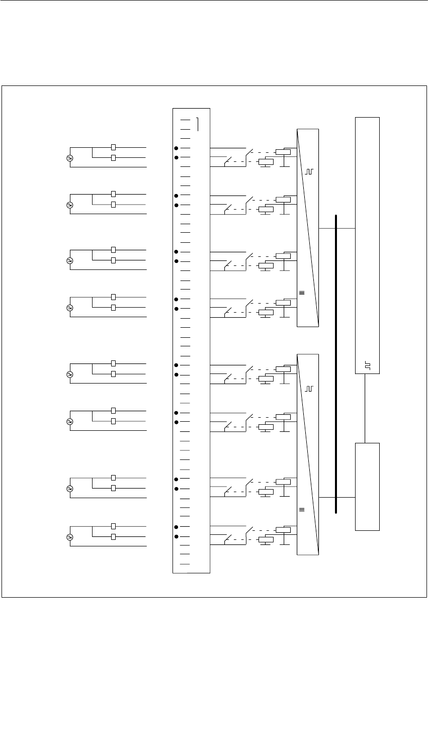
Digital Modules
4-92 S7-400, M7-400 Programmable Controllers Module Specifications
A5E00069467-07
Terminal Assignment and Block Diagram of the SM 422;
DO 16 30/230 VUC/Rel. 5 A
Data register and bus control
LED control
1
2
3
4
5
6
7
8
9
10
11
12
13
14
15
16
17
18
19
20
21
22
23
24
25
26
27
28
29
30
31
32
33
34
35
36
37
38
39
40
41
42
43
44
45
46
47
48
1L
2L
3L
5L
4L
6L
7L
8L
1
0
2
3
6
7
0
1
3
2
5
4
7
6
4
5
Process Module
Figure 4-22 Terminal Assignment and Block Diagram of the SM 422; DO 16 30/230 VUC/Rel. 5 A
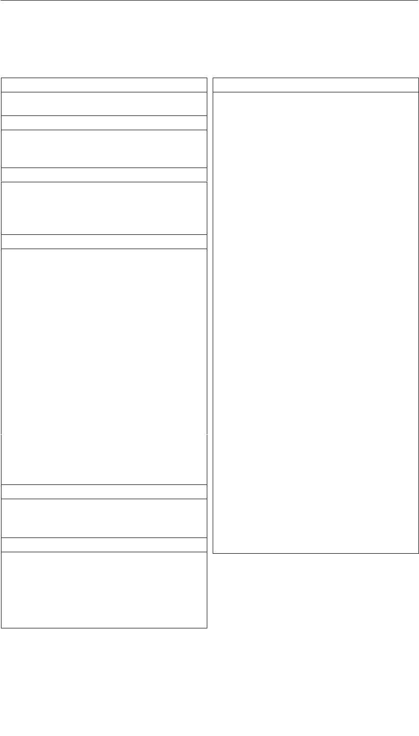
Digital Modules
4-93
S7-400, M7-400 Programmable Controllers Module Specifications
A5E00069467-07
Technical Specifications of the SM 422; DO 16 30/230 VUC/Rel. 5 A
Programming package
Associated programming
package As of STEP 7 V 2.0
Dimensions and Weight
Dimensions W H D
(in millimeters) 25 290 210
Weight Approx. 700 g
Data for Specific Module
Number of outputs 16
Length of cable
•Unshielded
•Shielded
Max. 600 m
Max. 1000 m
Voltages, Currents, Potentials
Total current of the outputs
(per group)
Up to 40 oC
Up to 60 oC
With fan subassembly
Max. 10 A 10 A
Max. 5 A 10 A
Isolation
•Between channels and
backplane bus Yes
•Between the channels
In groups of
Yes
2
Permitted potential
differences:
•Between the outputs of
the different groups 500 VAC
Insulation resistance 4000 VAC
Current consumption
•From the backplane bus Max. 1 A
Power dissipation of the
module Typ. 4.5 W
Status, Interrupts, Diagnostics
Status display
Interrupt
Diagnostic functions
Green LED per channel
None
None
Relay Features
Relay response times
•Power up
•Power down
Debouncing time
Max. 10 ms
Typ. 5.5 ms
Max. 5 ms
Typ. 3 ms
Typ. 0.5 ms
Data for Selecting an Actuator
Continuous thermal current Max. 5 A
Minimum load current 10 mA
External fuse for relay outputs Fuse, 6 A, quick-acting
Switching capacity and lifetime of the contacts
•For resistive load
Voltage Current No. of
switching
cyc. (typ.)
30 VDC
60 VDC
125 VDC
230 VAC
5.0 A
1.2 A
0.2 A
5.0 A
0.18 mill
0.1 mill
0.1 mill
0.18 mill
•For inductive load to IEC 947-5-1
13 DC/15 AC
Voltage Current No. of
switching
cyc. (typ.)
30 VDC
(=7 ms max.)
5.0 A 0.1 mill
230 VAC
(pf=0.4)
5.0 A 0.1 mill
Size of the motor starter Max. size 5 to NEMA
Lamp load Max. 60 W
Contact protection (internal) None
Connecting two outputs in parallel
•For redundant actuation of
a load Possible (only outputs
with identical load
voltage)
•To increase performance Not possible
Triggering a digital input Possible
Switch rate
•Mechanical Max. 20 Hz
•For resistive load Max. 10 Hz
•For inductive load to
IEC 947-5-1, 13 DC/15
AC
1 Hz
•For lamp load 1 Hz

Digital Modules
4-94 S7-400, M7-400 Programmable Controllers Module Specifications
A5E00069467-07
Note
Use a suppressor circuit in environments with high humidity and where sparks
might occur at the relay contacts. This will increase the life of the relay contacts.
To do this, connect an RC element or a varistor parallel to the relay contacts or to
the load. The dimensions depend on the size of the load (see Chapter 4 of the
installation manual).

5-1
S7-400, M7-400 Programmable Controllers Module Specifications
A5E00069467-07
Analog Modules
Structure of the Chapter
The present chapter is broken down into the following subjects:
1. Overview containing the modules that are available here and a description
2. Information that is generally available – in other words, affects all analog
modules (such as parameter assignment and diagnostics)
3. Information that refers to specific modules (for example, characteristics,
diagram of connections and block diagram, technical specifications and special
characteristics of the module):
a) For analog input modules
b) For analog output modules
STEP 7 Blocks for Analog Functions
You can use blocks FC 100 to FC 111 to read and output analog values in STEP 7.
You will find the FCs in the standard library of STEP 7 in the subdirectory called
“S5-S7 Converting Blocks” (for a description refer to the STEP 7 online help system
for the FCs).
Additional Information
Appendix A describes the structure of the parameter records (data records 0 and 1)
in the system data. You must be familiar with this structure if you want to modify the
parameters of the modules in the STEP 7 user program.
Appendix B describes the structure of the diagnostic data (data records 0, 1) in the
system data. You must be familiar with this structure if you want to evaluate the
diagnostic data of the modules in the STEP 7 user program.
5
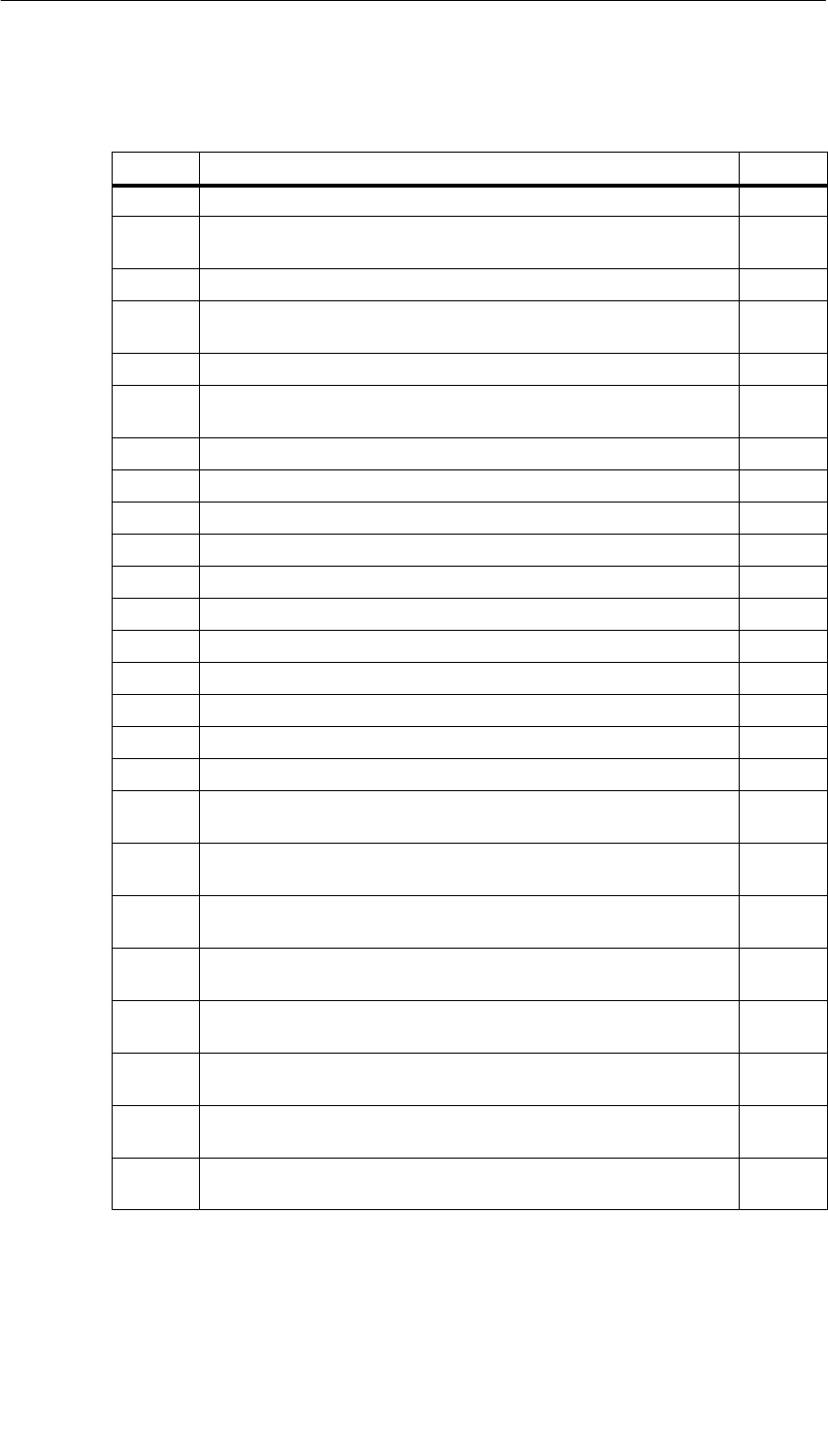
Analog Modules
5-2 S7-400, M7-400 Programmable Controllers Module Specifications
A5E00069467-07
Chapter Overview
Section Description Page
5.1 Module Overview 5-3
5.2 Sequence of Steps from Choosing to Commissioning the Analog
Modules 5-6
5.3 Analog Value Representation 5-7
5.4 Setting the Measuring Method and Measuring Ranges of the
Analog Input Channels 5-28
5.5 Behavior of the Analog Modules 5-31
5.6 Conversion, Cycle, Setting and Response Time of
Analog Modules 5-35
5.7 Analog Module Parameter Assignment 5-39
5.8 Connecting Sensors to Analog Inputs 5-43
5.9 Connecting Voltage Sensors 5-46
5.10 Connecting Current Sensors 5-47
5.11 Connecting Resistance Thermometers and Resistors 5-50
5.12 Connecting Thermocouples 5-53
5.13 Connecting Loads/Actuators to Analog Outputs 5-59
5.14 Connecting Loads/Actuators to Voltage Outputs 5-60
5.15 Connecting Loads/Actuators to Current Outputs 5-62
5.16 Diagnostics of the Analog Modules 5-63
5.17 Analog Module Interrupts 5-67
5.18 Analog Input Module SM 431; AI 8 13 Bit;
(6ES7431-1KF00-0AB0) 5-70
5.19 Analog Input Module SM 431; AI 8 14 Bit;
(6ES7431-1KF10-0AB0) 5-77
5.20 Analog Input Module SM 431; AI 8 14 Bit;
(6ES7431-1KF20-0AB0) 5-90
5.21 Analog Input Module SM 431; AI 16 13 Bit;
(6ES7431-0HH00-0AB0) 5-99
5.22 Analog Input Module SM 431; AI 16 16 Bit;
(6ES7431-7QH00-0AB0) 5-107
5.23 Analog Input Module SM 431; AI 8 RTD 16 Bit;
(6ES7431-7KF10-0AB0) 5-122
5.24 Analog Input Module SM 431; AI 8 16 Bit;
(6ES7431-7KF00-0AB0) 5-130
5.25 Analog Output Module SM 432; AO 8 13 Bit;
(6ES7432-1HF00-0AB0) 5-141

Analog Modules
5-3
S7-400, M7-400 Programmable Controllers Module Specifications
A5E00069467-07
5.1 Module Overview
Introduction
The following tables summarize the most important characteristics of the analog
modules. This overview is intended to make it easy to choose the suitable module
for your task.
Table 5-1 Analog Input Modules: Characteristics at a Glance
Module
Characteristics
SM 431;
AI 8 13
Bit
(-1KF00-)
SM 431;
AI 8 14
Bit
(-1KF10-)
SM 431;
AI 8 14
Bit
(-1KF20-)
SM 431;
AI 13 16
Bit
(-0HH0-)
SM 431;
AI 16 16
Bit
(-7QH00-)
SM 431;
AI 8 RTD
16 Bit
(-7KF10-)
SM 431;
AI 8 16
Bit
(-7KF00-)
Number of Inputs 8 AI U-/I
measure-
ment
4 AI for re-
sistance
measure-
ment
8 AI for U/I
measure-
ment
4 AI for re-
sistance/
tempera-
ture mea-
surement
8 AI for U/I
measure-
ment
4 AI for re-
sistance
measure-
ment
16 inputs 16 AI for U/
I/tempera-
ture mea-
surement
8 AI for re-
sistance
measure-
ment
8 inputs 8 inputs
Resolution 13 bits 14 bits 14 bits 13 bits 16 bits 16 bits 16 bits
Measuring Method Voltage
Current
Resistors
Voltage
Current
Resistors
Tempera-
ture
Voltage
Current
Resistors
Voltage
Current
Voltage
Current
Resistors
Tempera-
ture
Resistors Voltage
Current
Tempera-
ture
Measuring
Principle Integrating Integrating Instanta-
neous
value en-
coding
Integrating Integrating Integrating Integrating
Programmable
Diagnostics No No No No Yes Yes Yes
Diagnostic
Interrupt No No No No Adjustable Yes Yes
Limit value
Monitoring No No No No Adjustable Adjustable Adjustable
Hardware
Interrupt upon
Limit Violation
No No No No Adjustable Adjustable Adjustable
Hardware
Interrupt at End of
Cycle
No No No No Adjustable No No
Potential
Relationships Analog section isolated from CPU Non-
isolated Analog section isolated from CPU
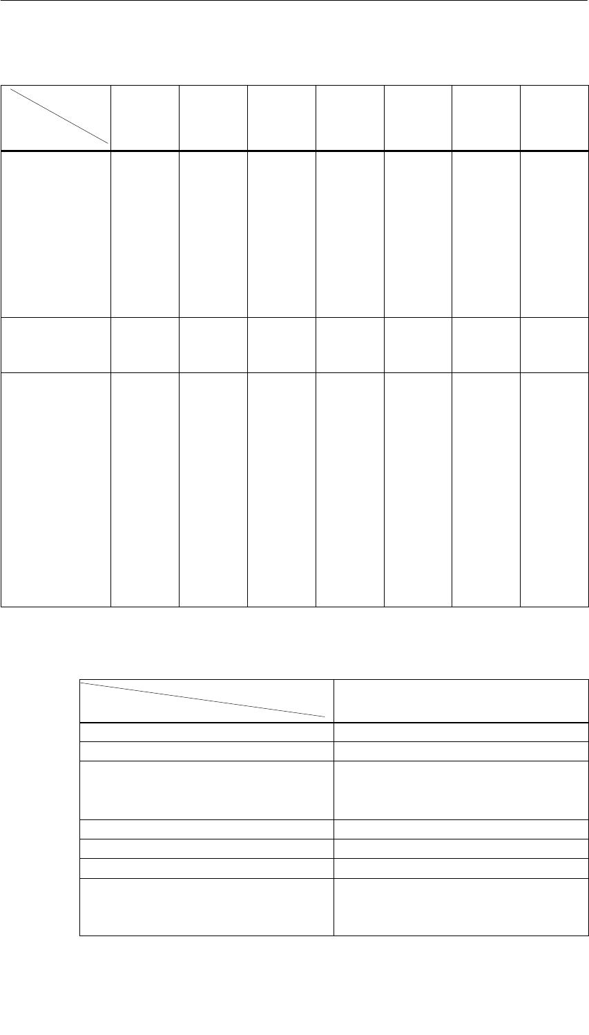
Analog Modules
5-4 S7-400, M7-400 Programmable Controllers Module Specifications
A5E00069467-07
Table 5-1 Analog Input Modules: Characteristics at a Glance, continued
Module SM 431;
AI 8 16
Bit
(-7KF00-)
SM 431;
AI 8 RTD
16 Bit
(-7KF10-)
SM 431;
AI 16 16
Bit
(-7QH00-)
SM 431;
AI 13 16
Bit
(-0HH0-)
SM 431;
AI 8 14
Bit
(-1KF20-)
SM 431;
AI 8 14
Bit
(-1KF10-)
SM 431;
AI 8 13
Bit
(-1KF00-)
Characteristics
Max. Permissible
Common Mode
Voltage
Between
the chan-
nels or be-
tween the
reference
potential of
the con-
nected
sensors
and MANA:
30 VAC
Between
the chan-
nels or be-
tween the
channel
and central
ground
point:
120 VAC
Between
the chan-
nels or be-
tween the
reference
potential of
the con-
nected
sensors
and MANA:
8 VAC
Between
the chan-
nels or be-
tween the
reference
potential of
the con-
nected
sensor and
central
ground
point:
2 VDC/AC
Between
the chan-
nels or be-
tween the
channel
and central
ground
point:
120 VAC
Between
channel
and central
ground
point:
120 VAC
Between
the chan-
nels or be-
tween the
channel
and central
ground
point:
120 VAC
Ext. Power Supply
Necessary No 24 VDC
(only with
current,
2-DMU)
24 VDC
(only with
current,
2-DMU)
24 VDC
(only with
current,
2-DMU)
24 VDC
(only with
current,
2-DMU)
No No
Special Features –Suitable for
tempera-
ture mea-
surement
Tempera-
ture sensor
types can
be parame-
terized
Lineariza-
tion of the
sensor
character-
istic curves
Smoothing
of the mea-
sured val-
ues
Rapid A/D
change,
suitable for
highly dy-
namic pro-
cesses
Smoothing
of the mea-
sured val-
ues
–Suitable for
tempera-
ture mea-
surement
Tempera-
ture sensor
types can
be parame-
terized
Lineariza-
tion of the
sensor
character-
istic curves
Smoothing
of the mea-
sured val-
ues
Resistance
thermome-
ter can be
parameter-
ized
Lineariza-
tion of the
sensor
character-
istic curves
Smoothing
of the mea-
sured val-
ues
Internal
measuring
resistor
Field con-
nection
with inter-
nal refer-
ence tem-
perature
(included
with the
module)
Smoothing
of the mea-
sured val-
ues
2-DMU Two-wire transmitter
Table 5-2 Analog Output Modules: Characteristics at a Glance
Module
Characteristics
SM 432; AO 8 13 Bit
(-1HF00-)
Number of outputs 8 outputs
Resolution 13 bits
Output type Channel by channel:
•Voltage
•Current
Programmable diagnostics No
Diagnostic Interrupt No
Substitute value output No
Potential relationships Analog section isolated from:
•CPU
•The load voltage

Analog Modules
5-5
S7-400, M7-400 Programmable Controllers Module Specifications
A5E00069467-07
Table 5-2 Analog Output Modules: Characteristics at a Glance
Module SM 432; AO 8 13 Bit
(-1HF00-)
Characteristics
Max. permissible common mode voltage Between the channels and the channels
against MANA 3 VDC
Special Features –

Analog Modules
5-6 S7-400, M7-400 Programmable Controllers Module Specifications
A5E00069467-07
5.2 Sequence of Steps from Choosing to Commissioning
the Analog Modules
Introduction
The following table contains the tasks that you have to perform one after the other
to commission analog modules successfully.
The sequence of steps is a suggestion, but you can perform individual steps either
earlier or later (for example, assign parameters to the module) or install other
modules or install, commission etc. other modules in between times.
Sequence of Steps
Table 5-3 Sequence of Steps from Choosing to Commissioning the Analog Module
Step Procedure Refer To...
1. Select the module Section 5.1 and specific module section from
Section 5.18
2. With some analog input modules: set
the measuring method and
measuring range by means of the
measuring range module
Section 5.4
3. Install the module in the SIMATIC S7
network “Installation” section in the manual for the
programmable controller being used:
•S7-400/M7-400 Programmable Controllers,
Hardware and Installation
4. Assign parameters to module Section 5.7
5. Connect measuring sensor or loads
to module Sections 5.8 to 5.15
6. Commission configuration “Commissioning” section in the manual for the
programmable controller being used:
•S7-400/M7-400 Programmable Controllers,
Hardware and Installation
7. If commissioning was not successful,
diagnose configuration Section 5.16

Analog Modules
5-7
S7-400, M7-400 Programmable Controllers Module Specifications
A5E00069467-07
5.3 Analog Value Representation
Introduction
This section describes the analog values for all the measuring ranges and output
ranges which you can use with the analog modules.
Converting Analog Values
Analog input modules convert the analog process signal into digital form.
Analog output modules convert the digital output value into an analog signal.
Analog Value Representation with 16-Bit Resolution
The digitized analog value is the same for both input and output values having the
same nominal range. The analog values are represented as a fixed-point number
in two’s complement. The resulting assignment is as follows:
Bit 15 14 13 12 11 10 9 8 7 6 5 4 3 2 1 0
Value of bits 215 214 213 212 211 210 29282726252423222120
Bit 15 Can Be Interpreted as a Sign
The sign of the analog value is always contained in bit number 15:
•”0” ³ )
•”1” ³ *
Resolution Less than 16 Bits
If the resolution of an analog module has fewer than 16 bits, the analog value is
stored left-justified on the module. The lower-order bit positions not used are
padded with zeros (“0”).

Analog Modules
5-8 S7-400, M7-400 Programmable Controllers Module Specifications
A5E00069467-07
Example
In the following example you can see how the positions not padded with “0” are
written for low resolution.
Table 5-4 Example: Bit Pattern of a 16-Bit and a 13-Bit Analog Value
Resolution Analog Value
Bit 15 14 13 12 11 10 9 8 7 6 5 4 3 2 1 0
16-bit analog value 0100011001110011
13-bit analog value 01000110011100 0 0
5.3.1 Analog Value Representation for Analog Input Channels
Introduction
The tables in this chapter contain the measured value representations for the
various measuring ranges of the analog input modules. The values in the tables
apply to all modules with the corresponding measuring ranges.
Notes for Readers of the Tables
Tables 5-6 to 5-8 contain the binary representation of the measured values.
Since the binary representation of the measured values is always the same,
starting at 5-9 these tables only contain the measured values and the units.
Measured-Value Resolution
The resolution of the analog values can differ depending on the analog module and
its parameter assignment. With resolutions < 16 bit, the bits marked with “x” are set
to “0”.
Note: This resolution doesn’t apply to temperature values. The changed
temperature values are the result of recalculation in the analog module
(see Tables 5-16 to 5-30).

Analog Modules
5-9
S7-400, M7-400 Programmable Controllers Module Specifications
A5E00069467-07
Table 5-5 Possible Resolutions of the Analog Values
Resolution
in Bits
Units Analog Value
in Bits Decimal Hexadecimal High-Order Byte Low-Order Byte
9 128 80H0 0 0 0 0 0 0 0 1 x x x x x x x
10 64 40H0 0 0 0 0 0 0 0 0 1 x x x x x x
11 32 20H0 0 0 0 0 0 0 0 0 0 1 x x x x x
12 16 10H0 0 0 0 0 0 0 0 0 0 0 1 x x x x
13 8 8H0 0 0 0 0 0 0 0 0 0 0 0 1 x x x
14 4 4H0 0 0 0 0 0 0 0 0 0 0 0 0 1 x x
15 2 2H0 0 0 0 0 0 0 0 0 0 0 0 0 0 1 x
16 1 1H0 0 0 0 0 0 0 0 0 0 0 0 0 0 0 1
Analog Modules
5-10 S7-400, M7-400 Programmable Controllers Module Specifications
A5E00069467-07
Binary Representation of the Input Ranges
The input ranges shown in Tables 5-6 to 5-8 are defined in two’s complement
representation:
Table 5-6 Bipolar Input Ranges
Units Measured
Value
Data Word Range
V
a
l
ue
in % 215 214 213 212 211 210 29282726252423222120
32767 u118.515 0 1 1 1 1 1 1 1 1 1 1 1 1 1 1 1 Over-
flow
32511 117.589 0 1 1 1 1 1 1 0 1 1 1 1 1 1 1 1 Over
27649 uw100.00
40110110000000001range
27648 100.000 0 1 1 0 1 1 0 0 0 0 0 0 0 0 0 0
1 0.003617 0 000000000000001
0 0.000 0 000000000000000Rated
–1 – 0.003617 1111111111111111range
–27648 –100.000 1 001010000000000
–27649 v– 100.004 1 0 0 1 0 0 1 1 1 1 1 1 1 1 1 1 Under
–32512 –117.593 1 000000100000000range
–32768 v– 117.596 1 0 0 0 0 0 0 0 0 0 0 0 0 0 0 0 Under-
flow
Table 5-7 Unipolar Input Ranges
Units Measured
Value
Data Word Range
V
a
l
ue
in % 215 214 213 212 211 210 29282726252423222120
32767 w118.515 0 1 1 1 1 1 1 1 1 1 1 1 1 1 1 1 Overflow
32511 117.589 0 1 1 1 1 1 1 0 1 1 1 1 1 1 1 1 Over-
range
27649 w100.004 0 110110000000001
range
27648 100.000 0 1 1 0 1 1 0 0 0 0 0 0 0 0 0 0
1 0.003617 0 000000000000001Rated
range
0 0.000 0 000000000000000
–1 – 0.003617 1 1 1 1 1 1 1 1 1 1 1 1 1 1 1 1 Under-
range
–4864 – 17.593 1110110100000000
range
–32768 v– 17.596 1 0 0 0 0 0 0 0 0 0 0 0 0 0 0 0 Under-
flow
Analog Modules
5-11
S7-400, M7-400 Programmable Controllers Module Specifications
A5E00069467-07
Table 5-8 Life-Zero Input Ranges
Units Measured
Value
Data Word Range
V
a
l
ue
in % 215 214 213 212 211 210 29282726252423222120
w32767 w118.515 0 1 1 1 1 1 1 1 1 1 1 1 1 1 1 1 Over-
flow
32511 117.589 0 1 1 1 1 1 1 0 1 1 1 1 1 1 1 1 Over-
range
27649 w100.004 0 110110000000001range
27648 100.000 0 1 1 0 1 1 0 0 0 0 0 0 0 0 0 0 Rated
1 0.003617 0 000000000000001range
0 0.000 0 000000000000000
–1 –0.003617 1 1 1 1 1 1 1 1 1 1 1 1 1 1 1 1 Under-
range
–4864 –17.593 1 110110100000000range
In the event of wire break, the module reports 7FFFH
Analog Value Representation in Voltage Measuring Ranges
Table 5-9 Analog Value Representation in Voltage Measuring Ranges ± 10 V to ± 1 V
System Voltage Measuring Range
Dec. Hex. ± 10 V ± 5 V ± 2.5 V ± 1 V
118.515% 32767 7FFF 11.851 V 5.926 V 2.963 V 1.185 V Overflow
117.593% 32512 7F00
117.589% 32511 7EFF 11.759 V 5.879 V 2.940 V 1.176 V Overrange
27649 6C01
100.000% 27648 6C00 10 V 5 V 2.5 V 1 V
75.000% 20736 5100 7.5 V 3.75 V 1.875 V 0.75 V
0.003617% 1 1 361.7 V180.8 V 90.4 V36.17 V
0% 0 0 0 V 0 V 0 V 0 V Rated range
–1 FFFF
– 75.00% – 20736 AF00 – 7.5 V – 3.75 V – 1.875 V – 0.75 V
– 100.000% –27648 9400 – 10 V – 5 V – 2.5 V – 1 V
–27649 93FF Underrange
–117.593% –32512 8100 – 11.759 V – 5.879 V – 2.940 V – 1.176 V
– 117.596% – 32513 80FF Underflow
– 118.519% –32768 8000 – 11.851 V – 5.926 V – 2.963 V – 1.185 V
Analog Modules
5-12 S7-400, M7-400 Programmable Controllers Module Specifications
A5E00069467-07
Table 5-10 Analog Value Representation in the Voltage Measuring Ranges ± 500 mV to ± 25 mV
System Voltage Measuring Range
Dec. Hex. ± 500 mV ± 250 mV ± 80 mV ± 50 mV ± 25 mV
118.515% 32767 7FFF 592.6 mV 296.3 mV 94.8 mV 59.3 mV 29.6 mV Overflow
117.593% 32512 7F00
117.589% 32511 7EFF 587.9 mV 294.0 mV 94.1 mV 58.8 mV 29.4 mV Overrange
27649 6C01
100.000% 27648 6C00 500 mV 250 mV 80 mV 50 mV 25 mV
75% 20736 5100 375 mV 187.54 mV 60 mV 37.5 mV 18.75 mV
0.003617% 1 1 18.08 V9.04 V2.89 V1.81 V904.2 nV Rated range
0% 0 0 0 mV 0 mV 0 mV 0 mV 0 mV
–1 FFFF
– 75.00% – 20736 AF00 – 375 mV –187.54 mV – 60 mV – 37.5 mV – 18.75 mV
–
100.000% –27648 9400 – 500 mV – 250 mV – 80 mV – 50 mV – 25 mV
–27649 93FF Underrange
–117.593% –32512 8100 – 587.9 mV – 294.0 mV – 94.1 mV – 58.8 mV – 29.4 mV
–
117.596% – 32513 80FF Underflow
–
118.519% –32768 8000 – 592.6 mV – 296.3 mV – 94.8 mV – 59.3 mV – 29.6 mV
Table 5-11 Analog Value Representation in the Voltage Measuring Ranges 1 to 5 V and 0 to 10 V
System Voltage Measuring Range
Dec. Hex. 1 to 5 V 0 to 10 V
118.515% 32767 7FFF 5.741 V 11.852 V Overflow
117.593% 32512 7F00
117.589% 32511 7EFF 5.704 V 11.759 V Overrange
27649 6C01
100.000% 27648 6C00 5 V 10 V
75% 20736 5100 3.75 V 7.5 V
0.003617% 1 1 1 V + 144.7 V0 V + 361.7 VRated range
0% 0 0 1 V 0 V
–1 FFFF Underrange
– 17.593% –4864 ED00 0.296 V Negative values not
ibl
– 4865 ECFF
g
possible Underflow
v–17.596% –32768 8000
Analog Modules
5-13
S7-400, M7-400 Programmable Controllers Module Specifications
A5E00069467-07
Analog Value Representation in Current Measuring Ranges
Table 5-12 Analog Value Representation in the Current Measuring Ranges ± 20 mA to ± 3.2 mA
System Current Measuring Range
Dec. Hex. ± 20 mA ± 10 mA ± 5 mA ± 3.2 mA
118.515% 32767 7FFF 23.70 mA 11.85 mA 5.93 mA 3.79 mA Overflow
117.593% 32512 7F00
117.589% 32511 7EFF 23.52 mA 11.76 mA 5.88 mA 3.76 mA Overrange
27649 6C01
100.000% 27648 6C00 20 mA 10 mA 5 mA 3.2 mA
75% 20736 5100 15 mA 7.5 mA 3.75 mA 2.4 mA
0.003617% 1 1 723.4 nA 361.7 nA 180.8 nA 115.7 nA
0% 0 0 0 mA 0 mA 0 mA 0 mA Rated range
–1 FFFF
– 75% – 20736 AF00 – 15 mA – 7.5 mA – 3.75 mA – 2.4 mA
–100.000% –27648 9400 – 20 mA – 10 mA – 5 mA – 3.2 mA
–27649 93FF Underrange
–117.593% –32512 8100 – 23.52mA – 11.76mA – 5.88 mA – 3.76 mA
– 117.596% – 32513 80FF Underflow
– 118.519% –32768 8000 – 23.70
mA – 11.85
mA – 5.93 mA – 3.79 mA
Table 5-13 Analog Value Representation in Current Measuring Ranges 0 to 20 mA
System Current Measuring Range
Dec. Hex. 0 to 20 mA
118.515% 32767 7FFF 23.70 mA Overflow
117.593% 32512 7F00
117.589% 32511 7EFF 23.52 mA Overrange
27649 6C01
100.000% 27648 6C00 20 mA
75% 20736 5100 15 mA
0.003617% 1 1 723.4 nA Rated range
0% 0 0 0 mA
– 1 FFFF Underrange
– 17.593% – 4864 ED00 – 3.52 mA
– 4865 ECFF Underflow
v – 17.596% – 32768 8000
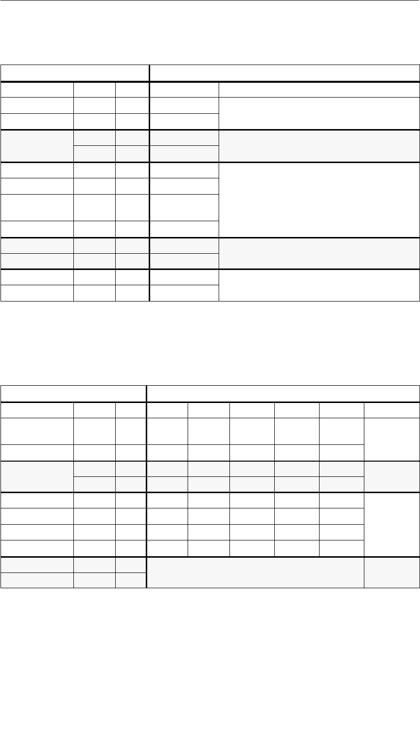
Analog Modules
5-14 S7-400, M7-400 Programmable Controllers Module Specifications
A5E00069467-07
Table 5-14 Analog Value Representation in Current Measuring Ranges 4 to 20 mA
System Current Measuring Range
Dec. Hex. 4 to 20 mA
118.515% 32767 7FFF 22.96 mA Overflow
117.593% 32512 7F00
117.589% 32511 7EFF 22.81 mA Overrange
27649 6C01
100.000% 27648 6C00 20 mA
75% 20736 5100 16 mA
0.003617% 1 1 4 mA +
578.7 nA Rated range
0% 0 0 4 mA
– 1 FFFF Underrange
– 17.593% – 4864 ED00 1.185 mA
Underflow
v – 17.596% – 32767 7FFF
Analog Value Representation for Resistance-Type Sensors
Table 5-15 Analog Value Representation for Resistance-Type Sensors from 48 to 6 k
System Resistance-Type Sensor Range
Dec. Hex. 48 150 300 600 6 k
118.515% 32767 7FFF 56.89 177.77
355.54 711.09 7.11 kOverflow
117.593% 32512 7F00
117.589% 32511 7EFF 56.44176.38
352.77 705.53 7.06 kOverrange
27649 6C01
100.000% 27648 6C00 48 150 300 600 6 k
75% 20736 5100 36 112.5 225450 4.5 kRated
0.003617% 1 1 1.74m5.43m10.85m21.70m217.0mrange
0% 0 0 0 0 0 0 0
(negative values physically not possible) Underrange
(g py y p )
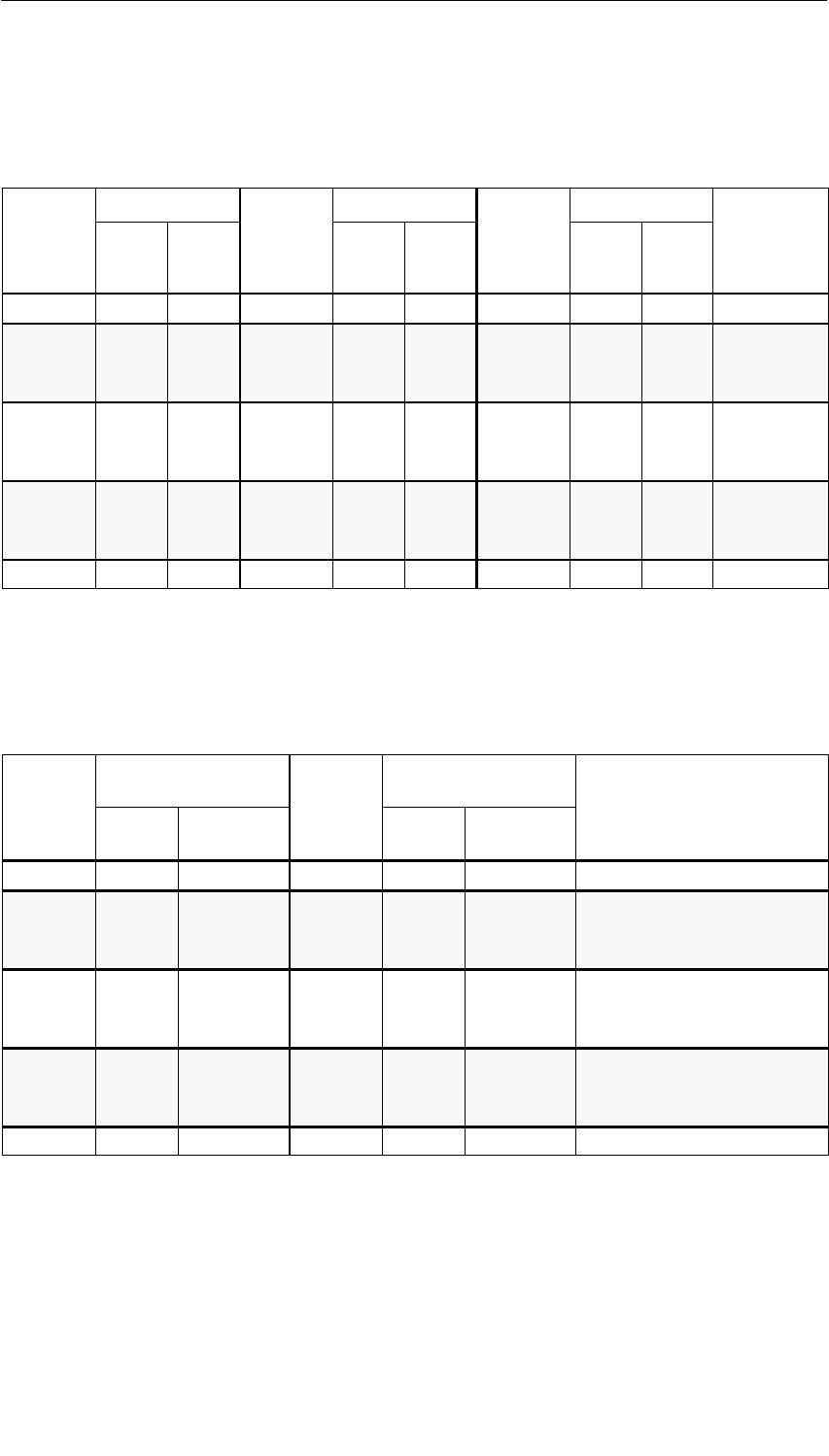
Analog Modules
5-15
S7-400, M7-400 Programmable Controllers Module Specifications
A5E00069467-07
Analog Value Representation for Resistance Thermometers Pt x00 Standard
Table 5-16 Analog Value Representation for Resistance Thermometers Pt 100, 200, 500,1000
Pt x00
Standard
Units Pt x00
Standard
Units Pt x00
Standard
Units
S
tan
d
ar
d
in 5C
(1 Digit =
0.15C)
Deci-
mal Hexa-
deci-
mal
S
tan
d
ar
d
in 5F
(1 Digit =
0.1 5F)
Deci-
mal Hexa-
deci-
mal
S
tan
d
ar
d
in K
(1 Digit =
0.1 K)
Deci-
mal Hexa-
deci-
mal
Range
> 1000.0 32767 7FFFH> 1832.0 32767 7FFFH> 1273.2 32767 7FFFHOverflow
1000.0
:
850.1
10000
:
8501
2710H
:
2135H
1832.0
:
1562.1
18320
:
15621
4790H
:
3D05H
1273.2
:
1123.3
12732
:
11233
31BCH
:
2BE1H
Overrange
850.0
:
–200.0
8500
:
–2000
2134H
:
F830H
1562.0
:
–328.0
15620
:
–3280
3D04H
:
F330H
1123.2
:
73.2
11232
:
732
2BE0H
:
2DCH
Rated range
–200.1
:
–243.0
–2001
:
–2430
F82FH
:
F682H
–328.1
:
–405.4
–3281
:
–4054
F32FH
:
F02AH
73.1
:
30.2
731
:
302
2DBH
:
12EH
Underrange
< – 243.0 –32768 8000H< – 405.4 –32768 8000H< 30.2 32768 8000HUnderflow
Analog Value Representation for Resistance Thermometers Pt x00 Climatic
Table 5-17 Analog Value Representation for Resistance Thermometers Pt 100, 200, 500,1000
Pt x00
Climatic
in
5
C
Units Pt x00
Climatic
in
5
F
Units
Range
i
n
5C
(1 Digit =
0.015C)
Decimal Hexadecimal
i
n
5F
(1 Digit =
0.01 5F)
Decimal Hexadecimal Range
> 155.00 32767 7FFFH> 311.00 32767 7FFFHOverflow
155.00
:
130.01
15500
:
13001
3C8CH
:
32C9H
311.00
:
266.01
31100
:
26601
797CH
:
67E9H
Overrange
130.00
:
–120.00
13000
:
–12000
32C8H
:
D120H
266.00
:
–184.00
26600
:
–18400
67E8H
:
B820H
Rated range
–120.01
:
–145.00
–12001
:
–14500
D11FH
:
C75CH
–184.01
:
–229.00
–18401
:
–22900
B81FH
:
A68CH
Underrange
< – 145.00 –32768 8000H< – 229.00 –32768 8000HUnderflow
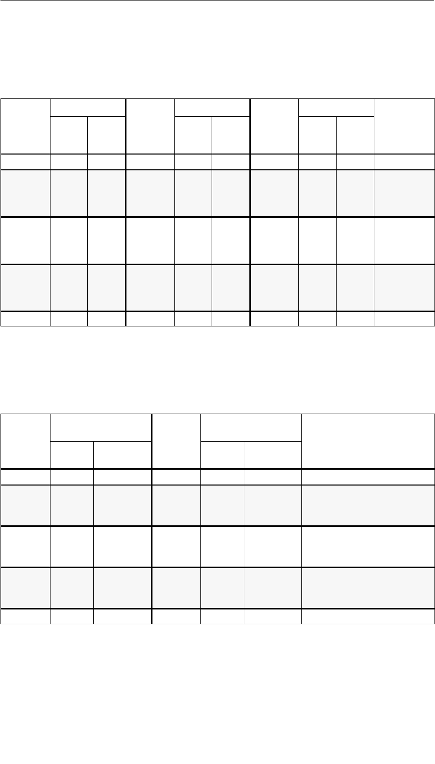
Analog Modules
5-16 S7-400, M7-400 Programmable Controllers Module Specifications
A5E00069467-07
Analog Value Representation for Resistance Thermometers Ni x00 Standard
Table 5-18 Analog Value Representation for Resistance Thermometers Ni100, 120, 200, 500, 1000
Ni x00
Standard
Units Ni x00
Standard
Units Ni x00
Standard
Units
S
tan
d
ar
d
in 5C
(1 Digit =
0.15C)
Deci-
mal Hexa-
deci-
mal
S
tan
d
ar
d
in 5F
(1 Digit =
0.1 5F)
Deci-
mal Hexa-
deci-
mal
S
tan
d
ar
d
in K
(1 Digit =
0.1 K)
Deci-
mal Hexa-
deci-
mal
Range
> 295.0 32767 7FFFH > 563.0 32767 7FFFH > 568.2 32767 7FFFHOverflow
295.0 2950 B86H563.0 5630 15FEH568.2 5682 1632H
: : : : : : : : : Overrange
250.1 2501 9C5H482.1 4821 12D5H523.3 5233 1471H
g
250.0 2500 9C4H482.0 4820 12D4H523.2 5232 1470H
: : : : : : : : : Rated range
–60.0 –600 FDA8H–76.0 –760 FD08H213.2 2132 854H
–60.1 –601 FDA7H –76.1 –761 FD07H 213.1 2131 853H
: : : : : : : : : Underrange
–105.0 –1050 FBE6H–157.0 –1570 F9DEH168.2 1682 692H
g
< –105.0 –32768 8000H< –157.0 –32768 8000H < 168.2 32768 8000HUnderflow
Analog Value Representation for Resistance Thermometers Ni x00 Climatic
Table 5-19 Analog Value Representation for Resistance Thermometers Ni 100, 120, 200, 500, 1000
Ni x00
Climatic
in
5
C
Units Ni x00
Climatic
in
5
F
Units
Range
i
n
5C
(1 Digit =
0.015C)
Decimal Hexadecimal
i
n
5F
(1 Digit =
0.01 5F)
Decimal Hexadecimal Range
> 295.00 32767 7FFFH> 325.11 32767 7FFFHOverflow
295.00
:
250.01
29500
:
25001
733CH
:
61A9H
327.66
:
280.01
32766
:
28001
7FFEH
:
6D61H
Overrange
250.00
:
–60.00
25000
:
–6000
61A8H
:
E890H
280.00
:
–76.00
28000
:
–7600
6D60H
:
E250H
Rated range
–60.01
:
–105.00
–6001
:
–10500
E88FH
:
D6FCH
–76.01
:
–157.00
–7601
:
–15700
E24FH
:
C2ACH
Underrange
< – 105.00 –32768 8000H< – 157.00 –32768 8000HUnderflow

Analog Modules
5-17
S7-400, M7-400 Programmable Controllers Module Specifications
A5E00069467-07
Analog Value Representation for Resistance Thermometers Cu 10 Standard
Table 5-20 Analog Value Representation for Resistance Thermometers Cu 10
Cu 10
Standard
Units Cu 10
Standard
Units Cu 10
Standard
Units
S
tan
d
ar
d
in 5C
(1 Digit =
0.015C)
Deci-
mal Hexa-
deci-
mal
S
tan
d
ar
d
in 5F
(1 Digit =
0.01 5F)
Deci-
mal Hexa-
deci-
mal
S
tan
d
ar
d
in K
(1 Digit =
0.01 K)
Deci-
mal Hexa-
deci-
mal
Range
> 312.0 32767 7FFFH> 593.6 32767 7FFFH> 585.2 32767 7FFFHOverflow
312.0
:
260.1
3120
:
2601
C30H
:
A29H
593.6
:
500.1
5936
:
5001
1730H
:
12D5H
585.2
:
533.3
5852
:
5333
16DCH
:
14D5H
Overrange
260.0
:
–200.0
2600
:
–2000
A28H
:
F830H
500.0
:
–328.0
5000
:
–3280
1389H
:
F330H
533.2
:
73.2
5332
:
732
14D4H
:
2DCH
Rated range
–200.1
:
–240.0
–2001
:
–2400
F82FH
:
F6A0H
–328.1
:
–400.0
–3281
:
–4000
F32FH
:
F060H
73.1
:
33.2
731
:
332
2DBH
:
14CH
Underrange
< – 240.0 –32768 8000H< – 400.0 –32768 8000H< 33.2 32768 8000HUnderflow
Analog Value Representation for Resistance Thermometers Cu 10 Climatic
Table 5-21 Analog Value Representation for Resistance Thermometers Cu 10
Cu 10
Climatic
in
5
C
Units Cu 10
Climatic
in
5
F
Units
Range
i
n
5C
(1 Digit =
0.015C)
Decimal Hexadecimal
i
n
5F
(1 Digit =
0.01 5F)
Decimal Hexadecimal Range
> 180.00 32767 7FFFH> 325.11 32767 7FFFHOverflow
180.00
:
150.01
18000
:
15001
4650H
:
3A99H
327.66
:
280.01
32766
:
28001
7FFEH
:
6D61AH
Overrange
150.00
:
–50.00
15000
:
–5000
3A98H
:
EC78H
280.00
:
–58.00
28000
:
–5800
6D60H
:
E958H
Rated range
–50.01
:
–60.00
–5001
:
–6000
EC77H
:
E890H
–58.01
:
–76.00
–5801
:
–7600
E957H
:
E250H
Underrange
< – 60.00 –32768 8000H< – 76.00 –32768 8000HUnderflow
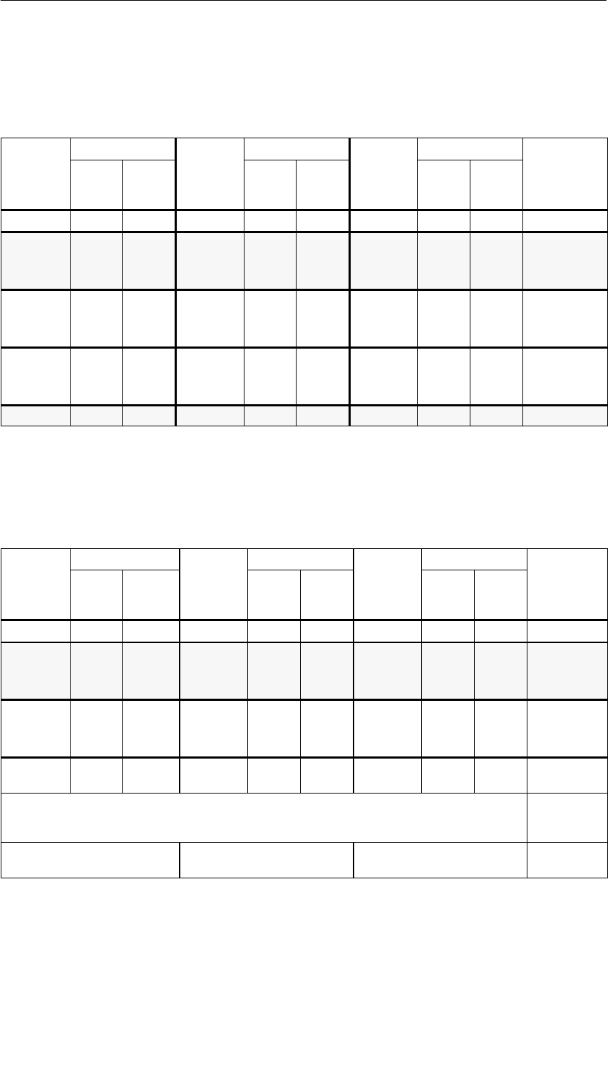
Analog Modules
5-18 S7-400, M7-400 Programmable Controllers Module Specifications
A5E00069467-07
Analog Value Representation for Themocouple Type B
Table 5-22 Analog Value Representation for Thermocouple Type B
Type B
Units
Type B
Units
Type B
Units
Type B
in 5CDeci-
mal Hexa-
deci-
mal
Type B
in 5FDeci-
mal Hexa-
deci-
mal
Type B
in K Deci-
mal Hexa-
deci-
mal
Range
> 2070.0 32767 7FFFH> 3276.6 32767 7FFFH> 2343.2 32767 7FFFHOverflow
2070.0
:
1821.0
20700
:
18210
50DCH
:
4722H
3276.6
:
2786.6
32766
:
27866
7FFEH
:
6CDAH
2343.2
:
2094.2
23432
:
20942
5B88H
:
51CEH
Overrange
1820.0
:
0,0
18200
:
0
4718H
:
0000H
2786.5
:
–32.0
27865
:
–320
6CD9H
:
FEC0H
2093.2
:
273.2
20932
:
2732
51C4H
:
0AACH
Rated range
:
–120.0
:
–1200
:
FB50H
:
–184.0
:
–1840
:
F8D0H
:
153.2
:
1532
:
05FCH
Underrange
< –120.0 –32768 8000H< –184.0 –32768 8000H< 153.2 32768 8000HUnderflow
Analog Value Representation for Thermocouple Type E
Table 5-23 Analog Value Representation for Thermocouple Type E
Type E
Units
Type E
Units
Type E
Units
Type E
in 5CDeci-
mal Hexade-
cimal
Type E
in 5FDeci-
mal Hexa-
deci-
mal
Type E
in K Deci-
mal Hexa-
deci-
mal
Range
> 1200.0 32767 7FFFH> 2192,0 32767 7FFFH> 1473.2 32767 7FFFHOverflow
1200.0
:
1000.1
12000
:
10001
2EE0H
:
2711H
2192.0
:
1833.8
21920
:
18338
55A0H
:
47A2H
1473.2
:
1274.2
14732
:
12742
398CH
:
31C6H
Overrange
1000.0
:
–270.0
10000
:
–2700
2710H
:
F574H
1832.0
:
–454.0
18320
:
–4540
4790H
:
EE44H
1273.2
:
0
12732
:
0
31BCH
:
0000H
Rated range
< –270.0 <
–2700 < F574H< –454.0 <
–4540 <EE44
H
< 0 < 0 <0000HUnderflow
In the case of incorrect wiring (for example, polarity reversal or open inputs) or of a sensor error in the
negative range (for example, incorrect thermocouple type), the analog input module reports an
underflow...
...if F0C4H is violated and
outputs 8000H
...if FB70H is violated and
outputs 8000H
...if E5D4H is violated and
outputs 8000H
Analog Modules
5-19
S7-400, M7-400 Programmable Controllers Module Specifications
A5E00069467-07
Analog Value Representation for Thermocouple Type J
Table 5-24 Analog Value Representation for Thermocouple Type J
Type J
Units
Type J
Units
Type J
Units
Type J
in 5CDeci-
mal Hexade-
cimal
Type J
in 5FDeci-
mal Hexa-
deci-
mal
Type J
in K Deci-
mal Hexa-
deci-
mal
Range
> 1450.0 32767 7FFFH> 2642.0 32767 7FFFH> 1723.2 32767 7FFFHOverflow
1450.0
:
1201.0
14500
:
12010
38A4H
:
2EEAH
2642.0
:
2193.8
26420
:
21938
6734H
:
55B2H
1723.2
:
1474.2
17232
:
14742
4350H
:
3996H
Overrange
1200.0
:
–210.0
12000
:
–2100
2EE0H
:
F7CCH
2192.0
:
–346.0
21920
:
–3460
55A0H
:
F27CH
1473.2
:
63.2
14732
:
632
398CH
:
0278H
Rated range
< –210.0 <
–2100 <F7CCH< –346.0 <
–3460 <F27C
H
< 63.2 < 632 <
0278HUnderflow
In the case of incorrect wiring (for example, polarity reversal or open inputs) or of a sensor error in the
negative range (for example incorrect thermocouple type), the analog input module reports an
underflow...
...if F31CH is violated and
outputs 8000H
...if EA0CH is violated and
outputs 8000H
...if FDC8H is violated and
outputs 8000H
Analog Value Representation for Thermocouple Type K
Table 5-25 Analog Value Representation for Thermocouple Type K
Type K
Units
Type K
Units
Type K
Units
Type K
in 5CDeci-
mal Hexade-
cimal
Type K
in 5FDeci-
mal Hexa-
deci-
mal
Type K
in K Deci-
mal Hexa-
deci-
mal
Range
> 1622.0 32767 7FFFH> 2951.6 32767 7FFFH> 1895.2 32767 7FFFHOverflow
1622.0
:
1373.0
16220
:
13730
3F5CH
:
35A2H
2951.6
:
2503.4
29516
:
25034
734CH
:
61CAH
1895.2
:
1646.2
18952
:
16462
4A08H
:
404EH
Overrange
1372.0
:
–270.0
13720
:
–2700
3598H
:
F574H
2501.6
:
–454.0
25061
:
–4540
61B8H
:
EE44H
1645.2
:
0
16452
:
0
4044H
:
0000H
Rated range
< –270.0 <
–2700 < F574H< –454.0 <
–4540 <EE44
H
< 0 < 0 <
0000HUnderflow
In the case of incorrect wiring (for example, polarity reversal or open inputs) or of a sensor error in the
negative range (for example, incorrect thermocouple type), the analog input module reports an
underflow...
...if F0C4H is violated and
outputs 8000H
...if E5D4H is violated and
outputs 8000H
...if FB70H is violated and
outputs 8000H
Analog Modules
5-20 S7-400, M7-400 Programmable Controllers Module Specifications
A5E00069467-07
Analog Value Representation for Thermocouple Type L
Table 5-26 Analog Value Representation for Thermocouple Type L
Type L
Units
Type L
Units
Type L
Units
Type L
in 5CDecimal Hexa-
decimal
Type L
in 5FDeci-
mal Hexa-
deci-
mal
Type L
in K Deci-
mal Hexa-
decimal Range
> 1150.0 32767 7FFFH> 2102.0 32767 7FFFH> 1423.2 32767 7FFFHOverflow
1150.0
:
901.0
11500
:
9010
2CECH
:
2332H
2102.0
:
1653.8
21020
:
16538
521CH
:
409AH
1423.2
:
1174.2
14232
:
11742
3798H
:
2DDEH
Overrange
900.0
:
–200.0
9000
:
–2000
2328H
:
F830H
1652.0
:
–328.0
16520
:
–3280
4088H
:
F330H
1173.2
:
73.2
11732
:
732
2DD4H
:
02DCH
Rated range
< –200.0 < –2000 < F830H< –328.0 <
–3280 <F330H< 73.2 < 732 <02DC
HUnderflow
In the case of incorrect wiring (for example, polarity reversal or open inputs) or of a sensor error in the
negative range (for example, incorrect thermocouple type), the analog input module reports an
underflow...
...if F380H is violated and outputs
8000H
...if EAC0H is violated and
outputs 8000H
...if FE2CH is violated and
outputs 8000H
Analog Value Representation for Thermocouple Type N
Table 5-27 Analog Value Representation for Thermocouple Type N
Type N
Units
Type N
Units
Type N
Units
Type N
in 5CDeci-
mal Hexade-
cimal
Type N
in 5FDeci-
mal Hexa-
deci-
mal
Type N
in K Deci-
mal Hexa-
deci-
mal
Range
> 1550.0 32767 7FFFH> 2822.0 32767 7FFFH> 1823.2 32767 7FFFHOverflow
1550.0
:
1300.1
15500
:
13001
3C8CH
:
32C9H
2822.0
:
2373.8
28220
:
23738
6E3CH
:
5CBAH
1823.2
:
1574.2
18232
:
15742
4738H
:
3D7EH
Overrange
1300.0
:
–270.0
13000
:
–2700
32C8H
:
F574H
2372.0
:
–454.0
23720
:
–4540
5CA8H
:
EE44H
1573.2
:
0
15732
:
0
3D74H
:
0000H
Rated range
< –270.0 <
–2700 < F574H< –454.0 <
–4540 <EE44
H
< 0 < 0 <
0000HUnderflow
In the case of incorrect wiring (for example, polarity reversal or open inputs) or of a sensor error in the
negative range (for example, incorrect thermocouple type), the analog input module reports an
underflow...
...if F0C4H is violated and
outputs 8000H
...if E5D4H is violated and
outputs 8000H
...if FB70H is violated and
outputs 8000H
Analog Modules
5-21
S7-400, M7-400 Programmable Controllers Module Specifications
A5E00069467-07
Analog Value Representation for Thermocouple Types R, S
Table 5-28 Analog Value Representation for Thermocouple Types R, S
Types R S
Units
Types R
Units
Types R
Units
Types R, S
in 5CDeci-
mal Hexa-
deci-
mal
Types R,
S
in 5F
Deci-
mal Hexa-
deci-
mal
Types R,
S
in K
Deci-
mal Hexa-
deci-
mal
Range
> 2019.0 32767 7FFFH> 3276.6 32767 7FFFH> 2292.2 32767 7FFFHOverflow
2019.0
:
1770.0
20190
:
17770
4EDEH
:
4524H
3276.6
:
3218.0
32766
:
32180
7FFEH
:
7DB4H
2292.2
:
2043.2
22922
:
20432
598AH
:
4FD0H
Overrange
1769.0
:
–50.0
17690
:
–500
451AH
:
FE0CH
3216.2
:
–58.0
32162
:
–580
7DA2H
:
FDBCH
2042.2
:
223.2
20422
:
2232
4FC6H
:
08B8H
Rated range
–51.0
:
–170.0
–510
:
–1700
FE02H
:
F95CH
–59.8
:
–274.0
–598
:
–2740
FDAAH
:
F54CH
222.2
:
103.2
2222
:
1032
08AEH
:
0408H
Underrange
< –170.0 –32768 8000H< –274.0 –32768 8000H< 103-2 < 1032 8000HUnderflow
Analog Value Representation for Thermocouple Type T
Table 5-29 Analog Value Representation for Thermocouple Type T
Type T
Units
Type T
Units
Type T
Units
Type T
in 5CDeci-
mal Hexa-
deci-
mal
Type T
in 5FDeci-
mal Hexa-
deci-
mal
Type T
in K Deci-
mal Hexa-
deci-
mal
Range
> 540.0 32767 7FFFH> 1004.0 32767 7FFFH> 813.2 32767 7FFFHOverflow
540.0
:
401.0
5400
:
4010
1518H
:
0FAAH
1004.0 10040 2738H813.2 8132 1FC4H
Overrange
400.0
:
–270.0
4000
:
–2700
0FA0H
:
F574H
752.0
:
–454.0
7520
:
–4540
1D60H
:
EE44H
673.2
:
3.2
6732
:
32
1AACH
:
0020H
Rated range
< –270.0 <
–2700 H< –454.0 <
–4540 <EE44
H
< 3.2 < 32 <
0020HUnderflow
In the case of incorrect wiring (for example, polarity reversal or open inputs) or of a sensor error in
the negative range (for example, incorrect thermocouple type), the analog input module reports an
underflow...
...if F0C4H is violated and
outputs 8000H
...if E5D4H is violated and
outputs 8000H
...if FB70H is violated and
outputs 8000H
Analog Modules
5-22 S7-400, M7-400 Programmable Controllers Module Specifications
A5E00069467-07
Analog Value Representation for Thermocouple Type U
Table 5-30 Analog Value Representation for Thermocouple Type U
Type U
Units
Type U
Units
Type U
Units
Type U
in 5CDeci-
mal Hexa-
deci-
mal
Type U
in 5FDeci-
mal Hexa-
deci-
mal
Type U
in K Deci-
mal Hexa-
decimal Range
> 850.0 32767 7FFFH> 1562.0 32767 7FFFH> 1123.2 32767 7FFFHOverflow
850.0
:
601.0
8500
:
6010
2134H
:
177AH
1562.0
:
1113.8
15620
:
11138
2738.0
H
:
2B82H
1123.2
:
874.2
11232
:
8742
2BE0H
:
2226H
Overrange
600.0
:
–200.0
6000 W
:
–2000
1770H
:
F830H
1112.0
:
–328.0
11120
:
–3280
2B70H
:
F330H
873.2
:
73.2
8732
:
732
221CH
:
02DCH
Rated range
< –200.0 <
–2000 H< –328.0 <
–3280 H< 73.2 < 732 <02DC
HUnderflow
In the case of incorrect wiring (for example, polarity reversal or open inputs) or of a sensor error in the
negative range (for example, incorrect thermocouple type), the analog input module reports an
underflow...
...if F380H is violated and
outputs 8000H
...if EAC0H is violated and
outputs 8000H
...if FE2CH is violated and
outputs 8000H
Analog Modules
5-23
S7-400, M7-400 Programmable Controllers Module Specifications
A5E00069467-07
5.3.2 Analog Value Representation for Analog Output Channels
Introduction
The tables in this chapter contain the analog value representation for output
channels of the analog output modules. The values in the tables apply to all
modules with the corresponding output ranges.
Notes on How to Read the Tables
Tables 5-31 to 5-33 contain the binary representation of the output values.
Since the binary representation of the output values is always the same, starting at
5-34 these tables only contain the output ranges and the units.
Binary Representation of the Output Ranges
The output ranges shown in Tables 5-31 to 5-33 are defined in two’s complement
representation:
Table 5-31 Bipolar Output Ranges
Units Output
Val e i
Data Word Range
Value in
%21
521
421
321
2211 21
029282726252423222120
w32512 0% 0 1 1 1 1 1 1 1 x x x x x x x x Overflow
32511 117.589 0 1 1 1 1 1 1 0 1 1 1 1 1 1 1 1 Overrange
27649 w100.004 0 1 1 0 1 1 0000000001
27648 100.000 0 1 1 0 1 1 0 0 0 0 0 0 0 0 0 0
1 0.003617 0 0 0 0 0 0 0000000001
0 0.000 0 0 0 0 0 0 0000000000Rated
–1 –
0.003617 11 1 1 1 1 1111111111range
–27648 –100.000 1 0 0 1 0 1 0000000000
–27649 v100.004 1 0 0 1 0 0 1 1 1 1 1 1 1 1 1 1 Under
–32512 –117.593 1 0 0 0 0 0 0100000000range
v32513 0% 1 0 0 0 0 0 0 0 x x x x x x x x Underflow

Analog Modules
5-24 S7-400, M7-400 Programmable Controllers Module Specifications
A5E00069467-07
Table 5-32 Unipolar Output Ranges
Units Output
Val e in
Data Word Range
Value in
%21
521
421
321
2211 21
029282726252423222120
w32512 0% 0 1 1 1 1 1 1 1 x x x x x x x x Overflow
32511 117.589 0 1 1 1 1 1 1 0 1 1 1 1 1 1 1 1 Overrange
27649 w100.004 0 1 1 0 1 1 0000000001
27648 100.000 0 1 1 0 1 1 0 0 0 0 0 0 0 0 0 0
1 0.003617 0 0 0 0 0 0 0000000001Rated
range
0 0.000 0 0 0 0 0 0 0000000000
–1 0.000 1 1 1 1 1 1 1 1 1 1 1 1 1 1 1 1 Limited to
rated
range
–32512 1 0 0 0 0 0 0100000000
age
lower limit
of 0 V and
0 mA
v32513 0% 1 0 0 0 0 0 0 0 x x x x x x x x Underflow
Analog Modules
5-25
S7-400, M7-400 Programmable Controllers Module Specifications
A5E00069467-07
Table 5-33 Life-Zero Output Ranges
Units Output
Val e in %
Data Word Range
Value in % 21
521
421
321
2211 21
029282726252423222120
w 32512 0 % 0 1 1 1 1 1 1 1 x x x x x x x x Over-
flow
32511 117.589 0 1 1 1 1 1 1 0 1 1 1 1 1 1 1 1 Over-
27649 w100.004 0 110110000000001range
27648 100.000 0 1 1 0 1 1 0 0 0 0 0 0 0 0 0 0 Rated
1 0.003617 0 000000000000001range
0 0.000 0 000000000000000
–1 – 0.003617 1 1 1 1 1 1 1 1 1 1 1 1 1 1 1 1 Under-
–6912 –25.000 1 110010100000000range
–6913 1 1 1 0 0 1 0 0 1 1 1 1 1 1 1 1 Limited
to over-
ran
g
e
–32512 –25.000 1000000100000000
range
lower
limit 0 V
and
0 mA
v–32513 – 25% 1 0 0 0 0 0 0 0 x x x x x x x x Under-
flow
Analog Modules
5-26 S7-400, M7-400 Programmable Controllers Module Specifications
A5E00069467-07
Analog Value Representation in Voltage Output Ranges
Table 5-34 Analog Value Representation in Output Range ±(10 V
System Voltage Output Range
Dec. Hex.±(10 V
118.5149% 32767 7FFF 0.00 V Overflow, off circuit and deenergized
32512 7F00
g
117.589% 32511 7EFF 11.76 V Overrange
27649 6C01
100% 27648 6C00 10 V
75% 20736 5100 7.5 V
0.003617% 1 1 361.7 µVRated range
0% 0 0 0 V
–1 FFFF – 361.7 µV
– 75% – 20736 AF00 – 7.5 V
– 100% –27648 9400 – 10 V
–27649 93FF Underrange
–117.593% –32512 8100 – 11.76 V
– 32513 80FF Underflow, off circuit and deenergized
– 118.519% –32768 8000 0.00 V
g
Table 5-35 Analog Value Representation in Output Ranges 0 to 10 V and 1 to 5 V
System Voltage Output Range
Dec. Hex.0 to 10 V 1 to 5 V
118.5149% 32767 7FFF 0.00 V 0.00 V Overflow, off circuit and
did
32512 7F00 deenergized
117.589% 32511 7EFF 11.76 V 5.70 V Overrange
27649 6C01
g
100% 27648 6C00 10 V 5 V
75% 20736 5100 7.5 V 3.75 V
0.003617% 1 1 361.7µV 1V+144.7µ
VRated range
0% 0 0 0 V 1 V
–1 FFFF Underrange
– 25% –6912 E500 0 V
g
–6913 E4FF Not possible.
The output value is limited to
–117.593% –32512 8100
Th
e
ou
t
pu
t
va
l
ue
i
s
li
m
it
e
d to
0 V.
– 32513 80FF Underflow, off circuit and
did
– 118.519% –32768 8000 0.00 V 0.00 V deenergized
Analog Modules
5-27
S7-400, M7-400 Programmable Controllers Module Specifications
A5E00069467-07
Analog Value Representation in Current Output Ranges
Table 5-36 Analog Value Representation in Output Range ±(20 mA
System Current Output Range
Dec. Hex.±(20 mA
118.5149% 32767 7FFF 0.00 mA Overflow, off circuit and deenergized
32512 7F00
117.589% 32511 7EFF 23.52 mA Overrange
27649 6C01
100% 27648 6C00 20 mA
75% 20736 5100 15 mA
0.003617% 1 1 723.4 nA
0% 0 0 0 mA Rated range
–1 FFFF – 723.4 mA
– 75% – 20736 AF00 – 15 mA
– 100% –27648 9400 – 20 mA
–27649 93FF Underrange
–117.593% –32512 8100 – 23.52 mA
– 32513 80FF Underflow, off circuit and deenergized
– 118.519% –32768 8000 0.00 mA
Table 5-37 Analog Value Representation in Output Ranges 0 and 20 mA and 4 to 20 mA
System Current Output Range
Dec. Hex.0 to 20 mA 4 to 20 mA:
118.5149% 32767 7FFF 0.00 mA 0.00 mA Overflow, off circuit
d d i d
32512 7F00 and deenergized
117.589% 32511 7EFF 23.52 mA 22.81 mA Overrange
27649 6C01
100% 27648 6C00 20 mA 20 mA
75% 20736 5100 15 mA 15 mA Rated range
0.003617% 1 1 723.4 nA 4mA+578.7 nA
0% 0 0 0 mA 4 mA
–1 FFFF Underrange
– 25% –6912 E500 0 mA
–6913 E4FF Not possible. The
output value is
–117.593% –32512 8100 ou
t
pu
t
va
l
ue
i
s
limited to 0 mA.
– 32513 80FF Underflow, off circuit
d d i d
– 118.519% –32768 8000 0.00 mA 0.00 mA and deenergized

Analog Modules
5-28 S7-400, M7-400 Programmable Controllers Module Specifications
A5E00069467-07
5.4 Setting the Measuring Method and Measuring Ranges
of the Analog Input Channels
Two Procedures
There are two procedures for setting the measuring method and the measuring
ranges of the analog input channels of the analog modules:
•With a measuring range module and STEP 7
•By wiring the analog input channel and STEP 7
Which of these two methods is used for the individual analog modules depends on
the module and is described in detail in the specific module sections.
The procedure for setting the measuring method and measuring range of the
module in STEP 7 is described in Section 5.7.
The following section describes how you set the measuring method and the
measuring range by means of measuring range modules.
Setting the Measuring Method and the Measuring Ranges with Measuring Range
Modules
If the analog modules have measuring range modules, they are supplied with the
measuring range modules plugged in.
If necessary, the measuring range modules must be replugged to change the
measuring method and the measuring range.
Attention
Make sure that the measuring range modules are on the side of the analog input
module.
Before installing the analog input module, therefore, check whether the measuring
range modules have to be set to another measuring method and another
measuring range.
Possible Settings for the Measuring Range Modules
The measuring range modules can be set to the following positions: “A”, “B”, “C” and
“D”.
Which measuring range module positions you must select for the individual
measuring methods and measuring ranges is described in detail in the specific
module section.
The settings for the various types of measurement and measuring ranges are also
printed on the analog module.

Analog Modules
5-29
S7-400, M7-400 Programmable Controllers Module Specifications
A5E00069467-07
Replugging Measuring Range Modules
If you want to replug a measuring range module, perform the following steps:
1. Use a screwdriver to ease the measuring range module out of the analog input
module.
Figure 5-1 Levering the Measuring Range Module out of the Analog Input Module
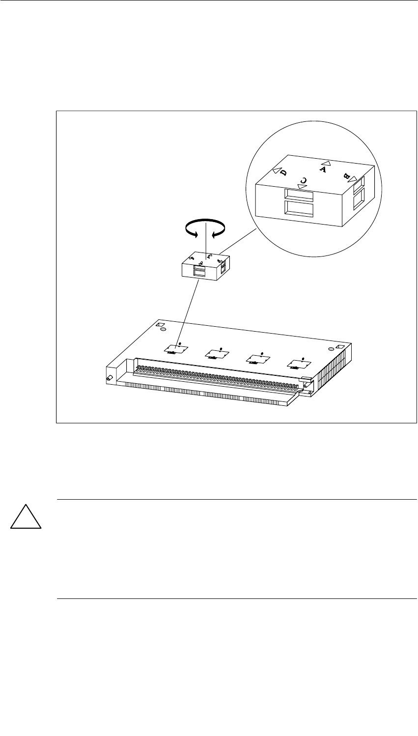
Analog Modules
5-30 S7-400, M7-400 Programmable Controllers Module Specifications
A5E00069467-07
2. Insert the measuring range module (correctly positioned (1)) into the analog
input module.
The measuring range selected is the one that points to marker point on
module (2).
1
2
Figure 5-2 Inserting the Measuring Range Module into the Analog Input Module
Perform the same steps for all other measuring range modules.
The next step is to install the module.
!Caution
This can result in damage.
If you have not set the measuring range modules correctly, the module may be
destroyed.
Make sure that the measuring range module is in the correct position before
connecting a sensor to the module.

Analog Modules
5-31
S7-400, M7-400 Programmable Controllers Module Specifications
A5E00069467-07
5.5 Behavior of the Analog Modules
Introduction
In this section, you will find information on:
•How the analog input and output values depend on the operating modes of the
CPU and the supply voltage of the analog module
•The behavior of the analog modules depending on where the analog values lie
within the value range
•The effect of errors on analog modules with diagnostics capability
•The effect of the operational limit of the analog module on the analog input and
output value, as illustrated by an example
5.5.1 Effect of Supply Voltage and Operating Mode
The input and output values of the analog modules depend on the operating mode
of the CPU and on the supply voltage of the module.
Table 5-38 Dependencies of the Analog Input/Output Values on the Operating Mode of the CPU and the
Supply Voltage L+
CPU Operating
Mode Supply Voltage L+ at
Analog Module Output Value of the Analog
Output Module Input Value of the
Analog Input Module*
POWER
ON
RUN L+ present CPU values Measured value
ON Until the first conversion...
•after power-up has been
completed, a signal of 0
mA or 0 V is output.
•after parameter
assignment has been
completed, the previous
value is output.
7FFFH until the first
conversion following
power-up or after
parameter assignment of
the module has been
completed
L+ missing 0 mA/0 V
POWER
ON
STOP L+ present Substitute value/last value
(default values: 0 mA/0 V)
Measured value
ON
(
de
f
ault values: 0 mA
/
0 V
)
7FFFH until the first
conversion following
power
-
up or after
L+ missing 0 mA/0 V
power
-
up or after
parameter assignment of
the module has been
completed
POWER
OFF
–L+ present 0 mA/0 V –
OFF L+ missing 0 mA/0 V –
* L+ only required with 2-wire transmitters

Analog Modules
5-32 S7-400, M7-400 Programmable Controllers Module Specifications
A5E00069467-07
Behavior on Failure of the Supply Voltage
Failure of the load power supply L+ of the diagnostics-capable analog module is
indicated in the case of parameterized two-wire transmitters by the EXTF LED on
the module. Furthermore, this information is made available on the module (entry in
diagnostic buffer).
Triggering of a diagnostic interrupt depends on the parameter assignment (see
Section 5.7).
5.5.2 Effect of Range of Values of the Analog Values
Effect of Errors on Analog Modules with Diagnostics Capability
Any errors that occur can lead to a diagnostics entry and a diagnostic interrupt with
analog modules with diagnostics capability and corresponding parameter
assignment. You will find the errors that might be involved in Section 5.16.
Effect of Range of Values on the Analog Input Module
The behavior of the analog modules depends on where the input values lie within
the range of values.
Table 5-39 Behavior of the Analog Input Modules as a Function of the Position of the
Analog Value Within the Range of Values
Measured
Value In Input Value LED
(EXTF) Diagnostics Interrupt
Rated range Measured
value – – –
Overrange/
underrange Measured
value – – –
Overflow 7FFFH Flashes1Entered1Diagnostic
interrupt1
Underflow 8000H Flashes1Entered1Diagnostic
interrupt1
Beyond the
programmed
limit
Measured
value – – Hardware interrupt1
1) Only for modules with diagnostics capability and depending on parameter assignment

Analog Modules
5-33
S7-400, M7-400 Programmable Controllers Module Specifications
A5E00069467-07
Effect of Range of Values on the Analog Output Module
The behavior of the analog modules depends on where the output values lie within
the value range.
Table 5-40 Behavior of the Analog Output Modules as a Function of the Position of the
Analog Value Within the Range of Values
Process Value
Lies Within Output Value LED
(EXTF) Diagnostics Interrupt
Rated range CPU value – – –
Overrange/und
errange CPU value – – –
Overflow 0 signal – – –
Underflow 0 signal – – –
5.5.3 Effect of Operational Limit and Basic Error Limit
Operational Limit
The operational limit is the measuring error or output error of the analog module
over the entire temperature range authorized for the module, referred to the rated
range of the module.
Basic Error Limit
The basic error limit is the operational limit at 25°C, referred to the rated range of
the module.
Note
The percentage details of operational and basic error limits in the technical
specifications of the module always refer to the highest possible input and output
value in the rated range of the module.
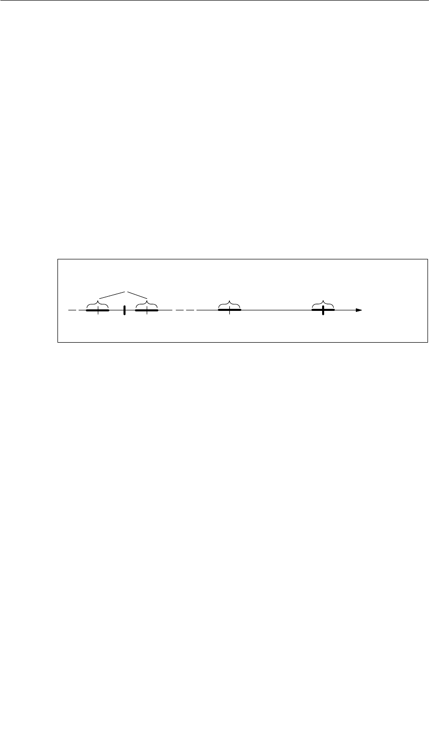
Analog Modules
5-34 S7-400, M7-400 Programmable Controllers Module Specifications
A5E00069467-07
Example of Determination of the Output Error of a Module
An analog output module SM 432; AO 8 13 Bit is being used for voltage output.
The output range “"10 V” is used. The module is operating at an ambient
temperature of 30°C. The operational limit thus applies. The technical
specifications of the module state:
•Operational limit for voltage output: "0.5%
An output error, therefore, of "0.05 V ("0.5% of 10 V) over the whole rated range
of the module must be expected.
This means that with an actual voltage of, say, 1 V, a value in the range from 0.95
V to 1.05 V is output by the module. The relative error is "5% in this case.
The figure below shows for the example how the relative error becomes
increasingly less the more the output value approximates to the end of the rated
range of 10 V.
(¢ "0.5%*)
1 V0 V
(¢ "0.625%)
Output Value
(¢ "5%)
8 V 10 V
* Operational limit
–1 V
"0.05 V
"0.05 V
"0.05 V
Figure 5-3 Example of the Relative Error of an Analog Output Module
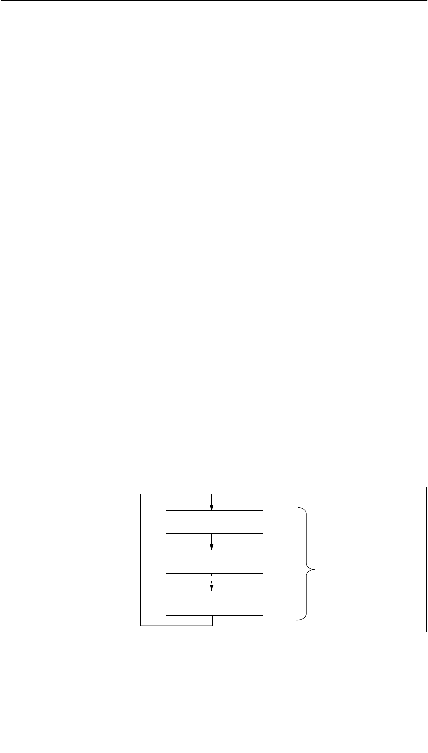
Analog Modules
5-35
S7-400, M7-400 Programmable Controllers Module Specifications
A5E00069467-07
5.6 Conversion, Cycle, Setting and Response Time of
Analog Modules
Conversion Time of Analog Input Channels
The conversion time consists of a basic conversion time and additional processing
times of the module for:
•Resistance test
•Wire-break monitoring
The basic conversion time depends directly on the conversion method of the
analog input channel (integrating method, instantaneous value conversion).
In the case of integrating conversion methods, the integration time has a direct
influence on the conversion time. The integration time depends on the interference
frequency suppression that you set in STEP 7 (refer to Section 4.3.1).
To find out the basic conversion times and additional processing times of the
different analog modules, refer to the technical specifications of the module
concerned, starting at Section 5.18.
Scan Time of Analog Input Channels
Analog-to-digital conversion and the transfer of the digitized measured values to
the memory and/or to the bus backplane are performed sequentially – in other
words, the analog input channels are converted one after the other. The scan time
– in other words, the time elapsing until an analog input value is again converted, is
the sum of the conversion times of all activated analog input channels of the analog
input module.
The following figure illustrates the components of the scan time for an n-channel
analog module.
Conversion time,
channel 1
Conversion time,
channel 2
Conversion time,
channel n
Cycle time
Figure 5-4 Scan Time of an Analog Input or Output Module

Analog Modules
5-36 S7-400, M7-400 Programmable Controllers Module Specifications
A5E00069467-07
Basic Execution Time of the Analog Input Channels
The basic execution time corresponds to the cycle time for all the enabled
channels.
Setting the Smoothing of Analog Values
You can set the smoothing of the analog values in STEP 7 for some analog input
modules.
Using Smoothing
Smoothing of analog values ensures a stable analog signal for further processing.
It makes sense to smooth the analog values with slow variations of measured
values – for example, with temperature measurements.
Smoothing Principle
The measured values are smoothed by digital filtering. Smoothing is accomplished
by the module calculating average values from a defined number of converted
(digitized) analog values.
The user assigns parameters to smoothing at not more than four levels (none, low,
average, high). The level determines the number of analog signals used for
averaging.
The higher the smoothing level chosen, the more stable is the smoothed analog
value and the longer it takes until the smoothed analog signal is applied after a
step response (refer to the following example).
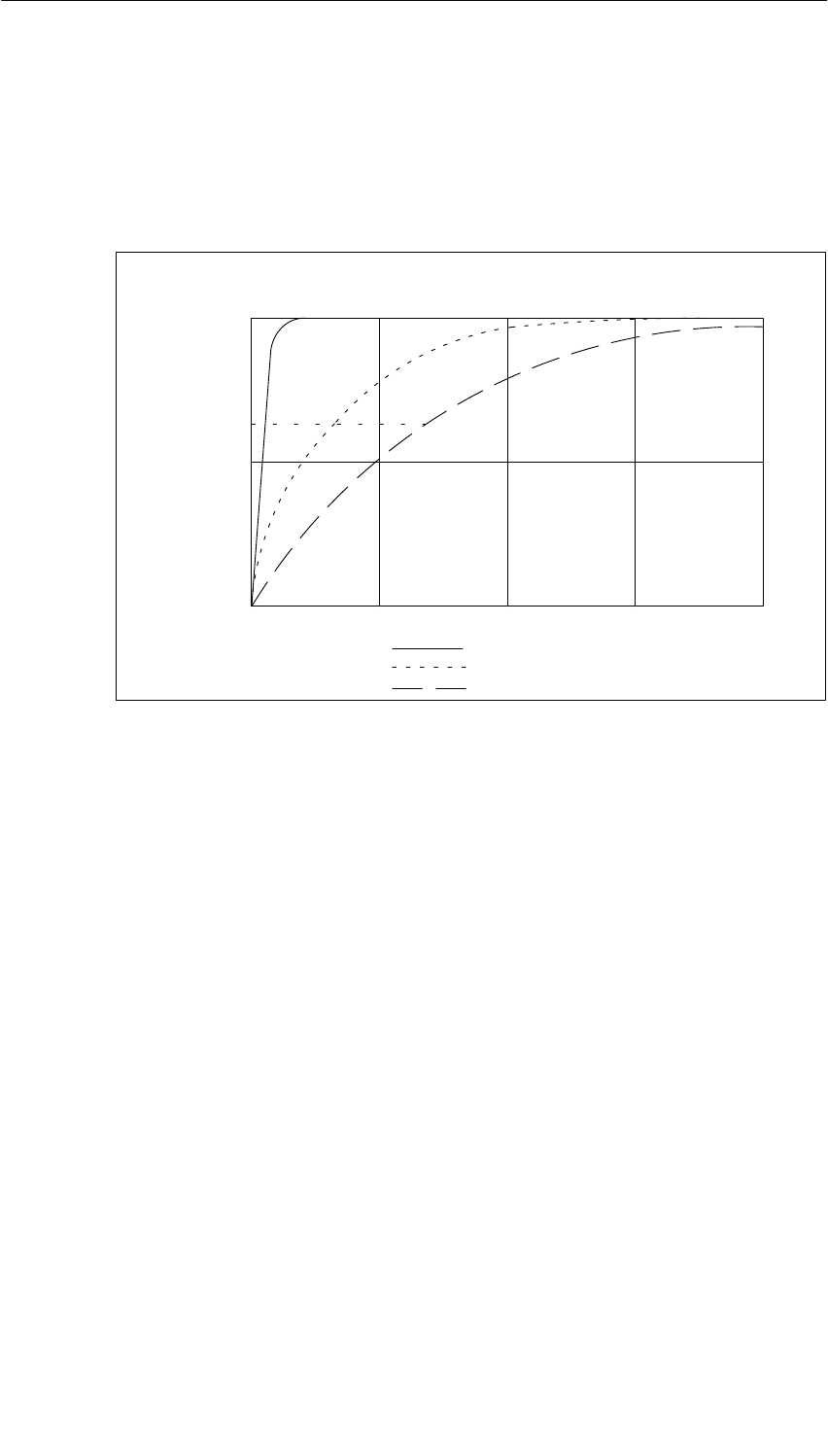
Analog Modules
5-37
S7-400, M7-400 Programmable Controllers Module Specifications
A5E00069467-07
Example
The following figure shows the number of module cycles for a step response after
which the smoothed analog value is approximately 100% applied, as a function of
the smoothing that has been set. The figure applies to every change of signal at
the analog input.
50
100
0
63
50 100 150 200
Smoothing: low:
average:
high:
Module cycles
Signal variation
in percent Step response for any analog input signal
Figure 5-5 Example of the Influence of Smoothing on the Step Response
Additional Information on Smoothing
Refer to the specific section on the analog input module (from Section 5.18) to
determine whether smoothing can be set for the specific module and for any
special features that have to be taken into account.
Conversion Time of the Analog Output Channels
The conversion time of the analog output channels comprises the transfer of the
digitized output values from the internal memory and the digital-to-analog
conversion.
Scan Time of Analog Output Channels
The analog output channels are converted sequentially – in other words, the
analog output channels are converted one after the other.
The scan time – in other words, the time elapsing until an analog output value is
again converted – is the sum of the conversion times of all activated analog output
channels (refer to 5-4).
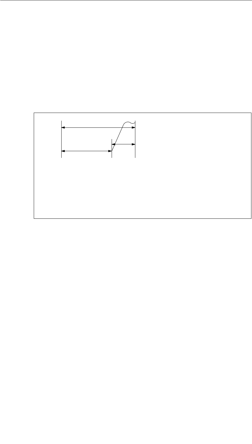
Analog Modules
5-38 S7-400, M7-400 Programmable Controllers Module Specifications
A5E00069467-07
Basic Execution Time of the Analog Output Channels
The basic execution time corresponds to the cycle time for all the enabled
channels.
Tip
You should disable any analog channels that are not being used to reduce the scan
time in STEP 7.
Overview of the Settling Time and Response Time of the Analog Output Modules
tA
tZ
tE
t1t2
tA = response time
tZ = cycle time corresponds to n conversion time (n = activated channels)
tE = settling time
t1 = new output value is present
t2 = output value transferred and converted
t3 = specified output value reached
t3
Figure 5-6 Settling and Response Times of the Analog Output Channels
Settling Time
The settling time (t2 to t3) – in other words, the time elapsing from application the
converted value until the specified value is reached at the analog output – is
load-dependent. A distinction is made between resistive, capacitive and inductive
loads.
For the settling times of the different analog output modules as a function of load
refer to the technical specifications of the module concerned, starting at
Section 5.25.
Response Time
The response time (t1 to t3) – in other words, the time elapsing from application of
the digital output values in the internal memory until the specified value is reached
at the analog output – in a worst case scenario is the sum of the scan time and the
settling time.
You have a worst case situation if, shortly prior to the transfer of a new output
value, the analog channel has been converted and is not converted again until all
other channels are converted (cycle time).

Analog Modules
5-39
S7-400, M7-400 Programmable Controllers Module Specifications
A5E00069467-07
5.7 Analog Module Parameter Assignment
Introduction
Analog modules can have different characteristics. You can set the characteristics
of the modules by means of parameter assignment.
Tools for Parameter Assignment
You assign parameters to analog modules with STEP 7. You must perform
parameter assignment in STOP mode of the CPU.
When you have set all the parameters, download the parameters from the
programming device to the CPU. When there is a transition from STOP to RUN
mode, the CPU transfers the parameters to the individual analog modules.
In addition, if necessary you must place the measuring range modules of the
module in the necessary position (refer to Section 5.4).
Static and Dynamic Parameters
The parameters are divided into static and dynamic parameters.
Set the static parameters in STOP mode of the CPU, as described above.
You can similarly modify the dynamic parameters in the current user program by
means of SFCs. Note, however, that after a change from RUN ³ STOP, STOP ³
RUN of the CPU, the parameters set in STEP 7 apply again. You will find a
description of the parameter assignment of modules in the user program in
Appendix A.
Table 5-41 Static and dynamic parameters of the analog groups
Parameter Settable with CPU Operating
Mode
Static PG (STEP 7 HWCONFIG) STOP
Dynamic PG (STEP 7 HWCONFIG) STOP
SFC 55 in the user program RUN

Analog Modules
5-40 S7-400, M7-400 Programmable Controllers Module Specifications
A5E00069467-07
5.7.1 Parameters of the Analog Input Modules
The analog input modules use a subset of the parameters and ranges of values
listed in the table below, depending on the functionality. Refer to the section on the
module concerned, starting from Section 5.18, to find out which subset the module
is capable of using.
The default settings apply if you have not performed parameter assignment in
STEP 7.
Table 5-42 Parameters of the Analog Input Modules
Parameter Value Range Default2) Parameter
Type Scope
Enable
•Diagnostic interrupt1)
•Hardware interrupt1)
Yes/no
Yes/no
No
No Dynamic Module
•Destination CPU for
interrupt 1 to 4 –Static Module
Trigger for hardware
interrupt
•End of scan cycle
reached at input Yes/no No Static Channel
•High limit
•Low limit
Constraint possible due to measuring
range
32511 to – 32512
– 32512 to 32511
– Dynamic Channel
Diagnostics
•Wire break
•Reference channel
error
•Underflow
•Overflow
•Short circuit to M
Yes/no
Yes/no
Yes/no
Yes/no
Yes/no
No
No
No
No
No
Static Channel
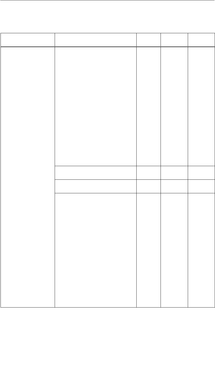
Analog Modules
5-41
S7-400, M7-400 Programmable Controllers Module Specifications
A5E00069467-07
Table 5-42 Parameters of the Analog Input Modules, continued
Parameter ScopeParameter
Type
Default2)
Value Range
Measurement
•Measuring type Disabled
U Voltage
4DMU Current
(four-wire transmitter)
2DMU Current
(two-wire transmitter)
R-4L Resistance
(four-conductor connection)
R-3L Resistance
three-conductor connection
RTD-4L Thermal resistor
(linear, four-conductor
connection)
RTD-3L Thermal resistor
(linear, three-conductor
connection)
TC-L Thermocouple (linear)
U
Static Channel
•Measuring range For the settable measuring ranges of
the input channels, please refer to the
individual module description.
"10 V
•Reference
temperature – 273.15 to 327.67 oC0 oCDynamic Module
•Temperature unit Degrees Celsius; degrees Fahrenheit;
Kelvins Degrees
Celsius Static Module
•Temperature
coefficient for
temperature
measurement with
thermal resistor
(RTD)
Platinum (Pt)
0.00385 /°C
0.003916 /°C
0.003902 /°C
0.003920 /°C
Nickel (Ni)
0.00618 /°C
0.00672 /°C
0.00385
Static Channel
•Interference
frequency
suppression
400 Hz; 60 Hz; 50 Hz; 10 Hz; none 50 or 60
Hz
•Smoothing None
Low
Average
High
None
•Reference junction None
Internal
RTD on channel 0
Reference temperature value dynamic
None
1) If you use the module in ER-1/ER-2, you must set this parameter to “No” because the interrupt lines are
not available in ER-1/ER-2.
2) Only in the CC (central controller) is it possible to start up the analog modules with the default settings.

Analog Modules
5-42 S7-400, M7-400 Programmable Controllers Module Specifications
A5E00069467-07
5.7.2 Parameters of the Analog Output Modules
The analog output modules use a subset of the parameters and ranges of values
listed in the table below, depending on the functionality. Refer to the section on the
module concerned, starting from Section 5.25, to find out which subset the module
is capable of using.
The default settings apply if you have not performed parameter assignment in
STEP 7.
Table 5-43 Parameters of the Analog Output Modules
Parameter Value Range Default1Parameter
Type Scope
Output
•Type of output Disabled
Voltage
Current
U
Static Channel
•Output range For the settable measuring ranges of the
output channels, please refer to the
individual module description.
"10 V
1) Only in the CC (central controller) is it possible to start up the analog modules with the default settings.

Analog Modules
5-43
S7-400, M7-400 Programmable Controllers Module Specifications
A5E00069467-07
5.8 Connecting Sensors to Analog Inputs
Introduction
You can connect different sensors to the analog input modules depending on the
measuring method; voltage and current sensors, and resistors.
This section contains general information that is generally applicable to all the
connection options for sensors described in the sections that follow.
Cables for Analog Signals
To reduce electrical interference, you should use twisted-pair shielded cables for
the analog signals. The shield of the analog signal cables should be grounded at
both cable ends.
If there are potential differences between the cable ends, an equipotential bonding
current can flow over the shield, which leads to an interference of the analog
signals. In such a case, you should ground the shield at one end of the cable only.
Non-Isolated Analog Input Modules
In the case of the non-isolated analog input modules there is an electrical
connection between the reference point of the measuring circuit MANA and chassis
ground.
You use non-isolated analog modules if there are few or no potential differences
between the measuring sensors and chassis ground.
Isolated Analog Input Modules
With the isolated analog input modules there is no electrical connection between
the reference point of the measuring circuit MANA and chassis ground.
You use isolated analog input modules if a potential difference UISO can occur
between the reference point of the measuring circuit MANA and chassis ground. By
means of an equipotential bonding conductor between the MANA terminal and
chassis ground, make sure that UISO does not exceed the permitted value.
Limited Potential Difference UCM
Only a limited potential difference UCM (common mode voltage) may occur
amongst the M– measuring lines of the input channels and between the leads and
the reference point of the measuring circuit MANA. In order to prevent the
permissible value from being exceeded, you must take different actions, described
below, depending on the potential connection of the sensors.
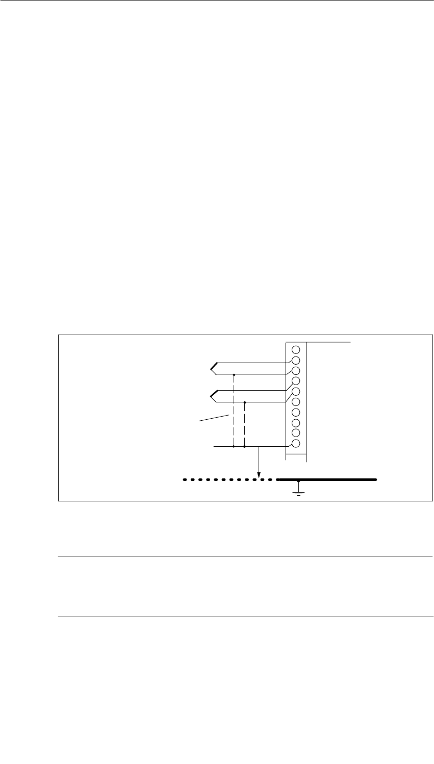
Analog Modules
5-44 S7-400, M7-400 Programmable Controllers Module Specifications
A5E00069467-07
Abbreviations and Mnemonics Used in the Figures Below
The abbreviations and mnemonics used in the figures below have the following
meanings:
M +: Measuring line (positive)
M –: Measuring line (negative)
MANA: Reference potential of the analog measuring circuit
UCM: Potential difference between inputs and reference potential of
the MANA measuring circuit
UISO: Potential difference between MANA and chassis ground
Connection of Isolated Measuring Sensors
The isolated sensors are not connected with the local ground potential (local
ground). They can be operated free of potential.
With isolated sensors, potential differences might arise between the different
sensors. These potential differences can arise as a result of interference or the
local distribution of the sensors.
To ensure that the permissible value for UCM is not exceeded during use in heavily
EMC-affected environments, connect M– to MANA in modules with an MANA
connection.
M+
M–
UISO
M+
M–
MANA
Connection required
for modules with
MANA
Chassis ground
Isolated
sensors
Figure 5-7 Connecting Isolated Sensors to an Isolated AI
Note
Do not connect M– to MANA when connecting two-wire transmitters for current
measurement and when connecting resistance-type sensors. This also applies to
inputs which are not used.
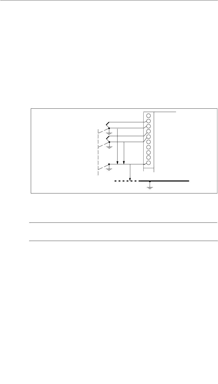
Analog Modules
5-45
S7-400, M7-400 Programmable Controllers Module Specifications
A5E00069467-07
Non-Isolated Sensors
The non-isolated sensors are connected with the local ground potential (local
ground). When using non-isolated sensors, you must connect MANA to chassis
ground.
Connecting Non-Isolated Sensors
Caused by local conditions or interference, potential differences UCM (static or
dynamic) can occur between the locally distributed individual measuring points. If
the potential difference UCM exceeds the permissible value, you must provide
equipotential bonding conductors between the measuring points.
M+
M–
UISO
M+
M–
MANA
Chassis ground
Non-isolated
sensors
UCM
Equipotential
bonding conductor
Figure 5-8 Connecting Non-Isolated Sensors to an Isolated AI
Note
Do not use non-isolated two-wire transmitters and non-isolated resistance sensors!
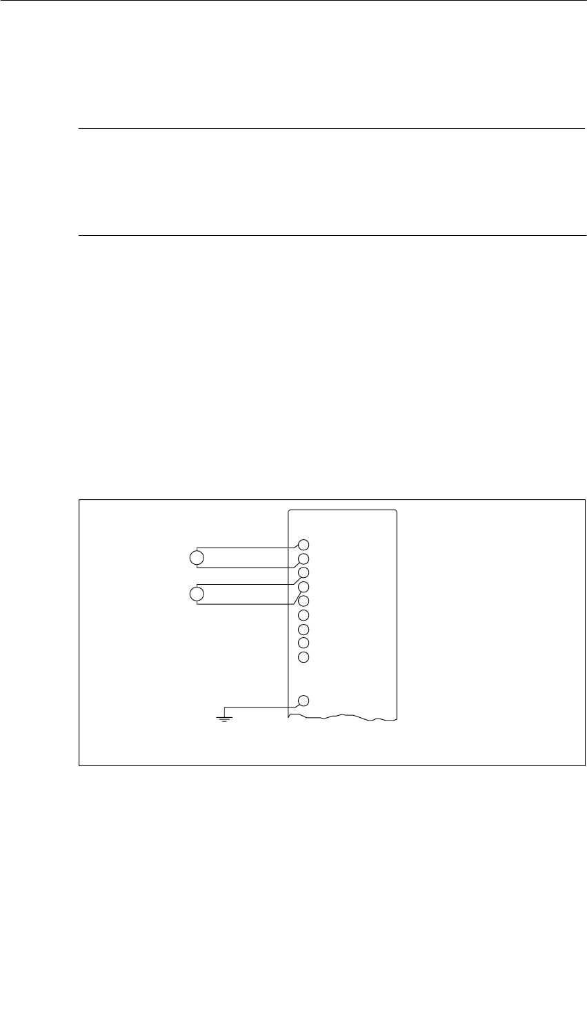
Analog Modules
5-46 S7-400, M7-400 Programmable Controllers Module Specifications
A5E00069467-07
5.9 Connecting Voltage Sensors
Note
The necessary connecting cables, which result from the potential connection of the
analog input module and the sensors, are not drawn in the figures shown below.
In other words, you must continue to take note of and implement Section 5.8 with
its generally applicable information on connecting sensors.
Abbreviations and Mnemonics Used in the Figure Below
The abbreviations and mnemonics used in the figure below have the following
meanings:
M +: Measuring line (positive)
M –: Measuring line (negative)
MANA: Reference potential of the analog measuring circuit
Connection of Voltage Sensors
+
–
U
+
–
U
M+
M–
M+
MANA*
M–
* Connection required in the case of modules with MANA
Figure 5-9 Connecting Voltage Sensors to an AI

Analog Modules
5-47
S7-400, M7-400 Programmable Controllers Module Specifications
A5E00069467-07
5.10 Connecting Current Sensors
Note
The necessary connecting cables, which result from the potential connection of the
analog input module and the sensors, are not drawn in the figures shown below.
In other words, you must continue to take note of and implement Section 5.8 with
its generally applicable information for connecting sensors.
Abbreviations and Mnemonics Used in the Figures Below
The abbreviations and mnemonics used in the figures below have the following
meanings:
M +: Measuring line (positive)
M –: Measuring line (negative)
MANA: Reference potential of the analog measuring circuit
M : Ground terminal
L +: Terminal for 24 VDC supply voltage
UH: Auxiliary supply
MI+: Current measuring line (positive)
MV+: Voltage measuring line (positive)
Supply Voltage of the Sensors
The two-wire transmitter receives its short-circuit-proof power supply via the
terminals of the analog input module.
This transmitter then converts the measured variable into a current.
Because the two-wire transmitter is supplied by the module, you must not ground
the M- cables.
Four-wire transmitters require a separate supply voltage UH (auxiliary supply).
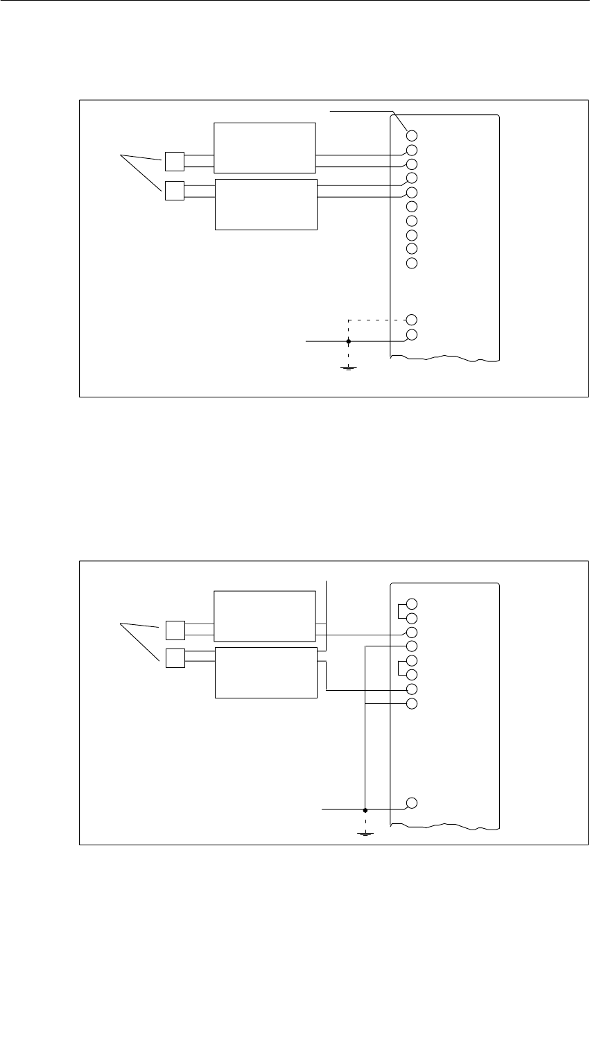
Analog Modules
5-48 S7-400, M7-400 Programmable Controllers Module Specifications
A5E00069467-07
Connecting Two-Wire Transmitters
+24 V
Sensor, for example,
pressure gauge +
–
L +
M+
M-
M+
M-
M
Two-wire
transmitter
Two-wire
transmitter
+
–
M
P
P
MANA
* Connection required in the case of modules with MANA
*
Figure 5-10 Connecting Two-Wire Transmitters to an Isolated AI
SM 431; 8 x 13 Bit: Connecting Two-Wire Transmitters
Because the supply voltage for the two-wire transmitters is not fed by the SM 431;
8 x 13 Bit, you must supply the sensors separately with 24 V.
+24 V
Sensor, for example,
pressure gauge +
–MI+
M–
Two-wire
transmitter
Two-wire
transmitter
+
–
MANA
MV+
MV+
MI+
M–
MI+
MI+
M
P
P
Figure 5-11 Connecting Two-Wire Transmitters to an SM 431; 8 x 13 Bit
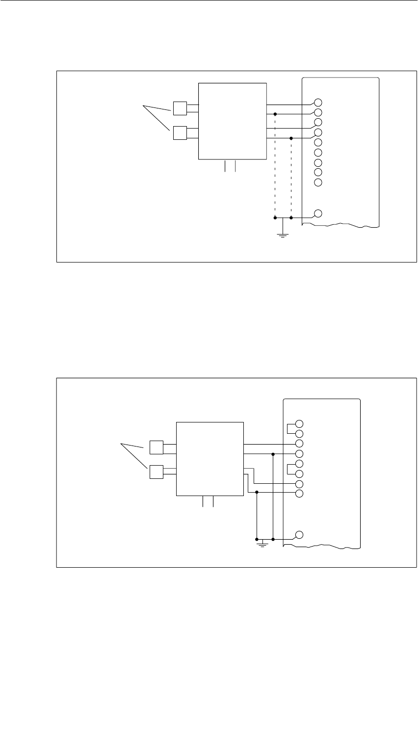
Analog Modules
5-49
S7-400, M7-400 Programmable Controllers Module Specifications
A5E00069467-07
Connecting Four-Wire Transmitters
M+
M–
M+
M–
MANA
Sensor,
for example,
pressure gauge
+
–
Four-wire
transmitter +
–
U H
* Connection required in the case of modules with MANA
P
P
**
Figure 5-12 Connecting Four-Wire Transmitters to an AI
SM 431; 8 x 13 Bit: Connecting Four-Wire Transmitters
To ensure that the permissible value for UCM is not exceeded, you must connect
the M– cables to MANA.
M
Sensor, for example,
pressure gauge +
–
Four-wire
transmitter +
–
U H
MI+
MI+
M–
MV+
MV+
MI+
MI+
M–
P
P
Figure 5-13 Connecting Four-Wire Transmitters to an SM 431; 8 x 13 Bit

Analog Modules
5-50 S7-400, M7-400 Programmable Controllers Module Specifications
A5E00069467-07
5.11 Connecting Resistance Thermometers and Resistors
Note
The necessary connecting cables, which result from the potential connection of the
analog input module and the sensors, are not drawn in the figures shown below.
In other words, you must continue to take note of and implement Section 5.8 with
its generally applicable information for connecting sensors.
Abbreviations and Mnemonics Used in the Figures Below
The abbreviations and mnemonics used in the figures below have the following
meanings:
IC+: Constant-current lead (positive)
IC–: Constant-current lead (negative)
M+: Measuring line (positive)
M–: Measuring line (negative)
Connecting Resistance Thermometers and Resistors
The resistance thermometers/resistors are wired in a four-conductor,
three-conductor or two-conductor connection.
With four-conductor and three-conductor connections, the module supplies a
constant current via terminals IC + and IC – so that the potential drop occurring on
the measuring cables is compensated. It is important that the connected constant
current cables are directly connected to the resistance thermometer/resistor.
Measurements with four-conductor or three-conductor connections supply a more
precise measuring result due to compensation than measurements with a
two-conductor connection.
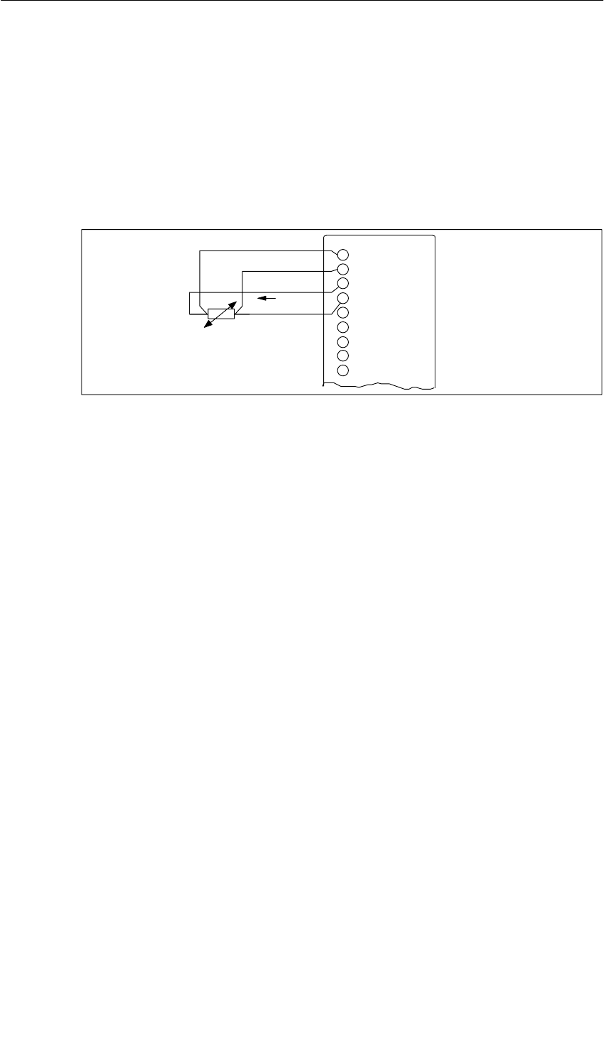
Analog Modules
5-51
S7-400, M7-400 Programmable Controllers Module Specifications
A5E00069467-07
Four-Conductor Connection of a Resistance Thermometer
The voltage generated at the resistance thermometer is measured via the M+ and
M– terminals. When you connect, watch out for the polarity of the connected cable
(connect IC + and M+ as well as IC – and M– to the resistance thermometer).
Make sure that the connected cables IC + and M+ and SO and SE+ and cables
IC – and M– and AGND and SE– are connected directly on the resistance
thermometer.
IC
M+
M–
IC+
IC–
SE+
SE–
SO
AGND
Figure 5-14 Four-Conductor Connection of Resistance Thermometers on an AI

Analog Modules
5-52 S7-400, M7-400 Programmable Controllers Module Specifications
A5E00069467-07
Three-Conductor Connection of a Resistance Thermometer
During three-conductor connection to modules with 4 terminals per resistance
thermometer, you must set up a jumper between M– and IC– and SE– and
AGND (see Figure 5-15).
The module compensates in this circuit for the effect of the line resistance between
the module and the resistance thermometer/resistor.
Make sure that the connected cables IC + and M+ and the cables SO and SE+ are
directly connected to the resistance thermometer.
To get an accurate measurement, make sure that the connected cables M+, IC +
and IC– and the cables SE+, SO and AGND are the same length and have the
same cross-section.
IC
M+
M–
IC+
IC–
SE+
SE–
SO
AGND
Figure 5-15 Three-Wire Connection of Resistance Thermometers to an AI
Two-Conductor Connection of a Resistance Thermometer
With a two-conductor connection, you must insert jumpers on the module between
M+ and IC+ and between M– and IC–.
Note: Cable resistance is also measured.
M+
M–
IC+
IC–
Figure 5-16 Two-Wire Connection of Resistance Thermometers to an AI
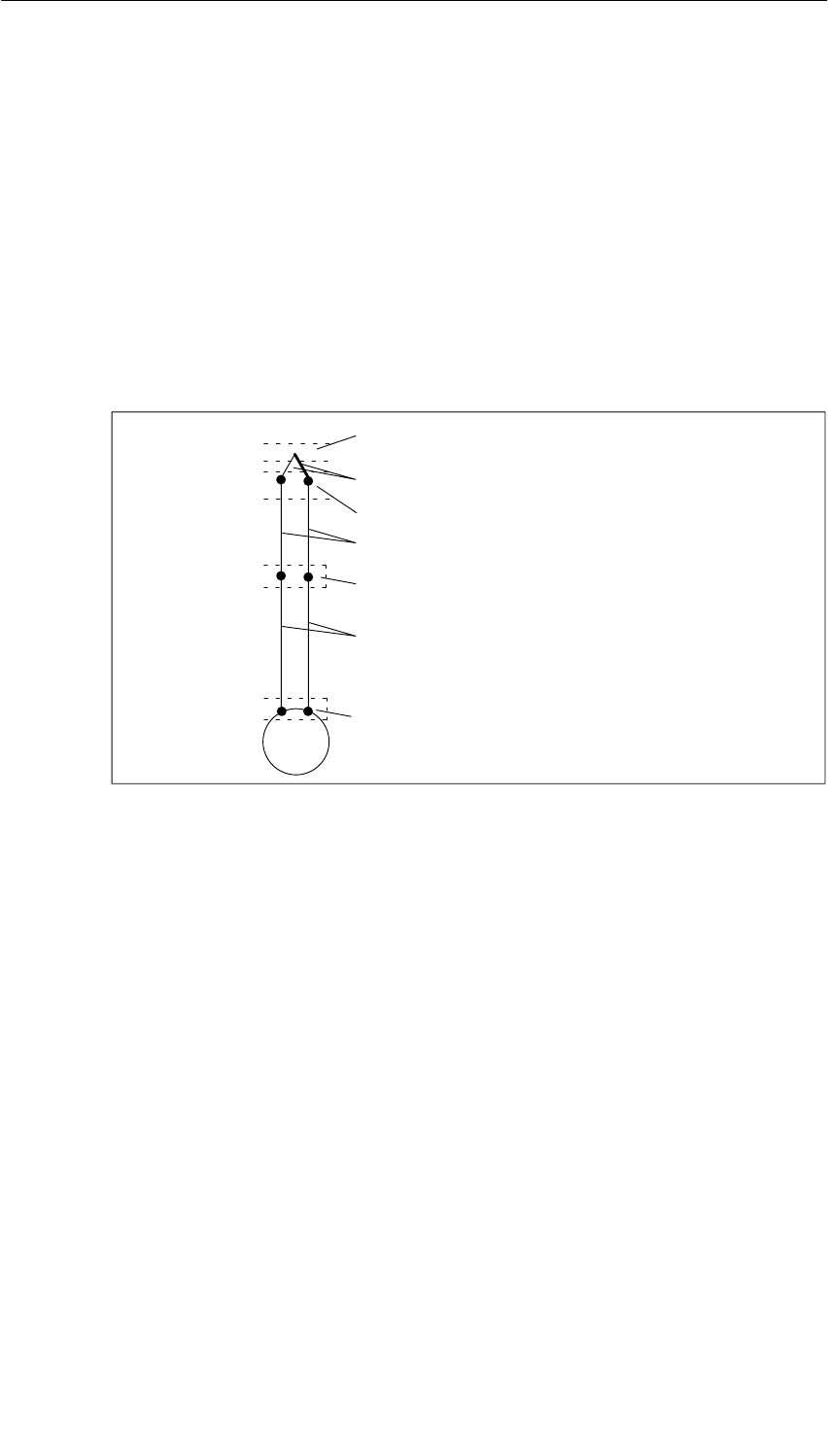
Analog Modules
5-53
S7-400, M7-400 Programmable Controllers Module Specifications
A5E00069467-07
5.12 Connecting Thermocouples
Design of Thermocouples
A thermocouple consists of a pair of sensors and the necessary installation and
connecting parts. The thermocouple consists of two wires of dissimilar metals or
metal alloys soldered or welded together at the ends.
There are different types of thermocouple, depending on the composition of the
material used – for example, K, J, N thermocouples. The measuring principle of all
thermocouples is the same, irrespective of their type.
(°(C
Leads
Compensating leads
Reference
junction
Connecting point
Thermocouple with positive or
negative limbs
Measuring junction
Measurement input
Figure 5-17 Design of Thermocouples
Principle of Operation of Thermocouples
If the measuring point is subjected to a temperature different from that of the free
ends of the thermocouple (point of connection), a voltage, the thermo emf, occurs
at the free ends. The magnitude of the thermo-e.m.f. generated depends on the
difference between the temperature at the measuring junction and the temperature
at the free ends, as well as on the material combination used for the thermocouple.
Since a thermocouple always measures a temperature difference, the free ends
must be kept at a known temperature at a reference junction in order to determine
the temperature of the measuring junction.
The thermocouples can be extended from their point of connection to the reference
junction by means of compensating wires. These compensating wires consist of
the same material as the thermocouple wires. The supply leads are copper wire.
Note: Make sure these wires are connected with the correct polarity, otherwise
there will be considerable measuring errors.

Analog Modules
5-54 S7-400, M7-400 Programmable Controllers Module Specifications
A5E00069467-07
Compensation of the Reference Junction Temperature
There are several options for you to choose from for acquiring the reference
junction temperature in order to obtain an absolute temperature value from the
difference in temperature between the reference junction and measuring point.
You can use internal or external compensation, depending on where you want the
reference junction to be.
The last column of the following table lists the feature you must set for the
“Reference Junction” parameter in STEP 7. The reference temperature value is a
separate parameter in STEP 7.
Table 5-44 Options for Compensation of the Reference Junction Temperature
Option Explanation Ref.
Junction
No compensation
(refer to Figure 5-18 for connection) When you want to acquire only the difference in
temperature between the measuring point and the
reference junction
None
Internal compensation
(refer to Figure 5-18 for connection) If you employ internal compensation, the internal
temperature of the module is used for comparison
purposes.
Internal
External compensation with a
compensating box in leads of an
individual thermocouple
(see Figure 5-19 for connection)
You have already acquired and compensated the
reference junction temperature using a
compensating box, which you have looped into an
individual thermocouple.
No further processing is necessary owing to the
module.
None
External compensation with a
resistance thermometer to obtain
the reference junction temperature
(recommended method)
(see Figure 5-20 for connection)
You can acquire the reference temperature by
means of a resistance thermometer (pt 100) and
have it calculated by the module for any
thermocouple.
RTD on
Channel 0
External compensation with a
resistance thermometer when
thermocouples with the same
reference junction are divided
amongst several modules
(see Figure 5-20 for connection)
Use a resistance thermometer on a module that
measures the reference junction temperature. Read
in the climatic temperature value to the CPU and
transfer the value to the other modules using
SFC55.
RTD on
Channel 0
Constant reference junction
temperature (thermometer, ice bath;
see Figure 5-18 for connection)
If the reference junction temperature is constant
and known, you can specify this value in parameter
assignment in STEP 7.
Reference
temperature
value

Analog Modules
5-55
S7-400, M7-400 Programmable Controllers Module Specifications
A5E00069467-07
Theory of Operation of Internal Compensation
With internal compensation, you can establish the reference point across the
terminals of the analog input modules. In this case, you must run the compensating
lines right up to the analog module. The internal temperature sensor acquires the
temperature of the module and supplies a compensation voltage.
Note that internal compensation is not as accurate as external compensation.
Theory of Operation of External Compensation with Compensating Box
If you employ external compensation, the temperature of the reference junction of
the thermocouples is taken into account via a compensating box, for example.
The compensating box contains a bridge circuit calibrated for a definite reference
junction temperature. The reference junction is formed by the connections for the
ends of the thermocouple’s compensating leads.
If the actual temperature deviates from the compensating temperature, the
temperature-sensitive bridge resistance changes. This results in a positive or
negative compensating voltage, which is added to the thermo-e.m.f.
Abbreviations and Mnemonics Used in the Figures Below
The abbreviations and mnemonics used in the figures below have the following
meanings:
M +: Measuring line (positive)
M –: Measuring line (negative)
IC+: Constant-current lead (positive)
IC–: Constant-current lead (negative)
Note
The necessary connecting cables, which result from the potential connection of the
analog input module and the sensors, are not drawn in the figures shown below.
In other words, you must continue to take note of and implement Section 5.8 with
its generally applicable information for connecting sensors.
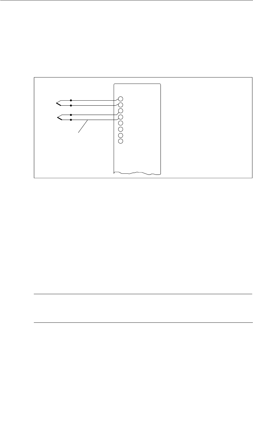
Analog Modules
5-56 S7-400, M7-400 Programmable Controllers Module Specifications
A5E00069467-07
Connection of Thermocouples without Compensation or Using the Reference
Temperature Value
Connect the thermocouples to the inputs of the module, either directly or by means
of compensating lines. Each channel can use a thermocouple type supported by
the analog module independently of the other channels.
M+
M–
M+
M–
Compensating leads
(same material as
thermocouple)
Figure 5-18 Connection of Thermocouples without Compensation or Using the Reference
Temperature Value to an Isolated AI
Connecting the Compensating Box
The compensating box is looped in in the leads of each thermocouple. The
compensating box must have an isolated supply. The power supply must have
adequate filtering, for example by means of a grounded shielding winding.
Each channel can use a thermocouple type supported by the analog module
independently of the other channels. Each channel requires its own compensating
box.
Note
Use compensating boxes with a reference junction temperature of 0 C for
analog input modules.
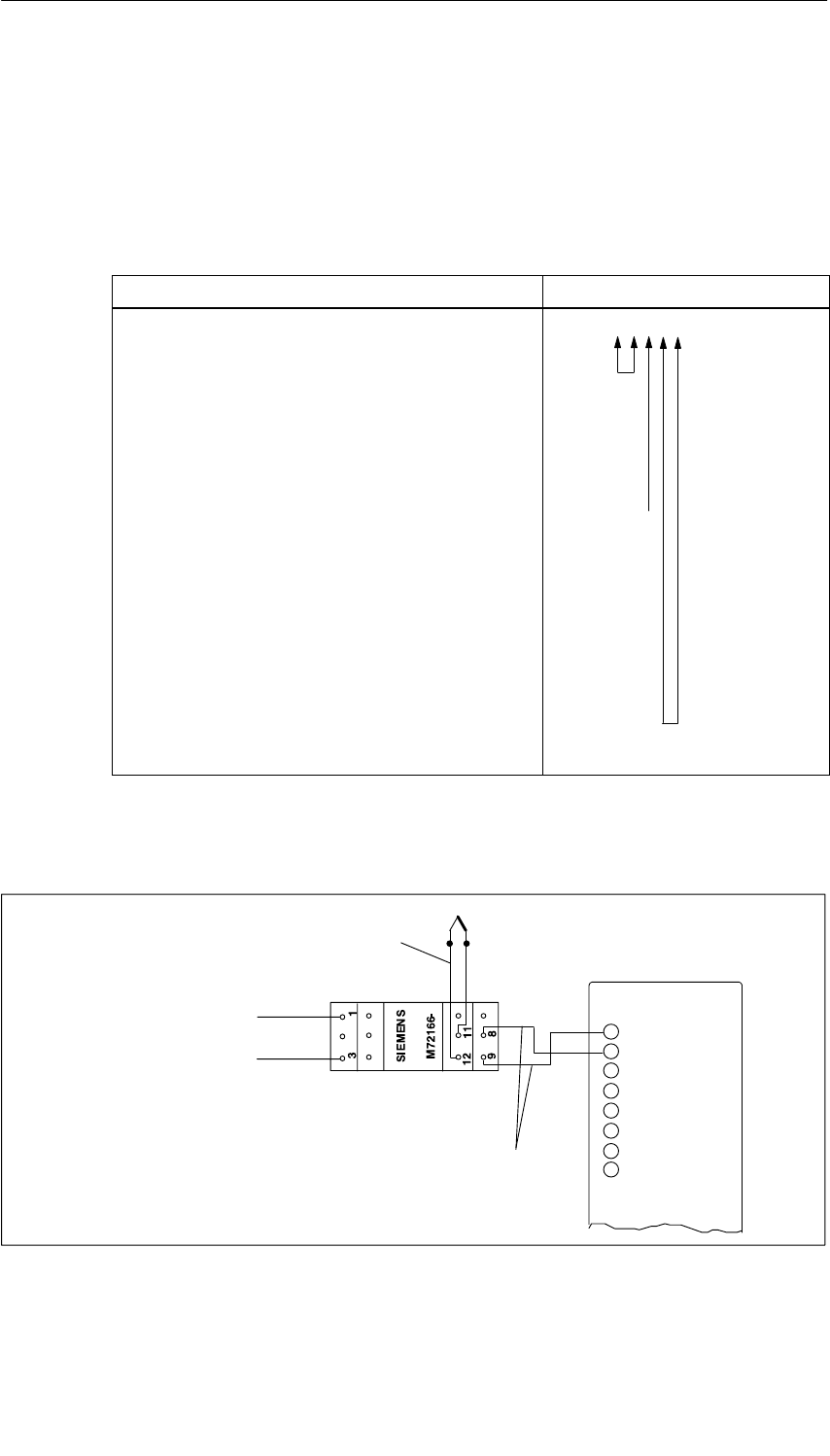
Analog Modules
5-57
S7-400, M7-400 Programmable Controllers Module Specifications
A5E00069467-07
Recommended Compensating Box
We recommend you to use a comparison point (with integrated power supply unit)
from Siemens as a compensating box. You will find the necessary ordering data in
the table below.
Table 5-45 Ordering Data of the Comparison Point
Recommended Compensating Box Order Number
Reference junction with integrated power supply
unit, for rail mounting
Auxiliary power 220 VAC
110 VAC
24 VAC
24 VDC
Connection to thermocouple Fe-CuNi Type L
Fe/Cu Ni Type J
Ni Cr/Ni Type K
Pt 10% Rh/Pt Type S
Pt 13% Rh/Pt Type R
Cu-CuNi Type U
Cu/Cu Ni Type T
Reference temperature 0 C
M72166-
B
1
B
2
B
3
B
4
1
2
3
4
5
6
7
0
0
Connecting to the Comparison Point (Order No. M72166-xxx00)
Output
(Cu wires)
M+
M–
M+
M–
Compensating leads (same
material as thermocouple)
+
––
+
–
Auxiliary power
+
Figure 5-19 Connection of a Thermocouple with Reference Junction (Order No. M72166-xxx00) to an
Isolated AI
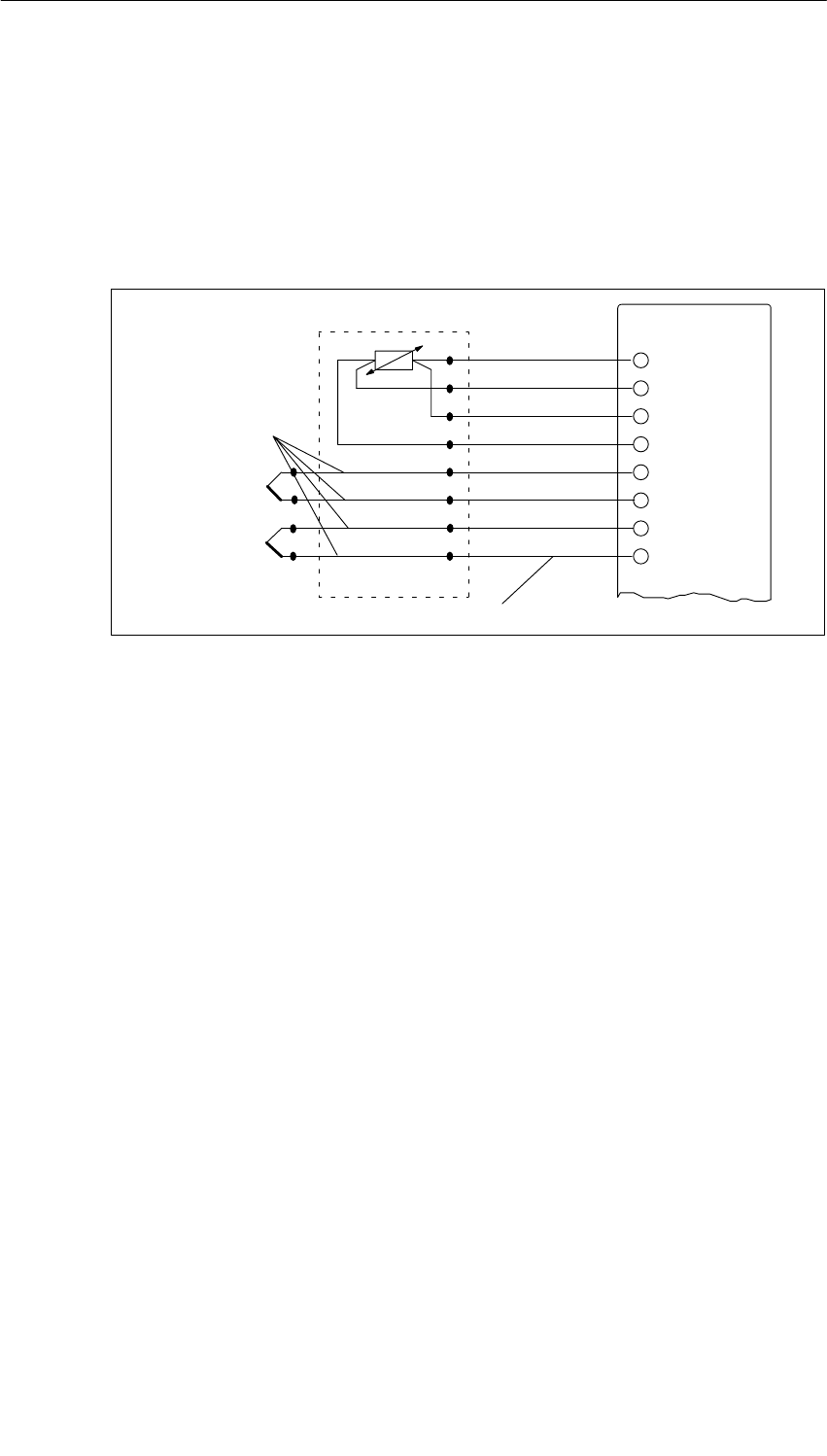
Analog Modules
5-58 S7-400, M7-400 Programmable Controllers Module Specifications
A5E00069467-07
Connecting Thermocouples and Resistance Thermometers
Connect the resistance thermometer to channel 0 of the module. Make sure that
you parameterize the “RTD on Channel 0“ reference junction in STEP 7 for each
channel that has a thermocouple connected to it.
If all thermocouples connected to the inputs of the module have the same
comparison point, you compensate as follows:
M+
M–
M+
M–
Reference
junction Incoming line (Cu)
Equalizing line (same
material as
thermocouple)
M–
I
I
C+
C–
M+
RTD on Channel 0
Figure 5-20 Connection of Thermocouples of the Same Type with External Compensation
by Means of a Resistance Thermometer, Connected to Channel 0

Analog Modules
5-59
S7-400, M7-400 Programmable Controllers Module Specifications
A5E00069467-07
5.13 Connecting Loads/Actuators to Analog Outputs
Introduction
You can use the analog output modules to supply loads and actuators with current
and voltage.
This section contains general information that is generally applicable to all the
connection options for loads and actuators described in the sections that follow.
Cables for Analog Signals
For the analog signals, you should use shielded and twisted pair cables. The cables
QV and S+ and M and S–, respectively, are to be twisted together. This reduces the
interference. Ground the screen of the analog cables at both ends of the cables.
If there are potential differences between the cable ends, an equipotential
bonding current, which can flow over the shield, can cause interference of the
analog signals. In such a case, you should ground the shield at one end of the
cable only.
Isolated Analog Output Modules
With the isolated analog output modules there is no electrical connection between
the reference point of the measuring circuit MANA and chassis ground.
You must use isolated analog output modules if a potential difference UISO can
occur between the reference point of the measuring circuit MANA and chassis
ground. By means of an equipotential bonding conductor between the MANA
terminal and chassis ground, make sure that UISO does not exceed the permitted
value.

Analog Modules
5-60 S7-400, M7-400 Programmable Controllers Module Specifications
A5E00069467-07
5.14 Connecting Loads/Actuators to Voltage Outputs
Connecting Loads to a Voltage Output
Connecting loads to a voltage output is possible both in a four-conductor and a
two-conductor connection.
Note
The necessary connecting cables, which result from the potential connection of the
analog output module, are not drawn in the figures shown below.
In other words, you must continue to take note of and implement Section 5.13 with
its generally applicable information for connecting loads and actuators.
Abbreviations and Mnemonics Used in the Figures Below
The abbreviations and mnemonics used in the figures below have the following
meanings:
QV: Analog output voltage
S +: Detector lead (positive)
S –: Detector lead (negative)
MANA: Reference potential of analog circuit
RL: Load impedance
L +: Terminal for 24 VDC supply voltage
M : Ground terminal
UISO: Potential difference between MANA and chassis ground
Four-Conductor Connection of Loads to a Voltage Output
A high accuracy at the load can be achieved through the four-conductor
connection. You must therefore connect the sensor leads (S– and S+) directly to
the load. The voltage is thus measured and corrected directly at the load.
Problems or a voltage drop can result in a potential difference between the sensor
lead S– and the reference circuit of the analog circuit MANA. This potential
difference (UCM) must not exceed the permissible value. If the permissible potential
difference is exceeded, the accuracy of the analog signal is impaired.
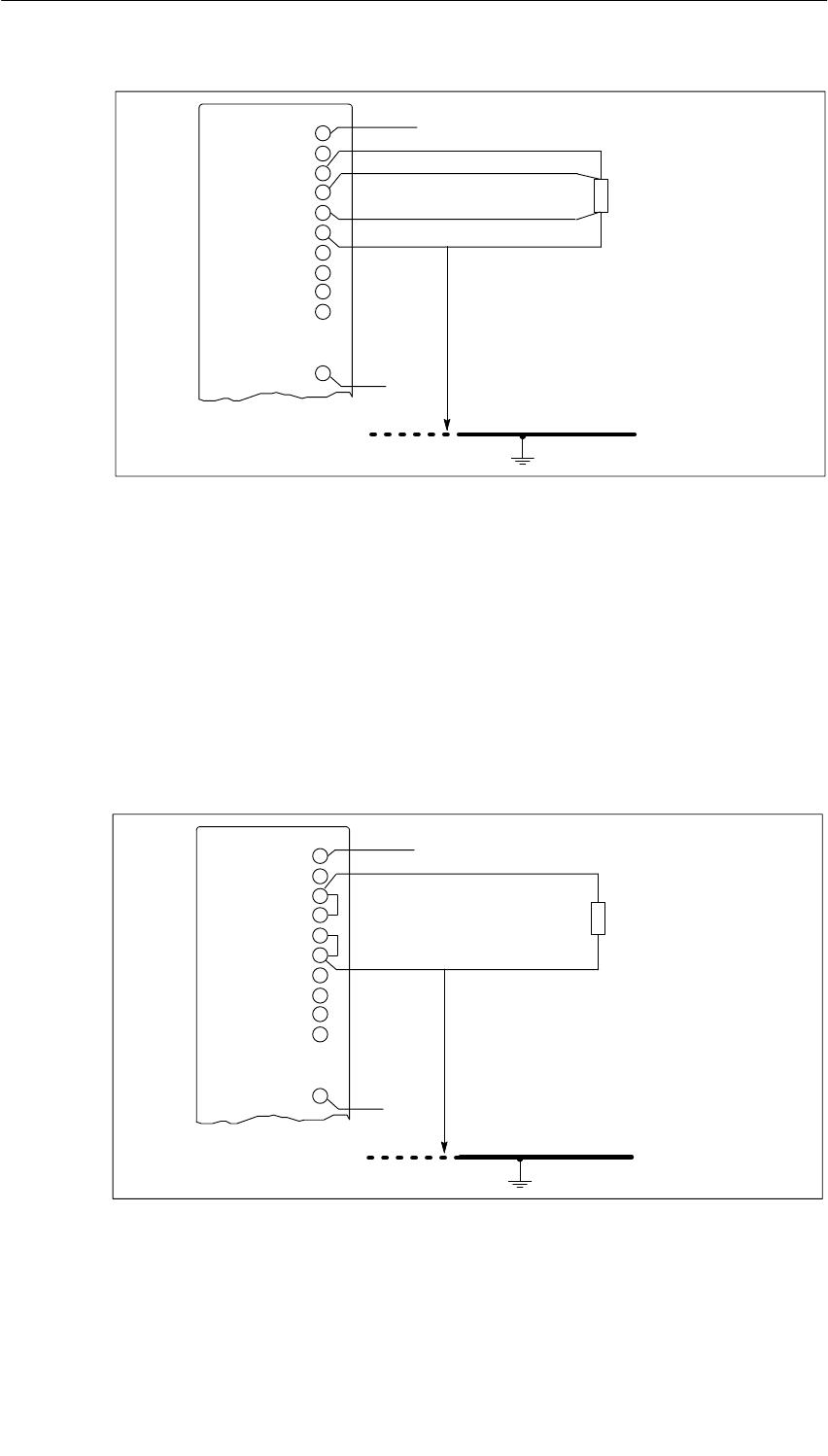
Analog Modules
5-61
S7-400, M7-400 Programmable Controllers Module Specifications
A5E00069467-07
+24 V
L+
QV
S+
S–
MANA
0 V
MUISO
Chassis ground
RL
Figure 5-21 Connecting Loads to a Voltage Output of an Isolated AO over a
Four-Conductor Connection
Two-Conductor Connection of Loads to a Voltage Output
In the case of a two-conductor connection, connect QV to S+ and MANA to S– on
the front connector. However, this will not produce the accuracy of a four-conductor
connection.
Connect the load to terminals QV and to the reference point of the measuring
circuit MANA of the module.
+24 V
L+
QV
S+
S–
MANA
0 V
MUISO
Chassis ground
RL
Figure 5-22 Two-Conductor Connection of Loads to a Voltage Output of an Isolated AO
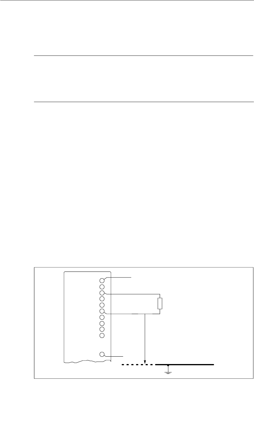
Analog Modules
5-62 S7-400, M7-400 Programmable Controllers Module Specifications
A5E00069467-07
5.15 Connecting Loads/Actuators to Current Outputs
Note
The necessary connecting cables, which result from the potential connection of the
analog output module, are not drawn in the figures shown below.
In other words, you must continue to take note of and implement Section 5.13 with
its generally applicable information for connecting loads/actuators.
Abbreviations and Mnemonics Used in the Figure Below
The abbreviations and mnemonics used in the figure below have the following
meanings:
QI: Analog output current
MANA: Reference potential of analog circuit
RL: Load impedance
L +: Terminal for 24 VDC supply voltage
M : Ground terminal
UISO: Potential difference between MANA and chassis ground
Connecting Loads to a Current Output
You must connect loads to QI and the reference point of the analog circuit MANA of
a current output.
+24 V
RL
L+
QI
MANA
M0 V
UISO
Chassis ground
Figure 5-23 Connecting Loads to a Current Output of an Isolated AO

Analog Modules
5-63
S7-400, M7-400 Programmable Controllers Module Specifications
A5E00069467-07
5.16 Diagnostics of the Analog Modules
Programmable and Non-Programmable Diagnostic Messages
In diagnostics, we make a distinction between programmable and
non-programmable diagnostic messages.
You obtain programmable diagnostic messages only if you have enabled
diagnostics by parameter assignment. You perform parameter assignment in the
“Diagnostics” parameter block in STEP 7 (refer to Section 5.7).
Non-programmable diagnostic messages are always made available by the analog
module irrespective of diagnostics being enabled.
Actions Following Diagnostic Messages in STEP 7
Each diagnostic message leads to the following actions:
•The diagnostic message is entered in the diagnosis of the analog module,
forwarded to the CPU and can be read out by the user program.
•The error LED on the analog module lights.
•If you have enabled diagnostic interrupts in STEP 7, a diagnostic interrupt is
triggered and OB 82 is called (refer to Section 4.5).
Reading out Diagnostic Messages
You can read out detailed diagnostic messages by means of SFCs in the user
program (refer to the Appendix “Diagnostic Data of Signal Modules”).
You can view the cause of the error in STEP 7 in the module diagnosis
(refer to the STEP 7 online help system).
Diagnostic Message in the Measured Value of Analog Input Modules
Every analog input module supplies the measured value 7FFFH irrespective of the
parameter assignment when an error is detected. This measured value means
either Overflow, Malfunction or a channel is disabled.
Diagnostic Message via the INTF and EXTF LEDs
Some analog input modules indicate faults by means of their two fault LEDs INTF
(internal fault) and EXTF (external fault). The LEDs go out when all the internal and
external faults have been eliminated.
Refer to the technical specifications of the modules, starting at Section 5.18, to find
out which analog input modules have these fault LEDs.
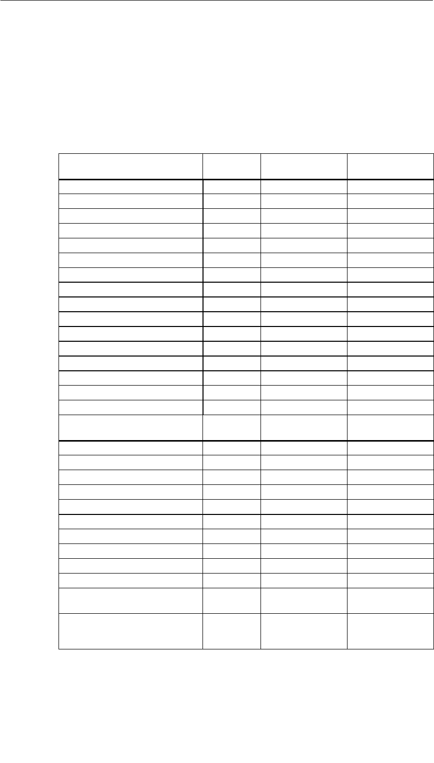
Analog Modules
5-64 S7-400, M7-400 Programmable Controllers Module Specifications
A5E00069467-07
Diagnostic Messages of the Analog Input Modules
The table below gives an overview of the diagnostic messages for the analog input
modules with diagnostics capability.
You can find out which diagnostic messages are possible with which modules in
the Appendix entitled “Diagnostic Data of the Signal Modules”.
Table 5-46 Diagnostic Messages of the Analog Input Modules
Diagnostic Message LED Diagnostics
Effective for Parameters Can
Be Assigned
Module problem INTF/EXTF Module No
Internal malfunction INTF Module No
External malfunction EXTF Module No
Channel error present INTF/EXTF Module No
External auxiliary supply missing EXTF Module No
Front connector missing EXTF Module No
Module not parameterized. INTF Module No
Wrong parameters INTF Module No
Channel information available INTF/EXTF Module No
Coding key incorrect or missing INTF Module No
Thermocouple connection fault EXTF Module No
STOP operating mode – Module No
EPROM error INTF Module No
RAM error INTF Module No
ADC/DAC error INTF Module No
Hardware interrupt lost INTF Module No
Configuring/parameter
assignment error INTF Channel No
Short-circuit to M EXTF Channel Yes
Wire break EXTF Channel Yes
Reference channel error EXTF Channel Yes
Underflow EXTF Channel Yes
Overflow EXTF Channel Yes
User connection not wired EXTF Channel No
Open conductor in + direction EXTF Channel No
Open conductor in – direction EXTF Channel No
Run time calibration error EXTF Channel No
Underrange or overrange EXTF Channel No
Open conductor in the current
source EXTF Channel No
User calibration doesn’t
correspond to the parameter
assignment
EXTF Channel No
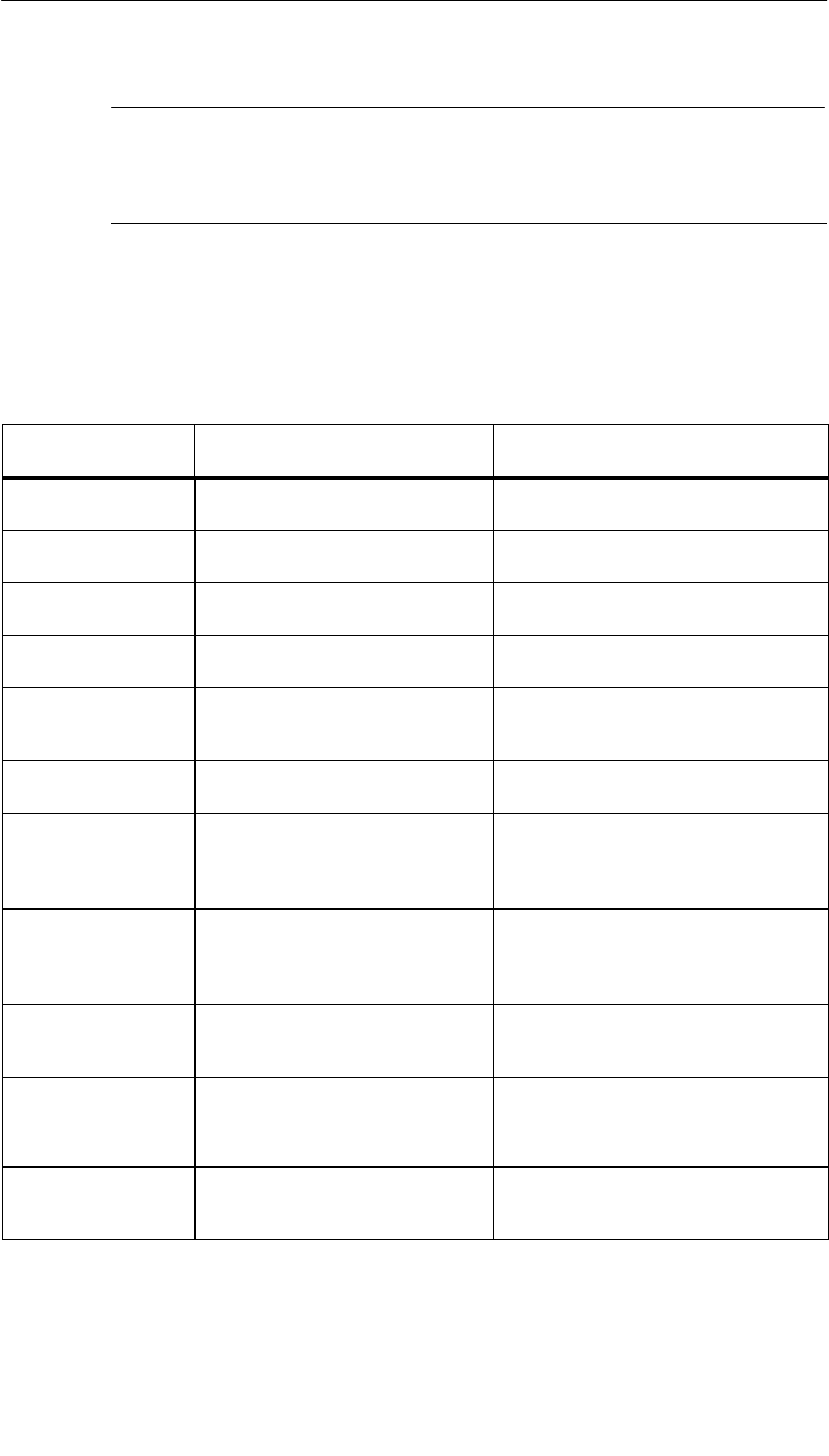
Analog Modules
5-65
S7-400, M7-400 Programmable Controllers Module Specifications
A5E00069467-07
Note
A prerequisite for detecting the errors indicated by programmable diagnostic
messages is that you must have assigned parameters to the analog module
accordingly in STEP 7.
Causes of Errors and Remedial Measures for Analog Input Modules
Table 5-47 Diagnostics Messages of the Analog Input Modules, Causes of Errors and Remedial
Measures
Diagnostics
Message Possible Error Cause Remedy
Module malfunction An error detected by the module
has occurred -
Internal malfunction The module has detected an error
within the programmable controller -
External malfunction The module has detected an error
outside the programmable controller -
There is a channel
error Indicates that only certain channels
are faulty -
No external auxiliary
voltage Load voltage to supply the 2-wire
transmitter is missing on terminals
L+ and M
Feed supply L+
No front connector Jumper between connections 1 and
2 in the front connector missing Install jumper
Parameters have not
been assigned to the
module
The module requires the information
as to whether it should work with
system default parameters or with
your parameters
Message queued after power-on until
parameter transmission by the CPU has
been completed; parameterize the
module, as required
Wrong parameters A parameter or combination of
parameters is incorrect;
impermissible measurement range,
for example
Reassign module parameter
Channel information
available Channel error present; the module
can supply additional channel
information
-
Measuring range
module
incorrect/missing
One or more measuring range
modules is missing or incorrectly
inserted
Insert the measuring range modules on the
module according to the parameter
assignment of the type of measurement
and the measurement range
STOP operating mode Module not parameterized and the
first module cycle not completed If a reboot of the CPU all the digitized
analog values are in the intermediate
memory, this message is reset
Analog Modules
5-66 S7-400, M7-400 Programmable Controllers Module Specifications
A5E00069467-07
Table 5-47 Diagnostics Messages of the Analog Input Modules, Causes of Errors and Remedial
Measures, continued
Diagnostics
Message RemedyPossible Error Cause
EPROM error The module is defective Replace module
RAM error
ADC/DAC error
Hardware interrupt lost The module cannot send an
interrupt, since the previous
interrupt was not acknowledged;
configuration error possible
Change interrupt handling in the CPU
(change priority for interrupt OB; shorten
interrupt program)
Configuring/parameter
i t
Illegal parameters transferred to
dl
Check measuring range module
assignment error module Reassign module parameter
Short circuit to M A short circuit to the M potential has
occurred on the sensor supply of
two-wire transmitters
Eliminate short circuit
Wire break Resistance too high in the sensor
connection Use different type of sensor or
connection, e.g. use conductors with a
larger cross-sectional core area
Open circuit between module and
sensor Close circuit
Channel not connected (open) Disable channel (“Measuring Type”
parameter)
Connect channel
Reference channel
error The reference junction connected at
channel 0 is faulty due to a wire
break, for example
Check terminals
The reference temperature value
transferred is not within the value
range
Reparameterize the reference
temperature
Underflow Input value violates underrange,
error may be caused:
Wrong measuring range selected Configure other measuring range
With the measuring ranges 4 to
20 mA and 1 to 5 V, if necessary by
polarity reversal of sensor
connection
Check terminals
Overflow Input value overflows overrange Configure other measuring range
Run time calibration
error A wiring fault has occurred on a
channel during the calibration cycle Eliminate the wiring fault (fault remains
until the next calibration; in other words,
a maximum 6 minutes or until there is a
STOP-RUN transition of the CPU)

Analog Modules
5-67
S7-400, M7-400 Programmable Controllers Module Specifications
A5E00069467-07
5.17 Analog Module Interrupts
Introduction
In this Section, the interrupt behavior of the analog modules is described. The
following interrupts exist:
•Diagnostic Interrupt
•Hardware interrupt
Note that not all analog modules have interrupt capability or they are only capable
of a subset of the interrupts described here Refer to the technical specifications of
the modules, starting at Section 5.18, to find out which analog modules have
interrupt capability.
The OBs and SFCs mentioned below can be found in the online help system for
STEP 7, where they are described in greater detail.
Enabling Interrupts
The interrupts are not preset – in other words, they are inhibited without
appropriate parameter assignment. You enable interrupts in STEP 7
(refer to Section 5.7).
Special Feature: The Module is Inserted in ER-1/ER-2
Note
If you use the analog module in ER-1/ER-2, you must set the parameters for the
input of all the interrupts to “No” because the interrupt lines are not available in
ER-1/ER-2.
Diagnostic Interrupt
If you have enabled diagnostic interrupts, then active error events (initial
occurrence of the error) and departing error events (message after troubleshooting)
are reported by means of an interrupt.
The CPU interrupts the execution of the user program and processes the
diagnostic interrupt block (OB 82).
In the user program, you can call SFC 51 or SFC 59 in OB 82 to obtain more
detailed diagnostic information from the module.
The diagnostic information is consistent until such time as OB 82 is exited. When
OB 82 is exited, the diagnostic interrupt is acknowledged on the module.

Analog Modules
5-68 S7-400, M7-400 Programmable Controllers Module Specifications
A5E00069467-07
Hardware Interrupt with Trigger “Upper or Lower Limit Exceeded”
Define a working range by setting parameters for an upper and lower limit value. If
the process signal (for example, the temperature) leaves this working range, the
module triggers a hardware interrupt, provided the interrupt is enabled.
The CPU interrupts execution of the user program and processes the hardware
interrupt block (OB 40).
In the user program of OB 40, you can set how the programmable controller is
required to react to a limit value being surpassed or not being reached.
When OB 40 is exited, the hardware interrupt is acknowledged on the module.
Note
Note that a hardware interrupt is not triggered if you have set the upper limit above
the overrange or the lower limit below the underrange.
Structure of the Start Information Tag OB40_POINT_ADDR of OB 40
The limit values exceeded by the different channels are entered in the start
information of OB 40 in the tag OB40_POINT_ADDR. The following figure shows
the assignment to the bits of local data double word 8.
1
16 Bit no.
17
3130 29 282726
LD 8
1
LB 8 LB 9
25 24
Value exceeds upper limit for channel 0
Value falls below lower limit for channel 0
Value exceeds upper limit for channel 1
LB 11
0
1
Value falls below lower limit for channel 1
11
.0
.1
Figure 5-24 Start Information of OB 40: Which Event Triggered the Hardware Interrupt at the Limit Value

Analog Modules
5-69
S7-400, M7-400 Programmable Controllers Module Specifications
A5E00069467-07
Hardware Interrupt on Trigger “Reached End of Scan Cycle”
By parameterizing the hardware interrupt a the end of the scan cycle, you have the
option of synchronizing a process with the scan cycle of the analog input module.
A scan cycle includes the conversion of the measured values of all enabled
channels of the analog input module. The module processes the channels one
after the other. After all the measured values have been converted, the module of
the CPU reports by means of an interrupt that there are new measured values on
all channels.
You can use the interrupt to load the currently converted analog values.

Analog Modules
5-70 S7-400, M7-400 Programmable Controllers Module Specifications
A5E00069467-07
5.18 Analog Input Module SM 431; AI 8 13 Bit;
(6ES7431-1KF00-0AB0)
Characteristics
The analog input module SM 431; AI 8 13 Bit has the following features:
•8 inputs for voltage/current measurement
•4 inputs for resistance measurement
•Unlimited measuring range selection
•13-bit resolution
•Analog section isolated from CPU
•The maximum permissible common mode voltage between the channels and
between the reference potential of the connected sensors and MANA is 30 VAC
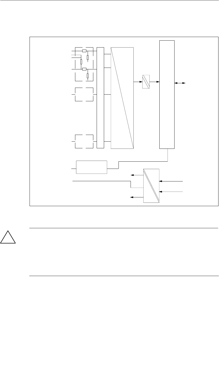
Analog Modules
5-71
S7-400, M7-400 Programmable Controllers Module Specifications
A5E00069467-07
Block Diagram of the SM 431; AI 8 13 Bit
A
D
+5V
0V
CH1
CH7
CH0
+5V
–5V
0V
Suppressor circuit, current jumpering
MV0+
MI0+
MI0+
M0–
CH1
CH7
F_CON
Bus control
M
Bus S7-400
ANA
Front
connector
monitoring
Bus S7-400
Bus S7-400
Figure 5-25 Block Diagram of the SM 431; AI 8 x 13 Bit
!Warning
The module can be damaged.
The shunt resistor of an input channel can be destroyed if you inadvertently
connect a voltage sensor to the M–/MI+ terminals of a channel.
Make sure that the front connector wiring corresponds to the following terminal
assignment diagram.

Analog Modules
5-72 S7-400, M7-400 Programmable Controllers Module Specifications
A5E00069467-07
Terminal Assignment Diagram of the SM 431; AI 8 13 Bit
MANA
V
A
V
A
Voltage
measurement Current measure-
ment Resistance mea-
surement
MV0+ MV0+ M0+
M0–
M1+
M1–
M2+
M2–
M3+
M3–
M0–
MV1+
M1–
MV2+
M2–
MV3+
M3–
M
MV4+
M4–
MV5+
M5–
MV6+
M6–
MV7+
M7–
MV7+
MI7+
MI7+
M7–
MV6+
MI6+
MI6+
M6–
MV5+
MI5+
MI5+
M5–
MV4+
MI4+
MI4+
M4–
MV3+
MI3+
MI3+
M3–
MV2+
MI2+
MI2+
M2–
MV1+
MI1+
MI1+
M1–
MI0+
MI0+
M0–
IC0+
IC0–
IC1+
IC1–
IC2+
IC2–
IC3+
IC3–
CH0
CH1
CH2
CH3
CH4
CH5
CH6
CH7
CH0
CH1
CH2
CH3
CH4
CH5
CH6
CH7
CH0
CH2
CH4
CH6
ANA
29
30
31
32
33
34
35
36
37
39
40
41
42
43
44
45
46
47
48
38
1
2
3
4
5
6
7
8
9
10
11
12
13
14
15
16
17
18
19
20
21
22
23
24
25
26
27
28
Word 0
Word 2
Word 4
Word 6
Word 8
Word 10
Word 12
Word 14
Word 0
Word 4
Word 8
Word 12
Figure 5-26 Terminal Assignment Diagram of the SM 431; AI 8 x 13 Bit
Analog Modules
5-73
S7-400, M7-400 Programmable Controllers Module Specifications
A5E00069467-07
Technical Specifications of the SM 431; AI 8 13 Bit
Programming package
Associated programming
package As of STEP 7 V 2.0
Dimensions and Weight
Dimensions W H D
(in millimeters) 25 290 210
Weight Approx. 500 g
Data for Specific Module
Number of inputs
•For resistance-type sensor
8
4
Length of cable
•Shielded max. 200 m
Voltages, Currents, Potentials
Rated load voltage L+ Not required
Constant measured current for
resistance-type sensor Typ. 1.67 mA
Isolation
•Between channels and
backplane bus
•Between the channels
Yes
No
Permitted potential difference
•Between inputs and MANA
(UCM)30 VAC
•Between the inputs (ECM)30 VAC
•Between MANA and
Minternal (UISO)75 VDC / 60 VAC
Insulation tested with
•Between bus and analog
section
•Between bus and chassis
ground
•Between analog section
and chassis ground
2120 VDC
500 VDC
2120 VDC
Current consumption
•From the backplane bus Max. 350 mA
Power dissipation of the
module Typ. 1.8 W
Analog Value Generation
Measuring principle Integrative
Integration time/conversion
time/resolution (per channel) (Does not go into the
response time)
•Parameters can be
assigned Yes
•Interference voltage
suppression f1 in Hz 60/50
•Integration time in
milliseconds 16.7/20
•Basic conversion time in
ms 23/25
•Resolution including sign 13/13 Bit
Smoothing of the measured
values Not possible
Basic execution time of the
module, in ms (all channels
enabled)
184/200
Suppression of Interference, Limits of Error
Interference voltage suppression for f = nx (f1 "1%),
(f1 = interference frequency) n = 1, 2, ...
•Common-mode
interference
(UCM < 30 V)
> 100 dB
•Series-mode interference
(peak value of
interference < rated value
of input range)
> 40 dB
Crosstalk between the inputs > 50 dB
Operational limit (in the entire temperature range, with
reference to the input range)
•Voltage input
–" 1 V
–" 10 V
– 1 V to 5 V
" 1.0%
" 0.6%
" 0.7%
•Current input
–" 20 mA
– 4 mA to 20 mA
" 1.0%
" 1.0%
•Resistance measurement
0 to 500 fourconductor
measurement (in the range
of 600)
" 1.25%
Basic error (operational limit at 25 °5C, referred to input
range)
•Voltage input
–" 1 V
–" 10 V
– 1 V to 5 V
" 0.7%
" 0.4%
" 0.5%
•Current input
–" 20 mA
– 4 mA to 20 mA
" 0.7%
" 0.7%
•Resistance measurement
0 to 500 fourconductor
measurement (in the range
of 600)
" 0.8%
Temperature error with reference to the input range
•In the resistance
measurement range
" 0.02% K
•In all the other
measurement ranges
" 0.007% K
Linearity error (with reference
to the input range)
" 0.05% K
Repeat accuracy (in the steady
state at 25 °C, referred to the
input range)
" 0.1%

Analog Modules
5-74 S7-400, M7-400 Programmable Controllers Module Specifications
A5E00069467-07
Status, Interrupts, Diagnostics
Interrupts None
Diagnostic functions None
Substitute value can be applied No
Data for Selecting a Sensor
Input range (rated values)/input
resistance
•Voltage " 1 V/200 k
" 10 V/200 k
1 V to 5 V/200 k
•Current " 20 mA/80
4 mA to 20 mA/80
•Resistors 0 to 600 ; of use up
to 500
Maximum input current for
current input (destruction limit) 40 mA continuous
Connection of the signal
sensors
•For measuring voltage Possible
•For measuring current
– As two-wire
transmitter Possible; with external
transmitter supply
– As four-wire
transmitter Possible
•For measuring resistance
– With two-conductor
terminal
– With three-conductor
terminal
Possible; cable
resistance is also
measured
– With four-conductor
terminal Possible
Characteristic linearization No
5.18.1 Commissioning the SM 431; AI 8 13 Bit
You set the mode of operation of the SM 431; AI 8 13 Bit in STEP 7.
Parameters
You will find a description of the general procedure for assigning parameters to
analog modules in Section 5.7.
An overview of the parameters that you can set and their default settings are
shown in the table below.
Table 5-48 Parameters of the SM 431; AI 8 13 Bit
Parameter Value Range Default1) Parameter
Type Scope
Measurement
•Measuring
method Disabled
U Voltage
4DMU Current (4-wire transmitter)
2DMU Current (2-wire transmitter)
R-4L Resistance (four-conductor
connection)
U
Static Channel
•Measuring
range Refer to Section 5.18.2 for the measuring
ranges of the input channels that you can
set.
"10 V
•Interference
suppression 60 Hz; 50 Hz 50 Hz
1) Only in the CC (central controller) is it possible to start up the analog modules with the default settings.
Analog Modules
5-75
S7-400, M7-400 Programmable Controllers Module Specifications
A5E00069467-07
5.18.2 Measuring Methods and Measuring Ranges of the
SM 431; AI 8 13 Bit
Measuring Methods
You can set the following measuring methods for the input channels:
•Voltage measurement
•Current measurement
•Resistance test
You perform the setting with the “Measuring Type” parameter in STEP 7.
Wiring for Resistance Measurement
The following conditions apply when measuring the resistance with the SM 431;
AI 8 x 13 Bit:
Table 5-49 Channels for Resistance Measurement of the SM 431; AI 8 13 Bit
Measuring Type
Parameter Permissible
for Channel n Condition
Resistance
(four-conductor
connection)
0, 2, 4 or 6 You must disable the(“Measuring Type” parameter for
channels n+1 (1, 3, 5, 7).
The reason: The connections of channel n+1 are used to
supply the resistance that is connected to channel n.
Unused Channels
Unused channels can usually be left open. You can improve the noise immunity of
the module in a measuring environment with serious interference by short-circuiting
the channels and connecting to MANA. Disable the “Measuring Type” parameter for
unused channels. In this way you shorten the scan time of the module.

Analog Modules
5-76 S7-400, M7-400 Programmable Controllers Module Specifications
A5E00069467-07
Measuring Ranges
You set the measuring ranges by means of the “Measuring Range” parameter in
STEP 7.
Table 5-50 Measuring Ranges of the SM 431; AI 8 x 13 Bit
Method Selected Measuring
Range Description
U: Voltage ±(1 V
1 to 5 V
±(10 V
You will find the digitized analog values in
Section 5.3.1 in the voltage measuring
range
2DMU: Current (two-wire
transmitter) 4 to 20 mA You will find the digitized analog values in
Section 5.3.1 in the current measuring
range
4DMU: Current
(four-wire transmitter) 4 to 20 mA
" 20 mA
You will find the digitized analog values in
Section 5.3.1 in the current measuring
range
R-4L: Resistance
(four-conductor
connection)
600 You will find the digitized analog values in
Section 5.3.1 in the resistance measuring
range
Default Settings
The default settings of the module are “Voltage” for the measuring method and
“" 10 V” for the measuring range. You can use this combination of measuring
method and measuring range without parameterizing the SM 431; AI 8 13 Bit in
STEP 7.
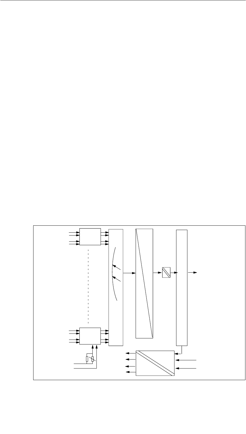
Analog Modules
5-77
S7-400, M7-400 Programmable Controllers Module Specifications
A5E00069467-07
5.19 Analog Input Module SM 431; AI 8 14 Bit;
(6ES7 431-1KF10-0AB0)
Characteristics
The analog input module SM 431; AI 8 14 Bit has the following features:
•8 inputs for voltage/current measurement
•4 inputs for resistance and temperature measurement
•Unlimited measuring range selection
•14-bit resolution
•Particularly suitable for measuring temperatures
•Temperature sensor types can be parameterized
•Linearization of the sensor characteristic curves
•Supply voltage 24 VDC required only for the connection of 2-wire transmitters
•Analog section isolated from CPU
•The maximum permissible common mode voltage between the channels and
between the channel and the central ground point is120 VAC
Block Diagram of the SM 431; AI 8 14 Bit
CH0
CH1
CH6
CH7
+5V
0V
0V
– 15V
+ 5V
+ 15V
L+
M
Bus S7-400
Bus control
ENABLE
MULTIPLEXER
OPTO RELAY
A
D
Meas.
range
module 0
Meas.
range
module 3
Bus S7-400
Bus S7-400
Figure 5-27 Block Diagram of the SM 431; AI 8 x 14 Bit

Analog Modules
5-78 S7-400, M7-400 Programmable Controllers Module Specifications
A5E00069467-07
Terminal Assignment Diagram of the SM 431; AI 8 14 Bit
Thermocouples
Voltage measurement
Current measurement
Resistance measurement
Resistance thermometer
M1+
M2–
M3–
M4–
M5–
M6–
M7–
CH0
CH1
CH2
CH3
CH4
CH5
CH6
CH7
L+
V
V
V
M
Tr
Tr
L+
M0+
M0–
M1–
M2+
M3+
M4+
M5+
M6+
M7+
M
M0+
M0–
IC0+
IC0–
M1+
M1–
IC1+
IC1–
M2+
M2–
IC2+
IC2–
M3+
M3–
IC3+
IC3–
M
CH0
CH2
CH4
CH6
29
30
31
32
33
34
35
36
37
39
40
41
42
43
44
45
46
47
48
38
1
2
3
4
5
6
7
8
9
10
11
12
13
14
15
16
17
18
19
20
21
22
23
24
25
26
27
28
Word 0
Word 2
Word 4
Word 6
Word 8
Word 10
Word 12
Word 14
Word 0
Word 4
Word 8
Word 12
Figure 5-28 Terminal Assignment Diagram of the SM 431; AI 8 x 14 Bit

Analog Modules
5-79
S7-400, M7-400 Programmable Controllers Module Specifications
A5E00069467-07
Technical Specifications of the SM 431; AI 8 14 Bit
Programming package
Associated programming
package As of STEP 7 V 2.0
Dimensions and Weight
Dimensions W H D
(in millimeters) 25 290 210
Weight Approx. 500 g
Data for Specific Module
Number of inputs
•For resistance-type sensor
8
4
Length of cable
•Shielded
in the 80 mV input range
and with thermocouples
Max. 200 m
Max. 50 m
Voltages, Currents, Potentials
Rated load voltage L+ 24 VDC (required only
for the supply of
two-wire transmitters)
•Reverse polarity protection Yes
Power supply of the
transmitters
•Supply current max. 50 mA
•Short-circuit proof Yes
Constant measured current for
resistance-type sensor
Typ. 1.67 mA
Isolation
•Between channels and
backplane bus
•Between the channels
•Between channels and
load voltage L+
Yes
No
Yes
Permitted potential difference
•Between inputs and MANA
(UCM)120 VAC
•Between the inputs (ECM)120 VAC
•Between MANA and
Minternal (UISO)75 VDC / 60 VAC
Insulation tested with
•Between bus and L+/M
•Between bus and analog
section
•Between bus and chassis
ground
•Between analog section
and L+/M
•Between analog section
and chassis ground
•Between L+/M and chassis
ground
2120 VDC
2120 VDC
500 VDC
707 VDC
2120 VDC
2120 VDC
Current consumption
•From the backplane bus Max. 600 mA
•From the backplane bus L+ Max. 200 mA (with 8
connected, fully
controlled two-wire
transmitters)
Power dissipation of the
module Typ. 3.5 W
Analog Value Generation
Measuring principle Integrative
Integration time/conversion
time/resolution (per channel) (Does not go into the
response time)
•Parameters can be
assigned Yes
•Interference voltage
suppression f1 in Hz 60/50
•Integration time in
milliseconds 16.7/20
•Basic conversion time in
ms 20.1/23.5
•Additional conversion time
for measuring resistance in
ms
40.2/47
•Additional conversion time
for open-circuit monitoring
in ms
4.3/4.3
•Additional conversion time
for measuring resistance
in ms
5.5/5.5
•Resolution including sign
– Smoothing activated
14/14 bit
16/16 bit
Smoothing of the measured
values Parameters can be
assigned in 4
stages
Basic execution time of the
module, in ms (all channels
enabled)
161/188

Analog Modules
5-80 S7-400, M7-400 Programmable Controllers Module Specifications
A5E00069467-07
Suppression of Interference, Limits of Error
Interference voltage suppression for f = nx (f1 "1%),
(f1 = interference frequency) n = 1, 2, ...
•Common-mode
interference
(UCM < 120 Vss)
> 100 dB
•Series-mode interference
(peak value of interference
< rated value of input
range)
> 40 dB
Crosstalk between the inputs >70 dB
Operational limit (in the entire temperature range, with
reference to the input range)
•Voltage input
–" 80 mV
–" 250 mV
–" 500 mV
–" 1 V
–" 2.5 V
–" 5 V
– 1 V to 5 V
–" 10 V
" 0.38%
" 0.35%
" 0.35%
" 0.35%
" 0.35%
" 0.35%
" 0.35%
" 0.35%
•Current input
– 0 ... 20 mA
–" 20 mA
– 4 mA to 20 mA
" 0.35%
" 0.35%
" 0.35%
•Resistance test
– 0 to 48 ;
four-conductor
measurement
" 0.35%
– 0 to 150 ,
four-conductor
measurement
" 0.35%
– 0 to 300
four-conductor
measurement
" 0.35%
– 0 to 600 ;
four-conductor
measurement
" 0.35%
– 0 to 5000 ;
four-conductor
measurement (in
the range of
6000 )
" 0.35%
– 0 to 300 ;
three-conductor
measurement
" 0.5%
– 0 to 600 ;
three-conductor
measurement
" 0.5%
– 0 to 5000 Ω;
three-conductor
measurement (in
the range of
6000 )
" 0.5%
•Thermocouples
– TC type B
– TC type R
– TC type S
– TC type T
– TC type E
– TC type J
– TC type K
– TC type U
– TC type L
– TC type N
" 14.8 K
" 9.4 K
" 10.6 K
" 2.2 K
" 4,0 K
" 5.2 K
" 7.6 K
" 3.5 K
" 5.1 K
" 5.5 K
•Resistance thermocouples, four-conductor
standard measuring range
– Pt 100
– Pt 200
– Pt 500
– Pt 1000
– Ni 100
– Ni 1000
" 4.6 K
" 5.7 K
" 4.6 K
" 3.7 K
" 0.9 K
" 0.9 K
Climatic measuring range
– Pt 100
– Pt 200
– Pt 500
– Pt 1000
– Ni 100
– Ni 1000
" 0.5 K
" 0.5 K
" 0.5 K
" 0.5 K
" 0.9 K
" 0.9 K
•Resistance thermocouples, three-conductor
standard measuring range
– Pt 100
– Pt 200
– Pt 500
– Pt 1000
– Ni 100
– Ni 1000
" 5.2 K
" 8.2 K
" 6.5 K
" 5.2 K
" 1.3 K
" 1.3 K
Climatic measuring range
– Pt 100
– Pt 200
– Pt 500
– Pt 1000
– Ni 100
– Ni 1000
" 0.7 K
" 0.7 K
" 0.7 K
" 0.7 K
" 1.3 K
" 1.3 K

Analog Modules
5-81
S7-400, M7-400 Programmable Controllers Module Specifications
A5E00069467-07
Basic error (operational limit at 25 °C, referred to input
range)
•Voltage input
–" 80 mV
–" 250 mV
–" 500 mV
–" 1 V
–" 2.5 V
–" 5 V
– 1 V to 5 V
–" 10 V
" 0.17%
" 0.15%
" 0.15%
" 0.15%
" 0.15%
" 0.15%
" 0.15%
" 0.15%
•Current input
– 0 mA to 20 mA
–" 20 mA
– 4 ... 20 mA
" 0.15%
" 0.15%
" 0.15%
•Resistance test
– 0 to 48 ;
four-conductor
measurement
" 0.15%
– 0 to 150 ,
four-conductor
measurement
" 0.15%
– 0 to 300
four-conductor
measurement
" 0.15%
– 0 to 600 ;
four-conductor
measurement
" 0.15%
– 0 to 5000 ;
four-conductor
measurement (in
the range of
6000 )
" 0.15%
– 0 to 300 ;
three-conductor
measurement
" 0.3%
– 0 to 600 ;
three-conductor
measurement
" 0.3%
– 0 to 5000 Ω;
three-conductor
measurement (in
the range of
6000 )
" 0.3%
•Thermocouples
– TC type B
– TC type R
– TC type S
– TC type T
– TC type E
– TC type J
– TC type K
– TC type U
– TC type L
– TC type N
" 8.2 K
" 5.2 K
" 5.9 K
" 1.2 K
" 1.8 K
" 2.3 K
" 3.4 K
" 1.8 K
" 2.3 K
" 2.9 K
•Resistance thermocouples, four-conductor
standard measuring range
– Pt 100
– Pt 200
– Pt 500
– Pt 1000
– Ni 100
– Ni 1000
" 2.0 K
" 2.5 K
" 2.0 K
" 1.6 K
" 0.4 K
" 0.4 K
Climatic measuring range
– Pt 100
– Pt 200
– Pt 500
– Pt 1000
– Ni 100
– Ni 1000
" 0.2 K
" 0.2 K
" 0.2 K
" 0.2 K
" 0.4 K
" 0.4 K
•Resistance thermocouples, three-conductor
standard measuring range
– Pt 100
– Pt 200
– Pt 500
– Pt 1000
– Ni 100
– Ni 1000
" 3.1 K
" 4.9 K
" 3.9 K
" 3.1 K
" 0.8 K
" 0.8 K
Climatic measuring range
– Pt 100
– Pt 200
– Pt 500
– Pt 1000
– Ni 100
– Ni 1000
" 0.4 K
" 0.4 K
" 0.4 K
" 0.4 K
" 0.8 K
" 0.8 K
Temperature error (with
reference to the input range)
" 0.004% K
Linearity error (with reference
to the input range)
" 0.01% K
Repeat accuracy (in the steady
state at 25 °C, referred to the
input range)
" 0.1%

Analog Modules
5-82 S7-400, M7-400 Programmable Controllers Module Specifications
A5E00069467-07
Status, Interrupts, Diagnostics
Interrupts None
Diagnostic functions None
Substitute value can be applied No
Data for Selecting a Sensor
Input range (rated values)/Input
resistance
•Voltage " 80 mV/1 M
" 250 mV/1 M
" 500 mV/1 M
" 1 V/1 M
" 2.5 V/1 M
" 5 V/1 M
1 to 5 V1 M
" 10 V/1 M
•Current 0 to 20 mA50
" 20 mA/50
4 to 20 mA50
•Resistors 0 to 48 1 M
0 to 150 1 M
0 to 300 1 M
0 to 600 1 M
0 to 6000 1 M
(can be used up to
5000 )
•Thermocouples TC type B/1 M
TC type R/1 M
TC type S/1 M
TC type T/1 M
TC type E/1 M
TC type J/1 M
TC type K/1 M
TC type U/1 M
TC type L/1 M
TC type N/1 M
•Resistance thermometer Pt 100/1 M
Pt 200/1 M
Pt 500/1 M
Pt 1000/1 M
Ni 100/1 M
Ni 1000/1 M
Maximum input voltage for
voltage input (destruction limit) Max. 18 V continuous
75 V for 1 ms (cycle
factor 1 : 20)
Maximum input current for
current input (destruction limit) 40 mA continuous
Connection of the sensor
•For measuring voltage Possible
•For measuring current
– As two-wire transmitter Possible
– As four-wire
transmitter Possible
•For measuring resistance
– With two-conductor
terminal Possible; cable
resistance is also
measured
– With three-conductor
terminal Possible
– With four-conductor
terminal Possible
•Load of the two-wire
transmitter Max. 750
Characteristic linearization Parameters can be
assigned
•For thermocouples Types B, R, S, T, E, J,
K, U, L, N
•For
resistance thermometers Pt 100, Pt 200, Pt 500,
Pt 1000, Ni 100,
Ni 1000
Temperature compensation Yes, programmable
•Internal temperature
compensation No
•External temperature
compensation with
compensating box
Possible
•External temperature
compensation with Pt 100 Possible
•Compensation for
definable reference
junction
temperature
Possible
Unit for temperature
measurement Degrees Celsius

Analog Modules
5-83
S7-400, M7-400 Programmable Controllers Module Specifications
A5E00069467-07
5.19.1 Commissioning the SM 431; AI 8 14 Bit
You set the mode of operation of the SM 431; AI 8 14 Bit by means of
measuring range modules on the module and in STEP 7.
Measuring Range Module
A measuring range module of the module matches two channels and one
resistance channel to each type of sensor. If necessary, the measuring range
modules must be replugged to change the measuring method and the measuring
range. The steps you have to perform to do this are described in detail in
Section 5.4.
The corresponding table in Section 5.19.2 tells you which assignment you have to
select for which measuring method and measuring range. In addition, the
necessary settings are embossed on the module.
Parameter
You will find a description of the general procedure for assigning parameters to
analog modules in Section 5.7.
An overview of the parameters that you can set and their default settings are
shown in the table below.
Table 5-51 Parameters of the SM 431; AI 8 14 Bit
Parameter Value Range Default1Parameter
Type Scope
Diagnostics
•Wire break Yes/no No Static Channel
Measurement
•Measuring type Disabled
U Voltage
4DMU Current (four-wire transmitter)
2DMU Current (two-wire transmitter)
R-4L Resistance (four-conductor
terminal)
R-3L Resistance (three-conductor
terminal)
RTD-4L Thermal resistor
(linear, four-conductor terminal)
RTD-3L Thermal resistor
(linear, three-conductor
terminal)
TC-L Thermocouple (linear)
U
Static Channel
•Measuring
range Refer to Section 5.19.2 for the
measuring ranges of the input channels
that you can set.
" 10 V
•Reference
Temperature – 273.15 to 327.67 oC0,00 oCDynamic Module
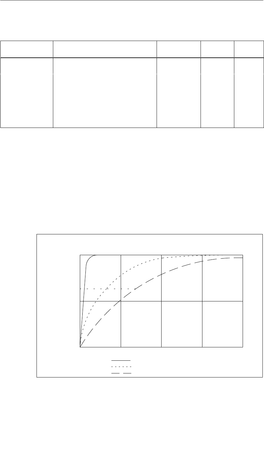
Analog Modules
5-84 S7-400, M7-400 Programmable Controllers Module Specifications
A5E00069467-07
Table 5-51 Parameters of the SM 431; AI 8 14 Bit, continued
Parameter ScopeParameter
Type
Default1
Value Range
•Interference
suppression 60 Hz; 50 Hz 50 Hz Static Channel
•Smoothing None
Low
Average
High
None
Static Channel
•Ref. junction None
RTD on Channel 0
Reference temperature value dynamic
None
1Only in the CC (central controller) is it possible to start up the analog modules with the default settings.
Smoothing of the Measured Values
You fill find information that is generally applicable to the smoothing of analog
values in Section 5.6.
The following figure indicates for the module in the case of a step response the
number of module cycles after which the smoothed analog value applies at almost
100%, depending on the smoothing setting. The figure applies to every change of
signal at an analog input.
50
100
0
63
50 100 150 200
Smoothing: low:
average:
high:
Module cycles
Signal variation
in percent
Step response for any analog input signal
Figure 5-29 Step Response of the SM 431; AI 8 14 Bit
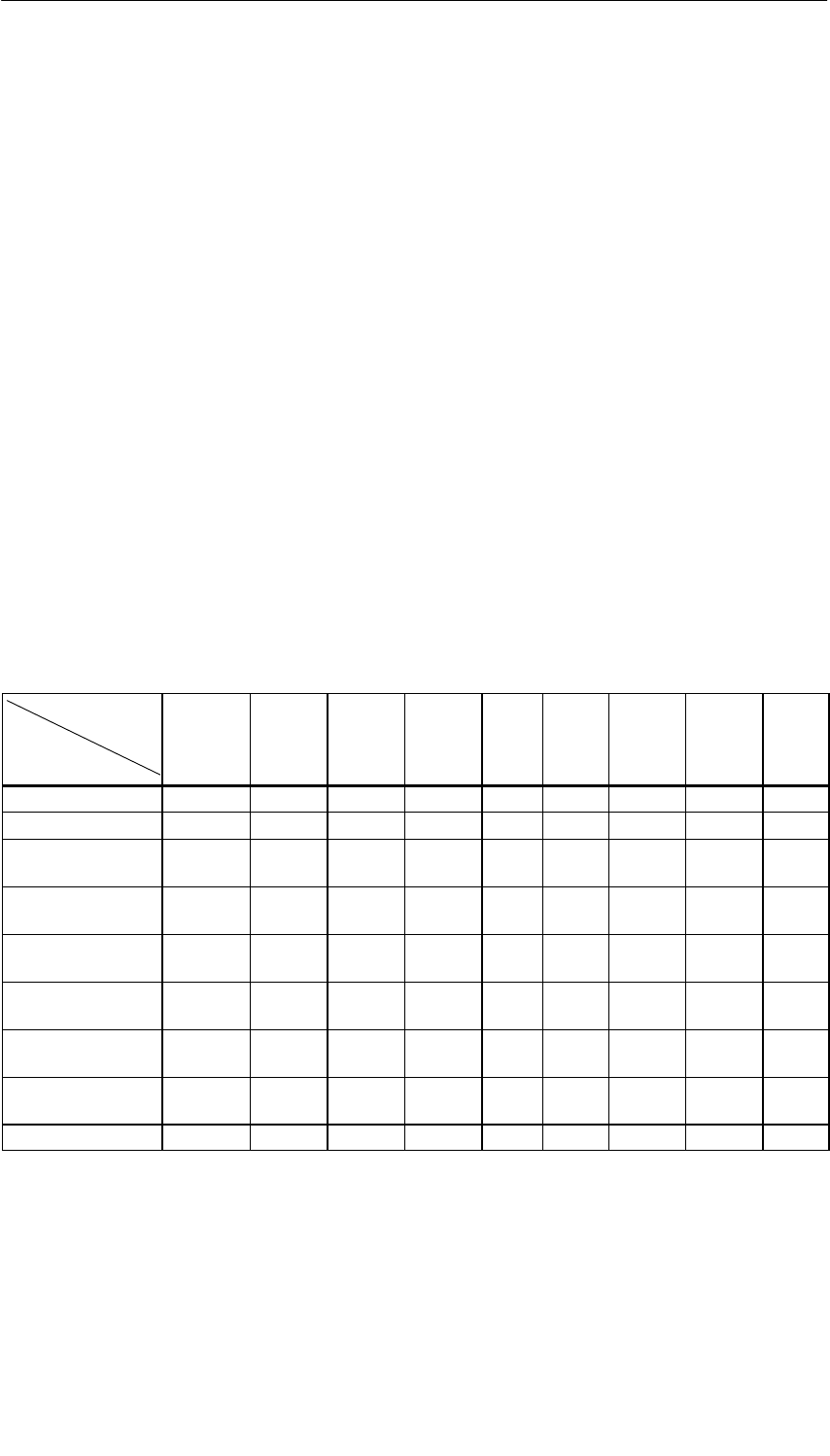
Analog Modules
5-85
S7-400, M7-400 Programmable Controllers Module Specifications
A5E00069467-07
5.19.2 Measuring Methods and Measuring Ranges of the
SM 431; AI 8 14 Bit
Measuring Methods
You can set the following measuring methods for the input channels:
•Voltage measurement
•Current measurement
•Resistance test
•Temperature measurement
You specify the setting by means of the measuring range modules on the module
and by means of the “Measuring Type” parameter in STEP 7.
Circuit Variants for the Channels
Two channels are set in each case with the measuring range module. There are
therefore restrictions as regards the measuring method for the adjacent channels
0/1, 2/3, 4/5 and 6/7, as shown in the following table:
Table 5-52 Selection of the Measuring Method for Channel n and Channel n+1 of the SM 431;
AI 8 14 Bit
Meas. Method
Chan. n+1
Meas. Method
Channel n
Disa-
bled Voltage Current
4-DMU Current
2-DMU R-4L R-3L RTD-4L RTD-3L TC-L
Disabled x x x x x
Voltage x x x
Current four-wire
transmitter x x
Current two-wire
transmitter x x
Resistor
four-conductor x
Resistor
three-conductor x
Thermal resistor
four-conductor x
Thermal resistor
three-conductor x
Thermocouples x x x
Example
If you select “current (two-wire transmitter)” for channel 6, you can then only
deactivate the measuring method or set “current (two-wire transmitter)” for
channel 7.
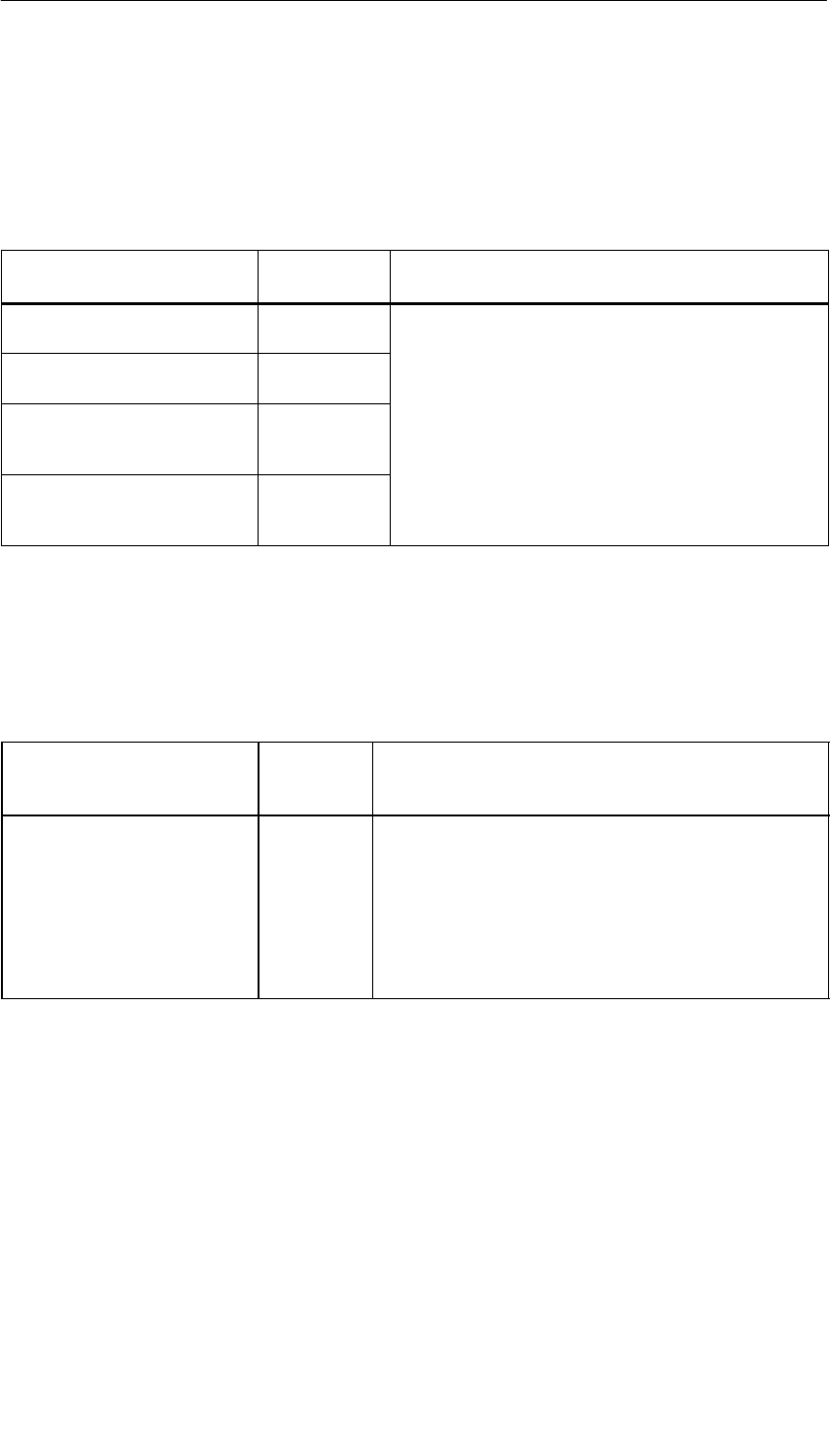
Analog Modules
5-86 S7-400, M7-400 Programmable Controllers Module Specifications
A5E00069467-07
Wiring for Resistance and Temperature Measurement
The following conditions apply when measuring the resistance and temperature
with the SM 431; AI 8 x 14 Bit:
Table 5-53 Channels for Resistance and Temperature Measurement with the SM 431; AI 8 14 Bit
Measuring Type Parameter Permissible
for Channel n Condition
Resistor
(four-conductor terminal) 0, 2, 4 or 6 You must disable the(“Measuring Type” parameter for
channels n+1 (1, 3, 5, 7).
Resistor
(three-conductor terminal) 0, 2, 4 or 6
(,,,)
The reason The connections of channel n+1 are used
to supply the resistance that is connected to
channel n
Thermal resistor
(linear, four-conductor termi-
nal)
0, 2, 4 or 6 channel n.
Thermal resistor
(linear, four-conductor termi-
nal)
0, 2, 4 or 6
Wiring for Junction Compensation for Thermocouples
If you select “RTD on Channel 0” as a reference junction for reference junction
compensation for thermocouples, the following applies:
Table 5-54 Thermocouple with Reference Junction Compensation via RTD on Channel 0
Reference Junction
Parameter Permissible
for
Channel n
Condition
RTD on Channel 0 2 to 7 You must connect and parameterize on channel 0 a
resistance thermometer with linearization, a 3- or
4- conductor connection in the climatic range (channels
0 and 1 are thus assigned).
The reason: If channel 0 is to be used as the reference
junction, a resistance-type sensor must be connected
there to record absolute temperatures in the climatic
range.
Unused Channels
Unused channels can usually be left open. Put the measuring range module in
position “A”. You can improve the noise immunity of the module in a measuring
environment with serious interference by short-circuiting the channels.
Disable the “Measuring Type” parameter for unused channels. In this way you
shorten the scan time of the module.

Analog Modules
5-87
S7-400, M7-400 Programmable Controllers Module Specifications
A5E00069467-07
Measuring Ranges
You set the measuring ranges by means of the measuring range modules on the
module and the “Measuring Type” parameter in STEP 7.
Table 5-55 Measuring Ranges of the SM 431; AI 8 x 14 Bit
Method Selected Measuring Range
(Type of Sensor) Measuring Range
Module Setting Description
U: Voltage " 80 mV
" 250 mV
" 500 mV
" 1 V
AYou will find the digitized analog
values in Section 5.3.1 in the
voltage measuring range
" 2.5 V
" 5 V
1 to 5 V
" 10 V
2DMU: Current (two-wire
transmitter) 4 to 20 mA DTo supply these transmitters with
current you must connect 24 V to
the L+ and M front connector
terminals.
You will find the digitized analog
values in Section 5.3.1 in the
current measuring range
4DMU: Current
(four-wire transmitter) 0 to 20 mA
4 to 20 mA
" 20 mA
CYou will find the digitized analog
values in Section 5.3.1 in the
current measuring range
R-4L: Resistors
(four-conductor
connection)
48
150
300
600
6000
AYou will find the digitized analog
values in Section 5.3.1 in the
resistance measuring range
R-3L: Resistors
(three-conductor
connection)
300
600
6000

Analog Modules
5-88 S7-400, M7-400 Programmable Controllers Module Specifications
A5E00069467-07
Table 5-55 Measuring Ranges of the SM 431; AI 8 x 14 Bit, continued
Method Selected DescriptionMeasuring Range
Module Setting
Measuring Range
(Type of Sensor)
TC-L: Thermocouple
(linear)
(temperature
measurement)
Type B
Type N
Type E
Type R
Type S
Type J
Type L
Type T
Type K
Type U
AYou will find the digitized analog
values in Section 5.3.1 in the
temperature range
RTD-4L: thermal resistor
(linear, four-conductor
connection)
(temperature
measurement)
Pt 100 climatic
Pt 200 climatic
Pt 500 climatic
Pt 1000 climatic
Ni 100 climatic
Ni 1000 climatic
A
RTD-3L: thermal resistor
(linear, three-conductor
connection)
(temperature
measurement)
Pt 100 standard
Pt 200 standard
Pt 500 standard
Pt 1000 standard
Ni 100 standard
Ni 1000 standard
Default Settings
The module has the following default settings in STEP 7:
•Channels 0 to 7: “Voltage” for the measuring method ; “" 10 V” for the
measuring range
You can use these measuring methods and measuring ranges without
parameterizing the SM 431; AI 8 14 Bit in STEP 7.

Analog Modules
5-89
S7-400, M7-400 Programmable Controllers Module Specifications
A5E00069467-07
Wire Break Check for Temperature or Resistance Measurement
The wire break check is intended primarily for temperature measurements (TC,
RTD) or resistance measurements. Always parameterize the wire break check in
these cases as this ensures that, in the event of a wire break, the measured value
provided by the module accepts the data for overrun 7FFFH.
Special Characteristics of the Wire Break Check for the Voltage Measurement
Methods
In some transmitters, incorrect measured values may be obtained due to the fact
that the wire break check is enabled. If so, disable the wire break check.
The reason Some transmitters try to correct the test current and in doing so corrupt
the setpoint value provided.
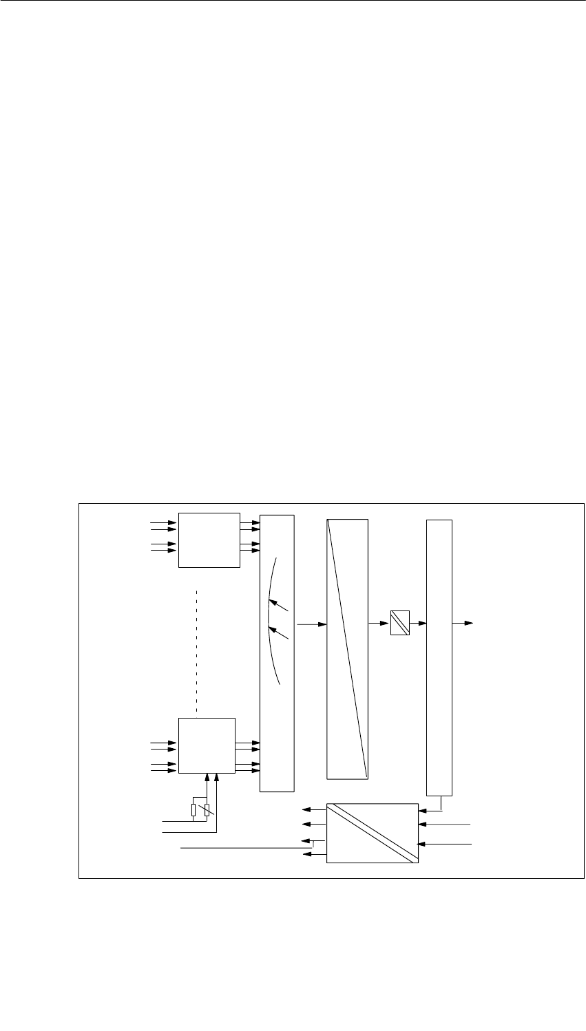
Analog Modules
5-90 S7-400, M7-400 Programmable Controllers Module Specifications
A5E00069467-07
5.20 Analog Input Module SM 431; AI 8 14 Bit;
(6ES7431-1KF20-0AB0)
Characteristics
The analog input module SM 431; AI 8 14 Bit has the following features:
•Rapid A/D changeover, therefore particularly suitable for highly dynamic
processes
•8 inputs for voltage/current measurement
•4 inputs for resistance measurement
•Unlimited measuring range selection
•14-bit resolution
•Supply voltage: 24 VDC required only for the connection of 2-wire transmitters
•Analog section isolated from CPU
•The maximum permissible common mode voltage between the channels and
between the reference potential of the connected sensors and MANA is 8 VAC
Block Diagram of the SM 431; AI 8 14 Bit
CH0
CH1
CH6
CH7
+5V
0V
0V
– 15V
+ 5V
+ 15V
L+
M
ENABLE
MULTIPLEXER
Bus S7-400
Bus control
A
D
Bus S7-400
Bus S7-400
Measuring
3
range
module
Measuring
0
range
module
MANA
MANA
Figure 5-30 Block Diagram of the SM 431; AI 8 x 14 Bit
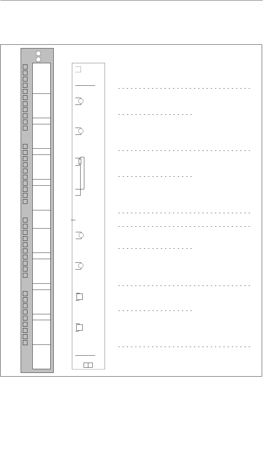
Analog Modules
5-91
S7-400, M7-400 Programmable Controllers Module Specifications
A5E00069467-07
Terminal Assignment Diagram of the SM 431; AI 8 14 Bit
Voltage measurement
Current measurement Resistance measurement
M1+
M2–
M3–
M4–
M5–
M6–
M7–
CH0
CH1
CH2
CH3
CH4
CH5
CH6
CH7
L+
V
A
A
M
Tr
Tr
L+
M0+
M0–
M1–
M2+
M3+
M4+
M5+
M6+
M7+
M
M0+
M0–
IC0+
IC0–
M1+
M1–
IC1+
IC1–
M2+
M2–
IC2+
IC2–
M3+
M3–
IC3+
IC3–
CH0
CH2
CH4
CH6
V
MANA
29
30
31
32
33
34
35
36
37
39
40
41
42
43
44
45
46
47
48
38
1
2
3
4
5
6
7
8
9
10
11
12
13
14
15
16
17
18
19
20
21
22
23
24
25
26
27
28
Word 0
Word 2
Word 4
Word 6
Word 8
Word 10
Word 12
Word 14
Word 0
Word 4
Word 8
Word 12
Figure 5-31 Terminal Assignment Diagram of the SM 431; AI 8 x 14 Bit

Analog Modules
5-92 S7-400, M7-400 Programmable Controllers Module Specifications
A5E00069467-07
Technical Specifications of the SM 431; AI 8 14 Bit
Programming package
Associated programming
package As of STEP 7 V 2.0
Dimensions and Weight
Dimensions W H D
(in millimeters) 25 290 210
Weight Approx. 500 g
Data for Specific Module
Number of inputs
•For resistance-type sensor
8
4
Length of cable
•Shielded Max. 200 m
Voltages, Currents, Potentials
Rated load voltage L+ 24 VDC (required only
for the supply of 2-wire
transmitters)
•Reverse polarity protection Yes
Power supply of the
transmitters
•Supply current Max. 50 mA
•Short-circuit proof Yes
Constant measured current for
resistance-type sensor Typ. 1.67 mA
Isolation
•Between channels and
backplane bus
•Between the channels
•Between channels and
load voltage L+
Yes
No
Yes
Permitted potential difference
•Between inputs and MANA
(UCM)8 VAC
•Between the inputs (ECM)8 VAC
•Between MANA and
Minternal (UISO)75 VDC/60 VAC
Insulation tested
•Between bus and analog
section
•Between bus and chassis
ground
•Between analog section
and L+/M
•Between analog section
and chassis ground
•Between L+/M and chassis
ground
2120 VDC
500 VDC
707 VDC
2120 VDC
2120 VDC
Current consumption
•From the backplane bus Max. 1000 mA
•From the backplane bus L+ Max. 200 mA (with 8
connected, fully
controlled 2-wire
transmitters)
Power dissipation of the
module Typ. 4.9 W
Analog Value Generation
Measuring principle Actual-value
conversion
Integration time/conversion
time/resolution (per channel) (Does not go into the
response time)
•Parameters can be
assigned Yes
•Interference voltage
suppression f1 in Hz None/400/60/50
•Basic conversion time in
ms 52 s
•Resolution (incl.
overrange) 14/14/14
Smoothing of the measured
values Can be parameterized
“none – a lot”
Time constant of the input
filter 15 s
Basic execution time of the
module, in ms (all channels
enabled)
0.420

Analog Modules
5-93
S7-400, M7-400 Programmable Controllers Module Specifications
A5E00069467-07
Suppression of interference, Limits of Error
Interference voltage suppression parameterized for
f = nx (f1 "1%), (f1 = interference frequency) n = 1, 2 ,
...
filter 400/60/50 Hz
•Common-mode
interference
(UCM < 11 Vss)
> 80 db
•Series-mode interference
(peak value of interference
< rated value of input
range)
> 40 dB
Crosstalk between the inputs > 70 dB
Operational limit (in the entire temperature range, with
reference to the input range)
•Voltage input
–"+ 1 V
–" 10 V
– 1 V to 5 V
" 0.7 %
" 0.9 %
" 0.9 %
•Current input
–" 20 mA
– 4 mA to 20 mA
" 0.8%
" 0.8%
•Resistance test
– 0...600 ;" 1.0%
Basic error (operational limit at 25°C, referred to input
range)
•Voltage input
–" 1 V
–" 10 V
– 1 ... 5 V
" 0.6%
" 0.75%
" 0.75%
•Current input
–" 20 mA
– 4 mA to 20 mA
" 0.7%
" 0.7%
•Resistance test
– 0 to 600 ;" 0.7%
Temperature error (with
reference to the input range)
" 0,03% K
Linearity error (with reference
to the input range)
" 0,05% K
Repeat accuracy (in the steady
state at 25 °C, referred to the
input range)
" 0.2%
Status, Interrupts, Diagnostics
Interrupts None
Diagnostic functions None
Substitute value can be applied No
Data for Selecting a Sensor
Input range (rated values)/Input
resistance
•Voltage " 1 V/10 M
" 10 V/10 M
1 V to 5 V10 M
•Current " 20 mA/50
4 mA to 20 mA50
•Resistors 0 to 600 10 M
Maximum input voltage for
voltage input
(destruction limit)
Max. 18 V continuous;
75 V for 1 ms (cycle
factor 1 : 20)
Maximum input current for
current input (destruction limit) 40 mA continuous
Connection of the signal
sensor
•For measuring voltage Possible
•For measuring current
– As two-wire
transmitter Possible
– As four-wire
transmitter Possible
•For measuring resistance
– With two-conductor
terminal
– With three-conductor
terminal
Possible; cable
resistance is also
measured
– With four-conductor
terminal Possible
•Load of the two-wire
transmitter Max. 750
Characteristic linearization No

Analog Modules
5-94 S7-400, M7-400 Programmable Controllers Module Specifications
A5E00069467-07
5.20.1 Commissioning the SM 431; AI 8 14 Bit
You set the mode of operation of the SM 431; AI 8 14 Bit by means of
measuring range modules on the module and in STEP 7.
Measuring Range Modules
A measuring range module of the module matches two channels and one
resistance channel to each type of sensor. If necessary, the measuring range
modules must be replugged to change the measuring method and the measuring
range. The steps you have to perform to do this are described in detail in
Section 5.4.
The corresponding table in Section 5.20.2 tells you which assignment you have to
select for which measuring method and measuring range. In addition, the
necessary settings are embossed on the module.
Parameters
You will find a description of the general procedure for assigning parameters to
analog modules in Section 5.7.
An overview of the parameters that you can set and their default settings are
shown in the table below.
Table 5-56 Parameters of the SM 431; AI 8 14 Bit (6ES7431-1KF20-0AB0)
Parameter Value Range Default1) Parameter
Type Scope
Measurement
•Measuring type Disabled
U Voltage
4DMU Current (four-wire transmitter)
2DMU Current (two-wire transmitter)
R-4L Resistance (four-conductor
terminal)
U
Static Channel
•Measuring
range Refer to Section 5.20.2 for the
measuring ranges of the input channels
that you can set.
"10 V
•Interference
suppression 400 Hz; 60 Hz; 50 Hz; none 50 Hz
•Smoothing None
High None
1) Only in the CC (central controller) is it possible to start up the analog modules with the default settings.
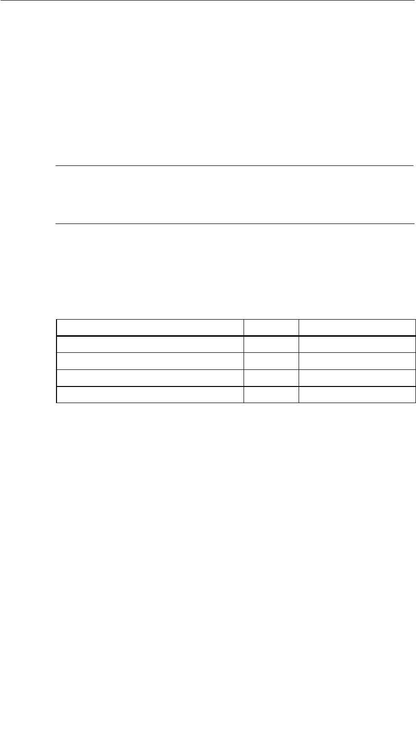
Analog Modules
5-95
S7-400, M7-400 Programmable Controllers Module Specifications
A5E00069467-07
Smoothing of the Measured Values
You will find information that is generally applicable to the smoothing of analog
values in Section 5.6. You can only set strong smoothing for the SM 431; AI 8 14
Bit.
The module cycle time is a constant, irrespective of how many channels are
enabled. It therefore has no effect on the filter settling time, which is defined by the
parameter assignment of interference frequency suppression and smoothing.
Note
It is only advisable to parameterize smoothing if you also parameterize
interference frequency suppression; otherwise, the measured value resolution will
be reduced to 9 bits (analog value representation is right aligned in this case).
Filter Settling Time with Strong Smoothing
Table 5-57 Interference Frequency Suppression and Filter Settling Time with Smoothing of
the SM 431; AI 8 14 Bit (6ES7431-1KF20-0AB0)
Interference Suppression Smoothing Filter settling time in ms
None High –
50 Hz High 100
60 Hz High 83.333
400 Hz High 12.5
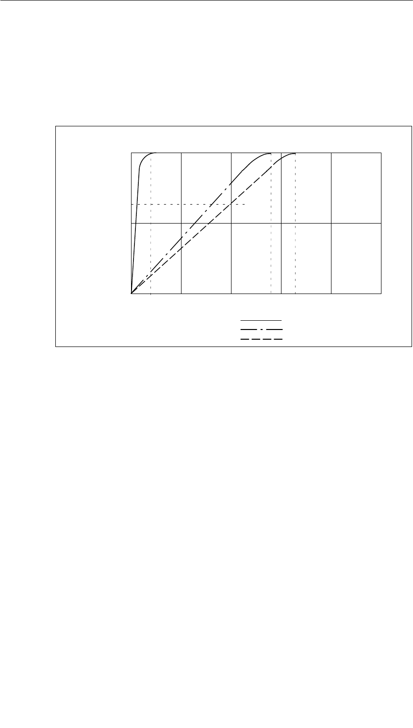
Analog Modules
5-96 S7-400, M7-400 Programmable Controllers Module Specifications
A5E00069467-07
Step Response with Strong Smoothing
The following figure illustrates the contents of Table 5-57. It shows the filter settling
time after which, in the case of a step response, the smoothed analog value is
applied to almost 100%, depending on the interference frequency suppression that
has been set. The figure applies to every change of signal at an analog input.
50
100
0
63
Interference frequency suppression 400 Hz:
60 Hz:
50 Hz:
Filter settling time in ms
Signal variation
in percent Step response for any analog input signal
12030 15060
12.5 83.333 100
Figure 5-32 Step Response of the SM 431; AI 8 14 Bit (6ES7 431-1KF20-0AB0)
5.20.2 Measuring Methods and Measuring Ranges of the SM 431;
AI 8 14 Bit
Measuring Methods
You can set the following measuring methods for the input channels:
•Voltage measurement
•Current measurement
•Resistance test
You specify the setting by means of the measuring range modules on the module
and the “Measuring Type” parameter in STEP 7.
Analog Modules
5-97
S7-400, M7-400 Programmable Controllers Module Specifications
A5E00069467-07
Circuit Variants of the Channels
Two channels are set in each case with the measuring range module. There are
therefore restrictions as regards the measuring method for the adjacent channels
0/1, 2/3, 4/5 and 6/7, as shown in the following table:
Table 5-58 Selection of the Measuring Method for Channel n and Channel n+1 of the SM 431; AI 8 14
Bit (6ES7 431-1KF20-0AB0)
Meas. Type
Channel n+1
Meas. Type Chan-
nel n
Disabled Voltage
"1 V Voltage
1 to 5 V Voltage
"10 V Current
4-DMU Current
2-DMU R-4L
Disabled x x x x x x
Voltage "1 V x x
Voltage 1 to 5 V x x x
Voltage "10 V x x x
Current four-wire
transmitter x x
Current two-wire
transmitter x x
Resistance
four-conductor x
Example
If you select “current (two-wire transmitter)” for channel 6, you can only disable the
measuring method or set “current (two-wire transmitter)” for channel 7.
Circuit for Resistance Measurement
The following conditions apply when measuring the resistance with the SM 431;
AI 8 x 14 Bit:
Table 5-59 Channels for Resistance Measurement of the SM 431; AI 8 14 Bit (6ES7431-1KF20-0AB0)
Measuring Type Parameter Permissible
for Channel n Condition
Resistor
(four-conductor terminal) 0, 2, 4 or 6 You must disable the(“Measuring Type” parameter for
channels n+1 (1, 3, 5, 7).
The reason The connections of channel n+1 are used
to supply the resistance that is connected to
channel n.

Analog Modules
5-98 S7-400, M7-400 Programmable Controllers Module Specifications
A5E00069467-07
Unused Channels
Unused channels can usually be left open. Put the measuring range modules in
position “B”. You can improve the noise immunity of the module in a measuring
environment with serious interference by connecting M– and MANA.
Measuring Ranges
You set the measuring ranges by means of the measuring range modules on the
module and the “Measuring Type” parameter in STEP 7.
Table 5-60 Measuring Ranges of the SM 431; AI 8 x 14 Bit (6ES7431-1KF20-0AB0)
Method Selected Measuring Range
(Type of Sensor) Measuring Range
Module Setting Description
U: Voltage " 1 V AYou will find the digitized analog
l i S ti 531 i th
1 to 5 V
" 10 V
Bvalues in Section 5.3.1 in the
voltage measuring range
2DMU: Current
(two-wire transmitter) 4 to 20 mA DTo supply these transmitters with
current you must connect 24 V to
the L+ and M front connector
terminals.
You will find the digitized analog
values in Section 5.3.1 in the
current measuring range
4DMU: Current
(four-wire transmitter) 4 to 20 mA
" 20 mA
CYou will find the digitized analog
values in Section 5.3.1 in the
current measuring range
R-4L: Resistor
(four-conductor
terminal)
600 AYou will find the digitized analog
values in Section 5.3.1 in the
resistance measuring range
Default Settings
The module has the following default settings in STEP 7:
•Channels 0 to 7: “Voltage” for the measuring method ; “" 10 V” for the
measuring range
You can use these measuring methods and measuring ranges without
parameterizing the SM 431; AI 8 14 Bit in STEP 7.

Analog Modules
5-99
S7-400, M7-400 Programmable Controllers Module Specifications
A5E00069467-07
5.21 Analog Input Module SM 431; AI 16 13 Bit;
(6ES7431-0HH00-0AB0)
Characteristics
The analog input module SM 431; AI 13 16 Bit has the following features:
•16 inputs for voltage/current measurement
•Unlimited measuring range selection
•13-bit resolution
•Non-isolated between the analog section and bus
•The maximum permissible common mode voltage between the channels and
the reference potentials of the connected sensors and central ground point is 2
VDC/VAC
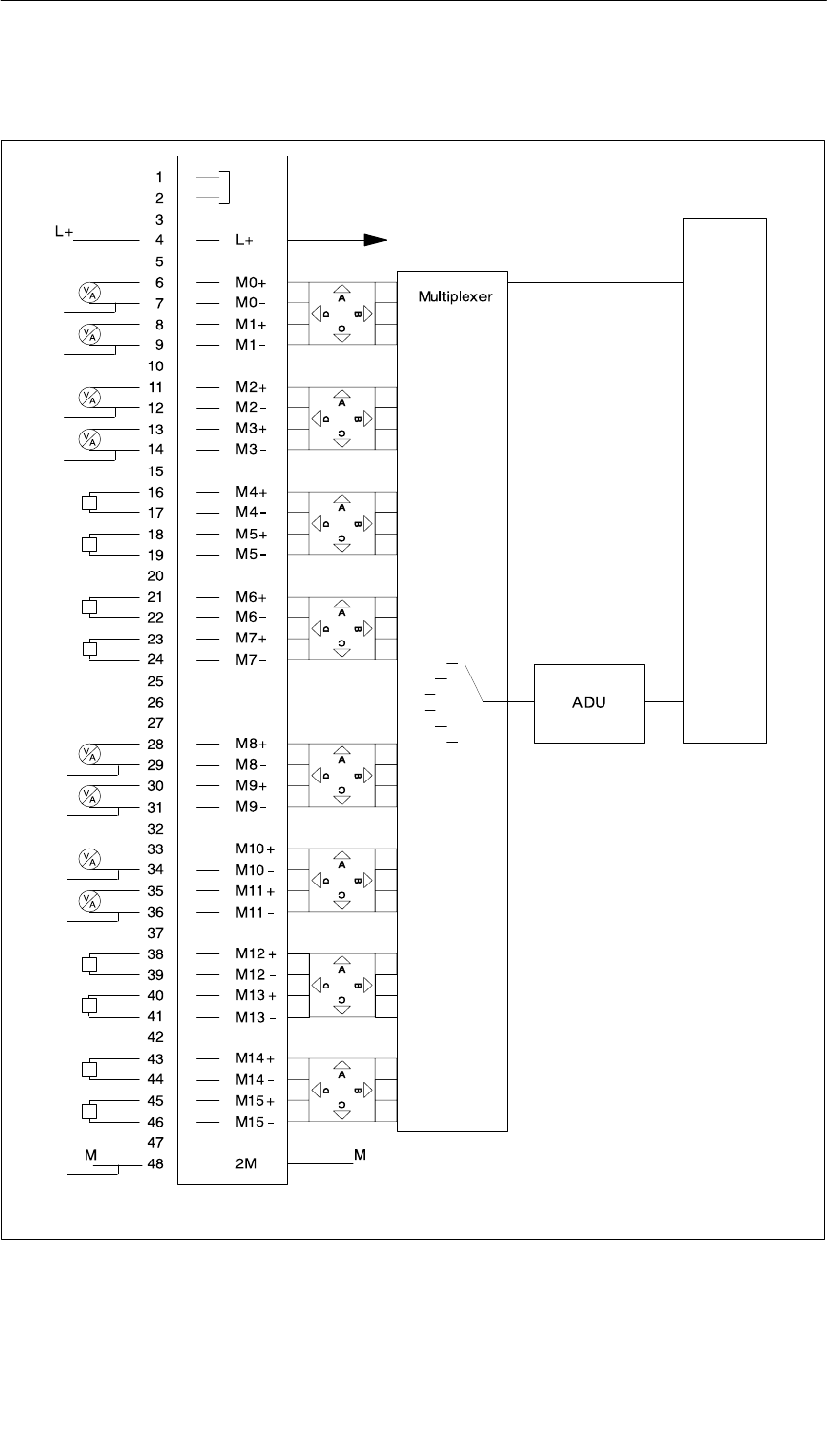
Analog Modules
5-100 S7-400, M7-400 Programmable Controllers Module Specifications
A5E00069467-07
Block Diagram of the SM 431; AI 16 x 13 Bit
Tr
Tr
Tr
Tr
Tr
Tr
Tr
Tr
*
*Voltage/current sensor and M must
be connected to the chassis ground
of the rack
*Voltage/current sensor and M must
be connected to the chassis ground
of the rack
Tr = Transducer = Transmitter
*
*
*
*
*
*
*
*
Measuring range module
Control and backplane bus interface
Figure 5-33 Block Diagram of the SM 431; AI 16 x 13 Bit
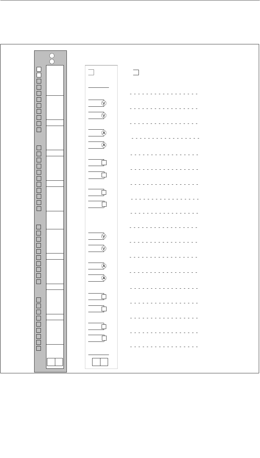
Analog Modules
5-101
S7-400, M7-400 Programmable Controllers Module Specifications
A5E00069467-07
Terminal Assignment Diagram of the SM 431; AI 16 x 13 Bit
Voltage measurement
Current measurement
M1+
M2–
M3–
M4–
M5–
M6–
M7–
CH0
CH1
CH2
CH3
CH4
CH5
CH6
CH7
L+
M0+
M0–
M1–
M2+
M3+
M4+
M5+
M6+
M7+
M
M8–
M9–
M8+
M9+
M10–
M11–
M10+
M11+
M12–
M13–
M12+
M13+
M14–
M15–
M14+
M15+
CH8
CH9
CH10
CH11
CH12
CH13
CH14
CH15
Word 0
Word 4
Word 8
Word 12
Word 16
Word 20
Word 24
Word 28
Word 2
Word 6
Word 10
Word 14
Word 18
Word 22
Word 26
Word 30
L+
M
29
30
31
32
33
34
35
36
37
39
40
41
42
43
44
45
46
47
48
38
1
2
3
4
5
6
7
8
9
10
11
12
13
14
15
16
17
18
19
20
21
22
23
24
25
26
27
28
Tr
Tr
Tr
Tr
Tr
Tr
Tr
Tr
Figure 5-34 Terminal Assignment Diagram of the SM 431; AI 16 x 13 Bit

Analog Modules
5-102 S7-400, M7-400 Programmable Controllers Module Specifications
A5E00069467-07
Technical Specifications of the SM 431; AI 16 x 13 Bit
Dimensions and Weight
Dimensions W H D
(in millimeters) 25 290 210
Weight Approx. 500 g
Data for Specific Module
Number of inputs
•Shielded
16
Max. 200 m
Voltages, Currents, Potentials
Rated load voltage L+ 24 VDC (only required
for the supply of 2-wire
transmitters)
•Reverse polarity protection Yes
Power supply of the
transmitters
•Supply current Max. 50 mA
•Short-circuit proof Yes
Constant measured current for
resistance-type sensor Typ. 1.67 mA
Isolation
•Between channels and
backplane bus
•Between the channels
•Between channels and
load voltage L+
No
No
No
Permitted potential difference
•Between inputs and MANA
(UCM)
•Between the inputs (ECM)
2 VDC/2 VACSS
2 VDC/2 VACSS
Insulation tested with
•Between bus and chassis
ground 500 VDC
Current consumption
•From the backplane bus Max. 100 mA
•From load voltage L+
(with 16 connected, fully
controlled two-wire
transmitters)
Max. 400 mA
Power dissipation of the
module Typ. 2 W
Analog Value Generation
Measuring principle Integrative
Integration time/conversion
time/resolution (per channel) (Does not go into the
response time)
•Parameters can be
assigned Yes
•Interference voltage
suppression f1 in Hz 60/50
•Integration time in
milliseconds 50/60
•Basic conversion time in
ms 55/65
•Resolution including sign 13 bits
Smoothing of the measured
values Not possible
Basic execution time of the
module, in ms (all channels
enabled)
880/1040
Suppression of Interference, Limits of Error
Interference voltage suppression for f = nx (f1 "1%),
(f1 = interference frequency) n = 1, 2, ...
•Common-mode
interference
(UCM < 2 V)
> 86 dB
•Series-mode interference
(peak value of interference
< rated value of input
range)
> 60 dB
Crosstalk between the inputs > 50 dB
Operational limit (in the entire temperature range, with
reference to the input range)
•Voltage input
–" 1 V
–" 10 V
– 1 V to 5 V
" 0.65%
" 0.65%
" 1 %
•Current input
–" 20 mA
– 4 mA to 20 mA
" 0.65%
" 0.65%
Basic error (operational limit at 25 °C, referred to input
range)
•Voltage input
–" 1 V
–" 10 V
– 1 V to 5 V
" 0.25%
" 0.25%
" 0.5%
•Current input
–" 20 mA
– 4 mA to 20 mA
" 0.25%
" 0.25%
Temperature error (with
reference to the input range)
" 0.01%
Linearity error (with reference
to the input range)
" 0.05%
Repeat accuracy (in the steady
state at 25 °C, referred to the
input range)
" 0.01%
Status, Interrupts, Diagnostics
Interrupts None
Diagnostic functions None
Substitute value can be applied No

Analog Modules
5-103
S7-400, M7-400 Programmable Controllers Module Specifications
A5E00069467-07
Data for Selecting a Sensor
Input range (rated values)/Input
resistance
•Voltage " 1 V/10 M
" 10 V/100 M
1 V to 5 V100 M
•Current " 20 mA/50
4 mA to 20 mA50
Maximum input voltage for
voltage input
(destruction limit)
20 V continuous;
75 V for 1 ms (cycle
factor 1 : 20)
Maximum input current for
current input (destruction limit) 40 mA
Connection of the signal
sensor
•For measuring voltage Possible
•For measuring current
– As two-wire
transmitter Possible
– As four-wire
transmitter Possible
•Load of the two-wire
transmitter Max. 750
Characteristic linearization No

Analog Modules
5-104 S7-400, M7-400 Programmable Controllers Module Specifications
A5E00069467-07
5.21.1 Commissioning the SM 431; AI 16 13 Bit
You set the mode of operation of the SM 431; AI 16 13 Bit by means of
measuring range modules on the module and in STEP 7.
Measurement Range Modules
A measuring range module of the module matches two consecutive channels to
each type of sensor. If necessary, the measuring range modules must be
replugged to change the measuring method and the measuring range. The steps
you have to perform to do this are described in detail in Section 5.4.
The corresponding table in Section 5.21.2 tells you which assignment you have to
select for which measuring method and measuring range. In addition, the
necessary settings are embossed on the module.
Parameters
You will find a description of the general procedure for assigning parameters to
analog modules in Section 5.7.
An overview of the parameters that you can set and their default settings are
shown in the table below.
Table 5-61 Parameters of the SM 431; AI 16 13 Bit
Parameter Value Range Default1) Parameter
Type Scope
Measurement
•Measuring type Disabled
U Voltage
4DMU Current (four-wire transmitter)
2DMU Current (two-wire transmitter)
U
Static Channel
•Measuring
range Refer to Section 5.21.2 for the measuring
ranges of the input channels that you can
set.
"10 V
•Interference
suppression 60 Hz; 50 Hz 50 Hz
1) Only in the CC (central controller) is it possible to start up the analog modules with the default settings.
Analog Modules
5-105
S7-400, M7-400 Programmable Controllers Module Specifications
A5E00069467-07
5.21.2 Measuring Methods and Measuring Ranges of the SM 431;
AI 16 13 Bit
Measuring Methods
You can set the following measuring methods for the input channels:
•Voltage measurement
•Current measurement
You specify the setting by means of the measuring range modules on the module
and the “Measuring Type” parameter in STEP 7.
Circuit Variants of the Channels
Two channels are set in each case with the measuring range module. There are
therefore restrictions as regards the measuring method for the adjacent channels
0/1, 2/3, 4/5, 6/7, 8/9, 10/11, 12/13 and 14/15, as shown in the following table:
Table 5-62 Selection of the Measuring Method for Channel n and Channel n+1 of the SM
431; AI 16 13 Bit
Meas. Type
Channel n+1
Meas. Type
Channel n
Disabled Voltage
"1 V Voltage
1 to 5 V Voltage
"10 V Current
4-DMU Current
2-DMU
Disabled x x x x x x
Voltage "1 V x x
Voltage 1 to 5 V x x x
Voltage "10 V x x x
Current four-wire
transmitter x x
Current two-wire
transmitter x x
Example
If you select “current (two-wire transmitter)” for channel 6, you can only disable the
measuring method or set “current (two-wire transmitter)” for channel 7.

Analog Modules
5-106 S7-400, M7-400 Programmable Controllers Module Specifications
A5E00069467-07
Unused Channels
Unused channels can usually be left open. Put the measuring range modules in
position “B”. You can improve the noise immunity of the module in a measuring
environment with serious interference by connecting M– and chassis ground.
Disable the “Measuring Type” parameter for unused channels. In this way you
shorten the scan time of the module.
Measuring Ranges
You set the measuring ranges by means of the measuring range modules on the
module and the “Measuring Type” parameter in STEP 7.
Table 5-63 Measuring Ranges of the SM 431; AI 16 x 13 Bit
Method Selected Measuring Range
(Type of Sensor) Measuring Range
Module Setting Description
U: Voltage " 1 V AYou will find the digitized analog
l i S ti 531 i th
1 to 5 V
" 10 V
Bvalues in Section 5.3.1 in the
voltage measuring range
2DMU: Current
(two-wire transmitter) 4 to 20 mA DTo supply these transmitters with
current you must connect 24 V to
the L+ and M front connector
terminals.
You will find the digitized analog
values in Section 5.3.1 in the
current measuring range
4DMU: Current
(four-wire transmitter) 4 to 20 mA
" 20 mA
CYou will find the digitized analog
values in Section 5.3.1 in the
current measuring range
Default Settings
The default settings of the module in STEP 7 are “Voltage” for the measuring
method and “" 10 V” for the measuring range. You can use this combination of
measuring method and measuring range without parameterizing the SM 431;
AI 16 13 Bit inSTEP 7.

Analog Modules
5-107
S7-400, M7-400 Programmable Controllers Module Specifications
A5E00069467-07
5.22 Analog Input Module SM 431; AI 16 16 Bit;
(6ES7431-7QH00-0AB0)
Characteristics
The analog input module SM 431; AI 16 16 Bit has the following features:
•16 inputs for voltage/current and temperature measurement
•8 inputs for resistance measurement
•Unlimited measuring range selection
•16-bit resolution
•Programmable diagnostics
•Programmable diagnostic interrupt
•Programmable hardware interrupt when limit has been exceeded
•Programmable end-of-scan-cycle interrupt
•Analog section isolated from CPU
•The maximum permissible common mode voltage between the channels and
between the channel and the central ground point is 120 VAC
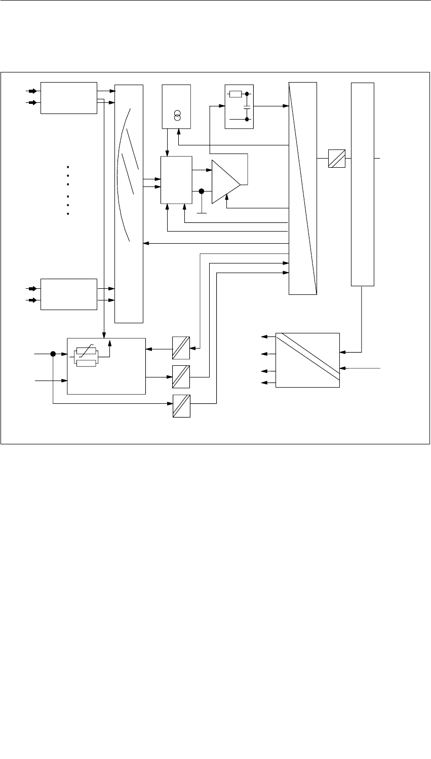
Analog Modules
5-108 S7-400, M7-400 Programmable Controllers Module Specifications
A5E00069467-07
Block Diagram of the SM 431; AI 16 16 Bit
Bus S7-400
Bus control
A
D
CH0
CH1
+ 15 V
+ 5 V
0 V
–15 V
+ 5 V
0 V
Iconst
Diagnostics
in
L+ loop
L +
M
PGA
Multiplexer
Opto relay
CH14
CH15
Meas. range
Meas. range
module 0
module 7
Signal
jumpering
Bus S7-400
Figure 5-35 Block Diagram of the SM 431; AI 16 x 16 Bit
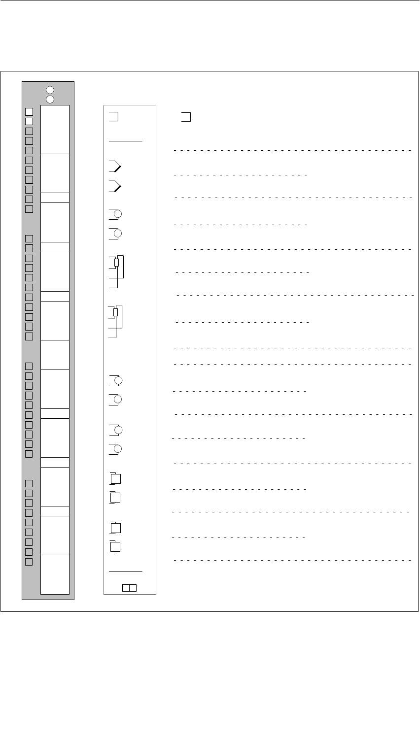
Analog Modules
5-109
S7-400, M7-400 Programmable Controllers Module Specifications
A5E00069467-07
Terminal Assignment Diagram of the SM 431; AI 16 16 Bit
Thermocouples
Voltage measurement
Current measurement
Resistance measurement
Resistance thermometer
M1+
M2–
M3–
M4–
M5–
M6–
M7–
CH0
CH1
CH2
CH3
CH4
CH5
CH6
CH7
L+
V
A
A
M
Tr
Tr
L+
M0+
M0–
M1–
M2+
M3+
M4+
M5+
M6+
M7+
M
M0+
M0–
IC0+
IC0–
M1+
M1–
IC1+
IC1–
M2+
M2–
IC2+
IC2–
M3+
M3–
IC3+
IC3–
CH0
CH2
CH4
CH6
V
M8–
M9–
M8+
M9+
M10–
M11–
M10+
M11+
M12–
M13–
M12+
M13+
M14–
M15–
M14+
M15+
CH8
CH9
CH10
CH11
CH12
CH13
CH14
CH15
M4+
M4–
IC4+
IC4–
M5+
M5–
IC5+
IC5–
M6+
M6–
IC6+
IC6–
M7+
M7–
IC7+
IC7–
CH8
CH10
CH12
CH14
A
A
Tr
Tr
29
30
31
32
33
34
35
36
37
39
40
41
42
43
44
45
46
47
48
38
1
2
3
4
5
6
7
8
9
10
11
12
13
14
15
16
17
18
19
20
21
22
23
24
25
26
27
28
INTF
EXTF
Word 0
Word 4
Word 8
Word 12
Word 16
Word 20
Word 24
Word 28
Word 2
Word 6
Word 10
Word 14
Word 18
Word 22
Word 26
Word 30
Word 0
Word 4
Word 8
Word 12
Word 16
Word 20
Word 24
Word 28
Figure 5-36 Terminal Assignment Diagram of the SM 431; AI 16 x 16 Bit

Analog Modules
5-110 S7-400, M7-400 Programmable Controllers Module Specifications
A5E00069467-07
Technical Specifications of the SM 431; AI 16 16 Bit
Programming package
Associated programming
package As of STEP 7 V 2.0
Dimensions and Weight
Dimensions W H D
(in millimeters) 25 290 210
Weight Approx. 500 g
Data for Specific Module
Number of inputs
•For resistance-type sensor
16
8
Length of cable
•Shielded
in the input ranges x 80
mV and with
thermocouples
Max. 200 m
Max. 50 m
Voltages, Currents, Potentials
Rated load voltage L+ 24 VDC (only required
for the supply of
two-wire transmitters)
•Reverse polarity protection Yes
Power supply of the
transmitters
•Supply current Max. 50 mA
•Short-circuit proof Yes
Constant measured current for
resistance-type sensor Typ. 1.67 mA
Isolation
•Between channels and
backplane bus
•Between the channels
•Between channels and
load voltage L+
Yes
No
Yes
Permitted potential difference
•Between inputs and MANA
(UCM)120 VAC
•Between the inputs (ECM)120 VAC
•Between MANA and
Minternal (UISO)75 VDC/60 VAC
Insulation tested with
•Between bus and L+/M
•Between bus and analog
section
•Between bus and chassis
ground
•Between analog section
and L+/M
•Between analog section
and chassis ground
•Between L+/M and chassis
ground
2120 VDC
2120 VDC
500 VDC
707 VDC
2120 VDC
2120 VDC
Current consumption
•From the backplane bus Max. 700 mA
•From load voltage L+
(with 16 connected, fully
controlled two-wire
transmitters)
Max. 400 mA
Power dissipation of the
module Typ. 4.5 W
Analog Value Generation
Measuring principle Integrative
Integration time/conversion
time/resolution (per channel) (Does not go into the
response time)
•Parameters can be
assigned Yes
•Interference voltage
suppression f1 in Hz 400/60/50
•Integration time in ms 2.5/16.7/20
•Basic conversion time in
ms 6/20.1/23.5
•Additional conversion time
for measuring resistance,
in ms
12/40.2/47
•Additional conversion time
for open-circuit monitoring,
in ms
4.3/4.3/4.3
•Additional conversion time
for measuring resistance
in ms
5.5/5.5/5.5
•Resolution including sign 16/16/16 bit
Smoothing of the measured
values Parameters can be
assigned in 4
stages
Basic execution time of the
module, in ms (all channels
enabled)
96/322/376

Analog Modules
5-111
S7-400, M7-400 Programmable Controllers Module Specifications
A5E00069467-07
Suppression of Interference, Limits of Error
Interference voltage suppression for f = nx (f1 "1%),
(f1 = interference frequency) n = 1, 2, ...
•Common-mode
interference
(UCM < 120 Vss)
> 100 dB
•Series-mode interference
(peak value of interference
< rated value of input
range)
> 40 dB
Crosstalk between the inputs > 70 dB
Operational limit (in the entire temperature range, with
reference to the input range)
•Voltage input
–" 25 mV
–" 50 mV
–" 80 mV
–" 250 mV
–" 500 mV
–" 1 V
–" 2.5 V
–" 5 V
– 1 V to 5 V
–" 10 V
" 0.35 %
" 0.32%
" 0.31%
" 0.3%
" 0.3%
" 0.3%
" 0.3%
" 0.3%
" 0.3%
" 0.3%
•Current input
– 0 mA to 20 mA
–" 5 mA
–" 10 mA
–" 20 mA
– 4 mA to 20 mA
" 0.3%
" 0.3%
" 0.3%
" 0.3%
" 0.3%
•Resistance test
– 0 to 48 ;
four-conductor
measurement
" 0.3%
– 0 to 150 ,
four-conductor
measurement
" 0.3%
– 0 to 300
four-conductor
measurement
" 0.3%
– 0 to 600 ;
four-conductor
measurement
" 0.3%
– 0 to 5000 ;
four-conductor
measurement (in
the range of
6000 )
" 0.3%
– 0 to 300 ;
three-conductor
measurement
" 0.4%
– 0 to 600 ;
three-conductor
measurement
" 0.4%
– 0 to 5000 Ω;
three-conductor
measurement (in
the range of
6000 )
" 0.4%
•Thermocouples
– TC type B
– TC type R
– TC type S
– TC type T
– TC type E
– TC type J
– TC type K
– TC type U
– TC type L
– TC type N
" 11.5 K
" 7.3 K
" 8.3 K
" 1.7 K
" 3.2 K
" 4.3 K
" 6.2 K
" 2.8 K
" 4.2 K
" 4.4 K
•Resistance thermocouples, four-conductor
standard measuring range
– Pt 100
– Pt 200
– Pt 500
– Pt 1000
– Ni 100
– Ni 1000
" 3.1 K
" 4.9 K
" 3.9 K
" 3.1 K
" 0.8 K
" 0.8 K
Climatic measuring range
– Pt 100
– Pt 200
– Pt 500
– Pt 1000
– Ni 100
– Ni 1000
" 0.4 K
" 0.4 K
" 0.4 K
" 0.4 K
" 0.8 K
" 0.8 K
•Resistance thermocouples, three-conductor
standard measuring range
– Pt 100
– Pt 200
– Pt 500
– Pt 1000
– Ni 100
– Ni 1000
" 4.2 K
" 6.5 K
" 5.2 K
" 4.2 K
" 1.0 K
" 1.0 K
Climatic measuring range
– Pt 100
– Pt 200
– Pt 500
– Pt 1000
– Ni 100
– Ni 1000
" 0.5 K
" 0.5 K
" 0.5 K
" 0.5 K
" 1.0 K
" 1.0 K

Analog Modules
5-112 S7-400, M7-400 Programmable Controllers Module Specifications
A5E00069467-07
Basic error (operational limit at 25 °C, referred to input
range)
•Voltage input
–" 25 mV
–" 50 mV
–" 80 mV
–" 250 mV
–" 500 mV
–" 1 V
–" 2.5 V
–" 5 V
– 1 V to 5 V
–"+ 10 V
" 0.23%
" 0.19%
" 0.17%
" 0.15%
" 0.15%
" 0.15%
" 0.15%
" 0.15%
" 0.15%
" 0.15%
•Current input
– 0 mA to 20 mA
–" 5 mA
–" 10 mA
–" 20 mA
– 4 mA to 20 mA
" 0.15%
" 0.15%
" 0.15%
" 0.15%
" 0.15%
•Resistance test
– 0 to 48 ;
four-conductor
measurement
" 0.15%
– 0 to 150 ,
four-conductor
measurement
" 0.15%
– 0 to 300
four-conductor
measurement
" 0.15%
– 0 to 600 ;
four-conductor
measurement
" 0.15%
– 0 to 5000 ;
four-conductor
measurement (in
the range of
6000 )
" 0.15%
– 0 to 300 ;
three-conductor
measurement
" 0.3%
– 0 to 600 ;
three-conductor
measurement
" 0.3%
– 0 to 5000 Ω;
three-conductor
measurement (in
the range of
6000 )
" 0.3%
•Thermocouples
– TC type B
– TC type R
– TC type S
– TC type T
– TC type E
– TC type J
– TC type K
– TC type U
– TC type L
– TC type N
" 7.6 K
" 4.8 K
" 5.4 K
" 1.1 K
" 1.8 K
" 2.3 K
" 3.4 K
" 1.7 K
" 2.3 K
" 2.6 K
•Resistance thermocouples, four-conductor
standard measuring range
– Pt 100
– Pt 200
– Pt 500
– Pt 1000
– Ni 100
– Ni 1000
" 1.6 K
" 2.5 K
" 2.0 K
" 1.6 K
" 0.4 K
" 0.4 K
Climatic measuring range
– Pt 100
– Pt 200
– Pt 500
– Pt 1000
– Ni 100
– Ni 1000
" 0.2 K
" 0.2 K
" 0.2 K
" 0.2 K
" 0.4 K
" 0.4 K
•Resistance thermocouples, three-conductor
standard measuring range
– Pt 100
– Pt 200
– Pt 500
– Pt 1000
– Ni 100
– Ni 1000
" 3.1 K
" 4.9 K
" 3.9 K
" 3.1 K
" 0.8 K
" 0.8 K
Climatic measuring range
– Pt 100
– Pt 200
– Pt 500
– Pt 1000
– Ni 100
– Ni 1000
" 0.4 K
" 0.4 K
" 0.4 K
" 0.4 K
" 0.8 K
" 0.8 K
Temperature error (with
reference to the input range)
" 0.004% K
Linearity error (with reference
to the input range)
" 0.01% K
Repeat accuracy (in the steady
state at 25 °C, referred to the
input range)
" 0.1%

Analog Modules
5-113
S7-400, M7-400 Programmable Controllers Module Specifications
A5E00069467-07
Status, Interrupts, Diagnostics
Interrupts
•Hardware interrupt Parameters can be
assigned
•Hardware interrupt when
limit has been exceeded Parameters can be
assigned
•Diagnostic Interrupt Parameters can be
assigned
Diagnostic functions
•Group error display
– For internal fault
– For external fault
Red LED (INTF)
Red LED (EXTF)
•Diagnostic information
readable Yes
Substitute value can be applied No
Data for Selecting a Sensor
Input range (rated values)/Input
resistance
•Voltage " 25 mV/1 M
" 50 mV/1 M
" 80 mV/1 M
" 250 mV/1 M
" 500 mV/1 M
" 1 V/1 M
" 2.5 V/1 M
" 5 V/1 M
1 V to 5 V1 M
" 10 V/1 M
•Current 0 mA to 20 mA50
" 5 mA/50
" 10 mA/50
" 20 mA/50
4 mA to 20 mA50
•Resistors 0 to 48 1 M
0 to 150 1 M
0 to 300 1 M
0 to 600 1 M
0 to 6000 1 M
(can be used up to
5000 )
•Thermocouples TC type B/1 M
TC type R/1 M
TC type S/1 M
TC type T/1 M
TC type E/1 M
TC type J/1 M
TC type K/1 M
TC type U/1 M
TC type L/1 M
TC type N/1 M
•Resistance thermometer Pt 100/1 M
Pt 200/1 M
Pt 500/1 M
Pt 1000/1 M
Ni 100/1 M
Ni 1000/1 M
Maximum input voltage for
voltage input
(destruction limit)
Max. 18 V continuous;
75 V for 1 ms (cycle
factor 1 : 20)
Maximum input current for
current input (destruction limit) 40 mA
Connection of the signal
sensor
•For measuring voltage Possible
•For measuring current
– As two-wire
transmitter Possible
– As four-wire
transmitter Possible
•For measuring resistance
– With two-conductor
terminal Possible; cable
resistance is also
measured
– With three-conductor
terminal Possible
– With four-conductor
terminal Possible
•Load of the two-wire
transmitter Max. 750
Characteristic linearization Parameters can be
assigned
•For thermocouples Types B, R, S, T, E, J,
K, U, L, N
•For
resistance thermometer Pt 100, Pt 200, Pt 500,
Pt 1000, Ni 100,
Ni 1000
Temperature compensation Yes, programmable
•Internal temperature
compensation No
•External temperature
compensation with
compensating box
Possible
•External temperature
compensation with Pt 100 Possible
•Compensation for
definable reference
junction
temperature
Possible
Unit for temperature
measurement Degrees Celsius

Analog Modules
5-114 S7-400, M7-400 Programmable Controllers Module Specifications
A5E00069467-07
5.22.1 Commissioning the SM 431; AI 16 16 Bit
You set the mode of operation of the SM 431; AI 16 16 Bit by means of
measuring range modules on the module and in STEP 7.
Measuring Range Module
A measuring range module of the module matches two channels and one
resistance channel to each type of sensor. If necessary, the measuring range
modules must be replugged to change the measuring method and the measuring
range. The steps you have to perform to do this are described in detail in
Section 5.4.
The corresponding table in Section 5.22.2 tells you which assignment you have to
select for which measuring method and measuring range. In addition, the
necessary settings are embossed on the module.
Parameters
You will find a description of the general procedure for assigning parameters to
analog modules in Section 5.7.
An overview of the parameters that you can set and their default settings are
shown in the table below.
Table 5-64 Parameters of the SM 431; AI 16 16 Bit
Parameter Value Range Default2) Parameter
Type Scope
Enable
•Diagnostic interrupt1)
•Hardware interrupt1) Yes/no
Yes/no No
No Dynamic Module
•Destination CPU for
interrupt 1 to 4 –Static Module
Trigger for hardware
interrupt
•End of scan cycle
reached at input
Yes/no No Static Channel
•High limit
•Low limit
32511 to – 32512
– 32512 to 32511 – Dynamic Channel
Diagnostics
•Wire break
•Reference channel
error
•Underflow
•Overflow
•Short circuit to M
Yes/no
Yes/no
Yes/no
Yes/no
Yes/no
No
No
No
No
No
Static Channel

Analog Modules
5-115
S7-400, M7-400 Programmable Controllers Module Specifications
A5E00069467-07
Table 5-64 Parameters of the SM 431; AI 16 16 Bit, continued
Parameter ScopeParameter
Type
Default2)
Value Range
Measurement
•Measuring type Disabled
U Voltage
4DMU Current
(4-wire transmitter)
2DMU Current
(two-wire transmitter)
R-4L Resistor
(four-conductor terminal)
R-3L Resistor
(three-conductor terminal)
RTD-4L Thermal resistor
(linear, four-conductor
terminal)
RTD-3L Thermal resistor
(linear, three-conductor
terminal)
TC-L Thermocouple (linear)
U
Static Channel
•Measuring range Refer to Section 5.22.2 for the
measuring ranges of the input
channels that you can set.
"10 V
•teference
Temperature – 273.15 to 327.67 oC0.00 oC
•Interference
suppression 400 Hz; 60 Hz; 50 Hz 50 Hz
•Smoothing None
Low
Average
High
None
Dynamic Module
•Ref. junction None
RTD on Channel 0
Reference temperature value
None
1) If you use the module in ER-1/ER-2, you must set this parameter to “No” because the interrupt lines are
not available in ER-1/ER-2.
2) Only in the CC (central controller) is it possible to start up the analog modules with the default settings.
A Point to Note About Channels for Hardware Interrupts with the End of Scan
Cycle Trigger
You can parameterize hardware interrupts for the end of scan cycle for one of the
16 channels because the module can only trigger these interrupts on one channel.
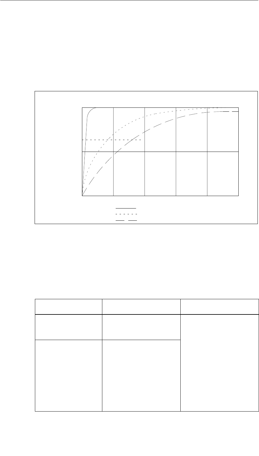
Analog Modules
5-116 S7-400, M7-400 Programmable Controllers Module Specifications
A5E00069467-07
Smoothing of the Measured Values
You fill find information that is generally applicable to the smoothing of analog
values in Section 5.6.
The following figure indicates for the module the number of module cycles after
which, in the case of a step response, the smoothed analog value is applied at
almost 100%, depending on the smoothing setting. The figure applies to every
change of signal at an analog input.
50
100
0
63
Smoothing: low:
average:
high:
Module cycles
Signal variation
in percent Step response for any analog input signal
60 8020 10040
Figure 5-37 Step Response of the SM 431; AI 16 16 Bit (6ES7431-7QH00-0AB0)
Displaying Parameter Assignment Errors
The SM 431; AI 16 16 Bit has diagnostics capability. Below you will find an
overview of the displays that are possible for modules with parameter assignment
errors.
Table 5-65 Diagnostic Information of the SM 431; AI 16 16 Bit
Incorrect Parameter
Assignment Possible Display Explanation
Of the module •Module malfunction
•Internal malfunction
•Wrong parameters
You can find an explanation of
the diagnostic information in
Tables 4-8 and 5-47 on Pages
4-10 and 5-65.
Affecting certain
channels •Module malfunction
•Internal malfunction
•There is a channel error
•Wrong parameters
•Channel information
available
•Vector channel error
•Channel parameter
assignment error
4
-
10 and 5
-
65
.
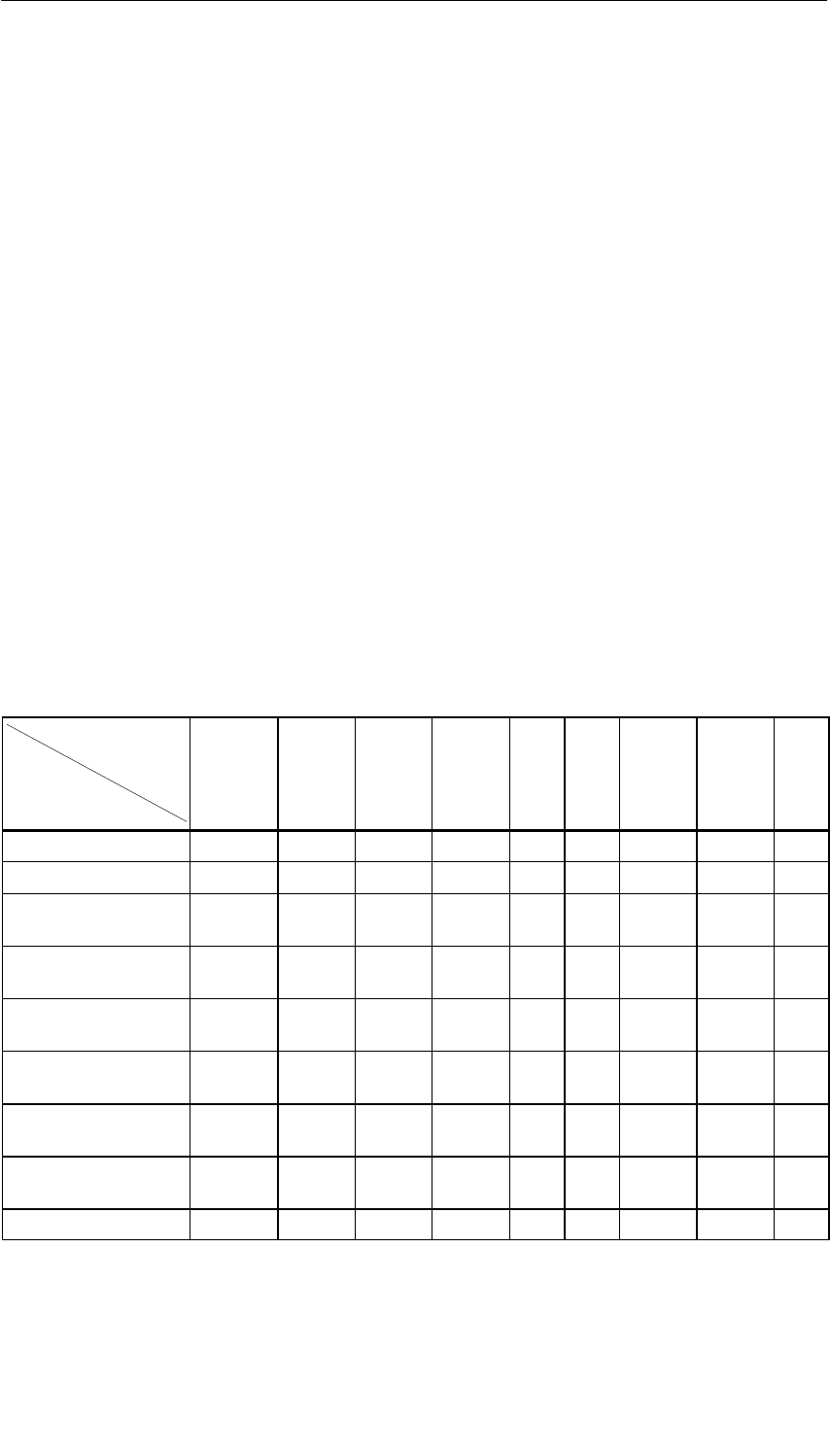
Analog Modules
5-117
S7-400, M7-400 Programmable Controllers Module Specifications
A5E00069467-07
5.22.2 Measuring Methods and Measuring Ranges of the SM 431;
AI 16 16 Bit
Measuring Methods
You can set the following measuring methods for the input channels:
•Voltage measurement
•Current measurement
•Resistance test
•Temperature measurement
You specify the setting by means of the measuring range modules on the module
and the “Measuring Type” parameter in STEP 7.
Circuit Variants for the Channels
Two channels are set in each case with the measuring range module. There are
therefore restrictions as regards the measuring method for the adjacent channels
0/1, 2/3, 4/5, 6/7, 8/9, 10/11, 12/13 and 14/15, as shown in the following table:
Table 5-66 Selection of the Measuring Method for Channel n and Channel n+1 of the SM 431;
AI 16 16 Bit
Meas. Type
Channel n+1
Meas. Type
Channel n
Disabled Voltage Current
4-DMU Current
2-DMU R-4L R-3L RTD-4L RTD-3L TC-L
Disabled x x x x x
Voltage x x x
Current four-wire
transmitter x x
Current two-wire
transmitter x x
Resistance
four-conductor x
Resistance
three-conductor x
Thermal resistor
four-conductor x
Thermal resistor
three-conductor x
Thermocouples x x x
Analog Modules
5-118 S7-400, M7-400 Programmable Controllers Module Specifications
A5E00069467-07
Example
If you have select “current (two-wire transmitter)” for channel 6, you can only
disable the measuring method or set “current (two-wire transmitter)” for channel 7.
Circuit for Resistance and Temperature Measurement
The following conditions apply when measuring the resistance and temperature
with the SM 431; AI 16 x 16 Bit:
Table 5-67 Channels for Resistance and Temperature Measurement of the SM 431; AI 16 16 Bit
Measuring Type Parameter Permissible
for Channel n Condition
Resistor
(four-conductor terminal) 0, 2, 4, 6, 8, 10,
12 or 14 You must disable the (“Measuring Type” parameter
for channels n+1 (1, 3, 5, 7, 9, 11, 13, 15).
Resistor
three-conductor terminal 0, 2, 4, 6, 8, 10,
12 or 14
(,,,,, , , )
The reason The connections of channel n+1 are used
to supply the resistance that is connected to channel
Thermal resistor
(linear, four-conductor termi-
nal)
0, 2, 4, 6, 8, 10,
12 or 14
pp y
n.
Thermal resistor
(linear, four-conductor termi-
nal)
0, 2, 4, 6, 8, 10,
12 or 14
Thermocouple (linear) 0 to 15 You can select the reference junction. It is only
advisable to specify a reference junction with
thermocouples.
Circuit for Reference Junction Compensation for Thermocouples
If you select “RTD on Channel 0” as a reference junction for reference junction
compensation for thermocouples, the following applies:
Table 5-68 Reference Junction Compensation via RTD on Channel 0 of the SM 431; AI 16 16 Bit
Reference Junction
Parameter Permissible
for
Channel n
Condition
RTD on Channel 0 2 to 15 You must connect and parameterize on channel 0 a
resistance thermometer with linearization, a 3- or
4- conductor terminal in climatic range. This means that
channels 0 and 1 are assigned.
The reason If channel 0 is to be used as the reference
junction, a resistance-type sensor must be connected
there to establish the absolute temperatures in the
climatic range.

Analog Modules
5-119
S7-400, M7-400 Programmable Controllers Module Specifications
A5E00069467-07
Unused Channels
Unused channels can usually be left open. Put the measuring range modules in
position “A”. You can improve the noise immunity of the module in a measuring
environment with serious interference by short-circuiting the channels.
Disable the “Measuring Type” parameter for unused channels. In this way you
shorten the scan time of the module.
Measuring Ranges
You set the measuring ranges by means of the measuring range modules on the
module and the “Measuring Type” parameter in STEP 7.
Table 5-69 Measuring Ranges of the SM 431; AI 16 x 16 Bit
Method Selected Measuring Range
(Type of Sensor) Measuring Range
Module Setting Description
U: Voltage " 25 mV
" 50 mV
" 80 mV
" 250 mV
" 500 mV
AYou will find the digitized
analog values in Section
5.3.1 in the voltage
measuring range
" 1 V
" 2.5 V
" 5 V
1 to 5 V
" 10 V
2DMU: Current (two-wire
transmitter) 4 to 20 mA DTo supply these transmitters
with current you must
connect 24 V to the L+ and
M front connector terminals.
You will find the digitized
analog values in Section
5.3.1 in the current
measuring range
4DMU: Current (four-wire
transmitter)
" 5 mA
" 10 mA
0 to 20 mA
4 to 20 mA
" 20 mA
CYou will find the digitized
analog values in Section
5.3.1 in the current
measuring range

Analog Modules
5-120 S7-400, M7-400 Programmable Controllers Module Specifications
A5E00069467-07
Table 5-69 Measuring Ranges of the SM 431; AI 16 x 16 Bit, continued
Method Selected DescriptionMeasuring Range
Module Setting
Measuring Range
(Type of Sensor)
R-3L: Resistor
(three-conductor terminal)
300
600
6000 max. 5000
AYou will find the digitized
analog values in Section
5.3.1 in the resistance
measurin
g
ran
g
e
R-4L: Resistor
(four-conductor terminal)
48
150
300
600
6000 max. 5000
measuring range
TC-L: Thermocouple
(linear)
(temperature
measurement)
Type B
Type N
Type E
Type R
Type S
Type J
Type L
Type T
Type K
Type U
AYou will find the digitized
analog values in Section
5.3.1 in the temperature
range
RTD-3L: thermal resistor
linear, three-conductor
terminal (temperature
measurement)
Pt 100 climatic
Pt 200 climatic
Pt 500 climatic
Pt 1000 climatic
Ni 100 climatic
Ni 1000 climatic
AYou will find the digitized
analog values in Section
5.3.1 in the temperature
range
RTD-4L: thermal resistor
linear, four-conductor
terminal (temperature
measurement)
Pt 100 standard
Pt 200 standard
Pt 500 standard
Pt 1000 standard
Ni 100 standard
Ni 1000 standard
Default Settings
The default settings of the module in STEP 7 are “Voltage” for the measuring
method and “" 10 V” for the measuring range. You can use this combination of
measuring method and measuring range without parameterizing the SM 431;
AI 16 16 Bit in STEP 7.

Analog Modules
5-121
S7-400, M7-400 Programmable Controllers Module Specifications
A5E00069467-07
Wire Break Check
The wire break check is intended primarily for temperature measurements (TC,
RTD) or resistance measurements. Always parameterize the wire break check in
these cases as this ensures that in the event of a wire break the measured value
provided by the module accepts the data for overrun 7FFFH.
Special Characteristics of the Wire Break Check for the Voltage Measurement
Methods
In some transmitters, incorrect measured values may occur due to the fact that the
wire break check is enabled. If so, disable the wire break check.
The reason Some transmitters try to correct the test current and in doing so corrupt
the setpoint value they provide.
Points to Note About the Wire Break Check when Current Sensors Are
Connected
A wire break check of current sensors is not possible for the SM 431; AI 16 16
Bit except in life-zero areas. You can therefore only parameterize the wire break
check for the “Current (four-wire transmitter)” measuring method and the “4 to 20
mA” measuring range.
Checking for Reference Channel Errors when Connecting Thermocouples
If you have connected a thermocouple, you can then enable the “Reference
channel error” diagnosis if you have parameterized an “RTD on Channel 0” or
“Reference Temperature Value” reference junction.
Points to Note About Checking for “Underflow” with some Measuring Methods
and Measuring Ranges
There is now underflow in life-zero areas. A value that is too low or is negative is
interpreted as a wire break. You can therefore not parameterize the underflow
check for the SM 431; AI 16 16 Bit for the following measuring methods and
ranges:
Table 5-70 Points to Note when Checking for “Underflow”
Measuring Method Measuring Range
Voltage 1 to 5 V
Current (four-wire transmitter) 4 to 20 mA
Current (two-wire transmitter) 4 to 20 mA
Points to Note About the “Short Circuit to M” Diagnosis
You can only parameterize the check for “Short Circuit to M” for the SM 431; AI
16 16 Bit for the “Current (2-wire transmitter)” measuring method.

Analog Modules
5-122 S7-400, M7-400 Programmable Controllers Module Specifications
A5E00069467-07
5.23 Analog Input Module SM 431; AI 8 RTD 16 Bit;
(6ES7 431-7KF10-0AB0)
Characteristics
The analog input module SM 431; AI 8 RTD 16 Bit has the following features:
•8 differential inputs for the resistance thermometer
•Resistance thermometer can be parameterized
•Linearization of the resistance thermometer characteristic curves
•16-bit resolution
•Update rate of 25 ms for 8 channels
•Programmable diagnostics
•Programmable diagnostic interrupt
•Programmable hardware interrupt when limit has been exceeded
•Analog section isolated from CPU
•The maximum permissible common mode voltage between the channel and the
central ground point is 120 VAC
Calibration Software
The analog input module AI 8 x RTD x 16 Bit; (6ES7431-7KF10-0AB0) is delivered
with the software “S7-400 RTD User Calibration” on two diskettes. After installing
the software, you can define user-specific calibration values for each channel and
and each module input range. You will find further information under ID 12436891
at the Customer Support FAQ site.
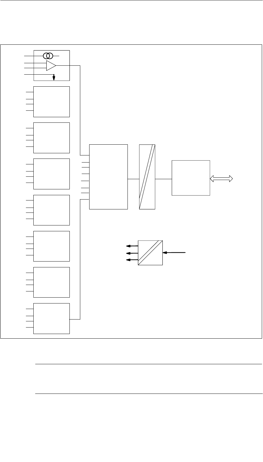
Analog Modules
5-123
S7-400, M7-400 Programmable Controllers Module Specifications
A5E00069467-07
Block Diagram of the SM 431; AI 8 RTD 16 Bit
Backplane
bus
interface
Bus
S7-400
SO+0
SE+0
SE–0
AGND
SO+7
SE+7
SE–7
AGND
CH0
CH1
CH2
CH3
CH4
CH5
CH6
CH7
A/D
converter
Isolation
Internal
voltage
supply
Figure 5-38 Block Diagram of the SM 431; AI 8 x RTD x 16 Bit
Note
An external protective network is required in the signal leads in accordance with
IEC 61000-4-5 (150 V/14 mm MOV across each + and – input to chassis ground)
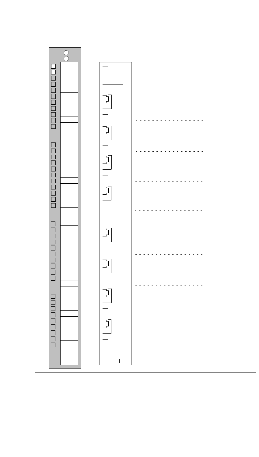
Analog Modules
5-124 S7-400, M7-400 Programmable Controllers Module Specifications
A5E00069467-07
Terminal Assignment Diagram of the SM 431; AI 8 RTD 16 Bit
SO0 CH0
CH1
CH2
CH3
CH4
CH5
CH6
CH7
SE+0
SE–0
AGND
29
30
31
32
33
34
35
36
37
39
40
41
42
43
44
45
46
47
48
38
1
2
3
4
5
6
7
8
9
10
11
12
13
14
15
16
17
18
19
20
21
22
23
24
25
26
27
28
INTF
EXTF
Word 0
Word 2
Word 4
Word 6
Word 1
Word 3
Word 5
Word 7
SO1
SE+1
SE–1
AGND
SO2
SE+2
SE–2
AGND
SO3
SE+3
SE–3
AGND
SO4
SE+4
SE–4
AGND
SO5
SE+5
SE–5
AGND
SO6
SE+6
SE–6
AGND
SO7
SE+7
SE–7
AGND
Figure 5-39 Terminal Assignment Diagram of the SM 431; AI 8 x RTD x 16 Bit
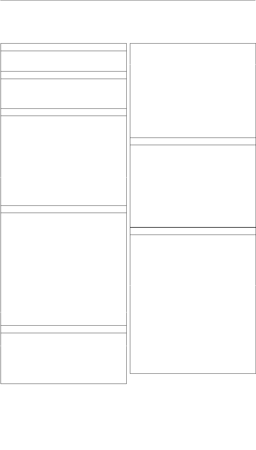
Analog Modules
5-125
S7-400, M7-400 Programmable Controllers Module Specifications
A5E00069467-07
Technical Specifications of the SM 431; AI 8 RTD 16 Bit
Dimensions and Weight
Dimensions W H D
(in millimeters) 25 290 210
Weight Approx. 650 g
Data for Specific Module
Number of inputs
•For resistance-type sensor
8
4
Length of cable
•Shielded Max. 200 m
Voltages, Currents, Potentials
Constant current for
resistance-type sensor Max. 1 mA
Isolation
•Between channels and
backplane bus Yes
Permitted potential difference
•Between MANA and
Minternal (UISO)120 VAC
Insulation tested with 1500 VAC
Current consumption
•From the backplane bus Max. 650 mA
Power dissipation of the
module Typ. 3.3 W
Analog Value Generation
Measuring principle Integrative
Integration/conversion time/
resolution (per channel)
•Parameterizable
(Does not go into the
response time)
Yes
•Basic conversion time in
ms 22/25
•Additional conversion time
for measuring resistance,
in ms
Max. 200
•Resolution including sign 16/16 bit
•Noise suppression
for interference frequency
f1 in Hz
60/50
Smoothing of the measured
values Parameters can be
assigned in 4 stages
Basic response time of module
(all channels enabled) 22/25 ms
Suppression of interference, Limits of Error
Noise suppression for f = n (f1 "1%),
(f1 = interference frequency) n = 1, 2, etc.
•Common-mode
interference (UCM < 120V)
•Series-mode interference
(peak value of interference
< rated value of the input
range)
> 100 dB
> 50 dB
Crosstalk between the inputs > 70 dB
Operational limit (over entire temperature range, referred
to 0 to 60 C input range)
•RTD input " 1.0 °C
Basic error (operational limit at 25 °C, referred to input
range)
•RTD input " 0.5 °C
Temperature error (with
reference to the input range)
" 0.007%/K
Linearity error (with reference
to the input range)
" 0.2 °C
Repeat accuracy (in the steady
state at 25 °C, referred to the
input range)
" 0.2 °C
Status, Interrupts, Diagnostics
Interrupts
•Hardware interrupt when
limit has been exceeded Parameters can be
assigned
•Diagnostic Interrupt Parameters can be
assigned
Diagnostic functions Parameters can be
assigned
•Group error display
– For internal fault
– For external fault
Red LED (INTF)
Red LED (EXTF)
•Diagnostic information can
be displayed Possible
Data for Selecting a Sensor
Input range (rated values) input
resistance
•Resistance thermometer Pt 100, Pt 200, Pt 500,
Pt 1000, Ni 100,
Ni 1000
•Maximum input voltage for
voltage input (destruction
limit)
35 V continuous;
75 V for max. 1 s
(duty factor 1:20)
Connection of the sensor
•For measuring resistance
With three-conductor
terminal Possible
With four-conductor
terminal Possible
Characteristic linearization
•For resistance
thermometer Pt 100,0,00385 to DIN
IEC 751
Ni 100, 0,00618 to DIN
43760
Unit for temperature
measurement Degrees Celsius;
degrees Fahrenheit

Analog Modules
5-126 S7-400, M7-400 Programmable Controllers Module Specifications
A5E00069467-07
5.23.1 Commissioning the SM 431; AI 8 RTD 16 Bit
You set the mode of operation of the SM 431; AI 8 RTD 16 Bit in STEP 7.
Parameters
You will find a description of the general procedure for assigning parameters to
analog modules in Section 5.7.
An overview of the parameters that you can set and their default settings are
shown in the table below.
Table 5-71 Parameters of the SM 431; AI 8 RTD 16 Bit
Parameter Value Range Default2) Parameter
Type Scope
Enable
•Diagnostic interrupt1)
•Hardware interrupt1) Yes/no
Yes/no No
No Dynamic Module
•Destination CPU for
interrupt 1 to 4 –Static Module
Trigger for hardware
interrupt3)
Dynamic
Channel
•High limit
•Low limit
32767 to – 32768
– 32768 to 32767
– Dynamic Channel
Diagnostics
•Wire break
•Underflow
•Overflow
Yes/no
Yes/no
Yes/no
No
No
No
Measurement
•Measuring type Disabled
RTD-4L Thermal resistor
(linear, four-conductor
terminal)
RTD-3L Thermal resistor
(linear, three-conductor
terminal)
RTD-3L
Static Channel
•Measuring range Refer to Section 5.23.2 for the
measuring ranges of the input
channels that you can set.
Pt 100
standard
•Temperature unit Degrees Celsius; degrees
Fahrenheit Degrees
Celsius Static Module
•Temperature
coefficient for
temperature
measurement with
thermal resistor (RTD)
For platinium (Pt)
0.00385 / °C
0.003916 / °C
0.003902 / °C
0.003920 / °C
For nickel (Ni)
0.00618 / °C
0.00672 / °C
0.00385
Static Channel
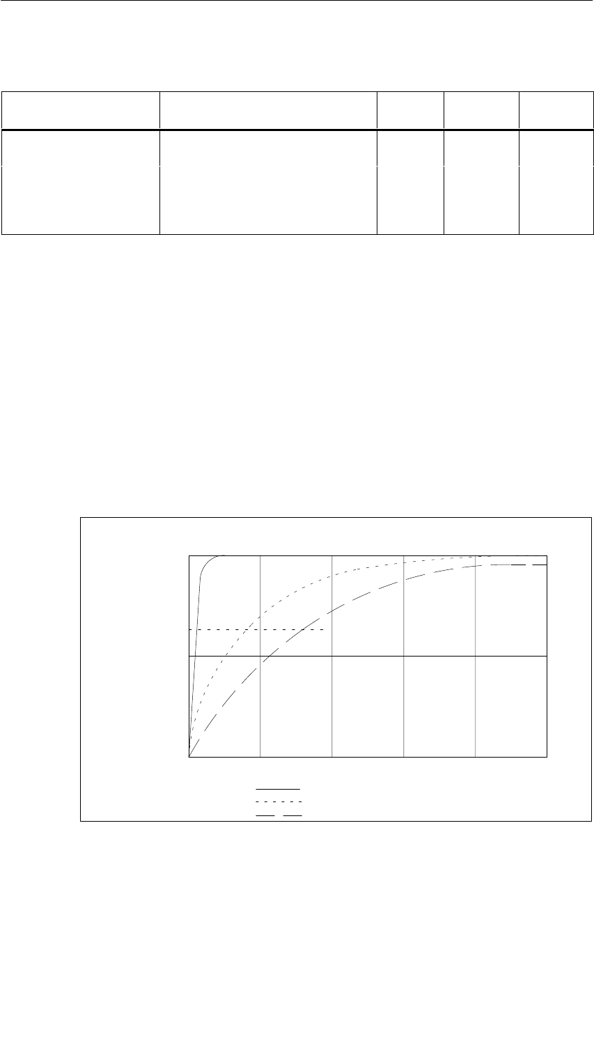
Analog Modules
5-127
S7-400, M7-400 Programmable Controllers Module Specifications
A5E00069467-07
Table 5-71 Parameters of the SM 431; AI 8 RTD 16 Bit, continued
Parameter ScopeParameter
Type
Default2)
Value Range
•Interference
suppression 60 Hz; 50 Hz; none 60 Hz
•Smoothing None
Low
Average
High
None
Static Channel
1) If you use the module in ER-1/ER-2, you must set this parameter to “No” because the interrupt lines are
not available in ER-1/ER-2.
2) Only in the CC (central controller) is it possible to start up the analog modules with the default settings.
3) The limit values must be within the temperature range of the connected sensor.
Smoothing of the Measured Values
You fill find information that is generally applicable to the smoothing of analog
values in Section 5.6.
The following figure shows for the module the number of module cycles, in the
case of a step response, after which the smoothed analog value is applied to
almost 100%, depending on the smoothing setting. The figure applies to every
change of signal at an analog input.
50
100
0
63
Smoothing: low:
average:
high:
Module cycles
Signal variation
in percent Step response for any analog input signal
60 8020 10040
Figure 5-40 Step Response of the SM 431; AI 8 RTD 16 Bit

Analog Modules
5-128 S7-400, M7-400 Programmable Controllers Module Specifications
A5E00069467-07
Displaying Parameter Assignment Errors
The SM 431; AI 8 RTD 16 Bit is capable of diagnostics. Below you will find an
overview of the displays that are possible for modules with parameter assignment
errors.
Table 5-72 Diagnostic Information of the SM 431; AI 8 RTD 16 Bit
Incorrect Parameter
Assignment Possible Display Explanation
Of the module •Module malfunction
•Internal malfunction
•Wrong parameters
•Module not parameterized.
You can find an
explanation of the
diagnostic information in
Tables 4-8 and 5-47 on
Pages 4-10 and 5-65.
Affecting certain
channels •Module malfunction
•Internal malfunction
•There is a channel error
•Wrong parameters
•Channel information available
•Vector channel error
•Channel parameter assignment
error
•User calibration doesn’t
correspond to the parameter
assignment
g
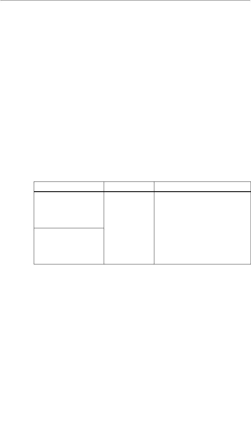
Analog Modules
5-129
S7-400, M7-400 Programmable Controllers Module Specifications
A5E00069467-07
5.23.2 Measuring Methods and Measuring Ranges of the SM 431;
AI 8 RTD 16 Bit
Measuring Methods
As the measuring method for the input channels, you can set the temperature
measurement.
Unused Channels
Disable the “Measuring Type” parameter for unused channels. In this way you
shorten the scan time of the module.
Measuring Ranges
You set the measuring ranges with the “Measuring Type” parameter in STEP 7.
Table 5-73 Measuring Ranges of the SM 431; AI 8 x RTD x 16 Bit
Method Selected Measuring Range Description
RTD-3L: Thermal resistor
(linear, three-conductor
terminal)
(temperature
measurement)
Pt 100 standard
Pt 200 standard
Pt 500 standard
Pt 1000 standard
Ni 100 standard
You will find the digitized analog values
in Section 5.3.1 in the temperature
range
RTD-4L: Thermal resistor
(linear, four-conductor
terminal)
(temperature
measurement)
Ni
100
stan
d
ar
d
Ni 1000 standard
Default Settings
The default settings of the module in STEP 7 are “Thermal resistor (linear,
3-conductor terminal)” for the measuring method and “Pt 100 standard” for the
measuring range. You can use this measuring method with this measuring range
without parameterizing the SM 431; AI 8 RTD 16 Bit with STEP 7.

Analog Modules
5-130 S7-400, M7-400 Programmable Controllers Module Specifications
A5E00069467-07
5.24 Analog Input Module SM 431; AI 8 16 Bit;
(6ES7431-7KF00-0AB0)
Characteristics
The analog input module SM 431; AI 8 16 Bit has the following features:
•8 isolated differential inputs for voltage/current/temperature measurement
•Unlimited measuring range selection
•Linearization of the thermocouple characteristic curves
•16-bit resolution
•Programmable diagnostics
•Programmable diagnostic interrupt
•Programmable hardware interrupt when limit has been exceeded
•Analog section isolated from CPU
•The maximum permissible common mode voltage between the channels and
between the channel and the central ground point is 120 VAC
•Internal measured resistance
•Field connection (6ES7431-7K00-6AA0) with internal reference temperature
(included with the product)
Calibration Software
The analog input module SM 431; AI x 16 Bit; (6ES7431-7KF00-0AB0) is delivered
with the software “S7-400 Thermocouple User Calibration” on two diskettes. After
installing the software, you can define user–specific calibration values for each
channel and and each module input range. You will find further information under
ID 12436891 at the Customer Support FAQ site.
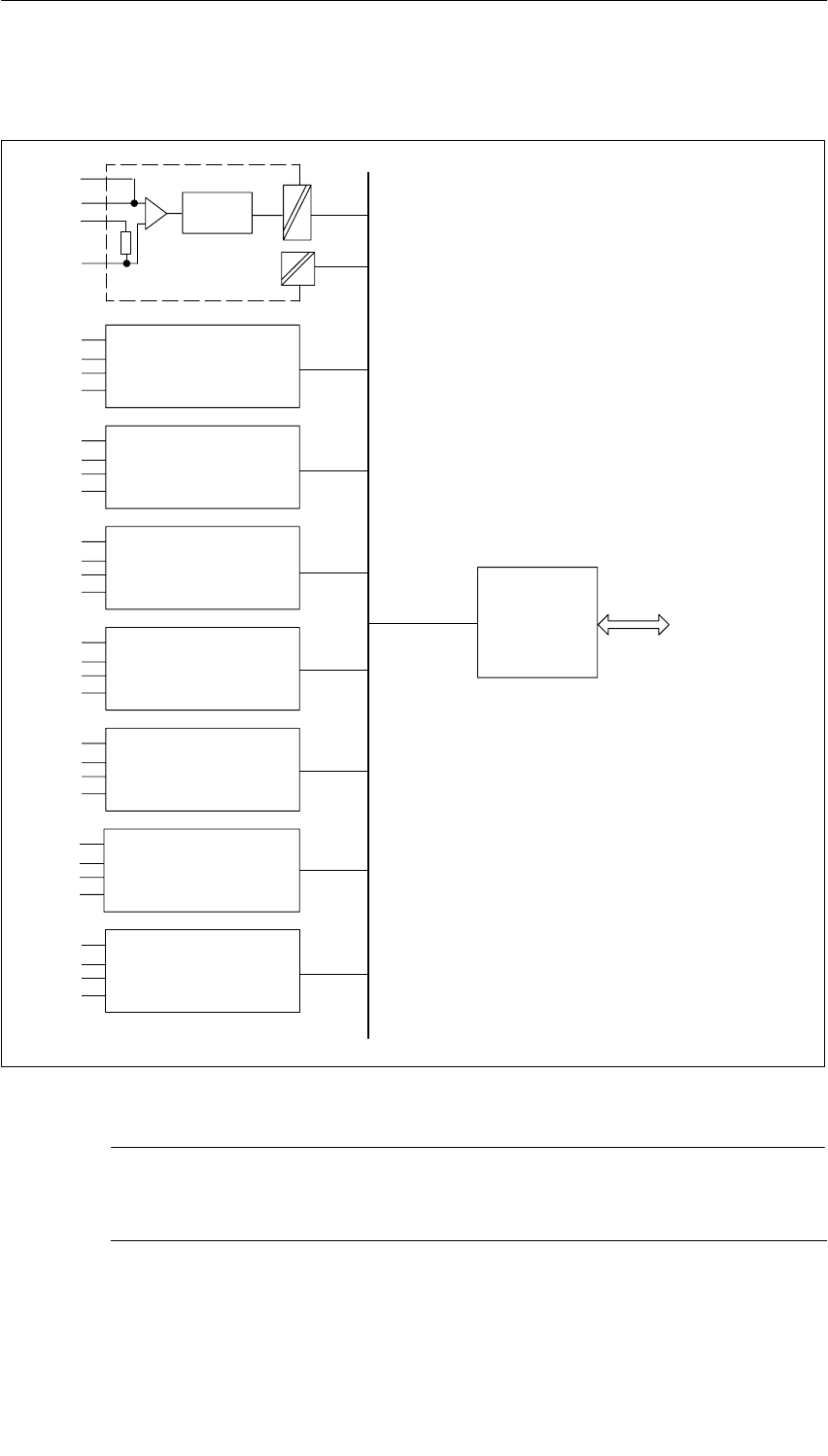
Analog Modules
5-131
S7-400, M7-400 Programmable Controllers Module Specifications
A5E00069467-07
Block Diagram of the SM 431; AI 8 16 Bit
Backplane
bus
interface
Bus
S7-400
M0+
M0+
R0
M0–
CH1
CH2
CH3
CH4
CH5
CH6
CH7
CH0
A/D
converter
Internal
supply
Figure 5-41 Block Diagram of the SM 431; AI 8 x 16 Bit
Note
An external protective network is required in the signal leads in accordance with
IEC 61000-4-5 (150 V/14 mm MOV across each + and – input to chassis ground)
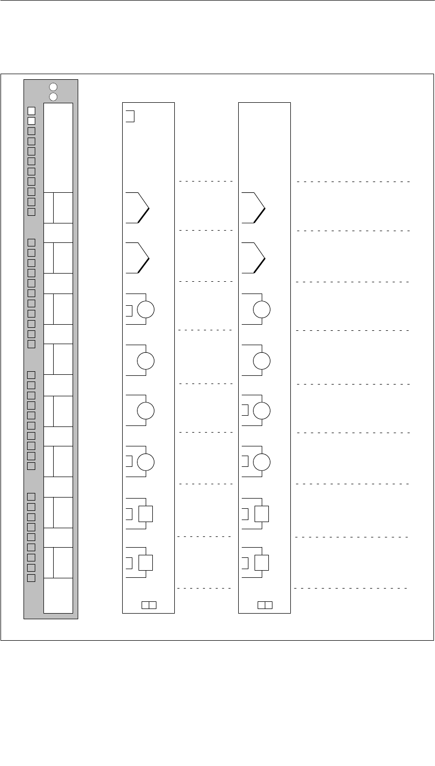
Analog Modules
5-132 S7-400, M7-400 Programmable Controllers Module Specifications
A5E00069467-07
Terminal Assignment Diagram of the SM 431; AI 8 16 Bit
R0 CH0
CH1
CH2
CH3
CH4
CH5
CH6
CH7
M0+
M0+
M0–
INTF
EXTF
Word 0
Word 2
Word 4
Word 6
Word 1
Word 3
Word 5
Word 7
V
A
V
A
Tr
Tr
R1
M1+
M1+
M1–
R2
M2+
M2+
M2–
R3
M3+
M3+
M3–
R4
M4+
M4+
M4–
R5
M5+
M5+
M5–
R6
M6+
M6+
M6–
R7
M7+
M7+
M7–
Thermocouples
Voltage measurement
Current measurement
0
1
2
3
4
5
6
7
R0
M0+
M0+
M0–
A
A
V
V
Tr
Tr
R1
M1+
M1+
M1–
R2
M2+
M2+
M2–
R3
M3+
M3+
M3–
R4
M4+
M4+
M4–
R5
M5+
M5+
M5–
R6
M6+
M6+
M6–
R7
M7+
M7+
M7–
29
30
31
32
33
34
35
36
37
39
40
41
42
43
44
45
46
47
48
38
1
2
3
4
5
6
7
8
9
10
11
12
13
14
15
16
17
18
19
20
21
22
23
24
25
26
27
28
Optional connector
(screw-type) Connector with
temperature reference
6ES7431-7KF00-6AA06ES7492-1AL00-0AA0
Figure 5-42 Terminal Assignment Diagram SM 431; AI 8 x 16 Bit
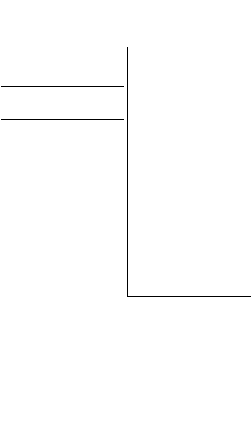
Analog Modules
5-133
S7-400, M7-400 Programmable Controllers Module Specifications
A5E00069467-07
Technical Specifications of the SM 431; AI 8 16 Bit
Dimensions and Weight
Dimensions W H D
(in millimeters) 25 290 210
Weight Approx. 650 g
Data for Specific Module
Number of inputs 8
Length of cable
•Shielded 200 m
Voltages, Currents, Potentials
Isolation
•Between channels and
backplane bus Yes
•Between the channels Yes
Permitted potential difference
•Between the inputs (UCM ) 120 VAC
•Between MANA and
Minternal (UISO)120 VAC
Insulation tested with 1500 VAC
Current consumption
•From the backplane bus Max. 1200 mA
Power dissipation of the
module Typ. 4.6 W
Analog Value Generation
Measuring principle Integrative
Integration time/conversion
time/resolution (per
channel)
(Does not go into the
response time)
•Parameters can be
assigned Yes
•Integration time in
milliseconds 2.5 16.7 20 100
•Basic conversion time
including integration
time in milliseconds
10 16.7 20 100
•Resolution in bits (incl.
overrange) 16 bits
•Noise suppression for
frequency f1 in Hz 400 60 50 10
•Basic execution time of
the module, in ms (all
channels enabled)
10 16.7 20 100
Smoothing of the measured
values Parameters can be
assigned in 4
stages
Suppression of Interference, Limits of Error
Interference voltage suppression for f = n (f1 " 1%),
(f1 = interference frequency) n= 1.2 ...
•Common-mode
interference
(UCM < 2.5 V)
> 130 dB
•Series-mode noise
(peak value of noise
< nominal value of input
range)
> 80 dB
Crosstalk between the
inputs > 130 dB

Analog Modules
5-134 S7-400, M7-400 Programmable Controllers Module Specifications
A5E00069467-07
Operational limit (in the entire temperature range, with
reference to the input range)
•Voltage input " 0.3 %
•Current input " 0.5 %
•Thermocouple Type B " 3.5 C
Type N " 2.7 C
Type E " 1.8 C
Type R " 3.3 C
Type S " 3.2 C
Type J " 2.4 C
Type L " 1.7 C
Type T " 0.8 C
Type K " 2.5 C
Type U " 1.2 C
Basic error (operational limit at 25 C, referred to input
range)
•Voltage input " 0.05 %
•Current input " 0.15 %
•Thermocouple Type B " 0.9 C
Type N " 0.7 C
Type E " 0.5 C
Type R " 0.9 C
Type S " 0.8 C
Type J " 0.6 C
Type L " 0.4 C
Type T " 0.2 C
Type K " 0.6 C
Type U " 0.3 C
Temperature error (with
reference to the input
range)
" 0.015%/K
Linearity error (with
reference to the input
range)
" 0.15%
Repeatability (in steady
state at 25 C, with
reference to the input
range)
" 0.15%
Status, Interrupts, Diagnostics
Interrupts
•Hardware interrupt Parameters can be
assigned
•Diagnostic Interrupt Programmable
Diagnostic functions Programmable
•Group error display
– For internal fault
– For external fault
Programmable
Red LED (INTF)
Red LED (EXTF)
•Diagnostic information
can be displayed Yes
Data for Selecting a Sensor
Input range (rated
values)/Input resistance
•Voltage " 25 mV
" 50 mV
" 80 mV
"100 mV
"250 mV
"500 mV
" 1 V
" 2.5 V
" 5 V
" 10 V
>2 MΩ
>2 MΩ
>2 MΩ
>2 MΩ
>2 MΩ
>2 MΩ
>2 MΩ
>2 MΩ
>2 MΩ
>2 MΩ
•Current " 25 mA /50 Ω
•Thermocouple Types B, N,
E, R, S, J, L,
T, K, U
>2 MΩ
Maximum input voltage for
voltage input (destruction
limit)
35 V continuous;
75 V for max. 1 s
(duty factor 1:20)
Maximum input current for
current input (destruction
limit)
32 mA
Connection of the sensor
•For measuring voltage Possible
•For measuring current
As four-wire transmitter Possible
Characteristic linearization
•For thermocouples Types B, N, E, R, S, J, L,
T, K, U
Temperature compensation Yes, programmable
•Internal temperature
compensation Possible
Unit for temperature
measurement Degrees Celsius; degrees
Fahrenheit

Analog Modules
5-135
S7-400, M7-400 Programmable Controllers Module Specifications
A5E00069467-07
5.24.1 Commissioning the SM 431; AI 8 16 Bit
You set the mode of operation of the SM 431; AI 8 16 Bit in STEP 7.
Parameter
You will find a description of the general procedure for assigning parameters to
analog modules in Section 5.7.
An overview of the parameters that you can set and their default settings are
shown in the table below.
Table 5-74 Parameters of the SM 431; AI 8 16 Bit
Parameter Value Range Default2) Parameter
Type Scope
Enable
•Diagnostic interrupt1)
•Hardware interrupt1) Yes/no
Yes/no No
No Dynamic Module
•Destination CPU for
interrupt 1 to 4 –Static Module
Trigger for hardware
interrupt3)
Dynamic
Channel
•High limit
•Low limit
32767 to – 32768
– 32768 to 32767
–
–
Dynamic Channel
Diagnostics
•Wire break
•Reference channel
error
•Underflow
•Overflow
Yes/no
Yes/no
Yes/no
Yes/no
No
No
No
No
Static Channel
Measurement
•Measuring method Disabled
U Voltage
4DMU Current
(four-wire transmitter)
TC-L Thermocouple (linear)
TC-L
Static Channel
•Measuring range Refer to Section 5.24.2 for the
measuring ranges of the input
channels that you can set.
Type J
•Reference
temperature – 273.15 to 327.67 oC
–327.68 to 327.67 oF100 oCDynamic Module
•Temperature unit4) Degrees Celsius; degrees Fahrenheit Degrees
Celsius
•Interference
suppression 400 Hz; 60 Hz; 50 Hz; 10 Hz 60 Hz Static Module
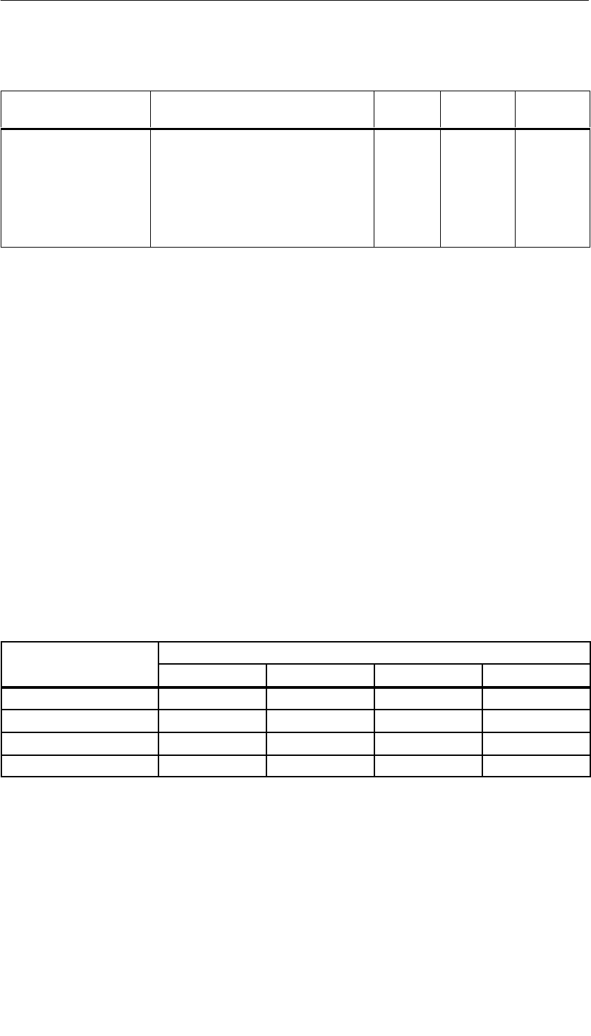
Analog Modules
5-136 S7-400, M7-400 Programmable Controllers Module Specifications
A5E00069467-07
Table 5-74 Parameters of the SM 431; AI 8 16 Bit, continued
Parameter ScopeParameter
Type
Default2)
Value Range
•Smoothing None
Low
Average
High
None
•Reference junction
(reference to the cold
junction)
None
Internal
Reference temperature value dynamic
Internal Static Module
1) If you use the module in ER-1/ER-2, you must set this parameter to “No” because the interrupt lines are
not available in ER-1/ER-2.
2) Only in the CC (central controller) is it possible to start up the analog modules with the default settings.
3) The limit values must be within the temperature range of the connected sensor.
4) Valid for the format of the output temperature and the dynamic reference temperature
Smoothing of the Measured Values
You fill find information that is generally applicable to the smoothing of analog
values in Section 5.6.
The cycle time of the module is a constant in the SM 431; AI 8 16 Bit that is not
dependent on the number of channels that are enabled. It therefore has no effect
on the step response, which is defined by the parameter assignment of
interference frequency suppression and smoothing.
Step Response
Table 5-75 How Response Times Depend on the Parameterized Interference Frequency Suppression
and Smoothing of the SM 431; AI 8 16 Bit
Interference Frequency
S pp essio i H
Response Time in ms with Parameterized Smoothing:
Suppression in Hz None Low Average High
10 100 200 1600 3200
50 20 40 320 640
60 16.7 33.3 267 533
400 10 20 160 320
The following figures illustrate the contents of Table 5-75. They show the response
time required for a step response before the smoothed analog value is almost
applied to 100%. The figures apply to every change of signal at an analog input.
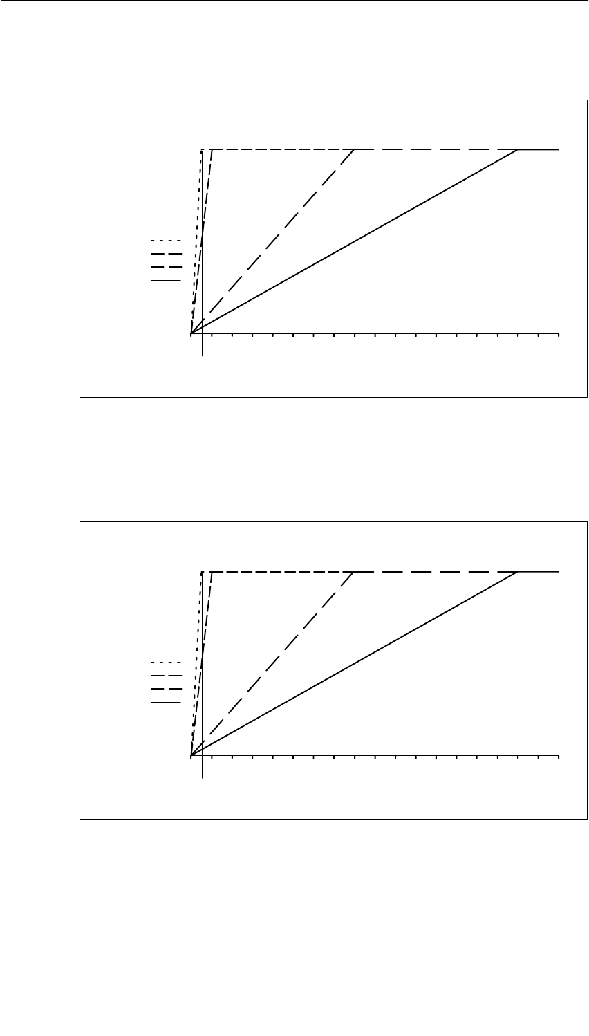
Analog Modules
5-137
S7-400, M7-400 Programmable Controllers Module Specifications
A5E00069467-07
Step Response at an Interference Frequency Suppression of 10 Hz
100
0
Smoo-
thing:
None:
Low:
Average:
High:
Response time in ms
Signal variation
in percent
Step response for any analog input signal
100
200
1600 3200
2400800
Figure 5-43 Step Response at 10 Hz Interference Frequency Suppression of the SM 431;
AI 8 16 Bit
Step Response at an Interference Frequency Suppression of 50 Hz
100
0
Smoo-
thing:
None:
Low:
Average:
High:
Response time in ms
Signal variation
in percent
Step response for any analog input signal
16080 240 320 400 480 560 64040
20
Figure 5-44 Step Response at 50 Hz Interference Frequency Suppression of the SM 431;
AI 8 16 Bit
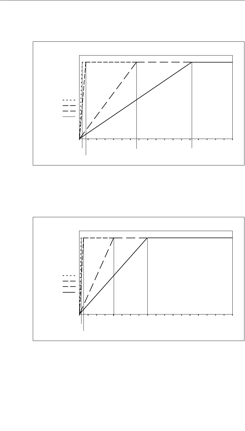
Analog Modules
5-138 S7-400, M7-400 Programmable Controllers Module Specifications
A5E00069467-07
Step Response at an Interference Frequency Suppression of 60 Hz
100
0
Smoo-
thing:
None:
Low:
Average:
High:
Response time
in ms
Signal variation
in percent Step response for any analog input signal
16080 240 320 400 480 560 640
16.7 267 533
33.3
Figure 5-45 Step Response at 60 Hz Interference Frequency Suppression of the SM 431;
AI 8 16 Bit
Step Response at an Interference Frequency Suppression of 400 Hz
100
0
Smoo-
thing:
None:
Low:
Average:
High:
Response time in ms
Signal variation
in percent Step response for any analog input signal
16080 240 320 400 480 560 640
10
20
Figure 5-46 Step Response at 400 Hz Interference Frequency Suppression of the
SM 431; AI 8 16 Bit

Analog Modules
5-139
S7-400, M7-400 Programmable Controllers Module Specifications
A5E00069467-07
Displaying Parameter Assignment Errors
The SM 431; AI 8 16 Bit has diagnostics capability. Below you will find an
overview of the displays that are possible for modules with parameter assignment
errors.
Table 5-76 Diagnostic Information of the SM 431; AI 8 16 Bit
Incorrect Parameter
Assignment Possible Display Explanation
Of the module •Module malfunction
•Internal malfunction
•Wrong parameters
•Module not parameterized.
You can find an
explanation of the
diagnostic information in
Tables 4-8 and 5-47 on
Pages 4-10 and 5-65.
Affecting certain
channels •Module malfunction
•Internal malfunction
•There is a channel error
•Wrong parameters
•Channel information available
•Vector channel error
•Channel parameter assignment
error
•User calibration doesn’t
correspond to the parameter
assignment
g
5.24.2 Measuring Methods and Measuring Ranges of the SM 431;
AI 8 16 Bit
Measuring Methods
You can set the following measuring methods for the input channels:
•Voltage measurement
•Current measurement
•Temperature measurement
You specify the setting by means of the “Measuring Type” parameter in STEP 7.
Unused Channels
Disable the “Measuring Type” parameter for unused channels. In this way you
shorten the scan time of the module.

Analog Modules
5-140 S7-400, M7-400 Programmable Controllers Module Specifications
A5E00069467-07
Measuring Ranges
You set the measuring ranges by means of the “Measuring Range” parameter in
STEP 7.
Table 5-77 Measuring Ranges of the SM 431; AI 8 x 16 Bit
Method Selected Measuring Range Description
U: Voltage "25 mV
"50 mV
"80 mV
"100 mV
"250 mV
"500 mV
"1 V
"2.5 V
"5 V
"10 V
1 to 5 V
You will find the digitized analog
values in Section 5.3.1 in the
voltage measuring range
4DMU: Current (four-wire
transmitter)
"3.2 mA
"5 mA
"10 mA
"20 mA
0 to 20 mA
4 to 20 mA
You will find the digitized analog
values in Section 5.3.1 in the
current measuring range
TC-L: Thermocouple (linear)
(temperature measurement) Type B
Type N
Type E
Type R
Type S
Type J
Type L
Type T
Type K
Type U
You will find the digitized analog
values in Section 5.3.1 in the
temperature range
Default Settings
The default settings of the module in STEP 7 are “Thermocouple (linear)” for the
measuring method and “Type J” for the measuring range. You can use this
combination of measuring method and measuring range without parameterizing the
SM 431; AI 8 16 Bit in STEP 7.
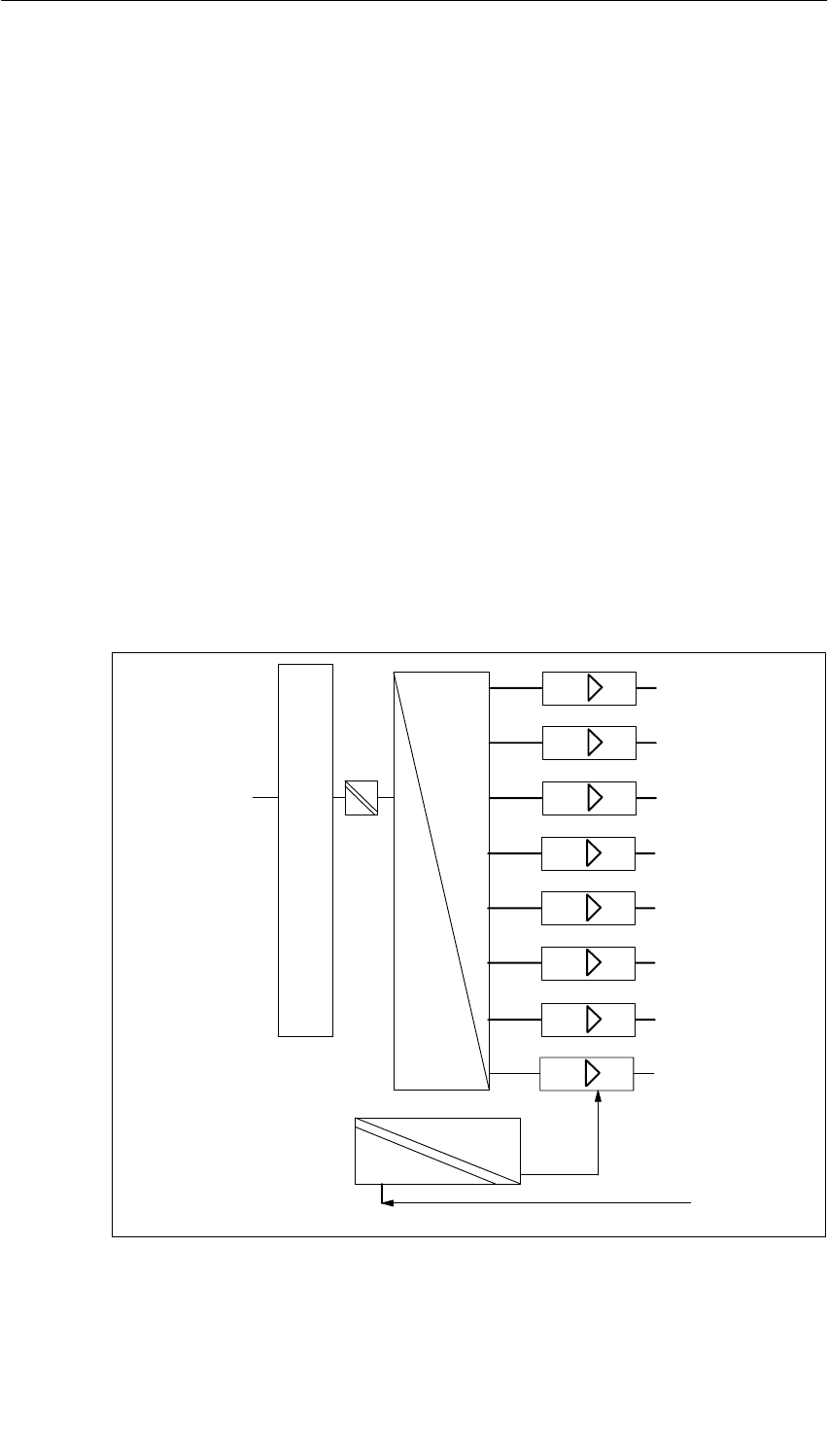
Analog Modules
5-141
S7-400, M7-400 Programmable Controllers Module Specifications
A5E00069467-07
5.25 Analog Output Module SM 432; AO 8 13 Bit;
(6ES7432-1HF00-0AB0)
Characteristics
The SM 432; AO 8 x 13 Bit has the following features:
•8 outputs
•The individual output channels can be programmed as
– Voltage outputs
– Current outputs
•13-bit resolution
•Analog section Isolated to CPU and load voltage
•Maximum permissible common mode voltage between the channels and the
channels against MANA is 3 VDC
Block Diagram of the SM 432; AO 8 x 13 Bit
Bus S7-400
D
A
24 V
Analog supply
CH1
CH2
CH3
CH4
CH5
CH6
CH7
CH0
L+/M
Bus control
Figure 5-47 Block Diagram of the SM 432; AO 8 x 13 Bit

Analog Modules
5-142 S7-400, M7-400 Programmable Controllers Module Specifications
A5E00069467-07
Terminal Assignment Diagram of the SM 432; AO 8 x 13 Bit
Voltage output Current output
S0–
CH0
CH1
CH2
CH3
CH4
CH5
CH6
CH7
L+
M
L+
QV0
S0+
M
QI0
QI1
QI2
QI3
CH0
CH2
CH3
QI4
QI5
QI6
QI7
CH4
CH5
CH6
CH7
L+
MANA
S1–
QV1
S1+
S2–
QV2
S2+
S3–
QV3
S3+
S4–
QV4
S4+
S5–
QV5
S5+
S6–
QV6
S6+
S7–
QV7
S7+
CH1
MANA
MANA
29
30
31
32
33
34
35
36
37
39
40
41
42
43
44
45
46
47
48
38
1
2
3
4
5
6
7
8
9
10
11
12
13
14
15
16
17
18
19
20
21
22
23
24
25
26
27
28
Word 0
Word 2
Word 4
Word 6
Word 8
Word 10
Word 12
Word 14
Word 0
Word 2
Word 4
Word 6
Word 8
Word 10
Word 12
Word 14
M
Figure 5-48 Terminal Assignment Diagram of the SM 432; AO 8 x 13 Bit

Analog Modules
5-143
S7-400, M7-400 Programmable Controllers Module Specifications
A5E00069467-07
Technical Specifications of the SM 432; AO 8 x 13 Bit
Programming package
Associated programming
package As of STEP 7 V 2.0
Dimensions and Weight
Dimensions W H D
(in millimeters) 25 290 210
Weight Approx. 650 g
Data for Specific Module
Number of outputs 8
Length of cable
•Shielded Max. 200 m
Voltages, Currents, Potentials
Supply voltage of the
electronics L+ 24 VDC
Rated load voltage L+ 24 VDC
•Reverse polarity protection Yes
Isolation
•Between channels and
backplane bus
•Between the channels
•Between channels and
load voltage L+
Yes
No
Yes
Permitted potential difference
•Between the outputs (ECM)
•Between S– and MANA
(UCM)
•Between MANA and
Minternal (UISO)
3 VDC
3 VDC
75 VDC/60 VAC
Insulation tested
•Between bus and L+/M
•Between bus and analog
section
•Between bus and chassis
ground
•Between analog section
and L+/M
•Between analog section
and chassis ground
•Between L+/M and chassis
ground
2120 VDC
2120 VDC
500 VDC
707 VDC
2120 VDC
2120 VDC
Current consumption
•From the backplane bus Max. 150 mA
•Power supply and load
voltage L+ (with rated load) Max. 400 mA
•Power supply and load
voltage L+ (no load) Max. 200 mA
Power dissipation of the
module Typ. max. 9 W
Analog Value Generation
Resolution including sign 13 bits
Conversion time (per channel)
•In the ranges 1 V to 5 V
and 4 mA to 20 mA 420 s
•In all ranges 300 s
Basic response time of module
(all channels enabled)
•In the ranges 1 V to 5 V
and 4 mA to 20 mA 3.36 ms
•In all the other ranges 2.4 ms
Settling time
•For resistive load
•For capacitive load
•For inductive load
0.1 ms
3.5 ms
0.5 ms
Suppression of Interference, Limits of Error
Interference voltage suppression for f = n (f1 " 1%),
(f1 = interference frequency) n= 1.2 ...
•Common-mode
interference
(UCM < AC 3 Vss/50 Hz)
>60 dB
Crosstalk between the outputs > 40 dB
Operational limit (in the entire temperature range, with
reference to the output range)
•Voltage outputs
–" 10 V
– 0 V to 10 V
– 1 V to 5 V
" 0.5 %
" 0.5 %
" 0.5 %
•Current outputs
–" 20 mA
– 4 mV to 20 mV
" 1%
" 1%
Basic error (operational limit at 25 °C, referred to the
output range)
•Voltage outputs
–" 10 V
– 0 V to 10 V
– 1 V to 5 V
" 0.5%
" 0.5%
" 0.5%
•Current outputs
–" 20 mA
– 0 mA to 20 mA
" 0.5%
" 0.5%
Temperature error (with
reference to the output range)
" 0.02% K
Linearity error (with reference
to the output range)
" 0.05%

Analog Modules
5-144 S7-400, M7-400 Programmable Controllers Module Specifications
A5E00069467-07
Repeat accuracy (in the steady
state at 25 °C, referred to the
output range)
" 0.05%
Output ripple; band width 0 to
50 kHz (with reference to the
output range)
" 0.05%
Status, Interrupts, Diagnostics
Interrupts None
Diagnostic functions None
Substitute value can be applied No
Data for Selecting an Actuator
Output ranges (rated values)
•Voltage " 10 V
0 V to 10 V
1 V to 5 V
•Current " 20 mA
0 mA to 20 mA
4 mA to 20 mA
Load resistance (in the nominal
range of the output)
•For voltage outputs Min. 1 k
– capacitive load Max. 1 F
•For current outputs Max. 500
00 with reduced
UCM to < 1 V
– Inductive load Max. 1 mH
Voltage outputs
•Short-circuit protection Yes
•Short-circuit current Max. 30 mA
Current outputs
•No-load voltage Max. 19 V
Destruction limit for voltages/
currents connected from
outside
•Voltage at outputs to MANA Max. 20 V continuous
75 V for 1 ms (cycle
factor 1 : 20)
•Current Max. 40 mA
continuous
Connection of actuators
•For voltage output
– Two-conductor
connection Possible, without
compensation for
circuit resistance
– Four-conductor
connection
(measuring circuit)
Possible
•For current output
– Two-conductor
connection Possible

Analog Modules
5-145
S7-400, M7-400 Programmable Controllers Module Specifications
A5E00069467-07
5.25.1 Commissioning the SM 432; AO 8 13 Bit
Parameter
You will find a description of the general procedure for assigning parameters to
analog modules in Section 5.7.
You will find an overview of the programmable parameters and their default values
in Table 5-43, on page 5-42.
Assigning Parameters to Channels
You can configure each output channel of the SM 432; AO 8 13 Bit individually.
You can thus assign different parameters to each output channel.
5.25.2 Output Ranges of the Analog Output Module SM 432;
AO 8 13 Bit
Wiring the Analog Outputs
You can wire the outputs as voltage or current outputs, or disable them. You wire
the outputs by means of the “Type of Output” parameter in STEP 7.
Unused Channels
To ensure that output channels of the SM 432; AO 8 13 Bit remain de-energized,
you must disable the “Type of Output” parameter and leave the terminal open.
Output Ranges
You program the output ranges for voltage and current outputs in STEP 7.
Table 5-78 Output Ranges of the Analog Output Module SM 432; AO8 13 Bit
Selected Type of Output Output Range Description
Voltage 1 to 5 V
0 to 10 V
"10 V
You will find the digital
analog values in Section
5.3.2 in the voltage and
t t t
Current 0 to 20 mA
4 to 20 mA
"20 mA
current output ranges
Default Settings
The default settings of the module are “Voltage” for the output type and “" 10 V”
for the output range. You can use this combination of output type and output range
without parameterizing the SM 432; AO 8 13 Bit in STEP 7.

Analog Modules
5-146 S7-400, M7-400 Programmable Controllers Module Specifications
A5E00069467-07

6-1
S7-400, M7-400 Programmable Controllers Module Specifications
A5E00069467-07
Interface Modules
Chapter Overview
Section Description Page
6.1 Common Features of the Interface Modules 6-2
6.2 The Interface Modules
IM 460-0; (6ES7460-0AA00-0AB0, 6ES7460-0AA01-0AB0) and
IM 461-0; (6ES7461-0AA00-0AA0, 6ES7461-0AA01-0AA0)
6-7
6.3 The Interface Modules
IM 460-1; (6ES7460-1BA00-0AB0, 6ES7460-1BA01-0AB0) and
IM 461-1; (6ES7461-1BA00-0AA0, 6ES7461-1BA01-0AA0)
6-10
6.4 The Interface Modules
IM 460-3; (6ES7460-3AA00-0AB0, 6ES7460-3AA01-0AB0) and
IM 461-3; (6ES7461-3AA00-0AA0, 6ES7461-3AA01-0AA0)
6-14
6.5 The Interface Modules
IM 460-4; (6ES7460-4AA01-0AB0,
IM 461-4; (6ES7461-4AA01-0AA0)
6-18
You will find a description of the IM 463-2 in Chapter 7.
6

Interface Modules
6-2 S7-400, M7-400 Programmable Controllers Module Specifications
A5E00069467-07
6.1 Common Features of the Interface Modules
Function
Interface modules (a send IM and a receive IM) are required if one or more
expansion units (EU) are to be connected to a central controller (CC). This
configuration is described in the Installation Manual, Chapter 4.
Configuration
Interface modules must always be used together. The send modules (send IMs)
are inserted in the CC, whilst the corresponding receive modules (receive IMs) are
plugged into the series-connected EU.
Table 6-1 Interface Modules of the S7-400
Partner Areas of Application
IM 460-0 Send IM for local link without PS transfer; with communication bus
IM 461-0 Receive IM for local link without PS transfer; with communication bus
IM 460-1 Send IM for local link with PS transfer; without communication bus
IM 461-1 Receive IM for local link with PS transfer; without communication bus
IM 460-3 Send IM for remote link up to 102 m; with communication bus
IM 461-3 Receive IM for remote link up to 102 m; with communication bus
IM 460-4 Send IM for remote link up to 605 m; without communication bus
IM 461-4 Receive IM for remote link up to 605 m; without communication bus
Overview of the Properties of the Connections
Note the rules for connections in the section after next.
Local connection Remote connection
Send IM 460-0 460-1 460-3 460-4
Receive IM 461-0 461-1 461-3 461-4
Max. number of connectable EMs per
chain 4 1 4 4
Max. distance 3 m 1.5 m 102.25 m 605 m
5 V transfer No Yes No No
Max. current transfer per interface –5 A – –
Communication bus transmission Yes No Yes No
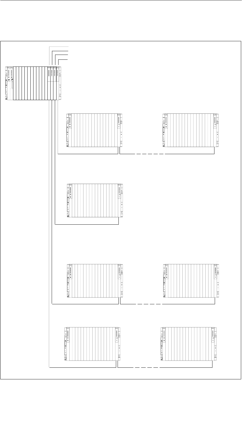
Interface Modules
6-3
S7-400, M7-400 Programmable Controllers Module Specifications
A5E00069467-07
Connection possibilities for central racks and expansion racks
Central rack CR
Expansion rack ER 1 Expansion rack ER 4
Expansion rack ER 1
Expansion rack ER 1 Expansion rack ER 4
Expansion without 5 V local transfer
Expansion with 5 V local transfer
Remote expansion
IM 460-0
IM 460-1
IM 460-3
Chain length max. 3 m
Chain length max. 102.25 m
Chain length max. 1.5 m
IM 461-0 IM 461-0
IM 461-1
IM 461-3 IM 461-3
IM 460-4
Expansion rack ER 1 Expansion rack ER 4
Chain length max. 605 m
IM 461-4 IM 461-4
Interface Modules
6-4 S7-400, M7-400 Programmable Controllers Module Specifications
A5E00069467-07
Rules for Connection
When you connect a central rack to expansion racks, you must observe the
following rules:
•You can connect up to 21 ERs of the S7-400 to one CR.
•The ERs are assigned numbers to identify them. The rack number must be set
on the coding switch of the receive IM. Any rack number between 1 and 21 may
be assigned. Numbers must not be duplicated.
•You may insert up to six send IMs in one CR. However, only two send IMs with
5 V transfer are allowed in one CR.
•Each chain connected to the interface of a send IM can comprise up to four ERs
(without 5 V transfer) or one ER (with 5 V transfer).
•The exchange of data via the communication bus is limited to 7 racks, meaning
the CR and ER numbers 1 to 6.
•The maximum (total) cable lengths specified for the type of connection must not
be exceeded.
Connection type Maximum (total) line
length
Local connection with 5 V transfer via IM 460-1 and IM 461-1 1.5 m
Local connection without 5 V transfer via IM 460-0 and IM 461-0 3 m
Remote connection via IM 460-3 and IM 461-3 102.25 m
Remote connection via IM 460-4 and IM 461-4 605 m
Terminator
The bus must be terminated in the last EU of a line. To do this, plug in the
appropriate terminator in the lower front connector of the receive IM in the last EU
of the line. Unused front connectors in a send IM do not have to be terminated. The
IM 461-1 with the order number 6ES7 461-1BA01-0AA0 does not require a
terminator.
Table 6-2 Terminators for the Receive IMs
Receive IM Terminator
IM 461-0 6ES7461-0AA00-7AA0
IM 461-1 6ES7461-1BA00-7AA0
IM 461-3 6ES7461-3AA00-7AA0
IM 461-4 6ES7461-4AA00-7AA0
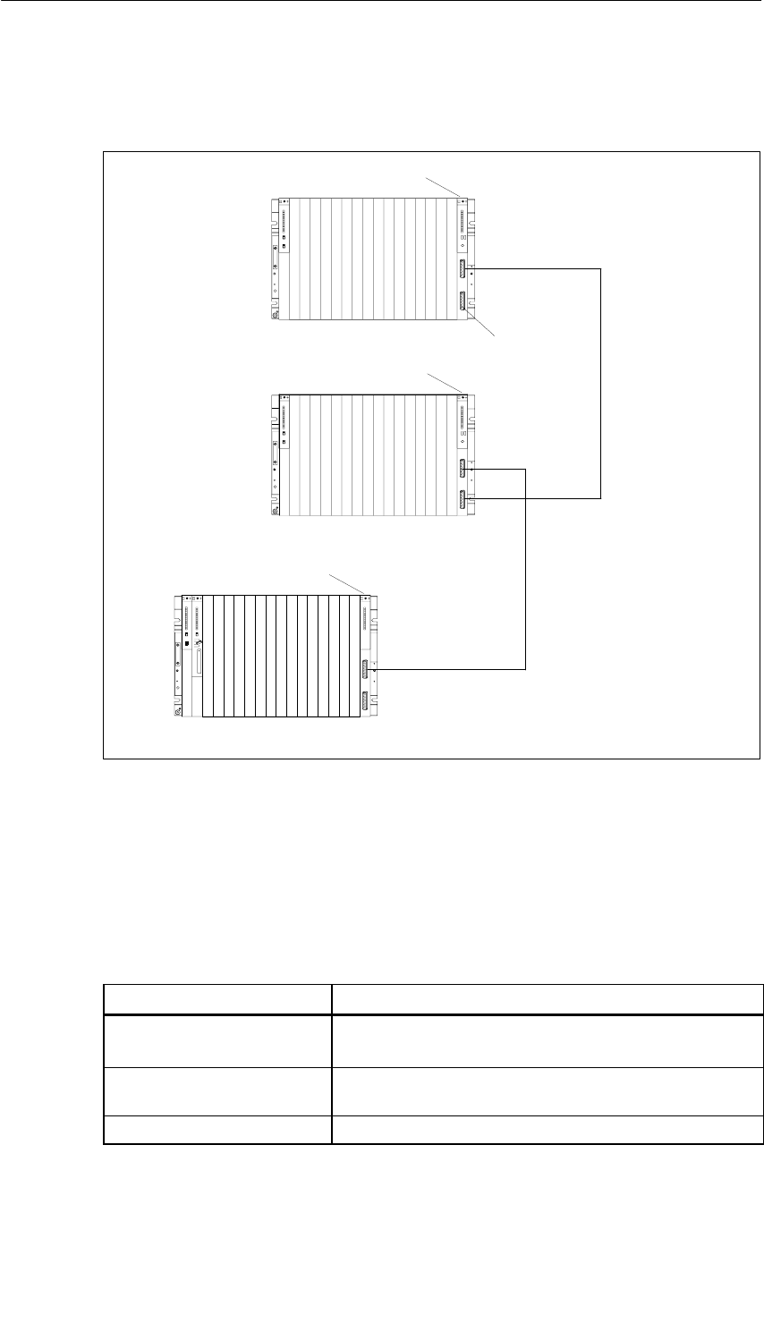
Interface Modules
6-5
S7-400, M7-400 Programmable Controllers Module Specifications
A5E00069467-07
The following figure shows you a typical configuration with send IMs, receive IMs
and terminators.
CC
Send IM
Receive IM
Receive IM
Terminator
Figure 6-1 Example: Configuration with Send IMs, Receive IMs and Terminators
Connecting Cable
Precut cables are available in different fixed lengths for connecting the individual
interface modules. (See Appendix C: Accessories and Spare Parts)
Table 6-3 Connecting Cable for Interface Modules
Interface Modules Connecting Cable
IM 460-0 and IM 461-0
IM 460-3 and IM 461-3
6ES7468-1... (P bus and communication bus are
transferred)
IM 460-1 and IM 461-1 6ES7468-3... (P bus is transferred; mounting rack is
supplied with current via the IM)
IM 460-4 and IM 461-4 6ES7468-1...

Interface Modules
6-6 S7-400, M7-400 Programmable Controllers Module Specifications
A5E00069467-07
Installation and Removal of the Modules During Operation
Please read the following warning on the insertion and removal of the interface
modules and associated connecting cables.
!Caution
Data may be lost or corrupted.
Removing or inserting the interface modules and/or their associated connecting
cables under voltage can result in the loss or corruption of data.
Switch off the power supply modules to the CC and EUs you are working on
before you carry out any changes.
Feeding in External Backup Voltage to the “EXT.-BATT.” Socket
(Not Possible in Modules as of Order Number -0AA01-)
When changing the battery in the power supply modules of the S7-400, you can
ensure uninterruptible backup in the CC if you apply between 5 VDC and 15 VDC
to the “EXT.-BATT.” socket of the CPU. This only provides backup power to the CC.
You can achieve corresponding backup in an EU in the case of the following
receive IMs by applying between 5 VDC and 15 VDC to the “EXT.-BATT.” socket.
•IM 461-0 6ES7461-0AA00-0AA0
•IM 461-1 6ES7461-1BA00-0AA0
•IM 461-3 6ES7461-3AA00-0AA0
The “EXT.-BATT.” input has the following features:
•Reverse polarity protection
•A short-circuit current limit of 20 mA
To provide an incoming supply at the “EXT.-BATT” socket, you need a connecting
cable with a 2.5 mm ∅ jack, as illustrated in the following figure. Note the polarity of
the jack.
Plus pole Minus pole
Jack 2.5 mm ∅
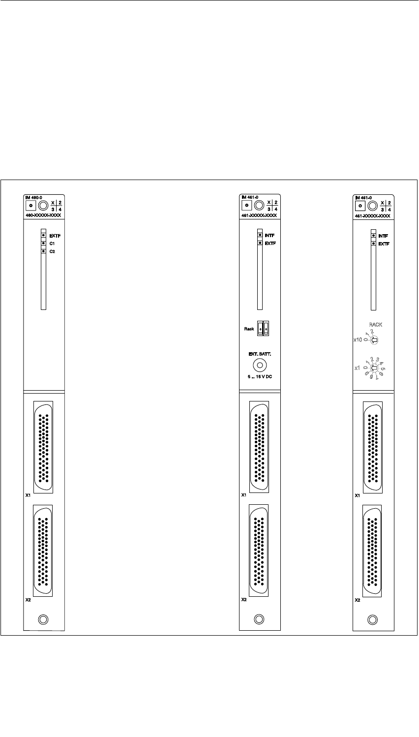
Interface Modules
6-7
S7-400, M7-400 Programmable Controllers Module Specifications
A5E00069467-07
6.2 The Interface Modules
IM 460-0; (6ES7460-0AA00-0AB0,
6ES7460-0AA01-0AB0) and IM 461-0;
(6ES7461-0AA00-0AA0, 6ES7461-0AA01-0AA0)
Position of the Operator Controls and Indicators of the IM 460-0 and IM 461-0
LEDs
EXTF
C1
C2
INTF
EXTF
DIP switch
External
backup voltage
Connector X1:
Interface C2
IM 460-0 IM 461-0
Interface C1
Connector X2:
IN
OUT
Under cover
INTF
EXTF
DIP switch
IM 461-0
6ES7461-0AA00-0AA0 6ES7461-0AA01-0AA0
IN
OUT
Figure 6-2 Position of the Operator Controls and Indicators of the IM 460-0 and IM 461-0
Interface Modules
6-8 S7-400, M7-400 Programmable Controllers Module Specifications
A5E00069467-07
Function
The interface module pair IM 460-0 (send IM) and IM 461-0 (receive IM) are used
for a local link. The communication bus is transferred at the full transmission rate.
Parameter Assignment for the Mounting Rack Number
Using the DIP switch on the front panel of the module, you must set the number of
the mounting rack in which the receive IM is installed. The permitted range is 1 to
21.
Setting/Changing the Number
Proceed as follows:
1. Put the switch of the power supply module in the EU in which you want to make
a change in the position (Output voltage 0 V).
2. Enter the number using the DIP switch.
3. Switch the power supply module on again.
Operator Controls and Indicators on the Send IM
EXTF LED
(red) Lights up in the event of an external fault Line 1 or line 2 is faulty
(terminator missing or broken cable)
C1 LED
(green) Line 1 (via front connector X1, connection 1) is correct.
C1 LED
(flashing
green)
An EU in the line is not ready for operation because
•The power supply module is not switched on or
•A module has not yet completed the initialization process
C2 LED
(green) Line 2 (via front connector X2, connection 2) is correct.
C2 LED
(flashing
green)
An EU in the line is not ready for operation because
•The power supply module is not switched on or
•A module has not yet completed the initialization process
Front
connectors X1
and X2
Connector (output) for line 1 and line 2
X1 = upper front connector; X2 = lower front connector
Interface Modules
6-9
S7-400, M7-400 Programmable Controllers Module Specifications
A5E00069467-07
Operator Controls and Indicators of the Receive IM
INTF LED (red) Lights up if a rack number > 21 or = 0 was set.
Lights up if you have changed the rack number under voltage.
EXTF LED (red) Lights up in the event of an external fault (line fault, for example, if
the terminator is not inserted or if a module has not yet completed
the initialization process).
DIP switch DIP switch to set the number of the mounting rack.
Socket for external
backup voltage
EXT.BATT.
On the IM 461-0 (order number 6ES7461-0AA00-0AA0) you can
connect external backup voltage (5 V to 15 V) or central backup (see
Installation Manual, Chapter 9) to this socket when you want to
replace the mounting rack power supply. This will ensure backup of
the corresponding EU without interruption. If you use this IM in a
cabinet, you should, for reasons of space, use an angled connector
for the incoming supply.
Front connector X1 Upper connector (input) for the connecting cable from the previous
interface module.
Front connector X2 Lower connector (output) for the connecting cable to the next
interface module or for the terminator.
Technical Specifications of the IM 460-0 and IM 461-0
Maximum line length (total) 3 m,
5 m in the IM 461-0 with the order number
6ES7461-0AA01-0AA0, in the IM 461-0 with
the order number 6ES7461-0AA00-0AA0 as of
version A4, in the IM 460-0 with the order
number 6ES7460-1AA01-0AA0 and in the IM
460-0 with the order number
6ES7460-1AA00-0AA0 as of version A5
Dimensions W x H x D (mm) 25 x 290 x 280
Weight
•IM 460-0
•IM 461-0
600 g
610 g
Current consumption from the S7-400
bus 5 VDC
•IM 460-0
•IM 461-0
Typ. 130 mA
Max. 140 mA
Typ. 260 mA
Max. 290 mA
Power loss
•IM 460-0
•IM 461-0
Typ. 650 mW
Max. 700 mW
Typ. 1300 mW
Max. 1450 mW
Terminator 6ES7461-0AA00-7AA0
Backup current No
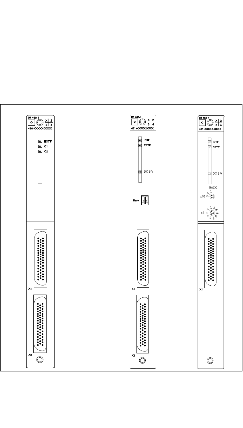
Interface Modules
6-10 S7-400, M7-400 Programmable Controllers Module Specifications
A5E00069467-07
6.3 The Interface Modules
IM 460-1; (6ES7460-1BA00-0AB0,
6ES7460-1BA01-0AB0) and IM 461-1;
(6ES7461-1BA00-0AA0, 6ES7461-1BA01-0AA0)
Position of the Operator Controls and Indicators of the IM 460-1 and IM 461-1
5 VDC
LEDs
EXTF
C1
C2
INTF
EXTF
DIP switch
IM 460-1 IM 461-1
Connector X1:
Interface C2
Interface C1
Connector X2:
IN
OUT
Under cover
5 VDC
LEDs
INTF
EXTF
DIP switch
6ES7461-1BA00-0AA0 6ES7461-1BA01-0AA0
IN
Figure 6-3 Position of the Operator Controls and Indicators of the IM 460-1 and IM 461-1

Interface Modules
6-11
S7-400, M7-400 Programmable Controllers Module Specifications
A5E00069467-07
Function
The interface module pair IM 460-1 (send IM) and IM 461-1 (receive IM) are used
for a local link (up to a maximum 1.5 m in total). A 5 V supply voltage is also
transferred with these interface modules. Please particularly remember the
following points:
•The current requirements of the module plugged into the EU must not exceed
5 V/5 A.
•You can only connect one EU per line.
•The modules in this mounting rack are not supplied with 24 V and are not
backed up.
•The communication bus is not transferred with the interface module pair
IM 460-1 and IM 461-1.
•You must not use a power supply module in the EU.
Note
If you connect an EU via a local link with 5 V transmission, ungrounded operation
is prescribed for the EU (see Installation Manual, Chapter 4)
Parameter Assignment for the Mounting Rack Number
Using the DIP switch on the front panel of the module, you must set the number of
the mounting rack in which the receive IM is installed. The permitted range is
1 to 21.
Setting/Changing the Number
Proceed as follows:
1. Put the power supply module in the CC into the position (Output voltage 0 V).
2. Enter the number using the DIP switch.
3. Switch the power supply module on again.
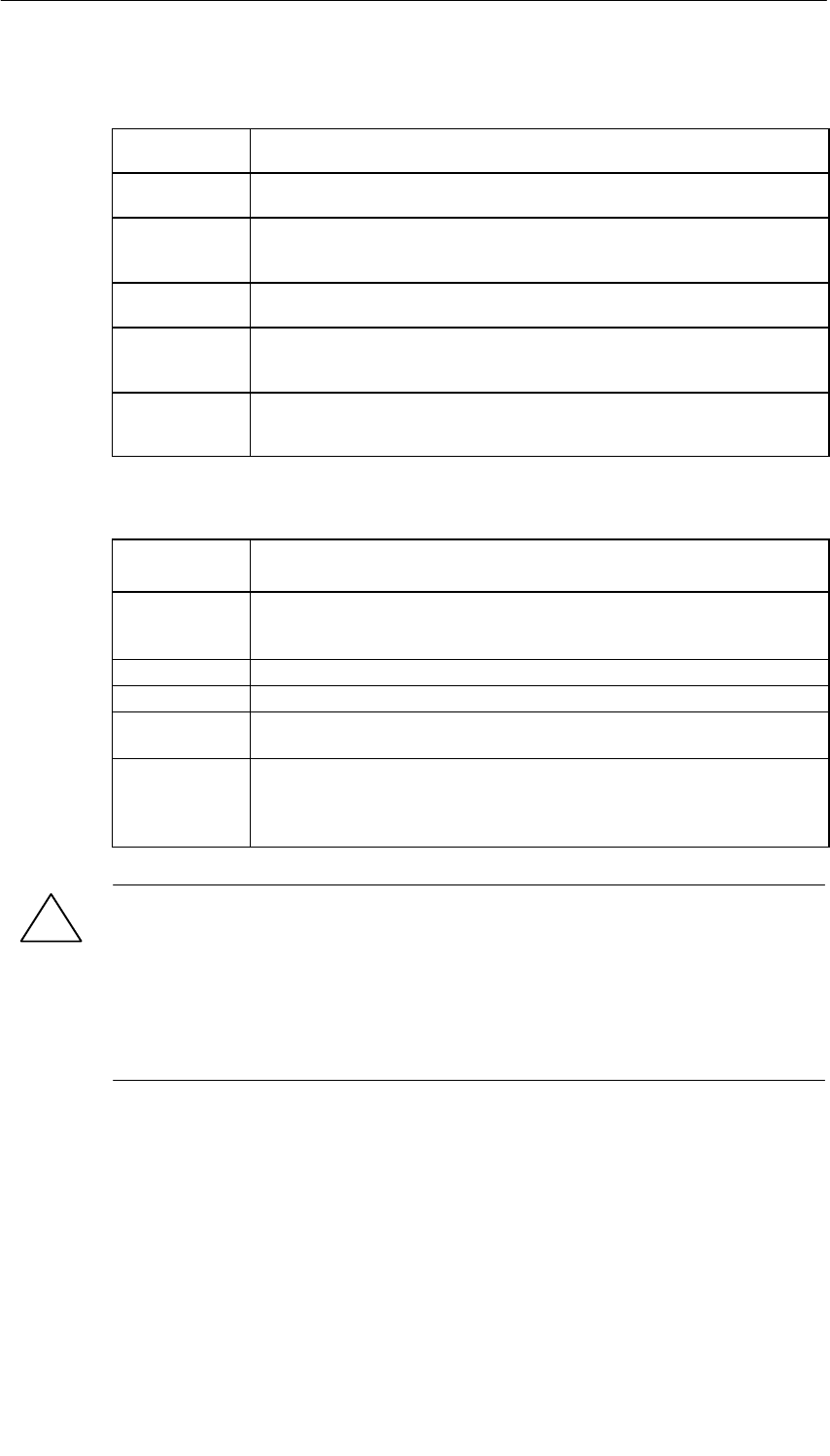
Interface Modules
6-12 S7-400, M7-400 Programmable Controllers Module Specifications
A5E00069467-07
Operator Controls and Indicators on the Send IM
EXTF LED
(red) Lights up in the event of an external fault Line 1 or line 2 is faulty
(terminator missing or open circuit)
C1 LED
(green) Line 1 (via front connector X1, connection 1) is correct.
C1 LED
(flashing
green)
A module has not yet completed the initialization process
C2 LED
(green) Line 2 (via front connector X2, connection 2) is correct.
C2 LED
(flashing
green)
A module has not yet completed the initialization process
Front
connectors X1
and X2
Connector (output) for line 1 and line 2
X1 = upper front connector; X2 = lower front connector
Operator Controls and Indicators of the Receive IM
INTF LED (red) Lights up if a rack number > 21 or = 0 was set.
Lights up if you have changed the rack number under voltage.
EXTF LED
(red) Lights up in the event of an external fault (line fault, for example, if the
terminator is not inserted or if a module has not yet completed the
initialization process, but not when the CC is switched off)
5 VDC (green) Power supply in the EU is correct.
DIP switch DIP switch to set the number of the mounting rack.
Front
connector X1 Upper connector (input) for the connecting cable from the previous
interface module.
Front
connector X2 Lower connector (output) for terminator. The front connector X2 is no
longer required for the IM 461-1 (order number
6ES7 461-1BA01-0AA0). The terminator (6ES7461-1BA00-7AA0)
previously required is now integrated in the module.
!Caution
Modules can be damaged.
If you want to connect an EU via the IM 461-1 interface module and use a power
supply module in this EU, you might damage the modules.
Don’t use a power supply module in an EU that you want to connect to the CC via
the IM 461-1 interface module.

Interface Modules
6-13
S7-400, M7-400 Programmable Controllers Module Specifications
A5E00069467-07
Technical Specifications of the IM 460-1 and IM 461-1
Maximum line length (total) 1.5 m
Dimensions W x H x D (mm) 25 x 290 x 280
Weight
•IM 460-1
•IM 461-1
600 g
610 g
Current consumption from the S7-400
bus 5 VDC
•IM 460-1
•IM 461-1
Typ. 50 mA max. 85 mA
Typ. 120 mA max. 100 mA
Power loss
•IM 460-1
•IM 461-1
Typ. 250 mW max. 425 mW
Typ. 500 mW max. 600 mW
Terminator 6ES7 461-1BA00-7AA0
Power supply for EU 5 V/5 A per line
Backup current No
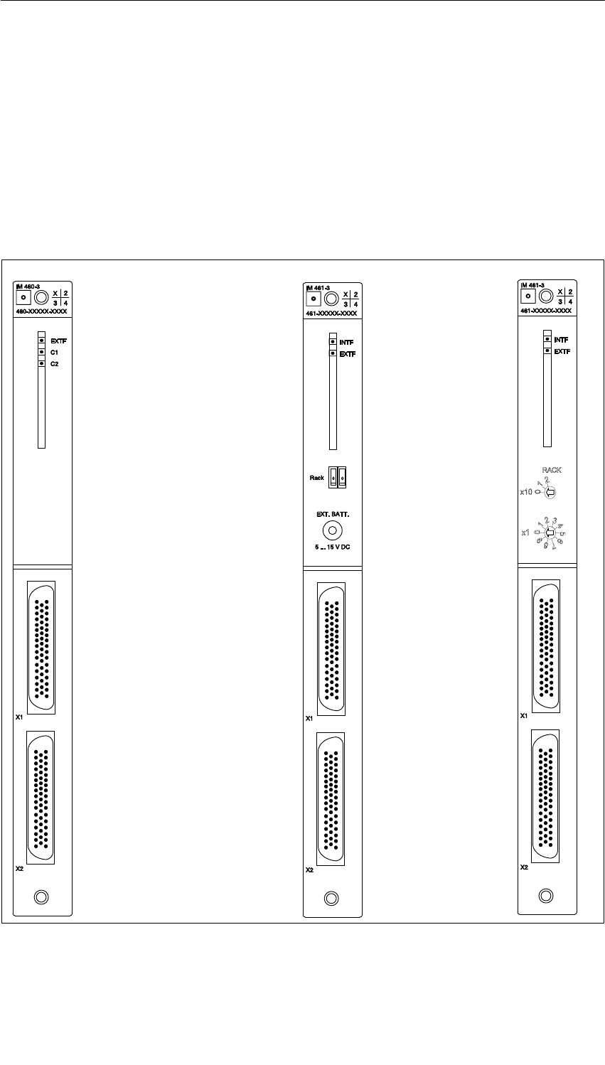
Interface Modules
6-14 S7-400, M7-400 Programmable Controllers Module Specifications
A5E00069467-07
6.4 The Interface Modules
IM 460-3; (6ES7460-3AA00-0AB0,
6ES7460-3AA01-0AB0) and IM 461-3;
(6ES7461-3AA00-0AA0, 6ES7461-3AA01-0AA0)
Position of the Operator Controls and Indicators of the IM 460-3 and IM 461-3
LEDs
EXTF
C1
C2
INTF
EXTF
DIP switch
External backup voltage
Connector X1:
Interface C2
Interface C1
Connector X2:
IN
OUT
IM 460-3 IM 461-3
Under cover
LEDs
INTF
EXTF
DIP switch
6ES7461-3AA00-0AA0 6ES7461-3AA01-0AA0
IN
OUT
Figure 6-4 Position of the Operator Controls and Indicators of the IM 460-3 and IM 461-3

Interface Modules
6-15
S7-400, M7-400 Programmable Controllers Module Specifications
A5E00069467-07
Function
The interface module pair IM 460-3 (send IM) and IM 461-3 (receive IM) are used
for a remote link of up to a maximum 102 m (exactly: 100 m plus inputs/outputs of
0.75 m in the line). The communication bus is transferred at the full transmission
rate.
Parameterization
Using the DIP switch on the front panel of the module, you must set the number of
the mounting rack that the receive IM is installed on. The permitted range is
1 to 21.
If required, you can change the distance setting for the line on the programming
device using STEP 7.
The default setting for the distance is 100 m.
Ensure that the distance corresponds as closely as possible to the current length
(the sum of all the connecting cables per line) as this will accelerate data
transmission.
Note
The distance set must always be longer than the actual length of cable per line.
Setting/Changing the Number
Proceed as follows:
1. Put the switch of the power supply module in the EU in which you want to make
a change in the position (Output voltage 0 V).
2. Enter the number using the DIP switch.
3. Switch the power supply module on again.
Interface Modules
6-16 S7-400, M7-400 Programmable Controllers Module Specifications
A5E00069467-07
Operator Controls and Indicators on the Send IM
EXTF LED
(red) Lights up in the event of an external fault Line 1 or line 2 is faulty
(terminator missing or broken cable)
C1 LED
(green) Line 1 (via front connector X1, connection 1) is correct.
C1 LED
(flashing
green)
An EU in the line is not ready for operation because
•The power supply module is not switched on or
•A module has not yet completed the initialization process
C2 LED
(green) Line 2 (via front connector X2, connection 2) is correct.
C2 LED
(flashing
green)
An EU in the line is not ready for operation because
•The power supply module is not switched on or
•A module has not yet completed the initialization process
Operator Controls and Indicators of the Receive IM
INTF LED (red) Lights up if a rack number > 21 or = 0 was set.
Lights up if you have changed the rack number under voltage.
EXTF LED (red) Lights up in the event of an external fault (line fault, for example, if
the terminator is not inserted or if a module has not yet completed
the initialization process, or if the CC is switched off)
DIP switch DIP switch to set the number of the mounting rack.
Socket for external
backup voltage
EXT.BATT.
On the IM 461-3 (order number 6ES7461-3AA00-0AA0) you can
connect an external backup voltage (5 V to 15 V) or a central backup
to this socket when you want to replace the mounting rack power
supply. This will ensure a backup of the corresponding EU without
interruption. If you use the receive IM in a cabinet, you should, for
reasons of space, use an angled connector for the incoming supply.
Front connector X1 Upper connector (input) for the connecting cable from the previous
interface module.
Front connector X2 Lower connector (output) for the connecting cable to the next
interface module or for the terminator.

Interface Modules
6-17
S7-400, M7-400 Programmable Controllers Module Specifications
A5E00069467-07
Technical Specifications of the IM 460-3 and IM 461-3
Maximum line length (total) 102 m
Dimensions W x H x D (mm) 25 x 290 x 280
Weight
•IM 460-3
•IM 461-3
630 g
620 g
Current consumption from the S7-400
bus 5 VDC
•IM 460-3
•IM 461-3
Typ. 1350 mA
Max. 1550 mA
Typ. 590 mA
Max. 620 mA
Power loss
•IM 460-3
•IM 461-3
Typ. 6750 mW
Max. 7750 mW
Typ. 2950 mW
Max. 3100 mW
Terminator 6ES7461-3AA00-7AA0
Backup current No
Interface Modules
6-18 S7-400, M7-400 Programmable Controllers Module Specifications
A5E00069467-07
6.5 The Interface Modules
IM 460-4; (6ES7460-4AA01-0AB0) and
IM 461-4; (6ES7461-4AA01-0AA0)
Position of the Operator Controls and Indicators of the IM 460-4 and IM 461-4
LEDs
EXTF
C1
C2
INTF
EXTF
DIP switch
Connector X1:
Interface C2
Interface C1
Connector X2:
IN
OUT
IM 460-4 IM 461-4
Under cover
6ES7461-4AA01-0AA0
Figure 6-5 Position of the Operator Controls and Indicators of the IM 460-4 and IM 461-4

Interface Modules
6-19
S7-400, M7-400 Programmable Controllers Module Specifications
A5E00069467-07
Function
The interface module pair IM 460-4 (send IM) and IM 461-4 (receive IM) are used
for a remote link of up to a maximum 605 m (exactly: 600 m plus inputs/outputs of
1.5 m in the line).
Parameterization
Using the DIP switch on the front panel of the module, you must set the number of
the mounting rack in which the receive IM is installed. The permitted range is
1 to 21.
If required, you can change the distance setting for the line on the programming
device using STEP 7.
The default setting for the distance is 600 m.
Ensure that the distance corresponds as closely as possible to the current length
(the sum of all the connecting cables per line) as this will accelerate data
transmission.
Note
The distance set must always be longer than the actual length of cable per line.
Setting/Changing the Number
Proceed as follows:
1. Put the switch of the power supply module in the EU in which you want to make
the change in the position (Output voltage 0 V).
2. Enter the number using the DIP switch.
3. Switch the power supply module on again.
Interface Modules
6-20 S7-400, M7-400 Programmable Controllers Module Specifications
A5E00069467-07
Operator Controls and Indicators on the Send IM
EXTF LED
(red) Lights up in the event of an external fault Line 1 or line 2 is faulty
(terminator missing or broken cable)
C1 LED
(green) Line 1 (via front connector X1, connection 1) is correct.
C1 LED
(flashing
green)
An EU in the line is not ready for operation because
•The power supply module is not switched on or
•A module has not yet completed the initialization process
C2 LED
(green) Line 2 (via front connector X2, connection 2) is correct.
C2 LED
(flashing
green)
An EU in the line is not ready for operation because
•The power supply module is not switched on or
•A module has not yet completed the initialization process
Operator Controls and Indicators of the Receive IM
INTF LED (red) Lights up if a rack number > 21 or = 0 was set.
Lights up if you have changed the rack number under voltage.
EXTF LED (red) Lights up in the event of an external fault (line fault, for example, if
the terminator is not inserted or if a module has not yet completed
the initialization process, or if the CC is switched off)
DIP switch DIP switch to set the number of the mounting rack.
Front connector X1 Upper connector (input) for the connecting cable from the previous
interface module.
Front connector X2 Lower connector (output) for the connecting cable to the next
interface module or for the terminator.

Interface Modules
6-21
S7-400, M7-400 Programmable Controllers Module Specifications
A5E00069467-07
Technical Specifications of the IM 460-4 and IM 461-4
Maximum line length (total) 605 m
Dimensions W x H x D (mm) 25 x 290 x 280
Weight
•IM 460-4
•IM 461-4
630 g
620 g
Current consumption from the S7-400
bus 5 VDC
•IM 460-4
•IM 461-4
Typ. 1350 mA
Max. 1550 mA
Typ. 590 mA
Max. 620 mA
Power loss
•IM 460-4
•IM 461-4
Typ. 6750 mW
Max. 7750 mW
Typ. 2950 mW
Max. 3100 mW
Terminator 6ES7461-4AA00-7AA0
Backup current No
Compatibility
You cannot use the IM 460-4 and IM 461-4 interface modules with CPUs that have
the following order numbers:
•6ES7412-1XF00-0AB0
•6ES7413-1XG00-0AB0
•6ES7413-2XG00-0AB0
•6ES7414-1XG00-0AB0
•6ES7414-2XG00-0AB0
•6ES7416-1XJ00-0AB0

Interface Modules
6-22 S7-400, M7-400 Programmable Controllers Module Specifications
A5E00069467-07
7-1
S7-400, M7-400 Programmable Controllers Module Specifications
A5E00069467-07
IM 463-2
Chapter Overview
Section Description Page
7.1 Using SIMATIC S5 Expansion Units in an S7-400 7-2
7.2 Rules for Connecting S5 Expansion Units 7-3
7.3 Operator Controls and Indicators 7-4
7.4 Installing and Connecting the IM 463-2 7-6
7.5 Setting the Operating Modes of the IM 314 7-8
7.6 Configuring S5 Modules for Operation in the S7-400 7-10
7.7 Pin Assignments of the 721 Connecting Cable 7-11
7.8 Terminating Connector for IM 314 7-13
7.9 Technical Specifications 7-14
Order Number
IM 463-2 6ES7463-2AA00-0AA0
7

IM 463-2
7-2 S7-400, M7-400 Programmable Controllers Module Specifications
A5E00069467-07
7.1 Using SIMATIC S5 Expansion Units in an S7-400
Area of Application
The IM 463-2 interface module is used for distributed connection of S5 expansion
units to an S7-400.
You can use the IM 463-2 in the CR of the S7-400. In the S5 expansion unit, you
use an IM 314.
This allows you to connect the following S5 expansion units to an S7-400:
•EU 183U
•EU 185U
•EU 186U
•ER 701-2
•ER 701-3
Accordingly, you can use all digital and analog I/O modules suitable for these EUs
or ERs.
Basic Requirement
If you connect an S5 expansion unit to a CR of the S7-400 via an IM 463-2, the
SIMATIC S5 basic requirements concerning EMC, ambient conditions, etc., apply
for the overall system.
Note
In environments contaminated by radiated noise, you must apply the type 721
cable shield (see Installation Manual, Chapter 4).
Expanding the Distributed Connection
You can also centrally expand the EUs connected in a distributed configuration via
an IM 463-2. The following table lists the S5 interface modules that you can use for
this purpose.
Table 7-1 S5 Interface Modules
Module Order Number
IM 300 6ES5300-5CA11
6ES5300-3AB11
6ES5300-5LB11
IM 306 6ES5306-7LA11

IM 463-2
7-3
S7-400, M7-400 Programmable Controllers Module Specifications
A5E00069467-07
7.2 Rules for Connecting S5 Expansion Units
Introduction
When you connect S5 expansion units to an S7-400 via the IM 463-2, there are
rules to observe with regard to cable length, maximum expansion, use of a
terminating connector and permissible potential differences.
Cable Length
The maximum cable length per IM 463-2 from the CR of the S7-400 to the last
S5 expansion unit is 600 m. You set the actual cable length at the IM 463-2
(see Section 7.3).
Maximum Expansion
You can use up to four IM 463-2s in one S7-400 CR.
At each IM 463-2 interface (C1 and C2), you can connect up to four S5 expansion
units in a distributed configuration.
You can connect further EUs centrally to the EUs connected in the distributed
configuration.
Addressing of the S5 modules
All S5 address areas are available (P, Q, IM3, IM4)
Note
Note that every S5 address can only be used once, even across different chains.
Terminating Connector
You must terminate the IM 314 of the last EU in each chain with the
6ES5760-1AA11 terminating connector.
Permissible Potential Differences
For the safe functioning of the distributed configuration, you must ensure that the
potential difference between two devices is not more than 7 V. Use an equipotential
bonding conductor.
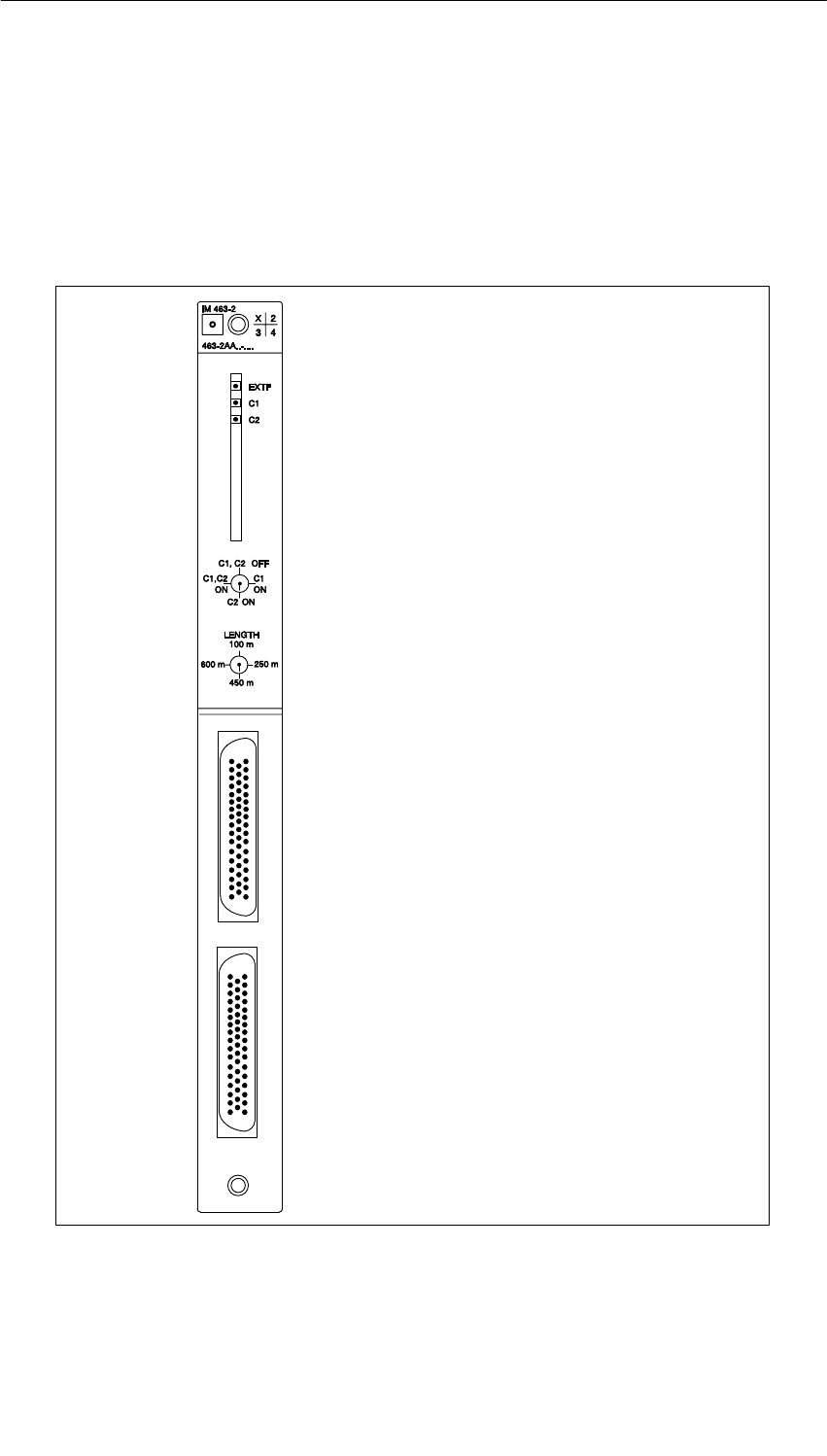
IM 463-2
7-4 S7-400, M7-400 Programmable Controllers Module Specifications
A5E00069467-07
7.3 Operator Controls and Indicators
Introduction
All controls and indicators on the IM 463-2 are arranged on the front plate. The
following figure shows the arrangement of the controls and indicators.
LEDs EXTF, C1, C 2
Interface selector switch
Cable length selector switch
C1 interface
C2 interface
X1 connector
X2 connector
Figure 7-1 Layout of the Controls and Indicators of the IM 463-2
IM 463-2
7-5
S7-400, M7-400 Programmable Controllers Module Specifications
A5E00069467-07
LEDs
Table 7-2 LEDs of the IM 4632
LED Meaning
LED EXTF (red) Lights up in the event of an external fault. Chain 1 or chain 2 has a
fault (power supply failed in the EU; terminating connector missing;
wire break, or interface selector switch wrongly set).
LED C1 (green) Chain 1 (via front connector X1, connection 1) is in order.
LED C2 (green) Chain 2 (via front connector X2, connection 2) is in order.
Front connector X1
and X2 Connector plug (output) for chain 1 and chain 2.
X1 = upper front connector; X2 = lower front connector
Interface Selector Switch
Table 7-3 LEDs of the IM 463-2
Switch Position Meaning
C1 ON You use only interface C1.
C2 ON You use only interface C2.
C1, C2 ON You use both interfaces.
C1, C2 OFF You use neither of the two interfaces.
You do not want to operate an S5 EU at present.
Cable Length Selector Selector
Table 7-4 Switch Position: Interface Selector of the IM 463-2
Switch Position Meaning
100 Cable length 1 to 100 m
250 Cable length 100 to 250 m
450 Cable length 250 to 450 m
600 Cable length 450 to 600 m
!Warning
Danger of data loss.
Changing the setting of the interface selector switch and the cable length selector
switch in RUN mode can result in loss of data.
Change the settings of these switches only in STOP mode of the CPU.

IM 463-2
7-6 S7-400, M7-400 Programmable Controllers Module Specifications
A5E00069467-07
7.4 Installing and Connecting the IM 463-2
Introduction
To install an IM 463-2 in a CR of the S7-400, proceed in the same way as when
installing other S7-400 modules (see Installation Manual, Chapter 5).
To connect an IM 463-2, follow the steps outlined below:
1. Prepare the connecting cable
2. Plug in the connecting cable
3. Select the interface
4. Select the cable length
Preparing the Connecting Cable
You can use the 721 connecting cable. However, you must change the connector
housing on the connection side of the IM 463-2.
Two connector housings are enclosed with every IM 463-2. You can prepare a
connecting cable for an IM 463-2 using one of these connector housings and a 721
connecting cable (see Catalog ST 54.1). To prepare the connecting cable, follow
the steps outlined below:
1. Remove one connector housing on the 721 connecting cable.
2. Open one of the connector housings enclosed with the IM 463-2.
3. Attach this connector housing to the 721 connecting cable.
4. Close the connector housing.

IM 463-2
7-7
S7-400, M7-400 Programmable Controllers Module Specifications
A5E00069467-07
Plugging in the Connecting Cable
To plug in the connecting cable, follow the steps outlined below:
1. Open the cover of the IM 463-2.
2. Plug the new connector of the connecting cable into one of the connectors of
the IM 463-2.
Interface C1 corresponds to the upper connector; interface C2 corresponds to
the lower connector.
3. Screw the connector of the connecting cable onto the connector of the
IM 463-2.
4. Close the cover.
Selecting the Interface
You select the interface with the selector switch on the front plate. Set the
interface(s) here that you want to use. Make the settings on the IM 463-2 only
when the CPU is in STOP mode.
Selecting the Cable Length
You select the cable length with the selector switch on the front plate. Set the range
corresponding to the chain length. Make the settings on the IM 463-2 only when
the CPU is in STOP mode.
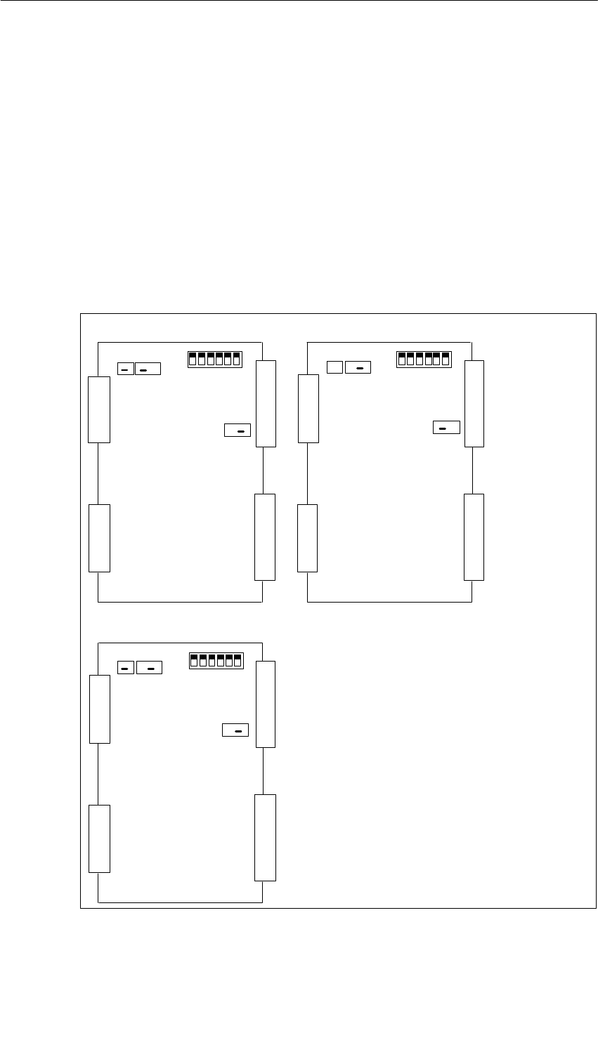
IM 463-2
7-8 S7-400, M7-400 Programmable Controllers Module Specifications
A5E00069467-07
7.5 Setting the Operating Modes of the IM 314
Introduction
To operate the IM 463-2, you must set on the IM 314 the S5 expansion unit used
and the address area of the S5 I/O modules.
Setting the S5 Expansion Unit
You set the S5 expansion unit in which you want to use the IM 314 using jumpers
BR1, BR2, and BR3 on the IM 314.
The following figure shows where these jumpers are located on the IM 314 and
which setting corresponds to which expansion unit.
••
•
BR 1 BR 1
•
BR 1
X3
X4
X1
X2
2 1 3 2 1 S1 off
on
X3
X4
X1
X2
2 1 3 2 1 S1 off
on
BR 3
3 2 1
X3
X4
X1
X2
BR 2
2 1 3 2 1 S1 off
on
BR 3
3 2 1
•
BR 2 BR 2
••
••
••
•• •
•• •• •
••
•
BR 3
3 2 1
••
Used in EU 185U, EU 186U Used in EU 183U
Used in ER 701-2, ER 701-3
Figure 7-2 Settings of the IM 314 with Expansion Units
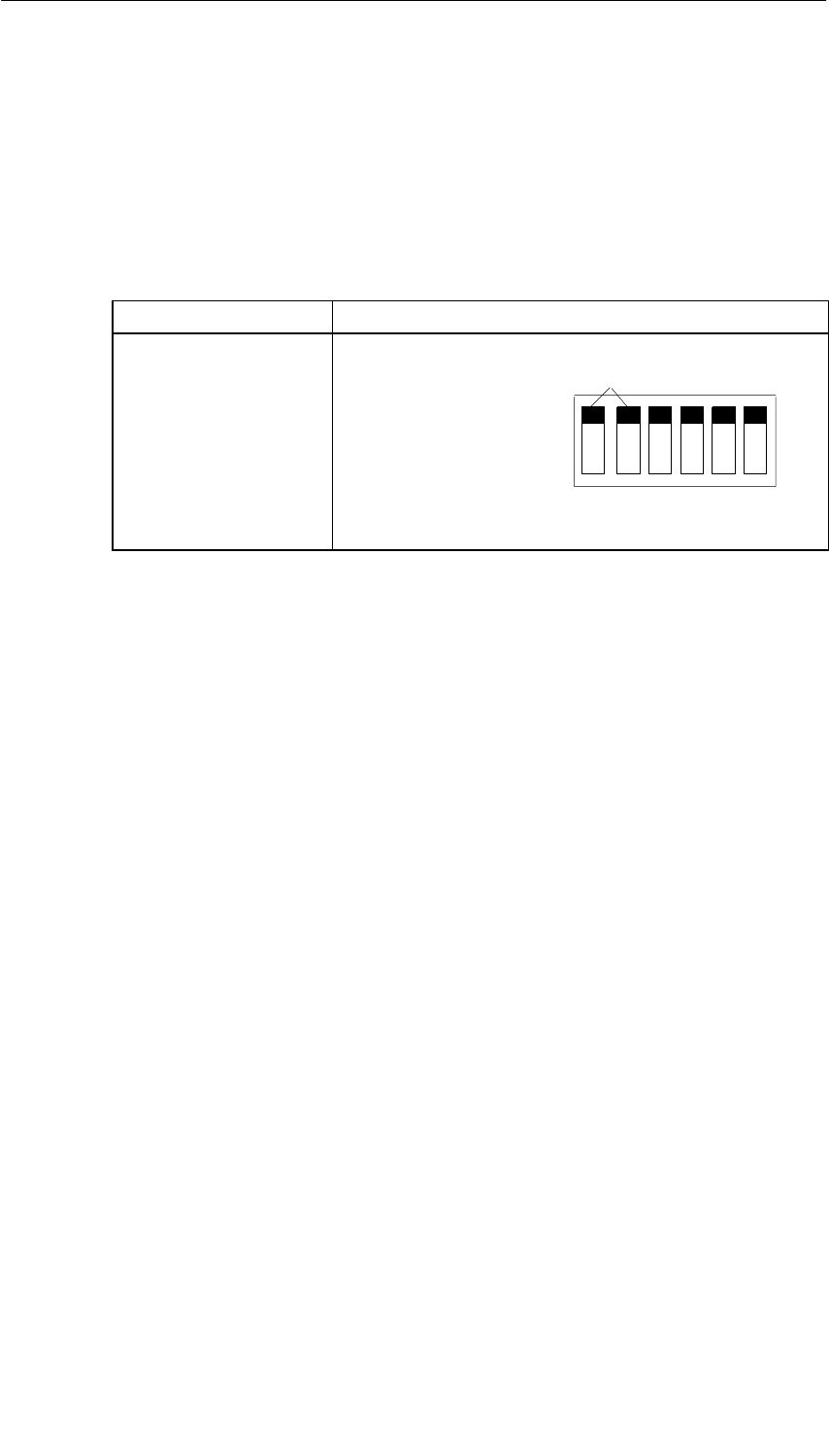
IM 463-2
7-9
S7-400, M7-400 Programmable Controllers Module Specifications
A5E00069467-07
Setting the Address Area
The address area of the S5 I/O modules is set on the IM 314. This setting applies
only for the digital and analog I/O modules.
The address areas P, Q, IM3, and IM4 are available. Set the switch to the relevant
position to address the digital and analog I/O modules in these areas.
Table 7-5 Settings Address Areas on the IM 314
I/O Area Address Switch Position
P area: F000 - F0FF
Q area: F100 - F1FF
IM3 area: FC00 - FCFF
IM4 area: FD00 - FDFF
O = OFF, 1 = ON
S1: 0000 *)
0001
1100
1101
OFF
ON
not relevant
*) Status as shipped
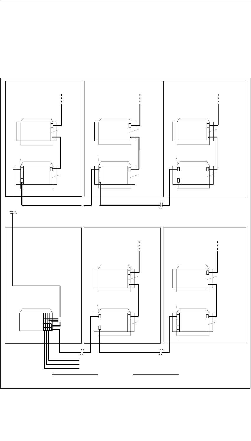
IM 463-2
7-10 S7-400, M7-400 Programmable Controllers Module Specifications
A5E00069467-07
7.6 Configuring S5 Modules for Operation in the S7-400
You configure the S5 modules using STEP 7. See the description of STEP 7 or the
online help function for details of how to proceed.
The following figure shows a possible connection of CRs and EUs via the IM 463-2
and IM 314.
IM 312-3
IM 300-3
IM 314
IM 312-3
IM 300-3
IM 314
IM 312-5
IM 314
All 721 connecting cables
further EU 184U,
EU 187U (central)
IM 312-3
IM 300-3
IM 314
IM 312-5
IM 300-5
IM 314
Terminating connector 760-1AA11
All 721 connecting cables
To further S5 expansion units (distributed) (max. 4 per IM 463-2)
max. 600 m
S7-400
Central mounting rack
IM 300-5
IM 463-2
S5
expansion
unit
Terminating connector 760-1AA11
S5
expansion
unit
S5
expansion
unit
S5
expansion
unit
S5
expansion
unit
S5
expansion
unit
S5
expansion
unit
S5
expansion
unit
S5
expansion
unit
S5
expansion
unit
Figure 7-3 Connection Variant for CCs and EUs via the IM 463-2 and IM 314
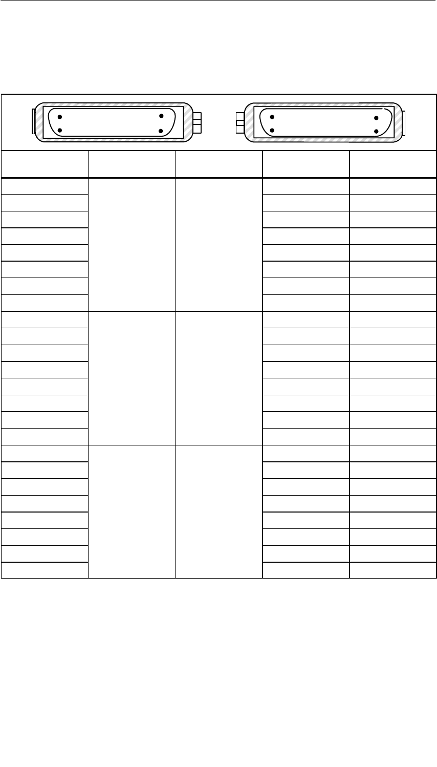
IM 463-2
7-11
S7-400, M7-400 Programmable Controllers Module Specifications
A5E00069467-07
7.7 Pin Assignments of the 721 Connecting Cable
Table 7-6 Assignment of the Connecting Cable 721
34
50
17 1
34 50
171
Connector
50-Pin Contact Bundle
Ident. Sheath Identification Foil Core Color Connector
50-Pin Contact
20 white 20
21 brown 21
4 green 4
51
red
yellow 5
18
1
No. 16 red gray 18
19 pink 19
2 blue 2
3 red 3
24 white 24
25 brown 25
8 green 8
92
green
yellow 9
22
2
No. 17 green gray 22
23 pink 23
6 blue 6
7 red 7
26 white 26
27 brown 27
10 green 10
11 3
yellow
yellow 11
42
3
No. 18 yellow gray 42
43 pink 43
44 blue 44
45 red 45
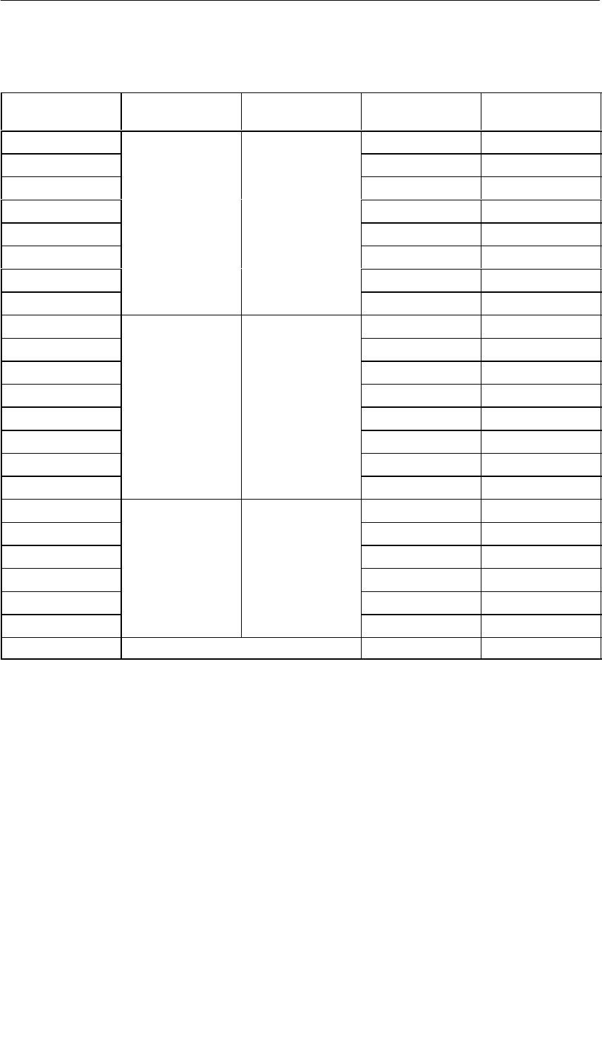
IM 463-2
7-12 S7-400, M7-400 Programmable Controllers Module Specifications
A5E00069467-07
Table 7-6 Assignment of the Connecting Cable 721, continued
Connector
50-Pin Contact Connector
50-Pin Contact
Core Color
Identification Foil
Bundle
Ident. Sheath
28 white 28
29 brown 29
12 green 12
13 4
brown
yellow 13
46
4
No. 19 brown gray 46
47 pink 47
30 blue 30
31 red 31
34 white 34
35 brown 35
36 green 36
37 5
black
yellow 37
38
5
No. 20 black gray 38
39 pink 39
40 blue 40
41 red 41
48 white 48
49 brown 49
14 6
blue
green 14
15
6
No. 21 blue yellow 15
32 gray 32
33 pink 33
- Shield -
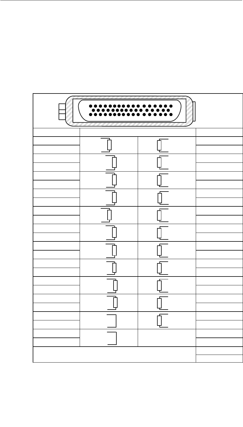
IM 463-2
7-13
S7-400, M7-400 Programmable Controllers Module Specifications
A5E00069467-07
7.8 Terminating Connector for IM 314
Introduction
The IM 314 of the last expansion unit of each chain is terminated with the
6ES5 760-1AA11 terminating connector.
Table 7-7 Assignment of the Terminator 760-1AA11
34 50
1
7
1
Plug Connection 180-Ohm Resistance or Jumper Plug Connection
28 8
29 9
26 6
27 7
48 4
47 5
44 2
45 3
42 24
43 25
38
1)
22
39 1) 23
34
1)
20
35 1) 21
36
1)
18
37 1) 19
40
1)
12
41 1) 13
48
2)
10
49 2) 11
15 30
16 31
14
50
1) 100
)
2) 200

IM 463-2
7-14 S7-400, M7-400 Programmable Controllers Module Specifications
A5E00069467-07
7.9 Technical Specifications (6ES7463–2AA00–0AA0)
Programming package
Associated programming
package As of STEP7 V 2.1
Dimensions and Weight
Dimensions
WxHxD (mm) 25x290x280
Weight 360 g
Module-Specific Data
Number and type of
interfaces 2 parallel, symmetrical
interfaces
Cable length:
from IM 463-2 to the last
IM 314
(per interface) max. 600 m
Transmission rate 2 Mbytes/s to
100 Kbytes/s
Parameter sets of the
signal modules differential signal in
accordance with
RS 485
Front connector 2 connectors,
50-pin male
Voltages, Currents, Potentials
Supply voltage from
S7-400 bus +5 V
Current consumption typ. 1.2 A
max. 1.32 A
Power losses typ. 6 W
max. 6.6 W

8-1
S7-400, M7-400 Programmable Controllers Module Specifications
A5E00069467-07
PROFIBUS DP Master Interface
IM 467/IM 467 FO
Chapter Overview
Section Description Page
8.1 PROFIBUS DP Master Interface IM 467/IM 467 FO 8-2
8.2 Configuration 8-6
8.3 Connection to PROFIBUS DP 8-8
8.4 Technical Specifications 8-12
8

PROFIBUS DP Master Interface IM 467/IM 467 FO
8-2 S7-400, M7-400 Programmable Controllers Module Specifications
A5E00069467-07
8.1 PROFIBUS DP Master Interface IM 467/IM 467 FO
Order Numbers
IM 467 6ES7467-5GJ02-0AB0 (RS 485)
IM 467 FO 6ES7467-5FJ00-0AB0 (F0)
Application
PROFIBUS DP, standardized to IEC 61784–1:2002 Ed1 CP 3/1, enables rapid
communication in the field between programmable controllers, PCs and field
devices. Field devices are devices such as: ET 200 distributed I/O devices, drives,
valve terminals, switchgear and many others.
The IM 467/IM 467 FO interface module is meant to be used in an S7-400
programmable controller. It permits the S7-400 to be connected to PROFIBUS DP.
Note
The PROFIBUS DP master interface IM 467 or IM 467 FO is not a
DP master in accordance with DPV 1.
Configuration
•Configured as for the S7-400
•Can be operated without a fan
•A maximum of 4 IM 467/IM 467 FO can be used in the central controller. There
are no slot rules.
•The IM 467/IM 467 FO and the CP 443-5 Extended cannot be used together.
•The transmission rate of 9.6 kbps to 12 Mbps can be set in steps using software
•Configuration and programming are possible via PROFIBUS DP.
You must not, however, change the PROFIBUS DP parameters.
•IM 467 with 9-pin subminiature D female connector for connection to
PROFIBUS DP (6ES7467-5GJ02-0AB0)
•IM 467 FO with fiber-optic cable for connection to
PROFIBUS DP (6ES7467-5FJ00-0AB0)
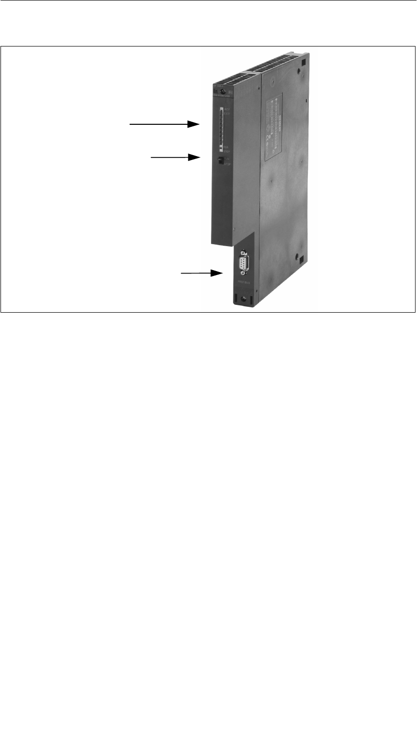
PROFIBUS DP Master Interface IM 467/IM 467 FO
8-3
S7-400, M7-400 Programmable Controllers Module Specifications
A5E00069467-07
PROFIBUS DP interface
9-pin subminiature D
LEDs
Mode selector
Figure 8-1 Configuration of the IM 467/467 FO
Communication Services
The IM 467/IM 467 FO offers two communication services:
•PROFIBUS DP
The IM 467/IM 467 FO is a PROFIBUS DP master in accordance with EN 50
170. It is configured entirely with STEP 7. It behaves in basically the same way
as the integrated PROFIBUS DP interfaces on the CPU modules (see the
technical specifications of the IM 467/IM 467 FO for the differences).
DP communication does not require any function calls in the STEP 7 user
program.
•S7 functions
The S7 functions guarantee optimal and easy communication in a
SIMATIC S7/M7/C7 automation solution. The following S7 functions are enabled
for the IM 467/IM 467 FO:
– Programming device functions via PROFIBUS DP
– Operator control and monitoring functions via PROFIBUS DP
Communication takes place without any additional configuration on the IM 467/
IM 467 FO.
S7 functions can be used on their own or in parallel with the PROFIBUS DP
protocol. If they are used in parallel with DP communication, this affects the
PROFIBUS DP bus cycle time.
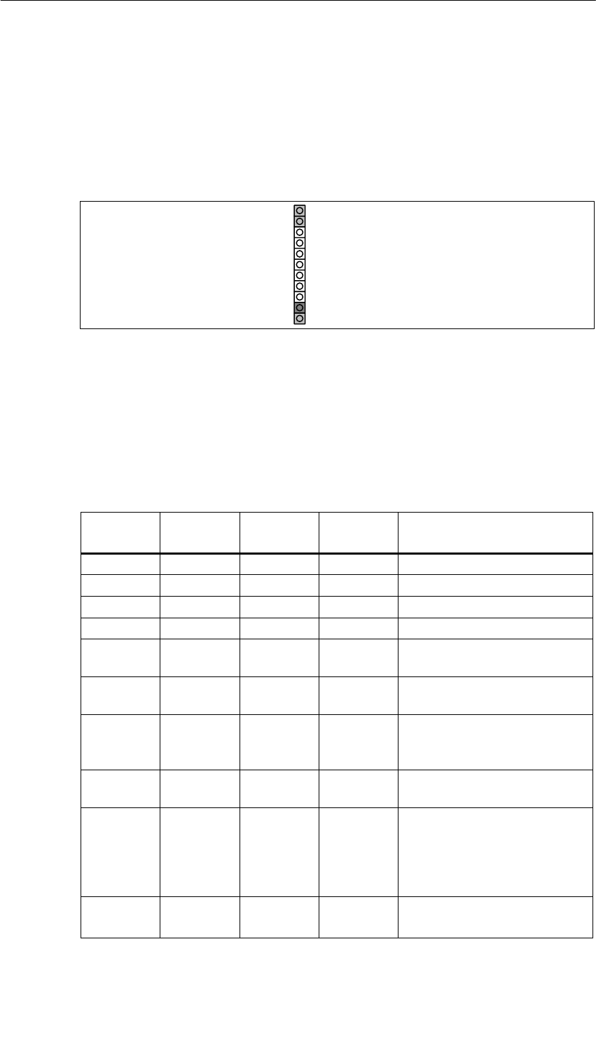
PROFIBUS DP Master Interface IM 467/IM 467 FO
8-4 S7-400, M7-400 Programmable Controllers Module Specifications
A5E00069467-07
8.1.1 Indicators and the Mode Selector
LED
The LED plate on the front panel of the IM 467/
IM 467 FO has the following four indicators:
INTF
EXTF
RUN
STOP
Figure 8-2 LEDs of the IM 467/467 FO
IM Operating Mode
The LEDs indicate the operating mode of the IM in accordance with the following
table:
Table 8-1 Operating Modes of the IM 467/467 FO
STOP LED
(yellow)
RUN LED
(green)
EXTF LED
(red)
INTF LED
(red)
CP Operating Mode
On Flashing Off Off Startup
Off On Off Off RUN
Flashing On Off Off STOPPING
On Off Off Off STOP
On Off Off On STOP with internal error (IM not
configured, for example)
Flashing Off Off Off Waiting for FW update (takes 10
sec. after power up)
Flashing Off On On
Waiting for FW update (IM
currently contains an incomplete
FW version).
Off On On Off RUN and PROFIBUS DP bus
fault
Off On Flashing Off
RUN; but there are faults on the
DP line (the DP slave is not
taking part in data transfer, or
the module in the DP slave is
faulty, for example)
Flashing Flashing Flashing Flashing Module error/
System error

PROFIBUS DP Master Interface IM 467/IM 467 FO
8-5
S7-400, M7-400 Programmable Controllers Module Specifications
A5E00069467-07
Controlling the Operating Mode
There are two ways to control the operating mode of the IM 467/IM 467 FO:
•By using the mode selector
•By using the programming device/PC
Mode Selector
You can switch operating modes as follows using the mode selector:
•From STOP to RUN
All the configured communication services and S7 communication services are
available in RUN.
The IM operating mode can only be controlled from the programming device/PC
when the switch is in the RUN position.
•From RUN to STOP
The IM goes into STOP mode. Any existing S7 connections are cleared down,
and the DP slaves are no longer supplied.
Loadable Firmware
The IM 467/IM 467 FO supports the updating of firmware (FW) by means of the
FW loader. The FW loader is a component of the NCM S7 configuration software
for PROFIBUS DP. Authorization is not required for this. After a FW update, the
central controller must be switched off and on again before normal operation can
be resumed.
Note
You can find additional information on loading firmware in the NCM S7 for
PROFIBUS DP manual and in the readme file of the NCM S7 for PROFIBUS DP
configuration software.
Note
An optical bus terminal (OBT) is required to load FW in the IM 467 FO.

PROFIBUS DP Master Interface IM 467/IM 467 FO
8-6 S7-400, M7-400 Programmable Controllers Module Specifications
A5E00069467-07
8.2 Configuration
The IM 467/IM 467 FO is configured with STEP 7. The configuration data are
retained even in the event of a power failure; a memory module is not required.
Using the S7 functions it is possible to program and configure remotely all the
IM 467/IM 467 FO connected to the network and all the CPUs connected via the
SIMATIC S7-400 backplane bus.
SIMATIC STEP 7 is the prerequisite for this.
•STEP 7 V3.1
The IM 467 (MLFB no. 6ES7467-5GJ00-0AB0) can be configured as of STEP 7
version 3.1.
•STEP 7 V4.02
The IM 467 (MLFB no. 6ES7467-5GJ01-0AB0) supports the SYNC/FREEZE
functional enhancement as of STEP 7 version 4.02.
•STEP 7 as of version 5.00
The IM 467/IM 467 FO (MLFB number
6ES7467-5GJ02-0AB0/6ES7467-5FJ00-0AB0) supports the functional
expansions of routing of programming device functions, DP direct
communication and equidistance as of STEP 7 version 5.00.
Module Replacement Without a Programming Device
The configuration data are stored in the load memory of the CPU. The non-volatile
storage of configuration data in the CPU is ensured by battery backup or EPROM
module cards.
The IM 467/IM 467 FO can be replaced without the need to explicitly reload the
configuration data.
It is only possible to remove and insert the IM 467/IM 467 FO in a deenergized
state.
Multiprocessor Operation
The connected DP slaves can only be assigned to and processed by one CPU.
Configuration and Diagnostics Cannot Be Carried Out Simultaneously
When configuration is in progress, the IM 467/IM 467 FO cannot be diagnosed at
the same time via MPI.

PROFIBUS DP Master Interface IM 467/IM 467 FO
8-7
S7-400, M7-400 Programmable Controllers Module Specifications
A5E00069467-07
Prerequisites
The IM 467/IM 467 FO is supported by all the CPU operating systems beginning
with the release numbers listed below.
You will also find the following information in the table:
•The number of IM 467/IM 467 FO that can be operated on a CPU
•Support of multiprocessor operation
Table 8-2 CPU and IM 467/467 FO
CPU MLFB Number Release Multiprocessor
Operation
Possible
No. of IM
467
Possible
412 6ES7412-1XF03-0AB0 1 Yes 4
412-2 6ES7412-2XG00-0AB0 1 Yes 4
414-2 6ES7414-2XG03-0AB0 1 Yes 4
416-2 6ES7416-2XK02-0AB0 1 Yes 4
416-3 6ES7414-3XL00-0AB0 1 Yes 4
417-4 6ES7417-4XL00-0AB0 1 Yes 4
Note
The 3 MB and 6 MB transmission rates are not enabled for the IM 467-FO.
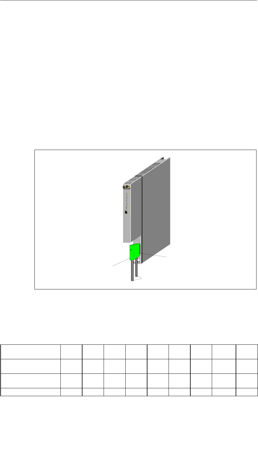
PROFIBUS DP Master Interface IM 467/IM 467 FO
8-8 S7-400, M7-400 Programmable Controllers Module Specifications
A5E00069467-07
8.3 Connection to PROFIBUS DP
There are two ways of connecting to PROFIBUS DP:
•Electrical connection via a bus connector
•Optical connection using a fiber-optic cable
8.3.1 Bus Connector
Only with 6ES7467-5GJ02-0AB0.
The bus cable is connected to the IM 467 by means of this connector. (See the
detailed description in the chapter on networking in the S7-400/M7-400, Hardware
and Installation manual.)
Bus connector
PROFIBUS DP bus cable
Switch for the bus
terminating resistor
Figure 8-3 Connecting the Bus Connector to the IM 467
Maximum Cable Lengths for PROFIBUS DP
Transmission Rate in
Kbps 9.6 19.2 93.75 187.5 500 1500 3000 6000 W 12000
Max. Length of a Bus
Segment in m 1.000 1.000 1.000 1.000 400 200 100 100 100
Max. Number of Bus
Segments 1) 10 10 10 10 10 10 10 10 10
Max. Length in m 10.000 10.000 10.000 10.000 4.000 2.000 1.000 1.000 1.000
1) Bus segments are interconnected by means of RS 485 repeaters
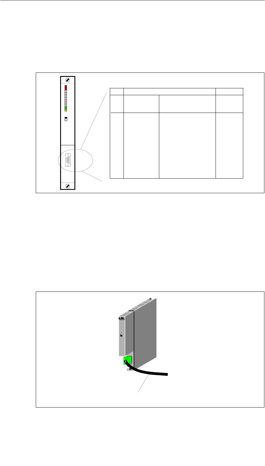
PROFIBUS DP Master Interface IM 467/IM 467 FO
8-9
S7-400, M7-400 Programmable Controllers Module Specifications
A5E00069467-07
Connector Pin Assignment
The electrical interface used to connect to
PROFIBUS DP (9-pin subminiature D female connector) is specified in the
following table.
1
2
3
4
5
6
7
8
9
PE
–
RxD/TxD–P
RTS (AG)
M5V2
P5V2
BATT
RxD/TxD–N
–
Protective earth
Data transfer line – B
Control –A
Data reference potential
Supply plus
–
Data transfer line – A
–
yes
–
yes
yes
–
yes
–
––
yes
RUN
RUN
STOP
STOP
INTF
EXTF
Pin
No. Signal Name PROFIBUS DP
Designation
Ass. with
RS 485
Figure 8-4 Connector Pin Assignment
8.3.2 Optical Connection to PROFIBUS DP
Only in the case of 6ES7467-5FJ00-0AB0.
The IM 467 F0 with an integrated fiber-optic cable interface is available for
connecting to the optical version of PROFIBUS DP.
CP443–5
443–5FX00–0XE0
STOP
RUN
INTF
EXTF
RUN
STOP
AUI/TP
X2
34
PROFIBUS FO bus cable
Figure 8-5 Optical Connection to PROFIBUS DP
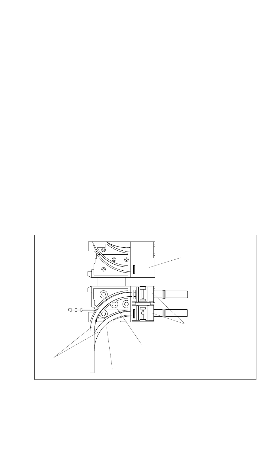
PROFIBUS DP Master Interface IM 467/IM 467 FO
8-10 S7-400, M7-400 Programmable Controllers Module Specifications
A5E00069467-07
8.3.3 Connecting a Fiber-Optic Cable to the IM 467 FO
Accessories Required
•Pack of Simplex connectors and polishing sets (6GK1901-0FB00-0AA0)
•Pack of plug-in adapters (6ES7195-1BE00-0XA0)
Installing Connectors
1. Remove approximately 30 cm of the sheath of the fiber-optic duplex cable.
2. Install the fiber-optic duplex cable with the associated Simplex connectors. You
can find a detailed description of Simplex connectors in the ”SIMATIC NET
PROFIBUS Networks” manual.
TIP: Close the two Simplex connectors together rather than separately to obtain
a Duplex connector. This ensures a more secure position in the plug-in adapter.
IMPORTANT: The polished surface of the plastic fibers must be absolutely
smooth and even. The plastic sheath must not stick out or be cut unevenly. If
this is not the case, considerable attenuation of the light signal via the fiber-optic
cable may occur.
3. Place the Simplex connectors in the plug-in adapter for the IM 467 FO and the
fiber-optic cable in the cable guides provided. Insert the plug-in adapter until
you hear the sides clearly latch into position.
Make sure when you insert the plugs in the plug-in adapter that the sender is
always at the top and the receiver is underneath.
Fiber-optic
duplex cable Max. 30 mm bending radius
Plug-in adapter for
the IM 467 FO
Put the 2 Simplex connectors
together to make
one duplex connector.
Tip: Cut the lower cable approx. 10 mm shorter
than the upper one to achieve better cable routing
in the cable channel of the IM 467 FO.
Figure 8-6 Installing the Connector
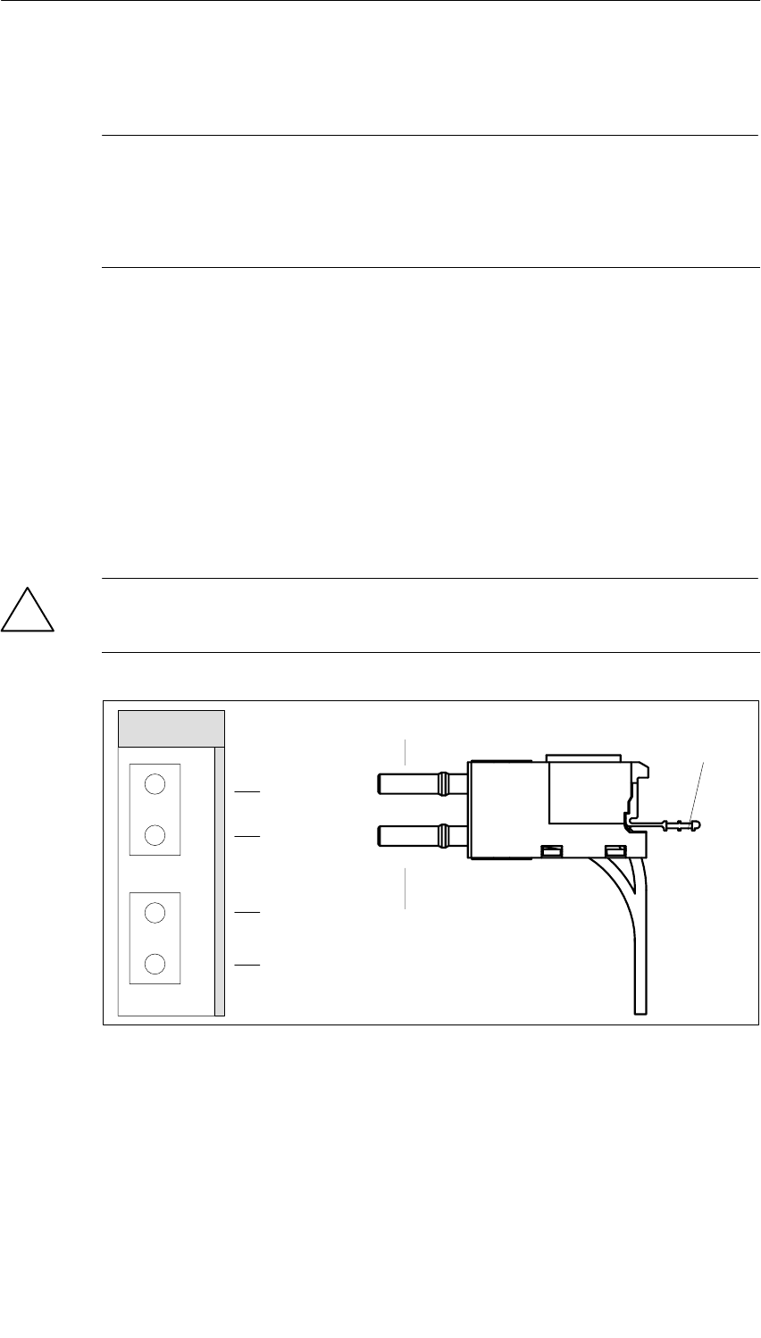
PROFIBUS DP Master Interface IM 467/IM 467 FO
8-11
S7-400, M7-400 Programmable Controllers Module Specifications
A5E00069467-07
Reusing Fiber-Optic Cables
Note
If you insert used fiber-optic cables in the plug-in adapter again, you must cut off
the bent lengths of both fiber-optic cable cores and install the Simplex connectors
again.
This avoids any attenuation losses due to parts of the cores of the fiber-optic
duplex cables being bent again and overstressed.
Inserting the Fiber-Optic Cables into the IM 467 FO
Insert the fiber-optic cables and attached plug-in adapters into the IM 467 FO.
Move the protruding handle of the plug-in adapter upwards.
Make sure that it is correctly positioned: The sender fiber-optic cable is plugged
into the receiver socket, and the receiver fiber-optic cable is inserted into the
sender socket of the fiber-optic interface of the IM 467 FO.
If the IM 467 FO is the last node in the fiber-optic network, you must close the
unoccupied fiber-optic cable interface with filler connectors (the connectors are
already in place when the IM 467 FO is delivered).
!Caution
Do not look directly into the opening of the optical sender diodes.
The light beam could damage your eyes.
Handle
Sender
Receiver
PROFIBUS DP
Receiver
Receiver
Sender
Sender
R
T
R
T
Figure 8-7 Inserting the Fiber-Optic Cables into the IM 467 FO
Bending Radius for the Fiber-Optic Cable
Make sure when you wire the fiber-optic duplex cable cores and insert them into
the plug-in adapter that the permissible bending radius of 30 mm is not violated.
See also the installation guidelines on fiber-optic cables in the SIMATIC NET
PROFIBUS Networks manual.

PROFIBUS DP Master Interface IM 467/IM 467 FO
8-12 S7-400, M7-400 Programmable Controllers Module Specifications
A5E00069467-07
8.4 Technical Specifications
8.4.1 Technical Specifications of the IM 467
6ES7467-5GJ02-0AB0.
Dimensions and Weight
Dimensions
W x H x D (mm)
Weight
25 x 290 x 210
700 g
PROFIBUS DP
•Standard
•Transmission rate
•Transmission
technology
PROFIBUS DP,
EN 50 170
9.6 kbps to 12 Mbps,
parameterizable in steps
RS 485 via 9-pin
subminiature D female
connector
Current consumption
Current consumption from
the S7-400 bus (24 VDC)
The IM does not consume
any current at 24 V, and it
only makes this voltage
available at the MPI/DP
interface.
Total current consumption
of the components
connected to the DP
interfaces, with a maximum
of 150 mA
PROFIBUS DP
Conditions of Use
Can be used in SIMATIC S7-400, max. 4
IM 467 in the central
controller
IM 467 cannot be used together with the CP 443-5
Supply voltage 5 VDC via the backplane
bus
Current consumption
•From 5 VDC
1.3 A
Addressing range Max. 4 KB for inputs and 4
KB for outputs
DP master Yes
•DPV 1 No
•Enable/disable No
Number of connectable I/O
devices
(slaves)
96
Number of connections for
S7 functions for the
programming device and
operation and monitoring
32 + 1 diagnostic
connection
Data volume per slave Max. 244 bytes
Consistency Max. 128 bytes
Configuration software STEP 7
DP slave No
Deviations from the DP Interface Integrated
in the CPU
•Different SSL IDs for system diagnostics
•Possibly extended SFC run times
•Additional return codes for SFC 14 and
SFC 15
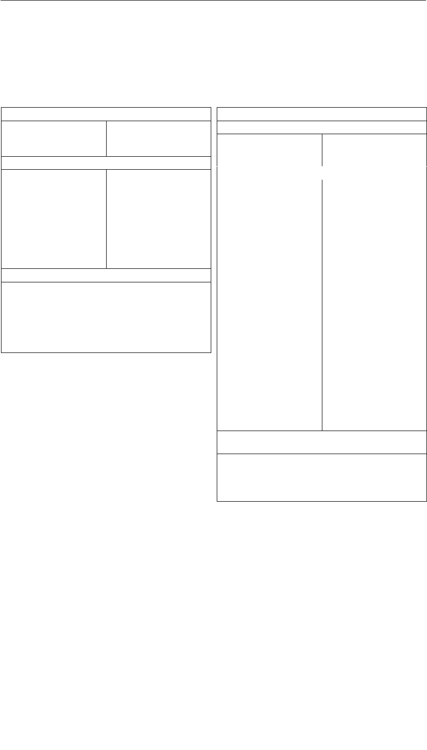
PROFIBUS DP Master Interface IM 467/IM 467 FO
8-13
S7-400, M7-400 Programmable Controllers Module Specifications
A5E00069467-07
8.4.2 Technical Specifications of the IM 467 FO
6ES7 467-5FJ00-0AB0
Dimensions and Weight
Dimensions
W x H x D (mm)
Weight
25 x 290 x 210
700 g
PROFIBUS DP
•Standard
•Transmission rate
•Transmission
technology
PROFIBUS DP,
EN 50 170
9.6 kbps to 12 Mbps,
parameterizable in steps (3
Mbps and 6 Mbps not
possible)
FOC
Wavelength l = 660 nm 2 x
Duplex socket
Current consumption
Current consumption from
the S7-400 bus (24 VDC)
The IM does not consume
any current at 24 V, and it
only makes this voltage
available at the MPI/DP
interface.
Total current consumption
of the components
connected to the DP
interfaces, with a maximum
of
150 mA
PROFIBUS DP
Conditions of Use
Can be used in SIMATIC S7-400, max. 4
IM 467 in the central
controller
IM 467 cannot be used with the CP 443-5
Supply voltage 5 VDC via the backplane
bus
Current consumption
•From 5 VDC
1.3 A
Addressing range Max. 4 KB for inputs and 4
KB for outputs
DP master Yes
•DPV 1 No
•Enable/disable No
Number of connectable I/O
devices
(slaves)
96
Number of connections for
S7 functions for the
programming device and
operator control and
monitoring
32 + 1 diagnostic
connection
Data volume per slave Max. 244 bytes
Consistency Max. 128 bytes
Configuration software STEP 7
DP slave No
Deviations from the DP Interface Integrated
in the CPU
•Different SSL IDs for system diagnostics
•Possibly extended SFC run times
•Additional return codes for SFC 14 and
SFC 15

PROFIBUS DP Master Interface IM 467/IM 467 FO
8-14 S7-400, M7-400 Programmable Controllers Module Specifications
A5E00069467-07

9-1
S7-400, M7-400 Programmable Controllers Module Specifications
A5E00069467-07
Cable Duct and Fan Subassemblies
Chapter Overview
Section Description Page
9.1 Fan Monitoring in the Fan Subassemblies 9-2
9.2 Cable Duct; (6ES7408-0TA00-0AA0) 9-4
9.3 The 120/230 VAC Fan Subassembly; (6ES7408-1TB00-0XA0) 9-5
9.4 The 24 VDC Fan Subassembly; (6ES7408-1TA00-0XA0) 9-7
Characteristics
The cable duct and the fan subassembly have the following characteristics
•The air inflow area is variable.
•Shield and cable clamping are possible.
In addition, the fan subassembly has the following characteristics:
•Fans and filter frames can be replaced from the front during operation.
•The fan function is controlled by means of speed monitoring.
•Operation with filter frames is optional.
9

Cable Duct and Fan Subassemblies
9-2 S7-400, M7-400 Programmable Controllers Module Specifications
A5E00069467-07
9.1 Fan Monitoring in the Fan Subassemblies
In this section, you will find out how to monitor the fans.
There is a signaling concept example at the end of the section.
LEDs
The three red LEDs are assigned to the individual fans. From left to right, these
are:
F1 – for fan 1
F2 – for fan 2
F3 – for fan 3
Fans
The fans have a redundant design. The fan subassembly continues to function
even if one fan fails.
Fan Monitoring
The function of the fans is controlled by means of speed monitoring. If the speed of
a fan drops below the limit speed of 1750 rpm, the LED assigned to it lights up. In
addition, the relay K1 drops out.
If the speed of a second fan drops below the limit speed, the LED assigned to it
lights up; in addition, the relay K2 drops out.
The following table is the function table for the fan monitoring.
Table 9-1 Function of Fan Monitoring
Fan1 Fan2 Fan3 LED F1 LED F2 LED F3 Relay K1 Relay K2
– – – L L L – –
– – + L L D – –
– + – L D L – –
+ – – D L L – –
– + + L D D – +
+ – + D L D – +
+ + – D D L – +
+ + + D D D + +
–* –* –* D* D* D* –* –*
+ Fan in operation or relay picked up
– Fan failed or relay dropped out
D LEDs dark
L LEDs lit
* Power off
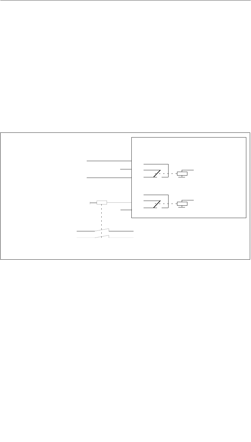
Cable Duct and Fan Subassemblies
9-3
S7-400, M7-400 Programmable Controllers Module Specifications
A5E00069467-07
Signaling Concept Example
You can check the fault-free functioning of the fan subassembly using digital inputs.
You can cause the power supply to be cut off after the failure of at least two fans by
using the relay K2. For example, you can use an intermediate contactor to interrupt
the mains.
The relay contacts are labeled as follows:
Relay K1: No. 1...3
Relay K2: No. 4...6
The following diagram explains the circuit in the fan subassembly when all fans are
functioning.
6
5
4
3
2
1
L+ ... to the monitor
... to the monitor
... to the digital input module
24 V
... to the mains
... to the power supply module
... in the fan assembly
K1
K2
Evaluation
(digital input module)
Evaluation
(digital input module)
Status: All fans operating
Figure 9-1 Example of a Message Concept
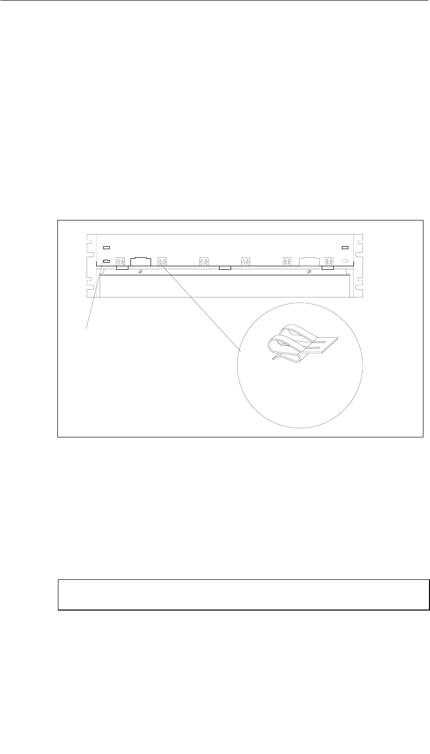
Cable Duct and Fan Subassemblies
9-4 S7-400, M7-400 Programmable Controllers Module Specifications
A5E00069467-07
9.2 Cable Duct; (6ES7408-0TA00-0AA0)
Function
The cable duct is used in installations outside the cabinet for
•Cable clamping and/or for
•Shielding or for
•Air circulation without fan assistance
Front View of the Cable Duct
Shielding
clamp
(Side elevation
Scale 1:1)
Eye for
clamping cable
Figure 9-2 Front View of the Cable Channel
Shielding Clamps
If you do not require the shielding clamps supplied, do not install them in the cable
duct.
Technical Specifications
Dimensions W H D (mm) 482.5109.5235
Weight ca. 1200 g

Cable Duct and Fan Subassemblies
9-5
S7-400, M7-400 Programmable Controllers Module Specifications
A5E00069467-07
9.3 The 120/230 VAC Fan Subassembly;
(6ES7408-1TB00-0XA0)
Operator Controls and Indicators on the 120/230 VAC Fan Subassembly
LEDs F1, F2, F3Quick-release lock
Relay contacts
1, 2, 3
Relay contacts
4, 5, 6
Voltage
selector switch
Fuse
compartment
Figure 9-3 Controls and Indicators of the Fan Subassembly 120/230 VAC (6ES7408-1TB00-0XA0)
Fuse
Included in this fan subassembly are standard cartridge fuse links,
5 x 20 mm, conforming to DIN
•250 mAT for 120 V
•160 mAT for 230 V.
The fuse for the 230 V range is already installed on shipping from the factory.
Note
If you change the voltage range, you must also insert the fuse for this voltage
range in the fan subassembly. You will find a description of how to change the fuse
in the Installation Manual, Chapter 9.
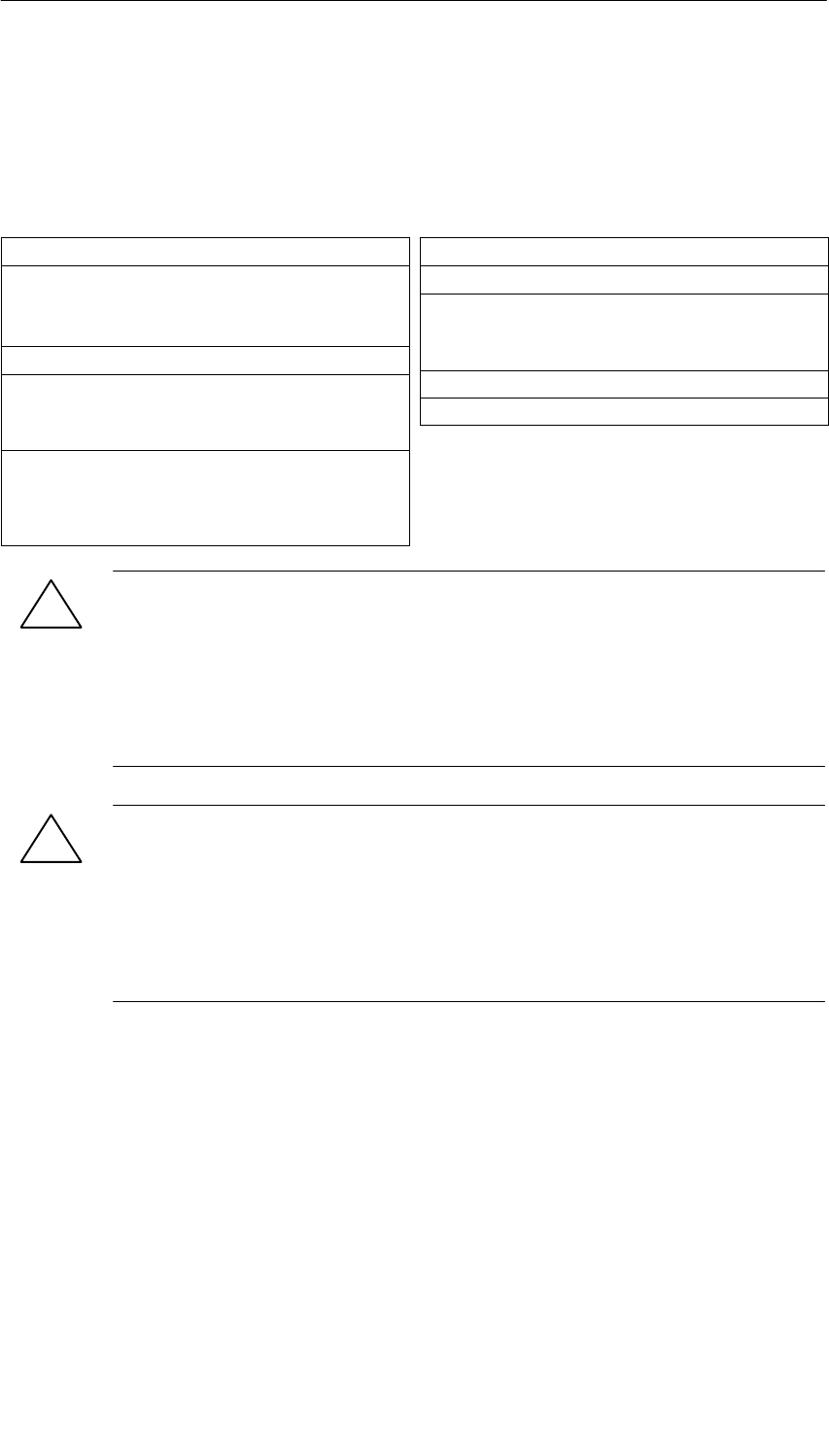
Cable Duct and Fan Subassemblies
9-6 S7-400, M7-400 Programmable Controllers Module Specifications
A5E00069467-07
Shielding Clamps
If you do not require the shielding clamps supplied, do not install them in the fan
subassembly.
Technical Specifications
Dimensions, Weights
Dimensions WxHxD (mm) 482.5×109.5×235
()
Weight appr. 2000 g
Cable diameter 3 bis 9 mm
Nominal Sizes
Lifespan of the fans
•at 40°C
•at 75°C
70000 h
25000 h
Max. contact load of relay
contacts 1 to 6
•Switching voltage
•Switching current
24 VDC
200 mA
Voltages, Currents, Potentials
At nominal voltage of 230 VAC 120 VAC
Power consumption
•with fan
•without fan
17 W 18 W
5 W 4 W
Starting current 0,6 A 1,15 A
Fuses 160 mA 250 mA
!Warning
Electrical current can lead to personal injury.
If you remove the left cover when installing or removing the fan subassembly, the
terminals on the transformer are accessible briefly.
Remove the voltage from the fan subassembly before you install or remove it.
Disconnect the supply cable before you remove the fan subassembly.
!Caution
Danger of damage to equipment.
If you mix up the power supply PCB and the monitoring PCB in the fan
subassembly, the fan subassembly may be damaged.
During maintenance of the unit, make sure you do not mix up the power supply
PCB and the monitoring PCB.
Monitoring Function
In the case of a fault (defective fans) the fans are not switched off. Once you have
replaced the defective fan(s), the fault is acknowledged automatically as soon as
the fans have reached the required speed. Any faults that occur are not stored.
When you switch on the fan subassembly, the fans start running. After
approximately 10 s the current status of the fans is indicated via LEDs and relays.
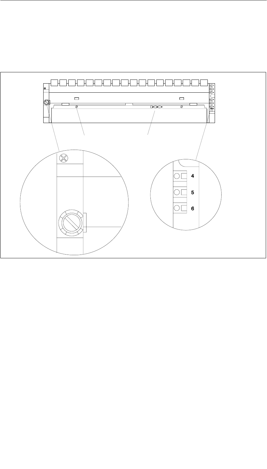
Cable Duct and Fan Subassemblies
9-7
S7-400, M7-400 Programmable Controllers Module Specifications
A5E00069467-07
9.4 The 24 VDC Fan Subassembly; (6ES7408-1TA00-0XA0)
Operator Controls and Indicators on the 24 VDC Fan Subassembly
LEDs F1, F2, F3Quick-release lock
Relay contacts
1, 2, 3
Relay contacts
4, 5, 6
Fuse
compartment
1 AT
1 AT
Figure 9-4 Controls and Indicators of the Fan Subassembly 24 VDC (6ES7408-1TA00-0XA0)
Characteristics
The 24 VDC fan subassembly has the same construction and functional
characteristics as the 120/230 VAC fan subassembly.
Installation
Installing the 24 VDC fan subassembly is the same as for the 120/230 VAC fan
subassembly.
Wiring
You connect the 24 VDC fan subassembly to the 24 VDC supply in the same
manner as for the 120/230 VAC fan subassembly. You should note the polarity of
the spring connections L+ and L–.

Cable Duct and Fan Subassemblies
9-8 S7-400, M7-400 Programmable Controllers Module Specifications
A5E00069467-07
Signaling Concept
The signaling concept of the 24 VDC fan subassembly is identical to the signaling
concept of the 120/230 VAC fan subassembly.
Fuse
Included in this fan subassembly are standard cartridge fuse links,
5 x 20 mm, conforming to DIN
•1.0 AT for 24 V
The fuse is already installed on shipping from the factory.
Shielding Clamps
If you do not require the shielding clamps supplied, do not install them in the fan
subassembly.
Technical Specifications
Dimensions, Weights
Dimensions WxHxD (mm) 482.5×109.5×235
()
Weight appr. 2000 g
Kabeldurchmesser 3 bis 9 mm
Nominal Sizes
Lifespan of the fans
•at 40°C
•at 75°C
70000 h
25000 h
Max. contact load of relay con-
tacts 1 to 6
•Switching voltage
•Switching current
24 VDC
200 mA
Voltages, Currents, Potentials
Input voltage
•Nominal value
•Valid range
DC 24 V
Static 19.2 V up to 30
V
Dynamic: 18.5 up to
30.2 V
Starting current 0.9 A at 24 V
Fuses 1.0 AT
Power consumption
•with fan
•without fan
12 W
1.4 W
!Caution
Danger of damage to equipment.
If you insert the monitoring PCB in the wrong position in the fan subassembly, the
fan subassembly may be damaged.
During maintenance of the unit, make sure you do not replace the monitoring PCB
in the wrong position.
Monitoring Function
In the case of a fault (defective fans) the fans are not switched off. Once you have
replaced the defective fan(s), the fault is acknowledged automatically as soon as
the fans have reached the required speed. Any faults that occur are not stored.
When you switch on the fan subassembly, the fans start running. After
approximately 10 s the current status of the fans is indicated via LEDs and relays.
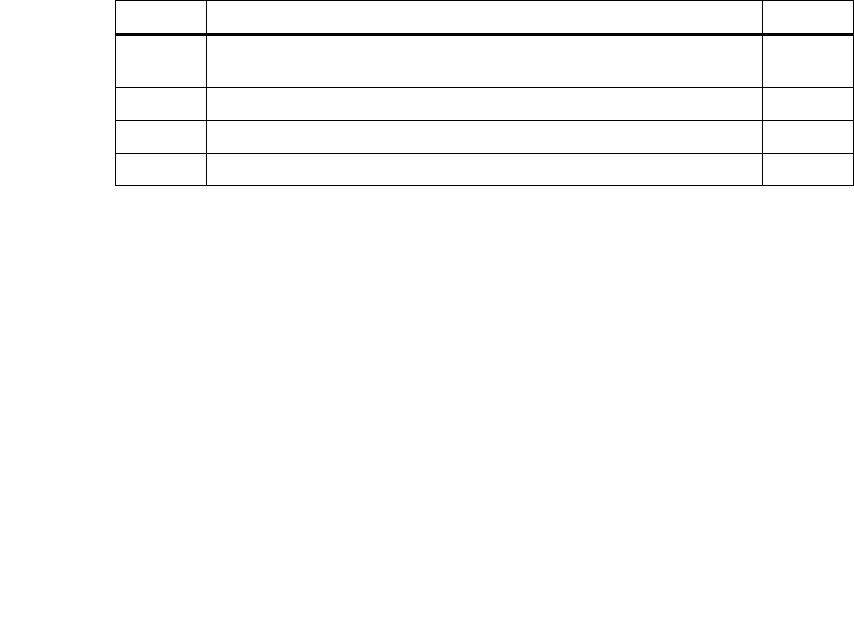
10-1
S7-400, M7-400 Programmable Controllers Module Specifications
A5E00069467-07
RS 485 Repeater
In this Chapter
In this chapter, you will find a detailed description of the RS 485 repeater.
Included in the description are:
•The purpose of the RS 485 repeater
•The maximum cable lengths possible between two RS 485 repeaters
•The functions of the individual operating elements and terminals
•Information about grounded and non-grounded operation
•Technical specifications and the block diagram
Further Information
You will find further information on the RS 485 repeater in the manuals
Hardware and Installation in the Chapter “Configuring of an MPI or PROFIBUS DP
network”.
Chapter Overview
Section Description Page
10.1 Application and Characteristics;
(6ES7972-0AA01-0XA0) 10-2
10.2 Appearance of the RS-485 Repeater; (6ES7972-0AA01-0XA0) 10-3
10.3 RS 485 Repeater in Ungrounded and Grounded Operation 10-4
10.4 Technical Specifications 10-6
10
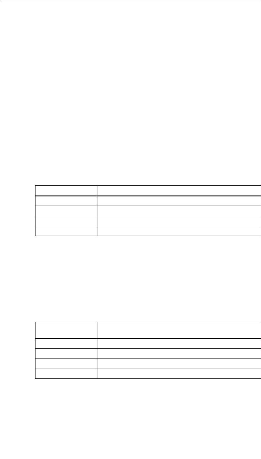
RS 485 Repeater
10-2 S7-400, M7-400 Programmable Controllers Module Specifications
A5E00069467-07
10.1 Application and Characteristics
(6ES7972-0AA01-0XA0)
What is an RS 485 Repeater?
The RS 485 repeater amplifies data signals on bus lines and interconnects bus
segments.
Application of the RS 485 Repeater
You need an RS 485 repeater if:
•more than 32 nodes are connected to the bus
•bus segments are to be operated non-grounded on the bus, or
•the maximum cable length of a segment is exceeded. (See table 10-1).
Table 10-1 Maximum Cable Length of a Segment
Baud Rate Max. Cable Length of a Segment (in m)
9.6 to 187.5 kbaud 1000
500 kbaud 400
1.5 Mbaud 200
3 to 12 Mbaud 100
Rules
If you configure the bus with RS 485 repeaters:
•Up to 9 RS 485 repeaters can be connected in series.
•The maximum cable length between two nodes must not exceed the values in
Table 10-2.
Table 10-2 Maximum Cable Length between Two RS 485 Repeaters
Baud Rate Maximum Length of Cable between 2 Nodes (in m) with
RS 485 Repeater (6ES7 972-0AA01-0XA0)
9.6 to 187.5 kbaud 10000
500 kbaud 4000
1.5 Mbaud 2000
3 to 12 Mbaud 1000
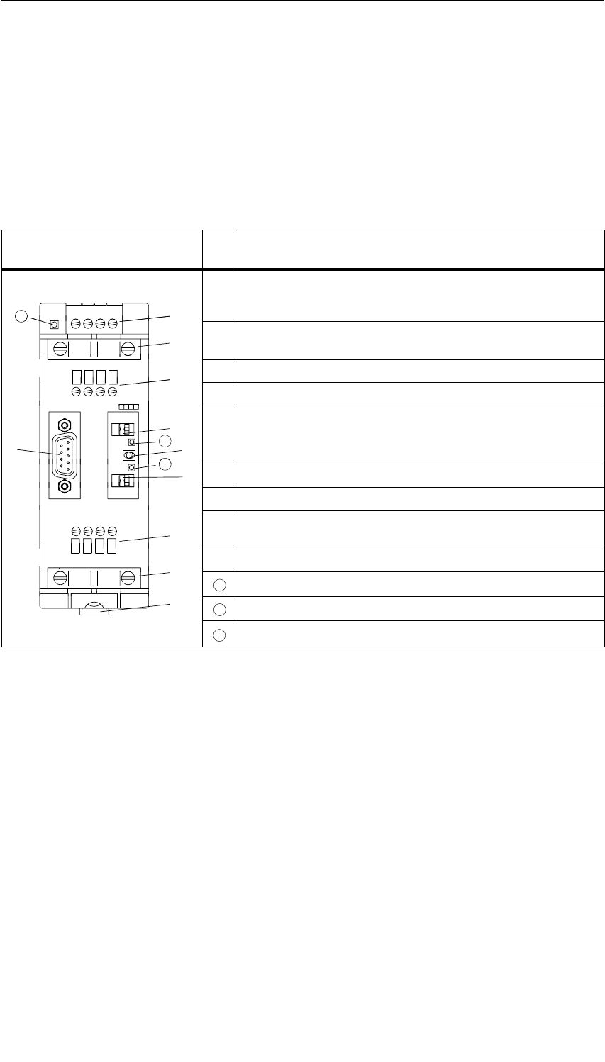
RS 485 Repeater
10-3
S7-400, M7-400 Programmable Controllers Module Specifications
A5E00069467-07
10.2 Appearance of the RS 485 Repeater;
(6ES7972-0AA01-0XA0)
The table below shows the appearance of the RS 485 repeater and lists its
functions.
Table 10-3 Description and Functions of the RS 485 Repeater
Repeater Design No
.Function
24 VDC L+ M PE M 5.2 À
10
ÀConnection for the RS 485 repeater power supply (pin “M5.2” is
the ground reference, if you want to measure the voltage
difference between terminals “A2” and “B2”).
À
Á
10
ÁShield clamp for the strain relief and grounding of the bus cable
of bus segment 1 or bus segment 2
ÂÂTerminals for the bus cable of bus segment 1
Â
A1 B1 A1 B1 ÃTerminating resistance for bus segment 1
Ã
Ä
È
A1 B1 A1 B1
PG
OP
11
12
OFF
ON
DP1
ÄSwitch for OFF operating mode
(= isolate bus segments from each other – for example, for
startup
Å
OP DP2 12
ÅTerminating resistance for bus segment 2
SIEMENS
ON ÆTerminals for the bus cable of bus segment 2
SIEMENS
RS 485-REPEATER
Æ
A2 B2 A2 B2 ÇSlide for mounting and removing the RS 485 repeater on the
standard rail
Á
ÈInterface for programming device/OP in bus segment 1
Á
10 LED 24 V supply voltage
Ç11 LED for bus segment 1
12 LED for bus segment 2

RS 485 Repeater
10-4 S7-400, M7-400 Programmable Controllers Module Specifications
A5E00069467-07
10.3 RS 485 Repeater in Ungrounded and Grounded
Operation
Grounded or Ungrounded
The RS 485 repeater is ...
•grounded, if all other nodes in the segment are also operated with a grounded
potential
•ungrounded, if all other nodes in the segment are operated with an ungrounded
potential
Note
The bus segment 1 is grounded if you connect a programming device to the
PG/OP socket of the RS 485 repeater. Ground connection is effected since the
MPI in the programming device is grounded and the PG/OP socket is connected
internally with bus segment 1 in the RS 485 repeater.
Grounded Operation of the RS 485 Repeater
For grounded operation of the RS 485 repeater, you must jump terminals “M” and
“PE” on the top of the RS 485 repeater.
Ungrounded Operation of the RS 485 Repeater
For ungrounded operation of the RS 485 repeater, “M” and “PE” on the top of the
RS 485 repeater must not be interconnected. In addition, the supply voltage of the
RS 485 repeater must be ungrounded.
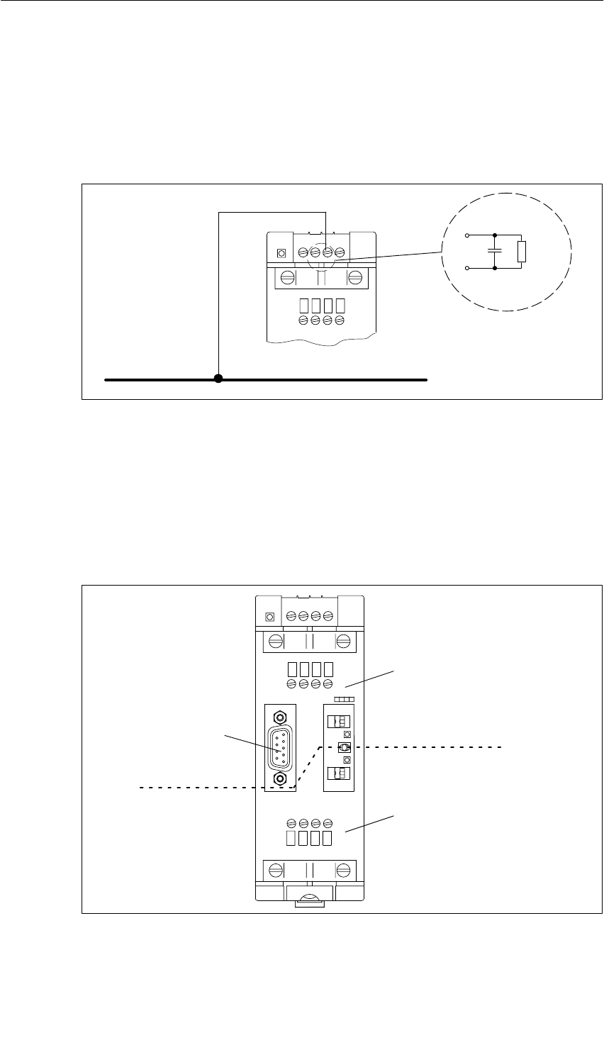
RS 485 Repeater
10-5
S7-400, M7-400 Programmable Controllers Module Specifications
A5E00069467-07
Terminal Connection Diagram
In the case of a repeater configuration with ungrounded reference potential
(ungrounded operation), any interference currents and static charges are
discharged by means of an RC network integrated in the repeater (refer to
Figure 10-1) to the protective conductor.
24 VDC L+ M PE M 5.2
A1 B1 A1 B1
M
22 nF 10 MΩ
Ground bus
PE
Figure 10-1 RC Network with 10 MΩ for Configuration with Ungrounded Reference Potential
Isolation Between Bus Segments
Bus segment 1 and bus segment 2 are galvanically isolated from each other. The
PG/OP interface is connected internally to the port for bus segment 1. Figure 10-2
shows the front panel of the RS 485 repeater.
24 VDC L+ M PE M 5.2
SIEMENS
RS 485-REPEATER
ON
A1 B1 A1 B1
A2 B2 A2 B2
PG
OP DP2
OFF
ON
DP1
Terminals for bus segment 1
Terminals for bus segment 2
PG/OP
interface
Isolation
Figure 10-2 Isolation Between the Bus Segments
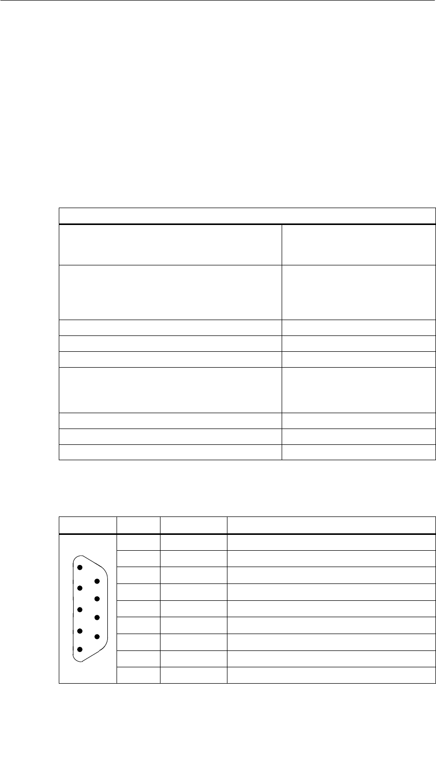
RS 485 Repeater
10-6 S7-400, M7-400 Programmable Controllers Module Specifications
A5E00069467-07
Amplification of the Bus Signals
The amplification of the bus signals takes place between the port for bus segment
1 or the PG/OP interface and the port for bus segment 2.
10.4 Technical Specifications
Technical Specifications of the RS 485 Repeater
Technical Specification
Power supply
pp y
•Rated voltage 24 VDC
g
•Ripple 20.4 to 28.8 VDC
Current consumption at rated voltage
pg
•without node at PG/OP socket 200 mA
•Node at PG/OP socket (5 V/90 mA) 230 mA
•Node at PG/OP socket (24 V/100 mA) 200 mA
Isolation Yes, 500 VAC
Connection of fiber optic cables Yes, via repeater adapters
Redundancy operation No
Transmission rate (automatically detected by the repeater) 9.6 kbaud, 19.2 kbaud, 45.45 kbaud,
93.75 kbaud, 187.5 kbaud, 500 kbaud.
1,5 Mbaud. 3 Mbaud,
6 Mbaud, 12 Mbaud
Degree of protection IP 20
Dimensions W H D (in millimeters) 45 128 67 mm
Weight (incl. packaging) 350 g
Pin Assignment of the Sub-D Connector (PG/OP Socket)
View Pin No. Signal Name Designation
1 – –
2 M24V Ground 24 V
53 RxD/TxD-P Data line B
9
44RTS Request To Send
3
85 M5V2 Data reference potential (from station)
3
2
76 P5V2 Supply plus (from station)
2
1
67 P24V 24 V
18 RxD/TxD-N Data line A
9 – –
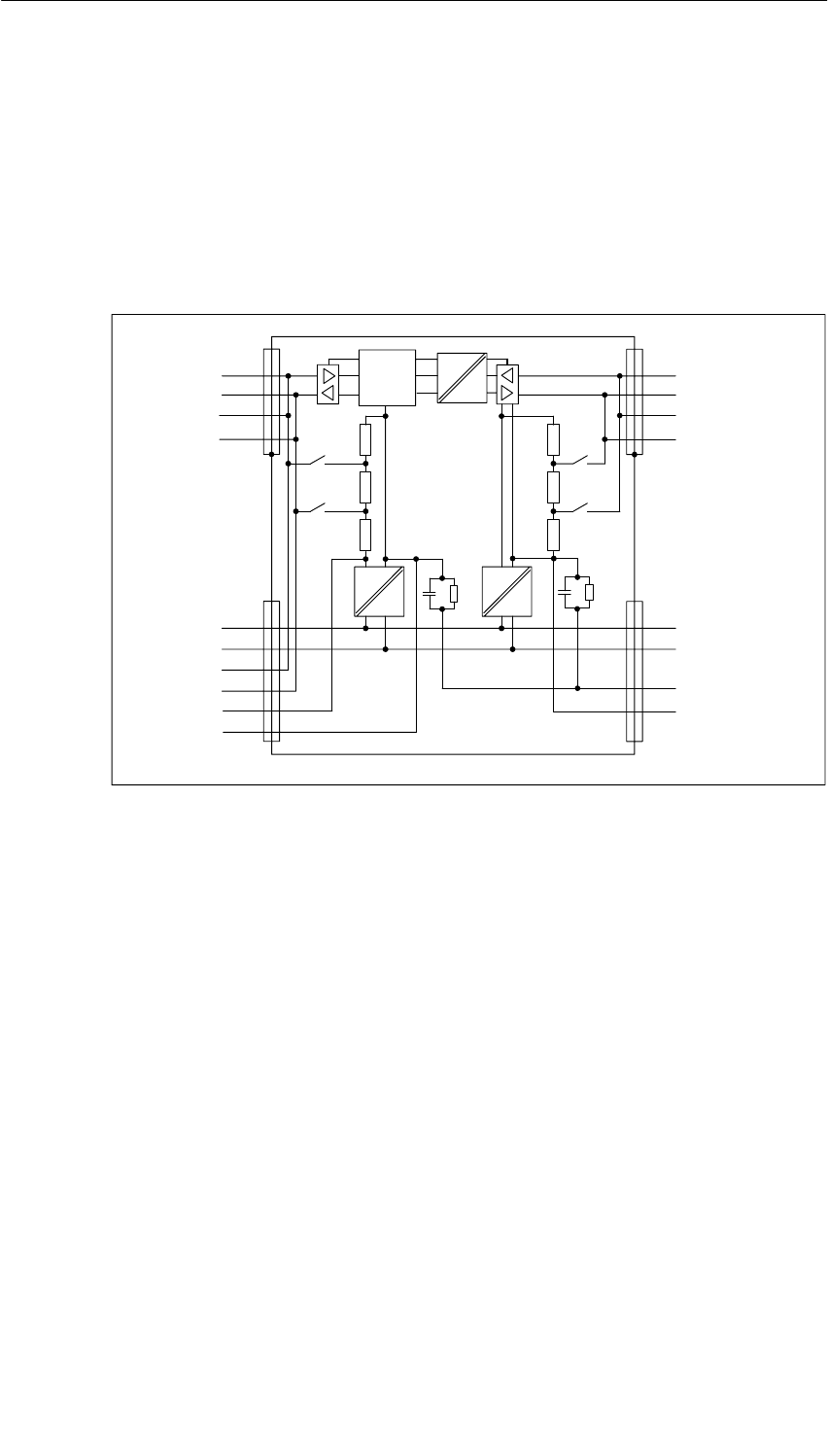
RS 485 Repeater
10-7
S7-400, M7-400 Programmable Controllers Module Specifications
A5E00069467-07
Block Diagram of the RS 485 Repeater
•Bus segment 1 and bus segment 2 are galvanically isolated from each other.
•Bus segment 2 and the PG/OP socket are galvanically isolated from each other.
•Signals are amplified
– between bus segment 1 and bus segment 2
– between PG/OP socket and bus segment 2
5V
24V
Segment 2
A2
B2
A2
B2
Segment 1
A1
B1
A1
B1
PG/OP-
socket
L+ (24 V)
M
A1
B1
5 V
M5 V
L+ (24 V)
M
PE
M 5.2
Logic
5V
24V
1M1M
Figure 10-3 Block Diagram of the RS 485 Repeater

RS 485 Repeater
10-8 S7-400, M7-400 Programmable Controllers Module Specifications
A5E00069467-07

11-1
S7-400, M7-400 Programmable Controllers Module Specifications
A5E00069467-07
CPUs for M7-400
In this Chapter
This chapter describes the CPUs of the M7-400 automation computer:
•CPU 486-3,
•CPU 488-3,
The CPUs differ essentially in their clock frequencies. You will find a comparison of
their performance features in Table 11-1.
The tables in Sections 11.1 and 11.2 give an overview of the performance features
and technical specifications of the CPUs.
Following this overview, the modules are described in detail.
Chapter Overview
Section Description Page
11.1 Performance Features 11-2
11.2 Technical Specifications 11-3
11.3 Function Elements 11-4
11.4 The BIOS Setup 11-16
11.5 I/O Addresses, Main Memory and Interrupt Assignments 11-40
11

CPUs for M7-400
11-2 S7-400, M7-400 Programmable Controllers Module Specifications
A5E00069467-07
11.1 Performance Features
Introduction
There are two CPUs with different clock frequencies available for use with the
automation computer.
Table 11-1 gives you an overview of the most important performance features of
these CPUs.
Table 11-1 Performance Features of the CPUs
Performance Features CPU 486-3
(6ES7486-3AA00-0AB0)
CPU 488-3
(6ES7488-3AA00-0AB0)
Processor Pentium 75 MHz Pentium 120 MHz
MEM 478 DRAM memory submodules*
for main memory
•Expansion capability
•Supply voltage
16 Mbytes
3.3 V
16 Mbytes
3.3 V
Second-level cache No 250 Kbytes
Submodule receptacle for memory card Yes
Submodule receptacles for interface
submodules 2
Connection of expansions Max. 3
MPI Yes
Watchdog * Yes
* see M7-SYS User Manual
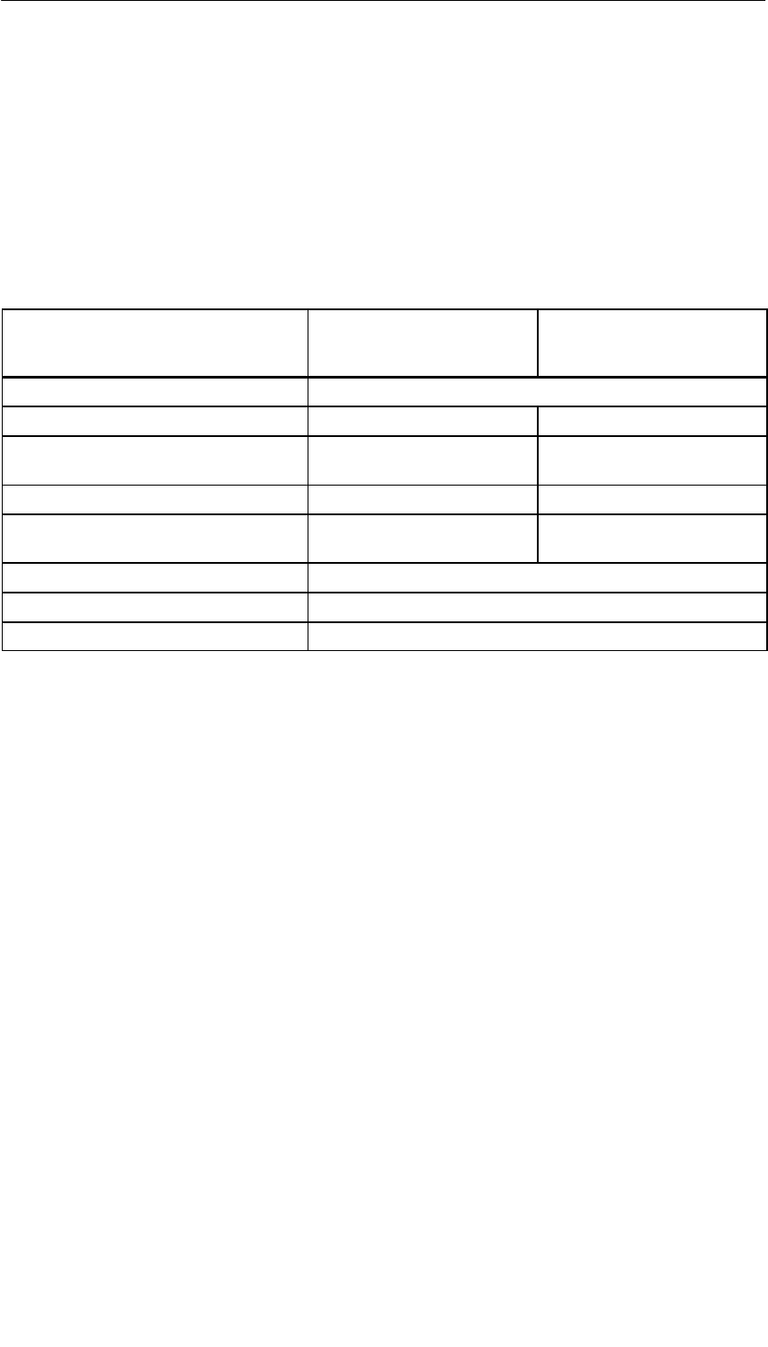
CPUs for M7-400
11-3
S7-400, M7-400 Programmable Controllers Module Specifications
A5E00069467-07
11.2 Technical Specifications
The following table contains the technical specifications of the CPUs for the
M7-400 automation computer.
Table 11-2 Technical Specifications of the CPUs
CPU 486-3
(6ES7486-3AA00-0AB0)
CPU 488-3
(6ES7488-3AA00-0AB0)
Nominal voltage 5 VDC (4.75 to 5.25 VDC)
Typical current consumption 2.75 A 3.0 A
Maximum permissible power
consumption 3.25 A 3.5 A
Maximum permissible power losses 16.25 W 17.5 W
Maximum permissible power losses with
interface submodules 19.25 W 20.5 W
Forced ventilation required No
Weight 1300 g
Dimensions W x H x D (mm) 50 x 290 x 219
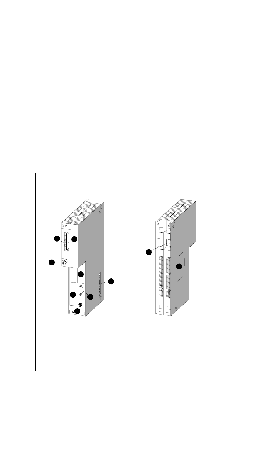
CPUs for M7-400
11-4 S7-400, M7-400 Programmable Controllers Module Specifications
A5E00069467-07
11.3 Function Elements
Introduction
In this section you will become familiar with the individual function elements of the
CPU 486-3 and CPU 488-3. You require the information here to be able to respond
to displays, start up, and operate an M7-400 automation computer and handle
further components (for example, memory cards, expansions).
In addition, you will find information on the watchdog, the BIOS setup and the
address assignments and interrupt assignments.
General View
Figure 11-1 shows the front and rear view of the CPU 486-3 and CPU 488-3
without covering flap. The positions of the indicators, operator controls, and other
elements required for operation can be seen from this figure.
Front view Rear view
1 = Receptacle for memory card
2 = Status and fault LEDs
3 = Mode selector switch
4 = Submodule receptacle for
interface submodules
5 = External battery supply
6 = MPI
7 = Expansion socket
8 = Cover for memory submodule
receptacle → 2 x DRAM
9 = Dongle interface
(in preparation)
1
2
3
4
46
5
7
8
9
Figure 11-1 Front and Rear View of a CPU 486-3 and CPU 488-3 without Covering Flap

CPUs for M7-400
11-5
S7-400, M7-400 Programmable Controllers Module Specifications
A5E00069467-07
CPU Elements
The following table gives the meanings of the individual elements of the CPU 486-3
and CPU 488-3.
Table 11-3 Elements of the CPU 486-3 and CPU 488-3
Element Meaning
Status and fault LEDs The status and fault LEDs indicate the operating state of your
CPU.
See page 11-6 for more detailed explanations.
Submodule receptacle
for memory card A long memory card can be inserted in the submodule
receptacle. The system and user software can be loaded from
this card into the main memory during startup. See page 11-8
for more detailed explanations.
Mode Selector The mode selector switch is a key switch. See page 11-9 for
more detailed explanations.
Submodule receptacles
for interface
submodules
Interface submodules can be plugged into these submodule
receptacles.
See page 11-11 for more detailed explanations.
Main memory The main memory is freely accessible via a cover on the
left-hand side of the housing. This allows problem-free insertion
and replacement of memory submodules.
See page 11-13 for more detailed explanations.
Expansion socket Expansions such as the EXM expansion module, AT adapter
module, ATM and MSM mass storage can be connected via the
expansion socket.
See page 11-14 for more detailed explanations.
MPI
(9-pin sub D socket) The CPU 486-3 and CPU 488-6 are equipped with a multipoint
interface. See page 11-15 for more detailed explanations.
External battery supply An external battery can be connected via this socket so that, for
example, the contents of the SRAM and the time of day are not
lost if the power supply fails. The same technical details apply
as for the S7-400 CPUs.
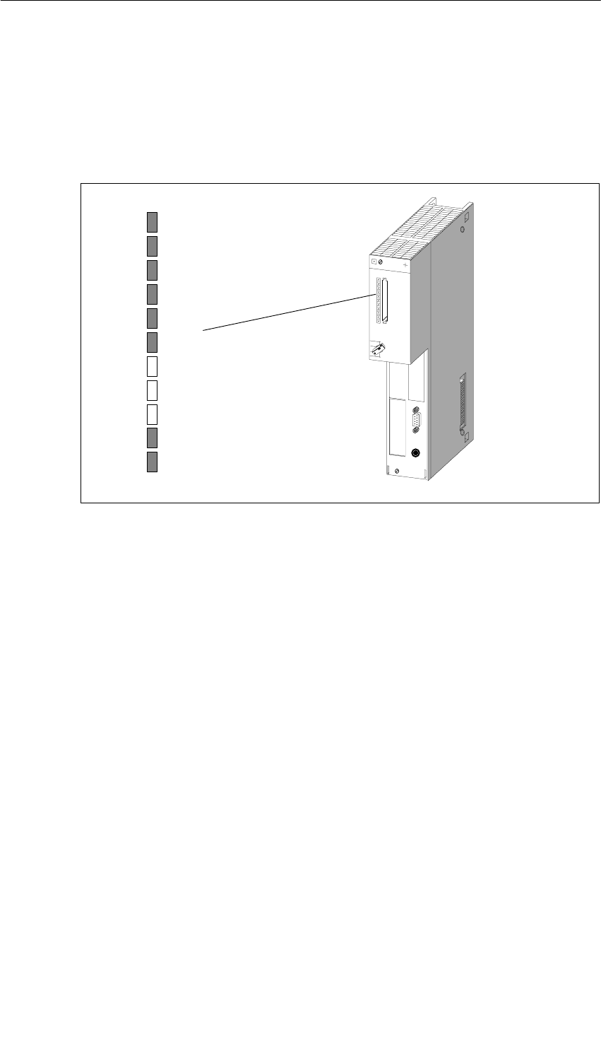
CPUs for M7-400
11-6 S7-400, M7-400 Programmable Controllers Module Specifications
A5E00069467-07
11.3.1 Status and Fault LEDs
Status and Fault LEDs
The CPU 486-3 and CPU 488-3 have the following status and fault LEDs:
INTF
EXTF
SD
HD
USR1
USR2
RUN
STOP
Figure 11-2 Status and Fault LEDs on the CPU 486-3 and CPU 488-3
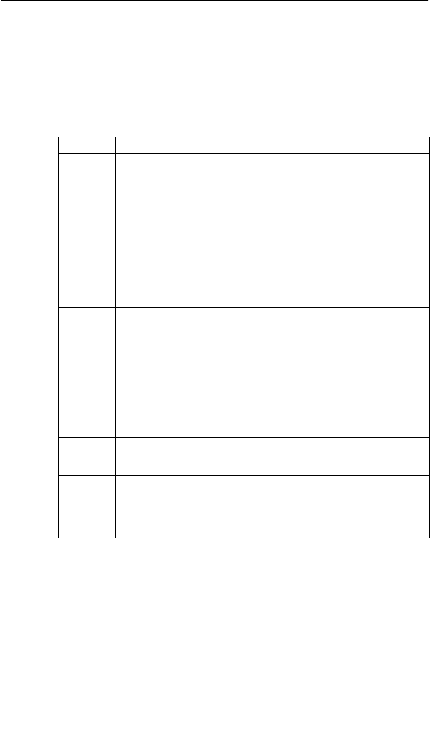
CPUs for M7-400
11-7
S7-400, M7-400 Programmable Controllers Module Specifications
A5E00069467-07
Meaning of the Status and Fault LEDs
The status and fault LEDs are explained in Table 11-4 in the order in which they are
arranged on the CPU 486-3 and CPU 488-3 modules. The following status and
fault LEDs are available:
Table 11-4 Meaning of the Status and Fault LEDs on the CPU 486-3 and CPU 488-3
LED Meaning Explanations
INTF (red)
EXTF (red) Internal or external
fault indicator Lights up in the event of:
•Hardware faults
•Firmware faults
•Programming faults
•Parameter assignment faults
•Computational faults
•Timer faults
•Memory card faults
•I/O faults
Use the programming device for precise fault-finding
(read out diagnostic buffer).
SD (green) Access to memory
card Lights up if read or write access to the memory card is
taking place.
HD (green) Hard disk access Lights up if read or write access to the hard disk of the
mass storage module is taking place
USR1
(yellow) Special LED for
the user program
(User)
Can be assigned by the user (see Programming
Manual)
USR2
(yellow) Special LED for
the user program
(User)
RUN
(green) “RUN” state LED Lights up if the system software is loaded and user
programs are running
(I/O access enabled).
STOP
(yellow) “STOP” state LED •Lights up when the user program of the
programmable module is not controlling the
process (I/O access disabled)
•Flashes when a memory reset is requested or is
being performed

CPUs for M7-400
11-8 S7-400, M7-400 Programmable Controllers Module Specifications
A5E00069467-07
11.3.2 Memory Cards
Introduction
The CPU 486-3 and CPU 488-3 offer the possibility of operating a memory card in
the same way as a diskette. In this section, you will learn how you can use these
options.
Note
If the power fails during a write access to the memory card, the entire contents of
the memory card can be damaged under unfavorable conditions.
Please note that in contrast to a diskette, a memory card is only designed for a
limited number of write accesses.
Memory Card
A memory card emulates a diskette from which an operating system can also be
booted. In addition, a memory card can also be used to exchange user software
and user data.
Memory cards with Flash EPROM are available for the CPUs (see the ordering
data).
Drive Assignment
The memory card is accessed by the operating system in the same way as a
conventional drive.
You can set the drive assignment in the BIOS setup (Section 11.4.11, page 11-35).
Boot Sequence
You can set the boot sequence in the BIOS setup (Section 11.4.12, page 11-36).
Formatting
Memory cards are formatted with the program FTLFORM.EXE included with the
system software. Read the relevant sections in the M7-SYS User Manual.
Note
The memory capacity specified for the memory card is the actual physical memory
capacity (gross). Formatting reduces the gross memory capacity to approximately
80% (net) that is then available to the operating system for storing data/programs.
UNDELETE: Files which were deleted from the memory card cannot be restored
using UNDELETE programs.
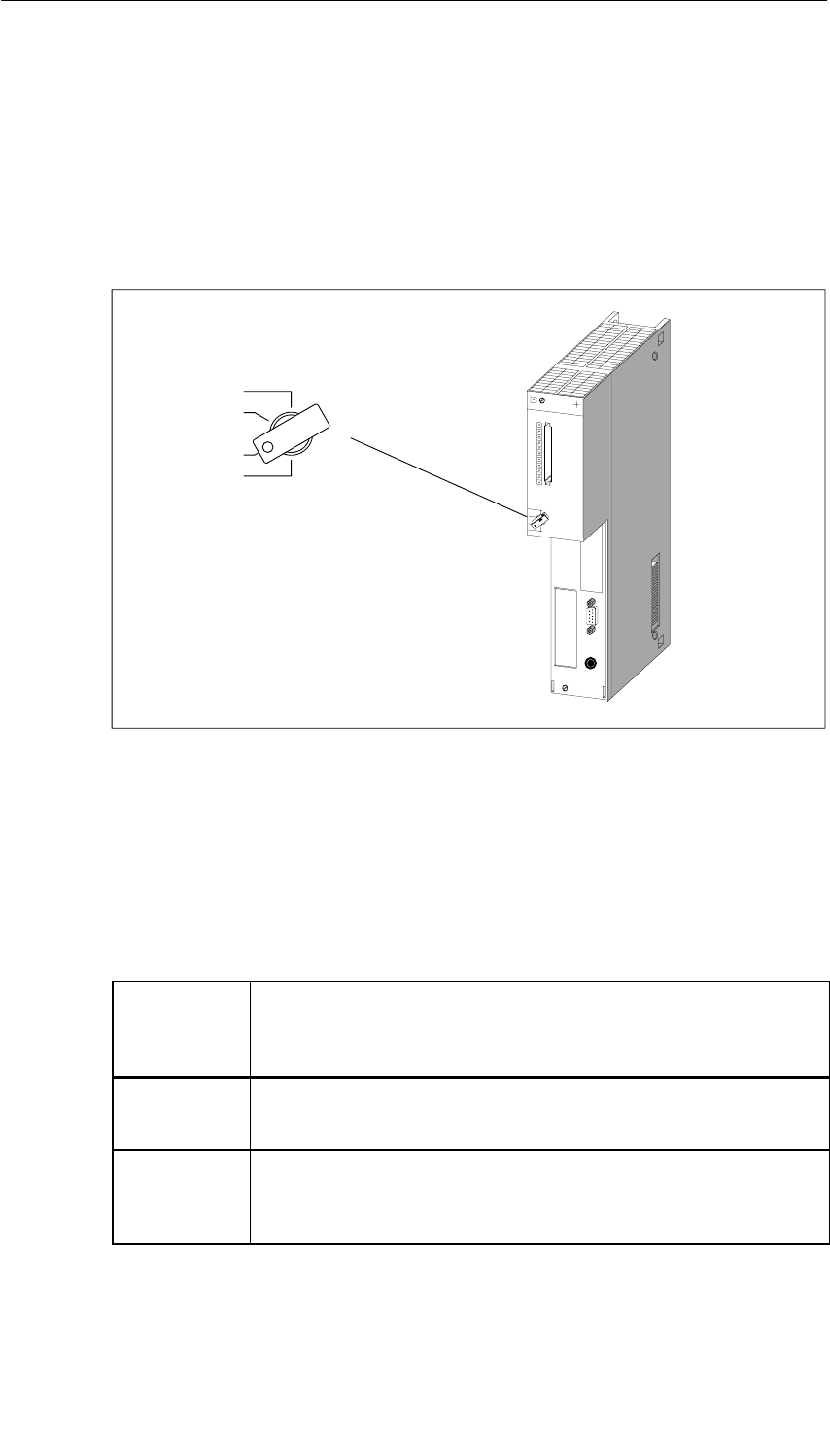
CPUs for M7-400
11-9
S7-400, M7-400 Programmable Controllers Module Specifications
A5E00069467-07
11.3.3 Mode Selector Switch
Mode Selector Switch
The mode selector switch of the CPUs is a keyswitch.
You can see the positions of the mode selector switch in the following figure.
MRES
STOP
RUN
RUN-P
Figure 11-3 Mode Selector Switch
Positions of the Mode Selector Switch
The positions of the mode selector switch are explained in Table 11-5 in the order
in which they are arranged on the CPUs.
Table 11-5 Positions of the Mode Selector Switch
Position of
the Mode
Selector
Switch
Explanations
RUN-P The CPU executes the user program.
The key cannot be removed in this position.
Write and read access to the CPU are possible.
RUN The CPU executes the user program. Read access only to the CPU is
possible.
The key can be removed in this position to prevent any unauthorized
persons from changing the operating mode.

CPUs for M7-400
11-10 S7-400, M7-400 Programmable Controllers Module Specifications
A5E00069467-07
Table 11-5 Positions of the Mode Selector Switch
Position of
the Mode
Selector
Switch
Explanations
STOP I/O access is disabled for the user program of the CPU. The user
program cannot control the process.
The key can be removed in this position to prevent any unauthorized
persons from changing the operating mode.
MRES Position of the keyswitch for software-controlled resetting of the CPU
(hardware reset).
Activating MRES
To generate a hardware reset via MRES, follow the steps outlined below:
1. Turn the mode selector switch to the STOP position.
Result: The STOP LED lights up.
2. Turn the mode selector switch to the MRES position and hold it there.
Result: The STOP LED goes dark for a second, lights up for a second, goes
dark again, and then remains lit.
3. Turn the switch back to the STOP position and then, in the next 3 seconds, to
the MRES position again and back to STOP.
Result: The STOP LED flashes for approximately 3 seconds at 2 Hz (a memory
reset is being carried out) and then remains lit.
4. If the STOP LED does not flash or other LEDs light up or flash, you must repeat
steps 2 and 3.
Note
Resetting by activating MRES is controlled by the system software. If this has not
been started, the CPU must be reset by switching the power supply off and on. If a
keyboard is connected to the CPU, it is also possible to initiate a complete restart
via hot keys (see Table 11-7 on page 11-19).
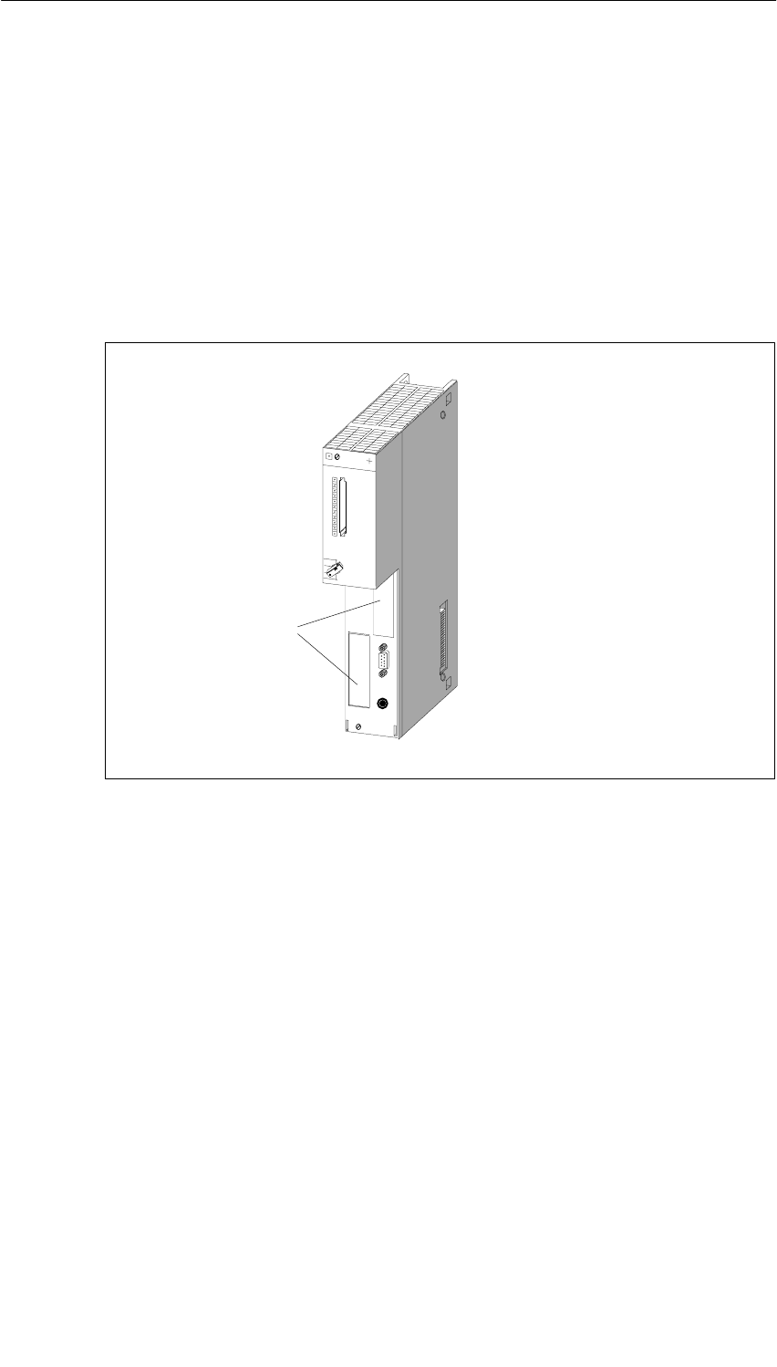
CPUs for M7-400
11-11
S7-400, M7-400 Programmable Controllers Module Specifications
A5E00069467-07
11.3.4 Submodule Receptacles for Interface Submodules
Submodule Receptacle Definition
The submodule receptacle is a slot for a submodule. The CPU 486-3 and
CPU 488-3 have a receptacle for the memory card and two submodule receptacles
for interface submodules.
Figure 11-4 shows the position of the two receptacles for interface submodules on
the CPU 486-3 and CPU 488-3.
Submodule
receptacle
Figure 11-4 Position of the Receptacles for Interface Submodules on the CPU 486-3 and
CPU 488-3
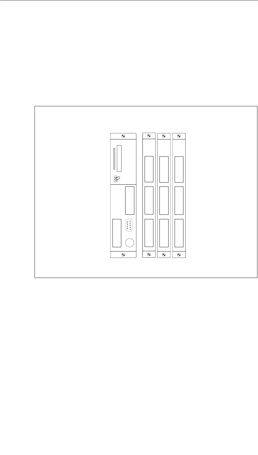
CPUs for M7-400
11-12 S7-400, M7-400 Programmable Controllers Module Specifications
A5E00069467-07
Numbering on the Submodule Receptacles
Each receptacle for an interface submodule has a submodule receptacle number
assigned to it. The submodule receptacle number depends on the module slot and
on the arrangement of the receptacle on the expansion module or the CPU. You
can see the submodule receptacle numbers in Figure 11-5.
You require these submodule receptacle numbers for configurations that you
undertake in the BIOS setup or for determining the I/O addresses of an interface
module (see the Chapter “M7-400 Expansions”).
3
08
6
7
912
10 13
11 14
CPU 486-3
CPU 488-3
EXM 478
Slot n n+2 n+3 n+4n+1
Figure 11-5 Submodule Receptacle Numbers on the CPU486-3/CPU488-3 and EXM478
Submodule Covers
Unused submodule receptacles are protected by submodule covers.

CPUs for M7-400
11-13
S7-400, M7-400 Programmable Controllers Module Specifications
A5E00069467-07
11.3.5 Memory Submodules Suitable for the Main Memory
Introduction
You must order the MEM 478 DRAM memory submodules for the main memory of
the CPUs separately. They are also shipped separately. These memory
submodules must be inserted before plugging into the mounting rack.
Main Memory Expansion
You can see from Table 11-6 which memory submodules you can use in which
CPU.
Table 11-6 Main Memory Expansion Possibilities
MEM478 DRAM Memory
Submodules CPU 486-3 CPU 488-3
2 x 8 Mbytes, 3.3 V • •
!Warning
DRAM memory submodules can be damaged.
If you use memory submodules for the main memory other than the DRAM
submodules designed for the purpose, the submodules can be damaged.
Use only the MEM 478 DRAM memory submodules for the main memory.
Inserting the Memory Submodules
The sections “Installing an M7-400” and “Replacing Modules and Submodules” in
the User Manual explain how to insert or replace the memory submodules.

CPUs for M7-400
11-14 S7-400, M7-400 Programmable Controllers Module Specifications
A5E00069467-07
11.3.6 Expansion Socket
Introduction
The CPU 486-3 and CPU 488-3 are each equipped with an expansion socket. The
ISA bus is continued via the expansion socket.
Which Expansions Can Be Connected?
One EXM 478 extension module with up to three interface submodules, one
MSM 478 mass storage module with diskette and hard disk drives, or one ATM 478
AT adapter module for short AT cards can be connected direct to the CPUs.
A total of up to three expansions can be connected in series to the CPU.
If three EXM 478 expansion modules are connected, up to 11 interface
submodules can be operated together with the slots on each CPU (see
Section 11.3.4).

CPUs for M7-400
11-15
S7-400, M7-400 Programmable Controllers Module Specifications
A5E00069467-07
11.3.7 Multipoint Interface (MPI)
X1 Interface
The X1 interface of the CPU 486-3 and CPU 488-3 for connecting devices such as
PCs/programming devices is a multipoint interface (MPI) and is connected via a
9-pin sub D connector.
Suitable Devices
You can connect the following at the MPI:
•Programming devices (PGs/PCs)
•Operator panels (OPs)
•Additional CPUs.
You can address up to 127 communications partners (programming devices, OPs,
CPUs) via the multipoint interface of the CPU 486-3 and CPU 488-3. A maximum
of 44 connections can be made to the CPU.
Connectors
Use only bus connectors or PG cables for connecting devices to the MPI (see
Chapter 6).

CPUs for M7-400
11-16 S7-400, M7-400 Programmable Controllers Module Specifications
A5E00069467-07
11.4 The BIOS Setup
Overview
The BIOS setup handles the configuration of the relevant CPUs in your M7-400
system. The settings and technical information concerning the configuration of this
programmable module are displayed in the BIOS setup. The CPUs already have a
default setup. It is set in such a way that the minimal configuration of a CPU (with
memory card drive) will power up via BIOS setup without programming.
You can change the default settings in the BIOS setup. This becomes necessary if,
for example, you want to connect expansions to your CPU (expansion module with
interface submodules, mass storage module with diskette and hard disk drives, or
AT adapter module with short AT card). You must inform the operating system of
these expansions.
If you want to make settings in the BIOS setup, you can do so:
•Directly at the relevant module if your M7-400 is equipped with interface
submodules and I/O devices such as a monitor and keyboard (interface
submodule IF 962-VGA).
•Remote setup with a terminal program (for example, HyperTerminal under
Windows 95) on programming device/PC or with an ANSI terminal via the
COM1 port (interface submodule IF 962-COM).
Remote Setup
To run BIOS settings via the Remote Setup without the interface submodule
IF 962-VGA, follow the steps outlined below:
1. Switch off the line voltage to your M7-400.
2. Connect the programming device to the COM1 port of the SIMATIC M7 device
(see Section 8.7.2 of the Installation Manual).
3. On your programming device under Windows 95 select “Start > Accessories >
Hyperterminal”.
4. In the HyperTerminal window, select the menu command “File > New
Connection”. Enter a connection description and select the COM port with the
following transmission properties: 19000 bps, 8 data bits, no parity, 1 stop bit,
no flow control.
5. Switch on the line voltage to the M7-400 and hold the “Q” key pressed during
startup until the M7-400 registers itself in the HyperTerminal with the hardware
tests (a “U” appears).
6. Press the ESC button immediately.
Result: You are in the BIOS setup.
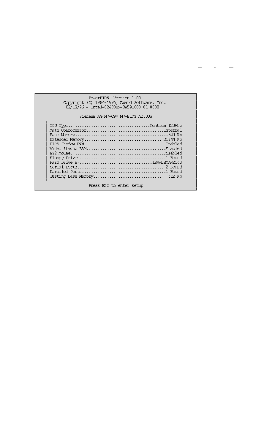
CPUs for M7-400
11-17
S7-400, M7-400 Programmable Controllers Module Specifications
A5E00069467-07
11.4.1 BIOS Power Up
Power Up without Error Message
After switching on or after warm restart of the CPU, the BIOS (Basic Input Output
System) starts a ”Power On Self Test” (POST) and displays the results in the POST
window.
Figure 11-6 POST Window for a CPU 488-3
If no error occurs, all LEDs on the CPU are switched off with the exception of the
STOP LED.
Power Up with Warnings
During power up, warnings are given in the POST window after the “Video Shadow
RAM...” line if:
•The battery power is missing
•There is no keyboard
•The CMOS checksum is wrong.
The warnings remain for 2 seconds. After this, the first line is suppressed from the
POST window.
If battery power is missing, the date is reset to 1.1.1994.
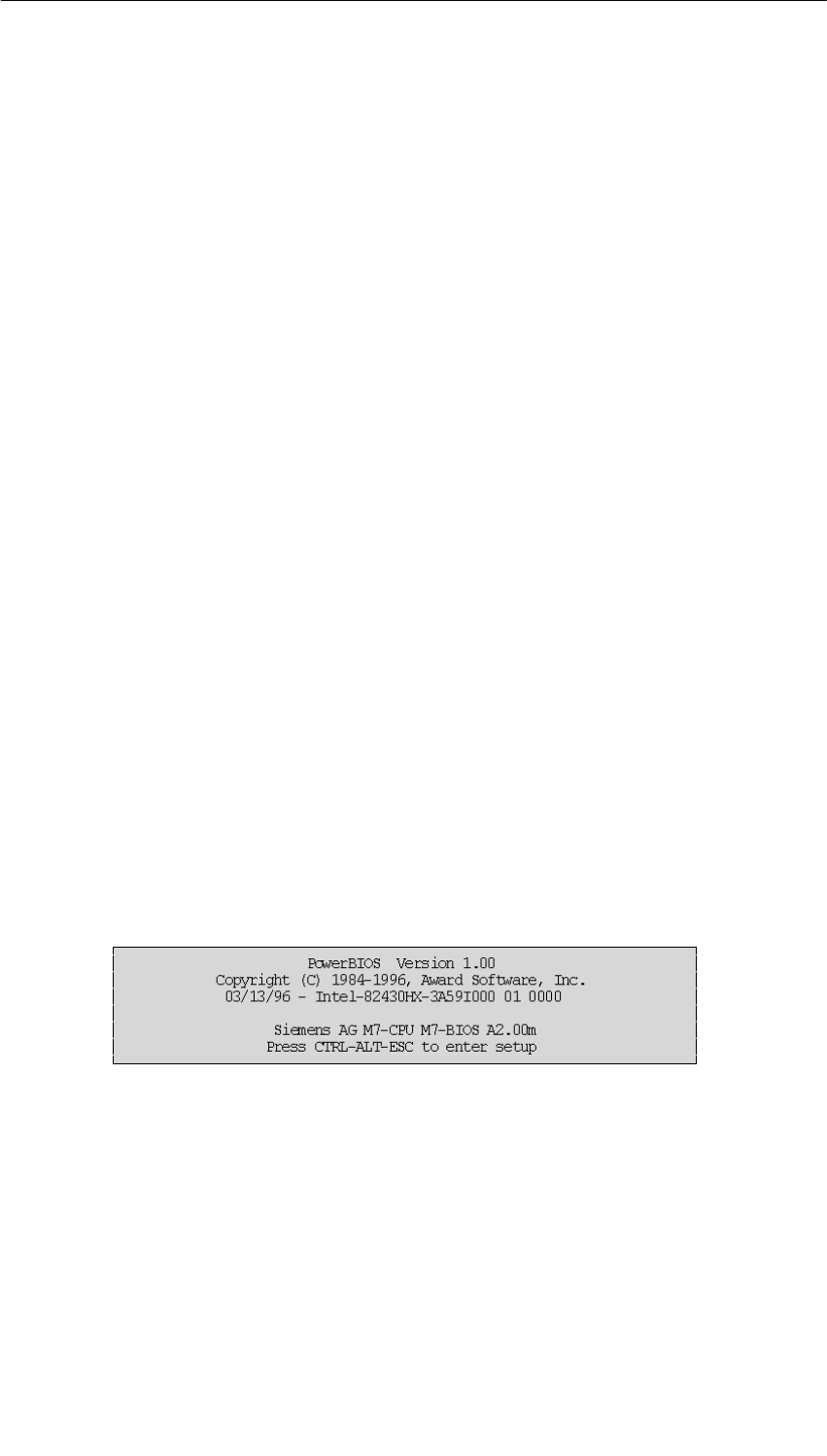
CPUs for M7-400
11-18 S7-400, M7-400 Programmable Controllers Module Specifications
A5E00069467-07
Power Up with Error Message
If one of the following errors occurs:
•Memory test error
•Hard disk configuration error
•CMOS checksum error,
the INTF LED remains lit as well as the STOP LED. A window appears on the
screen with the relevant error message. The window disappears after
approximately two seconds and the power up continues.
With an incorrect CMOS checksum, the default settings are loaded.
Behavior in the Event of Serious Errors
In the case of serious errors, the power up is stopped. Serious errors include:
•No memory plugged in.
•More than one IF962-VGA interface submodule has been plugged in (INTF LED
lights up).
•The CMOS memory location 15 (0xF) contains an invalid shutdown code during
the warm restart.
These errors prevent screen output since the video unit is not initialized. The
INTF LED lights up.
Ensure that the MEM 478 DRAM memory submodules required for operation are
plugged into the CPU or check to see if more than one IF262-VGA interface
submodule has been plugged into the CPU. If you do not find an error, there must
be an invalid shutdown code. If this is the case, reset the CPU using power off/on.
Warm Restart
After a warm restart of the CPU, the following window appears signaling an
accelerated system power up (see Section 11.4.2 “BIOS Hot Keys”).
Figure 11-7 Warm Restart Window for a CPU
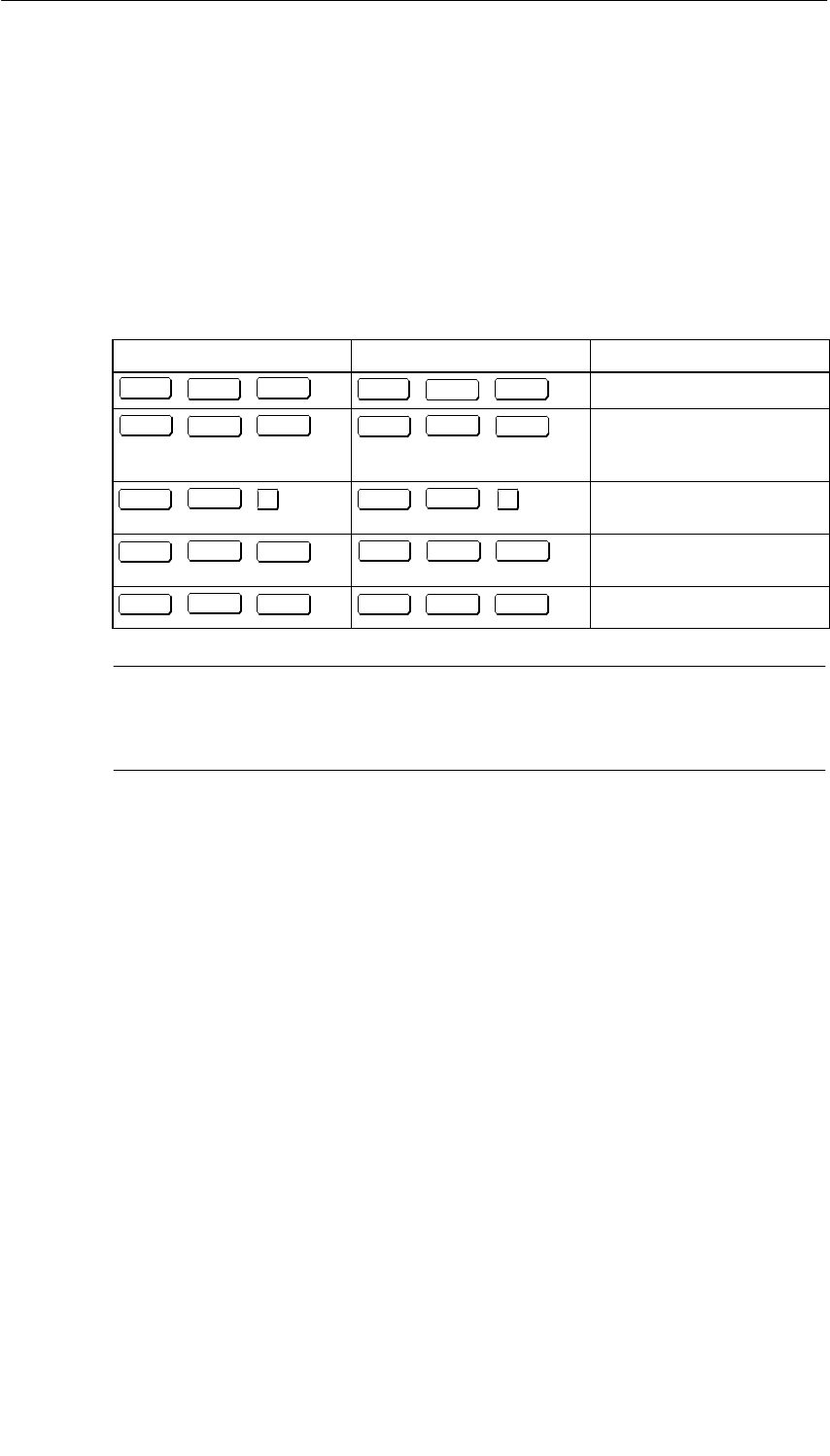
CPUs for M7-400
11-19
S7-400, M7-400 Programmable Controllers Module Specifications
A5E00069467-07
11.4.2 BIOS Hot Keys
BIOS Hot Keys
After power up, the BIOS offers the user a range of functions under MS-DOS.
These functions are executed by pressing the following groups of keys
simultaneously:
Table 11-7 BIOS Hot Keys with German and English Key Assignments
English Key Assignments German Key Assignments Function
CTRL Alt DEL
++ STRG Alt ENTF
++ Warm restart of the module
CTRL Alt HOME
++ STRG Alt POS1
++ Cold restart of the module
(power off/on with
initialization of all blocks)
↓
CTRL Alt
++ STRG Alt
++
↓IDE hard disk in standby
mode
CTRL Alt
++
PGDN STRG Alt Bild
++
↓Screen saver on (dark
screen)
CTRL Alt
++
PGUP STRG Alt Bild
++
↑Screen saver off
Note
These functions can be overlaid by other operating systems or user programs
such as Windows.

CPUs for M7-400
11-20 S7-400, M7-400 Programmable Controllers Module Specifications
A5E00069467-07
11.4.3 Operator Inputs in the BIOS Setup
Definition of the Setup Fields
Within the BIOS setup, there are fields in which you can make entries or selections.
These fields have the following functions:
•Editbox;
You can enter desired values in this field . The field content must be
deleted first with BACKSPACE or DEL .
•List box;
This field lists, for example, all menu pages in the setup menu, from
which you can select and start one.
•Check box;
You can switch on the associated function by activating the check box [ ] and
switch it off again by deactivating the check box [] .
•Option button;
By activating an option button () you can select one of a range of options.
Activating another option button has the effect of deactivating the previous
option button ( ).

CPUs for M7-400
11-21
S7-400, M7-400 Programmable Controllers Module Specifications
A5E00069467-07
Key Control within the Setup Menu
The following keys are used for control within the Setup menu and the associated
setup page (conforming to the WindowsTM Standard):
ENTER With this key, you jump to the first line of a list box,
edit box, check box, or option button.
If the cursor is at a button (OK, CANCEL, ...) or at a selected
line (inverse video) within a list box, you can activate the function
with ENTER .
If the cursor is not at a button when you press ENTER
this executes the same function as an activated OK button:
Return to the Setup menu with any changes made in the
setup page being retained.
ESC This key executes the same function as a CANCEL button:
Return to Setup menu with any changes in the setup page being
deleted.
TAB With this key, you can move the cursor from one box to the next
box or to the next button.
SHIFT TAB With this key, you can move the cursor from one box to the next
box or to the next button (only locally, not under Remote Setup).
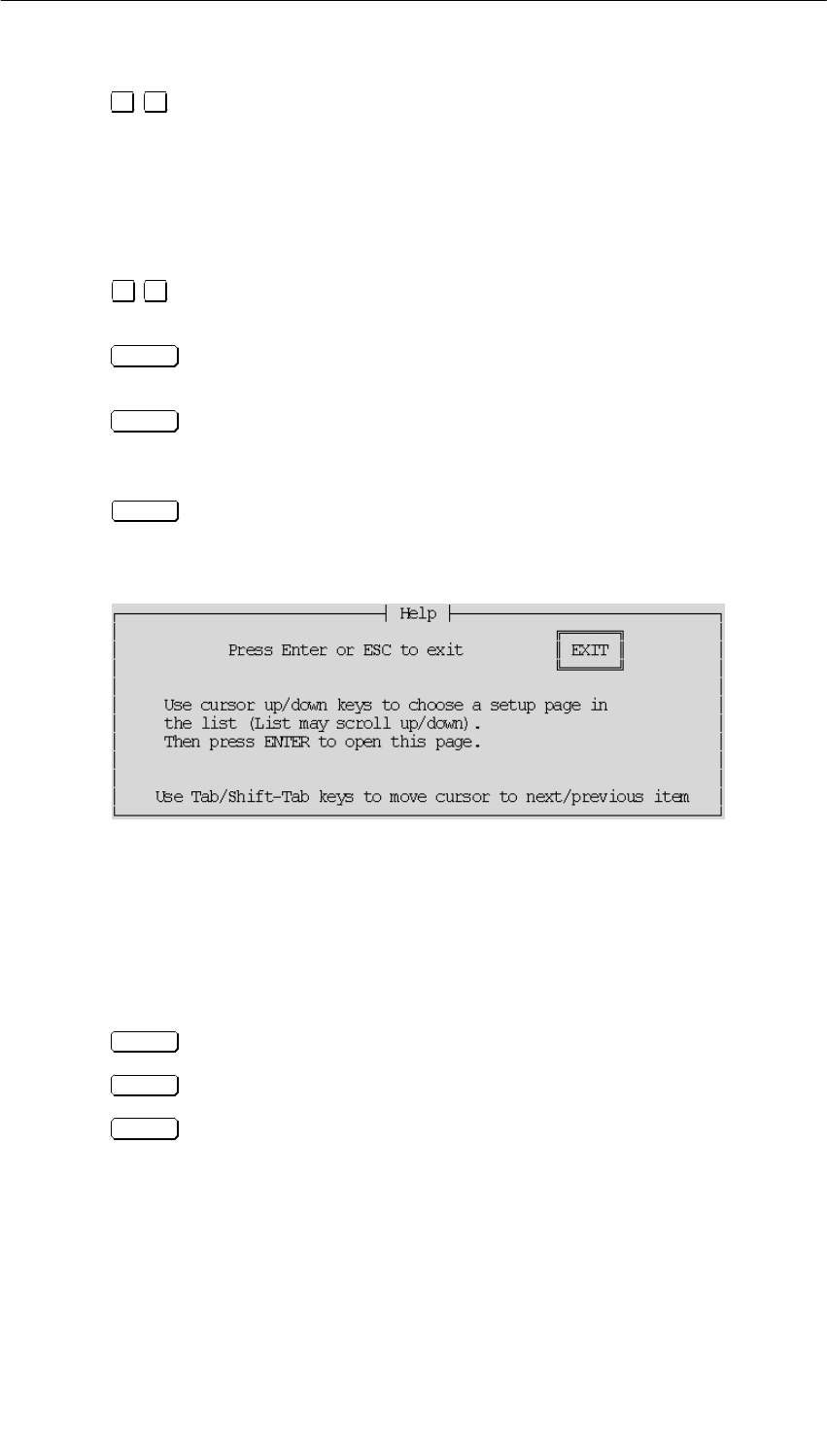
CPUs for M7-400
11-22 S7-400, M7-400 Programmable Controllers Module Specifications
A5E00069467-07
↑
↓With the cursor control keys, you can jump from line to line within a
list box. The line you are in is marked with a dark bar.
You can page with the cursor control keys within an edit box if
there are several values available for selection within the box.
You activate an option button if you position the cursor at the
button using the cursor control keys.
→
←With the cursor control keys, you can jump from character to
character within an edit box.
With the spacebar, you can confirm the selected lines as selected
or activate a check box.
INS Holding the INSERT key pressed during a complete restart of the
module leads to certain BIOS default settings being loaded which
are required for a safe startup.
F1 With this function key, a context-sensitive help window is
displayed.
Figure 11-8 shows an example.
Figure 11-8 Context-Sensitive Help Window
The Remote Setup can either be operated with the keyboard of the remote
computer or with the keyboard of the M7-400. In both cases the above key
assignments apply.
In the edit windows:
HOME sets the minimum value of the window.
end sets the maximum value of the window.
F1 displays a context-sensitive help text.
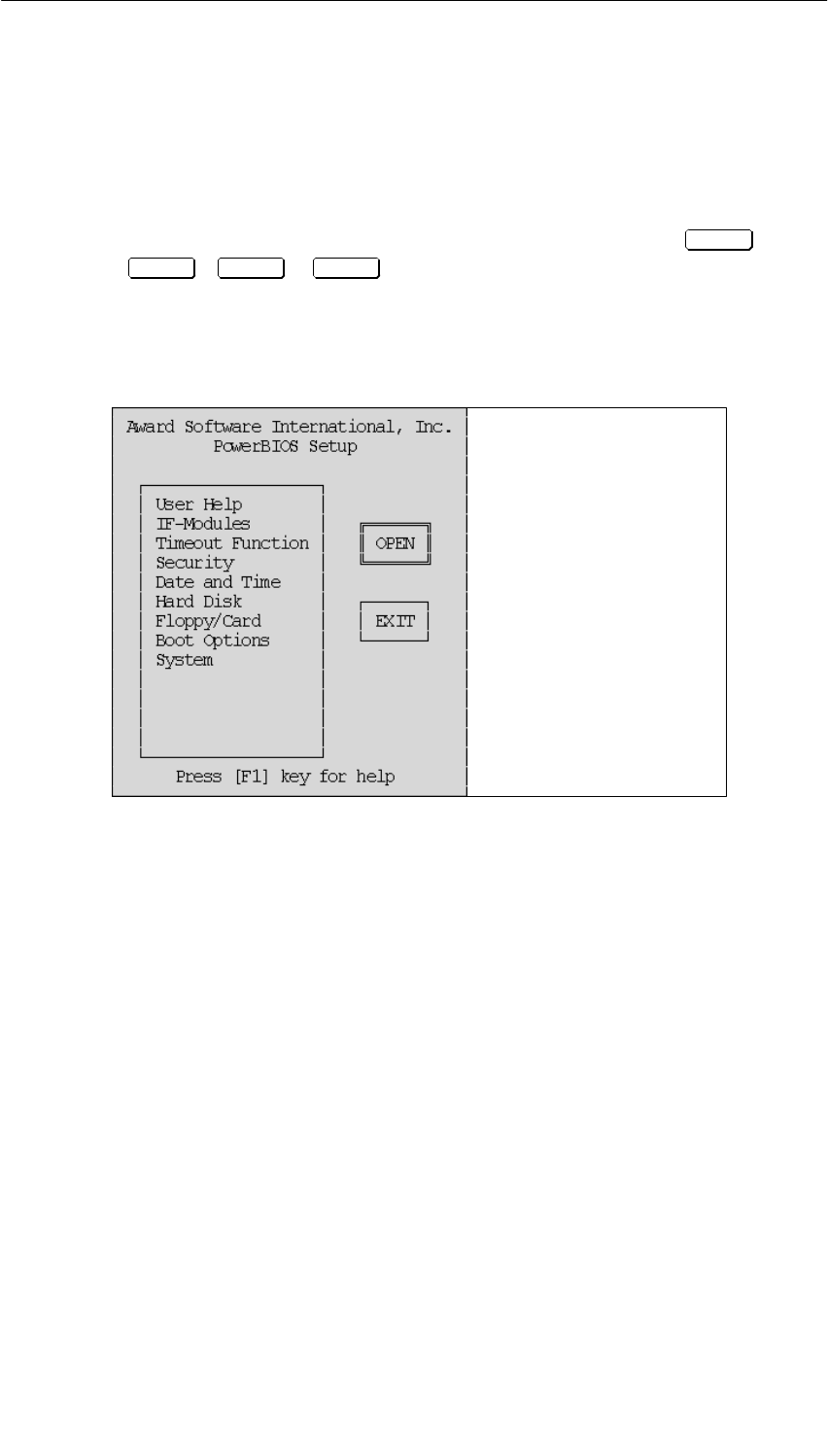
CPUs for M7-400
11-23
S7-400, M7-400 Programmable Controllers Module Specifications
A5E00069467-07
11.4.4 Opening and Exiting the BIOS Setup
Opening the Setup Menu
To open the Setup menu, press the following keys simultaneously while the CPU is
powering up and the POST window (Figure 11-6) is on the screen: CTRL
+ Alt + ESC or ESC under Remote Setup.
The Setup menu then appears to allow you to select the setup pages.
Figure 11-9 shows the front and rear view of the CPU 486-3 and CPU 488-3
without covering flap.
––> page 11-24
––> page 11-25
––> page 11-29
––> page 11-30
––> page 11-32
––> page 11-33
––> page 11-35
––> page 11-36
––> page 11-38
The setup pages are
described on
Figure 11-9 Setup Menu
The Setup menu consists of:
•A list box from which you can select the required setup page,
•An OPEN button which opens the selected setup page when activated,
•An EXIT button which closes the Setup menu after prompting you to decide
whether changes are to be saved or not,
The setup pages for the CPU 486-3 and CPU 488-3 are shown below.
The setup pages below show the default settings.
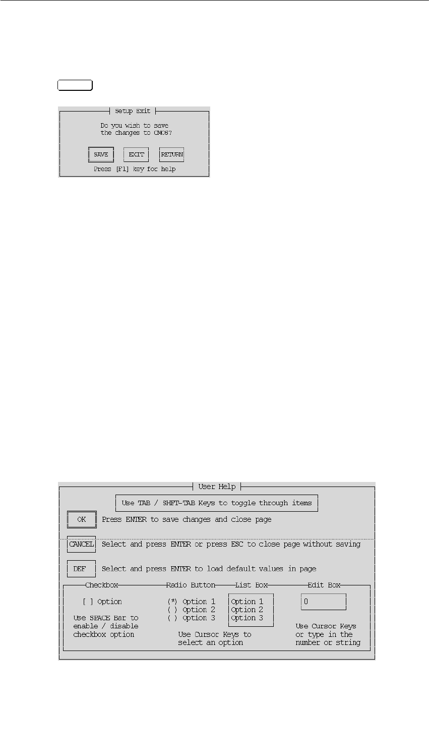
CPUs for M7-400
11-24 S7-400, M7-400 Programmable Controllers Module Specifications
A5E00069467-07
Exiting the BIOS Setup
To exit the BIOS setup, activate the EXIT button shown in Figure 11-9 or press
ESC . The “Setup Exit” dialog box then appears (see Figure 11-10).
Figure 11-10 “Setup Exit” Dialog Box
Here you have the following choices:
•SAVE
saves the parameters to the CMOS and then runs a cold restart.
•EXIT
exits the setup without saving the parameters to the CMOS and then runs a cold
restart (power off/on with initialization of all blocks).
•RETURN
returns to the setup. All changes that were made since Setup was opened are
abandoned.
11.4.5 Setup Page “User Help”
Opening the Setup Page
If you have selected “User Help” and activated the OPEN button in the Setup menu
(Figure 11-9 on page 11-23), this setup page appears on the screen (Figure 11-11).
Figure 11-11 “User Help” Setup Page
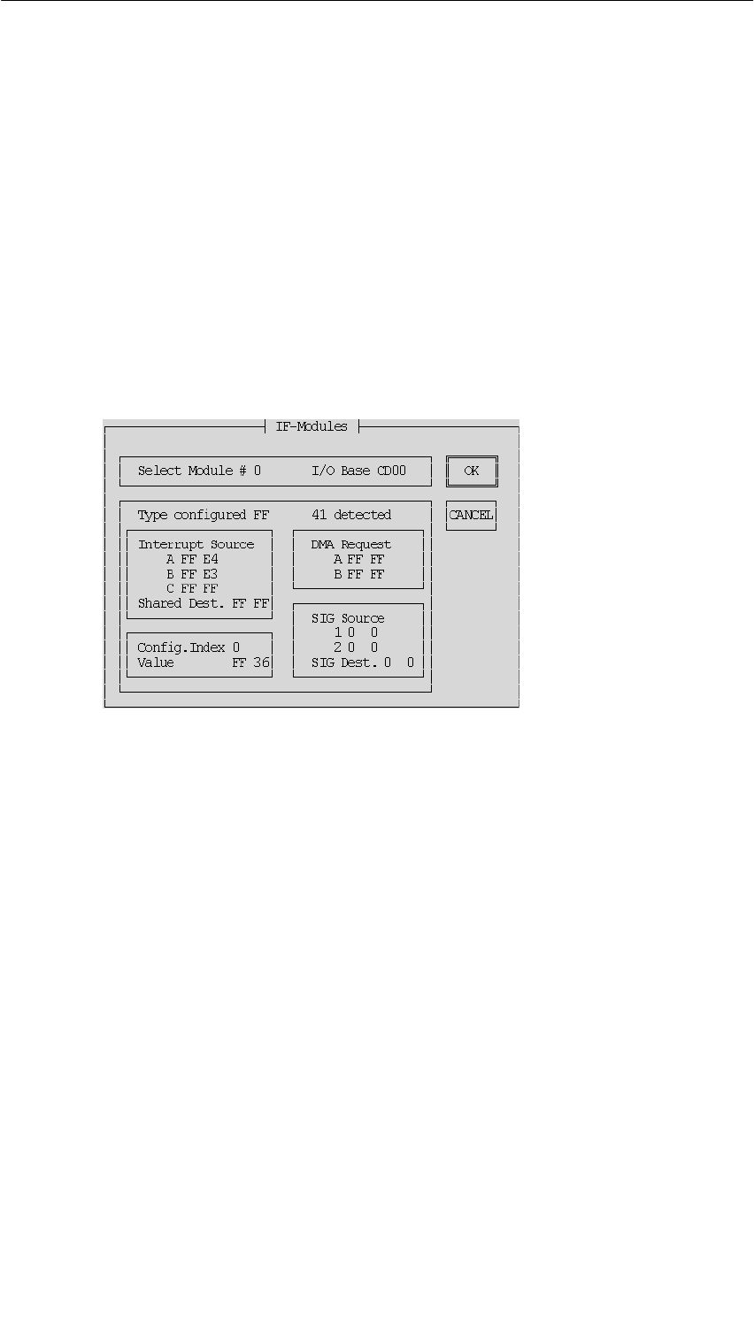
CPUs for M7-400
11-25
S7-400, M7-400 Programmable Controllers Module Specifications
A5E00069467-07
What is the Purpose of the Setup Page?
This setup page contains notes that help you to use the Setup menu.
OK Button
Activating this button returns to the Setup menu.
11.4.6 Setup Page “IF modules”
Opening the Setup Page
If you have selected “IF Modules” and activated the OPEN button in the Setup
menu (Figure 11-9 on page 11-23), this setup page appears on the screen
(Figure 11-12)
Figure 11-12 “IF Modules” Setup Page
What is the Purpose of the Setup Page?
If you have expanded your CPU with expansion modules, you can configure the
interface submodules used in the expansion modules on this setup page. See the
“Interface Submodules” and “M7-400 Expansions” chapters for the settings you
require.
You should only change the settings if you need to, otherwise the default settings
should be used.
Representation of Information
Information cannot be edited. It is shown on this setup page in gray type. The gray
type is not available in Remote Setup and is replaced there with black type.

CPUs for M7-400
11-26 S7-400, M7-400 Programmable Controllers Module Specifications
A5E00069467-07
Accepting Edited Values
Only the values for which the relevant interface submodule has been designed are
accepted by the system in the edit boxes. If, for example, you enter three values
under “Interrupt Source” and the interface submodule only has one interrupt, only
the first value will be significant.
Any changed values are only saved when you confirm them with the TAB key or
with SHIFT –TAB (only locally, not under Remote Setup).
Select Submodule Number
Here, you enter the consecutive number for the submodule receptacle containing
the interface submodule or you select the number using the cursor control keys
↑↓ .
In the M7-400, you can enter submodule receptacle numbers 0 to 14 if the
maximum possible three EXM 478 expansion modules are in use (see
Section 12.2) Three submodule receptacle numbers are used per slot on the
backplane bus.
The submodule receptacle number is linked to the other values on this setup page.
If you change the submodule receptacle number, the associated values also
appear, if they have been entered.
I/O Base (Gray Type)
Shows the current address of the expansion module (see Chapter 12 “M7-400
Expansions”) or CPU associated with the submodule receptacle. However, the
double-width CPU has two addresses, one address for submodule receptacles in
its left half and a second address, higher by + 100H for the submodule receptacle
in its right half. The information cannot be edited.
Type Configured + Detected (Gray Type)
At “Type configured,” you enter the type of interface submodule already plugged
into this slot or still to be plugged in.
“Detected” indicates the type of interface submodule currently (at the last CPU
power up) occupying this slot. The information cannot be edited.
The BIOS executes a SETPOINT/ACTUAL VALUE comparison. If the value set in
“Type configured” does not agree with the value in “detected”, or if the value 0FFH
has been configured in “Type configured”, the BIOS does not execute the
configuration for this interface submodule.
If there is no interface submodule in the submodule receptacle, the value “FF” is
displayed.

CPUs for M7-400
11-27
S7-400, M7-400 Programmable Controllers Module Specifications
A5E00069467-07
Interrupt Source
Here, you set interrupts A to C (see the “Interface Submodules” chapter) provided
for the interface submodule. The values positioned on the left are setpoints. You
can edit these. The value indicated in gray type to the right of these is the actual
value (determined at the last CPU power up). It cannot be edited.
Note
For the IF 961-AIO, IF 961-DIO and IF 961-CT1 interface modules there are no
default interrupts in the BIOS setup (default values are always 0xFF). Additionally,
no error message is given if no interrupt is set for an interface module, which is
configured for interrupt generation.
BIOS settings for interrupt capable interface modules
If you have set the interrupt generation for an interface module in the SIMATIC
manager, you have to set an interrupt for this interface module in the BIOS setup
page “IF modules”. For this, use an available interrupt (see above and Table 11-9
“Interrupt Assignment” on page 11-42).
Shared Dest.
Here, you set a shared interrupt for the interface submodule (see the “Interface
Submodules” and “M7-400 Expansions” chapters). This value is entered only once
per expansion module at the first submodule receptacle (0, 3, 6, 9, etc.). The value
on the left-hand side is the setpoint value, which you can edit. The value indicated
in gray type to the right of it is the actual value (determined at the last CPU power
up). It cannot be edited.
DMA Request
Enter here the DMA request A and B for the interface submodule (see the
“Interface Submodules” chapter). The values positioned on the left are setpoints.
You can edit these. The value indicated in gray type to the right of these is the
actual value (determined at the last CPU power up). It cannot be edited.
Config. Index
Here, you can address the 40 H configuration space of the interface submodules
(0H to 3FH). You will find the address in the Table “Offset Address for the
Configuration Register” of each interface submodule in the “Interface Submodules”
chapter.

CPUs for M7-400
11-28 S7-400, M7-400 Programmable Controllers Module Specifications
A5E00069467-07
Value (Gray Type)
Under the address set with “Config. Index”, you can now enter the configuration
value. You will find this value and its significance in the chapter “Interface
Submodules” under the relevant interface submodule.
The configuration value positioned on the left is the setpoint. You can edit this
value. When you have entered it, confirm by pressing the Ta b key or the key
combination Shift Ta b , so that it is accepted. The configuration value shown
to the right of this in gray type (black type in Remote Setup) is the actual value
(determined at the last power up of the CPU). It cannot be edited. If there is no
submodule in the submodule receptacle, the value “FF” is displayed.
SIG Source
Here, you enter the signal source if the relevant interface submodule is designed
for it (“Interface Submodules” chapter). The values for the signal source positioned
on the left are the setpoints. You can edit these. The values shown to the right of
this in gray type (black type in Remote Setup) are the actual values (determined at
the last power up of the CPU).
SIG Dest.
Here you enter the signal destination if the relevant interface submodule is
designed for it (“Interface Submodules” chapter). This value is entered only once
per expansion module at the first submodule receptacle (0, 3, 6, 9, etc.). The value
for the signal destination positioned on the left is the setpoint. You can edit this
value. The signal destination value shown to the right of this in gray type (black
type in Remote Setup) is the actual value (determined at the last power up of the
CPU). It cannot be edited.
OK Button
Returns to the Setup menu when activated. Changes on the setup page are
retained.
CANCEL Button
Returns to the Setup menu when activated. Deletes all changes you have made on
the setup page.
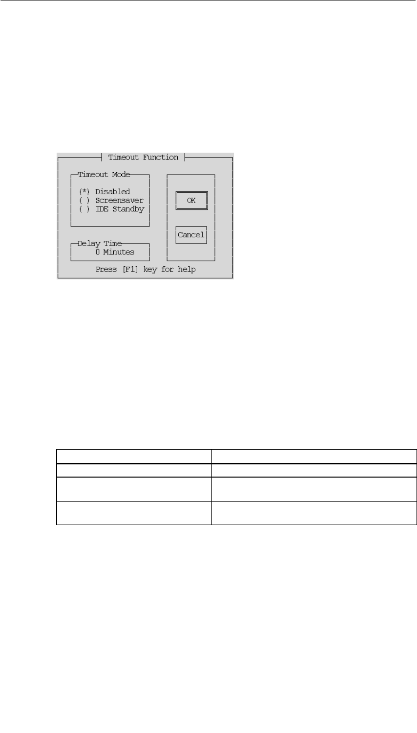
CPUs for M7-400
11-29
S7-400, M7-400 Programmable Controllers Module Specifications
A5E00069467-07
11.4.7 Setup Page “Timeout Function”
Opening the Setup Page
If you have selected “Timeout Function” in the Setup menu (Figure 11-9 on
page 11-23) and activated the OPEN button, this setup page appears on the
screen (Figure 11-13).
Figure 11-13 Setup Page “Timeout Function”
What is the Purpose of the Setup Page?
On this setup page, you determine whether the hard disk is to go into standby
mode during access pauses or the screen is to be protected by a screen saver
during entry pauses.
Timeout Mode
Timeout mode offers you the following possible selections:
By Activating the Option Button... You Can...
Disabled switch the timeout function off.
Screen saver or have the screen saver switched on during entry
pauses,
IDE Standby or operate the hard disk in energy-saving standby
mode during access pauses
Delay Time
In this edit box, you enter the time in minutes that has to elapse after the last entry
or the last hard disk access before the timeout function activates.
OK Button
Activating this button returns to the Setup menu. Changes on the setup page are
retained.
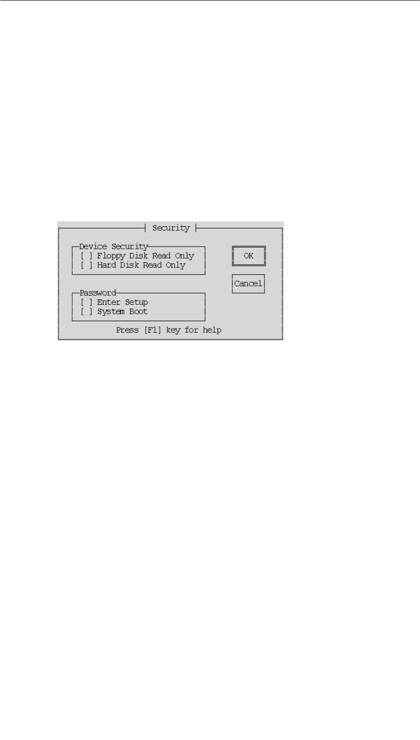
CPUs for M7-400
11-30 S7-400, M7-400 Programmable Controllers Module Specifications
A5E00069467-07
CANCEL Button
Activating this button returns to the Setup menu. Deletes all changes you have
made on the setup page.
11.4.8 Setup Page “Security”
Opening the Setup Page
If you have selected “Security” in the Setup menu (Figure 11-9 on page 11-23) and
activated the OPEN button, this setup page appears on the screen (Figure 11-14).
Figure 11-14 “Security” Setup Page
What is the Purpose of the Setup Page?
On this setup page, you activate or deactivate the write protection for the disk drive
and hard drive and the password protection for setting up and/or booting the CPU.
Device Security
Floppy Disk Read Only
When this check box is activated, write access to the hard disk is no longer
possible.
Hard Disk Read Only
When this check box is activated, write access to the hard disk is no longer
possible.

CPUs for M7-400
11-31
S7-400, M7-400 Programmable Controllers Module Specifications
A5E00069467-07
Password
Enter Setup
By activating this check box, you can assign a password that authorizes access to
the Setup.
System Boot
By activating this check box, you can assign a password that permits booting of the
operating system.
You can only set this password if a valid password was already entered for “Enter
Setup”.
Note
The password can have a maximum of 8 alphanumeric characters. Upper and
lower case are distinguished. If you use the American keyboard to enter the
password and then change, for example, to using another national keyboard such
as the German, this can have consequences for the password. For the password
Johnny_* you would then have to enter Johnnz?
Write down your password and keep it in a safe place where you can find it again.
If you lose or forget your password, contact your local Siemens dealer.
OK Button
Activating this button returns to the Setup menu. Changes on the setup page are
retained.
CANCEL Button
Activating this button returns to the Setup menu. Deletes all changes you have
made on the setup page.
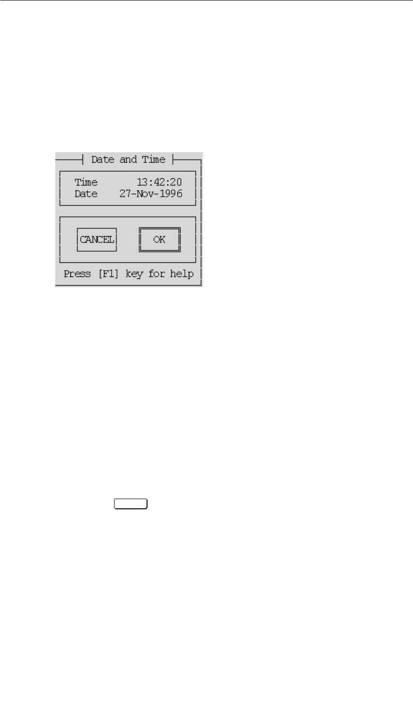
CPUs for M7-400
11-32 S7-400, M7-400 Programmable Controllers Module Specifications
A5E00069467-07
11.4.9 Setup Page “Date and Time”
Opening the Setup Page
If you have selected “Date and Time” and activated the OPEN button in the Setup
menu (Figure 11-9 on page 11-23), this BIOS setup page appears on the screen
(Figure 11-15).
Figure 11-15 “Date and Time” Setup Page (Default)
What is the Purpose of the Setup Page?
On this setup page, you set the date and time for the programmable module.
Date
You enter the date in the form dd-mm-yyyy (day, month, year) in this edit box.
Time
You enter the time in the form hh:mm:ss (hour, minute, second) in this edit box.
The seconds in the setup page are updated continuously and only stopped when
you select the seconds field. You can then accept the value displayed or set by
pressing the RETURN key.
OK Button
Activating this button returns to the Setup menu. Changes on the setup page are
retained.
CANCEL Button
Activating this button returns to the Setup menu. Deletes all changes you have
made on the setup page with the exception of the time.
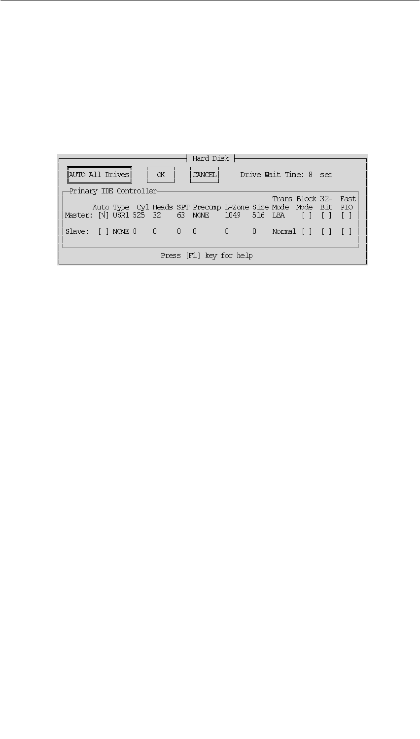
CPUs for M7-400
11-33
S7-400, M7-400 Programmable Controllers Module Specifications
A5E00069467-07
11.4.10 “Hard Disk” Setup Page
Opening the Setup Page
If you have selected “Hard Disk” and activated the OPEN button in the Setup menu
(Figure 11-9 on page 11-23), this BIOS setup page appears on the screen
(Figure 11-16).
Figure 11-16 “Hard Disk” Setup Page with only the Master Hard Disk Present
What is the Purpose of the Setup Page?
The setup page is used for transferring the parameters of the hard disk in your
mass storage module to the BIOS.
Only change the default settings if you install a different hard disk and this cannot
be detected automatically (see Auto function). If the wrong hard disk type is
entered, the operating system cannot be started.
AUTO All Drives
Sets the type and all parameters for the master and slave hard disks.
Auto
Sets the type and all parameters for the corresponding hard disk automatically
during BIOS startup if the check box is activated.
Type .... Size
These are drive-specific parameters.

CPUs for M7-400
11-34 S7-400, M7-400 Programmable Controllers Module Specifications
A5E00069467-07
Translation Mode
In Translation Mode you have four possible settings:
•Auto
reads the hard disk parameters and automatically sets the correct mode
(Normal, LBA, Large). The Translation Mode “Auto” is set as the default.
•Normal
used for hard disks with a memory capacity of 504 Mbytes.
•LBA (Logical Block Addressing)
is used for hard disks with a memory capacity of 504 Mbytes.
•Large
must be set for hard disks with a memory capacity of 504 Mbytes which do not
support the LBA mode.
Block Mode
Sets the block mode for DMA transfers. As the hard disks in the M7-400 are not
being operated in DMA mode, this check box should not be activated.
32 Bits
Sets 32-bit access mode. As this is not supported by ISA hard disk controllers, this
check box should not be activated.
Fast PIO
Sets a faster Programmed Input Output mode.
OK Button
Activating this button returns to the Setup menu. Changes on the setup page are
retained.
CANCEL Button
Activating this button returns to the Setup menu. Deletes all changes you have
made on the setup page.
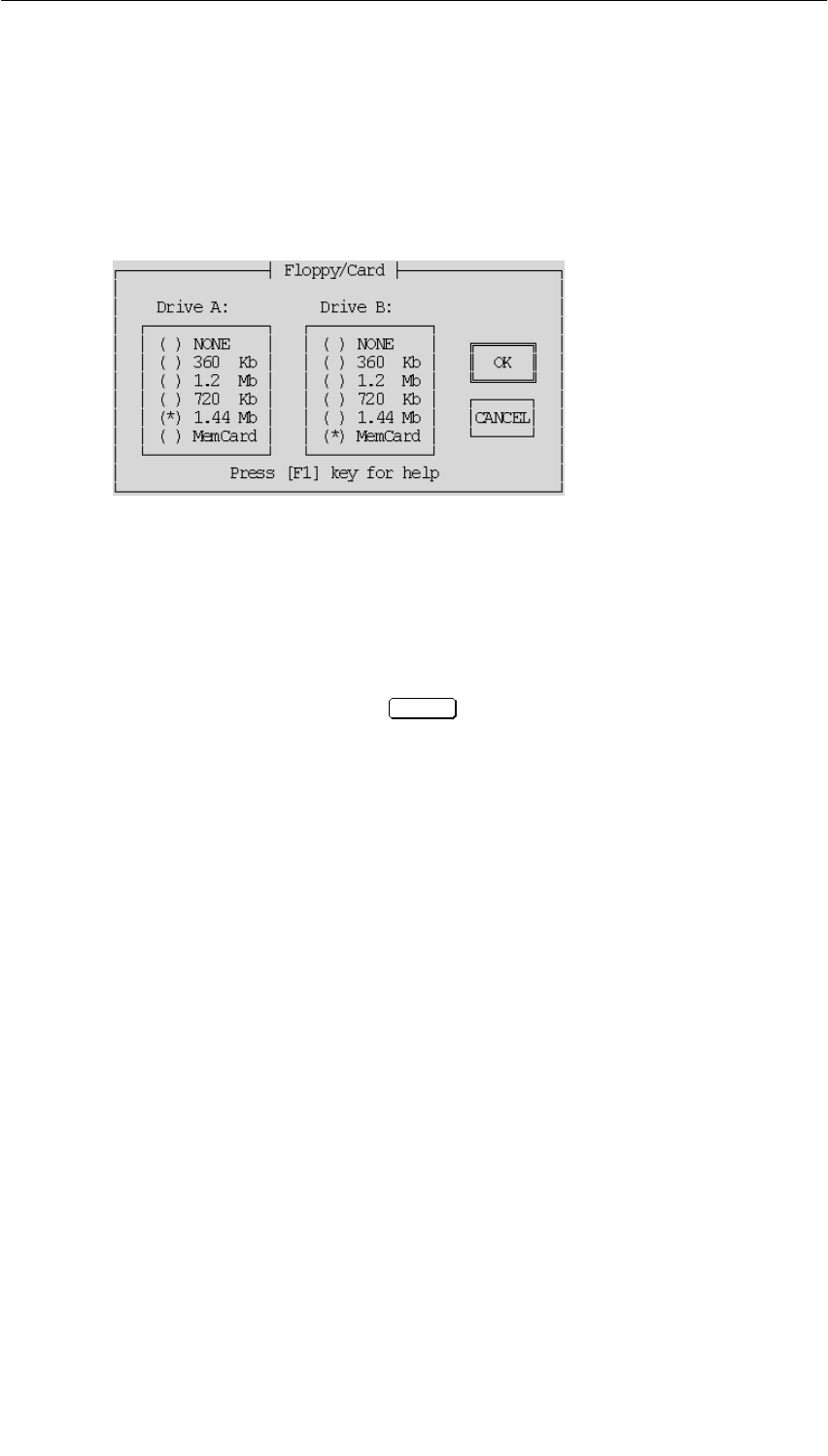
CPUs for M7-400
11-35
S7-400, M7-400 Programmable Controllers Module Specifications
A5E00069467-07
11.4.11 Setup Page “Floppy/Card”
Opening the Setup Page
If you have selected “Floppy/Card” and activated the OPEN button in the Setup
menu (Figure 11-9 on page 11-23), this setup page appears on the screen
(Figure 11-17).
Figure 11-17 “Floppy/Card” Setup Page
What is the Purpose of the Setup Page?
You can enter the diskette (floppy disk) drive in your mass storage module and the
memory card drive in your CPU on this page.
Drive A
At the first power up or after the INS key has been pressed during booting, the
BIOS setup detects whether the CPU has been expanded by a mass storage
module and whether it therefore has a floppy disk drive available or not.
•If a floppy disk drive is available, the BIOS assigns drive A to it by activating the
option button “1.44 Mb”.
•If a floppy disk drive is not available, the BIOS assigns drive A to the memory
card drive by activating the option button “MemCard”.
If you do not want either of the two drives entered, activate the option button
“NONE”.
The other Drive A settings are not significant at the present time.
Drive B
Drive B stands only for the memory card drive within the CPU if a floppy disk drive
is entered in Drive A.
•Activate the option button “MemCard” if you want to work with a memory card.
•Otherwise, activate the option button “NONE”.
The other Drive B settings are not significant at the present time.
OK Button
Activating this button returns to the Setup menu. Changes on the setup page are
retained.
CANCEL Button
Activating this button returns to the Setup menu. Deletes all changes you have
made on the setup page.
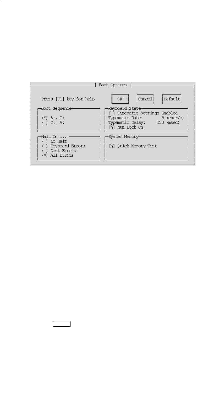
CPUs for M7-400
11-36 S7-400, M7-400 Programmable Controllers Module Specifications
A5E00069467-07
11.4.12 Setup Page “Boot Options”
Opening the Setup Page
If you have selected “Boot Options” and activated the OPEN button in the Setup
menu (Figure 11-9 on page 11-23), this setup page appears on the screen
(Figure 11-18).
Figure 11-18 “Boot Options” Setup Page
What is the Purpose of the Setup Page?
On this page, you set the boot drive and the method for the main memory test.
Boot Sequence
By activating the relevant option button, you select here the drive from which the
CPU is to boot at power up.
•Drive A represents the floppy disk drive or memory card, depending on which of
them has been entered as Drive A in the “Floppy/Card” setup page. If there is
no medium with boot capability in the floppy disk drive, the system will next try
to boot from the memory card (“Floppy/Card” setup page –> Drive B).
•Drive C represents the hard disk drive.
It is possible to designate a primary and secondary drive, that is, if there is no boot
program in the primary drive, the system boots automatically from the secondary
drive if there is a boot program there.
If neither Drive A nor Drive C contain a boot program, a message on the screen
prompts you to insert a medium with boot capability and to confirm this by
pressing RETURN .

CPUs for M7-400
11-37
S7-400, M7-400 Programmable Controllers Module Specifications
A5E00069467-07
Halt On ...
Here you can choose which error messages are displayed in an error window
during booting. Displaying an error window delays booting by approximately
2 seconds.
Keyboard State
Typematic Settings Enabled
If you activate this check box, the values “Typematic Rate” and “Typematic Delay”
are set by the BIOS.
Typematic Rate
This value is used to set the maximum keyboard rate in characters per second.
Typematic Delay
This value is used to set the delay time in milliseconds, after which characters are
transferred with the maximum keyboard rate.
Num Lock On
If you activate this check box, “Num Lock” becomes active after BIOS power up.
System Memory
If this check box is activated, only sample tests are made of the main memory at
power up so the test is especially fast.
OK Button
Activating this button returns to the Setup menu. Changes on the setup page are
retained.
CANCEL Button
Activating this button returns to the Setup menu. Deletes all changes you have
made on the setup page.
DEFAULT Button
When this button is activated, the default settings are entered in the setup page
again. The original settings are deleted.
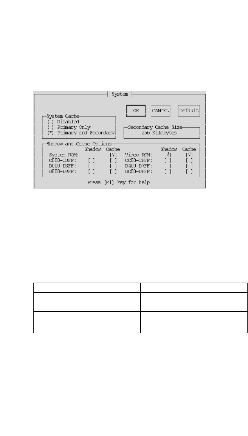
CPUs for M7-400
11-38 S7-400, M7-400 Programmable Controllers Module Specifications
A5E00069467-07
11.4.13 Setup Page “System”
Opening the Setup Page
If you have selected “System” and activated the OPEN button in the Setup menu
(Figure 11-9 on page 11-23), this setup page appears on the screen
(Figure 11-19).
Figure 11-19 “System” Setup Page
What is the Purpose of the Setup Page?
On this page, you make the settings for the cache memory, the system ROM, and
the video ROM. We recommend you use the default settings (see Figure 11-19).
System Cache
System Cache offers you the following possible selections:
By Activating the Option Button... You Can Switch...
Disabled all cache memory off,
Primary only only the process-oriented cache on,
Primary and Secondary both the internal and external cache on. If
Size 0 is displayed for Secondary Cache,
only the Primary Cache can be switched on.
Secondary Cache Size
Indicates the size of the secondary cache memory. This field is for information only
and cannot be edited.
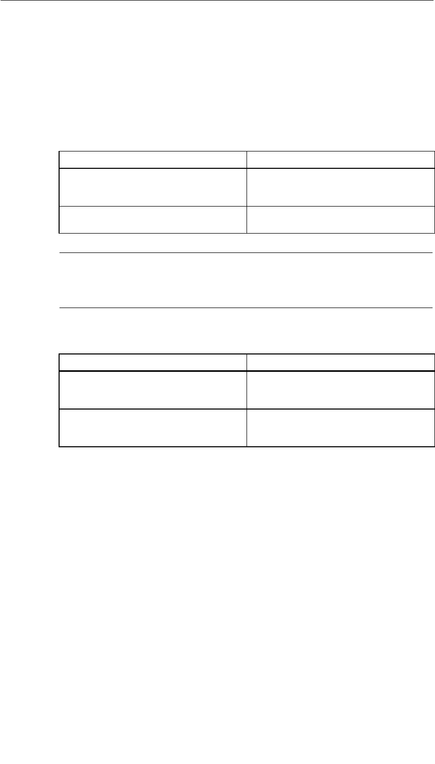
CPUs for M7-400
11-39
S7-400, M7-400 Programmable Controllers Module Specifications
A5E00069467-07
System Cache
For the memory areas of the System ROM, the VIDEO ROM, and the addresses of
BIOS expansions, you can set whether they are copied to the Shadow RAM and
whether the cache should be used.
•System ROM offers you the following possible selections:
By Activating the Option Button... You Determine...
Shadowed that the BIOS address area of 128 Kbytes is
to be copied into the high-speed shadow
RAM. This option cannot be switched off.
Shadowed and Cached that a cache memory is available for this
memory area in addition to shadow RAM.
Note
If you have switched off the cache memory in the “Primary and Secondary Cache”
field, the setting in the “System ROM” field does not change automatically.
•Video ROM offers you the following possible selections:
By Activating the Option Button... You Determine...
Shadowed that the video ROM (32 Kbytes) is copied
into the fast shadow RAM. This accelerates
video output (faster screen buildup).
Shadowed and Cached that a cache memory is available for this
memory area in addition to shadow RAM.
Further accelerates video output.
OK Button
Activating this button returns to the Setup menu. Changes on the setup page are
retained.
CANCEL Button
Activating this button returns to the Setup menu. Deletes all changes you have
made on the setup page.
DEFAULT Button
When this button is activated, the default settings are entered in the setup page
again. The original settings are deleted.
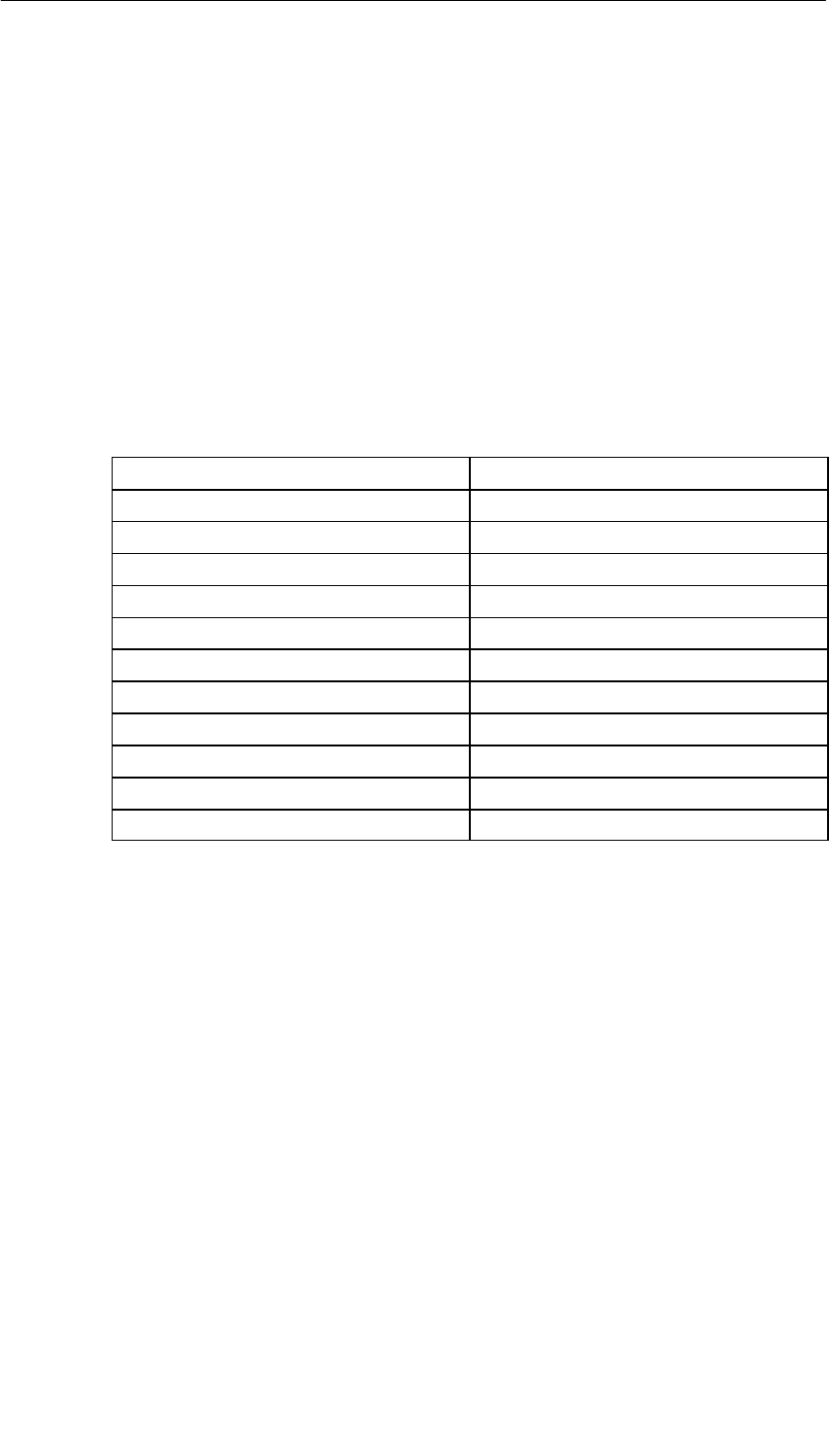
CPUs for M7-400
11-40 S7-400, M7-400 Programmable Controllers Module Specifications
A5E00069467-07
11.5 I/O Addresses, Main Memory and Interrupt
Assignments
Introduction
This section gives you detailed information, in the form of a table, on the I/O
address space assignment, main memory and interrupt assignments of the CPUs.
Memory Assignment
The main memory is assigned as follows in the M7-400:
Table 11-8 Main Memory Assignment
Address Content
1 MB to 15 MB User memory area
15 MB to 16 MB PROFIBUS DP*), otherwise free
E 8000H to F FFFFH BIOS
E 0000H to E 7FFFH Free (32 K)
D 0000H to D FFFFH Free (64 K)
C F000H to C FFFFH Free (4 K)
C C000H to C EFFFH Memory card, otherwise free (12 K)
C 8000H to C BFFFH Free (16 K)
C 0000H to C 7FFFH Shadow VGA BIOS (32 K)
A 0000H to B FFFFH VGA (128 K)
0 0000H to 9 FFFFH 640 K system area
*) If the interface submodule IF 964-DP is not plugged in the preferred slot (see Table 13-3
on page 13-4)
Keeping Memory Areas Free
The memory areas that are not always marked as “free” should be kept free when
using a memory manager.
SRAM Area
The size of the SRAM with battery backup is 64 Kbytes (net for data blocks
56 Kbytes). If the battery is removed and inserted again when there is no power
connected, the SRAM content will be lost. This is indicated by the BAF LED.

CPUs for M7-400
11-41
S7-400, M7-400 Programmable Controllers Module Specifications
A5E00069467-07
Memory Areas for AT Cards
AT cards which are inserted in the expansion module ATM 478 can occupy the
following memory areas:
Range M7 RMOS32 M7 RMOS32 with MS-DOS M7 RMOS32
with
Without EMS With EMS w
i
t
h
MS-Windows
D 0000H to E 7FFFH 96 K 96 K 32 K2) 32 K2)
C 8000H to C BFFFH 16 K 16 K 16 K 16 K
C C000H bis C EFFFH1) 12 K 12 K 12 K 12 K
C F000H to C FFFFH 4 K 4 K 4 K 4 K
1) The area is only available if no memory card is present.
2) Under M7 RMOS32 with MS Windows, or if the driver software under MS-DOS requires
expanded memory (EMS), the memory manager EMM386 occupies 64K in the area
D0000H to E7FFFH because it must be operated in EMS mode.
I/O Address Area
Addressing the ISA-compatible input/output components is done in the I/O area
under the addresses from 0100H to 03FFH. The addresses specified by the ISA
architecture are used here. In contrast to the original AT, the I/O addresses in the
CPUs are completely decoded so that the addresses above 03 FFH can be used
for addressing M7-400-specific hardware.
I/O Address Area for AT Adapter Modules
If you are using AT adapter modules, the following address areas are available for
addressing:
•0200H to 03FFH
•Except for the area 3 E0H to 3 E3H and
•Except for the areas which the interface submodules are occupying (see the
“Interface Submodules” chapter).

CPUs for M7-400
11-42 S7-400, M7-400 Programmable Controllers Module Specifications
A5E00069467-07
Interrupt Assignment
Table 11-9 Interrupt Assignment
Interrupt Function
NMI Group interrupt for faults and reset signals
IRQ0 System timer
IRQ1 Reserved for keyboard
IRQ2 Cascading of the 2nd interrupt controller
IRQ3 Assigned to COM2, otherwise free
IRQ4 Assigned to COM1, otherwise free
IRQ5 Assigned to LPT2, otherwise free
IRQ6 Assigned to floppy disk drive, otherwise free
IRQ7 Assigned to LPT1, otherwise free
IRQ8 Real-time clock
IRQ9 Software interrupt, rerouted to IRQ2
IRQ10 IF 964-DP, otherwise free
IRQ11 CP 1401, otherwise free
IRQ12 Assigned to trackball/mouse
IRQ13 Assigned to numeric coprocessor
IRQ14 Assigned to hard disk drive, otherwise free
IRQ15 Assigned

12-1
S7-400, M7-400 Programmable Controllers Module Specifications
A5E00069467-07
M7-400 Expansions
Chapter Overview
Section Description Page
12.1 Overview 12-2
12.2 EXM 478 Expansion Module; (6ES7 478-2AC00-0AC0) 12-6
12.3 ATM 478 AT Adapter Module; (6ES7 478-2CA00-0AC0) 12-15
12.4 MSM 478 Mass Storage Module; (6ES7 478-2BA00-0AC0) 12-22
12

M7-400 Expansions
12-2 S7-400, M7-400 Programmable Controllers Module Specifications
A5E00069467-07
12.1 Overview
Introduction
You can expand your automation computer from the M7-400 range by adding
expansion modules for interface submodules, short AT modules, and/or the mass
storage module. The interface submodules can include the IF 962-COM,
IF 962-LPT, ... .
The following expansion modules are available:
•EXM 478 expansion module for up to 3 interface submodules
•ATM 478 AT adapter module for one short AT module
•MSM 478 mass storage module with hard disk and floppy disk drive and an
LPT1 printer port.
Expansion Socket
On the right-hand side of a CPU or an M7-400 application module there is a
120-pin socket (AT-ISA bus) for connecting expansions. There is a matching
connector for this socket on the left-hand side of the EXM 478, ATM 478, and MSM
478 expansion modules (Figure 12-1).
The EXM 478, ATM 478 and MSM 478 expansion modules have one expansion
socket each on the right-hand side so that further expansion modules can be
plugged in.
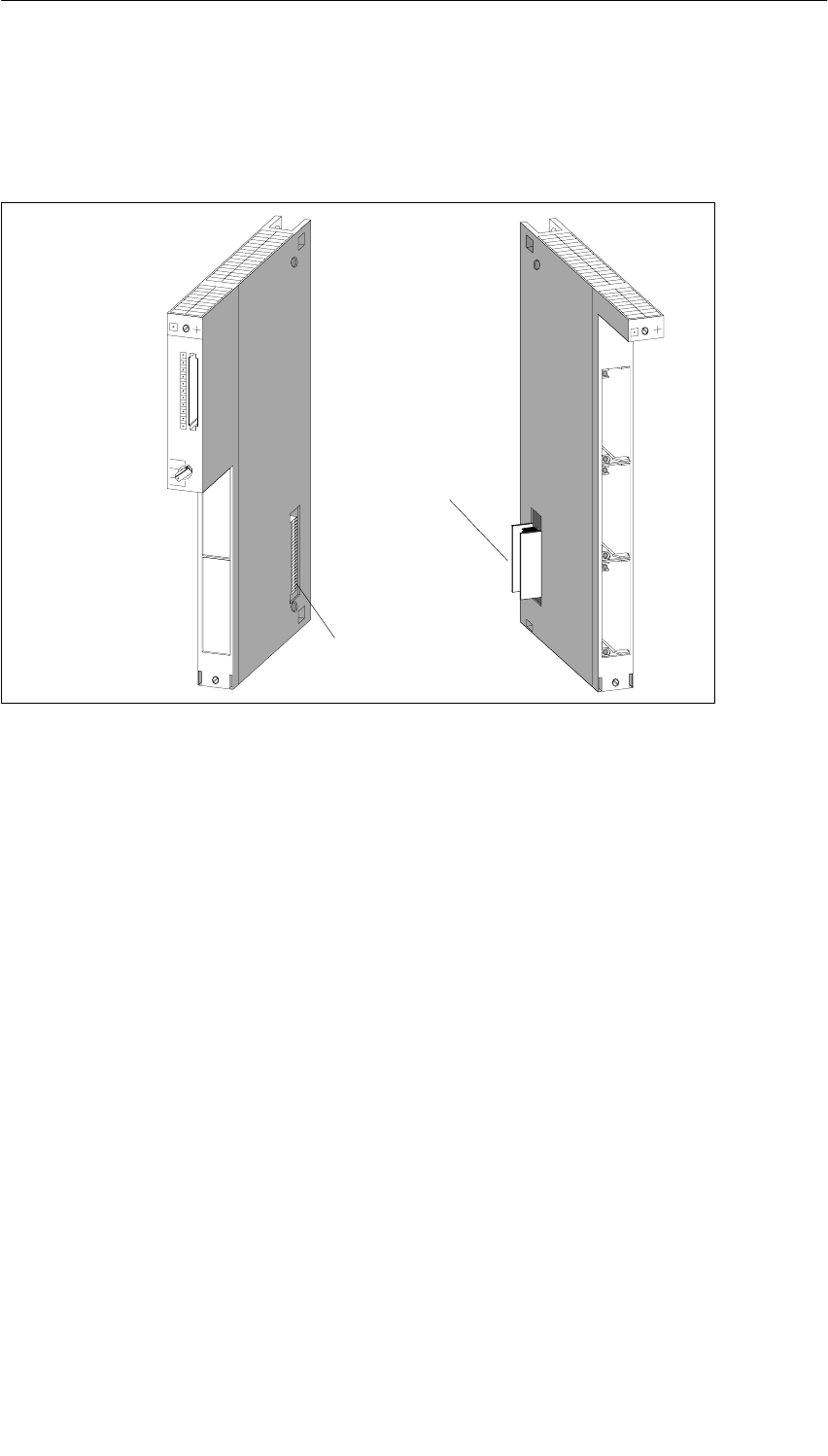
M7-400 Expansions
12-3
S7-400, M7-400 Programmable Controllers Module Specifications
A5E00069467-07
Behavior on the S7-400 Backplane Bus
The expansion modules can be accessed via the relevant programmable module
and not via the S7-400 backplane bus.
e.g. FM 456-4 e.g. EXM 478
Expansion
socket
Expansion
connector
Figure 12-1 Positions of Expansion Socket and Expansion Connector
Maximum Expansion
Figure 12-2 shows the maximum possible expansion using expansion modules for
a CPU 486-3, CPU 488-3, or FM 456.
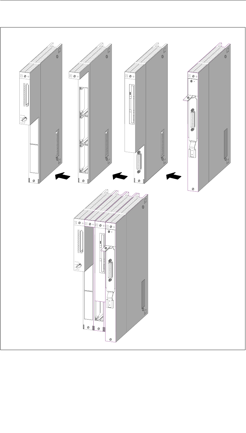
M7-400 Expansions
12-4 S7-400, M7-400 Programmable Controllers Module Specifications
A5E00069467-07
e.g. FM 456-4 e.g. EXM 478 e.g. ATM 478e.g. MSM 478
Figure 12-2 Maximum Expansion with Expansion Modules
M7-400 Expansions
12-5
S7-400, M7-400 Programmable Controllers Module Specifications
A5E00069467-07
Permissible Combinations
You can see from the table below which expansions can be connected to the
programmable M7-400 modules.
Table 12-1 Expansion Possibilities of the CPU 486-3, CPU 488-3, or FM 456
Programmable M7-400 Module Slot Slot Slot
Slot n in the Case of Single-Width Modules n + 1 n + 2 n + 3
Slot n and n+1
in the Case of Double-Width Modules n + 2 n + 3 n + 4
– – –
EXM 478 – –
EXM 478 EXM 478 –
EXM 478 EXM 478 EXM 478
EXM 478 EXM 478 ATM 478
EXM 478 ATM 478 ATM 478
EXM 478 ATM 478 –
CPU 486 3 CPU 488 3 FM 456 4
ATM 478 – –
CPU 486-3, CPU 488-3, FM 456-4 ATM 478 ATM 478 –
ATM 478 ATM 478 ATM 478
MSM 478 – –
EXM 478 MSM 478 –
EXM 478 EXM 478 MSM 478
EXM 478 MSM 478 ATM 478
MSM 478 ATM 478 ATM 478
MSM 478 ATM 478 –
Rules for the Combinations
The following rules apply for expansions from left to right after a CPU or application
module (slots n + 1, n + 2, n + 3 or n + 2, n + 3, n + 4):
1. Up to 3 EXM 478 expansion modules
2. Max. 1 MSM 478 mass storage module
(that is, always after the CPU 486-3, CPU 488-3, FM 456, or EXM 478)
3. Up to 3 ATM 478 AT adapter modules
(that is, always after the CPU 486-3, CPU 488-3, FM 456, EXM 478, or
MSM 478)
In total, a CPU or application module can be expanded with up to three modules.
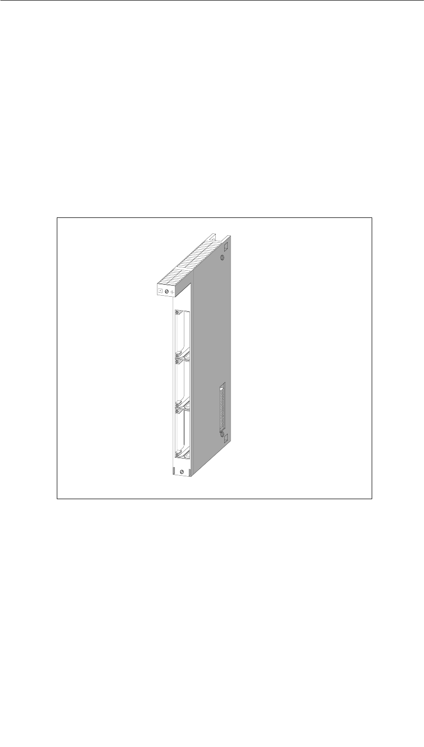
M7-400 Expansions
12-6 S7-400, M7-400 Programmable Controllers Module Specifications
A5E00069467-07
12.2 EXM 478 Expansion Module; (6ES7 478-2AC00-0AC0)
Characteristics
The EXM 478 expansion module is used to house up to three interface
submodules. By installing the relevant interface submodule in this expansion
module, such as the IF 962-VGA and IF 962-LPT, you can connect, for example, a
VGA monitor, a keyboard, and a printer to your automation computer.
The EXM 478 expansion module has a 120-pin connector on the left-hand side and
a 120-pin socket on the right-hand side for connecting a further expansion module
or a mass storage module.
Figure 12-3 EXM 478 Expansion Module

M7-400 Expansions
12-7
S7-400, M7-400 Programmable Controllers Module Specifications
A5E00069467-07
12.2.1 Addressing the EXM 478 Expansion Module
Introduction
In order to be able to program the interface submodules in the EXM 478 expansion
module, you must be able to determine their addresses. There are the following
addressing methods:
•Addressing in the AT-compatible I/O address area
•Addressing in the M7-400-specific I/O address area
In this section, you will find information on both methods of addressing the interface
submodules.
Addressing in the AT-Compatible I/O Address Area
Some of the interface submodules are automatically configured by the BIOS for
operation in the AT-compatible I/O address area. This automatic configuration
takes place, for example, for:
•The IF 962-VGA interface submodule
•Up to 4 COM ports (COM1 to COM4)
•Up to 3 LPT ports (one LPT port on the MSM 478 and two interface submodules
IF 962-LPT)
Further interfaces are configured in the BIOS setup. See the CPU/FM description
to learn how to operate the BIOS setup. The description of the interface
submodules will show the specific settings possible.
To configure in the BIOS setup, you must know the submodule receptacle numbers
of the interface submodule receptacles (slots). You will find this information in
Figure 12-4 later in this section.
Addressing in the M7-400-Specific I/O Address Area
All interface submodules can be accessed via M7-400-specific I/O addresses.
There is a description of how to determine the I/O address of an interface
submodule in the “specific address area” starting from page 12-10.
You require this information to program an interface submodule that is not
addressed in the AT-compatible address area.
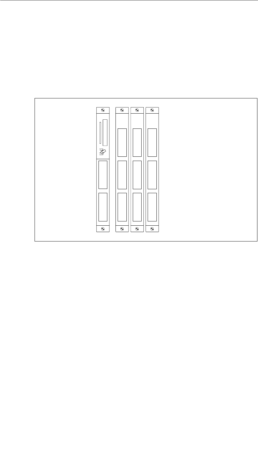
M7-400 Expansions
12-8 S7-400, M7-400 Programmable Controllers Module Specifications
A5E00069467-07
Numbering of the Submodule Receptacles
Each receptacle (slot) for an interface submodule has a submodule receptacle
number assigned to it. The submodule receptacle number depends on the
configuration of your CPU or FM. The submodule slot numbers are shown in
Figures 12-4 and 12-5.
You require these submodule receptacle numbers for configurations that you make
in the BIOS setup or to determine the I/O addresses of an interface submodule.
0
15
3
4
69
710
811
FM 456-4 EXM 478
Slot n n+1 n+2 n+3
Figure 12-4 Submodule Receptacle Numbers for the FM 456-4 and EXM 478
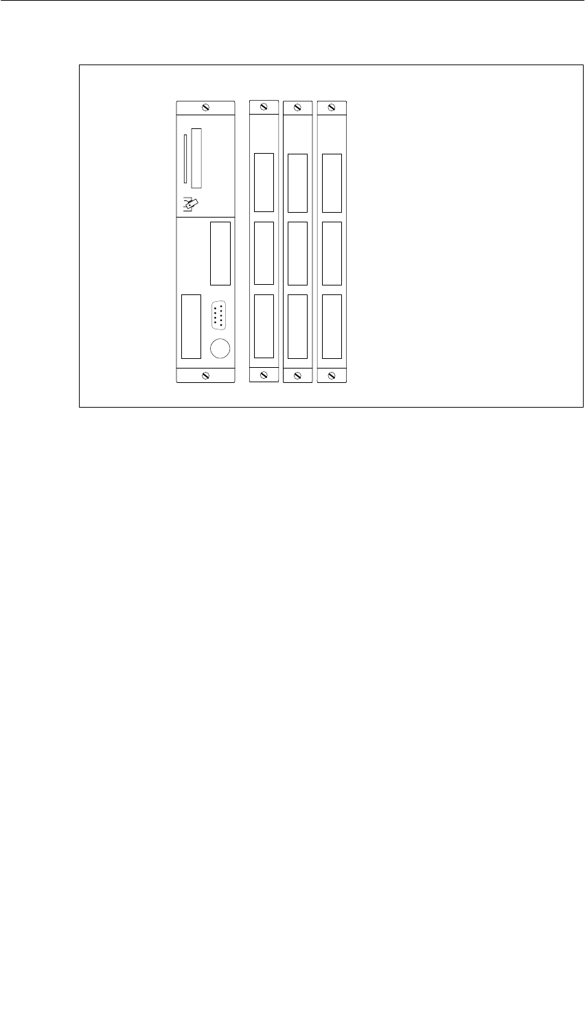
M7-400 Expansions
12-9
S7-400, M7-400 Programmable Controllers Module Specifications
A5E00069467-07
3
08
6
7
912
10 13
11 14
CPU 486-3/
CPU 488-3 EXM 478
Slot n n+2 n+3 n+4
n+1
Figure 12-5 Submodule Receptacle Numbers for the CPU 486-3, CPU 488-3, and
EXM 478

M7-400 Expansions
12-10 S7-400, M7-400 Programmable Controllers Module Specifications
A5E00069467-07
Division of Addresses in the M7-400-Specific I/O Address Area
The EXM 478 expansion module is operated on the ISA bus of the programmable
module. The I/O address area from C000H (to D2FFH) in the CPU 486-3,
CPU 488-3, or the FM 456 application module is reserved for this purpose. Each
expansion module occupies 256 bytes (100H) in this area. The division of the
address area is shown in Figure 12-6 using the FM 456-4 as an example.
Cn00
Co00
Cp00
Cq00
2) EXM 478
expansion module
Submodule receptacle
number 1
Reserved
00
40
80
All addresses are in hexadecimal notation.
Submodule receptacle
number 5
Submodule receptacle
number 4
Submodule receptacle
number 3
00
40
80
C0
FF
1) EXM 478
expansion module
e.g. FM 456-4
Cr00
3) EXM 478
expansion module
Submodule receptacle
number 0
Reserved
Submodule receptacle
number 6
00
40
80
Reserved
n .. q =Number of the slot of the
module in the mounting
rack
(in hexadecimal notation)
Example:
n = 6 FM 456-4 C600H
o = 7 1) EXM 478 C700H
p = 8 2) EXM 478 C800H
q = 9 3. EXM 478 C900H
BF
Figure 12-6 Base Addresses of the Expansion Modules and the Interface Submodules

M7-400 Expansions
12-11
S7-400, M7-400 Programmable Controllers Module Specifications
A5E00069467-07
Addresses Within an Expansion Module
Each expansion module occupies 256 bytes (100H) within the CPU/FM address
area. The division of the 256 addresses within an expansion module can be seen
from Table 12-2.
Table 12-2 Division of Addresses Within an Expansion Module
Address Function/Slot Remarks
00H to 3FHReserved In this address area, the automation computer’s
BIOS makes basic settings in the expansion
module such as assignment of interrupts, etc.
40H to 7FHInterface submodule x
80H to BFHInterface submodule y
C0H to FFHInterface submodule z
Base Addresses of the Interface Submodules
Special characteristics of the interface submodules such as the location of the
AT-compatible I/O addresses (IF 962-COM, IF 962-LPT, ...) are set via the base
addresses, or the interface submodules are accessed exclusively via these base
addresses (IF 961-DIO, IF 961-AIO,...).
The base address for an interface submodule is obtained from the sum of the
slot-dependent address of the expansion module and the interface submodule
address within the expansion module. You can find the resulting base addresses in
Tables 12-3 and 12-4:
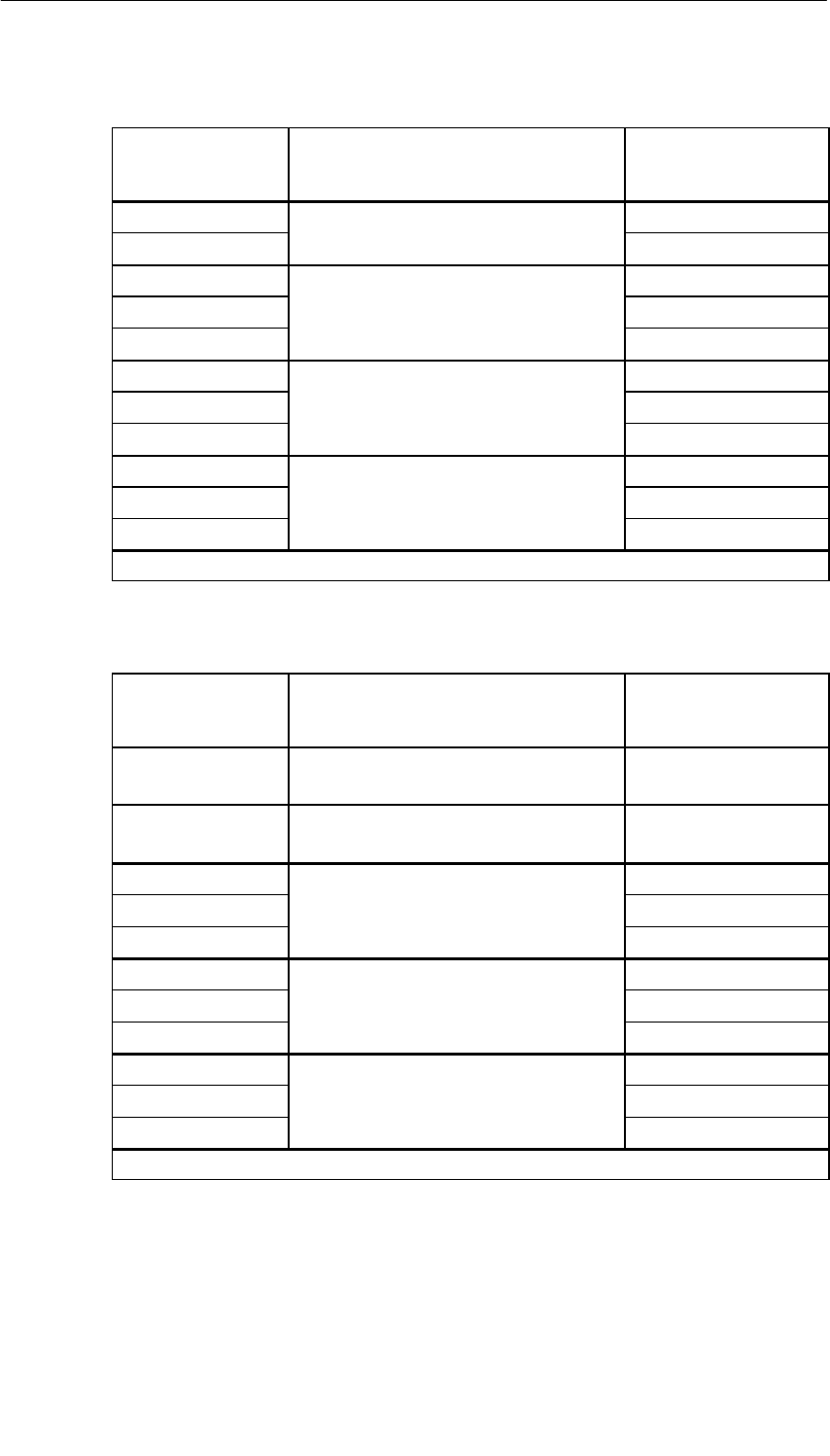
M7-400 Expansions
12-12 S7-400, M7-400 Programmable Controllers Module Specifications
A5E00069467-07
Table 12-3 Base Addresses of the Interface Submodules with FM 456-4
Base Address Modules Interface Submodule
in Submodule
Receptacle ...
Cn40HFM 456-4 Number 0
Cn80H
FM 456 4
Slot n Number 1
Co40HNummer 3
Co80H1st EXM 478 in slot o = n + 1 Number 4
CoC0HNumber 5
Cp40HNumber 6
Cp80H2nd EXM 478 in slot p = n + 2 Number 7
CpC0H
p
Number 8
Cq40HNumber 9
Cq80H3rd EXM 478 in slot q = n + 3 Number 10
CqC0H
q
Number 11
n .. q = Number of the module slot in the mounting rack in hexadecimal notation.
Table 12-4 Base Addresses of the Expansion Modules with CPU 486-3,
CPU 488-3
Base Address Modules Interface Submodule
in Submodule
Receptacle ...
Cn40HCPU 486-3, CPU 488-3
Slot n
Number 0
Co40HCPU 486-3, CPU 488-3
Slot o = n + 1
Nummer 3
Cp40HNumber 6
Cp80H1st EXM 478 in slot p = n + 2 Number 7
CpC0H
p
Number 8
Cq40HNumber 9
Cq80H2nd EXM 478 in slot q = n + 3 Number 10
CqC0H
q
Number 11
Cr40HNumber 12
Cr80H3rd EXM 478 in slot r = n + 4 Number 13
CrC0HNumber 14
n .. r = Number of the module slot in the mounting rack in hexadecimal notation.

M7-400 Expansions
12-13
S7-400, M7-400 Programmable Controllers Module Specifications
A5E00069467-07
12.2.2 Interrupt Assignments, Signal Switching EXM 478
Introduction
Up to three interrupts per interface submodule are permitted in an EXM 478
expansion module. The various possible methods of interrupt assignment or
interrupt operation are described below.
Interrupt Assignment
When configuring the interface submodules in the BIOS setup, you can assign ISA
interrupts to the three interrupts of an interface submodule (IRQa, IRQb, IRQc). For
this purpose, enter the ISA interrupt provided in the relevant screen form.
If you enter the value “F0H” instead of the ISA interrupt, this interrupt is processed
via a shared interrupt. See below for details.
Shared Interrupt
Since the number of interrupts is limited due to AT-compatibility, it is possible to
assign several individual interrupts of the interface submodules to a shared
interrupt in the EXM 478 expansion modules. The shared interrupt is shared by all
interface submodule interrupts within an expansion module where the interrupt
assignment “F0H” has been entered.
The shared interrupt is assigned to the ISA interrupt during configuration of the
interface submodule in the BIOS setup.
Signal Switching
In an EXM 478 expansion module, two interface submodule signals can be
switched to another (signal switching). This signal switching is done during
configuration of the interface submodule in the BIOS setup.
Refer to the interface submodule description to find out if an interface submodule
requires signals from a further interface submodule, that is, if signal switching is
necessary.
Note
You will find a detailed description of the BIOS setup in the M7-400 application
module or CPU description.

M7-400 Expansions
12-14 S7-400, M7-400 Programmable Controllers Module Specifications
A5E00069467-07
12.2.3 Technical Specifications of the EXM 478 Expansion Module
Technical Specifications of the EXM 478
The table below contains the technical specifications of the EXM 478 expansion
module:
EXM 478
6ES7 478-2AC00-0AC0
Performance Features
Number of connectable
interface modules 3
Connection of
expansion modules Yes
Technical Specifications
Supply voltage 5 VDC
Current consumption
(without interface
submodules) 0.2 A
Power losses
(without interface
submodules) 0.5 W
Permissible power losses
(with 3 interface
submodules)
•Without forced
ventilation
•With forced ventilation
max. 10 W
max. 12 W
Dimensions
W x H x D (mm) 25 x 290 x 210
Weight 0.65 kg
Note
The sum of the power losses of the EXM 478 expansion module and the interface
submodules it contains must not exceed the maximum permissible power losses.
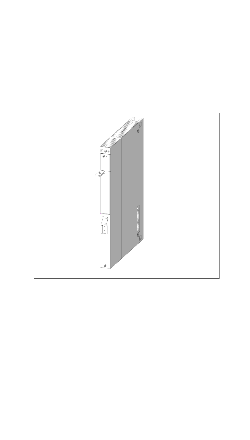
M7-400 Expansions
12-15
S7-400, M7-400 Programmable Controllers Module Specifications
A5E00069467-07
12.3 ATM 478 AT Adapter Module; (6ES7 478-2CA00-0AC0)
Characteristics
The ATM 478 AT adapter module is used to accommodate a short AT module
(card).
The ATM 478 AT adapter module has a 120-pin connector on the left-hand side
and a 120-pin socket on the right-hand side for connecting a further expansion
module or a mass storage module.
Figure 12-7 ATM 478 AT Adapter Module
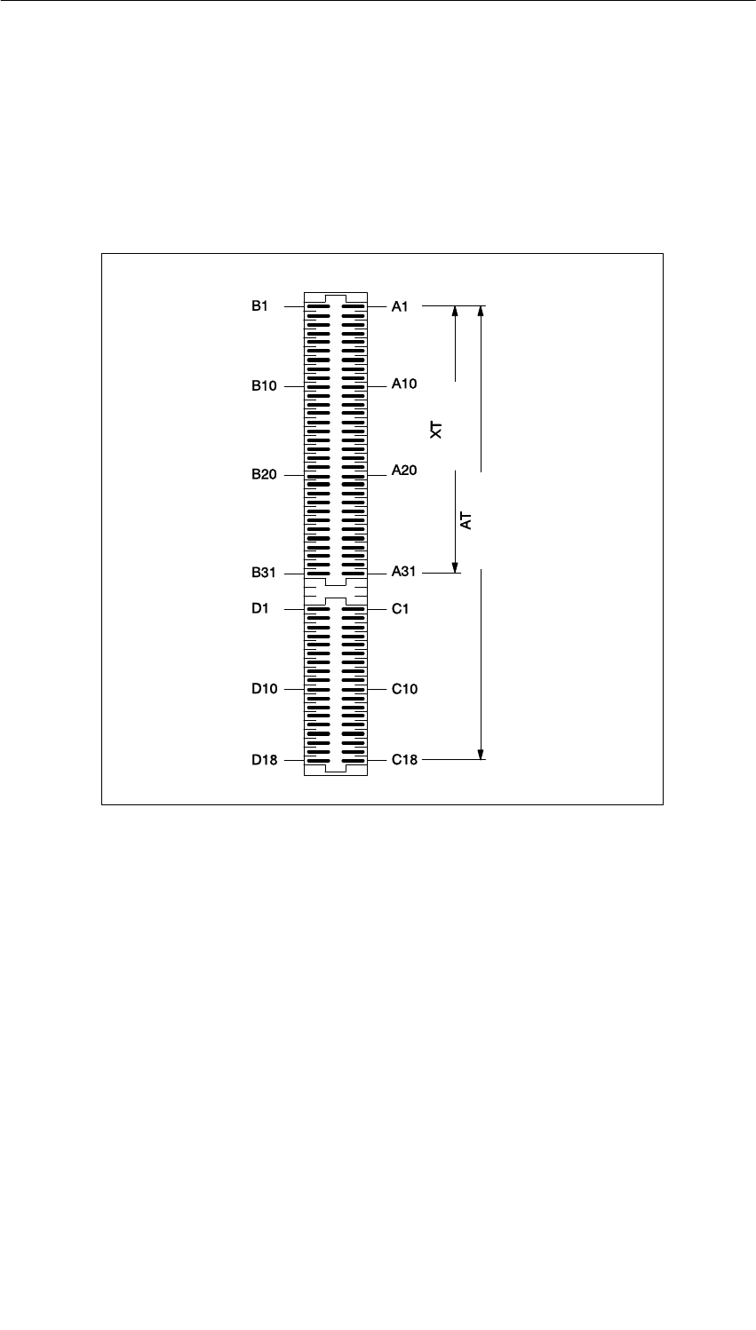
M7-400 Expansions
12-16 S7-400, M7-400 Programmable Controllers Module Specifications
A5E00069467-07
12.3.1 Pin Assignments of the AT Module
Pin Assignments
The ATM 478 AT adapter module has a 98-pin standard direct connector for short
AT modules (see Figure 12-8).
16 bit data
8 bit data
Figure 12-8 ATM 478 AT Adapter Module, 98-Pin Standard Direct Connector
See the following table for the pin assignments of the 98-pin standard direct
connector.

M7-400 Expansions
12-17
S7-400, M7-400 Programmable Controllers Module Specifications
A5E00069467-07
Table 12-5 Pin Assignments of the 98-Pin Standard Direct Connector
(ATConnector)
Pin Signal Name Pin Signal Name
XT Signals
B1 GND A1 I/OCHCK_N
B2 RESET DRV A2 SD7
B3 P5V A3 SD6
B4 IRQ9 A4 SD5
B5 N5V A5 SD4
B6 DRQ2 A6 SD3
B7 N12V A7 SD2
B8 0WS A8 SD1
B9 P12V A9 SD0
B10 GND A10 I/OCHRDY_N
B11 SMEMW_N A11 AEN
B12 SMEMR_N A12 SA19
B13 I/OW_N A13 SA18
B14 I/OR_N A14 SA17
B15 DACK3_N A15 SA16
B16 DRQ3 A16 SA15
B17 DACK1_N A17 SA14
B18 DRQ1 A18 SA13
B19 REFRESH A19 SA12
B20 SYSCLK A20 SA11
B21 IRQ7 A21 SA10
B22 IRQ6 A22 SA9
B23 IRQ5 A23 SA8
B24 IRQ4 A24 SA7
B25 IRQ3 A25 SA6
B26 DACK2_N A26 SA5
B27 T/C A27 SA4
B28 BALE A28 SA3
B29 P5V A29 SA2
B30 OSC A30 SA1
B31 GND A31 SA0
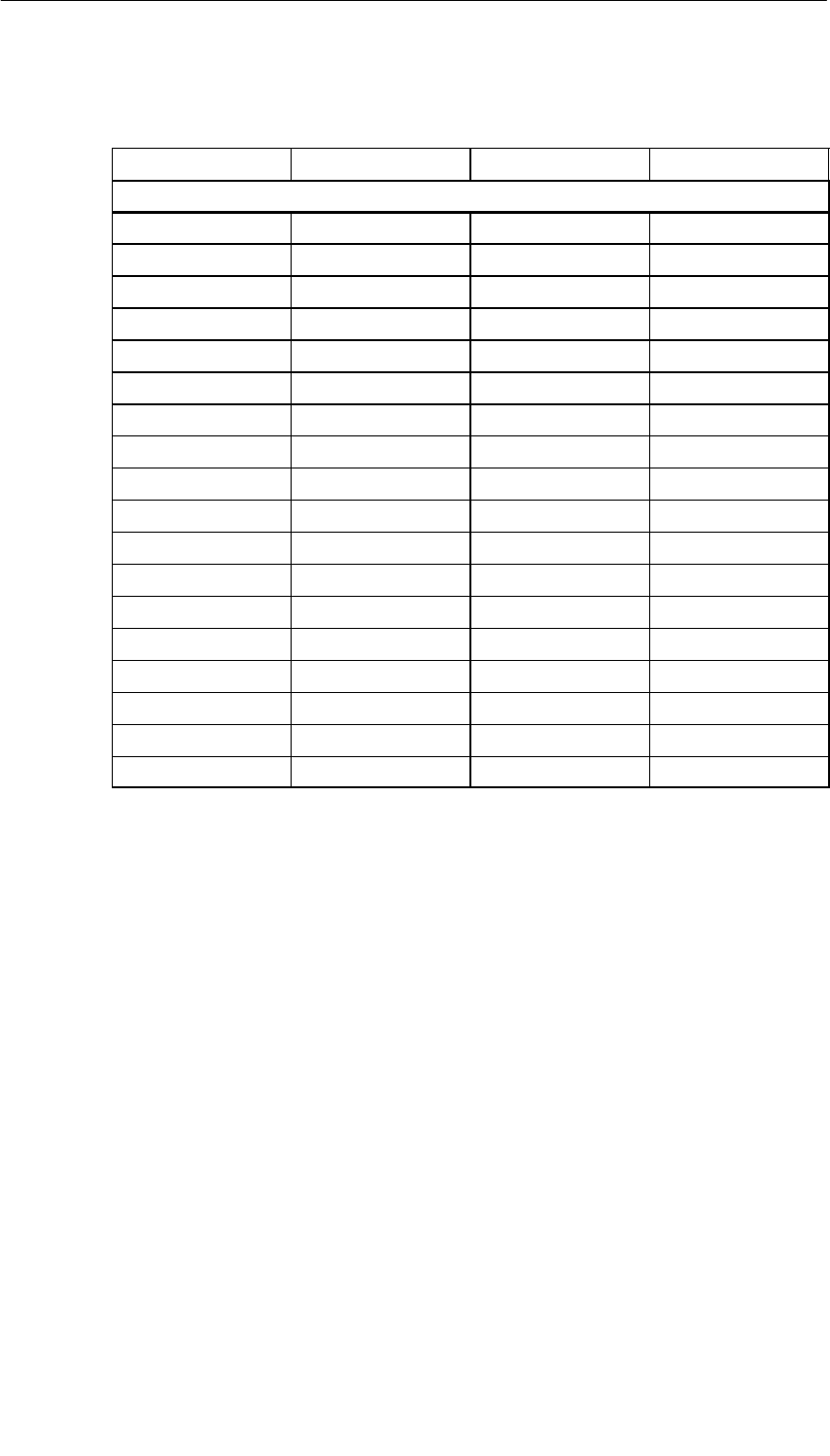
M7-400 Expansions
12-18 S7-400, M7-400 Programmable Controllers Module Specifications
A5E00069467-07
Table 12-5 Pin Assignments of the 98-Pin Standard Direct Connector
(ATConnector), continued
Pin Signal NamePinSignal Name
AT Expansion
D1 MEMCS_16_N C1 SBHE_N
D2 I/OCS16_N C2 LA23
D3 IRQ10 C3 LA22
D4 IRQ11 C4 LA21
D5 IRQ12 C5 LA20
D6 IRQ15 C6 LA19
D7 IRQ14 C7 LA18
D8 DACK0_N C8 LA17
D9 DRQ0 C9 MEMR_N
D10 DACK5_N C10 MEMW_N
D11 DRQ5 C11 SD8
D12 DACK6_N C12 SD9
D13 DRQ6 C13 SD10
D14 DACK7_N C14 SD11
D15 DRQ7 C15 SD12
D16 P5V C16 SD13
D17 MASTER_N C17 SD14
D18 GND C18 SD15

M7-400 Expansions
12-19
S7-400, M7-400 Programmable Controllers Module Specifications
A5E00069467-07
12.3.2 Technical Specifications of the ATM 478 AT Adapter Module
Technical Specifications of the ATM 478
The table below contains the technical specifications of the ATM 478 AT adapter
module:
ATM 478
6ES7 478-2CA00-0AC0
Performance Features
Number of connectable
AT modules (short) 1
Connection of
expansion modules Yes
Technical Specifications
Supply voltage 5 VDC
Current consumption
(without AT module) 0.12 A
Current consumption of
the AT module See calculation of
current consumption
Power losses
(without AT module) 0.6 W
Permissible power losses
(with AT module)
•Without forced
ventilation
•With forced ventilation
max. 10 W
max. 12 W
Dimensions
W x H x D (mm) 25 x 290 x 230
Weight (without AT module) 0.74 kg
Supply of the AT Module
Supply voltage max. current
+ 5 V (4.75 V to 5.25 V) 4 A
- 5 V (- 4.4 V to - 5.3 V) 70 mA
+ 12 V (11.7 V to 12.3 V) 500 mA
- 12 V (- 10.9 V to - 13.5 V) 100 mA
The supply voltages -5 V, +12 V, and -12 V are
monitored. In the event of a fault, the “INTF” LED
on the CPU or application module lights up.
Calculation of Power Consumption
You can calculate the power consumption of the short AT module using the
following formula:
I(AT module) = I(- 5 V) x 1.3 + (I(+ 12 V) + I(- 12V)) x 3.12

M7-400 Expansions
12-20 S7-400, M7-400 Programmable Controllers Module Specifications
A5E00069467-07
Example of Power Loss Calculation
The following table contains a calculation example for the total power losses for an
AT adapter module with an AT module.
Table 12-6 Calculation Example for Total Power Losses of an ATM 478 with AT Module
Remark Voltage Current
Consumption Power Losses
+ 5 V 0.8 A 4 W
Power losses of the AT module
+ 12 V 0.1 A 1.2 W
Power losses of the AT module - 12 V 0.05 A 0.6 W
- 5 V – –
Power losses of the internal power supply
of the
ATM 478 for supplying the AT module
(P+12V + P-12V + P-5V) x 0.3
(1.2 + 0.6 + 0) x 0.3 W 0.54 W
Power losses of the ATM 478 AT adapter module 0.6 W
Total power losses of the ATM 478 adapter module with AT module 6.94 W
In this example, the power losses are 6.94 W. The ATM 478 AT adapter module
can be operated without forced ventilation.
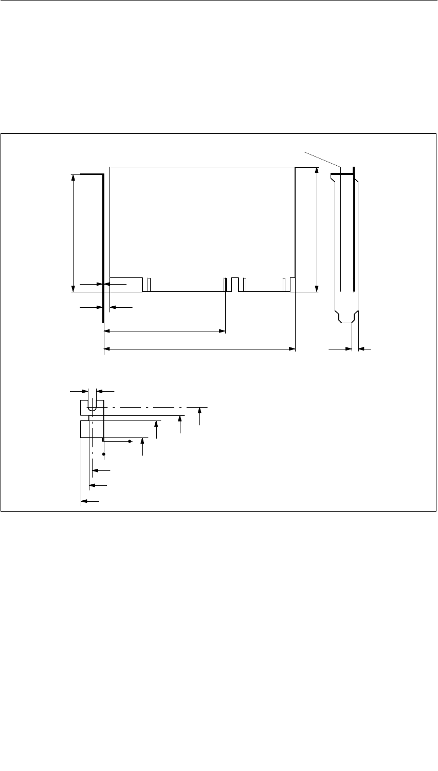
M7-400 Expansions
12-21
S7-400, M7-400 Programmable Controllers Module Specifications
A5E00069467-07
Permissible Dimensions of AT Modules
The following illustration shows you the maximum and minimum dimensions in
millimeters that AT modules must meet for the ATM 478 AT adapter module. If
these dimensions are not conformed to, proper installation in the ATM 478 AT
adapter module is no longer possible.
Components max. insertion height 14 mm
02.85
10.9 14 18.4
0
5.9
8
12.2
4.3
100.33
106.5 max.
2.84
108.76
0.8
3 min.
164 max.
Figure 12-9 Dimension Specifications for AT Modules to be Installed in an ATM 478
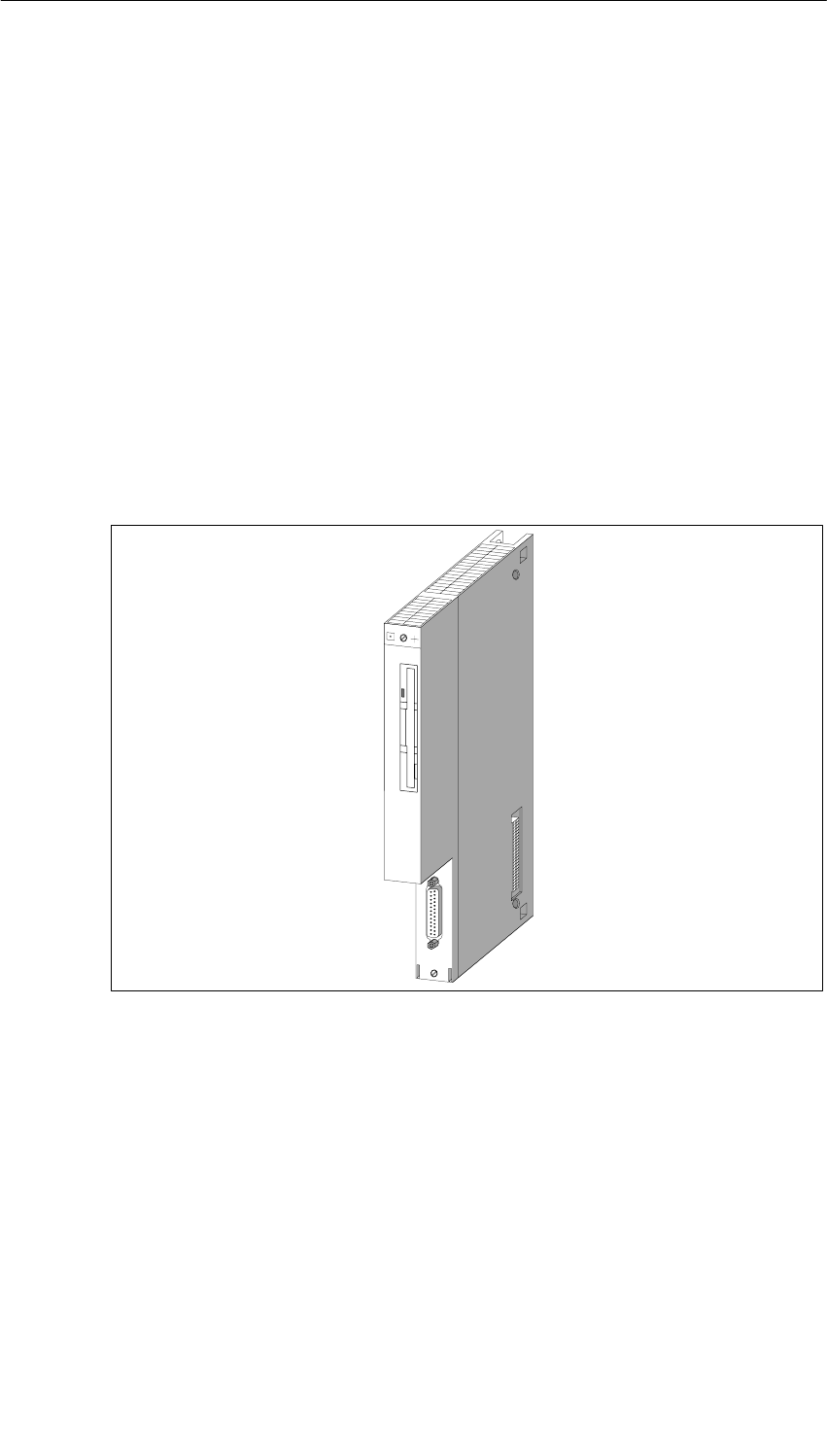
M7-400 Expansions
12-22 S7-400, M7-400 Programmable Controllers Module Specifications
A5E00069467-07
12.4 MSM 478 Mass Storage Module;
(6ES7 478-2BA00-0AC0)
Characteristics
The MSM 478 mass storage module is used for storing programs and larger
quantities of data. It also has an AT-compatible parallel port (LPT).
The MSM 478 mass storage module has the following function units:
•One 3.5’’/1.44-Mbyte floppy disk drive
•One hard disk drive with a capacity of ≥ 516 x 106 bytes
•One AT-compatible parallel port LPT1
The MSM 478 mass storage module has a 120-pin connector on the left-hand side
and a 120-pin socket on the right-hand side for connecting further expansion
modules.
Figure 12-10 MSM 478 Mass Storage Module
System Integration BIOS Setup
So that the BIOS of your CPU 486-3, CPU 488-3, or your FM 456 can correctly
access the diskette and the hard disk, you must make some settings in the BIOS
setup of your CPU/FM.
To learn how to make these settings, see the “BIOS setup” section of the module
description.

M7-400 Expansions
12-23
S7-400, M7-400 Programmable Controllers Module Specifications
A5E00069467-07
12.4.1 LPT1 Parallel Port
Characteristics
The MSM 478 mass storage module has an AT-compatible parallel port (LPT) for
connecting a printer with Centronics interface. The parallel port can also be used
as a bi-directional data interface. There is a 25-pin sub D socket connector on the
frontside of the submodule for plugging in the connecting cable.
This parallel port is always configured by the BIOS as LPT1 regardless of the slot
occupied by the MSM 478 mass storage module.
Addressing
I/O address of the parallel port (LPT): 03BCH (to 03BEH )
Device name: LPT1
Interrupt Request
The parallel port (LPT) supplies the interrupt request IRQ7.
Pin Assignment of the Parallel Port
There is a 25-pin sub D socket connector on the frontside of the submodule for
plugging in the connecting cable. See Table 12-7 for the pin assignments.
Cable Length
The cable length on the LPT1 parallel port should not exceed approximately 3 m.

M7-400 Expansions
12-24 S7-400, M7-400 Programmable Controllers Module Specifications
A5E00069467-07
Table 12-7 MSM 478 Parallel Port, Socket X1 (25-Pin Sub D Socket)
Pin Meaning Direction
1 /STROBE Input/output
2Data 0 Input/output
3Data 1 Input/output
4Data 2 Input/output
5Data 3 Input/output
6Data 4 Input/output
7Data 5 Input/output
8Data 6 Input/output
9Data 7 Input/output
10 /ACK Input
11 BUSY Input
12 PE Input
13 SLCT Input
14 /AUTO FEED Output
15 /ERROR Input
16 /RESET Output
17 /SLCT IN Output
18 GND –
19 GND –
20 GND –
21 GND –
22 GND –
23 GND –
24 GND –
25 GND –
Note
Operational ground (GND signal) at the COMa or COMb ports is referenced to
internal ground.
Suitable measures may be required on the process side to avoid ground loops.
M7-400 Expansions
12-25
S7-400, M7-400 Programmable Controllers Module Specifications
A5E00069467-07
12.4.2 Technical Specifications of the MSM 478 Mass Storage Module
Technical Specifications of the MSM 478
The table below contains the technical specifications of the MSM mass storage
module: 478
With Mass Storage Module MSM 478
6ES7 478-2AB00-0AC0
Performance Features
Diskette 3.5”, 1.44 Mbytes
Hard disk ≥ 516 x 106 bytes
Parallel port 1, LPT1
Connection of
expansion modules Yes
Technical Specifications
Supply voltage 5 VDC
Current consumption 1 A
Power losses 5 W
Dimensions
W x H x D (mm) 25 x 290 x 210
Weight 1.08 kg
Ambient Operating Conditions
Temperature:
Without forced
ventilation
With forced ventilation
without diskette
with diskette
Temperature change:
Relative humidity:
Height (in relation to sea
level)
Mechanical vibrations
(measured at the drive)
10 ≤ f ≤ 58 Hz
58 ≤ f ≤ 500 Hz
Shocks:
(measured at the drive)
from 0 to 40 oC
from 0 to 55 oC
from 0 to 40 oC
max. 10 K/h
8% to 80% at 25 oC,
no condensation
-50 m to 2,000 m
0,035 mm,
constant amplitude
0.1 g, constant
acceleration
Semisinusoidal: 5 g,
11 ms
Environmental Conditions for
Storage/Transport
Temperature:
Temperature change:
Relative humidity:
Mechanical vibrations
5 ≤ f ≤ 9 Hz
9 ≤ f ≤ 500 Hz
Shocks:
from -10 to 60 oC
max. 20 K/h
8% to 80% at 25 oC,
no condensation
3.5 mm amplitude
1 g acceleration
Semisinusoidal: 50 g,
11 ms
Note
The ambient conditions specified are limit values determined by the hard disk
drive. The values must not be exceeded on the hard disk drive.

M7-400 Expansions
12-26 S7-400, M7-400 Programmable Controllers Module Specifications
A5E00069467-07
13-1
S7-400, M7-400 Programmable Controllers Module Specifications
A5E00069467-07
Interface Submodules
Chapter Overview
Section Description Page
13.1 Interface Submodules Overview 13-2
13.2 Submodule IDs and Insertion Rules 13-4
13.3 IF 962-VGA Interface Submodule for M7-300/400;
(6ES7962-1BA00-0AC0) 13-5
13.4 IF 962-COM Interface Submodule for M7-300/400;
(6ES7962-3AA00-0AC0) 13-10
13.5 IF 962-LPT Interface Submodule for M7-300/400;
(6ES7962-4AA00-0AC0) 13-16
13.6 IF 961-DIO Interface Submodule for M7-300/400;
(6ES7961-1AA00-0AC0) 13-23
13.7 IF 961-AIO Interface Submodule for M7-300/400;
(6ES7961-2AA00-0AC0) 13-33
13.8 IF 961-CT1 Interface Submodule for M7-300/400;
(6ES7961-3AA00-0AC0) 13-56
13.9 IF 964-DP Interface Submodule for S7-400 and M7-400 13-61
13

Interface Submodules
13-2 S7-400, M7-400 Programmable Controllers Module Specifications
A5E00069467-07
13.1 Interface Submodules Overview
Introduction
The interface submodules are designed for use in the M7-300 and M7-400
automation computers. They can be operated in the M7-400 programmable
modules and in the EXM 378/EXM 478 expansion modules. The interface
submodules are controlled via the ISA bus.
The interface submodules are labeled on the front plate and so can be identified
even when installed.
Handling
Interface submodules and their front connectors must only be plugged in or
removed when the power is switched off. Avoid confusing front connectors since
this can destroy the interface submodules or the connected devices.
ESD Guidelines
The interface submodules are not enclosed on the underside. For this reason, you
must observe ESD guidelines when handling these modules.
Slots/Submodule Receptacle Numbers
To link the interface submodules into your system (for example, BIOS Setup), you
require the submodule receptacle numbers. See the descriptions of the M7-400
programmable modules or the M7-300/400 expansion modules for the numbering
of the individual submodule receptacles.
Addressing in the M7-300/400 - Reserved I/O Address Area
In the M7-300/400 automation computers, the I/O address area C000H is reserved
for addressing the interface submodules.
The base address at which an interface submodule can be addressed depends on
the submodule receptacle of the M7-400 programmable module or the M7-300/400
expansion module containing the interface submodule. You can find the
submodule-receptacle-dependent base address of the interface submodule in the
description of the M7-400 programmable module or the M7-300/400 expansion
module.
The sections below describe the registers and their meanings as well as the
associated offset addresses for the individual interface submodules.
The resulting I/O address is the sum of the base address and the offset address.
Submodule ID
Each interface submodule has a submodule ID stored in read-only memory. This
information is required in the BIOS Setup.

Interface Submodules
13-3
S7-400, M7-400 Programmable Controllers Module Specifications
A5E00069467-07
Interrupt Assignments
When configuring the interface submodules in the BIOS setup, you can assign ISA
interrupts to the three interrupts of an interface submodule (IRQa, IRQb, IRQc). For
this purpose, enter the ISA interrupt provided in the relevant screen form. See the
table below for the format for entering the interrupt.
Table 13-1 Format of the Interrupt Entry in the BIOS Setup of the Interface Submodule
Bit 7 Bit 6 Bit 5 Bit 4 Bit 3 Bit 2 Bit 1 Bit 0
1 1 1 0 ISA interrupt number
If you enter the value “F0H” instead of the ISA interrupt (“EXH”), this interrupt is
processed via a shared interrupt.
Shared Interrupt
Since the number of interrupts is limited due to AT-compatibility, it is possible to
assign several individual interrupts of the interface submodules to a shared
interrupt. The shared interrupt is shared by all interface submodule interrupts within
an expansion module where the interrupt assignment “F0H” has been entered.
The shared interrupt is assigned to the ISA interrupt during configuration of the
interface submodule in the BIOS setup.
Signal Switching
In an EXM 478 expansion module, two interface submodule signals can be
switched to another (signal switching). This signal switching is done during
configuration of the interface submodule in the BIOS setup.
Refer to the interface submodule description to find out if an interface submodule
requires signals from a further interface submodule, that is, if signal switching is
necessary.

Interface Submodules
13-4 S7-400, M7-400 Programmable Controllers Module Specifications
A5E00069467-07
13.2 Submodule IDs and Insertion Rules
Submodule IDs
The following table contains an overview of the submodule IDs for the interface
submodules.
Table 13-2 Overview of the Submodule IDs for the Interface Submodules
Interface Submodule Submodule ID
IF 961-AIO 01H
IF 961-CT1 03H
IF 961-DIO 02H
IF 962-COM 41H
IF 962-LPT 44H
IF 962-VGA 81H
IF 964-DP 8CH
Insertion Rules
The interface submodules cannot be operated in all submodule receptacles. The
following table shows the insertion rules for those interface submodules that cannot
be used in all receptacles:
Table 13-3 Insertion Rules for Interface Submodules that Cannot be Used in All Receptacles
Submodule Receptacle Numbers in the Following Modules
Interface Submodule EXM 378-2 EXM 378-3 FM 456-4 CPU 486-3/
CPU 488-3 EXM 478
1 2 3 4 5 0 1 0 3 all
IF 962-VGA
6ES7 962-1BA00-0AC0 –
IF 964-DP
6ES7 964-2AA00-0AB0 – *)
*) Preferred slot for IF 964-DP if only one submodule is inserted, see Table 11-8 on page 11-40.
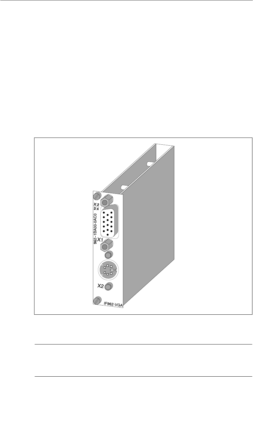
Interface Submodules
13-5
S7-400, M7-400 Programmable Controllers Module Specifications
A5E00069467-07
13.3 IF 962-VGA Interface Submodule for M7-300/400;
(6ES7962-1BA00-0AC0)
Characteristics
The IF 962-VGA interface submodule is used to connect a keyboard and a VGA
screen. The interfaces to the keyboard and the screen are AT-compatible.
As an alternative to a “normal” AT keyboard, a keyboard with an integrated
trackball can be connected (for example, the PG 740 keyboard).
The IF 962-VGA interface submodule is designed for the local area and the
distance to the I/O devices should not exceed approximately 2.5 m.
Figure 13-1 IF 962-VGA Interface Submodule
Note
You can operate a maximum of one keyboard/graphics submodule on one
programmable module (CPU or FM).
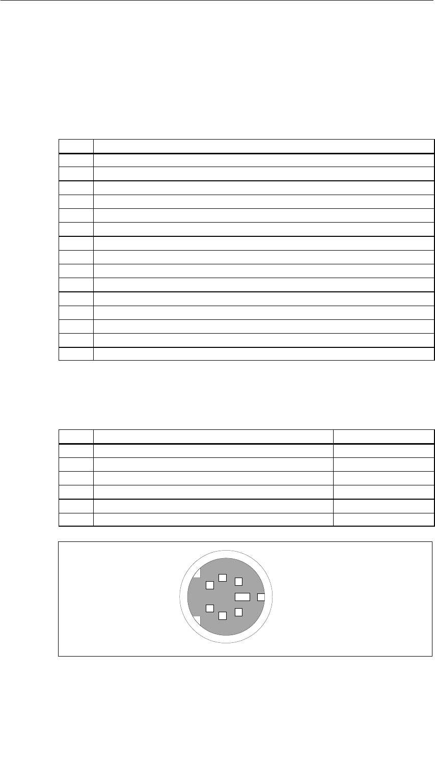
Interface Submodules
13-6 S7-400, M7-400 Programmable Controllers Module Specifications
A5E00069467-07
13.3.1 Pin Assignments
Socket X1 VGA Screen Connection
Table 13-4 Socket X1, VGA Screen Connection IF 962-VGA (15-Pin High-Density Sub D
Socket Connector)
Pin Meaning
1Analog red
2Analog green
3Analog blue
4
5Signal GND
6Analog GND red
7Analog GND green
8Analog GND blue
9
10 Signal GND
11
12
13 Horizontal sync
14 Vertical sync
15
Socket X2 Keyboard Connection
Table 13-5 X2 Socket, Keyboard Plug Connection IF 961-VGA (6-Pin Mini DIN Socket
Connector)
Pin Meaning Direction
1Keyboard data Input/output
2Mouse data Input/output
3Signal GND –
45 VDC –
5Keyboard clock Input/output
6Mouse clock Input/output
1
2
3
4
5
6
X2 socket
Figure 13-2 X2 Socket, Keyboard Plug Connection IF 961-VGA (6-Pin Mini DIN Socket
Connector)
Interface Submodules
13-7
S7-400, M7-400 Programmable Controllers Module Specifications
A5E00069467-07
13.3.2 Addressing, Interrupts, and Submodule ID
Addressing
Addressing corresponds to the AT standard.
The following addresses are occupied by the IF 962-VGA interface submodule:
Memory addresses: A0000H to C7FFFH
I/O addresses: 060H to 06FH, 3B0H to 3BBH, 3BFH to 3DFH
Interrupt Request
The interface submodule supplies the following interrupts:
•IRQ a: Keyboard interrupt
•IRQ b: Mouse interrupt (trackball)
•IRQ c: VGA interrupt
The BIOS routes these interrupts to ISA interrupts in accordance with Table 13-6.
Table 13-6 Interrupt Assignments of the IF 962-VGA Interface Submodule
Interrupt Source of the Interface Submodule ISA Interrupt
Keyboard IRQ a IRQ 1
Mouse (track ball) IRQ b IRQ 12
VGA IRQ c Can be set in the BIOS setup
Submodule ID
The IF 962-VGA interface submodule has the submodule ID 81H.

Interface Submodules
13-8 S7-400, M7-400 Programmable Controllers Module Specifications
A5E00069467-07
13.3.3 Technical Specifications
Technical Specifications
The IF 962-LPT interface submodule receives its supply voltage from the M7-400
programmable modules or from the M7-300/400 expansion modules. The current
consumption given in the technical specifications is the consumption required for
dimensioning the power supply, that is, the current consumption is referenced to
24 V in the M7-300 and to 5 V in the M7-400.
6ES7962-1BA00-0AC0
Technical Specifications
Supply voltage Supplied from the
M7-400
programmable
modules or from the
M7-300/400
expansion modules
Current consumption in the
M7-300
(for dimensioning the 24 V
current supply) 0.21 A
Current consumption in the
M7-400
(for dimensioning the 5 V
current supply) 0.6 A
VGA controller WD90C24
Video controller 1 Mbytes
Submodule ID 81H
Power losses 2.5 W
Dimensions
W x H x D (mm) 18.2 x 67 x 97
Weight 0.085 kg

Interface Submodules
13-9
S7-400, M7-400 Programmable Controllers Module Specifications
A5E00069467-07
Operating Modes
The WD90C24 VGA controller is used on the IF 962-VGA interface submodule.
Table 13-7 shows you the video modes supported by the BIOS of the IF 962-VGA
interface submodule.
Table 13-7 Video Modes of the IF 962-VGA Interface Submodule
Mode
(HEX) Text /
Graphics Monochrome/
Color Resolution
(Columns x
Lines)
Number
of
colours
Character
Size Horizontal
Frequency
(kHz)
Vertical
Frequency
(Hz)
0.1 Text Color 320 x 200 16 8 x 8 31.5 70
0.1 Text Color 320 x 350 16 8 x 14 31.5 70
0.1 Text Color 360 x 400 16 9 x 16 31.3 70
2.3 Text Color 640 x 200 16 8 x 8 31.5 70
2.3 Text Color 640 x 350 16 8 x 14 31.5 70
2.3 Text Color 720 x 400 16 9 x 16 31.3 70
4.5 Graphics Color 320 x 400 48 x 8 31.5 70
6 Graphics Monochr. 320 x 200 28 x 8 31.5 70
7 Text Monochr. 720 x 350 29 x 14 31.3 70
0D Graphics Color 320 x 200 16 8 x 8 31.5 70
0E Graphics Color 640 x 200 16 8 x 8 31.5 70
0F Graphics Monochr. 640 x 350 28 x 14 31.5 70
10 Graphics Color 640 x 350 16 8 x 14 31.5 70
11 Graphics Monochr. 640 x 480 28 x 16 31.5 60
12 Graphics Color 640 x 480 16 8 x 16 31.5 60
13 Graphics Color 320 x 200 256 8 x 8 31.5 70
54 Text Color 1056 x 344 16 9 x 9 31.1 70
55 Text Color 1056 x 400 16 8 x 16 31.1 70
5F Graphics Color 640 x 480 256 8 x 16 31.5 60
58/6A Graphics Color 800 x 600 16 8 x 8 35.1 56
58/6A Graphics Color 800 x 600 16 8 x 8 37.8 60
58/6A Graphics Color 800 x 600 16 8 x 8 47.7 72
5C Graphics Color 800 x 600 256 8 x 8 35.1 56
5C Graphics Color 800 x 600 256 8 x 8 37.8 60
5C Graphics Color 800 x 600 256 8 x 8 47.7 72
5D Graphics Color 1024 x 768 16 8 x 16 35.6 87 1)
5D Graphics Color 1024 x 768 16 8 x 16 48.4 60
60 Graphics Color 1024 x 768 256 8 x 16 35.6 87 1)
60 Graphics Color 1024 x 768 256 8 x 16 48.4 60
1) Interlaced mode
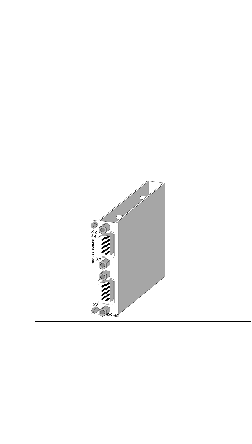
Interface Submodules
13-10 S7-400, M7-400 Programmable Controllers Module Specifications
A5E00069467-07
13.4 IF 962-COM Interface Submodule for M7-300/400;
(6ES7962-3AA00-0AC0)
Characteristics
The IF 962-COM interface submodule is used to connect devices with a serial port.
It contains two serial AT-compatible ports (COMa, COMb).
Up to four COM ports can be accessed on AT I/O addresses in one programmable
module using standard PC drivers. This also includes COM ports located on the
programmable module itself and those located on expansions. The IF 962-LPT
interface submodules can be operated in the AT-compatible address area and, if
special drivers are used, also in the M7-300/400-reserved address area.
Connector X1 corresponds to the COMa port, connector X2 to the COMb port. The
signal levels are defined in accordance with RS232C.
The cable length on the IF 962-COM interface submodule should not exceed
approximately 10 m.
Figure 13-3 IF 962-COM Interface Submodule
What Can be Connected to the Ports?
All devices with an RS232 interface such as:
Printers, modems, terminals, etc.

Interface Submodules
13-11
S7-400, M7-400 Programmable Controllers Module Specifications
A5E00069467-07
13.4.1 Pin Assignments
Socket X1, X2 COMa, COMb
Table 13-8 Socket X1, X2 IF 962-COM (9-Pin Sub D Plug Connector)
1DCD Receive signal level Input
2 RxD Receive data Input
3 TxD Transmitted data Output
4 DTR Data terminal ready Output
5Signal GND Operational ground (GNDint) –
6 DSR Data set ready Input
7RTS Request to send Output
8 CTS Clear to send Input
9 RI Ring indicator (incoming call) Input
Note
Operational ground (signal GND) at the COMa or COMb ports is referenced to
internal ground.
Suitable measures may be required on the process side to avoid ground loops.
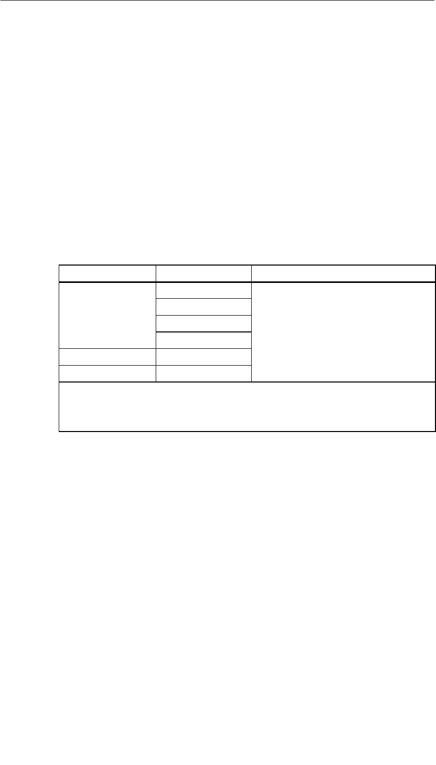
Interface Submodules
13-12 S7-400, M7-400 Programmable Controllers Module Specifications
A5E00069467-07
13.4.2 Addressing and Interrupts
Addressing
The IF 962-COM interface submodule can be addressed in the following two ways:
•In the AT-compatible I/O address area
•In the M7-300/400-reserved I/O address area (from C000H).
Addressing in the AT-Compatible I/O Address Area
The COM ports can be operated in the AT-compatible I/O address area. The
settings are made in the BIOS Setup. You can see the addresses that can be set in
the BIOS Setup from the following table.
Table 13-9 Addressing the COM Ports in the AT-Compatible Address Area
Name I/O Address Remarks
03F8H to 03FFH
*)
02F8H to 02FFH
*) 03E8H to 03EFHAutomatically configured by the BIOS and
02E8H to 02EFH
Automatically configured by the BIOS and
can be set in the BIOS setup.
– 0380H to 0387H
– 0280H to 0287H
*) The BIOS searches the addresses in the order 03F8H, 02F8H, 03E8H and 02E8H and
assigns COM1, COM2, COM3 and COM4 in ascending order. There is no fixed
assignment of the I/O addresses to COMx. For example, if only one COM port is detected
at address 12E8H, this will be COM1.
Example of Setting an AT-Compatible I/O Address
In the following example, the I/O addresses 03F8H (COM1) for COMa and 02F8H
(COM2) for COMb are to be set in the BIOS setup. Proceed as follows to do this:
1. Select the “IF Modules” page in the BIOS setup.
2. Enter the submodule receptacle number of the interface submodule in “Select
Module #”.
3. Enter the offset address for the configuration register of the interface submodule
“00H” at “Config.Index”.
4. Enter “36H” at “Value”. This value is then written into the configuration register
(see also Table 13-13).
5. Press the OK button.
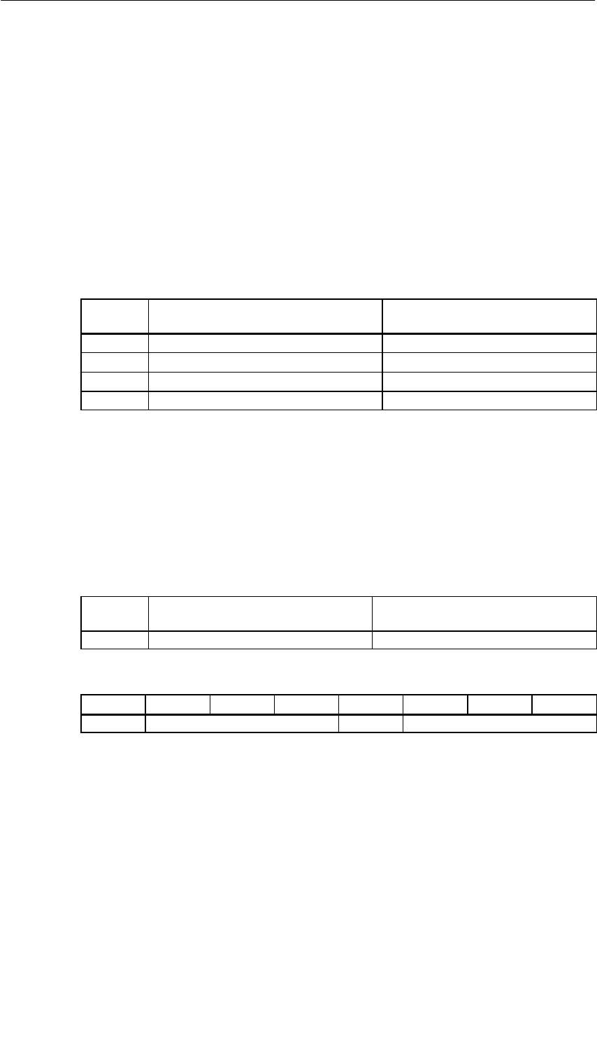
Interface Submodules
13-13
S7-400, M7-400 Programmable Controllers Module Specifications
A5E00069467-07
Addressing in the M7-300/400-Reserved I/O Address Ares
Regardless of possible addresses in the AT-compatible I/O address area, the
IF 962-COM interface submodule can be addressed in this reserved address area.
The base address depends on the interface submodule slot in the expansion
module or the programmable module. See the descriptions “M7-300 Expansions”,
“M7-400 Expansions” or the description of the M7-400 programmable modules for
the slot-dependent base address of the interface submodule.
The I/O address is the sum of the base address and the offset address.
The registers and their meanings and the offset addresses are described below.
Table 13-10 Offset Address Assignments for the IF 962-COM Interface Submodule
Offset
Address Function Remarks
00HConfiguration register Read/write
08H - 0FHUART 16C552 parallel port Unused
10H - 17HCOMa UART 16C552 Read/write
18H - 1FHCOMb UART 16C552 Read/write
Configuration Register
The BIOS setup defines in which AT-compatible I/O address area the COM
interface is to be operated or whether it is only to be operated in the reserved I/O
address area and this information is stored in the configuration register.
Tables 13-11 to 13-13 give you an overview of the possible settings in the
configuration register.
Table 13-11 Offset Address for the Configuration Register (IF 962-COM)
Offset
Address Function Remarks
00HConfiguration register Read/write
Table 13-12 Meaning of the Data Bits in the Configuration Register (IF 962-COM)
Bit 7 Bit 6 Bit 5 Bit 4 Bit 3 Bit 2 Bit 1 Bit 0
0Addressing type COM b 0Addressing type COM a

Interface Submodules
13-14 S7-400, M7-400 Programmable Controllers Module Specifications
A5E00069467-07
Table 13-13 Meaning of the Addressing Type Bits in the Configuration Register
(IF 962-COM)
I/O Address
Addressing Type COM b/a
I/O Address Bit 6/2 Bit 5/1 Bit 4/0
Addressing only possible in the reserved I/O address area
(from C000H) (default) 000
280H001
2E8H010
2F8H011
380H100
3E8H101
3F8H110
0 1 1 1
Note
The AT-compatible I/O address can only be set once for each COM port of an
automation computer (including those permanently installed in a programmable
module).
COM Ports
The COM ports (COMa and COMb) of the UART 16C552 can be addressed from
offset addresses 10H or 18H in accordance with component specification 16C552.
Data Formats
The following data formats can be set in the IF 962-COM interface submodule:
Data bits: 5 bits, 6 bits, 7 bits, 8 bits
Parity: Even, odd, disable
Stop bit: 1 bit, 1.5 bits, 2 bits
Transmission Speed
The following transmission speeds (transmission rates) can be set in the
IF962-COM interface submodule:
AT-compatible transmission speeds and transmission speeds up to 115.2 Kbps.
Note
Please note that a safe level of transmission speed depends on factors such as
cable length, cable type, and environmental interference.

Interface Submodules
13-15
S7-400, M7-400 Programmable Controllers Module Specifications
A5E00069467-07
Interrupt Request
The interface submodule supplies an interrupt request (IRQa and IRQb) for each
serial port.
You can define the assignment of the interrupt requests IRQa and IRQb to the
appropriate processor interrupt requests in the BIOS Setup.
Table 13-14 Interrupt Assignments of the IF 962-COM Interface Submodule
Interrupt Source of the Interface Submodule ISA Interrupt
COM a IRQ a Can be set in the BIOS
COM b IRQ b
Can be set in the BIOS
setup
Default settings in the BIOS are: IRQ 4 for COM1 and IRQ3 for COM2.
Submodule ID
The IF 962-COM interface submodule has the submodule ID 41H.
13.4.3 Technical Specifications
Technical Specifications
The IF 962-COM interface submodule receives its supply voltage from the M7-400
programmable modules or from the M7-300/400 expansion modules. The current
consumption given in the technical specifications is the consumption required for
dimensioning the power supply, that is, the current consumption is referenced to
24 V in the M7-300 and to 5 V in the M7-400.
6ES7962-3AA00-0AC0
Technical Specifications
Supply voltage Supplied from the M7-400
programmable modules or
from the M7-300/400
expansion modules
Current consumption in the
M7-300
(for dimensioning the 24 V
current supply) 0.04 A
Current consumption in the
M7-400
(for dimensioning the 5 V
current supply) 0.1 A
Submodule ID 41H
Power losses 0.5 W
Dimensions
W x H x D (mm) 18.2 x 67 x 97
Weight 0.080 kg
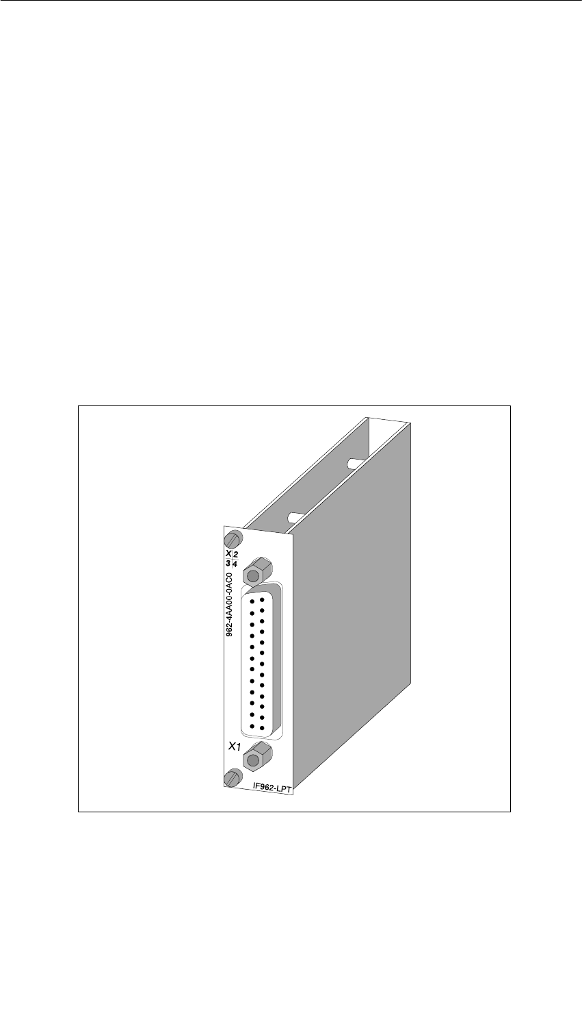
Interface Submodules
13-16 S7-400, M7-400 Programmable Controllers Module Specifications
A5E00069467-07
13.5 IF 962-LPT Interface Submodule for M7-300/400;
(6ES7962-4AA00-0AC0)
Characteristics
The IF 962-LPT interface submodule contains an AT-compatible parallel (LPT) port
for connecting a printer with Centronics interface. The IF962-LPT submodule can
also be used as a bi-directional data interface. There is a 25-pin sub D socket
connector on the frontside of the submodule for plugging in the connecting cable.
Up to four LPT ports can be accessed on AT I/O addresses in one programmable
module using standard PC drivers. This also includes LPT ports located on the
programmable module itself and those located on expansions. The IF 962-LPT
interface submodules can be operated in the AT-compatible address area and, if
special drivers are used, also in the M7-300/400-reserved address area.
The cable length on the IF 962-LPT interface submodule should not exceed
approximately 3 m.
Figure 13-4 IF 962-LPT Interface Submodule

Interface Submodules
13-17
S7-400, M7-400 Programmable Controllers Module Specifications
A5E00069467-07
13.5.1 Pin Assignments
X1 Socket
Table 13-15 Socket X1, IF 962-LPT (25-Pin Sub D Socket Connector)
Pin Meaning Direction
1 /STROBE Input/output
2Data 0 Input/output
3Data 1 Input/output
4Data 2 Input/output
5Data 3 Input/output
6Data 4 Input/output
7Data 5 Input/output
8Data 6 Input/output
9Data 7 Input/output
10 /ACK Input
11 BUSY Input
12 PE Input
13 SLCT Input
14 /AUTO FEED Output
15 /ERROR Input
16 /RESET Output
17 /SLCT IN Output
18 GND –
19 GND –
: GND –
24 GND –
25 GND –
Note
Operational ground (GND signal) at the COMa or COMb ports is referenced to
internal ground.
Suitable measures may be required on the process side to avoid ground loops.
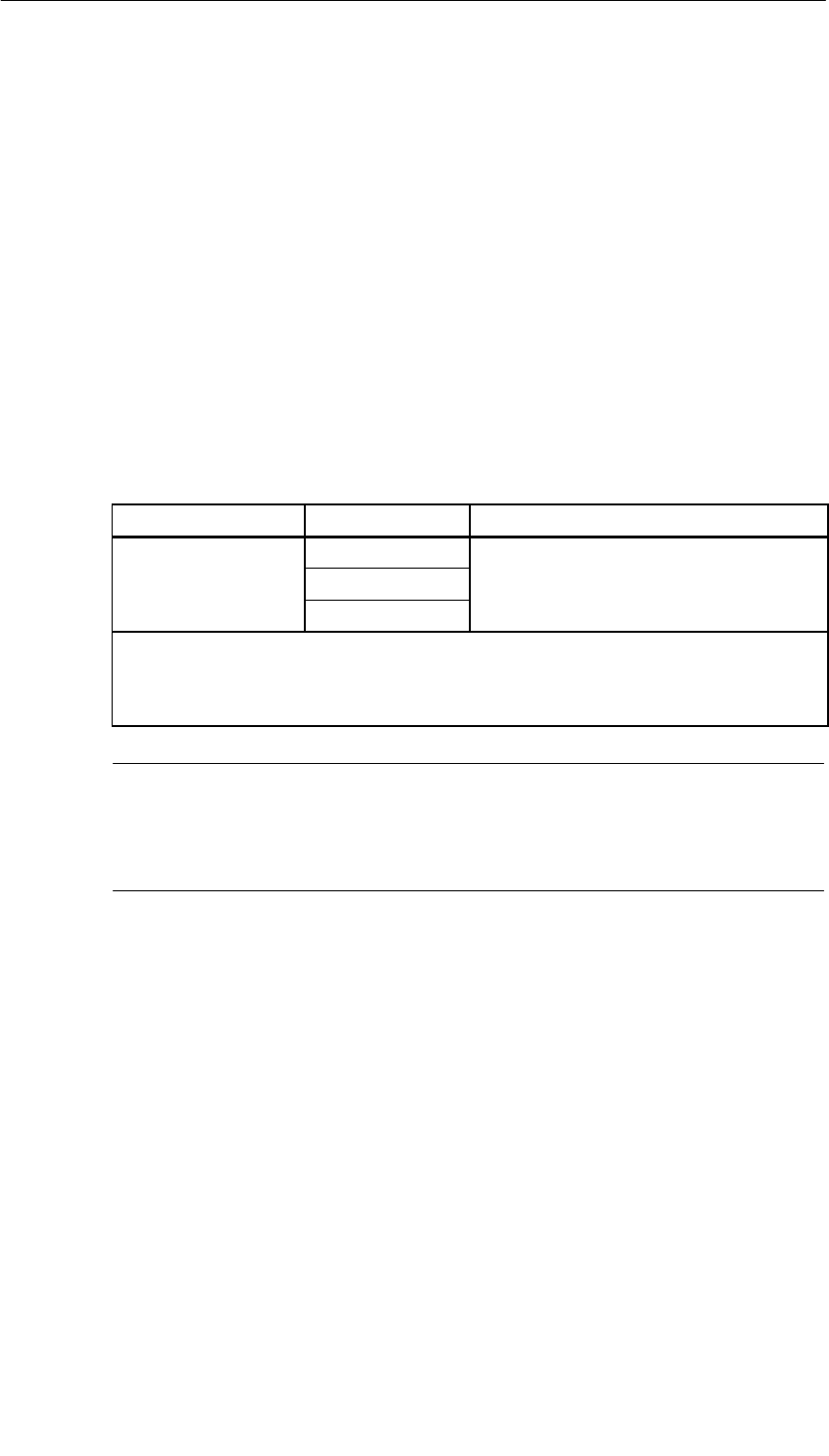
Interface Submodules
13-18 S7-400, M7-400 Programmable Controllers Module Specifications
A5E00069467-07
13.5.2 Addressing and Interrupts
Addressing
The IF 962-LPT interface submodule can be addressed in the following two ways:
•In the AT-compatible I/O address area
•In the M7-300/400-reserved I/O address area (from C000H)
Addressing in the AT-Compatible I/O Address Area
The LPT ports can be operated in the AT-compatible I/O address area. The
settings are made in the BIOS Setup. You can see the addresses that can be set in
the BIOS Setup from the following table.
Table 13-16 Addressing the LPT Ports
Name I/O Address Remarks
03BCH to 3BEH
*) 0378H to 37FHAutomatically configured by the BIOS and
can be set in the BIOS setup
)
0278H to 27FH
can be set in the BIOS setup
.
*) The BIOS searches the addresses in the order 03BCH, 0378H and 0278H and assigns
LPT1, LPT2 and LPT3 in ascending order. There is no fixed assignment of the I/O
addresses to LPTx. For example, if only one LPT port is detected at address 0378H, this
will be LPT1.
Note
The LPT port in the M7-400 expansion module MSM 478 is always at the I/O
address 03BCH. For this reason, the I/O address 03BCH must not be set for the IP
962-LPT interface submodule if an MSM 478 is in use.

Interface Submodules
13-19
S7-400, M7-400 Programmable Controllers Module Specifications
A5E00069467-07
Example of Setting an AT-Compatible I/O Address
In the following example, the I/O address 0278H is to be set in the BIOS setup.
Proceed as follows to do this:
1. Select the “IF Modules” page in the BIOS setup.
2. Enter the submodule receptacle number of the interface submodule in “Select
Module #”.
3. Enter the offset address for the configuration register of the interface submodule
“00H” at “Config.Index”.
4. Enter “FEH” or “02H” at “Value”. This value is then written into the configuration
register (see also Table 13-20).
5. Press the OK button.
Addressing in the M7-300/400-Reserved I/O Address Area
Regardless of possible addresses in the AT-compatible I/O address area, the
IF 962-COM interface submodule can be addressed in this reserved address area.
The base address depends on the interface submodule slot in the expansion
module or the programmable module. See the descriptions “M7-300 Expansions”,
“M7-400 Expansions” or the description of the M7-400 programmable modules for
the slot-dependent base address of the interface submodule.
The I/O address is the sum of the base address and the offset address.
The registers and their meanings and the offset addresses are described below.
Table 13-17 Offset Address Assignments for the IF 962-LPT Interface Submodule
Offset
Address Function Remarks
00HConfiguration register Read/write
10H - 17HUART 16C552 parallel port Read/write
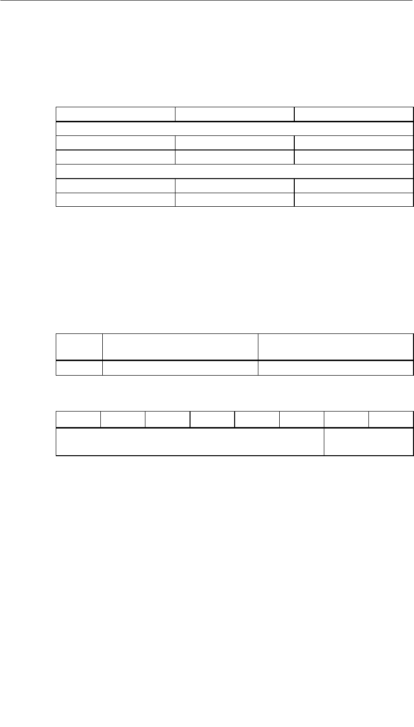
Interface Submodules
13-20 S7-400, M7-400 Programmable Controllers Module Specifications
A5E00069467-07
Default Settings in the BIOS
The following I/O addresses and interrupt numbers are set as defaults in the BIOS
for LPT ports:
Port I/O Address Interrupt No.
With mass storage module MSM 478
LPT1 (on MSM 478) 03BCH 7
LPT2 (IF 962-LPT) 0378H 5
Without mass storage module MSM 478
LPT1 (IF 962-LPT) 0378H 7
LPT2 (IF 962-LPT) 0278H 5
Configuration register
The BIOS setup defines in which AT-compatible I/O address area the LPT interface
is to be operated or whether it is only to be operated in the reserved I/O address
area and this information is stored in the configuration register. Tables 13-18 to
13-20 give you an overview of the possible settings in the configuration register.
Table 13-18 Offset Address for the Configuration Register (IF 962-LPT)
Offset
Address Function Remarks
0HConfiguration register Read/write
Table 13-19 Meaning of the Data Bits in the Configuration Register (IF 962-LPT)
Bit 7 Bit 6 Bit 5 Bit 4 Bit 3 Bit 2 Bit 1 Bit 0
Write: Any (“0” or “1”)
Read: Always “1” Addressing type LPT

Interface Submodules
13-21
S7-400, M7-400 Programmable Controllers Module Specifications
A5E00069467-07
Table 13-20 Meaning of the Addressing Type Bits in the Configuration Register
(IF 962-LPT)
I/O Address
Addressing Type
I/O Address Bit 1 Bit 0
Addressing only possible in the reserved I/O address area
(fromC000H)
(default)
0 0
378H0 1
278H1 0
3BCH1 1
Note
The AT-compatible I/O address can only be set once for each LPT port of a
programmable module.
The LPT port in the M7-400 expansion module MSM 478 is always at the I/O
address 03BCH. For this reason, the I/O address 03BCH must not be set for the IP
962-LPT interface submodule if an MSM 478 is in use.
Parallel Port
The parallel port of the interface submodule’s UART 16C552 can be addressed
from offset address 10H in accordance with component specification 16C552.
Interrupt Request
The interface submodule supplies an interrupt request (IRQa).
You can define the assignment of the IRQa interrupt request to the relevant
processor interrupt request in the BIOS setup.
Submodule ID
The IF 962-LPT interface submodule has the submodule ID 44H.

Interface Submodules
13-22 S7-400, M7-400 Programmable Controllers Module Specifications
A5E00069467-07
13.5.3 Technical Specifications
Technical Specifications
The IF 962-LPT interface submodule receives its supply voltage from the M7-400
programmable modules or from the M7-300/400 expansion modules. The current
consumption given in the technical specifications is the consumption required for
dimensioning the power supply, that is, the current consumption is referenced to
24 V in the M7-300 and to 5 V in the M7-400.
6ES7962-4AA00-0AC0
Technical Specifications
Supply voltage Supplied from the M7-400
programmable modules or
from the M7-300/400
expansion modules
Current consumption in the
M7-300
(for dimensioning the 24 V
current supply) 0.04 A
Current consumption in the
M7-400
(for dimensioning the 5 V
current supply) 0.1 A
Submodule ID 44H
Power losses 0.5 W
Dimensions
W x H x D (mm) 18.2 x 67 x 97
Weight 0.07 kg
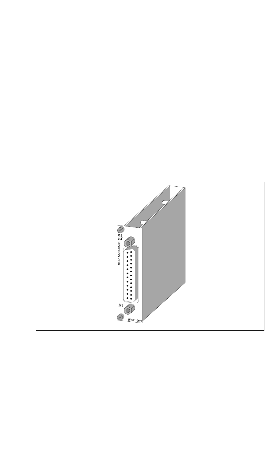
Interface Submodules
13-23
S7-400, M7-400 Programmable Controllers Module Specifications
A5E00069467-07
13.6 IF 961-DIO Interface Submodule for M7-300/400;
(6ES7961-1AA00-0AC0)
Characteristics
The IF 961-DIO interface submodule has the following characteristics:
•8 inputs, isolated in groups of 2
Input level 24 VDC; 8.5 mA
Input interrupt at rising and/or falling edge
Input delay can be set in common for all channels: approx. 750 µs or approx.
3 ms
•8 outputs, isolated in groups of 4
Level 24 VDC; 0.1A
Outputs short-circuit protected via electronic fuse.
Figure 13-5 IF 961-DIO Interface Submodule
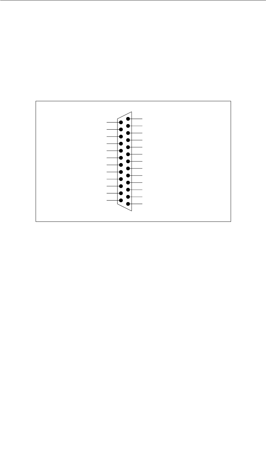
Interface Submodules
13-24 S7-400, M7-400 Programmable Controllers Module Specifications
A5E00069467-07
13.6.1 Pin Assignments
X1 Socket
There is a 25-pin sub D socket connector on the frontside of the submodule for
plugging in the connecting cable.
Figure 13-6 shows the pin assignments of the submodule.
13 5M
12 5L+
11 DO0
10 DO1
9 DO2
8 DO3
76M
6 6L+
5 DO4
4 DO5
3 DO6
2 DO7
1NC
DI7 25
DI6 24
4M 23
DI5 22
DI4 21
3M 20
DI3 19
DI2 18
2M 17
DI1 16
DI0 15
1M 14
Figure 13-6 X1 Socket Assignments, IF 961-DIO (25-Pin Sub D Connector)
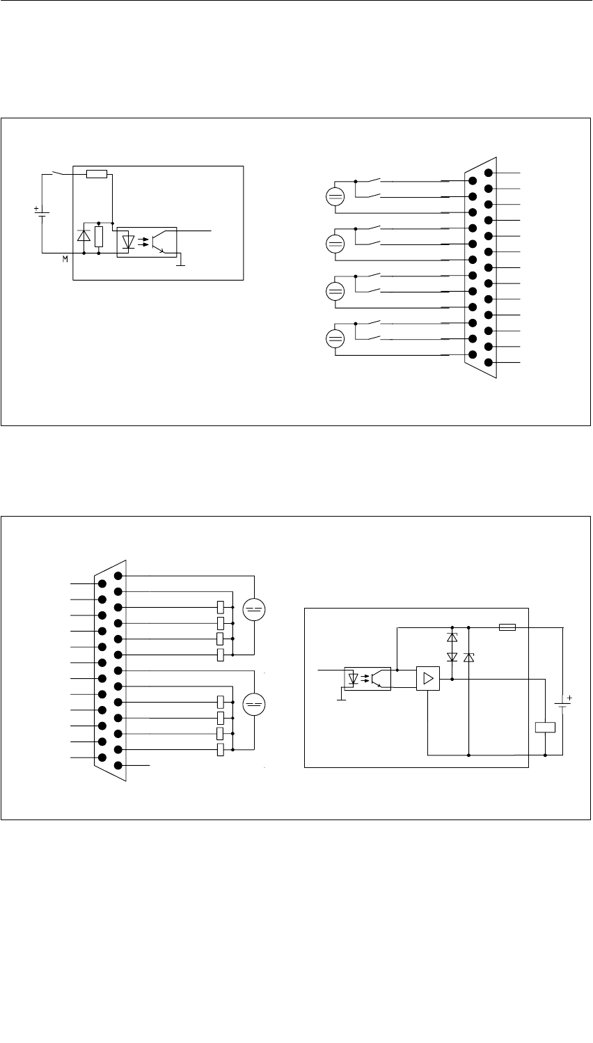
Interface Submodules
13-25
S7-400, M7-400 Programmable Controllers Module Specifications
A5E00069467-07
Figures 13-7 and 13-8 show the circuit block diagrams and the terminal connection
diagrams for wiring the digital inputs and digital outputs.
Terminal connection diagram
Circuit block
diagram
Internal
data bus
Minternal
13 5M
12 5L+
11 DO0
10 DO1
9 DO2
8 DO3
76M
6 6L+
5 DO4
4 DO5
3 DO6
2 DO7
1NC
DI7 25
DI6 24
4M 23
DI5 22
DI4 21
3M 20
DI3 19
DI2 18
2M 17
DI1 16
DI0 15
1M 14
Figure 13-7 Circuit Block Diagram and Terminal Connection Diagram for Wiring the Digital Inputs
Terminal connection diagram Circuit block diagram
L+
M
Minternal
Internal
data bus
13 5M
12 5L+
11 DO0
10 DO1
9 DO2
8 DO3
76M
6 6L+
5 DO4
4 DO5
3 DO6
2 DO7
1NC
DI7 25
DI6 24
4M 23
DI5 22
DI4 21
3M 20
DI3 19
DI2 18
2M 17
DI1 16
DI0 15
1M 14
Figure 13-8 Circuit Block Diagram and Terminal Connection Diagram for Wiring the Digital Outputs
Interface Submodules
13-26 S7-400, M7-400 Programmable Controllers Module Specifications
A5E00069467-07
13.6.2 Addressing and Interrupts
Addressing in the M7-300/400-Reserved I/O Address Area
The base address depends on the interface submodule slot in the expansion
module or the programmable module. See the descriptions “M7-300 Expansions”,
“M7-400 Expansions” or the description of the M7-400 programmable modules for
the slot-dependent base address of the interface submodule.
The I/O address is the sum of the base address and the offset address.
The registers and their meanings and the offset addresses are described below.
Table 13-21 Offset Address Assignments for the IF 961-DIO Interface Submodule
Offset
Address Function Remarks
00HUser data digital input function DI0 - DI7 (Digital Input)
01HUser data digital output function DO0 - DO7 (Digital Output)
02HAcknowledgment register Acknowledge interrupt
03HInterrupt register Read cause of interrupt
04HInterrupt enable register General enable of interrupt
05HSelection register rising edge Interrupt generation at rising edge of
a digital input
06HSelection register falling edge Interrupt generation at falling edge of
a digital input
07HMode register Set input delay
Digital Input Function
Tables 13-22 and 13-23 give an overview of the digital input function.
Table 13-22 Offset Address for the Digital Input Function (IF 961-DIO)
Offset
Address Function Remarks
0User data digital input function Read only
Table 13-23 Assignment of the Digital Input (DI) Channels to the Bits (IF 961-DIO)
Bit Function = 0 = 1
20DI channel 0 In the range
-30 V to 5 V In the range
from 13 V to 30 V
: : : :
27DI channel 7 In the range
-30 V to 5 V In the range
from 13 V to 30 V
Interface Submodules
13-27
S7-400, M7-400 Programmable Controllers Module Specifications
A5E00069467-07
Digital Output Function
Tables 13-24 and 13-25 give an overview of the digital output function.
Table 13-24 Offset Address for the Digital Output Function (IF 961-DIO)
Offset
Address Function Remarks
1User data digital output function Read/write
Table 13-25 Assignment of the Digital Output (DO) Channels to the Bits (IF 961-DIO)
Bit Function = 0 = 1
20DO channel 0 0 V + 24 V
: : : :
27DO channel 7 0 V + 24 V
Acknowledgment Register
The interrupt is acknowledged in this register. Tables 13-26 and 13-27 give an
overview of the acknowledgment register.
Table 13-26 Offset Address for the Acknowledgment Register (IF 961-DIO)
Offset
Address Function Remarks
2Acknowledgment register Write only
Table 13-27 Meaning of the Bits in the Acknowledgment Register (IF 961-DIO)
Bit Function = 0 = 1
20Reserved
: :
26Reserved
27Acknowledge interrupt No Yes
Interface Submodules
13-28 S7-400, M7-400 Programmable Controllers Module Specifications
A5E00069467-07
Interrupt Register
The cause of the interrupt is stored in this register. Tables 13-28 and 13-29 give an
overview of the interrupt register.
Table 13-28 Offset Address for the Interrupt Register (IF 961-DIO)
Offset
Address Function Remarks
3Interrupt register Read only
Table 13-29 Meaning of the Bits in the Interrupt Register (IF 961-DIO)
Bit Function = 0 = 1
20Level change at DI channel 0 No Yes
: : : :
27Level change at DI channel 7 No Yes
Interrupt Enable Register
Tables 13-30 and 13-31 give an overview of the interrupt enable register.
Table 13-30 Offset Address for the Interrupt Enable Register (IF 961-DIO)
Offset
Address Function Remarks
4Interrupt enable register Read/write
Table 13-31 Meaning of the Bits in the Interrupt Enable Register (IF 961-DIO)
Bit Function = 0 = 1
20Reserved
: :
26Reserved
27Interrupt Disabled Enabled
Interface Submodules
13-29
S7-400, M7-400 Programmable Controllers Module Specifications
A5E00069467-07
Selection Register Rising Edge
Tables 13-32 and 13-33 give an overview of the selection register for interrupt
generation at a rising edge of a digital input.
Table 13-32 Offset Address for the Selection Register Rising Edge (IF 961-DIO)
Offset
Address Function Remarks
5Selection register rising edge Read/write
Table 13-33 Meaning of the Bits in the Selection Register Rising Edge (IF 961-DIO)
Bit Function = 0 = 1
20Interrupt generation at rising edge of the
digital input channel 0 Disabled Enabled
: : : :
27Interrupt generation at rising edge of the
digital input channel 7 Disabled Enabled
Selection Register Falling Edge
Tables 13-34 and 13-35 give an overview of the selection register for interrupt
generation at a falling edge of a digital input.
Table 13-34 Offset Address for the Selection Register Falling Edge (IF 961-DIO)
Offset Address Function Remarks
6Selection register falling edge Read/write
Table 13-35 Meaning of the Bits in the Selection Register Falling Edge (IF 961-DIO)
Bit Function = 0 = 1
20Interrupt generation at falling edge of the digital
input channel 0 Disabled Enabled
: : : :
27Interrupt generation at falling edge of the digital
input channel 7 Disabled Enabled

Interface Submodules
13-30 S7-400, M7-400 Programmable Controllers Module Specifications
A5E00069467-07
Mode Register
Tables 13-36 and 13-37 give an overview of the mode register.
Table 13-36 Offset Address for the Mode Register (IF 961-DIO)
Offset Address Function Remarks
7Mode register Read/write
Table 13-37 Meaning of the Bits in the Mode Register (IF 961-DIO)
Bit Function = 0 = 1
20Input delay 3 ms 750 ms
21Reserved
: :
27Reserved
Reset Status
After switching on the interface submodule, the input delay is set to 3 ms.
Interrupt Request
The interface submodule supplies an interrupt request (IRQa).
You can define the assignment of the IRQa interrupt request to the relevant
processor interrupt request in the BIOS setup.
Submodule ID
The IF 961-DIO interface submodule has the submodule ID 02H.

Interface Submodules
13-31
S7-400, M7-400 Programmable Controllers Module Specifications
A5E00069467-07
13.6.3 Technical Specifications
Technical Specifications
The IF 961-DIO interface submodule receives its supply voltage from the M7-400
programmable modules or from the M7-300/400 expansion modules. The current
consumption given in the technical specifications is the consumption required for
dimensioning the power supply, that is, the current consumption is referenced to
24 V in the M7-300 and to 5 V in the M7-400.
6ES7961-1AA00-0AC0
Dimensions and Weight
Dimensions W x H x D
(mm)
W x H x D (mm) 18.2 x 67 x 97
Weight 0.065 kg
Module-Specific Data
Submodule ID 02H
Number of inputs
Number of outputs 8
8
Cable length
•Unshielded
•Shielded
200 m at 750 µs,
600 m at 3 ms delay
time
1000 m
Voltages, Currents, Potentials
Nominal voltage
Load current supply L+ 24 VDC
Permissible nominal
voltage range
Load current supply L+ 20.4 V to 28.8 V
Reverse polarity protection No
(fuse)
Current consumption L+ Dependent on wiring
Number of inputs that can
be controlled
simultaneously 8
Number of outputs that can
be controlled
simultaneously
Galvanic isolation
•In groups of
8
Yes (optocoupler)
2
Permissible potential
differences
•Between the M
terminals of the groups
•Between the input
(M terminal) and the
central grounding point
•Isolation checked with
75 VDC
60 VAC
75 VDC
60 VAC
500 VDC
Supply voltage Supplied from the
M7-400
programmable
modules or from the
M7-300/400
expansion modules
Current consumption in the
M7-300
(for dimensioning the 24 V
current supply) 0.03 A
Current consumption in the
M7-400
(for dimensioning the 5 V
current supply) 0.085 A
Power losses of the module 2.4 W

Interface Submodules
13-32 S7-400, M7-400 Programmable Controllers Module Specifications
A5E00069467-07
Status, Interrupts, Diagnostics
Status indicated
Interrupt
Diagnostic functions
–
1 sum interrupt from
up to 8 sources
No
Data for Selecting a Sensor
Input voltage
•Nominal value
•For signal “1”
•For signal “0”
24 VDC
from 13 V to 30 V
- 30 V to + 5 V
Input current
•At signal “1” from 4 mA to 8.5 mA
Input delay time 750 µs or 3 ms
Input characteristic In accordance with
IEC 1131, Part 2
Type of input in accordance
with IEC 1131 Type 1
Connection of 2-wire
BEROs
•Permissible quiescent
current
•Permissible supply
voltage
Possible under the
following
conditions:
v 1.5 mA
min. 22 V
Data for Selecting an Actuator
Output voltage
•At signal “0”
•At signal “1”
max. 3 V
L+ - 1.5 V
Output current
•At signal “1”
nominal value
permissible range
•At signal “0” (residual
current)
0.1 A
from 5 mA to 0.1 A
max. 100 mA
Lamp load max. 2.4 W
Parallel wiring of 2 outputs No
Setting a digital input Yes
Switching frequency max.
•With resistive load/lamp
load
•At inductive load
500 Hz
2.0 Hz at 0.1 A
Inductive cutoff voltage
limited (internally) to L+ - 39 V
Short-circuit protection of
the output yes, electronically
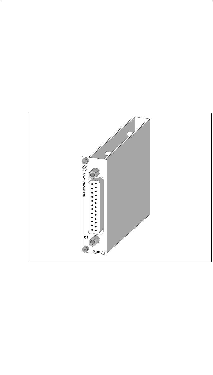
Interface Submodules
13-33
S7-400, M7-400 Programmable Controllers Module Specifications
A5E00069467-07
13.7 IF 961-AIO Interface Submodule for M7-300/400;
(6ES7961-2AA00-0AC0)
Characteristics
The IF 961-AIO interface submodule has the following characteristics:
•4 analog inputs, each as voltage and current input
•2 analog outputs, each as voltage and current output
•24 VDC external power supply of the analog circuit section
•Hardware interrupt capability and diagnostic capability
Figure 13-9 IF 961-AIO Interface Submodule
Special Feature of the Measuring Range Selection and Output Range Selection
You select the measuring type (current measuring or voltage measuring) of an
input channel via the wiring of the analog inputs (see Figure 13-10 ). You select the
output type (current or voltage output) via the wiring of the analog outputs (see
Figure 13-10).
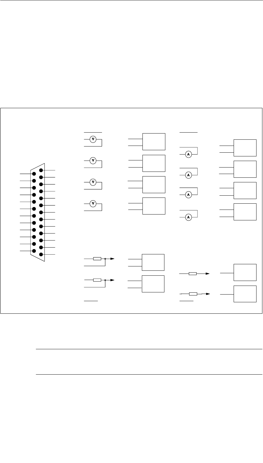
Interface Submodules
13-34 S7-400, M7-400 Programmable Controllers Module Specifications
A5E00069467-07
13.7.1 Pin Assignments and Terminal Connection Diagram
X1 Socket
There is a 25-pin sub D socket connector on the frontside of the submodule for
plugging in the connecting cable.
Figure 13-10 shows the assignments for the X1 socket and the terminal
connection diagram of the submodule.
V
Pinout diagram voltage measurement
M0-
MI1+
MV2+
M2-
M3-
MI3+
QI1
CH 0
CH 1
CH2
CH 3
CH 0
CH1
M
M1-
Pinout diagram voltage output
MV1+
M1- CH 1
MV3+
M3- CH 3
MI0+ CH 0
M0-
M2-
MI2+ CH 2
QV1
S1CH1
QV0
S0QI0
CH 0
RL
L +
RL
V
Pinout diagram current
measurement
2
4
6
8
10
11
13
15
16
17
18
19
20
21
22
23
24
12
9
M
Pinout diagram current output
RL
1L +
A
Ground bar
of the PLC
RL
A
Ground bar
of the PLC
2
4
6
8
10
11
13
15
16
17
18
19
20
21
22
23
24
12
9
1MV0+
13 M
12 S1
11 QV1
10 QV0
9S
0
8MV
3+
7NC
6MV
2+
5NC
4MV
1+
3NC
2MV
0+
1L+
L2+ 25
QI124
QI023
M3- 22
MI3+ 21
M2- 20
MI2+ 19
M1- 18
MI1+ 17
M0- 16
MI0+ 15
L1+ 14
Figure 13-10 X1 Socket Assignments (25-Pin Sub D Connector) and Terminal Connection Diagram of the
IF 961-AIO
Note
Use only shielded cables for connecting the inputs and outputs.
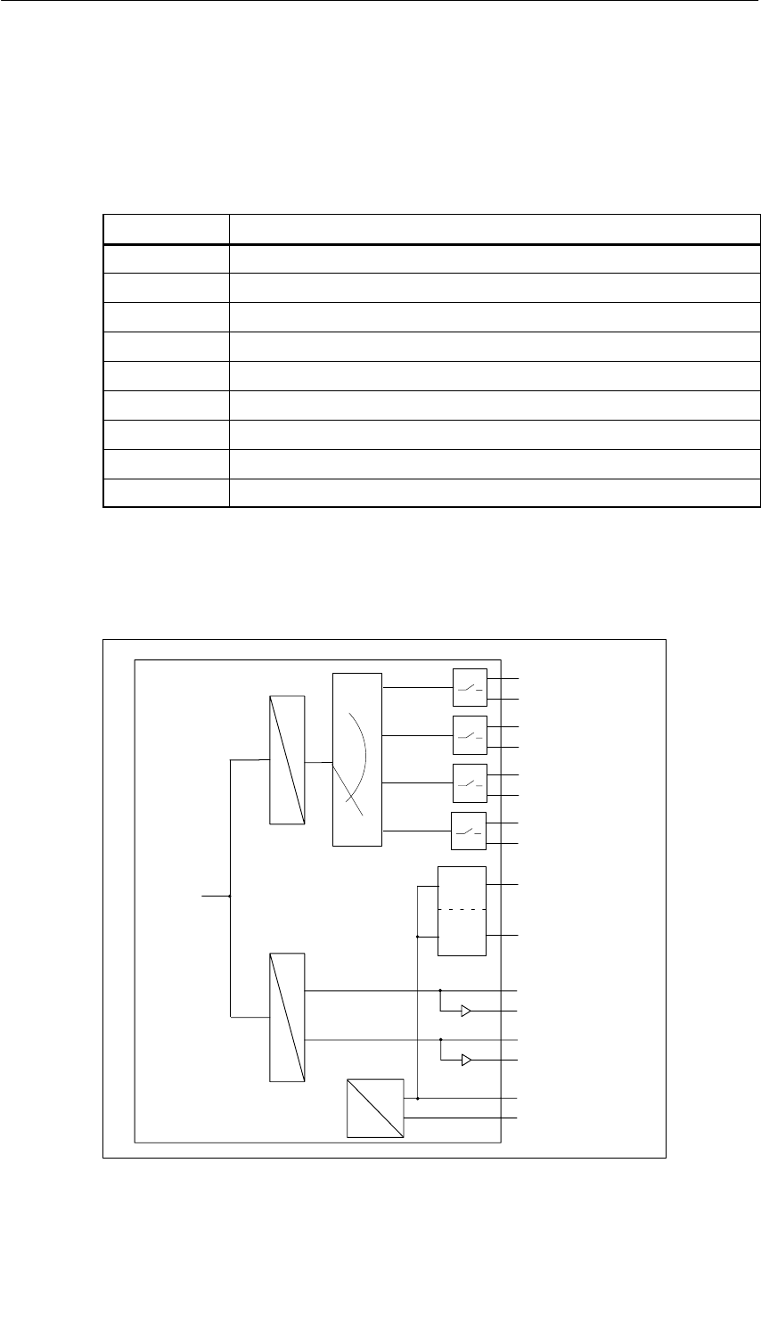
Interface Submodules
13-35
S7-400, M7-400 Programmable Controllers Module Specifications
A5E00069467-07
Meaning of Signals
The following table shows the meanings of the signals in Figure 13-10.
Table 13-38 Meaning of the Signals of the X1 Socket of the IF 961-AIO Interface
Submodule
Signal Meaning
MV0+ ... MV3+ Analog inputs: Voltage
MI0+ ... MI3+ Analog inputs: Current
M0- ... M3- Reference potential of the analog inputs
QV0, QV1Analog outputs: Voltage
QI0, QI1Analog outputs: Current
S0, S1Reference potential of the analog outputs
L+Voltage supply input 24 VDC
L1+, L2+Outputs for supplying the 2-wire transducers (24 VDC)
MGround (0 V)
Circuit Block Diagram
Figure 13-11 shows the circuit block diagram of the IF 961-AIO interface
submodule.
M
L+
A
D
Internal
supply
U
I
U
I
U
I
U
I
CH 0
CH 1
CH 2
CH 3
A
D
U
I
U
I
CH 0
CH 1
Inputs
Outputs
Internal
data bus L1+
L2+
Current
limiter
Figure 13-11 Circuit Block Diagram of the IF 961-AIO Interface Submodule

Interface Submodules
13-36 S7-400, M7-400 Programmable Controllers Module Specifications
A5E00069467-07
Grounding for the Analog Inputs
If the valid Common Mode area (VCM) cannot be retained, the analog inputs must
be grounded. To do this, the ground lines of the individual analog inputs (1) and the
shielding must be routed to the grounding point isolated.
Refer to Figure 13-12 for the grounding of the analog inputs.
Grounding for the Analog Outputs
To do this, the ground lines of the individual analog outputs (2) and the shielding
must be routed to the grounding point isolated.
With a grounded installation of the load current supply, the ground terminal of the
load current supply must be connected with its own line to the grounding point (3).
The following figure shows the grounding of the analog outputs.
M
L+
(3)
RL
Analog
input
Ground point
Load current
supply
M
L+
Analog
output
RL
CH 0
CH 1
IF 961-AIO
QI0
QI1
S0
QV0
QV1
S1
Transducer
-
+
Transducer
-
+
:
:
- 1
(2)
Figure 13-12 Grounding the Analog Inputs/Outputs of the Interface Submodule IF 961-AIO

Interface Submodules
13-37
S7-400, M7-400 Programmable Controllers Module Specifications
A5E00069467-07
13.7.2 Connecting Measured Value Sensors to Analog Inputs
Introduction
Depending on the measuring type, you can connect various measured value
sensors to the analog inputs:
•Voltage sensors
•Current sensors as
– two-wire transducers
– four-wire transducers
•Resistance
This section describes how to connect the measured value sensors and what to
look out for when connecting the measured value sensors.
Connecting Measured Value Sensors to Analog Inputs
The maximum permissible voltage difference (VCM = 8 V AC) between the inputs
and the internal ground must not be exceeded.
The measuring ranges (current/voltage) are selected via the wiring of the front
connector and by calling the software driver provided for the measuring range.
Unswitched Channels
You must short-circuit unswitched input channels and ground them. This achieves
optimal noise immunity for the analog module.
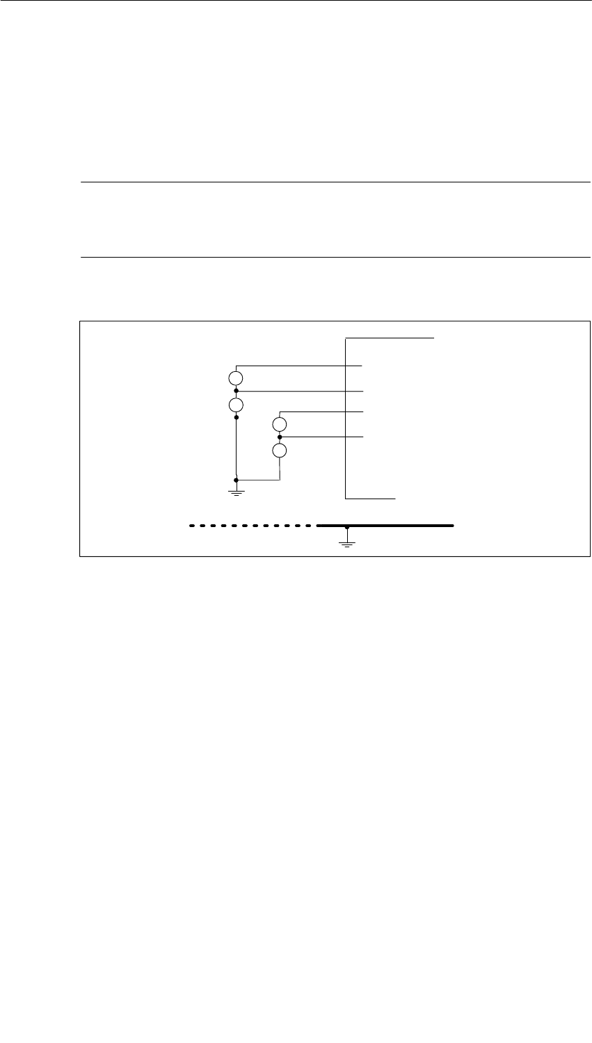
Interface Submodules
13-38 S7-400, M7-400 Programmable Controllers Module Specifications
A5E00069467-07
Isolated Measured Value Sensors
Potential differences can occur between the individual measured value sensors in
the case of isolated measured value sensors. These potential differences can
occur as the result of interference or the physical distribution of the measured value
sensors.
Note
Ensure that the VCM (common mode voltage) does not exceed the permissible
value. Violation of the permissible value can result in wrong measured values.
Figure 13-13 shows the connection of isolated measured value sensors.
+
-
VE0
Isolated measured
value sensors
Ground bus
MV0+
M0-
+
-
VE1
MV1+
M1-
+
-
VCM0
+
-
VCM1
MSENSOR
Figure 13-13 Connection of Isolated Measured Value Sensors
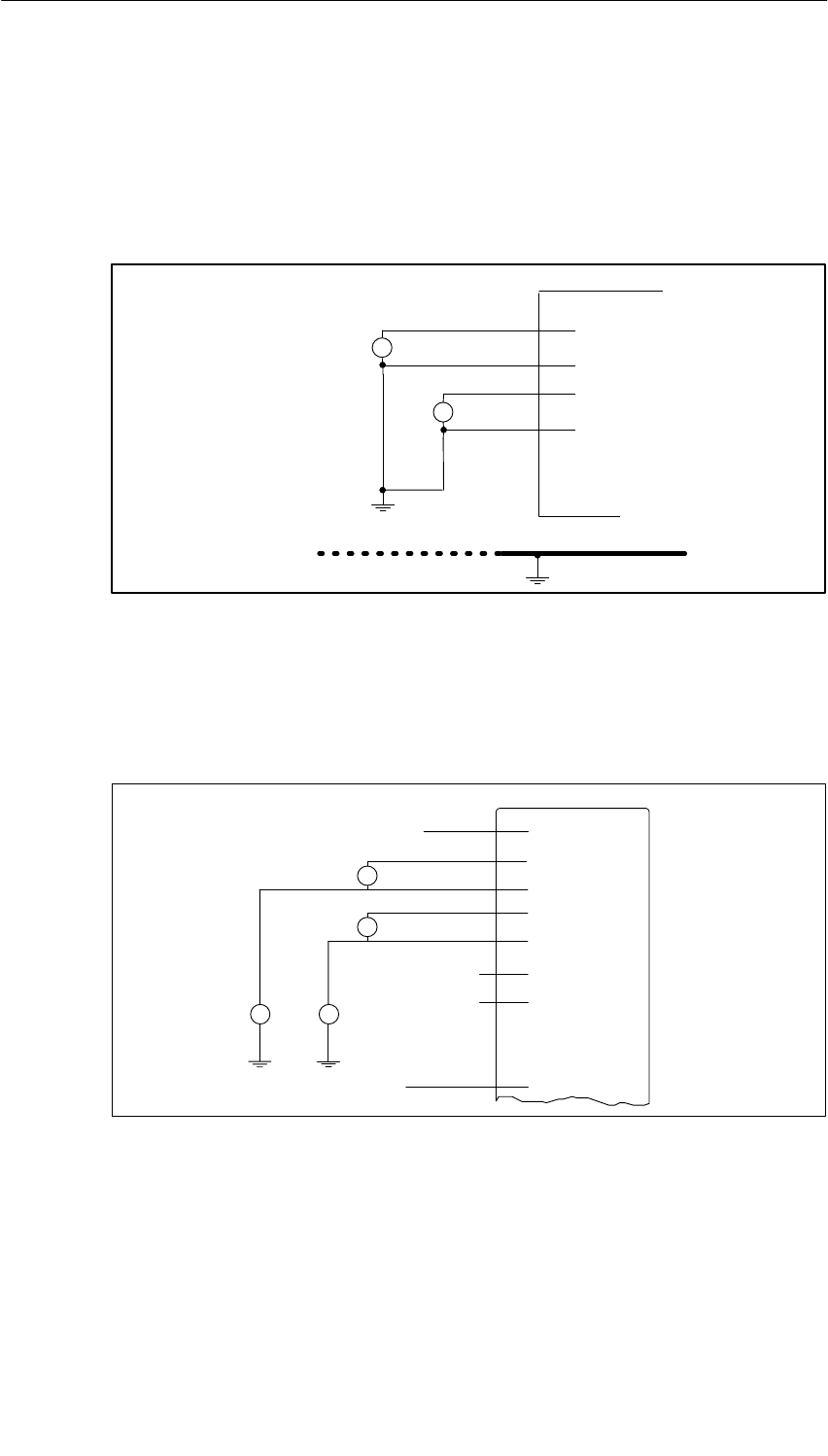
Interface Submodules
13-39
S7-400, M7-400 Programmable Controllers Module Specifications
A5E00069467-07
Non-Isolated Measured Value Sensors
Potential differences must not arise between non-isolated measured value sensors.
If necessary, you must take additional installation measures (equipotential bonding
conductor) to ensure this.
Figure 13-14 shows the connection of non-isolated measured value sensors.
+
-
VE0
Non-isolated
measured value
sensors
Ground bus
+
-
VE1
MSENSOR
MV0+
M0-
MV1+
M1-
Figure 13-14 Connection of Non-Isolated Measured Value Sensors
Connection of Voltage Sensors
Figure 13-15 shows the connection of voltage sensors to the analog input module.
+
-
U
+
-
U
+24 V MV0+
M0-
MV1+
M1-
M
L+
VCM1
VCM0
0 V
Figure 13-15 Connection of Voltage Sensors
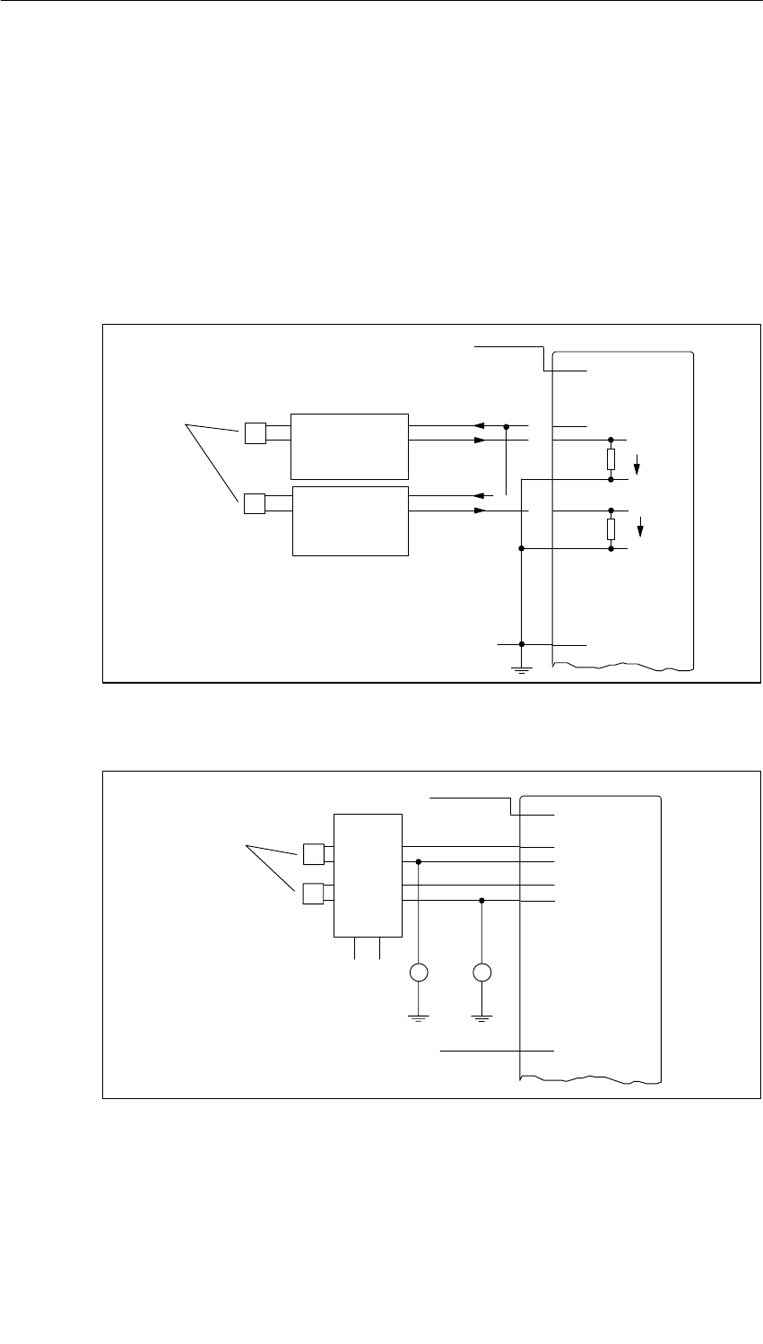
Interface Submodules
13-40 S7-400, M7-400 Programmable Controllers Module Specifications
A5E00069467-07
Connection of Current Sensors as Two-Wire and Four-Wire Transducers
Figures 13-16 and 13-17 show you how to connect current sensors as two-wire
and four-wire transducers to analog input modules.
The 24 V voltage is supplied to the two-wire transducer via a protected output (L1+,
L2+). The two-wire transducer converts the measured variable to a current of 4 to
20 mA. The range 4 to 20 mA is converted to the required format by a software
driver function.
Four-wire transducers have a separate supply voltage.
Two-wire
transducers
Two-wire
transducers
+24 V
Sensor,
e. g. pressure
gauge P
P
+
-
+
-
L+
M
L1+
M0-
MI1+
M1-
0 V
MI0- Vm
Vm
4 to 20
mA
4 to 20
mA
Figure 13-16 Connection of Two-Wire Transducers
+24 V
transducer
Four-wire
+
-
+
-
Sensor,
e. g. pressure
gauge P
P
L+
M
MV0+
M0-
MV1+
M1-
VCM1
VCM0
0 V
Figure 13-17 Connection of Four-Wire Transducers
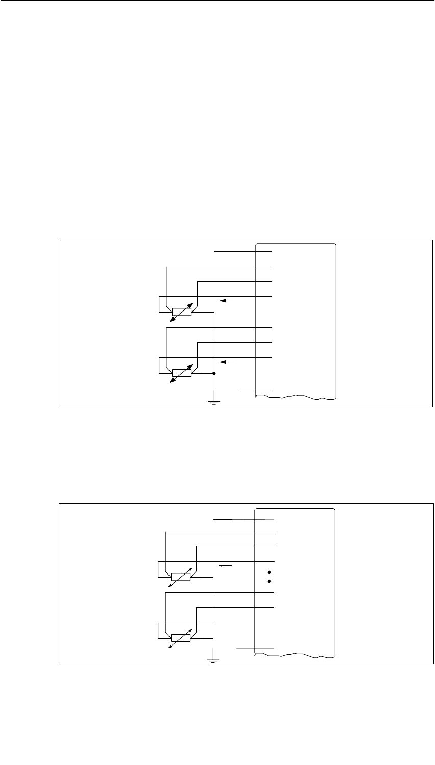
Interface Submodules
13-41
S7-400, M7-400 Programmable Controllers Module Specifications
A5E00069467-07
Connection of Resistance Thermometers (e.g. Pt 100) and Resistances
The resistance thermometers/resistances are measured in a 4-wire connection. A
constant current IC which can be set is supplied to the resistance thermometers/
resistances via one analog output QI each. The voltage arising at the resistance
thermometer/resistance is measured over the M+ and M- terminals. This achieves a
high degree of accuracy in the measured results for 4-wire connection.
The lines carrying the constant current are to be run in parallel to the measuring lines
and are not to be connected together until the terminals on the resistance. Voltage
drops on the constant current lines will then not corrupt the measured result.
Three-wire connection is not possible in the case of the IF 961-AIO interface
submodule.
Figure 13-18 shows the connection of resistance thermometers/resistances with a
single current supply via one analog output each.
IC
L+
MV0+
M0-
QI0+
+24 V
M
IC
MV1+
M1-
QI1+
0 V
Figure 13-18 Four-Wire Connection of Resistance Thermometers/Resistances with One
Constant Current Source Each
Figure 13-19 shows the connection of resistance thermometers/resistances with a
common current supply via only one analog output. Please take account here of
the maximum permissible load impedance for analog outputs and the maximum
permissible common mode voltage (VCM).
IC
L+
MV0+
M0-
QI0+
+24 V
M
MV3+
M3-
0 V
Figure 13-19 Four-Wire Connection of Resistance Thermometers/Resistances with a
Common Constant Current Source
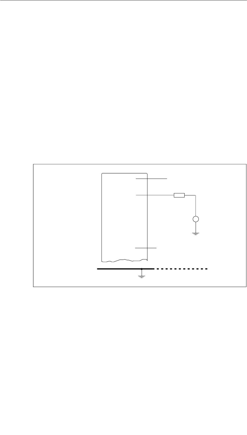
Interface Submodules
13-42 S7-400, M7-400 Programmable Controllers Module Specifications
A5E00069467-07
13.7.3 Connecting Loads/Actuators to Analog Outputs
Abbreviations Used
The abbreviations used in Figures 13-20 to 13-21 have the following meanings:
QI: Analog output current
QV: Analog output voltage
S: Reference potential of the analog circuit
RL: Load resistance
Figures 13-20 and 13-21 show you how you must connect loads/actuators to the
current or voltage outputs of the analog output module.
Connecting Loads to the Current Output
The following figure shows wiring on one channel as an example.
+24 V
RL
L+
QI
Ground bus
VCM
M0 V
Figure 13-20 Connecting Loads/Actuators via a Two-Wire Connection to a Current Output
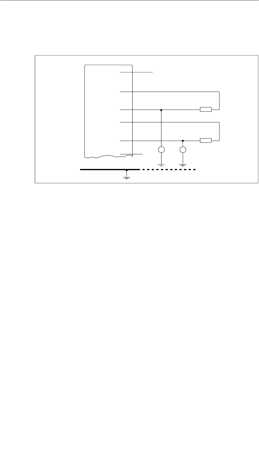
Interface Submodules
13-43
S7-400, M7-400 Programmable Controllers Module Specifications
A5E00069467-07
Connecting Loads to the Voltage Output
The following figure shows the wiring of two channels as an example.
+24 V
RL1
L+
QV1
S1
Ground bus
QV0
S0RL2
M0 V VCM1 VCM0
Figure 13-21 Connecting Loads/Actuators via a Three-Wire Connection to a Voltage Output
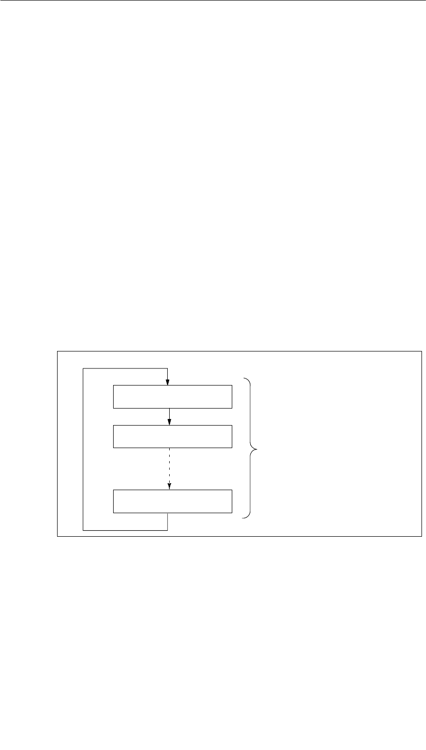
Interface Submodules
13-44 S7-400, M7-400 Programmable Controllers Module Specifications
A5E00069467-07
13.7.4 Conversion Time and Cycle Time of the Analog Input Channels
Introduction
This section contains the definitions of and relationships between the conversion
time and the cycle time of analog input modules.
Conversion Time
The conversion time consists of the conversion time of the analog-digital converter
(ADC) and the settling time of the multiplexer.
Cycle Time
Analog-digital conversion and transfer of the digitized measured values takes place
upon request or by way of multiplexing (parameter assignment required), that is the
analog input channels are converted in sequence one after the other. The cycle
time, that is, the time until an analog input value has been converted again, is the
sum of the conversion times of all analog input channels of the interface
submodule.
Figure 13-22 gives a breakdown of the cycle time for an four-channel analog input
module.
Conversion time channel 0
Conversion time channel 1
Conversion time channel 3
Cycle time
Figure 13-22 Cycle Time of the Analog Input Module

Interface Submodules
13-45
S7-400, M7-400 Programmable Controllers Module Specifications
A5E00069467-07
13.7.5 Conversion Time, Cycle Time, Settling Time, and Response
Time of the Analog Output Channels
Introduction
This section contains the definitions and relationships of times relevant to the
analog output modules.
Conversion Time
The conversion time of the analog output channels includes the transfer of the
digitized output values from the internal memory and the digital-analog conversion.
Settling Time
The settling time, that is, the time between the presence of the converted value and
reaching the specified value at the analog output, depends on the load. Here, a
distinction must be made between resistive, capacitive, and inductive load.
Response Time
The response time, that is, the time between the presence of the digital output
values in the internal memory and reaching the specified value at the analog
output, is, in the worst case, the sum of the cycle time and the settling time. The
worst case arises if the analog channel is converted shortly before transfer of a
new output value and converted back only after conversion of the other channels
(cycle time).
Figure 13-23 shows the response time of the analog output channels.
tA
tZ
tE
t1t2
tA = Response time
tC = Cycle time corresponds to n x conversion time (n = activated channels)
tS = Settling time
t1 = New digitized output value available
t2 = Output value received and converted
t3 = Specified output value reached
t3
Figure 13-23 Response Time of the Analog Output Channels

Interface Submodules
13-46 S7-400, M7-400 Programmable Controllers Module Specifications
A5E00069467-07
13.7.6 Starting Up the IF 961-AIO Interface Submodule
Electrical Installation
You must connect the ground terminal (M and S0/S1) of the analog input/output
module with the ground terminal of the load power supply. Use a cable with a
cross-section of 1 mm2 for this purpose.
Unswitched Channels
You must short-circuit unswitched input channels. This achieves optimal noise
immunity for the analog module.
Leave unswitched output channels open.
13.7.7 Addressing
Addressing
The IF 961-AIO interface submodule is addressed with the M7-300/400-reserved
I/O address area (starting from C000H).
Addressing in the M7-300/400-Reserved I/O Address Area
The base address depends on the interface submodule slot in the expansion
module or the programmable module. See the descriptions “M7-300 Expansions”,
“M7-400 Expansions” or the description of the M7-400 programmable modules for
the slot-dependent base address of the interface submodule.
The I/O address is the sum of the base address and the offset address.
The registers and their meanings and the offset addresses are described below.
Table 13-39 Offset Address Assignments for the IF 961-AIO Interface Submodule
Offset
Address Function when
Reading Function when
Writing
00HADC data channel 0 (20 - 215)ADC data channel 0 (20 - 215)
02HADC data channel 1 (20 - 215)ADC data channel 1 (20 - 215)
04HADC data channel 2 (20 - 215) Reserved
06HADC data channel 3 (20 - 215) Reserved
08HIndication of settings such as automatic
conversion, cycle time, interrupt enable Setting of automatic conversion,
cycle time and interrupt enable
0AHIndication of channel number Output of channel number
0CHIndication of end of conversion (EOC)
and voltage fault Start of analog-digital conversion
0EHReserved Interrupt acknowledgment

Interface Submodules
13-47
S7-400, M7-400 Programmable Controllers Module Specifications
A5E00069467-07
13.7.8 Analog Output Function
Analog Output Function
The 12-bit digital value to be converted is loaded left-justified into the DAC data
registers of the relevant DAC channel. After the data has been written into the
register, digital-analog conversion takes place in the selected channel.
You can see the assignment of the address to the output channels and the
meaning of the data bits in Table.
The data format of the analog output value is a 16-bit value in twos complement.
You can see the representation of the digital output value in Table 13-44.
Table 13-40 Meaning of the Data Bits in the Analog Output Function (IF 961-AIO)
Offset
Address D15 Writing D0 Remark
00H211 210 292827262524232221200 0 0 0 DAC data
channel 0
02H211 210 292827262524232221200 0 0 0 DAC data
channel 1
Status After Switching On
Both output channels contain the value “0”.
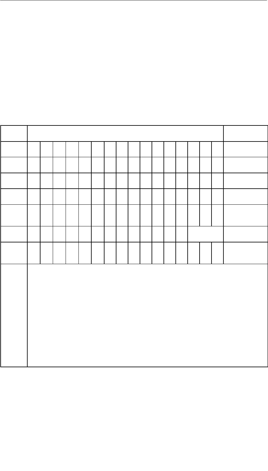
Interface Submodules
13-48 S7-400, M7-400 Programmable Controllers Module Specifications
A5E00069467-07
13.7.9 Analog Input Function
Analog Input Function
Tables 13-41 ad 13-42 contain an overview of the read and write registers for the
analog input function.
The data format of analog input values is a 16-bit value in two’s complement. You
can see the representation of the digitized measured value in Table 13-43.
Table 13-41 Meaning of the Input Bits in the Analog Input Function (IF 961-AIO)
Offset
Address D15 Reading D0 Remark
00H215 214 213 212 211 210 29282726252423222120ADC data
channel 0
02H215 214 213 212 211 210 29282726252423222120ADC data
channel 1
04H215 214 213 212 211 210 29282726252423222120ADC data
channel 2
06H215 214 213 212 211 210 29282726252423222120ADC data
channel 3
08HA
C
I
N
T0 0 0 0 0 0 0 0 0 0 0 ta ta ta Control register 1
0AH0 0 0 0 0 0 0 0 0 0 0 0 0 ADC
channel no. Control register 2
0CH0 0 0 0 0 0 0 0 0 0 0 0 0 0 P
F
E
O
C
Status register
ADC
ta = 000
ta = 001
ta = 010
ta = 011
ta = 100
INT
AC = 1
ADC channel no.
ADC = 001
ADC = 010
ADC = 011
ADC = 100
PF = 1
EOC = 1
5.7 ms cycle time of the automatic conversion function
2.8 ms
1.3 ms
600 µs
185 µs
Interrupt enable, INT = 0 = not enabled, INT = 1 = enabled
Automatic conversion of all ADC channels active
Number of the selected ADC channel (in the case of conversion on request)
(individual encoding)
Channel 0
Channel 1
Channel 2
Channel 3
Power failure, no external voltage
End of conversion, end of the analog-digital conversion of the selected channel
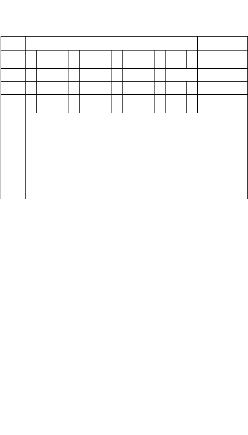
Interface Submodules
13-49
S7-400, M7-400 Programmable Controllers Module Specifications
A5E00069467-07
Table 13-42 Meaning of the Control Bits in the Analog Input Function (IF 961-AIO)
Offset
Address D15 Writing D0 Remark
08HA
C
I
N
T0 0 0 0 0 0 0 0 0 0 0 ta ta ta Control register 1
0AH0000000000000 ADC
channel no. Control register 2
0CH000000000000000S
CStatus register ADC
0EHxxxxxxxxxxxxxxxxAcknowledge
interrupt
x = any
ta = 000
ta = 001
ta = 010
ta = 011
ta = 100
AC = 1
INT = 1
ADC channel no.
ADC = 001
ADC = 010
ADC = 011
ADC = 100
SC = 1
5.7 ms cycle time of the automatic conversion function
2.8 ms
1.3 ms
600 µs
185 µs
Automatic conversion of all ADC channels active
Generation of an interrupt after end of cycle
Number of the selected ADC channel:
channel 0
channel 1
channel 2
channel 3
Start of analog-digital conversion, (SC = Start of conversion in the case of individual
encoding)
Status After Switching On
Control register 1: AC = 0, INT = 0, ta = 0 ⇒ 5.7 ms
Control register 2: ADC = 001 ⇒ ADC channel no. = 0
Status register ADC: SC = 0
Individual Start of an ADC Channel
Below are listed the steps required for individual encoding in the case of an ADC
channel:
1. Select the ADC input channel by writing the channel number into control register
2 (offset address “0AH”).
2. Start the ADC conversion by setting the SC bit in the status register ADC to “1”
(offset address “0CH”).
3. Read bit “EOC” in the status register ADC at offset address (0CH) and wait until
EOC = 1.
4. Read the analog value at the relevant address (offset addresses “00H” to “06H”).

Interface Submodules
13-50 S7-400, M7-400 Programmable Controllers Module Specifications
A5E00069467-07
Cyclic Conversion of the ADC Channels
Below are listed the steps required for cyclic conversion of the ADC channels:
1. Set the AC bit in control register 1 to “1” (offset address “08H”).
2. Wait for interrupt.
3. Read the values at the relevant address (offset addresses “00H” to “06H”).
4. Acknowledge the interrupt by writing to the offset address “0EH”, data bits 0 to
15 are irrelevant here.

Interface Submodules
13-51
S7-400, M7-400 Programmable Controllers Module Specifications
A5E00069467-07
13.7.10 Analog Value Representation for the Measuring Ranges of the
Analog Inputs
Voltage and Current Measuring Ranges
Table 13-43 contains the representation of the digitized measured value for
•The voltage measuring range ± 10 V and
•The current measuring range ± 20 mA.
Table 13-43 Representation of the Digitized Measured Value for the Analog Input Function (Voltage and
Current Measuring Range)
Range
Measured Units Measuring Range Measuring Range
Range
Measured
Value in % Decimal Hexadecimal "10 V "20 mA
Overflow ≤(118.51 32767 7FFFH≤(11.851 V ≤(23.7 mA
Overrange
117.589
:
100.004
32511
:
27649
7EFFH
:
6C01H
11.7589 V
:
10.0004 V
23.515 mA
:
20.001 mA
Nominal
range
100
:
0
:
-100
27648
:
0
:
-27648
6C00H
:
0H
:
9400H
10 V
:
0 V
:
-10 V
20 mA
:
0 mA
:
-20 mA
Underrange
-100.004
:
-117.59
-27649
:
-32512
93FFH
:
8100H
-10.0004 V
:
-11.759 V
-20.001 mA
:
-23.516 mA
Underflow ≥-118.51 -32768 8000H≥-11.851 V ≥-23.7 mA

Interface Submodules
13-52 S7-400, M7-400 Programmable Controllers Module Specifications
A5E00069467-07
13.7.11 Analog Value Representation for the Measuring Ranges of the
Analog Outputs
Voltage and Current Output Ranges
Table 13-44 contains the representation of
•The voltage output range ± 10 V and
•The current output range ± 20 mA.
Table 13-44 Representation of the Analog Output Ranges (Voltage and Current Output Ranges)
Range
Units Output Range Output Range
Range Decimal Hexadecimal "10 V "20 mA
Overflow ≥(32512 ≥(7F00H11.851 V
Overrange
32496
:
27664
7EF0H
:
6C10H
11.7534 V
:
10.0005 V
Nominal range
27648
:
0
:
-27648
6C00H
:
0H
:
9400H
10 V
:
0 V
:
-10 V
20 mA
:
0 mA
:
-20 mA
Underrange
-27664
:
-32512
93F0H
:
8100H
-10.0005 V
:
-11.759 V
Underflow ≤-32528 ≤(80F0H-11.851 V

Interface Submodules
13-53
S7-400, M7-400 Programmable Controllers Module Specifications
A5E00069467-07
13.7.12 Diagnostics, Interrupts, and Submodule ID
Interrupt Request
The interface submodule supplies an interrupt request (IRQa).
You can define the assignment of the IRQa interrupt request to the relevant
processor interrupt request in the BIOS setup.
Diagnostic and Hardware Interrupts
If the interface submodule IF 961-AIO was assigned parameters for cyclic
conversion, you have the possibility of initiating hardware interrupts at the
end-of-cycle. It is also possible to initiate a diagnostic interrupt if a hardware
interrupt is lost.
Submodule ID
The IF 961-DIO interface submodule has the submodule ID 01H.
Interface Submodules
13-54 S7-400, M7-400 Programmable Controllers Module Specifications
A5E00069467-07
13.7.13 Technical Specifications
Technical Specifications
The IF 961-AIO interface submodule receives its supply voltage from the M7-400
programmable modules or from the M7-300/400 expansion modules. The current
consumption given in the technical specifications is the consumption required for
dimensioning the power supply, that is, the current consumption is referenced to
24 V in the M7-300 and to 5 V in the M7-400.
6ES7961-2AA00-0AC0
Dimensions and Weight
Dimensions
W x H x D (mm) 18.2 x 67 x 97
Weight 0.085 kg
Module-Specific Data
Submodule ID 01H
Number of inputs 4
Number of outputs 2
Cable length, shielded < 200 m
Voltages, Currents, Potentials
Nominal voltage
Load current supply L + 24 VDC
Current consumption L + 150 mA
Reverse polarity protection No
Galvanic isolation No
Permissible common mode
range (VCM)
•Inputs to each other or
to the central grounding
point
•Voltage outputs to each
other or to the central
grounding point
•Current outputs to each
other or to the central
grounding point
< 8 VAC
< 1.5 VDC
< 2.4 VDC
Voltages, Currents, Potentials
Supply voltage Supplied from the
M7-400
programmable
modules or from the
M7-300/400
expansion modules
Current consumption in the
M7-300
(for dimensioning the 24 V
current supply) 0.03 A
Current consumption in the
M7-400
(for dimensioning the 5 V
current supply) 0.085 A
Power losses 2.5 W
Analog Value Generation for the Inputs
Measuring principle Instantaneous value
encoding
Resolution (incl. overrange) 16 bits, bipolar, twos
complement
Conversion time / channel 35 ms
Cycle time (all channels)
(automatic conversion) 5.7 ms, 2.8 ms,
1.3 ms, 600 ms,
185 ms
Interference Suppression, Error Limits for
Outputs
Load-dependent error at
voltage output (RL in ohms) Error (in %) = 19 x
100 / (19 + RL)
Interface Submodules
13-55
S7-400, M7-400 Programmable Controllers Module Specifications
A5E00069467-07
Interference Suppression, Error Limits for
Inputs
Interference voltage
suppression for
f = n (50/60 Hz " 1 %)
n = 1, 2, ...
•Common-mode
interference (Vpp < 1 V)
•Normal-mode
interference
(Peak value of
interference < nominal
value of the input range)
Cross-talk attenuation
between the inputs
> 60 dB
0 dB
> 60 dB
Operating error limits
(in the entire temperature
range, related to the input
range)
•Voltage input
•Current input
Basic error limits (operating
error limits at 25°(C, related
to input range)
•Voltage input
•Current input
"0.8 %
"0.8 %
"0.7 %
"0.7 %
Linearity error (related to
input range)
" 0.05 %
Repetition accuracy (in
settled state at 25° C,
related to the input range) " 0.2 %
Data for Selecting a Sensor
Input ranges (nominal
ranges)/input resistance
± 10 V/100 k
± 20 mA/50
Permissible input voltage
for voltage input
(destruction limit) ± 18 V
Permissible input current
for current input (destruc-
tion limit) ±(40 mA
Connection of signal
sensors
•For voltage
measurement
•For current
measurement
Possible
As two-wire-transducer
As four-wire-transducer
•For resistance
measurement
Possible
Possible
Possible 1)
1) When supplied via analog outputs with a
constant current
Analog Value Generation for the Outputs
Resolution (incl. overrange) 12 bits, bipolar, twos
complement
Cycle time (all channels) Per software
Interference Suppression, Error Limits for
Outputs
Cross-talk attenuation
between the outputs > 60 dB
Operating error limits (over
the entire temperature
range related to the output
range)
•Voltage output
•Current output
"1.0 %
"1.0 %
Basic error limit (operating
error limits at 25 C, related
to output range)
•Voltage output
•Current output
"0.8 %
"0.8 %
Output ripple (related to “full
scale” of the output range;
bandwidth 50 kHz) " 0.1 %
Data for Selecting an Actuator
Output ranges (nominal
values)
± 10 V
± 20 mA
Load impedance
•At voltage output
•At current output
•With capacitive load
min. 2 kW
max. 500 W
max. 1.6 mF
Voltage output
•Short-circuit protection
•Short-circuit current
Yes
max. 40 mA
Current output
•Idle voltage max. 13.1 V
Connection of actuators
•For voltage output
Three-wire connection
Four-wire connection
(measuring line)
•For current output
Two-wire connection
Possible
Not possible
Possible
Status, Interrupts, Diagnostics
Interrupts
•End-of-cycle interrupt
•Diagnostic interrupt
Yes, can be set
Yes, can be set
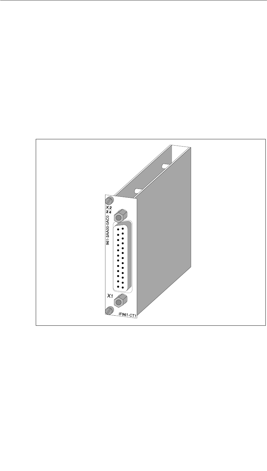
Interface Submodules
13-56 S7-400, M7-400 Programmable Controllers Module Specifications
A5E00069467-07
13.8 IF 961-CT1 Interface Submodule for M7-300/400;
(6ES7961-3AA00-0AC0)
Characteristics
The IF 961-CT1 interface submodule is used for connecting incremental encoders.
It has the following characteristics:
•Connection with RS422 or 24 V signals
•4 digital inputs (START, STOP, SET, RESET), isolated
•2 digital outputs (Q1, Q2), isolated
Figure 13-24 IF 961-CT1 Interface Submodule

Interface Submodules
13-57
S7-400, M7-400 Programmable Controllers Module Specifications
A5E00069467-07
13.8.1 What Can the IF961-CT1 Interface Submodule Do?
Introduction
This section contains an overview of the functionality of the IF 961-CT1 interface
submodule.
This functionality is achieved using the relevant driver software.
What Can the IF 961-CT1 Interface Submodule Do?
The IF 961-CT1 interface submodule is a high-speed counter module. There is a
counter on the submodule that can operate in the following counting ranges:
•0 to 4 294 967 295 or
• - 2 147 483 648 to + 2 147 483 647.
The maximum input frequency of the counter signals is 500 kHz (5 V) or
200 kHz (24V).
You can use the IF 961-CT1 interface submodule for the following counting tasks:
•Endless count
•Single up/down count
•Periodic up/down count
You can start and stop the count either via the user program or via external signals.
Comparison Values
You can store two comparison values on the submodule assigned to the two
outputs of the submodule. If the counter status reaches one of the comparison
values, the relevant output can be set to initiate control sequences directly in the
process.
Initial Value
You can specify an initial value (load value) for the IF 961-CT1. The counter is then
set to the initial value when a signal is present at the 24 V digital input on the
submodule.
Gate Functions
The count can be started and stopped in dependence on other events via gate
functions.
The IF 961-CT1 interface submodule has two gate functions:
•A software gate controlled via the program.
•A hardware gate controlled via the digital inputs of the interface submodule.

Interface Submodules
13-58 S7-400, M7-400 Programmable Controllers Module Specifications
A5E00069467-07
Interrupts
The IF 961-CT1 can initiate an interrupt when comparison values are reached or in
the event of overflow, underflow, or zero pass of the counter.
Diagnostic Interrupt
The IF 961-CT1 can initiate a diagnostic interrupt for the following events:
•Missing or incorrect counter module parameters
•Hardware interrupt lost
•Signal A, B, or N faulty
Which Signals Can the IF 961-CT1 Count?
The IF 961-CT1 interface submodule can count signals generated by incremental
encoders with 5 V differential signals or with 24 V signals.
The IF 961-CT1 interface submodule can also count 24 V signals generated, for
example, by a light barrier.
Additional Information
You will find more information about the interface submodule IF 961-CT1 in /108/,
IF 961-CT1 Counter Function Module, Programming and Parameter Assignment
Manual.

Interface Submodules
13-59
S7-400, M7-400 Programmable Controllers Module Specifications
A5E00069467-07
13.8.2 Addressing and Interrupts
Addressing
The IF 961-CT1 interface submodule is addressed with the M7-300/400-reserved
I/O address area (starting from C000H).
Addressing in the M7-300/400-Reserved I/O Address Area
The base address depends on the interface submodule slot in the expansion
module or the programmable module. See the descriptions “M7-300 Expansions”,
“M7-400 Expansions” or the description of the M7-400 programmable modules for
the slot-dependent base address of the interface submodule.
Interrupt Request
The interface submodule supplies an interrupt request (IRQa).
You can define the assignment of the IRQa interrupt request to the relevant
processor interrupt request in the BIOS setup.
Submodule ID
The IF 961-CT1 interface submodule has the submodule ID 03H.

Interface Submodules
13-60 S7-400, M7-400 Programmable Controllers Module Specifications
A5E00069467-07
13.8.3 Technical Specifications
Technical Specifications
The IF 961-CT1 interface submodule receives its supply voltage from the M7-400
programmable modules or from the M7-300/400 expansion modules. The current
consumption given in the technical specifications is the consumption required for
dimensioning the power supply, that is, the current consumption is referenced to
24 V in the M7-300 and to 5 V in the M7-400.
6ES7961-3AA00-0AC0
Technical Specifications
Supply voltage Supplied from the
M7-400
programmable
modules or from the
M7-300/400
expansion modules
Current consumption in the
M7-300
(for dimensioning the 24 V
current supply) 0.053 A
Current consumption in the
M7-400
(for dimensioning the 5 V
current supply) 0.15 A
Nominal voltage load
current supply
2L+ / 2M 24 VDC
Current consumption
2L+ / 2M Depends on the
load of the digital
outputs
Type ID 03H
Power losses 1.5 W
Dimensions
W x H x D (mm) 18.2 x 67 x 97
Weight 0.07 kg
Counter Inputs 5 V
Number of counter
channels 1, alternative to 24 V
Level In accordance to
RS422
Terminating resistance approx. 220 ohms
Differential voltage min 0.5 V
Sensor voltage No
Sensor monitoring Yes
Counter range 32 bits
Max. counter frequency 500 kHz
Counter Inputs 24 V
Number of counter
channels 1, alternative to 5 V
Low level
High level - 30 V to + 5 V
+ 11 V to + 30 V
Input resistance 1 k
Input current typ. 7 mA
Sensor voltage No
Sensor monitoring No
Counter range 32 bits
Max. counter frequency 200 kHz
Digital Inputs
Supply voltage 2L+ / 2M
Number of inputs 4
Low level
High level - 30 V to + 5 V
+ 11 V to + 30 V
Input current typ. 7 mA
Galvanic isolation Yes, to all others
except the digital
outputs
Input filter
(can be set) 50 kHz, 200 kHz
Digital Outputs
Supply voltage 2L+ / 2M
Number of outputs 2
Galvanic isolation Yes, to all others
except the digital
inputs
Output voltage
– Low level
– High level max. 3 V
2 L+ - 1.5 V
Switching current
– Nominal value
– Range 0.3 A
5 mA to 0.3 A
Switching time max. 300 ms
Cutoff voltage (inductive) Limited to
2L+ + (39 V
Short-circuit protection Yes, via electronic
fuse
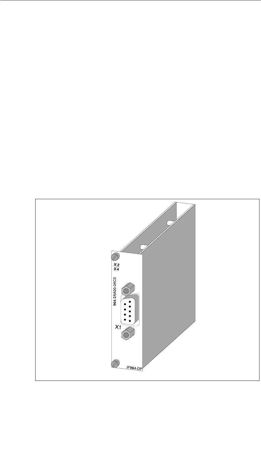
Interface Submodules
13-61
S7-400, M7-400 Programmable Controllers Module Specifications
A5E00069467-07
13.9 IF 964-DP Interface Submodule for S7-400 and M7-400
Order Numbers
You can use the IF 964-DP interface submodule with order number
6ES7964-2AA00-0AB0 (up to 07/99) in the M7-400.
You can use the IF 964-DP interface submodule with order number
6ES7964-2AA01-0AB0 (as of 07/99) in the S7-400 and in the M7-400.
Characteristics
The IF 964-DP interface submodule is used for connecting distributed I/O via
“PROFIBUS DP”. The submodule has an isolated RS485 interface. The maximum
transmission rate is 12 Mbps.
The permissible cable length depends on the transmission rate and the number of
nodes. In the case of a point-to-point connection with a speed of 12 Mbps, a cable
length of 100 m is possible, and with a speed of 9.6 Kbps a cable length of 1,200 m
is possible.
The system can be expanded to 125 stations.
Figure 13-25 IF 964-DP Interface Submodule

Interface Submodules
13-62 S7-400, M7-400 Programmable Controllers Module Specifications
A5E00069467-07
Additional Front Cover
The IF 964-DP interface submodule with order number 6ES7964-2AA01-0AB0 has
an additional front cover, which is similar to the front cover of the IF 960HF
synchronization submodule. As long as this second front cover is not screwed on,
the submodule interface on the S7-400 CPU remains off circuit. Only when you
insert an IF submodule and screw on the second front cover, is the submodule
interface on circuit.
When using the submodule in an M7 the additional front cover has no function, it
should, however, be mounted for technical maintenance reasons and due to
improved EMC properties.
Note
Even in an S7-400 CPU you may remove or insert the IF 964-DP interface
submodule only if it is off circuit.
If you remove the front cover of the interface submodule while the power supply is
switched on, the CPU goes into DEFECTIVE mode.
Additional Information
You can find information on “PROFIBUS DP” in the following technical overviews or
manuals:
•Technical overview Distributed I/O in SIMATIC S7 and M7
•Manuals on the DP masters, for example, S7-300 Programmable Controller or
S7-400, M7-400 Programmable Controllers for the PROFIBUS-DP interface of
the S7-300
•Manuals on the DP slaves, for example, ET 200M Distributed I/O Device or
ET 200C Distributed I/O Device
•The manual on the network components SINEC L2/L2FO Network Manual,
such as bus connectors, RS 485 repeaters
•Manuals on STEP 7
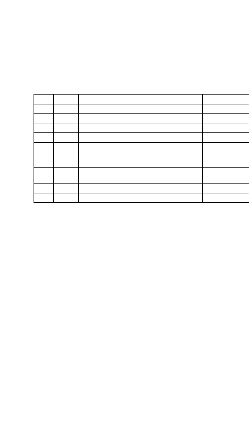
Interface Submodules
13-63
S7-400, M7-400 Programmable Controllers Module Specifications
A5E00069467-07
13.9.1 Pin Assignments
X1 Connector
There is a 9-pin sub D socket connector on the frontside of the submodule for
plugging in the connecting cable. See Table 13-45 for the pin assignments.
Table 13-45 X1 Socket, IF 964-DP (9-Pin Sub D Connector)
Pin Signal Meaning Direction
1 –
2M 24 24 V reference potential (6ES7 964-2AA01-0AB0) Output
3 LTG_B Line B Input/Output
4 RTSAS Request to send (AS) Output
5 M5ext Operational ground (isolated) Output
6 P5ext + 5 V (isolated), max. 20 mA
(for supplying the bus terminator) Output
7P 24 V +24 V, max. 150 mA, non-isolated
(6ES7 964-2AA01-0AB0) Output
8 LTG_A Line A Input
9 –
What Can be Connected to the Interface Submodule?
Devices with PROFIBUS can be connected, such as the following:
ET 200 M, ET 200 U (B/C) and other devices conforming to the standard.
Additional S7 DP masters (PG, OP)

Interface Submodules
13-64 S7-400, M7-400 Programmable Controllers Module Specifications
A5E00069467-07
13.9.2 Addressing and Interrupts
In the M7-300/400-Reserved I/O Address Area
The base address depends on the interface submodule slot in the expansion
module or the programmable module. See the descriptions “M7-300 Expansions”,
“M7-400 Expansions” or the description of the M7-400 programmable modules for
the slot-dependent base address of the interface submodule.
You require the base address for assigning parameters to the driver software.
Intermediate Memory
The IF 964-DP interface submodule provides (intermediate) storage of the data in
the dual-port RAM. The size of the memory and its address can be assigned via
the driver used.
Protected Mode: 1 out of 8 areas of 512 Kbytes in the address area
C0 00 00H bis FF FF FFH.
Note
The memory address must not collide with other system addresses. The
IF 964-VGA interface submodule, for example, occupies the addresses from
C 00 00H to C 7F FFH.
Interrupt Request
The interrupt line of the interface submodule is switched with a processor interrupt
per software parameter assignment.
Addressing in the S7-400 I/O Address Area
The interface submodule can be accessed by the respective interface in an
assigned address window.
Interrupt Request
The interrupt line of the interface submodule is permanently assigned to the
processor interrupt.
Submodule ID
The IF 964-DP interface submodule has the submodule ID 8CH.

Interface Submodules
13-65
S7-400, M7-400 Programmable Controllers Module Specifications
A5E00069467-07
13.9.3 Technical Specifications
Technical Specifications
The IF 964-DP interface submodule receives its supply voltage in the S7-400 from
the central processing unit and in the M7-400 from the programmable modules or
from the expansion modules. The current consumption given in the technical
specifications is the consumption required for dimensioning the power supply, that
is, the current consumption is referenced to 24 V in the M7-300 and to 5 V in the
M7-400.
6ES7964-2AA00-0AB0 6ES7964-2AA01-0AB0
Performance Features Performance Features
Transmission rate 9.6 Kbps to 12 Mbps Transmission rate 9.6 Kbps to 12 Mbps
Cable length
•At 9.6 Kbps
•At 12 Mbps
1200 m max.
100 m max.
Cable length
•At 9.6 Kbps
•At 12 Mbps
1200 m max.
100 m max.
Number of stations ≤ 125 Number of stations ≤ 125
Backup memory
(dual-port RAM) 256 Kbytes
Backup memory
(dual-port RAM) 256 Kbytes
Physical interface RS485 Physical interface RS485
Galvanic isolation Yes Galvanic isolation Yes
Technical Specifications Technical Specifications
Supply voltage Supplied from the
M7-400 programmable
modules or from the
M7-300/400 expansion
modules
Supply voltage Supplied from the
S7-400 or from the
M7-400 programmable
modules or from the
M7-300/400 expansion
modules
Current consumption in the
M7-300 (for dimensioning the
24 V power supply)
The module does not
consume any current at 24 V,
and it only makes this voltage
available at the DP interface.
Total current
consumption of the
components connected
to the DP interface,
with a maximum of 150
mA
Current consumption from the
S7-400 bus/in M7-300 (DC
24 V for the dimensioning of
the 24 V power supply)
The module does not
consume any current at 24 V,
and it only makes this voltage
available at the DP interface.
Total current
consumption of the
components connected
to the DP interface,
with a maximum of 150
mA
Current consumption in the
M7-400 (for dimensioning the
5 V power supply)
0.45 A .
Current carrying capacity of
the isolated 5 V (P5ext)Max. 90 mA Current carrying capacity of
the isolated 5 V (P5ext)Max. 90 mA
Load rating of the isolated 5V
(P5ext)max. 90 mA
Load rating of the isolated 5V
(P5ext)
Load rating of the 24 V
max. 90 mA
max. 150 mA
Submodule ID 8CHSubmodule ID 8CH
Power losses 2 W Power losses 2 W
Dimensions
W x H x D (mm) 18.2 x 67 x 97
Dimensions
W x H x D (mm) 18.2 x 67 x 97
Weight 0.065 kg Weight 0.065 kg

Interface Submodules
13-66 S7-400, M7-400 Programmable Controllers Module Specifications
A5E00069467-07

A-1
S7-400, M7-400 Programmable Controllers Module Specifications
A5E00069467-07
Parameter Sets for Signal Modules
Chapter Overview
Section Description Page
A.1 How to Assign the Parameters for Signal Modules in the
User Program A-2
A.2 Parameters of the Digital Input Modules A-4
A.3 Parameters of the Digital Output Modules A-7
A.4 Parameters of the Analog Input Modules A-10
A

Parameter Sets for Signal Modules
A-2 S7-400, M7-400 Programmable Controllers Module Specifications
A5E00069467-07
A.1 How to Assign the Parameters for Signal Modules in
the User Program
Parameter Assignment in the User Program
You have already assigned parameters to the modules in STEP 7.
In the user program, you can use a SFC:
•to reassign parameters to the module and
•and transfer the parameters from the CPU to the addressed signal module
In the M7-400
In M7-400 programmable controllers you can also parameterize the signal modules
in the user program with the M7 API software (refer to System Software Manuals
for M7-300/400).
Parameters Stored in Data Records
The signal module parameters are stored in data records 0 and 1.
Modifiable Parameters
You can change the parameters of record 1 and pass them to the signal module
using SFC 55. The parameters set on the CPU are not changed when you do this!
You cannot modify the parameters of data record 0 in the user program.
SFCs for Parameter Assignment
The following SFCs are available for assigning parameters to the signal modules in
the user program:
Table A-1 SFCs for assigning Parameters to Signal Modules
SFC No. Identifier Application
55 WR_PARM Transfer of modifiable parameters (data record 1) to the
addressed signal module.
56 WR_DPARM Transfer of parameters (data record 0 or 1) from the CPU
to the addressed signal module.
57 PARM_MOD Transfer of all parameters (data record 0 and 1) from the
CPU to the addressed signal module.

Parameter Sets for Signal Modules
A-3
S7-400, M7-400 Programmable Controllers Module Specifications
A5E00069467-07
Description of the Parameters
The following sections contain all the modifiable parameters for the various module
classes. The parameters of the signal modules are described:
•in the online help of STEP 7.
•in this reference manual
You will find the parameters that can be adjusted for the signal module
concerned in the specific sections for the different signal modules.
Further References
You can find an in-depth description of the principle of assigning parameters to
signal modules in the user program and a description of the SFCs that can be used
for this purpose in the STEP 7 manuals.
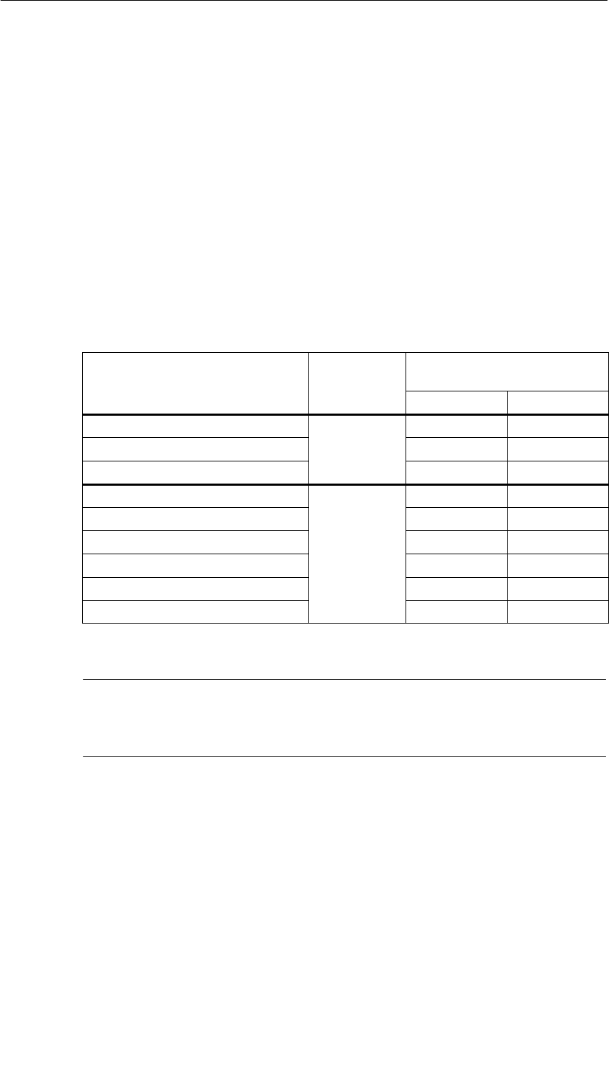
Parameter Sets for Signal Modules
A-4 S7-400, M7-400 Programmable Controllers Module Specifications
A5E00069467-07
A.2 Parameters of the Digital Input Modules
Parameters
The table below contains all the parameters you can set for digital input modules.
You will see which parameters you can modify from the list:
•in STEP 7
•with SFC 55 ”WR_PARM”
The parameters set with STEP 7 can also be transferred to the module with SFCs
56 and 57 (refer to the STEP 7 manuals).
Table A-2 Parameters of the Digital Input Modules
Parameter Data Record
No. Parameters Can Be Assigned
with ...
... SFC 55 ... STEP 7
Destination CPU for interrupts No Yes
Input delay 0No Yes
Diagnostics No Yes
Hardware interrupt enable Yes Yes
Diagnostic interrupt enable Yes Yes
Reaction to error*
1
Yes Yes
Hardware interrupt with rising edge 1Yes Yes
Hardware interrupt with falling edge Yes Yes
Substitute “1”*Yes Yes
*Only in 6ES7421-7BH00-0AB0
Note
If you want to enable the diagnostic interrupt in the user program in data record 1,
you must enable the diagnosis in data record 0 beforehand using STEP 7.
Structure of Data Record 1
The figure below shows the structure of data record 1 (bytes 0, 1, 2 and 3) for the
parameters of the digital input modules.
You enable a parameter by setting the corresponding bit to “1”.
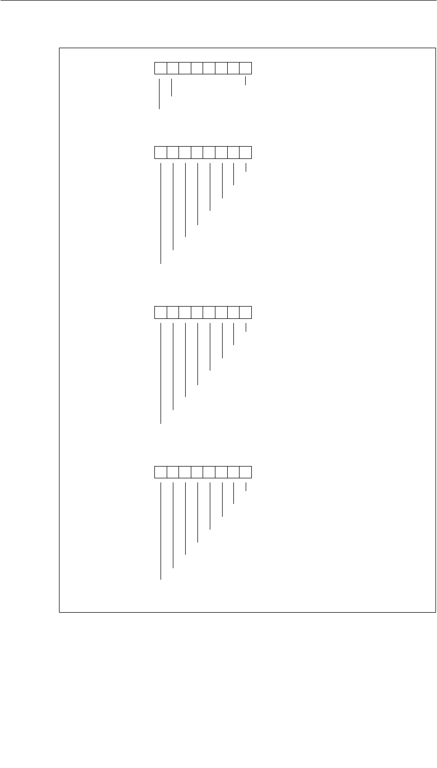
Parameter Sets for Signal Modules
A-5
S7-400, M7-400 Programmable Controllers Module Specifications
A5E00069467-07
Byte 0
76 0
Hardware interrupt enable
Diagnostic interrupt enable
Byte 1
76 0
On rising edge at channel 0
On rising edge at channel 2
On rising edge at channel 4
On rising edge at channel 6
54321
Hardware interrupt
On rising edge at channel 1
On rising edge at channel 3
On rising edge at channel 5
On rising edge at channel 7
Byte 2
76 0
On rising edge at channel 8
On rising edge at channel 10
On rising edge at channel 12
On rising edge at channel 14
54321
Hardware interrupt
On rising edge at channel 9
On rising edge at channel 11
On rising edge at channel 13
On rising edge at channel 15
Reaction to error *)
Byte 3
76 0
On falling edge at channel 1
On falling edge at channel 3
On falling edge at channel 5
On falling edge at channel 7
54321
Hardware interrupt
On falling edge at channel 0
On falling edge at channel 2
On falling edge at channel 4
On falling edge at channel 6
*) Only in 6ES7 421-7BH00-0AB0
Figure A-1 Data Record 1 of the Parameters of the Digital Input Modules
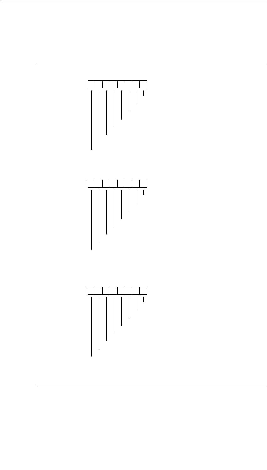
Parameter Sets for Signal Modules
A-6 S7-400, M7-400 Programmable Controllers Module Specifications
A5E00069467-07
The figure below shows the structure of data record 1 (bytes 4, 5 and 6) for the
parameters of the digital input modules.
You enable a parameter by setting the corresponding bit to “1”.
Byte 4
76 0
On falling edge at channel 9
On falling edge at channel 11
On falling edge at channel 13
On falling edge at channel 15
54321
Hardware interrupt
On falling edge at channel 8
On falling edge at channel 10
On falling edge at channel 12
On falling edge at channel 14
Byte 5
76 0
54321
Byte 6
76 0
Enable substitute value 1 on channel 15
54321
Substitute value *)
Substitute value *)
Enable substitute value 1 on channel 7
Enable substitute value 1 on channel 6
Enable substitute value 1 on channel 5
Enable substitute value 1 on channel 4
Enable substitute value 1 on channel 3
Enable substitute value 1 on channel 2
Enable substitute value 1 on channel 1
Enable substitute value 1 on channel 0
Enable substitute value 1 on channel 8
Enable substitute value 1 on channel 9
Enable substitute value 1 on channel 10
Enable substitute value 1 on channel 11
Enable substitute value 1 on channel 12
Enable substitute value 1 on channel 13
Enable substitute value 1 on channel 14
*) Only in 6ES7 421-7BH00-0AB0
Figure A-2 Data Record 1 for Parameters of the Digital Input Modules
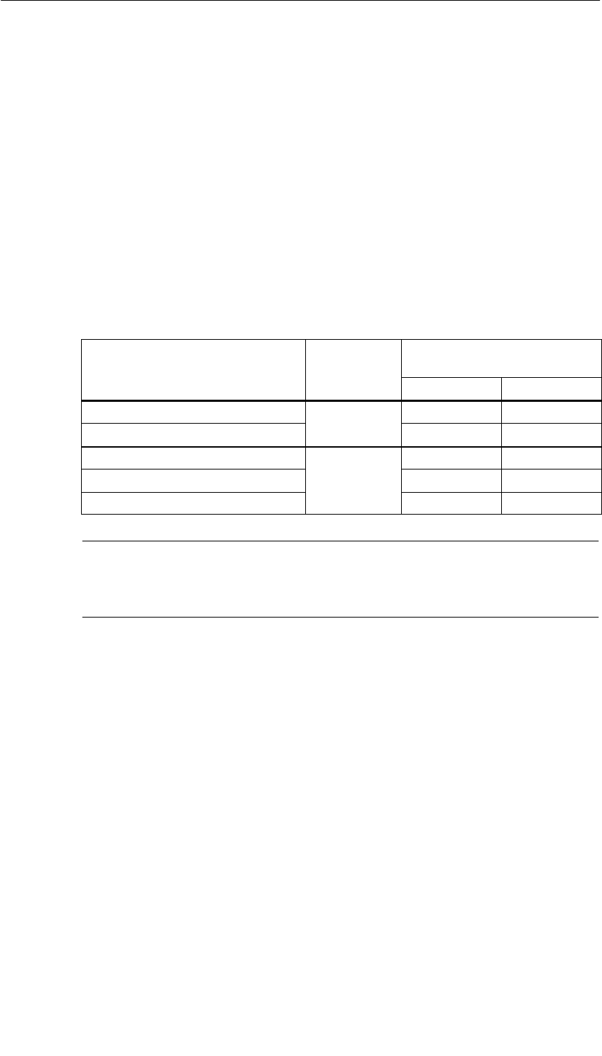
Parameter Sets for Signal Modules
A-7
S7-400, M7-400 Programmable Controllers Module Specifications
A5E00069467-07
A.3 Parameters of the Digital Output Modules
Parameters
The table below contains all the parameters you can set for digital output modules.
The comparison shows:
•Which parameters you can change with STEP 7 and
•Which parameters you can change with SFC 55 “WR_PARM”
The parameters set with STEP 7 can also be transferred to the module with SFCs
56 and 57 (refer to the STEP 7 manuals).
Table A-3 Parameters of the Digital Output Modules
Parameter Data Record
No. Parameters Can Be Assigned
with ...
... SFC 55 ... STEP 7
Destination CPU for Interrupts
0
No Yes
Diagnostics 0No Yes
Diagnostic interrupt enable Yes Yes
Reaction to CPU STOP 1Yes Yes
Enable substitute value “1” Yes Yes
Note
If you want to enable the diagnostic interrupt in the user program in data record 1,
you must enable the diagnosis in data record 0 beforehand using STEP 7.
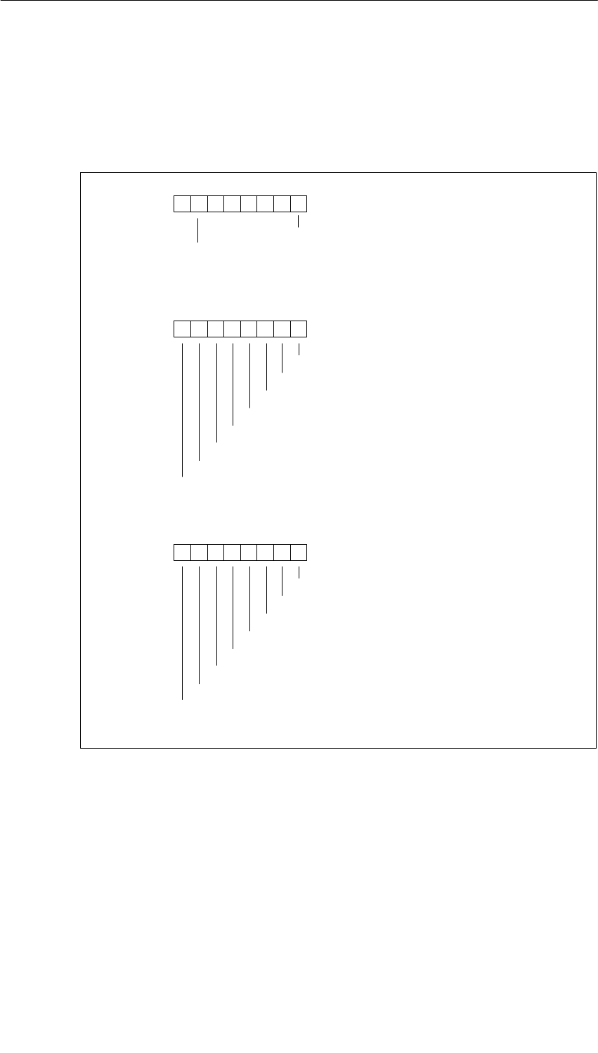
Parameter Sets for Signal Modules
A-8 S7-400, M7-400 Programmable Controllers Module Specifications
A5E00069467-07
Structure of Data Record 1
The figure below shows the structure of data record 1 (bytes 0, 1 and 2) for the
parameters of the digital output modules.
You enable a parameter by setting the corresponding bit to “1”.
Byte 0
76 0
Diagnostic interrupt enable
Reaction to CPU STOP
Byte 1
76 0
54321
Byte 2
76 0
Enable substitute value 1 on channel 15
54321
Substitute value
Substitute value
Enable substitute value 1 on channel 7
Enable substitute value 1 on channel 6
Enable substitute value 1 on channel 5
Enable substitute value 1 on channel 4
Enable substitute value 1 on channel 3
Enable substitute value 1 on channel 2
Enable substitute value 1 on channel 1
Enable substitute value 1 on channel 0
Enable substitute value 1 on channel 8
Enable substitute value 1 on channel 9
Enable substitute value 1 on channel 10
Enable substitute value 1 on channel 11
Enable substitute value 1 on channel 12
Enable substitute value 1 on channel 13
Enable substitute value 1 on channel 14
Figure A-3 Data Record 1 for Parameters of the Digital Output Modules
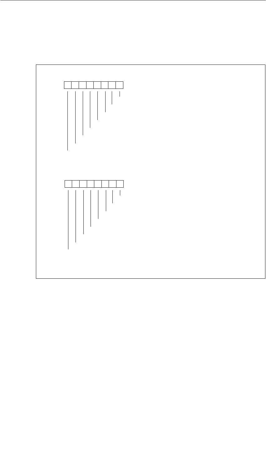
Parameter Sets for Signal Modules
A-9
S7-400, M7-400 Programmable Controllers Module Specifications
A5E00069467-07
The figure below shows the structure of data record 1 (bytes 3 and 4) for the
parameters of the digital output modules.
You enable a parameter by setting the corresponding bit to “1”.
Byte 3*
76 0
54321
Byte 4*
76 0
Enable substitute value 1 on channel 31
54321
Substitute value
Substitute value
Enable substitute value 1 on channel 23
Enable substitute value 1 on channel 22
Enable substitute value 1 on channel 21
Enable substitute value 1 on channel 20
Enable substitute value 1 on channel 19
Enable substitute value 1 on channel 18
Enable substitute value 1 on channel 17
Enable substitute value 1 on channel 16
Enable substitute value 1 on channel 24
Enable substitute value 1 on channel 25
Enable substitute value 1 on channel 26
Enable substitute value 1 on channel 27
Enable substitute value 1 on channel 28
Enable substitute value 1 on channel 29
Enable substitute value 1 on channel 30
*Bytes 3 and 4 are not relevant for SM 421; DO 16 20-125 VDC/1.5 A
Figure A-4 Data Record 1 for Parameters of the Digital Output Modules
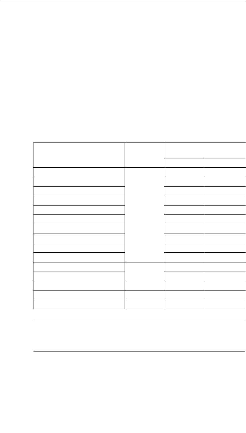
Parameter Sets for Signal Modules
A-10 S7-400, M7-400 Programmable Controllers Module Specifications
A5E00069467-07
A.4 Parameters of the Analog Input Modules
Parameters
The table below contains all the parameters you can set for analog input modules.
You will see which parameters you can modify from the list:
•in STEP 7
•with SFC 55 ”WR_PARM”
The parameters set with STEP 7 can also be transferred to the module with SFCs
56 and 57 (refer to the STEP 7 manuals).
Table A-4 Parameters of the Analog Input Modules
Parameter Data Record
No. Parameters Can Be Assigned
with ...
... SFC 55 ... STEP 7
Destination CPU for Interrupts No Yes
Measuring Type No Yes
Measuring Range No Yes
Diagnostics No Yes
Temperature Unit
0
No Yes
Temperature Coefficient 0No Yes
Interference Suppression No Yes
Smoothing No Yes
Reference Junction No Yes
End-of-scan-cycle interrupt No Yes
Diagnostic interrupt enable
1
Yes Yes
Hardware interrupt enable 1Yes Yes
Reference Temperature 1Yes Yes
High Limit 1Yes Yes
Low Limit 1Yes Yes
Note
If you want to enable the diagnostic interrupt in the user program in data record 1,
you must enable the diagnosis in data record 0 beforehand using STEP 7.
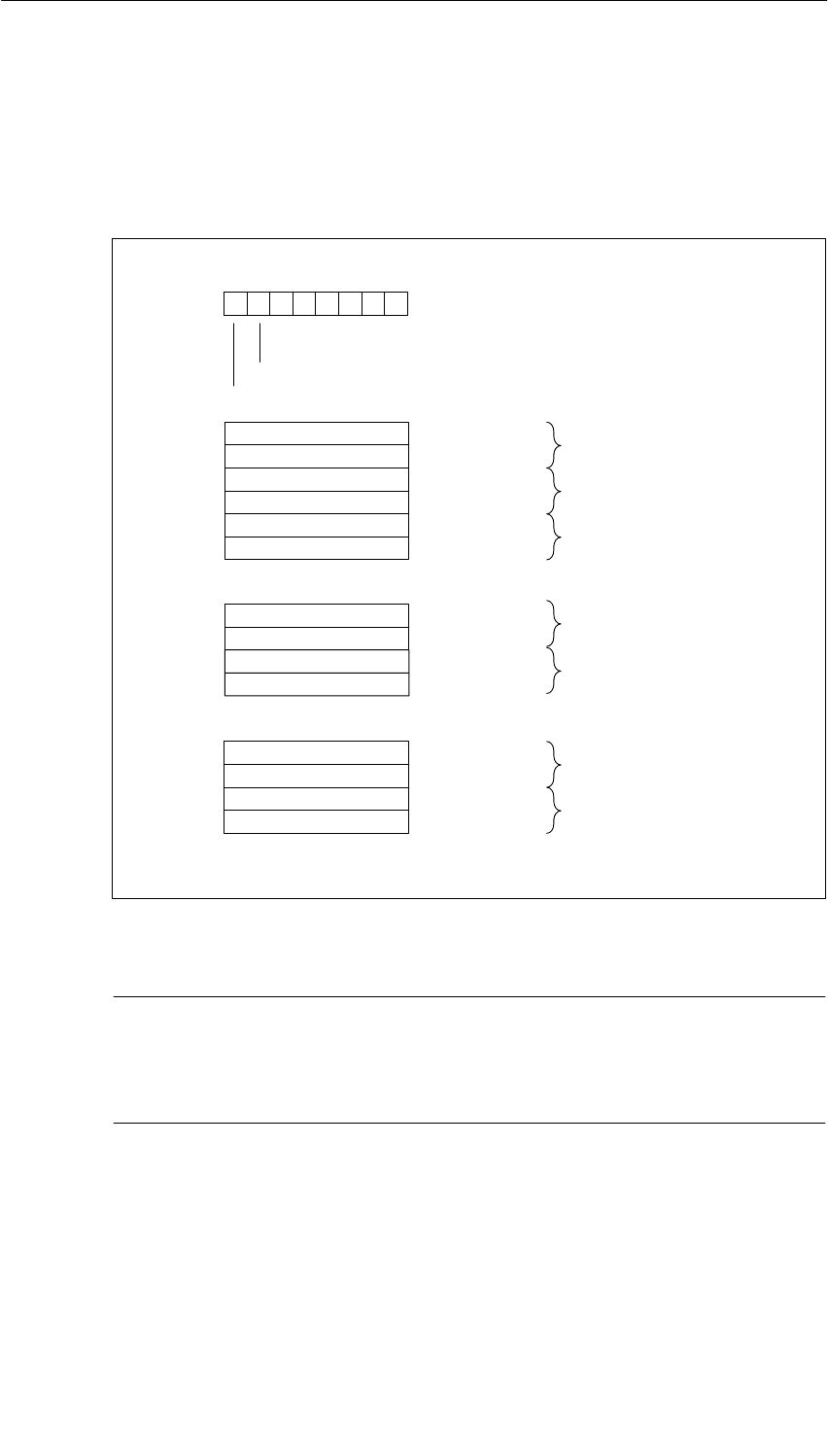
Parameter Sets for Signal Modules
A-11
S7-400, M7-400 Programmable Controllers Module Specifications
A5E00069467-07
Structure of Data Record 1
The figure below shows the structure of data record 1 for the parameters of the
analog input modules.
You enable a parameter by setting the corresponding bit to “1”.
Byte 0
76 0
Diagnostic interrupt enable
Hardware interrupt enable
Upper limit value
for channel 15
Lower limit value for
channel 15
Low-Order Byte
Low-Order Byte
High-Order Byte
High-Order Byte
Byte 63
Byte 64
Byte 65
Byte 66
Upper limit value
for channel 0
Lower limit value for
channel 0
Upper limit value for
channel 7
Lower limit value
for channel 7
Low-Order Byte
Low-Order Byte
Low-Order Byte
Low-Order Byte
High-Order Byte
High-Order Byte
High-Order Byte
High-Order Byte
Byte 3
Byte 4
Byte 5
Byte 6
Byte 31
Byte 32
Byte 33
Byte 34
Byte 1
Byte 2 Reference temperature
in 0.01 C
Low-Order Byte
High-Order Byte
•
•
•
•
•
•
Figure A-5 Data Record 1 for Parameters of the Analog Input Modules
Note
The representation of the limit values and the reference temperature corresponds
to the analog value representation (see Chapter 6). Please observe the range
limits when setting the limit values.

Parameter Sets for Signal Modules
A-12 S7-400, M7-400 Programmable Controllers Module Specifications
A5E00069467-07

B-1
S7-400, M7-400 Programmable Controllers Module Specifications
A5E00069467-07
Diagnostic Data of the Signal Modules
Chapter Overview
Section Description Page
B.1 Evaluating the Diagnostic Data of the Signal Modules in the User
Program B-2
B.2 Structure and Contents of Diagnostic Data Bytes 0 and 1 B-3
B.3 Diagnostic Data of the Digital Input Modules as of Byte 2 B-4
B.4 Diagnostic Data of the Digital Output Modules as of Byte 2 B-8
B.5 Diagnostic Data of the Analog Input Modules as of Byte 2 B-14
B

Diagnostic Data of the Signal Modules
B-2 S7-400, M7-400 Programmable Controllers Module Specifications
A5E00069467-07
B.1 Evaluating the Diagnostic Data of the Signal Modules
in the User Program
In This Appendix
This Appendix describes the structure of the diagnostic data in the system data.
You must be familiar with this structure if you want to evaluate the diagnostic data
of the signal module in the STEP 7 user program.
Diagnostic Data are Contained in Data Records
The diagnostic data of a module can be up to 43 bytes long and are contained in
data records 0 and 1:
•Data record 0 contains 4 bytes of diagnostic data that describe the current
status of a programmable controller.
•Data record 1 contains the four bytes of diagnostic data that are also contained
in data record 0 and as many as 39 bytes of module-specific diagnostic data.
Further Reading
An in-depth description of the principle of evaluating the diagnostic data of signal
modules in the user program and a description of the SFCs that can be used for
that purpose will be found in the STEP 7 manuals.
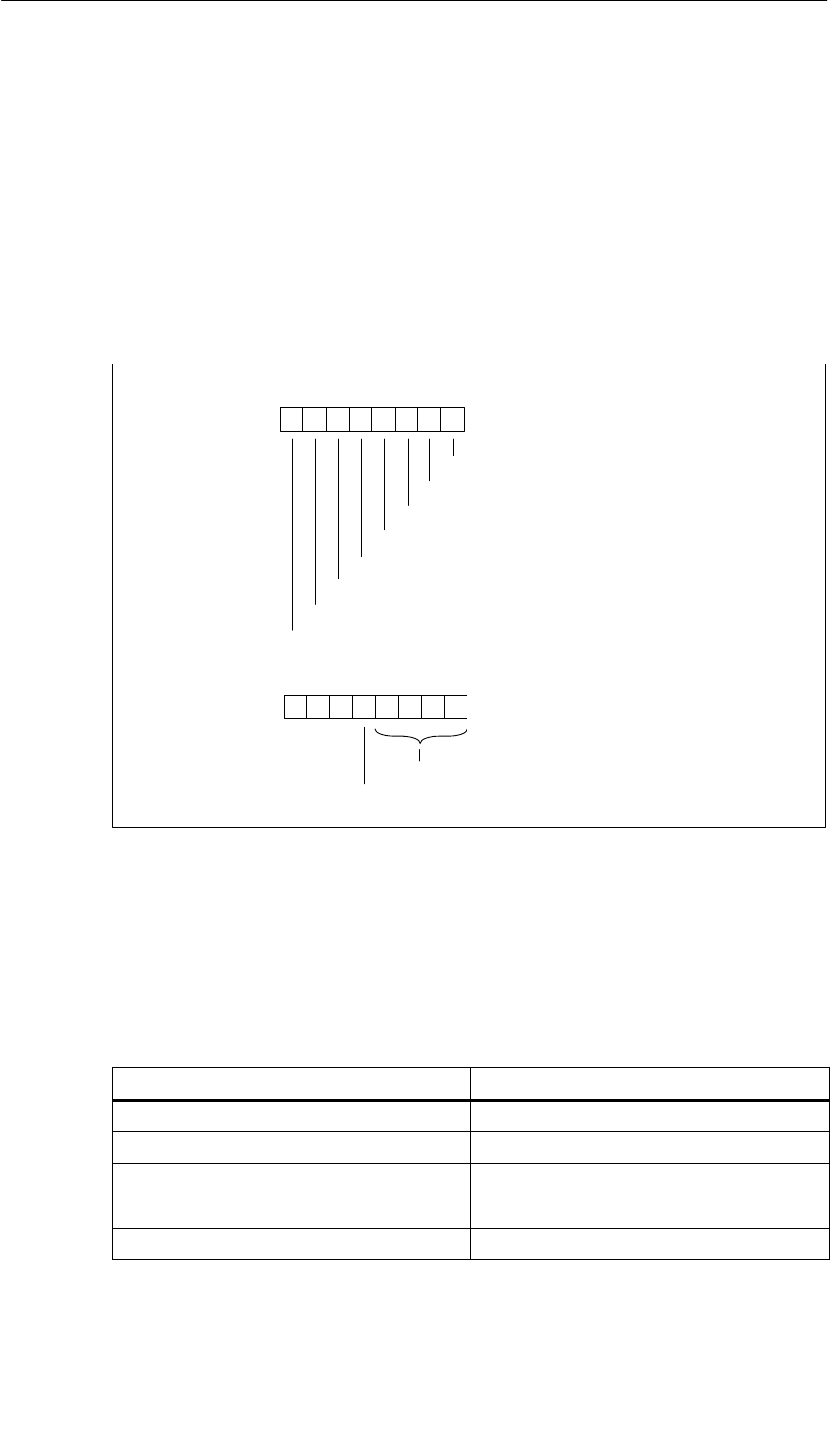
Diagnostic Data of the Signal Modules
B-3
S7-400, M7-400 Programmable Controllers Module Specifications
A5E00069467-07
B.2 Structure and Contents of
Diagnostic Data Bytes 0 and 1
The structure and contents of the different bytes of the diagnostic data are
described below. The following general rule applies: When an error occurs, the bit
concerned is set to ”1”.
Bytes 0 and 1
Byte 0
76 0
Module malfunction
Internal malfunction
External malfunction
There is a channel error
No external auxiliary supply
Front connector missing
Module not parameterized.
Incorrect parameter in the module
54321
Byte 1
76 0
Channel information available
54321
Module type (see Table B-1)
00 0
Figure B-1 Bytes 0 and 1 of the Diagnostic Data
Module Types
The following table contains the IDs of the module classes (bits 0 to 3 in byte 1).
Table B-1 Codes of the Module Types
Code Module Type
0101 Analog module
0110 CPU
1000 Function module
1100 CP
1111 Digital module
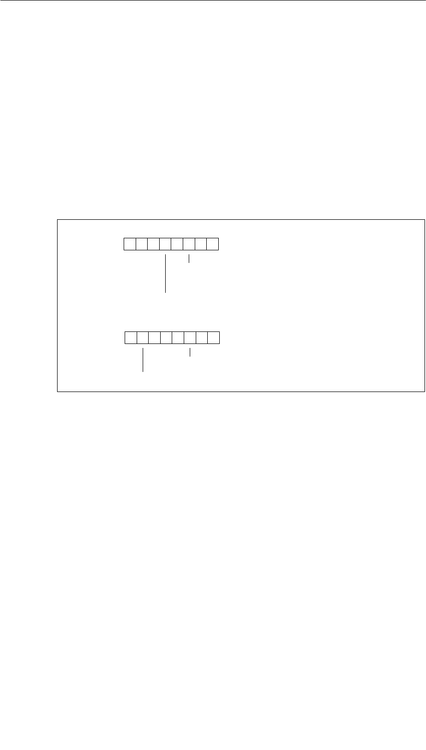
Diagnostic Data of the Signal Modules
B-4 S7-400, M7-400 Programmable Controllers Module Specifications
A5E00069467-07
B.3 Diagnostic Data of the Digital Input Modules
as of Byte 2
The structure and contents of the different bytes of the diagnostic data for special
digital input modules are described below. The following general rule applies:
When an error occurs, the bit concerned is set to ”1”.
You will find a description of possible error causes and appropriate remedies in the
section called “Diagnostics of the Modules”.
Bytes 2 and 3 of the SM 421; DI 16 24 VDC
Byte 2
76 0
Operating status 0: RUN
1: STOP
Module-internal supply voltage failure
54321
0
Byte 3
76 0
EPROM error
Hardware interrupt lost
54321
0
0
000 0
000 00
Figure B-2 Bytes 2 and 3 of the Diagnostic Data of the SM 421; DI 16 x 24 VDC

Diagnostic Data of the Signal Modules
B-5
S7-400, M7-400 Programmable Controllers Module Specifications
A5E00069467-07
Bytes 4 to 8 of the SM 421; DI 16 24 VDC
Byte 4
76 054321
Byte 5
70
Channel type B#16#70: digital input
Number of diagnostics bits that the module
outputs per channel: 8 bits long
Byte 6
70
Number of channels of the same
type in one module: 16 channels
Byte 7
76 0
Channel error, channel 0
Channel error, channel 1
Channel error, channel 6
Channel error, channel 7
54321
...
0
Byte 8
76 0
Channel error, channel 14
Channel error, channel 15
54321
...
Channel error, channel 8
Channel error, channel 9
Figure B-3 Bytes 4 to 8 of the Diagnostic Data of the SM 421; DI 16 x 24 VDC
Bytes 9 to 24 of the SM 421; DI 16 24 VDC
Data record 1 with bytes 9 to 24 contains the channel-specific diagnostic data. The
figure below shows the assignment of the diagnostic byte for a channel of the
module.
76 0
Sensor supply missing
54321
00
Configuring/parameter assignment error
Wire break
000
Figure B-4 Diagnostic Byte for a Channel of the SM 421; DI 16 x 24 VDC
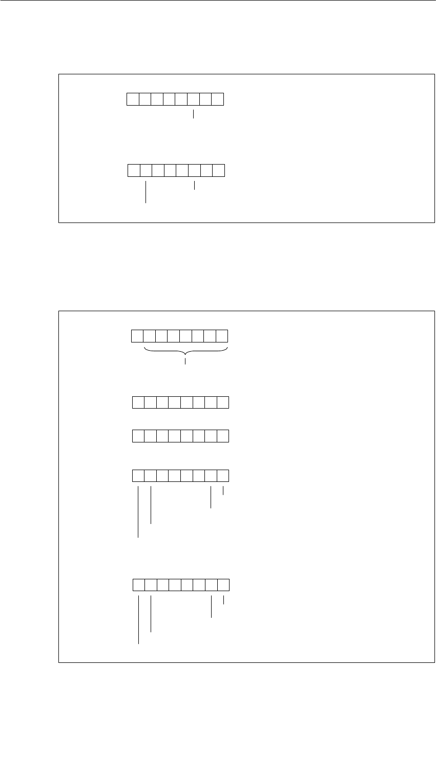
Diagnostic Data of the Signal Modules
B-6 S7-400, M7-400 Programmable Controllers Module Specifications
A5E00069467-07
Bytes 2 and 3 of the SM 421; DI 16 24/60 VUC
Byte 2
76 0
Operating status 0: RUN
1: STOP
54321
0
Byte 3
76 0
EPROM error
Hardware interrupt lost
54321
0
0000 00
000 00
Figure B-5 Bytes 2 and 3 of the Diagnostic Data of the SM 421; DI 16 x 24/60 VUC
Bytes 4 to 8 of the SM 421; DI 16 24/60 VUC
Byte 4
76 054321
Byte 5
70
Channel type B#16#70: digital input
Number of diagnostics bits that the module
outputs per channel: 8 bits long
Byte 6
70
Number of channels of the same
type in one module: 16 channels
Byte 7
76 0
Channel error, channel 0
Channel error, channel 1
Channel error, channel 6
Channel error, channel 7
54321
...
0
Byte 8
76 0
Channel error, channel 14
Channel error, channel 15
54321
...
Channel error, channel 8
Channel error, channel 9
Figure B-6 Bytes 4 to 8 of the Diagnostic Data of the SM 421; DI 16 x 24/60 VUC

Diagnostic Data of the Signal Modules
B-7
S7-400, M7-400 Programmable Controllers Module Specifications
A5E00069467-07
Bytes 9 to 24 of the SM 421; DI 16 24/60 VUC
Data record 1 with bytes 9 to 24 contains the channel-specific diagnostic data. The
figure below shows the assignment of the diagnostic byte for a channel of the
module.
76 054321
00
Configuring/parameter assignment error
Wire break
0000
Figure B-7 Diagnostic Byte for a Channel of the SM 421; DI 16 x 24/60 VUC
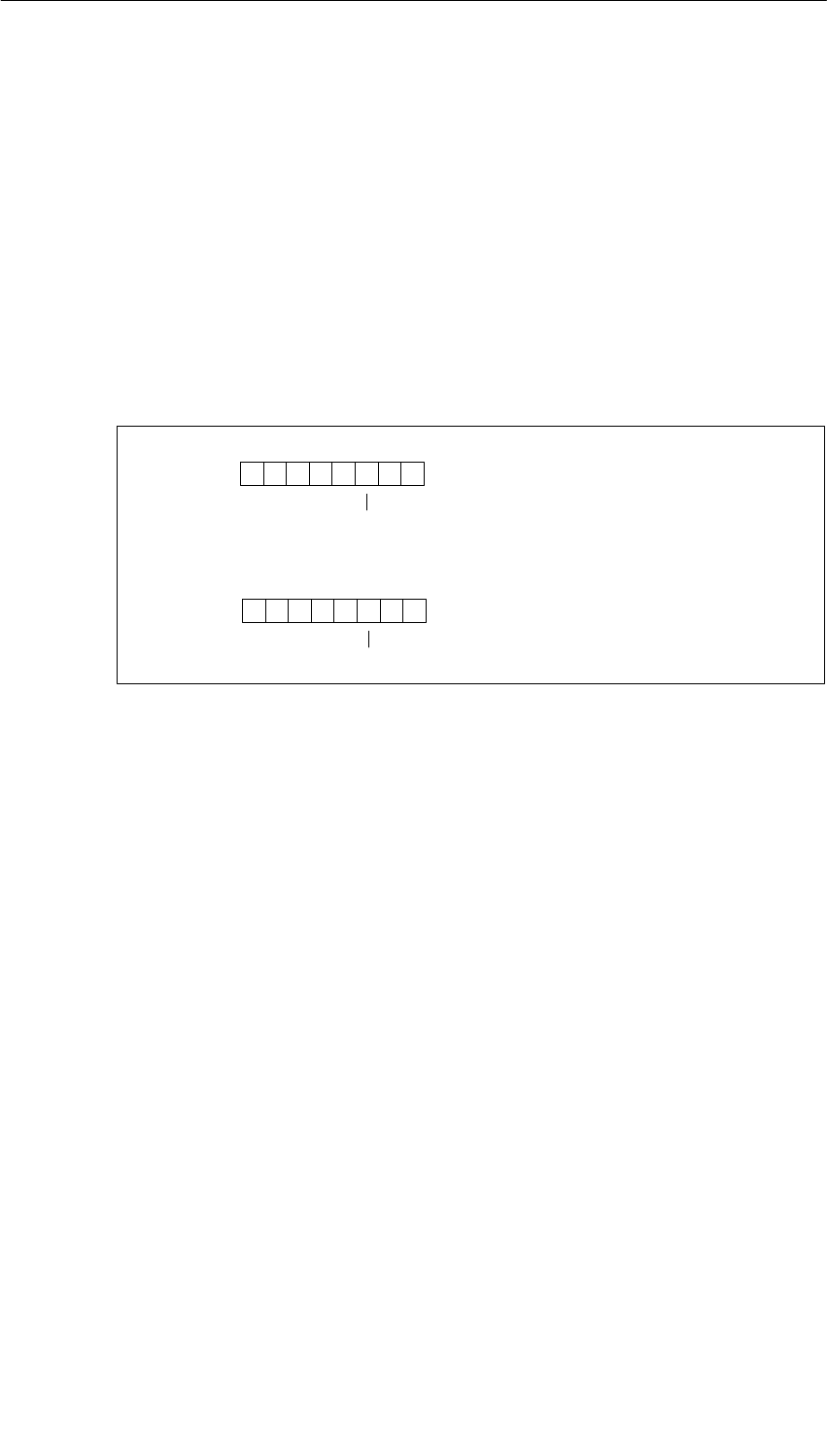
Diagnostic Data of the Signal Modules
B-8 S7-400, M7-400 Programmable Controllers Module Specifications
A5E00069467-07
B.4 Diagnostic Data of the Digital Output Modules
as of Byte 2
The structure and contents of the different bytes of the diagnostic data for special
digital output modules are described below. The following general rule applies:
When an error occurs, the bit concerned is set to ”1”.
You will find a description of possible error causes and appropriate remedies in the
section called on the special module.
Bytes 2 and 3 of the SM 422; DO 16 20-125 VDC/1.5 A
Byte 2
76 0
Operating status 0: RUN
1: STOP
54321
0
Byte 3
76 0
EPROM error
54321
0
0
000 0
000 000
0
Figure B-8 Bytes 2 and 3 of the Diagnostic Data of the SM 422;
DO 16 x 20-125 VDC/1.5 A
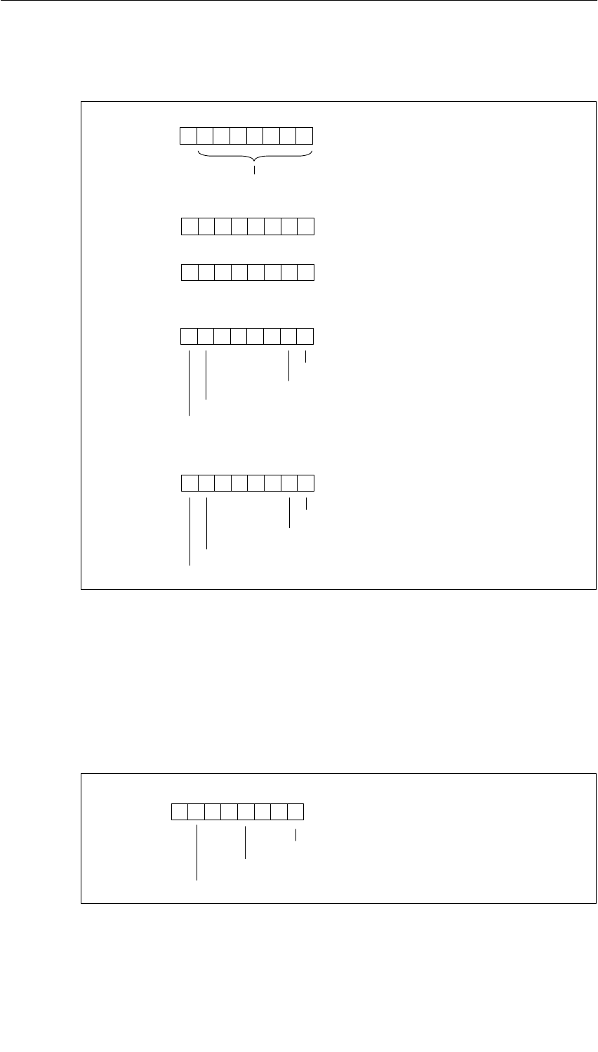
Diagnostic Data of the Signal Modules
B-9
S7-400, M7-400 Programmable Controllers Module Specifications
A5E00069467-07
Bytes 4 to 8 of the SM 422; DO 16 20-125 VDC/1.5 A
Byte 4
76 054321
Byte 5
70
Channel type B#16#72: digital output
Number of diagnostics bits that the module
outputs per channel: 8 bits long
Byte 6
70
Number of channels of the same
type in one module: 16 channels
0
Byte 7
76 0
Channel error, channel 0
Channel error, channel 1
Channel error, channel 6
Channel error, channel 7
54321
...
Byte 8
76 0
Channel error, channel 14
Channel error, channel 15
54321
...
Channel error, channel 8
Channel error, channel 9
Figure B-9 Bytes 4 to 8 of the Diagnostic Data of the SM 422; DO 16 x 20-125 VDC/1.5 A
Bytes 9 to 24 of the SM 421; DO 16 20-125 VDC/1.5 A
Data record 1 with bytes 9 to 24 contains the channel-specific diagnostic data. The
figure below shows the assignment of the diagnostic byte for a channel of the
module.
76 054321
0
Configuring/parameter assignment error
0000
External auxiliary supply missing
Short-circuit to M
Figure B-10 Diagnostic Byte for a Channel of the SM 422; DO 16 x 20-125 VDC/1.5 A

Diagnostic Data of the Signal Modules
B-10 S7-400, M7-400 Programmable Controllers Module Specifications
A5E00069467-07
Bytes 2 and 3 of the SM 422; DO 32 24 VDC/0.5 A
Byte 2
76 0
Operating status 0: RUN
1: STOP
Module-internal supply voltage failure
54321
0
Byte 3
76 0
EPROM error
54321
0
0
000 0
000 000
Figure B-11 Bytes 2 and 3 of the Diagnostic Data of the SM 422; DO 32 x 24 VDC/0.5 A
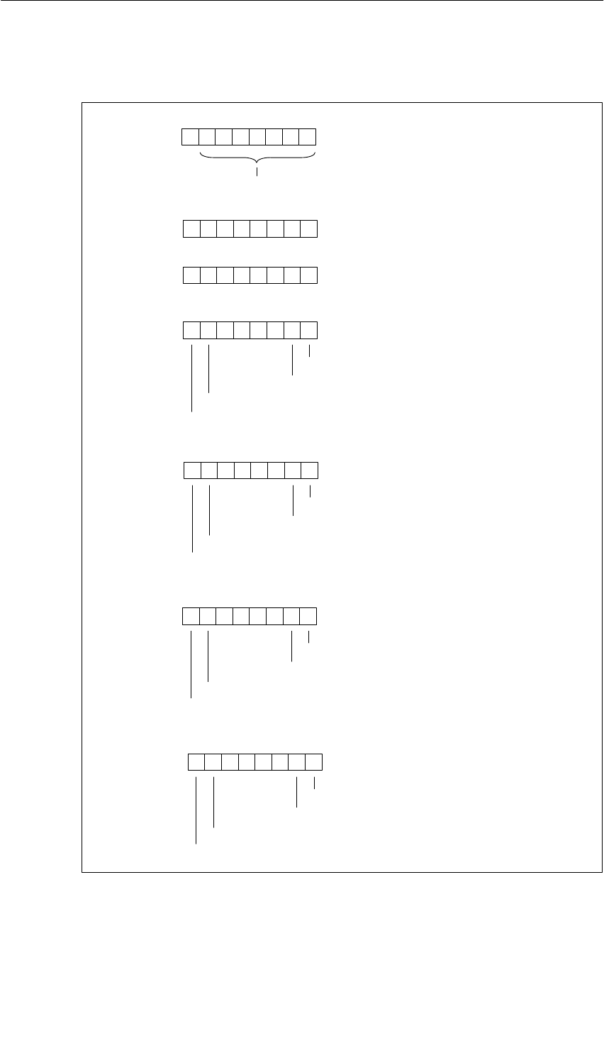
Diagnostic Data of the Signal Modules
B-11
S7-400, M7-400 Programmable Controllers Module Specifications
A5E00069467-07
Bytes 4 to 10 of the SM 422; DO 32 24 VDC/0.5 A
Byte 4
76 054321
Byte 5
70
Channel type B#16#72: digital output
Number of diagnostics bits that the module
outputs per channel: 8 bits long
Byte 6
70
Number of channels of the same
type in one module: 32 channels
Byte 7
76 0
Channel error, channel 0
Channel error, channel 1
Channel error, channel 6
Channel error, channel 7
54321
...
0
Byte 8
76 0
Channel error, channel 14
Channel error, channel 15
54321
...
Channel error, channel 8
Channel error, channel 9
Byte 9
76 0
Channel error, channel 17
Channel error, channel 22
Channel error, channel 23
54321
...
Channel error, channel 16
Byte 10
76 0
Channel error, channel 30
Channel error, channel 31
54321
... Channel error, channel 25
Channel error, channel 24
Figure B-12 Bytes 4 to 10 of the Diagnostic Data of the SM 422; DO 32 x 24 VDC/0.5 A

Diagnostic Data of the Signal Modules
B-12 S7-400, M7-400 Programmable Controllers Module Specifications
A5E00069467-07
Bytes 11 to 42 of the SM 422; DO 32 24 VDC/0.5 A
Data record 1 with bytes 11 to 42 contains the channel-specific diagnostic data.
The figure below shows the assignment of the diagnostic byte for a channel of the
module.
76 0
Short-circuit to L+
Short-circuit to M
Wire break
External auxiliary supply missing
54321
0
Configuring/parameter assignment error
00
Figure B-13 Diagnostic Byte for a Channel of the SM 422; DO 32 x 24 VDC/0.5 A
Bytes 2 and 3 of the SM 422; DO 16 20-120 VAC/2 A
Byte 2
76 0
Operating status 0: RUN
1: STOP
54321
0
Byte 3
76 0
EPROM error
54321
0
0
000 0
000 000
0
Figure B-14 Bytes 2 and 3 of the Diagnostic Data of the SM 422; DO 16 x 20-120 VAC/2 A
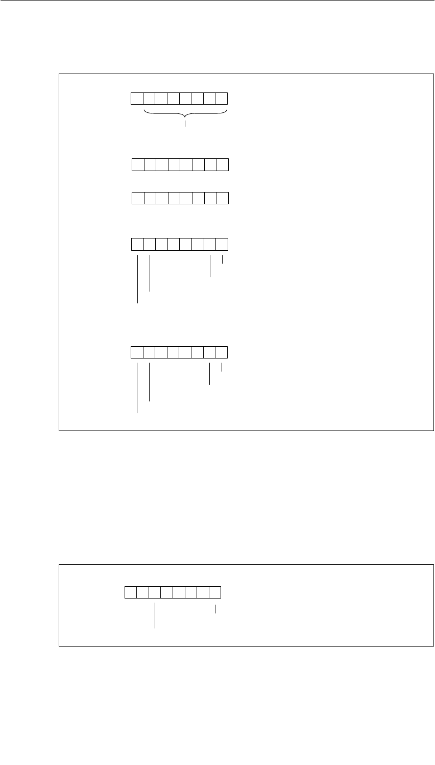
Diagnostic Data of the Signal Modules
B-13
S7-400, M7-400 Programmable Controllers Module Specifications
A5E00069467-07
Bytes 4 to 8 of the SM 422; DO 16 20-120 VAC/2 A
Byte 4
76 054321
Byte 5
70
Channel type B#16#72: digital output
Number of diagnostics bits that the module
outputs per channel: 8 bits long
Byte 6
70
Number of channels of the same
type in one module: 16 channels
0
Byte 7
76 0
Channel error, channel 0
Channel error, channel 1
Channel error, channel 6
Channel error, channel 7
54321
...
Byte 8
76 0
Channel error, channel 14
Channel error, channel 15
54321
...
Channel error, channel 8
Channel error, channel 9
Figure B-15 Bytes 4 to 8 of the Diagnostic Data of the SM 422; DO 16 x 20-120 VAC/2 A
Bytes 9 to 24 of the SM 422; DO 16 20-120 VAC/2 A
Data record 1 with bytes 9 to 24 contains the channel-specific diagnostic data. The
figure below shows the assignment of the diagnostic byte for a channel of the
module.
76 0
Fuse blown
54321
0
Configuring/parameter assignment error
00000
Figure B-16 Diagnostic Byte for a Channel of the SM 422; DO 16 x 20-120 VAC/2 A
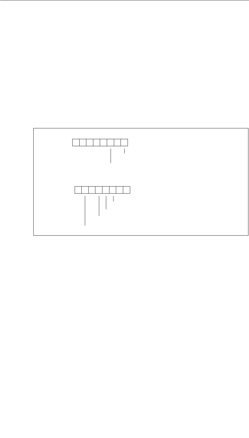
Diagnostic Data of the Signal Modules
B-14 S7-400, M7-400 Programmable Controllers Module Specifications
A5E00069467-07
B.5 Diagnostic Data of the Analog Input Modules
as of Byte 2
The structure and contents of the different bytes of the diagnostic data for the
special analog input modules are described below. The following general rule
applies: When an error occurs, the bit concerned is set to ”1”.
You will find a description of possible error causes and appropriate remedies in the
section called on the special module.
Bytes 2 and 3 of the SM 431; AI 16 16 Bit
Byte 2
76 0
Measuring range module incorrect or missing
Operating status 0: RUN
1: STOP
54321
0
Byte 3
76 0
EPROM error
RAM error
ADC/DAC error
Hardware interrupt lost
54321
0
0000 0
000
Figure B-17 Bytes 2 and 3 of the Diagnostic Data of the SM 431; AI 16 x 16 Bit
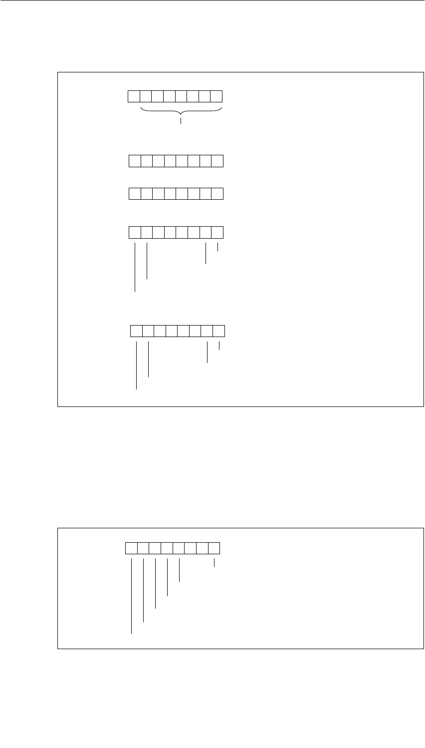
Diagnostic Data of the Signal Modules
B-15
S7-400, M7-400 Programmable Controllers Module Specifications
A5E00069467-07
Bytes 4 to 8 of the SM 431; AI 16 16 Bit
Byte 4
76 054321
Byte 5
70
Channel type B#16#71: analog input
Number of diagnostics bits that the module
outputs per channel: 8 bits long
Byte 6
70
Number of channels of the same
type in one module: 16 channels
Byte 7
76 0
Channel error, channel 0
Channel error, channel 1
Channel error, channel 6
Channel error, channel 7
54321
...
0
Byte 8
76 0
Channel error, channel 14
Channel error, channel 15
54321
...
Channel error, channel 8
Channel error, channel 9
Figure B-18 Bytes 4 to 8 of the Diagnostic Data of the SM 431; AI 16 x 16 Bit
Bytes 9 to 24 of the SM 431; AI 16 x 16 Bit
Data record 1 with bytes 9 to 24 contains the channel-specific diagnostic data. The
figure below shows the assignment of the diagnostic byte for a channel of the
module.
76 0
Configuring/parameter assignment error
Wire break
Underflow
Overflow
54321
Short-circuit to M
Reference channel error
00
Figure B-19 Diagnostic Byte for a Channel of the SM 431; AI 16 x 16 Bit
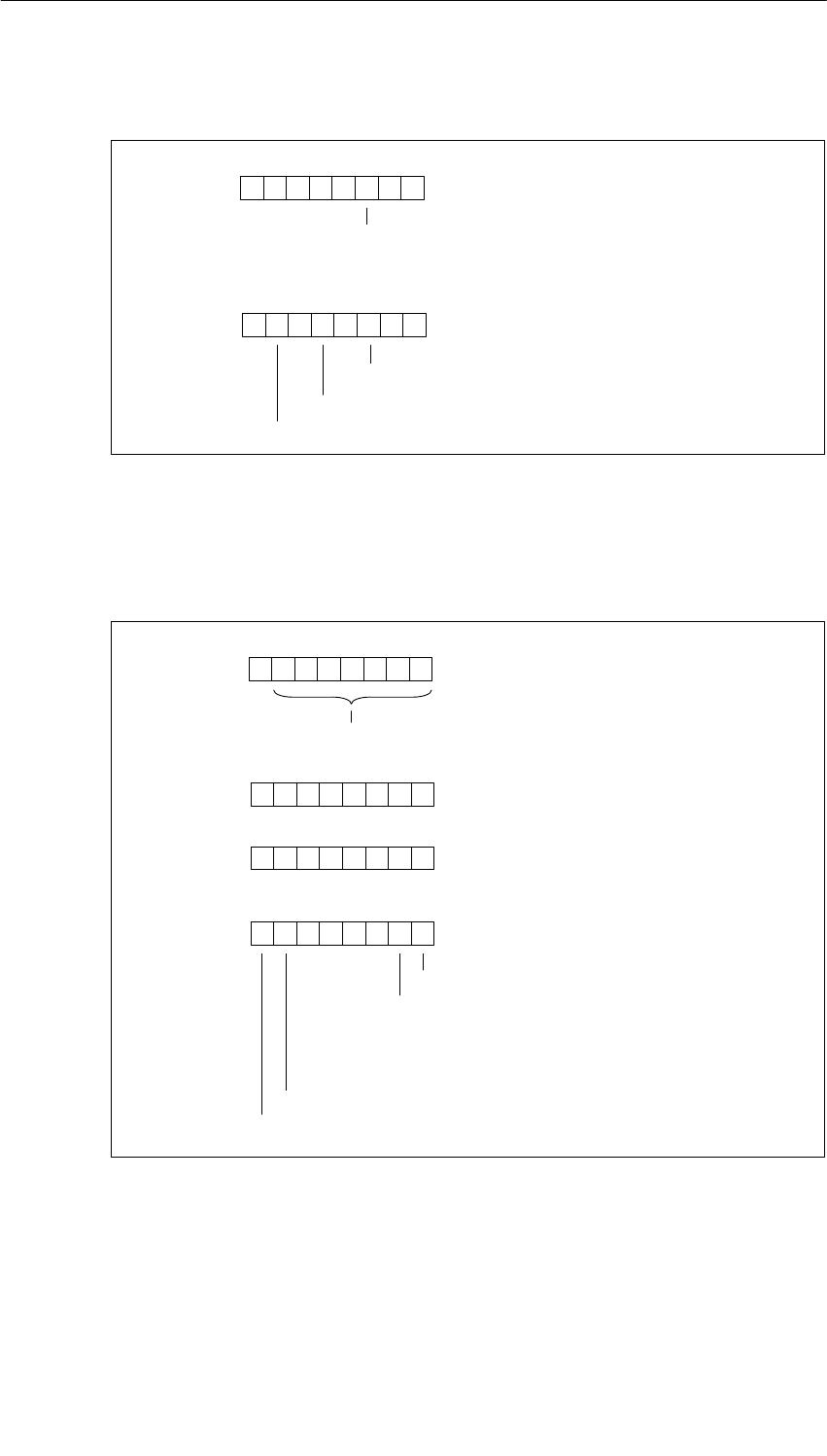
Diagnostic Data of the Signal Modules
B-16 S7-400, M7-400 Programmable Controllers Module Specifications
A5E00069467-07
Bytes 2 and 3 of the SM 431; AI 8 RTD 16 Bit
Byte 2
76 0
Operating status 0: RUN
1: STOP
54321
0
Byte 3
76 0
EPROM error
ADC/DAC error
Hardware interrupt lost
54321
0
0000 0
000
0
0
Figure B-20 Bytes 2 and 3 of the Diagnostic Data of the SM 431; AI 8 x RTD x 16 Bit
Bytes 4 to 7 of the SM 431; AI 8 RTD 16 Bit
Byte 4
76 054321
Byte 5
70
Channel type B#16#71: analog input
Number of diagnostics bits that the module
outputs per channel: 16 bits long
Byte 6
70
Number of channels of the same
type in one module: 8 channels
Byte 7
76 0
Channel error, channel 0
Channel error, channel 1
Channel error, channel 6
Channel error, channel 7
54321
...
...
...
...
...
0
Figure B-21 Bytes 4 to 7 of the Diagnostic Data of the SM 431; AI 8 x RTD x 16 Bit

Diagnostic Data of the Signal Modules
B-17
S7-400, M7-400 Programmable Controllers Module Specifications
A5E00069467-07
Bytes 8 to 23 of the SM 431; AI 8 RTD 16 Bit
Data record 1 with bytes 8 to 23 contains channel-specific diagnostic data. The
following figure shows the assignment of the even diagnostic bytes (bytes 8, 10, to
22) for a channel of the module.
76 0
Configuring/parameter assignment error
Wire break
Underflow
Overflow
54321
0000
Figure B-22 Even Diagnostic Byte for a Channel of the SM 431; AI 8 x RTD x 16 Bit
The following figure shows the assignment of the odd diagnostic bytes (bytes 9,
11, to 23) for a channel of the module.
76 0
User connection not wired
Run time calibration error
Underrange or overrange
54321
0
Open conductor in + direction
Open conductor in – direction
Open conductor in the current source
User calibration doesn’t correspond to the parameter assignment
Figure B-23 Odd Diagnostic Byte for a Channel of the SM 431; AI 8 x RTD x 16 Bit
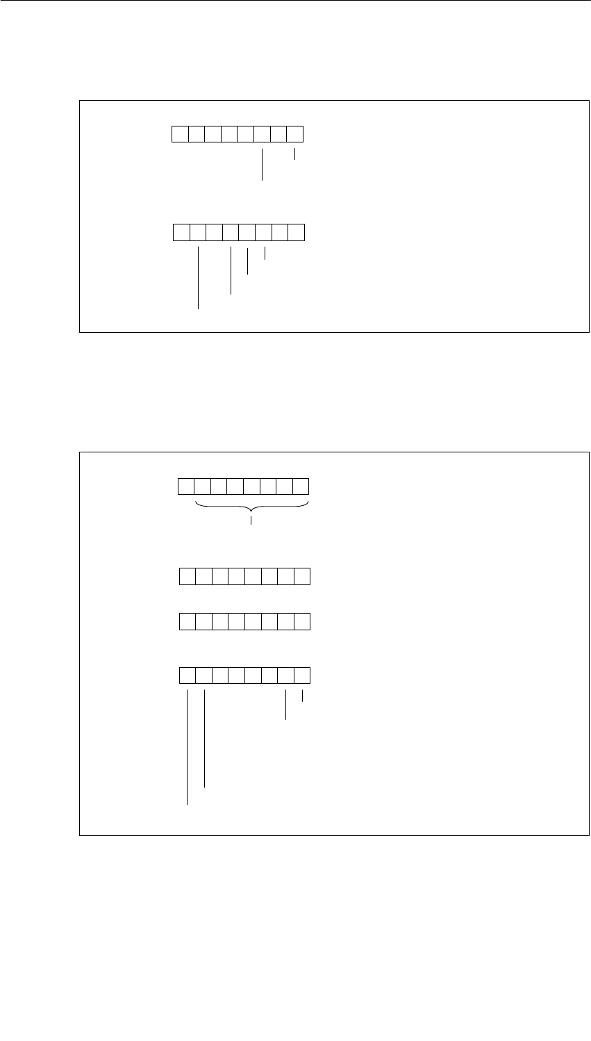
Diagnostic Data of the Signal Modules
B-18 S7-400, M7-400 Programmable Controllers Module Specifications
A5E00069467-07
Bytes 2 and 3 of the SM 431; AI 8 16 Bit
Byte 2
76 0
Operating status 0: RUN
1: STOP
54321
0
Byte 3
76 0
EPROM error
ADC/DAC error
Hardware interrupt lost
54321
0
0000 0
000
Thermocouple connection error
RAM error
Figure B-24 Bytes 2 and 3 of the Diagnostic Data of the SM 431; AI 8 x 16 Bit
Bytes 4 to 7 of the SM 431; AI 8 16 Bit
Byte 4
76 054321
Byte 5
70
Channel type B#16#71: analog input
Number of diagnostic bits that the module
outputs per channel: 16 bits long
Byte 6
70
Number of channels of the same
type in one module: 8 channels
Byte 7
76 0
Channel error, channel 0
Channel error, channel 1
Channel error, channel 6
Channel error, channel 7
54321
...
...
...
...
...
0
Figure B-25 Bytes 4 to 7 of the Diagnostic Data of the SM 431; AI 8 x 16 Bit
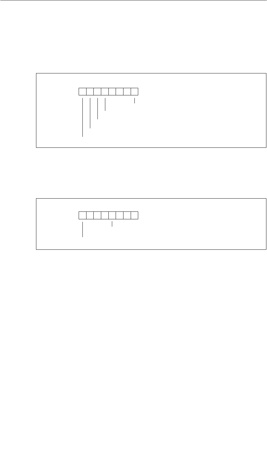
Diagnostic Data of the Signal Modules
B-19
S7-400, M7-400 Programmable Controllers Module Specifications
A5E00069467-07
Bytes 8 to 23 of the SM 431; AI 8 16 Bit
Data record 1 with bytes 8 to 23 contains channel-specific diagnostic data. The
following figure shows the assignment of the even diagnostic bytes (bytes 8, 10, to
22) for a channel of the module.
76 0
Configuring/parameter assignment error
Wire break
Underflow
Overflow
54321
000
Reference channel error
Figure B-26 Even Diagnostic Byte for a Channel of the SM 431; AI 8 x 16 Bit
The following figure shows the assignment of the odd diagnostic bytes (bytes 9,
11, to 23) for a channel of the module.
76 0
Run time calibration error
54321
0
User calibration doesn’t correspond to the parameter assignment
0 0 000
Figure B-27 Odd Diagnostic Byte for a Channel of the SM 431; AI 8 x 16 Bit

Diagnostic Data of the Signal Modules
B-20 S7-400, M7-400 Programmable Controllers Module Specifications
A5E00069467-07

C-1
S7-400, M7-400 Programmable Controllers Module Specifications
A5E00069467-07
Spare Parts and Accessories
Spare Parts and Accessories
For Racks
Number wheel for slot labeling C79165-Z1523-A22
Spare slot covers (qty 10) 6ES7490-1AA00-0AA0
For Power Supplies
Spare connector for PS 405 (DC) 6ES7490-0AA00-0AA0
Spare connector for PS 407 (AC) 6ES7490-0AB00-0AA0
Backup battery 6ES7971-0BA00
For CPUs
Key for CPU mode selector switch 6ES7911-0AA00-0AA0
2 Mbyte memory submodule 6ES7911-0AA00-0AA0
4 Mbyte memory submodule 6ES7911-0AA00-0AA0
For Digital Modules/Analog Modules
Cover foil (10 x) for labeling strips of the SMs 6ES7492-2XX00-0AA0
Cover flap for fuse receptacle on the AC modules 6ES7422-0XX00-7AA0
Measuring range module for analog modules 6ES7974-0AA00-0AA0
Front connector screw-type connection 6ES7492-1AL00-0AA0
Front connector spring connection 6ES7492-1BL00-0AA0
Front connector crimp connection 6ES7492-1CL00-0AA0
Crimping tool for crimp contacts 6XX3 071
Crimp contacts (package of 250) 6XX3 070
Extraction tool for crimp contacts 6ES5 497-8MA11
Fuses, 8 A, quick blow
•Wickmann
•Schurter
•Littelfuse
194-1800-0
SP001.1013
217.008
Labeling sheet for the front connector, petrol blue 6ES7492-2AX00-0AA0
Labeling sheet for the front connector, beige 6ES7492-2BX00-0AA0
Labeling sheet for the front connector, yellow 6ES7492-2CX00-0AA0
Labeling sheet for the front connector, red 6ES7492-2DX00-0AA0
C

Spare Parts and Accessories
C-2 S7-400, M7-400 Programmable Controllers Module Specifications
A5E00069467-07
For IMs
Terminating connector for IM 461-0 6ES7461-0AA00-7AA0
Terminating connector for IM 461-1 6ES7461-1AA00-7AA0
Terminating connector for IM 461-3 6ES7461-3AA00-7AA0
IM 463-2, send IM, 600 m to IM 314 of the S5 6ES7463-2AA00-0AA0
IM cable with communication bus, 0.75 m 6ES7468-1AH50-0AA0
IM cable with communication bus, 1.5 m 6ES7468-1BB50-0AA0
IM cable with communication bus, 5 m 6ES7468-1BF00-0AA0
IM cable with communication bus, 10 m 6ES7468-1CB00-0AA0
IM cable with communication bus, 25 m 6ES7468-1CC50-0AA0
IM cable with communication bus, 50 m 6ES7468-1CF00-0AA0
IM cable with communication bus, 100 m 6ES7468-1DB00-0AA0
IM cable with current transmission, 0.75 m 6ES7468-3AH50-0AA0
IM cable with current transmission, 1.5 m 6ES7468-3BB50-0AA0
For CP 441
IF963-RS232 interface submodule 6ES7961-1AA00-0AA0
IF963-TTY interface submodule 6ES7961-2AA00-0AA0
IF963-X27 interface submodule 6ES7961-3AA00-0AA0
IF module L2-DP 6ES7964-2AA00-0AB0
For Interfacing / Networking
RS 485 repeater 6ES7972-0AA00-0XA0
DIN rail 6ES5710-8MA...
PROFIBUS bus cable 6XV1830-0BH10
6XV1830-3BH10
PROFIBUS internal cable 6XV1830-0BH10
PROFIBUS grounding cable 6XV1830-3BH10
PROFIBUS bus connector without PG socket 6ES7972-0BA00-0XA0
PROFIBUS bus connector with PG socket 6ES7972-0BB10-0XA0
PROFIBUS bus connector without PG socket for CPU 417 6ES7972-0BA40-0X40
PROFIBUS bus connector with PG socket for CPU 417 6ES7972-0BB40-0X40
PROFIBUS RS 485 bus terminal 6GK1500-0AA00
6GK1500-0AB00
6GK1500-0DA00
PG cable, short 6ES7901-0BF00-0AA0
PG 705 cable 6ES7705-0AA00-7BA0
PC/MPI cable (5 m) 6ES7901-2BF00-0AA0
PC/MPI cable (16 m) 6ES7901-2CB60-0AA0
For Fan Subassembly
Spare fan for fan subassembly 6ES7408-1TA00-6AA0
Filters (qty 10) for fan subassembly 6ES7408-1TA00-7AA0
Monitoring PCB for fan subassembly 6ES7408-1TX00-6XA0
Power supply PCB for fan subassembly 6ES7408-1XX00-6XA0
Cabinets
Cabinet 2200 x 800 x 400 with extension set for
SIMATIC S7-400 8 MC 2281-7FC11-8DA1
Extension set for SIMATIC S7-400 8 MC 1605-0BS70-0AA0
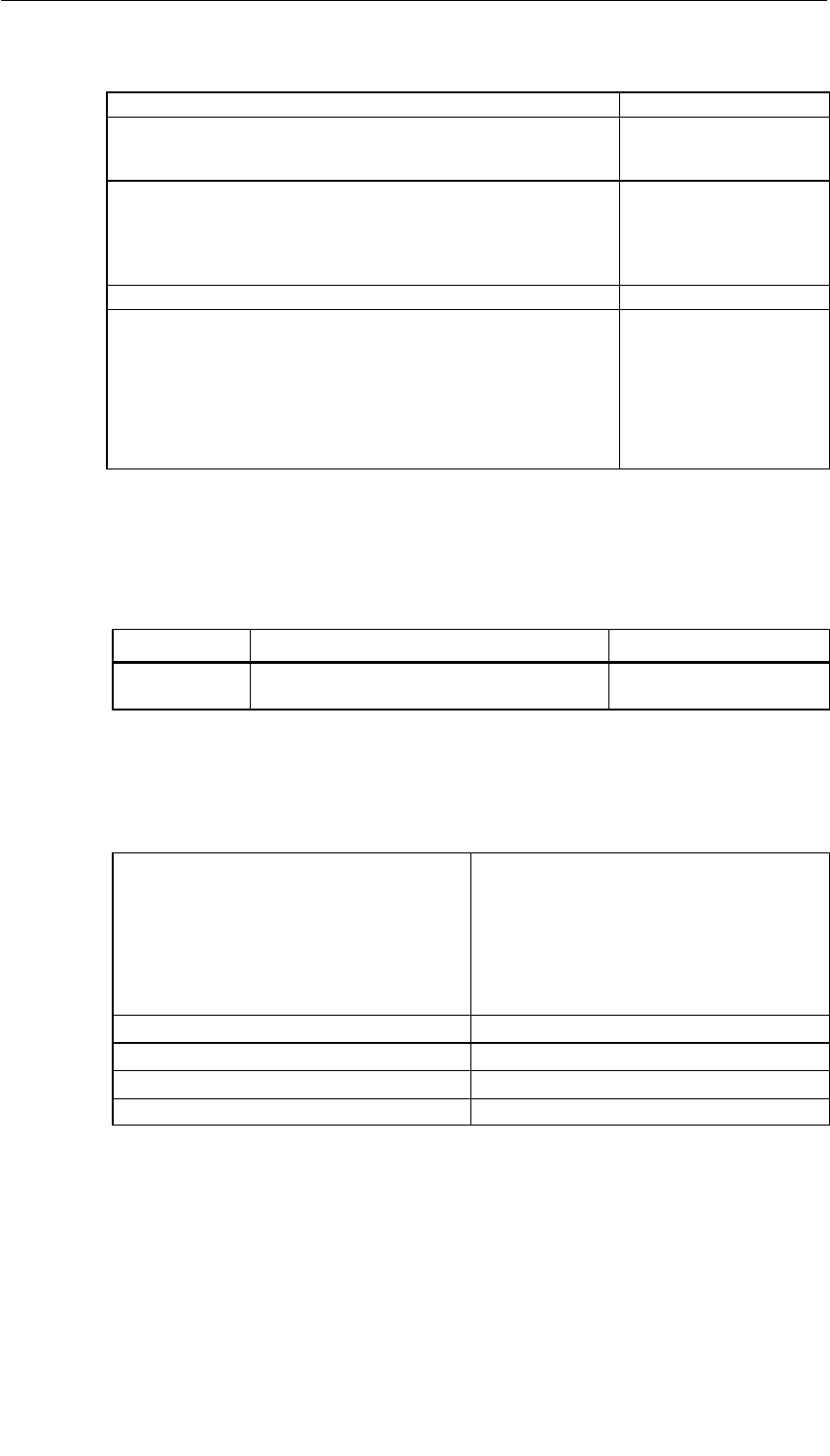
Spare Parts and Accessories
C-3
S7-400, M7-400 Programmable Controllers Module Specifications
A5E00069467-07
Cables
Connecting cables for printers with
•Serial port (COM, 10 m)
•Parallel port (Centronics) 9AB4173-2BN10-0CA0
6AP1901-0AL00
Connecting cable for interface module
•1
6ES7368 3BB00 0AA0
g
•1 m
•
25 m
6ES7368-3BB00-0AA0
6ES7368
-
3BC00
-
0AA0
•2
.
5 m
•5 m
6ES7368
-
3BC00
-
0AA0
6ES7368-3BF00-0AA0
5 m
•10 m
6ES7368 3BF00 0AA0
6ES7368-3CB00-0AA0
V.24 cable 9AB4173-2BN10-0CA0
Connector housing, gray
•9-pin
•15-pin
•25-pin
V42254-A6000-G109
V42254-A6000-G115
V42254-A6000-G125
25 pin
Connector housing, black
•9-pin
•15-pin
•25-pin
V42254 A6000 G125
V42254-A6001-G309
V42254-A6001-G315
V42254-A6001-G325
Memory Submodules for M7-400
The following table lists the memory submodules that can be used in the
CPU 486-3 and CPU 488-3.
Product Description Order No.
MEM 478 Memory submodule for main memory
DRAM 2 x 8 Mbytes/3.3 V 6ES7791-0EP00-0XA0
In the CPUs the memory submodules must always be used in pairs.
Spare Parts for M7-400 Modules
Memory cards
•Flash EPROM, 1 Mbyte
•Flash EPROM, 2 Mbytes
•Flash EPROM, 4 Mbytes
•Flash EPROM, 8 Mbytes
•Flash EPROM, 16 Mbytes
6ES7952-1KK00-0AA0
6ES7952-1KL00-0AA0
6ES7952-1KM00-0AA0
6ES7952-1KP00-0AA0
6ES7952-1KS00-0AA0
10 cover foils for SM labeling strips 6ES7492-2XX00-0AA0
Cover flap for fuse receptacle, AC-SM 6ES7422-0XX00-7AA0
12 spare submodule covers 6ES7398-0BA00-0AA0
6 connecting clips 6ES7498-6BA00-0AA0

Spare Parts and Accessories
C-4 S7-400, M7-400 Programmable Controllers Module Specifications
A5E00069467-07
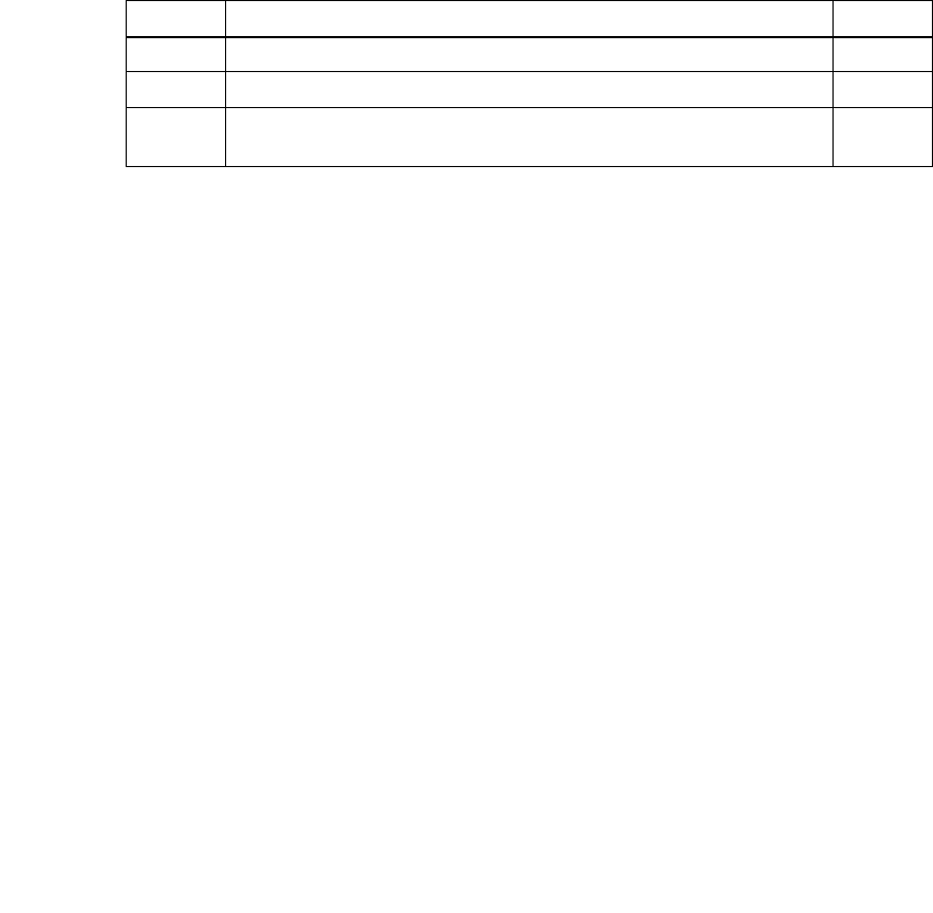
D-1
S7-400, M7-400 Programmable Controllers Module Specifications
A5E00069467-07
Guidelines for Handling Electrostatic
Sensitive Devices (ESD)
Introduction
In this appendix, we explain
•what is meant by “electrostatic sensitive devices”
•the precautions you must observe when handling and working with electrostatic
sensitive devices.
Chapter Overview
This chapter contains the following sections on electrostatic sensitive devices:
Section Description Page
D.1 What is ESD? D-2
D.2 Electrostatic Charging of Persons D-3
D.3 General Protective Measures Against Electrostatic Discharge
Damage D-4
D

Guidelines for Handling Electrostatic Sensitive Devices (ESD)
D-2 S7-400, M7-400 Programmable Controllers Module Specifications
A5E00069467-07
D.1 What is ESD?
Definition
All electronic modules are equipped with large-scale integrated ICs or components.
Due to their design, these electronic elements are very sensitive to overvoltages
and thus to any electrostatic discharge.
These Electrostatic Sensitive Devices are commonly referred to by the
abbreviation ESD.
Electrostatic sensitive devices are labelled with the following symbol:
!Caution
Electrostatic sensitive devices are subject to voltages that are far below the
voltage values that can still be perceived by human beings. These voltages are
present if you touch a component or the electrical connections of a module without
previously being electrostatically discharged. In most cases, the damage caused
by an overvoltage is not immediately noticeable and results in total damage only
after a prolonged period of operation.

Guidelines for Handling Electrostatic Sensitive Devices (ESD)
D-3
S7-400, M7-400 Programmable Controllers Module Specifications
A5E00069467-07
D.2 Electrostatic Charging of Persons
Charging
Every person with a non-conductive connection to the electrical potential of its
surroundings can be charged electrostatically.
Figure D-1 shows you the maximum values for electrostatic voltages which can
build up on a person coming into contact with the materials indicated in the figure.
These values are in conformity with the specifications of IEC 61000-4-2.
Voltage in kV
1
2
3
4
5
6
7
8
9
10
11
12
13
14
15
16
(kV
)
51020 30 40 50 60 70 80 90 100 Relative air
humidity in %
1
3
1Synthetic material
2Wool
3Antistatic material,
for example, wood
or concrete
2
Figure D-1 Electrostatic Voltages which Can Build up on a Person

Guidelines for Handling Electrostatic Sensitive Devices (ESD)
D-4 S7-400, M7-400 Programmable Controllers Module Specifications
A5E00069467-07
D.3 General Protective Measures Against Electrostatic
Discharge Damage
Ensure Sufficient Grounding
Make sure that the personnel, working surfaces and packaging are sufficiently
grounded when handling electrostatic sensitive devices. You thus avoid
electrostatic charging.
Avoid Direct Contact
You should touch electrostatic sensitive devices only if it is unavoidable
(for example, during maintenance work). Hold modules without touching the pins of
components or printed conductors. In this way, the discharged energy cannot affect
the sensitive devices.
If you have to carry out measurements on a module, you must discharge your body
before you start the measurement by touching grounded metallic parts. Use
grounded measuring devices only.

E-1
S7-400, M7-400 Programmable Controllers Module Specifications
A5E00069467-07
List of Abbreviations
Abbreviation Explanation
AC Alternating current
ADC Analog to digital converter
AI Aanalog input
AO Analog output
AS Automation system
BAF Battery failure
BUSF1;
BUSF2 LED – bus failure on the MPI/Profibus DP interface 1 or 2
CD Central device
CH Channel
COMP Compensating terminal
CP Communications processor
CR Central rack
CPU Central processing unit of a PLC
DAC Digital-to-analog converter
DB Data block
DC Direct current
DI Digital input
DO Digital output
EMC Electromagnetic compatibility
EEPROM Electrically erasable programmable read-only memory
EPROM Erasable programmable read-only memory
ER Expansion rack
ES Encoder supply
ESD Electrostatic sensitive devices
EWS Apply substitute value
EXM Extension module
EXTF Error LED “external fault”
FB Function block
FBD Function block diagram
E

List of Abbreviations
E-2 S7-400, M7-400 Programmable Controllers Module Specifications
A5E00069467-07
FC Function
FEPROM Flash erasable programmable read only memory
FM Function module
FOC Fiber-optic cable
FRCE Force
GD Global data communication
ICConstant-current lead
ID Input delay
IFM1F; IFM2F LED error at interface module 1/2
IM Interface module
INTF Error LED “internal fault”
IP Intelligent periphery
L+ Terminal for 24 VDC supply voltage
LAD Ladder logic diagram
LWH Hold last valid value
MGround terminal
M+ Measuring lead (positive)
M– Measuring lead (negative)
MANA Reference potential of the analog measuring circuit
MPI Multipoint interface
MRES Master reset
MSM Mass storage module
MSTR Master
OB Organization block
OP Operator panel
OS Operator system
PIQ Process-image output table
PII Process-image input table
PLC Programmable logic controller
PG Programming device
PS Power supply
QIAnalog output current
QVAnalog output voltage
RAM Random access memory
REDF Redundancy fault
RLLoad impedance

List of Abbreviations
E-3
S7-400, M7-400 Programmable Controllers Module Specifications
A5E00069467-07
S + Sensor lead (positive)
S – Sensor lead (negative)
SCL Structured control language
SP Sensor power
SF “Group error” LED
SFB System function block
SFC System function
SM Signal module
SSI Synchronous serial interface
SSL System status list
STL Statement list
TD Text display
TR Transducer
UCM Common mode voltage
UHAuxiliary voltage
Uiso Potential difference between MANA and local ground
UC Universal current
UR Universal rack
USR USR
Vs Sensor voltage
VZ Sign

Glossary-1
S7-400, M7-400 Programmable Controllers Module Specifications
A5E00069467-07
Glossary
Address An address denotes a specific operand or address area; examples of this are:
input I 12.1; memory word MW 25; data block DB 3.
Aggregate current
Sum of the currents of all output channels on a digital output module.
Backplane bus
The backplane bus is a serial data bus that is used by the modules to
communicate with each other and to supply them with the voltage they require.
The interconnection of the modules is established by the bus connector.
Backup battery
The backup battery ensures that the ³ user program is stored in a
powerfail-proof manner in the ³ CPU, and that defined data areas and memory
markers, timers and counters are kept ³ retentively.
Backup voltage, external
You can obtain the same kind of backup if you apply backup voltage to the ”EXT.-
BATT.” socket of the CPU (DC voltage between 5 V and 15 V) as you can with a
backup battery.
External backup voltage is required if you want to replace a power supply module
and to provide a backup supply while the user program and data (for example,
memory markers, timers, counters, system data, integrated clock) stored in RAM
are to be buffered for the time it takes to replace the module.
Bus A bus is a transmission medium that interconnects several nodes. Data
transmission can be serial or parallel, and be performed over electric conductors
or fiber-optic cables.

Glossary
Glossary-2 S7-400, M7-400 Programmable Controllers Module Specifications
A5E00069467-07
Bus connector
A physical connection between the bus nodes and the bus cable.
Bus segment
A bus segment is a self-contained section of a serial bus system. Bus segments
are interconnected by means of ³ repeaters.
Central controller
An S7-400 consists of a central controller (CC) that can be allocated expansion
units (EU), as required. The central controller is the mounting rack that contains
the ³ CPU.
Central processing unit
³ CPU
Cold restart
³ Restart of the programmable controller and its user program, after all the
dynamic data (variables of the input/output image, internal registers, timers,
counters, etc. and the corresponding program sections) have been reset to a
specified value.
A cold restart can be automatically triggered, such as after a power failure or loss
of information in dynamic memory sections, etc., or manually by pressing the
reset key.
Common mode voltage
A voltage that is common to all inputs/outputs of a group and is measured
between this group and any reference point (usually to ground).
Communication load
This is the load on the cyclic program scanning of a CPU caused by
communication operations (for example, via ³ PROFIBUS DP).
To prevent communication operations overloading cyclic program scanning, you
can set the maximum permissible load that communication can place on the scan
cycle by parameter assignment in STEP 7.
Communication processor
Programmable module for communication tasks, such as networking,
point-to-point connection.

Glossary
Glossary-3
S7-400, M7-400 Programmable Controllers Module Specifications
A5E00069467-07
Comparison point
Parameter in STEP 7 for analog input modules. Using this parameter, you can
determine the reference junction (the point where the temperature is known)
when thermocouples are used. The following can be reference junctions:
resistance thermometer on channel 0 of the module; ³ compensating box,
³ reference temperature.
Compensating box
Compensating boxes can be used for measuring temperatures with
thermocouples on analog input modules. The compensating box is a
compensation circuit for compensating temperature fluctuations at the
³ reference junction.
Configure Select and put together different components on a programmable controller and
install the requisite software (for example, operating system on M7 automation
computer) and adapt to the specific use (for example, by assigning parameters to
the modules).
CP
³ Communication processor
CPU The CPU (central processing unit) is a CPU module of the ³ programmable
controller that stores and runs the user program. It contains the operating
system, memory, processing unit and communication interface.
Data block Data blocks (DB) are data areas in the user program that contain user data.
Global data blocks can be accessed by all code blocks, whereas instance data
blocks are assigned to a specific FB call.
Data, static Static data is data that can only be used within a ³ function block. The data is
saved in an instance data block belonging to the function block. The data stored
in this way is retained until the next function block call.
Data, temporary
Temporary data are ³ local data of a block that are stored in the L stack during
execution of a block and that are no longer available after execution.

Glossary
Glossary-4 S7-400, M7-400 Programmable Controllers Module Specifications
A5E00069467-07
Declaration Assigning variables (parameters or local data of a block, for example) with a
name, data type, comment, etc.
Default setting
The default setting is a sensible basic setting that is used whenever no other
value is used.
Destination CPU for interrupt
Parameter in STEP 7. If several CPUs are installed, the user can use this
parameter to select the destination CPU for hardware and diagnostic interrupts.
Diagnostic buffer
The diagnostic buffer is a buffered memory area in the CPU in which the
diagnostic events are stored in the order in which they occur.
For troubleshooting, the user can read out the exact error cause in STEP 7 (PLC
-> Module Information) from the diagnostic buffer.
Diagnostic data
All the diagnostic events that occur are collected in the CPU and entered in the
³ diagnostic buffer. If there is an error OB, it is started.
Diagnostic interrupt
Modules with diagnostics capability report system errors to the ³ CPU by means
of diagnostic interrupts. The operating system of the CPU calls OB 82 in the
course of a diagnostic interrupt.
DiagnosticsGeneric term for ³ system diagnostics, process error diagnostics and
user-defined diagnostics.
Direct access
This is the direct accessing of the CPU by means of the ³ I/O bus to modules,
bypassing the ³ process image.

Glossary
Glossary-5
S7-400, M7-400 Programmable Controllers Module Specifications
A5E00069467-07
Direct communication
Direct communication involves assigning local input address areas of an
intelligent DP slave (for example, CPU 315-2 with PROFIBUS DP connection) or
of a DP master to the input address areas of a PROFIBUS DP partner. The
intelligent DP slave or DP master receives the input data that the PROFIBUS DP
partner sends to its DP master via these assigned input address areas.
DP master A node with a master function in the PROFIBUS DP. A master that behaves in
accordance with the EN 50170 with the DP protocol is a DP master. The bus
access right (token) is only passed amongst masters. The slaves, in this case DP
slaves, can only respond on the request of a master. The following distinctions
are made:
DP master (class 1): executes the user data communication with the DP slaves
assigned to it.
DP master (class 2): provides services such as: reading of the input/output data,
diagnostics, global control.
DP slave A ³ slave that is operated on the PROFIBUS bus system with the
PROFIBUS DP protocol is called a DP slave.
Edge, falling
Signal status change from 1 to 0
Edge, risingSignal status change from 0 to 1
EEPROM Electrically erasable programmable read-only memory
EPROM Erasable programmable read-only memory
Equidistance
Equidistance is a DP bus cycle that is accurate to a few s and can be configured
in STEP 7.

Glossary
Glossary-6 S7-400, M7-400 Programmable Controllers Module Specifications
A5E00069467-07
Equipotential bonding
An electrical connection (equipotential bonding conductor) that brings the bodies
of electrical resources and foreign conductive bodies to an identical or
approximately identical potential in order to avoid interfering or hazardous
voltages between these bodies.
External load memory
³ Memory card
FB
³ Function block
FC
³ Function
FEPROM In their ability to retain data in the event of a power failure (even without a backup
battery), FEPROMs (flash erasable programmable read only memories) are the
equivalent of the electrically erasable ³ EEPROMS, but can be erased
considerably more quickly.
Fiber-optic cable
A fiber-optic cable is a transmission medium made of glass fiber or plastic.
Fiber-optic cables are resistant to electromagnetic faults and they make fast data
transfer rates possible.
Force The “Force” function overwrites a variable (for example, memory marker, output)
with a value defined by the user.
At the same time, the variable is assigned write protection so that this value
cannot be modified from any point (including from the STEP 7user program). The
value is retained after the programming device is disconnected.
Write protection is not canceled until the ”Unforce” function is called and the
variable is written again with the value defined by the user program.
During commissioning, for example, the “Force” function allows certain outputs to
be set to the ”ON” state for any length of time even if the logic operations of the
user program are not fulfilled (for example, because inputs are not wired).
FREEZE Control command. The inputs of the ³ DP slaves are frozen to the current value.

Glossary
Glossary-7
S7-400, M7-400 Programmable Controllers Module Specifications
A5E00069467-07
Function A function (FC) in accordance with IEC 1131-3 is a ³ code block without
³ static data. A function allows parameters to be passed in the user program.
Functions are therefore suitable for programming complex functions, such as
calculations that are frequently repeated.
Functional grounding
Grounding which has the sole purpose of safeguarding the intended function of
the electrical equipment. Functional grounding short-circuits interference voltage
that would otherwise have an impermissible impact on the equipment.
Function block
A function block (FB) in accordance with IEC 1131-3 is a ³ code block with
³ static data. Because an FB has a memory, its parameters (outputs, for
example) can be accessed from any position in the user program.
Fuse blown Parameter in STEP 7 for digital output modules. When the parameter is enabled,
the failure of one or more fuses is detected by the module. With corresponding
parameter assignment, a ³ diagnostic interrupt is triggered.
Global data Global data are data that can be addressed from any ³ code block (FC, FB,
OB). In detail, this refers to bit memories (M), inputs (I), outputs (Q), timers,
counters and data blocks (DB). Absolute or symbolic access is possible to global
data.
Global data communication
Global data communication is a method of transferring ³ global data between
CPUs.
Ground The ground is the total number of all the interconnected inactive parts of a device
that cannot take on a hazardous voltage in the event of a fault.
Ground The conductive ground whose electric potential can be set to zero at any point.
In the proximity of grounding electrodes, the ground can have a potential other
than zero. The term ”reference ground” is frequently used to describe such
circumstances.

Glossary
Glossary-8 S7-400, M7-400 Programmable Controllers Module Specifications
A5E00069467-07
Ground, to To ground means to connect an electrically conductive part via a grounding
system to the grounding electrode (one or more conductive parts having a very
good contact to ground).
Hardware interrupt
A hardware interrupt is triggered by interrupt-triggering modules in response to a
particular event in the process (limit value violation; the module has completed
the cyclic change of its channels).
The hardware interrupt is reported to the CPU. In accordance with the priority of
this interrupt, the ³ organization block assigned to it is processed.
Input delay Parameter in STEP 7 for digital input modules. The input delay is used to
suppress injected interference. Interfering pulses from 0 ms to the set input delay
are suppressed.
The set input delay is subject to a tolerance that can be obtained from the
technical specifications of the module. A high input delay suppresses long
interfering pulses, whereas a low input delay suppresses short ones.
The permissible input delay depends on the length of the cable between the
encoder and the module. For example, a high input delay has to be set for long
unshielded supply conductors to the encoder (longer than 100m).
Integration time
The integration time is the inverse value of the ³ interference frequency
suppression in ms.
Interface, multipoint
³ MPI
Interference frequency suppression
Parameter in STEP 7 for analog input modules. The frequency of the AC network
can interfere with the measured value, especially with measurements in low
voltage ranges and with thermocouples. This parameter is used by the user to
specify the prevailing line frequency on his system.
Interrupt The SIMATIC S7 is familiar with 28 different run-time level, which govern running
of the user program. These run-time levels include interrupts such as hardware
interrupts, among other things. When an interrupt occurs, the operating system
automatically calls an assigned organization block in which the user can program
the reaction he wants (for example, in an FB).

Glossary
Glossary-9
S7-400, M7-400 Programmable Controllers Module Specifications
A5E00069467-07
Interrupt, diagnostic
³ Diagnostic Interrupt
Interrupt, end-of-scan-cycle
³ Hardwareinterrupt
Interrupt, hardware
³ Hardware interrupt
Interrupt response time
The interrupt response time is the time from when an interrupt signal first occurs
to calling the first instruction in the interrupt OB. The following general rule
applies: Higher priority interrupts take precedence. This means that the interrupt
response time is increased by the program processing time of the higher priority
interrupt OBs and interrupt OBs with the same priority that have not yet been
processed (queue).
I/O bus This is part of the ³ backplane bus in the programmable controller, optimized for
the rapid exchange of signals between the CPU(s) and the signal modules.
User data (for example, digital input signals of a signal module) and system data
(for example, default parameter data records of a signal module) are transferred
via the I/O bus.
Isolated With optically isolated input/output modules, the reference potentials of the
control and load circuit are galvanically isolated (by an optocoupler, contact
assembly or repeater, for example). Input/output circuits can be connected to
common potential.
Keep last value (KLV)
The module retains the last value read out before STOP mode.
Load memory
The load memory is part of a programmable module (CPU, CP). It contains
objects generated by the programming device (load objects). It is implemented
either as a plug-in memory card or a permanently integrated memory. In the case
of SIMATIC M7, the load memory can also be defined as a directory on the hard
disk.

Glossary
Glossary-10 S7-400, M7-400 Programmable Controllers Module Specifications
A5E00069467-07
Local data Local data are data assigned to a ³ code block that is declared in its
³ declaration section and its variable declaration. It includes (depending on the
block): formal parameters, ³ static data, ³ temporary data.
Logic blockIn the context of SIMATIC S7, a logic block is a block that contains part of the
STEP 7 user program. By contrast, a data block only contains data. There are
the following logic blocks: organization blocks (OBs), function blocks (FBs),
functions (FCs), system function block (SFBs), system functions (SFCs).
M7 Owing to its standardized AT computer architecture, automation computers
M7-300 and M7-400 represent a freely programmable expansion of the SIMATIC
automation platform. The hardware configuration is similar to that of a S7-300 or
S7-400. The user programs for the SIMATIC M7 can also be programmed in a
high-level language, such as C, or graphically.
Master When they are in possession of access rights on the ³ bus, masters can send
data to other nodes and request data from other nodes (= active node).
Measuring principle, instantaneous value encoding
A module with instantaneous value encoding is always used for very fast
measuring operations or variables that change very rapidly. In this process, the
module accesses the variable to be measured as fast as possible and delivers an
instantaneous snapshot of the signal at a particular time. Due to this measuring
procedure, the modules are more ”sensitive” than modules with an integrating
measuring procedure. Interference affecting the measured value can thus corrupt
the result. You must ensure when using these modules that the measuring signal
is clean by adhering strictly to the installation guidelines, for example.
Measuring principle, integrating
A module with an integrating measuring procedure is always used for
non-time-critical measuring operations. The integration time is inversely
proportional to the line frequency. You can set the latter in STEP 7. This then
gives you the integration time. If the line frequency is 50 Hz, the integration time
is 20 ms or an even multiple of that. Because the measured value is included up
to exactly this time period, at least one or more whole periods of the line
frequency, which may overlay the measuring signal, are also included. The
average value of the error is therefore included as zero (positive part of the first
half period = negative part of the second half period). Only the user signal is thus
recorded.

Glossary
Glossary-11
S7-400, M7-400 Programmable Controllers Module Specifications
A5E00069467-07
Measuring range module
Measuring range modules are plugged into the analog input modules for
adaptation to different measuring ranges.
Memory card
Pluggable load memory. Memory cards are credit-card size storage media for
CPUs and CPs. They are implemented as ³ RAM or ³ FEPROMs.
Memory reset
In a memory reset, the following memories of the CPU are deleted: working
memory, write/read area of the load memory, system memory.
In S7 and M7, the MPI parameters and diagnostic buffer are preserved.
In M7, the operating system is also rebooted when the memory of the M7
computer is reset by means of the mode selector.
Mode selector
Using the mode selector, the user can set the current operating mode of the CPU
(RUN, RUN-P, STOP) or reset the memory of the CPU (MRES).
Module filtering mode
By operating mode we mean:
1. The selection of an operating mode of the CPU using the mode switch or the
PG
2. The type of program execution in the CPU
MPI The multipoint interface (MPI) is the programming device interface of the
SIMATIC S7. It is used to access programmable modules (CPUs, CPs), text
displays and operator panel from a central point. The nodes on the MPI can
communicate with each other.
Multicomputing
Multicomputing operation is the synchronous operation of several (2 to 4) CPUs
in an appropriate central rack of the S7-400.
Multiprocessor operation
During multiprocessor operation, several CPUs access one or more master
interfaces for ³ PROFIBUS DP.

Glossary
Glossary-12 S7-400, M7-400 Programmable Controllers Module Specifications
A5E00069467-07
Non-isolated
In the case of non-isolated input/output modules, the reference potentials of the
control and load circuit are electrically connected.
OB
³ Organization block
Organization block
Organization blocks (OBs) form the interface between the operating system of
the CPU and the user program. The order in which the user program is
processed is defined in the organization blocks.
Operating mode
The SIMATIC S7 programmable controllers have the following operating modes:
STOP, ³ STARTUP, RUN and STOP.
Operating system
The operating system of the CPU organizes all functions and processes of the
CPU that are not tied to a specific control task.
Parameters 1st tag of a ³ logic block
2nd tag for setting the characteristics of a module (one or more per module).
When delivered to the customer, each module has a practical basic setting for its
parameters, which the user can modify in STEP 7.
PG
³ Programming device
PLC
³ Programmable controller
Point-to-point connection
Only two nodes are physically linked with one another in a point-to-point
connection. This type of communication link is used if the use of a
communication network is not recommended or when, for example, different
types of partners, such as a PLC and a process computer, are to be connected.

Glossary
Glossary-13
S7-400, M7-400 Programmable Controllers Module Specifications
A5E00069467-07
Priority class
The operating system of an S7 CPU has a maximum of 28 priority classes
(= program execution levels) – for cyclic program scanning or program scanning
controlled by hardware interrupt, for example.
Each priority class is assigned ³ organization blocks in which the user can
program a response. By default, the OBs have different priorities determining the
order in which they are executed or interrupted in the event that they are
activated simultaneously. The user can change the default priorities.
Process image
The signal states of the digital input and output modules are stored in the CPU in
a process image.
A distinction is made between the process input image and the process output
image. The process input image (PII) is read by the input modules before the
operating system scans the user program. The process output image (PIQ) is
transferred to the output modules at the end of program scanning.
Product status
Products having an identical order number are distinguished by their product
status. The product status is incremented for upwards compatible extensions,
modifications due to production reasons (use of new component parts and
components) and troubleshooting.
PROFIBUS-DP
Digital, analog and intelligent I/O modules and a wide range of field devices
complying with EN 50170, Part 3, such as drives or valve terminals, are moved
by the automation system to the process on site, over a distance of up to 23 km.
The modules and field devices are connected to the programmable controller by
means of the PROFIBUS-DP fieldbus and addressed in the same way as central
I/O.
Programmable controller
Programmable controllers (PLCs) are electronic controllers whose function is sto-
red as a program on the control device. The design and wiring of the device do
not therefore depend on the function of the controller.
The architecture of a programmable controller is similar to that of a computer; it
consists of a ³ CPU (central processing unit) with memory, input/output modules
and an internal bus system. The I/O and the programming language are
designed to meet the requirements of open-loop control.
Programmable controller
A programmable controller ³ consists of a ³ central device, a CPU and diverse
input/output modules.

Glossary
Glossary-14 S7-400, M7-400 Programmable Controllers Module Specifications
A5E00069467-07
Programming device
A programming device (PG) is an industry-standard, compact personal computer.
A PG is completely equipped for programming SIMATIC programmable
controllers.
Protection level
The SIMATIC S7 access protection concept prevents the central processing unit
from being accessed by unauthorized persons. It has three protection levels:
Protection level 1: all program device functions allowed
Protection level 2: read-only program device functions allowed
Protection level 3: no program device functions allowed
RAM A RAM (random access memory) is a semiconductor memory with random
access.
RC element Series connection of ohmic resistance and capacitor. When a load is
disconnected, overvoltage occurs in circuits with inductive load. This can result in
an arc and reduce the lifetime of the contacts. To suppress this arc, you can
bridge the contact with an RC element.
Reboot In the S7-400: When a CPU starts up, (for example, by switching the mode
selector from STOP to RUN or by switching the power on), either OB 101
(restart) or OB 100 (reboot) is processed before cyclic program scanning (OB 1).
In rebooting, the ³ process input image is read in and the STEP 7 user program
is processed, starting with the first instruction in OB1.
In the M7-400: At rebooting the process input image is read. User programs
continue to be processed and notified about the STARTUP and RUN modes.
Reference ground
³ Ground

Glossary
Glossary-15
S7-400, M7-400 Programmable Controllers Module Specifications
A5E00069467-07
Reference channel error
Parameter in STEP 7 for analog input modules. Using this parameter, you can
enable the group error message of the reference junction when thermocouples
are used. A reference channel error occurs when thermocouples are used and
the following occurs:
•If an error occurs (for example, wire break) on a reference channel on which a
thermal resistor (RTD) is connected to compensate for temperature drift
(channel 0).
•If the ³ reference temperature is outside the permissible range of values.
Each input channel that is assigned the “RTD on Channel 0” reference junction
has a reference channel error in the situation described above. The measured
temperature is no longer compensated.
Reference potential
Potential from which the voltages of the circuits involved are viewed and
measured.
Reference temperature
Parameter in STEP 7 for analog input modules. The reference temperature is the
temperature at the reference junction (in 1/100 oC climatic temperature range)
when thermocouples are used. The reference temperature makes it possible to
measure the temperature correctly using thermocouples. The temperature at the
reference junction must be known because a thermocouple always measures the
difference in temperature between the measuring point and the reference
junction.
Repeater A device for the amplification of bus signals and connection of ³ bus segments
over long distances.
Resolution With analog modules, the number of bits which represent the digitized analog
value in binary. The resolution depends on the module and with analog input
modules on the ³ integration time. The precision of the resolution of a measured
value increases with the length of the integration time. The resolution can be as
many as 16 bits, including sign.
Response time
The response time is the time from an input signal being detected to the change
to an output signal linked to it.
The actual response time is somewhere between a shortest and a longest
response time. When configuring a system, you must always assume the longest
response time.

Glossary
Glossary-16 S7-400, M7-400 Programmable Controllers Module Specifications
A5E00069467-07
Restart When a CPU starts up (through the use of the mode selector, for example, or
when the power is switched on), either OB 101 (restart), OB 100 (reboot: warm
restart) or OB 102 (cold restart) is processed before cyclic program scanning (OB
1). It is essential for a restart that the CPU is up.
The following applies: All the data areas (timers, counters, memory markers, data
blocks) and their contents are preserved. The ³ process input image is read,
and processing of the STEP 7 user program is continued from the point at which
it was last terminated (STOP, power off).
Other types of startup are the ³ cold restart and reboot (³ warm restart).
Retentivity Data areas in data blocks, and also timers, counters and memory markers are
retentive when their contents are not lost upon a complete restart or POWER
DOWN.
S7 basic communication
Communication functions integrated in the CPU of the SIMATIC S7/M7/C7 that
can be called by the user. The call is executed in the user program by means of
³ system functions. The user data volume can be up to 76 bytes (small data
volume). S7 basic communication is implemented via ³ MPI.
S7 communication
Communication functions integrated in the CPU of the SIMATIC S7/M7/C7 that
can be called by the user. The call is executed in the user program by means of
³ system function blocks. The user data volume can be up to 64 Kbytes (large
data volume). S7 communication offers a network-independent interface between
devices of the type SIMATIC S7/M7/C7 and the programming device/PC.
Scan time The scan time is the time required by the ³ CPU to scan the ³ user program
once.
SDB
³ System data block
Segment
³ Bus segment

Glossary
Glossary-17
S7-400, M7-400 Programmable Controllers Module Specifications
A5E00069467-07
Sequence layer
Sequence layers form the interface in M7 between the operating system of the
CPU and the user program. The order in which the blocks of the user program
are processed is defined in the sequence layers.
SFB
³ System function block
SFC
³ System function
Short-circuit
Connection with negligibly low impedance between operationally opposed live
conductors. The current is a multiple of the operating current; this can result in
thermal overloading (rated short-time current) or mechanical overloading (rated
peak withstand current) of the switchgear and system components.
Shunt resistor
Parallel or shunt resistor in electrical circuits.
Signal module
Signal modules (SM) form the interface between the process and the
programmable controller. There are input modules, output modules, input/output
modules (both digital and analog).
Slave A slave can only exchange data with a ³ master when requested by it to do so.
Smoothing Parameter in STEP 7 for analog input modules. The measured values are
smoothed by digital filtering. For specific modules it is possible to choose
between no, low, medium and high smoothing. The higher the smoothing, the
greater is the time constant of the digital filter.
Standard communication
Communication via standard and standardized protocols, such as PROFIBUS DP
or PROFIBUS FMS.

Glossary
Glossary-18 S7-400, M7-400 Programmable Controllers Module Specifications
A5E00069467-07
STARTUP The STARTUP mode is traversed during the transition from STOP mode to RUN
mode.
STARTUP can be triggered by the ³ mode selector or following power-on or by
means of an operator input on the programming device.
Rebooting and restarting are the two different types of startup. Depending on the
position of the mode selector, either a reboot or restart is executed in the case of
the S7-400. A reboot is executed in the case of the M7-300/400.
STEP 7 Parameter assignment and programming software for the parameterization and
creation of user programs for SIMATIC S7 controllers.
Substitute value
Substitute values are values that can be output to the process when signal output
modules have failed or be used in the user program instead of a process value
when signal input modules have failed.
The substitute values can be assigned parameters by the user in STEP 7 (old
value retained, substitute value 0 or 1). They are values which the output(s) have
to output in the event of a CPU STOP.
SYNC
Control command of the ³ master to the ³ slave: freeze the outputs at their
current value.
System data block
SDBs (system data blocks) are data areas on the central processing unit which
contain system settings and module parameters. The system data blocks are
created and modified in STEP 7.
System diagnostics
System diagnostics is the detection, analysis and reporting of errors that occur
within the programmable controller. Examples of such errors are: program errors
or failures on modules. System errors can be indicated with LED displays or in
STEP 7.
System function
A system function (SFC) is a function integrated in the operating system of the
CPU that can be called in the STEP 7 user program like a function (³ FC), as
required.

Glossary
Glossary-19
S7-400, M7-400 Programmable Controllers Module Specifications
A5E00069467-07
System function block
A system function block (SFB) is a ³ function block integrated in the operating
system of the CPU that can be called in the STEP 7 user program like a function
block (FB), as required. The associated instance data block is in working
memory.
Temperature coefficient
Parameter in STEP 7 for analog input modules when measuring temperatures
with a resistance thermometer (RTD). The temperature coefficient you select de-
pends on the resistance thermometer being used (to DIN standard).
Transmission rate
Rate of data transmission (bit/s)
Two-conductor/three-conductor/four-conductor connection
Method of connection to the module – for example, of resistance
thermometers/resistors to the front connector of the analog input module or of
loads at the voltage output of an analog output module.
Two-wire transmitter/four-wire transmitter
Kind of transmitter (two-wire transmitter: supply (via terminals of the analog input
module; four-wire transmitter: supply via separate terminals of the transmitter)
Ungrounded
Without galvanic connection to ground
User program
The user program contains all the statements, ³ declarations and data for signal
processing required to control a system or process. It is assigned to a
programmable module (CPU, FM, for example) and can be structured in smaller
units (blocks).
Varistor Voltage-dependent resistor

Glossary
Glossary-20 S7-400, M7-400 Programmable Controllers Module Specifications
A5E00069467-07
Warm restart
This is a reboot after a power failure using a set of dynamic data programmed by
the user and a user program section defined in the system.
A warm restart is indicated by setting a status bit or by some other appropriate
means that can be read by the user program and indicate that the standstill of the
programmable controller, brought about by a power failure, has been detected in
RUN mode.
Wire break Parameter in STEP 7. A wire break test is used for monitoring the connection
from the input to the encoder and from the output to the actuator. With wire
break, the module detects a flow of current at the appropriately parameterized
input/output.
Working memory
The working memory is a ³ random access memory in the ³ CPU which the
processor accesses during program execution of the user program.

Index-1
S7-400, M7-400 Programmable Controllers Module Specifications
A5E00069467-07
Index
A
Accessories, C-1
Accessories, M7-400, memory card, 11-8
Actuator connection, to analog output module,
5-59
Actuators, connecting, 13-42
ADC-DAC error, analog input module, 5-66
Address, Glossary-1
Address area, setting, 7-9
Address assignment, M7-400, CPUs, 11-40
Aggregate current, Glossary-1
Ambient conditions, 1-14, 7-2
climatic, 1-15
mechanical, 1-14
Analog functions, STEP 7 blocks, 5-1
Analog input module
ADC-DAC error, 5-66
channel error, 5-65
channel information available, 5-65
configuring error, 5-66
connecting resistance thermometers, 5-50
connecting resistors, 5-50
connecting sensor, 5-43
connecting thermocouple, 5-53
diagnostic data, B-14
diagnostic interrupt, 5-40
diagnostic message in measured value,
5-63
diagnostics, 5-40
EPROM error, 5-66
external malfunction, 5-65
ground short circuit, 5-66
hardware interrupt lost, 5-66
incorrect parameters, 5-65
interference frequency suppression, 5-41
internal malfunction, 5-65
isolated, 5-43
limit value, 5-40
measurement, 5-41
measuring range, 5-41
measuring range module incorrect/missing,
5-65
measuring type, 5-41
module malfunction, 5-65
no external auxiliary voltage, 5-65
no front connector, 5-65
non-isolated, 5-43
overflow, 5-66
parameter assignment error, 5-66
parameter assignment missing, 5-65
parameters, 5-40, A-10
potential difference, 5-43
RAM error, 5-66
reference channel error, 5-66
reference junction, 5-41
reference temperature, 5-41
run time calibration error, 5-66
SM 431; AI 16 x 13 Bit, 5-99
SM 431; AI 16 x 16 Bit, 5-107
SM 431; AI 8 x 13 Bit, 5-70
SM 431; AI 8 x 14 Bit, 5-77, 5-90
SM 431; AI 8 x 16 Bit, 5-130
SM 431; AI 8 x RTD x 16 Bit, 5-122
smoothing of analog input values, 5-36,
5-41
STOP operating mode, 5-65
structure of data record 1, A-11
temperature coefficient, 5-41
temperature unit, 5-41
underflow, 5-66
wire break, 5-66
wire break check, 5-40
Analog input modules
causes of errors and remedies, 5-65
diagnostic messages, 5-64
Analog module
assigning parameters, 5-39
behavior, 5-31
determination of measuring error/output
error, 5-34
diagnostics, 5-63
EXTF LED, 5-63
interrupts, 5-67
INTF LED, 5-63
load voltage failure, 5-32
sequence of steps for commissioning, 5-6

Index
Index-2 S7-400, M7-400 Programmable Controllers Module Specifications
A5E00069467-07
Analog output channel
conversion time, 5-37
response time, 5-38
Analog output module
connecting loads and actuators, 5-59
connecting loads to current output, 5-62
connecting loads to voltage output, 5-60
isolated, 5-59
output, 5-42
output range, 5-42
output type, 5-42
parameters, 5-42
response time, 5-38
settling time, 5-38
SM 432; AO 8 x 13 Bit, 5-141
Analog value
conversion, 5-7
sign, 5-7
Analog value representation, 5-7
binary representation of input ranges, 5-10
binary representation of output ranges, 5-23
for current measuring ranges, 5-13–5-16
for current output ranges, 5-27–5-30
for resistance thermometers, 5-15, 5-16,
5-17
for resistance-type sensors, 5-14
for thermocouple, 5-18, 5-19, 5-20, 5-21,
5-22
for voltage measurement ranges, 5-12
for voltage measuring ranges, 5-11–5-13
for voltage output ranges, 5-26–5-29
Analog-digital conversion, 13-44
Analog-to-digital conversion, 5-35
Approvals, 1-2
Area of application, 7-2
ATM 478, 12-15
dimensions of the AT module, 12-21
pin assignment of the AT module, 12-16
power consumptions, calculation, 12-19
technical specifications, 12-19
Auxiliary voltage missing
analog input module, 5-65
digital module, 4-11
B
Backplane bus, Glossary-1
Backup battery, Glossary-1
shipping and storage conditions, 1-12
technical specifications, 3-6
Backup time, 3-7
calculating, 3-7
Backup voltage, external, Glossary-1
Basic error limit, 5-33
Basic execution time
analog input channels, 5-36
analog output channels, 5-38
Battery. Siehe backup battery
BIOS setup, M7-400, 11-16
exiting, 11-24
key control, 11-20
opening, 11-23
setup fields, 11-20
setup page ”Boot Options”, 11-36
setup page ”Date/Time”, 11-32
setup page ”Floppy/Card”, 11-35
setup page ”Hard Disk”, 11-33
setup page ”IF modules”, 11-25
setup page ”Security”, 11-30
setup page ”System”, 11-38
setup page ”Timeout Function”, 11-29
setup page ”User Help”, 11-24
BIOS, M7-400
hot keys, 11-19
power up, 11-17
warm restart, 11-18
Bus, Glossary-1
Bus connector, 11-15
Bus segment, Glossary-2
Bytes 0 and 1, of diagnostic data, B-3
C
Cable length, 7-3
selecting, 7-7
Cable length selector switch, 7-5
Cables, for analog signals, 5-43, 5-59
Causes of errors and remedies
analog input module, 5-65
digital module, 4-11
CE mark, 1-2
Central controller, Glossary-2
Channel error
analog input module, 5-65
digital module, 4-11
Channel information available
analog input module, 5-65
digital module, 4-11
Cold restart, Glossary-2
Commissioning analog modules, sequence of
steps, 5-6
Commissioning digital modules, sequence of
steps, 4-5
Common mode voltage, Glossary-2

Index
Index-3
S7-400, M7-400 Programmable Controllers Module Specifications
A5E00069467-07
Communication bus, 2-5
Communication load, Glossary-2
Communication processor, Glossary-2
Comparison point, 5-57, Glossary-3
Compensating box, 5-55, Glossary-3
connecting, 5-56
Compensation
external, 5-55
internal, 5-55, 5-56
Config. index, M7-400, 11-27
Configure, Glossary-3
Configuring error, analog input module, 5-66
Connecting cable, 6-5
plugging in, 7-7
preparing, 7-6
Connecting cable 721, 7-11
Connection
distributed, 7-2
loads/actuators, 13-42
rules, 6-4
Conversion time
analog input channel, 13-44
analog input channels, 5-35
analog output channel, 5-37, 13-45
Converting, analog values, 5-7
CP, Glossary-2
CPU, Glossary-3
CPU 488-4, M7-400
performance features, 11-2
technical specifications, 11-3
CPU 488-5, M7-400
performance features, 11-2
technical specifications, 11-3
CPUs, M7-400, 11-1
expansion socket, 11-14
function elements, 11-4
main memory and interrupt assignment,
11-40
memory card, 11-8
mode selector switch, 11-9
multipoint interface (MPI), 11-15
performance features, 11-2
status and fault LEDs, 11-6
submodule receptacles for interface
submodules, 11-11
suitable submodules, 11-13
technical specifications, 11-3
CSA, 1-4
Current sensors, connecting, 5-47
Cycle time, analog input module, 13-44
D
Data
static, Glossary-3
temporary, Glossary-3
Data block, Glossary-3
Data record, for diagnostic data, B-2
Data record 1
analog input module configuration, A-11
digital output module configuration, A-8
structure for digital input module, A-4
Data records, for parameters, A-2
Date, M7-400, 11-32
Declaration, Glossary-4
Default setting, Glossary-4
Degree of protection, 1-18
IP 20, 1-18
Delay time, M7-400, 11-29
Destination CPU for interrupt, Glossary-4
digital output module, 4-8
Device security, M7-400, 11-30
Diagnostic buffer, Glossary-4
Diagnostic data, Glossary-4
bytes 0 and 1, B-3
data record, B-2
of the analog input modules, B-14
of the digital input modules, B-4
of the digital output modules, B-8
of the SM 421; DI 16 x 24 VDC, B-4
of the SM 421; DI 16 x 24/60 VUC, B-6
of the SM 422; DO 16 x 20-120 VAC/2 A,
B-12
of the SM 422; DO 16 x 20-125 VDC/1.5 A,
B-8
of the SM 422; DO 32 x 24 VDC/0.5 A, B-10
of the SM 431; AI 16 x 16 Bit, B-14
of the SM 431; AI 8 x 16 Bit, B-18
of the SM 431; AI 8 x RTD x 16 Bit, B-16
Diagnostic interrrupt enable
digital input module, 4-7
digital output module, 4-8
Diagnostic interrupt
IF 971-AIO, 13-53
of analog modules, 5-67
of digital modules, 4-13
Diagnostic messages, 4-9, 5-63
of analog input modules, 5-64
of the digital modules, 4-10
reading out, 4-9, 5-63

Index
Index-4 S7-400, M7-400 Programmable Controllers Module Specifications
A5E00069467-07
Diagnostics
analog input module, 5-40
digital input module, 4-7
digital output module, 4-8
of analog modules, 5-63
of digital modules, 4-9
system, Glossary-18
Diagnostics entry, 5-32
Digital input module
diagnostic data, B-4
diagnostic interrupt enable, 4-7
diagnostics, 4-7
hardware interrupt enable, 4-7
input delay, 4-7
keep last value, 4-7
no load voltage L+, 4-7
parameters, 4-7
sensor supply missing, 4-7
SM 421; DI 16 x 120 VAC, 4-41
SM 421; DI 16 x 120/230 VUC, 4-50, 4-53
SM 421; DI 16 x 24 VDC, 4-23, 4-32
SM 421; DI 16 x 24/60 VUC, 4-44
SM 421; DI 32 x 120 VUC, 4-56
SM 421; DI 32 x 24 VDC, 4-17, 4-20
structure of data record 1, A-4
substitute ”1”, 4-7
substitute a value, 4-7
wire break check, 4-7
Digital input modules, parameters, A-4
Digital module
assigning parameters, 4-6
causes of errors and remedies, 4-11
channel error, 4-11
channel information available, 4-11
diagnostic messages, 4-10
diagnostics, 4-9
EPROM error, 4-11
external malfunction, 4-11
EXTF LED, 4-9
fuse blown, 4-12
hardware interrupt, 4-14
hardware interrupt lost, 4-11, 4-14
internal malfunction, 4-11
internal voltage failure, 4-11
interrupt-triggering channels, 4-14
interrupts, 4-13
INTF LED, 4-9
M short circuit, 4-11
module malfunction, 4-11
no auxiliary voltage, 4-11
no front connector, 4-11
no load voltage L+, 4-12
no sensor supply, 4-12
parameter assignment error, 4-11
parameter assignment missing, 4-11
sequence of steps for commissioning, 4-5
short circuit to L+, 4-11
STOP mode, 4-11
wire break, 4-12
wrong parameters, 4-11

Index
Index-5
S7-400, M7-400 Programmable Controllers Module Specifications
A5E00069467-07
Digital output module
destination CPU for Interrupt, 4-8
diagnostic data, B-8
diagnostic interrupt enable, 4-8
diagnostics, 4-8
fuse blown, 4-8
keep last value, 4-8
no load voltage L+, 4-8
parameters, 4-8, A-7
short circuit to L+, 4-8
short circuit to M, 4-8
SM 422; DO 16 x 120/230 VAC/2 A, 4-83
SM 422; DO 16 x 20–120 VAC/2 A, 4-87
SM 422; DO 16 x 20–125 VDC/1.5 A, 4-65
SM 422; DO 16 x 24 VDC/2 A, 4-59, 4-62
SM 422; DO 16 x 30/230 VUC/Rel.5 A, 4-91
SM 422; DO 32 x 24 VDC/0.5 A, 4-70, 4-73
SM 422; DO 8 x 120/230 VAC/5 A, 4-79
structure of data record 1, A-8
substitute ”1”, 4-8
substitute a value, 4-8
wire break check, 4-8
Direct access, Glossary-4
Direct communication, Glossary-5
DMA request, M7-400, 11-27
DP master, Glossary-5
DP slave, Glossary-5
Drive A, M7-400, 11-35
Drive B, M7-400, 11-35
E
Edge, Glossary-5
EEPROM, Glossary-5
Einsatz der ET 200 / S7–300 in Zone 2, 1-19
Electromagnetic compatibility, 1-9
EMC directive, 1-2
EMV, 7-2
EPROM, Glossary-5
EPROM error
analog input module, 5-66
digital module, 4-11
Equidistance, Glossary-5
Equipotential bonding, Glossary-6
Error, of an analog module, 5-34
EXM 478, 12-6
addressing, 12-7
base addresses of the interface
submodules, 12-11
interrupt assignment, 12-13
numbering of the submodule receptacles,
12-8
signal switching, 12-13
technical specifications, 12-14
Expansion modules, M7-400, submodule
receptacles for interface submodules, 11-11
Expansion socket, M7-400, CPU, 11-14
Expansions
expansion socket, 12-2
maximum expansions, 12-3
overview, 12-2
permissible combinations, 12-5
External malfunction
analog input module, 5-65
digital module, 4-11
EXTF LED
analog module, 5-63
digital module, 4-9
F
Fault LEDs, M7-400, CPUs, 11-6
FB, Glossary-7
FC, Glossary-7
FEPROM, Glossary-6
Fiber-optic cable, Glossary-6
FM, approval, 1-8
Force, Glossary-6
Four-conductor connection, 5-51, Glossary-19
Four-wire transducers, 13-37
connection, 13-40
Four-wire transmitter, Glossary-19
Four-wire transmitters, 5-49
FREEZE, Glossary-6
Front connector missing
analog input module, 5-65
digital module, 4-11
Function (FC), Glossary-7
Function block (FB), Glossary-7
Function elements, M7-400, CPUs, 11-4

Index
Index-6 S7-400, M7-400 Programmable Controllers Module Specifications
A5E00069467-07
Functional grounding, Glossary-7
Fuse blown, Glossary-7
digital module, 4-12
digital output module, 4-8
G
Global data, Glossary-7
Ground, Glossary-7
Ground short circuit, analog input module, 5-66
Grounded operation, RS 485 repeater, 10-4
Grounding
for the analog inputs, IF 961–AIO, 13-36
for the analog outputs, IF 961–AIO, 13-36
H
Hardware interrupt, Glossary-8
end of scan cycle, 5-69
of digital modules, 4-14
when limit exceeded, 5-68
Hardware interrupt enable, digital input
module, 4-7
Hardware interrupt lost
analog input module, 5-66
digital module, 4-11, 4-14
Hardware interrupt, IF 961–AIO, 13-53
Hot keys, M7-400, 11-19
I
I/O base, M7-400, 11-26
I/O bus, 2-5, Glossary-9
IEC 61131-2, 1-2
IF 961-AIO, 13-33
addressing, 13-46
analog input function, 13-48
analog output function, 13-47
analog value representation inputs, 13-51
analog value representation output, 13-52
characteristics, 13-33
circuit block diagram, 13-35
cyclic conversion of the ADC channels,
13-50
electrical installation, 13-46
individual start of an ADC channel, 13-49
interrupt, 13-53
measured value sensors, connecting, 13-37
measuring range selection, 13-33
output range selection, 13-33
pin assignments, 13-34
starting up, 13-46
submodule ID, 13-53
technical specifications, 13-54
terminal connection diagram, 13-34
unswitched channels, 13-37, 13-46
IF 961-CT1, 13-56
addressing, 13-59
characteristics, 13-56
technical specifications, 13-60
IF 961-DIO, 13-23
addressing, 13-26
acknowledgment register, 13-27
digital input function, 13-26
digital output function, 13-27
interrupt enable register, 13-28
interrupt register, 13-28
mode register, 13-30
selection register falling edge, 13-29
selection register rising edge, 13-29
characteristics, 13-23
pin assignments, 13-24
technical specifications, 13-31
IF 962-COM, 13-10
addressing, 13-12
AT-compatible, 13-12
M7-300/400-reserved, 13-13
characteristics, 13-10
interrupts, 13-15
pin assignments COM, 13-11
technical specifications, 13-15

Index
Index-7
S7-400, M7-400 Programmable Controllers Module Specifications
A5E00069467-07
IF 962-LPT, 13-16
addressing, 13-18
AT-compatible, 13-18
M7-300/400 reserved, 13-19
characteristics, 13-16
interrupt request, 13-21
pin assignments, 13-17
technical specifications, 13-22
IF 962-VGA, 13-5
addressing, 13-7
characteristics, 13-5
interrupts, 13-7
keyboard connection, 13-6
pin assignments VGA, 13-6
submodule ID, 13-7
technical specifications, 13-8
video operating modes, 13-9
IF 964-DP, 13-61
additional information, 13-62
addressing, 13-64
adressing (intermediate) memory, 13-64
characteristics, 13-61
interrupts, 13-64
pin assignments, 13-63
technical specifications, 13-65
IM 314, 7-2
IM 467, 8-2
communication services, 8-3
configuration, 8-6
connection to PROFIBUS DP, 8-8
technical specifications, 8-12
IM 467 FO, 8-2
communication services, 8-3
configuration, 8-6
connection to PROFIBUS DP, 8-8
fiber-optic cable, connecting, 8-10
technical specifications, 8-13
Input characteristic curve to IEC 61131, for
digital inputs, 4-15
Input delay, Glossary-8
digital input module, 4-7
Insertion rules, interface submodule, 13-4
Insulation test, 1-18
Integration time, Glossary-8
Interface, selecting, 7-7
Interface module
IM 460-1 and IM 461-1, 6-10
IM 460-3, 6-14
IM 460-3 and IM 461-3, 6-14
IM 460-4, 6-18
IM 460-4 and IM 461-4, 6-18
IM 461-3, 6-14
signal switching, 13-3
Interface modules
IM 460-0, 6-7
IM 460-1, 6-10
IM 461-0, 6-7
IM 461-1, 6-10
IM 461-4, 6-18
Interface selector switch, 7-5
Interface submodules
addressing, 13-2
in the AT-compatible I/O address area,
12-7
in the M7-400-specific I/O address area,
12-7
base address, 12-10, 12-11
insertion rules, 13-4
interrupt assignment, 12-13, 13-3
numbering of the submodule receptacles,
12-8
shared interrupt, 13-3
signal switching, 12-13
submodule ID, 13-4
Interference
pulse-shaped, 1-10
sinusoidal, 1-10
Interference frequency suppression,
Glossary-8
analog input module, 5-41
Internal fault (INTF), 3-14
Internal malfunction
analog input module, 5-65
digital module, 4-11
Internal voltage failure, digital module, 4-11
Interrupt, Glossary-8
Interrupt assigment, M7-300, CPUs, 11-40
Interrupt response time, Glossary-9
Interrupt source, M7-400, 11-27

Index
Index-8 S7-400, M7-400 Programmable Controllers Module Specifications
A5E00069467-07
Interrupt-triggering channels, of the digital
module, 4-14
Interrupts
enabling, 4-13, 5-67
of analog modules, 5-67
of the digital modules, 4-13
INTF LED
analog module, 5-63
digital module, 4-9
IP 20, 1-18
Isolated, Glossary-9
Isolated measuring sensor, 5-44
Isolated measuring sensors, connecting, 5-44
K
Keep last value
digital input module, 4-7
digital output module, 4-8
Key control, M7-400, 11-20
KLV, Glossary-9
L
LBA mode, M7-400, 11-34
LEDs, 7-5
Limit value, analog input module, 5-40
Load connection, to analog output module,
5-59
Load connection to current output, on analog
output module, 5-62
Load connection to voltage output, to analog
output module, 5-60
Load memory, Glossary-9
Load voltage failure, of the analog module,
5-32
Load voltage L+ missing, digital module, 4-12
Loads, connecting, 13-42
Local data, Glossary-10
Logic block, Glossary-10
Low voltage directive, 1-3
M
M short circuit, digital module, 4-11
M7, Glossary-10
M7-400
main memory assignment, 11-40
parameter assignment in user program, A-2
Main memory assignment, 11-40
Master, Glossary-10
Maximum expansion, 7-3
Measured value sensors
isolated, 13-38
non-isolated, 13-39
Measurement, analog input module, 5-41
Measuring method, analog input channels,
5-28
Measuring principle
instantaneous value encoding, Glossary-10
integrating, Glossary-10
Measuring range
analog input channels, 5-28
analog input module, 5-41
Measuring range module, 5-28
replugging, 5-29
Measuring range module incorrect/missing,
analog input module, 5-65
Measuring sensor, isolated, 5-44
Measuring type, analog input module, 5-41
Memory assignment, M7-400, 11-40
Memory card, Glossary-11
Memory card, M7-400, CPUs, 11-8
Memory reset, Glossary-11
Memory submodules, M7-400, note on
ordering, C-3
Mode selector, Glossary-11
Mode selector switch, M7-400, CPUs, 11-9
Module classes, ID, B-3
Module filtering mode, Glossary-11
Module malfunction
analog input module, 5-65
digital module, 4-11
Module overview, 5-3
digital modules, 4-3
Modules, shipping and storage conditions, 1-12
MPI, Glossary-11
MSM 478
characteristics, 12-22
parallel port (LPT), 12-23
technical specifications, 12-25
Multicomputing, Glossary-11
Multipoint interface MPI, M7-400, CPUs, 11-15
Multiprocessor operation, Glossary-11
N
NAMUR recommendation, 3-3
No load voltage L+, digital output module, 4-8
Non-isolated, Glossary-12

Index
Index-9
S7-400, M7-400 Programmable Controllers Module Specifications
A5E00069467-07
Non-isolated sensors, 5-45
connecting, 5-45
O
OB, Glossary-12
OB 40, 4-14, 5-68
start information, 5-68
OB 82, 4-13, 5-67
Operating conditions, 1-14
Operating mode, Glossary-12
of CPU, 5-31
Operating system, Glossary-12
Operational limit, 5-33
Order number
6ES7 401-2TA01-0AA0, 2-8
6ES7 405-0DA00-0AA0, 3-30
6ES7 405-0DA01-0AA0, 3-32
6ES7 405-0KA00-0AA0, 3-34
6ES7 405-0KA01-0AA0, 3-36
6ES7 405-0KR00-0AA0, 3-36
6ES7 405-0RA00-0AA0, 3-38
6ES7 405-0RA01-0AA0, 3-40
6ES7 407-0DA00-0AA0, 3-19
6ES7 407-0DA01-0AA0, 3-21
6ES7 407-0KA01-0AA0, 3-23
6ES7 407-0KR00-0AA0, 3-23
6ES7 407-0RA00-0AA0, 3-26
6ES7 407-0RA01-0AA0, 3-28
6ES7 421-1BL00-0AA0, 4-17
6ES7 421-1BL01-0AA0, 4-20
6ES7 421-1EL00-0AA0, 4-56
6ES7 421-1FH00-0AA0, 4-50
6ES7 421-1FH20-0AA0, 4-53
6ES7 421-5EH00-0AA0, 4-41
6ES7 421-7BH00-0AB0, 4-23, 4-32
6ES7 421-7DH00-0AB0, 4-44
6ES7 422-1BH10-0AA0, 4-59
6ES7 422-1BH11-0AA0, 4-62
6ES7 422-1BL00-0AA0, 4-70
6ES7 422-1FF00-0AA0, 4-79
6ES7 422-1FH00-0AA0, 4-83
6ES7 422-1HH00-0AA0, 4-91
6ES7 422-5EH00-0AB0, 4-87
6ES7 422-5EH10-0AB0, 4-65
6ES7 422-7BL00-0AB0, 4-73
6ES7 431-0HH00-0AB0, 5-99
6ES7 431-1KF00-0AB0, 5-70
6ES7 431-1KF10-0AB0, 5-77
6ES7 431-1KF20-0AB0, 5-90
6ES7 431-7KF00-0AB0, 5-130
6ES7 431-7KF10-0AB0, 5-122
6ES7 431-7QH00-0AB0, 5-107
6ES7 432-1HF00-0AB0, 5-141
6ES7 460-0AA00-0AB0, 6-7
6ES7 460-0AA01-0AB0, 6-7
6ES7 460-1BA00-0AB0, 6-10
6ES7 460-1BA01-0AB0, 6-10
6ES7 460-3AA00-0AB0, 6-14
6ES7 460-3AA01-0AB0, 6-14
6ES7 460-4AA01-0AB0, 6-18
6ES7 461-0AA00-0AA0, 6-7
6ES7 461-0AA01-0AA0, 6-7
6ES7 461-1BA00-0AA0, 6-10
6ES7 461-1BA01-0AA0, 6-10
6ES7 461-3AA00-0AA0, 6-14
6ES7 461-3AA01-0AA0, 6-14
6ES7 461-4AA01-0AA0, 6-18
6ES7 467-5FJ00-0AB0, 8-2
6ES7 467-5GJ00-0AB0, 8-2
6ES7 467-5GJ01-0AB0, 8-2
6ES7 467-5GJ02-0AB0, 8-2
6ES7 972-0AA01-0XA0, 10-2
Organization block (OB), Glossary-12
Output, analog output module, 5-42
Output analog values, STEP 7 blocks, 5-1
Output range, analog output module, 5-42
Output type, analog output module, 5-42
Overflow, analog input module, 5-66
P
Parameter assignment
for analog modules, 5-39
for digital modules, 4-6
in user program, A-2
Parameter assignment error
analog input module, 5-66
digital module, 4-11
Parameter assignment missing
analog input module, 5-65
digital module, 4-11
Parameters, Glossary-12
analog input module, 5-40, A-10
analog output module, 5-42
data records, A-2
digital input module, 4-7
digital input modules, A-4
digital output module, 4-8, A-7
dynamic, 4-6, 5-39
modifying in user program, 4-6, 5-39
static, 4-6, 5-39
Parameters incorrect, analog input module,
5-65

Index
Index-10 S7-400, M7-400 Programmable Controllers Module Specifications
A5E00069467-07
PARM_MOD, SFC 57, A-2
Password, M7-400, 11-31
Performance features, M7-400, CPUs, 11-2
Permissible potential differences, 7-3
PG cable, 11-15, C-2
Pin assignment, RS 485 repeater, 10-6
PLC, Glossary-13
Point-to-point connection, Glossary-12
Potential difference, with analog input modules,
5-43
Power supply module
PS 405 10A, 3-34, 3-36
PS 405 10A R, 3-36
PS 405 20A, 3-38, 3-40
PS 405 4A, 3-30, 3-32
PS 407 10A, 3-23
PS 407 10A R, 3-23
PS 407 20A, 3-26, 3-28
PS 407 4A, 3-19, 3-21
Priority class, Glossary-13
Process image, Glossary-13
Product status, Glossary-13
PROFIBUS DP, Glossary-13
PROFIBUS DP master interface, 8-2
Programmable controller, Glossary-13
Programmable controller (PLC), Glossary-13
Programming device (PG), Glossary-14
Protection class, 1-18
Protection level, Glossary-14
Pulse edge, 4-7
Pulse-shaped interference, 1-10
Q
Quick memory test, 11-37
R
Rack
CR2, 2-7
CR3, 2-8
ER1, 2-9
ER2, 2-9
UR1, 2-3, 2-5
UR2, 2-3, 2-5
Radio interference, emission of, 1-11
RAM, Glossary-14
RAM error, analog input module, 5-66
RC element, Glossary-14
Read analog values, STEP 7 blocks, 5-1
Read only, M7-400, 11-30
Reboot, Glossary-14
Redundant operation, 3-4
Redundant power supply modules, 3-4
Reference channel error, Glossary-15
analog input module, 5-66
Reference junction, analog input module, 5-41
Reference junction temperature with
thermocouples, compensating, 5-54
Reference potential, Glossary-15
Reference temperature, Glossary-15
analog input module, 5-41
Repeater, Glossary-15
Siehe auch RS 485 repeater
Resistance thermometer, connections, 13-41
Resistance thermometer connection, to analog
input module, 5-50
Resistor connection, to analog input module,
5-50
Resolution, 5-7, Glossary-15
Response time, 5-38, Glossary-15
analog output, 13-45
Restart, Glossary-16
Retentivity, Glossary-16
RS 485 repeater, 10-1
appearance, 10-3
application, 10-2
definition, 10-2
grounded, 10-4
grounded operation, 10-4
rules, 10-2
ungrounded, 10-4
ungrounded operation, 10-4
Run time calibration error, analog input
module, 5-66
S
S5 modules, configuring, 7-10
S7 basic communication, Glossary-16
S7 communication, Glossary-16
Scan time, Glossary-16
analog input channels, 5-35
analog output channels, 5-37
SDB, Glossary-18
Secondary cache size, M7-400, 11-38
Select boot sequence, M7-400, 11-36
Select submodule, M7-400, 11-26
Sensor connection, to analog input module,
5-43

Index
Index-11
S7-400, M7-400 Programmable Controllers Module Specifications
A5E00069467-07
Sensor supply missing
digital input module, 4-7
digital module, 4-12
Sensors, non-isolated, 5-45
Sequence layer, Glossary-17
Settling time, 5-38
analog output, 13-45
Setup fields, M7-400, 11-20
Setup page, M7-400
”Boot Options”, 11-36
”Date/Time”, 11-32
”Floppy/Card”, 11-35
”Hard Disk”, 11-33
”IF modules”, 11-25
”Security”, 11-30
”System”, 11-38
”Timeout Function”, 11-29
User Help, 11-24
SFB, Glossary-19
SFC, Glossary-17, Glossary-18
SFC 51, 4-13, 5-67
SFC 55 WR_PARM, A-2
SFC 56 WR_DPARM, A-2
SFC 57 PARM_MOD, A-2
SFC 59, 4-13, 5-67
Shared destination, M7-400, 11-27
Short circuit to L+
digital module, 4-11
digital output module, 4-8
Short circuit to M, digital output module, 4-8
Short-circuit, Glossary-17
Shunt resistor, Glossary-17
SIG destination, M7-400, 11-28
SIG source, M7-400, 11-28
Sign, analog value, 5-7
Signal module, Glossary-17
Sinusoidal interference, 1-10
Slave, Glossary-17
SM 421; DI 16 x 24 VDC, diagnostic data, B-4
SM 421; DI 16 x 24/60 VUC, diagnostic data,
B-6
SM 422; DO 16 x 20-120 VAC/2 A, diagnostic
data, B-12
SM 422; DO 16 x 20-125 VDC/1.5 A,
diagnostic data, B-8
SM 422; DO 32 x 24 VDC/0.5 A, diagnostic
data, B-10
SM 431; AI 16 x 16 Bit, diagnostic data, B-14
SM 431; AI 8 x 16 Bit, diagnostic data, B-18
SM 431; AI 8 x RTD x 16 Bit, diagnostic data,
B-16
Smoothing, Glossary-17
Smoothing of analog input values, 5-36
analog input module, 5-41
Spare parts, C-1
Standard communication, Glossary-17
Standards, 1-2
Startup, Glossary-18
Status LEDs, M7-400, CPUs, 11-6
STEP 7, Glossary-18
STEP 7 blocks, for analog functions, 5-1
STOP mode, digital module, 4-11
STOP operating mode, analog input module,
5-65
Submodule IDs, interface submodule, 13-4
Submodule receptacles for interface
submodules, M7-400
CPUs, 11-11
expansion modules, 11-11
Substitute ”1”
digital input module, 4-7
digital output module, 4-8
Substitute a value
digital input module, 4-7
digital output module, 4-8
Substitute value, Glossary-18
Suitable submodules, M7-400, CPUs, 11-13
SYNC, Glossary-18
System cache, M7-400, 11-38
System data block (SDB), Glossary-18
System diagnostics, Glossary-18
System function (SFC), Glossary-18
System function block (SFB), Glossary-19
System perturbation, 1-11
System ROM, 11-39
System ROM, M7-400, 11-39

Index
Index-12 S7-400, M7-400 Programmable Controllers Module Specifications
A5E00069467-07
T
Technical specifications
IF 961-AIO, 13-54
IF 961-DIO, 13-31
IF 962-COM, 13-15
IF 962-LPT, 13-22
IF 962-VGA, 13-8
IF 964-DP, 13-65
IM 460-0 and 461-0, 6-9
IM 460-1 and 461-1, 6-13
IM 460-3 and 461-3, 6-17
IM 460-4 and 461-4, 6-21
PS 405 10 A, 3-35
PS 405 10A, 3-37
PS 405 10A R, 3-37
PS 405 20 A, 3-39, 3-41
PS 405 4 A, 3-31, 3-33
PS 407 10A, 3-25
PS 407 10A R, 3-25
PS 407 20 A, 3-27, 3-29
PS 407 4 A, 3-22
PS 407 4A, 3-20
RS 485 repeater, 10-6
Technical specifications, M7-400, CPUs, 11-3
Temperature coefficient, Glossary-19
analog input module, 5-41
Temperature unit, analog input module, 5-41
Terminating connector, 7-3, 7-13
Test voltages, 1-18
Thermo emf, 5-53
Thermocouple
design, 5-53
principle of operation, 5-53
Thermocouple connection, to analog input
module, 5-53
Three-conductor connection, 5-52, Glossary-19
Time, M7-400, 11-32
Timeout mode, M7-400, 11-29
Transducer
four-wire, 13-37
two-wire, 13-37
Transmission rate, Glossary-19
Two-conductor connection, 5-52, Glossary-19
Two-wire transducers, 13-37
connection, 13-40
Two-wire transmitter, Glossary-19
Two-wire transmitters, 5-48
Type configured, M7-400, 11-26
U
UL, 1-4
Underflow, analog input module, 5-66
Ungrounded operation, RS 485 repeater, 10-4
User program, Glossary-19
parameter assignment in, A-2
V
Value, M7-400, 11-28
Varistor, Glossary-19
Vibrations, 1-15
Video ROM, 11-39
Voltage sensors, 13-37
connecting, 5-46
connection, 13-39
W
Warm restart, Glossary-20
Warm restart, M7-400, 11-18
Wire break, Glossary-20
analog input module, 5-66
digital module, 4-12
Wire break check
digital input module, 4-7
digital output module, 4-8
Working memory, Glossary-20
WR_DPARM, SFC 56, A-2
WR_PARM, SFC 55, A-2
Wrong parameters, digital module, 4-11
