Siemens Simatic S7 300 Cpu 31Xc And 31X Users Manual 31x, Technical Data
S7-300 to the manual f531312e-6de6-4209-b2fb-a63a795f637b
2015-02-05
: Siemens Siemens-Simatic-S7-300-Cpu-31Xc-And-Cpu-31X-S7-300-Users-Manual-410420 siemens-simatic-s7-300-cpu-31xc-and-cpu-31x-s7-300-users-manual-410420 siemens pdf
Open the PDF directly: View PDF ![]() .
.
Page Count: 244 [warning: Documents this large are best viewed by clicking the View PDF Link!]
- Title
- Preface
- Table of contents
- 1 Guide to the S7-300 documentation
- 2 Operating and display elements
- 3 Communication
- 3.1 Interfaces
- 3.2 Communication services
- 3.2.1 Overview of communication services
- 3.2.2 PG communication
- 3.2.3 OP communication
- 3.2.4 Data exchanged by means of S7 basic communication
- 3.2.5 S7 communication
- 3.2.6 Global data communication (MPI only)
- 3.2.7 Routing
- 3.2.8 PtP communication
- 3.2.9 Data consistency
- 3.2.10 Communication via PROFINET (only CPU 31x-2 PN/DP)
- 3.3 S7 connections
- 3.4 DPV1
- 4 Memory concept
- 4.1 Memory areas and retentivity
- 4.2 Memory functions
- 5 Cycle and reaction times
- 6 Technical data of CPU 31xC
- 7 Technical data of CPU 31x
- Appendix
- A.1 Information about upgrading to a CPU 31xC or CPU 31x
- A.1.1 Area of applicability
- A.1.2 Changed behavior of certain SFCs
- A.1.3 Interrupt events from distributed I/Os while the CPU status is in STOP
- A.1.4 Runtimes that change while the program is running
- A.1.5 Converting the diagnostic addresses of DP slaves
- A.1.6 Reusing existing hardware configurations
- A.1.7 Replacing a CPU 31xC/31x
- A.1.8 Using consistent data areas in the process image of a DP slave system
- A.1.9 Load memory concept for the CPU 31xC/31x
- A.1.10 PG/OP functions
- A.1.11 Routing for the CPU 31xC/31x as an intelligent slave
- A.1.12 Changed retentive behavior for CPUs with firmware >= V2.1.0
- A.1.13 FMs/CPs with separate MPI address in the central rack of a CPU 315-2 PN/DP / CPU 317
- A.1.14 Using loadable blocks for S7 communication for the integrated PROFINET interface
- A.1 Information about upgrading to a CPU 31xC or CPU 31x
- Glossary
- Index

Preface
Guide to the S7-300
documentation
1
Operating and display
elements
2
Communication
3
Memory concept
4
Cycle and reaction times
5
Technical data of CPU 31xC
6
Technical data of CPU 31x
7
Appendix
A
SIMATIC
S7-300
CPU 31xC and CPU 31x,
Technical data
Manual
Edition 08/2004
A5E00105475-05
This manual is part of the documentation package
with the order number: 6ES7398-8FA10-8BA0

Safety Guidelines
This manual contains notices which you should observe to ensure your own personal safety as well as to avoid
property damage. The notices referring to your personal safety are highlighted in the manual by a safety alert
symbol, notices referring to property damage only have no safety alert symbol.
Danger
indicates an imminently hazardous situation which, if not avoided, will result in death or serious injury.
Warning
indicates a potentially hazardous situation which, if not avoided, could result in death or serious injury.
Caution
used with the safety alert symbol indicates a potentially hazardous situation which, if not avoided, may
result in minor or moderate injury.
Caution
used without safety alert symbol indicates a potentially hazardous situation which, if not avoided, may
result in property damage.
Notice
used without the safety alert symbol indicates a potential situation which, if not avoided, may result in
an undesirable result or state.
When several danger levels apply, the notices of the highest level (lower number) are always displayed. If a
notice refers to personal damages with the safety alert symbol, then another notice may be added warning of
property damage.
Qualified Personnel
The device/system may only be set up and operated in conjunction with this documentation. Only qualified
personnel should be allowed to install and work on the equipment. Qualified persons are defined as persons who
are authorized to commission, to earth, and to tag circuits, equipment and systems in accordance with
established safety practices and standards.
Intended Use
Please note the following:
Warning
This device and its components may only be used for the applications described in the catalog or
technical description, and only in connection with devices or components from other manufacturers
approved or recommended by Siemens.
This product can only function correctly and safely if it is transported, stored, set up and installed
correctly, and operated and maintained as recommended.
Trademarks
All designations marked with ® are registered trademarks of Siemens AG. Other designations in this
documentation might be trademarks which, if used by third parties for their purposes, might infringe upon the
rights of the proprietors.
Copyright Siemens AG ,2004.All rights reserved
Reproduction, transmission or use of this document or its contents is not permitted without
express written authority. Offenders will be liable for damages. All rights, including rights
created by patent grant or registration of a utility model or design, are reserved.
Disclaimer of Liability
We have checked the contents of this manual for agreement with the hardware and
software described. Since deviations cannot be precluded entirely, we cannot guarantee
full agreement. However, the data in the manual are reviewed regularly, and any
necessary corrections will be included in subsequent editions. Suggestions for
improvement are welcomed.
Siemens AG
Automation and Drives Group
P.O. Box 4848, D-90327 Nuremberg (Germany)
Siemens AG 2004
Technical data subject to change
Siemens Aktiengesellschaft Order No. A5E00105475-05

CPU 31xC and CPU 31x, Technical data
Manual, Edition 08/2004, A5E00105475-05 iii
Preface
Purpose of the Manual
This manual contains all the information you will need concerning the configuration,
communication, memory concept, cycle, response times and technical data for the CPUs.
You will then learn the points to consider when upgrading to one of the CPUs discussed in
this manual.
Required basic knowledge
• To understand this manual, you require a general knowledge of automation engineering.
• You should also be accustomed to working with STEP 7 basic software.
Area of application
Table 1-1 Application area covered by this manual
as of version
CPU Convention:
CPU designations:
Order number
Firmware Hardware
CPU 312C 6ES7312-5BD01-0AB0 V2.0.0 01
CPU 313C 6ES7313-5BE01-0AB0 V2.0.0 01
CPU 313C-2 PtP 6ES7313-6BE01-0AB0 V2.0.0 01
CPU 313C-2 DP 6ES7313-6CE01-0AB0 V2.0.0 01
CPU 314C-2 PtP 6ES7314-6BF01-0AB0 V2.0.0 01
CPU 314C-2 DP
CPU 31xC
6ES7314-6CF01-0AB0 V2.0.0 01
CPU 312 6ES7312-1AD10-0AB0 V2.0.0 01
CPU 314 6ES7314-1AF10-0AB0 V2.0.0 01
CPU 315-2 DP 6ES7315-2AG10-0AB0 V2.0.0 01
CPU 315-2 PN/DP 6ES7315-2EG10-0AB0 V2.3.0 01
CPU 317-2 DP 6ES7317-2AJ10-0AB0 V2.1.0 01
CPU 317-2 PN/DP
CPU 31x
6ES7317-2EJ10-0AB0 V2.3.0 01
Note
The special features of the CPU 315F-2 DP (6ES7 315-6FF00-0AB0) and CPU 317F-2 DP
(6ES7 317-6FF00-0AB0) are described in their Product Information, available on the Internet
at
http://www.siemens.com/automation/service&support, article ID 17015818.

Preface
CPU 31xC and CPU 31x, Technical data
iv Manual, Edition 08/2004, A5E00105475-05
Note
There you can obtain the descriptions of all current modules. For new modules, or modules
of a more recent version, we reserve the right to include a Product Information containing
latest information.
Approvals
The SIMATIC S7-300 product series has the following approvals:
• Underwriters Laboratories, Inc.: UL 508 (Industrial Control Equipment)
• Canadian Standards Association: CSA C22.2 No. 142, (Process Control Equipment)
• Factory Mutual Research: Approval Standard Class Number 3611
CE label
The SIMATIC S7-300 product series satisfies the requirements and safety specifications of
the following
EC Directives:
• EC Directive 73/23/EEC "Low-voltage directive"
• EC Directive 89/336/EEC "EMC directive"
C tick mark
The SIMATIC S7-300 product series is compliant with AS/NZS 2064 (Australia).
Standards
The SIMATIC S7-300 product series is compliant with IEC 61131-2.

Preface
CPU 31xC and CPU 31x, Technical data
Manual, Edition 08/2004, A5E00105475-05 v
Documentation classification
This manual is part of the S7-300 documentation package.
Name of the manual Description
YOU ARE READING the Manual
• CPU 31xC and CPU 31x, Technical data
Control and display elements, communication,
memory concept, cycle and response times,
technical data
Reference Manual
• CPU data: CPU 312 IFM – 318-2 DP
Control and display elements, communication,
memory concept, cycle and response times,
technical data
Operating Instructions
• S7-300, CPU 31xC and CPU 31x: Installation
Configuration, installation, wiring, addressing,
commissioning, maintenance and the test
functions, diagnostics and troubleshooting.
Installation Manual
• S7-300 Automation System: Installation: CPU
312 IFM – 318-2 DP
Configuration, installation, wiring, addressing,
commissioning, maintenance and the test
functions, diagnostics and troubleshooting.
System Manual
PROFINET System Description
Basic information on PROFINET:
Network components, data exchange and
communication, PROFINET I/O, Component
based Automation, application example of
PROFINET I/O and Component based
Automation
Programming Manual
From PROFIBUS DP to PROFINET IO
Guideline for the migration from PROFIBUS DP
to PROFINET I/O.
Manual
• CPU 31xC: Technological functions
• Examples
Description of the individual technological
functions Positioning, Counting. PtP
communication, rules
The CD contains examples of the technological
functions
Reference Manual
• S7-300 Automation System: Module data
Descriptions of the functions and technical data
of signal modules, power supply modules and
interface modules.
Instruction List
• CPU 312 IFM – 318-2 DP
• CPU 31xC and CPU 31x
List of CPU instruction resources and the
relevant execution times. List of executable
blocks.
Getting Started
The following Getting Started editions are available
as a collective volume:
• CPU 31x: Commissioning
• CPU 31xC: Commissioning
• CPU 31xC: Positioning with analog output
• CPU 31xC: Positioning with digital output
• CPU 31xC: Counting
• CPU 31xC: Rules
• CPU 31xC: PtP communication
• CPU 31x-2 PN/DP: Commissioning a
PROFINET IO subnet
The example used in this Getting Started
guides you through the various steps in
commissioning required to obtain a fully
functional application.

Preface
CPU 31xC and CPU 31x, Technical data
vi Manual, Edition 08/2004, A5E00105475-05
Additional information required:
Name of the manual Description
Reference Manual
System software for S7-300/400 system and standard
functions
Description of the SFCs, SFBs and OBs.
This manual is part of the STEP 7
documentation package. For further
information, refer to the STEP 7 Online
Help.
Manual
SIMATIC NET: Twisted Pair and Fiber-Optic Networks
Description of Industrial Ethernet
networks, network configuration,
components, installation guidelines for
networked automation systems in
buildings, etc.
Manual
Component-based Automation: Configuring systems with
SIMATIC iMap
Description of the engineering software
iMAP
Manual
Programming with STEP 7 V5.3
Programming with STEP 7
Manual
SIMATIC communication
Basics, services, networks,
communication functions, connecting
PGs/OPs, engineering and configuring in
STEP 7.
Recycling and Disposal
The devices described in this manual can be recycled, due to their ecologically compatible
components. For environment-friendly recycling and disposal of your old equipment, contact
a certified disposal facility for electronic scrap.
CPU 31xC and CPU 31x, Technical data
Manual, Edition 08/2004, A5E00105475-05 vii
Table of contents
Preface ......................................................................................................................................................iii
1 Guide to the S7-300 documentation ....................................................................................................... 1-1
2 Operating and display elements ............................................................................................................. 2-1
2.1 Operating and display elements: CPU 31xC ............................................................................. 2-1
2.1.1 Status and Error Indicators: CPU 31xC .....................................................................................2-4
2.2 Operating and display elements: CPU 31x................................................................................ 2-5
2.2.1 Operating and display elements: CPU 312, 314, 315-2 DP: ..................................................... 2-5
2.2.2 Operating and display elements: CPU 317-2 DP ...................................................................... 2-7
2.2.3 Operating and display elements: CPU 31x-2 PN/DP ................................................................ 2-9
2.2.4 Status and error displays of the CPU 31x................................................................................ 2-11
3 Communication....................................................................................................................................... 3-1
3.1 Interfaces ................................................................................................................................... 3-1
3.1.1 Multi-Point Interface (MPI) ......................................................................................................... 3-1
3.1.2 PROFIBUS DP........................................................................................................................... 3-2
3.1.3 PROFINET (PN)......................................................................................................................... 3-3
3.1.4 Point to Point (PtP) .................................................................................................................... 3-5
3.2 Communication services............................................................................................................ 3-6
3.2.1 Overview of communication services ........................................................................................3-6
3.2.2 PG communication..................................................................................................................... 3-7
3.2.3 OP communication..................................................................................................................... 3-7
3.2.4 Data exchanged by means of S7 basic communication............................................................ 3-7
3.2.5 S7 communication ..................................................................................................................... 3-8
3.2.6 Global data communication (MPI only)......................................................................................3-9
3.2.7 Routing..................................................................................................................................... 3-10
3.2.8 PtP communication .................................................................................................................. 3-15
3.2.9 Data consistency...................................................................................................................... 3-16
3.2.10 Communication via PROFINET (only CPU 31x-2 PN/DP) ...................................................... 3-16
3.2.10.1 PROFINET IO System ............................................................................................................. 3-19
3.2.10.2 Blocks in PROFINET IO........................................................................................................... 3-20
3.2.10.3 System status lists (SSLs) in PROFINET IO ........................................................................... 3-23
3.2.10.4 Open communication via Industrial Ethernet........................................................................... 3-24
3.2.10.5 SNMP communication service ................................................................................................. 3-26
3.3 S7 connections ........................................................................................................................ 3-26
3.3.1 S7 connection as communication path .................................................................................... 3-26
3.3.2 Assignment of S7 connections................................................................................................. 3-27
3.3.3 Distribution and availability of S7 connection resources ......................................................... 3-29
3.3.4 Connection resources for routing............................................................................................. 3-31
3.4 DPV1........................................................................................................................................ 3-32

Table of contents
CPU 31xC and CPU 31x, Technical data
viii Manual, Edition 08/2004, A5E00105475-05
4 Memory concept ..................................................................................................................................... 4-1
4.1 Memory areas and retentivity..................................................................................................... 4-1
4.1.1 CPU memory areas.................................................................................................................... 4-1
4.1.2 Retentivity of the load memory, system memory and RAM....................................................... 4-2
4.1.3 Retentivity of memory objects .................................................................................................... 4-3
4.1.4 Address areas of system memory ............................................................................................. 4-5
4.1.5 Properties of the Micro Memory Card (MMC) ............................................................................ 4-9
4.2 Memory functions..................................................................................................................... 4-11
4.2.1 General: Memory functions ...................................................................................................... 4-11
4.2.2 Loading user program from Micro Memory Card (MMC) to the CPU ...................................... 4-11
4.2.3 Handling with modules ............................................................................................................. 4-12
4.2.3.1 Download of new blocks or delta downloads ........................................................................... 4-12
4.2.3.2 Uploading blocks...................................................................................................................... 4-12
4.2.3.3 Deleting blocks......................................................................................................................... 4-13
4.2.3.4 Compressing blocks................................................................................................................. 4-13
4.2.3.5 Promming (RAM to ROM)........................................................................................................ 4-13
4.2.4 CPU memory reset and restart ................................................................................................ 4-13
4.2.5 Recipes .................................................................................................................................... 4-15
4.2.6 Measured value log files .......................................................................................................... 4-17
4.2.7 Backup of project data to a Micro Memory Card (MMC) ......................................................... 4-19
5 Cycle and reaction times......................................................................................................................... 5-1
5.1 Overview .................................................................................................................................... 5-1
5.2 Cycle time................................................................................................................................... 5-2
5.2.1 Overview .................................................................................................................................... 5-2
5.2.2 Calculating the cycle time .......................................................................................................... 5-5
5.2.3 Different cycle times................................................................................................................... 5-8
5.2.4 Communication load .................................................................................................................. 5-9
5.2.5 Cycle time extension as a result of testing and commissioning functions ............................... 5-11
5.2.6 Cycle extension through component-based automation (CBA)............................................... 5-11
5.3 Response time ......................................................................................................................... 5-14
5.3.1 Overview .................................................................................................................................. 5-14
5.3.2 Shortest response time ............................................................................................................ 5-16
5.3.3 Longest response time............................................................................................................. 5-17
5.3.4 Reducing the response time with direct I/O access................................................................. 5-18
5.4 Calculating method for calculating the cycle/response time.................................................... 5-19
5.5 Interrupt response time ............................................................................................................ 5-21
5.5.1 Overview .................................................................................................................................. 5-21
5.5.2 Reproducibility of delay interrupts and watchdog interrupts .................................................... 5-23
5.6 Sample calculations ................................................................................................................. 5-24
5.6.1 Example of cycle time calculation ............................................................................................ 5-24
5.6.2 Sample of response time calculation ....................................................................................... 5-25
5.6.3 Example of interrupt response time calculation ....................................................................... 5-27
6 Technical data of CPU 31xC................................................................................................................... 6-1
6.1 General technical data ............................................................................................................... 6-1
6.1.1 Dimensions of CPU 31xC .......................................................................................................... 6-1
6.1.2 Technical data of the Micro Memory Card (MMC) ..................................................................... 6-2
6.2 CPU 312C .................................................................................................................................. 6-3
6.3 CPU 313C .................................................................................................................................. 6-8
6.4 CPU 313C-2 PtP and CPU 313C-2 DP ................................................................................... 6-14

Table of contents
CPU 31xC and CPU 31x, Technical data
Manual, Edition 08/2004, A5E00105475-05 ix
6.5 CPU 314C-2 PtP and CPU 314C-2 DP ................................................................................... 6-21
6.6 Technical data of the integrated I/O......................................................................................... 6-28
6.6.1 Arrangement and usage of integrated I/Os.............................................................................. 6-28
6.6.2 Analog I/O ................................................................................................................................ 6-34
6.6.3 Configuration............................................................................................................................ 6-39
6.6.4 Interrupts .................................................................................................................................. 6-45
6.6.5 Diagnostics............................................................................................................................... 6-46
6.6.6 Digital inputs............................................................................................................................. 6-46
6.6.7 Digital outputs .......................................................................................................................... 6-48
6.6.8 Analog inputs ........................................................................................................................... 6-51
6.6.9 Analog outputs ......................................................................................................................... 6-53
7 Technical data of CPU 31x ..................................................................................................................... 7-1
7.1 General technical data ............................................................................................................... 7-1
7.1.1 Dimensions of CPU 31x............................................................................................................. 7-1
7.1.2 Technical data of the Micro Memory Card (MMC)..................................................................... 7-2
7.2 CPU 312..................................................................................................................................... 7-3
7.3 CPU 314..................................................................................................................................... 7-8
7.4 CPU 315-2 DP ......................................................................................................................... 7-13
7.5 CPU 315-2 PN/DP ................................................................................................................... 7-19
7.6 CPU 317-2 DP ......................................................................................................................... 7-26
7.7 CPU 317-2 PN/DP ................................................................................................................... 7-33
A Appendix.................................................................................................................................................A-1
A.1 Information about upgrading to a CPU 31xC or CPU 31x ......................................................... A-1
A.1.1 Area of applicability....................................................................................................................A-1
A.1.2 Changed behavior of certain SFCs............................................................................................A-2
A.1.3 Interrupt events from distributed I/Os while the CPU status is in STOP ................................... A-4
A.1.4 Runtimes that change while the program is running .................................................................A-5
A.1.5 Converting the diagnostic addresses of DP slaves ................................................................... A-5
A.1.6 Reusing existing hardware configurations ................................................................................. A-6
A.1.7 Replacing a CPU 31xC/31x ....................................................................................................... A-6
A.1.8 Using consistent data areas in the process image of a DP slave system ................................. A-7
A.1.9 Load memory concept for the CPU 31xC/31x ........................................................................... A-8
A.1.10 PG/OP functions ........................................................................................................................A-8
A.1.11 Routing for the CPU 31xC/31x as an intelligent slave............................................................... A-8
A.1.12 Changed retentive behavior for CPUs with firmware >= V2.1.0 ................................................ A-9
A.1.13 FMs/CPs with separate MPI address in the central rack of a CPU 315-2 PN/DP / CPU 317 ... A-9
A.1.14 Using loadable blocks for S7 communication for the integrated PROFINET interface ...........A-10
Glossary ..................................................................................................................................... Glossary-1
Index................................................................................................................................................ Index-1

Table of contents
CPU 31xC and CPU 31x, Technical data
x Manual, Edition 08/2004, A5E00105475-05
Tables
Table 1-1 Application area covered by this manual ...................................................................................... iii
Table 1-1 Ambient influence on the automation system (AS).................................................................... 1-1
Table 1-2 Galvanic isolation ....................................................................................................................... 1-1
Table 1-3 Communication between sensors/actuators and the PLC......................................................... 1-2
Table 1-4 The use of local and distributed I/O ........................................................................................... 1-2
Table 1-5 Configuration consisting of the Central Unit (CU) and Expansion Modules (EMs).................... 1-2
Table 1-6 CPU performance ...................................................................................................................... 1-3
Table 1-7 Communication .......................................................................................................................... 1-3
Table 1-8 Software ..................................................................................................................................... 1-3
Table 1-9 Supplementary features ............................................................................................................. 1-4
Table 2-1 Positions of the mode selector switch........................................................................................ 2-3
Table 2-2 Differences of the CPUs 31xC ................................................................................................... 2-3
Table 2-3 Positions of the mode selector switch........................................................................................ 2-6
Table 2-4 Positions of the mode selector switch........................................................................................ 2-8
Table 2-5 Positions of the mode selector switch...................................................................................... 2-10
Table 2-6 General status and error displays of the CPU 31x .................................................................. 2-11
Table 2-7 Bus error displays of CPU 31x................................................................................................. 2-11
Table 3-1 Operating modes for CPUs with two DP interfaces ................................................................... 3-2
Table 3-2 Communication services of the CPUs ....................................................................................... 3-6
Table 3-3 Client and server in S7 communication, using connections with unilateral /
bilateral configuration ................................................................................................................. 3-8
Table 3-4 GD resources of the CPUs....................................................................................................... 3-10
Table 3-5 Number of routing connections for DP CPUs .......................................................................... 3-12
Table 3-6 New System Standard Functions of PROFINET IO and PROFIBUS DP and
Those That Must Be Replaced................................................................................................. 3-21
Table 3-7 System and Standard Functions in PROFIBUS DP that must be Implemented with
Different Functions in PROFINET IO ....................................................................................... 3-22
Table 3-8 OBs in PROFINET IO and PROFIBUS DP.............................................................................. 3-22
Table 3-9 Comparison of the System Status Lists of PROFINET and PROFIBUS ................................. 3-23
Table 3-10 Distribution of connections....................................................................................................... 3-29
Table 3-11 Availability of connection resources......................................................................................... 3-30
Table 3-12 Number of routing connection resources (for DP/PN CPUs)................................................... 3-31
Table 3-13 Interrupt blocks with DPV1 functionality................................................................................... 3-33
Table 3-14 System function blocks with DPV1 functionality ...................................................................... 3-33

Table of contents
CPU 31xC and CPU 31x, Technical data
Manual, Edition 08/2004, A5E00105475-05 xi
Table 4-1 Retentivity of the RAM ............................................................................................................... 4-2
Table 4-2 Retentive behavior of memory objects (applies to all CPUs with DP/MPI-SS (31x-2 PN/DP) .. 4-3
Table 4-3 Retentive behavior of DBs for CPUs with firmware >= V2.1.0 .................................................. 4-4
Table 4-4 Address areas of system memory ............................................................................................. 4-5
Table 5-1 Cyclic program processing......................................................................................................... 5-3
Table 5-2 Formula for calculating the process image (PI) transfer time .................................................... 5-5
Table 5-3 CPU 31xC: Data for calculating the process image (PI) transfer time....................................... 5-5
Table 5-4 CPU 31x: Data for calculating the process image (PI) transfer time ......................................... 5-6
Table 5-5 Extending the user program processing time ............................................................................ 5-6
Table 5-6 Operating system processing time at the scan cycle checkpoint .............................................. 5-7
Table 5-7 Extended cycle time due to nested interrupts............................................................................ 5-7
Table 5-8 Cycle time extension as a result of errors.................................................................................. 5-8
Table 5-9 Cycle time extension as a result of testing and commissioning functions............................... 5-11
Table 5-10 Formula: Shortest response time............................................................................................. 5-16
Table 5-11 Formula: Longest response time ............................................................................................. 5-18
Table 5-12 Calculating the response time.................................................................................................. 5-20
Table 5-13 Process/diagnostic interrupt response times ........................................................................... 5-21
Table 5-14 Process/diagnostic interrupt response times ........................................................................... 5-22
Table 6-1 Available MMCs ......................................................................................................................... 6-2
Table 6-2 Maximum number of loadable blocks on the MMC.................................................................... 6-2
Table 6-3 Technical data of CPU 312C ..................................................................................................... 6-3
Table 6-4 Technical data of CPU 313C ..................................................................................................... 6-8
Table 6-5 Technical data for CPU 313C-2 PtP/ CPU 313C-2 DP............................................................ 6-14
Table 6-6 Technical data of CPU 314C-2 PtP and CPU 314C-2 DP....................................................... 6-21
Table 6-7 Parameters of standard DI.......................................................................................................6-39
Table 6-8 Parameters of the interrupt inputs............................................................................................ 6-39
Table 6-9 Parameters of standard AI .......................................................................................................6-41
Table 6-10 Parameters of standard AO ..................................................................................................... 6-42
Table 6-11 Start information for OB40, relating to the interrupt inputs of the integrated I/O ..................... 6-45
Table 6-12 Technical data of digital inputs................................................................................................. 6-47
Table 6-13 Technical data of digital outputs .............................................................................................. 6-49
Table 6-14 Technical data of analog inputs ............................................................................................... 6-51
Table 6-15 Technical data of analog outputs............................................................................................. 6-53

Table of contents
CPU 31xC and CPU 31x, Technical data
xii Manual, Edition 08/2004, A5E00105475-05
Table 7-1 Available MMCs ......................................................................................................................... 7-2
Table 7-2 Maximum number of loadable blocks on the MMC.................................................................... 7-2
Table 7-3 Technical data for the CPU 312................................................................................................. 7-3
Table 7-4 Technical data for the CPU 314................................................................................................. 7-8
Table 7-5 Technical data for the CPU 315-2 DP...................................................................................... 7-13
Table 7-6 Technical data for the CPU 315-2 PN/DP................................................................................ 7-19
Table 7-7 Technical data for the CPU 317-2 DP...................................................................................... 7-26
Table 7-8 Technical data for the CPU 317-2 PN/DP................................................................................ 7-33
Table A-1 Consistent data ..........................................................................................................................A-7

CPU 31xC and CPU 31x, Technical data
Manual, Edition 08/2004, A5E00105475-05 1-1
Guide to the S7-300 documentation 1
Overview
There you find a guide leading you through the S7-300 documentation.
Selecting and configuring
Table 1-1 Ambient influence on the automation system (AS)
Information on.. is available in ...
What provisions do I have to make for AS installation
space?
S7-300, CPU 31xC and CPU 31x operating instructions:
Installation: Configuring - Component dimensions
S7-300, CPU 31xC and CPU 31x operating instructions:
Installation: Mounting - Installing the mounting rail
How do environmental conditions influence the AS? S7-300, CPU 31xC and CPU 31x operating instructions:
Installation: Appendix
Table 1-2 Galvanic isolation
Information on.. is available in ...
Which modules can I use if electrical isolation is required
between sensors/actuators?
S7-300, CPU 31xC and CPU 31x operating instructions:
Installation: Configuring – Electrical assembly, protective
measures and grounding
Module Data Manual
Under what conditions do I have to isolate the modules
electrically?
How do I wire that?
S7-300, CPU 31xC and CPU 31x operating instructions:
Installation: Configuring – Electrical assembly, protective
measures and grounding
CPU 31xC and CPU 31x operating instructions: Installation:
Wiring
Under which conditions do I have to isolate stations
electrically?
How do I wire that?
S7-300, CPU 31xC and CPU 31x operating instructions:
Installation – Configuring – Configuring subnets

Guide to the S7-300 documentation
CPU 31xC and CPU 31x, Technical data
1-2 Manual, Edition 08/2004, A5E00105475-05
Table 1-3 Communication between sensors/actuators and the PLC
Information on.. is available in ...
Which module is suitable for my sensor/actuator? For CPU: CPU 31xC and CPU 31x Manual, Technical Data
For signal modules: Reference manual of your signal
module
How many sensors/actuators can I connect to the module? For CPU: CPU 31xC and CPU 31x Manual, technical data
of signal modules: Reference manual of your signal module
To connect my sensors/actuators to the PLC, how do I wire
the front connector ?
S7-300, CPU 31xC and CPU 31x operating instructions:
Installation: Wiring – Wiring the front connector
When do I need expansion modules (EM) and how do I
connect them?
S7-300, CPU 31xC and CPU 31x operating instructions:
Installation: Configuring – Distribution of modules to several
racks
How to mount modules on racks / mounting rails S7-300, CPU 31xC and CPU 31x operating instructions:
Installation: Assembly – Installing modules on the mounting
rail
Table 1-4 The use of local and distributed I/O
Information on.. is available in ...
Which range of modules do I want to use? For local I/O and expansion devices: Module Data reference
manual
For distributed I/O and PROFIBUS DP: Manual of the
relevant I/O device
Table 1-5 Configuration consisting of the Central Unit (CU) and Expansion Modules (EMs)
Information on.. is available in ...
Which rack / mounting rail is most suitable for my
application?
S7-300, CPU 31xC and CPU 31x operating instructions:
Installation: Configuring
Which interface modules (IM) do I need to connect the EMs
to the CU?
S7-300, CPU 31xC and CPU 31x operating instructions:
Installation: Configuring – Distribution of modules to several
racks
What is the right power supply (PS) for my application? S7-300, CPU 31xC and CPU 31x operating instructions:
Installation: Configuring

Guide to the S7-300 documentation
CPU 31xC and CPU 31x, Technical data
Manual, Edition 08/2004, A5E00105475-05 1-3
Table 1-6 CPU performance
Information on.. is available in ...
Which memory concept is best suited to my application? CPU 31xC and CPU 31x Manual, Technical Data
How do I insert and remove Micro Memory Cards? S7-300, CPU 31xC and CPU 31x operating instructions:
Installation: Commissioning – Commissioning modules –
Removing / inserting a Micro Memory Card (MMC)
Which CPU meets my demands on performance? S7-300 instruction list: CPU 31xC and CPU 31x
Length of the CPU response / execution times CPU 31xC and CPU 31x Manual, Technical Data
Which technological functions are implemented? Technological Functions Manual
How can I use these technological functions? Technological Functions Manual
Table 1-7 Communication
Information on.. is available in ...
Which principles do I have to take into account? Communication with SIMATIC Manual
PROFINET System Manual, System Description
Options and resources of the CPU CPU 31xC and CPU 31x Manual, Technical Data
How to use communication processors (CPs) to optimize
communication
CP Manual
Which type of communication network is best suited to my
application?
S7-300, CPU 31xC and CPU 31x operating instructions:
Installation: Configuring – Configuring subnets
How to network the various components S7-300, CPU 31xC and CPU 31x operating instructions:
Installation: Configuring – Configuring subnets
What to take into account when configuring PROFINET
networks
SIMATIC NET Manual, Twisted-Pair and Fiber Optic
Networks (6GK1970-1BA10-0AA0) – Network Configuration
PROFINET System Manual, System Description –
Installation and Commissioning
Table 1-8 Software
Information on.. is available in ...
Software requirements of my S7-300 system CPU 31xC and CPU 31x Manual, Technical Data –
Technical Data

Guide to the S7-300 documentation
CPU 31xC and CPU 31x, Technical data
1-4 Manual, Edition 08/2004, A5E00105475-05
Table 1-9 Supplementary features
Information on.. is available in ...
How to implement monitor and modify functions
(Human Machine Interface)
For text-based displays: The relevant Manual
For Operator Panels: The relevant Manual
For WinCC: The relevant Manual
How to integrate process control modules For PCS7: The relevant Manual
What options are offered by redundant and fail-safe
systems?
S7-400H Manual – Redundant Systems
Fail-Safe Systems Manual
Information to be observed when migrating from PROFIBUS
DP to PROFINET IO
Programming Manual: From PROFIBUS DP to PROFINET
IO
CPU 31xC and CPU 31x, Technical data
Manual, Edition 08/2004, A5E00105475-05 2-1
Operating and display elements 2
2.1 Operating and display elements: CPU 31xC
Operating and display elements of CPU 31xC
SF
BF
DC5V
RUN
STOP
RUN
STOP
MRES
FRCE
X1 X2
X11 X12
MMC
123
4
5
6
7
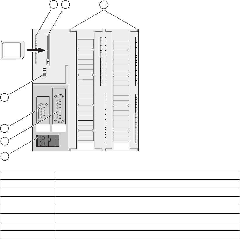
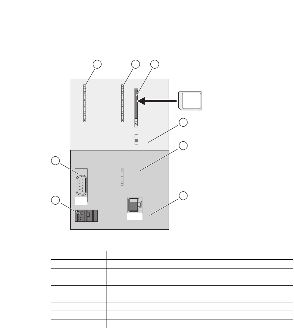
The figures show the following CPU elements
(1) Status and error displays
(2) Slot for the Micro Memory Card (MMC), incl. the ejector
(3) Connections of the integrated I/O.
(4) Power supply connection
(5) 2. Interface X2 (PtP or DP)
(6) 1. Interface X1 (MPI)
(7) Mode selector switch
Operating and display elements
2.1 Operating and display elements: CPU 31xC
CPU 31xC and CPU 31x, Technical data
2-2 Manual, Edition 08/2004, A5E00105475-05
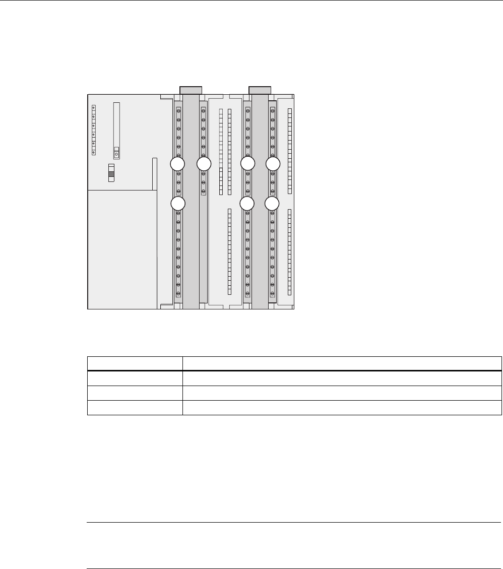
The figure below illustrates the integrated digital and analog I/Os of the CPU with open front
covers.
SF
BF
DC5V
FRCE
RUN
STOP
RUN
STOP
MRES
X11 X12
2
21 3
123
Figure 2-1 Integrated I/Os of CPU 31xC (CPU 314C-2 PtP, for example)
The figure shows the following integrated I/Os
(1) Analog I/Os
(2) each with 8 digital inputs
(3) each with 8 digital outputs
Slot for the SIMATIC Micro Memory Card (MMC)
A SIMATIC micro memory card (MMC) is used as memory module. You can use MMCs as
load memory and as portable storage medium.
Note
These CPUs do not have an integrated load memory and thus require an MMC for
operation.

Operating and display elements
2.1 Operating and display elements: CPU 31xC
CPU 31xC and CPU 31x, Technical data
Manual, Edition 08/2004, A5E00105475-05 2-3
Mode selector switch
Use the mode selector switch to set the CPU operating mode.
Table 2-1 Positions of the mode selector switch
Position Meaning Description
RUN RUN mode The CPU executes the user program.
STOP STOP mode The CPU does not execute a user program.
MRES CPU memory
reset
Mode selector switch position with pushbutton function for CPU
memory reset. A CPU memory reset by means of mode selector
switch requires a specific sequence of operation.
Reference
• CPU operating modes:
STEP 7 Online Help
.
• Information on CPU memory reset:
Operating instructions CPU 31xC and CPU31x,
Commissioning, Commissioning Modules, CPU Memory Reset by means of Mode
Selector Switch
• Evaluation of the LEDs upon error or diagnostic event:
Operating Instructions CPU 31xC
and CPU 31x, Test Functions, Diagnostics and Troubleshooting, Diagnostics with the
help of Status and Error LEDs
Power supply connection
Each CPU is equipped with a double-pole power supply socket. The connector with screw
terminals is inserted into this socket when the CPU is delivered.
Differences between the CPUs
Table 2-2 Differences of the CPUs 31xC
Element CPU
312C
CPU
313C
CPU
313C-2 DP
CPU
313C-2 PtP
CPU
314C-2 DP
CPU
314C-2 PtP
9-pole DP
interface (X2)
– – X – X –
15-pole PtP
interface (X2)
– – – X – X
Digital inputs 10 24 16 16 24 24
Digital outputs 6 16 16 16 16 16
Analog inputs – 4 + 1 – – 4 + 1 4 + 1
Analog outputs – 2 – – 2 2
Technological
functions
2 counters 3 counters 3 counters 3 counters 4 counters
1 channel for
positioning
4 counters
1 channel
for
positioning

Operating and display elements
2.1 Operating and display elements: CPU 31xC
CPU 31xC and CPU 31x, Technical data
2-4 Manual, Edition 08/2004, A5E00105475-05
2.1.1 Status and Error Indicators: CPU 31xC
LED designation Color Meaning
SF red Hardware or software error
BF (for CPUs with DP
interface only)
red Bus error
DC5V green 5-V power for CPU and S7-300 bus is OK
FRCE yellow Force job is active
RUN green CPU in RUN
The LED flashes during STARTUP at a rate of 2 Hz, and in HOLD
state at 0.5 Hz.
STOP yellow CPU in STOP and HOLD or STARTUP
The LED flashes at 0.5 Hz when the CPU requests a memory reset,
and during the reset at 2 Hz.
Reference
• CPU operating modes:
STEP 7 Online Help
.
• Information on CPU memory reset:
Operating instructions CPU 31xC and CPU31x,
Commissioning, Commissioning Modules, CPU Memory Reset by means of Mode
Selector Switch
Evaluation of the LEDs upon error or diagnostic event:
Operating
Instructions CPU 31xC and CPU 31x, Test Functions, Diagnostics and Troubleshooting,
Diagnostics with the help of Status and Error LEDs
Operating and display elements
2.2 Operating and display elements: CPU 31x
CPU 31xC and CPU 31x, Technical data
Manual, Edition 08/2004, A5E00105475-05 2-5
2.2 Operating and display elements: CPU 31x
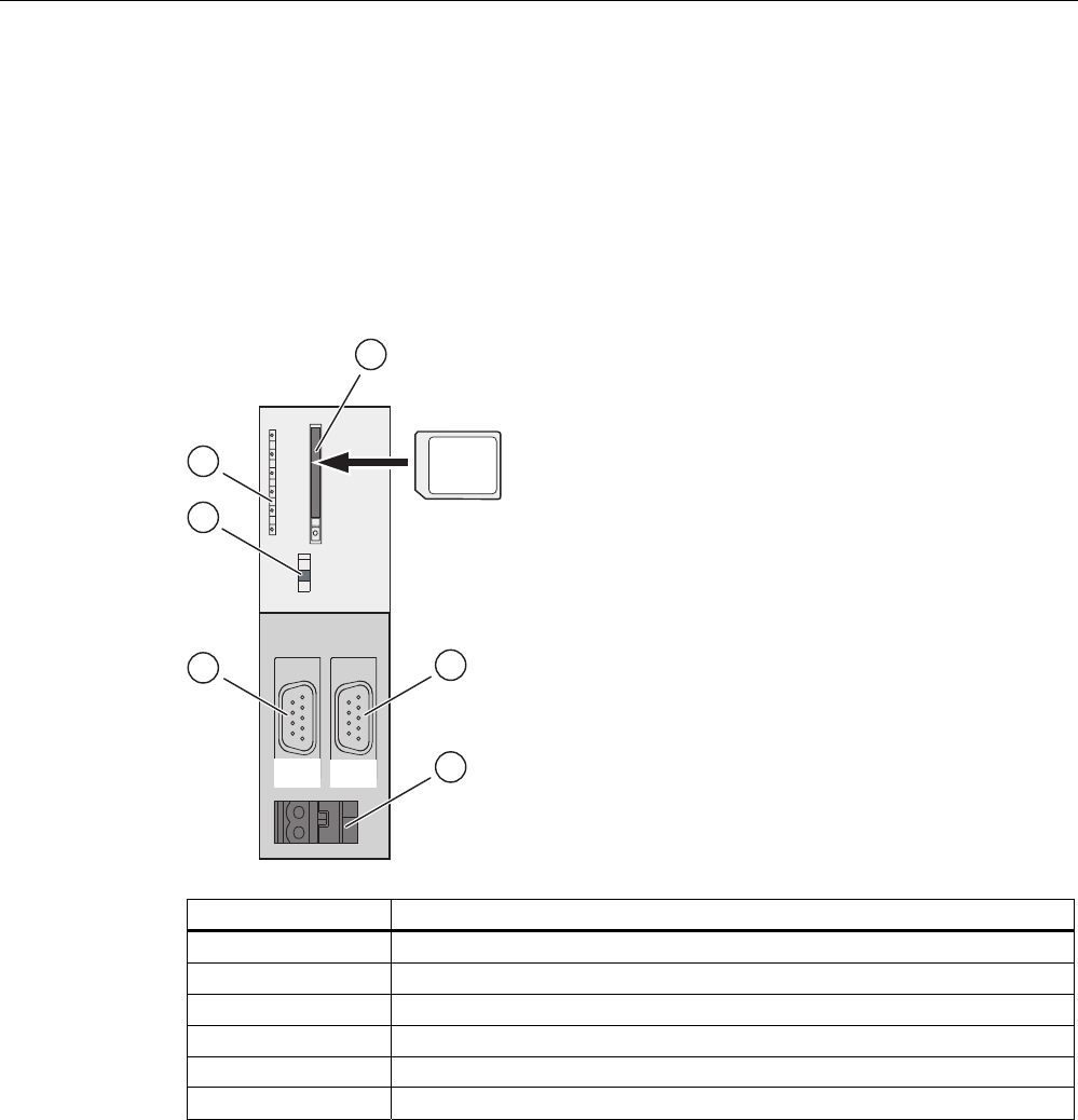
2.2.1 Operating and display elements: CPU 312, 314, 315-2 DP:
Operating and display elements
SF
BF
DC5V
RUN
STOP
RUN
STOP
MRES
FRCE
X2
X1
MMC
1
2
3
4
5
6
The figures show the following CPU elements
(1) Slot for the Micro Memory Card (MMC), incl. the ejector
(2) 2. Interface X2 (only for CPU 315-2 DP)
(3) Power supply connection
(4) 1. Interface X1 (MPI)
(5) Mode selector switch
(6) Status and error displays

Operating and display elements
2.2 Operating and display elements: CPU 31x
CPU 31xC and CPU 31x, Technical data
2-6 Manual, Edition 08/2004, A5E00105475-05
Slot for the SIMATIC Micro Memory Card (MMC)
A SIMATIC Micro Memory Card (MMC) is used as memory module. You can use MMCs as
load memory and as portable storage medium.
Note
These CPUs do not have an integrated load memory and thus require an MMC for
operation.
Mode selector switch
The mode selector switch is used to set the CPU operating mode.
Table 2-3 Positions of the mode selector switch
Position Meaning Description
RUN RUN mode The CPU executes the user program.
STOP STOP mode The CPU does not execute a user program.
MRES CPU memory reset Mode selector switch position with pushbutton function for CPU
memory reset. A CPU memory reset by means of mode
selector switch requires a specific sequence of operation.
Reference
• CPU operating modes:
STEP 7 Online Help
.
• Information on CPU memory reset:
Operating instructions CPU 31xC and CPU31x,
Commissioning, Commissioning Modules, CP Memory Reset by means of Mode Selector
Switch
• Evaluation of the LEDs upon error or diagnostic event:
Operating Instructions CPU 31xC
and CPU 31x, Test Functions, Diagnostics and Troubleshooting, Diagnostics with the
help of Status and Error LEDs
Power supply connection
Each CPU is equipped with a double-pole power supply socket. The connector with screw
terminals is inserted into this socket when the CPU is delivered.
Operating and display elements
2.2 Operating and display elements: CPU 31x
CPU 31xC and CPU 31x, Technical data
Manual, Edition 08/2004, A5E00105475-05 2-7
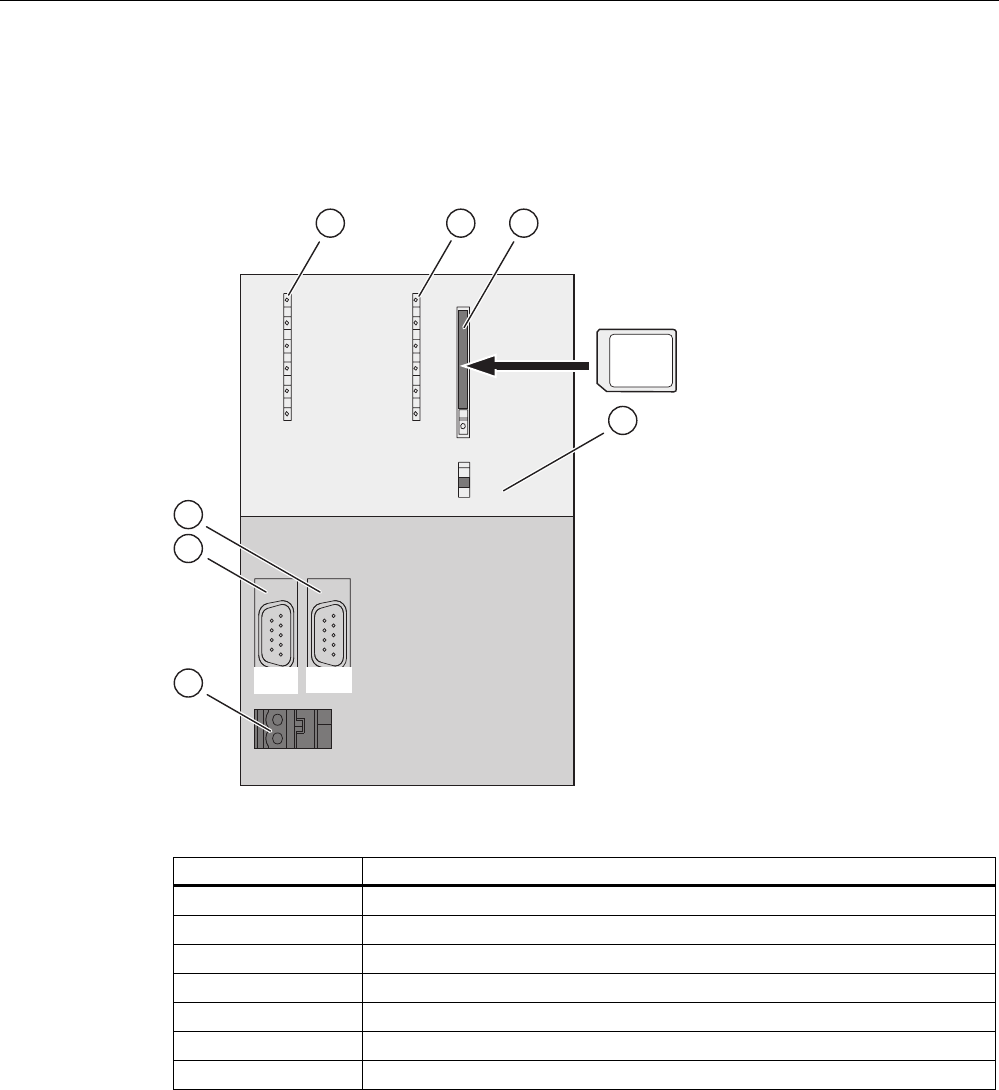
2.2.2 Operating and display elements: CPU 317-2 DP
Operating and display elements
RUN
STOP
MRES
BF1
BF2
SF
DC5V
FRCE
RUN
STOP
X2
X1
MMC
1 2 3
4
5
6
7
The figures show the following CPU elements
(1) Bus error indicator
(2) Status and error displays
(3) Slot for the Micro Memory Card (MMC), incl. the ejector
(4) Mode selector switch
(5) Power supply connection
(6) 1. Interface X1 (MPI/DP)
(7) 2. Interface X2 (DP)

Operating and display elements
2.2 Operating and display elements: CPU 31x
CPU 31xC and CPU 31x, Technical data
2-8 Manual, Edition 08/2004, A5E00105475-05
Slot for the SIMATIC Micro Memory Card (MMC)
A SIMATIC Micro Memory Card (MMC) is used as memory module. You can use MMCs as
load memory and as portable storage medium.
Note
These CPUs do not have an integrated load memory and thus require an MMC for
operation.
Mode selector switch
Use the mode selector switch to set the CPU operating mode.
Table 2-4 Positions of the mode selector switch
Position Meaning Description
RUN RUN mode The CPU executes the user program.
STOP STOP mode The CPU does not execute a user program.
MRES CPU memory reset Mode selector switch position with pushbutton function for CPU
memory reset. A CPU memory reset by means of mode
selector switch requires a specific sequence of operation.
Reference
• CPU operating modes:
STEP 7 Online Help
.
• Information on CPU memory reset:
Operating instructions CPU 31xC and CPU31x,
Commissioning, Commissioning Modules, CP Memory Reset by means of Mode Selector
Switch
• Evaluation of the LEDs upon error or diagnostic event:
Operating Instructions CPU 31xC
and CPU 31x, Test Functions, Diagnostics and Troubleshooting, Diagnostics with the
help of Status and Error LEDs
Power supply connection
Each CPU is equipped with a double-pole power supply socket. The connector with screw
terminals is inserted into this socket when the CPU is delivered.
Operating and display elements
2.2 Operating and display elements: CPU 31x
CPU 31xC and CPU 31x, Technical data
Manual, Edition 08/2004, A5E00105475-05 2-9
2.2.3 Operating and display elements: CPU 31x-2 PN/DP
Operating and display elements
RUN
STOP
MRES
BF1 SF
DC5V
FRCE
RUN
STOP
X1
LINK
RX
/
TX
MAC-ADD.:
X1-X2-X3
X4-X5-X6
X2
BF2
MMC
1 2 3
4
5
6
7
8
The figures show the following CPU elements
(1) Bus error indicators
(2) Status and error displays
(3) Slot for the Micro Memory Card (MMC), incl. the ejector
(4) Mode selector switch
(5) Status display of 2nd interface (X2)
(6) 2. Interface X2 (PN)
(7) Power supply connection
(8) 1. Interface X1 (MPI/DP)

Operating and display elements
2.2 Operating and display elements: CPU 31x
CPU 31xC and CPU 31x, Technical data
2-10 Manual, Edition 08/2004, A5E00105475-05
Slot for the SIMATIC Micro Memory Card (MMC)
A SIMATIC Micro Memory Card (MMC) is used as memory module. You can use MMCs as
load memory and as portable storage medium.
Note
These CPUs do not have an integrated load memory and thus require an MMC for
operation.
Mode selector switch
Use the mode selector switch to set the CPU operating mode.
Table 2-5 Positions of the mode selector switch
Position Meaning Description
RUN RUN mode The CPU executes the user program.
STOP STOP mode The CPU does not execute a user program.
MRES CPU memory reset Mode selector switch position with pushbutton function for CPU
memory reset. A CPU memory reset by means of mode selector
switch requires a specific sequence of operation.
Reference
• CPU operating modes:
STEP 7 Online Help
.
• Information on CPU memory reset:
Operating instructions CPU 31xC and CPU31x,
Commissioning, Commissioning Modules, CP Memory Reset by means of Mode Selector
Switch
• Evaluation of the LEDs upon error or diagnostic event:
Operating Instructions CPU 31xC
and CPU 31x, Test Functions, Diagnostics and Troubleshooting, Diagnostics with the
help of Status and Error LEDs
Power supply connection
Each CPU is equipped with a double-pole power supply socket. The connector with screw
terminals is inserted into this socket when the CPU is delivered.

Operating and display elements
2.2 Operating and display elements: CPU 31x
CPU 31xC and CPU 31x, Technical data
Manual, Edition 08/2004, A5E00105475-05 2-11
2.2.4 Status and error displays of the CPU 31x
General status and error displays
Table 2-6 General status and error displays of the CPU 31x
LED designation Color Meaning
SF red Hardware or software error.
DC5V green 5-V power for the CPU and the S7-300 bus
FRCE yellow LED is lit: Active force job
LED flashes at 2 Hz: Node flash test function (only CPUs with
firmware V2.2.0 or higher)
RUN green CPU in RUN
The LED flashes during STARTUP at a rate of 2 Hz, and in HOLD
state at 0.5 Hz.
STOP yellow CPU in STOP, or HOLD, or STARTUP
The LED flashes at 0.5 Hz when the CPU requests a memory reset,
and during the reset at 2 Hz.
Displays for the X1 and X2 interfaces
Table 2-7 Bus error displays of CPU 31x
CPU LED designation Color Meaning
315-2 DP BF red Bus error at DP interface (X2)
BF1 red Bus error at interface 1 (X1) 317-2 DP
BF2 red Bus error at interface 2 (X1)
BF1 red Bus error at interface 1 (X1)
BF2 red Bus error at interface 2 (X1)
LINK green Active communication at interface 2 (X2).
31x-2 PN/DP
RX/TX yellow Receive / Transmit data at interface 2 (X2)
Reference
• CPU operating modes:
STEP 7 Online Help
.
• Information on CPU memory reset:
Operating instructions CPU 31xC and CPU31x,
Commissioning, Commissioning Modules, CP Memory Reset by means of Mode Selector
Switch
• Evaluation of the LEDs upon error or diagnostic event:
Operating Instructions CPU 31xC
and CPU 31x, Test Functions, Diagnostics and Troubleshooting, Diagnostics with the
help of Status and Error LEDs

Operating and display elements
2.2 Operating and display elements: CPU 31x
CPU 31xC and CPU 31x, Technical data
2-12 Manual, Edition 08/2004, A5E00105475-05

CPU 31xC and CPU 31x, Technical data
Manual, Edition 08/2004, A5E00105475-05 3-1
Communication 3
3.1 Interfaces
3.1.1 Multi-Point Interface (MPI)
Availability
All CPUs described in this manual are equipped with an MPI interface X1.
A CPU equipped with an MPI/DP interface is configured and supplied as MPI. To use the
DP interface, set DP interface mode in STEP 7.
Properties
The MPI (Multi-Point Interface) represents the CPU interface for PG/OP connections, or for
communication on an MPI subnet.
The typical (default) transmission rate of all CPUs is 187.5 kbps. You can also set 19.2 kbps
for communication with an S7-200. The 315-2 PN/DP and 317 CPUs support transmission
rates up to 12 Mbps.
The CPU automatically broadcasts its bus configuration via the MPI interface (the
transmission rate, for example). A PG, for example, can thus receive the correct parameters
and automatically connect to a MPI subnet.
Note
You may only connect PGs to an MPI subnet which is in RUN.
Other stations (for example, OP, TP, ...) should not be connected to the MPI subnet while
the system is in RUN. Otherwise, transferred data might be corrupted as a result
interference, or global data packages may be lost.

Communication
3.1 Interfaces
CPU 31xC and CPU 31x, Technical data
3-2 Manual, Edition 08/2004, A5E00105475-05
Devices capable of MPI communication
• PG/PC
• OP/TP
• S7-300 / S7-400 with MPI interface
• S7-200 (19.2 kbps only)
3.1.2 PROFIBUS DP
Availability
CPUs with “DP“ name suffix are equipped at least with a DP X2 interface.
The 315-2 PN/DP and 317 CPUs are equipped with an MPI/DP X1 interface. A CPU with
MPI/DP interface is supplied with a default MPI configuration. You need to set DP mode in
STEP 7 if you want to use the DP interface.
Operating modes for CPUs with two DP interfaces
Table 3-1 Operating modes for CPUs with two DP interfaces
MPI/DP interface (X1) PROFIBUS DP interface (X2)
• MPI
• DP master
• DP slave 1
• not configured
• DP master
• DP slave 1
1 simultaneous operation of the DP slave on both interfaces is excluded
Properties
The PROFIBUS DP interface is mainly used to connect distributed I/O. PROFIBUS DP
allows you to create large subnets, for example.
The PROFIBUS DP interface can be set for operation in master or slave mode, and supports
transmission rates up to 12 Mbps.
The CPU broadcasts its bus parameters (transmission rate, for example) via the
PROFIBUS DP interface when master mode is set. A PG, for example, can thus receive the
correct parameters and automatically connect to a PROFIBUS subnet. In your configuration
you can specify to disable bus parameter broadcasting.

Communication
3.1 Interfaces
CPU 31xC and CPU 31x, Technical data
Manual, Edition 08/2004, A5E00105475-05 3-3
Note
(for DP interface in slave mode only)
When you disable the Commissioning / Debug mode / Routing check box in the DP interface
properties dialog in STEP 7, all user-specific transmission rate settings will be ignored, and
the transmission rate of the master is automatically set instead. This disables the routing
function at this interface.
Devices capable of PROFIBUS DP communication
• PG/PC
• OP/TP
• DP slaves
• DP masters
• Actuators/Sensors
• S7-300/S7-400 with PROFIBUS DP interface
Reference
Further information on PROFIBUS: http://www.profibus.com
3.1.3 PROFINET (PN)
Availability
CPUs with a “PtP“ name suffix are equipped with a PtP X2 interface. X2.
Connecting to Industrial Ethernet
You can use the integrated PROFINET interface of the CPU to establish a connection to
Industrial Ethernet.
The integrated PROFINET interface of the CPU can be configured via MPI or PROFINET.
Requirements
• CPUs with FW 2.3.0 or higher (for example CPU 315-2 PN/DP)
• STEP 7 V5.3 + Servicepack 1 or higher

Communication
3.1 Interfaces
CPU 31xC and CPU 31x, Technical data
3-4 Manual, Edition 08/2004, A5E00105475-05
Devices capable of PROFINET (PN) communication
• PROFINET IO components (for example, interface module IM 151-3 PN in an ET 200S)
• S7-300 / S7-400 with PROFINET interface (for example, CPU 317-2 PN/DP or
CP 343-1 PN)
• Active network components (a switch, for example)
• PG/PC with network card
Properties of PROFINET interface X2
Properties
IEEE standard 802.3
Connector design RJ45
Transmission speed Max. 100 Mbps
Media Twisted Pair Cat5 (100BASE-TX)
Note
Networking PROFINET components
The use of switches, rather than hubs, for networking PROFINET components brings about
a substantial improvement in decoupling bus traffic, and improves runtime performance
under higher bus load. PROFINET CBA with cyclic PROFINET interconnections requires the
use of switches in order to maintain compliance with performance specifications. Full duplex
mode at 100 Mbps is mandatory for cyclic PROFINET interconnections.
PROFINET IO also requires the use of switches and 100 Mbps full duplex mode.
Reference
• For information on how to configure the integrated PROFINET interface of the CPU, refer
to the
S7-300, CPU 31xC and CPU 31x Installation
operating manual.
• For details on PROFINET, refer to the
PROFINET System Description
• For detailed information on Ethernet networks, network configuration and network
components refer to the
SIMATIC NET Manual: Twisted Pair and Fiber Optic Networks
,
available under article ID 8763736 on the Internet URL
http://www.siemens.com/automation/service&support
•
Tutorial: Commissioning Component-Based Automation Systems
, article ID 14142554
• Further information on PROFINET: http://www.profibus.com
See also
PROFINET IO System (Page 3-19)

Communication
3.1 Interfaces
CPU 31xC and CPU 31x, Technical data
Manual, Edition 08/2004, A5E00105475-05 3-5
3.1.4 Point to Point (PtP)
Availability
CPUs with a “PtP“ name suffix are equipped with a PtP X2 interface.
Properties
Using the PtP interface of your CPU, you can connect external devices with serial interface.
You can operate such a system at transmission rates up to 19.2 kbps in full duplex mode
(RS 422), and up to 38.4 kbps in half duplex mode (RS 485).
Transmission rate
• Half duplex: 38.4 kbps
• Full duplex: 19.2 kbps
Drivers
PtP communication drivers installed in those CPUs:
• ASCII drivers
• 3964(R) Protocol
• RK 512 (CPU 314C-2 PtP only)
Devices capable of PtP communication
Devices equipped with a serial port, for example, barcode readers, printers, etc.
Reference
CPU 31xC: Technological functions
manual

Communication
3.2 Communication services
CPU 31xC and CPU 31x, Technical data
3-6 Manual, Edition 08/2004, A5E00105475-05
3.2 Communication services
3.2.1 Overview of communication services
Selecting the communication service
You need to decide on a communication service, based on functionality requirements. Your
choice of communication service will have no effect on:
• the functionality available,
• whether an S7 connection is required or not, and
• the time of connecting.
The user interface can vary considerably (SFC, SFB, ...), and is also determined by the
hardware used (SIMATIC CPU, PC, ...).
Overview of communication services
The table below provides an overview of communication services offered by the CPUs.
Table 3-2 Communication services of the CPUs
Communication service Functionality Time at which the S7
connection is established ...
via MPI via DP via
PtP
via
PN
PG communication Commissioning, test,
diagnostics
From the PG, starting when
the service is being used
X X – X
OP communication Monitor and modify via OP at POWER ON X X – X
S7 basic communication Data exchange is programmed at the blocks
(SFC parameters)
X – – –
S7 communication Data exchange in server
and client mode:
Configuration of
communication required.
via active partner at POWER
ON.
Only in
server
mode
Only in
server
mode
– X
Global data
communication
Cyclic data exchange (for
example, flag bits)
does not require an S7
connection
X – – –
Routing PG functions
(only for CPUs with
DP or PN interface)
for example testing,
diagnostics on other
networks also
from the PG, starting when the
service is being used
X X – X
PtP communication Data exchange via serial
interface
does not require an S7
connection
– – X –
SNMP
(Simple Network
Management Protocol)
Standard protocol for
network diagnostics and
configuration
does not require an S7
connection
– – – X
open communication by
means of TCP/IP
Data exchange via
Industrial Ethernet with
TCP/IP protocol (by means
of loadable FBs)
Does not require an S7
connection, is handled in the
user program by means of
loadable FBs
– – – X

Communication
3.2 Communication services
CPU 31xC and CPU 31x, Technical data
Manual, Edition 08/2004, A5E00105475-05 3-7
See also
Distribution and availability of S7 connection resources (Page 3-29)
Connection resources for routing (Page 3-31)
3.2.2 PG communication
Properties
PG communication is used to exchange data between engineering stations (PG, PC, for
example) and SIMATIC modules which are capable of communication. This service is
available for MPI, PROFIBUS and Industrial Ethernet subnets. Transition between subnets is
also supported.
PG communication provides the functions needed to download / upload programs and
configuration data, to run tests and to evaluate diagnostic information. These functions are
integrated in the operating system of
SIMATIC S7 modules.
A CPU can maintain several simultaneous online connections to one or multiple PGs.
3.2.3 OP communication
Properties
OP communication is used to exchange data between operator stations (OP, TP, for
example) and SIMATIC modules which are capable of communication. This service is
available for MPI, PROFIBUS and Industrial Ethernet subnets.
OP communication provides functions you require for monitoring and modifying. These
functions are integrated in the operating system of SIMATIC S7 modules. A CPU can
maintain several simultaneous connections to one or several OPs.
3.2.4 Data exchanged by means of S7 basic communication
Properties
S7-based communication is used to exchange data between S7 CPUs and the
communication-capable SIMATIC modules within an S7 station (acknowledged data
exchange). Data are exchanged across non-configured S7 connections. The service is
available via MPI subnet, or within the station to function modules (FM).
S7-based communication provides the functions you require for data exchange. These
functions are integrated into the CPU operating system. The user can utilize this service by
means of "System function" (SFC) user interface.

Communication
3.2 Communication services
CPU 31xC and CPU 31x, Technical data
3-8 Manual, Edition 08/2004, A5E00105475-05
Reference
• Details on SFCs are found in the
Instruction list
, for more details refer to the
STEP 7 Online Help
or to the
System and Standard Functions
Reference Manual.
• For further information on communication, refer to the
Communication with SIMATIC
manual.
3.2.5 S7 communication
Properties
A CPU can always operate in server or client mode in S7 communication: We distinguish
between
• communication with unilateral configuration (for PUT/GET only)
• communication with bilateral configuration (for USEND, URCV, BSEND, BRCV, PUT,
GET)
However, the functionality depends on the CPU. A CP is therefore required in certain
situations.
Table 3-3 Client and server in S7 communication, using connections with unilateral / bilateral
configuration
CPU Use in server mode for
connections with unilateral
configuration
Use in server mode for
connections with bilateral
configuration
Use as client
31xC >= V1.0.0 Always possible at the
MPI/DP interface, without
programming the user
interface
Only possible with CP
and loadable FBs.
Only possible with CP
and loadable FBs.
31x >= V2.0.0 Always possible at the
MPI/DP interface, without
programming the user
interface
Only possible with CP
and loadable FBs.
Only possible with CP
and loadable FBs.
31x >= V2.2.0 Always possible at the
MPI/DP interface, without
programming the user
interface
• Possible at PN
interface with
loadable FBs, or
• with CP and loadable
FBs.
• Possible at PN
interface with
loadable FBs, or
• with CP and
loadable FBs.
The user interface is implemented using standard function modules (FBs) from the standard
library of STEP 7, under communication blocks.
Reference
For further information on communication, refer to the
Communication with SIMATIC
manual.

Communication
3.2 Communication services
CPU 31xC and CPU 31x, Technical data
Manual, Edition 08/2004, A5E00105475-05 3-9
3.2.6 Global data communication (MPI only)
Properties
Global data communication is used for cyclic exchange of global data via MPI subnets (for
example, I, Q, M) between SIMATIC S7 CPUs (data exchange without acknowledgement).
One CPU broadcasts its data to all other DP CPUs on the MPI subnet. This function is
integrated in the CPU operating system.
Reduction ratio
The reduction ratio specifies the cyclic intervals for GD communication. You can set the
reduction ratio when you configure global data communication in STEP 7. For example, if
you set a reduction ratio of 7, global data are transferred only with every 7th cycle. This
reduces CPU load.
Send and receive conditions
Conditions which should be satisfied for GD communication:
• For the transmitter of a GD packet:
Reduction ratiotransmitter x cycle timetransmitter ≥ 60 ms
• For the receiver of a GD packet:
Reduction ratioreceiver x cycle timereceiver
< reduction ratiotransmitter x cycle timetransmitter
A GD packet may be lost if you do not adhere to these conditions. The reasons being:
• the performance of the "smallest" CPU in the GD circuit
• asynchronous transmitting / receiving of global data at the stations
When setting in STEP 7: “Transmit after each CPU cycle“, and the CPU has a short scan
cycle time (< 60 ms), the operating system might overwrite a GD packet of the CPU before it
is transmitted. The loss of global data is indicated in the status box of a GD circuit, if you set
this function in your STEP 7 configuration.

Communication
3.2 Communication services
CPU 31xC and CPU 31x, Technical data
3-10 Manual, Edition 08/2004, A5E00105475-05
GD resources of the CPUs
Table 3-4 GD resources of the CPUs
Parameters CPU 31xC, 312, 314 CPU 315-2 DP,
315-2 PN/DP, 317
Number of GD circuits per CPU Max. 4 Max. 8
GD packets transmitted per GD circuit Max. 1 Max. 1
GD packets transmitted by all GD circuits Max. 4 Max. 8
GD packets received per GD circuit Max. 1 Max. 1
GD packets received by all GD circuits Max. 4 Max. 8
Data length per GD packet max. 22 bytes max. 22 bytes
Consistency max. 22 bytes max. 22 bytes
Min. reduction ratio (default) 1 (8) 1 (8)
3.2.7 Routing
Properties
STEP 7 V5.1 + SP4 or higher allows you to access your S7 stations on all subnets with your
PG/PC, for example, to
• download user programs
• download a hardware configuration, or
• perform debugging and diagnostic functions.
Note
When the CPU is used as intelligent slave, the routing function is only available when the
DP interface is set active. IN STEP 7, set the Test, Commission Routing check box on
the properties dialog of the DP interface. For detailed information, refer to the
Programming with STEP 7
manual, or directly to the
STEP 7 Online Help
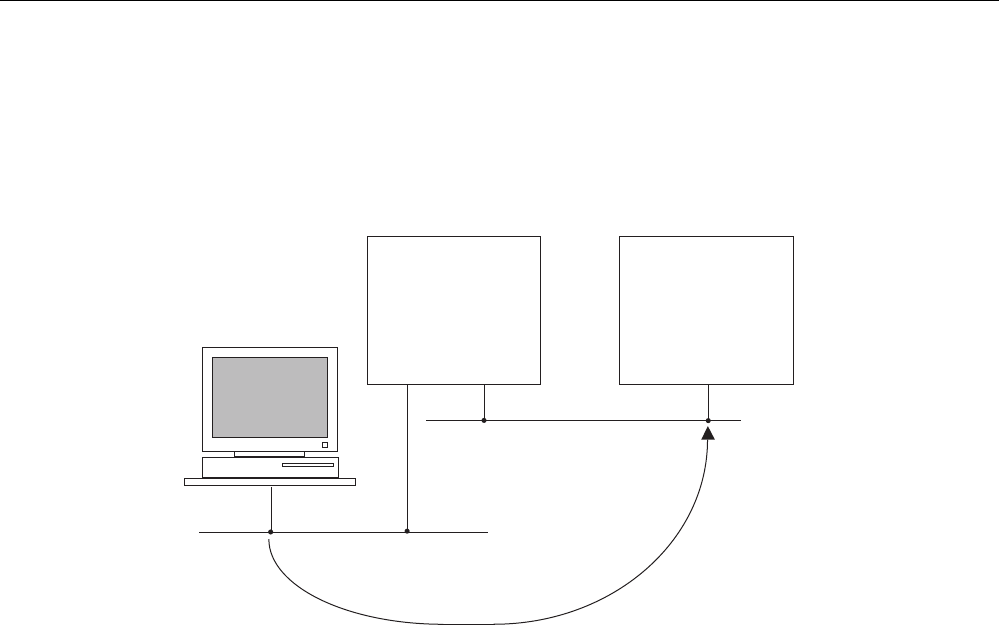
Communication
3.2 Communication services
CPU 31xC and CPU 31x, Technical data
Manual, Edition 08/2004, A5E00105475-05 3-11
Routing network nodes: MPI - DP
Gateways between subnets are routed in a SIMATIC station that is equipped with interfaces
to the respective subnets. The figure below shows CPU 1 (DP master) acting as router for
subnets 1 and 2.
Subnet 1 (e.g. MPI)
Subnet 2 (e.g. PROFIBUS DP)
PG
S7-300
CPU (DP master)
S7-300
CPU (DP slave)
The figure below shows the access to an Ethernet subnet. CPU 1 (315-2 DP, for example) is
the router for subnet 1 and 2; CPU 2 is the router for subnet 2 and 3.
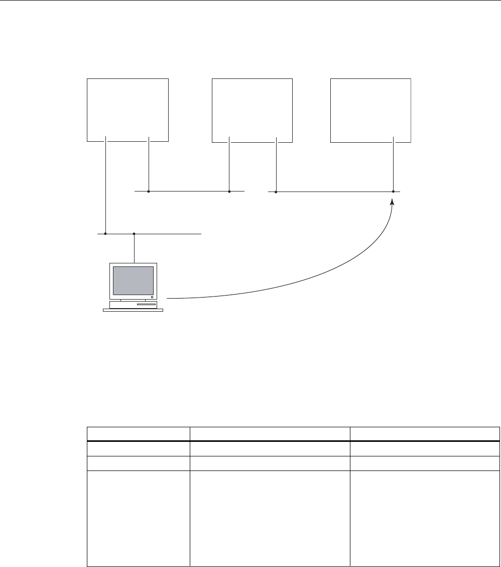
Communication
3.2 Communication services
CPU 31xC and CPU 31x, Technical data
3-12 Manual, Edition 08/2004, A5E00105475-05
Routing network nodes: MPI – DP - Ethernet
CPU 1
(e.g. 315-2 DP)
PN
Subnet 3 (PROFInet)
PN
PG
Subnet 2 (PROFIBUS)
DP
(master)
MPI
Subnet 1 (MPI)
MPI/DP
(active slave)
CPU 2
(317-2 PN/DP)
CPU 3
(317-2 PN/DP)
Number of routed connections
The CPUs with DP interface provide a different number of connections for the routing
function:
Table 3-5 Number of routing connections for DP CPUs
CPU As of firmware version Number of connections for routing
31xC, CPU 31x 2.0.0 Max. 4
317-2 DP 2.1.0 Max. 8
31x-2 PN/DP 2.2.0 Interface X1 configured as:
• MPI: Max. 10
• DP master Max. 24
• DP slave (active): Max. 14
Interface X2 configured as:
• PROFINET Max. 24

Communication
3.2 Communication services
CPU 31xC and CPU 31x, Technical data
Manual, Edition 08/2004, A5E00105475-05 3-13
Requirements
• The station modules are "capable of routing" (CPUs or CPs).
• The network configuration does not exceed project limits.
• The modules have loaded the configuration data containing the latest "knowledge" of the
entire network configuration of the project.
Reason: All modules participating in the network transition must receive the routing
information defining the paths to other subnets.
• In your network configuration, the PG/PC you want to use to establish a connection via
network node must be assigned to the network it is physically connected to.
• The CPU must set to master mode, or
• when set to operate in slave mode, the Test, Commissioning, Routing functionality must
be enabled by setting the check box in STEP 7, in the
DP interface for DP slave properties dialog box.
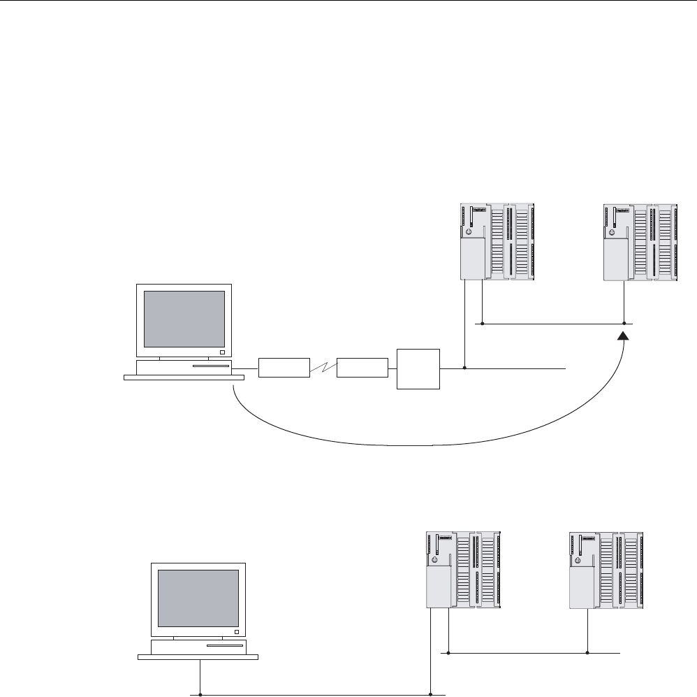
Communication
3.2 Communication services
CPU 31xC and CPU 31x, Technical data
3-14 Manual, Edition 08/2004, A5E00105475-05
Routing: Example of a TeleService application
The figure below shows the example of an application for remote maintenance of an
S7 station using a PG. The connection to other subnets is here established via modem
connection.
The lower section of the figure shows how to configure this in STEP 7.
DP master
Subnet 1 (e.g. MPI)
Subnet 2
(e.g. PROFIBUS DP)
ModemModem
Real installation
Subnet 1 (e.g. MPI)
Subnet 2 (e.g. PROFIBUS DP)
Configuration in STEP 7
DP slave
TeleService
adapter
e.g. 31xC-2DP e.g. 31xC-2DP
DP master
e.g. CPU 31xC-2 DP
DP slave
e.g. CPU 31xC-2 DP
PG
PG

Communication
3.2 Communication services
CPU 31xC and CPU 31x, Technical data
Manual, Edition 08/2004, A5E00105475-05 3-15
Reference
• on configuring in STEP 7 is found in the
Configuring Hardware and Connections in
STEP 7
manual
• of a basic nature is contained in the
Communication with SIMATIC
Manual.
• on the TeleService adapter can be found on the Internet URL:
http://www.ad.siemens.de/support. In the Manual Search section, you can enter the
search term A5E00078070 to download the documentation.
• on SFCs are found in the
Instruction list
, for more details refer to the
STEP 7 Online Help
or to the
System and Standard Functions
Reference Manual.
• on communication are found in the
Communication with SIMATIC
Manual.
3.2.8 PtP communication
Properties
PtP communication enables you to exchange data via serial port. PtP communication can be
used to interconnect automation devices, computers or communication-capable systems of
external suppliers. The function also allows adaptation to the protocol of the communication
partner.
Reference
Further Information
• on SFCs are found in the
Instruction list
.
For detailed information, refer to the
STEP 7 Online Help
, or to the
System and Standard
Functions
Reference Manual.
• on communication are found in the
Communication with SIMATIC
Manual.

Communication
3.2 Communication services
CPU 31xC and CPU 31x, Technical data
3-16 Manual, Edition 08/2004, A5E00105475-05
3.2.9 Data consistency
Properties
A data area is considered consistent, if the operating system can read/write access the data
area in a continuous block. Data exchanged collectively between the stations should belong
together and originate from a single processing cycle, that is, be consistent. If the user
program contains a programmed communication function, for example, access to shared
data with XSEND/ XRCV, access to that data area can be coordinated by means of the
"BUSY" parameter itself.
With PUT/GET functions
For S7 communication functions, such as PUT/GET or write / read via OP communication,
which do not require a block in the user program on the CPU (operating in server mode),
allowances must be made in the program for the extent of the data consistency. The
PUT/GET functions for S7 communication, or for reading/writing variables via OP
communication, are executed at the CPU's scan cycle checkpoint. In order to ensure a
defined process interrupt reaction time, the communication variables are copied in consistent
blocks with a maximum length of 64 bytes (CPU 317: 160 bytes) to / from work memory at
the scan cycle checkpoint of the operating system. Data consistency is not guaranteed for
larger data areas.
Note
Where defined data consistency is required, the length of communication variables in the
CPU's user program may not exceed 64 bytes (CPU 317: 160 bytes.)
3.2.10 Communication via PROFINET (only CPU 31x-2 PN/DP)
What is PROFINET??
Within the framework of Totally Integrated Automation (TIA), PROFINET represents a
consequent enhancement of:
• PROFIBUS DP, the proven field bus, and
• Industrial Ethernet, the communication bus at cell level.
Experience gained from both systems was and is being integrated into PROFINET.
PROFINET is an Ethernet-based automation standard of PROFIBUS International
(previously PROFIBUS Users Organization e.V.), and defines a multi-vendor communication,
automation, and engineering model.

Communication
3.2 Communication services
CPU 31xC and CPU 31x, Technical data
Manual, Edition 08/2004, A5E00105475-05 3-17
Objectives in PROFINET
The objectives in PROFINET are:
• An open Ethernet standard for automation based on Industrial Ethernet
Industrial Ethernet and standard Ethernet components can be used together, however,
Industrial Ethernet devices are more reliable, and are therefore more suitable for
industrial environments (temperature, immunity to noise etc.)
• Use of TCP/IP and IT standards
• Automation with real-time Ethernet
• Total integration of field bus systems
Implementation of PROFINET by us
We have integrated PROFINET as follows:
• We have chosen PROFINET IO for integrated communication between field devices.
• We integrated communication between PLCs of distributed systems
with PROFINET CBA (Component-Based automation.)
• Installation engineering and network components are available in SIMATIC NET.
• For remote maintenance and network diagnostics, we used the proven IT standards from
the office world (for example, SNMP = Simple Network Management Protocol for network
configuration and diagnostics).
Documentation of PROFIBUS International on the Internet
On the Internet at "www.profibus.com" of PROFIBUS International (previously PROFIBUS
User Organization, PUO) you can find numerous articles relating to PROFINET.
For further information, refer to the Internet URL "www.siemens.com\profinet\".
What is PROFINET IO?
Within the framework of PROFINET, PROFINET IO is a communication concept for the
implementation of modular, distributed applications.
PROFINET IO allows you to create automation solutions, which are familiar to you from
PROFIBUS.
That is, you have the same application view in STEP 7, regardless of whether you configure
PROFINET or PROFIBUS devices.
What is PROFINET CBA (Component based Automation)?
Within the framework of PROFINET, PROFINET CBA is an automation concept for the
implementation of applications with distributed intelligence.
PROFINET CBA lets you create distributed automation solutions, based on default
components and partial solutions.
Component-Based Automation allows you to use complete technological modules as
standardized components in complex systems.
The components are also created in an engineering tool which may differ from vendor to
vendor. Components of SIMATIC devices are created, for example, with STEP 7.
Communication
3.2 Communication services
CPU 31xC and CPU 31x, Technical data
3-18 Manual, Edition 08/2004, A5E00105475-05
Extent of PROFINET CBA and PROFINET IO
PROFINET IO and CBA represent two different views of automation devices on Industrial
Ethernet.
352),1(7
&RPSRQHQW9LHZ
352),1(7&%$
,2'DWD9LHZ
352),1(7,2
'LVWULEXWHG,QWHOOLJHQFH
3ODQWZLGH(QJLQHHULQJ
'LVWULEXWHG,2
1RUPDO,29LHZLQ67(3
3&'
352),1(7&RPSRQHQW'HVFULSWLRQ
*6'
*HQHULF6WDWLRQ'HVFULSWLRQ
2QH&DEOH,76WDQGDUGV6WDQGDUG$SSOLFDWLRQV
3URWRFROV1RQ57&RQWUROOHU
Figure 3-1 Extent of PROFINET IO and Component-Based Automation
Component-Based Automation organizes the system structure based on the various
functions. These functions are configured and programmed.
PROFINET IO provides you with a view of the system that is very similar to the view
obtained in PROFIBUS. You continue to configure and program the individual automation
devices.
Further Information
For further information on PROFINET IO and PROFINET CBA, refer to the
PROFINET
System Description
. Differences between PROFIBUS DP and PROFINET IO and their
common features are described in the
From PROFIBUS DP to PROFINET IO
Programming
Manual.
For detailed information on PROFINET CBA, refer to the SIMATIC IMAP and Component-
Based Automation documentation.
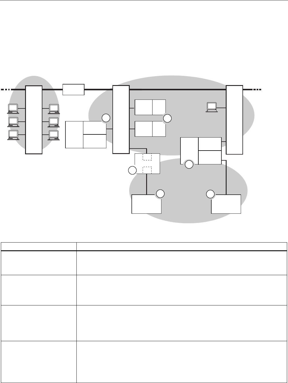
Communication
3.2 Communication services
CPU 31xC and CPU 31x, Technical data
Manual, Edition 08/2004, A5E00105475-05 3-19
3.2.10.1 PROFINET IO System
Extended Functions of PROFINET IO
The following graphic shows the new functions of PROFINET IO
&38
[
31'3
(7
'36/$9(
5RXWHU
6ZLWFK
,2
&RQWUROOHU
'3
0DVWHU
(7
6
,2
'HYLFH
(7
6
,2
'HYLFH
&38
[
31'3
,2
&RQWUROOHU
'3
0DVWHU
6ZLWFK
(7
'36/$9(
3*
6ZLWFK
,(
,(3%/LQN
3%
&RPSDQ\1HWZRUN ,QGXVWULDO(WKHUQHW
352),%86
2
3
4
5
6
1
The graphic displays You can see the connection path in the graphic
The connection of company
network and field level
From PCs in your company network, you can access devices at the field level
Example:
• PC — Switch 1 — Router — Switch 2 — CPU 31x-2 PN/DP (1).
The connection between the
automation system and field
level
You can, of course, also access other areas in Industrial Ethernet from a PG at the field
level.
Example:
• PG — Switch 3 — Switch 2 — to an IO device of the ET 200S (2).
The IO controller of the CPU
31x-2 PN/DP (1) controls
devices on Industrial Ethernet
and on PROFIBUS directly
At this point, you see the extended IO feature between the IO controller and IO device(s)
on Industrial Ethernet:
• The CPU 31x-2 PN/DP (1) is the IO controller for one of the ET 200S (2) IO devices.
• The CPU 31x-2 PN/DP (1) is also the IO controller for the ET 200 (DP slave) (5) via
the IE/PB Link (6).
A CPU can be both IO
controller and DP master
Here, you can see that a CPU can be both IO controller for an IO device as well as
DP master for a DP slave:
• The CPU 31x-2 PN/DP (3) is the IO controller for the other ET 200S (2) IO device.
CPU 31x-2 PN/DP (3) — Switch 3 — Switch 2 — ET 200S (2)
• The CPU 31x-2 PN/DP (3) is the DP master for a DP slave (4). The DP slave (4) is
assigned locally to the CPU (3) and is not visible on Industrial Ethernet.

Communication
3.2 Communication services
CPU 31xC and CPU 31x, Technical data
3-20 Manual, Edition 08/2004, A5E00105475-05
Requirements
• CPUs as of Firmware 2.3.0 (for example CPU 315-2 PN/DP)
• STEP 7, as of Version 5.3 + Service Pack 1
Reference
You will find information on the topic of PROFINET in the following sources:
• in the
System Description PROFINET
• in the
From PROFIBUS DP to PROFINET IO
programming manual. This manual also
lists the new PROFINET blocks and system status lists.
See also
PROFINET (PN) (Page 3-3)
3.2.10.2 Blocks in PROFINET IO
Chapter Content
This chapter explains the following:
• Which blocks are intended for PROFINET
• Which blocks are intended for PROFIBUS DP
• Which blocks are intended for both PROFINET IO and PROFIBUS DP
Compatibility of the New Blocks
For PROFINET IO, it was necessary to create some new blocks, among other things,
because larger configurations are now possible with PROFINET. You can also use these
new blocks with PROFIBUS.

Communication
3.2 Communication services
CPU 31xC and CPU 31x, Technical data
Manual, Edition 08/2004, A5E00105475-05 3-21
Comparison of the System and Standard Functions of PROFINET IO and PROFIBUS DP
For CPUs with an integrated PROFINET interface, the table below provides you with an
overview of:
• System and standard functions for SIMATIC that you may need to replace when
converting from PROFIBUS DP to PROFINET IO.
• New system and standard functions
Table 3-6 New System Standard Functions of PROFINET IO and PROFIBUS DP and Those That
Must Be Replaced
Blocks PROFINET IO PROFIBUS DP
SFC13 (read diagnostic data of
a DP slave)
No
Substitute:
• event-related: SFB 54
• state-related: SFB 52
Yes
SFC58/59 (write/read data
record in I/O)
No (replacement: SFB53/52) yes (but should already have
been replaced by SFB53/52 in
DPV1)
SFB52/53 (read/write data
record)
Yes Yes
SFB54 (evaluate alarm) Yes Yes
SFC102 (read predefined
parameters)
No (replacement: SFB81) Yes
new:
SFB81 (read predefined
parameters)
Yes Yes
SFC5 (query start address of a
module)
No (replacement: SFC70) Yes
new:
SFC70 (query start address of a
module)
Yes Yes
SFC49 (query the slot belonging
to a logical address)
No (replacement: SFC71) Yes
new:
SFC71 (query the slot belonging
to a logical address)
Yes Yes

Communication
3.2 Communication services
CPU 31xC and CPU 31x, Technical data
3-22 Manual, Edition 08/2004, A5E00105475-05
The following table provides you with an overview of the system and standard functions for
SIMATIC, whose functionality must be implemented by other functions when converting from
PROFIBUS DP to PROFINET IO.
Table 3-7 System and Standard Functions in PROFIBUS DP that must be Implemented with
Different Functions in PROFINET IO
Blocks PROFINET IO PROFIBUS DP
SFC55 (write dynamic
parameters)
No
(implement with SFB53)
Yes
SFC56 (write predefined
parameters)
No
(implement with SFB81 and
SFB53)
Yes
SFC57 (assign parameters to
module)
No
(implement with SFB81 and
SFB53)
Yes
You cannot use the following SIMATIC system and standard functions with PROFINET IO:
• SFC7 (trigger hardware interrupt on DP master)
• SFC11 (synchronize groups of DP slaves)
• SFC12 (deactivate and activate DP slaves)
• SFC72 (read data from a communication partner within local S7 station)
• SFC73 (write data to a communication partner within local S7 station)
• SFC74 (abort an existing connection to a communication partner within local S7 station)
Comparison of the Organization Blocks of PROFINET IO and PROFIBUS DP
Here, there are changes in OBs 83 and 86 as shown in the table below.
Table 3-8 OBs in PROFINET IO and PROFIBUS DP
Blocks PROFINET IO PROFIBUS DP
OB83 (removing and inserting
modules and submodules
during operation)
Also possible with an S7-300,
new error information
With an S7-300 not possible
Removing and inserting during
operation is reported by slaves
added using a GSD file by
means of a diagnostic interrupt;
in other words OB82.
With S7 slaves, OB86 is called
due to the station failure.
OB86 (rack failure) New error information Unchanged
Detailed Information
For detailed descriptions of the individual blocks, refer to the manual
System Software for
S7-300/400 System and Standard Functions
.

Communication
3.2 Communication services
CPU 31xC and CPU 31x, Technical data
Manual, Edition 08/2004, A5E00105475-05 3-23
3.2.10.3 System status lists (SSLs) in PROFINET IO
Chapter Content
This chapter explains the following:
• Which SSLs are intended for PROFINET
• Which SSLs are intended for PROFIBUS DP
• Which SSLs are intended for both PROFINET IO and PROFIBUS DP
Compatibility of the new SSLs
For PROFINET IO, it was necessary to create some new SSLs, among other things,
because larger configurations are now possible with PROFINET.
You can also use these new SSLs with PROFIBUS.
You can continue to use a known PROFIBUS SSL that is also supported by PROFINET. If
you use an SSL in PROFINET that does not support PROFINET, an error code is returned in
RET_VAL (8083: Index wrong or not permitted).
Comparison of the System Status Lists of PROFINET and PROFIBUS
Table 3-9 Comparison of the System Status Lists of PROFINET and PROFIBUS
SSL-ID PROFINET IO PROFIBUS DP Applicability
W#16#0591 yes
(parameter adr1 changed)
Yes Module status information for the interfaces of a
module/submodule
W#16#0A91 yes
(parameter adr1 changed)
Yes Status information of all subsystems and master
systems (S7-300 without CPU 318-2 DP)
W#16#0C91 yes
(parameter adr1/adr2 and
expected/actual type ID
changed)
Yes Module status information of a module/submodule in a
central configuration or attached to an integrated DP or
PN interface module using the logical address of the
module.
W#16#4C91 yes
(parameter adr1 changed)
Yes Not with S7-300
Module status information of a module/submodule
attached to an external DP or PN interface module
using the start address
W#16#0D91 yes
(parameter adr1 changed)
Yes Module status information of all modules in the
specified rack/station
new:
W#16#0696
Yes Yes Module status information of all submodules of a
module using the logical address of the module, not
possible for submodule 0
new:
W#16#0C96
Yes Yes Module status information of a submodule using the
logical address of this submodule
W#16#xy92 No
(replacement: SSL-ID
W#16#0x94)
Yes Rack/stations status information
Replace this SSL with the SSL with the ID W#16#xy94
in PROFIBUS DP as well.
new:
W#16#0x94
Yes Yes Rack/station status information

Communication
3.2 Communication services
CPU 31xC and CPU 31x, Technical data
3-24 Manual, Edition 08/2004, A5E00105475-05
Detailed Information
For detailed descriptions of the individual system status lists, refer to the manual
System
Software for S7-300/400 System and Standard Functions
.
3.2.10.4 Open communication via Industrial Ethernet
Requirements
• CPU 31x-2 PN/DP with firmware version 2.2.0 or higher:
• STEP 7 V5.3 + Servicepack 1 or higher
Functionality
CPUs with Firmware V2.3.0 or higher and integrated PROFINET interface support the open
communication functionality via Industrial Ethernet (in short:
open IE communication
)
Open IE communication is always handled directly via TCP/IP.
How to use open IE communication
To be able to exchange data with other TCP/IP-compatible communication partners by
means of the user program, STEP 7 provides four FBs and one UDT for the configuration of
your connection:
• FB 63 "TSEND", for sending data
• FB 64 "TRCV", for receiving data
• FB 65 "TCON", for connecting
• FB 66 "TDISCON", for disconnecting
• UDT 65 "TCON_PAR" contains the data structure for the configuration of your
connection.
Data block for the configuration of the connection
TCP/IP communication is connection-oriented. Data can only be transferred when a
connection to the communication partner is established. The CPU supports multiple parallel
connections to a communication partner.
To configure your connection, you need to create a DB that contains the data structure of
UDT 65 "TCON_PAR." This data structure contains all parameters you need to establish the
connection. You need to create such a data structure for each connection, and you can also
organize it in a global DB (for example, ARRAY[1..8] "T_ADDR_INFO".)
Connection parameter CONNECT of FB 65 "TCON" reports the address of the
corresponding connection description to the user program (for example, P#DBa.DBXb.c
byte 64).

Communication
3.2 Communication services
CPU 31xC and CPU 31x, Technical data
Manual, Edition 08/2004, A5E00105475-05 3-25
Establishing a connection for communication
FB 65 "TCON" establishes communication between the CPU and a communication partner.
You can establish up to eight connections. The CPU automatically monitors and holds the
active connection.
Communication partner A must initiate the connection. When the connection of
communication partner A is active, it transmits a request to connect to communication
partner B. Communication partner B waits until it receives the request for a passive
connection.
In your connection configuration, you define which communication partner activates the
connection, and which communication partners respond to the request with a passive
connection.
Both communication partners must have established their connection in order to be able to
exchange data.
Data exchange
Bidirectional data exchange is enabled after you established communication, that is, data
can be transmitted and received in parallel. FBs available for data exchange:
Name of the FB Description
FB 63 "TSEND" Transmit data
FB 64 "TRCV" Receive data
You can transmit and receive up to 1460 bytes of user data.
Disconnecting
FB 66 "TDISCON" disconnects the CPU from a communication partner.
Communication interruptions
Events causing interruptions of communication:
• You program the cancellation of connections at FB 66 "TDISCON."
• The CPU goes from RUN to STOP.
• At POWER OFF / POWER ON
Reference
For detailed information on the blocks described earlier, refer to the
STEP 7 Online Help.

Communication
3.3 S7 connections
CPU 31xC and CPU 31x, Technical data
3-26 Manual, Edition 08/2004, A5E00105475-05
3.2.10.5 SNMP communication service
Availability
The SNMP communication service is available for CPUs with integrated PROFINET
interface and Firmware 2.3.0 or higher.
Properties
SNMP (Simple Network Management Protocol) is a standard protocol for TCP/IP networks.
Reference
For further information on the SNMP communication service and diagnostics with SNMP,
refer to the
PROFINET System Description.
3.3 S7 connections
3.3.1 S7 connection as communication path
An S7 connection is established when S7 modules communicate with one another. This
S7 connection is the communication path.
Note
Global data communication, PtP communication, communication with TCP/IP and SNMP do
not require S7 connections.
Every communication link requires S7 connection resources on the CPU for the entire
duration of this connection.
Thus, every S7 CPU provides a specific number of S7 connection resources. These are
used by various communication services (PG/OP communication, S7 communication or
S7 basic communication).

Communication
3.3 S7 connections
CPU 31xC and CPU 31x, Technical data
Manual, Edition 08/2004, A5E00105475-05 3-27
Connection points
An S7 connection between modules with communication capability is established between
connection points. The S7 connection always has two connection points: The active and
passive connection points:
• The active connection point is assigned to the module that establishes the S7 connection.
• The passive connection point is assigned to the module that accepts the S7 connection.
Any module that is capable of communication can thus act as an S7 connection point. At the
connection point, the established communication link always uses one S7 connection of the
module concerned.
Transition point
If you use the routing functionality, the S7 connection between two modules capable of
communication is established across a number of subnets. These subnets are
interconnected via a network transition. The module that implements this network transition
is known as a router. The router is thus the point through which an S7 connection passes.
Any CPU with a DP or PN interface can be the router for an S7 connection. You can
establish a certain maximum number of routing connections. This does not limit the data
volume of the S7 connections.
See also
Connection resources for routing (Page 3-31)
3.3.2 Assignment of S7 connections
There are several ways to allocate S7 connections on a communication-capable module:
• Reservation during configuration
• Allocating connections via programming
• Allocating connections during commissioning, testing and diagnostics routines
• Allocating connection resources to OCMS services
Reservation during configuration
One connection resource each is automatically reserved on the CPU for PG and OP
communication. Whenever you need more connection resources (for example, when
connecting several OPs), configure this increase in the CPU properties dialog box in
STEP 7.
Connections must also be configured (using NetPro) for the use of S7 communication. For
this purpose, connection resources have to be available, which are not allocated to PG/OP
or other connections. The required S7 connections are then permanently allocated for
S7 communication when the configuration is uploaded to the CPU.

Communication
3.3 S7 connections
CPU 31xC and CPU 31x, Technical data
3-28 Manual, Edition 08/2004, A5E00105475-05
Assigning connections in the program
In S7 basic communication, and in open Industrial Ethernet communication with TCP/IP, the
user program establishes the connection. The CPU operating system initiates the
connection. S7 basic communication uses the corresponding S7 connections. The open
IE communication does not use any S7 connections. The maximum number of eight
connections also applies to this type of communication.
Using connections for commissioning, testing and diagnostics
An active online function on the engineering station (PG/PC with STEP 7) occupies
S7 connections for PG communication:
• An S7 connection resource for PG communication which was reserved in your CPU
hardware configuration is assigned to the engineering station, that is, it only needs to be
allocated.
• If all reserved S7 connection resources for PG communication are allocated, the
operating system automatically assigns a free S7 connection resource which has not yet
been reserved. If no more connection resources are available, the engineering station
cannot go online to the CPU.
Allocating connection resources to OCMS services
An online function of the OCM station (OP/TP/... with
ProTool
) allocates S7 connection
resources for OP communication:
• An S7 connection resource for OP communication you have reserved in your CPU
hardware configuration is therefore assigned to the OCM station engineering station, that
is, it only needs to be allocated.
• If all reserved S7 connection resources for OP communication are allocated, the
operating system automatically assigns a free S7 connection resource which has not yet
been reserved. If no more connection resources are available, the OCM station cannot go
online to the CPU.
Time sequence for allocation of S7 connection resources
When you program your project in STEP 7, the system generates parameter assignment
blocks which are read by the modules in the startup phase. This allows the module's
operating system to reserve or allocate the relevant S7 connection resources. That is, for
instance, OPs cannot access a reserved S7 connection resource for PG communication.
The CPU's S7 connection resources which were not reserved can be used freely. These
S7 connection resources are allocated in the order they are requested.
Example
If there is only one free S7 connection left on the CPU, you can still connect a PG to the bus.
The PG can then communicate with the CPU. The S7 connection is only used, however,
when the PG is communicating with the CPU. If you connect an OP to the bus while the PG
is not communicating, the OP can establish a connection to the CPU. Since an OP maintains
its communication link at all times, in contrast to the PG, you cannot subsequently establish
another connection via the PG.
See also
Open communication via Industrial Ethernet (Page 3-24)

Communication
3.3 S7 connections
CPU 31xC and CPU 31x, Technical data
Manual, Edition 08/2004, A5E00105475-05 3-29
3.3.3 Distribution and availability of S7 connection resources
Distribution of connection resources
Table 3-10 Distribution of connections
Communication service Distribution
PG communication
OP communication
S7 basic communication
In order to avoid allocation of connection resources being dependent only on
the chronological sequence in which various communication services are
requested, connection resources can be reserved for these services.
For PG and OP communication respectively, at least one connection
resource is reserved by default.
In the table below, and in the technical data of the CPUs, you can find the
configurable S7 connection resources and the default configuration for each
CPU. You "redistribute“ connection resources by setting the relevant CPU
parameters in STEP 7.
S7 communication
Other communication resources (e.g. via
CP 343-1, with a data length of
> 240 bytes)
Here you allocate connection resources which are still available and not
reserved for a specific service (PG/OP communication, S7-based
communication).
Routing PG functions
(only for CPUs with DP/PN interface)
The CPUs provide a certain number of connection resources for routing.
These connections are available in addition to the connection resources.
The subsection below shows the number of connection resources.
Global data communication
Point-to-point communication
These communication services do not use connection resources.
Open communication by means of TCP/IP This communication service does not occupy any connection resources.
Eight connections are available in parallel.
SNMP This communication service does not occupy any connection resources.

Communication
3.3 S7 connections
CPU 31xC and CPU 31x, Technical data
3-30 Manual, Edition 08/2004, A5E00105475-05
Availability of connection resources
Table 3-11 Availability of connection resources
Reserved for
CPU Total number
connection
resources PG
communication
OP communication S7 basic
communication
Free
S7 connections
312C 6 1 to 5, default 1 1 to 5, default 1 0 to 2, default 2
313C
313C-2 PtP
313C-2 DP
8 1 to 7, default 1 1 to 7, default 1 0 to 4, default 4
314C-2 PtP
314C-2 DP
12 1 to 11, default
1
1 to 11, default 1 0 to 8, default 8
312 6 1 to 5, default 1 1 to 5, default 1 0 to 2, default 2
314 12 1 to 11, default
1
1 to 11, default 1 0 to 8, default 8
315-2 DP
315-2 PN/DP
16 1 to 15, default
1
1 to 15, default 1 0 to 12, default 12
317-2 DP
317-2 PN/DP
32 1 to 31, default
1
1 to 31, default 1 0 to 30, default 0
Displays all non-
reserved S7
connection resources
as free connection
resources.
Note
When using a CPU 315-2 PN/DP, you can configure up to 14 connection resources for
S7 communication in NetPro: These connections are then reserved. When using a
CPU 317-2 PN/DP, you can configure up to 16 connection resources for S7 communication
in NetPro.

Communication
3.3 S7 connections
CPU 31xC and CPU 31x, Technical data
Manual, Edition 08/2004, A5E00105475-05 3-31
3.3.4 Connection resources for routing
Number of connection resources for routing
The CPUs with DP interface provide a different number of connection resources for the
routing function:
Table 3-12 Number of routing connection resources (for DP/PN CPUs)
CPU As of firmware version Number of connections for routing
31xC, CPU 31x 2.0.0 Max. 4
317-2 DP 2.1.0 Max. 8
31x-2 PN/DP 2.2.0 Interface X1 configured as:
• MPI: Max. 10
• DP master Max. 24
• DP slave (active): Max. 14
Interface X2 configured as:
• PROFINET: Max. 24
Example of a CPU 314C-2 DP
The CPU 314C-2 DP provides 12 connection resources:
• Reserve two connection resources for PG communication.
• Reserve three connection resources for OP communication.
• Reserve one connection resource for S7-based communication.
This leaves six connection resources available for other communication service, e.g.
S7 communication, OP communication, etc.
Example for a CPU 317-2 PN/DP
The CPU 317-2 PN/DP provides 32 connection resources:
• Reserve four connection resources for PG communication.
• Reserve six connection resources for OP communication.
• Reserve two connection resources for S7-based communication.
• In NetPro you configure eight S7 connection resources for S7 communication via the
integrated PROFINET interface
This leaves 12 S7 connections available for any communication service, e.g.
S7 communication, OP communication, etc. However, only a maximum of 16 connection
resources can be configured for S7 communication at the integrated PN interface in NetPro.
In addition, 24 routing connections are available that do not affect the S7 connection
resources mentioned above.

Communication
3.4 DPV1
CPU 31xC and CPU 31x, Technical data
3-32 Manual, Edition 08/2004, A5E00105475-05
3.4 DPV1
New automation and process engineering tasks require the range of functions performed by
the existing DP protocol to be extended. In addition to cyclical communication functions,
acyclical access to non-S7 field devices is another important requirement of our customers,
and was implemented in the standard EN 50170. In the past, acyclical access was only
possible with S7 slaves. The distributed I/O standard EN 50170 has been further developed.
All the changes concerning new DPV1 functions are included in IEC 61158/ EN 50170,
volume 2, PROFIBUS.
Definition DPV1
The term DPV1 is defined as a functional extension of the acyclical services (to include new
interrupts, for example) provided by the DP protocol.
Availability
All CPUs with DP interface(s) and serving as DP masters feature the enhanced DPV1
functionality.
Note
If you want to use the CPU as an intelligent slave, remember that it does not have DPV1
functionality.
Requirement for using the DPV1 functionality with DP slaves
For DPV1 slaves from other vendors, you will need a GSD file conforming to EN 50170,
revision 3 or later.
Extended functions of DPV1
• Use of any DPV1 slaves from external vendors (in addition to the existing DPV0 and
S7 slaves, of course).
• Selective handling of DPV1-specific interrupt events by new interrupt blocks.
• Reading/writing SFBs that conform to standards to the data record (although this can only
be used for centralized modules).
• User-friendly SFB for reading diagnostics.
Communication
3.4 DPV1
CPU 31xC and CPU 31x, Technical data
Manual, Edition 08/2004, A5E00105475-05 3-33
Interrupt blocks with DPV1 functionality
Table 3-13 Interrupt blocks with DPV1 functionality
OB Functionality
OB 40 Process interrupt
OB 55 Status interrupt
OB 56 Update interrupt
OB 57 Vendor-specific interrupt
OB 82 Diagnostic interrupt
Note
You can now also use organizational blocks OB40 and OB82 for DPV1 interrupts.
System blocks with DPV1 functionality
Table 3-14 System function blocks with DPV1 functionality
SFB Functionality
SFB 52 Read data record from DP slave or centralized module
SFB 53 Write data record to DP slave or centralized module
SFB 54 Read additional alarm information from a DP slave or a centralized module in the
relevant OB.
SFB 75 Set any interrupts for intelligent slaves
Note
You can also use SFB 52 to SFB 54 for centralized I/O modules. SFBs 52 to 54 can also be
used for PN IO.
Reference
For further information on the blocks mentioned earlier, refer to the reference manual
System Software for S7-300/400: System and Standard Software
, or directly to the
STEP 7 Online Help
.
See also
PROFIBUS DP (Page 3-2)

Communication
3.4 DPV1
CPU 31xC and CPU 31x, Technical data
3-34 Manual, Edition 08/2004, A5E00105475-05
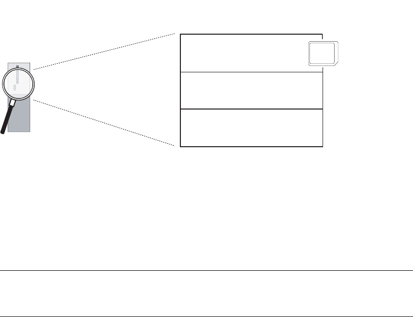
CPU 31xC and CPU 31x, Technical data
Manual, Edition 08/2004, A5E00105475-05 4-1
Memory concept 4
4.1 Memory areas and retentivity
4.1.1 CPU memory areas
The three memory areas of your CPU:
CPU
Loading memory
(located on the MMC)
Memory of the CPU
System memory
Working memory
MMC
Load memory
The load memory is located on a Micro Memory Card (MMC). The size of the load memory
corresponds exactly to the size of the MMC. It is used to store code blocks, data blocks and
system data (configuration, connections, module parameters, etc.). Blocks that are identified
as non runtime-related are stored exclusively in load memory. You can also store all the
configuration data for your project on the MMC.
Note
User programs can only be downloaded and thus the CPU can only be used if the MMC is
inserted in the CPU.

Memory concept
4.1 Memory areas and retentivity
CPU 31xC and CPU 31x, Technical data
4-2 Manual, Edition 08/2004, A5E00105475-05
System memory
The RAM system memory is integrated in the CPU and cannot be expanded.
It contains
• the address areas for address area memory bits, timers and counters
• the process image of the I/Os
• local data
RAM
The RAM is integrated in the CPU and cannot be extended. It is used to run the code and
process user program data. Programs only run in RAM and system memory.
Table 4-1 Retentivity of the RAM
All CPUs except CPU 317 CPU 317
RAM is always retentive. 256 KB of RAM can be used for retentive data
modules. The remainder of the RAM can only be
used for code blocks and non-retentive data blocks.
4.1.2 Retentivity of the load memory, system memory and RAM
Your CPU is equipped with a service-free retentive memory.i.e. its operation does not
require a buffer battery. Data is kept in retentive memory across POWER OFF and
restart (warm start).
Retentive data in load memory
Your program in load memory is always retentive: It is stored on the MMC, where it is
protected against power failure or CPU memory reset.
Retentive data in system memory
In your configuration (Properties of CPU, Retentivity tab), specify which part of memory bits,
timers and counters should be kept retentive and which of them are to be initialized with "0"
on restart (warm restart).
The diagnostic buffer, MPI address (and transmission rate) and operating hour counter data
are generally written to the retentive memory area on the CPU. Retentivity of the MPI
address and baud rate ensures that your CPU can continue to communicate, even after a
power loss, memory reset or loss of communication parameters (e.g. due to removal of the
MMC or deletion of communication parameters).

Memory concept
4.1 Memory areas and retentivity
CPU 31xC and CPU 31x, Technical data
Manual, Edition 08/2004, A5E00105475-05 4-3
Retentive data in RAM
Therefore, the contents of retentive DBs are always retentive at restart and POWER
ON/OFF.
CPUs V2.1.0 or higher also support volatile DBs (the volatile DBs are initialized at restart of
POWER OFF-ON with their initial values from load memory.)
See also
Properties of the Micro Memory Card (MMC) (Page 4-9)
4.1.3 Retentivity of memory objects
Retentive behavior of memory objects
The table below shows the retentive behavior of memory objects during specific operating
state transitions.
Table 4-2 Retentive behavior of memory objects (applies to all CPUs with DP/MPI-SS
(31x-2 PN/DP)
Memory object Operating state transition
POWER ON /
POWER OFF
STOP →
RUN
CPU memory
reset
User program/data (load memory) X X X
• Retentive behavior of DBs for CPUs
with firmware < V2.1.0
X
X
–
• Retentive behavior of DBs for CPUs
with firmware >= V2.1.0
Can be set in the properties of the DBs
in STEP 7 V5.2 + SP1 or higher.
–
Flag bits, timers and counters configured as
retentive data
X X –
Diagnostics buffers, operating hour
counters
X X X
MPI address, transmission rate
(or also DP address, transmission rate of
the MPI/DP interface of CPU 315-2 PN/DP
and CPU 317, if these are configured as
DP nodes.)
X X X
x = retentive; – = not retentive
Retentive behavior of a DB for CPUs with firmware < V2.1.0
For these CPUs, the contents of the DBs are always retentive at POWER ON/OFF or STOP-
RUN.

Memory concept
4.1 Memory areas and retentivity
CPU 31xC and CPU 31x, Technical data
4-4 Manual, Edition 08/2004, A5E00105475-05
Retentive behavior of a DB for CPUs with firmware >= V2.1.0
For these CPUs you can specify in STEP 7 (beginning with version 5.2 + SP 1), or at SFC 82
CREA_DBL (parameter ATTRIB -> NON_RETAIN bit), whether a DB at POWER ON/OFF or
RUN-STOP
• keeps the actual values (retentive DB), or
• accepts the initial values from load memory (non-retentive DB)
Table 4-3 Retentive behavior of DBs for CPUs with firmware >= V2.1.0
At POWER ON/OFF or restart (warm start) of the CPU, the DB should
receive the initial values
(non-retentive DB)
retain the actual values (retentive DB)
Background:
At POWER ON/OFF and restart (STOP-
RUN) of the CPU, the actual values of the
DB are non-retentive. The DB receives the
start values from load memory.
Background:
At POWER OFF/ON and restart (STOP-RUN) of the
CPU, the actual values of the DB are retained.
Requirement in STEP 7:
• The "Non-retain" check box must be set
in the block properties of the DB, or
• a non-retentive DB was generated with
SFC 82 "CREA_DBL" and the
corresponding block attribute (ATTRIB -
> NON_RETAIN bit.)
Requirement in STEP 7:
• The "Non-retain" check box must be reset in the
block properties of the DB or
• a retentive DB was generated with SFC 82.
Note
Note that only 256 KB of RAM can be used for retentive data blocks on a CPU 317. The
remainder of the RAM is used by code blocks and non-retentive data blocks.

Memory concept
4.1 Memory areas and retentivity
CPU 31xC and CPU 31x, Technical data
Manual, Edition 08/2004, A5E00105475-05 4-5
4.1.4 Address areas of system memory
System memory of the S7 CPUS is organized in address areas (refer to the table below). In
a corresponding operation of your user program, you address data directly in the relevant
address area.
Address areas of system memory
Table 4-4 Address areas of system memory
Address areas Description
Process image of inputs At every start of an OB1 cycle, the CPU reads the values at the
input of the input modules and saves them the process image of
inputs.
Process image of outputs During its cycle, the program calculates the values for the outputs
and writes these to the process image of outputs. At the end of
the OB1 cycle, the CPU writes the calculated output values to the
output modules.
Flag bits This area provides memory for saving the intermediate results of
a program calculation.
Timers Timers are available in this area.
Counters Counters are available in this area.
Local data Temporary data in a code block (OB, FB, FC) is saved to this
memory area while the block is being edited.
Data blocks See
Recipes and measurement value logs
Reference
The address areas of your CPU are listed in the
Instruction list for CPUs 31xC and 31x
.
I/O process image
When the user program addresses the input (I) and output (O) address areas, it does not
query the signal states of digital signal modules. Instead, it rather accesses a memory area
in CPU system memory. This particular memory area is the process image.
The process image is organized in two sections: The process image of inputs, and the
process image of outputs.
Advantages of the process image
Process image access, compared to direct I/O access, offers the advantage that a consistent
image of process signals is made available to the CPU during cyclic program execution.
When the signal status at an input module changes during program execution, the signal
status in the process image is maintained until the image is updated in the next cycle.
Moreover, since the process image is stored in CPU system memory, access is significantly
faster than direct access to the signal modules.
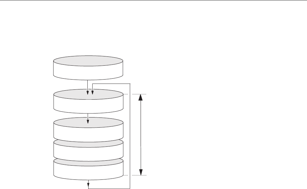
Memory concept
4.1 Memory areas and retentivity
CPU 31xC and CPU 31x, Technical data
4-6 Manual, Edition 08/2004, A5E00105475-05
Process image update
The operating system updates the process image periodically. The figure below shows the
sequence of this operation within a cycle.
Cycle time
Startup
PIO
PII
User program
CCP (OS)
Startup program
Processing the user program (OB 1)
and all programs called inside of it.
Writing the process image of the outputs
into the modules.
Reading the inputs from the modules
and refreshing the data in the process
image of the inputs.

Memory concept
4.1 Memory areas and retentivity
CPU 31xC and CPU 31x, Technical data
Manual, Edition 08/2004, A5E00105475-05 4-7
Configurable process image with CPU317 (FW V2.3.0 or higher)
IN STEP 7, you can define a user-specific size of the I/O process images between 0 to 2048
for a CPU317, FW V2.3.0 or higher.
Note the information below:
Note
Currently, the dynamic setting of the process image only affects its update at the scan cycle
control point. That is, the process image of inputs is only updated up to the set PII size with
the corresponding values of the peripheral input modules existing within this address area,
or the values of the process image of outputs up to the set PIO size are written to the
peripheral output modules existing within this address area.
This set size of the process image is ignored with respect to STEP 7 commands used to
access the process image (for example U I100.0, L EW200, = Q20.0, T AD150, or
corresponding indirect addressing commands also). However, up to the maximum size of the
process image (that is, up to I/O byte 2047), these commands do not return any
synchronous access errors, but rather access the permanently available internal memory
area of the process image.
The same applies to the use of actual parameters of block calls from the I/O area (area of
the process image).
Particularly if these process image limits were changed, you should check to which extent
your user program accesses the process image in the area between the set and the
maximum process image size. If access to this area continues, the user program may not
detect changes at the inputs of the I/O module, or actually fails to write the data of outputs to
the output module, without the system generating an error message.
You should also note that certain CPs may only be addressed outside of the process image.

Memory concept
4.1 Memory areas and retentivity
CPU 31xC and CPU 31x, Technical data
4-8 Manual, Edition 08/2004, A5E00105475-05
Local data
Local data store:
• the temporary variables of code blocks
• the start information of the OBs
• transfer parameters
• intermediate results
Temporary Variables
When you create blocks, you can declare temporary variables (TEMP) which are only
available during block execution and then overwritten again. These local data have fixed
length in each OB. Local data must be initialized prior to the first read access. Each OB also
requires 20 bytes of local data for its start information. Local data access is faster compared
to access to data in DBs.
The CPU is equipped with memory for storing temporary variables (local data) of currently
executed blocks. The size of this memory area depends on the CPU. It is distributed in
partitions of equal size to the priority classes. Each priority class has its own local data area.
Caution
All temporary variables (TEMP) of an OB and its nested blocks are stored in local data.
When using complex nesting levels for block processing, you may cause an overflow in the
local data area.
The CPUs will change to STOP mode if you exceed the permissible length of local data for a
priority class.
Make allowances for local data space required for synchronous error OBs. This is assigned
to the respective triggering priority class.
See also
Retentivity of the load memory, system memory and RAM (Page 4-2)

Memory concept
4.1 Memory areas and retentivity
CPU 31xC and CPU 31x, Technical data
Manual, Edition 08/2004, A5E00105475-05 4-9
4.1.5 Properties of the Micro Memory Card (MMC)
The MMC as memory module for the CPU
The memory module used on your CPU is a SIMATIC Micro Memory Card (MMC.) You can
use MMCs as load memory or as a portable storage medium.
Note
The CPU requires the MMC for operation.
Data stored on the MMC:
• User programs (all blocks)
• Archives and recipes
• Configuration data (STEP 7 projects)
• Data for operating system update and backup
Note
You can either store user and configuration data or the operating system on the MMC.
Properties of an MMC
The MMC ensures maintenance-free and retentive operation of these CPUs.
Caution
Data on a SIMATIC Micro Memory Card can be corrupted if you remove the card while it is
being accessed by a write operation. In this case, you may have to delete the MMC on your
PG, or format the card in the CPU. Never remove an MMC in RUN mode. Always remove it
when power is off, or when the CPU is in STOP state, and when the PG is not a writing to
the card. When the CPU is in STOP mode and you cannot not determine whether or not a
PG is writing to the card (e.g. load/delete block), disconnect the communication lines.

Memory concept
4.1 Memory areas and retentivity
CPU 31xC and CPU 31x, Technical data
4-10 Manual, Edition 08/2004, A5E00105475-05
MMC copy protection
Your MMC has an internal serial number that provides copy protection at user level. You can
read this serial number from the SSL partial list 011CH index 8 using SFC 51 "RDSYSST."
You can then program a STOP command, for example, in a copy-protected block if the
expected and actual serial numbers of your MCC do not tally.
Reference
•
SSL partial list in the instruction list,
or
• in the manual
System and Standard Functions.
Information on CPU memory reset:
Operating instructions CPU 31xC and CPU31x, Commissioning, Commissioning
Modules, CPU Memory Reset by means of Mode Selector Switch
Useful life of an MMC
The useful life of an MMC depends mainly on following criteria:
1. The number of delete or programming operations,
2. External influences such as ambient temperature.
At ambient temperatures up to 60 °C, a maximum of 100,000 delete/write operations can be
performed on an MMC.
Caution
To prevent loss of data, always make sure that you do not exceed the maximum number of
delete/write operations.
See also
Operating and display elements: CPU 31xC (Page 2-1)
Operating and display elements: CPU 312, 314, 315-2 DP: (Page 2-5)
Operating and display elements: CPU 317-2 DP (Page 2-7)
Operating and display elements: CPU 31x-2 PN/DP (Page 2-9)
Memory concept
4.2 Memory functions
CPU 31xC and CPU 31x, Technical data
Manual, Edition 08/2004, A5E00105475-05 4-11
4.2 Memory functions
4.2.1 General: Memory functions
Memory functions
Memory functions are used to generate, modify or delete entire user programs or specific
blocks. You can also ensure that your project data are retained by archiving these. If there
is... You created a new user program, use a PG/ PC to download the complete program to
MMC.
4.2.2 Loading user program from Micro Memory Card (MMC) to the CPU
User program download
All user program data are downloaded from your PG/PC to the CPU via MMC. The previous
content of the MMC is deleted in the process. Blocks use the load memory area as specified
under "Load memory requirements" in "General block properties".
The figure shows the load and work memory of the CPU
Loading memory Working memory
Stored on
hard disk
Code modules
Data modules
Comments
Symbols
Code modules
Data modules
Process-relevant
parts of the code
and data modules *
MMC
PG
CPU
* If not alI of the work memory area is retentive, its retentive area is indicated in the STEP 7
module status as retentive memory (same as on CPU 317). You cannot run the program
until all the blocks are downloaded.

Memory concept
4.2 Memory functions
CPU 31xC and CPU 31x, Technical data
4-12 Manual, Edition 08/2004, A5E00105475-05
Note
This function is only permitted when the CPU is in STOP mode. Load memory is cleared if
the load operation could not be completed due to power loss or illegal block data.
4.2.3 Handling with modules
4.2.3.1 Download of new blocks or delta downloads
There are two ways to download additional user blocks or download deltas:
• Download of blocks: You already created a user program and downloaded it to the CPU
via MMC. You then want to add new blocks to the user program. In this case, you do not
need to reload the entire user program to the MMC. Rather, you can download only the
new blocks to the MMC (this reduces download times for highly complex programs).
• Delta download: In this case, you only download the deltas in the blocks of your user
program. In the next step, perform a delta download of the user program, or only of
changed blocks to the MMC, using the PG/PC.
Warning
The delta download of blocks / user programs overwrites all data stored under the same
name on the MMC.
The data of dynamic blocks are transferred to RAM and activated after the block is
downloaded.
4.2.3.2 Uploading blocks
Uploading blocks
Other than download operations, an upload operation is the transfer of specific blocks or a
user program from the CPU to the PG/PC. The block content is here identical with that of the
last download to the CPU. Dynamic DBs form the exception, because their actual values are
transferred. An upload of blocks or of the user program from the CPU in STEP 7 does not
influence CPU memory.

Memory concept
4.2 Memory functions
CPU 31xC and CPU 31x, Technical data
Manual, Edition 08/2004, A5E00105475-05 4-13
4.2.3.3 Deleting blocks
Deleting blocks
When you delete a block, it is deleted from load memory. In STEP 7, you can also delete
blocks with the user program (DBs also with SFC 23 "DEL_DB"). RAM used by this block is
released.
4.2.3.4 Compressing blocks
Compressing blocks
When data are compressed, gaps which have developed between memory objects in load
memory/RAM as a result of load/delete operations will be eliminated. This releases free
memory in a continuous block. Data compression is possible when the CPU is in RUN or in
STOP.
4.2.3.5 Promming (RAM to ROM)
Promming (RAM to ROM)
When writing the RAM content to ROM, the actual values of the DBs are transferred from
RAM to load memory to form the start values for the DBs.
Note
This function is only permitted when the CPU is in STOP mode. Load memory is cleared if
the function could not be completed due to power loss.
4.2.4 CPU memory reset and restart
CPU memory reset
After the insertion/removal of a Micro Memory Card, a CPU memory reset restores defined
conditions for CPU restart (warm start). A CPU memory reset rebuilds the CPU's memory
management. Blocks in load memory are retained. All dynamic runtime blocks are
transferred once again from load memory to RAM, in particular to initialize the data blocks in
RAM (restore initial values).

Memory concept
4.2 Memory functions
CPU 31xC and CPU 31x, Technical data
4-14 Manual, Edition 08/2004, A5E00105475-05
Restart (warm start)
• All retentive DBs retain their actual value (non-retentive DBs are also supported by CPUs
with Firmware >= V2.1.0. Non-retentive DBs receive their initial values).
• The values of all retentive M, C, T are retained.
• All non-retentive user data are initialized:
– M, C, T, I, O with "0"
• All run levels are initialized.
• The process images are deleted.
Reference
Also refer to
CPU memory reset by means mode selector switch
in the section
Commissioning
in the
CPU 31xC and CPU 31x Operating Instructions
.
Memory concept
4.2 Memory functions
CPU 31xC and CPU 31x, Technical data
Manual, Edition 08/2004, A5E00105475-05 4-15
4.2.5 Recipes
Introduction
A recipe represents a collection of user data. You can implement a simple recipe concept
using static DBs. In this case, the recipes should have the same structure (length). One DB
should exist per recipe.
Processing sequence
Recipe is written to load memory:
• The various data records of recipes are created as static DBs in STEP 7 and then
downloaded to the CPU. Therefore, recipes only use load memory, rather than RAM.
Working with recipe data:
• SFC83 "READ_DBL" is called in the user program to copy the data record of a current
recipe from the DB in load memory to a static DB that is located in work memory. As a
result, the RAM only has to accommodate the data of one record. The user program can
now access data of the current recipe. The figure below shows how to handle recipe
data:
Loading memory
:
Current
recipe
Recipe 1
Recipe 2
Recipe n
Working memory
(MMC)
(CPU)
SFC 83 READ_DBL
SFC 84 WRIT_DBL
Saving a modified recipe:
• The data of new or modified recipe data records generated during program execution can
be written to load memory. To do this, call SFC 84 "WRIT_DBL" in the user program.
These data written to load memory are portable and also retentive on memory reset. You
can backup modified records (recipes) by uploading and saving these in a single block to
the PG/PC.
Note
Active system functions SFC82 to 84 (active access to the MMC) have a distinct
influence on PG functions (for example, block status, variable status, download block,
upload, open). This typically reduces performance (compared to passive system
functions) by the factor 10.

Memory concept
4.2 Memory functions
CPU 31xC and CPU 31x, Technical data
4-16 Manual, Edition 08/2004, A5E00105475-05
Note
As a precaution against loss of data, always make sure that you do not exceed the
maximum number of delete/write operations. Also refer to the SIMATIC Micro Memory
Card (MMC) section in the "Structure and Communication Connections of a CPU"
chapter.
Caution
Data on a SIMATIC Micro Memory Card can be corrupted if you remove the card while it
is being accessed by a write operation. In this case, you may have to delete the MMC on
your PG, or format the card in the CPU. Never remove an MMC in RUN mode. Always
remove it when power is off, or when the CPU is in STOP state, and when the PG is not
a writing to the card. When the CPU is in STOP mode and you cannot not determine
whether or not a PG is writing to the card (e.g. load/delete block), disconnect the
communication lines.
Memory concept
4.2 Memory functions
CPU 31xC and CPU 31x, Technical data
Manual, Edition 08/2004, A5E00105475-05 4-17
4.2.6 Measured value log files
Introduction
Measured values are generated when the CPU executes the user program. These values
are to be logged and analyzed.
Processing sequence
Acquisition of measured values:
• The CPU writes all measured values to a DB (for alternating backup mode in several
DBs) which is located in RAM.
Measured value logging:
• Before the data volume can exceed work memory capacity, you should call
SFC 84 "WRIT_DBL" in the user program to swap measured values from the DB to load
memory. The figure below shows how to handle measured value log files:
:
Measured values 1
Measured values 2
Measured values n
Current measured
values
Working memory
(CPU)
Loading memory
(MMC)
SFC 82 CREA_DBL
SFC 84 WRIT_DBL
• You can call SFC 82 "CREA_DBL" in the user program to generate new (additional) static
DBs in load memory which do not require RAM space.
Reference
For detailed information on SFC 82, refer to the
System Software for S7-300/400, System
and Standard Functions
Reference Manual, or directly to the STEP 7 Online Help.
Note
SFC 82 is terminated and an error message is generated if a DB already exists under the
same number in load memory and/or RAM.

Memory concept
4.2 Memory functions
CPU 31xC and CPU 31x, Technical data
4-18 Manual, Edition 08/2004, A5E00105475-05
The data written to load memory are portable and retentive on CPU memory reset.
Evaluation of measured values:
• Measured value DBs saved to load memory can be uploaded and evaluated by other
communication partners (PG, PC, for example).
Note
The active system functions SFC 82 to 84 (current access to the MMC) have a distinct
influence on PG functions (block status, variable status, load block, upload, open, for
example). This typically reduces performance (compared to passive system functions) by
the factor 10.
Note
For CPUs with firmware V2.1.0 or higher, you can also generate non-retentive DBs using
SFC 82 (parameter ATTRIB -> NON_RETAIN bit.)
Note
As a precaution against loss of data, always make sure that you do not exceed the
maximum number of delete/write operations. For further information, refer to the
Technical Data of the Micro Memory Card (MMC) in the General Technical Data of your
CPU.
Caution
Data on a SIMATIC Micro Memory Card can be corrupted if you remove the card while it
is being accessed by a write operation. In this case, you may have to delete the MMC on
your PG, or format the card in the CPU. Never remove an MMC in RUN mode. Always
remove it when power is off, or when the CPU is in STOP state, and when the PG is not
a writing to the card. When the CPU is in STOP mode and you cannot not determine
whether or not a PG is writing to the card (e.g. load/delete block), disconnect the
communication lines.

Memory concept
4.2 Memory functions
CPU 31xC and CPU 31x, Technical data
Manual, Edition 08/2004, A5E00105475-05 4-19
4.2.7 Backup of project data to a Micro Memory Card (MMC)
Function principle
Using the Save project to Memory Card and Fetch project from Memory Card functions, you
can save all project data to a SIMATIC Micro Memory Card, and retrieve these at a later
time. For this operation, the SIMATIC Micro Memory Card can be located in a CPU or in the
MMC adapter of a PG or PC.
Project data are compressed before they are saved to a SIMATIC Micro Memory Card, and
uncompressed when fetched.
Note
In addition to project data, you may also have to store your user data on the MMC. You
should therefore first verify MMC memory space.
A message warns you if the memory capacity on your MMC is insufficient.
The volume of project data to be saved corresponds with the size of the project's archive file.
Note
For technical reasons, you can only transfer the entire contents (user program and project
data) using the Save project to memory card action.

Memory concept
4.2 Memory functions
CPU 31xC and CPU 31x, Technical data
4-20 Manual, Edition 08/2004, A5E00105475-05
CPU 31xC and CPU 31x, Technical data
Manual, Edition 08/2004, A5E00105475-05 5-1
Cycle and reaction times 5
5.1 Overview
Overview
This section contains detailed information about the following topics:
• Cycle time
• Reaction time
• Interrupt response time
• Sample calculations
Reference: Cycle time
You can view the cycle time of your user program on the PG. For further information, refer to
the
STEP 7 Online Help
, or to the
Configuring Hardware and Connections in STEP 7
Manual
Reference: Execution time
can be found in the
S7-300 Instruction List for CPUs 31xC and 31x
. This tabular list contains
the execution times for all
• STEP 7 instructions the relevant CPU can execute,
• the SFCs / SFBs integrated in the CPUs,
• the IEC functions which can be called in STEP 7.

Cycle and reaction times
5.2 Cycle time
CPU 31xC and CPU 31x, Technical data
5-2 Manual, Edition 08/2004, A5E00105475-05
5.2 Cycle time
5.2.1 Overview
Introduction
This section explains what we mean by the term "cycle time", what it consists of, and how
you can calculate it.
Meaning of the term cycle time
The cycle time represents the time that an operating system needs to execute a program,
that is, one OB 1 cycle, including all program sections and system activities interrupting this
cycle. This time is monitored.
Time slice model
Cyclic program processing, and therefore user program execution, is based on time shares.
To clarify these processes, let us assume that every time share has a length of precisely
1 ms.
Process image
During cyclic program processing, the CPU requires a consistent image of the process
signals. To ensure this, the process signals are read/written prior to program execution.
Subsequently, the CPU does not address input (I) and output (Q) address areas directly at
the signal modules, but rather accesses the system memory area containing the I/O process
image.
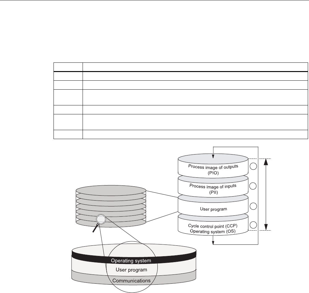
Cycle and reaction times
5.2 Cycle time
CPU 31xC and CPU 31x, Technical data
Manual, Edition 08/2004, A5E00105475-05 5-3
Sequence of cyclic program processing
The table and figure below show the phases in cyclic program processing.
Table 5-1 Cyclic program processing
Step Sequence
1 The operating system initiates cycle time monitoring.
2 The CPU copies the values of the process image of outputs to the output modules.
3 The CPU reads the status at the inputs of the input modules and then updates the
process image of inputs.
4 The CPU processes the user program in time shares and executes program instructions.
5 At the end of a cycle, the operating system executes queued tasks, for example, loading
and deleting blocks.
6 The CPU then returns to the start of the cycle, and restarts cycle time monitoring.
Cycle time
Time slices (1 ms each)
Time slice (1 ms)
2
3
4
5
In contrast to S7-400 CPUs, the S7-300 CPUs data only allow data access from an OP / TP
(monitor and modify functions) at the scan cycle check point (Data consistency, see the
Technical Data). Processing of the user program is not interrupted by the monitor and modify
functions.

Cycle and reaction times
5.2 Cycle time
CPU 31xC and CPU 31x, Technical data
5-4 Manual, Edition 08/2004, A5E00105475-05
Extending the cycle time
Always make allowances for the extension of the cycle time of a user program due to:
• Time-based interrupt processing
• Process interrupt processing
• Diagnostics and error processing
• Communication with PGs, Operator Panels (OPs) and connected CPs (for example,
Ethernet, PROFIBUS DP)
• Testing and commissioning such as, e.g. status/controlling of variables or block status
functions.
• Transfer and deletion of blocks, compressing user program memory
• Write/read access to the MMC, using SFC 82 to 84 in the user program
• Ethernet communication via integrated PROFINET interface
• CBA communication via PROFINET interface (system load, SFC call, update at scan
cycle check point)
• PROFINET IO communication via PROFINET interface (system load)

Cycle and reaction times
5.2 Cycle time
CPU 31xC and CPU 31x, Technical data
Manual, Edition 08/2004, A5E00105475-05 5-5
5.2.2 Calculating the cycle time
Introduction
The cycle time is derived from the sum of the following influencing factors.
Process image update
The table below shows the time a CPU requires to update the process image (process
image transfer time). The times specified might be prolonged as a result of interrupts or CPU
communication. The process image transfer time is calculated as follows:
Table 5-2 Formula for calculating the process image (PI) transfer time
The transfer time of the process image is calculated as follows:
Base load K + number of bytes in PI in module rack 0 x (A)
+ number of bytes in PO in module rack 1 to 3 x (B)
+ number of words in PO via DP x (D)
+ number of words in PO via PROFINET x (P)
= Transfer time for the process image
Table 5-3 CPU 31xC: Data for calculating the process image (PI) transfer time
Const. Portions CPU
312C
CPU
313C
CPU
313C-2
DP
CPU
313C-2
PtP
CPU
314C-2
DP
CPU
314C-2
PtP
K Base load 150 μs 100 μs 100 μs 100 μs
A per byte in module rack 0 37 μs 35 μs 37 μs 37 μs
B per byte in module
racks 1 to 3 *
- 43 μs 47 μs 47 μs
D
(DP only)
per WORD in the DP area
for the integrated DP
interface
- - 1 μs - 1 μs -

Cycle and reaction times
5.2 Cycle time
CPU 31xC and CPU 31x, Technical data
5-6 Manual, Edition 08/2004, A5E00105475-05
Table 5-4 CPU 31x: Data for calculating the process image (PI) transfer time
Const. Portions CPU 312 CPU 314 CPU 315 CPU 317
K Base load 150 μs 100 μs 100 μs 50 μs
A per byte in module
rack 0
37 μs 35 μs 37 μs 15 μs
B per byte in module
racks 1 to 3 *
- 43 μs 47 μs 25 μs
D
(DP only)
per WORD in the DP
area for the integrated
DP interface
- - 1 μs 1 μs
P
(PROFINET
only)
per WORD in the
PROFINET area for
the integrated
PROFINET interface
- - 46 μs 46 μs
* + 60 μs per rack
* + 60 μs per rack
Extending the user program processing time
In addition to actually working through the user program, your CPU's operating system also
runs a number of processes in parallel
such as timer management for the core operating system. These processes extend the
processing time of the user program. The table below lists the multiplication factors required
to calculate your user program processing time.
Table 5-5 Extending the user program processing time
CPU Factor
312C 1,06
313C 1,10
313C-2DP 1,10
313C-PtP 1,06
314C-2DP 1,10
314C-2PtP 1,09
312 1,06
314 1,10
315 1,10
317 1,07

Cycle and reaction times
5.2 Cycle time
CPU 31xC and CPU 31x, Technical data
Manual, Edition 08/2004, A5E00105475-05 5-7
Operating system processing time at the scan cycle checkpoint
The table below shows the operating system processing time at the scan cycle checkpoint of
the CPUs. These times are calculated without taking into consideration times for:
• Testing and commissioning routines, e.g. status/controlling of variables or block status
functions
• Transfer and deletion of blocks, compressing user program memory
• Communication
• Read/write access to the MMC, using SFC82 to 84
Table 5-6 Operating system processing time at the scan cycle checkpoint
CPU Cycle control at the scan cycle check point (CCP)
312C 500 μs
313C 500 μs
313C-2 500 μs
314C-2 500 μs
312 500 μs
314 500 μs
315 500 μs
317 150 μs
Extension of the cycle time as a result of nested interrupts
Enabled interrupts also extend cycle time. Details are found in the table below.
Table 5-7 Extended cycle time due to nested interrupts
Interrupt type Process
interrupt
Diagnostic
Interrupt
Time-of-day
interrupt
Delay interrupt Watchdog
interrupt
312C 700 μs 700 μs 600 μs 400 μs 250 μs
313C 500 μs 600 μs 400 μs 300 μs 150 μs
313C-2 500 μs 600 μs 400 μs 300 μs 150 μs
314C-2 500 μs 600 μs 400 μs 300 μs 150 μs
312 700 μs 700 μs 600 μs 400 μs 250 μs
314 500 μs 600 μs 400 μs 300 μs 150 μs
315 500 μs 600 μs 400 μs 300 μs 150 μs
317 190 μs 240 μs 200 μs 150 μs 90 μs
The program runtime at interrupt level must be added to this time extension.
Cycle and reaction times
5.2 Cycle time
CPU 31xC and CPU 31x, Technical data
5-8 Manual, Edition 08/2004, A5E00105475-05
Extension of the cycle time due to error
Table 5-8 Cycle time extension as a result of errors
Type of error Programming errors I/O access errors
312C 600 μs 600 μs
313C 400 μs 400 μs
313C2 400 μs 400 μs
314C-2 400 μs 400 μs
312 600 μs 600 μs
314 400 μs 400 μs
315 400 μs 400 μs
317 100 μs 100 μs
The interrupt OB processing time must be added to this extended time. The times required
for multiple nested interrupt/error OBs are added accordingly.
5.2.3 Different cycle times
Overview
The cycle time (Tcyc) length is not the same in every cycle. The figure below shows different
cycle times Tcyc1 and Tcyc2. Tcyc2 is longer than Tcyc1, because the cyclically executed OB1 is
interrupted by a time-of-day interrupt OB (here: OB 10).
Current cycle Next cycle
OB10
T
cyc 1 cyc 2
T
Cycle after next
Updating
PIO
Updating
PII
Updating
PIO
Updating
PII
Updating
PIO
Updating
PII
OB1 OB1 OB1
CCP CCP
Block processing times may fluctuate
Fluctuation of the block processing time (e.g. OB 1) may also be a factor causing cycle time
fluctuation, due to:
• conditional instructions,
• conditional block calls,
• different program paths,
• loops etc.
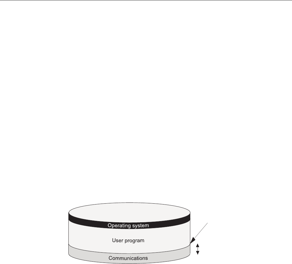
Cycle and reaction times
5.2 Cycle time
CPU 31xC and CPU 31x, Technical data
Manual, Edition 08/2004, A5E00105475-05 5-9
Maximum cycle time
In
STEP 7
you can modify the default maximum cycle time. OB80 is called on when this time
expires. In this block you can specify the CPUs response to this timeout error. The CPU
switches to STOP mode if OB80 does not exist in its memory.
5.2.4 Communication load
Configured communication load for PG/OP communication, S7 communication and CBA
The CPU operating system continuously provides a specified percentage of total CPU
processing performance (time-sharing technology) for communication tasks. Processing
performance not required for communication is made available to other processes. In HW
Config, you can specify a communication load value between 5% and 50%. Default value is
20%.
You can use the following formula for calculating the cycle time extension factor:
100 / (100 – configured communication load in %)
Interruption
of user program
Share can be configured
between 5 % and 50 %
Time slice (1 ms)
Example: 20 % communication load
In your hardware configuration, you have specified a communication load of 20 %. The
calculated cycle time is 10 ms. Using the above formula, the cycle time is extended by the
factor 1.25.
Example: 50 % communication load
In your hardware configuration, you have specified a communication load of 50%. The
calculated cycle time is 10 ms. Using the above formula, the cycle time is extended by the
factor 2.

Cycle and reaction times
5.2 Cycle time
CPU 31xC and CPU 31x, Technical data
5-10 Manual, Edition 08/2004, A5E00105475-05
Physical cycle time depending on communication load
The figure below describes the non-linear dependency of the physical cycle time on
communication load. In our sample we have chosen a cycle time of 10 ms.
0% 10 % 20 % 30 % 40 % 50 % 60 %
Cycle time
10 ms
20 ms
25 ms
15 ms
5ms
30 ms
5%
Communication load
The communication load can
be defined in this area.
Influence on the physical cycle time
From the statistical viewpoint, asynchronous events—such as interrupts—occur more
frequently within the OB1 cycle when the cycle time is extended as a result of
communication load. This further extends the OB1 cycle. This extension depends on the
number of events that occur per OB1 cycle and the time required to process these events.
Note
Change the value of the "communication load" parameter to check the effects on the cycle
time at system runtime. You must consider the communication load when you set the
maximum cycle time, otherwise timing errors may occur.
Tips
• Use the default setting wherever possible.
• Increase this value only if the CPU is used primarily for communications and if the user
program is not time critical.
• In all other situations you should only reduce this value.

Cycle and reaction times
5.2 Cycle time
CPU 31xC and CPU 31x, Technical data
Manual, Edition 08/2004, A5E00105475-05 5-11
5.2.5 Cycle time extension as a result of testing and commissioning functions
Runtimes
The runtimes of the testing and commissioning functions are operating system runtimes, so
they are the same for every CPU. Initially, there is no difference between process mode and
testing mode. How the cycle time is extended as a result of active testing and commissioning
functions is shown in the table below.
Table 5-9 Cycle time extension as a result of testing and commissioning functions
Function CPU 31xC/ CPU 31x
Status variable 50 μs for each variable
Control variable 50 μs for each variable
Block status 200 μs for each monitored line
Configuration during parameter assignment
For process operation, the maximum permissible cycle load by communication is not
specified in "Cycle load by communication", but rather in "Maximum permitted increase of
cycle time as a result of testing functions during process operation". Thus, the configured
time is monitored absolutely in process mode and data acquisition is stopped if a timeout
occurs. This is how STEP 7 stops data requests in loops before a loop ends, for example.
When running in Testing mode, the complete loop is executed in every cycle. This can
significantly increase cycle time.
5.2.6 Cycle extension through component-based automation (CBA)
By default, the operating system of your CPU updates the PROFINET interface as well as
the DP interconnections at the cycle control point. However, if you deactivated these
automatic updates during configuration (e.g. to obtain improved capabilities of influencing the
time behavior of the CPU), you must perform the update manually. This is done by calling
SFCs 112 to 114 at the appropriate times.
Reference
Information about SFC 112 to 114 is available in the
STEP 7 Online Help
.
Extending the OB1 cycle time
The OB1 cycle is extended by
• Increasing the number of PROFINET interconnections,
• Increasing the number of remote partners,
• Increasing the data volume and
• Incrasing the transfer frequency
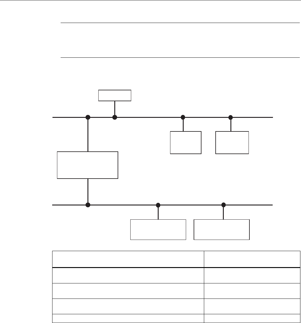
Cycle and reaction times
5.2 Cycle time
CPU 31xC and CPU 31x, Technical data
5-12 Manual, Edition 08/2004, A5E00105475-05
Note
The use of CBA with cyclical PROFINET interconnections requires the use of switches to
maintain the performance data. 100-Mbit full-duplex operation is mandatory with cyclical
PROFINET interconnections.
The following graphic shows the configuration that was used for the measurements.
Industrial Ethernet
PROFIBUS
...
...
HMI/OPC
Quantity: 32
Quantity: 16
PROFINET device with
proxy functionality
(CPU 317-2 PN/DP)
Number of observed
interconnections
in SIMATIC iMAP
or OPC: 200
PROFINET
remote
node 1
PROFIBUS device 1
(as DP slave)
PROFINET
remote
node 32
PROFIBUS device 16
(as DP slave)
The upper graphic displays
Incoming/outgoing remote connections
Number
Cyclical interconnection via Ethernet 200, scan cycle rate: Intervals of
10 ms
Acyclic interconnection via Ethernet 50, scan cycle rate: Intervals of
500 ms
Interconnections from the PROFINET device with proxy
functionality (CPU 317-2 PN/DP) to the PROFIBUS devices.
16 x 4
Interconnections of PROFIBUS devices among each other 16 x 6
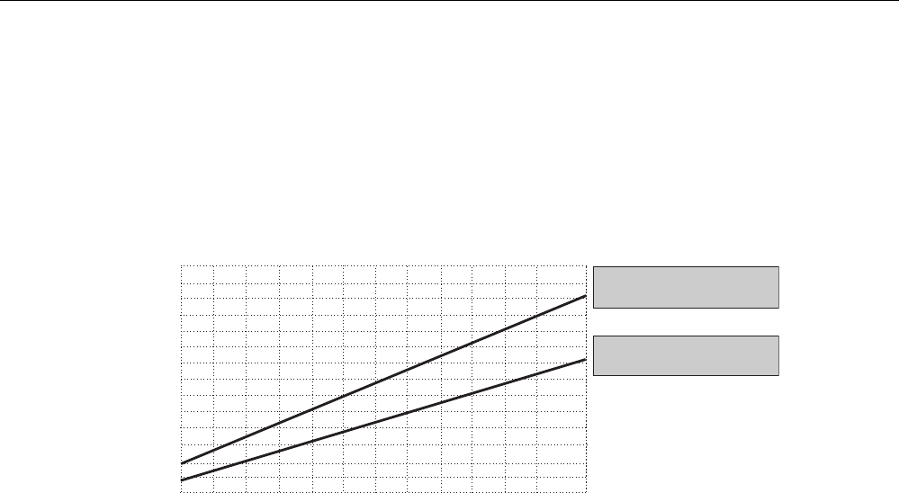
Cycle and reaction times
5.2 Cycle time
CPU 31xC and CPU 31x, Technical data
Manual, Edition 08/2004, A5E00105475-05 5-13
Additional marginal conditions
The maximum cycle load through communication in the measurement is 20 %.
The lower graphic shows that the OB1 cycle is influenced by increasing the cyclical
PROFINET interconnections to remote partners at PROFINET:
032
64 96 128 160 200
0
2
4
6
8
10
12
14
Cycle time in ms
Dependency of the OB1 cycle on the number of interconnections
Number of interconnections
OB1 cycle with 32 remote
PROFINET partners
OB1 cycle with 5 remote
PROFINET partners
Base load through PROFIBUS devices
The 16 PROFIBUS devices with their interconnections among each other generate an
additional base load of up to 1,0 ms.
Tips and notes
The upper graphic already includes the use of uniform values for the transfer frequency of all
interconnections to a partner.
• The performance can drop by up to 50 % if the values are distributed to different
frequency levels.
• The use of data structures and arrays in an interconnection instead of many single
interconnections with simple data structures increases the performance.

Cycle and reaction times
5.3 Response time
CPU 31xC and CPU 31x, Technical data
5-14 Manual, Edition 08/2004, A5E00105475-05
5.3 Response time
5.3.1 Overview
Definition of response time
The response time is the time between the detection of an input signal and the change of a
linked output signal.
Fluctuation width
The physical response time lies between the shortest and the longest response time. You
must always reckon with the longest response time when configuring your system.
The shortest and longest response times are shown below, to give you an idea of the
fluctuation width of the response time.
Factors
The response time depends on the cycle time and following factors:
• Delay of the inputs and outputs of signal modules or integrated I/O.
• Additional update times for PROFINET IO
• additional DP cycle times on PROFIBUS DP
• Execution in the user program
Reference
• The delay times are located in the specifications of the signal modules
(
Module data
Reference Manual).
Update times for PROFINET IO
If you configured your PROFINET IO system in STEP 7, STEP 7 calculates the update time
for PROFINET IO. You can then view the PROFINET IO update times on your PG.
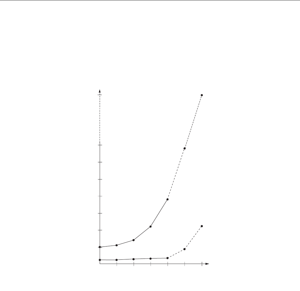
Cycle and reaction times
5.3 Response time
CPU 31xC and CPU 31x, Technical data
Manual, Edition 08/2004, A5E00105475-05 5-15
DP cycle times in the PROFIBUS DP network
If you have configured your PROFIBUS DP master system in STEP 7, STEP 7 calculates the
typical DP cycle time to be expected. You can then view the DP cycle time of your
configuration on the PG.
The figure below gives you an overview of the DP cycle time. In this example, let us assume
that the data of each DP slave has an average length of 4 bytes.
6ms
4ms
2ms
2 4 8 16 32
1ms
3ms
5ms
7ms
64
17 ms
1
Bus runtime
Number of DP slaves;
maximum number is
dependent on CPU
Minimum
slave interval
Transmission rate 1.5 Mbit/s
Transmission rate 12 MBit/s
With multi-master operation on a PROFIBUS-DP network, you must make allowances for the
DP cycle time at each master. That is, you will have to calculate the times for each master
separately and then add up the results.
Cycle and reaction times
5.3 Response time
CPU 31xC and CPU 31x, Technical data
5-16 Manual, Edition 08/2004, A5E00105475-05
5.3.2 Shortest response time
Conditions for the shortest response time
The figure below shows the conditions under which the shortest response time is reached.
Delay of inputs
Immediately before reading in the PII, the status of
the monitored input changes. This change of the input
signal is still included in the PII.
The change of the input signal is processed by
the application program.
The response of the user program to the change
of the input signal is issued to the outputs.
Delay of outputs
Response time
CCP (OS)
PIO
PII
User program
CCP (OS)
PIO
Calculation
The (shortest) response time is the sum of:
Table 5-10 Formula: Shortest response time
1 x process image transfer time for the inputs
+ 1 x process image transfer time for the outputs
+ 1 x program processing time
+ 1 × operating system processing time at the SCC
+ I/O delay
= Shortest response time
The result is equivalent to the sum of the cycle time plus the I/O delay times.
See also
Overview (Page 5-14)
Cycle and reaction times
5.3 Response time
CPU 31xC and CPU 31x, Technical data
Manual, Edition 08/2004, A5E00105475-05 5-17
5.3.3 Longest response time
Conditions for the longest response time
The figure below shows the conditions under which the longest response time is reached.
Response time
While reading in the PII, the status of the monitored
input changes. This change of the input signal is not
included in the PII any longer.
The change of the input signal is included in the PII.
The change of the input signal is processed by the
application program.
The response of the user program to the change
of the input signal is issued to the outputs.
Delay of inputs +
2 x DP cycle time at PROFIBUS DP
Delay of outputs +
2 x DP cycle time at PROFIBUS DP
CCP (OS)
PIO
PII
CCP (OS)
PIO
PII
PIO

Cycle and reaction times
5.3 Response time
CPU 31xC and CPU 31x, Technical data
5-18 Manual, Edition 08/2004, A5E00105475-05
Calculation
The (longest) response time is the sum of:
Table 5-11 Formula: Longest response time
2 x process image transfer time for the inputs
+ 2 x process image transfer time for the outputs
+ 2 x program processing time
+ 2 × operating system processing time
+ 2 x program processing time
+ 4 x PROFINET IO update time (only if PROFINET IO is used.)
+ 4 x DP cycle time on PROFIBUS DP (only if PROFIBUS DP is used.)
+ I/O delay
= Longest response time
Equivalent to the sum of 2 x the cycle time + I/O delay time + 4 x times the PROFINET IO
update time or 4 x times the DP cycle time on PROFIBUS DP.
See also
Overview (Page 5-14)
5.3.4 Reducing the response time with direct I/O access
Reducing the response time
You can reach faster response times with direct access to the I/O in your user program, e.g.
with
• L PIB or
• T PQW
you can partially avoid the response times described above.
Note
You can also achieve fast response times by using process interrupts.
See also
Shortest response time (Page 5-16)
Longest response time (Page 5-17)

Cycle and reaction times
5.4 Calculating method for calculating the cycle/response time
CPU 31xC and CPU 31x, Technical data
Manual, Edition 08/2004, A5E00105475-05 5-19
5.4 Calculating method for calculating the cycle/response time
Introduction
This section gives you an overview of how to calculate the cycle/response time.
Cycle time
1. Determine the user program runtime with the help of the
Instruction list
.
2. Multiply the calculated value by the CPU-specific factor from the table
Extension of user
program processing time
.
3. Calculate and add the process image transfer time. Corresponding guide values are
found in table
Data for calculating process image transfer time
.
4. Add the processing time at the scan cycle checkpoint. Corresponding guide values are
found in the table
Operating system processing time at the scan cycle checkpoint
.
5. Include the extensions as a result of testing and commissioning functions as well as
cyclical PROFINET interconnections in your calculation. These values are found in the
table
Cycle time extension due to testing and commissioning functions.
The final result is
the cycle time.
Extension of the cycle time as a result of interrupts and communication load
100 / (100 – configured communication load in %)
1. Multiply the cycle time by the factor as in the formula above.
2. Calculate the runtime of interrupt processing program sections with the help of the
instruction list. Add the corresponding value from the table below
.
3. Multiply both values by the CPU-specific extension factor of the user program processing
time.
4. Add the value of the interrupt-processing program sequences to the theoretical cycle
time, multiplied by the number of triggering (or expected) interrupt events within the cycle
time. The result is an approximation of the physical cycle time. Note down the result.
See also
Cycle extension through component-based automation (CBA) (Page 5-11)

Cycle and reaction times
5.4 Calculating method for calculating the cycle/response time
CPU 31xC and CPU 31x, Technical data
5-20 Manual, Edition 08/2004, A5E00105475-05
Response time
Table 5-12 Calculating the response time
Shortest response time Longest response time
- Multiply the physical cycle time by factor 2.
Now add I/O delay. Now add the I/O delay plus the DP cycle times on
PROFIBUS-DP or the PROFINET IO update
times.
The result is the shortest response time. The result is the longest response time.
See also
Longest response time (Page 5-17)
Shortest response time (Page 5-16)
Calculating the cycle time (Page 5-5)
Cycle extension through component-based automation (CBA) (Page 5-11)

Cycle and reaction times
5.5 Interrupt response time
CPU 31xC and CPU 31x, Technical data
Manual, Edition 08/2004, A5E00105475-05 5-21
5.5 Interrupt response time
5.5.1 Overview
Definition of interrupt response time
The interrupt response time is the time that expires between the first occurrence of an
interrupt signal and the call of the first interrupt OB instruction. Generally valid: Higher-
priority interrupts take priority. This means that the interrupt response time is increased by
the program processing time of the higher-priority interrupt OBs and the interrupt OBs of
equal priority which have not yet been executed (queued).
Process/diagnostic interrupt response times of the CPUs
Table 5-13 Process/diagnostic interrupt response times
Process interrupt response times Diagnostic interrupt response
times
CPU external
min.
external
max.
Integrated I/O
max.
Min. Max.
CPU 312 0.5 ms 0,8 ms - 0.5 ms 1,0 ms
CPU 312C 0.5 ms 0,8 ms 0,6 ms 0.5 ms 1,0 ms
CPU 313C 0,4 ms 0,6 ms 0.5 ms 0,4 ms 1,0 ms
CPU 313C-2 0,4 ms 0,7 ms 0.5 ms 0,4 ms 1,0 ms
CPU 314 0,4 ms 0,7 ms - 0,4 ms 1,0 ms
CPU 314C-2 0,4 ms 0,7 ms 0.5 ms 0,4 ms 1,0 ms
CPU 315-2 DP
CPU 315-2 PN/DP
0,4 ms 0,7 ms - 0,4 ms 1,0 ms
CPU 317-2 DP
CPU 317-2 PN/DP
0,2 ms 0,3 ms - 0,2 ms 0,3 ms

Cycle and reaction times
5.5 Interrupt response time
CPU 31xC and CPU 31x, Technical data
5-22 Manual, Edition 08/2004, A5E00105475-05
Calculation
The formula below show how you can calculate the minimum and maximum interrupt
response times.
Table 5-14 Process/diagnostic interrupt response times
Calculation of the minimum and maximum interrupt reaction time
Minimum interrupt reaction time of the CPU
+ Minimum interrupt reaction time of the
signal modules
+ PROFINET IO update time (only if
PROFINET IO is used.)
+ DP cycle time on PROFIBUS DP (only if
PROFIBUS DP is used.)
= Quickest interrupt reaction time
Maximum interrupt reaction time of the CPU
+ Maximum interrupt reaction time of the signal
modules
+ 2 x PROFINET IO update time (only if PROFINET
IO is used.)
+ 2 x DP cycle time on PROFIBUS DP (only if
PROFIBUS DP is used.)
The maximum interrupt reaction time is longer when
the communication functions are active. The extra
time is calculated using the following formula:
tv: 200 μs + 1000 μs x n%
n = Setting of the cycle load as a result of
communication
Extension of interrupt response times with cyclic PROFINET interconnections
When using cyclical PROFINET interconnections to a remote partner, the interrupt response
time can increase by up to 1.2 ms in addition to the values mentioned above:
• More than 10 cyclical interconnections are configured to the remote partner or
• The interconnection data to the remote partner are greater than 100 bytes.
Signal modules
The process interrupt response time of signal modules is determined by the following factors:
• Digital input modules
Process interrupt response time = internal interrupt preparation time + input delay
You will find these times in the data sheet for the respective digital input module.
• Analog input modules
Process interrupt response time = internal interrupt preparation time + input delay
The internal interrupt preparation time for analog input modules can be neglected. The
conversion times can be found in the data sheet for the individual analog input modules.
The diagnostic interrupt response time of signal modules is equivalent to the period that
expires between the time a signal module detects a diagnostic event and the time this signal
module triggers the diagnostic interrupt. This short time can be neglected.

Cycle and reaction times
5.5 Interrupt response time
CPU 31xC and CPU 31x, Technical data
Manual, Edition 08/2004, A5E00105475-05 5-23
Process interrupt processing
Process interrupt processing begins after process interrupt OB40 is called. Higher-priority
interrupts stop process interrupt processing. Direct I/O access is executed during runtime of
the instruction. After process interrupt processing has terminated, cyclic program execution
continues or further interrupt OBs of equal or lower priority are called and processed.
See also
Overview (Page 5-1)
5.5.2 Reproducibility of delay interrupts and watchdog interrupts
Definition of "Reproducibility"
Delay interrupt:
The period that expires between the call of the first instruction in the interrupt OB and the
programmed time of interrupt.
Watchdog interrupt:
The fluctuation width of the interval between two successive calls, measured between the
respective initial instructions of the interrupt OBs.
Reproducibility
The following times apply for the CPUs described in this manual:
• Delay interrupt: +/- 200 μs
• Watchdog interrupt: +/- 200 μs
These times only apply if the interrupt can actually be executed at this time and if not
interrupted, for example, by higher-priority interrupts or queued interrupts of equal priority.

Cycle and reaction times
5.6 Sample calculations
CPU 31xC and CPU 31x, Technical data
5-24 Manual, Edition 08/2004, A5E00105475-05
5.6 Sample calculations
5.6.1 Example of cycle time calculation
Installation
You have configured an S7300 and equipped it with following modules in rack "0":
• a CPU 314C-2
• 2 digital input modules SM 321; DI 32 x 24 VDC (4 bytes each in the PI)
• 2 digital output modules SM 322; DO 32 x 24 VDC/0.5 A (4 bytes each in the PI)
User program
According to the Instruction List, the user program runtime is 5 ms. There is no active
communication.
Calculating the cycle time
In this example, the cycle time is equivalent to the sum of the following times:
• User program execution time:
approx. 5 ms x CPU-specific factor 1.10 = approx. 5.5 ms
• Process image transfer time
Process image of inputs: 100 μs + 8 Byte x 37 μs = approx. 0.4 ms
Process image of outputs: 100 μs + 8 Byte x 37 μs = approx. 0.4 ms
• Operating system runtime at the scan cycle checkpoint:
approx. 0.5 ms
Cycle time = 5.5 ms + 0.4 ms + 0.4 ms + 0.5 ms = 6.8 ms.
Calculating the physical cycle time
• There is no active communication.
• Interrupts are not processed.
Hence, the physical cycle time is 6 ms.

Cycle and reaction times
5.6 Sample calculations
CPU 31xC and CPU 31x, Technical data
Manual, Edition 08/2004, A5E00105475-05 5-25
Calculating the longest response time
Longest response time:
6.8 ms x 2 = 13.6 ms.
• I/O delay can be neglected.
• Neither PROFIBUS DP, nor PROFINET IO are being used, so you do not have to make
allowances for any DP cycle times on PROFIBUS DP or for PROFINET IO update times.
• Interrupts are not processed.
5.6.2 Sample of response time calculation
Installation
You have configured an S7300 and equipped it with the following modules in two racks:
• a CPU 314C-2
Configuring the cycle load as a result of communication: 40 %
• 4 digital input modules SM 321; DI 32 x 24 VDC (4 bytes each in the PI)
• 3 digital output modules SM 322; DO 16 x 24 VDC/0.5 A (2 bytes each in the PI)
• 2 analog input modules SM 331; AI 8 x 12-bit (not in the PI)
• 2 analog output modules SM 332; AO 4 x 12 bit (not in the PI)
User program
According to the instruction list, the user program runtime is 10.0 ms.
Calculating the cycle time
In this example, the cycle time is equivalent to the sum of the following times:
• User program execution time:
approx. 10 ms x CPU-specific factor 1.10 = approx. 11 ms
• Process image transfer time
Process image of inputs: 100 μs + 16 bytes x 37 μs = approx. 0.7 ms
Process image of outputs: 100 μs + 6 bytes x 37 μs = approx. 0.3 ms
• Operating system runtime at the scan cycle checkpoint:
approx. 0.5 ms
The sum of the listed times is equivalent to the cycle time:
Cycle time = 11.0 ms + 0.7 ms + 0.3 ms + 0.5 ms = 12.5 ms.

Cycle and reaction times
5.6 Sample calculations
CPU 31xC and CPU 31x, Technical data
5-26 Manual, Edition 08/2004, A5E00105475-05
Calculating the physical cycle time
Under consideration of communication load:
12.5 ms * 100 / (100-40) = 20.8 ms.
Thus, under consideration of time-sharing factors, the actual cycle time is 21 ms.
Calculation of the longest response time
• Longest response time = 21 ms * 2 = 42 ms.
• I/O delay
– The maximum delay of the input digital module SM 321; DI 32 x 24 VDC is 4.8 ms per
channel.
– The output delay of the digital output module SM 322; DO 16 x 24 VDC/0.5 A can be
neglected.
– The analog input module SM 331; AI 8 x 12 bit was configured for an interference
suppression at 50 Hz. The result is a conversion time of 22 ms per channel. With the
eight active channels, the result is a cycle time of 176 ms for the analog input module.
– The analog output module SM 332; AO 4 x 12-bit was programmed for the measuring
range of 0 ...10 Hz. This gives a conversion time of 0.8 ms per channel. Since
4 channels are active, the result is a cycle time of 3.2 ms. A settling time of 0.1 ms for
a resistive load must be added to this value. The result is a response time of 3.3 ms
for an analog output.
• Neither PROFIBUS DP, nor PROFINET IO are being used, so you do not have to make
allowances for any DP cycle times on PROFIBUS DP or for PROFINET IO update times.
• Response times plus I/O delay:
– Case 1: An output channel of the digital output module is set when a signal is received
at the digital input. The result is a response time of:
Response time = 42 ms + 4.8 ms = 46.8 ms.
– Case 2: An analog value is fetched, and an analog value is output. The result is a
response time of:
Longest response time = 42 ms + 176 ms + 3.3 ms = 221.3 ms.

Cycle and reaction times
5.6 Sample calculations
CPU 31xC and CPU 31x, Technical data
Manual, Edition 08/2004, A5E00105475-05 5-27
5.6.3 Example of interrupt response time calculation
Installation
You have assembled an S7-300, consisting of one CPU 314C-2 and four digital modules in
the CPU rack. One of the digital input modules is an SM 321; DI 16 x 24 VDC; with
process/diagnostic interrupt function.
You have enabled only the process interrupt in your CPU and SM parameter configuration.
You decided not to use time-controlled processing, diagnostics or error handling. You have
configured a 20% communication load on the cycle.
You have configured a delay of 0.5 ms for the inputs of the DI module.
No activities are required at the scan cycle checkpoint.
Calculation
In this example, the process interrupt response time is based on following time factors:
• Process interrupt response time of CPU 314C-2: approx. 0,7 ms
• Extension by communication according to the formula:
200 μs + 1000 μs x 20 % = 400 μs = 0.4 ms
• Process interrupt response time of SM 321; DI 16 x 24 VDC:
– Internal interrupt preparation time: 0.25 ms
– Input delay: 0.5 ms
• Neither PROFIBUS DP, nor PROFINET IO are being used, so you do not have to make
allowances for any DP cycle times on PROFIBUS DP or for PROFINET IO update times.
The process interrupt response time is equivalent to the sum of the listed time factors:
Process interrupt response time = 0.7 ms + 0.4 ms + 0.25 ms + 0.5 ms = approx. 1.85 ms.
This calculated process interrupt response time expires between the time a signal is
received at the digital input and the call of the first instruction in OB40.

Cycle and reaction times
5.6 Sample calculations
CPU 31xC and CPU 31x, Technical data
5-28 Manual, Edition 08/2004, A5E00105475-05

CPU 31xC and CPU 31x, Technical data
Manual, Edition 08/2004, A5E00105475-05 6-1
Technical data of CPU 31xC 6
6.1 General technical data
6.1.1 Dimensions of CPU 31xC
Each CPU features the same height and depth, only the width dimensions differ.
• Height: 125 mm
• Depth: 115 mm, or 180 mm with opened front cover.
Width of CPU
CPU Width
CPU 312C 80 mm
CPU 313C 120 mm
CPU 313C-2 PtP 120 mm
CPU 313C-2 DP 120 mm
CPU 314C-2 PtP 120 mm
CPU 314C-2 DP 120 mm
Technical data of CPU 31xC
6.1 General technical data
CPU 31xC and CPU 31x, Technical data
6-2 Manual, Edition 08/2004, A5E00105475-05
6.1.2 Technical data of the Micro Memory Card (MMC)
Plug-in SIMATIC Micro Memory Cards
The following memory modules are available:
Table 6-1 Available MMCs
Type Order number Required for a firmware update via MMC
MMC 64k 6ES7 953-8LFxx-0AA0 –
MMC 128k 6ES7 953-8LGxx-0AA0 –
MMC 512k 6ES7 953-8LJxx-0AA0 –
MMC 2M 6ES7 953-8LLxx-0AA0 Minimum requirement for CPUs without DP interface
MMC 4M 6ES7 953-8LMxx-0AA0 Minimum requirement for CPUs with DP interface
MMC 8M 1 6ES7 953-8LPxx-0AA0 –
1 This MMC cannot be used together with CPU 312C or CPU 312.
Maximum number of loadable blocks in the MMC
The number of blocks that can be stored on the MMC depends on the capacity of the MMC
being used. The maximum number of blocks that can be loaded is therefore limited by the
capacity of your MMC (including blocks generated with the "CREATE DB" SFC):
Table 6-2 Maximum number of loadable blocks on the MMC
Size of MMC Maximum number of blocks that can be loaded
64 KB 768
128 KB 1024
512 KB
2 MB
4 MB
8 MB
Here the maximum number of blocks that can be loaded for the
specific CPU is less than the number of blocks that can be stored on
the MMC.
Refer to the corresponding specifications of a specific CPU to
determine the maximum number of blocks that can be loaded.

Technical data of CPU 31xC
6.2 CPU 312C
CPU 31xC and CPU 31x, Technical data
Manual, Edition 08/2004, A5E00105475-05 6-3
6.2 CPU 312C
Technical data
Table 6-3 Technical data of CPU 312C
Technical data
CPU and version
Order number 6ES7 312-5BD01-0AB0
• Hardware version 01
• Firmware version V2.0
• Associated programming package STEP 7 as of V 5.2 + SP 1
(please use previous CPU for STEP 7 V 5.1 +
SP 3 or later)
Memory
RAM
• Integrated 16 KB
• Expandable No
Load memory Plugged in with MMC (max. 4 MB)
Data storage life on the MMC
(following final programming)
At least 10 years
Buffering Guaranteed by MMC (maintenance-free)
Execution times
Processing times of
• Bit operations Min. 0.2 μs
• Word instructions Min. 0.4 μs
• Fixed-point arithmetic Min. 5 μs
• Floating-point arithmetic Min. 6 μs
Timers/counters and their retentivity
S7 counters 128
• Retentive memory Configurable
• Default from C0 to C7
• Counting range 0 to 999
IEC Counters Yes
• Type SFB
• Number unlimited (limited only by RAM size)
S7 timers 128
• Retentive memory Configurable
• Default Not retentive
• Timer range 10 ms to 9990 s

Technical data of CPU 31xC
6.2 CPU 312C
CPU 31xC and CPU 31x, Technical data
6-4 Manual, Edition 08/2004, A5E00105475-05
Technical data
IEC Timers Yes
• Type SFB
• Number unlimited (limited only by RAM size)
Data areas and their retentivity
Flag bits 128 bytes
• Retentive memory Configurable
• Default retentivity MB0 to MB15
Clock flag bits 8 (1 byte per flag bit)
Data blocks Max. 511
(DB 1 to DB 511)
• Length max. 16 KB
Local data per priority class max. 256 bytes
Blocks
Total 1024 (DBs, FCs, FBs)
The maximum number of blocks that can be
loaded may be reduced if you are using another
MMC.
OBs see the Instruction List
• Length max. 16 KB
Nesting depth
• Per priority class 8
• additional within an error OB 4
FBs Max. 512
(FB 0 to FB 511)
• Length max. 16 KB
FCs Max. 512
(FC 0 to FC 511)
• Length max. 16 KB
Address areas (I/O)
Total I/O address area max. 1024 bytes/1024 bytes
(can be freely addressed)
I/O process image 128 bytes/128 bytes
Digital channels Max. 256
• of those local Max. 256
• Integrated channels 10 DI / 6 DO
Analog channels Max. 64
• of those local Max. 64
• Integrated channels None

Technical data of CPU 31xC
6.2 CPU 312C
CPU 31xC and CPU 31x, Technical data
Manual, Edition 08/2004, A5E00105475-05 6-5
Technical data
Assembly
Racks Max. 1
Modules per rack Max. 8
Number of DP masters
• Integrated None
• Via CP Max. 1
Number of function modules and communication
processors you can operate
• FM Max. 8
• CP (PtP) Max. 8
• CP (LAN) Max. 4
Time-of-day
Real-time clock Yes (SW clock)
• Buffered No
• Accuracy Deviation per day < 10 s
• Behavior of the realtime clock after POWER
OFF
The clock keeps running, continuing at the time-
of-day it had when power was switched off.
Operating hours counter 1
• Number 0
• Value range 2 31 hours
(if SFC 101 is used)
• Granularity 1 hour
• Retentive Yes; must be manually restarted after every
restart
Clock synchronization Yes
• In the PLC Master
• On MPI Master/slave
S7 signaling functions
Number of stations that can be logged on for
signaling functions
max. 6
(depends on the number of connections
configured for PG / OP and S7 basic
communication)
Process diagnostics messages Yes
• Simultaneously enabled interrupt S blocks Max. 20
Testing and commissioning functions
Status/control variables Yes
• Variables Inputs, outputs, memory bits, DBs, timers,
counters
• Number of variables
– Of those as status variable
– Of those as control variable
Max. 30
Max. 30
Max. 14
Forcing Yes
• Variables Inputs, outputs
• Number of variables Max. 10

Technical data of CPU 31xC
6.2 CPU 312C
CPU 31xC and CPU 31x, Technical data
6-6 Manual, Edition 08/2004, A5E00105475-05
Technical data
Block status Yes
Single step Yes
Breakpoints 2
Diagnostic buffer Yes
• Number of entries (not configurable) Max. 100
Communication functions
PG/OP communication Yes
Global data communication Yes
• Number of GD circuits 4
• Number of GD packets
– Sending stations
– Receiving stations
Max. 4
Max. 4
Max. 4
• Length of GD packets
– Consistent data
max. 22 bytes
22 bytes
S7 basic communication Yes
• User data per request
• Consistent data
max. 76 bytes
76 bytes (for X_SEND or X_RCV)
64 bytes (for X_PUT or X_GET as the server)
S7 communication
• As server Yes
• User data per request
– Consistent data
max. 180 bytes (with PUT/GET)
64 bytes
S5-compatible communication Yes (via CP and loadable FCs)
Number of connections Max. 6
can be used for
• PG communication
– Reserved (default)
– Configurable
Max. 5
1
from 1 to 5
• OP communication
– Reserved (default)
– Configurable
Max. 5
1
from 1 to 5
• S7-based communication
– Reserved (default)
– Configurable
Max. 2
2
from 0 to 2
Routing No
Interfaces
1st interface
Type of interface Integrated RS485 interface
Physics RS 485
electrically isolated No
Interface power supply
(15 to 30 VDC)
Max. 200 mA

Technical data of CPU 31xC
6.2 CPU 312C
CPU 31xC and CPU 31x, Technical data
Manual, Edition 08/2004, A5E00105475-05 6-7
Technical data
Functionality
• MPI Yes
• PROFIBUS DP No
• Point-to-point communication No
MPI
Services
• PG/OP communication Yes
• Routing No
• Global data communication Yes
• S7 basic communication Yes
• S7 communication
– As server
– As client
Yes
No
• Transmission rates max. 187.5 kbps
Programming
Programming language LAD/FBD/STL
Available instructions see the Instruction List
Nesting levels 8
System functions (SFCs) see the Instruction List
System function blocks (SFBs) see the Instruction List
User program security Yes
Integrated I/O
• Default addresses of the integrated
– Digital inputs
– Digital outputs
124.0 to 125.1
124.0 to 124.5
Integrated functions
Counters 2 channels (see the Manual
Technological
Functions
)
Frequency counters 2 channels, max. 10 kHz (see the Manual
Technological Functions
)
Pulse outputs 2 channels for pulse width modulation, max.
2.5 kHz (see the Manual
Technological
Functions
)
Controlled positioning No
Integrated "Controlling" SFB No
Dimensions
Mounting dimensions W x H x D (mm) 80 x 125 x 130
Weight 409 g
Voltages and currents
Power supply (rated value) 24 VDC
• Permitted range 20.4 V to 28.8 V
Current consumption (no-load operation) Typically 60 mA
Inrush current Typically 11 A
Power consumption (nominal value) 500 mA

Technical data of CPU 31xC
6.3 CPU 313C
CPU 31xC and CPU 31x, Technical data
6-8 Manual, Edition 08/2004, A5E00105475-05
Technical data
I2t 0.7 A2s
External fusing of power supply lines
(recommended)
LS switch Type C min. 2 A,
LS switch Type B min. 4 A
Power loss Typically 6 W
Reference
In Chapter
Specifications of the integrated I/O
you can find
• the specifications of integrated I/Os under
Digital inputs of CPUs 31xC
and
Digital outputs
of CPUs 31xC
.
• the block diagrams of the integrated I/Os under
Arrangement and usage of integrated
I/Os
.
6.3 CPU 313C
Technical data
Table 6-4 Technical data of CPU 313C
Technical data
CPU and version
Order number 6ES7 313-5BE01-0AB0
• Hardware version 01
• Firmware version V2.0.0
• Associated programming package STEP 7 as of V 5.2 + SP 1
(please use previous CPU for STEP 7 V 5.1 +
SP 3 or later)
Memory
RAM
• Integrated 32 KB
• Expandable No
Load memory Plugged in with MMC (max. 8 MB)
Data storage life on the MMC
(following final programming)
At least 10 years
Buffering Guaranteed by MMC (maintenance-free)
Execution times
Processing times of
• Bit operations min. 0.1 μs
• Word instructions min. 0.2 μs
• Fixed-point arithmetic min. 2 μs
• Floating-point arithmetic min. 6 μs

Technical data of CPU 31xC
6.3 CPU 313C
CPU 31xC and CPU 31x, Technical data
Manual, Edition 08/2004, A5E00105475-05 6-9
Technical data
Timers/counters and their retentivity
S7 counters 256
• Retentive memory Configurable
• Default from C0 to C7
• Counting range 0 to 999
IEC Counters Yes
• Type SFB
• Number unlimited (limited only by RAM size)
S7 timers 256
• Retentive memory Configurable
• Default Not retentive
• Timer range 10 ms to 9990 s
IEC Timers Yes
• Type SFB
• Number unlimited (limited only by RAM size)
Data areas and their retentivity
Flag bits 256 bytes
• Retentive memory Configurable
• Default retentivity MB0 to MB15
Clock flag bits 8 (1 byte per flag bit)
Data blocks Max. 511
(DB 1 to DB 511)
• Length max. 16 KB
Local data per priority class max. 510 bytes
Blocks
Total 1024 (DBs, FCs, FBs)
The maximum number of blocks that can be
loaded may be reduced if you are using another
MMC.
OBs see the Instruction List
• Length max. 16 KB
Nesting depth
• Per priority class 8
• additional within an error OB 4
FBs Max. 512
(FB 0 to FB 511)
• Length max. 16 KB
FCs Max. 512
(FC 0 to FC 511)
• Length max. 16 KB

Technical data of CPU 31xC
6.3 CPU 313C
CPU 31xC and CPU 31x, Technical data
6-10 Manual, Edition 08/2004, A5E00105475-05
Technical data
Address areas (I/O)
Total I/O address area max. 1024 bytes/1024 bytes
(can be freely addressed)
I/O process image 128 bytes/128 bytes
Digital channels Max. 1016
• of those local Max. 992
• Integrated channels 24 DI / 16 DO
Analog channels Max. 253
• of those local Max. 248
• Integrated channels 4 + 1 AI / 2 AO
Assembly
Racks Max. 4
Modules per rack max. 8; max. 7 in rack 3
Number of DP masters
• Integrated None
• via CP Max. 2
Number of function modules and communication
processors you can operate
• FM Max. 8
• CP (PtP) Max. 8
• CP (LAN) Max. 6
Time-of-day
Real-time clock Yes (HW clock)
• Buffered Yes
• Buffered period Typically 6 weeks (at an ambient temperature of
40 °C)
• Behavior of the clock on expiration of the
buffered period
The clock keeps running, continuing at the time-
of-day it had when power was switched off.
• Accuracy Deviation per day < 10 s
Operating hours counter 1
• Number 0
• Value range 2 31 hours
(if SFC 101 is used)
• Granularity 1 hour
• Retentive Yes; must be manually restarted after every
restart
Clock synchronization Yes
• In the PLC Master
• On MPI Master/slave
S7 signaling functions
Number of stations that can be logged on for
signaling functions
Max. 8
(depends on the number of connections
configured for PG / OP and S7 basic
communication)

Technical data of CPU 31xC
6.3 CPU 313C
CPU 31xC and CPU 31x, Technical data
Manual, Edition 08/2004, A5E00105475-05 6-11
Technical data
Process diagnostics messages Yes
• Simultaneously enabled interrupt S blocks Max. 20
Testing and commissioning functions
Status/control variables Yes
• Variables Inputs, outputs, memory bits, DBs, timers,
counters
• Number of variables
– of those as status variable
– of those as control variable
Max. 30
Max. 30
Max. 14
Forcing Yes
• Variables Inputs, outputs
• Number of variables Max. 10
Block status Yes
Single step Yes
Breakpoints 2
Diagnostic buffer Yes
• Number of entries (not configurable) Max. 100
Communication functions
PG/OP communication Yes
Global data communication Yes
• Number of GD circuits 4
• Number of GD packets
– Sending stations
– Receiving stations
Max. 4
Max. 4
Max. 4
• Length of GD packets
– Consistent data
max. 22 bytes
22 bytes
S7 basic communication Yes
• User data per request
– Consistent data
max. 76 bytes
76 bytes (for X_SEND or X_RCV)
64 bytes (for X_PUT or X_GET as the server)
S7 communication
• As server Yes
• as client Yes (via CP and loadable FBs)
• User data per request
– Consistent data
max. 180 bytes (with PUT/GET)
64 bytes
S5-compatible communication Yes (via CP and loadable FCs)
Number of connections Max. 8

Technical data of CPU 31xC
6.3 CPU 313C
CPU 31xC and CPU 31x, Technical data
6-12 Manual, Edition 08/2004, A5E00105475-05
Technical data
can be used for
• PG communication
– Reserved (default)
– Configurable
Max. 7
1
from 1 to 7
• OP communication
– Reserved (default)
– Configurable
Max. 7
1
from 1 to 7
• S7 basic communication
– Reserved (default)
– Configurable
Max. 4
4
from 0 to 4
Routing No
Interfaces
1st interface
Type of interface Integrated RS485 interface
Physics RS 485
electrically isolated No
Interface power supply
(15 to 30 VDC)
Max. 200 mA
Functionality
• MPI Yes
• PROFIBUS DP No
• PtP communication No
MPI
Services
• PG/OP communication Yes
• Routing No
• Global data communication Yes
• S7 basic communication Yes
• S7 communication
– As server
– As client
Yes
No (but via CP and loadable FBs)
• Transmission rates max. 187.5 kbps
Programming
Programming language LAD/FBD/STL
Available instructions see the Instruction List
Nesting levels 8
System functions (SFCs) see the Instruction List
System function blocks (SFBs) see the Instruction List
User program security Yes

Technical data of CPU 31xC
6.3 CPU 313C
CPU 31xC and CPU 31x, Technical data
Manual, Edition 08/2004, A5E00105475-05 6-13
Technical data
Integrated I/O
• Default addresses of the integrated
– Digital inputs
– Digital outputs
– Analog inputs
– Analog outputs
124.0 to 126.7
124.0 to 125.7
752 to 761
752 to 755
Integrated functions
Counters 3 channels (see the Manual
Technological
Functions
)
Frequency counters 3 channels, max. 30 kHz (see the Manual
Technological Functions
)
Pulse outputs 3 channels for pulse width modulation, max. 2.5
kHz (see the Manual
Technological Functions
)
Controlled positioning No
Integrated "Controlling" SFB PID controller (see the Manual
Technological
Functions
)
Dimensions
Mounting dimensions W x H x D (mm) 120 x 125 x 130
Weight 660 g
Voltages and currents
Power supply (rated value) 24 VDC
• Permitted range 20.4 V to 28.8 V
Current consumption (no-load operation) Typically 150 mA
Inrush current Typically 11 A
Power consumption (nominal value) 700 mA
I2t 0.7 A2s
External fusing of power supply lines
(recommended)
LS switch Type C min. 2 A,
LS switch Type B min. 4 A,
Power loss Typically 14 W
Reference
In Chapter
Specifications of the integrated I/O
you can find
• the specifications of integrated I/O under
Digital inputs of CPUs 31xC
,
Digital outputs of
CPUs 31xC, Analog inputs of CPUs 31xC
and
Analog outputs of CPUs 31xC
.
• the block diagrams of the integrated I/Os under
Arrangement and usage of integrated
I/Os
.

Technical data of CPU 31xC
6.4 CPU 313C-2 PtP and CPU 313C-2 DP
CPU 31xC and CPU 31x, Technical data
6-14 Manual, Edition 08/2004, A5E00105475-05
6.4 CPU 313C-2 PtP and CPU 313C-2 DP
Technical data
Table 6-5 Technical data for CPU 313C-2 PtP/ CPU 313C-2 DP
Technical data
CPU 313C-2 PtP CPU 313C-2 DP
CPU and version CPU 313C-2 PtP CPU 313C-2 DP
Order number 6ES7 313-6BE01-0AB0 6ES7 313-6CE01-0AB0
• Hardware version 01 01
• Firmware version V2.0.0 V2.0.0
Associated programming package STEP 7 as of V 5.2 + SP 1
(please use previous CPU for STEP7
V 5.1 + SP 3 or later)
STEP 7 as of V 5.2 + SP 1
(please use previous CPU for STEP 7
V 5.1 + SP 3 or later)
Memory CPU 313C-2 PtP CPU 313C-2 DP
RAM
• Integrated 32 KB
• Expandable No
Load memory Plugged in with MMC (max. 8 MB)
Data storage life on the MMC
(following final programming)
At least 10 years
Buffering Guaranteed by MMC (maintenance-free)
Execution times CPU 313C-2 PtP CPU 313C-2 DP
Processing times of
• Bit operations min. 0.1 μs
• Word instructions min. 0.2 μs
• Fixed-point arithmetic min. 2 μs
• Floating-point arithmetic min. 6 μs
Timers/counters and their retentivity CPU 313C-2 PtP CPU 313C-2 DP
S7 counters 256
• Retentive memory Configurable
• Default from C0 to C7
• Counting range 0 to 999
IEC Counters Yes
• Type SFB
• Number unlimited (limited only by RAM size)
S7 timers 256
• Retentive memory Configurable
• Default Not retentive
• Timer range 10 ms to 9990 s
IEC Timers Yes
• Type SFB
• Number unlimited (limited only by RAM size)

Technical data of CPU 31xC
6.4 CPU 313C-2 PtP and CPU 313C-2 DP
CPU 31xC and CPU 31x, Technical data
Manual, Edition 08/2004, A5E00105475-05 6-15
Technical data
CPU 313C-2 PtP CPU 313C-2 DP
Data areas and their retentivity CPU 313C-2 PtP CPU 313C-2 DP
Flag bits 256 bytes
• Retentive memory Configurable
• Default retentivity MB0 to MB15
Clock flag bits 8 (1 byte per flag bit)
Data blocks Max. 511
(DB 1 to DB 511)
• Length max. 16 KB
Local data per priority class max. 510 bytes
Blocks CPU 313C-2 PtP CPU 313C-2 DP
Total 1024 (DBs, FCs, FBs)
The maximum number of blocks that can be loaded may be reduced if you are
using another MMC.
OBs see the Instruction List
• Length max. 16 KB
Nesting depth
• Per priority class 8
• additional within an error OB 4
FBs Max. 512
(FB 0 to FB 511)
• Length max. 16 KB
FCs Max. 512
(FC 0 to FC 511)
• Length max. 16 KB
Address areas (I/O) CPU 313C-2 PtP CPU 313C-2 DP
Total I/O address area max. 1024 bytes/1024 bytes
(can be freely addressed)
max. 1024 bytes/1024 bytes
(can be freely addressed)
• Distributed None max. 1008 bytes
I/O process image 128 bytes/128 bytes 128 bytes/128 bytes
Digital channels Max. 1008 Max. 8192
• of those local Max. 992 Max. 992
• Integrated channels 16 DI / 16 DO 16 DI / 16 DO
Analog channels Max. 248 Max. 512
• of those local Max. 248 Max. 248
• Integrated channels None None
Assembly CPU 313C-2 PtP CPU 313C-2 DP
Racks Max. 4
Modules per rack max. 8; max. 7 in rack 3
Number of DP masters
• Integrated No 1
• via CP Max. 1 Max. 1

Technical data of CPU 31xC
6.4 CPU 313C-2 PtP and CPU 313C-2 DP
CPU 31xC and CPU 31x, Technical data
6-16 Manual, Edition 08/2004, A5E00105475-05
Technical data
CPU 313C-2 PtP CPU 313C-2 DP
Number of function modules and
communication processors you can
operate
• FM Max. 8
• CP (PtP) Max. 8
• CP (LAN) Max. 6
Time-of-day CPU 313C-2 PtP CPU 313C-2 DP
Real-time clock Yes (HW clock)
• Buffered Yes
• Buffered period Typically 6 weeks (at an ambient temperature of 40 °C)
• Behavior of the clock on expiration of
the buffered period
The clock keeps running, continuing at the time-of-day it had when power was
switched off.
• Accuracy Deviation per day < 10 s
Operating hours counter 1
• Number 0
• Value range 2 31 hours
(if SFC 101 is used)
• Granularity 1 hour
• Retentive Yes; must be manually restarted after every restart
Clock synchronization Yes
• In the PLC Master
• On MPI Master/slave
S7 signaling functions CPU 313C-2 PtP CPU 313C-2 DP
Number of stations that can log in for
signaling functions (e.g. OS)
Max. 8
(depends on the number of connections configured for PG / OP and S7 basic
communication)
Process diagnostics messages Yes
• Simultaneously enabled interrupt S
blocks
Max. 20
Testing and commissioning functions CPU 313C-2 PtP CPU 313C-2 DP
Status/control variables Yes
• Variables Inputs, outputs, memory bits, DBs, timers, counters
• Number of variables
– Of those as status variable
– Of those as control variable
Max. 30
Max. 30
Max. 14
Forcing Yes
• Variables Inputs, outputs
• Number of variables Max. 10
Block status Yes
Single step Yes
Breakpoints 2
Diagnostic buffer Yes
• Number of entries (not configurable) Max. 100

Technical data of CPU 31xC
6.4 CPU 313C-2 PtP and CPU 313C-2 DP
CPU 31xC and CPU 31x, Technical data
Manual, Edition 08/2004, A5E00105475-05 6-17
Technical data
CPU 313C-2 PtP CPU 313C-2 DP
Communication functions CPU 313C-2 PtP CPU 313C-2 DP
PG/OP communication Yes
Global data communication Yes
• Number of GD circuits 4
• Number of GD packets
– Sending stations
– Receiving stations
Max. 4
Max. 4
Max. 4
• Length of GD packets
– Consistent data
max. 22 bytes
22 bytes
S7 basic communication Yes (server)
• User data per request
– Consistent data
max. 76 bytes
76 bytes (for X_SEND or X_RCV)
64 bytes (for X_PUT or X_GET as the server)
S7 communication
• As server Yes
• as client Yes (via CP and loadable FBs)
• User data per request
– Consistent data
max. 180 bytes (with PUT/GET)
64 bytes
S5-compatible communication Yes (via CP and loadable FCs)
Number of connections Max. 8
can be used for
• PG communication
– Reserved (default)
– Configurable
Max. 7
1
from 1 to 7
• OP communication
– Reserved (default)
– Configurable
Max. 7
1
from 1 to 7
• S7-based communication
– Reserved (default)
– Configurable
Max. 4
4
from 0 to 4
Routing No Max. 4
Interfaces CPU 313C-2 PtP CPU 313C-2 DP
1st interface
Type of interface Integrated RS485 interface
Physics RS 485
electrically isolated No
Interface power supply (15 to 30 VDC) Max. 200 mA
Functionality
• MPI Yes
• PROFIBUS DP No
• Point-to-point communication No

Technical data of CPU 31xC
6.4 CPU 313C-2 PtP and CPU 313C-2 DP
CPU 31xC and CPU 31x, Technical data
6-18 Manual, Edition 08/2004, A5E00105475-05
Technical data
CPU 313C-2 PtP CPU 313C-2 DP
MPI
Services
• PG/OP communication Yes
• Routing No Yes
• Global data communication Yes
• S7 basic communication Yes
• S7 communication
– As server
– As client
•
• Yes
• No (but via CP and loadable FBs)
Type of interface Integrated RS422/RS485 interface Integrated RS485 interface
Physics RS 422/485 RS 485
electrically isolated Yes Yes
Interface power supply (15 to 30 VDC) No Max. 200 mA
Number of connections None 8
Functionality
• MPI No No
• PROFIBUS DP No Yes
• Point-to-point communication Yes No
DP master
Number of connections – 8
Services
• PG/OP communication – Yes
• Routing – Yes
• Global data communication – No
• S7 basic communication – No
• S7 communication – No
• Constant bus cycle time – Yes
• SYNC/FREEZE – Yes
• Enable/disable DP slaves – Yes
• DPV1 – Yes
• Transmission rates – Up to 12 Mbps
• Number of DP slaves per station – Max. 32
• Address area – Max. 1 KB I / 1 KB O
• User data per DP slave – Max. 244 bytes I / 244 bytes O

Technical data of CPU 31xC
6.4 CPU 313C-2 PtP and CPU 313C-2 DP
CPU 31xC and CPU 31x, Technical data
Manual, Edition 08/2004, A5E00105475-05 6-19
Technical data
CPU 313C-2 PtP CPU 313C-2 DP
DP slave
Number of connections – 8
Services
• PG/OP communication – Yes
• Routing – Yes (only if interface is active)
• Global data communication – No
• S7 basic communication – No
• S7 communication – No
• Direct data exchange – Yes
• Transmission rates – Up to 12 Mbps
• Automatic baud rate search – Yes (only if interface is passive)
• Intermediate memory – 244 bytes I / 244 bytes O
• Address areas – Max. 32, with max. 32 bytes each
• DPV1 – No
GSD file – The latest GSD file is available at:
http://www.ad.siemens.de/support
in the Product Support area
Point-to-point communication
• Transmission rates 38.4 kbps half duplex
19.2 kbps full duplex
–
• Cable length Max. 1200 m –
• User program can control the interface Yes –
• The interface can trigger a break or an
interrupt in the user program
Yes (message with break ID) –
• Protocol driver 3964(R); ASCII –
Programming CPU 313C-2 PtP CPU 313C-2 DP
Programming language LAD/FBD/STL
Available instructions see the Instruction List
Nesting levels 8
System functions (SFCs) see the Instruction List
System function blocks (SFBs) see the Instruction List
User program security Yes
Integrated I/O CPU 313C-2 PtP CPU 313C-2 DP
• Default addresses of the integrated
– Digital inputs
– Digital outputs
124.0 to 125.7
124.0 to 125.7

Technical data of CPU 31xC
6.4 CPU 313C-2 PtP and CPU 313C-2 DP
CPU 31xC and CPU 31x, Technical data
6-20 Manual, Edition 08/2004, A5E00105475-05
Technical data
CPU 313C-2 PtP CPU 313C-2 DP
Integrated functions
Counters 3 channels (see the Manual
Technological Functions
)
Frequency counters 3 channels, max. 30 kHz (see the Manual
Technological Functions
)
Pulse outputs 3 channels for pulse width modulation, max. 2.5 kHz (see the Manual
Technological Functions
)
Controlled positioning No
Integrated "Controlling" SFB PID controller (see the Manual
Technological Functions
)
Dimensions CPU 313C-2 PtP CPU 313C-2 DP
Mounting dimensions W x H x D (mm) 120 x 125 x 130
Weight approx. 566 g
Voltages and currents CPU 313C-2 PtP CPU 313C-2 DP
Power supply (rated value) 24 VDC
• Permitted range 20.4 V to 28.8 V
Current consumption (no-load operation) Typically 100 mA
Inrush current Typically 11 A
Power consumption (nominal value) 700 mA 900 mA
I2t 0.7 A2s
External fusing of power supply lines
(recommended)
LS switch type B: min. 4 A, type C: min. 2 A
Power loss Typically 10 W
Reference
In Chapter
Specifications of the integrated I/O
are found
• under
Digital inputs of CPUs 31xC
and
Digital outputs of CPUs 31xC
the technical data of
integrated I/Os.
• the block diagrams of the integrated I/Os under
Arrangement and usage of integrated
I/Os
.

Technical data of CPU 31xC
6.5 CPU 314C-2 PtP and CPU 314C-2 DP
CPU 31xC and CPU 31x, Technical data
Manual, Edition 08/2004, A5E00105475-05 6-21
6.5 CPU 314C-2 PtP and CPU 314C-2 DP
Technical data
Table 6-6 Technical data of CPU 314C-2 PtP and CPU 314C-2 DP
Technical data
CPU 314C-2 PtP CPU 314C-2 DP
CPU and version CPU 314C-2 PtP CPU 314C-2 DP
Order number 6ES7 314-6BF01-0AB0 6ES7 314-6CF01-0AB0
• Hardware version 01 01
• Firmware version V2.0.0 V2.0.0
Associated programming package STEP 7 as of V 5.2 + SP 1
(please use previous CPU for STEP 7
V 5.1 + SP 3 or later)
STEP 7 as of V 5.2 + SP 1
(please use previous CPU for STEP 7
V 5.1 + SP 3 or later)
Memory CPU 314C-2 PtP CPU 314C-2 DP
RAM
• Integrated 48 KB
• Expandable No
Load memory Plugged in with MMC (max. 8 MB)
Data storage life on the MMC
(following final programming)
At least 10 years
Buffering Guaranteed by MMC (maintenance-free)
Execution times CPU 314C-2 PtP CPU 314C-2 DP
Processing times of
• Bit operations Min. 0.1 μs
• Word instructions Min. 0.2 μs
• Fixed-point arithmetic Min. 2 μs
• Floating-point arithmetic Min. 6 μs
Timers/counters and their retentivity CPU 314C-2 PtP CPU 314C-2 DP
S7 counters 256
• Retentive memory Configurable
• Default from C0 to C7
• Counting range 0 to 999
IEC Counters Yes
• Type SFB
• Number unlimited (limited only by RAM size)
S7 timers 256
• Retentive memory Configurable
• Default Not retentive
• Timer range 10 ms to 9990 s
IEC Timers Yes
• Type SFB
• Number unlimited (limited only by RAM size)

Technical data of CPU 31xC
6.5 CPU 314C-2 PtP and CPU 314C-2 DP
CPU 31xC and CPU 31x, Technical data
6-22 Manual, Edition 08/2004, A5E00105475-05
Technical data
CPU 314C-2 PtP CPU 314C-2 DP
Data areas and their retentivity CPU 314C-2 PtP CPU 314C-2 DP
Flag bits 256 bytes
• Retentive memory Configurable
• Default retentivity MB0 to MB15
Clock flag bits 8 (1 byte per flag bit)
Data blocks Max. 511
(DB 1 to DB 511)
• Length max. 16 KB
Local data per priority class max. 510 bytes
Blocks CPU 314C-2 PtP CPU 314C-2 DP
Total 1024 (DBs, FCs, FBs)
The maximum number of blocks that can be loaded may be reduced if you are
using another MMC.
OBs See the Instruction List
• Length max. 16 KB
Nesting depth
• Per priority class 8
• additional within an error OB 4
FBs Max. 512
(FB 0 to FB 511)
• Length max. 16 KB
FCs Max. 512
(FC 0 to FC 511)
• Length max. 16 KB
Address areas (I/O) CPU 314C-2 PtP CPU 314C-2 DP
Total I/O address area max. 1024 bytes/1024 bytes
(can be freely addressed)
max. 1024 bytes/1024 bytes
(can be freely addressed)
• Distributed None max. 1000 bytes
I/O process image 128 bytes/128 bytes 128 bytes/128 bytes
Digital channels Max. 1016 Max. 8192
• of those local Max. 992 Max. 992
• Integrated channels 24 DI / 16 DO 24 DI / 16 DO
Analog channels Max. 253 Max. 512
• of those local Max. 248 Max. 248
• Integrated channels 4 + 1 AI / 2 AO 4 + 1 AI / 2 AO
Assembly CPU 314C-2 PtP CPU 314C-2 DP
Racks Max. 4
Modules per rack max. 8; max. 7 in rack 3
Number of DP masters
• Integrated No 1
• via CP Max. 1 Max. 1

Technical data of CPU 31xC
6.5 CPU 314C-2 PtP and CPU 314C-2 DP
CPU 31xC and CPU 31x, Technical data
Manual, Edition 08/2004, A5E00105475-05 6-23
Technical data
CPU 314C-2 PtP CPU 314C-2 DP
Number of function modules and
communication processors you can
operate
• FM Max. 8
• CP (PtP) Max. 8
• CP (LAN) Max. 10
Time-of-day CPU 314C-2 PtP CPU 314C-2 DP
Real-time clock Yes (HW clock)
• Buffered Yes
• Buffered period Typically 6 weeks (at an ambient temperature of 40 °C)
• Behavior of the clock on expiration
of the buffered period
The clock keeps running, continuing at the time-of-day it had when power was
switched off.
• Accuracy Deviation per day < 10 s
Operating hours counter 1
• Number 0
• Value range 2 31 hours
(if SFC 101 is used)
• Granularity 1 hour
• Retentive Yes; must be manually restarted after every restart
Clock synchronization Yes
• In the PLC Master
• On MPI Master/slave
S7 signaling functions CPU 314C-2 PtP CPU 314C-2 DP
Number of stations that can log in for
signaling functions (e.g. OS)
Max. 12
(depends on the number of connections configured for PG / OP and S7 basic
communication)
Process diagnostics messages Yes
• Simultaneously enabled interrupt S
blocks
Max. 40
Testing and commissioning functions CPU 314C-2 PtP CPU 314C-2 DP
Status/control variables Yes
• Variables Inputs, outputs, memory bits, DBs, timers, counters
• Number of variables
– of those as status variable
– of those as control variable
Max. 30
Max. 30
Max. 14
Forcing Yes
• Variables Inputs, outputs
• Number of variables Max. 10
Block status Yes
Single step Yes
Breakpoints 2
Diagnostic buffer Yes
• Number of entries (not configurable) Max. 100

Technical data of CPU 31xC
6.5 CPU 314C-2 PtP and CPU 314C-2 DP
CPU 31xC and CPU 31x, Technical data
6-24 Manual, Edition 08/2004, A5E00105475-05
Technical data
CPU 314C-2 PtP CPU 314C-2 DP
Communication functions CPU 314C-2 PtP CPU 314C-2 DP
PG/OP communication Yes
Global data communication Yes
• Number of GD circuits 4
• Number of GD packets
– Sending stations
– Receiving stations
Max. 4
Max. 4
Max. 4
• Length of GD packets
– Consistent data
max. 22 bytes
22 bytes
S7 basic communication Yes
• User data per request
– Consistent data
max. 76 bytes
76 bytes (for X_SEND or X_RCV)
64 bytes (for X_PUT or X_GET as the server)
S7 communication
• As server Yes
• as client Yes (via CP and loadable FBs)
• User data per request
– Consistent data
max. 180 bytes (with PUT/GET)
64 bytes
S5-compatible communication Yes (via CP and loadable FCs)
Number of connections Max. 12
can be used for
• PG communication
– Reserved (default)
– Configurable
Max. 11
1
from 1 to 11
• OP communication
– Reserved (default)
– Configurable
Max. 11
1
from 1 to 11
• S7-based communication
– Reserved (default)
– Configurable
Max. 8
8
from 0 to 8
Routing No Max. 4
Interfaces CPU 314C-2 PtP CPU 314C-2 DP
1st interface
Type of interface Integrated RS485 interface
Physics RS 485
electrically isolated No
Interface power supply (15 to 30 VDC) Max. 200 mA
Functionality
• MPI Yes
• PROFIBUS DP No
• Point-to-point communication No

Technical data of CPU 31xC
6.5 CPU 314C-2 PtP and CPU 314C-2 DP
CPU 31xC and CPU 31x, Technical data
Manual, Edition 08/2004, A5E00105475-05 6-25
Technical data
CPU 314C-2 PtP CPU 314C-2 DP
MPI
Number of connections 12
Services
• PG/OP communication Yes
• Routing No Yes
• Global data communication Yes
• S7 basic communication Yes
• S7 communication
– As server
– As client
Yes
No (but via CP and loadable FBs)
• Transmission rates max. 187.5 kbps
2nd interface CPU 314C-2 PtP CPU 314C-2 DP
Type of interface Integrated RS422/RS485 interface Integrated RS485 interface
Physics RS 422/485 RS 485
electrically isolated Yes Yes
Interface power supply (15 to 30 VDC) No Max. 200 mA
Number of connections None 12
Functionality
• MPI No No
• PROFIBUS DP No Yes
• Point-to-point communication Yes No
DP master
Number of connections – 12
Services
• PG/OP communication – Yes
• Routing – Yes
• Global data communication – No
• S7 basic communication – No
• S7 communication – No
• Constant bus cycle time – Yes
• SYNC/FREEZE – Yes
• Enable/disable DP slaves – Yes
• DPV1 – Yes
• Transmission rates – Up to 12 Mbps
• Number of DP slaves per station – Max. 32
• Address area – Max. 1 KB I / 1 KB O
• User data per DP slave – max. 244 bytes I / 244 bytes O

Technical data of CPU 31xC
6.5 CPU 314C-2 PtP and CPU 314C-2 DP
CPU 31xC and CPU 31x, Technical data
6-26 Manual, Edition 08/2004, A5E00105475-05
Technical data
CPU 314C-2 PtP CPU 314C-2 DP
DP slave
Number of connections – 12
Services
• PG/OP communication – Yes
• Routing – Yes (only if interface is active)
• Global data communication – No
• S7 basic communication – No
• S7 communication – No
• Direct data exchange – Yes
• Transmission rates – Up to 12 Mbps
• Intermediate memory – 244 bytes I / 244 bytes O
• Automatic baud rate search – Yes (only if interface is passive)
• Address areas Max. 32, with max. 32 bytes each
• DPV1 – No
GSD file – The latest GSD file is available at:
http://www.ad.siemens.de/support
in the Product Support area
Point-to-point communication
• Transmission rates 38.4 kbps half duplex
19.2 kbps full duplex
–
• Cable length Max. 1200 m –
• User program can control the
interface
Yes –
• The interface can trigger a break or
an interrupt in the user program
Yes (message with break ID) –
• Protocol driver 3964 (R); ASCII and RK512 –
Programming CPU 314C-2 PtP CPU 314C-2 DP
Programming language LAD/FBD/STL
Available instructions see the Instruction List
Nesting levels 8
System functions (SFCs) see the Instruction List
System function blocks (SFBs) see the Instruction List
User program security Yes
Integrated I/O CPU 314C-2 PtP CPU 314C-2 DP
• Default addresses of the integrated
– Digital inputs
– Digital outputs
– Analog inputs
– Analog outputs
124.0 to 126.7
124.0 to 125.7
752 to 761
752 to 755

Technical data of CPU 31xC
6.5 CPU 314C-2 PtP and CPU 314C-2 DP
CPU 31xC and CPU 31x, Technical data
Manual, Edition 08/2004, A5E00105475-05 6-27
Technical data
CPU 314C-2 PtP CPU 314C-2 DP
Integrated functions
Counters 4 channels (see the Manual
Technological Functions
)
Frequency counters 4 channels, max. 60 kHz (see the Manual
Technological Functions
)
Pulse outputs 4 channels for pulse width modulation, max. 2.5 kHz (see the Manual
Technological Functions
)
Controlled positioning 1 channel (see the Manual
Technological Functions
)
Integrated "Controlling" SFB PID controller (see the Manual
Technological Functions
)
Dimensions CPU 314C-2 PtP CPU 314C-2 DP
Mounting dimensions W x H x D (mm) 120 x 125 x 130
Weight approx. 676 g
Voltages and currents CPU 314C-2 PtP CPU 314C-2 DP
Power supply (rated value) 24 VDC
• Permitted range 20.4 V to 28.8 V
Current consumption (no-load
operation)
Typically 150 mA
Inrush current Typically 11 A
Power consumption (nominal value) 800 mA 1000 mA
I2t 0.7 A2s
External fusing of power supply lines
(recommended)
LS switch type C min. 2 A,
LS switch type B min. 4 A
Power loss Typically 14 W
Technical data of CPU 31xC
6.6 Technical data of the integrated I/O
CPU 31xC and CPU 31x, Technical data
6-28 Manual, Edition 08/2004, A5E00105475-05
6.6 Technical data of the integrated I/O
6.6.1 Arrangement and usage of integrated I/Os
Introduction
Integrated I/Os of CPUs 31xC can be used for technological functions or as standard I/O.
The figures below illustrate possible usage of I/Os integrated in the CPUs.
Reference
Further information on integrated I/O is found in the Manual
Technical Functions
.
CPU 312C: Pin-out of the integrated DI/DO (connector X11)
1
2
3
4
5
6
8
7
9
10
11
12
13
14
16
15
17
18
20
19
Standard
X11
DI
DI
DI
DI+0.1
DI+0.2
DI+0.3
DI+0.4
DI+0.5
DI+0.6
DI+0.7
Interrupt
input
X
X
X
X
X
X
X
X
Count
Z0 (A)
Z0 (B)
Z0 (HW gate)
Z1 (A)
Z1 (B)
Z1 (HW gate)
Latch 0
Latch 1
V0
V1
DI+0.0
DI+1.1
DO+0.0
DO+0.1
DO+0.2
DO+0.3
DO+0.4
DO+0.5
DI+1.0
DI
DI
DI
DI
DI
DI
DI
X
X
DO
DO
DO
DO
DO
DO
2M
1L+
1M
Zn Counter n
A, B Encoder signals
Vn Comparator n
X Pin usable if not assigned to technology function
s
HW gate Gate control
Latch Store counter distance
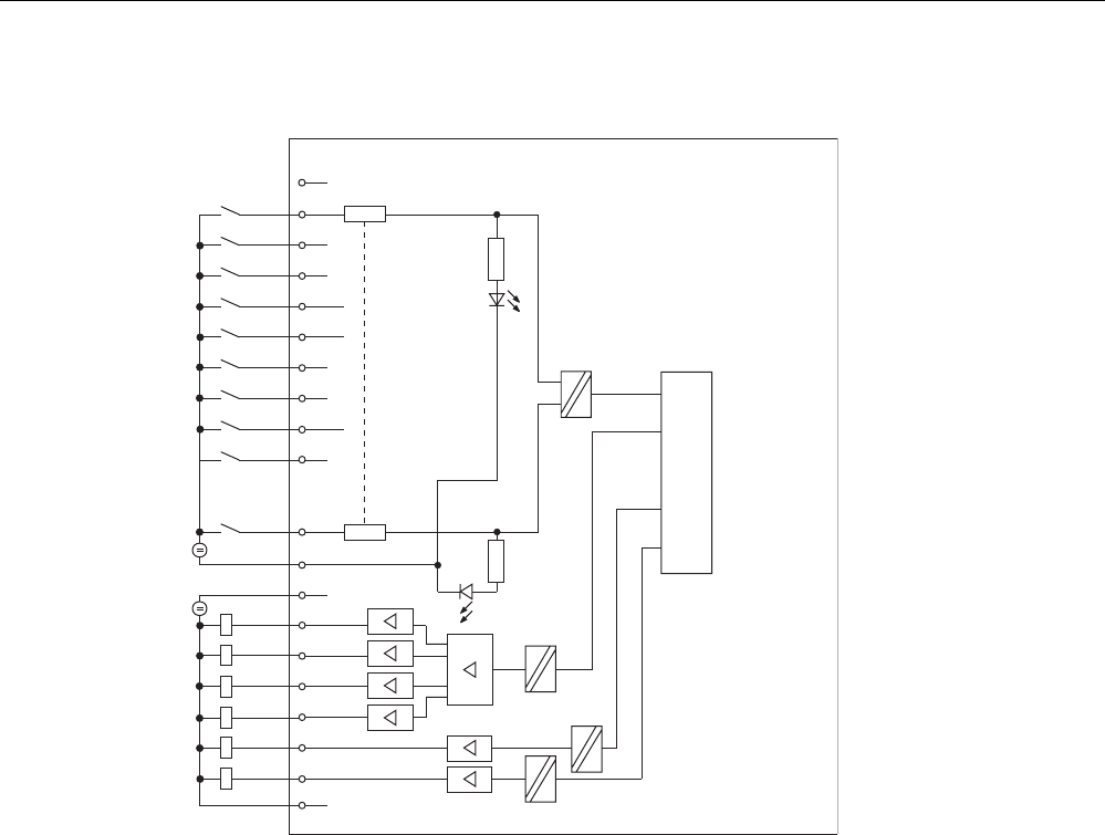
Technical data of CPU 31xC
6.6 Technical data of the integrated I/O
CPU 31xC and CPU 31x, Technical data
Manual, Edition 08/2004, A5E00105475-05 6-29
Block diagram of the integrated digital I/O
CPU interface
1
2
3
4
5
6
7
8
9
10
11
12
13
14
15
16
17
18
19
20
2M
1M
1L+
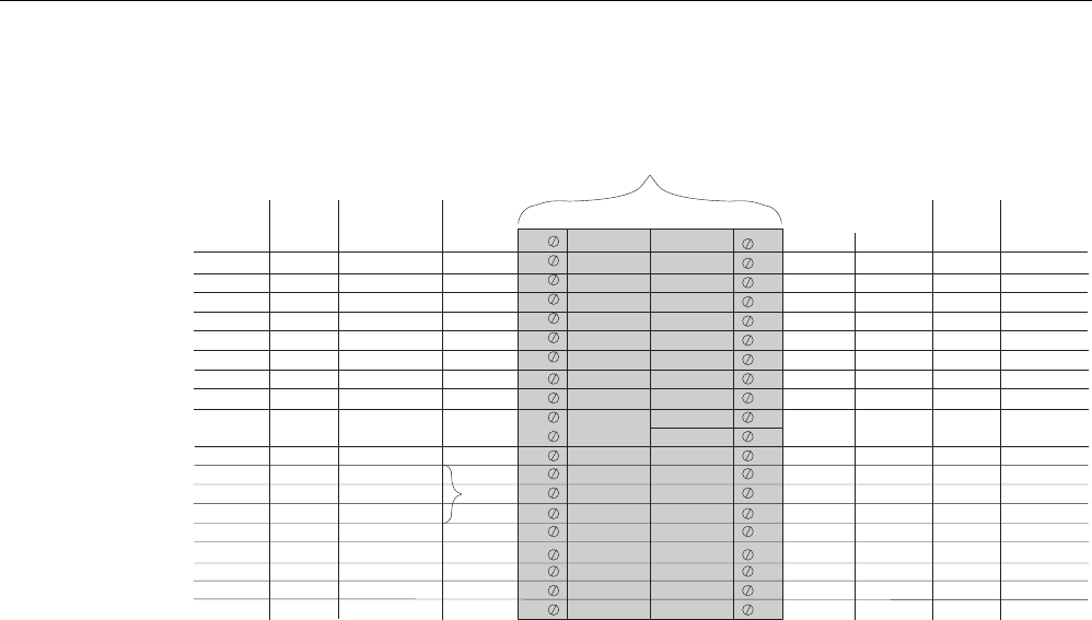
Technical data of CPU 31xC
6.6 Technical data of the integrated I/O
CPU 31xC and CPU 31x, Technical data
6-30 Manual, Edition 08/2004, A5E00105475-05
CPU 313C, CPU 313C-2 DP/PtP, CPU 314C-2 DP/PtP: DI/DO (connectors X11 and X12)
1
2
3
4
5
6
8
7
9
10
11
12
13
14
16
15
17
18
20
19
Standard
DI
Posi-
tioning
X11 of CPU 313C-2 PtP/DP
X12 of CPU 314C-2 PtP/DP
21
22
23
24
25
26
28
27
29
30
31
32
33
34
36
35
37
38
40
39
X
X
X
X
X
X
X
X
DI+0.1
DI+0.2
DI+0.3
DI+0.4
DI+0.5
DI+0.6
DI+0.7
X
X
X
X
X
X
X
X
Interrupt
input
X
X
X
X
X
X
X
X
X
X
X
X
X
X
X
X
Count
Z0 (A)
Z0 (B)
Z0 (HW gate)
Z1 (A)
Z1(B)
Z1 (HW gate)
Z2 (A)
Z2 (B)
Z2 (HW gate)
Z3 (A)
Z3 (B)
Z3 (HW gate)
Z0 (Latch)
Z1 (Latch)
Z2 (Latch)
Z3
(Latch)
A0
B0
N0
Prob 0
Bero
0
Positioning
Digital Analog
CONV_EN
R+
Rapid
R-
Creep
Count
V0
V1
V2
V3
Standard
DO
X
X
X
X
X
X
X
X
X
X
X
X
X
X
X
X
DI+0.0
DI+1.1
DI+1.2
DI+1.3
DI+1.4
DI+1.5
DI+1.6
DI+1.7
DI+1.0
DO+0.1
DO+0.2
DO+0.3
DO+0.4
DO+0.5
DO+0.6
DO+0.7
DO+0.0
DO+1.1
DO+1.2
DO+1.3
DO+1.4
DO+1.5
DO+1.6
DO+1.7
DO+1.0
1)
1)
1L+ 2L+
2M
3L+
1)
1M 3M
1)
1)
CONV_DIR
1) CPU 314C-2 only
Zn Counter n
A, B Encoder signals
HW gate Gate control
Latch Store counter distance
Vn Comparator n
Prob 0 Measuring probe 0
Bero 0 Reference point switch 0
R+, R- Directional signal
Rapid Rapid traverse
Creep Creep speed
CONV_EN Power section enable
CONV_DIR Directional signal (only with control type "voltage 0 to 10 V or current from 0 to 10 mA and directional signal")
X Pin usable if not assigned to technology functions
Reference
Details are found in the Manual
Technical Functions
under
Counting, Frequency
Measurement and Pulse Width Modulation
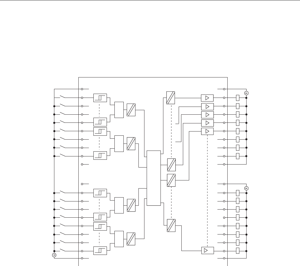
Technical data of CPU 31xC
6.6 Technical data of the integrated I/O
CPU 31xC and CPU 31x, Technical data
Manual, Edition 08/2004, A5E00105475-05 6-31
Block diagram of integrated digital I/O of CPUs 313C/313C-2/314C-2
21
22
23
24
25
26
27
28
29
30
31
32
33
34
35
36
37
38
39
40
CPU interface
1
2
3
4
5
6
7
8
9
10
11
12
13
14
15
16
17
18
19
20
2L+
3M
1L+
1M
2M
3L+
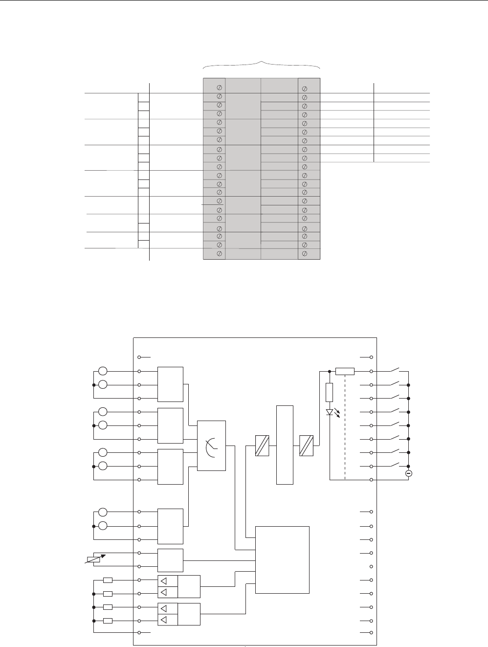
Technical data of CPU 31xC
6.6 Technical data of the integrated I/O
CPU 31xC and CPU 31x, Technical data
6-32 Manual, Edition 08/2004, A5E00105475-05
CPU 313C/314C-2: Pin-out of the integrated AI/AO and DI (connector X11)
1
2
3
4
5
6
8
7
9
10
11
12
13
14
16
15
17
18
20
19
Standard Positioning
AI (Ch0)
AI (Ch1)
AI (Ch2)
AI (Ch3)
PT 100 (Ch4)
AO (Ch0)
AO (Ch1)
Control
output 0
X11
PEWx+0
PEWx+2
PEWx+4
PEWx+6
PEWx+8
PAW x+0
PAW x+2
Standard DI
21
22
23
24
25
26
28
27
29
30
31
32
33
34
36
35
37
38
40
39
X
X
X
X
X
X
X
X
DI+2.1
DI+2.2
DI+2.3
DI+2.4
DI+2.5
DI+2.6
DI+2.7
DI+2.0
1)
V
I
C
V
I
C
V
I
C
V
I
C
V
A
V
A
4M
M
ANA
Interrupt input
X
X
X
X
X
X
X
X
1) CPU 314C-2 only
Block diagram of integrated digital/analog I/O of CPUs 313C/314C-2
21
22
23
24
25
26
27
28
29
30
31
32
33
34
35
36
37
38
39
40
1
2
3
4
5
6
7
8
9
10
11
12
13
14
15
16
17
18
19
20
AI0
4M
AI
AI/A0 8DI
AI
AI
AI
A0
A0
AI
CH0
CH1
CH2
CH3
CH0
CH1
PT100
U
U
I
I
CPU interface
AI2
AI1
A
V
A
V
A
V
AI3
A
V
AI4
R
AO0
AO1
M
ANA
V
A
V
A
Controller

Technical data of CPU 31xC
6.6 Technical data of the integrated I/O
CPU 31xC and CPU 31x, Technical data
Manual, Edition 08/2004, A5E00105475-05 6-33
Simultaneous usage of technological functions and standard I/O
Technological functions and standard I/O can be used simultaneously with appropriate
hardware. For example, you can use all digital inputs not used for counting functions as
standard DI.
Read access to inputs used by technological functions is possible. Write access to outputs
used by technological functions is not possible.
See also
CPU 312C (Page 6-3)
CPU 313C (Page 6-8)
CPU 313C-2 PtP and CPU 313C-2 DP (Page 6-14)
CPU 314C-2 PtP and CPU 314C-2 DP (Page 6-21)
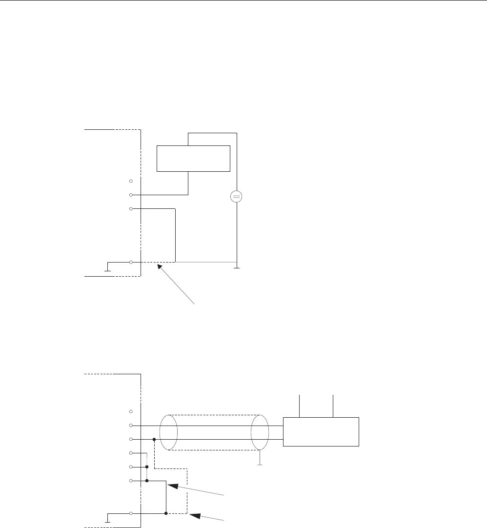
Technical data of CPU 31xC
6.6 Technical data of the integrated I/O
CPU 31xC and CPU 31x, Technical data
6-34 Manual, Edition 08/2004, A5E00105475-05
6.6.2 Analog I/O
Wiring of the current/voltage inputs
The figure below shows the wiring diagram of the current/voltage inputs operated with
2-/4-wire measuring transducers.
2-wire
signal converter
AI2
AI2
AI2
u
I
c
8
9
10
M
M
ANA
20
We recommend connecting AIx
C
with M
ANA
using a bridge.
+
-
++24V
-
Al
0
: Pin 2 to 4
AI
1
: Pin 5 to 7
Al
2
: Pin 8 to 10
Al
3
: Pin 11 to 13
Figure 6-1 Connection of a 2-wire measuring transducer to an analog current/voltage input of
CPU 313C/314C-2
4-wire
signal converter
AI : Pin 2 to 4
AI : Pin 5 to 7
AI : Pin 8 to 10
AI : Pin 11 to 13
0
1
2
3
L+
AI2
AI2
AI2
AI3
AI3
AI3
u
I
c
u
I
c
8
9
10
11
12
13
M
ANA
20
M
M
+
-
+
-
Short-circuit non-wired input channels
and connect Alx
C
with M
ANA.
We recommend connecting Alx
C
with M
ANA
when using the 4-wire signal converter.
Figure 6-2 Connection of a 4-wire measuring transducer to an analog current/voltage input of
CPU 313C/314C-2
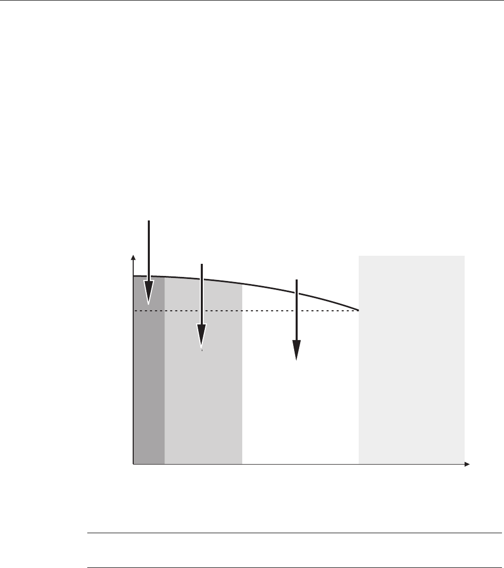
Technical data of CPU 31xC
6.6 Technical data of the integrated I/O
CPU 31xC and CPU 31x, Technical data
Manual, Edition 08/2004, A5E00105475-05 6-35
Measurement principle
31xC CPUs use the measurement principle of actual value encoding. Here, they operate
with a sampling rate of 1 kHz. That is, a new value is available at the peripheral input word
register once every millisecond. This value can then be read via user program (e.g. L PEW).
The "previous" value is read again if access times are shorter than 1 ms.
Integrated hardware low-pass filter
An integrated low-pass filter attenuates analog input signals of channel 0 to 3. They are
attenuated according to the trend in the figure below.
Attenuation
<1%
Attenuation
<10% strong
attenuation
100 %
Input frequency
Internal
signal level
400 Hz
63 %
200 Hz50 Hz
Inadmissible
input frequency
Figure 6-3 Low-pass characteristics of the integrated filter
Note
The maximum frequency of the input signal is 400 Hz.
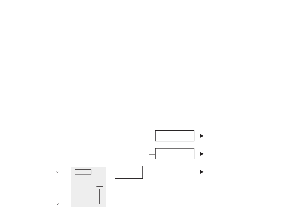
Technical data of CPU 31xC
6.6 Technical data of the integrated I/O
CPU 31xC and CPU 31x, Technical data
6-36 Manual, Edition 08/2004, A5E00105475-05
Input filters (software filter)
The current / voltage inputs have a software filter for the input signals which can be
programmed with STEP 7. It filters the configured interference frequency (50/60 Hz) and
multiples thereof.
The selected interference suppression also determines the integration time.
At an interference suppression of 50 Hz the software filter forms the average based on the
last 20 measurements and saves the result as a measurement value.
You can suppress interference frequencies (50 Hz or 60 Hz) according to the parameters set
in STEP 7. A setting of 400 Hz will not suppress interference.
An integrated low-pass filter attenuates analog input signals of channel 0 to 3.
A
I
x
Selection in STEP 7
(Software filter)
50-Hz configuration
(mean value filter)
60-Hz configuration
(mean value filter)
A/D converter 400-Hz configuration
Hardware low-pass filter
(RC circuit)
Figure 6-4 Principle of interference suppression with STEP 7
Technical data of CPU 31xC
6.6 Technical data of the integrated I/O
CPU 31xC and CPU 31x, Technical data
Manual, Edition 08/2004, A5E00105475-05 6-37
In the two graphics below we illustrate how the 50 Hz and 60 Hz interference suppression
work
1.05 ms
Value
1
Value
2
Value
3
...
Value
19
Value
20
Value
1
Value
2
Value
3
...
Value
19
Value
20
1.05 ms 1.05 ms 1.05 ms 1.05 ms
1.05 ms 1.05 ms 1.05 ms 1.05 ms 1.05 ms
Example of a 50-Hz parasitic frequency suppression (integration time corresponds to 20 ms
)
1 averaged measured value
1 averaged measured value
Cycle 1
Cycle 2
Figure 6-5 50 Hz interference suppression

Technical data of CPU 31xC
6.6 Technical data of the integrated I/O
CPU 31xC and CPU 31x, Technical data
6-38 Manual, Edition 08/2004, A5E00105475-05
Value
1
Value
2
Value
3
...
Value
16
Value
17
Value
1
Value
2
Value
3
...
Value
16
Value
17
1.05 ms 1.05 ms 1.05 ms 1.05 ms 1.05 ms
1.05 ms 1.05 ms 1.05 ms 1.05 ms 1.05 ms
Example of a 60-Hz parasitic frequency suppression (integration time corresponds to 16.7 ms)
1 averaged measured value
1 averaged measured value
Cycle 1
Cycle 2
Figure 6-6 60 Hz interference suppression
Note
If the interference frequency is not 50/60 Hz or a multiple thereof, the input signal must be
filtered externally.
In this case, 400 Hz frequency suppression must be configured for the respective input. This
is equivalent to a "Deactivation" of the software filter.
Inputs not connected
The three inputs of a current/voltage analog output channel that is not connected should be
bypasses and connected to MANA (pin 20 of the front connector). This ensures maximum
interference resistance for these analog inputs.
Outputs not connected
In order to disconnect unused analog outputs from power, you must disable and leave them
open during parameter assignment with STEP 7.
Reference
Details (visualization and processing of analog values, for example) are found in chapter 4 of
the
Module Data
Reference Manual.

Technical data of CPU 31xC
6.6 Technical data of the integrated I/O
CPU 31xC and CPU 31x, Technical data
Manual, Edition 08/2004, A5E00105475-05 6-39
6.6.3 Configuration
Introduction
You configure the integrated I/O of CPU 31xC with STEP 7. Always make these settings
when the CPU is in STOP. The generated parameters are downloaded from the PG to the
S7-300 and written to CPU memory .
You can also choose to change the parameters at SFC 55 in the user program (see the
Reference Manual
System and Standard Functions
). Refer to the structure of record 1 for
the respective parameters.
Parameters of standard DI
The table below gives you an overview of the parameters for standard digital inputs.
Table 6-7 Parameters of standard DI
Parameters Value range Default Range of efficiency
Input delay (ms) 0,1/0,5/3/15 3 Channel group
The table below gives you an overview of the parameters when using digital inputs as
interrupt inputs.
Table 6-8 Parameters of the interrupt inputs
Parameters Value range Default Range of efficiency
Interrupt input Disabled /
positive edge
disabled digital input
Interrupt input Disabled/
negative edge
disabled digital input
Technical data of CPU 31xC
6.6 Technical data of the integrated I/O
CPU 31xC and CPU 31x, Technical data
6-40 Manual, Edition 08/2004, A5E00105475-05
Byte 0
7
7
7
7
7
Byte 1
Byte 2
Byte 4
Byte 5
Byte 8
7
Byte 9
7
Byte 6
00
01
10
11 :
B
B
B
B
:
:
:
3
0,1 ms
0,5 ms
15 ms
ms
0:
1:
00B
70 Bit-Nr.
Byte 0
0 Bit-Nr.
0 Bit-Nr.
0 Bit-Nr.
0 Bit-Nr.
0 Bit-Nr.
0 Bit-Nr.
0 Bit-Nr.
0:
1:
Interrupt input DI +0.1
Interrupt input DI +0.0
Interrupt input DI +0.7
Default setting:
deactivated
rising edge
Input delay DI +0.0 to DI +0.3
Input delay DI +0.4 to DI +0.7
Input delay DI +1.0 to DI +1.3
Input delay DI +1.4 to DI +1.7
Input delay DI +2.0 to DI +2.3
Input delay DI +2.4 to DI +2.7
reserved
Default setting:
Byte 3 reserved
Interrupt input DI +1.1
Interrupt input DI +1.0
Interrupt input DI +1.7
Interrupt input DI +2.1
Interrupt input DI +2.0
Interrupt input DI +2.7
Interrupt input DI +0.1
Interrupt input DI +0.0
Interrupt input
Interrupt input DI +1.1
Interrupt input DI +1.0
Interrupt input DI +1.7
Default setting:
deactivated
rising edge
Interrupt input DI +2.1
Interrupt input DI +2.0
Interrupt input DI +2.7
Byte 7 reserved
Figure 6-7 Structure of record 1 for standard DI and interrupt inputs (length of 10 bytes)

Technical data of CPU 31xC
6.6 Technical data of the integrated I/O
CPU 31xC and CPU 31x, Technical data
Manual, Edition 08/2004, A5E00105475-05 6-41
Parameters of standard DO
There are no parameters for standard digital outputs.
Parameters of standard AI
The table below gives you an overview of the parameters for standard analog inputs.
Table 6-9 Parameters of standard AI
Parameters Value range Default Range of efficiency
Integration time (ms)
Interference suppression
(Hz)
(channel 0 to 3)
2,5/16,6/20
400/60/50
20
50
Channel
Channel
Measurement range
(channel 0 to 3)
Disabled/
+/- 20 mA/
0 ... 20 mA/
4 ... 20 mA/
+/- 10 V/
0 ... 10 V
+/- 10 V Channel
Type of measurement
(channel 0 to 3)
Disabled/
V voltage/
I current
U voltage Channel
Unit of measurement
(channel 4)
Celsius/Fahrenheit/
Kelvin
Celsius Channel
Measurement range
(Pt 100 input; channel 4)
Disabled/
Pt 100/600 Ω
600 Ω Channel
Type of measurement
(Pt 100 input; channel 4)
Disabled/
resistor/
thermocouple
Resistance Channel
Reference
See also Chapter 4.3 in the
Module Data
Reference Manual.

Technical data of CPU 31xC
6.6 Technical data of the integrated I/O
CPU 31xC and CPU 31x, Technical data
6-42 Manual, Edition 08/2004, A5E00105475-05
Parameters of standard AO
The table below gives you an overview of standard analog output parameters (see also
Chapter 4.3 in the
Module Data
Reference Manual).
Table 6-10 Parameters of standard AO
Parameters Value range Default Range of efficiency
Output range
(channel 0 to 1)
Disabled/
+/- 20 mA/
0 ... 20 mA/
4 ... 20 mA/
+/- 10 V/
0 ... 10 V
+/- 10 V Channel
Type of output
(channel 0 to 1)
Disabled/
V voltage/
I current
U voltage Channel
Technical data of CPU 31xC
6.6 Technical data of the integrated I/O
CPU 31xC and CPU 31x, Technical data
Manual, Edition 08/2004, A5E00105475-05 6-43
reserved
Unit of measure
reserved Default setting:
Celsius
Fahrenheit
Kelvin
Parasitic frequency suppression integration time of channel AI 0
Default setting:
Measuring range of channel AI 0 (settings see byte 6)
Measurement type of channel AI 0 (settings see byte 6)
0 Bit no.
Measuring range of channel AI 3
Measurement type of channel AI 3
Default setting:
deactivated
V voltage
I current
I current Default setting:
deactivated
Measuring range of channel AI 3
Measurement type of channel AI 4
Default setting:
deactivated
resistance
thermal resistance
Default setting:
deactivated
reserved
Parasitic frequency suppression integration time of channel AI 1
Parasitic frequency suppression integration time of channel AI 2
Parasitic frequency suppression integration time of channel AI 3
Measuring range of channel AI 1 (settings see byte 6)
Measurement type of channel AI 1 (settings see byte 6)
Measuring range of channel AI 2 (settings see byte 6)
Measurement type of channel AI 2 (settings see byte 6)
%
%
PV +]
PV +]
PV +]
+
+
+
+
ಹ P$
ಹ P$
P$
ಹ 9
9
+
+
+
+
+
+
+
+
2KP
3W
%LW1U
%LW1U
%LW1U
%LW1U
%LW1U
%LW1U
%LW1U
+
+
+
+
+
+
+
+
%
%
%
%
%
%
%\WH
%\WH
%\WH
%\WH
%\WH
%\WH
%\WH
%\WH
%\WHELV
Technical data of CPU 31xC
6.6 Technical data of the integrated I/O
CPU 31xC and CPU 31x, Technical data
6-44 Manual, Edition 08/2004, A5E00105475-05
%LW1U
%LW1U
%\WH
%\WH
%\WH
0:
2:
3:
4:
8:
9:
9
H
H
H
H
H
H
H
0 … 20 mA
4 … 20 mA
+/- 20 mA
0…10V
+/- 10 V
0:
1:
3:
9
H
H
H
H
Output range of channel AO 1
deactivated
Default setting:
Output range of channel AO 1
deactivated
Default setting:
V voltage
I current
Output range of channel AO 0
Output range of channel AO 0
(setting see byte 12)
(setting see byte 12)
Figure 6-8 Structure of record 1 for standard AI/AO (length of 13 bytes)
Parameter for technological functions
The parameters for the respective function are found in the Manual
Technological Functions
.

Technical data of CPU 31xC
6.6 Technical data of the integrated I/O
CPU 31xC and CPU 31x, Technical data
Manual, Edition 08/2004, A5E00105475-05 6-45
6.6.4 Interrupts
Interrupt inputs
All digital inputs of the on-board I/O of CPUs 31xC can be used as interrupt inputs.
You can specify interrupt behavior for each individual input in your parameter declaration.
Options are:
• no interrupt
• Interrupt at the positive edge
• Interrupt at the negative edge
• Interrupt at the positive and negative edge
Note
Every channel will hold one event if the rate of incoming interrupts exceeds the handling
capacity of OB40. Further events (interrupts) will be lost, without diagnostics or explicit
message.
Start information for OB40
The table below shows the relevant temporary variables (TEMP) of OB40 for the interrupt
inputs of 31xC CPUs. A description of process interrupt OB 40 is found in the Reference
Manual
System and Standard Functions
.
Table 6-11 Start information for OB40, relating to the interrupt inputs of the integrated I/O
Byte Variables Data type Description
6/7 OB40_MDL_ADDR WORD B#16#7C Address of the interrupt-
triggering module (here: default
addresses of the digital inputs)
8 on OB40_POINT_ADDR DWORD see the figure
below
Displaying the interrupt-
triggering integrated inputs

Technical data of CPU 31xC
6.6 Technical data of the integrated I/O
CPU 31xC and CPU 31x, Technical data
6-46 Manual, Edition 08/2004, A5E00105475-05
31 30 29 28 27 26 25 24 16 15… 87654321…
Bit no.
PRAL: process interrupt
Inputs are designated with default addresses.
reserved
23
PRAL from E124.0
PRAL from E124.7
PRAL from E125.0
PRAL from E125.7
PRAL from E126.0
PRAL from E126.7
Figure 6-9 Displaying the statuses of CPU 31xC interrupt inputs
PRAL: process interrupt
The inputs are assigned default addresses.
6.6.5 Diagnostics
Standard I/O
Diagnostic data is not available for integrated I/O which is operated as standard I/O (see also
the Reference Manual
Module Data
).
Technological functions
Diagnostics options for the respective technological function are found in the Manual
Technological Functions
.
6.6.6 Digital inputs
Introduction
This section provides the specifications for the digital inputs of CPUs 31xC.
The table includes the following CPUs:
• under CPU 313C-2, the CPU 313C-2 DP and CPU 313C-2 PtP
• under CPU 314C-2, the CPU 314C-2 DP and CPU 314C-2 PtP

Technical data of CPU 31xC
6.6 Technical data of the integrated I/O
CPU 31xC and CPU 31x, Technical data
Manual, Edition 08/2004, A5E00105475-05 6-47
Technical data
Table 6-12 Technical data of digital inputs
Technical data
CPU 312C CPU 313C CPU 313C-2 CPU 314C-2
Module-specific data CPU 312C CPU 313C CPU 313C-2 CPU 314C-2
Number of inputs 10 24 16 24
• Number of these inputs which can be used
for technological functions
8 12 12 16
Cable length
• Unshielded For standard DI: Max. 600 m
For technological functions: No
For standard DI: Max. 1000 m
For technological function at max. counting frequency
• Shielded
100 m 100 m 100 m 50 m
Voltage, currents, potentials CPU 312C CPU 313C CPU 313C-2 CPU 314C-2
Rated load voltage L+ 24 VDC
• Polarity reversal protection Yes
Number of inputs which can be controlled
simultaneously
• Horizontal assembly
– up to 104 °F
– up to 60 °C
10
5
24
12
16
8
24
12
• Vertical assembly
– up to 104 °F
5
12
8
12
Electrical isolation
• Between channels and the backplane bus Yes
• Between the channels No
Permitted potential difference
• Between different circuits 75 VDC / 60 VAC
Insulation test voltage 500 VDC
Current consumption
• On load voltage L+ (no-load) – Max. 70 mA Max. 70 mA Max. 70 mA
Status, interrupts, diagnostics CPU 312C CPU 313C CPU 313C-2 CPU 314C-2
Status display green LED per channel
Interrupts • Yes, if the corresponding channel is configured as interrupt input
• For using technological functions, please refer to the
Technological
Functions
Manual.
Diagnostics functions • no diagnostics when operated as standard I/O
• For using technological functions, please refer to the
Technological
Functions
Manual.

Technical data of CPU 31xC
6.6 Technical data of the integrated I/O
CPU 31xC and CPU 31x, Technical data
6-48 Manual, Edition 08/2004, A5E00105475-05
Technical data
CPU 312C CPU 313C CPU 313C-2 CPU 314C-2
Data for the selection of an encoder for
standard DI
CPU 312C CPU 313C CPU 313C-2 CPU 314C-2
Input voltage
• Rated value 24 VDC
• For signal "1" 15 V to 30 V
• For signal "0" -3 V to 5 V
Input current
• For signal "1" Typically 9 mA
Delay of standard inputs
• Configurable Yes (0.1 / 0.5 / 3 / 15 ms)
You can reconfigure the input delay of the standard inputs during program
runtime. Please note that your newly set filter time may only take effect
after the previously set filter time has expired.
• Rated value 3 ms
For using technological functions:
"Minimum pulse width/ minimum pause
between pulses at maximum counting
frequency"
48 μs 16 μs 16 μs 8 μs
Input characteristics curve to IEC 1131, type 1
Connection of 2wire BEROs Possible
• Permitted quiescent current Max. 1,5 mA
6.6.7 Digital outputs
Introduction
This chapter contains the specifications for the digital outputs of CPUs 31xC.
The table includes the following CPUs:
• under CPU 313C-2, the CPU 313C-2 DP and CPU 313C-2 PtP
• under CPU 314C-2, the CPU 314C-2 DP and CPU 314C-2 PtP
Fast digital outputs
Technological functions use fast digital outputs.

Technical data of CPU 31xC
6.6 Technical data of the integrated I/O
CPU 31xC and CPU 31x, Technical data
Manual, Edition 08/2004, A5E00105475-05 6-49
Technical data
Table 6-13 Technical data of digital outputs
Technical data
CPU 312C CPU 313C CPU 313C-2 CPU 314C-2
Module-specific data CPU 312C CPU 313C CPU 313C-2 CPU 314C-2
Number of outputs 6 16 16 16
2 4 4 4
• Of those are fast outputs
Caution:
You cannot connect the high-speed outputs of your CPU in parallel.
Cable length
• Unshielded Max. 600 m
• Shielded Max. 1000 m
Voltage, currents, potentials CPU 312C CPU 313C CPU 313C-2 CPU 314C-2
Rated load voltage L+ 24 VDC
• Polarity reversal protection No
Total current of outputs (per group)
Max. 2.0 A Max. 3,0 A Max. 3,0 A Max. 3,0 A
• Horizontal assembly
– up to 104 °F
– up to 60 °C Max. 1,5 A Max. 2.0 A Max. 2.0 A Max. 2.0 A
• Vertical assembly
– up to 104 °F Max. 1,5 A Max. 2.0 A Max. 2.0 A Max. 2.0 A
Electrical isolation
• Between channels and the backplane bus Yes
No Yes Yes Yes
• Between the channels
– In groups of – 8 8 8
Permitted potential difference
• Between different circuits 75 VDC / 60 VAC
Insulation test voltage 500 VDC
Current consumption
• with load voltage L+ Max. 50 mA Max. 100 mA Max. 100 mA Max. 100 mA
Status, interrupts, diagnostics CPU 312C CPU 313C CPU 313C-2 CPU 314C-2
Status display green LED per channel
Interrupts • no interrupts when operated as standard I/O
• For using technological functions, please refer to the
Technological
Functions
Manual.
Diagnostics functions • no diagnostics when operated as standard I/O
• For using technological functions, please refer to the
Technological
Functions
Manual.

Technical data of CPU 31xC
6.6 Technical data of the integrated I/O
CPU 31xC and CPU 31x, Technical data
6-50 Manual, Edition 08/2004, A5E00105475-05
Technical data
CPU 312C CPU 313C CPU 313C-2 CPU 314C-2
Data for the selection of an actuator for
standard DI
CPU 312C CPU 313C CPU 313C-2 CPU 314C-2
Output voltage
• For signal "1" Min. L+ (-0.8 V)
Output current
• For signal "1"
– Rated value
– Permitted range
0,5 A
5 mA to 600 mA
• For signal "0" (residual current) Max. 0.5 mA
Load impedance range 48 Ω to 4 kΩ
Lamp load Max. 5 W
Parallel connection of 2 outputs
• for redundant load control Possible
• for performance increase Not possible
Controlling of digital inputs Possible
Switching frequency
• under resistive load Max. 100 Hz
• For inductive load to IEC 947-5, DC13 Max. 0.5 Hz
• under lamp load Max. 100 Hz
• fast outputs under resistive load Max. 2.5 kHz
Inductive breaking voltage limited internally to Typically (L+) - 48 V
Short-circuit protection of the output Yes, electronic
• Response threshold Typically 1 A

Technical data of CPU 31xC
6.6 Technical data of the integrated I/O
CPU 31xC and CPU 31x, Technical data
Manual, Edition 08/2004, A5E00105475-05 6-51
6.6.8 Analog inputs
Introduction
This chapter contains the specifications for analog outputs of CPUs 31xC.
The table includes the following CPUs:
• CPU 313C
• CPU 314C-2 DP
• CPU 314C-2 PtP
Technical data
Table 6-14 Technical data of analog inputs
Technical data
Module-specific data
Number of inputs 4 channels with current/voltage input
1 channel with resistance input
Cable length
• Shielded Max. 100 m
Voltage, currents, potentials
Resistance input
• No-load voltage Typically 2.5 V
• Measurement current Typically 1.8 mA to 3.3 mA
Electrical isolation
• Between channels and the backplane bus Yes
• Between the channels No
Permitted potential difference
• Between inputs (AIC) and MANA (UCM) 8.0 VDC
• between MANA and Minternal (UISO) 75 VDC / 60 VAC
Insulation test voltage 600 VDC
Analog value generation
Measurement principle Actual value encoding (successive
approximation)
Integration time/conversion time/resolution (per channel)
• Configurable Yes
• Integration time in ms 2,5 / 16,6 / 20
• Permitted input frequency Max. 400 Hz
• Resolution (including overdrive) 11 bits + signed bit
• Suppression of interference frequency f1 400 / 60 / 50 Hz

Technical data of CPU 31xC
6.6 Technical data of the integrated I/O
CPU 31xC and CPU 31x, Technical data
6-52 Manual, Edition 08/2004, A5E00105475-05
Technical data
Time constant of the input filter 0,38 ms
Basic processing time 1 ms
Interference suppression, error limits
Interference voltage suppression for f = nx (f1 ± 1 %), (f1 = interference
frequency), n = 1, 2
• Commonmode interference (UCM < 1.0 V) > 40 dB
• Feedback interference (peak value of the interference < rated value of
the input range)
> 30 dB
Crosstalk between the inputs > 60 dB
Operational error limits (across the temperature range, in relation to input
range)
• Voltage/current < 1 %
• Resistance < 5 %
Basic error limit (operational limit at 25 °C, in relation to input range)
• Voltage/current < 0,7 %
• Resistance < 3 %
Temperature error (in relation to input range) ± 0,006 %/K
Linearity error (referred to input range) ± 0,06 %
Repeat accuracy (in transient state at 25 °C, in relation to input range) ± 0,06 %
Status, interrupts, diagnostics
Interrupts • no interrupts when operated as standard
I/O
Diagnostics functions • no diagnostics when operated as
standard I/O
• For using technological functions, please
refer to the
Technological Functions
Manual.
Encoder selection data
Input ranges (rated value)/input resistance
• Voltage ± 10 V/100 kΩ
0 V to 10 V/100 kΩ
• Current ± 20 mA/50 Ω
0 mA to 20 mA/50 Ω
4 mA to 20 mA/50 Ω
• Resistance 0 Ω to 600 Ω/10 MΩ
• Resistance thermometer Pt 100/10 MΩ
Permitted continuous input voltage (destruction limit)
• For voltage inputs Max. 30 V
• For current inputs Max. 2.5 V
Permitted continuous input current (destruction limit)
• For voltage inputs Max. 0,5 mA;
• For current inputs Max. 50 mA;

Technical data of CPU 31xC
6.6 Technical data of the integrated I/O
CPU 31xC and CPU 31x, Technical data
Manual, Edition 08/2004, A5E00105475-05 6-53
Technical data
Connection of signal generators
• For voltage measurement Possible
• For current measurement
– as 2-wire measuring transducer
– as 4-wire measuring transducer
Possible, with external power supply
Possible
• for measuring resistance
– with 2-wire connection
– with 3-wire connection
– with 4-wire connection
Possible, without compensation of
cable resistance
Not possible
Not possible
Linearization of the characteristics trend By software
• For resistance thermometers Pt 100
Temperature compensation No
Technical unit for temperature measurement Degrees Celsius/Fahrenheit/Kelvin
6.6.9 Analog outputs
Introduction
This chapter contains the specifications for digital outputs of CPUs 31xC.
The table includes the following CPUs:
• CPU 313C
• CPU 314C-2 DP
• CPU 314C-2 PtP
Technical data
Table 6-15 Technical data of analog outputs
Technical data
Module-specific data
Number of outputs 2
Cable length
• Shielded Max. 200 m
Voltage, currents, potentials
Rated load voltage L+ 24 VDC
• Polarity reversal protection Yes
Electrical isolation
• Between channels and the backplane bus Yes
• Between the channels No

Technical data of CPU 31xC
6.6 Technical data of the integrated I/O
CPU 31xC and CPU 31x, Technical data
6-54 Manual, Edition 08/2004, A5E00105475-05
Technical data
Permitted potential difference
• between MANA and Minternal (UISO) 75 VDC / 60 VAC
Insulation test voltage 600 VDC
Analog value generation
Resolution (including overdrive) 11 bits + signed bit
Conversion time (per channel) 1 ms
Settling time
• with resistive load 0,6 ms
• With capacitive load 1,0 ms
• With inductive load 0.5 ms
Interference suppression, error limits
Crosstalk between the outputs > 60 dB
Operational error limits (across the temperature range, in relation to output
range)
• Voltage/current ± 1 %
Basic error limit (operational limit at 25 °C, in relation to output range)
• Voltage/current ± 0,7 %
Temperature error (in relation to output range) ± 0.01 %/K
Linearity error (in relation to output range) ± 0,15 %
Repeat accuracy (in transient state at 25 °C, in relation to output range) ± 0,06 %
Output ripple; bandwidth 0 to 50 kHz (in relation to output range) ± 0,1 %
Status, interrupts, diagnostics
Interrupts • no interrupts when operated as standard
I/O
• For using technological functions, please
refer to the
Technological Functions
Manual.
Diagnostics functions • no diagnostics when operated as
standard I/O
• For using technological functions, please
refer to the
Technological Functions
Manual.
Actuator selection data
Output range (rated values)
• Voltage ± 10 V
0 V to 10 V
• Current ± 20 mA
0 mA to 20 mA
4 mA to 20 mA
Load resistance (within output rating)
• For voltage outputs
– Capacitive load
min. 1 kΩ
max. 0.1 μF
• For current outputs
– Inductive load
max. 300 Ω
0.1 mH

Technical data of CPU 31xC
6.6 Technical data of the integrated I/O
CPU 31xC and CPU 31x, Technical data
Manual, Edition 08/2004, A5E00105475-05 6-55
Technical data
Voltage output
• Short-circuit protection Yes
• Short-circuit current Typically 55 mA
Current output
• No-load voltage Typically 17 V
Destruction limit for externally applied voltages/currents
• Voltage measured between the outputs and MANA Max. 16 V
• Current Max. 50 mA;
Connection of actuators
• For voltage outputs
– wire connection
– wire connection (test lead)
Possible, without compensation of
cable resistance
Not possible
• For current outputs
– wire connection
Possible

Technical data of CPU 31xC
6.6 Technical data of the integrated I/O
CPU 31xC and CPU 31x, Technical data
6-56 Manual, Edition 08/2004, A5E00105475-05
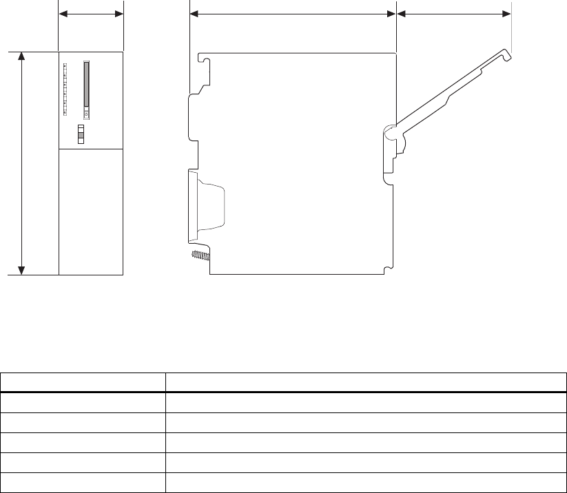
CPU 31xC and CPU 31x, Technical data
Manual, Edition 08/2004, A5E00105475-05 7-1
Technical data of CPU 31x 7
7.1 General technical data
7.1.1 Dimensions of CPU 31x
Each CPU features the same height and depth, only the width dimensions differ.
• Height: 125 mm
• Depth: 115 mm, or 180 mm with opened front cover.
40 115 65
125
Figure 7-1 Dimensions of CPU 31x
Width of CPU
CPU Width
CPU 312 40 mm
CPU 314 40 mm
CPU 315-2 DP 40 mm
CPU 315-2 PN/DP 80 mm
CPU 317 80 mm

Technical data of CPU 31x
7.1 General technical data
CPU 31xC and CPU 31x, Technical data
7-2 Manual, Edition 08/2004, A5E00105475-05
7.1.2 Technical data of the Micro Memory Card (MMC)
Plug-in SIMATIC Micro Memory Cards
The following memory modules are available:
Table 7-1 Available MMCs
Type Order number Required for a firmware update via MMC
MMC 64k 6ES7 953-8LFxx-0AA0 –
MMC 128k 6ES7 953-8LGxx-0AA0 –
MMC 512k 6ES7 953-8LJxx-0AA0 –
MMC 2M 6ES7 953-8LLxx-0AA0 Minimum requirement for CPUs without DP interface
MMC 4M 6ES7 953-8LMxx-0AA0 Minimum requirement for CPUs with DP interface
MMC 8M 1 6ES7 953-8LPxx-0AA0 –
1 This MMC cannot be used together with CPU 312C or CPU 312.
Maximum number of loadable blocks in the MMC
The number of blocks that can be stored on the MMC depends on the capacity of the MMC
being used. The maximum number of blocks that can be loaded is therefore limited by the
capacity of your MMC (including blocks generated with the "CREATE DB" SFC):
Table 7-2 Maximum number of loadable blocks on the MMC
Size of MMC Maximum number of blocks that can be loaded
64 KB 768
128 KB 1024
512 KB
2 MB
4 MB
8 MB
Here the maximum number of blocks that can be loaded for the
specific CPU is less than the number of blocks that can be stored on
the MMC.
Refer to the corresponding specifications of a specific CPU to
determine the maximum number of blocks that can be loaded.

Technical data of CPU 31x
7.2 CPU 312
CPU 31xC and CPU 31x, Technical data
Manual, Edition 08/2004, A5E00105475-05 7-3
7.2 CPU 312
Technical data
Table 7-3 Technical data for the CPU 312
Technical data
CPU and version
Order number 6ES7312-1AD10-0AB0
• Hardware version 01
• Firmware version V2.0.0
• Associated programming package STEP 7 as of V 5.1 + SP 4
Memory
RAM
• Integrated 16 KB
• Expandable No
Load memory Plugged in with MMC (max. 4 MB)
Data storage life on the MMC
(following final programming)
At least 10 years
Buffering Guaranteed by MMC (maintenance-free)
Execution times
Processing times of
• Bit operations Min. 0.2 μs
• Word instructions Min. 0.4 μs
• Fixed-point arithmetic Min. 5 μs
• Floating-point arithmetic Min. 6 μs
Timers/counters and their retentivity
S7 counters 128
• Retentive memory Configurable
• Default from C0 to C7
• Counting range 0 to 999
IEC Counters Yes
• Type SFB
• Number unlimited (limited only by RAM size)
S7 timers 128
• Retentive memory Configurable
• Default Not retentive
• Timer range 10 ms to 9990 s
IEC Timers Yes
• Type SFB
• Number unlimited (limited only by RAM size)

Technical data of CPU 31x
7.2 CPU 312
CPU 31xC and CPU 31x, Technical data
7-4 Manual, Edition 08/2004, A5E00105475-05
Technical data
Data areas and their retentivity
Flag bits 128 bytes
• Retentive memory Yes
• Default retentivity MB0 to MB15
Clock flag bits 8 (1 byte per flag bit)
Data blocks 511
(DB 1 to DB 511)
• Length 16 KB
Local data per priority class max. 256 bytes
Blocks
Total 1024 (DBs, FCs, FBs)
The maximum number of blocks that can be
loaded may be reduced if you are using another
MMC.
OBs See the Instruction List
• Length max. 16 KB
Nesting depth
• Per priority class 8
• additional within an error OB 4
FBs Max. 512
(FB 0 to FB 511)
• Length max. 16 KB
FCs Max. 512
(FC 0 to FC 511
• Length max. 16 KB
Address areas (I/O)
Total I/O address area 1024 bytes /1024 bytes
(can be freely addressed)
I/O process image 128 bytes/128 bytes
Digital channels Max. 256
of those local Max. 256
Analog channels Max. 64
of those local Max. 64
Assembly
Racks Max. 1
Modules per rack Max. 8
Number of DP masters
• Integrated None
• Via CP 1

Technical data of CPU 31x
7.2 CPU 312
CPU 31xC and CPU 31x, Technical data
Manual, Edition 08/2004, A5E00105475-05 7-5
Technical data
Number of function modules and communication
processors you can operate
• FM Max. 8
• CP (PtP) Max. 8
• CP (LAN) Max. 4
Time-of-day
Real-time clock Yes (SW clock)
• Buffered No
• Accuracy Deviation per day < 15 s
• Behavior of the realtime clock after POWER
ON
The clock keeps running, continuing at the time-
of-day it had when power was switched off.
Operating hours counter 1
• Number 0
• Value range 2 31
(if SFC 101 is used)
• Granularity 1 hour
• Retentive Yes; must be manually restarted after every
restart
Clock synchronization Yes
• In the PLC Master
• On MPI Master/slave
S7 signaling functions
Number of stations that can be logged on for
signaling functions
6
(depends on the number of connections
configured for PG / OP and S7 basic
communication)
Process diagnostics messages Yes
• Simultaneously enabled interrupt S blocks Max. 20
Testing and commissioning functions
Status/control variables Yes
• Variables Inputs, outputs, memory bits, DBs, timers,
counters
• Number of variables
– Of those as status variable
– Of those as control variable
30
30
14
Forcing Yes
• Variables Inputs, outputs
• Number of variables Max. 10
Block status Yes
Single step Yes
Breakpoints 2
Diagnostic buffer Yes
• Number of entries (not configurable) Max. 100

Technical data of CPU 31x
7.2 CPU 312
CPU 31xC and CPU 31x, Technical data
7-6 Manual, Edition 08/2004, A5E00105475-05
Technical data
Communication functions
PG/OP communication Yes
Global data communication Yes
• Number of GD circuits 4
• Number of GD packets
– Sending stations
– Receiving stations
Max. 4
Max. 4
Max. 4
• Length of GD packets
– Consistent data
max. 22 bytes
22 bytes
S7 basic communication Yes
• User data per request
– Consistent data
max. 76 bytes
76 bytes (for X_SEND or X_RCV)
64 bytes (for X_PUT or X_GET as the server)
S7 communication
• As server Yes
• User data per request
– Consistent data
Max. 180 bytes (with PUT/GET)
64 bytes
S5-compatible communication Yes (via CP and loadable FCs)
Number of connections Max. 6
can be used for
• PG communication
– Reserved (default)
– Configurable
Max. 5
1
from 1 to 5
• OP communication
– Reserved (default)
– Configurable
Max. 5
1
from 1 to 5
• S7-based communication
– Reserved (default)
– Configurable
Max. 2
2
from 0 to 2
Routing No
Interfaces
1st interface
Type of interface Integrated RS485 interface
Physics RS 485
electrically isolated No
Interface power supply
(15 to 30 VDC)
max. 200 mA
Functionality
• MPI Yes
• PROFIBUS DP No
• Point-to-point communication No

Technical data of CPU 31x
7.2 CPU 312
CPU 31xC and CPU 31x, Technical data
Manual, Edition 08/2004, A5E00105475-05 7-7
Technical data
MPI
Services
• PG/OP communication Yes
• Routing No
• Global data communication Yes
• S7 basic communication Yes
• S7 communication
– As server
– As client
Yes
No
• Transmission rates 187.5 kbps
Programming
Programming language LAD/FBD/STL
Available instructions See the Instruction List
Nesting levels 8
System functions (SFCs) See the Instruction List
System function blocks (SFBs) See the Instruction List
User program security Yes
Dimensions
Mounting dimensions W x H x D (mm) 40 x 125 x 130
Weight 270 g
Voltages and currents
Power supply (rated value) 24 VDC
• Permitted range 20.4 V to 28.8 V
Current consumption (no-load operation) Typically 60 mA
Inrush current Typically 2.5 A
Power consumption (nominal value) 0,6 A
I2t 0.5 A2s
External fusing of power supply lines
(recommended)
min. 2 A
Power loss Typically 2,5 W

Technical data of CPU 31x
7.3 CPU 314
CPU 31xC and CPU 31x, Technical data
7-8 Manual, Edition 08/2004, A5E00105475-05
7.3 CPU 314
Technical data for the CPU 314
Table 7-4 Technical data for the CPU 314
Technical data
CPU and version
Order number 6ES7314-1AF10-0AB0
• Hardware version 01
• Firmware version V 2.0.0
• Associated programming package STEP 7 as of V 5.1 + SP 4
Memory
RAM
• Integrated 48 KB
• Expandable No
Load memory Plugged in with MMC (max. 8 MB)
Data storage life on the MMC
(following final programming)
At least 10 years
Buffering Guaranteed by MMC (maintenance-free)
Execution times
Processing times of
• Bit operations Min. 0.1 μs
• Word instructions Min. 0.2 μs
• Fixed-point arithmetic Min. 2.0 μs
• Floating-point arithmetic Min. 6 μs
Timers/counters and their retentivity
S7 counters 256
• Retentive memory Configurable
• Default from C0 to C7
• Counting range 0 to 999
IEC Counters Yes
• Type SFB
• Number unlimited (limited only by RAM size)
S7 timers 256
• Retentive memory Configurable
• Default Not retentive
• Timer range 10 ms to 9990 s
IEC Timers Yes
• Type SFB
• Number unlimited (limited only by RAM size)

Technical data of CPU 31x
7.3 CPU 314
CPU 31xC and CPU 31x, Technical data
Manual, Edition 08/2004, A5E00105475-05 7-9
Technical data
Data areas and their retentivity
Flag bits 256 bytes
• Retentive memory Yes
• Default retentivity MB0 to MB15
Clock flag bits 8 (1 byte per flag bit)
Data blocks
• Number 511
(DB 1 to DB 511)
• Length 16 KB
Local data per priority class Max. 510
Blocks
Total 1024 (DBs, FCs, FBs)
The maximum number of blocks that can be
loaded may be reduced if you are using another
MMC.
OBs See the Instruction List
• Length 16 KB
Nesting depth
• Per priority class 8
• additional within an error OB 4
FBs See the Instruction List
• Number 512
(FB 0 to FB 511)
• Length 16 KB
FCs See the Instruction List
• Number 512
(FC 0 to FC 511)
• Length 16 KB
Address areas (I/O)
Total I/O address area Max. 1024 bytes/1024 bytes (can be freely
addressed)
I/O process image 128 bytes/128 bytes
Digital channels Max. 1024
of those local Max. 1024
Analog channels Max. 256
of those local Max. 256
Assembly
Racks Max. 4
Modules per rack 8
Number of DP masters
• Integrated None
• via CP Max. 1

Technical data of CPU 31x
7.3 CPU 314
CPU 31xC and CPU 31x, Technical data
7-10 Manual, Edition 08/2004, A5E00105475-05
Technical data
Number of function modules and communication
processors you can operate
• FM Max. 8
• CP (PtP) Max. 8
• CP (LAN) Max. 10
Time-of-day
Real-time clock Yes (HW clock)
• Buffered Yes
• Buffered period Typically 6 weeks (at an ambient temperature of
104 °F)
• Behavior of the clock on expiration of the
buffered period
The clock keeps running, continuing at the time-
of-day it had when power was switched off.
• Accuracy Deviation per day: < 10 s
Operating hours counter 1
• Number 0
• Value range 2 31 hours
(if SFC 101 is used)
• Granularity 1 hour
• Retentive yes; must be manually restarted after every
restart
Clock synchronization Yes
• In the PLC Master
• On MPI Master/slave
S7 signaling functions
Number of stations that can log in for signaling
functions (e.g. OS)
12
(depends on the number of connections
configured for PG / OP and S7 basic
communication)
Process diagnostics messages Yes
• Simultaneously enabled interrupt S blocks Max. 40
Testing and commissioning functions
Status/control variables Yes
• Variables Inputs, outputs, memory bits, DBs, timers,
counters
• Number of variables
– Of those as status variable
– Of those as control variable
30
30
14
Forcing Yes
• Variables Inputs/Outputs
• Number of variables Max. 10
Block status Yes
Single step Yes
Breakpoints 2
Diagnostic buffer Yes

Technical data of CPU 31x
7.3 CPU 314
CPU 31xC and CPU 31x, Technical data
Manual, Edition 08/2004, A5E00105475-05 7-11
Technical data
• Number of entries (not configurable) Max. 100
Communication functions
PG/OP communication Yes
Global data communication Yes
• Number of GD circuits 4
• Number of GD packets
– Sending stations
– Receiving stations
Max. 4
Max. 4
Max. 4
• Length of GD packets
– Consistent data
max. 22 bytes
22 bytes
S7 basic communication Yes
• User data per request
– Consistent data
max. 76 bytes
76 bytes (for X_SEND or X_RCV)
64 bytes (for X_PUT or X_GET as the server)
S7 communication Yes
• As server Yes
• as client Yes (via CP and loadable FBs)
• User data per request
– Consistent data
Max. 180 (for PUT/GET)
64 bytes
S5-compatible communication Yes (via CP and loadable FCs)
Number of connections 12
can be used for
• PG communication
– Reserved (default)
– Configurable
Max. 11
1
1 to 11
• OP communication
– Reserved (default)
– Configurable
Max. 11
1
1 to 11
• S7-based communication
– Reserved (default)
– Configurable
Max. 8
8
0 to 8
Routing No
Interfaces
1st interface
Type of interface Integrated RS485 interface
Physics RS 485
electrically isolated No
Interface power supply
(15 to 30 VDC)
max. 200 mA
Functionality
• MPI Yes
• PROFIBUS DP No
• Point-to-point communication No

Technical data of CPU 31x
7.3 CPU 314
CPU 31xC and CPU 31x, Technical data
7-12 Manual, Edition 08/2004, A5E00105475-05
Technical data
MPI
Services
• PG/OP communication Yes
• Routing No
• Global data communication Yes
• S7 basic communication Yes
• S7 communication
– As server
– As client
Yes
Yes
No (but via CP and loadable FBs)
• Transmission rates 187.5 kbps
Programming
Programming language LAD/FBD/STL
Available instructions See the Instruction List
Nesting levels 8
System functions (SFCs) See the Instruction List
System function blocks (SFBs) See the Instruction List
User program security Yes
Dimensions
Mounting dimensions W x H x D (mm) 40 x 125 x 130
Weight 280 g
Voltages and currents
Power supply (rated value) 24 VDC
• Permitted range 20.4 V to 28.8 V
Current consumption (no-load operation) Typically 60 mA
Inrush current Typically 2.5 A
Power consumption (nominal value) 0,6 A
I2t 0.5 A2s
External fusing of power supply lines
(recommended)
min. 2 A
Power loss Typically 2.5 W

Technical data of CPU 31x
7.4 CPU 315-2 DP
CPU 31xC and CPU 31x, Technical data
Manual, Edition 08/2004, A5E00105475-05 7-13
7.4 CPU 315-2 DP
Technical data
Table 7-5 Technical data for the CPU 315-2 DP
Technical data
CPU and version
Order number 6ES7315-2AG10-0AB0
• Hardware version 01
• Firmware version V 2.0.0
• Associated programming package STEP 7 as of V 5.1 + SP 4
Memory
RAM
• Integrated 128 KB
• Expandable No
Load memory Plugged in with MMC (max. 8 MB)
Data storage life on the MMC
(following final programming)
At least 10 years
Buffering Guaranteed by MMC (maintenance-free)
Execution times
Processing times of
• Bit operations Min. 0.1 μs
• Word instructions Min. 0.2 μs
• Fixed-point arithmetic Min. 2.0 μs
• Floating-point arithmetic Min. 6 μs
Timers/counters and their retentivity
S7 counters 256
• Retentive memory Configurable
• Default from C0 to C7
• Counting range 0 to 999
IEC Counters Yes
• Type SFB
• Number unlimited (limited only by RAM size)
S7 timers 256
• Retentive memory Configurable
• Default Not retentive
• Timer range 10 ms to 9990 s
IEC Timers Yes
• Type SFB
• Number unlimited (limited only by RAM size)

Technical data of CPU 31x
7.4 CPU 315-2 DP
CPU 31xC and CPU 31x, Technical data
7-14 Manual, Edition 08/2004, A5E00105475-05
Technical data
Data areas and their retentivity
Flag bits 2048 bytes
• Retentive memory Yes
• Default retentivity MB0 to MB15
Clock flag bits 8 (1 byte per flag bit)
Data blocks
• Number 1023
(DB 1 to DB 1023)
• Length 16 KB
Local data capacity Max. 1024 bytes per task/510 per block
Blocks
Total 1024 (DBs, FCs, FBs)
The maximum number of blocks that can be
loaded may be reduced if you are using another
MMC.
OBs See the Instruction List
• Length 16 KB
Nesting depth
• Per priority class 8
• additional within an error OB 4
FBs See the Instruction List
• Number 2048
(FB 0 to FB 2047)
• Length 16 KB
FCs See the Instruction List
• Number 2048
(FC 0 to FC 2047)
• Length 16 KB
Address areas (I/O)
Total I/O address area max. 2048 bytes/2048 bytes
(can be freely addressed)
Distributed Max. 2000
I/O process image 128/128
Digital channels Max. 16384
of those local Max. 1024
Analog channels Max. 1024
of those local Max. 256
Assembly
Racks Max. 4
Modules per rack 8
Number of DP masters
• Integrated 1
• via CP 1

Technical data of CPU 31x
7.4 CPU 315-2 DP
CPU 31xC and CPU 31x, Technical data
Manual, Edition 08/2004, A5E00105475-05 7-15
Technical data
Number of function modules and communication
processors you can operate
• FM Max. 8
• CP (PtP) Max. 8
• CP (LAN) Max. 10
Time-of-day
Real-time clock Yes (HW clock)
• Buffered Yes
• Buffered period Typically 6 weeks (at an ambient temperature of
104 °F)
• Behavior of the clock on expiration of the
buffered period
The clock keeps running, continuing at the time-
of-day it had when power was switched off.
• Accuracy Deviation per day: < 10 s
Operating hours counter 1
• Number 0
• Value range 2 31 hours
(if SFC 101 is used)
• Granularity 1 hour
• Retentive yes; must be manually restarted after every
restart
Clock synchronization Yes
• In the PLC Master
• On MPI Master/slave
S7 signaling functions
Number of stations that can log in for signaling
functions (e.g. OS)
16
(depends on the number of connections
configured for PG / OP and S7 basic
communication)
Process diagnostics messages Yes
• Simultaneously enabled interrupt S blocks 40
Testing and commissioning functions
Status/control variables Yes
• Variables Inputs, outputs, memory bits, DBs, timers,
counters
• Number of variables
– Of those as status variable
– Of those as control variable
30
30
14
Forcing
• Variables Inputs/Outputs
• Number of variables Max. 10
Block status Yes
Single step Yes
Breakpoints 2

Technical data of CPU 31x
7.4 CPU 315-2 DP
CPU 31xC and CPU 31x, Technical data
7-16 Manual, Edition 08/2004, A5E00105475-05
Technical data
Diagnostic buffer Yes
• Number of entries (not configurable) Max. 100
Communication functions
PG/OP communication Yes
Global data communication Yes
• Number of GD circuits 8
• Number of GD packets
– Sending stations
– Receiving stations
Max. 8
Max. 8
Max. 8
• Length of GD packets
– Consistent data
max. 22 bytes
22 bytes
S7 basic communication Yes
• User data per request
– Consistent data
max. 76 bytes
76 bytes (for X_SEND or X_RCV)
64 bytes (for X_PUT or X_GET as the server)
S7 communication Yes
• As server Yes
• as client Yes (via CP and loadable FBs)
• User data per request
– Consistent data
Max. 180 bytes (with PUT/GET)
64 byte (as the server)
S5-compatible communication Yes (via CP and loadable FCs)
Number of connections 16
can be used for
• PG communication
– Reserved (default)
– Configurable
Max. 15
1
1 to 15
• OP communication
– Reserved (default)
– Configurable
Max. 15
1
1 to 15
• S7-based communication
– Reserved (default)
– Configurable
Max. 12
12
0 to 12
Routing Yes (max. 4)
Interfaces
1st interface
Type of interface Integrated RS485 interface
Physics RS 485
electrically isolated No
Interface power supply
(15 to 30 VDC)
max. 200 mA

Technical data of CPU 31x
7.4 CPU 315-2 DP
CPU 31xC and CPU 31x, Technical data
Manual, Edition 08/2004, A5E00105475-05 7-17
Technical data
Functionality
• MPI Yes
• PROFIBUS DP No
• Point-to-point communication No
MPI
Services
• PG/OP communication Yes
• Routing Yes
• Global data communication Yes
• S7 basic communication Yes
• S7 communication
– As server
– As client
Yes
Yes
No (but via CP and loadable FBs)
• Transmission rates 187.5 kbps
2nd interface
Type of interface Integrated RS485 interface
Physics RS 485
electrically isolated Yes
Type of interface Integrated RS485 interface
Interface power supply (15 to 30 VDC) max. 200 mA
Functionality
MPI No
PROFIBUS DP Yes
Point-to-point communication No
DP master
Services
• PG/OP communication Yes
• Routing Yes
• Global data communication No
• S7 basic communication No
• S7 communication No
• Constant bus cycle time Yes
• SYNC/FREEZE Yes
• DPV1 Yes
Transmission speed Up to 12 Mbps
Number of DP slaves per station 124
Address area max. 244 bytes

Technical data of CPU 31x
7.4 CPU 315-2 DP
CPU 31xC and CPU 31x, Technical data
7-18 Manual, Edition 08/2004, A5E00105475-05
Technical data
DP slave
Services
• PG/OP communication Yes
• Routing Yes (only if interface is active)
• Global data communication No
• S7 basic communication No
• S7 communication No
• Direct data exchange Yes
• Transmission rates Up to 12 Mbps
• Automatic baud rate search Yes (only if interface is passive)
• Intermediate memory 244 bytes I / 244 bytes O
• Address areas max. 32 with max. 32 bytes each
• DPV1 No
GSD file The latest GSD file is available at:
http://www.ad.siemens.de/support
in the Product Support area
Programming
Programming language LAD/FBD/STL
Available instructions See the Instruction List
Nesting levels 8
System functions (SFCs) See the Instruction List
System function blocks (SFBs) See the Instruction List
User program security Yes
Dimensions
Mounting dimensions W x H x D (mm) 40 x 125 x 130
Weight 290 g
Voltages and currents
Power supply (rated value) 24 VDC
• Permitted range 20.4 V to 28.8 V
Current consumption (no-load operation) Typically 60 mA
Inrush current Typically 2.5 A
Power consumption (nominal value) 0.8 A
I2t 0.5 A2s
External fusing of power supply lines
(recommended)
min. 2 A
Power loss Typically 2,5 W

Technical data of CPU 31x
7.5 CPU 315-2 PN/DP
CPU 31xC and CPU 31x, Technical data
Manual, Edition 08/2004, A5E00105475-05 7-19
7.5 CPU 315-2 PN/DP
Technical data
Table 7-6 Technical data for the CPU 315-2 PN/DP
Technical data
CPU and version
Order number 6ES7315-2EG10-0AB0
• Hardware version 01
• Firmware version V 2.3.0
• Associated programming package STEP 7 as of V 5.3 + SP 1
Memory
RAM
• RAM 128 KB
• Expandable No
Capacity of the retentive memory for retentive
data blocks
128 KB
Load memory Plugged in with MMC (max. 8 MB)
Buffering Guaranteed by MMC (maintenance-free)
Data storage life on the MMC
(following final programming)
At least 10 years
Execution times
Processing times of
• Bit operations 0.1 μs
• Word instructions 0.2 μs
• Fixed-point arithmetic 2 μs
• Floating-point arithmetic 6 μs
Timers/counters and their retentivity
S7 counters 256
• Retentive memory Configurable
• Default from C0 to C7
• Counting range 0 to 999
IEC Counters Yes
• Type SFB
• Number Unlimited
(limited only by RAM size)
S7 timers 256
• Retentive memory Configurable
• Default Not retentive
• Timer range 10 ms to 9990 s

Technical data of CPU 31x
7.5 CPU 315-2 PN/DP
CPU 31xC and CPU 31x, Technical data
7-20 Manual, Edition 08/2004, A5E00105475-05
Technical data
IEC Timers Yes
• Type SFB
• Number Unlimited
(limited only by RAM size)
Data areas and their retentivity
Flag bits 2048 bytes
• Retentive memory Configurable
• Default retentivity From MB0 to MB15
Clock flag bits 8 (1 byte per flag bit)
Data blocks
• Number 1023
(DB 1 to DB 1023)
• Length 16 KB
• Non-Retain support (configured retention) Yes
Local data per priority class Max. 1024 bytes per run level / 510 bytes per
block
Blocks
Total 1024 (DBs, FCs, FBs)
The maximum number of blocks that can be
loaded may be reduced if you are using another
MMC.
OBs See the Instruction List
• Length 16 KB
Nesting depth
• Per priority class 8
• additional within an error OB 4
FBs See the Instruction List
• Number 2048
(FB 0 to FB 2047)
• Length 16 KB
FCs See the Instruction List
• Number 2048
(FC 0 to FC 2047)
• Length 16 KB
Address areas (I/O)
Total I/O address area max. 2048 bytes/2048 bytes
(can be freely addressed)
Distributed max. 2000 bytes
I/O process image 128/128
Digital channels 16384/16384
of those local Max. 1024
Analog channels 1024/1024
of those local Max. 256

Technical data of CPU 31x
7.5 CPU 315-2 PN/DP
CPU 31xC and CPU 31x, Technical data
Manual, Edition 08/2004, A5E00105475-05 7-21
Technical data
Assembly
Racks Max. 4
Modules per rack 8
Number of DP masters
• Integrated 1
• via CP 2
Number of function modules and communication processors you can operate
• FM Max. 8
• CP (PtP) Max. 8
• CP (LAN) Max. 10
Time-of-day
Real-time clock Yes (hardware clock)
• Factory setting DT#1994-01-01-00:00:00
• Buffered Yes
• Buffered period Typically 6 weeks (at an ambient temperature of
104 °F)
• Behavior of the clock on expiration of the
buffered period
The clock keeps running, continuing at the time-
of-day it had when power was switched off.
• Behavior of the realtime clock after POWER
ON
The clock continues running after POWER OFF.
• Accuracy Deviation per day: < 10 s
Operating hours counter 1
• Number 0
• Value range 2 31 hours
(if SFC 101 is used)
• Granularity 1 hour
• Retentive yes; must be manually restarted after every
restart
Clock synchronization Yes
• In the PLC Master/slave
• On MPI Master/slave
S7 signaling functions
Number of stations that can be logged on for
signaling functions
16
(depends on the number of connections
configured for PG / OP and S7 basic
communication)
Process diagnostics messages Yes
• Simultaneously enabled interrupt S blocks 40
Testing and commissioning functions
Status/control variables Yes
• Variables Inputs, outputs, memory bits, DBs, timers,
counters

Technical data of CPU 31x
7.5 CPU 315-2 PN/DP
CPU 31xC and CPU 31x, Technical data
7-22 Manual, Edition 08/2004, A5E00105475-05
Technical data
• Number of variables
– Of those as status variable
– Of those as control variable
30
Max. 30
Max. 14
Forcing
• Variables Inputs/Outputs
• Number of variables Max. 10
Block status Yes
Single step Yes
Breakpoints 2
Diagnostic buffer Yes
• Number of entries (not configurable) Max. 100
Communication functions
Open IE communication via TCP/IP Yes (via integrated PROFINET interface and
loadable FBs, max. 8 connections)
PG/OP communication Yes
Global data communication Yes
• Number of GD circuits 8
• Number of GD packets
– Sending stations
– Receiving stations
Max. 8
Max. 8
Max. 8
• Length of GD packets
– Consistent data
max. 22 bytes
22 bytes
S7 basic communication Yes
• User data per request
– Consistent data
max. 76 bytes
76 bytes
S7 communication Yes
• As server Yes
• as client Yes (via integrated PN interface and loadable
FBs, or even via CP and loadable FBs)
• User data per request
– Consistent data
See the STEP 7 Online Help,
Common
parameters of SFBs/FBs and SFC/FC of the S7
communication)
S5-compatible communication Yes (via CP and loadable FCs)
Number of connections 16
can be used for
• PG communication
– Reserved (default)
– Configurable
Max. 15
1
1 to 15
• OP communication
– Reserved (default)
– Configurable
Max. 15
1
1 to 15
• S7-based communication
– Reserved (default)
– Configurable
Max. 14
0
0 to 14

Technical data of CPU 31x
7.5 CPU 315-2 PN/DP
CPU 31xC and CPU 31x, Technical data
Manual, Edition 08/2004, A5E00105475-05 7-23
Technical data
Routing
• Interface X1 configured as
– MPI
– DP master
– DP slave (active)
• Interface X2 configured as PROFINET
Yes
Max. 10
Max. 24
Max. 14
Max. 24
CBA (at 50 % communication load)
• Maximum data length for arrays and
structures between two partners
– Acyclic PROFINET interconnections
– Cyclic PROFINET interconnections
– Local interconnections
1400 bytes
450 bytes
Slave-dependent
• Number of coupled PROFIBUS devices 16
• Total of all master/slave connections 1000
• Number of device-internal and PROFIBUS
interconnections
500
• Number of remote interconnecting partners 32
Remote interconnections with acyclical transmission
Scan rate: Minimum scan interval 500 ms
Number of incoming interconnections 100
Number of outgoing interconnections 100
Remote interconnections with cyclical transmission
Scan rate: Minimum scan interval 10 ms
Number of incoming interconnections 200
Number of outgoing interconnections 200
HMI interconnections via PROFINET (acyclic)
HMI interconnections 500 ms
Number of HMI variables 200
Sum of all interconnections 4000 bytes input/4000 bytes output
Interfaces
1st interface
Type of interface Integrated RS485 interface
Physics RS 485
electrically isolated Yes
Interface power supply
(15 to 30 VDC)
max. 200 mA
Functionality
• MPI Yes
• PROFIBUS DP Yes
• Point-to-point communication No
• PROFINET No

Technical data of CPU 31x
7.5 CPU 315-2 PN/DP
CPU 31xC and CPU 31x, Technical data
7-24 Manual, Edition 08/2004, A5E00105475-05
Technical data
MPI
Services
• PG/OP communication Yes
• Routing Yes
• Global data communication Yes
• S7 basic communication Yes
• S7 communication
– As server
– As client
Yes
Yes
No (but via CP and loadable FBs)
• Transmission rates Max. 12 Mbps
DP master
Services
• PG/OP communication Yes
• Routing Yes
• Global data communication No
• S7 basic communication No
• S7 communication No
• Constant bus cycle time Yes
• SYNC/FREEZE Yes
• DPV1 Yes
Transmission speed Up to 12 Mbps
Number of DP slaves 124
DP slave
Services
• Routing Yes (only if interface is active)
• Global data communication No
• S7 basic communication No
• S7 communication No
• Direct data exchange Yes
• Transmission rates Up to 12 Mbps
• Automatic baud rate search Yes (only if interface is passive)
• Intermediate memory 244 bytes I / 244 bytes O
• Address areas max. 32 with max. 32 bytes each
• DPV1 No
2nd interface
Type of interface PROFINET
Physics Ethernet
electrically isolated Yes
Autosensing (10/100 Mbps) Yes

Technical data of CPU 31x
7.5 CPU 315-2 PN/DP
CPU 31xC and CPU 31x, Technical data
Manual, Edition 08/2004, A5E00105475-05 7-25
Technical data
Functionality
• PROFINET Yes
• MPI No
• PROFIBUS DP No
• Point-to-point communication No
Services
• PG communication Yes
• OP communication Yes
• S7 communication
– Max. configurable interconnections
Yes (with loadable FBs)
14
• Routing Yes
• PROFINET IO Yes
• PROFINET CBA Yes
PROFINET IO
Number of integrated PROFINET IO controllers 1
Number of connectable PROFINET IO devices 128
Max. user data consistency with PROFINET IO 256 bytes
Update Time 1 ms to 512 ms
The minimum value is determined by the set
communication portion for PROFINET IO, the
number of IO devices and the amount of
configured user data.
Routing Yes
S7 protocol functions
• PG functions Yes
• OP functions Yes
• Open IE communication via TCP/IP Yes
GSD file The latest GSD file is available at:
http://www.ad.siemens.de/support
in the Product Support area
Programming
Programming language LAD/FBD/STL
Available instructions See the Instruction List
Nesting levels 8
System functions (SFCs) See the Instruction List
System function blocks (SFBs) See the Instruction List
User program security Yes
Dimensions
Mounting dimensions W x H x D (mm) 80 x 125 x 130
Weight 460 g

Technical data of CPU 31x
7.6 CPU 317-2 DP
CPU 31xC and CPU 31x, Technical data
7-26 Manual, Edition 08/2004, A5E00105475-05
Technical data
Voltages and currents
Power supply (rated value) 24 VDC
• Permitted range 20.4 V to 28.8 V
Current consumption (no-load operation) 100 mA
Inrush current Typically 2.5 A
I2t Min. 1 A2s
External fusing of power supply lines
(recommended)
min. 2 A
Power loss Typically 3.5 W
7.6 CPU 317-2 DP
Technical data
Table 7-7 Technical data for the CPU 317-2 DP
Technical data
CPU and version
Order number 6ES7317-2AJ10-0AB0
• Hardware version 01
• Firmware version V 2.1.0
• Associated programming package STEP 7 as of V 5.2 + SP 1
Memory
RAM
• Integrated 512 KB
• Expandable No
Capacity of the retentive memory for retentive
data blocks
max. 256 KB
Load memory Plugged in with MMC (max. 8 MB)
Buffering Guaranteed by MMC (maintenance-free)
Data storage life on the MMC
(following final programming)
At least 10 years
Execution times
Processing times of
• Bit operations 0.05 μs
• Word instructions 0.2 μs
• Fixed-point arithmetic 0.2 μs
• Floating-point arithmetic 1.0 μs

Technical data of CPU 31x
7.6 CPU 317-2 DP
CPU 31xC and CPU 31x, Technical data
Manual, Edition 08/2004, A5E00105475-05 7-27
Technical data
Timers/counters and their retentivity
S7 counters 512
• Retentive memory Configurable
• Default from C0 to C7
• Counting range 0 to 999
IEC Counters Yes
• Type SFB
• Number Unlimited
(limited only by RAM size)
S7 timers 512
• Retentive memory Configurable
• Default Not retentive
• Timer range 10 ms to 9990 s
IEC Timers Yes
• Type SFB
• Number Unlimited
(limited only by RAM size)
Data areas and their retentivity
Flag bits 4096 bytes
• Retentive memory Configurable
• Default retentivity From MB0 to MB15
Clock flag bits 8 (1 byte per flag bit)
Data blocks
• Number 2047
(DB 1 to DB 2047)
• Length 64 KB
• Non-Retain support (configured retention) Yes
Local data per priority class max. 1024 bytes
Blocks
Total 2048 (DBs, FCs, FBs)
The maximum number of blocks that can be
loaded may be reduced if you are using another
MMC.
OBs See the Instruction List
• Length 64 KB
Nesting depth
• Per priority class 16
• additional within an error OB 4
FBs See the Instruction List
• Number 2048
(FB 0 to FB 2047)
• Length 64 KB

Technical data of CPU 31x
7.6 CPU 317-2 DP
CPU 31xC and CPU 31x, Technical data
7-28 Manual, Edition 08/2004, A5E00105475-05
Technical data
FCs See the Instruction List
• Number 2048
(FC 0 to FC 2047)
• Length 64 KB
Address areas (I/O)
Total I/O address area max. 8192 bytes/8192 bytes
(can be freely addressed)
Distributed max. 8192 bytes
I/O process image 256/256
Digital channels 65536/65536
of those local Max. 1024
Analog channels 4096/4096
of those local 256/256
Assembly
Racks Max. 4
Modules per rack 8
Number of DP masters
• Integrated 2
• via CP 2
Number of function modules and communication processors you can operate
• FM Max. 8
• CP (PtP) Max. 8
• CP (LAN) Max. 10
Time-of-day
Real-time clock Yes (HW clock)
• Buffered Yes
• Buffered period Typically 6 weeks (at an ambient temperature of
104 °F)
• Behavior of the clock on expiration of the
buffered period
The clock keeps running, continuing at the time-
of-day it had when power was switched off.
• Accuracy Deviation per day: < 10 s
Operating hours counter 4
• Number 0 to 3
• Value range 2 31 hours
(if SFC 101 is used)
• Granularity 1 hour
• Retentive yes; must be manually restarted after every
restart
Clock synchronization Yes
• In the PLC Master/slave
• On MPI Master/slave

Technical data of CPU 31x
7.6 CPU 317-2 DP
CPU 31xC and CPU 31x, Technical data
Manual, Edition 08/2004, A5E00105475-05 7-29
Technical data
S7 signaling functions
Number of stations that can be logged on for
signaling functions
32
(depends on the number of connections
configured for PG / OP and S7 basic
communication)
Process diagnostics messages Yes
• Simultaneously enabled interrupt S blocks 60
Testing and commissioning functions
Status/control variables Yes
• Variables Inputs, outputs, memory bits, DBs, timers,
counters
• Number of variables
– Of those as status variable
– Of those as control variable
30
Max. 30
Max. 14
Forcing
• Variables Inputs/Outputs
• Number of variables Max. 10
Block status Yes
Single step Yes
Breakpoints 2
Diagnostic buffer Yes
• Number of entries (not configurable) Max. 100
Communication functions
PG/OP communication Yes
Global data communication Yes
• Number of GD circuits 8
• Number of GD packets
– Sending stations
– Receiving stations
Max. 8
Max. 8
Max. 8
• Length of GD packets
– Consistent data
max. 22 bytes
22 bytes
S7 basic communication Yes
• User data per request
– Consistent data
max. 76 bytes
76 bytes (for X_SEND or X_RCV)
76 bytes (for X_PUT or X_GET as the server)
S7 communication Yes
• As server Yes
• as client Yes (via CP and loadable FBs)
• User data per request
– Consistent data
Max. 180 bytes (with PUT/GET)
160 byte (as the server)
S5-compatible communication Yes (via CP and loadable FCs)

Technical data of CPU 31x
7.6 CPU 317-2 DP
CPU 31xC and CPU 31x, Technical data
7-30 Manual, Edition 08/2004, A5E00105475-05
Technical data
Number of connections 32
can be used for
• PG communication
– Reserved (default)
– Configurable
Max. 31
1
1 to 31
• OP communication
– Reserved (default)
– Configurable
Max. 31
1
1 to 31
• S7-based communication
– Reserved (default)
– Configurable
Max. 30
0
0 to 30
Routing Yes (max. 8)
Interfaces
1st interface
Type of interface Integrated RS485 interface
Physics RS 485
electrically isolated Yes
Interface power supply
(15 to 30 VDC)
max. 200 mA
Functionality
• MPI Yes
• PROFIBUS DP Yes
• Point-to-point communication No
MPI
Services
• PG/OP communication Yes
• Routing Yes
• Global data communication Yes
• S7 basic communication Yes
• S7 communication
– As server
– As client
Yes
No (but via CP and loadable FBs)
• Transmission rates Max. 12 Mbps
DP master
Services
• PG/OP communication Yes
• Routing Yes
• Global data communication No
• S7 basic communication No
• S7 communication No
• Constant bus cycle time Yes
• SYNC/FREEZE Yes
• DPV1 Yes

Technical data of CPU 31x
7.6 CPU 317-2 DP
CPU 31xC and CPU 31x, Technical data
Manual, Edition 08/2004, A5E00105475-05 7-31
Technical data
Transmission speed Up to 12 Mbps
Number of DP slaves 124
Address range per DP slave max. 244 bytes
DP slave
(except for DP slave at both interfaces)
Services
• Routing Yes (only if interface is active)
• Global data communication No
• S7 basic communication No
• S7 communication No
• Direct data exchange Yes
• Transmission rates Up to 12 Mbps
• Automatic baud rate search Yes (only if interface is passive)
• Intermediate memory 244 bytes I / 244 bytes O
• Address areas max. 32 with max. 32 bytes each
• DPV1 No
2nd interface
Type of interface Integrated RS485 interface
Physics RS 485
electrically isolated Yes
Type of interface Integrated RS485 interface
Interface power supply (15 to 30 VDC) max. 200 mA
Functionality
MPI No
PROFIBUS DP Yes
Point-to-point communication No
DP master
Services
• PG/OP communication Yes
• Routing Yes
• Global data communication No
• S7 basic communication No
• S7 communication No
• Constant bus cycle time Yes
• SYNC/FREEZE Yes
• DPV1 Yes
Transmission speed Up to 12 Mbps
Number of DP slaves 124
Address area max. 244 bytes

Technical data of CPU 31x
7.6 CPU 317-2 DP
CPU 31xC and CPU 31x, Technical data
7-32 Manual, Edition 08/2004, A5E00105475-05
Technical data
DP slave
(except for DP slave at both interfaces)
Services
• PG/OP communication Yes
• Routing Yes (only if interface is active)
• Global data communication No
• S7 basic communication No
• S7 communication No
• Direct data exchange Yes
• Transmission rates Up to 12 Mbps
• Automatic baud rate search Yes (only if interface is passive)
• Intermediate memory 244 bytes I / 244 bytes O
• Address areas max. 32 with max. 32 bytes each
• DPV1 No
GSD file The latest GSD file is available at:
http://www.ad.siemens.de/support
in the Product Support area
Programming
Programming language LAD/FBD/STL
Available instructions See the Instruction List
Nesting levels 8
System functions (SFCs) See the Instruction List
System function blocks (SFBs) See the Instruction List
User program security Yes
Dimensions
Mounting dimensions W x H x D (mm) 80 x 125 x 130
Weight 460 g
Voltages and currents
Power supply (rated value) 24 VDC
• Permitted range 20.4 V to 28.8 V
Current consumption (no-load operation) Typically 100 mA
Inrush current Typically 2.5 A
I2t 1 A2s
External fusing of power supply lines
(recommended)
min. 2 A
Power loss Typically 4 W

Technical data of CPU 31x
7.7 CPU 317-2 PN/DP
CPU 31xC and CPU 31x, Technical data
Manual, Edition 08/2004, A5E00105475-05 7-33
7.7 CPU 317-2 PN/DP
Technical data
Table 7-8 Technical data for the CPU 317-2 PN/DP
Technical data
CPU and version
Order number 6ES7317-2EJ10-0AB0
• Hardware version 01
• Firmware version V 2.3.0
• Associated programming package STEP 7 as of V 5.3 + SP 1
Memory
RAM
• RAM 512 KB
• Expandable No
Capacity of the retentive memory for retentive
data blocks
256 KB
Load memory Plugged in with MMC (max. 8 MB)
Buffering Guaranteed by MMC (maintenance-free)
Data storage life on the MMC
(following final programming)
At least 10 years
Execution times
Processing times of
• Bit operations 0.05 μs
• Word instructions 0.2 μs
• Fixed-point arithmetic 0.2 μs
• Floating-point arithmetic 1.0 μs
Timers/counters and their retentivity
S7 counters 512
• Retentive memory Configurable
• Default from C0 to C7
• Counting range 0 to 999
IEC Counters Yes
• Type SFB
• Number Unlimited
(limited only by RAM size)
S7 timers 512
• Retentive memory Configurable
• Default Not retentive
• Timer range 10 ms to 9990 s

Technical data of CPU 31x
7.7 CPU 317-2 PN/DP
CPU 31xC and CPU 31x, Technical data
7-34 Manual, Edition 08/2004, A5E00105475-05
Technical data
IEC Timers Yes
• Type SFB
• Number Unlimited
(limited only by RAM size)
Data areas and their retentivity
Flag bits 4096 bytes
• Retentive memory Configurable
• Default retentivity From MB0 to MB15
Clock flag bits 8 (1 byte per flag bit)
Data blocks
• Number 2047
(DB 1 to DB 2047)
• Length 64 KB
• Non-Retain support (configured retention) Yes
Local data per priority class max. 1024 bytes
Blocks
Total 2048 (DBs, FCs, FBs)
The maximum number of blocks that can be
loaded may be reduced if you are using another
MMC.
OBs See the Instruction List
• Length 64 KB
Nesting depth
• Per priority class 16
• additional within an error OB 4
FBs See the Instruction List
• Number 2048
(FB 0 to FB 2047)
• Length 64 KB
FCs See the Instruction List
• Number 2048
(FC 0 to FC 2047)
• Length 64 KB
Address areas (I/O)
Total I/O address area max. 8192 bytes/8192 bytes
(can be freely addressed)
Distributed max. 8192 bytes
I/O process image
• Configurable 2048/2048
• Default 256/256
Digital channels 65536/65536
of those local Max. 1024

Technical data of CPU 31x
7.7 CPU 317-2 PN/DP
CPU 31xC and CPU 31x, Technical data
Manual, Edition 08/2004, A5E00105475-05 7-35
Technical data
Analog channels 4096/4096
of those local 256/256
Assembly
Racks Max. 4
Modules per rack 8
Number of DP masters
• Integrated 1
• via CP 2
Number of function modules and communication processors you can operate
• FM Max. 8
• CP (PtP) Max. 8
• CP (LAN) Max. 10
Time-of-day
Real-time clock Yes (hardware clock)
• Factory setting DT#1994-01-01-00:00:00
• Buffered Yes
• Buffered period Typically 6 weeks (at an ambient temperature of
104 °F)
• Behavior of the clock on expiration of the
buffered period
The clock keeps running, continuing at the time-
of-day it had when power was switched off.
• Behavior of the realtime clock after POWER
ON
The clock continues running after POWER OFF.
• Accuracy Deviation per day: < 10 s
Operating hours counter 4
• Number 0 to 3
• Value range 2 31 hours
(if SFC 101 is used)
• Granularity 1 hour
• Retentive yes; must be manually restarted after every
restart
Clock synchronization Yes
• In the PLC Master/slave
• On MPI Master/slave
S7 signaling functions
Number of stations that can be logged on for
signaling functions
32
(depends on the number of connections
configured for PG / OP and S7 basic
communication)
Process diagnostics messages Yes
• Simultaneously enabled interrupt S blocks 60
Testing and commissioning functions
Status/control variables Yes
• Variables Inputs, outputs, memory bits, DBs, timers,
counters

Technical data of CPU 31x
7.7 CPU 317-2 PN/DP
CPU 31xC and CPU 31x, Technical data
7-36 Manual, Edition 08/2004, A5E00105475-05
Technical data
• Number of variables
– Of those as status variable
– Of those as control variable
30
Max. 30
Max. 14
Forcing
• Variables Inputs/Outputs
• Number of variables Max. 10
Block status Yes
Single step Yes
Breakpoints 2
Diagnostic buffer Yes
• Number of entries (not configurable) Max. 100
Communication functions
Open IE communication via TCP/IP Yes (via integrated PROFINET interface and
loadable FBs, max. 8 connections)
PG/OP communication
Global data communication Yes
• Number of GD circuits 8
• Number of GD packets
– Sending stations
– Receiving stations
Max. 8
Max. 8
Max. 8
• Length of GD packets
– Consistent data
max. 22 bytes
22 bytes
S7 basic communication Yes
• User data per request
– Consistent data
max. 76 bytes
76 bytes
S7 communication Yes
• As server Yes
• as client Yes (via integrated PN interface and loadable
FBs, or even via CP and loadable FBs)
• User data per request
– Consistent data
See the STEP 7 Online Help,
Common
parameters of SFBs/FBs and SFC/FC of the S7
communication)
S5-compatible communication Yes (via CP and loadable FCs)
Number of connections 32
can be used for
• PG communication
– Reserved (default)
– Configurable
Max. 31
1
1 to 31
• OP communication
– Reserved (default)
– Configurable
Max. 31
1
1 to 31
• S7-based communication
– Reserved (default)
– Configurable
Max. 30
0
0 to 30

Technical data of CPU 31x
7.7 CPU 317-2 PN/DP
CPU 31xC and CPU 31x, Technical data
Manual, Edition 08/2004, A5E00105475-05 7-37
Technical data
Routing
• Interface X1 configured as
– MPI
– DP master
– DP slave (active)
• Interface X2 configured as
– PROFINET
Yes
Max. 10
Max. 24
Max. 14
Max. 24
CBA (at 50 % communication load)
• Maximum data length for arrays and
structures between two partners
– Acyclic PROFINET interconnections
– Cyclic PROFINET interconnections
– Local interconnections
1400 bytes
450 bytes
Slave-dependent
• Number of coupled PROFIBUS devices 16
• Total of all master/slave connections 1000
• Number of device-internal and PROFIBUS
interconnections
500
• Number of remote interconnecting partners 32
Remote interconnections with acyclical transmission
Scan rate: Minimum scan interval 500 ms
Number of incoming interconnections 100
Number of outgoing interconnections 100
Remote interconnections with cyclical transmission
Scan rate: Minimum scan interval 10 ms
Number of incoming interconnections 200
Number of outgoing interconnections 200
HMI interconnections via PROFINET (acyclic)
HMI interconnections 500 ms
Number of HMI variables 200
Sum of all interconnections 4000 bytes input/4000 bytes output
Interfaces
1st interface
Type of interface Integrated RS485 interface
Physics RS 485
electrically isolated Yes
Interface power supply
(15 to 30 VDC)
max. 200 mA
Functionality
• MPI Yes
• PROFIBUS DP Yes
• Point-to-point communication No
• PROFINET No

Technical data of CPU 31x
7.7 CPU 317-2 PN/DP
CPU 31xC and CPU 31x, Technical data
7-38 Manual, Edition 08/2004, A5E00105475-05
Technical data
MPI
Services
• PG/OP communication Yes
• Routing Yes
• Global data communication Yes
• S7 basic communication Yes
• S7 communication
– As server
– As client
Yes
Yes
No (but via CP and loadable FBs)
• Transmission rates Max. 12 Mbps
DP master
Services
• PG/OP communication Yes
• Routing Yes
• Global data communication No
• S7 basic communication No
• S7 communication No
• Constant bus cycle time Yes
• SYNC/FREEZE Yes
• DPV1 Yes
Transmission speed Up to 12 Mbps
Number of DP slaves 124
DP slave
Services
• Routing Yes (only if interface is active)
• Global data communication No
• S7 basic communication No
• S7 communication No
• Direct data exchange Yes
• Transmission rates Up to 12 Mbps
• Automatic baud rate search Yes (only if interface is passive)
• Intermediate memory 244 bytes I / 244 bytes O
• Address areas max. 32 with max. 32 bytes each
• DPV1 No
2nd interface
Type of interface PROFINET
Physics Ethernet
electrically isolated Yes
Autosensing (10/100 Mbps) Yes

Technical data of CPU 31x
7.7 CPU 317-2 PN/DP
CPU 31xC and CPU 31x, Technical data
Manual, Edition 08/2004, A5E00105475-05 7-39
Technical data
Functionality
• PROFINET Yes
• MPI No
• PROFIBUS DP No
• Point-to-point communication No
Services
• PG communication Yes
• OP communication Yes
• S7 communication
– Max. configurable interconnections
Yes (with loadable FBs)
16
• Routing Yes
• PROFINET IO Yes
• PROFINET CBA Yes
PROFINET IO
Number of integrated PROFINET IO controllers 1
Number of connectable PROFINET IO devices 128
Max. user data consistency with PROFINET IO 256 bytes
Update Time 1 ms to 512 ms
The minimum value is determined by the set
communication portion for PROFINET IO, the
number of IO devices and the amount of
configured user data.
S7 protocol functions
• PG functions Yes
• OP functions Yes
• Open IE communication via TCP/IP Yes
GSD file The latest GSD file is available at:
http://www.ad.siemens.de/support
in the Product Support area
Programming
Programming language LAD/FBD/STL
Available instructions See the Instruction List
Nesting levels 8
System functions (SFCs) See the Instruction List
System function blocks (SFBs) See the Instruction List
User program security Yes
Dimensions
Mounting dimensions W x H x D (mm) 80 x 125 x 130
Weight 460 g

Technical data of CPU 31x
7.7 CPU 317-2 PN/DP
CPU 31xC and CPU 31x, Technical data
7-40 Manual, Edition 08/2004, A5E00105475-05
Technical data
Voltages and currents
Power supply (rated value) 24 VDC
• Permitted range 20.4 V to 28.8 V
Current consumption (no-load operation) 100 mA
Inrush current Typically 2.5 A
I2t Min. 1 A2s
External fusing of power supply lines
(recommended)
min. 2 A
Power loss Typically 3.5 W

CPU 31xC and CPU 31x, Technical data
Manual, Edition 08/2004, A5E00105475-05 A-1
Appendix A
A.1 Information about upgrading to a CPU 31xC or CPU 31x
A.1.1 Area of applicability
Who should read this information?
You are already using a CPU from the SIEMENS S7-300 series and now want to upgrade to
a new device.
Please note that problems may occur while downloading your user program to the "new"
CPU.
If you have used one of the following CPUs in the past ...
as of version CPU Order number
Firmware Hardware
CPU 312 IFM 6ES7 312-5AC02-0AB0
6ES7 312-5AC82-0AB0
1.0.0 01
CPU 313 6ES7 313-1AD03-0AB0 1.0.0 01
CPU 314 6ES7 314-1AE04-0AB0
6ES7 314-1AE84-0AB0
1.0.0 01
CPU 314 IFM 6ES7 314-5AE03-0AB0 1.0.0 01
CPU 314 IFM 6ES7 314-5AE83-0AB0 1.0.0 01
CPU 315 6ES7 315-1AF03-0AB0 1.0.0 01
CPU 315-2 DP 6ES7 315-2AF03-0AB0
6ES7 315-2AF83-0AB0
1.0.0 01
CPU 316-2 DP 6ES7 316-2AG00-0AB0 1.0.0 01
CPU 318-2 DP 6ES7 318-2AJ00-0AB0 V3.0.0 03

Appendix
A.1 Information about upgrading to a CPU 31xC or CPU 31x
CPU 31xC and CPU 31x, Technical data
A-2 Manual, Edition 08/2004, A5E00105475-05
... then please note if you upgrade to one of the following CPUs
From version CPU Order number
Firmware Hardware
Hereafter called
312 6ES7312-1AD10-0AB0 V2.0.0 01
312C 6ES7312-5BD01-0AB0 V2.0.0 01
313C 6ES7313-5BE01-0AB0 V2.0.0 01
313C-2 PtP 6ES7313-6BE01-0AB0 V2.0.0 01
313C-2 DP 6ES7313-6CE01-0AB0 V2.0.0 01
314 6ES7314-1AF10-0AB0 V2.0.0 01
314C-2 PtP 6ES7314-6BF01-0AB0 V2.0.0 01
314C-2 DP 6ES7314-6CF01-0AB0 V2.0.0 01
315-2 DP 6ES7315-2AG10-0AB0 V2.0.0 01
315-2 PN/DP 6ES7315-2EG10-0AB0 V2.3.0 01
317-2 DP 6ES7317-2AJ10-0AB0 V2.1.0 01
317-2 PN/DP 6ES7317-2EJ10-0AB0 V2.3.0 01
CPU 31xC/31x
Reference
If you intend to migrate from PROFIBUS DP to PROFINET, we also recommend the
following manual:
Guide: From PROFIBUS DP to PROFINET IO
See also
DPV1 (Page 3-32)
A.1.2 Changed behavior of certain SFCs
SFC 56, SFC 57 and SFC 13 which work asynchronously
Some of the SFCs that work asynchronously, when used on CPUs 312IFM – 318-2 DP, were
always, or under certain conditions, processed after the first call ("quasi-synchronous").
On the 31xC/31x CPUs these SFCs actually run asynchronously. Asynchronous processing
may cover multiple OB1 cycles. As a result, a wait loop may turn into an endless loop within
an OB.
The following SFCs are affected:
• SFC 56 "WR_DPARM"; SFC 57 "PARM_MOD"
On CPUs 312 IFM to 318-2 DP, these SFCs always work "quasi-synchronously" during
communication with centralized I/O modules and always work synchronously during
communication with distributed I/O modules.

Appendix
A.1 Information about upgrading to a CPU 31xC or CPU 31x
CPU 31xC and CPU 31x, Technical data
Manual, Edition 08/2004, A5E00105475-05 A-3
Note
If you are using SFC 56 "WR_DPARM" or SFC 57 "PARM_MOD", you should always
evaluate the SFC's BUSY bit.
• SFC 13 "DPNRM_DG"
On CPUs 312 IFM to 318-2 DP, this SFC always works "quasi synchronously" when it is
called in OB82. On CPUs 31xC/31x it generally works asynchronously.
Note
In the user program, the job should merely be started in OB 82. The data should be
evaluated in the cyclical program, taking account of the BUSY bits and the value returned
in RET_VAL.
Hint
If you are using a CPU 31xC/31x, we recommend that you use SFB 54, rather than SFC
13 "DPNRM_DG".
SFC 20 "BLKMOV"
In the past, this SFC could be used with CPUs 312 IFM to 318-2 DP to copy data from a non
runtime-related DB.
SFC 20 no longer has this functionality with CPUs 31xC/31x. SFC83 "READ_DBL" is now
used instead.
SFC 54 "RD_DPARM"
This SFC is no longer available on CPUs 31xC/31x. Use SFC 102 "RD_DPARA" instead,
which works asynchronously.

Appendix
A.1 Information about upgrading to a CPU 31xC or CPU 31x
CPU 31xC and CPU 31x, Technical data
A-4 Manual, Edition 08/2004, A5E00105475-05
SFCs that may return other results
You can ignore the following points if you only use logical addressing in your user program.
When using address conversion in your user program (SFC 5 "GADR_LGC",
SFC 49 "LGC_GADR"), you must check the assignment of the slot and logical start address
for your DP slaves.
• In the past, the diagnostic address of a DP slave was assigned to the slave's virtual slot
2. Since DPV1 was standardized, this diagnostic address has been assigned to virtual
slot 0 (station proxy) for CPUs 31xC/31x.
• If the slave has modeled a separate slot for the interface module (e.g. CPU31x-2 DP as
an intelligent slave or IM 153), then its address is assigned to slot 2.
Activating / deactivating DP slaves via SFC 12
With CPUs 31xC/31x, slaves that were deactivated via SFC 12 are no longer automatically
activated at the RUN to STOP transition. Now they are not activated until they are restarted
(STOP to RUN transition).
A.1.3 Interrupt events from distributed I/Os while the CPU status is in STOP
Interrupt events from distributed I/Os while the CPU status is in STOP
With the new DPV1 functionality (IEC 61158/ EN 50170, volume 2, PROFIBUS), the
handling of incoming interrupt events from the distributed I/Os while the CPU status is in
STOP has also changed.
Previous response by the CPU with STOP status
With CPUs 312IFM – 318-2 DP, initially an interrupt event was noticed while the CPU was in
STOP mode. When the CPU status subsequently returned to RUN, the interrupt was then
fetched by an appropriate OB (e.g. OB 82).
New response by the CPU
With CPUs 31xC/31x, an interrupt event (process or diagnostic interrupt, new DPV1
interrupts) is acknowledged by the distributed I/O while the CPU is still in STOP status, and
is entered in the diagnostic buffer if necessary (diagnostic interrupts only). When the CPU
status subsequently returns to RUN, the interrupt is no longer fetched by the OB. Possible
slave faults can be read using suitable SSL queries (e.g. read SSL 0x692 via SFC51).

Appendix
A.1 Information about upgrading to a CPU 31xC or CPU 31x
CPU 31xC and CPU 31x, Technical data
Manual, Edition 08/2004, A5E00105475-05 A-5
A.1.4 Runtimes that change while the program is running
Runtimes that change while the program is running
If you have created a user program that has been fine-tuned in relation to certain processing
times, please note the following points if you are using a CPU 31xC/31x:
• the program will run much faster on the CPU 31xC/31x.
• Functions that require MMC access (e.g. system start-up time, program download in
RUN, return of DP station, etc), may sometimes run slower on the CPU 31xC/31x.
A.1.5 Converting the diagnostic addresses of DP slaves
Converting the diagnostic addresses of DP slaves
If you are using a CPU 31xC/31x with DP interface as the master, please note that you may
have to reassign the diagnostic addresses for the slaves since the changes to the DPV1
standard sometimes require two diagnostic addresses per slave.
• The virtual slot 0 has its own address (diagnostic address of the station proxy). The
module status data for this slot (read SSL 0xD91 with SFC 51 "RDSYSST") contains IDs
that relate to the entire slave/station, e.g. the station error ID. Failure and restoration of
the station are also signaled in OB86 on the master via the diagnostic address of the
virtual slot 0.
• At some of the slaves the interface module is also modeled as a separate virtual slot (for
example, CPU as an intelligent slave or IM153), and a suitable separate address is
assigned to virtual slot 2.
The change of operating status is signaled in the master's diagnostic interrupt OB 82 via
this address for CPU 31xC-2DP acting as an intelligent slave.
Note
Reading diagnostics data with SFC 13 "DPNRM_DG":
The originally assigned diagnostics address still works. Internally, STEP 7 assigns this
address to slot 0.
When using SFC51 "RDSYSST", for example, to read module status information or module
rack/station status information, you must also consider the change in slot significance as well
as the additional slot 0.

Appendix
A.1 Information about upgrading to a CPU 31xC or CPU 31x
CPU 31xC and CPU 31x, Technical data
A-6 Manual, Edition 08/2004, A5E00105475-05
A.1.6 Reusing existing hardware configurations
Reusing existing hardware configurations
If you reuse the configuration of a CPU 312 IFM to 318-2 DP for a CPU 31xC/31x, the CPU
31xC/31x may not run correctly.
If this is the case, you will have to replace the CPU in the STEP 7 hardware configuration
editor. When you replace the CPU, STEP 7 will automatically accept all the settings (if
appropriate and possible).
A.1.7 Replacing a CPU 31xC/31x
Replacing a CPU 31xC/31x
When supplied, the CPU 31xC/31x adds a connecting plug to the power supply connector.
You no longer need to disconnect the cables of the CPU when you replace a 31xC / 31x
CPU. Insert a screwdriver with 3.5 mm blade into the right side of the connector to open the
interlock mechanism, then unplug it from the CPU. Once you have replaced the CPU, simply
plug the connecting plug back into the power supply connector.

Appendix
A.1 Information about upgrading to a CPU 31xC or CPU 31x
CPU 31xC and CPU 31x, Technical data
Manual, Edition 08/2004, A5E00105475-05 A-7
A.1.8 Using consistent data areas in the process image of a DP slave system
Consistent data
The table below illustrates the points to consider with respect to communication in a DP
master system if you want to transfer I/O areas with "Total length" consistency. You can
transfer a maximum of 128 bytes of consistent data.
Table A-1 Consistent data
CPU 315-2 DP
(as of firmware 2.0.0),
CPU 317,
CPU 31xC
CPU 315-2 DP
(as of firmware 1.0.0),
CPU 316-2 DP,
CPU 318-2 DP (firmware < 3.0)
CPU 318-2 DP
(firmware >= 3.0)
Even if they exist in the process
image, consistent data is not
automatically updated.
You can choose whether or not
to update the address area of
consistent data in the process
image.
The address area of consistent
data in the process image is
automatically updated.
To read and write consistent
data, you can also use SFC 14
and SFC 15. If the address area
of consistent data is not in the
process image, you must use
SFC 14 and SFC 15 to read
and write consistent data.
Direct access to consistent
areas is also possible (e.g.
L PEW or T PAW).
To read and write consistent data,
you must use SFC14 and 15.
To read and write consistent
data, you can also use SFC 14
and SFC 15.
If the address area of
consistent data is not in the
process image, you must use
SFC 14 and SFC 15 to read
and write consistent data.
Direct access to consistent
areas is also possible (for
example, L PEW or T PAW).

Appendix
A.1 Information about upgrading to a CPU 31xC or CPU 31x
CPU 31xC and CPU 31x, Technical data
A-8 Manual, Edition 08/2004, A5E00105475-05
A.1.9 Load memory concept for the CPU 31xC/31x
Load memory concept for the CPU 31xC/31x
On CPUs 312 IFM to 318-2 DP, the load memory is integrated into the CPU and may be
extended with a memory card,
The load memory of the CPU 31xC/31x is located on the micro memory card (MMC), and is
retentive. When blocks are downloaded to the CPU, they are stored on the MMC and cannot
be lost even in the event of a power failure or memory reset.
Reference
See also the
Memory concept
chapter in the
CPU Data 31xC and 31x manual.
Note
User programs can only be downloaded and thus the CPU can only be used if the MMC is
inserted.
A.1.10 PG/OP functions
PG/OP functions
With CPUs 315-2 DP (6ES7315-2AFx3-0AB0), 316-2DP and 318-2 DP, PG/OP functions at
the DP interface were only possible if the interface was set to active. With CPUs 31xC/31x,
these functions are possible at both active and passive interfaces. The performance of the
passive interface is considerably lower, however.
A.1.11 Routing for the CPU 31xC/31x as an intelligent slave
Routing for the CPU 31xC/31x as an intelligent slave
If you use the CPU 31xC/31x as an intelligent slave, the routing function can only be used
with an actively-configured DP interface.
In the properties of the DP interface in STEP 7, select the "Test, Commissioning, Routing"
check box of the "DP-Slave" option.

Appendix
A.1 Information about upgrading to a CPU 31xC or CPU 31x
CPU 31xC and CPU 31x, Technical data
Manual, Edition 08/2004, A5E00105475-05 A-9
A.1.12 Changed retentive behavior for CPUs with firmware >= V2.1.0
Changed retentive behavior for CPUs with firmware >= V2.1.0
For data blocks for these CPUs
• you can set the retentive response in the block properties of the DB.
• Using SFC 82 "CREA_DBL" -> Parameter ATTRIB, NON_RETAIN bit, you can specify if
the actual values of a DB should be maintained at POWER OFF/ON or STOP-RUN
(retentive DB) or if the start values should be read from the load memory (non-retentive
DB).
A.1.13 FMs/CPs with separate MPI address in the central rack of a CPU 315-2 PN/DP /
CPU 317
FMs/CPs with separate MPI address in the central rack of a CPU 315-2 PN/DP / CPU 317
All CPUs, except CPU 315-2 PN/DP, CPU 317
and CPU 318-2 DP
CPU 315-2 PN/DP, CPU 317 and CPU 318-2 DP
If there are FM/CPs with their own MPI address in
the central rack of an S7-300, then they are in the
exact same CPU subnet as the CPU MPI station.
If there are FM/CPs with their own MPI address
in the central rack of an S7-300, then the CPU
forms its own communication bus via the
backplane bus with these FM/CPs, which are
separated from the other subnets.
The MPI address of such an FM/CP is no longer
relevant for the stations on other subnets. The
communication to the FM/CP is made via the MPI
address of the CPU.
When exchanging your existing CPU with a CPU 315-2 PN/DP / CPU 317, you therefore
need to:
• replace the CPU in your STEP 7 project with the CPU 315-2 PN/DP / CPU 317.
• Reconfigure the OPs. The control and the destination address must be reassigned (= the
MPI address of the CPU 315-2 PN/DP / CPU 317 and the slot of the respective FM)
• Reconfigure the project data for FM/CP to be loaded to the CPU.
This is required for the FM/CP in this rack to remain "available" to the OP/PG.

Appendix
A.1 Information about upgrading to a CPU 31xC or CPU 31x
CPU 31xC and CPU 31x, Technical data
A-10 Manual, Edition 08/2004, A5E00105475-05
A.1.14 Using loadable blocks for S7 communication for the integrated PROFINET
interface
If you have already used S7 communication via CP with loadable FBs (FB 8, FB 9, FB 12 –
FB 15 and FC 62 with version V1.0) from the SIMATIC_NET_CP STEP 7 library (these
blocks all feature the family type CP300 PBK) and now want to use the integrated
PROFINET interface for S7 communication, you must use the corresponding blocks from the
Standard Library\Communication Blocks STEP 7 library in your program (the corresponding
blocks FB 8, FB 9, FB 12 – FB 15 and FC 62 have at least version V1.1 and family type
CPU_300).
Procedure
1. Download and overwrite the old FBs/FCs in your program container with the
corresponding blocks from the standard library.
2. Update the corresponding block calls, including updating the instance DBs, in your user
program.
CPU 31xC and CPU 31x, Technical data
Manual, Edition 08/2004, A5E00105475-05 Glossary-1
Glossary
Accumulator
Accumulators represent CPU register and are used as buffer memory for download, transfer,
comparison, calculation and conversion operations.
Address
An address is the identifier of a specific address or address area. Examples: Input I 12.1;
Flag Word MW 25; Data Block DB 3.
Analog module
Analog modules convert process values (e.g. temperature) into digital values which can be
processing in the CPU, or they convert digital values into analog manipulated variables.
Application
An application is a program that runs directly on the MS-DOS / Windows operating system.
Applications on the PG include, for example, the STEP 5 basic package, GRAPH 5 and
others.
See User program
ASIC
ASIC is the acronym for Application Specific Integrated Circuits.
PROFINET ASICs are components with a wide range of functions for the development of
your own devices. They implement the requirements of the PROFINET standard in a circuit
and allow extremely high packing densities and performance.
Because PROFINET is an open standard, SIMATIC NET offers PROFINET ASICs for the
development of your old devices under the name ERTEC .
Backplane bus
The backplane bus is a serial data bus. It supplies power to the modules and is also used by
the modules to communicate with each other. Bus connectors interconnect the modules.

Glossary
CPU 31xC and CPU 31x, Technical data
Glossary-2 Manual, Edition 08/2004, A5E00105475-05
Backup memory
Backup memory ensures buffering of the memory areas of a CPU without backup battery. It
backs up a configurable number of timers, counters, flag bits, data bytes and retentive
timers, counters, flag bits and data bytes).
Bus
A bus is a communication medium connecting several nodes. Data can be transferred via
serial or parallel circuits, that is, via electrical conductors or fiber optic.
Bus segment
A bus segment is a self-contained section of a serial bus system. Bus segments are
interconnected via repeaters.
Clock flag bits
flag bit which can be used to generate clock pulses in the user program (1 byte per flag bit).
Note
When operating with S7300 CPUs, make sure that the byte of the clock memory bit is not
overwritten in the user program!
Coaxial Cable
A coaxial cable, also known as "coax", is a metallic cabling system used in high-frequency
transmission, for example as the antenna cable for radios and televisions as well as in
modern networks in which high data transmission rates are required. In a coaxial cable, an
inner conductor is surrounded by an outer tube-like conductor. The two conductors are
separated by a dielectric layer. In contrast to other cables, this design provides a high
degree of immunity to and low emission of electromagnetic interference.
Code block
A SIMATIC S7 code block contains part of the STEP 7 user program. (in contrast to a DB:
this contains only data.)
Communication processor
Communications processors are modules for point-to-point and bus links.
Component-Based automation
See PROFINET CBA

Glossary
CPU 31xC and CPU 31x, Technical data
Manual, Edition 08/2004, A5E00105475-05 Glossary-3
Compress
The PG online function "Compress" is used to rearrange all valid blocks in CPU RAM in one
continuous area of user memory, starting at the lowest address. This eliminates
fragmentation which occurs when blocks are deleted or edited.
Configuration
Assignment of modules to module racks/slots and (e.g. for signal modules) addresses.
Consistent data
Data which are related in their contents and not to be separated are referred to as consistent
data.
For example, the values of analog modules must always be handled consistently, that is, the
value of an analog module must not be corrupted as a result of read access at two different
points of time.
Counters
Counters are part of CPU system memory. The content of "Counter cells" can be modified by
STEP 7 instructions (for example, up/down count.)
CP
See Communication processor
CPU
Central processing unit = CPU of the S7 automation system with a control and arithmetic
unit, memory, operating system, and interface for programming device.
Cycle time
The cycle time represents the time a CPU requires for one execution of the user program.
Cyclic interrupt
See Interrupt, cyclic interrupt
Data block
Data blocks (DB) are data areas in the user program which contain user data. There are
global data blocks which can be accessed by all code blocks, and instance data blocks
which are assigned to a specific FB call.
Data, static
Static data can only be used within a function block. These data are saved in an instance
data block that belongs to a function block. Data stored in an instance data block are
retained until the next function block call.

Glossary
CPU 31xC and CPU 31x, Technical data
Glossary-4 Manual, Edition 08/2004, A5E00105475-05
Data, temporary
Temporary data represent local data of a block. They are stored in the L-stack when the
block is executed. After the block has been processed, these data are no longer available.
Default Router
The default router is the router that is used when data must be forwarded to a partner
located within the same subnet.
In STEP 7, the default router is named
Router
. STEP 7 assigns the local IP address to the
default router.
Determinism
See Real Time
Device
Within the context of PROFINET, "device" is the generic term for:
• Automation systems,
• Field devices (for example, PLC, PC),
• Active network components (for example, distributed I/O, valve blocks, drives),
• hydraulic devices and
• pneumatic devices.
The main characteristic of a device is its integration in PROFINET communication over
Ethernet or PROFIBUS.
The following device types are distinguished based on their attachment to the bus:
• PROFINET devices
• PROFIBUS devices
See PROFIBUS Device
See PROFINET Device
Device Name
Before an IO device can be addressed by an IO controller, it must have a device name. In
PROFINET, this method was selected because it is simpler to work with names than with
complex IP addresses.
The assignment of a device name for a concrete IO device can be compared with setting the
PROFIBUS address of a DP slave.
When it ships, an IO device does not have a device name. An IO device can only be
addressed by an IO controller, for example for the transfer of project engineering data
(including the IP address) during startup or for user data exchange in cyclic operation, after it
has been assigned a device name with the PG/PC .

Glossary
CPU 31xC and CPU 31x, Technical data
Manual, Edition 08/2004, A5E00105475-05 Glossary-5
Diagnostic buffer
The diagnostics buffer represents a buffered memory area in the CPU. It stores diagnostic
events in the order of their occurrence.
Diagnostic Interrupt
Modules capable of diagnostics operations report detected system errors to the CPU by
means of diagnostic interrupts.
Diagnostics
See System diagnostics
DP master
A master which behaves in accordance with EN 50170, Part 3 is known as a DP master.
DP slave
A slave operated on PROFIBUS with PROFIBUS DP protocol and in accordance with EN
50170, Part 3 is referred to as DP slave.
DPV1
The designation DPV1 means extension of the functionality of the acyclical services (to
include new interrupts, for example) provided by the DP protocol. The DPV1 functionality has
been incorporated into IEC 61158/EN 50170, volume 2, PROFIBUS.
Electrically isolated
The reference potential of the control and on-load power circuits of isolated I/O modules is
electrically isolated; for example, by optocouplers, relay contact or transformer. I/O circuits
can be interconnected with a root circuit.
Equipotential bonding
Electrical connection (equipotential bonding conductor) which eliminates potential difference
between electrical equipment and external conductive bodies by drawing potential to the
same or near the same level, in order to prevent disturbing or dangerous voltages between
these bodies.
Error display
One of the possible reactions of the operating system to a runtime error is to output an error
message. Further reactions: Error reaction in the user program, CPU in STOP.
Error handling via OB
After the operating system has detected a specific error (e.g. access error with STEP 7), it
calls a dedicated block (Error OB) that determines further CPU actions.

Glossary
CPU 31xC and CPU 31x, Technical data
Glossary-6 Manual, Edition 08/2004, A5E00105475-05
Error response
Reaction to a runtime error. Reactions of the operating system: It sets the automation
system to STOP, indicates the error, or calls an OB in which the user can program a
reaction.
ERTEC
See ASIC
Fast Ethernet
Fast Ethernet describes the standard with which data is transmitted at 100 Mbps. Fast
Ethernet uses the 100 Base-T standard.
FB
See Function block
FC
See Function
Flag bits
Flag bits are part of the CPU's system memory. They store intermediate results of
calculations. They can be accessed in bit, word or dword operations.
Flash EPROM
FEPROMs can retain data in the event of power loss, same as electrically erasable
EEPROMs. However, they can be erased within a considerably shorter time (FEPROM =
Flash Erasable Programmable Read Only Memory). They are used on Memory Cards.
Force
The Force function can be used to assign the variables of a user program or CPU (also:
inputs and outputs) constant values.
In this context, please note the limitations listed in the
Overview of the test functions section
in the chapter entitled Test functions, Diagnostics and Troubleshooting in the S7-300
Installation manual
.
Function
According to IEC 1131-3, a function (FC) is a --> code block without --> static data. A
function allows transfer of parameters in user program. Functions are therefore suitable for
programming frequently occurring complex functions, e.g. calculations.

Glossary
CPU 31xC and CPU 31x, Technical data
Manual, Edition 08/2004, A5E00105475-05 Glossary-7
Function block
According to IEC 1131-3, a function block (FB) is a --> code block with --> static data. An FB
allows the user program to pass parameters. Function blocks are therefore suitable for
programming frequently occurring complex functions, e.g. controls, mode selections.
Functional ground
Grounding which has the sole purpose of safeguarding the intended function of electrical
equipment. With functional grounding you short-circuit interference voltage which would
otherwise have an unacceptable impact on equipment.
GD circuit
A GD circuit comprises a number of CPUs sharing data by means of global data
communication, and is used as follows:
• A CPU broadcasts a GD packet to the other CPUs.
• A CPU sends and receives a GD packet from another CPU.
A GD circuit is identified by a GD circuit number.
GD element
A GD element is generated by assigning shared global data. It is identified by a unique
global data ID in the global data table.
GD packet
A GD packet can consist of one or several GD elements transmitted in a single message
frame.
Global data
Global data can be addressed from any code block (FC, FB, OB). In particular, this refers to
flag bits M, inputs I, outputs Q, timers, counters and data blocks DB. Global data can be
accessed via absolute or symbolic addressing.
Global data communication
Global data communication is a method of transferring global data between CPUs (without
CFBs).
Ground
The conductive earth whose electrical potential can be set equal to zero at any point.
Ground potential can be different from zero in the area of grounding electrodes. The term
reference ground is frequently used to describe this situation.
Grounding means, to connect an electrically conductive component via an equipotential
grounding system to a grounding electrode (one or more conductive components with highly
conductive contact to earth).

Glossary
CPU 31xC and CPU 31x, Technical data
Glossary-8 Manual, Edition 08/2004, A5E00105475-05
Chassis ground is the totality of all the interconnected passive parts of a piece of equipment
on which dangerous fault-voltage cannot occur.
GSD file
The properties of a PROFINET device are described in a GSD file (General Station
Description) that contains all the information required for configuration.
Just as in PROFIBUS, you can integrate a PROFINET device in STEP 7 using a GSD file.
In PROFINET IO, the GSD file is in XML format. The structure of the GSD file complies with
ISO 15734, the worldwide standard for device descriptions.
In PROFIBUS, the GSD file is in ASCII format.
Hub
In contrast to a switch, a hub sets itself to the lowest speed at the ports and forwards the
signals to all connected devices. A hub is also not capable of giving priority to signals. This
would lead to a high communication load on Industrial Ethernet.
See Switch
Industrial Ethernet
Industrial Ethernet (formerly SINEC H1) is a technology that allows data to be transmitted
free of interference in an industrial environment.
Due to the openness of PROFINET, you can use standard Ethernet components. We
recommend, however, that you install PROFINET as Industrial Ethernet.
See Fast Ethernet
Instance data block
The STEP 7 user program assigns an automatically generated DB to every call of a function
block. The instance data block stores the values of inputs / outputs and in/out parameters, as
well as local block data.
Interface, MPI-capable
See MPI
Interrupt
The CPU's operating system knows 10 different priority classes for controlling user program
execution. These priority classes include interrupts, e.g. process interrupts. When an
interrupt is triggered, the operating system automatically calls an assigned OB. In this OB
the user can program the desired response (e.g. in an FB).
Interrupt, cyclic interrupt
A cyclic interrupt is generated periodically by the CPU in a configurable time pattern. A
corresponding OB will be processed.

Glossary
CPU 31xC and CPU 31x, Technical data
Manual, Edition 08/2004, A5E00105475-05 Glossary-9
Interrupt, delay
The delay interrupt belongs to one of the priority classes in SIMATIC S7 program
processing. It is generated on expiration of a time started in the user program. A
corresponding OB will be processed.
See Interrupt, delay
Interrupt, diagnostic
See Diagnostic Interrupt
Interrupt, process
See Process interrupt
Interrupt, status
A status interrupt can be generated by a DPV1 slave and causes OB 55 to be called on the
DPV1 master. For detailed information on OB 55, see the
Reference Manual System
software for S7-300/400: System and Standard Functions
.
Interrupt, time-of-day
The time-of-day interrupt belongs to one of the priority classes in
SIMATIC S7 program processing. It is generated at a specific date (or daily) and time-of-day
(e.g. 9:50 or hourly, or every minute). A corresponding OB will be processed.
Interrupt, update
An update interrupt can be generated by a DPV1 slave and causes OB56 to be called on the
DPV1 master. For detailed information on OB56, see the
Reference Manual System
software for S7-300/400: System and Standard Functions
.
Interrupt, vendor-specific
A vendor-specific interrupt can be generated by a DPV1 slave. It causes OB57 to be called
on the DPV1 master.
For detailed information on OB 57, see the
Reference Manual System Software for
S7-300/400: System and Standard Functions
.
IO controller
See PROFINET IO Controller
See PROFINET IO Device
See PROFINET IO Supervisor
See PROFINET IO System

Glossary
CPU 31xC and CPU 31x, Technical data
Glossary-10 Manual, Edition 08/2004, A5E00105475-05
IO device
See PROFINET IO Controller
See PROFINET IO Device
See PROFINET IO Supervisor
See PROFINET IO System
IO supervisor
See PROFINET IO Controller
See PROFINET IO Device
See PROFINET IO Supervisor
See PROFINET IO System
IO system
See PROFINET IO System
IP address
To allow a PROFINET device to be addressed as a node on Industrial Ethernet, this device
also requires an IP address that is unique within the network. The IP address is made up of
4 decimal numbers with a range of values from 0 through 255. The decimal numbers are
separated by a period.
The IP address is made up of
• The address of the (subnet) network and
• The address of the node (generally called the host or network node).
LAN
Local area network to which several computers are connected within an enterprise. The LAN
therefore has a limited geographical span and is solely available to a company or institution.
Load memory
Load memory is part of the CPU. It contains objects generated by the programming device. It
is implemented either as a plug-in Memory Card or permanently integrated memory.
Load power supply
Power supply to the signal / function modules and the process I/O connected to them.
Local data
See Data, temporary

Glossary
CPU 31xC and CPU 31x, Technical data
Manual, Edition 08/2004, A5E00105475-05 Glossary-11
MAC address
Each PROFINET device is assigned a worldwide unique device identifier in the factory. This
6-byte long device identifier is the MAC address.
The MAC address is divided up as follows:
• 3 bytes vendor identifier and
• 3 bytes device identifier (consecutive number).
The MAC address is normally printed on the front of the device.
Example: 08-00-06-6B-80-C0
Master
When a master is in possession of the token, it can send data to other nodes and request
data from other nodes (= active node).
See Slave
Memory Card (MC)
Memory Cards are memory media for CPUs and CPs. They are implemented in the form of
RAM or FEPROM. An MC differs from a Micro Memory Card only in its dimensions (MC is
approximately the size of a credit card).
Micro Memory Card (MMC)
Micro Memory Cards are memory media for CPUs and CPs. Their only difference to the
Memory Card is the smaller size.
Module parameters
Module parameters are values which can be used to configure module behavior. A
distinction is made between static and dynamic module parameters.
MPI
The multipoint interface (MPI) is the programming device interface of SIMATIC S7. It enables
multiple-node operation (PGs, text-based displays, OPs) on one or several PLCs. Each node
is identified by a unique address (MPI address).
MPI address
See MPI
NCM PC
See SIMATIC NCM PC

Glossary
CPU 31xC and CPU 31x, Technical data
Glossary-12 Manual, Edition 08/2004, A5E00105475-05
Nesting depth
A block can be called from another by means of a block call. Nesting depth is referred to as
the number of simultaneously called code blocks.
Network
A network is a larger communication system that allows data exchange between a large
number of nodes.
All the subnets together form a network.
A network consists of one or more interconnected subnets with any number of nodes.
Several networks can exist alongside each other.
Non-isolated
The reference potential of the control and on-load power circuits of non-isolated I/O modules
is electrically interconnected.
OB
See Organization blocks
OB priority
The CPU operating system distinguishes between different priority classes, for example,
cyclic program execution, process interrupt controlled program processing. Each priority
class is assigned organization blocks (OBs) in which the S7 user can program a response.
The OBs are assigned different default priority classes. These determine the order in which
OBs are executed or interrupt each other when they appear simultaneously.
Operating state
SIMATIC S7 automation systems know the following operating states: STOP, START, RUN.
Operating system
The CPU OS organizes all functions and processes of the CPU which are not associated to
a specific control task.
See CPU
Organization blocks
Organization blocks (OBs) form the interface between CPU operating system and the user
program. OBs determine the sequence for user program execution.
Parameters
1. Variable of a STEP 7 code block
2. Variable for declaring module response (one or several per module). All modules have a

Glossary
CPU 31xC and CPU 31x, Technical data
Manual, Edition 08/2004, A5E00105475-05 Glossary-13
suitable basic factory setting which can be customized in STEP 7.
There are static and dynamic parameters
Parameters, dynamic
Unlike static parameters, you can change dynamic module parameters during runtime by
calling an SFC in the user program, e.g. limit values of an analog signal input module.
Parameters, static
Unlike dynamic parameters, static parameters of modules cannot be changed by the user
program. You can only modify these parameters by editing your configuration in STEP 7, for
example, modification of the input delay parameters of a digital signal input module.
PC station
See SIMATIC PC Station
PG
See Programming device
PLC
Programmable controllers (PLCs) are electronic controllers whose function is saved as a
program in the control unit. Therefore, the configuration and wiring of the unit does not
dependend on the PLC function. A programmable logic controller has the structure of a
computer; it consists of a CPU with memory, input/output modules and an internal bus
system. The I/O and the programming language are oriented to control engineering needs.
A PLC in the context of SIMATIC S7 --> is a programmable logic controller.
See CPU
PNO
See PROFIBUS International
Priority class
The S7 CPU operating system provides up to 26 priority classes (or "Program execution
levels"). Specific OBs are assigned to these classes. The priority classes determine which
OBs interrupt other OBs. Multiple OBs of the same priority class do not interrupt each other.
In this case, they are executed sequentially.
Process image
The process image is part of CPU system memory. At the start of cyclic program execution,
the signal states at the input modules are written to the process image of the inputs. At the
end of cyclic program execution, the signal status of the process image of the outputs is
transferred to the output modules.

Glossary
CPU 31xC and CPU 31x, Technical data
Glossary-14 Manual, Edition 08/2004, A5E00105475-05
Process interrupt
A process interrupt is triggered by interrupt-triggering modules as a result of a specific event
in the process. The process interrupt is reported to the CPU. The assigned organization
block will be processed according to interrupt priority.
Process-Related Function
See PROFINET Component
Product version
The product version identifies differences between products which have the same order
number. The product version is incremented when forward-compatible functions are
enhanced, after production-related modifications (use of new parts/components) and for bug
fixes.
PROFIBUS
Process Field Bus - European fieldbus standard.
See PROFIBUS DP
See PROFIBUS International
PROFIBUS Device
A PROFIBUS node has at least one or more PROFIBUS ports.
A PROFIBUS device cannot take part directly in PROFINET communication but must be
included over a PROFIBUS master with a PROFINET port or an Industrial
Ethernet/PROFIBUS link (IE/PB Link) with proxy functionality.
See Device
PROFIBUS DP
A PROFIBUS with the DP protocol that complies with EN 500170. DP stands for distributed
peripheral I/O (fast, real-time, cyclic data exchange). From the perspective of the user
program, the distributed I/O is addressed in exactly the same way as the central I/O.
See PROFIBUS
See PROFIBUS International
PROFIBUS International
Technical committee that defines and further develops the PROFIBUS and PROFINET
standard.
Also known as the PROFIBUS User Organization (PNO).
Home page www.profibus.com

Glossary
CPU 31xC and CPU 31x, Technical data
Manual, Edition 08/2004, A5E00105475-05 Glossary-15
PROFINET
Within the framework of Totally Integrated Automation (TIA), PROFINET represents a
consequent enhancement of:
• PROFIBUS DP, the proven field bus, and
• Industrial Ethernet, the communication bus at cell level.
Experience gained from both systems was and is being integrated into PROFINET.
PROFINET is an Ethernet-based automation standard of PROFIBUS International
(previously PROFIBUS Users Organization e.V.), and defines a multi-vendor communication,
automation, and engineering model.
See PROFIBUS International
PROFINET ASIC
See ASIC
PROFINET CBA
Within the framework of PROFINET, PROFINET CBA is an automation concept for the
implementation of applications with distributed intelligence.
PROFINET CBA lets you create distributed automation solutions, based on default
components and partial solutions.
Component-Based Automation allows you to use complete technological modules as
standardized components in complex systems.
The components are also created in an engineering tool which may differ from vendor to
vendor. Components of SIMATIC devices are created, for example, with STEP 7.
PROFINET Component
A PROFINET component includes the entire data of the hardware configuration, the
parameters of the modules, and the corresponding user program. The PROFINET
component is made up as follows:
• Technological Function
The (optional) technological (software) function includes the interface to other PROFINET
components in the form of interconnectable inputs and outputs.
• Device
The device is the representation of the physical programmable controller or field device
including the I/O, sensors and actuators, mechanical parts, and the device firmware.
PROFINET Device
A PROFINET device always has at least one Industrial Ethernet port. A PROFINET device
can also have a PROFIBUS port as a master with proxy functionality.
See Device

Glossary
CPU 31xC and CPU 31x, Technical data
Glossary-16 Manual, Edition 08/2004, A5E00105475-05
PROFINET IO
Within the framework of PROFINET, PROFINET IO is a communication concept for the
implementation of modular, distributed applications.
PROFINET IO allows you to create automation solutions, which are familiar to you from
PROFIBUS.
That is, you have the same application view in STEP 7, regardless of whether you configure
PROFINET or PROFIBUS devices.
PROFINET IO Controller
Device via which the connected IO devices are addressed. This means that the IO controller
exchanges input and output signals with assigned field devices. The IO controller is often the
controller on which the automation program runs.
See PROFINET IO Device
See PROFINET IO Supervisor
See PROFINET IO System
PROFINET IO Device
Distributed field device assigned to one of the IO controllers (for example, remote I/O, valve
terminal, frequency converter, switches)
See PROFINET IO Controller
See PROFINET IO Supervisor
See PROFINET IO System
PROFINET IO Supervisor
PG/PC or HMI device for commissioning and diagnostics.
See PROFINET IO Controller
See PROFINET IO Device
See PROFINET IO System
PROFINET IO System
PROFINET IO controller with assigned PROFINET IO devices.
See PROFINET IO Controller
See PROFINET IO Device
Programming device
Basically speaking, PGs are compact and portable PCs which are suitable for industrial
applications. Their distinguishing feature is the special hardware and software for SIMATIC
programmable logic controllers.

Glossary
CPU 31xC and CPU 31x, Technical data
Manual, Edition 08/2004, A5E00105475-05 Glossary-17
Proxy
The PROFINET device with proxy functionality is the substitute for a PROFIBUS device on
Ethernet. The proxy functionality allows a PROFIBUS device to communicate not only with
its master but also with all nodes on PROFINET.
You can integrate existing PROFIBUS systems into PROFINET communication, for example
with the help of an IE/PB Link or a CPU 31x-2 PN/DP. IE/PB LinkThe IE/PB Link then
handles communication over PROFINET as a substitute for the PROFIBUS components.
See PROFINET Device
RAM
Work memory is a RAM memory in the CPU which is accessed by the processor during user
program execution.
RAM (Random Access Memory) is a semiconductor read/write memory.
Real Time
Real time means that a system processes external events within a defined time.
Determinism means that a system reacts in a predictable (deterministic) manner.
In industrial networks, both these requirements are important. PROFINET meets these
requirements. PROFINET is implemented as a deterministic real-time network as follows:
• The transfer of time-critical data between different stations over a network within a
defined interval is guaranteed.
To achieve this, PROFINET provides an optimized communication channel for real-time
communication : Real Time (RT).
• An exact prediction of the time at which the data transfer takes place is possible.
• It is guaranteed that problem-free communication using other standard protocols, for
example industrial communication for PG/PC can take place within the same network.
Reduction factor
The reduction rate determines the send/receive frequency for GD packets on the basis of the
CPU cycle.
Reference ground
See Ground
Reference potential
Voltages of participating circuits are referenced to this potential when they are viewed and/or
measured.
Repeater
See Hub

Glossary
CPU 31xC and CPU 31x, Technical data
Glossary-18 Manual, Edition 08/2004, A5E00105475-05
Restart
On CPU start-up (e.g. after is switched from STOP to RUN mode via selector switch or with
POWER ON), OB100 (restart) is initially executed, prior to cyclic program execution (OB1).
On restart, the input process image is read in and the STEP 7 user program is executed,
starting at the first instruction in OB1.
Retentive memory
A memory area is considered retentive if its contents are retained even after a power loss
and transitions from STOP to RUN. The non-retentive area of memory flag bits, timers and
counters is reset following a power failure and a transition from the STOP mode to the RUN
mode.
Retentive can be the:
• Flag bits
• S7 timers
• S7 counters
• Data areas
Router
A router works in a way similar to a switch. With a router, however, it is also possible to
specify which communications nodes can communicate via the router and which cannot.
Communication nodes on different sides of a router can only communicate with each other if
you have explicitly enabled communication via the router between the two nodes.
See Default Router
See Switch
RT
See Real Time
Runtime error
Errors occurred in the PLC (that is, not in the process itself) during user program execution.
Segment
See Bus segment
SFB
See System function block
SFC
See System function

Glossary
CPU 31xC and CPU 31x, Technical data
Manual, Edition 08/2004, A5E00105475-05 Glossary-19
Signal module
Signal modules (SM) form the interface between the process and the PLC. There are digital
input and output modules (input/output module, digital) and analog input and output modules
(input/output module, analog).
SIMATIC
Name of products and systems for industrial automation from Siemens AG.
SIMATIC NCM PC
SIMATIC NCM PC is a version of STEP 7 tailored to PC configuration. For PC stations, it
offers the full range of functions of STEP 7.
SIMATIC NCM PC is the central tool with which you configure the communication services
for your PC station. The configuration data generated with this tool must be downloaded to
the PC station or exported. This makes the PC station ready for communication.
SIMATIC NET
Siemens business area for industrial communication, networks, and network components.
SIMATIC PC Station
A "PC station" is a PC with communication modules and software components within a
SIMATIC automation solution.
Slave
A slave can only exchange data after being requested to by the master.
See Master
SNMP
SNMP (Simple Network Management Protocol) is the standardized protocol for diagnostics
of the Ethernet network infrastructure and for assignment of parameters to it.
Within the office area and in automation engineering, devices of a wide range of vendors
support SNMP on Ethernet.
Applications based on SNMP can be operated on the same network at the same time as
applications with PROFINET.
The range of functions supported differs depending on the device type. A switch, for
example, has more functions than a CP 1616.
STARTUP
A START-UP routine is executed at the transition from STOP to RUN mode. Can be
triggered by means of the mode selector switch, or after power on, or by an operator action
on the programming device. An S7-300 performs a restart.

Glossary
CPU 31xC and CPU 31x, Technical data
Glossary-20 Manual, Edition 08/2004, A5E00105475-05
STEP 7
Engineering system. Contains programming software for the creation of user programs for
SIMATIC S7 controllers.
Subnet mask
The bits set in the subnet mask decides the part of the IP address that contains the address
of the subnet/network.
In general:
• The network address is obtained by an AND operation on the IP address and subnet
mask.
• The node address is obtained by an AND NOT operation on the IP address and subnet
mask.
Subnetwork
All the devices connected by switches are located in the same network - a subnet. All the
devices in a subnet can communicate directly with each other.
All devices in the same subnet have the same subnet mask.
A subnet is physically restricted by a router.
Substitute
See Proxy
Substitute value
Substitute values are configurable values which output modules transfer to the process when
the CPU switches to STOP mode.
In the event of an I/O access error, a substitute value can be written to the accumulator
instead of the input value which could not be read (SFC 44).
Switch
PROFIBUS is based on a bus topology. Communication nodes are connected by a passive
cable - the bus.
In contrast, Industrial Ethernet is made up of point-to-point links: Each communication node
is connected directly to one other communication node.
If a communication node needs to be connected to several other communication nodes, this
communication node is connected to the port of an active network component- a switch.
Other communications nodes (including switches) can then be connected to the other ports
of the switch. The connection between a communication node and the switch remains a
point-to-point link.
The task of a switch is therefore to regenerate and distribute received signals. The switch
"learns" the Ethernet address(es) of a connected PROFINET device or other switches and
forwards only the signals intended for the connected PROFINET device or connected switch.
A switch has a certain number of ports. At each port, connect a maximum of one PROFINET
device or a further switch.

Glossary
CPU 31xC and CPU 31x, Technical data
Manual, Edition 08/2004, A5E00105475-05 Glossary-21
System diagnostics
System diagnostics refers to the detection, evaluation and signaling of errors which occur
within the PLC, Examples of such error/faults include: Program errors or failures on modules.
System errors can be indicated by LEDs or in STEP 7.
System function
A system function (SFC) is a --> function integrated in the operating system of the CPU that
can be called when necessary in the STEP 7 user program.
System function block
A system function block (SFB) is a --> function block integrated in the operating system of
the CPU that can be called when necessary in the STEP 7 user program.
System memory
System memory is an integrated RAM memory in the CPU. System memory contains the
address areas (e.g. timers, counters, flag bits) and data areas that are required internally by
the operating system (for example, communication buffers).
System status list
The system status list contains data that describes the current status of an S7-300. You can
always use this list to obtain an overview of:
• The configuration of the S7-300
• the current CPU configuration and configurable signal modules
• the current status and processes in the CPU and in configurable signal modules.
Terminating resistor
The terminating resistor is used to avoid reflections on data links.
Timer
See Timers
Timers
Timers are part of CPU system memory. The content of timer cells is automatically updated
by the operating system, asynchronously to the user program. STEP 7 instructions are used
to define the precise function of the timer cell (for example, on-delay) and to initiate their
execution (for example, start).
TOD interrupt
See Interrupt, time-of-day

Glossary
CPU 31xC and CPU 31x, Technical data
Glossary-22 Manual, Edition 08/2004, A5E00105475-05
Token
Allows access to the bus for a limited time.
Topology
Structure of a network. Common structures include:
• Bus topology
• Ring topology
• Star topology
• Tree topology
Transmission rate
Data transfer rate (in bps)
Twisted Pair
Fast Ethernet via twisted-pair cables is based on the IEEE 802.3u standard (100 Base-TX).
The transmission medium is a 2x2 wire, twisted and shielded cable with a characteristic
impedance of 100 ohms (AWG 22). The transmission characteristics of this cable must meet
the requirements of category 5 (see glossary).
The maximum length of the connection between end device and network component must
not exceed 100 m. The ports are implemented according to the 100 Base-TX standard with
the RJ-45 connector system.
Ungrounded
Having no direct electrical connection to ground
User memory
User memory contains the code blocks / data blocks of the user program. User memory can
be integrated in the CPU, or stored on plug-in Memory Cards or memory modules. However,
the user program is principally processed from the RAM of the CPU.
User program
In SIMATIC, a distinction is made between the operating system of the CPU and user
programs. The user program contains all instructions and declarations, as well as signal
processing data that can be controlled by the plant or the process. It is assigned to a
programmable module (for example CPU or FM) and can be structured in smaller units
(blocks).
See Operating system
See STEP 7
Varistor
Voltage-dependent resistor

Glossary
CPU 31xC and CPU 31x, Technical data
Manual, Edition 08/2004, A5E00105475-05 Glossary-23
WAN
Network with a span beyond that of a local area network allowing, for example,
intercontinental operation. Legal rights do not belong to the user but to the provider of the
transmission networks.

Glossary
CPU 31xC and CPU 31x, Technical data
Glossary-24 Manual, Edition 08/2004, A5E00105475-05
CPU 31xC and CPU 31x, Technical data
Manual, Edition 08/2004, A5E00105475-05 Index-1
Index
A
Aim of this Documentation, iii
Analog inputs
Configuration, 6-41
Not connected, 6-38
Technical data, 6-51
Analog outputs
Not connected, 6-38
Technical data, 6-53
Applicability of this manual, A-1, A-2
Application area covered by this manual, iii
Application View, 3-17, Glossary-16
Automation concept, 3-17, Glossary-15
B
Blocks, 3-20
compatibility, 3-20
Download, 4-11
Upload, 4-12, 4-13
C
Communication
CPU services, 3-6
Data consistency, 3-16
Global data communication, 3-9
S7 basic communication, 3-7
S7 communication, 3-8
Communication load
configured, 5-9
Dependency of physical cycle time, 5-10
Influence on the physical cycle time, 5-10
Communications concept, 3-17, Glossary-16
Component-Based automation, 3-17, Glossary-15
Compression, 4-13
Configuration
Interrupt inputs, 6-39
Standard AI, 6-41
Standard DI, 6-39
Standard DO, 6-41
Technological functions, 6-44
Consistent data, A-7
CPU 312C
Technical data, 6-3, 7-3, 7-8, 7-13, 7-26, 7-33
Usage of integrated I/Os, 6-28
CPU 313C
Technical data, 6-8
Usage of integrated I/Os, 6-30
CPU 313C-2 DP
Technical data, 6-14
Usage of integrated I/Os, 6-30
CPU 313C-2 PtP
Technical data, 6-14
Usage of integrated I/Os, 6-30
CPU 314C-2 DP
Technical data, 6-21
Usage of integrated I/Os, 6-30
CPU 314C-2 PtP
Technical data, 6-21
Usage of integrated I/Os, 6-30
CPU memory reset, 4-13
CPUs 31xC
Differences, 2-3
Cycle time
Calculation, 5-5
Definition, 5-2
Extension, 5-4
Maximum cycle time, 5-9
Process image, 5-2
Sample calculation, 5-24
Sequence of cyclic program processing, 5-3
Time slice model, 5-2

Index
CPU 31xC and CPU 31x, Technical data
Index-2 Manual, Edition 08/2004, A5E00105475-05
D
Data consistency, 3-16
Diagnostics
Standard I/O, 6-46
Technological functions, 6-46
Differences between the CPUs, 2-3
Digital inputs
Configuration, 6-39
Technical data, 6-47
Digital outputs
Configuration, 6-41
Fast, 6-48
Technical data, 6-49
Download
of blocks, 4-11
E
Error displays, 2-11
G
Global data communication, 3-9
I
I/O process image, 4-5
IE/PB Link, Glossary-17
Industrial Ethernet, 3-16, Glossary-15
Integrated I/Os
Usage, 6-28, 6-33
Interfaces
MPI, 3-1
PtP interface, 3-3, 3-5
Which devices can I connect to which
interface?, 3-2
Interrupt inputs, 6-45
Configuration, 6-39
Interrupt response time
Calculation, 5-22
Definition, 5-21
of signal modules, 5-22
of the CPUs, 5-21
Process interrupt processing, 5-23
Sample calculation, 5-27
Interrupt, delay, 5-23
L
Load memory, 4-1
Local data, 4-8
Longest response time
Calculation, 5-18
Conditions, 5-17
M
Maximum cycle time, 5-9
Memory
Compression, 4-13
Memory areas
Load memory, 4-1
RAM, 4-2
System memory, 4-2
Memory functions
Compression, 4-13
CPU memory reset, 4-13
Download of blocks, 4-11
Promming, 4-13
RAM to ROM, 4-13
Restart, 4-14
Uploading blocks, 4-12, 4-13
Warm start, 4-14
MMC - Useful life, 4-10
Mode selector switch, 2-3, 2-6, 2-8, 2-10
MPI, 3-1
N
Network node, 3-11
O
OB 83, 3-22
OB86, 3-22

Index
CPU 31xC and CPU 31x, Technical data
Manual, Edition 08/2004, A5E00105475-05 Index-3
P
Power supply
Connector, 2-3, 2-6, 2-8, 2-10
Process interrupt processing, 5-23
PROFIBUS, 3-16, Glossary-15
PROFIBUS International, 3-17
PROFINET
Implementation, 3-17
PROFINET, 3-4, 3-16
interface, 3-3
Objectives, 3-17
PROFINET CBA, 3-17
PROFINET IO, 3-17
PROFINET IO, 3-18
PtP interface, 3-3, 3-5
R
RAM, 4-2
RAM to ROM, 4-13
Required basic knowledge, iii
Response time
Calculating the longest, 5-18
Calculating the shortest, 5-16
Conditions for the longest, 5-17
Conditions for the shortest, 5-16
Definition, 5-14
DP cycle times, 5-14, 5-15
Factors, 5-14
Fluctuation width, 5-14
Reduction with direct I/O access, 5-18
Sample calculation, 5-25
Restart, 4-14
Retentive memory, 4-2
Load memory, 4-2
Retentive behavior of memory objects, 4-3
System memory, 4-2
Routing
Access to stations on other subnets, 3-10
Example of an application, 3-14
Network node, 3-11
Requirements, 3-13
S
S7 basic communication, 3-7
S7 communication, 3-8
S7 connections
Distribution, 3-29
End point, 3-27
of CPUs 31xC, 3-30
Time sequence for allocation, 3-28
Transition point, 3-27
Sample calculation
of the cycle time, 5-24
Sample calculation
of interrupt response time, 5-27
of the response time, 5-25
Scope of this documentation, v
SFB 52, 3-21
SFB 53, 3-21
SFB 54, 3-21
SFB 81, 3-21
SFC 49, 3-21
SFC 70, 3-21
SFC 71, 3-21
SFC102, 3-21
SFC13, 3-21
SFC5, 3-21
SFC58, 3-21
SFC59, 3-21
Shortest response time
Calculation, 5-16
Conditions, 5-16
SIMATIC Micro Memory Card
Plug-in MMCs, 6-2, 7-2
Properties, 4-9
Slot, 2-2, 2-6, 2-8, 2-10
Simple Network Management Protocol, 3-26
SNMP, 3-26
SSL, 3-23
W#16#0696, 3-23
W#16#0A91, 3-23
W#16#0C91, 3-23
W#16#0C96, 3-23
W#16#0x94, 3-23
W#16#4C91, 3-23
W#16#xy92, 3-23
Status displays, 2-11
System and Standard Functions, 3-21
System memory, 4-2, 4-5
I/O process image, 4-5
Local data, 4-8

Index
CPU 31xC and CPU 31x, Technical data
Index-4 Manual, Edition 08/2004, A5E00105475-05
T
Technical data
Analog inputs, 6-51
Analog outputs, 6-53
CPU 312C, 6-3, 7-3, 7-8, 7-13, 7-26, 7-33
CPU 313C, 6-8
CPU 313C-2 DP, 6-14
CPU 313C-2 PtP, 6-14
CPU 314C-2 DP, 6-21
CPU 314C-2 PtP, 6-21
Digital inputs, 6-47
Digital outputs, 6-49
U
Upload, 4-12, 4-13
Useful life of an MMC, 4-10
User program
Upload, 4-12, 4-13
W
Warm start, 4-14
Watchdog interrupt, 5-23
