Siemens Sitrans Lr 460 Users Manual JM01 LR460
LR 460 to the manual 04a3ef36-e66a-4dbd-945a-8ad8b987dd6c
2015-02-05
: Siemens Siemens-Sitrans-Lr-460-Users-Manual-409986 siemens-sitrans-lr-460-users-manual-409986 siemens pdf
Open the PDF directly: View PDF ![]() .
.
Page Count: 123 [warning: Documents this large are best viewed by clicking the View PDF Link!]
- Safety Notes
- FCC and IC Conformity
- The Manual
- SITRANS LR 460
- Specifications
- Installation
- Wiring
- Quick Start
- Operating SITRANS LR 460 via SIMATIC PDM
- Parameter Reference
- Parameter menus
- Pull-down menus via SIMATIC PDM
- Quick Start Wizard
- 1. Quick Start
- 2. Identification
- 3. Input
- 3.2. Standard Setup
- 3.3. Sensor Calibration
- 3.3.1. Sensor Units
- 3.3.2. Calibration Type
- 3.3.3. Low Calibration Pt. (default 30.000 m)
- 3.3.4. High Calibration Pt. (default 0.350 m)
- 3.3.5. Unit (Level)
- 3.3.6. Low Level Point (default 0.000)
- 3.3.7. High Level Point (default 100.000)
- 3.3.8. Level Offset (default 0.000)
- 3.3.9. Sensor Offset (default 0)
- 3.3.A. Temperature Units
- 3.4. Measuring Limits
- 3.5. Detailed Setup
- 3.6. Echo Information
- 4. Output
- 6. Maintenance settings
- Appendix A: Technical Reference
- Appendix B: Troubleshooting
- Appendix C: Maintenance
- Appendix D: Local Operation Interface
- Appendix E: HART Communications
- Appendix F: HART Information Structure
- Appendix G: Remote operation via PROFIBUS PA
- Appendix H: Communication via PROFIBUS PA
- Appendix J: PROFIBUS PA Profile Structure
- Appendix K: Software Revision History
- Glossary
- Index
- LCD menu structure

Instruction Manual January 2007
LR 460
sitrans

© Siemens Milltronics Process Instruments Inc. 2007
Safety Guidelines: Warning notices must be observed to ensure personal safety as well as that of
others, and to protect the product and the connected equipment. These warning notices are
accompanied by a clarification of the level of caution to be observed.
Qualified Personnel: This device/system may only be set up and operated in conjunction with this
manual. Qualified personnel are only authorized to install and operate this equipment in accordance with
established safety practices and standards.
Unit Repair and Excluded Liability:
• The user is responsible for all changes and repairs made to the device by the user or the user’s
agent.
• All new components are to be provided by Siemens Milltronics Process Instruments Inc.
• Restrict repair to faulty components only.
• Do not reuse faulty components.
Warning: This product can only function properly and safely if it is correctly transported, stored,
installed, set up, operated, and maintained.
Note: Always use product in accordance with specifications.
Copyright Siemens Milltronics Process
Instruments Inc. 2007. All Rights Reserved
Disclaimer of Liability
This document is available in bound version and in
electronic version. We encourage users to purchase
authorized bound manuals, or to view electronic versions
as designed and authored by Siemens Milltronics Process
Instruments Inc. Siemens Milltronics Process Instruments
Inc. will not be responsible for the contents of partial or
whole reproductions of either bound or electronic
versions.
While we have verified the contents of this
manual for agreement with the
instrumentation described, variations
remain possible. Thus we cannot
guarantee full agreement. The contents of
this manual are regularly reviewed and
corrections are included in subsequent
editions. We welcome all suggestions for
improvement.
Technical data subject to change.
MILLTRONICS®is a registered trademark of Siemens Milltronics Process Instruments Inc.
Contact SMPI Technical Publications at the following address:
Technical Publications
Siemens Milltronics Process Instruments Inc.
1954 Technology Drive, P.O. Box 4225
Peterborough, Ontario, Canada, K9J 7B1
Email: techpubs.smpi@siemens.com
• For a selection of Siemens Milltronics level measurement manuals, go to:
www. siemens.com/processautomation. Under Process Instrumentation, select
Level
Measurement
and then go to the manual archive listed under the product family.
• For a selection of Siemens Milltronics weighing manuals, go to:
www. siemens.com/processautomation. Under Weighing Technology, select
Continuous
Weighing Systems
and then go to the manual archive listed under the product family.

i
mmmmm
Table of Content s
Table of Contents
Safety Notes .............................................................................................................................................1
Safety marking symbols ..............................................................................................................1
FCC and IC Conformity ...........................................................................................................................2
The Manual ...............................................................................................................................................3
Support ............................................................................................................................................3
SITRANS LR 460 ...................................................................................................................5
Specifications ......................................................................................................................6
Power............................................................................................................................................. 6
Performance................................................................................................................................. 6
Interface ........................................................................................................................................ 7
Programmer (infrared keypad) ................................................................................................ 8
Mechanical................................................................................................................................... 8
Environmental .............................................................................................................................. 9
Process.......................................................................................................................................... 9
Communication............................................................................................................................ 9
Approvals .................................................................................................................................... 10
Dimensions........................................................................................................................................... 11
Standard configuration .............................................................................................................11
Installation ......................................................................................................................... 12
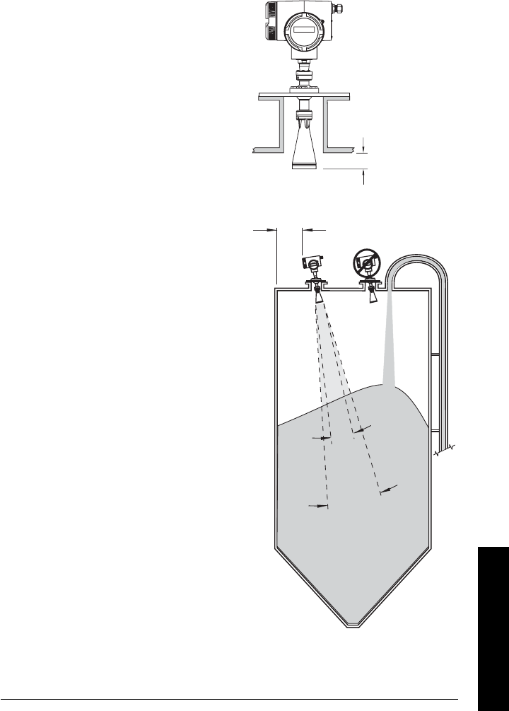
Mounting Location ................................................................................................................................12
Key considerations ......................................................................................................................13
Nozzle design............................................................................................................................. 13
Nozzle location........................................................................................................................... 13
Device orientation..................................................................................................................... 13
Installation in vessel with obstructions .................................................................................14
Easy Aimer Installation ........................................................................................................................15
Air Purging System (Optional) ............................................................................................................16
Universal Slotted Flange (for use with Air Purging Option only) .....................................17
Optional Dust Cap .................................................................................................................................18
Wiring .................................................................................................................................. 19
Connecting SITRANS LR 460 ..............................................................................................................19
HART wiring ..................................................................................................................................20
PROFIBUS wiring ........................................................................................................................21
Hazardous area installations .............................................................................................................23
Product Nameplate .....................................................................................................................23
Instructions specific to hazardous area installations ........................................................23
Quick Start ..........................................................................................................................26
Activating SITRANS LR 460 ................................................................................................................26
RUN mode display .......................................................................................................................26
Programming SITRANS LR 460 ..........................................................................................................27
The handheld programmer and PROGRAM mode display ...............................................27

ii
mmmmm
Table of Cotents
Quick Start Wizard via the handheld programmer .............................................................28
Quick Start Wizard via SIMATIC PDM ...................................................................................30
Device Description (DD) .......................................................................................................... 30
Quick Start Wizard steps......................................................................................................... 31
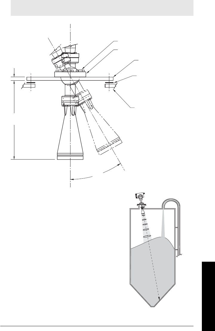
Level application example ...................................................................................................................34
Auto False Echo Suppression ............................................................................................................35
Operating SITRANS LR 460 via SIMATIC PDM ............................................................36
Functions in SIMATIC PDM ................................................................................................................36
SIMATIC PDM Rev. 6.0, SP2 Features ....................................................................................36
Echo profile saving and viewing............................................................................................ 37
Trend Diagram (Level Trend over Time) ............................................................................. 37
Manual TVT Shaper.................................................................................................................. 38
Accessing Functions in PDM ...................................................................................................39
Changing parameter settings via SIMATIC PDM ...............................................................40
Configuring a new device .........................................................................................................40
Calibrating LR 460 via PDM .......................................................................................................41
Parameters accessed via pull-down menus ........................................................................41
Reset ............................................................................................................................................ 41
Configuration Flag Reset (HART only).................................................................................. 41
Auto False Echo Suppression ................................................................................................ 41
D/A (Digital/Analog) Trim ........................................................................................................ 42
Simulate AO (Analog Output) ................................................................................................. 42
Simulation ................................................................................................................................... 42
Parameter Reference .......................................................................................................43
Parameter menus ........................................................................................................................43
Pull-down menus via SIMATIC PDM .....................................................................................43
Quick Start Wizard ................................................................................................................................44
Quick Start .............................................................................................................................................44
Language .....................................................................................................................................44
Application Type ....................................................................................................................... 44
Operation .................................................................................................................................... 44
Units.............................................................................................................................................. 45
High Calibration Point .............................................................................................................. 45
Low Calibration Point ............................................................................................................... 45
Rate............................................................................................................................................... 45
Apply Changes........................................................................................................................... 45
Identification ........................................................................................................................................46
Operation Unit ............................................................................................................................46
Configuration ..............................................................................................................................46
Device .......................................................................................................................................... 48
Statistics ...................................................................................................................................... 49
Input .......................................................................................................................................................50
Static Revision Number ...........................................................................................................50
Class .............................................................................................................................................50
Standard Setup ..........................................................................................................................50
Sensor Calibration .................................................................................................................... 51
Measuring Limits....................................................................................................................... 53
Detailed Setup ........................................................................................................................... 53

iii
mmmmm
Table of Contents
Echo Information ....................................................................................................................... 61
Output ....................................................................................................................................................61
AIFB1............................................................................................................................................ 61
AIFB2............................................................................................................................................ 65
mA Output ................................................................................................................................... 65
Relay Configuration .................................................................................................................. 67
Device Certification ..................................................................................................................67
Remaining Device Lifetime ..................................................................................................... 68
Remaining Sensor Lifetime..................................................................................................... 68
Service Interval.......................................................................................................................... 69
Calibration Interval.................................................................................................................... 69
Appendix A: Technical Reference .................................................................................71
Principles of Operation ........................................................................................................................71
Measurement Response .....................................................................................................................71
Echo Processing ...................................................................................................................................72
Profile monitoring via SIMATIC PDM .....................................................................................72
Time Varying Threshold (TVT)................................................................................................ 72
Echo selection ..............................................................................................................................72
False Echoes ...........................................................................................................................................73
Auto False-Echo Suppression ..................................................................................................73
Near Range (Blanking) ..............................................................................................................74
Echo confidence ....................................................................................................................................74
Loss of Echo (LOE) .......................................................................................................................74
LOE Timer.................................................................................................................................... 74
Fail-safe Mode .......................................................................................................................................74
Maximum Process Temperature Chart ............................................................................................76
Appendix B: Troubleshooting .........................................................................................77
General Fault Codes/PROFIBUS PA Extended Diagnostics ......................................................80
Appendix C: Maintenance ..............................................................................................84
Unit Repair and Excluded Liability ....................................................................................................84
Appendix D: Local Operation Interface ........................................................................85
The LCD Display .....................................................................................................................................85
RUN mode (startup display) .....................................................................................................85
PROGRAM Mode Display .........................................................................................................85
The handheld programmer .................................................................................................................86
Hand-held programmer: key functions in RUN mode ........................................................86
PROGRAMMING via the handheld programmer ................................................................86
Hand-held programmer: key functions in Navigation mode .......................................... 87
Hand-held programmer: key functions in Edit mode........................................................ 87
Individual Parameter Reset .................................................................................................... 87
Appendix E: HART Communications ............................................................................88
HART Device Description (DD) ...........................................................................................................88
SIMATIC Process Device Manager (PDM) .....................................................................................88
HART modem interface for SIMATIC PDM ..........................................................................88
HART Version .........................................................................................................................................89

iv
mmmmm
Table of Cotents
Burst Mode ...................................................................................................................................89
HART Communication Parameter .....................................................................................................89
Appendix F: HART Information Structure .....................................................................90
Block Model for recording and processing measured values ...................................................90
Description of the blocks ...........................................................................................................91
Appendix G: Remote operation via PROFIBUS PA .....................................................92
Configuration tool ..................................................................................................................................92
SIMATIC PDM ..............................................................................................................................92
Device Description.................................................................................................................... 92
Configuration ................................................................................................................................93
The GSD file................................................................................................................................ 93
Setting the PROFIBUS address.............................................................................................. 93
Configuring a new device: procedure.................................................................................. 93
Configuring PROFIBUS PA with an S7-300/ 400 PLC ........................................................ 94
Calibration via SIMATIC PDM ..................................................................................................94
Appendix H: Communication via PROFIBUS PA ......................................................... 95
Cyclic versus Acyclic Data ..................................................................................................................95
Cyclic Data ....................................................................................................................................95
Status Byte .............................................................................................................................................96
Diagnostics .............................................................................................................................................97
Diagnosis reply (applies only to cyclic masters) .................................................................97
Acyclic Diagnostics .....................................................................................................................97
Acyclic Extended Diagnostics (General Fault Codes) ........................................................98
Acyclic Data Transmission ..................................................................................................................98
Appendix J: PROFIBUS PA Profile Structure ...............................................................99
PROFIBUS Level Device Design ........................................................................................................99
Block Model for recording and processing measured values ...................................... 99
Description of the blocks ........................................................................................................ 100
Level Transducer Block function groups ......................................................................... 100
Analog Input Function Blocks 1 and 2............................................................................... 102
Appendix K: Software Revision History ..................................................................... 105
Glossary ............................................................................................................................107
Index .................................................................................................................................. 111
LCD menu structure ........................................................................................................ 113
7ML19985JM01 SITRANS LR 460 – INSTRUCTION MANUAL Page 1
mmmmm
SITRANS LR 460
Safety Notes
Special attention must be paid to warnings and notes highlighted from the rest of the text
by grey boxes.
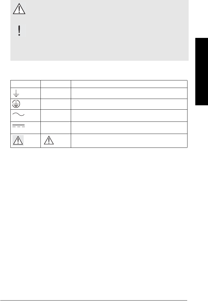
Safety marking symbols
WARNING: relates to a caution symbol on the product, and means
that failure to observe the necessary precautions can result in death,
serious injury, and/or considerable material damage.
WARNING: means that failure to observe the necessary precautions
can result in death, serious injury, and/or considerable material
damage.
Note: means important information about the product or that part of the operating
manual.
In manual: On product: Description
Earth (ground) Terminal
Protective Conductor Terminal
Alternating Current
Direct Current
(Label on product: yellow background.) WARNING: refer
to accompanying documents (manual) for details.

Page 2 SITRANS LR 460 – INSTRUCTION MANUAL 7ML19985JM01
mmmmm
SITRANS LR 460
FCC and IC Conformity
US Installations only: Federal Communications Commission (FCC) rules
Canadian Installations only: Industry Canada (IC) rules
WARNING: Changes or modifications not expressly approved by
Siemens Milltronics could void the user’s authority to operate the
equipment.
Notes:
• This equipment has been tested and found to comply with the limits for a Class A
digital device, pursuant to Part 15 of the FCC Rules. These limits are designed to
provide reasonable protection against harmful interference when the equipment is
operated in a commercial environment.
• This equipment generates, uses, and can radiate radio frequency energy and, if not
installed and used in accordance with the instruction manual, may cause harmful
interference to radio communications. Operation of this equipment in a residential
area is likely to cause harmful interference to radio communications, in which case
the user will be required to correct the interference at his own expense.
Notes:
• This device shall be installed and operated in a completely enclosed container to
prevent RF emission, which otherwise can interfere with aeronautical navigation.
Installation shall be done by trained installers, in strict compliance with the
manufacturer’s instructions.
• The use of this device is on a ’no-protection non-interference’ basis.
- The user shall accept operations of high powered radar in the same frequency
band, which may interfere with or damage this device.
- The user is responsible for removing, at the user’s expense, any device found to
interfere with primary licensing operations.

7ML19985JM01 SITRANS LR 460 – INSTRUCTION MANUAL Page 3
mmmmm
SITRANS LR 460
The Manual
This manual will help you set up your SITRANS LR 460 for optimum performance. We
always welcome suggestions and comments about manual content, design, and
accessibility. Please direct your comments to techpubs.smpi@siemens.com.
For other Siemens Milltronics level measurement manuals, go to:
www.siemens.com/level, and look under Level Measurement.
Application Examples
The application example used in this manual illustrates a typical installation using
SITRANS LR 460. There is often more than one way to approach an application, and other
configurations may also apply. If the example does not apply to your application, check
the applicable parameter reference for the available options.
Support
If you have questions, you can access our 24-hour hotline at:
www.siemens.com/automation/support-request
Phone: +49 180 50 50 222
Abbreviations and Identifications
Note: Please follow the installation and operating procedures for a quick, trouble-free
installation and to ensure the maximum accuracy and reliability of your SITRANS
LR 460. This manual applies to the SITRANS LR 460 only.
Short
form Long Form Description Units
A/D Analog to digital
AIFB Analog Input Function Block
CE / FM /
CSA
Conformitè Europèene /
Factory Mutual / Canadian
Standards Association
safety approval
CiInternal capacitance
D/A Digital to analog
DAC Digital Analog Converter
DCS Distributed Control System control room apparatus

Page 4 SITRANS LR 460 – INSTRUCTION MANUAL 7ML19985JM01
mmmmm
SITRANS LR 460
FV Full Vacuum
ESD Electrostatic Discharge
HART PV HART Primary Variable Output value from AIFB1
HART SV HART Secondary Variable Output value from AIFB2
IiInput current mA
IoOutput current mA
IS Intrinsically Safe safety approval
LiInternal inductance mH
LR Level Radar
LTB Level Transducer Block
mH milliHenry 10-3 Henry
µF microFarad 10-6 Farad
µsmicrosecond 10-6 Second
PA Process Automation
(PROFIBUS)
PDM Process Device Manager
(SIMATIC)
pF pico Farads 10-12 Farad
ppm parts per million
psia pounds/square inch absolute
PV Primary Value1 default measured value
RH relative humidity
SCFM standard cubic feet/minute
SV1 Secondary Value1 1LTB level output (level units)
SV2 Secondary Value2 1LTB distance output (sensor
units)
TV Transmitter Variable
TVT Time Varying Threshold sensitivity threshold
UiInput voltage V
UoOutput voltage V
1. The output from the Level Transducer Block can be called the Primary Value (or
Secondary Value). When it becomes the input to the AIFB, it is called the
Process Variable. It is distinct from the HART PV.
Short
form Long Form Description Units
(cont’d)
7ML19985JM01 SITRANS LR 460 – INSTRUCTION MANUAL Page 5
mmmmm
SITRANS LR 460
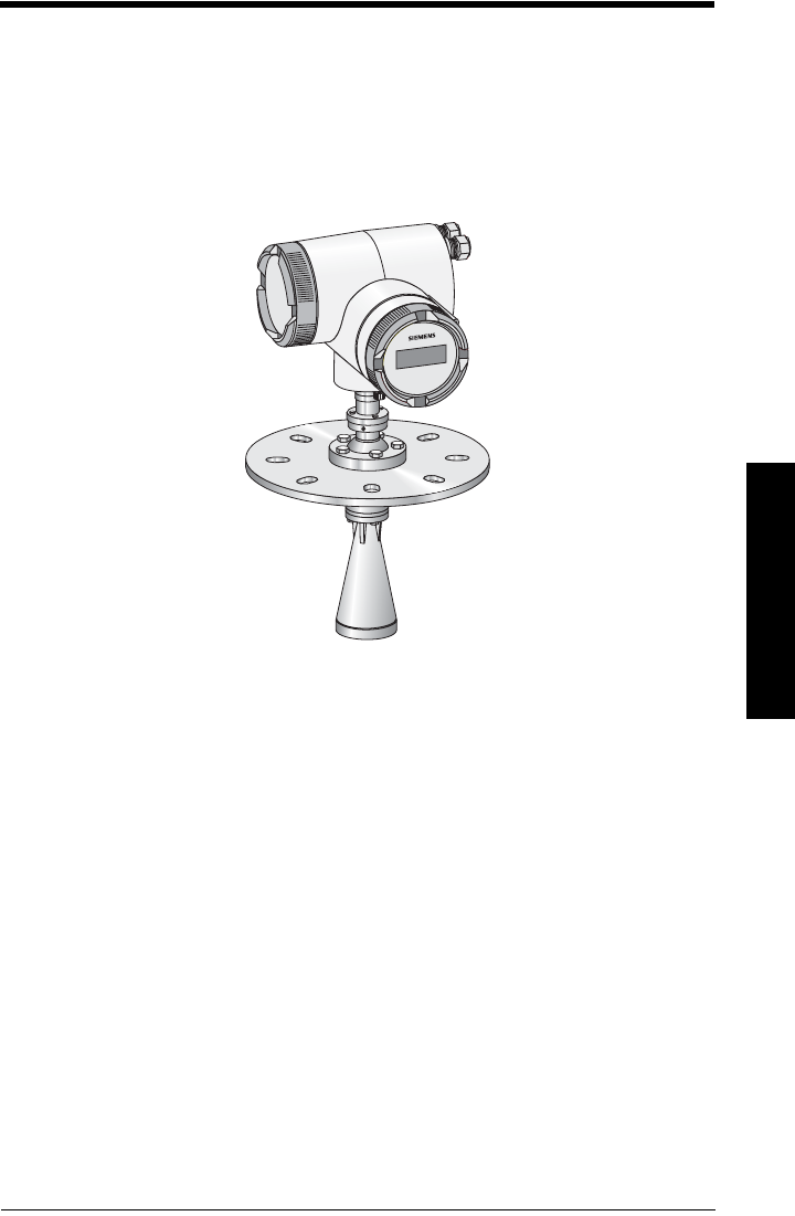
SITRANS LR 460
SITRANS LR 460 is a 4-wire 24 GHz FMCW (Frequency Modulated/Continuous Wave) radar
level transmitter with advanced signal processing for continuous monitoring of solids up
to 100 meters. It is ideal for extreme dust and difficult applications. The Easy Aimer design
makes it easy to install the device and orient the signal towards the material angle of
repose. The high frequency signal creates a narrow emission cone, which makes the
LR 460 quite insensitive to vessel interferences.
SITRANS LR 460 is available with an optional air purge connection for cleaning the interior
of the antenna.
Programming
SITRANS LR 460 carries out its level measurement function according to the set of built-in
parameter tables. You can make parameter changes via the Siemens Milltronics
handheld programmer, a PC running SIMATIC PDM or a HART handheld communicator.
Approvals and Certificates
SITRANS LR 460 is available with General Purpose approval, or approval for hazardous
areas containing dust. For details see
Approvals
on page 10.
System Implementation
SITRANS LR 460 supports HART communication protocol, or PROFIBUS PA (optional), and
SIMATIC PDM software.

Page 6 SITRANS LR 460 – INSTRUCTION MANUAL 7ML19985JM01
mmmmm
Specifications
Specifications
SITRANS LR 460
Power
Power Supply
• 100 to 230 V AC, ±15%, 50/60 Hz, 6 W
• 24 V DC, +25/-20%, 6 W
• Fuse (AC) SI1 Fast acting ceramic, 4 x 20 mm, 1 A, 250 V AC
SI2 Slow-Blow, 4 x 20 mm, 0.63 A, 250 V AC
• Fuse (DC) SI1 Fast acting ceramic, 4 x 20 mm, 2 A, 250 V AC
SI2 Slow-Blow, 4 x 20 mm, 0.63 A, 250 V AC
Performance
Reference operating conditions according to IEC 60770-1
• ambient temperature +15 to +25 oC
• humidity 45 to 75% relative humidity
• ambient pressure 860 to 1060 mbar (12.47 to 15.37 psi)
Measurement Accuracy (measured in accordance with IEC 60770-1)
• non-linearity (accuracy) greater of 25 mm (1”) or 0.25% of span (including
hysteresis and non-repeatability)
• non-repeatability 10 mm (0.4”) [included in non-linearity specification]
• deadband (resolution) 10 mm (0.4”) [included in non-linearity specification]
• hysteresis error 0 mm
Analog Output Accuracy (measured in accordance with IEC 60770-1)
• non-linearity (accuracy) 0.100% of span (including hysteresis and repeatability)
• non-repeatability 0.030% of span (included in non-linearity specification)
• deadband (resolution) 0.030% of span [included in non-linearity specification]
• hysteresis error 0%
Frequency 25 GHz nominal
Measurement range10.35 to 100 m (1.15 to 328.08 ft).
Note: Siemens Milltronics makes every attempt to ensure the accuracy of these
specifications, but reserves the right to change them at any time.
1. Referenced from flange face.

7ML19985JM01 SITRANS LR 460 – INSTRUCTION MANUAL Page 7
mmmmm
Specifications
Long-term stability ≤ ± 1 mm/year
Near Range (blanking) 0.35 m (1.15 ft)
Update time mA output and loop display is updated once per
second
Beam angle
• 3" horn: 11° at –3 dB boundary
• 4" horn: 8° at –3 dB boundary
Memory
• non-volatile EEPROM
• no battery required
Interface
Analog output (Not applicable to PROFIBUS PA option)
• signal range 4 to 20 mA
upper limit 20 to 23 mA adjustable
• fail signal 3.6 mA to 23 mA; or last value
• load Max. 600 Ω; for HART1 communication min. 230 Ω
Digital output
• function Configurable as a device status or limit value (level)
• signal type Relay, either NCC or NOC function, max. 50 V DC,
max. 200 mA, rating max. 5 W.
Self-resetting fuse, Ri=9 Ω
Electrical isolation Outputs electrically isolated from the power supply and
from each other
Display
• LCD two lines of 16 characters each, configurable for the
following displays:
level, amplitude, digital output,
temperature, validity, signal-to-noise ratio,
output current, distance
1. HART® is a registered trademark of HART Communication Foundation.

Page 8 SITRANS LR 460 – INSTRUCTION MANUAL 7ML19985JM01
mmmmm
Specifications
Programmer (infrared keypad)1
Siemens Milltronics infrared IS (Intrinsically Safe) handheld programmer for hazardous
and all other locations (battery is non-replaceable)
• approval: ATEX II 1 G EEx ia IIC T4, certificate SIRA 01ATEX2147
CSA and FM Class I, Div. 1, Gr. A, B, C, D T6 @ max.
ambient temperature of 40 °C (104 °F)
• ambient temperature: −20 to 40 °C (−5 to 104 °F)
• interface: proprietary infrared pulse signal
• power: 3 V lithium battery
• weight: 150 g (0.3 lb)
•color: black
Mechanical
Wetted parts (in contact
with the process)
• flange and horn 304 stainless steel (or equivalent)
•emitter PTFE
Process Connection
• universal flanges 3"/80 mm, 4"/100 mm, 6"/150 mm (See page 17 for flange
dimensions.)
Pressure (vessel) 0.5 bar (7.25 psi) maximum
Horn
• 3" horn 2.93" (74.5 mm) diameter
• 4" horn 3.84" (97.5 mm) diameter
Weight
• Weight of instrument and flange
1. Ordered separately.
Process Connection Weight
Universal, 3" / 80 mm flange with 3" horn 6.1 kg (13.4 lbs)
Universal, 4" / 100 mm flange with 4" horn 10.6 kg (23.36 lbs)
Universal, 6" / 160 mm flange with 4"horn TBA

7ML19985JM01 SITRANS LR 460 – INSTRUCTION MANUAL Page 9
mmmmm
Specifications
Enclosure
• construction Die-cast aluminum, painted (polyester powder-coated)
• conduit 2 x M20
or 2 x ½” NPT (option)
• ingress protection Type 4X/NEMA 4X, Type 6/NEMA 6, IP671
Dust cap (optional)
• 3" PTFE, pipe clamp connection, O.D. 95 mm (3.74")
• 4" PTFE, pipe clamp connection, O.D. 120 mm (4.72")
Air Purge Connection
• equipped with female 1/8" NPT fitting
Environmental
• location indoor/outdoor
• altitude 2000 m (6562 ft) max
• relative humidity suitable for outdoor (Type / NEMA 4X, 6/ IP67)
• installation category II
• pollution degree 4
• permitted ambient -40 to 65 °C (-40 to 149 °F) (non-hazardous version)
temperature3LCD: -10 to 55 °C (14 to 131 °F)
Observe the temperature classes in hazardous areas!
Process
• Process temperature2-40 to 200 °C (-40 to 392 °F)
• Pressure (vessel) 0.5 bar (7.25 psi) maximum
Communication
Communication: HART
• Load 230 to 600 Ω, 230 to 500 Ω when connecting a coupling
module
• Max. Line Length multi-wire: ≤ 1500 m (4921 ft)
• Protocol HART, Version 5.1
1. Use only approved, suitable sized hubs for watertight applications.
2. Process temperature varies with ambient temperature. See Process/Ambient de-rating curves in
Appendix III.

Page 10 SITRANS LR 460 – INSTRUCTION MANUAL 7ML19985JM01
mmmmm
Specifications
Communication: PROFIBUS PA
•Protocol PROFIBUS PA,
technology: IEC 61158-2, slave-functionality
•Device Class B
• Device Profile 3.01
Bus current (PROFIBUS PA) 10.5 mA
Approvals
• Hazardous areas FM/CSA Class II, Div. 1, Groups E,F and G, Class III
ATEX II 1 D; 1/2 D, 2D T85 deg C
• General CSAus/c, FM, CE
• Radio FCC, Industry Canada, European Radio (R&TTE)
7ML19985JM01 SITRANS LR 460 – INSTRUCTION MANUAL Page 11
mmmmm
Specifications
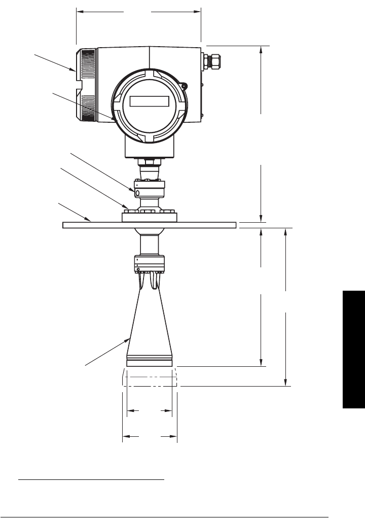
Dimensions
Standard configuration1 2
1. Consult factory when using horn extension in applications subject to shock and vibration.
2. Universal flange mates with EN 1092-1 / ASME B16.5 / JIS B2238 bolt hole pattern.
204 mm
(8.0")
287 mm
(11.29")
electronics
cover
connection
cover
universal
slotted flange
(see page 17
for details)
horn antenna
74.5 mm
(2.93")
228 mm
(8.97")
97.5 mm
(3.84")
Easy Aimer ball
locking bolts
reference
point
3" horn
4" horn
285 mm
(11.22")
purge
connection
Page 12 SITRANS LR 460 – INSTRUCTION MANUAL 7ML19985JM01
mmmmm
Installation
Installation
Mounting Location
WARNINGS:
• SITRANS LR 460 is to be used only in the manner outlined in this
manual, otherwise protection provided by the equipment may be
impaired.
• Installation shall only be performed by qualified personnel and in
accordance with local governing regulations.
Notes:
• For European Union and member countries, installation must be according to ETSI
EN 302372.
• Refer to device nameplate for approval information.
• Use appropriate conduit and conduit fittings or cable glands, to maintain IP or NEMA
rating.
• Observe all maximum permissible ambient and process temperatures. Refer to
Maximum Process Temperature Chart
on page 76.
• For US and Canadian installations, see
FCC and IC Conformity
on page 2.
Notes:
• Provide easy access for viewing the display and programming via the handheld
programmer.
• Provide an environment suitable to the housing rating and materials of construction.
• Provide a sun shield if the device is mounted in direct sunlight.
ambient temperature
max. 65 °C (149 °F)-
process temperature
max. 200 °C (392 °F)
flange
temperature
7ML19985JM01 SITRANS LR 460 – INSTRUCTION MANUAL Page 13
mmmmm
Installation
Key considerations
• Correct location is critical to a successful application.
• Avoid reflective interference from vessel walls and obstructions by following the
guidelines below.
Nozzle design
• Bottom edge of horn must project
from nozzle.
• Nozzle must allow adequate
clearance to allow positioning if LR
460 has to be at an angle so that
emission cone perpendicular to
material surface.
Nozzle location
• Locate antenna at least 1 meter away
from side wall.
• Keep emission cone free of interference
from ladders, pipes, I-beams or filling
streams.
• Make allowance for beam spread to
avoid interference with the emission
cone.
Device orientation
• Align the antenna so that the radar
cone is perpendicular to the surface
of the monitored material, if possible.
(See
Easy Aimer Installation
on page
15.)
• To compensate for vessels with
obstructions, see also
Polarization
Reference Point
on page 14.
Min. clearance:
10 mm (0.4")
SITRANSLR400
SITRANSLR400
min. 1 m (39")
emission
cone
4" horn
3"
horn
11°
8°
Page 14 SITRANS LR 460 – INSTRUCTION MANUAL 7ML19985JM01
mmmmm
Installation
Installation in vessel with obstructions
Polarization Reference Point
Obstructions such as ladders, pipes, or the fill path, can cause false reflections. To avoid
this, use the Polarization Reference Point to orient the device.
• A small center punch mark provides a polarization reference point.
• To get the best signal, rotate the device till the Polarization Reference Point either
faces towards the obstruction, or faces away from the obstruction (at 180 degrees).
Polarization
Reference
Point
Note: the device can be rotated through 360
degrees without damage to the unit.
7ML19985JM01 SITRANS LR 460 – INSTRUCTION MANUAL Page 15
mmmmm
Installation
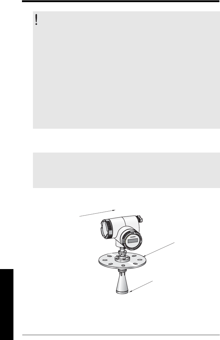
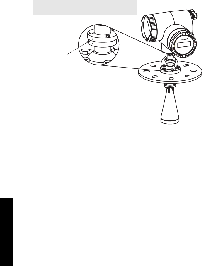
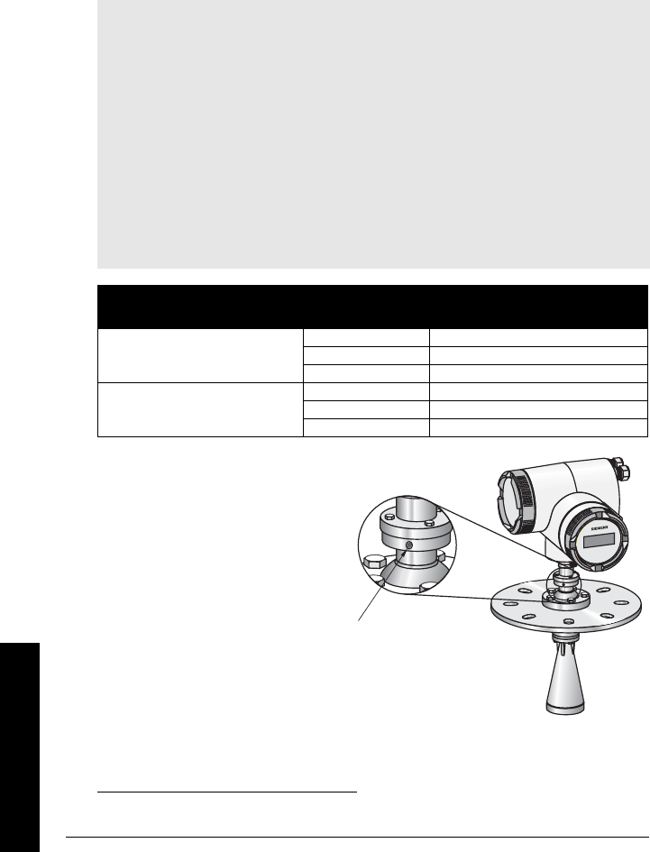
Easy Aimer Installation
1. Holding the electronics enclosure firmly,
loosen the Easy Aimer ball locking bolts and
gently reposition the enclosure.
2. Direct SITRANS LR 460 so the horn antenna is
pointed at an angle perpendicular to the
material surface, if possible. (As a guide, aim
the beam at a point approximately 2/3 of the
way across the tank diameter.)
3. When the desired position is reached, re-
tighten the 5 bolts to 15-23 N m (11 to 17 Lbf-ft).
Note: When the Easy Aimer ball is loosened, the device is free to tilt to a maximum of
30°.
top clamping plate (upper socket)
bottom clamping plate
(lower socket)
customer gasket as
required [recommended
thickness 1.5 to 1.8 mm (0.06
to 0.07")]
customer mounting plate,
as required
ø 4" (102 mm) min.,
central opening
30°
max.
285 mm
(11.22")
0.38"
(10 mm)
Easy Aimer ball locking bolts
SITRANSLR4
00
Easy Aimer
Page 16 SITRANS LR 460 – INSTRUCTION MANUAL 7ML19985JM01
mmmmm
Installation
Air Purging System (Optional)
For more frequent cleaning, a purging system can be installed between the flange and the
horn antenna. The system provides an 1/8" inlet (female thread) on the flange where
cooling air or cleaning fluid passes through the flange and exits the inside of the horn to
clean it. The customer will supply the purging medium by a manual or automatic valve
system.
This option is only available with the universal flange for purging shown on page 17. 1
• The purge connection is closed
by the manufacturer, using a 1/8"
plug.
• When the plug is removed to
connect a purging system, the
operator is responsible for
ensuring that the purging circuit
conforms to "Ex" requirements:
for example, by fitting an NRV
valve.
Notes:
• The Air Purge feature should not be activated with a dust cap in place.
• Purge duration, pressure, and interval, will vary with each application. It is the user’s
responsibility to determine the requirements depending on the application and
cleaning required.
• Short duration bursts of high pressure provide more effective cleaning than
continuous low pressure air.
• Some dust particles are highly abrasive and can be drawn into the inside of the horn
during purge cleaning, damaging the internal PTFE emitter of the antenna. A
replacement kit is available from your local Siemens Milltronics representative.
• It is the customer’s responsibility to ensure that any vacuum or pressure in the
measured vessel is maintained, considering the hole that passes through the
process connection and SITRANS LR 460 antenna system.
Recommendation for
effective cleaning
Air Consumption
(Flow rate versus applied pressure)
Pressure: 90 to 110 psi
Air Pressure Approx. inlet volume flow rate
20 5 SCFM
40 6 SCFM
Inlet flow: 10 SCFM 1
60 8 SCFM
80 9 SCFM
90 10 SCFM
1. SCFM (standard cubic feet/minute) referenced to 14.7 psia, 68°F and 36% relative humidity (RH).
purged process
connection with factory-
installed 1/8" NPT plug
7ML19985JM01 SITRANS LR 460 – INSTRUCTION MANUAL Page 17
mmmmm
Installation
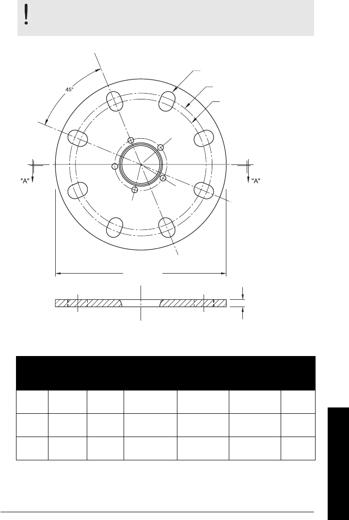
Universal Slotted Flange (for use with Air Purging Option
only)
Slotted Flange Dimensions (see above)
WARNING: The user is responsible for the selection of bolting and
gasket materials which will fall within the limits of the flange and its
intended use and which are suitable for the service conditions.
Pipe
Size
Flange
O.D.
Thick-
ness (s)
Bolt Hole
Circle Max Ø
Bolt Hole
Circle Min Ø
Bolt Hole
radius
No. of
Slotted
Holes
3" or
80 mm
7.87"
(200 mm)
0.38"
(9.65 mm)
6.30"
(160 mm)
5.91"
(150 mm)
0.38"
(9.5 mm)
8
4" or
100 mm
9.00"
(229 mm)
0.38"
(9.65 mm)
7. 52 "
(191 mm)
6.89"
(175 mm)
0.38"
(9.5 mm)
8
6" or
150 mm
11.22"
(285 mm)
0.38"
(9.65 mm)
9.53"
(242 mm)
9.45"
(240 mm)
0.45"
(11.5 mm)
8
flange O.D.
bolt hole circle
min. diameter
number of slotted bolt holes
section A-A
thickness
bolt hole circle max. diameter
Page 18 SITRANS LR 460 – INSTRUCTION MANUAL 7ML19985JM01
mmmmm
Installation
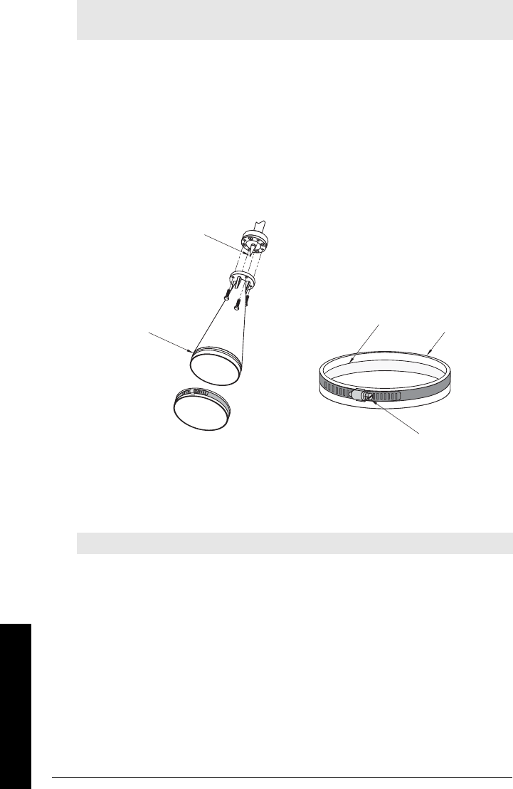
Optional Dust Cap
The dust cap fits onto the end of the horn and prevents the buildup of dust and other
process material inside the horn.
• It is particularly useful for applications in areas of high humidity, or with bulk solids
with a high moisture content.
• Two sizes are available, to fit the standard 3" and 4" horns.
Installation
1. Thoroughly clean inside the horn. If you remove the horn for easier cleaning, take
care not to damage or bend the plastic emitter.
2. Press the cap firmly onto the horn until the ridge inside the cap snaps into position in
the groove on the outside of the horn.
3. Hand tighten the adjustable clamp supplied to secure the cap.
4. Use a screwdriver or nut driver to tighten the clamp screw until the clamp provides
an air-tight seal.
Note: The dust cap must be removed before using the Air Purge feature (see
Air
Purging System (Optional)
on page 16).
Note: It is critical to ensure no moisture can be trapped inside.
plastic emitter
groove ridge dust cap
clamp screw

7ML19985JM01 SITRANS LR 460 – INSTRUCTION MANUAL Page 19
mmmmm
Wiring
Wiring
Connecting SITRANS LR 460
1. Release the cover lock on the enclosure with a 3 mm Allen key and unscrew the
cover. (Use a screwdriver for extra leverage, if required.)
2. Loosen the cable gland and push the power cable through until it reaches the
terminal strip.
(Go to
HART wiring
on page 20 or
PROFIBUS wiring
on page 21 for next steps.)
WARNINGS:
• Turn off power to the device before unscrewing the housing cover in a
hazardous area.
• All field wiring for AC models must have insulation suitable for at least
250 V.
• The DC input terminals shall be supplied from a source that provides
electrical isolation between the input and the output, in order to meet
the applicable safety requirements of IEC 61010-1.
• The equipment shall be protected by a fuse or circuit breaker of up to
16 A in the building installation.
• A circuit breaker or switch in the building installation, marked as the
disconnect switch, shall be in close proximity to the equipment and
within easy reach of the operator.
• To avoid short-circuits, do not connect a load resistance with bare
wires inside the connection box.
Notes:
• AC and DC input circuits: min. 14 AWG (2.5 sq. mm) copper wire.
• Lay power cables separately from communication wiring.
• Recommended torque on terminal clamping screws: 0.5 to 0.6 N m (0.37 to 0.44 Lbf-ft).
power
cable
cable gland
cover
lock
metal bracket
terminal
strip
Page 20 SITRANS LR 460 – INSTRUCTION MANUAL 7ML19985JM01
mmmmm
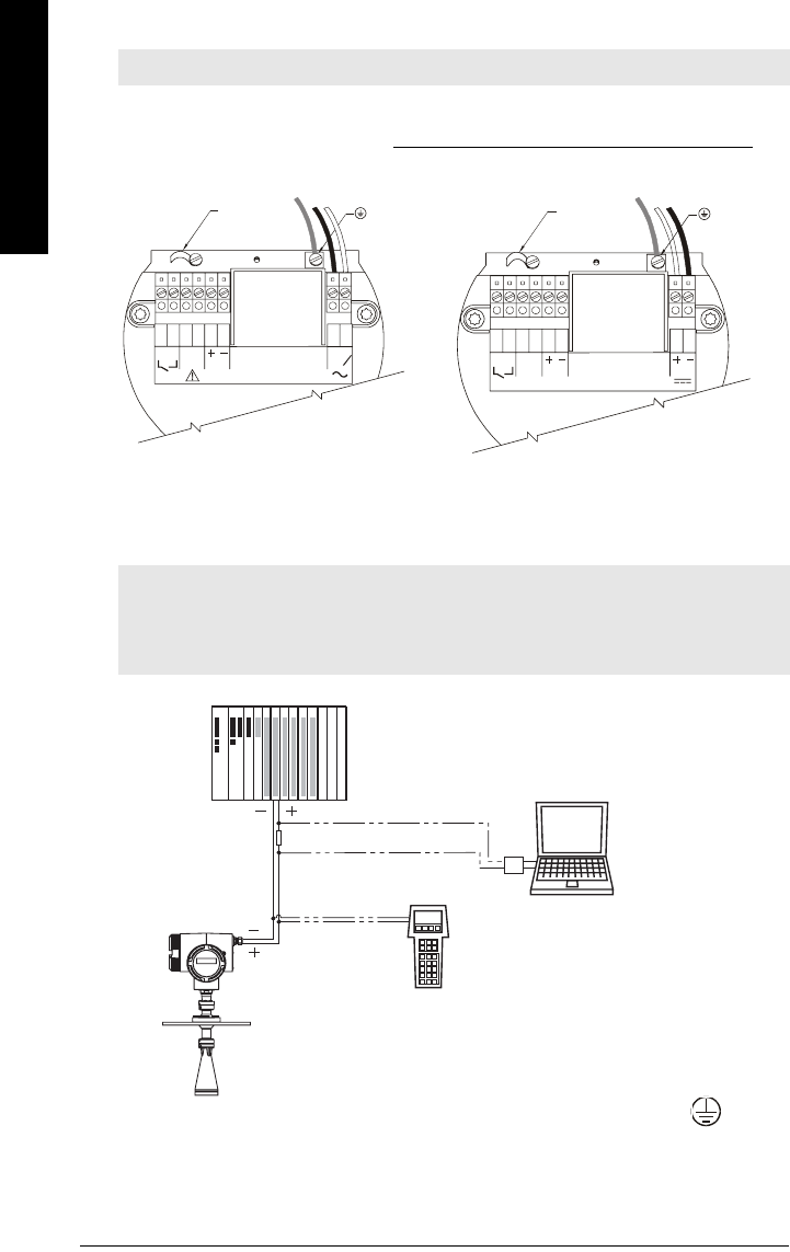
Wirng
HART wiring
Install in accordance with
Wiring and Installation
in the HART Application Guide (order
number HCF_LIT-34), available from: http://www.hartcomm.org/technical/doclist.html.
Connecting HART
Typical PLC/mA configuration with HART
3. Connect the earth conductor of the power supply to the earth terminal on the
metal bracket inside the enclosure. Adjust the cable length so that the earth
conductor would be last to disconnect if cable is pulled.
Note: LR 460 HART requires no power from the 4-20 mA loop.
Notes:
• For error-free communication via the HART protocol, a 250 Ohm resistor may be
required if the loop resistance is less than 250 Ohms.
• Only one HART communication device should be inserted in the loop.
1264 5
378
L
1
L
2
N
mA
Rated temperature of
connection cables must
exceed maximum ambient
temperature by at least 15 K
AC version
earth
terminal
cable clamp
1264 5
378
mA
19-30 V
Rated temperature of
connection cables must
exceed maximum ambient
temperature by at least 15 K
DC version
earth
terminal
cable clamp
PLC with mA
input card
PC/laptop with
HART modem
running PDM
LR 460
R = 250 Ω
HART
Communicator
375
7ML19985JM01 SITRANS LR 460 – INSTRUCTION MANUAL Page 21
mmmmm
Wiring
4. Tighten the cable gland and check the strain relief (pull and turn).
5. Replace the enclosure cover and hand tighten it. The sealing ring must be clean and
undamaged.
6. Tighten the screw on the cover lock.
7. Connect the external earth terminal located
between the cable glands to a ground
connection at your vessel. Use a cable with
a cross-section of 2.5 mm2 or greater.
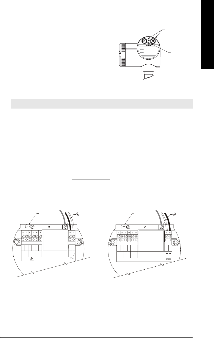
PROFIBUS wiring
Power Demands
To determine how many devices can be connected to a bus line, calculate the combined
maximum current consumption of all the connected devices: 10.5 mA for SITRANS LR 460.
Allow a current reserve for safety.
Bus Termination
PROFIBUS PA MUST be terminated at both extreme ends of the cable for it to work
properly. Please refer to the PROFIBUS PA User and Installation Guidelines (order
number 2.092), available from www.profibus.com.
Install in accordance with
PROFIBUS PA User and Installation Guidelines
(order number
2.092), available from www.profibus.com.
Note: PROFIBUS PA is not polarity-sensitive.
cable
glands
earth
(ground)
terminal
12645378
PROFI-
BUS PA
19-30 V
Rated temperature of
connection cables must
exceed maximum ambient
temperature by at least 15 K
DC version
earth
terminal
cable clamp
1264 5
378
L
1
L
2
N
Rated temperature of
connection cables must
exceed maximum ambient
temperature by at least 15 K
PROFI-
BUS PA
AC version
earth
terminal
cable clamp
Page 22 SITRANS LR 460 – INSTRUCTION MANUAL 7ML19985JM01
mmmmm
Wirng
Connecting PROFIBUS PA
Typical PLC/mA configuration with PROFIBUS PA
(Continued from
Connecting SITRANS LR 460
on page 19, step 2.)
3. Connect the earth conductor of the power supply to the earth terminal on the
metal bracket inside the enclosure. Adjust the cable length so that the earth
conductor would be last to disconnect if cable is pulled.
4. Tighten the cable gland and check the strain relief (pull and turn).
5. Replace the enclosure cover and hand tighten it. The sealing ring must be clean and
undamaged.
6. Tighten the screw on the cover lock.
7. Connect the external earth terminal located
between the cable glands to a ground
connection at your vessel. Use a cable with
a cross-section of 2.5 mm2 or greater.
Class 1
Master
DP/PA
Coupler
PROFIBUS PA
HART
ET200
Class 2
Master
SITRANS
LR 460
SITRANS
LR 460
SITRANS
LR 460
PLC PDM
PROFIBUS PA
cable
glands
earth
(ground)
terminal
7ML19985JM01 SITRANS LR 460 – INSTRUCTION MANUAL Page 23
mmmmm
Wiring
Hazardous area installations
Product Nameplate
Instructions specific to hazardous area installations
(Reference European ATEX Directive 94/9/EC, Annex II, 1/0/6)
The following instructions apply to equipment covered by certificate number
Sira 06 ATEX 9218X.
1. For use and assembly, refer to the main instructions.
2. The equipment is certified for use as Category II 1D, 1/2 D & 2D equipment. The
Essential Health and Safety Requirements are assured by compliance with
IEC 61241-0: 2004 and IEC 61241-1: 2004.
3. The equipment may be used with dust and fibers with apparatus temperature
class T (see table below).
Note: The nameplate shown is a typical example. Please check the nameplate on your
device for your specific device configuration.
Note: Installation shall be performed only by qualified personnel and in accordance
with local governing regulations.
Siemens Milltronics Process Instruments Inc., Peterborough
Made in Canada
SITRANS LR 460 Radar Level Meter
Serial #
Amb. Temp.:
Enclosure:
Output:
Power Rating:
TYPE/NEMA 4X, 6 / IP67
7ML5426-0AA00-0AC-0
IECEx SIR 06.0058X
Ex tD A20 IP67 T85°C
4 - 20 mA HART
– 40°C to 65°C
100 - 230 V , ±15%, 50/60 Hz, 6 W
Do Not Open in an explosive dust atmosphere.
II 1D, 1/2 D, 2D
Ex tD A20 IP67 T85°C
SIRA 06ATEX9218X
Canada 267P-LR460
0518
0891
GYZ/S1034567

Page 24 SITRANS LR 460 – INSTRUCTION MANUAL 7ML19985JM01
mmmmm
Wirng
4. Thermal Data for 7ML5426 Series
5. The equipment has not been assessed as a safety related device (as referred to by
Directive 94/9/EC Annex II, clause 1.5).
6. Installation and inspection of this equipment shall be carried out by suitably trained
personnel in accordance with the applicable code of practice (EN 61241-14 and EN
61241 –17 in Europe).
7. Repair of this equipment shall be carried out by suitably trained personnel in
accordance with the applicable code of practice.
8. Components to be incorporated into or used as replacements in the equipment shall
be fitted by suitably trained personnel in accordance with the manufacturer’s
documentation.
9. It is the user’s responsibility to ensure that a manual override is possible in order to
shut down the equipment, and that protective systems are incorporated within
automatic processes which deviate from the intended operating conditions,
provided that this does not compromise safety.
10. Equipment Marking: The equipment marking contains at least the information on the
product label. See
Product Nameplate
on page 23.
11. If the equipment is likely to come into contact with aggressive substances, it is the
user’s responsibility to take suitable precautions to prevent it from being adversely
affected, and to ensure that the type of protection is not compromised.
• Aggressive substances include, for example, acidic liquids or gases that may
attack metals, or solvents that may affect polymeric materials.
• Suitable precautions include, for example, regular checks as part of routine
inspections, or establishing from the material’s data sheet that it is resistant to
specific chemicals.
SPECIAL CONDITIONS FOR SAFE USE
The ‘X’ suffix to the certificate number relates to the following special condition(s) for
safe use.
• Cable or conduit entries must meet the requirements of European Directive
94/9/EC for Group II, Category 1D, 1/2D, or 2D, as appropriate, and must
maintain the overall IP rating of the enclosure.
• For applications that require the purge feature, the user shall implement a
means to ensure that combustible dust from the hazardous area cannot enter
the purge supply in such a way as to compromise the area classification.
Device
category
Permitted ambient
temperature at horn antenna
Permitted ambient
temperature at electronic
enclosure
1D, 1/2D, 2D –40 °C (–40 °F) ≤ Tamb ≤+200°C
(+392 °F)
–40 °C (–40 °F) ≤ Tamb ≤ +65°C
(+149 °F)

7ML19985JM01 SITRANS LR 460 – INSTRUCTION MANUAL Page 25
mmmmm
Wiring
Notes

Page 26 SITRANS LR 460 – INSTRUCTION MANUAL 7ML19985JM01
mmmmm
Quick Start
Quick Start
To set up SITRANS LR 460 for a simple application requires only the following settings:
• select application type (silo construction)
• select operation mode: level, distance or space
• set speed of response
• set High and Low Calibration Points
A Quick Start wizard groups together all the settings you need. There are two ways to
access the wizard:
•
Quick Start Wizard via the handheld programmer
on page 28
•
Quick Start Wizard via SIMATIC PDM
on page 30
Activating SITRANS LR 460
Power up the instrument. SITRANS LR 460 automatically starts up in RUN mode, and
detects the distance to the material level referenced from the sensor flange face. The
LCD displays the measurement and the default unit is meters. System status is displayed
on the LCD, or on a remote communications terminal.
1
2
RUN mode display
See
RUN mode (startup display)
on page 85 for more detailed information.
Note: SITRANS LR 460 only supports SIMATIC PDM version 6.0 with SP2.
Notes:
• Keep infrared devices such as laptops, cell phones, and PDAs, away from
SITRANS LR 460 to prevent inadvertent operation.
• Frequently switching the device off and on causes wear of the electronics (see
2.3.
Statistics
on page 49 to access the records).
1. See
Loss of Echo (LOE)
on page 74 for more detail.
2. Flashes once per second to indicate that the device is functioning.
98.82
3.800 mA
m
98.82
S: 0
m
reliable echo
indicator1
flashing
heartbeat2
mA value, HART only (press key 5 on
handheld programmer to activate)
units
level
Normal operation LOE condition
fault code
unreliable echo
indicator1
7ML19985JM01 SITRANS LR 460 – INSTRUCTION MANUAL Page 27
mmmmm
Quick Start
Programming SITRANS LR 460
Activate PROGRAM mode at any time, to change parameter values and set operating
conditions.
• Parameters are organized into function groups and arranged in a four-level menu
structure (see
LCD menu structure
on page 113).
• Set parameters to suit your specific application.
• For a detailed list with instructions, see
Parameter Reference
on page 43.
The handheld programmer and PROGRAM mode display
• Point the programmer at the display (from a maximum distance of 600 mm [2 ft.] and
press Mode to activate PROGRAM mode.
•Use ARROW keys to navigate to a menu item. (See
LCD menu structure
on
page 113.)
• Press Right ARROW to open Edit
mode: the PROGRAM icon will flash.
• If required, scroll to the desired item or key
in a new value and press Right ARROW
to accept it. The LCD displays the new
value and the PROGRAM icon disappears.
• Press Mode to return to RUN mode.
Note: See
Appendix D: Local Operation Interface
on page 85 for more detailed
information on the programmer and the LCD display.
C
number
keys
handheld
programmer
max. 600 mm
(2 ft)
function
keys
display
2.1.2
0
ADDR
menu item PROGRAM
icon
parameter value
Page 28 SITRANS LR 460 – INSTRUCTION MANUAL 7ML19985JM01
mmmmm
Quick Start
Quick Start Wizard via the handheld programmer
The Quick Start menu appears as soon as you activate PROGRAM mode.
1. Quick Start
a. Point the programmer at the display (from a maximum distance of 600 mm [2 ft.]),
then press Mode to activate PROGRAM mode and open Menu level 1.
b. Press Right ARROW to navigate to menu item 1.1.
c. Press Right ARROW to open Edit mode: the PROGRAM icon will flash.
d. To change a setting, scroll to the desired selection or key in a new value.
e. After modifying a value, press Right ARROW to accept it. The LCD displays
the next menu item, the PROGRAM icon disappears, and the rightmost digit
flashes to indicate Navigation Mode.
1.1. Language
1.2. Application Type
1.3. Operation
Notes:
• The wizard is a complete package and the settings are inter-related.
• Do not use the Quick Start wizard to modify individual parameters: see instead
Parameter Reference
on page 43.
• Changes apply only at the end of the sequence, after you select Apply changes.
Note: There is no need to perform a Reset before starting the Quick Start sequence.
Options ENGLISH, DEUTSCH, FRANCAIS, ESPANOL
Options STEEL Silo construction
CONCRETE
Options
LEVEL Distance to material surface referenced from Low Calibration
Point (process empty level).
SPACE Distance to High Calibration Point (process full level)
referenced from material surface.
DISTANCE Distance to material surface referenced from Sensor
Reference Point.
7ML19985JM01 SITRANS LR 460 – INSTRUCTION MANUAL Page 29
mmmmm
Quick Start
Operation types
1.4. Units
Select the units for the Quick Start variables (high and low calibration point, and level,
distance, or space).
1.5. High Calibration Point
Distance from Sensor Reference to High Calibration Point: usually process full level.
(See 1.3. Operation for an illustration.)
1.6. Low Calibration Point
Distance from Sensor Reference to Low Calibration Point: usually process empty
level. (See 1.3. Operation for an illustration.)
1.7. Rate
Sets the reaction speed of the device to measurement changes in the target range.
Use a setting just faster than the maximum filling or emptying rate (whichever is
greater). Slower settings provide higher accuracy: faster settings allow for more level
fluctuation
1.8. Apply Changes
In order to save the Quick Start settings it is necessary to enable Apply Changes.
Select YES. SITRANS LR 460 is now ready to operate and returns to RUN mode.
Options mm, cm, m, in, ft
Values Range 0.0000 to 100.00 m
Values Range: 0.0000 to 100.00 m
Options
SLOW 0.1 m/minute
MED 1.0 m/minute
FAST 10.0m/minute
Options YES, NO
SITRANSL
R4
00
high
calibration
point
low calibration point
level
space
distance
sensor reference point
(flange face)

Page 30 SITRANS LR 460 – INSTRUCTION MANUAL 7ML19985JM01
mmmmm
Quick Start
Quick Start Wizard via SIMATIC PDM
The graphical Quick Start Wizard groups together all the settings you need to make for a
simple application into 4 steps.
To use HART or PROFIBUS PA, you will need a PC configuration tool: we recommend
SIMATIC PDM.
Please consult the operating instructions or online help for details on using SIMATIC PDM.
(Application Guides for setting up Siemens PROFIBUS PA and HART instruments with
SIMATIC PDM are available on our website: www.siemens.com/processautomation.)
Device Description (DD)
You will need the DD for SIMATIC PDM version 6.0 with SP2. You can locate the DD in
Device Catalog, under Sensors/Level/Echo/Siemens Milltronics/SITRANS LR 460. If you do
not see SITRANS LR 460 under Siemens Milltronics, you can download the DD from the
product page of our website at: https://pia.khe.siemens.com/index.asp?Nr=14655, under
Downloads.
Save the files to your computer, and extract the zipped file to an easily accessed location.
Launch SIMATIC PDM – Manager Device Catalog, browse to the unzipped DD file and
select it.
Configuring a new device
1. Set Address (default for PROFIBUS PA is 126; for HART is 0).
• Point the handheld programmer at the display then press Mode to activate
PROGRAM mode, menu item 1.
• Press Down ARROW , Right ARROW , Right ARROW to navigate to
Address (menu item 2.1.2).
• Press Right ARROW to open Edit mode: the PROGRAM icon will flash.
• If required, key in a new value and press Right ARROW to accept it. The LCD
displays the new value and the PROGRAM icon disappears.
2. You will need the most up-to-date Device Description (DD) for your instrument.
Launch SIMATIC PDM – Manager Device Catalog, browse to the unzipped DD file
and select it.
3. Launch SIMATIC Manager and create a new project for LR 460. Application Guides
for setting up HART and PROFIBUS PA devices with SIMATIC PDM.can be
downloaded from the product page of our website at:
https://pia.khe.siemens.com/index.asp?Nr=14655
4. Open the menu Device – Reset and click on Factory Reset.
5. Upload parameters to the PC/PG.
6. Calibrate the device via the Quick Start Wizard.
7ML19985JM01 SITRANS LR 460 – INSTRUCTION MANUAL Page 31
mmmmm
Quick Start
Quick Start Wizard steps
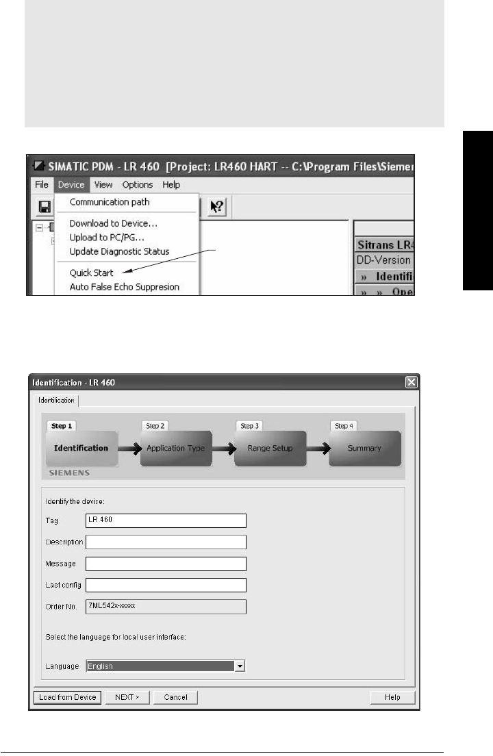
Open the menu Device – Quick Start, and follow steps 1 to 4.
Step 1 – Identification
Click NEXT to accept default values. (Description, Message, and Last config fields can be
left blank.)
Notes:
• The Quick Start settings are not independent parameters. The settings are inter-
related, and changes only apply when you click Transfer at the end of step 4.
• Do not use the Quick Start Wizard to modify individual parameters: see instead
Parameter Reference
on page 43.
•Click BACK to return and revise settings, or Cancel to exit the Quick Start.
• The layout of the dialog boxes shown may vary according to the resolution setting for
your computer monitor.
Quick
Start
Page 32 SITRANS LR 460 – INSTRUCTION MANUAL 7ML19985JM01
mmmmm
Quick Start
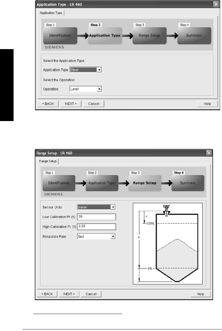
Step 2 – Application type
Select the application type and operation type1 and click NEXT.
Step 3 – Range Setup
Set Sensor Units, enter values for Low and High Calibration points, and select a
Response Rate just faster than the maximum fill/empty rate. Click NEXT.
1. For an illustration see
Operation types
on page 29.
7ML19985JM01 SITRANS LR 460 – INSTRUCTION MANUAL Page 33
mmmmm
Quick Start
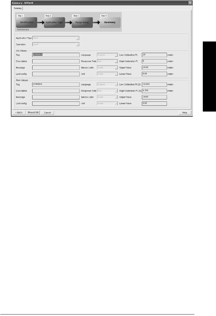
Step 4 – Summary
Check parameter settings, and click BACK to return and revise values, or TRANSFER to
transfer values to the device.
After the values have been transferred to the device the message Device Configuration
Complete appears. Click OK to upload values from the device to the PC/PG. and
synchronize the device and PDM
Page 34 SITRANS LR 460 – INSTRUCTION MANUAL 7ML19985JM01
mmmmm
Quick Start
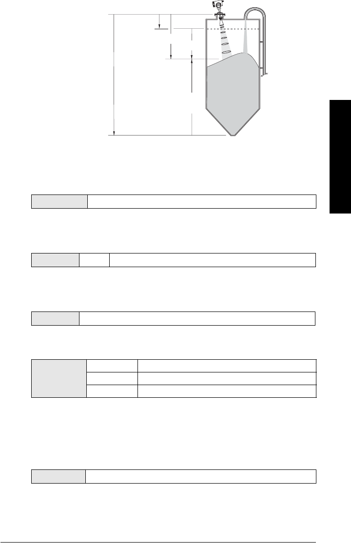
Level application example
The application is a steel silo containing flour that takes an average 3 hours to fill and 3
weeks to empty.
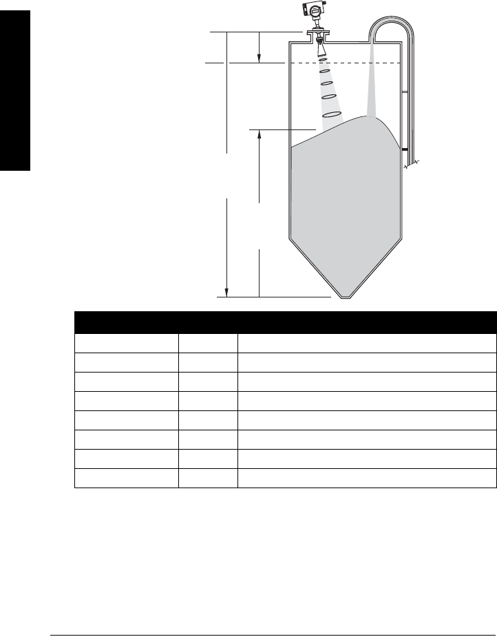
Using the Easy Aimer, the LR 460 is oriented so that the emission cone is approximately
perpendicular to the material surface.
Fill rate = 0.09 m/minute (15.5 / 180). Response rate has been set to slow: 0.1 m/minute, or
slightly faster than the fill rate.
Quick Start Setting Description
Language ENGLISH
Application Type STEEL Silo construction
Operation LEVEL Material level referenced from Low Calibration point.
Units m
High Calibration Point 1.0 Process full level.
Low Calibration Point 15.5 Process empty level.
Rate SLOW Response rate = 0.1 m/minute.
Apply Changes YES Save new settings.
SITRANSL
R4
00
Sensor Reference Point
(flange face)
Level
Low Calibration Point
High Calibration Point
15.5 m
1.0 m
LR 460 with Easy Aimer

7ML19985JM01 SITRANS LR 460 – INSTRUCTION MANUAL Page 35
mmmmm
Quick Start
Auto False Echo Suppression
If SITRANS LR 460 displays a false high level, or the reading is fluctuating between the
correct level and a false high level, you can use the Auto False Echo Suppression
parameters to prevent false echo detection. See
TVT (Auto False Echo Suppression)
setup
on page 57 for instructions.

Page 36 SITRANS LR 460 – INSTRUCTION MANUAL 7ML19985JM01
mmmmm
SIMATIC PDM
Operating SITRANS LR 460 via
SIMATIC PDM
SIMATIC PDM is a software package used to commission and maintain SITRANS LR 460
and other process devices. Please consult the operating instructions or online help for
details on using SIMATIC PDM. (You can find more information at www.fielddevices.com:
go to Products and Solutions > Products and Systems > Process Device Manager.)
Functions in SIMATIC PDM
SIMATIC PDM monitors the process values, alarms and status signals of the device. It
allows you to display, compare, adjust, verify, and simulate process device data.
See
Accessing Functions in PDM
on page 39 for operating instructions.
SIMATIC PDM Rev. 6.0, SP2 Features
The graphic interface in SITRANS LR 460 makes monitoring and adjustments easy.
• A graphical Quick Start wizard groups together all the settings you need to make for
a simple application into four easy steps. See
Quick Start Wizard via SIMATIC PDM
on page 30.
• See
Echo profile saving and viewing
on page 37 for easy echo profile comparison.
• See
Trend Diagram (Level Trend over Time)
on page 37 for Level trend monitoring.
• See
Manual TVT Shaper
on page 38.
Notes:
• SITRANS LR 460 only supports SIMATIC PDM version 6.0 with SP2.
• For a complete list of parameters with instructions, see
Parameter Reference
starting on page 43.
7ML19985JM01 SITRANS LR 460 – INSTRUCTION MANUAL Page 37
mmmmm
SIMATIC PDM.
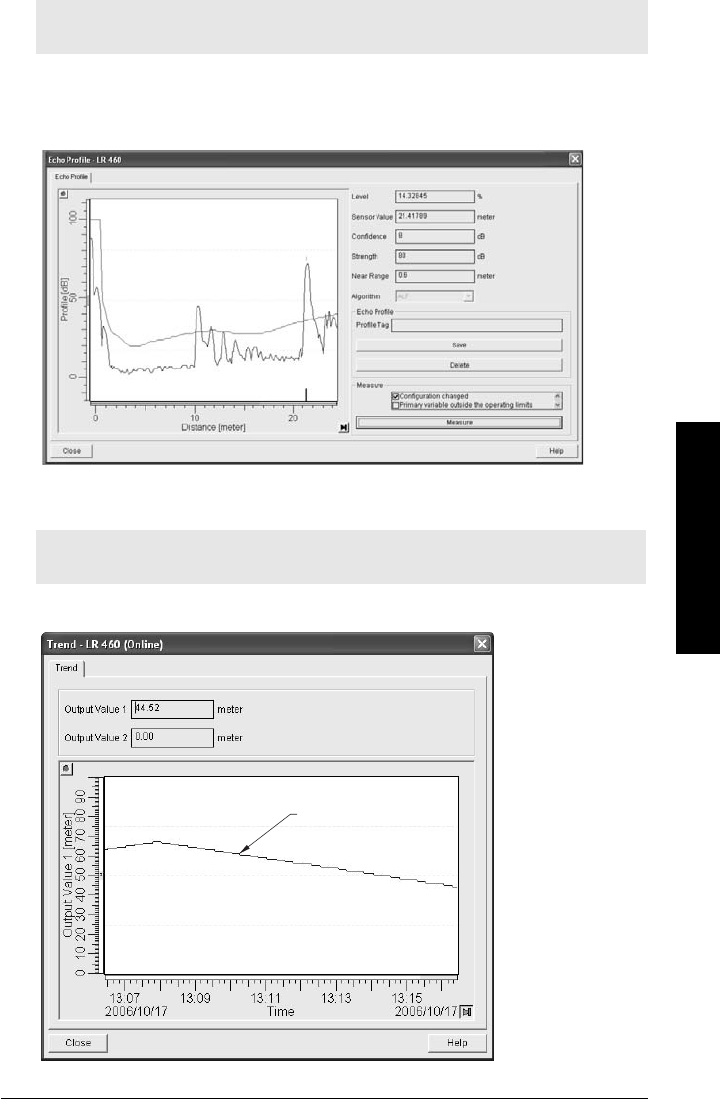
Echo profile saving and viewing
• Open the menu View – Display, and scroll down to Echo Profile.
• Press Measure to update an echo profile.
• After saving a profile open menu View – Show echo profile.
Trend Diagram (Level Trend over Time)
Open the menu View – Trend to see the level trend over tme.
Note: Double click each axis and record the Xscale and Data Scale values, so that you
can restore the default view by resetting to these values.
Note: Double click each axis and record the Xscale and Data Scale values, so that you
can restore the default view by resetting to these values.
trend line
Page 38 SITRANS LR 460 – INSTRUCTION MANUAL 7ML19985JM01
mmmmm
SIMATIC PDM
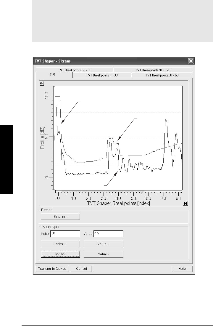
Manual TVT Shaper
Open the menu Device – TVT Shaper
• Change the position of the X cursor on the TVT curve using the Index+ and Index–
buttons: raise and lower the curve using Value+ and Value–.
• Alternatively, enter values directly into the dialog boxes for each breakpoint.
Notes:
• For a more detailed explanation see
Auto False-Echo Suppression
on page 73.
• See
3.5.6. TVT (Auto False Echo Suppression) setup
on page 57 for more
instructions.
• Double click each axis and record the Xscale and Data Scale values, so that you can
restore the default view by resetting to these values.
TVT curve
X cursor
echo profile
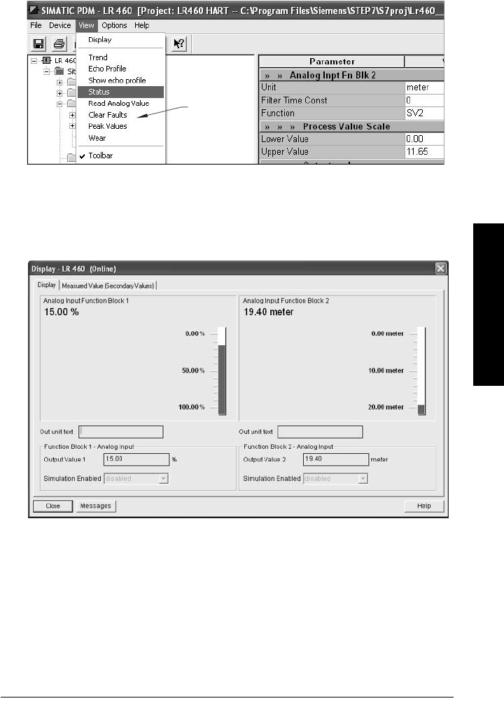
7ML19985JM01 SITRANS LR 460 – INSTRUCTION MANUAL Page 39
mmmmm
SIMATIC PDM.
Accessing Functions in PDM
You have access to a number of functions via pull-down menus from the menu bar. under
Device or View.
For a complete list see
Pull-down menus via SIMATIC PDM
on page 43.
Online Display
The online display allows you to compare outputs in real time. Open the menu View –
Display.
pull-down
menus
Page 40 SITRANS LR 460 – INSTRUCTION MANUAL 7ML19985JM01
mmmmm
SIMATIC PDM
Changing parameter settings via SIMATIC PDM
1. Launch SIMATIC PDM, connect to SITRANS LR 460, and upload data from the
device.
2. Adjust parameter values in the parameter value field then press Enter. The status
fields read Changed.
3. Open the Device menu, click on Download to device, then use File – Save, to save
parameter settings. The status fields are cleared.
Configuring a new device
Device Description (DD)
You will need the DD for SIMATIC PDM version 6.0 with SP2. You can locate the DD in
Device Catalog, under Sensors/Level/Echo/Siemens Milltronics/SITRANS LR 460. If you do
not see SITRANS LR 460 under Siemens Milltronics, you can download the DD from the
product page of our website at: https://pia.khe.siemens.com/index.asp?Nr=14655, under
Downloads.
Save the files to your computer, and extract the zipped file to an easily accessed location.
Launch SIMATIC PDM – Manager Device Catalog, browse to the unzipped DD file and
select it.
1. Set Address (default for PROFIBUS PA is 126; for HART is 0).
• Point the handheld programmer at the display then press Mode to activate
PROGRAM mode, menu item 1.0.
• Press Down ARROW , Right ARROW , Right ARROW to navigate to
Address (menu item 2.1.2).
• Press Right ARROW to open Edit mode: the PROGRAM icon will flash.
• If required, key in a new value and press Right ARROW to accept it. The LCD
displays the new value and the PROGRAM icon disappears.
Note: For a complete list of parameters, see
Parameter Reference
on page 43.
value
fields

7ML19985JM01 SITRANS LR 460 – INSTRUCTION MANUAL Page 41
mmmmm
SIMATIC PDM.
2. You will need the most up-to-date Device Description (DD) for your instrument.
Launch SIMATIC PDM – Manager Device Catalog, browse to the unzipped DD file
and select it.
3. Launch SIMATIC Manager and create a new project for LR 460. Application Guides
for setting up HART and PROFIBUS PA devices with SIMATIC PDM.can be
downloaded from the product page of our website at:
https://pia.khe.siemens.com/index.asp?Nr=14655
4. Open the Menu Device – Reset and click on Factory Reset.
5. Upload parameters to the PC/PG.
6. Calibrate the device.
Calibrating LR 460 via PDM
• See
Quick Start Wizard via SIMATIC PDM
on page 30 and follow 4 steps to setup
for a simple application.
• Open the menu Device – Sensor Calibration to set parameters individually.
• For a complete list of parameters see
Parameter Reference
on page 43.
Parameters accessed via pull-down menus
See
Pull-down menus via SIMATIC PDM
on page 43 for a complete list of parameters
that can be accessed only via pull-down menus in SIMATIC PDM.
Reset
Factory Defaults
Use Factory Defaults to reset all parameters excluding device addresses to the default
settings.
1. Open the menu Device – Reset, select Factory Defaults, and click OK.
2. After the reset is complete upload parameters to the PC/PG.
Device Reset
This has the same effect as cycling power (a Warm Start). It does not reset any
parameters.
• Open the menu Device – Reset, select Device Reset, and click OK to the option
Master Reset?
Configuration Flag Reset (HART only)
To reset the configuration flag to zero, open the menu Device – Configuration Flag Reset
and execute a reset.
Auto False Echo Suppression
Use this parameter to learn a new TVT curve, to avoid false echoes caused by
obstructions. See
Auto False-Echo Suppression
on page 73 for a more detailed
explanation and
TVT (Auto False Echo Suppression) setup
on page 57 for instructions.

Page 42 SITRANS LR 460 – INSTRUCTION MANUAL 7ML19985JM01
mmmmm
SIMATIC PDM
D/A (Digital/Analog) Trim
Allows you to trim the 4 mA and 20 mA points in order to calibrate the mA output.
Open the menu Device – D/A Trim. You will be prompted to attach a calibrated meter and
enter the values at 4 mA and at 20 mA.
Simulate AO (Analog Output)
Allows you to input a simulated value in order to test the functioning of the mA
connections during commissioning or maintenance of the device.
To simulate a user-defined mA value:
1. Open the menu Device – Simulate AO.
2. Select Other, enter the new value, and click OK. The message ’Field Device fixed
at new value’ appears. Click OK.
3. When you are ready to end simulation, select End and click OK to return the
device to the original output level.
Simulation
Simulate Analog Input to AIFB1 or AIFB2
Allows you to input a simulated value in order to test the functioning of the Analog Input
Function Blocks.
1. Open the menu Device – Simulation, and select the desired function block.
2. Enable simulation, enter a value, and click Transfer.
3. After simulation is complete, disable simulation.
Simulate Input
Allows you to simulate the sensor value which is input to the Level Transducer Block. This
tests everything between the Level Transducer Block and Output.
1. Open the menu Device – Simulation, and select Simulation (Input).
2. To enable simulation select Fixed or Ramp.
If you select Ramp, enter the step length and number of steps.
3. Enter the simulated value and click Transfer.
4. After simulation is complete, disable simulation.
Note: The Simulation parameter influences output to the control system.

7ML19985JM01 SITRANS LR 460 – INSTRUCTION MANUAL Page 43
mmmmm
Parameters
Parameter Reference
Parameter menus
The parameters are grouped in menus according to function. Submenus arranged on four
levels give access to associated features and options.
Parameters accessible via the handheld programmer are preceded by a number. (See
LCD menu structure
on page 113 for a chart.) Parameters not preceded by a number are
accessible only via SIMATIC PDM.
Some parameters are accessible in SIMATIC PDM via pull-down menus. Where those
parameters can also be accessed via the handheld programmer, they are found in the
numbered list, and directions for PDM are given beside the individual parameter. Page
references for further information can be found under
Pull-down menus via SIMATIC
PDM
. below.
Pull-down menus via SIMATIC PDM
Notes:
• Default settings in the parameter tables are indicated with an asterisk (*) unless
explicitly stated.
• For Quick Access to parameters via the handheld programmer, press Mode to
activate PROGRAM mode, then key in the menu number. (For details see
PROGRAMMING via the handheld programmer
on page 86.)
• Values shown in the following tables can be entered via the handheld programmer.
Device menus page View menus page
Communication path - Display -
Download to device
Upload to PC/PG
Update diagnostic status
-
-
-
Trend
Echo Profile
Show Echo Profile
Status
Read Analog Value
Clear Faults
Peak Values
Wear
37
37
37
-
-
-
53
49
Quick Start
Auto False Echo Suppression
TVT shaper
44
57
59
Maintenance
Selftest
Reset
Configuration Flag Reset
68
-
47
41
D/A Trim
Write Locking
42
49
Simulate AO 42
HART Communication
Simulation
89
42
Sensor Calibration 51
Page 44 SITRANS LR 460 – INSTRUCTION MANUAL 7ML19985JM01
mmmmm
Parameters
Quick Start Wizard
The Quick Start wizard groups together all the settings you need to make for a simple
application.
• The wizard is a complete package and settings are inter-related.
• Do not use the wizard to modify individual parameters.
• You can access the Quick Start wizard either via SIMATIC PDM, or via the handheld
programmer.
• There is no need to perform a reset before a Quick Start.
1. Quick Start
In SIMATIC PDM, Open the menu Device – Quick Start, and follow steps 1 to 5.
If you are using the handheld programmer, activate program mode and work
through the Quick Start sequence.
1.1. Language
1.2. Application Type
1.3. Operation
Operation types
Options ENGLISH, DEUTSCH, FRANCAIS, ESPANOL
Options STEEL Silo construction
CONCRETE
Options
LEVEL Distance to material surface referenced from Low
Calibration Point (process empty level).
SPACE Distance to High Calibration Point (process full level)
referenced from material surface.
DISTANCE Distance to material surface referenced from Sensor
Reference Point.
SITRANSLR4
00
high
calibration
point
low calibration point
level
space
distance
sensor reference point
(flange face)

7ML19985JM01 SITRANS LR 460 – INSTRUCTION MANUAL Page 45
mmmmm
Parameters
1.4. Units
Select the units for the Quick Start variables (high and low calibration point, and
level, distance, or space).
1.5. High Calibration Point
Distance from Sensor Reference to High Calibration Point: usually process full
level (see illustration to 1.3)
1.6. Low Calibration Point
Distance from Sensor Reference to Low Calibration Point: usually process empty
level (see illustration to 1.3)
1.7. Rate
Sets the reaction speed of the device to measurement changes in the target
range.
Use a setting just faster than the maximum filling or emptying rate (whichever is
greater). Slower settings provide higher accuracy: faster settings allow for more
level fluctuation
1.8. Apply Changes
In order to save the settings changed in the Quick Start wizard it is necessary to
enable Apply Changes.
Options mm, cm, m, in, ft
Values Range: 0.0000 to 100.00 m
Values Range: 0.0000 to 100.00 m
Options
SLOW 0.1 m/minute
MED 1.0 m/minute
FAST 10.0 m/minute
Options YES, NO
Page 46 SITRANS LR 460 – INSTRUCTION MANUAL 7ML19985JM01
mmmmm
Parameters
2. Identification
Operation Unit
Tag
Text that can be used in any way, for example as a unique label for a field device
in the plant.
Description
Text that is associated with the Field Device. This text can be used by the user in
any way. There is no specific recommended use.
Message
Text that is associated with the Field Device. This text can be used by the user in
any way. There is no specific recommended use..
2.1. Configuration
2.1.2. Address
The unique address of the device on the network (PROFIBUS or HART address).
To set the address via the handheld programmer:
• Press Mode to activate PROGRAM mode, menu item 1.0.
• Press Down ARROW , Right ARROW , Right ARROW to navigate to
Address.
• Press Right ARROW to open Edit mode: the PROGRAM icon will flash.
• If required, key in a new value and press Right ARROW to accept it.
To set Address via PDM (PROFIBUS PA only):
Open the menu Device – Set Address.
2.1.3. Remote operation enable (REMLOCK)
Enables or disables programming via the network and PDM.
Note: Default settings in the parameter tables are indicated with an asterisk (*) unless
explicitly stated
Values PROFIBUS PA 0 - 126, default: 126 (We recommend a setting in the range
1 to 125.)
HART 0 to 15,default: 0
Handheld programmer
Values
0*
Remote operation enabled
1Remote operation disabled

7ML19985JM01 SITRANS LR 460 – INSTRUCTION MANUAL Page 47
mmmmm
Parameters
2.1.5. Reset
Two Reset options are available via SIMATIC PDM. Selecting Factory Default
resets all parameters excluding device addresses to default values. Device Reset
(Warm Start ) has the same effect as recycling power. Only Factory Default is
available via the handheld programmer.
To perform a Reset via the handheld programmer:
a. Press Mode to open PROGRAM mode, and key in 215 for Quick Access, or use
ARROW keys to navigate to Reset.
b. Press RIGHT Arrow to open Edit Mode.
c. Press DOWN Arrow to scroll to PARAMS and RIGHT Arrow to select it. After
the Reset is performed, the display will return to NONE.
d. Press Mode to return to Measurement Mode.
To perform a Reset via SIMATIC PDM:
Open the menu Device – Reset, and select Factory Defaults or Device Reset (for
more detail see
Device Reset
on page 41).
Reset Fault
Resets the Fault message after an active fault has occurred and been corrected.
This is required only for faults listed as requiring a manual reset in the General
Fault Code list (see page 80).
Open the menu View – Clear Faults. You will see the fault listed. Click Transfer.
To reset via the handheld programmer, key in the value of the fault code in
question.
Notes:
• After resetting to Factory Defaults, complete reprogramming is required.
• Resetting to Factory Defaults does not clear values in the Quick Start Wizard:
they can be re-applied.
• Performing a Device Reset clears all values from the Quick Start Wizard.
HART PROFIBUS Description
Handheld
Program-
mer
Options
PA R AM S PA R AM S Factory Defaults
WARMSTART Device Reset: restarts the device (this
option is rarely used).
ADDRESS Reset PROFIBUS address to 126.
NONE NONE No reset performed.

Page 48 SITRANS LR 460 – INSTRUCTION MANUAL 7ML19985JM01
mmmmm
Parameters
2.1.6. Acknowledge Fault
This is required only for faults listed as requiring a manual reset in the General
Fault Code list (see page 80).
To acknowledge via SIMATIC PDM see
Reset Fault
on page 47.
To acknowledge via the handheld programmer, key in the value of the fault code
in question. The fault code will disappear.
2.1.7. Menu Timer
Determines the length of time (in seconds) the device will stay in PROGRAM mode
without any key presses occurring.
2.1.8. Backlight
Controls the setting for the LCD backlight feature.
2.2. Device
Manufacturer
References a specific manufacturer, usually the name of the company
responsible for the manufacture of this Field Device.
Product designation
Uniquely identifies the Field Device when combined with the Manufacturer
Identification and Device Type. This variable cannot be modified by the Host user.
Device Serial Num
Uniquely identifies the Field Device. This variable cannot be modified by the Host.
Order No.
The order number for this device.
Date of birth
Date of manufacture.
2.2.1. Software Revision
Corresponds to the software or firmware that is embedded in the Field Device.
2.2.2. Hardware Revision
Corresponds to the electronics hardware of the Field Device.
Profile Revision (PROFIBUS devices only)
PROFIBUS PA Profile standard that this device conforms to.
Static Revision No. (PROFIBUS PA devices only)
The revision level of the static data associated with the Physical Block. The Static
Revision No. is updated whenever a standard profile configuration parameter is
changed.
Handheld
programmer
Values
0Backlight off
1Backlight on
2*
Backlight remains illuminated for 3 minutes from last key
press.

7ML19985JM01 SITRANS LR 460 – INSTRUCTION MANUAL Page 49
mmmmm
Parameters
PROFIBUS Ident Number (PROFIBUS PA devices only)
Identifies the device on the network. The Ident Number must match that in the
GSD file (the GSD file provides information on the device to the master).
Last config
Date on which the device was installed. The user must enter the date.
Local Operation Enable
Enables/disables programming the device via the handheld programmer. When
disabled, the user still has access to the mode control of the two Analog Input
Function Blocks.
2.2.4. Write Locking
Prevents any changes to parameters via PDM or the handheld programmer.
Open the menu Device – Write Locking, and select On or Off.
2.2.5. Language
Selects the language to be used on the LCD.
2.3. Statistics
To view Statistics via PDM, open the menu View – Wear.
2.3.1. Powered Hours
Number of hours the unit has been powered up since manufacture.
2.3.2. Power-on Resets
The number of power cycles that have occurred since manufacture.
Values
0Profile-specific (uses generic device DD and profile GSD for
class B device)
1Manufacturer-specific (uses Siemens Milltronics DD and
GSD file, which identifies the LR 460.
Options UNLOCKED *programming enabled
LOCKED programming disabled
Options
*English
German
French
Spanish

Page 50 SITRANS LR 460 – INSTRUCTION MANUAL 7ML19985JM01
mmmmm
Parameters
3. Input
Static Revision Number
The revision level of the static data associated with the Level Transducer Block,
updated whenever a standard profile configuration parameter is changed.
Class
Indicates the Level Transducer Block as per PROFIBUS PA Profile specifications.
3.2. Standard Setup
3.2.1. Antenna
Identifies antenna configuration.
3.2.2. Response Rate
Sets the reaction speed of the device to measurement changes in the target
range.
1
Use a setting just faster than the maximum filling or emptying rate (whichever is
greater). Slower settings provide higher accuracy and a smoother output signal:
faster settings allow for more level fluctuation.
Options 3" HORN
4" HORN
Related
parameters
Response
Rate
LOE Timer1
(minutes) Fill Rate Empty Rate
Values
*SLOW 100 0.1 m/minute 0.1 m/minute
MED 10 1 m/minute 1 m/minute
FAST 110 m/minute 10 m/minute
Note: If you change Response Rate it resets the following parameters: LOE
Timer, Fill Rate, and Empty Rate.
1. For instructions on usage see
3.5.1.1. LOE (Loss of Echo) Timer
. For technical details
see
LOE Timer
.
7ML19985JM01 SITRANS LR 460 – INSTRUCTION MANUAL Page 51
mmmmm
Parameters
3.3. Sensor Calibration
To perform calibration via SIMATIC PDM open the menu Device – Sensor
Calibration.12
3.3.1. Sensor Units
Whatever units the sensor is measuring in.
3.3.2. Calibration Type
In Dry calibration, the user enters all four calibration values: High and Low Level
Points, and High and Low Calibration Points.
3.3.3. Low Calibration Pt. (default 30.000 m)
Distance from Sensor Reference to Low Calibration Point (corresponding to Low
Level Point). Unit is defined in Sensor units.
1. Sensor Reference Point: the point to which all the Sensor Calibration parameters are
referenced, which is the flange face.
2. Level Value: the level measured in level units.
Options m, in, cm, mm, ft
default: m
Options DRY CAL * Dry calibration
SITRANSL
R400
Sensor Reference Point1
(flange face)
Low Calibration Point
High Calibration Point
LR 460 with Easy Aimer
Level2
High Level Point
(typically 100%)
Low Level Point
(typically 0%)

Page 52 SITRANS LR 460 – INSTRUCTION MANUAL 7ML19985JM01
mmmmm
Parameters
3.3.4. High Calibration Pt. (default 0.350 m)
Distance from Sensor Reference to High Calibration Point (corresponding to High
Level Point). Unit is defined in Sensor units.
3.3.5. Unit (Level)
Selected engineering units for Level (PV), referenced from Low Level Point (plus
level offset, if any).
3.3.6. Low Level Point (default 0.000)
The level when the material is at Low Calibration Point. The unit is defined in Level
units.
3.3.7. High Level Point (default 100.000)
The level when the material is at High Calibration Point. The unit is defined in Level
units.
3.3.8. Level Offset (default 0.000)
A constant offset that can be added to Level to form PV/SV! (default level output).
See page 101 for an illustration. The unit is defined in Level units.
3.3.9. Sensor Offset (default 0)
The offset from the Sensor’s reference point to the vessel’s reference point. This
is a constant offset that is subtracted from the Sensor value. The unit is defined in
Sensor Units. (See How the Level Transducer Block works: on page 100 for
further details.)
Compensates, for example if the sensor head is changed.
3.3.A. Temperature Units
Selects the engineering unit to be displayed with the value representing
temperature.
Options
percent
linear
%
m, in, cm, mm, ft, in;
default: m
Options °C, °F, °R, °K
default: °C

7ML19985JM01 SITRANS LR 460 – INSTRUCTION MANUAL Page 53
mmmmm
Parameters
3.4. Measuring Limits
You can view maximum and minimum values for the sensor values and the
process temperature.
In SIMATIC PDM open the menu View – Peak Values, and click on the
appropriate tab.
3.4.1. Min. Measured Value1 (default 0.000)
The minimum recorded Sensor value, defined in Sensor units.
3.4.2. Max. Measured Value1
The maximum recorded Sensor value, defined in Sensor units.
3.4.3. Min. Sensor Value (default 0.000) – PROFIBUS PA only
Defines the minimum usable value for the measuring range (physical limit of the
sensor) in Sensor units.
3.4.4. Max. Sensor Value (default 100.000) – PROFIBUS PA only
Defines the maximum usable value for the measuring range (physical limit of the
sensor) in Sensor units.
3.4.5. Process Temperature Min.
The minimum recorded temperature of the internal electronics.
Open the menu View – Peak Values and select the tab Temperature. If necessary,
click on the Reset button.
3.4.6. Process Temperature Max.
The maximum recorded temperature of the internal electronics.
Open the menu View – Peak Values and select the tab Temperature. If necessary,
click on the Reset button.
3.5. Detailed Setup
3.5.1. Fail-safe
3.5.1.1. LOE (Loss of Echo) Timer
Amount of time, in minutes, that a Loss of Echo must persist, before the
device goes into Fail-safe mode. See Fail-safe Mode for more details.
3.5.1.2. Restrict LOE (Loss of Echo)
Restricts the rate at which the detected echo is reported when a LOE
condition ends, to prevent an immediate jump to the new echo. The rate
of restriction is the same as the response (fill/empty) rate.
1. In PDM, open View menu, scroll down to Peak Values, and click Sensor tab.
Values Range: 0.00 to 720 (minutes)
Default: 10.000
Options YES (ON) /NO (OFF)
Default: YES

Page 54 SITRANS LR 460 – INSTRUCTION MANUAL 7ML19985JM01
mmmmm
Parameters
3.5.2. Echo select
3.5.2.1. Echo Algorithm.
Selects the algorithm to be applied to the echo profile to extract the true
echo.
Use Echo Confidence to determine which algorithm gives the highest
confidence under all level conditions. If the wrong echo is processed,
observe the echo processing displays and select an alternate algorithm.
3.5.2.2. Echo Threshold Long
Sets the minimum echo confidence that the echo must meet in order to
prevent a Loss of Echo condition and the expiration of the LOE timer. When
Echo Confidence exceeds the Confidence Threshold, the echo is
evaluated.
Use this feature when an incorrect material level is reported.
3.5.2.3. Echo Marker
The point on the selected echo from which the measured value is taken.
Options
TF First echo above TVT is selected.
ALF Area, Largest, and First combination
A long range Area only
Llong range Largest only
*FFirst large echo
AL Area and Largest average
AF long range Area and First average
LF long range Largest and First average
BLF Best of First and Largest
Related
parame-
ters
•
3.6.2.1. Echo Confidence Long
•
3.5.2.4. Narrow Echo Filter (default 0)
•
3.5.2.5. Reform Echo (default 0)
Values Range: 0 to 99
Default: 10
Related
Parameters LOE Timer
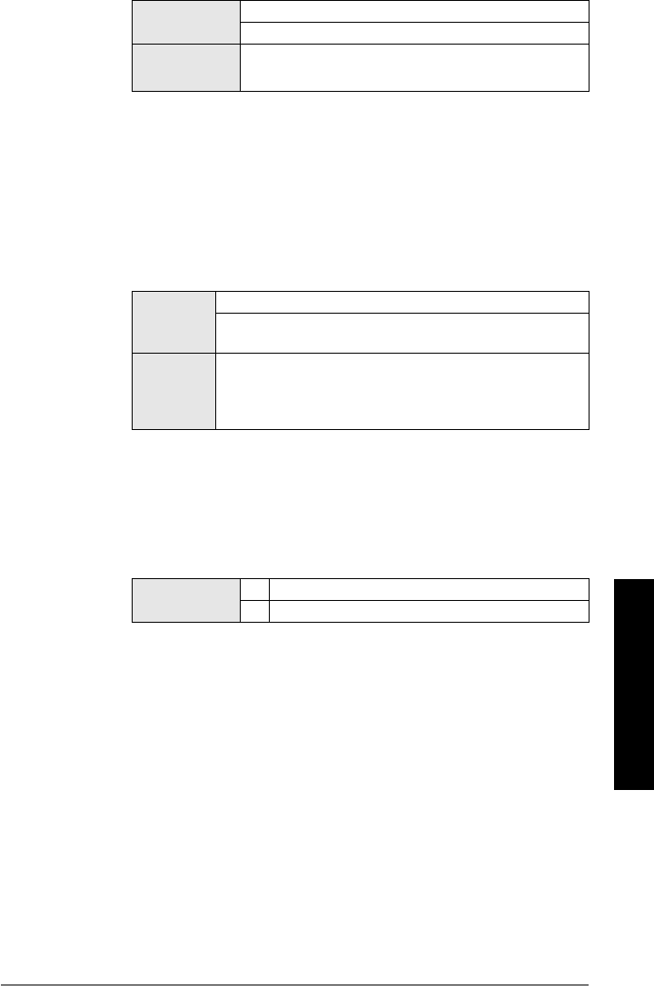
7ML19985JM01 SITRANS LR 460 – INSTRUCTION MANUAL Page 55
mmmmm
Parameters
3.5.2.4. Narrow Echo Filter (default 0)
Filters out echoes of a specific width.
To remove a false echo from the Echo Profile, take its width in mm and
multiply it by 0.014. Enter the result.
For example, to filter out a spike with 500 mm width enter 7 (the sum of 500
x 0.014).
When a value is keyed in, the nearest acceptable value is entered.
3.5.2.5. Reform Echo (default 0)
Smooths jagged peaks in the echo profile. Reforms fragmented echoes
into one echo.
Use this feature when monitoring solids, if the reported level fluctuates
slightly even though the monitored surface is still.
Enter the amount of smoothing required. When a value is keyed in, the
nearest acceptable value is entered.
3.5.2.6. Echo detection position
The point on the selected echo from which the measured value is taken.
3.5.3. Echo Sampling
3.5.3.1. Window.
A "distance window" centered on the echo, used to derive the reading.
When a new measurement is in the window, the window is re-centered
and the reading is calculated .
When the value is 0, the window is automatically calculated after each
measurement.
• For slower Measurement Response values, the window is narrow.
• For faster Measurement Response values, the window becomes
progressively wider.
Values 0 = OFF
greater = wider
Related
Parameters
•
3.6.2.1. Echo Confidence Long
•
3.5.2.5. Reform Echo (default 0)
Values
0 = OFF
Greater = Wider
Recommended range 10 to 20: higher is not recommended.
Related
Parame-
ters
•Material
•
3.5.2.1. Echo Algorithm
•
3.5.2.4. Narrow Echo Filter (default 0)
•
3.5.2.3. Echo Marker
Options * CENTER
RISING
Page 56 SITRANS LR 460 – INSTRUCTION MANUAL 7ML19985JM01
mmmmm
Parameters
3.5.3.2. Window Used
Displays the size of the window used for the previous measurement.
Window used is the closest usable window size, depending on the device
measurement resolution.
For example, if window = 1 m, the window used might be 0.96 m.
3.5.3.3. Shots
The number of echo profile samples averaged to produce a
measurement..
3.5.4. Range
3.5.4.1. Near Range
The range in front of the device (referenced from the flange face) within
which any echoes will be ignored. (This is sometimes referred to as
Blanking or Dead Zone.)
The default setting of 0.6 m avoids a false echo being triggered by
condensation or other material buildup. If no buildup is anticipated (for
example, with dry cement) then the minimum setting 0.35 m can be used.
3.5.4.2. Far Range
Maximum distance from the reference point, within which an echo should
be considered valid.
Values Range: 0.35 to 100 m max.
Default: 0.6 m
Note: Far Range can extend beyond the bottom of the vessel.
Values Range: 0 to 100 m max.
Default: The value of Low Calibration Point plus 20%.
SITRANSLR400
Sensor Reference Point
(flange face)
Low Calibration Point
High Calibration Point
Level
Near Range
Far Range

7ML19985JM01 SITRANS LR 460 – INSTRUCTION MANUAL Page 57
mmmmm
Parameters
3.5.6. TVT (Auto False Echo Suppression) setup
SITRANS LR 460 first learns the echo profile. Then the learned profile, or part of it,
is used to screen out false echoes. (See Auto False-Echo Suppression on page 73
for a more detailed explanation.)
To use Auto False Echo Suppression via SIMATIC PDM:
a. Determine Range (the distance within which the learned TVT will
replace the default TVT). Measure the actual distance from the
antenna reference point to the material surface using a rope or tape
measure, and make allowances for the actual location of the LR 460.
Subtract 2 m (6.56 ft) from this distance, and use the resulting value.
b. Open the menu Device – Auto False Echo Suppression.
c. Enter the value for Range and click Set Range.
d. Click Learn. The On and Off buttons disappear while the new curve
is being learned.
e. When the buttons reappear, click Close. Auto TVT is now on, and the
learned TVT curve will be used.
f. To turn Auto False Echo Suppression off or on, reopen menu Device
– Auto TVT and click On or Off.
To use Auto False Echo Suppression via the handheld programmer:
3.5.6.1. Auto TVT (Auto False Echo Suppression)
a. Go to
3.5.6.2. Range (Auto False Echo Suppression Distance)
step a
and enter the value.
b. Select Learn. The device will automatically revert to On (Use
Learned TVT) after a few seconds.
3.5.6.2. Range (Auto False Echo Suppression Distance)
Defines the endpoint of the Learned TVT distance.
a. Determine the actual distance from the antenna reference point to
the material surface. Use a rope or tape measure, and make
allowances for the actual location of the LR 460. Subtract 2 m (6.56
ft) from this distance, and use the resulting value.
b. Enter the value for Range and press Right Arrow to accept it.
c. Go to
3.5.6.1. Auto TVT (Auto False Echo Suppression)
. step b.
Note: If the Reform parameter has been used to reshape the echo profile, Auto
False Echo Suppression must be re-enabled, to relearn the TVT curve
Values
OFF
ON Enable Auto False Echo Suppression
LEARN "Learn" the TVT curve
Related
parameters •
3.5.2.5. Reform Echo (default 0)
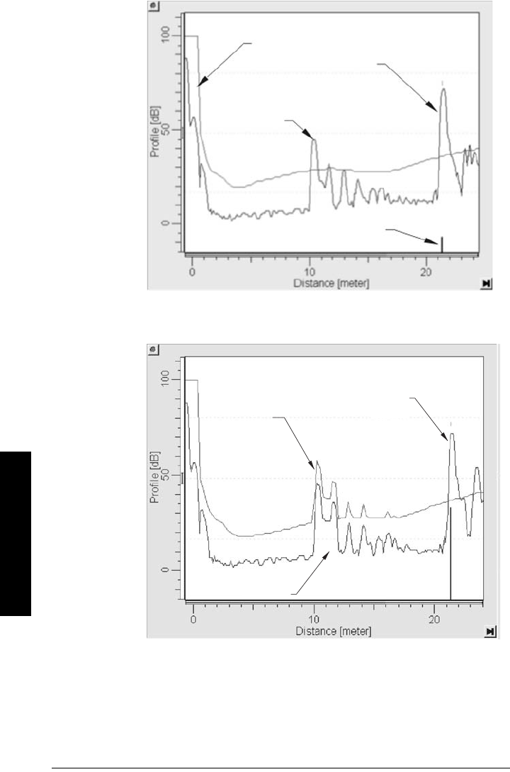
Page 58 SITRANS LR 460 – INSTRUCTION MANUAL 7ML19985JM01
mmmmm
Parameters
Display before Auto False Echo Suppression
default
TVT
Level (db)
Echo Marker
material
surface
false echo
Example after Auto False Echo Suppression
learned TVT
curve
material
surface
false echo
Level (db)

7ML19985JM01 SITRANS LR 460 – INSTRUCTION MANUAL Page 59
mmmmm
Parameters
3.5.6.3. TVT Hover Level
Defines in percent how high the TVT (Time Varying Threshold) curve is
placed above the echo profile, with respect to largest echo.
3.5.6.4. Manual TVT Shaper Mode
Enables the TVT curve to be manually adjusted at a specified range.
3.5.7. Manual TVT shaper
You can manually adjust the TVT curve by entering values for up to 120
breakpoints on the curve.
Use this feature to bias the shape of the TVT curve to avoid selecting false
echoes from fixed objects.
Each breakpoint is normalized to a value of 0. Change the value of the
breakpoints to adjust the curve. In the case of multiple false echoes, shaping can
be applied along different points of the curve. Shaping should be applied
sparingly in order to avoid missing the true echo.
The Manual TVT shaper feature allows you to adjust the TVT curve while viewing
the echo profile.
To change a breakpoint via PDM:
a. Confirm that Shaper Mode is selected.
b. Open the menu Device – TVT Shaper then either adjust the curve manually, or
enter values for the desired breakpoints. (See
Manual TVT Shaper
on page
38.)
To change a breakpoint via the handheld programmer:
a. Confirm that Shaper Mode is selected.
b. Access the submenu for the breakpoint number in question and enter values
for all desired breakpoints.
3.5.7.1. Shaper A (1 - 9).
3.5.7.2. Shaper B (10 - 18)
3.5.7.3. Shaper C (19 - 27)
Values Range: 0 to 100%
Default: 40%
Options ON
*OFF
Values Range: -50 to 50
Preset: 0
Related •
3.5.6.4. Manual TVT Shaper Mode

Page 60 SITRANS LR 460 – INSTRUCTION MANUAL 7ML19985JM01
mmmmm
Parameters
3.5.7.4. Shaper D (28 - 36)
3.5.7.5. Shaper E (37 - 45)
3.5.7.6. Shaper F (46 - 54)
3.5.7.7. Shaper G (55 - 63)
3.5.7.8. Shaper H (64 - 72)
3.5.7.9. Shaper I (73 - 81)
3.5.7.A. Shaper J (82 - 90)
3.5.7.B. Shaper K (91 - 99)
3.5.7.C. Shaper L (100 - 108)
3.5.7.D. Shaper M (109 - 118)
3.5.7.E. Shaper N (119 - 120)
3.5.8. Rate
3.5.8.1. Fill Rate
Defines the maximum rate at which the reported sensor value is allowed
to increase. Allows you to further adjust the LR 460 response to increases
in the actual material level. Fill Rate is automatically updated whenever
Response Rate is altered.
Enter a value slightly greater than the maximum vessel-filling rate, in
Sensor Units per minute.
3.5.8.2. Empty rate
Defines the maximum rate at which the reported sensor value is allowed
to decrease.Adjusts the LR 460 response to decreases in the actual
material level. Empty Rate is automatically updated whenever Response
Rate is altered.
Enter a value slightly greater than the vessel’s maximum emptying rate, in
Sensor Units per minute.
Values Range: 0.0000 to 99999 m / min.
Default: 10.000
Altered by Response Rate
Related Unit (Level)
High Level Point
Values Range: 0.0000 to 99999 m / min.
Default: 10.000
Altered by Response Rate
Related Units (Level)
High Level Point

7ML19985JM01 SITRANS LR 460 – INSTRUCTION MANUAL Page 61
mmmmm
Parameters
3.6. Echo Information
3.6.1. Level Transducer Block (LTB) Values (for diagnostic purposes)
The output from the Level Transducer Block can be called the Primary Value (or
Secondary Value). When it becomes the input to the AIFB, it is called the Process
Variable.
3.6.1.1. Primary Value (PV
)
The default value for level (in level units).
Open the menu View – Display, and select the tab Measured Value
(Secondary Values).
3.6.1.2. Secondary Value 1 (SV1)
Equivalent value to PV (level).
3.6.1.3. Secondary Value 2 (SV2)
The value for distance (in sensor units).
Open the menu View – Display, and select the tab Measured Value
(Secondary Values) and see Sensor Value.
3.6.2. Echo Quality
3.6.2.1. Echo Confidence Long.
Measures echo reliability. It displays the echo confidence of the
measurement echo from the last shot. Confidence Threshold defines the
minimum criterion for echo confidence.
Open the menu View – Echo Profile.
3.6.2.2. Echo Strength
Displays the absolute strength of the echo selected as the measurement
echo.
Open the menu View – Echo Profile.
4. Output
4.1. AIFB1
Static Revision No.
The revision level of the static data associated with Analog Input Function Block 1.
The Static Revision No. is updated whenever a standard profile configuration
parameter is changed.
Values (view only) 0 to 99
---- Shot not used
Related Parameters Confidence Threshold
Values (view only) –20 to 99
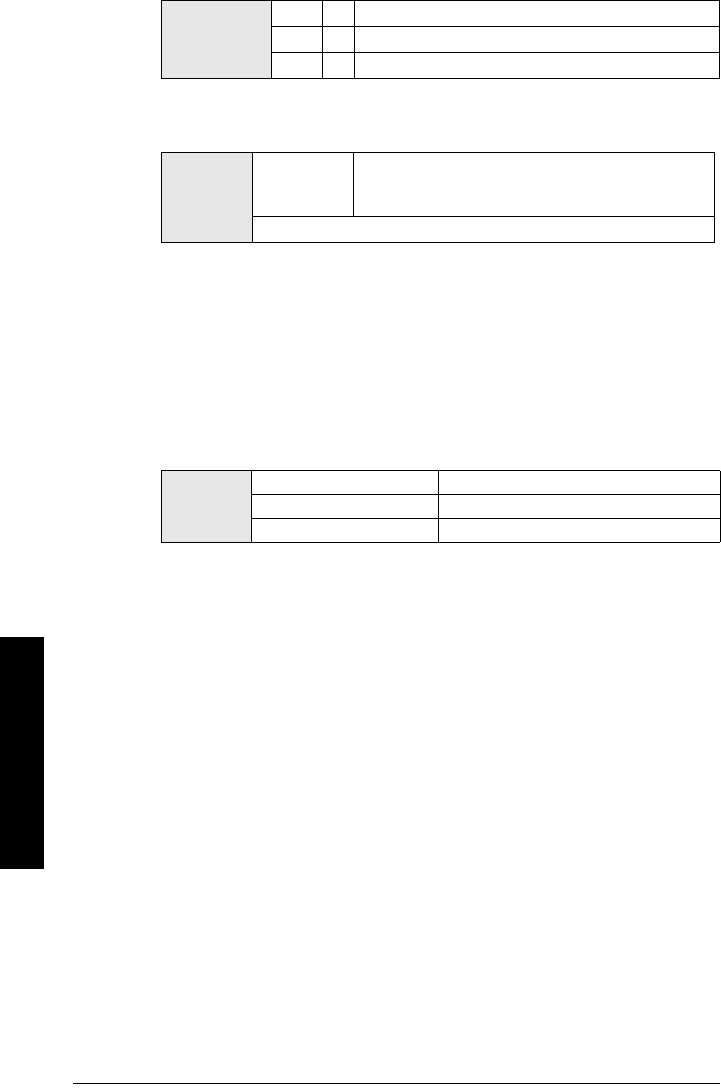
Page 62 SITRANS LR 460 – INSTRUCTION MANUAL 7ML19985JM01
mmmmm
Parameters
4.1.1. Target Mode (PROFIBUS PA only)
Used to request an operating mode from the Function Block.
4.1.2. Unit
Engineering unit to be displayed with the output value.
4.1.3. Filter Time Constant
The time constant for the damping filter. The engineering unit is always in
seconds. (This is an exponential filter: when a change occurs at the input, the
output will be at 63.2% of the change in one time constant, and will be at full
change after 5 time constants.)
4.1.4. Function
Used to select between the different level block outputs: Level, or Distance. (See
Level Transducer Block function groups
on page 100 for an illustration.)
4.1.5. Batch Information (PROFIBUS PA only)
These 4 parameters are intended to be used in Batch Applications conforming to
IEC 61512 Part 1 (ISA S88). Other applications do not require these values, which
are only stored in the Function Block.
4.1.5.1. Batch ID.
Identifies a certain batch to allow assignment of equipment-
related information (for example faults, alarms) to the batch.
4.1.5.2. Batch Unit
Identifies the active Control Recipe Unit Procedure or the related Unit (for
example, reactor, centrifuge, drier).
4.1.5.3. Batch operation
Identifies the active Control Recipe Operation.
4.1.5.4. Batch Phase
Identifies the active Control Recipe Phase.
Values
128 Out of Service (O/S)
16 Manual Mode (MAN)
8*
Automatic Mode (AUTO)
Options
percent
user--defined
linear
%
text
m, cm, mm, ft, in
default: m
Options
PV/Primary Value Level
SV1/Secondary Value 1 Level
SV2/ Secondary Value 2 Distance (value in sensor units)

7ML19985JM01 SITRANS LR 460 – INSTRUCTION MANUAL Page 63
mmmmm
Parameters
4.1.6. Process Value Scale
4.1.6.1. Lower Value .
Defines the operational lower range value of the input
value (Process Value Scale) in engineering units. Process Value Scale
normalizes the input value to a customer-defined range.
4.1.6.2. Upper Value
Defines the operational upper range value of the input value (Process
Value Scale) in engineering units. Process Value Scale normalizes the
input value to a customer-defined range.
4.1.7. Output Scale
Scales the Process Variable. The function block parameter OUT SCALE
contains the values of the lower limit and upper limit effective range.
4.1.7.1. Lower Value
Defines the operational lower range value of the output
value in engineering units.
4.1.7.2. Upper Value
Defines the operational upper range value of the output value in
engineering units.
4.1.8. Output Limits
4.1.8.1. Lower Limit Alarm
The setting for the lower alarm limit in engineering
units.
4.1.8.2. Lower Limit Warning
The setting for the lower warning limit in engineering units.
4.1.8.3. Upper Limit Warning
The setting for the upper warning limit in engineering units.
4.1.8.4. Upper Limit Alarm
The setting for the upper alarm limit in engineering units
0
1
2
3
4
5
6
12345
Process Value Scale (typical
Input (0 to 100%)
Output Scale
Out (AIFB1 or AIFB2 Out)

Page 64 SITRANS LR 460 – INSTRUCTION MANUAL 7ML19985JM01
mmmmm
Parameters
4.1.8.5. Limit Hysteresis
Hysteresis is used to adjust the sensitivity of the trigger for alarm
messages. It is used to compensate when a process variable fluctuates
around the same value as a limit. A high level alarm occurs when a value
exceeds an upper limit. The alarm’s status remains true until the value
drops below the limit minus the alarm hysteresis. The directions are
reversed for low limit detection.
Enter a value for the hysteresis here, to be used for all warnings and
alarms. The units are the same as the output value scale.
4.1.8.6. Min Out
Min Out is a minimum peak indicator for the AIFB output values.
4.1.8.7. Max Out
Max Out is a maximum peak indicator for the AIFB output values.
4.1.9. Fail-safe Mode (PROFIBUS PA only)
4.1.9.1. Fail-safe Mode.
Fail-safe Mode occurs if the status of the input value is bad, or if the device
has been put into Fail-safe mode using Simulation. One of three options
can be selected for the material level to be reported when the LOE timer
expires.
4.1.9.2. Fail-safe Value
(Accessible in PDM only after FS VALUE is selected in Fail-safe Mode).
User-defined default value for the OUT parameter, if sensor or sensor
electronic fault is detected. Units are the same as the OUT value.
4.1.A. Human Interface
4.1.A.1. Decimal Point
The number of digits to display after the decimal point. (The LCD is limited
to displaying three decimal places.)
Out unit text
If the code list does not contain a desired unit for the OUT parameter, (see
General Requirement) you can write the specific text in this parameter.
Handheld
programmer
Options
Material level to be reported
FS VALUE Default value used as output value.
LAST VAL * Store last valid output value.
USE BAD Calculated output value is incorrect.
Values Range:
Default: 0.000
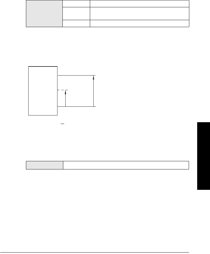
7ML19985JM01 SITRANS LR 460 – INSTRUCTION MANUAL Page 65
mmmmm
Parameters
4.2. AIFB2
(See AIFB1: the parameters for AIFB2 are identical.)
4.3. mA Output
The mA output is provided by Analog Input Function Block 2 (AIFB2). You can enter
a user-defined mA value, either for simulation, or to perform a mA Trim.
To set these parameters via PDM, see
Simulate AO (Analog Output)
on page 42
or
D/A (Digital/Analog) Trim
on page 42.
4.3.1. Function
Allows you to set the mA output to one of three options including a user-defined
value.
To set the mA output via PDM, open the menu Device – Simulate AO.
4.3.2. Out value
A mA value derived from the ratio of current level to the range between Lower
Value and Upper Value.
4.3.3. Man Value
A user-defined mA value which can be used either for simulation, or to do a digital/
analog trim.
To set the mA Output via PDM, open the menu Device – Simulate AO and select
an option.
Handheld
programmer
values
AUTO Uses the current measured value.
FIXED The current can be set by the HART master only.
HART default is 4 mA.
MANUAL Uses a user-defined value input in
4.3.3. Man Value
.
Values Range: 3.8 to 20.5 mA.
Analog
Input
Function
Block 1
Lower Value = 4 mA
(
4.1.7. Output Scale
)
Upper Value = 20 mA
(
4.1.7. Output Scale
)
y
x
mA OUT value = x x 16 mA + 4
y
measured
value

Page 66 SITRANS LR 460 – INSTRUCTION MANUAL 7ML19985JM01
mmmmm
Parameters
4.3.4. Min Limit
The mA value to correspond with 4.1.7.1. Lower Value .
4.3.5. Max Limit
The mA value to correspond with 4.1.7.2. Upper Value .
4.3.6. FS Mode
The mA value to be output in the event of a fault or failure.
4.3.7. FS Value
A user-defined mA value to be reported when the Fail-safe timer expires.
4.3.8. 4 mA Trim
Calibrates the 4 mA output.
a. Set
4.3.1. Function
to MANUAL mode.
b. Set
4.3.3. Man Value
to 4 mA.
c. Attach a calibrated meter and check the output at the terminals. Record the
remote reading in mA.
d. Enter the recorded value in
4.3.8. 4 mA Trim
.
e. Restore
4.3.1. Function
to its previous setting.
f. Confirm that the mA output is as expected.
Values Range:
Default: 3.8 mA
Values Range:
Default: 20.5 mA
Options
mA HOLD * Level remains at last reading.
mA SET User-defined value set in
4.3.7. FS Value
mA HIGH Use Max Limit as material level.
mA LOW Use Min Limit as material level.
Values Range: 3.5 to 20.5 mA
Default: 3.5 mA
Values Range: 2.0 to 6.0 mA
Related parame-
ters
4.3.1. Function
A mA value derived from the ratio of current level to the range
between Lower Value and Upper Value.

7ML19985JM01 SITRANS LR 460 – INSTRUCTION MANUAL Page 67
mmmmm
Parameters
4.3.9. 20 mA Trim
Calibrates the 20 mA output.
a. Set
4.3.1. Function
to MANUAL mode.
b. Set
4.3.3. Man Value
to 20 mA.
c. Attach a calibrated meter and check the output at the terminals. Record the
remote reading in mA.
d. Enter the recorded value in
4.3.9. 20 mA Trim
.
e. Restore
4.3.1. Function
to its previous setting.
f. Confirm that the mA output is as expected.
4.4. Relay Configuration
4.4.1. AIFB
Select AIFB1 or AIFB2.
4.4.2. Function
4.4.3. NC/NO
4.4.4. State
Certificates and Approvals
Device Certification
Values Range: 18 to 24 mA
Related parame-
ters
4.3.1. Function
A mA value derived from the ratio of current level to the range
between Lower Value and Upper Value.
Handheld
programmer
Options
DISABLED *
MANUAL
LO ALM
HI ALM
ANY ALM
FAIL-SAFE
Handheld programmer
options
NO * Normally Open
NC Normally Closed
Handheld programmer
options
OFF * Relay de-energized
ON Relay energized

Page 68 SITRANS LR 460 – INSTRUCTION MANUAL 7ML19985JM01
mmmmm
Parameters
6. Maintenance settings
Use these parameters to set up schedules for calibration and maintenance. The device
will track itself based on operating hours, instead of a calendar-based schedule, and will
monitor its predicted lifetime.
The maintenance warnings and alarms are communicated to the end user through either
the status or condensed status bytes. This information can be integrated into any Asset
Management system. For optimal use, we recommend that you use SIMATIC PCS7 Asset
Management Software in conjunction with SIMATIC PDM.
6.1. Remaining Device Lifetime
The device tries to predict its overall lifetime. A factory default can be reset by the user.
6.1.1. Total Device Operating Time
6.1.2. Remaining Device Lifetime
6.1.3. Maintenance Required Limit
6.1.4. Maintenance Demanded Limit
6.1.5. Maintenance Alert Activation
6.1.6. Total Expected Device Life
6.1.7. Maintenance Status
6.1.8. Acknowledge Status
6.1.9. Acknowledge
6.2. Remaining Sensor Lifetime
The device monitors the predicted lifetime of the sensor (the components exposed to the
vessel environment). A factory default can be reset by the user.
6.2.1. Total Sensor Operating Time
6.2.2. Remaining Sensor Lifetime
6.2.3. Maintenance Required Limit
6.2.4. Maintenance Demanded Limit
6.2.5. Maintenance Alert Activation

7ML19985JM01 SITRANS LR 460 – INSTRUCTION MANUAL Page 69
mmmmm
Parameters
6.2.6. Total Expected Sensor Life
6.2.7. Maintenance Status
6.2.8. Acknowledge Status
6.2.9. Acknowledge
6.3. Service Interval
The device monitors the time it has been in service, and when additional service may be
required. A factory default can be reset by the user.
6.3.1. Time Elapsed Since Last Service
6.3.2. Maintenance Required Limit
6.3.3. Maintenance Demanded Limit
6.3.4. Maintenance Alert Activation
6.3.5. Total Service Interval
6.3.6. Maintenance Status
6.3.7. Acknowledge Status
6.3.8. Acknowledge
6.4. Calibration Interval
The device monitors the time since it was last calibrated, and when additional calibration
may be required. A factory default can be reset by the user.
6.4.1. Time Elapsed Since Last Calibration
6.4.2. Maintenance Required Limit
6.4.3. Maintenance Demanded Limit
6.4.4. Maintenance Alert Activation
6.4.5. Total Calibration Interval
6.4.6. Maintenance Status
6.4.7. Acknowledge Status
6.4.8. Acknowledge

Page 70 SITRANS LR 460 – INSTRUCTION MANUAL 7ML19985JM01
mmmmm
Parameters
Notes

7ML19985JM01 SITRANS LR 460 – INSTRUCTION MANUAL Page A-71
mmmmm
A: Technical Reference
Appendix A: Technical Reference
Principles of Operation
SITRANS LR 460 is a long range FMCW (Frequency Modulated Continuous Wave) radar
transmitter. Radar level measurement uses the time of flight principle to determine
distance to a material surface.
FMCW radar transmits a continuous wave. The frequency of the wave is constantly
increasing: this is known as the sweep. By the time the first part of the wave has been
reflected off the target and returned to the device, the part of the wave that is just being
emitted is at a higher frequency. The difference in frequency between the transmitted and
received signals is proportional to time of flight.
Electromagnetic wave propagation is virtually unaffected by temperature or pressure
changes, or by changes in the vapor or dust levels inside a vessel.
SITRANS LR 460 consists of an enclosed electronic component coupled to an antenna
and process connection. The electronic component generates an electromagnetic signal
from 24.2 GHz to 25.2 GHz that is directed to the antenna.
The signal is emitted from the antenna, and the reflected echoes are digitally converted
to an echo profile. The profile is analyzed to determine the distance from the material
surface to the reference point on the instrument. This distance is used as a basis for the
display of material level and output.
Measurement Response
The measurement response (response rate) limits the maximum rate at which the
display and output respond to changes in the measurement. Once the real process fill/
empty rate (m/s) is established, a response rate can be selected that is slightly higher
than the application rate. The response rate automatically adjusts the filters that affect
the output response rate.
There are three preset options: slow, medium, and fast.
If none of the preset options is satisfactory, the filters can be adjusted individually.
Related
Parameters
Response
Rate
LOE Timer
(minutes) Fill Rate Empty Rate
Values
1* slow 100 0.1 m/minute 0.1 m/minute
2medium 10 1 m/minute 1 m/minute
3fast 110 m/minute 10 m/minute
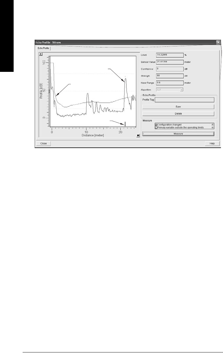
Page A-72 SITRANS LR 460 – INSTRUCTION MANUAL 7ML19985JM01
mmmmm
A: Technical Reference
Echo Processing
Profile monitoring via SIMATIC PDM
To view an echo profile open the menu View – Profile.
You will see the echo profile, the Time Varying Threshold (TVT), and a vertical line
indicating the distance from the sensor to the echo selected.
Echo strength is indicated on the Profile (dB) vertical axis. The distance shown on the
horizontal axis is the distance from the sensor to the target.
Time Varying Threshold (TVT)
The TVT is a threshold curve used to detect the presence of significant echoes. See
Auto
False-Echo Suppression
on page 73 for more detail.
Echo selection
The device considers all peaks that are above the TVT as a potential good echo.
Each peak gets a rating based on its strength, area, height above the TVT, and other
parameters. The true echo is selected based on the setting for
Echo Algorithm
on page 54.
echo profile
echo distance
TVT curve

7ML19985JM01 SITRANS LR 460 – INSTRUCTION MANUAL Page A-73
mmmmm
A: Technical Reference
False Echoes
False echoes can appear during the receive cycle. They can be caused by interference
with the emission cone, or by internal impediments like a ladder rung, and are usually
indicated by an incorrect high level reading.
Beam angle at –3dB reference
Make allowance for the beam
spreading, to avoid interference
with the emission cone.
Polarization reference point
You can rotate the device to minimize false echoes. See
Polarization Reference Point
on
page 14 for details.
Auto False-Echo Suppression
The TVT adjustment parameters allow you to manipulate the TVT (Time Varying
Threshold), so that SITRANS LR 460 will ignore false echoes.
The default TVT hovers above the echo profile, and effectively screens out small false
echoes. But if an obstruction is causing a large echo before the material level echo, that
echo will rise above the default TVT.
1. Set Auto False-Echo Suppression to Learn. The instrument learns the echo profile at
that moment1. The new TVT follows the echo profile, so that nothing rises above it.
2. Set Auto False Echo Suppression Distance so that the learned TVT will be used in
the area of the false echoes, which will not rise above it. From that point on the
default TVT will be used. The material level echo rises above this, and is selected as
the true echo.
See page 58 for examples of the echo profile before and after using Auto False-Echo
Suppression.
Note: If possible, rotate the instrument before using Auto False-Echo Suppression, to
lower the amplitude of false echoes.
1. Set Auto False-Echo Suppression to Learn when the material level is substantially lower than
process full level (ideally when the vessel is empty or almost empty).
3" horn 4" horn
11°
emission
cone
reference
point
8°
distance to
target

Page A-74 SITRANS LR 460 – INSTRUCTION MANUAL 7ML19985JM01
mmmmm
A: Technical Reference
Near Range (Blanking)
Near Range allows you to set a distance in front of the antenna, within which any echoes
will be ignored.
Echo confidence
Echo confidence is an internally generated numeric rating given to an echo based on its
relative strength, area, and height.
Loss of Echo (LOE)
A loss of echo (LOE) occurs when the calculated measurement is judged to be unreliable
because the echo confidence value has dropped below the echo confidence threshold.
The LOE timer starts running, and if the LOE condition persists beyond ten minutes (the
time limit set by the LOE timer) the Unreliable Echo indicator replaces the Reliable Echo
indicator.
Reliable Echo indicator Unreliable Echo indicator
While LOE is pending the x flashes, alternating with the two horizontal bars. When LOE
becomes active, the x becomes solid and the auxiliary display shows fault code S: 0.
Upon receiving a reliable echo, the loss of echo condition is aborted, the Reliable Echo
indicator reappears, and the reading returns to the current level.
LOE Timer
The LOE timer determines the time (in minutes) to elapse after the last valid reading
before Fail-safe mode is activated. When the LOE timer expires, the material level to be
reported is determined by Fail-safe Mode.
Fail-safe Mode
Fail-safe mode defines the reaction of the device if a Fail-safe condition is detected, so
that the process will be put into a safe state in the event of a fault or failure. The
particular application determines whether a high or low level is safe.
Note: Auto False-Echo Suppression is generally recommended in preference to using
Near Range.

7ML19985JM01 SITRANS LR 460 – INSTRUCTION MANUAL Page A-75
mmmmm
A: Technical Reference
The Fail-safe condition may be triggered by a loss of echo, a bad configuration, or certain
device faults. You can select one of three possible values to be reported when a Fail-safe
mode occurs:
• User-defined default value (Fail-safe value) used as output value.
• Store last valid output value.
• Calculated output value is incorrect.
Fail-safe value
The user-defined Fail-safe value allows you to enter the safest output value for your
application.
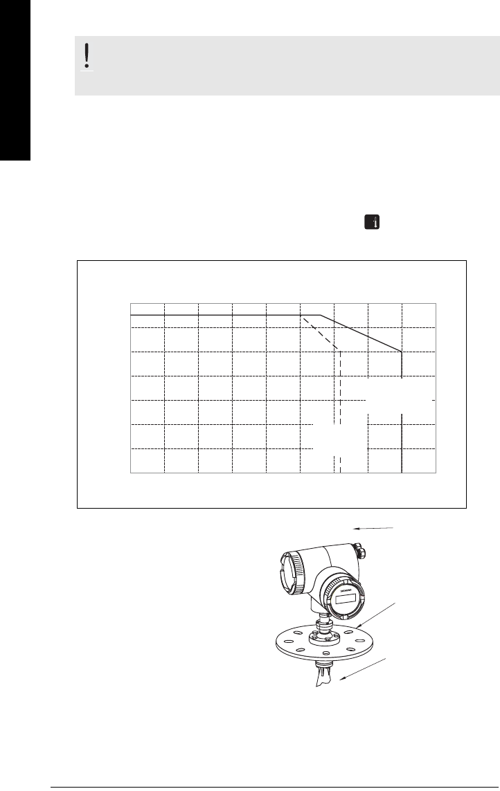
Page A-76 SITRANS LR 460 – INSTRUCTION MANUAL 7ML19985JM01
mmmmm
A: Technical Reference
Maximum Process Temperature Chart
To check maximum and minimum temperatures recorded via SIMATIC PDM, open the menu
View – Peak Values, and click on the temperature tab. The peak temperatures indicate the extent
of change required to the installation in order to provide a reliable thermal-operating zone for
SITRANS LR 460.
• For example, if the internal temperature exceeds the maximum allowable limit, a
sun shield or a longer nozzle may be required.
To check temperature peaks via the handheld programmer, press (#6) to view internal
temperature on the LCD secondary display.
.
Where the chart does not apply, please use your own judgement regarding the use of
SITRANS LR 460.
WARNING: Internal temperature must not exceed 85 oC (185 oF).
Note: The chart below is for guidance only.
6
Maximum Flange and Process Temperatures versus Allowable Ambient
for SITRANS LR 460
max.
flange
temperature
max.
process
temperature
Ambient Temperature (oC)
Flange and Process Surface Temperatures (oC)
050
60
100 200150
40
20
0
• The chart above is provided for
guidance only.
• It does not represent every possible
process connection arrangement.
• It does not take into consideration
heating from direct sunshine
exposure.
ambient
temperature
process temperature
flange
temperature

7ML19985JM01 SITRANS LR 460 – INSTRUCTION MANUAL Page B-77
mmmmm
B: Troubleshooting
Appendix B: Troubleshooting
1. Check the following:
• There is power at the instrument.
• The LCD shows the relevant data.
• Check whether any fault codes are being displayed (see
General Fault Codes/
PROFIBUS PA Extended Diagnostics
on page 80 for a detailed list).
• The device can be programmed using the handheld programmer.
2. Verify that the wiring connections are correct.
3. Check the HART (or PROFIBUS) address and make sure all devices are at unique
HART (or PROFIBUS) addresses.
4. If you continue to experience problems, go to our website at:
www.siemens.com/processautomation, and check the FAQs for SITRANS LR 460, or
contact your Siemens Milltronics representative.
Troubleshooting LR 460
Symptom Possible cause Remedy
LR 460 reads
100%
continuously
False echo near antenna.
Move LR 460 to better location.
Rotate LR 460 to change polarization
field.
Shorten vessel nozzle to allow antenna
to project into vessel.
Aim LR 460 away from false echo.
Antenna buildup.
Clean antenna.
Install PTFE dust cover.
Use Air Purge option.
Reading is
frozen
Antenna buildup.
Clean antenna.
Install PTFE dust cover.
Use Air Purge option.
Low dK and low bulk
density material. Lower echo confidence threshold.

Page B-78 SITRANS LR 460 – INSTRUCTION MANUAL 7ML19985JM01
mmmmm
B: Troubleshooting
Reads empty
when vessel not
empty.
Reads vessel bottom
through low dK material.
Increase TVT manually at vessel bottom
region.
Set Far Range to a lower value.
Lower TVT hover level.
Reading
fluctuates.
Due to solids’ sloped
surfaces some fluctuation
is normal.
Reduce response rate.
Decrease fill/empty parameter values.
Increase filter time constant in AIFB.
Echo has double
peak/is split Increase Echo Reform.
Reading is too
slow and lags
behind actual
level change.
Increase response rate.
Turn off Window tracking.
Change fill/empty rate parameter
values.
Increase filter time constant in AIFB.
Device cannot
be programmed
via the
handheld
programmer
Make sure local operation is enabled.
See
Local Operation Enable
on page 49.
Also make sure that Write Locking is
Off. See
Write Locking
on page 49.
You are unable
to modify a
parameter via
remote
communications
Make sure remote operation is
enabled. See
Remote operation enable
(REMLOCK)
on page 46. Also make sure
that Write Locking is Off. See
Write
Locking
on page 49.
Troubleshooting LR 460 (cont’d)
Symptom Possible cause Remedy

7ML19985JM01 SITRANS LR 460 – INSTRUCTION MANUAL Page B-79
mmmmm
B: Troubleshooting
The PLC value
equals the
display value,
but does not
correspond to
actual material
level.
• scaling in AIFB1 is
incorrect
• High Calibration Point is
incorrectly entered
• the wrong echo is being
selected
• Adjust scaling in AIFB
• Correct High Calibration Point setting
The PLC value is
not equal to the
displayed value
(regardless of
actual material
level).
• You may not be looking
at the right spot in the
PLC
•You may have
programmed scaling
into the PLC, instead of
leaving all scaling to be
performed in the LR 460.
• The PLC may not be
communicating with the
LR 460.
• Check the network to verify that you
are communicating.
Troubleshooting LR 460 (cont’d)
Symptom Possible cause Remedy

Page B-80 SITRANS LR 460 – INSTRUCTION MANUAL 7ML19985JM01
mmmmm
B: Troubleshooting
General Fault Codes/PROFIBUS PA Extended
Diagnostics
Note: Some faults cause the device to go to Fail-safe mode. These are indicated with
an asterisk (*).
LCD
display Meaning Corrective Action Byte Bit
S:0 *
Loss of Echo (LOE) condition:
the device was unable to get
a measurement within the
Fail-safe timer period.
Possible causes: faulty
installation, material buildup,
and/or presence of foam.
Ensure installation details
are correct. Ensure no
material buildup. Adjust
process conditions to
minimize foaming. If problem
persists, contact your local
Siemens representative.
0
0
S:2 *Internal electronics failure.
Reset power. If fault persists,
contact your local Siemens
representative: repair
required.
2
S:3
Device is nearing its lifetime
limit according to the value
set in Maintenance Required
Limit.
Replacement is
recommended. 3
S:4
Device is nearing its lifetime
limit according to the value
set in Maintenance
Demanded Limit.
Replacement is
recommended. 4
S:6
Sensor is nearing its lifetime
limit according to the value
set in Maintenance Required
Limit.
Replacement is
recommended. 6
S:7
Sensor is nearing its lifetime
limit according to the value
set in Maintenance
Demanded Limit.
Replacement is
recommended. 7

7ML19985JM01 SITRANS LR 460 – INSTRUCTION MANUAL Page B-81
mmmmm
B: Troubleshooting
S:8
Service interval as defined in
Maintenance Required Limit
has expired.
Perform service.
1
0
S:9
Service interval as defined in
Maintenance Demanded
Limit has expired.
Perform service.
1
S:10
Input parameters High
Calibration Point and Low
Calibration Point are the
same.
Check calibration settings of
device. Ensure settings for
High Calibration Point and
Low Calibration Point are
different.
3
S:11 Internal temperature sensor
failure.
Return the device to the
factory. 4
S:12 *
Internal temperature of the
device has exceeded
specifications: it is operating
outside its temperature
range.
Lower the ambient
temperature enough to cool
the device.
Fault code will persist until a
manual reset is performed
using PDM or the LCD
interface.
5
S:14 *
Upper and lower input values
(Process Value Scale) for
AIFB1 are the same.
Check configuration for
AIFB1. Ensure that Upper
Value and Lower Value
(Process Value Scale) are not
the same.
6
S:15
Upper and lower input values
(Process Value Scale) for
AIFB2 are the same.
Check configuration for
AIFB2. Ensure that Upper
Value and Lower Value
(Process Value Scale) are not
the same.
7
LCD
display Meaning (cont’d) Corrective Action Byte
(cont’d) Bit

Page B-82 SITRANS LR 460 – INSTRUCTION MANUAL 7ML19985JM01
mmmmm
B: Troubleshooting
S: 17
Calibration interval as
defined in Maintenance
Required Limit has expired.
Perform calibration.
2
1
S: 18
Calibration interval as
defined in Maintenance
Demanded Limit has expired.
Perform calibration. 2
S:28 Internal device failure caused
by a memory error.
Repair required: contact your
local Siemens
representative.
3
4
S:29 EEPROM damaged.
Repair required: contact your
local Siemens
representative.
5
S:30 EEPROM corrupt.
Reset power. If error persists,
contact your local Siemens
representative.
6
S:31 Flash error.
Repair required: contact your
local Siemens
representative.
7
S: 32
The IDENT number used in
communications, and number
selected by the Ident Number
Selector do not correspond.
Ensure value of the Ident
number selector is correct
for the network
configuration. If it is correct,
the device needs to be re-
parameterized by the PLC. 4
0
S:33
Factory calibration for the
internal temperature sensor
has been lost.
Repair required: contact your
local Siemens
representative.
1
LCD
display Meaning (cont’d) Corrective Action Byte
(cont’d) Bit

7ML19985JM01 SITRANS LR 460 – INSTRUCTION MANUAL Page B-83
mmmmm
B: Troubleshooting
S:34 * Factory calibration for the
device has been lost.
Repair required: contact your
local Siemens
representative.
4
2
S:35 * Factory calibration for the
device has been lost.
Repair required: contact your
local Siemens
representative.
3
S:36 * Unable to start microwave
module.
Reset power. If error persists,
contact your local Siemens
representative.
4
S:37 * Unable to collect profile.
Repair required: contact your
local Siemens
representative.
5
S:38 *
Microwave module hardware
failure: unable to calculate
distance measurement.
Repair required: contact your
local Siemens
representative.
6
S:51
The mA calibration was not
retrieved from EEPROM and
is corrupt.
Perform a current trim to
calibrate the 4 mA and 20 mA
points.
14 3
LCD
display Meaning (cont’d) Corrective Action Byte
(cont’d) Bit

Page C-84 SITRANS LR 460 – INSTRUCTION MANUAL 7ML19985JM01
mmmmm
C: Maintenance
Appendix C: Maintenance
SITRANS LR 460 requires no maintenance or cleaning under normal operating conditions.
Under severe operating conditions, the antenna may require periodic cleaning. If
cleaning becomes necessary:
• We recommend using high pressure air to clean the antenna.
• The inside of the horn can be scraped, but be very careful not to damage the
small PTFE emitter inside the horn.
Unit Repair and Excluded Liability
All changes and repairs must be done by qualified personnel, and applicable safety
regulations must be followed. Please note the following:
• The user is responsible for all changes and repairs made to the device.
• All new components must be provided by Siemens Milltronics Process Instruments
Inc.
• Restrict repair to faulty components only.
• Do not re-use faulty components.
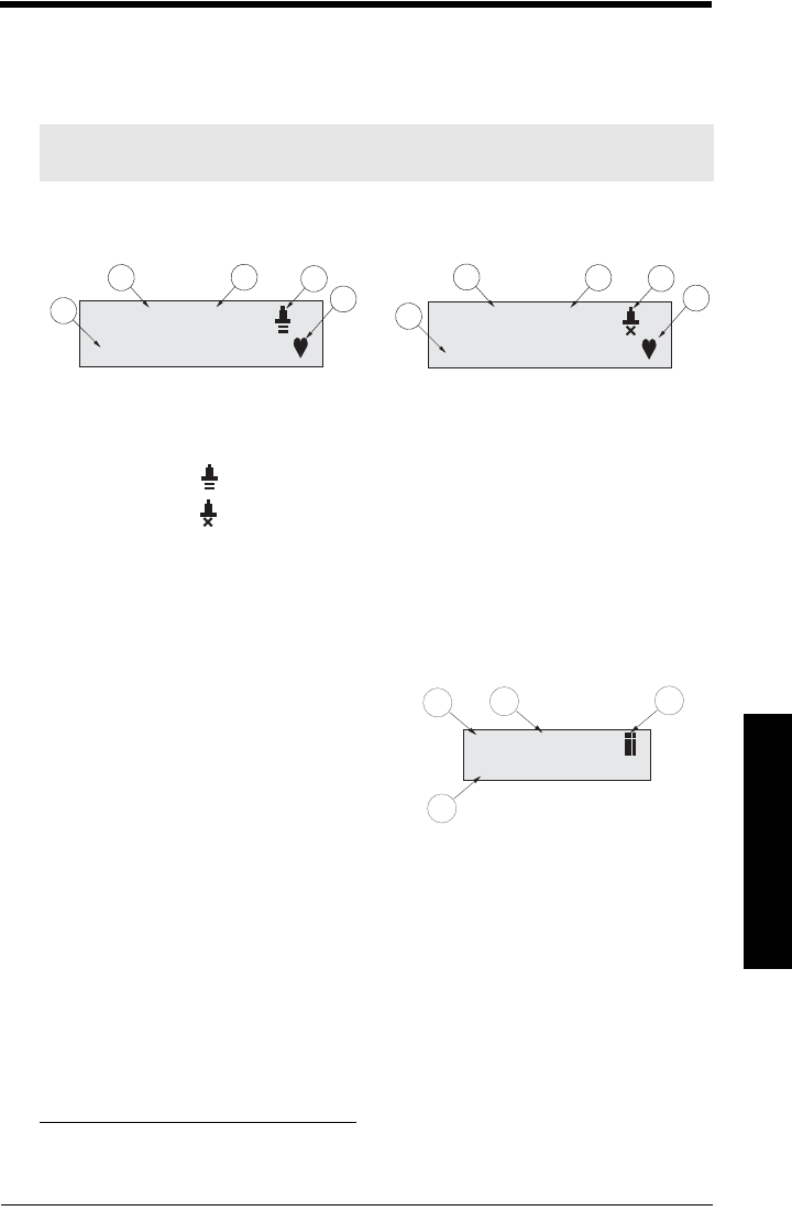
7ML19985JM01 SITRANS LR 460 (HART) – INSTRUCTION MANUAL Page D-85
mmmmm
D: Local Interface
Appendix D: Local Operation Interface
The LCD Display
RUN mode (startup display)
1 – Primary display: level, space, or distance
2 – Units: for Primary Value (m, cm, mm, ft, in, or percent) if applicable
3 – Echo status indicator:
Reliable Echo: visible during normal operation.
Unreliable Echo: If LOE is pending1 the x flashes, alternating with the two
horizontal bars.
When LOE becomes active, the x becomes solid and the
auxiliary display shows fault code S: 0.
4 – Heartbeat: a small heart-shaped icon flashes on and off once per second.
5 – Auxiliary display2: distance, mA value (HART only), confidence, or temperature.
PROGRAM Mode Display
1 – Menu level
2 – Parameter name
3 – Edit Mode indicator/PROGRAM icon
4 – Value of current parameter
Note: SITRANS LR 460 continues to monitor In and Out values even when the device is
in PROGRAM mode.
1. See
LOE Timer
on page 74 for details.
2. Appears in response to request via Siemens Milltronics handheld programmer
98.82
3.800 mA
m
98.82
S: 0
m
Normal operation
13
4
2
LOE condition
5
3
4
2
5
1
1.3.1
0.01.18
SOFT REV
123
4
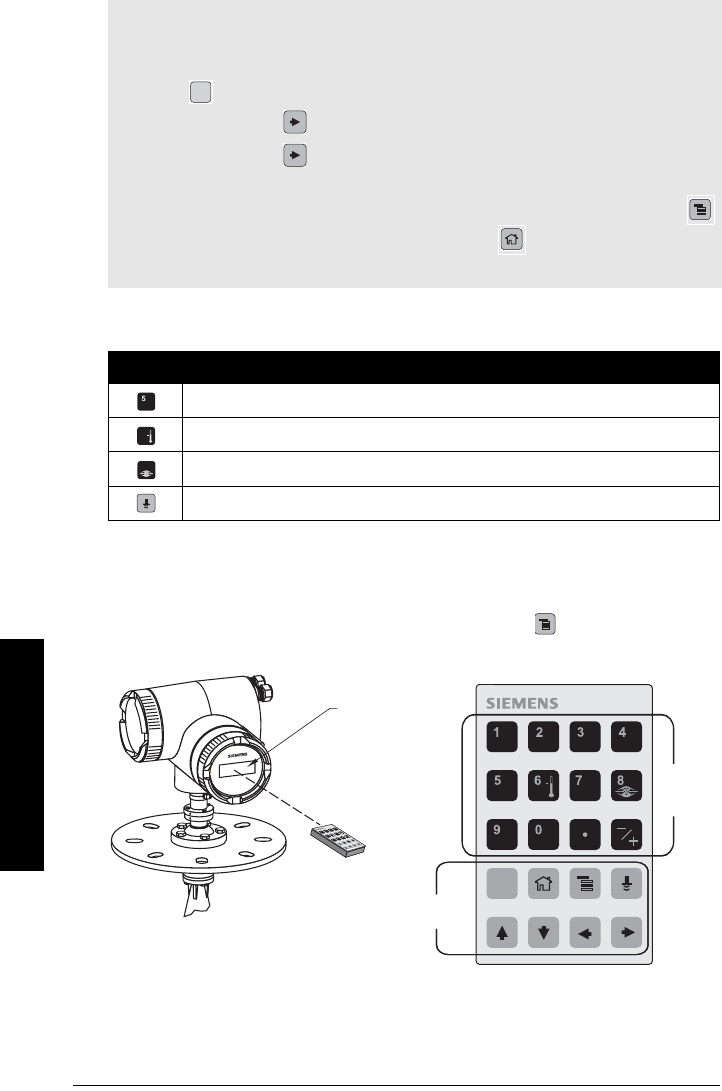
Page D-86 SITRANS LR 460 (HART) – INSTRUCTION MANUAL 7ML19985JM01
mmmmm
D: Local Interface
The handheld programmer
Hand-held programmer: key functions in RUN mode
PROGRAMMING via the handheld programmer
To activate PROGRAM mode, point the handheld programmer at the display (from a
maximum distance of 600 mm [2 ft.]), and press the Mode key .
Notes:
• Local programming must be enabled, to allow changes (see
Local Operation Enable
on page 49).
•CLEAR can be used to clear the field.
• Press Right ARROW to open Edit mode: the PROGRAM icon flashes.
• Press Right ARROW again to accept the value and cancel Edit mode: the final
digit of the Menu number flashes (the Edit mode icon is not visible).
• For Quick Access to parameters via the handheld programmer, press Mode key
to activate PROGRAM mode, followed by Home key , then enter the menu
number (see
LCD menu structure
on page 113 for details).
Key Function
Updates mA value (HART version only)
Updates internal enclosure temperature value and displays it in LCD auxiliary region.
Updates echo confidence value and displays it in LCD auxiliary region.
Updates measurement value and displays it in LCD auxiliary region.
C
6
8
C
number
keys
handheld
programmer
max. 600 mm
(2 ft)
function
keys
display
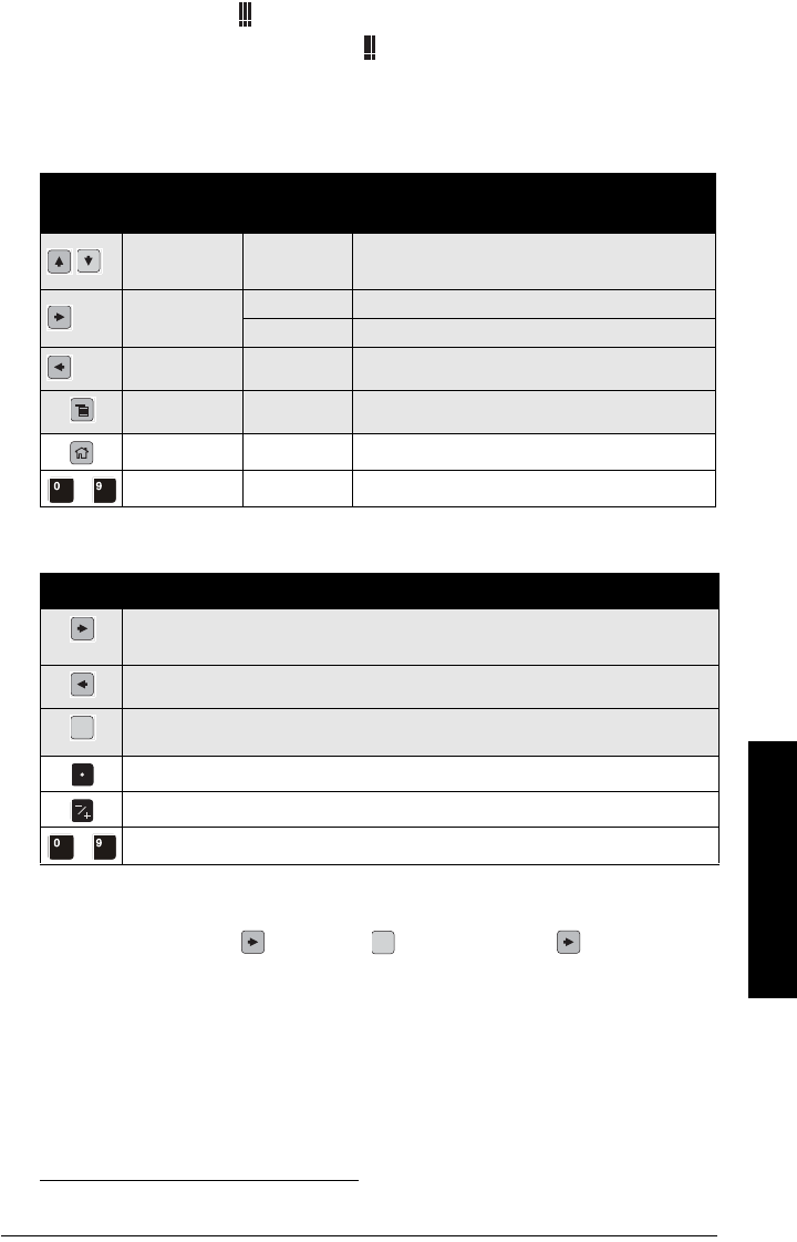
7ML19985JM01 SITRANS LR 460 (HART) – INSTRUCTION MANUAL Page D-87
mmmmm
D: Local Interface
• In Navigation mode the rightmost digit of the menu number flashes and the
PROGRAM icon is not visible.
• In Edit Mode the PROGRAM icon appears and flashes: press a number key to
enter parameter data.1
Hand-held programmer: key functions in Navigation mode
Hand-held programmer: key functions in Edit mode
Individual Parameter Reset
1. Press Right ARROW , then CLEAR , then Right ARROW .
2. The value returns to the default factory setting.
1. For example, press 3 to move to the third item in the current menu.
Key Name When
displaying: Navigation Mode
Up/down arrow menu or item Show previous or next menu or item.
Right arrow menu Show first item in the selected menu, or next menu.
item Change to Edit mode.
Left arrow menu or item Show parent menu.
Mode key menu or item Change to RUN mode.
Home key menu or item Show first item of top level menu (menu 1, item 1).
to menu or item Select appropriate item or menu1.
Key Edit Mode
Right arrow: accept the data (write the parameter) and change from Edit to Navigation
mode.
Left arrow: cancel Edit mode without changing the parameter.
Erase the most recently changed character. If this is the first key in Edit mode, erase the
display.
Add a decimal point.
Change the sign of the entered value.
to Add the corresponding character.
C
C

Page E-88 SITRANS LR 460 (HART) – INSTRUCTION MANUAL 7ML19985JM01
mmmmm
E: HART Communications
Appendix E: HART Communications
Highway Addressable Remote Transducer, HART, is an industrial protocol that is
superimposed on the 4-20 mA signal. It is an open standard, and full details about HART
can be obtained from the HART Communication Foundation at www.hartcomm.org
SITRANS LR 460 can be configured over the HART network using either the HART
Communicator 275 by Fisher-Rosemount, or a software package. There are a number of
different software packages available. The recommended software package is the
SIMATIC Process Device Manager (PDM) by Siemens.
HART Device Description (DD)
SITRANS LR 460 cannot be set up using a generic DD. The configuration software needs
the HART Device Description for SITRANS LR 460.
You can download the HART DD for SITRANS LR 460 from the product page of our
website. Go to: https://pia.khe.siemens.com/index.asp?Nr=14655 and click on Downloads.
Older versions of the library will have to be updated in order to use all the features of
SITRANS LR 460.
SIMATIC Process Device Manager (PDM)
This software package is designed to permit easy configuration, monitoring, and
troubleshooting of HART devices. The HART DD for SITRANS LR 460 was written with
SIMATIC PDM in mind and has been extensively tested with this software.
For more information see
SIMATIC PDM
on page 92.
HART modem interface for SIMATIC PDM
To interface SIMATIC PDM with a HART device you will need a HART modem. Two
options are available.
HART Modem model Part Number
HART modem/RS-232 (for use with a PC and SIMATIC PDM) 7MF4997-1DA
HART modem/USB (for use with a PC and SIMATIC PDM) 7MF4997-1DB

7ML19985JM01 SITRANS LR 460 (HART) – INSTRUCTION MANUAL Page E-89
mmmmm
E: HART Communications
HART Version
SITRANS LR 460 conforms to HART rev. 5.1.
Burst Mode
SITRANS LR 460 does not support Burst Mode.
HART Communication Parameter
To set the number of preamble requests open the menu Device – HART Communication.
Warning: Incorrect use of this parameter can cause all communication
to be lost.

Page F-90 SITRANS LR 460 (HART) – INSTRUCTION MANUAL 7ML19985JM01
mmmmm
F; Profile structure HART
Appendix F: HART Information Structure
SITRANS LR 460 detects a material level via the sensor, and then processes that
information to provide a measured value. The measured value is conveyed as a digital
signal.
The LR 460 device design enables it to provide outputs to two different channels:
• a 4-20 mA channel
• a digital channel
Block Model for recording and processing measured values
The LR 460 follows a profile block model similar to a PROFIBUS Profile 3.01, Class B,
PA device. The functions of the device are divided into blocks.
Information is recorded by the sensor, then passed through the Level Transducer Block to
two independent Analog Input Function Blocks (AIFB1 and AIFB2).
The parameters used to configure the Function Blocks are standard profile parameters,
following a convention similar to that used in the PROFIBUS Profile Structure. They can
be modified by HART communications via PDM.
Level Transducer Block (LTB)
The Level Transducer Block carries out adjustments to the sensor, such as level
calibration. It supplies the output (Primary Value/PV, or Secondary Value 1/SV!, or
Secondary Value 2/SV2) which is utilized by either or both of the AIFBs.
sensor
sensor
Level
Transducer
Block
electronics
temperature
Analog
Input
Function
Block 2
Analog
Input
Function
Block 1
mA
Output
Block
HART
SV
HART
PV
HART
Digital
Channel
4-20 mA
Channel
SV1
SV2
PV

7ML19985JM01 SITRANS LR 460 (HART) – INSTRUCTION MANUAL Page F-91
mmmmm
F: Profile structure HART
Analog Input Function Blocks AIFB1 and AIFB2
The two AIFBs are identical, but completely independent of each other. They utilize the
output from the Level Transducer Block.
You set parameters for each AIFB in order for it to apply any required quality checks,
scaling, and Fail-safe Operation selections.
AIFB1
The output of Analog Input Function Block 1 supplies the measured value and associated
status information as a digital signal to two communication channels:
• via the mA Output Block to a 4 to 20 mA channel
• to the HART digital channel, as the HART Primary Variable. This can only be
viewed via the HART digital channel.
AIFB2
The output of Analog Input Function Block 2 supplies the measured value and associated
status information as a digital signal to the HART digital channel, as the HART Secondary
Variable. This can only be viewed via the HART digital channel.
Description of the blocks
For a detailed description of how the Level Transducer Block and Analog Input Function
Blocks process information, see
Description of the blocks
on page 100.

Page G-92 SITRANS LR 460 (PROFIBUS PA) – INSTRUCTION MANUAL 7ML19985JM01
mmmmm
G: Remote Operation PA
Appendix G: Remote operation via
PROFIBUS PA
PROFIBUS PA is an open industrial protocol. Full details about PROFIBUS PA can be
obtained from PROFIBUS International at www.profibus.com.
Configuration tool
To use PROFIBUS PA, you will need a PC configuration tool: we recommend
SIMATIC PDM. Please consult the operating instructions or online help for details on
using SIMATIC PDM. (You can find more information at www.fielddevices.com: go to
Products and Solutions > Products and Systems > Communications and Software >
Process Device Manager.)
SIMATIC PDM
SIMATIC PDM is a software package used to commission and maintain SITRANS LR 460
and other process devices.
SIMATIC PDM monitors the process values, alarms and status signals of the device. It
allows you to display, adjust, verify, and simulate, process device data.
For details on using special features available via SIMATIC PDM, see
Operating SITRANS
LR 460 via SIMATIC PDM
on page 36.
Device Description
In order to use Process Device Manager (PDM) with PROFIBUS PA, you will need the
Device Description for SITRANS LR 460, which will be included with new versions of
SIMATIC PDM.
You can locate the Device Description in Device Catalog, under Sensors/Level/Echo/
Siemens Milltronics. If you do not see SITRANS LR 460 under Siemens Milltronics, you
can download it from our web site. Go to the SITRANS LR 460 product page at:
https://pia.khe.siemens.com/index.asp?Nr=14655 and click Downloads.
After downloading the DD file, extract the zipped file, launch SIMATIC PDM – Manager
Device Catalog, browse to the unzipped DD file and select it.
Notes:
• See
Appendix H: Communication via PROFIBUS PA
on page 95 for more details.
• The full range of SITRANS LR 460 functions is available only over a PROFIBUS PA
network.
7ML19985JM01 SITRANS LR 460 (PROFIBUS PA) – INSTRUCTION MANUAL Page G-93
mmmmm
G: Remote Operation PA
Configuration
To configure a PROFIBUS PA Class 1 Master (for example, a PLC), you will need a
GSD file.
The GSD file
The GSD file SIEM8132.gsd is available from the SITRANS LR 460 product page on our
web site. Go to https://pia.khe.siemens.com/index.asp?Nr=14655 and click Downloads.
Download the DeviceInstall, and run it from your computer. This will install the GSD file
into your system (as long as you are using SIMATIC software).
Setting the PROFIBUS address
When your instrument is shipped, the PROFIBUS address is set to 126. You can set it
locally (see below) or remotely via the bus, using a parameterization tool such as
SIMATIC PDM (see
Address
on page 46).
• Point the handheld programmer at the display then press Mode to activate
PROGRAM mode, menu item 1.0.
• Press Down ARROW , Right ARROW , Right ARROW to navigate to
Address (menu item 2.1.2).
• Press Right ARROW to open Edit mode: the PROGRAM icon will flash.
• If required, key in a new value and press Right ARROW to accept it. The LCD
displays the new value and the PROGRAM icon disappears.
Configuring a new device: procedure
1. You will need the most up-to-date Device Description (DD) for your instrument.
Launch SIMATIC PDM – Manager Device Catalog, browse to the unzipped DD file
and select it.
2. Launch SIMATIC Manager and create a new project for LR 460. Application Guides
for setting up HART and PROFIBUS PA devices with SIMATIC PDM.can be
downloaded from the product page of our website at:
https://pia.khe.siemens.com/index.asp?Nr=14655
3. Open the Menu Device – Reset and click on Factory Reset.
4. Upload parameters to the PC/PG.
5. Calibrate the device. See
Quick Start Wizard via SIMATIC PDM
on page 30.
Note: If you are not using SIMATIC software, you can download the GSD file
separately, and import it with the software you are using.
Values Range: 0 to 126 (We recommend a setting in the range 1 to 125.)
Pre-set: 126

Page G-94 SITRANS LR 460 (PROFIBUS PA) – INSTRUCTION MANUAL 7ML19985JM01
mmmmm
G: Remote Operation PA
Configuring PROFIBUS PA with an S7-300/ 400 PLC
1. If SITRANS LR 460 is not listed in the STEP 7 device catalog, you can download the
DeviceInstall file from the Siemens Milltronics Web site and run it from your
computer. Go to https://pia.khe.siemens.com/index.asp?Nr=14655 and click
Downloads.
2. Add the SITRANS LR 460 "rack": click and drag the SITRANS LR 460 folder from the
hardware catalog.
3. Fill the rack with desired modules, by dragging and dropping them from the
hardware catalog.
4. After configuring PROFIBUS PA in steps 2 and 3, download it to the PLC.
5. Add code to the PLC program to read data consistently using the SFC14.
Calibration via SIMATIC PDM
1. Open the menu Device – Sensor Calibration and select the button Dry Calibration.
2. Enter the new value for Low Calibration Point (default units are meters). Click OK.
3. Enter the corresponding value for Low Level Point in percent (default is 0). Click OK.
4. Enter the new value for High Calibration Point (default units are meters). Click OK.
5. Enter the corresponding value for High Level Point in percent (default is 100). Click
OK.
6. The message ’Sensor Trim Successful’ appears. Click OK.
7. SITRANS LR 460 is now ready to operate.
For a complete list of parameters, see
Parameter Reference
on page 43.

7ML19985JM01 SITRANS LR 460 (PROFIBUS PA) – INSTRUCTION MANUAL Page H-95
mmmmm
H: Communication PA
Appendix H: Communication via
PROFIBUS PA
SITRANS LR 460 is a Class B, Profile Version 3.01, PA device. It supports Class 1 Master
for cyclic and acyclic data exchange, and Class 2 for acyclic services. The full range of
SITRANS LR 460 functions is available only over a PROFIBUS PA network.
PROFIBUS PA is an open industrial protocol. Full details about PROFIBUS PA can be
obtained from PROFIBUS International at www.profibus.com.
Cyclic versus Acyclic Data
When you request data from a device via PROFIBUS PA, you have two choices. Cyclic
data is provided at every bus scan: acyclic data is requested and provided as needed.
Input information is always requested at every bus scan and is set up as cyclic data.
Configuration information is only needed periodically and is set up as acyclic data.
Cyclic Data
When you configure SITRANS LR 460 on the PROFIBUS PA bus, there are two slots
available for modules.
Slot 0 always transmits AIFB1 information1; slot 1 defaults to Free Place, but can be
changed to AIFB2 information. If you do not wish to have data transmitted, then you must
use a Free Place module in that slot.
Each of the two Analog Input Function Blocks can be set up to return Level, or Distance.
Within the function blocks, the values are scaled according to the user requirements (see
Analog Input Function Blocks 1 and 2
on page 102 for details).
Note: Each of the slots has to have a module defined in it.
1. See
Analog Input Function Blocks 1 and 2
on page 102 for more information.

Page H-96 SITRANS LR 460 (PROFIBUS PA) – INSTRUCTION MANUAL 7ML19985JM01
mmmmm
H: Communication PA
AIFB1 and AIFB2 return 5 bytes of data each:
The first 4 bytes are the floating point representation (IEEE) of the variable. The variables
are the outputs of the function block. The 5th byte is the status word and the list of
possible values is given in the chart below.
The 5 bytes must be read consistently, in a contiguous chunk: they cannot be read byte by
byte, and cannot suffer an interrupt. If you are using an S7-300 / 400, you will need to use
SFC14 DPRD_DAT: Read Consistent Data of a Standard PD Slave.
Status Byte
Status Codes for Good Quality
Values in hex notation Description
0x80 Data is GOOD.
0x84 A parameter in the function block has been changed: status
active for 10 s
0x89 Active low warning.
0x8A Active high warning.
0x8D Active low alarm.
0x8E Active high alarm.
Status Codes for Bad Quality
Values in hex notation Description
0x10 This could be caused by LOE or by a sensor malfunc-
tion: value is BAD.
0x01 There is an error in the configuration of the function
blocks in PROFIBUS PAa.
a. This could happen when a firmware download has been done, but a system
reset has not been done. This could also happen if the function blocks are not
configured properly using PDM or acyclic services.
0X1F
The function block has been placed out of service.
(You will see this only if you read status word via
acyclic services, after placing the function block out of
service.)
0xC4 Bad configuration: value is BAD.
0XDE AI block out of service: value is BAD.
Floating Point Status
AIFB2
AIFB1 byte 1 byte 2 byte 3 byte 4 byte 5
byte 6 byte 7 byte 8 byte 9 byte10byte10

7ML19985JM01 SITRANS LR 460 (PROFIBUS PA) – INSTRUCTION MANUAL Page H-97
mmmmm
H: Communication PA
Diagnostics
All diagnostic information shown below is viewable via PDM.
Diagnosis reply (applies only to cyclic masters)
This is a response to a GET-DIAG message.
During DPV0 data exchange, the PROFIBUS PA slave will notify the Master when a
serious error occurs. The Master will then send a Diagnosis request. The reply to this
request is normally logged in the PLC and is referred to as the "Hex values."
The reply may contain two parts. The first part is 6 bytes long and is defined by the
PROFIBUS standard. If there is a second part, it is called the ’extended diagnostic’ and it
is eight bytes long. The last four bytes of the extended diagnostic message give the error
code shown below. (The same information is also available acyclically via the Diagnosis
Object.
Acyclic Diagnostics
This consists of four bytes.
Status Codes for Uncertain Quality
Values in hex notation Description
0x4B Value is a substituted value (normally used in Fail-safe).
0x4C/0x4F Initial value.
0x47 Last usable value.
Hex values Byte Bit Description Indication
classa
a. R indicates the message remains active as long as the reason for the message
exists.
A indicates the message will automatically reset after 10 seconds
0x01000000
0
0 Electronics failure R
0x02000000 1 Mechanical failure R
0x04000000 2 Motor Temperature too high R
0x08000000 3 Electronics temperature too high R
0x10000000 4 Memory error R
0X20000000 5 Measurement failure R
0X40000000 6 Device not initialized (no calibration) R
0x80000000 7 Self calibration failed R

Page H-98 SITRANS LR 460 (PROFIBUS PA) – INSTRUCTION MANUAL 7ML19985JM01
mmmmm
H: Communication PA
Values of the DIAGNOSIS bit:
0 = not set
1 = set
Acyclic Extended Diagnostics (General Fault Codes)
In addition to the extended diagnostics available by cyclic data exchange (shown above),
further extended diagnostics are available via acyclic communications. This consists of
six bytes. The location of Extended Diagnostics is shown on a Data Map which can be
downloaded from our website (see
Acyclic Data Transmission
below for details).
For a table listing the fault codes, meanings, and suggested corrective action to take, see
General Fault Codes/PROFIBUS PA Extended Diagnostics
on page 80.
Acyclic Data Transmission
SITRANS LR 460 supports up to four simultaneous connections by a Class 2 Master
(C2 connection). It supports one connection by a Class 1 Master (C1 connection).
You can download a Data Map containing a list of all acyclic data, including slot and
index addresses, format, range of values, start value, and attributes. Go to the product
page of our website at: http://pia.khe.siemens.com/index.asp?Nr=14655 and click on
Downloads.
Hex values Byte Bit Description Indication
class
0x00010000
1
0Zero point error (limit position) R
0x00020000 1Power supply failure (electrical, pneumatic) R
0x00040000 2Configuration invalid R
0x00080000 3New startup carried out (Warm Start) A
0x00100000 4Restart carried out (Cold Start) A
0X00200000 5Maintenance required R
0X00400000 6Characterization invalid R
0X00800000 7
Set to 1 (one), if the Ident_Number of the
running cyclic data transfer and the value of
Physical Block IDENT__NUMBER_SELECTOR
parameter are different.
R
2 0 to 7 Reserved for use within the PNO
30 to 6 Reserved for use within the PNO
0X00000080 7More diagnosis information is available
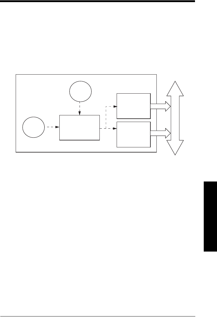
7ML19985JM01 SITRANS LR 460 (PROFIBUS PA) – INSTRUCTION MANUAL Page J-99
mmmmm
J: Profile structure PA
Appendix J: PROFIBUS PA Profile
Structure
PROFIBUS Level Device Design
The device follows the profile block model and is implemented as a Profile 3.01, Class B,
PA device. Standard profile parameters are used to program the Level Transducer Block.
Block Model for recording and processing measured values
The functions of the device are divided into blocks for different areas of responsibility.
They can be parameterized by acyclic data transfer via PDM.
The device is implemented with one Level Transducer Block (LTB), and two Analog Input
Function Blocks (AIFB1 and AIFB2).
All data is viewed from the perspective of the DCS or PLC, so information from the sensor
is an input.
Level Transducer Block (LTB)
The Level Transducer Block (LTB) carries out adjustments to the sensor, such as level
calibration. It supplies the outputs utilized by either or both of the AIFBs.
Analog Input Function Blocks AIFB1 and AIFB2
The two AIFBs are completely independent of each other. They utilize the output from the
TB, and apply any required quality checks, scaling, and Fail-safe operation selections.
The output of an Analog Input Function Block supplies the measured value and
associated status information to PROFIBUS PA, via cyclic data transfer.
sensor
sensor
Level
Transducer
Block
electronics
temperature
Analog Input
Function Block2
Analog Input
Function Block1
PROFIBUS PA
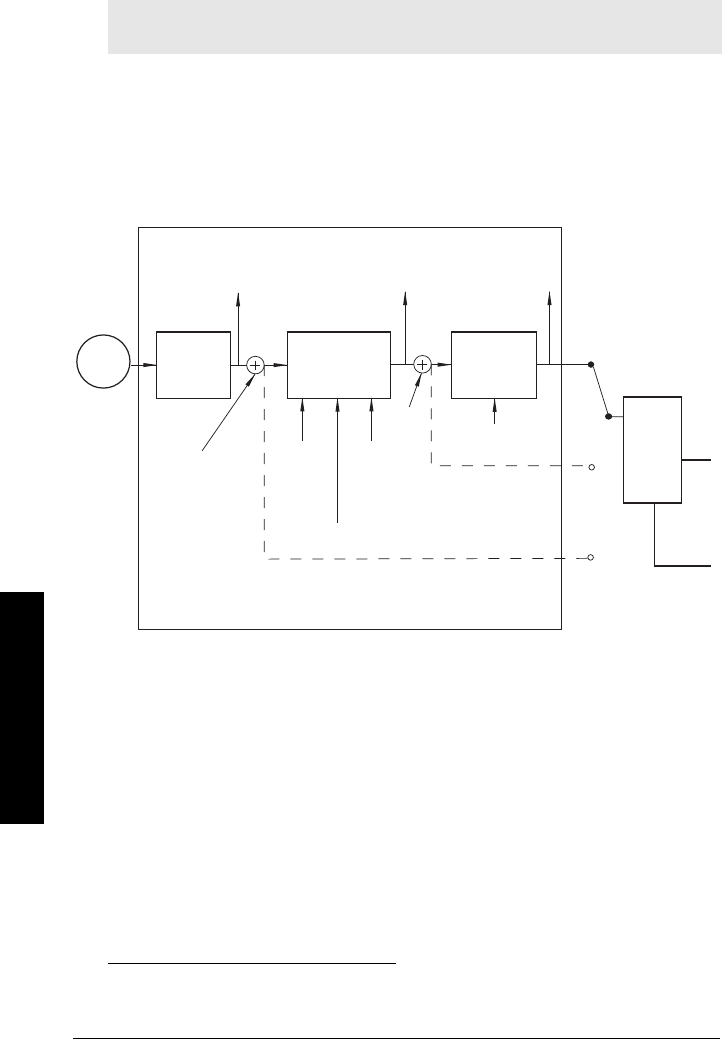
Page J-100 SITRANS LR 460 (PROFIBUS PA) – INSTRUCTION MANUAL 7ML19985JM01
mmmmm
J; Profi;e structure PA
Description of the blocks
Level Transducer Block function groups
The figure below shows the signal flow of measured values from the sensor through the
Level Transducer Block into the output value (Primary Value/ Level; Secondary Value 1 /
Level; or Secondary Value 2 /Distance. The LTB implements all of the basic parameters
(see parameter diagram on page 101).1
How the Level Transducer Block works:
1. The sensor technology block selects the proper echo. See
Echo selection
on page
72 for more detail.
The sensor value (in sensor units) is checked to see if it is within its measuring limits.
If the limit is exceeded, this results in a Bad status and the error message Failure in
measurement. The sensor value is stored in Sensor Value.
The analog signal from the sensor is transformed into a digital signal.
A Sensor Offset (default 0) provides compensation if necessary for differences
between the vessel reference point and the sensor reference point.
Note: Primary Value (PV) is the default measured value; Secondary Value 1 (SV1) is an
equivalent value.
1. A Linearization module is required by the PROFIBUS PA specifications. The
Linearization block is turned off in SITRANS LR 460.
Level Transducer Block
Sensor Value
(sensor units)
Sensor Sensor
technology
Level
calibration Linearization
(turned off)1
Level
(level units)
Primary Value
Level
(level units)
(Analog
Input)
AIFB1
Secondary Value 1
[Level]
(Level Units)
Secondary Value 2
[Distance]
(Sensor Units)
Sensor
Offset
Level
Offset
High
Calibration
Point
High Level
Point
Low
Calibration
Point
Low Level
Point
Calibration
Type
Linearization
Type
PV
SV1
SV2
AIFB2
(Analog
Input)
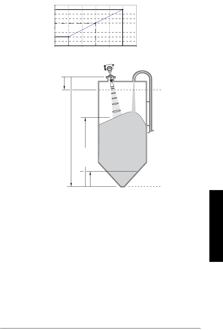
7ML19985JM01 SITRANS LR 460 (PROFIBUS PA) – INSTRUCTION MANUAL Page J-101
mmmmm
J: Profile structure PA
2. Level Calibration is a linear transfer function that converts a sensor value to a level
value.
3. The Level Transducer Block (LTB) provides three possible outputs
• Primary Value (PV)/Level
• Secondary Value 1 (SV1)/Level (plus level offset, if any)
• Secondary Value 2 (SV2)/Distance (in Sensor units)
0
0.5
1
1.5
2
2.5
3
3.5
4
4.5
Low Calibration Point Sensor Value High Calibration Point
Level
High Level Point
Low Level Point
Calibration
Level Value
SITRANSL
R4
00
Sensor Reference Point
(flange face)
Level
(PV/SV1)
Low Calibration Point
High Calibration Point
SV2 (distance)
Low Level Point
High Level Point
Level
Offset
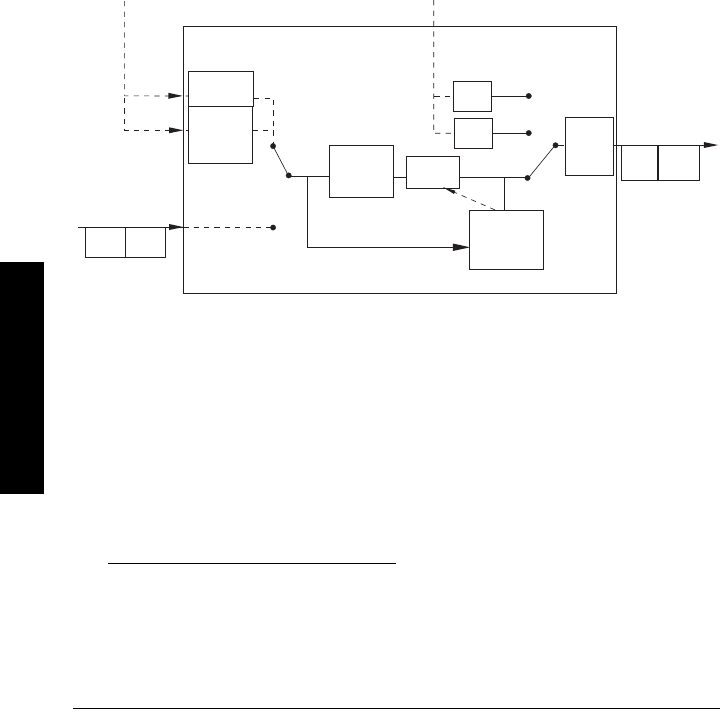
Page J-102 SITRANS LR 460 (PROFIBUS PA) – INSTRUCTION MANUAL 7ML19985JM01
mmmmm
J; Profi;e structure PA
Electronics temperature
The Level Transducer Block also monitors the internal temperature of the device
electronics. If the temperature exceeds permitted limits, it does not change the sensor
value, but it does change the status.The permitted limits correspond to those of the
permitted ambient temperature.
If a temperature limit is exceeded, the status changes. Peak indicators1 allow you to
check the maximum and minimum temperatures that have occurred.
Analog Input Function Blocks 1 and 2
There are two identical Analog Input Function Blocks which operate independently. The
figure below shows how measured values are processed within the Analog Input
Function Block (AIFB1 or AIFB2) to produce the device output, which is communicated via
cyclic transfer to PROFIBUS PA, and displayed on the LCD.
Analog Input Function Block function groups (simulation, mode and status)2
How the AIFBs work
The Analog Input Function Blocks allow you to control modifications to the output value
(PROFIBUS cyclic data).
1. Open View menu, scroll down to Peak Values, and click on Temperature tab in the
Peak Values window.
2. The output from the Level Transducer Block can be called the Primary Value (or
Secondary Value). When it becomes the input to the AIFB, it is called the Process
Variable.
enable
on FB
algorithm
Status
OUT
AUTO
MODE and
STATUS
handling
Process Variable2
from TB
(Function Block
input)
Value Status
Alarm
Limit
Check
Out of
Service
OUT MAN
Value
simulate
value and
status
Value Status
Operator Operator
off
Simulate
Parameter
Fail-safe
no
output
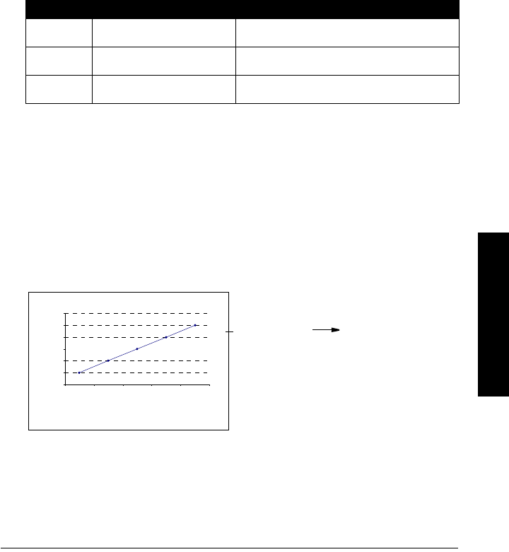
7ML19985JM01 SITRANS LR 460 (PROFIBUS PA) – INSTRUCTION MANUAL Page J-103
mmmmm
J: Profile structure PA
Output Conversion
Values transmitted by the TB have a status attached. The decision on what to do with
each value is made by the Analog Input Function Block.
Device/ Input Simulation
The input can be a simulated value instead of a TB OUT value. This allows the AI block to
be tested independently of the characteristics of the environment.
Fail-safe
• If the status of the Primary Value or Simulation Value is bad, the fault logic can
output either the last usable measured value, or a given substitute value.
Device / Output Simulation
One of three settings can be selected. The result is the output parameter (OUT).
AIFB execution steps:
The AIFBs can provide a linear conversion to any desired units.
1. The input value is normalized (Scaling Input)
Process Variable range applies to any of the four TB values. (Units of the Process
Variable scale are the same as the units used for the TB output.) Output units
together with Process Variable range determine how the TB output is converted to
whatever units the customer wants.
2. The scaling output is applied.
For example:
Setting description Output value
AUTO automatic the automatically-recorded measured value
MAN manual a manually-set fixed simulation value
O/S function block disabled the preset safety value.
0
1
2
3
4
5
6
12345
AIFB2
Process Variable range
(typical Input (0 to 100%)
Output range:
Out (or AIFB2 Out) straight to LCD
(same values displayed
on LCD as PLC)

Page J-104 SITRANS LR 460 (PROFIBUS PA) – INSTRUCTION MANUAL 7ML19985JM01
mmmmm
J; Profi;e structure PA
3. This value is filtered using a first order filter based on a time constant provided by
the user.
4. The status of the Process Variable (input value) is checked. If the status is Bad, a
Fail-safe condition occurs. The output is determined by the Fail-safe Mode of the
block.
5. The target mode parameter allows the entire AI block to be overridden by a Manual
Out value.
6. The value is checked against the user parameterized warning and alarm limits.
(There is an upper and lower warning limit and an upper and lower alarm limit. The
unit of the limits corresponds to the unit of the output range. A hysteresis parameter
prevents toggling in the Status field of the OUT value.)
7. The OUT VALUE parameter is the value for the cyclic data transfer.

7ML19985JM01 SITRANS LR 460 – INSTRUCTION MANUAL Page K-105
mmmmm
K: software rev.
Appendix K: Software Revision History
Note: The software revision number of the device is shown on the sticker on the
product.
Software
Rev. DD Rev. Date Changes
1.03.00-00 1.03.01-00 01/12/2007 • Initial release.
•

Page K-106 SITRANS LR 460 – INSTRUCTION MANUAL 7ML19985JM01
mmmmm
K: sorftware rev.
Notes

7ML19985JM01 SITRANS LR 460 – INSTRUCTION MANUAL Page 107
mmmmm
Glossary
Glossary
accuracy: degree of conformity of a measure to a standard or a true value.
agitator: mechanical apparatus for mixing or aerating. A device for creating turbulence.
algorithm: a prescribed set of well-defined rules or processes for the solution of a problem in a
finite number of steps.
ambient temperature: the temperature of the surrounding air that comes in contact with the
enclosure of the device.
antenna: an aerial which sends out and receives a signal in a specific direction. There are four
basic types of antenna in radar level measurement, horn, parabolic, rod, and waveguide.
attenuation: a term used to denote a decrease in signal magnitude in transmission from one
point to another. Attenuation may be expressed as a scalar ratio of the input magnitude to
the output magnitude or in decibels.
Auto False-Echo Suppression: a technique used to adjust the level of a TVT curve to avoid the
reading of false echoes. (See TVT.)
Auto False-Echo Suppression Distance: defines the endpoint of the TVT distance. (See TVT.)
This is used in conjunction with auto false echo suppression.
beam angle: the angle diametrically subtended by the one-half power limits (-3 dB) of the
sound beam.
beam spreading: the divergence of a beam as it travels through a medium.
blanking: see Near Range.
capacitance: the property of a system of conductors and dielectrics that permits the storage of
electricity when potential differences exist between the conductors. Its value is
expressed as the ratio of a quantity of electricity to a potential difference, and the unit is a
Farad.
confidence: describes the quality of an echo. HIgher values represent higher quality.
Confidence threshold defines the minimum value.
damping: term applied to the performance of an instrument to denote the manner in which the
measurement settles to its steady indication after a change in the value of the level.
dB (decibel): a unit used to measure the amplitude of signals.
derating: to decrease a rating suitable for normal conditions according to guidelines specified
for different conditions.
dielectric: a nonconductor of direct electric current.1
1. Many conductive liquids/electrolytes exhibit dielectric properties; the relative
dielectric constant of water is 80.

Page 108 SITRANS LR 460 – INSTRUCTION MANUAL 7ML19985JM01
mmmmm
Glossary
dielectric constant (DK): the ability of a dielectric to store electrical potential energy under the
influence of an electric field. Also known as Relative Permittivity. An increase in the
dielectric constant is directly proportional to an increase in signal amplitude. The value is
usually given relative to a vacuum /dry air: the dielectric constant of air is 11.
echo: a signal that has been reflected with sufficient magnitude and delay to be perceived in
some manner as a signal distinct from that directly transmitted. Echoes are frequently
measured in decibels relative to the directly transmitted signal.
echo confidence: the recognition of the validity of the echo. A measure of echo reliability.
Echo Marker: a marker that points to the processed echo.
Echo Processing: the process by which the radar unit determines echoes.
Echo Strength: describes the strength of the selected echo in dB above 1 µV rms.
Echo Profile: a graphical display of a processed echo.
emission cone: the extension of the antenna’s angle
false echo: any echo which is not the echo from the desired target. Generally, false echoes are
created by vessel obstructions.
frequency: the number of periods occurring per unit time. Frequency may be stated in cycles
per second.
hertz (Hz): unit of frequency, one cycle per second. 1 Gigahertz (GHz) is equal to 109 Hz.
horn antenna: a conical, horn-shaped antenna which focuses microwave signals. The larger
the horn diameter, the more focused the radar beam.
inductance: the property of an electric circuit by virtue of which a varying current induces an
electromotive force in that circuit or in a neighboring circuit. The unit is a Henry.
microwaves: the term for the electromagnetic frequencies occupying the portion of the radio
frequency spectrum from 1 GHz to 300 GHz.
multiple echoes: secondary echoes that appear as double, triple, or quadruple echoes in the
distance from the target echo.
Near Range: a blind zone extending away from the reference point plus any additional shield
length.The instrument is programmed to ignore this zone.
nozzle: a length of pipe mounted onto a vessel that supports the flange.
parameters: in programming, variables that are given constant values for specific purposes or
processes.
polarization: the property of a radiated electromagnetic wave describing the time-varying
direction and amplitude of the electric field vector.
polarization error: the error arising from the transmission or reception of an electromagnetic
wave having a polarization other than that intended for the system.

7ML19985JM01 SITRANS LR 460 – INSTRUCTION MANUAL Page 109
mmmmm
Glossary
PROFIBUS PA: one of the PROFIBUS family of protocols, specifically tailored for the needs of
process industries (PA = Process Automation).
propagation factor (pf): where the maximum velocity is 1.0, pf is a value that represents a
reduction in propagation velocity as a result of the wave travelling through a pipe or
medium.
pulse radar: a radar type that directly measures distance using short microwave pulses.
Distance is determined by the return transmit time.
radar: radar is an acronym for RAdio Detection And Ranging. A device that radiates
electromagnetic waves and utilizes the reflection of such waves from distant objects to
determine their existence or position.
range: distance between a transmitter and a target.
range extension: the distance below the zero percent or empty point in a vessel.
relative permittivity: see dielectric constant.
repeatability: the closeness of agreement among repeated measurements of the same
variable under the same conditions.
shot: one transmit pulse or measurement.
speed of light: the speed of electromagnetic waves (including microwave and light in free
space. Light speed is a constant 299,792,458 meters per second.
stillpipe: a pipe that is mounted inside a vessel parallel to the vessel wall, and is open to the
vessel at the bottom.
stilling-well: see stillpipe.
two wire radar: a low-energy radar. Can be loop powered, analog, intrinsically safe, or a digital
(BUS) transmitter.
TVT (time varying threshold): a time-varying curve that determines the threshold level above
which echoes are determined to be valid.
waveguide antenna: a hollow, metallic tube that transmits a microwave signal to the product
target.

Page 110 SITRANS LR 460 – INSTRUCTION MANUAL 7ML19985JM01
mmmmm
Glossary
Notes

7ML19985JM01 SITRANS LR 460 – INSTRUCTION MANUAL Page 111
mmmmm
Index
Index
A
abbreviations
list 3
accuracy
specifications 6
activating LR 460 26
address 46
application example 34
approvals 10
Auto False-Echo Suppression
explanation 73
TVT shaper adjustment 38
auxiliary region
PROGRAM mode 85
B
blanking
explanation (see Near Range) 74
setting (see Near Range) 56
burst mode 89
bus address (device address)
PROFIBUS PA 93
bus termination
PROFIBUS PA installations 21
C
cleaning
instructions 84
communication 9
confidence key 86
configuration
PROFIBUS PA device 93
configuring new device
via PDM 40, 93
connecting HART 20
connecting PROFIBUS PA 22
cyclic data 95
versus acyclic 95
D
device description
HART 88
Device Description (DD)
how to update 40
device description (DD)
PROFIBUS PA 92
diagnostics 97
dimensions 11
E
echo confidence
explanation 74
echo monitoring
level trend diagram 37
profile saving 37
echo status indicator
reliable echo 85
unreliable echo 85
F
factory reset
performing 47
via PDM 41
fail-safe mode
explanation 74
false echoes
explanation 73
set TVT curve to ignore 73
fault codes 80
function keys
edit mode 87
navigation mode 87
G
general fault codes 80
GSD file
downloading 93
H
hand-held programmer
parameter reset 87
programming 85
HART
device description 88
HART Communications
details 88
HART modem 88
HART version 89
hazardous area installations
wiring requirements 23
I
identifications and abbreviations
list 3
installation
hazardous area requirements 23
requirements 12
L
Level application example 34
LOE timer
explanation 74
M
maintenance

Page 112 SITRANS LR 460 – INSTRUCTION MANUAL 7ML19985JM01
mmmmm
Index
cleaning 84
maintenance settings 68
measure key 86
measurement response
explanation 71
mounting
location 12
N
Near Range
explanation 74
setting 56
network address 93
O
operating principles 71
P
parameter reset
factory reset via PDM 41
via handheld programmer 47
PDM
see SIMATIC PDM 36
power consumption
PROFIBUS PA 21
primary region
PROGRAM mode 85
RUN mode 85
Primary Value
relation to Process Variable 102
Primary Value (PV)
view 61
process temperature
maximum 76
Process Variable
definition 61
diagram 102
PROFIBUS address
setting 93
PROFIBUS/HART address 46
program mode icon 85
Programming SITRANS LR 460 27
Q
Quick Start Wizard
via handheld programmer 28
via SIMATIC PDM 30
R
Range
Far Range (range extension) 56
Near Range (blanking) 56
Reform Echo 55
reliable echo indicator 85
repair
cautions 84
excluded liability 84
reset parameters
factory reset 47
individual via handheld programmer 87
via PDM 41
RUN mode display 26
S
safety marking symbols 1
safety notes 1
Secondary Value(SV)
view 61
SIMATIC PDM
6.0 features 36
overview 36, 92
SITRANS LR 460
overview 5
specifications
accuracy 6
approvals 10
communication 9
performance 6
power 6
status byte
status codes 96
status codes 96
T
temperature key 86
Trend Diagram
level over time 37
TVT curve 73
manual TVT shaper 38
TVT Shaper
manual adjustment via PDM 38
U
unreliable echo indicator 85
W
wiring
HART 20
PROFIBUS PA 21

SITRANS LR 460 (HART/PROFIBUS PA) – INSTRUCTION MANUAL Page 113 SITRANS LR 460 (HART/PROFIBUS PA) – INSTRUCTION MANUAL 7ML19985JM01
Appendix C: menu chart
LCD menu structure
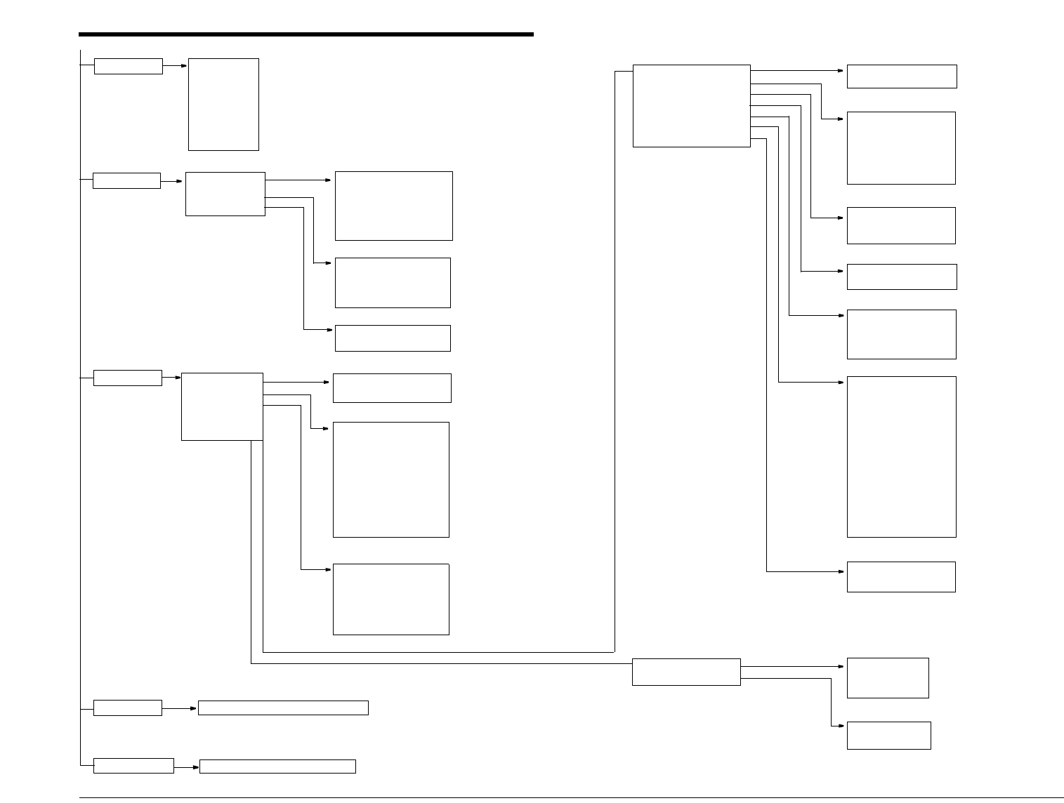
Page 114 SITRANS LR 460 (HART/PROFIBUS PA) – INSTRUCTION MANUAL SITRANS LR 460 (HARAT/PROFIBUS PA) – INSTRUCTION MANUAL 7ML19985JM01
Appendix C: menu chart
LCD menu structure
1. ALGORITHM
2. THRSH LONG
3. MARKER
4. NARROW FLT
5. REFORM
6. E POS
1. QUICK START
1. CONFIG
2. DEVICE
3. STATS
IDENT
DEVICE
1. LANGUAGE
2. APPL TYPE
3. OPERATION
4. UNITS
5. CAL HIGH
6. CAL LOW
7. RATE
8. APPLY?
1. SOFT REV
2. HARD REV
4. LOCK
5. LANGUAGE
2. ADDR
3. REM LOCK
5. RESET
6. ACK FAULT
7. MENU TIMER
8. BACKLIGHT
CONFIG
INPUT
2. IDENT
3. INPUT
QUICK START
ECHO SAMP
FAIL-SAFE
1. LOE TIME
2. RESTRICT
1. FAIL-SAFE
2. ECHO SEL
3. ECHO SAMP
4. RANGE
6. TVT SETUP
7. TVT SHAPER
8. RATE
DT SETUP
ECHO SEL
1. WINDOW
2. WIND USED
3. SHOTS
See
OUTPUT
on page 115.
OUTPUT
4. OUTPUT
See
MAINT SET
on page 116
MAINT SET
6. MAINT SET
STATS
1. PWRD HRS
2. RESETS
2. ST SETUP
3. SENSOR CAL
4. MEAS LIM
5. DT SETUP
6. ECHO INFO
SENSOR CAL
1. SENS UNIT
2. CAL TYPE
3. CAL LO
4. CAL HIGH
5. LVL UNIT
6. LV MIN
7. UV MAX
8. LEV OFFSET
9. SEN OFFSET
A.TEMP UNIT
1. ANTENNA
2. RESPRATE
ST SETUP
MEAS LIM
1. MEAS MIN
2. MEAS MAX
3. LV MIN
4. UV MAX
5. PROC T MIN
6. PROC T MAX
1. SHAPER A
2. SHAPER B
3. SHAPER C
4. SHAPER D
5. SHAPER E
6. SHAPER F
7. SHAPER G
8. SHAPER H
9. SHAPER I
A.SHAPER J
B.SHAPER K
C.SHAPER L
D.SHAPER M
E.SHAPER N
RATE
RANGE
1. NEAR RANGE
2. FAR RANGE
TVT SHAPER
1. FILL RATE
2. EMPTY RATE
TVT SETUP
1. AUTO TVT
2. RANGE
3. TVT HOVER
4. SHAPER MD
ECHO INFO
1. TB VALUES
2. ECHO QUAL
ECHO QUAL
1. ECHO CON L
2. STRENGTH
1. LEVEL
2. LEVEL
3. SENSOR VAL
TB VALUES

7ML19985JM01 SITRANS LR 460 – INSTRUCTION MANUAL Page 115
mmmmm
LCD menus
LCD menu charts (continued)
4. OUTPUT 1. AIFB1
2. AIFB2
3. mA OUTPUT
4. RLY CONFIG
1. TARGET MODE
2. UNIT
3. FILT TIME
4. CHANNEL
5. BATCH (PROFIBUS PA)
6. PR VAL SCL
7. OUT SCALE
8. OUT. LIM.
A. INTERFACE
AIFB1
OUTPUT
INTERFACE
BATCH
1. BATCH ID
2. BATCH UNIT
3. BATCH OP
4. BATCH PH
PR VAL SCL
1. LOWR VALUE
2. UPPR VALUE
OUT SCALE
1. LOWR VALUE
2. UPPR VALUE
OUT. LIM.
1. LO ALARM
4. UP ALARM
5. LIMIT HYS.
6. MIN OUT
7. MAX OUT
1. DECIMAL
MA OUTPUT
1. FUNCTION
2. OUT VALUE
3. MAN VALUE
4. MIN LIM
5. MAX LIM
6. FS MODE
7. FS VALUE
8. 4 MA TRIM
9. 20 MA TRIM
RLY CONFIG
1. AIFB
2. FUNCTION
3. NC/NO
4. STATE
As AIFB1
AIFB2

Page 116 SITRANS LR 460 – INSTRUCTION MANUAL 7ML19985JM01
mmmmm
LCD menus
LCD menu charts (continued)
6. MAINT SET 1. DVC REMLIF
2. SNS REMLIF
3. SERVICE
4. CAL
1. DVC OP TIM
2. REST LIFE
3. REQ LIMIT
4. DEM LIMIT
5. ACTIVATION
6. EXP LIFE
7. MAINT STAT
8. ACK STATUS
9. ACK
MAINT SET DVC REMLIF
1. SNS OP TIM
2. REST LIFE
3. REQ LIMIT
4. DEM LIMIT
5. ACTIVATION
6. EXP LIFE
7. MAINT STAT
8. ACK STATUS
9. ACK
SNS REMLIF
1. LAST SVC
2. REQ LIMIT
3. DEM LIMIT
4. ACTIVATION
5. INTERVAL
6. MAINT STAT
7. ACK STATUS
8. ACK
SERVICE
1. LAST CAL
2. REQ LIMIT
3. DEM LIMIT
4. ACTIVATION
5. INTERVAL
6. MAINT STAT
7. ACK STATUS
8. ACK
CAL

*7ml19985JM01* Rev. 1.1
www.siemens.com/processautomation
Siemens Milltronics Process Instruments Inc.
1954Technology Drive, P.O. Box 4225
Peterborough, ON, Canada K9J 7B1
Tel: (705) 745-2431 Fax: (705) 741-0466
Email: techpubs.smpi@siemens.com
Siemens Milltronics Process Instruments Inc. 2007
Subject to change without prior notice
Printed in Canada
