Siemens Sitrans P Users Manual FI01_2009_en_kap02
P to the manual 820c338e-ed89-4382-be5d-db93e3a08f2e
2015-02-05
: Siemens Siemens-Sitrans-P-Users-Manual-410289 siemens-sitrans-p-users-manual-410289 siemens pdf
Open the PDF directly: View PDF ![]() .
.
Page Count: 234 [warning: Documents this large are best viewed by clicking the View PDF Link!]
- Contents
- SITRANS P measuring instruments for pressure
- Product overview
- Transmitters for gage, absolute and differential pressure
- Transmitters for food, pharmaceuticals and biotechnology
- Transmitters for gage pressure for the paper industry
- Transmitters for gage, absolute and differential pressure, flow and level
- SITRANS P Accessories
- Transmitters for hydrostatic level
- Remote seals for transmitters and pressure gages
- Fittings
- Technical description
- Selection aid
- Shut-off valves for gage pressure and absolute pressure transmitters
- Shut-off valves for differential pressure transmitters
- 2-, 3- and 5-spindle valve manifolds DN 5
- Multiway cocks PN 100
- 3- and 5-way valve manifolds DN 5
- 3-way valve manifold DN 8
- Valve manifold combination DN 5/DN 8
- Valve manifold combination DN 8
- 2-, 3- and 5-spindle valve manifolds for protective boxes
- 3- and 5-spindle valve manifolds for vertical angular differential pressure lines
- Low-pressure multiway cock
- Accessories
- SITRANS P measuring instruments for pressure
Siemens FI 01 · 2009
2/2 Product overview
2/4 Transmitters for gage, absolute and
differential pressure
2/4 Z series for gage pressure
2/6 Z series for gage and absolute pressure
2/12 SITRANS P250 for differential pressure
2/17 ZD series for gage and absolute pressure
2/21 Transmitters for food, pharma-
ceuticals and biotechnology
2/21 SITRANS P Compact for gage
and absolute pressure
2/28 SITRANS P300 for gage and absolute
pressure
2/47 Transmitters for gage pressure for pa-
per industry
SITRANS P300 and DS III series with
PMC connection
2/47 Technical description
Technical specifications, ordering data,
dimensional drawings
2/52 -DS III series with PMC connection
2/58 - SITRANS P300 with PMC connection
2/63 Transmitters for gage, absolute and
differential pressure, flow and level
DS III, DS III PA and DS III FF series
2/63 Technical description
Technical specifications, ordering data,
dimensional drawings
2/70 -for gage pressure
2/79 - for gage and absolute pressure with
front-flush diaphragm
2/89 - for absolute pressure (from gage
pressure series)
2/98 -for absolute pressure
(from differential pressure series)
2/107 - for differential pressure and flow
2/124 - for level
2/134 SITRANS P Accessories
2/134 Supplementary electronics for 4-wire con-
nection
2/136 Accessories/spare parts for SITRANS P,
P300 and DS III series
2/142 Factory-mounting of valve manifolds on
SITRANS P transmitters
2/146 Transmitters for hydrostatic level
2/146 MPS series (submersible sensor)
2/150 Remote seals for transmitters and
pressure gages
2/150 Technical description
2/158 Diaphragm seals of sandwich design
2/161 Diaphragm seals of flange design
2/170 Quick-release diaphragm seals
2/173 Miniature diaphragm seal
2/174 Flushing rings
2/176 Clamp-on seals of flange design
2/179 Quick-release clamp-on seals
2/182 Remote seals - Measuring setups
2/187 Questionnaire
2/190 Fittings
2/190 Technical description
2/191 Selection aid
Shut-off valves for gage and absolute
pressure transmitters
2/193 Shut-off valves to DIN 16270, DIN 16271
and DIN 16272
2/195 Angle adapter
2/196 Double shut-off valves
2/197 Accessories for shut-off
valves/double shut-off valves
2/198 2-way valve manifolds DN 5
Shut-off valves for differential pressure
transmitters
2/201 2-, 3- and 5-spindle valve manifolds DN 5
2/204 Multiway cocks PN 100
2/206 3-way and 5-way valve manifolds DN 5
2/209 3-way valve manifold DN 8
2/212 Valve manifold combination DN 5/DN 8
2/214 Valve manifold combination DN 8
2/216 2-, 3- and 5-spindle valve manifolds for
installing in protective boxes
2/220 3- and 5-spindle valve manifolds for
vertical angular diff. pressure lines
2/223 Low-pressure multiway cock
Accessories
2/225 Oval flange
2/226 Adapters, connection glands
2/227 Connection parts G½
2/228 Water traps, Sealing rings to EN 837-1
2/229 Pressure surge reducers
2/230 Primary shut-off valves
2/232 Compensation vessels
2/233 Connection parts
You can download all instructions, cata-
logs and certificates for SITRANS P free
of charge at the following Internet ad-
dress:
www.siemens.com/sitransp
SITRANS P
measuring instruments
for pressure
© Siemens AG 2008
SITRANS P measuring instruments for pressure
Product overview
2/2 Siemens FI 01 · 2009
2
■
Overview
Application Description Page Software for
Parameterization
SITRANS P – measuring instruments for pressure, absolute pressure, differential pressure, flow and level
Two- or three-wire transmitters
for measuring gage and abso-
lute pressure
SITRANS P, Z series
Compact single-range transmitters
Analog electronics
Available ex stock
2/4 –
Two- or three-wire transmitters
for measuring differential pres-
sure
SITRANS P250
Compact single-range transmitters
Analog electronics
Available ex stock
2/12 –
Two- or three-wire transmitters
for measuring gage and abso-
lute pressure
SITRANS P, ZD series
Range adjustment: 5 : 1
Digital display
Available ex stock
2/17 –
Transmitters for gage and abso-
lute pressure for food, pharma-
ceuticals and biotechnology
SITRANS P Compact
Single-range transmitters in 2-wire system
Hygiene-based design with various aseptic connec-
tions according to EHEDG, FDA and GMP recom-
mendations.
2/21 –
Two-wire transmitters for mea-
suring gage and absolute pres-
sure
SITRANS P300
• Hygiene-based design according to EHEDG, FDA
and GMP
• Parameterization over 3 buttons or communication
over HART, PROFIBUS PA or FOUNDATION
Fieldbus
• Standard process connection G½, ½-NPT and
flush-mounted process connections available
• Measuring range adjustment 100 : 1
2/28 SIMATIC PDM
Two-wire transmitters for mea-
suring gage pressure SITRANS P300 and DS III series with PMC con-
nection for the paper industry
• Measuring range adjustment 100 : 1
• Process connections for the paper industry
• Parameter assignment over 3 buttons and HART,
PROFIBUS PA or FOUNDATION Fieldbus
2/47 SIMATIC PDM
Two-wire transmitters for mea-
suring:
• Gage pressure,
• Absolute pressure
• Differential pressure and
• Flow or
• Level
SITRANS P, DS III series
SITRANS P, DS III PA series
SITRANS P, DS III FF series
Range adjustment: 100 : 1
Parameterization using:
• 3 keys and HART for DS III series
• 3 keys and PROFIBUS-PA for DS III PA series
• 3 buttons and FOUNDATION Fieldbus for DS III FF
series
• Available ex stock
2/63 SIMATIC PDM
SIMATIC PDM
Supplementary electronics for
adaptation of two-wire transmit-
ters for four-wire connections
Output: 0 or 4 to 20 mA
Power supply: 24 V AC/DC, 230 V AC
2/134 –
© Siemens AG 2008

SITRANS P measuring instruments for pressure
Product overview
2/3
Siemens FI 01 · 2009
2
2-wire transmitter for measuing
hydrostatic levels SITRANS P, MPS series (submersible sensor)
For measuring liquid levels in wells, tanks, channels,
dams etc.
2/146 –
Remote seals for measuring
viscous, corrosive or fibrous
media (as well as media at
extreme temperatures)
Remote seals in sandwich and flange designs
Quick-release remote seals for the food industry
Wide range of diaphragm materials and filling liq-
uids available
2/150 –
Shutting off the lines for the
medium and differential pres-
sure
Mounting of transmitter on valve
manifold or shut-off fitting
Shut-off fittings and valve manifolds available in
steel, brass or stainless steel
Valve manifolds available for the various process
connections of the SITRANS P transmitters
2/190 –
Application Description Page Software for
Parameterization
© Siemens AG 2008
SITRANS P measuring instruments for pressure
Transmitters for gage, absolute and differential pressure
Z series for gage pressure
2/4 Siemens FI 01 · 2009
2
■
Overview
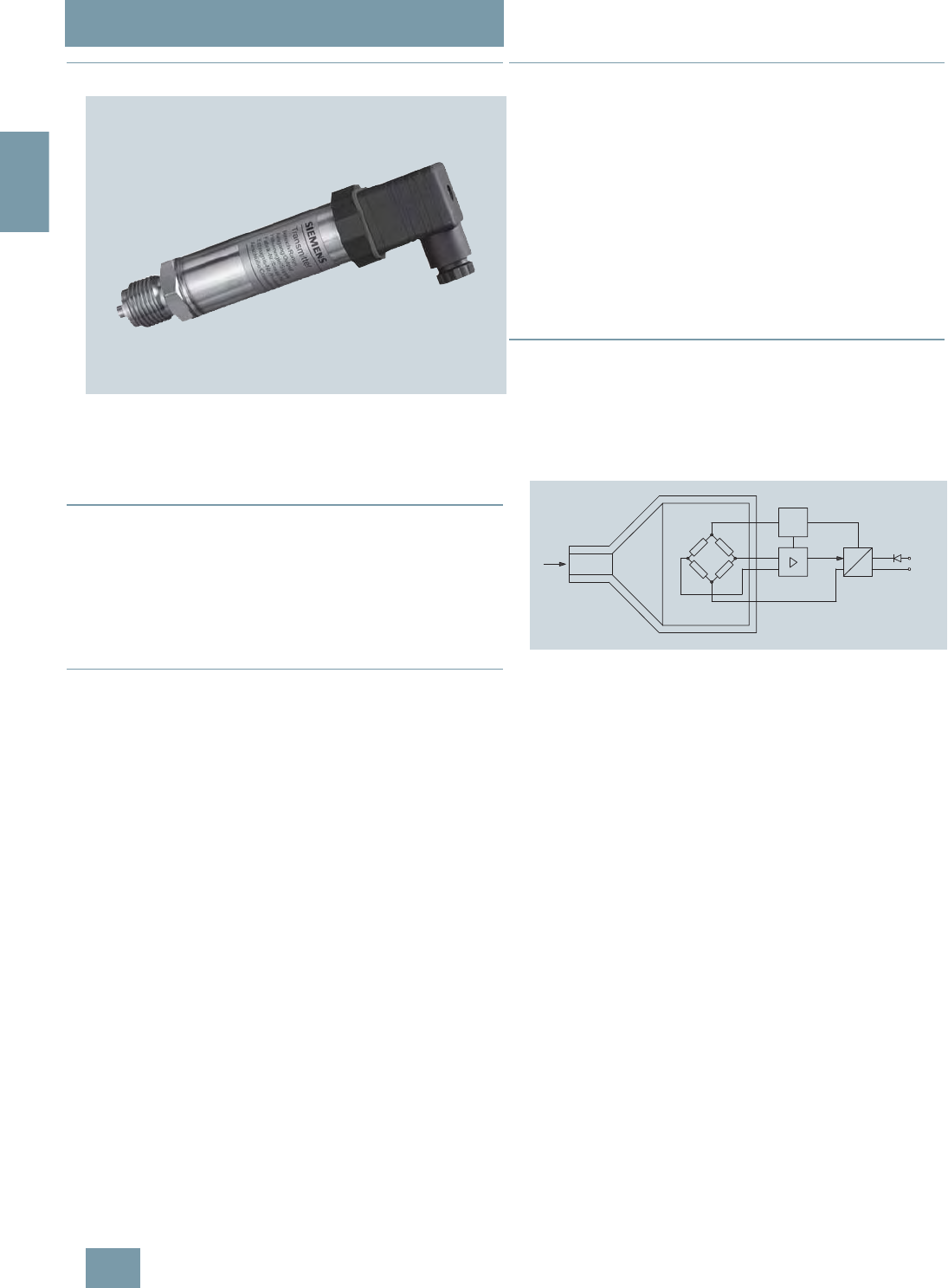
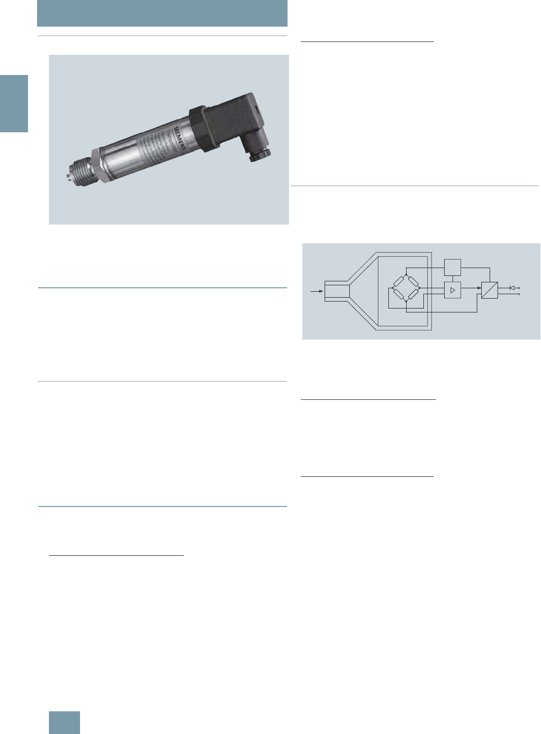
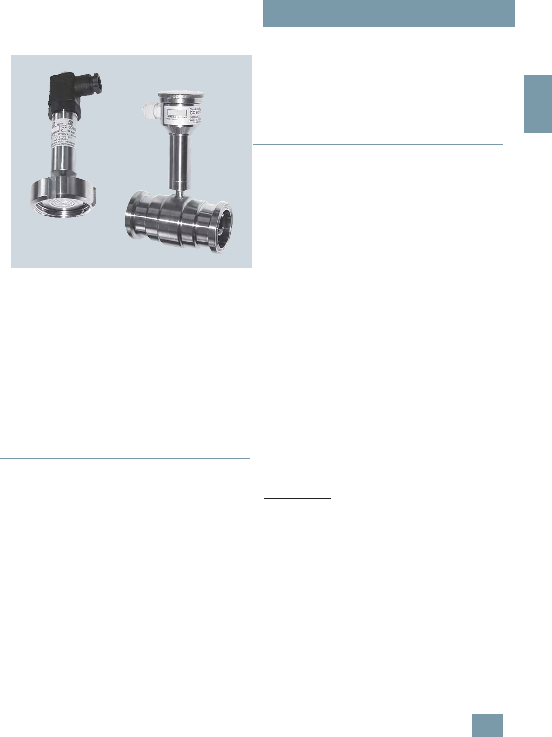
SITRANS P pressure transmitters, Z series for gage pressure
(7MF1562-...)
The SITRANS P pressure transmitter, Z series (7MF1562-...),
measures the gage pressure of aggressive and non-aggressive
gases, liquids and vapors.
■
Benefits
• High measuring accuracy
• Sturdy brass housing
• For aggressive and non-aggressive media
• For measuring the pressure of liquids, gases and vapor
• Temperature-compensated measuring cell
• Compact design
■
Application
The pressure transmitter of the Z series for gage pressure
(7MF1562-...) is used above all in the following industrial areas:
• Power engineering
• Mechanical engineering
• Shipbuilding
• Water supply etc.
A concrete application example is the measurement of com-
pressed air containing oil in compressors or compressor sta-
tions.
■
Design
The main components of the pressure transmitter are:
• Brass housing with silicon measuring cell and electronics
plate
• Process connection
• Electrical connection
The silicon measuring cell has a thin-film strain gage which is
mounted on a ceramic diaphragm. The ceramic diaphragm can
also be used for aggressive media.
The process connection to DIN EN 837-1 is made of brass and
has a male thread G½B or a female thread G1/8B.
The electrical connection is made using a plug to DIN 43650
with a M16x1.5 cable inlet.
■
Function
The pressure transmitters of the Z series for gage pressure mea-
sure the pressure of aggressive and non-aggressive gases,
liquids and vapors.
The measuring cell is temperature-compensated.
Mode of operation
SITRANS P pressure transmitters, Z series (7MF1562-...), functional dia-
gram
The thin-film measuring cell has a thin-film resistance bridge at
which the operating pressure p is transmitted through a ceramic
diaphragm.
The measuring cell output voltage is fed to an amplifier and con-
verted into an output current of 4 to 20 mA. The output current
is linearly proportional to the input pressure.
pI
0
, U
B
U
const.
UI
© Siemens AG 2008
SITRANS P measuring instruments for pressure
Transmitters for gage, absolute and differential pressure
Z series for gage pressure
2/5
Siemens FI 01 · 2009
2
■
Technical specifications
■
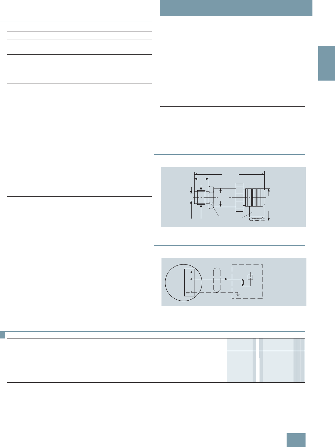
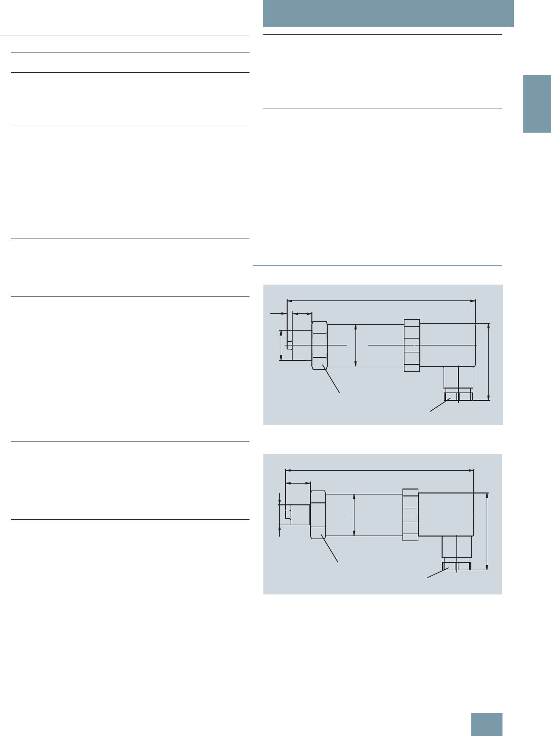
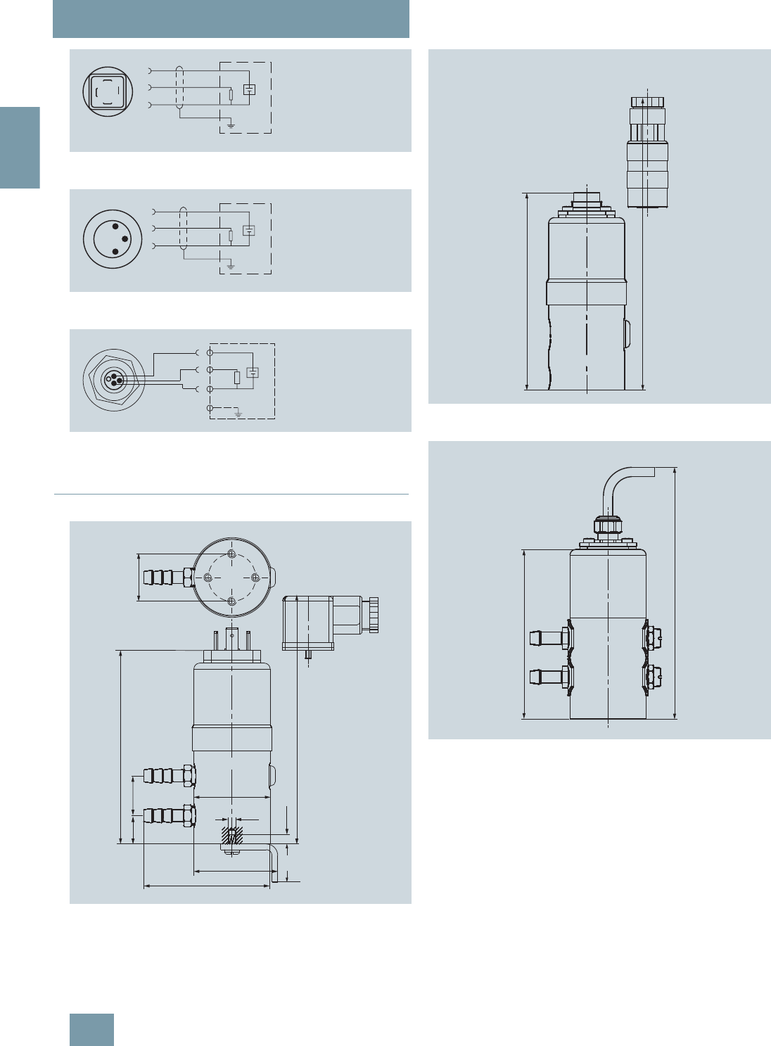
Dimensional drawings
SITRANS P pressure transmitters, Z series (7MF1562-...), dimensions in
mm (inch)
■
Schematics
SITRANS P pressure transmitters, Z series (7MF1562-...), connection dia-
gram
D) Subject to export regulations AL: N, ECCN: EAR99H.
SITRANS P pressure transmitter, Z series for gage pressure
Mode of operation
Measuring principle Thin-film strain gage
Input
Measured variable Realtive pressure
Measured range 0 to 16 bar g (0 to 232 psi g) or
0 to 25 bar g (0 to 363 psi g)
Output
Current output signal 4 ... 20 mA
Measuring accuracy To EN 60770-1
Error in measurement (at 25 °C
(77 °F), including conformity error,
hysteresis and repeatability)
0.5% of full-scale value-typical
Response time T99 < 0.1 s
Long-term drift
• Start of scale 0.3% of full-scale value/year - typ-
ical
• Measured span 0.3% of full-scale value/year - typ-
ical
Influence of ambient temperature
• Start of scale 0.3%/10 K (0.3%/10 K) of full-
scale value - typical
• Measured span 0.3%/10 K (0.3%/10 K) of full-
scale value - typical
Rated conditions
Medium conditions
• Process temperature -30 ... +120 °C (-22 ... +248 °F)
Degree of protection to EN 60529 IP65
Ambient conditions
• Ambient temperature -25 ... 85 °C (-13 ... +185 °F)
• Storage temperature -50 ... 100 °C (-58 ... +212 °F)
Design
Weight ≈0.2 kg (≈0.44 lb)
Wetted parts materials
• Measuring cell Al2O3 - 96%
• Process connection Brass, mat. No. 2.0402
• Gasket Viton
Process connection Male thread G½B
female thread G1/8B
Power supply
Terminal voltage on pressure trans-
mitter
• For current output 10 to 36 V DC
Certificate and approvals
Classification according to pressure
equipment directive
(DRGL 97/23/EC)
For gases of fluid group 1 and
liquids of fluid 1; complies with
requirements of article 3, para-
graph 3 (sound engineering prac-
tice)
6:
G/8B
*%
0[
ෘ
GLDP
1+
2-
+
Signal
R
L
U
B
I
0
I
0
Output current
U
B
Power supply
R
L
Load
Connections:
1 (+U
B
)
2 (-U
B
)
■
Selection and Ordering data Order No. Order code
SITRANS P pressure transmitters, Z series for pressure
2-wire system, characteristic rising
D) 7MF1562 -7770 0 7 7 7
Measured range Max. working pressure
0 ... 16 bar g (0 ... 232 psi g) 32 bar g (464 psi g) 3CB
0 ... 25 bar g (0 ... 363 psi g) 64 bar g (928 psi g) 3CD
Other version for measuring range ≥ 1 bar g (≥ 14.5 psi g), add Order code and plain text:
Measuring range: ... to ... bar g (psi g) 9AA H 1 Y
© Siemens AG 2008
SITRANS P measuring instruments for pressure
Transmitters for gage, absolute and differential pressure
Z series for gage and absolute pressure
2/6 Siemens FI 01 · 2009
2
■
Overview
SITRANS P pressure transmitters, Z series for pressure and absolute
pressure (7MF1564-...)
SITRANS P pressure transmitters, Z series (7MF1564-...), mea-
sure the gage and absolute pressure as well as the level of liq-
uids and gases.
■
Benefits
• High measuring accuracy
• Sturdy stainless steel housing
• For aggressive and non-aggressive media
• For measuring the pressure of liquids, gases and vapor
• Temperature-compensated measuring cell
• Compact design
■
Application
The pressure transmitter of the Z series for gage pressure and
absolute pressure (7MF1564-...) is used above all in the follow-
ing industrial areas:
• Chemical industry
• Pharmaceutical industry
• Food industry
• Mechanical engineering
• Shipbuilding
• Water supply
■
Design
The design of the pressure transmitter is dependent on the mea-
suring range.
Measuring range <1 bar (<14.5 psi)
Main components:
• Stainless steel housing with piezo-resistive silicon measuring
cell (with stainless steel diaphragm, temperature-compen-
sated) and electronics module
• Process connection made of stainless steel in diverse designs
(see Selection and Ordering data)
• Electrical connection made using a plug to DIN 43650 with the
cable inlet M16 x 1.5, ½-14 NPT or round plug connector M12.
The pressure transmitters with a nominal range < 1 bar g
(< 14.5 psi g) are optionally available with or without explosion
protection.
Measuring range ≥1 bar (≥14.5 psi)
Main components:
• Stainless steel housing with ceramic measuring cell and elec-
tronics module. The temperature-compensated ceramic mea-
suring cell has a thin-film strain gage which is mounted on a
ceramic diaphragm. The ceramic diaphragm can also be
used for aggressive media.
• Process connection made of stainless steel in diverse designs
(see Selection and Ordering data)
• Electrical connection made using a plug to DIN 43650 with the
cable inlet M16 x 1.5, ½-14 NPT or round plug connector M12.
The pressure transmitters with a nominal range ≥1barg
(≥14.5 psi g) are optionally available with or without explosion
protection.
■
Function
The pressure transmitter measures the gage and absolute pres-
sure as well as the level of liquids and gases.
Mode of operation
SITRANS P pressure transmitters, Z series (7MF1564-...), functional dia-
gram
The mode of operation of the pressure transmitter is dependent
on the measuring range.
Measuring range <1 bar (<14.5 psi)
The silicon measuring cell of the pressure transmitter has a
piezo-resistive bridge to which the operating pressure is trans-
mitted through silicone oil and a stainless steel diaphragm.
The measuring cell output voltage is fed to an amplifier and con-
verted into an output current 4 ... 20 mA. The output current is
linearly proportional to the input pressure
Measuring range ≥1 bar (≥14.5 psi)
The thin-film measuring cell has a thin-film resistance bridge to
which the operating pressure p is transmitted through a ceramic
diaphragm.
The voltage output from the measuring cell is converted by an
amplifier into an output current 4 ... 20 mA or an output voltage
of 0 ... 10 V DC.
The output current and voltage are linearly proportional to the in-
put pressure
pI
0
, U
B
U
const.
UI
© Siemens AG 2008
SITRANS P measuring instruments for pressure
Transmitters for gage, absolute and differential pressure
Z series for gage and absolute pressure
2/7
Siemens FI 01 · 2009
2
■
Technical specifications
■
Dimensional drawings
Pressure transmitter 7MF1564-... with process connection G½" male,
dimensions in mm (inch)
Pressure transmitter 7MF1564-... with process connection G¼" male,
dimensions in mm (inch)
SITRANS P pressure transmitters, Z series for gage pressure, abso-
lute pressure and level
Mode of operation
• Measuring range <1 bar
(<14.5 psi) Piezo-resistive
• Measuring range ≥1bar
(≥14.5 psi) Thin-film strain gage
Input
Measured variable Gage and absolute pressure
Measured range
• Pressure
- Metric 0 ... 400 bar g (0 ... 5802 psi g)
- US measuring range 0 ... 6000 psi g
• Absolute pressure
- Metric 0 ... 16 bar a (0 ... 232 psi a)
- US measuring range 0 ... 300 psi a
Output
Output signal
• Current output signal 4 ... 20 mA
• Voltage output signal (only mea-
suring range ≥1 bar (14.5 psi)) 0...10VDC
Accuracy To EN 60770-1
Error in measurement (at 25 °C
(77 °F), including conformity error,
hysteresis and repeatability)
0.25% of full-scale value – typical
Response time T99 < 0.1 s
Long-term drift
• Start of scale 0.25% of full scale value/year
• Full-scale value 0.25% of full scale value/year
Influence of ambient temperature
• Start of scale 0.25%/10 K (0.25%/10 K) of full-
scale value
• Full-scale value 0.25%/10 K (0.25%/10 K) of full-
scale value
Rated operating conditions
Process temperature -30 ... +120 °C
(-22 … +248 °F)
Ambient temperature -25 ... +85 °C (-13 … +185 °F)
Storage temperature -50 ... +100 °C
(-58 … +212 °F)
Degree of protection to EN 60529 IP65
Design
Weight ≈0.25 kg (≈0.55 lb)
Wetted parts materials
• Measuring cell
- Measuring range <1 bar
(<14.5 psi) Stainless steel, 1.4571/316Ti
- Measuring range ≥1 bar
(≥14.5 psi) Al2O3 – 96%
• Process connection Stainless steel, mat. No.
1.4571/316Ti
• Gasket Viton
Process connection See Selection and Ordering data
Power supply UH
Terminal voltage on pressure trans-
mitter
• For current output 10 ... 36 V DC
• For voltage output signal (only
measuring range ≥1 bar
(14.5 psi))
15 ... 36 V DC
Certificate and approvals
Classification according to pressure
equipment directive
(DRGL 97/23/EC)
For gases of fluid group 1 and liq-
uids of fluid 1; complies with
requirements of article 3, para-
graph 3 (sound engineering prac-
tice)
Explosion protection
• Intrinsic safety "i" (only with current
output) TÜV 02 ATEX 1953X
- Identification Ex II 1/2G EEx ia IIC T4
• Intrinsic safety "T.I.I.S." (only with
current output) applied
Lloyds Register of Shipping Certificate No. 03/30003
27
132 (5.2) without Ex protection
1)
141 (5.6) with Ex protection
(diam. 1.1)
M16x1,5
or
½-14 NPT
1) Length on version for voltage
output 0 ... 10 V: 106 (4.2)
2) Inner diameter 3 (0.12)
Ø
50
G
½
B
2)
20
(1.97)
SW27
(0.8)
5
(0.2)
122 (4.8) without Ex protection
1)
131 (5.15) with Ex protection
(diam. 1.1)
M16x1,5
or
½-14 NPT
1) Length on version for voltage
output 0 ... 10 V: 96 (3.8)
2) Inner diameter 3 (0.12)
Ø
27
50
G¼B
2)
16
(1.97)
SW27
(0.63)
© Siemens AG 2008
SITRANS P measuring instruments for pressure
Transmitters for gage, absolute and differential pressure
Z series for gage and absolute pressure
2/8 Siemens FI 01 · 2009
2
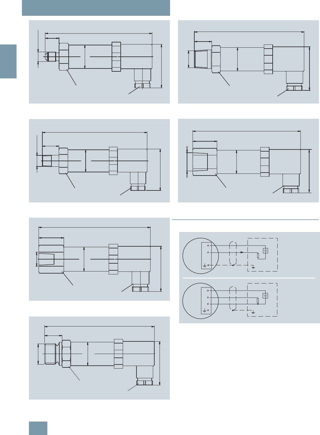
Pressure transmitter 7MF1564-... with process connection 7/16-20 UNF
male, dimensions in mm (inch)
Pressure transmitter 7MF1564-... with process connection ¼"-18 NPT
male, dimensions in mm (inch)
Pressure transmitter 7MF1564-... with process connection ¼"-18 NPT
female, dimensions in mm (inch)
Pressure transmitter 7MF1564-... with process connection G1“ male,
dimensions in mm (inch)
Pressure transmitter 7MF1564-... with process connection ½"-14 NPT
male, dimensions in mm (inch)
Pressure transmitter 7MF1564-... with process connection ½"-14 NPT
female, dimensions in mm (inch)
■
Schematics
SITRANS P pressure transmitters, Z series (7MF1564-...), connection
diagram, with current output (top) and voltage output (bottom)
ZLWKRXW([SURWHFWLRQ
81)
GLDP
6:
0[
RU
137
ZLWK([SURWHFWLRQ
/HQJWKRQYHUVLRQIRUYROWDJH
RXWSXW9
ZLWKRXW([SURWHFWLRQ
137
ZLWK([SURWHFWLRQ
GLDP
6:
0[
RU
137
/HQJWKRQYHUVLRQIRUYROWDJH
RXWSXW9
Ø27
(diam. 1.1)
1) Length on version for voltage
output 0 ... 10 V: 98 (3.9)
124 (4.88) without Ex protection
1)
133 (5.23) with Ex protection
M16x1.5
or
½-14 NPT
50
28
(1.97)
SW27
(1.1)
¼-18 NPT
129 (5.2) without Ex protection
1)
138 (5.6) with Ex protection
(diam. 1.1)
M16x1,5
or
½-14 NPT
1) Length on version for voltage
output 0 ... 10 V: 103 (4.1)
21
50
Ø27
G1
(1.97)
SW39
(0.8)
ZLWKRXW([SURWHFWLRQ
137
ZLWK([SURWHFWLRQ
GLDP
6:
0[
RU
137
/HQJWKRQYHUVLRQIRUYROWDJH
RXWSXW9
ZLWKRXW([SURWHFWLRQ
137
ZLWK([SURWHFWLRQ
GLDP
6: 0[
RU
137
/HQJWKRQYHUVLRQIRUYROWDJH
RXWSXW9
1+
2-
+
Signal RL
UB
I0
I0 Output current
UB Power supply
RL Load
Connections:
1 (+UB)
2 (-UB)
1+
3+
+
Signal
2- RL
UB
U0
U0 Output voltage
UB Power supply
RL Load
Connections:
1 (+UB)
2 (-UB)
3 (U0)
© Siemens AG 2008

SITRANS P measuring instruments for pressure
Transmitters for gage, absolute and differential pressure
Z series for gage and absolute pressure
2/9
Siemens FI 01 · 2009
2
Please note:
• It is not possible to have a smaller span than the smallest span of the device of the entire device range.
• The value must not fall below the minimum permissible operating pressure of the special measuring range of the selected
measuring cell.
• The required span of the device must lie between the smallest and the largest possible span of the entire device range.
■
Selection and Ordering data Order No. Order code
SITRANS P pressure transmitters for pressure, series Z for gage and absolute pressure
2 or 3-wire system, rising characteristic curve
D) 7 MF 1 5 6 4 - 777 7 7 -77717 7 7
Measuring range perm. working pressure Burst pressure
Min. Max.
For gage pressure
with metal measuring cell
0 ... 100 mbar g (0 ... 1.45 psi g) -0,6 bar g (-8.7 psi g) 0,6 bar g (8.7 psi g) 1 bar g (14.5 psi g) }3AA 0
0 ... 160 mbar g (0 ... 2.32 psi g) -0,6 bar g (-8.7 psi g) 0,6 bar g (8.7 psi g) 1 bar g (14.5 psi g) }3AB 0
0 ... 250 mbar g (0 ... 3.63 psi g) -1 bar g (-14.5 psi g) 1bar g (14.5 psi g) 1.7 bar g (25 psi g) }3AC 0
0 ... 400 mbar g (0 ... 5.80 psi g) -1 bar g (-14.5 psi g) 1bar g (14.5 psi g) 1.7 bar g (25 psi g) }3AD 0
0 ... 600 mbar g (0 ... 8.70 psi g) -1 bar g (-14.5 psi g) 3bar g (43.5 psi g) 5 bar g (72 psi g) }3AG 0
Other version for measuring range < 1 bar (< 14.5 psi g), add Order code and plain text:
measuring range: ... up to ... mbar g (psi g)1) 9AC 0 H 1 Y
with ceramic measuring cell
0 ... 1 bar g (0 ... 14.5 psi g) -0,4 bar g (-5.8 psi g) 2bar g (30 psi g) 5 bar g (72 psi g) }3BA
0 ... 1.6 bar g (0 ... 23.2 psi g) -0,4 bar g (-5.8 psi g) 3,2 bar g (45 psi g) 5 bar g (72 psi g) }3BB
0 ... 2.5 bar g (0 ... 36.3 psi g) -0,8 bar g (-11.6 psi g) 5bar g (72 psi g) 12 bar g (175 psi g) }3BD
0 ... 4 bar g (0 ... 58.0 psi g) -0,8 bar g (-11.6 psi g) 8bar g (115 psi g) 12 bar g (175 psi g) }3BE
0 ... 6 bar g (0 ... 87.0 psi g) -1 bar g (-14.5 psi g) 12 bar g (175 psi g) 25 bar g (360 psi g) }3BG
0 ... 10 bar g (0 ... 145 psi g) -1 bar g (-14.5 psi g) 20 bar g (290 psi g) 50 bar g (725 psi g) }3CA
0 ... 16 bar g (0 ... 232 psi g) -1 bar g (-14.5 psi g) 32 bar g (460 psi g) 50 bar g (725 psi g) }3CB
0 ... 25 bar g (0 ... 363 psi g) -1 bar g (-14.5 psi g) 50 bar g (725 psi g) 120 bar g (1750 psi g) }3CD
0 ... 40 bar g (0 ... 580 psi g) -1 bar g (-14.5 psi g) 80 bar g (1150 psi g) 120 bar g (1750 psi g) }3CE
0 ... 60 bar g (0 ... 870 psi g) -1 bar g (-14.5 psi g) 120 bar g (1750 psi g) 250 bar g (3600 psi g) }3CG
0 ... 100 bar g (0 ... 1450 psi g) -1 bar g (-14.5 psi g) 200 bar g (2900 psi g) 450 bar g (6525 psi g) }3DA
0 ... 160 bar g (0 ... 2320 psi g) -1 bar g (-14.5 psi g) 320 bar g (4640 psi g) 450 bar g (6525 psi g) }3DB
0 ... 250 bar g (0 ... 3626 psi g) -1 bar g (-14.5 psi g) 500 bar g (7250 psi g) 650 bar g (9425 psi g) }3DD
0 ... 400 bar g (0 ... 5802 psi g) -1 bar g (-14.5 psi g) 600 bar g (8700 psi g) 650 bar g (9425 psi g) }3DE
Other version for measuring range ≥ 1 bar g (≥ 14.5 psi g), add Order code and plain text:
measuring range: ... up to... bar (psi g)1) 9AA H 1 Y
For absolute pressure
0 ... 600 mbar a (0 ... 8.7 psi a) 0 bar a (0 psi a) 3bar a (43.5 psi a) 5bar a (72 psi a) }J) 5AG 0
0 ... 1 bar a (0 ... 14.5 psi a) 0 bar a (0 psi a) 2bar a (30 psi a) 5bar a (72 psi a) }J) 5BA
0 ... 1.6 bar a (0 ... 23.2 psi a) 0 bar a (0 psi a) 3,2 bar a (45 psi a) 5bar a (72 psi a) }J) 5BB
0 ... 2.5 bar a (0 ... 36.3 psi a) 0 bar a (0 psi a) 5bar a (72 psi a) 12 bar a (175 psi a) }J) 5BD
0 ... 4 bar a (0 ... 58.0 psi a) 0 bar a (0 psi a) 8bar a (115 psi a) 12 bar a (175 psi a) }J) 5BE
0 ... 6 bar a (0 ... 87.0 psi a) 0 bar a (0 psi a) 12 bar a (175 psi a) 25 bar a (360 psi a) }J) 5BG
0 ... 10 bar a (0 ... 145 psi) 0 bar a (0 psi a) 20 bar a (290 psi a) 50 bar a (725 psi a) }J) 5CA
0 ... 16 bar a (0 ... 232 psi) 0 bar a (0 psi a) 32 bar a (460 psi a) 50 bar a (725 psi a) }J) 5CB
Other version for measuring range < 1 bar (< 14.5 psi a), add Order code and plain text:
measuring range: ... up to ... mbar a (psi a)
J) 9AB 0 H 1 Y
} Available ex stock D) Subject to export regulations AL: N, ECCN: EAR99H.
J) Subject to export regulations AL: 9I999, ECCN: EAR99.
1) The transmitters can also be ordered with special measuring ranges, e.g. the transmitter with the 1 bar measuring cell (14.5 psi measuring cell):
-0.2 ... +0.8 bar g (-2.9 ... +11.6 psi g) or
-0.4 ... +0.6 bar g (-5.8 ... +8.7 psi g) or ..., however start-of-scale value not under -0.4 bar g (-5.8 psi g), also see column "min. perm. operating pressure"
© Siemens AG 2008

SITRANS P measuring instruments for pressure
Transmitters for gage, absolute and differential pressure
Z series for gage and absolute pressure
2/10 Siemens FI 01 · 2009
2
■
Selection and Ordering data Order No. Order code
SITRANS P pressure transmitters for pressure, series Z for pressure and absolute pressure
2 or 3-wire system, rising characteristic curve
D) 7 MF 1 5 6 4 - 777 7 7 -77717 7 7
Measuring range Perm. working pressure Burst pressure
min. max.
Measuring ranges for gage pressure (only for US market)
(0 ... 10 psi g) (-3 psi g) (20 psi g) (60 psi g) 4BA
(0 ... 15 psi g) (-6 psi g) (30 psi g) (72 psi g) 4BB
(3 ... 15 psi g) (-6 psi g) (30 psi g) (72 psi g) 4BC
(0 ... 20 psi g) (-6 psi g) (40 psi g) (72 psi g) 4BD
(0 ... 30 psi g) (-6 psi g) (60 psi g) (72 psi g) 4BE
(0 ... 60 psi g) (-11.5 psi g) (120 psi g) (175 psi g) 4BF
(0 ... 100 psi g) (-14.5 psi g) (200 psi g) (360 psi g) 4BG
(0 ... 150 psi g) (-14.5 psi g) (300 psi g) (725 psi g) 4CA
(0 ... 200 psi g) (-14.5 psi g) (400 psi g) (725 psi g) 4CB
(0 ... 300 psi g) (-14.5 psi g) (600 psi g) (1750 psi g) 4CD
(0 ... 500 psi g) (-14.5 psi g) (1000 psi g) (1750 psi g) 4CE
(0 ... 750 psi g) (-14.5 psi g) (1500 psi g) (3600 psi g) 4CF
(0 ... 1000 psi g) (-14.5 psi g) (2000 psi g) (3600 psi g) 4CG
(0 ... 1500 psi g) (-14.5 psi g) (3000 psi g) (6525 psi g) 4DA
(0 ... 2000 psi g) (-14.5 psi g) (4000 psi g) (6525 psi g) 4DB
(0 ... 3000 psi g) (-14.5 psi g) (6000 psi g) (9425 psi g) 4DD
(0 ... 5000 psi g) (-14.5 psi g) (8700 psi g) (9425 psi g) 4DE
(0 ... 6000 psi g) (-14.5 psi g) (8700 psi g) (9425 psi g) 4DF
Other version, add Order code and plain text: Measuring range: ... up to ... psi g 9BA H 1 Y
Measuring ranges for absolute pressure (only for US market)
(0 ... 10 psi a) (0 psi a) (20 psi a) (60 psi a) J) 6AG
(0 ... 15 psi a) (0 psi a) (30 psi a) (72 psi a) J) 6BA
(0 ... 20 psi a) (0 psi a) (40 psi a) (72 psi a) J) 6BB
(0 ... 30 psi a) (0 psi a) (60 psi a) (72 psi a) J) 6BD
(0 ... 60 psi a) (0 psi a) (120 psi a) (175 psi a) J) 6BE
(0 ... 100 psi a) (0 psi a) (200 psi a) (360 psi a) J) 6BG
(0 ... 150 psi a) (0 psi a) (300 psi a) (725 psi a) J) 6CA
(0 ... 200 psi a) (0 psi a) (400 psi a) (725 psi a) J) 6CB
(0 ... 300 psi a) (0 psi a) (600 psi a) (1725 psi a) J) 6CC
Other version, add Order code and plain text: Measuring range: ... up to ... psi a J) 9BB H 1 Y
Output signal
4 ... 20 mA;C 2-wire system; power supply 10 ... 36 V DC }0
0 ... 10 V; 3-wire system; power supply 15 ... 36 V DC 1 0
Explosion protection
Without }0
With explosion protection Ex II 1/2 G EEx ia IIC T4 (only for version 4 ... 20 mA; 2-wire system;
power supply 10 ... 30 V DC) 1
With explosion protection "Intrinsic safety T.I.I.S." (available soon) 2
Electrical connection
Plug to DIN 43650, Form A, cable inlet M16 x 1.5 }1
Round connector M12, IP67 2
Plug to DIN 43650, cable inlet ½-14 NPT 3
Plug to DIN 43650, cable inlet Pg11 4
Cable gland Pg11 with 2 m PE cable, IP68 6
Special version (specify Order code and plain text) 9 N 1 Y
} Available ex stock D) Subject to export regulations AL: N, ECCN: EAR99H.
J) Subject to export regulations AL: 9I999, ECCN: EAR99.
© Siemens AG 2008

SITRANS P measuring instruments for pressure
Transmitters for gage, absolute and differential pressure
Z series for gage and absolute pressure
2/11
Siemens FI 01 · 2009
2
■
Selection and Ordering data Order No. Order code
SITRANS P pressure transmitters for pressure, series Z for pressure and absolute pressure
2 or 3-wire system, rising characteristic curve
D) 7 MF 1 5 6 4 - 777 7 7 -77717 7 7
Process connection
G½" male to EN 837-1 (½" BSP male) (standard for metric pressure ranges mbar, bar) }A
G½" male thread and G1/8" female thread B
G¼“ male to EN837-1 (¼“ BSP male) C
7/16"-20 UNF male D
¼"-18 NPT male (standard for pressure ranges psi) E
¼"-18 NPT female F
½"-14 NPT male G
½"-14 NPT female H
RC ½" male to JIS B 7505 K
G1" male (only for measuring ranges ≥ 1 bar g (14.5 psi g)) and max. permissible working pressure
100 bar g (1450 psi g) M
Special version (specify Order code and plain text) Z P 1 Y
Sealing material between sensor and housing
Viton (standard) }A
Neoprene B
Perbunan C
Special version (specify Order code and plain text) Z Q 1 Y
Further designs Order code / Order No.
Quality inspection certificate (Factory calibration) to IEC 60770-2,
add "-Z" to Order No. and Order code. C11
Oxygen version, oil and grease-free cleaning (only if the sealing material between sensor and housing is
Viton and only for measuring ranges ≥ 1 bar g (≥ 14.5 psi g)
and ≥ 1 bar a (≥ 14.5 psi a)
E10
Accessories Order No.
Quality inspection certificate (Factory calibration) to IEC 60770-2 supplied later,
specify factory no. of transmitter.
D) 7MF1564-8CC11
} Available ex stock D) Subject to export regulations AL: N, ECCN: EAR99H.
© Siemens AG 2008
SITRANS P measuring instruments for pressure
Transmitters for gage, absolute and differential pressure
SITRANS P250 for differential pressure
2/12 Siemens FI 01 · 2009
2
■
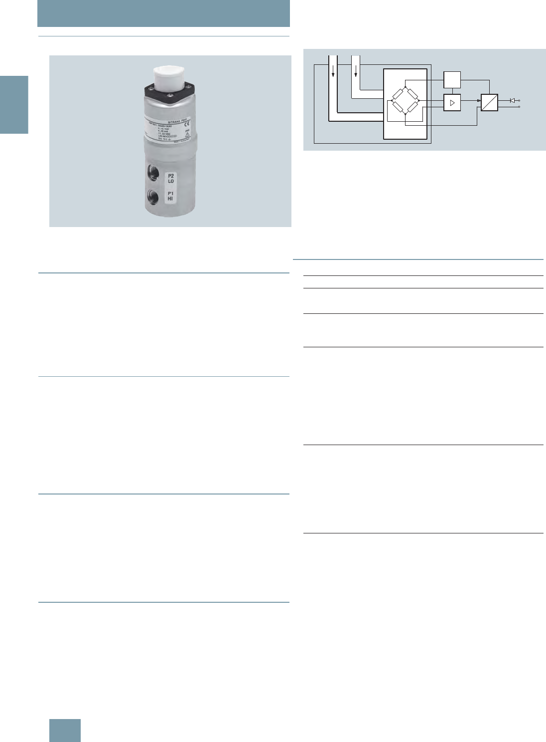
Overview
SITRANS P250 transmitter for differential pressure
The SITRANS P250 transmitter measures the differential pres-
sure of liquids and gases.
■
Benefits
• High measuring accuracy
• Sturdy stainless steel enclosure
• For aggressive and non-aggressive media
• For the measurement of the differential pressure of liquids and
gases
• Temperature-compensated measuring cell
• Compact design
■
Application
The SITRANS P250 transmitter for differential pressure is prima-
rily used in the following industries:
• Chemical industry
• Pharmaceutical industry
• Food industry
• Mechanical engineering
• Shipbuilding
• Water supply
■
Design
Main components:
• Stainless steel enclosure with piezo-resistive ceramic measur-
ing cell and (temperature-compensated) electronics module.
• Process connection made of stainless steel in diverse designs
(see Selection and ordering data)
• Electrical connection through connectors acc. to EN 175301-
803-A and round connectors M12, as well as with permanently
fixed cable
■
Function
The pressure transmitter measures the differential pressure of
liquids and gases.
Mode of operation
SITRANS P250 pressure transmitter, function diagram
The piezo-resistive ceramic measuring cell (membrane) has a
Wheatstone bridge circuit, on which the operating pressure P1
and P2 of the media acts at both ends.
The voltage output from the measuring cell is converted by an
amplifier into an output current of 4 to 20 mA or an output voltage
of 0 to 5 or 10 V DC.
The output current and voltage are linearly proportional to the in-
put pressure.
■
Technische Daten
SITRANS P250 differential pressure transmitter
Application
Differential pressure transmitter Liquids and neutral gases
Mode of operation
Measuring principle Piezo-resistive measuring cell
(ceramic diaphragm)
Input
Measured variable Differential pressure
Measuring range 0 ... 0.1 to 0 ... 25 bar
(0 ... 1.45 to 0 ... 363 psi)
Operating pressure ≤ 25 bar (363 psi) at a differential
pressure range < 6 bar (87 psi)
≤ 50 bar (725 psi) at a differential
pressure range > 10 bar (145 psi)
Burst pressure 1.5 x operating pressure
Output
Output signal
• Current output signal 4 ... 20 mA
• Voltage output signal 0 ... 5 V and 0 ... 10 V DC
Load
3-wire > 10 kΩ
2-wire ≤ (UH - 11 V) / 0.02 A
Measuring accuracy
Dynamic behavior (at 25°C (77°F),
including conformity error, hystere-
sis and repeatability)
≤ 1 % of typical full-scale value,
see "Measuring range" table
Long-term drift acc. to IEC 60770 ≤ 0.5 % of full-scale value/year
Influence of ambient temperature
• Start of scale ≤ 0.6 %/10 K of full-scale value
(≤ 1.2 %/10 K for measuring cell
0 ... 0.1 bar (1.45 psi))
• Full-scale value ≤ 0.22 %/10 K of full-scale value
(≤ 0.37 %/10 K for measuring cell
0 ... 0.1 bar (1.45 psi))
Dynamic behavior Suitable for static and dynamic
measurements
Response time T99 < 5 ms
Load variation < 50 Hz
p1p2
U
const.
U
II0, UB
© Siemens AG 2008

SITRANS P measuring instruments for pressure
Transmitters for gage, absolute and differential pressure
SITRANS P250 for differential pressure
2/13
Siemens FI 01 · 2009
2
■
Schematics
Connection with current output 4 ... 20 mA and plug to EN 175301-803-A
Connection with current output 4 ... 20 mA and round connector
Connection with current output 4 ... 20 mA and permanently fixed cable
Conditions of use
Ambient conditions
• Temperature of medium -15 ... +85 °C (5 ... 185 °F)
• Ambient temperature -15 ... +85 °C (5 ... 185 °F)
• Storage temperature -40 ... +85 °C (-40 ... +185 °F)
Degree of protection acc. to
EN 60529 IP65
Mounting position Any
Mounting Mounting bracket, included in
delivery
Design
Weight Approx. 430 g (approx. 0.95 lb)
Enclosure material Stainless steel 1.4305/AISI 303
Electrical connection • Plug EN 175301-803-A
• Circular plug EN 60130-9
• Cable 1.5 m
Process connection • Hose sleeve Ø 4 mm/6 mm
• Pipe union Ø 6 mm/8 mm
• Male thread 7/16-20 UNF, G1/8
• Female thread 1/8-27 NPT
• (Standard), G1/8
Wetted parts materials Stainless steel 1.4305/AISI 303,
CuZn nickel-plated
• Process connection Approx. 430 g (approx. 0.95 lb)
• Diaphragm Ceramic Al2O3 (96 %)
• Sealing material FPM (standard), EPDM, NBR,
MVQ, CR
Power supply UH
Terminal voltage on pressure trans-
mitter
• 2-wire, 4 ... 20 mA 11 ... 33 V DC
• 3-wire, 0 ... 5 V DC 11 ... 33 V DC/
24 V AC ±15 %
• 3-wire, 0 ... 10 V DC 18 ... 33 V DC/
24 V AC ±15 %
Current consumption at nominal
pressure
• 2-wire < 20 mA
•3-wire < 5mA
Protection against polarity reversal Protected against short-circuit
and polarity reversal. Each con-
nection against the other with
max. supply voltage.
Certificates and approvals
Approval CE conformity
Measuring range Max. per-
missible
operating
pressure
(on either
side)
Burst
pressure Max. per-
missible
operating
pressure
(on one
side)
Accuracy
[bar] [psi]
0 ... 0.1 0 ... 1.45 25 bar
(363 psi) 37,5 bar
(544 psi) 0.6 bar
(8.7 psi) ≤ 1,0 %
0 ... 0.2 0 ... 2.9 25 bar
(363 psi) 37,5 bar
(544 psi) 0.6 bar
(8.7 psi) ≤ 1,0 %
0 ... 0.25 0 ... 3.63 25 bar
(363 psi) 37,5 bar
(544 psi) 0.6 bar
(8.7 psi) ≤ 0,5 %
0 ... 0.3 0 ... 4.35 25 bar
(363 psi) 37,5 bar
(544 psi) 0.6 bar
(8.7 psi) ≤ 0,5 %
0 ... 0.4 0 ... 5.8 25 bar
(363 psi) 37,5 bar
(544 psi) 1.2 bar
(17.4 psi) ≤ 0,8 %
0 ... 0.5 0 ... 7.25 25 bar
(363 psi) 37,5 bar
(544 psi) 1.2 bar
(17.4 psi) ≤ 0,5 %
0 ... 0.6 0 ... 8.7 25 bar
(363 psi) 37,5 bar
(544 psi) 1.2 bar
(17.4 psi) ≤ 0,5 %
0 ... 1.0 0 ... 14.5 25 bar
(363 psi) 37,5 bar
(544 psi) 2 bar
(29 psi) ≤ 0,5 %
0 ... 1.6 0 ... 23.2 25 bar
(363 psi) 37,5 bar
(544 psi) 3.2 bar
(46.4 psi) ≤ 0,5 %
0 ... 2.5 0 ... 36.3 25 bar
(363 psi) 37,5 bar
(544 psi) 5 bar
(72.5 psi) ≤ 0,5 %
0 ... 4 0 ... 58 25 bar
(363 psi) 37,5 bar
(544 psi) 8 bar
(116 psi) ≤ 0,5 %
0 ... 6 0 ... 87 25 bar
(363 psi) 37,5 bar
(544 psi) 12 bar
(174 psi) ≤ 0,5 %
0 ... 10 0 ... 145 50 bar
(725 psi) 75 bar
(1088 psi) 20 bar
(290 psi) ≤ 0,5 %
0 ... 16 0 ... 232 50 bar
(725 psi) 75 bar
(1088 psi) 32 bar
(464 psi) ≤ 0,5 %
0 ... 25 0 ... 363 50 bar
(725 psi) 75 bar
(1088 psi) 50 bar
(725 psi) ≤ 0,5 %
UB Power supply
RL Load
IO Output current
Connection: 1 (+),
2 (-)
IO
UB
RL
1+ +
2-
1
2
+
Connection: 1 (+),
3 (-)
IO Output current
RL Load
UB Power supply
UB
RL
IO
3-
1+
1
2
3
Connection: 1 (+, brown),
2 (-, green)
IO Output current
UB Power supply
RL Load
UB
RL
IO
2-
1+ +
© Siemens AG 2008
SITRANS P measuring instruments for pressure
Transmitters for gage, absolute and differential pressure
SITRANS P250 for differential pressure
2/14 Siemens FI 01 · 2009
2
Connection with voltage output 0 ... 5 V DC (0 ... 10 V DC) and plug to EN
175301-803-A
Connection with voltage output 0 ... 5 V DC (0 ... 10 V DC) and round con-
nector
Connection with voltage output 0 ... 5 V DC (0 ... 10 V DC) and perma-
nently fixed cable
■
Dimensional drawings
SITRANS P250 differential pressure transmitter with socket outlet to
EN 175301-803-A, dimensions in mm (inch)
SITRANS P250 differential pressure transmitter with round connector to
EN 60130-9, dimensions in mm (inch)
SITRANS P250 differential pressure transmitter with cable, dimensions in
mm (inch)
+
Connection: 1 (+UB),
2 (-),
3 (+U0)
UO Output voltage
RL Load
UB Power supply
UB
RL
UO
1+
3-
1
2
32+
+
Connection: 1 (+UB, brown),
2 (+U0, green),
3 (-, white)
UO Output voltage
UB Power supply
RL Load
UB
RL
UO
1
2
3
1
2
3
Connection: 1 (+UB),
2 (-),
3 (+U0)
Uo Output voltage
UB Power supply
RL Load
+
UO
UB
RL
1+
2-
3+
Stainless
(mounted)
Socket outlet
EN 175301-803-A
20 (0.79)
P1
P2
Ø 25
(0.98)
M 4
44 (1.7)
X
~ 136 (5.4)
15 ± 0,5 21 ± 0,8
5 (0.2)
102 (4.02)
Round connector
EN 60130-9
(mounted)
~158 (6.2)
~108(4.3)
Cable
~95 (3.7)
~138 (5.4)
© Siemens AG 2008
SITRANS P measuring instruments for pressure
Transmitters for gage, absolute and differential pressure
SITRANS P250 for differential pressure
2/15
Siemens FI 01 · 2009
2
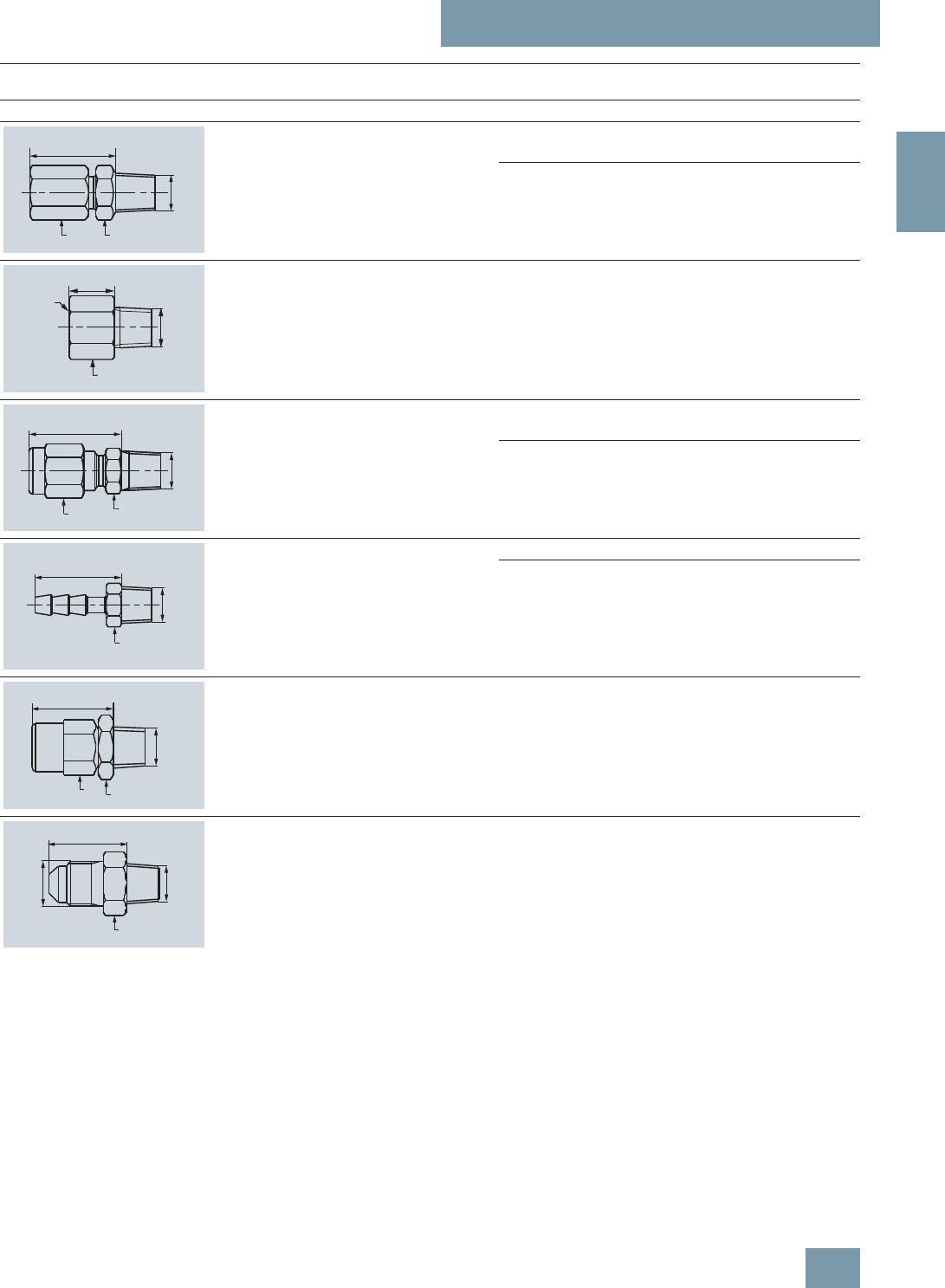
Process connections Ø Width across
flats LX
[mm] [inch] [mm] [inch] [mm] [inch]
Pipe union with screw-in nipple for outer pipe
(stainless steel 1.4305/AISI 303) 6a = 10
b = 12
24 65
8a = 12
b = 14
26 67
Female thread G1/8
(stainless steel 1.4305/AISI 303) - a = 14 12 53
Pipe union with screw-in nipple for outer pipe
(CuZn nickel-plated) 6a = 10
b = 12
24 65
8a = 12
b = 14
25 66
Hose connection for hose (CuZn nickel-plated,
stainless steel 1.4571/AISI 316TI) 4 a = 10 20 61
6 a = 10 25 66
Male thread G1/8
(CuZn nickel-plated) -a = 10
b = 12
20 61
Male thread G1/8
7/16-20 UNF (CuZn nickel-plated) - a = 14 18 59
L
ab
1/8-27 NPT
L
a
1/8-27 NPT
G1/8
ab
L
1/8-27 NPT
a
L
1/8-27 NPT
L
b
a
1/8-27 NPT
a
L
1/8-27 NPT
7/16-20 UNF
© Siemens AG 2008

SITRANS P measuring instruments for pressure
Transmitters for gage, absolute and differential pressure
SITRANS P250 for differential pressure
2/16 Siemens FI 01 · 2009
2
■
Selection and ordering data Order No. Order code
SITRANS P 250 pressure transmitter for differential pressure
Accuracy ≤ 1 %, wetted parts ceramic/stainless steel 1.4301,
scope of delivery: transmitter, mounting bracket and instruction manual, without explosion protection
7 M F 1 6 4 1 - 777 7 0 - 77707 7 7
Measuring range
0 ... 0.1 bar (0 ... 1.45 psi) }3AA
0 ... 0.2 bar (0 ... 2.90 psi) }3AC
0 ... 0.25 bar (0 ... 3.63 psi) }3AD
0 ... 0.3 bar (0 ... 5.35 ps) }3AE
0 ... 0.4 bar (0 ... 5.80 psi) }3AF
0 ... 0.5 bar (0 ... 7.25 psi) }3AG
0 ... 0.6 bar (0 ... 8.70 psi) }3AH
0 ... 1.0 bar (0 ... 14.5 psi) }3BA
0 ... 1.6 bar (0 ... 23.2 psi) }3BB
0 ... 2.5 bar (0 ... 36.3 psi) }3BD
0 ... 4.0 bar (0 ... 58.0psi) }3BE
0 ... 6.0 bar (0 ... 87.0 psi) }3BG
0 ... 10.0 bar (0 ... 145 psi) }3CA
0 ... 16.0 bar (0 ... 232 psi) }3CB
0 ... 25.0 bar (0 ... 363 psi) }3CD
Output signal
4 ... 20 mA }0
0 ... 5 V DC 1
0 ... 10 V DC 2
Electrical connection
• Plug acc. to EN 175 301-803-A (suitable coupling included in scope of delivery) }1
• Round connector acc. to EN 60139-9 2
• Cable 1.5 m with cable gland 3
Process connection
• Without connections, female thread 1/8-27 NPT }A
• Hose connection
- CuZn nickel-plated, for hose ∅ 4 mm B
- CuZn nickel-plated, for hose ∅ 6 mm C
- PVDF, for hose ∅ 6 mm D
• Pipe union
- CuZn nickel-plated, for pipe ∅ 6 mm E
- Stainless steel 1.4304, for pipe ∅ 6 mm F
- CuZn nickel-plated, for pipe ∅ 8 mm G
- Stainless steel 1.4304, for pipe ∅ 8 mm H
• Male thread, 7/16-20 UNF (CuZn nickel-plated) L
• Adapter
- Inner, G1/8 (stainless steel), for pipe ∅ 6 mm M
- Outer, with union nut, for pipe ∅ 6 mm N
sealing material
• Fluoro rubber (Viton/FPM) }A
• Ethylene propylene diene monomer rubber (EPDM) B
• Nitrile butadiene rubber (NBR) C
• Silicone rubber (MVQ) D
• Neoprene (CR) E
Weitere Ausführungen Kurzangabe
Please add "-Z" to Order No. and specify Order code(s).
Quality inspection certificate (Factory calibration) to IEC 60770-2 supplied C11
} Available ex stock
© Siemens AG 2008
SITRANS P measuring instruments for pressure
Transmitters for gage, absolute and differential pressure
ZD series for gage and absolute pressure
2/17
Siemens FI 01 · 2009
2
■
Overview
SITRANS P pressure transmitters, ZD series, are for measuring
the gage pressure, absolute pressure and level of liquids and
gases.
They are used to indicate and monitor the pressure measured at
the point of installation. ZD pressure transmitters are available in
an axial and a radial version.
■
Benefits
• Robust stainless steel housing with 2 connection versions
• Integrated display with status messages
• Thin-film measuring cell with ceramic diaphragm
• 2-wire system, 4 ... 20 mA
• Parameterizable using keys underneath the housing cover
• Range adjustment 1:5 (max. 1:10)
• Measuring accuracy < 0.25% (typical)
■
Application
The ZD is a configurable pressure transmitter for measuring the
gage and absolute pressure of gases, liquids and vapor.
It is equipped with a display for indicating the pressure value at
the point of installation.
SITRANS P pressure transmitters, ZD series, are used in the fol-
lowing industrial areas for example:
• Chemical industry
• Mechanical engineering
• Food industry
• Pharmaceutical industry
• Shipbuilding
• Water supply
■
Design
The pressure transmitter is comprised of a thin-film measuring
cell with a ceramic diaphragm, an electronics board and a digi-
tal indicator.
All parts are accommodated in a stainless steel field housing
(∅80 mm) with a glass cover and stainless steel process con-
nection.
At the rear of the housing is the electrical connection for the volt-
age supply using a current loop 4 ... 20 mA. The connection is
made with a plug connector.
At the front of the housing is the 5-digit display behind a glass
cover. Underneath the display are the 3 keys for parameterizing
the pressure transmitter. Above the display are a green and a red
LED for indicating the operating status.
The ZD pressure transmitter is available in two versions (see "Di-
mension drawing"):
In the radial version (type A) the display is fitted in parallel with
the process connection. The display can be rotated by up to
±120° relative to the process connection.
In the axial version (type B) the display is at right angles to the
process connection. The display can be rotated by 360° relative
to the process connection.
■
Function
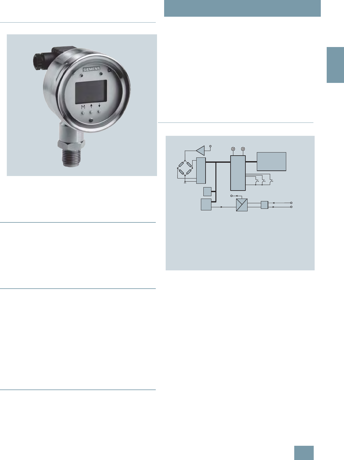
SITRANS P pressure transmitters, ZD series, mode of operation
Mode of operation
The ZD pressure transmitter has a thin-film strain gage which is
mounted on a ceramic diaphragm.
The measuring cell is temperature-compensated.
Functions
The ZD pressure transmitter has a 5-digit display behind a glass
cover. The following data are shown on the display:
•Measured pressure
• Technical pressure dimension (default setting: bar)
• Limit violation in upward or downward direction, indicated by
LED and arrow symbols in the display
The pressure transmitter is set using the 3 input keys behind the
glass cover underneath the display.
The key "M" is used to select the operating mode. Following
modes of operation are available:
• Measured value
• Password
• Dimension
• Start and end of scale
• Upper and lower limit value
• Zero adjustment
600.00
Uref
PA/D
D/A
EEPROM
+
-
LCD
Red LEDGreen LED
µC
UK
UAUI
EMC
4 ... 20 mA UH, IA
mbar
3 keysConfiguring of parameters
A/D Analog-to-digital converter
D/A Digital-to-analog converter
EEPROM Memory for all parameters
EMC Output stage with protective components
IAOutput current
Uref Reference voltage
LCD Display of measured values with dimensions
Green LED Display of normal mode
Red LED Display of error messages or limit violation
P Ceramic measuring cell
UHPower supply
µC Microcontroller for computing functions and monitoring
3 keys
© Siemens AG 2008

SITRANS P measuring instruments for pressure
Transmitters for gage, absolute and differential pressure
ZD series for gage and absolute pressure
2/18 Siemens FI 01 · 2009
2
• Upper and lower current saturation limit
• Electrical damping
The other two keys are used to set the values in the individual op-
erating modes.
Two LED indicators are fitted above the display to monitor the set
range and the status.
The green LED signals that the measured pressure lies within the
set limits. The red LED lights up when the measured pressure
lies outside the set limits and when there is an error.
■
Technical specifications
SITRANS P pressure transmitters, ZD series
Mode of operation
Measuring principle Thin-film strain gage
Input
Measured variable Gage and absolute pressure
Measured range Resolution
0 ... 2 bar (0 ... 29 psi) 0.6 mbar (0.008 psi)
0 ... 10 bar (0 ... 145 psi) 3 mbar (0.044 psi)
0 ... 50 bar (0 ... 725 psi) 15 mbar (0.218 psi)
0 ... 200 bar (0 ... 2900 psi) 60 mbar (0.9 psi)
0 ... 400 bar (0 ... 5800 psi) 120 mbar (1.8 psi)
Measured range Overload limit
0 ... 2 bar (0 ... 29 psi) 5 bar (72.5 psi)
0 ... 10 bar (0 ... 145 psi) 25 bar (363 psi)
0 ... 50 bar (0 ... 725 psi) 120 bar (1740 psi)
0 ... 200 bar (0 ... 2900 psi) 500 bar (7250 psi)
0 ... 400 bar (0 ... 5800 psi) 600 bar (8700 psi)
Range adjustment (turndown) 5:1
Output
Output signal 4 ... 20 mA
Lower current limit min. 3.6 mA
Upper current limit max. 23 mA
Output protected against Reversed polarity, overvoltage
and short-circuiting
Max. load R B = (UH- 12 V) / 0.023 A
Voltage measurement Linear rising
Measuring accuracy To EN 60770-1
Error in measurement (including
non-linearity, hysteresis and repeat-
ability, at 25 °C (77 °F))
< 0.25% of full-scale value (typi-
cal), max. 0.5%
Adjustment time < 100 ms
Long-term drift 0.25% of full scale value/year
Influence of ambient temperature < ±0.25%/10 K (< ±0.25%/10 K)
of full-scale value
Vibration influence 0.05%/g to 500 Hz in all directions
(to IEC 68-2-64)
Power supply effect < ±0.01%/V of full-scale value
Rated conditions
Ambient conditions
• Ambient temperature -25 ... +85 °C (-13 ... +185 °F)
• Storage temperature -40 ... +85 °C (-40 ... +185 °F)
Medium conditions
• Process temperature -30 ... +100 °C (-22 ... +212 °F)
Degree of protection IP65 to EN 60529
Electromagnetic compatibility
• Emitted interference and interfer-
ence immunity To EN 61326/A1 appendix A
(1998)
Displays and controls
Display LCD, max. 5 digits, digit height
9mm
Decimal point Freely parameterizable
Limit values Freely parameterizable
Limit violation display Red LED and message on LCD
(↑ symbol /↓ symbol in case of
limit violation in upward / down-
ward direction)
Parameterization With 3 keys
Units mA or % or physical variable
(default setting: bar)
Other dimensions: mbar, kPa,
MPa, mmH20, mH20, psi, inH20,
mmHg, kg/cm², torr, atm
Damping Between 0.1 and 100 s
(increment: 0.1 s) freely parame-
terizable
Design
Weight ≈0.6 kg (≈1.32 lb)
Electrical connection Using 2-pole plug connector with
M16x1.5-Cable inlet to
EN 175301-803A, plastic
Process connection • Male thread G½B and female
thread G1/8B
• G½B to EN 837-1
• Female thread: ½-14 NPT
Version of housing/process connec-
tion • Radial (type A), can be swiveled
by max. ±120° (α)
• Axial (type B), can be swiveled
by max. ±360°
Material
Non-wetted parts materials
• Field housing Ø 80 mm (3.15 inch), stainless
steel mat. No. 1.4016
• Cover Stainless steel, mat. No. 1.4016
with glass
Wetted parts materials
• Measuring cell Al2O3
• Gasket Viton
• Process connection Stainless steel, mat. No.
1.4571/316Ti
Power supply
Terminal voltage on pressure trans-
mitter (UH)12 ... 30 V DC
Certificate and approvals
Classification according to pressure
equipment directive 97/23/EC For gases of fluid group 1 and liq-
uids of fluid 1; complies with
requirements of article 3, para-
graph 3 (sound engineering prac-
tice)
© Siemens AG 2008
SITRANS P measuring instruments for pressure
Transmitters for gage, absolute and differential pressure
ZD series for gage and absolute pressure
2/19
Siemens FI 01 · 2009
2
■
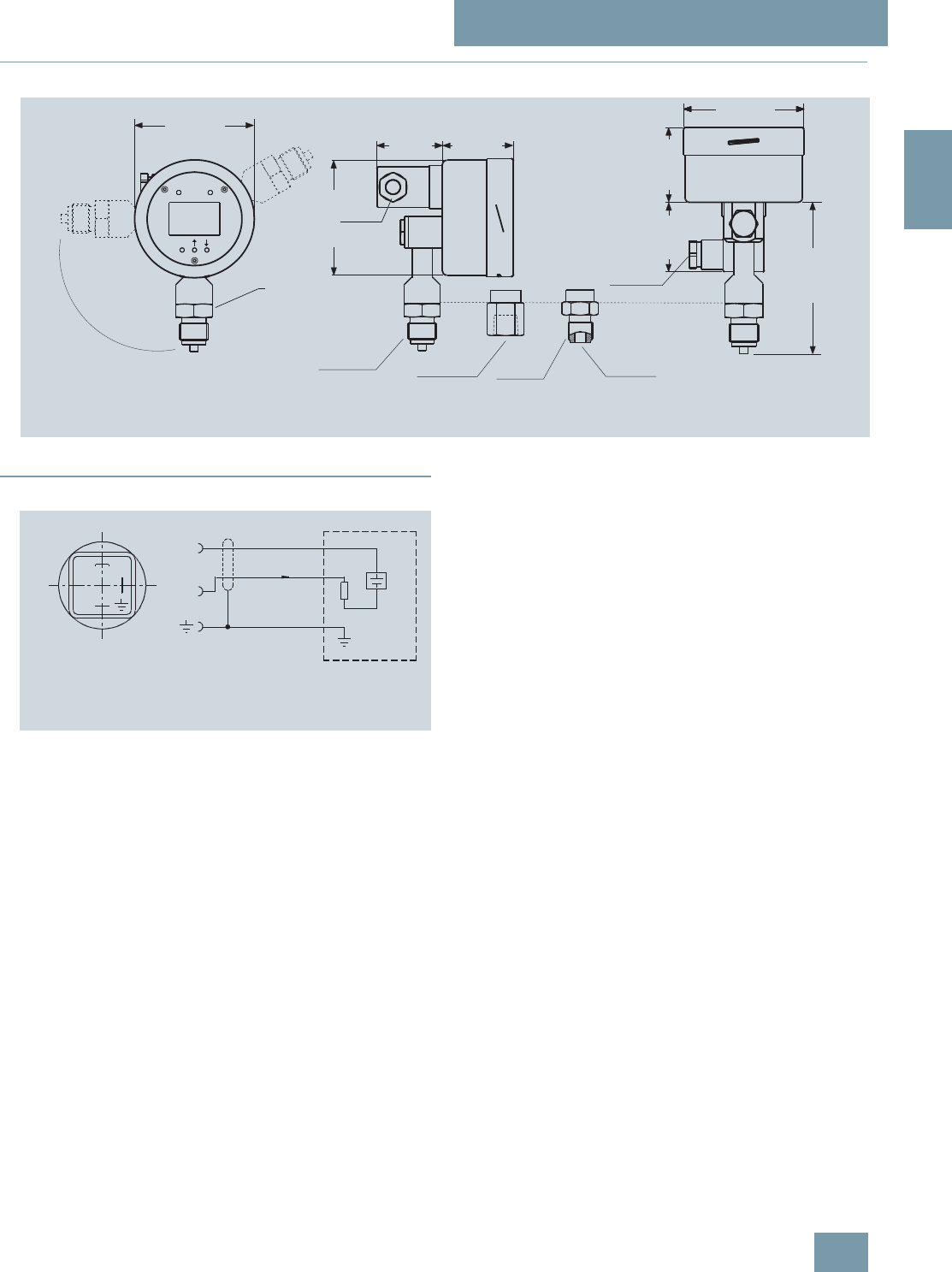
Dimensional drawings
SITRANS P pressure transmitters, ZD series, dimensional drawing, dimensions in mm (inch)
■
Schematics
SITRANS P pressure transmitters, ZD series, connection diagram
s
a
Ø 82 (3.23)
G½B
SW 27
48,5 (1.91)
M
45 (1.77)
152 (5.98)
Ø 82 (3.23)
48,5 (1.91)
45 (1.77)
½-14 NPT G½B
M16x1,5
or
½-NPT
G1/8B
Ø 82 (3.23)
EN 837-1
Type A Type B
M16x1,5
or
½-NPT
1
2
1 (+)
2 (-)
I0
RL
UB
+
UBPower supply
RLLoad
I0Output current
© Siemens AG 2008

SITRANS P measuring instruments for pressure
Transmitters for gage, absolute and differential pressure
ZD series for gage and absolute pressure
2/20 Siemens FI 01 · 2009
2
F) Subject to export regulations AL: 9I999, ECCN: N.
Selection and Ordering data Order No. Ord. Code
SITRANS P pressure transmitters, ZD
series for gage and absolute pressure 7M F 1 5 8 0 -
Conformity error 0.25%, range adjustment
1 : 5 (max. 1 : 10), housing and process
connection made of stainless steel,
membrane made of ceramic, 2-wire system,
output 4 ... 20 mA
7 7 7 7 0777
Input variable
Gage pressure }1
Absolute pressure }
F) 2
Measured range Span
0 ... 2 bar
(0 ... 29 psi) 0 ... 0.4 / 2 bar
(0 ... 5.8 / 29 psi)
}D
0 ... 10 bar
(0 ... 145 psi) 0 ... 2 / 10 bar
(0 ... 5.8 / 145 psi)
}E
0 ... 50 bar
(0 ... 725 psi) 0 ... 10 / 50 bar
(0 ... 145 / 725 psi)
}F
0 ... 200 bar
(0 ... 2900 psi) 0 ... 40 / 200 bar
(0 ... 580 / 2900 psi)
}G
0 ... 400 bar
(0 ... 5800 psi) 0 ... 80 / 400 bar
(0 ... 1160 / 5800 psi)
}H
Other version (on request)
add Order Code and plain text:
Process connection: ............
Z J 1 Y
Process connection
G½B male thread and G1/8B female thread }A
G½B to EN 837-1 F) B
Female thread ½-14 NPT F) C
G 1“ male thread F) M
Design
Process connection vertically downwards,
thread in connector M16x1.5
}1
Process connection horizontally to rear,
thread in connector M16x1.5 2
Process connection vertically downwards,
thread in connector ½"-14 NPT
}3
Process connection horizontally to rear,
thread in connector ½"-14 NPT 4
Selection and Ordering data Order Code
Further designs
Please add "Z" to Order No. and specify Order
code(s) and plain text.
Quality inspection certificate (Factory cali-
bration) to IEC 60770-2 supplied C1 1
Factory certificate
to EN 10204-2.2 supplied C1 4
Oxygen application, oil and grease-free
cleaned
(only in conjunction with the sealing material
Viton between sensor and enclosure and only
in conjunction with measuring ranges >= 1
bar g and 1 bar abs)
E1 0
Sealing material FEP between sensor and
housing, instead of Viton
max. operating pressure 15 bar (218 psi),
max. measuring temperature -10 ... +50 °C
E2 0
Additional data
Please add "Z" to Order No. and specify Order
code(s) and plain text.
Measuring range to be set,
specify in plain text:
Y01: ... up to ... mbar, bar, kPa, MPa, psi
Y0 1
TAG number made of stainless steel Y1 5
Accessories Order No.
Quality inspection certificate (Factory
calibration) to IEC 60770-2
supplied later,
specify factory of transmitter.
7MF1564-8CC11
} Available ex stock
© Siemens AG 2008
SITRANS P measuring instruments for pressure
Transmitters for food, pharmaceuticals and biotechnology
SITRANS P Compact
for gage and absolute pressure
2/21
Siemens FI 01 · 2009
2
■
Overview
The SITRANS P Compact pressure transmitter is designed for
the special requirements of the food, pharmaceutical and bio-
technology industries.
The use of high-grade materials guarantees compliance with hy-
giene regulations.
Particular value has been placed on a high surface quality. It is
therefore possible, for example, to guarantee roughness values
down to Ra=0.4μm (1.57 ⋅10-5 inch) in the wetted area
(welded seam area Ra<0.8μm (3.15 ⋅10-5 inch)). The system
can be electropolished in addition.
A further important feature is the hygiene-based design of the
process connection by means of various aseptic connections.
The completely welded stainless steel housing can be designed
up to degree of protection IP67.
Using appropriate thermal decouplers, the SITRANS P Compact
pressure transmitter can be used for process temperatures up to
200 °C (392 °F).
■
Benefits
• Measuring ranges from 0 to 160 mbar (0 to 2.32 psi) to 0 to
40 bar (0 to 580 psi)
• Linearity error including hysteresis < +0.2% of full-scale value
• Piezo-resistive measurement system, vacuum-proof and over-
load-proof
• Hygiene-based design according to EHEDG, FDA and GMP
recommendations
• Material and surface quality according to hygiene require-
ments
• Wetted parts made of stainless steel; completely welded
• Signal output 4 to 20 mA (0 to 20 mA as option)
• Stainless steel housing with degree of protection IP65 (IP67 as
option)
• Process temperature up to 200 °C (392 °F)
• Explosion protection II 2G EEx [ib] IIC T6 to ATEX
• Easy and safe to clean
■
Application
The SITRANS P Compact pressure transmitter is designed for
the special requirements of the food, pharmaceutical and bio-
technology industries.
The use of high-grade materials guarantees compliance with hy-
giene regulations.
The SITRANS P Compact pressure transmitter is available in
many versions. Exact adaptation of the pressure transmitter to
conditions at the place of use is thus possible
■
Design
The electronics is potted to protect it against moisture, corrosive
atmospheres and vibration.
Notes on operating the pressure transmitter
Compensation of internal atmospheric pressure
Compensation of the internal atmospheric pressure of the
SITRANS P Compact pressure transmitters is performed as fol-
lows:
• in the plug versions by means of the screwed gland (IP65)
• in the field housings by means of an integral sintered filter
(IP65) or a vented cable (IP67)
• in versions with cable outlet by means of a vented cable (IP67)
In the absolute pressure range there is no need for compensa-
tion with respect to atmospheric pressure.
Note: These degrees of protection are only achieved under the
following conditions:
• if the pressure transmitter is installed correctly
• if the screwed glands are securely tightened
• if the cable diameters agree with the nominal diameters of the
gaskets in the housing
Note: The integral EMC measures are only effective if the earth
connection is made correctly.
CE marking
The CE marking of the pressure transmitter certifies compliance
with the guidelines of the European Council (9/336/EC), the EMC
law (13.11.1992), as well as the applicable generic standards.
Interference-free operation in systems and plants is achieved
only if the specifications for shielding, earthing, cable routing
and electrical isolation are observed during installation and as-
sembly.
Hazardous areas
Note: Electrical equipment in hazardous areas must only be in-
stalled and operated by trained personnel.
Modifications to units and connections result in cancellation of
the explosion protection and guarantee.
With intrinsically-safe circuits, make sure that equipotential
bonding exists throughout the complete cabling inside and out-
side of the hazardous area. The limits specified in the ATEX ap-
proval must be observed.
© Siemens AG 2008

SITRANS P measuring instruments for pressure
Transmitters for food, pharmaceuticals and biotechnology
SITRANS P Compact
for gage and absolute pressure
2/22 Siemens FI 01 · 2009
2
■
Function
The process pressure acts on a piezo-resistive semiconductor
measuring bridge through a remote seal and a transmission liq-
uid. The pressure transmitter converts the pressure values into a
load-independent current.
A compensation network makes the output signal largely inde-
pendent of the ambient temperature. As a result of a specially
adapted remote seal connection with minimized volume, the in-
fluence of the process temperature on the output signal is
greatly reduced compared to a conventional screw connection.
The pressure transmitters can be powered with a non-regulated
DC voltage of 10 to 30 V. Output signals common to measuring
technology are available.
■
Technical specifications
Pressure transmitters for food, pharmaceuticals and biotechnology
Mode of operation
Measuring principle Piezo-resistive
Input
Measured variable Gage or absolute pressure
Measured range 0 ... 160 mbar (0 ... 2.32 psi)
...
0 ... 40 bar (0 ... 580 psi)
Output
Output signal
• Two-wire system 4 ... 20 mA
• Three-wire system 0 ... 20 mA
Measuring accuracy To EN 60770-1
Linearity error including hysteresis
(reference point adjustment) ≤0.2% of full-scale value
Adjustment accuracy ≤± 0.2% of full-scale value
Adjustment time < 20 ms
Influence of ambient temperature
On th enclosure
• Zero < 0.2%/10 K of full-scale value
• Measured span < 0.2%/10 K of full-scale value
On the process connection (remote
seal) Zero error (depends on design)
• Flange remote seal
- DN 25 / 1" 4.8 mbar/10 K (0.070 psi/10 K)
- DN 32 / 1¼” 2.3 mbar/10 K (0.033 psi/10 K)
- DN 40 / 1½” 1.6 mbar/10 K (0.023 psi/10 K)
- DN 50 / 2" 0.6 mbar/10 K (0.009 psi/10 K)
• Clamp-on seal
- DN 25 / 1" 9.5 mbar/10 K (0.138 psi/10 K)
- DN 32 / 1¼” 4.1 mbar/10 K (0.060 psi/10 K)
- DN 40 / 1½” 3.9 mbar/10 K (0.057 psi/10 K)
- DN 50 / 2" 3.9 mbar/10 K (0.057 psi/10 K)
The zero error specified for the process connection should be consid-
ered as a guideline for a standard design. We will produce a detailed
system calculation on request. Systems with reduced remote seal errors
are available on request.
Rated conditions
Installation conditions
• Mounting position Any, vertical as standard
Ambient conditions
• Ambient temperature -10 ... +70 °C (14 ... 158 °F)
• Storage temperature -10 ... +90 °C (14 ... 194 °F)
• Process temperature Max. 200 °C (392 °F), depends
on design
• Degree of protection (to EN 60529) IP65, optional IP67
• Electromagnetic compatibility
- Emitted interference To EN 50081 Part 1, issue 1993
(residential and industrial areas).
The unit has no own emissions.
- Interference immunity to EN 50082 Part 2, issue March
1995 (industrial areas)
Design
Weight (without remote seal)
• Field housing ≈460 g (≈1.01 lb)
• Housing with plug ≈200 g (≈0.44 lb)
Housing
• Designs • Field housing IP65 or IP67, with
screwed gland
• Angled plug DIN 43650, IP65
• Cable connection, IP67
• Round plug connector M12,
IP65
• Material Stainless steel, mat.
No. 1.4404/1.4305
Material of union nut Polyamide (with electrical con-
nection using plug or cable)
Electronics unit potted with sili-
cone
Internal ventilation for measuring
ranges < 16 bar (< 232 psi),
through housing thread or con-
nection cable depending on
design
Process connection
• Versions See Ordering data
• Material of coupling Stainless steel, mat.
No. 1.4404/316L
Power supply
Terminal voltage on transmitter 10 ... 30 V DC
Rated voltage 24 V DC
Certificate and approvals
Classification according to pressure
equipment directive
(DRGL 97/23/EC)
For gases of fluid group 1 and liq-
uids of fluid group 1; complies
with the requirements of article 3,
paragraph 1 (appendix 1);
assigned to category III, confor-
mity evaluation module H by the
TÜV Nord
Explosion protection
• Intrinsic safety "i" TÜV 03 ATEX 2099 X
- Identification Ex II 2G EEx ib IIC T6
© Siemens AG 2008

SITRANS P measuring instruments for pressure
Transmitters for food, pharmaceuticals and biotechnology
SITRANS P Compact
for gage and absolute pressure
2/23
Siemens FI 01 · 2009
2
Selection and Ordering data Order No. Ord. code
SITRANS P Compact pressure trans-
mitters for pressure and absolute
pressure with diaphragm flush at front
7 M F 8 0 1 0 -
2-wire system
Process temperature up to 140 °C
(284 °F)
Accuracy: 0.2% of full-scale value
Output 4 ... 20 mA
17 7 7 7 -7777 777
Diaphragm seal
with quick-release clamp
Milk pipe union to DIN 11851 with
slotted union nut
•DN25 A D
•DN32 A E
•DN40 A F
•DN50 A G
•DN65 A H
Milk pipe union to DIN 11851 with
threaded socket
•DN25 B D
•DN32 B E
•DN40 B F
•DN50 B G
•DN65 B H
Clamp connection to DIN 32676
•DN25 C D
•DN40 C F
•DN50 C G
Clamp connection to ISO 2852
• 1 inch D M
•1½inch D N
• 2 inch D P
•2½inch D Q
IDF standard with slotted union nut
• 1 inch E M
•1½inch E N
• 2 inch E P
IDF standard with threaded socket
• 1 inch F M
•1½inch F N
• 2 inch F P
SMS standard with slotted union nut
• 1 inch GM
•1½inch G N
• 2 inch G P
SMS standard with threaded socket
• 1 inch H M
•1½inch H N
• 2 inch H P
DRD flange, without welding-type flange
• DN 50, PN 40 J H
Varivent connection (Tuchenhagen)
• D = 50, for Varivent housing DN 25 and
1 inch K F
• D = 68, for Varivent housing
DN 40 ... DN 125 and 1½ ... 6 inch K L
Special version
(add Order code and plain text) Z A J 1 Y
Filling liquid
Vegetable oil 1
medicinal white oil 2
Food oil, FDA-listed 3
Special version
(add Order code and plain text) 9 L 1 Y
Output signal
4 ... 20 mA 1
Special version
(add Order code and plain text) 9 M 1 Y
Selection and Ordering data Order No. Ord. code
SITRANS P Compact pressure trans-
mitters for pressure and absolute
pressure with diaphragm flush at front
7 M F 8 0 1 0 -
2-wire system
Process temperature up to 140 °C
(284 °F)
Accuracy: 0.2% of full-scale value
Output 4 ... 20 mA
17 7 7 7 -7777 7 7 7
Diaphragm seal
with aseptic connection
Aseptic screwed gland to DIN 11864-1,
form A,
with slotted union nut
• 1 inch P M
• 1½ inch P N
• 2 inch P P
• 2½ inch P Q
Aseptic screwed gland to
DIN 11864-1, form A
with threaded socket
• 1 inch QM
• 1½ inch Q N
• 2 inch Q P
• 2½ inch QQ
Aseptic screwed NEUMO
with slotted union nut1)
1) Please specify as well:
Connections for pipes: R01, R02 or R03,
see table "Further designs" on next page
•DN25 R D
•DN32 R E
•DN40 R F
•DN50 R G
Aseptic screwed NEUMO
with threaded socket1)
•DN25 S D
•DN32 S E
•DN40 S F
•DN50 S G
Aseptic screwed NEUMO
with clamp connection, form R1)
•DN25 T D
•DN32 T E
•DN40 T F
•DN50 T G
Aseptic screwed NEUMO
with clamp connection, form V1)
•DN25 U D
•DN32 U E
•DN40 U F
•DN50 U G
Special version
(add Order code and plain text) Z A J 1 Y
Filling liquid
Vegetable oil 1
medicinal white oil 2
Food oil, FDA-listed 3
Special version
(add Order code and plain text) 9 L 1 Y
Output signal
4 ... 20 mA 1
Special version
(add Order code and plain text) 9 M 1 Y
© Siemens AG 2008

SITRANS P measuring instruments for pressure
Transmitters for food, pharmaceuticals and biotechnology
SITRANS P Compact
for gage and absolute pressure
2/24 Siemens FI 01 · 2009
2
F) Subject to export regulations AL: 9I999, ECCN: N.
Selection and Ordering data Order No. Ord. code
SITRANS P Compact pressure trans-
mitters for pressure and absolute
pressure with diaphragm flush at front
7 M F 8 0 1 0 -
2-wire system
Process temperature up to 140 °C
(284 °F)
Accuracy: 0.2% of full-scale value
Output 4 ... 20 mA
17777-7 7 7 7 7 7 7
Housing design (stainless steel mat.
No. 1.4404/316L) / electr. connection
Housing with angled plug to DIN 43650,
IP65 1
Housing with round plug M12, IP65,
union nut made of polyamide 2
Housing with round plug M12, IP65,
union nut made of stainless steel 3
Stainless steel field housing (small) with
cable gland, IP65 4
Stainless steel field housing (small) with
cable gland, IP67
Internal ventilation for measuring ranges
< 10 bar (< 145 psi)
5
Measured range Overload pressure
0 ... 160 mbar g
(0 ... 2.32 psi g) 2 bar g
(29 psi g) B B
0 ... 250 mbar g
(0 ... 3.63 psi g) 2 bar g
(29 psi g) B C
0 ... 400 mbar g
(0 ... 5.8 psi g) 6 bar g
(87 psi g) B D
0 ... 600 mbar g
(0 ... 8.7 psi g) 6 bar g
(87 psi g) B E
0 ... 1 bar g
(0 ... 14.5 psi g) 10 bar g
(145 psi g) C A
0 ... 1.6 bar g
(0 ... 23.2 psi g) 10 bar g
(145 psi g) C B
0 ... 2.5 bar g
(0 ... 36.3 psi g) 16 bar g
(232 psi g) C C
0 ... 4 bar g
(0 ... 58 psi g) 16 bar g
(232 psi g) C D
0 ... 6 bar g
(0 ... 87 psi g) 30 bar g
(435 psi g) C E
0 ... 10 bar g
(0 ... 145 psi g) 30 bar g
(435 psi g) D A
0 ... 16 bar g
(0 ... 232 psi g) 50 bar g
(725 psi g) D B
0 ... 25 bar g
(0 ... 363 psi g) 50 bar g
(725 psi g) D C
0 ... 40 bar g
(0 ... 580 psi g) 70 bar g
(1015 psi g) D D
-160 ... 0 mbar g
(-2.32 ... 0 psi g) 2 bar g
(29 psi g) E B
-250 ... 0 bar g
(-3.73 ... 0 psi g) 2 bar g
(29 psi g) E C
-400 ... 0 bar g
(-5.8 ... 0 psi g) 6 bar g
(87 psi g) E D
-600 ... 0 bar g
(-8.7 ... 0 psi g) 6 bar g
(87 psi g) E E
-1 ... 0 bar g
(-14.5 ... 0 psi g) 10 bar g
(145 psi g) F A
-1 ... 0.6 bar g
(-14.5 ... 8.7 psi g) 10 bar g
(145 psi g) F B
-1 ... 1.5 bar g
(-14.5 ... 21.8 psi g) 16 bar g
(232 psi g) F C
-1 ... 3 bar g
(-14.5 ... 43.5 psi g) 16 bar g
(232 psi g) F D
-1 ... 5 bar g
(-14.5 ... 72.5 psi g) 30 bar g
(435 psi g) F E
Selection and Ordering data Order No. Ord. code
SITRANS P Compact pressure trans-
mitters for pressure and absolute
pressure with diaphragm flush at front
7 M F 8 0 1 0 -
2-wire system
Process temperature up to 140 °C
(284 °F)
Accuracy: 0.2% of full-scale value
Output 4 ... 20 mA
17 7 7 7 -7 7 7 7 7 7 7
Measured range Overload pres-
sure
(continued)
-1 ... 9 bar g
(-14.5 ... 130.5 psi g) 30 bar g
(435 psi g) G A
-1 ... 15 bar g
(-14.5 ... 217.6 psi g) 50 bar g
(725 psi g) G B
0...1bar a
(0 ... 14.5 psi a) 10 bar a
(145 psi a)
F) H A
0...1.6bar a
(0 ... 23.2 psi a) 10 bar a
(145 psi a)
F) H B
0...2.5bar a
(0 ... 36.3 psi a) 16 bar a
(232 psi a)
F) H C
0...4bar a
(0 ... 58 psi a) 16 bar a
(232 psi a)
F) H D
0...6bar a
(0 ... 87 psi a) 30 bar a
(435 psi a)
F) H E
0 ... 10 bar a
(0 ... 145 psi a) 30 bar a
(435 psi a)
F) J A
Special version
(add Order code and plain text)
F) Z A P 1 Y
Explosion protection
without 1
with, to ATEX 100a, II 2 G, EEx ib IIC T6 2
Further designs Order code
Please add "-Z" to Order No. and specify
Order code
Hygiene version P01
Roughness of process connection:
Foil Ra < 0.8 μm (3.15·10-8 inch);
Welded seams Ra < 1.5 μm
(5.9·10-8 inch)
Integral cooling element K01
Process temperature max. 200 °C
(392 °F) instead of 140 °C (284 °F)
Connections for pipe
Pipes to DIN 11850 R01
ISO pipes to DIN 2463 R02
Pipes to O. D. Tubing "BS 4825 Part 1" R03
Certificates
Quality inspection certificate (Factory
calibration) to IEC 60770-2 C11
Acceptance test certificate to
EN 10204-3.1
C12
Use of FDA-listed remote seal filling liq-
uids certified by factory certificate to
EN 10204-2.2
C17
Roughness depth measurement Ra
certified by factory certificate to
EN 10204-3.1
C18
Certification to EHEDG for clamp-on
seals with aseptic screwed gland
to DIN 11864
C19
© Siemens AG 2008

SITRANS P measuring instruments for pressure
Transmitters for food, pharmaceuticals and biotechnology
SITRANS P Compact
for gage and absolute pressure
2/25
Siemens FI 01 · 2009
2
Selection and Ordering data Order No. Ord. code
SITRANS P Compact pressure trans-
mitters for pressure and absolute
pressure with clamp-on remote seal
7 M F 8 0 1 0 -
2-wire system
Process temperature up to 140 °C
(284 °F)
Accuracy: 0.2% of full-scale value
Output 4 ... 20 mA
27 7 7 7 -777 7 7 7 7
Clamp-on remote seal (screwed gland
at both ends)
with quick-release clamps
Milk pipe union to DIN 11851 with
threaded socket
•DN25 A D
•DN32 A E
•DN40 A F
•DN50 A G
•DN65 A H
Clamp connection to DIN 32676
•DN25 C D
•DN32 C E
•DN40 C F
•DN50 C G
•DN65 C H
Clamp connection to ISO 28521)
1) Please note the internal diameter of the pipe. Please specify pipe classes
(see "Further designs")
• 1 inch D M
•1½inch D N
• 2 inch D P
•2½inch D Q
Special version
(add Order code and plain text) Z A J 1 Y
Filling liquid
Vegetable oil 1
Medicinal white oil 2
Food oil, FDA-listed 3
Special version
(add Order code and plain text) 9 L 1 Y
Output signal
4 ... 20 mA 1
Special version
(add Order code and plain text) 9 M 1 Y
Selection and Ordering data Order No. Ord. code
SITRANS P Compact pressure trans-
mitters for pressure and absolute
pressure with clamp-on remote seal
7 M F 8 0 1 0 -
2-wire system
Process temperature up to 140 °C
(284 °F)
Accuracy: 0.2% of full-scale value
Output 4 ... 20 mA
27 7 7 7 -7777 7 7 7
Clamp-on seal
with aseptic connection
Aseptic screwed gland to
DIN 11864-1, form A
with threaded socket
• 1 inch QM
• 1½ inch Q N
• 2 inch Q P
Aseptic screwed NEUMO
with threaded socket1)
1) Please specify as well:
Connections for pipes: R01, R02 or R03,
see table "Further designs" on next page
•DN25 S D
•DN32 S E
•DN40 S F
•DN50 S G
•DN65 S H
Aseptic screwed NEUMO
with clamp connection, form R1)
•DN25 T D
•DN32 T E
•DN40 T F
•DN50 T G
Aseptic screwed gland SÜDMO
with threaded socket W 501
• 1 inch V M
• 1½ inch V N
• 2 inch V P
Aseptic screwed gland SÜDMO
with clamp connection W 601
• 1 inch WM
• 1½ inch WN
• 2 inch WP
Special version
(add Order code and plain text) Z A J 1 Y
Filling liquid
Vegetable oil 1
medicinal white oil 2
Food oil, FDA-listed 3
Special version
(add Order code and plain text) 9 L 1 Y
Output signal
4 ... 20 mA 1
Special version
(add Order code and plain text) 9 M 1 Y
© Siemens AG 2008

SITRANS P measuring instruments for pressure
Transmitters for food, pharmaceuticals and biotechnology
SITRANS P Compact
for gage and absolute pressure
2/26 Siemens FI 01 · 2009
2
F) Subject to export regulations AL: 9I999, ECCN: N.
Selection and Ordering data Order No. Ord. code
SITRANS P Compact pressure trans-
mitters for pressure and absolute
pressure with clamp-on remote seal
7 M F 8 0 1 0 -
2-wire system
Process temperature up to 140 °C
(284 °F)
Accuracy: 0.2% of full-scale value
Output 4 ... 20 mA
27777-7 7 7 7 7 7 7
Housing design (stainless steel mat.
No. 1.4404/316L) / electr. connection
Housing with angled plug to DIN 43650,
IP65, union nut made of polyamide 1
Housing with round plug M12, IP65,
union nut made of polyamide 2
Housing with round plug M12, IP65,
union nut made of stainless steel 3
Stainless steel field housing (small) with
cable gland, IP65 4
Stainless steel field housing (small) with
cable gland, IP67
Internal ventilation for measuring ranges
< 10 bar (< 145 psi)
5
Measured range Overload pressure
0 ... 160 mbar g
(0 ... 2.32 psi g) 2 bar g
(29 psi g) B B
0 ... 250 mbar g
(0 ... 3.63 psi g) 2 bar g
(29 psi g) B C
0 ... 400 mbar g
(0 ... 5.8 psi g) 6 bar g
(87 psi g) B D
0 ... 600 mbar g
(0 ... 8.7 psi g) 6 bar g
(87 psi g) B E
0 ... 1 bar g
(0 ... 14.5 psi g) 10 bar g
(145 psi g) C A
0 ... 1.6 bar g
(0 ... 23.2 psi g) 10 bar g
(145 psi g) C B
0 ... 2.5 bar g
(0 ... 36.3 psi g) 16 bar g
(232 psi g) C C
0 ... 4 bar g
(0 ... 58 psi g) 16 bar g
(232 psi g) C D
0 ... 6 bar g
(0 ... 87 psi g) 30 bar g
(435 psi g) C E
0 ... 10 bar g
(0 ... 145 psi g) 30 bar g
(435 psi g) D A
0 ... 16 bar g
(0 ... 232 psi g) 50 bar g
(725 psi g) D B
0 ... 25 bar g
(0 ... 363 psi g) 50 bar g
(725 psi g) D C
0 ... 40 bar g
(0 ... 580 psi g) 70 bar g
(1015 psi g) D D
-160 ... 0 mbar g
(-2.32 ... 0 psi g) 2 bar g
(29 psi g) E B
-250 ... 0 bar g
(-3.73 ... 0 psi g) 2 bar g
(29 psi g) E C
-400 ... 0 bar g
(-5.8 ... 0 psi g) 6 bar g
(87 psi g) E D
-600 ... 0 bar g
(-8.7 ... 0 psi g) 6 bar g
(87 psi g) E E
-1 ... 0 bar g
(-14.5 ... 0 psi g) 10 bar g
(145 psi g) F A
-1 ... 0.6 bar g
(-14.5 ... 8.7 psi g) 10 bar g
(145 psi g) F B
-1 ... 1.5 bar g
(-14.5 ... 21.8 psi g) 16 bar g
(232 psi g) F C
-1 ... 3 bar g
(-14.5 ... 43.5 psi g) 16 bar g
(232 psi g) F D
-1 ... 5 bar g
(-14.5 ... 72.5 psi g) 30 bar g
(435 psi g) F E
Selection and Ordering data Order No. Ord. code
SITRANS P Compact pressure trans-
mitters for pressure and absolute
pressure with clamp-on remote seal
7 M F 8 0 1 0 -
2-wire system
Process temperature up to 140 °C
(284 °F)
Accuracy: 0.2% of full-scale value
Output 4 ... 20 mA
27777-7 7 7 7 7 7 7
Measured range Overload pressure
(continued)
-1 ... 9 bar g
(-14.5 ... 130.5 psi g)30 bar g
(435 psi g) G A
-1 ... 15 bar g
(-14.5 ... 217.6 psi g)50 bar g
(725 psi g) G B
0...1bar a
(0 ... 14.5 psi a) 10 bar a
(145 psi a)
F) H A
0...1.6bar a
(0 ... 23.2 psi a) 10 bar a
(145 psi a)
F) H B
0...2.5bar a
(0 ... 36.3 psi a) 16 bar a
(232 psi a)
F) H C
0...4bar a
(0 ... 58 psi a) 16 bar a
(232 psi a)
F) H D
0...6bar a
(0 ... 87 psi a) 30 bar a
(435 psi a)
F) H E
0 ... 10 bar a
(0 ... 145 psi a) 30 bar a
(435 psi a)
F) J A
Special version
(add Order code and plain text)
F) Z A P 1 Y
Explosion protection
without 1
with, to ATEX 100a, II 2 G, EEx ib IIC T6 2
Further designs Order code
Please add "-Z" to Order No. and specify
Order code
Hygiene version P01
Roughness of process connection:
Foil Ra < 0.8 μm (3.15·10-8 inch);
Welded seams Ra < 1.5 μm
(5.9·10-8 inch)
Integral cooling element K01
Process temperature max. 200 °C
(392 °F) instead of 140 °C (284 °F)
Connections for pipe
Pipes to DIN 11850 R01
ISO pipes to ISO 2463 R02
Pipes to O. D. Tubing "BS 4825 Part 1" R03
Certificates
Quality inspection certificate (Factory
calibration) to IEC 60770-2 C11
Acceptance test certificate to
EN 10204-3.1
C12
Use of FDA-listed remote seal filling liq-
uids certified by factory certificate
to EN 10204-2.2
C17
Roughness depth measurement Ra
certified by factory certificate
to EN 10204-3.1
C18
Certification to EHEDG for clamp-on
seals with aseptic screwed gland
to DIN 11864
C19
© Siemens AG 2008
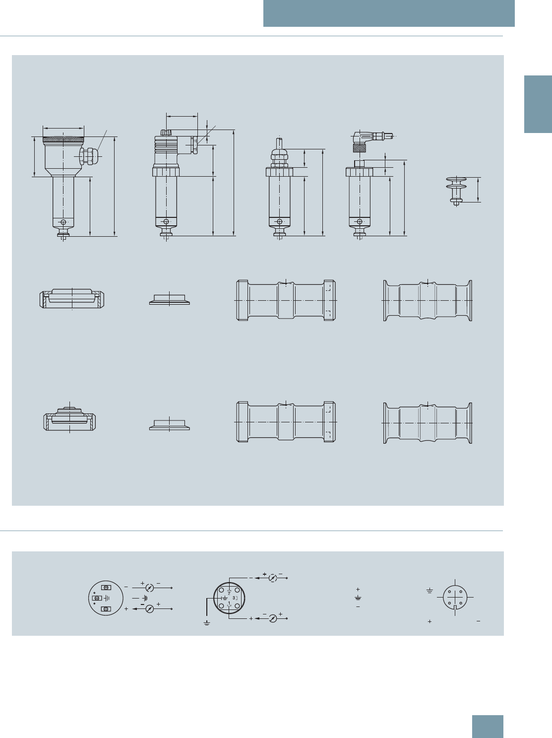
SITRANS P measuring instruments for pressure
Transmitters for food, pharmaceuticals and biotechnology
SITRANS P Compact
for gage and absolute pressure
2/27
Siemens FI 01 · 2009
2
■
Dimensional drawings
SITRANS P, dimensions in mm (inch)
■
Schematics
SITRANS P Compact, connection diagram
Housing
Process connections
Standard
Aseptic
Pipe clamp connection
to DIN 32 676
DN 25 ... 100
to ISO 2853
1 ... 2½
Pipe-screwed gland
(food)
Round thread
to DIN 11 851
DN 25 ... 65
Food screwed gland
Union nut
to DIN 11 851
DN 25 ... 65
Aseptic screwed gland
Round thread
Neumo, Südmo, Guth
DIN 11 864-1
DN 25 ... 65
1 ... 2
Clamp connection
Neumo, Südmo, Guth
DN 25 ... 50
1 ... 2
Pipe screwed gland (aseptic)
Round thread
DIN 11 864-1
Neumo, Südmo, Guth
DN 25 ... 65
1 ... 2
Pipe clamp connection
Neumo, Südmo, Guth
DN 25 ... 65
1 ... 2
Thermal decoupler
for process temperature
up to 200 °C (392 °F)
30 (1.18)
Clamp connection
to DIN 32 676
ISO 2852
DN 25 ... 65
1 ... 2½
Fieldhousing
stainless steel
Degree of protection IP65
IP67 as alternative
ø 50
(diam. 1.97)
For cable diam.
4.5 ... 10 (0.18 ... 0.39)
» 50 (1.97)
74,5 (2.93)
124,5 (4.9)
Angled plug to
DIN 43 650
Degree of protection IP65
39 (1.53)For cable diam.
4 ... 10 (0.18 ... 0.39)
74,5 (2.93)
» 132 (5.2)
38,5 (1.52) » 8 (0.3)
Cable connection
Degree of protection IP67
(cable ventilation)
74,5 (2.93)
107,5 (4.23)
22,5
(0.9)
Round plug with
screw connection M12
Degree of protection IP65
74,5 (2.93)
94 (3.7)
9 (0.35)
Field housing
0 V
24 V
Angled plug
0 V
24 V
Cable connection
brown
yellow
green
Round plug
4 black
1 brown2 white
Two-wire system
© Siemens AG 2008
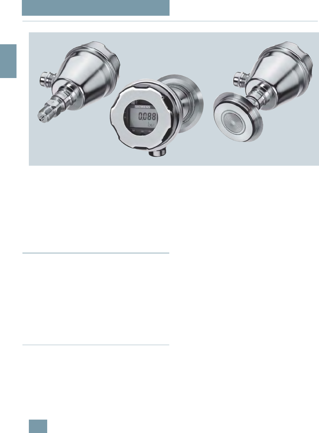
SITRANS P measuring instruments for pressure
Transmitters for food, pharmaceuticals and biotechnology
SITRANS P300 for gage and absolute pressure
2/28 Siemens FI 01 · 2009
2
■
Overview
The SITRANS P300 is a digital pressure transmitter for gage and
absolute pressure. All conventional thread versions are available
as process connections. In addition, various hygiene-based
connections and flange connections with front-flush diaphragms
meet the requirements of a dead space free process connec-
tion.
The output signal is a load-independent direct current from 4 to
20 mA or a PROFIBUS PA signal, which is linearly proportional to
the input pressure. Communication is over HART protocol or
over PROFIBUS PA interface. Convenient buttons for easy local
operation of the basic settings of the pressure transmitter.
The SITRANS P300 has a single-chamber stainless steel casing.
The pressure transmitter is approved with "intrinsically safe" type
of protection It can be used in zone 1 or zone 0.
■
Benefits
• High quality and long life
• High reliability even under extreme chemical and mechanical
loads
• Extensive diagnosis and simulation functions
• Minimum conformity error
• Small long-term drift
• Wetted parts made of high-grade materials (such as stainless
steel, Hastelloy)
• Measuring range 8 mbar to 400 bar
• High measuring accuracy
• Parameterization over control keys and HART communication
or PROFIBUS PA communication
■
Application
The pressure transmitter is available in versions for gage pres-
sure and for absolute pressure. The output signal is always a
load-independent direct current from 4 to 20 mA or a
PROFIBUS PA signal, which is linearly proportional to the input
pressure. The pressure transmitter measures aggressive, non-
aggressive and hazardous gases, as well as vapors and liquids.
It can be used for the following measurement types:
• Gage pressure
• Absolute pressure
With appropriate parameter settings, it can also be used for the
following additional measurement types:
• Level
• Volume
• Mass
The "intrinsically-safe" EEx version of the transmitter can be in-
stalled in hazardous areas (zone 1). The transmitters are pro-
vided with an EC type examination certificate and comply with
the respective harmonized European standards of ATEX.
Gage pressure
This variant measures aggressive, non-aggressive and hazard-
ous gases, vapors and liquids.
The smallest measuring span is 10 mbar g, the largest 400 bar g.
Level
With appropriate parameter settings, the gage pressure variant
measures the level of aggressive, non-aggressive and hazard-
ous liquids.
For measuring the level in an open container you require one de-
vice; for measuring the level in a closed container, you require
two devices and a process control system.
Absolute pressure
This variant measures the absolute pressure of aggressive, non-
aggressive and hazardous gases, vapors and liquids.
The smallest measuring span is 8 mbar a, the largest 30 bar a.
© Siemens AG 2008
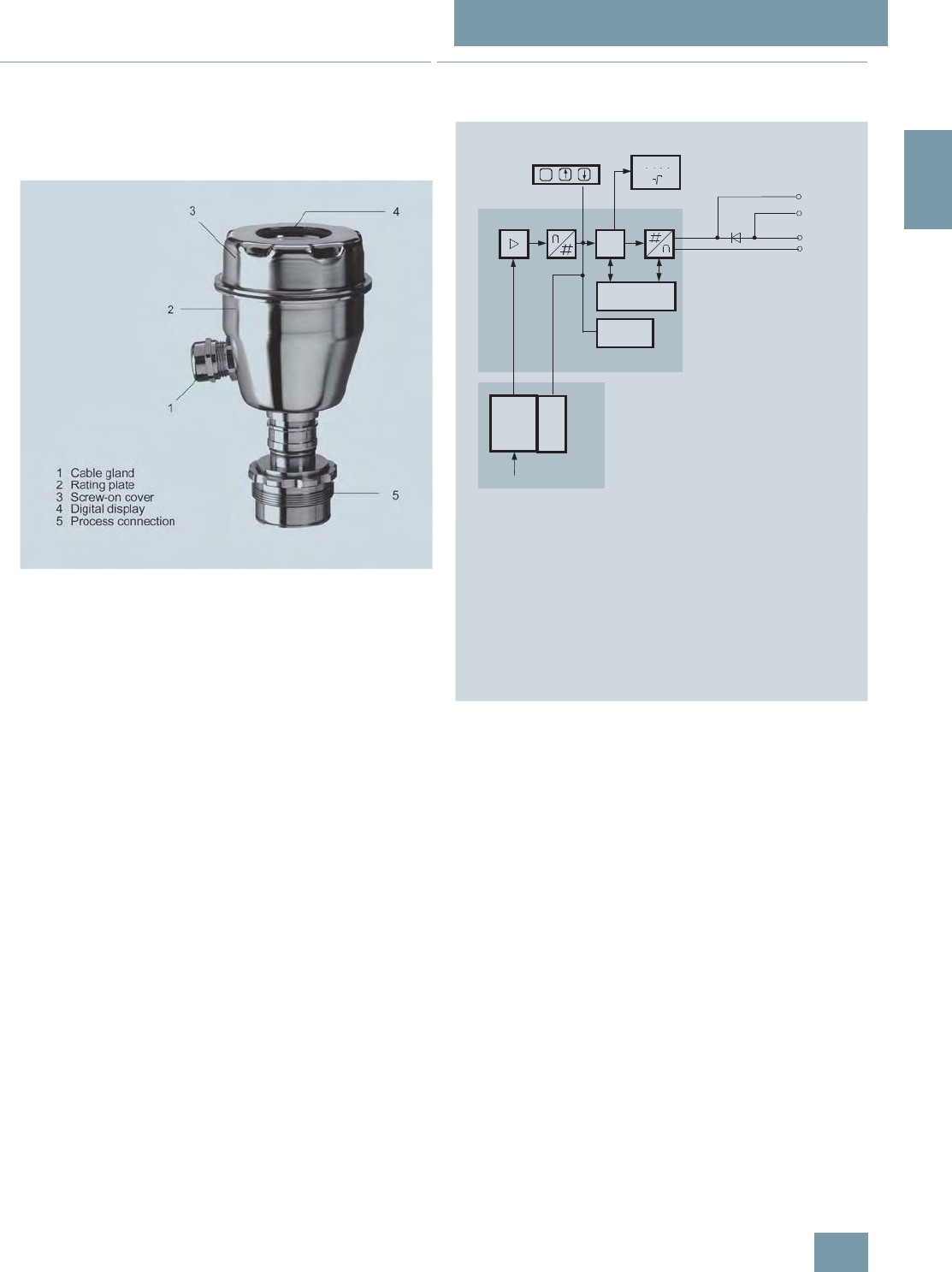
SITRANS P measuring instruments for pressure
Transmitters for food, pharmaceuticals and biotechnology
SITRANS P300 for gage and absolute pressure
2/29
Siemens FI 01 · 2009
2
■
Design
The device comprises:
• Electronics
• Housing
• Measuring cell
Perspective view of the SITRANS P300
The housing has a screw-on cover (3), with or without an inspec-
tion window depending on the version. The electrical terminal
housing, the buttons for operation of the device and, depending
on the version, the digital display are located under this cover.
The connections for the auxiliary power UH and the shield are in
the terminal housing. The cable gland is mounted on the side of
the housing. The measuring cell with the process connection (5)
is located on the underside of the housing. Depending on the
version of the device, the measuring cell with the process con-
nection may differ from the one shown in the diagram.
■
Function
Operation of the electronics with HART communication
Function diagram of electronics
The input pressure is converted into an electrical signal by the
sensor (1). This signal is amplified by the measuring amplifier (2)
and digitalized in an analog to digital converter (3). The digital
signal is analyzed in a microcontroller (4) and corrected with re-
gard to linearity and thermal characteristics. In a digital to ana-
log converter (5) it is then converted into the output current of 4
to 20 mA. A diode circuit provides reverse voltage protection.
You can make an uninterrupted current measurement with a low-
ohm ammeter at the connection (10). The data specific to the
measuring cell, the electronic data and parameter settings are
stored in two non-volatile memories (6). The first memory is
linked with the measuring cell, the second with the electronics.
The buttons (8) can be used to call up individual functions, so-
called modes. If you have a device with a digital display (9), you
can use this to track mode settings and other messages. The ba-
sic mode settings can be changed with a computer via the HART
modem (7).
IA, UH
5
6
7
8
Pe
1
4
3
2
C
m
M
10
00000
00
9
6
1 Measuring cell sensor
2Instrument amplifier
3Analog-to-digital converter
4Microcontroller
5 Digital-to-analog converter
6One non-volatile memory each in the measuring cell and electronics
7 HART interface
8 Three input keys (local operation)
9 Digital display
10Diode circuit and connection for external ammeter
IAOutput current
UHPower supply
PeInput variable
Sensor
EEPROM
EEPROM
HART interface
Electronics
Measuring cell
© Siemens AG 2008
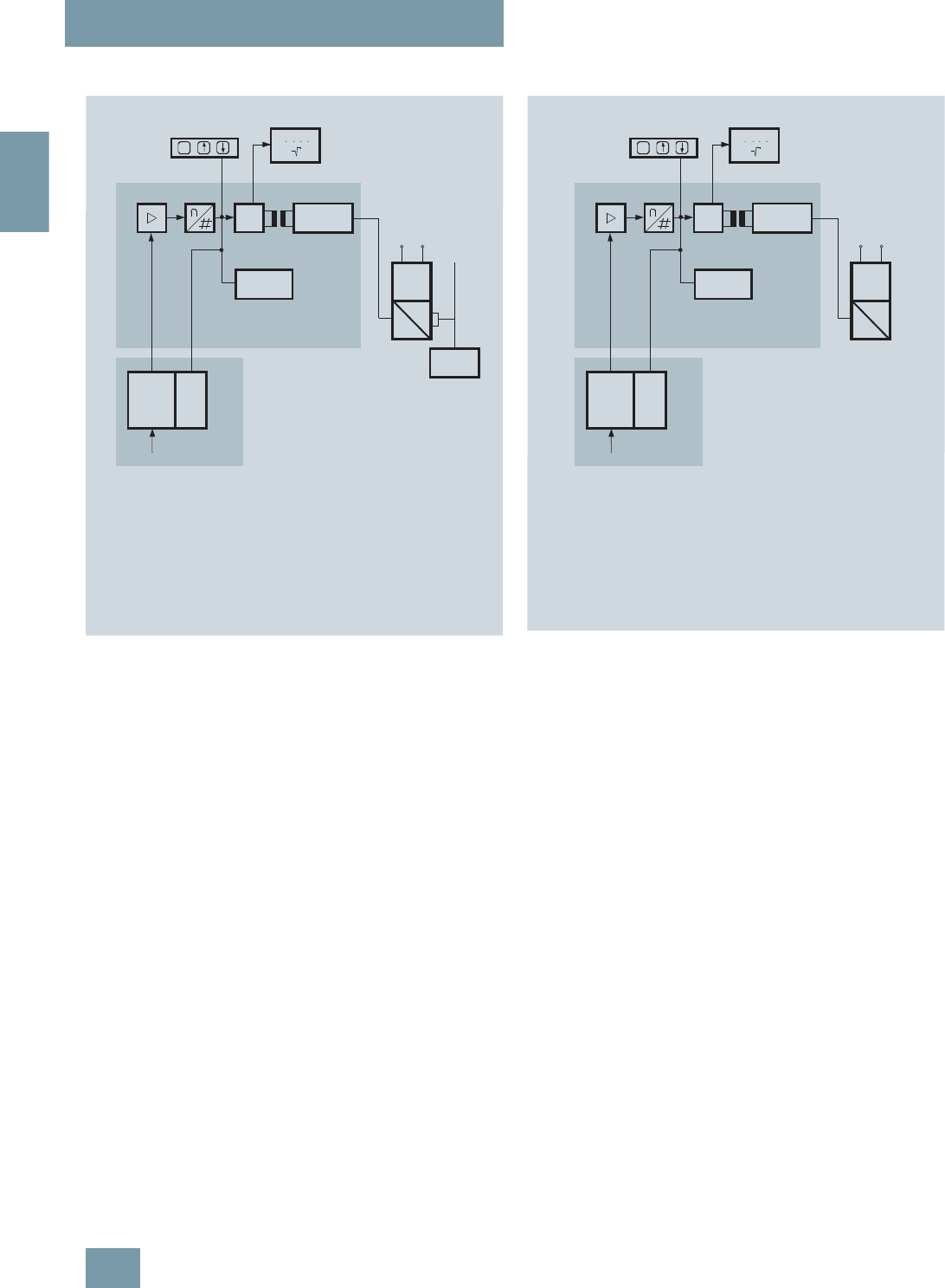
SITRANS P measuring instruments for pressure
Transmitters for food, pharmaceuticals and biotechnology
SITRANS P300 for gage and absolute pressure
2/30 Siemens FI 01 · 2009
2
Operation of the electronics with PROFIBUS PA communica-
tion
Function diagram of electronics
The input pressure is converted into an electrical signal by the
sensor (1). This signal is amplified by the measuring amplifier (2)
and digitalized in an analog to digital converter (3). The digital
signal is analyzed in a microcontroller (4) and corrected with re-
gard to linearity and thermal characteristics. It is then made
available at the PROFIBUS PA over an electrically isolated
PROFIBUS PA interface (7). The data specific to the measuring
cell, the electronic data and parameter settings are stored in two
non-volatile memories (6). The first memory is linked with the
measuring cell, the second with the electronics.
The buttons (8) can be used to call up individual functions, so-
called modes. If you have a device with a digital display (9), you
can use this to track mode settings and other messages. The ba-
sic mode settings can be changed with a computer over the bus
master (12).
Mode of operation of the FOUNDATION Fieldbus
electronics
Function diagram of electronics
The bridge output voltage created by the sensor (1, Figure
"Function diagram of electronics") is amplified by the instrument
amplifier (2) and digitized in the analog-to-digital converter (3).
The digital information is evaluated in the microcontroller, its lin-
earity and temperature response corrected, and provided on the
FOUNDATION Fieldbus through an electrically isolated
FOUNDATION Fieldbus Interface (7).
The data specific to the measuring cell, the electronics data, and
the parameter data are stored in the two non-volatile memories
(6). The one memory is coupled to the measuring cell, the other
to the electronics. As the result of this modular design, the elec-
tronics and the measuring cell can be replaced separately from
each other.
Using the three input keys (8) you can parameterize the pressure
transmitter directly at the point of measurement. The input keys
can also be used to control the view of the results, the error mes-
sages and the operating modes on the digital display (9).
The results with status values and diagnostic values are trans-
ferred by cyclic data transmission on the FOUNDATION
Fieldbus. Parameterization data and error messages are trans-
ferred by acyclic data transmission. Special software such as
National Instruments Configurator is required for this.
Mode of operation of the measuring cells
The process connections available include the following:
•G½
• ½-14 NPT
• Front-flush diaphragm:
- Flanges to EN
- Flanges to ASME
- NuG and pharmaceutical connections
6
8
pe
1
2
C
m
M
00000
00
EEPROM
EEPROM
9
6
345 7
10
12
11
1 Measuring cell sensor
2Instrument amplifier
3Analog-to-digital converter
4Microcontroller
5 Electrical isolation
6One non-volatile memory
each in the measuring cell
and electronics
7 PROFIBUS-PA interface
Sensor
Electronics
Measuring cell
PA
interface
Bus-
Master
Power
supply
unit
Coup-
ler
Power supply
PROFIBUS-DP
PROFIBUS-PA
8 Three input keys
(local operation)
9 Digital display
10Power supply
11 DP/PA coupler or link
12 Bus master
p
e
Input variable
6
8
pe
1
2
C
m
M
00000
00
EEPROM
EEPROM
9
6
345 7
10
1 Measuring cell sensor
2Instrument amplifier
3Analog-to-digital converter
4Microcontroller
5 Electrical isolation
6One non-volatile memory
each in the measuring cell
and electronics
7 FF interface
Sensor
Electronics
Measuring cell
FF
interface
Power
supply
unit
Coup-
ler
Power supply
8 Three input keys
(local operation)
9 Digital display
10Power supply
p
e
Input variable
© Siemens AG 2008
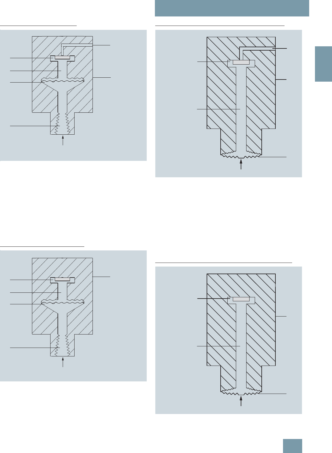
SITRANS P measuring instruments for pressure
Transmitters for food, pharmaceuticals and biotechnology
SITRANS P300 for gage and absolute pressure
2/31
Siemens FI 01 · 2009
2
Measuring cell for gage pressure
Measuring cell for gage pressure, function chart
The input pressure (pe) is transferred to the gage pressure sen-
sor (6) via the seal diaphragm (4) and the filling liquid (5), dis-
placing its measuring diaphragm. The displacement changes
the resistance value of the four piezo resistors in the measuring
diaphragm in a bridge circuit. The change in the resistance
causes a bridge output voltage proportional to the input pres-
sure.
The transmitters with spans ≤ 63 bar measure the input pressure
against atmosphere, those with spans ≥ 160 bar against
vacuum.
Measuring cell for absolute pressure
Measuring cell for absolute pressure, function chart
The input pressure (pe) is transferred to the absolute pressure
sensor (5) via the seal diaphragm (3) and the filling liquid (4),
displacing its measuring diaphragm. The displacement
changes the resistance value of the four piezo resistors in the
measuring diaphragm in a bridge circuit. The change in the re-
sistance causes a bridge output voltage proportional to the input
pressure.
Measuring cell for gage pressure, front-flush diaphragm
Measuring cell for gage pressure, front-flush diaphragm, function chart
The input pressure (pe) is transferred to the gage pressure sen-
sor (6) via the seal diaphragm (4) and the filling liquid (5), dis-
placing its measuring diaphragm. The displacement changes
the resistance value of the four piezo resistors in the measuring
diaphragm in a bridge circuit. The change in the resistance
causes a bridge output voltage proportional to the input pres-
sure.
The transmitters with spans ≤ 63 bar measure the input pressure
against atmosphere, those with spans ≥ 160 bar against
vacuum.
Measuring cell for absolute pressure, front-flush diaphragm
Measuring cell for absolute pressure, front-flush diaphragm, function
chart
1
2
3
4
5
6
1 Reference pressure
2 Measuring cell
3 Process connection
4 Seal diaphragm
5 Filling liquid
6 Relative pressure sensor
pe Pressure as input variable
pe
1
2
3
4
5
1 Measuring cell
2 Process connection
3 Seal diaphragm
4 Filling liquid
5 Absolute pressure sensor
pe Pressure as input variable
pe
1 Reference pressure
2 Measuring cell
3 Seal diaphragm
4 Filling liquid
5 Relative pressure sensor
pe Pressure as input variable
5
4
3
2
1
SH
1 Measuring cell
2 Seal diaphragm
3 Filling liquid
4 Absolute pressure sensor
pe Pressure as input variable
4
3
2
1
SH
© Siemens AG 2008
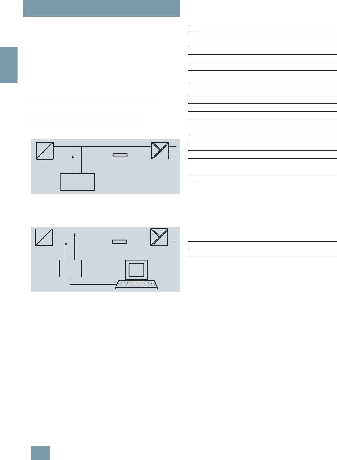
SITRANS P measuring instruments for pressure
Transmitters for food, pharmaceuticals and biotechnology
SITRANS P300 for gage and absolute pressure
2/32 Siemens FI 01 · 2009
2
The input pressure (pe) is transferred to the absolute pressure
sensor (5) via the seal diaphragm (3) and the filling liquid (4),
displacing its measuring diaphragm. The displacement
changes the resistance value of the four piezo resistors in the
measuring diaphragm in a bridge circuit. The change in the re-
sistance causes a bridge output voltage proportional to the input
pressure.
Parameterization of SITRANS P300
Depending on the version, there are a range of options for pa-
rameterizing the pressure transmitter and for setting or scanning
the parameters.
Parameterization using the input keys (local operation)
With the input keys you can easily set the most important param-
eters without any additional equipment.
Parameterization using HART communication
Parameterization using HART communication is performed with
a HART communicator or a PC.
Communication between a HART communicator and a pressure transmit-
ter
When parameterizing with the HART communicator, the connec-
tion is made directly to the 2-wire system.
HART communication between a PC communicator and a pressure
transmitter
When parameterizing with a PC, the connection is made through
a HART modem.
The signals needed for communication in conformity with the
HART 5.x or 6.x protocols are superimposed on the output cur-
rent using the Frequency Shift Keying (FSK) method.
Adjustable parameters on SITRANS P300 with HART communi-
cation
Diagnostic functions for SITRANS P300 with HART communica-
tion
• Zero correction display
• Event counter
• Limit transmitter
• Saturation alarm
• Slave pointer
• Simulation functions
• Maintenance timer
Available physical units of display for SITRANS P300 with HART
communication
+
HART
communicator
230 ... 1100 W
transmitter
SITRANS P Power supply
transmitter
SITRANS P Power supply
HART
modem
PC or
laptop
RS 232
230 ... 500 W
Parameters Input keys HART com-
munication
Start of scale x x
Full-scale value x x
Electrical damping x x
Start-of-scale value without application
of a pressure ("Blind setting") xx
Full-scale value without application of a
pressure ("Blind setting") xx
Zero adjustment x x
Current transmitter x x
Fault current x x
Disabling of keys, write protection x x1)
1) Cancel apart from write protection
Type of dimension and actual dimension x x
Input of characteristic x
Freely-programmable LCD x
Diagnostics functions x
Physical variable Physical dimensions
Pressure (setting can also be made
in the factory) Pa, MPa, kPa, bar, mbar, torr, atm,
psi, g/cm2, kg/cm2, inH2O, inH2O
(4 °C), mmH2O, ftH2O (20 °C),
inHg, mmHg
Level (height data) m, cm, mm, ft, in
Volume m3, dm3, hl, yd3, ft3, in3, US gal-
lon, lmp. gallon, bushel, barrel,
barrel liquid
Mass g, kg, t, lb, Ston, Lton, oz
Temperature K, °C, °F, °R
Miscellaneous %, mA
© Siemens AG 2008

SITRANS P measuring instruments for pressure
Transmitters for food, pharmaceuticals and biotechnology
SITRANS P300 for gage and absolute pressure
2/33
Siemens FI 01 · 2009
2
Parameterization through PROFIBUS PA interface
Fully digital communication through PROFIBUS PA, profile 3.0, is
particularly user-friendly. The PROFIBUS puts the DS III PA is in
connection with a process control system, e.g. SIMATIC PSC 7.
Communication is possible even in a potentially explosive envi-
ronment.
For parameterization through PROFIBUS you need suitable soft-
ware, e.g. SIMATIC PDM (Process Device Manager).
Parameterization through FOUNDATION Fieldbus Interface
Fully digital communication through FOUNDATION Fieldbus is
particularly user-friendly. Through the FOUNDATION Fieldbus
the P300 FF is connected to a process control system. Commu-
nication is possible even in a potentially explosive environment.
For parameterization through the FOUNDATION Fieldbus you
need suitable software, e.g. National Instruments Configurator.
Adjustable parameters for P300 PA and FF
Diagnostic functions for P300 PA and FF
• Event counter
• Slave pointer
• Maintenance timer
• Simulation functions
• Display of zero correction
• Limit transmitter
• Saturation alarm
Physical dimensions available for the display
Hygiene version
In the case of the SITRANS P300 with 7MF812.-... front-flush di-
aphragm, selected connections comply with the requirements of
the EHEDG or 3A. You will find further details in the order form.
Please note in particular that the seal materials used must com-
ply with the requirements of 3A. Similarly, the filling liquids used
must be FDA-compliant.
Parameters Input keys
(DS III HART) PROFIBUS PA and
FOUNDATION
Fieldbus interface
Electrical damping x x
Zero adjustment (correction of
position) xx
Key and/or function disabling x x
Source of measured-value dis-
play xx
Physical dimension of display x x
Position of decimal point x x
Bus address x x
Adjustment of characteristic x x
Input of characteristic x
Freely-programmable LCD x
Diagnostics functions x
Physical variable Physical dimensions
Pressure (setting can also
be made in the factory) MPa, kPa, Pa, bar, mbar, torr, atm, psi,
g/cm2, kg/cm2, mmH2O, mmH2O (4 °C),
inH2O, inH20 (4 °C), ftH2O (20 °C), mmHg,
inHg
Level (height data) m, cm, mm, ft, in, yd
Volume m3, dm3, hl, yd3, ft3, in3, US gallon, lmp.
gallon, bushel, barrel, barrel liquid
Volume flow m3/s, m3/min, m3/h, m3/d, l/s, l/min, l/h, l/
d, Ml/d, ft3/s, ft3/min, ft3/h, ft3/d, US gal-
lon/s, US gallon/min, US gallon/h, US gal-
lon/d, bbl/s, bbl/min, bbl/h, bbl/d
Mass flow g/s, g/min, g/h, g/d, kg/s, kg/min, kg/h,
kg/d, t/s, t/min, t/h, /t/d, lb/s, lb/min, lb/h,
lb/d, STon/s, STon/min, STon/h, STon/d,
LTon/s, LTon/min, LTon/h, LTon/d
Total mass flow t, kg, g, lb, oz, LTon, STon
Temperature K, °C, °F, °R
Miscellaneous %
© Siemens AG 2008

SITRANS P measuring instruments for pressure
Transmitters for food, pharmaceuticals and biotechnology
SITRANS P300 for gage and absolute pressure
2/34 Siemens FI 01 · 2009
2
■
Technical specifications
F
SITRANS P300 for gage pressure and absolute pressure
HART PROFIBUS PA and FOUNDATION Fieldbus
Gage pressure input
Measured variable Gage pressure
Spans (infinitely adjustable) or
nominal measuring range and
max. pemissible test pressure
Span Max. perm. test pres-
sure Nominal measuring
range Max. perm. test pres-
sure
0.01 ... 1 bar g
(0.15 ... 14.5 psi g) 6 bar g
(87 psi g) 1 bar g
(14.5 psi g) 6 bar g
(87 psi g)
0.04 ... 4 bar g
(0.58 ... 58 psi g) 10 bar g
(145 psi g) 4 bar g
(58 psi g) 10 bar g
(145 psi g)
0.16 ... 16 bar g
(2.3 ... 232 psi g) 32 bar g
(464 psi g) 16 bar g
(232 psi g) 32 bar g
(464 psi g)
0.6 ... 63 bar g
(9.1 ... 914 psi g) 100 bar g
(1450 psi g) 63 bar g
(914 psi g) 100 bar g
(1450 psi g)
1.6 ... 160 bar g
(23.2 ... 2321 psi g) 250 bar g
(3626 psi g) 160 bar g
(2321 psi g) 250 bar g
(3626 psi g)
4.0 ... 400 bar g
(58 ... 5802 psi g) 600 bar g
(8700 psi g) 400 bar g
(5802 psi g) 600 bar g
(8700 psi g)
Depending on the process connection, the span
may differ from these values Depending on the process connection, the nomi-
nal measuring range may differ from these values
Lower measuring limit
• Measuring cell with silicone oil 30 mbar a (0.44 psi a)
Upper measuring limit
• Measuring cell with silicone oil 100% of max. span 100% of the max. nominal measuring range
Absolute pressure input
Measured variable Absolute pressure
Spans (infinitely adjustable) or
nominal measuring range and
max. pemissible test pressure
Span Max. perm. test pres-
sure Nominal measuring
range Max. perm. test pres-
sure
8 ... 250 mbar a
(0.12 ... 3.6 psi a) 6 bar a
(87 psi a) 250 mbar a
(3.6 psi a) 6 bar a
(87 psi a)
0.043 ... 1.30 bar a
(0.62 ... 19 psi a) 10 bar a
(145 psi a) 1.30 bar a
(19 psi a) 10 bar a
(145 psi a)
0.16 ... 5 bar a
(2.3 ... 73 psi a) 30 bar a
(435 psi a) 5 bar a
(73 psi a) 30 bar a
(435 psi a)
1 ... 30 bar a
(14.5 ... 435 psi a) 100 bar a
(1450 psi a) 30 bar a
(435 psi a) 100 bar a
(1450 psi a)
Lower measuring limit
•Measuring cell with silicone oil 0 mbar a (0 psi a)
Upper measuring limit
• Measuring cell with silicone oil 100% of max. span 100% of the max. nominal measuring range
Input of gage pressure, with front-flush diaphragm
Measured variable Gage pressure, front-flush
Spans (infinitely adjustable) or
nominal measuring range and
max. pemissible test pressure
Span Max. perm. test pres-
sure Nominal measuring
range Max. perm. test pres-
sure
0.01 ... 1 bar g
(0.145 ... 14.5 psi g) 6bar g
(87 psi g) 1 bar g
(14.5 psi g) 6bar g
(87 psi g)
0.04 ... 4 bar g
(0.58 ... 58 psi g) 10 bar g
(145 psi g) 4 bar g
(58 psi g) 10 bar g
(145 psi g)
0.16 ... 16 bar g
(2.32 ... 232 psi g) 32 bar g
(464 psi g) 16 bar g
(232 psi g) 32 bar g
(464 psi g)
0.6 ... 63 bar g
(9.14 ... 914 psi g) 100 bar g
(1450 psi g) 63 bar g
(914 psi g) 100 bar g
(1450 psi g)
Lower measuring limit -100 mbar g (-1.45 psi g)
Upper measuring limit
• Measuring cell with silicone oil 100% of max. span 100% of the max. nominal measuring range
© Siemens AG 2008

SITRANS P measuring instruments for pressure
Transmitters for food, pharmaceuticals and biotechnology
SITRANS P300 for gage and absolute pressure
2/35
Siemens FI 01 · 2009
2
Input of absolute pressure, with front-flush diaphragm
Measured variable Absolute pressure (front-flush)
Spans (infinitely adjustable) or
nominal measuring range and
max. pemissible test pressure
Span Max. perm. test pres-
sure Nominal measuring
range Max. perm. test pres-
sure
43 ... 1300 mbar a
(0.62 ... 18.9 psi a) 10 bar a
(145 psi a) 1300 mbar a
(18.9 psi a) 10 bar a
(145 psi a)
0.16 ... 5 bar a
(2.32 ... 72.5 psi a) 30 bar a
(435 psi a) 5bara
(72,5 psi a) 30 bar a
(435 psi a)
1 ... 30 bar a
(14.5 ... 435 psi a) 100 bar a
(1450 psi a) 30 bar a
(435 psi a) 100 bar a
(1450 psi a)
Depending on the process connection, the span
may differ from these values Depending on the process connection, the nomi-
nal measuring range may differ from these values
Lower measuring limit 0 bar a (0 psi a)
Upper measuring limit
• Measuring cell with silicone oil 100% der max. Messspanne 100% des max. Nennmessbereichs
Output
Output signal 4 ... 20 mA Digital PROFIBUS PA signal
Physical bus - IEC 61158-2
With polarity reversal protection No Yes
Electrical damping T63 (step width 0.1 s) Set to 0.1 s (0 ... 100 s)
Accuracy To EN 60770-1
Reference conditions
(All error data refer always refer to the set
span)
Increasing characteristic, start-of-scale value 0 bar, stainless steel seal diaphragm, measuring cell
with silicone oil, room temperature 25 °C (77 °F), span ratio (r = max. span / set span)
Measurement deviation with cut-off point set-
ting, including hysteresis and repeatability.
Gage pressure Absolute
pressure (Absolute
pressure,
front-
flushed)
Gage pressure Absolute
pressure (Absolute
pressure,
front-
flushed)
Linear characteristic curve ≤ 0,075% ≤ 0,1% ≤ 0,2%
•r ≤ 10 ≤ (0.0029 ⋅ r + 0.071)% ≤ 0,1% ≤ 0,2%
• 10 < r ≤ 30 ≤ (0.0045 ⋅ r + 0.071)% ≤ 0,2% ≤ 0,4%
• 30 < r ≤ 100 ≤ (0.005 ⋅ r + 0.05)% - -
Settling time T63 without electrical damping Approx. 0.2 s
Long-term drift at ± 30 °C (± 54 °F) ≤ (0.25 ⋅ r)%/5 years ≤ (0.1 ⋅ r)%/year ≤ 0.25%/5 years ≤ 0.1%/year
Influence of ambient temperature
• at -10 ... +60 °C (14 ... 140 °F) ≤ (0.1 ⋅ r +0.2)% ≤ (0.2 ⋅ r
+0.3)% ≤ 0,3% ≤ 0,5%
• at -40 ... -10 °C and +60 ... +85 °C
(-40 ... 14 °F and 140 ... 185 °F) ≤ (0.1 ⋅ r + 0.15)% / 10 K ≤ (0.2 ⋅ r +
0.3)%/10 K ≤ 0.25%/10 K ≤ 0.5%/
10 K
Influence of the medium temperature (only
with front-flush diaphragm)
• Temperature difference between medium
temperature and ambient temperature 3 mbar/10 K (0.04 psi/10 K)
SITRANS P300 for gage pressure and absolute pressure
HART PROFIBUS PA and FOUNDATION Fieldbus
© Siemens AG 2008

SITRANS P measuring instruments for pressure
Transmitters for food, pharmaceuticals and biotechnology
SITRANS P300 for gage and absolute pressure
2/36 Siemens FI 01 · 2009
2
Rated operating conditions
Installation conditions
Ambient temperature Observe the temperature class in areas subject to explosion hazard.
• Measuring cell with silicone oil -40 ... +85 °C (-40 ... +185 °F)
• Measuring cell with Neobee oil (with front-
flush diaphragm) -10 ... +85 °C (14 ... +185 °F)
• Measuring cell with inert liquid (not with
front-flush diaphragm) -20 ... +85 °C (-4 ... +185 °F)
• Digital display -30 ... +85 °C (-22 ... +185 °F)
• Storage temperature -50 ... +85 °C (-58 ... +185 °F)
(with Neobee: -20 ... +85 °C (-4 ... +185 °F)
Climatic class
Condensation Permissible
Degree of protection to EN 60529 IP65, IP68, NEMA X, enclosure cleaning, resistant to lyes, steam to 150° C (302 °F)
Electromagnetic compatibility
• Emitted interference and interference immunity
To EN 61326 and NAMUR NE 21
Medium conditions
Process temperature
• Measuring cell with silicone oil -40 ... +100 °C (-40 ... +212 °F)
• Measuring cell with silicone oil (with front-
flush diaphragm) -40 ... +150 °C (-40 ... +302 °F)
• Measuring cell with Neobee oil (with front-
flush diaphragm) -40 ... +150 °C (-40 ... +302 °F)
• Measuring cell with silicone oil, with temper-
ature isolator (only with front-flush dia-
phragm)
-40 ... +200 °C (-40 ... +392 °F)
• Measuring cell with inert liquid -20 ... +100 °C (-4 ... +212 °F)
• Measuring cell with high temperature oil -10 ... +250 °C (14 ... +482 °F)
Design (standard version)
Weight (without options) Approx. 800 g (1.8 lb)
Housing material Stainless steel, mat. No. 1.4301/304
Material of parts in contact with the medium
• Connection shank Stainless steel, mat. No. 1.4404/316L or Hastelloy C276, mat. No. 2.4819
• Oval flange Stainless steel, mat. No. 1.4404/316L
• Seal diaphragm Stainless steel, mat. No. 1.4404/316L or Hastelloy C276, mat. No. 2.4819
• Measuring cell filling • Silicone oil
• Inert filling liquid
Process connection • G½B to DIN EN 837-1
• Female thread ½-14 NPT
• Oval flange PN 160 (MWP 2320 psi) with fastening thread:
-7/16-20 UNF to IEC 61518
- M10 as per DIN 19213
Design (version with front-flush dia-
phragm)
Weight (without options) Approx. 1 ... 13 kg (2.2 ... 29 lb)
Housing material Stainless steel, mat. No. 1.4301/304
Material of parts in contact with the medium
• Process connection Stainless steel, mat. No. 1.4404/316L
• Seal diaphragm Stainless steel, mat. No. 1.4404/316L
• Measuring cell filling • Silicone oil
• Inert filling liquid
• FDA compliant fill fluid (Neobee oil)
Process connection • Flanges as per EN and ASME
• F&B and pharmaceutical flanges
SITRANS P300 for gage pressure and absolute pressure
HART PROFIBUS PA and FOUNDATION Fieldbus
© Siemens AG 2008

SITRANS P measuring instruments for pressure
Transmitters for food, pharmaceuticals and biotechnology
SITRANS P300 for gage and absolute pressure
2/37
Siemens FI 01 · 2009
2
Power supply UH
Terminal voltage on transmitter 10.5 ... 42 V DC
for intrinsically safe operation: 10.5 ... 30 V DC Supplied through bus
Separate power supply - Not necessary
Bus voltage
• Without EEx - 9 ... 32 V
• For intrinsically-safe operation - 9 ... 24 V
Current consumption
• Max. basic current - 12.5 mA
• Startup current ≤ basic current - Yes
• Max. fault current in the event of a fault - 15.5 mA
Fault disconnection electronics (FDE) - Available
Certificate and approvals
Classification according to pressure equip-
ment directive (DRGL 97/23/EC) For gases of fluid group 1 and liquids of fluid group 1; complies with requirements of Article 3, para-
graph 3 (sound engineering practice)
Water, waste water Available soon
Explosion protection
Intrinsic safety "i" PTB 05 ATEX 2048
Identification Ex II 1/2 G EEx ia/ib IIB/IIC T4, T5, T6
Permissible ambient temperature
• Temperature class T4 -40 ... +85 °C (-40 ... +185 °F)
• Temperature class T5 -40 ... +70 °C (-40 ... +158 °F)
• Temperature class T6 -40 ... +60 °C (-40 ... +140 °F)
Connection To certified intrinsically-safe circuits with maxi-
mum values:
Ui = 30 V, Ii = 100 mA,
Pi = 750 mW, Ri = 300 Ω
To certified intrinsically-safe circuits with maxi-
mum values:
FISCO supply unit:
Ui = 17.5 V, Ii = 380 mA, Pi = 5.32 W
Linear barrier:
Ui = 24 V, Ii = 250 mA, Pi = 1.2 W
Effective inner capacitance: Ci = 6 nF Ci = 1.1 nF
Effective inner inductance: Li = 0.4 mH Li ≤ 7 μH
Explosion protection to FM for USA and
Canada (cFMUS)
• Identification (DIP) or (IS); (NI) Certificate of Compliance 3025099
CL I, DIV 1, GP ABCD T4 ... T6; CL II, DIV 1, GP EFG; CL III; CL I, ZN 0/1 AEx ia IIC T4 ... T6;
CL I, DIV 2, GP ABCD T4 ... T6; CL II, DIV 2, GP FG; CL III
• Identification (DIP) or (IS) Certificate of Compliance 3025099C
CL I, DIV 1, GP ABCD T4 ... T6; CL II, DIV 1, GP EFG; CL III; Ex ia IIC 4 ... T6;
CL I, DIV 2, GP ABCD T4 ... T6; CL II, DIV 2, GP FG; CL III
SITRANS P300 for gage pressure and absolute pressure
HART PROFIBUS PA and FOUNDATION Fieldbus
© Siemens AG 2008

SITRANS P measuring instruments for pressure
Transmitters for food, pharmaceuticals and biotechnology
SITRANS P300 for gage and absolute pressure
2/38 Siemens FI 01 · 2009
2
HART communication
HART communication 230 ... 1100 Ω
Protocol HART Version 5.x
Software for computer SIMATIC PDM
PROFIBUS PA communication
Simultaneous communication with
master class 2 (max.) 4
The address can be set using Configuration tool or local opera-
tion (standard setting address
126)
Cyclic data usage
• Output byte 5 (one measuring value) or
10 (two measuring values)
• Input byte 0, 1, or 2 (register operating mode
and reset function for metering)
Internal preprocessing
Device profile PROFIBUS PA Profile for Process
Control Devices Version 3.0,
Class B
Function blocks 2
• Analog input
- Adaptation to customer-specif-
ic process variables Yes, linearly rising or falling char-
acteristic
- Electrical damping T63 , adjust-
able 0 ... 100 s
- Simulation function Input /Output
- Failure mode Can be parameterized (last good
value, substitute value, incorrect
value)
- Limit monitoring Yes, one upper and lower warning
limit and one alarm limit respec-
tively
• Register (totalizer) Can be reset, preset, optional
direction of counting, simulation
function of register output
- Failure mode Can be parameterized (summation
with last good value, continuous
summation, summation with incor-
rect value)
- Limit monitoring One upper and lower warning limit
and one alarm limit respectively
• Physical block 1
Transducer blocks 2
• Pressure transducer block
- Can be calibrated by applying
two pressures Yes
- Monitoring of sensor limits Yes
- Specification of a container
characteristic with Max. 30 nodes
- Square-rooted characteristic
for flow measurement Yes
- Gradual volume suppression
and implementation point of
square-root extraction
Parameterizable
- Simulation function for mea-
sured pressure value and sen-
sor temperature
Constant value or over parameter-
izable ramp function
Communication FOUNDATION Fieldbus
Function blocks 3 function blocks analog input,
1 function block PID
• Analog input
- Adaptation to customer-specif-
ic process variables Yes, linearly rising or falling char-
acteristic
- Electrical damping T63 , adjust-
able 0 ... 100 s
- Simulation function Output/input (can be locked within
the device with a bridge)
- Failure mode Can be parameterized (last good
value, substitute value, incorrect
value)
- Limit monitoring Yes, one upper and lower warning
limit and one alarm limit respec-
tively
- Square-rooted characteristic
for flow measurement Yes
• PID Standard FF function block
• Physical block 1 Resource block
Transducer blocks 1 transducer block Pressure with
calibration, 1 transducer block
LCD
• Pressure transducer block
- Can be calibrated by applying
two pressures Yes
- Monitoring of sensor limits Yes
- Simulation function: Measured
pressure value, sensor temper-
ature and electronics tempera-
ture
Constant value or over parameter-
izable ramp function
© Siemens AG 2008

SITRANS P measuring instruments for pressure
Transmitters for food, pharmaceuticals and biotechnology
SITRANS P300 for gage and absolute pressure
2/39
Siemens FI 01 · 2009
2
F) Subject to export regulations AL: 9I999, ECCN: N.
Selection and Ordering data Order No.
SITRANS P300 pressure transmitters for gage
and absolute pressure, single-chamber measur-
ing housing, rating plate inscription in English
4 ... 20 mA/HART 7 M F 8 0 2 3 -
PROFIBUS PA 7 M F 8 0 2 4 -
FOUNDATION Fieldbus (FF) 7 M F 8 0 2 5 -
77777 -7 7 7 7
Measuring cell filling Measuring cell cleaning
Silicone oil Standard 1
Inert liquid Cleanliness level 2 to
DIN 25410 3
max. span
0.01 ... 1 bar g (0.145 ... 14.5 psi g) B
0.04 ... 4 bar g (0.58 ... 58 psi g) C
0.16 ...16 bar g (2.32 ... 232 psi g) D
0.63 ... 63 bar g (9.14 ... 914 psi g) E
1.6 ... 160 bar g (23.2 ... 2320 psi g) F
4 ... 400 bar g (58 ... 5800 psi g) G
2.5 ... 25 mbar a (0.036 ... 3.63 psi a) F) Q
13 ... 1300 mbar a (0.19 ... 18.9 psi a) F) S
0.05 ... 5 bar a (0.7 ... 72.5 psi a) F) T
0.3 ... 30 bar a (4.35 ... 435 psi a) F) U
Wetted parts materials
Seal diaphragm Measuring cell
Stainless steel Stainless steel A
Hastelloy Stainless steel F) B
Hastelloy Hastelloy F) C
Version for diaphragm seal 1) 2) Y
Process connection
• G½B to EN 837-1 0
• ½-14 NPT 1
• Oval flange made of stainless steel
- Mounting thread 7/16-20 UNF to EN 61518 2
- Mounting thread M10 to DIN 19213 3
- Mounting thread M12 to DIN 19213 4
• Male thread M20 x 1,5 5
• Male thread ½ -14 NPT 6
Non-wetted parts materials
• St. steel, deep-drawn and electrolytically polished 4
Version
• Standard version 1
Explosion protection
• Without A
• With ATEX, Type of protection:
- "Intrinsic safety (EEx ia)" B
• Zone 20/21/223) C
• Ex nA/nL (zone 2)4) E
• With FM „Intrinsic safe“ (cFMUS)M
Electrical connection / cable entry
• Screwed gland M20x1.5 (Polyamide) 5) A
• Screwed gland M20x1.5 (metal) B
• Screwed gland M20x1.5 (stainless steel) C
• M12 connector (metal, without cable socket) F
• M12 connector (stainless steel, without cable socket) G
• ½-14 NPT thread, metal 6) H
• ½-14 NPT thread, stainless steel6) J
Display
• Without display, with keys, closed lid5) 1
• With display and keys, closed lid 2
• With display and keys, lid with macrolon washer
(setting on HART devices: mA,
on PROFIBUS PA and FOUNDATION Fieldbus
devices: pressure units)
4
• With display (setting acc. to specifications, Order
code "Y21" or "Y22" required), lid with macrolon
washer
5
• With display and keys, lid with glass pane
(setting on HART devices: mA, on PROFIBUS and
FOUNDATION Fieldbus devices: pressure units)
6
• With display (setting acc. to specifications, Order
code "Y21" or "Y22" required), lid with glass pane
7
Power supply units see "SITRANS I power supply units and isol. amplifiers".
Factory-mounting of shut-off valves and valve manifolds see page
2/142.
Included in delivery of the device:
• Brief instructions (Leporello)
• CD-ROM with detailed documentation
1) When the manufacture’s certificate M (calibration certificate) has to be
ordered for transmitters with diaphragm seals, it is recommended only to
order this certificate exclusively with the diaphragm seals. The measuring
accuracy of the total combination is certified here.
2) Whe the acceptance test certificate 3.1 for transmitters with direct-con-
nected diaphragm seals is ordered, this certificate must also be ordered
with the corresponding seals.
3) Can only be ordered in conjunction with electrical connection Option A.
4) Can only be ordered in conjunction with electrical connection Option B, C,
F or G.
5) Only together with HART electronics.
6) Without cable gland.
Selection and Ordering data Order No.
SITRANS P300 pressure transmitters for gage
and absolute pressure, single-chamber measur-
ing housing, rating plate inscription in English
4 ... 20 mA/HART 7 M F 8 0 2 3 -
PROFIBUS PA 7 M F 8 0 2 4 -
FOUNDATION Fieldbus (FF) 7 M F 8 0 2 5 -
7 7 7 7 7 -7 7 7 7
© Siemens AG 2008

SITRANS P measuring instruments for pressure
Transmitters for food, pharmaceuticals and biotechnology
SITRANS P300 for gage and absolute pressure
2/40 Siemens FI 01 · 2009
2
F) Subject to export regulations AL: 9I999, ECCN: N.
Selection and Ordering data Order No.
SITRANS P300 pressure transmitters for gage
and absolute pressure with front-flush membrane,
single-chamber measuring housing, rating plate
inscription in English
4 ... 20 mA/HART F) 7 M F 8 1 2 3 -
PROFIBUS PA F) 7 M F 8 1 2 4 -
FOUNDATION Fieldbus (FF) F) 7 M F 8 1 2 5 -
77777 -7 7 7 7
Measuring cell filling Measuring cell cleaning
Silicone oil Standard 1
Inert liquid Cleanliness level 2 to
DIN 25410 3
FDA compliant fill fluid
• Neobee oil Standard 4
max. span
0.01 ... 1 bar g (0.15 ... 14.5 psi g) B
0.04 ... 4 bar g (0.58 ... 58 psi g) C
0.16 ... 16 bar g (2.32 ... 232 psi g) D
0.63 ... 63 bar g (9.14 ... 914 psi g) E
13 ... 1300 mbar a1) (0.19 ... 18.9 psi a) S
0.05 ... 5 bar a1) (0.7 ... 72.5 psi a) T
0.03 ... 30 bar a1) (4.35 ... 435 psi a) U
Wetted parts materials
Seal diaphragm Measuring cell
Stainless steel Stainless steel A
Process connection
• Flange version with Order code M.., N.., R.. or Q..
(see "Further designs") 7
Non-wetted parts materials
• Stainless steel, deep-drawn and electrolytically
polished 4
Version
• Standard version 1
Explosion protection
• Without A
• With ATEX, Type of protection:
- "Intrinsic safety (EEx ia)" B
• Zone 20/21/222) C
• Ex nA/nL (zone 2)3) E
• With FM „Intrinsic safe“ (cFMUS)M
Electrical connection / cable entry
• Screwed gland M20x1.5 (Polyamide)4) A
• Screwed gland M20x1.5 (metal) B
• Screwed gland M20x1.5 (stainless steel) C
• M12 connector (without cable socket) F
• M12 connector (stainless steel, without cable socket) G
• ½-14 NPT thread, metal5) H
• ½-14 NPT thread, stainless steel5) J
Display
• Without display, with keys, closed lid4) 1
• With display and keys, closed lid 2
• With display and keys, lid with macrolon washer
(setting on HART devices: mA,
on PROFIBUS PA and FOUNDATION Fieldbus
devices: pressure units)
4
• With display (setting acc. to specifications, Order
code "Y21" or "Y22" required), lid with macrolon
washer
5
• With display and keys, lid with glass pane
(setting on HART devices: mA,
on PROFIBUS PA and FOUNDATION Fieldbus
devices: pressure units)
6
• With display (setting acc. to specifications, Order
code "Y21" or "Y22" required), lid with glass pane 7
Power supply units see "SITRANS I power supply units and isol. amplifiers".
Included in delivery of the device:
• Brief instructions (Leporello)
• CD-ROM with detailed documentation
1) Not with temperature decoupler P00 and P10, not for process connections
R02, R04, R10 and R11, and can only be ordered in conjunction with sili-
cone oil.
2) Can only be ordered in conjunction with electrical connection Option A.
3) Can only be ordered in conjunction with electrical connection Option B, C,
F or G.
4) Only together with HART electronics.
5) Without cable gland.
Selection and Ordering data Order No.
SITRANS P300 pressure transmitters for gage
and absolute pressure with front-flush membrane,
single-chamber measuring housing, rating plate
inscription in English
4 ... 20 mA/HART F) 7 M F 8 1 2 3 -
PROFIBUS PA F) 7 M F 8 1 2 4 -
FOUNDATION Fieldbus (FF) F) 7 M F 8 1 2 5 -
7 7 7 7 7 -7 7 7 7
© Siemens AG 2008

SITRANS P measuring instruments for pressure
Transmitters for food, pharmaceuticals and biotechnology
SITRANS P300 for gage and absolute pressure
2/41
Siemens FI 01 · 2009
2
Selection and Ordering data Order code
Further designs
Add "-Z" to Order No. and specify Order
code.
HART PA FF
Mounting bracket
made completely of stainless steel, for wall or
pipe mounting
A02 9
9
9
9
9
9
Cable socket for M12 plug
• Metal A50 9
9
9
9
• Stainless steel A51 9
9
9
9
Rating plate inscription
(instead of English)
•German B10 9
9
9
9
9
9
• French B12 9
9
9
9
9
9
• Spanish B13 9
9
9
9
9
9
• Italian B14 9
9
9
9
9
9
English rating plate B21 9
9
9
9
9
9
Pressure units in inH20 or psi
Quality inspection certificate (Factory cali-
bration) to IEC 60770-21) C11 9
9
9
9
9
9
to IEC 60770-2
Acceptance test certificate2) C12 9
9
9
9
9
9
to EN 10204-3.1
Factory certificate C14 9
9
9
9
9
9
to EN 10204-2.2
Type of protection IP68 D12 9
9
9
9
9
9
Only for SITRANS P300 with front-flush
diaphragm (7MF81..-...)
Flange to EN 1092-1, form B1
• DN 25, PN 403) M11 9
9
9
9
9
9
• DN 25, PN 1003) M21 9
9
9
9
9
9
• DN 40, PN 40 M13 9
9
9
9
9
9
• DN 40, PN 100 M23 9
9
9
9
9
9
• DN 50, PN 16 M04 9
9
9
9
9
9
• DN 50, PN 40 M14 9
9
9
9
9
9
• DN 80, PN 25 M06 9
9
9
9
9
9
• DN 80, PN 40 M16 9
9
9
9
9
9
Flanges to ASME B16.5
• 1", class 1503) M40 9
9
9
9
9
9
• 1½", class 150 M41 9
9
9
9
9
9
• 2", class 150 M42 9
9
9
9
9
9
• 3", class 150 M43 9
9
9
9
9
9
• 4", class 150 M44 9
9
9
9
9
9
• 1", class 3003) M45 9
9
9
9
9
9
• 1½", class 300 M46 9
9
9
9
9
9
• 2", class 300 M47 9
9
9
9
9
9
• 3", class 300 M48 9
9
9
9
9
9
Threaded connection acc. to DIN 3852-2,
Form A
• G ¾“-A, flush-mounted4) R01 9
9
9
9
9
9
• G 1“-A, flush-mounted4) R02 9
9
9
9
9
9
• G 2“-A, flush-mounted4) R04 9
9
9
9
9
9
Tank connection5)
Sealing is included in delivery
• TG 52/50, PN 40 R10 9
9
9
9
9
9
• TG 52/150, PN 40 R11 9
9
9
9
9
9
Sanitary process connection according
DIN 11851 (Dairy connection)
certified to 3A6)
• DN 50, PN 25 N04 9
9
9
9
9
9
• DN 80, PN 25 N06 9
9
9
9
9
9
Tri-Clamp connection according
DIN 32676/ISO 2852
certified to 3A6)
• DN 50/2“, PN 16 N14 9
9
9
9
9
9
• DN 65/3“, PN 10 N15 9
9
9
9
9
9
Varivent connection
certified to 3A and EHEDG3)
• Type N = 68 for Varivent housing
DN 40 ... 125 and 1½" ... 6", PN 40 N28 9
9
9
9
9
9
Temperature decoupler up to 200 °C7)
for version with front-flush diaphragm P00 9
9
9
9
9
9
Temperature decoupler up to 250 °C
Measuring cell filling: High-temperature oil,
only in conjunction with measuring cell filling
silicone oil
P10 9
9
9
9
9
9
Bio-Control (Neumo) sanitary connection
certified to 3A and EHEDG3)
• DN 50, PN 16 Q53 9
9
9
9
9
9
• DN 65, PN 16 Q54 9
9
9
9
9
9
Sanitary process connection to DRD
• 65 mm, PN 40 M32 9
9
9
9
9
9
SMS socket with union nut
•2“ M67 9
9
9
9
9
9
•2½“ M68 9
9
9
9
9
9
•3“ M69 9
9
9
9
9
9
SMS threaded socket
•2“ M73 9
9
9
9
9
9
•2½“ M74 9
9
9
9
9
9
•3“ M75 9
9
9
9
9
9
IDF socket with union nut ISO 2853
•2“ M82 9
9
9
9
9
9
•2½“ M83 9
9
9
9
9
9
•3“ M84 9
9
9
9
9
9
IDF threaded socket ISO 2853
•2“ M92 9
9
9
9
9
9
•2½“ M93 9
9
9
9
9
9
•3“ M94 9
9
9
9
9
9
Sanitary process connection to
NEUMO Bio-Connect screw connection
certified to 3A and EHEDG3)
• DN 50, PN 16 Q05 9
9
9
9
9
9
• DN 65, PN 16 Q06 9
9
9
9
9
9
• DN 80, PN 16 Q07 9
9
9
9
9
9
• DN 100, PN 16 Q08 9
9
9
9
9
9
• DN 2“, PN 16 Q13 9
9
9
9
9
9
• DN 2½“, PN 16 Q14 9
9
9
9
9
9
• DN 3“, PN 16 Q15 9
9
9
9
9
9
• DN 4“, PN 16 Q16 9
9
9
9
9
9
Sanitary process connection to
NEUMO Bio-Connect flange connection
certified to 3A and EHEDG3)
• DN 50, PN 16 Q23 9
9
9
9
9
9
• DN 65, PN 16 Q24 9
9
9
9
9
9
• DN 80, PN 16 Q25 9
9
9
9
9
9
• DN 100, PN 16 Q26 9
9
9
9
9
9
• DN 2“, PN 16 Q31 9
9
9
9
9
9
• DN 2½“, PN 16 Q32 9
9
9
9
9
9
• DN 3“, PN 16 Q33 9
9
9
9
9
9
• DN 4“, PN 16 Q34 9
9
9
9
9
9
Sanitary process connection to
NEUMO Bio-Connect clamp connection
certified to 3A and EHEDG3)
• DN 50, PN 16 Q39 9
9
9
9
9
9
• DN 65, PN 10 Q40 9
9
9
9
9
9
• DN 80, PN 10 Q41 9
9
9
9
9
9
• DN 100, PN 10 Q42 9
9
9
9
9
9
• DN 2½“, PN 16 Q48 9
9
9
9
9
9
• DN 3“, PN 10 Q49 9
9
9
9
9
9
• DN 4“, PN 10 Q50 9
9
9
9
9
9
Selection and Ordering data Order code
Further designs
Add "-Z" to Order No. and specify Order
code.
HART PA FF
© Siemens AG 2008

SITRANS P measuring instruments for pressure
Transmitters for food, pharmaceuticals and biotechnology
SITRANS P300 for gage and absolute pressure
2/42 Siemens FI 01 · 2009
2
Sanitary process connection to
NEUMO Connect S flange connection
certified to 3A and EHEDG
• DN 50, PN 16 Q63 9
9
9
9
9
9
• DN 65, PN 10 Q64 9
9
9
9
9
9
• DN 80, PN 10 Q65 9
9
9
9
9
9
• DN 100, PN 10 Q66 9
9
9
9
9
9
• DN 2“, PN 16 Q72 9
9
9
9
9
9
• DN 2½“, PN 10 Q73 9
9
9
9
9
9
• DN 3“, PN 10 Q74 9
9
9
9
9
9
• DN 4“, PN 10 Q75 9
9
9
9
9
9
Aseptic threaded socket to DIN 11864-1
Form A
• DN 50, PN 25 N33 9
9
9
9
9
9
• DN 65, PN 25 N34 9
9
9
9
9
9
• DN 80, PN 25 N35 9
9
9
9
9
9
• DN 100, PN 25 N36 9
9
9
9
9
9
Aseptic flange with notch to DIN 11864-2
Form A
• DN 50, PN 16 N43 9
9
9
9
9
9
• DN 65, PN 16 N44 9
9
9
9
9
9
• DN 80, PN 16 N45 9
9
9
9
9
9
• DN 100, PN 16 N46 9
9
9
9
9
9
Aseptic flange with groove to DIN 11864-2
Form A
• DN 50, PN 16 N43 +
P11
9
9
9
9
9
9
• DN 65, PN 16 N44 +
P11
9
9
9
9
9
9
• DN 80, PN 16 N45 +
P11
9
9
9
9
9
9
• DN 100, PN 16 N46 +
P11
9
9
9
9
9
9
Aseptic clamp with groove to DIN 11864-3
Form A
• DN 50, PN 25 N53 9
9
9
9
9
9
• DN 65, PN 25 N54 9
9
9
9
9
9
• DN 80, PN 16 N55 9
9
9
9
9
9
• DN 100, PN 16 N56 9
9
9
9
9
9
1) When the manufacture’s certificate M (calibration certificate) has to be
ordered for transmitters with diaphragm seals, it is recommended only to
order this certificate exclusively with the diaphragm seals. The measuring
accuracy of the total combination is certified here.
2) Whe the acceptance test certificate 3.1 for transmitters with direct-con-
nected diaphragm seals is ordered, this certificate must also be ordered
with the corresponding seals.
3) Special Viton seal included in delivery.
4) Lower measuring limit -100 mbar g (1.45 psi g).
5) The weldable socket can be ordered under accessories
6) Certified to 3A.
The maximum temperatures of the medium depend on the respective cell
fillings.
7) 3A certification only if used in conjunction with 3A-compliant sealing rings.
Selection and Ordering data Order code
Further designs
Add "-Z" to Order No. and specify Order
code.
HART PA FF
Selection and Ordering data Order code
Additional data
Add "-Z" to Order No. and specify Order
code.
HART PA FF
Measuring range to be set Y01 9
9
Specify in plain text V (max. 5 digits):
Y01: ... up to ... mbar, bar, kPa, MPa, psi
Measuring point number (TAG No.) Y15 9
9
9
9
9
9
Max. 16 characters, specify in plain text:
Y15: ...........................................
Measuring point text Y16 9
9
9
9
9
9
Max. 27 characters, specify in plain text:
Y16: ...........................................
Entry of HART TAG Y17 9
9
Max. 8 characters, specify in plain text:
Y17: ...........................................
Setting of pressure indication in pressure
units Y21 9
9
9
9
9
9
Specify in plain text (standard setting: mA):
Y21: mbar, bar, kPa, MPa, psi, ...
Note:
The following pressure units can be selected:
bar, mbar, mm H2O*), inH2O*), ftH2O*),
mmHG, inHG, psi, Pa, kPa, MPa, g/cm2,
kg/cm2, Torr, ATM or %
*) ref. temperature 20 °C
Setting of pressure indicator in
non-pressure units Y22 +
Y01
9
9
Specify in plain text:
Y22: ..... up to ..... l, m3, m, USg, ...
(specification of measuring range in pressure
units "Y01" is essential, unit with max. 5 char-
acters)
Preset bus address Y25 9
9
9
9
possible between 1 ... 126)
Specify in plain text:
Y25: .....................
Only "Y01" and "Y21" can be factory preset
9
9
= available
Ordering example
Item line: 7MF8023-1DB24-1AB7-Z
B line: A02 + Y01 + Y21
C line: Y01: 1 ... 10 bar (14.5 ... 145 psi)
C line: Y21: bar (psi)
© Siemens AG 2008
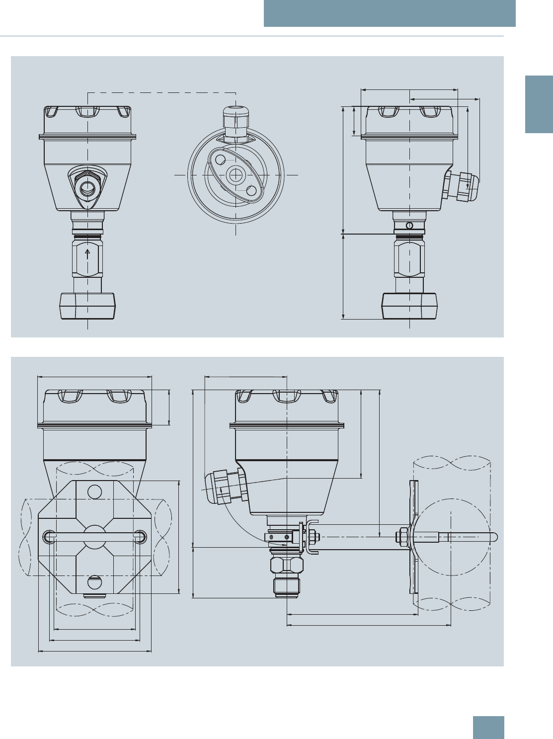
SITRANS P measuring instruments for pressure
Transmitters for food, pharmaceuticals and biotechnology
SITRANS P300 for gage and absolute pressure
2/43
Siemens FI 01 · 2009
2
■
Dimensional drawings
SITRANS P300, with oval flange, dimensions in mm (inch)
SITRANS P300, process connection M20 x 1,5, with mounted mounting bracket, dimensions in mm (inch)
+ DSSUR[
DSSUR[
DSSUR[
DSSUR[
ෘ
+ DSSUR[
DSSUR[
DSSUR[
ෘ DSSUR[
DSSUR[
DSSUR[
DSSUR[
DSSUR[
DSSUR[
r
© Siemens AG 2008
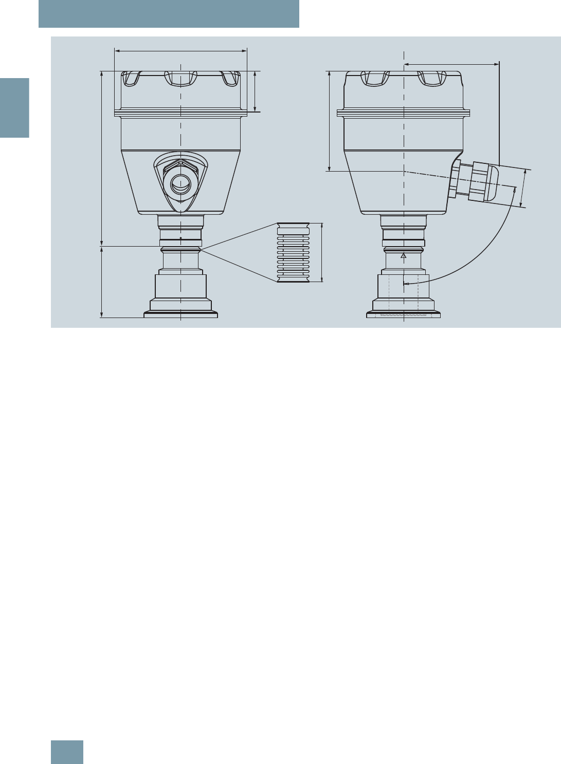
SITRANS P measuring instruments for pressure
Transmitters for food, pharmaceuticals and biotechnology
SITRANS P300 for gage and absolute pressure
2/44 Siemens FI 01 · 2009
2
SITRANS P300, front-flush, dimensions in mm (inch)
The diagram shows a SITRANS P300 with an example of a
flange. In this drawing the height is subdivided into H1 and H2.
H1 = Height of the SITRANS P300 up to a defined cross-section
H2 = Height of the flange up to this defined cross-section
Only the height H2 is indicated in the dimensions of the flanges.
r
ෘ
+ DSSUR[+ DSSUR[
7HPSHUDWXUHGHFRXSOHU
© Siemens AG 2008
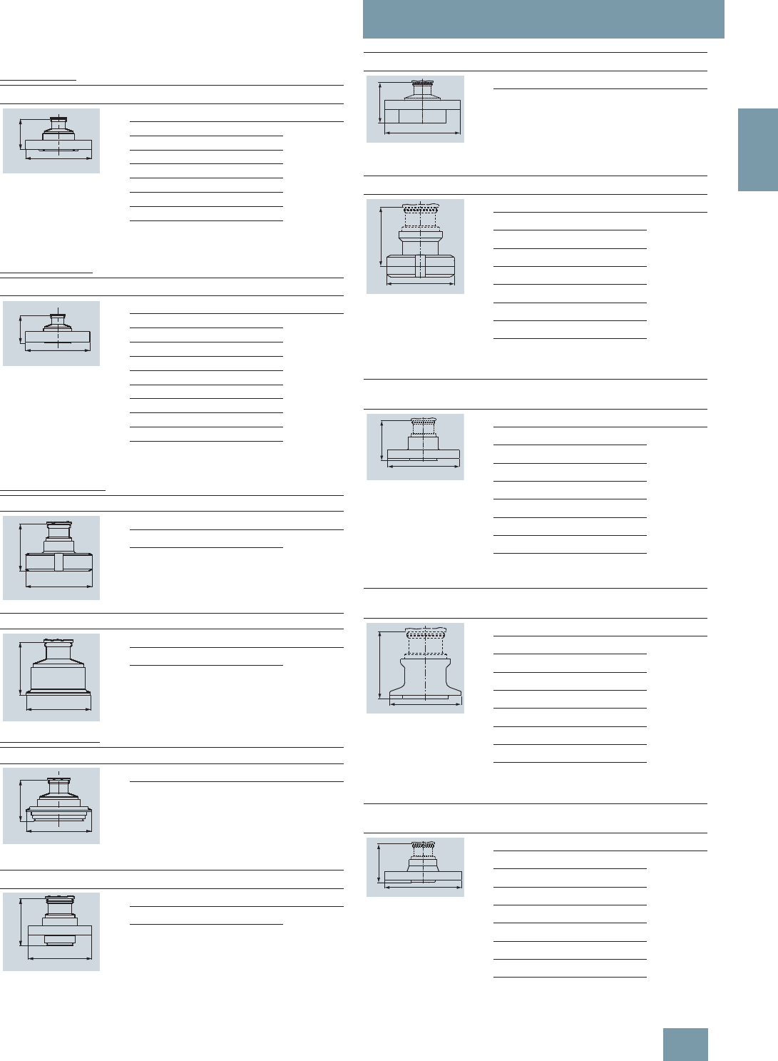
SITRANS P measuring instruments for pressure
Transmitters for food, pharmaceuticals and biotechnology
SITRANS P300 for gage and absolute pressure
2/45
Siemens FI 01 · 2009
2
Flanges to EN and ASME
Flanges to EN
Flanges to ASME
NuG and pharmaceutical connections
Connections to DIN
Other connections
EN 1092-1
DN PN ∅DH
2
25 40 115 mm (4.5“) Approx.
52 mm (2“)
25 100 140 mm (5.5“)
40 40 150 mm (5.9“)
40 100 170 mm (6.7“)
50 16 165 mm (6.5“)
50 40 165 mm (6.5“)
80 16 200 mm (7.9“)
80 40 200 mm (7.9“)
ASME B16.5
DN class ∅DH
2
1“ 150 110 mm (4.3“) Approx.
52 mm (2“)
1“ 300 125 mm (4.9“)
1½“ 150 130 mm (5.1“)
1½“ 300 155 mm (6.1“)
2“ 150 150 mm (5.9“)
2“ 300 165 mm (6.5“)
3“ 150 190 mm (7.5“)
3“ 300 210 mm (8.1“)
4“ 150 230 mm (9.1“)
4“ 300 255 mm (10.0“)
DIN 11851 (Dairy connection)
DN PN ∅DH
2
50 25 92 mm (3.6“) Approx.
52 mm (2“)
80 25 127 mm (5.0“)
Tri-Clamp according DIN 32676
DN PN ∅DH
2
50 16 64 mm (2.5“) Approx.
52 mm (2“)
65 16 91 mm (3.6“)
Varivent connection
DN PN ∅DH
2
40 ... 125 40 84 mm
(3.3“) Approx.
52 mm (2“)
Bio-Control connection
DN PN ∅DH
2
50 16 90 mm (3.5“) Approx.
52 mm (2“)
65 16 120 mm (4.7“)
'
+
'
+
'
+
'
+
'
+
'
+
Sanitary process connection to DRD
DN PN ∅DH
2
50 40 105 mm (4.1“) Approx.
52 mm (2“)
Sanitary process screw connection to NEUMO Bio-Connect
DN PN ∅DH
2
50 16 82 mm (3.2“) Approx.
52 mm (2“)
65 16 105 mm (4.1“)
80 16 115 mm (4.5“)
100 16 145 mm (5.7“)
2“ 16 82 mm (3.2“)
2½“ 16 105 mm (4.1“)
3“ 16 105 mm (4.1“)
4“ 16 145 mm (5.7“)
Sanitary connection to NEUMO Bio-Connect
flange connection
DN PN ∅DH
2
50 16 110 mm (4.3“) Approx.
52 mm (2“)
65 16 140 mm (5.5“)
80 16 150 mm (5.9“)
100 16 175 mm (6.9“)
2“ 16 100 mm (3.9“)
2½“ 16 110 mm (4.3“)
3“ 16 140 mm (5.5“)
4“ 16 175 mm (6.9“)
Sanitary connection to NEUMO Bio-Connect
clamp connection
DN PN ∅DH
2
50 16 77,4 mm (3.0“) Approx.
52 mm (2“)
65 10 90,9 mm (3.6“)
80 10 106 mm (4.2“)
100 10 119 mm (4.7“)
2“ 16 64 mm (2.5“)
2½“ 16 77,4 mm (3.0“)
3“ 10 90,9 mm (3.6“)
4“ 10 119 mm (4.7“)
Sanitary connection to NEUMO Bio-Connect S
flange connection
DN PN ∅DH
2
50 16 125 mm (4.9“) Approx.
52 mm (2“)
65 10 145 mm (5.7“)
80 10 155 mm (6.1“)
100 10 180 mm (7.1“)
2“ 16 125 mm (4.9“)
2½“ 10 135 mm (5.3“)
3“ 10 145 mm (5.7“)
4“ 10 180 mm (7.1“)
'
+
'
+
'
+
'
+
'
+
© Siemens AG 2008
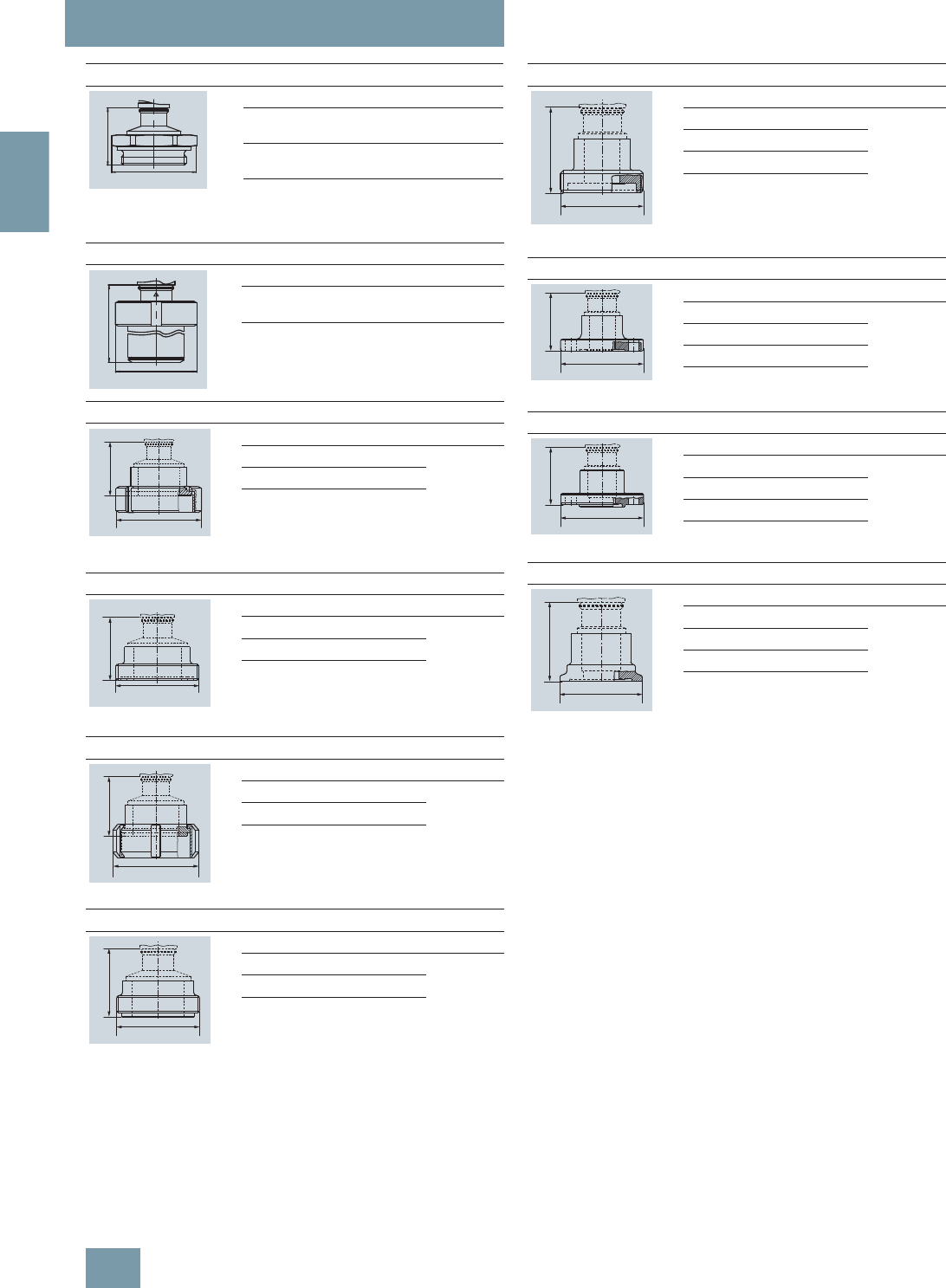
SITRANS P measuring instruments for pressure
Transmitters for food, pharmaceuticals and biotechnology
SITRANS P300 for gage and absolute pressure
2/46 Siemens FI 01 · 2009
2
Thread connection G¾“, G1“ and G2“ to DIN 3852
DN PN ∅DH
2
¾“ 63 37 mm (1.5“) Approx. 45
mm (1.8“)
1“ 63 48 mm (1.9“) Approx. 47
mm (1.9“)
2“ 63 78 mm (3.1“) Approx. 52
mm (2“)
Tank connection TG52/50 und TG52/150
DN PN ∅DH
2
25 40 63 mm (2.5“) Approx. 63
mm (2.5“)
25 40 63 mm (2.5“) Approx.170
mm (6.7“)
SMS socket with union nut
DN PN ∅DH
2
2“ 25 84 mm (3.3“) Approx. 52
mm (2.1“)
2½“ 25 100 mm (3.9“)
3“ 25 114 mm (4.5“)
SMS threaded socket
DN PN ∅DH
2
2“ 25 70 x 1/6 mm Approx. 52
mm (2.1“)
2½“ 25 85 x 1/6 mm
3“ 25 98 x 1/6 mm
IDF socket with union nut
DN PN ∅DH
2
2“ 25 77 mm (3“) Approx. 52
mm (2.1“)
2½“ 25 91 mm (3.6“)
3“ 25 106 mm (4.2“)
IDF threaded socket
DN PN ∅DH
2
2“ 25 64 mm (2.5“) Approx. 52
mm (2.1“)
2½“ 25 77,5 mm (3.1“)
3“ 25 91 mm (3.6“)
'
+
'
+
'
+
'
+
'
+
'
+
Aseptic threaded socket to DIN 11864-1 Form A
DN PN ∅DH
2
50 25 78 x 1/6“ Approx. 52
mm (2.1“)
65 25 95 x 1/6“
80 25 110 x ¼“
100 25 130 x ¼“
Aseptic flange with notch to DIN 11864-2 Form A
DN PN ∅DH
2
50 16 94 Approx. 52
mm (2.1“)
65 16 113
80 16 133
100 16 159
Aseptic flange with groove to DIN 11864-2 Form A
DN PN ∅DH
2
50 16 94 Approx. 52
mm (2.1“)
65 16 113
80 16 133
100 16 159
Aseptic clamp with groove to DIN 11864-3 Form A
DN PN ∅DH
2
50 25 77,5 Approx. 52
mm (2.1“)
65 25 91
80 16 106
100 16 130
+
'
+
'
+
'
+
'
© Siemens AG 2008
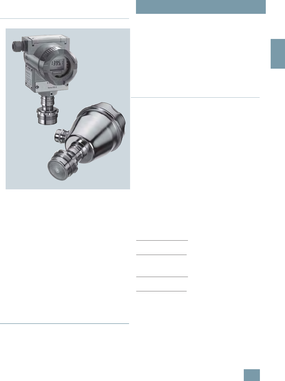
SITRANS P measuring instruments for pressure
Transmitters for gage pressure for the paper industry
SITRANS P300 and DS III series
with PMC connection – Technical description
2/47
Siemens FI 01 · 2009
2
■
Overview
The SITRANS P300 and DS III pressure transmitters have been
fitted with special process connections for the paper industry.
With the two process connection threads 1½" and 1" flush at the
front, the SITRANS P300 and DS III transmitters can be used for
all processes in the paper industry.
SITRANS P300 and DS III series pressure transmitters are digital
pressure transmitters featuring extensive user-friendliness and
high accuracy. The parameterization is performed using control
keys, over HART communication, PROFIBUS PA or
FOUNDATION Fieldbus interface (DS III only).
Extensive functionality enables the pressure transmitter to be
precisely adapted to the plant’s requirements. Operation is very
simple in spite of the numerous setting options.
Transmitters with type of protection "Intrinsic safety" and "Explo-
sion-proof" may be installed within potentially explosive atmo-
spheres (zone 1) or in zone 0. The transmitters are provided with
an EC type examination certificate and comply with the corre-
sponding harmonized European standards (ATEX).
Various versions of the pressure transmitters are available for
measuring:
• Gage pressure
• Filling level
• Volume level
• Mass level
■
Benefits
• High quality and long life
• High reliability even under extreme chemical and mechanical
loads, e.g. abrasion.
• For aggressive and non-aggressive gases, vapors and liquids
• Extensive diagnosis and simulation functions
• Minimum conformity error
• Small long-term drift
• Wetted parts made of Hastelloy
• Infinitely adjustable spans from 30 mbar g to 16 bar g for DS III
with HART interface
• Nominal measuring range from 1 mbar g to 16 bar g for DS III
with PROFIBUS PA and FOUNDATION Fieldbus interface
• Infinitely adjustable spans from 30 mbar g to 16 bar g for
SITRANS P300 with HART interface
• Nominal measuring range from 1 bar g to 16 bar g for
SITRANS P300 with PROFIBUS PA interface
• High measuring accuracy
• Parameterization over control keys and HART communication,
or over PROFIBUS PA or FOUNDATION Fieldbus interface (DS
III only).
■
Application
The pressure transmitters of the DS III series, can be used in in-
dustrial areas with extreme chemical and mechanical loads.
Electromagnetic compatibility in the range 10 kHz ... 1 GHz
makes the DS III pressure transmitters suitable for locations with
high electromagnetic emissions.
Pressure transmitters with type of protection "Intrinsic safety" and
"Explosion-proof" may be installed within potentially explosive at-
mospheres (zone 1) or in zone 0. The pressure transmitters are
provided with an EC type examination certificate and comply
with the corresponding harmonized European standards
(ATEX).
Pressure transmitters with the type of protection "Intrinsic safety"
for use in zone 0 may be operated with power supply units of cat-
egory "ia" and "ib".
The transmitters can be equipped with various designs of re-
mote seals for special applications such as the measurement of
highly viscous substances.
The pressure transmitter can be operated locally over 3 control
keys or programmed externally over HART communication or
over PROFIBUS PA or FOUNDATION Fieldbus interface (only
DS III).
SITRANS P, DS III series
Measured variable: Gage pressure of aggressive and non-
aggressive gases, vapors and liquids.
Span (infinitely adjustable)
For DS III HART: 0.03 ... 16 bar g (0.433 ... 232 psi g)
Nominal measuring range
For DS III PA and FF: 1 ... 16 bar g (14.5 ... 232 psi g)
SITRANS P300
Span (infinitely adjustable)
For DS III HART: 0.03 ... 16 bar g (0.433 ... 232 psi g)
Nominal measuring range
For DS III PA: 1 ... 16 bar g (14.5 ... 232 psi g)
© Siemens AG 2008
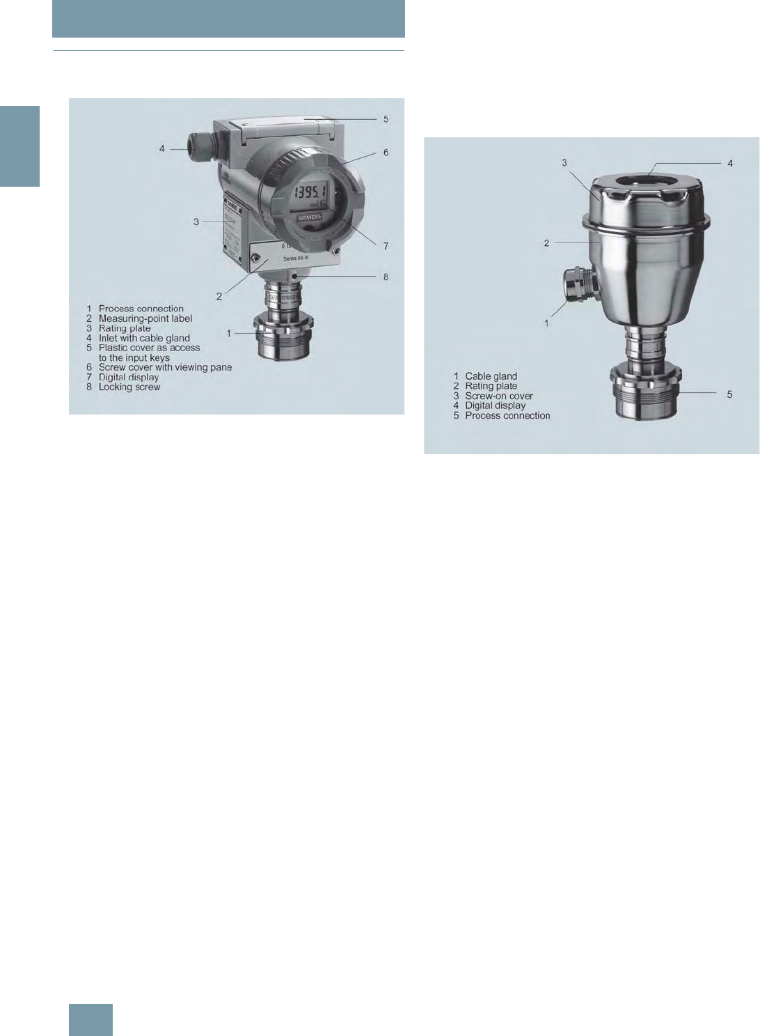
SITRANS P measuring instruments for pressure
Transmitters for gage pressure for the paper industry
SITRANS P300 and DS III series
with PMC connection – Technical description
2/48 Siemens FI 01 · 2009
2
■
Design
SITRANS P, DS III series
Device front view, SITRANS P DS III
The transmitter comprises a range of different components, de-
pending on the order specifications. The various options are
listed in the ordering information. The components described
below are the same for all transmitters.
The rating plate (3, Figure "Front view") with the Order No. is lo-
cated on the side of the housing. The specified number together
with the ordering information provide details on the optional de-
sign details and on the possible measuring range (physical
properties of built-in sensor element).
The approval label is located on the opposite side.
The housing is made of die-cast aluminium or stainless steel pre-
cision casting. A round cover is screwed on at the front and rear
of the housing. The front cover (6) can be fitted with a viewing
pane so that the measured values can be read directly on the
digital display. The inlet (4) for the electrical connection is lo-
cated either on the left or right side. The unused opening on the
opposite side is sealed by a blanking plug. The protective earth
connection is located on the rear of the housing.
The electrical connections for the power supply and screen are
accessible by unscrewing the rear cover. The bottom part of the
housing contains the measuring cell with process connection
(1). The measuring cell is prevented from rotating by a locking
screw (8). As the result of this modular design, the measuring
cell and the electronics can be replaced separately from each
other. The set parameter data are retained.
At the top of the housing is a plastic cover (5), which hides the
input keys.
SITRANS P300
The device comprises:
•Electronics
• Housing
• Measuring cell
Perspective view of the SITRANS P300
The housing has a screwable cover (3), with or without an in-
spection window depending on the version. The electrical termi-
nal housing, the buttons for operation of the device and, de-
pending on the version, the digital display are located under this
cover. The connections for the auxiliary power UH and the shield
are in the terminal housing. The cable gland is on the side of the
housing. The measuring cell with the process connection (5) is
located on the underside of the housing. Depending on the ver-
sion of the device, the measuring cell with the process connec-
tion may differ from the one shown in the diagram.
© Siemens AG 2008

SITRANS P measuring instruments for pressure
Transmitters for gage pressure for the paper industry
SITRANS P300 and DS III series
with PMC connection – Technical description
2/49
Siemens FI 01 · 2009
2
■
Function
Operation of the electronics with PROFIBUS PA communica-
tion
Function diagram of electronics
The bridge output voltage created by the sensor (1, Figure
"Function diagram of electronics") is amplified by the instrument
amplifier (2) and digitized in the analog-to-digital converter (3).
The digital information is evaluated in a microcontroller, its linear-
ity and temperature response corrected, and converted in a dig-
ital-to-analog converter (5) into an output current of 4 to 20 mA.
The diode circuit (10) protects against incorrect polarity.
The data specific to the measuring cell, the electronics data, and
the parameter data are stored in the two non-volatile memories
(6). The one memory is coupled to the measuring cell, the other
to the electronics. As the result of this modular design, the elec-
tronics and the measuring cell can be replaced separately from
each other.
Using the 3 input keys (8) you can parameterize the pressure
transmitter directly at the point of measurement. The input keys
can also be used to control the view of the results, the error mes-
sages and the operating modes on the digital display (9).
The HART modem (7) permits parameterization using a protocol
according to the HART specification.
The pressure transmitters with spans ≤ 63 bar g measure the in-
put pressure compared to atmosphere, transmitters with spans
≥ 160 bar g compared to vacuum.
Operation of the electronics with PROFIBUS PA communica-
tion
Function diagram of electronics
The bridge output voltage created by the sensor (1, Figure
"Function diagram of electronics") is amplified by the instrument
amplifier (2) and digitized in the analog-to-digital converter (3).
The digital information is evaluated in the microcontroller, its lin-
earity and temperature response corrected, and provided on the
PROFIBUS PA through an electrically isolated PA interface (7).
The data specific to the measuring cell, the electronics data, and
the parameter data are stored in the two non-volatile memories
(6). The first memory is linked with the measuring cell, the sec-
ond with the electronics. This modular design means that the
electronics and the measuring cell can be replaced separately
from one another.
Using the three input keys (8) you can parameterize the pressure
transmitter directly at the point of measurement. The input keys
can also be used to control the view of the results, the error mes-
sages and the operating modes on the digital display (9).
The results with status values and diagnostic values are trans-
ferred by cyclic data transmission on the PROFIBUS PA. Param-
eterization data and error messages are transferred by acyclic
data transmission. Special software such as SIMATIC PDM is re-
quired for this.
IA, UH
5
6
7
8
Pe
1
4
3
2
C
m
M
10
00000
00
9
6
1 Measuring cell sensor
2Instrument amplifier
3Analog-to-digital converter
4Microcontroller
5 Digital-to-analog converter
6One non-volatile memory each in the measuring cell and electronics
7 HART interface
8 Three input keys (local operation)
9 Digital display
10Diode circuit and connection for external ammeter
IAOutput current
UHPower supply
PeInput variable
Sensor
EEPROM
EEPROM
HART interface
Electronics
Measuring cell
6
8
pe
1
2
C
m
M
00000
00
EEPROM
EEPROM
9
6
345 7
10
12
11
1 Measuring cell sensor
2Instrument amplifier
3Analog-to-digital converter
4Microcontroller
5 Electrical isolation
6One non-volatile memory
each in the measuring cell
and electronics
7 PROFIBUS-PA interface
Sensor
Electronics
Measuring cell
PA
interface
Bus-
Master
Power
supply
unit
Coup-
ler
Power supply
PROFIBUS-DP
PROFIBUS-PA
8 Three input keys
(local operation)
9 Digital display
10Power supply
11 DP/PA coupler or link
12 Bus master
p
e
Input variable
© Siemens AG 2008
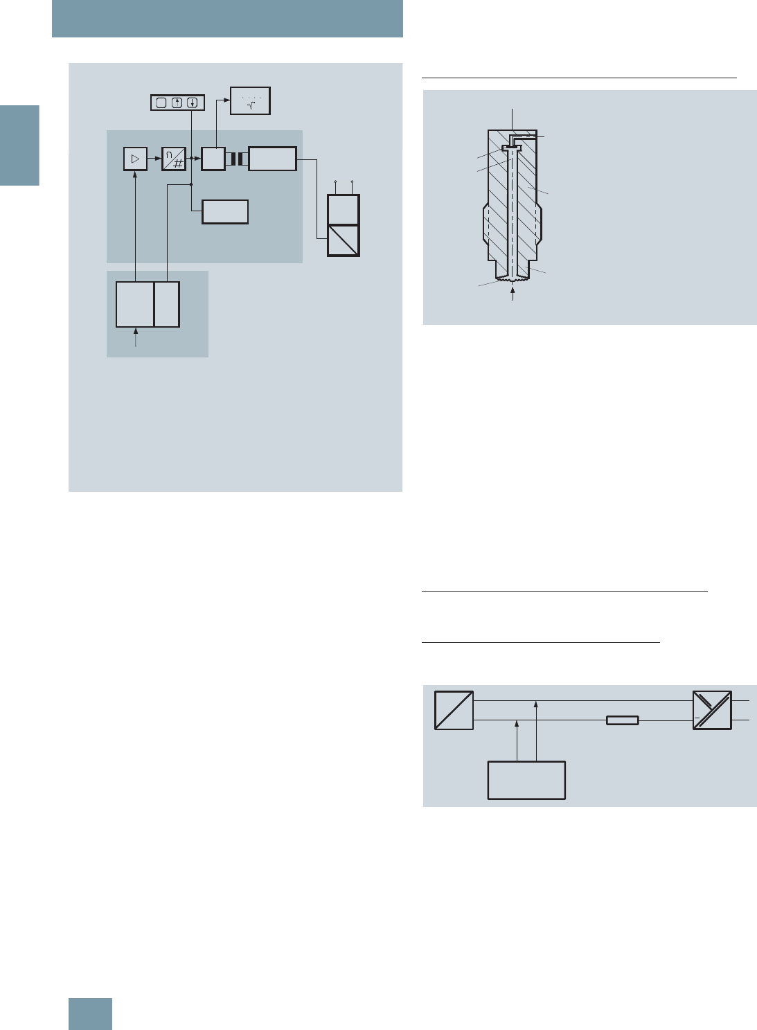
SITRANS P measuring instruments for pressure
Transmitters for gage pressure for the paper industry
SITRANS P300 and DS III series
with PMC connection – Technical description
2/50 Siemens FI 01 · 2009
2
Mode of operation of the FOUNDATION Fieldbus electronics
Function diagram of electronics
The bridge output voltage created by the sensor (1, Figure
"Function diagram of electronics") is amplified by the instrument
amplifier (2) and digitized in the analog-to-digital converter (3).
The digital information is evaluated in the microcontroller, its lin-
earity and temperature response corrected, and provided on the
FOUNDATION Fieldbus through an electrically isolated
FOUNDATION Fieldbus Interface (7).
The data specific to the measuring cell, the electronics data, and
the parameter data are stored in the two non-volatile memories
(6). The one memory is coupled to the measuring cell, the other
to the electronics. As the result of this modular design, the elec-
tronics and the measuring cell can be replaced separately from
each other.
Using the three input keys (8) you can parameterize the pressure
transmitter directly at the point of measurement. The input keys
can also be used to control the view of the results, the error mes-
sages and the operating modes on the digital display (9).
The results with status values and diagnostic values are trans-
ferred by cyclic data transmission on the FOUNDATION
Fieldbus. Parameterization data and error messages are trans-
ferred by acyclic data transmission. Special software such as
National Instruments Configurator is required for this.
Mode of operation of the measuring cell
Measuring cell for gage pressure with front-flush diaphragm
Measuring cell for gage pressure, with front-flush diaphragm, function
diagram
The pressure pe is applied through the process connection
(2, Figure "Measuring cell for gage pressure, with front-flush di-
aphragm for paper industry, function diagram") to the measuring
cell (1). This pressure is subsequently transmitted further
through the seal diaphragm (3) and the filling liquid (4) to the sil-
icon pressure sensor (5) whose measuring diaphragm is then
flexed. This changes the resistance of the four piezo-resistors fit-
ted in the diaphragm in a bridge circuit. This change in resis-
tance results in a bridge output voltage proportional to the input
pressure.
Parameterization
Depending on the version, there are a range of options for pa-
rameterizing the pressure transmitter and for setting or scanning
the parameters.
Parameterization using the input keys (local operation)
With the input keys you can easily set the most important param-
eters without any additional equipment.
Parameterization using HART communication
Parameterization using HART communication is performed with
a HART communicator or a PC.
Communication between a HART communicator and a pressure
transmitter
When parameterizing with the HART communicator, the connec-
tion is made directly to the 2-wire system.
6
8
pe
1
2
C
m
M
00000
00
EEPROM
EEPROM
9
6
345 7
10
1 Measuring cell sensor
2Instrument amplifier
3Analog-to-digital converter
4Microcontroller
5 Electrical isolation
6One non-volatile memory
each in the measuring cell
and electronics
7FF interface
Sensor
Electronics
Measuring cell
FF
interface
Power
supply
unit
Coup-
ler
Power supply
8 Three input keys
(local operation)
9 Digital display
10Power supply
p
e
Input variable
p
1
4
3
2
e
5
1 Measuring cell
2Process connection
3Seal diaphragm
4 Filling liquid
5 Silicon pressure sensor
pePressure as input variable
+
HART
communicator
230 ... 1100 W
transmitter
SITRANS P Power supply
© Siemens AG 2008

SITRANS P measuring instruments for pressure
Transmitters for gage pressure for the paper industry
SITRANS P300 and DS III series
with PMC connection – Technical description
2/51
Siemens FI 01 · 2009
2
HART communication between a PC communicator and a pressure
transmitter
When parameterizing with a PC, the connection is made through
a HART modem.
The signals needed for communication in conformity with the
HART 5.x or 6.x protocols are superimposed on the output cur-
rent using the Frequency Shift Keying (FSK) method.
Adjustable parameter DS III HART and P300 HART
Diagnostic functions for DS III HART and P300 HART
• Zero correction display
• Event counter
• Limit transmitter
• Saturation alarm
• Slave pointer
• Simulation functions
• Maintenance timer
Available physical units of display for DS III HART and P300
HART
Parameterization through PROFIBUS PA interface
Fully digital communication through PROFIBUS PA, profile 3.0, is
particularly user-friendly. The PROFIBUS puts the DS III PA is in
connection with a process control system, e.g. SIMATIC PSC 7.
Communication is possible even in a potentially explosive envi-
ronment.
For parameterization through PROFIBUS you need suitable soft-
ware, e.g. SIMATIC PDM (Process Device Manager).
Parameterization through FOUNDATION Fieldbus Interface
Fully digital communication through FOUNDATION Fieldbus is
particularly user-friendly. Through the FOUNDATION Fieldbus
the DS III FF is connected to a process control system. Commu-
nication is possible even in a potentially explosive environment.
For parameterization through the FOUNDATION Fieldbus you
need suitable software, e.g. National Instruments Configurator.
Adjustable parameters for DS III PA and FF and P300 PA and FF
Diagnostic functions for DS III PA and FF and P300 PA and FF
• Event counter
• Slave pointer
• Maintenance timer
• Simulation functions
• Display of zero correction
• Limit transmitter
• Saturation alarm
Physical dimensions available for the display
Parameters Input keys HART com-
munication
Start of scale x x
Full-scale value x x
Electrical damping x x
Start-of-scale value without application
of a pressure ("Blind setting") xx
Full-scale value without application of a
pressure ("Blind setting") xx
Zero adjustment x x
Current transmitter x x
Fault current x x
Disabling of keys, write protection x x1)
1) Cancel apart from write protection
Type of dimension and actual dimension x x
Characteristic (linear) x x
Input of characteristic x
Freely-programmable LCD x
Diagnostics functions x
Physical variable Physical dimensions
Pressure (setting can also be
made in the factory) Pa, MPa, kPa, bar, mbar, torr, atm,
psi, g/cm2, kg/cm2, inH2O, inH2O
(4 °C), mmH2O, ftH2O (20 °C),
inHg, mmHg
Level (height data) m, cm, mm, ft, in
Volume m3, dm3, hl, yd3, ft3, in3, US gallon,
lmp, gallon, bushel, barrel, barrel
liquid
Mass g, kg, t, lb, Ston, Lton, oz
Temperature K, °C, °F, °R
Miscellaneous %, mA
transmitter
SITRANS P Power supply
HART
modem
PC or
laptop
RS 232
230 ... 500 W
Adjustable parameters Input keys PROFIBUS PA and
FOUNDATION
Fieldbus interface
Electrical damping x x
Zero adjustment (correction of
position) xx
Key and/or function disabling x x
Source of measured-value dis-
play xx
Physical dimension of display x x
Position of decimal point x x
Bus address x x
Adjustment of characteristic x x
Input of characteristic x
Freely-programmable LCD x
Diagnostic functions x
Physical variable Physical dimensions
Pressure (setting can also be
made in the factory) MPa, kPa, Pa, bar, mbar, torr, atm,
psi, g/cm2, kg/cm2, mmH2O,
mmH2O (4 °C), inH2O, inH20
(4 °C), ftH2O (20 °C), mmHg, inHg
Level (height data) m, cm, mm, ft, in, yd
Mass g, kg, t, lb, Ston, Lton, oz
Volume m3, dm3, hl, yd3, ft3, in3, US gallon,
lmp, gallon, bushel, barrel, barrel
liquid
Temperature K, °C, °F, °R
Miscellaneous %
© Siemens AG 2008

SITRANS P measuring instruments for pressure
Transmitters for gage pressure for the paper industry
DS III series with PMC connection
2/52 Siemens FI 01 · 2009
2
■
Technical specifications
SITRANS P, DS III series for gage pressure with PMC connection for the paper industry
HART PROFIBUS PA or FOUNDATION Fieldbus
Input
Measured variable Gage pressure
Spans (infinitely adjustable) or
nominal measuring range and
max. permissible test pressure
Span Max. perm. test pres-
sure Nominal measuring
range Max. perm. test pres-
sure
0.01 ... 1 bar g
(0.145 ... 14.5 psi g) 6 bar g
(87 psi g) 1 bar g
(14.5 psi g) 6 bar g
(87 psi g)
0.04 ... 4 bar g
(0.58 ... 58 psi g) 10 bar g
(145 psi g) 4 bar g
(58 psi g) 10 bar g
(145 psi g)
0.16 ... 16 bar g
(2.32 ... 232 psi g) 32 bar g
(464 psi g) 16 bar g
(232 psi g) 32 bar g
(464 psi g)
Lower measuring limit
• Measuring cell with silicone oil filling 100 mbar a (1.45 psi a)
Upper measuring limit 100% of max. span
Output
Output signal 4 ... 20 mA Digital PROFIBUS PA or FOUNDATION Fieldbus
signal
• Lower limit (infinitely adjustable) 3.55 mA, factory preset to 3.84 mA -
• Upper limit (infinitely adjustable) 23 mA, factory preset to 20.5 mA or optionally set
to 22.0 mA -
Load
• Without HART communication RB ≤ (UH - 10.5 V)/0.023 A in Ω,
UH : Power supply in V -
• With HART communication RB = 230 ... 500 Ω (SIMATIC PDM) or
RB = 230 ... 1100 Ω (HART Communicator) -
Physical bus - IEC 61158-2
With polarity reversal protection - Yes
Accuracy To EN 60770-1
Reference conditions
(All error data refer always refer to the set
span)
Increasing characteristic, start-of-scale value 0 bar, stainless steel seal diaphragm, silicone oil filling,
room temperature 25 °C (77 °F) r: Span ratio (r = max. span/set span)
Error in measurement and fixed-point setting
(including hysteresis and repeatability)
• Linear characteristic ≤0,075%
-r ≤ 10 ≤ (0.0029 ⋅ r + 0.071)%
- 10 < r ≤ 30 ≤ (0.0045 ⋅ r + 0.071)%
- 30 < r ≤ 100 ≤ (0.005 ⋅ r + 0.05)%
Long-term drift (temperature change ± 30 °C
(± 54 °F)) ≤ (0.25 ⋅ r)% every 5 years ≤ 0.25% every 5 years
Influence of ambient temperature
• at -10 ... +60 °C (14 ... 140 °F) ≤ (0.08 ⋅ r + 0.1)% ≤0,3%
• at -40 ... -10 °C and +60 ... +85 °C
(-40 ... +14 °F and 140 ... 185 °F) ≤ (0.1 ⋅ r + 0.15)%/10 K ≤ 0.25%/10 K
Influence of medium temperature
• Temperature difference between medium
temperature and ambient temperature 3 mbar/10 K (0.04 psi/10 K)
Influence of mounting position ≤ 0.1 mbar g (0.00145 psi g) per 10° inclination
Measured Value Resolution - 3 ⋅10-5 of nominal measuring range
© Siemens AG 2008

SITRANS P measuring instruments for pressure
Transmitters for gage pressure for the paper industry
DS III series with PMC connection
2/53
Siemens FI 01 · 2009
2
Rated operating conditions
Degree of protection (to EN 60529) IP65, IP68, NEMA X, enclosure cleaning, resistant to lyes, steam to 150° C (302 °F)
Process temperature -20 ... +100 °C (-4 ... +212 °F)
Ambient conditions
• Ambient temperature -20 ... +85 °C (-4 ... +185 °F)
• Storage temperature -50 ... +85 °C (-58 ... +185 °F)
• Climatic class
- Condensation Permissible
• Electromagnetic compatibility
- Emitted interference and interference im-
munity To EN 61326 and NAMUR NE 21
Design
Weight (without options) ≈ 1.5 kg (≈ 3.3 lb)
Housing material Poor in copper die-cast aluminium, GD-AlSi12 or stainless steel precision casting, mat. No. 1.4408
Wetted parts materials Stainless steel
• Gasket (standard) PTFE flat gasket
• O-ring (minibolt) FPM (Viton) or optionally: FFPM or NBR
Measuring cell filling Silicone oil or inert filling liquid
Process connection (standard) Front-flush, 1½", PMC Standard design
Process connection (minibolt) Front-flush, 1", minibolt design
Power supply UH Supplied through bus
Terminal voltage on transmitter 10.5 ... 45 V DC
10.5 ... 30 V DC in intrinsically-safe mode -
Separate 24 V power supply necessary - No
Bus voltage
• Not Ex - 9 ... 32 V
• With intrinsically-safe operation - 9 ... 24 V
Current consumption
• Basic current (max.) - 12.5 mA
• Startup current ≤ basic current - Yes
• Max. current in event of fault - 15.5 mA
Fault disconnection electronics (FDE) avail-
able -Yes
Certificate and approvals
Classification according to pressure equip-
ment directive (DRGL 97/23/EC) For gases of fluid group 1 and liquids of fluid group 1; complies with requirements of Article 3, para-
graph 3 (sound engineering practice)
SITRANS P, DS III series for gage pressure with PMC connection for the paper industry
HART PROFIBUS PA or FOUNDATION Fieldbus
© Siemens AG 2008

SITRANS P measuring instruments for pressure
Transmitters for gage pressure for the paper industry
DS III series with PMC connection
2/54 Siemens FI 01 · 2009
2
SITRANS P, DS III series for gage pressure with PMC connection
for the paper industry
HART communication
HART communication 230 ... 1100 Ω
Protocol HART Version 5.x
Software for computer SIMATIC PDM
PROFIBUS PA communication
Simultaneous communication with
master class 2 (max.) 4
The address can be set using Configuration tool or local opera-
tion (standard setting address
126)
Cyclic data usage
• Output byte 5 (one measuring value) or
10 (two measuring values)
• Input byte 0, 1, or 2 (register operating mode
and reset function for metering)
Internal preprocessing
Device profile PROFIBUS PA Profile for Process
Control Devices Version 3.0,
Class B
Function blocks 2
• Analog input
- Adaptation to customer-specif-
ic process variables Yes, linearly rising or falling char-
acteristic
- Electrical damping T63 , adjust-
able 0 ... 100 s
- Simulation function Input /Output
- Failure mode Can be parameterized (last good
value, substitute value, incorrect
value)
- Limit monitoring Yes, one upper and lower warning
limit and one alarm limit respec-
tively
• Register (totalizer) Can be reset, preset, optional
direction of counting, simulation
function of register output
- Failure mode Can be parameterized (summation
with last good value, continuous
summation, summation with incor-
rect value)
- Limit monitoring One upper and lower warning limit
and one alarm limit respectively
• Physical block 1
Transducer blocks 2
• Pressure transducer block
- Can be calibrated by applying
two pressures Yes
- Monitoring of sensor limits Yes
- Specification of a container
characteristic with Max. 30 nodes
- Square-rooted characteristic
for flow measurement Yes
- Gradual volume suppression
and implementation point of
square-root extraction
Parameterizable
- Simulation function for mea-
sured pressure value and sen-
sor temperature
Constant value or over parameter-
izable ramp function
Communication FOUNDATION Fieldbus
Function blocks 3 function blocks analog input, 1
function block PID
• Analog input
- Adaptation to customer-specif-
ic process variables Yes, linearly rising or falling char-
acteristic
- Electrical damping T63 , adjust-
able 0 ... 100 s
- Simulation function Output/input (can be locked within
the device with a bridge)
- Failure mode Can be parameterized (last good
value, substitute value, incorrect
value)
- Limit monitoring Yes, one upper and lower warning
limit and one alarm limit respec-
tively
- Square-rooted characteristic
for flow measurement Yes
• PID Standard FF function block
• Physical block 1 Resource block
Transducer blocks 1 transducer block Pressure with
calibration, 1 transducer block
LCD
• Pressure transducer block
- Can be calibrated by applying
two pressures Yes
- Monitoring of sensor limits Yes
- Simulation function: Measured
pressure value, sensor temper-
ature and electronics tempera-
ture
Constant value or over parameter-
izable ramp function
© Siemens AG 2008

SITRANS P measuring instruments for pressure
Transmitters for gage pressure for the paper industry
DS III series with PMC connection
2/55
Siemens FI 01 · 2009
2
Selection and Ordering data Order No.
SITRANS P pressure transmitters for gage
pressure, with PMC connection
series DS III HART
7 M F 4 1 3 3 -
77777 -7 7 7 7
Measuring cell filling Measuring cell
cleaning
Silicone oil Standard 1
Inert liquid Grease-free 3
Span
0.01 ... 1 bar g1)
1) Only with "PMC Style Standard" process connection
(0.15 ... 14.5 psi g)1) B
0.04 ... 4 bar g (0.58 ... 58 psi g) C
0.16 ... 16 bar g (2.32 ... 232 psi g) D
Wetted parts materials
Seal diaphragm Connection shank
Hastelloy Stainless steel B
Process connection
• PMC Style Standard: Thread 1½" 2
• PMC Style Mini bolt: 1" front-flush (min. span:
500 mbar (7.25 psi), can not be ordered with mit
1-bar (14.5 psi) measuring cell (Option B))
3
Non-wetted parts materials
• Housing made of die-cast aluminum 0
• Housing stainless steel precision casting 3
Version
• Standard version 1
• International version, English label inscriptions,
documentation in 5 languages on CD 2
Explosion protection
• None A
Electrical connection / cable entry
• Female thread M20x1.5 B
• Female thread ½-14 NPT C
• M12 connectors (metal) F
Display
• Without indicator 0
• Without visible digital indicator (digital indicator
hidden, setting: mA)
}1
• With visible digital indication, setting: mA 6
• With customer-specific digital indication (setting
as specified, Order code "Y21" or "Y22"
required)
7
Power supply units see "SITRANS I power supply units and isolation
amplifiers".
Included in delivery of the device:
• Brief instructions (Leporello)
• CD-ROM with detailed documentation
• Sealing ring
Selection and Ordering data Order No.
SITRANS P pressure transmitter for gage
pressure, with PMC connection
DS III PA (PROFIBUS PA) series 7 M F 4 1 3 4 -
DS III FF series (FOUNDATION Fieldbus) 7 M F 4 1 3 5 -
7 7 7 7 7 -7 7 7 7
Measuring cell filling Measuring cell
cleaning
Silicone oil Standard 1
Inert liquid Grease-free 3
Nominal measuring range
1 bar g1)
1) Only with "PMC Style Standard" process connection
(14.5 psi g)1) B
4 bar g (58 psi g) C
16 bar g (232 psi g) D
Wetted parts materials
Seal diaphragm Connection shank
Hastelloy Stainless steel B
Process connection
• PMC Style Standard: front-flush 1½" 2
• PMC Style Mini bolt: front-flush 1"
(min. span: 500 mbar (7.25 psi), can not be or-
dered with mit 1-bar (14.5 psi) measuring cell
(Option B))
3
Non-wetted parts materials
• Housing made of die-cast aluminum 0
• Housing stainless steel precision casting 3
Version
• Standard version 1
• International version, English label inscriptions,
documentation in 5 languages on CD 2
Explosion protection
• None A
Electrical connection / cable inlet
• Screwed gland M20x1.5 B
• Screwed gland ½-14 NPT C
• M12 connectors (metal) F
Display
• Without indicator 0
• Without visible digital indicator (digital indicator
hidden, setting: mA)
}1
• With visible digital display 6
• With customer-specific digital display (setting as
specified, Order code "Y21" or required) 7
Included in delivery of the device:
• Brief instructions (Leporello)
• CD-ROM with detailed documentation
• Sealing ring
© Siemens AG 2008

SITRANS P measuring instruments for pressure
Transmitters for gage pressure for the paper industry
DS III series with PMC connection
2/56 Siemens FI 01 · 2009
2
Selection and Ordering data Order code
Further designs HART PA FF
Add "-Z" to Order No. and specify Order
code.
M12 cable sockets (metal) A50 9
9
9
9
9
9
Rating plate inscription
(instead of German)
• English B11 9
9
9
9
9
9
• French B12 9
9
9
9
9
9
• Spanish B13 9
9
9
9
9
9
• Italian B14 9
9
9
9
9
9
English rating plate B21 9
9
9
9
9
9
Pressure units in inH20 or psi
Quality inspection certificate (Factory cali-
bration) to IEC 60770-2 C11 9
9
9
9
9
9
Acceptance test certificate C12 9
9
9
9
9
9
To EN 10204-3.1
Factory certificate C14 9
9
9
9
9
9
To EN 10204-2.2
Output signal can be set to upper limit of
22.0 mA D05 9
9
9
9
9
9
Mounting
• Weldable sockets for standard 1½" threaded
connection P01 9
9
9
9
9
9
• Weldable socket for mini bolt connection 1"
(incl. screw 5/16-18 UNC-2B and washer) P02 9
9
9
9
9
9
Selection and Ordering data Order code
Additional data HART PA FF
Add "-Z" to Order No. and specify Order
code.
Measuring range to be set Y01 9
9
Specify in plain text (max. 5 digits):
Y01: ... up to ... mbar, bar, kPa, MPa, psi
Measuring point number (TAG No.) Y15 9
9
9
9
9
9
Max. 16 characters, specify in plain text:
Y15: ...........................................
Measuring point text Y16 9
9
9
9
9
9
Max. 27 characters, specify in plain text:
Y16: ...........................................
Entry of HART address (TAG) Y17 9
9
Max. 8 characters, specify in plain text:
Y17: ...........................................
Setting of pressure indication in pressure
units Y21 9
9
9
9
9
9
Specify in plain text (standard setting: mA):
Y21: mbar, bar, kPa, MPa, psi, ...
Note:
The following pressure units can be selected:
bar, mbar, mm H2O*), inH2O*), ftH2O*),
mmHG, inHG, psi, Pa, kPa, MPa, g/cm2,
kg/cm2, Torr, ATM or %
*) ref. temperature 20 °C
Setting of pressure indication in
non-pressure units Y22 +
Y01
9
9
Specify in plain text:
Y22: ..... up to ..... l, m3, m, USg, ...
(specification of measuring range in pressure
units "Y01" is essential, unit with
max. 5 characters)
Preset bus address Y25 9
9
9
9
Max. 8 characters, specify in plain text:
Y25: ...........
Only "Y01" and "Y21" can be factory preset
9
9
= available
Ordering example
Item line: 7MF4133-1DB20-1AB7-Z
B line: A22 + Y01 + Y21
C line: Y01: 1 ... 10 bar (14.5 ... 145 psi)
C line: Y21: bar (psi)
© Siemens AG 2008
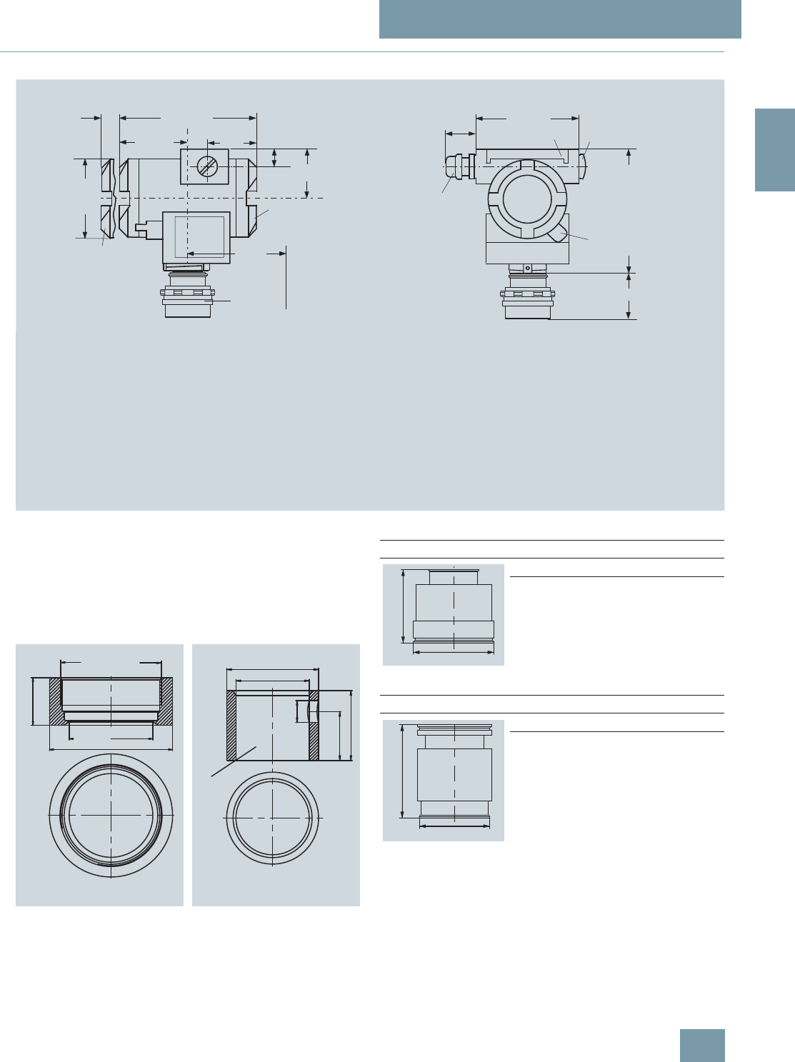
SITRANS P measuring instruments for pressure
Transmitters for gage pressure for the paper industry
DS III series with PMC connection
2/57
Siemens FI 01 · 2009
2
■
Dimensional drawings
SITRANS P DS III pressure transmitters for gage pressure, with PMC connection, dimensions in mm (inch)
The diagram shows a SITRANS P DS III with an example of a
flange. In this drawing the height is subdivided into H1 and H2.
H1 = Height of the SITRANS P DS III up to a defined cross-sec-
tion
H2 = Height of the flange up to this defined cross-section
Only the height H2 is indicated in the dimensions of the flanges.
PMC Style standard (left) and PMC Style minibolt (right) weldable sock-
ets, dimensions in mm (inch)
Material: Stainless steel, mat. No. 1.4404 / 316L
3
6
approx. 30 (1.18)
74 (2.9) 2
51)
41)
Space for rotation
of housing
7
144 (567)
15
(0.6)
51
(2.0)
20
(0.8)
50
(1.97)
Ø 80
(3.15)
90 (3.6)
2)
100 (3.94)
1
H1 = approx. 130 (5.12)
H2
1Process connection: PMC standard
2Blanking plug
3Electrical connection:
- screwed gland M20x1,5
- screwed gland ½-14 NPT
4 Terminal side
5 Electronics side, digital display (longer overall length for cover with window)
6Protective cover over keys
7Screw cover safety bracket (only for explosion-proof enclosure,
not shown in the drawing)
1) Allow approx. 20 mm (0.79 inch) thread length in addition
2) 92 mm (3.6 inch) for minimum distance to permit rotation with indicator
0[
2ULQJVXUIDFH
ERUHKROHPPಯZLWKRXWEXUU
PMC Style standard
DN PN ∅DH
2
40.9 mm (1.6") Approx.
36.8 mm
(1.4’’)
PMC Style minibolt
DN PN ∅DH
2
26.3 mm (1.0") Approx.
33.1 mm
(1.3’’)
'
+
'
+
© Siemens AG 2008

SITRANS P measuring instruments for pressure
Transmitters for gage pressure for the paper industry
SITRANS P300 with PMC connection
2/58 Siemens FI 01 · 2009
2
■
Technical specifications
SITRANS P300 for gage pressure with PMC connection for the paper industry
HART PROFIBUS PA
Input
Measured variable Gage pressure (flush-mounted)
Spans (infinitely adjustable) or
nominal measuring range and
max. permissible test pressure
Span Max. perm. test pres-
sure Nominal measuring
range Max. perm. test pres-
sure
0.01 ... 1 bar g
(0.15 ... 14.5 psi g) 6 bar g
(87 psi g) 1 bar g
(14.5 psi g) 6 bar g
(87 psi g)
0.04 ... 4 bar g
(0.58 ... 58 psi g) 10 bar g
(145 psi g) 4 bar g
(58 psi g) 10 bar g
(145 psi g)
0.16 ... 16 bar g
(2.3 ... 232 psi g) 32 bar g
(464 psi g) 16 bar g
(232 psi g) 32 bar g
(464 psi g)
Depending on the process connection, the span
may differ from these values Depending on the process connection, the nomi-
nal measuring range may differ from these values
Lower measuring limit
• Measuring cell with silicone oil 100 mbar a (1.45 psi a)
Upper measuring limit
• Measuring cell with silicone oil 100% of max. span 100% of the max. nominal measuring range
Output
Output signal 4 ... 20 mA Digital PROFIBUS PA signal
Physical bus - IEC 61158-2
With polarity reversal protection No Yes
Electrical damping T63 (step width 0.1 s) Set to 0.1 s (0 ... 100 s)
Accuracy To EN 60770-1
Reference conditions
(All error data refer always refer to the set
span)
Increasing characteristic, start-of-scale value 0 bar, stainless steel seal diaphragm, measuring cell
with silicone oil, room temperature 25 °C (77 °F), span ratio (r = max. span/set span)
Measurement deviation with cut-off point set-
ting, including hysteresis and repeatability.
Linear characteristic curve ≤ 0,075%
•r ≤ 10 ≤ (0.0029 ⋅ r + 0.071)%
• 10 < r ≤ 30 ≤ (0.0045 ⋅ r + 0.071)%
• 30 < r ≤ 100 ≤ (0.005 ⋅ r + 0.05)%
Settling time T63 without electrical damping Approx. 0.2 s
Long-term drift at ±30 °C (±54 °F) ≤ (0.25 ⋅ r)%/5 years ≤ 0.25%/5 years
Influence of ambient temperature
• at -10 ... +60 °C (14 ... 140 °F) ≤ (0.1 ⋅ r + 0.2)% ≤ 0,3%
• at -40 ... -10 °C and +60 ... +85 °C
(-40 ... 14 °F and 140 ... 185 °F) ≤ (0.1 ⋅ r + 0.15)%/10 K ≤ 0.25%/10 K
Influence of the medium temperature (only
with front-flush diaphragm)
• Temperature difference between medium
temperature and ambient temperature 3 mbar/10 K (0.04 psi/10 K)
Rated operating conditions
Installation conditions
Ambient temperature Observe the temperature class in areas subject to explosion hazard.
• Measuring cell with silicone oil -40 ... +85 °C (-40 ... +185 °F)
• Digital display -30 ... +85 °C (-22 ... +185 °F)
• Storage temperature -50 ... +85 °C (-58 ... +185 °F)
Climatic class
Condensation Permissible
Degree of protection to EN 60529 IP65, IP68, NEMA X, enclosure cleaning, resistant to lyes, steam to 150° C (302 °F)
Electromagnetic compatibility
• Emitted interference and interfer. immunity To EN 61326 and NAMUR NE 21
© Siemens AG 2008

SITRANS P measuring instruments for pressure
Transmitters for gage pressure for the paper industry
SITRANS P300 with PMC connection
2/59
Siemens FI 01 · 2009
2
Medium conditions
Process temperature
• Measuring cell with silicone oil -40 ... +100 °C (-40 ... +212 °F)
Design
Weight (without options) Approx. 1 kg (2.2 lb)
Housing material Stainless steel, mat. No. 1.4301/304
Material of parts in contact with the medium
• Seal diaphragm Hastelloy C276, mat. No. 2.4819
• Measuring cell filling Silicone oil
Power supply UH
Terminal voltage on transmitter 10.5 ... 42 V DC
for intrinsically safe operation: 10.5 ... 30 V DC Supplied through bus
Separate power supply - Not necessary
Bus voltage
• Without EEx - 9 ... 32 V
• For intrinsically-safe operation - 9 ... 24 V
Current consumption
• Max. basic current - 12.5 mA
• Startup current ≤ basic current - Yes
• Max. fault current in the event of a fault - 15.5 mA
Fault disconnection electronics (FDE) - Available
Certificate and approvals
Classification according to pressure equip-
ment directive (DRGL 97/23/EC) For gases of fluid group 1 and liquids of fluid group 1; complies with requirements of Article 3, para-
graph 3 (sound engineering practice)
Explosion protection
Intrinsic safety "i" PTB 05 ATEX 2048
Identification Ex II 1/2 G EEx ia/ib IIB/IIC T4, T5, T6
Permissible ambient temperature
• Temperature class T4 -40 ... +85 °C (-40 ... +185 °F)
• Temperature class T5 -40 ... +70 °C (-40 ... +158 °F)
• Temperature class T6 -40 ... +60 °C (-40 ... +140 °F)
Connection To certified intrinsically-safe circuits with maxi-
mum values:
Ui = 30 V, Ii = 100 mA,
Pi = 750 mW, Ri = 300 Ω
To certified intrinsically-safe circuits with maxi-
mum values:
FISCO supply unit:
Ui = 17.5 V, Ii = 380 mA, Pi = 5.32 W
Linear barrier:
Ui = 24 V, Ii = 250 mA, Pi = 1.2 W
Effective inner capacitance: Ci = 6 nF Ci = 1.1 nF
Effective inner inductance: Li = 0.4 mH Li ≤ 7 μH
Explosion protection to FM for USA and
Canada (cFMUS)
• Identification (DIP) or (IS); (NI) Certificate of Compliance 3025099
CL I, DIV 1, GP ABCD T4 ... T6; CL II, DIV 1, GP EFG; CL III; CL I, ZN 0/1 AEx ia IIC T4 ... T6;
CL I, DIV 2, GP ABCD T4 ... T6; CL II, DIV 2, GP FG; CL III
• Identification (DIP) or (IS) Certificate of Compliance 3025099C
CL I, DIV 1, GP ABCD T4 ... T6; CL II, DIV 1, GP EFG; CL III; Ex ia IIC 4 ... T6;
CL I, DIV 2, GP ABCD T4 ... T6; CL II, DIV 2, GP FG; CL III
SITRANS P300 for gage pressure with PMC connection for the paper industry
HART PROFIBUS PA
© Siemens AG 2008

SITRANS P measuring instruments for pressure
Transmitters for gage pressure for the paper industry
SITRANS P300 with PMC connection
2/60 Siemens FI 01 · 2009
2
SITRANS P300 for gage pressure with PMC connection for the
paper industry
HART communication
HART communication 230 ... 1100 Ω
Protocol HART Version 5.x
Software for computer SIMATIC PDM
PROFIBUS PA communication
Simultaneous communication with
master class 2 (max.) 4
The address can be set using configuration tool
Local operation
(standard setting Address 126)
Cyclic data usage
• Output byte One measuring value: 5 bytes
Two measuring values: 10 bytes
• Input byte Register operating mode: 1 bytes
Reset function due to metering.
1 bytes
Device profile PROFIBUS PA Profile for Process
Control Devices Version 3.0,
Class B
Function blocks 2
• Analog input
- Adaptation to customer-specific
process variables Linearly rising or falling character-
istic
- Electrical damping T63 0 ... 100 s adjustable
- Simulation function Input /Output
- Limit monitoring One upper and lower warning limit
and one alarm limit respectively
• Register (totalizer) Can be reset and preset
Optional direction of counting
Simulation function of the register
output
- Limit monitoring One upper and lower warning limit
and one alarm limit respectively
• Physical block 1
Transducer blocks 2
• Pressure transducer block
- Monitoring of sensor limits Yes
- Specification of a container
characteristic with Max. 31 nodes
- Characteristic Linear
- Simulation function Available
• Transducer block "Electronic tem-
perature"
- Simulation function Available
Communication FOUNDATION Fieldbus
Function blocks 3 function blocks analog input,
1 function block PID
• Analog input
- Adaptation to customer-specif-
ic process variables Yes, linearly rising or falling char-
acteristic
- Electrical damping T63 , adjust-
able 0 ... 100 s
- Simulation function Output/input (can be locked within
the device with a bridge)
- Failure mode Can be parameterized (last good
value, substitute value, incorrect
value)
- Limit monitoring Yes, one upper and lower warning
limit and one alarm limit respec-
tively
- Square-rooted characteristic
for flow measurement Yes
• PID Standard FF function block
• Physical block 1 Resource block
Transducer blocks 1 transducer block Pressure with
calibration, 1 transducer block
LCD
• Pressure transducer block
- Can be calibrated by applying
two pressures Yes
- Monitoring of sensor limits Yes
- Simulation function: Measured
pressure value, sensor temper-
ature and electronics tempera-
ture
Constant value or over parameter-
izable ramp function
© Siemens AG 2008

SITRANS P measuring instruments for pressure
Transmitters for gage pressure for the paper industry
SITRANS P300 with PMC connection
2/61
Siemens FI 01 · 2009
2
F) Subject to export regulations AL: 9I999, ECCN: N.
Selection and Ordering data Order No.
SITRANS P300 pressure transmitters with PMC
connection, single-chamber measuring housing,
rating plate inscription in English
4 ... 20 mA/HART F) 7 M F 8 1 2 3 -
PROFIBUS PA F) 7 M F 8 1 2 4 -
FOUNDATION Fieldbus (FF) F) 7 M F 8 1 2 5 -
77777 -7 7 7 7
Measuring cell filling Measuring cell cleaning
Silicone oil Standard 1
Inert liquid Cleanliness level 2 to
DIN 25410 3
Span
1 bar g (14.5 psi g) B
4 bar g (58 psi g) C
16 bar g (232 psi g) D
Wetted parts materials
Seal diaphragm Measuring cell
Hastelloy Stainless steel B
Process connection
• PMC Style Standard: Thread 1½" 2
• PMC Style Mini bolt: 1" front-flush (min. span: 500
mbar (7.25 psi), can not be ordered with mit 1-bar
(14.5 psi) measuring cell (Option B))
3
Non-wetted parts materials
• Stainless steel, deep-drawn and electrolytically
polished 4
Version
• Standard version 1
Explosion protection
• None A
• With ATEX, Type of protection:
- "Intrinsic safety (EEx ia)" B
• Zone 20/21/221)
1) Can only be ordered in conjunction with electrical connection Option A.
C
• Ex nA/nL (zone 2)2)
2) Can only be ordered in conjunction with electrical connection Option B, C,
F or G.
E
• With FM + CSA, Type of protection:
- "Intrinsic Safe (is)" (planned) M
Electrical connection / cable entry
• Screwed gland M20x1.5 (Polyamide)3)
3) Only together with HART electronics.
A
• Screwed gland M20x1.5 (metal) B
• Screwed gland M20x1.5 (stainless steel) C
• M12 connector (without cable socket) F
• M12 connector (stainless steel, without cable socket) G
• ½-14 NPT thread, metal4)
4) Without cable gland.
H
• ½-14 NPT thread, stainless steel4) J
Display
• Without display, with keys, closed lid3) 1
• With display and keys, closed lid 2
• With display and keys, lid with glass pane
(setting on HART devices: mA, on PROFIBUS PA
and FOUNDATION Fieldbus devices: pressure unit)
6
• With display (setting acc. to specifications, Order
code "Y21" or "Y22" required), lid with glass pane
7
Power supply units see "SITRANS I power supply units and isolation
amplifiers".
Included in delivery of the device:
• Brief instructions (Leporello)
• CD-ROM with detailed documentation
• Sealing ring
Selection and Ordering data Order code
Further designs HART PA FF
Add "-Z" to Order No. and specify Order
code.
Cable socket for M12 plug
• Metal A50 9
9
9
9
• Stainless steel A51 9
9
9
9
Rating plate inscription
(instead of English)
•German B10 9
9
9
9
9
9
•French B12 9
9
9
9
9
9
• Spanish B13 9
9
9
9
9
9
• Italian B14 9
9
9
9
9
9
English rating plate B21 9
9
9
9
9
9
Pressure units in inH2O or psi
Quality inspection certificate (Factory cali-
bration) to IEC 60770-2 C11 9
9
9
9
9
9
Acceptance test certificate C12 9
9
9
9
9
9
To EN 10204-3.1
Factory certificate C14 9
9
9
9
9
9
To EN 10204-2.2
Set output signal to upper limit of 22.0 mA D05 9
9
9
9
9
9
Type of protection IP68 D12 9
9
9
9
9
9
Mounting
• Weldable sockets for standard 1½" threaded
connection P01 9
9
9
9
9
9
• Weldable socket for mini bolt connection 1"
(incl. screw 5/16-18 UNC-2B and washer) P02 9
9
9
9
9
9
Additional data
Add "-Z" to Order No. and
specify Order code.
Measuring range to be set Y01 9
9
Specify in plain text (max. 5 digits):
Y01: ... up to ... mbar, bar, kPa, MPa, psi
Measuring point number (TAG No.) Y15 9
9
9
9
9
9
Max. 16 characters, specify in plain text: Y15:
......
Measuring point text Y16 9
9
9
9
9
9
Max. 27 characters, specify in plain text: Y16:
......
Entry of HART address (TAG) Y17 9
9
Max. 8 characters, specify in plain text:
Y17: ...........................................
Setting of pressure indication in pressure
units Y21 9
9
9
9
9
9
Specify in plain text (standard setting: mA):
Y21: mbar, bar, kPa, MPa, psi, ...
Note: The following pressure units can be
selected:
bar, mbar, mm H2O*), inH2O*), ftH2O*),
mmHG, inHG, psi, Pa, kPa, MPa, g/cm2,
kg/cm2, Torr, ATM or %
*) ref. temperature 20 °C
Setting of pressure indication in non-pres-
sure units Y22 +
Y01
9
9
Specify in plain text:
Y22: ..... up to ..... l, m3, m, USg, ...
(specification of measuring range in pressure
units "Y01" is essential, unit with max. 5 char-
acters)
Preset bus address Y25 9
9
9
9
Specify in plain text:
Y25: .....................
Only "Y01" and "Y21" can be factory preset
9
9
= available
© Siemens AG 2008
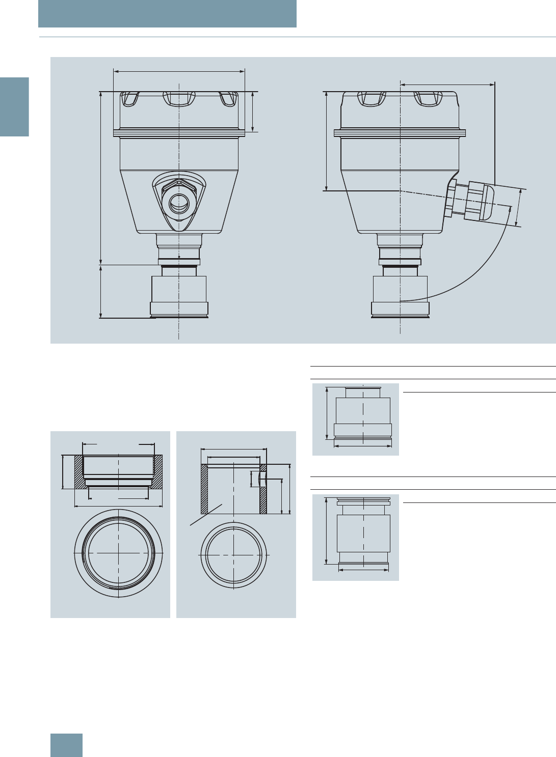
SITRANS P measuring instruments for pressure
Transmitters for gage pressure for the paper industry
SITRANS P300 with PMC connection
2/62 Siemens FI 01 · 2009
2
■
Dimensional drawings
SITRANS P300 pressure transmitters for gage pressure, with PMC connection, dimensions in mm (inch)
The diagram shows a SITRANS P300 with an example of a
flange. In this drawing the height is subdivided into H1 and H2.
H1 = Height of the SITRANS P300 up to a defined cross-section
H2 = Height of the flange up to this defined cross-section
Only the height H2 is indicated in the dimensions of the flanges.
PMC Style Standard (left) and PMC Style Minibolt (right) weldable sock-
ets, dimensions in mm (inch)
Material: Stainless steel, mat. No. 1.4404 / 316L
r
ෘ
+ $SSUR[+ $SSUR[
0[
2ULQJVXUIDFH
ERUHKROHPPಯZLWKRXWEXUU
PMC Style Standard
DN PN ∅DH
2
40.4 mm (1.6") Approx.
36.8 mm
(1.4’’)
PMC Style Minibolt
DN PN ∅DH
2
26.3 mm (1.0") Approx.
33.1 mm
(1.3’’)
'
+
'
+
© Siemens AG 2008
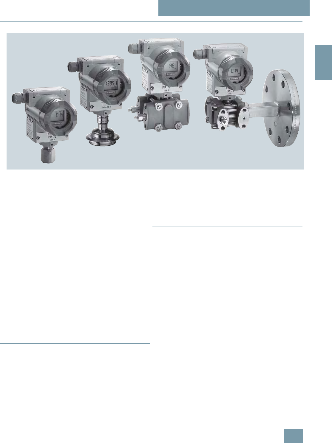
SITRANS P measuring instruments for pressure
Transmitters for gage, absolute and differential pressure, flow and level
DS III, DS III PA and DS III FF series
Technical description
2/63
Siemens FI 01 · 2009
2
■
Overview
SITRANS P pressure transmitters, DS III series, are digital pres-
sure transmitters featuring extensive user-friendliness and high
accuracy. The parameterization is performed using control keys,
over HART communication, PROFIBUS-PA or FOUNDATION
Fieldbus interface.
Extensive functionality enables the pressure transmitter to be
precisely adapted to the plant’s requirements. Operation is very
simple in spite of the numerous setting options.
Transmitters with type of protection "Intrinsic safety" and "Explo-
sion-proof" may be installed within potentially explosive atmo-
spheres (zone 1) or in zone 0. The transmitters are provided with
an EC type examination certificate and comply with the corre-
sponding harmonized European standards (ATEX).
The transmitters can be equipped with various designs of re-
mote seals for special applications such as the measurement of
highly viscous substances.
Various versions of the DS III pressure transmitters are available
for measuring:
• Gage pressure
• Absolute pressure
• For differential pressure transmitters
• Filling level
• Mass level
• Volume level
• Volume flow
• Mass flow
■
Benefits
• High quality and long life
• High reliability even under extreme chemical and mechanical
loads
• For aggressive and non-aggressive gases, vapors and liquids
• Extensive diagnosis and simulation functions
• Separate replacement of measuring cell and electronics with-
out recalibration
• Minimum conformity error
• Small long-term drift
• Wetted parts made of high-grade materials (e.g. stainless
steel, Hastelloy, gold, Monel, tantalum)
• Infinitely adjustable span from 0.01 mbar to 400 mbar for
DS III with HART communication
• Nominal measuring range from 1 to 400 bar for DS III PA
(PROFIBUS PA) and FF (FOUNDATION Fieldbus)
• High measuring accuracy
• Parameterization over control keys and HART communication,
PROFIBUS PA communication or FOUNDATION Fieldbus in-
terface.
■
Application
The pressure transmitters of the DS III series, can be used in in-
dustrial areas with extreme chemical and mechanical loads.
Electromagnetic compatibility in the range 10 kHz to 1 GHz
makes the DS III pressure transmitters suitable for locations with
high electromagnetic emissions.
Pressure transmitters with type of protection "Intrinsic safety" and
"Explosion-proof" may be installed within potentially explosive at-
mospheres (zone 1) or in zone 0. The pressure transmitters are
provided with an EC type examination certificate and comply
with the corresponding harmonized European standards
(ATEX).
Pressure transmitters with the type of protection "Intrinsic safety"
for use in zone 0 may be operated with power supply units of cat-
egory "ia" and "ib".
The transmitters can be equipped with various designs of re-
mote seals for special applications such as the measurement of
highly viscous substances.
The pressure transmitter can be operated locally over 3 control
keys or programmed externally over HART communication or
over PROFIBUS PA or FOUNDATION Fieldbus interface.
© Siemens AG 2008
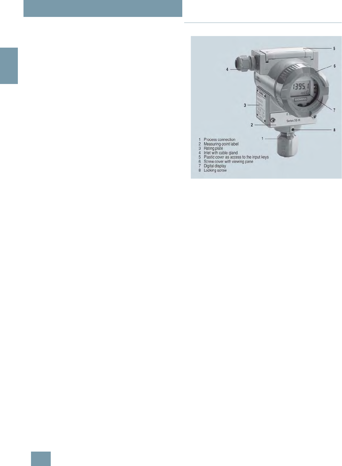
SITRANS P measuring instruments for pressure
Transmitters for gage, absolute and differential pressure, flow and level
DS III, DS III PA and DS III FF series
Technical description
2/64 Siemens FI 01 · 2009
2
Pressure transmitter for gage pressure
• Measured variable: Gage pressure of aggressive and non-ag-
gressive gases, vapors and liquids.
• Span (infinitely adjustable)
for DS III HART: 0.01 ... 400 bar g (0.145 ... 5802 psi g)
• Nominal measuring range
for DS III PA and FF: 1 ... 400 bar g (14.5 ... 5802 psi g)
Pressure transmitters for absolute pressure
• Measured variable: Absolute pressure of aggressive and non-
aggressive gases, vapors and liquids.
• Span (infinitely adjustable)
for DS III HART: 8.3 mbar a ... 100 bar a (0.12 ... 1450 psi a)
• Nominal measuring range
for DS III PA and FF: 250 mbar a ... 100 bar a
(3.63 ... 1450 psi a)
• There are two series:
- Gage pressure series
- Differential pressure series
Pressure transmitters for differential pressure and flow
• Measured variables:
-Differential pressure
- Small positive or negative pressure
- Flow q ~ √Δp (together with a primary differential pressure
device (see Chapter "Flow Meters"))
• Span (infinitely adjustable)
for DS III HART: 1 mbar ... 30 bar (0.0145 ... 435 psi)
• Nominal measuring range
for DS III PA and FF: 20 mbar ... 30 bar (0.29 ... 435 psi)
Pressure transmitters for level
• Measured variable: Level of aggressive and non-aggressive
liquids in open and closed vessels.
•Span (infinitely adjustable)
for DS III HART: 25 mbar ... 5 bar (0.363 ... 72.5 psi)
• Nominal measuring range
for DS III PA and FF: 250 mbar ... 5 bar (3.63 ... 72.5 psi)
• Nominal diameter of the mounting flange
- DN 80 or DN 100
- 3 inch or 4 inch
In the case of level measurements in open containers, the low-
pressure connection of the measuring cell remains open (mea-
surement "compared to atmospheric").
In the case of measurements in closed containers, the lower-
pressure connection has to be connected to the container in or-
der to compensate the static pressure.
The wetted parts are made from a variety of materials, depend-
ing on the degree of corrosion resistance required.
■
Design
Front view
The transmitter consists of various components depending on
the order. The possible versions are listed in the ordering infor-
mation. The components described below are the same for all
transmitters.
The rating plate (3, Figure "Front view") with the Order No. is lo-
cated on the side of the housing. The specified number together
with the ordering information provide details on the optional de-
sign details and on the possible measuring range (physical
properties of built-in sensor element).
The approval label is located on the opposite side.
The housing is made of die-cast aluminium or stainless steel pre-
cision casting. A round cover is screwed on at the front and rear
of the housing. The front cover (6) can be fitted with a viewing
pane so that the measured values can be read directly on the
digital display. The inlet (4) for the electrical connection is lo-
cated either on the left or right side. The unused opening on the
opposite side is sealed by a blanking plug. The protective earth
connection is located on the rear of the housing.
The electrical connections for the power supply and screen are
accessible by unscrewing the rear cover. The bottom part of the
housing contains the measuring cell with process connection
(1). The measuring cell is prevented from rotating by a locking
screw (8). As the result of this modular design, the measuring
cell and the electronics can be replaced separately from each
other. The set parameter data are retained.
At the top of the housing is a plastic cover (5), which hides the
input keys.
© Siemens AG 2008
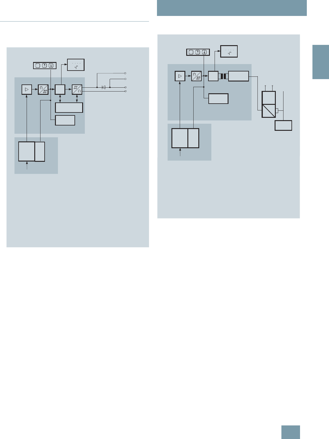
SITRANS P measuring instruments for pressure
Transmitters for gage, absolute and differential pressure, flow and level
DS III, DS III PA and DS III FF series
Technical description
2/65
Siemens FI 01 · 2009
2
■
Function
Operation of the electronics with PROFIBUS PA communica-
tion
Function diagram of the electronics
The bridge output voltage created by the sensor (1, Figure
"Function diagram of the electronics") is amplified by the instru-
ment amplifier (2) and digitized in the analog-to-digital converter
(3). The digital information is evaluated in a microcontroller, its
linearity and temperature response corrected, and converted in
a digital-to-analog converter (5) into an output current of 4 to
20 mA.
The diode circuit (10) protects against incorrect polarity.
The data specific to the measuring cell, the electronics data, and
the parameter data are stored in the two non-volatile memories
(6). The one memory is coupled to the measuring cell, the other
to the electronics. As the result of this modular design, the elec-
tronics and the measuring cell can be replaced separately from
each other.
Using the 3 input keys (8) you can parameterize the pressure
transmitter directly at the point of measurement. The input keys
can also be used to control the view of the results, the error mes-
sages and the operating modes on the digital display (9).
The HART modem (7) permits parameterization using a protocol
according to the HART specification.
The pressure transmitters with spans ≤ 63 bar measure the input
pressure compared to atmosphere, transmitters with spans
≥160 bar compared to vacuum.
Operation of the electronics with PROFIBUS PA communica-
tion
Function diagram of the electronics
The bridge output voltage created by the sensor (1, Figure
"Function diagram of the electronics") is amplified by the instru-
ment amplifier (2) and digitized in the analog-to-digital converter
(3). The digital information is evaluated in the microcontroller, its
linearity and temperature response corrected, and provided on
the PROFIBUS PA through an electrically isolated PA interface
(7).
The data specific to the measuring cell, the electronics data, and
the parameter data are stored in the two non-volatile memories
(6). The first memory is linked with the measuring cell, the sec-
ond with the electronics. This modular design means that the
electronics and the measuring cell can be replaced separately
from one another.
Using the three input keys (8) you can parameterize the pressure
transmitter directly at the point of measurement. The input keys
can also be used to control the view of the results, the error mes-
sages and the operating modes on the digital display (9).
The results with status values and diagnostic values are trans-
ferred by cyclic data transmission on the PROFIBUS PA. Param-
eterization data and error messages are transferred by acyclic
data transmission. Special software such as SIMATIC PDM is re-
quired for this.
IA, UH
5
6
7
8
Pe
1
4
3
2
C
m
M
10
00000
00
9
6
1 Measuring cell sensor
2Instrument amplifier
3Analog-to-digital converter
4Microcontroller
5 Digital-to-analog converter
6One non-volatile memory each in the measuring cell and electronics
7 HART interface
8 Three input keys (local operation)
9 Digital display
10Diode circuit and connection for external ammeter
IAOutput current
UHPower supply
PeInput variable
Sensor
EEPROM
EEPROM
HART interface
Electronics
Measuring cell
6
8
pe
1
2
C
m
M
00000
00
EEPROM
EEPROM
9
6
345 7
10
12
11
1 Measuring cell sensor
2Instrument amplifier
3Analog-to-digital converter
4Microcontroller
5 Electrical isolation
6One non-volatile memory
each in the measuring cell
and electronics
7 PROFIBUS-PA interface
Sensor
Electronics
Measuring cell
PA
interface
Bus-
Master
Power
supply
unit
Coup-
ler
Power supply
PROFIBUS-DP
PROFIBUS-PA
8 Three input keys
(local operation)
9 Digital display
10Power supply
11 DP/PA coupler or link
12 Bus master
p
e
Input variable
© Siemens AG 2008
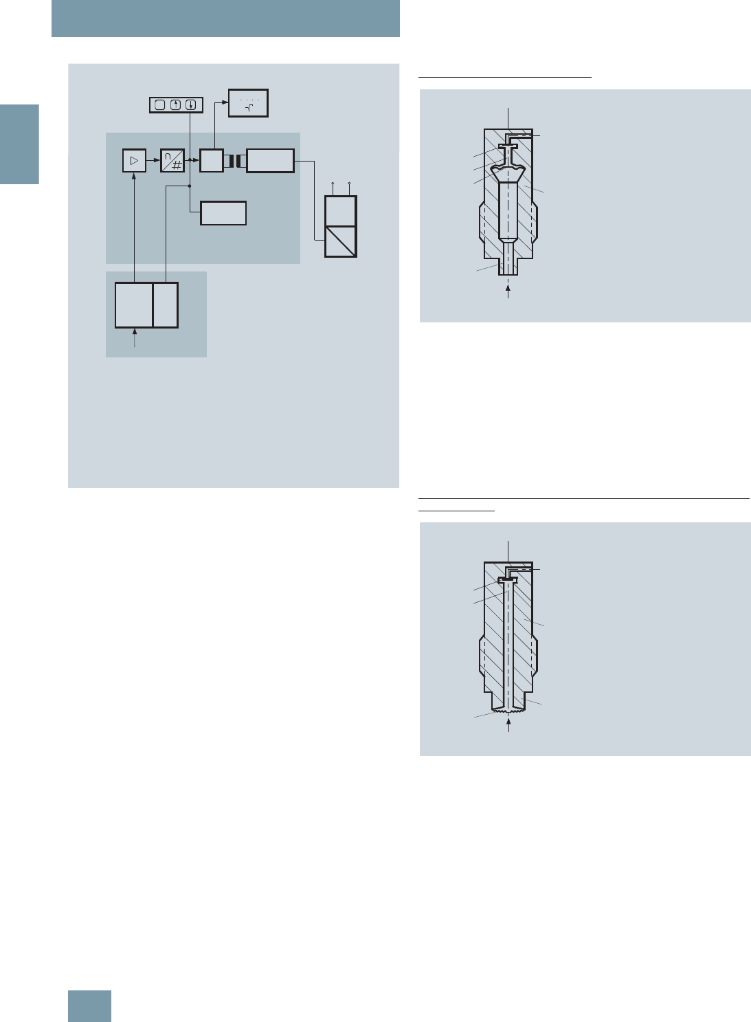
SITRANS P measuring instruments for pressure
Transmitters for gage, absolute and differential pressure, flow and level
DS III, DS III PA and DS III FF series
Technical description
2/66 Siemens FI 01 · 2009
2
Mode of operation of the FOUNDATION Fieldbus electronics
Function diagram of the electronics
The bridge output voltage created by the sensor (1, Figure
"Function diagram of the electronics") is amplified by the instru-
ment amplifier (2) and digitized in the analog-to-digital converter
(3). The digital information is evaluated in the microcontroller, its
linearity and temperature response corrected, and provided on
the FOUNDATION Fieldbus through an electrically isolated
FOUNDATION Fieldbus Interface (7).
The data specific to the measuring cell, the electronics data, and
the parameter data are stored in the two non-volatile memories
(6). The one memory is coupled to the measuring cell, the other
to the electronics. As the result of this modular design, the elec-
tronics and the measuring cell can be replaced separately from
each other.
Using the three input keys (8) you can parameterize the pressure
transmitter directly at the point of measurement. The input keys
can also be used to control the view of the results, the error mes-
sages and the operating modes on the digital display (9).
The results with status values and diagnostic values are trans-
ferred by cyclic data transmission on the FOUNDATION
Fieldbus. Parameterization data and error messages are trans-
ferred by acyclic data transmission. Special software such as
National Instruments Configurator is required for this.
Mode of operation of the measuring cells
Measuring cell for gage pressure
Measuring cell for gage pressure, function diagram
The pressure pe is applied through the process connection (2,
Figure "Measuring cell for gage pressure, function diagram) to
the measuring cell (1). This pressure is subsequently transmitted
further through the seal diaphragm (3) and the filling liquid (4) to
the silicon pressure sensor (5) whose measuring diaphragm is
then flexed. This changes the resistance of the four piezo-resis-
tors fitted in the diaphragm in a bridge circuit. This change in re-
sistance results in a bridge output voltage proportional to the in-
put pressure.
Measuring cell for gage pressure, with front-flush diaphragm for
paper industry
Measuring cell for gage pressure, with front-flush diaphragm for paper in-
dustry, function diagram
The pressure pe is applied through the process connection (2,
Figure "Measuring cell for gage pressure, with front-flush dia-
phragm for paper industry, function diagram") to the measuring
cell (1). This pressure is subsequently transmitted further
through the seal diaphragm (3) and the filling liquid (4) to the sil-
icon pressure sensor (5) whose measuring diaphragm is then
flexed. This changes the resistance of the four piezo-resistors fit-
ted in the diaphragm in a bridge circuit. This change in resis-
tance results in a bridge output voltage proportional to the input
pressure.
6
8
pe
1
2
C
m
M
00000
00
EEPROM
EEPROM
9
6
345 7
10
1 Measuring cell sensor
2Instrument amplifier
3Analog-to-digital converter
4Microcontroller
5 Electrical isolation
6One non-volatile memory
each in the measuring cell
and electronics
7FF interface
Sensor
Electronics
Measuring cell
FF
interface
Power
supply
unit
Coup-
ler
Power supply
8 Three input keys
(local operation)
9 Digital display
10Power supply
p
e
Input variable
p
1
4
3
2
e
5
1 Measuring cell
2Process connection
3Seal diaphragm
4 Filling liquid
5 Silicon pressure sensor
pePressure as input variable
p
1
4
3
2
e
5
1 Measuring cell
2Process connection
3Seal diaphragm
4 Filling liquid
5 Silicon pressure sensor
pePressure as input variable
© Siemens AG 2008
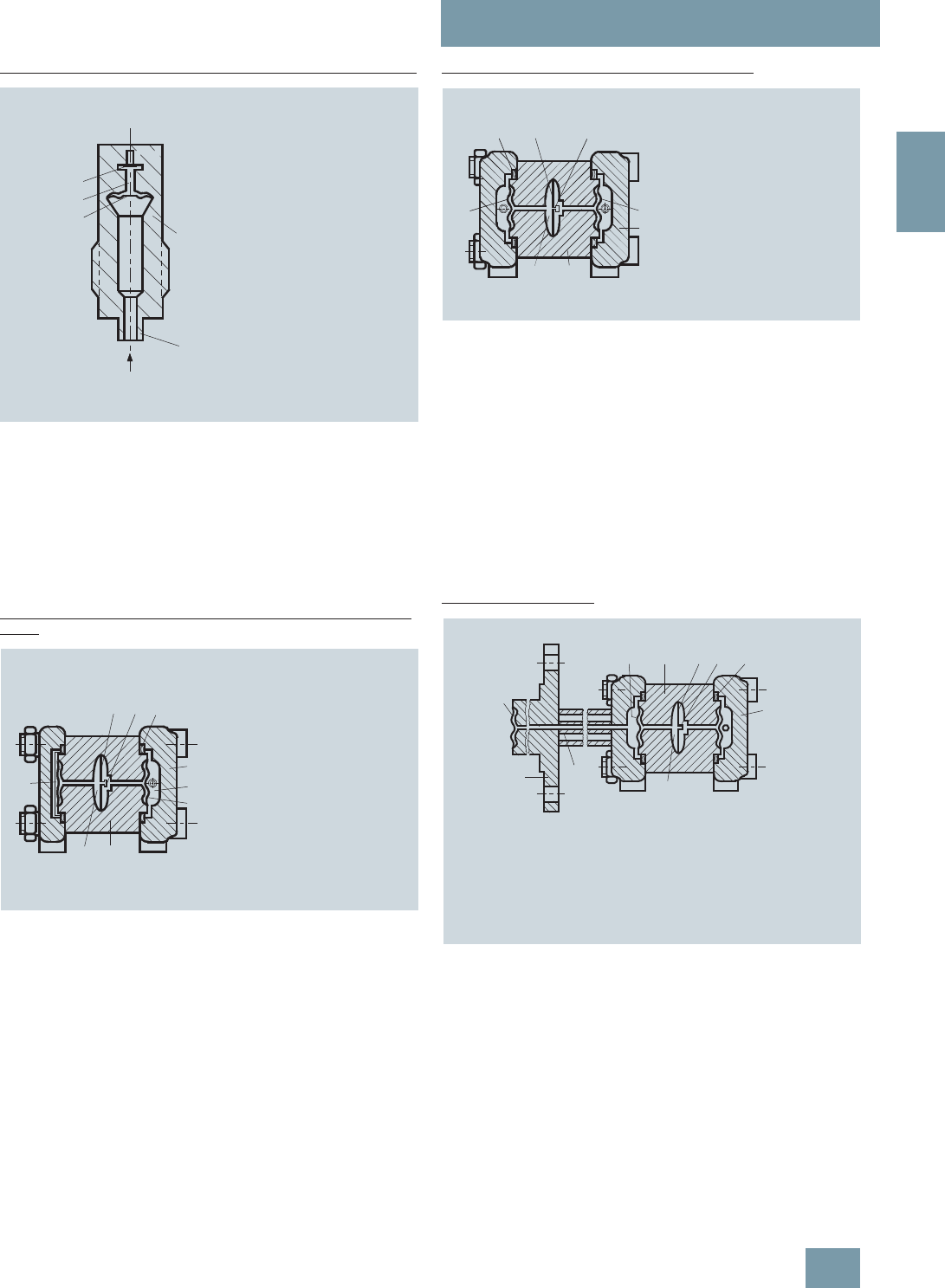
SITRANS P measuring instruments for pressure
Transmitters for gage, absolute and differential pressure, flow and level
DS III, DS III PA and DS III FF series
Technical description
2/67
Siemens FI 01 · 2009
2
Measuring cell for absolute pressure from gage pressure series
Measuring cell for absolute pressure from the pressure series, function
diagram
The absolute pressure pe is transmitted through the seal dia-
phragm (3, Figure "Measuring cell for absolute pressure from the
gage pressure series, function diagram") and the filling liquid (4)
to the silicon absolute pressure sensor (5) whose measuring di-
aphragm is then flexed. This changes the resistance of the four
piezo-resistors fitted in the diaphragm in a bridge circuit. This
change in resistance results in a bridge output voltage propor-
tional to the input pressure.
Measuring cell for absolute pressure from differential pressure
series
Measuring cell for absolute pressure from differential pressure series,
function diagram
The input pressure pe is transmitted through the seal diaphragm
(6, Figure "Measuring cell for absolute pressure from differential
pressure series, function diagram") and the filling liquid (8) to the
silicon pressure sensor (3).
The difference in pressure between the input pressure pe and
the reference vacuum (1) on the low-pressure side of the mea-
suring cell flexes the measuring diaphragm. The resistance of
the four piezo-resistors fitted in the diaphragm in a bridge circuit
thus changes. This change in resistance results in a bridge out-
put voltage proportional to the absolute pressure.
An overload diaphragm is installed to provide protection from
overloads. If the measuring limits are exceeded, the overload di-
aphragm (2) is flexed until the seal diaphragm rests on the body
of the measuring cell (7), thus protecting the silicon pressure
sensor from overloads.
Measuring cell for differential pressure and flow
Measuring cell for differential pressure and flow, function diagram
The differential pressure is transmitted through the seal dia-
phragms (1, Figure "Measuring cell for differential pressure and
flow, function diagram") and the filling liquid (7) to the silicon
pressure sensor (4).
The measuring diaphragm is flexed by the applied differential
pressure. This changes the resistance of the four piezo-resistors
fitted in the diaphragm in a bridge circuit. This change in resis-
tance results in a bridge output voltage proportional to the abso-
lute pressure.
An overload diaphragm is installed to provide protection from
overloads. If the measuring limits are exceeded, the overload di-
aphragm (2) is flexed until the seal diaphragm rests on the body
of the measuring cell (7), thus protecting the silicon pressure
sensor from overloads.
Measuring cell for level
Measuring cell for level, function diagram
The input pressure (hydrostatic pressure) acts hydraulically on
the measuring cell through the seal diaphragm on the mounting
flange (2, Figure "Measuring cell for level, function diagram").
This differential pressure is subsequently transmitted further
through the measuring cell (3) and the filling liquid (9) to the sil-
icon pressure sensor (6) whose measuring diaphragm is then
flexed.
This changes the resistance of the four piezo-resistors fitted in
the diaphragm in a bridge circuit.
This change in resistance results in a bridge output voltage pro-
portional to the differential pressure.
An overload diaphragm is installed to provide protection from
overloads. If the measuring limits are exceeded, the overload di-
aphragm (2) is flexed until the seal diaphragm rests on the body
pe
2
5
4
3
11 Measuring cell
2Process connection
3Seal diaphragm
4 Filling liquid
5 Silicon absolute pressure sensor
peAbsolute pressure as input variable
1
234
5
p
e
6
78
1 Reference vacuum
2Overload diaphragm
3Silicon pressure sensor
4 O-ring
5Process flange
6 Seal diaphragm
7Body of measuring cell
8 Filling liquid
peAbsolute pressure as
input variable
3
7
5
1
1
4
+-
2
6
1 Seal diaphragm
2 O-ring
3Overload diaphragm
4 Silicon pressure sensor
5Process flange
6Body of measuring cell
7 Filling liquid
35
8
-
4 6 7
1
2
+
9
10
6 Silicon pressure sensor
7 O-ring
8Process flange
9 Filling liquid
10Capillary with filling liquid
of mounting flange
1 Flange with tube
2 Seal diaphragm on
mounting flange
3Seal diaphragm
4Body of measuring cell
5Overload diaphragm
© Siemens AG 2008
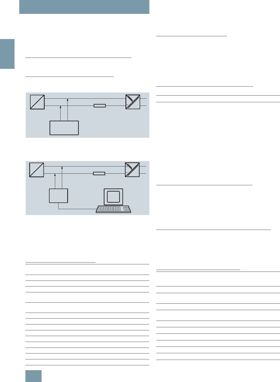
SITRANS P measuring instruments for pressure
Transmitters for gage, absolute and differential pressure, flow and level
DS III, DS III PA and DS III FF series
Technical description
2/68 Siemens FI 01 · 2009
2
of the measuring cell (7), thus protecting the silicon pressure
sensor from overloads.
Parameterization DS III
Depending on the version, there are a range of options for pa-
rameterizing the pressure transmitter and for setting or scanning
the parameters.
Parameterization using the input keys (local operation)
With the input keys you can easily set the most important param-
eters without any additional equipment.
Parameterization using HART communication
Parameterization using HART communication is performed with
a HART communicator or a PC.
Communication between a HART communicator and a pressure transm.
When parameterizing with the HART communicator, the connec-
tion is made directly to the 2-wire system.
HART communication between a PC communicator and a pressure
transmitter
When parameterizing with a PC, the connection is made through
a HART modem.
The signals needed for communication in conformity with the
HART 5.x or 6.x protocols are superimposed on the output cur-
rent using the Frequency Shift Keying (FSK) method.
Adjustable parameters, DS III HART
Diagnostic functions for DS III HART
• Zero correction display
• Event counter
• Limit transmitter
• Saturation alarm
• Slave pointer
• Simulation functions
• Maintenance timer
Available physical units of display for DS III HART
Table style: Technical specifications 2
Parameterization through PROFIBUS PA interface
Fully digital communication through PROFIBUS PA, profile 3.0, is
particularly user-friendly. The PROFIBUS puts the DS III PA is in
connection with a process control system, e.g. SIMATIC PSC 7.
Communication is possible even in a potentially explosive envi-
ronment.
For parameterization through PROFIBUS you need suitable soft-
ware, e.g. SIMATIC PDM (Process Device Manager).
Parameterization through FOUNDATION Fieldbus Interface
Fully digital communication through FOUNDATION Fieldbus is
particularly user-friendly. Through the FOUNDATION Fieldbus
the DS III FF is connected to a process control system. Commu-
nication is possible even in a potentially explosive environment.
For parameterization through the FOUNDATION Fieldbus you
need suitable software, e.g. National Instruments Configurator.
Adjustable parameters for DS III PA and FF
Parameters Input keys
(DS III HART) HART com-
munication
Start of scale x x
Full-scale value x x
Electrical damping x x
Start-of-scale value without application
of a pressure ("Blind setting") xx
Full-scale value without application of a
pressure ("Blind setting") xx
Zero adjustment x x
Current transmitter x x
Fault current x x
Disabling of keys, write protection x x1)
Type of dimension and actual dimension x x
Characteristic (linear / square-rooted) x2) x2)
Input of characteristic x
Freely-programmable LCD x
Diagnostics functions x
+
HART
communicator
230 ... 1100 W
transmitter
SITRANS P Power supply
transmitter
SITRANS P Power supply
HART
modem
PC or
laptop
RS 232
230 ... 500 W
1) Cancel apart from write protection
2) Only differential pressure
Physical variable Physical dimensions
Pressure (setting can also
be made in the factory) Pa, MPa, kPa, bar, mbar, torr, atm, psi,
g/cm2, kg/cm2, inH2O, inH2O (4 °C),
mmH2O, ftH2O (20 °C), inHg, mmHg
Level (height data) m, cm, mm, ft, in
Volume m3, dm3, hl, yd3, ft3, in3, US gallon, lmp.
gallon, bushel, barrel, barrel liquid
Mass g, kg, t, lb, Ston, Lton, oz
Volume flow m3/d, m3/h, m3/s, l/min, l/s, ft3/d, ft3/min,
ft3/s, US gallon/min, US gallon/s
Mass flow t/d, t/h, t/min, kg/d, kg/h, kg/min, kg/s, g/d,
g/h, g/min, g/s, lb/d, lb/h, lb/min, lb/s,
LTon/d, LTon/h, STon/d, STon/h, STon/min
Temperature K, °C, °F, °R
Miscellaneous %, mA
Parameters Input keys
(DS III HART) PROFIBUS PA and
FOUNDATION
Fieldbus interface
Electrical damping x x
Zero adjustment (correction of
position) xx
Key and/or function disabling x x
Source of measured-value dis-
play xx
Physical dimension of display x x
Position of decimal point x x
Bus address x x
Adjustment of characteristic x x
Input of characteristic x
Freely-programmable LCD x
Diagnostics functions x
© Siemens AG 2008

SITRANS P measuring instruments for pressure
Transmitters for gage, absolute and differential pressure, flow and level
DS III, DS III PA and DS III FF series
Technical description
2/69
Siemens FI 01 · 2009
2
Diagnostic functions for DS III PA and FF
• Event counter
• Slave pointer
• Maintenance timer
• Simulation functions
• Display of zero correction
• Limit transmitter
• Saturation alarm
Physical dimensions available for the display
Physical variable Physical dimensions
Pressure (setting can also
be made in the factory) MPa, kPa, Pa, bar, mbar, torr, atm, psi,
g/cm2, kg/cm2, mmH2O, mmH2O (4 °C),
inH2O, inH20 (4 °C), ftH2O (20 °C), mmHg,
inHg
Level (height data) m, cm, mm, ft, in, yd
Volume m3, dm3, hl, yd3, ft3, in3, US gallon, lmp.
gallon, bushel, barrel, barrel liquid
Volume flow m3/s, m3/min, m3/h, m3/d, l/s, l/min, l/h, l/
d, Ml/d, ft3/s, ft3/min, ft3/h, ft3/d, US gal-
lon/s, US gallon/min, US gallon/h, US gal-
lon/d, bbl/s, bbl/min, bbl/h, bbl/d
Mass flow g/s, g/min, g/h, g/d, kg/s, kg/min, kg/h,
kg/d, t/s, t/min, t/h, /t/d, lb/s, lb/min, lb/h,
lb/d, STon/s, STon/min, STon/h, STon/d,
LTon/s, LTon/min, LTon/h, LTon/d
Total mass flow t, kg, g, lb, oz, LTon, STon
Temperature K, °C, °F, °R
Miscellaneous %
© Siemens AG 2008

SITRANS P measuring instruments for pressure
Transmitters for gage, absolute and differential pressure, flow and level
DS III series
for gage pressure
2/70 Siemens FI 01 · 2009
2
■
Technical specifications
SITRANS P, DS III series for gage pressure
HART PROFIBUS PA or FOUNDATION Fieldbus
Input
Measured variable Gage pressure
Spans (infinitely adjustable) or
nominal measuring range and
max. permissible test pressure
Span Max. perm. test pres-
sure Nominal measuring
range Max. perm. test pres-
sure
0.01 ... 1 bar g
(0.145 ... 14.5 psi g) 6 bar g
(87 psi g) 1 bar g
(14.5 psi g) 6 bar g
(87 psi g)
0.04 ... 4 bar g
(0.58 ... 58 psi g) 10 bar g
(145 psi g) 4 bar g
(58 psi g) 10 bar g
(145 psi g)
0.16 ... 16 bar g
(2.23 ... 232 psi g) 32 bar g
(464 psi g) 16 bar g
(232 psi g) 32 bar g
(464 psi g)
0.6 ... 63 bar g
(9.14 ... 914 psi g) 100 bar g
(1450 psi g) 63 bar g
(914 psi g) 100 bar g
(1450 psi g)
1.6 ... 160 bar g
(23.2 ... 2320 psi g) 250 bar g
(3626 psi g) 160 bar g
(2320 psi g) 250 bar g
(3626 psi g)
4.0 ... 400 bar g
(58 ... 5802 psi g) 600 bar g
(8700 psi g) 400 bar g
(5802 psi g) 600 bar g
(8700 psi g)
7.0 ... 700 bar g
(102 ... 10153 psi g) 800 bar g
(11603 psi g) 700 bar g
(10153 psi g) 800 bar g
(11603 psi g)
Lower measuring limit
• Measuring cell with silicone oil filling 30 mbar a (0.435 psi a)
• Measuring cell with inert filling liquid 30 mbar a (0.435 psi a)
Upper measuring limit 100% of max. span (max. 160 bar g (2320 psi g) with oxygen measurement and inert liquid)
Output
Output signal 4 ... 20 mA Digital PROFIBUS PA or FOUNDATION Fieldbus
signal
• Lower limit (infinitely adjustable) 3.55 mA, factory preset to 3.84 mA -
• Upper limit (infinitely adjustable) 23 mA, factory preset to 20.5 mA or optionally set
to 22.0 mA -
Load
• Without HART communication RB ≤ (UH - 10.5 V)/0.023 A in Ω,
UH : Power supply in V -
• With HART communication RB = 230 ... 500 Ω (SIMATIC PDM) or
RB = 230 ... 1100 Ω (HART Communicator) -
Physical bus - IEC 61158-2
With polarity reversal protection - Yes
Accuracy To EN 60770-1
Reference conditions
(All error data refer always refer to the set
span)
Increasing characteristic, start-of-scale value 0 bar, stainless steel seal diaphragm, silicone oil filling,
room temperature 25 °C (77 °F)) r: Span ratio (r = max. span/set span)
Error in measurement and fixed-point setting
(including hysteresis and repeatability)
• Linear characteristic ≤0,075%
-r ≤ 10 ≤ (0.0029 ⋅ r + 0.071)%
- 10 < r ≤ 30 ≤ (0.0045 ⋅ r + 0.071)%
- 30 < r ≤ 100 ≤ (0.005 ⋅ r + 0.05)%
Long-term drift (temperature change ±30 °C
(±54 °F)) ≤ (0.25 ⋅ r)% every 5 years ≤ 0.25% every 5 years
Influence of ambient temperature
• at -10 ... +60 °C (14 ... 140 °F) ≤ (0.08 ⋅ r + 0.1)%
(at 700 bar: ≤ (0.1 ⋅ r + 0.2)%) ≤0,3%
• at -40 ... -10 °C and +60 ... +85 °C
(-40 ... +14 °F and 140 ... 185 °F) ≤ (0.1 ⋅ r + 0.15)%/10 K ≤ 0.25%/10 K
Measured Value Resolution - 3 ⋅10-5 of nominal measuring range
© Siemens AG 2008

SITRANS P measuring instruments for pressure
Transmitters for gage, absolute and differential pressure, flow and level
DS III series
for gage pressure
2/71
Siemens FI 01 · 2009
2
Rated operating conditions
Degree of protection (to EN 60529) IP65
Process temperature
• Measuring cell with silicone oil filling -40 ... +100 °C (-40 ... +212 °F)
• Measuring cell with inert filling liquid -20 ... +100 °C (-4 ... +212 °F)
• In conjunction with dust explosion protec-
tion -20 ... +60 °C (-4 ... +140 °F)
Ambient conditions
• Ambient temperature
- Digital indicators -30 ... +85 °C (-22 ... +185 °F)
• Storage temperature -50 ... +85 °C (-58 ... +185 °F)
• Climatic class
- Condensation Permissible
• Electromagnetic compatibility
- Emitted interference and interference
immunity To EN 61326 and NAMUR NE 21
Design
Weight (without options) ≈ 1.5 kg (≈ 3.3 lb)
Housing material Poor in copper die-cast aluminium, GD-AlSi12 or stainless steel precision casting, mat. No. 1.4408
Wetted parts materials
• Connection shank Stainless steel, mat. No. 1.4404/316L or Hastelloy C4, mat. No. 2.4610
• Oval flange Stainless steel, mat. No. 1.4404/316L
• Seal diaphragm Stainless steel, mat. No. 1.4404/316L or Hastelloy C276, mat. No. 2.4819
Measuring cell filling Silicone oil or inert filling liquid (max. 160 bar (2320 psi g) with oxygen measurement)
Process connection Connection shank G½A to DIN EN 837-1, female thread ½ -14 NPT or oval flange (PN 160
(MWP 2320 psi g)) to DIN 19213 with mounting thread M10 or 7/16-20 UNF to EN 61518
Material of the mounting bracket
• Steel Sheet steel, Mat. No. 1.0330, chrome-plated
• Stainless steel Stainless steel, Mat. No. 1.4301 (SS304)
Power supply UH Supplied through bus
Terminal voltage on transmitter 10.5 ... 45 V DC
10.5 ... 30 V DC in intrinsically-safe mode -
Separate 24 V power supply necessary - No
Bus voltage
• Not Ex - 9 ...32 V
• With intrinsically-safe operation - 9 ...24 V
Current consumption
• Basic current (max.) - 12.5 mA
• Startup current ≤ basic current - Yes
• Max. current in event of fault - 15.5 mA
Fault disconnection electronics (FDE) avail-
able -Yes
SITRANS P, DS III series for gage pressure
HART PROFIBUS PA or FOUNDATION Fieldbus
© Siemens AG 2008

SITRANS P measuring instruments for pressure
Transmitters for gage, absolute and differential pressure, flow and level
DS III series
for gage pressure
2/72 Siemens FI 01 · 2009
2
Certificate and approvals
Classification according to pressure equip-
ment directive (DRGL 97/23/EC) For gases of fluid group 1 and liquids of fluid group 1; complies with requirements of Article 3, para-
graph 3 (sound engineering practice)
Explosion protection
• Intrinsic safety "i" PTB 99 ATEX 2122
- Identification Ex II 1/2 G EEx ia/ib IIB/IIC T6
- Permissible ambient temperature -40 ... +85 °C (-40 ... +185 °F) temperature class T4;
-40 ... +70 °C (-40 ... +158 °F) temperature class T5;
-40 ... +60 °C (-40 ... +140 °F) temperature class T6
- Connection To certified intrinsically-safe circuits with maxi-
mum values:
Ui = 30 V, Ii = 100 mA,
Pi = 750 mW; Ri = 300 Ω
FISCO supply unit:
Uo = 17.5 V, Io = 380 mA, Po = 5.32 W
Linear barrier:
Uo = 24 V, Io = 250 mA, Po = 1.2 W
- Effective internal inductance/capacitance L i = 0.4 mH, Ci = 6 nF L i = 7 μH, Ci = 1.1 nF
• Explosion-proof "d" PTB 99 ATEX 1160
- Identification Ex II 1/2 G EEx d IIC T4/T6
- Permissible ambient temperature -40 ... +85 °C (-40 ... +185 °F) temperature class T4;
-40 ... +60 °C (-40 ... +140 °F) temperature class T6
- Connection To circuits with values: UH = 10.5 ... 45 V DC To circuits with values: UH = 9 ... 32 V DC
• Dust explosion protection for zone 20 PTB 01 ATEX 2055
- Identification Ex II 1 D IP65 T 120 °C
Ex II 1/2 D IP65 T 120 °C
- Permissible ambient temperature -40 ... +85 °C (-40 ... +185 °F)
- Max.surface temperature 120 °C (248 °F)
- Connection To certified intrinsically-safe circuits with maxi-
mum values:
Ui = 30 V, Ii = 100 mA,
Pi = 750 mW, Ri = 300 Ω
FISCO supply unit:
Uo = 17.5 V, Io = 380 mA, Po = 5.32 W
Linear barrier:
Uo = 24 V, Io = 250 mA, Po = 1.2 W
- Effective internal inductance/capacitance L i = 0.4 mH, Ci = 6 nF L i = 7 μH, Ci = 1.1 nF
• Dust explosion protection for zone 21/22 PTB 01 ATEX 2055
- Identification Ex II 2 D IP65 T 120 °C
- Connection To circuits with values: UH = 10.5 ... 45 V DC;
Pmax = 1.2 W To circuits with values: UH = 9 ... 32 V DC;
Pmax = 1.2 W
• Type of protection "n" (zone 2) TÜV 01 ATEX 1696 X Planned
- Identification Ex II 3 G EEx nA L IIC T4/T5/T6 -
• Explosion protection to FM Certificate of Compliance 3008490
- Identification (XP/DIP) or (IS); (NI) CL I, DIV 1, GP ABCD T4...T6; CL II, DIV 1, GP EFG; CL III; CL I, ZN 0/1 AEx ia IIC T4...T6; CL I,
DIV 2, GP ABCD T4...T6; CL II, DIV 2, GP FG; CL III
• Explosion protection to CSA Certificate of Compliance 1153651
- Identification (XP/DIP) or (IS) CL I, DIV 1, GP ABCD T4...T6; CL II, DIV 1, GP EFG; CL III; Ex ia IIC T4...T6; CL I, DIV 2, GP ABCD
T4...T6; CL II, DIV 2, GP FG; CL III
SITRANS P, DS III series for gage pressure
HART PROFIBUS PA or FOUNDATION Fieldbus
© Siemens AG 2008

SITRANS P measuring instruments for pressure
Transmitters for gage, absolute and differential pressure, flow and level
DS III series
for gage pressure
2/73
Siemens FI 01 · 2009
2
HART communication
HART communication 230 ... 1100 Ω
Protocol HART Version 5.x
Software for computer SIMATIC PDM
PROFIBUS PA communication
Simultaneous communication with
master class 2 (max.) 4
The address can be set using Configuration tool or local opera-
tion (standard setting address
126)
Cyclic data usage
• Output byte 5 (one measuring value) or
10 (two measuring values)
• Input byte 0, 1, or 2 (register operating mode
and reset function for metering)
Internal preprocessing
Device profile PROFIBUS PA Profile for Process
Control Devices Version 3.0,
Class B
Function blocks 2
• Analog input
- Adaptation to customer-specif-
ic process variables Yes, linearly rising or falling char-
acteristic
- Electrical damping T63 , adjust-
able 0 ... 100 s
- Simulation function Input /Output
- Failure mode Can be parameterized (last good
value, substitute value, incorrect
value)
- Limit monitoring Yes, one upper and lower warning
limit and one alarm limit respec-
tively
• Register (totalizer) Can be reset, preset, optional
direction of counting, simulation
function of register output
- Failure mode Can be parameterized (summation
with last good value, continuous
summation, summation with incor-
rect value)
- Limit monitoring One upper and lower warning limit
and one alarm limit respectively
• Physical block 1
Transducer blocks 2
• Pressure transducer block
- Can be calibrated by applying
two pressures Yes
- Monitoring of sensor limits Yes
- Specification of a container
characteristic with Max. 30 nodes
- Square-rooted characteristic
for flow measurement Yes
- Gradual volume suppression
and implementation point of
square-root extraction
Parameterizable
- Simulation function for mea-
sured pressure value and sen-
sor temperature
Constant value or over parameter-
izable ramp function
Communication FOUNDATION Fieldbus
Function blocks 3 function blocks analog input,
1 function block PID
• Analog input
- Adaptation to customer-specif-
ic process variables Yes, linearly rising or falling char-
acteristic
- Electrical damping T63 , adjust-
able 0 ... 100 s
- Simulation function Output/input (can be locked within
the device with a bridge)
- Failure mode Can be parameterized (last good
value, substitute value, incorrect
value)
- Limit monitoring Yes, one upper and lower warning
limit and one alarm limit respec-
tively
- Square-rooted characteristic
for flow measurement Yes
• PID Standard FF function block
• Physical block 1 Resource block
Transducer blocks 1 transducer block Pressure with
calibration, 1 transducer block
LCD
• Pressure transducer block
- Can be calibrated by applying
two pressures Yes
- Monitoring of sensor limits Yes
- Simulation function: Measured
pressure value, sensor temper-
ature and electronics tempera-
ture
Constant value or over parameter-
izable ramp function
© Siemens AG 2008

SITRANS P measuring instruments for pressure
Transmitters for gage, absolute and differential pressure, flow and level
DS III series
for gage pressure
2/74 Siemens FI 01 · 2009
2
Selection and Ordering data Order No.
SITRANS P pressure transmitters for gage
pressure, series DS III HART 7 M F 4 0 3 3 -
77777 -7 7 7 7
Measuring cell filling Measuring cell
cleaning
Silicone oil Standard }1
Inert liquid1) Grease-free 3
Span
0.01 ... 1 bar g (0.15 ... 14.5 psi g) }B
0.04 ... 4 bar g (0.58 ... 58 psi g) }C
0.16 ... 16 bar g (2.32 ... 232 psi g) }D
0.63 ... 63 bar g (9.14 ... 914 psi g) }E
1.6 ... 160 bar g (23.2 ... 2320 psi g) }F
4.0 ... 400 bar g (58.0 ... 5802 psi g) }G
7,0 ... 700 bar g (102.0 ...10153 psi g) }J
Wetted parts materials
Seal diaphragm Process connection
Stainless steel Stainless steel }A
Hastelloy Stainless steel B
Hastelloy Hastelloy C
Version as diaphragm seal 2) 3) Y
Process connection
• Connection shank G½B to EN 837-1 }0
• Female thread ½-14 NPT 1
• Oval flange made of stainless steel
- Mounting thread 7/16-20 UNF to EN 61518 2
- Mounting thread M10 to DIN 19213 3
- Mounting thread M12 to DIN 19213 4
• Male thread M20 x 1,5 5
• Male thread ½-14 NPT 6
Non-wetted parts materials
• Housing made of die-cast aluminium }0
• Housing stainless steel precision casting4) 3
Version
• Standard version 1
• International version, English label inscriptions,
documentation in 5 languages on CD
}2
Explosion protection
• Without A
• With ATEX, Type of protection:
- "Intrinsic safety (EEx ia)" B
- "Explosion-proof (EEx d)"5) D
- "Intrinsic safety and explosion-proof enclosure
(EEx ia + EEx d)"6) P
- "Ex nA/nL (zone 2)" E
- "Intrinsic safety, explosion-proof enclosure and
dust explosion protection (EEx ia + EEx d +
Zone 1D/2D)"6)
}R
• With FM + CSA, Type of protection:
- "Intrinsic safety and explosion-proof
(is + xp)"5) N C
Electrical connection / cable entry
• Screwed gland Pg 13.5 (adapter)7) A
• Screwed gland M20x1.5 }B
• Screwed gland ½-14 NPT C
• Han 7D plug (plastic housing) incl. mating
connector7) D
• M12 connector (metal)8) F
Display
• Without indicator 0
• Without visible digital indicator (digital indicator
hidden, setting: mA)
}1
• With visible digital indicator, setting: mA 6
• with customer-specific digital indicator
(setting as specified, Order code "Y21" or "Y22"
required)
7
}Available ex stock
Power supply units see "SITRANS I power supply units and isolation
amplifiers".
Factory-mounting of shut-off valves and valve manifolds see page
2/142.
Included in delivery of the device:
• Brief instructions (Leporello)
• CD-ROM with detailed documentation
1) For oxygen application, add Order code E10.
2) When the manufacture’s certificate M (calibration certificate) has to be
ordered for transmitters with diaphragm seals, it is recommended only to
order this certificate exclusively with the diaphragm seals. The measuring
accuracy of the total combination is certified here.
3) Whe the acceptance test certificate 3.1 for transmitters with direct-con-
nected diaphragm seals is ordered, this certificate must also be ordered
with the corresponding seals.
4) Not together with Electrical connection „Screwed gland Pg 13.5“ and
„Han7D plug“.
5) Without cable gland, with blanking plug
6) With enclosed cable gland EEx ia and blanking plug
7) Not together with type of protection "Explosion-proof" and type of protection
"Ex nA".
8) Cannot be used together with the following types of protection:
"Explosion-proof" and "Intrinsic safety and explosion-proof"
Selection and Ordering data Order No.
SITRANS P pressure transmitters for gage
pressure, series DS III HART 7 M F 4 0 3 3 -
7 7 7 7 7 -7 7 7 7
© Siemens AG 2008

SITRANS P measuring instruments for pressure
Transmitters for gage, absolute and differential pressure, flow and level
DS III series
for gage pressure
2/75
Siemens FI 01 · 2009
2
Selection and Ordering data Order No.
SITRANS P pressure transmitters for gage
pressure
DS III PA (PROFIBUS PA) series 7 M F 4 0 3 4 -
DS III FF series (FOUNDATION Fieldbus) 7 M F 4 0 3 5 -
77777 -7 7 7 7
Measuring cell filling Measuring cell
cleaning
Silicone oil Standard 1
Inert liquid1) Grease-free 3
Nominal measuring range
1 bar g (14.5 psi g) B
4 bar g (58 psi g) C
16 bar g (232 psi g) D
63 bar g (914 psi g) E
160 bar g (2320 psi g) F
400 bar g (5802 psi g) G
700 bar g (10153 psi g) J
Wetted parts materials
Seal diaphragm Process connection
Stainless steel Stainless steel A
Hastelloy Stainless steel B
Hastelloy Hastelloy C
Version as diaphragm seal2) 3) Y
Process connection
• Connection shank G½A to EN 837-1 0
• Female thread ½-14 NPT 1
• Oval flange made of stainless steel
- Mounting thread 7/16-20 UNF to EN 61518 2
- Mounting thread M10 to DIN 19213 3
- Mounting thread M12 nach DIN 19213 4
• Male thread M20 x 1,5 5
• Male thread ½-14 NPT 6
Non-wetted parts materials
• Housing made of die-cast aluminium 0
• Housing stainless steel precision casting 3
Version
• Standard version 1
• International version, English label inscriptions,
documentation in 5 languages on CD 2
Explosion protection
• Without A
• With ATEX, Type of protection:
- "Intrinsic safety (EEx ia)" B
- "Explosion-proof (EEx d)"4) D
- "Intrinsic safety and explosion-proof enclosure
(EEx ia + EEx d)"5) P
- "Ex nA/nL (zone 2)" E
- "Intrinsic safety, explosion-proof enclosure and
dust explosion protection (EEx ia + EEx d +
Zone 1D/2D)"6) (not for DS III FF)
R
• With FM + CSA, Type of protection:
- "Intrinsic safety and explosion-proof
(is + xp)"5) N C
Electrical connection / cable entry
• Screwed gland M20x1.5 B
• Screwed gland ½-14 NPT C
• Plug M12 (metal)6) F
Display
• Without indicator 0
• Without visible digital indicator (digital indicator
hidden, setting: mA)
}1
• With visible digital indicator 6
• With customer-specific digital indicator (setting
as specified, Order code "Y21" or required) 7
Factory-mounting of shut-off valves and valve manifolds see page
2/142.
The device is delivered together with brief instructions (Leporello) and a
CD-ROM containing detailed documentation.
1) For oxygen application, add Order code E10.
2) When the manufacture’s certificate M (calibration certificate) has to be
ordered for transmitters with diaphragm seals, it is recommended only to
order this certificate exclusively with the diaphragm seals. The measuring
accuracy of the total combination is certified here.
3) Whe the acceptance test certificate 3.1 for transmitters with direct-con-
nected diaphragm seals is ordered, this certificate must also be ordered
with the corresponding seals.
4) Without cable gland, with blanking plug.
5) With enclosed cable gland EEx ia and blanking plug.
6) Cannot be used together with the following types of protection:
"Explosion-proof" and "Intrinsic safety and explosion-proof"
Selection and Ordering data Order No.
SITRANS P pressure transmitters for gage
pressure
DS III PA (PROFIBUS PA) series 7 M F 4 0 3 4 -
DS III FF series (FOUNDATION Fieldbus) 7 M F 4 0 3 5 -
7 7 7 7 7 -7 7 7 7
© Siemens AG 2008

SITRANS P measuring instruments for pressure
Transmitters for gage, absolute and differential pressure, flow and level
DS III series
for gage pressure
2/76 Siemens FI 01 · 2009
2
Selection and Ordering data Order code
Further designs
Add "-Z" to Order No. and specify Order code. HART PA FF
Pressure transmitter with mounting
bracket made of:
•Steel A01 9
9
9
9
9
9
• Stainless steel A02 9
9
9
9
9
9
Plug
• Han 7D (metal, gray) A30 9
9
• Han 8U (instead of Han 7D) A31 9
9
Cable sockets for M12 connectors (metal) A50 9
9
9
9
9
9
Rating plate inscription
(instead of German)
• English B11 9
9
9
9
9
9
• French B12 9
9
9
9
9
9
• Spanish B13 9
9
9
9
9
9
• Italian B14 9
9
9
9
9
9
English rating plate B21 9
9
9
9
9
9
Pressure units in inH2O or psi
Quality inspection certificate (Factory cali-
bration) to IEC 60770-21)
1) When the manufacture’s certificate M (calibration certificate) has to be
ordered for transmitters with diaphragm seals, it is recommended only to
order this certificate exclusively with the diaphragm seals. The measuring
accuracy of the total combination is certified here.
C11 9
9
9
9
9
9
Acceptance test certificate2)
2) Whe the acceptance test certificate 3.1 for transmitters with direct-con-
nected diaphragm seals is ordered, this certificate must also be ordered
with the corresponding seals.
C12 9
9
9
9
9
9
To EN 10204-3.1
Factory certificate C14 9
9
9
9
9
9
To EN 10204-2.2
"Functional Safety (SIL)" certificate C20 9
9
"PROFIsafe“ certificate and protocol C21 9
9
Setting of upper limit of output signal to
22.0 mA D05 9
9
Manufacturer's declaration acc. to NACE D07 9
9
9
9
9
9
Type of protection IP68 D12 9
9
9
9
9
9
(not together with 7D/
Han 8U plug, cable gland Pg 13.5)
Digital indicator alongside the input keys D27 9
9
9
9
9
9
(only together with the devices 7MF4033-
....0-.A.6 or -.A.7-Z, Y21 or Y22 + Y01)
Supplied with oval flange D37 9
9
9
9
9
9
(1 item), PTFE packing and screws in thread
of oval flange
Use in or on zone 1D/2D E01 9
9
9
9
9
9
(only together with type of protection
"Intrinsic safety (EEx ia)")
Use on zone 0 E02 9
9
9
9
9
9
(only together with type of protection
"Intrinsic safety (EEx ia)")
Oxygen application E10 9
9
9
9
9
9
(max. 120 bar g (1740 psi g) at 60°C (140 °F)
for oxygen measurement and inert liquid)
Explosion-proof "Intrinsic safety" to
INMETRO (Brazil) E25 9
9
9
9
9
9
(only for transmitter 7MF4...-.....-.B..)
Explosion-proof "Intrinsic safety" to
NEPSI (China) E55 9
9
9
9
9
9
(only for transmitter 7MF4...-.....-.B..)
Explosion protection "Explosion-proof" to
NEPSI (China) E56 9
9
9
9
9
9
(only for transmitter 7MF4...-.....-.D..)
Explosion-proof "Zone 2" to NEPSI (China) E57 9
9
9
9
9
9
(only for transmitter 7MF4...-.....-.E..)
Selection and Ordering data Order code
Additional data
Add "-Z" to Order No. and specify Order
code.
HART PA FF
Measuring range to be set Y01 9
9
Specify in plain text (max. 5 digits):
Y01: ... up to ... mbar, bar, kPa, MPa, psi
Measuring point number (TAG No.) Y15 9
9
9
9
9
9
Max. 16 characters, specify in plain text:
Y15: ...........................................
Measuring point text Y16 9
9
9
9
9
9
Max. 27 characters, specify in plain text:
Y16: ...........................................
Entry of HART address (TAG) Y17 9
9
Max. 8 characters, specify in plain text:
Y17: ...........................................
Setting of pressure indication in pressure
units Y21 9
9
9
9
9
9
Specify in plain text (standard setting: mA):
Y21: mbar, bar, kPa, MPa, psi, ...
Note:
The following pressure units can be selected:
bar, mbar, mm H2O*), inH2O*), ftH2O*),
mmHG, inHG, psi, Pa, kPa, MPa, g/cm2,
kg/cm2, Torr, ATM oder %
*) ref. temperature 20 °C
Setting of pressure indication in
non-pressure units Y22 +
Y01
9
9
Specify in plain text:
Y22: ..... up to ..... l/min, m3/h, m, USgpm, ...
(specification of measuring range in
pressure units "Y01" is essential, unit with
max. 5 characters)
Preset bus address Y25 9
9
(possible between 1 and 126)
Specify in plain text:
Y25: .....................
Only "Y01", "Y21", "Y22", "Y25" and "D05" can be factory preset
9
9
= available
Ordering example
Item line: 7MF4033-1EA00-1AA7-Z
B line: A01 + Y01 + Y21
C line: Y01: 10 ... 20 bar (145 ... 290 psi)
C line: Y21: bar (psi)
© Siemens AG 2008
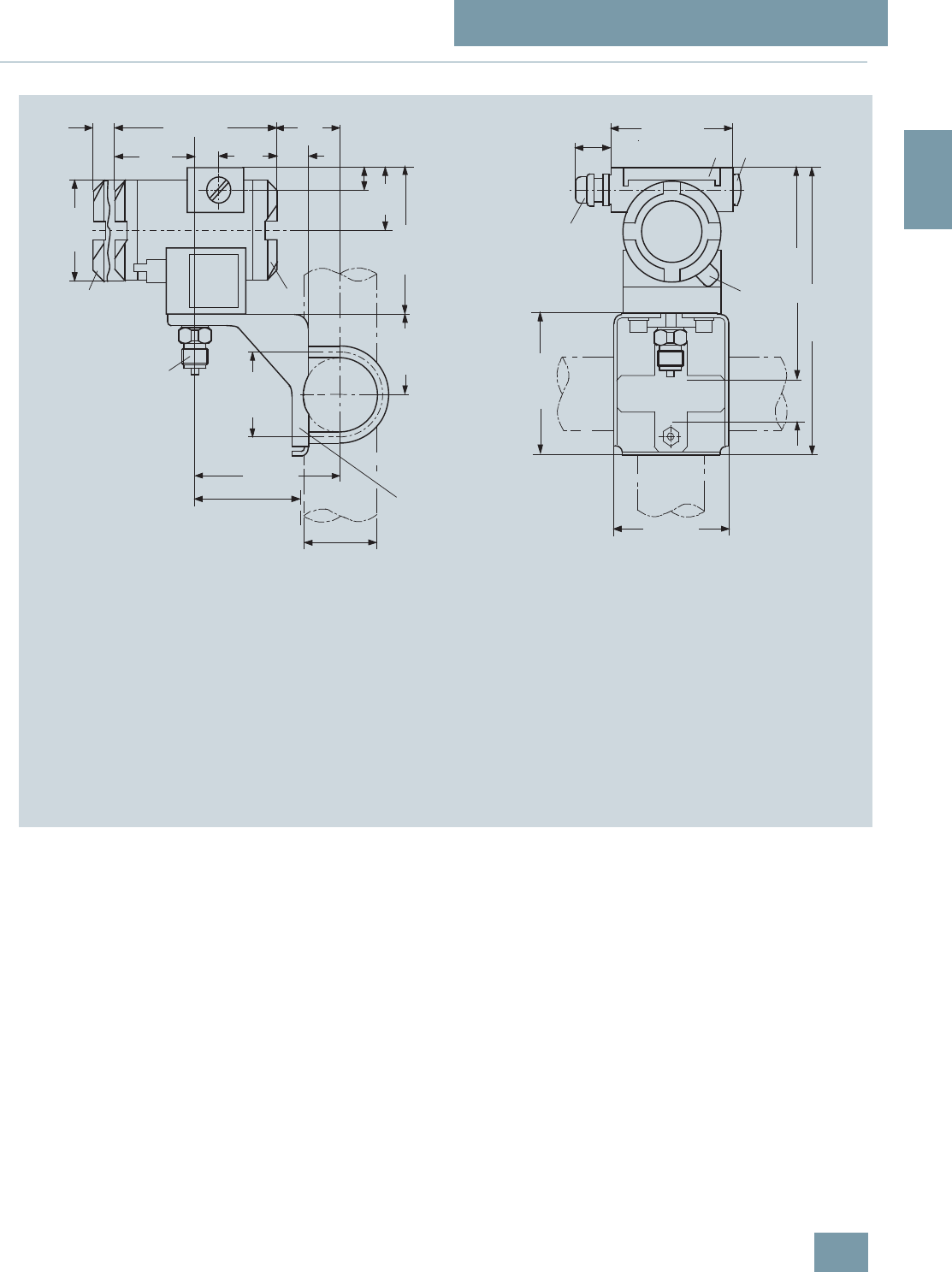
SITRANS P measuring instruments for pressure
Transmitters for gage, absolute and differential pressure, flow and level
DS III series
for gage pressure
2/77
Siemens FI 01 · 2009
2
■
Dimensional drawings
SITRANS P pressure transmitters, DS III HART series for gage pressure, dimensions in mm (inch)
1 Process connection:
- ½-14 NPT,
- connection shank G½B or
- oval flange
2 Blanking plug
3 Electrical connection:
- screwed gland M20x1,5 4),
- screwed gland ½-14 NPT or
- PROFIBUS-Stecker M12
3) 4)
4 Terminal side
5 Electronic side, digital display (longer overall
length for cover with window)
6 Protective cover over keys
7 Mounting bracket (option)
8 Screw cover - safety bracket (only for type of protection
"Explosion-proof enclosure", not shown in the drawing)
1) Allow approx. 20 mm (0.79 inch) thread length in addition
2) Minimum distance for rotating
3) Not with type of protection "Explosion-proof enclosure"
4) Not with type of protection "FM + CSA"
approx 30 (1.2)
15
(0.6) 144 (5.67)
55
(2.2)
51
(2.0)
74
(2.9)
4) 100 (3.94)
237 (9.3)
171 (6.7)
36,5
(1,44)
min. 90 (3.6)
ø 50 ... 60
(1.97 ... 2.36)
ø80
(3.15)
72 (2.8)
123 (4.8)
20
(0.8)
50
(1.97)
117 (4.6)
68 (2.7)
5)
54
1
3
2
6
1) 1) 8
120 (4.7)
105 (4.1)
7
28
(1.1)
© Siemens AG 2008
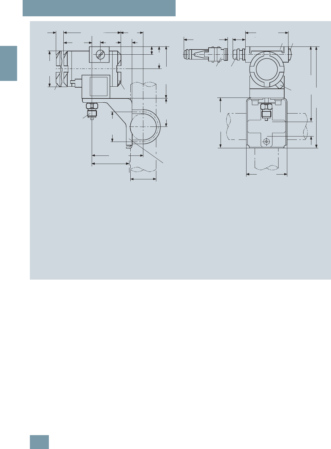
SITRANS P measuring instruments for pressure
Transmitters for gage, absolute and differential pressure, flow and level
DS III series
for gage pressure
2/78 Siemens FI 01 · 2009
2
SITRANS P pressure transmitters, DS III PA and FF series for gage pressure, dimensions in mm (inch)
1 Process connection:
- ½-14 NPT,
- onnection shankG½B or
- oval flange
2 Blanking plug
3 Electrical connection:
- screwed gland Pg 13,5 (adapter)2) 3),
- screwed gland M20x1,5 3),
- screwed gland ½-14 NPT or
- Han 7D/ Han 8U 2) 3) plug
4 Terminal side
5 Electronic side, digital display (longer overall
length for cover with window)
6 Protective cover over keys
7 Mounting bracket (option)
8 Screw cover - safety bracket (only for type of protection
"Explosion-proof enclosure", not shown in the drawing)
1) Allow approx. 20 mm (0.79 inch) thread length to permit unscrewing
2) Not with type of protection "Explosion-proof enclosure"
3) Not with type of protection "FM + CSA" [is + xp]"
4) For Pg 13,5 with adapter approx. 45 mm (1.77 inch)
5) Minimum distance for rotating
ca. 30 (1.2)
ca. 96 (3.78)
15
(0.6) 144 (5.67)
55
(2.2)
51
(2.0)
74
(2.9)
4) 100 (3.94)
237 (9.3)
171 (6.7)
36,5
(1,44)
min. 90 (3.6)
ø 50 ... 60
(1.97 ... 2.36)
ø80
(3.15)
72 (2.8)
123 (4.8)
20
(0.8)
50
(1.97)
117 (4.6)
68 (2.7)
5)
54
1
33
2
6
1) 1) 8
120 (4.7)
105 (4.1)
7
28
(1.1)
© Siemens AG 2008

SITRANS P measuring instruments for pressure
Transmitters for gage, absolute and differential pressure, flow and level
DS III series for gage and absolute pressure,
with front-flush diaphragm
2/79
Siemens FI 01 · 2009
2
■
Technical specifications
SITRANS P, DS III series for gage and absolute pressure, with front-flush diaphragm
HART PROFIBUS PA or FOUNDATION Fieldbus
Input gage pressure, with front-flush
diaphragm
Measured variable Gage pressure, flush-mounted
Spans (infinitely adjustable) or
nominal measuring range and
max. permissible test pressure
Span Max. perm. test pres-
sure Nominal measuring
range Max. perm. test pres-
sure
0.01 ... 1 bar g
(0.145 ... 14.5 psi g) 6 bar g
(87 psi g) 1 bar g
(14.5 psi g) 6 bar g
(87 psi g)
0.04 ... 4 bar g
(0.58 ... 58 psi g) 10 bar g
(145 psi g) 4 bar g
(58 psi g) 10 bar g
(145 psi g)
0.16 ... 16 bar g
(2.23 ... 232 psi g) 32 bar g
(464 psi g) 16 bar g
(232 psi g) 32 bar g
(464 psi g)
0.6 ... 63 bar g
(9.14 ... 914 psi g) 100 bar g
(1450 psi g) 63 bar g
(914 psi g) 100 bar g
(1450 psi g)
Lower measuring limit -100 mbar a (-1.45 psi a)
Upper measuring limit 100% of max. span 100% of nominal measuring range
Input absolute pressure, with front-flush
diaphragm
Measured variable Absolute pressure, flush-mounted
Spans (infinitely adjustable) or
nominal measuring range and
max. permissible test pressure
Span Max. perm. test pres-
sure Nominal measuring
range Max. perm. test pres-
sure
43 ... 1300 mbar a
(0.62 ... 18.9 psi a) 10 bar a
(145 psi a) 1300 mbar a
(18.9 psi a) 10 bar a
(145 psi a)
0,16 ... 5 bar a
(2.32 ... 72,5 psi a) 30 bar a
(435 psi a) 5 bar a
(72,5 psi a) 30 bar a
(435 psi a)
1 ... 30 bar a
(14.5 ... 435 psi a) 100 bar a
(1450 psi a) 30 bar a
(435 psi a) 100 bar a
(1450 psi a)
Depending on the process connection, the span
may differ from these values Depending on the process connection, the nomi-
nal measuring range may differ from these values
Lower measuring limit 0 bar a (0 psi a)
Upper measuring limit 100% of max. span 100% of nominal measuring range
Output
Output signal 4 ... 20 mA Digital PROFIBUS PA or FOUNDATION Fieldbus
signal
• Lower limit (infinitely adjustable) 3.55 mA, factory preset to 3.84 mA -
• Upper limit (infinitely adjustable) 23 mA, factory preset to 20.5 mA or optionally
set to 22.0 mA -
Load
•Without HART communication RB ≤ (UH - 10.5 V)/0.023 A in Ω,
UH : Power supply in V -
• With HART communication RB = 230 ... 500 Ω (SIMATIC PDM) or
RB = 230 ... 1100 Ω (HART Communicator) -
Physical bus - IEC 61158-2
With polarity reversal protection - Yes
Accuracy To EN 60770-1
Reference conditions
(All error data refer always refer to the set span) Increasing characteristic, start-of-scale value 0 bar, stainless steel seal diaphragm, silicone oil fill-
ing, room temperature 25 °C (77 °F)) r: Span ratio (r = max. span/set span)
Error in measurement and fixed-point setting
(including hysteresis and repeatability)
Gage pressure,
front-flushed Absolute pressure,
front-flushed Gage pressure,
front-flushed Absolute pressure,
front-flushed
• Linear characteristic ≤0,075% ≤ 0,2%
-r ≤ 10 ≤ (0.0029 ⋅ r + 0.071)% ≤ 0,2%
- 10 < r ≤ 30 ≤ (0.0045 ⋅ r + 0.071)% ≤ 0,4%
- 30 < r ≤ 100 ≤ (0.005 ⋅ r + 0.05)% -
Long-term drift (temperature change ±30 °C
(±54 °F)) ≤ (0.25 ⋅ r)% every 5
years ≤ 0.25% every 5 years
© Siemens AG 2008

SITRANS P measuring instruments for pressure
Transmitters for gage, absolute and differential pressure, flow and level
DS III series for gage and absolute pressure,
with front-flush diaphragm
2/80 Siemens FI 01 · 2009
2
Influence of ambient temperature
• at -10 ... +60 °C (14 ... 140 °F) ≤ (0.1 ⋅ r + 0.2)% ≤ (0,2 ⋅ r + 0,3)% ≤0,3% ≤ 0,5%
• at -40 ... -10 °C and +60 ... +85 °C
(-40 ... +14 °F and 140 ... 185 °F) ≤ (0.1 ⋅ r + 0.15)%/10 K ≤ (0,2 ⋅ r + 0,3)%/10 K ≤ 0.25%/10 K ≤ 0,5%/10 K
Influence of mounting position 0.1 mbar g (0.00145 psi g) per 10° inclination
Measured Value Resolution - 3 ⋅10-5 of nominal measuring range
Influence of the medium temperature (only with
front-flush diaphragm)
• Temperature difference between medium tem-
perature and ambient temperature 3 mbar/10 K (0.04 psi/10 K)
Rated operating conditions
Installation conditions
Ambient temperature Observe the temperature class in areas subject to explosion hazard.
• Measuring cell with silicone oil -40 ... +85 °C (-40 ... +185 °F)
• Measuring cell with Neobee oil (with front-flush
diaphragm) -10 ... +85 °C (14 ... +185 °F)
• Measuring cell with inert liquid (not with front-
flush diaphragm) -20 ... +85 °C (-4 ... +185 °F)
• Digital display -30 ... +85 °C (-22 ... +185 °F)
• Storage temperature -50 ... +85 °C (-58 ... +185 °F)
(with Neobee: -20 ... +85 °C (-4 ... +185 °F)
Climatic class
Condensation Permissible
Degree of protection to EN 60529 IP65, IP68, NEMA X, enclosure cleaning, resistant to lyes, steam to 150° C (302 °F)
Electromagnetic compatibility
• Emitted interference and interference immunity
To EN 61326 and NAMUR NE 21
Medium conditions
Process temperature
• Measuring cell with silicone oil -40 ... +100 °C (-40 ... +212 °F)
• Measuring cell with silicone oil (with front-flush
diaphragm) -40 ... +150 °C (-40 ... +302 °F)
• Measuring cell with Neobee oil (with front-flush
diaphragm) -40 ... +150 °C (-40 ... +302 °F)
• Measuring cell with silicone oil, with tempera-
ture isolator (only with front-flush diaphragm) -40 ... +200 °C (-40 ... +392 °F)
• Measuring cell with inert liquid -20 ... +100 °C (-4 ... +212 °F)
• Measuring cell with high temperature oil -10 ... +250 °C (14 ... +482 °F)
Design
Weight (without options) ≈ 1.5 kg (≈ 3.3 lb)
Housing material Poor in copper die-cast aluminium, GD-AlSi12 or stainless steel precision casting, mat. No. 1.4408
Wetted parts materials Stainless steel, mat. No. 1.4404/316L
Measuring cell filling Silicone oil or inert filling liquid
SITRANS P, DS III series for gage and absolute pressure, with front-flush diaphragm
HART PROFIBUS PA or FOUNDATION Fieldbus
© Siemens AG 2008

SITRANS P measuring instruments for pressure
Transmitters for gage, absolute and differential pressure, flow and level
DS III series for gage and absolute pressure,
with front-flush diaphragm
2/81
Siemens FI 01 · 2009
2
Hygiene version
In the case of SITRANS P DSIII with 7MF413x front-flush dia-
phragm, selected connections comply with the requirements of
EHEDG.
Power supply UHSupplied through bus
Terminal voltage on transmitter 10.5 ... 45 V DC
10.5 ... 30 V DC in intrinsically-safe mode -
Separate 24 V power supply necessary - No
Bus voltage
• Not Ex - 9 ...32 V
• With intrinsically-safe operation - 9 ...24 V
Current consumption
• Basic current (max.) - 12.5 mA
• Startup current ≤ basic current - Yes
• Max. current in event of fault - 15.5 mA
Fault disconnection electronics (FDE) available - Yes
Certificate and approvals
Classification according to pressure equipment
directive (DRGL 97/23/EC) For gases of fluid group 1 and liquids of fluid group 1; complies with requirements of Article 3,
paragraph 3 (sound engineering practice)
Explosion protection
• Intrinsic safety "i" PTB 99 ATEX 2122
- Identification Ex II 1/2 G EEx ia/ib IIB/IIC T6
- Permissible ambient temperature -40 ... +85 °C (-40 ... +185 °F) temperature class T4;
-40 ... +70 °C (-40 ... +158 °F) temperature class T5;
-40 ... +60 °C (-40 ... +140 °F) temperature class T6
- Connection To certified intrinsically-safe circuits with maxi-
mum values:
Ui = 30 V, Ii = 100 mA,
Pi = 750 mW; Ri = 300 Ω
FISCO supply unit:
Uo = 17.5 V, Io = 380 mA, Po = 5.32 W
Linear barrier:
Uo = 24 V, Io = 250 mA, Po = 1.2 W
- Effective internal inductance/capacitance L i = 0.4 mH, Ci = 6 nF L i = 7 μH, Ci = 1.1 nF
• Explosion-proof "d" PTB 99 ATEX 1160
- Identification Ex II 1/2 G EEx d IIC T4/T6
- Permissible ambient temperature -40 ... +85 °C (-40 ... +185 °F) temperature class T4;
-40 ... +60 °C (-40 ... +140 °F) temperature class T6
- Connection To circuits with values: UH = 10.5 ... 45 V DC To circuits with values: UH = 9 ... 32 V DC
• Dust explosion protection for zone 20 PTB 01 ATEX 2055
- Identification Ex II 1 D IP65 T 120 °C
Ex II 1/2 D IP65 T 120 °C
- Permissible ambient temperature -40 ... +85 °C (-40 ... +185 °F)
- Max.surface temperature 120 °C (248 °F)
- Connection To certified intrinsically-safe circuits with maxi-
mum values:
Ui = 30 V, Ii = 100 mA,
Pi = 750 mW, Ri = 300 Ω
FISCO supply unit:
Uo = 17.5 V, Io = 380 mA, Po = 5.32 W
Linear barrier:
Uo = 24 V, Io = 250 mA, Po = 1.2 W
- Effective internal inductance/capacitance L i = 0.4 mH, Ci = 6 nF L i = 7 μH, Ci = 1.1 nF
• Dust explosion protection for zone 21/22 PTB 01 ATEX 2055
- Identification Ex II 2 D IP65 T 120 °C
- Connection To circuits with values: UH = 10.5 ... 45 V DC;
Pmax = 1.2 W To circuits with values: UH = 9 ... 32 V DC;
Pmax = 1.2 W
• Type of protection "n" (zone 2) TÜV 01 ATEX 1696 X Planned
- Identification Ex II 3 G EEx nA L IIC T4/T5/T6 -
• Explosion protection to FM Certificate of Compliance 3008490
- Identification (XP/DIP) or (IS); (NI) CL I, DIV 1, GP ABCD T4...T6; CL II, DIV 1, GP EFG; CL III; CL I, ZN 0/1 AEx ia IIC T4...T6; CL I,
DIV 2, GP ABCD T4...T6; CL II, DIV 2, GP FG; CL III
• Explosion protection to CSA Certificate of Compliance 1153651
- Identification (XP/DIP) or (IS) CL I, DIV 1, GP ABCD T4...T6; CL II, DIV 1, GP EFG; CL III; Ex ia IIC T4...T6; CL I, DIV 2, GP ABCD
T4...T6; CL II, DIV 2, GP FG; CL III
SITRANS P, DS III series for gage and absolute pressure, with front-flush diaphragm
HART PROFIBUS PA or FOUNDATION Fieldbus
© Siemens AG 2008

SITRANS P measuring instruments for pressure
Transmitters for gage, absolute and differential pressure, flow and level
DS III series for gage and absolute pressure,
with front-flush diaphragm
2/82 Siemens FI 01 · 2009
2
HART communication
HART communication 230 ... 1100 Ω
Protocol HART Version 5.x
Software for computer SIMATIC PDM
PROFIBUS PA communication
Simultaneous communication with
master class 2 (max.) 4
The address can be set using Configuration tool or local opera-
tion (standard setting address
126)
Cyclic data usage
• Output byte 5 (one measuring value) or
10 (two measuring values)
• Input byte 0, 1, or 2 (register operating mode
and reset function for metering)
Internal preprocessing
Device profile PROFIBUS PA Profile for Process
Control Devices Version 3.0,
Class B
Function blocks 2
• Analog input
- Adaptation to customer-specif-
ic process variables Yes, linearly rising or falling char-
acteristic
- Electrical damping T63 , adjust-
able 0 ... 100 s
- Simulation function Input /Output
- Failure mode Can be parameterized (last good
value, substitute value, incorrect
value)
- Limit monitoring Yes, one upper and lower warning
limit and one alarm limit respec-
tively
• Register (totalizer) Can be reset, preset, optional
direction of counting, simulation
function of register output
- Failure mode Can be parameterized (summation
with last good value, continuous
summation, summation with incor-
rect value)
- Limit monitoring One upper and lower warning limit
and one alarm limit respectively
• Physical block 1
Transducer blocks 2
• Pressure transducer block
- Can be calibrated by applying
two pressures Yes
- Monitoring of sensor limits Yes
- Specification of a container
characteristic with Max. 30 nodes
- Square-rooted characteristic
for flow measurement Yes
- Gradual volume suppression
and implementation point of
square-root extraction
Parameterizable
- Simulation function for mea-
sured pressure value and sen-
sor temperature
Constant value or over parameter-
izable ramp function
Communication FOUNDATION Fieldbus
Function blocks 3 function blocks analog input,
1 function block PID
• Analog input
- Adaptation to customer-specif-
ic process variables Yes, linearly rising or falling char-
acteristic
- Electrical damping T63 , adjust-
able 0 ... 100 s
- Simulation function Output/input (can be locked within
the device with a bridge)
- Failure mode Can be parameterized (last good
value, substitute value, incorrect
value)
- Limit monitoring Yes, one upper and lower warning
limit and one alarm limit respec-
tively
- Square-rooted characteristic
for flow measurement Yes
• PID Standard FF function block
• Physical block 1 Resource block
Transducer blocks 1 transducer block Pressure with
calibration, 1 transducer block
LCD
• Pressure transducer block
- Can be calibrated by applying
two pressures Yes
- Monitoring of sensor limits Yes
- Simulation function: Measured
pressure value, sensor temper-
ature and electronics tempera-
ture
Constant value or over parameter-
izable ramp function
© Siemens AG 2008

SITRANS P measuring instruments for pressure
Transmitters for gage, absolute and differential pressure, flow and level
DS III series for gage and absolute pressure,
with front-flush diaphragm
2/83
Siemens FI 01 · 2009
2
F) Subject to export regulations AL: 9I999, ECCN: N. F) Subject to export regulations AL: 9I999, ECCN: N.
Selection and Ordering data Order No.
SITRANS P pressure transmitters for gage and
absolute pressure, front-flush membrane,
series DS III HART
F) 7 M F 4 1 3 3 -
77777 -7 7 7 7
Measuring cell filling Measuring cell
cleaning
Silicone oil Standard 1
Inert liquid Grease-free 3
FDA compliant fill fluid
• Neobee oil Standard 4
Span
0.01 ... 1 bar g1)
1) Only with "Standard" process connection
(0.15 ... 14.5 psi g)1) B
0.04 ... 4 bar g (0.58 ... 58 psi g) C
0.16 ... 16 bar g (2.32 ... 232 psi g) D
0.63 ... 63 bar g (9.14 ... 914 psi g) E
13 ... 1300 mbar a2)
2) Not with temperature decoupler P00 and P10, not for process connections
R02, R04, R10 and R11, and can only be ordered in conjunction with sili-
cone oil.
(0.19 ... 18.9 psi a)2) S
0.05 ... 5 bar a2) (0.7 ... 72.5 psi a)2) T
3 ... 30 bar a2) (43.5 ... 435 psi a)2) U
Wetted parts materials
Seal diaphragm Connection shank
Stainless steel Stainless steel A
Process connection
• Flange version with Order code M.., N.., R.. or
Q.. 7
Non-wetted parts materials
• Housing made of die-cast aluminium 0
• Housing stainless steel precision casting 3
Version
• Standard version 1
• International version, English label inscriptions,
documentation in 5 languages on CD 2
Explosion protection
• Without A
• With ATEX, Type of protection:
- "Intrinsic safety (EEx ia)" B
- "Explosion-proof (EEx d)"3)
3) Without cable gland, with blanking plug.
D
- "Intrinsic safety, explosion-proof enclosure and
dust explosion protection (EEx ia + EEx d +
Zone 1D/2D)"4)
4) With enclosed cable gland EEx ia and blanking plug.
R
• With FM + CSA, Type of protection:
- "Intrinsic safety and explosion-proof
(is + xp)"3) (available soon) N C
Electrical connection / cable entry
• Inner thread M20x1.5 B
• Female thread ½-14 NPT C
• M12 connectors (metal)5)
5) Cannot be used together with the following types of protection:
"Explosion-proof" and "Intrinsic safety and explosion-proof"
F
Display
• Without indicator 0
• Without visible digital indicator (digital indicator
hidden, setting: mA)
}1
• With visible digital indication, setting: mA 6
• With customer-specific digital indication (setting
as specified, Order code "Y21" or "Y22"
required)
7
Power supply units see "SITRANS I power supply units and isolation
amplifiers".
Included in delivery of the device:
• Brief instructions (Leporello)
• CD-ROM with detailed documentation
Selection and Ordering data Order No.
SITRANS P pressure transmitters for gage
pressure, front-flush membrane
DS III PA series (PROFIBUS PA) F) 7 M F 4 1 3 4 -
DS III FF series (FOUNDATION Fieldbus) F) 7 M F 4 1 3 5 -
7 7 7 7 7 -7 7 7 7
Measuring cell filling Measuring cell
cleaning
Silicone oil Standard 1
Inert liquid Grease-free 3
FDA compliant fill fluid
• Neobee oil Standard 4
Nominal measuring range
1 bar g1)
1) Only with "Standard" process connection
(14.5 psi g)1) B
4 bar g (58 psi g) C
16 bar g (232 psi g) D
63 bar g (914 psi g) E
1300 mbar a2)
2) Not with temperature decoupler P00 and P10, not for process connections
R02, R04, R10 and R11, and can only be ordered in conjunction with sili-
cone oil.
(18.9 psi a)2) S
5 bar a2) (72.5 psi a)2) T
30 bar a2) (435 psi a)2) U
Wetted parts materials
Seal diaphragm Connection shank
Stainless steel Stainless steel A
Process connection
• Flange version with Order code M.., N.., R.. or
Q.. 7
Non-wetted parts materials
• Housing made of die-cast aluminium 0
• Housing stainless steel precision casting 3
Version
• Standard version 1
• International version, English label inscriptions,
documentation in 5 languages on CD 2
Explosion protection
• Without A
• With ATEX, Type of protection:
- "Intrinsic safety (EEx ia)" B
- "Explosion-proof (EEx d)"3)
3) Without cable gland, with blanking plug.
D
- "Intrinsic safety, explosion-proof enclosure and
dust explosion protection (EEx ia + EEx d +
Zone 1D/2D)"4)
4) With enclosed cable gland EEx ia and blanking plug.
R
• With FM + CSA, Type of protection:
- "Intrinsic safety and explosion-proof
(is + xp)"3) (available soon) N C
Electrical connection / cable entry
• Screwed gland M20x1.5 B
• Screwed gland ½-14 NPT C
• M12 connectors (metal) 5)
5) Cannot be used together with the following types of protection:
"Explosion-proof" and "Intrinsic safety and explosion-proof"
F
Display
• Without indicator 0
• Without visible digital indicator (digital indicator
hidden, setting: mA)
}1
• With visible digital display 6
• With customer-specific digital display (setting as
specified, Order code "Y21" or required) 7
Included in delivery of the device:
• Brief instructions (Leporello)
• CD-ROM with detailed documentation
© Siemens AG 2008

SITRANS P measuring instruments for pressure
Transmitters for gage, absolute and differential pressure, flow and level
DS III series for gage and absolute pressure,
with front-flush diaphragm
2/84 Siemens FI 01 · 2009
2
Selection and Ordering data Order code
Further designs HART PA FF
Add "-Z" to Order No. and specify Order
code.
Cable sockets for M12 connectors (metal) A50 9
9
9
9
9
9
Rating plate inscription
(instead of German)
• English B11 9
9
9
9
9
9
• French B12 9
9
9
9
9
9
• Spanish B13 9
9
9
9
9
9
• Italian B14 9
9
9
9
9
9
English rating plate B21 9
9
9
9
9
9
Pressure units in inH2O or psi
Quality inspection certificate (Factory cali-
bration) to IEC 60770-2 C11 9
9
9
9
9
9
Acceptance test certificate C12 9
9
9
9
9
9
To EN 10204-3.1
Factory certificate C14 9
9
9
9
9
9
To EN 10204-2.2
"PROFIsafe" certificate and protocol C21 9
9
Flanges to EN 1092-1
• DN 25, PN 401) M11 9
9
9
9
9
9
• DN 25, PN 1001) M21 9
9
9
9
9
9
• DN 40, PN 40 M13 9
9
9
9
9
9
• DN 40, PN 100 M23 9
9
9
9
9
9
• DN 50, PN 16 M04 9
9
9
9
9
9
• DN 50, PN 40 M14 9
9
9
9
9
9
• DN 80, PN 16 M06 9
9
9
9
9
9
• DN 80, PN 40 M16 9
9
9
9
9
9
Flanges to ASME B16.5
• Stainless steel flange 1" class 1501) M40 9
9
9
9
9
9
• Stainless steel flange 1½" class 150 M41 9
9
9
9
9
9
• Stainless steel flange 2" class 150 M42 9
9
9
9
9
9
• Stainless steel flange 3" class 150 M43 9
9
9
9
9
9
• Stainless steel flange 4" class 150 M44 9
9
9
9
9
9
• Stainless steel flange 1" class 3001) M45 9
9
9
9
9
9
• Stainless steel flange 1½" class 300 M46 9
9
9
9
9
9
• Stainless steel flange 2" class 300 M47 9
9
9
9
9
9
• Stainless steel flange 3" class 300 M48 9
9
9
9
9
9
• Stainless steel flange 4" class 300 M49 9
9
9
9
9
9
Threaded connection acc. to DIN 3852-2,
Form A
• G ¾“, flush-mounted2) R01 9
9
9
9
9
9
• G 1“, flush-mounted2) R02 9
9
9
9
9
9
• G 2“, flush-mounted2) R04 9
9
9
9
9
9
Tank connection3)
Sealing is included in delivery
• TG 52/50, PN 40 R10 9
9
9
9
9
9
• TG 52/150, PN 40 R11 9
9
9
9
9
9
Sanitary process connection according
DIN 11851 (Dairy connection)
• DN 50, PN 25 N04 9
9
9
9
9
9
• DN 80, PN 25 N06 9
9
9
9
9
9
Tri-Clamp connection according
DIN 32676/ISO 2852
• DN 50/2“, PN 16 N14 9
9
9
9
9
9
• DN 65/3“, PN 10 N15 9
9
9
9
9
9
Varivent connection
certified to EHEDG
• Type N = 68 for Varivent housing
DN 40 ... 125 and 1½" ... 6", PN 40 N28 9
9
9
9
9
9
Temperature decoupler up to 200 °C4)
for version with front-flush diaphragm P00 9
9
9
9
9
9
Temperature decoupler up to 250 °C
Measuring cell filling: High-temperature oil,
only in conjunction with measuring cell filling
silicone oil
P10 9
9
9
9
9
9
Bio-Control (Neumo) sanitary connection
certified to EHEDG
• DN 50, PN 16 Q53 9
9
9
9
9
9
• DN 65, PN 16 Q54 9
9
9
9
9
9
Sanitary process connection to DRD
• 65 mm, PN 40 M32 9
9
9
9
9
9
SMS socket with union nut
•2“ M67 9
9
9
9
9
9
•2½“ M68 9
9
9
9
9
9
•3“ M69 9
9
9
9
9
9
SMS threaded socket
•2“ M73 9
9
9
9
9
9
•2½“ M74 9
9
9
9
9
9
•3“ M75 9
9
9
9
9
9
IDF socket with union nut ISO 2853
•2“ M82 9
9
9
9
9
9
•2½“ M83 9
9
9
9
9
9
•3“ M84 9
9
9
9
9
9
IDF threaded socket ISO 2853
•2“ M92 9
9
9
9
9
9
•2½“ M93 9
9
9
9
9
9
•3“ M94 9
9
9
9
9
9
Sanitary process connection to
NEUMO Bio-Connect screw connection
certified to EHEDG
• DN 50, PN 16 Q05 9
9
9
9
9
9
• DN 65, PN 16 Q06 9
9
9
9
9
9
• DN 80, PN 16 Q07 9
9
9
9
9
9
• DN 100, PN 16 Q08 9
9
9
9
9
9
• DN 2“, PN 16 Q13 9
9
9
9
9
9
• DN 2½“, PN 16 Q14 9
9
9
9
9
9
• DN 3“, PN 16 Q15 9
9
9
9
9
9
• DN 4“, PN 16 Q16 9
9
9
9
9
9
Sanitary process connection to
NEUMO Bio-Connect flange connection
certified to EHEDG
• DN 50, PN 16 Q23 9
9
9
9
9
9
• DN 65, PN 16 Q24 9
9
9
9
9
9
• DN 80, PN 16 Q25 9
9
9
9
9
9
• DN 100, PN 16 Q26 9
9
9
9
9
9
• DN 2“, PN 16 Q31 9
9
9
9
9
9
• DN 2½“, PN 16 Q32 9
9
9
9
9
9
• DN 3“, PN 16 Q33 9
9
9
9
9
9
• DN 4“, PN 16 Q34 9
9
9
9
9
9
Sanitary process connection to
NEUMO Bio-Connect clamp connection
certified to EHEDG
• DN 50, PN 16 Q39 9
9
9
9
9
9
• DN 65, PN 10 Q40 9
9
9
9
9
9
• DN 80, PN 10 Q41 9
9
9
9
9
9
• DN 100, PN 10 Q42 9
9
9
9
9
9
• DN 2½“, PN 16 Q48 9
9
9
9
9
9
• DN 3“, PN 10 Q49 9
9
9
9
9
9
• DN 4“, PN 10 Q50 9
9
9
9
9
9
Selection and Ordering data Order code
Further designs HART PA FF
Add "-Z" to Order No. and specify Order
code.
© Siemens AG 2008

SITRANS P measuring instruments for pressure
Transmitters for gage, absolute and differential pressure, flow and level
DS III series for gage and absolute pressure,
with front-flush diaphragm
2/85
Siemens FI 01 · 2009
2
Sanitary process connection to NEUMO
Connect S flange connection
certified to EHEDG
• DN 50, PN 16 Q63 9
9
9
9
9
9
• DN 65, PN 10 Q64 9
9
9
9
9
9
• DN 80, PN 10 Q65 9
9
9
9
9
9
• DN 100, PN 10 Q66 9
9
9
9
9
9
• DN 2“, PN 16 Q72 9
9
9
9
9
9
• DN 2½“, PN 10 Q73 9
9
9
9
9
9
• DN 3“, PN 10 Q74 9
9
9
9
9
9
• DN 4“, PN 10 Q75 9
9
9
9
9
9
Aseptic threaded socket to DIN 11864-1
Form A
• DN 50, PN 25 N33 9
9
9
9
9
9
• DN 65, PN 25 N34 9
9
9
9
9
9
• DN 80, PN 25 N35 9
9
9
9
9
9
• DN 100, PN 25 N36 9
9
9
9
9
9
Aseptic flange with notch to DIN 11864-2
Form A
• DN 50, PN 16 N43 9
9
9
9
9
9
• DN 65, PN 16 N44 9
9
9
9
9
9
• DN 80, PN 16 N45 9
9
9
9
9
9
• DN 100, PN 16 N46 9
9
9
9
9
9
Aseptic flange with groove to DIN 11864-2
Form A
• DN 50, PN 16 N43 +
P11
9
9
9
9
9
9
• DN 65, PN 16 N44 +
P11
9
9
9
9
9
9
• DN 80, PN 16 N45 +
P11
9
9
9
9
9
9
• DN 100, PN 16 N46 +
P11
9
9
9
9
9
9
Aseptic clamp with groove to DIN 11864-3
Form A
• DN 50, PN 25 N53 9
9
9
9
9
9
• DN 65, PN 25 N54 9
9
9
9
9
9
• DN 80, PN 16 N55 9
9
9
9
9
9
• DN 100, PN 16 N56 9
9
9
9
9
9
1) Special Viton seal included in delivery.
2) Lower measuring limit -100 mbar g (1.45 psi g).
3) The weldable socket can be ordered under accessories
4) The maximum temperatures of the medium depend on the respective cell
fillings.
Selection and Ordering data Order code
Further designs HART PA FF
Add "-Z" to Order No. and specify Order
code.
Selection and Ordering data Order code
Additional data HART PA FF
Add "-Z" to Order No. and specify Order
code.
Measuring range to be set Y01 9
9
Specify in plain text (max. 5 digits):
Y01: ... up to ... mbar, bar, kPa, MPa, psi
Measuring point number (TAG No.) Y15 9
9
9
9
9
9
Max. 16 characters, specify in plain text:
Y15: ...........................................
Measuring point text Y16 9
9
9
9
9
9
Max. 27 characters, specify in plain text:
Y16: ...........................................
Setting of pressure indicator in pressure
units Y21 9
9
9
9
9
9
Specify in plain text (standard setting: mA):
Y21: mbar, bar, kPa, MPa, psi, ...
Note:
The following pressure units can be selected:
bar, mbar, mm H2O*), inH2O*), ftH2O*),
mmHG, inHG, psi, Pa, kPa, MPa, g/cm2,
kg/cm2, Torr, ATM oder %
*) ref. temperature 20 °C
Preset bus address Y25 9
9
(possible between 1 and 126)
Specify in plain text:
Y25: .....................
Only "Y01" and "Y21" can be factory preset
9
9
= available
Ordering example
Item line: 7MF4133-1DB20-1AB7-Z
B line: A22 + Y01 + Y21
C line: Y01: 1 ... 10 bar (14.5 ... 145 psi)
C line: Y21: bar (psi)
© Siemens AG 2008
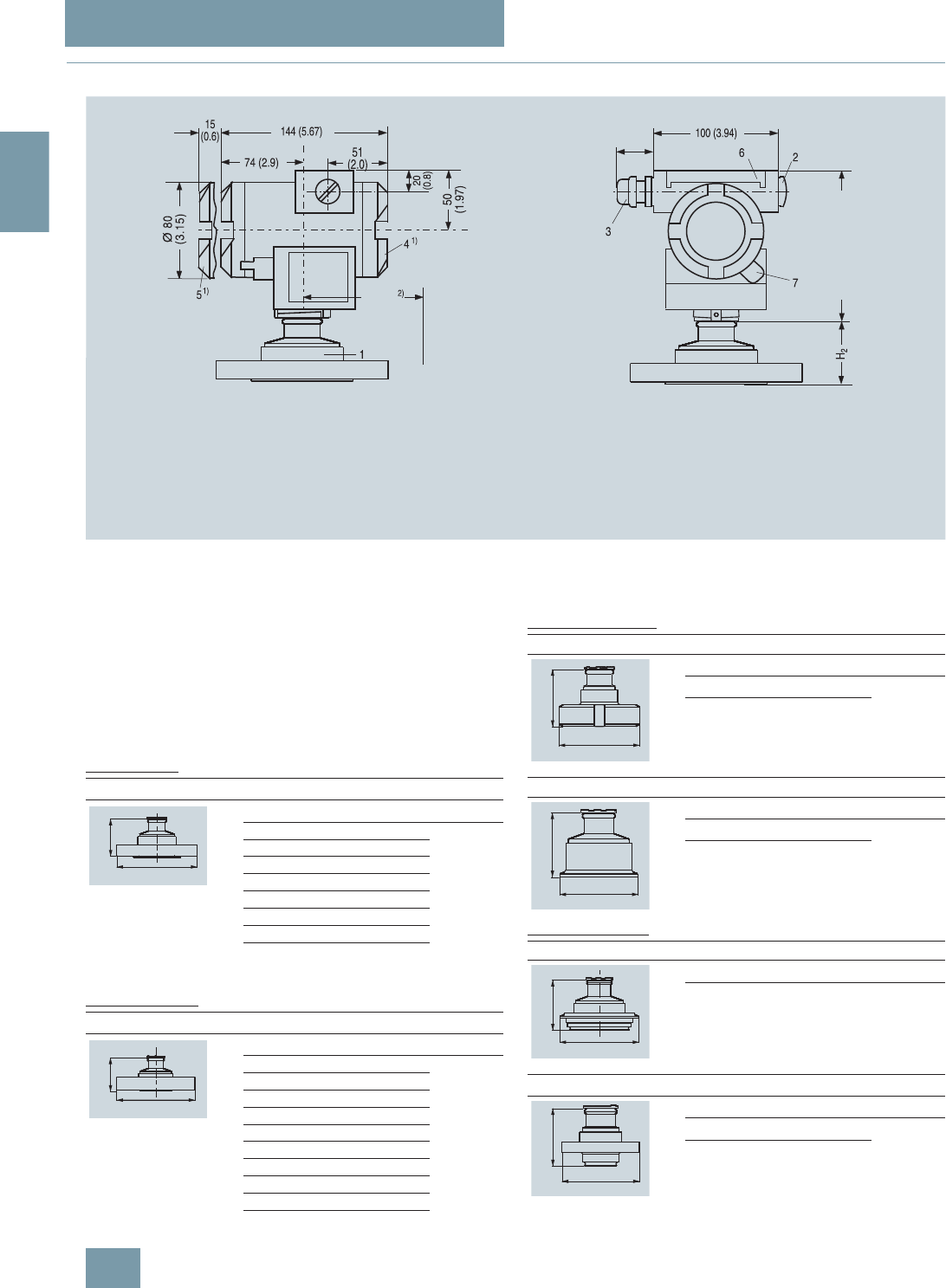
SITRANS P measuring instruments for pressure
Transmitters for gage, absolute and differential pressure, flow and level
DS III series for gage and absolute pressure,
with front-flush diaphragm
2/86 Siemens FI 01 · 2009
2
■
Dimensional drawings
SITRANS P pressure transmitters, DS III series for gage pressure, with front-flush diaphragm, dimensions in mm (inch)
The diagram shows a SITRANS P DS III with an example of a
flange. In this drawing the height is subdivided into H1 and H2.
H1 = Height of the SITRANS DS III up to a defined cross-section
H2 = Height of the flange up to this defined cross-section
Only the height H2 is indicated in the dimensions of the flanges.
Flanges to EN and ASME
Flanges to EN
Flanges to ASME
NuG and pharmaceutical connections
Connections to DIN
Other connections
90 (3.6)
3URFHVV FRQQHFWLRQ VHH IODQJH WDEOHV
%ODQNLQJ SOXJ
(OHFWULFDO FRQQHFWLRQ
VFUHZHGJODQG0[
VFUHZHGJODQG137
7HUPLQDO VLGH
(OHFWURQLFV VLGH GLJLWDO GLVSOD\ ORQJHU RYHUDOO OHQJWK IRU FRYHU ZLWKZLQGRZ
3URWHFWLYH FRYHU RYHU NH\V
6FUHZ FRYHU VDIHW\ EUDFNHW RQO\ IRU H[SORVLRQSURRI HQFORVXUH
QRWVKRZQLQWKHGUDZLQJ
$OORZDSSUR[ PP LQFK
WKUHDGOHQJWKLQDGGLWLRQ
PP LQFK IRUPLQLPXP GLVWDQFH
WRSHUPLWURWDWLRQZLWKLQGLFDWRU
6SDFHIRUURWDWLRQ
RIKRXVLQJ
DSSUR[
+ DSSUR[
EN 1092-1
DN PN ∅DH
2
25 40 115 mm (4.5“) Approx.
52 mm (2“)
25 100 140 mm (5.5“)
40 40 150 mm (5.9“)
40 100 170 mm (6.7“)
50 16 165 mm (6.5“)
50 40 165 mm (6.5“)
80 16 200 mm (7.9“)
80 40 200 mm (7.9“)
ASME B16.5
DN class ∅DH
2
1“ 150 110 mm (4.3“) Approx.
52 mm (2“)
1“ 300 125 mm (4.9“)
1½“ 150 130 mm (5.1“)
1½“ 300 155 mm (6.1“)
2“ 150 150 mm (5.9“)
2“ 300 165 mm (6.5“)
3“ 150 190 mm (7.5“)
3“ 300 210 mm (8.1“)
4“ 150 230 mm (9.1“)
4“ 300 255 mm (10.0“)
'
+
'
+
DIN 11851 (Dairy connection)
DN PN ∅DH
2
50 25 92 mm (3.6“) Approx.
52 mm (2“)
80 25 127 mm (5.0“)
Tri-Clamp according DIN 32676
DN PN ∅DH
2
50 16 64 mm (2.5“) Approx.
52 mm (2“)
65 16 91 mm (3.6“)
Varivent connection
DN PN ∅DH
2
40 ... 125 40 84 mm
(3.3“) Approx.
52 mm (2“)
Bio-Control connection
DN PN ∅DH
2
50 16 90 mm (3.5“) Approx.
52 mm (2“)
65 16 120 mm (4.7“)
'
+
'
+
'
+
'
+
© Siemens AG 2008
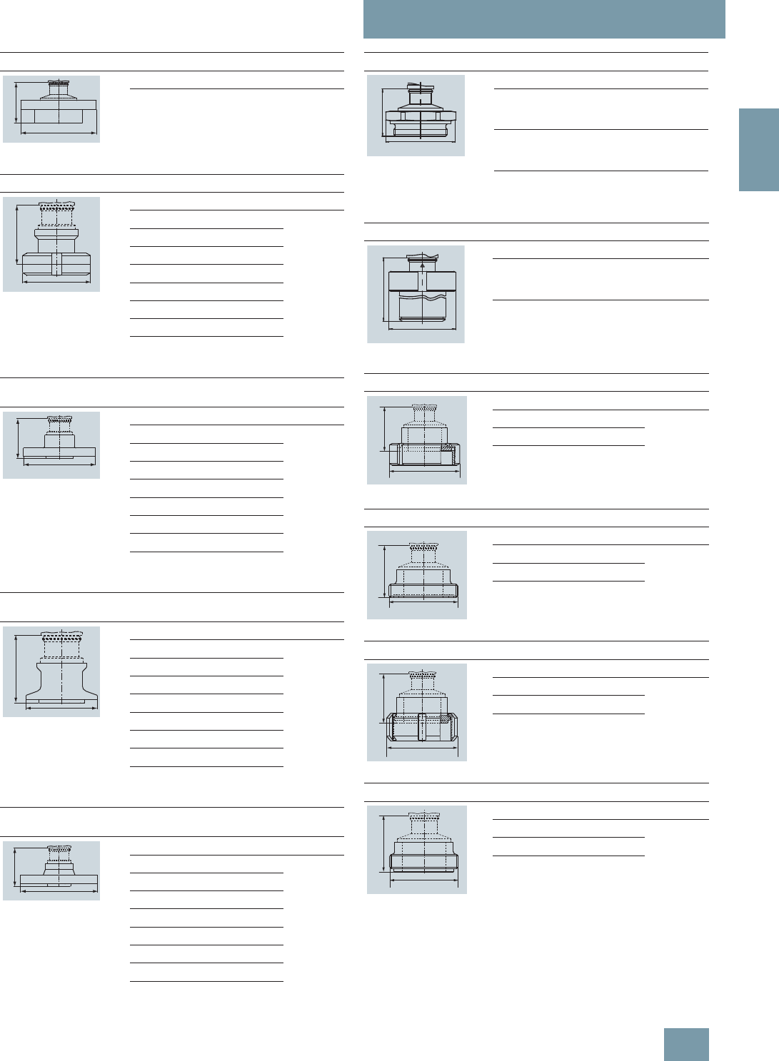
SITRANS P measuring instruments for pressure
Transmitters for gage, absolute and differential pressure, flow and level
DS III series for gage and absolute pressure,
with front-flush diaphragm
2/87
Siemens FI 01 · 2009
2
Sanitary process connection to DRD
DN PN ∅DH
2
50 40 105 mm (4.1“) Approx.
52 mm (2“)
Sanitary process screw connection to NEUMO Bio-Connect
DN PN ∅DH
2
50 16 82 mm (3.2“) Approx.
52 mm (2“)
65 16 105 mm (4.1“)
80 16 115 mm (4.5“)
100 16 145 mm (5.7“)
2“ 16 82 mm (3.2“)
2½“ 16 105 mm (4.1“)
3“ 16 105 mm (4.1“)
4“ 16 145 mm (5.7“)
Sanitary connection to NEUMO Bio-Connect
flange connection
DN PN ∅DH
2
50 16 110 mm (4.3“) Approx.
52 mm (2“)
65 16 140 mm (5.5“)
80 16 150 mm (5.9“)
100 16 175 mm (6.9“)
2“ 16 100 mm (3.9“)
2½“ 16 110 mm (4.3“)
3“ 16 140 mm (5.5“)
4“ 16 175 mm (6.9“)
Sanitary connection to NEUMO Bio-Connect
clamp connection
DN PN ∅DH
2
50 16 77,4 mm (3.0“) Approx.
52 mm (2“)
65 10 90,9 mm (3.6“)
80 10 106 mm (4.2“)
100 10 119 mm (4.7“)
2“ 16 64 mm (2.5“)
2½“ 16 77,4 mm (3.0“)
3“ 10 90,9 mm (3.6“)
4“ 10 119 mm (4.7“)
Sanitary connection to NEUMO Bio-Connect S
flange connection
DN PN ∅DH
2
50 16 125 mm (4.9“) Approx.
52 mm (2“)
65 10 145 mm (5.7“)
80 10 155 mm (6.1“)
100 10 180 mm (7.1“)
2“ 16 125 mm (4.9“)
2½“ 10 135 mm (5.3“)
3“ 10 145 mm (5.7“)
4“ 10 180 mm (7.1“)
'
+
'
+
'
+
'
+
'
+
Thread connection G¾“, G1“ and G2“ to DIN 3852
DN PN ∅DH
2
¾“ 63 37 mm (1.5“) Approx.
45 mm
(1.8“)
1“ 63 48 mm (1.9“) Approx.
47 mm
(1.9“)
2“ 63 78 mm (3.1“) Approx.
52 mm (2“)
Tank connection TG52/50 and TG52/150
DN PN ∅DH
2
25 40 63 mm (2.5“) Approx.
63 mm
(2.5“)
25 40 63 mm (2.5“) Approx.
170 mm
(6.7“)
SMS socket with union nut
DN PN ∅DH
2
2“ 25 84 mm (3.3“) Approx.
52 mm
(2.1“)
2½“ 25 100 mm (3.9“)
3“ 25 114 mm (4.5“)
SMS threaded socket
DN PN ∅DH
2
2“ 25 70 x 1/6 mm Approx.
52 mm
(2.1“)
2½“ 25 85 x 1/6 mm
3“ 25 98 x 1/6 mm
IDF socket with union nut
DN PN ∅DH
2
2“ 25 77 mm (3“) Approx.
52 mm
(2.1“)
2½“ 25 91 mm (3.6“)
3“ 25 106 mm (4.2“)
IDF threaded socket
DN PN ∅DH
2
2“ 25 64 mm (2.5“) Approx.
52 mm
(2.1“)
2½“ 25 77.5 mm (3.1“)
3“ 25 91 mm (3.6“)
'
+
'
+
'
+
'
+
'
+
'
+
© Siemens AG 2008

SITRANS P measuring instruments for pressure
Transmitters for gage, absolute and differential pressure, flow and level
DS III series for gage and absolute pressure,
with front-flush diaphragm
2/88 Siemens FI 01 · 2009
2
Aseptic threaded socket to DIN 11864-1 Form A
DN PN ∅DH
2
50 25 78 x 1/6“ Approx. 52
mm (2.1“)
65 25 95 x 1/6“
80 25 110 x ¼“
100 25 130 x ¼“
Aseptic flange with notch to DIN 11864-2 Form A
DN PN ∅DH
2
50 16 94 Approx. 52
mm (2.1“)
65 16 113
80 16 133
100 16 159
Aseptic flange with groove to DIN 11864-2 Form A
DN PN ∅DH
2
50 16 94 Approx. 52
mm (2.1“)
65 16 113
80 16 133
100 16 159
Aseptic clamp with groove to DIN 11864-3 Form A
DN PN ∅DH
2
50 25 77,5 Approx. 52
mm (2.1“)
65 25 91
80 16 106
100 16 130
+
'
+
'
+
'
+
'
© Siemens AG 2008

SITRANS P measuring instruments for pressure
Transmitters for gage, absolute and differential pressure, flow and level
DS III series for absolute pressure
(from gage pressure series)
2/89
Siemens FI 01 · 2009
2
■
Technical specifications
SITRANS P, DS III series for absolute pressure (from the gage pressure series)
HART PROFIBUS PA or FOUNDATION Fieldbus
Input
Measured variable Absolute pressure
Spans (infinitely adjustable) or
nominal measuring range and
max. permissible test pressure
Span Max. perm. test
pressure Nominal measuring
range Max. perm. test
pressure
8.3 ... 250 mbar a
(0.12 ... 3.6 psi a) 6 bar a
(87 psi a) 250 mbar a
(3.6 psi a) 6 bar a
(87 psi a)
43 ... 1300 mbar a
(0.62 ... 18.9 psi a) 10 bar a
(145 psi a) 1300 mbar a
(18.9 psi a) 10 bar a
(145 psi a)
160 ... 5000 mbar a
(2.32 ... 72.5 psi a) 30 bar a
(435 psi a) 5 bar a
(72.5 psi a) 30 bar a
(435 psi a)
1 ... 30 bar a
(14.5 ... 435 psi a) 100 bar a
(1450 psi a) 30 bar a
(435 psi a) 100 bar a
(1450 psi a)
Lower measuring limit
• Measuring cell with silicone oil filling 0 mbar a (0 psi a)
Upper measuring limit 100% of max. span
Output
Output signal 4 ... 20 mA Digital PROFIBUS PA or FOUNDATION Fieldbus
signal
• Lower limit (infinitely adjustable) 3.55 mA, factory preset to 3.84 mA -
• Upper limit (infinitely adjustable) 23 mA, factory preset to 20.5 mA or optionally set
to 22.0 mA -
Load
• Without HART communication RB ≤ (UH - 10.5 V)/0.023 A in Ω,
UH : Power supply in V -
• With HART communication RB = 230 ... 500 Ω (SIMATIC PDM) or
RB = 230 ... 1100 Ω (HART Communicator) -
Physical bus - IEC 61158-2
With polarity reversal protection - Yes
Accuracy To EN 60770-1
Reference conditions
(All error data refer always refer to the set
span)
Increasing characteristic, start-of-scale value 0 bar, stainless steel seal diaphragm, silicone oil filling,
room temperature 25 °C (77 °F)) r: Span ratio (r = max. span / set span)
Error in measurement and fixed-point setting
(including hysteresis and repeatability)
• Linear characteristic ≤0.1%
-r ≤ 10 ≤0.1%
- 10 < r ≤ 30 ≤0.2%
Long-term drift (temperature change ±30 °C
(±54 °F)) ≤ (0.1 ⋅ r)%/year ≤ 0.1%/year
Influence of ambient temperature
• at -10 ... +60 °C (14 ... 140 °F) ≤ (0.1 ⋅ r +0.2)% ≤0,3%
• at -40 ... -10 °C and +60 ... +85 °C
(-40 ... +14 °F and 140 ... 185 °F) ≤ (0.1 ⋅ r + 0.15)%/10 K ≤ 0.25%/10 K
Measured Value Resolution - 3 ⋅10-5 of nominal measuring range
© Siemens AG 2008

SITRANS P measuring instruments for pressure
Transmitters for gage, absolute and differential pressure, flow and level
DS III series for absolute pressure
(from gage pressure series)
2/90 Siemens FI 01 · 2009
2
Rated operating conditions
Degree of protection (to EN 60529) IP65
Process temperature
• Measuring cell with silicone oil filling -40 ... +100 °C (-40 ... +212 °F)
• Measuring cell with inert filling liquid -20 ... +100 °C (-4 ... +212 °F)
• In conjunction with dust explosion protec-
tion -20 ... +60 °C (-4 ... +140 °F)
Ambient conditions
• Ambient temperature
- Digital indicators -30 ... +85 °C (-22 ... +185 °F)
• Storage temperature -50 ... +85 °C (-58 ... +185 °F)
• Climatic class
- Condensation Permissible
• Electromagnetic compatibility
- Emitted interference and interference im-
munity To EN 61326 and NAMUR NE 21
Design
Weight (without options) ≈ 1.5 kg (≈ 3.3 lb)
Housing material Poor in copper die-cast aluminium, GD-AlSi12 or stainless steel precision casting, mat. No. 1.4408
Wetted parts materials
• Connection shank Stainless steel, mat. No. 1.4404/316L or Hastelloy C4, mat. No. 2.4610
• Oval flange Stainless steel, mat. No. 1.4404/316L
• Seal diaphragm Stainless steel, mat. No. 1.4404/316L or Hastelloy C276, mat. No. 2.4819
Measuring cell filling Silicone oil or inert filling liquid (max. 160 bar a (2320 psi a) with oxygen measurement)
Process connection Connection shank G½A to DIN EN 837-1, female thread ½ -14 NPT or oval flange (PN 160
(MWP 2320 psi a)) to DIN 19213 with mounting thread M10 or 7/16-20 UNF to EN 61518
Material of the mounting bracket
• Steel Sheet steel, Mat. No. 1.0330, chrome-plated
• Stainless steel Stainless steel, Mat. No. 1.4301 (SS304)
Power supply UH Supplied through bus
Terminal voltage on transmitter 10.5 ... 45 V DC
10.5 ... 30 V DC in intrinsically-safe mode -
Separate 24 V power supply necessary - No
Bus voltage
• Not Ex - 9 ... 32 V
• With intrinsically-safe operation - 9 ... 24 V
Current consumption
• Basic current (max.) - 12.5 mA
• Startup current ≤ basic current - Yes
• Max. current in event of fault - 15.5 mA
Fault disconnection electronics (FDE) avail-
able -Yes
SITRANS P, DS III series for absolute pressure (from the gage pressure series)
HART PROFIBUS PA or FOUNDATION Fieldbus
© Siemens AG 2008

SITRANS P measuring instruments for pressure
Transmitters for gage, absolute and differential pressure, flow and level
DS III series for absolute pressure
(from gage pressure series)
2/91
Siemens FI 01 · 2009
2
Certificate and approvals
Classification according to pressure equip-
ment directive (DRGL 97/23/EC) For gases of fluid group 1 and liquids of fluid group 1; complies with requirements of Article 3, para-
graph 3 (sound engineering practice)
Explosion protection
• Intrinsic safety "i" PTB 99 ATEX 2122
- Identification Ex II 1/2 G EEx ia/ib IIB/IIC T6
- Permissible ambient temperature -40 ... +85 °C (-40 ... +185 °F) temperature class T4;
-40 ... +70 °C (-40 ... +158 °F) temperature class T5;
-40 ... +60 °C (-40 ... +140 °F) temperature class T6
- Connection To certified intrinsically-safe circuits with maxi-
mum values:
Ui = 30 V, Ii = 100 mA,
Pi = 750 mW; Ri = 300 Ω
FISCO supply unit:
Uo = 17.5 V, Io = 380 mA, Po = 5.32 W
Linear barrier:
Uo = 24 V, Io = 250 mA, Po = 1.2 W
- Effective internal inductance/capacitance L i = 0.4 mH, Ci = 6 nF L i = 7 μH, Ci = 1.1 nF
• Explosion-proof "d" PTB 99 ATEX 1160
- Identification Ex II 1/2 G EEx d IIC T4/T6
- Permissible ambient temperature -40 ... +85 °C (-40 ... +185 °F) temperature class T4;
-40 ... +60 °C (-40 ... +140 °F) temperature class T6
- Connection To circuits with values: UH = 10.5 ... 45 V DC To circuits with values: UH = 9 ... 32 V DC
• Dust explosion protection for zone 20 PTB 01 ATEX 2055
- Identification Ex II 1 D IP65 T 120 °C
Ex II 1/2 D IP65 T 120 °C
- Permissible ambient temperature -40 ... +85 °C (-40 ... +185 °F)
- Max.surface temperature 120 °C (248 °F)
- Connection To certified intrinsically-safe circuits with maxi-
mum values:
Ui = 30 V, Ii = 100 mA,
Pi = 750 mW, Ri = 300 Ω
FISCO supply unit:
Uo = 17.5 V, Io = 380 mA, Po = 5.32 W
Linear barrier:
Uo = 24 V, Io = 250 mA, Po = 1.2 W
- Effective internal inductance/capacitance L i = 0.4 mH, Ci = 6 nF L i = 7 μH, Ci = 1.1 nF
• Dust explosion protection for zone 21/22 PTB 01 ATEX 2055
- Identification Ex II 2 D IP65 T 120 °C
- Connection To circuits with values: UH = 10.5 ... 45 V DC;
Pmax = 1.2 W To circuits with values: UH = 9 ... 32 V DC;
Pmax = 1.2 W
• Type of protection "n" (zone 2) TÜV 01 ATEX 1696 X Planned
- Identification Ex II 3 G EEx nA L IIC T4/T5/T6 -
• Explosion protection to FM Certificate of Compliance 3008490
- Identification (XP/DIP) or (IS); (NI) CL I, DIV 1, GP ABCD T4...T6; CL II, DIV 1, GP EFG; CL III; CL I, ZN 0/1 AEx ia IIC T4...T6; CL I,
DIV 2, GP ABCD T4...T6; CL II, DIV 2, GP FG; CL III
• Explosion protection to CSA Certificate of Compliance 1153651
- Identification (XP/DIP) or (IS) CL I, DIV 1, GP ABCD T4...T6; CL II, DIV 1, GP EFG; CL III; Ex ia IIC T4...T6; CL I, DIV 2, GP ABCD
T4...T6; CL II, DIV 2, GP FG; CL III
SITRANS P, DS III series for absolute pressure (from the gage pressure series)
HART PROFIBUS PA or FOUNDATION Fieldbus
© Siemens AG 2008

SITRANS P measuring instruments for pressure
Transmitters for gage, absolute and differential pressure, flow and level
DS III series for absolute pressure
(from gage pressure series)
2/92 Siemens FI 01 · 2009
2
HART communication
HART communication 230 ... 1100 Ω
Protocol HART Version 5.x
Software for computer SIMATIC PDM
PROFIBUS PA communication
Simultaneous communication with
master class 2 (max.) 4
The address can be set using Configuration tool or local opera-
tion (standard setting address
126)
Cyclic data usage
• Output byte 5 (one measuring value) or
10 (two measuring values)
• Input byte 0, 1, or 2 (register operating mode
and reset function for metering)
Internal preprocessing
Device profile PROFIBUS PA Profile for Process
Control Devices Version 3.0,
Class B
Function blocks 2
• Analog input
- Adaptation to customer-specif-
ic process variables Yes, linearly rising or falling char-
acteristic
- Electrical damping T63 , adjust-
able 0 ... 100 s
- Simulation function Input /Output
- Failure mode Can be parameterized (last good
value, substitute value, incorrect
value)
- Limit monitoring Yes, one upper and lower warning
limit and one alarm limit respec-
tively
• Register (totalizer) Can be reset, preset, optional
direction of counting, simulation
function of register output
- Failure mode Can be parameterized (summation
with last good value, continuous
summation, summation with incor-
rect value)
- Limit monitoring One upper and lower warning limit
and one alarm limit respectively
• Physical block 1
Transducer blocks 2
• Pressure transducer block
- Can be calibrated by applying
two pressures Yes
- Monitoring of sensor limits Yes
- Specification of a container
characteristic with Max. 30 nodes
- Square-rooted characteristic
for flow measurement Yes
- Gradual volume suppression
and implementation point of
square-root extraction
Parameterizable
- Simulation function for mea-
sured pressure value and sen-
sor temperature
Constant value or over parameter-
izable ramp function
Communication FOUNDATION Fieldbus
Function blocks 3 function blocks analog input,
1 function block PID
• Analog input
- Adaptation to customer-specif-
ic process variables Yes, linearly rising or falling char-
acteristic
- Electrical damping T63 , adjust-
able 0 ... 100 s
- Simulation function Output/input (can be locked within
the device with a bridge)
- Failure mode Can be parameterized (last good
value, substitute value, incorrect
value)
- Limit monitoring Yes, one upper and lower warning
limit and one alarm limit respec-
tively
- Square-rooted characteristic
for flow measurement Yes
• PID Standard FF function block
• Physical block 1 Resource block
Transducer blocks 1 transducer block Pressure with
calibration, 1 transducer block
LCD
• Pressure transducer block
- Can be calibrated by applying
two pressures Yes
- Monitoring of sensor limits Yes
- Simulation function: Measured
pressure value, sensor temper-
ature and electronics tempera-
ture
Constant value or over parameter-
izable ramp function
© Siemens AG 2008

SITRANS P measuring instruments for pressure
Transmitters for gage, absolute and differential pressure, flow and level
DS III series for absolute pressure
(from gage pressure series)
2/93
Siemens FI 01 · 2009
2
F) Subject to export regulations AL: 9I999, ECCN: N.
Selection and Ordering data Order No.
SITRANS P pressure transmitters for absolute
pressure, from the pressure series DS III HART F) 7 M F 4 2 3 3 -
77777 -7 7 7 7
Measuring cell filling Measuring cell
cleaning
Silicone oil Standard 1
Inert liquid1) Grease-free 3
Span
8.3 ... 250 mbar a (0.12 ... 3.63 psi a) D
43 ... 1300 mbar a (0.62 ... 18.9 psi a) F
0.16 ... 5 bar a (2.32 ... 72.5 psi a) G
1 ... 30 bar a (14.5 ... 435 psi a) H
Wetted parts materials
Seal diaphragm Process connection
Stainless steel Stainless steel A
Hastelloy Stainless steel B
Hastelloy Hastelloy C
Version for diaphragm seal2)3)4) Y
Process connection
• Connection shank G½B to EN 837-1 0
• Female thread ½-14 NPT 1
• Oval flange made of stainless steel
- Mounting thread 7/16-20 UNF to EN 61518 2
- Mounting thread M10 to DIN 19213 3
• Male thread M20 x 1,5 5
• Male thread ½-14 NPT 6
Non-wetted parts materials
• Housing made of die-cast aluminium 0
• Housing stainless steel precision casting5) 3
Version
• Standard version 1
• International version, English label inscriptions,
documentation in 5 languages on CD 2
Explosion protection
• Without A
• With ATEX, Type of protection:
- "Intrinsic safety (EEx ia)" B
- "Explosion-proof (EEx d)"6) D
- "Intrinsic safety and explosion-proof enclosure
(EEx ia + EEx d)"7) P
-"Ex nA/nL (zone 2)"E
- "Intrinsic safety, explosion-proof enclosure and
dust explosion protection (EEx ia + EEx d +
Zone 1D/2D)"7)
R
• With FM + CSA, Type of protection:
- "Intrinsic safety and explosion-proof
(is + xp)"6) N C
Electrical connection / cable entry
• Screwed gland Pg 13.58) A
• Screwed gland M20x1.5 B
• Screwed gland ½-14 NPT C
• Han 7D plug (plastic housing) incl. mating
connector8) D
• Plug M12 (metal)9) F
Display
• Without indicator 0
• Without visible digital indicator (digital indicator
hidden, setting: mA)
}1
• With visible digital indicator 6
• With customer-specific digital indicator (setting
as specified, Order code "Y21" or required) 7
Power supply units see "SITRANS I power supply units and isolation
amplifiers".
Factory-mounting of shut-off valves and valve manifolds see page
2/142.
Included in delivery of the device:
• Brief instructions (Leporello)
• CD-ROM with detailed documentation
1) For oxygen application, add Order code E10.
2) Version 7MF4233-1DY... only up to max. span 200 mbar a (2.9 psi a)
3) When the manufacture’s certificate M (calibration certificate) has to be
ordered for transmitters with diaphragm seals, it is recommended only to
order this certificate exclusively with the diaphragm seals. The measuring
accuracy of the total combination is certified here.
4) Whe the acceptance test certificate 3.1 for transmitters with direct-con-
nected diaphragm seals is ordered, this certificate must also be ordered
with the corresponding seals.
5) Not together with Electrical connection „Screwed gland Pg 13.5“ and
„Han7D plug“.
6) Without cable gland, with blanking plug.
7) With enclosed cable gland EEx ia and blanking plug.
8) Not together with type of protection "Explosion-proof" and type of protection
"Ex nA".
9) Not together with types of protection "Explosion-proof" or "Intrinsic safety
and explosion-proof"
Selection and Ordering data Order No.
SITRANS P pressure transmitters for absolute
pressure, from the pressure series DS III HART F) 7 M F 4 2 3 3 -
7 7 7 7 7 -7 7 7 7
© Siemens AG 2008

SITRANS P measuring instruments for pressure
Transmitters for gage, absolute and differential pressure, flow and level
DS III series for absolute pressure
(from gage pressure series)
2/94 Siemens FI 01 · 2009
2
F) Subject to export regulations AL: 9I999, ECCN: N.
Selection and Ordering data Order No.
SITRANS P pressure transmitters for absolute
pressure (from the gage pressure series)
DS III PA series (PROFIBUS PA) F) 7 M F 4 2 3 4 -
DS III FF series (FOUNDATION Fieldbus) F) 7 M F 4 2 3 5 -
77777 -7 7 7 7
Measuring cell filling Measuring cell
cleaning
Silicone oil Standard 1
Inert liquid1) Grease-free 3
Nominal measuring range
250 mbar a (3.63 psi a) D
1300 mbar a (18.9 psi a) F
5 bar a (72.5 psi a) G
30 bar a (435 psi a) H
Wetted parts materials
Seal diaphragm Process connection
Stainless steel Stainless steel A
Hastelloy Stainless steel B
Hastelloy Hastelloy C
Version as diaphragm seal2)3)4) Y
Process connection
• Connection shank G½B to EN 837-1 0
• Female thread ½-14 NPT 1
• Oval flange made of stainless steel
- Mounting thread 7/16-20 UNF to EN 61518 2
- Mounting thread M10 to DIN 19213 3
• Male thread M20 x 1,5 5
• Male thread ½-14 NPT 6
Non-wetted parts materials
• Housing made of die-cast aluminium 0
• Housing stainless steel precision casting 3
Version
• Standard version 1
• International version, English label inscriptions,
documentation in 5 languages on CD 2
Explosion protection
• Without A
• With ATEX, Type of protection:
- "Intrinsic safety (EEx ia)" B
- "Explosion-proof (EEx d)"5) D
- "Intrinsic safety and explosion-proof enclosure
(EEx ia + EEx d)"6) P
- "Ex nA/nL (zone 2)" E
- "Intrinsic safety, explosion-proof enclosure and
dust explosion protection (EEx ia + EEx d +
Zone 1D/2D)"6) (not for DS III FF)
R
• With FM + CSA, Type of protection:
- "Intrinsic safety and explosion-proof
(is + xp)"5) N C
Electrical connection / cable entry
• Screwed gland M20x1.5 B
• Screwed gland ½-14 NPT C
• Plug M12 incl. mating connector7) F
Display
• Without indicator 0
• Without visible digital indicator (digital indicator
hidden, setting: mA)
}1
• With visible digital indicator 6
• With customer-specific digital indicator (setting
as specified, Order code "Y21" or required) 7
Factory-mounting of shut-off valves and valve manifolds see page
2/142.
Included in delivery of the device:
• Brief instructions (Leporello)
• CD-ROM with detailed documentation
1) For oxygen application, add Order code E10.
2) Version 7MF4233-1DY... only up to max. span 200 mbar a (2.9 psi a).
3) When the manufacture’s certificate M (calibration certificate) has to be
ordered for transmitters with diaphragm seals, it is recommended only to
order this certificate exclusively with the diaphragm seals. The measuring
accuracy of the total combination is certified here.
4) Whe the acceptance test certificate 3.1 for transmitters with direct-con-
nected diaphragm seals is ordered, this certificate must also be ordered
with the corresponding seals.
5) Without cable gland, with blanking plug.
6) With enclosed cable gland EEx ia and blanking plug.
7) Not together with types of protection "Explosion-proof" or "Intrinsic safety
and explosion-proof"
Selection and Ordering data Order No.
SITRANS P pressure transmitters for absolute
pressure (from the gage pressure series)
DS III PA series (PROFIBUS PA) F) 7 M F 4 2 3 4 -
DS III FF series (FOUNDATION Fieldbus) F) 7 M F 4 2 3 5 -
7 7 7 7 7 -7 7 7 7
© Siemens AG 2008

SITRANS P measuring instruments for pressure
Transmitters for gage, absolute and differential pressure, flow and level
DS III series for absolute pressure
(from gage pressure series)
2/95
Siemens FI 01 · 2009
2
Selection and Ordering data Order code
Further designs HART PA FF
Add "-Z" to Order No. and specify Order
code.
Pressure transmitter with mounting
bracket made of:
•Steel A01 9
9
9
9
9
9
• Stainless steel A02 9
9
9
9
9
9
Plug
• Han 7D (metal, gray) A30 9
9
• Han 8U (instead of Han 7D) A31 9
9
Cable sockets for M12 connectors (metal) A50 9
9
9
9
9
9
Rating plate inscription
(instead of German)
• English B11 9
9
9
9
9
9
• French B12 9
9
9
9
9
9
• Spanish B13 9
9
9
9
9
9
• Italian B14 9
9
9
9
9
9
English rating plate B21 9
9
9
9
9
9
Pressure units in inH2O or psi
Quality inspection certificate (Factory cali-
bration) to IEC 60770-2 1) C11 9
9
9
9
9
9
Acceptance test certificate2) C12 9
9
9
9
9
9
To EN 10204-3.1
Factory certificate C14 9
9
9
9
9
9
To EN 10204-2.2
"Functional Safety (SIL)" certificate C20 9
9
"PROFIsafe" certificate and protocol C21 9
9
Setting of upper limit of output signal to
22.0 mA D05 9
9
Manufacturer's declaration acc. to NACE D07 9
9
9
9
9
9
Type of protection IP68 D12 9
9
9
9
9
9
(not together with Han 7D / Han 8U plug,
Pg 13.5 screwed gland)
Digital indicator alongside the input keys D27 9
9
9
9
9
9
(only together with the devices 7MF4233-
....0-.A.6 or -.A.7-Z, Y21 or Y22 + Y01).
Supplied with oval flange D37 9
9
9
9
9
9
(1 item), PTFE packing and screws in thread
of oval flange
Use in or on zone 1D/2D E01 9
9
9
9
9
9
(only together with type of protection "Intrinsic
safety (EEx ia)")
Use on zone 0 E02 9
9
9
9
9
9
(only together with type of protection "Intrinsic
safety (EEx ia)")
Oxygen application E10 9
9
9
9
9
9
(max. 120 bar a (1740 psi a) at 60 °C (140 °F)
with oxygen measurement and inert liquid)
Explosion-proof "Intrinsic safety" to
INMETRO (Brazil) E25 9
9
9
9
9
9
(only for transmitter 7MF4...-.....-.B..)
Explosion-proof "Intrinsic safety" to NEPSI
(China) E55 9
9
9
9
9
9
(only for transmitter 7MF4...-.....-.B..)
Explosion protection "Explosion-proof" to
NEPSI (China) E56 9
9
9
9
9
9
(only for transmitter 7MF4...-.....-.D..)
Explosion-proof "Zone 2" to NEPSI (China) E57 9
9
9
9
9
9
(only for transmitter 7MF4...-.....-.E..)
Additional data HART PA FF
Add "-Z" to Order No. and specify Order
code.
Measuring range to be set Y01 9
9
Specify in plain text (max. 5 digits):
Y01: ... up to ... mbar, bar, kPa, MPa, psi
Measuring point number (TAG No.) Y15 9
9
9
9
9
9
Max. 16 characters, specify in plain text:
Y15: ...........................................
Measuring point text Y16 9
9
9
9
9
9
Max. 27 characters, specify in plain text:
Y16: ...........................................
Entry of HART address (TAG) Y17 9
9
Max. 8 characters, specify in plain text:
Y17: ...........................................
Setting of pressure indication in pressure
units Y21 9
9
9
9
9
9
Specify in plain text (standard setting: mA):
Y21: mbar, bar, kPa, MPa, psi, ...
Note:
The following pressure units can be selected:
bar, mbar, mm H2O*), inH2O*), ftH2O*),
mmHG, inHG, psi, Pa, kPa, MPa, g/cm2,
kg/cm2, Torr, ATM oder %
*) ref. temperature 20 °C
Setting of pressure indication in
non-pressure units Y22 +
Y01
9
9
9
9
9
9
Specify in plain text:
Y22: ..... up to ..... l/min, m3/h, m, USgpm, ...
(specification of measuring range in pressure
units "Y01" is essential, unit with
max. 5 characters)
Preset bus address Y25 9
9
(possible between 1 and 126)
Specify in plain text:
Y25: .....................
Only "Y01", "Y21", "Y22", "Y25" and "D05" can be factory preset
9
9
= available
1) When the manufacture’s certificate M (calibration certificate) has to be
ordered for transmitters with diaphragm seals, it is recommended only to
order this certificate exclusively with the diaphragm seals. The measuring
accuracy of the total combination is certified here.
2) Whe the acceptance test certificate 3.1 for transmitters with direct-con-
nected diaphragm seals is ordered, this certificate must also be ordered
with the corresponding seals.
Selection and Ordering data Order code
© Siemens AG 2008
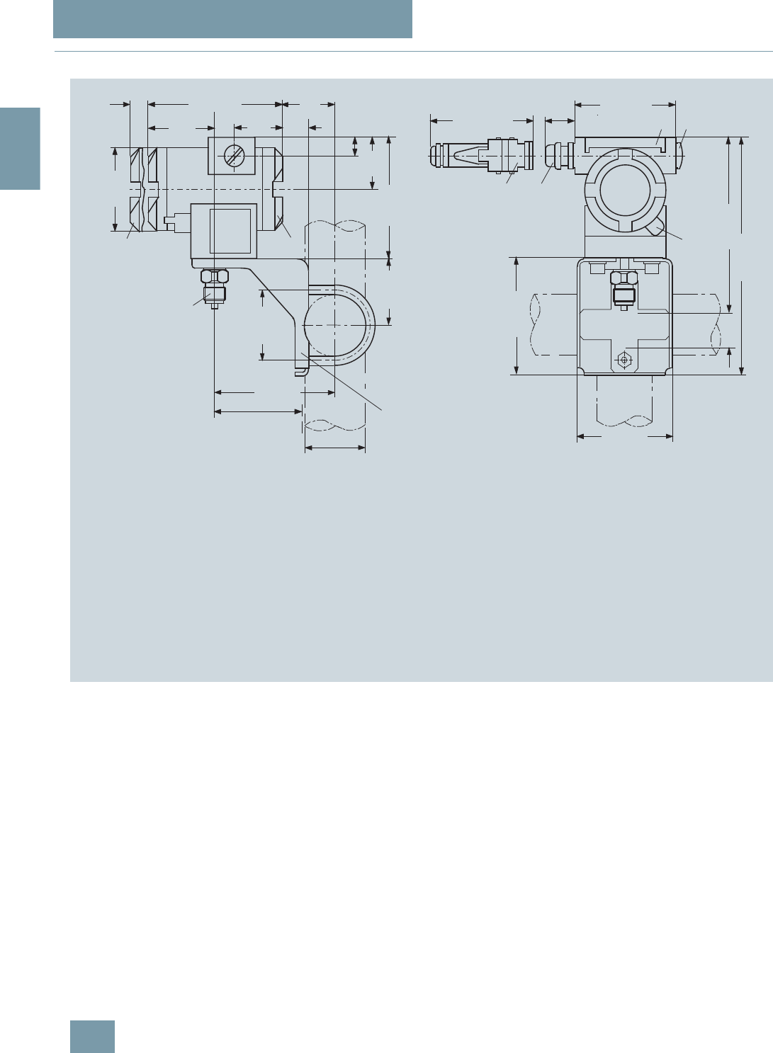
SITRANS P measuring instruments for pressure
Transmitters for gage, absolute and differential pressure, flow and level
DS III series for absolute pressure
(from gage pressure series)
2/96 Siemens FI 01 · 2009
2
■
Dimensional drawings
SITRANS P pressure transmitters, DS III HART series for absolute pressure, from the pressure series, dimensions in mm (inch)
1 Process connection:
- ½-14 NPT,
- onnection shankG½B or
- oval flange
2 Blanking plug
3 Electrical connection:
- screwed gland Pg 13,5 (adapter)2) 3),
- screwed gland M20x1,5 3),
- screwed gland ½-14 NPT or
- Han 7D/ Han 8U 2) 3) plug
4 Terminal side
5 Electronic side, digital display (longer overall
length for cover with window)
6 Protective cover over keys
7 Mounting bracket (option)
8 Screw cover - safety bracket (only for type of protection
"Explosion-proof enclosure", not shown in the drawing)
1) Allow approx. 20 mm (0.79 inch) thread length to permit unscrewing
2) Not with type of protection "Explosion-proof enclosure"
3) Not with type of protection "FM + CSA" [is + xp]"
4) For Pg 13,5 with adapter approx. 45 mm (1.77 inch)
5) Minimum distance for rotating
ca. 30 (1.2)
ca. 96 (3.78)
15
(0.6) 144 (5.67)
55
(2.2)
51
(2.0)
74
(2.9)
4) 100 (3.94)
237 (9.3)
171 (6.7)
36,5
(1,44)
min. 90 (3.6)
ø 50 ... 60
(1.97 ... 2.36)
ø80
(3.15)
72 (2.8)
123 (4.8)
20
(0.8)
50
(1.97)
117 (4.6)
68 (2.7)
5)
54
1
33
2
6
1) 1) 8
120 (4.7)
105 (4.1)
7
28
(1.1)
© Siemens AG 2008
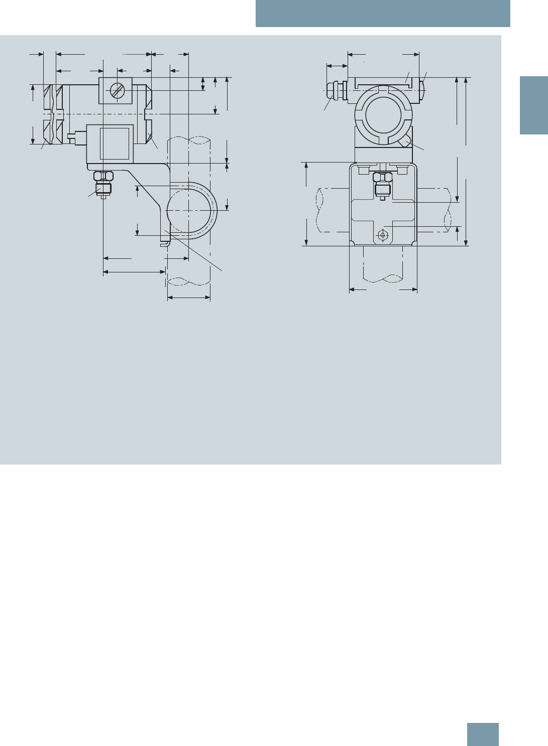
SITRANS P measuring instruments for pressure
Transmitters for gage, absolute and differential pressure, flow and level
DS III series for absolute pressure
(from gage pressure series)
2/97
Siemens FI 01 · 2009
2
SITRANS P pressure transmitters, DS III PA and FF series for absolute pressure, from the pressure series, dimensions in mm (inch)
1 Process connection:
- ½-14 NPT,
- connection shank G½B or
- oval flange
2 Blanking plug
3 Electrical connection:
- screwed gland M20x1,5 4),
- screwed gland ½-14 NPT or
- PROFIBUS-Stecker M12
3) 4)
4 Terminal side
5 Electronic side, digital display (longer overall
length for cover with window)
6 Protective cover over keys
7 Mounting bracket (option)
8 Screw cover - safety bracket (only for type of protection
"Explosion-proof enclosure", not shown in the drawing)
1) Allow approx. 20 mm (0.79 inch) thread length in addition
2) Minimum distance for rotating
3) Not with type of protection "Explosion-proof enclosure"
4) Not with type of protection "FM + CSA"
approx 30 (1.2)
15
(0.6) 144 (5.67)
55
(2.2)
51
(2.0)
74
(2.9)
4) 100 (3.94)
237 (9.3)
171 (6.7)
36,5
(1,44)
min. 90 (3.6)
ø 50 ... 60
(1.97 ... 2.36)
ø80
(3.15)
72 (2.8)
123 (4.8)
20
(0.8)
50
(1.97)
117 (4.6)
68 (2.7)
5)
54
1
3
2
6
1) 1) 8
120 (4.7)
105 (4.1)
7
28
(1.1)
© Siemens AG 2008

SITRANS P measuring instruments for pressure
Transmitters for gage, absolute and differential pressure, flow and level
DS III series for absolute pressure
(from differential pressure series)
2/98 Siemens FI 01 · 2009
2
■
Technical specifications
SITRANS P, DS III series for absolute pressure (from differential pressure series)
HART PROFIBUS PA or FOUNDATION Fieldbus
Input
Measured variable Absolute pressure pressure
Spans (infinitely adjustable) or
nominal measuring range and
max. permissible working pressure
Span Maximum working pres-
sure Nominal measuring
range Maximum working pres-
sure
8.3 ... 250 mbar a
(0.12 ... 3.6 psi a) 32 bar a
(464 psi a) 250 mbar a
(3.6 psi a) 32 bar a
(464 psi a)
43 ... 1300 mbar a
(0.62 ... 18.9 psi a) 32 bar a
(464 psi a) 1300 bar a
(18.9 psi a) 32 bar a
(464 psi a)
160 ... 5000 mbar a
(2.32 ... 72.5 psi a) 32 bar a
(464 psi a) 5 bar a
(72.5 psi a) 32 bar a
(464 psi a)
1 ... 30 bar a
(14.5 ... 435 psi a) 160 bar a
(2320 psi a) 30 bar a
(435 psi a) 160 bar a
(2320 psi a)
5.3 ... 100 bar a
(77 ... 1450 psi a) 160 bar a
(2320 psi a)
(for connection thread
M10 and 7/16-20 UNF in
the process flanges)
100 bar a
(1450 psi a) 160 bar a
(2320 psi a)
(for connection thread
M10 and 7/16-20 UNF in
the process flanges)
Lower measuring limit
• Measuring cell with silicone oil filling 0 mbar a (0 psi a)
Upper measuring limit 100% of max. span
Output
Output signal 4 ... 20 mA Digital PROFIBUS PA or FOUNDATION Fieldbus
signal
• Lower limit (infinitely adjustable) 3.55 mA, factory preset to 3.84 mA -
• Upper limit (infinitely adjustable) 23 mA, factory preset to 20.5 mA or optionally set
to 22.0 mA -
Load
• Without HART communication RB ≤ (UH - 10.5 V)/0.023 A in Ω,
UH : Power supply in V -
• With HART communication RB = 230 ... 500 Ω (SIMATIC PDM) or
RB = 230 ... 1100 Ω (HART Communicator) -
Physical bus - IEC 61158-2
With polarity reversal protection - Yes
Accuracy To EN 60770-1
Reference conditions
(All error data refer always refer to the set
span)
Increasing characteristic, start-of-scale value 0 bar, stainless steel seal diaphragm, silicone oil filling,
room temperature 25 °C (77 °F)) r: Span ratio (r = max. span / set span)
Error in measurement and fixed-point setting
(including hysteresis and repeatability)
• Linear characteristic ≤0.1%
-r ≤ 10 ≤0.1%
- 10 < r ≤ 30 ≤0.2%
Long-term drift (temperature change ± 30 °C
(± 54 °F)) ≤ (0.1 ⋅ r)%/year ≤ 0.1%/year
Influence of ambient temperature
• at -10 ... +60 °C (14 ... 140 °F) ≤ (0.1 ⋅ r +0.2)% ≤0.3%
• at -40 ... -10 °C and +60 ... +85 °C
(-40 ... +14 °F and 140 ... 185 °F) ≤ (0.1 ⋅ r + 0.15)%/10 K ≤ 0.25%/10 K
Measured Value Resolution - 3 ⋅10-5 of nominal measuring range
© Siemens AG 2008

SITRANS P measuring instruments for pressure
Transmitters for gage, absolute and differential pressure, flow and level
DS III series for absolute pressure
(from differential pressure series)
2/99
Siemens FI 01 · 2009
2
Rated operating conditions
Degree of protection (to EN 60529) IP65
Process temperature
• Measuring cell with silicone oil filling -40 ... +100 °C (-40 ... +212 °F)
• Measuring cell with inert filling liquid -20 ... +100 °C (-4 ... +212 °F)
• In conjunction with dust explosion protec-
tion -20 ... +60 °C (-4 ... +140 °F)
Ambient conditions
• Ambient temperature
- Digital indicators -30 ... +85 °C (-22 ... +185 °F)
• Storage temperature -50 ... +85 °C (-58 ... +185 °F)
• Climatic class
- Condensation Permissible
• Electromagnetic compatibility
- Emitted interference and interference im-
munity To EN 61326 and NAMUR NE 21
Design
Weight (without options) ≈ 4.5 kg (≈ 9.9 lb)
Housing material Poor in copper die-cast aluminium, GD-AlSi12 or stainless steel precision casting, mat. No. 1.4408
Wetted parts materials
• Seal diaphragm Stainless steel, mat. No. 1.4404/316L or Hastelloy C276, mat. No. 2.4819, Monel, mat. No. 2.4360,
tantalum or gold
• Process flanges and sealing screw Stainless steel, mat. No. 1.4408, Hastelloy C4, mat. No. 2.4610 or Monel, mat. No. 2.4360
• O-Ring FPM (Viton) or optionally: PTFE, FEP, FEPM and NBR
Measuring cell filling Silicone oil or inert filling liquid (max. 160 bar (2320 psi a) with oxygen measurement)
Process connection ¼-18 NPT and flange connection to DIN 19213 with mounting thread M10 to DIN 19213 or
7/16-20 UNF to EN 61518
Material of the mounting bracket
• Steel Sheet steel, Mat. No. 1.0330, chrome-plated
• Stainless steel Stainless steel, Mat. No. 1.4301 (SS304)
Power supply UH Supplied through bus
Terminal voltage on transmitter 10.5 ... 45 V DC
10.5 ... 30 V DC in intrinsically-safe mode -
Separate 24 V power supply necessary - No
Bus voltage
• Not Ex - 9 ... 32 V
• With intrinsically-safe operation - 9 ... 24 V
Current consumption
• Basic current (max.) - 12.5 mA
• Startup current ≤ basic current - Yes
• Max. current in event of fault - 15.5 mA
Fault disconnection electronics (FDE) avail-
able -Yes
SITRANS P, DS III series for absolute pressure (from differential pressure series)
HART PROFIBUS PA or FOUNDATION Fieldbus
© Siemens AG 2008

SITRANS P measuring instruments for pressure
Transmitters for gage, absolute and differential pressure, flow and level
DS III series for absolute pressure
(from differential pressure series)
2/100 Siemens FI 01 · 2009
2
Certificate and approvals
Classification according to pressure equip-
ment directive (DRGL 97/23/EC) For gases of fluid group 1 and liquids of fluid group 1; complies with requirements of Article 3, para-
graph 3 (sound engineering practice)
Explosion protection
• Intrinsic safety "i" PTB 99 ATEX 2122
- Identification Ex II 1/2 G EEx ia/ib IIB/IIC T6
- Permissible ambient temperature -40 ... +85 °C (-40 ... +185 °F) temperature class T4;
-40 ... +70 °C (-40 ... +158 °F) temperature class T5;
-40 ... +60 °C (-40 ... +140 °F) temperature class T6
- Connection To certified intrinsically-safe circuits with maxi-
mum values:
Ui = 30 V, Ii = 100 mA,
Pi = 750 mW; Ri = 300 Ω
FISCO supply unit:
Uo = 17.5 V, Io = 380 mA, Po = 5.32 W
Linear barrier:
Uo = 24 V, Io = 250 mA, Po = 1.2 W
- Effective internal inductance/capacitance L i = 0.4 mH, Ci = 6 nF L i = 7 μH, Ci = 1.1 nF
• Explosion-proof "d" PTB 99 ATEX 1160
- Identification Ex II 1/2 G EEx d IIC T4/T6
- Permissible ambient temperature -40 ... +85 °C (-40 ... +185 °F) temperature class T4;
-40 ... +60 °C (-40 ... +140 °F) temperature class T6
- Connection To circuits with values: UH = 10.5 ... 45 V DC To circuits with values: UH = 9 ... 32 V DC
• Dust explosion protection for zone 20 PTB 01 ATEX 2055
- Identification Ex II 1 D IP65 T 120 °C
Ex II 1/2 D IP65 T 120 °C
- Permissible ambient temperature -40 ... +85 °C (-40 ... +185 °F)
- Max.surface temperature 120 °C (248 °F)
- Connection To certified intrinsically-safe circuits with maxi-
mum values:
Ui = 30 V, Ii = 100 mA,
Pi = 750 mW, Ri = 300 Ω
FISCO supply unit:
Uo = 17.5 V, Io = 380 mA, Po = 5.32 W
Linear barrier:
Uo = 24 V, Io = 250 mA, Po = 1.2 W
- Effective internal inductance/capacitance L i = 0.4 mH, Ci = 6 nF L i = 7 μH, Ci = 1.1 nF
• Dust explosion protection for zone 21/22 PTB 01 ATEX 2055
- Identification Ex II 2 D IP65 T 120 °C
- Connection To circuits with values: UH = 10.5 ... 45 V DC;
Pmax = 1.2 W To circuits with values: UH = 9 ... 32 V DC;
Pmax = 1.2 W
• Type of protection "n" (zone 2) TÜV 01 ATEX 1696 X Planned
- Identification Ex II 3 G EEx nA L IIC T4/T5/T6 -
• Explosion protection to FM Certificate of Compliance 3008490
- Identification (XP/DIP) or (IS); (NI) CL I, DIV 1, GP ABCD T4...T6; CL II, DIV 1, GP EFG; CL III; CL I, ZN 0/1 AEx ia IIC T4...T6; CL I,
DIV 2, GP ABCD T4...T6; CL II, DIV 2, GP FG; CL III
• Explosion protection to CSA Certificate of Compliance 1153651
- Identification (XP/DIP) or (IS) CL I, DIV 1, GP ABCD T4...T6; CL II, DIV 1, GP EFG; CL III; Ex ia IIC T4...T6; CL I, DIV 2, GP ABCD
T4...T6; CL II, DIV 2, GP FG; CL III
SITRANS P, DS III series for absolute pressure (from differential pressure series)
HART PROFIBUS PA or FOUNDATION Fieldbus
© Siemens AG 2008

SITRANS P measuring instruments for pressure
Transmitters for gage, absolute and differential pressure, flow and level
DS III series for absolute pressure
(from differential pressure series)
2/101
Siemens FI 01 · 2009
2
HART communication
HART communication 230 ... 1100 Ω
Protocol HART Version 5.x
Software for computer SIMATIC PDM
PROFIBUS PA communication
Simultaneous communication with
master class 2 (max.) 4
The address can be set using Configuration tool or local opera-
tion (standard setting address
126)
Cyclic data usage
• Output byte 5 (one measuring value) or
10 (two measuring values)
• Input byte 0, 1, or 2 (register operating mode
and reset function for metering)
Internal preprocessing
Device profile PROFIBUS PA Profile for Process
Control Devices Version 3.0,
Class B
Function blocks 2
• Analog input
- Adaptation to customer-specif-
ic process variables Yes, linearly rising or falling char-
acteristic
- Electrical damping T63 , adjust-
able 0 ... 100 s
- Simulation function Input /Output
- Failure mode Can be parameterized (last good
value, substitute value, incorrect
value)
- Limit monitoring Yes, one upper and lower warning
limit and one alarm limit respec-
tively
• Register (totalizer) Can be reset, preset, optional
direction of counting, simulation
function of register output
- Failure mode Can be parameterized (summation
with last good value, continuous
summation, summation with incor-
rect value)
- Limit monitoring One upper and lower warning limit
and one alarm limit respectively
• Physical block 1
Transducer blocks 2
• Pressure transducer block
- Can be calibrated by applying
two pressures Yes
- Monitoring of sensor limits Yes
- Specification of a container
characteristic with Max. 30 nodes
- Square-rooted characteristic
for flow measurement Yes
- Gradual volume suppression
and implementation point of
square-root extraction
Parameterizable
- Simulation function for mea-
sured pressure value and sen-
sor temperature
Constant value or over parameter-
izable ramp function
Communication FOUNDATION Fieldbus
Function blocks 3 function blocks analog input,
1 function block PID
• Analog input
- Adaptation to customer-specif-
ic process variables Yes, linearly rising or falling char-
acteristic
- Electrical damping T63 , adjust-
able 0 ... 100 s
- Simulation function Output/input (can be locked within
the device with a bridge)
- Failure mode Can be parameterized (last good
value, substitute value, incorrect
value)
- Limit monitoring Yes, one upper and lower warning
limit and one alarm limit respec-
tively
- Square-rooted characteristic
for flow measurement Yes
• PID Standard FF function block
• Physical block 1 Resource block
Transducer blocks 1 transducer block Pressure with
calibration, 1 transducer block
LCD
• Pressure transducer block
- Can be calibrated by applying
two pressures Yes
- Monitoring of sensor limits Yes
- Simulation function: Measured
pressure value, sensor temper-
ature and electronics tempera-
ture
Constant value or over parameter-
izable ramp function
© Siemens AG 2008

SITRANS P measuring instruments for pressure
Transmitters for gage, absolute and differential pressure, flow and level
DS III series for absolute pressure
(from differential pressure series)
2/102 Siemens FI 01 · 2009
2
E) Combinations of the versions marked with E) are subject to the export
regulations AL: 2B230, ECCN: N.
F) Subject to export regulations AL: 9I999, ECCN: N.
Selection and Ordering data Order No.
SITRANS P pressure transmitters for absolute
pressure, from the differential pressure,
series DS III HART
F) 7 M F 4 3 3 3 -
77777 -7 7 7 7
Measuring cell filling Measuring cell
cleaning
Silicone oil Standard 1
Inert liquid1) Grease-free 3
Span
8.3 ... 250 mbar a (0.12 ... 3.63 psi a) E) D
43 ... 1300 mbar a (0.62 ... 18.9 psi a) E) F
0.16 ... 5 bar a (2.32 ... 72.5 psi a) E) G
1 ... 30 bar a (14.5 ... 435 psi a) H
5.3 ... 100 bar a (76.9 ... 1450 psi a) K E
Wetted parts materials
Seal diaphragm Parts of measuring cell
Stainless steel Stainless steel A
Hastelloy Stainless steel B
Hastelloy Hastelloy C
Tantalum Tantalum E
Monel Monel E) H
Gold Gold L
Version for diaphragm seal2)3)4) Y
Process connection
Female thread ¼-18 NPT with flange connection
• Sealing screw opposite process connection
- Mounting thread 7/16-20 UNF to EN 61518 2
- Mounting thread M10 to DIN 19213
(only for replacement needs) 0
• Vent on side of process flange5)
- Mounting thread 7/16-20 UNF to EN 61518 6
- Mounting thread M10 to DIN 19213
(only for replacement needs) 4
Non-wetted parts materials
Process flange screws Electronics housing
Stainless steel Die-cast aluminium 2
Stainless steel Stainless steel precision
casting6) 3
Version
• Standard version 1
• International version, English label inscriptions,
documentation in 5 languages on CD 2
Explosion protection
• Without A
• With ATEX, Type of protection:
- "Intrinsic safety (EEx ia)" B
- "Explosion-proof (EEx d)"7) D
- "Intrinsic safety and explosion-proof enclosure
(EEx ia + EEx d)" 8) P
- "Ex nA/nL (zone 2)" E
- "Intrinsic safety, explosion-proof enclosure and
dust explosion protection (EEx ia + EEx d +
Zone 1D/2D)"8)
R
• With FM + CSA, Type of protection:
- "Intrinsic safety and explosion-proof
(is + xp)"7) N C
Electrical connection / cable entry
• Screwed gland Pg 13.59) A
• Screwed gland M20x1.5 B
• Screwed gland ½-14 NPT C
• Han 7D plug (plastic housing) incl. mating
connector9) D
• Plug M12 (metal)10) F
Display
• Without indicator 0
• Without visible digital indicator (digital indicator
hidden, setting: mA)
}1
• With visible digital indicator 6
• With customer-specific digital indicator (setting
as specified, Order code "Y21" or required) 7
Power supply units see "SITRANS I power supply units and isolation
amplifiers".
Factory-mounting of shut-off valves and valve manifolds see page
2/142.
Included in delivery of the device:
• Brief instructions (Leporello)
• CD-ROM with detailed documentation
• Sealing plug(s) or sealing screw(s) for the process flanges(s)
1) For oxygen applications, add Order code E10.
2) Version 7MF4333-1DY... only up to max. span 200 mbar a (2.9 psi a).
3) When the manufacture’s certificate M (calibration certificate) has to be
ordered for transmitters with diaphragm seals, it is recommended only to
order this certificate exclusively with the diaphragm seals. The measuring
accuracy of the total combination is certified here.
4) Whe the acceptance test certificate 3.1 for transmitters with direct-con-
nected diaphragm seals is ordered, this certificate must also be ordered
with the corresponding seals.
5) Not for span "5.3 ... 100 bar a (76.9 ... 1450 psi a)". Position of the top vent
valve in the process flange (see dimensional drawing).
6) Not together with Electrical connection „Screwed gland Pg 13.5“ and
„Han7D plug“.
7) Without cable gland, with blanking plug
8) With enclosed cable gland EEx ia and blanking plug
9) Not together with type of protection "Explosion-proof" and and type of
protection "Ex nA".
10) Not together with types of protection "Explosion-proof" or "Intrinsic safety
and explosion-proof"
Selection and Ordering data Order No.
SITRANS P pressure transmitters for absolute
pressure, from the differential pressure,
series DS III HART
F) 7 M F 4 3 3 3 -
7 7 7 7 7 -7 7 7 7
© Siemens AG 2008

SITRANS P measuring instruments for pressure
Transmitters for gage, absolute and differential pressure, flow and level
DS III series for absolute pressure
(from differential pressure series)
2/103
Siemens FI 01 · 2009
2
E) Combinations of the versions marked with E) are subject to the export
regulations AL: 2B230, ECCN: N.
F) Subject to export regulations AL: 9I999, ECCN: N.
Selection and Ordering data Order No.
SITRANS P pressure transmitters for absolute
pressure (from the differential pressure series)
DS III PA series (PROFIBUS PA) F) 7 M F 4 3 3 4 -
DS III FF series (FOUNDATION Fieldbus) F) 7 M F 4 3 3 5 -
77777 -7 7 7 7
Measuring cell filling Measuring cell
cleaning
Silicone oil Standard 1
Inert liquid1) Grease-free 3
Nominal measuring range
250 mbar a (3.63 psi a) E) D
1300 mbar a (18.9 psi a) E) F
5 bar a (72.5 psi a) E) G
30 bar a (435 psi a) H
100 bar a (1450 psi a) K E
Wetted parts materials
Seal diaphragm Parts of measuring cell
Stainless steel Stainless steel A
Hastelloy Stainless steel B
Hastelloy Hastelloy C
Tantalum Tantalum E
Monel Monel E) H
Gold Gold L
Version as diaphragm seal2)3)4) Y
Process connection
Female thread ¼-18 NPT with flange connection
• Sealing screw opposite process connection
- Mounting thread 7/16-20 UNF to EN 61518 2
- Mounting thread M10 to DIN 19213
(only for replacement needs) 0
• Vent on side of process flange5)
- Mounting thread 7/16-20 UNF to EN 61518 6
- Mounting thread M10 to DIN 19213
(only for replacement needs) 4
Non-wetted parts materials
Process flange screws Electronics housing
Stainless steel Die-cast aluminium 2
Stainless steel Stainless steel precision
casting 3
Version
• Standard version 1
• International version, English label inscriptions,
documentation in 5 languages on CD 2
Explosion protection
• Without A
• With ATEX, Type of protection:
- "Intrinsic safety (EEx ia)" B
- "Explosion-proof (EEx d)"6) D
- "Intrinsic safety and explosion-proof enclosure
(EEx ia + EEx d)"7)
P
- "Ex nA/nL (zone 2)" E
- "Intrinsic safety, explosion-proof enclosure and
dust explosion protection (EEx ia + EEx d +
Zone 1D/2D)"7) (not for DS III FF)
R
• With FM + CSA, Type of protection:
- "Intrinsic safety and explosion-proof
(is + xp)"6)
N C
Electrical connection / cable entry
• Screwed gland M20x1.5 B
• Screwed gland ½-14 NPT C
• M12 Connector (metall)8) F
Display
• Without indicator 0
• Without visible digital indicator (digital indicator
hidden, setting: mA)
}1
• With visible digital indicator 6
• With customer-specific digital indicator (setting
as specified, Order code "Y21" or required) 7
Factory-mounting of shut-off valves and valve manifolds see page
2/142.
Included in delivery of the device:
• Brief instructions (Leporello)
• CD-ROM with detailed documentation
• Sealing plug(s) or sealing screw(s) for the process flanges(s)
1) For oxygen application, add Order code E10.
2) Version 7MF4334-1DY... only up to max. span 200 mbar a (2.9 psi a).
3) When the manufacture’s certificate M (calibration certificate) has to be
ordered for transmitters with diaphragm seals, it is recommended only to
order this certificate exclusively with the diaphragm seals. The measuring
accuracy of the total combination is certified here.
4) Whe the acceptance test certificate 3.1 for transmitters with direct-con-
nected diaphragm seals is ordered, this certificate must also be ordered
with the corresponding seals.
5) Not for nominal measuring range 100 bar a (1450 psi a). Position of the top
vent valve in the process flange (see dimensional drawing).
6) Without cable gland, with blanking plug
7) With enclosed cable gland EEx ia and blanking plug
8) Cannot be used together with the following types of protection:
"Explosion-proof" and "Intrinsic safety and explosion-proof".
Selection and Ordering data Order No.
SITRANS P pressure transmitters for absolute
pressure (from the differential pressure series)
DS III PA series (PROFIBUS PA) F) 7 M F 4 3 3 4 -
DS III FF series (FOUNDATION Fieldbus) F) 7 M F 4 3 3 5 -
7 7 7 7 7 -7 7 7 7
© Siemens AG 2008

SITRANS P measuring instruments for pressure
Transmitters for gage, absolute and differential pressure, flow and level
DS III series for absolute pressure
(from differential pressure series)
2/104 Siemens FI 01 · 2009
2
Selection and Ordering data Order code
Further designs HART PA FF
Add "-Z" to Order No. and specify Order
code.
Pressure transmitter with mounting
bracket made of:
•Steel A01 9
9
9
9
9
9
• Stainless steel A02 9
9
9
9
9
9
O-rings for process flanges
(instead of FPM (Viton))
• PTFE (Teflon) A20 9
9
9
9
9
9
• FEP (with silicone core, approved for food) A21 9
9
9
9
9
9
• FFPM (Kalrez, compound 4079) A22 9
9
9
9
9
9
• NBR (Buna N) A23 9
9
9
9
9
9
Plug
• Han 7D (metal, gray) A30 9
9
• Han 8U (instead of Han 7D) A31 9
9
Sealing screws A40 9
9
9
9
9
9
¼-18 NPT, with valve in material of process
flanges
Cable sockets for M12 connectors (metal) A50 9
9
9
9
9
9
Rating plate inscription
(instead of German)
• English B11 9
9
9
9
9
9
• French B12 9
9
9
9
9
9
• Spanish B13 9
9
9
9
9
9
• Italian B14 9
9
9
9
9
9
English rating plate B21 9
9
9
9
9
9
Pressure units in inH2O or psi
Quality inspection certificate (Factory cali-
bration) to IEC 60770-2 1) C11 9
9
9
9
9
9
Acceptance test certificate2) C12 9
9
9
9
9
9
To EN 10204-3.1
Factory certificate C14 9
9
9
9
9
9
To EN 10204-2.2
"Functional Safety (SIL)" certificate C20 9
9
"PROFIsafe" certificate and protocol C21 9
9
Setting of upper limit of output signal to
22.0 mA D05 9
9
Manufacturer's declaration acc. to NACE D07 9
9
9
9
9
9
(only together with seal diaphragm made of
Hastelloy and stainless steel)
Type of protection IP68 D12 9
9
9
9
9
9
(not together with Han 7D/Han 8U plug,
cable gland PG 13.5)
Digital indicator alongside the input keys D27 9
9
9
9
9
9
(only together with the devices 7MF4333-
....2-.A.6 or -.A.7-Z, Y21 or Y22 + Y01)
Supplied with oval flange D37F) 9
9
9
9
9
9
(1 item), PTFE packing and stainless steel
screws in thread of process flange
Use in or on zone 1D/2D E01 9
9
9
9
9
9
(only together with type of protection "Intrinsic
safety (EEx ia)")
Use on zone 0 E02 9
9
9
9
9
9
(only together with type of protection "Intrinsic
safety (EEx ia)")
Oxygen application E10 9
9
9
9
9
9
(max. 120 bar a (1740 psi a) at 60°C (140 °F)
with oxygen measurement and inert liquid)
Explosion-proof "Intrinsic safety" to
INMETRO (Brazil) E25 9
9
9
9
9
9
(only for transmitter 7MF4...-.....-.B..)
Explosion-proof "Intrinsic safety" to NEPSI
(China) E55 9
9
9
9
9
9
(only for transmitter 7MF4...-.....-.B..)
Explosion protection "Explosion-proof" to
NEPSI (China) E56 9
9
9
9
9
9
(only for transmitter 7MF4...-.....-.D..)
Explosion-proof "Zone 2" to NEPSI (China) E57 9
9
9
9
9
9
(only for transmitter 7MF4...-.....-.E..)
Interchanging of process connection side H01 9
9
9
9
9
9
Vent on side for gas measurements H02 9
9
9
9
9
9
Process flange
• Hastelloy K01 9
9
9
9
9
9
• Monel K02 9
9
9
9
9
9
• Stainless steel with PVDF insert
max. PN 10 (MWP 145 psi),
max. temperature of medium 90 °C (194 °F)
K04 9
9
9
9
9
9
For ½-14 NPT inner process connection on
the side in the middle of the process flange,
vent valve not possible
Additional data
Add "-Z" to Order No. and specify Order
code.
Measuring range to be set Y01 9
9
Specify in plain text (max. 5 digits):
Y01: ... up to ... mbar, bar, kPa, MPa, psi
Measuring point number (TAG No.) Y15 9
9
9
9
9
9
Max. 16 characters, specify in plain text:
Y15: ...........................................
Measuring point text Y16 9
9
9
9
9
9
Max. 27 characters, specify in plain text:
Y16: ...........................................
Entry of HART address (TAG) Y17 9
9
Max. 8 characters, specify in plain text:
Y17: ...........................................
Setting of pressure indication in pressure
units Y21 9
9
9
9
9
9
Specify in plain text (standard setting: mA):
Y21: mbar, bar, kPa, MPa, psi, ...
Note:
The following pressure units can be selected:
bar, mbar, mm H2O*), inH2O*), ftH2O*),
mmHG, inHG, psi, Pa, kPa, MPa, g/cm2,
kg/cm2, Torr, ATM oder %
*) ref. temperature 20 °C
Setting of pressure indication in
non-pressure units Y22 +
Y01
9
9
Specify in plain text:
Y22: ..... up to ..... l/min, m3/h, m, USgpm, ...
(specification of measuring range in pressure
units "Y01" is essential, unit with
max. 5 characters)
Preset bus address Y25 9
9
(possible between 1 and 126)
Specify in plain text:
Y25: .....................
Only "Y01", "Y21", "Y22", "Y25" and "D05" can be factory preset
9
9
= available
1) When the manufacture’s certificate M (calibration certificate) has to be
ordered for transmitters with diaphragm seals, it is recommended only to
order this certificate exclusively with the diaphragm seals. The measuring
accuracy of the total combination is certified here.
2) Whe the acceptance test certificate 3.1 for transmitters with direct-con-
nected diaphragm seals is ordered, this certificate must also be ordered
with the corresponding seals.
Selection and Ordering data Order code
Further designs HART PA FF
Add "-Z" to Order No. and specify Order
code.
F) Subject to export regulations AL: 9I999, ECCN: N.
© Siemens AG 2008
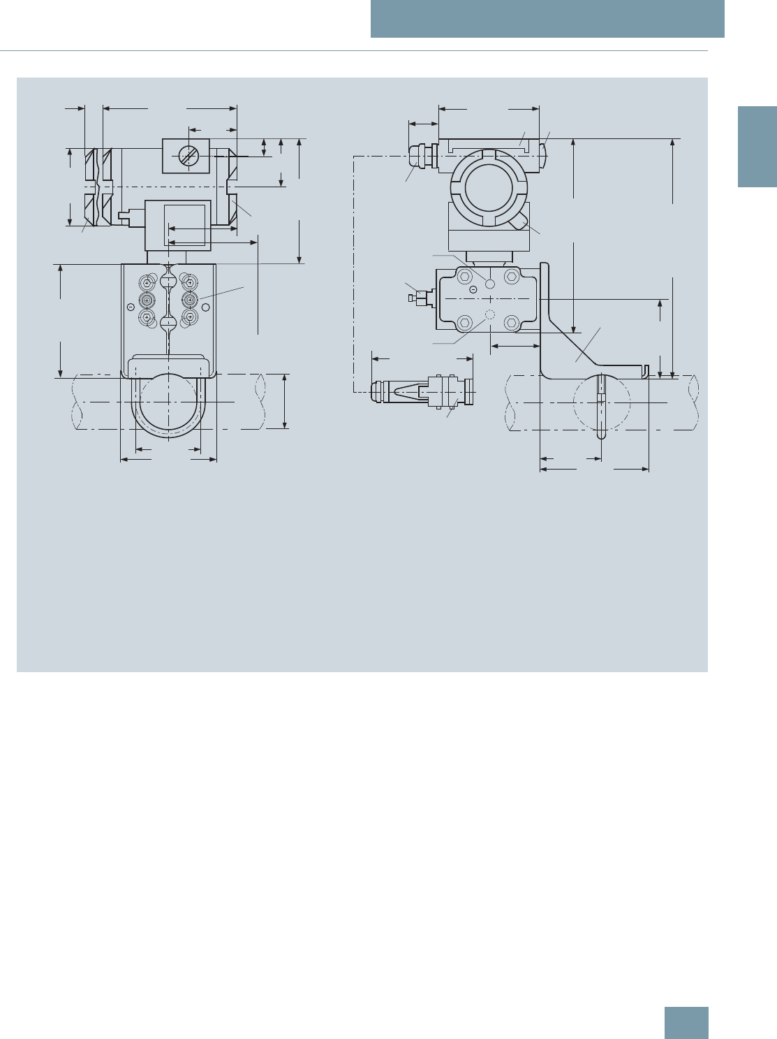
SITRANS P measuring instruments for pressure
Transmitters for gage, absolute and differential pressure, flow and level
DS III series for absolute pressure
(from differential pressure series)
2/105
Siemens FI 01 · 2009
2
■
Dimensional drawings
SITRANS P pressure transmitters, DS III HART series for absolute pressure, from the differential pressure series, dimensions in mm (inch)
5
1
approx. 261 (10.3)
3
3
2
6
198 (7.8)
4
8
134 (5.27)
68 (2.7)
72 (2.83)
7
120 (4.7)
96 (3.8)
52 (2.05)
90 (3.6)
4)
Space for rotation
of housing
1)
69 (2.7)
1)
9
approx. 96 (3.78)
approx. 30 (1.2)
5)
100 (3.94)
15
(0.6) 144 (5.67)
20
(0.8)
51
(2.0)
Ø 80
(3.15)
117 (4.6)
50
(1.97)
105 (4.1)
+
10
11
1Process connection: ¼-18 NPT (EN 61518)
2Blanking plug
3Electrical connection:
- screwed gland Pg 13,5 (adapter) 2) 3),
- screwed gland M20x1,5 3),
- screwed gland ½-14 NPT or
- Han 7D/ Han 8U plug 2) 3)
4 Terminal side
5 Electronics side, digital display (longer overall length for cover with window)
6Protective cover over keys
7Mounting bracket (option)
8 Sealing screw with valve (option)
9Screw cover - safety bracket (only for type of protection
"Explosion-proof enclosure", not shown in the drawing)
10Lateral venting for liquid measurement (Standard)
11 Lateral venting for gas measurement (suffix H02)
1) Allow approx. 20 mm (0.79 inch) thread length to permit unscrewing
2) Not with type of protection "explosion-proof enclosure"
3)Not with type of protection "FM + CSA [is + xp]"
4) 92 mm (3.62 inch) for minimum distance to permit rotation with indicator
5) 45 mm (1.8 inch) for Pg 13,5 with adapter
ø
50 ... 60
(1.97 ... 2.36)
© Siemens AG 2008

SITRANS P measuring instruments for pressure
Transmitters for gage, absolute and differential pressure, flow and level
DS III series for absolute pressure
(from differential pressure series)
2/106 Siemens FI 01 · 2009
2
SITRANS P pressure transmitters, DS III PA and FF series for absolute pressure, from the differential pressure series, dimensions in mm (inch)
5
1
approx. 261 (10.3)
3
2
6
198 (7.8)
4
8
134 (5.27)
68 (2.7)
72 (2.83)
7
120 (4.7)
96 (3.8)
52 (2.05)
90 (3.6)
2)
Space for rotation
of housing
1)
69 (2.7)
1)
9
approx. 30 (1.2) 100 (3.94)
15
(0.6) 144 (5.67)
20
(0.8)
51
(2.0)
Ø 80
(3.15)
117 (4.6)
50
(1.97)
105 (4.1)
+
1Process connection: ¼-18 NPT (EN 61518)
2Blanking plug
3Electrical connection:
- screwed gland M20x1,5 4),
- screwed gland ½-14 NPT or
- PROFIBUS plug M12 3) 4)
4 Terminal side
5 Electronic side, digital display (longer overall length for cover with window)
6Protective cover over keys
7Mounting bracket (option)
8 Sealing screw with valve (option)
9Screw cover safety bracket (only for explosion-proof enclosure,
not shown in the drawing)
10Lateral venting for liquid measurement (Standard)
11 Lateral venting for gas measurement (suffix H02)
1) Allow approx. 20 mm (0.79 inch) thread length in addition
2) 92 mm (3.62 inch) for minimum distance to permit rotation with indicator
3)Not with type of protection "explosion-proof enclosure"
4) Not with type of protection "FM + CSA"
10
11
ø
50 ... 60
(1.97 ... 2.36)
© Siemens AG 2008

SITRANS P measuring instruments for pressure
Transmitters for gage, absolute and differential pressure, flow and level
DS III series
for differential pressure and flow
2/107
Siemens FI 01 · 2009
2
■
Technical specifications
SITRANS P, DS III series, for differential pressure and flow
HART PROFIBUS PA or FOUNDATION Fieldbus
Input
Measured variable Differential pressure and flow
Spans (infinitely adjustable) or
nominal measuring range and
max. permissible working pressure
Span Maximum working pres-
sure Nominal measuring
range Maximum working pres-
sure
1 ... 20 mbar
(0.4015 ... 8.031 inH2O) 32 bar
(464 psi) 20 mbar g
(8.031 inH2O) 32 bar
(464 psi)
1 ... 60 mbar
(0.4015 ... 24.09 inH2O) 160 bar
(2320 psi) 60 mbar
(24.09 inH2O) 160 bar
(2320 psi)
2.5 ... 250 mbar
(1.004 ... 100.4 inH2O) 250 mbar
(100.4 inH2O)
6 ... 600 mbar
(2.409 ... 240.9 inH2O) 600 mbar
(240.9 inH2O)
16 ... 1600 mbar
(6.424 ... 642.4 inH2O) 1600 mbar
(642.4 inH2O)
50 ... 5000 mbar
(20.08 ... 2008 inH2O) 5 bar
(2008 inH2O)
0.3 ... 30 bar
(4.35 ... 435 psi) 30 bar
(435 psi)
2.5 ... 250 mbar
(1.004 ... 100.4 inH2O) 420 bar
(6091 psi) 250 mbar
(100.4 inH2O) 420 bar
(6091 psi)
6 ... 600 mbar
(2.409 ... 240.9 inH2O) 600 mbar
(240.9 inH2O)
16 ... 1600 mbar
(6.424 ... 642.4 inH2O) 1600 mbar
(642.4 inH2O)
50 ... 5000 mbar
(20.08 ... 2008 inH2O) 5 bar
(2008 inH2O)
0.3 ... 30 bar
(4.35 ... 435 psi) 30 bar
(435 psi)
Lower measuring limit
• Measuring cell with silicone oil filling -100% of max. span (-33% with 30 bar (435 psi) measuring cell or 30 mbar a (0.44 psi))
Upper measuring limit 100% of max. span (for oxygen version and inert filling liquid; max. 160 bar g (2320 psi g))
Output
Output signal 4 ... 20 mA Digital PROFIBUS PA or FOUNDATION Fieldbus
signal
• Lower limit (infinitely adjustable) 3.55 mA, factory preset to 3.84 mA -
• Upper limit (infinitely adjustable) 23 mA, factory preset to 20.5 mA or optionally set
to 22.0 mA -
Load
• Without HART communication RB ≤ (UH - 10.5 V)/0.023 A in Ω,
UH : Power supply in V -
• With HART communication RB = 230 ... 500 Ω (SIMATIC PDM) or
RB = 230 ... 1100 Ω (HART Communicator) -
Physical bus - IEC 61158-2
With polarity reversal protection - Yes
Accuracy To EN 60770-1
Reference conditions
(All error data refer always refer to the set
span)
Increasing characteristic, start-of-scale value 0 bar, stainless steel seal diaphragm, silicone oil filling,
room temperature 25 °C (77 °F)) r: Span ratio (r = max. span / set span)
Error in measurement and fixed-point setting
(including hysteresis and repeatability)
• Linear characteristic ≤0,075%
-r ≤ 10 ≤ (0.0029 ⋅ r + 0.071)%
- 10 < r ≤ 30 ≤ (0.0045 ⋅ r + 0.071)%
- 30 < r ≤ 100 ≤ (0.005 ⋅ r + 0.05)%
• Square-root characteristic (flow > 50%) ≤0,1%
-r ≤ 10 ≤0,1%
- 10 < r ≤ 30 ≤0,2%
© Siemens AG 2008

SITRANS P measuring instruments for pressure
Transmitters for gage, absolute and differential pressure, flow and level
DS III series
for differential pressure and flow
2/108 Siemens FI 01 · 2009
2
• Square-root characteristic (flow 25 ... 50%) ≤0,2
-r ≤ 10 ≤0,2% -
- 10 < r ≤ 30 ≤0,4% -
Long-term drift (temperature change ±30 °C
(± 54 °F)) ≤ (0.25 ⋅ r)% every 5 years
static pressure max. 70 bar g (1015 psi g) ≤ (0.25% every 5 years
static pressure max. 70 bar g (1015 psi g)
• 20 mbar (0.29 psi)-measuring cell ≤ (0.2 ⋅ r) per year ≤ 0.2 per year
Influence of ambient temperature
• at -10 ... +60 °C (14 ... 140 °F) ≤ (0.08 ⋅ r + 0.1)% ≤0,3%
• at -40 ... -10 °C and +60 ... +85 °C
(-40 ... +14 °F and 140 ... 185 °F) ≤ (0.1 ⋅ r + 0.15)%/10 K
(Twice the value with 20-mbar (0.29 psi)
measuring cell)
≤ 0.25%/10 K
Influence of static pressure
• on the zero point ≤ (0.15 ⋅ r)% per 100 bar (1450 psi) ≤ 0.15% je 100 bar (1450 psi)
- 20 mbar (0.29 psi)-measuring cell ≤ (0.15 ⋅ r)% per 32 bar (464 psi) ≤ 0.15% je 32 bar (464 psi)
• on the span ≤ 0.2% je 100 bar (1450 psi) -
- 20 mbar (0.29 psi)-measuring cell ≤ 0.2% je 32 bar (464 psi) -
Measured Value Resolution - 3 ⋅10-5 of nominal measuring range
Rated operating conditions
Degree of protection (to EN 60529) IP65
Process temperature
• Measuring cell with silicone oil filling -40 ... +100 °C (-40 ... +212 °F)
• Measuring cell with inert filling liquid -20 ... +100 °C (-4 ... +212 °F)
• In conjunction with dust explosion protec-
tion -20 ... +60 °C (-4 ... +140 °F)
Ambient conditions
• Ambient temperature
- Digital indicators -30 ... +85 °C (-22 ... +185 °F)
• Storage temperature -50 ... +85 °C (-58 ... +185 °F)
• Climatic class
- Condensation Permissible
• Electromagnetic compatibility
- Emitted interference and interference
immunity To EN 61326 and NAMUR NE 21
Material of the mounting bracket
• Steel Sheet steel, Mat. No. 1.0330, chrome-plated
• Stainless steel Stainless steel, Mat. No. 1.4301 (SS304)
Design
Weight (without options) ≈ 4.5 kg (≈ 9.9 lb)
Housing material Poor in copper die-cast aluminium, GD-AlSi12 or stainless steel precision casting, mat. No. 1.4408
Wetted parts materials
• Seal diaphragm Stainless steel, mat. No. 1.4404/316L or Hastelloy C276, mat. No. 2.4819, Monel, mat. No. 2.4360,
tantalum or gold
Measuring cell filling Silicone oil or inert filling liquid (max. 160 bar (2320 psi g) with oxygen measurement)
Process connection Female thread ¼-18 NPT and flange connection with mounting thread M10 to DIN 19213 or
7/16-20 UNF to EN 61518
SITRANS P, DS III series, for differential pressure and flow
HART PROFIBUS PA or FOUNDATION Fieldbus
© Siemens AG 2008

SITRANS P measuring instruments for pressure
Transmitters for gage, absolute and differential pressure, flow and level
DS III series
for differential pressure and flow
2/109
Siemens FI 01 · 2009
2
Power supply UH Supplied through bus
Terminal voltage on transmitter 10.5 ... 45 V DC
10.5 ... 30 V DC in intrinsically-safe mode -
Separate 24 V power supply necessary - No
Bus voltage
• Not Ex - 9 ...32 V
• With intrinsically-safe operation - 9 ...24 V
Current consumption
• Basic current (max.) - 12.5 mA
• Startup current ≤ basic current - Yes
• Max. current in event of fault - 15.5 mA
Fault disconnection electronics (FDE) avail. - Yes
SITRANS P, DS III series, for differential pressure and flow
HART PROFIBUS PA or FOUNDATION Fieldbus
© Siemens AG 2008

SITRANS P measuring instruments for pressure
Transmitters for gage, absolute and differential pressure, flow and level
DS III series
for differential pressure and flow
2/110 Siemens FI 01 · 2009
2
Certificate and approvals
Classification according to pressure equip-
ment directive (DRGL 97/23/EC)
PN 32/160 (MWP 464/2320 psi) For gases of fluid group 1 and liquids of fluid group 1; complies with requirements of Article 3, para-
graph 3 (sound engineering practice)
PN 420 (MWP 6092 psi) For gases of fluid group 1 and liquids of fluid group 1; complies with basic safety requirements of
Article 3, paragraph 1 (appendix 1); assigned to category III, conformity evaluation module H by the
TÜV Nord.
Explosion protection
• Intrinsic safety "i" PTB 99 ATEX 2122
- Identification Ex II 1/2 G EEx ia/ib IIB/IIC T6
- Permissible ambient temperature -40 ... +85 °C (-40 ... +185 °F) temperature class T4;
-40 ... +70 °C (-40 ... +158 °F) temperature class T5;
-40 ... +60 °C (-40 ... +140 °F) temperature class T6
- Connection To certified intrinsically-safe circuits with maxi-
mum values:
Ui = 30 V, Ii = 100 mA,
Pi = 750 mW; Ri = 300 Ω
FISCO supply unit:
Uo = 17.5 V, Io = 380 mA, Po = 5.32 W
Linear barrier:
Uo = 24 V, Io = 250 mA, Po = 1.2 W
- Effective internal inductance/capacitance L i = 0.4 mH, Ci = 6 nF L i = 7 μH, Ci = 1.1 nF
• Explosion-proof "d" PTB 99 ATEX 1160
- Identification Ex II 1/2 G EEx d IIC T4/T6
- Permissible ambient temperature -40 ... +85 °C (-40 ... +185 °F) temperature class T4;
-40 ... +60 °C (-40 ... +140 °F) temperature class T6
- Connection To circuits with values: UH = 10.5 ... 45 V DC To circuits with values: UH = 9 ... 32 V DC
• Dust explosion protection for zone 20 PTB 01 ATEX 2055
- Identification Ex II 1 D IP65 T 120 °C
Ex II 1/2 D IP65 T 120 °C
- Permissible ambient temperature -40 ... +85 °C (-40 ... +185 °F)
- Max.surface temperature 120 °C (248 °F)
- Connection To certified intrinsically-safe circuits with maxi-
mum values:
Ui = 30 V, Ii = 100 mA,
Pi = 750 mW, Ri = 300 Ω
FISCO supply unit:
Uo = 17.5 V, Io = 380 mA, Po = 5.32 W
Linear barrier:
Uo = 24 V, Io = 250 mA, Po = 1.2 W
- Effective internal inductance/capacitance L i = 0.4 mH, Ci = 6 nF L i = 7 μH, Ci = 1.1 nF
• Dust explosion protection for zone 21/22 PTB 01 ATEX 2055
- Identification Ex II 2 D IP65 T 120 °C
- Connection To circuits with values: UH = 10.5 ... 45 V DC;
Pmax = 1.2 W To circuits with values: UH = 9 ... 32 V DC;
Pmax = 1.2 W
• Type of protection "n" (zone 2) TÜV 01 ATEX 1696 X Planned
- Identification Ex II 3 G EEx nA L IIC T4/T5/T6 -
• Explosion protection to FM Certificate of Compliance 3008490
- Identification (XP/DIP) or (IS); (NI) CL I, DIV 1, GP ABCD T4...T6; CL II, DIV 1, GP EFG; CL III; CL I, ZN 0/1 AEx ia IIC T4...T6; CL I,
DIV 2, GP ABCD T4...T6; CL II, DIV 2, GP FG; CL III
• Explosion protection to CSA Certificate of Compliance 1153651
- Identification (XP/DIP) or (IS) CL I, DIV 1, GP ABCD T4...T6; CL II, DIV 1, GP EFG; CL III; Ex ia IIC T4...T6; CL I, DIV 2, GP ABCD
T4...T6; CL II, DIV 2, GP FG; CL III
SITRANS P, DS III series, for differential pressure and flow
HART PROFIBUS PA or FOUNDATION Fieldbus
© Siemens AG 2008

SITRANS P measuring instruments for pressure
Transmitters for gage, absolute and differential pressure, flow and level
DS III series
for differential pressure and flow
2/111
Siemens FI 01 · 2009
2
HART communication
HART communication 230 ... 1100 Ω
Protocol HART Version 5.x
Software for computer SIMATIC PDM
PROFIBUS PA communication
Simultaneous communication with
master class 2 (max.) 4
The address can be set using Configuration tool or local opera-
tion (standard setting address
126)
Cyclic data usage
• Output byte 5 (one measuring value) or
10 (two measuring values)
• Input byte 0, 1, or 2 (register operating mode
and reset function for metering)
Internal preprocessing
Device profile PROFIBUS PA Profile for Process
Control Devices Version 3.0,
Class B
Function blocks 2
• Analog input
- Adaptation to customer-specif-
ic process variables Yes, linearly rising or falling char-
acteristic
- Electrical damping T63 , adjust-
able 0 ... 100 s
- Simulation function Input /Output
- Failure mode Can be parameterized (last good
value, substitute value, incorrect
value)
- Limit monitoring Yes, one upper and lower warning
limit and one alarm limit respec-
tively
• Register (totalizer) Can be reset, preset, optional
direction of counting, simulation
function of register output
- Failure mode Can be parameterized (summation
with last good value, continuous
summation, summation with incor-
rect value)
- Limit monitoring One upper and lower warning limit
and one alarm limit respectively
• Physical block 1
Transducer blocks 2
• Pressure transducer block
- Can be calibrated by applying
two pressures Yes
- Monitoring of sensor limits Yes
- Specification of a container
characteristic with Max. 30 nodes
- Square-rooted characteristic
for flow measurement Yes
- Gradual volume suppression
and implementation point of
square-root extraction
Parameterizable
- Simulation function for mea-
sured pressure value and sen-
sor temperature
Constant value or over parameter-
izable ramp function
Communication FOUNDATION Fieldbus
Function blocks 3 function blocks analog input,
1 function block PID
• Analog input
- Adaptation to customer-specif-
ic process variables Yes, linearly rising or falling char-
acteristic
- Electrical damping T63 , adjust-
able 0 ... 100 s
- Simulation function Output/input (can be locked within
the device with a bridge)
- Failure mode Can be parameterized (last good
value, substitute value, incorrect
value)
- Limit monitoring Yes, one upper and lower warning
limit and one alarm limit respec-
tively
- Square-rooted characteristic
for flow measurement Yes
• PID Standard FF function block
• Physical block 1 Resource block
Transducer blocks 1 transducer block Pressure with
calibration, 1 transducer block
LCD
• Pressure transducer block
- Can be calibrated by applying
two pressures Yes
- Monitoring of sensor limits Yes
- Simulation function: Measured
pressure value, sensor temper-
ature and electronics tempera-
ture
Constant value or over parameter-
izable ramp function
© Siemens AG 2008

SITRANS P measuring instruments for pressure
Transmitters for gage, absolute and differential pressure, flow and level
DS III series
for differential pressure and flow
2/112 Siemens FI 01 · 2009
2
Selection and Ordering data Order No.
SITRANS P pressure transmitters for differen-
tial pressure and flow, Series DS III HART
PN 32/160 (MWP 464/2320 psi)
7 M F 4 4 3 3 -
77777 -7 7 7 7
Measuring cell filling Measuring cell
cleaning
Silicone oil Standard }1
Inert liquid1) Grease-free 3
Span
PN 32 (MWP 464 psi)
1 ... 20 mbar2) (0.4015 ... 8.03 inH2O) }B
PN 160 (MWP 2320 psi)
1 ... 60 mbar (0.4015 ... 24.09 inH2O) }C
2.5 ... 250 mbar (1.004 ... 100.4 inH2O) }D
6 ... 600 mbar (2.409 ... 240.9 inH2O) }E
16 ... 1600 mbar (6.424 ... 642.4 inH2O) }F
50 ... 5000 mbar (20.08 ... 2008 inH2O) }G
0.3 ... 30 bar (4.35 ... 435 psi) }H
Wetted parts materials
(stainless steel process flanges)
Seal diaphragm Parts of measuring cell
Stainless steel Stainless steel }A
Hastelloy Stainless steel B
Hastelloy Hastelloy C
Tantalum3) Tantalum E
Monel3) Monel H
Gold3) Gold L
Version for diaphragm seal4) 5) Y
Process connection
Female thread ¼-18 NPT with flange connection
• Sealing screw opposite process connection
- Mounting thread 7/16-20 UNF to EN 61518 2
- Mounting thread M10 to DIN 19213
(only for replacement needs)
}0
• Vent on side of process flange2)
- Mounting thread 7/16-20 UNF to EN 61518 6
- Mounting thread M10 to DIN 19213
(only for replacement needs) 4
Non-wetted parts materials
Process flange screws Electronics housing
Stainless steel Die-cast aluminium }2
Stainless steel Stainless steel precision
casting6) 3
Version
• Standard version 1
• International version, English label inscriptions,
documentation in 5 languages on CD
}2
Explosion protection
• Without A
• With ATEX, Type of protection:
- "Intrinsic safety (EEx ia)" B
- "Explosion-proof (EEx d)"7) D
- "Intrinsic safety and explosion-proof
enclosure (EEx ia + EEx d)"8) P
- "Ex nA/nL (zone 2)" E
- "Intrinsic safety, explosion-proof enclosure
and dust explosion protection
(EEx ia + EEx d + Zone 1D/2D)"8)
}R
• With FM + CSA, Type of protection:
- "Intrinsic safety and explosion-proof
(is + xp)"7) N C
Electrical connection / cable entry
• Screwed gland Pg 13.59) A
• Screwed gland M20x1.5 }B
• Screwed gland ½-14 NPT C
• Han 7D plug (plastic housing) incl. mating
connector10) D
• M12 connectors (metal)10) F
Display
• Without indicator 0
• Without visible digital indicator (digital indicator
hidden, setting: mA)
}1
• With visible digital indication 6
• With customer-specific digital indication (setting
as specified, Order code "Y21" or required) 7
} Available ex stock
Power supply units see "SITRANS I power supply units and isolation
amplifiers".
Factory-mounting of shut-off valves and valve manifolds see page
2/142.
Included in delivery of the device:
• Brief instructions (Leporello)
• CD-ROM with detailed documentation
• Sealing plug(s) or sealing screw(s) for the process flanges(s)
1) For oxygen application, add Order code E10.
2) Not suitable for connection of remote seal. Position of the top vent valve in
the process flanges (see dimensional drawing).
3) Only together with max. spans 250, 1600, 5000 and 30000 mbar
(100.4, 240.9, 2008 inH2O and 435 psi)
4) When the manufacture’s certificate M (calibration certificate) has to be
ordered for transmitters with diaphragm seals, it is recommended only to
order this certificate exclusively with the diaphragm seals. The measuring
accuracy of the total combination is certified here.
5) Whe the acceptance test certificate 3.1 for transmitters with direct-con-
nected diaphragm seals is ordered, this certificate must also be ordered
with the corresponding seals.
6) Not together with Electrical connection „Screwed gland Pg 13.5“ and
„Han7D plug“.
7) Without cable gland, with blanking plug
8) With enclosed cable gland EEx ia and blanking plug
9) Not together with type of protection "Explosion-proof" and and type of
protection "Ex nA".
10) Cannot be used together with the following types of protection:
"Explosion-proof" and "Intrinsic safety and explosion-proof"
Selection and Ordering data Order No.
SITRANS P pressure transmitters for differen-
tial pressure and flow, Series DS III HART
PN 32/160 (MWP 464/2320 psi)
7 M F 4 4 3 3 -
7 7 7 7 7 -7 7 7 7
© Siemens AG 2008

SITRANS P measuring instruments for pressure
Transmitters for gage, absolute and differential pressure, flow and level
DS III series
for differential pressure and flow
2/113
Siemens FI 01 · 2009
2
Selection and Ordering data Order No.
SITRANS P pressure transmitters
for differential pressure and flow
PN 32/160 (MWP 464/2320 psi)
DS III PA series (PROFIBUS PA) 7 M F 4 4 3 4 -
DS III FF series (FOUNDATION Fieldbus) 7 M F 4 4 3 5 -
77777 -7 7 7 7
Measuring cell filling Measuring cell
cleaning
Silicone oil Standard 1
Inert liquid1) Grease-free 3
Nominal measuring range
PN 32 (MWP 464 psi)
20 mbar2) (8.03 inH2O) B
PN 160 (MWP 2320 psi)
60 mbar (24.09 inH2O) C
250 mbar (100.4 inH2O) D
600 mbar (240.9 inH2O) E
1600 mbar (642.4 inH2O) F
5 bar (2008 inH2O) G
30 bar (435 psi) H
Wetted parts materials
(stainless steel process flanges)
Seal diaphragm Parts of measuring cell
Stainless steel Stainless steel A
Hastelloy Stainless steel B
Hastelloy Hastelloy C
Tantalum3) Tantalum E
Monel3) Monel H
Gold3) Gold L
Version as diaphragm seal4) 5) Y
Process connection
Female thread ¼-18 NPT with flange connection
• Sealing screw opposite process connection
- Mounting thread 7/16-20 UNF to EN 61518 2
- Mounting thread M10 to DIN 19213
(only for replacement needs) 0
• Venting on side of process flanges2)
- Mounting thread 7/16-20 UNF to EN 61518 6
- Mounting thread M10 to DIN 19213
(only for replacement needs) 4
Non-wetted parts materials
Process flange screws Electronics housing
Stainless steel Die-cast aluminium 2
Stainless steel Stainless steel precision
casting 3
Version
• Standard version 1
• International version, English label inscriptions,
documentation in 5 languages on CD 2
Explosion protection
• Without A
• With ATEX, Type of protection:
- "Intrinsic safety (EEx ia)" B
- "Explosion-proof (EEx d)"6) D
- "Intrinsic safety and explosion-proof
enclosure (EEx ia + EEx d)"7)
P
- "n (Zone 2)" (planned) E
- "Intrinsic safety, explosion-proof enclosure
and dust explosion protection (EEx ia +
EEx d + Zone 1D/2D)"7) (not for DS III FF)
R
• With FM + CSA, Type of protection:
- "Intrinsic safety and explosion-proof
(is + xp)"6) N C
Electrical connection / cable entry
• Screwed gland M20x1.5 B
• Screwed gland ½-14 NPT C
• M12 connectors (metal)8) F
Display
• Without indicator 0
• Without visible digital indicator (digital indicator
hidden, setting: mA)
}1
• With visible digital indication 6
• With customer-specific digital indication (setting
as specified, Order code "Y21" or required) 7
Factory-mounting of shut-off valves and valve manifolds see page
2/142.
Included in delivery of the device:
• Brief instructions (Leporello)
• CD-ROM with detailed documentation
• Sealing plug(s) or sealing screw(s) for the process flanges(s)
1) For oxygen application, add Order code E10.
2) Not suitable for connection of remote seal. Position of the top vent valve in
the process flanges (see dimensional drawing).
3) Only together with max. spans 250, 1600, 5000 and 30000 mbar
(100.4, 240.9, 2008 inH2O and 435 psi).
4) When the manufacture’s certificate M (calibration certificate) has to be
ordered for transmitters with diaphragm seals, it is recommended only to
order this certificate exclusively with the diaphragm seals. The measuring
accuracy of the total combination is certified here.
5) Whe the acceptance test certificate 3.1 for transmitters with direct-con-
nected diaphragm seals is ordered, this certificate must also be ordered
with the corresponding seals.
6) Without cable gland, with blanking plug.
7) With enclosed cable gland EEx ia and blanking plug.
8) Cannot be used together with the following types of protection:
"Explosion-proof" and "Intrinsic safety and explosion-proof".
Selection and Ordering data Order No.
SITRANS P pressure transmitters
for differential pressure and flow
PN 32/160 (MWP 464/2320 psi)
DS III PA series (PROFIBUS PA) 7 M F 4 4 3 4 -
DS III FF series (FOUNDATION Fieldbus) 7 M F 4 4 3 5 -
7 7 7 7 7 -7 7 7 7
© Siemens AG 2008

SITRANS P measuring instruments for pressure
Transmitters for gage, absolute and differential pressure, flow and level
DS III series
for differential pressure and flow
2/114 Siemens FI 01 · 2009
2
Selection and Ordering data Order code
Further designs
Add "-Z" to Order No. and specify Order code. HART PA FF
Pressure transmitter with mounting
bracket made of:
•Steel A01 9
9
9
9
9
9
• Stainless steel A02 9
9
9
9
9
9
O-rings for process flanges
(instead of FPM (Viton))
• PTFE (Teflon) A20 9
9
9
9
9
9
• FEP (with silicone core, approved for food) A21 9
9
9
9
9
9
• FFPM (Kalrez, compound 4079) A22 9
9
9
9
9
9
• NBR (Buna N) A23 9
9
9
9
9
9
Plug
• Han 7D (metal, gray) A30 9
9
• Han 8U (instead of Han 7D) A31 9
9
Sealing screws
¼-18 NPT, with valve in mat. of process flanges
A40 9
9
9
9
9
9
Cable sockets for M12 connectors (metal) A50 9
9
9
9
9
9
Rating plate inscription (instead of German)
• English B11 9
9
9
9
9
9
• French B12 9
9
9
9
9
9
• Spanish B13 9
9
9
9
9
9
• Italian B14 9
9
9
9
9
9
English rating plate (calibration certificate) B21 9
9
9
9
9
9
Pressure units in inH2O or psi
Quality inspection certificate (Factory cali-
bration) to IEC 60770-2 1) C11 9
9
9
9
9
9
Acceptance test certificate2)
To EN 10 204-3.1 C12 9
9
9
9
9
9
Factory certificate
To EN 10 204-2.2 C14 9
9
9
9
9
9
"Functional Safety (SIL)" certificate C20 9
9
"PROFIsafe" certificate and protocol C21 9
9
Setting of upper limit of output signal to
22.0 mA D05 9
9
Manufacturer's declaration acc. to NACE D07 9
9
9
9
9
9
(only together with seal diaphragm made of
Hastelloy and stainless steel)
Type of protection IP68
(not together with 7D/
Han 8U plug, cable gland Pg 13.5)
D12 9
9
9
9
9
9
Digital indicator alongside the input keys D27 9
9
9
9
9
9
(only together with the devices 7MF4433-
....2-.A.6 or -.A.7-Z, Y21 or Y22 + Y01)
Process flange screws made of Monel
(max. nominal pressure PN20) D34 9
9
9
9
9
9
Supplied with oval flange set D37 9
9
9
9
9
9
(2 items), PTFE packings and stainles steel
screws in thread of process flanges
Use in or on zone 1D/2D E01 9
9
9
9
9
9
(only together with type of protection
"Intrinsic safety (EEx ia)")
Use on zone 0 E02 9
9
9
9
9
9
(only together with type of protection
"Intrinsic safety (EEx ia)")
TÜV approval to AD/TRD E06 9
9
(only together with type of protection
"Intrinsic safety (EEx ia)")
Overfilling safety device for flammable
and non-flammable liquids
(max. PN 32 (MVWP 464 psi), basic device
with type of protection "Intrinsic safety
(EEx ia)", to WHG and VbF, not together with
measuring cell filling "inert liquid")
E08 9
9
9
9
9
9
Oxygen application E10 9
9
9
9
9
9
(max. 120 bar (1740 psi) at 60°C (140 °F) with
oxygen measurement and inert liquid)
Explosion-proof "Intrinsic safety" to
INMETRO (Brazil) E25 9
9
9
9
9
9
(only for transmitter 7MF4...-.....-.B..)
Explosion-proof "Intrinsic safety" to NEPSI
(China) E55 9
9
9
9
9
9
(only for transmitter 7MF4...-.....-.B..)
Explosion protection "Explosion-proof" to
NEPSI (China)
(only for transmitter 7MF4...-.....-.D..)
E56 9
9
9
9
9
9
Explosion-proof "Zone 2" to NEPSI (China) E57 9
9
9
9
9
9
(only for transmitter 7MF4...-.....-.E..)
Interchanging of process connection side H01 9
9
9
9
9
9
Vent on side for gas measurements H02 9
9
9
9
9
9
Stainless steel process flanges for vertical
differential pressure lines
(not together with K01, K02 and K04)3)
H03 9
9
9
9
9
9
Process flange
• Hastelloy K01 9
9
9
9
9
9
• Monel K02 9
9
9
9
9
9
• Stainless steel with PVDF insert
max. PN 10 (MWP 145 psi),
max. temperature of medium 90 °C (194 °F)
K04 9
9
9
9
9
9
For ½-14 NPT inner process connection on
the side in the middle of the process flange,
vent valve not possible
9
9
= available
1) When the manufacture’s certificate M (calibration certificate) has to be
ordered for transmitters with diaphragm seals, it is recommended only to
order this certificate exclusively with the diaphragm seals. The measuring
accuracy of the total combination is certified here.
2) Whe the acceptance test certificate 3.1 for transmitters with direct-con-
nected diaphragm seals is ordered, this certificate must also be ordered
with the corresponding seals.
3) Not suitable for connection of remote seal
Selection and Ordering data Order code
Further designs
Add "-Z" to Order No. and specify Order code. HART PA FF
© Siemens AG 2008

SITRANS P measuring instruments for pressure
Transmitters for gage, absolute and differential pressure, flow and level
DS III series
for differential pressure and flow
2/115
Siemens FI 01 · 2009
2
Selection and Ordering data Order code
Additional data
Add "-Z" to Order No. and specify Order code.
HART PA FF
Measuring range to be set
Specify in plain text:
• With linear characteristic (max. 5 digits):
Y01: ... up to ... mbar, bar, kPa, MPa, psi Y01 9
9
• With square-rooted characteristic (max. 5
digits):
Y02: ... up to ... mbar, bar, kPa, MPa, psi
Y02 9
9
Measuring point number (TAG No.) Y15 9
9
9
9
9
9
Max. 16 char., specify in plain text: Y15: .......
Measuring point text Y16 9
9
9
9
9
9
Max. 27 char., specify in plain text: Y16: .......
Entry of HART address (TAG) Y17 9
9
Max. 8 char., specify in plain text: Y17: .......
Setting of pressure indicator in pressure
units
Specify in plain text (standard setting: mA):
Y21: mbar, bar, kPa, MPa, psi, ...
Y21 9
9
9
9
9
9
Note:
The following pressure units can be selected:
bar, mbar, mm H2O*), inH2O*), ftH2O*),
mmHG, inHG, psi, Pa, kPa, MPa, g/cm2,
kg/cm2, Torr, ATM oder %
*) ref. temperature 20 °C
Setting of pressure indicator in
non-pressure units Y221)
+
Y01 or
Y02
1) Not together with over-filling safety device for flammable and
non-flammable liquids (Order code "E08")
9
9
Specify in plain text:
Y22: ..... up to ..... l/min, m3/h, m, USgpm, ...
(specification of measuring range in pressure
units "Y01" or "Y02" is essential, unit with
max. 5 characters)
Preset bus address Y25 9
9
(possible between 1 and 126)
Specify in plain text:
Y25: .....................
Only "Y01", "Y21", "Y22", "Y25" and "D05" can be factory preset
9
9
= available
© Siemens AG 2008

SITRANS P measuring instruments for pressure
Transmitters for gage, absolute and differential pressure, flow and level
DS III series
for differential pressure and flow
2/116 Siemens FI 01 · 2009
2
Selection and Ordering data Order No.
SITRANS P pressure transmitters for differen-
tial pressure and flow, Series DS III HART
PN 420 (MWP 6092 psi)
7 M F 4 5 3 3 -
77777 -7 7 7 7
Measuring cell filling Measuring cell
cleaning
Silicone oil Standard 1
Span
2.5 ... 250 mbar (1.004 ... 100.4 inH2O) D
6 ... 600 mbar (2.409 ... 240.9 inH2O) E
16 ... 1600 mbar (6.424 ... 642.4 inH2O) F
50 ... 5000 mbar (20.08 ... 2008 inH2O) G
0.3 ... 30 bar (4.35 ... 435 psi) H
Wetted parts materials
(stainless steel process flanges)
Seal diaphragm Parts of measuring cell
Stainless steel Stainless steel A
Hastelloy Stainless steel B
Gold1) Gold L
Process connection
Female thread ¼-18 NPT with flange connection
• Sealing screw opposite process connection
- Mounting thread 7/16-20 UNF to EN 61518 3
- Mounting thread M12 to DIN 19213
(only for replacement needs) 1
• Venting on side of process flanges. Position of
the top vent valve in the process flanges (see
dimensional drawing).
- Mounting thread 7/16-20 UNF to EN 61518 7
- Mounting thread M12 to DIN 19213
(only for replacement needs) 5
Non-wetted parts materials
Process flange screws Electronics housing
Stainless steel Die-cast aluminium 2
Stainless steel Stainless steel precision
casting2) 3
Version
• Standard version 1
• International version, English label inscriptions,
documentation in 5 languages on CD 2
Explosion protection
• Without A
• With ATEX, Type of protection:
- "Intrinsic safety (EEx ia)" B
- "Explosion-proof (EEx d)"3) D
- "Intrinsic safety and explosion-proof
enclosure (EEx ia + EEx d)"4)
P
-"Ex nA/nL (zone 2)"E
- "Intrinsic safety, explosion-proof enclosure
and dust explosion protection (EEx ia +
EEx d + Zone 1D/2D)"4)
R
• With FM + CSA, Type of protection:
- "Intrinsic safety and explosion-proof
(is + xp)"3), max PN 360
N C
Electrical connection / cable entry
• Screwed gland Pg 13.55) A
• Screwed gland M20x1.5 B
• Screwed gland ½-14 NPT C
• Han 7D plug (plastic housing) incl. mating
connector5) D
• M12 connectors (metal)6) F
Display
• Without indicator 0
• Without visible digital indicator (digital indicator
hidden, setting: mA)
}1
• With visible digital indication 6
• With customer-specific digital indication (setting
as specified, Order code "Y21" or required) 7
Power supply units see "SITRANS I power supply units and isolation
amplifiers".
Factory-mounting of shut-off valves and valve manifolds see page
2/142.
Scope of delivery: Pressure transmitter as ordered (Instruction Manual is
extra ordering item)
1) Not together with max. span 600 mbar (240.9 inH2O)
2) Not together with Electrical connection „Screwed gland Pg 13.5“ and
„Han7D plug“.
3) Without cable gland, with blanking plug
4) With enclosed cable gland EEx ia and blanking plug
5) Not together with type of protection "Explosion-proof" and and type of
protection "Ex nA".
6) Cannot be used together with the following types of protection:
"Explosion-proof" and "Intrinsic safety and explosion-proof".
Selection and Ordering data Order No.
SITRANS P pressure transmitters for differen-
tial pressure and flow, Series DS III HART
PN 420 (MWP 6092 psi)
7 M F 4 5 3 3 -
7 7 7 7 7 -7 7 7 7
© Siemens AG 2008

SITRANS P measuring instruments for pressure
Transmitters for gage, absolute and differential pressure, flow and level
DS III series
for differential pressure and flow
2/117
Siemens FI 01 · 2009
2
Selection and Ordering data Order No.
SITRANS P pressure transmitters for differen-
tial pressure and flow, Series DS III HART
PN 420 (MWP 6092 psi)
DS III PA (PROFIBUS PA) series 7 M F 4 5 3 4 -
DS III FF series (FOUNDATION Fieldbus) 7 M F 4 5 3 5 -
17777 -7 7 7 7
Nominal measuring range
250 mbar (100.4 inH2O) D
600 mbar (240.9 inH2O) E
1600 mbar (642.4 inH2O) F
5 bar (2008 inH2O) G
30 bar (435 psi) H
Wetted parts materials
(stainless steel process flanges)
Seal diaphragm Parts of measuring cell
Stainless steel Stainless steel A
Hastelloy Stainless steel B
Gold1) Gold L
Process connection
Female thread ¼-18 NPT with flange connection
• Sealing screw opposite process connection
- Mounting thread 7/16-20 UNF to EN 61518 3
- Mounting thread M12 to DIN 19213
(only for replacement needs) 1
• Venting on side of process flanges. Position of
the top vent valve in the process flanges (see
dimensional drawing).
- Mounting thread 7/16-20 UNF to EN 61518 7
- Mounting thread M12 to DIN 19213
(only for replacement needs) 5
Non-wetted parts materials
Process flange screws Electronics housing
Stainless steel Die-cast aluminium 2
Stainless steel Stainless steel precision
casting 3
Version
• Standard version 1
• International version, English label inscriptions,
documentation in 5 languages on CD 2
Explosion protection
• Without A
• With ATEX, Type of protection:
- "Intrinsic safety (EEx ia)" B
- "Explosion-proof (EEx d)"2) D
- "Intrinsic safety and explosion-proof
enclosure (EEx ia + EEx d)"3) P
- "Ex nA/nL (zone 2)" E
- "Intrinsic safety, explosion-proof enclosure
and dust explosion protection (EEx ia +
EEx d + Zone 1D/2D)"3) (not for DS III FF)
R
• With FM + CSA, Type of protection:
- "Intrinsic safety and explosion-proof
(is + xp)"2), max PN 360 N C
Electrical connection / cable entry
• Screwed gland M20x1.5 B
• Screwed gland ½-14 NPT C
• Plug M12 incl. mating connector4) F
Display
• Without indicator 0
• Without visible digital indicator (digital indicator
hidden, setting: mA)
}1
• With visible digital indicator 6
• With customer-specific digital indicator (setting
as specified, Order code "Y21" or required) 7
Factory-mounting of shut-off valves and valve manifolds see page
2/142.
Included in delivery of the device:
• Brief instructions (Leporello)
• CD-ROM with detailed documentation
• Sealing plug(s) or sealing screw(s) for the process flanges(s)
1) Not together with max. span 600 mbar (240.9 inH2O)
2) Without cable gland, with blanking plug.
3) With enclosed cable gland EEx ia and blanking plug.
4) Not together with types of protection "Explosion-proof" and "Intrinsic safety
and explosion-proof"
Selection and Ordering data Order No.
SITRANS P pressure transmitters for differen-
tial pressure and flow, Series DS III HART
PN 420 (MWP 6092 psi)
DS III PA (PROFIBUS PA) series 7 M F 4 5 3 4 -
DS III FF series (FOUNDATION Fieldbus) 7 M F 4 5 3 5 -
17 7 7 7 -7 7 7 7
© Siemens AG 2008

SITRANS P measuring instruments for pressure
Transmitters for gage, absolute and differential pressure, flow and level
DS III series
for differential pressure and flow
2/118 Siemens FI 01 · 2009
2
Selection and Ordering data Order code
Further designs HART PA FF
Add "-Z" to Order No. and specify Order
code.
Pressure transmitter with mounting
bracket made of:
•Steel A01 9
9
9
9
9
9
• Stainless steel A02 9
9
9
9
9
9
O-rings for process flanges
(instead of FPM (Viton))
• PTFE (Teflon) A20 9
9
9
9
9
9
• FEP (with silicone core, approved for food) A21 9
9
9
9
9
9
• FFPM (Kalrez, compound 4079) A22 9
9
9
9
9
9
• NBR (Buna N) A23 9
9
9
9
9
9
Plug
• Han 7D (metal, gray) A30 9
9
• Han 8U (instead of Han 7D) A31 9
9
Sealing screws A40 9
9
9
9
9
9
¼-18 NPT, with valve in material of process
flanges
Cable sockets for M12 connectors (metal) A50 9
9
9
9
9
9
Rating plate inscription
(instead of German)
• English B11 9
9
9
9
9
9
• French B12 9
9
9
9
9
9
• Spanish B13 9
9
9
9
9
9
• Italian B14 9
9
9
9
9
9
English rating plate B21 9
9
9
9
9
9
Pressure units in inH2O or psi
Quality inspection certificate (Factory cali-
bration) to IEC 60770-2 C11 9
9
9
9
9
9
Acceptance test certificate C12 9
9
9
9
9
9
To EN 10204-3.1
Factory certificate C14 9
9
9
9
9
9
To EN 10204-2.2
"Functional Safety (SIL)" certificate C20 9
9
"PROFIsafe" certificate and protocol C21 9
9
Setting of upper limit of output signal to
22.0 mA D05 9
9
Manufacturer's declaration acc. to NACE D07 9
9
9
9
9
9
(only together with seal diaphragm made of
Hastelloy and stainless steel)
Type of protection IP68 D12 9
9
9
9
9
9
(not together with Han 7D / Han 8U plug,
Pg 13.5 screwed gland)
Digital indicator alongside the input keys D27 9
9
9
9
9
9
(only together with the devices 7MF4533-
....2-.A.6 or -.A.7-Z, Y21 or Y22 + Y01)
Use in or on zone 1D/2D E01 9
9
9
9
9
9
(only together with type of protection
"Intrinsic safety (EEx ia)")
Use on zone 0 E02 9
9
9
9
9
9
(only together with type of protection
"Intrinsic safety (EEx ia)")
Explosion-proof "Intrinsic safety" to
INMETRO (Brazil) E25 9
9
9
9
9
9
(only for transmitter 7MF4...-.....-.B..)
Explosion-proof "Intrinsic safety" to
NEPSI (China) E55 9
9
9
9
9
9
(only for transmitter 7MF4...-.....-.B..)
Explosion protection "Explosion-proof" to
NEPSI (China) E56 9
9
9
9
9
9
(only for transmitter 7MF4...-.....-.D..)
Explosion-proof "Zone 2" to NEPSI (China) E57 9
9
9
9
9
9
(only for transmitter 7MF4...-.....-.E..)
Interchanging of process connection side H01 9
9
9
9
9
9
Stainless steel process flanges for
vertical differential pressure lines H03 9
9
9
9
9
9
Additional data
Add "-Z" to Order No. and specify Order
code.
Measuring range to be set
Specify in plain text:
• With linear characteristic (max. 5 digits):
Y01: ... up to ... mbar, bar, kPa, MPa, psi Y01 9
9
• With square-rooted characteristic
(max. 5 digits):
Y02: ... up to ... mbar, bar, kPa, MPa, psi
Y02 9
9
Measuring point number (TAG No.) Y15 9
9
9
9
9
9
Max. 16 characters, specify in plain text:
Y15: ...........................................
Measuring point text Y16 9
9
9
9
9
9
Max. 27 characters, specify in plain text:
Y16: ...........................................
Entry of HART address (TAG) Y17 9
9
Max. 8 characters, specify in plain text:
Y17: ...........................................
Setting of pressure indication in pressure
units Y21 9
9
9
9
9
9
Specify in plain text (standard setting: mA):
Y21: mbar, bar, kPa, MPa, psi, ...
Note:
The following pressure units can be selected:
bar, mbar, mm H2O*), inH2O*), ftH2O*),
mmHG, inHG, psi, Pa, kPa, MPa, g/cm2,
kg/cm2, Torr, ATM or %
*) ref. temperature 20 °C
Setting of pressure indication in
non-pressure units Y22 +
Y01 or
Y02
9
9
Specify in plain text:
Y22: ..... up to ..... l/min, m3/h, m, USgpm, ...
(specification of measuring range in pressure
units "Y01" or "Y02" is essential, unit with
max. 5 characters)
Preset bus address Y25 9
9
(possible between 1 and 126)
Specify in plain text:
Y25: .....................
Only "Y01", "Y21", "Y22", "Y25" and "D05" can be factory preset
9
9
= available
Selection and Ordering data Order code
Further designs HART PA FF
Add "-Z" to Order No. and specify Order
code.
© Siemens AG 2008

SITRANS P measuring instruments for pressure
Transmitters for gage, absolute and differential pressure, flow and level
DS III series
for differential pressure and flow
2/119
Siemens FI 01 · 2009
2
■
Dimensional drawings
SITRANS P pressure transmitters, DS III HART series for differential pressure and flow, dimensions in mm (inch)
5
1
approx. 261 (10.3)
3
3
2
6
198 (7.8)
4
8
134 (5.27)
68 (2.7)
72 (2.83)
7
120 (4.7)
96 (3.8)
52 (2.05)
90 (3.6)
4)
Space for rotation
of housing
1)
69 (2.7)
1)
9
approx. 96 (3.78)
approx. 30 (1.2)
5)
100 (3.94)
15
(0.6) 144 (5.67)
20
(0.8)
51
(2.0)
Ø 80
(3.15)
117 (4.6)
50
(1.97)
105 (4.1)
+
10
11
1Process connection: ¼-18 NPT (EN 61518)
2Blanking plug
3Electrical connection:
- screwed gland Pg 13,5 (adapter) 2) 3),
- screwed gland M20x1,5 3),
- screwed gland ½-14 NPT or
- Han 7D/ Han 8U plug 2) 3)
4 Terminal side
5 Electronics side, digital display (longer overall length for cover with window)
6Protective cover over keys
7Mounting bracket (option)
8 Sealing screw with valve (option)
9Screw cover - safety bracket (only for type of protection
"Explosion-proof enclosure", not shown in the drawing)
10Lateral venting for liquid measurement (Standard)
11 Lateral venting for gas measurement (suffix H02)
1) Allow approx. 20 mm (0.79 inch) thread length to permit unscrewing
2) Not with type of protection "explosion-proof enclosure"
3)Not with type of protection "FM + CSA [is + xp]"
4) 92 mm (3.62 inch) for minimum distance to permit rotation with indicator
5) 45 mm (1.8 inch) for Pg 13,5 with adapter
ø
50 ... 60
(1.97 ... 2.36)
© Siemens AG 2008
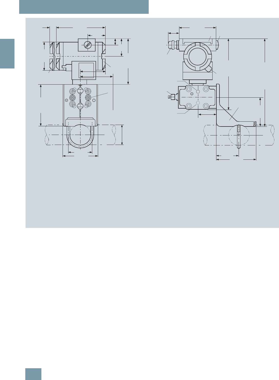
SITRANS P measuring instruments for pressure
Transmitters for gage, absolute and differential pressure, flow and level
DS III series
for differential pressure and flow
2/120 Siemens FI 01 · 2009
2
SITRANS P pressure transmitters, DS III PA and FF series for differential pressure and flow, dimensions in mm (inch)
5
1
approx. 261 (10.3)
3
2
6
198 (7.8)
4
8
134 (5.27)
68 (2.7)
72 (2.83)
7
120 (4.7)
96 (3.8)
52 (2.05)
90 (3.6)
2)
Space for rotation
of housing
1)
69 (2.7)
1)
9
approx. 30 (1.2) 100 (3.94)
15
(0.6) 144 (5.67)
20
(0.8)
51
(2.0)
Ø 80
(3.15)
117 (4.6)
50
(1.97)
105 (4.1)
+
1Process connection: ¼-18 NPT (EN 61518)
2Blanking plug
3Electrical connection:
- screwed gland M20x1,5 4),
- screwed gland ½-14 NPT or
- PROFIBUS plug M12 3) 4)
4 Terminal side
5 Electronic side, digital display (longer overall length for cover with window)
6Protective cover over keys
7Mounting bracket (option)
8 Sealing screw with valve (option)
9Screw cover safety bracket (only for explosion-proof enclosure,
not shown in the drawing)
10Lateral venting for liquid measurement (Standard)
11 Lateral venting for gas measurement (suffix H02)
1) Allow approx. 20 mm (0.79 inch) thread length in addition
2) 92 mm (3.62 inch) for minimum distance to permit rotation with indicator
3)Not with type of protection "explosion-proof enclosure"
4) Not with type of protection "FM + CSA"
10
11
ø
50 ... 60
(1.97 ... 2.36)
© Siemens AG 2008
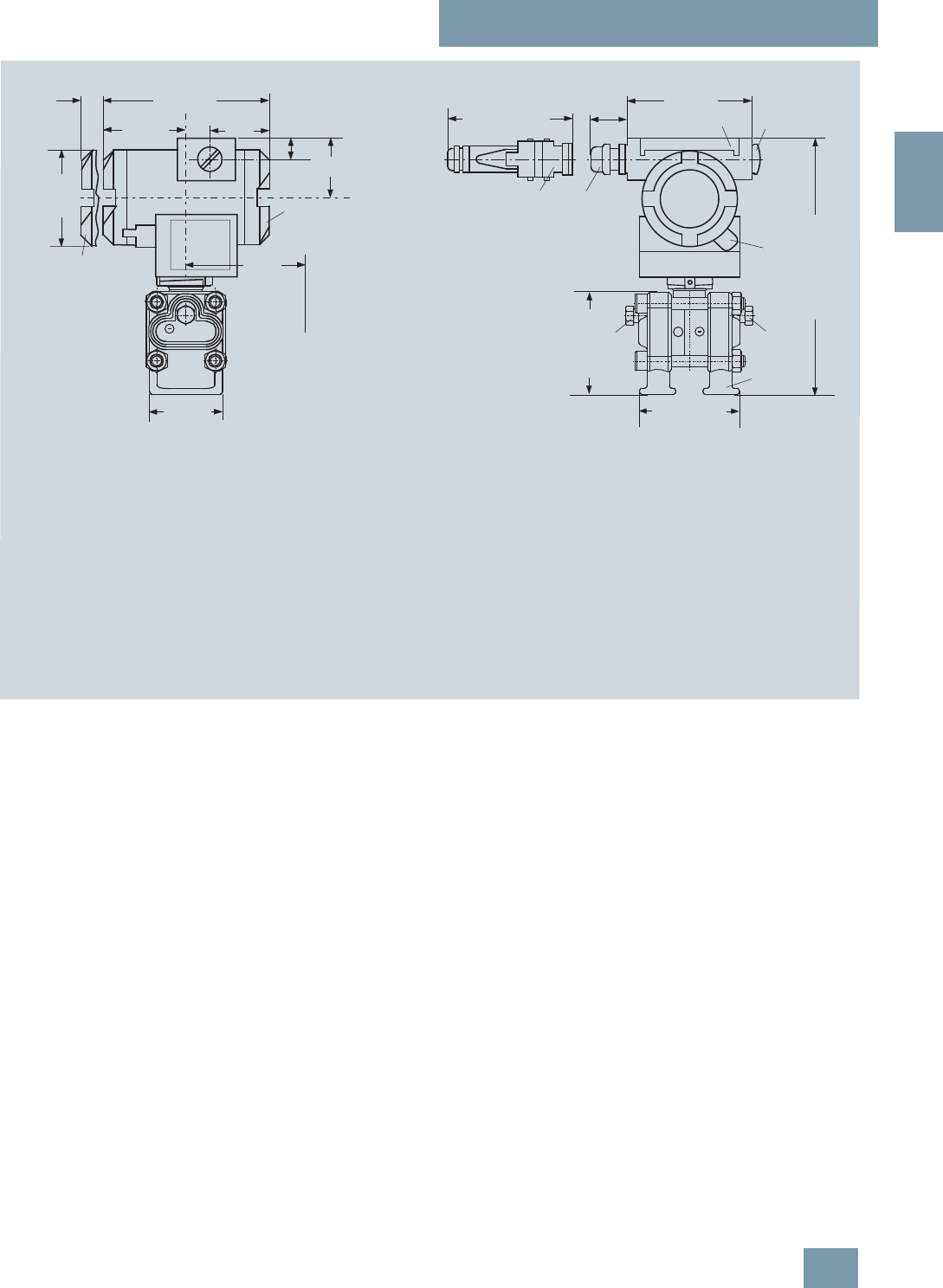
SITRANS P measuring instruments for pressure
Transmitters for gage, absolute and differential pressure, flow and level
DS III series
for differential pressure and flow
2/121
Siemens FI 01 · 2009
2
SITRANS P pressure transmitters, DS III HART series for differential pressure and flow, with process covers for vertical differential pressure lines, option
„H03“, dimensions in mm (inch)
3
6
approx. 30 (1.18)
8)
74 (2.9) 2
51)
88
approx. 84,6 (3.33)
approx. 85
(3.35)6)
3
41)
67 (2.64)5)
Space for rotation
of housing
approx. 217 (8.54)7)
9
1
144 (5.67)
15
(0.6)
51
(2.0)
20
(0.8)
50
(1.97)
Ø 80
(3.15)
90 (3.6)
4)
approx. 96 (3.78)
100 (3.94)
+
1Process connection: ¼-18 NPT (EN 61518)
2Blanking plug
3Electrical connection:
- screwed gland Pg 13,5 (adapter) 2) 3),
- screwed gland M20x1,5 3),
- screwed gland ½-14 NPT or
- Han 7D/ Han 8U plug 2) 3)
4 Terminal side
5 Electronics side, digital display (longer overall length for cover with window)
6Protective cover over keys
7Mounting bracket (option)
8 Sealing screw with valve (option)
9Screw cover - safety bracket (only for type of protection
"Explosion-proof enclosure", not shown in the drawing)
1) Allow approx. 20 mm (0.79 inch) thread length to permit unscrewing
2) Not with type of protection "explosion-proof enclosure"
3)Not with type of protection "FM + CSA [is + xp]"
4) 92 mm (3.6 inch) for minimum distance to permit rotation with indicator
5) 74 mm (2.9 inch) for PN ³ 420 (MWP ³ 6092 psi)
6) 91 mm (3.6 inch) for PN ³ 420 (MWP ³ 6092 psi)
7) 219 mm (8.62 inch) for PN ³ 420 (MWP ³ 6092 psi)
8) 45 mm (1.8 inch) for Pg 13,5 with adapter
© Siemens AG 2008
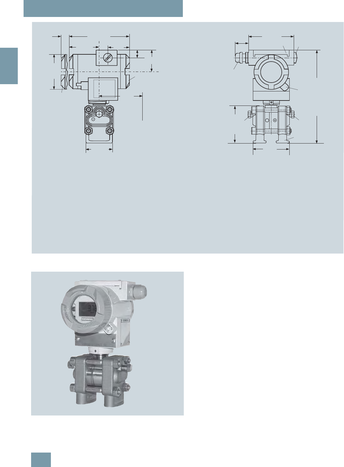
SITRANS P measuring instruments for pressure
Transmitters for gage, absolute and differential pressure, flow and level
DS III series
for differential pressure and flow
2/122 Siemens FI 01 · 2009
2
SITRANS P pressure transmitters, DS III PA and FF series for differential pressure and flow, with process covers for vertical differential pressure lines,
option „H03“, dimensions in mm (inch)
SITRANS P pressure transmitters, DS III series for differential pressure
and flow, with process covers for vertical differential pressure lines
3
6
approx 30 (1.18)
6)
74 (2.9) 2
51)
88
approx.
84,6 (3.33)
approx.
85 (3.35)6)
41)
67 (2.64)5)
Space for rotation
of housing
approx. 217 (8.54)7)
9
1
144 (5.67)
15
(0.6)
51
(2.0)
20
(0.8)
50
(1.97)
diam. 80
(3.15)
90 (3.6)
4)
100 (3.94)
+
1Process connection ¼-18 NPT (EN 61 518)
2Blanking plug
3Electrical connection:
screwed gland M20x1.5 3),
screwed gland ½-14 NPT or
PROFIBUS plug M12 2) 3)
4 Terminal side
5 Electronics side, digital display (longer overall length for cover with window)
6Protective cover over keys
7Mounting bracket (option)
8 Sealing screw with valve (option)
9Screw cover safety bracket (only for explosion-proof enclosure,
not shown in the drawing)
1) Allow approx. 20 mm (0.79 inch) thread length in addition
2) Not with type protection "explosion-proof enclosure"
3)Not with type protection "FM + CSA [is + xp]"
4) 92 mm (3.6 inch) for minimum distance to permit rotation
without indicator
5) 74 mm (2.9 inch) for PN ³ 420 (MWP ³ 6092 psi)
6) 91 mm (3.6 inch) for PN ³ 420 (MWP ³ 6092 psi)
7) 219 mm (8.62 inch) for PN ³ 420 (MWP ³ 6092 psi)
© Siemens AG 2008
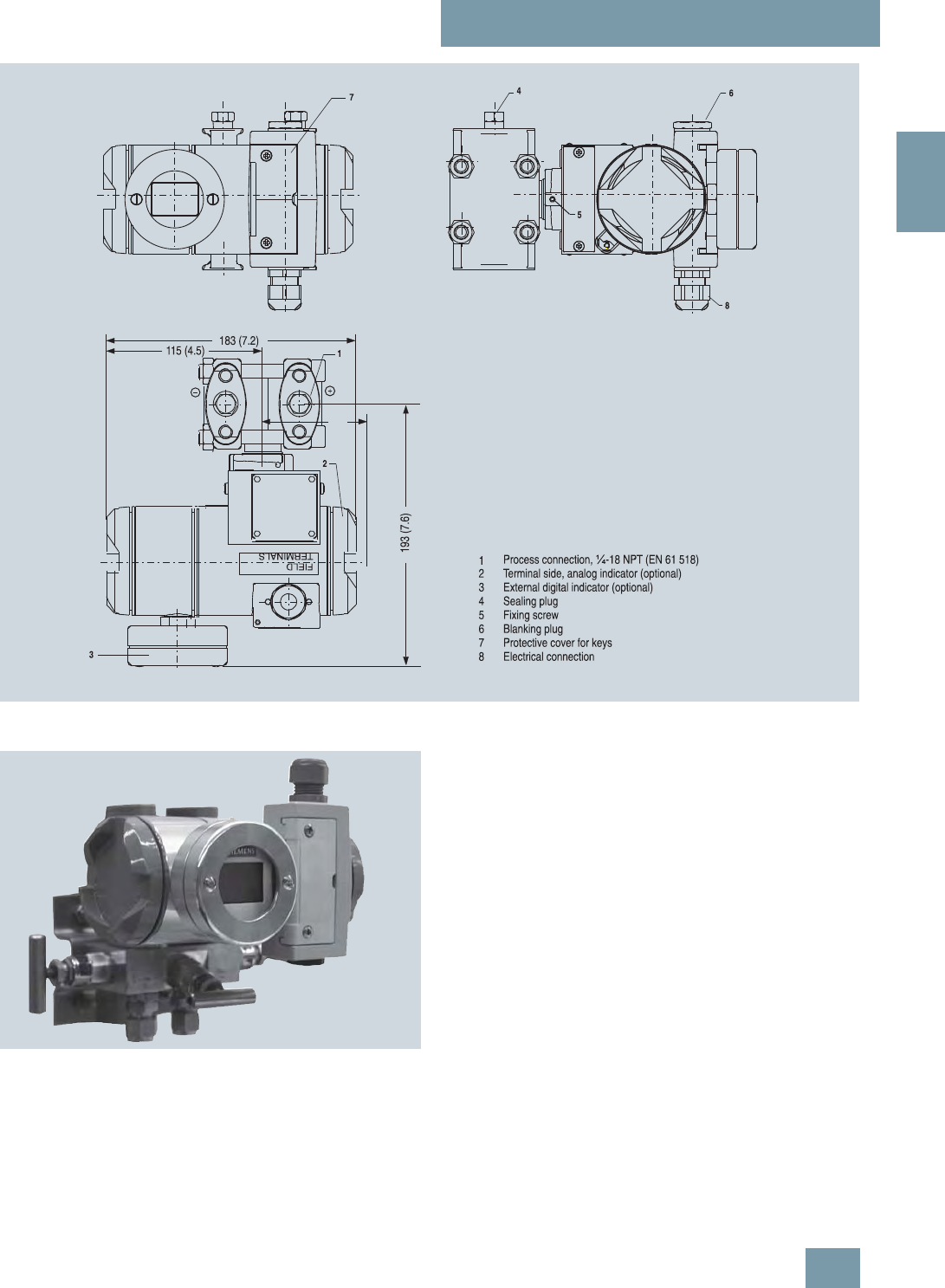
SITRANS P measuring instruments for pressure
Transmitters for gage, absolute and differential pressure, flow and level
DS III series
for differential pressure and flow
2/123
Siemens FI 01 · 2009
2
SITRANS P pressure transmitters, DS III FF series for differential pressure and flow, with digital indicator beside control keys, for vertical differential
pressure lines, option „D27“, dimensions in mm (inch)
SITRANS P pressure transmitters, DS III series for differential pressure
and flow, with digital indicator beside control keys
90
(3.6)
© Siemens AG 2008

SITRANS P measuring instruments for pressure
Transmitters for gage, absolute and differential pressure, flow and level
DS III series
for level
2/124 Siemens FI 01 · 2009
2
■
Technical specifications
SITRANS P, DS III series for level
HART PROFIBUS PA or FOUNDATION Fieldbus
Input
Measured variable Level
Spans (infinitely adjustable) or
nominal measuring range and
max. permissible working pressure
Span Maximum working
pressure Nominal measuring
range Maximum working
pressure
25 ... 250 mbar g
(0.36 ... 3.63 psi g) See "Mounting flange" 250 mbar g
(3.63 psi g) See "Mounting flange"
25 ... 600 mbar g
(0.36 ... 8.7 psi g) See "Mounting flange" 600 mbar g
(8.7 psi g) See "Mounting flange"
53 ... 1600 mbar g
(0.77 ... 23.2 psi g) See "Mounting flange" 1600 mbar g
(23.2 psi g) See "Mounting flange"
160 ... 5000 mbar g
(2.32 ... 72.5 psi g) See "Mounting flange" 5000 mbar g
(72.5 psi g) See "Mounting flange"
Lower measuring limit
• Measuring cell with silicone oil filling -100% of max. span or 30 mbar (0.435 psi a), depending on mounting flange
Upper measuring limit 100% of max. span 100% of the max. nominal measuring range
Output
Output signal 4 ... 20 mA Digital PROFIBUS PA or FOUNDATION Fieldbus
signal
• Lower limit (infinitely adjustable) 3.55 mA, factory preset to 3.84 mA -
• Upper limit (infinitely adjustable) 23 mA, factory preset to 20.5 mA or optionally
set to 22.0 mA -
Load
• Without HART communication RB ≤ (UH - 10.5 V)/0.023 A in Ω,
UH : Power supply in V -
• With HART communication RB = 230 ... 500 Ω (SIMATIC PDM) or
RB = 230 ... 1100 Ω (HART Communicator) -
Physical bus - IEC 61158-2
With polarity reversal protection - Yes
Accuracy To EN 60770-1
Reference conditions
(All error data refer always refer to the set span) Increasing characteristic, start-of-scale value 0 bar, stainless steel seal diaphragm, silicone oil fill-
ing, room temperature 25 °C (77 °F)) r: Span ratio (r = max. span / set span)
Error in measurement and fixed-point setting
(including hysteresis and repeatability)
• Linear characteristic ≤0.075%
-r ≤ 10 ≤0.15%
- 10 < r ≤ 30 ≤0.3%
- 30 < r ≤ 100 ≤ (0.0075 ⋅ r + 0.075)%
Long-term drift (temperature change ±30 °C
(±54 °F)) ≤ (0.25 ⋅ r)% every 5 years
static pressure max. 70 bar g (1015 psi g) ≤ (0.25% every 5 years
static pressure max. 70 bar g (1015 psi g)
Influence of ambient temperature
• at -10 ... +60 °C (14 ... 140 °F)
- 250 mbar (3.63 psi) measuring cell ≤ (0.5 ⋅ r + 0.2)%
(0.4 instead of 0.2 with 10 < r ≤ 30) ≤0,7%
- 600 mbar (8.7 psi) measuring cell ≤ (0.3 ⋅ r + 0.2)%
(0.4 instead of 0.2 with 10 < r ≤ 30) ≤0,5%
- 1600 and 5000 mbar (23.2 and 72.5 psi)
measuring cells ≤ (0.25 ⋅ r + 0.2)% (0.4 instead of 0.2 with 10 < r
≤ 30) ≤0,45%
• at -40 ... -10 °C and +60 ... +85 °C
(-40 ... +14 °F and 140 ... 185 °F)
- 250 mbar (3.63 psi) measuring cell ≤ (0.25 ⋅ r +0.15)%/10 K
double values with 10 < r ≤ 30 ≤ 0.4%/10 K
- 600 mbar (8.7 psi) measuring cell ≤ (0.15 ⋅ r +0.15)%/10 K
double values with 10 < r ≤ 30 ≤ 0.3%/10 K
- 1600 and 5000 mbar (23.2 and 72.5 psi)
measuring cells ≤ (0.12 ⋅ r +0.15)%/10 K
double values with 10 < r ≤ 30 ≤ 0.27%/10 K
© Siemens AG 2008

SITRANS P measuring instruments for pressure
Transmitters for gage, absolute and differential pressure, flow and level
DS III series
for level
2/125
Siemens FI 01 · 2009
2
Influence of static pressure
• on the zero point
- 250 mbar (3.63 psi) measuring cell ≤ (0.3 ⋅ r)% per nominal pressure ≤ 0.3% per nominal pressure
- 600 mbar (8.7 psi) measuring cell ≤ (0.15 ⋅ r)% per nominal pressure ≤ 0.15% per nominal pressure
- 1600 and 5000 mbar (23.2 and 72.5 psi)
measuring cells ≤ (0.1 ⋅ r)% per nominal pressure ≤ 0.1% per nominal pressure
• on the span ≤ (0.1 ⋅ r)% per nominal pressure ≤ 0.1% per nominal pressure
Measured Value Resolution - 3 ⋅10-5 of nominal measuring range
Rated operating conditions
Degree of protection (to EN 60529) IP65
Process temperature Note: Always take into account assignment of max. permissible working temperature to max. per-
missible working pressure of the respective flange connection!
• Measuring cell with silicone oil filling -40 ... +100 °C (-40 ... +212 °F)
- High-pressure side pabs ≥ 1bar: -40 ... +175 °C (-40 ... +347 °F)
pabs ≥ 1bar: -40 ... +80 °C (-40 ... +176 °F)
- Low-pressure side -40 ... +100 °C (-40 ... +212 °F)
-20 ... +60 °C (-4 ... +140 °F) in conjunction with dust explosion protection
Ambient conditions
• Ambient temperature
- Digital indicators -30 ... +85 °C (-22 ... +185 °F)
• Storage temperature -50 ... +85 °C (-58 ... +185 °F)
• Climatic class
- Condensation Permissible
• Electromagnetic compatibility
- Emitted interference and interference immu-
nity To EN 61326 and NAMUR NE 21
Design
Weight (without options)
• To EN (pressure transmitter with mounting
flange, without tube) ≈ 11 ... 13 kg (≈ 24.2 ... 28.7 lb)
• To ASME (pressure transmitter with mounting
flange, without tube) ≈ 11 ... 18 kg (≈ 24.2 ... 39.7 lb)
Wetted parts materials Poor in copper die-cast aluminium, GD-AlSi12 or stainless steel precision casting, mat. No. 1.4408
Housing material
High-pressure side
• Seal diaphragm of mounting flange Stainless steel, mat. No. 1.4404/316L, Monel, mat. No. 2.4360, Hastelloy B2, mat. No. 2.4617,
Hastelloy C276, mat. No. 2.4819, Hastelloy C4, mat. No. 2.4610, tantalum, PTFE, ECTFE
Measuring cell filling Silicone oil
Process connection
• High-pressure side Flange to EN and ASME
• Low-pressure side Female thread ¼-18 NPT and flange connection with mounting thread M10 to DIN 19213 or
7/16-20 UNF to EN 61518
Power supply UH Supplied through bus
Terminal voltage on transmitter 10.5 ... 45 V DC
10.5 ... 30 V DC in intrinsically-safe mode -
Separate 24 V power supply necessary - No
Bus voltage
• Not Ex - 9 ... 32 V
• With intrinsically-safe operation - 9 ... 24 V
Current consumption
• Basic current (max.) - 12.5 mA
• Startup current ≤ basic current - Yes
• Max. current in event of fault - 15.5 mA
Fault disconnection electronics (FDE) available - Yes
SITRANS P, DS III series for level
HART PROFIBUS PA or FOUNDATION Fieldbus
© Siemens AG 2008

SITRANS P measuring instruments for pressure
Transmitters for gage, absolute and differential pressure, flow and level
DS III series
for level
2/126 Siemens FI 01 · 2009
2
Certificate and approvals
Classification according to pressure equipment
directive (DRGL 97/23/EC) For gases of fluid group 1 and liquids of fluid group 1; complies with requirements of Article 3,
paragraph 3 (sound engineering practice)
Explosion protection
• Intrinsic safety "i" PTB 99 ATEX 2122
- Identification Ex II 1/2 G EEx ia/ib IIB/IIC T6
- Permissible ambient temperature -40 ... +85 °C (-40 ... +185 °F) temperature class T4;
-40 ... +70 °C (-40 ... +158 °F) temperature class T5;
-40 ... +60 °C (-40 ... +140 °F) temperature class T6
- Connection To certified intrinsically-safe circuits with maxi-
mum values:
Ui = 30 V, Ii = 100 mA,
Pi = 750 mW; Ri = 300 Ω
FISCO supply unit:
Uo = 17.5 V, Io = 380 mA, Po = 5.32 W
Linear barrier:
Uo = 24 V, Io = 250 mA, Po = 1.2 W
- Effective internal inductance/capacitance L i = 0.4 mH, Ci = 6 nF L i = 7 μH, Ci = 1.1 nF
• Explosion-proof "d" PTB 99 ATEX 1160
- Identification Ex II 1/2 G EEx d IIC T4/T6
- Permissible ambient temperature -40 ... +85 °C (-40 ... +185 °F) temperature class T4;
-40 ... +60 °C (-40 ... +140 °F) temperature class T6
- Connection To circuits with values: UH = 10.5 ... 45 V DC To circuits with values: UH = 9 ... 32 V DC
• Dust explosion protection for zone 20 PTB 01 ATEX 2055
- Identification Ex II 1 D IP65 T 120 °C
Ex II 1/2 D IP65 T 120 °C
- Permissible ambient temperature -40 ... +85 °C (-40 ... +185 °F)
- Max.surface temperature 120 °C (248 °F)
- Connection To certified intrinsically-safe circuits with maxi-
mum values:
Ui = 30 V, Ii = 100 mA,
Pi = 750 mW, Ri = 300 Ω
FISCO supply unit:
Uo = 17.5 V, Io = 380 mA, Po = 5.32 W
Linear barrier:
Uo = 24 V, Io = 250 mA, Po = 1.2 W
- Effective internal inductance/capacitance L i = 0.4 mH, Ci = 6 nF L i = 7 μH, Ci = 1.1 nF
• Dust explosion protection for zone 21/22 PTB 01 ATEX 2055
- Identification Ex II 2 D IP65 T 120 °C
- Connection To circuits with values: UH = 10.5 ... 45 V DC;
Pmax = 1.2 W To circuits with values: UH = 9 ... 32 V DC;
Pmax = 1.2 W
• Type of protection "n" (zone 2) TÜV 01 ATEX 1696 X Planned
- Identification Ex II 3 G EEx nA L IIC T4/T5/T6 -
• Explosion protection to FM Certificate of Compliance 3008490
- Identification (XP/DIP) or (IS); (NI) CL I, DIV 1, GP ABCD T4...T6; CL II, DIV 1, GP EFG; CL III; CL I, ZN 0/1 AEx ia IIC T4...T6; CL I,
DIV 2, GP ABCD T4...T6; CL II, DIV 2, GP FG; CL III
• Explosion protection to CSA Certificate of Compliance 1153651
- Identification (XP/DIP) or (IS) CL I, DIV 1, GP ABCD T4...T6; CL II, DIV 1, GP EFG; CL III; Ex ia IIC T4...T6; CL I, DIV 2, GP ABCD
T4...T6; CL II, DIV 2, GP FG; CL III
SITRANS P, DS III series for level
HART PROFIBUS PA or FOUNDATION Fieldbus
© Siemens AG 2008

SITRANS P measuring instruments for pressure
Transmitters for gage, absolute and differential pressure, flow and level
DS III series
for level
2/127
Siemens FI 01 · 2009
2
HART communication
HART communication 230 ... 1100 Ω
Protocol HART Version 5.x
Software for computer SIMATIC PDM
PROFIBUS PA communication
Simultaneous communication with
master class 2 (max.) 4
The address can be set using Configuration tool or local opera-
tion (standard setting address
126)
Cyclic data usage
• Output byte 5 (one measuring value) or
10 (two measuring values)
• Input byte 0, 1, or 2 (register operating mode
and reset function for metering)
Internal preprocessing
Device profile PROFIBUS PA Profile for Process
Control Devices Version 3.0,
Class B
Function blocks 2
• Analog input
- Adaptation to customer-specif-
ic process variables Yes, linearly rising or falling char-
acteristic
- Electrical damping T63 , adjust-
able 0 ... 100 s
- Simulation function Input /Output
- Failure mode Can be parameterized (last good
value, substitute value, incorrect
value)
- Limit monitoring Yes, one upper and lower warning
limit and one alarm limit respec-
tively
• Register (totalizer) Can be reset, preset, optional
direction of counting, simulation
function of register output
- Failure mode Can be parameterized (summation
with last good value, continuous
summation, summation with incor-
rect value)
- Limit monitoring One upper and lower warning limit
and one alarm limit respectively
• Physical block 1
Transducer blocks 2
• Pressure transducer block
- Can be calibrated by applying
two pressures Yes
- Monitoring of sensor limits Yes
- Specification of a container
characteristic with Max. 30 nodes
- Square-rooted characteristic
for flow measurement Yes
- Gradual volume suppression
and implementation point of
square-root extraction
Parameterizable
- Simulation function for mea-
sured pressure value and sen-
sor temperature
Constant value or over parameter-
izable ramp function
Communication FOUNDATION Fieldbus
Function blocks 3 function blocks analog input,
1 function block PID
• Analog input
- Adaptation to customer-specif-
ic process variables Yes, linearly rising or falling char-
acteristic
- Electrical damping T63 , adjust-
able 0 ... 100 s
- Simulation function Output/input (can be locked within
the device with a bridge)
- Failure mode Can be parameterized (last good
value, substitute value, incorrect
value)
- Limit monitoring Yes, one upper and lower warning
limit and one alarm limit respec-
tively
- Square-rooted characteristic
for flow measurement Yes
• PID Standard FF function block
• Physical block 1 Resource block
Transducer blocks 1 transducer block Pressure with
calibration, 1 transducer block
LCD
• Pressure transducer block
- Can be calibrated by applying
two pressures Yes
- Monitoring of sensor limits Yes
- Simulation function: Measured
pressure value, sensor temper-
ature and electronics tempera-
ture
Constant value or over parameter-
izable ramp function
Mounting flange
Nom. diam. Nom. press.
• To EN 1092-1
- DN 80 PN 40
- DN 100 PN16, PN40
• To ASME B16.5
- 3 inch Class 150, class 300
- 4 inch Class 150, class 300
© Siemens AG 2008

SITRANS P measuring instruments for pressure
Transmitters for gage, absolute and differential pressure, flow and level
DS III series
for level
2/128 Siemens FI 01 · 2009
2
Selection and Ordering data Order No.
SITRANS P pressure transmitters for level
series DS III HART 7 M F 4 6 3 3 -
7 7 Y7 7 -7 7 7 7
Measuring cell filling Measuring cell
cleaning
Silicone oil Standard 1
Span
25 ... 250 mbar (0.363 ... 3.63 psi) D
25 ... 600 mbar (0.363 ... 8.70 psi) E
53 ... 1600 mbar (0.77 ... 23.2 psi) F
0.16 ... 5 bar (2.32 ... 72.5 psi) G
Process connection of low-pressure side
Female thread ¼-18 NPT with flange connection
• Mounting thread 7/16-20 UNF to EN 61518 2
• Mounting thread M10 to DIN 19213
(only for replacement needs) 0
Non-wetted parts materials
Process flange screws Electronics housing
Stainless steel Die-cast aluminium 2
Stainless steel Stainless steel precision
casting1) 3
Version
• Standard version 1
• International version, English label inscriptions,
documentation in 5 languages on CD 2
Explosion protection
• Without A
• With ATEX, Type of protection:
- "Intrinsic safety (EEx ia)" B
- "Explosion-proof (EEx d)"2) D
- "Intrinsic safety and explosion-proof
enclosure (EEx ia + EEx d)"3) P
- "Ex nA/nL (zone 2)" E
- "Intrinsic safety, explosion-proof enclosure
and dust explosion protection (EEx ia +
EEx d + Zone 1D/2D)"3)
R
• With FM + CSA, Type of protection:
- "Intrinsic safety and explosion-proof
(is + xp)"1) N C
Electrical connection / cable entry
• Screwed gland Pg 13.54) A
• Screwed gland M20x1.5 B
• Screwed gland ½-14 NPT C
• Han 7D plug (plastic housing) incl. mating
connector4) D
• M12 connectors (metal)5) F
Display
• Without indicator 0
• Without visible digital indicator (digital indicator
hidden, setting: mA)
}1
• With visible digital indication 6
• With customer-specific digital indication (setting
as specified, Order code "Y21" or required) 7
Ordering information:
1st order item: Pressure transmitter 7MF4633-...
2nd order item: Mounting flange 7MF4912-3...
Ordering example:
Item line 1: 7MF4633-1EY20-1AA1-Z
B line: Y01
C line: Y01: 80 to 143 mbar (1.16 to 2.1 psi)
Item line 2: 7MF4912-3GE01
Power supply units see "SITRANS I power supply units and isolation
amplifiers".
Included in delivery of the device:
• Brief instructions (Leporello)
• CD-ROM with detailed documentation
• Sealing plug(s) or sealing screw(s) for the process flanges(s)
1) Not together with Electrical connection „Screwed gland Pg 13.5“ and
„Han7D plug“.
2) Without cable gland, with blanking plug.
3) With enclosed cable gland EEx ia and blanking plug.
4) Not together with type of protection "Explosion-proof" and type of protection
"Ex nA".
5) Not together with types of protection "Explosion-proof" or "Intrinsic safety
and explosion-proof"
© Siemens AG 2008

SITRANS P measuring instruments for pressure
Transmitters for gage, absolute and differential pressure, flow and level
DS III series
for level
2/129
Siemens FI 01 · 2009
2
Selection and Ordering data Order No.
SITRANS P pressure transmitter
for level
DS III PA series (PROFIBUS PA) 7 M F 4 6 3 4 -
DS III FF series (FOUNDATION Fieldbus) 7 M F 4 6 3 5 -
17Y7 7 -7 7 7 7
Nominal measuring range
250 mbar (3.63 psi) D
600 mbar (8.70 psi) E
1600 mbar (23.2 psi) F
5 bar (72.5 psi) G
Process connection of low-pressure side
Female thread ¼-18 NPT with flange connection
• Mounting thread M10 to DIN 19213
(only for replacement needs) 0
• Mounting thread 7/16-20 UNF to EN 61518 2
Non-wetted parts materials
Process flange screws Electronics housing
Stainless steel Die-cast aluminium 2
Stainless steel Stainless steel precision
casting 3
Version
• Standard version 1
• International version, English label inscriptions,
documentation in 5 languages on CD 2
Explosion protection
• Without A
• With ATEX, Type of protection:
- "Intrinsic safety (EEx ia)" B
- "Explosion-proof (EEx d)"1)
1) Without cable gland, with blanking plug.
D
- "Intrinsic safety and explosion-proof e
nclosure (EEx ia + EEx d)"2)
2) With enclosed cable gland EEx ia and blanking plug.
P
- "Ex nA/nL (zone2)" E
- "Intrinsic safety, explosion-proof enclosure
and dust explosion protection (EEx ia +
EEx d + Zone 1D/2D)"2) (not for DS III FF)
R
• With FM + CSA, Type of protection:
- "Intrinsic safety and explosion-proof
(is + xp)"1) N C
Electrical connection / cable entry
• Screwed gland M20x1.5 B
• Screwed gland ½-14 NPT C
• Plug M12 incl. mating connector3)
3) Not together with types of protection "Explosion-proof" and "Intrinsic safety
and explosion-proof"
F
Display
• Without indicator 0
• Without visible digital indicator (digital indicator
hidden, setting: mA)
}1
• With visible digital indication 6
• With customer-specific digital indication (setting
as specified, Order code "Y21" or required) 7
Ordering information:
1st order item: Pressure transmitter 7MF4634-...
2nd order item: Mounting flange 7MF4912-...
Ordering example:
Item line 1: 7MF4634-1EY20-1AA1
Item line 2: 7MF4912-3GE01
Included in delivery of the device:
• Brief instructions (Leporello)
• CD-ROM with detailed documentation
• Sealing plug(s) or sealing screw(s) for the process flanges(s)
Selection and Ordering data Order code
Further designs HART PA FF
Add "-Z" to Order No. and
specify Order code.
O-rings for process flanges on
low-pressure side
(instead of FPM (Viton))
• PTFE (Teflon) A20 9
9
9
9
9
9
• FEP (with silicone core, approved for food) A21 9
9
9
9
9
9
• FFPM (Kalrez, compound 4079) A22 9
9
9
9
9
9
• NBR (Buna N) A23 9
9
9
9
9
9
Plug
• Han 7D (metal, gray) A30 9
9
• Han 8U (instead of Han 7D) A31 9
9
Sealing screws
¼-18 NPT, with valve in material of process
flanges A40 9
9
9
9
9
9
Cable sockets for M12 connectors (metal) A50 9
9
9
9
9
9
Rating plate inscription
(instead of German)
• English B11 9
9
9
9
9
9
•French B12 9
9
9
9
9
9
• Spanish B13 9
9
9
9
9
9
• Italian B14 9
9
9
9
9
9
English rating plate B21 9
9
9
9
9
9
Pressure units in inH2O or psi
Quality inspection certificate (Factory cali-
bration) to IEC 60770-2 C11 9
9
9
9
9
9
Acceptance test certificate C12 9
9
9
9
9
9
To EN 10204-3.1
Factory certificate C14 9
9
9
9
9
9
To EN 10204-2.2
"Functional Safety (SIL)" certificate C20 9
9
"PROFIsafe" certificate and protocol C21 9
9
Setting of upper limit of output signal to
22.0 mA D05 9
9
Type of protection IP68 D12 9
9
9
9
9
9
(not together with PROFIBUS plug M12)
Supplied with oval flange D37 9
9
9
9
9
9
(1 item), PTFE packing and stainless steel
screws in thread of process flange
Use on zone 1D / 2D E01 9
9
9
9
9
9
(only together with type of protection
"Intrinsic safety (EEx ia)")
Use on zone 0 E02 9
9
9
9
9
9
(only together with type of protection
"Intrinsic safety (EEx ia)")
Overfilling safety device for flammable
and non-flammable liquids E08 9
9
9
9
(max. PN 32 (MVWP 464 psi), basic device
with type of protection "Intrinsic safety
(EEx ia)")
Explosion-proof "Intrinsic safety" to
INMETRO (Brazil) E25 9
9
9
9
9
9
(only for transmitter 7MF4...-.....-.B..)
Explosion-proof "Intrinsic safety" to
NEPSI (China) E55 9
9
9
9
9
9
(only for transmitter 7MF4...-.....-.B..)
Explosion protection "Explosion-proof" to
NEPSI (China) E56 9
9
9
9
9
9
(only for transmitter 7MF4...-.....-.D..)
Explosion-proof "Zone 2" to NEPSI (China) E57 9
9
9
9
9
9
(only for transmitter 7MF4...-.....-.E..)
Interchanging of process connection side H01 9
9
9
9
9
9
© Siemens AG 2008

SITRANS P measuring instruments for pressure
Transmitters for gage, absolute and differential pressure, flow and level
DS III series
for level
2/130 Siemens FI 01 · 2009
2
Additional data HART PA FF
Add "-Z" to Order No. and
specify Order code.
Measuring range to be set Y01 9
9
Specify in plain text (max. 5 digits):
Y01: ... up to ... mbar, bar, kPa, MPa, psi
Measuring point number (TAG No.) Y15 9
9
9
9
9
9
Max. 16 characters, specify in plain text:
Y15: ...........................................
Measuring point text Y16 9
9
9
9
9
9
Max. 27 characters, specify in plain text:
Y16: ...........................................
Entry of HART address (TAG) Y17 9
9
Max. 8 characters, specify in plain text:
Y17: ...........................................
Setting of pressure indicator in pressure
units Y21 9
9
9
9
9
9
Specify in plain text (standard setting: mA):
Y21: mbar, bar, kPa, MPa, psi, ...
Note:
The following pressure units can be selected:
bar, mbar, mm H2O*), inH2O*), ftH2O*),
mmHG, inHG, psi, Pa, kPa, MPa, g/cm2,
kg/cm2, Torr, ATM or %
*) ref. temperature 20 °C
Setting of pressure indicator in
non-pressure units Y221)
+ Y01
9
9
Specify in plain text:
Y22: ..... up to ..... l/min, m3/h, m, USgpm, ...
(specification of measuring range in
pressure units "Y01" is essential, unit with
max. 5 characters)
Preset bus address Y25 9
9
(possible between 1 and 126)
Specify in plain text:
Y25: .....................
Only "Y01", "Y21", "Y22", "Y25" and "D05" can be factory preset
9
9
= available
1) Not together with over-filling safety device for flammable and
non-flammable liquids (Order code "E08")
Selection and Ordering data Order code Selection and Ordering data Order No.Ord. code
Mounting flange 7 M F 4 9 1 2 -
Directly mounted on the
SITRANS P pressure transmitter (converter part)
for level, for DS III series
37 7 7 7 7 7 7
Connection acc. to EN 1092-1
Nom. diam. Nom. press.
DN 80 PN 40 D
DN 100 PN 16 G
PN 40 H
Connection acc. to ASME B16.5
Nom. diam. Nom. press.
3 inch Class 150 Q
Class 300 R
4 inch Class 150 T
Class 300 U
Other version, add
Order code and plain text:
Nominal diameter: ...; Nominal pressure: ...
Z J 1 Y
Wetted parts materials
• Stainless steel 316L A
- Coated with PFA D
- Coated with PTFE E 0
- Coated with ECTFE1)
1) For vacuum on request
F
• Monel 400, mat. No. 2.4360 G
• Hastelloy B2, mat. No. 2.4617 H
• Hastelloy C276, mat. No. 2.4819 J
• Hastelloy C4, mat. No. 2.4610 U
• Tantalum K
Other version, add
Order code and plain text:
material of parts in contact with the medium: ...
Sealing face, see "Technical specifications"
Z K 1 Y
Tube length
• Without 0
• 50 mm (1.97 inch) 1
• 100 mm (3.94 inch) 2
• 150 mm (5.90 inch) 3
• 200 mm (7.87 inch) 4
Other version: add
Order code and plain text:
Tube length: ...
9 L 1 Y
Filling liquid
• Silicone oil M5 1
• Silicone oil M50 2
• High-temperature oil 3
• Halocarbon oil (for O2 measurements) 4
• Glycerin / water2)
2) Not suitable for use in low-pressure range
6
• Food oil (FDA-listed) 7
Other version, add
Order code and plain text:
filling liquid: ...
9 M 1 Y
© Siemens AG 2008

SITRANS P measuring instruments for pressure
Transmitters for gage, absolute and differential pressure, flow and level
DS III series
for level
2/131
Siemens FI 01 · 2009
2
Selection and Ordering data Order code
Further designs
Add "-Z" to Order No. and
specify Order code.
HART PA and
FF
Flame flashover lock-out A01 9
9
9
9
For mounting on zone 0 (including documen-
tation)
Quality inspection certificate (Factory cali-
bration) to IEC 60770-2 C11 9
9
9
9
Acceptance test certificate C12 9
9
9
9
To EN 10204-3.1
Vacuum-proof design V04 9
9
9
9
(for use in low-pressure range)
Calculation of span of associated
pressure transmitter Y05 9
9
9
9
(enclose filled-in questionnaire with order)
Note:
suffix "Y01" required with pressure transmitter!
9
9
= available
© Siemens AG 2008
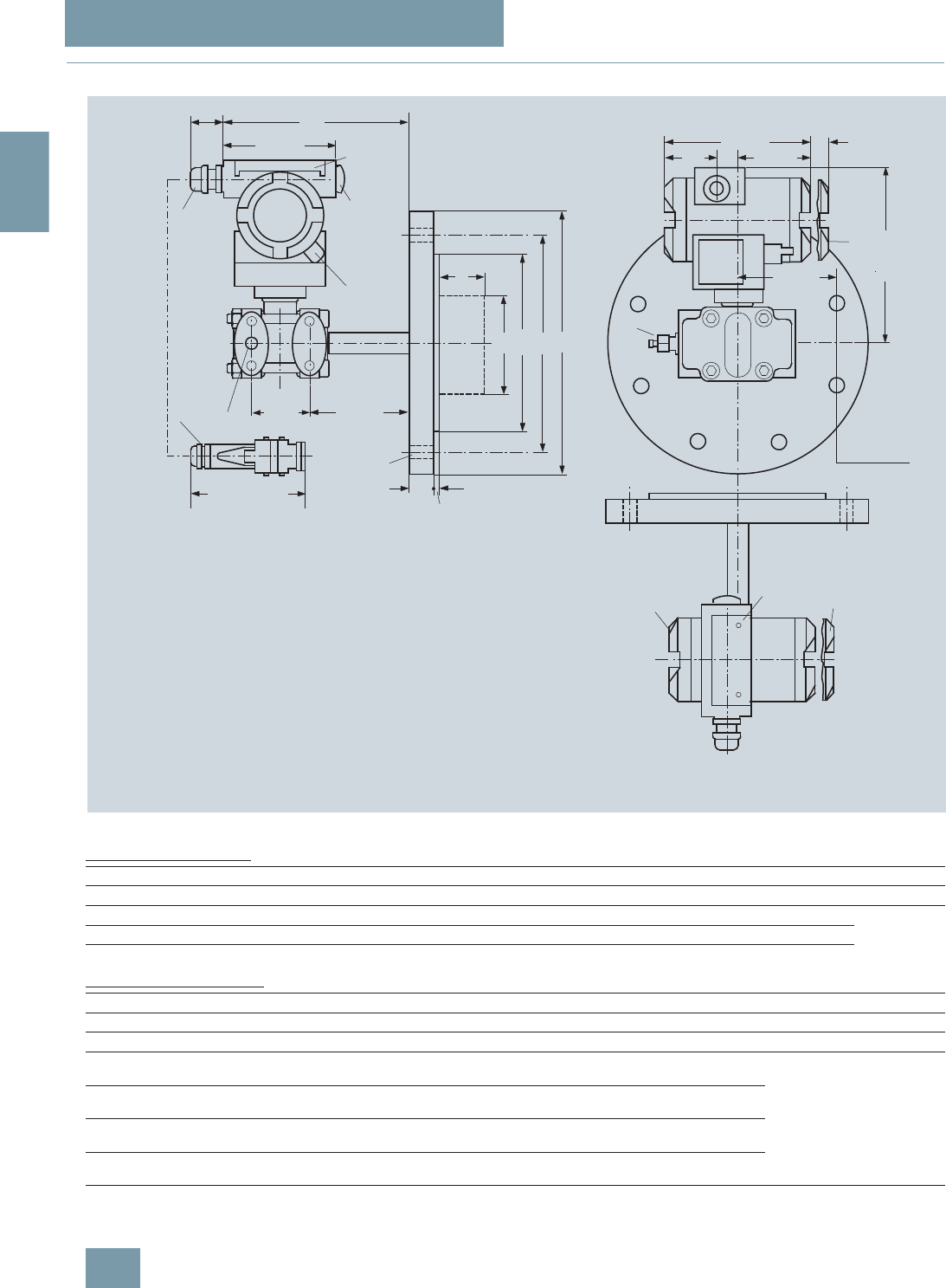
SITRANS P measuring instruments for pressure
Transmitters for gage, absolute and differential pressure, flow and level
DS III series
for level
2/132 Siemens FI 01 · 2009
2
■
Dimensional drawings
SITRANS P pressure transmitters, DS III HART series for level, including mounting flange, dimensions in mm (inch)
Connection to EN 1092-1
Connection to ASME B16.5
d: Internal diameter of gasket to DIN 2690
dM: Effective diaphragm diameter
1) 89 mm = 3½ inch with tube length L = 0.
185
6
3
54 (2.1)
D
k
L
f
b
2
108 (4.25)
d4
d5
1
2
n x d
8
51)
41)
6
165 (6.5)
3
9
51)
Space for rotation
of housing
approx. 30 (1.18)5)
100 (3.94)
approx. 96 (3.78)
144 (5.67)
51
(2.0)
74 (2.9)
15
(0.6)
90 (3.6)
4)
1Process connection of low pressure side ¼-18 NPT (EN 61 518)
2Blanking plug
3Electrical connection:
screwed gland Pg 13.5 (adapter) 2) 3),
screwed gland M20x1.5, screwed gland ½-14 NPT or
Han 7D/ Han 8U plug 2) 3)
4 Terminal side
5 Electronics side, digital display (longer overall length for cover with window)
6Protective cover over keys
8Sealing screw with valve (option)
9Screw cover safety bracket (only for type of protection "Explosion-proof enclosure",
not shown in the drawing)
1) Allow approx. 20 mm (0.79 inch) thread length in addition
2) Not with type of protection "Explosion-proof enclosure"
3)Not with type of protection "FM + CSA [is + xp]"
4) 92 mm (3.62 inch) for minimum distance to permit rotation without indicator
5) Approx. 45 mm (1.77 inch) for Pg 13.5 with adapter
Nom. diam. Nom. press. b D d d2d4d5dMfknL
mm mm mm mm mm mm mm mm mm mm mm
DN 80 PN 40 24 200 90 18 138 76 72 1) 2 160 8 0, 50, 100,
150 or 200
DN 100 PN 40 20 220 115 18 158 94 89 2 180 8
PN 40 24 235 115 22 162 94 89 2 190 8
Nom. diam. Nom. press. b D d2d4d5dMfk nL
lb/sq.in. inch inch inch inch inch inch inch inch inch
(mm) (mm) (mm) (mm) (mm) (mm) (mm) (mm) (mm)
3 inch 150 0.94
(23.8) 7.5
(190.5) 0.75
(19.0) 5
(127) 3
(76) 2.81 1)
(72) 0.06
(1.6) 6
(152.4) 4 0, 2, 3.94, 5.94 or 7.87
(0, 50, 100, 150 or 200)
300 1.12
(28.6) 8.25
(209.5) 0.87
(22.2) 5
(127) 3
(76) 2.81 1)
(72) 0.06
(1.6) 6.69
(168.3) 8
4 inch 150 0.94
(23.8) 9
(228.5) 0.75
(19.0) 6.19
(157.2) 3.69
(94) 3.5
(89) 0.06
(1.6) 7.5
(190.5) 8
300 1.25
(31.7) 10
(254) 0.87
(22.2) 6.19
(157.2) 3.69
(94) 3.5
(89) 0.06
(1.6) 7.88
(200) 8
© Siemens AG 2008
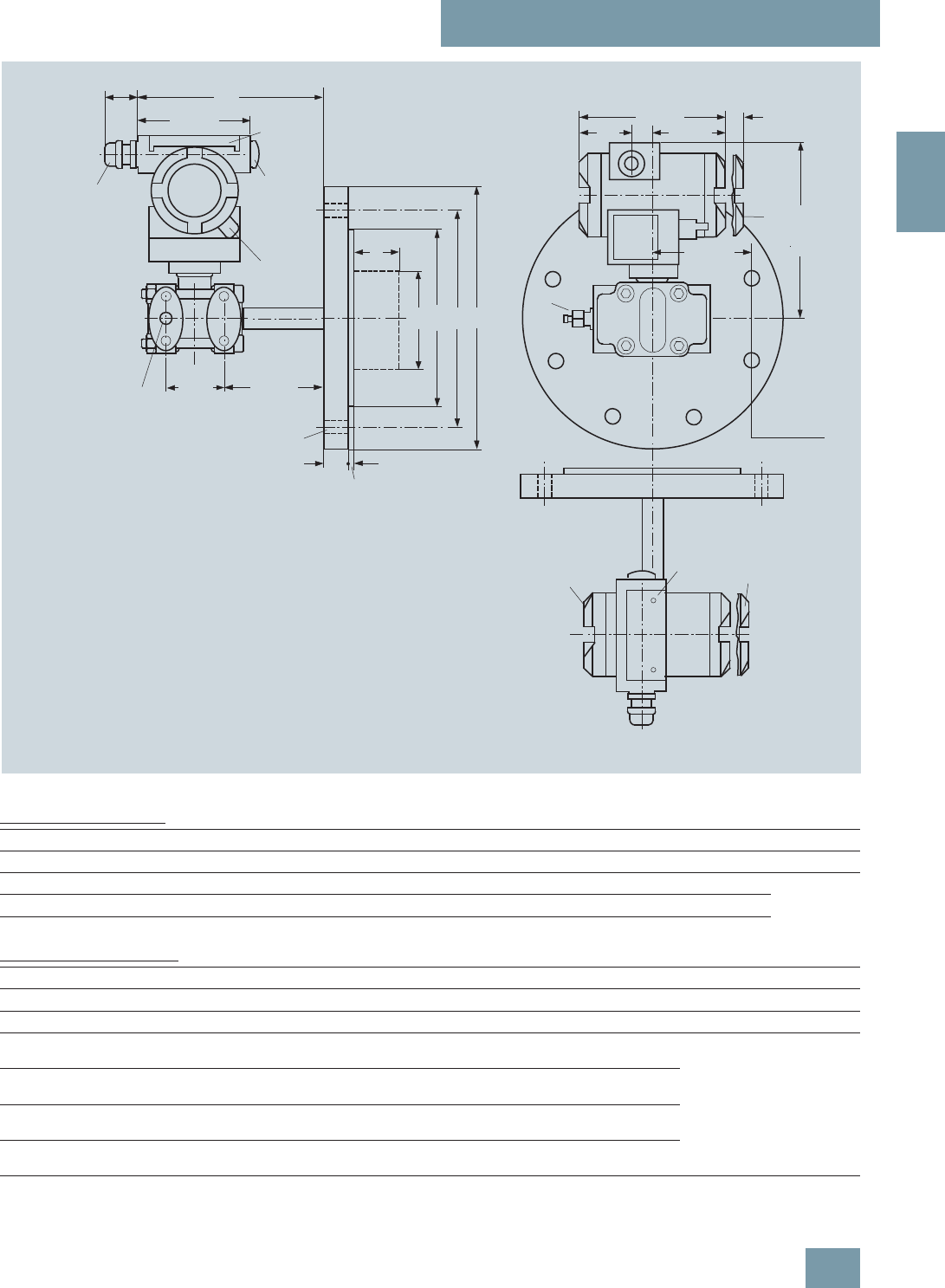
SITRANS P measuring instruments for pressure
Transmitters for gage, absolute and differential pressure, flow and level
DS III series
for level
2/133
Siemens FI 01 · 2009
2
SITRANS P pressure transmitters, DS III PA and FF series for level, including mounting flange, dimensions in mm (inch)
Connection to EN 1092-1
Connection to ASME B16.5
d: Internal diameter of gasket to DIN 2690
dM: Effective diaphragm diameter
1) 89 mm = 3½ inch with tube length L = 0.
185
6
3
54 (2.1)
D
k
L
f
b
2
108 (4.25)
d4
d5
1
2
n x d
8
51)
41)
6
165 (6.5)
9
51)
Space for rotation
of housing
approx. 30 (1.18)
100 (3.94) 144 (5.67)
51
(2.0)
74 (2.9)
15
(0.6)
90 (3.6)
4)
1Process connection of low pressure side ¼-18 NPT (EN 61518)
2Blanking plug
3Electrical connection:
- screwed connection M20x1,5 3),
- screwed connection ½-14 NPT or
- PROFIBUS plug M12 2) 3)
4 Terminal side
5 Electronics side, digital display (longer overall length for cover with window)
6Protective cover over keys
8 Sealing screw with valve (option)
9Screw cover safety bracket (only for "explosion-proof enclosure",
not shown in the drawing)
1) Allow approx. 20 mm (0.79 inch) thread length in addition
2) Not with type of protection "Explosion-proof enclosure"
3)Not with type of protection "FM + CSA [is + xp]"
4) 92 mm (3.62 inch) for minimum distance to permit rotation with indicator
Nom. diam. Nom. press. b D d d2d4d5dMfknL
mm mm mm mm mm mm mm mm mm mm mm
DN 80 PN 40 24 200 90 18 138 76 721) 2 160 8 0, 50, 100,
150 or 200
DN 100 PN 40 20 220 115 18 158 94 89 2 180 8
PN 40 24 235 115 22 162 94 89 2 190 8
Nom. diam. Nom. press. b D d2d4d5dMfk nL
lb/sq.in. inch inch inch inch inch inch inch inch inch
(mm) (mm) (mm) (mm) (mm) (mm) (mm) (mm) (mm)
3 inch 150 0.94
(23.8) 7.5
(190.5) 0.75
(19.0) 5
(127) 3
(76) 2.811)
(72) 0.06
(1.6) 6
(152.4) 4 0, 2, 3.94, 5.94 or 7.87
(0, 50, 100, 150 or 200)
300 1.12
(28.6) 8.25
(209.5) 0.87
(22.2) 5
(127) 3
(76) 2.811)
(72) 0.06
(1.6) 6.69
(168.3) 8
4 inch 150 0.94
(23.8) 9
(228.5) 0.75
(19.0) 6.19
(157.2) 3.69
(94) 3.5
(89) 0.06
(1.6) 7.5
(190.5) 8
300 1.25
(31.7) 10
(254) 0.87
(22.2) 6.19
(157.2) 3.69
(94) 3.5
(89) 0.06
(1.6) 7.88
(200) 8
© Siemens AG 2008
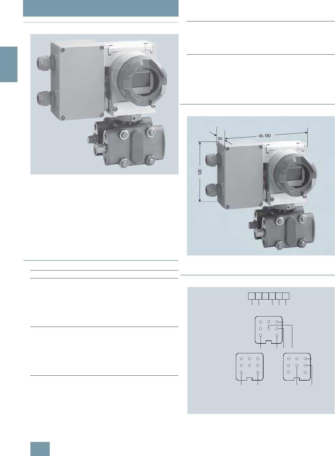
SITRANS P measuring instruments for pressure
SITRANS P Accessories
Supplementary electronics for 4-wire connection
2/134 Siemens FI 01 · 2009
2
■
Overview
SITRANS P pressure transmitter with supplementary electronics for 4-
wire connection
Direct connection of the supplementary electronics to a
SITRANS P pressure transmitter from the DS III HART series pro-
duces a transmitter for four-wire connection.
The supplementary electronics cannot be attached to explosion-
protected pressure transmitters. The supplementary electronics
is fitted in a light metal housing which is mounted on the left side
of the pressure transmitter.
Note on ordering:
The supplementary electronics has to be be ordered through the
supplementary options of the pressure transmitter in question.
■
Technical specifications
■
Dimensional drawings
SITRANS P pressure transmitters with supplementary electronics for four-
wire connection, dimension drawing, dimensions in mm (inch)
■
Schematics
Supplementary electronics for 4-wire connection, connection diagram
SITRANS P, supplementary electronics for 4-wire connection
Output
Output signal 0 ... 20 mA or 4 ... 20 mA
Load Max. 750 Ω
Voltage measurement Linear (square-rooting in transmit-
ter if necessary)
Electrical isolation Between power supply and input/
output
Measuring accuracy To EN 60770-1
Conformity error (in addition to
transmitter) ≤0.15% of set span
Influence of ambient temperature ≤0.1% per 10 K
Power supply effect ≤0.1% per 10% change in volt-
age or frequency
Load effect ≤0.1% per 100% change
Rated conditions
Ambient temperature -20 ... +80 °C (-4 ... +176 °F)
Storage temperature -50 ... +85 °C (-58 ... +185 °F)
Degree of protection IP54 to EN 60529
Electromagnetic compatibility
(EMC) EN 50081, EN 50082
Structural design
Dimensions (W x H x D) in mm
(inch) 80 x 120 x 60 (3.15 x 4.72 x 2.36)
Electrical connection Screw terminals (Pg 13.5 cable
inlet) or Han 7D / Han 8U plug
Power supply
Supply voltage 230 V AC (-10 ... +6%,
47 ... 63 Hz, approx. 6 VA) or
24 V AC/DC (24 V AC ± 10%,
47 ... 63 Hz, approx. 3 VA)
Permissible ripple (within the speci-
fied limits) Approx. 2.5 Vpp
12
34
5
67
12
34
5
67SL
+
1
+
234 5 6
SL
12
3
4
5
67SL
+-
-
IaUH
IaUH
IaUH
-
Terminals
1 HAN 8U/7D plug
2 plugs
AC 230 V
UC 24 V
Han 7D
Han 7D
Han 7D
Han 8U
IaOutput current SL Protective earth conductorUHPower supply
© Siemens AG 2008

SITRANS P measuring instruments for pressure
SITRANS P Accessories
Supplementary electronics for 4-wire connection
2/135
Siemens FI 01 · 2009
2
Selection and Ordering data Order code
Supplementary electronics for 4-wire
connection V7 7
Order No. of the transmitter
7MF4.33-.....-1AB. add "-Z" and Order code.
Power supply Electrical connection
24 V AC/DC Terminals; 2 Pg screwed
glands, to left 1
2 Han 7D/Han 8U plugs
incl. mating connector, to left 3
1 Han 7D plug incl. mating
connector, angled 5
Terminals; 1 Pg screwed
gland, downwards 6
1 Han 8U plug incl. mating
connector, downwards
(observe arrangement of
plug and differential pressure
line)
9
230 V AC Terminals; 2 Pg screwed
glands, to left 7
2 Han 7D plugs incl. mating
connector, to left 8
Output current
0 ... 20 mA 0
4 ... 20 mA 1
Selection and Ordering data Order No.
Accessories
Instruction Manual
German/English E86060-K6017-
A131-A3
© Siemens AG 2008

SITRANS P measuring instruments for pressure
SITRANS P Accessories
Accessories / spare parts for SITRANS P
P300 and DS III series
2/136 Siemens FI 01 · 2009
2
F) Subject to export regulations AL: 9I999, ECCN: N.
Selection and Ordering data Order No.
Replacement measuring cell for pressure
for SITRANS P, DS III, DS III PA and DS III FF series 7 M F 4 9 9 0 -
7777 0 - 0 D C 0
Measuring cell filling Measuring cell cleaning
Silicone oil Standard 1
Inert liquid Grease-free 3
Measured span
0.01 ... 1 bar g (0.15 ... 14.5 psi g) B
0.04 ... 4 bar g (0.58 ... 58 psi g) C
0.16 ... 16 bar g (2.32 ... 232 psi g) D
0.63 ... 63 bar g (9.14 ... 914 psi g) E
1.6 ... 160 bar g (23.2 ... 2320 psi g) F
4.0 ... 400 bar g (58.0 ... 5802 psi g) G
Wetted parts materials
Seal diaphragm Process connection
Stainless steel Stainless steel A
Hastelloy Stainless steel B
Hastelloy Hastelloy C
Process connection
• Connection shank G½B to EN 837-1 0
• Female thread ½-14 NPT 1
• Oval flange made of stainless steel,
max. span 160 bar (2320 psi)
- Mounting thread 7/16-20 UNF to EN 61518 2
- Mounting thread M10 to DIN 19213 3
Further designs Order code
Please add "-Z" to Order No. and specify
Order code.
Acceptance test certificate C12
to EN 10204-3.1
Selection and Ordering data Order No.
Replacement measuring cell for absolute
pressure (from the pressure series)
for SITRANS P, DS III, DS III PA and DS III FF series
F) 7 M F 4 9 9 2 -
7 7 7 7 0 - 0 D C 0
Measuring cell filling Measuring cell cleaning
Silicone oil Standard 1
Inert liquid Grease-free 3
Measured span
8.3 ... 250 mbar a (0.12 ... 3.63 psi a) D
43 ... 1300 mbar a (0.62 ... 18.9 psi a) F
0.16 ... 5 bar a (2.32 ... 72.5 psi a) G
1 ... 30 bar a (14.5 ... 435 psi a) H
Wetted parts materials
Seal diaphragm Process connection
Stainless steel Stainless steel A
Hastelloy Stainless steel B
Hastelloy Hastelloy C
Process connection
• Connection shank G½B to EN 837-1 0
• Female thread ½-14 NPT 1
• Oval flange made of stainless steel,
max. span 160 bar (2320 psi)
- Mounting thread 7/16-20 UNF to EN 61518 2
- Mounting thread M10 to DIN 19213 3
Further designs Order code
Please add "-Z" to Order No. and specify
Order code.
Acceptance test certificate C12
to EN 10204-3.1
© Siemens AG 2008

SITRANS P measuring instruments for pressure
SITRANS P Accessories
Accessories / spare parts for SITRANS P
P300 and DS III series
2/137
Siemens FI 01 · 2009
2
E) Combinations of the versions marked with E) are subject to the export
regulations AL: 2B230, ECCN: N.
F) Subject to export regulations AL: 9I999, ECCN: N.
Selection and Ordering data Order No.
Spare parts / Accessories
Replacement measuring cell for absolute pres-
sure (from the differential pressure series) for
SITRANS P, DS III, DS III PA and DS III FF series
F) 7 M F 4 9 9 3 -
77777 - 0 D C 0
Measuring cell filling Measuring cell cleaning
Silicone oil Standard 1
Inert liquid Grease-free 3
Measured span
8.3 ... 250 mbar a (0.12 ... 3.63 psi a) E) D
43 ... 1300 mbar a (0.62 ... 18.9 psi a) E) F
0.16 ... 5 bar a (2.32 ... 72.5 psi a) E) G
1 ... 30 bar a (14.5 ... 435 psi a) H
5.3 ... 100 bar a (76.9 ... 1450 psi a) K E
Wetted parts materials
Seal diaphragm Parts of measuring cell
Stainless steel Stainless steel A
Hastelloy Stainless steel B
Hastelloy Hastelloy C
Tantalum Tantalum E
Monel Monel E) H
Gold Gold L
Process connection
Female thread ¼-18 NPT with flange connection
• Sealing screw opposite process connection
- Mounting thread M10 to DIN 19213 0
- Mounting thread 7/16-20 UNF to EN 61518 2
• Vent on side of process flange1)
1) Not for span "5.3 ... 100 bar (76.9 ... 1450 psi)"
- Mounting thread M10 to DIN 19213 4
- Mounting thread 7/16-20 UNF to EN 61518 6
Non-wetted parts materials
• Stainless steel process flange screws 2
Further designs
Please add "-Z" to Order No. and specify
Order code.
Order code
O-rings for process flanges
(instead of FPM (Viton))
• PTFE (Teflon) A20
• FEP (with silicone core, approved for food) A21
• FFPM (Kalrez, compound 4079) A22
• NBR (Buna N) A23
Acceptance test certificate C12
to EN 10204-3.1
Process connection G½A D16
Remote seal flanges D20
(not together with K01, K02 and K04)
Vent on side for gas measurements H02
Process flanges
• without K00
• with process flange made of
- Hastelloy K01
- Monel K02
- Stainless steel with PVDF insert
max. PN 10 (MWP 145 psi)
max. temperature of medium 90 °C (194 °F)
K04
Selection and Ordering data Order No.
Spare parts / Accessories
Replacement measuring cell for differential
pressure and PN 32/160 (MWP 464/2320 psi) for
SITRANS P, DS III, DS III PA and DS III FF series
7 M F 4 9 9 4 -
7 7 7 7 7 - 0 D C 0
Measuring cell filling Measuring cell cleaning
Silicone oil Standard 1
Inert liquid Grease-free 3
Measured span
PN 32 (MWP 464 psi)
1 ... 20 mbar1)
1) Not suitable for connection of remote seal
(0.4015 ... 8.03 inH2O) B
PN 160 (MWP 2320 psi)
1 ... 60 mbar (0.4015 ... 24.09 inH2O) C
2.5 ... 250 mbar (1.004 ... 100.4 inH2O) D
6 ... 600 mbar (2.409 ... 240.9 inH2O) E
16 ... 1600 mbar (6.424 ... 642.4 inH2O) F
50 ... 5000 mbar (20.08 ... 2008 inH2O) G
0.3 ... 30 bar (4.35 ... 435 psi) H
Wetted parts materials
(stainless steel process flanges)
Seal diaphragm Parts of measuring cell
Stainless steel Stainless steel A
Hastelloy Stainless steel B
Hastelloy Hastelloy C
Tantalum2)
2) Only together with max. spans 250, 1600, 5000 and 30000 mbar
(3.63, 23.2, 72.5 and 435 psi).
Tantalum E
Monel2) Monel H
Gold2) Gold L
Process connection
Female thread ¼-18 NPT with flange connection
• Sealing screw opposite process connection
- Mounting thread M10 to DIN 19213 0
- Mounting thread 7/16-20 UNF to EN 61518 2
• Vent on side of process flange
- Mounting thread M10 to DIN 19213 4
- Mounting thread 7/16-20 UNF to EN 61518 6
Non-wetted parts materials
Stainless steel process flange screws 2
Further designs
Please add "-Z" to Order No. and specify Order code. Order code
O-rings for process flanges
(instead of FPM (Viton))
• PTFE (Teflon) A20
• FEP (with silicone core, approved for food) A21
• FFPM (Kalrez, compound 4079) A22
• NBR (Buna N) A23
Acceptance test certificate C12
to EN 10204-3.1
Remote seal flanges D20
(not together with K01, K02 and K04)
Vent on side for gas measurements H02
Stainless steel process flanges for vertical
differential pressure lines H03
(not together with K01, K02 and K04)
Process flanges
• without K00
• with process flange made of
- Hastelloy K01
- Monel K02
- Stainless steel with PVDF insert
max. PN 10 (MWP 145 psi)
max. temperature of medium 90 °C (194 °F)
K04
© Siemens AG 2008

SITRANS P measuring instruments for pressure
SITRANS P Accessories
Accessories / spare parts for SITRANS P
P300 and DS III series
2/138 Siemens FI 01 · 2009
2
Selection and Ordering data Order No.
Spare parts / Accessories
Replacement measuring cell for differential
pressure and PN 420 (MWP 6092 psi) for
SITRANS P, DS III, DS III PA and
DS III FF series
7 M F 4 9 9 5 -
77777 - 0 D C 0
Measuring cell filling Measuring cell cleaning
Silicone oil Standard 1
Measured span
2.5 ... 250 mbar (1.004 ... 100.4 inH2O) D
6 ... 600 mbar (2.409 ... 240.9 inH2O) E
16 ... 1600 mbar (6.424 ... 642.4 inH2O) F
50 ... 5000 mbar (20.08 ... 2008 inH2O) G
0.3 ... 30 bar (4.35 ... 435 psi) H
Wetted parts materials
(stainless steel process flanges)
Seal diaphragm Parts of measuring cell
Stainless steel Stainless steel A
Hastelloy Stainless steel B
Gold1)
1) Not together with max. span 600 mbar (240.9 inH2O)
Gold L
Process connection
Female thread ¼-18 NPT with flange
connection
• Sealing screw opposite process connection
- Mounting thread M12 to DIN 19213 1
- Mounting thread 7/16-20 UNF to EN 61518 3
• Vent on side of process flange
- Mounting thread M12 to DIN 19213 5
- Mounting thread 7/16-20 UNF to EN 61518 7
Non-wetted parts materials
• Stainless steel process flange screws 2
Further designs Order code
Please add "-Z" to Order No. and specify Order
code.
O-rings for process flanges
(instead of FPM (Viton))
• PTFE (Teflon) A20
• FEP (with silicone core, approved for food) A21
• FFPM (Kalrez, compound 4079) A22
• NBR (Buna N) A23
Acceptance test certificate C12
to EN 10204-3.1
Stainless steel process flanges for vertical dif-
ferential pressure lines H03
without process flanges K00
Selection and Ordering data Order No.
Spare parts / Accessories
Replacement measuring cell for level
for SITRANS P, DS III, DS III PA and
DS III FF series
7 M F 4 9 9 6 -
7 7 7 7 7 - 0 D C 0
Measuring cell filling Measuring cell cleaning
Silicone oil Standard 1
Rated measuring range
250 mbar (3.63 psi) D
600 mbar (8.70 psi) E
1600 mbar (23.2 psi) F
5 bar (72.5 psi) G
Wetted parts materials
(stainless steel process flanges)
Seal diaphragm Parts of measuring cell
Stainless steel Stainless steel A
Process connection of low-pressure side
Female thread ¼-18 NPT with flange
connection
• Sealing screw opposite process connection
- Mounting thread M10 to DIN 19213 0
- Mounting thread 7/16-20 UNF to EN 61518 2
Non-wetted parts materials
• Stainless steel process flange screws 2
Further designs Order code
Please add "-Z" to Order No. and specify Order
code.
O-rings for process flanges
(instead of FPM (Viton))
• PTFE (Teflon) A20
• FEP (with silicone core, approved for food) A21
• FFPM (Kalrez, compound 4079) A22
• NBR (Buna N) A23
Acceptance test certificate C12
to EN 10204-3.1
without process flanges K00
© Siemens AG 2008

SITRANS P measuring instruments for pressure
SITRANS P Accessories
Accessories / spare parts for SITRANS P
P300 and DS III series
2/139
Siemens FI 01 · 2009
2
F) Subject to export regulations AL: 9I999, ECCN: N.
Selection and Ordering data Order No.
Spare parts / Accessories
Mounting bracket and mounting parts
for pressure transmitters
DS III, DS III PA and DS III FF series
(7MF403.-.....-..C.)
for absolute pressure transmitters
DS III, DS III PA and DS III FF series
(7MF423.-.....-..C.)
• made of steel 7MF4997-1AB
• made of stainless steel 7MF4997-1AH
Mounting bracket and mounting parts
for pressure transmitters
DS III, DS III PA and DS III FF series
(7MF403.-.....-..A., -..B. and -..D.)
for absolute pressure transmitters
DS III, DS III PA and DS III FF series
(7MF423.-.....-..A., -..B. and -..D.)
• Made of steel 7MF4997-1AC
• Made of stainless steel }7MF4997-1AJ
Mounting bracket and mounting parts
for differential pressure transmitters with flange
thread M10
DS III, DS III PA and DS III FF series
(7MF433.-... and 7MF443.-...)
• made of steel 7MF4997-1AD
• made of stainless steel }7MF4997-1AK
Mounting bracket and mounting parts
for differential pressure transmitters with flange
thread M12
DS III, DS III PA and DS III FF series
(7MF453.-...)
• made of steel 7MF4997-1AE
• made of stainless steel 7MF4997-1AL
Mounting bracket and mounting parts
for differential and absolute pressure trans-
mitters with flange thread 7/16-20 UNF
DS III, DS III PA and DS III FF series
(7MF433.-..., 7MF443.-... and 7MF453.-...)
• made of steel 7MF4997-1AF
• made of stainless steel 7MF4997-1AM
Cover
Made of die-cast aluminium, including gasket,
for DS III, DS III PA and DS III FF series
• without window F) 7MF4997-1BB
• with window }
F) 7MF4997-1BE
Cover
Made of stainless steel, including gasket,
for DS III, DS III PA and DS III FF series
• without window F) 7MF4997-1BC
• with window F) 7MF4997-1BF
Digital indicator
Including mounting material
for DS III, DS III PA and DS III FF series 7MF4997-1BR
Measuring-point label
• without inscription (5 off) 7MF4997-1CA
• with inscription (1 off)
Data according to Y01 or Y02, Y15 and Y16
(see "SITRANS P pressure transmitters")
7MF4997-1CB-Z
Y..: ................
Mounting screws 7MF4997-1CD
for measuring-point label, earthing and con-
nection terminals or for digital indicator (50 off)
Sealing screws
(1 set = 2 off) for process flange
• made of stainless steel 7MF4997-1CG
• made of Hastelloy F) 7MF4997-1CH
Screw plug with valve (1 set = 2 off)
• made of stainless steel }7MF4997-1CP
• made of Hastelloy F) 7MF4997-1CQ
Electronics
• for DS III series 7MF4997-1DK
• for DS III PA series 7MF4997-1DL
• for DS III FF series 7MF4997-1DM
Connection board
• for DS III series 7MF4997-1DN
• for DS III PA and DS III FF series 7MF4997-1DP
O-rings for process flanges made of
• FPM (Viton) F) 7MF4997-2DA
• PTFE (Teflon) F) 7MF4997-2DB
• FEP (with silicone core, approved for food) F) 7MF4997-2DC
• FFPM (Kalrez, compound 4079) F) 7MF4997-2DD
• NBR (Buna N) F) 7MF4997-2DE
Weldable sockets for PMC connection
for DS III and P300 series
• PMC Style Standard: Thread 1½“ 7MF4997-2HA
• PMC Style Mini bolt: front-flush 1“ F) 7MF4997-2HB
Sealing rings for PMC connection
(packing unit: 5 pcs)
• Sealing ring made of PTFE for PMC Style
Standard: Thread 1½"
F) 7MF4997-2HC
• Sealing ring made of Viton for PMC Style
Minibolt: front-flush 1“
F) 7MF4997-2HD
Weldable socket for TG 52/50- and
TG 52/150 connection
for DS III and P300 series
• TG 52/50 connection 7MF4997-2HE
• TG 52/150 connection 7MF4997-2HF
Seals for TG 52/50 and TG 52/150 made of
silicone 7MF4997-2HG
Seals for flange connection with flush-
mounted diaphragm
Material FPM (Viton), 10 units
• DN 25, PN 40 (M11) F) 7MF4997-2HH
• DN 25, PN 100 (M21) F) 7MF4997-2HJ
• 1", class 150 (M40) F) 7MF4997-2HK
• 1", class 300 (M45) F) 7MF4997-2HL
Mounting bracket and mounting parts
for P300
• Made of stainless steel 7MF8997-1AA
Lid without window for P300
• Gasket not included 7MF8997-1BA
Lid with glass window for P300
• Gasket not included 7MF8997-1BD
NBR housing gasket for P300 7MF8997-1BG
Measuring point label for P300
• Unlabeled 7MF8997-1CA
Cable gland for P300
• Metal 7MF8997-1EA
• Plastic (blue) 7MF8997-1EB
} Available ex stock
Selection and Ordering data Order No.
© Siemens AG 2008

SITRANS P measuring instruments for pressure
SITRANS P Accessories
Accessories / spare parts for SITRANS P
P300 and DS III series
2/140 Siemens FI 01 · 2009
2
D) Subject to export regulations AL: N, ECCN: EAR99H.
G) Subject to export regulations AL: N, ECCN: 5D992B1.
Selection and Ordering data Order No.
Instruction Manual1)
1) You can download the Instruction Manuals free-of-charge from the Internet
site www.siemens.com/sitransp.
• for P300 series with HART communication
-German A5E00359580
- English A5E00359579
- French A5E00359578
- Spanish A5E00359576
- Italian A5E00359577
- Leporello German/English A5E00359581
• for P300 series with PROFIBUS PA communi-
cation
-German A5E00414587
- English A5E00414588
- French A5E00414589
- Spanish A5E00414590
- Italian A5E00414591
- Leporello German/English A5E00414592
• for DS III series
-German A5E00047090
- English A5E00047092
- French A5E00053218
- Spanish A5E00053219
- Italian A5E00053220
• for DS III PA series
-German A5E00053275
- English A5E00053276
- French A5E00053277
- Spanish A5E00053278
- Italian A5E00053279
• for DS III FF series
-German A5E00279627
- English A5E00279629
- French (planned) A5E00279630
- Spanish (planned) A5E00279632
- Italian (planned) A5E00279631
Brief instructions (Leporello)
• for DS III series, German, English A5E00047093
• for DS III PA series, German, English A5E00053274
• for DS III FF series, German, English A5E00282355
CD with documentation G) A5E00090345
for P300, DS III, DS III PA and DS III FF series
German, English, French, Italian, Spanish
Instruction Manual
for replacement of electronics, measuring cell
and connection board
• German/English A5E00078060
HART modem
• with RS232 interface }
D)
7MF4997-1DA
• with USB interface }
D)
7MF4997-1DB
Supplementary electronics for 4-wire connec-
tion see page 2/134
} Available ex stock
Power supply units see "SITRANS I power supply units and input isola-
tors".
© Siemens AG 2008
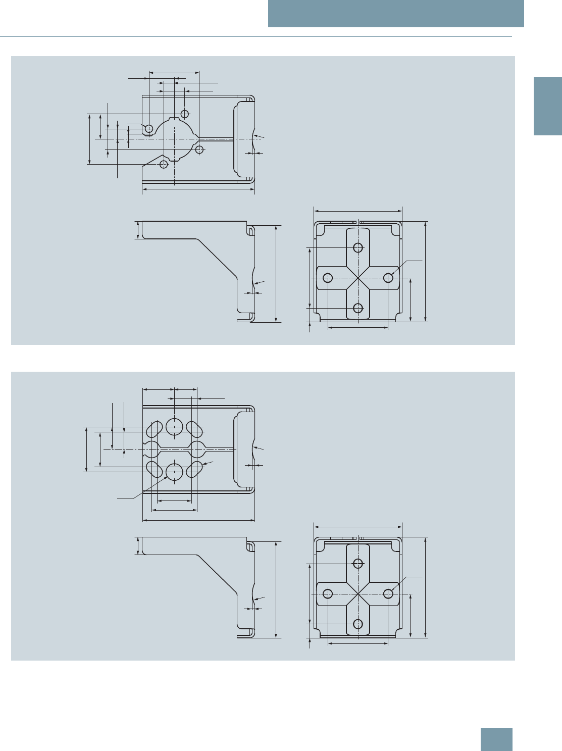
SITRANS P measuring instruments for pressure
SITRANS P Accessories
Accessories / spare parts for SITRANS P
P300 and DS III series
2/141
Siemens FI 01 · 2009
2
■
Dimensional drawings
Mounting bracket for SITRANS P gage and absolute pressure transmitter, DS III series
Material of mounting bracket: Sheet-steel Mat. No. 1.0330, chrome-plated, or stainless steel Mat. No. 1.4301 (304)
Mounting bracket for SITRANS P differential pressure transmitter, DS III series,
Material of mounting bracket: Sheet-steel Mat. No. 1.0330, chrome-plated, or stainless steel Mat. No. 1.4301 (304)
5
5
5
5
5
© Siemens AG 2008
SITRANS P measuring instruments for pressure
SITRANS P Accessories
Factory-mounting of valve manifolds on
SITRANS P transmitters
2/142 Siemens FI 01 · 2009
2
■
Overview
SITRANS P transmitters
• P300 for relative and absolute pressure,
• DS III for relative and absolute pressure (both designs) and
• DS III for differential pressure
can be delivered factory-fitted with the following valve manifolds:
• 7MF9011-4EA and 7MF9011-4FA valve manifolds for relative
pressure and absolute pressure transmitters
• 7MF9411-5BA and 7MF9411-5CA valve manifolds for abso-
lute pressure and differential pressure transmitters
■
Design
The 7MF9011-4EA valve manifolds are sealed with gaskets
made of PTFE between transmitter and the valve manifold as
standard. Soft iron, stainless steel and copper gaskets are also
available for sealing purposes if preferred.
The 7MF9011-4FA valve manifolds are sealed with PTFE sealing
tape between the transmitter and the valve manifold.
The 7MF9411-5BA and 7MF9411-5CA valve manifolds are
sealed with PTFE sealing rings between the transmitter and the
valve manifold.
Once installed, the complete unit is checked under pressure for
leaks and is certified leak-proof with a factory certificate to
EN 10204 - 2.2.
All valve manifolds should preferably be secured with the re-
spective mounting brackets. The transmitters are mounted on
the valve manifold and not on the unit itself.
If you order a mounting bracket when choosing the option "Fac-
tory mounting of valve manifolds", you will receive a mounting
bracket for the valve manifold instead of a bracket for mounting
the transmitter.
If you order an acceptance test certificate 3.1 to EN10204 when
choosing the option "Factory mounting of valve manifolds", a
separate certificate is provided for the transmitters and the valve
manifolds respectively.
■
Selection and Ordering data
7MF9011-4FA valve block on
relative and absolute pressure transmitters
Add -Z to the Order No. of the transmitter
and add order codes. Order
code
SITRANS P DSIII
7MF403.-...1.-..., 7MF423.-...1.-... and
SITRANS P300
7MF802.-...1.-...
With process connection female thread
½-14 NPT in-sealed with PTFE sealing
strip
Delivery incl. high-pressure test certified
by factory certificate to EN10204-2.2
T03
7MF9011-4EA valve block on
relative and absolute pressure transmitters
Add -Z to the Order No. of the transmitter
and add order codes. Order
code
SITRANS P DSIII
7MF403.-...0.-..., 7MF423.-...0.-... and
SITRANS P300
7MF802.-...0.-...
T02
with process connection collar G1/2 A to
EN837-1 with gasket made of PTFE
between valve manifold and transmitter
Alternative sealing material:
• soft iron A70
• stainless steel, Mat. No. 14571 A71
• copper A72
Delivery incl. high-pressure test certified
by factory certificate to EN10204-2.2
Further designs:
Delivery includes mounting brackets and
mounting clips made of stainless steel
(instead of the mounting bracket sup-
plied with the transmitter)
A02
Supplied acceptance test certificate to
EN 10204- 3.1 for transmitters and
mounted valve manifold
C12
Oil and grease-free cleaning for oxygen
operation E10
7MF9411-5BA valve manifold on
absolute and differential pressure transmitters
Add -Z to the Order No. of the transmitter
and add order codes. Order
code
SITRANS P DSIII
7MF433.-…, 7MF443.-… and
7MF453.-…1)
mounted with gaskets made of PTFE and
screws made of
• chromized steel U01
• stainless steel U02
Delivery incl. high-pressure test certified
by factory certificate to EN10204-2.2
7MF9411-5CA valve manifold on differential pressure transmitters
Add -Z to the Order No. of the transmitter
and add order codes. Order
code
SITRANS P DSIII
7MF443.-... und 7MF453.-…1)
mounted with gaskets made of PTFE and
screws made of
• chromized steel U03
• stainless steel U04
Delivery incl. high-pressure test certified
by factory certificate to EN10204-2.2
Further designs:
Delivery includes mounting bracket and
mounting clips made of
• steel A01
• stainless steel A02
(instead of the mounting bracket sup-
plied with the transmitter)
Supplied acceptance test certificate to
EN10204-3.1 for transmitters and
mounted valve manifold
C12
Oil and grease-free cleaning for oxygen
operation E10
1) For 7MF453.-... transmitters, you require a 7/10-20 UNF connection thread
in the process flange.
© Siemens AG 2008
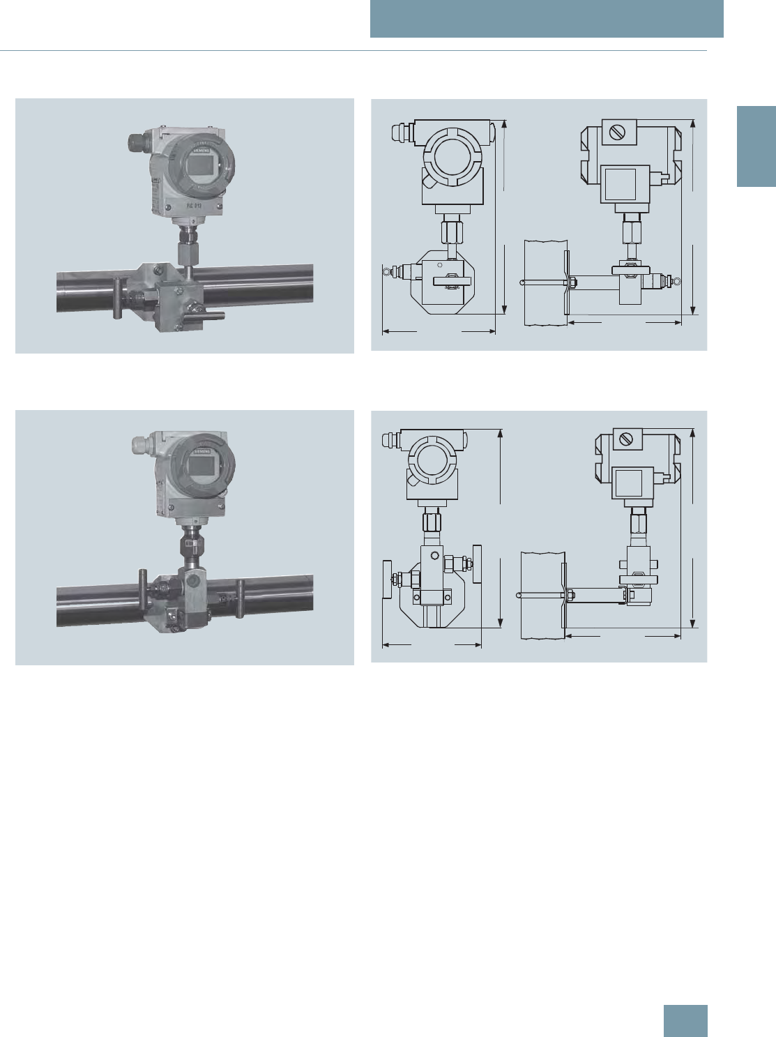
SITRANS P measuring instruments for pressure
SITRANS P Accessories
Factory-mounting of valve manifolds on
SITRANS P transmitters
2/143
Siemens FI 01 · 2009
2
■
Dimensional drawings
Valve manifolds mounted on SITRANS P DS III
Valve manifold 7MF9011-4EA with mounted relative pressure and abso-
lute pressure transmitters
Valve manifold 7MF9011-4EA with mounted relative pressure and abso-
lute pressure transmitters, dimensions in mm (inch)
Valve manifold 7MF9011-4FA with mounted relative pressure and abso-
lute pressure transmitters
Valve manifold 7MF9011-4FA with mounted relative pressure and abso-
lute pressure transmitters, dimensions in mm (inch)
© Siemens AG 2008
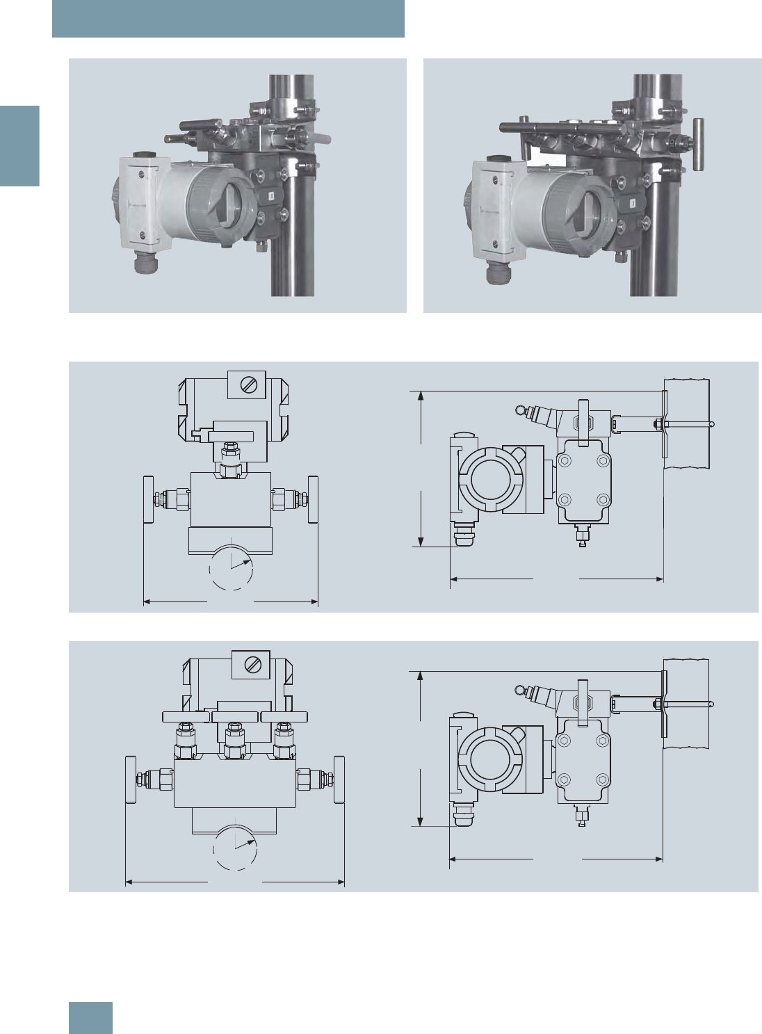
SITRANS P measuring instruments for pressure
SITRANS P Accessories
Factory-mounting of valve manifolds on
SITRANS P transmitters
2/144 Siemens FI 01 · 2009
2
Valve manifold 7MF9411-5BA with mounted differential pressure trans-
mitter Valve manifold 7MF9411-5CA with mounted differential pressure trans-
mitter
Valve manifold 7MF9411-5BA with mounted differential pressure transmitter, dimensions in mm (inch)
Valve manifold 7MF9411-5CA with mounted differential pressure transmitter, dimensions in mm (inch)
5
5
© Siemens AG 2008
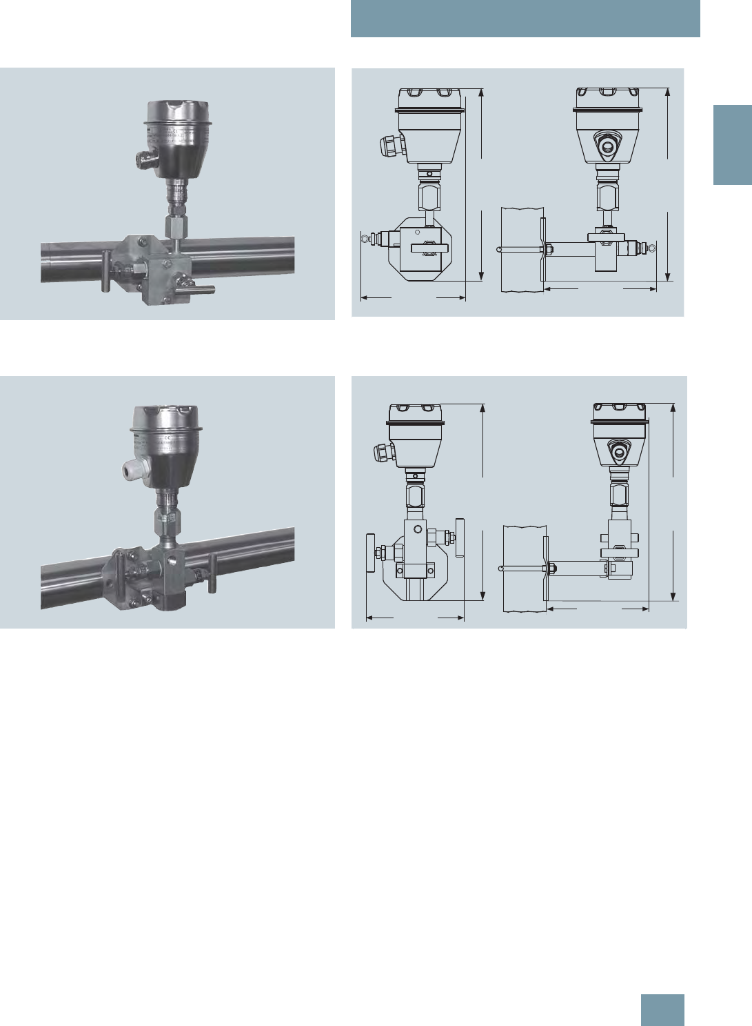
SITRANS P measuring instruments for pressure
SITRANS P Accessories
Factory-mounting of valve manifolds on
SITRANS P transmitters
2/145
Siemens FI 01 · 2009
2
Valve manifolds mounted on SITRANS P300
Valve manifold 7MF9011-4EA with mounted relative pressure and abso-
lute pressure transmitters
Valve manifold 7MF9011-4EA with mounted relative pressure and abso-
lute pressure transmitters, dimensions in mm (inch)
Valve manifold 7MF9011-4FA with mounted relative pressure and abso-
lute pressure transmitters Valve manifold 7MF9011-4FA with mounted relative pressure and abso-
lute pressure transmitters, dimensions in mm
© Siemens AG 2008
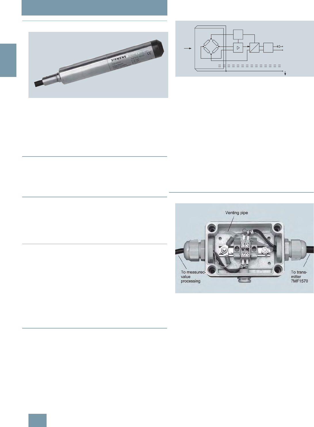
SITRANS P measuring instruments for pressure
Transmitters for hydrostatic level
MPS series (submersible sensor)
2/146 Siemens FI 01 · 2009
2
■
Overview
SITRANS P pressure transmitters, MPS series (submersible sensor)
SITRANS P pressure transmitters, MPS series, are submersible
sensors for hydrostatic level measurements.
The pressure transmitters of the MPS series are available for var-
ious measuring ranges and with explosion protection as an op-
tion.
A junction box and a cable hanger are available as accessories
for simple installation.
■
Benefits
• Compact design
• Simple installation
• Small error in measurement (0.3%)
• Degree of protection IP68
■
Application
SITRANS P pressure transmitters, MPS series, are used in the
following branches for example:
• Oil and gas industries
• Shipbuilding
• Water supply
■
Design
SITRANS P pressure transmitters, MPS series, have a flush-
mounted piezo-resistive sensor with stainless steel diaphragm.
These pressure transmitters are equipped with an electronic cir-
cuit fitted together with the sensor in a stainless steel housing.
The cable also contains a strength cord and vent pipe.
The diaphragm is protected against external influences by a
protective cap.
The sensor, electronic circuit and cable are sealed in a common
housing of small dimensions.
The pressure transmitter is temperature-compensated for a wide
temperature range.
■
Function
SITRANS P pressure transmitters, MPS series, are for measuring
the liquid levels in wells, tanks, channels and dams.
SITRANS P pressure transmitters, MPS series, mode of operation and
wiring diagram
On one side of the sensor, the diaphragm is exposed to the hy-
drostatic pressure which is proportional to the submersion
depth. This pressure is compared with atmospheric pressure.
Pressure compensation is carried out using the vent pipe in the
connection cable.
The hydrostatic pressure of the liquid column acts on the sensor
diaphragm, and transmits the pressure to the piezo-resistive
bridge in the sensor.
The output voltage of the sensor is applied to the electronic cir-
cuit where it is converted into an output current of 4 to 20 mA.
The cable of the 7MF1570 transmitter must always be connected
in the supplied junction box. The junction box has to be installed
near the measuring point.
If the medium is anything other than water, it is also necessary to
check compatibility with the specified materials of the transmit-
ter.
■
Integration
Junction box 7MF1570-8AA, opened
pI
0
, U
B
U
const.
UIEM +2 (brown)
-1 (blue)
Vent pipe
Screen
Diaphragm
Sensor
© Siemens AG 2008

SITRANS P measuring instruments for pressure
Transmitters for hydrostatic level
MPS series (submersible sensor)
2/147
Siemens FI 01 · 2009
2
Measuring point setup, in principle
■
Technical specifications
SITRANS P pressure transmitters, MPS series (submersible sensor)
Mode of operation
Measuring principle Piezo-resistive
Input
Measured variable Hydrostatic level
Measuring range Maximum working pressure
• 0 ... 2 mH2O (0 ... 6 ftH2O) • 1.4 bar (20.3 psi) (corresponds
to 14 mH2O (42 ftH2O))
• 0 ... 4 mH2O (0 ... 12 ftH2O) • 1.4 bar (20.3 psi) (corresponds
to 14 mH2O (42 ftH2O))
• 0 ... 5 mH2O (0 ... 15 ftH2O) • 1.4 bar (20.3 psi) (corresponds
to 14 mH2O (42 ftH2O))
• 0 ... 6 mH2O (0 ... 18 ftH2O) • 3.0 bar (43.5 psi) (corresponds
to 30 mH2O (90 ftH2O))
• 0 ... 10 mH2O (0 ... 30 ftH2O) • 3.0 bar (43.5 psi) (corresponds
to 30 mH2O (90 ftH2O))
• 0 ... 20 mH2O (0 ... 60 ftH2O) • 6.0 bar (87.0 psi) (corresponds
to 60 mH2O (180 ftH2O))
Output
Output signal 4 ... 20 mA
Accuracy To EN 60770-1
Error in measurement (including
non-linearity, hysteresis and repeat-
ability, at 25 °C (77 °F))
0.3% of full-scale value (typical)
Influence of ambient temperature
Zero and span
• 1 ... 6 mH2O (3 ... 18 ftH2O) 0.45%/10 K of full-scale value
•≥ 6 mH2O (≥ 18 ftH2O) 0.3%/10 K of full-scale value
Long-term stability
Zero and span
• 1 ... 6 mH2O (3 ... 18 ftH2O) 0.25% of full-scale value/year
•≥ 6 mH2O (≥ 18 ftH2O) 0.2% of full-scale value/year
Rated operating conditions
Ambient conditions
• Process temperature -10 ... +80 °C (+14 ... +176 °F)
• Storage temperature -40 ... +100 °C (-40 ... +212 °F)
Degree of protection to
DIN EN 60529 IP68
Design
Weight
• Pressure transmitters ≈ 0.4 kg (≈ 0.88 lb)
• Cable 0.08 kg/m (≈ 0.054 lb/ft)
Electrical connection Cable with 2 conductors with
screen and vent pipe, strength
cord (max. 300 N (67.44 lbf)
Material
• Seal diaphragm Stainless steel, mat. No.
1.4571/316 Ti
• Casing Stainless steel, mat. No.
1.4571/316 Ti
• Gasket Viton
• Connecting cable Optionally
PE/HFFR sheath (non-halogen)
or
FEP sheath
Power supply
Terminal voltage on pressure trans-
mitter (UB)10 ... 36 V DC
Certificate and approvals
The transmitter is not subject to the pressure equipment directive
(DGRL 97/23/EC)
Explosion protection
• Intrinsic safety "i" TÜV 03 ATEX 2004X
- Identification Ex II 1 G EEx ia IIC T4
Junction box
Application For connecting the transmitter
cable
Design
Weight 0.2 kg (0.44 lb)
Electrical connection 2 x 3-way (28 ... 18 AWG)
Cable entry 2 x M20x1.5
Enclosure material Polycarbonate
Vent pipe for atmospheric pressure
Screw for cable strength cord
Rated operating conditions
Degree of protection to DIN EN
60529 IP54
Cable hanger
Application For mounting the transmitter
Design
Weight 0.16 kg (0.35 lb)
Material Galvanized steel, polyamide
© Siemens AG 2008
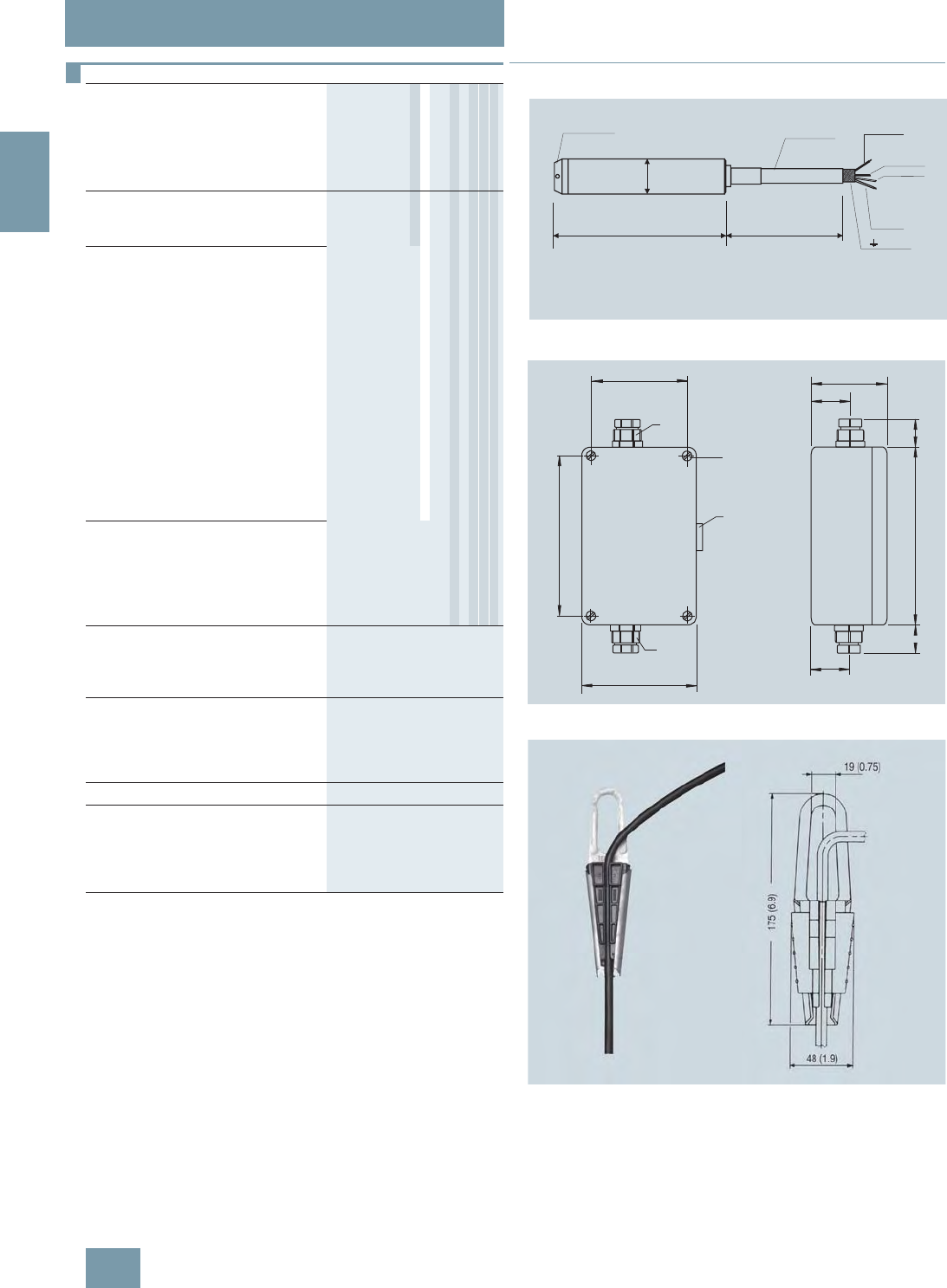
SITRANS P measuring instruments for pressure
Transmitters for hydrostatic level
MPS series (submersible sensor)
2/148 Siemens FI 01 · 2009
2
C) Subject to export regulations AL: N, ECCN: EAR99.
D) Subject to export regulations AL: N, ECCN: EAR99H.
■
Dimensional drawings
SITRANS P pressure transmitters, MPS series, dimensions in mm (inch)
Junction box, dimensions in mm (inch)
Cable hanger, dimensions in mm (inch)
Selection and Ordering data Order No.
SITRANS P pressure transmitters
for pressure, MPS series (submers-
ible sensor)
C) 7 M F 1 5 7 0 - 7 7 A 0 7 7 7 7
2-wire system
Note: Junction box and cable hanger
included in delivery
Cable material
PE }1
FEP 5
Measuring range Cable length L
0 ... 2 mH2O10m }C
0 ... 4 mH2O10m }D
0 ... 5 mH2O25m }B
0 ... 6 mH2O25m }E
0 ... 10 mH2O25m }F
0 ... 20 mH2O25m }G
0 ... 6 ftH2O32ft K
0 ... 12 ftH2O32ft L
0 ... 18 ftH2O82ft M
0 ... 30 ftH2O82ft N
0 ... 60 ftH2O82ft P
Special measuring range/Special cable
length 1)
Specify measuring range and cable
length in plain text
1) Special measuring ranges between 0 ... 1 mH2O (0 ... 3 ftH2O)
and 0 ... 200 mH2O (0 ... 656 ftH2O) and special cable lengths up to
1000 m (3281ft) are possible. With Ex versions the max.
special cable length is 50 m (150 ft). The length of free-hanging cable
should not exceed 375 m.
ZJ 1 Y
Explosion protection
• without }1
• with, type of protection "Intrinsic safe-
ty" (Ex II 1 G EEx ia IIC T4)
}2
• With approval for drinking water to
WRAS and ACS
}
D)
6
Further designs Order code
Quality inspection certificate (Factory
calibration) to IEC 60770-2, add "-Z" to
Order No. and Order code.
C11
Order No.
Quality inspection certificate (Factory
calibration) to IEC 60770-2 supplied
later, specify factory no. of transmitter
for this porpose.
7MF1564-8CC11
Accessories (as spare parts)
Junction box 7MF1570-8AA
for connecting the transmitter cable
Cable hanger 7MF1570-8AB
for mounting the pressure transmitter
} Available ex stock
Power supply units see "SITRANS I power supply units and input isola-
tors".
+ (brown)
- (blue)
Screen
Vent pipe
Protective cap
158 (6.2) L
Ø 27
(1.1
diam.)
Cable sheath 8.3 (0.33) diam. (black or blue, PE/HFFR)
Flexible cable with 0.5 mm2 (0.00078 inch2) cross-section
Vent pipe 1 (0.04) diam. (inner diameter)
Protective cap with 4 x 3 diam. (4 x 0.12 diam.) holes (black, PA)
Cable sheath
Strength
cord (white)
Venting
valve
57 (2.25)
Mounting
hole
50 (1.97)
79 (3.1)
30
(1.2)
94 (3.7)
65 (2.56)
M20x1.5
22
(0.87)
M20x1.5
22
(0.87)
30
(1.2)
© Siemens AG 2008
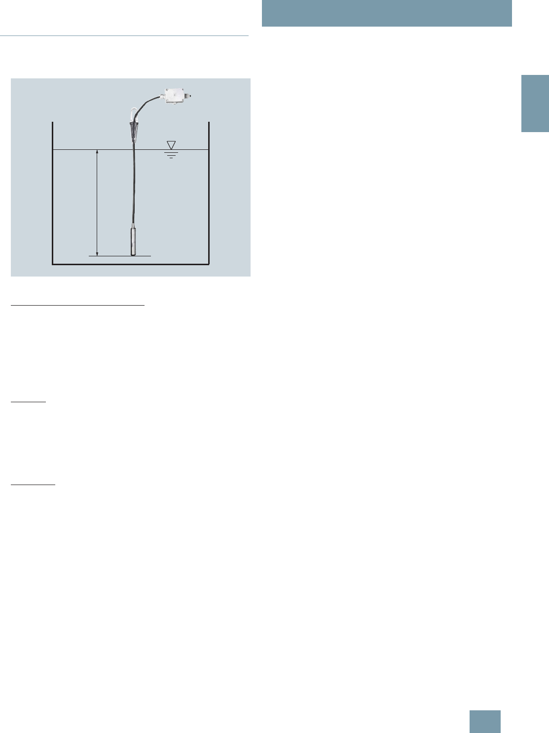
SITRANS P measuring instruments for pressure
Transmitters for hydrostatic level
MPS series (submersible sensor)
2/149
Siemens FI 01 · 2009
2
■
More information
Determination of the measuring range in case of media with
a density
≠
1000 kg/m3 (medium
≠
water)
Calculation of the measuring range:
p =
ρ
x g x H
with:
ρ = density of medium
g = local acceleration due to gravity
H = maximum level
Example:
Medium: Diesel fuel = 850 kg/m3
Acceleration due to gravity: 9.81 m/s2
Start-of-scale : 0 m
Maximum level: 6,2 m
Calculation:
p = 850 kg/m3 x 9.81 m/s2 x 6.2 m
p = 51698.7 N/m2
p = 517 mbar
Transmitter to be ordered:
7MF1570-5ZA02-Z
J1Y: 0 ... 517 mbar; able length e.g. 8 m
+ρ
© Siemens AG 2008
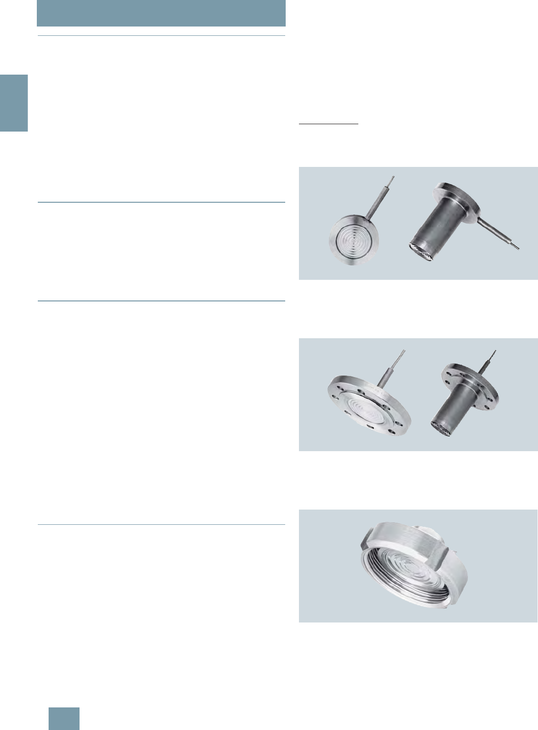
SITRANS P measuring instruments for pressure
Remote seals for transmitters and pressure gages
Technical description
2/150 Siemens FI 01 · 2009
2
■
Overview
In many cases the pressure transmitter and the measured me-
dium have to be physically separated. It is then necessary to use
a remote seal.
The remote seals can be used with the following SITRANS P
pressure transmitter series:
• Pressure (P300, DS III, DS III PA, DS III FF)
• Absolute pressure (P300, DS III, DS III PA, DS III FF)
• Differential pressure and flow (DS III, DS III PA, DS III FF)
Note
When configuring your remote seal, be sure to read the informa-
tion about transmission response, temperature error and re-
sponse time to be found in the sections "Function" and "Technical
data". Only then will the remote seal work to optimum effect.
■
Benefits
• No direct contact between the pressure transmitter and the
medium
• Individual configuration of the pressure transmitter for perfect
adaptation to the operating conditions
• Available in many versions
• Specially designed for difficult operating conditions
• Quick-release versions available for the food industry
■
Application
Remote seal systems should be used if a separation between
the measured medium and the measuring instrument is essential
or appropriate.
Examples of such cases:
• The temperature of the medium is outside the limits specified
for the pressure transmitter.
• The medium is corrosive and requires diaphragm materials
which are not available for the pressure transmitter.
• The medium is highly viscous or contains solids which would
Siemens FI 01 · 2009block the measuring chambers of the
pressure transmitter.
• The medium may freeze in the measuring chambers or pulse
line.
• The medium is heterogeneous or fibrous.
• The medium tends towards polymerization or crystallization.
• The process requires quick-release remote seals, as neces-
sary e.g. in the food industry for fast cleaning.
• The process requires cleaning of the measuring point, e.g. in
a batch process.
■
Design
A remote seal system consists of the following components.
• Pressure transmitter
• One or two remote seals
• Filling liquid
• Connection between pressure transmitter and remote seal (di-
rect mounting or by means of capillary)
The volume in contact with the measured medium is terminated
by a flat elastic diaphragm lying in a bed. Between the dia-
phragm and the pressure transmitter is the filling liquid.
In many cases, a capillary has to be connected between the re-
mote seal and the pressure transmitter in order e.g. to minimize
temperature effects on the latter when hot media are involved.
However, the capillary influences the response time and the tem-
perature response of the complete remote seal system. Two
capillaries of equal length must always be used to connect a re-
mote seal to a pressure transmitter for differential pressure.
The remote seal can be optionally equipped with a projecting di-
aphragm (tube).
Remote seals of sandwich design are fitted with a dummy
flange.
Designs
Diaphragm seal
With diaphragm seals, the pressure is measured by means of a
flat diaphragm which rests in a bed.
The following types of diaphragm seals exist:
Diaphragm seal of sandwich design without (left) and with a projecting
diaphragm (tube)
• Sandwich design
• Sandwich design with projecting diaphragm (tube) to DIN or
ASME which are secured using a dummy flange.
Diaphragm seal of flange design without (left) and with a projecting dia-
phragm (tube)
• Flange design
• Flange design with projecting diaphragm (tube) to DIN or
ASME, secured using holes in the flange.
Quick-release diaphragm seal
• Quick-release remote seals, e.g. to DIN 11851, SMS standard,
IDF standard, APV RJT standard, clamp connection, etc.
• Miniature diaphragm seal with male thread for screwing into
tapped holes
• Remote seals with customer-specific process connections
© Siemens AG 2008
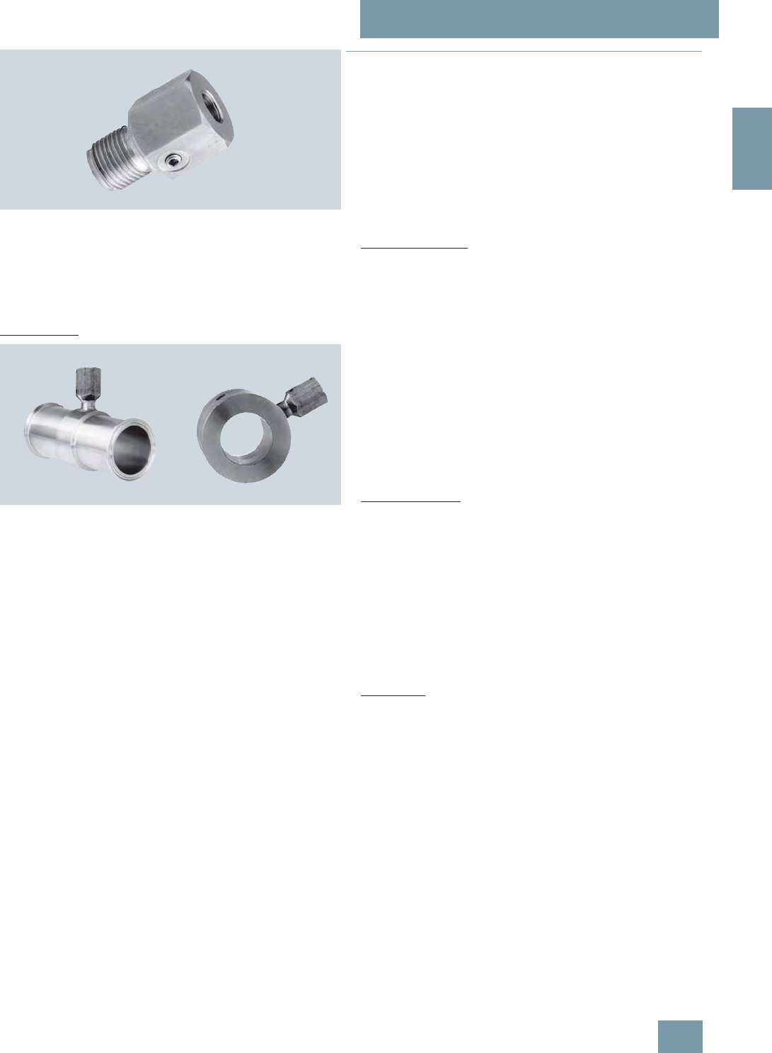
SITRANS P measuring instruments for pressure
Remote seals for transmitters and pressure gages
Technical description
2/151
Siemens FI 01 · 2009
2
Miniature diaphragm seal with diaphragm flush with front
• Miniature diaphragm seals
The quick-release remote seals are used above all in the food in-
dustry. Their design means that the measured medium cannot
accumulate in dead volumes. The quick-release clamp present
on the remote seal means that quick dismounting is possible for
cleaning.
Clamp-on seal
Clamp-on seal with quick-release design (left) and for flange mounting
With clamp-on seals, the pressure is first measured using a cy-
lindrical diaphragm positioned in a pipe, and then transmitted to
the pressure transmitter by means of the filling liquid.
The clamp-on seal is a special design for flowing media. It con-
sists of a cylindrical pipe in which a cylindrical diaphragm is em-
bedded. Since it is completely integrated in the process pipe, no
turbulences, dead volumes or other obstructions to the flow oc-
cur. Furthermore, the clamp-on seal can be cleaned by a pig.
The following types of clamp-on seals exist:
• Quick-release clamp-on seals, e.g. to DIN 11851, SMS stan-
dard, IDF standard, APV/RJT standard, clamp connection etc.
The quick-release facility attached to the remote seal enables
the seal to be removed quickly for cleaning purposes.
• Clamp-on seals for flanging to EN or ASME.
• Clamp-on seals with customer-specific process connections.
Note:
The pressure data on the transmitter and the remote seal must
be observed with regard to pressure/temperature behavior.
■
Function
The measured pressure is transferred from the diaphragm to the
filling liquid and passes through the capillary to the measuring
chamber of the pressure transmitter. The interior of the dia-
phragm seal and of the capillary, as well as the measuring cham-
ber of the transmitter, are filled gas-free by the filling liquid.
Transmission response
The transmission response of a remote seal is characterized by
the following variables:
•Temperature error
• Adjustment time
Temperature error
Temperature errors are caused by the change of volume of the
filling liquid due to temperature variations. To select the right re-
mote seal you must calculate the temperature error.
Below you will find an overview of the factors which influence the
size of the temperature error, as well as information on how to
calculate the temperature error.
The temperature error is dependent on the following variables:
• Rigidity of the diaphragm used
• Filling liquid used
• Influence of the filling liquid underneath the process flanges or
in the connection shank of the pressure transmitter
• Internal diameter of the capillary: The bigger the internal diam-
eter, the bigger the temperature error
• Length of the capillary: The longer the capillary, the bigger the
temperature error
Diaphragm rigidity
The rigidity of the diaphragm is of decisive importance. The big-
ger the diameter of the diaphragm, the softer the diaphragm and
the more sensitively it reacts to temperature-induced changes in
volume of the filling liquid.
The result is that small measuring ranges are only possible with
large diaphragm diameters.
Other factors apart from diaphragm rigidity which also play a
role:
• Diaphragm thickness
• Diaphragm material
• Coatings if present
Filling liquid
Every filling liquid reacts to temperature variations with a change
of volume. Temperature errors can be minimized by selecting a
suitable filling liquid, but the filling liquid must also be appropri-
ate for the temperature limits and operating pressure. Further-
more, the filling liquid must also be physiologically harmless.
Since the filling liquid is present under the diaphragm, in the
capillary and under the process flange of the pressure transmit-
ter (or in the connection shank), the temperature error must be
calculated separately for each combination.
Note:
When operating in the low-pressure range, also during commis-
sioning, it is recommended to use a vacuum-proof remote seal
(see Selection and Ordering data).
An example of a temperature error calculation can be found in
the section "Technical Specifications".
© Siemens AG 2008

SITRANS P measuring instruments for pressure
Remote seals for transmitters and pressure gages
Technical description
2/152 Siemens FI 01 · 2009
2
Response time
The response time is dependent on the following factors:
• Internal diameter of the capillary: The bigger the internal diam-
eter, the shorter the response time
• Viscosity of the filling liquid The greater the viscosity, the
longer the response time
• Length of the capillary: The longer the capillary, the longer the
response time
• Pressure in the pressure measuring system: The higher the
pressure, the shorter the response time
Recommendations
The following should be observed to obtain an optimum combi-
nation of transmitter and remote seal:
• Choose the biggest possible diameter for the remote seal. The
effective diameter of the seal diaphragm is then bigger and
the temperature error smaller.
• Choose the shortest possible capillary. The response time is
then shorter and the temperature error smaller
• Choose the filling liquid with the least viscosity and the small-
est coefficient of expansion. Make sure, however, that the fill-
ing liquid meets the process requirements with regard to pres-
sure, vacuum and temperature. And ensure that the filling
liquid and the medium are compatible with one another.
• Note the following points for use in the vacuum range:
- The pressure transmitter must always be positioned below
the lowest spigot.
- The operating range of some filling liquids is very limited with
regard to the permissible temperature of the medium.
- A vacuum-proof seal is necessary for continuous operation
in the low-pressure range.
• Recommendations for the minimum span can be found in the
section "Technical data".
Note
The remote seals listed here are a selection of the most common
designs. On account of the large variety of process connections,
certain remote seals which are not listed here may be available
nevertheless.
Other versions can be:
• Other process connections, standards
• Aseptic or sterile connections
• Other dimensions
• Other nominal pressures
• Special diaphragm materials, including coatings
• Other sealing faces
• Other filling liquids
• Other capillary lengths
• Sheathing of capillaries with protective hose
• Calibration at higher/lower temperatures etc.
Please contact your Siemens Regional Office for more infor-
mation.
© Siemens AG 2008

SITRANS P measuring instruments for pressure
Remote seals for transmitters and pressure gages
Technical description
2/153
Siemens FI 01 · 2009
2
■
Technical specifications
Temperature error Diaphragm seals
Temperature errors of diaphragm seals when connected to pressure transmitters for pressure, absolute pressure, differential pres-
sure (single-sided) and level
Remarks:
• Values apply for the filling liquids silicone oil M5, silicone oil M50, high-temperature oil, halocarbon oil and food oil (FDA listed).
• Half the values apply to glycerin/water mixture as the filling liquid.
• Values apply to stainless steel as the diaphragm material.
Nominal diameter/
design Diaphragm
diameter Temperature
error of remote
seal
Temperature error of
capillary Temperature
error of process
flange/connec-
tion spigot
Recommended
min. spans (guid-
ance values,
observe temp.
error)
mm (inch) mbar/
10 K (psi/
10 K) mbar/
(10 K ⋅mKap)(psi/
(10 K ⋅mKap))mbar/
10 K (psi/
10 K) mbar (psi)
Sandwich
design or with
flange to
EN 1092-1
DN 50 without tube 59 (2.32) 1.5 (0.022) 2 (0.029) 2 (0.029) 200 (2.90)
DN 50 with tube 48 (1.89) 5 (0.073) 10 (0.145) 10 (0.145) 500 (7.25)
DN 80 without tube 89 (3.50) 0.2 (0.003) 0.2 (0.003) 0.2 (0.003) 100 (1.45)
DN 80 with tube 72 (2.83) 1 (0.015) 1 (1.015) 1 (1.015) 250 (3.63)
DN 100 without tube 89 (3.50) 0.4 (0.006) 0.4 (0.006) 0.4 (0.006) 100 (1.45)
DN 100 with tube 89 (3.50) 0.4 (0.006) 0.4 (0.006) 0.4 (0.006) 100 (1.45)
DN 125 without tube 124 (4.88) 0.2 (0.003) 0.1 (0.002) 0.1 (0.002) 20 (0.29)
DN 125 with tube 124 (4.88) 0.2 (0.003) 0.1 (0.002) 0.1 (0.002) 20 (0.29)
Sandwich
design or with
flange to
ASME B16.5
2 inch without tube 59 (2.32) 1.5 (0.022) 2 (0.029) 2 (0.029) 200 (2.90)
2 inch with tube 48 (1.89) 5 (0.073) 10 (0.145) 10 (0.145) 500 (7.25)
3 inch without tube 89 (3.50) 0.2 (0.003) 0.2 (0.003) 0.2 (0.003) 100 (1.45)
3 inch with tube 72 (2.83) 1 (0.015) 1 (1.015) 1 (1.015) 250 (3.63)
4 inch without tube 89 (3.50) 0.4 (0.006) 0.4 (0.006) 0.4 (0.006) 100 (1.45)
4 inch with tube 89 (3.50) 0.4 (0.006) 0.4 (0.006) 0.4 (0.006) 100 (1.45)
5 inch without tube 124 (4.88) 0.2 (0.003) 0.1 (0.002) 0.1 (0.002) 20 (0.29)
5 inch with tube 124 (4.88) 0.2 (0.003) 0.1 (0.002) 0.1 (0.002) 20 (0.29)
Remote seal
with union nut to
DIN 11851
DN 25 25 (0.98) 20 (0.290) 60 (0.870) 60 (0.870) 6000 (87)
DN 32 32 (1.26) 8 (0.116) 25 (0.363) 25 (0.363) 4000 (58)
DN 40 40 (1.57) 4 (0.058) 10 (0.145) 10 (0.145) 2000 (29)
DN 50 52 (2.05) 4 (0.058) 5 (0.073) 5 (0.073) 500 (7.25)
DN 65 59 (2.32) 3 (0.044) 4 (0.058) 4 (0.058) 500 (7.25)
DN 80 72 (2.83) 1 (0.015) 1 (0.015) 1 (0.015) 250 (3.63)
Remote seal
with threaded
socket to
DIN 11851
DN 25 25 (0.98) 20 (0.290) 60 (0.870) 60 (0.870) 6000 (87)
DN 32 32 (1.26) 8 (0.116) 25 (0.363) 25 (0.363) 4000 (58)
DN 40 40 (1.57) 4 (0.058) 10 (0.145) 10 (0.145) 2000 (29)
DN 50 52 (2.05) 4 (0.058) 5 (0.073) 5 (0.073) 500 (7.25)
DN 65 59 (2.32) 3 (0.044) 4 (0.058) 4 (0.058) 500 (7.25)
DN 80 72 (2.83) 1 (0.015) 1 (0.015) 1 (0.015) 250 (3.63)
Clamp connec-
tion 1½ inch 32 (1.26) 8 (0.116) 25 (0.363) 25 (0.363) 4000 (58)
2 inch 40 (1.57) 4 (0.058) 10 (0.145) 10 (0.145) 2000 (29)
2½ inch 59 (2.32) 3 (0.044) 5 (0.073) 5 (0.073) 500 (7.25)
3 inch 72 (2.83) 1 (0.015) 1 (0.015) 1 (0.015) 250 (3.63)
Miniature dia-
phragm seal G1B 25 (0.98) 20 (0.290) 60 (0.870) 60 (0.870) 6000 (87)
G1½B 40 (1.57) 4 (0.058) 10 (0.145) 10 (0.145) 2000 (29)
G2B 52 (2.05) 4 (0.058) 5 (0.073) 5 (0.073) 500 (7.25)
© Siemens AG 2008

SITRANS P measuring instruments for pressure
Remote seals for transmitters and pressure gages
Technical description
2/154 Siemens FI 01 · 2009
2
Temperature errors of diaphragm seals with connection to differential pressure transmitters (double-sided)
Remarks:
• Values apply for the filling liquids silicone oil M5, silicone oil M50, high-temperature oil, halocarbon oil and food oil (FDA listed)
• Half the values apply to glycerin/water mixture as the filling liquid
• Values apply to stainless steel as the diaphragm material.
Nominal diameter/
design Diaphragm
diameter Temperature error
of remote seal Temperature error of cap-
illary Temperature error
of process
flange/connec-
tion spigot
Recommended
min. spans
(guidance val-
ues, observe
temperature
error)
mm (inch) mbar/
10 K (psi/
10 K) mbar/
(10 K ⋅mKap)(psi/
(10 K ⋅mKap)) mbar/
10 K (psi/
10 K) mbar (psi)
Sandwich
design or with
flange to
EN 1092-1
DN 50 without tube 59 (2.32) 0.3 (0.0043) 0.3 (0.0045) 0.3 (0.0045) 250 (3.626)
DN 50 with tube 48 (1.89) 1.26 (0.018) 1.7 (0.025) 1.7 (0.025) 250 (3.626)
DN 80 without tube 89 (3.50) 0.05 (0.001) 0.05 (0.001) 0.05 (0.0007) 50 (0.725)
DN 80 with tube 72 (2.83) 0.24 (0.004) 0.17 (0.003) 0.17 (0.003) 100 (1.45)
DN 100 without tube 89 (3.50) 0.1 (0.002) 0.07 (0.001) 0.07 (0.001) 50 (0.725)
DN 100 with tube 89 (3.50) 0.1 (0.002) 0.07 (0.001) 0.07 (0.001) 50 (0.725)
DN 125 without tube 124 (4.88) 0.05 (0.001) 0.03 (0.0004) 0.03 (0.0004) 20 (0.29)
DN 125 with tube 124 (4.88) 0.05 (0.001) 0.03 (0.0004) 0.03 (0.0004) 20 (0.29)
Sandwich
design with
flange to ASME
B16.5
2 inch without tube 59 (2.32) 0.3 (0.0043) 0.3 (0.0043) 0.3 (0.0045) 250 (3.626)
2 inch with tube 48 (1.89) 1.26 (0.018) 1.7 (0.025) 1.7 (0.025) 250 (3.626)
3 inch without tube 89 (3.50) 0.05 (0.001) 0.05 (0.0007) 0.05 (0.0007) 50 (0.725)
3 inch with tube 72 (2.83) 0.24 (0.004) 0.17 (0.003) 0.17 (0.003) 100 (1.45)
4 inch without tube 89 (3.50) 0.1 (0.002) 0.07 (0.001) 0.07 (0.001) 50 (0.725)
4 inch with tube 89 (3.50) 0.1 (0.002) 0.07 (0.001) 0.07 (0.001) 50 (0.725)
5 inch without tube 124 (4.88) 0.05 (0.001) 0.03 (0.0004) 0.03 (0.0004) 20 (0.29)
5 inch with tube 124 (4.88) 0.05 (0.001) 0.03 (0.0004) 0.03 (0.0004) 20 (0.29)
Remote seal
with union nut to
DIN 11851
DN 50 52 (2.05) 1 (0.015) 0.83 (0.012) 0.83 (0.012) 250 (3.626)
DN 65 59 (2.32) 0.7 (0.010) 0.67 (0.010) 0.67 (0.010) 250 (3.626)
DN 80 72 (2.83) 0.24 (0.004) 0.17 (0.003) 0.17 (0.003) 100 (1.450)
Remote seal
with threaded
socket to
DIN 11851
DN 50 52 (2.05) 1 (0.015) 0.83 (0.012) 0.83 (0.012) 250 (3.626)
DN 65 59 (2.32) 0.7 (0.010) 0.67 (0.010) 0.67 (0.010) 250 (3.626)
DN 80 72 (2.83) 0.24 (0.004) 0.17 (0.003) 0.17 (0.003) 100 (1.450)
Clamp connec-
tion 2 inch 40 (1.57) 1 (0.015) 2.5 (0.036) 2.5 (0.036) 2000 (29.01)
2½ inch 59 (2.32) 0.7 (0.010) 0.67 (0.010) 0.67 (0.010) 250 (3.626)
3 inch 72 (2.83) 0.24 (0.004) 0.17 (0.003) 0.17 (0.003) 100 (1.450)
© Siemens AG 2008

SITRANS P measuring instruments for pressure
Remote seals for transmitters and pressure gages
Technical description
2/155
Siemens FI 01 · 2009
2
Temperature error Clamp-on seals
Temperature errors of clamp-on seals when connected to pressure transmitters for pressure and absolute pressure, and with single-
sided connection to pressure transmitters for differential pressure
Temperature errors of clamp-on seals with double-sided connection to pressure transmitters for differential pressure
Remarks:
• Values apply for the filling liquids silicone oil M5, silicone oil M50, high-temperature oil, halocarbon oil and food oil (FDA listed).
• Half the values apply to glycerin/water mixture as the filling liquid.
• Values apply to stainless steel as the diaphragm material.
• Diaphragm thickness 0.05 mm (0.002 inch) for DN 25/DN 40/DN 50 and 0.1 mm (0.004 inch) for DN 80/DN 100
Nominal diameter/
design Temperature error of remote
seal Temperature error of
capillary Temperature error of pro-
cess flange/connection
spigot
Recommended min. spans
(guidance values, observe
temperature error)
mbar/10 K (psi/10 K) mbar/10 K (psi/10 K) mbar/10 K (psi/10 K) mbar (psi)
DN 25 (1 inch) 6.0 (0.0870) 8.5 (0.123) 8.5 (0.123) 1000 (14.5)
DN 40 (1½ inch) 4.5 (0.065) 4.5 (0.065) 4.5 (0.065) 250 (3.63)
DN 50 (2 inch) 4.0 (0.058) 3.0 (0.044) 3.0 (0.044) 100 (1.45)
DN 80 (3 inch) 9.5 (0.138) 5.0 (0.073) 5.0 (0.073) 100 (1.45)
DN 100 (4 inch) 8.0 (0.012) 3.0 (0.044) 3.0 (0.044) 100 (1.45)
Nominal diameter/
design Temperature error of remote
seal Temperature error of
capillary Temperature error of pro-
cess flange/connection
spigot
Recommended min. spans
(guidance values, observe
temperature error)
mbar/10 K (psi/10 K) mbar/10 K (psi/10 K) mbar/10 K (psi/10 K) mbar (psi)
DN 25 (1 inch) 2.3 (0.033) 1.8 (0.026) 1.8 (0.026) 1000 (14.5)
DN 40 (1½ inch) 0.8 (0.012) 0.3 (0.004) 0.3 (0.004) 250 (3.63)
DN 50 (2 inch) 0.3 (0.004) 0.1 (0.002) 0.1 (0.002) 100 (1.45)
DN 80 (3 inch) 3.0 (0.044) 0.5 (0.007) 0.5 (0.007) 100 (1.45)
DN 100 (4 inch) 1.0 (0.015) 0.1 (0.002) 0.1 (0.002) 100 (1.45)
© Siemens AG 2008

SITRANS P measuring instruments for pressure
Remote seals for transmitters and pressure gages
Technical description
2/156 Siemens FI 01 · 2009
2
Calculation of the temperature error
The following equation is used to calculate the temperature er-
ror:
Example of temperature error calculation
Dependence of temperature error on diaphragm material
The temperature errors listed in the previous table are based on
the use of stainless steel as the diaphragm material. If other dia-
phragm materials are used, the temperature errors change as
follows:
Maximum temperature of medium
The following maximum temperatures of the medium apply de-
pending on the material of the wetted parts:
Maximum capillary length for diaphragm seals (guidance
values)
dp = (ϑRS – ϑCal) ⋅ fRS + (ϑCap – ϑCal) ⋅ lCap ⋅fCap + (ϑTR – ϑCal) ⋅ fPF
dp Additional temperature error (mbar)
ϑRS Temperature on remote seal diaphragm (generally
corresponds to temperature of medium)
ϑCal Calibration (reference) temperature (20 °C (68 °F))
fRS Temperature error of remote seal
ϑCap Ambient temperature on the capillaries
lCap Capillary length
fCap Temperature error of capillaries
ϑTR Ambient temperature on pressure transmitter
fPF Temperature error of the oil filling in the process
flanges of the pressure transmitter
Existing conditions
SITRANS P pressure transmitter for
differential pressure, 250 mbar, set
to 0 ... 100 mbar, with DN 80 remote
seal diaphragms without tube, dia-
phragm made of stainless steel,
mat. No. 1.4404/316L
fRS = 0.1 mbar/10 K
(0.0014 psi/10 K)
Capillary length lCap = 6 m (19.7 ft)
Capillaries fitted on both sides fCap = 0.07 mbar/(10 K ⋅ mCap)
(0.001 psi/(10 K ⋅ mCap))
Filling liquid silicone M5 fPF = 0.07 mbar/10 K
(0.001 psi/10 K)
Process temperature ϑRS = 100 °C (212 °F)
Temperature on the capillaries ϑCap = 50 °C (122 °F)
Temperature on pressure transmit-
ter ϑTR = 50 °C (122 °F)
Calibration temperature ϑCal = 20 °C (68 °F)
Required
Additional temperature error of
remote seals dp
Calculation
in mbar
dp = (100 °C – 20 °C) ⋅ 0.1 mbar/10 K + (50 °C – 20 °C) ⋅ 6m ⋅
0.07 mbar/(10 K ⋅ m) + (50 °C – 20 °C) ⋅ 0.07 mbar/10 K
dp = 0.8 mbar + 1.26 mbar + 0.21 mbar
in psi
dp = (212 °F – 68 °F) ⋅ 0.0014 psi/10 K + (112 °F – 68 °F) ⋅ 19.7 ft ⋅
0.001 psi/(10 K ⋅ 3.28 ft) + (112 °F – 68 °F) ⋅ (0.001 psi/10 K)
dp = 0.012 psi + 0.018 psi + 0.003 psi
Result
dp = 2.27 mbar (0.033 psi) (corresponds to 2.27% of set span)
Note
The determined temperature error only applies to the error resulting
from connection of the remote seal.
The transmission response of the respective transmitter is not included
in this consideration.
It must be calculated separately, and the resulting error added to the
error determined above from connection of the remote seal.
Diaphragm material Change in temperature error of
remote seal
Increase in values by
Stainless steel See previous tables
Hastelloy C4, mat. No. 2.4610 50%
Hastelloy C276, mat. No. 2.4819 50%
Monel 400, mat. No. 2.4360 60%
Tantalum 50%
Titanium 50%
PTFE coating on stainless steel dia-
phragm 80%
ECTFE coating or PFA coating on
stainless steel diaphragm 100%
Gold coating on stainless steel dia-
phragm 40%
Material pabs < 1 bar
(14.5 psi) pabs > 1 bar
(14.5 psi)
°C (°F) °C (°F)
Stainless steel, 316L 200 (392) 400 (662)
PTFE coating 200 (392) 260 (500)
ECTFE coating 100 (212) 150 (302)
PFA coating 200 (392) 260 (500)
Hastelloy C4, mat. No. 2.4610 200 (392) 260 (500)
Hastelloy C276, mat. No.
2.4819 200 (392) 400 (662)
Monel 400, mat. No. 2.4360 200 (392) 400 (662)
Tantalum 200 (392) 300 (572)
Nom. diam. Max. length of capillary
Diaphragm seal Clamp-on seal
m (ft) m (ft)
DN 25 (1 inch) 2.5 (8.2) 2.5 (8.2)
DN 32 (1¼ inch) 2.5 (8.2) 2.5 (8.2)
DN 40 (1½ inch) 4 (13.1) 6 (19.7)
DN 50 (2 inch) 6 (19.7) 10 (32.8)
DN 65 (2½ inch) 8 (26.2) 10 (32.8)
DN 80 (3 inch) 10 (32.8) 10 (32.8)
DN 100 (4 inch) 10 (32.8) 10 (32.8)
DN 125 (5 inch) 10 (32.8) - -
© Siemens AG 2008
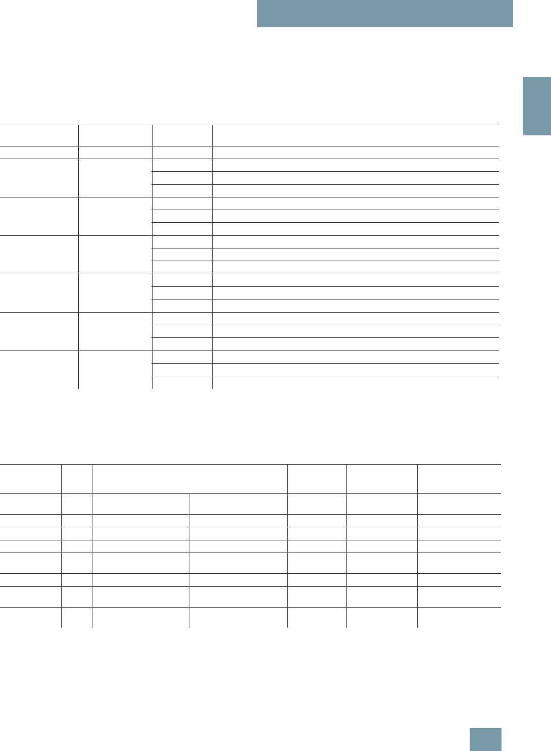
SITRANS P measuring instruments for pressure
Remote seals for transmitters and pressure gages
Technical description
2/157
Siemens FI 01 · 2009
2
Response times
The values listed in the following table are the response times (in
seconds per meter of capillary) for a change in pressure which
corresponds to the set span.
The listed values must be multiplied by the respective length of
the capillary, or with transmitters for differential pressure and flow
by the total length of both capillaries.
The response times are independent of the set span within the
range of the respective transmitter. The response times are of in-
significant importance for spans above 10 bar (145 psi). The re-
sponse times of the pressure transmitters are not considered in
the table.
Technical data of filling liquids
When selecting the filling liquid, check that it is suitable with re-
spect to the permissible temperature of the medium and the pro-
cess pressure.
Also check the compatibility of the filling liquid with the mea-
sured medium. For example, only physiologically harmless filling
liquids may be used in the food industry.
Oxygen and chlorine are special cases of measured medium.
The liquid must not react with either of these two media or a leak-
ing remote seal may lead to an explosion or fire.
Filling liquid Density Temperature
on capillary Response time in s/m (s/ft) with max. span of pressure transmitter
kg/dm3(lb/in3) °C (°F) 250 mbar (3.63 psi) 600 mbar (8.7 psi) 1600 mbar (23.2 psi)
Silicone oil M5 0.914 (0.033) +60 (140) 0.06 (0.018) 0.02 (0.006) 0.01 (0.003)
+20 (68) 0.11 (0.034) 0.02 (0.006) 0.02 (0.006)
- 20 (-4) 0.3 (0.091) 0.12 (0.037) 0.05 (0.015)
Silicone oil M50 0.966 (0.035) +60 (140) 0.6 (0.183) 0.25 (0.076) 0.09 (0.027)
+20 (68) 0.61 (0.186) 0.26 (0.079) 0.1 (0.030)
- 20 (-4) 1.69 (0.515) 0.71 (0.216) 0.27 (0.082)
High-temperature oil 1.070 (0.039) +60 (140) 0.14 (0.043) 0.06 (0.018) 0.02 (0.006)
+20 (68) 0.65 (0.198) 0.27 (0.082) 0.1 (0.030)
-10 (14) 3.96 (1.207) 1.65 (0.503) 0.62 (0.189)
Halocarbon oil 1.968 (0.071) +60 (140) 0.07 (0.021) 0.03 (0.009) 0.01 (0.003)
+20 (68) 0.29 (0.088) 0.12 (0.037) 0.05 (0.015)
- 20 (-4) 2.88 (0.878) 1.2 (0.366) 0.45 (0.137)
Food oil (FDA listed) 0.920 (0.033) +60 (140) 0.75 (0.229) 0.33 (0.101) 0.17 (0.052)
+20 (68) 4 (1.220) 1.75 (0.534) 0.67 (0.204)
- 20 (-4) 20 (6.100) 8.5 (2.593) 3.25 (0.991)
Glycerin/water 1.220 (0.044) +60 (140) 0.13 (0.040) 0.05 (0.015) 0.02 (0.006)
+20 (68) 0.76 (0.232) 0.32 (0.098) 0.12 (0.037)
0 (32) 9.72 (2.963) 4.05 (1.234) 1.51 (0.460)
Filling liquid Digit in
Order
No.
Permissible temperature of medium Density at
20 °C (68 °F) Viscosity at
20 °C (68 °F) Coefficient of expan-
sion
pabs <
1 bar (pabs <
14.5 psi) pabs >
1bar (pabs >
14.5 psi)
°C (°F) °C (°F) kg/dm3(lb/in3)m
2/s⋅106(ft2/s⋅106)1/°C (1/°F)
Silicone oil M5 1 -60 ... +80 (-76 ... +176) -90 ... +180 (-130 ... +356) 0.914 (0.03) 4 (43) 0.00108 (0.00060)
Silicone oil M50 2 -40 ... +150 (-40 ... +302) -40 ... +250 (-40 ... +482) 0.96 (0.03) 50 (538) 0.00104 (0.00058)
High-tempera-
ture oil 3 -10 ... +200 (+14 ... +392) -10 ... +350 (+14 ... +662) 1.07 (0.04) 39 (420) 0.00080 (0.00044)
Halocarbon oil 4 -40 ... +80 (-40 ... +176) -40 ... +175 (-40 ... +347) 1.968 (0.07) 14 (151) 0.00086 (0.00048)
Glycerin/water 6 Not possi-
ble Not possible -10 ... +120 (+14 ... +248) 1.22 (0.04) 88 (947) 0.00050 (0.00028)
Food oil (FDA
listed) 7 -20 ... +160 (-4 ... +320) -20 ... +200 (-4 ... +392) 0.92 (0.03) 10 (107) 0.00080 (0.00044)
© Siemens AG 2008

SITRANS P measuring instruments for pressure
Diaphragm seals of sandwich design
For gage, absolute, differential pressure and flow
with flexible capillary
2/158 Siemens FI 01 · 2009
2
■
Overview
Diaphragm seals of sandwich design
■
Technical specifications
Diaphragm seals of sandwich design
Nominal diameter Nominal pressure
• DN 50 PN 16 ... PN 100
• DN 80 PN 16 ... PN 100
• DN 100 PN 16 ... PN 100
• DN 125 PN 16 ... PN 100
• 2 inch Class 150 ... class 2500
• 3 inch Class 150 ... class 2500
• 4 inch Class 150 ... class 2500
• 5 inch Class 150 ... class 2500
Sealing face
• For stainless steel, mat. No.
1.4404/216L To EN 1092-1, form B1 or
ASME B16.5 RF 125 ... 250 AA
• For the other materials To EN 1092-1, form B2 or
ASME B16.5 RFSF
Materials
• Main body Stainless steel 316L
• Wetted parts Stainless steel 316L
• Without foil
• PTFE (for vacuum on request)
• ECTFE (for vacuum on request)
• PFA (for vacuum on request)
Monel 400, mat. No. 2.4360
Hastelloy C276, mat. No. 2.4819
Hastelloy C4, mat. No. 2.4610
Tantalum
• Capillary Stainless steel, mat. No.
1.4571/316Ti
• Sheath Spiral hose made of stainless
steel, mat. No. 1.4301/316
Sealing material in the process
flanges
• For pressure transmitters, absolute
pressure transmitters and low-
pressure applications
Copper
• For other applications Viton
Maximum pressure See above and the technical data
of the pressure transmitters
Tube length Without tube as standard (tube
available on request)
Capillary
• Length Max. 10 m (32.8 ft), longer
lengths on request
• Internal diameter max. 2 mm (0.079 inch)
• Minimum bending radius 150 mm (5.9 inch)
Filling liquid Silicone oil M5
Silicone oil M50
High-temperature oil
Halocarbon oil (for measuring O2)
Food oil (FDA listed)
Glycerine/water (not suitable for
use in low-pressure range)
Permissible ambient temperature Dependent on the pressure trans-
mitter and the filling liquid of the
remote seal
More information can be found in
the technical data of the pressure
transmitters and in the section
"Technical data of filling liquid" in
the Technical description to the
remote seals
Weight Approx. 4 kg (8.82 lb)
Certificate and approvals
Classification according to pressure
equipment directive (DRGL
97/23/EC)
For gases of fluid group 1 and liq-
uids of fluid group 1; complies
with requirements of article 3,
paragraph 3 (sound engineering
practice)
© Siemens AG 2008

SITRANS P measuring instruments for pressure
Diaphragm seals of sandwich design
For gage, absolute, differential pressure and flow
with flexible capillary
2/159
Siemens FI 01 · 2009
2
Selection and Ordering data Order No. Ord.code
Diaphragm seal
Sandwich-type design, with flexible capillary
connected to a SITRANS P transmitter
(order separately):
for pressure 7MF4037 and 7MF4237 together
with Order code "V01" (vacuum-proof design)
and 7MF80271);
Scope of delivery (1 off)
1) With 7MF8027 and the measuring cells Q, S, T and U also order the vac-
uum-tight version.
D) 7 M F 4 9 0 0 -
for absolute pressure 7MF4337;
Scope of delivery (1 off)
D) 7 M F 4 9 0 1 -
for differential pressure and flow 7MF4437;
scope of delivery 2 off
D) 7 M F 4 9 0 3 -
17 7 7 7 -7B777
Nominal diameter and nominal pressure
•DN50 PN16...100 A
(recommended only for pressure transmitters
for pressure)
•DN80 PN16...100 B
• DN 100 PN 16 ... 100 C
• DN 125 PN 16 ... 100 D
• 2 inch Class 150 ... 2500 E
(recommended only for pressure transmitters
for pressure)
• 3 inch Class 150 ... 2500 H
• 4 inch Class 150 ... 2500 L
• 5 inch Class 150 ... 2500 N
Smooth sealing face to EN 1092-1, form B1 or
to ASME B16.5 RF 125 ... 250 AA
Other version
Add Order code and plain text:
Nominal diameter: ...; Nominal pressure: ...
Sealing face: see "Technical data"
Z J 1 Y
Wetted parts materials
• Stainless steel 316L
- without foil A
- with PTFE coating E 0
- with ECTFE coating2)
2) For vacuum on request
F
- with PFA coating D
• Monel 400, mat. No. 2.4360 G
• Hastelloy C276, mat. No. 2.4819 J
• Hastelloy C4, mat. No. 2.4610 U
• Tantalum K
Other version
Add Order code and plain text:
Wetted parts materials: ...
Z K 1 Y
Tube length
• without tube 0
Other version:
Add Order code and plain text:
Tube length: ...
9 L 1 Y
Filling liquid
• Silicone oil M5 1
• Silicone oil M50 2
• High-temperature oil 3
• Halocarbon oil (for measuring O2)4
• Glycerin/water3)
3) Not suitable for use in low-pressure range.
6
• Food oil (FDA listed)l 7
Other version
Add Order code and plain text:
Filling liquid: ...
9 M 1 Y
Selection and Ordering data Order No. Ord.code
Diaphragm seal
Sandwich-type design, with flexible capillary
connected to a SITRANS P transmitter (order
separately):
for pressure 7MF4037 and 7MF4237 together
with Order code "V01" (vacuum-proof design)
and 7MF80271);
Scope of delivery (1 off)
1) With 7MF8027 and the measuring cells Q, S, T and U also order the
vacuum-tight version.
D) 7 M F 4 9 0 0 -
for absolute pressure 7MF4337;
Scope of delivery (1 off)
D) 7 M F 4 9 0 1 -
for differential pressure and flow 7MF4437;
scope of delivery 2 off
D) 7 M F 4 9 0 3 -
17 7 7 7 -7B7 7 7
Length of capillary2)
2) Max. capillary length, see section "Technical description".
D) Subject to export regulations AL: N, ECCN: EAR99H.
• 1.0 m (3.28 ft) 2
• 1.6 m (5.25 ft) 3
• 2.5 m (8.20 ft) 4
• 4.0 m (13.1 ft) 5
• 6.0 m (19.7 ft) 6
• 8.0 m (26.25 ft) 7
• 10.0 m (32.8 ft) 8
Other version
Add Order code and plain text:
Length of capillary: ...
9 N 1 Y
Selection and Ordering data Order code
Further designs
Please add "-Z" to Order No. and specify Order code.
Spark arrestor
With spark arrestor for mounting on zone 0 (including
documentation)
• Pressure and absolute pressure A01
• for differential pressure transmitters A02
Quality inspection certificate (Factory calibration) to
IEC 60770-2 C11
Acceptance test certificate C12
to EN 10204, section 3.1
Vacuum-proof design
for use in low-pressure range for transmitters for
• Pressure V01
• For differential pressure transmitters V03
Calculation of span of associated pressure
transmitter Y05
Enclose filled-in questionnaire with order
© Siemens AG 2008
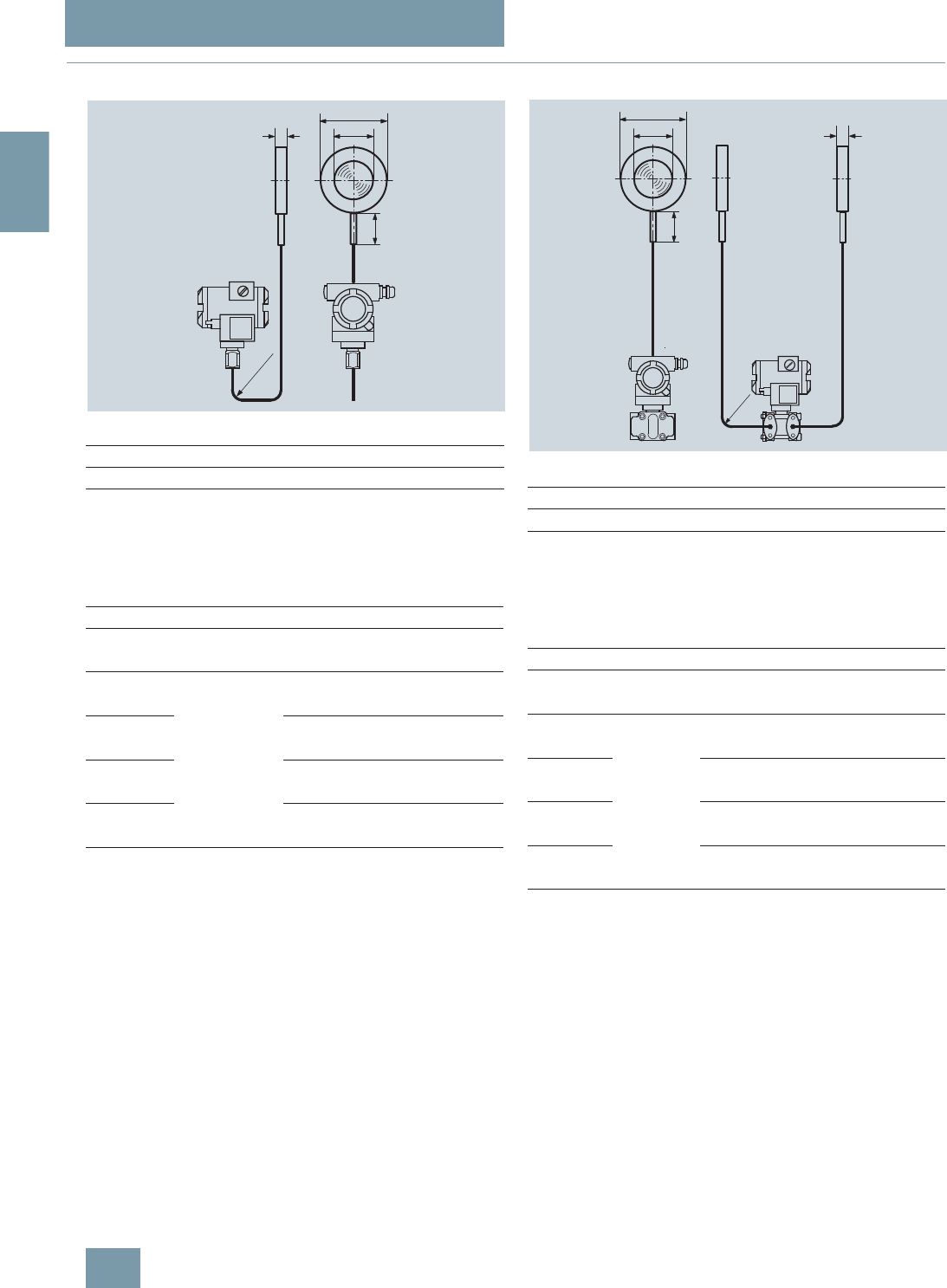
SITRANS P measuring instruments for pressure
Diaphragm seals of sandwich design
For gage, absolute, differential pressure and flow
with flexible capillary
2/160 Siemens FI 01 · 2009
2
■
Dimensional drawings
Connection to EN 1092-1
Connection to ASME B16.5
d: Inside diameter of gasket according to EN 1092-1 /
ASME B16.5
dM: Effective diaphragm diameter
Diaphragm seals of sandwich design with flexible capillary for connec-
tion to SITRANS P pressure transmitters for pressure, dimensions in mm
(inch)
Connection to EN 1092-1
Connection to ASME B16.5
d: Inside diameter of gasket according to EN 1092-1 /
ASME B16.5
dM: Effective diaphragm diameter
Diaphragm seals of sandwich design (without flange) with flexible capil-
lary for connection to SITRANS P pressure transmitters for absolute pres-
sure or differential pressure and flow, dimensions in mm (inch)
Nom. diam. Nom. press. b D dMl
mm mm mm mm
DN 50 PN 16 ... PN 100 20 102 59 100
DN 80 20 138 89 100
DN 100 20 158 89 100
DN 125 22 188 124 100
Nom. diam. Nom. press. b D dMI
lb/sq.in. mm mm mm mm
(inch) (inch) (inch) (inch)
2 inch 150 .... 2500 20 100 59 100
(0.79) (3.94) (2.32) (3.94)
3 inch 20 134 89 100
(0.79) (5.28) (2.32) (3.94)
4 inch 20 158 89 100
(0.79) (6.22) (2.32) (3.94)
5 inch 22 186 124 100
(0.87) (7.32) (4.88) (3.94)
b
l
D
dM
R ³ 150
(5.9)
Nom. diam. Nom. press. b D dMl
mm mm mm mm
DN 50 PN 16 ... PN 100 20 102 59 100
DN 80 20 138 89 100
DN 100 20 158 89 100
DN 125 22 188 124 100
Nom. diam. Nom. press. b D dMI
lb/sq.in. mm mm mm mm
(inch) (inch) (inch) (inch)
2 inch 150 ... 2500 20 100 59 100
(0.79) (3.94) (2.32) (3.94)
3 inch 20 134 89 100
(0.79) (5.28) (2.32) (3.94)
4 inch 20 158 89 100
(0.79) (6.22) (2.32) (3.94)
5 inch 22 186 124 100
(0.87) (7.32) (4.88) (3.94)
D
dM
l
b
+
_
R ³ 150
(5.9)
© Siemens AG 2008

SITRANS P measuring instruments for pressure
Diaphragm seals of flange design
For gage, absolute, differential pressure and flow
with flexible capillary
2/161
Siemens FI 01 · 2009
2
■
Overview
Diaphragm seals of flange design
■
Technical specifications
Diaphragm seals of flange design with flexible capillary
Nominal diameter Nominal pressure
• DN 50 (recommendable only for
pressure transmitters for pressure) PN 10 ... PN 40, PN 100
• DN 80 PN 10 ... PN 40, PN 100
• DN 100 PN 16, PN 40
• DN 125 PN 16, PN 40
• 2 inch (recommendable only for
pressure transmitters for pressure) Class 150, class 300, class 600,
class 1500
• 3 inch Class 150, class 300, class 600
• 4 inch Class 150, class 300, class 400
• 5 inch Class 150, class 300, class 400
Sealing face
• For stainless steel, mat.
No. 1.4404/316L To EN 1092-1, form B1 or
ASMR B16.5 RF 125 ... 250 AA
• For the other materials To EN 1092-1, form B2 or
ASME B16.5 RFSF
Materials
• Main body Stainless steel 316L
• Wetted parts Stainless steel 316L
• Without foil
• PTFE (for vacuum on request)
• ECTFE (for vacuum on request)
• PFA (for vacuum on request)
Monel 400, mat. No. 2.4360
Hastelloy C276, mat. No. 2.4819
Hastelloy C4, mat. No. 2.4610
Tantalum
• Capillary Stainless steel, mat.
No. 1.4571/316Ti
• Sheath Spiral hose made of stainless
steel, mat. No. 1.4404/316L
Sealing material in the process
flanges
• For pressure transmitters, absolute
pressure transmitters and low-
pressure applications
Copper
• For other applications Viton
Maximum pressure See above and the technical data
of the pressure transmitter
Tube length Without tube as standard (tube
available on request)
Capillary
• Length Max. 10 m (32.8 ft), longer
lengths on request
• Internal diameter 2 mm (0.079 inch)
• Minimum bending radius 150 mm (5.9 inch)
Filling liquid
(for remote seals of sandwich and
flange design) Silicone oil M5
Silicone oil M50
High-temperature oil
Halocarbon oil (for measuring O2)
Food oil (FDA listed)
Glycerine/water (not for use in
low-pressure range)
Permissible ambient temperature Dependent on the pressure trans-
mitter and the filling liquid of the
remote seal
More information can be found in
the technical data of the pressure
transmitters and in the section
"Technical data of filling liquid" in
the Technical description to the
remote seals
Weight Approx. 4 kg (8.82 lb)
Certificate and approvals
Classification according to pressure
equipment directive
(DRGL 97/23/EC)
For gases of fluid group 1 and liq-
uids of fluid group 1; complies
with requirements of article 3,
paragraph 3 (sound engineering
practice)
© Siemens AG 2008

SITRANS P measuring instruments for pressure
Diaphragm seals of flange design
For gage, absolute, differential pressure and flow
with flexible capillary
2/162 Siemens FI 01 · 2009
2
Selection and Ordering data Order No. Ord. code
Diaphragm seal
Flange design, with flexible capillary, connected
to a pressure transmitter
SITRANS P (order separately):
for pressure 7MF4037 and 7MF4237 together
with Order code "V01" (vacuum-proof design)
and 7MF80271);
scope of delivery: 1 off
D) 7 M F 4 9 2 0 -
for absolute pressure 7MF4337;
scope of delivery: 1 off
D) 7 M F 4 9 2 1 -
for differential pressure and flow 7MF4437;
scope of delivery: 2 off
D) 7 M F 4 9 2 3 -
17 7 7 7 -7B777
Nominal diameter and nominal pressure
•DN50 PN10...40 A
PN 100 B
(DN 50 recommended only for pressure
transmitters for pressure)
•DN80 PN10...40 D
PN 100 E
• DN 100 PN 16 G
PN 40 H
• DN 125 PN 16 J
PN 40 K
• 2 inch Class 150 L
Class 300 M
Class 600 N
Class 1500 P
(2 inch recommended only for pressure
transmitters for pressure)
• 3 inch Class 150 Q
Class 300 R
Class 600 S
• 4 inch Class 150 T
Class 300 U
Class 400 V
• 5 inch Class 150 W
Class 300 X
Class 400 Y
Smooth sealing face to EN 1092-1, form B1 or
to ASME B16.5 RF 125 ... 250 AA
Other version
Add Order code and plain text:
Nominal diameter: ...; Nominal pressure: ...
Sealing face: See "Technical data"
Z J 1 Y
Wetted parts materials
• Stainless steel 316L
- without foil A
- with PTFE coating E 0
- with ECTFE coating2) F
- with PFA coating D
• Monel 400, mat. No. 2.4360 G
• Hastelloy C276, mat. No. 2.4819 J
• Hastelloy C4, mat. No. 2.4610 U
• Tantalum K
Other version
Add Order code and plain text:
Wetted parts materials: ...
Z K 1 Y
Tube length
• without tube 0
Other version:
Add Order code and plain text:
Tube length: ...
9 L 1 Y
Filling liquid
• Silicone oil M5 1
• Silicone oil M50 2
• High-temperature oil 3
• Halocarbon oil (for measuring O2)4
• Glycerin/water3) 6
• Food oil (FDA listed) 7
Other version
Add Order code and plain text:
Filling liquid: ...
9 M 1 Y
Length of capillary4)
• 1.0 m (3.28 ft) 2
• 1.6 m (5.25 ft) 3
• 2.5 m (8.20 ft) 4
• 4.0 m (13.1 ft) 5
• 6.0 m (19.7 ft) 6
• 8.0 m (26.25 ft) 7
• 10.0 m (32.8 ft) 8
Other version
Add Order code and plain text:
Length of capillary: ...
9 N 1 Y
1) With 7MF8027 and the measuring cells Q, S, T and U also order the
vacuum-tight version.
2) For vacuum on request.
3) Not suitable for use in low-pressure range.
4) Max. capillary length, see section "Technical description".
D) Subject to export regulations AL: N, ECCN: EAR99H.
Selection and Ordering data Order code
Further designs
Please add "-Z" to Order No. and specify Order code.
Spark arrestor
With spark arrestor for mounting on zone 0 (including
documentation) for transmitters for
• pressure and absolute pressure A01
• differential pressure A02
Quality inspection certificate (Factory calibration) to
IEC 60770-2 C11
Acceptance test certificate C12
to EN 10204, section 3.1
Vacuum-proof design
for use in low-pressure range for transmitters for
• pressure V01
• differential pressure V03
Calculation of span of associated pressure
transmitter Y05
Enclose filled-in questionnaire with order
Selection and Ordering data Order No. Ord. code
Diaphragm seal
Flange design, with flexible capillary, connected
to a pressure transmitter
SITRANS P (order separately):
for pressure 7MF4037 and 7MF4237 together
with Order code "V01" (vacuum-proof design)
and 7MF80271);
scope of delivery: 1 off
D) 7 M F 4 9 2 0 -
for absolute pressure 7MF4337;
scope of delivery: 1 off
D) 7 M F 4 9 2 1 -
for differential pressure and flow 7MF4437;
scope of delivery: 2 off
D) 7 M F 4 9 2 3 -
17 7 7 7 -7B7 7 7
© Siemens AG 2008
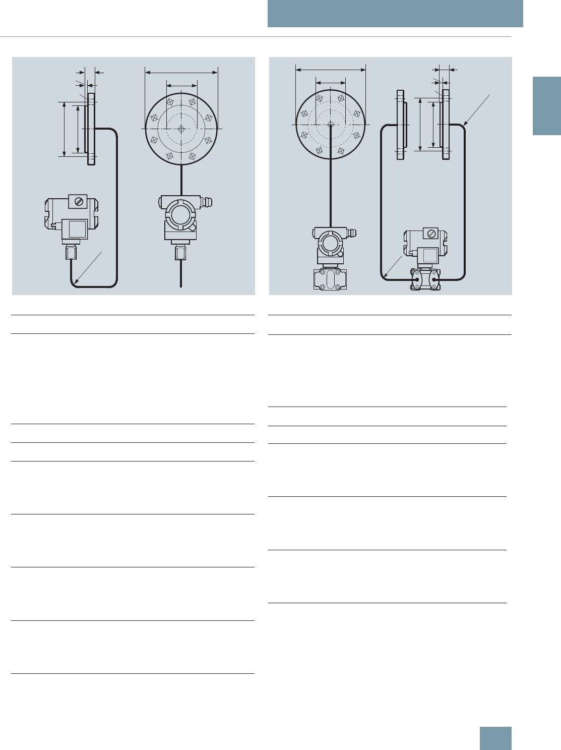
SITRANS P measuring instruments for pressure
Diaphragm seals of flange design
For gage, absolute, differential pressure and flow
with flexible capillary
2/163
Siemens FI 01 · 2009
2
■
Dimensional drawings
Connection to EN 1092-1
Connection to ASME B16.5
d: Inside diameter of gasket according to EN 1092-1 / ASME B16.5
dM: Effective diaphragm diameter
Diaphragm seals of flange design with flexible capillary for connection to
SITRANS P pressure transmitters for pressure, dimensions in mm (inch)
Connection to EN 1092-1
Connection to ASME B16.5
d: Inside diameter of gasket according to EN 1092-1 / ASME B16.5
dM: Effective diaphragm diameter
Diaphragm seals of flange design with flexible capillary for connection to
SITRANS P pressure transmitters for absolute pressure or for differential
pressure and flow, dimensions in mm (inch)
Nom.
diam. Nom.
press. b
mm D
mm d2
mm d4
mm dM
mm f
mm k
mm n
DN 50 PN 40 20 165 18 102 59 2 125 4
PN 100 28 195 26 102 59 2 145 4
DN 80 PN 40 24 200 18 138 89 2 160 8
PN 100 32 230 26 138 89 2 180 8
DN 100 PN 16 20 220 18 158 89 2 180 8
PN 40 24 235 22 162 89 2 190 8
DN 125 PN 16 22 250 18 188 124 2 210 8
PN 40 26 270 26 188 124 2 220 8
Nom.
diam. Nom.
press. bD d
2d4dMfkn
lb/sq.in.mmmm mmmmmmmmmm
(inch) (inch) (inch) (inch) (inch) (inch) (inch)
2 inch 150 20 150 20 92 59 1.6 120.5 4
(0.79) (5.80) (0.79) (3.62) (2.32) (0.06) (4.74)
300 22.5 165 20 92 59 1.6 127 8
(0.89) (6.50) (0.79) (3.62) (2.32) (0.06) (5)
600 32 165 20 92 59 1.6 127 8
(1.26) (6.50) (0.79) (3.62) (2.32) (0.06) (5)
3 inch 150 24 190 20 127 89 1.6 152.5 4
(0.96) (7.48) (0.79) (5) (3.50) (0.06) (6)
300 29 210 22 127 89 1.6 168.5 8
(1.14) (8.27) (0.87) (5) (3.50) (0.06) (6.63)
400 38.5 210 22 127 89 6.4 168.5 8
(1.52) (8.27) (0.87) (5) (3.50) (0.25) (6.63)
4 inch 150 24 230 20 158 89 1.6 190.5 4
(0.95) (9.06) (0.79) (6.22) (3.50) (0.06) (7.5)
300 32 255 22 158 89 1.6 200 8
(1.26) (10.04) (0.87) (6.22) (3.50) (0.06) (7.87)
400 41.5 255 26 158 89 6.4 200 8
(1.62) (10.04) (1.02) (6.22) (3.50) (0.25) (7.87)
5 inch 150 24 255 22 186 124 2 216 4
(0.94) (10.04) (0.87) (7.32) (4.88) (0.08) (8.50)
300 35 280 22 186 124 2 235 8
(1.38) (11.02) (0.87) (7.32) (4.88) (0.08) (9.25)
400 45.5 280 26 186 124 7 235 8
(1.79) (11.02) (1.02) (7.32) (4.88) (0.28) (9.25)
b
f
n d2
x
D
ø k
ø d4
M
d
R ³ 150 (5.9)
Nom.
diam. Nom.
press. b
mm D
mm d2
mm d4
mm dM
mm f
mm k
mm n
DN 80 PN 40 24 200 18 138 89 2 160 8
PN 100 32 230 26 138 89 2 180 8
DN 100 PN 16 20 220 18 158 89 2 180 8
PN 40 24 235 22 162 89 2 190 8
DN 125 PN 16 22 250 18 188 124 2 210 8
PN 40 26 270 26 188 124 2 220 8
Nom.
diam. Nom.
press. bD d
2d4dMfkn
lb/sq.in. mm mm mm mm mm mm mm
(inch) (inch) (inch) (inch) (inch) (inch) (inch)
3 inch 150 24 190 20 127 89 1.6 152.5 4
(0.96) (7.48) (0.79) (5) (3.50) (0.06) (6)
300 29 210 22 127 89 1.6 168.5 8
(1.14) (8.27) (0.87) (5) (3.50) (0.06) (6.63)
600 38.5 210 22 127 89 6.4 168.5 8
(1.52) (8.27) (0.87) (5) (3.50) (0.25) (6.63)
4 inch 150 24 230 20 158 89 1.6 190.5 4
(0.95) (9.06) (0.79) (6.22) (3.50) (0.06) (7.5)
300 32 255 22 158 89 1.6 200 8
(1.26) (10.04) (0.87) (6.22) (3.50) (0.06) (7.87)
400 41.5 255 26 158 89 6.4 200 8
(1.62) (10.04) (1.02) (6.22) (3.50) (0.25) (7.87)
5 inch 150 24 255 22 186 124 2 216 4
(0.94) (10.04) (0.87) (7.32) (4.88) (0.08) (8.50)
300 35 280 22 186 124 2 235 8
(1.38) (11.02) (0.87) (7.32) (4.88) (0.08) (9.25)
400 45.5 280 26 186 124 7 235 8
(1.79) (11.02) (1.02) (7.32) (4.88) (0.28) (9.25)
D
+
_
b
f
n d 2
x
ø k
M
d
ø d4
R ³ 150 (5.9)
R ³ 150
(5.9)
© Siemens AG 2008

SITRANS P measuring instruments for pressure
Diaphragm seals of flange design
For gage and absolute pressure,
directly fitted on transmitter
2/164 Siemens FI 01 · 2009
2
■
Overview
Diaphragm seals of flange design, directly fitted on a pressure transmitter
for pressure
■
Technical specifications
Diaphragm seals (flange design) for pressure and absolute pres-
sure, directly fitted on a transmitter
Nominal diameter Nominal pressure
• DN 50 PN 40, PN 100
• DN 80 PN 40, PN 100
• DN 100 PN 16, PN 40
• 2 inch Class 150, class 300, class 600,
class 1500
• 3 inch Class 150, class 300, class 600
• 4 inch Class 150, class 300, class 400
Sealing face
• For stainless steel, mat. No.
1.4404/316L To EN 1092-1, form B1 or ASME
B16.5 RF 125 ... 250 AA
• For the other materials Smooth to EN 1092-1, form B2 or
ASME B16.5 RFSF
Materials
• Main body Stainless steel 316L
• Wetted parts Stainless steel 316L
• Without foil
• PTFE (for vacuum on request)
• ECTFE (for vacuum on request)
• PFA (for vacuum on request)
Monel 400, mat. No. 2.4360
Hastelloy C276, mat. No. 2.4819
Hastelloy C4, mat. No. 2.4610
Tantalum
• Capillary Stainless steel, 1.4571/316Ti
• Sealing material on the process
connection Copper
Maximum pressure See above and the technical data
of the transmitter
Tube length • Without tube
• 50 mm (1.97 inch)
• 100 mm (3.94 inch)
• 150 mm (5.91 inch)
• 200 mm (7.87 inch)
Capillary
• Length Max. 10 m (32.8 ft), longer
lengths on request
• Internal diameter 2 mm (0.079 inch)
• Minimum bending radius 150 mm (5.9 inch)
Filling liquid • Silicone oil M5
• Silicone oil M50
• High-temperature oil
• Halocarbon oil (for measuring
O2)
• Food oil (FDA listed)
• Glycerine/water (not suitable for
use in low-pressure range)
Max. recommended process
temperature 170 °C (338 °F)
Permissible ambient temperature Dependent on the pressure trans-
mitter and the filling liquid of the
remote seal.
More information can be found in
the technical data of the pressure
transmitters and in the section
"Technical data of filling liquid" in
the Technical description to the
remote seals.
Weight Approx. 4 kg (8.82 lb)
Certificate and approvals
Classification according to pressure
equipment directive (DRGL
97/23/EC)
For gases of fluid group 1 and liq-
uids of fluid group 1; complies
with requirements of article 3,
paragraph 3 (sound engineering
practice)
© Siemens AG 2008

SITRANS P measuring instruments for pressure
Diaphragm seals of flange design
For gage and absolute pressure,
directly fitted on transmitter
2/165
Siemens FI 01 · 2009
2
Selection and Ordering data Order No. Ord.code
Diaphragm seal D) 7 M F 4 9 1 0 -
Directly fitted to a pressure transmitter
SITRANS P for pressure 7MF4037 and
7MF4237 together with Order code "V01" (vac-
uum-proof design) and 7MF80271); must be
ordered separately
7 7 7 7 7 7 7 7
Process connection
• Vertical (pressure transmitter upright) 0
• Horizontal 2
Nominal diameter and nominal pressure
•DN50 PN40 A
PN 100 B
•DN80 PN40 D
PN 100 E
• DN 100 PN 16 G
PN 40 H
• 2 inch Class 150 L
Class 300 M
Class 600 N
Class 1500 P
• 3 inch Class 150 Q
Class 300 R
Class 600 S
• 4 inch Class 150 T
Class 300 U
Class 400 V
Smooth sealing face to DIN 1092-01, form B1 or
B2, or to ASME B16.5 125 ... 250 AA or RFSF
Other version
Add Order code and plain text:
Nominal diameter: ...; Nominal pressure: ...
Z J 1 Y
Wetted parts materials
• Stainless steel 316L
- without foil A
- with PTFE coating E 0
- with ECTFE coating2) F
- with PFA coating D
• Monel 400, mat. No. 2.4360 G
• Hastelloy C276, mat. No. 2.4819 J
• Hastelloy C4, mat. No. 2.4610 U
• Tantalum K
Other version
Add Order code and plain text:
Wetted parts materials: ...
Z K 1 Y
Tube length
• Without tube 0
• 50 mm • (1.97 inch) 1
• 100 mm • (3.94 inch) 2
• 150 mm • (5.90 inch) 3
• 200 mm • (7.87 inch) 4
Other version:
Add Order code and plain text:
Tube length: ...
9 L 1 Y
Filling liquid
• Silicone oil M5 1
• Silicone oil M50 2
• High-temperature oil 3
• Halocarbon oil (for measuring O2)4
• Glycerin/water3) 6
• Food oil (FDA listed) 7
Other version
Add Order code and plain text:
Filling liquid: ...
9 M 1 Y
1) With 7MF8027 and the measuring cells Q, S, T and U also order the vac-
uum-tight version.
2) For vacuum on request.
3) Not suitable for use in low-pressure range.
D) Subject to export regulations AL: N, ECCN: EAR99H.
Selection and Ordering data Order code
Further designs
Please add "-Z" to Order No. and specify Order code.
Spark arrestor A01
With spark arrestor for mounting on zone 0 (including
documentation) for transmitters for pressure and abso-
lute pressure
Quality inspection certificate (Factory calibration) to
IEC 60770-2 C11
to IEC 60770-2
Acceptance test certificate C12
to EN 10204, section 3.1
Vacuum-proof design V01
for use in low-pressure range for transmitters for
pressure
Calculation of span of associated pressure
transmitter Y05
Enclose filled-in questionnaire with order
Selection and Ordering data Order No. Ord.code
Diaphragm seal D) 7 M F 4 9 1 0 -
Directly fitted to a pressure transmitter
SITRANS P for pressure 7MF4037 and
7MF4237 together with Order code "V01" (vac-
uum-proof design) and 7MF80271); must be
ordered separately
7 7 7 7 7 7 7 7
© Siemens AG 2008
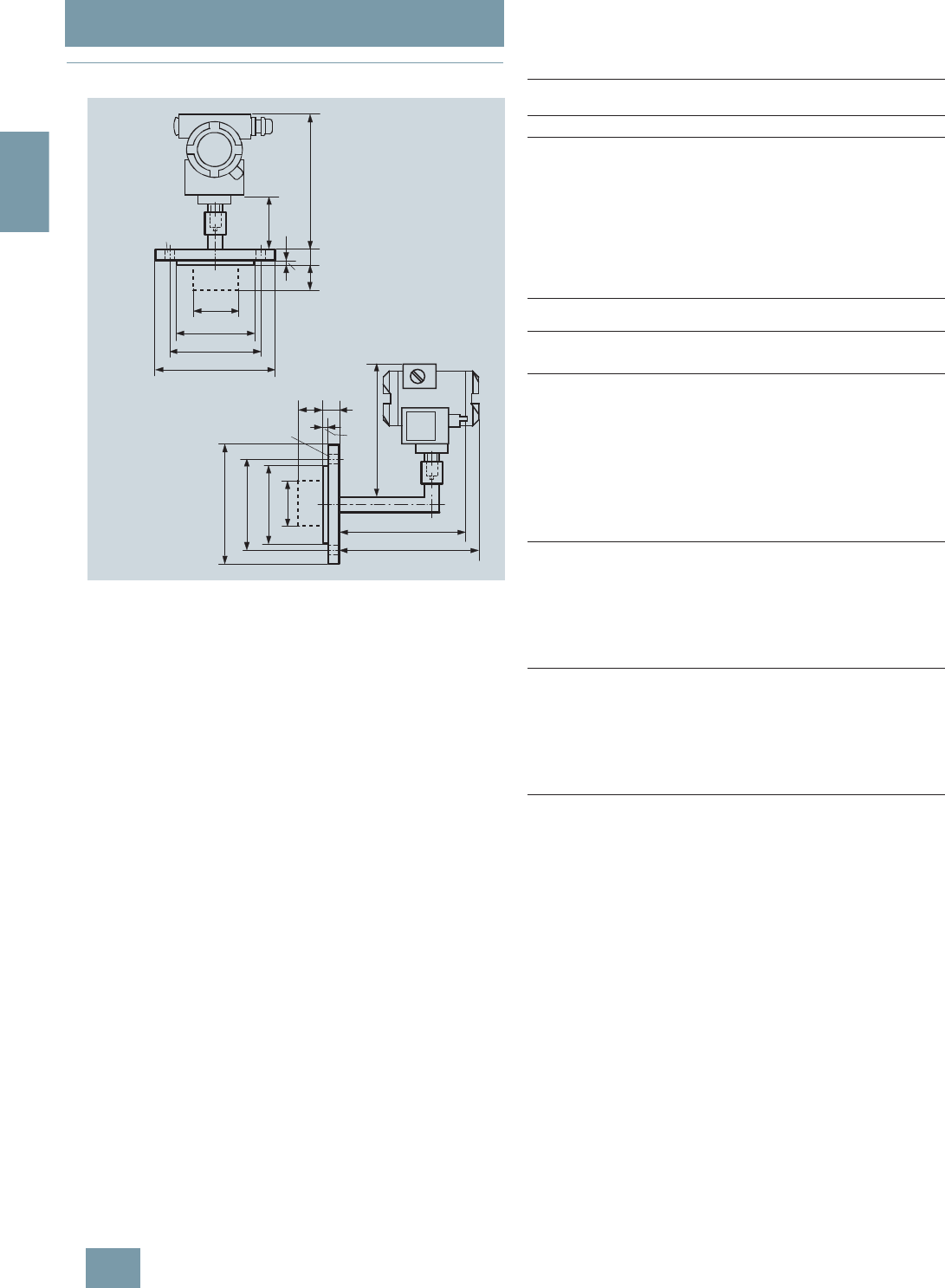
SITRANS P measuring instruments for pressure
Diaphragm seals of flange design
For gage and absolute pressure,
directly fitted on transmitter
2/166 Siemens FI 01 · 2009
2
■
Dimensional drawings
Diaphragm seals of flange design, direct connection to a SITRANS P
pressure transmitter (process connection vertical (top) and horizontal
(bottom)), dimensions in mm (inch)
Connection to EN 1092-1
Connection to ASME B16.5
d: Inside diameter of gasket according to EN 1092-1/
ASME B16.5
dM: Effective diaphragm diameter
193 (7.6)
83 (3.27)
b
f
193 (7.6)
211 (8.3)
226 (8.9)
b
f
n d2
x
n d2
x
ø d4
ø k
ø D
ø D
ø k
ø d4
L
ø d5
ø d5
L
Vertical
process connection
Horizontal
process connection
Tube length L
see Ordering Data
Nom.
diam. Nom.
press. bDd
2d4d5dMfkn
mm mm mm mm mm mm mm mm
DN 50 PN 40 20 165 18 102 48.3 59 2 125 4
PN 100 28 195 26 102 48.3 59 2 145 4
DN 80 PN 40 24 200 18 138 76 89 2 160 8
PN 100 32 230 26 138 76 89 2 180 8
DN 100 PN 16 20 220 18 158 94 89 2 180 8
PN 40 24 235 22 162 94 89 2 190 8
Nom.
diam. Nom.
press. bD d
2d4d5dMfkn
lb/
sq.in. mm mm mm mm mm mm mm mm
(inch) (inch) (inch) (inch) (inch) (inch) (inch) (inch)
2 inch 150 20 150 20 92 48.3 59 1.6 120.5 4
(0.79) (5.91) (0.79) (3.62) (1.9) (2.32) (0.06) (4.74)
300 22.5 165 20 92 48.3 59 1.6 127 8
(0.89) (6.5) (0.79) (3.62) (1.9) (2.32) (0.06) (5)
600 32 165 20 92 48.3 59 6.4 127 8
(1.26) (6.5) (0.79) (3.62) (1.9) (2.32) (0.25) (5)
1500 45 215 26 92 48.3 59 6.4 165 8
(1.77) (8.46) (1.02) (3.62) (1.9) (2.32) (0.25) (6.5)
3 inch 150 24 190 20 127 76 89 1.6 152.5 4
(0.95) (7.48) (0.79) (5) (3) (3.50) (0.06) (6)
300 29 210 22 127 76 89 1.6 168.5 8
(1.14) (8.27) (0.87) (5) (3) (3.50) (0.06) (6.63)
600 38.5 210 22 127 76 89 6.4 168.5 8
(1.52) (8.27) (0.87) (5) (3) (3.50) (0.25) (6.63)
4 inch 150 24 230 20 158 94 89 1.6 190.5 8
(0.95) (9.06) (0.79) (6.22) (3.69) (3.50) (0.06) (7.5)
300 32 255 22 158 94 89 1.6 200 8
(1.26) (10.04) (0.79) (6.22) (3.69) (3.50) (0.06) (7.87)
400 41.5 255 26 158 94 89 6.4 200 8
(1.62) (10.04) (1.02) (6.22) (3.69) (3.50) (0.25) (7.87)
© Siemens AG 2008

SITRANS P measuring instruments for pressure
Diaphragm seals of flange design
For differential pressure,
fixed connection and with capillary
2/167
Siemens FI 01 · 2009
2
■
Overview
Diaphragm seals of flange design for pressure transmitters for differential
pressure, fixed connection and with flexible capillary
■
Technical specifications
Diaphragm seals of flange design for pressure transmitters for dif-
ferential pressure, fixed connection and with flexible capillary
Nominal diameter Nominal pressure
• DN 80 PN 40
• DN 100 PN 16, PN 40
• 3 inch Class 150, class 300
• 4 inch Class 150, class 300
Sealing face
• For stainless steel, mat.
No. 1.4404/316L To EN 1092-1, form B1 or
ASME B16.5 RF 125 ... 250 AA
• For the other materials To EN 1092-1, form B2 or
ASME B16.5 RFSF
Materials
• Main body Stainless steel 316L
• Wetted parts Stainless steel 316L
• Without foil
• PTFE (for vacuum on request)
• ECTFE (for vacuum on request)
• PFA (for vacuum on request)
Monel 400, mat. No. 2.4360
Hastelloy C276, mat. No. 2.4819
Hastelloy C4, mat. No. 2.4610
Tantalum
• Capillary Stainless steel, mat.
No. 1.4571/316Ti
• Sheath Spiral hose made of stainless
steel, mat. No. 1.4301/316
Sealing material in the process
flanges
• For pressure transmitters, absolute
pressure transmitters and low-
pressure applications
Copper
• For other applications Viton
Maximum pressure See above and the technical data
of the pressure transmitter
Tube length Without tube
50 mm (1.97 inch)
100 mm (3.94 inch)
150 mm (5.91 inch)
200 mm (7.87 inch)
Capillary
• Length Max. 10 m (32.8 ft), longer
lengths on request
• Internal diameter 2 mm (0.079 inch)
• Minimum bending radius 150 mm (5.9 inch)
Filling liquid Silicone oil M5
Silicone oil M50
High-temperature oil
Halocarbon oil (for measuring O2)
Food oil (FDA listed)
Glycerine/water (not suitable for
use in low-pressure range)
Max. recommended process
temperature 170 °C (338 °F)
Permissible ambient temperature Dependent on the pressure trans-
mitter and the filling liquid of the
remote seal
More information can be found in
the technical data of the pressure
transmitters and in the section
"Technical data of filling liquid" in
the Technical description to the
remote seals
Weight Approx. 4 kg (8.82 lb)
Certificate and approvals
Classification according to pressure
equipment directive (DRGL
97/23/EC)
For gases of fluid group 1 and liq-
uids of fluid group 1; complies
with requirements of article 3,
paragraph 3 (sound engineering
practice)
© Siemens AG 2008

SITRANS P measuring instruments for pressure
Diaphragm seals of flange design
For differential pressure,
fixed connection and with capillary
2/168 Siemens FI 01 · 2009
2
Selection and Ordering data Order No. Ord. code
Diaphragm seal D) 7 M F 4 9 1 3 -
Mounting flange (with tube as option) for
direct mounting to high-pressure side and
flanged remote seal without tube, fitted by
means of capillary to low-pressure side of
SITRANS P for differential pressure, DS III series
(7MF4437)
17 7 7 7 -7B7 7 7
Flange, connection to EN 1092-1
Nom. diam. Nom. press.
•DN80 PN40 D
• DN 100 PN 16 G
PN 40 H
Flange, connection to ASME B16.5
Nom. diam. Nom. press.
• 3 inch Class 150 Q
Class 300 R
• 4 inch Class 150 T
Class 300 U
Other version
Add Order code and plain text:
Flange: ..., Nominal diameter: ...; Nominal
pressure: ...
Z J 1 Y
Wetted parts materials
Smooth sealing face to EN 1092-1, form B1 or
B2, or to ASME B16.5 RF 125 ... 250 AA or RFSF
• Stainless steel 316L
- without foil A
- with PTFE coating E 0
- with ECTFE coating1) F
- with PFA coating D
• Monel 400, mat. No. 2.4360 G
• Hastelloy C276, mat. No. 2.4819 J
• Hastelloy C4, mat. No. 2.4610 U
• Tantalum K
Other version
Add Order code and plain text:
Wetted parts materials: ...
Z K 1 Y
Tube length
(for mounting flange on high-pressure side)
• Without tube 0
• 50 mm (1.97 inch) 1
• 100 mm (3.94 inch) 2
• 150 mm (5.90 inch) 3
• 200 mm (7.87 inch) 4
Other version:
Add Order code and plain text:
Tube length: ...
9 L 1 Y
Filling liquid
• Silicone oil M5 1
• Silicone oil M50 2
• High-temperature oil 3
• Halocarbon oil (for measuring O2)4
• Glycerin/water2) 6
• Food oil (FDA listed) 7
Other version
Add Order code and plain text:
Filling liquid: ...
9 M 1 Y
Length of capillary3)
• 1.0 m (3.28 ft) 2
• 1.6 m (5.25 ft) 3
• 2.5 m (8.20 ft) 4
• 4.0 m (13.1 ft) 5
• 6.0 m (19.7 ft) 6
• 8.0 m (26.25 ft) 7
• 10.0 m (32.8 ft) 8
Other version
Add Order code and plain text:
Length of capillary: ...
9 N 1 Y
1) For vacuum on request.
2) Not suitable for use in low-pressure range.
3) Max. capillary length, see section "Technical description".
D) Subject to export regulations AL: N, ECCN: EAR99H.
Selection and Ordering data Order code
Further designs
Please add "-Z" to Order No. and specify Order code.
Spark arrestor
With spark arrestor for mounting on zone 0 (including
documentation)
A02
Quality inspection certificate (Factory calibration) to
IEC 60770-2 C11
Acceptance test certificate
to EN 10204, section 3.1 C12
Vacuum-proof design
for use in low-pressure range V03
Calculation of span of associated pressure
transmitter
Enclose filled-in questionnaire with order
Y05
Selection and Ordering data Order No. Ord. code
Diaphragm seal D) 7 M F 4 9 1 3 -
Mounting flange (with tube as option) for
direct mounting to high-pressure side and
flanged remote seal without tube, fitted by
means of capillary to low-pressure side of
SITRANS P for differential pressure, DS III series
(7MF4437)
17 7 7 7 -7B7 7 7
© Siemens AG 2008
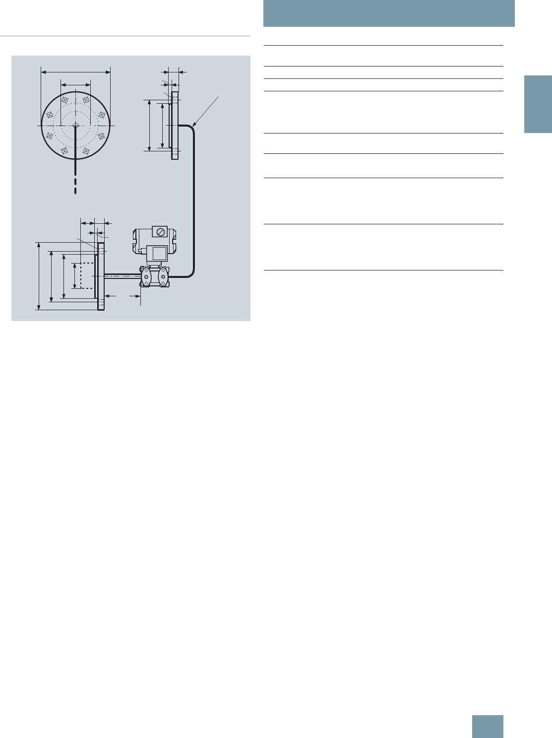
SITRANS P measuring instruments for pressure
Diaphragm seals of flange design
For differential pressure,
fixed connection and with capillary
2/169
Siemens FI 01 · 2009
2
■
Dimensional drawings
Diaphragm seals of flange design with flexible capillary, fixed connec-
tion, for connection to a SITRANS P pressure transmitter for differential
pressure, dimensions in mm (inch)
Connection to EN 1092-1
Connection to ASME B16.5
d: Inside diameter of gasket according to EN 1092-1 /
ASME B16.5
dM: Effective diaphragm diameter
D
+
b
f
n d2
x
ø k
M
d
ø d4
R 150 (5.9)
>
_
100
(3.94)
b
f
n d2
x
ø D
ø k
ø d4
ø d5
L
Tube length L
see
Ordering data
Nom.
diam. Nom.
press. bDd
2d4d5dMfkn
mm mm mm mm mm mm mm mm
DN 80 PN 40 24 200 18 138 76 89 2 160 8
DN 100 PN 16 20 200 18 158 94 89 2 180 8
PN 40 24 235 22 162 94 89 2 190 8
Nom.
diam. Nom.
press. bD d
2d4d5dMfkn
lb/
sq.in. mm mm mm mm mm mm mm mm
(inch) (inch) (inch) (inch) (inch) (inch) (inch) (inch)
3 inch 150 24 190 20 127 76 89 1,6 152,5 4
(0.96) (7.48) (0.79) (5) (3) (3.50) (0.06) (6)
300 29 210 22 127 76 89 1,6 168,5 8
(1.14) (8.27) (0.87) (5) (3) (3.50) (0.06) (6.63)
4 inch 150 24 230 20 158 94 89 1,6 190,5 4
(0.95) (9.06) (0.79) (6.22) (3.69) (3.50) (0.06) (7)
300 32 255 22 158 94 89 1,6 200 8
(1.26) (10.04) (0.87) (6.22) (3.69) (3.50) (0.06) (7.87)
© Siemens AG 2008
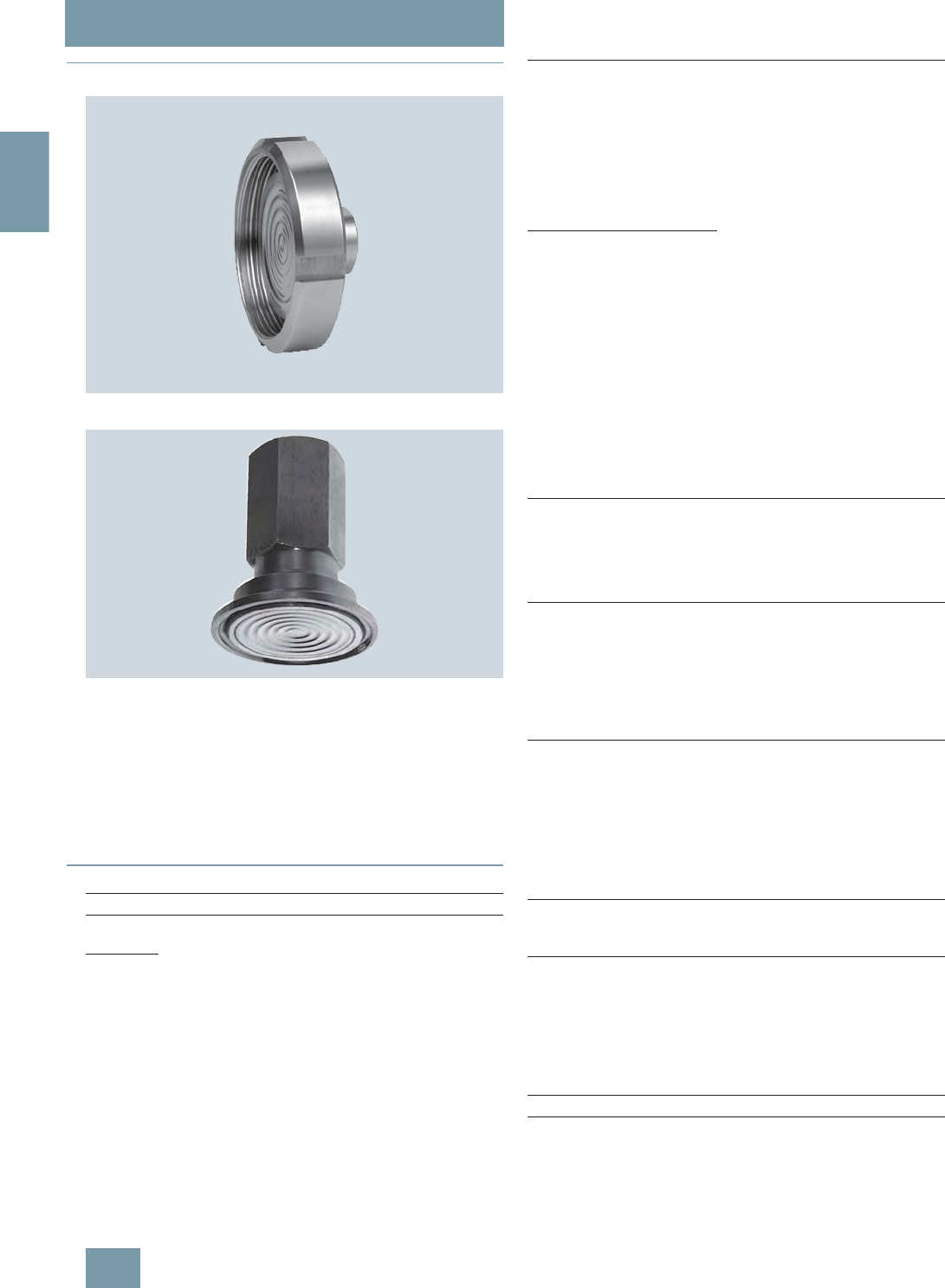
SITRANS P measuring instruments for pressure
Quick-release diaphragm seals
For gage, absolute and differential pressure
2/170 Siemens FI 01 · 2009
2
■
Overview
Quick-release diaphragm seals, to DIN 11851 with slotted union nut
Quick-release diaphragm seals, with clamp connection
Quick-release diaphragm seals are available for the following
SITRANS P pressure transmitter series:
• For pressure: MK II, DS III, DS III PA, DS III FF
• For differential pressure and flow: DS III, DS III PA, DS III FF
The quick-release remote seals are common designs in the food
industry. Their design means that the measured medium cannot
accumulate in dead volumes. The quick-release clamp present
on the remote seal means that quick dismounting is possible for
cleaning.
■
Technical specifications
Quick-release diaphragm seal
Connection, nominal diameter Nominal pressure
For pressure
• To DIN 11851 with slotted union nut
-DN25 PN40
-DN32 PN40
-DN40 PN40
-DN50 PN25
-DN65 PN25
-DN80 PN25
• To DIN 11851 with threaded socket
-DN25 PN40
-DN32 PN40
-DN40 PN40
-DN50 PN25
-DN65 PN25
-DN80 PN25
• Clamp connection
- 1½ inch PN 40
- 2 inch PN 40
- 2½ inch PN 25
- 3 inch PN 25
For differential pressure and flow
• To DIN 11851 with slotted union nut
-DN50 PN25
-DN65 PN25
-DN80 PN25
• To DIN 11851 with threaded socket
-DN50 PN25
-DN65 PN25
-DN80 PN25
• Clamp connection
- 2 inch PN 40
- 2½ inch PN 25
- 3 inch PN 25
Sealing face
• For stainless steel, mat. No.
1.4404/316L To EN 1092-1, form B1 or
ASME B 16.5RF 125 ... 250 AA
• For the other materials To EN 1092-1, form B2 or
ASME B16.5 RFSF
Materials
• Main body Stainless steel 316L
• Wetted parts Stainless steel 316L
• Capillary Stainless steel, mat.
No. 1.4571/316Ti
• Sheath Spiral hose made of stainless
steel, mat. No. 1.4301/316
Maximum pressure See above and the technical data
of the pressure transmitter
Tube length Without tube
Capillary
• Length Max. 10 m (32.8 ft), longer
lengths on request
• Internal diameter 2 mm (0.079 inch)
• Minimum bending radius 150 mm (5.9 inch)
Filling liquid Food oil (FDA listed)
Glycerin/water (not suitable for
use in low-pressure range)
Permissible ambient temperature Dependent on the pressure trans-
mitter and the filling liquid of the
remote seal
More information can be found in
the technical data of the pressure
transmitters and in the section
"Technical data of filling liquid" in
the Technical description to the
remote seals
Weight Approx. 4 kg (8.82 lb)
Certificates and approvals
Classification according to pressure
equipment directive
(DRGL 97/23/EC)
For gases of fluid group 1 and liq-
uids of fluid group 1; complies
with requirements of article 3,
paragraph 3 (sound engineering
practice)
© Siemens AG 2008

SITRANS P measuring instruments for pressure
Quick-release diaphragm seals
For gage, absolute and differential pressure
2/171
Siemens FI 01 · 2009
2
Selection and Ordering data Order No. Ord. code
Quick-release diaphragm seal D) 7 M F 4 9 4 0 -
for SITRANS P pressure transmitters for
pressure 7MF4037 and 7MF4237 together with
Order code "V01" (vacuum-proof design) and
7MF80271); must be ordered separately
Filling liquid: Food oil (FDA listed)
Material: Stainless steel, mat. No. 1.4435
1) With 7MF8027 and the measuring cells Q, S, T and U also order the
vacuum-tight version.
77A 0 7-7B7 7 7
Nom. diam. Nom. press.
• Connection to DIN 11851 with slotted union nut
- DN25 PN40 1B
- DN32 PN40 1C
- DN40 PN40 1D
- DN50 PN25 1E
- DN65 PN25 1F
- DN80 PN25 1G
• Connection to DIN 11851 with screw necks
- DN25 PN40 2B
- DN32 PN40 2C
- DN40 PN40 2D
- DN50 PN25 2E
- DN65 PN25 2F
- DN80 PN25 2G
• Clamp connection
- 1½ inch PN 40 4L
- 2 inch PN 40 4M
- 2½ inch PN 40 4N
- 3 inch PN 40 4P
Other version
Add Order codes and plain text:
Nominal diameter: ... 9 H 1 Y
Nominal pressure: ... Z J 1 Y
Filling liquid
• Glycerin/water2)
2) Not suitable for use in low-pressure range.
6
• Food oil (FDA listed) 7
Other version
Add Order code and plain text:
Filling liquid: ...
9 M 1 Y
Connection to pressure transmitter
• direct 0
through capillary, length:3)
3) Max. capillary length, see section "Technical description"
D) Subject to export regulations AL: N, ECCN: EAR99H.
• 1.0 m (3.28 ft) 2
• 1.6 m (5.25 ft) 3
• 2.5 m (8.20 ft) 4
• 4.0 m (13.1 ft) 5
• 6.0 m (19.7 ft) 6
• 8.0 m (26.25 ft) 7
• 10.0 m (32.8 ft) 8
Other version
Add Order code and plain text:
Length of capillary: ...
9 N 1 Y
Further designs Order code
Please add "-Z" to Order No. and specify Order
code.
Quality inspection certificate (Factory cali-
bration) to IEC 60770-2 C11
Acceptance test certificate C12
to EN 10204, section 3.1
Vacuum-proof design V01
for use in low-pressure range
Selection and Ordering data Order No. Ord. code
Quick-release diaphragm seal D) 7M F 4 9 4 3 -
for SITRANS P pressure transmitters for pres-
sure for differential pressure and flow, type
7MF4437; order separately
Filling liquid: Food oil (FDA listed)
Material: Stainless steel, mat. No. 1.4435
Delivery unit: 2 off
77A 0 7-7B7 7 7
Nom. diam. Nom. press.
• Connection to DIN 11851 with slotted union nut
- DN50 PN25 1E
- DN65 PN25 1F
- DN80 PN25 1G
• Connection to DIN 11851 with threaded
socket
- DN50 PN25 2E
- DN65 PN25 2F
- DN80 PN25 2G
• Clamp connection
- 2 inch PN 40 4M
- 2½ inch PN 40 4N
- 3 inch PN 40 4P
Other version
Add Order codes and plain text:
Nominal diameter: ... 9 H 1 Y
Nominal pressure: ... Z J 1 Y
Filling liquid
• Glycerin/water1) 6
• Food oil (FDA listed) 7
Other version
Add Order code and plain text:
Filling liquid: ...
9 M 1 Y
Connection to transmitter
through capillary, Length:2)
• 1.0 m (3.28 ft) 2
• 1.6 m (5.25 ft) 3
• 2.5 m (8.20 ft) 4
• 4.0 m (13.1 ft) 5
• 6.0 m (19.7 ft) 6
• 8.0 m (26.25 ft) 7
• 10.0 m (32.8 ft) 8
Other version
Add Order code and plain text:
Length of capillary: ...
9 N 1 Y
Further designs Order code
Please add "-Z" to Order No. and specify Order
code.
Quality inspection certificate (Factory cali-
bration) to IEC 60770-2 C11
Acceptance test certificate C12
to EN 10204, section 3.1
Vacuum-proof design V03
for use in low-pressure range
1) Not suitable for use in low-pressure range.
2) Max. capillary length, see section "Technical description"
D) Subject to export regulations AL: N, ECCN: EAR99H.
© Siemens AG 2008
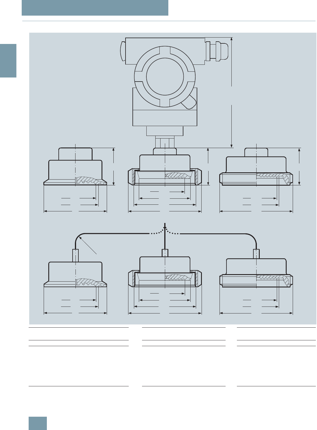
SITRANS P measuring instruments for pressure
Quick-release diaphragm seals
For gage, absolute and differential pressure
2/172 Siemens FI 01 · 2009
2
■
Dimensional drawings
dM Effective diaphragm diameter
Quick-release diaphragm seal, dimensions in mm (inch)
146 (5.75)
H
H
H
dM
1
G
D
dM
D
DN
dM
1
G
DN
DN
dM
1
G
D
dM
D
DN
DN
R ³ 150 (5.9)
dM
1
G
DN
Mounted directly on SITRANS P transmitter for pressure
Mounted on SITRANS P transmitter for pressure or differential pressure and flow
Clamp connection (left) Connection to DIN 11851 with slotted
union nut (center) Connection to DIN 11851 with
threaded socket (right)
DN Ø dMØD H DN Ød
MØD H G
1DN Ø dMHG
1
(1½ inch) 32 (1.26) 50,5 (2) 35 (1.38) 25 25 63 36 Rd 52x1/6 25 25 36 Rd 52x1/6
(2 inch) 40 (1.57) 64 (2.52) 35 (1.38) 32 32 70 36 Rd 52x1/6 32 32 36 Rd 52x1/6
(2½ inch) 52 (2.05) 77,5 (3.05) 35 (1.38) 40 40 78 36 Rd 65x1/6 40 40 36 Rd 65x1/6
(3 inch) 72 (2.83) 91 (3.58) 35 (1.38) 50 52 112 36 Rd 78x1/6 50 52 36 Rd 78x1/6
65 65 112 36 Rd 95x1/6 65 65 36 Rd 95x1/6
80 72 127 36 Rd 110x1/6 80 72 36 Rd 110x1/6
25 25 63 36 Rd 52x1/6
© Siemens AG 2008
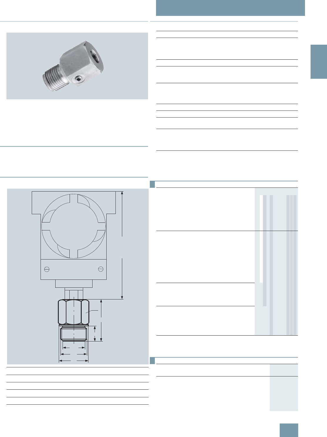
SITRANS P measuring instruments for pressure
Miniature diaphragm seal
For gage and absolute pressure
2/173
Siemens FI 01 · 2009
2
■
Overview
Miniature diaphragm seals
The miniature diaphragm seals are available for the following
SITRANS P pressure transmitter series for pressure:
• P300, DS III, DS III PA, DS III FF
Suitable for high pressures, contaminated, fibrous and viscous
media in the chemical, paper, food and drink industries.
■
Design
• Flush-mounted diaphragm
• No dead spaces
• Fixed threaded stems
■
Dimensional drawings
dM: Effective diaphragm diameter
Miniature diaphragm seal, dimensions in mm (inch)
■
Technical specifications
GØ d
MSW Ø d L H
mm (inch) mm (inch) mm (inch) mm (inch) mm (inch)
G1B 25 (0.98) 41 (1.61) 39 (1.53) 28 (1.1) 56 (2.21)
G1½B 40 (1.57) 55 (2.17) 60 (2.36) 30 (1.18) 50 (1.97)
G2B 50 (1.97) 60 (2.36) 70 (2.76) 30 (1.18) 63 (2.48)
146 (5.75)
d
G
L
H
SW
dM
Miniature diaphragm seals
Span with
• G1B > 6 bar (> 87 psi)
• G1½B > 2 bar (> 29 psi)
• G2B > 600 mbar (> 8.7 psi)
Filling liquid Silicone oil M5 or food oil (FDA listed)
Material
• Main body Stainl. steel mat No. 1.4404/ 316L
• Diaphragm Stainl. steel mat No. 1.4404 / 316L
Maximum pressure 100% of nominal pressure of pressure
transmitter, up to maximum of PN 400
(5802 psi) (depending on the seal
used)
Temperature of use Same as pressure transmitter
Temperature range of medium Same as pressure transmitter
Max. recommended process
temperature 150 °C (302 °F)
Weight
• G1B Approx. 0.3 kg (approx. 0.66 lb)
• G1½B Approx. 0.5 kg (approx. 1.10 lb)
• G2B Approx. 0.8 kg (approx. 1.76 lb)
Certificate and approvals
Classification according to
pressure equipment directive
(DRGL 97/23/EC)
For gases of fluid group 1 and liquids
of fluid group 1; complies with
requirements of article 3, para-
graph 3 (sound engineering practice)
Selection and Ordering data Order No. Ord. code
Miniature diaphragm seals D) 7 M F 4 9 6 0 -
directly fitted to SITRANS P pressure transmitters
for pressure; type, 7MF4037 and 7MF4237
together with Order code "V01" (vacuum-proof
design) and 7MF80271); must be ordered sepa-
rately
Material: Stainless steel, mat. No. 1.4401
Pressure rating, see "Pressure transmitters"
1) With 7MF8027 and the measuring cells Q, S, T and U also order the
vacuum-tight version.
D) Subject to export regulations AL: N, ECCN: EAR99H.
17 7 07 7 7 7
Process connection
•G1B C
•G1½B D
•G2B E
•1“ - NPT K
• 1½“ - NPT L
•2“ - NPT M
Other version, add Order code and plain text:
Process connection: ... Z J 1 Y
Wetted parts materials
• Stainless steel 316L A
Other version, add Order code and plain text:
Wetted parts materials: ... Z K 1 Y
Filling liquid
• Silicone oil M5 1
• Food oil (FDA listed) 7
Other version, add Order code and plain text:
Filling liquid: ... 9 M 1 Y
Selection and Ordering data Order code
Further designs
Please add "-Z" to Order No. and specify Order code.
Quality inspection certificate (Factory calibration) to
IEC 60770-2 C11
Acceptance test certificate
to EN 10204, section 3.1 C12
Vacuum-proof design
for use in low-pressure range
V01
© Siemens AG 2008
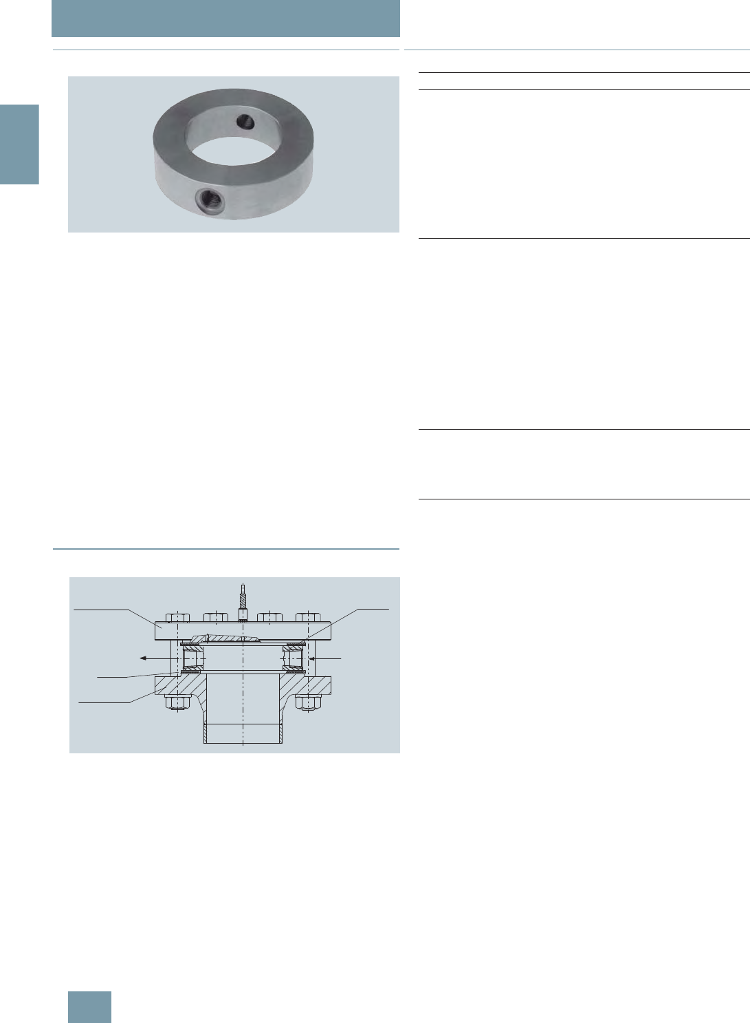
SITRANS P measuring instruments for pressure
Flushing rings
For diaphragm seals
2/174 Siemens FI 01 · 2009
2
■
Overview
Flushing ring
Flushing rings are required for flange-mounted and sandwich-
type remote seals (Order No. 7MF4900 ... 7MF4923) if the dan-
ger exists that the process conditions and the geometry of the
connection could cause the medium to form deposits or block-
ages.
The flushing ring is clamped between the process flange and
the remote seal.
Deposits can be flushed away from the diaphragm through the
holes in the side, or the pressure volume can be vented. Different
nominal diameters and forms permit adaptation to the respec-
tive process flange.
Process connection
For flanges to EN and ASME:
DN 50, 80, 100, 125; PN 16 ... 100 or
DN 2 inch, 3 inch, 4 inch, 5 inch; Class 150 ... 600
Standard design
Material: CrNi-Stahl, mat. No. 1.4404/316L
Sealing faces and flushing holes: See Selection and Ordering
data
■
Design
Installation example
■
Technical specifications
Dichtung
Spülring
Measuring
point flange
Flushing outlet
Remote seal flange
Gasket
Flushing inlet
Flushing ring
Flushing ring for remote seals of sandwich and flange design
Nominal diameter Nominal pressure
• DN 50 PN 16 ... PN 100
• DN 80 PN 16 ... PN 100
• DN 100 PN 16 ... PN 100
• DN 125 PN 16 ... PN 100
• 2 inch Class 150 ... class 600
• 3 inch Class 150 ... class 600
• 4 inch Class 150 ... class 600
• 5 inch Class 150 ... class 600
Sealing face
• To EN 1092-1 Form B1
Form B2
Form D/Form D
Form C/Form C
Form C/Form C
Form E
Form F
• To ASME B16.5 RF 125 ... 250 AA
RFSF
RJT ring groove
Flushing holes (2 off), female
thread: •G¼
•G½
•¼-18NPT
•½-14NPT
Material Stainless steel 1.4404/316L
© Siemens AG 2008

SITRANS P measuring instruments for pressure
Flushing rings
For diaphragm seals
2/175
Siemens FI 01 · 2009
2
D) Subject to export regulations AL: N, ECCN: EAR99H.
■
Dimensional drawings
Connection to EN 1092-1
Connection to ASME B 16.5
Flushing ring, dimension drawing
Selection and Ordering data Order No. Ord. code
Flushing ring D) 7 M F 4 9 2 5 -
for remote seals 7MF4900 to 7MF4923 17777 777
Nom. diam. Nom. press.
•DN50 PN16...PN100 A
•DN80 PN16...PN100 B
• DN 100 PN 16 ... PN 100 C
• DN 125 PN 16 ... PN 100 D
• 2 inch Class 150 ... 600 G
• 3 inch Class 150 ... 600 H
• 4 inch Class 150 ... 600 J
• 5 inch Class 150 ... 600 K
Other version
Add Order code and plain text:
Nominal diameter: ...; Nominal pressure: ...
Z J 1 Y
Sealing face
• EN 1092-1
- Form B1 A
- Form B2 C
- Form C/Form C D
- Form D/Form C E
- Form D/Form D F
- Form E G
- Form F H
• ASME B16.5
- RF 125 ... 250 AA M
- RFSF Q
- RJT ring groove R
Other version
Add Order code and plain text:
Sealing face: ...
Z K 1 Y
Flushing holes (2 off)
• Female thread G¼ 1
• Female thread G½ 2
• Female thread ¼-18 NPT 3
• Female thread ½-14 NPT 4
Material
• Stainless steel 316L 0
Other version
Add Order code and plain text:
Material: ...
9 M 1 Y
Selection and Ordering data Order code
Further designs
Please add "-Z" to Order No. and specify Order code.
Acceptance test certificate C12
to EN 10204, section 3.1
DN PN d4dih Weight
(mm) (bar) (mm) (mm) (mm) (kg)
50 16 ... 100 102 62 30 1.10
80 16 ... 100 138 92 30 1.90
100 16 ... 100 162 92 30 3.15
125 16 ... 100 188 126 30 3.50
DN Class d4dih Weight
inch mm (inch) mm (inch) mm (inch) kg (lb)
2 150 ... 600 92 (3.62) 62 (2.44) 30 (1.18) 0.60 (1.32)
3 150 ... 600 127 (5) 92 (3.62) 30 (1.18) 1.05 (2.31)
4 150 ... 600 157 (6.18) 92 (3.62) 30 (1.18) 2.85 (6.28)
5 150 ... 600 185.5 (7.3) 126 (4.96) 30 (1.18) 3.30 (7.28)
di
h
d4
Thread
© Siemens AG 2008

SITRANS P measuring instruments for pressure
Clamp-on seals of flange design
For gage pressure, differential pressure and flow
2/176 Siemens FI 01 · 2009
2
■
Overview
Clamp-on seals for flange-mounting
The clamp-on seal is completely integrated in the process line.
It is particularly suitable for flowing and highly viscous media.
The clamp-on remote seal consists of a cylindrical jacket into
which a thin-walled pipe is welded. It is clamped directly be-
tween two flanges in the pipeline.
■
Design
• Clamp-on seals for flange-mounting (flange design) to
EN/ASME for SITRANS P pressure transmitters
- For pressure: P300, DS III, DS III PA and DS III FF series
- For differential pressure and flow: DS III, DS III PA and
DS III FF
• Sealing face to EN 1092-1 or ASME B16.5
• Connection to the transmitter directly or by means of a flexible
capillary (max. 10 m long)
• See Technical data for details of materials used for the wetted
parts
• Material used for the capillary, the guard sleeve, the seal’s
main body and the measuring cell: Stainless steel,
mat.-No. 1.4571
• Filling liquid: Silicone oil, high-temperature oil, halocarbon oil,
food oil (FDA listed) or glycerin/water (not suitable for uses in
low-pressure range)
■
Function
The measured pressure is transferred from the diaphragm to the
filling liquid and passes either directly or through the capillary to
the measuring chamber of the pressure transmitter. The interior
of the diaphragm seal and of the capillary, as well as the mea-
suring chamber of the pressure transmitter, are filled gas-free by
the filling liquid.
Note:
When operating in the low-pressure range, also during commis-
sioning, it is recommended to use a vacuum-proof remote seal
(see Selection and Ordering data).
■
Technical specifications
Clamp-on seals for flange-mounting
Nominal diameter Nominal pressure
• DN 25 PN 6 ... PN 100
• DN 40 PN 6 ... PN 100
• DN 50 PN 6 ... PN 100
• DN 80 PN 6 ... PN 100
• DN 100 PN 6 ... PN 100
• 1 inch Class 150 ... class 2500
• 1½ inch Class 150 ... class 2500
• 2 inch Class 150 ... class 2500
• 3 inch Class 150 ... class 2500
• 4 inch Class 150 ... class 2500
Process connection Flange to EN 1092-1 or
ASME B 16.5
Sealing face To EN 1092-1, form B1 or to
ASME B16.5 RF 125 ... 250 A or
RFSF
Materials
• Main body Stainless steel 1.4404/316L
• Diaphragm Stainless steel 1.4404/316L
• Wetted parts Stainless steel 1.4404/316L
• Without foil
• ECTFE coating
• PFA coating (for vacuum on re-
quest)
Monel 400, mat. No. 2.4360
Hastelloy C276, mat. No. 2.4819
Hastelloy C4, mat. No. 2.4610
Tantalum
• Capillary Stainless steel, mat.
No. 1.4571/316Ti
• Sheath Spiral hose made of stainless
steel, mat. No. 1.4301/316
Capillary
• Length Max. 10 m (32.8 ft)
• Internal diameter 2 mm (0.079 inch)
• Minimum bending radius 150 mm (5.9 inch)
Filling liquid Silicone oil M5
Silicone oil M50
High-temperature oil
Halocarbon oil
Food oil (FDA listed)
Glycerin/water (not suitable for
uses in low-pressure range)
Permissible ambient temperature See pressure transmitters, see fill-
ing liquid
Weight Approx. 4 kg (8.82 lb)
Certificates and approvals
Classification according to pressure
equipment directive
(DRGL 97/23/EC)
For gases of fluid group 1 and liq-
uids of fluid group 1; complies
with the requirements of article 3,
paragraph 1 (appendix 1);
assigned to category III, confor-
mity evaluation module H by the
TÜV Nord
© Siemens AG 2008

SITRANS P measuring instruments for pressure
Clamp-on seals of flange design
For gage pressure, differential pressure and flow
2/177
Siemens FI 01 · 2009
2
D) Subject to export regulations AL: N, ECCN: EAR99H.
Selection and Ordering data Order No. Ord. code
Clamp-on seal for flange-mounting for
SITRANS P pressure transmitters
for pressure
7MF4037 and 7MF4237 together with Order
code "V01" (vacuum-proof design) and
7MF80271); must be ordered separately, scope
of delivery: 1 off
1) With 7MF8027 and the measuring cells Q, S, T and U also order the
vacuum-tight version.
D) 7 M F 4 9 8 0 -
for differential pressure and flow
7MF4433 or 7MF4434; order separately, scope
of delivery: 1 pair (set); Material: Completely of
stainless steel, mat. No. 1.4404/316L;
Process connection to EN 1092-1 or ASME
B16.5; sealing face to EN 1092-1, form B1,
or to ASME B16.5 RF 125 ... 250 AA
D) 7 M F 4 9 8 3 -
17 7 07-7B777
Nominal diameter and nominal pressure
•DN25 PN6...100 B
•DN40 PN6...100 D
•DN50 PN6...100 E
•DN80 PN6...100 G
• DN 100 PN 6 ... 100 H
• 1 inch Class 150 ... 2500 L
• 1½ inch Class 150 ... 2500 M
• 2 inch Class 150 ... 2500 N
• 3 inch Class 150 ... 2500 P
• 4 inch Class 150 ... 2500 Q
Other version
Add Order code and plain text:
Nominal diameter: ...; Nominal pressure: ...
Z J 1 Y
Wetted parts materials
• Stainless steel 316L
- Without foil A
- With PFA coating D
- With ECTFE coating2)
2) For vacuum on request.
F
• Monel 400, mat. No. 2.4360 G
• Hastelloy C276, mat. No. 2.4819 J
• Hastelloy C4, mat. No. 2.4610 U
• Tantalum K
Other version
Add Order code and plain text:
Wetted parts materials: ...
Z K 1 Y
Filling liquid
• Silicone oil M5 1
• Silicone oil M50 2
• High-temperature oil 3
• Halocarbon oil (for measuring O2)4
• Glycerin/water3)
3) Not suitable for use in low-pressure range.
6
• Food oil (FDA listed) 7
Other version
Add Order code and plain text:
Filling liquid: ...
9 M 1 Y
Connection to transmitter
• direct (only for 7MF4980) 0
through capillary, length:4)
4) Max. capillary length, see section "Technical description"
• 1.0 m (3.28 ft) 2
• 1.6 m (5.25 ft) 3
• 2.5 m (8.20 ft) 4
• 4.0 m (13.1 ft) 5
• 6.0 m (19.7 ft) 6
• 8.0 m (26.25 ft) 7
• 10.0 m (32.8 ft) 8
Other version
Add Order code and plain text:
Length of capillary: ...
9 N 1 Y
Selection and Ordering data Order code
Further designs
Please add "-Z" to Order No. and specify Order code.
Spark arrestor
With spark arrestor for mounting on zone 0 (including
documentation)
• Pressure and absolute pressure A01
• for differential pressure transmitters A02
Quality inspection certificate (Factory calibration) to
IEC 60770-2 C11
Acceptance test certificate C12
To EN 10204, section 3.1
Vacuum-proof design V01
For use in low-pressure range
Calculation of span of associated pressure trans-
mitter Y05
Enclose filled-in questionnaire with order
Note:
Suffix "Y01" required with pressure transmitter!
© Siemens AG 2008
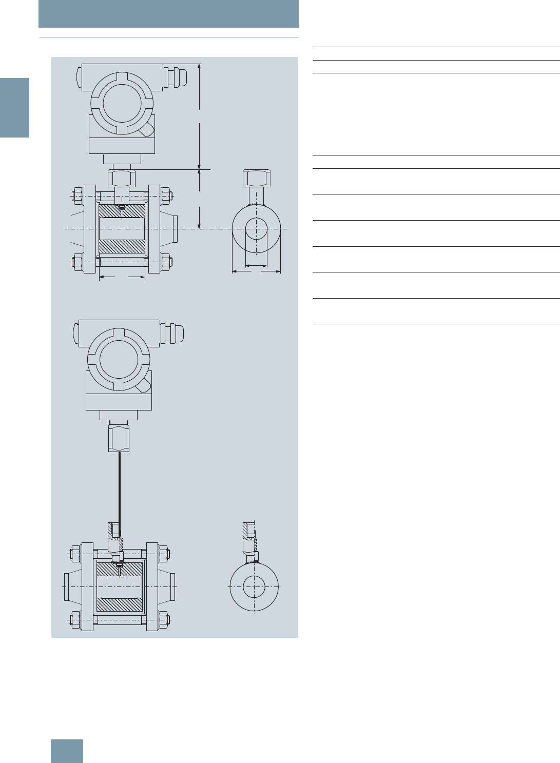
SITRANS P measuring instruments for pressure
Clamp-on seals of flange design
For gage pressure, differential pressure and flow
2/178 Siemens FI 01 · 2009
2
■
Dimensional drawings
Clamp-on seal for flange-mounting, connected to SITRANS P pressure
transmitter, dimensions in mm (inch)
Connection to EN 1092-1
Connection to ASME B16.5
D
ø Mb
L
H
146 (5.75)
Bending radius ³ 150 mm (5.9)
DN PN D Mb L H
mm bar mm mm mm mm
25 6 ... 100 63 28,5 60 78.5
40 6 ... 100 85 43 60 89.5
50 6 ... 100 95 54.5 60 92.5
80 6 ... 100 130 82.5 60 112
100 6 ... 100 150 107 60 122
DN Class D Mb L H
(inch) mm mm mm mm
(inch) (inch) (inch) (inch)
1 150 ... 2500 63 28.5 60 78.5
(2.48) (1.12) (2.36) (3.1)
1½ 150 ... 2500 85 43 60 86
(3.35) (1.69) (2.36) (3.4)
2 150 ... 2500 95 54.5 60 94.5
(3.74) (2.15) (2.36) (3.72)
3 150 ... 2500 130 82.5 60 112
(5.12) (3.25) (2.36) (4.4)
4 150 ... 2500 150 107 60 122
(5.9) (4.21) (2.36) (4.8)
© Siemens AG 2008
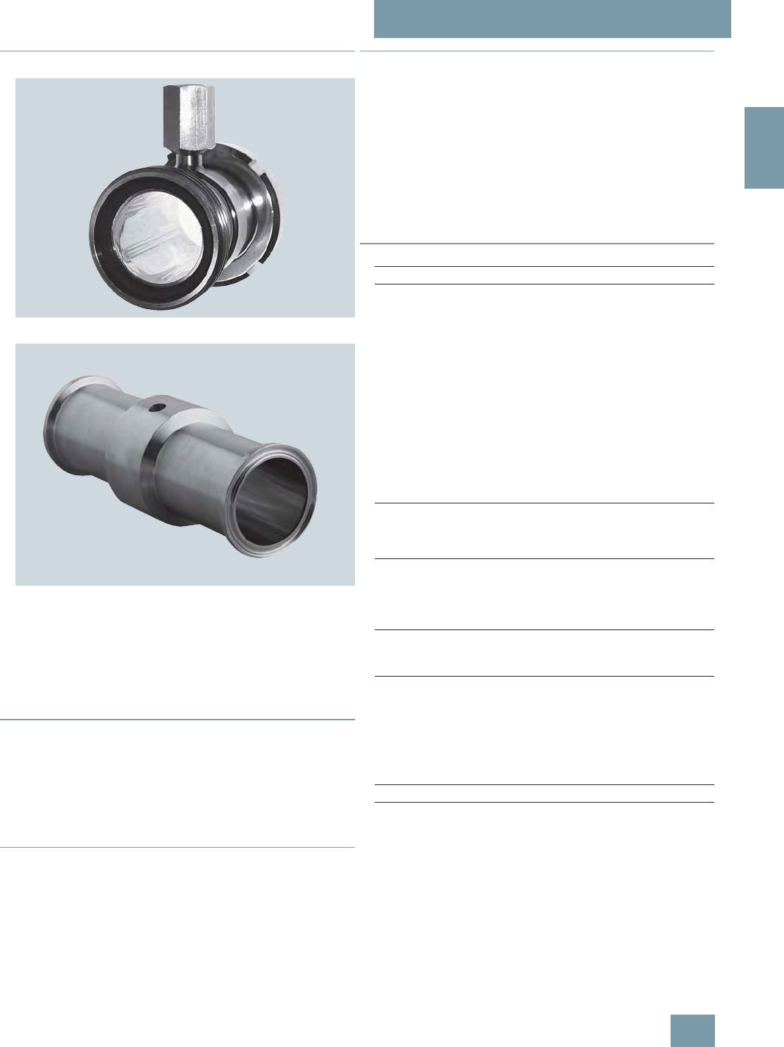
SITRANS P measuring instruments for pressure
Quick-release clamp-on seals
For pressure and absolute pressure
2/179
Siemens FI 01 · 2009
2
■
Overview
Quick-release clamp-on seals, to DIN 11851 with threaded socket
Quick-release clamp-on seals, with clamp connection
Quick-release clamp-on seals for pressure are available for the
following SITRANS P pressure transmitter series:
• P300
• DS III
• DS III PA
• DS III FF
■
Application
The quick-release clamp-on seal is a special design for flowing
media and high-viscosity media. Since it is completely inte-
grated in the process pipe, no turbulences, dead volumes or
other obstructions to the flow occur. The measured medium
flows unhindered through the clamp-on seal and results in self-
cleaning of the measuring chamber. Furthermore, the clamp-on
seal can be cleaned by a pig.
■
Design
The quick-release clamp is available in two versions:
• DIN 11851 with threaded socket
• Clamp connection
The clamp-on seal is connected to the pressure transmitter ei-
ther directly or by way of a capillary.
■
Function
The measured pressure is transferred from the diaphragm,
mounted on the inner circumference of the clamp-on seal, to the
filling liquid and then passes through the capillary to the measur-
ing chamber of the pressure transmitter. The interior of the
clamp-on seal and of the capillary, as well as the measuring
chamber of the pressure transmitter, are filled gas-free by the fill-
ing liquid.
Note:
When operating in the low-pressure range, also during commis-
sioning, it is recommended to use a vacuum-proof pressure
transmitter (see Selection and Ordering data).
■
Technical specifications
Clamp-on seals of quick-release design for pressure
Connection Nominal
diameter Nominal
pressure
• To DIN 11851 with threaded
socket DN 25 PN 40
DN 40 PN 40
DN 50 PN 25
DN 65 PN 25
DN 80 PN 25
DN 100 PN 25
• Clamp connection 1½ inch PN 40
2 inch PN 40
2½ inch PN 40
3 inch PN 40
Material
• Main body Stainless steel 1.4404/316L
• Diaphragm Stainless steel 1.4404/316L
Capillary
• Length Max. 10 m (32.8 ft)
• Internal diameter 2 mm (0.079 inch)
• Minimum bending radius 150 mm (5.9 inch)
Filling liquid • Food oil (FDA listed)
• Glycerin/water (not suitable for
use in low-pressure range)
Permissible ambient temperature Dependent on the pressure trans-
mitter and the filling liquid of the
remote seal
More information can be found in
the technical data of the pressure
transmitters and in the section
"Technical data of filling liquid" in
the Technical description to the
remote seals
Weight Approx. 4 kg (approx. 8.82 lb)
Certificate and approvals
Classification according to pres-
sure equipment directive
(DRGL 97/23/EC)
For gases of fluid group 1 and liq-
uids of fluid group 1; complies with
the requirements of article 3,
paragraph 1 (appendix 1);
assigned to category III, confor-
mity evaluation module H by the
TÜV Nord
© Siemens AG 2008

SITRANS P measuring instruments for pressure
Quick-release clamp-on seals
For pressure and absolute pressure
2/180 Siemens FI 01 · 2009
2
Selection and Ordering data Order No. Ord. code
Quick-release clamp-on seal D) 7 M F 4 9 5 0 -
for SITRANS P pressure transmitters for
pressure
7MF4037 and 7MF4237 together with Order
code "V01" (vacuum-proof design) and
7MF80271); must be ordered
separately
Filling liquid: Food oil (FDA listed)
Material: Stainless steel 316L
1) With 7MF8027 and the measuring cells Q, S, T and U also order the vac-
uum-tight version.
77A 0 7-7B7 7 7
Nom. diam. Nom. press.
• Connection to DIN 11851 with screw necks
- DN25 PN40 2B
- DN40 PN40 2D
- DN50 PN25 2E
- DN65 PN25 2F
- DN80 PN25 2G
- DN 100 PN 25 2H
• Clamp connection
- 1½ inch PN 40 4L
- 2 inch PN 40 4M
- 2½ inch PN 40 4N
- 3 inch PN 40 4P
Other version
Add Order codes and plain text:
Nominal diameter: ... 9 H 1 Y
Nominal pressure: ... Z J 1 Y
Filling liquid
• Glycerin/water2)
2) Not suitable for use in low-pressure range.
6
• Food oil (FDA listed) 7
Other version
Add Order code and plain text:
Filling liquid: ...
9 M 1 Y
Connection to transmitter
• Direct 0
Through capillary, length:3)
3) Max. capillary length, see section "Technical description"
D) Subject to export regulations AL: N, ECCN: EAR99H.
• 1.0 m (3.28 ft) 2
• 1.6 m (5.25 ft) 3
• 2.5 m (8.20 ft) 4
• 4.0 m (13.1 ft) 5
• 6.0 m (19.7 ft) 6
• 8.0 m (26.25 ft) 7
• 10.0 m (32.8 ft) 8
Other version
Add Order code and plain text:
Length of capillary: ...
9 N 1 Y
Selection and Ordering data Order code
Further designs
Please add "-Z" to Order No. and specify Order code.
Quality inspection certificate (Factory calibration) to
IEC 60770-2 C11
Acceptance test certificate C12
to EN 10204, section 3.1
Vacuum-proof design V01
for use in low-pressure range
© Siemens AG 2008
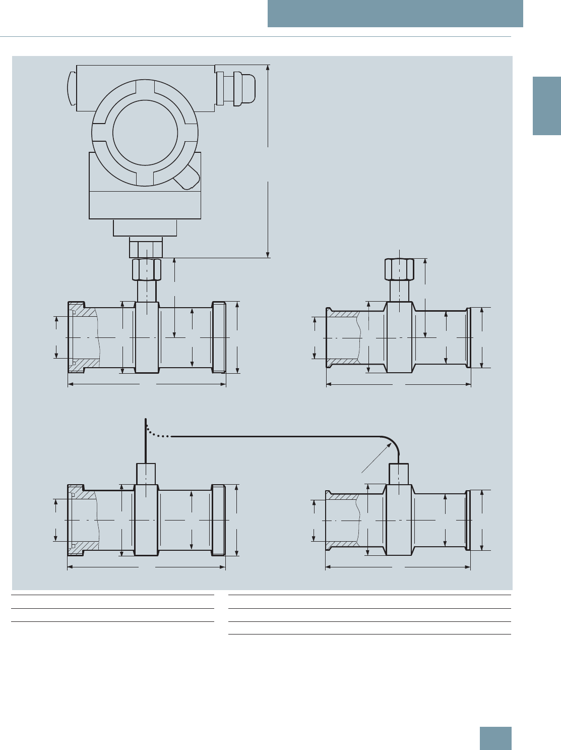
SITRANS P measuring instruments for pressure
Quick-release clamp-on seals
For pressure and absolute pressure
2/181
Siemens FI 01 · 2009
2
■
Dimensional drawings
Quick-release clamp-on seal, dimensions in mm (inch)
L
DN
G
H
1
146 (5.9)
d
L
H
D2
D1
D2
D1
L
DN
G1
d
L
D2
D1
D2
D1
R ³ 150 (5.9)
D
D
Mounted directly on SITRANS P transmitter for pressure
Mounted on SITRANS P transmitter for pressure or differential pressure and flow
Connection to DIN 11851 with screw necks Clamp connection for pipes to BS 4825/3 and o.D. tubes
DN Ø D1ØD
2HLG
1dØD
1ØD
2HLD
25 38 52 68 128 Rd 52x1/6 mm (inch) mm (inch) mm (inch) mm (inch) mm (inch) mm (inch)
40 55 65 74.5 160 Rd 65x1/6 22.2 (1) 38 (1.5) 50 (1.97) 67 (2.64) 114 (4.49) 50.5 (1.98)
50 68 78 81 170 Rd 78x1/6 34.9 (1½) 43 (1.69) 65 (2.56) 74.5 (2.93) 146 (5.75) 50.5 (1.98)
65 85 95 89.5 182 Rd 95x1/6 47.6 (2) 56 (2.2) 75 (2.95) 79.5 (3.13) 156 (6.14) 64 (2.52)
80 110 110 97 182 Rd 110x1/4 60.3 (2½) 68 (2.68) 77 (3.03) 80.5 (3.17) 156 (6.14) 77.5 (3.05)
100 130 130 107 182 Rd 110x1/4 73.0 (3) 82 (3.23) 91 (3.58) 87.5 (3.44) 156 (6.14) 91 (3.58)
© Siemens AG 2008

SITRANS P measuring instruments for pressure
Remote seals
Measuring setups
2/182 Siemens FI 01 · 2009
2
■
Overview
This section shows examples of typical measuring setups for us-
ing SITRANS P pressure transmitters with and without remote
seals.
Equations for calculating start of scale and full scale are pro-
vided for each example.
Questionnaires are included to help you select the right combi-
nation of remote seal and pressure transmitter.
Installation
Remote seals of sandwich design are fitted between the con-
nection flange of the measuring point and a dummy flange. Re-
mote seals of flange design are fitted directly on the connection
flange of the measuring point. The respective pressure rating of
the dummy flange or the flanged remote seal must be observed.
The pressure transmitter should be installed below the connec-
tion flange (and below the lower connection flange in the case of
differential pressure transmitters). This arrangement must be
used in the low-pressure range.
When measuring at pressures above atmospheric, the pressure
transmitter can also be installed above the connection flange.
The capillaries between the remote seal and the pressure trans-
mitter should be as short as possible to obtain a good transmis-
sion response.
Offset of measuring range
If there is a difference in height between the two connection
flanges when measuring with two remote seals, an additional dif-
ferential pressure will result from the oil filling of the remote seal
capillaries. This results in a measuring range offset which has to
be taken into account when you set the pressure transmitter.
An offset in the measuring range also occurs when combining a
remote seal with a transmitter if the remote seal is not installed at
the same height as the transmitter.
Pressure transmitter output
If the level, separation layer or density increase in closed ves-
sels, the differential pressure and hence the output signal of the
pressure transmitter also increase.
For an inverted relationship between the differential pressure
and the output signal, the start-of-scale and full-scale values of
the SITRANS P must be interchanged.
With open vessels, a rising pressure is usually assigned to an in-
creasing level, separation layer or density.
Influence of ambient temperature
Temperature differences between the individual capillaries and
between the individual remote seals should be avoided.
Temperature variations in the area of the measuring setup cause
a change in volume of the filling liquid and hence measuring er-
rors.
Notes
• For the separation layer measurement, the separation layer
has to be positioned between the two spigots. Also you must
make sure that the level in the container is always above the
top spigot.
• When measuring density, make sure that the level of the me-
dium remains constant. The level should be above the top
spigot.
Possible combinations of pressure transmitters and remote
seals
Type of installation Pressure transmit-
ters Remote seals
A/B 7MF4033
7MF4034
7MF4035
7MF8023
7MF8024
7MF8025
7MF4900
7MF4910
7MF4920
C1 and C27MF4233
7MF4234
7MF4235
7MF4900
7MF4910
7MF4920
(vacuum-proof design
in each case)
7MF4333
7MF4334
7MF4335
7MF4901
7MF4921
D 7MF4433
7MF4434
7MF4435
7MF4903
7MF4923
E 7MF4433
7MF4434
7MF4435
7MF4913
G, H and J 7MF4433
7MF4434
7MF4435
7MF4903
7MF4923
© Siemens AG 2008
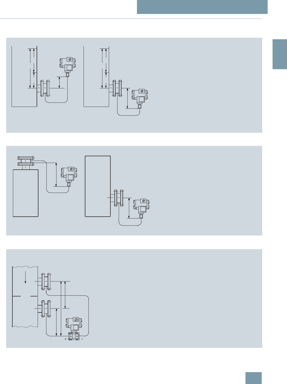
SITRANS P measuring instruments for pressure
Remote seals
Measuring setups with remote seals
2/183
Siemens FI 01 · 2009
2
■
Dimensional drawings
Types of installation for pressure and level measurements (open vessels)
Types of installation for absolute level measurements (closed vessels)
Type of installation for differential pressure and flow measurements
H1
H1
HU
D
H
HO
HU
D
H
HO
Installation type A
Start-of-scale: p
MA
= r
FL
· g · H
U
- r
Oil
· g · H
1
Full-scale: p
ME
= r
FL
· g · H
O
- r
Oil
· g · H
1
Installation type B
Start-of-scale: p
MA
= r
FL
· g · H
U
+ r
Oil
· g · H
1
Full-scale: p
ME
= r
FL
· g · H
O
+ r
Oil
· g · H
1
Legend
p
MA
Start-of-scale value to be set
p
ME
Full-scale value to be set
r
FL
Density of medium in vessel
r
Oil
Density of filling oil in the capillary to
the remote seal
gLocal acceleration due to gravity
H
U
Start-of-scale value
H
O
Full-scale value
H
1
Distance between vessel flange and pressure trans.
Pressure transmitter
above the measuring point
Pressure transmitter
below the measuring point
H1 £ 7 m (23 ft), with halocarbon oil as filling liquid only H1 £ 4 m (13.1 ft)
Installation type A Installation type B
Installation type C1 and C2
Start-of-scale: pMA = pSTART + rOil
· g · H1
Full-scale: pME = pEND + rOil · g · H1
Legend
pMA Start-of-scale value to be set
pME Full-scale value to be set
pSTART Start-of-scale value
pEND Full-scale value
rOil Density of filling oil in the capillary to
the remote seal
gLocal acceleration due to gravity
H1Distance between vessel flange and pressure trans.
H1
H1
pabspabs
Pressure transmitter for absolute pressure always below the measuring point: H1 ³ 200 mm (7.9 inch)
Installation type C1Installation type C2
H
2
H
V
H
1
Installation type D
Start-of-scale: p
MA
= p
START
- r
Oil
· g · H
V
Full-scale: p
ME
= p
END
- r
Oil
· g · H
V
Legend
p
MA
Start-of-scale value to be set
p
ME
Full-scale value to be set
p
START
Start-of-scale value
p
END
Full-scale value
r
Oil
Density of filling oil in the capillary to
the remote seal
gLocal acceleration due to gravity
H
V
Distance between the measuring points (spigots)
Installation type D Filter monitoring
© Siemens AG 2008
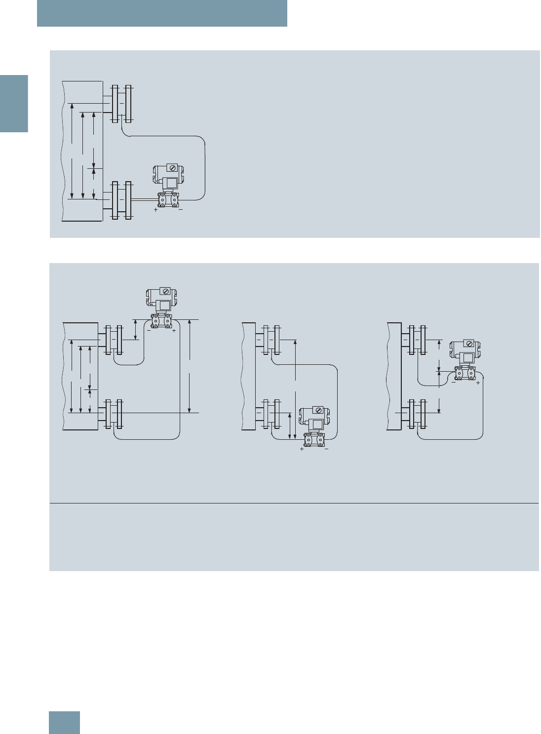
SITRANS P measuring instruments for pressure
Remote seals
Measuring setups with remote seals
2/184 Siemens FI 01 · 2009
2
Types of installation for level measurements (closed vessels)
HO
HV
Installation type E
Start-of-scale: p
MA
= r
FL
· g · H
U
- r
Oil
· g · H
V
Full-scale: p
ME
= r
FL
· g · H
O
- r
Oil
· g · H
V
Legend
p
MA
Start-of-scale value to be set
p
ME
Full-scale value to be set
r
FL
Density of medium in vessel
r
Oil
Density of filling oil in the capillary to
the remote seal
gLocal acceleration due to gravity
H
U
Start-of-scale value
H
O
Full-scale value
H
V
Distance between the measuring points (spigots)
Installation type E
DH
HU
H
U
DH
H
O
H
V
H
2
H
1
Installation type G, H and J
Start-of-scale: p
MA
= r
FL
· g · H
U
- r
Oil
· g · H
V
Full-scale: p
ME
= r
FL
· g · H
O
- r
Oil
· g · H
V
Legend
p
MA
Start-of-scale value to be set
p
ME
Full-scale value to be set
r
FL
Density of medium in vessel
r
Oil
Density of filling oil in the capillary to
the remote seal
gLocal acceleration due to gravity
H
U
Start-of-scale value
H
O
Full-scale value
H
V
Distance between the measuring points (spigots)
H
1
H
2
Installation type J
between the measuring points, no vacuum
H
2
£ 7 m (23 ft), with halocarbon oil as
filling liquid only H
2
£ 4 m (13.1 ft)
H
1
H
2
Installation type H
below the lower measuring point
Installation type G
Pressure transmitter for differential pressure
above the upper measuring point, no vacuum
H
1
£ 7 m (23 ft), with halocarbon oil as
filling liquid only H
1
£ 4 m (13.1 ft)
© Siemens AG 2008
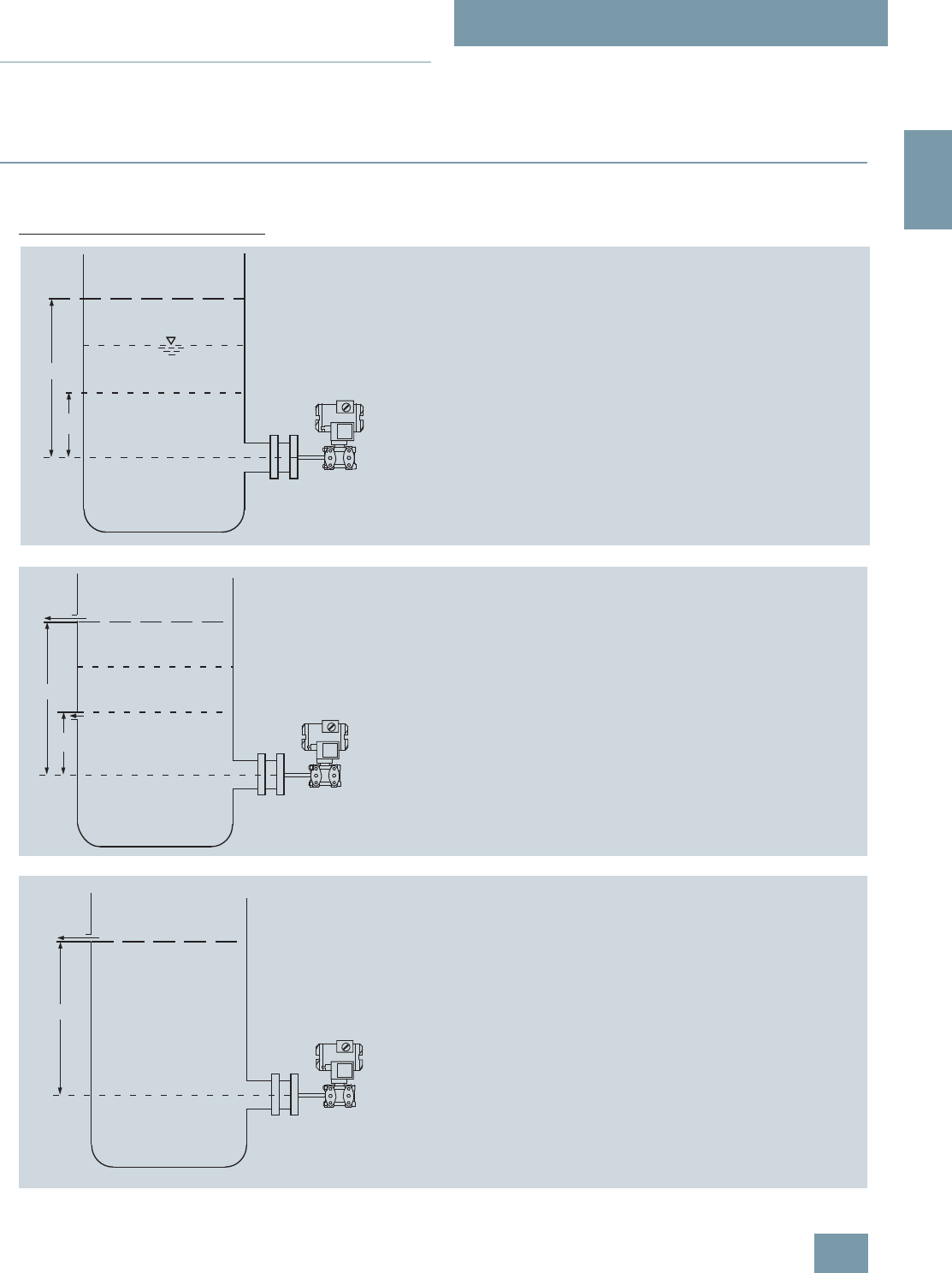
SITRANS P measuring instruments for pressure
Remote seals
Measuring setups without remote seals
2/185
Siemens FI 01 · 2009
2
■
Overview
Notes
• For the separation layer measurement, the separation layer
has to be positioned between the two spigots.
Also you must make sure that the level in the container is al-
ways above the top spigot.
• When measuring density, make sure that the level of the me-
dium remains constant. The level should be above the top
spigot
■
Dimensional drawings
Pressure transmitters for differential pressure, for flanging
Measuring setups for open containers
r
+
Ho
Hu
Level measurement
Start-of-scale: p
MA
= r · g · H
U
Full-scale: p
ME
= r · g · H
O
Legend
p
MA
Start-of-scale value to be set
p
ME
Full-scale value to be set
rDensity of medium in vessel
gLocal acceleration due to gravity
H
U
Start-of-scale value
H
O
Full-scale value
Full-scale value
Start-of-scale value
r
r
H
u
2
1
H
o
+
Separation layer measurement
Start-of-scale: p
MA
= g · (H
U
· r
1
+ (H
O
- H
U
) · r
2
)
Full-scale: p
ME
= r
1
· g · H
O
Legend
p
MA
Start-of-scale value to be set
p
ME
Full-scale value to be set
r
1
Density of heavier liquid
r
2
Density of lighter liquid
gLocal acceleration due to gravity
H
U
Start-of-scale value
H
O
Full-scale value
Constant level
= full-scale value
Start-of-scale value
Separation layer
Ho
+
r
Density measurement
Start-of-scale: pMA = rMIN · g · HO
Full-scale: pME = rMAX · g · HO
Legende
pMA Start-of-scale value to be set
pME Full-scale value to be set
rMINMinimum density of medium in vessel
rMAX Maximum density of medium in vessel
gLocal acceleration due to gravity
HOFull-scale value in m
Constant level
© Siemens AG 2008
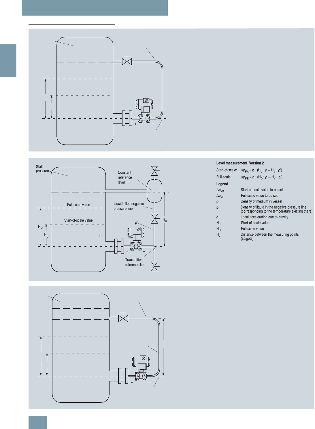
SITRANS P measuring instruments for pressure
Remote seals
Measuring setups without remote seals
2/186 Siemens FI 01 · 2009
2
Measuring setups for closed containers
r
Ho
Hu
Level measurement, Version 1
Start-of-scale: Dp
MA
= r · g · H
U
Full-scale: Dp
ME
= r · g · H
O
Legend
Dp
MA
Start-of-scale value to be set
Dp
ME
Full-scale value to be set
rDensity of medium in vessel
gLocal acceleration due to gravity
H
U
Start-of-scale value
H
O
Full-scale value
Maximum level
Start-of-scale value
Full-scale value
Transmitter
reference line
Static
pressure Gas-filled negative
pressure line
Maximum level
H
r
r
r'Hv
Hu
22
1
o
Separation layer measurement
Start-of-scale: DpMA = g · (HU · r1 + (HO - HU) · r2 - HV · r'2)
Full-scale: DpME = g · (HO · r1 - HV · r'2)
Legend
DpMA Start-of-scale value to be set
DpME Full-scale value to be set
r1Density of heavier liquid with separation layer
in vessel
r2Density of lighter liquid with separation layer
r'2Density of liquid in the negative pressure line
(corresponding to the temperature existing there)
gLocal acceleration due to gravity
HUStart-of-scale value
HOFull-scale value
HVDistance between the measuring points
(spigots)
Max. separation layer
Start-of-scale value
Full-scale value
Static
pressure
Constant level
Static
pressure
Transmitter
reference line
© Siemens AG 2008

2/187
Siemens FI 01 · 2009
2
Questionnaire
Checking of transmitter/remote seal combinations
s
* Customer:___________________ Tag. No.: _____________________
* Plant: ___________________ Item No.: _____________________
* Ordering code:________________ Person responsible: ___________
* Ordering department: _____ Phone: _____________________
* Transmitter Order No.: 7MF 4 –1 –1
Order No. of transmitter known?
* Order No. of remote seal:
* 7MF 4 9 – – –Z
Suffixes _______________________
Suffixes _______________________
* Or without Order No.: Process connection
* Standard: ________________________
* Nominal diameter: ________________________
* Nominal pressure: ________________________
* Constructional design: Sandwich-type rem. seal
Flanged remote seal
Quick-release
remote seal
Clamp-on seal
Other.: ______________
* Connection: Direct connection
Capillary on one side;
connection to:
+ side – side
Capillaries on both sides;
Capillary length: ___ m
* Vacuum-proof design Yes No
* Wetted parts materials: ________________________
* Tube: No Yes, ___mm long
* Filling liquid ________________________
* Miscellaneous ________________________
Calculation of measuring range necessary?
* Medium ____________________________
* Density of medium: _______ kg/m3
* Temperature of medium: Normal ________ °C
Minimum________ °C
Maximum________ °C
* Ambient temperature on capillaries: Normal ________ °C
Minimum________ °C
Maximum________ °C
* Ambient temperature on transmitter: Normal ________ °C
Minimum________ °C
Maximum________ °C
* Operating pressure referred to absolute zero: ____ bar a
* Does a vacuum occur during startup?NoYes
If yes, associated temperature of medium: ________ °C
* Installation type, see pages 2/183 and 2/184
* Measuring: With install. types A, B, C1, C2 and D: from ___ to ___ mbar
range With install. types A, B, G, H and J: HU = ___ mm; HO = ___ mm
* Dimensions: With install. types A, B, C1 and C2:H
1 = ___ mm
With install. types D, G, H and J: HV = ___ mm
* Start-of-scale value following calculation:_________ mbar ( 4 mA)
* Full-scale value following calculation:_________ mbar (20 mA)
* Associated span: _________ mbar
* Error to be expected: _________ of set span per 10 K
_________ change in temperature
AB C2
C1
EJHG
D
< . %
NoYes
* Range to be set:
* (without calculation)
Start-of-scale:_________ mbar ( 4 mA)
Full-scale: _________ mbar (20 mA)
* Required measuring accuracy:
Error: _________ of set span per
:_________ 10 V change in
:_________ temperature
< . %
*) Values must be entered here!
Please fill in this questionnaire
and enclose with every order!
No Yes
Checked: Name:
Department:
Date:
© Siemens AG 2008
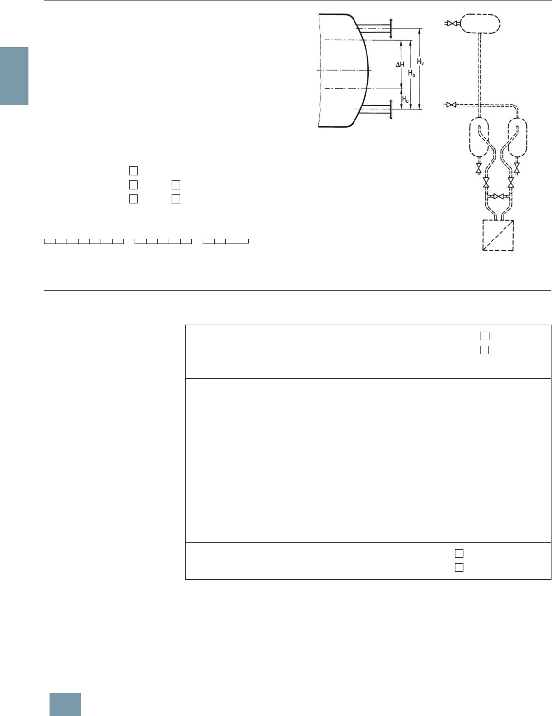
2/188 Siemens FI 01 · 2009
2
s
Questionnaire
for hydrostatic level measurements
s
Order date: _______________________________________________
Processing date: __________________________________________
Ordering code (customer): _________________________________
Ordering code (supplier): __________________________________
Customer reference:_______________________________________
Measuring point: __________________________________________
Position:__________________________________________________
Dimensions: ______________________________________________
Pressure: bar
Temperature: K °C
Measuring range: cm m
(please mark with cross)
Order No. of transmitter 1):
Y01
The different pressures and tem-
peratures (densities) in the vessel
and in the reference column result
in an offset in the start-of-scale
and full-scale values.
The calibration data are deter-
mined in addition.
It is also checked whether – as a
result of the range offset – the
ordered transmitter is suitable for
this measurement.
Please supply the following characteristic data so that we can calculate the measuring range,
start-of-scale value, full-scale value and calibration data:
1) Reference line filled with condensation! Falling differential pressure with increasing level.
2) Reference line without gas or filled with gas (air). Rising differential pressure with increasing level.
3) If not specified otherwise, this value is assumed as the calculation pressure of the level meter.
The input signal (differential pressure) depends on the density (pressure and temperature).
The influence is practically negligible for a lowest liquid level of 20 to 30% of the distance between the
measuring points.
4) If a pressure correction of the level is required, the measuring range must be the same as the
distance between the measuring points, and the transmitter is designed for the calculation pressure
of 1 bar (absolute).
Pressure correction means: the static pressure and the temperature are measured separately and
calculated by a correction computer or measured-value computer.
7MF4 ––Z–
Please mark type of boiler with a cross: Closed1)
Open or not under pressure2)
Medium ____________________
Licensed boiler pressure (absolute) _______________ bar
Operating pressure (absolute) Lowest _______________ bar
Normal3) _______________ bar
Highest _______________ bar
Temperature of reference column (cold) _______________ K
Distance between measuring points (dimension according to sketch) HV = _________ m
Measuring range4) = start-of-scale value to full-scale value
Start-of-scale value HU =___________ m
Full-scale value HO =___________ m
Position of equalizing vessel above bottom measuring
point if different from HV_______________ m
Please mark pressure correction of level with a cross: No
Yes4)
© Siemens AG 2008

2/189
Siemens FI 01 · 2009
2
s
Questionnaire (suitable for US market)
Checking of transmitter/remote seal combinations
* Customer:___________________ Tag. No.: _____________________
* Plant: ___________________ Item No.: _____________________
* Ordering code:________________ Person responsible: ___________
* Ordering department: _____ Phone: _____________________
* Transmitter Order No.: 7MF 4 –1 –1
Order No. of transmitter known?
* Order No. of remote seal:
* 7MF 4 9 – – –Z
Suffixes _______________________
Suffixes _______________________
* Or without Order No.: Process connection
* Standard: ________________________
* Nominal diameter: ________________________
* Nominal pressure: ________________________
* Constructional design: Sandwich-type rem. seal
Flanged remote seal
Quick-release
remote seal
Clamp-on seal
Other.: ______________
* Connection: Direct connection
Capillary on one side;
connection to:
+ side – side
Capillaries on both sides;
Capillary length: ___ ft
* Vacuum-proof design Yes No
* Wetted parts materials: ________________________
* Tube: No Yes, __inch long
* Filling liquid ________________________
* Miscellaneous ________________________
Calculation of measuring range necessary?
* Medium ____________________________
* Density of medium: _______ kg/m3
* Temperature of medium: Normal ________ °F
Minimum ________ °F
Maximum ________ °F
* Ambient temperature on capillaries: Normal ________ °F
Minimum ________ °F
Maximum ________ °F
* Ambient temperature on transmitter: Normal ________ °F
Minimum ________ °F
Maximum ________ °F
* Operating pressure referred to absolute zero: ____ psiabs
* Does a vacuum occur during startup?NoYes
If yes, associated temperature of medium: ________ °F
* Installation type, see pages 2/183 and 2/184
* Measuring: With install. types A, B, C1, C2 and D: from ___ to ___ psi
range With install. types A, B, G, H and J: HU = ___ inch; HO = ___ inch
* Dimensions: With install. types A, B, C1 and C2:H
1 = ___ inch
With install. types D, G, H and J: HV = ___ inch
* Start-of-scale value following calculation: _________ psi ( 4 mA)
* Full-scale value following calculation: _________ psi (20 mA)
* Associated span: _________ psi
* Error to be expected: _________ of set span per 18 °F
_________ change in temperature
AB C2
C1
EJHG
D
< . %
NoYes
* Range to be set:
* (without calculation)
Start-of-scale:_________ psi ( 4 mA)
Full-scale: _________ psi (20 mA)
* Required measuring accuracy:
Error: _________ of set span per
:_________ 18 °F change in
:_________ temperature
< . %
*) Values must be entered here!
Please fill in this questionnaire
and enclose with every order!
No Yes
Checked: Name:
Department:
Date:
© Siemens AG 2008
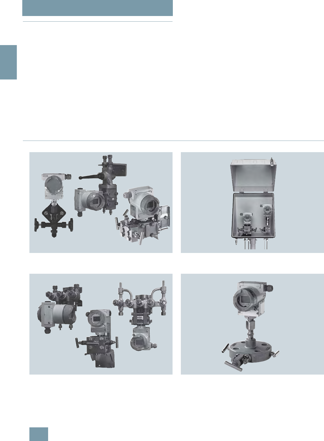
SITRANS P measuring instruments for pressure
Fittings
Technical description
2/190 Siemens FI 01 · 2009
2
■
Overview
All 21-off fittings can be secured onto walls, racks (72 mm grid)
and vertical and horizontal pipes.
This offers the advantage when assembling a plant that the shut-
off fittings can be secured first and the lines for the medium and
differential pressure connected to them. It is then possible to
check all connections for leaks and to blow out or flush the pipes
in order to remove dirt (welding residues, shavings etc.).
The measuring instruments can be screwed onto the shut-off fit-
tings right at the end when all piping has been completed.
If an instrument has to be removed for maintenance, the fittings
and pipes remain as they are. It is only necessary to close the
valves – the instrument can then be removed, and refitted follow-
ing maintenance.
Classification according to pressure equipment directive
(DGRL 97/23/EC):
For gases of fluid group 1 and liquids of fluid group 1; compli-
ance with requirements of article 3, paragraph 3 (sound engi-
neering practice).Siemens FI 01 · 2009
New standard DIN EN 61518
The flange connection between transmitter and valve manifold
was modified in the new standard DIN EN 61518. The only con-
nection thread approved for use in the process flanges of the
pressure transmitter is 7/16-20 UNF.
The valve manifolds for M12 screws, including the accessory
sets, have therefore been deleted.
Material acceptance test certificate to EN 10204-3.1
If a material acceptance test certificate to EN 10204-3.1 is re-
quired when ordering valve manifolds or shut-off fittings, please
note that a single certificate is sufficient for each ordered item
type. This means that you will only be charged for one certificate
in the cost calculations.
■
Pressure transmitters with shut-off fittings - mounting examples
SITRANS P transmitter for gage pressure with double shut-off valve,
SITRANS P pressure transmitter with multiway cock or 3-spindle valve
manifold
SITRANS P transmitter for differential pressure with 3-way valve manifold,
3-spindle valve manifold or valve manifold combination DN 5/DN 8
SITRANS P pressure transmitter for differential pressure, mounted in pro-
tective box (available on request)
SITRANS P pressure transmitter mounted on valve combination
"Monoflange" for direct connection to flanges (available on request)
© Siemens AG 2008
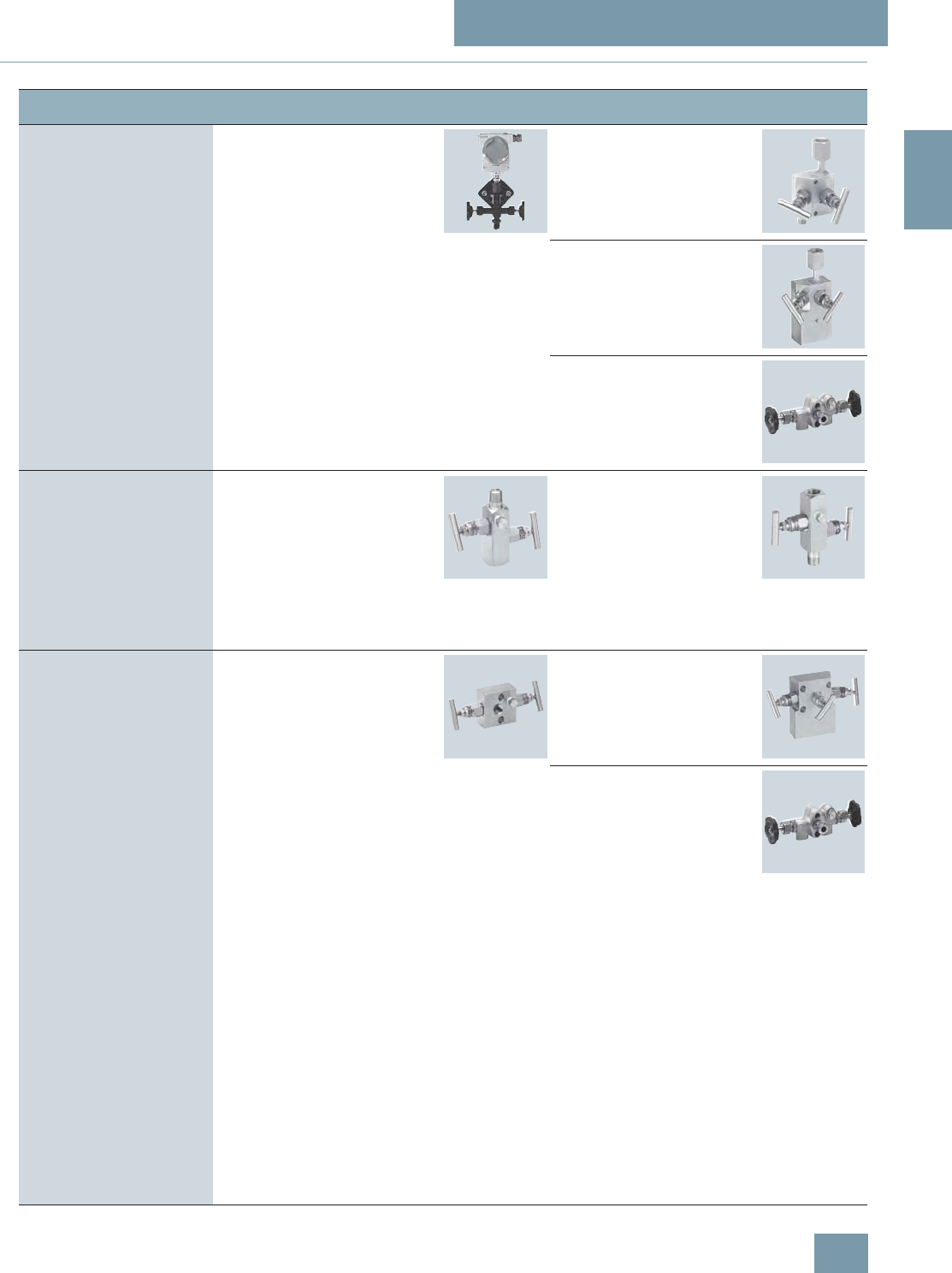
SITRANS P measuring instruments for pressure
Fittings
Selection aid
2/191
Siemens FI 01 · 2009
2
■
Selection of available shut-off valves
Transmitters Shut-off valves for general
applications Page Shut-off valves for spe-
cial applications Page
Relative and absolute pres-
sure transmitters with process
connection G½" male thread
e.g.
• SITRANS P, Z series
7MF1564-.....-.A..
• SITRANS P300
7MF802.-...0.-....
• SITRANS P DS III series
7MF403.-...0.-.... and
7MF423.-...0.-....
Shut-off valves/double shut-
off valves to DIN 16270,
DIN 16271 and DIN 16272
2/193 Double shut-off valve DN 5
for crossover ½-NPT-F to
G½ nipple connection
7MF9011-4EA
2/196
2-spindle valve manifold
DN 5 for installation in pro-
tective boxes
7MF9412-1B
2/216
2-way valve manifolds,
DN 5, forged version
7MF9401-2J. and
7MF9401-2K.
2/198
Relative and absolute pres-
sure transmitter with G½"-14
NPT female thread
•e.g.
• SITRANS P Z series
7MF1564-.....-.H..
• SITRANS P300
7MF802.-...1.-....
• SITRANS P DS III series
7MF403.-...1.-.... and
7MF423.-...1.-....
Double shut-off valve DN 5
7MF9011-4FA and
7MF9011-4GA
2/196 Double shut-off valve
DN 5 for process connec-
tion
½-NPT
7MF9011-4DA
2/196
Absolute pressure transmitter
with process connection to
IEC 61518
e.g.
• SITRANS P DS III series
7MF433.-...
2-spindle valve manifold DN 5
7MF9411-5A. 2/201 2-spindle valve manifold
DN 5 for installation in pro-
tective boxes
7MF9412-1C.
2/216
2-way valve manifolds,
DN 5, forged version
7MF9401-2E. and
7MF9401-2F.
2/198
© Siemens AG 2008
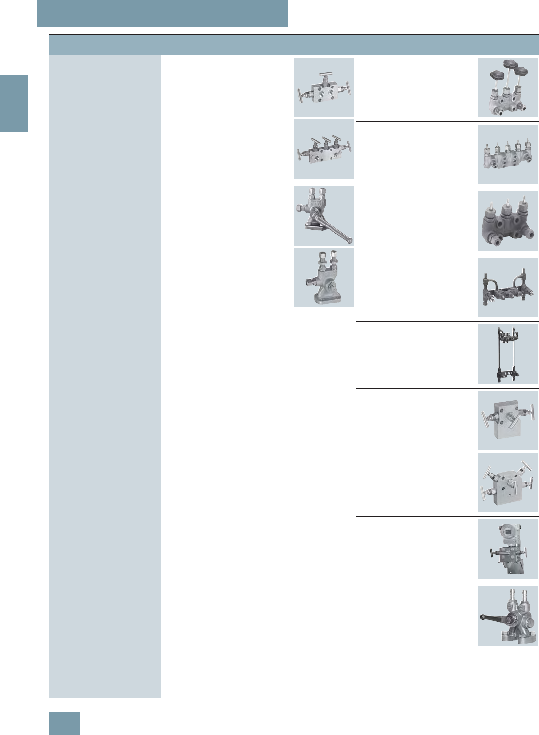
SITRANS P measuring instruments for pressure
Fittings
Selection aid
2/192 Siemens FI 01 · 2009
2
Differential pressure transmit-
ter with process connection to
IEC 61518
e.g.
• SITRANS P DS III series
7MF443.-... and
7MF453.-...
For 3/5-spindle valve manifold
DN 5
7MF9411-5B. and
7MF9411-5C.
2/201 3-way valve manifolds,
DN 5, forged version
7MF9410-1..
2/206
5-way valve manifolds,
DN 5, forged version
7MF9410-3..
2/206
PN 100 multiway cocks
7MF9004-... 2/204 3-way valve manifolds,
DN 8, forged version
7MF9416-1.. and
7MF9416-2..
2/209
Valve manifold combina-
tion DN 5/DN 8 for vapor
measurement
7MF9416-6..
2/212
Valve manifold combina-
tion DN 8 for vapor mea-
surement
7MF9416-4..
2/214
3- and 5-spindle valve
manifolds for DN 5 for
installation in protective
boxes
7MF9412-1D. and
7MF9412-1E.
2/216
3- and 5-spindle valve
manifolds for vertical dif-
ferential pressure lines
7MF9413-1..
2/220
Low-pressure multiway
cock
7MF9004-4..
2/223
Transmitters Shut-off valves for general
applications Page Shut-off valves for spe-
cial applications Page
© Siemens AG 2008

SITRANS P measuring instruments for pressure
Fitttings - Shut-off valves for gage and absolute pressure transmitters
Shut-off valves
to DIN 16270, DIN 16271 and DIN 16272
2/193
Siemens FI 01 · 2009
2
■
Overview
Transmitter for pressure with double shut-off valve 7MF9401-...
The shut-off valves for pressure gages are used to shut off the
line of the measured medium when dealing with aggressive and
non-aggressive gases, vapors and liquids.
■
Design
A water trap must be connected upstream of the shut-off valve
in the case of temperatures of the medium above 120 °C. The
shut-off valves form B have a shaft with which they can be se-
cured on an instrument bracket. An adapter is therefore not re-
quired to secure these valves. The vent/test connection can be
shut off separately with the double shut-off valves DN 5. This per-
mits checking of the zero on the pressure gage. In addition, the
characteristic of the pressure gage can be checked using an ex-
ternal pressure source.
Instrument bracket, see page 2/197.
Selection and Ordering data Order No.
Shut-off valves, form B, DIN 16270
without test collar, connection shank,
without certificate
Material
Valve housing Maximum permissible
working pressure
CW614N (CuZn39Pb3)
(mat. No. 2.0402) 250 bar 7MF9401-7AA
P250GH
(mat. No. 1.0460) 400 bar 7MF9401-7AB
X 6 CrNiMoTi 17 12 2
(mat. No. 1.4571/316Ti)400 bar 7MF9401-7AC
Shut-off valves, form B, DIN 16271
with test collar, connection shank,
without certificate
Material
Valve housing Maximum permissible
working pressure
CW614N (CuZn39Pb3)
(mat. No. 2.0402) 250 bar 7MF9401-7BA
P250GH
(mat. No. 1.0460) 400 bar 7MF9401-7BB
X 6 CrNiMoTi 17 12 2
(mat. No. 1.4571/316Ti)400 bar 7MF9401-7BC
Shut-off valves, form B, DIN 16270
without test collar, pipe union with ferrule
12 S DIN EN ISO 8484-1, without certificate
Material
Valve housing Maximum permissible
working pressure
P250GH
(mat. No. 1.0460) 400 bar 7MF9401-8AB
X 6 CrNiMoTi 17 12 2
(mat. No. 1.4571/316Ti)400 bar 7MF9401-8AC
Shut-off valves, form B, DIN 16271
with test collar, pipe union with ferrule
12 S DIN EN ISO 8484-1, without certificate
Material
Valve housing Maximum permissible
working pressure
P250GH
(mat. No. 1.0460) 400 bar 7MF9401-8BB
X 6 CrNiMoTi 17 12 2
(mat. No. 1.4571/316Ti)400 bar 7MF9401-8BC
Double shut-off valves, form B, DIN 16272
with test collar, connection shank,
without certificate
Material
Valve housing Maximum permissible
working pressure
CW614N (CuZn39Pb3)
(mat. No. 2.0402) 250 bar 7MF9401-7DA
P250GH
(mat. No. 1.0460) 400 bar 7MF9401-7DB
X 6 CrNiMoTi 17 12 2
(mat. No. 1.4571/316Ti)400 bar 7MF9401-7DC
Double shut-off valves, form B, DIN 16272
with test collar, pipe union with ferrule
12 S DIN EN ISO 8484-1, without certificate
Material
Valve housing Maximum permissible
working pressure
P250GH
(mat. No. 1.0460) 400 bar 7MF9401-8DB
X 6 CrNiMoTi 17 12 2
(mat. No. 1.4571/316Ti)400 bar 7MF9401-8DC
Accessories
Factory test certificate EN 10204–2.2 7MF9000-8AB
Material acceptance test certificate
EN 10204-3.1 7MF9000-8AD
Selection and Ordering data Order No.
© Siemens AG 2008
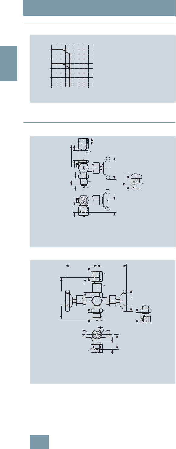
SITRANS P measuring instruments for pressure
Fitttings - Shut-off valves for gage and absolute pressure transmitters
Shut-off valves
to DIN 16270, DIN 16271 and DIN 16272
2/194 Siemens FI 01 · 2009
2
■
Characteristic curves
Permissible operating pressure as a function of the permissible operating
temperature
■
Dimensional drawings
Shut-off valve, form B, dimension drawing, dimensions in mm
Double shut-off valve, form B, dimension drawing, dimensions in mm
0
100
200
300
400
bar
°C0100 200 300 400
Operating pressure
Operating temperature
Steel or stainless
steel version
400 bar at 120 °C
350 bar at 200 °C
Brass version
250 bar at 120 °C
200 bar at 200 °C
18
120± 5
28
20
63
h11
A
B
20
C
20
34
D
diam. 6
diam. 26
AConnection on device side: to DIN 16 284, G½, SW 27
BConnection on measurement side: connection shank to DIN EN 837-1, G½
CConnection on measurement side: pipe union with ferrule 12 mm diam.,
S series, to DIN EN ISO 8434-1
DConnection on test collar (with sealing cap): thread M20x1,5
18
120± 5
28
20
63
h11
20
45
SW 27
A
B
D
20
C
diam. 26
diam. 6
approx. 90approx. 85
AConnection on device side: to DIN 16 284, G½, SW 27
BConnection on measurement side: connection shank to DIN EN 837-1, G½
CConnection on measurement side: pipe union with ferrule 12 mm diam.,
S series, to DIN EN ISO 8434-1
DConnection on test collar (with protective cap): thread M20x1,5
© Siemens AG 2008
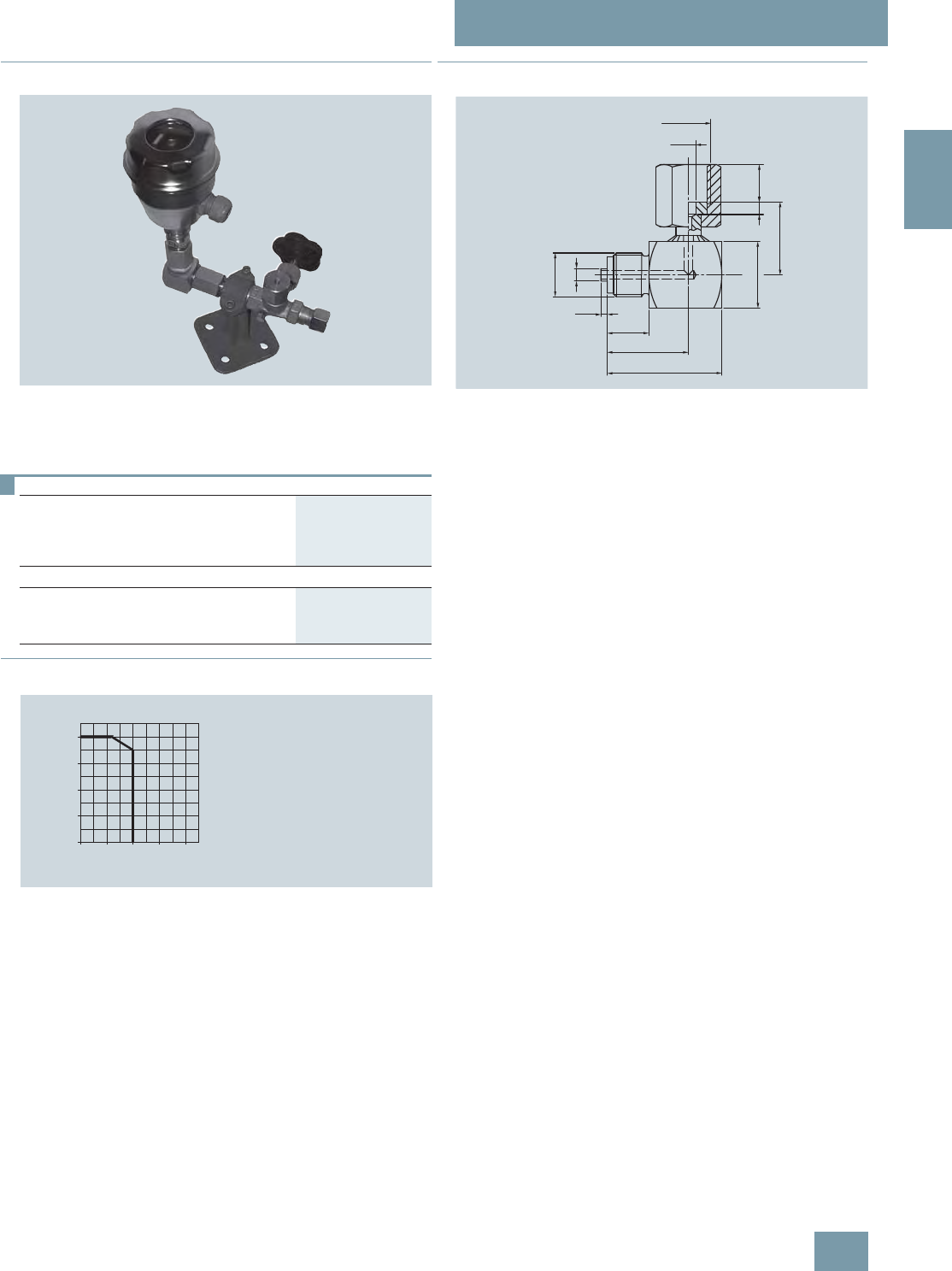
SITRANS P measuring instruments for pressure
Fitttings - Shut-off valves for gage and absolute pressure transmitters
Angle adapter
2/195
Siemens FI 01 · 2009
2
■
Overview
P300 pressure transmitter with shut-off valve and angle adapter
The angle adapter enables pressure transmitters with top dis-
plays to be read from the front.
■
Characteristic curves
Permissible operating overpressure as a function of the permissible op-
erating temperature
■
Dimensional drawings
Angle adapter, dimensions in mm
Selection and Ordering data Order No.
Angle adapters 7MF9401-7WA
Material: X 12 CrNiMoTi 17 12 2 (mat. No.
1.45714/316Ti), max. permissible operating
pressure 400 bar
Accessories
Factory test certificate EN 10204–2.2 7MF9000-8AB
Material acceptance test certificate
EN 10204-3.1 7MF9000-8AD
0
100
200
300
400
bar
°C0100 200 300 400
Design stainless steel
400 bar at 120 °C
350 bar at 200 °C
Operating pressure
Operating temperature
*®
*®
É
É
၂
© Siemens AG 2008
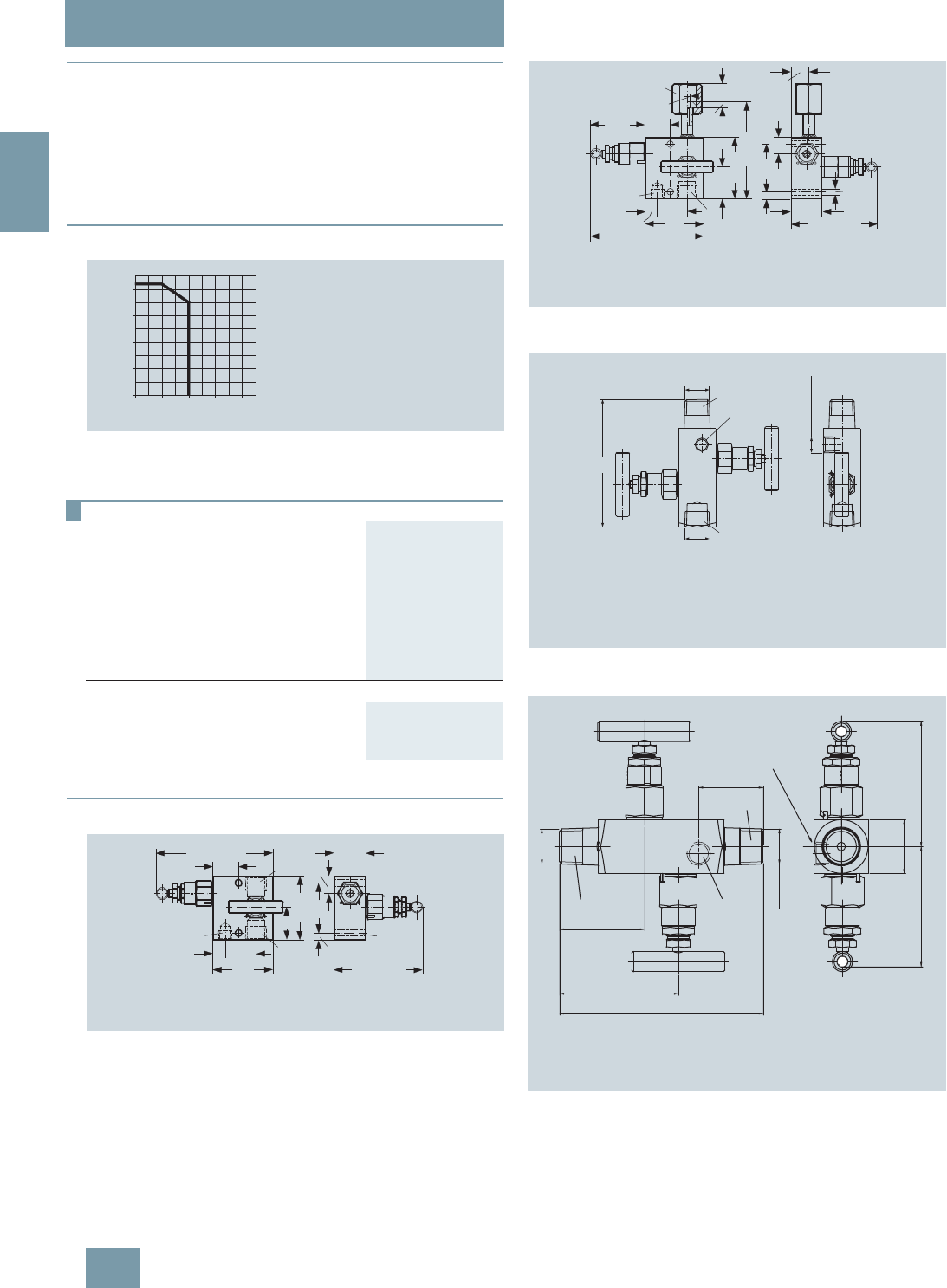
SITRANS P measuring instruments for pressure
Fitttings - Shut-off valves for gage and absolute pressure transmitters
Double shut-off valves
2/196 Siemens FI 01 · 2009
2
■
Overview
The double shut-off valves DN 5 are suitable for pressure gages
and pressure transmitters and available in 4 versions:
• Sleeve-collar
• Sleeve-sleeve
• Sleeve-nipple
• Collar-collar
■
Characteristic curves
Permissible operating pressure as a function of the permissible operating
temperature
■
Dimensional drawings
Double shut-off valve DN 5 (sleeve-sleeve) 7MF9011-4DA, dimensions in
mm
Double shut-off valve DN 5 (sleeve-nipple) 7MF9011-4EA, dimensions in
mm
Double shut-off valve DN 5 (sleeve-collar) 7MF9011-4FA, dimensions in
mm
Double shut-off valve DN 5 (collar-collar) 7MF9011-4GA, dimensions in
mm
Selection and Ordering data Order No.
Double shut-off valves DN 5
Material: X 6 CrNiMoTi 17 13 2 (mat. No.
1.4404/316L), max. permissible working
pressure 420 bar;
• Sleeve-sleeve 7MF9011-4DA
• Sleeve-nipple connection 7MF9011-4EA
• Sleeve-collar 7MF9011-4FA
• Collar-collar 7MF9011-4GA
Accessories
Factory test certificate EN 10204–2.2 7MF9000-8AB
Material acceptance test certificate
EN 10204-3.1 7MF9000-8AD
0
100
200
300
400
bar
°C0100 200 300 400
Operating pressure
Operating temperature
420 bar at 120 °C
350 bar at 200 °C
17
A
B
C
25.5
12 31
60
63.5
33
31.75
7
50
approx. 118
approx. 90
diam. 6.4
AConnection on device side: ½-14 NPT
BConnection on measurement side: ½-14 NPT
CVent and test connection: ¼-18 NPT
31.75
60
31
12
C
B
25.5
33
A
18
6
63.5
100.5
18.5
17
50
7
approx. 90
approx. 118
diam.
6.4
diam. 7
approx.
58
AConnection on device side: nipple to DIN 16 284, G½, SW 27
BConnection on measurement side: ½-14 NPT
CVent and test connection: ¼-18 NPT
AConnection on device side: ½-14 NPT
BConnection on measurement side: ½-14 NPT
CVent and test connection: ¼-18 NPT
110
½-14 NPT
¼-18 NPT
½-14 NPT
A
B
C
DSSUR[ DSSUR[
137
137
B
~137
C
A
A Connection on device side : ½-14 NPT
B Connection on measurement side: ½-14 NPT
C Vent and test connection: ¼-18 NPT
© Siemens AG 2008
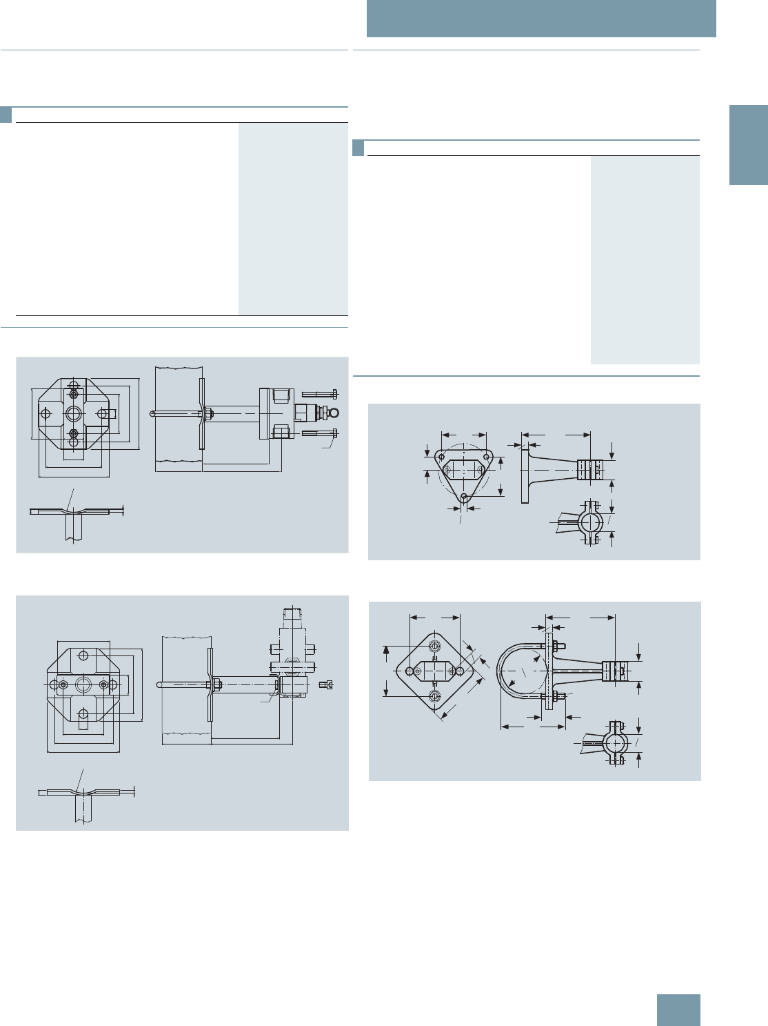
SITRANS P measuring instruments for pressure
Fitttings - Shut-off valves for gage and absolute pressure transmitters
Accessories for
shut-off valves / double shut-off valves
2/197
Siemens FI 01 · 2009
2
■
Overview
The mounting set is suitable for the double shut-off valves
7MF9011-4.A and for wall, rack and pipe mounting.
■
Dimensional drawings
Mounting bracket (7MF9011-8AB) for shut-off valves 7MF9011-4DA and
7MF9011-4EA for wall, rack or pipe mounting, dimensions in mm
Mounting bracket (7MF9011-8AC) for shut-off valves 7MF9011-4FA and
7MF9011-4GA for wall, rack or pipe mounting, dimensions in mm
■
Overview
The instrument brackets are needed to mount the following units:
• Pressure gages with threaded connection at the bottom
• Shut-off valves to DIN 16270, DIN 16271 and DIN 16272
(7MF9401-7.. and 7MF9401-8..)
■
Dimensional drawings
Instrument bracket form H, for wall mounting, M56340-A0046/-A0047,
dimensions in mm
Instrument bracket form A, wall or pipe mounting,
M56340-A0053/-A0079, dimensions in mm
Selection and Ordering data Order No.
Mounting set for shut-off valves
• 7MF9011-4DA und -4EA
made of stainless steel, scope of delivery:
1x mounting bracket,
2x hexagon screws M6x40,
1x mounting clip,
2x washers 8.4 to DIN 125;
2x hexagon nuts 8.4 to DIN EN 24032
7MF9011-8AB
• 7MF9011-4FA und -4GA
made of stainless steel, scope of delivery:
1x mounting bracket,
2x hexagon screws M6x10,
1x mounting clip,
2x washers 8.4 to DIN 125;
2x hexagon nuts 8.4 to DIN EN 24032
7MF9011-8AC
6:
5
hex. 10
65
4
R30
6.5
Ø60.3
85
100
25
11
50
72
90
72
90
SW10
Selection and Ordering data Order No.
Instrument bracket, form H, DIN 16281
made of aluminium alloy, painted black,
for wall mounting, screw-type bracket cover
• Projection length 60 mm M56340-A0046
• Projection length 100 mm M56340-A0047
Instrument bracket, form A, DIN 16281
made of annealed cast iron, galvanized and
primed for mounting on a wall or rack or or
on a sectional rail (horizontal/vertical);
Screw-type bracket cover
M56340-A0053
Instrument bracket, form A, DIN 16281
made of annealed cast iron, galvanized and
primed with pipe clamp for mouting on a
pipe (horizotal/vertical)
Screw-type bracket cover
M56340-A0079
18
10
100
28
o26 h11
65
56
o7
(60)
(160)
72
72
85
o11
10
100
91 34
M8
28
o26 h11
o63
<
_
© Siemens AG 2008

SITRANS P measuring instruments for pressure
Fitttings - Shut-off valves for gage and absolute pressure transmitters
2-way valve manifolds DN 5
2/198 Siemens FI 01 · 2009
2
■
Overview
The two-way valve manifold DN 5 (7MF9401-2..) is used to shut
off and vent the line with the measured medium, and to test the
connected pressure gage or transmitter.
■
Benefits
• Available for aggressive and non-aggressive liquids and
gases
• Two connection versions available
- For flanging to pressure transmitters
- With nipple for connection of pressure gages and pressure
transmitters for pressure
• Max. working pressure 420 bar, with version for oxygen max.
100 bar
■
Application
The 2-way valve manifold is available in versions for aggressive
and non-aggressive liquids and gases.
Mounting plates are available for wall mounting, for securing to
mounting racks or for pipe mounting.
■
Design
The 2-way valve manifold DN 5 has 3 connections:
• A process connection (pipe union with ferrule Ø 12 mm)
• A connection for a pressure gage (flange or nipple)
• A test connection (thread G3/8)
The 2-fold valve manifold DN 5 also has an operating valve and
a test valve, each with an internal spindle thread.
Materials used
2-way valve manifold DN 5 for flanging to pressure transmitters
■
Function
The characteristic of the pressure measuring instrument or pres-
sure transmitter can be tested through the test connection.
A pressure gage for local display can be connected to the test
connection.
The two-way valve manifold DN 5 can be used in addition to shut
off and vent the line with the measured medium.
■
Accessories
Accessory set for 2-way valve manifold DN 5 for flanging
• A31: 2 screws 7/16-20 UNF x 21/8inch to ASME B18.3,
1 flat gasket
• A34: 2 screws 7/16-20 UNF x 21/8inch to ASME B18.3,
1 O-ring (FPM 90)
• A11: 2 screws M10x55 to DIN EN 4762, 2 washers,
1 flat gasket
• A15 (suitable for oxygen): 2 screws M10x55 to DIN EN 4762,
2 washers, 1 flat gasket
• A16: 2 screws M10x55 to DIN EN 4762, 2 washers,
1 flat gasket (FPM 90)
Note: M10 screws only permissible up to PN 160!
Washers Ø 10.5 to DIN 125
Flat gaskets made of PTFE, max. 420 bar, 80 °C
O-ring to DIN 3771, 20 x 2.65 - S – FPM90, max. 420 bar, 120 °C
Mounting plate
Made of electrogalvanized sheet-steel
•M11: For wall mounting or for securing on rack (72 mm grid)
Scope of delivery:
- 1 mounting plate with bolts for mounting on valve manifold
• M12: For pipe mounting
Scope of delivery:
- 1 mounting plate M11
- 2 pipe brackets with nuts and washers for pipes with max.
Ø 60.3 mm
Valve manifold 100 bar, suitable for oxygen
• S12: (only in combination with versions for aggressive liquids
and gases): Suitable for oxygen
For non-aggressive liquids and
gases For aggressive
liquids and gases
Component Material Mat. No. Material Mat. No.
Housing P250GH 1.0460 X 6
CrNiMoTi
17 12 2
1.4571/
316Ti
Head parts C 35 1.0501
Spindles X 12 CrMoS 17 1.4104
Cones X 35 CrMo 17 hard-
ened and tempered 1.4122
Valve seats X 6 CrNiMoTi 17 12 2 1.4571/316Ti
Packings PTFE - PTFE -
© Siemens AG 2008

SITRANS P measuring instruments for pressure
Fitttings - Shut-off valves for gage and absolute pressure transmitters
2-way valve manifolds DN 5
2/199
Siemens FI 01 · 2009
2
Selection and Ordering data Order No.
2-way valve manifold DN 5 7 M F 9 4 0 1 - 7 7 A
for flanging to pressure transmitters, max.
working pressure 420 bar, weight 1.85 kg
(order accessory set and mounting plate with
Order code), without certificate
• for non-aggressive liquids and gases 2 E
• for aggressive liquids and gases 2 F
for fitting to pressure gages or pressure trans-
mitters for pressure, with nipple connection to
DIN 16284, max. working pressure 420 bar,
weight 1.8 kg (order mounting plate with
Order code)1)
1) For suitable seals, see page 2/228.
• for non-aggressive liquids and gases 2 J
• for aggressive liquids and gases 2 K
Accessories
Factory test certificate EN 10204–2.2 7MF9000-8AB
Material acceptance test certificate
EN 10204-3.1 7MF9000-8AD
Selection and Ordering data Order code Order No.
Further designs1)
1) When ordering accessory set or mounting together with the 2-way valve
manifold, please use Order code; otherwise use Order No.
Please add "-Z" to Order No. and
specify Order code.
Accessory set to EN
(required for flanging,
weight 0.2 kg)
2x screws 7/16-20 UNF x
21/8inch to ASME B18.3; chromized
steel
1x gasket made of PTFE,
max. permissible 420 bar, 80 °C
A31 7MF9001-5CC
2x screws 7/16-20 UNF x
21/8inch to ASME B18.3; chromized
steel
1x O-ring to DIN 3771, 20 x 2.65
- S - FPM90, max. permissble
420 bar, 120 °C
A34 7MF9401-5AA
Accessory set to DIN2)
2) Flange connections to DIN 19213 only permissible up to PN 160!
(required for flanging3),
weight 0.2 kg)
3) Only required for versions 7MF9401-2E. und -2F.
2x screws M10x55 to
DIN EN ISO 4762; chromized steel
2x washers Ø 10.5 to DIN 125;
1x gaskets made of PTFE,
max. permissible 420 bar, 80 °C
• Standard design A11 7MF9001-6AD
• Version for oxygen A15 7MF9001-6AE
2x screws M10x55 to
DIN EN ISO 4762; chromized steel
2x washers Ø 10.5 mm
to DIN 125;
1x O-ring to DIN 3771, 20 x 2.65
- S - FPM90, max. permissble
420 bar, 120 °C
A16 7MF9001-6AF
Mounting plate
for valve manifold, made of
electrogalvanized sheet-steel
for wall mounting or for securing
on rack (72 mm grid),
weight 0.5 kg
Scope of delivery:
1 mounting plate with bolts for
mounting on valve manifold
M11 7MF9006-6EA
for pipe mounting,
weight 0.7 kg
Scope of delivery:
1x mounting plate M11, 2x pipe
brackets with nuts and washers
(for pipe with max. Ø 60.3 mm)
M12 7MF9006-6GA
Valve manifold 100 bar
Suitable for oxygen, only for
7MF9401-2F. and 7MF9401-2K. S12
© Siemens AG 2008
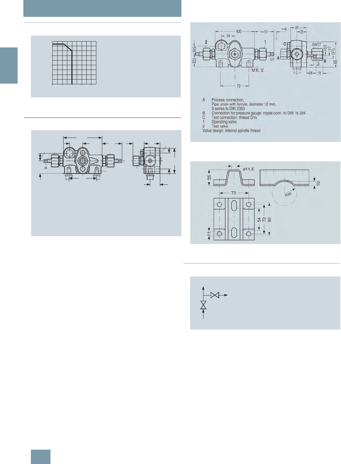
SITRANS P measuring instruments for pressure
Fitttings - Shut-off valves for gage and absolute pressure transmitters
2-way valve manifolds DN 5
2/200 Siemens FI 01 · 2009
2
■
Characteristic curves
2-way valve manifold DN 5, permissible working pressure as a function
of the permissible working temperature
■
Dimensional drawings
2-way valve manifold DN 5 (7MF9401-2E/-2F) for flanging, dimensions in
mm
2-way valve manifold DN 5 (7MF9401-2J/-2K) for connection to pressure
gages and pressure transmitters, dimensions in mm
Mounting plate 7MF9006-6.. (M11, M12) for valve manifold, dimensions
in mm
■
Schematics
Connection diagram of the 2-way valve manifolds
0
100
200
300
400
bar
°C0100 200 300 400
Operating pressure
Operating temperature
100
34
19,5
32,5
7
72
M10, 12
51 41
65
41,3
1
2
A
B
C
Ø12
25
59
AProcess connection,
Pipe union with ferrule, diameter 12 mm,
S series to DIN 2353
BConnection for pressure gauge: flange conn. to DIN EN 61 518, Form A
CTest connection: thread G3/8
1Operating valve
2Test valve
Valve design: Internal spindle thread
B
A
C
AProcess connection
BTransmitter connection
C Test and blow-out connection
© Siemens AG 2008

SITRANS P measuring instruments for pressure
Fitttings - Shut-off valves for differential pressure transmitters
2-, 3- and 5-spindle valve manifolds DN 5
2/201
Siemens FI 01 · 2009
2
■
Overview
The 2-spindle, 3-spindle and 5-spindle valve manifolds
7MF9411-5.. are for pressure transmitters for absolute pressure
or differential pressure.
The valve manifolds are used to shut off the differential pressure
lines and to check the pressure transmitter zero.
The 2-spindle and the 5-spindle valve manifold enable in addi-
tion venting on the transmitter side and checking of the pressure
transmitter characteristic.
■
Benefits
• Max. working pressure 420 bar
• Each available in version for oxygen
■
Application
The spindle valve manifolds DN 5 are designed for liquids and
gases
Each is available in a version for oxygen on request
■
Design
All versions of the valve manifolds have a process connection ½-
14 NPT. The connection for the pressure transmitter is always
designed as a flange connection to EN 61518, form B . The 2-
spindle and the 5-spindle valve manifold have in addition a vent
and test connection ¼-18 NPT.
The valves have an external spindle thread.
Materials used
■
Function
Functions of all valve manifolds:
• Shutting off the differential pressure lines
• Checking the pressure transmitter zero
Additional functions of the 2-spindle and 5-spindle valve mani-
folds through the vent and test connection:
• Venting on the transmitter side
• Checking the pressure transmitter characteristic
Component Material Mat. No.
Housing X 2 CrNiMo 17 13 2 1.4404/316L
Cones X 6 CrNiMoTi 17 12 2 1.4571/316Ti
Spindles X 2 CrNiMo 18 10 1.4404/316L
Head parts X 5 CrNiMo 18 10 1.4401/316
Packings PTFE -
Selection and Ordering data Order No.
Valve manifolds DN 5 7 M F 9 4 1 1 - 7 7 A
for liquids and gases, for flanging to pressure
transmitters for absolute and differential
pressure, max. working pressure 420 bar
(order accessory set with Order code),
without certificate
• 2-spindle valve manifold 5 A
• 3-spindle valve manifold 5 B
• 5-spindle valve manifold 5 C
Accessories
Factory test certificate EN 10204–2.2 7MF9000-8AB
Material acceptance test certificate
EN 10204-3.1 7MF9000-8AD
Selection and Ordering data Order code Order No.
Further designs1)
Please add "-Z" to Order No. and
specify Order code.
Accessory set to EN
(connection between valve manifold
and pressure transmitter)
for valve manifold 7MF9411-5A.
2x screws 7/16-20 UNF x
1¾ inch to ASME B18.2.1; chromized
steel
1x gasket made of PTFE,
max. permissible 420 bar, 80 °C
K35 7MF9411-7DB
2x screws 7/16-20 UNF x
1¾ inch to ASME B18.2.1; stainless
steel
1x gasket made of PTFE,
max. permissible 420 bar, 80 °C
K45 7MF9411-7DC
for valve manifold 7MF9411-5B. and
-5C.
4x screws 7/16-20 UNF x
1¾ inch to ASME B18.2.1; chromized
steel
2x flat gaskets made of PTFE,
max. permissible 420 bar, 80 °C
K36 7MF9411-5DB
4x screws 7/16-20 UNF x
1¾ inch to ASME B18.2.1; stainless
steel
2x flat gaskets made of PTFE,
max. permissible 420 bar, 80 °C
K46 7MF9411-5DC
Accessory set to DIN2)
(connection between valve manifold
and pressure transmitter)
for valve manifold 7MF9411-5A.
2x screws M10x45 to DIN EN 24014;
chromized steel
2x washers Ø 10.5 mm to DIN 125;
1x gasket made of PTFE,
max. permissible 420 bar, 80 °C
K15 7MF9411-7BB
2x screws M10x45 to DIN EN 24014;
stainless steel
2x washers Ø 10.5 mm to DIN 125,
stainless steel;
1x gasket made of PTFE,
max. permissible 420 bar, 80 °C
K25 7MF9411-7BC
© Siemens AG 2008

SITRANS P measuring instruments for pressure
Fitttings - Shut-off valves for differential pressure transmitters
2-, 3- and 5-spindle valve manifolds DN 5
2/202 Siemens FI 01 · 2009
2
■
Accessories
Accessory set for 2-, 3- and 5-spindle valve manifolds
2-spindle valve manifold DN 5
• K35: 2 screws 7/16-20 UNF x 1¾ inch to ASME B18.2.1,
1 flat gasket
• K15: 2 screws M10x45 to DIN EN 24014, 2 washers,
1 flat gasket
3-spindle and 5-way valve manifold DN 5
• K36: 4 screws 7/16-20 UNF x 1¾ inch to ASME B18.2.1,
2 flat gaskets
• K16: 4 screws M10x45 to DIN EN 24014, 4 washers,
2 flat gaskets
Washers Ø 10.5 to DIN 125
Flat gaskets made of PTFE, max. 420 bar, 80 °C
Note: Flange connection with M10 screws only permissible up to
PN 160!
Mounting plate
Made of electrogalvanized sheet-steel
•M11: For wall mounting or for securing on rack (72 mm grid)
Scope of delivery:
- 1 mounting plate with bolts for mounting on valve manifold
• M12: For pipe mounting
Scope of delivery:
- 1 mounting plate M11
- 2 pipe brackets with nuts and washers for pipes with max.
Ø 60.3 mm
Valve manifold 100 bar, suitable for oxygen
• S12: For 2-way valve manifold
•S13: For 3-way valve manifold
•S13: For 5-way valve manifold
■
Characteristic curves
Valve manifolds PN 5 (7MF9411-5..), permissible working pressure as a
function of the permissible working temperature
for valve manifolds 7MF9411-5B.
and -5C.
4x screws M10x45 to DIN EN 24014;
chromized steel
4x washers Ø 10.5 mm to DIN 125;
2x flat gaskets made of PTFE,
max. permissible 420 bar, 80 °C
Flange connection with M10 screws
only permissible up to PN 160.
K16 7MF9411-6BB
4x screws M10x45 to DIN EN 24014;
stainless steel
4x washers Ø 10.5 mm to DIN 125,
stainless steel;
2x flat gaskets made of PTFE,
max. permissible 420 bar, 80 °C
Flange connection with M10 screws
only permissible up to PN 160.
K26 7MF9411-6BC
Mounting plate
• for valve manifold, made of
electrogalvanized sheet-steel
-for wall mounting or for securing
on rack (72 mm grid), weight
0.5 kg
Scope of delivery:
1 mounting plate with bolts for
mounting on valve manifold
M11 7MF9006-6EA
-for pipe mounting, weight 0.7 kg
Scope of delivery:
1x mounting plate M11, 2x pipe
brackets with nuts and washers
(for pipe with max. Ø 60.3 mm)
M12 7MF9006-6GA
• for valve manifold, made of
stainless steel
-for wall mounting or for securing
on rack (72 mm grid), weight
0.5 kg
Scope of delivery:
1 mounting plate with bolts for
mounting on valve manifold
M21 7MF9006-6EC
-for pipe mounting, weight 0.7 kg
Scope of delivery:
1x mounting plate M11, 2x pipe
brackets with nuts and washers
(for pipe with max. Ø 60.3 mm)
M22 7MF9006-6GC
Valve manifold 100 bar
Suitable for oxygen
• for 7MF9411-5A. S12
• for 7MF9411-5B. S13
• for 7MF9411-5C. S14
1) When ordering accessory set or mounting together with the valve
manifolds, please use Order code; otherwise use Order No.
2) Flange connections to DIN 19213 only permissible up to 160!
Selection and Ordering data Order code Order No.
Further designs1)
Please add "-Z" to Order No. and
specify Order code.
0
100
200
300
400
bar
°C0100 200 300 400
Operating pressure
Operating temperature
© Siemens AG 2008
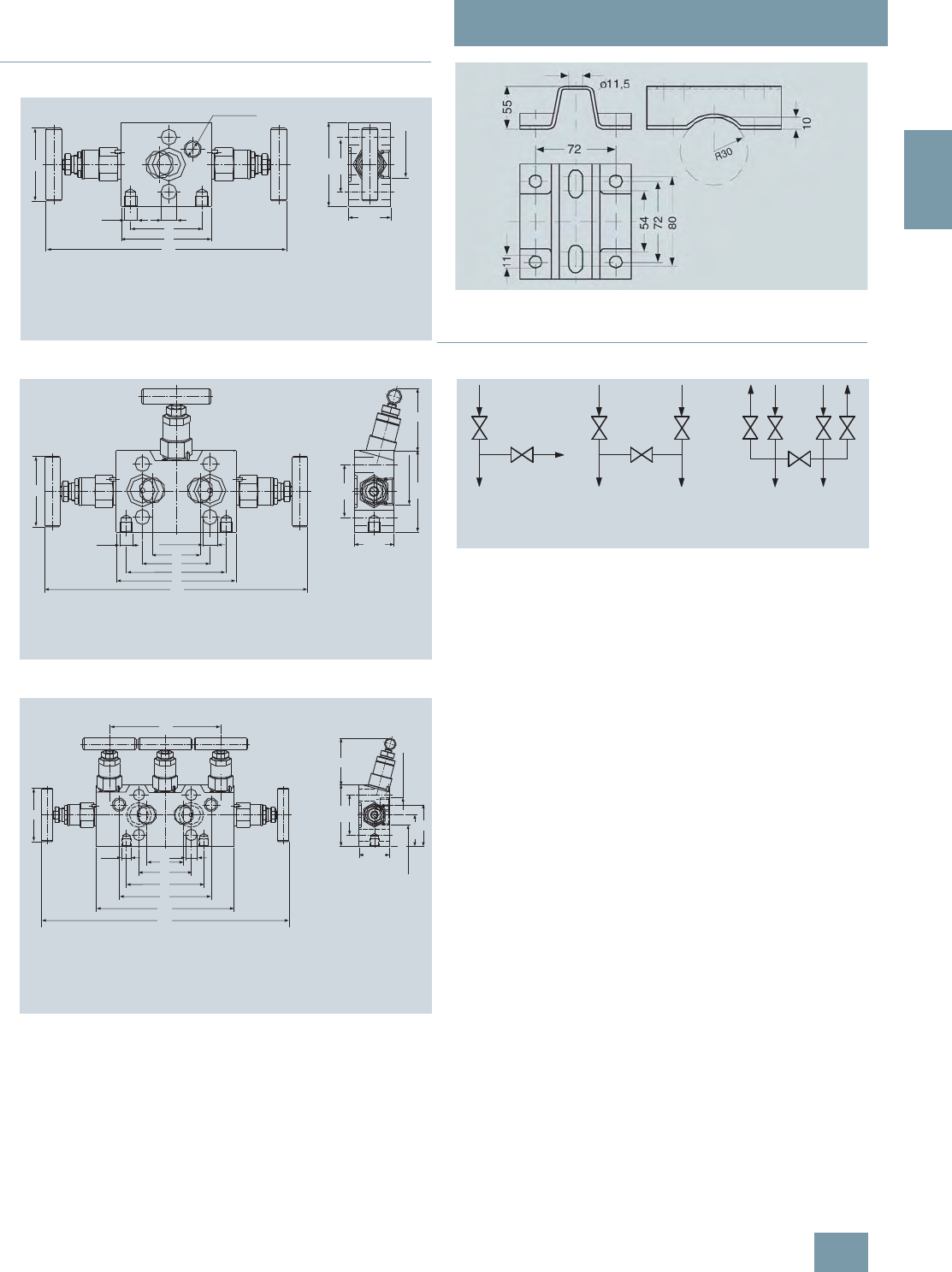
SITRANS P measuring instruments for pressure
Fitttings - Shut-off valves for differential pressure transmitters
2-, 3- and 5-spindle valve manifolds DN 5
2/203
Siemens FI 01 · 2009
2
■
Dimensional drawings
2-spindle valve manifold DN 5 (7MF9411-5A.), dimensions in mm
3-spindle valve manifold DN 5 (7MF9411-5B.), dimensions in mm
5-spindle valve manifold DN 5 (7MF9411-5C.), dimensions in mm
Mounting plate 7MF9006-6.. (M11, M12) for valve manifold, dimensions
in mm
■
Schematics
2-spindle, 3-spindle and 5-spindle valve manifold DN 5, connections
AProcess connection: ½-14 NPT
B Transmitter connection: Flange connection to EN 61 518, form B
CVent / test connection: ¼-18 NPT
Valve design: external spindle thread
¼-18 NPT
55
M10 Ø12
54
68
182
63.5
41.3
½-14 NPT
31.75
A
B
C
55
41.3
½-14 NPT
63.5 48
31.75
diam. 12
38
54
80
96
210
M10
A
B
AProcess connection: ½-14 NPT
BTransmitter connection: flange connection to EN 61 518, form B
Valve design: external spindle thread
Ø12
38
54
80
96
255
M10
115
55
4863.5
41.3
32.5
43
½-14 NPT ¼-18 NPT
31.75
142
A
C
B
AProcess connection: ½-14 NPT
BTransmitter connection: Flange connection to EN 61 518, form B
CVent / test connection: ¼-18 NPT
Valve design: external spindle thread
B
A
B
A
B
A
B
A
CC
B
A
A Process connection
B Transmitter connection
C Blow-out-connection
© Siemens AG 2008

SITRANS P measuring instruments for pressure
Fitttings - Shut-off valves for differential pressure transmitters
Multiway cocks PN 100
2/204 Siemens FI 01 · 2009
2
■
Overview
Multiway cock PN 100 (7MF9004-1P.) for differential pressure transmitters
The multiway cock PN 100 can be flanged to pressure transmit-
ters for differential pressure.
■
Benefits
• Version available for aggressive liquids, gases and vapors
• Robust design
• Oil-free and grease-free version possible
• One-hand operation
■
Application
The PN 100 multiway cock is available in versions for aggressive
and non-aggressive liquids, gases and vapors.
■
Design
The multiway cock can be flanged with four screws to pressure
transmitters for differential pressure.
The PN 100 has 2 process connections and one blow-out con-
nection. A steel version of the multiway cock is available for non-
aggressive media, and a stainless steel version for aggressive
media. The housing is forged in one piece. The switching lever
is removable.
Sealing can be improved during operation.
Note: An accessory set is always required for flanging of the
multiway cock to a differential pressure transmitter.
■
Function
• Shutting off the differential pressure lines
• Blowing out the differential pressure lines
• Testing the pressure transmitter zero
Cock positions; the symbols are printed on the cock
■
Technical specifications
Multiway cocks PN 100
Measured medium Water, non-aggres-
sive liquids and
gases
Aggressive liquids,
gases and vapors
Material P250GH, mat. No.:
1.0460 X 6 CrNiMoTi 17 12 2,
mat. No. 1.4571/316Ti
Connections Steel, for pipe
Ø 12 mm, L series Stainless steel, for
pipe Ø 12 mm, L
series
• Process connection 2 bulkhead glands
• Connection for blow-
ing out Pipe union with ferrule
Max. permissible
working temperature 200 °C
Max. permissible
working pressure 100 bar (up to max. 60 °C)
Weight 2.5 kg
Selection and Ordering data Order No.
Multiway cock PN 100 7 M F 9 0 0 4 - 7 7 A
for flanging to pressure transmitters, weight
2.5 kg (without accessory set),
without certificate
for water and non-aggressive gases and
vapors 1 P
for aggressive liquids, gases and vapors 1 Q
Accessories
Factory test certificate EN 10204–2.2 7MF9000-8AB
Material acceptance test certificate
EN 10204-3.1 7MF9000-8AD
Selection and Ordering data Order code Order No.
Further designs1)
Please add "-Z" to Order No. and
specify Order code.
1) When ordering accessory set or mounting together with the multiway cock,
please use Order code; otherwise use Order No.
Accessory set to EN
(required for flanging, weight 0.2 kg)
4x screws 7/16-20 UNF x 1 inch to
ASME B18.2.1; chromized steel
2x gaskets made of PTFE, max.
permissible temperature 80 °C
L31 7MF9004-5CC
Accessory set to DIN
(required for flanging, weight 0.2 kg)
4x screws M10x25 to DIN EN 24017;
chromized steel
4x washers Ø 10.5 mm to DIN 125;
2x gaskets made of PTFE, max.
permissible temperature 80 °C
• Standard design L11 7MF9004-6AD
• Version for oxygen (together with
Order code S11 L15 7MF9004-6AE
Multiway cock in oil-free and
grease-free design
Max. PN 63 (instead of PN 100),
BAM-tested lubricant, gasket suit-
able for oxygen measurement (only
with Order No. 7MF9004–1Q.Z)
S11
Mounting bracket
Required for wall mounting or for
securing on rack (72 mm grid),
made of electrogalvanized sheet-
steel, weight 0.85 kg
M13 7MF9004-6AA
© Siemens AG 2008
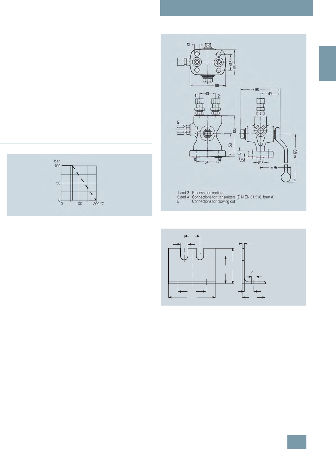
SITRANS P measuring instruments for pressure
Fitttings - Shut-off valves for differential pressure transmitters
Multiway cocks PN 100
2/205
Siemens FI 01 · 2009
2
■
Accessories
Accessory set for multiway cock PN 100
• L31: 4 screws 7/16-20 UNF x 1 inch, 2 flat gaskets
• L11: 4 screws M10x25 to DIN EN 24017, 4 washers, 2 flat gas-
kets
• L15 (suitable for oxygen): 4 screws M10x25 to DIN EN 24017,
4 washers, 2 flat gaskets
Washers Ø 10.5 to DIN 125
Flat gaskets made of PTFE, max. permissible temperature 80 °C
Multiway cock in oil-free and grease-free design
• S11 (only for aggressive liquids, gases and vapors
(7MF9004-1Q.)): Max. PN 63 (instead of PN 100), BAM-tested
lubricant, gasket suitable for oxygen
Mounting brackets
• M13: Required for wall mounting or for securing on rack
(72 mm grid); made of electrogalvanized sheet-steel
■
Characteristic curves
Multiway cock PN 100, permissible operating pressure as a function of
the permissible operating temperature
■
Dimensional drawings
Multiway cock 7MF9004-1P. for flanging to pressure transmitters for dif-
ferential pressure, dimensions in mm
Mounting bracket 7MF9004-6AA (M13), dimensions in mm
40
19
72
120
70
90
6
24
60
o11
© Siemens AG 2008
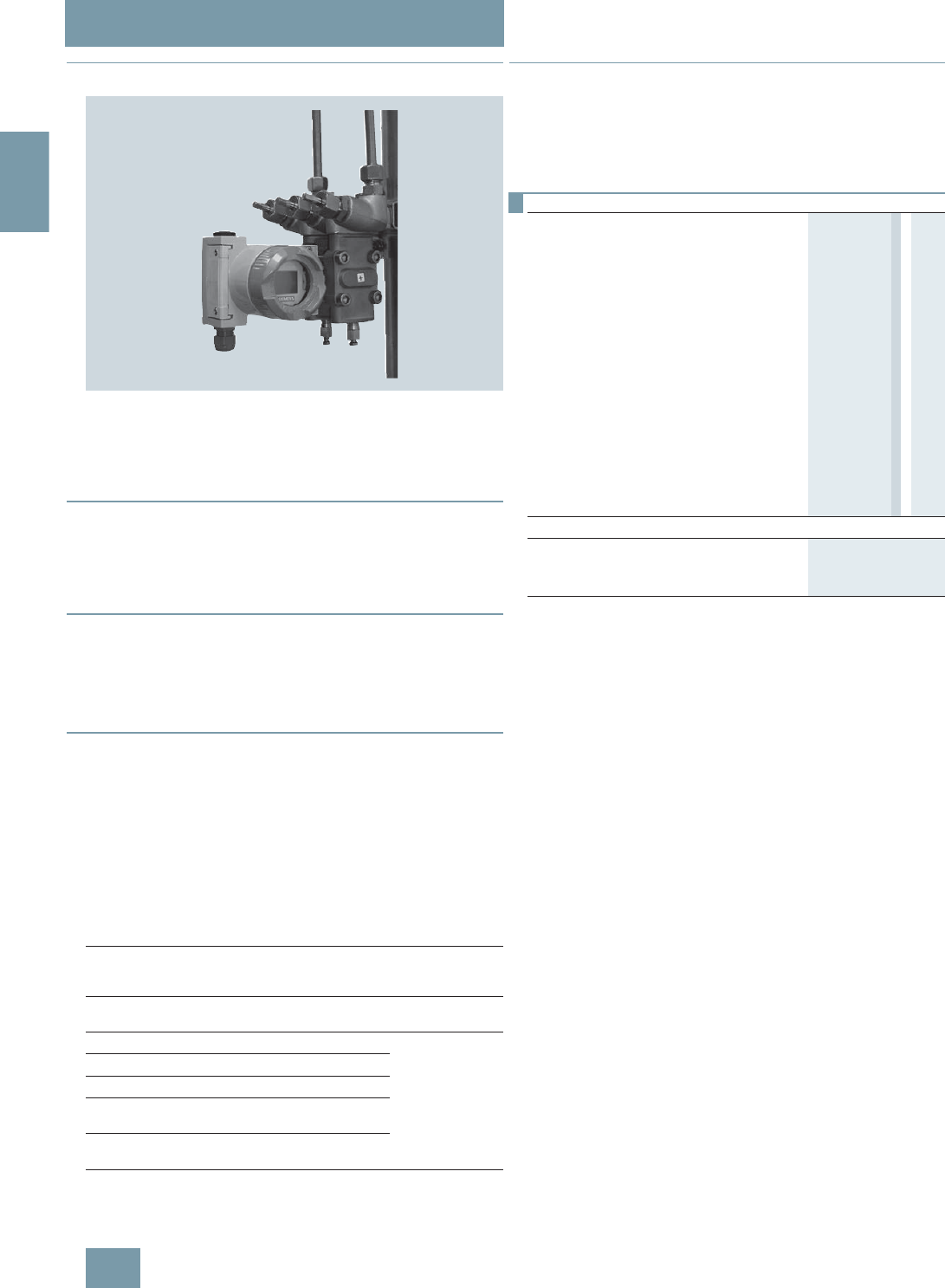
SITRANS P measuring instruments for pressure
Fitttings - Shut-off valves for differential pressure transmitters
3-way and 5-way valve manifolds DN 5
2/206 Siemens FI 01 · 2009
2
■
Overview
The three-spindle and five-spindle valve manifolds DN 5
(7MF9410-1../-3..) are used to shut off the differential pressure
lines and to check the transmitter zero.
In addition, the five-way valve manifold permits blowing out of
the differential pressure lines.
■
Benefits
• Available for aggressive and non-aggressive liquids and
gases
• Max. working pressure 420 bar, with version for oxygen max.
100 bar
■
Application
The 3-way and 5-way valve manifolds are available in versions
for aggressive and non-aggressive liquids and gases.
Mounting plates are available for wall mounting, for securing to
mounting racks or for pipe mounting.
■
Design
The process connection of the 3-way and 5-way valve manifolds
is a pipe union with ferrule.
Both valve manifolds have 2 flange connections for connecting
a pressure transmitter.
In addition, the five-way valve manifold has 2 blow-out connec-
tions.
Depending on the version the valve manifold has either 3 or 5
valves, each with an internal spindle thread.
Materials used
■
Function
• Shutting off the differential pressure lines
• Checking the pressure transmitter zero
• In addition, the five-way valve manifold permits blowing out of
the differential pressure lines.
For non-aggressive liquids and
gases For aggressive
liquids and
gases
Component Material Mat. No. Material Mat.
No.
Housing P250GH 1.0460 X 6
CrNiMoTi
17 12 2
1.4571/
316Ti
Head parts C 35 1.0501
Spindles X 12 CrMoS 17 1.4104
Cones X 35 CrMo 17 hardened
and tempered 1.4122
Valve seats X 6 CrNiMoTi 17 12 2 1.4571/
316Ti
Packings PTFE - PTFE -
Selection and Ordering data Order No.
3-way valve manifold DN 5 7 M F 9 4 1 0 - 7 7 A
for flanging to pressure transmitters for differ-
ential pressure, process connection: Pipe
union with ferrule, max. working pressure
420 bar, weight 2.9 kg (order accessory set
and mounting plate with Order code),
without certificate
• for non-aggressive liquids and gases 1 E
• for aggressive liquids and gases 1 F
5-way valve manifold DN 5
for flanging to pressure transmitters for differ-
ential pressure, process connection: Pipe
union with ferrule, max. working pressure
420 bar, weight 4.4 kg (order accessory set
and mounting plate with Order code),
without certificate
• for non-aggressive liquids and gases 3 E
• for aggressive liquids and gases 3 F
Accessories
Factory test certificate EN 10204–2.2 7MF9000-8AB
Material acceptance test certificate
EN 10204-3.1 7MF9000-8AD
© Siemens AG 2008

SITRANS P measuring instruments for pressure
Fitttings - Shut-off valves for differential pressure transmitters
3-way and 5-way valve manifolds DN 5
2/207
Siemens FI 01 · 2009
2
F) Subject to export regulations AL: 9I999, ECCN: N.
■
Accessories
Accessory set for 3-way and 5-way valve manifold DN 5 for
flanging
• B31: 4 screws 7/16-20 UNF x 21/8inch to ASME B18.2.1,
2 flat gaskets
• B34: 4 screws 7/16-20 UNF x 21/8inch to ASME B18.2.1,
2 O-rings (FPM 90)
• B11: 4 screws M10x55 to DIN EN 24014, 4 washers,
2 flat gaskets
• B15 (suitable for oxygen): 4 screws M10x55 to DIN EN 24014,
4 washers, 2 flat gaskets
• B16: 4 screws M10x55 to DIN EN 24014, 4 washers,
2 O-rings (FPM 90)
Washers Ø 10.5 to DIN 125
Flat gaskets made of PTFE, max. 420 bar, 80 °C
O-ring to DIN 3771, 20 x 2.65 – S – FPM90, max. 420 bar, 120 °C
Note: M10 screws only permissible up to PN 160!
Mounting plate
Made of electrogalvanized sheet-steel
•M11: For wall mounting or for securing on rack (72 mm grid)
Scope of delivery:
- 1 mounting plate 7MF9006-6EA with bolts for mounting on
valve manifold
• M12: For pipe mounting
Scope of delivery:
- 1 mounting plate M11
- 2 pipe brackets with nuts and washers for pipes with max.
Ø 60.3 mm
Valve manifold 100 bar, suitable for oxygen
S12: Only in combination with versions for aggressive liquids
and gases
Selection and Ordering data Order code Order No.
Further designs1)
1) When ordering accessory set or mounting together with the valve
manifolds, please use Order code; otherwise use Order No.
Please add "-Z" to Order No. and
specify Order code.
Accessory set to EN
(required for flanging, weight 0.2 kg)
4x screws 7/16-20 UNF x
21/8inch to ASME B18.2; chromized
steel
2x flat gaskets made of PTFE,
max. permissible 420 bar, 80 °C
B31 F) 7MF9010-5CC
4x screws 7/16-20 UNF x
21/8inch to ASME B18.2; chromized
steel
2x O-rings to DIN 3771,
20 x 2.65 - S - FPM90, max. permiss-
ble 420 bar, 120 °C
B34 7MF9410-5CA
Accessory set to DIN2)
2) Flange connections to DIN 19213 only permissible up to PN 160!
(required for flanging, weight 0.2 kg)
4x screws M10x55 to DIN EN 24014;
chromized steel
4x washers Ø 10.5 mm to DIN 125;
2x flat gaskets made of PTFE,
max. permissible 420 bar, 80 °C
• Standard design B11 7MF9010-6AD
• Version for oxygen B15 7MF9010-6AE
4x screws M10x55 to DIN EN 24014;
chromized steel
4x washers Ø 10.5 mm to DIN 125;
2x O-rings to DIN 3771,
20 x 2.65 - S - FPM90, max. permiss-
ble 420 bar, 120 °C
B16 7MF9010-6CC
Mounting plate
for valve manifold, made of
electrogalvanized sheet-steel
for wall mounting or for securing on
rack (72 mm grid), weight 0.5 kg
Scope of delivery:
1 mounting plate with bolts for
mounting on valve manifold
M11 7MF9006-6EA
for pipe mounting, weight 0.7 kg
Scope of delivery:
1x mounting plate M11, 2x pipe
brackets with nuts and washers
(for pipe with max. Ø 60.3 mm)
M12 7MF9006-6GA
Valve manifold 100 bar
suitable for oxygen
for 7MF9410-1F S13
for 7MF9410-3F S14
© Siemens AG 2008
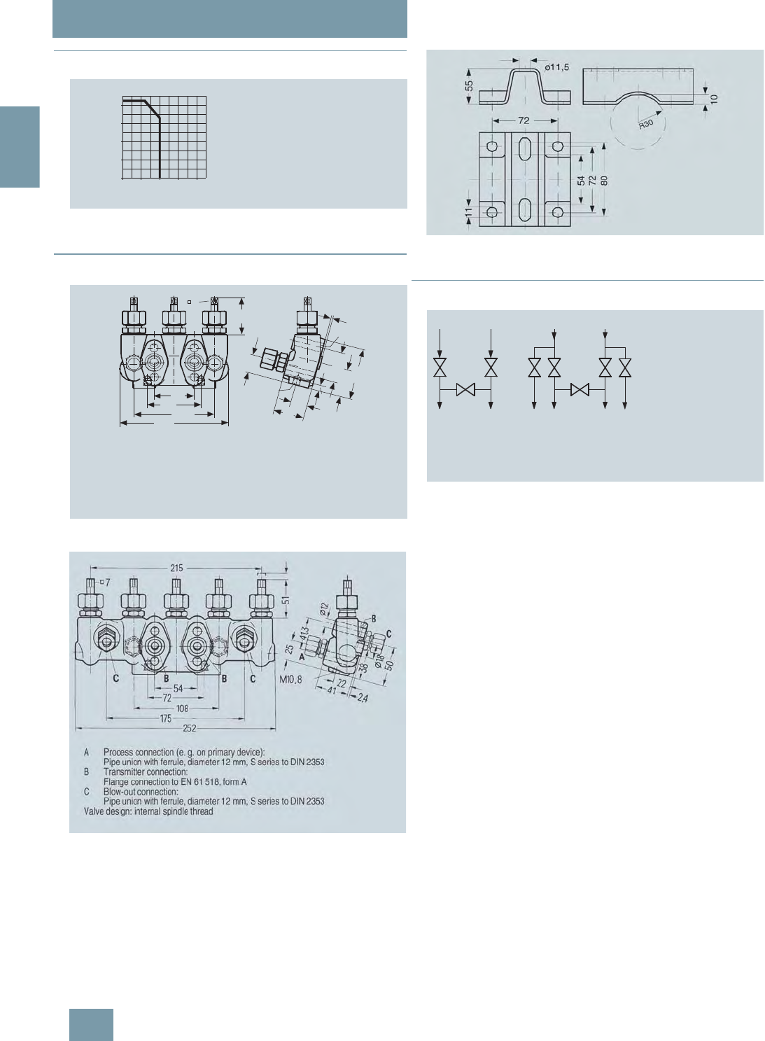
SITRANS P measuring instruments for pressure
Fitttings - Shut-off valves for differential pressure transmitters
3-way and 5-way valve manifolds DN 5
2/208 Siemens FI 01 · 2009
2
■
Characteristic curves
Permissible operating pressure as a function of the permissible operating
temperature
■
Dimensional drawings
3-way valve manifold DN 5 (7MF9410-1..), dimensions in mm
5-way valve manifold DN 5 (7MF9410-3..), dimensions in mm
Mounting plate 7MF9006-6.. (M11, M12) for valve manifold, dimensions
in mm
■
Schematics
3-way and 5-way valve manifolds, connections
0
100
200
300
400
bar
°C0100 200 300 400
Operating temperature
Operating pressure
7
51
54
72
108
147
25
2,4
41,3
70
38
8
M10 22
41
Ø 12
B
A
AProcess connection (e.g. on primary device):
Pipe union with ferrule, diameter 12 mm, S series to DIN 2353
BTransmitter connection:
Flange connection to EN 61 518, form A
Valve design: internal spindle thread
B
A
B
A
B
A
B
A
CC
Three-way valve
manifold for
liquids and gases
B Transmitter connection
C Vent/test connection
Five-way valve
manifold for liquids
and gases or vapors
A Process connection
© Siemens AG 2008

SITRANS P measuring instruments for pressure
Fitttings - Shut-off valves for differential pressure transmitters
3-way valve manifold DN 8
2/209
Siemens FI 01 · 2009
2
■
Overview
The 3-way valve manifold DN 8 (7MF9416-1../-2..) is for pressure
transmitters for differential pressure. It is used to shut off and
blow out differential pressure lines and to test the pressure trans-
mitter zero.
In the designs with a test connection, a test device can be con-
nected to test the pressure transmitter characteristic.
■
Benefits
• For aggressive and non-aggressive liquids and gases
• The maximum working pressure is 420 bar.
■
Application
The 3-way valve manifold is available in versions for aggressive
and non-aggressive liquids and gases.
Mounting plates are available for wall mounting, for securing to
mounting racks or for pipe mounting.
■
Design
For the process connection on the version for non-aggressive
media it is possible to choose between a pipe union with ferrule
and welding pins.
The version for aggressive media always has a pipe union with
ferrule.
Both versions are available optionally with a test connection
M20x1.5.
The valves have an internal spindle thread.
Materials used
■
Function
The 3-way valve manifold DN 8 performs two functions as stan-
dard:
• Shutting off the differential pressure lines
• Checking the pressure transmitter zero
All versions are also available with a test connection, to which a
test device for checking the pressure transmitter characteristic
can be connected.
For non-aggressive liquids and
gases For aggressive
liquids and
gases
Component Material Mat. No. Material Mat.
No.
Housing P250GH 1.0460 X 6
CrNiMoTi
17 12 2
1.4571/
316Ti
Head parts C 35 1.0501
Spindles X 12 CrMoS 17 1.4104
Cones X 35 CrMo 17 hard-
ened and tempered 1.4122
Valve seats X 6 CrNiMoTi 17 12 2 1.4571/316Ti
Packings PTFE - PTFE -
Selection and Ordering data Order No.
3-way valve manifold DN 8 7 M F 9 4 1 6 - 7 7 A
for flanging to pressure transmitters for differ-
ential pressure, max. working pressure
420 bar, (order accessory set and mounting
plate with Order code), without certificate
for non-aggressive liquids and gases
procedss connection: Pipe union with ferrule
• without test connection 1 B
• with test connection 1 C
for non-aggressive liquids and gases
procedss connection: Welding pin Ø 14 x 2.5
• without test connection 2 C
• with test connection 2 D
for aggressive liquids and gases
process connection: Pipe union with ferrule
• without test connection 1 D
• with test connection 1 E
Accessories
Factory test certificate EN 10204–2.2 7MF9000-8AB
Material acceptance test certificate
EN 10204-3.1 7MF9000-8AD
© Siemens AG 2008

SITRANS P measuring instruments for pressure
Fitttings - Shut-off valves for differential pressure transmitters
3-way valve manifold DN 8
2/210 Siemens FI 01 · 2009
2
F) Subject to export regulations AL: 9I999, ECCN: N.
■
Accessories
Accessory set for 3-way valve manifold DN 8 for flanging
• B31: 4 screws 7/16-20 UNF x 21/8inch to ASME B18.2.1,
2 flat gaskets
• B34: 4 screws 7/16-20 UNF x 21/8inch to ASME B18.2.1,
2 O-rings (FPM 90)
• B11: 4 screws M10x55 to DIN EN 24014, 4 washers,
2 flat gaskets
• B16: 4 screws M10x55 to DIN EN 24014, 4 washers,
2 O-rings (FPM 90)
Washers Ø 10.5 to DIN 125
Flat gaskets made of PTFE, max. 420 bar, 80 °C
O-ring to DIN 3771, 20 x 2.65 – S – FPM90, max. 420 bar, 120 °C
Note: M10 screws only permissible up to PN 160!
Mounting plate
Made of electrogalvanized sheet-steel
• M11: For wall mounting or for securing on rack (72 mm grid)
Scope of delivery:
- 1 mounting plate with bolts for mounting on valve manifold
• M12: For pipe mounting
Scope of delivery:
- 1 mounting plate M11
- 2 pipe brackets with nuts and washers for pipes with max.
Ø 60.3 mm
■
Characteristic curves
3-way valve manifold DN 8, permissible working pressure as a function
of the permissible working temperature
Selection and Ordering data Order code Order No.
Further designs1)
1) When ordering accessory set or mounting together with the valve manifold,
please use Order code; otherwise use Order No.
Please add "-Z" to Order No. and
specify Order code.
Accessory set to EN
(required for flanging, weight 0.2 kg)
4x screws 7/16-20 UNF x
21/8inch to ASME B18.2; chromized
steel
2x flat gaskets made of PTFE,
max. permissible 420 bar, 80 °C
B31 F) 7MF9010-5CC
4x screws 7/16-20 UNF x
21/8inch to ASME B18.2; chromized
steel
2x O-rings to DIN 3771,
20 x 2.65 - S - FPM90, max. permiss-
ble 420 bar, 120 °C
B34 7MF9410-5CA
Accessory set to DIN2)
2) Flange connections to DIN 19213 only permissible up to PN 160!
(required for flanging, weight 0.2 kg)
4x screws M10x55 to DIN EN 24014;
chromized steel
4x washers Ø 10.5 mm to DIN 125;
2x flat gaskets made of PTFE, max.
permissible 420 bar, 80 °C
B11 7MF9010-6AD
4x screws M10x55 to DIN EN 24014;
chromized steel
4x washers Ø 10.5 mm to DIN 125;
2x O-rings to DIN 3771,
20 x 2.65 - S - FPM90, max. permiss-
ble 420 bar, 120 °C
B16 7MF9010-6CC
Mounting plate
for valve manifold, made of
electrogalvanized sheet-steel
for wall mounting or for securing on
rack (72 mm grid),
weight 0.5 kg
Scope of delivery:
1 mounting plate with bolts for
mounting on valve manifold
M11 7MF9006-6EA
for pipe mounting, weight 0.7 kg
Scope of delivery:
1x mounting plate M11, 2x pipe
brackets with nuts and washers
(for pipe with max. Ø 60.3 mm)
M12 7MF9006-6GA
0
100
200
300
400
bar
°C0100 200 300 400
Operating temperature
Operating pressure
© Siemens AG 2008
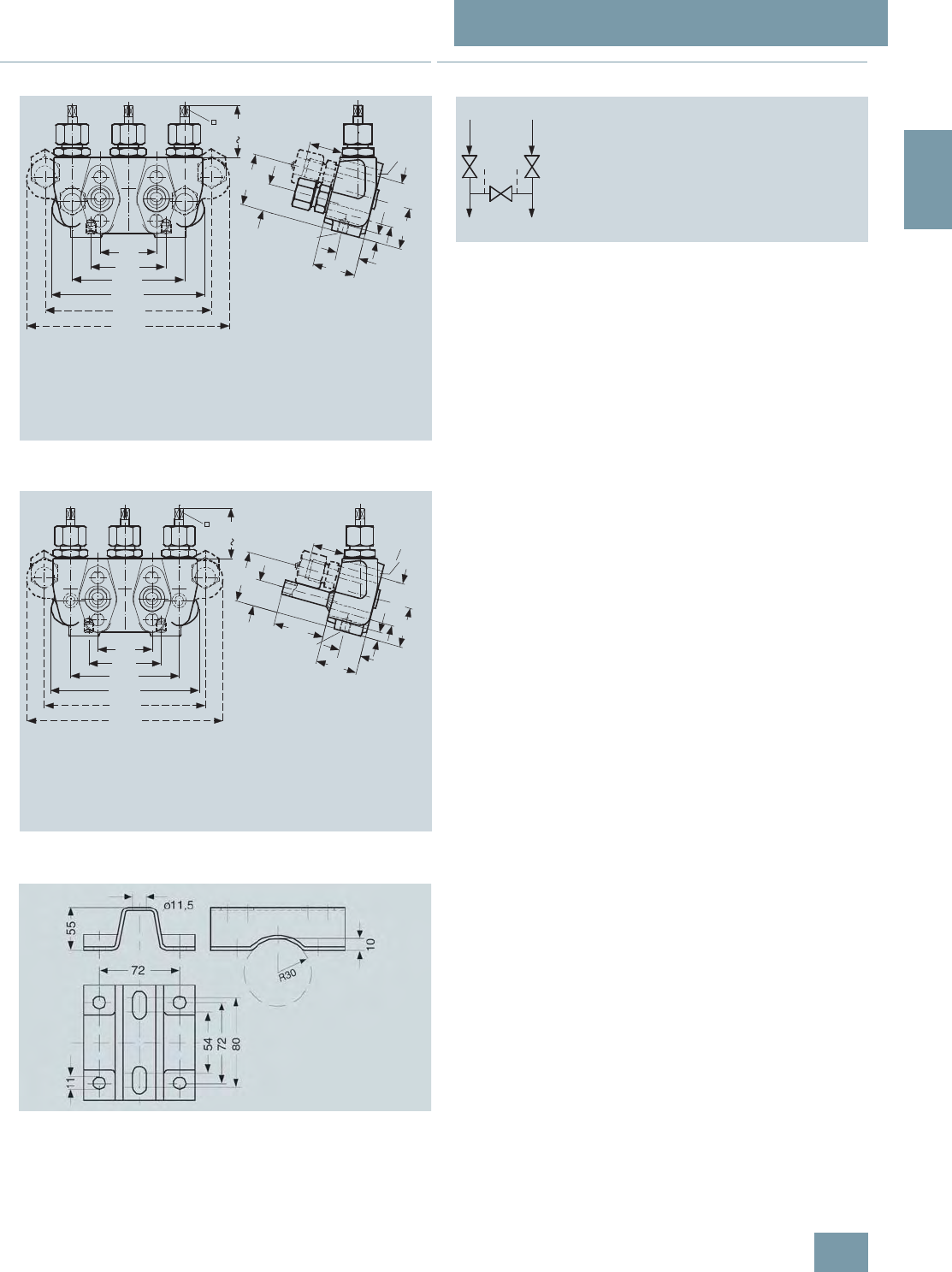
SITRANS P measuring instruments for pressure
Fitttings - Shut-off valves for differential pressure transmitters
3-way valve manifold DN 8
2/211
Siemens FI 01 · 2009
2
■
Dimensional drawings
3-way valve manifold DN 8 (7MF9416-1..) with pipe union, dimensions in
mm
3-way valve manifold DN 8 (7MF9416-2..) with welding pin, dimensions
in mm
Mounting plate 7MF9006-6.. (M11, M12) for valve manifold, dimensions
in mm
■
Schematics
3-way valve manifold DN 8, connections
7
48
31,5
M10 22
41
48
25
41,3
38
8
Ø12
A
B
C
54
72
108
160
195
147
AProcess connection (e.g. on primary device):
Pipe union with ferrule, diameter 12 mm, S series to DIN 2353
BTransmitter connection:
Flange connection to EN 61 518, form A
CTest connection:
M20x1.5
Valve design: internal spindle thread
7
48
54
72
108
160
195
147
31,5
50
M10 22
41
48
25
41,3
38
8
o12
AB
C
AProcess connection (e.g. on primary device):
Welding pin, diameter 14x2,5
BTransmitter connection:
Flange connection to EN 61 518, form A
CTest connection:
M20x1.5
Valve design: internal spindle thread
B
A
D
B
A
D
A Process connection
B Transmitter connection
C Vent/test connection
Three-way valve
manifold for
liquids and gases
© Siemens AG 2008

SITRANS P measuring instruments for pressure
Fitttings - Shut-off valves for differential pressure transmitters
Valve manifold combination DN 5/DN 8
2/212 Siemens FI 01 · 2009
2
■
Overview
The valve manifold combination DN 5/DN 8 (7MF9416-6..) is for
pressure transmitters for differential pressure.
The combination is used to shut off and blow out differential
pressure lines and to test the pressure transmitter zero.
In the designs with a test connection, a test device can be con-
nected to test the pressure transmitter characteristic.
■
Benefits
• Max. working pressure 420 bar
■
Application
The valve manifold combination DN 5/DN 8 is designed for va-
pors.
■
Design
The valve manifold combination DN 5/DN 8 has a process con-
nection with welding pins.
The connection for the pressure transmitter is designed as as
flange connection, while the blow-out connection is designed as
a pipe union with ferrule.
The manifold valves have an internal spindle thread, while the
blow-out valves have an external spindle thread.
The optional test connections are M20x1.5.
Materials used
■
Function
• Shutting off the differential pressure lines
• Blowing out the differential pressure lines
• Checking the pressure transmitter zero
As an option it is possible to order a version with a test connec-
tion, to which a test device for checking the transmitter charac-
teristic can be connected.
Valve manifold DN 5 Blow-out valves DN 8
Component Material Mat. No. Material Mat. No.
Housing P250GH 1.0460 16 Mo 3 1.5415
Head parts C 35 1.0501 21 CrMo V57 1.7709
Spindles X 12
CrMoS 17 1.4104 X 20 Cr 13 1.4021
Cones X 35
CrMo 17 1.4122 X 35
CrMo 17
hardened
and tem-
pered
1.4122
Valve seats X 6 CrNiMoTi 1.4571/316Ti X 20 Cr 13 1.4021
Packings PTFE - Pure
graphite -
Welding pins - - 16 Mo 3 1.5415
Selection and Ordering data Order No.
Valve manifold combination DN 5/DN 8 for
vapors 7 M F 9 4 1 6 - 6 7A
for flanging to pressure transmitters for differ-
ential pressure, max. working pressure
420 bar, also available in stainless steel on
request (order accessory set with Order
code), without certificate
• without test connection C
• with test connection M20 × 1.5 D
Accessories
Factory test certificate EN 10204–2.2 7MF9000-8AB
Material acceptance test certificate
EN 10204-3.1 7MF9000-8AD
Selection and Ordering data Order code Order No.
Further designs1)
1) When ordering accessory set together with the valve manifold combina-
tion, please use Order code; otherwise use Order No.
Please add "-Z" to Order No. and
specify Order code.
Accessory set to EN
(required for flanging, weight 0.2 kg)
4x screws 7/16-20 UNF x
21/8inch to ASME B18.2; chromized
steel
2x O-rings to DIN 3771,
20 x 2.65 - S - FPM90,
max. permissble 420 bar, 120 °C
B34 7MF9410-5CA
Accessory set to DIN2)
2) Flange connections to DIN 19213 only permissible up to 160!
(required for flanging, weight 0.2 kg)
4x screws M10x55 to DIN EN 24014;
chromized steel
4x washers Ø 10.5 mm to DIN 125;
2x O-rings to DIN 3771,
20 x 2.65 - S - FPM90, max. permiss-
ble 420 bar, 120 °C
Flange connection to DIN 19213
only permissible up to PN 160!
B16 7MF9010-6CC
© Siemens AG 2008
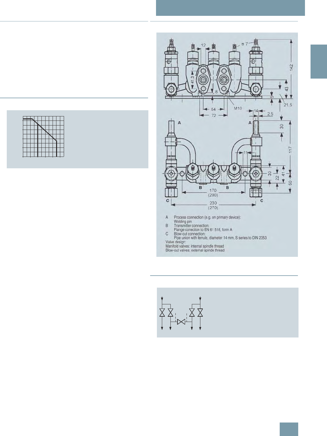
SITRANS P measuring instruments for pressure
Fitttings - Shut-off valves for differential pressure transmitters
Valve manifold combination DN 5/DN 8
2/213
Siemens FI 01 · 2009
2
■
Accessories
Accessory set for valve manifold combination DN 5/DN 8 for
flanging
• B34: 4 screws 7/16-20 UNF x 21/8inch to ASME B18.2.1,
2 O-rings (FPM 90)
• B16: 4 screws M10x55 to DIN EN 24014, 4 washers,
2 O-rings (FPM 90)
Washers Ø 10.5 to DIN 125
O-ring to DIN 3771, 20 x 2.65 - S – FPM90, max. 420 bar, 120 °C
Note: M10 screws only permissible up to PN 160!
■
Characteristic curves
Permissible operating pressure as a function of the permissible operating
temperature
■
Dimensional drawings
Valve manifold combination DN 5/DN 8 (7MF9416-6C.), dimensions in
mm (deviating dimensions for 7MF9416-6D. shown in brackets)
■
Schematics
Valve manifold combination DN 5/DN 8, connections
0
100
200
300
400
bar
°C0100 200 300 400
12
500
Operating pressure
Operating temperature
1 Valve manifold
2 Blow-out connection
1)
1) According to DIN 19210 the design
can be such that the temperatures
for the differential pressure line can be
set approx. 100 °C lower than the
media temperature.
B
A
D
B
A
D
C C
Valve manifold
combination
for vapors
A Process connection
B Transmitter connection
C Blow-out connection
D Test connection
© Siemens AG 2008

SITRANS P measuring instruments for pressure
Fitttings - Shut-off valves for differential pressure transmitters
Valve manifold combination DN 8
2/214 Siemens FI 01 · 2009
2
■
Overview
The valve manifold combination DN 8 (7MF9416-4..) is for pres-
sure transmitters for differential pressure.
It is used to shut off and blow out the differential pressure lines
and to check the pressure transmitter zero.
In the designs with a test connection, a test device can be con-
nected to check the pressure transmitter characteristic.
■
Benefits
• Max. working pressure 420 bar
■
Application
The valve manifold combination DN 8 is designed for vapors.
■
Design
The valve manifold combination DN 8 has a process connection
with welding pins.
The connection for the pressure transmitter is designed as as
flange connection, while the blow-out connection is designed as
a pipe union with ferrule.
The manifold valves have an internal spindle thread, while the
blow-out valves have an external spindle thread.
The optional test connection is M20x1.5.
The valve manifold combination DN 8 is supplied with a mount-
ing plate.
Materials used
■
Function
• Shutting off the differential pressure lines
• Blowing out the differential pressure lines
• Checking the pressure transmitter zero
As an option it is possible to order a version with a test connec-
tion, to which a test device for checking the pressure transmitter
characteristic can be connected.
Valve manifold Blow-out valves
Component Material Mat. No. Material Mat. No.
Housing P250GH 1.0460 16 Mo 3 1.5415
Head parts C 35 1.0501 21 CrMo V57 1.7709
Spindles X 12
CrMoS 17 1.4104 X 20 Cr 13 1.4021
Cones X 35
CrMo 17 1.4122 X 35
CrMo 17
hardened
and tem-
pered
1.4122
Valve seats X 6 CrNiMoTi 1.4571/316Ti X 20 Cr 13 1.4021
Packings PTFE - Pure
graphite -
Welding pins - - 16 Mo 3 1.5415
© Siemens AG 2008
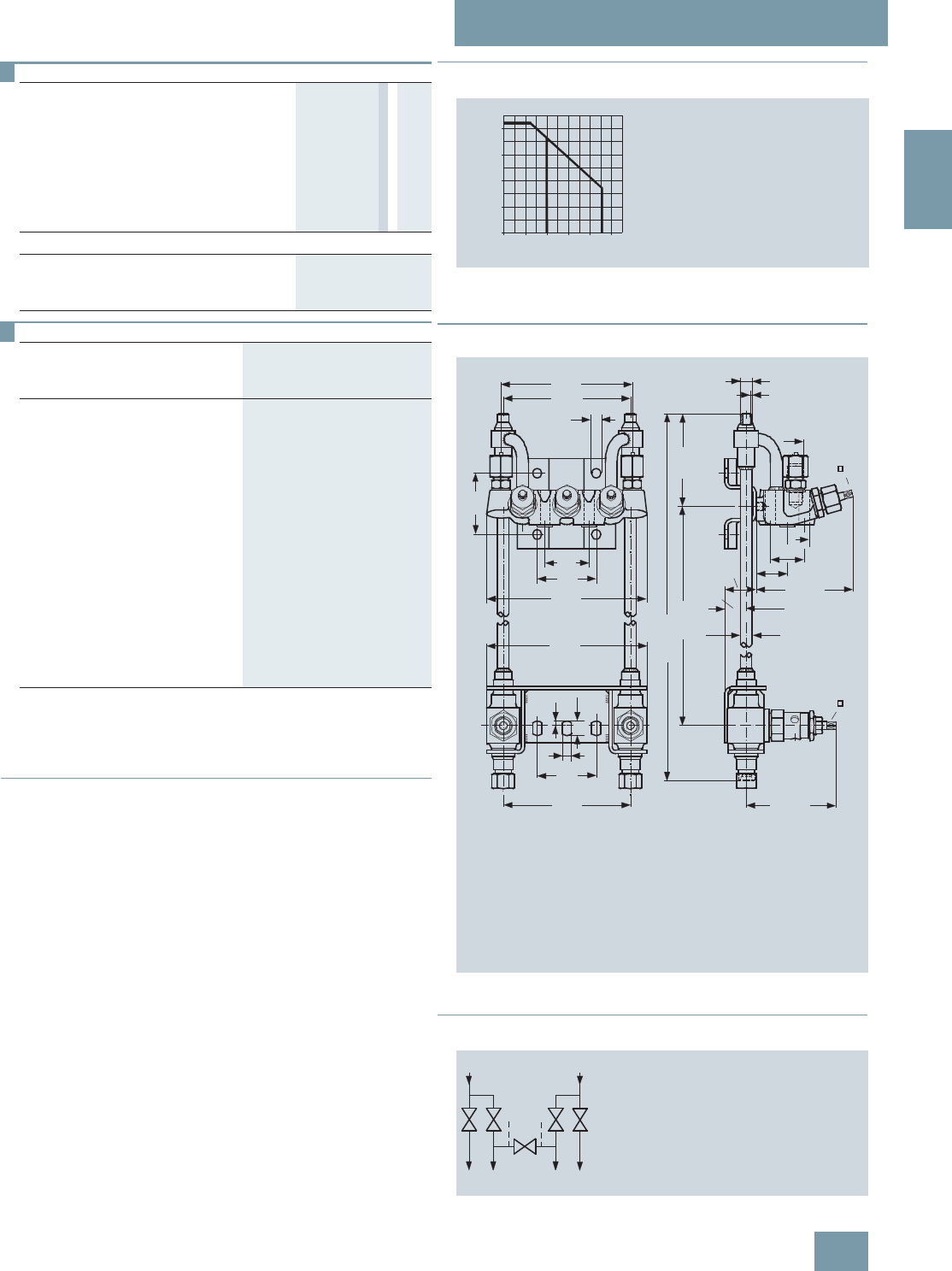
SITRANS P measuring instruments for pressure
Fitttings - Shut-off valves for differential pressure transmitters
Valve manifold combination DN 8
2/215
Siemens FI 01 · 2009
2
■
Accessories
Accessory set for valve manifold combination DN 8 for
flanging
• B34: 4 screws 7/16-20 UNF x 21/8inch to ASME B 18.2.1,
2 O-rings (FPM 90)
• B16: 4 screws M10x55 to DIN EN 24014, 4 washers,
2 O-rings (FPM 90)
Washers Ø 10.5 to DIN 125
O-ring to DIN 3771, 20 x 2.65 – S – FPM90, max. 420 bar, 120 °C
Note: M10 screws only permissible up to PN 160!
■
Characteristic curves
Permissible operating pressure as a function of the permissible operating
temperature
■
Dimensional drawings
Valve manifold combination DN 8 (7MF9416-4..), dimensions in mm
■
Schematics
Valve manifold combination DN 8, connections
Selection and Ordering data Order No.
Valve manifold combination DN 8 for
vapors 7 M F 9 4 1 6 - 7 7 A
for flanging to pressure transmitters for differ-
ential pressure, with mounting plate, max.
working pressure 420 bar, also available in
stainless steel on request (order accessory
set with Order code), without certificate
• without test connection 4 C
• with test connection M20 × 1.5 4 D
Accessories
Factory test certificate EN 10204–2.2 7MF9000-8AB
Material acceptance test certificate
EN 10204-3.1 7MF9000-8AD
Selection and Ordering data Order code Order No.
Further designs1)
1) When ordering accessory set together with the valve manifold combination,
please use Order code; otherwise use Order No.
Please add "-Z" to Order No. and
specify Order code.
Accessory set to EN
(required for flanging, weight 0.2 kg)
4x screws 7/16-20 UNF x
21/8inch to ASME B18.2; chromized
steel
2x O-rings to DIN 3771,
20 x 2.65 - S - FPM90,
max. permissble 420 bar, 120 °C
B34 7MF9410-5CA
Accessory set to DIN2)
2) Flange connections to DIN 19213 only permissible up to 160!
(required for flanging, weight 0.2 kg)
4x screws M10x55 to DIN EN 24014;
chromized steel
4x washers Ø 10.5 mm to DIN 125;
2x O-rings to DIN 3771,
20 x 2.65 - S - FPM90,
max. permissble 420 bar, 120 °C
Flange connection to DIN 19 213
only permissible up to PN 160!
B16 7MF9010-6CC
0
100
200
300
400
bar
°C0100 200 300 400
12
500
Operating pressure
Operating temperature
1 Valve manifold
2 Blow-out connection
1)
1) According to DIN 19210 the design
can be such that the temperatures
for the differential pressure line can be
set approx. 100 °C lower than the
media temperature.
525
160
155
11
54
72
195
72
195
5,5
17
11
72
155
109
2.5
M20x1.5
7
38
41.3
38
26
7
351
AA
B
CC
D
ca. 119
ca. 110
AProcess connection (e.g. on primary device):
Welding pin
BTransmitter connection:
Flange connection to EN 61 518, form A
CBlow-out connection:
Pipe union with ferrule, diameter 14 mm, S series to DIN 2353
CTest connection (only with Order No. 7MF9416-4D.):
M20x1.5
Valve design:
Manifold valves: internal spindle thread
Blow-out valves: external spindle thread
diam. 14
diam. 12
diam. 14x2.5
B
A
D
B
A
D
C C
A Process connection
B Transmitter connection
C Blow-out connection
D Test connection
Valve manifold
combination
for vapors
© Siemens AG 2008

SITRANS P measuring instruments for pressure
Fitttings - Shut-off valves for differential pressure transmitters
2-, 3- and 5-spindle valve manifolds
for installing in protective boxes
2/216 Siemens FI 01 · 2009
2
■
Overview
The two-spindle, three-spindle and five-spindle valve manifolds
(7MF9412-1..) are used to shut off the differential pressure lines
and to check the transmitter zero.
The five-spindle valve manifold permits venting on the transmit-
ter side and checking of the transmitter characteristic.
These valve manifolds are preferentially used when mounting in
protective boxes. In addition, they can also be used for wall,
frame or pipe mounting together with the mounting bracket.
Transmitters of the DS series can be operated and read from the
front when using these valve manifolds.
■
Application
The valve manifolds DN 5 are designed for liquids and vapors
and for installing in protective boxes.
Each is available in a version for oxygen on request
■
Design
All versions of the spindle manifolds have a process connection
½-14 NPT.
The connection for the pressure transmitter is always designed
as a flange connection to EN 61518, Form A.
The 2-spindle and the 5-spindle valve manifold have in addition
a vent and test connection ¼-18 NPT.
The valves have an external spindle thread.
Materials used
■
Functions
Functions of all valve manifolds:
• Shutting off the differential pressure lines
• Checking the pressure transmitter zero
Additional functions of the 2-spindle and 5-spindle valve mani-
folds through the vent and test connection:
• Venting on the transmitter side
• Checking the pressure transmitter characteristic
Components Material Mat. No.
Housing X 2 CrNiMo 17 13 2 1.4404/316L
Cones X 6 CrNiMoTi 17 12 2 1.4571/316Ti
Spindles X 2 CrNiMo 18 10 1.4404/316L
Head parts X 5 CrNiMo 18 10 1.4401/316
Packings PTFE -
Selection and Ordering data Order No.
Valve manifolds DN 5 for mounting in
protective boxes 7 M F 9 4 1 2 - 7 7 A
for liquids and gases
for flanging to pressure transmitters for
absolute and differential pressure
Material: stainless steel, mat. No: 1.4404/316L
max. working pressure 420 bar
(order accessory set with Order code),
without certificate
• 2-spindle valve manifold with rotatng sleeve
G½ 1 B
• 2-spindle valve manifold with flange
connection 1 C
• 3-spindle valve manifold 1 D
• 5-spindle valve manifold 1 E
Accessories
Factory test certificate EN 10204–2.2 7MF9000-8AB
Material acceptance test certificate
EN 10204-3.1 7MF9000-8AD
Selection and Ordering data Order code Order No.
Further designs1)
Please add "-Z" to Order No. and
specify Order code.
Accessory set to EN
(connection between valve manifold
and pressure transmitter)
for valve manifold 7MF9412–1C.
2x screws 7/16-20 UNF x 2 inch to
ASME B18.2.1; chromized steel
1x O-ring to DIN 3771,
20 x 2.65 - S - FPM90,
max. permissble 420 bar, 120 °C
F32 7MF9412-6CA
2x screws 7/16-20 UNF x
2 inch to ASME B18.2.1; chromized
steel
1x gasket made of PTFE,
max. permissible 420 bar, 80 °C2)
F35 7MF9412-6DA
for valve manifold 7MF9412–1D and
-1E.
4x screws 7/16-20 UNF x
2 inch to ASME B18.2.1; chromized
steel
2x O-rings to DIN 3771,
20 x 2.65 - S - FPM90,
max. permissble 420 bar, 120 °C2)
F34 7MF9412-6GA
4x screws 7/16-20 UNF x
2 inch to ASME B18.2.1; chromized
steel
2x flat gaskets made of PTFE,
max. permissible 420 bar, 80 °C2)
F36 7MF9412-6HA
© Siemens AG 2008

SITRANS P measuring instruments for pressure
Fitttings - Shut-off valves for differential pressure transmitters
2-, 3- and 5-spindle valve manifolds
for installing in protective boxes
2/217
Siemens FI 01 · 2009
2
■
Accessories
Accessory set for 2-, 3- and 5-spindle valve manifolds (Con-
nection between manifold and transmitter)
2-spindle valve manifold DN 5 with flange connection
• F32: 2 screws 7/16 20 UNF x 2 inch to ASME B 18.2.1,
1 O Ring (FPM90)
• F35: 2 screws 7/16 20 UNF x 2 inch to ASME B 18.2.1,
1 flat-gasket
• F12: 2 screws M10x50 to DIN EN 24014, 2 washers,
1 O-ring (FPM90)
• F15: 2 screws M10x50 toDIN EN 24014, 2 washers,
1 flat gasket
3-spindle and 5-way valve manifold DN 5
• F34: 4 screws 7/16 20 UNF x 2 inch toASME B 18.2.1,
2 O-rings (FPM90)
• F36: 4 screws 7/16 20 UNF x 2 inch toASME B 18.2.1,
2 flat-gaskets
• F14: 4 screws M10x50 toDIN EN 24014, 4 washers,
2 O-rings (FPM90)
• F16: 4 screws M10x50 toDIN EN 24014, 4 washers,
2 flat-gaskets
Washers Ø 10,5 to DIN 125
Flat-gaskets made of PTFE, max. 420 bar, 80 °C
O-ring to DIN 3771, 20 x 2,65 - S - FPM90; max.420 bar, 120 °C
Note:
Flange connections with M10 screws only permissible up to
PN 160!
Mounting bracket for wall mounting or for securing to
mounting rack
With bolds for mounting on valve manifold
•M14: For 2-spindle valve manifold DN 5
•M17: For 3-spindle valve manifold DN 5
• M18: For 5-spindle valve manifold DN 5
Mounting clips (2 off)
• M16: For securing the mounting brackets M14, M17 and M18
to pipe
Valve manifold 100 bar, suitable for oxygen
• S12: For 2-spindle valve manifold DN 5
•S13: For 3-spindle valve manifold DN 5
•S14: For 5-spindle valve manifold DN 5
■
Characteristic curves
Permissible operating pressure as a function of the permissible operating
temperature
Accessory set to DIN
(connection between valve manifold
and pressure transmitter)
for valve manifold 7MF9412–1C.
2x screws M10x50 to DIN EN 24014;
chromized steel
2x washers Ø 10.5 mm to DIN 125;
1x O-ring to DIN 3771,
20 x 2.65 - S - FPM90, max. permiss-
ble 420 bar, 120 °C2)
F12 7MF9412-6AA
2x screws M10x50 to DIN EN 24014;
chromized steel
2x washers Ø 10.5 mm to DIN 125;
1x gasket made of PTFE,
max. permissible 420 bar, 80 °C2)
F15 7MF9412-6BA
for valve manifold 7MF9412–1D and
-1E.
4x screws M10x50 to DIN EN 24014;
chromized steel
4x washers Ø 10.5 mm to DIN 125;
2x O-rings to DIN 3771,
20 x 2.65 - S - FPM90, max. permiss-
ble 420 bar, 120 °C2)
F14 7MF9412-6EA
4x screws M10x50 to DIN EN 24014;
chromized steel
4x washers Ø 10.5 mm to DIN 125;
2x flat gaskets made of PTFE,
max. permissible 420 bar, 80 °C2)
F16 7MF9412-6FA
Mounting bracket
required for wall mounting or for
securing to mounting rack, with bolts
for mounting on valve manifold
• for valve manifolds 7MF9412-1B.
and -1C. M14 7MF9006-6LA
• for valve manifold 7MF9412-1D. M17 7MF9006-6NA
• for valve manifold 7MF9412-1E. M18 7MF9006-6PA
Mounting clip
2 off, to secure mounting bracket
to pipe
M16 7MF9006-6KA
Valve manifold 100 bar
suitable for oxygen
• for valve manifolds 7MF9412-1B.
and -1C. S12
• for valve manifold 7MF9412-1D. S13
• for valve manifold 7MF9412-1E. S14
1) When ordering accessory set or mounting together with the valve
manifolds, please use Order code; otherwise use Order No.
2) Flange connections with M10 screws only permissible up to PN 160!
Selection and Ordering data Order code Order No.
Further designs1)
Please add "-Z" to Order No. and
specify Order code.
0
100
200
300
400
bar
°C0100 200 300 400
Operating pressure
Operating temperature
420 bar at 120 °C
350 bar at 200 °C
© Siemens AG 2008
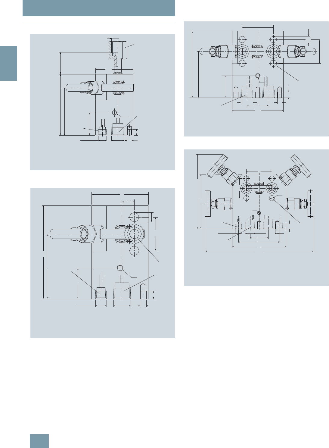
SITRANS P measuring instruments for pressure
Fitttings - Shut-off valves for differential pressure transmitters
2-, 3- and 5-spindle valve manifolds
for installing in protective boxes
2/218 Siemens FI 01 · 2009
2
■
Dimensional drawings
2-spindle valve manifold DN 5 (7MF9412-1B..) with rotating sleeve,
dimensions in mm
2-spindle valve manifold DN 5 (7MF9412-1C..), dimensions in mm
3-spindle valve manifold DN 5 (7MF9412-1D..), dimensions in mm
5-spindle valve manifold DN 5 (7MF9412-1E..), dimensions in mm
AProcess connection: ½-14 NPT
B Transmitter connection:
Nipple to DIN 16 284, G½, SW 27
CVent / test connection: ¼-18 NPT
G½
63.5
M8
M8
¼-18 NPT
B
A
C
37
103
80
38
10
½-14 NPT
AProcess connection: ½-14 NPT
B Transmitter connection:
Flange connection to EN 61 518, form A
CVent / test connection: ¼-18 NPT
Valve design: external spindle thread
115
80
¼-18 NPT ½-14 NPT M8
M8
38
1041.3
Ø 12
70
15
B
A
C
AProcess connection: ½-14 NPT
BTransmitter connection: Flange connection EN 61 518, form A
Valve design: external spindle thread
½NPT M8
115
80
M8
10
38
88.9
12
41.3
54
A
B
38
AProcess connection: ½-14 NPT
BTransmitter connection:
Flange connection to EN 61 518, form A
C Vent / test conenction: ¼-18 NPT
Valve design: external spindle thread
54
115
approx. 157
M8
41.3
12
M8
¼-18 NPT ½-14 NPT
38
87
114
ca. 228
10
A
B
C
© Siemens AG 2008
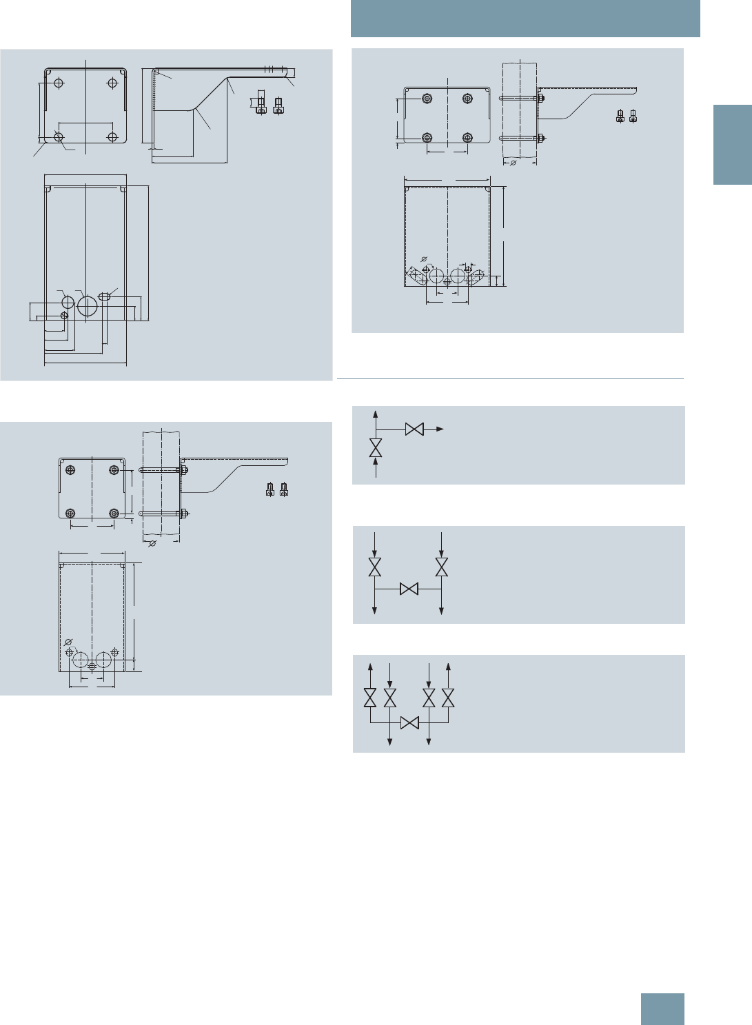
SITRANS P measuring instruments for pressure
Fitttings - Shut-off valves for differential pressure transmitters
2-, 3- and 5-spindle valve manifolds
for installing in protective boxes
2/219
Siemens FI 01 · 2009
2
Mounting bracket (7MF9006-6LA)/(M14) for 2-spindle valve manifolds,
dimensions in mm
Mounting bracket (7MF9006-6NA)/(M17) for 3-spindle valve manifolds,
dimensions in mm
Mounting bracket (7MF9006-6PA)/(M18) for 5-spindle valve manifolds,
dimensions in mm
■
Schematics
2-spindle valve manifold DN 5 (with rotating sleeve G½ or flange connec-
tion), connections
3-spindle valve manifold DN 5, connections
5-spindle valve manifold DN 5, connections
Ø26
110
110
6.5
24
26.6
31.6
57.6
77.1
6.35
Ø16
Ø9
R4.5
12
72
872
4x Ø11
R20
2.5
R10
100
R2.5+1
55
100
R5
R5
31.5
19
M8
12
180
72
8
72
60,3
110
38
76
180
19
26
72
8
72
60,3
180
19
38
76
155
17
26 9
B
A
CA Process connection
B Connection for pressure gauge or trans-
mitter for pressure or absolute pressure
C Vent/test connection
B
A
B
A
A Process connection
B Transmitter connection
B
A
B
A
C C
A Process connection
B Transmitter connection
C Vent/test connection
© Siemens AG 2008

SITRANS P measuring instruments for pressure
Fitttings - Shut-off valves for differential pressure transmitters
3- and 5-spindle valve manifolds
for vertical angular differential pressure lines
2/220 Siemens FI 01 · 2009
2
■
Overview
These 3-spindle and 5-spindle valve manifolds 7MF9413-1..
were developed specially for vertical differential pressure lines.
The valve manifolds are used to shut off the differential pressure
lines and to check the pressure transmitter zero.
The 5-spindle valve manifold permits venting on the transmitter
side and checking of the pressure transmitter characteristic.
■
Benefits
• For vertical differential pressure lines
• Max. operating pressure 420 bar
• Transmitters of the DS series can be operated and read from
the front.
■
Application
The 3-spindle and 5-spindle valve manifolds for vertical differen-
tial pressure lines are for liquids and gases. The valve manifolds
are flanged on the pressure transmitter.
■
Design
All versions of the spindle valve manifolds have a process con-
nection ½-14 NPT.
The connection for the pressure transmitter is always designed
as a flange connection to EN 61518, form B .
The 2-spindle and the 5-spindle valve manifold have in addition
a vent and test connection ¼-18 NPT.
Materials used:
■
Function
Functions of all valve manifolds:
• Shutting off the differential pressure lines
• Checking the pressure transmitter zero
Additional functions of the 2-spindle and 5-spindle valve mani-
folds through the vent and test connection:
• Venting on the transmitter side
• Checking the pressure transmitter characteristic
Component Material Mat. No.
Housing X 2 CrNiMo 17 13 2 1.4404/316L
Cones X 6 CrNiMoTi 17 12 2 1.4571/316Ti
Spindles X 2 CrNiMo 18 10 1.4404/316L
Head parts X 5 CrNiMo 18 10 1.4401/316
Packings PTFE -
Selection and Ordering data Order No.
Valve manifolds for vertical differential
pressure lines 7 M F 9 4 1 3 - 7 7 A
for liquids and gases
for flanging to pressure transmitters for abso-
lute and differential pressure
Material: stainless steel, mat. No: 1.4404/316L
max. working pressure 420 bar
(order accessory set with Order code),
without certificate
• 3-spindle valve manifold 1 D
• 5-spindle valve manifold 1 E
Accessories
Factory test certificate EN 10204–2.2 7MF9000-8AB
Material acceptance test certificate
EN 10204-3.1 7MF9000-8AD
Selection and Ordering data Order code Order No.
Further designs1)
1) When ordering accessory set or mounting together with the multiway cock,
please use Order code; otherwise use Order No.
Please add "-Z" to Order No. and
specify Order code.
Accessory set to EN
(connection between valve manifold
and pressure transmitter)
4x screws 7/16-20 UNF x
1¾ inch to ASME B18.2.1;
chromized steel
2x flat gaskets made of PTFE,
max. permissible 420 bar, 80 °C
K36 7MF9411-5DB
Accessory set to DIN2)
2) Flange connections to DIN 19213 only permissible up to 160!
(connection between valve manifold
and pressure transmitter)
4x screws M10x45 to DIN EN 24014;
chromized steel
4x washers Ø 10.5 mm to DIN 125;
2x flat gaskets made of PTFE,
max. permissible 420 bar, 80 °C
Flange connection with M10 screws
only permissible up to PN 160.
K16 7MF9411-6BB
Mounting bracket
required for wall mounting or for
securing to mounting rack, with bolts
for mounting on valve manifold
• for valve manifold 7MF9413-1D. M17 7MF9006-6NA
• for valve manifold 7MF9413-1E. M18 7MF9006-6PA
required for mounting on 2" stand-
pipe, with bolts for mounting on
valve manifold
• for valve manifold 7MF9413-1D. M19 7MF9006-6QA
Mounting clip
2 off, to secure mounting bracket
to pipe M16 7MF9006-6KA
Valve manifold 100 bar
suitable for oxygen
• for valve manifold 7MF9413-1D. S13
• for valve manifold 7MF9413-1E. S14
© Siemens AG 2008
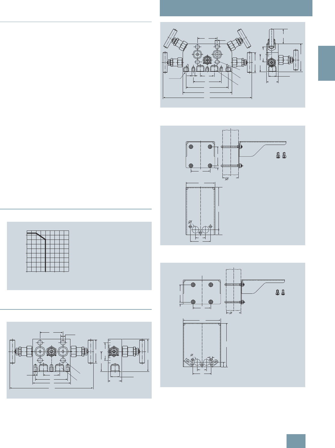
SITRANS P measuring instruments for pressure
Fitttings - Shut-off valves for differential pressure transmitters
3- and 5-spindle valve manifolds
for vertical angular differential pressure lines
2/221
Siemens FI 01 · 2009
2
■
Accessories
Accessory set (connection between manifold and
transmitter)
• K36: 4 screws 7/16-20 UNF x 1¾ inch to ASME B18.2.1, 2 flat
gaskets
• K16: 4 screws M10x45 to DIN EN 24014, 4 washers, 2 flat
gaskets
Washers Ø 10.5 to DIN 125
Flat gaskets made of PTFE, max. 420 bar, 80 °C
Note: Flange connection with M10 screws only permissible up to
PN 160!
Mounting bracket for wall mounting or for securing to
mounting rack
With bolts for mounting on valve manifold
•M17: For 3-spindle valve manifold
•M18: For 5-spindle valve manifold
Mounting bracket for mounting on 2" standpipe
With bolts for mounting on valve manifold
•M19: For 3-spindle valve manifold
Mounting clips (2 off)
For securing the mounting brackets M17, M18 and M19 to pipe
Valve manifold 100 bar, suitable for oxygen
• For 3-spindle valve manifold
•For 5-spindle valve manifold
■
Characteristic curves
Permissible operating pressure as a function of the permissible operating
temperature
■
Dimensional drawings
3-spindle valve manifold 7MF9413-1D. for vertical differential pressure
lines, dimensions in mm
5-spindle valve manifold 7MF9413-1E. for vertical differential pressure
lines, dimensions in mm
Mounting bracket (7MF9006-6NA)/(M17) for 3-spindle valve manifolds,
dimensions in mm
Mounting bracket (7MF9006-6PA)/(M18) for 5-spindle valve manifolds,
dimensions in mm
0
100
200
300
400
bar
°C0100 200 300 400
Operating pressure
Operating temperature
420 bar at 120 °C
350 bar at 200 °C
38
76
89
197
M8
55
54 Ø12
47
76,2
41,3
31,75
1/2NPT
B
A
Ø12
54
38
76
115
134
242
M8
¼-NPT
55
½-NPT
31,75
76,2
41,3
47
40
A
C
B
72
8
72
60,3
110
38
76
180
19
26
72
8
72
60,3
180
19
38
76
155
17
26 9
© Siemens AG 2008

SITRANS P measuring instruments for pressure
Fitttings - Shut-off valves for differential pressure transmitters
3- and 5-spindle valve manifolds
for vertical angular differential pressure lines
2/222 Siemens FI 01 · 2009
2
Mounting bracket (7MF9006-6QA)/(M19) for 3-spindle and 5-spindle
valve manifolds, dimensions in mm
■
Schematics
3-spindle valve manifold for vertical differential pressure lines, connec-
tions
5-spindle valve manifold for vertical differential pressure lines, connec-
tions
728
100
76 9
26
38
92
19
16 50
5
72
B
A
B
A
A Process connection
B Transmitter connection
B
A
B
A
C
C
A Process connection
B Transmitter connection
C Vent/test connection
1/4-18 NPT
© Siemens AG 2008
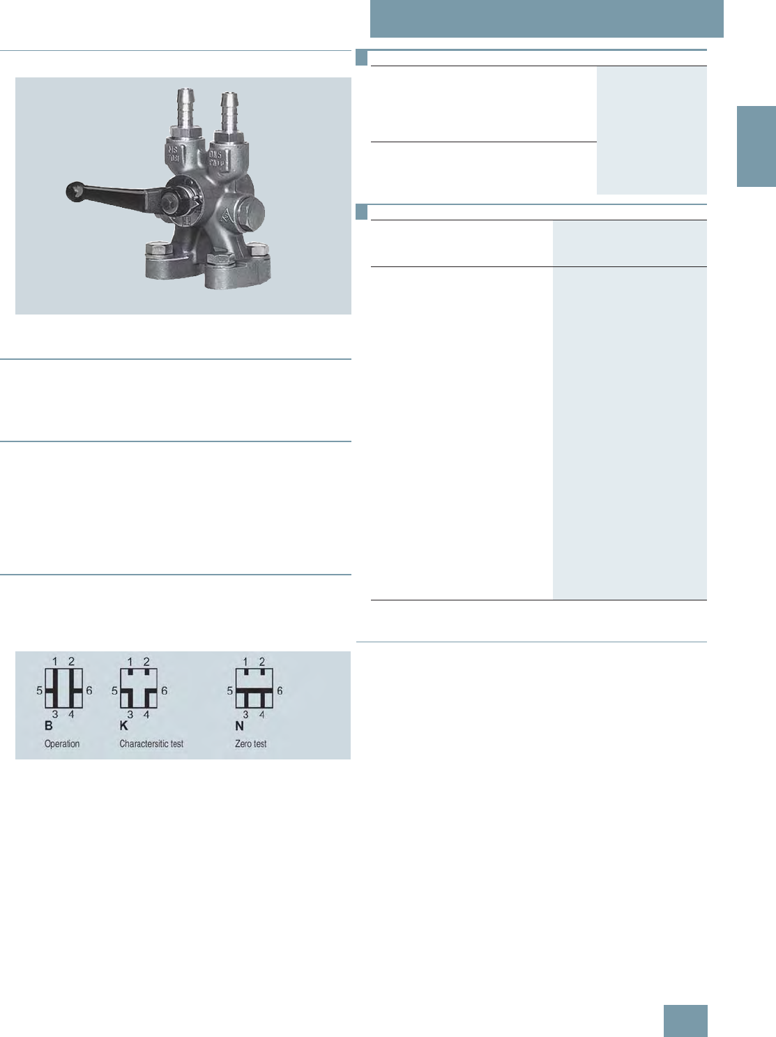
SITRANS P measuring instruments for pressure
Fitttings - Shut-off valves for differential pressure transmitters
Low-pressure multiway cock
2/223
Siemens FI 01 · 2009
2
■
Overview
The low-pressure multiway cock 7MF9004-4CA/-4DA can be
flanged to pressure transmitters for differential pressure.
■
Benefits
• Robust design
• For liquids and gases
• One-hand operation
■
Design
The multiway cock has 2 process connections and 2 test con-
nections, which are available in 2 versions (with sealing screws
G3/8 or quick-release couplings). The housing is made of hot-
pressed brass CuZn39Pb3, CW 614N. Test connections with
sealing screws or with self-sealing quick-release couplings.
Note: An accessory set is always required for flanging of the
multiway cock to a differential pressure transmitter.
■
Function
• Shutting off the differential pressure lines
• Testing the pressure transmitter zero
• Testing the pressure transmitter characteristic
Cock positions; the symbols are printed on the cock
■
Accessories
Accessory set for low-pressure multiway cock
• L11: 4 screws M10x25 to DIN EN 24017, 4 washers, 2 flat gas-
kets
•L15 (suitable for oxygen): 4 screws M10x25 to DIN EN 24017,
4 washers, 2 flat gaskets
• L31: 4 screws 7/16-20 UNF x 1 inch, 2 flat gaskets
Washers Ø 10.5 to DIN 125
Flat gaskets made of PTFE, max. permissible temperature 80 °C
Multiway cock in oil-free and grease-free design
• S11: BAM-tested lubricant, gasket suitable for oxygen
Mounting brackets
• M13: Required for wall mounting or for securing on rack
(72 mm grid); made of electrogalvanized sheet-steel
Selection and Ordering data Order No.
Low-pressure multiway cock
for liquids and gases, for flanging to pressure
transmitters, max. working pressure 25 bar,
max. working temperature 60 °C
(up to 80 °C for a short time), weight 1.75 kg
(without accessory set)
Test connections
2x sealing screws G3/87MF9004-4CA
2x quick-release couplings 7MF9004-4DA
Selection and Ordering data Order code Order No.
Further designs1)
1) When ordering accessory set or mounting together with the multiway cock,
please use Order code; otherwise use Order No.
Please add "-Z" to Order No. and
specify Order code.
Accessory set to EN
(required for flanging, weight 0.2 kg)
4x screws 7/16-20 UNF x 1 inch
to ASME B18.2.1; chromized steel
2x gaskets made of PTFE, max.
permissible temperature 80 °C
L31 7MF9004-5CC
Accessory set to DIN
(required for flanging, weight 0.2 kg)
4x screws M10x25 to DIN EN 24017;
chromized steel
4x washers Ø 10.5 mm to DIN 125;
2x gaskets made of PTFE, max.
permissible temperature 80 °C
• Standard design L11 7MF9004-6AD
• Version for oxygen L15 7MF9004-6AE
Multiway cock in oil-free and
grease-free design
BAM-tested lubricant, gasket
suitable for oxygen S11
Mounting bracket
required for wall mounting or for
securing on rack (72 mm grid),
made of electrogalvanized sheet-
steel, weight 0.85 kg
M13 7MF9004-6AA
© Siemens AG 2008
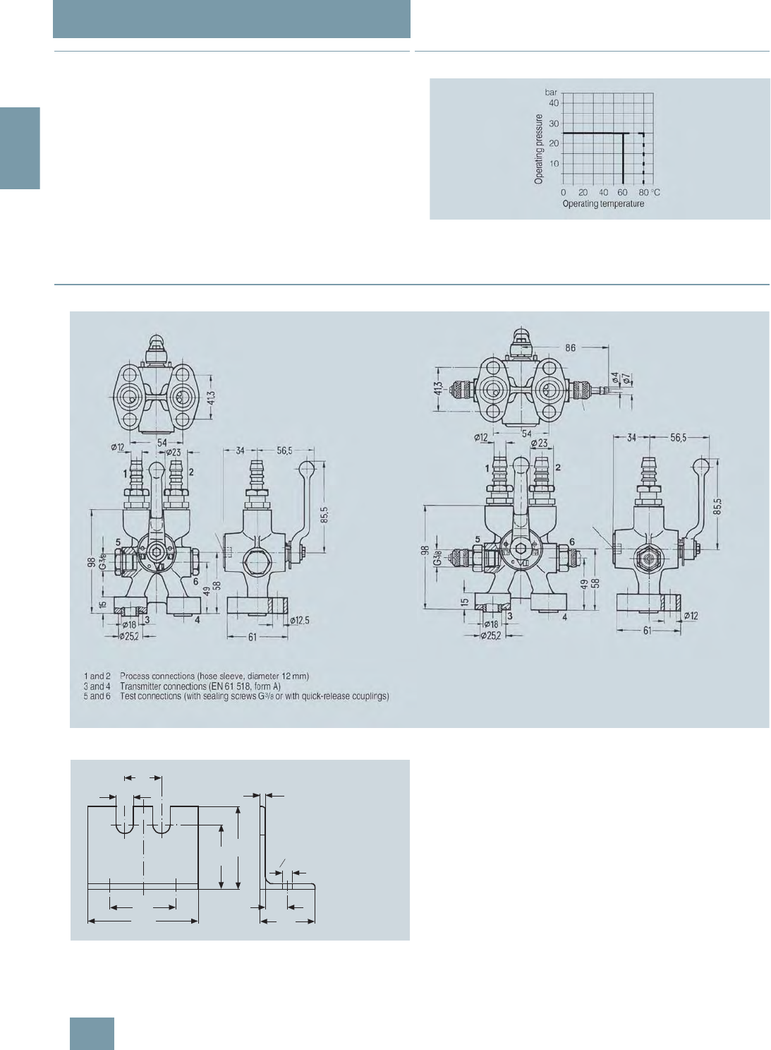
SITRANS P measuring instruments for pressure
Fitttings - Shut-off valves for differential pressure transmitters
Low-pressure multiway cock
2/224 Siemens FI 01 · 2009
2
■
Options
Test connections
• 2 sealing screws G3/8
• 2 quick-release couplings
■
Characteristic curves
Low-pressure multiway cock, permissible operating pressure as a func-
tion of the permissible operating temperature
■
Dimensional drawings
Low-pressure multiway cock 7MF9004-4CA/-4DA for direct flanging to pressure transmitters for differential pressure, dimensions in mm
Mounting bracket 7MF9004-6AA (M13), dimensions in mm
40
19
72
120
70
90
6
24
60
o11
© Siemens AG 2008
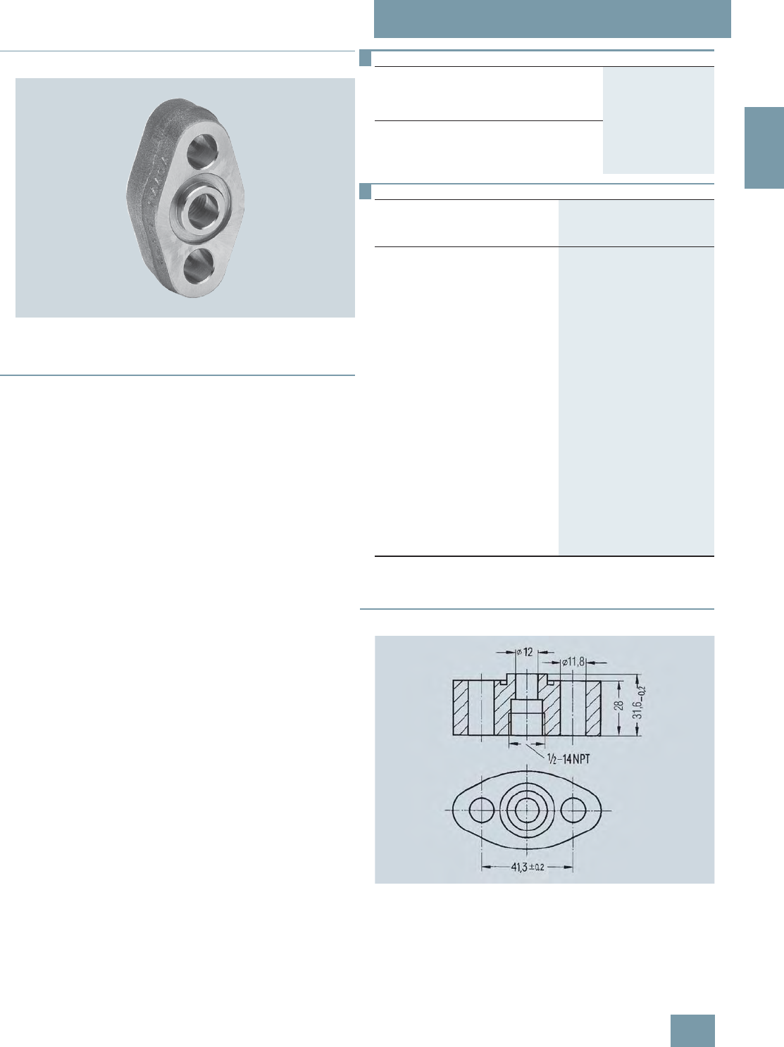
SITRANS P measuring instruments for pressure
Fittings - Accessories
Oval flange
2/225
Siemens FI 01 · 2009
2
■
Overview
The oval flange 7MF9408-2C. for pressure transmitters for abso-
lute pressure and differential pressure has a ½-14 NPT female
thread and is designed for max. operating pressure 400 bar.
■
Accessories
• E34: 2 screws 7/16-20 UNF x 1½ inch to ASME B18.3,
1 O-ring (FPM 90)
• E13: 2 screws M10x40 to DIN EN 4762, 2 washers,
1 O-ring (FPM 90)
• E36: 2 screws 7/16-20 UNF x 1½ inch to ASME B18.2.1,
1 flat gasket
• E16: 2 screws M10x40 to DIN EN ISO 4762, 2 washers,
1 flat gasket
Washers Ø 10.5 to DIN 125
Flat gaskets made of PTFE, max. 420 bar, 80 °C
O-ring to DIN 3771, 20 x 2.65 – S – FPM90, max. 420 bar, 120 °C
Note: M10 screws only permissible up to PN 160!
■
Dimensional drawings
Oval flange 7MF9408-2C., dimensions in mm
Selection and Ordering data Order No.
Oval flange
with female thread ½-14 NPT, max. working
pressure 420 bar, flange connection to
DIN EN 61518, form A
Material
P250GH, mat. No.: 1.0460 7MF9408-2CE
X 2 CrNiMo 17 13 2, mat. No. 1.4404/316L 7MF9408-2CL
Selection and Ordering data Order code Order No.
Further designs
Please add "-Z" to Order No. and
specify Order code.
Accessory set to EN1)
2x screws 7/16-20 UNF x
1½ inch to ASME B 18.2.3;
chromized steel
1x flat gasket made of PTFE,
max. permissible 420 bar, 80 °C
E36 7MF9408-5DA
2x screws 7/16-20 UNF x
1½ inch to ASME B 18.2.3;
chromized steel
1x O-ring to DIN 3771,
20 x 2.65 - S - FPM90,
max. permissble 420 bar, 120 °C
E34 7MF9408-5CA
Accessory set to DIN1)
1) When ordering accessory set together with the oval flange, please
use Order code; otherwise use Order No.
2x screws M10x40 to
DIN EN ISO 4762; chromized steel
2x washers Ø 10.5 mm to DIN 125;
1x O-ring to DIN 3771,
20 x 2.65 - S - FPM90,
max. permissble 420 bar, 120 °C2)
2) Flange connections with M10 screws only permissible up to PN 160!
E13 7MF9408-6AA
2x screws M10x40 to
DIN EN ISO 4762; chromized steel
2x washers Ø 10.5 mm to DIN 125;
1x flat gasket made of PTFE,
max. permissible 420 bar, 80 °C2)
E16 7MF9408-6BA
© Siemens AG 2008
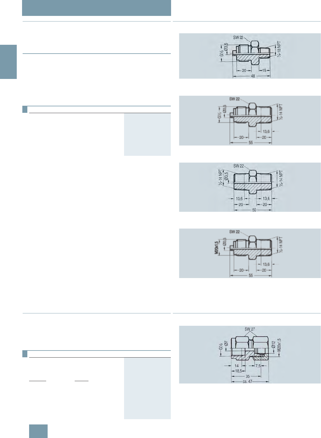
SITRANS P measuring instruments for pressure
Fittings - Accessories
Adapters, connection glands
2/226 Siemens FI 01 · 2009
2
■
Overview
Adapters enable e.g. a transition from medium connections with
NPT thread to shut-off valves to DIN 16270 ... 16272 or pipes in
conjunction with a connection gland (e.g. 7MF9008).
■
Design
The connection pieces are made of X 6 CrNiMoTi 17 12 2, mat.
No. 1.4571 and available in 3 versions
• Thread ¼-18 NPT and connection shank G½ to DIN EN 837-1
• Thread ½-14 NPT and connection shank G½ to DIN EN 837-1
• Thread ½-14 NPT and thread ½-14 NPT
■
Dimensional drawings
Connection piece with thread ¼-18 NPT and connection shank G½
7MF9001-1AA, dimensions in mm
Connection piece with thread ½--14 NPT and connection shank G½
7MF9001-1CA, dimensions in mm
Connection piece with thread ½-14 NPT and thread ½-14 NPT
7MF9001-1DA, dimensions in mm
Connection piece with thread ½-14 NPT and thread M20 x 1.5
7MF9001-1EA, dimensions in mm
■
Overview
Connection glands to connect medium or differential pressure
lines to collars G½ to DIN EN 837-1
• For rated pressures up to PN 630
• For oxygen only up to PN 250
■
Dimensional drawings
Connection gland 7MF9008-1G., dimensions in mm
Selection and Ordering data Order No.
Adapter
(weight 0.2 kg)
with thread ¼-18 NPT – G½ 7MF9001-1AA
with thread ½-14 NPT – G½ 7MF9001-1CA
with thread ½-14 NPT – ½-14 NPT 7MF9001-1DA
with thread ½-14 NPT – M20 x 1.5 7MF9001-1EA
Selection and Ordering data Order No.
Connection screwed gland
for pipelines
(weight 0.2 kg)
Material Design
11SMn30
(mat. No. 1.0715) Standard 7MF9008-1GA
X 6 CrNiMoTi 17 12 2
(mat. No. 1.4571/316Ti)Standard 7MF9008-1GB
X 6 CrNiMoTi 17 12 2
(mat. No. 1.4571/316Ti)Grease-free 7MF9008-1GC
© Siemens AG 2008
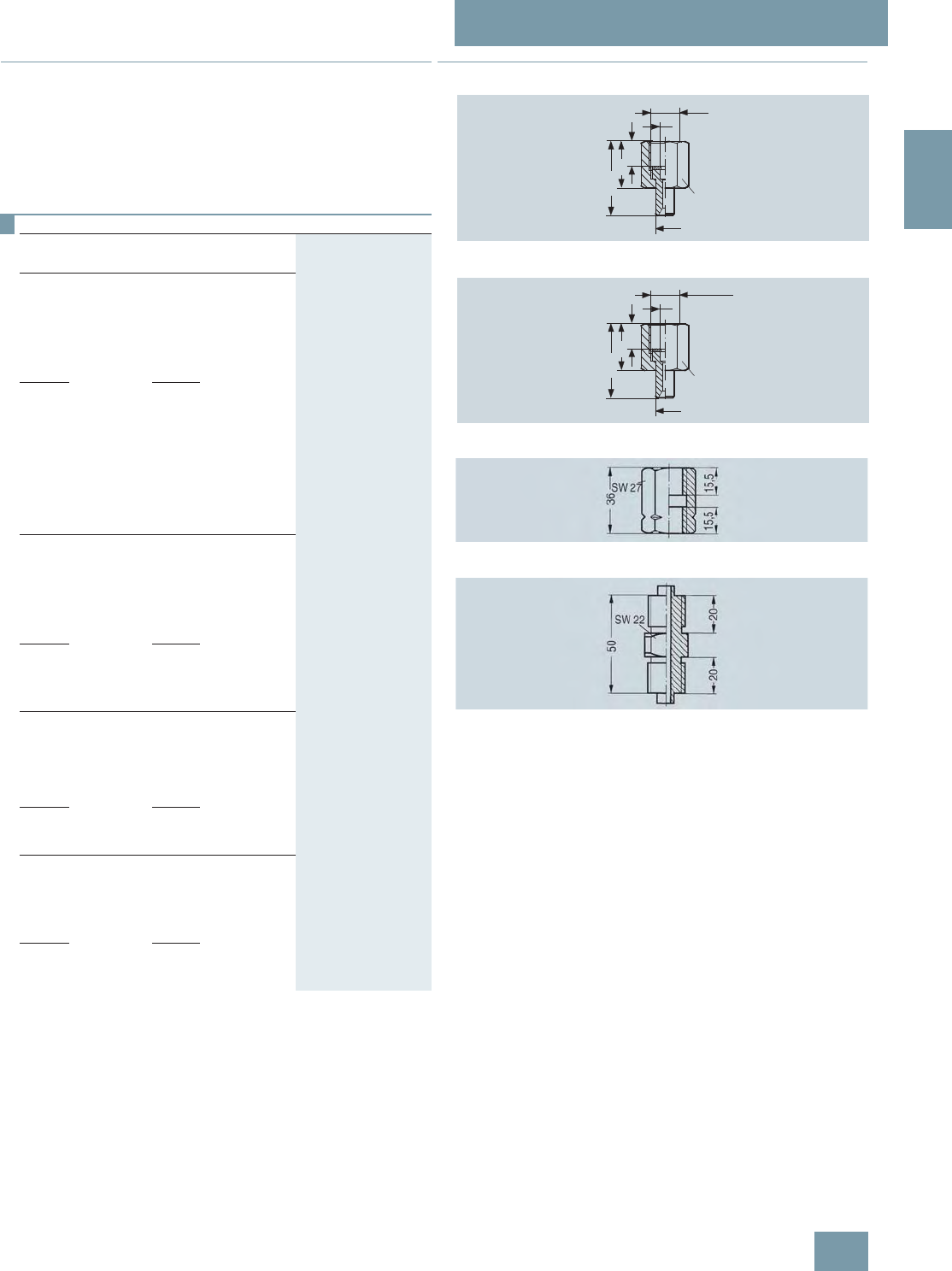
SITRANS P measuring instruments for pressure
Fittings - Accessories
Connection parts G 1/2
2/227
Siemens FI 01 · 2009
2
■
Overview
Connection parts G½ for pressure gages and shut-off fittings are
available in 3 versions:
• Nipple connection
• Clamping sleeve
• Collar connection piece
■
Dimensional drawings
Nipple connection (G) M56340-A0001 to -A0003, dimensions in mm
Nipple connection (M20 x 1.5) M56340-A0008, dimensions in mm
Clamping sleeve M56340-A0004/-A0005, dimensions in mm
Collar connection piece M56340-A0006/-A0007, dimensions in mm
Selection and Ordering data Order No.
Adapters G½
for pressure gages and shut-off fittings
Nipple connection
G½ to DIN 16284 (union nut with nipple and
gasket); max. working pressure 400 bar;
weight 0.1 kg;
connection: G½ to DIN EN 837-1;
Female thread G½
Material Mat. No.
CuZn39Pb3 CW 614N M56340-A0001
Union nut
9SMn28k
Nipple:
RSt 37-2
1.0715
1.0037
M56340-A0002
Union nut
X 8 CrNiS 18 9
Nipple:
X 6 CrNiMoTi 17 12 2
1.4305
1.4571/316Ti
M56340-A0003
Nipple connection
M20 x 1.5 to DIN 16284 (union nut with nipple
and gasket); max. working pressure 400 bar;
weight 0.1 kg;
connection: G½ to DIN EN 837-1;
Female thread G½
Material Mat. No.
Union nut
X 8 CrNiS 18 9
Nipple:
X 6 CrNiMoTi 17 12 2
1.4305
1.4571/316Ti
M56340-A0008
Clamping sleeve
G½ to DIN 16283; max. working pressure
400 bar; weight 0.1 kg;
Connections: G½ to DIN EN 837-1;
Female thread: G½ right-hand G½ left-hand
Material Mat. No.
CuZn39Pb3 CW614N M56340-A0004
9 SMn 28 k 1.0715 M56340-A0005
Collar-adapter
max. working pressure; weight 0.1 kg;
Connections: G½ to DIN EN 837-1;
Male thread: G½, G½
Material Mat. No.
CuZn39Pb3 CW614N M56340-A0006
9 SMn 28 k 1.0715 M56340-A0007
16
30
48
Ø 7
SW 27
Ø 12
G½
16
30
48
Ø 7
SW 27
Ø 14
M20 x 1,5
© Siemens AG 2008
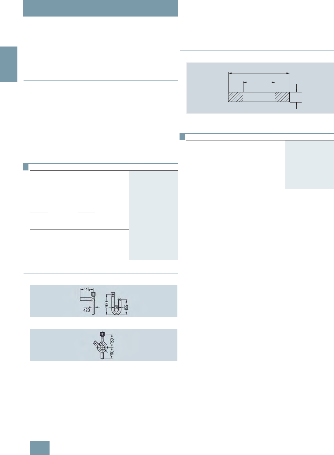
SITRANS P measuring instruments for pressure
Fittings - Accessories
Water traps, Sealing rings to EN 837-1
2/228 Siemens FI 01 · 2009
2
■
Overview
Water traps protect pressure gages and shut-off fittings from
heating up (e.g. by steam) by the water column produced by the
water trap.
The max. working temperature is 120 °C at 160 bar, 300 °C at
80 bar or 400 °C at 63 bar. If the temperature of the measured
medium is higher, a sufficiently long line has to be connected up-
stream of the trap to enable heat dissipation.
■
Design
The water traps are available in U shape (type B) or circular
shape (type D) to DIN 16282. They have a weld-on end
Ø 20 mm × 2.6 mm on the measurement side. The connection
on the device side is a clamping sleeve G½ to DIN 16283.
The water traps are made of steel (P250GH) or stainless steel
(X 6 CrNiMoTi 17 12 2)
Water traps are designed as standard for max. operating tem-
perature 120 °C at max. operating pressure 160 bar (300 °C at
80 bar, 400 °C at 63 bar). Water traps for higher operating pres-
sures and temperatures are available on request.
■
Dimensional drawings
Water traps, type B, M56340-A0043/-A0061, dimensions in mm
Water traps, type D, M56340-A0045/-A0063, dimensions in mm
■
Overview
The sealing rings to EN 837-1 are required to seal measuring in-
struments for pressure with the process connection G½B.
■
Dimensional drawings
Sealing ring 7MF9007-7A. to EN 837-1, dimensions in mm
F) Subject to export regulations AL: 9I999, ECCN: N.
Selection and Ordering data Order No.
Water traps
for pressure gages and pressure transmitters,
max. working temperature 120 °C,
max. working pressure 160 bar (or 400 °C
and 104 bar), weight 0.7 kg
Water trap B to DIN 16282
Material Mat. No.
P235GH 1.0345 M56340-A0043
X 6 CrNiMoTi 17 12 2 1.4571/316Ti M56340-A0061
Water trap D to DIN 16282
Material Mat. No.
P235GH 1.0345 M56340-A0045
X 6 CrNiMoTi 17 12 2 1.4571/316Ti M56340-A0063
Selection and Ordering data Order No.
Sealing ring to EN 837-1 for thread G½
made of
(packing unit 100 pcs)
• copper F) 7MF9007-7AA
• soft iron F) 7MF9007-7AB
• stainless steel, mat.-No. 1.4571 F) 7MF9007-7AC
• PTFE F) 7MF9007-7AD
© Siemens AG 2008
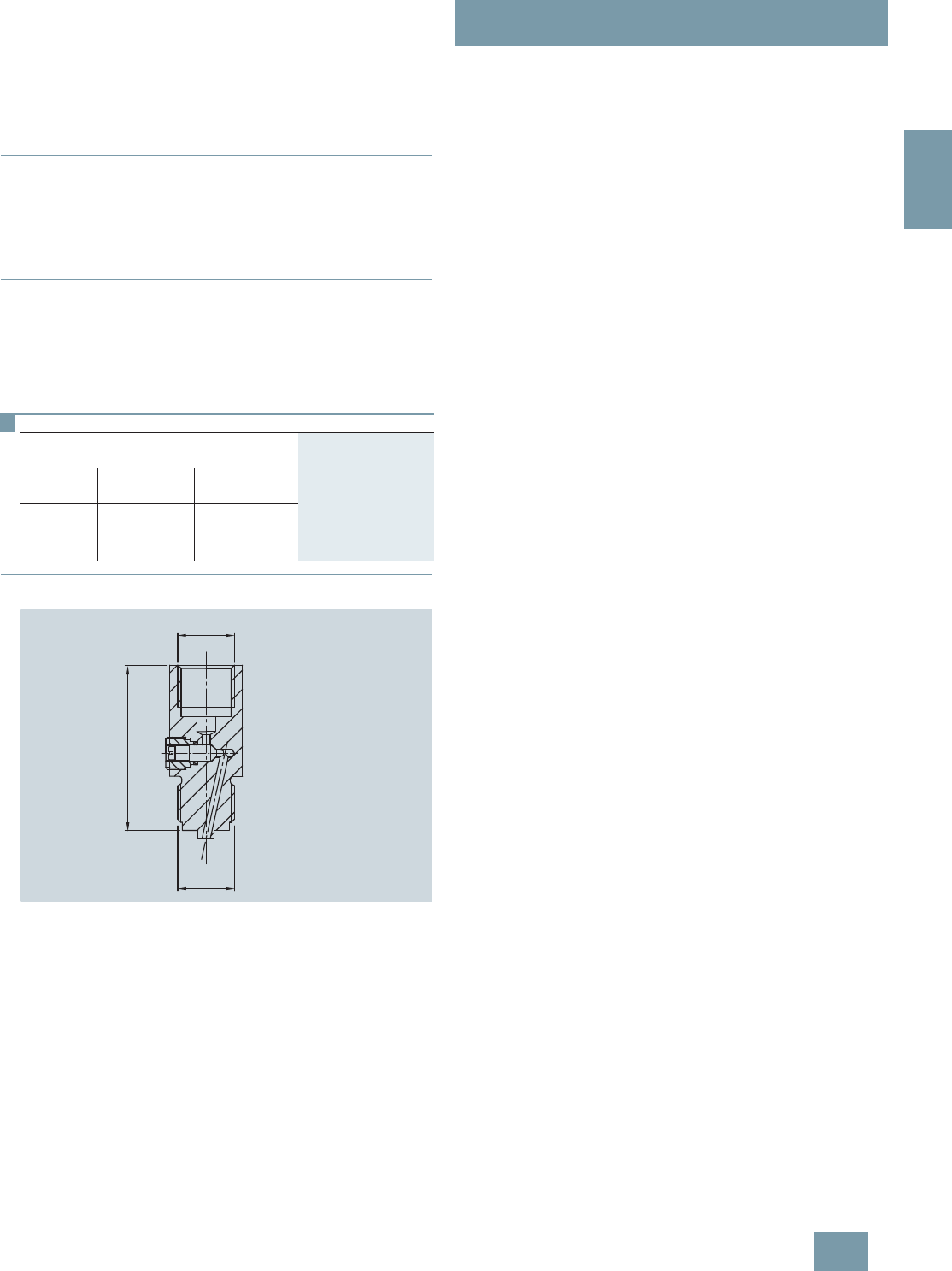
SITRANS P measuring instruments for pressure
Fittings - Accessories
Pressure surge reducers
2/229
Siemens FI 01 · 2009
2
■
Overview
The pressure surge reducer protects the pressure gage against
damage, premature wear and tear and inaccurate/fluctuating in-
dications.
■
Application
The pressure reducer is used when pulsations occur in the mea-
sured medium (e.g. in slow-running vapor engines, piston
pumps and compressors), or if drastic fluctuations are likely to
occur in the measured medium (e.g. in hydraulic presses and
tensile testing machines).
■
Design
• Enclosure made of brass or stainless steel
• Adjustable nozzle
• Sleeve for connection to the measuring instrument
• Pin for connection to supply lead
■
Dimensional drawings
Pressure surge reducer, dimensions in mm
Selection and Ordering data Order No.
Pressure surge reducer
Weight approx. 0,21 kg
Material Full-scale value Weight approx.
in kg
Brass 250 bar 0.21 M56340-A54
Stainless
steel 600 bar 0.21 M56340-A59
*®
6OHHYHIRUFRQQHFWLRQ
WRWKHSUHVVXUHGLVSOD\
3LQIRUFRQQHFWLRQ
WRVXSSO\OHDG
*®
© Siemens AG 2008
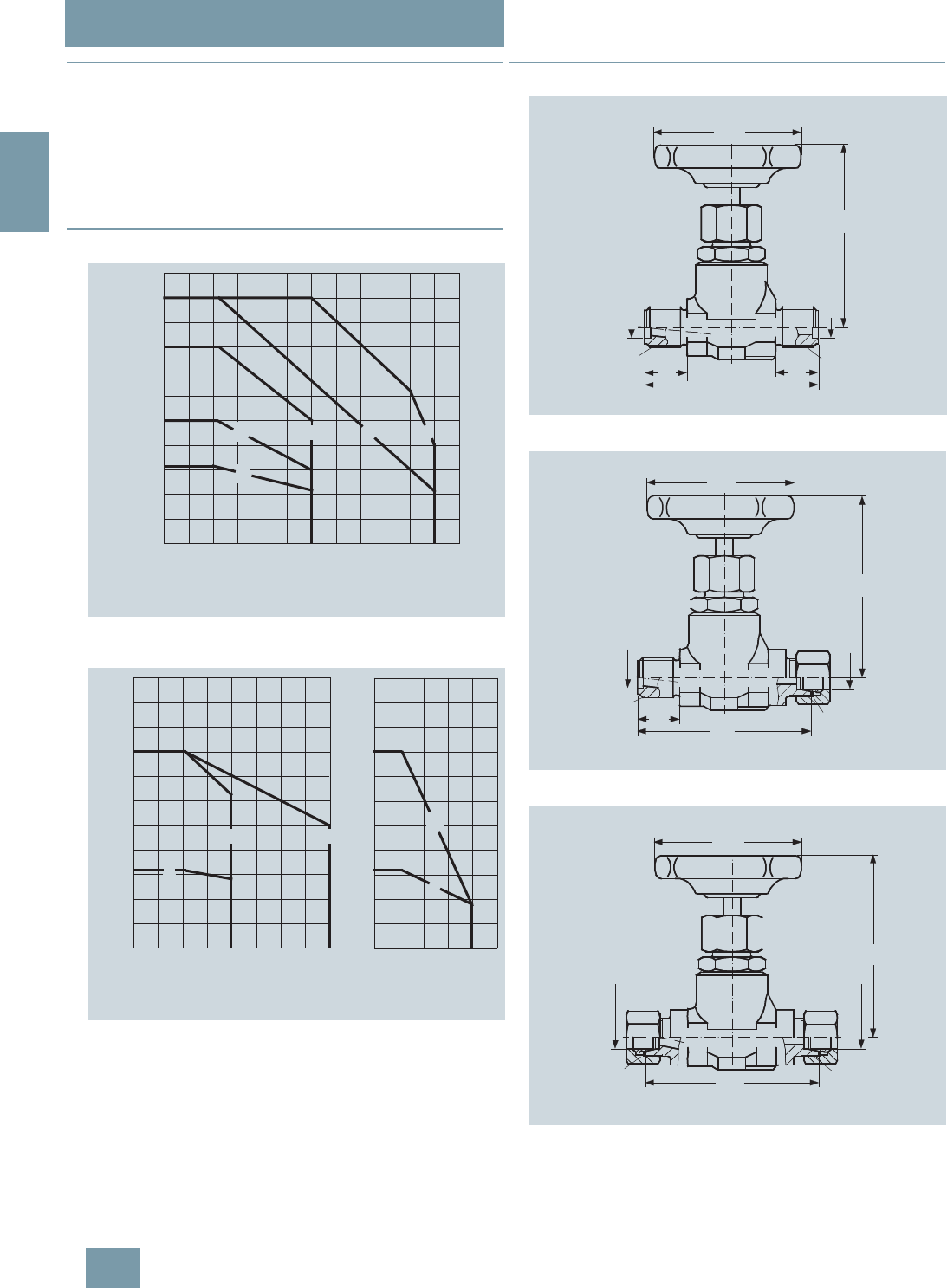
SITRANS P measuring instruments for pressure
Fittings - Accessories
Primary shut-off valves
2/230 Siemens FI 01 · 2009
2
■
Overview
Primary shut-off valves are available in the following versions:
• For non-corrosive liquids, gases and vapors
• For corrosive liquids and gases
• Grease-free for oxygen
The shut-off valves are available in various materials and with
various connections (see Selection and Ordering data)
■
Characteristic curves
Shut-off valve 7MF9017-1.., permissible working pressure as a function
of the permissible working temperature
Shut-off valve 7MF9017-2.. and -3.., permissible working pressure as a
function of the permissible working temperature
■
Dimensional drawings
Shut-off valve 7MF9017–1A., dimensions in mm
Shut-off valve 7MF9017-1B. and -2B., dimensions in mm
Shut-off valves 7MF9017-1C., -1D. and -2C., dimensions in mm
600 °C0100 200 300 400 500
0
100
200
300
400
500
bar
A
BCD E
Shut-off valve 7MF9017-1..
Operating temperature
Operating pressure
400 °C0100 200
0
100
200
300
400
500
bar
F
GH
300 0 100 200 °C
0
100
200
300
400
500
bar
J
K
Shut-off valve 7MF9017-2.. Shut-off valve 7MF9017-3..
Operating temperature
Operating pressure
95
G½
902222
G½
Ø11,2
Ø11,2
Ø80
95
M20x1,5
90
22
G½
Ø11,2
Ø80
Ø11,2
95
M20x1,5
(M22x1,5)
M20x1,5
(M22x1,5) 90
Ø80
Ø12 (Ø14)
Ø12 (Ø14)
© Siemens AG 2008
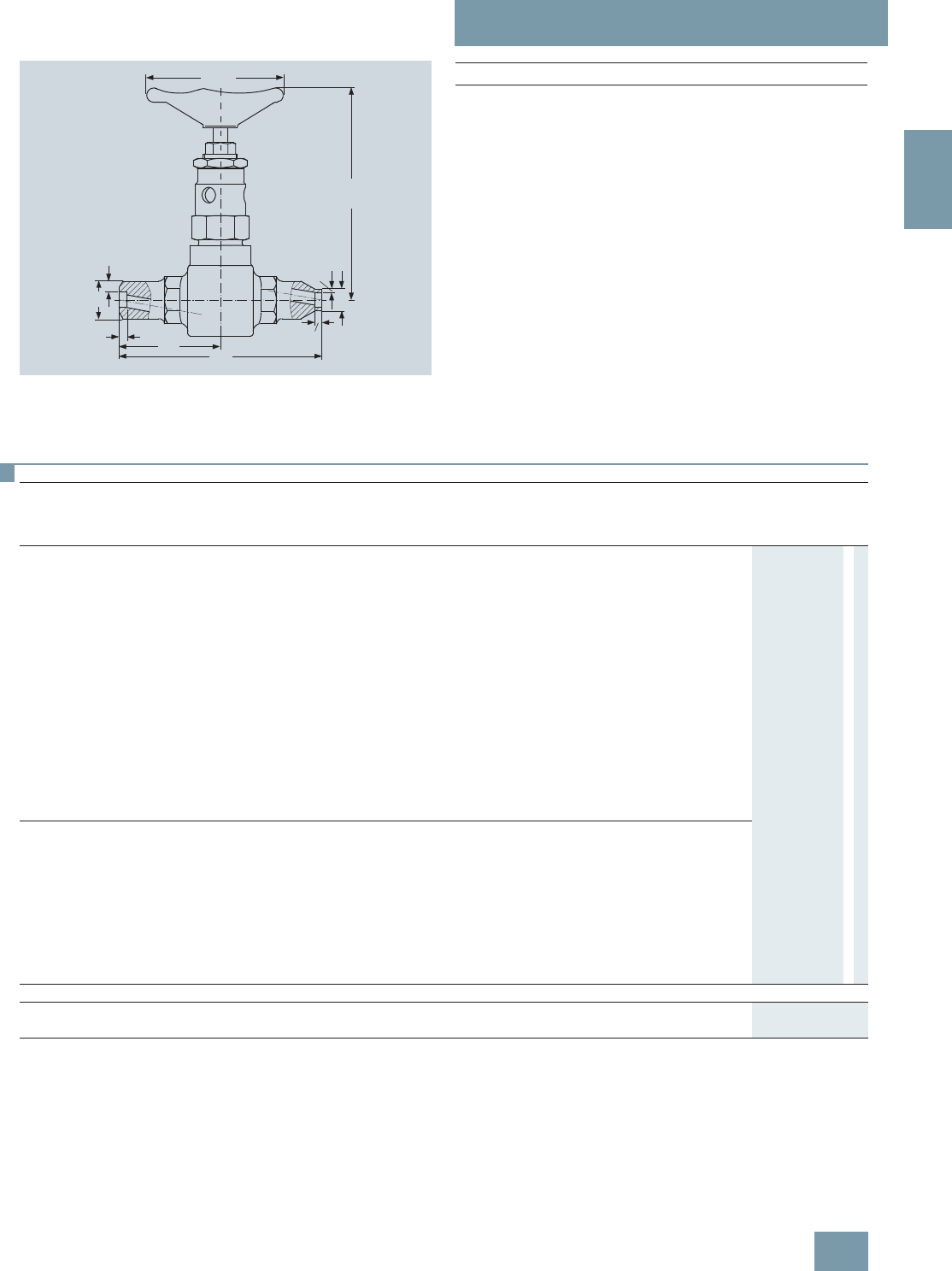
SITRANS P measuring instruments for pressure
Fittings - Accessories
Primary shut-off valves
2/231
Siemens FI 01 · 2009
2
Shut-off valves 7MF9017-, dimensions in mm
Ø120
Øa
Ø14
2,5
141
b
565 130
4,5
Ø A x b 7MF9017-
14 mm x 2.5 mm 1F. and 1G.
21.3 mm x 6.3 mm 1H. and 2H.
24 mm x 7.1 mm 1J., 1K. and 2J.
Selection and Ordering data
Primary shut-off valves, without certificate
Max.
working
pressure
Charac-
teristic1) Material Mat. No. Spindle
thread Connections Approx.
weight kg Order No.
Shut-off valve for non-aggressive liquids, gases and vapors 7 M F 9 0 1 7 - 1 7A
160 bar A P250GH 1.0460 Internal Threaded socket G½ form R, DIN 19207 0.8 A
160 bar AP250GH 1.0460 Internal Threaded socket G½ form R, DIN 19207
DIN 19207 and pipe union
with ferrule for pipe ∅ 12 mm, S series
0.8 B
400 bar CP250GH 1.0460 Internal Pipe union with ferrule
for pipe ∅ 12 mm, S series 1C
400 bar CP250GH 1.0460 Internal Pipe union with ferrule
for pipe ∅ 14 mm, S series 1D
500 bar D16 Mo 3 1.5415 External Welding sleeves ∅ 14 mm × 2.5 mm 1.6 F
500 bar E11 CrMo 9 10 1.7383 External Welding sleeves ∅ 14 mm × 2.5 mm 1.6 G
500 bar D16 Mo 3 1.5415 External Welding sleeves ∅ 21.3 mm × 6.3 mm
and ∅ 14 mm × 2.5 mm 1.6 H
500 bar D16 Mo 3 1.5415 External Welding sleeves ∅ 24 mm × 7.1 mm
and ∅ 14 mm × 2.5 mm 1.6 J
500 bar E11 CrMo 9 10 1.7383 External Welding sleeves ∅ 24 mm × 7.1 mm
and ∅ 14 mm × 2.5 mm 1.6 K
Shut-off valve for aggressive liquids and gases 7 M F 9 0 1 7 - 2 7A
160 bar F X 6 CrNiMoTi 17 12 2 1.4571/
316Ti Internal Threaded socket G½ form R, DIN 19207
DIN 19207 and pipe union
with ferrule for pipe ∅ 12 mm, S series
0.8 B
400 bar GX 6 CrNiMoTi 17 12 2 1.4571/
316Ti Internal Pipe union with ferrule
for pipe ∅ 12 mm, S series 1C
400 bar HX 6 CrNiMoTi 17 12 2 1.4571/
316Ti External Welding sleeves ∅ 21.3 mm × 6.3 mm
and ∅ 14 mm × 2.5 mm 1.6 H
400 bar HX 6 CrNiMoTi 17 12 2 1.4571/
316Ti External Welding sleeves ∅ 24 mm × 7.1 mm
and ∅ 14 mm × 2.5 mm 1.6 J
Accessories
Factory test certificate EN 10204–2.2 7MF9000-8AB
Material acceptance test certificate EN 10204-3.1 7MF9000-8AD
1) See Figure "Permissible working pressure as a function of the permissible working temperature"
© Siemens AG 2008
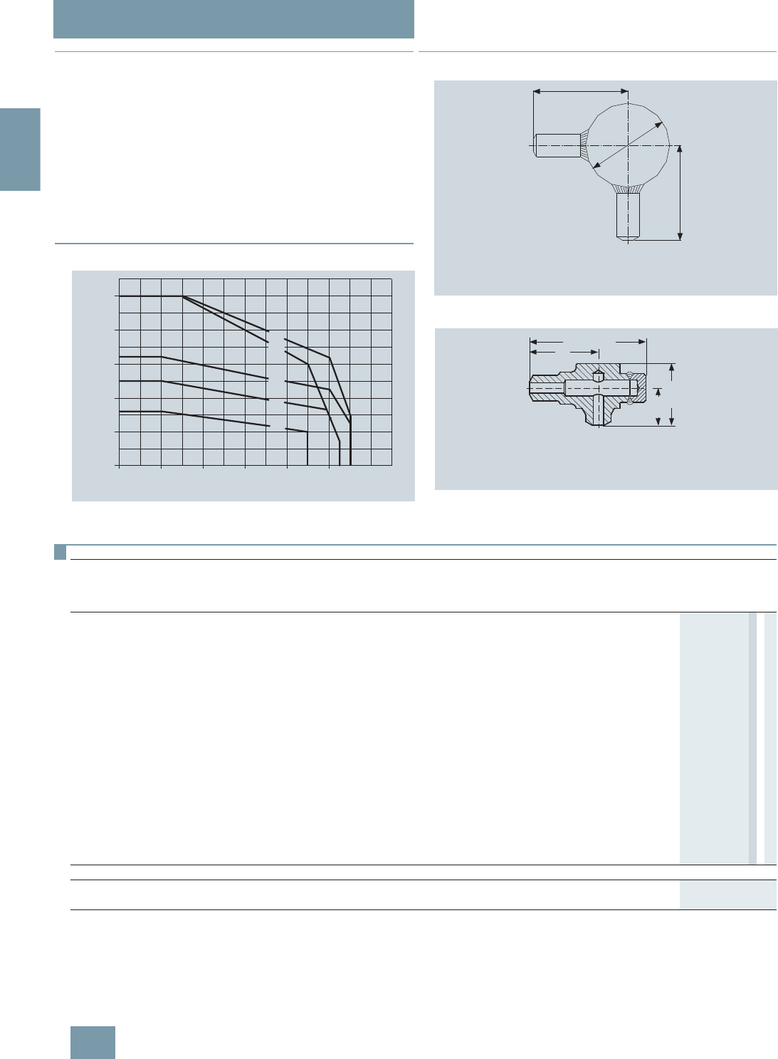
SITRANS P measuring instruments for pressure
Fittings - Accessories
Compensation vessels
2/232 Siemens FI 01 · 2009
2
■
Overview
The compensation vessels prevent the level difference which oc-
curs with pressure changes in the pressure lines and which fal-
sifies the measurement.
According to DIN 19211, the temperature in the compensation
vessel must be assumed to be 50 K less than the steam temper-
ature in the pipe when calculating the wall thicknesses. This is
because the temperature in the compensation vessel during op-
eration can only rise up to the saturated steam temperature.
A material acceptance test certificate A to EN 10204-3.1 is avail-
able for the materials from which the compensation vessels are
made.
■
Characteristic curves
Permissible operating pressure as a function of the permissible operating
temperature
■
Dimensional drawings
Compensation vessel 7MF9015-1.., dimensions in mm
Compensation vessel 7MF9015-5.., dimensions in mm
0
100
200
300
400
bar
°C0100 200 300 400
500
500 600
E
D
C
B
A
Operating pressure
Operating temperature
100
88,9
100
I
O
O Output (see Ordering data for dimensions)
I Input (see Ordering data for dimensions)
65
35
1
)
58
1
)
I
O
approx. 110
I Input (see Ordering data for dimensions)
O Output (see Ordering data for dimensions)
1
) 30 mm longer with 7MF9015-5A.
Selection and Ordering data
Compensation vessel, without certificate
Max.
working
pressure
Characteristic1)Material Mat. No. Connections Approx.
contents
cm³
Approx.
weight
kg
Order No.
Input Output
7 M F 9 0 1 5 - 7 7 A
160 bar A 16 Mo 3 1.5415 Threaded socket G½,
form R, DIN 19207 Threaded socket G½,
form V, DIN 19207 250 0.8 1 A
250 bar B16 Mo 3 1.5415 Welding sleeve
∅ 21 mm × 6.3 mm Welding sleeve
∅ 21.3 mm × 6.3 mm 250 0.8 1 B
250 bar B16 Mo 3 1.5415 Welding sleeve
∅ 24 mm × 7.1 mm Welding sleeve
∅ 24 mm × 7.1 mm 250 11 C
250 bar C11 CrMo 9 10 1.7383 Welding sleeve
∅ 24 mm × 7.1 mm Welding sleeve
∅ 24 mm × 7.1 mm 250 11 D
250 bar B16 Mo 3 1.5415 Welding sleeve
∅ 33.7 mm × 4.5 mm Welding sleeve
∅ 24 mm × 7.1 mm 250 0.7 1 E
160 bar A16 Mo 3 1.5415 Threaded socket G½,
form R, DIN 19207 Threaded socket G½,
form V, DIN 19207 20 1.6 5 A
500 bar D16 Mo 3 1.5415 Welding sleeve
∅ 21 mm × 6.3 mm Welding sleeve
∅ 21.3 mm × 6.3 mm 20 1.6 5 B
500 bar D16 Mo 3 1.5415 Welding sleeve
∅ 24 mm × 7.1 mm Welding sleeve
∅ 24 mm × 7.1 mm 20 1.6 5 C
500 bar E11 CrMo 9 10 1.7383 Welding sleeve
∅ 24 mm × 7.1 mm Welding sleeve
∅ 24 mm × 7.1 mm 20 1.6 5 D
Accessories
Factory test certificate EN 10204–2.2 7MF9000-8AB
Material acceptance test certificate EN 10204-3.1 7MF9000-8AD
1) See Figure "Permissible working pressure as a function of the permissible working temperature"
© Siemens AG 2008
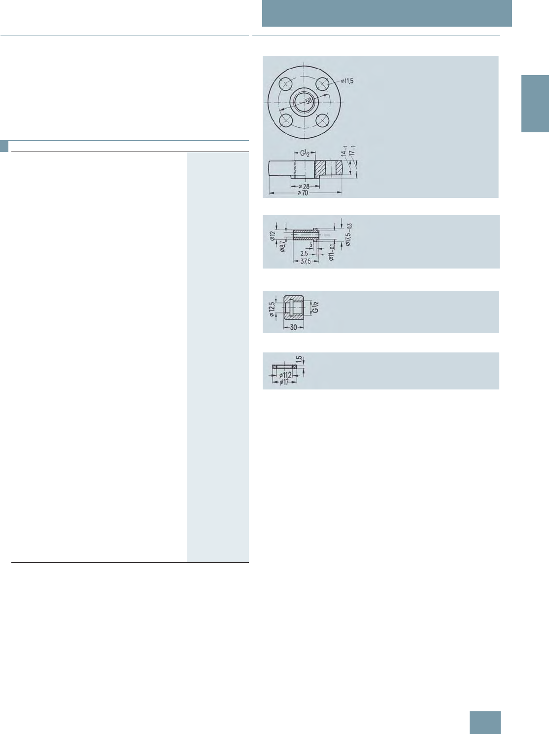
SITRANS P measuring instruments for pressure
Fittings - Accessories
Connection parts
2/233
Siemens FI 01 · 2009
2
■
Overview
Connection parts are available in the following versions:
• Threaded flange pair G½ with stainless steel gasket
• Nipple G½ form V to DIN 19207
• Union nut G½ made of C 35 to DIN 16284
• Gasket B½ (grooved) to DIN 19207
All connection parts are also available grease-free for oxygen.
F) Subject to export regulations AL: 9I999, ECCN: N.
■
Dimensional drawings
Threaded flange 7MF9007-4CA/-4DA, dimensions in mm
Nipple G½ 7MF9007-4KA/-4LA, dimensions in mm
Union nut G½ 7MF9007-4MA/-4NA, dimensions in mm
Gasket 7MF9007-6BA/-6CA, dimensions in mm
7
Selection and Ordering data Order No.
Threaded flange pair G½
• with stainless steel gasket 7MF9007-4CA
• grease-free for oxygen, with stainless
steel gasket 7MF9007-4DA
Scope of delivery:
2x threaded flanges G½ to DIN 19207; material:
P250GH (mat. No. 1.0460)
4x hexagon screws M10x45 to DIN EN 24014;
Material: C35E (mat. No. 1.1181)
4x hexagon screws M10x50 to DIN EN 24032
1x gasket G½ (7MF9007-6BA) grooved,
to DIN 19207;
Material: X 6 CrNiMoTi 17 12 2
(mat. No. 14571/316Ti)
Only for 7MF9007-4CA!
1x gasket G½ (7MF9k007-6CA), grease-free for
oxygen, grooved, to DIN 19207;
Material: X 6 CrNiMoTi 17 12 2
(mat. No. 14571/316Ti)
Only for 7MF9007-4DA!
Nipple G½
to DIN 19207
• Material: 16 Mo 3 (mat. No. 1.5415) 7MF9007-4KA
• grease-free for oxygen,
Material: X 6 CrNiMoTi 17 12 2
(mat. No. 1.4571/316Ti)
7MF9007-4LA
Union nut G½
to DIN 16284
• Material: C35E (mat. No. 1.1181) 7MF9007-4MA
• grease-free for oxygen,
Material: X 6 CrNiMoTi 17 12 2
(mat. No. 1.4571/316Ti)
7MF9007-4NA
Gasket G½
to DIN 19207, grooved
• Material: X 6 CrNiMoTi 17 12 2
(mat. No. 1.4571/316Ti)
F) 7MF9007-6BA
• grease-free for oxygen,
Material: X 6 CrNiMoTi 17 12 2
(mat. No. 1.4571/316Ti)
F) 7MF9007-6CA
© Siemens AG 2008

SITRANS P measuring instruments for pressure
2/234 Siemens FI 01 · 2009
2
© Siemens AG 2008
