Siemens Welding System St Pcs 7 Users Manual SIMATIC Process Control
ST PCS 7 to the manual 999d0011-6fa0-44e9-b5d4-cf09cd146107
2015-02-05
: Siemens Siemens-Welding-System-St-Pcs-7-Users-Manual-410671 siemens-welding-system-st-pcs-7-users-manual-410671 siemens pdf
Open the PDF directly: View PDF ![]() .
.
Page Count: 344 [warning: Documents this large are best viewed by clicking the View PDF Link!]
- Catalog ST PCS 7
- Contents
- 1 Introduction
- 2 System-neutral components
- 3 Starter systems
- 4 Engineering System
- 5 Operator System
- 6 Batch automation
- 7 SIMATIC Route Control
- 8 Asset Management
- 9 Communication
- 10 Automation systems
- 11 Process I/O
- 12 IT world
- 13 Migration to PCS 7
- 14 Ordering data for previous version SIMATIC PCS 7 V6.1
- 15 Update/upgrade packages
- 16 Appendix
simatic
SIMATIC PCS 7
Process Control System
Catalog ST PCS 7 · November 2007
© Siemens AG 2007
Related catalogs
SIMATIC
Add-ons for the SIMATIC PCS 7
Process Control System
Only PDF:
(E86060-K4678-A121-A6-7600)
ST PCS 7.1
SIMATIC
Migration solutions with the
SIMATIC PCS 7
Process Control System
Order no.:
E86060-K4678-A131-A3-7600
ST PCS 7.2
SIMATIC
Products for Totally Integrated
Automation and Micro Automation
Order no.:
E86060-K4670-A101-B1-7600
E86060-K4670-A151-A3-7600 (News)
ST 70
SIMATIC HMI
Human Machine Interface
Systems
Order no.:
E86060-K4680-A101-B5-7600
ST 80
Industrial Communication
Industrial Communication for
Automation and Drives
Order no.:
E86060-K6710-A101-B5-7600
E86060-K6710-A121-A2-7600 (News)
IK PI
TELEPERM M
AS 488/TM
Automation Systems
Only PDF:
(E86060-W3812-A100-A3-7600)
PLT 112
Field Instruments
for Process Automation
Order no.:
E86060-K6201-A101-A9-7600
FI 01
Training for Automation and ITC
Industrial Solutions
Order no.:
E86060-K6850-E101-B8 (in German)
I
T
C
Catalog CA 01
the Offline Mall of
Automation and Drives
Order no.:
E86060-D4001-A100-C6 (CD-ROM)
E86060-D4001-A500-C6 (DVD)
A&D Mall
Internet:
www.siemens.com/automation/mall
© Siemens AG 2007
s
Supersedes:
Catalog ST PCS 7 · March 2007
The products contained in this catalog
can also be found in the e-Catalog CA 01
Order No.:
E86060-D4001-A110-C6-7600 (CD-ROM)
E86060-D4001-A510-C6-7600 (DVD)
Please contact
your local
Siemens branch
© Siemens AG 2007
SIMATIC PCS 7
Process Control System
Version 7.0
Catalog ST PCS 7 ·
October 2007
Introduction 1
System-neutral components 2
Starter systems 3
Engineering system 4
Operator system 5
Batch automation 6
SIMATIC Route Control 7
Asset Management 8
Communication 9
Automation systems 10
Process I/O 11
IT world 12
Migration to SIMATIC PCS 7 13
Ordering data for previous version
SIMATIC PCS 7 V6.1 14
Update/upgrade packages 15
Appendix 16
The products and sys-
tems described in this
catalog are manufac-
tured/distributed under
application of a certified
quality management
system in accordance
with DIN EN ISO 9001
(Certified Registration
No. 1323-QM). The cer-
tificate is recognized by
all IQNet countries.
© Siemens AG 2007
1/2 Siemens ST PCS 7 · November 2007
Siemens Automation and Drives.
Welcome
More than 70,000 people aiming for the same goal:
increasing your competitiveness. That's Siemens
Automation and Drives.
We offer you a comprehensive portfolio for sustained
success in your sector, whether you're talking automa-
tion engineering, drives or electrical installation sys-
tems. Totally Integrated Automation (TIA) and Totally
Integrated Power (TIP) form the core of our offering.
TIA and TIP are the basis of our integrated range of
products and systems for the manufacturing and process
industries as well as building automation. This portfolio
is rounded off by innovative services over the entire life
cycle of your plants.
Learn for yourself the potential our products and
systems offer. And discover how you can permanently
increase your productivity with us.
Your regional Siemens contact can provide more infor-
mation. He or she will be glad to help.
© Siemens AG 2007

1/3
Siemens ST PCS 7 · November 2007
© Siemens AG 2007
SIMATIC Sensors
AS-Interface
Totally
Integrated
Automation
Field Level
Control Level
Operations Level
Management Level
Ethernet
ERP Enterprise Resource Planning
MES Manufacturing Execution Systems
Ethernet
SIMATIC PCS 7
Process Control (DCS)
Maintenance
Modernization
and Upgrade
Industrial Software for
Design and Engineering
Installation and Commissioning
Operation
SINUMERIK
Computer Numeric Control SIMOTION
Motion Control System
PROFIBUS PA
Process Instrumentation
HART
PROFIBUS
Industrial Ethernet
PROFINET
HART
1/4 Siemens ST PCS 7 · November 2007
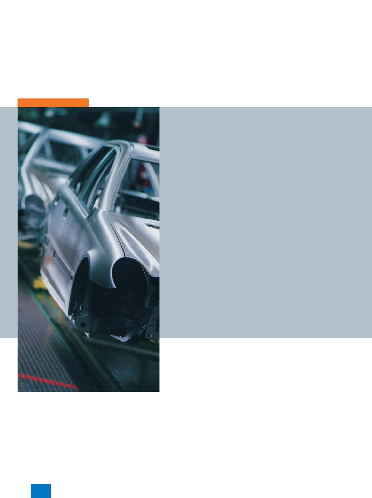
Sharpen your competitive edge.
Totally Integrated Automation
With Totally Integrated Automation (TIA), Siemens is the only
manufacturer to offer an integrated range of products and sys-
tems for automation in all sectors - from incoming goods to out-
going goods, from the field level through the production control
level to connection with the corporate management level.
On the basis of TIA, we implement solutions that are perfectly
tailored to your specific requirements and are characterized by a
unique level of integration. This integration not only ensures sig-
nificant reductions in interface costs but also guarantees the
highest level of transparency across all levels.
© Siemens AG 2007
GAMMA instabus
KNX/ EIB
SIMATIC IT
SIMATIC WinCC
SCADA System
SIMATIC NET
Industrial
Communication
SIMATIC Controllers
Modular/Embedded/PC-based SIMATIC HMI
Human Machine Interface Safety Integrated
SIRIUS Industrial Controls
SENTRON Switching Devices
SIMOCODE pro
Motor Management System
SIMATIC Distributed I/O SINAMICS Drive Systems
Totally
Integrated
Power
AS-Interface
1/5
Siemens ST PCS 7 · November 2007
It goes without saying that you profit from Totally Integrated
Automation during the entire life cycle of your plants - from the
first planning steps, through operation, right up to moderniza-
tion. Consistent integration in the further development of our
products and systems guarantees a high degree of investment
security here.
Totally Integrated Automation makes a crucial contribution
towards optimizing everything that happens in the plant and
thus creates the conditions for a significant increase in produc-
tivity.
© Siemens AG 2007
PROCESS FIELD BUS
U
I
cos o
P
W
£ 110 kV
U
I
cos o
P
W
Planning
and configuration
Products and systems
Communication
Process/production
automation
Load
manage-
ment
HMI Graphs Prognoses
Planning
and configuration
Products and systems
Communication
Process/production
automation
Load
manage-
ment
HMI Graphs Prognoses
1/6 Siemens ST PCS 7 · November 2007
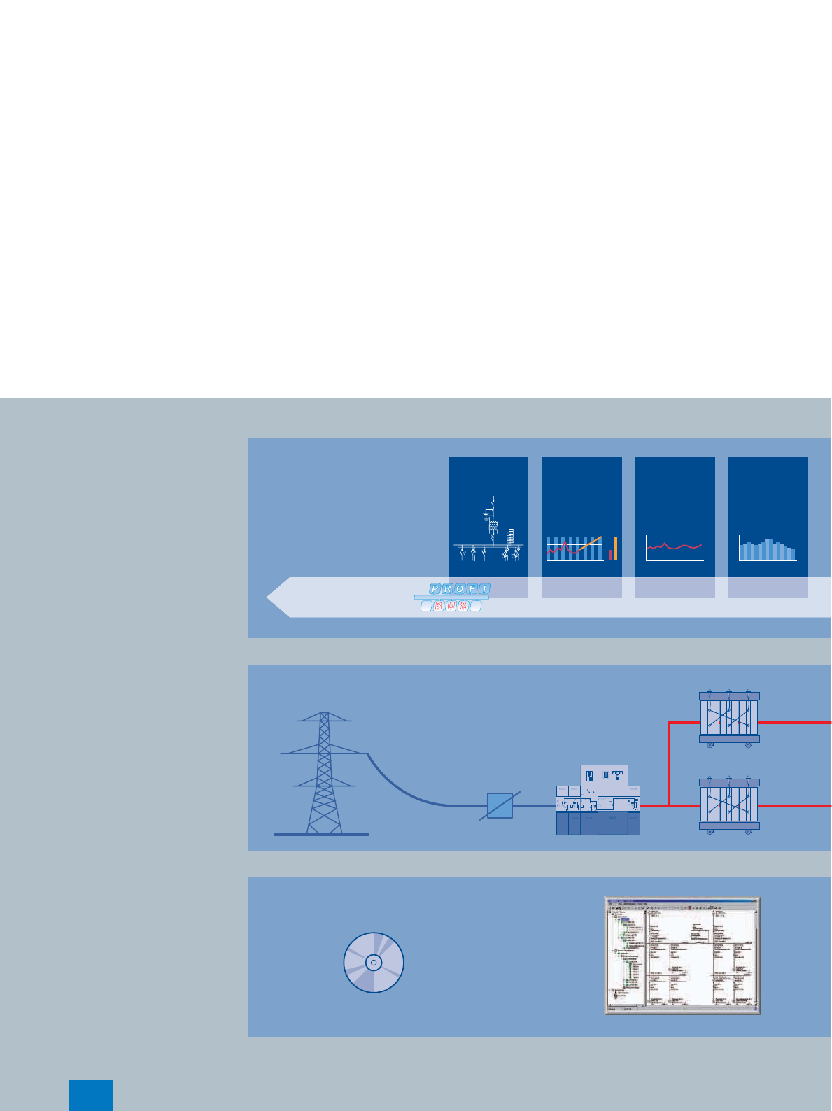
Integrated energy distribution from a single source.
Totally Integrated Power
Totally Integrated Power (TIP) brings together all the components
of electrical energy distribution into an integrated whole. Thus TIP
provides the answer to growing market demands in the planning,
construction and use of utility buildings and industrial buildings.
On the basis of TIP, we offer integrated solutions for energy distri-
bution, from medium voltage to the power outlet. Totally Inte-
grated Power is based here on integration in planning and config-
uring as well as on perfectly matched products and systems.
© Siemens AG 2007
CODES
V=VACATION
H=HOLIDAY
S=SICK
REGULAR HOLIDAY OTHER
OVER THE HOURS
TIME & ONE-HALF SICK VACATION
TOTAL HOURS
DATE
IN
OUT
IN
OUT
OVERTIME
SUN MON TUE WED THUR FRI SAT SUN TOTAL
TOTAL HOURS
DATE
IN
OUT
IN
OUT
OVERTIME
SUN MON TUE WED THUR FRI SAT SUN TOTAL
TOTAL HOURS
DATE
IN
OUT
IN
OUT
OVERTIME
SUN MON TUE WED THUR FRI SAT SUN TOTAL
DATE:
EMPLOYEE
COST CENTER
PAY PERIOD BEGINNING
PAY PERIOD ENDING
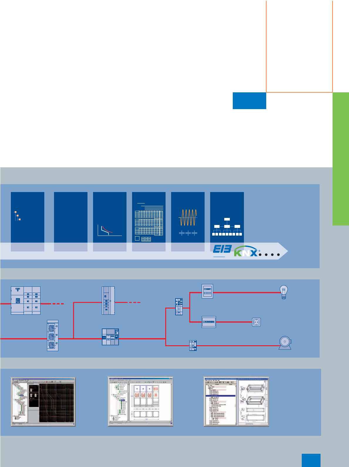
instabus EIB
Message/
error
manage-
ment
Selective
protection
Main-
tenance Protocols Power
quality Cost center
Building
automation
Substation
Distribution
Maintenance
task
Hall 1 Air conditioning system
checkup
Distribution 3 Replacing circuit
breaker contacts
Infeed II Replacing meters
Message/
error
manage-
ment
Selective
protection
Main-
tenance Protocols Power
quality Cost center
Building
automation
Substation
Distribution
Maintenance
task
Hall 1 Air conditioning system
checkup
Distribution 3 Replacing circuit
breaker contacts
Infeed II Replacing meters
1/7
Siemens ST PCS 7 · November 2007
Totally Integrated Power offers communication
and software modules for connecting the energy
distribution systems to industrial automation and
building automation. This enables the implemen-
tation of significant savings potential.
© Siemens AG 2007

1/8 Siemens ST PCS 7 · November 2007
Protecting the environment
and resources.
Environmental sustainability
Environmental protection will continue to grow in importance
as a result of progressive urbanization and global population
growth. These global mega-trends make the careful and sus-
tainable handling of natural resources a central challenge.
We are convinced that every individual - and especially
every company - has an ecological responsibility. At Siemens
Automation and Drives, we stand by this conviction. Our high
environmental protection goals are part of our strict environ-
mental management. We investigate the possible effects of our
products and systems on the environment right back at the de-
velopment stage. We concern ourselves, for example, with the
question of how to reduce power consumption in plant
operation - and we offer appropriate solutions, such as our
energy-saving motors that cut power consumption in industrial
manufacturing by up to 40% thanks to their high efficiency
levels.
Our products and systems comply with the EC Directive
RoHS (Restriction of Hazardous Substances). All the relevant
Siemens AG sites are, of course, certified in accordance with
DIN EN ISO 14001.
Our commitment goes well beyond compliance with the rele-
vant directives and legislation: we are an active driving force
behind environmental protection, through further develop-
ment of environmental management systems, for example,
and we are involved in professional associations such as the
German Electrical and Electronic Manufacturers Association
(ZVEI).
© Siemens AG 2007

1/9
Siemens ST PCS 7 · November 2007
© Siemens AG 2007
Introduction
System architecture
SIMATIC PCS 7 V7.0
1/10 Siemens ST PCS 7 · November 2007
■
Overview
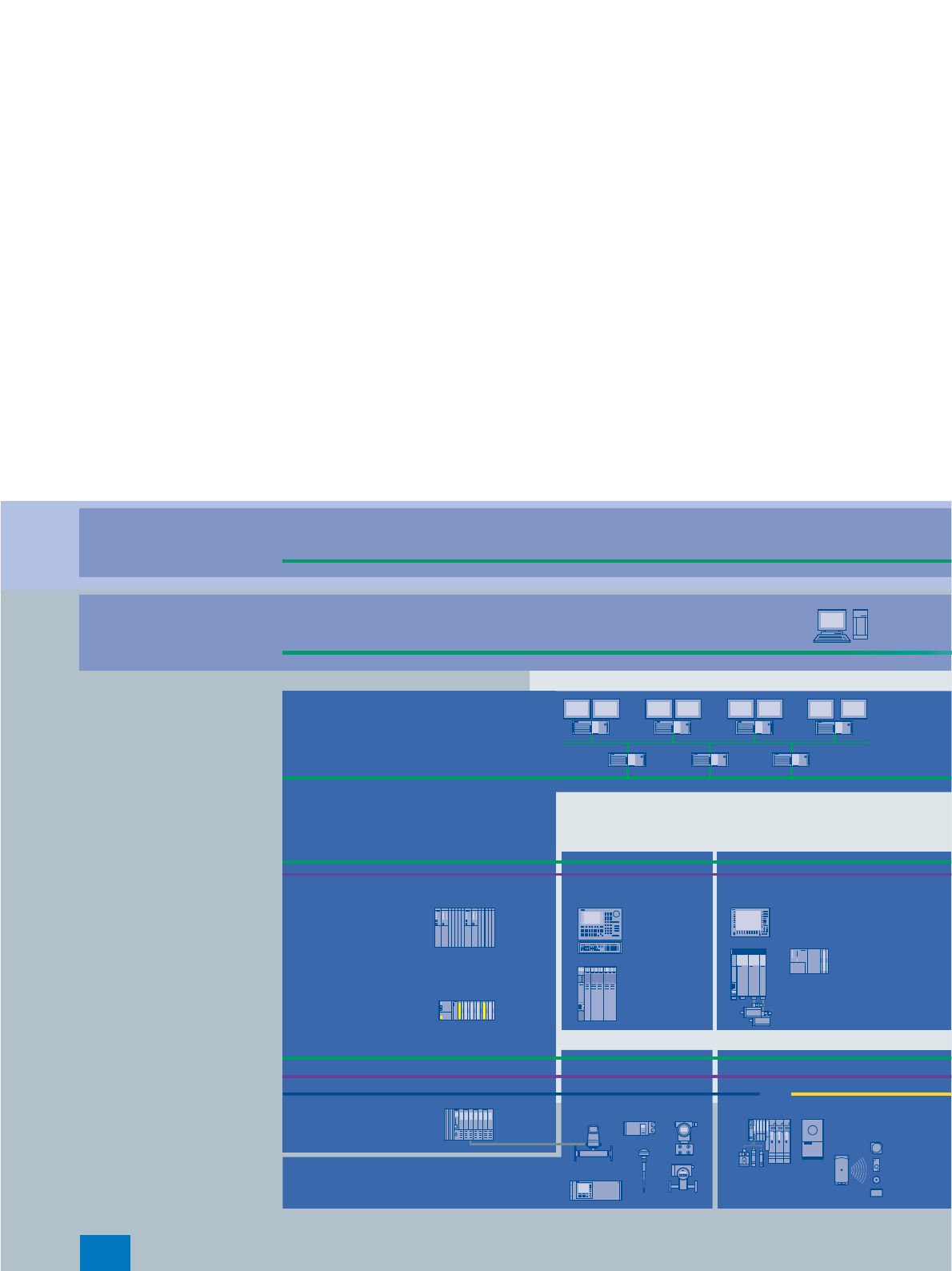
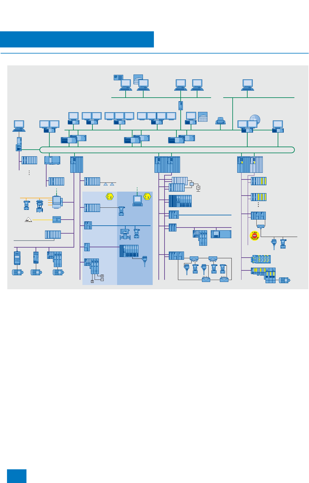
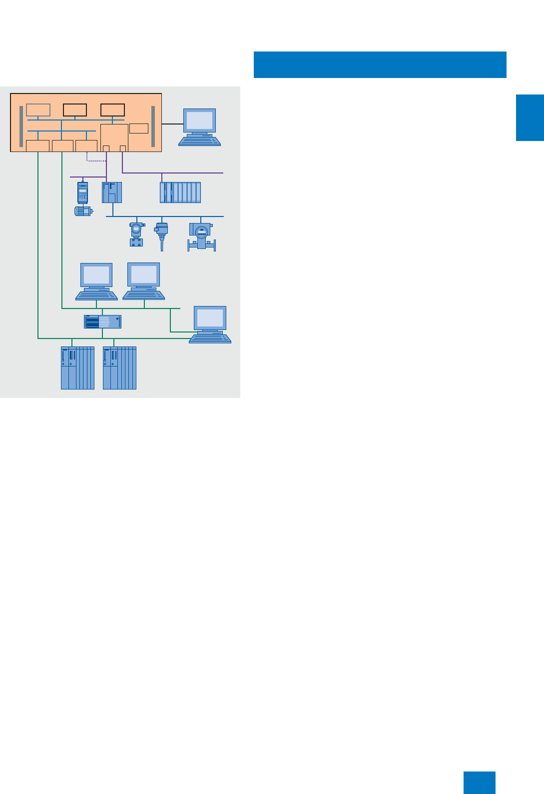
SIMATIC PCS 7 system configuration
Totally Integrated Automation with SIMATIC PCS 7
The SIMATIC PCS 7 process control system is a significant com-
ponent of Totally Integrated Automation (TIA), the unique basis
offered by Siemens for uniform and customized automation in all
sectors of the production, process and hybrid industries. Using
TIA, Siemens is the only company able to offer uniform automa-
tion technology on one single platform for all applications of pro-
cess automation, starting with input logistics, covering produc-
tion or primary processes as well as downstream (secondary)
processes, up to output logistics. This is suitable for optimization
of all operating sequences of an entire company, i.e. from the
ERP (Enterprise Resource Planning) level and MES (Manage-
ment Execution System) level to the control level, right down to
the field level.
Integrated in a holistic automation solution for a production site,
automation of the primary processes is the prime task of SI-
MATIC PCS 7. On the other hand, secondary processes (e.g. fill-
ing, packaging) or input/output logistics (e.g. raw material distri-
bution, storage) are frequently implemented using the PLC-
based or PC-based components of SIMATIC.
The advantages of Totally Integrated Automation, in particular
the uniform data management, communication and configura-
tion, are already evident during planning and engineering, but
also during installation and commissioning, everyday operation
as well as maintenance, repairs and modernization.
Uniform data management means that all software components
access a common database. Within a project, inputs and modi-
fications are therefore only necessary at one point. This reduces
the work required, and simultaneously avoids potential faults.
Once symbolic identifications have been introduced, they are
understood by every software component. Data consistency is
also guaranteed even if several persons are working simulta-
neously on a project. Parameters defined in the engineering sys-
tem can be transferred beyond the network limits down to sen-
sors, actuators or drives in the field.
Uniform communication from the corporate management level
down to the field level is based on internationally recognized
standards such as Industrial Ethernet or PROFIBUS, and also
supports the global flow of information via the Internet. Since the
hardware and software components involved also use these
communications mechanisms, connections are extremely easy
to configure, also cross-system or over different networks.
The use of an engineering system with a uniform and matched
range of tools minimizes the configuration overhead. The engi-
neering tools for the application software, the hardware compo-
nents and the communications functions can be called from a
central project manager (SIMATIC Manager). This is also the ba-
sic application for creation, management, saving and documen-
tation of a project.
Compatibility of further developments is guaranteed within TIA.
This also guarantees that the company’s investments have a se-
cure future, and allows the company to modernize and expand
the plants throughout the complete lifecycle.
INTERNET
INTERNET
DP/FF Link
FF-H1
SAP
SIMATIC
PCS 7 BOX
PROFIBUS PA
PROFIBUS DP
PROFIBUS DP
PROFIBUS DP
ET 200M
Ethernet
SIMATIC IT
ET 200S
ET 200pro
PROFIBUS PA
ET 200iSP
MTA
COx, NOx
SIMATIC
PCS 7
AS RTX
PROFIBUS PA
ET 200M
PROFIBUS DP
PROFIBUS PA
ET 200iSP
HART
ET 200S
ET 200M
Office LAN (Ethernet)
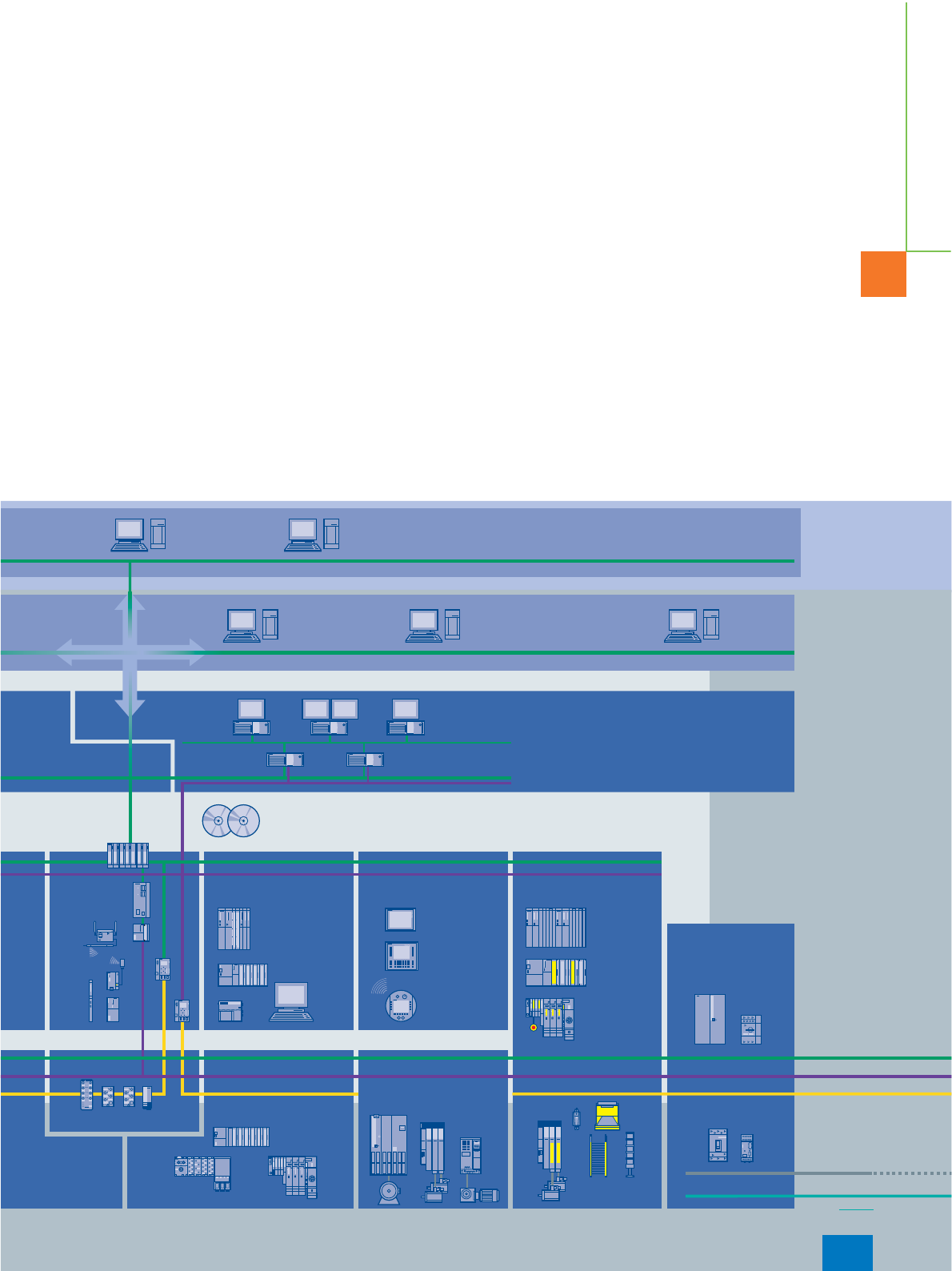
SIMATIC PCS 7
Takes you beyond the limits!
Active Field Splitter
Active Field Distributors
DP/PA link
with redundant
DP/PA couplers
DP/PA link
Integrated Drives
Fault-tolerant
automation
systems
ET 200M
single/redundant
ET 200M
with CP 341
DP/PA link
Y link
Modbus, serial connection
DP/AS-Interface link
Safety-related
automation
systems
ET 200M
Standard
automation
systems
Industrial Ethernet, single/redundant
OS / Route Control
Server
Batch/archive
server
Management information/
Manufacturing Execution System
Web Client
Web Server/
OpenPCS 7
Security
Modules
OS-LAN, single/redundant
OS / Batch / Route Control
Clients Engineering
Station
Network
printer
Asset Management/
Maintenance station
OS
Single Station
Standard and
F modules
ET 200M
F modules
Weighing systems
Zone 1Zone 2
DP/PA link
Ex operator
terminal
Ex I/O, HART
© Siemens AG 2007

Introduction
System architecture
SIMATIC PCS 7 V7.0
1/11
Siemens ST PCS 7 · November 2007
■
Benefits
With its pioneering design, modular and open architecture
based on state-of-the-art SIMATIC technology, consistent appli-
cation of industrial standards, and the I&C functionality paired
with high-performance, the SIMATIC PCS 7 process control sys-
tem allows cost-effective implementation and economical oper-
ation of I&C plants in all phases of their lifecycle and with con-
sideration of all aspects: from planning, engineering,
commissioning, training, through operation, maintenance and
repair, up to expansion and refurbishment. In the process, SI-
MATIC PCS 7 combines high-performance and reliability with
simple and safe operation and maximum convenience.
You primarily profit from Totally Integrated Automation with the
SIMATIC PCS 7 process control system through:
7Calculable development, implementation and lifecycle costs
7Minimization of engineering overhead
7Facilities for process optimization
7Adaptability to changing requirements
7Advantages resulting from the use of standard SIMATIC com-
ponents, such as:
- Low hardware and engineering costs
- Proven quality and stability
- Simple, fast definition and selection of system components
- Low costs for spare parts
- Short delivery times for spare parts and expansion compo-
nents
- Global availability
- Savings in logistics, maintenance and training costs
■
Function
A consistent and homogeneous overall system
SIMATIC PCS 7 is a modern process control system that can be
used alone or in combination with other systems, e.g. SIMATIC,
SIMOTION or drive systems, as a consistent and homogenous
overall system. Its popularity is increasing along with the de-
mand for seamlessly integrated universal automation engineer-
ing solutions, which is determined by sustained competition and
price pressure, the demand for increasingly flexible production
plants and the need for increased productivity.
Against the background of ever-increasing complexity, in partic-
ular due to the merging of automation engineering with informa-
tion technology, horizontal and vertical integrated system plat-
forms are being increasingly accepted in comparison to
automation solutions with so-called "best-in-class products".
Totally Integrated Automation with SIMATIC PCS 7 combines
consistent data management, communication and configuration
with outstanding system properties and high performance. This
guarantees that the typical demands placed on a process con-
trol system are comprehensively satisfied, and that you are per-
fectly equipped for future requirements:
7Simple and reliable process control
7User-friendly operation and visualization, also using the
Internet
7Powerful, fast and consistent system-wide engineering
7System-wide online modifications
7System openness at all levels
7Flexibility and scalability
7Redundancy at all levels
7Safety-related automation solutions
7Extensive fieldbus integration
7Flexible solutions for batch processes
7Efficient control of material transport
7Asset management for I&C equipment (diagnostics, preven-
tive maintenance and repairs)
7Direct interface with the IT world
7Advanced security concept for safeguarding the I&C system.
Flexibility and scalability
As a result of its modular architecture based on selected hard-
ware and software components from the standard SIMATIC
range, SIMATIC PCS 7 can be applied effectively in small and
large plants alike. It allows easy expansion or system modifica-
tion to enable customers to meet the changing production re-
quirements of their facility. SIMATIC PCS 7 is scalable from a
small single system consisting of approx. 160 process tags (mo-
tors, valves, PID controllers), such as might be used for a labo-
ratory system or a test center, up to a distributed multi-user sys-
tem with client/server architecture and approx. 60,000 process
tags, such as might be used for automation of a very large pro-
duction plant or for groups of connected facilities.
SIMATIC PCS 7 thus covers all sizes of plant - and if the plant
grows, SIMATIC PCS 7 grows with it!
Open for the future
SIMATIC PCS 7 is based on modular hardware and software
components, which are perfectly matched to one another due to
their conformance with TIA. These components can be ex-
panded and innovated seamlessly and with little effort and are
open for the future via long-term stable interfaces. This makes
long-term protection of customer investments possible, despite
the fast pace of innovation and short product cycles.
SIMATIC PCS 7 consistently applies new, powerful technologies
together with internationally established industrial standards
such as IEC, XML, PROFIBUS, Ethernet Gigabit technology,
TCP/IP, OPC, ISA-88 or ISA-95, just to mention a few.
Openness with SIMATIC PCS 7 covers all levels, and equally ap-
plies to automation systems and process I/Os as to industrial
communications networks, operator systems or engineering
systems.
Not just system architecture and communication are character-
ized by openness. This is a feature also evident in the program-
ming and data transfer interfaces for user programs as well as in
the import and export functions for graphics, text and data, e.g.
from the CAD/CAE world. SIMATIC PCS 7 can therefore also be
combined with components from other vendors, and integrated
in existing infrastructures.
© Siemens AG 2007

Introduction
1/12 Siemens ST PCS 7 · November 2007
© Siemens AG 2007
System-neutral components
System documentation
2/2 Siemens ST PCS 7 · November 2007
2
■
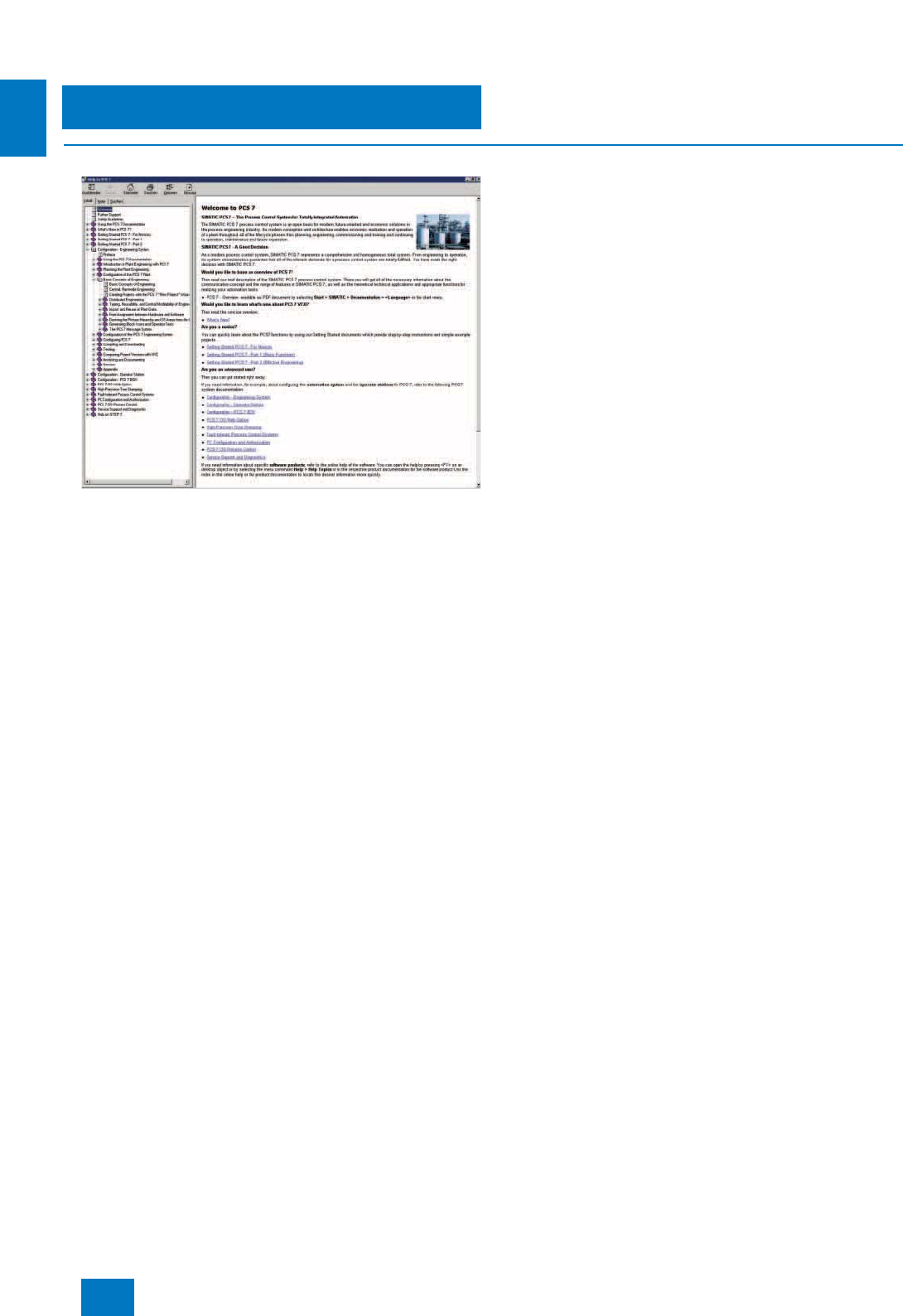
Overview
The system documentation of the SIMATIC PCS 7 process con-
trol system is an integral component of the SIMATIC PCS 7 sys-
tem software. It is available in two versions:
• As online help (HTML help)
• As electronic documentation in Acrobat Reader format (PDF)
The 3-language documentation (German, English, French) pro-
vides both beginners and experienced users with valuable infor-
mation on all aspects of the process control system. The range
extends from the system introduction, covers initial steps and
cross-system topics, up to a description of individual system
components. With the "Getting Started" documentation you can
gain initial practical experience using example projects.
SIMATIC PCS 7 Programming Instructions Driver Blocks
Programming Instructions for creating drive blocks and with the
title "SIMATIC PCS 7 Programming Instructions Driver Blocks"
can be ordered separately. These Programming Instructions
help the advanced SIMATIC PCS 7 user to create system-con-
form driver blocks, which can be placed like standard blocks on
system plans and automatically parameterized and intercon-
nected in HW-Config.
S7 Manual Collection
As a supplement to the SIMATIC PCS 7 system documentation,
the S7 Manual Collection provides comprehensive information
on all system components offered in the context of SIMATIC S7.
This multi-language collection of electronic manuals on DVD
contains documentation on the following in addition to the
SIMATIC PCS 7 system documentation:
• SIMATIC S7-200/300/400,
• SIMATIC C7,
• LOGO! logic module,
• SIMATIC DP,
• SIMATIC PC,
• SIMATIC programming devices,
•STEP7,
• engineering software,
• runtime software,
• SIMATIC PCS 7,
• SIMATIC HMI and
• SIMATIC NET.
The electronic manuals of the S7 Manual Collection are usually
in 5 languages (German, English, French, Italian, Spanish),
those of the integral SIMATIC PCS 7 system documentation
mostly in 3 languages (German, English, French).
For the migration of existing plants, you may also require de-
tailed information on the system components of TELEPERM M or
SIMATIC S5.
TELEPERM M Manual Collection
The TELEPERM M Manual Collection comprises TELEPERM M
manuals in 2 languages (German, English) on CD.
S5 Manual Collection
An S5 Manual Collection in 2 languages (German, English) on
CD, which contains all electronic manuals concerning
SIMATIC S5, rounds off the range of available information.
© Siemens AG 2007
System-neutral components
System documentation
2/3
Siemens ST PCS 7 · November 2007
2
■
Selection and Ordering Data Order No
■
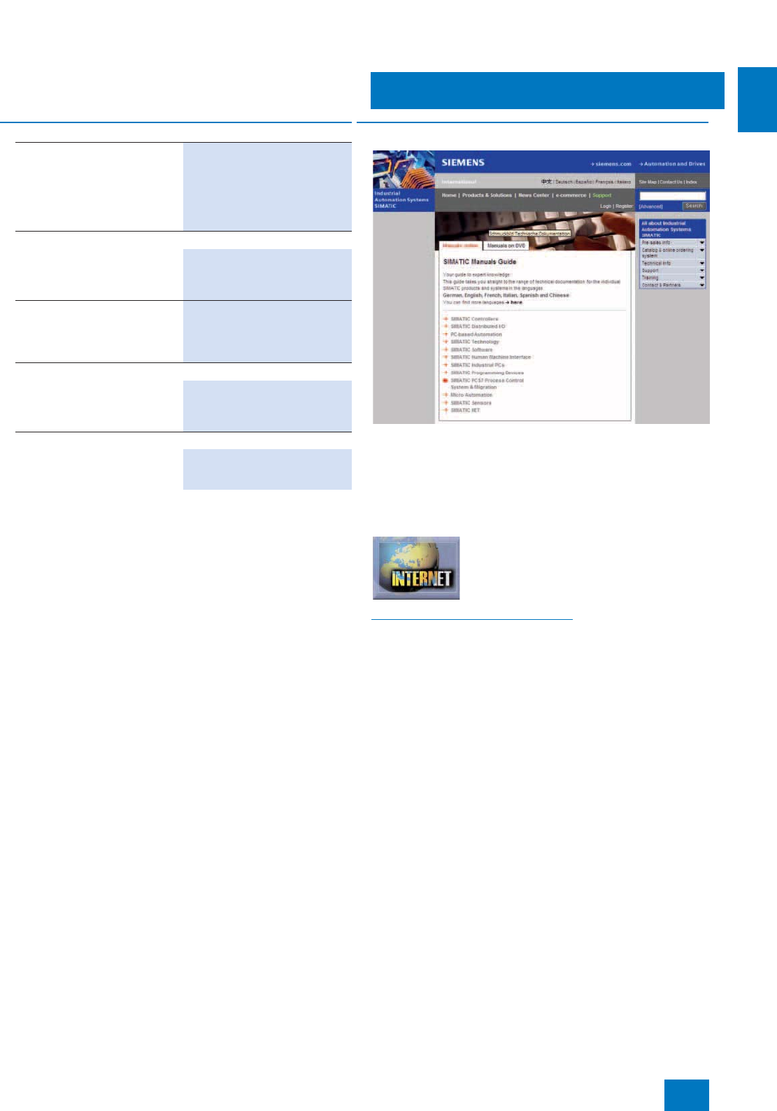
More information
The "SIMATIC Guide Manuals" on the Internet directs you
straight to the complete range of technical documentation avail-
able for SIMATIC products and systems in German, English,
French, Italian, Spanish and Chinese. If other languages are
available, you can also find them there. You can select individual
documents from this range for viewing or downloading.
Additional information is available in the Internet under:
http://www.siemens.com/simatic-docu
SIMATIC PCS 7 Programming
Instructions Driver Blocks V7.0
for SIMATIC PCS 7 V6.1 and V7.0
Electronic documentation on CD,
in 2 languages (German, English)
Type of delivery: CD, certificate of
license, terms and conditions
6ES7 653-1XD07-8YX8
SIMATIC S7 manuals
S7 Manual Collection
Electronic manuals on DVD, in
5 languages (German, English,
French, Italian, Spanish)
6ES7 998-8XC01-8YE0 D)
S7 Manual Collection -
maintenance service for 1 year
Type of delivery: Current DVD
"S7 Manual Collection" and the
three subsequent updates
6ES7 998-8XC01-8YE2 D)
TELEPERM M migration manuals
TELEPERM M Manual
Collection
Electronic manuals on CD, in
2 languages (German, English)
6DL5 900-8AX03-8YX8 D)
SIMATIC S5 manuals
S5 Manual Collection
Electronic manuals on CD, in
2 languages (German, English)
6ES5 998-7WE02 D)
D) Subject to export regulations: AL: N, ECCN: 5D992B1
© Siemens AG 2007
System-neutral components
Administration
2/4 Siemens ST PCS 7 · November 2007
2
■
Overview
Central user management, access control and electronic
signature
SIMATIC Logon is a central user administration function with ac-
cess control based on Windows 2000/XP and Windows Server
2003 for:
• System components of SIMATIC PCS 7
• Non-system components linked via an interface
It can be used to fulfill the validation requirements of 21 CFR Part
11. An electronic signature function can also be used in conjunc-
tion with SIMATIC Logon.
SIMATIC Logon Upgrade
All previous versions can be upgraded to the current version.
■
Design
The optional chipcard reader can be used for access control in
addition to the keyboard. SIMATIC Logon additionally supports
logon devices which can be operated with a Microsoft device
driver for the respective operating system (e.g. logon devices on
a USB interface). It is also possible to connect logon devices via
a separately created device-specific drive.
The number of SIMATIC Logon licenses required depends on
the number of clients/single stations that access applications for
which SIMATIC Logon is used for access protection.
SIMATIC Logon was developed for the SIMATIC PCS 7 process
control system but can also be used together with other SIMATIC
products in the context of Totally Integrated Automation (TIA),
e.g. with SIMATIC WinCC. A requirement for working together is
that user groups have already been created in the partner appli-
cations, or can be defined.
SIMATIC Logon is already integrated in the system software
of the SIMATIC PCS 7 V7.0 process control system. Separate
licenses are not required in this context.
■
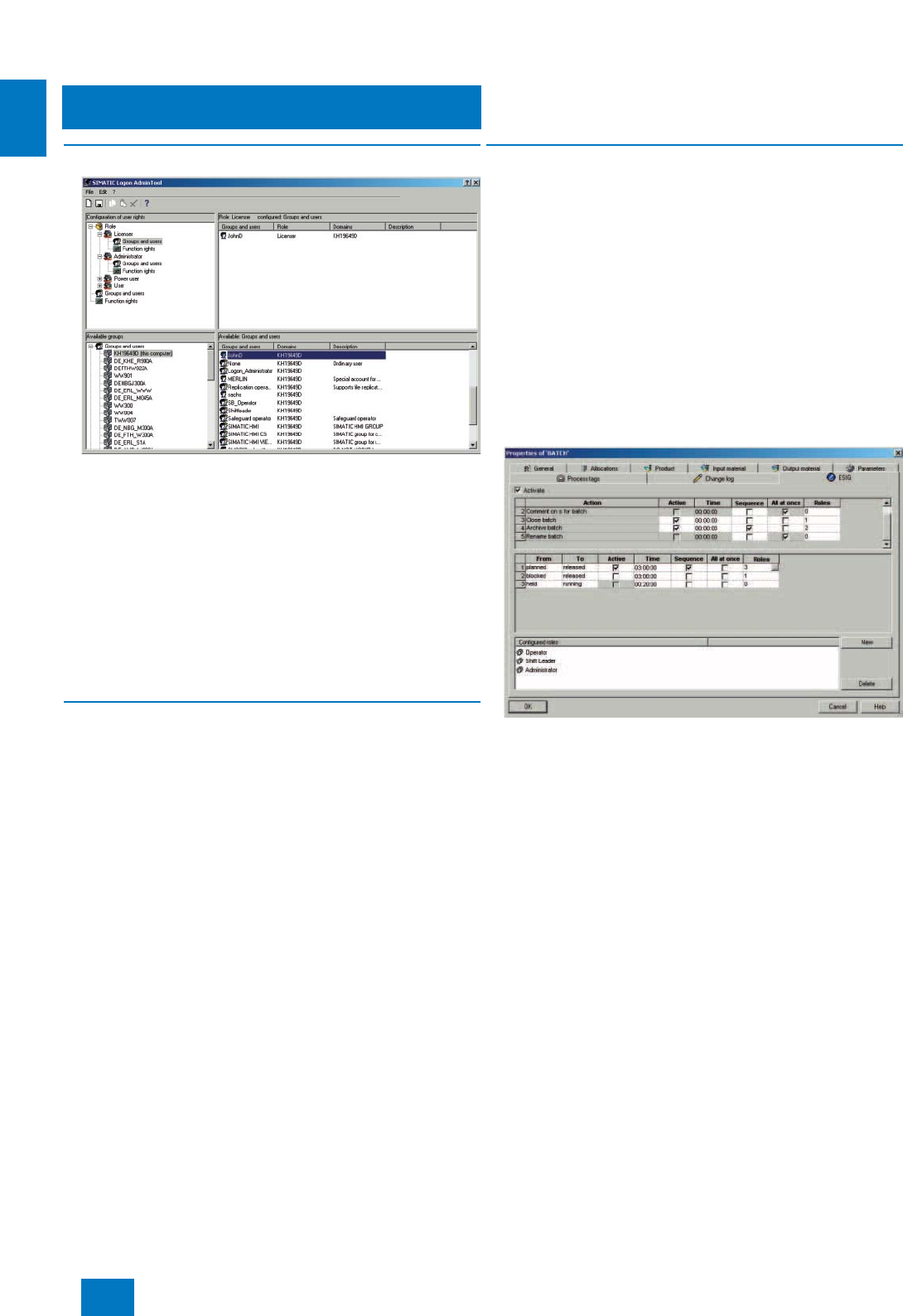
Function
SIMATIC Logon Admin Tool
Using the SIMATIC Logon Admin Tool it is possible to assign the
roles defined in the SIMATIC PCS 7 applications (e.g. Automa-
tion License Manager and SIMATIC BATCH) to the Windows
users/user groups. Administrators with the necessary Windows
administrator privileges can also use the SIMATIC Logon Admin
Tool to edit Windows users and user groups.
SIMATIC Logon Service
The login dialog of the SIMATIC Logon Service is activated when
an application is started which is managed by SIMATIC Logon.
The user receives his specific privileges after making the login,
password and domain entries. The SIMATIC Logon Service dia-
log for logoff, user change or password edit can be called in the
applications.
SIMATIC Electronic Signature
The SIMATIC Electronic Signature means that operations cannot
be performed until enabled by previously assigned Windows
users/user groups. Users/user groups are assigned to the oper-
ations in the respective application.
At the moment this function is implemented as a system function
only on SIMATIC BATCH. However, the Electronic Signature can
be used on any products in the specific applications.
The software products listed here under "Selection and ordering
data" are only relevant to use in the TIA environment.
© Siemens AG 2007

System-neutral components
Administration
2/5
Siemens ST PCS 7 · November 2007
2
B) Subject to export regulations: AL: N, ECCN: EAR99H
■
Options
Access security by means of chipcard reader
A chipcard reader can be used to check a person’s authorization
to access and operate a single station or a client. This method of
access security uses the chipcard as a "key" to the operator ter-
minals. Operations are only allowed when the card is actually in-
serted in the reader.
The unmistakable identification of access rights is required in
particular for plants which have to meet validation requirements.
The chipcard reader is compliant with EN 55022 Class B and
EN 50082-1 standards.
The reader is available with an USB interface for the connection
of the operator station.
Note:
The reader with USB interface can only be used with SIMATIC Logon.
■
Selection and Ordering Data Order No.
only for TIA applications
SIMATIC Logon V1.4
Single license for 1 installation
7 languages (German, English,
French, Spanish, Italian, Chi-
nese, Japanese), executes with
Windows 2000 Professional SP4,
Windows 2000 Server, Windows
XP Professional SP2 or Windows
Server 2003 SP1 and R2
Engineering software and elec-
tronic documentation on CD
Type of delivery: CD, license key
disk, emergency key disk, certifi-
cate of license, terms and condi-
tions
6ES7 658-7BX41-2YA0
SIMATIC Logon Upgrade to
V1.4
Single license for 1 installation
7 languages (German, English,
French, Spanish, Italian, Chi-
nese, Japanese), executes with
Windows 2000 Professional SP4,
Windows 2000 Server, Windows
XP Professional SP2 or Windows
Server 2003 SP1 and R2
Engineering software and elec-
tronic documentation on CD
Type of delivery: CD, license key
disk, emergency key disk, certifi-
cate of license, terms and condi-
tions
6ES7 658-7BX41-2YE0
Options
Chipcard reader USB
Chipcard reader with USB inter-
face,
driver software and operating
instructions
6ES7 652-0XX02-1XC0 B)
Chipcard
Chipcard for chipcard reader;
1 card required per user;
package with 10 chipcards
6ES7 652-0XX05-1XD1
© Siemens AG 2007

System-neutral components
Operating system
2/6 Siemens ST PCS 7 · November 2007
2
■
Overview
Operating system upgrade
When existing SIMATIC PCS 7 systems are updated to
Version 7.0, it may also be necessary to upgrade the operating
system.
If you replace your existing hardware by new SIMATIC PCS 7
Industrial Workstations from this catalog when carrying out an
upgrade, the Windows XP Professional or Windows Server 2003
operating systems including 5 CAL (Client Access Licenses) re-
quired for SIMATIC PCS 7 V7.0 are already included in the scope
of delivery. You can also purchase individual operating systems
or additional Client Access Licenses (CAL) from Fujitsu Siemens
Computers GmbH.
Contact address for quotations and orders
Fujitsu Siemens Computers GmbH
Mr. Dominikus Besserer
Phone: +49 821 804-2434
Fax: +49 821 804-2972
E-mail: dominikus.besserer@fujitsu-siemens.com
Note:
Please note when ordering that SIMATIC PCS 7 V7.0 is operated
together with Windows XP Professional Service Pack 2 and
Windows Server 2003 Service Pack 2.
Release 2 of Windows Server 2003 has not been approved
for SIMATIC PCS 7 V7.0.
© Siemens AG 2007
System-neutral components
SIMATIC PCS 7 Industrial Workstation
Introduction
2/7
Siemens ST PCS 7 · November 2007
2
■
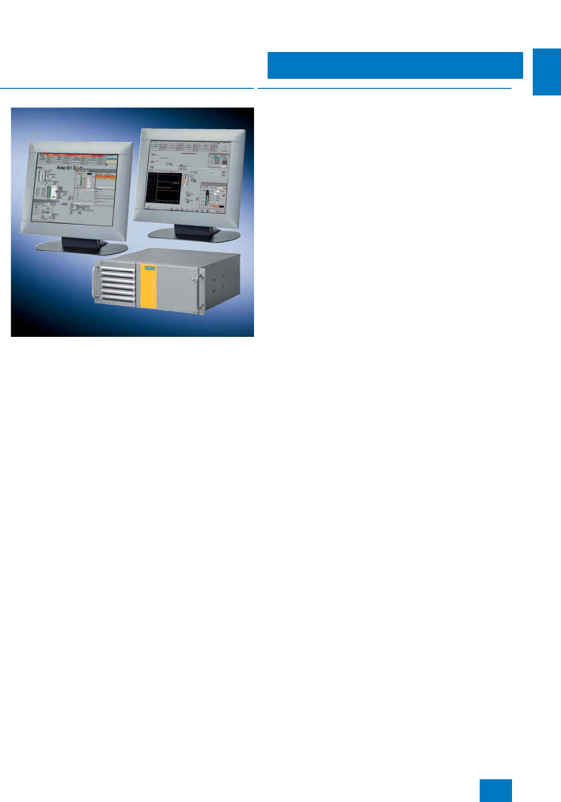
Overview
We offer a range of modern, powerful SIMATIC PCS 7 Industrial
Workstations for the systems positioned in the SIMATIC PCS 7
system architecture above the controller level, e.g. for engineer-
ing, operation and monitoring (also via Internet/intranet), batch
control, route control, asset management or IT applications etc.
These are optimized for use as single station, client or server,
and can be expanded specific to the system.
■
Design
Microsoft Windows operating system
The multi-language Microsoft Windows XP Professional or
Server 2003 operating system as well as the SIMATIC PCS 7
system software for OS or ES/OS are preinstalled on the SI-
MATIC PCS 7 Industrial Workstation. The Microsoft Server 2003
operating system is supplied with 5 CALs (Client Access Li-
censes). You can purchase further CALs from Fujitsu Siemens
Computers GmbH (see page 2/6).
Monitors and multi-VGA operation
The core component of the SIMATIC PCS 7 Industrial Worksta-
tion is a SIMATIC industrial PC without keyboard or monitor. This
basic hardware can be combined with the industrial LCD moni-
tors recommended in the Section "HMI devices/monitors" for
SIMATIC PCS 7 in the Catalog "PC-based Automation" to suit the
operating environment and the customer’s requirements.
Using a multi-VGA graphics card, the visualization of a project/
subproject when engineering or a plant/unit in process operation
can be divided among up to 4 process monitors per operator
station with application of different views (see page 2/16).
This is supported in the SIMATIC PCS 7 workstations designed
as clients by additional hardware versions:
• SIMATIC PCS 7 OS Client RACK PC 547B WXP with multi-
VGA graphics card "2 Screens" and
• SIMATIC PCS 7 OS Client RACK PC 547B WXP with multi-
VGA graphics card "4 Screens"
Clients and single stations with a standard graphic interface
module for controlling a process monitor can also be expanded
by a multi-VGA graphics card "2 Screens" or "4 Screens" (see
page 2/16).
© Siemens AG 2007
System-neutral components
SIMATIC PCS 7 Industrial Workstation
Introduction
2/8 Siemens ST PCS 7 · November 2007
2
■
Options
Notes on the use of other basic hardware and non-SIMATIC software
Siemens guarantees the compatibility of hardware and software
for system configurations based on components in this catalog.
The system test confirms that the system software of the
SIMATIC PCS 7 process control system can be run on the
SIMATIC PCS 7 Industrial Workstations offered in this catalog.
Despite comprehensive tests, it cannot be excluded that the
function of a SIMATIC PCS 7 system could be disturbed or inter-
fered with as a result of additional non-SIMATIC software, i.e.
software which has not been explicitly approved for SIMATIC
PCS 7.
If you use hardware other than the basic hardware offered in this
catalog, or additional non-SIMATIC software, this is at your own
risk. If compatibility problems arise as a result of these hard-
ware/
software components, the support provided for elimination
thereof is not free of charge.
The licenses for plant bus communication via Industrial Ethernet,
i.e. for Basic Communication Ethernet (BCE) and CP 1613 com-
munication are bound to the SIMATIC PCS 7 Industrial Worksta-
tions. Depending on the selected type of communication, the
SIMATIC PCS 7 Industrial Workstations for single stations and
servers are delivered either with a BCE license or CP 1613 li-
cense. If you are not using SIMATIC PCS 7 V7.0 on SIMATIC
PCS 7 Industrial Workstations, you additionally require a
SIMATIC PCS 7 BCE V7.0 license (Order No. 6ES7 650-1CD07-
2YB5) for all single stations or servers which are connected to
the plant bus via a standard network card and not via a CP 1613.
Requirements on the configuration of the SIMATIC PCS 7 basic hardware
Depending on the application of the SIMATIC PCS 7 basic hard-
ware, the following hardware requirements must be observed.
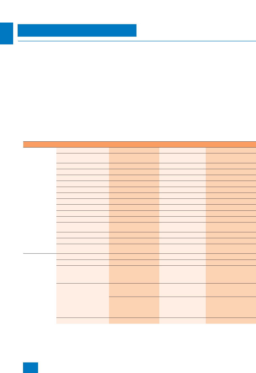
Minimum configuration of basic hardware depending on target system
Target systems Engineering station (ES) ●
Engineering station with server
operating system
●
OS single station ●
OS server ●
OS client ●
Central archive server ●
PCS 7 Web server ●
Maintenance station (MS) ●
BATCH single station ●
BATCH server ●
BATCH client ●
Common OS/BATCH client ●
Route Control (RC) single sta-
tion
●
Route Control server ●
Route Control client ●
Common OS/BATCH/Route
Control single station
●
Technical
specifications of
basic hardware
Processor, clock Intel Pentium IV, 2 GHz Intel Pentium IV, 2 GHz Intel Pentium IV, 2 GHz
Main memory (RAM) 2 GB 1 GB 512 MB
Hard disk
• Storage capacity 120 GB 120 GB 80 GB
• Size of C partition 20 GB 20 GB 20 GB
Network adapter,
communications interfaces RJ45 connection (Fast Ether-
net) for terminal bus (OS-LAN) RJ45 connection (Fast Eth-
ernet) for terminal bus
(OS-LAN)
RJ45 connection (Fast Ether-
net) for terminal bus (OS-LAN)
CP1613 A2 or RJ45 network
card (Fast Ethernet) with BCE
for plant bus (ES, as well as
BATCH/OS/RC on one PC)
CP1613 or RJ45 network
card (Fast Ethernet) with
BCE for plant bus (ES, MS,
OS single station/server and
RC single station/server)
--
Optical drive DVD-ROM DVD-ROM DVD-ROM
© Siemens AG 2007
System-neutral components
SIMATIC PCS 7 Industrial Workstation
Introduction
2/9
Siemens ST PCS 7 · November 2007
2
Additional recommendations/limitations
• It is generally of advantage for the system performance if the
technical specifications of the basic hardware, e.g. clock,
main memory or hard disk, are above the recommended val-
ues listed in the table. This particularly applies to multiproject
engineering.
• A requirement for integration of PC-based SIMATIC PCS 7 ba-
sic hardware into the PC diagnostics of the SIMATIC PCS 7
asset management is the SIMATIC PC DiagMonitor software.
This belongs to the scope of delivery of SIMATIC PCS 7 Indus-
trial Workstations and SIMATIC PCS 7 BOX RTX/416 and can-
not be executed on other systems.
• For long-term archiving with large quantity frameworks, we
recommend the PCS 7 Premium server from the Catalog
ST PCS 7.1 (Add-ons for the SIMATIC PCS 7 process control
system) as the central archive server. However, the PCS 7
Premium server cannot be integrated into the PC diagnostics
of the SIMATIC PCS 7 asset management.
• For increased data availability on the central archive server,
we recommend a RAID hard disk system (at least RAID 1).
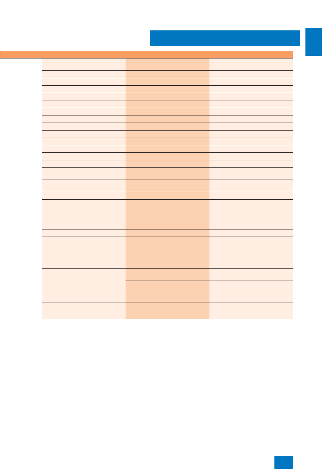
Recommended configuration of basic hardware depending on target system
Target systems Engineering station with server operating
system
●
OS single station ●
OS server ●
OS client ●
Central archive server ●
PCS 7 Web server ●
Maintenance station (MS) ●
BATCH single station ●
BATCH server ●
BATCH client ●
Common OS/BATCH client ●
Route Control (RC) single station ●
Route Control server ●
Route Control client ●
Common OS/BATCH/Route Control
single station
●
Engineering station with server operating
system
●
Technical
specifications of
basic hardware
PC type SIMATIC Rack PC 547B
CPU
• Processor, clock Intel Core 2 Duo E6600 / 2 x 2.4 GHz Intel Core 2 Duo E6600 / 2 x 2.4 GHz
• Front Side Bus (FSB) 1066 MHz 1066 MHz
• Second Level Cache 4 MB 4 MB
Main memory (RAM) 2 GB 1 GB
Hard disks
• Number, storage capacity, type 2 x 250 GB SATA in RAID 1 network for
server and ES/OS single stations;
1 x 250 GB SATA for client systems
1 x 250 GB SATA
• Size of C partition 50 GB 50 GB
Network adapter,
communications interfaces RJ45 connection (Gigabit Ethernet) for
terminal bus (OS-LAN) on board RJ45 connection (Gigabit Ethernet) for
terminal bus (OS-LAN) on board
CP1613 A2 or RJ45 Ethernet network
card 10/100/1000 Mbit/s with BCE for
plant bus (ES, MS, OS single station/
server and RC single station/server)
--
Optical drive DVD writer (DVD±RW) for engineering
station; DVD-ROM for all other target
systems
DVD-ROM
© Siemens AG 2007
System-neutral components
SIMATIC PCS 7 Industrial Workstation
Basic hardware
2/10 Siemens ST PCS 7 · November 2007
2
■
Overview
The SIMATIC PCS 7 Industrial Workstations are based on a
SIMATIC Rack PC of type 547B which features powerful, innova-
tive Intel PC architecture of 19" design. They are certified by the
CE marking for use in offices and industrial environments, and
comply with the specific requirements of process control tech-
nology.
■
Application
Specially optimized versions are available for operation as sin-
gle stations, servers or clients. The operating system and the fol-
lowing ES/OS software of the SIMATIC PCS 7 process control
system are already preinstalled when delivered:
• Single station: PCS 7 Engineering Software for AS/OS (includ-
ing OS Runtime software)
• Server: PCS 7 OS Software Server
• Client: PCS 7 OS Software Client
You only need the corresponding licenses in order to use the
preinstalled SIMATIC PCS 7 software.
Note:
Please note the standard installation if you use the SIMATIC
PCS 7 Industrial Workstations within the SIMATIC PCS 7 pro-
cess control system for other tasks, e.g. as basic hardware for
SIMATIC BATCH, SIMATIC Route Control, StoragePlus, Central
Archive Server or PCS 7 Web Server. You can then extend or re-
ject the existing SIMATIC PCS 7 installation, and restore it for the
operating system using the restore DVD.
The CP 1613 communication integrated in the IE version of the
SIMATIC PCS 7 Workstation for single stations and servers is a
combination of CP 1613 communications processor and
S7-1613 communications software. When using fault-tolerant
automation systems, the SIMATIC PCS 7 Workstation requires
the S7-REDCONNECT software instead of the S7-1613 commu-
nications software. The S7-REDCONNECT Upgrade is suitable
for upgrading the communications software (for ordering data,
see page 9/29).
© Siemens AG 2007
System-neutral components
SIMATIC PCS 7 Industrial Workstation
Basic hardware
2/11
Siemens ST PCS 7 · November 2007
2
■
Design
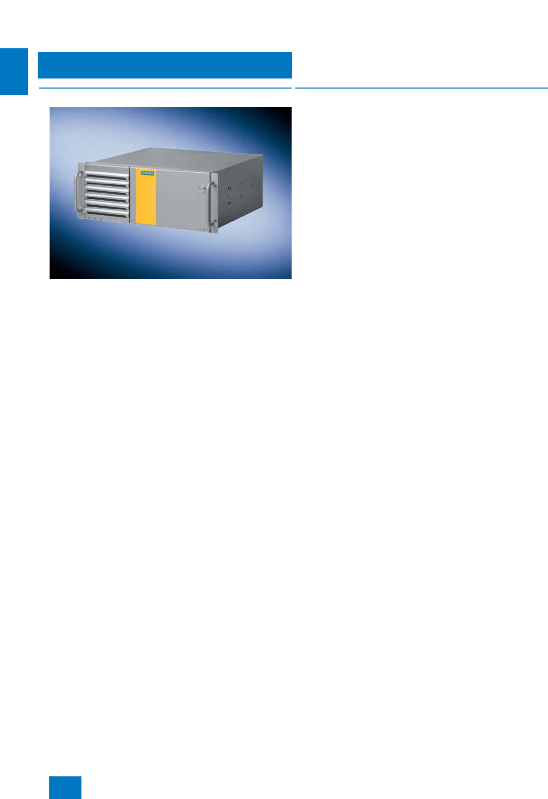
The SIMATIC PCS 7 Industrial Workstations of type Rack PC
547B have a painted all-metal housing of 19" rack design which
is particularly protected against dust by a filter and pressurized
ventilation. This mechanically and electromechanically rugged
housing has a service-friendly design. The SIMATIC PCS 7 In-
dustrial Workstations of type Rack PC 547B can be positioned
and installed horizontally or vertically. High-grade components
with high MTBF values and monitoring functions for the inner
housing temperature, fan and program execution permit reliable
24-hour continuous operation at ambient temperatures between
5 and 40 °C.
The SIMATIC PCS 7 Industrial Workstations of type Rack PC
547B have the following features:
• Motherboard with future-oriented Intel architecture for modern
Core 2 Duo processors, based on Intel 945G Express chipset
• Powerful AGP graphics with Dynamic Video Memory, sound
(Line In, Line Out, Mic.) and 10/100/1000 Mbit/s Ethernet RJ45
port integrated onboard
• PCI-Express technology (1 PCIe x16 and 2 PCIe x1 slots)
• 6 slots for drives:
- At the front: three 5.25" slots (1 occupied by DVD-ROM/
DVD-RW) and
- one 3.5" slot (occupied by diskette drive)
- Inside: two 3.5" slots (occupied by 1 hard disk on the client,
and 2 hard disks on the server and ES/OS single station)
• Increased system availability through RAID 1 with 2 SATA
hard disks and NCQ technology (Native Command Queuing)
on the server and ES/OS single station
• Second serial interface (for server) available (COM2)
• Total of 6 USB 2.0 interfaces (4 at rear, 2 at front)
• High electromagnetic compatibility (CE-certified for industrial
and office environments)
• Dust protection by means of pressurized ventilation in con-
junction with a front fan and a dust filter
• PC front complies with IP30 degree of protection when the
front door is closed
• Front door can be locked to prevent unauthorized access to
swap media, control elements and interfaces located at the
front
• Easy and fast installation and maintenance of PC compo-
nents: access to the front drives through a hinged front door;
only 3 screws to open the device
• 3 LEDs on the front of the PC visualize the operating status:
- Power (switched on)
- HD (hard disk access)
- Status (fan and temperature monitoring)
• Suitable for easy mounting with telescopic rails
• Easy to remove fixing bracket with handles
• Card hold-down device to secure PC modules during trans-
portation and to protect them from vibration and shock
• Power supply unit with temperature-controlled fan
• Power connector lock for the power supply cable
• SIMATIC PC DiagMonitor diagnostics software for monitoring
program execution (watchdog), temperature, fan speed, hard
disk status and system failure (heartbeat); including operating
hours counter
• Can be integrated into the system diagnostics of the SIMATIC
PCS 7 asset management by means of SIMATIC PC DiagMon-
itor
Restore DVD
The operating system and SIMATIC PCS 7 software are prein-
stalled on the basic devices. Two restore DVDs are supplied for
quickly restoring the delivered status if required.
• Restore DVD 1 only contains the operating system with default
settings for optimum PCS 7 operation
• Restore DVD 2 contains a full installation (operating system
plus ES/OS software including SQL server)
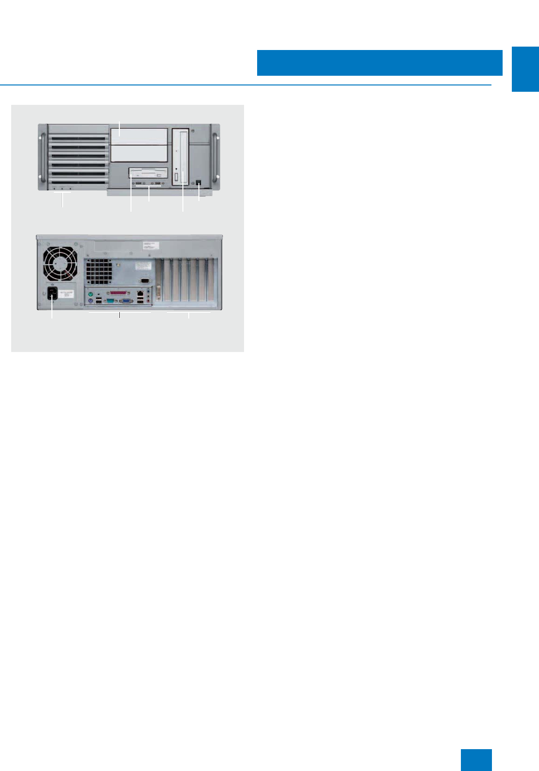
Operational display
Hard disk access
Fan/temperature status
3.5" diskette
drive
AC power supply Extension slots:
4 x PCI, 2 x PCIe x1,
1 x PCIe x16
Interfaces for keyboard,
mouse, 4 x USB 2.0,
COM1, LPT1, VGA,
Audio, Gigabit Ethernet
2 x USB
Optical drive
Power switch
2 slots for 5.25" drives
© Siemens AG 2007

System-neutral components
SIMATIC PCS 7 Industrial Workstation
Basic hardware
2/12 Siemens ST PCS 7 · November 2007
2
■
Technical specifications
SIMATIC PCS 7 Industrial Workstation (single station/server/client)
Design and equipment features
Design 19" rack, 4 HU, for horizontal and
vertical installation, prepared for
easy mounting with telescopic
rails, 19" fixing bracket with han-
dle, easy to remove
Degree of protection to EN 60529 IP30 with front door closed; IP20
at rear
Motherboard FSC D2156-S21
Chipset Intel 945G Express
CPU
• Processor base LGA 775
• Processor / clock Intel Core 2 Duo E6600 /
2x2.4GHz
• Front Side Bus (FSB) 1066 MHz
• Second Level Cache 4 MB
Main memory (SDRAM)
•Type Dual channel DDR2-667 SDRAM
(PC2-5300)
• Maximum configuration 4 memory bases in total
(expandable to 4 GB)
• Standard configuration Single station/server:
2GB (2x1GB)
Client: 1 GB (2 x 512 MB)
Motherboard slots 4 x PCI (max. 265 mm long)
2 x PCIe x1
1 x PCIe x16
Slots for drives
• On the front 1 x 3.5" (occupied by diskette
drive)
3 x 5.25" (1 occupied by
DVD-ROM/DVD±RW)
• On the inside 2 x 3.5" for hard disk drives
(2 occupied with server/single
station; 1 occupied with client)
RAID controller RAID controller Intel ICH7R with
Intel Storage Manager software
(onboard)
Hard disks
• Storage volumes / features 250 GB / 3.5" SATA, 8 MB cache,
7200 rpm, NCQ
• Single station/server SATA-RAID 1 (mirror) with 2 hard
disks
•Client 1 SATA hard disk
Interchangeable drives
• Diskette drive 3.5" diskette drive 1.44 MB
• DVD drive in ES/OS single station DVD writer (DVD±RW) 5.25" ATAPI
Read:
• DVD-ROM: single layer 16x,
dual layer 12x
• DVD-R/+R: single layer 16x,
dual layer 7x
• DVD-RW/+RW 13x
• CD-ROM/CD-R 48x, CD-RW 40x
Write:
• DVD+R 18x, DVD+RW 8x,
DVD-R 18x, DVD-RW 6x
• DVD+R9 (DL) 8x, DVD-R DL 8x
• CD-R 48x, CD-RW 32x
• DVD drive in server/client DVD-ROM 5.25" ATAPI
Read:
• DVD-ROM: single layer 16x,
dual layer 8x
• DVD+R/RW, DVD-R/RW 8x,
DVD-RAM 2x
• CD-ROM, CD-R 32x,
CD-RW 20x
Graphics card Intel GMA950 graphics controller
(on board), 2D and 3D engine
integrated in chipset, up to
2048 x 1536 pixels with 75 Hz
image refresh rate
• Graphics memory Dynamic video memory technol-
ogy (up to 224 MB)
• Resolutions. frequencies, colors • Up to 800 x 600 at 120 Hz, 32 bit
colors
• Up to 1280 x 1024 at 100 Hz,
32 bit colors
• Up to 2048 x 1536 at 75 Hz,
16 bit colors
Mouse Optical mouse
Interface modules / interfaces
• OS-LAN interface module 10/100/1000 Mbit/s Ethernet
(RJ45) on board,
Broadcom BCM5751 controller
• Plant bus interface module (single
station/server), alternatives
- RACK PC 547B BCE Ethernet network card RJ45 (PCI)
10/100/1000 Mbit/s
- RACK PC 547B IE CP 1613 A2 communications
processor
•USB 6 x USB 2.0, 4 x at rear and 2 x at
front, high current in each case
•Serial Server: 1 x COM1 and 1 x COM2
(each V.24), 9-contact Sub-D
connector
Single station/client: 1 x COM1
(V.24), 9-contact Sub-D connector
• Parallel 1 x LPT1 (25-pin, EPP and ECP)
•Audio 1 x Line In; 1 x Micro In; 1 x Line
Out (2 x 0.5 W/8 Ω); Realtek
ALC262 Audio Codec
•VGA 1 x Sub-D socket, 15-contact
• Keyboard 1 x PS/2
•Mouse 1 x PS/2
■
Technical specifications (cont.)
© Siemens AG 2007

System-neutral components
SIMATIC PCS 7 Industrial Workstation
Basic hardware
2/13
Siemens ST PCS 7 · November 2007
2
Operating systems and diagnostics software
ES/OS single station/client Microsoft Windows XP
Professional MUI, 6 languages,
selectable: German, English,
French, Italian, Spanish, Chinese
Server Microsoft Windows Server 2003
(standard edition) MUI,
6 languages, selectable:
German, English, French, Italian,
Spanish, Chinese
System-tested SIMATIC industrial
software SIMATIC PC DiagMonitor
Monitoring/diagnostics functions
Watchdog • Monitoring of program execution
• Monitoring time adjustable in the
software
Temperature Violation of permissible operating
temperature
Fans Speed monitoring for:
•Front fan
• Processor fan
• Power supply fan
Displays Front LEDs
• Power (device switched on)
• HD (access to hard disk)
• Status (fan/temperature
monitoring)
Safety
Protection class Protection class I compliant with
IEC 61140
Safety directives EN 60950-1;
UL60950;
CSA C22.2 No. 60950-00
Noise level
Operation < 45 dB (A) to DIN 45635
Electromagnetic compatibility (EMC)
Emitted interference (AC) EN 55022 Class B; FCC Class A
EN 61000-3-2 Class D,
EN 61000-3-3
Immunity to conducted interference
on the supply lines ± 2 kV (to IEC 61000-4-4, burst)
± 1 kV (to IEC 61000-4-5,
symmetrical surge)
± 2 kV (to IEC 61000-4-5,
unsymmetrical surge)
Immunity to interference on signal
lines ± 2 kV (to IEC 61000-4-4, burst,
length > 3 m)
± 2 kV (to IEC 61000-4-5, sym-
metrical surge, length > 30 m)
Immunity to static discharge ± 4 kV, contact discharge
(to IEC 61000-4-2)
± 8 kV, atmospheric discharge
(to IEC 61000-4-2)
Immunity to high-frequency
irradiation 1 V/m, 2 to 2.7 GHz
10 V/m, 80 MHz to 1 GHz and
1.4 to 2 GHz, 80% AM
(to IEC 61000-4-3)
10 V, 10 kHz to 80 MHz
(to IEC 61000-4-6)
Magnetic field 100 A/m, 50 Hz/60 Hz
(to IEC 61000-4-8)
■
Technical specifications (cont.)
Climatic conditions
Temperature Tested according to
IEC 60068-2-2, IEC 60068-2-1,
IEC 60068-2-14
• Operation +5 ... +40 °C (no DVD writer
operation),
+5 ... +35 °C (without limitation)
CPU up to 65 W power loss
Gradient: max. 10 °C/h,
no condensation
• Storage/transport -20 ... +60 °C
Gradient: max. 20 °C/h,
no condensation
Relative humidity Tested according to
IEC 60068-2-78, IEC 60068-2-30
• Operation 5 ... 80% at 25 °C
(no condensation)
Gradient: max. 10 °C/h,
no condensation
• Storage/transport 5 ... 95% at 25 °C
(no condensation)
Gradient: max. 20 °C/h,
no condensation
Mechanical environmental conditions
Vibrations Tested according to
IEC 60068-2-6, 10 cycles
• Operation 20 ... 58 Hz, amplitude 0.015 mm;
58 ... 200 Hz: 2 m/s²
Note: No mechanical interfer-
ences are tolerable when writing
with CD/DVD writers.
• Storage/transport 5 ... 8.51 Hz, amplitude 3.5 mm;
8.51 ... 500 Hz: 9.8 m/s²
Shock Tested according to
IEC 60068-2-27
• Operation Half sine: 9.8 m/s², 20 ms,
100 shocks per axis
Note: No mechanical interfer-
ences are tolerable when writing
with CD/DVD writers.
• Storage/transport Half sine: 250 m/s², 6 ms,
1000 shocks per axis
Approvals
CE living accommodation (emitted
interference) EN 61000-6-3:2001
CE industrial areas (noise immunity) EN 61000-6-2:2005
cULus 60950-1
■
Technical specifications (cont.)
© Siemens AG 2007

System-neutral components
SIMATIC PCS 7 Industrial Workstation
Basic hardware
2/14 Siemens ST PCS 7 · November 2007
2
Power supply
Nominal supply voltage 100 to 240 V AC, wide-range
(90 to 264 V AC)
Frequency 50 ... 60 Hz (minimum 47 to
maximum 63 Hz, sinusoidal)
Short-term voltage dip 16 ms at 0.85 of nominal supply
voltage (max. 10 events per hour;
recovery time min. 1 s)
Power consumption (with 210 W
secondary) 310 W (approx 68% efficiency)
AC input current Continuous current up to 7 A (up
to 30 A for 5 ms during startup)
Max. current output •+3.3V: 24 A
•+5V: 26 A
(total power for +3.3 V and +5 V
max. 190 W)
• +12 V: 15 A
• -12 V: 0.2 A
•+5V
aux: 2 A
Dimensions and weights
Overall dimensions in mm
(W x H x D) 433.5 x 176.5 x 445.5
Weight 16 ... 23 kg
■
Selection and Ordering Data Order No.
SIMATIC PCS 7 Industrial Workstation, single station version
SIMATIC PC in 19" rack, without
monitor, keyboard and printer;
Core 2 Duo E6600 2.4 GHz pro-
cessor, 2 GB RAM (2 x 1 GB),
sound, SATA-RAID 1 with 2 hard
disks of 250 GB, graphics con-
troller on board with dynamic
video memory, DVD writer
DVD±RW IDE, 3.5" diskette drive,
optical mouse, Ethernet
10/100/1000 Mbit/s (RJ45) on
board for connection to OS-LAN;
SIMATIC PC DiagMonitor diag-
nostics software and 2 restore
DVDs;
SIMATIC PCS 7 ES/OS software
preinstalled
Windows XP Professional MUI
operating system
(German, English, French, Italian,
Spanish, Chinese)
•SIMATIC PCS 7 ES/OS 547B
BCE WXP
Connection to plant bus with
Ethernet network card RJ45
(PCI) 10/100/1000 Mbit/s and
Basic Communication Ethernet
(BCE) for up to 8 automation
systems (not fault-tolerant
systems)
6ES7 650-0NF07-0YX0 D)
•SIMATIC PCS 7 ES/OS 547B
IE WXP
Connection to plant bus with
CP 1613 A2 communications
processor
6ES7 650-0NF07-0YX1 D)
■
Technical specifications (cont.)
SIMATIC PCS 7 Industrial Workstation, server version
SIMATIC PC in 19" rack, without
monitor, keyboard and printer;
Core 2 Duo E6600 2.4 GHz pro-
cessor, 2 GB RAM (2 x 1 GB),
sound, SATA-RAID 1 with 2 hard
disks of 250 GB, graphics con-
troller on board with dynamic
video memory, DVD-ROM IDE,
3.5" diskette drive, optical mouse,
Ethernet 10/100/1000 Mbit/s
(RJ45) on board for connection to
OS-LAN;
SIMATIC PC DiagMonitor diag-
nostics software and 2 restore
DVDs;
SIMATIC PCS 7 OS software for
server preinstalled
Windows Server 2003 MUI
operating system
(German, English, French, Italian,
Spanish, Chinese)
•SIMATIC PCS 7 OS Server
547B BCE SRV03
Connection to plant bus with
Ethernet network card RJ45
(PCI) 10/100/1000 Mbit/s and
Basic Communication Ethernet
(BCE) for up to 8 automation
systems (not fault-tolerant
systems)
6ES7 650-0NH07-0YX0 D)
•SIMATIC PCS 7 OS Server
547B IE SRV03
Connection to plant bus with
CP 1613 A2 communications
processor
6ES7 650-0NH07-0YX1 D)
SIMATIC PCS 7 Industrial Workstation, client version
SIMATIC PC in 19" rack, without
monitor, keyboard and printer;
Core 2 Duo E6600 2.4 GHz pro-
cessor, 1 GB RAM (2 x 512 MB),
SATA hard disk of 250 GB, graph-
ics controller on board with
dynamic video memory, DVD-
ROM IDE, 3.5" diskette drive, opti-
cal mouse, Ethernet
10/100/1000 Mbit/s (RJ45) on
board for connection to OS-LAN;
SIMATIC PC DiagMonitor diag-
nostics software and 2 restore
DVDs;
SIMATIC PCS 7 OS software for
client preinstalled
Windows XP Professional MUI
operating system
(German, English, French, Italian,
Spanish, Chinese)
•SIMATIC PCS 7 OS Client 547B
WXP
- without multi-VGA graphics
card 6ES7 650-0NG07-0YX0 D)
- with Multi-VGA graphics card
"2 Screens" 6ES7 650-0NG07-0YA0 D)
- with Multi-VGA graphics card
"4 Screens" 6ES7 650-0NG07-0YB0 D)
D) Subject to export regulations: AL: N, ECCN: 5D992B1
■
Selection and Ordering Data Order No.
© Siemens AG 2007
System-neutral components
SIMATIC PCS 7 Industrial Workstation
Basic hardware
2/15
Siemens ST PCS 7 · November 2007
2
B) Subject to export regulations: AL: N, ECCN: EAR99H
1) The PCS 7 systems are delivered as standard with a "European power
cable". The country-specific versions listed above are required for some
countries.
■
Accessories
Keyboards
The SIMATIC PCS 7 Industrial Workstations are delivered without
a keyboard. The SIMATIC PC keyboard with USB connection, for
example, is suitable for process operation with SIMATIC PCS 7.
The SIMATIC PC keyboard is a standard MF2 keyboard with
105 keys, without additional special functions. It combines the
convenience of an office keyboard with the EMC of an industrial
device. Standards/approvals: UL 1950, CSA C22.2 No. 950,
FCC Part 15, subpart B, class B, VDE-GS (EN 60950/ZHI/618),
CE, C-TICK-Mark (Australia).
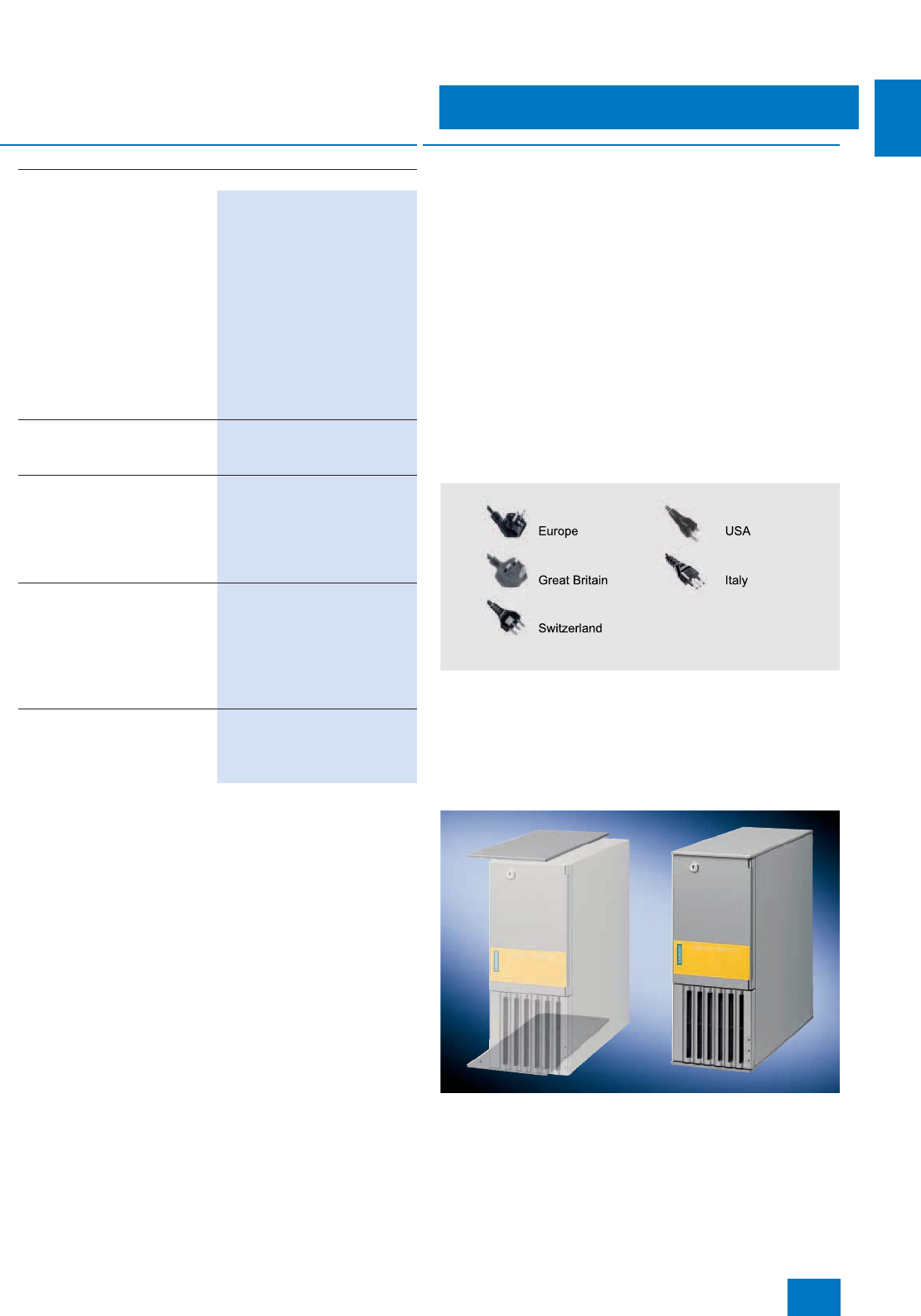
Power supply cable for Rack PC
The SIMATIC PCS 7 systems are delivered as standard with a
"European power cable". This can be used in Germany, France,
Spain, Netherlands, Belgium, Sweden, Austria and Finland.
The country-specific versions listed in the Ordering data are re-
quired for other countries. The following picture shows the ap-
pearance of the power supply plugs:
Country-specific power supply cables for Rack PC
Tower Kit
A Tower Kit for converting a SIMATIC PCS 7 Industrial Worksta-
tion of Rack PC design into an industrial Tower PC can be or-
dered as an option. The Tower Kit is suitable for SIMATIC PCS 7
Industrial Workstations based on the Rack PC types 547B and
IL 43.
Additional and expansion components
Memory modules for expanding
the main memory
• 512 MB memory expansion for
SIMATIC Rack PC 547B
(1 x 512 MB), DDR2-667
SDRAM
6ES7 648-2AF30-0HA0 B)
• 1 GB memory expansion for
SIMATIC Rack PC 547B
(2 x 512 MB),
DDR2-667 SDRAM,
kit for dual-channel technology
6ES7 648-2AF40-0HB0 B)
• 2 GB memory expansion for
SIMATIC Rack PC 547B
(2 x 1 GB), DDR2-667 SDRAM,
kit for dual-channel technology
6ES7 648-2AF50-0HB0 B)
SIMATIC PC keyboard
(USB connection)
• International key assignment 6ES7 648-0CB00-0YA0
Tower kit for SIMATIC PCS 7
Industrial Workstations
based on Rack PC 547B and
IL 43
• Tower kit for conversion of a
Rack PC into an industrial
Towe r P C
6ES7 648-1AA00-0XC0
3-m power cable for Rack PC 1)
• For Great Britain 6ES7 900-0BA00-0XA0
• For Switzerland 6ES7 900-0CA00-0XA0
•For USA 6ES7 900-0DA00-0XA0
•For Italy 6ES7 900-0EA00-0XA0
•For China 6ES7 900-0FA00-0XA0
SIMATIC NET S7-REDCONNECT
Upgrade
For communication with fault-
tolerant AS systems, see page
9/29
■
Selection and Ordering Data Order No.
© Siemens AG 2007
System-neutral components
SIMATIC PCS 7 Industrial Workstation
Multi-VGA graphics cards
2/16 Siemens ST PCS 7 · November 2007
2
■
Overview
The SIMATIC PCS 7 industrial workstations are supplied as stan-
dard with a graphics interface module for controlling one pro-
cess monitor. The multi-VGA graphics cards "2 Screens" and
"4 Screens" are available for multi-channel mode with 2 or up to
4 process monitors.
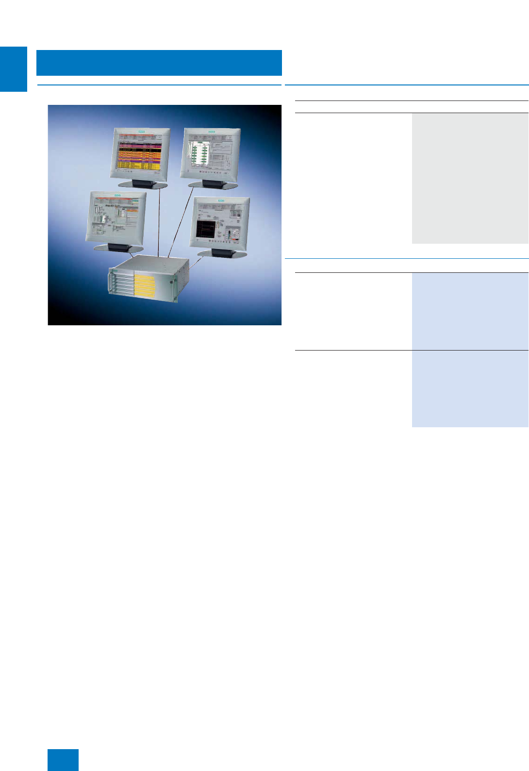
Using a multi-VGA graphics card, the visualization of a
project/subproject when engineering or a plant/unit in process
operation can be divided among up to 4 process monitors per
operator station with application of different views. These
project/plant sections can all be operated using just one key-
board and one mouse. Compared to single-channel mode, it is
thus possible to enormously improve the efficiency, convenience
and ergonomics of engineering and process control.
■
Technical specifications
B) Subject to export regulations: AL: N, ECCN: EAR99H
Multi-VGA graphics cards
Memory 32 MB DDRAM per output
• Graphics card "2 Screens" 2 x 32 MB
• Graphics card "4 Screens" 4 x 32 MB
Clock 360 MHz integrated RAMDAC
Max. analog resolution per channel 2048 x 1536 at 24 bpp and 85 Hz
Max. digital resolution per channel 1280 x 1024
Electromagnetic compatibility
(EMC)
• Emitted interference EN 55022 Class B
• Noise immunity EN 50082
Slot requirement 1 PCI slot
■
Selection and Ordering Data Order No.
Multi-VGA Graphics Card
"2 Screens"
for operating 2 process monitors
on 1 station
Type of delivery:
Dual graphics card, driver CD,
manual, 1 dual DVI cable for
2 digital outputs, 2 adapters for
VGA outputs
6ES7 652-0XX03-1XE0 B)
Multi-VGA Graphics Card
"4 Screens"
for operating 4 process monitors
on 1 station
Type of delivery:
Quad graphics card, driver CD,
manual, 2 dual DVI cables for
4 digital outputs, 4 adapters for
VGA outputs
6ES7 652-0XX03-1XE1 B)
© Siemens AG 2007
System-neutral components
SIMATIC PCS 7 Industrial Workstation
Operator panels/monitors
2/17
Siemens ST PCS 7 · November 2007
2
■
Overview
Operating devices
In addition to the mouse and SIMATIC PC keyboard described
as operating devices in the Section "Basic hardware", you can
find further devices such as fingerprint mouse, trackball or
Ex-PC operator panel in the Catalog ST PCS 7.1 (Add-ons for
the SIMATIC PCS 7 process control system).
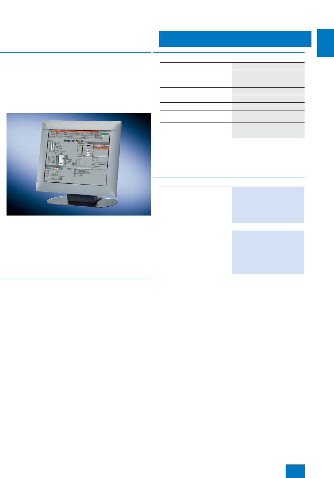
Process monitors
We recommend the SCD 19101-D industrial monitor (LCD color
monitor) for the SIMATIC PCS 7 process control system.
In addition, industrial LCD monitors with IP65 degree of protec-
tion (front) are available for installation in desks, control cabinets
or 19" racks. These are available from:
• the Catalog ST PC "PC-based Automation" or
• the A&D Mall/CA 01 under "Automation Systems – PC-based
Automation - Expansion Components - Industrial LCD Moni-
tors"
■
Benefits
Outstanding characteristics of the SCD 19101-D LCD monitor
include:
7Rugged, fail-safe and long-life industrial design:
- High resistance to shock and vibration
- Extremely high electromagnetic compatibility
- Anti-glare and hardened mineral glass pane for high
mechanical protection
- IP20 degree of protection
- Complies with CE standard "Industry"
7Modern design with exceptional ergonomics:
- Sharp and high-contrast picture with uniform brightness
- No flickering
- Large reading angle up to 170° horizontal and vertical
- Automatic picture adjustment (Auto Adjust)
7No X-rays
7Low energy consumption and heat development
7Small space requirement and low weight
7Configuration using on-screen display (OSD)
7Long service life
■
Technical specifications
Detailed technical data can be found in
• Catalog ST PC "PC-based Automation" or
• the Mall/CA 01 at "Automation systems - Monitors, printers and
input devices for industry"
B) Subject to export regulations: AL: N, ECCN: EAR99H
Monitor SCD 19101-D
Screen 19" (48 cm) TFT color monitor,
1280 x 1024 pixels,
16 million colors
Line frequency 50 ... 97 kHz
Image refresh rate 30 ... 100 Hz
Power supply 110/230 V AC
Dimensions (WxHxD) in mm 465 x 444 x 91 (depth of
stand 240)
Degree of protection IP20
Weight Approx. 10 kg
■
Selection and Ordering Data Order No.
SCD 19101-D industrial LCD
monitor
(same design as SCD 1898-I)
Desktop unit, 230 V AC,
48 cm (19") screen diagonal,
horizontal frequency 50...97 kHz,
IP20 degree of protection
6GF6 220-1DA01 B)
Additional and expansion components
Connection cable
• Video + Touch, 1.8 m long 6AV8 107-0BA00-0AA0
• Video + Touch, 5 m long 6AV8 107-0DA00-0AA0
• Video + Touch, 10 m long 6AV8 107-0FA00-0AA0
• Video, connecting cable 20 m
long 6AV8 107-0HB00-0AA0
© Siemens AG 2007
System-neutral components
SIMATIC PCS 7 Industrial Workstation
Special configurations
2/18 Siemens ST PCS 7 · November 2007
2
■
Overview
The SIMATIC PCS 7 Industrial Workstations offered in the cata-
log section "Basic hardware" already cover the majority of appli-
cations. In the case of special system requirements, particularly
if several supplementary/expansion components such as multi-
VGA graphics card, signal module or memory expansion have
to be integrated at the same time, we also offer the possibility for
ordering completely assembled special configurations of these
SIMATIC PCS 7 Industrial Workstations.
A special SIMATIC PCS 7 Industrial Workstation can be com-
piled interactively on the Internet using a configurator, and its
Order No. generated in the process. This can subsequently be
transferred to the shopping cart for ordering.
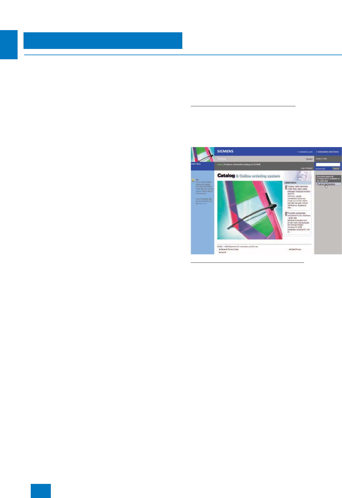
Configurator in the A&D Mall
The configurator "Special SIMATIC PCS 7 Industrial Worksta-
tions" is integrated in the catalog & online ordering system "A&D
Mall" (www.siemens.com/automation/mall). It can be accessed
there in two manners:
Selection using quick link "Configuration list"
A selection window in which all available configurators are cate-
gorized according to technical criteria is opened when you click
the quick link "Configuration list" on the right side of the A&D Mall
(see figure). You can find the configurator "Special SIMATIC
PCS 7 Industrial Workstations" here in the category "Process
automation".
Selection using the "Siemens A&D product tree"
If you click the link "Products" at the second position in the hori-
zontal primary navigation (see blue area at the top in the figure),
the "Siemens A&D product tree" is displayed on the left. Navi-
gate there from "Process automation" via "Process control sys-
tems", "SIMATIC PCS 7 V7.0" and "SIMATIC PCS 7 Industrial
Workstations" on to "Special configurations". Select the
"Configurators" tab here, and then the configurator "Special
SIMATIC PCS 7 Industrial Workstations".
© Siemens AG 2007
Starter systems
SIMATIC PCS 7 BOX
Introduction
3/2 Siemens ST PCS 7 · November 2007
3
■
Overview
Scalable automation performance in the bottom performance range of
SIMATIC PCS 7
(for SIMATIC PCS 7 AS RTX, see page 10/4)
SIMATIC PCS 7 BOX systems are compact and rugged indus-
trial PCs as low-price starter solutions for process automation
with SIMATIC PCS 7. They are available in two versions:
• SIMATIC PCS 7 all-in-one system
with functionality for automation (AS), HMI (OS) and engineer-
ing (ES)
• SIMATIC PCS 7 Runtime system
with AS and OS functionality
Expanded by distributed process I/Os on the PROFIBUS, each
version represents a complete process control system for small
applications.
■
Application
The SIMATIC PCS 7 BOX starter systems can be used for various
applications:
• Small production applications
• Enclosed subprocesses (package units)
• Automation of a laboratory or test center
As a fully adequate member of the SIMATIC PCS 7 range, they
work with the PCS 7 standard system software, are scalable, and
can be expanded without destroying the compatibility. However,
the engineering and runtime licenses for AS and OS are limited
to 2000 POs (process objects).
Use as asset management station
SIMATIC PCS 7 BOX can be incorporated into the PC diagnos-
tics of the SIMATIC PCS 7 asset management using the SIMATIC
PC DiagMonitor software. Equipped as an all-in-one system with
software licenses for SIMATIC PDM and SIMATIC PCS 7 asset
management, they are additionally suitable for use as a mainte-
nance station. For further information, see Chapter "Asset man-
agement".
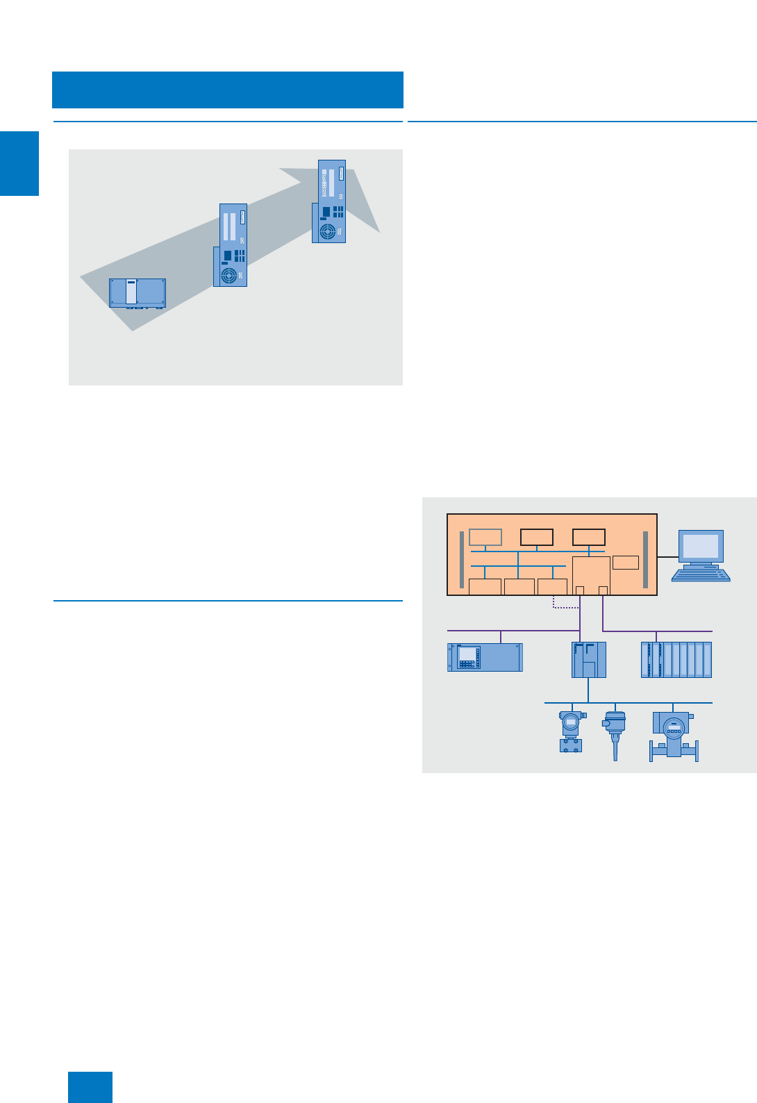
■
Design
Two SIMATIC PCS 7 BOX systems with different performances
are currently available:
• SIMATIC PCS 7 BOX RTX with WinAC RTX software controller
• SIMATIC PCS 7 BOX 416 with WinAC Slot 416 hardware con-
troller
Together with the compact SIMATIC PCS 7 AS RTX Microbox au-
tomation system (see page 10/4), these allow finer scaling of the
automation performance in the bottom performance range of
SIMATIC PCS 7. It is then possible to react more variably to indi-
vidual customer requirements with small applications. With re-
gard to the achievable quantity framework, the SIMATIC PCS 7
BOX systems are approximately comparable with the following
standard automation systems:
• SIMATIC PCS 7 BOX 416 with an AS 416
• SIMATIC PCS 7 BOX RTX with an AS 414
In a direct comparison of the two systems, the SIMATIC PCS 7
BOX RTX impresses primarily due to the following advantages:
• Low price
• Very fast program execution
Particular advantages of the SIMATIC PCS 7 BOX 416 are:
• High availability
• Support of changes to the configuration during runtime (CiR)
through the stand-alone WinAC Slot CPU
Stand-alone operation using example of a SIMATIC PCS 7 BOX 416
SIMATIC PCS 7 AS RTX with
WinAC RTX software controller
SIMATIC PCS 7 BOX RTX with
WinAC RTX software controller
SIMATIC PCS 7 BOX 416
with WinAC Slot 416
hardware controller
Runtime system with
AS functionality
Runtime systems with AS and
OS functionality
or all-in-one systems
with AS, OS and ES functionality
ES
CP 5611
onboard
CPU 416-2 24 V DC
DP MPI/DP
PDM OS
SIMATIC PCS 7 BOX
PROFIBUS DP PROFIBUS MPI/DP
PROFIBUS PA
DP/PA
link
© Siemens AG 2007
Starter systems
SIMATIC PCS 7 BOX
Introduction
3/3
Siemens ST PCS 7 · November 2007
3
Integration in the SIMATIC PCS 7 system network using example of the
SIMATIC PCS 7 BOX 416
SIMATIC PCS 7 BOX systems (SIMATIC PCS 7 BOX RTX as
well as SIMATIC PCS 7 BOX 416) are based on the industrial
SIMATIC Box PC 627B which permits combination of the fre-
quently distributed PCS functionality for automation, HMI and
engineering in one system. They use standard system software
of SIMATIC PCS 7 V7.0, and are integrated in the SIMATIC PCS 7
engineering and the PCS 7 project wizard. This guarantees full
compatibility with SIMATIC PCS 7 V7.0.
SIMATIC PCS 7 BOX can be configured either using the engi-
neering software integrated in the system or a central engineer-
ing system. OS-specific changes in the configuration on the
SIMATIC PCS 7 BOX or on the central engineering system can
be downloaded online, i.e. without terminating OS process oper-
ation.
SIMATIC PCS 7 BOX support ET 200M, ET 200ISP and ET 200S
remote I/O stations connected over PROFIBUS DP by means of
a comprehensive range of low-cost signal/function modules as
well as intelligent field/process devices connected directly over
PROFIBUS DP/PA.
SIMATIC PCS 7 BOX systems can be operated in stand-alone
mode and also in the system network with other SIMATIC PCS 7
system components. The two architectures are illustrated using
examples of the SIMATIC PCS 7 BOX 416.
A system produced with SIMATIC PCS 7 BOX can be expanded
at any time by further SIMATIC PCS 7 hardware and software
components. It is just as easy to integrate SIMATIC PCS 7 BOX
into existing SIMATIC PCS 7 systems. The connections on the
plant bus and OS-LAN (terminal bus) are made using the Ether-
net interfaces integrated in the SIMATIC PCS 7 BOX.
The engineering licenses as well as the runtime licenses for AS
and OS are administered by the engineering software.
With a SIMATIC PCS 7 BOX all-in-one system, the runtime li-
censes for AS and OS are components of the engineering soft-
ware, and can be expanded by AS/OS Software Engineering
PowerPacks to a maximum of 2000 POs.
With a SIMATIC PCS 7 BOX runtime system, the OS Runtime li-
censes can be expanded by OS Software PowerPacks, the
AS Runtime licenses by further AS Runtime licenses for 100 or
1000 POs to a maximum of 2000 POs. The process objects of
additional AS Runtime licenses are then added to process ob-
jects which already exist. The number and type (100 or 1000) of
additional AS Runtime licenses are only limited by the expansion
limit.
SIMATIC PCS 7 BOX
ES
CP 5611
onboard
Ethernet
onboard Ethernet
onboard
CPU 416-2 24 V DC
DP MPI/DP
PDM OS
PROFIBUS PROFIBUS MPI/DP
PROFIBUS PA
OS-LAN (Terminal bus)
Plant bus
DP/PA
link
OS clients
OS
server
Engineering
system
Automation
systems
© Siemens AG 2007
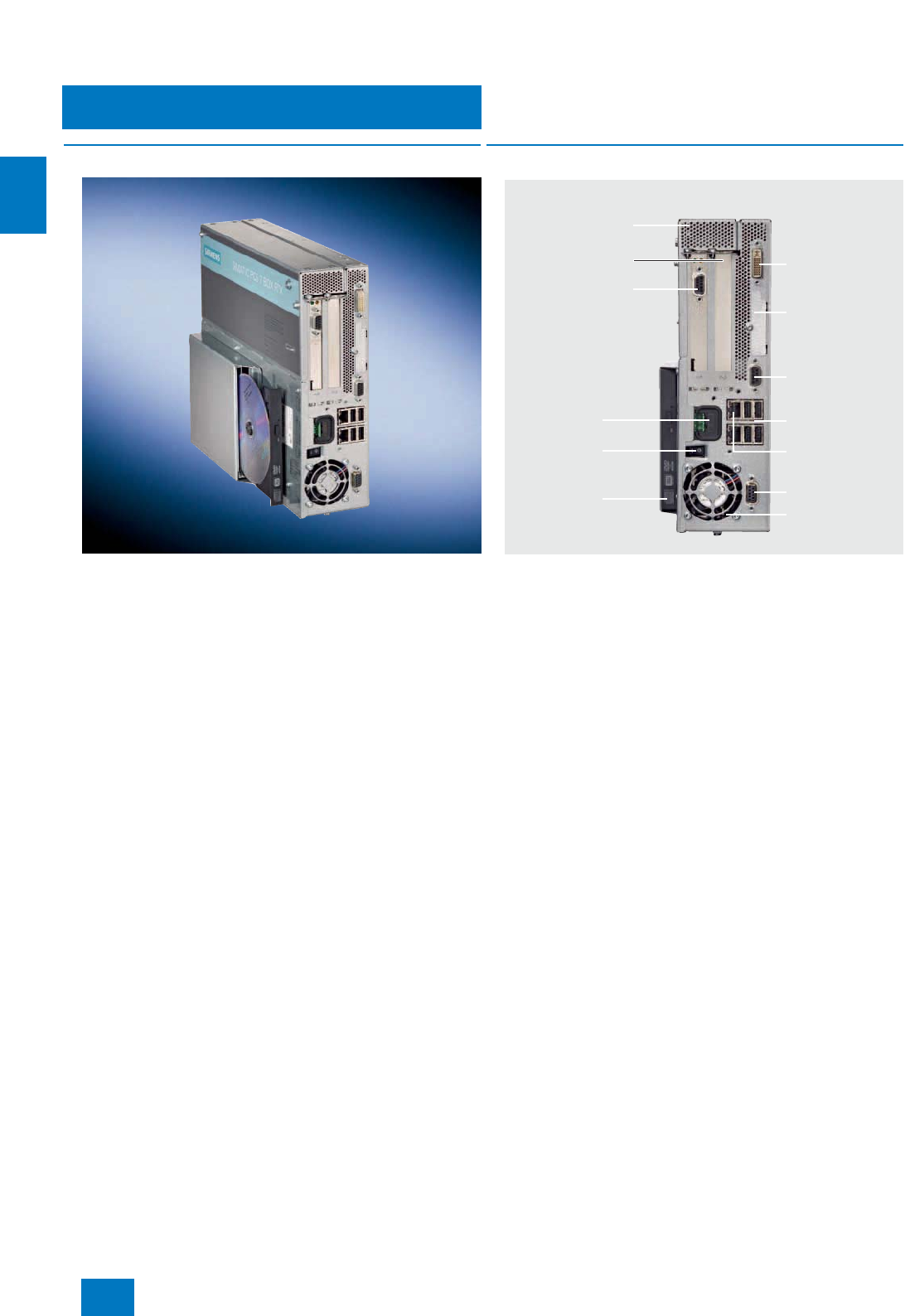
Starter systems
SIMATIC PCS 7 BOX
SIMATIC PCS 7 BOX RTX
3/4 Siemens ST PCS 7 · November 2007
3
■
Overview
The SIMATIC PCS 7 BOX RTX equipped with a WinAC RTX soft-
ware controller features an exceptional price/performance ratio.
With regard to the automation performance, it is positioned
slightly below the SIMATIC PCS 7 BOX 416, but is primarily char-
acterized by its very fast program execution.
The WinAC RTX software controller working on the SIMATIC
Box PC 627B basic hardware only generates a low basic load,
and particularly exhibits its strengths in applications character-
ized by real-time demands and a deterministic response.
■
Design
SIMATIC PCS 7 BOX RTX design
SIMATIC PCS 7 BOX RTX systems are offered in the form of
two product bundles:
• Preinstalled SIMATIC PCS 7 all-in-one system with AS, ES
and OS functionality,
including AS/OS Engineering and Runtime licenses for
250 POs
• Preinstalled SIMATIC PCS 7 runtime system with AS and OS
functionality,
including AS/OS Runtime license for 250 POs
These bundles can be extended by the following expansion
components (see also page 2/15 and catalog on PC-based
Automation):
• SIMATIC PCS 7 PowerPacks/Runtime licenses for up to
2000 POs
• AS/OS Software Engineering PowerPack for all-in-one system
• OS Software Single Station PowerPack and AS Runtime li-
cense for runtime system
• SIMATIC PDM package for PCS 7
• SIMATIC PC keyboard
• LC and CRT displays for office and industrial environments
1 x DVI-I (VGA via
supplied adapter)
All-metal enclosure,
rack-mountable, also suitable
for portrait assembly
DP interface (CP 5613)
Power supply
24 V DC
On/off button
Optical drive
DVD +/- R/RW
1 vacant PCI expansion slot,
e.g. for multi-VGA
graphics card
4 x USB 2.0 interfaces
DP interface
Power supply fan
2 x Gigabit Ethernet
connection for
10/100/1000 Mbit/s
Slot for CompactFlash
card (accessible from
outside)
COM1: Serial
interface 1
© Siemens AG 2007

Starter systems
SIMATIC PCS 7 BOX
SIMATIC PCS 7 BOX RTX
3/5
Siemens ST PCS 7 · November 2007
3
■
Technical specifications
Basic hardware: SIMATIC Box PC 627B
Design and equipment features
Design Rack-mountable device with rug-
ged metal enclosure, suitable for
wall and portrait mounting
Degree of protection to EN 60529 IP20
CPU
• Processor Intel Core 2 Duo T7400 2.16 GHz
• Front Side Bus 667 MHz
• Second Level Cache 4 MB
Chipset Intel 945 GM
Main memory 2 GB DDR2-667 SDRAM
(2 x 1 GB)
Graphics
• Graphics controller Intel 2D/3D GMA950, integrated
in chipset
•Graphics memory Dynamic video memory 8 to
128 MB
• Resolutions/colors/frequencies • VGA: Max. 1600 x 1200 /
32 bit colors / 85 Hz
• DVI: Max. 1600 x 1200 /
32 bit colors / 60 Hz
Drives
•Flash drive For CompactFlash card
• Hard disk 3.5" SATA, 160 GB
• Optical drive DVD ± R/RW
• Diskette drive Connectable via USB (not
included in scope of delivery)
Interfaces
• PROFIBUS (12 Mbit/s) 1 x 9-contact Sub-D socket,
CP 5611-compatible,
1 x 9-contact Sub-D socket,
CP 5613
• Ethernet 2 x 10/100/1000 Mbit/s (RJ 45)
•USB 4 x USB 2.0/high-speed
(2 x high-current)
•Serial 1 x COM1 (V.24), 9-contact Sub-
D connector
• Parallel -
• Graphics connection 1 x DVI-I (DVI/VGA combined):
• DVI: digital
• VGA analog
• Keyboard/mouse Connectable via USB (keyboard
not included in scope of deliv-
ery)
Operating system and diagnos-
tics software
Operating system Windows XP Professional MUI
preinstalled on hard disk and
enclosed on restore DVD, no
activation necessary
System-tested SIMATIC industrial
software SIMATIC PC DiagMonitor
Monitoring/diagnostics functions
Watchdog • Monitoring of program execu-
tion
• Can be parameterized for fault
scenario or restart
• Monitoring time adjustable in
the software
Temperature • Processor temperature
• Air inlet temperature
• Temperature in vicinity of power
supply
(via SIMATIC PC DiagMonitor
and SIMATIC PCS 7 Asset Man-
agement)
Fans • Failure of device fan and power
supply fan
(via SIMATIC PC DiagMonitor
and SIMATIC PCS 7 Asset Man-
agement)
Operating hours counter (via SIMATIC PC DiagMonitor
and SIMATIC PCS 7 Asset Man-
agement)
Displays • Two-digit 7-segment display for
visualization of POST codes
during BIOS booting
• Two programmable status
LEDs
Safety
Protection class Protection class I compliant with
IEC 61140
Safety directives EN 61131-2; UL508; CSA C22.2
No 142
Noise level
Operation < 55 dB (A) to DIN 45635-1
Electromagnetic compatibility
(EMC)
Emitted interference EN 55022 Class B; EN 61000-3-2
Class D
EN 61000-3-3; FCC Class A
Immunity to conducted interfer-
ence on the supply lines ± 2 kV (to IEC 61000-4-4; burst)
± 1 kV (to IEC 61000-4-5;
symmetrical surge)
± 2 kV (to IEC 61000-4-5;
asymmetrical surge)
Immunity to interference on signal
lines ± 1 kV (to IEC 61000-4-4; burst;
length < 3 m)
± 2 kV (to IEC 61000-4-4; burst;
length > 3 m)
± 2 kV (to IEC 61000-4-5; surge;
length > 30 m)
Immunity to static discharge ± 6 kV contact discharge
(to IEC 61000-4-2)
± 8 kV air discharge (to
IEC 61000-4-2)
Immunity to high-frequency irradia-
tion 10 V/m, 80 to 1000 MHz and
1.4 to 2 GHz, 80% AM
(to IEC 61000-4-3)
1 V/m, 2 to 2.7 GHz, 80% AM
(to IEC 61000-4-3)
10 V, 9 kHz to 80 MHz, 80% AM
(to IEC 61000-4-6)
Immunity to magnetic fields 100 A/m, 50/60 Hz
(to IEC 61000-4-8)
■
Technical specifications (cont.)
© Siemens AG 2007
Starter systems
SIMATIC PCS 7 BOX
SIMATIC PCS 7 BOX RTX
3/6 Siemens ST PCS 7 · November 2007
3Climatic conditions
Temperature Tested according to
IEC 60068-2-1, IEC 60068-2-2,
IEC 60068-2-14
• Operation • +5 to +45 °C (with DVD writer,
only up to +40 °C)
• +5 to +50 °C (power of all slots
max. 20 W)
• +5 to +55 °C (power of all slots
max. 10 W)
• Storage/transport -20 to +60 °C
• Gradient Operation: max. 10 °C/h; stor-
age: 20 °C/h, no condensation
Relative humidity Tested according to
IEC 60068-2-78, IEC 60068-2-30
• Operation 5 to 80% at 25 °C
(no condensation)
• Storage/transport 5 to 95% at 25 °C
(no condensation)
Mechanical environmental condi-
tions
Vibrations Tested according to
IEC 60068-2-6
• Operation 10 to 58 Hz: 0.075 mm, 58 to
500 Hz: 9.8 m/s²
Limitation with DVD writer:
10 to 58 Hz: 0.019 mm /
58 to 500 Hz: 2.5 m/s²
Limitation with portrait assembly:
10 to 58 Hz: 0.0375 mm / 58 to
500 Hz: 4.9 m/s²
• Storage/transport 5 to 9 Hz: 3.5 mm, 9 to 500 Hz:
9.8 m/s²
Shock Tested according to
IEC 60068-2-27, IEC 60068-2-29
• Operation 50 m/s², 30 ms
Limitation with portrait assembly:
25 m/s², 30 ms
• Storage/transport 250 m/s², 6 ms
Approvals
CE living accommodation
• Emitted interference EN 61000-6-3: 2001
• Noise immunity EN 61000-6-1: 2001
CE industrial environment
• Emitted interference EN 61000-6-4: 2001
• Noise immunity EN 61000-6-2: 2005
cULus UL 60950-1, Report E11 5352
and CAN/CSA-C22.2 No. 60950-
1; UL508 and CAN/CSA-C22.2
No. 142;
Power supply (electrically
isolated)
Power supply 24 V DC (-15% / +20%), SELV
DC input current Continuous current up to 8 A (up
to 14 A for 30 s during startup)
Max. power consumption
(at 24 V DC) 210 W
Dimensions and weights
Dimensions including DVD writer
(W x H x D) in mm 297 x 267 x 100
Weight Approx. 7 kg
■
Technical specifications (cont.)
Automation: WinAC software PLC
CPU WinAC RTX software controller
for SIMATIC Box PC 627B with
Windows XP Professional operat-
ing system, preconfigured for
SIMATIC PCS 7
All-in-one system
Preinstalled software/license PCS 7 Engineering Software
V7.0 for AS/OS
Number of process objects
(AS/OS engineering and runtime) 250 POs (expandable per
PowerPack to 2000 POs)
Runtime system
Preinstalled software/license PCS 7 OS Software Single
Station V7.0 and
SIMATIC PCS 7 AS Runtime
license
Number of process objects
(runtime) • 250 POs for OS (expandable
per PowerPack to 2000 POs)
• 250 POs for AS (expandable
per AS Runtime license)
■
Technical specifications (cont.)
© Siemens AG 2007

Starter systems
SIMATIC PCS 7 BOX
SIMATIC PCS 7 BOX RTX
3/7
Siemens ST PCS 7 · November 2007
3
■
Selection and Ordering Data Order No.
SIMATIC PCS 7 BOX RTX all-in-
one system (ES, OS and AS)
assembled and preinstalled,
comprising:
• SIMATIC Box PC 627B, 24 V
DC, with Windows XP Profes-
sional MUI operating system
(German, English, French, Ital-
ian, Spanish), WinAC RTX soft-
ware controller and SIMATIC
PC DiagMonitor diagnostics
software
• Mouse
• SIMATIC PCS 7 Engineering
Software V7.0 for AS/OS includ-
ing AS/OS Runtime license for
productive operation, 250 POs,
5 languages (German, English,
French, Italian, Spanish), float-
ing license for 1 user
6ES7 650-2QA07-0YX0 D)
SIMATIC PCS 7 BOX RTX
runtime system (OS and AS)
assembled and preinstalled,
comprising:
• SIMATIC Box PC 627B, 24 V
DC, with Windows XP Profes-
sional MUI operating system
(German, English, French, Ital-
ian, Spanish), WinAC RTX soft-
ware controller and SIMATIC
PC DiagMonitor diagnostics
software
• Mouse
• SIMATIC PCS 7 OS Software
Single Station V7.0, 250 POs,
5 languages (German, English,
French, Italian, Spanish), single
license for 1 installation
• SIMATIC PCS 7 AS Runtime
license, 250 POs
5 languages (German, English,
French, Italian, Spanish), single
license for 1 installation
6ES7 650-2QB07-0YX0 D)
Additional and expansion components
SIMATIC PCS 7 PowerPacks for all-in-one system
SIMATIC PCS 7 PowerPack
Engineering Software AS/OS
V7.0
for extending the engineering
software for AS/OS
5 languages (German, English,
French, Italian, Spanish), exe-
cutes with Windows
XP Professional, floating license
for 1 user
Type of delivery: License key
disk, emergency key disk, certifi-
cate of license, terms and condi-
tions
• From 250 to 1000 POs, includ-
ing AS/OS Runtime license 6ES7 658-5AB07-0YD5
• From 1000 to 2000 POs, includ-
ing AS/OS Runtime license 6ES7 658-5AC07-0YD5
D) Subject to export regulations: AL: N, ECCN: 5D992B1
SIMATIC PCS 7 PowerPacks/licenses for runtime system
SIMATIC PCS 7 PowerPack
OS Software Single Station
V7.0
for extending the OS Software
Single Station
5 languages (German, English,
French, Italian, Spanish), exe-
cutes with Windows
XP Professional, single license
for 1 installation
Type of delivery: License key
disk, emergency key disk, certifi-
cate of license, terms and condi-
tions
• From 250 POs to 1000 POs 6ES7 658-2AB07-0YD0
• From 1000 POs to 2000 POs 6ES7 658-2AC07-0YD0
SIMATIC PCS 7 AS Runtime
license (can be added to exist-
ing licenses)
5 languages (German, English,
French, Italian, Spanish), exe-
cutes with Windows
XP Professional, single license for
1 installation
Type of delivery:
License key disk, certificate of
license, terms and conditions
• 100 POs 6ES7 653-2BA00-0XB5
• 1000 POs 6ES7 653-2BB00-0XB5
SIMATIC PDM
SIMATIC PDM PCS 7 V6.0
Complete package for integra-
tion into the engineering toolset
of the SIMATIC PCS 7 engineer-
ing system
5 languages (German, English,
French, Italian, Spanish), exe-
cutes with Windows 2000 Profes-
sional or Windows
XP Professional, floating license
for 1 user, with:
• SIMATIC PDM Basic
• Option "Integration in
STEP 7/PCS 7"
• Option "Routing through S7-
400"
• Option "128 TAGs"
Software and electronic docu-
mentation on toolset DVD
Type of delivery:
• License key disk, emergency
key disk, certificate of license,
terms and conditions
• 2 CDs with SIMATIC PDM V6.0
and device library
Note:
TAG options and PowerPacks:
see page 4/14
6ES7 658-3LX06-0YA5
Further SIMATIC PCS 7 system
software
• SIMATIC BATCH: see Section
"Batch automation"
• SIMATIC PCS 7 asset-manage-
ment: see Section "Asset
management"
SIMATIC PC keyboard
(USB connection)
• International key assignment 6ES7 648-0CB00-0YA0
■
Selection and Ordering Data Order No.
© Siemens AG 2007
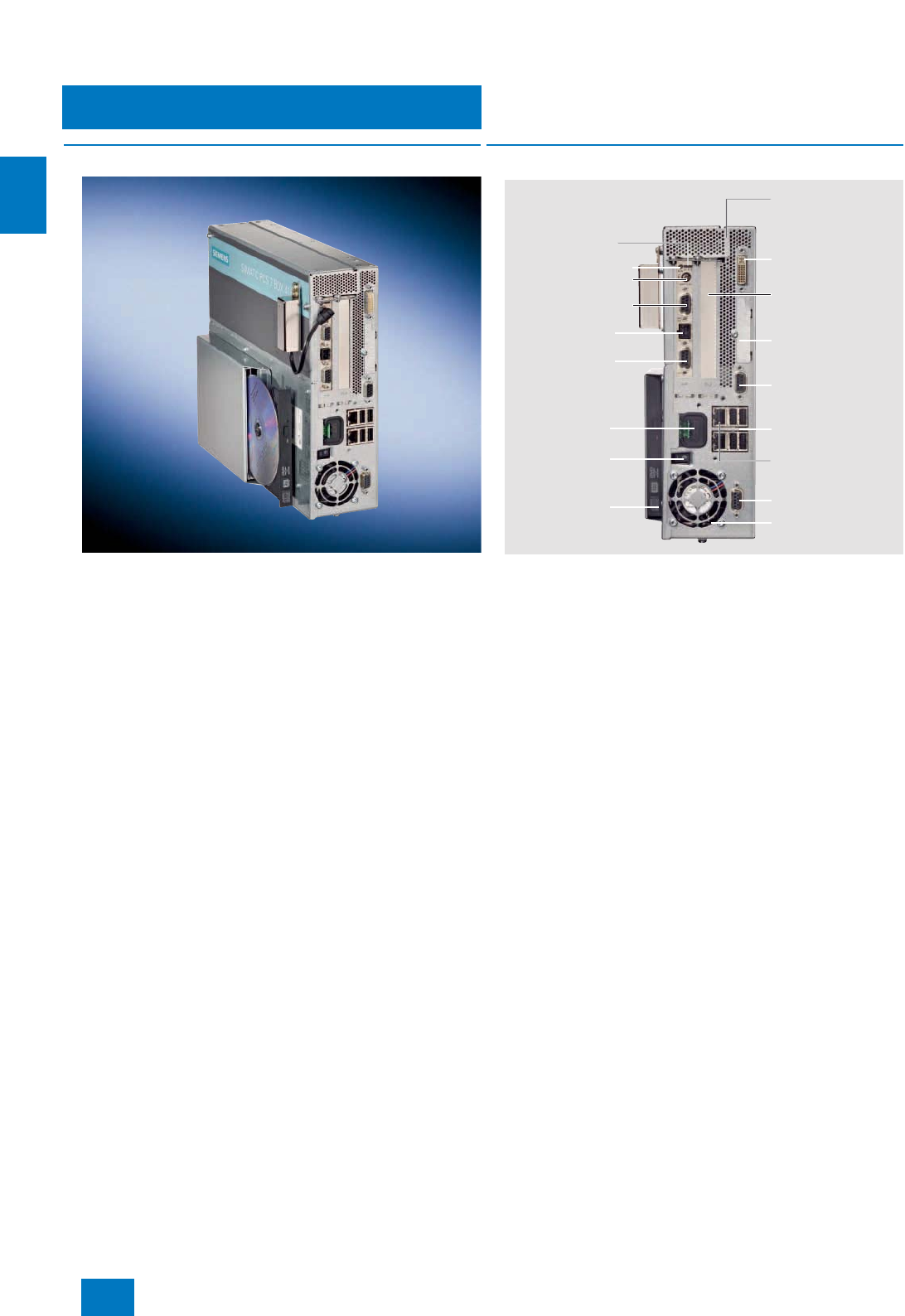
Starter systems
SIMATIC PCS 7 BOX
SIMATIC PCS 7 BOX 416
3/8 Siemens ST PCS 7 · November 2007
3
■
Overview
The SIMATIC PCS 7 BOX 416 equipped with a WinAC Slot 416
V4.0 hardware controller is based like the SIMATIC PCS 7 BOX
RTX on the industrial PC SIMATIC Box PC 627B. With regards to
the automation performance, it is positioned slightly above the
SIMATIC PCS 7 BOX RTX, and is particularly recommendable if
high availability or changes to the configuration during operation
(CiR) are relevant factors for the selection.
■
Design
Design of SIMATIC PCS 7 BOX 416
SIMATIC PCS 7 BOX 416 systems are offered in the form of
two product bundles:
• Preinstalled SIMATIC PCS 7 all-in-one system with AS, ES
and OS functionality,
including AS/OS Engineering and Runtime licenses for
250 POs
• Preinstalled SIMATIC PCS 7 runtime system with AS and OS
functionality,
including AS/OS Runtime license for 250 POs
These bundles can be extended by the following expansion
components (see also page 2/15 and catalog on PC-based
Automation):
• SIMATIC PCS 7 PowerPacks/Runtime licenses for up to
2000 POs
- AS/OS Software Engineering PowerPack for all-in-one sys-
tem
- OS Software Single Station PowerPack and AS Runtime
license for runtime system
• SIMATIC PDM package for PCS 7
• SIMATIC PC keyboard
• LC and CRT displays for office and industrial environments
• SITOP smart power supply 230 AC/24 V DC, 240 W
• SITOP DC UPS module 15 A with RS 232 interface
• DC UPS software for further processing of the signals sent by
the DC UPS module with RS 232 interface on the PC (status
visualization as well as definition of response to various oper-
ating states of the DC UPS module), executes with Windows
NT, 2000 and XP; freeware for downloading at www.sie-
mens.com/sitop
• SITOP battery module 24 V DC/20 A/7 Ah for DC UPS module
15 A
1 x DVI-I (VGA via
supplied adapter)
All-metal enclosure,
rack-mountable, also
suitable for portrait
assembly
DP interface
MPI/DP interface
RUN/STOP LEDs
RUN mode switch
Backup battery connection
External connection
24 V DC supply
Power supply
24 V DC
On/off button
Optical drive
DVD +/- R/RW
1 vacant PCI expansion
slot, e.g. for multi-VGA
graphics card
4 x USB 2.0 interfaces
DP interface
Power supply fan
2 x Gigabit Ethernet
connection for
10/100/1000 Mbit/s
Slot for CompactFlash
card (accessible from
outside)
COM1: Serial interface 1
© Siemens AG 2007

Starter systems
SIMATIC PCS 7 BOX
SIMATIC PCS 7 BOX 416
3/9
Siemens ST PCS 7 · November 2007
3
■
Function
WinAC Slot 416 V4.0
Through use of the WinAC Slot 416 V4.0, it is possible for the au-
tomation program in the Slot CPU to execute completely auton-
omously from the SIMATIC Box PC and its Windows operating
system. Therefore the system can be restarted even if the
SIMATIC Box PC is switched off or faulty. 24 V DC from a sepa-
rate source is connected to the Slot CPU to provide a power sup-
ply independent of the PC. Neither software faults on the PC
side, nor a power loss, nor rebooting of the PC have an effect on
execution of the automation program in the Slot CPU.
If one of the following events occurs, the automation program is
immediately informed and can thus react accordingly, e.g. by in-
termediate storage of production data and transfer of the system
to a defined status:
• Shutting-down of the Windows operating system
• Fault in the Windows operating system ("blue screen")
• Failure of PC-internal communication
• Switching-off of the PC (Separate 24 V DC supply required)
With the SIMATIC PCS 7 BOX 416, the process I/O is connected
via the two PROFIBUS DP ports of the WinAC Slot 416 V4.0. In
conjunction with SIMATIC PCS 7 V7.0, the WinAC Slot 416 V4.0
also permits changes to the configuration during operation
(CiR). The type and scope of online modifications depend on the
process I/O used.
Since SIMATIC PDM can only access field devices on the
PROFIBUS DP via the onboard CP 5611 communications pro-
cessor, an additional link is required between the DP port and
the CP 5611. The plug required belongs to the scope of delivery
of the SIMATIC PCS 7 BOX 416.
Use with SIMATIC BATCH
SIMATIC PCS 7 BOX 416 systems can also be used for automa-
tion of batch processes with SIMATIC BATCH. The capacity of
SIMATIC BATCH is limited to 10 UNITs (instances of plant units)
in this case. The following SIMATIC BATCH option packages can
be executed on the SIMATIC PCS 7 BOX in addition to the SI-
MATIC BATCH Server Basic Package for up to 10 UNITs:
• Batch Control Center
• Recipe System
• Batch Planning
• Hierarchical Recipe
• ROP Library
• Separation Procedures/Formulas
Use with SIMATIC Route Control
SIMATIC PCS 7 BOX 416 systems are not only suitable for auto-
mation of batch processes with SIMATIC BATCH, but also for
control of material transports with SIMATIC Route Control. The
capacity of SIMATIC Route Control is limited to 30 simultaneous
material transports in this case. The SIMATIC Route Control
Server and SIMATIC Route Control Center runtime software is
then executed on the SIMATIC PCS 7 BOX 416. The Route Con-
trol Engineering is also possible on a SIMATIC PCS 7 BOX 416
all-in-one system.
■
Technical specifications
Basic hardware: SIMATIC Box PC 627B
Design and equipment features
Design Rack-mountable device with rug-
ged metal enclosure, suitable for
wall and portrait mounting
Degree of protection to EN 60529 IP20
CPU
• Processor Intel Core 2 Duo T7400 2.16 GHz
• Front Side Bus 667 MHz
• Second Level Cache 4 MB
Chipset Intel 945 GM
Main memory 2 GB DDR2-667 SDRAM
(2 x 1 GB)
Graphics
• Graphics controller Intel 2D/3D GMA950, integrated
in chipset
• Graphics memory Dynamic video memory 8 to
128 MB
• Resolutions/colors/frequencies • VGA: Max. 1600 x 1200 /
32 bit colors / 85 Hz
• DVI: Max. 1600 x 1200 /
32 bit colors / 60 Hz
Drives
• Flash drive For CompactFlash card
• Hard disk 3.5" SATA, 160 GB
• Optical drive DVD ± R/RW
• Diskette drive Connectable via USB (not
included in scope of delivery)
Interfaces
• PROFIBUS/MPI 1 x 9-contact Sub-D socket,
12 Mbit/s (electrically isolated,
CP 5611-compatible)
• Ethernet 2 x 10/100/1000 Mbit/s (RJ 45)
•USB 4 x USB 2.0/high-speed
(2 x high-current)
•Serial 1 x COM1 (V.24), 9-contact
Sub-D connector
• Parallel -
• Graphics connection 1 x DVI-I (DVI/VGA combined):
• DVI: digital
• VGA analog
• Keyboard/mouse Connectable via USB (keyboard
not included in scope of deliv-
ery)
Operating system and
diagnostics software
Operating system Windows XP Professional MUI
preinstalled on hard disk and
enclosed on restore DVD, no
activation necessary
System-tested SIMATIC industrial
software SIMATIC PC DiagMonitor
© Siemens AG 2007

Starter systems
SIMATIC PCS 7 BOX
SIMATIC PCS 7 BOX 416
3/10 Siemens ST PCS 7 · November 2007
3Monitoring/diagnostics functions
Watchdog • Monitoring of program execu-
tion
• Can be parameterized for fault
scenario or restart
• Monitoring time adjustable in
the software
Temperature • Processor temperature
• Air inlet temperature
• Temperature in vicinity of power
supply
(via SIMATIC PC DiagMonitor
and SIMATIC PCS 7 Asset Man-
agement)
Fans • Failure of device fan and power
supply fan
(via SIMATIC PC DiagMonitor
and SIMATIC PCS 7 Asset
Management)
Operating hours counter (via SIMATIC PC DiagMonitor
and SIMATIC PCS 7 Asset
Management)
Displays • Two-digit 7-segment display for
visualization of POST codes
during BIOS booting
• Two programmable status
LEDs
Safety
Protection class Protection class I compliant with
IEC 61140
Safety directives EN 61131-2; UL508;
CSA C22.2 No 142
Noise level
Operation < 55 dB (A) to DIN 45635-1
Electromagnetic compatibility
(EMC)
Emitted interference EN 55022 Class B;
EN 61000-3-2 Class D
EN 61000-3-3; FCC Class A
Immunity to conducted interfer-
ence on the supply lines ± 2 kV (to IEC 61000-4-4; burst)
± 1 kV (to IEC 61000-4-5;
symmetrical surge)
± 2 kV (to IEC 61000-4-5;
asymmetrical surge)
Immunity to interference on signal
lines ± 1 kV (to IEC 61000-4-4; burst;
length < 3 m)
± 2 kV (to IEC 61000-4-4; burst;
length > 3 m)
± 2 kV (to IEC 61000-4-5; surge;
length > 30 m)
Immunity to static discharge ± 6 kV contact discharge
(to IEC 61000-4-2)
± 8 kV air discharge
(to IEC 61000-4-2)
Immunity to high-frequency irradia-
tion 10 V/m, 80 to 1000 MHz and
1.4 to 2 GHz, 80% AM
(to IEC 61000-4-3)
1 V/m, 2 to 2.7 GHz, 80% AM
(to IEC 61000-4-3)
10 V, 9 kHz to 80 MHz, 80% AM
(to IEC 61000-4-6)
Immunity to magnetic fields 100 A/m, 50/60 Hz
(to IEC 61000-4-8)
■
Technical specifications (cont.)
Climatic conditions
Temperature Tested according to
IEC 60068-2-1,
IEC 60068-2-2,
IEC 60068-2-14
• Operation • +5 ... +45 °C (with DVD writer,
only up to +40 °C)
• +5 ... +50 °C (power of all slots
max. 20 W)
• +5 ... +55 °C (power of all slots
max. 10 W)
• Storage/transport -20 ... +60 °C
•Gradient Operation: max. 10 °C/h; stor-
age: 20 °C/h, no condensation
Relative humidity Tested according to
IEC 60068-2-78, IEC 60068-2-30
• Operation 5 ... 80% at 25 °C
(no condensation)
• Storage/transport 5 ... 95% at 25 °C
(no condensation)
Mechanical environmental
conditions
Vibrations Tested according to
IEC 60068-2-6
• Operation 10 to 58 Hz: 0.075 mm, 58 to
500 Hz: 9.8 m/s²
Limitation with DVD writer:
10 to 58 Hz: 0.019 mm / 58 to
500 Hz: 2.5 m/s²
Limitation with portrait assembly:
10 to 58 Hz: 0.0375 mm /
58 to 500 Hz: 4.9 m/s²
• Storage/transport 5 ... 9 Hz: 3,5 mm,
9to500Hz:9.8 m/s²
Shock Tested according to
IEC 60068-2-27, IEC 60068-2-29
• Operation 50 m/s², 30 ms
Limitation with portrait assem-
bly: 25 m/s², 30 ms
• Storage/transport 250 m/s², 6 ms
Approvals
CE living accommodation
• Emitted interference EN 61000-6-3: 2001
• Noise immunity EN 61000-6-1: 2001
CE industrial environment
• Emitted interference EN 61000-6-4: 2001
• Noise immunity EN 61000-6-2: 2005
cULus UL 60950-1, Report E11 5352
and CAN/CSA-C22.2
No. 60950-1; UL508 and
CAN/CSA-C22.2 No. 142
Power supply (electrically
isolated)
Power supply 24 V DC (-15% / +20%), SELV
DC input current Continuous current up to 8 A (up
to 14 A for 30 s during startup)
Max. power consumption
(at 24 V DC) 210 W
Dimensions and weights
Dimensions including DVD writer
(WxHxD) in mm 297 x 267 x 100
Weight Approx. 7 kg
■
Technical specifications (cont.)
© Siemens AG 2007

Starter systems
SIMATIC PCS 7 BOX
SIMATIC PCS 7 BOX 416
3/11
Siemens ST PCS 7 · November 2007
3
Automation: WinAC Slot PLC module
CPU WinAC Slot 416 V4.0 hardware
controller
for SIMATIC Box PC 627B with
Windows XP Professional operat-
ing system
Main memory 1.6 + 1.6 MB (integrated)
Load memory 256 KB
Memory card 2 MB RAM (fitted)
Execution times Binary command: 0.04 µs,
IEEE floating-point: 0.12 µs
PROFIBUS DP PROFIBUS DP and
PROFIBUS DP/MPI interfaces
onboard
Dimensions PCI plug-in card (3/4 long)
All-in-one system
Preinstalled software/license PCS 7 Engineering Software
V7.0 for AS/OS
Number of process objects
(AS/OS engineering and runtime) 250 POs (expandable per Pow-
erPack to 2000 POs)
Runtime system
Preinstalled software/license PCS 7 OS Software Single
Station V7.0 and
SIMATIC PCS 7 AS Runtime
license
Number of process objects
(runtime) • 250 POs for OS (expandable
per PowerPack to 2000 POs)
• 250 POs for AS (expandable
per AS Runtime license)
■
Technical specifications (cont.)
■
Selection and Ordering Data Order No.
SIMATIC PCS 7 BOX 416 all-in-
one system (ES, OS and AS)
assembled and preinstalled,
comprising:
• SIMATIC Box PC 627B, 24 V
DC, with WinAC Slot 416 V4.0,
Windows XP Professional MUI
operating system (German, En-
glish, French, Italian, Spanish)
and DiagMonitor diagnostics
software
• Memory card 2 MB
• Backup battery
•Mouse
• SIMATIC PCS 7 Engineering
Software V7.0 for AS/OS includ-
ing AS/OS Runtime license for
productive operation, 250 POs,
5 languages (German, English,
French, Italian, Spanish), float-
ing license for 1 user
6ES7 650-2PA07-0YX0 D)
SIMATIC PCS 7 BOX 416
runtime system (OS and AS)
assembled and preinstalled,
comprising:
• SIMATIC Box PC 627B, 24 V
DC, with WinAC Slot 416 V4.0,
Windows XP Professional MUI
operating system (German, En-
glish, French, Italian, Spanish)
and DiagMonitor diagnostics
software
• Memory card 2 MB
• Backup battery
•Mouse
• SIMATIC PCS 7 OS Software
Single Station V7.0, 250 POs,
5 languages (German, English,
French, Italian, Spanish), single
license for 1 installation
• SIMATIC PCS 7 AS Runtime
license, 250 POs
5 languages (German, English,
French, Italian, Spanish), single
license for 1 installation
6ES7 650-2PB07-0YX0 D)
D) Subject to export regulations: AL: N, ECCN: 5D992B1
© Siemens AG 2007

Starter systems
SIMATIC PCS 7 BOX
SIMATIC PCS 7 BOX 416
3/12 Siemens ST PCS 7 · November 2007
3
1) Additive DC UPS software (executes with Windows NT, 2000 and XP) for
further processing of the signals sent by the DC UPS module with RS 232
interface on the PC; freeware for downloading at http://www.sie-
mens.com/sitop
Additional and expansion components
SIMATIC PCS 7 PowerPacks for
all-in-one system
SIMATIC PCS 7 PowerPack Engi-
neering Software AS/OS V7.0
for extending the engineering
software for AS/OS
5 languages (German, English,
French, Italian, Spanish), exe-
cutes with Windows
XP Professional, floating license
for 1 user
Type of delivery: License key
disk, emergency key disk, certifi-
cate of license, terms and condi-
tions
• From 250 to 1000 POs, includ-
ing AS/OS Runtime license 6ES7 658-5AB07-0YD5
• From 1000 to 2000 POs, includ-
ing AS/OS Runtime license 6ES7 658-5AC07-0YD5
SIMATIC PCS 7 PowerPacks/
licenses for runtime
system
SIMATIC PCS 7 PowerPack
OS Software Single Station V7.0
for extending the OS Software
Single Station
5 languages (German, English,
French, Italian, Spanish), exe-
cutes with Windows
XP Professional, single license
for 1 installation
Type of delivery: License key
disk, emergency key disk, certifi-
cate of license, terms and condi-
tions
• From 250 POs to 1000 POs 6ES7 658-2AB07-0YD0
• From 1000 POs to 2000 POs 6ES7 658-2AC07-0YD0
SIMATIC PCS 7 AS Runtime
license (can be added to
existing licenses)
5 languages (German, English,
French, Italian, Spanish), exe-
cutes with Windows
XP Professional, single license for
1 installation
Type of delivery:
License key disk, certificate of
license, terms and conditions
•100 POs 6ES7 653-2BA00-0XB5
• 1000 POs 6ES7 653-2BB00-0XB5
■
Selection and Ordering Data Order No.
SIMATIC PDM PCS 7 V6.0
Complete package for integra-
tion into the engineering toolset of
the SIMATIC PCS 7 engineering
system
5 languages (German, English,
French, Italian, Spanish), exe-
cutes with Windows 2000
Professional or Windows
XP Professional, floating license
for 1 user, with:
• SIMATIC PDM Basic
• Option "Integration in
STEP 7/PCS 7"
• Option "Routing through S7-
400"
• Option "128 TAGs"
Software and electronic docu-
mentation on toolset DVD
Type of delivery:
• License key disk, emergency
key disk, certificate of license,
terms and conditions
• 2 CDs with SIMATIC PDM V6.0
and device library
Note: TAG options and
PowerPacks: see page 4/14
6ES7 658-3LX06-0YA5
Further SIMATIC PCS 7 system
software
• SIMATIC BATCH: see Section
"Batch automation"
• SIMATIC PCS 7 asset-manage-
ment: see Section "Asset man-
agement"
SIMATIC PC keyboard (USB
connection)
• International key assignment 6ES7 648-0CB00-0YA0
Power supply 230 V AC /
24 V DC
• SITOP smart 240W
Stabilized load power supply,
input: 120/230 V AC, output:
24 V DC / 10 A
6EP1 334-2AA01
• SITOP DC UPS module
24 V DC/15 A 1)
with RS 232 interface and
charger unit for 24 V lead
battery
Input: 24 V DC/16 A, output
24 V DC/15 A
6EP1 931-2EC31
• SITOP battery module
24 V DC/20 A/7 Ah
for DC UPS module 15 A
6EP1 935-6ME21
■
Selection and Ordering Data Order No.
© Siemens AG 2007
Starter systems
Runtime Basic Packages
3/13
Siemens ST PCS 7 · November 2007
3
■
Overview
Components of the Runtime Basic Package V7.0
The SIMATIC PCS 7 Runtime Basic Package V7.0 has been spe-
cially designed as a low-cost starter solution for process auto-
mation with SIMATIC PCS 7 automation systems of S7-400 de-
sign. The hardware and the system software of this product
bundle are scalable, and can be expanded using other SIMATIC
PCS 7 system components. The three versions differ with re-
gards to the automation system used as platform: AS 414-3,
AS 416-2 or AS 417-4-1H. The have a neutral design so that all
options remain available for an individual system configuration.
■
Design
A SIMATIC PCS 7 Runtime Basic Package V7.0 comprises:
• One AS 414-3, AS 416-2 or AS 417-4-1H automation system
with Runtime license for 100 POs as defined in the Chapter
"Automation systems",
in each case as follows:
- UR2 rack (9 slots)
- Without power supply, without backup batteries
- Without memory card
• One cumulative SIMATIC PCS 7 AS Runtime license
with 1000 POs (AS-414-3, AS 416-2) or 400 PO (AS 417-4-H),
single license for 1 installation
• One SIMATIC PCS 7 OS Software Single Station V7.0,
1000 POs, single license for 1 installation
AS 414-3 / AS 416-2 / AS 417-4-1H
SIMATIC PCS 7 AS Runtime license
(cumulative),
1000 POs (AS 414-3, AS 416-2) or
400 POs (AS 417-4-1H)
SIMATIC PCS 7 OS Software Single Station
1000 POs
- Runtime license for 100 POs
- UR2 rack
- Without power supply
- Without backup batteries
- Without memory card
■
Selection and Ordering Data Order No.
SIMATIC PCS 7 Runtime Basic
Package AS 414-3
comprising:
• 1 x AS 414-3 automation sys-
tem with Runtime license for
100 POs
(according to definition in
Chapter "Standard automation
systems")
- UR2 rack (9 slots)
- Without power supply, without
backup batteries
- Without memory card
• 1 x SIMATIC PCS 7 AS Runtime
license, 1000 POs (cumula-
tive),
6 languages (German, English,
French, Italian, Spanish,
Chinese), single license for
1 installation
• 1 x SIMATIC PCS 7 OS Software
Single Station V7.0, 1000 POs,
6 languages (German, English,
French, Italian, Spanish,
Chinese), single license for
1 installation
6ES7 650-3XG07-0YX0 D)
SIMATIC PCS 7 Runtime Basic
Package AS 416-2
comprising:
• 1 x AS 416-2 automation sys-
tem with Runtime license for
100 POs (according to defini-
tion in Chapter "Standard auto-
mation systems")
- UR2 rack (9 slots)
- Without power supply, without
backup batteries
- Without memory card
• 1 x SIMATIC PCS 7 AS Runtime
license, 1000 POs (cumula-
tive),
6 languages (German, English,
French, Italian, Spanish,
Chinese), single license for
1 installation
• 1 x SIMATIC PCS 7 OS Software
Single Station V7.0, 1000 POs,
6 languages (German, English,
French, Italian, Spanish,
Chinese), single license for
1 installation
6ES7 650-3XH07-0YX0 D)
D) Subject to export regulations: AL: N, ECCN: 5D992B1
© Siemens AG 2007

Starter systems
Runtime Basic Packages
3/14 Siemens ST PCS 7 · November 2007
3
D) Subject to export regulations: AL: N, ECCN: 5D992B1
SIMATIC PCS 7 Runtime Basic
Package AS 417-4-1H
comprising:
• 1 x AS 417-4-1H automation
system with Runtime license for
100 POs
(according to definition in
Chapter "Standard automation
systems")
- UR2 rack (9 slots)
- Without power supply, without
backup batteries
- Without memory card
• 1 x SIMATIC PCS 7 AS Runtime
license, 400 POs (cumulative),
6 languages (German, English,
French, Italian, Spanish,
Chinese), single license for
1 installation
• 1 x SIMATIC PCS 7 OS Software
Single Station V7.0, 1000 POs,
6 languages (German, English,
French, Italian, Spanish,
Chinese), single license for
1 installation
6ES7 650-3XJ07-0YX0 D)
■
Selection and Ordering Data Order No.
© Siemens AG 2007
Siemens ST PCS 7 · November 2007
4/2 Introduction
4/3 ES hardware
4/3 ES single station
4/4 ES software
4/4 Introduction
4/5 Standard engineering software
4/10 Version Cross Manager
4/11 Version Trail
4/12 Import/Export Assistant
4/13 SIMATIC PDM Process Device Manager
4/20 Engineering Process Safety
4/20 Introduction
4/22 Engineering F/FH systems
4/23 SIMATIC Safety Matrix
4/25 SIMATIC PCS 7 Safety ES Packages
4/26 Simulation
4/26 Simulation with S7-PLCSIM
Engineering system
© Siemens AG 2007
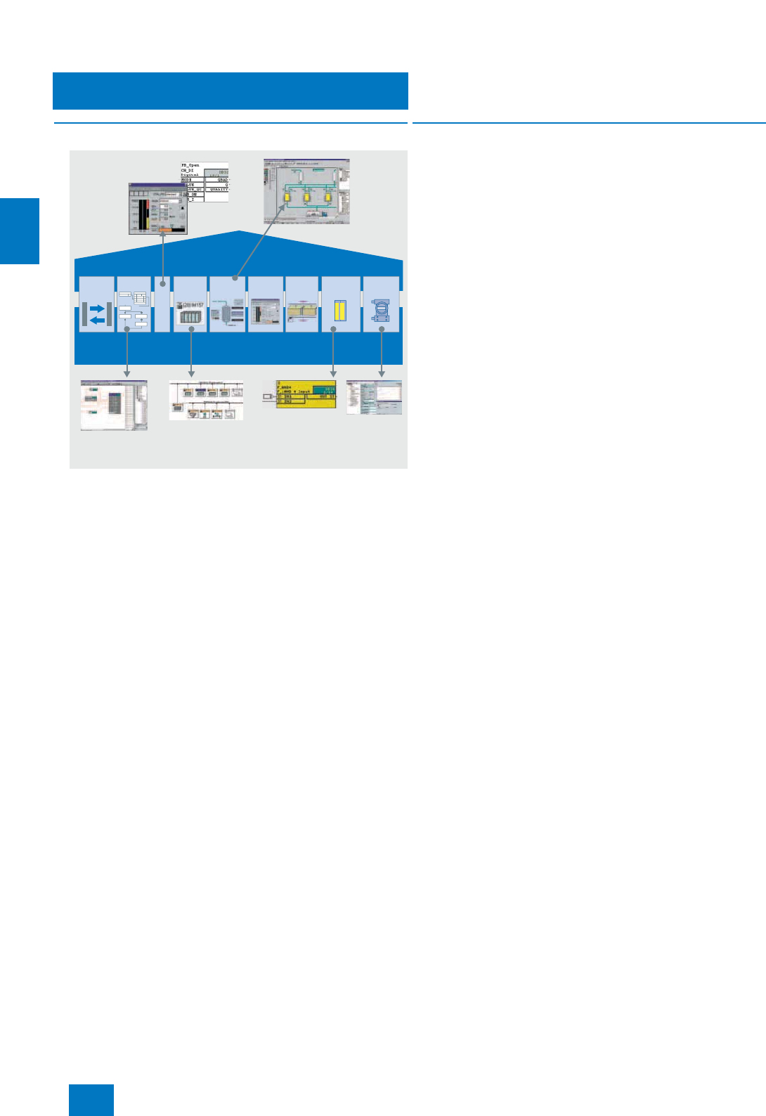
Engineering system
Introduction
4/2 Siemens ST PCS 7 · November 2007
4
■
Overview
The engineering system of the SIMATIC PCS 7 process control
system is based on powerful PC technology combined with the
Windows XP Professional operating system. This can also be
used in offices or industrial environments.
The engineering software executed on it can be optimally
matched to different customer requirements and tasks.
In accordance with the application, the following system ver-
sions are defined by licensing of the standard engineering soft-
ware:
• A classic, exclusive engineering station; not suitable for pro-
ductive operation as an operator station
• A combined engineering/operator station for small applica-
tions; also suitable for productive operation as an operator
station
The basic functionality covered by the standard engineering
software can be optionally expanded depending on the project-
specific task and its implementation.
■
Design
The control center of the engineering system is the SIMATIC
Manager. It is the integration platform for the engineering toolset
as well as the configuration basis for all engineering tasks of the
SIMATIC PCS 7 process control system. All aspects of the
SIMATIC PCS 7 project are created, managed, archived and
documented here. A uniform database guarantees that once
data have been entered they are available throughout the sys-
tem.
The engineering toolset contains tools which are optimally
matched to one another for system-wide project-oriented engi-
neering, and which simultaneously provide the basis for asset
management of the I&C equipment. These include tools for ef-
fective engineering of the following components:
• Control system hardware including distributed I/O and field
devices
• Communication networks
• Automation functionality for continuous and batch processes
(AS engineering)
• Operation and monitoring functionality (OS engineering)
• Safety applications (Safety Integrated for Process Automa-
tion)
• Diagnostics and asset management functionality
• Batch processes automated using SIMATIC BATCH
• Material transports controlled using SIMATIC Route Control
• Cooperation with higher-level CAD/CAE planning tools (im-
porting and exporting of tags and example solutions)
Technologists as well as process and production engineers can
carry out planning and configuration in their acquainted environ-
ments when using this range of tools as well as predefined
blocks (tag types) and plans (example solutions).
SIMATIC
PDM
S7
F Systems
SIMATIC
BATCH
Faceplate
Designer
Graphics
Designer
HW
Config
Libraries
CFC/SFC
Import/
Export
Assistant
Parameteri-
zation of
field devices
Engineering
for fail-safe
systems
Engineering for network/
communication/hardware
Engineering for
automation
OS
engineering
Technological
function blocks
SIMATIC Manager /
uniform database
PCS 7 engineering
© Siemens AG 2007
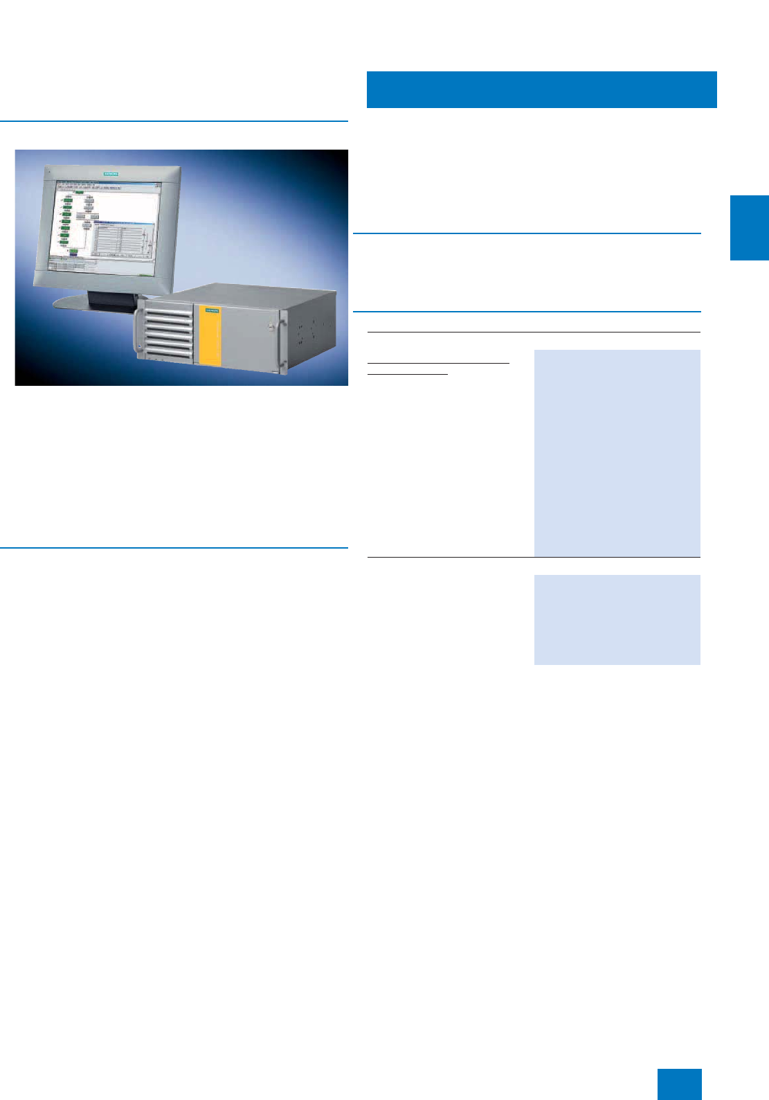
Engineering system
ES hardware
ES single station
4/3
Siemens ST PCS 7 · November 2007
4
■
Overview
Just like the single-user system of the operator system, the cen-
tral engineering system of the SIMATIC PCS 7 process control
system is based on the single station version of a SIMATIC
PCS 7 industrial workstation. This is characterized by powerful
PC technology combined with the Windows XP Professional op-
erating system. It can be used in offices or industrial environ-
ments.
One process monitor can be connected to the integral graphics
interface. Increased user-friendliness can be achieved by con-
necting up to 4 process monitors using a special multi-VGA
graphics card.
■
Design
The hardware platform for the engineering system of the
SIMATIC PCS 7 process control system is the SIMATIC PCS 7
Industrial Workstation of single station design. This is based on
the SIMATIC Rack PC 547B and is already prepared for installa-
tion in 19" rack systems.
The SIMATIC PCS 7 Industrial Workstation of single station de-
sign is available in two versions which differ in their communica-
tions interface to the Industrial Ethernet plant bus:
• SIMATIC PCS 7 ES/OS RACK PC 547B BCE WXP
FastEthernet connection to plant bus with 10/100/1000 Mbit/s
RJ45 network card and Basic Communication Ethernet (BCE)
for communication with up to 8 automation systems (not fault-
tolerant)
• SIMATIC PCS 7 ES/OS RACK PC 547B IE WXP
FastEthernet connection to plant bus with CP 1613 communi-
cations processor (without limitations)
The CP 1613 communication integrated in the IE version
SIMATIC PCS 7 ES/OS RACK PC 547B IE WXP is a combination
of CP 1613 communications processor and S7-1613 communi-
cations software. When using fault-tolerant automation systems,
the ES/OS single station requires the S7-REDCONNECT soft-
ware instead of the S7-1613 communications software. The
S7-REDCONNECT Upgrade is suitable for upgrading the com-
munications software (for ordering data, see page 9/29).
The Windows XP Professional operating system and the
SIMATIC PCS 7 engineering software for AS/OS are preinstalled
on the SIMATIC PCS 7 Industrial Workstation on delivery. The
scope of performance of the preinstalled SIMATIC PCS 7 engi-
neering software is defined by installation of the purchased soft-
ware licenses.
A 10/100/1000 Mbit/s Ethernet RJ45 port is already onboard and
can be used for connecting to an OS LAN (terminal bus).
The scope of delivery also includes a mouse. The keyboard and
monitor must be ordered separately (see page 2/15 and 2/17).
Options/expansions
A multi-VGA card can be added to the engineering system. 2 or
4 monitors can then be connected per station (see Section
"SIMATIC PCS 7 Industrial Workstation" in Chapter "System-
neutral components").
■
Technical specifications
Detailed technical data of the single station version of the
SIMATIC PCS 7 Industrial Workstation can be found at page 2/12
in tabular format.
D) Subject to export regulations: AL: N, ECCN: 5D992B1
Note:
Ordering data in abbreviated form; for detailed Ordering data, see page
2/14
■
Selection and Ordering Data Order No.
Single station
Windows XP Professional MUI
operating system
(German, English, French, Italian,
Spanish, Chinese)
•SIMATIC PCS 7 ES/OS 547B
BCE WXP
Connection to plant bus with
Ethernet network card RJ45
(PCI) 10/100/1000 Mbit/s and
Basic Communication Ethernet
(BCE) for up to 8 automation
systems (not H-systems)
6ES7 650-0NF07-0YX0 D)
•SIMATIC PCS 7 ES/OS 547B
IE WXP
Connection to plant bus with
CP 1613 A2 communications
processor
6ES7 650-0NF07-0YX1 D)
Additional and expansion components
SIMATIC NET S7-REDCONNECT
Upgrade
for communication with fault-toler-
ant AS systems, see page 9/28
Further additional and expansion
components can be found at
page 2/15
© Siemens AG 2007
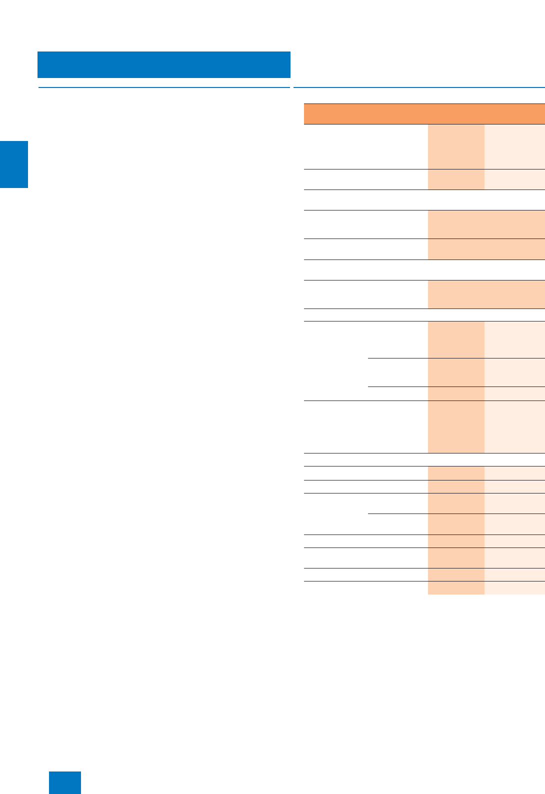
Engineering system
ES software
Introduction
4/4 Siemens ST PCS 7 · November 2007
4
■
Overview
The functionality of the engineering system is largely covered by
the standard engineering software. The following software op-
tions are available in addition for special functions:
• SIMATIC PCS 7 Import/Export Assistant
• SIMATIC Version Cross Manager
• SIMATIC Version Trail
• Engineering Process Safety for safety applications based on
Safety Integrated for Process Automation
• SIMATIC PCS 7 Asset Engineering
• SIMATIC Route Control Engineering
• SIMATIC PDM Process Device Manager for SIMATIC PCS 7
• S7-PLCSIM for the functional testing of CFC/SFC programs
■
Design
Available hardware and software components of the engineering system,
as well as possible configurations
Note on Microsoft SQL Server software
The "SQL Server" software from Microsoft delivered with
SIMATIC PCS 7 may not be used outside the SIMATIC PCS 7
environment without the written approval of Siemens.
SIMATIC PCS 7 engineering system
with Windows XP Professional operating system
Versions Classic,
exclusively
engineering
station
Combined
engineering/
operator sta-
tion for small
applications
Can be used as operator station for
productive operation No Yes
SIMATIC PCS 7 Industrial Workstation including operating system,
alternatives
BCE communication for up to
8 automation systems
(not H systems)
SIMATIC PCS 7 ES/OS 547B BCE
WXP
Communication IE SIMATIC PCS 7 ES/OS 547B IE
WXP
Additional IE communications software
for SIMATIC PCS 7 ES/OS 547B IE WXP
Software for IE communication with
fault-tolerant automation systems
(additive to S7-1613)
SIMATIC NET
S7-REDCONNECT/2006
Upgrade
Standard engineering software, alternatives
SIMATIC PCS 7
Engineering
Software V7.0,
without OS
Runtime license
for productive
operation
AS and OS,
including 2-hour
OS test
operation
●
OS, including
2-hour OS test
operation
●
AS
●
SIMATIC PCS 7
Engineering
Software V7.0,
with OS Runtime
license for pro-
ductive operation
AS and OS
●
Supplementary engineering software (optional)
Import/Export Assistant V7.0
●
Version Cross Manager V7.0
●
Engineering
Process Safety S7 F Systems
V6.0
●
Safety Matrix
Tool
●
PCS 7 Asset Engineering V7.0
●
SIMATIC Route Control
Engineering V7.0
●
SIMATIC PDM PCS 7 V6.0
●
Simulation with S7-PLCSIM V5.4
●
© Siemens AG 2007

Engineering system
ES software
Standard engineering software
4/5
Siemens ST PCS 7 · November 2007
4
■
Overview
The standard engineering software provides the basic function-
ality for configuration of SIMATIC PCS 7 plants with:
• Automation systems
• Process I/O
• Communication networks
• Operator systems
• Maintenance station
• SIMATIC BATCH
• SIMATIC Route Control
Licensing of the standard engineering software depends on use
of the engineering station as:
• Classic, exclusive engineering station (not suitable for pro-
ductive operation as an operator station)
• Combined engineering/operator station for small applications
(suitable for productive operation as an operator station)
Classic, exclusive engineering station with unlimited
number of process objects (POs)
Three software versions with unlimited POs are available for the
classic engineering station:
• AS/OS - for engineering of automation systems (AS) and
operator systems (OS)
• OS - only for OS engineering
• AS - only for AS engineering
With the OS and AS/OS software versions, the OS configuration
can be tested in an OS test mode limited to 2 hours. This OS test
mode is not suitable for productive operation. After 2 hours, the
engineering station automatically switches to demonstration
mode.
The AS/OS software version is additionally upgraded by adding
an AS runtime license for 600 POs.
By means of a Rental License limited to 30 days for AS engineer-
ing or OS engineering (unlimited POs in each case), a cost-ef-
fective alternative is offered for short-term projects or short-term
capacity bottlenecks.
Combined engineering/operator station for small applica-
tions (scalable POs)
To support compact process control plants, an ES/OS software
combination of limited volume is offered with 250, 1,000 or 2,000
POs. In addition to the engineering licenses, these "All-in-one Li-
censes" also contain runtime licenses for AS and OS with the
corresponding volumes.
PowerPacks enable further expansion of the volume:
• From 250 POs to 1,000 POs
• From 1,000 to 2,000 POs
(in each case including AS/OS runtime license)
• From 2,000 POs to unlimited POs
(only with OS runtime license)
■
Function
Essential tools of the standard engineering software and their
functions:
SIMATIC Logon
Together with the versatile recording facilities provided by the
modification logbook, SIMATIC Logon, the user administration
and access control function used in the engineering system, of-
fers plant owners exceptional system support when complying
with FDA requirements.
Using SIMATIC Logon, the administrator can assign specific ac-
cess privileges to groups of users, thus controlling the possibili-
ties for data access. Operator interventions in the engineering
system as well as all online modifications which affect the auto-
mation systems, operator systems, SIMATIC BATCH or SIMATIC
Route Control can be recorded in the modification reports.
If the modification reports are linked to the data of SIMATIC
Logon during evaluation, it can be clearly proven who has car-
ried out a specific modification and at what time.
SIMATIC Manager
The SIMATIC Manager is the control center for engineering of the
SIMATIC PCS 7 process control system. All aspects of the
SIMATIC PCS 7 project are created, managed, archived and
documented here. The tools for engineering of the hardware
components, communication and application software are also
called from here.
The hardware required for use in a SIMATIC project, such as au-
tomation systems, communications components and process
I/O, is stored in an electronic catalog. The hardware is config-
ured and parameterized using the HW-Config tool.
To create the automation logic, standardized function blocks are
combined with one another in the graphic configuration tool CFC
according to technological specifications. Predefined blocks
(process tag types) or charts (example solutions) can be used
for this purpose simply by selecting them from a catalog and
then positioning, graphically interconnecting and parameteriz-
ing them in the working area. No detailed programming knowl-
edge is required, one can completely concentrate on the tech-
nological aspects of configuration. The process tag data
relevant to operation and monitoring, such as messages and
variables, are generated at the same time as configuration of the
automation functions.
Sequential controls permit control and selective processing of
the basic automation functions created per CFC by means of
changes in operating mode and status. Powerful test and com-
missioning functions for the graphic configuration and commis-
sioning of sequential controls are offered by the SFC editor.
Complete SIMATIC PCS 7 projects or all project modifications
can be compiled in one working step and downloaded to the tar-
get systems involved, e.g. automation systems, operator system
or SIMATIC BATCH. The engineering system automatically en-
sures that the sequence is correct. The procedure is displayed
and controlled in a central dialog.
Selective configuration modifications can be downloaded online
to the corresponding target systems. Short turnaround times re-
sult in short waiting times for the commissioning engineer, and
have a favorable effect on the commissioning costs. Program
modifications relevant to automation systems can be initially de-
bugged in a test system prior to downloading to the target sys-
tem of the running plant.
© Siemens AG 2007
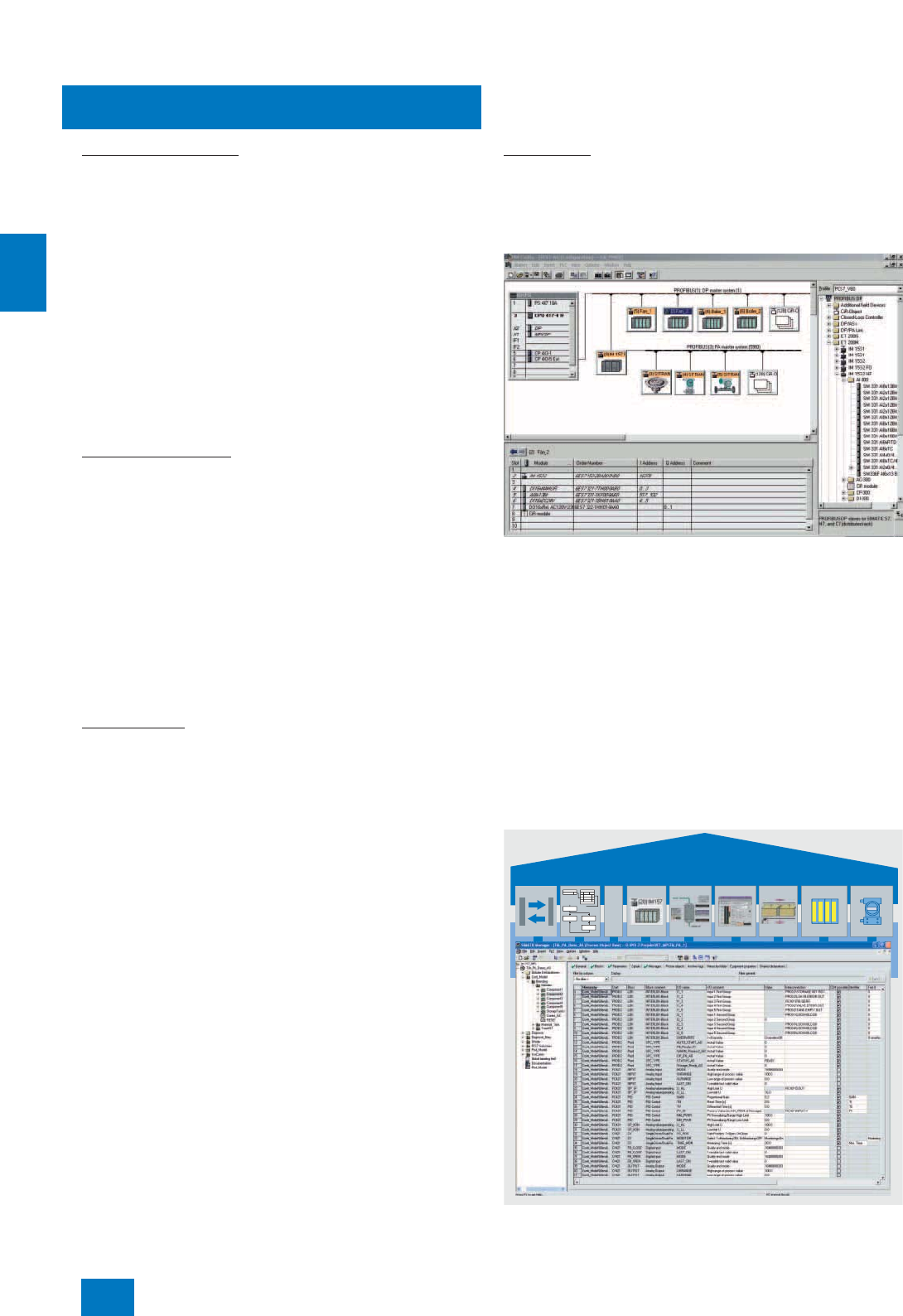
Engineering system
ES software
Standard engineering software
4/6 Siemens ST PCS 7 · November 2007
4
Multi-project engineering
Multi-project engineering permits division of a large complex
project into several subprojects in accordance with technologi-
cal criteria in order to allow several teams to work on the project
in parallel. To achieve this, a host "Multi-project" is defined in the
SIMATIC Manager. Individual (sub)projects can be inserted into
or removed from a multi-project at any time. Similarly, projects
can be divided or combined (Branch & Merge).
Central configuration functions for multi-projects help to reduce
the configuration overhead. For example, a hierarchy folder can
be created in the current project and also automatically in all
other projects. It cannot be modified there, but objects can be
inserted. All block types used in a multi-project can also be up-
dated centrally.
The (sub)projects belonging to a multi-project are saved on a
central server and can be sent to local engineering stations for
editing. The engineering performance is then not affected by
network access.
Concurrent engineering
In the case of concurrent engineering, several configuration en-
gineers can work in CFC and SFC simultaneously on a project
without this having to be first divided into subprojects. The
project is located on one of the engineering stations involved.
This requires connections to the OS LAN (terminal bus) and
plant bus in order to download the configuration data to the tar-
get systems.
The engineering stations working as "project clients" can access
the project data via the OS LAN (terminal bus) or a different
LAN/WAN. A CFC can be opened and viewed simultaneously by
several configuration engineers. However, simultaneous write
operations to the database are rejected by the system.
It is then possible, for example, to use charts in online (debug-
ging) mode during commissioning while carrying out modifica-
tions to the project at the same time.
Branch & Merge
Branch & Merge supports the division and combination of
projects from the technological viewpoint.
Charts or plant units can be copied into another project and ed-
ited there. Interconnections which are not specific to a project,
typically for interlocking, become text interconnections. When
merging, charts with the same name are overwritten in the origi-
nal object, and text interconnections – even those which you
have entered yourself – can be closed by pressing a button.
Project views
The SIMATIC Manager supports the various tasks for creating a
plant project by means of the following project views:
•Component view (HW-Config)
for configuration of hardware such as automation systems,
bus components or process I/O
Component view: hardware configuration in the SIMATIC Manager with
HW-Config
•Process object view
as the central development environment for all aspects of pro-
cess tags/objects
The process object view of the SIMATIC Manager supports the
work of a process engineer by providing a universal view of the
process tag. It shows the technological hierarchy of the plant
(presented in tree form) in combination with a tabular view of all
aspects of the process tag/object (general data, parameters,
signals, messages, image objects and measured value ar-
chives). This provides the technologist with fast orientation.
All objects in the marked branch of the hierarchy are displayed
in the table so that they can be directly processed with user-
friendly edit, filter, replace, import and export functions. A spe-
cial test mode offers the facility for testing process tags and
CFCs online and for starting them up.
Process object view
Libraries
SIMATIC Manager
© Siemens AG 2007
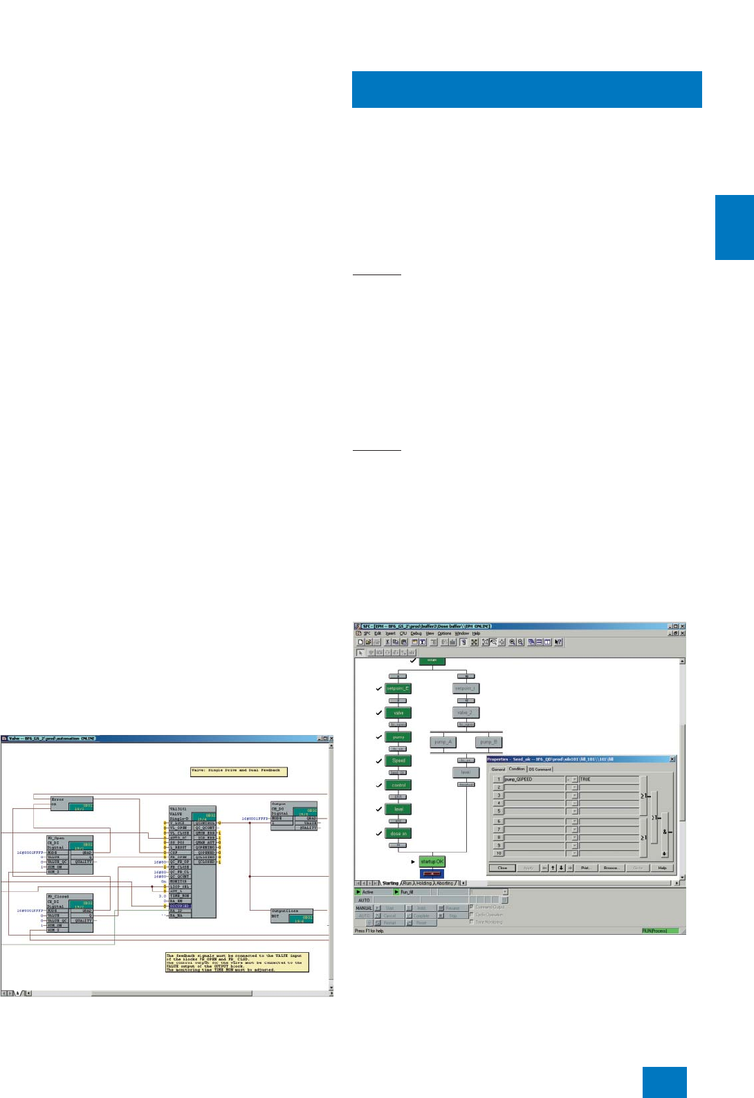
Engineering system
ES software
Standard engineering software
4/7
Siemens ST PCS 7 · November 2007
4
The OS areas and the image hierarchy for process control, as
well as the SIMATIC PCS 7 asset management, can be derived
from the technological hierarchy. Furthermore, it also forms the
basis for the plant-oriented identification of process objects.
Common displays can be positioned in pictures by means of the
image hierarchy, and automatically linked to subordinate im-
ages. The configuration engineer is only responsible for the cor-
rect positioning. Since the number of common display fields and
their semantics can be configured, it is also possible to imple-
ment customized alarm configurations.
Using the process object view, "Smart Alarm Hiding" can also be
configured This function is understood as the dynamic hiding of
messages (alarms) of the technological blocks grouped in a
plant unit which are of secondary importance depending on the
operating state of this unit (startup, service, etc.). Alarms can be
displayed or hidden separately for each of the maximum
32 operating states through selection of option boxes in the
alarm matrix of the process object view. Although hidden alarms
are not signaled visually and audibly, they are still logged and ar-
chived as before.
Continuous function chart (CFC)
The CFC editor is the tool for graphical configuration and com-
missioning of continuous automation functions. Preengineered
function blocks can be positioned, configured and intercon-
nected within CFCs with the support of powerful autorouting and
integral configuration of HMI messages. Special configuration
techniques such as chart-in-chart for implementing hierarchical
plans or the multiple usage of chart block types (chart compiled
as block type) or SFC types (standardized sequential controls)
in the form of instances offer an additional rationalization poten-
tial.
When creating a new CFC, a new runtime group with the same
name as the chart is created. All the blocks that are subse-
quently entered in the chart are automatically added to this run-
time group. Each block is therefore already assigned runtime
properties when inserting, and these properties can be opti-
mized by means of modifications in the runtime editor or by us-
ing algorithms.
The algorithm first determines the optimum block sequence sep-
arately for each runtime group, and then the optimum sequence
of runtime groups.
In addition to convenient editing functions, the scope of CFC
functions also includes powerful test and commissioning func-
tions as well as individually configurable documentation func-
tions.
Continuous function chart
Sequential function chart (SFC)
The SFC editor is used for the graphical configuration and com-
missioning of sequential controls for batch production opera-
tions. It possesses convenient editing functions as well as pow-
erful test and commissioning functions.
Using a sequential control, basic automation functions usually
created using CFC are controlled and selectively processed by
means of changes in operating mode and status. Depending on
the subsequent use, the sequential controls can be created ei-
ther as a SFC plan or SFC type.
SFC plan
The SFC plan can be used to implement sequential controls
which can be applied once and which access several partial ar-
eas of the production plant. Each SFC plan contains standard-
ized inputs and outputs for status information and for control by
the user program or the user. The SFC plan can be positioned
and linked as a block in the CFC. The required CFC block con-
nections are selected by simple operations and connected to
the steps or transitions of the step chains. An ISA 88-conform
status manager enables the configuration of up to 8 separate se-
quence chains within a single SFC, e.g. for states such as
HOLDING or ABORTING, for SAFE STATE or for different operat-
ing modes.
SFC type
SFC types are standardized sequential controls which can be
applied repeatedly and which access one partial area of the pro-
duction plant. They can be organized in libraries, and handled
like normal function blocks, i.e. they can be selected from a cat-
alog and positioned, interconnected and parameterized as an
instance in a CFC plan.
Changes to the original automatically result in corresponding
changes in all instances. An SFC type may contain up to
32 sequences. Using the function "Create/update block sym-
bols", a block symbol is automatically positioned and intercon-
nected in the associated process display for all SFC instances
with HMI features.
Sequential function chart
© Siemens AG 2007
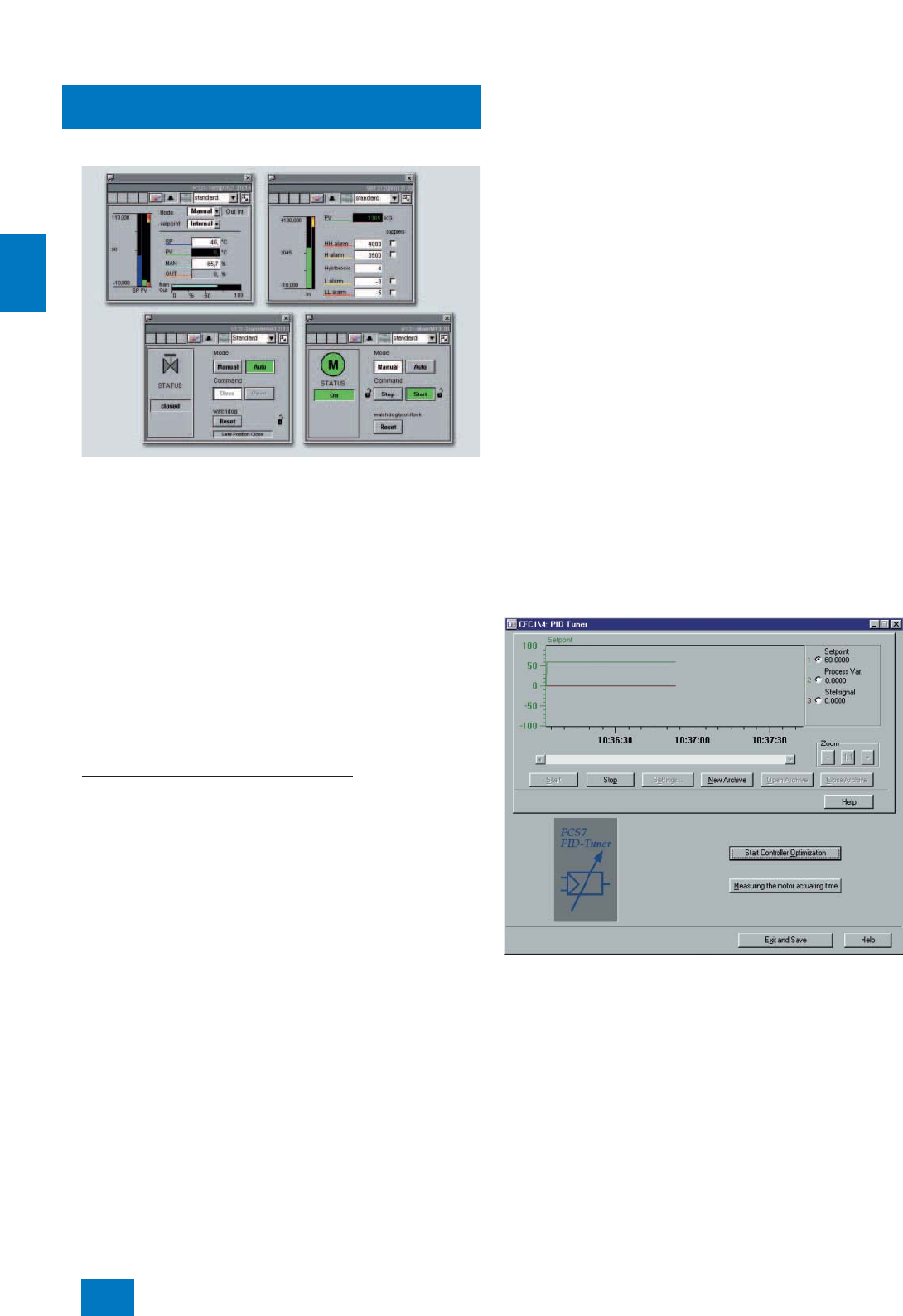
Engineering system
ES software
Standard engineering software
4/8 Siemens ST PCS 7 · November 2007
4
I&C libraries
Examples of editable OS standard displays (faceplates) from the PCS 7
library
Preconfigured and tested blocks, faceplates and symbols are
organized in I&C libraries and form the basic elements for the
graphic configuration of automation solutions. The use of these
library elements plays a major role in minimizing the engineering
input and project costs.
The comprehensive range of blocks can be categorized as fol-
lows:
• Simple logic and driver blocks
• Technological blocks with integral operation and signaling
functions such as PID controllers, motors or valves
• Blocks for integration of PROFIBUS field devices in accor-
dance with PROFIBUS PA profile 3.0 (including standardized
evaluation of the process value status)
• Blocks with more advanced control algorithms for Advanced
Process Control (APC) functions
Advanced Process Control (APC) functions
The APC functions concentrated in separate blocks expand the
PID-based control functions of SIMATIC PCS 7 by more ad-
vanced control algorithms, e.g.:
• Model-based multi-variable controller
The use of a multi-variable controller is recommendable for com-
plex processes where several variables which are mutually de-
pendent have to be controlled. Separate control of the individual
variables, e.g. using PID controllers, has the disadvantages that
interactions result in different effects on the respective variables.
The model-based ModPreCon multi-variable controller inte-
grated in SIMATIC PCS 7 separately analyzes the response of up
to four mutually dependent variables over a longer period of
time. A parameter matrix is calculated from the results, and used
by the ModPreCon for optimum control of the variables.
Note:
The ModPreCon makes great demands on memory and processing time
of the designated automation system. For that reason, please check the
resources of the designated automation system before use. We recom-
mend the use of an automation system of type AS 416 or higher.
• Setting of control parameters dependent on working point
The GainSched block has been designed for variable setting of
controller parameters depending on the working point in non-lin-
ear controlled systems. The block functions similar to the poly-
gon block, and can derive three separate output variables from
the response of an input variable, and apply these as control pa-
rameters for a linked controller block. The GainSched block then
adjusts the control parameters of the combined controller de-
pending on the response of the actual value.
The faceplate of the GainSched block can be called from the
faceplate of the associated controller.
• Monitoring of control quality
The ConPerMon block can be used to monitor the quality of a
controller block according to a patented procedure. The set-
point, actual value and manipulated variable of the controller
block (e.g. PID controller) are connected to the ConPerMon
block which determines the control quality using these online
values. The block can trigger a warning or alarm depending on
the deviation from a reference value, e.g. the control quality de-
termined during commissioning.
The faceplate of the ConPerMon block can be called from the
faceplate of the associated controller. OS displays can be gen-
erated during engineering which list all deviations in the control
quality of a plant or unit. The plant operator can use these dis-
plays to recognize problems early, and to analyze and specifi-
cally eliminate such before they result in serious deficiencies or
a production failure.
PID Tuner
The PID Tuner is a function integrated in the CFC for optimization
of the CTRL_PID and CTRL_S software controllers. The optimum
parameters for a control loop can then be determined for PID, PI
and P control modes in defined steps.
The tool is suitable for optimizing controlled systems with or with-
out an integral component. Optimization can be carried out in
manual or automatic mode. The transient response of the con-
trollers with the determined parameters can be checked by de-
fining jumps. The controller parameters can be saved, and re-
called as required.
During determination of the controller parameters, the typical
controller values (actual value, setpoint, manipulated variable)
are recorded by a trend function.
© Siemens AG 2007

Engineering system
ES software
Standard engineering software
4/9
Siemens ST PCS 7 · November 2007
4
Graphics designer and faceplate designer
The project data for the engineering of the operator systems are
organized with the SIMATIC Manager. All the data relevant to op-
eration and monitoring of a process tag, such as messages and
HMI variables, are generated automatically during definition of
the automation function. A powerful graphics designer is avail-
able for the generation of process displays.
In addition to the standard faceplates, the faceplate designer is
used to simply generate customized faceplates for operation
and monitoring of process tags or plant components. Block sym-
bols can be conveniently interconnected to process tags using
Drag & Drop.
DOCPRO
DOCPRO is a tool for effective generation and management of
plant documentation in accordance with defined standards.
DOCPRO permits you to structure your project data in any man-
ner, to process them in the form of standardized circuit manuals,
and to print them in a uniform layout. You can incorporate your
own cover sheets, layouts, graphics, logos or title block data. It
is easy to control printing, i.e. you can specifically output individ-
ual parts of the project or all project data on the printer.
C) Subject to export regulations: AL: N, ECCN: EAR99S
■
Selection and Ordering Data Order No.
A classic, exclusive engineering station without limitation of quanti-
ties, not suitable for productive operation as an operator station
SIMATIC PCS 7 Engineering
Software V7.0
6 languages (German, English,
French, Italian, Spanish,
Chinese), executes with Windows
XP Professional, floating license
for 1 user
Electronic documentation on PCS
7 toolset DVD
Type of delivery:
License key disk, emergency key
disk, certificate of license, terms
and conditions;
PCS 7 V7.0 toolset DVDs,
Microsoft SQL Server 2005
including EULA and supplemen-
tary CDs/DVDs (e.g. Microsoft
ServicePacks and tools)
AS/OS engineering software,
enabled for two-hour OS test
operation
• Unlimited POs, including AS
Runtime license for 600 POs 6ES7 658-5AF07-0YA5
OS engineering software,
enabled for two-hour OS test
operation
• Unlimited POs 6ES7 658-2DF07-0YA5
AS engineering software
• Unlimited POs 6ES7 658-1AF07-0YA5
SIMATIC PCS 7 Engineering
Software V7.0 Rental License
6 languages (German, English,
French, Italian, Spanish,
Chinese), executes with Windows
XP Professional
Rental license for 30 days
Type of delivery:
License key disk, certificate of
license, terms and conditions;
PCS 7 V7.0 toolset DVDs,
Microsoft SQL Server 2005
including EULA and supplemen-
tary CDs/DVDs (e.g. Microsoft
ServicePacks and tools)
• For AS, unlimited POs 6ES7 658-1AF07-0YA6 C)
• For OS, unlimited POs 6ES7 658-2DF07-0YA6 C)
A combined engineering/operator station for small applications,
suitable for productive operation as an operator station
SIMATIC PCS 7 Engineering
Software V7.0
6 languages (German, English,
French, Italian, Spanish,
Chinese), executes with Windows
XP Professional, floating license
for 1 user
Electronic documentation on PCS
7 toolset DVD
Type of delivery:
License key disk, emergency key
disk, certificate of license, terms
and conditions;
PCS 7 V7.0 toolset DVDs,
Microsoft SQL Server 2005
including EULA and supplemen-
tary CDs/DVDs (e.g. Microsoft
ServicePacks and tools)
AS/OS engineering software,
including AS/OS Runtime license
for productive operation
• 250 POs 6ES7 658-5AA07-0YA5
• 1000 POs 6ES7 658-5AB07-0YA5
• 2000 POs 6ES7 658-5AC07-0YA5
SIMATIC PCS 7 Engineering
PowerPack AS/OS V7.0
for extending the engineering
software for AS/OS of a combined
ES/OS station
6 languages (German, English,
French, Italian, Spanish,
Chinese), executes with Windows
XP Professional, floating license
for 1 user
Type of delivery:
License key disk, emergency key
disk, certificate of license, terms
and conditions
• From 250 to 1000 POs, including
AS/OS Runtime license 6ES7 658-5AB07-0YD5
• From 1000 to 2000 POs, includ-
ing AS/OS Runtime license 6ES7 658-5AC07-0YD5
• From 2000 to unlimited POs,
including OS Runtime license 6ES7 658-5AF07-0YD5
■
Selection and Ordering Data Order No.
© Siemens AG 2007
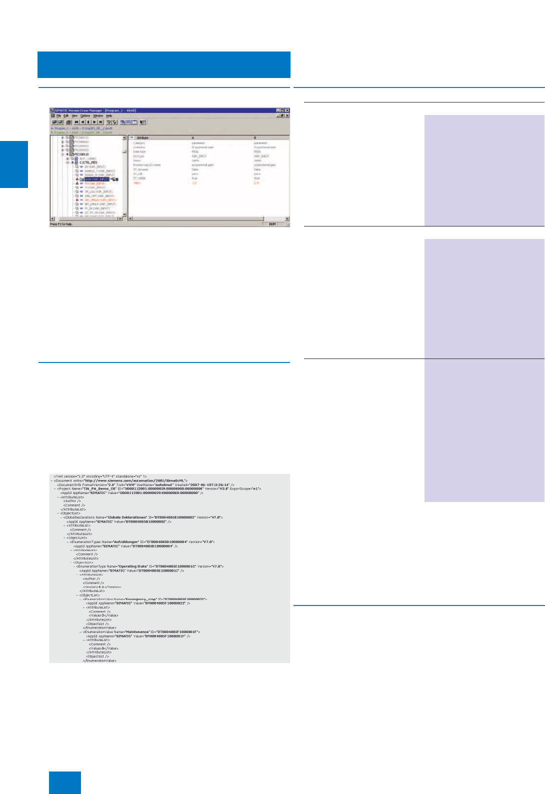
Engineering system
ES software
Version Cross Manager
4/10 Siemens ST PCS 7 · November 2007
4
■
Overview
The SIMATIC Version Cross Manager is a user-friendly tool for
determining the differences between various versions of individ-
ual projects or multi-projects by:
• Tracing missing, additional or differing objects by comparing
hardware configuration, communication, technological hierar-
chy, CFC/SFC plans, SFC details, block types, alarms, global
variables, signals and run sequences
• Graphic display of comparison results in a combination of tree
and tabular formats
• Clear hierarchical structuring according to the technological
hierarchy of the plant
• Color-coded identification of the differences
■
Function
Data exchange with planning tools
Using the SIMATIC Version Cross Manager you can also ex-
change data with planning tools (CAx data). It supports the fol-
lowing exchange functions:
• Export of CAx-relevant data, e.g. global declarations, techno-
logical hierarchy or measuring points
• Export of files in SIMATIC XML format (SML)
• Import of CAx data present in SIMATIC XML format
Example of an XML export
The SIMATIC Version Cross Manager is a SIMATIC product
which was developed for the SIMATIC PCS 7 process control
system but which can also be used together with other SIMATIC
products in the context of Totally Integrated Automation (TIA). In
the case of products which can be used in both the SIMATIC
PCS 7 and TIA environments, the ordering data and type of de-
livery may differ depending on the application. To provide a bet-
ter overview and to avoid faulty ordering, the selection and or-
dering data of such products are therefore listed separately
depending on the target application.
■
More information
Upgrade
SIMATIC PCS 7 engineering systems with Engineering Software
V6.0 or V6.1 can be upgraded to Version 7.0 using the SIMATIC
PCS 7 Engineering Upgrade Package. This upgrade package
also includes the upgrade from SIMATIC Version Cross Checker
V6.0/V6.1 to SIMATIC Version Cross Manager V7.0.
For applications outside SIMATIC PCS 7, a separate SIMATIC
Upgrade Version Cross Manager V7.0 can be obtained for up-
grading the SIMATIC Version Cross Checkers V6.0/V6.1.
For further information, see Chapter "Update/upgrade pack-
ages".
■
Selection and Ordering Data Order No.
For SIMATIC PCS 7 applications
SIMATIC Version Cross
Manager V7.0
6 languages (German, English,
French, Italian, Spanish,
Chinese), executes with Windows
XP Professional or Windows
Server 2003, floating license for
1user
Type of delivery:
License key disk, emergency key
disk, certificate of license, terms
and conditions as well as TIA
toolset CD V7.0
6ES7 658-1CX07-2YA5
For TIA applications
SIMATIC Version Cross
Manager V7.0
6 languages (German, English,
French, Spanish, Italian,
Chinese), executes with Windows
2000 Professional, Windows
XP Professional or Windows
Server 2003, floating license for
1user
Type of delivery:
License key disk, emergency key
disk, certificate of license, terms
and conditions as well as TIA
toolset CD V7.0
6ES7 658-1CX07-2YA5
SIMATIC Version Cross
Manager Upgrade V7.0
for upgrading from Version
Cross Checker V6.0/V6.1 to
Version Cross Manager V7.0
6 languages (German, English,
French, Spanish, Italian, Chi-
nese), executes with Windows
2000 Professional, Windows
XP Professional or Windows
Server 2003, floating license for
1user
Type of delivery:
License key disk, emergency key
disk, certificate of license, terms
and conditions as well as TIA
toolset CD V7.0
6ES7 658-1CX07-2YE5
© Siemens AG 2007
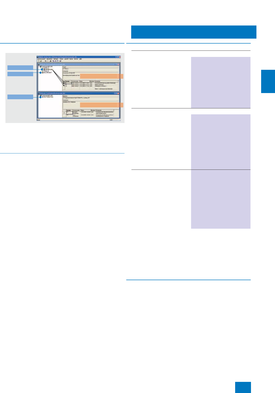
Engineering system
ES software
Version Trail
4/11
Siemens ST PCS 7 · November 2007
4
■
Overview
SIMATIC Version Trail is a software option for engineering which,
together with the SIMATIC Logon central user administration,
can assign a version history to libraries, projects and multi-
projects. It can be used within SIMATIC PCS 7 or also in the con-
text of Totally Integrated Automation with SIMATIC.
■
Function
When archiving, SIMATIC Version Trail in association with
SIMATIC Logon creates a version history with the following infor-
mation:
• Version
• Version name
• Date and time
•User
• Comment
This version history can be displayed and printed. Individual ver-
sion releases can be dearchived from the version history and
used further. SIMATIC Logon organizes the access protection.
The SIMATIC Version Trail is a SIMATIC product which was de-
veloped for the SIMATIC PCS 7 process control system but
which can also be used together with other SIMATIC products in
the context of Totally Integrated Automation (TIA). In the case of
products which can be used in both the SIMATIC PCS 7 and TIA
environments, the ordering data and type of delivery may differ
depending on the application. To provide a better overview and
to avoid faulty ordering, the selection and ordering data of such
products are therefore listed separately depending on the target
application.
■
More information
Upgrade
SIMATIC PCS 7 engineering systems with Engineering Software
V6.0 or V6.1 can be upgraded to Version 7.0 using the SIMATIC
PCS 7 Engineering Upgrade Package. A component of this up-
grade package is also the upgrade for SIMATIC Version Trail
from V6.1 to V7.0.
For applications outside SIMATIC PCS 7, a separate SIMATIC
Upgrade Version Trail V7.0 can be obtained for upgrading
SIMATIC Version Trail V6.1.
For further information, see Chapter "Update/upgrade pack-
ages".
Note:
Please note that Version Trail cannot be used on its own, but only
in combination with SIMATIC Logon (see page 2/4).
Versioned project 1
Versioned project 2
Multi project
Library
Project
■
Selection and Ordering Data Order No.
For SIMATIC PCS 7 applications
SIMATIC Version Trail V7.0
6 languages (German, English,
French, Italian, Spanish, Chi-
nese), executes with Windows
XP Professional or Windows
Server 2003, floating license for
1user
Type of delivery: License key
disk, emergency key disk, certifi-
cate of license, terms and condi-
tions as well as TIA toolset CD
V7.0
6ES7 658-1FX07-2YA5
For TIA applications
SIMATIC Version Trail V7.0
6 languages (German, English,
French, Spanish, Italian,
Chinese), executes with Windows
2000 Professional, Windows
XP Professional or Windows
Server 2003, floating license for
1user
Type of delivery: License key
disk, emergency key disk, certifi-
cate of license, terms and condi-
tions as well as TIA toolset CD
V7.0
6ES7 658-1FX07-2YA5
SIMATIC Version Trail Upgrade
V7.0
6 languages (German, English,
French, Spanish, Italian, Chi-
nese), executes with Windows
2000 Professional, Windows
XP Professional or Windows
Server 2003, floating license for
1user
Type of delivery: License key
disk, emergency key disk, certifi-
cate of license, terms and condi-
tions as well as TIA toolset CD
V7.0
6ES7 658-1FX07-2YE5
© Siemens AG 2007
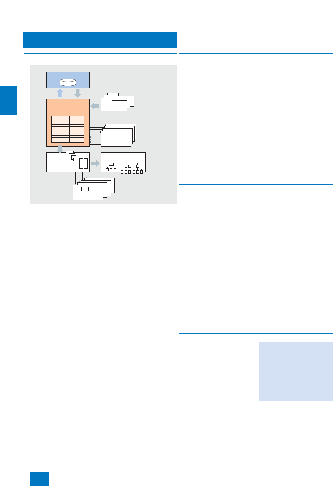
Engineering system
ES software
Import/Export Assistant
4/12 Siemens ST PCS 7 · November 2007
4
■
Overview
Efficient processing of mass data
The import/export assistant (IEA) is an effective tool for rational
engineering of mass data, and is based on multiple use of pro-
cess tag types and example solutions. It is particularly suitable
for large plants with many process tags of the same type or with
several plant components of the same type. Plant data which
have already been configured (such as process tag lists or
charts from the CAD/CAE world) can be imported into the engi-
neering system and used for largely automatic generation of
process tags. The data of the host planning system can be sub-
sequently matched again with the parameters optimized during
commissioning.
To permit simple and fast modification, the PCS 7 projects can
also be exported, the data processed using the IEA editor or
other programs (e.g. Microsoft Excel or Access), and subse-
quently reimported.
■
Benefits
The import/export assistant offers the following benefits when
using previously configured plant data:
7Importing of previously configured plant data from the host
CAD/CAE world, such as process tag list
- No multiple inputs with the associated input errors
- Simple handling, easy-to-use graphic environment
7Automatic and reproducible generation of process tags and
derivatives based on the imported process tag lists and exam-
ple solutions (technological hierarchy, charts of the individual
process tags)
- Drastic reduction in time required, and avoidance of errors
7Automatic derivation of the OS display hierarchy, automatic in-
terconnecting of blocks and positioning in displays
- Considerable reduction in time required and costs
7Commissioning of individual process tags with the user-
friendly CFC and SFC graphic tools
7Exporting of parameters optimized during commissioning
back to the CAD/CAE world
- Consistent data in the host planning tools
■
Function
• Generation/modification of process tag types or example so-
lutions
• Importing of data from plant planning
- Generation of process tags from process tag types and de-
rivatives from example solutions; provision with data from the
import file (one process tag/derivative per import file line in
each case)
- Assignment of an import file to a process tag type, and
checking of the assignment
- Generation of a template for an input file for the process tag
• Exporting of data for plant planning
- Generation of an export file per process tag type/example
solution in each case, with one line for each process tag of
this type or each derivative of this example solution
• Matching of process tags
- Removal of parameter/signal connection points not present
on the process tag type and of messages from the process
tags
- Addition of parameter/signal connection points and mes-
sages newly defined on the process tag type
- Correction of modified categories of process tag type
- Display of inconsistencies between process tag and type
which cannot be matched automatically
Higher-level planning tools
CAD/CAE
Import/export
assistant
Typical
libraries
Process
object plans
Technological
hierarchy
OS display hierarchy
OS displays
Example solutions and
process object types
(e.g. control,
motor, valve)
■
Selection and Ordering Data Order No.
SIMATIC PCS 7 Import/Export
Assistant V7.0
6 languages (German, English,
French, Italian, Spanish,
Chinese), executes with Windows
XP Professional, floating license
for 1 user
Type of delivery:
License key disk, emergency key
disk, certificate of license, terms
and conditions
6ES7 658-1DX07-2YB5
© Siemens AG 2007
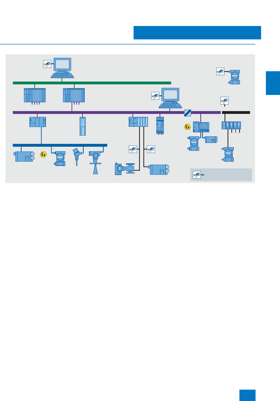
Engineering system
ES software
SIMATIC PDM Process Device Manager
4/13
Siemens ST PCS 7 · November 2007
4
■
Overview
Configuration options with SIMATIC PDM
SIMATIC PDM (Process Device Manager) is a universal, vendor-
independent tool for the configuration, parameterization, com-
missioning, diagnostics and servicing of intelligent field devices
(sensors and actuators) and field components (remote I/Os,
multiplexers, control-room devices, compact controllers), which
in the following sections will be referred to simply as devices.
Using one software, SIMATIC PDM enables the processing of
more than 1200 devices from Siemens and over 100 vendors
worldwide on one homogeneous user interface. Parameters and
functions for all supported devices are displayed in a consistent
and uniform fashion independent of their communications inter-
face.
From the viewpoint of device integration, SIMATIC PDM is the
most powerful open device manager available in the world. De-
vices which previously were not supported can be easily inte-
grated in SIMATIC PDM at any time by importing their device de-
scriptions (EDD). This provides security for your investment and
saves you investment costs, training expenses and consequen-
tial costs.
SIMATIC PDM is integrated in the asset management of SIMATIC
PCS 7. The Process Device Manager provides wider information
for all devices described by the Electronic Device Description
(EDD), e.g. detailed diagnostics information (vendor informa-
tion, information on fault diagnostics and troubleshooting, further
documentation), modification logbook (audit trial), parameter in-
formation. It is possible to change directly to SIMATIC PDM from
the diagnostics faceplates in the maintenance station.
SIMATIC
PDM
SIMATIC
PDM
SIMATIC
PDM
SIMATIC
PDM
SIMATIC
PDM
SIMATIC
PDM
SIMATIC
PDM
S7-400
PROFIBUS PA
SITRANS P SITRANS
T3K
SITRANS LR SITRANS F M
SIMOCODE
pro
MICROMASTER
SIMATIC
PDM
SIMATIC
PDM
SIMATIC
PDM
SIMATIC
PDM
ET 200iSP
S7-400
SIPART PS2
SIPART PS2
HART
RS 232/RS 485
SITRANS P
SIMATIC
PDM
SIMATIC
PDM
Plant bus
DP/PA
link
SIMATIC PCS 7 engineering station
with SIMATIC PDM
PROFIBUS DP fieldbus
Up to 12 Mbit/s
Possible connection point
of a PG/PC with SIMATIC PDM
(stand-alone operation)
HART
multiplexer
Stand-alone
computer
with SIMATIC PDM
Device on
the workbench
HART protocol
HART device
ET 200M
(IM 153-2 with
HART mod-
ules)
© Siemens AG 2007
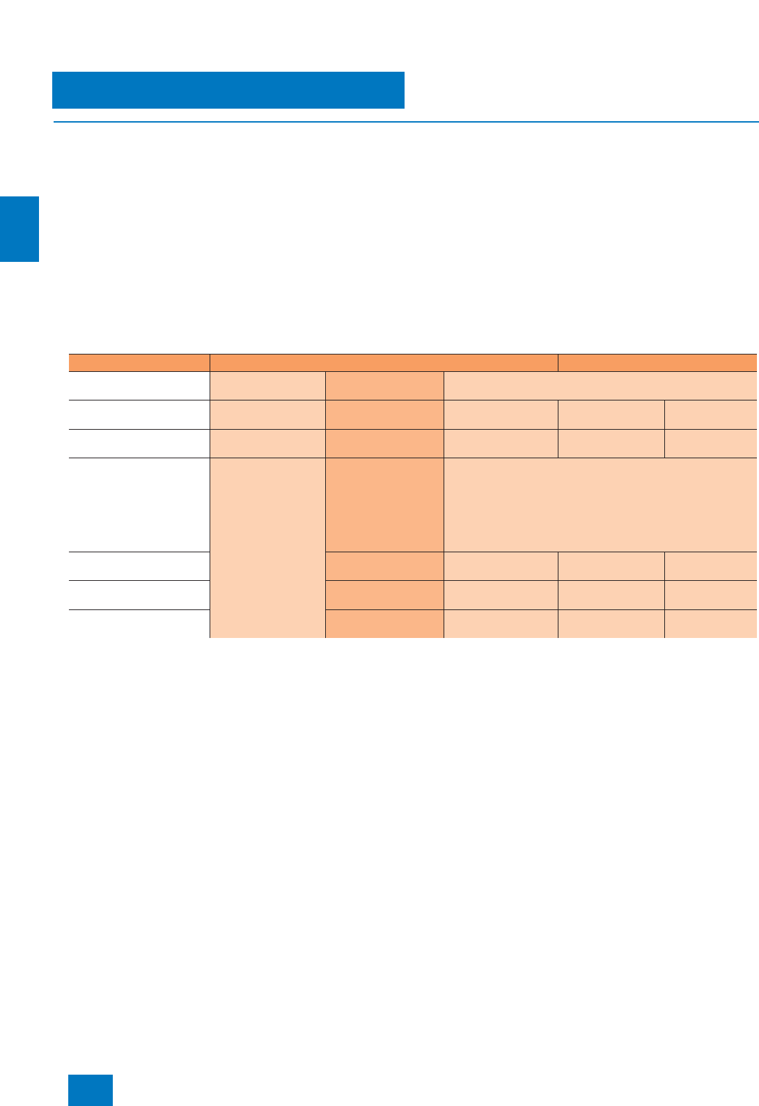
Engineering system
ES software
SIMATIC PDM Process Device Manager
4/14 Siemens ST PCS 7 · November 2007
4
■
Design
Customer-oriented product structure
The SIMATIC PDM Process Device Manager can be used in a
versatile manner in the context of Totally Integrated Automation
(TIA). Use in the engineering system of SIMATIC PCS 7 is one
possible application.
The customer-oriented products structure of SIMATIC PDM sup-
ports you in adaptation of the scope of functions and perfor-
mance to your individual requirements. You can select the mini-
mum configuration SIMATIC PDM Single Point, one of the
application-specific, predefined product configurations SI-
MATIC PDM Service, SIMATIC PDM PCS 7 or SIMATIC PDM S7,
or produce your desired configuration from the individual com-
ponents offered (see table).
The selection depends on the application range and environ-
ment of use:
• System-integrated in a SIMATIC PCS 7/S7 configuration envi-
ronment:
- SIMATIC PDM PCS 7 (for integration in an engineering sys-
tem for SIMATIC PCS 7)
- SIMATIC PDM S7 (for integration in a SIMATIC S7 configura-
tion environment)
• SIMATIC PDM stand-alone as service tool for operation on a
mobile computer on the PROFIBUS or with direct connection
to the device:
- SIMATIC PDM Single Point (for processing of a single field
device via a point-to-point coupling)
- SIMATIC PDM Service (for enhanced servicing, including
modification logbook and lifelist detailed diagnostics)
n: Components included in delivery of individual PDM configurations
opt: Can be ordered as options
Note: For definition of TAG, see page 4/15.
Minimum configuration SIMATIC PDM Single Point
This low-cost minimum configuration with handheld functionality
is tailored to processing exactly one field device via a point-to-
point coupling. All device functions are supported as defined in
the device description. These functions include:
7Unlimited selection of devices / management of device cata-
log
7Communication via PROFIBUS DP/PA or HART modem
7Parameterization and diagnostics in accordance with the de-
vice description
7Exporting and importing of parameter data
7Device identification
7Lifelist
The following system functions of SIMATIC PDM Basic are not
available with SIMATIC PDM Single Point:
• EDD-based diagnostics in the lifelist
• Project editing
• Storage function (only exporting and importing of parameter
data)
• Recording functions
• Routing
• Communication with HART field devices via remote I/Os
The functions of SIMATIC PDM Single Point cannot be extended
(e.g. to SIMATIC PDM Basic or with the routing option through
S7-400), nor can it be expanded with TAG options or Power-
Packs.
SIMATIC PDM stand-alone SIMATIC PDM system-integrated
Minimum configuration Components for
individual configuration Predefined product configurations
Product name SIMATIC PDM
Single Point SIMATIC PDM Basic SIMATIC PDM Service SIMATIC PDM S7 SIMATIC PDM
PCS 7
TAGs included in scope of
delivery 1 4 128 128 128
TAG expansions Cannot be expanded TAG options
- 128 TAGs
- 512 TAGs
- 1024 TAGs
- 2048 TAGs
and/or PowerPacks
PowerPacks
- From 128 to 512 TAGs
- From 512 to 1024 TAGs
- From 1024 to 2048 TAGs
- From 2048 to unlimited TAGs
Option "Integration in
STEP 7/PCS 7" opt opt n n
Option "Routing through
S7-400" opt opt opt n
Option "Communication via
standard HART multiplexer" opt opt opt opt
© Siemens AG 2007

Engineering system
ES software
SIMATIC PDM Process Device Manager
4/15
Siemens ST PCS 7 · November 2007
4
Predefined product configurations
SIMATIC PDM Service
This is a predefined product configuration especially for mobile
use in servicing for projects with up to 128 TAGs. It offers service
engineers all functions of SIMATIC PDM Basic, including modifi-
cation logbook, calibration report and detailed diagnostics in the
lifelist. SIMATIC PDM Service can be expanded by the functional
options "Integration in STEP 7/PCS 7", "Routing through S7-400"
and "Communication via standard HART multiplexer" as well
as by SIMATIC PDM PowerPacks (see under TAG options/
PowerPacks). The following program components are part of
SIMATIC PDM Service:
• SIMATIC PDM Basic
• Option: 128 TAGs
SIMATIC PDM PCS 7
SIMATIC PDM PCS 7 is a predefined product configuration for
integration into the engineering system (engineering tool set)
and the maintenance station of SIMATIC PCS 7. The product ver-
sion designed for projects with up to 128 TAGs allows the use of
all functions of SIMATIC PDM Basic (including modification log-
book, calibration report and detailed diagnostics in the lifelist).
In addition, it contains the functionality for integration of the
SIMATIC PDM into HW-Config as well as the routing from the
central engineering system to the field devices. SIMATIC PDM
PCS 7 can be expanded by the option "Communication via stan-
dard HART multiplexer" and by SIMATIC PDM PowerPacks (see
under TAG options/PowerPacks). The following program compo-
nents are part of SIMATIC PDM PCS 7:
• SIMATIC PDM Basic
• Option: 128 TAGs
• Option: Integration in STEP 7/SIMATIC PCS 7
• Option: Routing through S7-400
SIMATIC PDM S7
SIMATIC PDM S7 is a predefined product configuration tailored
to the use of SIMATIC PDM in a SIMATIC S7 configuration envi-
ronment. It offers all functions of SIMATIC PDM Basic (including
modification logbook, calibration report and detailed diagnos-
tics in the lifelist) as well as the functionality for integration of
PDM into HW-Config. SIMATIC PDM S7 can be expanded by the
functional options "Routing through S7-400" und "Communica-
tion via standard HART multiplexer" and by SIMATIC PDM
PowerPacks (see under TAG options/PowerPacks). The follow-
ing program components are part of SIMATIC PDM S7:
• SIMATIC PDM Basic
• Option: 128 TAGs
• Option: Integration in STEP 7/SIMATIC PCS 7
Components for individual configuration
SIMATIC PDM Basic
SIMATIC PDM Basic is the basic component for production of in-
dividual SIMATIC PDM configurations from single components.
It contains all functions required for operation and parameteriza-
tion of the devices, as well as enabling for the following commu-
nication modes:
• PROFIBUS DP/PA,
• HART communication (modem, RS 232 and PROFIBUS),
• Modbus,
• SIREC bus and
•SIPART DR.
Without TAG expansion, SIMATIC PDM Basic can manage
projects with up to 4 TAGs, and can be used - with observation
of the system requirements - for stand-alone operation on any
computer (PC/notebook) with local connection to bus segments
or with direct connection to the device.
SIMATIC PDM Basic can be expanded by functional options and
TAG options/PowerPacks. Use of the following functions requires
at least 128 TAGs:
• Modification logbook
• Calibration report
• Detailed diagnostics in the lifelist
SIMATIC PDM Basic is also available in the form of a rental li-
cense for 50 operating hours for low-cost processing of short-
term projects.
SIMATIC PDM option: Integration in STEP 7/PCS 7
This option is required for use of SIMATIC PDM within a
SIMATIC S7 or SIMATIC PCS 7 project with a local connection to
the PROFIBUS. SIMATIC PDM can then be started directly from
the hardware project (HW-Config).
SIMATIC PDM option: Routing through S7-400
This option is required additive to the option "Integration in
STEP7/PCS 7" if SIMATIC PDM is to be used in a central engi-
neering system for SIMATIC PCS 7/S7 with Ethernet bus connec-
tion to the automation systems for plant-wide configuration, pa-
rameterization, commissioning and diagnostics of field devices.
SIMATIC PDM option: Communication via standard HART multi-
plexer
This option permits SIMATIC PDM to use the HART OPC server
for communication with HART field devices via HART multiplex-
ers.
TAG options/PowerPacks
A TAG corresponds to a SIMATIC PDM object, which represents
individual field devices or components within a project, e.g.
measuring instruments, positioners, switching devices or remote
I/Os. TAGs are also relevant for diagnostics with the lifelist of
SIMATIC PDM. In this case, TAGs are considered to be all rec-
ognized devices with diagnostics capability, whose detailed di-
agnostics is effected through the device description (EDD).
In contrast to PowerPacks, TAG options are only suitable for
product configurations on the basis of individual components.
Using the SIMATIC PDM TAG options, the basic software SI-
MATIC PDM Basic can be expanded from 4 TAGs to 128, 512,
1024 or 2048 TAGs, and with the help of an additive PowerPack
also to unlimited TAGs.
The number of available TAGs can be subsequently increased
for all SIMATIC PDM product configurations by means of the
SIMATIC PDM PowerPacks. PowerPacks are available for ex-
pansion to 512, 1024, 2048 and unlimited TAGs.
Demonstration software
A demonstration version of SIMATIC PDM is also available. On-
line communication and storage functions are not available with
this version.
© Siemens AG 2007
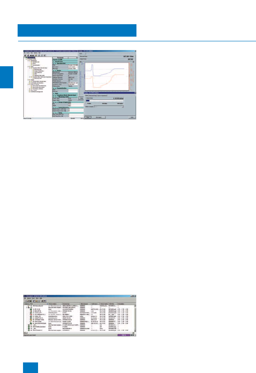
Engineering system
ES software
SIMATIC PDM Process Device Manager
4/16 Siemens ST PCS 7 · November 2007
4
■
Function
Parameter view of SIMATIC PDM with trend curve and online display
Core functions
• Adjustment and modification of device parameters
• Comparing (e.g. project and device data)
• Plausibility testing of data input
• Device identification and testing
• Device status indication with operating modes, alarms and
states
• Simulation
• Diagnostics (standard, detailed)
• Management (e.g. networks and PCs)
• Export/import (parameter data, reports)
• Commissioning functions, e.g. measuring circuit tests of de-
vice data
• Device replacement (lifecycle management)
• Global and device-specific modification logbook for user op-
erations (audit trail)
• Device-specific calibration reports
• Graphic presentations of echo envelope curves, trend dis-
plays, valve diagnosis results etc.
• Presentation of incorporated manuals
• Document manager for integration of up to 10 multimedia files
Support of system management
SIMATIC PDM supports the operative system management in
particular through:
• Uniform presentation and operation of devices
• Indicators for preventive maintenance and servicing
• Detection of changes in the project and device
• Increasing the operational reliability
• Reducing the investment, operating and maintenance costs
• Graded user privileges including password protection
PDM lifelist with status and diagnostics display
Graphical user interface
The GUI of SIMATIC PDM satisfies the requirements of the direc-
tives VDI/VDE GMA 2187 and IEC 65/349/CD. Even complex de-
vices with several hundred parameters can thus be represented
clearly and processed quickly. Using SIMATIC PDM it is very
easy to navigate in highly complex stations such as remote I/Os
and even connected field devices.
Several views are available to users to help them with their tasks:
• Hardware project view
• Process device network view (preferably for stand-alone ap-
plication)
• Process device plant view as TAG-related view, also with dis-
play of diagnostics information
• Parameter view for parameterizing the field devices
• Lifelist view for commissioning and service
Communication
SIMATIC PDM supports several communication protocols and
components for communicating with devices that have the fol-
lowing interfaces:
• PROFIBUS DP/PA interface
• HART interface
• Modbus interface
• Special interface from Siemens
Further communication protocols on request.
Routing
From the central engineering system of the SIMATIC PCS 7
process control system, you can navigate with SIMATIC PDM
through the various bus systems and remote I/Os down to the
connected devices. By means of this routing functionality, every
device in the plant which can be parameterized per EDD can be
processed. The following processing functions are available:
• Read diagnostics information from the device
• Modify device settings
• Adjust and calibrate devices
• Monitor process values
• Create simulation values
• Reparameterize devices.
© Siemens AG 2007

Engineering system
ES software
SIMATIC PDM Process Device Manager
4/17
Siemens ST PCS 7 · November 2007
4
■
Integration
Device Integration
SIMATIC PDM supports all devices described by EDD (Elec-
tronic Device Description). EDD is standardized to EN 50391
and IEC 61804. Internationally it is the most widely used stan-
dardized technology for device integration. At the same time it is
the directive of the established organizations for PROFIBUS
(PNO: PROFIBUS International) and HART (HCF: HART Commu-
nication Foundation).
The devices are directly integrated in SIMATIC PDM through
their EDD or the current HCF catalog. In the EDD the device is
described in terms of its functions and construction using the
Electronic Device Description Language (EDDL) specified by
PNO. Using this description, SIMATIC PDM automatically cre-
ates its user interface with the specific device data.
The current device catalog of SIMATIC PDM covers more than
1200 devices from over 100 manufacturers world-wide. In addi-
tion, devices from all manufacturers can be integrated in
SIMATIC PDM by simply importing their EDDs. It is thus possible
to keep the device range up to date at all times and to add to the
number of manufacturers and devices supported by SIMATIC
PDM. To permit improved transparency, SIMATIC PDM also al-
lows the creation of project-specific device catalogs. If devices
are to be used which cannot be found in the SIMATIC PDM de-
vice catalog, we will be glad to help you integrate them.
Contact addresses
Siemens AG, Automation and Drives,
Technical Support
Europe
Phone: +49 180 50 50 222
Fax: +49 180 50 50 223
E-mail: FPlease fill in a Support Request on the Internet (see be-
low for address)
Asia/Pacific
Phone: +86 1064 719 990
Fax: +86 1064 747 474
E-mail: adsupport.asia@siemens.com
America
Phone: +1 423 262 2522
Fax: +1 423 262 2200
E-mail: techsupport.sea@siemens.com
Support Request
Additional information is available in the Internet under:
http://www.siemens.com/automation/support-request
■
Technical specifications
Selection and ordering data for SIMATIC PCS 7 applications
Requirements for stand-alone operation
Hardware • PG/PC/notebook with processor
corresponding to operating
system requirements
• Main memory 256 MB or more
• Vacant hard disk 210 MB or
more
Operating systems (alternative) • Microsoft Windows 2000
Professional SP1 or higher
• Microsoft Windows XP
Professional SP1/SP2
Further software components
• SIMATIC PDM integrated in
STEP 7 STEP 7 V5.1 or higher with
ServicePack 6 or higher, order
separately
■
Selection and Ordering Data Order No.
SIMATIC PDM PCS 7 V6.0
Complete package for integra-
tion into the engineering toolset of
the SIMATIC PCS 7 engineering
system
6 languages (German, English,
French, Italian, Spanish,
Chinese), executes with Windows
XP Professional
Floating license for 1 user, with
• SIMATIC PDM Basic
• Option "Integration in
STEP 7/PCS 7"
• Option "Routing through S7-400"
• Option "128 TAGs"
Type of delivery:
License key disk, emergency key
disk, certificate of license, terms
and conditions; 2 CDs with
SIMATIC PDM V6.0 and device
library as well as supplementary
DVD with Microsoft ServicePacks
and tools
6ES7 658-3LX06-0YA5
PowerPacks
SIMATIC PDM PowerPack
for expanding the TAGs of
SIMATIC PDM PCS 7 V6.0
6 languages (German, English,
French, Italian, Spanish,
Chinese), executes with Windows
XP Professional
Floating license for 1 user
Type of delivery:
License key disk, certificate of
license, terms and conditions
• From 128 TAGs to 512 TAGs 6ES7 658-3XB06-2YD5
• From 512 TAGs to 1024 TAGs 6ES7 658-3XC06-2YD5
• From 1024 TAGs to 2048 TAGs 6ES7 658-3XD06-2YD5
• From 2048 TAGs to unlimited
TAGs 6ES7 658-3XH06-2YD5
© Siemens AG 2007

Engineering system
ES software
SIMATIC PDM Process Device Manager
4/18 Siemens ST PCS 7 · November 2007
4
SIMATIC PDM belongs to the SIMATIC products which can be
used both in the context of SIMATIC PCS 7 and in the extended
context of Totally Integrated Automation (TIA). Depending on the
field of application, SIMATIC PDM is used in various product ver-
sions with different functionalities, ordering data and type of de-
livery. To provide a better overview and to avoid faulty ordering,
the special selection and ordering data for SIMATIC PCS 7 are
listed separately.
Selection and ordering data for TIA applications
Demonstration software
SIMATIC PDM Demo V6.0
without online communication
and storage functionality
6 languages (German, English,
French, Italian, Spanish, Chi-
nese), executes with Windows
XP Professional
Type of delivery:
2 CDs with SIMATIC PDM V6.0
and device library as well as sup-
plementary DVD with Microsoft
ServicePacks and tools
6ES7 658-3GX06-0YC8
SIMATIC PDM Upgrade/Update Service
SIMATIC PDM Upgrade from
V5.x to V6.0
for all product versions and com-
binations
6 languages (German, English,
French, Italian, Spanish, Chi-
nese), executes with Windows
XP Professional, floating license
for 1 user
Type of delivery:
License key disk, emergency key
disk, certificate of license, terms
and conditions; 2 CDs with
SIMATIC PDM V6.0 and device
library as well as supplementary
DVD with Microsoft ServicePacks
and tools
6ES7 651-5CX06-0YE5
SIMATIC PDM Software Update
Service
Subscription for 1 year with auto-
matic extension
Requirement: current software
version
6ES7 658-3XX00-0YL8
■
Selection and Ordering Data Order No.
Minimum configuration SIMATIC PDM Single Point
SIMATIC PDM Single Point V6.0
for operation and parameteriza-
tion of one field device; communi-
cation via PROFIBUS DP/PA or
HART modem, including 1 TAG,
cannot be expanded with respect
to functions or with TAG
option/PowerPack
6 languages (German, English,
French, Spanish, Italian,
Chinese), executes with Windows
2000 Professional or Windows
XP Professional
Floating license for 1 user
Type of delivery:
License key disk, certificate of
license, terms and conditions;
2 CDs with SIMATIC PDM V6.0
and device library
6ES7 658-3HX06-0YA5
■
Selection and Ordering Data Order No.
Predefined SIMATIC PDM V6.0 product configurations for special
applications
SIMATIC PDM Service V6.0
Complete package for stand-
alone users for servicing, with
• SIMATIC PDM Basic V6.0
• Option "128 TAGs"
6 languages (German, English,
French, Italian, Spanish,
Chinese), executes with Windows
2000 Professional or Windows
XP Professional, floating license
for 1 user
Type of delivery:
License key disk, emergency key
disk, certificate of license, terms
and conditions;
2 CDs with SIMATIC PDM V6.0
and device library as well as sup-
plementary DVD with Microsoft
ServicePacks and tools
6ES7 658-3JX06-0YA5
SIMATIC PDM S7 V6.0
Complete package for use in a
SIMATIC S7 configuration envi-
ronment, with
• SIMATIC PDM Basic V6.0
• Option "Integration in
STEP 7/PCS 7"
• Option "128 TAGs"
6 languages (German, English,
French, Italian, Spanish, Chi-
nese), executes with Windows
2000 Professional or Windows
XP Professional, floating license
for 1 user
Type of delivery:
License key disk, emergency key
disk, certificate of license, terms
and conditions;
2 CDs with SIMATIC PDM V6.0
and device library as well as sup-
plementary DVD with Microsoft
ServicePacks and tools
6ES7 658-3KX06-0YA5
Components for individual configuration
SIMATIC PDM Basic V6.0
for operation and parameteriza-
tion of field devices and compo-
nents, communication via
PROFIBUS DP/PA, HART
(modem, RS 232, PROFIBUS)
and Modbus, including 4 TAGs
6 languages (German, English,
French, Spanish, Italian,
Chinese), executes with Windows
2000 Professional or Windows
XP Professional
Type of delivery:
License key disk, emergency key
disk, certificate of license, terms
and conditions;
2 CDs with SIMATIC PDM V6.0
and device library
• Floating license for 1 user 6ES7 658-3AX06-0YA5
• Rental license for 50 hours 6ES7 658-3AX06-0YA6
■
Selection and Ordering Data Order No.
© Siemens AG 2007

Engineering system
ES software
SIMATIC PDM Process Device Manager
4/19
Siemens ST PCS 7 · November 2007
4
Integration in STEP 7 /
SIMATIC PCS 7
Only required if integration of
SIMATIC PDM into HW-Config is
to be used
6 languages (German, English,
French, Spanish, Italian,
Chinese), executes with Windows
2000 Professional or Windows
XP Professional
Type of delivery:
License key disk, emergency key
disk, certificate of license, terms
and conditions
• Floating license for 1 user 6ES7 658-3BX06-2YB5
Routing through S7-400
6 languages (German, English,
French, Spanish, Italian,
Chinese), executes with Windows
2000 Professional or Windows
XP Professional
Type of delivery:
License key disk, emergency key
disk, certificate of license, terms
and conditions
• Floating license for 1 user 6ES7 658-3CX06-2YB5
Communication via standard
HART multiplexer
6 languages (German, English,
French, Spanish, Italian,
Chinese), executes with Windows
2000 Professional or Windows
XP Professional
Type of delivery:
License key disk, emergency key
disk, certificate of license, terms
and conditions
• Floating license for 1 user 6ES7 658-3EX06-2YB5
TAG options / PowerPacks
SIMATIC PDM TAG option
for TAG expansion, additive to
SIMATIC PDM Basic V6.0
6 languages (German, English,
French, Spanish, Italian,
Chinese), executes with Windows
2000 Professional or Windows
XP Professional
Floating license for 1 user
Type of delivery:
License key disk, certificate of
license, terms and conditions
• Up to 128 TAGs 6ES7 658-3XA06-2YB5
• Up to 512 TAGs 6ES7 658-3XB06-2YB5
• Up to 1024 TAGs 6ES7 658-3XC06-2YB5
• Up to 2048 TAGs 6ES7 658-3XD06-2YB5
■
Selection and Ordering Data Order No.
SIMATIC PDM PowerPack
for subsequent TAG expansion of
all SIMATIC PDM V6.0 product
configurations
6 languages (German, English,
French, Spanish, Italian,
Chinese), executes with Windows
2000 Professional or Windows
XP Professional
Floating license for 1 user
Type of delivery:
License key disk, certificate of
license, terms and conditions
• From 128 TAGs to 512 TAGs 6ES7 658-3XB06-2YD5
• From 512 TAGs to 1024 TAGs 6ES7 658-3XC06-2YD5
• From 1024 TAGs to 2048 TAGs 6ES7 658-3XD06-2YD5
• From 2048 TAGs to unlimited
TAGs 6ES7 658-3XH06-2YD5
Demonstration software
SIMATIC PDM Demo V6.0
without online communication
and storage functionality
6 languages (German, English,
French, Spanish, Italian,
Chinese), executes with Windows
2000 Professional or Windows
XP Professional
Type of delivery:
2 CDs with SIMATIC PDM V6.0
and device library
6ES7 658-3GX06-0YC8
SIMATIC PDM Upgrade/Update Service
SIMATIC PDM Upgrade from
V5.x to V6.0
for all product versions and
combinations
6 languages (German, English,
French, Italian, Spanish,
Chinese), executes with Windows
2000 Professional or Windows
XP Professional, floating license
for 1 user
Type of delivery:
License key disk, emergency key
disk, certificate of license, terms
and conditions;
2 CDs with SIMATIC PDM V6.0
and device library
6ES7 651-5CX06-0YE5
SIMATIC PDM Software Update
Service
Subscription for 1 year with
automatic extension
Requirement: current software
version
6ES7 658-3XX00-0YL8
■
Selection and Ordering Data Order No.
© Siemens AG 2007
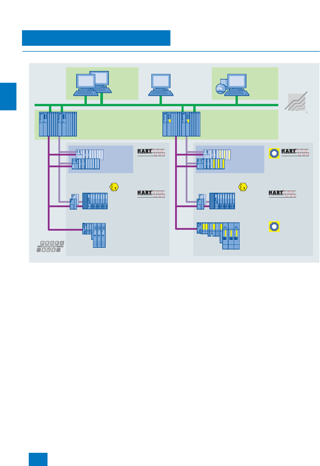
Engineering system
Engineering Process Safety
Introduction
4/20 Siemens ST PCS 7 · November 2007
4
■
Overview
Common engineering system for basic process control system and safety instrumented system
The process industry frequently features complex technological
sequences with high safety demands, and faults and failures in
the process automation could have fatal consequences for per-
sonnel, machines, plants and the environment. Therefore pro-
cess safety is of particular significance. The safety technology
used must reliably detect errors in the process and also its own
internal errors, and automatically set the plant/application to a
safe state if an error is detected.
Safety Integrated for Process Automation is the comprehensive
range of products and services from Siemens for safe, fault-tol-
erant applications in the process industry. This is characterized
by:
• AS 412F/FH, AS 414F/FH and AS 417F/FH safety-related au-
tomation systems
• Failsafe PROFIBUS communication using the PROFIsafe pro-
file
• Failsafe transmitters (SITRANS P DS III) on the PROFIBUS PA
with PROFIsafe
• ET 200M and ET 200S distributed I/O systems with safety-
related I/O modules
• User-friendly process visualization via the operator system, in-
cluding safety-relevant fault messages
• Engineering system with S7 F Systems software package,
CFC and SIMATIC Safety Matrix
• Safety lifecycle management with support of highly qualified
solution partners: services for all phases of the lifecycle of a
safety instrumented system (analysis, implementation and op-
eration)
TÜV
TÜV
Industrial
Ethernet
Operator
system
High-availability
Fail-safe, fault-tolerant
and high-availability
ET 200M
redundant/
non-
redundant
ET 200iSP
redundant/
non-
redundant
ET 200S
Standard/
safety-related
Standard/
safety-related
Standard
ET 200M
redundant/
non-
redundant
ET 200iSP
redundant/
non-
redundant
ET 200S
Standard
Standard
Standard
Engineering
system
Maintenance
station
© Siemens AG 2007

Engineering system
Engineering Process Safety
Introduction
4/21
Siemens ST PCS 7 · November 2007
4
■
Benefits
Safety Integrated for Process Automation permits complete inte-
gration of safety engineering into the SIMATIC PCS 7 process
control system. The Basic Process Control System (BPCS) and
Safety Instrumented System (SIS) melt together into a uniform
and innovative complete system. The advantages of this fusion
are quite clear:
• One common controller platform
• One common engineering system
• No separate safety bus - standard and safety-related commu-
nication take place on the same fieldbus (PROFIBUS with
PROFIsafe)
• Mixed operation of standard and safety-related I/O modules in
ET 200M and ET 200S remote I/O stations
• Uniform data management - no complex data exchange be-
tween BPCS and safety system
• Integration of safety-related applications into process visual-
ization on the operator station
• Automatic integration of safety-related fault messages with
time tagging into the process control system
• Integration of safety-related hardware into the SIMATIC PCS 7
asset management for diagnostics and preventive mainte-
nance
The SIMATIC PCS 7 engineering system is a universal tool
equally suitable for BPCS and safety applications.
Using the S7 F Systems engineering tool, you can parameterize
the AS 414F/FH and AS 417F/FH automation systems as well as
the safety-related F-modules of the ET 200M and ET 200S I/O
systems.
Using Continuous Function Chart (CFC) and predefined function
blocks from the F-block library of S7 F Systems, you can config-
ure safety-related applications simply, efficiently and without
weary acquaintance.
However, this is even simpler, more convenient and faster using
the SIMATIC Safety Matrix based on CFC. The configuration tool
functioning according to the principle of a Cause&Effect matrix
automatically creates complex safety programs once you have
assigned the events (causes) occurring during a process to ex-
actly defined reactions (effects).
© Siemens AG 2007
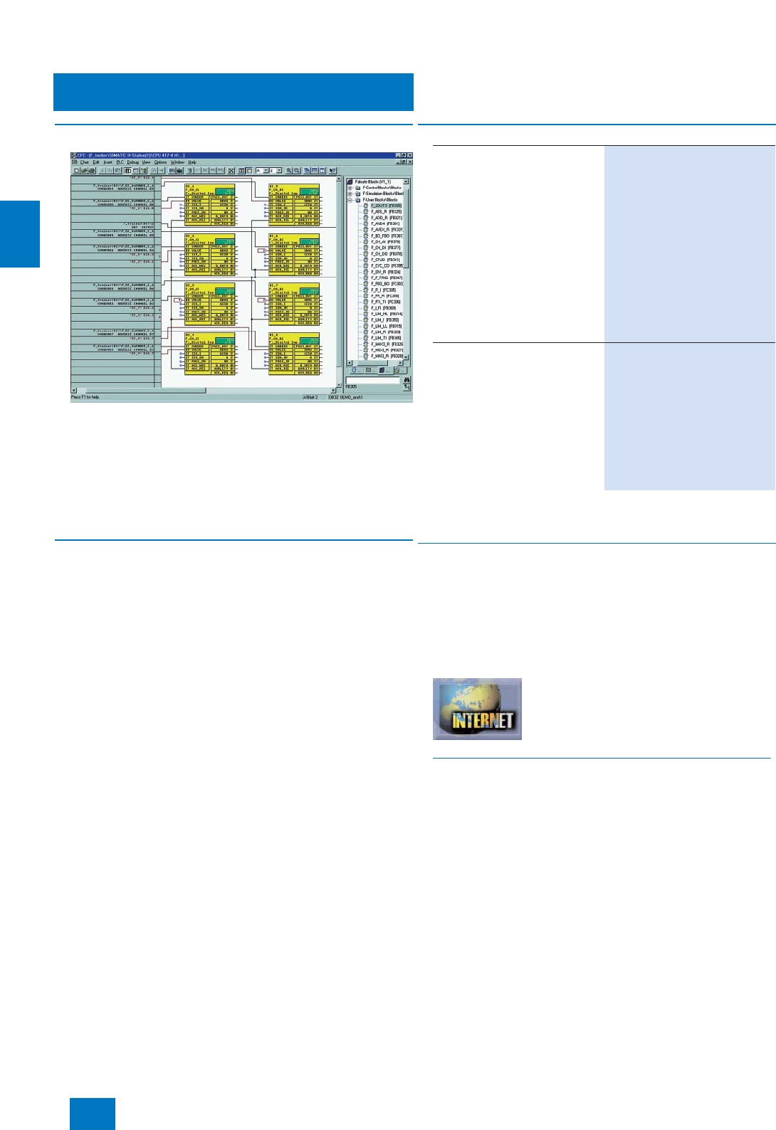
Engineering system
Engineering Process Safety
Engineering F/FH systems
4/22 Siemens ST PCS 7 · November 2007
4
■
Overview
The engineering tool S7 F Systems integrated in the SIMATIC
Manager can be used to configure an F system (F/FH). With this
tool you can:
• Parameterize CPU and F-signal modules
• Create safety-related applications in the CFC.
Predefined, TÜV-approved blocks are available for this purpose.
The safety-related blocks save the user having to perform redun-
dant programming for detecting and reacting to errors.
■
Configuration
S7 F Systems supports configuration by means of functions for
• Comparison of safety-related F-programs
• Recognition of changes in the F-program using the checksum
• Separation of safety-related and standard functions.
Access to the F-functions can be password-protected.
The F-block library integrated in S7 F Systems contains pre-
defined function blocks for generation of safety-related applica-
tions with the CFC or the SIMATIC Safety Matrix based on it. The
certified F-blocks are extremely robust and intercept program-
ming errors such as division by zero or out-of-range values. They
avoid the need for diverse programming tasks for detecting and
reacting to errors.
Note:
With a S7 F Systems Upgrade from V5.x to V6.0, the type of S7 F Systems
license changes from single license to floating license.
■
Options
S7 F ConfigurationPack
When using the safety-related SM 326F/336F I/O modules (AI,
DI, DO) as standard I/Os (without F-functionality), an S7 F Con-
figurationPack is required for engineering. This is included in
S7 F Systems V6.0, and is also available on the Internet for
downloading.
Additional information is available in the Internet under:
http://support.automation.siemens.com/WW/view/de/15208817
■
Selection and Ordering Data Order No.
S7 F Systems V6.0
Programming and configuration
environment for creating and
using safety-related STEP 7 pro-
grams for a target system based
on S7-400H
2 languages (German, English),
executes with Windows
XP Professional SP2, Windows
Server 2003 SP1/SP2 and
Windows 2000 SP4, floating
license for 1 user
Type of delivery:
Certificate of license as well as
software and electronic docu-
mentation on CD
6ES7 833-1CC01-0YA5
S7 F Systems Upgrade from
V5.x to V6.0
2 languages (German, English),
executes with Windows
XP Professional SP2, Windows
Server 2003 SP1/SP2 and
Windows 2000 SP4, floating
license for 1 user
Type of delivery:
Certificate of license as well as
software and electronic docu-
mentation on CD
6ES7 833-1CC01-0YE5
© Siemens AG 2007

Engineering system
Engineering Process Safety
SIMATIC Safety Matrix
4/23
Siemens ST PCS 7 · November 2007
4
■
Overview
The SIMATIC Safety Matrix which can be used in addition to the
CFC is an innovative safety lifecycle tool from Siemens that can
be used not only for user-friendly configuration of safety applica-
tions, but also for their operation and service. The tool, which is
based on the proven principle of a cause & effect matrix, is ide-
ally suited to processes where defined statuses require specific
safety reactions.
The SIMATIC Safety Matrix not only means that programming of
the safety logic is significantly simpler and more convenient, but
also much faster than in the conventional manner. During the risk
analysis of a plant, the configuration engineer can assign exactly
defined reactions (effects) to events (causes) which may occur
during a process.
■
Benefits
The advantages of the SIMATIC Safety Matrix in the implementa-
tion phase:
7Simple programming using Cause&Effect method
7No programming knowledge required
7Automatic generation of CFCs including driver blocks
7Automatic version tracking
7integrated change tracking
71-to-1 printout of Cause&Effect matrix
■
Design
In the context of SIMATIC PCS 7, the following individual prod-
ucts are offered for the SIMATIC Safety Matrix:
•SIMATIC Safety Matrix Tool
for configuration of safety functions on the SIMATIC PCS 7 en-
gineering system
•SIMATIC Safety Matrix Editor
for creating and debugging the Safety Matrix logic in an exter-
nal computer, independent of the engineering system (can be
optionally used additive to the SIMATIC Safety Matrix Tool)
•SIMATIC Safety Matrix Viewer for SIMATIC PCS 7
for operation and monitoring of the SIMATIC Safety Matrix us-
ing the SIMATIC PCS 7 operator system (for ordering data, re-
fer to page 5/15)
System requirements
The SIMATIC Safety Matrix Editor offers the advantage that the
Safety Matrix can also be created, processed further and de-
bugged outside the SIMATIC PCS 7 engineering system. The
SIMATIC Safety Matrix Editor can be used on a computer with
Windows 2000 Professional SP2 or higher or Windows XP Pro-
fessional. However, generation of the safety-related CFC pro-
gram as well as compilation and downloading to the automation
system are only possible by means of the SIMATIC engineering
system with the SIMATIC Safety Matrix Tool.
Hardware
requirement Software
requirement
SIMATIC Safety Matrix
Tool SIMATIC PCS 7
AS 412H/F/FH,
AS 414H/F/FH or
AS 417H/F/FH
(S7 F Systems
RT license is inte-
grated in the case
of F/FH systems)
SIMATIC PCS 7 V6.0 SP2
or higher,
S7 F Systems V5.2 HF 2
or higher with S7 F-Lib
V1.2
SIMATIC Safety Matrix
Editor Windows 2000 Profes-
sional SP2 or higher or
Windows XP Professional
SIMATIC Safety Matrix
Viewer SIMATIC PCS 7
AS 412H/F/FH,
AS 414H/F/FH or
AS 417H/F/FH
(S7 F Systems
RT license is inte-
grated in the case
of F/FH systems)
SIMATIC PCS 7-OS V6.0
SP2 or higher
© Siemens AG 2007
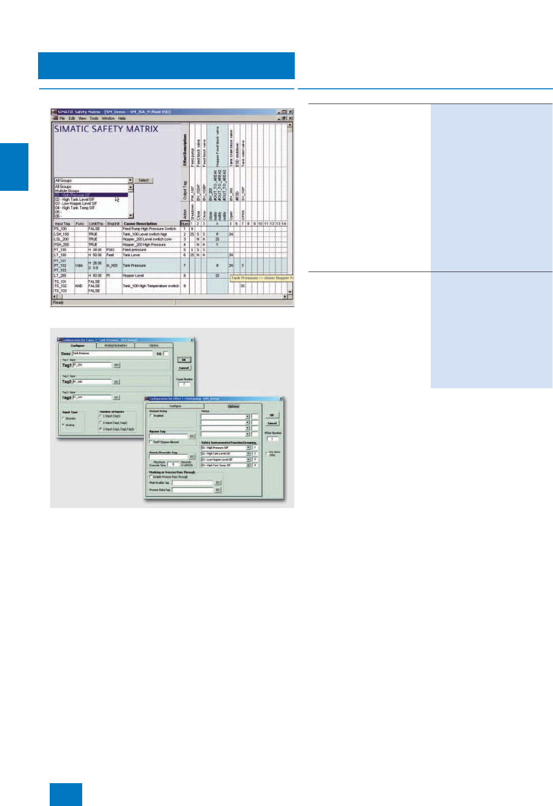
Engineering system
Engineering Process Safety
SIMATIC Safety Matrix
4/24 Siemens ST PCS 7 · November 2007
4
■
Function
Safety Matrix: intersections define the linking of causes and effects
Configuration of analog or digital causes and their digital effects
The matrix table is comparable with a spreadsheet program, and
the configuration engineer first enters the possible process
events (inputs) in the horizontal lines, and then configures their
type and number, logical links, possible delays and interlocks,
and any tolerable faults. In the vertical columns, he subse-
quently defines the reactions (outputs) to a particular event.
Events and reactions are linked simply by clicking the cell at the
intersection of the row and column. Using these data, the
SIMATIC Safety Matrix automatically generates complex, safety-
related CFC programs. No special programming knowledge is
required of the configuration engineer, and he can completely
concentrate on the safety requirements of the plant.
C) Subject to export regulations: AL: N, ECCN: EAR99S
■
Selection and Ordering Data Order No.
SIMATIC Safety Matrix Tool
Creation, configuration, compila-
tion, loading and online monitor-
ing of the Safety Matrix in a
SIMATIC PCS 7 environment
Including SIMATIC Safety Matrix
Viewer for SIMATIC PCS 7, for
operation and monitoring of the
Safety Matrix in a SIMATIC PCS 7
environment with several operator
control levels
1 language (English), executes
with Windows XP Professional,
floating license for 1 user
Type of delivery: Certificate of
license and authorization diskette
for Safety Matrix Tool and Safety
Matrix Viewer; software and elec-
tronic documentation on CD
6ES7 833-1SM00-0YA5 C)
SIMATIC Safety Matrix Editor
Creation and checking of the
Safety Matrix logic on an external
computer without a SIMATIC
PCS 7/ STEP 7 environment
1 language (English), executes
with Windows 2000 Professional
or Windows XP Professional,
floating license for 1 user
Type of delivery: Certificate of
license and authorization
diskette; software and electronic
documentation on CD
6ES7 833-1SM40-0YA5 C)
© Siemens AG 2007

Engineering system
Engineering Process Safety
SIMATIC PCS 7 Safety ES Packages
4/25
Siemens ST PCS 7 · November 2007
4
■
Overview
The SIMATIC PCS 7 standard engineering software can be orde-
red together with software components for engineering the inte-
grated safety technology as low-cost all-in-one packages.
Their composition depends on the application of the SIMATIC
PCS 7 Engineering Station:
• A combined engineering/operator station for small applica-
tions (productive operation as an operator station is possible)
• Exclusive engineering station without limitation of quantities
(cannot be used for productive operation as an operator sta-
tion)
The engineering software for basic process control and safety
applications can now be ordered using one single Order No.
An engineering station can also be subsequently extended
using S7 F Systems and SIMATIC Safety Matrix Tool using the
SIMATIC PCS 7 Safety Matrix ES Extension Package.
■
Selection and Ordering Data Order No.
SIMATIC PCS 7 Safety ES Packages
SIMATIC PCS 7 Safety
ES Package for AS/OS
Executes with Windows XP Pro-
fessional, floating license for
1user
Combination of
S7 F Systems, 2 languages
(German, English) and
SIMATIC PCS 7 Engineering
Software AS/OS, 6 languages
(German, English, French, Italian,
Spanish, Chinese)
•250 POs
incl. AS/OS Engineering and
Runtime licenses for 250 POs
6ES7 651-6AA07-0YA5
•Unlimited POs
incl. AS/OS Engineering license
for unlimited POs and
AS Runtime license for 600 POs
(2-hour OS test mode possible)
6ES7 651-6AF07-0YA5
SIMATIC PCS 7 Safety Matrix
ES Package for AS/OS
Executes with Windows XP Pro-
fessional, floating license for
1user
Combination of
S7 F Systems, 2 languages
(German, English)
SIMATIC Safety Matrix Tool, 1 lan-
guage (English)
SIMATIC PCS 7 Engineering Soft-
ware AS/OS, 6 languages (Ger-
man, English, French, Italian,
Spanish, Chinese)
•250 POs
incl. AS/OS Engineering and
Runtime licenses for 250 POs
6ES7 651-6BA07-0YA5
•Unlimited POs
incl. AS/OS Engineering license
for unlimited POs and
AS Runtime license for 600 POs
(2-hour OS test mode possible)
6ES7 651-6BF07-0YA5
SIMATIC PCS 7 Safety Matrix
ES Extension Package
Executes with Windows XP Pro-
fessional, floating license for
1user
Combination of:
S7 F Systems, 2 languages
(German, English)
SIMATIC Safety Matrix Tool, 1 lan-
guage (English)
6ES7 651-6BX07-0YA5
© Siemens AG 2007
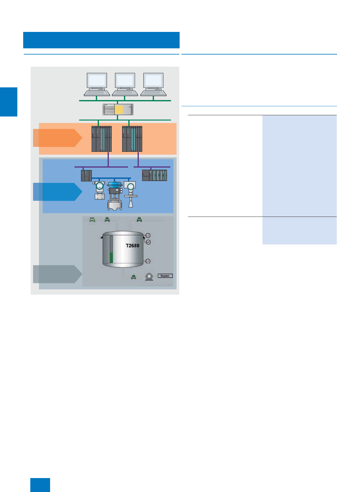
Engineering system
Simulation
Simulation with S7-PLCSIM
4/26 Siemens ST PCS 7 · November 2007
4
■
Overview
Overview of simulation software for SIMATIC PCS 7
Using the S7-PLCSIM simulation software, user programs cre-
ated with CFC/SFC can be tested on a PG/PC, regardless of
whether the target hardware is available. The detection and
elimination of errors is thus brought forward into an early phase
of development. This results in faster commissioning, lower
costs and better program quality.
■
Function
S7-PLCSIM simulates a SIMATIC S7 CPU with the associated
process images. The program to be tested is loaded into the
simulated S7 CPU in a manner identical to the procedure with
real hardware, and is executed there. S7-PLCSIM is completely
integrated in STEP 7. Process data can be exchanged between
S7-PLCSIM and other Windows applications via an interface.
For further programs concerning testing and simulation, see the catalog
"Add Ons for the SIMATIC PCS 7 Process Control System".
OS clients/
multi-clients
OS server
ET 200M
PROFIBUS DP
PROFIBUS PA
Field devices
Automation
systems
AS simulation
with S7-PLCSIM
Fieldbus
simulation with
SIMBApro FAT
Dynamic Plant
simulation with
SIMIT
■
Selection and Ordering Data Order No.
S7-PLCSIM V5.4
Functional testing of programs
which were created with
CFC/SFC, on PC/PG
5 languages (German, English,
French, Italian, Spanish),
executes with Windows 2000
Professional or Windows
XP Professional, floating license
for 1 user
Type of delivery: Authorization
diskette, certificate of license,
terms and conditions; software
and electronic documentation on
CD
• S7-PLCSIM V5.4 6ES7 841-0CC05-0YA5
• S7-PLCSIM upgrade from V3.x,
V4.x, V5.0, V5.2 or V5.3 to V5.4 6ES7 841-0CC05-0YE5
S7-PLCSIM Software Update
Service
Subscription for 1 year with auto-
matic extension; requirement:
current software version
6ES7 841-0CA01-0YX2
© Siemens AG 2007
Siemens ST PCS 7 · November 2007
5/2 Introduction
5/4 OS hardware
5/4 Introduction
5/6 OS basic hardware
5/8 Signal output
5/9 OS software
5/9 Introduction
5/12 OS standard software for
single station/server/client
5/14 SFC Visualization
5/15 SIMATIC PCS 7 Safety Matrix
OS Packages
5/16 Redundant operator systems
5/16 OS redundancy
5/19 OS archiving
5/19 Introduction
5/20 OS short-term archiving
5/21 OS long-term archiving with
StoragePlus
5/23 OS long-term archiving with
Central Archive Server
5/25 Operation and monitoring via
Web
5/25 SIMATIC PCS 7 Web server
5/27 Data exchange with host
systems
5/27 OpenPCS 7
Operator system
© Siemens AG 2007
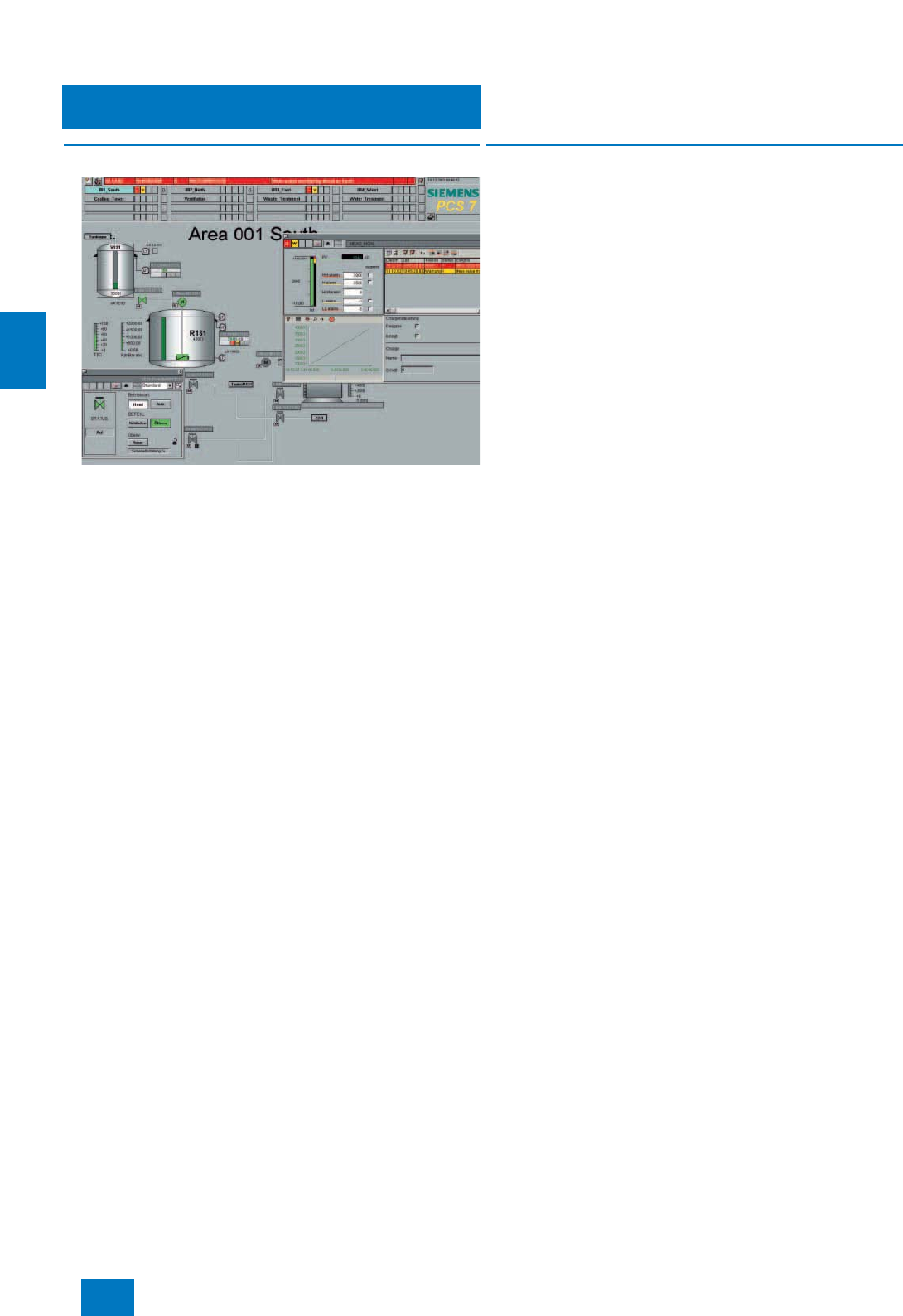
Operator system
Introduction
5/2 Siemens ST PCS 7 · November 2007
5
■
Overview
User interface of the OS process control system with freely positionable
windows
The operator system of the SIMATIC PCS 7 process control sys-
tem permits user-friendly and secure execution of the process
by the operating personnel. The operator can observe the pro-
cess sequence by means of various views and intervene to con-
trol the system when necessary.
The operator system architecture is extremely variable and can
be flexibly adapted to different plant architectures and customer
requirements.
The basis is formed by perfectly coordinated operator stations
for single-user systems (OS single stations) and for multi-user
systems with client/server architecture.
The system software of the operator stations is available in differ-
ent levels based on the number of process objects (PO) used:
• 250, 1000, 2000, 3000 or 5000 POs per OS single station
• 250, 1000, 2000, 3000, 5000 or 8500 POs per OS server (with
client/server architecture)
The number of POs for an operator station can be increased up
to 5000 (OS single station) or 8500 (OS server) at any time by
means of PowerPacks to allow for higher requirements or system
expansions.
■
Benefits
7Flexible, modular architecture with scalable hardware and
software components for single-user and multi-user systems
7High-performance operated stations based on standard PC
technology with Microsoft Windows XP Professional /
Server 2003, can be used in office or industrial environments
7Client/server multi-user systems with up to 12 OS servers/
pairs of servers, each for 8500 process objects (PO) and up
to 32 OS clients per server/pair of servers
7High-performance archive system based on Microsoft SQL
server with cyclic archives and integral data backup, option-
ally with long-term archiving via StoragePlus/central archive
server (CAS)
7OS health check for monitoring important server applications
7Integration of modifications without interrupting runtime oper-
ations, and online testing through selective loading of redun-
dant servers
7Optimized AS/OS communication:
data transmission only following change in data, independent
of AS reply cycle; suppression of nuisance alarms
7User-friendly process control and high operational reliability,
also in conjunction with multi-screen technology
7Extended status displays through combination of status and
analog values with alarm information
7Alarm suppression during startup or on malfunction of a sen-
sor/actuator
7Dynamic or manual hiding of visual and acoustic alarms that
are unimportant depending on the plant status, e.g. during
plant startup (however, all messages are recorded and ar-
chived); with manual hiding, the duration until display takes
place again can be set.
7Alarm priorities as additional attribute for filtering important
messages
7Central user management, access control, electronic signa-
ture
7Sign-of-life monitoring for subordinate systems connected to
the plant bus
7System-wide time synchronization based on UTC (Universal
Time Coordinated)
© Siemens AG 2007
Operator system
Introduction
5/3
Siemens ST PCS 7 · November 2007
5
■
Technical specifications
1) If every OS client has access to all OS servers/pairs of servers
Definitions
Process object
(PO) A process object (PO) is a synonym for an opera-
ble and observable block with approx. 30 to 50
individual OS variables (parameters). Thus the
quantity framework data of the engineering sys-
tem can be compared with those of the operating
system.
OS variable An OS variable or parameter is a defined memory
location required for operating and monitoring
with the operator system; values can be written
into it and read from it (e.g. setpoint, actual value
etc.). A PO usually has several OS variables
(which can be operated and monitored).
Licensing As of SIMATIC PCS 7 V7.0, the OS software will
only be licensed on the basis of POs. This signifi-
cantly simplifies calculation of the required
license. An average of 50 OS variables will be
calculated for a PO, where motors, valves etc.
require fewer variables, and controls, dosing
functions etc. require more variables. Checking of
the license will also be carried out using the POs,
and additionally includes checking of the total
number of OS variables used.
Every block fulfilling the following criteria is
counted and calculated as a PO:
• It is not a driver block.
• It can be operated and monitored.
• It can send messages.
Process objects OS variables (approx.)
250 12500
1000 50000
2000 100000
3000 150000
5000 250000
8500 425000
OS quantity framework
Max. number of OS servers / pairs
of servers 12
Max. number of automation systems
per OS server / pair of servers 64
Max. number of OS clients in multi-
client mode 1)
(per multi-user system)
32
Max. number of monitors per
operator station with multi-channel
operation
4
Max. number of OS areas 64
Max. number of windows per
monitor 1 to 16 (adjustable)
Number of trends per trend window 10
Selection time for OS area display
(100 process symbols) < 2 s
Max. number of process objects:
• Per OS single station 5000 POs
• Per OS server 8500 POs
Max. number of configurable mes-
sages per server/single station 150.000
Number of process tags
• Per OS single station Approx. 3000
• Per OS server Approx. 5000
• Per multi-user system Approx. 60000
Integral high-performance archive
system
(cyclic buffer), based on Microsoft
SQL server, for:
• Process value archiving (per
OS server / single station) Approx. 1000/s
• Message archiving
(per OS server / single station) Steady-state load approx. 10/s
Message peak approx. 3000 / 4 s
Long-term archiving
• Process value archiving with
StoragePlus Process values from up to 4 sin-
gle stations, servers or pairs of
servers
- Process values of one server Approx. 1000/s
- Process values of all servers Approx. 1600/s
• Process value archiving with
central archive server (CAS) Process values from up to 11
servers or pairs of servers
- Process values of one server Approx. 1000/s
- Process values of all servers Approx. 10000/s
© Siemens AG 2007
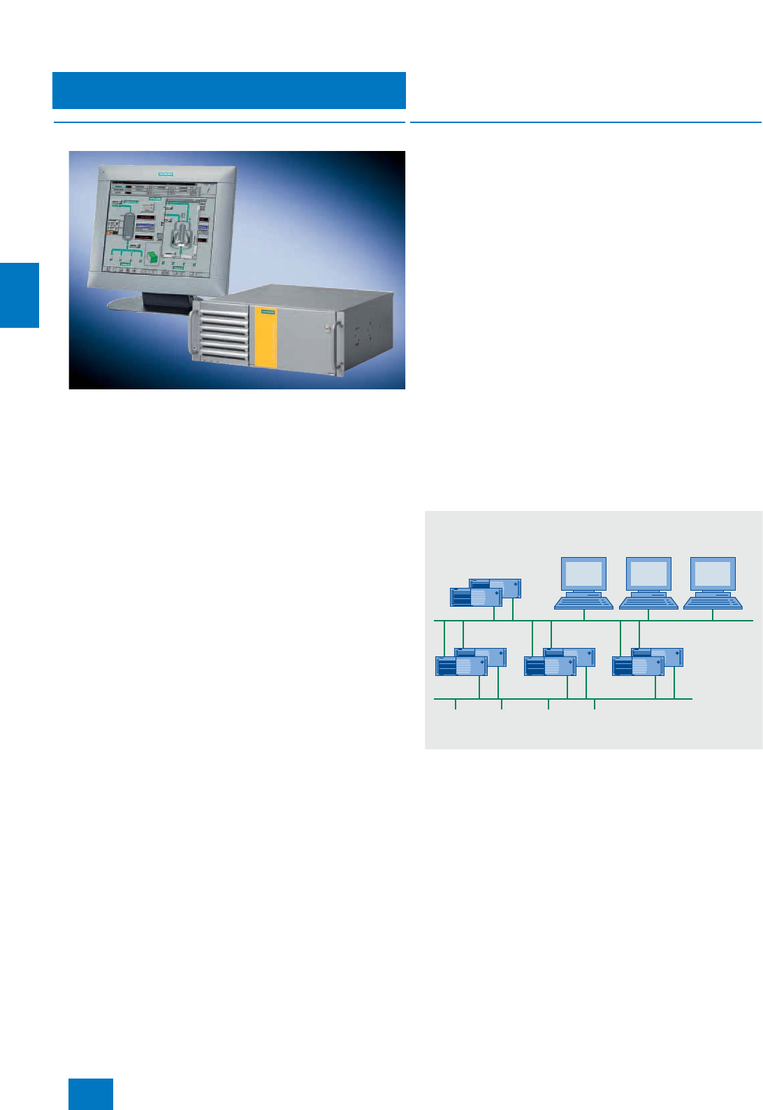
Operator system
OS hardware
Introduction
5/4 Siemens ST PCS 7 · November 2007
5
■
Overview
All operator stations are based on modern SIMATIC PCS 7 in-
dustrial workstations optimized for use as OS single station,
OS client or OS server. The SIMATIC PCS 7 industrial worksta-
tions are characterized by powerful PC technology combined
with the Microsoft Windows XP Professional or Server 2003 op-
erating system. They can be used in harsh industrial environ-
ments or also in offices.
Standard components and interfaces from the PC world offer
generous scope for system-, customer- or sector-specific op-
tions and expansions.
The connection of as many as 4 process monitors via an optional
multi-VGA graphics card in the OS single station or in the OS cli-
ent permits the user-friendly control of several plant areas from
one operator station.
■
Design
Single-user system (OS single station)
In a single-user system architecture, all operation and monitor-
ing functions for a complete project (plant/unit) are concentrated
in one station. A 10/100/1000 Mbit/s Ethernet RJ45 port is al-
ready onboard and can be used for connecting to an OS LAN
(terminal bus). The OS single station can be linked to the Indus-
trial Ethernet plant bus by means of two different network con-
nections:
• CP 1613 A2 communications processor,
for communication with max. 64 automation systems
• Standard FastEthernet network card and Basic Communica-
tion Ethernet
for communication with max. 8 automation systems (not fault-
tolerant systems)
The OS single station can be operated on the plant bus in paral-
lel with other single-user systems or with a multi-user system ar-
chitecture. Two OS single stations can, however, also be oper-
ated redundantly (SIMATIC PCS 7 single station redundancy).
Multi-user system with client/server architecture
A multi-user system consists of operator terminals (OS clients),
which receive data (project data, process values, archives,
alarms and messages) from one or more OS servers through an
OS LAN (terminal bus). The OS LAN can share the transmission
medium with the plant bus or it can be designed as a separate
bus (Ethernet with TCP/IP).
In this architecture, redundant OS servers may be set up to meet
higher availability requirements. Critical applications running on
the OS server are monitored by Health Check for software faults.
If a fault is detected, switchover to the redundant system is trig-
gered. Synchronization of the redundant OS servers takes place
automatically and at high speed.
OS clients can access the data of not only one OS server/server
pair, but from several OS servers/pairs of servers simultaneously
(multi-client mode). This makes it possible to divide a plant into
technological units and to distribute the data accordingly to sev-
eral OS servers/pairs of servers. In addition to scalability, the ad-
vantage of distributed systems is the ability to decouple plant ar-
eas from each other, which results in higher availability.
Industrial Ethernet
Automation systems
Central Archive
Server (CAS) OS clients
(max. 32 in multi-client mode)
OS servers
(max. 12
redundant)
© Siemens AG 2007

Operator system
OS hardware
Introduction
5/5
Siemens ST PCS 7 · November 2007
5
SIMATIC PCS 7 supports multi-user systems with up to
12 OS servers or 12 redundant OS pairs of servers. In multi-
client mode, OS clients can access data from one or more of the
12 OS servers/pairs of servers in parallel (up to 32 OS clients si-
multaneously on all).
The OS servers are designed in addition with client functions
which permit them to access the data (archives, messages,
tags, variables) from the other OS servers of the multi-user sys-
tem. This means that process graphics on one OS server can
also be linked with variables on other OS servers (area-indepen-
dent displays).
Like the OS single stations, the OS servers can be connected to
the Industrial Ethernet plant bus using a CP 1613 communica-
tions processor or a standard FastEthernet card with Basic Co-
munication Ethernet (BCE). A 10/100/1000 Mbit/s Ethernet RJ45
port is already onboard and can be used for connecting to an
OS LAN (terminal bus).
The CP 1613 communication integrated in the IE version of the
ES/OS single station and the OS server is a combination of
CP 1613 communications processor and S7-1613 communica-
tions software. When using fault-tolerant automation systems,
the SIMATIC PCS 7 Workstation requires the S7-REDCONNECT
software instead of the S7-1613 communications software. The
S7-REDCONNECT Upgrade is suitable for upgrading the com-
munications software (for ordering data, see page 9/28).
OS archiving
The operator system already includes a high-performance ar-
chiving system based on Microsoft SQL Server with cyclic ar-
chives for short-term saving of process values and messages/
events (alarms). This short-term archive can be combined with
a long-term archive on the basis of StoragePlus or the central ar-
chive server (CAS).
The StoragePlus provided for the bottom performance range is
able to archive approx. 1600 process values/s from a total of
4 single stations/servers/pairs of servers. The powerful CAS sat-
isfies much higher requirements. It can be configured as a single
server or as a redundant pair of servers, and can archive ap-
prox. 10000 values/s from up to 11 servers/pairs of servers. The
data managed in StoragePlus and in the CAS can be saved on
all storage media supported by the operating system. This re-
quires additional hardware and software, e.g. a DVD writer with
suitable burning software.
The StoragePlus computer and the CAS are stations on the
OS LAN (terminal bus), and are not connected to the plant bus.
When using a SIMATIC PCS 7 Industrial Workstation as the hard-
ware platform, the 10/100/1000 Mbit/s Ethernet RJ45 port al-
ready onboard can be used for connecting to the OS LAN.
© Siemens AG 2007

Operator system
OS hardware
OS basic hardware
5/6 Siemens ST PCS 7 · November 2007
5
■
Overview
The complete range of SIMATIC PCS 7 Industrial Workstations is
available for configuration of operating systems (see page 2/7).
Specially optimized versions of the SIMATIC PCS 7 Industrial
Workstation are available for operation as single stations, serv-
ers or clients. The operating system and the following
ES/OS software of the SIMATIC PCS 7 process control system
are already preinstalled when delivered:
• Single station: PCS 7 Engineering Software for AS/OS (includ-
ing OS Runtime software)
• Server: PCS 7 OS Software Server
• Client: PCS 7 OS Software Client
You need the corresponding licenses in order to use the pre-
installed SIMATIC PCS 7 software.
■
Technical specifications
Detailed technical data for the single station, server and client
versions of the SIMATIC PCS 7 Industrial Workstation can be
found in Section "SIMATIC PCS 7 Industrial Workstation" of the
Chapter "System-neutral components" in tabular format.
■
Selection and Ordering Data Order No.
OS single station
SIMATIC PCS 7 Industrial Work-
station, single station version
Windows XP Professional MUI
operating system (German,
English, French, Italian, Spanish,
Chinese)
•SIMATIC PCS 7 ES/OS 547B
BCE WXP
Connection to plant bus with
Ethernet network card RJ45
(PCI) 10/100/1000 Mbit/s and
Basic Communication Ethernet
(BCE) for up to 8 automation
systems (not H-systems)
6ES7 650-0NF07-0YX0 D)
•SIMATIC PCS 7 ES/OS 547B
IE WXP
Connection to plant bus with
CP 1613 A2 communications
processor
6ES7 650-0NF07-0YX1 D)
OS server
SIMATIC PCS 7 Industrial
Workstation, server version
Windows Server 2003 MUI oper-
ating system (German, English,
French, Italian, Spanish, Chinese)
•SIMATIC PCS 7 OS Server
547B BCE SRV03
Connection to plant bus with
Ethernet network card RJ45
(PCI) 10/100/1000 Mbit/s and
Basic Communication Ethernet
(BCE) for up to 8 automation
systems (not H-systems)
6ES7 650-0NH07-0YX0 D)
•SIMATIC PCS 7 OS Server
547B IE SRV03
Connection to plant bus with
CP 1613 A2 communications
processor
6ES7 650-0NH07-0YX1 D)
OS client
SIMATIC PCS 7 Industrial
Workstation, client version
Windows XP Professional MUI
operating system (German,
English, French, Italian, Spanish,
Chinese)
•SIMATIC PCS 7 OS Client 547B
WXP
- without multi-VGA graphics
card 6ES7 650-0NG07-0YX0 D)
- with Multi-VGA graphics card
"2 Screens" 6ES7 650-0NG07-0YA0 D)
- with Multi-VGA graphics card
"4 Screens" 6ES7 650-0NG07-0YB0 D)
D) Subject to export regulations: AL: N, ECCN: 5D992B1
© Siemens AG 2007

Operator system
OS hardware
OS basic hardware
5/7
Siemens ST PCS 7 · November 2007
5
B) Subject to export regulations: AL: N, ECCN: EAR99H
Note:
Ordering data in abbreviated form; for detailed Ordering data, see
page 2/14.
■
Options
The basic hardware referred to may be expanded with the fol-
lowing options, depending on the customer’s particular require-
ments and whether the hardware is used as OS single station,
OS server or OS client, e.g. with:
• Hardware and software components for redundant operation
• Industrial LCD monitors for office and industry environments
(see page 2/17)
• Signal module for audible and visual signaling of messages
• Chipcard reader for access protection (see page 2/4)
Multi-VGA operation with up to 4 process monitors is supported
in the OS client by two additional hardware versions:
• SIMATIC PCS 7 OS Client 547B WXP with multi-VGA graphics
card "2 Screens" and
• SIMATIC PCS 7 OS Client 547B WXP with multi-VGA graphics
card "4 Screens"
OS clients and OS single stations with an integral standard
graphic interface module for controlling a process monitor can
also be functionally expanded by a multi-VGA graphics card
"2 Screens" or "4 Screens" (see page 2/16 for ordering data).
Upgrading from BCE to CP 1613 communication
OS single stations and OS servers with BCE communication can
be subsequently upgraded for communication with CP 1613.
Items required:
• CP 1613 A2:
PCI card for connecting to Industrial Ethernet
• SIMATIC NET S7-1613:
S7 communications software for CP 1613
Upgrade from BCE to CP 1613 communication
CP 1613 A2
PCI card for connection to
Industrial Ethernet, with ITP and
RJ45 connections
6GK1 161-3AA01 B)
SIMATIC NET S7-1613/2006 for
Industrial Ethernet
S7 communication software for
CP 1613,
can be used with Windows 2000
Professional/2000 Server/
XP Professional/Server 2003
Single license for 1 installation,
runtime software, software and
electronic manual on CD-ROM,
license key on diskette, Class A,
2 languages (German/English)
6GK1 716-1CB64-3AA0
Expansion of communication software
from S7-1613 to S7-REDCONNECT
SIMATIC NET S7-REDCONNECT
Upgrade
For communication with fault-tol-
erant AS systems, see page 9/28
Additional and expansion components
See page 2/15
■
Selection and Ordering Data Order No.
© Siemens AG 2007
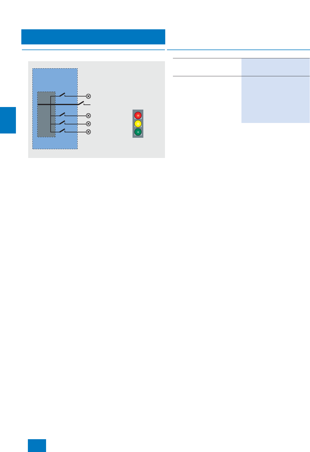
Operator system
OS hardware
Signal output
5/8 Siemens ST PCS 7 · November 2007
5
■
Overview
OS Single Station and OS Client can be expanded by a signal
module. This signal module can operate a horn and up to 3 dif-
ferent lamps or buzzer sounds symbolizing different signal
classes. Together with a hardware timer (watchdog) the signal
module is able to detect and signal the failure of an operator sta-
tion. A hardware acknowledge key can also be connected.
The signal module occupies one PCI slot in the operator station.
B) Subject to export regulations: AL: N, ECCN: EAR99H
Driver
Signal module External circuit
Acknowledgeable contact
Acknowledgement input
Contact channel 1
Contact channel 2
Contact channel 3
■
Selection and Ordering Data Order No.
PCI Signal Module
PCI card for installing in an opera-
tor station
6DS1 916-8RR B)
Connecting cable
For connecting an external audio
detector to a signal module
•3 m 6XV2 175-8AH30
•10 m 6XV2 175-8AN10
•32 m 6XV2 175-8AN32
•50 m 6XV2 175-8AN50
© Siemens AG 2007
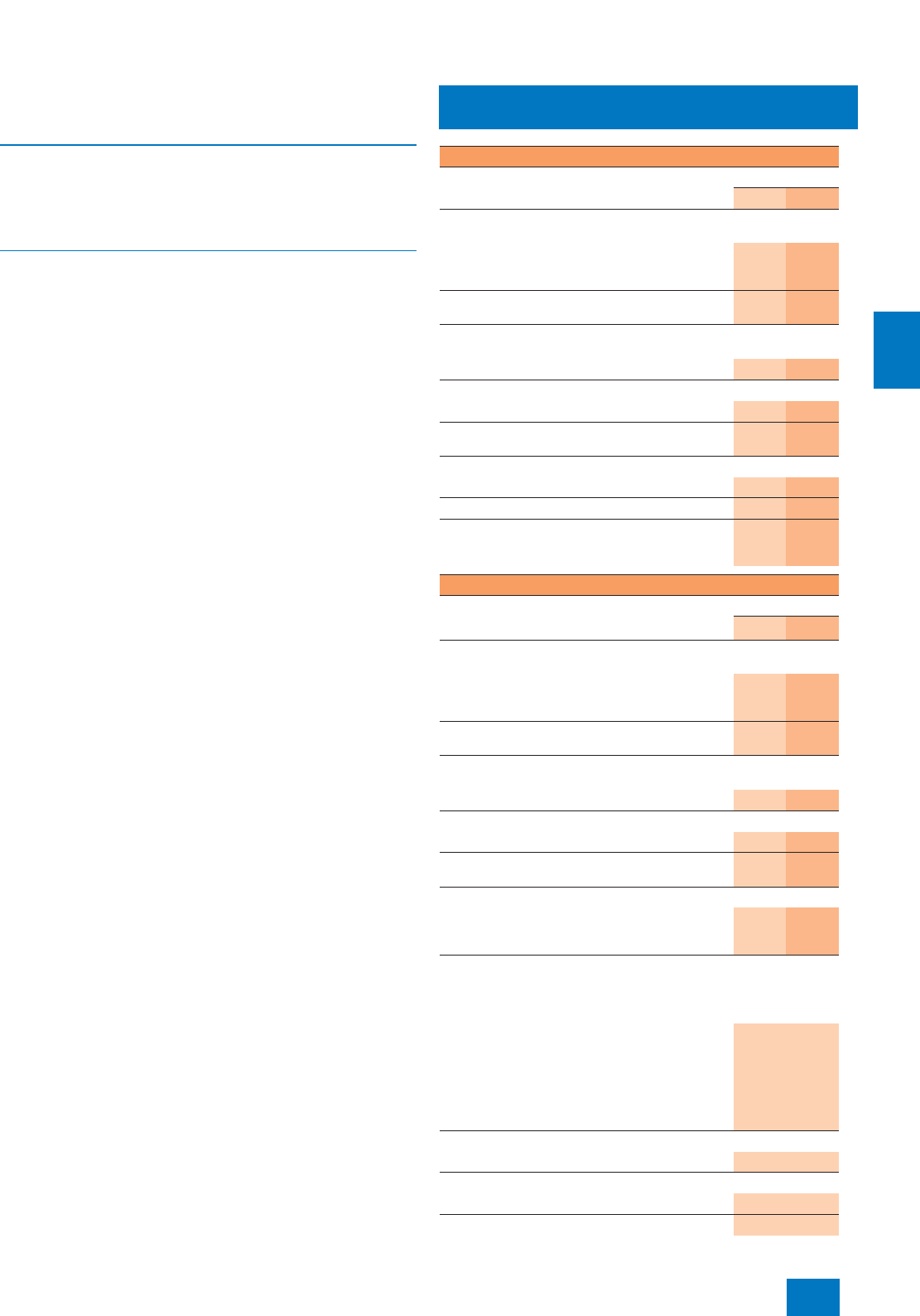
Operator system
OS software
Introduction
5/9
Siemens ST PCS 7 · November 2007
5
■
Overview
OS basic hardware and OS software are structured by OS single
station, OS server and OS client in compliance with the architec-
ture of the operator system and are accordingly coordinated in
this regard.
■
Design
The OS standard software of OS single stations and OS clients
can be expanded by SIMATIC PCS 7 SFC Visualization and
Safety Matrix Viewer.
The high-performance cyclic buffer archiving system integrated
as standard in OS single station and OS server for short-term ar-
chiving of up to 512 variables can be expanded within the limit
of 10000 variables using SIMATIC PCS 7 archive licenses and
SIMATIC PCS 7 Archive PowerPacks. The SIMATIC PCS 7 ar-
chive licenses (Count Relevant Licenses) are cumulative.
SIMATIC PCS 7 Archive PowerPacks permit expansion in steps
from 1500 to 5000 or 10000 variables. For ordering data for
SIMATIC PCS 7 Archive and SIMATIC PCS 7 Archive Power-
Packs, refer to page 5/20.
The short-term archive can also be combined with a long-term
archive. StoragePlus is available for long-term archiving in the
bottom performance range, and the central archive server (CAS)
is envisaged for the top performance range. See page 5/19 for
details.
You can also implement redundant system configurations with
OS single stations and OS servers. See page 5/16 for details.
The following tables provide a selection aid for ordering an op-
erator station. Depending on whether a redundant or non-redun-
dant design is selected, the tables indicate the respectively re-
quired number of
• SIMATIC PCS 7 Industrial Workstations,
• licenses for OS standards software, and
• licenses for optionally used supplementary OS software.
Note on Microsoft SQL Server software
The "SQL Server" software from Microsoft delivered with
SIMATIC PCS 7 may not be used outside the SIMATIC PCS 7
environment without the written approval of Siemens.
Single-user system
OS single station
with Windows XP Professional operating system Redundancy
Without With
SIMATIC PCS 7 Industrial Workstation including
operating system, alternatives
SIMATIC PCS 7 ES/OS 547B BCE WXP
with BCE communication for up to 8 automation
systems (not H systems)
1 2
SIMATIC PCS 7 ES/OS 547B IE WXP
with Industrial Ethernet communication 1 2
Additional IE communications software for
SIMATIC PCS 7 ES/OS 547B IE WXP
SIMATIC NET S7-REDCONNECT Upgrade 1 2
OS standard software
SIMATIC PCS 7 OS Software Single Station V7.0 1--
SIMATIC PCS 7 Single Station Redundancy V7.0
including RS 232 connecting cable, 10 m -- 1
Supplementary OS software (optional)
SIMATIC PCS 7 SFC Visualization V7.0 1 2
SIMATIC Safety Matrix Viewer for PCS 7 1 2
SIMATIC PCS 7 Archive V7.0/ SIMATIC PCS 7
Archive PowerPack for expansion of short-term
cyclic buffer archive
1 2
Multi-user system with client/server architecture
OS server
with Windows 2003 Server operating system Redundancy
Without With
SIMATIC PCS 7 Industrial Workstation including
operating system, alternatives
SIMATIC PCS 7 OS Server 547B BCE SRV03
with BCE communication for up to 8 automation
systems (not H systems)
1 2
SIMATIC PCS 7 OS Server 547B IE SRV03
with Industrial Ethernet communication 1 2
Additional IE communications software for
SIMATIC PCS 7 OS Server 547B IE SRV03
SIMATIC NET S7-REDCONNECT Upgrade 1 2
OS standard software
SIMATIC PCS 7 OS Software Server V7.0 1--
PCS 7 Server Redundancy V7.0, including RS 232
connecting cable, 10 m -- 1
Supplementary OS software (optional)
SIMATIC PCS 7 Archive V7.0/ SIMATIC PCS 7
Archive PowerPack for expansion of short-term
cyclic buffer archive
1 2
OS client
with Windows XP Professional operating system
SIMATIC PCS 7 Industrial Workstation including
operating system, alternatives
Connection for OS-LAN (terminal bus) onboard:
SIMATIC PCS 7 OS Client 547B WXP, alternatively
with:
• onboard standard graphics,
• multi-VGA graphics card "2 Screens", or
• multi-VGA graphics card "4 Screens"
1
OS standard software
SIMATIC PCS 7 OS Software Client V7.0 1
Supplementary OS software (optional)
SIMATIC PCS 7 SFC Visualization V7.0 1
SIMATIC Safety Matrix Viewer for PCS 7 1
© Siemens AG 2007
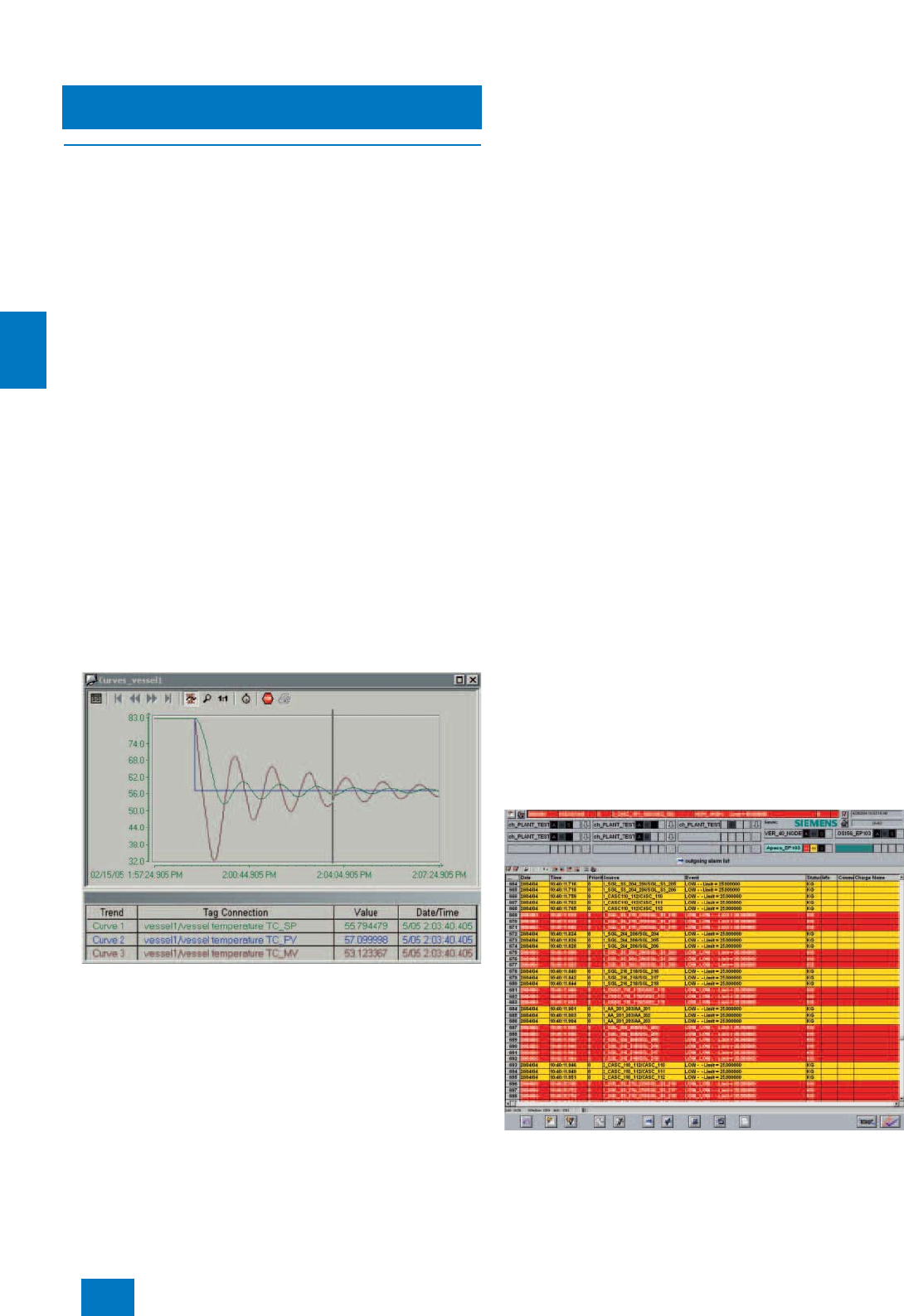
Operator system
OS software
Introduction
5/10 Siemens ST PCS 7 · November 2007
5
■
Function
Graphical user interface
The predefined user interface of the operator system has all the
features typical of a control system. It is multilingual, clearly
structured, ergonomic and easy to understand. Operators can
survey the process extremely easily, and rapidly navigate be-
tween different views of the plant. The system supports them in
this process with hierarchical display structures that can be con-
figured as required. These facilitate the direct selection of lower-
level areas during process control.
Process displays and process tags can also be called up by
name. An online language selector permits the user to change
the display language during runtime.
A standard view and a server view are available for the techno-
logical representation of a plant, each with variously designed
area overviews. Features provided in both views include:
• Message line for display of last message, can be configured
such that either the message of the highest class or with the
highest priority is shown
• Date, time and name of the operator
• Area overview with up to 36/49/64 areas (depending on reso-
lution of the process monitor)
• Working area for plant displays and movable windows for
faceplates, trends, messages etc.
• System function keys
In a special message view it is possible to switch between con-
trol message pages such as new list, old list, cleared alarm list,
operator action list, control element list and message history list.
Trends
Trend window on the operator station
Trends can be displayed as a full-size picture or as a window in
the working area, and printed directly. Some trends/trend groups
are predefined during plant configuration. In particular for com-
parisons, standardized curves with percentage scaling can be
produced in addition to the absolute display. The standard set-
tings for dimensions and limits (e.g. minimum/maximum) de-
fined during configuration are automatically applied during run-
time. At runtime, operators can compose their own trends, select
them by process tag name, and save them for reuse.
Messages and alarms
Up to 150,000 messages/alarms can be configured per OS sin-
gle station/OS server.
Message priorities are issued as an additional attribute to the
known signal classes in order to make it easier to assess large
quantities of signals and to be better able to distinguish impor-
tant messages from the less important.
By means of intelligent alarm management, alarms that are of
lower importance for the safe and fault-free operation of the plant
in certain plant states can be hidden and silenced. These alarms
are still logged and archived as before. This saves a noticeable
amount of work for the operators. Insignificant alarms can be
hidden in two ways:
• Dynamically, i.e. depending on preconfigured definition for up
to 32 operating states (Smart Alarm Hiding)
• Manually, with time limit
Operators can specifically disable messages (alarms) from indi-
vidual process tags or from all process tags of a display/area in
the event of faults in a sensor/actuator or during startup. Dis-
abling and enabling are recorded in an input report.
Active messages are signaled by group displays representing
preconfigured views based on message groups. The group dis-
plays also indicate whether messages are disabled or not.
The last message to have arrived – or the message with the high-
est priority when alarm priorities are utilized – is displayed at the
top edge of the standard view. A predefined window with further
messages can be called up with the "Extended message line".
The "Loop-in-alarm" and "Select display using process tag" func-
tions support the quick evaluation and resolution of faults. Using
"Loop-in-alarm", the operator can jump directly to the process
display with the object which caused the fault, and can then call
up the associated faceplate (loop display) through the process
tag whose block symbol is colored (cyan). The faceplate window
(loop display) can be anchored so that it remains visible even
when the display is changed.
Flexible setting options for audible output and priorities which
can be defined using signal variables additionally support the
signaling of messages/alarms through a sound card or by con-
trolling external horns via a signal module.
Message window on the operator station
© Siemens AG 2007
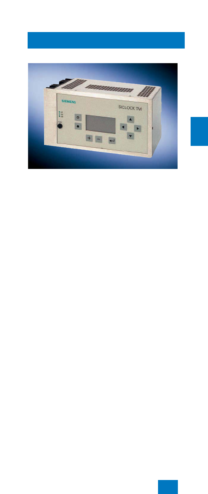
Operator system
OS software
Introduction
5/11
Siemens ST PCS 7 · November 2007
5
Central user management, access control and
electronic signature
With SIMATIC Logon, the operator system has central user ad-
ministration with access control that complies with the validation
requirements of 21 CFR Part 11. The administrator can divide
the users into groups and assign differently defined access
rights (roles) to these groups. The operator obtains the specific
rights when logging on within the scope of the access control.
Apart from the keyboard, an optional chipcard reader, for exam-
ple, can be used as the logon device. In addition, SIMATIC
Logon offers the "electronic signature" function.
SIMATIC Logon is already integrated in SIMATIC PCS 7 and
need not be ordered separately. For further information on
SIMATIC Logon as well as ordering data for an optional chipcard
reader, see page 2/5.
Sign-of-life monitoring
With the "Sign-of-life monitoring" function, the operator system is
able to monitor the correct operation of all subordinate systems
connected to the plant bus. A graphical plant configuration dis-
play shows the status of each monitored component. The
SIMATIC PCS 7 asset management offers enhanced functional-
ity in this context (see Chapter "Asset Management").
Clock synchronization
SICLOCK TM central plant clock
Together with a SICLOCK time generator (see Catalog "Add Ons
for SIMATIC PCS 7"), the operator system of the SIMATIC PCS 7
process control system can implement the system-wide syn-
chronization on the basis of UTC (Universal Time Coordinated).
This feature is especially beneficial for widely distributed plants
present in different time zones, e.g. pipelines.
Script languages
Visual Basic and C are the scripting languages available for cus-
tom programming of OS applications.
© Siemens AG 2007

Operator system
OS software
OS standard software
for single station/server/client
5/12 Siemens ST PCS 7 · November 2007
5
■
Overview
The OS standard software is adapted to the SIMATIC PCS 7
Industrial Workstations offered (OS single station, OS server and
OS client).
The OS standard software for OS single stations and OS servers
can be adapted to plants of various size by means of the number
of process objects (PO). The number of POs can be increased
at any time by adding more PowerPacks in order to allow for
higher requirements of system expansions.
You can also implement redundant system configurations with
OS single stations and OS servers. See page 5/16 for details.
The engineering of the SIMATIC PCS 7 process control system
is usually concentrated in a separate engineering system. In the
case of OS single stations used for small plants, engineering
and operator functionality can be combined in one station, ex-
cept with redundant systems (for engineering software, see Sec-
tion "Engineering system").
The high-performance cyclic buffer archiving system integrated
as standard in OS single station and OS server for short-term ar-
chiving of up to 512 variables can be expanded to 1500, 5000
or 10000 variables using SIMATIC PCS 7 Archive PowerPacks.
Furthermore, the variables of the SIMATIC PCS 7 archive itself
can also be accumulated for the short-term archive within the ex-
pansion limit of 10000 variables (Count Relevant Licenses).
The short-term archive can also be combined with a long-term
archive. See page 5/19 for details.
The OS standard software of OS single stations and OS clients
can be expanded by SFC visualization and the safety matrix
viewer.
■
Selection and Ordering Data Order No.
OS Software Single Station
SIMATIC PCS 7 OS Software
Single Station V7.0
6 languages (German, English,
French, Italian, Spanish,
Chinese), executes with Win-
dows XP Professional, single
license for 1 installation
Electronic documentation on
PCS 7 toolset DVD
Type of delivery:
License key disk, emergency key
disk, certificate of license, terms
and conditions;
PCS 7 V7.0 toolset DVDs,
Microsoft SQL Server 2005
including EULA and supplemen-
tary CDs/DVDs (e.g. Microsoft
ServicePacks and tools)
•250POs
1) 6ES7 658-2AA07-0YA0
• 1000 POs 6ES7 658-2AB07-0YA0
• 2000 POs 6ES7 658-2AC07-0YA0
• 3000 POs 6ES7 658-2AD07-0YA0
• 5000 POs 6ES7 658-2AE07-0YA0
SIMATIC PCS 7 OS Software
Single Station PowerPack V7.0
for extending the OS Software
Single Station
6 languages (German, English,
French, Italian, Spanish,
Chinese), executes with Win-
dows XP Professional, single
license for 1 installation
Type of delivery:
License key disk, emergency key
disk, certificate of license, terms
and conditions
• From 250 POs to 1000 POs 6ES7 658-2AB07-0YD0
• From 1000 POs to 2000 POs 6ES7 658-2AC07-0YD0
• From 2000 POs to 3000 POs 6ES7 658-2AD07-0YD0
• From 3000 POs to 5000 POs 6ES7 658-2AE07-0YD0
1) A process object (PO) is a synonym for an operable and observable
block with approx. 30 to 50 individual OS variables (parameters).
When licensing, an average of 50 OS variables is calculated for one
PO.
© Siemens AG 2007

Operator system
OS software
OS standard software
for single station/server/client
5/13
Siemens ST PCS 7 · November 2007
5
OS Software Server
SIMATIC PCS 7 OS Software
Server V7.0
6 languages (German, English,
French, Italian, Spanish, Chi-
nese), executes with Windows
Server 2003, single license for
1 installation
Electronic documentation on PCS
7 toolset DVD
Type of delivery:
License key disk, emergency key
disk, certificate of license, terms
and conditions;
PCS 7 V7.0 toolset DVDs,
Microsoft SQL Server 2005
including EULA and supplemen-
tary CDs/DVDs (e.g. Microsoft
ServicePacks and tools)
• 250 POs 6ES7 658-2BA07-0YA0
• 1000 POs 6ES7 658-2BB07-0YA0
• 2000 POs 6ES7 658-2BC07-0YA0
• 3000 POs 6ES7 658-2BD07-0YA0
• 5000 POs 6ES7 658-2BE07-0YA0
• 8500 POs 6ES7 658-2BF07-0YA0
SIMATIC PCS 7 OS Software
Server PowerPack V7.0
for extending the OS Software
Server
6 languages (German, English,
French, Italian, Spanish,
Chinese), executes with Win-
dows Server 2003, single license
for 1 installation
Type of delivery: License key
disk, emergency key disk, certifi-
cate of license, terms and condi-
tions
• From 250 POs to 1000 POs 6ES7 658-2BB07-0YD0
• From 1000 POs to 2000 POs 6ES7 658-2BC07-0YD0
• From 2000 POs to 3000 POs 6ES7 658-2BD07-0YD0
• From 3000 POs to 5000 POs 6ES7 658-2BE07-0YD0
• From 5000 POs to 8500 POs 6ES7 658-2BF07-0YD0
■
Selection and Ordering Data Order No.
OS Software Client
SIMATIC PCS 7 OS Software
Client V7.0
6 languages (German, English,
French, Italian, Spanish,
Chinese), executes with Win-
dows XP Professional, floating
license for 1 user
Electronic documentation on PCS
7 toolset DVD
Type of delivery:
License key disk, emergency key
disk, certificate of license, terms
and conditions;
PCS 7 V7.0 toolset DVDs,
Microsoft SQL Server 2005
including EULA and supplemen-
tary CDs/DVDs (e.g. Microsoft
ServicePacks and tools)
6ES7 658-2CX07-0YA5
■
Selection and Ordering Data Order No.
© Siemens AG 2007
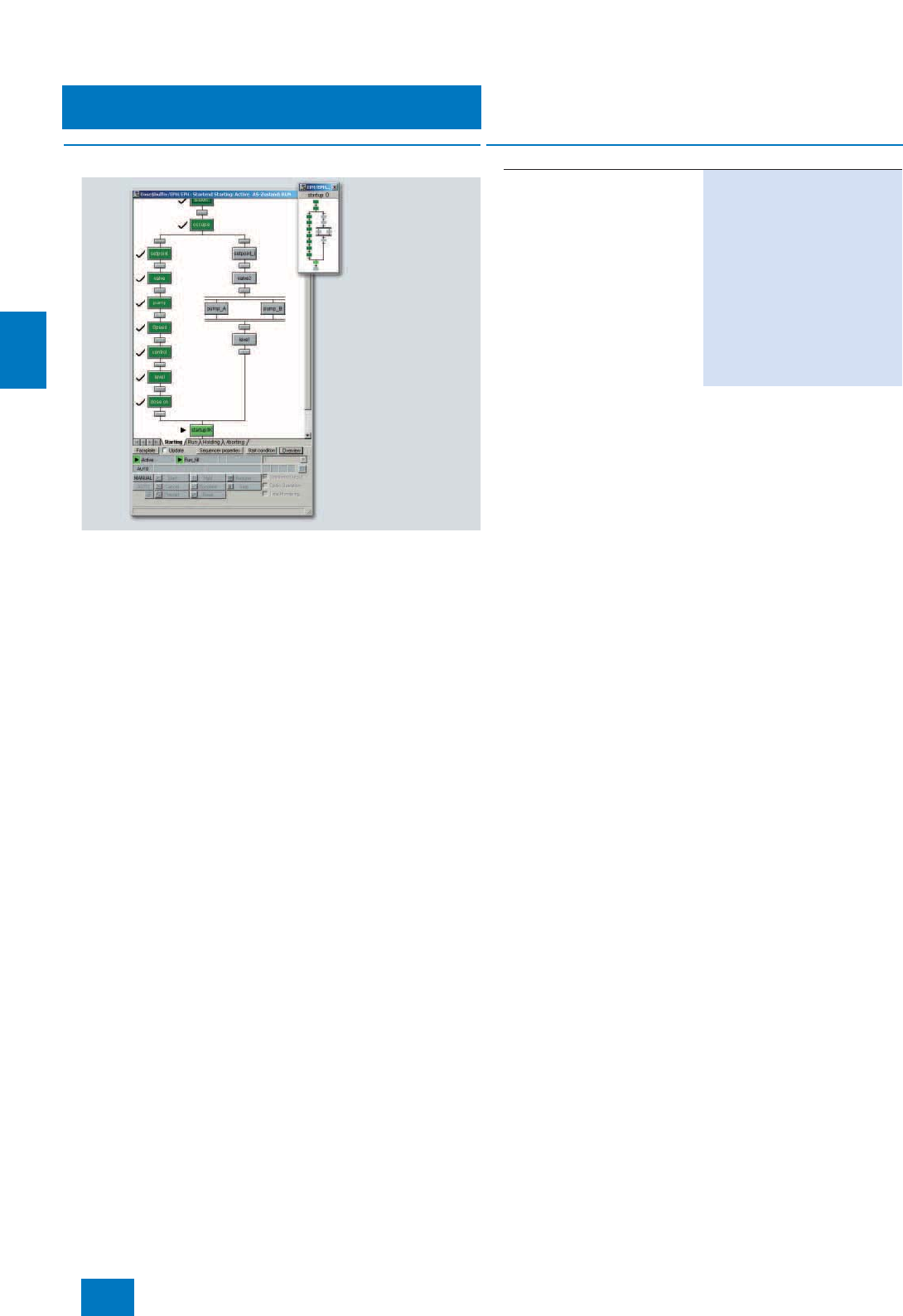
Operator system
OS software
SFC Visualization
5/14 Siemens ST PCS 7 · November 2007
5
■
Overview
The SFC visualization function of the operator system enables
you to display and operate the sequence controls configured
with the SFC tool in the same way as on the engineering system.
No additional configuration work is necessary.
In an overview display it is possible, for example, to open step
and transition displays and to present step comments or dynam-
ically supplied stepping conditions.
■
Selection and Ordering Data Order No.
SIMATIC PCS 7
SFC Visualization V7.0
For displaying and operating SFC
sequence controls on an operator
station
6 languages (German, English,
French, Italian, Spanish, Chi-
nese), executes with Windows
XP Professional or Windows
Server 2003, floating license for
1user
Type of delivery:
License key disk, emergency key
disk, certificate of license, terms
and conditions
6ES7 652-0XD07-2YB5
© Siemens AG 2007
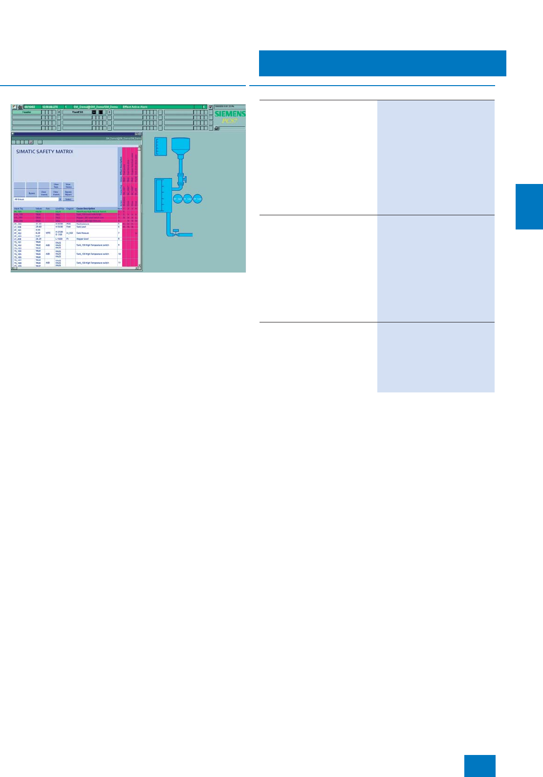
Operator system
OS software
SIMATIC PCS 7 Safety Matrix OS Packages
5/15
Siemens ST PCS 7 · November 2007
5
■
Overview
Using the SIMATIC Safety Matrix Viewer, you can operate and
monitor the SIMATIC Safety Matrix from the SIMATIC PCS 7
OS Single Station or from the SIMATIC PCS 7 OS Client.
The SIMATIC Safety Matrix Viewer is available together with the
SIMATIC PCS 7 OS software as a low-price SIMATIC PCS 7
Safety Matrix OS Package. The difference is in the SIMATIC
PCS 7 OS software which depends on whether the OS Single
Station or the OS Client is the target system.
By means of the SIMATIC PCS 7 Safety Matrix OS Extension
Package, a SIMATIC PCS 7 OS Single Station or a SIMATIC
PCS 7 OS Client can be subsequently expanded by the
SIMATIC Safety Matrix Viewer.
Details on the SIMATIC Safety Matrix as well as information on
SIMATIC PCS 7 Safety ES Packages can be found from page
4/20.
■
Selection and Ordering Data Order No.
SIMATIC PCS 7 Safety Matrix
OS Single Station Package
Executes with Windows XP Pro-
fessional, single license for
1 installation
Combination of:
• SIMATIC PCS 7 OS Software
Single Station for 250 POs,
6 languages (German, English,
French, Italian, Spanish, Chi-
nese)
• SIMATIC Safety Matrix Viewer,
1 language (English)
6ES7 652-6AA07-0YA0
SIMATIC PCS 7 Safety Matrix
OS Client Package
Executes with Windows XP Pro-
fessional, floating license for
1user
Combination of:
• SIMATIC PCS 7 OS Software
Client, 6 languages (German,
English, French, Italian,
Spanish, Chinese)
• SIMATIC Safety Matrix Viewer,
1 language (English)
6ES7 652-6CX07-0YA5
SIMATIC PCS 7 Safety Matrix
OS Extension Package
Executes with Windows XP Pro-
fessional, floating license for
1user
comprising: SIMATIC Safety
Matrix Viewer, 1 language
(English)
6ES7 652-6BX07-0YA5
© Siemens AG 2007
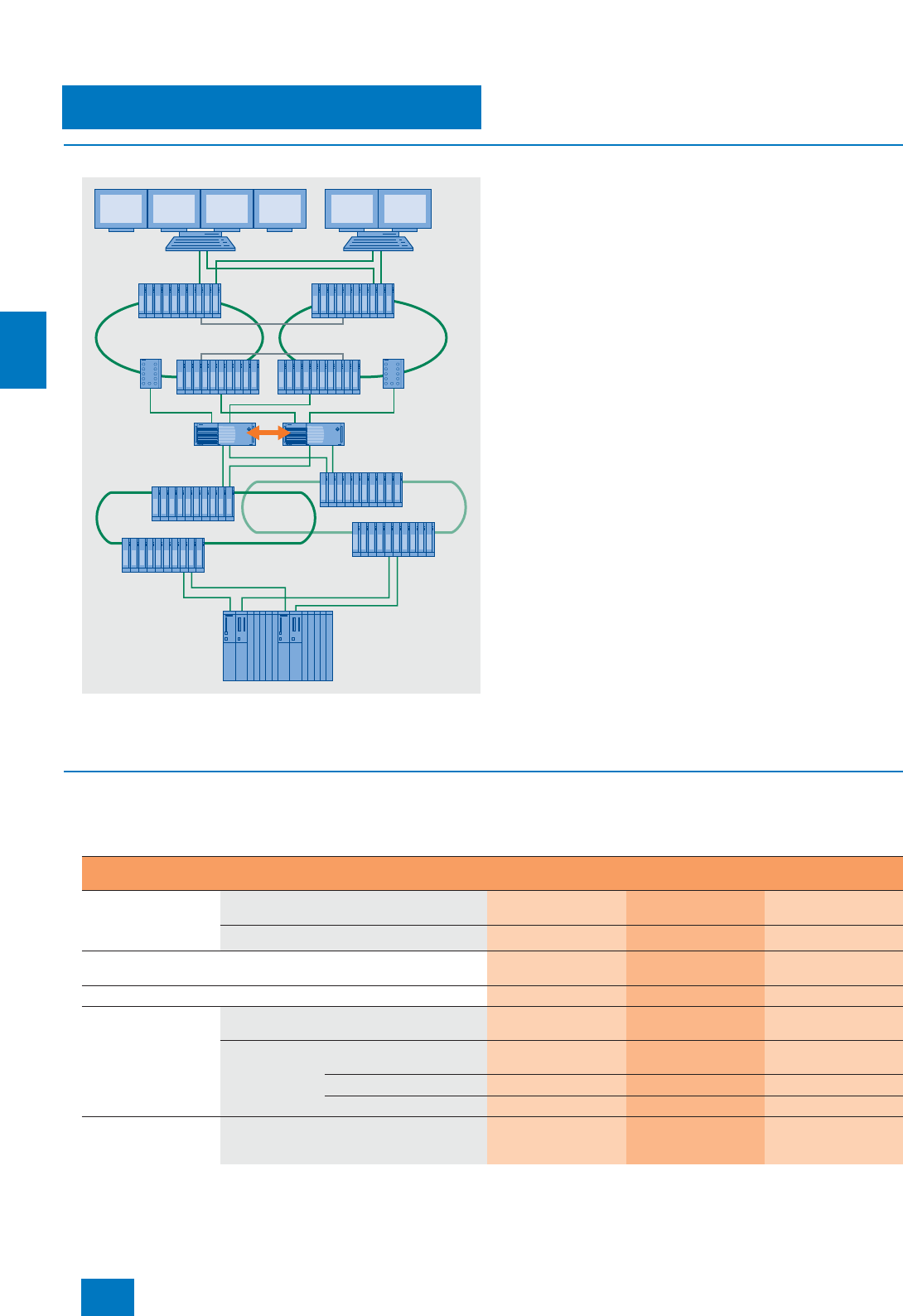
Operator system
Redundant operator systems
OS redundancy
5/16 Siemens ST PCS 7 · November 2007
5
■
Overview
OS redundancy shown in a client/server architecture with high availability
OS single stations and OS servers can have a redundant design
if necessary:
• A SIMATIC PCS 7 Single Station Redundancy programming
package is required to design redundant OS single stations.
This contains:
- OS Software Single Station
- Software WinCC/Redundancy (in each case for two
OS single stations)
- RS 232 cable connector for optimization of internal commu-
nication between the two OS single stations.
• A SIMATIC PCS 7 Server Redundancy programming package
is required to design redundant OS servers. This contains:
- OS Software Server
- Software WinCC/Redundancy (in each case for two
OS servers)
- RS 232 cable connector for optimization of internal server-
server communication.
A separate Ethernet connection can be used instead of the serial
RS 232 connection for optimization of internal communication
between the two redundant stations (OS single
stations/OS servers). This is an alternative e.g. with larger dis-
tances between the stations or if the COM interface is required
elsewhere.
An optical or electrical connection can be used depending on
the environmental conditions and the distance between the re-
dundant stations, e.g. up to 100 m per crossover network cable
with RJ45 connectors. For further information, refer to the Man-
ual "SIMATIC PCS 7 V7.0 fault-tolerant process control systems";
for appropriate cable material and further accessories, refer to
Catalog IK PI (Industrial Communication).
What further components are required depends on the plant ar-
chitecture. The design of the plant bus and terminal bus
(OS-LAN) is of particular importance, as well as the type and
number of subordinate automation systems. The maximum re-
quirements are determined by the redundant configuration
shown in the figure with a fault-tolerant automation system and
two redundant rings each for the plant bus and terminal bus.
■
Design
The following table provides an overview of which components
are required for a redundant OS single station or OS pair of serv-
ers depending on certain criteria:
AS 412H/
AS 414H/
AS 417H
Client Client
OS-LAN (Ethernet), ring 1 OS-LAN (Ethernet), ring 2
Redundant servers
Redundant Industrial Ethernet
plant bus (double ring)
Up to 8 AS per single
station/pair of servers 9 to 64 AS per single
station/pair of servers Min. 1 fault-tolerant
AS
SIMATIC PCS 7 Indus-
trial Workstation, single
station or server ver-
sion, alternatives
Incl. Ethernet network card 10/100/1000 Mbit/s
and BCE 2-- --
Incl. CP 1613 and S7-1613 software 2 (alternative to BCE) 2 2
SIMATIC PCS 7 Single Station/Server Redundancy V7.0 (including RS
232 connecting cable) 1 1 1
S7-REDCONNECT Upgrade -- -- 2
Connection to redun-
dant plant bus
(2 rings), alternatives
BCE Desktop adapter network
card 2-- --
CP 1613 CP 1613 communications
processor 2 (alternative to BCE) 2 2
S7-1613 software 2 (alternative to BCE) 2--
S7-REDCONNECT software -- -- 2
Connection to redun-
dant terminal bus
(2 rings)
SIMATIC PCS 7 Redundant Terminalbus
Adapter Package 2 2 2
© Siemens AG 2007
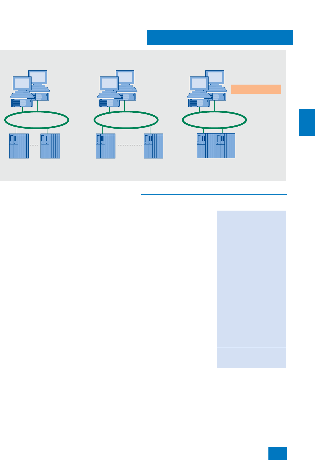
Operator system
Redundant operator systems
OS redundancy
5/17
Siemens ST PCS 7 · November 2007
5
Connection of redundant OS single stations / OS servers on the plant bus
Connection to plant bus
The operator systems (single stations or servers) communicate
with the automation systems via the Industrial Ethernet plant bus.
The following special points must be observed for redundant
configurations:
• BCE communication via Ethernet network card
10/100/1000 Mbit/s is generally also sufficient for redundant
operator stations. Up to 8 automation systems can be con-
nected per pair of servers in this manner.
• Communication using CP 1613 is only required in the follow-
ing cases:
- Connection of a subordinate fault-tolerant automation sys-
tem
- More than 8 stations are required per OS.
• An operator station with CP 1613 is delivered with the S7-1613
software. If a subordinate fault-tolerant automation system is
to be connected, the S7-REDCONNECT software is required.
In this case, the S7-REDCONNECT upgrade must be ordered.
• If an operator station with BCE communication is to be up-
graded for operation with a subordinate fault-tolerant automa-
tion system, the S7-REDCONNECT software is required in ad-
dition to the CP 1613 communications processor.
• If the plant bus is to be designed as a redundant dual ring, you
require two interface modules (2 x Ethernet network cards
10/100/1000 Mbit/s or 2 x CP 1613) per OS single station /
OS server.
Connection to terminal bus (OS-LAN)
You can connect clients and servers to a non-redundant terminal
bus (OS-LAN) using the onboard Ethernet interface or a desktop
adapter network card. With a redundant terminal bus where two
rings are connected together via two pairs of switches, each sta-
tion must be connected to both rings using a SIMATIC PCS 7
redundant terminal bus adapter package. The SIMATIC PCS 7
redundant terminal bus adapter package consists of server and
desktop adapter network cards (for details on the configuration,
refer to the Manual "SIMATIC PCS 7 V7.0 fault-tolerant process
control systems").
Redundant OS single stations / OS servers
with BCE communication
• FastEthernet card
• PCS 7 single station
redundancy or
PCS 7 server
redundancy
• CP 1613
• S7-1613 software
• PCS 7 single station
redundancy or
PCS 7 server
redundancy
• CP 1613
• S7-1613 software
+ Upgrade
S7-REDCONNECT
• PCS 7 single station
redundancy or
PCS 7 server redundancy
Max. 8 automation systems
per single station/pair of servers
Max. 64 automation systems
per single station/pair of servers
Fault-tolerant systems
AS 414H, AS 417H
Redundant OS single stations / OS servers
with CP 1613 communication
Plant busPlant busPlant bus
■
Selection and Ordering Data Order No.
Design of redundant OS single stations
SIMATIC PCS 7 Single Station
Redundancy V7.0
6 languages (German, English,
French, Italian, Spanish,
Chinese), executes with Windows
XP Professional, single license for
2 installations
with OS Software Single Station
and WinCC/Redundancy as well
as RS 232 connecting cable,
10 m
Type of delivery:
2 license key disks, 2 emergency
key disks, certificate of license,
terms and conditions; PCS 7 V7.0
toolset DVDs, Microsoft
SQL Server 2005 including EULA,
supplementary CDs/DVDs (e.g.
Microsoft ServicePacks and tools)
as well as RS 232 connecting
cable, 10 m
• 250 POs 6ES7 652-3AA07-2YA0
• 1000 POs 6ES7 652-3AB07-2YA0
• 2000 POs 6ES7 652-3AC07-2YA0
• 3000 POs 6ES7 652-3AD07-2YA0
• 5000 POs 6ES7 652-3AE07-2YA0
PowerPacks for PO expansion
See under OS Software Single
Station PowerPack V7.0
(2 PowerPacks each required)
© Siemens AG 2007

Operator system
Redundant operator systems
OS redundancy
5/18 Siemens ST PCS 7 · November 2007
5
B) Subject to export regulations: AL: N, ECCN: EAR99H
Design of redundant OS servers
SIMATIC PCS 7 Server
Redundancy V7.0
6 languages (German, English,
French, Italian, Spanish,
Chinese), executes with Windows
Server 2003, single license for
2 installations
with OS Software Server und
WinCC/Redundancy as well as
RS 232 connecting cable, 10 m
Type of delivery:
2 license key disks, 2 emergency
key disks, certificate of license,
terms and conditions; PCS 7 V7.0
toolset DVDs, Microsoft
SQL Server 2005 including EULA,
supplementary CDs/DVDs (e.g.
Microsoft ServicePacks and tools)
as well as RS 232 connecting
cable, 10 m
•250 POs 6ES7 652-3BA07-2YA0
• 1000 POs 6ES7 652-3BB07-2YA0
• 2000 POs 6ES7 652-3BC07-2YA0
• 3000 POs 6ES7 652-3BD07-2YA0
• 5000 POs 6ES7 652-3BE07-2YA0
• 8500 POs 6ES7 652-3BF07-2YA0
PowerPacks for PO expansion
See under OS Software Server
PowerPack V7.0 (2 PowerPacks
each required)
Individual components for redundancy upgrading with existing OS
single stations / OS servers
WinCC/Redundancy V6.2
For alignment of archives follow-
ing OS restart; single license for
2 installations
Installation required on each of
the two redundant SIMATIC
PCS 7 Industrial Workstations
6AV6 371-1CF06-2AX0
RS 232 connecting cable, 10 m 6ES7 902-1AC00-0AA0
Expansion components for OS single stations / OS servers
For connection to redundant plant bus (BCE/CP 1613), for upgrading
from BCE to CP 1613 including communication with fault-tolerant AS
Desktop adapter network card
for BCE and as spare part for
redundant terminal bus
INTEL PCI network card for con-
nection to Industrial Ethernet
(10/100/1000 Mbit/s), with RJ45
connection
A5E00504378 B)
CP 1613 A2
PCI card for connection to
Industrial Ethernet, with ITP and
RJ45 connections
6GK1 161-3AA01 B)
SIMATIC NET S7-1613/2006 for
Industrial Ethernet
S7 communications software for
CP 1613,
runtime software, in 2 languages
(German, English), executes with
Windows 2000 Professional/
2000 Server/ XP Professional/
Server 2003, single license for
1 installation,
software and electronic manual
on CD-ROM, license key on dis-
kette
6GK1 716-1CB64-3AA0
■
Selection and Ordering Data Order No.
Communications software when using fault-tolerant AS
To be used instead of the S7-1613 software
SIMATIC NET S7-
REDCONNECT/2006
Software for fail-safe S7 commu-
nication over redundant networks,
for CP 1613, runtime software, in
2 languages (German, English),
executes with Windows
2000 Professional/ 2000 Server/
XP Professional/ Server 2003, sin-
gle license for 1 installation, soft-
ware and electronic manual on
CD-ROM, license key on diskette
6GK1 716-0HB64-3AA0
Upgrading for communication with fault-tolerant AS
Starting from OS single stations / OS servers with CP 1613 and
S7-1613 software
SIMATIC NET S7-
EDCONNECT/2006 Upgrade
Software for expansion of
S7-1613 to S7-REDCONNECT,
runtime software, in 2 languages
(German, English), executes with
Windows 2000 Professional/
2000 Server/ XP Professional/
Server 2003, single license for
1 installation,
software and electronic manual
on CD-ROM, license key on dis-
kette
6GK1 716-0HB64-3AC0
Components for connection of OS single
stations/OS servers/OS clients to a redundant terminal bus
SIMATIC PCS 7 Redundant
Terminal Bus Adapter Package
Server and desktop adapter for
designing a redundant terminal
bus,
consisting of 2 Intel PCI network
cards for connection to Industrial
Ethernet (10/100/1000 Mbit/s),
with RJ45 connection
6ES7 652-0XX01-1XF0 B)
■
Selection and Ordering Data Order No.
© Siemens AG 2007
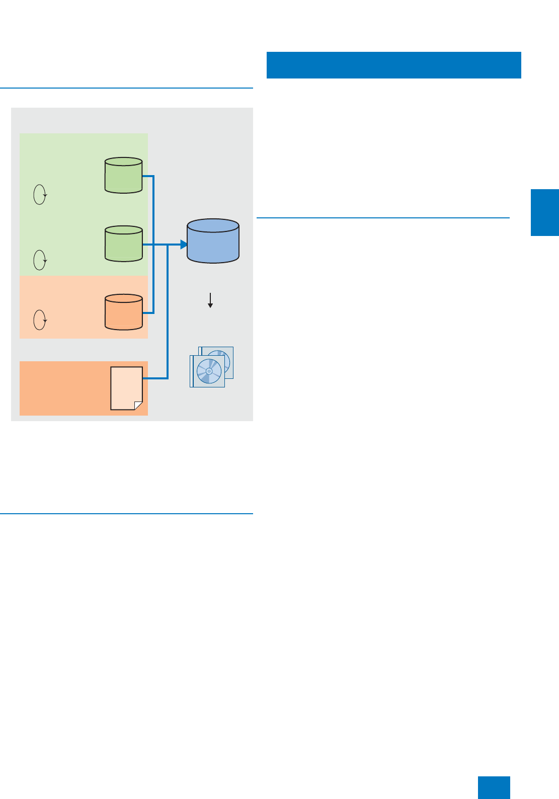
Operator system
OS archiving
Introduction
5/19
Siemens ST PCS 7 · November 2007
5
■
Overview
Overview of short-term and long-term archiving
The operator system already includes a high-performance ar-
chiving system based on Microsoft SQL Server with cyclic ar-
chives for short-term saving of process values (typically 1 to
4 weeks) and messages/events (typically 2 months). Data from
the short-term archive as well as OS reports and batch data from
SIMATIC BATCH can be exported time-controlled or event-con-
trolled for permanent archiving in a long-term archive.
■
Design
Two alternatives with different features are available for the OS
long-term archiving:
• StoragePlus:
More economical version for the lower performance range; for
the archiving of about 1600 values/s from as many as four sin-
gle stations, servers or pairs of servers
• Central archive server (CAS), for single or redundant configu-
ration:
High-performance version for archiving about 10000 values/s
from as many as 11 servers or pairs of servers
During long-term archiving with StoragePlus, the archived data
can be visualized by means of the StoragePlus viewer. Process
values and messages exported to the central archive server can
also be accessed from an OS client.
The data managed in StoragePlus and in the central archive
server can be saved on commercially available storage media
(e.g. DVD). This requires additional hardware and software
which support the respectively used operating system, e.g.
a DVD writer with appropriate writer software.
The StoragePlus computer and the central archive server are
stations on the terminal bus, and are not connected to the plant
bus. When using a SIMATIC PCS 7 Industrial Workstation (BCE
version) as the hardware platform, the Ethernet interface
(Ethernet RJ45 port) already onboard can be used for connect-
ing to the terminal bus.
Through a redundant design of the central archive server, the
availability of long-term data is increased, and these can also be
accessed by the OS clients or the OpenPCS 7 station. SIMATIC
BATCH does not yet swap out the batch data to the two central
archive servers. However, following automatic matching of the
archives, the batch data are available on both central archive
servers following swapping out.
■
Function
Features of the archive variables and licensing of short-term
and long-term archiving
• There is only one type of archive variable for OS short-term ar-
chiving and CAS long-term archiving. SIMATIC PCS 7 Archive
and SIMATIC PCS 7 Archive PowerPacks can be used univer-
sally - both for the operator system and for the CAS.
• The "SIMATIC PCS 7 Archives" are Count Relevant Licenses,
i.e. the archive variables of several licenses are cumulative.
Starting with the smallest cumulative number of
1500 variables, any combinations are possible with consider-
ation of the expansion limits of 10000 variables for OS short-
term archiving and 120000 variables for CAS long-term ar-
chiving, e.g. 2 x 1500 or 1 x 1500 with 1 x 5000 variables.
• The number of archive variables can also be increased using
"SIMATIC PCS 7 Archive PowerPacks". Starting with
1500 variables, increasing is possible in steps through 5000,
10000, 30000 and 80000 variables up to 120000 variables.
• If a CAS is not used, the licenses of the SIMATIC PCS 7 Ar-
chive are installed on the OS single stations and OS servers of
the system. Otherwise the installation is only on the CAS.
OS single stations and OS servers then "book" their archive
variables from the CAS’s stock of variables. It is therefore un-
necessary to carry out the complex installation of archive vari-
able licenses on all OS single stations and OS servers in the
system.
• Operator systems (OS single stations and OS servers) are
assigned 512 archive variables each by the OS software, the
CAS is immediately provided with 1500 archive variables by
the central archive server basic package. If the short-term ar-
chiving of the operator systems is combined with the CAS
long-term archiving, the 512 archive variables of the OS single
stations and OS servers are not cumulated with the
1500 archive variables of the CAS. The 1500 archive variables
of the CAS are then available universally for short-term and
long-term archiving.
• In the case of redundant systems, two archives must be con-
figured with the corresponding number of archive variables.
Process values
Central archive server:
long-term archiving
Messages/events
Batch data
Slow
archiving cycle
> 1 min
Fast
archiving cycle
≤ 1 min
Alarm archive
Automatic
saving
e.g. daily
Automatic
saving
(applicative)
e.g. weekly
Saving on
hard disk
e.g. for 6 months
On user request,
transfer following
end of a batch
Backup
archiving
on DVD
Batch server
OS server:
short-term archiving (cyclic)
Microsoft
SQL server
e.g.
2 months
e.g.
2 weeks
e.g.
7 days
30 byte/
value
Max.
30 byte/
value
172 byte/
event
XML
files
© Siemens AG 2007

Operator system
OS archiving
OS short-term archiving
5/20 Siemens ST PCS 7 · November 2007
5
■
Overview
An integral component of the OS software of OS single stations
and OS servers is a high-performance archiving system which
can be configured during runtime and which is based on
Microsoft SQL server technology. It is used to record process
data (typical period 1 to 4 weeks) and messages/events (typical
period 2 months) in cyclic archives.
The data from the short-term archive as well as OS reports and
batch data from SIMATIC BATCH can be exported time-con-
trolled or event-controlled for permanent archiving in
StoragePlus or in a central archive server (CAS).
Commencing with the 512 archive variables present in the sys-
tem, the short-term archive for process data can be expanded
within the limit of 10000 archive variables with accumulated
SIMATIC PCS 7 archives (Count Relevant Licenses) or SIMATIC
PCS 7 Archive PowerPacks. The archive variables can be ex-
panded in steps from 1500 to 5000 or 10000 variables using
SIMATIC PCS 7 Archive PowerPacks.
Further information on licensing, in particular in combination with
long-term archiving per CAS,can be found at page 5/19 under
"Features of archive variables and licensing of short-term and
long-term archiving".
■
Selection and Ordering Data Order No.
Expansion of integral high-performance cyclic buffer archive
(512 variables) of OS Single Station and OS Server
SIMATIC PCS 7 Archive V7.0
6 languages (German, English,
French, Italian, Spanish,
Chinese), executes with Windows
XP Professional or Windows
Server 2003, single license for
1 installation (Count Relevant
License)
Type of delivery:
License key disk, emergency key
disk, certificate of license, terms
and conditions
• 1500 variables 6ES7 658-2EA07-2YB0
• 5000 variables 6ES7 658-2EB07-2YB0
• 10000 variables 6ES7 658-2EC07-2YB0
SIMATIC PCS 7 Archive
PowerPack V7.0
6 languages (German, English,
French, Italian, Spanish,
Chinese), executes with Windows
XP Professional or Windows
Server 2003, single license for
1 installation
Type of delivery:
License key disk, emergency key
disk, certificate of license, terms
and conditions
• For expansion from 1500 to
5000 variables 6ES7 658-2EB07-2YD0
• For expansion from 5000 to
10000 variables 6ES7 658-2EC07-2YD0
© Siemens AG 2007
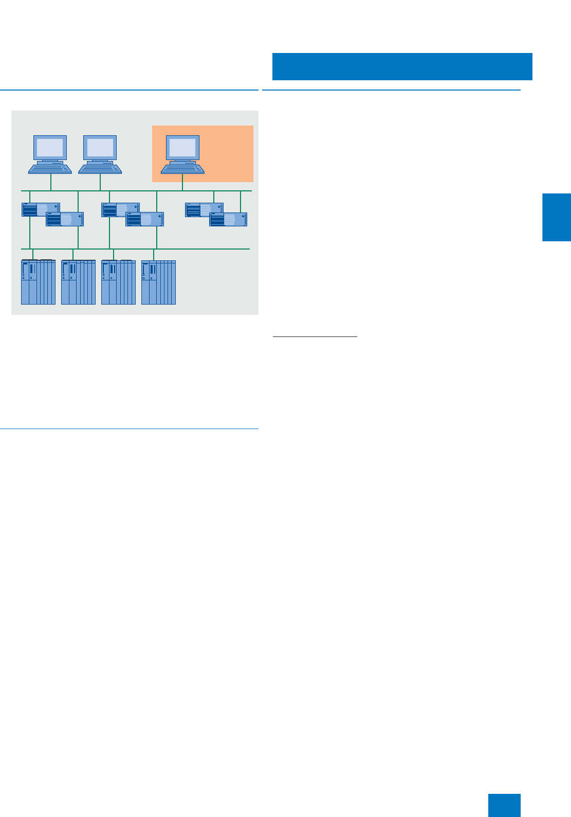
Operator system
OS archiving
OS long-term archiving
with StoragePlus
5/21
Siemens ST PCS 7 · November 2007
5
■
Overview
StoragePlus is a program package for long-term archiving of
• OS archive data (process values and messages),
• OS reports and
• batch data of the SIMATIC PCS 7 process control system.
StoragePlus manages the process values and messages ex-
ported from the OS archives, the OS reports as well as batch
data from SIMATIC BATCH in a central database. All these data
can be visualized in a graphic and clear manner using the Inter-
net Explorer.
■
Application
StoragePlus can be used for long-term archiving of process val-
ues and messages, OS reports and SIMATIC BATCH data from
up to 4 single stations/servers/pairs of servers of the SIMATIC
PCS 7 V7.0 process control system. For this purpose Storage-
Plus has to be installed on a separate computer with Windows
XP Professional oder Windows Server 2003 (see page 2/14)
which is connected by terminal bus to the OS and batch serv-
ers/single stations of the SIMATIC PCS 7 system.
■
Function
StoragePlus manages the process values, messages and OS re-
ports which are swapped out of the OS archives, as well as
batch data from SIMATIC BATCH, in a central database and
makes these data available independent of the PCS 7 runtime
systems:
• All data can be visualized in a graphic and clear manner using
the Internet Explorer, selection of the data is selected by inte-
grated filter functions.
• Messages and process values can be shown in table form,
and process values also in graphic form.
• Tables of process values can be exported in CSV format for
processing in other Windows applications, e.g. Microsoft
Excel.
The data managed by StoragePlus and the cataloging can be
swapped out onto all commercially available storage media. You
require additional hardware and software for this which support
the StoragePlus operating system, e.g. DVD writer with appropri-
ate writer software.
StoragePlus is able to read in data which were swapped out
using StoragePlus V1.0 / V1.1 and to convert the data into the SI-
MATIC PCS 7 V7.0 (StoragePlus V1.2) data format.
Overview of functions
• Archiving of messages, process values and reports of the SI-
MATIC PCS 7 V7.0⋅operator systems
• Archiving of batch data from SIMATIC BATCH V7.0
• Cataloging of all StoragePlus data
• Swapping out of all StoragePlus data as well as the cataloging
onto external storage media
• Reading-in of the swapped-out StoragePlus data and catalog-
ing from external storage media
• Parameterizing of views (display windows and masks) includ-
ing the selection criteria for displaying the data
• Visualizing of messages in table form dependent on filter func-
tions
• Displaying of process values in table or graphic form depen-
dent on filter functions
• Exporting of process values in CSV format, e.g. to Microsoft
Excel
• Visualizing a batch overview (selecting the detailed protocol
of a batch from the batch overview is possible)
• Web-based presentation of data
• Access protection with user-specific rights
• Migration of messages and measurement values from Stor-
agePlus V1.0 / V1.1
OS clients
Automation
systems
Batch server
(redundant)
StoragePlus
(separate
computer)
OS server
(redundant)
OS-LAN
Plant bus
© Siemens AG 2007

Operator system
OS archiving
OS long-term archiving
with StoragePlus
5/22 Siemens ST PCS 7 · November 2007
5
■
Technical specifications
StoragePlus
Long-term archiving Up to 4 single stations, servers or
pairs of servers simultaneously
Data input for process-value
archiving by one server Approx. 1000/s
Data input for process-value
archiving by all servers Approx. 1600/s
Max. data volume input per day 500 MB
Hardware requirements
Main memory 512 MB or more, 2 GB recom-
mended
Hard disk memory recommended
• Security EIDE-RAID 1 with 2 hard disks for
80 GB or more
• Capacity 2 hard disks for 80 GB or more for
separating database and log files
Software requirements
Operating system / applications • Microsoft Windows
XP Professional including SP2
or Windows Server 2003
including SP1
• Microsoft Internet Explorer V6.0
including SP1
• Microsoft Internet Information
Services (IIS) and installed
Message Queuing
Software required for StoragePlus
from the scope of delivery of
SIMATIC PCS 7; when used for Stor-
agePlus, no additional licenses are
required.
• Microsoft SQL Server 2005
• OS client SIMATIC PCS 7 V7.0
• Client software SIMATIC BATCH
V7.0
■
Selection and Ordering Data Order No.
SIMATIC StoragePlus V1.2
Software for long-term archiving
of data from up to 4 single sta-
tions, servers or pairs of servers
4 languages (German, English,
French, Chinese), executes with
Windows XP Professional or Win-
dows Server 2003, single license
for 1 installation
Type of delivery:
License key disk, emergency key
disk, certificate of license, terms
and conditions
6ES7 652-0XC21-2YB0
© Siemens AG 2007
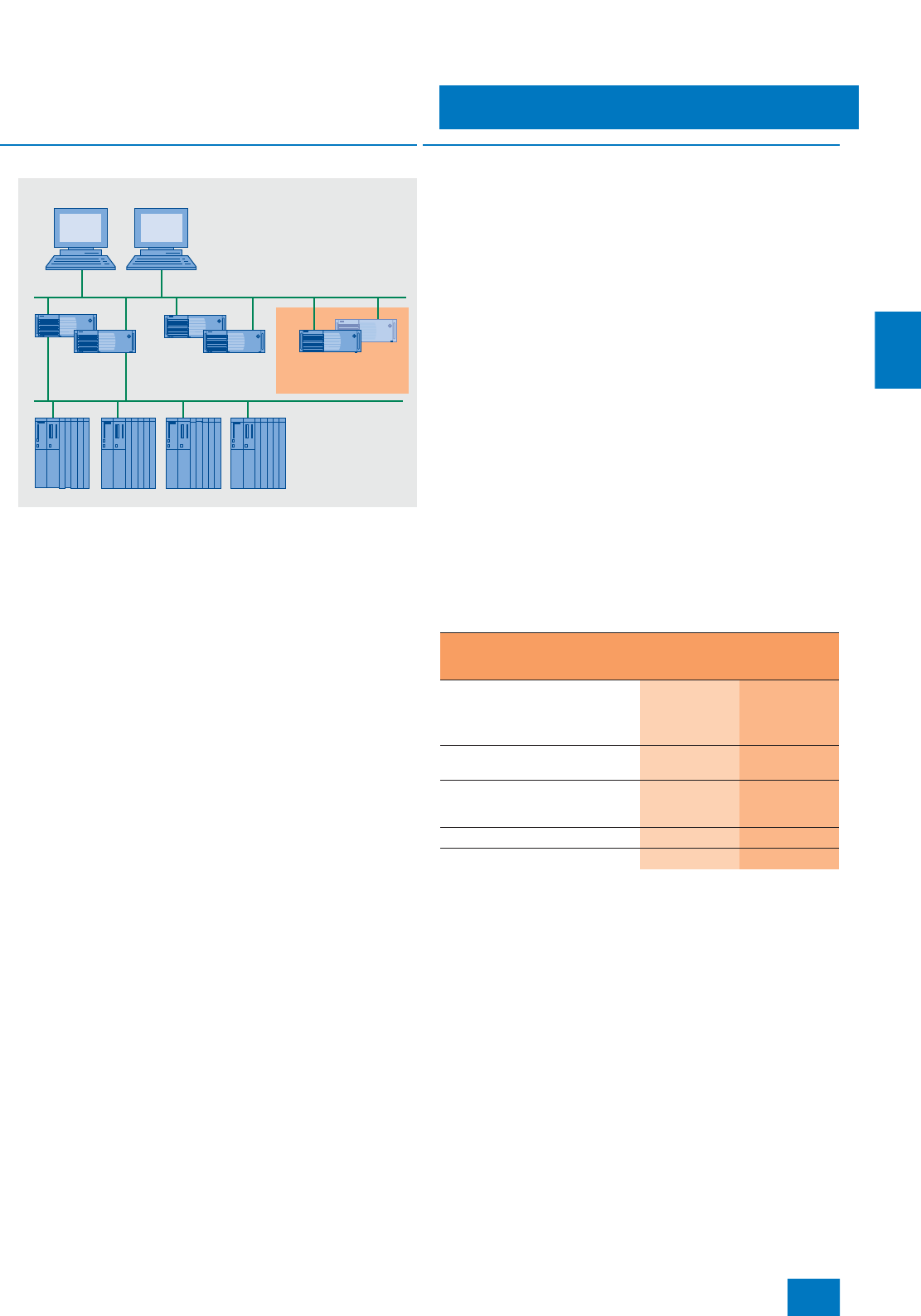
Operator system
OS archiving
OS long-term archiving
with Central Archive Server
5/23
Siemens ST PCS 7 · November 2007
5
■
Overview
The central archive server (CAS) can be used for long-term ar-
chiving of
• OS archive data (process values and messages),
• OS reports and
• batch data of the SIMATIC PCS 7 process control system.
The process values and messages exported from the OS ar-
chives, as well as the OS reports and batch data from SIMATIC
BATCH are managed by the CAS in a central database. They
can be visualized directly on the OS clients or with the Storage-
Plus viewer of the CAS.
■
Design
The SIMATIC PCS 7 OS Server (BCE version) with the Microsoft
Windows Server 2003 operating system offered in Section "SI-
MATIC PCS 7 Industrial Workstation" in the Chapter "System-
neutral components" can be used as the basic hardware for the
CAS. The OS Software server of the SIMATIC PCS 7 V7.0 pro-
cess control system is preinstalled on this basic device in addi-
tion to the operating system. The Central Archive Server Basic
Package is required to configure the CAS. This can be extended
to a maximum of 120000 archive variables using SIMATIC PCS 7
Archive/SIMATIC PCS 7 Archive PowerPack licenses. Detailed
information on licensing of the CAS in combination with OS
short-term archiving can be found at page 5/19 under "Features
of archive variables and licensing of short-term and long-term
archiving".
The CAS does not require a connection to the plant bus. It can
be connected to the OS and batch servers of the SIMATIC PCS 7
plant via OS-LAN (terminal bus), e.g. via the integral network
connection (Ethernet RJ45 port onboard) of the server.
Redundant design of central archive server
The CAS can also have a redundant design. This increases the
availability of long-term data, and these can also be accessed
by the OS clients or the OpenPCS 7 station. SIMATIC BATCH
does not yet swap out the batch data to the two central archive
servers. However, following automatic matching of the archives,
the batch data are available on both central archive servers fol-
lowing swapping out.
The following table shows the corresponding number of compo-
nents required for single and redundant CAS configurations.
Instead of the serial RS 232 connection, it is also possible to use
a separate Ethernet connection for optimization of internal com-
munication between the redundant central archive servers, e.g.
as an alternative for larger distances.
OS clients
Automation
systems
Batch server
(redundant)
Central Archive
Server (CAS)
OS server
(redundant)
OS-LAN
Plant bus
Single central
archive server
(CAS)
Redundant
central archive
server (CAS)
SIMATIC PCS 7 Industrial Work-
station, server version
Incl. Ethernet network card and
BCE
1 2
Central archive server basic
package 1 2
SIMATIC PCS 7 Archives/SIMATIC
PCS 7 Archive PowerPacks for
additional archive variables
Licenses for
one server Licenses for
two servers
WinCC option "Redundancy" -- 1
RS 232 connecting cable, 10 m -- 1
© Siemens AG 2007

Operator system
OS archiving
OS long-term archiving
with Central Archive Server
5/24 Siemens ST PCS 7 · November 2007
5
■
Function
The central archive server (CAS) can archive approx.
10000 process values/s from as many as 11 servers or pairs of
servers of the SIMATIC PCS 7 V7.0 process control system. It is
configured in a SIMATIC PCS 7 project like other stations of the
SIMATIC PCS 7 process control system (e.g. OS server, batch
server, route control server, all clients or OpenPCS 7 station).
The process values and messages managed in the database of
the CAS can be visualized clearly on the OS clients. The Stor-
agePlus Viewer of the CAS can be used for data visualization on
the OS single station. Data selection is supported by integrated
filter functions. Messages and process values can be shown in
table form, and process values also in graphic form. Tables of
process values can be exported in CSV format for processing in
other Windows applications, e.g. Microsoft Excel.
The data managed by CAS and the cataloging can be swapped
out onto all commercially available storage media. This requires
additional hardware and software which support the CAS oper-
ating system, e.g. a DVD writer with appropriate writer software.
Swapping-out can be initiated either by an operator input or
when a certain amount of the hard disk is full.
Overview of functions
• Archiving of messages, process values and reports of the SI-
MATIC PCS 7 V7.0⋅operator systems
• Archiving of batch data from SIMATIC BATCH V7.0
• Cataloging of all data
• Swapping out of all data as well as cataloging onto external
storage media
• Reading-in of the swapped-out data and cataloging from ex-
ternal storage media
• Data visualization on the OS clients:
- Parameterizing of views (display windows and masks) in-
cluding the selection criteria for displaying the data
- Visualizing of messages in table form dependent on filter
functions
- Displaying of process values in table or graphic form depen-
dent on filter functions
- Visualizing a batch overview (selecting the detailed protocol
of a batch from the batch overview is possible)
• Exporting of process values in CSV format, e.g. to Microsoft
Excel
• Access protection with user-specific privileges, also using SI-
MATIC logon
• Configurable redundancy mode
■
Technical specifications
Central archive server (CAS)
Long-term archiving Up to 11 servers/server pairs
simultaneously
Data input for process-value
archiving by one server Approx. 1000/s
Data input for process-value
archiving by all servers Approx. 10000/s
Message input by one server
(limited by the performance of
short-term archiving)
Steady-state load approx. 10/s
Message peak approx. 3000/4 s
■
Selection and Ordering Data Order No.
Central archive server (CAS)
Central Archive Server Basic
Package V7.0,
including 1500 variables
Can be expanded by SIMATIC
PCS 7 Archives/SIMATIC PCS 7
Archive PowerPacks to up to
120000 variables; 6 languages
(German, English, French, Italian,
Spanish, Chinese), executes with
Windows Server 2003, single
license for 1 installation
Type of delivery:
License key disk, emergency key
disk, certificate of license, terms
and conditions
6ES7 658-2FA07-0YB0
SIMATIC PCS 7 Archive V7.0
6 languages (German, English,
French, Italian, Spanish,
Chinese), executes with Win-
dows XP Professional or Windows
Server 2003, single license for
1 installation (Count Relevant
License)
Type of delivery:
License key disk, emergency key
disk, certificate of license, terms
and conditions
• 1500 variables 6ES7 658-2EA07-2YB0
• 5000 variables 6ES7 658-2EB07-2YB0
• 10000 variables 6ES7 658-2EC07-2YB0
• 30000 variables 6ES7 658-2ED07-2YB0
• 80000 variables 6ES7 658-2EE07-2YB0
• 120000 variables 6ES7 658-2EF07-2YB0
SIMATIC PCS 7 Archive Power-
Pack V7.0
6 languages (German, English,
French, Italian, Spanish,
Chinese), executes with Win-
dows XP Professional or Windows
Server 2003, single license for
1 installation
Type of delivery:
License key disk, emergency key
disk, certificate of license, terms
and conditions
• For expansion from 1500 to
5000 variables 6ES7 658-2EB07-2YD0
• For expansion from 5000 to
10000 variables 6ES7 658-2EC07-2YD0
• For expansion from 10000 to
30000 variables 6ES7 658-2ED07-2YD0
• For expansion from 30000 to
80000 variables 6ES7 658-2EE07-2YD0
• For expansion from 80000 to
120000 variables 6ES7 658-2EF07-2YD0
Additional components for redundant CAS
WinCC/Redundancy
For alignment of archives follow-
ing restart; single license for
2 installations
Installation required on each of
the redundant SIMATIC PCS 7
Industrial Workstations
6AV6 371-1CF06-2AX0
RS 232 connecting cable, 10 m 6ES7 902-1AC00-0AA0
© Siemens AG 2007
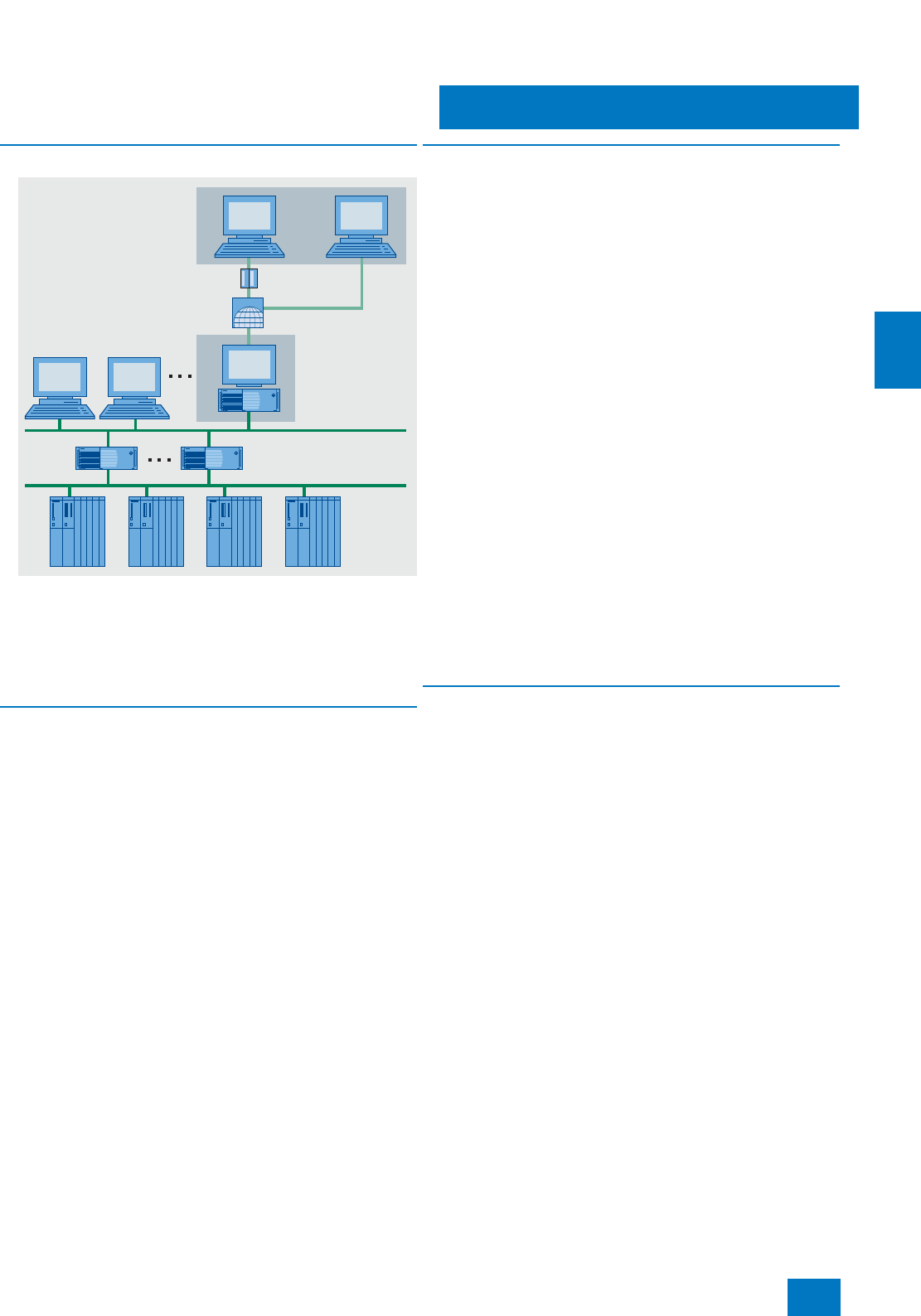
Operator system
Operation and monitoring via Web
SIMATIC PCS 7 Web server
5/25
Siemens ST PCS 7 · November 2007
5
■
Overview
The SIMATIC PCS 7 Web server can be used to operate and
monitor a system via intranet/Internet. The SIMATIC PCS 7 Web
server uses the mechanisms of a multi-client for accessing the
subordinate OS servers, and makes the project data globally
available via intranet/Internet. The project-specific process data
in the SIMATIC PCS 7 Web server are accessed via Web clients
which are equipped with Internet Explorer.
■
Application
A differentiation is basically made between the following types of
application when operating and monitoring SIMATIC PCS 7 sys-
tems via the Web:
• Standard:
Up to 50 Web clients access the data of one SIMATIC PCS 7
Web server over intranet/Internet.
• Diagnostics:
One or only a few Web clients have access to several
SIMATIC PCS 7 Web servers/single-user systems for remote
operation, diagnostics or monitoring.
■
Design
The products offered in the context of SIMATIC PCS 7 for opera-
tion and monitoring via Web permit cost-optimized solutions for
both types of task:
• Server-based licensing is recommended for the "Standard"
type of application. In this case, each SIMATIC PCS 7 Web
server requires a SIMATIC PCS 7 Web Server license which in-
cludes the simultaneous access of 3, 10, 25 or 50 Web clients.
Licenses are not installed on the Web clients themselves.
• Diagnostics licenses are tailored for such types of application.
The SIMATIC PCS 7 Web Diagnostics license available for the
Web diagnostics client allows the latter access to the as-
signed SIMATIC PCS 7 Web diagnostics servers/single-user
systems at all times. On the server side, a SIMATIC PCS 7
Web Diagnostics Server license or SIMATIC PCS 7 Web
Server license is required per SIMATIC PCS 7 Web server/
single-user system. Since there are no functional differences
between the license-free Web client and the Web client with
SIMATIC PCS 7 Web Diagnostics license, mixed operation is
possible.
The SIMATIC PCS 7 OS server with the Microsoft Windows
Server 2003 operating system offered in Chapter "SIMATIC PCS
7 Industrial Workstation" in the Section "System-neutral compo-
nents" can be used as the basic hardware for the SIMATIC PCS 7
Web server. The OS Software server of the SIMATIC PCS 7 V7.0
process control system is preinstalled on this basic device in ad-
dition to the operating system. In order to configure the SIMATIC
PCS 7 Web server, you require the license "OS Software Client"
in addition to the SIMATIC PCS 7 Web Server license or SIMATIC
PCS 7 Web Diagnostics Server license. Deviating from the
specification in the ordering data, the license of the OS Software
Client in this special application is enabled for the Microsoft
Windows Server 2003 operating system.
■
Function
The Web clients equipped with Internet Explorer and with plug-
ins installable via the World Wide Web access the project data
provided by the SIMATIC PCS 7 Web server via intranet/Internet.
The process displays are converted by "Publishing" into a form
suitable for presentation by the Internet Explorer.
A plant can be operated and monitored via the Web clients in the
same manner as via the OS clients. The user must log on with the
Web client just as with an OS client, and the rules for assignment
of privileges are also identical. The input operations made on the
Web clients are recorded in the OS operating log.
The integral OS user management guarantees high security
when accessing the OS servers from the SIMATIC PCS 7 Web
server. In line with the security requirements of the respective
system, access protection is possible using password, firewall
technology and individual security strategies.
INTERNET
Modem
OS-LAN
(terminal bus)
Plant bus
LAN intranet
Web server in a
SIMATIC PCS 7
client
SIMATIC PCS 7
Web clients
© Siemens AG 2007

Operator system
Operation and monitoring via Web
SIMATIC PCS 7 Web server
5/26 Siemens ST PCS 7 · November 2007
5
1) Deviating from the specification in the ordering data, the license of the
OS Software Client V7.0 in this special application is also enabled for the
Microsoft Windows Server 2003 operating system.
■
Selection and Ordering Data Order No.
SIMATIC PCS 7 Web Server
V7.0
6 languages (German, English,
French, Italian, Spanish,
Chinese), executes with Windows
Server 2003, single license for
1 installation
Type of delivery:
License key disk, emergency key
disk, certificate of license, terms
and conditions
• For 3 clients 6ES7 658-2GA07-2YB0
• For 10 clients 6ES7 658-2GB07-2YB0
• For 25 clients 6ES7 658-2GC07-2YB0
• For 50 clients 6ES7 658-2GD07-2YB0
SIMATIC PCS 7 PowerPack Web
Server V7.0
6 languages (German, English,
French, Italian, Spanish,
Chinese), executes with Windows
Server 2003, single license for
1 installation
Type of delivery:
License key disk, emergency key
disk, certificate of license, terms
and conditions
For expansion of PCS 7 Web
server license
• From 3 to up to 10 clients 6ES7 658-2GB07-2YD0
• From 10 to up to 25 clients 6ES7 658-2GC07-2YD0
• From 25 to up to 50 clients 6ES7 658-2GD07-2YD0
OS Software Client
SIMATIC PCS 7 OS Software
Client V7.0 1)
6 languages (German, English,
French, Italian, Spanish,
Chinese), executes with Windows
XP Professional, floating license
for 1 user
Electronic documentation on
PCS 7 toolset DVD
Type of delivery:
• License key disk, emergency
key disk, certificate of license,
terms and conditions
• PCS 7 V7.0 toolset DVDs,
Microsoft SQL Server 2005 in-
cluding EULA and supplemen-
tary CDs/DVDs (e.g. Microsoft
ServicePacks and tools)
6ES7 658-2CX07-0YA5
SIMATIC PCS 7 Web Diagnos-
tics Client V7.0
6 languages (German, English,
French, Italian, Spanish,
Chinese), executes with Windows
XP Professional, single license for
1 installation
Type of delivery:
License key disk, emergency key
disk, certificate of license, terms
and conditions
6ES7 658-2JX07-2YB0
SIMATIC PCS 7 Web Diagnos-
tics Server V7.0
6 languages (German, English,
French, Italian, Spanish,
Chinese), executes with Windows
Server 2003, single license for
1 installation
Type of delivery: License key
disk, emergency key disk, certifi-
cate of license, terms and condi-
tions
6ES7 658-2HX07-2YB0
■
Selection and Ordering Data Order No.
© Siemens AG 2007
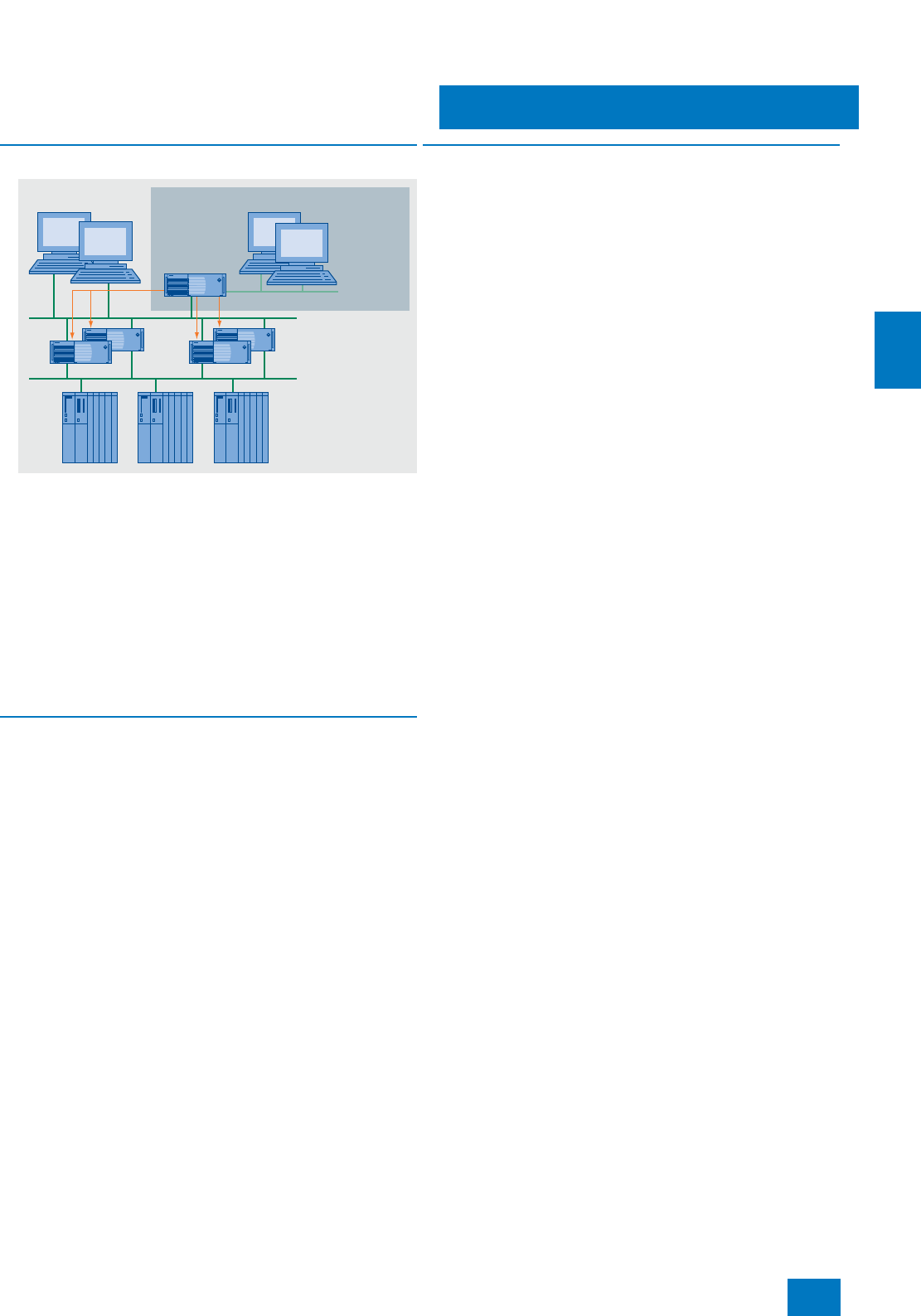
Operator systemwwwwww
OpenPCS 7
5/27
Siemens ST PCS 7 · November 2007
5
■
Overview
Systems for production planning, process data evaluation and
management (OPC clients) that are at a higher level than the
process control system can access SIMATIC PCS 7 V7.0 pro-
cess data by means of the OpenPCS 7 server. The OpenPCS 7
server collects data for the OPC clients. Depending on the sys-
tem configuration, these data may be distributed across different
SIMATIC PCS 7 stations (OS server, central archive server).
The OpenPCS 7 server covers the distribution of data with re-
gard to the period (OS1 / OS2 /… / CAS), the location (OS1 /
OS2 / … ) and the redundancy (OS1 master / OS1 standby …).
OpenPCS 7 replaces the @PCS 7 previously available in the
SIMATIC PCS 7 context, and is simultaneously the pendant to
the Connectivity Pack of the WinCC SCADA system. Access to
the data of SIMATIC BATCH is therefore impossible.
■
Design
The OpenPCS 7 server can be operated in two different config-
urations:
• As autonomous OpenPCS 7 server based on a SIMATIC
PCS 7 Industrial Workstation in the client version (recom-
mended preferred configuration), or
• as multi-functional SIMATIC PCS 7 Industrial Workstation, cli-
ent version, with OpenPCS 7 server and OS client functional-
ities (OpenPCS 7 server/OS client).
Each OPC client without PCS 7 OS/WinCC license requires a
WinCC/Client Access license for access to the OpenPCS 7
server. The client access license referred to an OpenPCS 7
server is available in two versions:
• As access privilege for an OPC client and
• as access privilege for any number of OPC clients.
■
Function
The OpenPCS 7 interface is based on the OPC specifications
(Openness, Productivity, Collaboration) that mainly make use of
Microsoft’s DCOM technology (Distributed Component Object
Model) for communication between the applications. It supports
the following standardized access options:
OPC DA (data access server)
For read and write access to process values according to OPC
specification OPC DA V1.00, V2.05a, V3.00
As an OPC DA server, the OpenPCS 7 server provides other ap-
plications with current data from the OS data management. The
OPC client can log itself on to ongoing changes or also write val-
ues.
OPC HDA (historical data access server)
For read-only access to archived process values according to
OPC Specification OPC HDA V1.20
As an OPC HDA server, the OpenPCS 7 server provides other
applications with historical data from the OS archive system. The
OPC client, e.g. a reporting tool, can specifically request the re-
quired data by defining the start and end of a time interval. Nu-
merous functions, e.g. variance, mean value or integral, already
permit preprocessing by the HDA server and thus contribute to-
wards reduction of the communications load.
OPC A&E (alarm & events server)
For read-only access to messages, alarms and events accord-
ing to OPC Specification OPC A&E V1.10
As an OPC A&E server, the OpenPCS 7 server passes on OS
messages together with all accompanying process values to the
subscribers at the production and corporate management lev-
els. They can of course also be acknowledged there. Filter
mechanisms and subscriptions ensure that only selected, mod-
ified data are transmitted.
OPC "H" A&E (historical alarm & events server)
For read-only access to archived alarms and messages
By means of a Siemens extension to the OPC standard interface,
the OpenPCS 7 server is also able to transmit historical alarms
and messages from the archive to the subscribers at the produc-
tion and corporate management levels.
OLE-DB
Simple, standardized direct access to the archive data in the
Microsoft SQL server database of the operator system is possi-
ble with the OLE-DB. Through this, all OS archive data are ac-
cessible with the accompanying process values, message texts
and user texts.
Microsoft
Visual Basic
for Applications
Microsoft Excel
SAP
OPC clients
OS clients
OS server
OpenPCS 7
server
(OS multi-client
with OpenPCS 7)
Automation
systems
© Siemens AG 2007

Operator system
Data exchange with host systems
OpenPCS 7
5/28 Siemens ST PCS 7 · November 2007
5
■
Selection and Ordering Data Order No.
Multi-functional OpenPCS 7 server/OS client
SIMATIC PCS 7 OpenPCS 7/OS
Client V7.0
Software for expansion of an
existing OS client by OpenPCS 7
server functionality
6 languages (German, English,
French, Italian, Spanish, Chinese),
executes with Windows
XP Professional, single license for
1 installation
Type of delivery:
License key disk, emergency key
disk, certificate of license, terms
and conditions
6ES7 658-0GX07-2YB0
Autonomous OpenPCS 7 server
SIMATIC PCS 7 OpenPCS 7
V7.0
OpenPCS 7 software for a sepa-
rate OpenPCS 7 server, based on
the hardware of the SIMATIC PCS
Workstation, client version
6 languages (German, English,
French, Italian, Spanish, Chinese),
executes with Windows
XP Professional, single license for
1 installation
Type of delivery:
License key disk, emergency key
disk, certificate of license, terms
and conditions
6ES7 658-0HX07-2YB0
OPC client access licenses to an OpenPCS 7 server
Access privilege for an
OPC client
WinCC/Client Access License
(CAL)
Single license for 1 installation
6AV6 371-1ES06-0AX0
Access privilege for any num-
ber of OPC clients
WinCC/Client Access License
(CAL) per processor
License for any number of clients
per processor
6AV6 371-1ES06-0CX0
■
Selection and Ordering Data Order No.
© Siemens AG 2007
Siemens ST PCS 7 · November 2007
6/2 SIMATIC BATCH
6/2 Introduction
6/3 SIMATIC BATCH hardware
6/5 SIMATIC BATCH software
6/5 Introduction
6/7 Server Basic Package
6/8 Batch Control Center
6/9 Recipe System
6/10 Batch Planning
6/11 Hierarchical Recipe
6/12 ROP Library
6/12 Separation Procedures/Formulas
6/12 SIMATIC BATCH API
Batch automation
© Siemens AG 2007
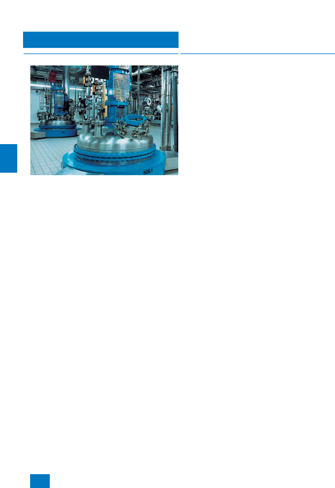
Batch automation
SIMATIC BATCH
Introduction
6/2 Siemens ST PCS 7 · November 2007
6
■
Design
SIMATIC BATCH is configured as a single-user system or as a
client/server system, and can be used in plants of any size due
to its modular architecture and scalability in 5 steps using 10, 20,
40, 100 and unlimited units (instances of plant units).
With small applications, e.g. for laboratory automation, SIMATIC
BATCH can also be combined with the PC-based starter system
SIMATIC PCS 7 BOX 416. The capacity of SIMATIC BATCH is
limited to 10 units in this case.
However, characteristic for the automation of batch processes
using SIMATIC BATCH are client/server architectures with which
one batch server and several batch clients process a plant
project together. The batch server can also be configured with
redundancy in order to increase availability.
■
Integration
Integration in SIMATIC PCS 7
SIMATIC BATCH is fully integrated in SIMATIC PCS 7. The plant
data can be configured entirely using the engineering system.
The engineering system transfers all data required for creating
recipes to the batch server. It is therefore possible to edit recipes
separate from the engineering system. Changes to the configu-
ration which are made on the engineering system are available
to the batch server using an update function (online/offline).
The SIMATIC Logon integrated in SIMATIC PCS 7 implements
the following functions:
• Central user administration with access control
• Function "Electronic Signature"
This means that operations cannot be performed until enabled
by authorized Windows users/user groups.
Communication with the automation systems
SIMATIC BATCH communicates with the automation system
through the operator system. The PCS 7 operator stations rele-
vant to the batch are made known to the batch server during
configuration of the batch applications. Operator instructions
and dialogs can also be integrated into the batch-AS communi-
cation. Attention is then drawn to necessary operator inputs, or
data input is made possible, e.g. for laboratory values. SIMATIC
BATCH provides special standard faceplates for controlling and
monitoring plant units and equipment modules.
SFC instances derived from a SFC-type template are generally
used as the interface to the subordinate automation level. The
properties of the SFC type can be defined in a features dialog:
• Operations
• Setpoints/actual values
• Instance parameters
• Times etc.
It is also possible to use special batch interface blocks for com-
munication with the processing programs in the automation sys-
tems, e.g. for plant expansions or for connection of non-SIMATIC
systems.
© Siemens AG 2007
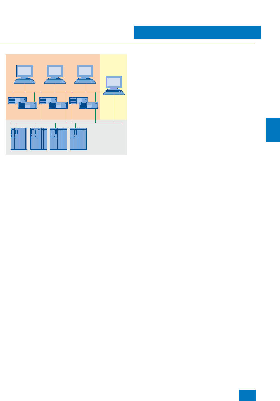
Batch automation
SIMATIC BATCH
SIMATIC BATCH hardware
6/3
Siemens ST PCS 7 · November 2007
6
■
Design
The modularity and flexibility of SIMATIC BATCH are optimally
supported by the hardware available. The basic hardware from
the Section "SIMATIC PCS 7 Industrial Workstation" in the Chap-
ter "System-neutral components" can be used for SIMATIC
BATCH. Please note that the operating system and the ES/OS
software of the SIMATIC PCS 7 process control system are pre-
installed as standard on the single station, server or client as the
basic device. If these basic devices are used for SIMATIC
BATCH, it is possible to extend or reject the existing SIMATIC
PCS 7 installation, and restore it for the operating system using
the restore DVD.
Hardware for small plants
For small plants, SIMATIC BATCH can be installed together with
the OS software on a single station system. You can find further
details on the hardware for this OS/BATCH single station with the
ordering data of this section:
• In the Section "SIMATIC PCS 7 Industrial Workstation" of the
Chapter "System-neutral components"
• In the Section "OS hardware" in the Chapter "Operator system"
A further alternative for small plants is operation of SIMATIC
BATCH on the starter system SIMATIC PCS 7 BOX 416.
Client/server configuration
Batch process automation typically has a distributed cli-
ent/server configuration with one batch server and several batch
clients, which together process a plant project. The batch server
of such a configuration can also be configured with redundancy
in order to increase availability.
SIMATIC BATCH clients and OS clients can run on separate or
common basic hardware. The batch server software is usually
executed on separate server hardware (Batch Server). Depend-
ing on the load on the operator system, the OS and batch server
software can also be executed on common server hardware
(OS/Batch Server).
Since the batch server is only a node on the OS-LAN, we recom-
mend that only the server version of the SIMATIC PCS 7 Indus-
trial Workstation with BCE communication is used. The
10/100/1000 Mbit/s Ethernet RJ45 port is already onboard and
can be used for connecting to the OS LAN.
Redundancy
The batch server redundancy is supported by the SIMATIC
BATCH basic package. The two batch servers of a redundant
pair of servers have identical configurations. Contrary to the
case of OS redundancy, they must always be connected via a
separate Ethernet connection in order to optimize the internal
communication. Since the batch server is not usually connected
to the plant bus, the Ethernet network card of the SIMATIC PCS 7
Industrial Workstation which is provided as standard for the plant
bus connection can be used for the redundant communication.
An optical or electrical connection can be used depending on
the environmental conditions and the distance between the two
batch servers, e.g. up to 100 m per crossover network cable
(RJ45 connectors). For details, refer to Manual "SIMATIC PCS 7
V7.0 fault-tolerant process control systems"; for appropriate ca-
ble material and further accessories, refer to Catalog IK PI.
If the SIMATIC BATCH software and the SIMATIC PCS 7
OS software are installed together on a redundant pair of serv-
ers, the two servers must be connected together via an addi-
tional desktop adapter network card for the redundant commu-
nication. The serial RS 232 connection described in the Section
"OS redundancy" is omitted.
For information and components for connection to a redundant
terminal bus, see page 9/28.
Expansion options
The basic hardware is expandable according to the customer’s
particular requirements and whether the hardware is used as
single station, server or client with the following options:
• Multi-VGA graphics card for connection of up to 4 monitors
• Process monitors (see Spage 2/17)
The multi-VGA graphics cards "2 Screens" and "4 Screens" are
offered for multichannel operation of an OS/batch single station
or a batch client with 2 up to 4 process monitors. Using a multi-
VGA graphics card, the visualization of the plant/unit can be di-
vided among up to 4 process monitors per operator station by
using different views. These plant sections can all be operated
using just one keyboard and one mouse. The multi-VGA graph-
ics cards are compliant with the EN 55022 and EN 50082 stan-
dards. Each card occupies one PCI slot.
Note:
Since all messages from SIMATIC BATCH are processed in the operator
system’s message system, the use of a signal module is only recom-
mendable with multi-function OS/batch stations (clients, single stations).
SIMATIC BATCH clients and OS clients
Automation
systems
Batch server OS server
Engineering
System
OS-LAN
Plant bus
© Siemens AG 2007

Batch automation
SIMATIC BATCH
SIMATIC BATCH hardware
6/4 Siemens ST PCS 7 · November 2007
6
B) Subject to export regulations: AL: N, ECCN: EAR99H
D) Subject to export regulations: AL: N, ECCN: 5D992B1
Note:
Ordering data in abbreviated form; for detailed Ordering data,
see page 2/14.
■
Selection and Ordering Data Order No.
Batch single station
SIMATIC PCS 7 Industrial Work-
station, single station version
Windows XP Professional MUI
operating system (German, Eng-
lish, French, Italian, Spanish, Chi-
nese)
•SIMATIC PCS 7 ES/OS 547B
BCE WXP
Connection to plant bus with
Ethernet network card RJ45
(PCI) 10/100/1000 Mbit/s and
Basic Communication Ethernet
(BCE)
6ES7 650-0NF07-0YX0 D)
•SIMATIC PCS 7 ES/OS 547B
IE WXP
Connection to plant bus via In-
dustrial Ethernet with
CP 1613 A2 communications
processor
6ES7 650-0NF07-0YX1 D)
Batch server
SIMATIC PCS 7 Industrial Work-
station, server version
Windows Server 2003 MUI oper-
ating system (German, English,
French, Italian, Spanish, Chinese)
•SIMATIC PCS 7 OS Server
547B BCE SRV03
Connection to plant bus with
Ethernet network card RJ45
(PCI) 10/100/1000 Mbit/s and
Basic Communication Ethernet
(BCE)
6ES7 650-0NH07-0YX0 D)
Batch client
SIMATIC PCS 7 Industrial Work-
station, client version
Windows XP Professional MUI
operating system (German, Eng-
lish, French, Italian, Spanish, Chi-
nese)
•SIMATIC PCS 7 OS Client 547B
WXP
- without multi-VGA graphics
card 6ES7 650-0NG07-0YX0 D)
- with Multi-VGA graphics card
"2 Screens" 6ES7 650-0NG07-0YA0 D)
- with Multi-VGA graphics card
"4 Screens" 6ES7 650-0NG07-0YB0 D)
Additional and expansion components
See also page 2/15
Desktop adapter network card
for redundant communication
between two redundant OS/batch
servers
A5E00504378 B)
SIMATIC PCS 7 BOX 416
See page 3/8
■
Selection and Ordering Data Order No.
© Siemens AG 2007
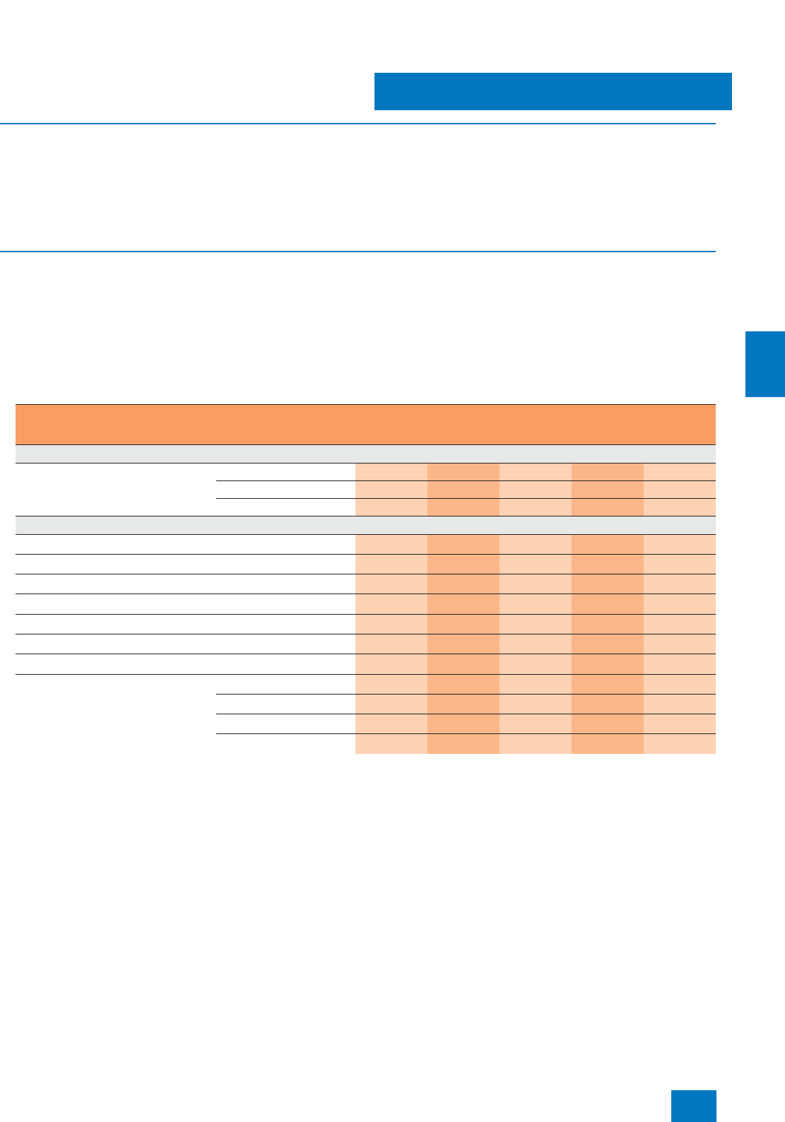
Batch automation
SIMATIC BATCH software
Introduction
6/5
Siemens ST PCS 7 · November 2007
6
■
Overview
The basic software for all SIMATIC BATCH system configurations
(single stations or client/server systems) is the SIMATIC BATCH
Server Basic Package, configured with
• Batch server software for 10 units (instances of plant units)
• 1 x SIMATIC BATCH BatchCC (Batch Control Center)
• 1 x SIMATIC BATCH Recipe System (recipe editor)
The basic software is always required. It provides everything
needed to implement a small SIMATIC BATCH project on the
hardware of a SIMATIC PCS 7 BOX 416, a single station or a
client/server configuration consisting of a batch client and a
batch server. It also includes the SIMATIC Logon for central user
administration with access control and for the electronic signa-
ture.
■
Design
The capacity of the SIMATIC BATCH server basic packages can
be expanded by SIMATIC BATCH PO options and PowerPacks.
An appropriate number of SIMATIC BATCH BatchCC und
SIMATIC BATCH Recipe System option packages is needed to
expand the client/server configuration with additional batch cli-
ents. The functions of SIMATIC PCS 7 BOX 416, single stations,
batch clients and batch servers can be expanded using the fol-
lowing optional packages (see table).
SIMATIC BATCH software components for SIMATIC PCS 7 BOX, single station, batch server and batch client
n: Components included in delivery of basic software
opt: Can be ordered as options
SIMATIC BATCH works closely with the operator system and
communicates through the operator system with the automation
systems. For small plants, SIMATIC BATCH can therefore be
installed together with the OS software on a single station or a
SIMATIC PCS 7 BOX 416. The ordering data for the OS software
can be found in the Chapter "Operator system".
Software component SIMATIC
PCS7BOX
416
Single
station Batch
server Batch
client 1 Batch
Client 1+n
Basic software
SIMATIC BATCH server basic package Batch Server for 10 units nnn
Batch Control Center n n n
Recipe System n n n
Option packages
SIMATIC BATCH ROP Library opt opt opt
SIMATIC BATCH Hierarchical Recipe opt opt opt
SIMATIC BATCH Separation Procedures/Formulas opt opt opt
SIMATIC BATCH API opt opt
SIMATIC BATCH Batch Planning opt opt opt opt
SIMATIC BATCH Batch Control Center opt
SIMATIC BATCH Recipe System opt
SIMATIC BATCH PO options
For expansion of the SIMATIC BATCH
Server Basic Package to
20 units opt opt
40 units opt opt
100 units opt opt
Unlimited units opt opt
© Siemens AG 2007

Batch automation
SIMATIC BATCH software
Introduction
6/6 Siemens ST PCS 7 · November 2007
6
■
Function
SIMATIC BATCH offers a versatile range of powerful functions for
automating batch processes, and these are described in detail
in the system documentation. The most important functions of
the various program components are presented in summarized
form on the following pages. The current system version
SIMATIC BATCH V7.0 particularly features the following new
functions:
• By means of a user-friendly formula editor which is able to link
process parameters or constants using the four fundamental
arithmetic operations, you can enter formulas at the step
points of a sequence (phase parameters, transitions).
• Deepening and further development of cooperation with
SIMATIC Route Control:
- The locations for material transport which are defined in the
SIMATIC Manager and are specific to Route Control can be
exported to SIMATIC BATCH.
- The locations can be used as transfer parameters (source,
target or via) for the transport phases so that products of a
batch can be routed into other specific units.
• It is possible to compare text variables and fixed text strings
for transitions.
• Product names can be saved in the formulas.
• System-based support for versioning of recipes, formulas and
library objects facilitates plant validation.
• Through user-specific saving of individual system settings,
e.g. GUI, window or language, the usual working environment
is available on any client.
• In the recipe editor and in BatchCC (except in the message
window), swapping to a new language is effective immedi-
ately, i.e. even before the current application is completed.
© Siemens AG 2007

Batch automation
SIMATIC BATCH software
Server Basic Package
6/7
Siemens ST PCS 7 · November 2007
6
■
Overview
The SIMATIC BATCH server basic package contains:
• Batch server software for 10 units (instances of plant units)
• SIMATIC BATCH BatchCC (Batch Control Center)
• SIMATIC BATCH Recipe System (recipe editor)
An integral component is also SIMATIC Logon for central user
administration and access control as well as for the "Electronic
signature", e.g. for enabling basic recipes, formulas and library
objects.
A small SIMATIC BATCH project can be implemented on the
hardware of a SIMATIC PCS 7 BOX 416, single station or cli-
ent/server combination (batch client and batch server) with the
SIMATIC BATCH Server Basic Package.
The capacity of the Server Basic Package can be extended by
means of SIMATIC BATCH PO options and SIMATIC BATCH
PowerPacks to batches with 20, 40, 100 or unlimited units.
C) Subject to export regulations: AL: N, ECCN: EAR99S
1) Instances of plant units
■
Selection and Ordering Data Order No.
SIMATIC BATCH
Server Basic Package V7.0
(10 units)
For single station, client/server
configuration or SIMATIC PCS 7
BOX 416, comprising:
• Batch server for 10 units 1)
• Recipe System
• Batch Control Center (BatchCC)
6 languages (German, English,
French, Italian, Spanish,
Chinese), executes with Windows
XP Professional or Windows
Server 2003, single license for
1 installation
Type of delivery:
License key disk, certificate of
license, terms and conditions
6ES7 657-0SA07-0YB0 C)
SIMATIC BATCH
PO Option V7.0
For expansion of the SIMATIC
BATCH Server Basic Package
6 languages (German, English,
French, Italian, Spanish,
Chinese), executes with Windows
XP Professional or Windows
Server 2003, single license for
1 installation
Type of delivery:
License key disk, certificate of
license, terms and conditions
• To 20 units 6ES7 657-0XB07-2YB0
• To 40 units 6ES7 657-0XC07-2YB0
• To 100 units 6ES7 657-0XD07-2YB0
• To unlimited units 6ES7 657-0XE07-2YB0
SIMATIC BATCH
PowerPack V7.0
For expansion of the units
6 languages (German, English,
French, Italian, Spanish,
Chinese), executes with Windows
XP Professional or Windows
Server 2003, single license for
1 installation
Type of delivery:
License key disk, certificate of
license, terms and conditions
• From 20 units to 40 units 6ES7 657-0XC07-2YD0
• From 40 units to 100 units 6ES7 657-0XD07-2YD0
• From 100 units to unlimited units 6ES7 657-0XE07-2YD0
© Siemens AG 2007
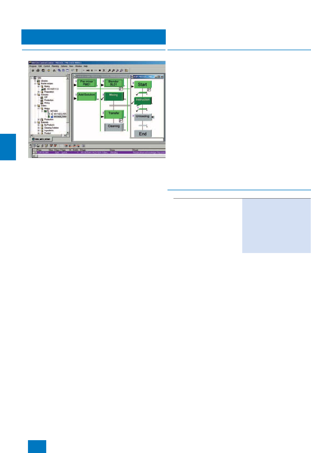
Batch automation
SIMATIC BATCH software
Batch Control Center
6/8 Siemens ST PCS 7 · November 2007
6
■
Overview
The SIMATIC BATCH Batch Control Center (BatchCC) is the
"command center" for monitoring and controlling batch pro-
cesses with SIMATIC BATCH. Using BatchCC you can manage
all data relevant to SIMATIC BATCH through a graphical user in-
terface.
Note:
The SIMATIC BATCH batch control center option package is included
once in the SIMATIC BATCH server basic package.
■
Function
BatchCC offers powerful functions for the following tasks:
• Reading in and updating the plant data of the basic automa-
tion
• Definition of user privileges for all functions, for clients, or for
plant units of SIMATIC BATCH
• Definition of material names and codes
• Management of master recipes, and starting the recipe editor
in order to enter the recipe structure
• Management of libraries with recipe elements (library opera-
tions)
• Importing and exporting of basic recipes, formulas and library
objects
• Editing of formula categories and management of associated
formulas (parameter sets)
• Creation of batches with master recipes
• Starting of batch processing and controlling of batches
• Monitoring and diagnostics of batch processing
• Online modification of occupation strategy and assignment of
units during batch processing
• Recording and archiving of recipes and batch data
■
Selection and Ordering Data Order No.
SIMATIC BATCH
BatchCC V7.0
6 languages (German, English,
French, Italian, Spanish,
Chinese), executes with Windows
XP Professional or Windows
Server 2003, floating license for
1user
Type of delivery: License key
disk, certificate of license, terms
and conditions
6ES7 657-0LX07-2YB5
© Siemens AG 2007
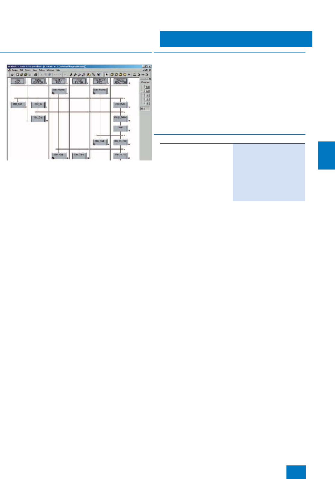
Batch automation
SIMATIC BATCH software
Recipe System
6/9
Siemens ST PCS 7 · November 2007
6
■
Overview
The SIMATIC BATCH recipe system option package presents it-
self to the user in the form of a recipe editor. The recipe editor is
a convenient tool for simple, intuitive creation and modification
of master recipes and library operations. It has a graphical user
interface, editing functions typical of those in Microsoft Windows
for single and group objects, and a structural syntax check func-
tion.
The basis for recipe creation are the batch objects created from
the batch plant configuration using the SIMATIC PCS 7 engi-
neering system, e.g. plant units and technological functions. The
batch recipe editor can be started individually, but can also be
called from BatchCC.
Note:
The SIMATIC BATCH recipe system option package is included once in
the SIMATIC BATCH server basic package.
■
Function
• Creation of new master recipes and library operations
• Modification of existing master recipes and library operations
(changes in structure or parameters)
• Documentation of master recipes and library operations
• Implementation of plausibility checks
• Selection of unit candidates using limitation of equipment
properties
• Assignment of enabling for test or production of master reci-
pes and library operations
• Routing of products of one batch into specific other units
■
Selection and Ordering Data Order No.
SIMATIC BATCH
Recipe System V7.0
6 languages (German, English,
French, Italian, Spanish,
Chinese), executes with Windows
XP Professional or Windows
Server 2003, floating license for
1user
Type of delivery: License key
disk, certificate of license, terms
and conditions
6ES7 657-0AX07-2YB5
© Siemens AG 2007
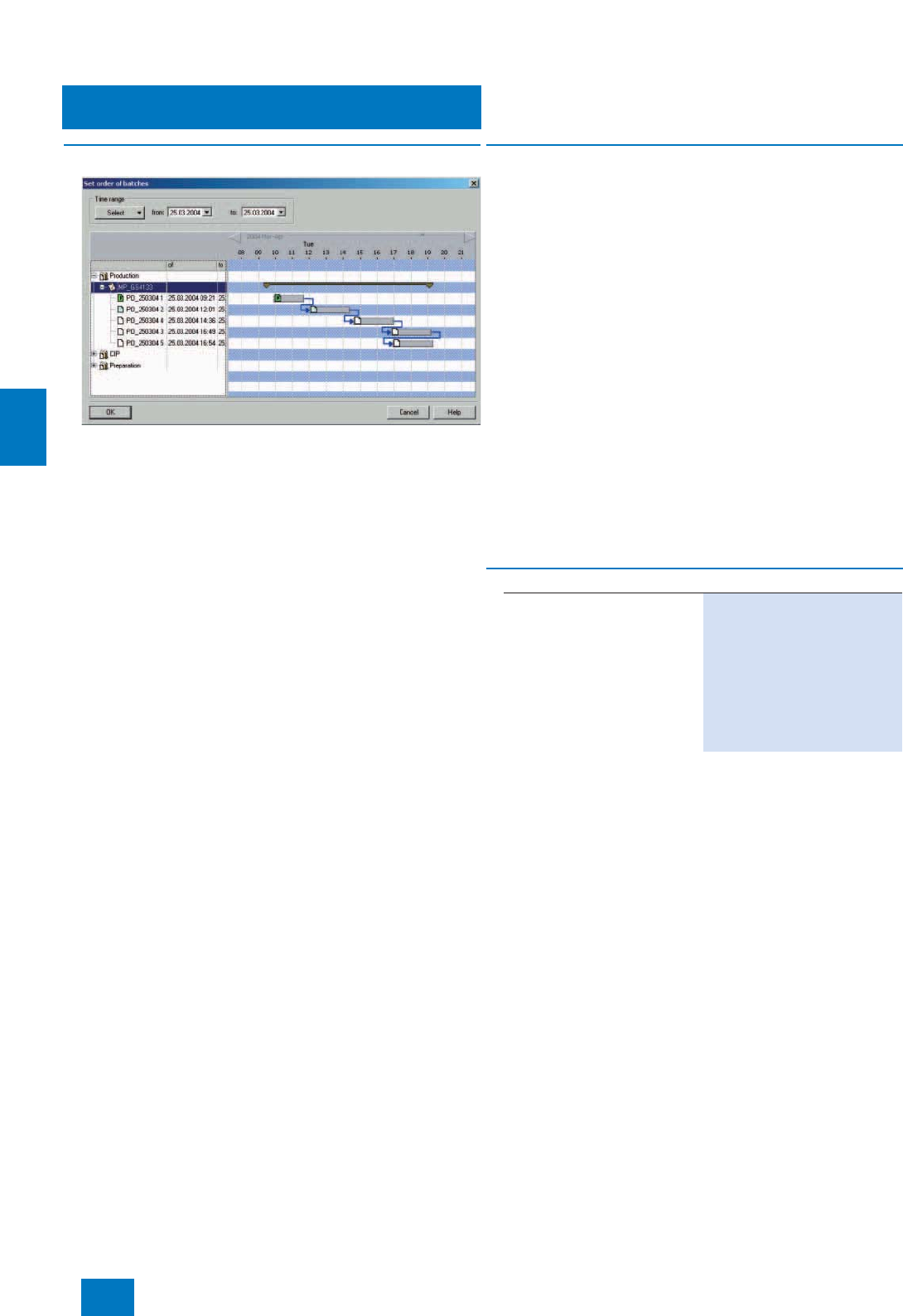
Batch automation
SIMATIC BATCH software
Batch Planning
6/10 Siemens ST PCS 7 · November 2007
6
■
Overview
The SIMATIC BATCH BatchCC enables the creation of individual
production orders and batches. Far more planning functionality
is offered by the additional SIMATIC BATCH batch planning op-
tion package. BatchCC can then be used to plan batches in ad-
vance for a large number of production orders.
■
Function
The range of functions includes not only the planning but also
the modification, canceling, deleting and releasing of batches.
Dividing and saving batches for a production can be performed
manually or, after specifying the number of batches and the pro-
duction quantity, automatically. The following batch parameters
can be selected and changed before the release order is given:
• Quantity to be prepared
• Starting mode (immediately, by operator input or time-con-
trolled)
• Plant unit assignment
• Formula (parameter set)
• Run sequence (interlinking with the previous or next batch)
• Indication of batch runtime
Batch planning and control are conveniently supported and sim-
plified by special displays such as order category list, produc-
tion order list, batch planning list, batch status list and batch re-
sults list.
All batches and their plant unit assignments can be clearly pre-
sented by a combination of Gantt diagram and table. Conflicts
of time or due to multiple assignment of plant units are marked
by symbols. Time conflicts are easily eliminated by moving the
affected batches in the Gantt diagram.
■
Selection and Ordering Data Order No.
SIMATIC BATCH
Batch Planning V7.0
6 languages (German, English,
French, Italian, Spanish,
Chinese), executes with Windows
XP Professional or Windows
Server 2003, floating license for
1user
Type of delivery: License key
disk, certificate of license, terms
and conditions
6ES7 657-0BX07-2YB5
© Siemens AG 2007
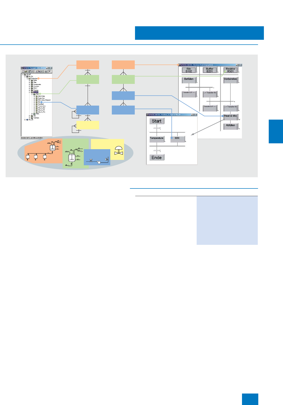
Batch automation
SIMATIC BATCH software
Hierarchical Recipe
6/11
Siemens ST PCS 7 · November 2007
6
■
Overview
Hierarchical recipes according to ISA-88.01
SIMATIC BATCH and SIMATIC PCS 7 form a functional unit that
fully covers the models described in the ISA-88.01 standard.
The hierarchical recipe structure is mapped on the plant module
as follows:
• Recipe procedure for controlling the process or the produc-
tion in a plant
• Partial recipe procedure for controlling a process step in a
plant unit
• Recipe operation/function for the process engineering
task/function in an equipment module
Technical
Equipment
Recipe
procedure
Recipe
operation
Recipe
function
Partial recipe
procedure
Plant
Plant
Unit
Unit
Technical
Equipment
Individual
control unit
Individual
control unit
■
Selection and Ordering Data Order No.
SIMATIC BATCH
Hierarchical Recipe V7.0
6 languages (German, English,
French, Italian, Spanish, Chinese),
executes with Windows
XP Professional or Windows
Server 2003, single license for
1 installation
Type of delivery: License key
disk, certificate of license, terms
and conditions
6ES7 657-0FX07-2YB0
© Siemens AG 2007
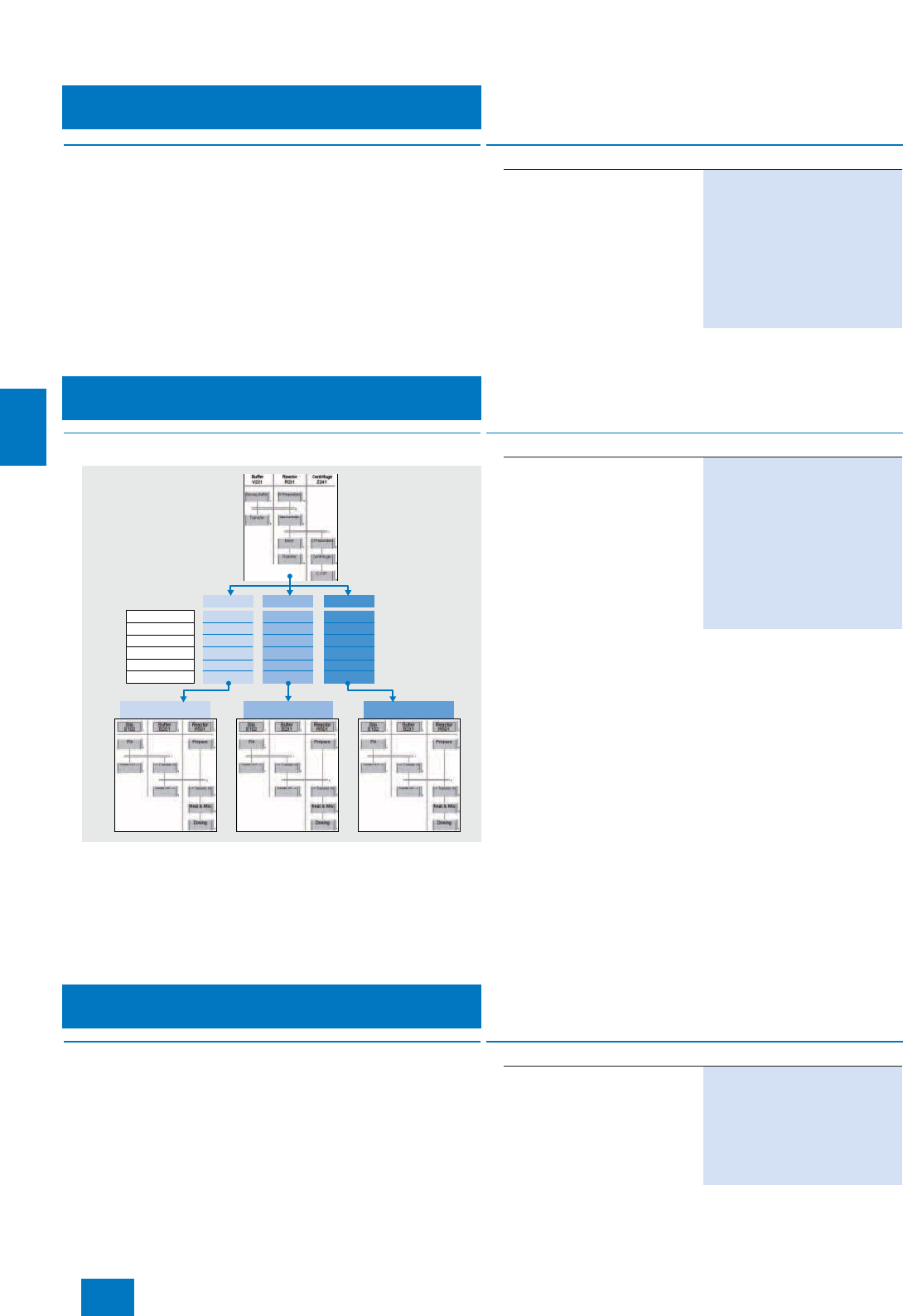
Batch automation
SIMATIC BATCH software
ROP Library
6/12 Siemens ST PCS 7 · November 2007
6
■
Overview
The management of recipe operations is conveniently sup-
ported by a user library (ROP library). Library recipe operations
can be inserted as a reference in recipe procedures and can
thus be modified from a central location. This reduces the re-
quirements for engineering and validation. If the reference link is
broken, the recipe operation becomes a fixed component of the
recipe procedure, and is thus independent of further central
modifications.
■
Overview
The flexibility achieved by recipes which are independent of
plant units can be increased even further if the procedure and
parameter sets (formulas) are separated from one another. Vari-
ous master recipes can be created by linking several formulas
using a recipe procedure. This enables central modification of
procedures. The formula structure is determined by the formula
category defined by the user.
■
Overview
The SIMATIC BATCH API application programming interface is
an open interface for custom expansions. It provides the user
with access to SIMATIC BATCH data and functions and enables
the programming of special industry or project specific applica-
tions.
■
Selection and Ordering Data Order No.
SIMATIC BATCH
ROP Library V7.0
6 languages (German, English,
French, Italian, Spanish, Chi-
nese), executes with Windows
XP Professional or Windows
Server 2003, single license for
1 installation
Type of delivery: License key
disk, certificate of license, terms
and conditions
6ES7 657-0GX07-2YB0
Formula 3
900 kg
95 °C
12 min
No
Yes
50 g
Master Recipe #2 Master Recipe #3Master Recipe #1
Formula 2
500 kg
80 °C
15 min
Yes
No
150 g
Formula 1
1000 kg
90 °C
10 min
Yes
No
100 g
Quantity
Temperature
Time
Salt
Pepper
Sugar
■
Selection and Ordering Data Order No.
SIMATIC BATCH
Separation Procedures/
Formulas V7.0
6 languages (German, English,
French, Italian, Spanish, Chinese),
executes with Windows
XP Professional or Windows
Server 2003, single license for
1 installation
Type of delivery: License key
disk, certificate of license, terms
and conditions
6ES7 657-0HX07-2YB0
■
Selection and Ordering Data Order No.
SIMATIC BATCH API V7.0
1 language (English), executes
with Windows XP Professional or
Windows Server 2003, single
license for 1 installation
Type of delivery: License key
disk, certificate of license, terms
and conditions
6ES7 657-0MX07-2YB0
Separation Procedures/Formulas
SIMATIC BATCH API
© Siemens AG 2007
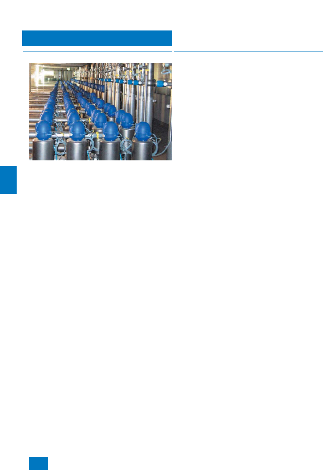
SIMATIC Route Control
Introduction
7/2 Siemens ST PCS 7 · November 2007
7
■
Overview
SIMATIC Route Control adds a tool for the configuration, control,
monitoring and diagnostics of material transports in pipeline net-
works. It is not specialized on any particular industry.
With SIMATIC Route Control, which can also be combined with
SIMATIC BATCH, users of SIMATIC PCS 7 are capable of auto-
mating not only their production processes and associated
warehouses but also the material transports linking both areas.
SIMATIC Route Control can handle complex networks as well as
simple transport routes. In particular SIMATIC Route Control is
predestined for plants with a multitude of complex route combi-
nations or extensive tank farms such as are found above all in
the chemical, petrochemical and food and drinks industries.
■
Application
The possible applications of SIMATIC Route Control extend from
small plants with simple/static lines up to plants in the medium
and upper performance range with an extensive network of
routes/pipes.
SIMATIC Route Control is particularly recommended for the fol-
lowing conditions:
• Frequent conversions and extensions of the transport network
including actuators and sensors
• Transport routes with high flexibility, characterized by:
- Regularly changing materials
- Dynamic selection of the origin and destination of the mate-
rial transport (including reversal of direction on bidirectional
transport routes)
• Numerous simultaneous material transports
• Plant projects in combination with SIMATIC BATCH
© Siemens AG 2007

SIMATIC Route Control
Introduction
7/3
Siemens ST PCS 7 · November 2007
7
■
Configuration
SIMATIC Route Control is fully integrated in SIMATIC PCS 7 and,
thanks to the modular architecture and 3-step scalability (up to
30 / up to 100 / up to 300 simultaneous material transports), can
be flexibly adapted to different sizes of plant.
SIMATIC Route Control provides graded user privileges for en-
gineering, operating and maintenance personnel who are inte-
grated into the user administration with SIMATIC logon. SIMATIC
Logon is an integral component of SIMATIC PCS 7.
Route Control in the engineering system
The Route Control Engineering Tool, the Route Control Library
and the Route Control Assistant are integrated together with the
other engineering tools of the SIMATIC PCS 7 process control
system in the central engineering system.
In SIMATIC PCS 7, blocks from the SIMATIC PCS 7 standard li-
brary are inserted into CFC plans and connected to plant control
blocks in accordance with the technological requirements in or-
der to control and monitor the elements of a plant. These individ-
ual connections are omitted with SIMATIC Route Control (RC).
You adapt the standard blocks of the technological elements rel-
evant to RC (RC elements) using standardized interface blocks
from the Route Control library, and allow RC to control and mon-
itor the elements during operation. This is of course also possi-
ble with existing plantswithout an increased overhead.
The blocks of the Route Control library support redundancy at
the controller level. They can be used with standard automation
systems or also with fault-tolerant systems or mixed configura-
tions. The changes in the engineering system can be recorded
(Change log), both in the SIMATIC PCS 7 project and in the RC
project.
The Route Control Assistant functions as the interface between
the PCS 7 basic configuration expanded by RC components
and the RC engineering tool. It analyzes the hardware and soft-
ware configuration of the SIMATIC PCS 7 (multi-)project, and
generates a database which serves as the basis for further,
RC-specific configuration with the RC engineering tool.
During the RC-specific configuration, the elements imported
from the SIMATIC PCS 7 project by the Route Control Assistant
must be inserted into a sub-route structure. These sub-routes di-
vide the plant. The complete routes will be subsequently "joined
together" from them during the automatic route searching. The
response of the sub-routes in a particular function are already
defined when inserting the elements into them. Functions repre-
sent the technological requirements when operating the plant
(e.g. "Open source", "Pumps" etc.).
As a rule: the more finely divided the sub-route structure, the
more flexible the subsequent automatic route searching. With
purely static routes, a sub-route can already be a complete
route.
Route Control Server/Route Control Center
After the transport network has been configured and the variants
of the material transports tested, the Route Control configuration
data are transferred to the Route Control Server where they can
be activated via the Route Control Center at a suitable time from
the process engineering viewpoint. From then onwards, the new
data are taken into consideration when searching for the route.
If a material transport is pending during operation, a route (ma-
terial transport) is requested by the controller (e.g. using an
adapted RC SFC type) or by the operator on the Route Control
Center. In addition to definition of the source and target as well
as up to 10 optional locations (intermediate points), this also in-
cludes the creation of a start signal on the route control block
RC_IF_ROUTE in the automation system (AS). The AS "informs"
the RC Server which then starts searching for the route and – if
possible – combines the statically defined sub-routes into a
complete transport route. From this point onward, the Route
Control takes over control and monitoring of all RC elements in-
volved in the transport route. If faults occur, detailed diagnostics
information is provided concerning the cause, e.g. why the
search for a suitable transport route was unsuccessful. The plant
control program only switches the individual technological func-
tions, everything else is handled by the Route Control.
The Route Control Server (RC Server) supplies the Route Control
Clients (Route Control Center) with the necessary data and
transfers their operations to the automation systems.
For maintenance purposes, an automation system can be spe-
cifically set to "in maintenance" (out of service). The material
transports being carried out by this automation system are still
continued until finished. However, new material transports are no
longer permitted.
RC block symbols and faceplates
In the process displays of the SIMATIC PCS 7 operator systems,
each route block is represented by an RC block symbol and an
RC faceplate. Through a route block’s RC block symbol it is pos-
sible to select its RC faceplate, and through a route block’s RC
faceplate it is possible to select the Route Control Center.
Drop-down lists for location selection
The selection of locations (synonym: nodes) is made simpler in
the process display by means of drop-down lists.
© Siemens AG 2007
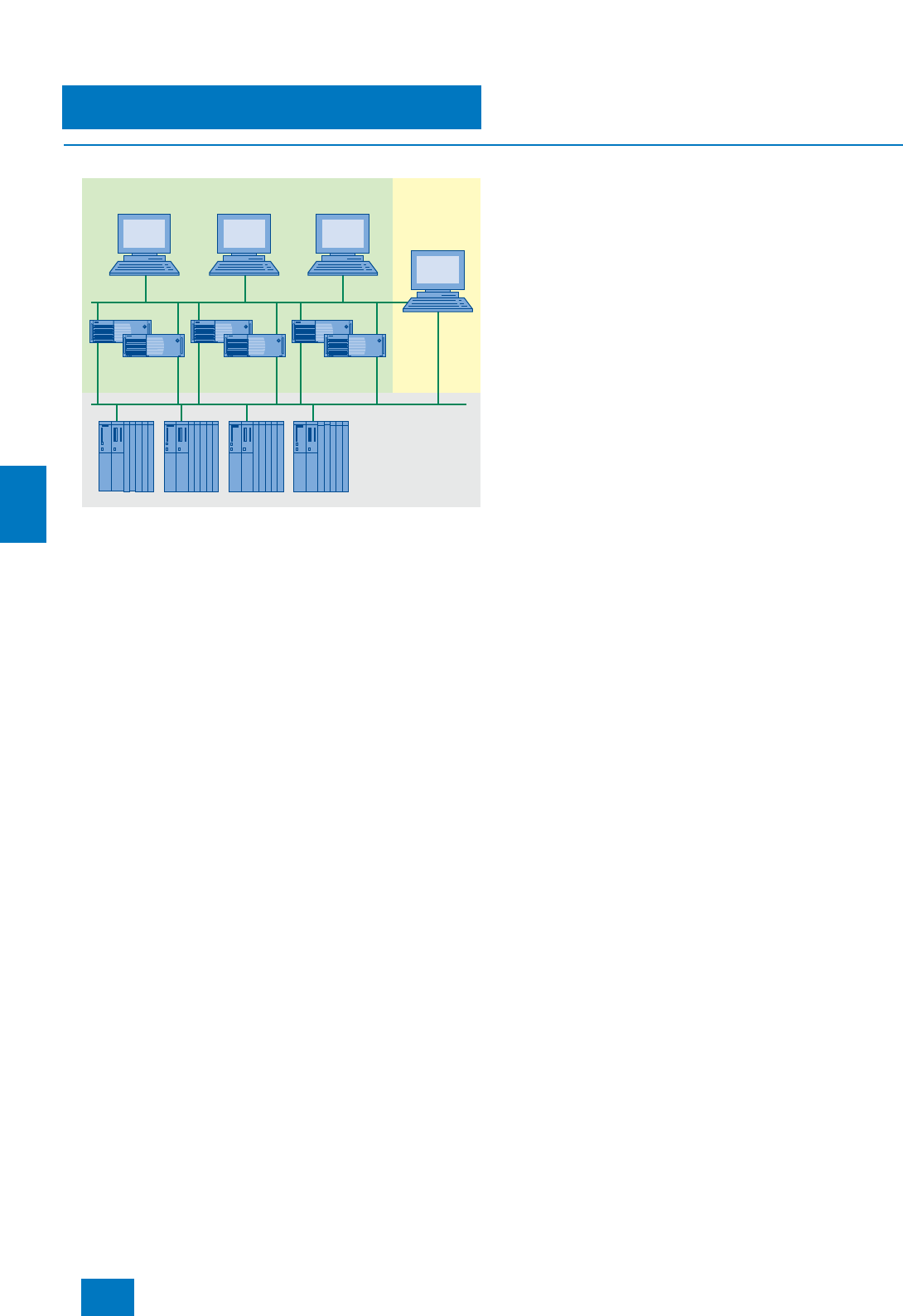
SIMATIC Route Control
Route Control Hardware
7/4 Siemens ST PCS 7 · November 2007
7
■
Design
The modularity and flexibility of SIMATIC Route Control are opti-
mally supported by the hardware available. The basic hardware
from page 2/14 can be used for SIMATIC Route Control.
Hardware for small plants
For small plants, SIMATIC Route Control can be installed either
alone or together with the OS software on a single station system
or a SIMATIC PCS 7 BOX 416. You can select the hardware for
the OS/RC single station at page 2/14, page 5/6, or further down
in this section. You can find information and the ordering data for
the SIMATIC PCS 7 BOX 416 at page 3/8.
Client/server configuration
Distributed multi-user systems with client/server architecture,
expandable with up to 32 clients per server, are typical for the
automation of material transports with SIMATIC Route Control.
Basically it is possible to operate an RC Server, Batch Server
and OS Server on shared basic hardware. However, availability
will be higher and performance better if each component has its
own server hardware. The availability of the RC Server can be
further increased through redundant configuration of the server
hardware. SIMATIC PCS 7 supports multiple-station systems
with up to 12 servers/server pairs.
The Route Control Client is represented by the Route Control
Center (RCC). The RCC can be installed on an OS Client, a
Batch Client or separate client hardware.
RC server and OS/RC single stations can be connected to the
Industrial Ethernet plant bus via a CP 1613 A2 communications
processor or via a simple FastEthernet network card with BCE
(suitable for communication with up to 8 automation systems;
not H systems).
The CP 1613 communication integrated in the IE version of the
SIMATIC PCS 7 Workstation for single stations and servers is a
combination of CP 1613 communications processor and
S7-1613 communications software. When using fault-tolerant
automation systems, the SIMATIC PCS 7 Workstation requires
the S7-REDCONNECT software instead of the S7-1613 commu-
nications software. The S7-REDCONNECT Upgrade is suitable
for upgrading the communications software (for ordering data,
see page 9/28).
Redundancy
RC Server redundancy is supported by the SIMATIC Route Con-
trol Server software. Further software components or a separate
connection between the two servers as is the case with the
OS server redundancy or batch server redundancy are not re-
quired.
With the assistance of the SIMATIC Route Control Server soft-
ware, the two redundant RC servers carry out mutual monitoring
during operation. If the active RC server fails, the redundant
partner immediately becomes the master and takes over opera-
tion. The RC clients are automatically switched over to the new
master in this case. Following return of the failed RC server, data
matching is carried out with the active RC server, and the latter
remains the master.
For information and components for the redundant bus connec-
tion (plant bus and terminal bus), see page 9/28.
Expansion options
The basic hardware (PC basic unit) is expandable with the fol-
lowing options according to the customer’s particular require-
ments and whether the hardware is used as RC Single Station,
RC Server or Batch Client:
• Multi-VGA graphics card for connection of up to 4 monitors
• Process monitors (see page 2/17)
The Multi-VGA graphics cards "2 Screens" and "4 Screens" are
offered for multichannel operation of an OS/RC Single Station or
a client with 2 up to 4 process monitors. Views distributed over 2
or as many as 4 process monitors by means of a graphics card
can be controlled using one keyboard and one mouse. The
Multi-VGA graphics cards are compliant with EN 55022 and
EN 50082 standards. Each card occupies one PCI slot in the op-
erator station.
Note:
Since all messages from SIMATIC Route Control are processed
in the operator system’s message system, it is not necessary to
use a signal module.
Requirements for selection of the automation systems
SIMATIC Route Control can operate together with the WinAC
Slot 416 controller of the SIMATIC PCS 7 BOX 416 (up to
30 simultaneous material transports) and with the following auto-
mation systems of the SIMATIC PCS 7 process control system:
• AS 416-3 (up to 30 simultaneous material transports)
• AS 417-4
• AS 417H
Safety-related automation systems, e.g. AS 417F/FH, cannot be
used to control material transport with SIMATIC Route Control.
SIMATIC Route Control clients and OS clients
Automation
systems
Route Control
server
OS server
Engineering
System
OS-LAN
Plant bus
© Siemens AG 2007

SIMATIC Route Control
Route Control Hardware
7/5
Siemens ST PCS 7 · November 2007
7
D) Subject to export regulations: AL: N, ECCN: 5D992B1
Note:
Ordering data in abbreviated form; for detailed Ordering data, see page
2/14.
For Ordering data of the SIMATIC PCS 7 BOX 416, refer to page 3/8.
■
Selection and Ordering Data Order No.
RC single station
SIMATIC PCS 7 Industrial Work-
station, single station version
Windows XP Professional MUI
operating system
(German, English, French, Italian,
Spanish, Chinese)
•SIMATIC PCS 7 ES/OS 547B
BCE WXP
Connection to plant bus with
Ethernet network card RJ45
(PCI) 10/100/1000 Mbit/s and
Basic Communication Ethernet
(BCE) for up to 8 automation
systems (not H-systems)
6ES7 650-0NF07-0YX0 D)
•SIMATIC PCS 7 ES/OS 547B
IE WXP
Connection to plant bus with
CP 1613 A2 communications
processor
6ES7 650-0NF07-0YX1 D)
RC server
SIMATIC PCS 7 Industrial Work-
station, server version
Windows Server 2003 MUI
operating system
(German, English, French, Italian,
Spanish, Chinese)
•SIMATIC PCS 7 OS Server
547B BCE SRV03
Connection to plant bus with
Ethernet network card RJ45
(PCI) 10/100/1000 Mbit/s and
Basic Communication Ethernet
(BCE) for up to 8 automation
systems (not H-systems)
6ES7 650-0NH07-0YX0 D)
•SIMATIC PCS 7 OS Server
547B IE SRV03
Connection to plant bus with
CP 1613 A2 communications
processor
6ES7 650-0NH07-0YX1 D)
RC client
SIMATIC PCS 7 Industrial Work-
station, client version
Windows XP Professional MUI
operating system
(German, English, French, Italian,
Spanish, Chinese)
• SIMATIC PCS 7 OS Client 547B
WXP
- without multi-VGA graphics
card 6ES7 650-0NG07-0YX0 D)
- with Multi-VGA graphics card
"2 Screens" 6ES7 650-0NG07-0YA0 D)
- with Multi-VGA graphics card
"4 Screens" 6ES7 650-0NG07-0YB0 D)
Additional and expansion components
SIMATIC NET S7-REDCONNECT
Upgrade
for communication with fault-toler-
ant AS systems, see page 9/28
Further additional and expansion
components can be found at
page 2/15
■
Selection and Ordering Data Order No.
© Siemens AG 2007
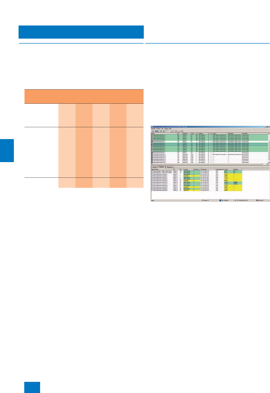
SIMATIC Route Control
Route Control runtime software
7/6 Siemens ST PCS 7 · November 2007
7
■
Overview
The Route Control Software is structured such that SIMATIC
Route Control can be flexibly adapted to different plant sizes and
architectures (single/multi-user systems):
• Route Control Engineering (component of the SIMATIC PCS 7
Engineering System)
• Route Control Server
• Route Control Center (RCC)
SIMATIC Route Control works closely with the operator system,
hence where small plants are concerned it is possible for the
Route Control Center and Route Control Server to be installed
not only on their own but also together with the OS software on a
single station or a SIMATIC PCS 7 BOX 416 (up to 30 simulta-
neous material transports). The ordering data for the OS soft-
ware can be found in the Chapter "Operator system".
In the case of multi-user systems with small quantity frameworks
it is also possible to operate the Route Control Server, Batch
Server and OS Server on shared basic hardware. However,
availability will be higher and performance better if they are in-
stalled on separate server hardware.
The Route Control Server program package suitable for up to
30 simultaneous material transports can be expanded by means
of add-on PowerPacks to meet higher requirements (up to 100 or
300 simultaneous material transports).
The Route Control Client is represented by the Route Control
Center (RCC). The RCC can be installed on an OS Client, a
Batch Client or separate client hardware.
■
Function
Route Control Server
The Route Control Server supplies the RC Clients (Route Control
Center) with the necessary data and transfers their operations to
the automation systems. When a material transport is requested
through the Route Control Center, it is the job of the RC Server to
dynamically compile a suitable transport route from the partial
routes which were configured using a map of the automation
systems on the basis of the selected parameters (source, desti-
nation and intermediate locations) and with due consideration of
other parameters (e.g. function catalogs, function IDs or material
IDs). Configuration changes can be taken immediately into ac-
count in the determination of a suitable transport route after
transfer from the Route Control Engineering Tool to the Route
Control Server and subsequent activation through the Route
Control Center (online loading).
Route Control Center
Route Control Center (RCC)
The RCC can be called either from the faceplate of a route block
or from the keyset on the operator station. It displays all of a ma-
terial transport’s relevant route data and error information in sev-
eral coordinated views
Software
components
(runtime)
SIMATIC
PCS 7
BOX 416
Single
station Server
single Server
redun-
dant
Client
SIMATIC Route
Control Server
Up to 30 simulta-
neous material
transports
1 1 1 2 --
SIMATIC Route
Control Server
PowerPack
•From 30 up to
100 simultaneous
material trans-
ports
-- 112--
• From 100 up to
300 simultaneous
material trans-
ports
-- 112--
SIMATIC Route
Control Center 1 1 -- -- 1
© Siemens AG 2007

SIMATIC Route Control
Route Control runtime software
7/7
Siemens ST PCS 7 · November 2007
7
Key functional features are:
• Overview of all RC elements, partial routes and request details
• Operation of the selected material transport: Selection of op-
erating mode: manual/automatic; request, start, stop, con-
tinue and end material transport in manual mode; set/change
request parameters (locations: source, destination, intermedi-
ate locations) and general properties (function catalog, func-
tion ID, material ID and "ignore error") in manual mode; acti-
vate/deactivate sequence functions in manual mode
• Diagnostics of material transport request errors caused by
locked RC elements, locked partial routes, inconsistent actu-
ations or prohibited sequential material
• Diagnostics of currently running material transports: color and
text display of transport route status in the route view of the
RCC; detailed analyses by evaluation of feedback signals
from RC elements
• Server functions: select RC Server, display RC Server status,
update view (read in data again from the RC Server)
• Display of the operator who has logged on
• Definition of route parameters (source, destination, material,
function ID etc.), and saving and loading these settings with
names
• Switchover between "AS in maintenance" and "AS in operation"
■
Selection and Ordering Data Order No.
SIMATIC Route Control Server
V7.0
for up to 30 simultaneous
material transports
For SIMATIC PCS 7 BOX 416,
single station and client/server
configuration
6 languages (German, English,
French, Italian, Spanish, Chinese),
executes with Windows
XP Professional or Windows
Server 2003, single license for
1 installation
Type of delivery: License key
disk, emergency key disk, certifi-
cate of license, terms and condi-
tions
6ES7 658-7FA07-0YB0
SIMATIC Route Control Server
PowerPack V7.0
For expansion of SIMATIC Route
Control Server
6 languages (German, English,
French, Italian, Spanish, Chinese),
executes with Windows
XP Professional or Windows
Server 2003, single license for
1 installation
Type of delivery: License key
disk, emergency key disk, certifi-
cate of license, terms and condi-
tions
• From 30 to up to
100 simultaneous material
transports
6ES7 658-7FB07-0YD0
• From 100 to up to
300 simultaneous material
transports
6ES7 658-7FC07-0YD0
SIMATIC Route Control Center
V7.0
6 languages (German, English,
French, Italian, Spanish, Chinese),
executes with Windows
XP Professional or Windows
Server 2003, floating license for
1user
Type of delivery: License key
disk, emergency key disk, certifi-
cate of license, terms and condi-
tions
6ES7 658-7EX07-0YB5
© Siemens AG 2007
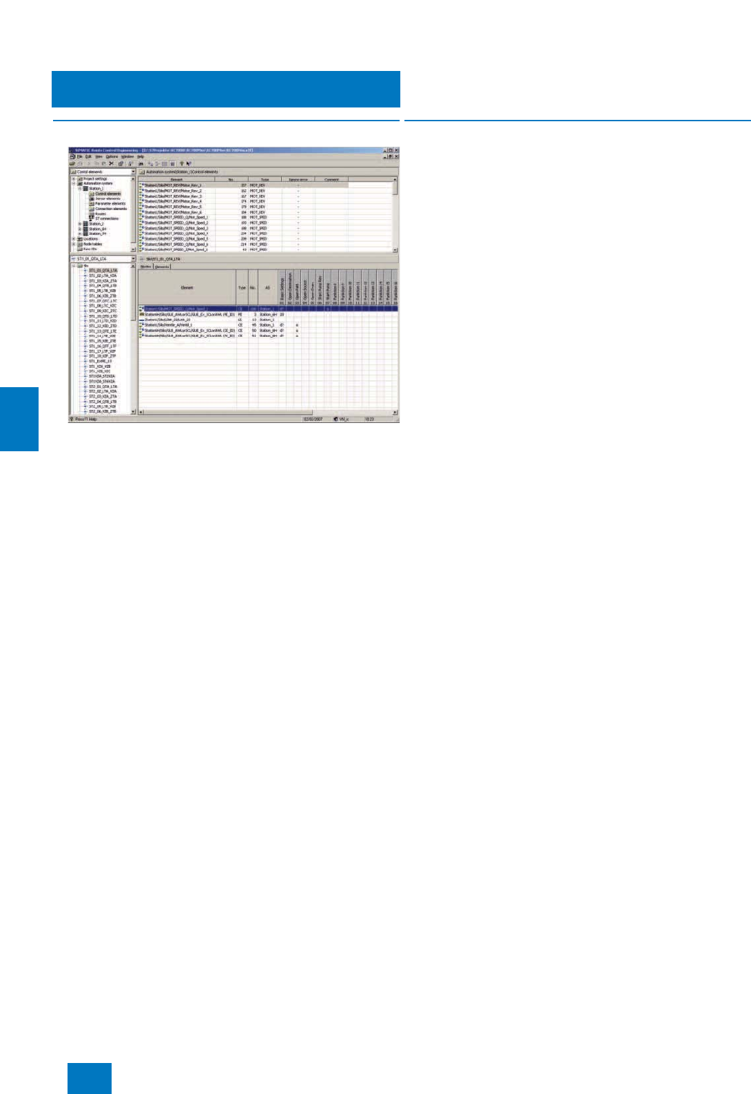
SIMATIC Route Control
Route Control engineering software
7/8 Siemens ST PCS 7 · November 2007
7
■
Overview
The Route Control (RC) configuration supplements the basic
SIMATIC PCS 7 plant configuration with blocks from the PCS 7
standard library. Existing plants are then also easy to upgrade
with SIMATIC Route Control. Technological elements of rele-
vance for control of the material transport (RC elements) are
adapted in the CFC Editor using uniform interface blocks from
the Route Control Library. The RC elements include:
• Control elements (actuators)
• Sensor elements (sensors)
• Parameter elements (setpoints)
• Connection elements (material information related to partial
route)
■
Function
Locations of partial or complete routes are configured in the-
SIMATIC Manager as "Equipment properties of plant units" and
transferred to the RC project together with the other RC-relevant
basic data of the SIMATIC PCS 7 project. The configuration re-
quirements caused by many repeated sequences can be mini-
mized by exporting locations in CSV format, duplicating and
modifying them using a spreadsheet program, and then import-
ing them again.
Locations (synonym: nodes) are parameters for requesting a
material transport (source, destination, intermediate loca-
tions/via) and which mark the start and end of each partial route,
and thus also the source and destination of a material transport.
In addition to the basic tools (SIMATIC Manager, CFC, etc.) of
the SIMATIC PCS 7 engineering system, the following configura-
tion components of the SIMATIC Route Control Engineering pro-
gram package are available for configuration of the route control
applications:
Route Control library
The Route Control library contains blocks for RC and transport
route configuration and interface blocks for RC elements. It is
provided in the catalog of the CFC editor.
Route Control wizard
The Route Control wizard is the interface between the SIMATIC
PCS 7 basic configuration supplemented with RC interface
blocks and the actual RC configuration in the RC engineering
tool. The wizard, which can be called up from the SIMATIC Man-
ager menu, accepts the RC-specific configuration data of the
SIMATIC PCS 7 project into the Route Control engineering. In
doing so, it carries out plausibility checks, defines the AS-OS
and AS-AS communication connections (NetPro and CFC), and
configures the RC server signals.
Route Control Engineering tool
Following importing of the basic data of a SIMATIC PCS 7 project
relevant to the RC into an RC project, the RC-specific objects are
configured using the Route Control Engineering tool:
• Partial routes:
division of the transport paths into partial routes is used to in-
crease the flexibility and minimize the configuring overhead
by means of repeated application. Relevant partial route pa-
rameters: "bidirectional" and "priority" (lowest total of partial
route priorities is decisive when searching for the overall
route).
• Interconnections:
Through inclusion in a partial route, the RC elements receive
additional properties depending on the type, and these can
be edited using configuration dialogs (e.g. in the basic set-
ting: "close valve").
• Function catalogs:
The partial routes can be assigned to function catalogs de-
pending on technological and product-specific aspects, e.g.
"cleaning" or "product transport". In the route search, function
catalogs permit restriction of the resulting quantity to the type
of material transport.
• Function steps/sequence functions:
Function catalogs contain as many as 32 configurable techno-
logical sequence functions which define the sequence of ma-
terial transport by means of the RC elements connected in the
partial routes, e.g. base position of the control elements, open
transport valves, open origin valve, switch on pump).
© Siemens AG 2007

SIMATIC Route Control
Route Control engineering software
7/9
Siemens ST PCS 7 · November 2007
7
Configuration of the partial routes and assignment of the RC el-
ements to the partial routes are performed in a matrix of the
Route Control Engineering tool. With the aid of generic elements,
objects or blocks generated on a user-specific basis can be in-
tegrated into the RC project and handled like RC elements.
Special configuration functions make it easier to perform repeti-
tive routine work and extend the range of options for controlling
material transport, e.g.:
• Exporting configuration data in the form of CSV files to
Microsoft Excel, copying and editing the data there, and then
re-importing the files into Route Control
• Controlling the joint use of partial routes by configurable func-
tion IDs
• Checking material compatibilities and interlocking partial
routes in case of incompatible material sequences based on
the material ID saved in the connection element of the partial
route
• Injection of dynamic (external) setpoints coming from the pro-
cess at runtime into the route block (e.g. weighed quantity)
■
Selection and Ordering Data Order No.
SIMATIC Route Control
Engineering V7.0
6 languages (German, English,
French, Italian, Spanish, Chinese),
executes with Windows
XP Professional or Windows
Server 2003
Type of delivery: License key
disk, emergency key disk (not
with rental license), certificate of
license, terms and conditions
• Floating license for 1 user 6ES7 658-7DX07-0YB5
• Rental license for 30 days 6ES7 658-7DX07-0YB6
© Siemens AG 2007

SIMATIC Route Control
7/10 Siemens ST PCS 7 · November 2007
7
© Siemens AG 2007

Asset Management
Introduction
8/2 Siemens ST PCS 7 · November 2007
8
■
Overview
The PCS 7 Asset Management supplements SIMATIC PCS 7 by
a valuable instrument for minimization of the total cost of owner-
ship of a plant.
Asset management for plant engineering is understood to be the
administration and management of the plant equipment, partic-
ularly the I&C equipment, as well as all activities and measures
which serve to retain or increase the value of a plant. These pri-
marily include:
• Corrective maintenance
Reaction to existing fault and diagnostics messages
• Preventive maintenance
Preventive diagnostics and maintenance
• Predictive maintenance
Predictive maintenance and diagnostics
■
Function
Maintenance functions and information are frequently only avail-
able in a separate level independent of the production. Parallel
to process control, SIMATIC PCS 7 with the integral asset man-
agement system also provides uniform maintenance information
and functions in the process control system for the system com-
ponents of the plant (assets). Supplementary hardware or soft-
ware tools for asset management functions are therefore super-
fluous.
Whereas the plant operator receives all information relevant to
the process via the operator system and can specifically access
the process, the maintenance engineer checks the hardware of
the automation plant via the maintenance station, and processes
its diagnostics messages and maintenance requests.
When implementing the SIMATIC PCS 7 asset management,
consistent attention was paid to the conformity with international
standards, specifications and recommendations. SIMATIC
PCS 7 asset management takes into account e.g. the NAMUR
requirements (process control standards committee in the
chemical and pharmaceutical industries) defined in the follow-
ing documents for systems for asset management at plant level
and for status messages from field devices:
• NAMUR recommendation NE91 (requirements for systems for
asset management at plant level)
• NAMUR recommendation NE 105 (requirements for the inte-
gration of fieldbus devices in engineering tools)
• NAMUR recommendation NE107 (status messages "Device
failure", "Maintenance requirements", "Function check" from
field devices).
In addition, it observes the IEC 61804-2 for describing devices
by means of the Electronic Device Description Language
(EDDL) and specifications made by the PROFIBUS & PROFINET
International (PI) organization, e.g.:
• PROFIBUS Profile Guidelines Identification & Maintenance
Functions
• PROFIBUS PA Profile for Process Control Devices
■
Integration
The SIMATIC PCS 7 Asset Management is integrated seam-
lessly into the SIMATIC PCS 7 process control system as a sec-
tor-independent software package. It consistently uses the hard-
ware and software components of the engineering system and
operator system.
The system interface for maintenance engineers is the mainte-
nance station based on the engineering system (for details, see
the next Section "Maintenance station").
■
Configuration
The PCS 7 Asset Management is based on the hardware and
software project of the application which is generated during the
standard configuration with the SIMATIC PCS 7 engineering sys-
tem. Supported by the system, all data relevant to the PCS 7 as-
set management are derived from the project data of the appli-
cation simply by pressing a button, and the diagnostics displays
are also generated.
The procedure is simple, and no additional overhead is required
for the asset management. It can be summarized as follows:
• Generation of the hardware and software project of the appli-
cation
• System-supported generation of the diagnostics displays with
all components present in the project, including the display hi-
erarchy, according to the project’s hardware structure. The
names of the displays, symbols etc. imported from the project
can be changed by users according to personal requirements
or depending on project-specific features. These modifica-
tions are retained during further operations
• Compilation of the configuration data, and downloading to the
operator station and maintenance station with subsequent test
and commissioning phase.
Automation
Enterprise Resource
Planning
(ERP level)
Enterprise Asset
Management
System
MES
Maintenance
Operations
Plant
Asset
Management
Controls
(Process
and field level)
Manufacturing
Execution Systems
(MES level)
Maintenance
© Siemens AG 2007
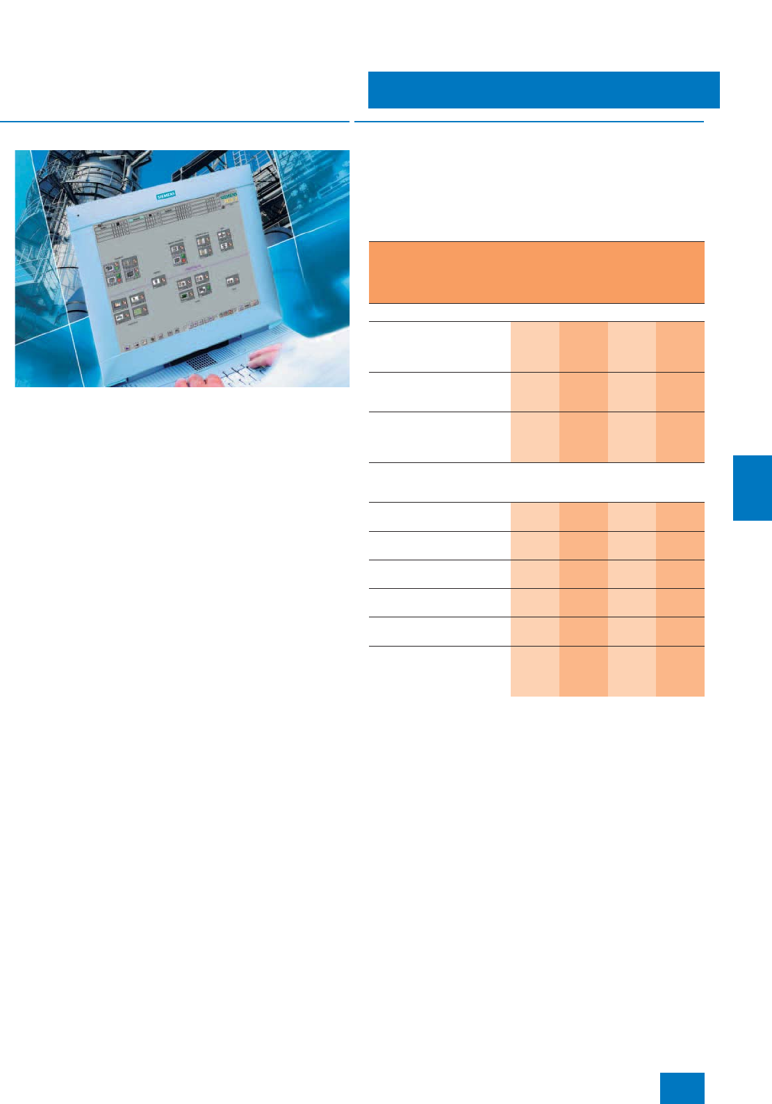
Asset Management
Maintenance station
8/3
Siemens ST PCS 7 · November 2007
8
■
Overview
The maintenance engineer can process the diagnostics mes-
sages and maintenance requests of the assets on the mainte-
nance station. Via the maintenance station the engineer can ac-
cess:
• Components of the process control system, e.g. intelligent
field devices and I/O modules, fieldbus, controller, network
components and plant bus as well as servers and clients of
the operator systems
• Assets that do not belong directly to the process control sys-
tem, such as pumps, motors, centrifuges, heat exchangers or
control loops (passive or indirect assets). These are repre-
sented by proxy objects in which the diagnostics rules are
stored.
The maintenance station for PCS 7 asset management uses
hardware and software components of the engineering system
and operator system. As a result of the close interlacing, ES, OS
and asset management functions execute on common hard-
ware. Such a multi-functional station cannot only be used for as-
set management, but also for system engineering or HMI.
The message system, user desktop, display hierarchy and oper-
ator prompting are oriented according to the HMI philosophy of
the operator system. The diagnostics data of all assets are dis-
played on uniform faceplates whose contents depend on the in-
telligence of the respective component. This means that working
with the maintenance station is simple and intuitive – complex fa-
miliarization is not required.
The diagnostics displays structured according to the plant hier-
archy with the operating states of all PCS 7 components can be
displayed on the maintenance station and also on an OS client.
However, enhanced online diagnostics functions in conjunction
with HW-Config or SIMATIC PDM can only be called from the
maintenance station.
The user management and access control for the maintenance
station accept the SIMATIC Logon integrated in SIMATIC PCS 7.
■
Design
Depending on the architecture of the SIMATIC PCS 7 plant, the
maintenance station can be implemented based on a SIMATIC
PCS 7 BOX RTX/416, PCS 7 single station or client/server com-
bination.
The following table shows possible hardware/software configu-
rations of the maintenance station (MS).
Two MS servers can also be operated as a redundant pair of
servers. The redundant MS servers must be configured like re-
dundant OS servers and expanded by the SIMATIC PCS 7 Asset
Runtime software.
The SIMATIC PCS 7 Asset Runtime basic package already con-
tains 100 asset TAGs. These can be expanded by cumulative
SIMATIC PCS 7 Asset Runtime licenses for 10, 100 or
1000 asset TAGs (Count Relevant Licenses).
Required SIMATIC PCS 7
hardware/software SIMATIC
PCS 7
BOX
RTX/416
SIMATIC
PCS 7
ES
single
station
MS/ES
client MS
server
Basic hardware
SIMATIC PCS 7
BOX RTX/416 all-in-one
system (Windows XP
operating system)
n
SIMATIC PCS 7 ES/OS 547B
BCE/IE WXP (Windows XP
operating system)
n n
SIMATIC PCS 7 OS Server
547B BCE/IE SRV03
(Windows Server 2003
operating system)
n
Required SIMATIC PCS 7 software corresponding to operating
system or basic hardware
(without taking into account the quantity frameworks)
SIMATIC PCS 7 Engineering
Software V7.0 AS/OS n n
SIMATIC PDM PCS 7 V6.0
SP2 HF1 or higher n n n
SIMATIC PCS 7 OS Software
Server V7.0
n
SIMATIC PCS 7 OS Software
Client V7.0 n
SIMATIC PCS 7 Asset
Engineering V7.0 n n n
SIMATIC PCS 7 Asset
Runtime V7.0
(basic package and
additional asset TAGs)
n n n
© Siemens AG 2007
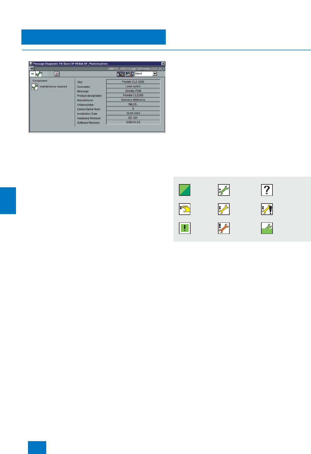
Asset Management
Maintenance station
8/4 Siemens ST PCS 7 · November 2007
8
■
Function
Diagnostics message of a component in the faceplate view "Identity"
The maintenance station provides comprehensive maintenance
information for the system components of the plant (assets). In
order to obtain information on the diagnostics status of individual
plant areas or components, maintenance engineers can change
from the overview display to the respective diagnostics display
of the subordinate hardware level. If a fault is signaled in the
overview display, the "loop in alarm" function permits rapid
switching to the diagnostics faceplate of the associated compo-
nent.
The scope of information available depends on the individual
possibilities of the asset, and is filtered according to the user’s
area of responsibility.
The following information is available:
• Display of diagnostics status determined by the system
• Information on components such as tag name, vendor or se-
rial number
• Display of diagnostics messages of a component
• Visualization of type and current state of initiated maintenance
measure
Information on passive or indirect assets
For passive or indirect assets (pumps, motors, control loops
etc.) without self-diagnostics, you can use the programmable
logic block AssetMon to derive inadmissible operating states
from various measured values and their deviations from a de-
fined normal status and to display them as a maintenance alarm
on the maintenance station. AssetMon is able to process up to
3 analog values and up to 16 binary values.
With the aid of the AssetMon, individual diagnostics structures,
project-specific diagnostics rules and condition monitoring
functions can also be implemented.
Enhanced information for assets according to IEC 61804-2
Further information can be called for assets described by the
electronic device description (EDD) according to IEC 61804-2.
This information is automatically read out of the components and
made available by SIMATIC PDM in the background.
• Detailed diagnostics information
- Device-specific information from the vendor
- Information on fault diagnostics and troubleshooting
- Additional documentation
• Results of internal condition monitoring functions
• Status information (e.g. local operation, local configuration
changes)
• Display of modification logbook (audit trail) of the component
with all entries on the persons, times and types of operator in-
tervention on the component
• Parameter view of the assets (display of parameters saved in
the component and in the project; if required, also differences
between them)
Uniform symbols
Uniform symbols for visualization of the maintenance status and for HMI
on the maintenance station
A significant feature with visualization of the access manage-
ment functionality is the uniform symbols and texts for displaying
the statuses of all assets, i.e. for operator stations as well as for
network components, controllers or field devices. The asset
faceplates are also uniform. The amount of information dis-
played depends on the intelligence of the respective compo-
nent.
Gut
Simulation
Konfigura-
tionsände-
rung erkannt
Wartungs-
bedarf
(gering)
Wartungs-
anforderung
(mittel)
Wartungs-
alarm
(hoch)
Instandhaltungs-
Auftrag unbek./
nicht angefordert
Instandhaltungs-
Auftrag
angefordert
Instandhaltungs-
Auftrag
in Arbeit
© Siemens AG 2007

Asset Management
Maintenance station
8/5
Siemens ST PCS 7 · November 2007
8
Typical sequence of a maintenance cycle
• Intelligent sensors recognize the threat of failures by means of
the implemented diagnostics system long before the actual
failure, and can signal these.
• Diagnostics information on network components and basic
PC devices is transferred to the maintenance station via an
OPC SNMP link present in the assets.
• The symbol of the associated component (e.g. a field device)
signals "Maintenance required" on the maintenance station.
An entry is automatically made in the message log so that the
chronology of occurred events can also be analyzed later.
Parallel to this, the vendor’s detailed diagnostics information is
determined by means of SIMATIC PDM and the device de-
scription (EDD).
• On the overview display, maintenance engineers recognize
"Maintenance required" in the technological plant. The mainte-
nance engineers are rapidly guided to the corresponding de-
vice using standard mechanisms known from the operator sta-
tion such as "Common display" and "Operator prompting
using loop in alarm". Important information is then shown in the
faceplate of the associated device, e.g. process tag number,
location and device type.
• The existing detailed diagnostics information on the problem
can then be called using the "Diagnostics" view depending on
the device type and vendor, e.g. fault description, cause,
trend information or handling instructions.
• They can assess the fault in the "Maintenance" view, and ini-
tiate corresponding reactions. This can be e.g. the input of a
comment or handling instruction, the assignment of a work in-
struction number, or the increasing/decreasing of the mainte-
nance requirement priority depending on the significance for
the technological plant. Current working measures can also
be traced/accompanied in this view. All operations can be
logged. The log also contains the faceplate contents with ID
data, messages, detailed diagnostics information, work in-
structions, notes and status.
• The work request with all information gained on the mainte-
nance station is passed on to the corresponding maintenance
department (identified by symbol "Maintenance order re-
quested"). The release for maintenance of the component can
also be made on the maintenance station (identified by sym-
bol "Maintenance order being processed"). The current status
of the maintenance measure is then indicated for all involved
parties, and also for subsequent shifts.
• Once the maintenance measure has been carried out, it is
concluded on the maintenance station – the status displays
then return to the normal state. The complete maintenance cy-
cle is documented on the maintenance station without gaps –
automatically and without additional configuration overhead.
1) With asset TAGs, the number of asset objects monitored in SIMATIC PCS 7
is licensed. An asset object represents individual hardware components
within a SIMATIC PCS 7 project, e.g.
- measuring devices, positioners, switchgear or remote I/O stations
monitored per EDD or
- basic devices or Ethernet components monitored in the maintenance
station via an SNMP OPC link.
The asset TAGs of the SIMATIC PCS 7 Asset Runtime licenses (groups of
10, 100 and 1000) are cumulative (Count Relevant Licenses).
■
Selection and Ordering Data Order No.
SIMATIC PCS 7 Asset Runtime
Basic Package V7.0
including SNMP OPC server
license and 100 asset TAGs 1)
For installation on SIMATIC PCS 7
BOX RTX/416, single station or
server
6 languages (German, English,
French, Italian, Spanish, Chi-
nese), executes with Windows
XP Professional or Windows
Server 2003, single license for
1 installation
Type of delivery:
License key disk, certificate of
license, terms and conditions
6ES7 658-7GB07-0YB0
SIMATIC PCS 7 Asset Runtime
V7.0
for expansion of asset TAGs
6 languages (German, English,
French, Italian, Spanish, Chi-
nese), executes with Windows
XP Professional or Windows
Server 2003, single license for
1 installation
Type of delivery:
License key disk, certificate of
license, terms and conditions
•10 asset TAGs 6ES7 658-7GA07-2YB0
• 100 asset TAGs 6ES7 658-7GB07-2YB0
• 1000 asset TAGs 6ES7 658-7GC07-2YB0
Asset engineering
SIMATIC PCS 7 Asset
Engineering V7.0
For installation on SIMATIC PCS 7
BOX 416, single station or client
6 languages (German, English,
French, Italian, Spanish, Chi-
nese), executes with Windows
XP Professional / Server 2003,
floating license for 1 user
Type of delivery:
License key disk, emergency key
disk, certificate of license, terms
and conditions
6ES7 658-7GX07-0YB5
© Siemens AG 2007

Asset Management
8/6 Siemens ST PCS 7 · November 2007
8
© Siemens AG 2007
Siemens ST PCS 7 · November 2007
9/2 Introduction
9/3 Industrial Ethernet
9/3 Introduction
9/6 SCALANCE X Industrial Ethernet
switches
9/21 OSM/ESM/OMC Industrial Ethernet
switches
9/23 Passive network components:
FastConnect
9/25 Passive network components:
ITP cables and connectors
9/26 Passive network components:
Fiber-optic cables
9/28 System connection PCS 7 systems
9/30 Industrial Wireless LAN (IWLAN)
9/33 Industrial Security
9/33 Introduction
9/34 Industrial Security components
9/35 PROFIBUS
9/35 Introduction
PROFIBUS DP
9/36 Introduction
9/37 Electrical networks
9/39 Optical networks with
glass fiber-optic cables
9/40 Optical networks with
plastic fiber-optic cables
9/41 AS connection
9/42 Y-Link
PROFIBUS PA
9/43 Introduction
9/45 Routers: DP/PA link and DP/PA
coupler
9/49 Active field distributor AFD and
active field splitter AFS
9/50 FastConnect/SpliTConnect
9/51 Other communication
9/51 AS-Interface
9/52 Modbus
Communication
© Siemens AG 2007
Communication
Introduction
9/2 Siemens ST PCS 7 · November 2007
9
■
Overview
The SIMATIC NET network components based on globally es-
tablished standards provide SIMATIC PCS 7 with a powerful and
rugged range of products for implementing totally integrated
communications networks for reliable data exchange between
all system components and levels of a plant.
The SIMATIC NET products specially developed for industrial
applications are completely suitable for all types of plant in all in-
dustrial sectors. They are matched to one another and meet high
standards, especially in areas where they are subject to extreme
influences, such as
• interfering electromagnetic fields,
• corrosive liquids and atmospheres,
• explosion hazards,
• high mechanical loads.
The SIMATIC NET products guarantee expandability and safe-
guard investments through compatible further developments as
well as uniformity from incoming goods to outgoing goods and
from field devices up to the management information system.
■
Design
Incorporated in Totally Integrated Automation, the unique basis
offered by Siemens for uniform automation of all sectors in the
production, process or hybrid industries, the SIMATIC NET bus-
ses promote fast and reliable communication between the indi-
vidual systems/applications of the SIMATIC PCS 7 process con-
trol systems such as:
• Automation systems, distributed I/Os and field components
• Asset management/engineering system and operator system
• SIMATIC BATCH and SIMATIC Route Control
• Process control via Internet/intranet and IT applications.
Industrial Ethernet is used as the plant bus as well as OS-LAN
(terminal bus) for multi-user systems with client/server architec-
ture. For small systems, the "Basic Communication Ethernet"
(BCE) integrated in the SIMATIC PCS 7 Industrial Workstations
permits operation of single stations and servers on the plant bus
even without a CP 1613 communications processor.
In medium and large plants characterized by high requirements,
SIMATIC PCS 7 applies modern Gigabit and FastEthernet tech-
nology which combines the high security provided by redundant
optical rings with the scalable performance provided by switch-
ing technology and high transmission rates up to 1 Gbit/s.
PROFIBUS in the DP or PA version is used as the communica-
tions medium for interfacing intelligent distributed I/O devices,
transmitters and actuators to the controller level. The rugged
and reliable PROFIBUS is a universal, open fieldbus complying
with the IEC 61158 and IEC 61784 international standards. In the
PA version (which permits digital data transmission and power
supply for the field devices on a two-wire cable), or with a series-
connected isolating transformer (RS 485-iS coupler), it can be
routed intrinsically-safe into hazardous areas of Zone 1.
© Siemens AG 2007
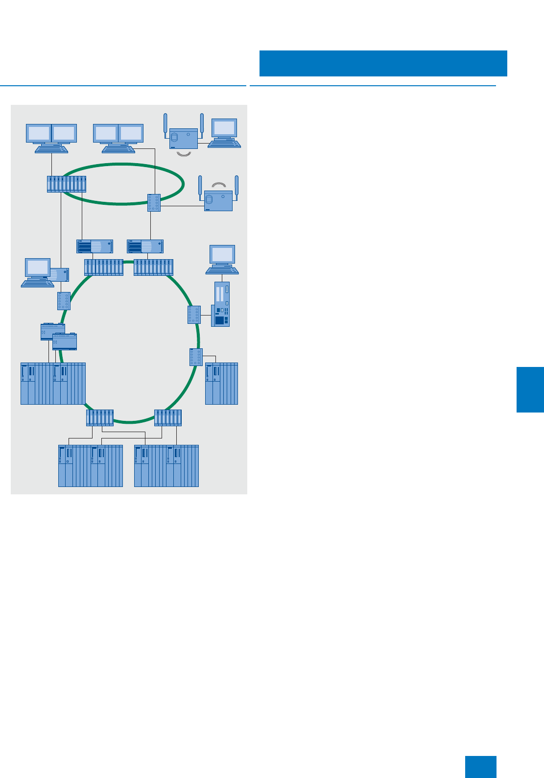
Communication
Industrial Ethernet
Introduction
9/3
Siemens ST PCS 7 · November 2007
9
■
Overview
Industrial Ethernet, connection examples
The plant bus and the OS-LAN (terminal bus) for multi-user
systems with client/server architecture are implemented with
Industrial Ethernet, a powerful area and cell network for indus-
trial applications in line with the international IEEE 802.3 stan-
dard (Ethernet). Bus structures with optical rings are particularly
suitable for this because of their high noise immunity and high
availability.
In medium-sized and large plants characterized by high
requirements, SIMATIC PCS 7 applies modern Gigabit and
FastEthernet technology. This combines the high reliability of op-
tical rings with the scalable performance of switching technol-
ogy and high transmission rates up to 1 Gbit/s.
■
Benefits
Ethernet currently has a market share of over 80% with a ten-
dency to rise further, thus placing it in pole position in the global
LAN landscape. Ethernet offers important characteristics that
can give you significant advantages for your application:
7Fast commissioning through simple connections
7High flexibility since existing networks can be extended with-
out any adverse effects
7High availability thanks to redundant network topologies
7Almost unlimited communications performance because scal-
able performance is available through switching technology if
required
7Networking of different application areas such as office and
production areas
7Investment protection through continuous and compatible fur-
ther development
7Plant-wide clock system permits exact assignment of events
within the complete plant
Ethernet technology for industrial environment
With Industrial Ethernet, SIMATIC NET expands the Ethernet
technology by special components and capabilities for use in in-
dustrial environments:
7Network components for tough industrial environments
7Fast local assembly using the FastConnect cabling system
with RJ45 technology
7Failsafe networks with fast switchover to redundant system
(≤300 ms)
7Continuous monitoring of network components through a sim-
ple yet effective signaling concept
7Future-oriented network components with the SCALANCE X
Ethernet product family
SIMATIC
PCS 7 BOX
AS 414/
AS 416/
AS 417
AS 412H/
AS 414H/
AS 417H
AS 412H/
AS 414H/
AS 417H
OSM/
ESM
SCALANCE
X-200/
X-200 IRT
SCALANCE
X-200/X-200 IRT
SCALANCE X-400
SCALANCE X-400
SCALANCE
X-400
SCALANCE
W788-1PRO
OS-LAN
(terminal bus,
optical/electrical)
OS clients
Plant bus
Industrial Ethernet
(optical/electrical)
Remote
client
Redundant
OS servers
Engineering
station
© Siemens AG 2007
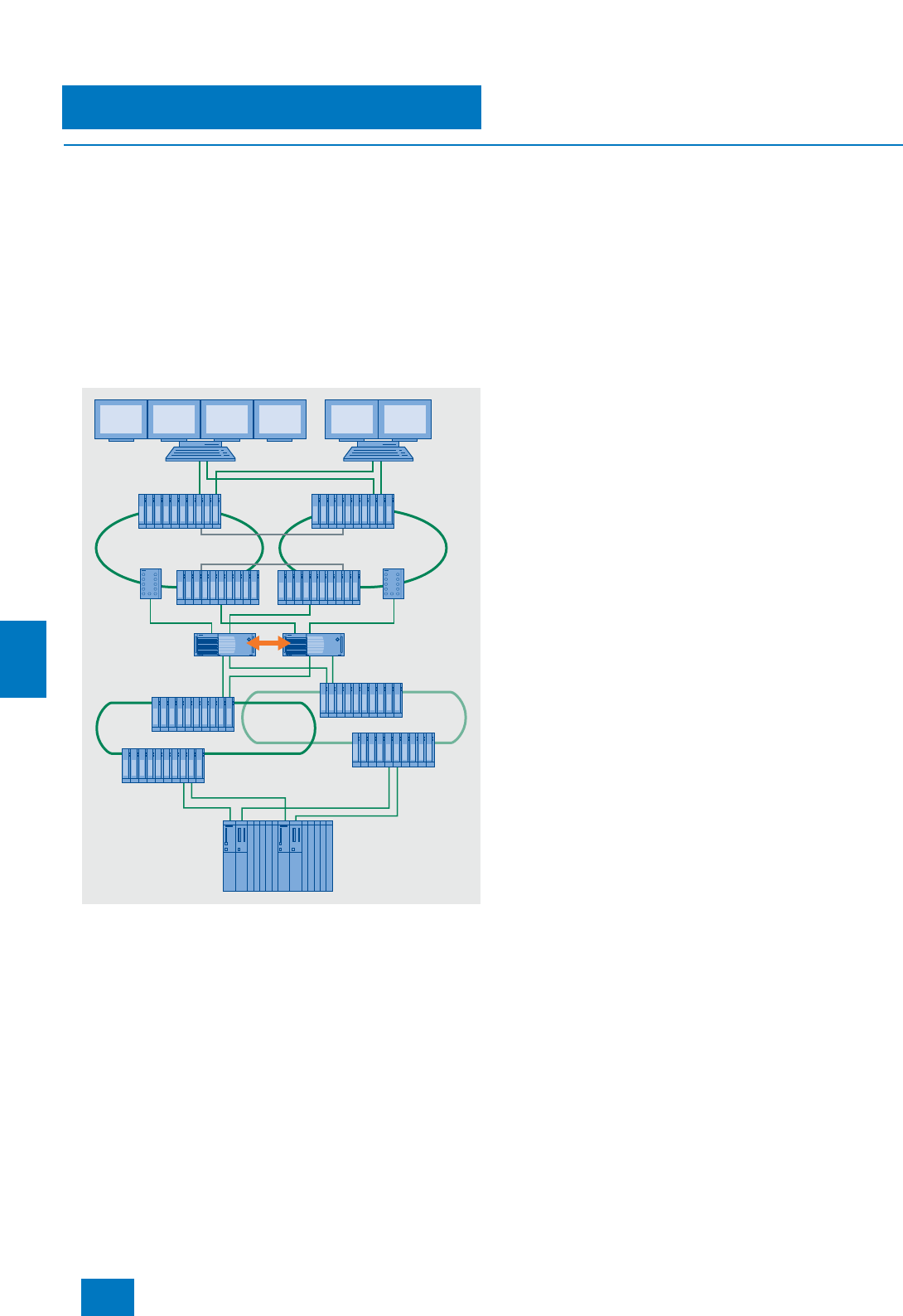
Communication
Industrial Ethernet
Introduction
9/4 Siemens ST PCS 7 · November 2007
9
■
Design
In the various SIMATIC PCS 7 subsystems (ES, OS, AS etc.) on-
board interface modules, simple network cards or special com-
munications processors (e.g. CP 1613) are used as communica-
tion interfaces. These are defined when selecting the respective
system components depending on the requirements (for further
information, refer to page 9/28).
The communication nodes are integrated into the bus with the
aid of Industrial Ethernet switches. The modern Industrial Ether-
net switches from the SCALANCE X range are to be recom-
mended in particular. These offer scalable performance at an
attractive price and support a wide variety of possible configu-
rations. Further alternatives result by using the tried and tested
ESM and OSM switches.
Example configuration with plant bus and OS LAN with two redundant
rings
OS LAN (terminal bus)
Client-server and server-server communication is carried out on
a dedicated Ethernet LAN. The communication network identi-
fied as OS LAN or terminal bus can be implemented with stan-
dard SIMATIC NET components such as switches, onboard in-
terfaces, network cards, communications processors (CP),
cables etc.
A ring design avoids communication failures if e.g. the line is
damaged or opened at a particular point. To increase the avail-
ability even further, the OS LAN can also be distributed redun-
dantly between two rings which are connected together by two
pairs of switches (see example configuration). The switches
from the SCALANCE X-400, X-300 and X-200 IRT ranges have
the standby redundancy function required for this. Each of the
redundant servers and clients can then be connected to both
rings via two separate interface modules (redundant terminal
bus adapter package). Communication is as standard on ring 1.
Communication on ring 2 is only activated in the event of a fault
on ring 1 which is relevant to the redundant switchover.
Industrial Ethernet plant bus
The automation systems (AS) communicate with one another
and with the engineering system and operator systems (serv-
ers/single stations) over the Industrial Ethernet plant bus. This
can be designed analogous to the OS LAN with standard
SIMATIC NET components such as switches, network cards,
communications processors (CP), cables etc. In the case of
small plants with up to 8 standard automation systems per oper-
ator system, single stations and servers can be operated cost-
effectively on the plant bus using "Basic Communication Ether-
net" (BCE) and a FastEthernet network card. The CP 1613 com-
munications processor is always required if more than 8 stan-
dard automation systems or fault-tolerant automation systems
are used.
As far as availability is concerned, ring topologies are always the
first choice for the plant bus. With particularly high availability re-
quirements, the plant bus can also be configured as a redundant
double ring (two CPs per AS CPU and OS server). Double faults
such as a switch failure on ring 1 with a simultaneous interruption
in the bus cable on ring 2 can then be tolerated. The two rings in
such a configuration are physically separated. The coupling
partners are linked together logically when configuring with
NetPro over a fault-tolerant S7 connection (4-way redundancy).
One switch each takes over the function of the redundancy man-
ager for each ring. The current switches of the SCALANCE
X-400, X-300, X-200 IRT and X-200 ranges can be used as the
redundancy manager in a ring.
Note:
Detailed information on Industrial Ethernet and on the network compo-
nents can be found in Catalog IK PI, in the A&D Mall, or in Catalog CA 01
under "Communication/Networks/SIMATIC NET communication sys-
tems".
AS 412H/
AS 414H/
AS 417H
Client Client
OS-LAN (Ethernet), ring 1 OS-LAN (Ethernet), ring 2
Redundant servers
Redundant Industrial Ethernet
plant bus (double ring)
© Siemens AG 2007

Communication
Industrial Ethernet
Introduction
9/5
Siemens ST PCS 7 · November 2007
9
■
Function
Decision aid for Industrial Ethernet switches
Different types of switches can be used for the Industrial Ether-
net communication within the SIMATIC PCS 7 process control
system. In addition to the OSM/ESM switches, these are cur-
rently the following switches:
In order to support you when selecting, the following list shows
important properties of the various switch ranges.
SCALANCE X-400
71-Gbit ports and 100-Mbit ports (optical/electrical, number
and version depend on device)
7Modular design for flexible electrical or optical Industrial
Ethernet networks; variable network topology, type and num-
ber of ports (retrofitting of optical ports, extension by 8 further
ports with X414-3E)
7Digital inputs
7Redundant 24 V DC supply
7Redundancy manager for the ring
7Standby redundancy (redundant connection between two
rings)
7Many ports at one central position in the control cabinet
7IP20 protection
7Electrical 100-Mbit ports with collar for FastConnect cabling
system
7Router functionality (X414-3E; connection of two subnets)
7Support of office standards such as virtual LANs incl. priority
assignment (port-based VLANs), Rapid Spanning Tree
(RSTP), Simple Network Management Protocol (SNMP) or IP
Multicast filtering (e.g. for video applications) permits integra-
tion of automation networks into company networks
7Configuration of MAC address filters
7Slot numbering and labeling strips
7Option: C-PLUG swap medium for simple replacement of de-
vices in event of fault
SCALANCE X-300
7Compact design
7IP30 protection
7Gigabit ports and FastEthernet ports (optical/electrical; ver-
sion depends on device)
710 ports (3 x Gigabit and 7 x FastEthernet)
7Redundant 24 V DC supply
7Redundancy manager for the ring
7Standby redundancy between two rings
7Variable assembly (DIN rail, SIMATIC rail, horizontal and verti-
cal wall mounting)
7Electrical ports with collar for FastConnect cabling system
7Option: C-PLUG swap medium for simple replacement of de-
vices in event of fault
SCALANCE X-200 IRT
7Compact design
7IP30 protection
7100-Mbit ports (electrical/optical; number and version depend
on device)
7Max. 4 ports
7Redundant 24 V DC supply
7Redundancy manager for the ring
7Standby redundancy between two rings
7Variable assembly (DIN rail, SIMATIC rail, horizontal and verti-
cal wall mounting)
7Electrical ports with collar for FastConnect cabling system
7Option: C-PLUG swap medium for simple replacement of de-
vices in event of fault
SCALANCE X-200
7Compact design
7IP30 protection
7100-Mbit ports (electrical/optical; number and version depend
on device)
76 to 24 ports
7Redundant 24 V DC supply
7Redundancy manager for the ring
7Variable assembly (DIN rail, SIMATIC rail, horizontal and verti-
cal wall mounting)
7Electrical ports with collar for FastConnect cabling system
7Operation of SCALANCE X208 in temperature range from
-20to +70°C
7Option: C-PLUG swap medium for simple replacement of de-
vices in event of fault
OSM/ESM
7Standby redundancy between two rings
7Redundancy manager for the ring
7Digital inputs
7Configuration of MAC address filtersand had
■
Technical specifications
SCALANCE X
range Switches
X-400 SCALANCE X414-3E and X408-2
X-300 SCALANCE X308-2, X308-2LD and X310
X-200 SCALANCE X224, X216, X208, X212-2, X212-2LD,
X204-2 and X206-1LD
X-200 IRT SCALANCE X204 IRT, X202-2 IRT, X202-2P IRT,
X201-3P IRT and X200-4P IRT
Plant bus / OS-LAN Industrial Ethernet
Number of stations 1,023 per network segment
(IEEE 802.3 standard)
Number of switches Up to 50
Length of the network
• Local network Electrical: up to approx. 5 km
Optical: up to approx. 150 km
•WAN Worldwide with TCP/IP
Topol ogy Line, tree, ring, star
© Siemens AG 2007
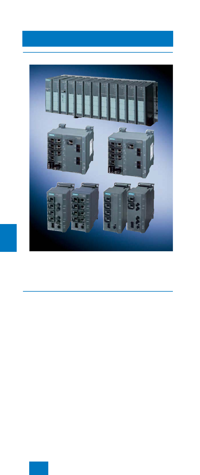
Communication
Industrial Ethernet
SCALANCE X Industrial Ethernet switches
9/6 Siemens ST PCS 7 · November 2007
9
■
Overview
Switches are active network components that specifically dis-
tribute data to the relevant addressees. SCALANCE X is the
modern range of Industrial Ethernet switches from SIMATIC NET.
The SCALANCE X family comprises product lines that comple-
ment each other and are carefully tuned to the specific automa-
tion task.
■
Application
The products referred to below from the SCALANCE X-400,
X-300, X-200 IRT and X-200 ranges are suitable for use in
SIMATIC PCS 7 systems.
SCALANCE X-400
SCALANCE X-400 switches are suitable for designing a plant
bus and OS-LAN (terminal bus) with an electrical or optical
Gigabit ring technology (non-redundant and redundant rings).
• SCALANCE X414-3E with 2 Gigabit Ethernet ports (electri-
cal/optical), 12 electrical FastEthernet ports and optionally
4 optical FastEthernet ports (BFOC); can be expanded by ex-
tender module with 8 electrical or 8 optical FastEthernet ports
(BFOC)
• SCALANCE X408-2 with 4 Gigabit Ethernet ports (electrical/
optical) and 4 FastEthernet ports (electrical/optical)
Both versions permit a maximum communications performance,
in particular with very large plants with comprehensive quantity
frameworks and expansive communication networks.
SCALANCE X-300
SCALANCE X-300 switches can be used to implement Industrial
Ethernet structures with a line, star or ring topology (non-redun-
dant and redundant rings) with transmission rates up to
1000 Mbit/s.
• SCALANCE X310 with 3 electrical Gigabit Ethernet RJ45 ports
and 7 electrical FastEthernet RJ45 ports
• SCALANCE X308-2 with 2 optical Gigabit Ethernet SC ports
for glass multimode FO cables, 1 electrical Gigabit Ethernet
RJ45 port and 7 electrical FastEthernet RJ45 ports
• SCALANCE X308-2LD with 2 optical Gigabit Ethernet SC
ports for glass multimode FO cables, 1 electrical Gigabit
Ethernet RJ45 port and 7 electrical FastEthernet RJ45 ports
SCALANCE X-200 IRT
SCALANCE X-200 IRT switches are used for Industrial Ethernet
structures with a line, star or ring topology (non-redundant and
redundant rings) with transmission rates up to 100 Mbit/s.
• SCALANCE X204 IRT with 4 electrical RJ45 ports
• SCALANCE X202-2 IRT with 2 electrical RJ45 ports and
2 optical BFOC ports for glass multimode FO cables
• SCALANCE X202-2P IRT with 2 electrical RJ45 ports and
2 POF (polymer optical fiber) ports
• SCALANCE X201-3P IRT with 1 electrical RJ45 port and
3POF ports
• SCALANCE X200-4P IRT with 4 POF ports
SCALANCE X-200
SCALANCE X-200 switches are suitable for Industrial Ethernet
structures with a line, star or ring topology with transmission
rates up to 100 Mbit/s (non-redundant and redundant rings).
However, they do not have a standby redundancy functionality
(see table with product characteristics).
• SCALANCE X208 with 8 electrical RJ45 ports
• SCALANCE X204-2 with 2 optical glass FO ports and
4 electrical RJ45 ports
• SCALANCE X224 with 24 electrical RJ45 ports
• SCALANCE X216 with 16 electrical RJ45 ports
• SCALANCE X208 with 8 electrical RJ45 ports
• SCALANCE X204-2 with 4 electrical RJ45 ports and 2 optical
BFOC ports for glass multimode FO cables
• SCALANCE X212-2 with 12 electrical RJ45 ports and 2 optical
BFOC ports for glass multimode FO cables
• SCALANCE X212-2LD with 12 electrical RJ45 ports and
2 optical BFOC ports for glass singlemode FO cables
• SCALANCE X206-1LD with 6 electrical RJ45 ports and
1 optical BFOC port for glass singlemode FO cables
© Siemens AG 2007
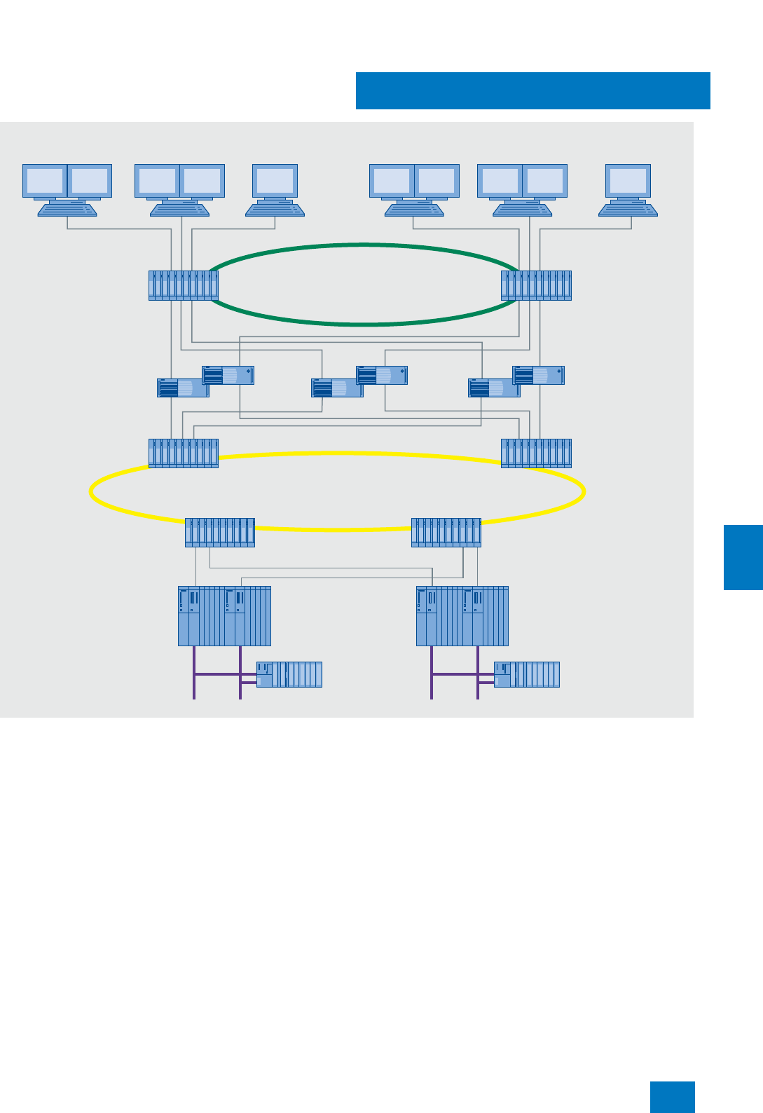
Communication
Industrial Ethernet
SCALANCE X Industrial Ethernet switches
9/7
Siemens ST PCS 7 · November 2007
9
Example of the use of SCALANCE X414-3E switches in the SIMATIC PCS 7 process control system
Switch
SCALANCE
X414-3E
ET 200M
Switch
SCALANCE
X414-3E
Switch
SCALANCE
X414-3E
PROFIBUS
ET 200M
PROFIBUS
Switch
SCALANCE
X414-3E
Switch
SCALANCE
X414-3E
Switch
SCALANCE
X414-3E
SIMATIC IT SIMATIC BATCHOperator Station
AS 414H/AS 417H
redundant controller
OS Server
(redundant)
1 Gbit/s terminal bus
1 Gbit/s plant bus
Engineering StationOperator Station Operator Station
© Siemens AG 2007
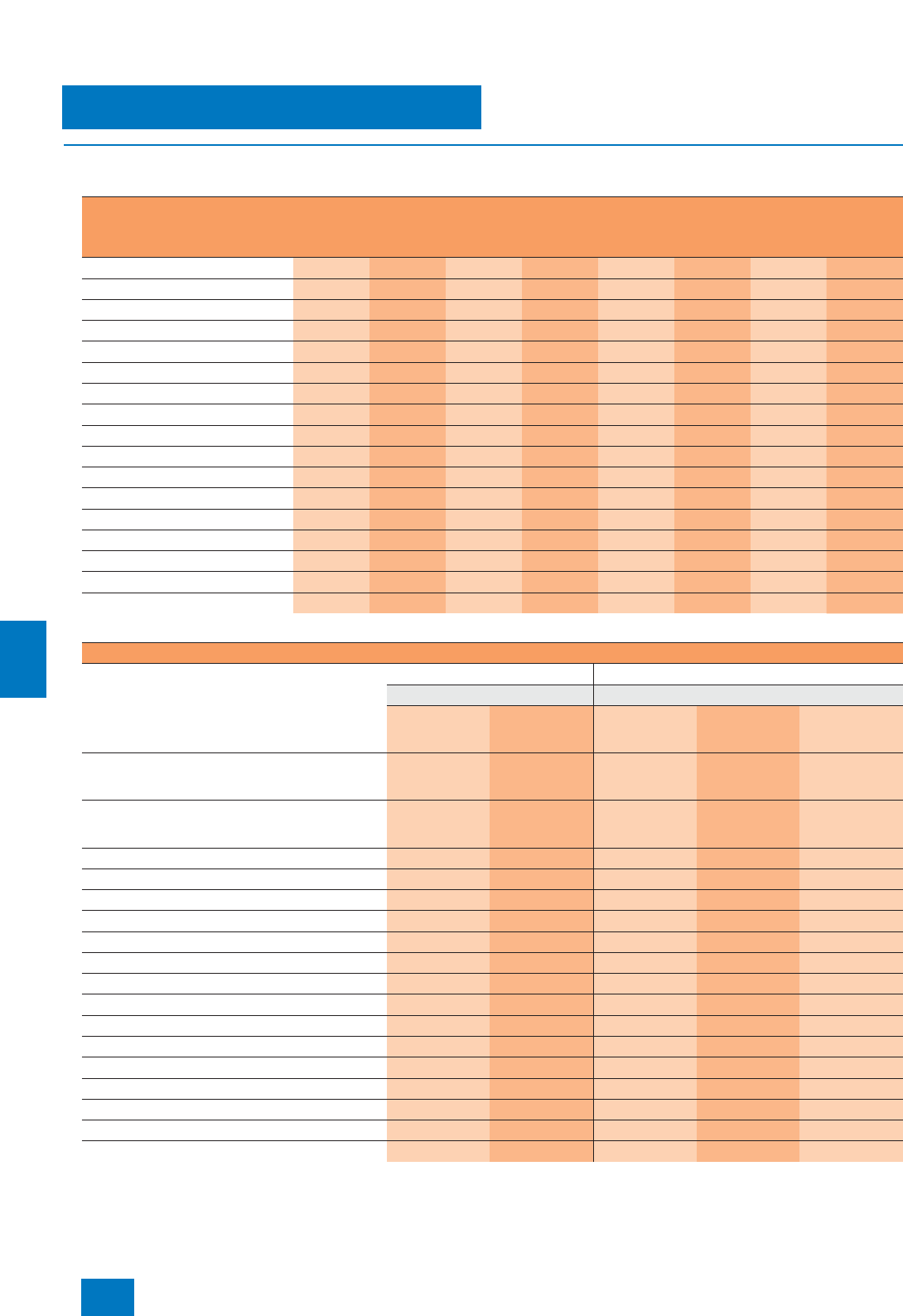
Communication
Industrial Ethernet
SCALANCE X Industrial Ethernet switches
9/8 Siemens ST PCS 7 · November 2007
9
■
Design
Product characteristics
Summary of interfaces
1) With additional EM495-8 extender module
2) 2 additive plug-on media modules
3) With EM496-4 extender module and 4 plug-on media modules additive to 2)
Features X414-3E X408-2 X310,
X308-2,
X308-2LD
X204 IRT,
X202-2 IRT,
X202-2P
IRT
X201-3P
IRT,
X200-4P
IRT
X224,
X216 X212-2,
X212-2LD X208,
X206-1LD,
X204-2
Compact enclosure • • • • • •
LED diagnostics • • • • • • • •
SIMATIC world • • • • • • • •
2 x 24 V DC • • • • • • • •
Signaling contact • • • • • • • •
Local display (set button) • • • • • • • •
Diagnostics: Web, SNMP • • • • • • • •
PROFINET diagnostics • • • • • • • •
C-PLUG • • • • • • • •
Ring redundancy with RM • • • • • • • •
Standby redundancy • • • • •
IRT capability • •
Gigabit technology •••
Modular design • •
Digital inputs 8
IT features (VLAN, RSTP, IGMP, ...) •••
Layer 3 switching (IP routing) •
Module type Type and number of ports
Gigabit Ethernet 1000 Mbit/s Fast Ethernet 100 Mbit/s
Electrical (TP) Optical (FO) Electrical (TP) Optical (FO)
RJ45 socket SC socket RJ45 socket Plastic FO: (POF/
PCF)
SC RJ socket
Glass FO:
ST socket (BFOC
connection)
X414-3E
(Gigabit ports either optical or electrical) 22 (multimode or
singlemode) 12 / 201) – 42) / 123)
(multimode or
singlemode)
X408-2
(Gigabit and FastEthernet ports each either optical or
electrical)
44 (multimode or
singlemode) 4 – 42)(multimode or
singlemode)
X310 3 – 7 – –
X308-2 12 (multimode) 7 – –
X308-2LD 12 (singlemode) 7 – –
X204 IRT – – 4 – –
X202-2 IRT (optical and electrical ports additive) – – 2 – 2 (multimode)
X202-2P IRT (optical and electrical ports additive) – – 2 2 –
X201-3P IRT (optical and electrical ports additive) – – 1 3 –
X200-4P IRT – – – 4 –
X224 – – 24 – –
X216 – – 16 – –
X212-2 – – 12 –2 (multimode)
X212-2LD – – 12 –2 (singlemode)
X208 – – 8 – –
X206-1LD – – 6 – 1 (singlemode)
X204-2 (optical and electrical ports additive) – – 4 – 2 (multimode)
© Siemens AG 2007
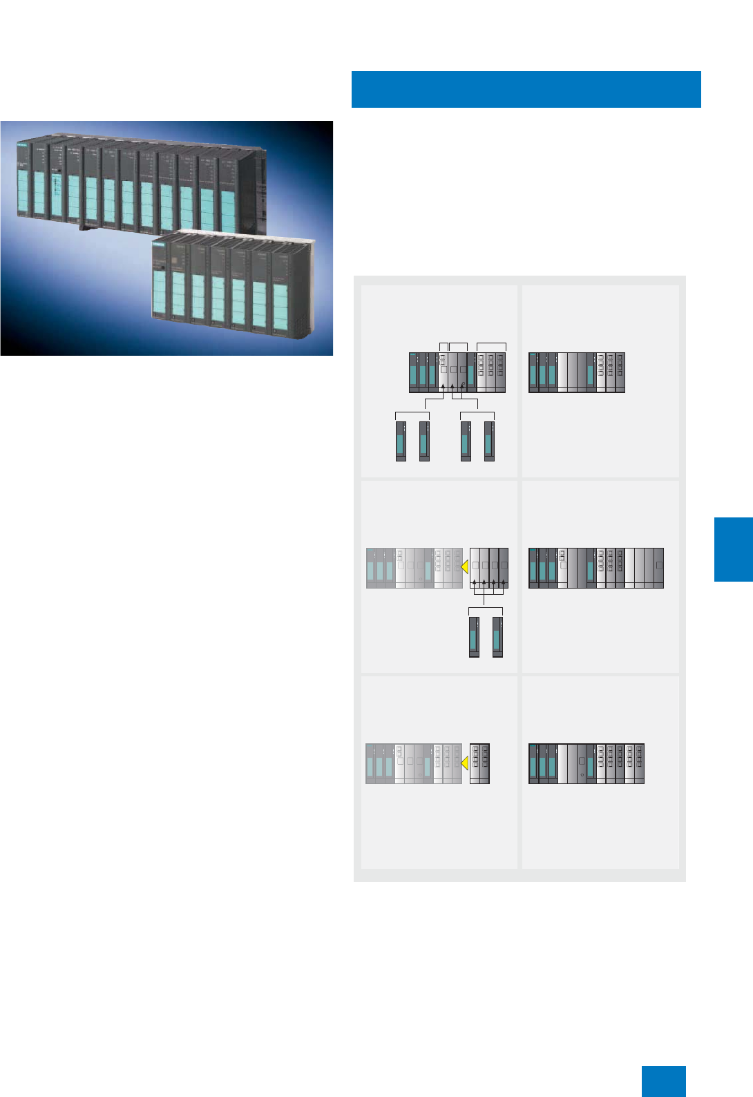
Communication
Industrial Ethernet
SCALANCE X Industrial Ethernet switches
9/9
Siemens ST PCS 7 · November 2007
9
SCALANCE X414-3E and X408-2
• Modular switches with IP20 protection for installation in control
cabinets; can be combined with media modules (X414-3E and
X408-2) and extenders (only X414-3E)
• Mounting possibilities: SIMATIC S7-300 rail or 35 mm DIN rail
• Redundant 24 V DC supply
• 10/100/1000 Mbit/s technology for different transmission me-
dia (8-core electric, twisted-pair or fiber-optic, multimode/
singlemode)
• Two (X414-3E) or four (X408-2) integral Gigabit Ethernet
twisted-pair interfaces (10/100/1000 Mbit/s, RJ45 sockets) for
connecting several switches together
• Node connection via 12 (X414-3E) or 4 (X408-2) Fast Ethernet
twisted-pair ports integrated in the switch (10/100 Mbit/s;
RJ45 sockets with retaining collar)
• Extender interface for expansion by 8 Fast Ethernet ports
(only X414-3E):
- Electrical ports with Fast Ethernet extender (can be docked
on right of switch) or
- optical ports with module extender and media modules
• Implementation of optical Gigabit rings with 2-port Gigabit
Ethernet media module for conversion of integral Gigabit
Ethernet ports to fiber-optic conductors (FOC):
- Module version for multimode (1000BaseSX ports for up to
750 m FOC) and
- singlemode (up to 70 km FOC, see Catalog IK PI)
• SCALANCE X414-3 has 2 slots for optical Fast Ethernet media
modules with 2 ports, SCALANCE X408-2 has 2 universal
slots which can be alternatively used for optical Fast Ethernet
or Gigabit Ethernet media modules with 2 ports
• Integration in optical 100-Mbit/s rings using plug-in 2-port
Fast Ethernet media module for multi-mode FOC (up to 3 km)
or alternatively single-mode FOC (up to 26 km)
• Optical interfacing of remote nodes via a second plug-in
2-port FOC media module for Fast Ethernet
• Hot swapping of extenders (only X414-3) and media modules
• Max. cable lengths between two modules for communication
via multimode FOC (for cables, see page 9/26):
- Up to 3000 m via 100BaseFX ports (100 Mbit/s)
- Up to 750 m via 1000BaseSX ports (1000 Mbit/s)
• Max. cable lengths between two modules for communication
via twisted-pair (for cables, see page 9/25):
- Up to 100 m via 10/100BaseTX (10/100 Mbit/s) or
1000BaseTX Ports (1000 Mbit/s)
• Detection of failure of a transmission link or a switch in the ring,
and activation of the replacement link within 0.3 s (also in
large networks):
- With Gigabit Ethernet (SCALANCE X-400 switches in ring)
just like
- with Fast Ethernet (SCALANCE X-400 switches in ring with
SCALANCE X-200, X-200 IRT or OSM/ESM)
• Standby functionality for redundant connection of two rings
• Slot numbering and labeling strips for unambiguous port iden-
tification
• Suitable for operating temperatures from 0 to +60 °C
Possible applications of media and extender modules with SCALANCE
X-414-3
234567891011
G_IK10_XX_10180G_IK10_XX_10180
Slot
number
e.g. for use in optical gigabit ring,
connecting four separate optical nodes
and up to twelve electrical nodes
e.g. for use in electrical gigabit ring,
connecting ten separate optical nodes
and up to twelve electrical nodes
EM496-4
extender
module
EM496-4
extender
module
e.g. for use in optical gigabit ring with
single mode for a distance of up to
10 km, connecting two separate opti-
cal nodes and up to twenty electrical
nodes
EM495-8
extender
module
EM495-8
extender
module
SCALANCE X414-3E
Gigabit
Fast
Ethernet
TP-Ports
Fast
Ethernet
MM492-2
oder
MM492-2LD
Gigabit
MM491-2
oder
MM491-2LD
Fast Ethernet
SCALANCE X414-3E
SCALANCE X414-3E
234567891011
MM491-2
oder
MM491-2LD
Fast Ethernet
SCALANCE X414-3E
12 13 14 15
234567891011
23456789101112131415
MM491-2LD
MM491-2
MM491-2
MM491-2
MM491-2
SCALANCE X414-3E SCALANCE X414-3E
1213 2345678910111213
MM492-2LD
MM491-2
MM492-2
MM491-2
MM491-2
234567891011
© Siemens AG 2007
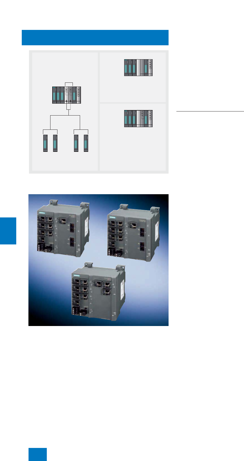
Communication
Industrial Ethernet
SCALANCE X Industrial Ethernet switches
9/10 Siemens ST PCS 7 · November 2007
9
Possible applications of media modules with SCALANCE X-408-2
SCALANCE X-300
With the X310, X308-2 and X308-2LD switches from the
SCALANCE X-300 range, it is possible to implement line and star
topologies as well as low-cost electrical or optical ring topolo-
gies with transmission rates up to 1000 Mbit/s. All switches can
be used in the ring as redundancy managers. They additionally
support standby redundancy for bus configurations with two re-
dundant rings. As a redundancy manager, an X-300 switch mon-
itors the SCALANCE X switches connected via its ring ports, and
switches without interruption to the substitute link on failure of a
transmission link or a switch in the ring. Each X-300 switch has
3 Gigabit Ethernet ports and 7 FastEthernet ports which are de-
signed as follows depending on the device type:
• SCALANCE X310 with
- 3 electrical Gigabit Ethernet RJ45 ports (1000BaseTX)
- 7 electrical FastEthernet RJ45 ports (10/100BaseTX)
• SCALANCE X308-2 with
- 2 optical Gigabit Ethernet SC ports for glass multimode FOC
(1000BaseSX)
- 1 electrical Gigabit Ethernet RJ45 port (1000BaseTX)
- 7 electrical FastEthernet RJ45 ports (10/100BaseTX)
• SCALANCE X308-2LD with
- 2 optical Gigabit Ethernet SC ports for glass singlemode
FOC (1000BaseFX)
- 1 electrical Gigabit Ethernet RJ45 port (1000BaseTX)
- 7 electrical FastEthernet RJ45 ports (10/100BaseTX)
Features of the X-300 switches
• Rugged metal enclosure of S7-300 format, IP30 protection, for
installation in control cabinets
• Mounting possibilities: DIN rail, SIMATIC S7-300 rail, direct
wall mounting
• Redundant 24 V DC supply
• Cable length between two devices with electrical transmission
per TP ports 1000BaseTX with RJ45 sockets:
- Depending on the cable type, up to 90 m with IE FC cable,
IE FC RJ45 Modular Outlet and patch cable, up to 10 m with
TP-Cord (see page 9/23)
• Cable length between two devices with optical transmission:
- Up to 750 m via 1000BaseSX ports (1000 Mbit/s) and
Industrial Ethernet glass multimode FOC (see page 9/26 or
in Catalog IK PI)
- Up to 10 km via 1000BaseFX ports (1000 Mbit/s) and Indus-
trial Ethernet glass singlemode FOC (see Section "Passive
network components" in Catalog IK PI)
• Cable length between two devices with electrical transmission
per TP ports 10/100BaseTX with RJ45 sockets:
- Depending on the cable type, up to 100 m with IE FC cable
and IE FC RJ45 Plugs (see page 9/23 or in Catalog IK PI)
- Up to 10 m with TP-Cord (see Section "Passive network com-
ponents" in Catalog IK PI)
• Permissible operating temperature for all device types: 0 to
+60°C
G_IK10_XX_10201
SCALANCE X408-2
MM492-2
MM492-2LD
Gigabit
MM491-2
MM491-2LD
Fast
Ethernet
2345678
2345678
2345678
MM492-2
MM491-2
MM492-2LD
or
or
or
Example 1
Example 2
e.g. for use in optical gigabit ring,
connecting up to six electrical nodes
or
for redundant connection of optical gigabit
rings via electrical gigabit segments,
connecting up to four electrical nodes.
Slot
number
optionally
Gigabit or
Fast Ethernet
e.g. for use in optical gigabit ring with
single mode for a distance of up to
10 km, connecting two separate optical
nodes and up to four electrical nodes.
© Siemens AG 2007
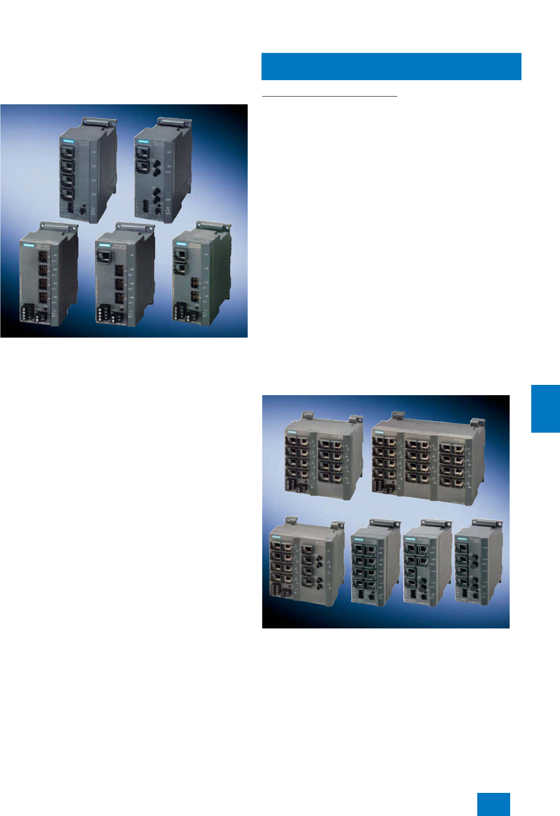
Communication
Industrial Ethernet
SCALANCE X Industrial Ethernet switches
9/11
Siemens ST PCS 7 · November 2007
9
SCALANCE X-200 IRT
With the X204 IRT, X202-2 IRT, X202-2P IRT, X201-3P IRT and
X200-4P IRT switches from the SCALANCE X-200 IRT range, it is
possible to implement line and star topologies as well as low-
cost electrical or optical ring topologies with transmission rates
up to 100 Mbit/s. All switches can be used in the ring as redun-
dancy managers, and additionally support the standby redun-
dancy for bus configurations with two redundant rings. As a
redundancy manager, an X-200 IRT switch monitors the
SCALANCE X switches connected via its ring ports, and
switches without interruption to the substitute link on failure of a
transmission link or a switch in the ring. Each X-200 IRT switch
has 4 FastEthernet ports which are designed as follows depend-
ing on the device type:
• SCALANCE X204 IRT with
- 4 electrical RJ45 ports (10/100BaseTX)
• SCALANCE X202-2 IRT with
- 2 electrical RJ45 ports (10/100BaseTX)
- 2 optical BFOC ports (100BaseFX) for glass multimode FOC
• SCALANCE X202-2P IRT with
- 2 electrical RJ45 ports (10/100BaseTX)
- 2 optical POF (Polymer Optical Fiber) ports
• SCALANCE X201-3P IRT with
- 1 electrical RJ45 port (10/100BaseTX)
- 3 optical POF ports
• SCALANCE X200-4P IRT with
- 4 optical POF ports
Features of the X-200 IRT switches
• Rugged metal enclosure of S7-300 format, IP30 protection, for
installation in control cabinets
• Mounting possibilities: DIN rail, SIMATIC S7-300 rail, direct
wall mounting
• Redundant 24 V DC supply
• Cable length between two devices with electrical transmission
per TP ports 10/100BaseTX with RJ45 sockets:
- Depending on the cable type, up to 100 m with IE FC cable
and IE FC RJ45 Plugs (see page 9/23 or in Catalog IK PI)
- Up to 10 m with TP-Cord (see Section "Passive network com-
ponents" in Catalog IK PI)
• Cable length of a segment with optical transmission:
- Up to 3 km via 100BaseFX ports with BFOC socket (corre-
sponds to ST socket) and Industrial Ethernet glass multi-
mode FOC (see page 9/26 or in Catalog IK PI)
- Up to 100 m via POF ports and Industrial Ethernet PCF
(Polymer Cladded Fiber) (see Section "Passive network
components" in Catalog IK PI)
- Up to 50 m via POF ports and Industrial Ethernet POF
(Polymer Optical Fiber) (see Section "Passive network com-
ponents" in Catalog IK PI)
• The permissible operating temperatures vary as follows de-
pending on the device type:
- -20 to +70°C (X204 IRT)
- -10 to +60°C (X202-2-IRT)
- 0 to +60°C (X202-2P IRT)
- 0 to +50°C (X201-3P IRT)
- 0 to +40°C (X200-4P IRT)
SCALANCE X-200
With the X208, X216, X224, X204-2, X212-2, X212-2LD and
X206-1LD switches from the SCALANCE X-200 range, it is pos-
sible to implement line and star topologies as well as low-cost
electrical or optical ring topologies with transmission rates up to
100 Mbit/s. All switches can be used in the ring as redundancy
managers. As a redundancy manager, an X-200 switch monitors
the SCALANCE X switches connected via its ring ports, and
switches without interruption to the substitute link on failure of a
transmission link or a switch in the ring.
© Siemens AG 2007

Communication
Industrial Ethernet
SCALANCE X Industrial Ethernet switches
9/12 Siemens ST PCS 7 · November 2007
9
The SCALANCE X-200 switches have 6 to 24 FastEthernet ports
which are designed as follows depending on the device type:
• SCALANCE X224 with
- 24 electrical RJ45 ports (10/100BaseTX)
• SCALANCE X216 with
- 16 electrical RJ45 ports (10/100BaseTX)
• SCALANCE X208 with
- 8 electrical RJ45 ports (10/100BaseTX)
• SCALANCE X204-2 with
- 4 electrical RJ45 ports (10/100BaseTX)
- 2 optical BFOC ports (100BaseFX) for glass multimode FOC
• SCALANCE X212-2 with
- 12 electrical RJ45 ports (10/100BaseTX)
- 2 optical BFOC ports (100BaseFX) for glass multimode FOC
• SCALANCE X212-2LD with
- 12 electrical RJ45 ports (10/100BaseTX)
- 2 optical BFOC ports (100BaseFX) for glass singlemode
FOC
• SCALANCE X206-1LD with
- 6 electrical RJ45 ports (10/100BaseTX)
- 1 optical BFOC port (100BaseFX) for glass singlemode FOC
Features of the X-200 switches
• Rugged metal enclosure of S7-300 format, IP30 protection, for
installation in control cabinets
• Mounting possibilities: DIN rail, SIMATIC S7-300 rail, direct
wall mounting
• Redundant 24 V DC supply
• Cable length between two devices with electrical transmission
per TP ports 10/100BaseTX with RJ45 sockets:
- Depending on the cable type, up to 100 m with IE FC cable
and IE FC RJ45 Plugs (see page 9/23 or in Catalog IK PI)
- Up to 10 m with TP-Cord (see Section "Passive network com-
ponents" in Catalog IK PI)
• Cable length of a segment with optical transmission via
100BaseFX ports with BFOC socket (corresponds to ST
socket):
- Up to 3 km with Industrial Ethernet glass multimode FOC
(see page 9/26 or in Catalog IK PI)
- Up to 26 km with Industrial Ethernet glass singlemode FOC
(see Section "Passive network components" in Catalog IK PI)
• The permissible operating temperatures vary depending on
the device type:
- -20 to +70°C (X208)
- -10 to +60°C (X204-2)
- 0 to +60°C (all others)
■
Technical specifications
Type SCALANCE X414-3E SCALANCE X408-2
Transmission rate 10/100/1000 Mbit/s 10/100/1000 Mbit/s
Interfaces
• Communications connection, electrical (see
also table "Summary of interfaces") In the basic device:
2 x RJ45 (10/100/1000 Mbit/s; TP);
12 x RJ45 (10/100 Mbit/s; TP)
With extender modules:
8 x RJ45 (10/100 Mbit/s; TP) via EM495-8
4 x RJ45 (10/100/1000 Mbit/s; TP);
4 x RJ45 (10/100 Mbit/s; TP)
• Communications connection, optical (see also
table "Summary of interfaces") In the basic device:
up to 2 x glass FOC with SC sockets
(1000 Mbit/s) via MM492-2, MM492-2LD,
MM492-2LH or MM492-2LH+ media module;
or
up to 4 x glass FOC with BFOC sockets
(100 Mbit/s) via MM491-2 or MM491-2LD
media module
With extender modules:
up to 12 x glass FOC with BFOC sockets
(100 Mbit/s) via EM496-4 and MM491-2 or
MM491-2LD
Up to 4 x glass FOC with SC sockets (1000 Mbit/s)
via MM492-2 or MM492-2LD media module;
or
up to 4 x glass FOC with BFOC sockets
(100 Mbit/s) via MM491-2 or MM491-2LD media
module
• Extender interface EM495-8 or EM496-4 --
• Connection for power supply 1 x 4-contact terminal block 1 x 4-contact terminal block
• Connection for signaling contact 1 x 4-contact terminal block 1 x 4-contact terminal block
• Connection for digital input signals 2 x 5-contact terminal block --
• Slot for swap medium C-PLUG C-PLUG
Power supply 2 x 24 V DC (18 to 32 V) 2 x 24V DC (18to32V)
Current consumption <2000mA <700mA
Power loss at 24 V DC 15 W (without media and extender modules),
< 48 W (maximum configuration) 15 W (without media modules),
< 48 W (maximum configuration)
© Siemens AG 2007
Communication
Industrial Ethernet
SCALANCE X Industrial Ethernet switches
9/13
Siemens ST PCS 7 · November 2007
9
Network size parameters / TP cable length
•0 to 55 m IE TP Torsion Cable with IE FC RJ45 Plug IE TP Torsion Cable with IE FC RJ45 Plug
•0 to 85 m IE FC Marine/ Trailing/ Flexible/ FRNC Cable
with IE FC RJ45 Plug IE FC Marine/ Trailing/ Flexible/ FRNC Cable with
IE FC RJ45 Plug
• 0 to 100 m IE FC Standard Cable GP with IE FC RJ45
Plug IE FC Standard Cable GP with IE FC RJ45 Plug
• 0 to 750 m Cable length multimode FOC at 1000 Mbit/s;
MM492-2 with glass FOC
50/125 µm;
≤ 2.7 dB/km with 850 nm;
≥600 MHz x km
Cable length multimode FOC at 1000 Mbit/s;
MM492-2 with glass FOC
50/125 µm;
≤ 2.7 dB/km with 850 nm;
≥600 MHz x km
• 0 to 3000 m Cable length multimode FOC at 100 Mbit/s;
MM491-2 with glass FOC
62.5/125 µm or 50/125 µm;
≤ 1 dB/km with 1300 nm;
≥ 600 MHz x km
Cable length multimode FOC at 100 Mbit/s;
MM491-2 with glass FOC
62.5/125 µm or 50/125 µm;
≤ 1 dB/km with 1300 nm;
≥ 600 MHz x km
•0 to 10 km Cable length singlemode FOC at 1000 Mbit/s;
MM492-2LD with glass FOC
10/125 µm or 9/125 µm;
≤ 0.5 dB/km with 1300 nm
Cable length singlemode FOC at 1000 Mbit/s;
MM492-2LD with glass FOC
10/125 µm or 9/125 µm;
≤ 0.5 dB/km with 1300 nm
•0 to 26 km Cable length singlemode FOC at 100 Mbit/s;
MM491-2LD with glass FOC 10/125 µm or
9/125 µm;
≤ 0.5 dB/km with 1300 nm
Cable length singlemode FOC at 100 Mbit/s;
MM491-2LD with glass FOC 10/125 µm or
9/125 µm;
≤ 0.5 dB/km with 1300 nm
•0 to 40 km Cable length singlemode FOC at 1000 Mbit/s;
MM492-2LH with glass FOC
10/125 µm or 9/125 µm;
≤ 0.5 dB/km with 1300 nm
Cable length singlemode FOC at 1000 Mbit/s;
MM492-2LH with glass FOC
10/125 µm or 9/125 µm;
≤ 0.5 dB/km with 1300 nm
•0 to 70 km Cable length singlemode FOC at 1000 Mbit/s;
MM492-2LH+ with glass FOC
10/125 µm or 9/125 µm;
≤ 0.5 dB/km with 1300 nm
Cable length singlemode FOC at 1000 Mbit/s;
MM492-2LH+ with glass FOC
10/125 µm or 9/125 µm;
≤ 0.5 dB/km with 1300 nm
Permissible ambient conditions
• Operating temperature 0 to +60 °C 0 to +60 °C
• Transport/storage temperature -40 °C to +80 °C -40 °C to +80 °C
• Relative humidity during operation < 95% (no condensation) < 95% (no condensation)
Design
• Dimensions (W x H x D) in mm 344 x 145 x 117 275 x 145 x 117
•Weight 3.1 kg 1.9 kg
• Mounting S7-300 rail, DIN rail S7-300 rail, DIN rail
Degree of protection IP20 IP20
Approvals
• Radio interference suppression level EN 61000-6-4 Class A EN 61000-6-4 Class A
• Noise immunity EN 61000-6-2 EN 61000-6-2
•cUL-Listung UL 60950-1, CSA C22.2 No. 60950-1,
UL 508, CSA C22.2 No. 14-M91
UL 1604 and 2279 (Hazardous Location)
UL 60950-1, CSA C22.2 No. 60950-1,
UL 508, CSA C22.2 No. 14-M91
UL 1604 and 2279 (Hazardous Location)
•FM FM 3611,
FM Hazardous Location FM 3611,
FM Hazardous Location
• ATEX Zone 2 EN 50021 EN 50021
•C-Tick AS/NZS 2064 (Class A) AS/NZS 2064 (Class A)
•CE EN 61000-6-2, EN 61000-6-4 EN 61000-6-2, EN 61000-6-4
• Shipbuilding approvals • Germanischer Lloyd (GL)
• American Bureau of Shipping (ABS)
• Llyods Register of Shipping (LRS)
• Bureau Veritas (BV)
• Nippon Kaiji Kyokai (NK)
• Det Norske Veritas (DNV)
Available soon
Type SCALANCE X414-3E SCALANCE X408-2
© Siemens AG 2007

Communication
Industrial Ethernet
SCALANCE X Industrial Ethernet switches
9/14 Siemens ST PCS 7 · November 2007
9
Type SCALANCE X310 SCALANCE X308-2 SCALANCE X308-2LD
Transmission rate 10/100/1000 Mbit/s 10/100/1000 Mbit/s 10/100/1000 Mbit/s
Interfaces
• Communications connection, electrical
(see also table "Summary of interfaces") 3 x RJ45 (10/100/1000 Mbit/s;
TP)
7 x RJ45 (10/100 Mbit/s; TP)
1 x RJ45 (10/100/1000 Mbit/s;
TP)
7 x RJ45 (10/100 Mbit/s; TP)
1 x RJ45 (10/100/1000 Mbit/s;
TP)
7 x RJ45 (10/100 Mbit/s; TP)
• Communications connection, optical (see also
table "Summary of interfaces") -- 2 x glass FO cable (multimode)
with SC socket (1000 Mbit/s) 2 x glass FO cable (single-
mode) with SC socket
(1000 Mbit/s)
• Connection for power supply 1 x 4-contact terminal block 1 x 4-contact terminal block 1 x 4-contact terminal block
• Connection for signaling contact 1 x 2-contact terminal block 1 x 2-contact terminal block 1 x 2-contact terminal block
• Slot for swap medium C-PLUG C-PLUG C-PLUG
Power supply 2 x 24 V DC (18 to 32 V) 2 x 24V DC (18to32V) 2 x 24 V DC (18 to 32 V)
Current consumption 400 mA 400 mA 400 mA
Power loss at 24 V DC 9.6 W 9.6 W 9.6 W
Network size parameters / TP cable length
•0 to 55 m IE TP Torsion Cable with IE FC
RJ45 Plug IE TP Torsion Cable with IE FC
RJ45 Plug IE TP Torsion Cable with IE FC
RJ45 Plug
IE FC Outlet RJ45 with IE TP
Torsion Cable (0 to 45 m)
+ 10 m TP Cord
IE FC Outlet RJ45 with IE TP
Torsion Cable (0 to 45 m)
+ 10 m TP Cord
IE FC Outlet RJ45 with IE TP
Torsion Cable (0 to 45 m)
+ 10 m TP Cord
•0 to 85 m IE FC Marine/ Trailing/ Flexible/
FRNC Cable with IE FC RJ45
Plug
IE FC Marine/ Trailing/ Flexible/
FRNC Cable with IE FC RJ45
Plug
IE FC Marine/ Trailing/ Flexible/
FRNC Cable with IE FC RJ45
Plug
IE FC Outlet RJ45 with IE FC
Marine/Trailing/Flexible Cable
(0 to 75 m) + 10 m TP Cord
IE FC Outlet RJ45 with IE FC
Marine/Trailing/Flexible Cable
(0 to 75 m) + 10 m TP Cord
IE FC Outlet RJ45 with IE FC
Marine/Trailing/Flexible Cable
(0 to 75 m) + 10 m TP Cord
• 0 to 100 m IE FC Standard Cable GP with
IE FC RJ45 Plug IE FC Standard Cable GP with
IE FC RJ45 Plug IE FC Standard Cable GP with
IE FC RJ45 Plug
IE FC Outlet RJ45 with
IE FC TP Standard Cable GP
(0 to 90 m) + 10 m TP Cord
IE FC Outlet RJ45 with
IE FC Standard Cable GP
(0 to 90 m) + 10 m TP Cord
IE FC Outlet RJ45 with
IE FC Standard Cable GP
(0 to 90 m) + 10 m TP Cord
• 0 to 750 m -- Cable length multimode FOC at
1000 Mbit/s;
glass FOC 50/125 µm;
≤ 2.7 dB/km with 850 nm;
≥600MHz xkm
--
•0 to 10 km -- -- Cable length singlemode FOC
at 1000 Mbit/s;
10/125 µm or 9/125 µm;
≤ 0.5 dB/km with 1300 nm
Permissible ambient conditions
• Operating temperature 0 to +60 °C 0 to +60 °C 0 to +60 °C
• Transport/storage temperature -40 to +80°C -40 to +80 °C -40 to +80 °C
• Relative humidity during operation < 95% (no condensation) < 95% (no condensation) < 95% (no condensation)
Design
• Dimensions (W x H x D) in mm 120 x 125 x 124 120 x 125 x 124 120 x 125 x 124
•Weight 1400 g 1400 g 1400 g
• Mounting DIN rail, S7-300 rail, wall mount-
ing DIN rail, S7-300 rail, wall mount-
ing DIN rail, S7-300 rail, wall mount-
ing
Degree of protection IP30 IP30 IP30
Approvals
• Radio interference suppression level EN 61000-6-4 Class A EN 61000-6-4 Class A EN 61000-6-4 Class A
• Noise immunity EN 61000-6-2 EN 61000-6-2 EN 61000-6-2
•cUL-Listung UL 60950-1,
CSA C22.2 No. 60950-1;
UL 508, CSA C22.2 No.
14-M91;
UL 1604 and 2279
(Hazardous Location)
UL 60950-1,
CSA C22.2 No. 60950-1;
UL 508, CSA C22.2 No.
14-M91;
UL 1604 and 2279
(Hazardous Location)
UL 60950-1,
CSA C22.2 No. 60950-1;
UL 508, CSA C22.2 No.
14-M91;
UL 1604 and 2279
(Hazardous Location)
•FM FM 3611 FM 3611 FM 3611
• ATEX Zone 2 EN 50021 EN 50021 EN 50021
•C-Tick AS/NZS 2064 (Class A) AS/NZS 2064 (Class A) AS/NZS 2064 (Class A)
•CE EN 61000-6-2, EN 61000-6-4 EN 61000-6-2, EN 61000-6-4 EN 61000-6-2, EN 61000-6-4
© Siemens AG 2007
Communication
Industrial Ethernet
SCALANCE X Industrial Ethernet switches
9/15
Siemens ST PCS 7 · November 2007
9
Type SCALANCE X204 IRT SCALANCE X202-2 IRT SCALANCE X202-2P IRT
Transmission rate 10/100 Mbit/s 10/100 Mbit/s 10/100 Mbit/s
Interfaces
• Communications connection, electrical (see
also table "Summary of interfaces") 4 x RJ45 (10/100 Mbit/s; TP) 2 x RJ45 (10/100 Mbit/s; TP) 2 x RJ45 (10/100 Mbit/s; TP)
• Communications connection, optical (see also
table "Summary of interfaces") -- 2 x BFOC socket (100 Mbit/s) 2 x SC RJ socket (100 Mbit/s)
• Connection for power supply 1 x 4-contact terminal block 1 x 4-contact terminal block 1 x 4-contact terminal block
• Connection for signaling contact 1 x 2-contact terminal block 1 x 2-contact terminal block 1 x 2-contact terminal block
• Slot for swap medium C-PLUG C-PLUG C-PLUG
Power supply 2 x 24 V DC (18 to 32 V) 2 x 24 V DC (18 to 32 V) 2 x 24 V DC (18 to 32 V)
Current consumption 200 mA 300 mA 300 mA
Power loss at 24 V DC 4.8 W 7.2 W 7.2 W
Network size parameters / TP cable length
•0 to 50 m -- -- POF 980/1000 with 650 nm
10 MHz x 100 m
•0 to 55 m IE TP Torsion Cable with IE FC
RJ45 Plug IE TP Torsion Cable with IE FC
RJ45 Plug IE TP Torsion Cable with IE FC
RJ45 Plug
IE FC Outlet RJ45 with IE TP
Torsion Cable (0 to 45 m)
+ 10 m TP Cord
IE FC Outlet RJ45 with IE TP
Torsion Cable (0 to 45 m)
+ 10 m TP Cord
IE FC Outlet RJ45 with IE TP
Torsion Cable (0 to 45 m)
+ 10 m TP Cord
•0 to 85 m IE FC Marine/ Trailing/ Flexible/
FRNC Cable with IE FC RJ45
Plug
IE FC Marine/ Trailing/ Flexible/
FRNC Cable with IE FC RJ45
Plug
IE FC Marine/ Trailing/ Flexible/
FRNC Cable with IE FC RJ45
Plug
IE FC Outlet RJ45 with IE FC
Marine/Trailing/Flexible Cable
(0 to 75 m) + 10 m TP Cord
IE FC Outlet RJ45 with IE FC
Marine/Trailing/Flexible Cable
(0 to 75 m) + 10 m TP Cord
IE FC Outlet RJ45 with IE FC
Marine/Trailing/Flexible Cable
(0 to 75 m) + 10 m TP Cord
• 0 to 100 m -- -- PCF 200/230 with 650 nm
17 MHz x km
IE FC Standard Cable GP with
IE FC RJ45 Plug IE FC Standard Cable GP with
IE FC RJ45 Plug IE FC Standard Cable GP with
IE FC RJ45 Plug
IE FC Outlet RJ45 with
IE FC TP Standard Cable GP
(0 to 90 m) + 10 m TP Cord
IE FC Outlet RJ45 with
IE FC Standard Cable GP
(0 to 90 m) + 10 m TP Cord
IE FC Outlet RJ45 with
IE FC Standard Cable GP
(0 to 90 m) + 10 m TP Cord
• 0 to 3000 m -- Glass FOC 62.5/125 µm or
50/125µm;
≤ 1.0 dB/km with 1300 nm;
≥600 MHz x km
--
Permissible ambient conditions
• Operating temperature -20 °C to +70 °C -10 to +60 °C 0 to +60 °C
• Transport/storage temperature -40 °C to +80 °C -40 to +80 °C -40 to +80 °C
• Relative humidity during operation < 95% (no condensation) < 95% (no condensation) < 95% (no condensation)
Design
• Dimensions (W x H x D) in mm 60 x 125 x 124 60 x 125 x 124 60 x 125 x 124
•Weight 780 g 780 g 780 g
• Mounting DIN rail, S7-300 rail, wall
mounting DIN rail, S7-300 rail,
wall mounting DIN rail, S7-300 rail,
wall mounting
Degree of protection IP30 IP30 IP30
Approvals
• Radio interference suppression level EN 61000-6-4 Class A EN 61000-6-4 Class A EN 61000-6-4 Class A
• Noise immunity EN 61000-6-2 EN 61000-6-2 EN 61000-6-2
•cUL-Listung UL 60950-1, CSA C22.2
No. 60950-1 UL 60950-1, CSA C22.2
No. 60950-1 UL 60950-1, CSA C22.2
No. 60950-1
•FM FM 3611 FM 3611 FM 3611
• ATEX Zone 2 EN 50021 EN 50021 EN 50021
•C-Tick AS/NZS 2064 (Class A) AS/NZS 2064 (Class A) AS/NZS 2064 (Class A)
•CE EN 61000-6-2, EN 61000-6-4 EN 61000-6-2, EN 61000-6-4 EN 61000-6-2, EN 61000-6-4
• Shipbuilding approvals • American Bureau of Shipping
• Nippon Kaiji Kyokai
• Det Norske Veritas
• American Bureau of Shipping
• Nippon Kaiji Kyokai
• Det Norske Veritas
• Lloyds Register of Shipping
• Det Norske Veritas
• Germanischer Lloyd
© Siemens AG 2007

Communication
Industrial Ethernet
SCALANCE X Industrial Ethernet switches
9/16 Siemens ST PCS 7 · November 2007
9
Type SCALANCE X201-3P IRT SCALANCE X200-4P IRT
Transmission rate 10/100 Mbit/s 10/100 Mbit/s
Interfaces
• Communications connection, electrical (see
also table "Summary of interfaces") 1 x RJ45 (10/100 Mbit/s; TP) --
• Communications connection, optical (see also
table "Summary of interfaces") 3 x SC RJ socket (100 Mbit/s) 4 x SC RJ socket (100 Mbit/s)
• Connection for power supply 1 x 4-contact terminal block 1 x 4-contact terminal block
• Connection for signaling contact 1 x 2-contact terminal block 1 x 2-contact terminal block
• Slot for swap medium C-PLUG C-PLUG
Power supply 2 x 24 V DC (18 to 32 V) 2 x 24V DC (18to32V)
Current consumption 350 mA 400 mA
Power loss at 24 V DC 8.4 W 9.6 W
Network size parameters / TP cable length
•0 to 50 m POF 980/1000 with 650 nm 10 MHz x 100 m POF 980/1000 with 650 nm 10 MHz x 100 m
•0 to 55 m IE TP Torsion Cable with IE FC RJ45 Plug --
IE FC Outlet RJ45 with IE TP Torsion Cable
(0 to 45 m)
+ 10 m TP Cord
--
•0 to 85 m IE FC Marine/ Trailing/ Flexible/ FRNC Cable
with IE FC RJ45 Plug --
IE FC Outlet RJ45 with IE FC Marine/Trail-
ing/Flexible Cable (0 to 75 m) + 10 m TP Cord --
• 0 to 100 m IE FC Standard Cable GP with IE FC RJ45
Plug --
IE FC Outlet RJ45 with
IE FC Standard Cable GP
(0 to 90 m) + 10 m TP Cord
--
PCF 200/230 with 650 nm 17 MHz x km PCF 200/230 with 650 nm 17 MHz x km
• 0 to 3000 m -- --
Permissible ambient conditions
• Operating temperature 0 to +50 °C 0 to +40 °C
• Transport/storage temperature -40 to +80 °C -40 to +80 °C
• Relative humidity during operation < 95% (no condensation) < 95% (no condensation)
Design
• Dimensions (W x H x D) in mm 60 x 125 x 124 60 x 125 x 124
•Weight 780 g 780 g
• Mounting DIN rail, S7-300 rail, wall mounting DIN rail, S7-300 rail, wall mounting
Degree of protection IP30 IP30
Approvals
• Radio interference suppression level EN 61000-6-4 Class A EN 61000-6-4 Class A
• Noise immunity EN 61000-6-2 EN 61000-6-2
•cUL-Listung UL 60950-1, CSA C22.2 No. 60950-1 UL 60950-1, CSA C22.2 No. 60950-1
•FM FM 3611 FM 3611
• ATEX Zone 2 EN 50021 EN 50021
•C-Tick AS/NZS 2064 (Class A) AS/NZS 2064 (Class A)
•CE EN 61000-6-2, EN 61000-6-4 EN 61000-6-2, EN 61000-6-4
• Shipbuilding approvals • Lloyds Register of Shipping
• Det Norske Veritas
• Germanischer Lloyd
• Lloyds Register of Shipping
• Det Norske Veritas
• Germanischer Lloyd
© Siemens AG 2007
Communication
Industrial Ethernet
SCALANCE X Industrial Ethernet switches
9/17
Siemens ST PCS 7 · November 2007
9
Type SCALANCE X208 SCALANCE X206-1LD SCALANCE X204-2
Transmission rate 10/100 Mbit/s 10/100 Mbit/s 10/100 Mbit/s
Interfaces
• Communications connection, electrical (see
also table "Summary of interfaces") 8 x RJ45 (10/100 Mbit/s; TP) 6 x RJ45 (10/100 Mbit/s; TP) 4 x RJ45 (10/100 Mbit/s; TP)
• Communications connection, optical (see
also table "Summary of interfaces") -- 1 x BFOC socket (100 Mbit/s) 2 x BFOC socket (100 Mbit/s)
• Connection for power supply 1 x 4-contact terminal block 1 x 4-contact terminal block 1 x 4-contact terminal block
• Connection for signaling contact 1 x 2-contact terminal block 1 x 2-contact terminal block 1 x 2-contact terminal block
• Slot for swap medium C-PLUG C-PLUG C-PLUG
Power supply 2 x 24 V DC (18 to 32 V) 2 x 24 V DC (18 to 32 V) 2 x 24 V DC (18 to 32 V)
Current consumption 185 mA 200 mA 215 mA
Power loss at 24 V DC 4W 4.8 W 5.16 W
Network size parameters / TP cable length
•0 to 55 m IE TP Torsion Cable with
IE FC RJ45 Plug IE TP Torsion Cable with
IE FC RJ45 Plug IE TP Torsion Cable with
IE FC RJ45 Plug
IE FC Outlet RJ45 with IE TP
Torsion Cable (0 to 45 m)
+ 10 m TP Cord
IE FC Outlet RJ45 with IE TP
Torsion Cable (0 to 45 m)
+ 10 m TP Cord
IE FC Outlet RJ45 with IE TP
Torsion Cable (0 to 45 m)
+ 10 m TP Cord
•0 to 85 m IE FC Marine/Trailing/
Flexible/FRNC Cable with IE FC
RJ45 Plug
IE FC Marine/Trailing/Flexible/
FRNC Cable with IE FC RJ45
Plug
IE FC Marine/ Trailing/
Flexible/ FRNC Cable with IE FC
RJ45 Plug
IE FC Outlet RJ45 with IE FC
Marine/Trailing/Flexible Cable
(0 to 75 m) + 10 m TP Cord
IE FC Outlet RJ45 with IE FC
Marine/Trailing/Flexible Cable
(0 to 75 m) + 10 m TP Cord
IE FC Outlet RJ45 with IE FC
Marine/Trailing/Flexible Cable
(0 to 75 m) + 10 m TP Cord
• 0 to 100 m IE FC Standard Cable GP with
IE FC RJ45 Plug IE FC Standard Cable GP with
IE FC RJ45 Plug IE FC Standard Cable GP with
IE FC RJ45 Plug
IE FC Outlet RJ45 with
IE FC Standard Cable
(0 to 90 m)
+ 10 m TP Cord
IE FC Outlet RJ45 with
IE FC Standard Cable GP
(0 to 90 m)
+ 10 m TP Cord
IE FC Outlet RJ45 with
IE FC Standard Cable GP
(0 to 90 m)
+ 10 m TP Cord
• 0 to 3 km -- -- Glass FOC 62.5/125 µm or
50/125 µm;
≤ 1.0 dB/km with 1300 nm;
≥600 MHz x km
•0 to 26 km -- Glass FOC or 9/125 µm single-
mode fiber;
0.5 dB/km with 1300 nm
--
Permissible ambient conditions
• Operating temperature -20 to +70 °C 0 to +60 °C -10 to +60 °C
• Transport/storage temperature -40 to +80 °C -40 to +80 °C -40 to +80 °C
• Relative humidity during operation < 95% (no condensation) < 95% (no condensation) < 95% (no condensation)
Design
• Dimensions (W x H x D) in mm 60 x 125 x 124 60 x 125 x 124 60 x 125 x 124
•Weight 780 g 780 g 780 g
• Mounting DIN rail, S7-300 rail, wall mount-
ing DIN rail, S7-300 rail, wall mount-
ing DIN rail, S7-300 rail, wall mount-
ing
Degree of protection IP30 IP30 IP30
Approvals
• Radio interference suppression level EN 61000-6-4 Class A EN 61000-6-4 Class A EN 61000-6-4 Class A
• Noise immunity EN 61000-6-2 EN 61000-6-2 EN 61000-6-2
•cUL-Listung UL 60950-1, CSA C22.2
No. 60950-1 UL 60950-1, CSA C22.2
No. 60950-1 UL 60950-1, CSA C22.2
No. 60950-1
•FM FM 3611 FM 3611 FM 3611
• ATEX Zone 2 EN 50021 EN 50021 EN 50021
•C-Tick AS/NZS 2064 (Class A) AS/NZS 2064 (Class A) AS/NZS 2064 (Class A)
•CE EN 61000-6-2, EN 61000-6-4 EN 61000-6-2, EN 61000-6-4 EN 61000-6-2, EN 61000-6-4
• Shipbuilding approvals • Lloyds Register of Shipping
• Det Norske Veritas
• Germanischer Lloyd
• Nippon Kaiji Kyokai
• American Bureau of Shipping
• Bureau Veritas
• Lloyds Register of Shipping
• Det Norske Veritas
• Germanischer Lloyd
• Nippon Kaiji Kyokai
• Bureau Veritas
• Lloyds Register of Shipping
• Det Norske Veritas
• Germanischer Lloyd
• Nippon Kaiji Kyokai
• Bureau Veritas
© Siemens AG 2007

Communication
Industrial Ethernet
SCALANCE X Industrial Ethernet switches
9/18 Siemens ST PCS 7 · November 2007
9
Type SCALANCE X212-2 SCALANCE X212-2LD
Transmission rate 10/100 Mbit/s 10/100 Mbit/s
Interfaces
• Communications connection, electrical (see
also table "Summary of interfaces") 12 x RJ45 (10/100 Mbit/s; TP) 12 x RJ45 (10/100 Mbit/s; TP)
• Communications connection, optical (see also
table "Summary of interfaces") 2 x BFOC socket (100 Mbit/s) 2 x BFOC socket (100 Mbit/s)
• Connection for power supply 1 x 4-contact terminal block 1 x 4-contact terminal block
• Connection for signaling contact 1 x 2-contact terminal block 1 x 2-contact terminal block
• Slot for swap medium C-PLUG C-PLUG
Power supply 2 x 24 V DC (18 to 32 V) 2 x 24V DC (18to32V)
Current consumption 330 mA 330 mA
Power loss at 24 V DC 7.92 W 7.92 W
Network size parameters / TP cable length
•0 to 55 m IE TP Torsion Cable with IE FC RJ45 Plug IE TP Torsion Cable with IE FC RJ45 Plug
IE FC Outlet RJ45 with IE TP Torsion Cable
(0 to 45 m)
+ 10 m TP Cord
IE FC Outlet RJ45 with IE TP Torsion Cable
(0 to 45 m)
+ 10 m TP Cord
•0 to 85 m IE FC Marine/ Trailing/ Flexible/ FRNC Cable
with IE FC RJ45 Plug IE FC Marine/ Trailing/ Flexible/ FRNC Cable with
IE FC RJ45 Plug
IE FC Outlet RJ45 with IE FC Marine/
Trailing/Flexible Cable (0 to 75 m) + 10 m TP
Cord
IE FC Outlet RJ45 with IE FC Marine/Trailing/
Flexible Cable (0 to 75 m) + 10 m TP Cord
• 0 to 100 m IE FC Standard Cable GP with IE FC RJ45
Plug IE FC Standard Cable GP with IE FC RJ45 Plug
IE FC Outlet RJ45 with
IE FC Standard Cable GP
(0 to 90 m) + 10 m TP Cord
IE FC Outlet RJ45 with
IE FC Standard Cable GP
(0 to 90 m) + 10 m TP Cord
• 0 to 750 m Glass FOC 62.5/125 µm or 50/125 µm;
≤ 1.0 dB/km with 1300 nm; ≥600 MHz x km --
• 0 to 3 km -- Glass FOC or 9/125 µm singlemode fiber;
0.5 dB/km with 1300 nm
•0 to 26 km IE TP Torsion Cable with IE FC RJ45 Plug IE TP Torsion Cable with IE FC RJ45 Plug
Permissible ambient conditions
• Operating temperature 0 to +60 °C 0 to +60 °C
• Transport/storage temperature -40 to +80 °C -40 to +80 °C
• Relative humidity during operation < 95% (no condensation) < 95% (no condensation)
Design
• Dimensions (W x H x D) in mm 120 x 125 x 124 120 x 125 x 124
•Weight 1200 g 1200 g
• Mounting DIN rail, S7-300 rail, wall mounting DIN rail, S7-300 rail, wall mounting
Degree of protection IP30 IP30
Approvals
• Radio interference suppression level EN 61000-6-4 Class A EN 61000-6-4 Class A
• Noise immunity EN 61000-6-2 EN 61000-6-2
•cUL-Listung UL 60950-1, CSA C22.2 No. 60950-1 UL 60950-1, CSA C22.2 No. 60950-1
•FM FM 3611 FM 3611
• ATEX Zone 2 EN 50021 EN 50021
•C-Tick AS/NZS 2064 (Class A) AS/NZS 2064 (Class A)
•CE EN 61000-6-2, EN 61000-6-4 EN 61000-6-2, EN 61000-6-4
• Shipbuilding approvals • Lloyds Register of Shipping
• Det Norske Veritas
• Germanischer Lloyd
• Nippon Kaiji Kyokai
• Bureau Veritas
• Lloyds Register of Shipping
• Det Norske Veritas
• Germanischer Lloyd
• Nippon Kaiji Kyokai
• Bureau Veritas
© Siemens AG 2007
Communication
Industrial Ethernet
SCALANCE X Industrial Ethernet switches
9/19
Siemens ST PCS 7 · November 2007
9
Type SCALANCE X216 SCALANCE X224
Transmission rate 10/100 Mbit/s 10/100 Mbit/s
Interfaces
• Communications connection, electrical (see
also table "Summary of interfaces") 16 x RJ45 (10/100 Mbit/s; TP) 24 x RJ45 (10/100 Mbit/s; TP)
• Communications connection, optical (see also
table "Summary of interfaces") -- --
• Connection for power supply 1 x 4-contact terminal block 1 x 4-contact terminal block
• Connection for signaling contact 1 x 2-contact terminal block 1 x 2-contact terminal block
• Slot for swap medium C-PLUG C-PLUG
Power supply 2 x 24 V DC (18 to 32 V) 2 x 24V DC (18to32V)
Current consumption 240 mA 350 mA
Power loss at 24 V DC 5.76 W 8.4 W
Network size parameters / TP cable length
•0 to 55 m IE TP Torsion Cable with IE FC RJ45 Plug IE TP Torsion Cable with IE FC RJ45 Plug
IE FC Outlet RJ45 with IE TP Torsion Cable
(0 to 45 m)
+ 10 m TP Cord
IE FC Outlet RJ45 with IE TP Torsion Cable
(0 to 45 m)
+ 10 m TP Cord
•0 to 85 m IE FC Marine/ Trailing/ Flexible/ FRNC Cable
with IE FC RJ45 Plug IE FC Marine/ Trailing/ Flexible/ FRNC Cable with
IE FC RJ45 Plug
IE FC Outlet RJ45 with IE FC Marine/Trailing/
Flexible Cable (0 to 75 m) + 10 m TP Cord IE FC Outlet RJ45 with IE FC Marine/Trailing/
Flexible Cable (0 to 75 m) + 10 m TP Cord
• 0 to 100 m IE FC Standard Cable GP with IE FC RJ45
Plug IE FC Standard Cable GP with IE FC RJ45 Plug
IE FC Outlet RJ45 with
IE FC Standard Cable GP
(0 to 90 m) + 10 m TP Cord
IE FC Outlet RJ45 with
IE FC Standard Cable GP
(0 to 90 m) + 10 m TP Cord
Permissible ambient conditions
• Operating temperature 0 to +60 °C 0 to +60 °C
• Transport/storage temperature -40 to +80 °C -40 to +80 °C
• Relative humidity during operation < 95% (no condensation) < 95% (no condensation)
Design
• Dimensions (W x H x D) in mm 120 x 125 x 124 120 x 125 x 124
•Weight 1200 g 1200 g
• Mounting DIN rail, S7-300 rail, wall mounting DIN rail, S7-300 rail, wall mounting
Degree of protection IP30 IP30
Approvals
• Radio interference suppression level EN 61000-6-4 Class A EN 61000-6-4 Class A
• Noise immunity EN 61000-6-2 EN 61000-6-2
•cUL-Listung UL 60950-1, CSA C22.2 No. 60950-1 UL 60950-1, CSA C22.2 No. 60950-1
•FM FM 3611 FM 3611
• ATEX Zone 2 EN 50021 EN 50021
•C-Tick AS/NZS 2064 (Class A) AS/NZS 2064 (Class A)
•CE EN 61000-6-2, EN 61000-6-4 EN 61000-6-2, EN 61000-6-4
• Shipbuilding approvals • Lloyds Register of Shipping
• Det Norske Veritas
• Germanischer Lloyd
• Nippon Kaiji Kyokai
• American Bureau of Shipping
• Bureau Veritas
• Lloyds Register of Shipping
• Det Norske Veritas
• Germanischer Lloyd
• Nippon Kaiji Kyokai
• American Bureau of Shipping
• Bureau Veritas
© Siemens AG 2007
Communication
Industrial Ethernet
SCALANCE X Industrial Ethernet switches
9/20 Siemens ST PCS 7 · November 2007
9
B) Subject to export regulations: AL: N, ECCN: EAR99H
E) Subject to export regulations: AL: N, ECCN: 5A991
Note:
For further components and accessories, especially cable material and
connectors as well as tools and supplementary material for assembly, re-
fer to page 9/23, 9/25 and 9/26 as well as to Catalog IK PI.
■
Selection and Ordering Data Order No.
Industrial Ethernet switches, transmission rate 10/100/1000 Mbit/s
for electrical and/or optical Industrial Ethernet networks, especially for
Fast Ethernet and Gigabit rings
SCALANCE X-400 Industrial
Ethernet switches
• SCALANCE X414-3E
2 x 10/100/1000 Mbit/s and
12 x 10/100 Mbit/s RJ45 ports;
1 x Gigabit Ethernet and
2 x Fast Ethernet media module
slots;
1 x Extender interface
6GK5 414-3FC00-2AA2
• SCALANCE X408-2
4 x 10/100/1000 Mbit/s and
4 x 10/100 Mbit/s RJ45 ports;
2 x Gigabit/Fast Ethernet media
module slots
6GK5 408-2FD00-2AA2
MM491/MM492 media modules
Media modules with 2 ports;
1 Gbit/s, SC connection
• MM492-2 media module
1000BaseSX, multi-mode
FO cable up to 750 m
6GK5 492-2AL00-8AA2 B)
• MM492-2LD media module
1000BaseLX, single-mode
FO cable up to 10 km
6GK5 492-2AM00-8AA2 E)
• MM492-2LH media module
1000BaseLX, single-mode
FO cable up to 40 km
6GK5 492-2AN00-8AA2
• MM492-2LH+ media module
1000BaseLX, single-mode
FO cable up to 70 km
6GK5 492-2AP00-8AA2
Media modules with 2 ports;
100 Mbit/s, BFOC connection
(ST sockets)
• MM491-2 media module
100BaseFX, multi-mode FO
cable up to 3 km
6GK5 491-2AB00-8AA2
• MM491-2LD media module
100BaseFX long distance, sin-
gle-mode FO cable up to 26 km
6GK5 491-2AC00-8AA2
EM495/EM496 extender mod-
ules for SCALANCE X414-3E
• EM495-8 extender module
with 8 x 10/100 Mbit/s TP ports 6GK5 495-8BA00-8AA2
• EM496-4 extender module
with 4 slots for 100 Mbit/s media
modules
6GK5 496-4MA00-8AA2
Industrial Ethernet switches, transmission rate 10/100 Mbit/s
for Industrial Ethernet line, star or ring topologies
SCALANCE X-300 Industrial
Ethernet switches
• SCALANCE X310
3 x 10/100/1000 Mbit/s RJ45
ports
7 x 10/100 Mbit/s RJ45 ports
6GK5 310-0FA00-2AA3
• SCALANCE X308-2
2 x 1000 Mbit/s multimode SC
ports (1000BaseSX)
1 x 10/100/1000 Mbit/s RJ45
port
7 x 10/100 Mbit/s RJ45 ports
6GK5 308-2FL00-2AA3
• SCALANCE X308-2LD
2 x 1000 Mbit/s singlemode SC
ports (1000BaseFX)
1 x 10/100/1000 Mbit/s RJ45
port
7 x 10/100 Mbit/s RJ45 ports
6GK5 308-2FM00-2AA3
SCALANCE X-200 IRT Industrial
Ethernet switches
• SCALANCE X204 IRT
4 x 10/100 Mbit/s RJ45 ports 6GK5 204-0BA00-2BA3
• SCALANCE X202-2 IRT
2 x 10/100 Mbit/s RJ45 ports,
2 x 100 Mbit/s multi-mode BFOC
ports (100BaseFX)
6GK5 202-2BB00-2BA3
• SCALANCE X202-2P IRT
2 x 10/100 Mbit/s RJ45 ports,
2 x 100 Mbit/s POF/PCF SC RJ
ports
6GK5 202-2BH00-2BA3
• SCALANCE X201-3P IRT
1 x 10/100 Mbit/s RJ45 port,
3 x 100 Mbit/s POF/PCF SC RJ
ports
6GK5 201-3BH00-2BA3
• SCALANCE X200-4P IRT
4 x 100 Mbit/s POF/PCF SC RJ 6GK5 200-4AH00-2BA3
SCALANCE X-200 Industrial
Ethernet switches
with electrical ports and optical
ports for glass multimode FO
cable up to 3 km
• SCALANCE X204-2
4 x 10/100 Mbit/s RJ45 ports
2 x 100 Mbit/s multi-mode BFOC
ports (100BaseFX)
6GK5 204-2BB10-2AA3
• SCALANCE X212-2
12 x 10/100 Mbit/s RJ45 ports
2 x 100 Mbit/s multi-mode BFOC
ports (100BaseFX)
6GK5 212-2BB00-2AA3
SCALANCE X-200 Industrial
Ethernet switches
with electrical ports and optical
ports for glass singlemode FO
cable up to 26 km
• SCALANCE X206-1LD
6 x 10/100 Mbit/s RJ45 ports
1 x 100 Mbit/s singlemode
BFOC ports (100BaseFX)
6GK5 206-1BC10-2AA3
• SCALANCE X212-2LD
12 x 10/100 Mbit/s RJ45 ports
2 x 100 Mbit/s singlemode
BFOC ports (100BaseFX)
6GK5 212-2BC00-2AA3
SCALANCE X-200 Industrial
Ethernet switches
with electrical ports
• SCALANCE X208
8 x 10/100 Mbit/s RJ45 ports 6GK5 208-0BA10-2AA3 E)
• SCALANCE X216
16 x 10/100 Mbit/s RJ45 ports 6GK5 216-0BA00-2AA3
• SCALANCE X224
24 x 10/100 Mbit/s RJ45 ports 6GK5 224-0BA00-2AA3
Accessory for Industrial Ethernet switches
C-PLUG
Swap medium for simple replace-
ment of devices in event of fault;
for saving of configuration and
application data, can be used in
SIMATIC NET products with
C-PLUG slot
6GK1 900-0AB00 B)
■
Selection and Ordering Data Order No.
© Siemens AG 2007
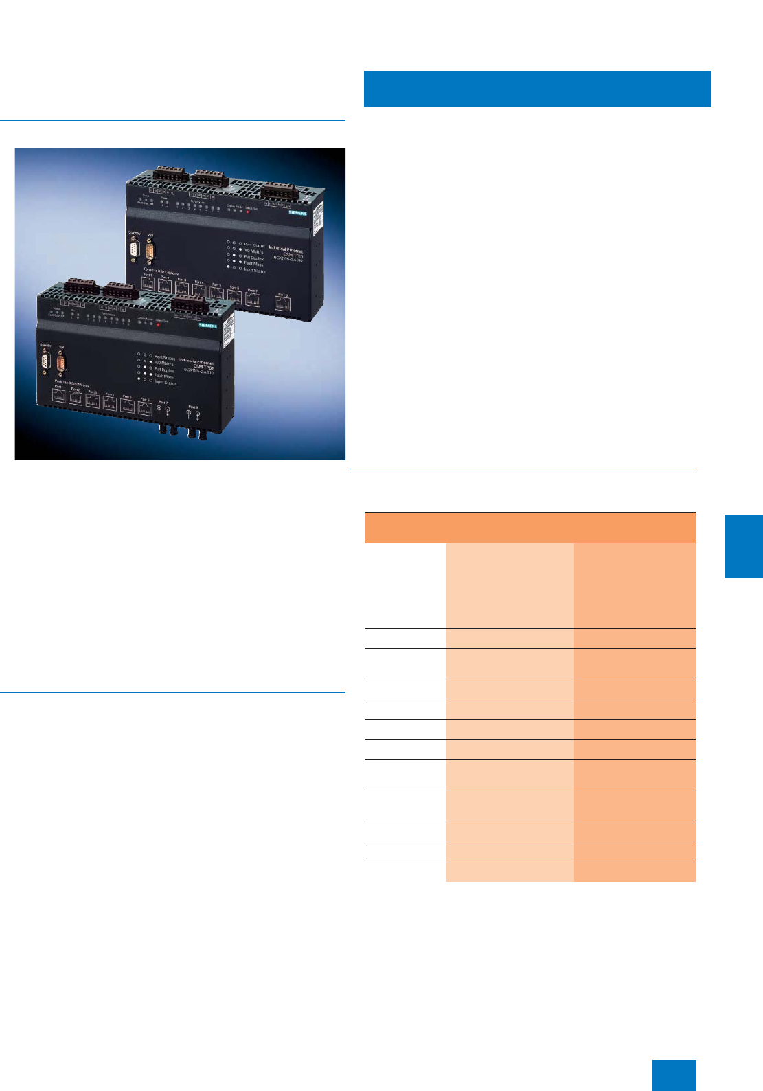
Communication
Industrial Ethernet
OSM/ESM/OMC Industrial Ethernet switches
9/21
Siemens ST PCS 7 · November 2007
9
■
Overview
The Industrial Ethernet OSM and ESM switches are used to con-
struct Industrial Ethernet networks at the control level:
• The modules are interconnected (backbone) at 100 Mbit/s
over
- Glass fiber-optic cables (FO) for OSM
- Twisted pair cables for ESM
• Connection of data terminals or network segments depending
on the OSM/ESM type through
- 2 to 8 twisted pair ports 10/100BaseTX in RJ45 or 9-pole
Sub-D design for 10/100 Mbit/s
- 3 or 8 FO ports 100BaseFX with BFOC interface (ST socket)
for 100 Mbit/s
• Integral redundancy manager supports high-speed media re-
dundancy also for large networks
• Very easy network configuration and extension without com-
plex configuration rules or parameterization
■
Application
Industrial Ethernet OSM and ESM
The Industrial Ethernet OSM (Optical Switch Module) and ESM
(Electrical Switch Module) are used in the construction of
switched networks with data transmission rates of 100 Mbit/s in
the control level range, in which strict demands are placed on
network availability and comprehensive diagnostics are re-
quired.
In existing networks, load decoupling and thus increased net-
work performance can be achieved by creating segments (di-
viding a network into subnetworks/segments) and connecting
these segments to an OSM/ESM.
The redundancy manager integrated into OSM/ESM allows In-
dustrial Ethernet rings to be constructed in switching technology
with high-speed switching over of the communication path on
failure of a switch or interruption in the transmission path (recon-
figuration time max. 0.3 seconds).
The transmission rate in the ring is 100 Mbit/s; for each ring, up
to 50 Industrial Ethernet OSMs (optical ring) or ESMs (electrical
ring) can be used. Apart from the 2 ring ports, OSM/ESM has
other ports (with either RJ45, ITP or BFOC interfaces) to which
data terminals or network segments can be connected.
Selection support for the various product versions of OSM is pro-
vided by the table under "Technical specifications".
Industrial Ethernet media converter
Industrial Ethernet nodes with RJ45 TP interface can be con-
nected via an Industrial Ethernet media converter to one of the
8 optical ports of an OSM BC08. The two types of media con-
verter SCALANCE X101-1 or X101-1LD convert the electric
twisted-pair interface, port type 10/100BaseTX (10/100 Mbit/s,
RJ45 socket) as follows:
• X101-1: into an optical interface for multimode glass FOC
• X101-1LD: into an optical interface for singlemode glass FOC
The port type of the optical interface is 100BaseFX in each case
(100 Mbit/s; 2 x BFOC socket).
Notes:
Just like the OMC TP11 media converter, the SCALANCE X101-1 does
not support diagnostics per SNMP protocol.
For further information on the Industrial Ethernet media converter, see
Catalog IK PI, Section "Active network components - Industrial Ethernet
media converter".
■
Technical specifications
Selection support for product versions of OSM and ESM
1) TP cable preferably inside a control cabinet
2) For cross-building connection of Fast Ethernet networks with OSM
3) For design of an optical network, where TP cables are preferably only used
inside control cabinets
4) Connects a station with RJ45-TP interface to one of the 8 optical ports of
an OSM BC08
5) Inside buildings
6) Inside switchrooms
Type and
number of ports Preferentially
for use
RJ45 (TP)
Sub-D (ITP)
Multi-mode FO
Single-mode FO
With
high
EMC
loading
For
plant
bus
For ter-
minal
bus
(OS-
LAN)
OSM TP22 2 – 2 – n1) n n
OSM ITP62
(Standard) – 6 2 – n n n
OSM TP62 6 – 2 – n n
OSM ITP62-LD – 6 – 2 n n n
OSM ITP53 – 5 3 – n n 2) n2)
OSM BC08 ––- 8 – n3) n3) n3)
SCALANCE
X101-1 1–- 1 – n4) n4) n4)
SCALANCE
X101-1LD 1–- –- 1n4) n4) n4)
ESM ITP80 – 8 – – n n 5) n
ESM TP40 4 – – – n6) n
ESM TP80 8 – – – n6) n
© Siemens AG 2007

Communication
Industrial Ethernet
OSM/ESM/OMC Industrial Ethernet switches
9/22 Siemens ST PCS 7 · November 2007
9
E) Subject to export regulations: AL: N, ECCN: 5A991
■
Selection and Ordering Data Order No.
Industrial Ethernet OSM TP22
Optical switch module with 2 fiber
optic ports 100 Mbit/s, 2 RJ45
ports 10/100 Mbit/s and 4 digital
inputs; redundant 24 V DC supply
and signal contact; with network
management
6GK1 105-2AE00
Industrial Ethernet OSM ITP62
Optical switch module with 2 fiber
optic ports 100 Mbit/s, 6 ITP ports
10/100 Mbit/s and 8 digital inputs;
redundant 24 V DC supply and
signal contact; with network man-
agement
6GK1 105-2AA10
Industrial Ethernet OSM TP62
Optical switch module with 2 fiber
optic ports 100 Mbit/s, 6 RJ45
ports 10/100 Mbit/s and 8 digital
inputs; redundant 24 V DC supply
and signal contact; with network
management
6GK1 105-2AB10
Industrial Ethernet
OSM ITP62-LD
Optical switch module with 2 fiber
optic ports 100 Mbit/s long dis-
tance (single-mode fiber optic
cable up to 26 km), 6 ITP ports
10/100 Mbit/s and 8 digital inputs;
redundant 24 V DC supply and
signal contact; with network man-
agement
6GK1 105-2AC10
Industrial Ethernet OSM ITP53
Optical switch module with 3 fiber
optic ports 100 Mbit/s, 5 ITP ports
10/100 Mbit/s and 8 digital inputs;
redundant 24 V DC supply and
signal contact; with network man-
agement,
for cross-building connection of
two Fast Ethernet networks with
OSM
6GK1 105-2AD10
Industrial Ethernet ESM TP40
Electrical switch module with
4 RJ45 ports 10/100 Mbit/s and
4 digital inputs; redundant
24 V DC supply and signal con-
tact; with network management,
preferably for OS-LAN
6GK1 105-3AC00
Industrial Ethernet ESM ITP80
Electrical switch module with
8 ITP ports 10/100 Mbit/s and
8 digital inputs; redundant
24 V DC supply and signal con-
tact; with network management,
preferably for OS-LAN
6GK1 105-3AA10
Industrial Ethernet ESM TP80
Electrical switch module with
8 RJ45 ports 10/100 Mbit/s and
8 digital inputs; redundant
24 V DC supply and signal con-
tact; with network management,
preferably for OS-LAN
6GK1 105-3AB10
Industrial Ethernet OSM BC08
Optical switch module with 8 fiber
optic ports 100 Mbit/s and
8 digital inputs; redundant
24 V DC supply and signal con-
tact; with network management
6GK1 105-4AA00
SCALANCE X101-1 Industrial
Ethernet media converter
For conversion from RJ45 TP to
multimode fiber optic cable
(BFOC) with 100 Mbit/s;
1 x 10/100 Mbit/s RJ45 Port and
1 x 100 Mbit/s multimode BFOC;
redundant 24 V supply and signal
contact
6GK5 101-1BB00-2AA3 E)
SCALANCE X101-1LD Industrial
Ethernet media converter
For conversion from RJ45 TP to
singlemode fiber optic cable
(BFOC) with 100 Mbit/s;
1 x 10/100 Mbit/s RJ45 Port and
1 x 100 Mbit/s singlemode BFOC;
redundant 24 V supply and signal
contact
6GK5 101-1BC00-2AA3 E)
■
Selection and Ordering Data Order No.
© Siemens AG 2007
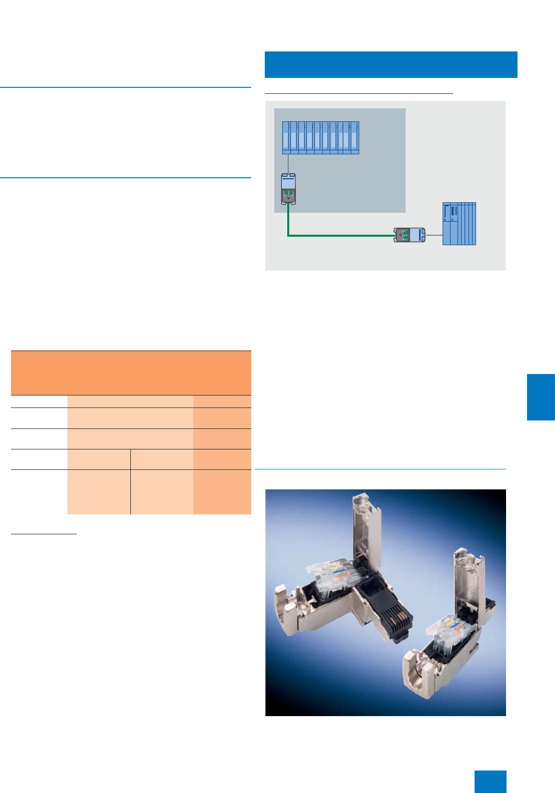
Communication
Industrial Ethernet
Passive network components: FastConnect
9/23
Siemens ST PCS 7 · November 2007
9
■
Overview
Industrial Ethernet FastConnect (IE FC) is a fast assembly sys-
tem with insulation displacement for easy assembly and wiring
of 4-core and 8-core IE FC cables. Using the FC Stripping Tool it
is possible to remove the outer casing and the woven shield of
the IE FC cable accurately in a single step. The cable prepared
in this manner is subsequently assembled on the contacts of the
connection element.
■
Application
Connection elements
The connection elements which can be used depend on
whether the transmission rate is 10/100 Mbit/s or 1000 Mbit/s:
• IE FC RJ45 Plug 90/180 (10/100 Mbit/s) in association with
4-core (2 x 2) IE FC cables
• IE FC Outlet RJ45 (10/100 Mbit/s) in association with 4-core
(2 x 2) IE FC cables
• IE FC RJ45 Modular Outlet (10/100/1000 Mbit/s) with 8-core
(4 x 2) IE FC cables
The following table provides an overview of the available
switches, the transmission rates they support, and the IE FC
standard cables and IE FC connection elements which can be
used. In addition to the IE FC standard cables, Catalog IK PI of-
fers further IE FC cables with special properties.
IE FC RJ45 Plugs
The IE FC RJ45 Plugs are the ideal solution for communication
links with a transmission rate up to 100 Mbit/s. They permit sim-
ple, fast and direct assembly of the 4-core (2 x 2) twisted pair
(TP) FastConnect installation cables in the field (without patch
technology) up to a cable length of 100 m. Since the IE FC RJ45
Plugs have no parts which can be lost, assembly is also possible
under difficult conditions.
IE FC Outlet RJ45 and IE FC RJ45 Modular Outlet
Alternatives for conversion from RJ45 to the insulation displace-
ment system are the
• IE FC Outlet RJ45 for 4-core TP (2 x 2) IE FC cables and trans-
mission rates up to 100 Mbit/s and
• IE FC RJ45 Modular Outlet for 8-core TP (4 x 2) IE FC cables
and transmission rates up to 1000 Mbit/s.
The latter has the advantage that the existing wiring can still be
used if the communication is converted from 100 Mbit/s to
1000 Mbit/s. It is only necessary to replace the 2FE insert by one
of type 1GE. In contrast to the plugs, an RJ45 patch cable
(TP Cord) is additionally required for each outlet which connects
this to the network components or data terminal.
Detailed information on the FastConnect Outlets and the avail-
able TP Cords can be found in Catalog IK PI, Section "Industrial
Ethernet", and in the A&D Mall, or in CA 01 under "Communica-
tion/networks / SIMATIC NET communication systems".
Further information on network structures is provided in the man-
ual for TP and fiber-optic networks.
■
Design
IE FC RJ45 plug with 90° outgoing cable (left) and with 180° outgoing
cable (right)
Switches X414-3E, X408-2, X310, X308-2,
X308-2LD, X204 IRT, X202-2 IRT,
X202-2P IRT, X201-3P IRT, X224,
X216, X212-2, X212-2LD, X208,
X206-1LD,X204-2, ESM
X414-3E,
X408-2
Port type 10/100BaseTX 1000BaseTX
Transmission
rate 10/100 Mbit/s 1.000 Mbit/s
Max. cable
length 100 m 100 m
Cable type IE FC Standard
Cable 2 x 2 IE FC Standard
Cable 4 x 2 IE FC Standard
Cable 4 x 2
Connection
elements IE FC RJ45
Plug 90/180,
alternative: IE FC
Outlet RJ45
+ TP Cord
IE FC RJ45
Modular Outlet
with insert 2FE
+ TP Cord
IE FC RJ45
Modular Outlet
with insert 1GE
+ TP Cord
SCALANCE X-400
1000 Mbit/s connection
SIMATIC PCS 7
automation
system
IE FC RJ45 Modular Outlet
Insert 1GE
IE FC Standard Cable 4x2
IE FC RJ45 Modular
Outlet Insert 1GE
© Siemens AG 2007
Communication
Industrial Ethernet
Passive network components: FastConnect
9/24 Siemens ST PCS 7 · November 2007
9
Industrial Ethernet FastConnect RJ45 Plugs are available in two
versions:
• with 180° (straight) outgoing cable,
• with 90° (angled) cable outlet.
They are used for optimized connection of Industrial Ethernet
FastConnect cables to data terminals and network components.
The plugs have a rugged, industry-compatible metal housing
that provides optimum protection against faults in data commu-
nication. The 4 integral insulation displacement contacts permit
simple, fault-free contacting of the various types of FC cable.
Following introduction of the stripped ends of the cables into the
tipped-up barrel contacts, the latter are pressed down for secure
contacting of the conductors.
The IE FC RJ45 Modular Outlet (Base Module) designed for
transmission rates up to 1,000 Mbit/s consists of a rugged metal
housing with IP40 degree of protection which is suitable for both
DIN rail and wall mounting. It has 8 barrel contacts for connect-
ing 8-core Industrial Ethernet FC installation cables and an inter-
face for the replaceable insert, e.g.:
• IE FC RJ45 Modular Outlet Insert 2FE with 2 x RJ45 sockets
for 100 Mbit/s
• IE FC RJ45 Modular Outlet Insert 1GE with 1 x RJ45 socket for
1,000 Mbit/s
■
Selection and Ordering Data Order No.
Industrial Ethernet
FCStandardCable GP2x2
For universal use, for connection
to IE FC Outlet RJ45 or IE FC
RJ45, 4-core (2 x 2), shielded
• Cut-to-length;
max. delivery length 1,000 m,
minimum ordering length 20 m
6XV1 840-2AH10
• Preferred length 1,000 m 6XV1 840-2AU10
Industrial Ethernet
FCStandardCable GP4x2
For universal use, for connection
to IE FC Modular Outlet RJ45,
8-core (4 x 2), shielded
• Cut-to-length;
max. delivery length 1,000 m,
minimum ordering length 20 m
6XV1 870-2E
Industrial Ethernet
FC Stripping Tool
Preadjusted stripping tool for fast
stripping of Industrial Ethernet FC
cables
6GK1 901-1GA00
Industrial Ethernet FC Blade
Cassettes
Spare blade cassettes for the
FC stripping tool, 5 cassettes
6GK1 901-1GB00
IE FC RJ45 Plug 180
RJ45 plug connector for Industrial
Ethernet with a rugged metal
housing and integrated insulation
displacement contacts for con-
necting Industrial Ethernet FC
installation cables; with 180°
cable outlet; for network compo-
nents and CPs/CPUs with Indus-
trial Ethernet interface
• 1 pack = 1 unit 6GK1 901-1BB10-2AA0
• 1 pack = 10 units 6GK1 901-1BB10-2AB0
• 1 pack = 50 units 6GK1 901-1BB10-2AE0
Industrial Ethernet FC RJ45
Plug 90
RJ45 plug connector for Industrial
Ethernet with a rugged metal
housing and integrated insulation
displacement contacts for con-
necting Industrial Ethernet FC
installation cables; with 90° cable
outlet
• 1 pack = 1 unit 6GK1 901-1BB20-2AA0
• 1 pack = 10 units 6GK1 901-1BB20-2AB0
• 1 pack = 50 units 6GK1 901-1BB20-2AE0
Industrial Ethernet
FC Outlet RJ45 6GK1 901-1FC00-0AA0
IE FC RJ45 Modular Outlet with
Insert 1GE
FastConnect RJ45 Outlet for
Industrial Ethernet with a replace-
able insert for 1 x 1,000 Mbit/s
interface
6GK1 901-1BE00-0AA2
IE FC RJ45 Modular Outlet with
Insert 2FE
FastConnect RJ45 Outlet for
Industrial Ethernet with a replace-
able insert for 2 x 100 Mbit/s inter-
face
For further IE FC RJ45 Modular
Outlet versions and replaceable
inserts, see Catalog IK PI
6GK1 901-1BE00-0AA1
Documentation
Manual for TP and fiber-optic
networks
Network architecture, compo-
nents, configurations, installation
•German 6GK1 970-1BA10-0AA0
• English 6GK1 970-1BA10-0AA1
■
Selection and Ordering Data Order No.
© Siemens AG 2007
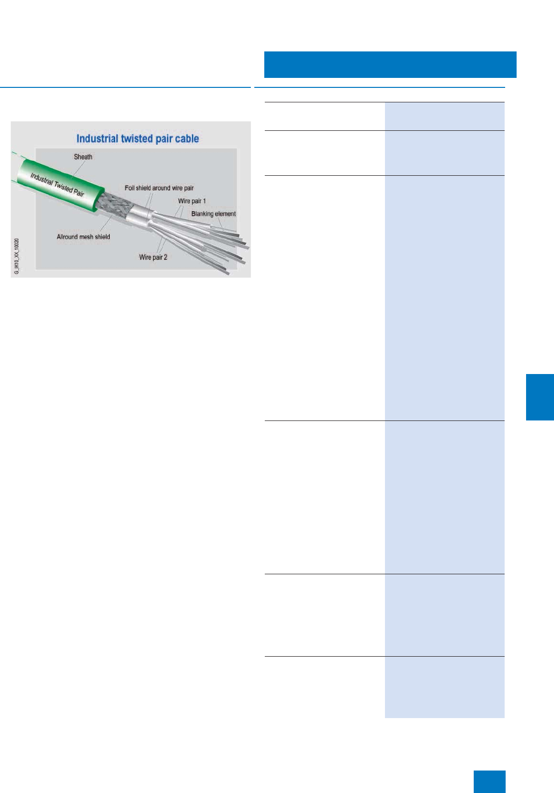
Communication
Industrial Ethernet
Passive network components:
ITP cables and connectors
9/25
Siemens ST PCS 7 · November 2007
9
■
Overview
Electrical transmission media
Terminals can be connected through industrial twisted pairs
(ITPs). The preassembled ITP standard cable with Sub-D con-
nectors is available for connection between stations and network
components. Line lengths of up to 100 m can be achieved while
saving on patch technology.
The ITP standard cable 9/15 is equipped with a 9-pin and a
15-pin connector. The cable is used for direct connection of ter-
minals with ITP interface to Industrial Ethernet components with
ITP interface.
The ITP XP standard cable 9/9 is equipped with two 9-pin con-
nectors. This cable is crossed for direct connection of two Indus-
trial Ethernet network components with ITP interface.
The ITP XP standard cable 15/15 is equipped with two 15-pin
connectors. This cable is crossed for direct connection of two
terminals with ITP interface.
The Industrial Ethernet ITP connectors have Sub-D connectors
made of metal and are available in two versions:
• 9-pin plug with straight cable outlet, for connection to
OSM/ESM, OLM or ELM
• 15-pin plug with variable cable outlet, for connection to termi-
nals with ITP interface
Alternatively, the terminals can also be connected to twisted pair
(TP cord) cables. Detailed information on TP cord cables can be
found in the IK PI catalog, in the A&D Mall or in CA 01 at "Com-
munication/Networks / SIMATIC NET communication systems".
■
Selection and Ordering Data Order No.
ITP Standard Cable for
Industrial Ethernet
Not preassembled, cut-to-length
2 x 2-core, without connectors
For connection of a terminal; for
self-assembly of connectors or for
the connection between patch
panel and socket
6XV1 850-0AH10
ITP Standard Cable 9/15
ITP installation cable for direct
connection of terminals with ITP
interface to Industrial Ethernet
network components with ITP
interface;
with a 9-pin and a 15-pin Sub-D
plug
•2 m 6XV1 850-0BH20
•5 m 6XV1 850-0BH50
•8 m 6XV1 850-0BH80
•12 m 6XV1 850-0BN12
•15 m 6XV1 850-0BN15
•20 m 6XV1 850-0BN20
•30 m 6XV1 850-0BN30
•40 m 6XV1 850-0BN40
•50 m 6XV1 850-0BN50
•60 m 6XV1 850-0BN60
•70 m 6XV1 850-0BN70
•80 m 6XV1 850-0BN80
•90 m 6XV1 850-0BN88
•100 m 6XV1 850-0BT10
ITP XP Standard Cable 9/9
Crossed ITP installation cable for
direct connection of two Industrial
Ethernet network components
with ITP interface;
with two 9-pin Sub-D plugs
•2 m 6XV1 850-0CH20
•5 m 6XV1 850-0CH50
•8 m 6XV1 850-0CH80
•12 m 6XV1 850-0CN12
•15 m 6XV1 850-0CN15
•20 m 6XV1 850-0CN20
•30 m 6XV1 850-0CN30
•40 m 6XV1 850-0CN40
ITP XP Standard Cable 15/15
Crossed ITP installation cable for
direct connection of two terminals
with ITP interface;
with two 15-pin sub-D plugs
•2 m 6XV1 850-0DH20
•6 m 6XV1 850-0DH60
•10 m 6XV1 850-0DN10
ITP Connector for Industrial
Ethernet
• 9-pin, for connection to
OSM/ESM, OLM or ELM 6GK1 901-0CA00-0AA0
• 15-pin, for connection to
terminals with ITP interface 6GK1 901-0CA01-0AA0
© Siemens AG 2007

Communication
Industrial Ethernet
Passive network components: Fiber-optic cables
9/26 Siemens ST PCS 7 · November 2007
9
■
Overview
Optical transmission media
Glass fiber-optic cables are preferably used as the optical trans-
mission medium. The two types of cable offered are suitable for
above-ground routing indoors or outdoors. They are available in
fixed lengths, precut/preassembled with 2 x 2 BFOC connectors
(FIBER OPTIC standard cable) or 2 x 2 SC-connectors
(FO Standard Cable).
The FO Standard Cable with 2 x 2 SC connectors is required for
optical networks in the Gigabit range, e.g. for implementing op-
tical Gigabit Ethernet rings with SCALANCE X414-3E and
MM492-2 media modules.
■
Technical specifications
Switches X414-3E + MM492-2,
X408-2 + MM492-2 X414-3E + MM491-2,
X408-2 + MM491-2,
X212-2, X212-2LD,
X202-2 IRT, X206-1LD,
X204-2, OSM
Port type 1000BaseSX 100BaseFX
Transmission rate 1000 Mbit/s 10/100 Mbit/s
Max. cable length 750 m 3000 m
Cable type FO Standard Cable Fiber optic standard
cable
FO multimode fiber
type 50/125 µm 62.5/125 µm
Connector type 2 x 2 SC 2 x 2 BFOC (ST)
Cable type FO
Standard Cable FIBER OPTIC
Standard Cable
Applications Universal cable for
installation indoors and
outdoors
Delivery format Cut-to-length,
pre-assembled with
4 BFOC(ST) or
4 SC connectors
Cut-to-length,
pre-assembled with
4 BFOC connectors
(ST)
Cable type (stan-
dard designation) AT-W(ZN)YY
2x1G50/125 AT-VYY 2G62.5/125
3.1B200 + 0.8F600 F
Fiber type Multimode gradient
fiber 50/125 mm Multimode gradient
fiber 62.5/125 mm
Damping
• At 850 nm ≤ 2.7 dB/km ≤ 3.1 dB/km
• At 1300 nm ≤ 0.7 dB/km ≤ 0.8 dB/km
Modal bandwidth
• At 850 nm ≥ 600 MHz × km ≥ 200 MHz × km
• At 1300 nm ≥ 1200 MHz × km ≥ 600 MHz × km
Number of fibers 2 2
Cable design Segmentable Segmentable outer
conductor
Core type Hollow core, filled Compact core
Materials
• Basic element PVC, orange/black PVC, gray
• Strain relief Aramide fiber Kevlar fiber and impreg-
nated glass fiber
• Outer sheath/color
of cable PVC, green PVC, black
Mechanical charac-
teristics
• Dimensions of ba-
sic element 2.9 mm diam. (3.5 ± 0.2) mm diam.
• Cable dimensions 4.5 x 7.4 mm (6.3 × 9.8) ± 0.4 mm
• Cable weight Approx. 40 kg/km Approx. 74 kg/km
• Permissible tensile
force ≤ 500 N ≤ 500 N (temporary)
• Bending radius 70 mm ≥ 100 mm only on the
flat side
• Resistance to later-
al force 300 N/cm –
Permissible ambi-
ent conditions
• Routing and instal-
lation temperature -5 ... +50 ºC -5 ... +50 ºC
• Operating temper-
ature -25 ... +80 ºC -20 ... +60 ºC
• Storage temper-
ature -25 ... +80 ºC -25 ... +70 ºC
Behavior in fire –Flame-retardant to
IEC 60332-3 and
VDE 0482-266-2-4
Silicone-free Yes Yes
Resistance to min-
eral oils and grease Limited resistance –
UL/CSA approvals OFNG, UL1651
FT4/IEEE1202 –
UV-resistant Yes –
Rodent protection –Yes
Gigabit length
• 1000BaseSX 750 m –
• 1000BaseLX 2000 m –
© Siemens AG 2007

Communication
Industrial Ethernet
Passive network components: Fiber-optic cables
9/27
Siemens ST PCS 7 · November 2007
9
B) Subject to export regulations: AL: N, ECCN: EAR99H
1) Special tools and specially trained personnel are required for
pre-assembling glass fiber-optic cables.
Other lengths and other fiber-optic cables can be found in
Catalog IK PI.
Note:
Supplementary components for the SIMATIC NET cable range
can be ordered from your local contact person. For technical
support, please contact:
J. Hertlein, A&D SE PS
Tel.: +49 911 750-4465
Fax: +49 911 750-9991
E-mail: juergen.hertlein@siemens.com
Further information on assembly is provided in the manual for TP
and fiber-optic networks.
■
Selection and Ordering Data Order No.
FO Standard Cable
50/125 1)
Preferred lengths, preassembled
with 2 x 2 SC connectors:
•1 m 6XV1 873-6AH10
•3 m 6XV1 873-6DH30
•5 m 6XV1 873-6DH50
•10 m 6XV1 873-6AN10
•20 m 6XV1 873-6DN20
•50 m 6XV1 873-6DN50
•100 m 6XV1 873-6AT10
•200 m 6XV1 873-6AT20
•300 m 6XV1 873-6GT30
FIBER OPTIC CABLE standard
cable
62.5/125, splittable 1)
Preferred lengths, preassembled
with 2 x 2 BFOC (ST) connectors:
•1 m 6XV1 820-5BH10 B)
•3 m 6XV1 820-5BH30 B)
•5 m 6XV1 820-5BH50 B)
•10 m 6XV1 820-5BN10 B)
•20 m 6XV1 820-5BN20 B)
•50 m 6XV1 820-5BN50 B)
•100 m 6XV1 820-5BT10 B)
•200 m 6XV1 820-5BT20 B)
•300 m 6XV1 820-5BT30 B)
BFOC (ST) connector set
For FIBER OPTIC CABLE
standard cable, 20 units
6GK1 901-0DA20-0AA0 B)
© Siemens AG 2007
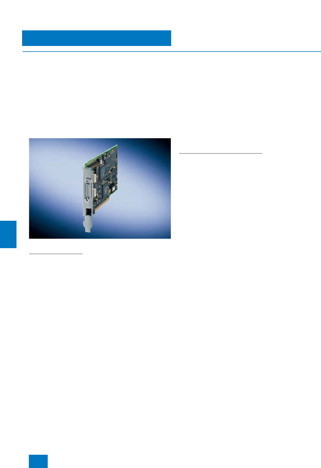
Communication
Industrial Ethernet
System connection PCS 7 systems
9/28 Siemens ST PCS 7 · November 2007
9
■
Design
Connection of single stations, servers and clients
SIMATIC PCS 7 subsystems for engineering, operation and
monitoring (also via Internet/Intranet), batch control, route con-
trol, asset management or IT applications are distributed be-
tween various SIMATIC PCS 7 Industrial Workstations of single
station, server or client design depending on the configuration.
Depending on their task and the associated integration into
the complete system, these SIMATIC PCS 7 Industrial
Workstations are connected either only on the plant bus, only
on the OS LAN (terminal bus) or on both buses of the Industrial
Ethernet network. The redundant or non-redundant connection
is made using onboard interfaces, simple network cards or spe-
cial communications processors (e.g. CP 1613).
CP 1613
Connection to plant bus
Single stations and servers can be operated on the plant bus via
Basic Communication Ethernet (network card plus BCE license)
or CP 1613 communication. CP 1613 communication is always
required for ES/OS single stations and OS servers if an operator
system has more than 8 subordinate automation systems or if
fault-tolerant automation systems are used. In all other cases,
the more cost-effective Basic Communication Ethernet (BCE)
can be used instead.
BCE and CP 1613 communication is embedded in each case in
an alternative SIMATIC PCS 7 Workstation for single station and
server.
The separately available desktop adapter network card can also
be used for BCE. The BCE license is already included with SI-
MATIC PCS 7 Workstations. If you use alternative hardware in-
stead for your stations, you require an additional BCE license for
each station which communicates over the plant bus via BCE.
The CP 1613 communication delivered with SIMATIC PCS 7
Workstations for single stations and servers instead of BCE is
a combination of CP 1613 communications processor and
S7-1613 communications software. However, if fault-tolerant
automation systems are used, ES/OS single stations and
OS servers require the S7-REDCONNECT software instead of
the S7-1613 communications software. ES/OS single stations
and OS servers with S7-1613 communications software can be
accordingly upgraded in this case using the S7-REDCONNECT
Upgrade (see also page 9/28).
Single stations and servers with BCE can also be subsequently
upgraded to CP 1613 communication. Depending on the above-
mentioned criteria, either the S7-1613 communications software
or the S7-REDCONNECT software is required in addition to the
CP 1613 communications processor.
Connection to OS LAN (terminal bus)
SIMATIC PCS 7 Industrial Workstations in client, server or single
station designs are connected as standard to the OS LAN via the
onboard Industrial Ethernet interface. In the case of servers or
single stations without a connection to the plant bus, the network
card envisaged for BCE can be used as an alternative.
The OS LAN can also have a redundant configuration, where two
rings are connected together via two pairs of switches (see also
"Introduction" at the beginning of the catalog section on Indus-
trial Ethernet). A "SIMATIC PCS 7 Redundant Terminal Bus
Adapter Package", comprising server and desktop adapter net-
work cards, is required to connect the stations to the two rings of
the redundant OS LAN.
Connection of automation systems
The SIMATIC PCS 7 automation systems communicate with
other subsystems of the process control system (e.g. operator
system or engineering system) via the Industrial Ethernet plant
bus. The automation systems are connected to the plant bus us-
ing the CP 443-1 communications processor, also redundant in
the case of fault-tolerant systems.
© Siemens AG 2007
Communication
Industrial Ethernet
System connection PCS 7 systems
9/29
Siemens ST PCS 7 · November 2007
9
B) Subject to export regulations: AL: N, ECCN: EAR99H
■
Selection and Ordering Data Order No.
System connection of single stations, servers and clients
Desktop adapter network card
for BCE and as spare part for
redundant terminal bus
INTEL PCI network card for con-
nection to Industrial Ethernet
(10/100/1000 Mbit/s), with RJ45
connection
A5E00504378 B)
SIMATIC PCS 7 Redundant
Terminal Bus Adapter Package
Server and desktop adapter for
designing a redundant terminal
bus,
consisting of 2 Intel PCI network
cards for connection to Industrial
Ethernet (10/100/1000 Mbit/s),
with RJ45 connection
6ES7 652-0XX01-1XF0 B)
CP 1613 A2
PCI card for connection to
Industrial Ethernet, with ITP and
RJ45 connections
6GK1 161-3AA01 B)
SIMATIC NET S7-1613/2006 for
Industrial Ethernet
S7 communications software for
CP 1613,
runtime software, in 2 languages
(German, English), executes with
Windows 2000 Professional/
2000 Server/ XP Professional/
Server 2003, single license for
1 installation,
software and electronic manual
on CD-ROM, license key on dis-
kette
6GK1 716-1CB64-3AA0
SIMATIC NET
S7-REDCONNECT/2006
Software for fail-safe S7 commu-
nication over redundant networks,
for CP 1613, runtime software, in
2 languages (German, English),
executes with Windows
2000 Professional/ 2000 Server/
XP Professional/ Server 2003, sin-
gle license for 1 installation, soft-
ware and electronic manual on
CD-ROM, license key on diskette
6GK1 716-0HB64-3AA0
SIMATIC NET
S7-REDCONNECT/2006
Upgrade
Software for expansion of
S7-1613 to S7-REDCONNECT,
runtime software, in 2 languages
(German, English), executes with
Windows 2000 Professional/
2000 Server/ XP Professional/
Server 2003, single license for
1 installation,
software and electronic manual
on CD-ROM, license key on dis-
kette
6GK1 716-0HB64-3AC0
System connection of single stations and servers which are not
based on the SIMATIC PCS 7 Industrial Workstation
PCS 7 BCE V7.0
Runtime license for plant bus
communication via standard net-
work card and Basic
Communication Ethernet; already
integrated in SIMATIC PCS 7
Industrial Workstations,
in 3 languages (German, English,
French), executes with Windows
XP Professional or Windows
Server 2003, floating license for
1user
Type of delivery: License key
disk, certificate of license, terms
and conditions
6ES7 650-1CD07-2YB5
System connection of automation systems
CP 443-1
Communications processor for
connection of SIMATIC S7-400 to
Industrial Ethernet through
TCP/IP, ISO and UDP; for S7 com-
munication, S5-compatible com-
munication (SEND/RECEIVE) with
FETCH/WRITE with or without
RFC 1006, diagnostics expan-
sion, Multicast, commissioning
through LAN 10/100 Mbit/s, with
electronic manual on CD-ROM
6GK7 443-1EX11-0XE0
■
Selection and Ordering Data Order No.
© Siemens AG 2007
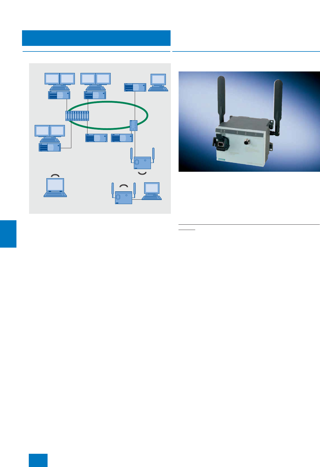
Communication
Industrial Ethernet
Industrial Wireless LAN (IWLAN)
9/30 Siemens ST PCS 7 · November 2007
9
■
Overview
SIMATIC PCS 7 allows you to integrate mobile or stationary
remote clients into the OS-LAN (terminal bus) via a SCALANCE
W788-1PRO access point.
The following applications can be implemented in this manner:
• Use of additional remote OS clients (1 or 2 on IWLAN)
• Linking of Web clients to a SIMATIC PCS 7 Web server (1 or
2 on IWLAN)
• Remote access to an engineering station with application of
Remote Desktop (Windows XP or Server 2003 operating sys-
tem) or PC Anywhere, e.g. during commissioning
Mobile remote clients (e.g. notebooks) possessing a WLAN in-
terface can communicate with the access point via it. Stationary
remote clients in a desktop/tower housing (SIMATIC PCS 7 In-
dustrial Workstations) require a SCALANCE W746-1PRO Ether-
net client module for the IWLAN communication with the access
point.
SCALANCE W746-1PRO Ethernet client module and
SCALANCE W788-1PRO access point are both very rugged,
use state-of-the-art authentication and encryption procedures,
and guarantee high reliability of the radio channel.
Note:
Please note that Industrial Wireless LAN is not approved of as a terminal
bus (OS-LAN) or plant bus of SIMATIC PCS 7.
■
Design
SCALANCE W746-1PRO Ethernet client module
The SCALANCE W746-1PRO Ethernet client module is highly
suitable for integrating devices with an Industrial Ethernet con-
nection into Industrial Wireless LAN (IWLAN) radio networks with
reliable communication. The SCALANCE W746-1PRO Ethernet
client module handles the radio connection for a maximum of
eight connected devices with Ethernet interface. If one of the
connected devices is exchanged, the Ethernet client module
recognizes this immediately and administers the new address.
Special features of the SCALANCE W746-1PRO Ethernet client
module
• Versatile power supply facilities (operation on 100 V to 240 V
AC network with PS791-1PRO power supply)
• Antenna diversity for reliable reception in complex radio envi-
ronments with two ANT795-4MR omnidirectional antennas
screwed onto the housing, can be replaced by other types
from the SCALANCE W700 range
• Transmission rate up to 54 Mbit/s at 2.4 GHz and 5 GHz with
radio approval in more than 30 countries
• Conforms to the IEEE 802.11b/g and IEEE 802.11a standards
• High reliability through reservation of data transfer rate with
IWLAN communication with SCALANCE W788-1PRO access
point
• WPA and 128-bit encryption (AES) for high security against il-
legal access
• Rugged metal enclosure resistant to shock and vibration, and
with IP65 dust protection
• Suitable for ambient temperatures from -20 to +60°C (resistant
to condensation)
For further information and detailed technical specifications, re-
fer to Catalog IK PI, the A&D Mall or Catalog CA 01 under "Com-
munication/networks, SIMATIC NET communication systems, In-
dustrial mobile communication".
SCALANCE
X414-3
SCALANCE
X204-2/X208
OS-LAN
(terminal bus)
PCS 7
Web server
OS clients
Redundant
OS server
Engineering station
Access point
SCALANCE W788-1PRO
Ethernet
Client module
SCALANCE
W746-1PRO
Stationary
remote client
Mobile remote client
with WLAN interface
© Siemens AG 2007
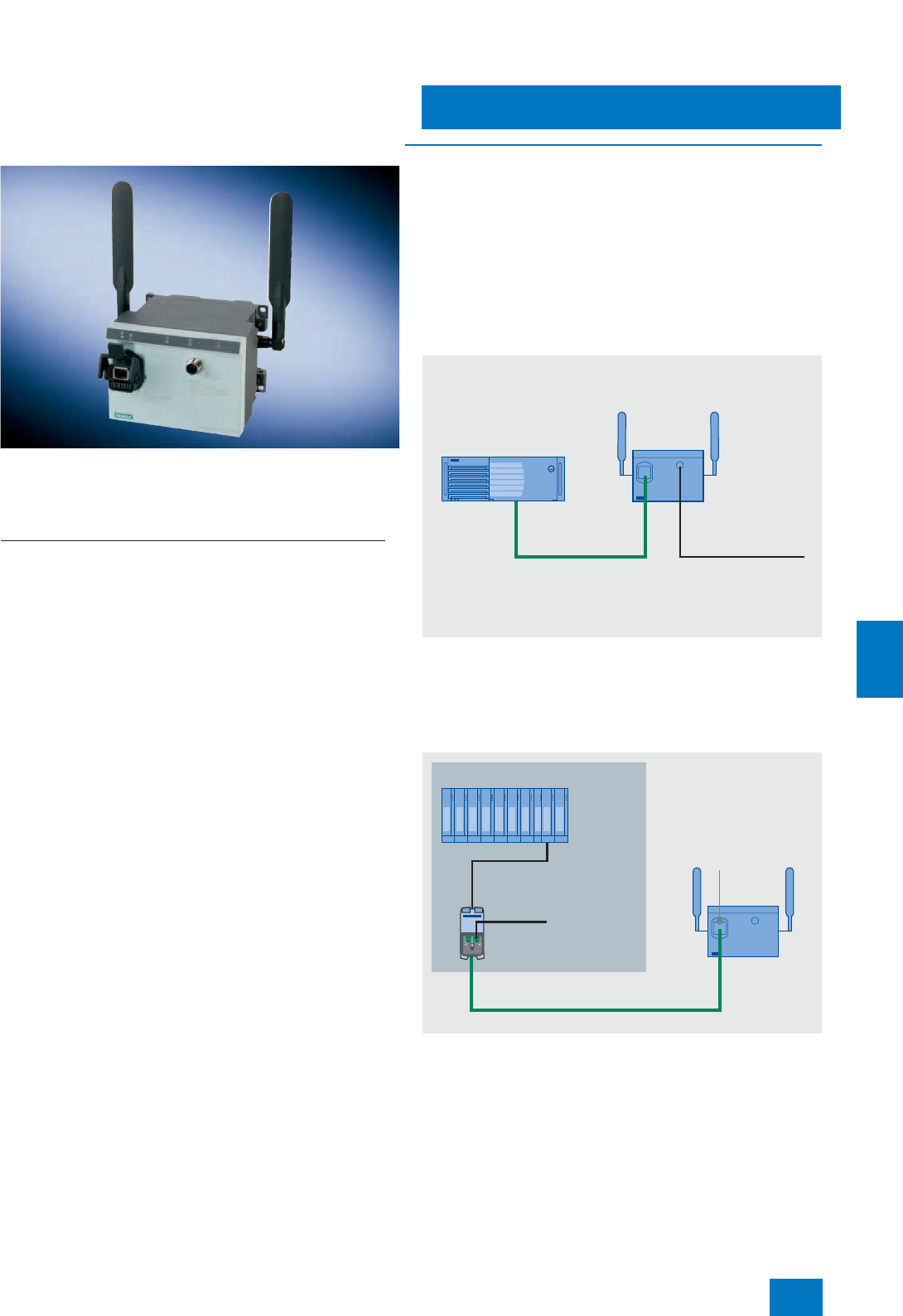
Communication
Industrial Ethernet
Industrial Wireless LAN (IWLAN)
9/31
Siemens ST PCS 7 · November 2007
9
SCALANCE W788-1PRO access point
The SCALANCE W788-1PRO access point is highly suitable for
designing Industrial Wireless LAN (IWLAN) radio networks with
reliable communication. It has an Industrial Ethernet interface for
the connection to the wire-bound network.
Special features of the SCALANCE W788-1PRO access point
• Versatile power supply facilities (operation on 100 V to 240 V
AC network with PS791-1PRO power supply)
• Antenna diversity for reliable reception in complex radio envi-
ronments with two ANT795-4MR omnidirectional antennas
screwed onto the housing, can be replaced by other types
from the SCALANCE W700 range
• Transmission rate up to 54 Mbit/s at 2.4 GHz and 5 GHz with
radio approval in more than 30 countries
• Conforms to the IEEE 802.11b/g and IEEE 802.11a standards
• WPA and 128-bit encryption (AES) for high security against il-
legal access
• Rugged metal enclosure resistant to shock and vibration, and
with IP65 dust protection
• Suitable for ambient temperatures from -20 to +60°C (resistant
to condensation)
For further information and detailed technical specifications, re-
fer to Catalog IK PI, the A&D Mall or Catalog CA 01 under "Com-
munication/networks, SIMATIC NET communication systems, In-
dustrial mobile communication".
■
Integration
The data and power connections for the SCALANCE
W746-1PRO Ethernet client module and the SCALANCE
W788-1PRO access point can be made using a hybrid cable or
separate cables (preferably over short distances):
• With separate cables, a 4-core TP (2 x 2) IE FC Standard Ca-
ble (type A) is used as the data cable. This Industrial Ethernet
cable is connected on site to the supplied IP67 hybrid plug
connector. A Power M12 Cable Connector PRO is additionally
required for the power supply. IE FC Standard Cable and
Power M12 Cable Connector PRO must be ordered in addi-
tion.
Example of data and power supply connections using separate cables
• If the data and power supply are connected using one cable,
an FC Modular Outlet with power insert and the hybrid cable
must be ordered in addition. The hybrid connector included in
the scope of supply and the FC Modular Outlet with power in-
sert can be assembled and connected on site.
Example of data and power supply connections using a hybrid cable
• If 100 ... 240 V AC is available on site, the PS791-1PRO power
supply can be used (to be ordered in addition). It is supplied
including AC connector and cable to the Ethernet client mod-
ule/access point, but without AC cable.
SCALANCE
W746-1PRO
PC
(remote client)
24 V DC
Power cable 2x0.75
with power M12 cable
connector PRO
IE FC cable 2x2
with hybrid
plug-in connector
SCALANCE X-400
24 V DC
IE FC RJ45 Modular
Outlet Power Insert
IE Hybrid Cable 2x2 + 4x0,34
IE Hybrid
cable connector
SCALANCE
W788-1PRO
© Siemens AG 2007

Communication
Industrial Ethernet
Industrial Wireless LAN (IWLAN)
9/32 Siemens ST PCS 7 · November 2007
9
G) Subject to export regulations: AL: N, ECCN: 5A002ENC3
1) Order directly from:
HARTING Deutschland GmbH & Co KG
P.O. Box 2451
D-32381 Minden
Tel. +49 571-8896-0
Fax. +49 571-8896-354
E-mail: de.sales@HARTING.com
Internet: www.HARTING.com
Further information on country approvals
Additional information is available in the Internet under:
http://www.siemens.com/simatic-net/ik-info
■
More information
Note:
Supplementary components for the SIMATIC NET cable range
can be ordered from your local contact person. Technical advice
on this subject is available from:
J. Hertlein A&D SE PS
Tel. +49 (0)911/750 44 65
Fax. 0911/750 99 91
E-mail: juergen.hertlein@siemens.com
■
Selection and Ordering Data Order No.
Stationary remote client
SCALANCE W746-1PRO
IWLAN Ethernet client module
with built-in radio interface;
IEEE 802.11b/g/a radio networks
at 2.4/5 GHz up to 54 Mbit/s.
Country approvals; WPA/AES;
Power over Ethernet (PoE),
IP65 protection (-20 to +60 °C)
for administration of the radio
connection of up to eight linked
devices with Industrial Ethernet
connection
Scope of delivery:
Two ANT795-4MR antennas,
IP67 hybrid connector, mounting
material,
manual on CD-ROM (German,
English)
• Country approvals for operation
outside the USA and Canada 6GK5 746-1ST00-2AA6 G)
• Country approvals for operation
in the USA and Canada 6GK5 746-1ST00-2AB6 G)
Access point
SCALANCE W788-1PRO
IWLAN access point with built-in
radio interface; IEEE 802.11b/g/a
radio networks at 2.4/5 GHz up to
54 Mbit/s. Country approvals;
WPA/AES; Power over Ethernet
(PoE), IP65 protection
(-20to+60°C)
Scope of delivery:
Two ANT795-4MR antennas,
IP67 hybrid connector, mounting
material,
manual on CD-ROM (German,
English)
• Country approvals for operation
outside the USA and Canada 6GK5 788-1ST00-2AA6 G)
• Country approvals for operation
in the USA and Canada 6GK5 788-1ST00-2AB6 G)
Components for system connection
Data and power connection via
separate lines
IE FC Standard Cable GP 2 x 2
4-core (2 x 2), shielded TP instal-
lation cable for universal use, can
be connected to IE FC Outlet
RJ45/IE FC RJ45 Plug; cut-to-
length; max. delivery unit 1000 m,
minimum ordering quantity 20 m
6XV1 840-2AH10
Power M12 Cable Connector
PRO
Socket for connection of
SCALANCE W-700 for 24 V DC
supply; 4-pole, a-coded, with
mounting instructions, 3 units
6GK1 907-0DC10-6AA3
Data and power connection via
common line
IE FC Standard Cable GP 2 x 2
4-core (2 x 2), shielded TP instal-
lation cable for universal use, can
be connected to IE FC Outlet
RJ45/IE FC RJ45 Plug; cut-to-
length; max. delivery unit 1000 m,
minimum ordering quantity 20 m
6XV1 840-2AH10
IE FC RJ45 Modular Outlet with
Power Insert
Fast Connect RJ45 Modular
Outlet for Industrial Ethernet with
a power insert for 1 x 24 V and
1 x 100 Mbit/s interface
6GK1 901-1BE00-0AA3
IE Hybrid Cable 2x2 + 4x0.34
4-core, shielded installation
cable;
cut-to-length; max. delivery unit
1000 m, minimum ordering quan-
tity 20 m
6XV1 870-2J
IP 67 hybrid connector
(1 unit included in delivery of
SCALANCE W746/788)
Plug for connection of
SCALANCE W-700 to Industrial
Ethernet and Power over Ethernet
(PoE), with mounting instructions,
1unit
09 45 125 1300.001)
Power supply for 100 to 240 V AC
PS791-1PRO power supply
AC/DC power supply, 10 W,
IP65 (-20 to +60°C),
input: 90 to 265 V AC, output:
24 V DC,
metal enclosure
Scope of delivery:
AC power 3+PE cable connector,
DC power cord M12, mounting
material, operating instructions
(German, English)
6GK5 791-1PS00-0AA6 G)
Accessories
For antennas and further acces-
sories for access points and
Ethernet client modules, refer to
Catalog IK PI, the A&D Mall or
Catalog CA 01 under "Communi-
cation/networks, SIMATIC NET
communication systems,
Industrial mobile communication"
■
Selection and Ordering Data Order No.
© Siemens AG 2007
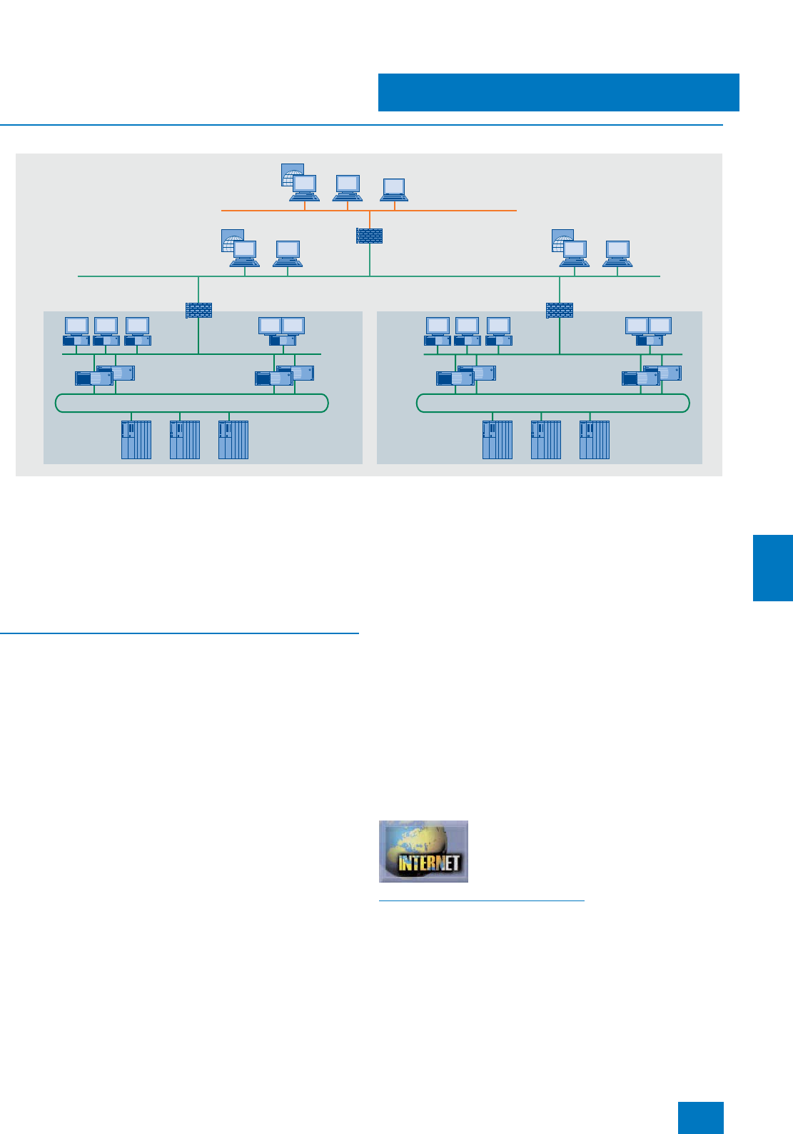
Communication
Industrial Security
Introduction
9/33
Siemens ST PCS 7 · November 2007
9
■
Overview
Example of "defense in depth" security architecture
The progressive standardization, opening and networking of
control systems has been accompanied by an enormous in-
crease in security risks. The potential dangers arising from de-
structive programs such as computer viruses, worms or trojans
or from access by unauthorized personnel range from network
overloads or failures, theft of passwords and data, to unautho-
rized access to the process automation. Apart from material
damage, specifically targeted sabotage can also have danger-
ous consequences for people and the environment.
■
Function
With its pioneering security concept, SIMATIC PCS 7 offers com-
prehensive solutions for safeguarding a process engineering
plant that are based on a hierarchical security architecture (de-
fense in depth). The special feature of this concept is its inte-
grated approach. It is not just restricted to the use of individual
security methods (e.g. encryption) or devices (e.g. firewalls). Its
strengths lie more in the interaction of a host of security mea-
sures in the plant network. The security concept is described in
detail in the manual "SIMATIC PCS 7 recommendations and in-
formation", and comprises advice and recommendations (best
practices) on the following topics:
• Creation of a network architecture with defense in depth, com-
bined with the segmentation of the plant into security cells
• Network administration with name resolution, assignment of
IP addresses and division into subnetworks
• Operation of plants in Windows domains (active directory)
• Administration of the Windows and SIMATIC PCS 7 operator
privileges; integration of the SIMATIC PCS 7 operator privi-
leges into the Windows administration
• Reliable control of the clock synchronization in the Windows
network
• Management of security patches for Microsoft products
• Use of antivirus software and firewalls
• Support and remote access (VPN, IPSec)
On the system side, SIMATIC PCS 7 V7.0 supports the imple-
mentation of guidelines and recommendations of the security
concept by means of:
• Compatibility with the current versions of the antivirus soft-
ware: Trend Micro OfficeScan, Symantec Norton AntiVirus and
McAfee Virusscan
• Application of the local Windows XP firewall
• SIMATIC security control (SSC) for automatic setting of safety-
related parameters of DCOM, registry and Windows firewall
during the setup
• User administration and authentication by means of SIMATIC
Logon
• Integration of the SCALANCE S602, S612 and S613 industrial
security modules of SIMATIC NET
The manual "SIMATIC PCS 7 Security Concept, Recommenda-
tions and Advice" is available on the Internet via the SIMATIC
Guide for Technical Documentation under "SIMATIC PCS 7
Process Control Systems & Migration".
You can find the SIMATIC Guide for Technical Documentation on
the Internet.
Additional information is available in the Internet under:
http://www.siemens.com/simatic-docu
INTERNET
INTERNET
INTERNET
Plant bus 1
Terminal bus 1 (OS-LAN) Terminal bus 2 (OS-LAN)
Plant bus 2
Security cell
Firewall
Firewall Firewall
Security cell
Manufacturing Execution
System (MES)
Enterprise Resource
Planning (ERP)
© Siemens AG 2007
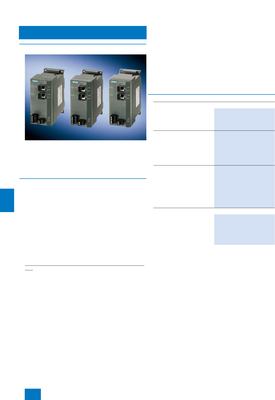
Communication
Industrial Security
Industrial Security components
9/34 Siemens ST PCS 7 · November 2007
9
■
Overview
The SCALANCE S industrial security modules can safeguard in-
dustrial systems/devices or network segments of an Ethernet
against unauthorized access by means of a firewall. Some of
them, e.g. SCALANCE S612 and S613, additionally use encryp-
tion and authentication (VPN) to protect the data transmission
between systems/devices or network segments against data
manipulation and espionage.
■
Design
SCALANCE S industrial security modules
The following SCALANCE S industrial security modules can be
used in the context of the SIMATIC PCS 7 security concept:
• SCALANCE S602 industrial security module
with firewall functionality
• SCALANCE S612 industrial security module
with firewall functionality and VPN (Virtual Private Network)
functionality for up to 32 devices (up to 64 simultaneous VPN
tunnels)
• SCALANCE S613 industrial security module
with firewall functionality and VPN (Virtual Private Network)
functionality for up to 64 devices (up to 128 simultaneous VPN
tunnels); suitable for extended temperature range from -20 to
+70 °C.
Security functions of the SCALANCE S industrial security mod-
ules
• Firewall functionality (S602, S612 and S613)
- Filtering of data packets as well as enabling or blocking of
communication links on the basis of filter lists (packet filter
firewall); IP and MAC addresses can be filtered, as well as
communication protocols (ports) with incoming and outgo-
ing communication.
- Saving of access data in a log file; for verification purposes
and for recognition of attacks and derivation of preventive
measures.
• VPN functionality (S612 and S613)
- Secure authentication (identification) of the network notes
through monitoring and checking the incoming data traffic
using proven VPN mechanisms.
- Data encryption and data integrity checking for protection
against espionage and data manipulation; establishment of
VPN tunnels to other security modules
Configuration
Using the supplied configuration tool, it is easy to create and
configure the security modules which are to communicate se-
curely with one another. You do not require any special
IT knowledge.
The complete configuration can be saved on the optional swap
medium C-PLUG (order separately) and transmitted to another
security module. This permits easy and fast replacement of
modules in the event of a fault.
B) Subject to export regulations: AL: N, ECCN: EAR99H
F) Subject to export regulations: AL: N, ECCN: 5D002ENC3
Note:
For further components and accessories, especially cable material and
connectors as well as tools and supplementary material for assembly, re-
fer to page 9/23, 9/25 and 9/26 as well as to Catalog IK PI.
■
Selection and Ordering Data Order No.
SCALANCE S industrial security modules
SCALANCE S602
Industrial security module for
protection against unauthorized
access by means of Stateful
Inspection Firewall
6GK5 602-0BA00-2AA3 F)
SCALANCE S612
Industrial security module for
protection against unauthorized
access by means of Stateful
Inspection Firewall as well as for
protection of up to 32 devices per
VPN tunnel (up to 64 VPN tunnels
simultaneously)
6GK5 612-0BA00-2AA3 F)
SCALANCE S613
Industrial security module for
protection against unauthorized
access by means of Stateful
Inspection Firewall as well as for
protection of up to 64 devices per
VPN tunnel (up to 128 VPN tun-
nels simultaneously); suitable for
extended temperature range from
-20 to +70° C
6GK5 613-0BA00-2AA3 F)
Accessories
C-PLUG
Swap medium for simple replace-
ment of devices in event of fault;
for saving of configuration and
application data, can be used in
SIMATIC NET products with
C-PLUG slot
6GK1 900-0AB00 B)
© Siemens AG 2007
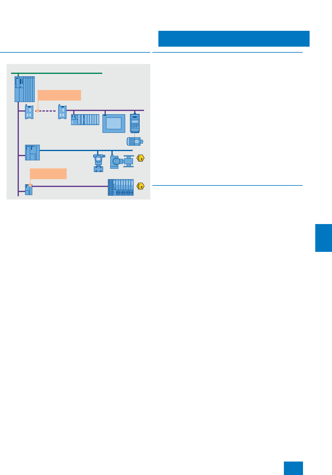
Communication
PROFIBUS
Introduction
9/35
Siemens ST PCS 7 · November 2007
9
■
Overview
Communication at field level with PROFIBUS
Distributed peripherals such as remote I/O stations with their
I/O modules, transmitters, drives, valves or operator terminals
communicate with the automation systems (controllers) at field
level through a powerful real-time bus system. This communica-
tion is characterized by:
• Cyclic transmission of process data
• Acyclic transfer of interrupts, parameters and diagnostics
data
PROFIBUS is predestined for these tasks because it enables
high-speed communication with the intelligent distributed I/Os
by means of a communications protocol (PROFIBUS DP) as well
as communication and simultaneous power supply for transmit-
ters and actuators (PROFIBUS PA).
PROFIBUS is simple, rugged and reliable, can be expanded on-
line by further distributed components, and can be used in both
standard environments and hazardous areas. It supports the co-
existence of field devices from different vendors on one line (in-
teroperability) as well as the vendor-independent exchangeabil-
ity of devices from one profile family.
■
Benefits
SIMATIC PCS 7 utilizes the benefits of the PROFIBUS from start
to finish:
7Small planning and engineering overheads as well as low
commissioning costs
7Optimum distributed system structure with low hardware and
space requirements
7Significantly reduced overhead for wiring, jumpering, distribu-
tion, power supply and field mounting
7High-speed communication with high measurement accuracy
7Efficient engineering, interoperability and replaceability of de-
vices through vendor-independent device description
7Short commissioning times through short loop tests, easy pa-
rameterization and the elimination of calibration work
7Bidirectional communication and high amounts of information
permit enhanced diagnostics functions for fast fault locating
and troubleshooting
7Optimum life cycle management through processing and
evaluation of diagnostics and status information by an asset
management system
■
Function
Users have numerous facilities for communication and line diag-
nostics, as well as for diagnostics of the intelligent field devices
connected. Furthermore, the PROFIBUS is fully integrated into
the global asset management of the SIMATIC PCS 7 process
control system.
In addition to all these properties, the following PROFIBUS func-
tions are particularly relevant to process automation:
• Integration of previously installed HART devices
• Redundancy
• Safety-related communication with PROFIsafe up to SIL 3 ac-
cording to IEC 61508
• Clock synchronization
• Time tagging
On account of its exceptional characteristics, PROFIBUS is now
established in all sectors of the production, process and hybrid
industries and has become the most successful open field bus
in the world.
PROFIBUS transmission systems
PROFIBUS DP
7RS 485: simple and low-cost electrical transmission system
based on shielded two-wire cable.
7RS 485-iS: intrinsically-safe electrical transmission system for
hazardous areas up to Ex zone 1, implemented using a
shielded two-wire cable with a transmission rate of 1.5 Mbit/s.
7Fiber-optic: optical transmission system with glass or plastic
fiber-optic cables, for fast transmission of large quantities of
data in environments with high interferences or for covering
long distances.
PROFIBUS PA
7MBP (Manchester Coded; Bus Powered): intrinsically-safe
transmission system which permits simultaneous transmission
of digital data and powering of the field devices on a single
two-wire cable. It is suitable for direct connection of devices in
environments up to Ex zone 1 or 21 and associated sen-
sors/actuators in environments up to Ex zone 0 or 20.
PROFIBUS DP
PROFIBUS PA
PROFIBUS DP
OLM OLM
Industrial Ethernet
RS 485-iS coupler
Long distances
with fiber-optic
DP/PA link
Automation system
Ex isolation
+ repeater
© Siemens AG 2007

Communication
PROFIBUS DP
Introduction
9/36 Siemens ST PCS 7 · November 2007
9
■
Application
The PROFIBUS DP fieldbus enables the SIMATIC PCS 7 auto-
mation systems (controllers) to communicate with distributed
I/Os from the ET 200 range (remote I/Os) as well as with
field/process devices, CPUs/CPs and operator terminals that
have a PROFIBUS DP interface. It is possible to route the
PROFIBUS DP into Ex zone 1 by using a fieldbus isolating trans-
former (RS 485-iS coupler) and the RS 485-iS transmission tech-
nology. Connection of the intelligent, distributed field/process
devices and operator terminals on PROFIBUS PA to the automa-
tion system takes place likewise through PROFIBUS DP.
Depending on the type of automation system and the number of
available slots, up to 4 PROFIBUS DP lines can be connected to
a SIMATIC PCS 7 automation system through internal interfaces
in the CPU, and up to 10 PROFIBUS DP lines through additional
CP 443-5 Extended communications processors. On a
PROFIBUS DP line it is possible to operate up to 125 devices,
and on a bus segment up to 31 devices with PROFIBUS DP in-
terface (32 stations).
Electrical and optical transmission technologies offer many dif-
ferent configuration options for PROFIBUS DP networks. Electri-
cal networks can span up to approx. 10 km. With optical trans-
mission systems, the total size of the network is governed
primarily by the cycle times as a result of the almost loss-free
transmission.
With SIMATIC PCS 7, PROFIBUS DP topologies are always im-
plemented through the standard electrical PROFIBUS DP con-
nection on the automation system in the form of electrical or
mixed (electrical/optical) networks. In the case of mixed net-
works, the transition between the two media is implemented by
an optical link module (OLM). As regards communication be-
tween the stations, there is no difference between electrical two-
wire technology and fiber optic technology.
Electrical networks can be configured with a line or tree topol-
ogy. Mixed electrical/optical networks with OLMs as routers can
be configured with a line, ring or star topology.
■
Technical specifications
1) According to PROFIBUS installation guideline 2.262
PROFIBUS DP
Data transmission RS 485 RS 485-iS Fiber-optic
Transmission rate 9.6 kbit/s ... 12 Mbit/s 9.6 kbit/s ... 1.5 Mbit/s 9.6 kbit/s ... 12 Mbit/s
Cable 2-wire shielded 2-wire shielded Plastic as well as multi-mode and
single-mode glass-fiber
Type of protection EEx(ib)
Topology Line, tree Line Ring, star, line
Nodes per segment 32 32 1) –
Nodes per network (with
repeater) 126 126 126
Cable length per segment depen-
dent on transmission rate 1200 m at max. 93.75 kbit/s
1000 m at 187.5 kbit/s
400 m at 500 kbit/s
200 m at 1.5 Mbit/s
100 m at 12 Mbit/s
1000 m at 187.5 kbit/s1)
400 m at 500 kbit/s1)
200 m at 1.5 Mbit/s1)
Max. 80 m (plastic)
2-3 km (multi-mode glass-fiber)
>15 km at 12 Mbit/s (single-mode
glass-fiber)
Repeater for signal refreshing
with RS 485 networks Max. 9 Max. 91) Not relevant
© Siemens AG 2007
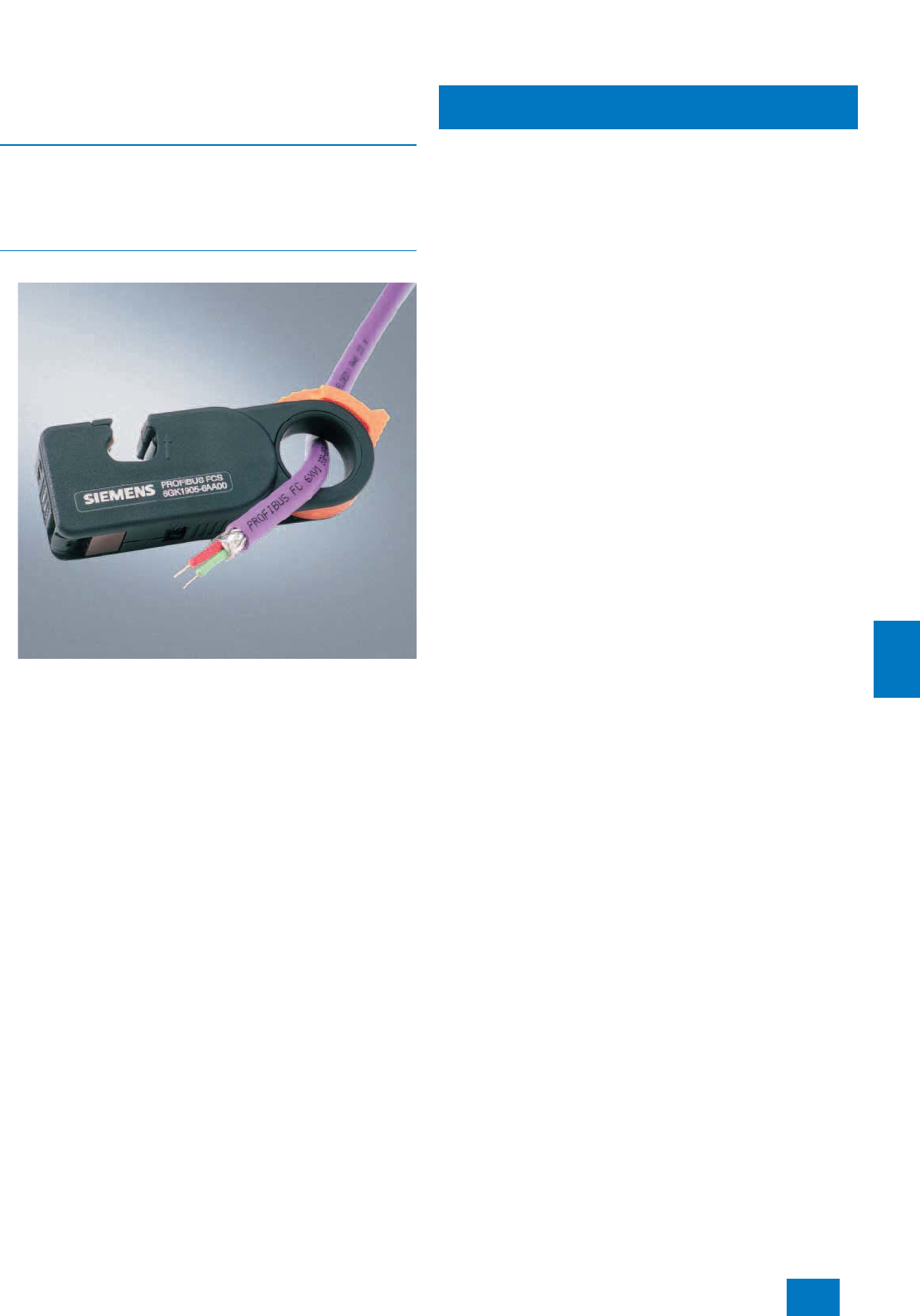
Communication
PROFIBUS DP
Electrical networks
9/37
Siemens ST PCS 7 · November 2007
9
■
Overview
Shielded twisted-pair cables are used as the transmission me-
dium for electric PROFIBUS DP networks. The PROFIBUS DP
stations are connected to these bus lines through a bus connec-
tor (max. 32 stations per segment).
■
Design
FastConnect Stripping Tool
FastConnect
PROFIBUS FastConnect is a system for fast and easy assembly
of PROFIBUS copper cables. The system comprises compatible
components:
• FastConnect Standard Cable for fast assembly
• FastConnect Stripping Tool
with FastConnect Blade Cassettes (spare blade cassettes for
the stripping tool)
• FastConnect bus connector for PROFIBUS
Repeater for PROFIBUS
A repeater links the individual bus segments with RS 485 tech-
nology. Main applications are:
• Increase in number of nodes and distances
• Electrical isolation of segments
If diagnostics functions for physical cable diagnostics are re-
quired in addition to the standard repeater functionality, a diag-
nostics repeater can be alternatively used. It additionally per-
forms physical online monitoring of the copper bus cables. In the
event of a fault it sends a diagnostic message with detailed in-
formation about the type and location of the fault to the DP mas-
ter.
Active RS 485 terminating element
The active RS 485 terminating element is used to terminate bus
segments. The component supplied with 24 V DC independent
of the bus stations provides a defined RS 485 signal level, and
suppresses reflections on the line. Bus stations (e.g. ET 200S)
can be coupled and decoupled without feedback to/from
PROFIBUS networks terminated by active RS 485 terminating
elements.
RS 485-iS coupler
The RS 485-iS coupler is an isolating transformer with which the
PROFIBUS DP fieldbus can be routed intrinsically-safe into the
hazardous area.
The RS 485-iS coupler has the following functions:
• Connection of intrinsically-safe PROFIBUS DP stations, e.g.
ET 200iSP, ET 200iS or devices from other vendors with
Ex i DP connection
• Conversion of the electrical PROFIBUS DP RS 485 transmis-
sion technology into the intrinsically-safe RS 485-iS transmis-
sion technology with a transmission rate of 1.5 Mbit/s
• Suitable as a safety barrier
• Additional use as a repeater in the hazardous area.
The RS 485-iS coupler as an open unit can only be used in hous-
ings, cabinets or rooms for electrical equipment. It is assembled
on a SIMATIC S7-300 rail which can be positioned horizontally or
vertically.
The RS 485-iS coupler is integrated into the PROFIBUS as fol-
lows:
• Connection to standard PROFIBUS DP via standard Sub-D
socket (at the bottom on the RS 485-iS coupler, behind the
right front door).
• Connection of PROFIBUS DP with RS 485-iS transmission
technology via screw terminals (at the top of the RS 485-iS
coupler, behind the right front door)
• The last bus station on the intrinsically-safe PROFIBUS DP
segment (not further RS 485-iS couplers) must be terminated
by a selectable resistance using the connector, Order No.
6ES7 972-0DA60-0XA0.
© Siemens AG 2007
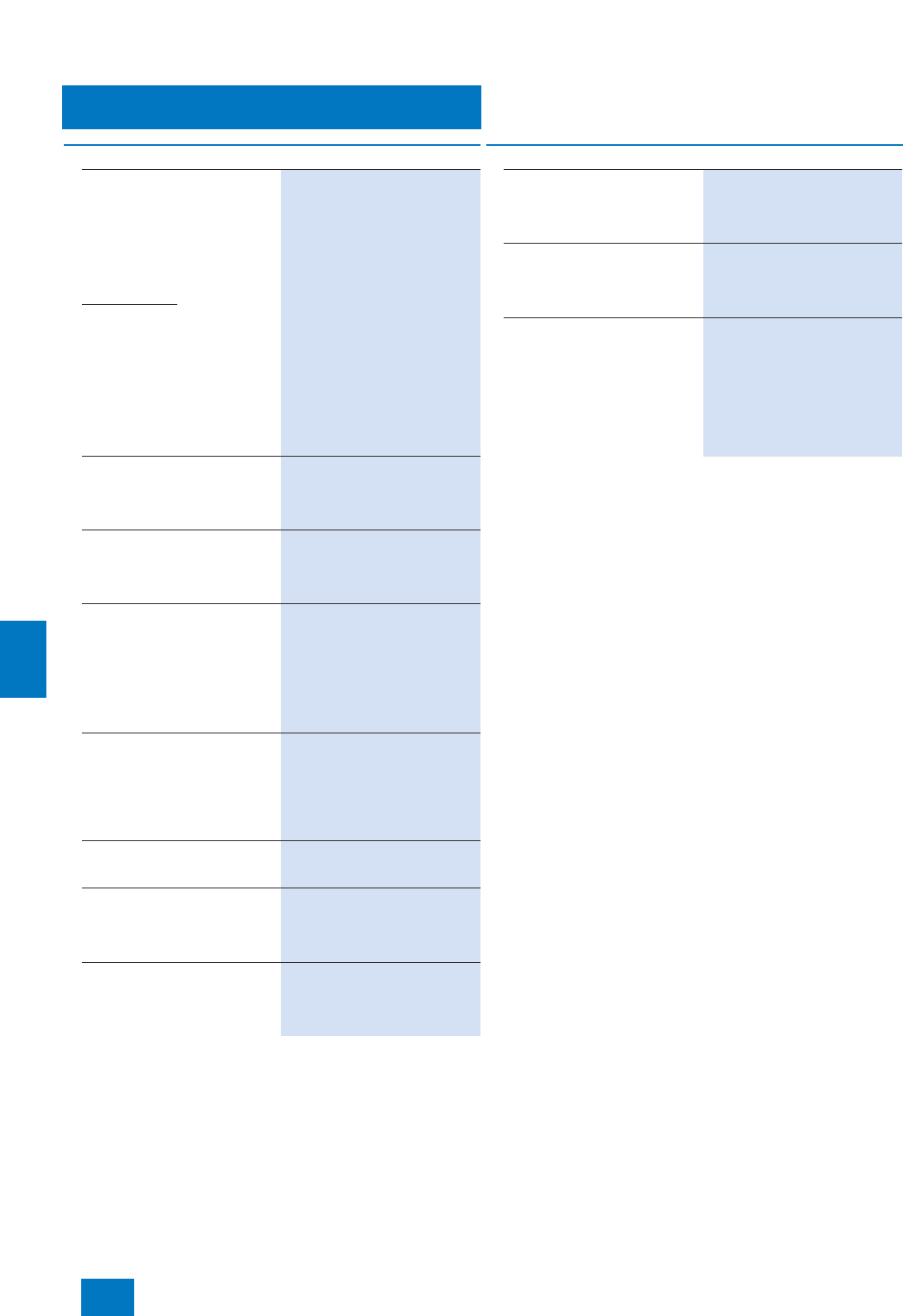
Communication
PROFIBUS DP
Electrical networks
9/38 Siemens ST PCS 7 · November 2007
9
B) Subject to export regulations: AL: N, ECCN: EAR99H
Note:
For further information on electrical PROFIBUS networks as well as com-
ponents and accessories, particularly cable material for special applica-
tions, refer to Catalog IK PI, Chapter "PROFIBUS", Section "Electrical
networks with OLM".
■
Selection and Ordering Data Order No.
PROFIBUS FastConnect
Standard Cable
Standard type with special design
for fast mounting, 2-core,
shielded, cut-to-length
Specify length in m
Max. delivery unit 1000 m,
minimum order quantity 20 m
6XV1 830-0EH10
Preferred lengths
-20 m 6XV1 830-0EN20
-50 m 6XV1 830-0EN50
-100 m 6XV1 830-0ET10
-200 m 6XV1 830-0ET20
-500 m 6XV1 830-0ET50
- 1000 m 6XV1 830-0EU10
Other PROFIBUS cables See Catalog IK PI
PROFIBUS FastConnect
Stripping Tool
Preadjusted stripping tool for fast
stripping of PROFIBUS
FastConnect bus cables
6GK1 905-6AA00
PROFIBUS FastConnect Blade
Cassettes
Spare blade cassettes for
PROFIBUS FastConnect
stripping tool, 5 units
6GK1 905-6AB00
PROFIBUS FastConnect bus
connector RS 485 with 90°
cable outlet
With insulation displacement
system,
max. data transfer rate 12 Mbit/s
• Without PG interface 6ES7 972-0BA50-0XA0
• With PG interface 6ES7 972-0BB50-0XA0
PROFIBUS FastConnect bus
connector RS 485 Plug 180
With 180° cable outlet, with insu-
lation displacement system, for
connection of PC, PG, OP
6GK1 500-0FC00
Other bus connectors
See Catalog IK PI
RS 485 Repeater for PROFIBUS
Data transfer rate max. 12 Mbit/s,
24 V DC, IP 20 housing
6ES7 972-0AA01-0XA0
RS 485 Diagnostic Repeater
For connection of 1 or 2 segments
to PROFIBUS DP; with online
diagnostics functions for monitor-
ing of bus cables
6ES7 972-0AB01-0XA0
Active RS 485 Terminating
Element for PROFIBUS
For terminating bus segments for
data transfer rates from 9.6 kbit/s
to 12 Mbit/s
6ES7 972-0DA00-0AA0
RS 485-IS Coupler
Isolating transformer for connec-
tion of PROFIBUS DP segments
with RS 485 and RS 485-iS trans-
mission technologies
6ES7 972-0AC80-0XA0
PROFIBUS connector with
selectable terminating resistor
For connection of IM 152 to
PROFIBUS DP with RS 485-iS
transmission technology
6ES7 972-0DA60-0XA0 B)
S7-300 rail
Lengths:
•160 mm 6ES7 390-1AB60-0AA0
•482 mm 6ES7 390-1AE80-0AA0
•530 mm 6ES7 390-1AF30-0AA0
•830 mm 6ES7 390-1AJ30-0AA0
• 2000 mm 6ES7 390-1BC00-0AA0
■
Selection and Ordering Data Order No.
© Siemens AG 2007

Communication
PROFIBUS DP
Optical networks with glass fiber-optic cables
9/39
Siemens ST PCS 7 · November 2007
9
■
Overview
We recommend use of glass fiber optic cables with 2 multi-mode
fibers for optical PROFIBUS networks in indoor and outdoor ar-
eas.
The standard FIBER OPTIC CABLE is available in fixed lengths
for distances up to 2000 m, preassembled with 4 BFOC connec-
tors. A BFOC connector set with 20 connectors is available as an
accessory.
Further fiber optic cables can be found in Catalog IK PI, Chapter
"PROFIBUS", Section "Optical networks with OLM".
Optical Link Module
Optical Link Modules (OLM) permit the construction of optical
and hybrid (electrical/optical) networks in line, ring or star topol-
ogy. The maximum distance between two OLMs can be up to
15 km for OLMs of type G12-1300 (see Catalog IK PI) and glass
fiber optic cables with single-mode fibers (on request). The
PROFIBUS OLM/G12 used as standard is equipped with one
RS 485 interface and two glass fiber optic cable interfaces
(4 BFOC sockets). The fiber optic line length between two OLMs
of this type can be up to 3000 m when using the standard FIBER
OPTIC CABLE.
The OLMs have a compact metal housing suitable for DIN rail
assembly. They automatically recognize all PROFIBUS data
transfer rates. Faults can be rapidly located as follows:
• Display of module status via floating signaling contact
• Checking of FO link quality (loss per section) via test output for
optical receivers for logging and plausibility checks.
B) Subject to export regulations: AL: N, ECCN: EAR99H
1) Note:
Additional components of the SIMATIC NET wiring range can be ordered
from your local contact person.
For technical advice contact:
J. Hertlein, A&D SE PS
Tel.: +49 911 750-4465,
Fax: +49 911 750-9991
E-mail: juergen.hertlein@siemens.com
■
Selection and Ordering Data Order No.
FIBER OPTIC CABLE
Standard glass FO cable,
splittable
Pre-assembled with 4 BFOC
connectors
Preferred lengths
•1 m 6XV1 820-5BH10 B)
•5 m 6XV1 820-5BH50 B)
•10 m 6XV1 820-5BN10 B)
•20 m 6XV1 820-5BN20 B)
•50 m 6XV1 820-5BN50 B)
•100 m 6XV1 820-5BT10 B)
Other lengths and cables See Catalog IK PI
BFOC Connector Set1)
For standard and trailing FIBER
OPTIC CABLES, 20 units
6GK1 901-0DA20-0AA0 B)
PROFIBUS OLM/G12 V4.0
Optical link module with 1 x RS
485 and 2 x glass FOC interfaces
(4 BFOC sockets), for standard
distances up to 3000 m, with sig-
nal contact and measuring output
6GK1 503-3CB00 B)
© Siemens AG 2007
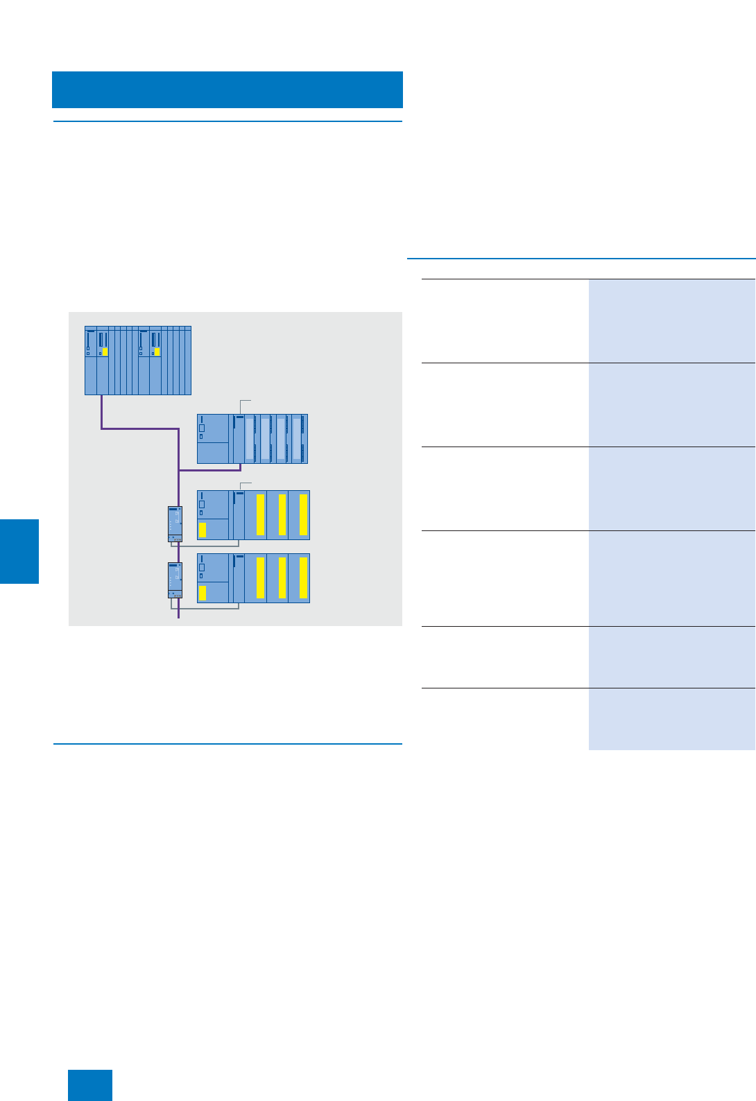
Communication
PROFIBUS DP
Optical networks with plastic fiber-optic cables
9/40 Siemens ST PCS 7 · November 2007
9
■
Overview
SIMATIC NET plastic/PCF fiber-optic cables can be used to
design optical PROFIBUS DP networks inside buildings.
For AS interfacing of ET 200M with exclusively F modules,
plastic/PCF fiber-optic cables are an alternative if compliance
with safety integrity level SIL 3 is required for the safety-related
application. Using plastic/PCF fiber-optic cables, the ET 200M
systems are connected to the electrical bus cable of the
PROFIBUS DP via optical bus terminals (OBT). The advantage
of this configuration is that the isolating module essential for sig-
nal decoupling between the IM and the F modules in the case of
a direct electrical connection of the ET 200M (only F modules in
a rack with IM 153-2) can be omitted.
OBT for PROFIBUS DP
Using the OBT (optical bus terminal) for PROFIBUS, it is possible
to connect a PROFIBUS DP station with integrated optical inter-
faces to an RS 485 segment or a PROFIBUS DP station without
integrated optical interface. Plastic/PCF fiber-optic cables can
be used for the optical connection between the PROFIBUS DP
station with integrated optical interface and the OBT.
■
Design
We particularly recommend the following plastic/PCF standard
cables for implementing optical networks in indoor areas:
• PROFIBUS Plastic Fiber Optic standard cable:
- Rugged round cable with purple PVC outer casing and Kev-
lar tension-relief elements as well as plastic fibers with rug-
ged polyamide inner casing.
- Easy to assemble on site with 2 x 2 Simplex connectors
- Cable lengths up to 50 m
• PROFIBUS PCF Fiber Optic standard cable:
- Preassembled, rugged round cable with purple PVC outer
casing and Kevlar tension-relief elements as well as two PCF
fibers (Polymer Optical Fiber)
- Cannot be assembled on site
- Cable lengths up to 300 m
Further SIMATIC NET plastic/PCF fiber optic cables can be
found in Catalog IK PI, Chapter "PROFIBUS", Section "Optical
networks with OBT and integrated interface".
The following components are available for on-site assembly of
the PROFIBUS Plastic Fiber Optic standard cable:
• Simplex connector/polishing set (set with 100 simplex con-
nectors and 5 polishing sets)
• Stripping tool set for removing the outer casing and core cas-
ing
• You require additional plug adapters for connecting cables
with Simplex connectors to devices with integrated FO inter-
faces (e.g. IM 153-2 FO).
B) Subject to export regulations: AL: N, ECCN: EAR99H
Note:
For further information on optical PROFIBUS networks as well as compo-
nents and accessories, particularly cable material for special applica-
tions, refer to Catalog IK PI, Chapter "PROFIBUS", Section "Optical
networks with OLM" and "Optical networks with OBT and integral inter-
face".
OBT
IM 153-2
IM 153-2 FO
OBT
Safety-related
automation system
ET 200M
with standard
I/O modules
ET 200M
with safety-
related
F modules
Plastic Fiber Optic Cable
PROFIBUS DP
copper cable
■
Selection and Ordering Data Order No.
PROFIBUS OBT
Optical bus terminal for connect-
ing a PROFIBUS station or an RS
485 segment without integrated
optical interface to the optical
PROFIBUS; without simplex con-
nector
6GK1 500-3AA00
PROFIBUS Plastic Fiber Optic,
standard cable
Robust round cable with 2 plastic
fiber optic cores, PVC external
sheath and PA internal sheath,
without connectors, for indoor
use, cut-to-length
6XV1 821-0AH10
PROFIBUS Plastic Fiber Optic,
duplex core
Plastic fiber optic cable with
2 cores, PVC sheath, without con-
nectors, for use in environments
with low mechanical stress, 50-m
ring
6XV1 821-2AN50 B)
PROFIBUS Plastic Fiber Optic,
Simplex Connector/Polishing
Set
100 simplex connectors and
5 polishing sets for assembling
PROFIBUS plastic fiber optic
cables for the optical PROFIBUS
DP
6GK1 901-0FB00-0AA0 B)
PROFIBUS Plastic Fiber Optic,
Stripping Tool Set
To remove the external or core
sleeve of plastic fiber optic
cables
6GK1 905-6PA10 B)
Connection Adapter
Pack of 50, for using simplex con-
nectors with the integrated
FO interfaces (e.g. IM 153-2 FO);
for 25 modules
6ES7 195-1BE00-0XA0
© Siemens AG 2007
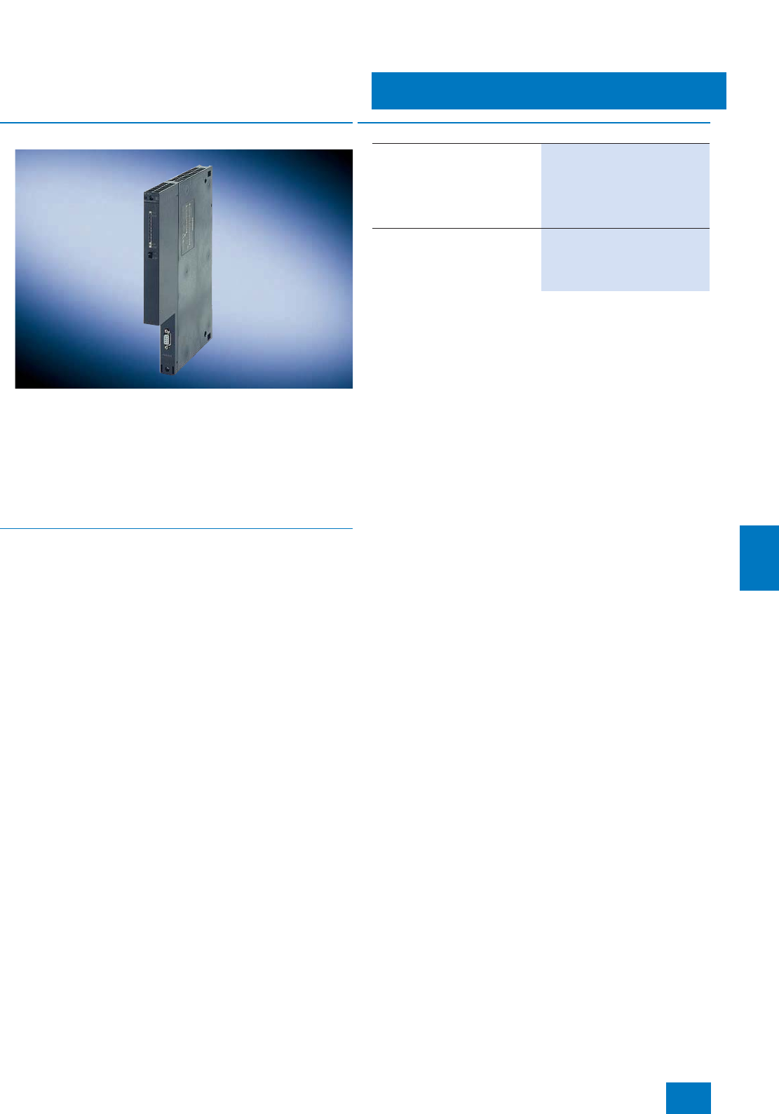
Communication
PROFIBUS DP
AS connection
9/41
Siemens ST PCS 7 · November 2007
9
■
Overview
PROFIBUS DP lines can be connected to a SIMATIC PCS 7 au-
tomation system (controller) via up to 4 internal interfaces in the
CPU and up to 10 additional CP 443-5 Extended communica-
tions processors.
If a module slot provided in the CPU for the PROFIBUS connec-
tion is still vacant, an IF 964-DP interface module is required in
addition. When using data set routing with SIMATIC PDM, use of
the CP 443-5 Extended communications processor is essential
for the PROFIBUS connection.
■
Benefits
Advantages of the CP 443-5 Extended communications module:
• Compact design; 9-contact Sub-D socket for connection to
PROFIBUS DP
• Simple installation
Can be plugged into AS rack slot; connection to the other
S7-400 modules via backplane bus
• Operation without fan; backup battery or memory submodule
are not required
■
Selection and Ordering Data Order No.
CP 443-5 Extended
Communications processor for
connection of SIMATIC S7-400 to
PROFIBUS as DP master or for S7
communication,
for data set routing of SIMATIC
PDM
6GK7 443-5DX04-0XE0
IF 964-DP
Interface module for connection
of another PROFIBUS DP line, for
plugging into a free DP module
slot of the CPU
6ES7 964-2AA04-0AB0
© Siemens AG 2007
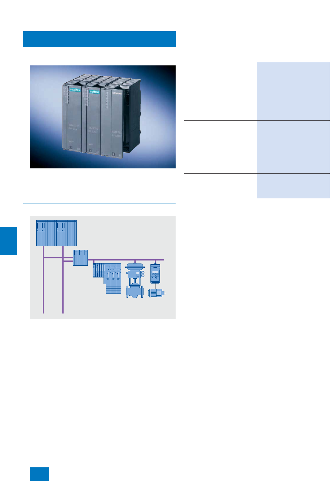
Communication
PROFIBUS DP
Y-Link
9/42 Siemens ST PCS 7 · November 2007
9
■
Overview
The Y-link is a bus coupler for transition from a redundant
PROFIBUS DP master system to a single-channel
PROFIBUS DP master system. It can be used for connecting de-
vices with only one PROFIBUS DP interface to the redundant
PROFIBUS DP master system AS 414H/ AS 417H.
■
Design
The Y-link comprises:
• Two IM 153-2 High Feature interface modules for extended
temperature range
• One Y-coupler incl. RS 485 repeater
• One IM 157 (IM/IM) bus module for two IM 153-2 High Feature
modules, for extended temperature range
• One BM Y-coupler bus module
Evaluation of the Y-Link diagnostics (and hence indirectly of the
connected DP standard slaves) is supported by driver blocks.
It is recommendable to have a redundant -24 V DC supply for
the Y-Link, e.g. with two PS 307/PS 305 load power supplies.
B) Subject to export regulations: AL: N, ECCN: EAR99H
Fault-tolerant
automation system
Connection of non-redundant
PROFIBUS DP devices to
redundant PROFIBUS DP
Y-Link
redundant PROFIBUS DP
■
Selection and Ordering Data Order No.
Y-Link
For connection of devices with
only one PROFIBUS DP interface
to a fault-tolerant automation sys-
tem, comprising:
• 2 IM 153-2 High Feature inter-
face modules
• 1 Y-coupler
• 1 BM IM 157 bus module (IM/IM)
• 1 BM Y-coupler bus module
6ES7 197-1LA11-0XA0 B)
PS 307 load power supply
Including connection assembly;
120/230 V AC; 24 V DC
• 2 A; 50 mm wide 6ES7 307-1BA00-0AA0
• 5 A; 80 mm wide 6ES7 307-1EA00-0AA0
• 5 A, extended temperature
range; 80 mm wide 6ES7 307-1EA80-0AA0
• 10 A, 200 mm wide 6ES7 307-1KA01-0AA0
PS 305 load power supply
24/48/60/110 V DC; 24 V DC
• 2 A, extended temperature
range; 80 mm wide 6ES7 305-1BA80-0AA0
© Siemens AG 2007
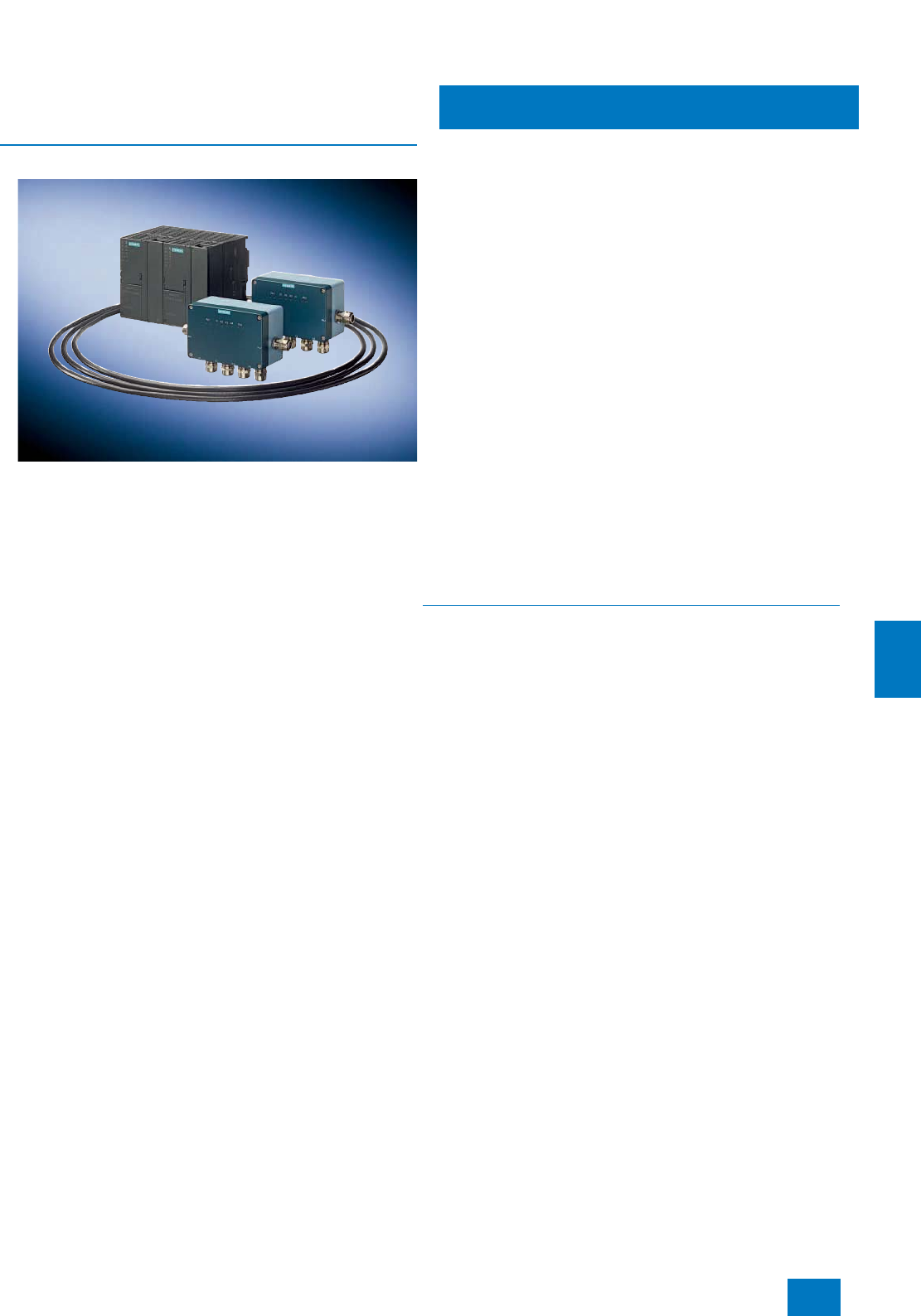
Communication
PROFIBUS PA
Introduction
9/43
Siemens ST PCS 7 · November 2007
9
■
Overview
Direct interfacing of the devices in the field, especially in the
hazardous area, together with the information content of the
communication, are of significant importance in the process in-
dustry. PROFIBUS PA, which permits both digital data transmis-
sion and the power supply on a two-wire line with the intrinsi-
cally-safe MBP transmission technology (Manchester Coded;
Bus Powered) is tailored to these requirements. It is optimally
suitable for direct integration of the pneumatic actuators, sole-
noid valves and sensors positioned in operating environments
up to Ex zone 1 or 0 into the process control system.
The typical response time of a transmitter of approx. 10 ms indi-
cates that short cycle times can be achieved with the
PROFIBUS PA even in the case of a segment configuration with
up to 31 devices. Practically all typical applications of the pro-
cess industry can be implemented - both with small or large
plant distances. Bidirectional communication and high informa-
tion content allow enhanced diagnostics for fast and exact fault
detection and elimination. The standardized communications
services guarantee interoperability and replaceability between
multi-vendor field devices and remote parameterization of the
field devices during operation.
The PROFIsafe profile allows seamless integration of safety
communication into the PROFIBUS PA. You need not configure
a separate safety bus for your safety-related applications. The
PROFIBUS PA with the PROFIsafe profile is incorporated in
"Safety Integrated for Process Automation". This comprehensive
range of products and services from Siemens for failsafe, fault-
tolerant applications in the process industry offers you attractive
and cost-effective alternatives to separate safety systems.
You can define the degree of redundancy separately for the con-
troller, fieldbus and I/O levels of your plant depending on the au-
tomation task and the derived safety requirements, and match
them to the field instrumentation (Flexible Modular Redundancy,
FMR). You can find an overview of the redundant architectures
of PROFIBUS PA under "Design".
The PROFIBUS PA is based on electrical transmission compo-
nents. A shielded two-wire cable is used for digital data trans-
mission and for the power supply. With line, tree and ring topol-
ogies, it is possible to configure networks with spur lines up to
120 m and bus segments up to approx. 1.9 km for operating en-
vironments up to Ex zone 2. With bus segments for hazardous
areas in line with zone 1, the max. possible length per spur line
is reduced to 30 m and per bus segment to 1 km. The line
lengths actually achievable in practice depend on the number of
PA devices and their current consumption. Bus segments are
terminated either automatically (with active field distributors AFD
in the case of ring topologies) or with the passive terminating el-
ement for PROFIBUS PA (SpliTConnect terminator).
The DP/PA Link is preferred for the gateway from PROFIBUS PA
to PROFIBUS DP. When using the DP/PA Link, the transmission
rate on the PROFIBUS DP is independent of the subordinate
PROFIBUS PA segments. The configuration of the DP/PA Link
depends on the operating environment (Ex zone) or the selected
redundancy architecture. The types of coupler described in the
Section "Gateways - DP/PA link and DP/PA coupler" are used for
the configuration. With a small amount of data (small quantity
framework) and low timing requirements, the DP/PA coupler can
also be operated in stand-alone mode as a gateway.
■
Benefits
Advantages provided by distributed field automation with appli-
cation of the PROFIBUS PA profile included low hardware over-
head, cost-effective engineering, increased operational safety
and problem-free maintenance. These advantages are under-
lined by the following features:
• Modularity and uniformity from the sensor up to the control
level permit new plant concepts
• Implementation of intrinsically-safe applications through use
of the fieldbus in hazardous areas
• Flexible Modular Redundancy (FMR) from the automation sys-
tem (controller) down to the PROFIBUS PA field device with re-
dundant architectures for environments up to Ex zone 2 (ring
and line topologies with coupler redundancy)
• Safety-related and fault-tolerant applications with low device
and cabling overheads
• Reduced configuration costs through simple, central engi-
neering of the field devices (PROFIBUS PA and HART with
SIMATIC PDM, also cross-vendor)
• Simple installation using two wire cable for common power
supply and data transmission
• Reduced commissioning costs through simplified loop check
• Low servicing costs thanks to simple wiring and comprehen-
sive diagnostics facilities
© Siemens AG 2007
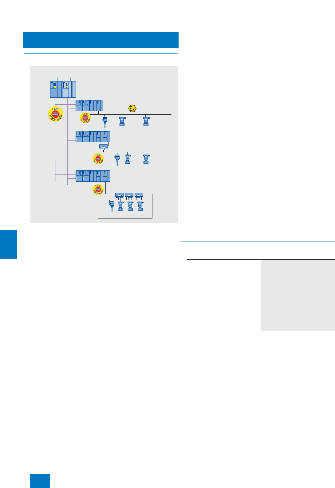
Communication
PROFIBUS PA
Introduction
9/44 Siemens ST PCS 7 · November 2007
9
■
Design
Basic PROFIBUS PA design versions when using the DP/PA link as the
router
Basic PROFIBUS PA design versions are presented at this point.
In these configuration examples, DP/PA links are used in each
case as the DP/PA router. Up to 5 DP/PA couplers can be oper-
ated in a DP/PA link. Mixed configurations (e.g. line and ring on
one link) are also possible. The DP/PA router can also be imple-
mented with a DP/PA coupler. In this case, the PROFIBUS DP
connection is directly on the coupler instead of per interface
module.
Linear architecture with single coupler
In this design version, each PROFIBUS PA line is linked with one
DP/PA coupler of a DP/PA router. Depending on the operating
environment, you can use either the FDC 157-0 DP/PA coupler
(up to Ex zone 2) or the Ex [i] DP/PA coupler (up to Ex zone 1).
The DP/PA router can be connected to a single or redundant
PROFIBUS DP.
Linear architecture with redundant couplers
The active field splitter (AFS) connects a PROFIBUS PA line with
two FDC 157-0 DP/PA couplers of a DP/PA router. This router is
operable on a single or redundant PROFIBUS DP. The AFS
switches the PROFIBUS PA line to the active one of the two re-
dundant couplers.
Flexible Modular Redundancy is possible at the device level by
grouping individual devices in different PROFIBUS PA lines.
Only one PROFIBUS PA line can be configured with coupler re-
dundancy on each DP/PA router. A PROFIBUS PA ring cannot
then be operated on this router.
Ring architecture
Active field distributors (AFD) integrate PROFIBUS PA field
devices via 4 short-circuit proof spur line connections into
a PROFIBUS PA ring with automatic bus termination. The
PROFIBUS PA ring is connected to two FDC 157-0 DP/PA cou-
plers of a DP/PA router. The DP/PA router can be operated on a
single or redundant PROFIBUS DP. Up to 8 AFDs can be config-
ured per ring.
Flexible Modular Redundancy is possible at the device level by
grouping individual devices on different AFDs. Only one ring can
be configured on each DP/PA router. A PROFIBUS PA line with
coupler redundancy cannot then be operated on this router.
The following limits must be observed for a PROFIBUS PA ring
with respect to the configuration with PROFIBUS PA devices:
• Max. 31 PROFIBUS-PA devices
• Max. current consumption of all PROFIBUS-PA devices: 1 A
Particular advantages of the ring architecture:
• High availability
• Transparent redundancy management of the intelligent
FDC 157-0 DP/PA couplers for the higher-level system
• Active bus terminations for automatic bus termination in the
FDC 157-0 DP/PA couplers and the AFDs permit:
- Automatic, bumpless isolation of defective sub-segments in
event of short-circuit or wire breakage
- Changing of the ring configuration and the instrumentation
during operation, including addition or removal of ring seg-
ments
• Safety-related and fault-tolerant applications with low device
and cabling overheads
■
Technical specifications
PROFIBUS PA
PROFIBUS PA
PROFIBUS PA
PROFIBUS DP
Active field
splitter
Active field distributors
DP/PA Link
DP/PA Link
with redundant DP/PA couplers
DP/PA Link
with redundant DP/PA couplers
Direct fieldbus interfacing
AS 414FH/
AS 417FH
PROFIBUS PA
Data transmission MBP
Transmission rate 31.25 Mbit/s
Cable 2-wire shielded
Type of protection EEx(ia/ib)
Topol ogy Line, tree, ring
PA devices per segment/coupler 31
PA devices per DP/PA link 64
Cable length per segment depen-
dent on transmission rate 1900 m: standard
1900 m: EEx(ib)
1000 m: EEx(ia)
© Siemens AG 2007
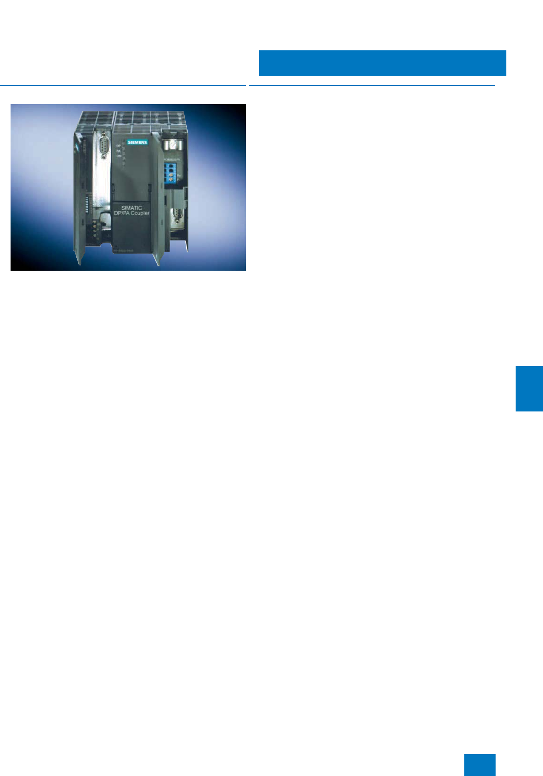
Communication
PROFIBUS PA
Routers: DP/PA link and DP/PA coupler
9/45
Siemens ST PCS 7 · November 2007
9
■
Overview
To create a smooth network transition between PROFIBUS DP
and PROFIBUS PA, the SIMATIC product range offers two ver-
sions: the DP/PA coupler and the DP/PA link.
The following criteria can be applied when choosing the network
transition:
• DP/PA coupler:
For small quantity frameworks (volumes of data) and low tim-
ing requirements; limiting of data transfer rate on the
PROFIBUS DP to 45.45 kbit/s
• DP/PA link:
For large number of stations and high cycle time require-
ments; data transfer rate on the PROFIBUS DP up to 12 Mbit/s
■
Application
The two DP/PA routers are based on two versions of the
DP/PA coupler:
• Ex [i] DP/PA coupler (max. output current 110 mA)
for implementation of PROFIBUS PA networks with a line or
tree topology in environments up to Ex zone 1, not for redun-
dant architectures (coupler redundancy, ring)
• FDC 157-0 DP/PA coupler (max. output current 1000 mA)
for implementation of PROFIBUS PA networks with a line, tree
or ring topology in environments up to Ex zone 2; can be used
for the redundant architectures "Ring" and "Coupler redun-
dancy"
DP/PA couplers are also integral components of the DP/PA link
(see design). The DP/PA link connects PROFIBUS DP and
PROFIBUS PA together, and decouples the transmission rates.
In contrast to the DP/PA coupler which limits the data transmis-
sion rate on the PROFIBUS DP to 45.45 kbit/s, the DP/PA link
does not influence the performance of the PROFIBUS DP.
The DP/PA link functions as a slave on the PROFIBUS DP and as
a master on the PROFIBUS PA. From the viewpoint of the host
PROFIBUS DP master, the DP/PA link is a modular slave whose
modules are the devices connected on the PROFIBUS PA. Ad-
dressing of these devices is carried out indirectly via the DP/PA
link which itself only requires one node address. The host
PROFIBUS master can scan devices connected to the
DP/PA link all at once.
If the router is a DP/PA coupler, the nodes on the PROFIBUS PA
are directly addressed by the PROFIBUS DP master (controller).
The DP/PA coupler is an electrical node, but is transparent for
communication between the master and PA field devices; it
therefore does not require setting of parameters or addresses
(exception: FDC 157-0 DP/PA coupler used as PROFIBUS diag-
nostics slave).
PROFIBUS diagnostics with FDC 157-0 DP/PA coupler,
configured as PROFIBUS diagnostics slave
FDC 157-0 DP/PA couplers configured as PROFIBUS diagnos-
tics slaves supply extensive diagnostic and status information
via PROFIBUS for swift location and clearance of faults:
• I&M data (Identification & Maintenance)
• Current and voltage values on the main cable
• Redundancy status
• Wire breakage
• Short-circuit
• Signal level
For this purpose, each FDC 157-0 DP/PA coupler requires its
own PROFIBUS address. This applies independent of use in a
DP/PA link or as a DP/PA router.
The DP/PA link and DP/PA couplers as DP/PA routers can be
mounted on an S7-300 profile rail. They are operated with 24 V
DC, and can be installed in environments up to Ex zone 2 with
extended temperature range.
© Siemens AG 2007
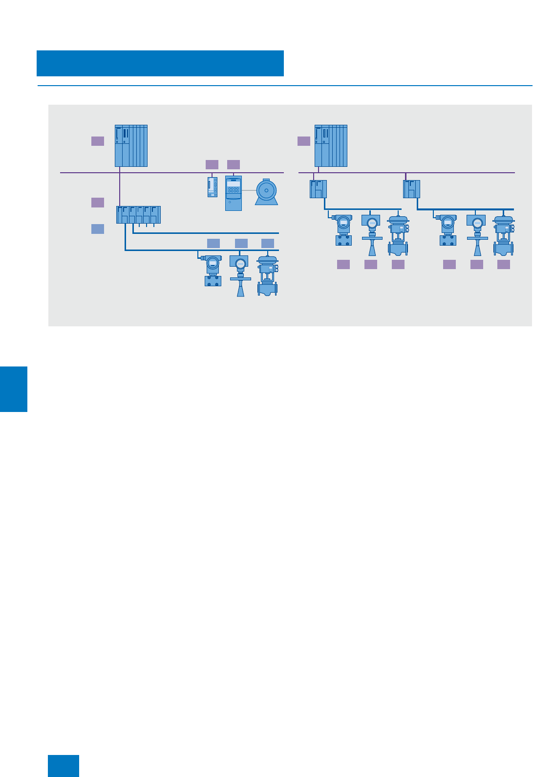
Communication
PROFIBUS PA
Routers: DP/PA link and DP/PA coupler
9/46 Siemens ST PCS 7 · November 2007
9
■
Design
Configuration examples with DP/PA link and DP/PA coupler
DP/PA link:
The DP/PA link is a modular combination consisting of the
IM 153-2 High Feature PROFIBUS DP interface module (with op-
tional redundancy) and up to 5 DP/PA couplers (Ex [i] or
FDC 157-0) packaged in an S7-300 design.
All components of the DP/PA link are interconnected through the
S7 backplane bus. Use of active bus modules on the backplane
allows hot swapping of individual modules and redundancy of
the IM 153-2 High Feature PROFIBUS DP interface modules and
the FDC 157-0 DP/PA coupler.
The PS 307 or PS 305 load power supply can be used for the
24 V DC. With a redundant IM 153-2 High Feature interface
module for PROFIBUS DP, it is also recommendable to have a
redundant 24 V DC supply, e.g. with two PS 307/PS 305 load
power supplies.
The PROFIBUS PA lines/rings designed with the DP/PA couplers
are physically separated as regards current input, but form one
bus system in communication terms. A PROFIBUS PA ring or a
PROFIBUS PA line with coupler redundancy can be operated on
each DP/PA link. Further PROFIBUS PA lines can be operated
on this DP/PA link using individual couplers. The FDC 157-0
DP/PA couplers provided for the ring coupling or coupler redun-
dancy must always be located at the right-hand end of a se-
quence of up to 5 couplers.
The following basic components are available to configure the
DP/PA link:
• IM 153-2 High Feature interface module for extended temper-
ature range
• DP/PA coupler (Ex [i] and FDC 157-0)
• Components for redundant design and for hot swapping
- DIN rail for hot swapping (as an alternative to the standard
DIN rail)
- BM PS/IM for 1 load power supply and 1 IM 153-2 High Fea-
ture module
- IM/IM (IM 157) bus module for two IM 153-2 High Feature
modules, for redundant and non-redundant design and for
extended temperature range
- DP/PA bus module for one DP/PA coupler Ex [i] or
FDC 157-0, for extended temperature range (up to
5 DP/PA couplers possible per DP/PA link)
- DP/PA but module for 2 DP/PA coupler FDC 157-0, for ex-
tended temperature range
Additive option:
• PS 307 load power supply for 120/230 V AC; 24 V DC, version
in 2, 5 or 10 A, or
PS 305 load power supply for 24/48/60/110 V DC; 24 V DC,
2A
2 2
4 5
4 53 7 86
3
2
13 4
PROFIBUS PA
PROFIBUS DP
PROFIBUS PA
High Speed solution with DP/PA link
DP/PA link
• IM 153-2 interface module (single/redundant)
• DP/PA couplers (max. 5 per IM 153-2)
• Slave on DP side - master on PA side
• Max. 64 PA devices (244 bytes I/O data)
Low-cost solution with direct addressing
DP/PA coupler
• transparent for communication
• Ex version 13.5 V / 110 mA
• Non-Ex version 31 V / 1000 mA
PROFIBUS master
S7-400
DP/PA link
DP/PA coupler
up to 12 Mbit/s 45.45 kbit/s
31.25 kbit/s
© Siemens AG 2007

Communication
PROFIBUS PA
Routers: DP/PA link and DP/PA coupler
9/47
Siemens ST PCS 7 · November 2007
9
■
Technical specifications
DP/PA coupler
Connection for PROFIBUS PA
• DP/PA coupler Ex [i] 2 terminals of a 4-pole screw-type
terminal, integral terminating
resistor
• DP/PA coupler FDC 157-0 4-pole screw-type terminal for
connection and looping through,
selectable terminating resistor
Connection for PROFIBUS DP 9-pin Sub-D plug,
contact assignment as described
in IEC 61158/EN 50170
Backplane bus Connection through S7 back-
plane bus connector (only neces-
sary for DP/PA link); non-floating
The active BM DP/PA bus mod-
ules are required for the hot
swapping function
Diagnostic displays
• DP/PA coupler Ex [i] and
DP/PA coupler FDC 157-0 Bus activity "DP" (yellow)
Bus activity "PA" (yellow)
24 V DC "ON" (green)
• Additive with DP/PA coupler
FDC 157-0 Group fault "SF" (red)
Bus fault "BF" (rot)
DP/PA coupler activated, feed-
ing/transmitting "ACT" (yellow),
only with PA redundancy
Power supply 24 V DC (20.4 V ... 28.8 V)
Current consumption
• DP/PA coupler Ex [i] Max. 400 mA
• DP/PA coupler FDC 157-0 Max. 2300 mA
Voltage at coupler output
• DP/PA coupler Ex [i] 13 V ... 14 V DC
• DP/PA coupler FDC 157-0 31 ±1V DC
Max. current at coupler output
• DP/PA coupler Ex [i] 110 mA
• DP/PA coupler FDC 157-0 1 A (up to 50 °C), 0.8 A (up to
60 °C)
Power loss
• DP/PA coupler Ex [i] Approx. 7 W
• DP/PA coupler FDC 157-0 Approx. 13.4 W
Operating temperature
• DP/PA coupler Ex [i] and
DP/PA coupler FDC 157-0 -25 ... +60 °C
(horizontal installation)
-25 ... +40 °C (vertical installation)
Dimensions (W x H x D) in mm 80 x 125 x 130
Weight Approx. 515 g
IM 153-2 High Feature (for extended temperature range)
Function Linking of PROFIBUS DP
(9.6 kbit/s to 12 Mbit/s, slave
functionality) and PROFIBUS PA
with support of the "Configuration
in Run" function
The DP/PA link function is only
implemented by extending the
IM 153-2 High Feature with one or
more DP/PA couplers. Stand-
alone operation of the IM 153-2
High Feature is not possible.
1 Y coupler, up to
5 DP/PA couplers or up to
64 slaves can be connected
Isolation from the higher-level DP
master system
Interfaces
• Connection for PROFIBUS DP 9-pin Sub-D plug, contact assign-
ment as described in
IEC 61158/EN 50170, Vol. 2
• Backplane bus Connection through S7 back-
plane bus connector, non-floating
Bus modules and profile rails for
hot swapping are required for the
hot swapping function and for a
redundant PROFIBUS DP inter-
face module.
Diagnostic displays Group fault "SF" (red)
Bus fault DP "BF 1" (red)
Bus fault PA "BF 2" (red)
IM active "ACT" (yellow)
24 V DC "ON" (green)
Power supply 24 V DC
Current consumption Max. 100 mA (in DP/PA link)
Max. 200 mA (in Y-link)
Power loss Approx. 2 W (in DP/PA link)
Approx. 4 W (in Y-link)
Voltage failure bridging 20 ms
Mechanical design of power
supply 4-pin screw terminal, short-
circuiting link between PE and
M24; the short-circuiting link must
be removed for floating operation
(independent of this, the DP inter-
face is always floating)
Permissible operating temperature -25 ... +60 °C
(horizontal installation)
-25 ... +40 °C (vertical installation)
Dimensions (W x H x D) in mm 40 x 125 x 130
Weight Approx. 350 g
© Siemens AG 2007

Communication
PROFIBUS PA
Routers: DP/PA link and DP/PA coupler
9/48 Siemens ST PCS 7 · November 2007
9
B) Subject to export regulations: AL: N, ECCN: EAR99H
■
Selection and Ordering Data Order No.
DP/PA coupler
For transition from RS 485 to MBP
• DP/PA coupler Ex [i] 6ES7 157-0AD82-0XA0
• DP/PA coupler FDC 157-0,
redundant design possible 6ES7 157-0AC83-0XA0 B)
IM 153-2 High Feature
Interface module for DP/PA Link
and Y-Link; for extended temper-
ature range
6ES7 153-2BA82-0XB0 B)
Accessories
PS 307 load power supply
Including connection assembly;
120/230 V AC; 24 V DC
• 2 A; 50 mm wide 6ES7 307-1BA00-0AA0
• 5 A; 80 mm wide 6ES7 307-1EA00-0AA0
• 5 A, extended temperature
range; 80 mm wide 6ES7 307-1EA80-0AA0
• 10 A, 200 mm wide 6ES7 307-1KA01-0AA0
PS 305 load power supply
24/48/60/110 V DC; 24 V DC
• 2 A, extended temperature
range; 80 mm wide 6ES7 305-1BA80-0AA0
Standard profile rails
(without hot swapping function)
• 482 mm wide (19 inches) 6ES7 390-1AE80-0AA0
• 530 mm wide 6ES7 390-1AF30-0AA0
Components for hot swapping and for redundant design
Active bus modules for hot
swapping
• BM PS/IM
for one load power supply and
one IM 153-2 High Feature mod-
ule
6ES7 195-7HA00-0XA0
• BM IM 157
For two IM 153-2 High Feature
modules, for redundant and
non-redundant configuration, for
extended temperature range, for
hot swapping function,
permissible operating tempera-
ture -25...+60 °C
6ES7 195-7HD80-0XA0
•BM DP/PA
For one DP/PA coupler Ex [i] or
FDC 157-0,
for extended temperature range,
for hot swapping function,
permissible operating tempera-
ture -25 to +60 °C
6ES7 195-7HF80-0XA0
•BM DP/PA
For two DP/PA couplers
FDC 157-0,
for extended temperature range,
for hot swapping function,
permissible operating tempera-
ture -25 to +60 °C
6ES7 195-7HG80-0XA0 B)
Profile rail for hot swapping
For max. 5 active bus modules
• 482 mm wide (19 inches) 6ES7 195-1GA00-0XA0
• 530 mm wide 6ES7 195-1GF30-0XA0
• 620 mm wide 6ES7 195-1GG30-0XA0
■
Selection and Ordering Data Order No.
© Siemens AG 2007
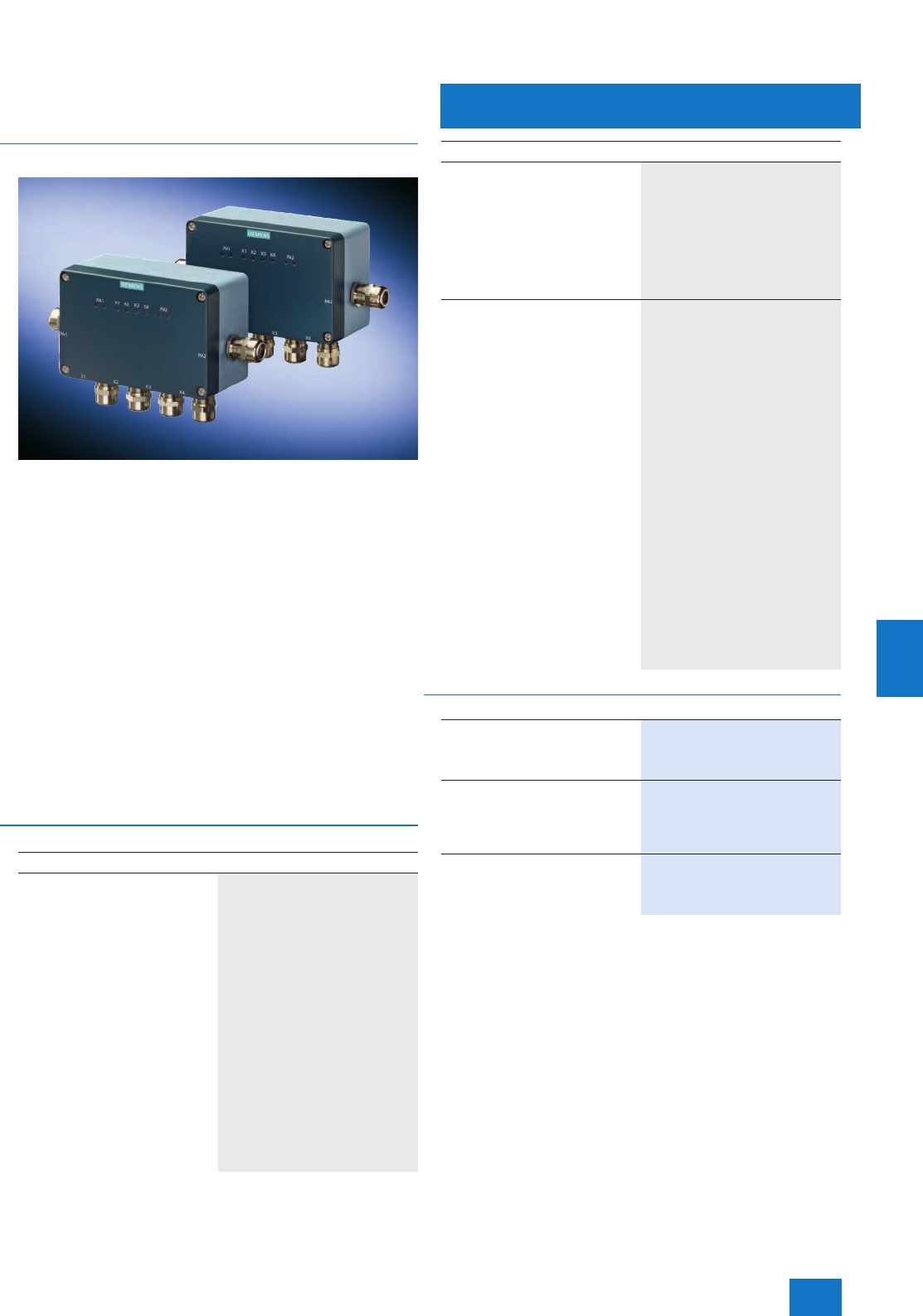
Communication
PROFIBUS PA
Active field distributor AFD
and active field splitter AFS
9/49
Siemens ST PCS 7 · November 2007
9
■
Overview
Active field distributor AFD
An active field distributor (AFD) can integrate up to
4 PROFIBUS PA field devices via short-circuit proof spur line
connections into a PROFIBUS PA ring with automatic bus termi-
nation. The PROFIBUS PA ring is connected to two FDC 157-0
DP/PA couplers of a DP/PA router. Up to 8 AFDs and up to
31 PROFIBUS PA devices can be configured per ring. The num-
ber of PROFIBUS PA devices is additionally limited by the max.
current consumption of 1 A for all devices.
An AFD can be replaced during operation. The function of the
PROFIBUS PA devices on the other AFDs is not influenced by
this.
Active field splitter AFS
The active field splitter (AFS) connects a PROFIBUS PA line with
two redundant FDC 157-0 DP/PA couplers of a DP/PA router. The
AFS switches the PROFIBUS PA line to the active one of the two
redundant couplers.
Up to 31 PROFIBUS PA devices can be connected on the
PROFIBUS PA line. This number is additionally limited by the
max. current consumption of 1 A for all devices.
■
Technical specifications
B) Subject to export regulations: AL: N, ECCN: EAR99H
Active field distributor AFD and active field splitter AFS
Active field distributor AFD
Connection of PROFIBUS PA field
devices • Max. 4 per AFD
• Max. 31 per ring
• Operating environment up to
zone 2 or 22
• Max. current consumption of all
devices 1 A
Current Imax. per spur line X1 to X4 60 mA
Power supply 16 V DC (16 ... 32 V)
Current consumption Approx. 20 mA
Power loss Approx. 600 mW
Output voltage for PA section 31 V ±1V DC
Voltage failure bridging 5 ms
Output current for PA section (for
dimensioning of device configura-
tion)
1A
Diagnostic displays Status PA main line PA1, PA2
(green)
Fault PA main line PA1, PA2 (red)
Status/fault PA spur line X1 to X4
(green)
Permissible operating temperature -25 ... +70 °C
Dimensions (W x H x D) in mm 120 x 57 x 80
Weight Approx. 700 g
Active field splitter AFS
Connection of PROFIBUS PA field
devices • Max. 31 per line
• Operating environment up to
zone 2 or 22
• Max. current consumption of all
devices 1 A
Power supply 16 V DC (16 ... 32 V)
Current consumption Approx. 20 mA
Power loss Approx. 600 mW
Output voltage for PA section 31 V ±1V DC
Voltage failure bridging 5 ms
Output current for PA section (for
dimensioning of device configura-
tion)
1A
Diagnostic displays Status PA main line PA1, PA2
(green)
Fault PA main line PA1, PA2 (red)
Permissible operating temperature -25 ... +70 °C
Dimensions (W x H x D) in mm 120 x 57 x 80
Weight Approx. 700 g
■
Selection and Ordering Data Order No.
Active field distributor AFD
with 4 short-circuit-proof spur line
connections for integration of field
devices
6ES7 157-0AF81-0XA0 B)
Active field splitter AFS
for connecting a PROFIBUS PA
line to 2 redundant FDC 157-0
DP/PA couplers; automatic
switchover to the active coupler
6ES7 157-0AF82-0XA0 B)
Profile rail adapter
for an active field distributor AFD
or active field splitter AFS,
optional
6ES7 157-0AF83-0XA0
Active field distributor AFD and active field splitter AFS
© Siemens AG 2007
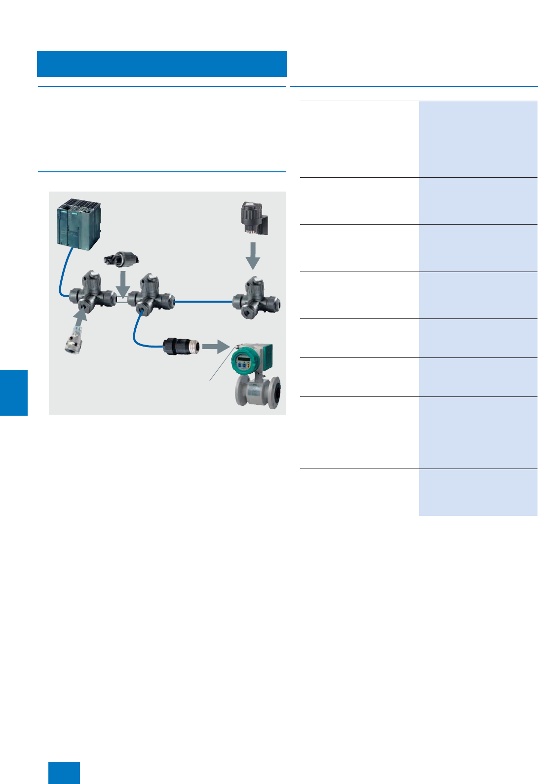
Communication
PROFIBUS PA
FastConnect/SpliTConnect
9/50 Siemens ST PCS 7 · November 2007
9
■
Overview
PROFIBUS FC process cables, color-coded for the various ap-
plications (Ex, non-Ex area) are available for designing field bus
networks in accordance with IEC 61158-2 (e.g. PROFIBUS PA).
The FastConnect stripping tool can be used to strip the FC pro-
cess cable for PROFIBUS PA to the correct length for casing and
shield.
■
Design
SpliTConnect
The SpliTConnect Tap enables the design of fieldbus segments
according to IEC 61158-2 with field device connection points.
The SpliTConnect Coupler can be used to construct a
PROFIBUS PA hub by connecting SpliTConnect Taps in series.
By replacing the contacting screw by the SpliTConnect Termina-
tor, the SpliTConnect Tap can be used as a bus terminating ele-
ment.
Terminal equipment can be connected directly through the
FC process cable. Using the SpliTConnect M12 Outlet, PA field
devices can also be connected to the SpliTConnect Tap by an
M12 connection. The SpliTConnect M12 Jack is a connecting el-
ement between an FC process cable and an M12 connector on
the PROFIBUS PA field device. For details on SpliTConnect net-
work components, see Catalog IK PI.
FC Process cable
DP/PA link SpliTConnect
terminator
SpliTConnect
coupler
SpliTConnect
M12 Jack
Connector on
PA field device
SpliTConnect taps
SpliTConnect M12 Outlet
for direct connection of
PA field devices to the
SpliTConnect tap
■
Selection and Ordering Data Order No.
FC Process Cable
2-core, shielded
• Blue for Ex applications 6XV1 830-5EH10
• Black for non-Ex applications 6XV1 830-5FH10
Sold by the meter:
Max. delivey unit 1000 m,
minimum ordering quantity 20 m
PROFIBUS FastConnect
Stripping Tool
Stripping tool for rapid stripping
of insulation from PROFIBUS
FastConnect bus cables
6GK1 905-6AA00
PROFIBUS FastConnect
Blade Cassettes
Spare blade cassettes for the
PROFIBUS FastConnect strip-
ping tool, 5 pcs
6GK1 905-6AB00
SpliTConnect Tap
For design of PROFIBUS PA seg-
ments and connection of PA field
devices, insulation displacement
system, IP67, 10 pcs
6GK1 905-0AA00
SpliTConnect M12 Outlet
Replacement element for direct
connection of PA field devices to
the SpliTConnect Tap, 5 pcs
6GK1 905-0AB10
SpliTConnect Coupler
Connection element for cascad-
ing SpliTConnect Taps in order to
configure star points, 10 pcs
6GK1 905-0AC00
SpliTConnect Terminator
For termination of PROFIBUS PA
segments, 5 pcs
• Terminator (Ex); use possible in
hazardous area 6GK1 905-0AD00
• Terminator (non-Ex); use not
possible in hazardous area 6GK1 905-0AE00
SpliTConnect M12 Jack
Connection element between
FC process cable and M12 plug
on the PROFIBUS PA field device,
5pcs
6GK1 905-0AF00
© Siemens AG 2007
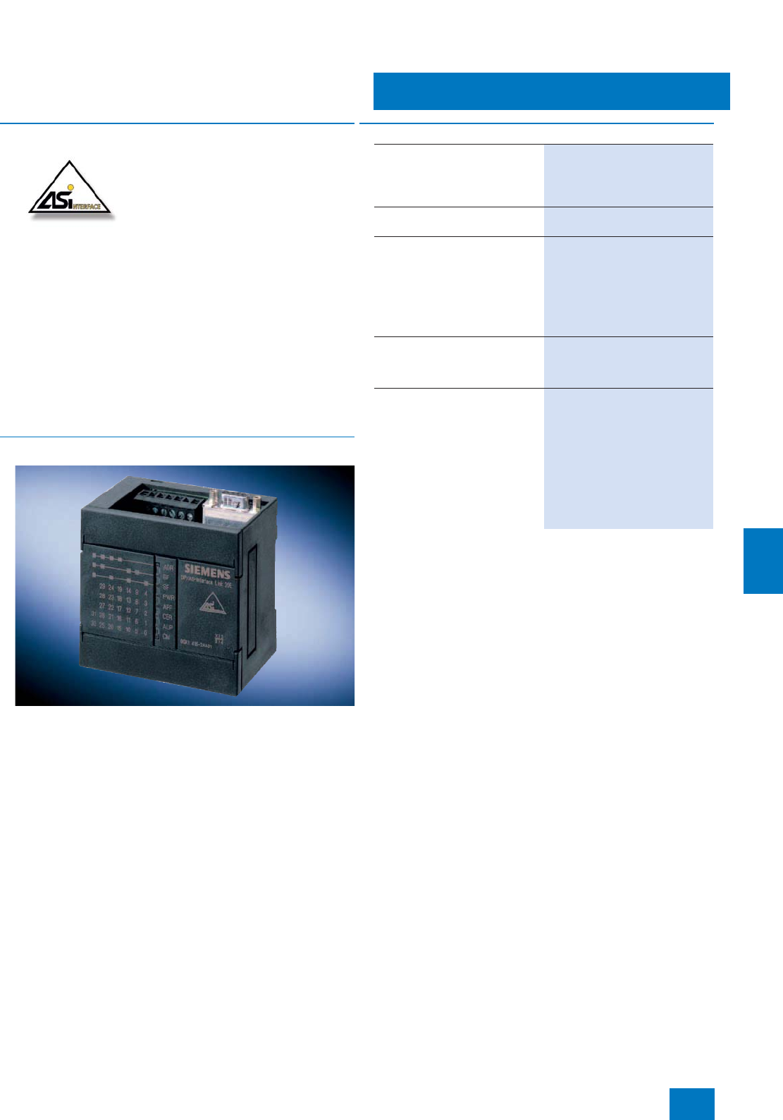
Communication
Other communication
AS-Interface
9/51
Siemens ST PCS 7 · November 2007
9
■
Overview
The actuator-sensor interface (AS-Interface) is a multi-vendor
networking system for simple - usually binary - actuators and
sensors in the lowest field area. AS-Interface enables a wiring
loom with parallel wiring to be replaced by a simple two-wire ca-
ble shared by all sensors or actuators.
The AS-Interface works by the master-slave principle. Sensors/
actuators connected through the AS-Interface cable are con-
trolled by the master as slaves.
Note:
AS-Interface is integrated in SIMATIC pcs 7 as a subordinate
bus. Consequently, this bus does not offer the full functionality of
SIMATIC PCS 7; this applies in particular to diagnostics func-
tions. Further information, see Catalog IK PI.
■
Design
System components
The basic components of a system installation are:
• CP 343-2 AS-Interface master module for ET 200M or/and
DP/AS-Interface link for connection of an AS-Interface line to
PROFIBUS DP
• AS-Interface shaped cable (use of round cable also possible
if preferred)
• Modules for connecting standard sensors/actuators
• Power supply unit for powering the slaves
• Actuators and sensors with an integrated slave ASIC
• Address programming device for setting the slave address
■
Selection and Ordering Data Order No.
CP 343-2
Communications processor for
connection of SIMATIC S7-300
and ET 200M to AS-Interface,
without front connector
6GK7 343-2AH00-0XA0
Front Connector
20-pin, with screw contacts 6ES7 392-1AJ00-0AA0
CP 343-2 Manual
Including software and examples
•German 6GK7 343-2AH00-8AA0
• English 6GK7 343-2AH00-8BA0
•French 6GK7 343-2AH00-8CA0
• Italian 6GK7 343-2AH00-8EA0
DP/AS-Interface Link 20E
PROFIBUS DP/ AS-Interface
gateway, degree of protection
IP 20
6GK1 415-2AA01
Manual for
DP/AS-Interface Link 20E
Paper version
incl. type and GSD files
•German 6GK1 971-2DS01-0AA0
• English 6GK1 971-2DS01-0AA1
•French 6GK1 971-2DS01-0AA2
• Spanish 6GK1 971-2DS01-0AA3
• Italian 6GK1 971-2DS01-0AA4
© Siemens AG 2007
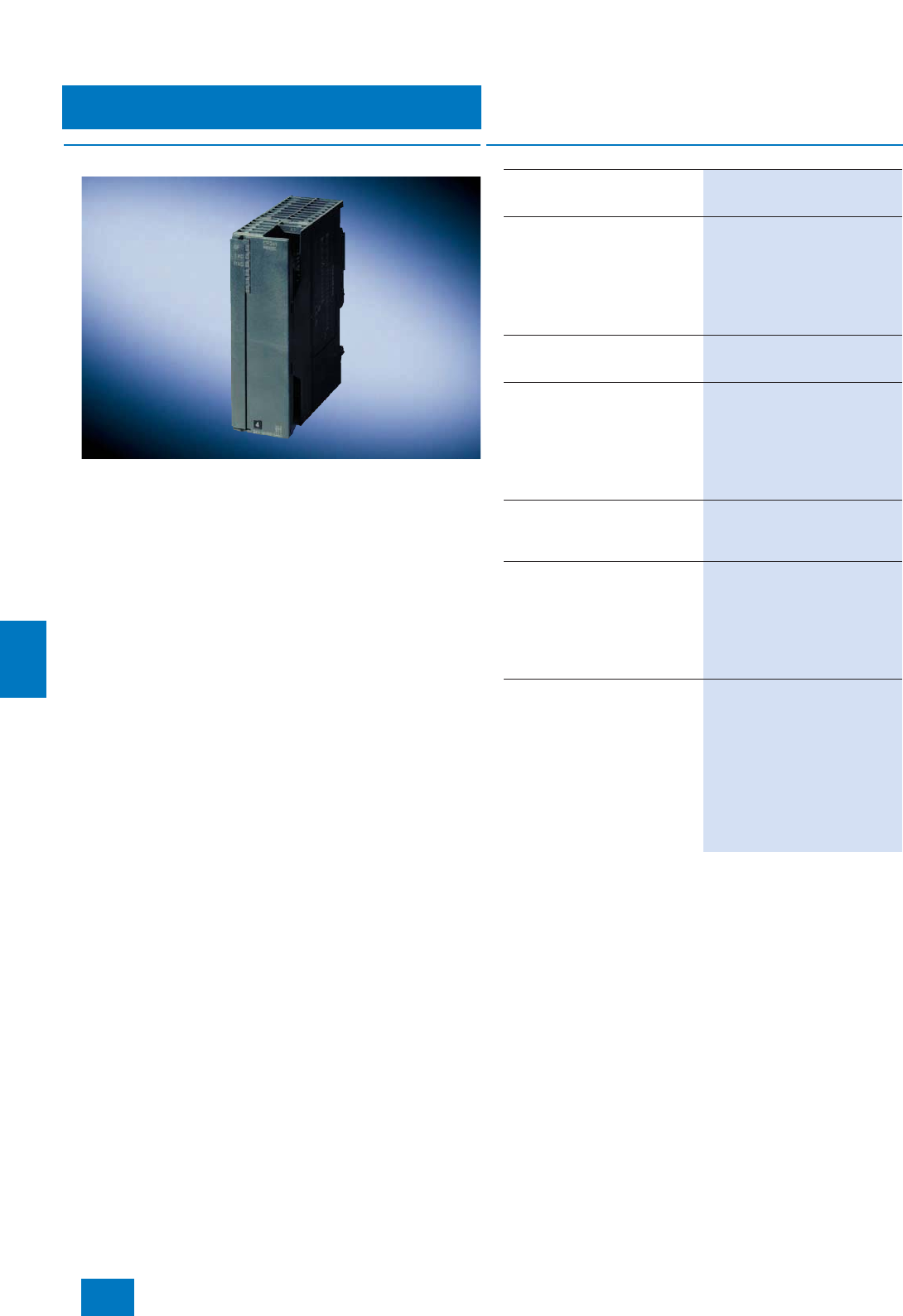
Communication
Other communication
Modbus
9/52 Siemens ST PCS 7 · November 2007
9
■
Overview
Modbus is connected to PROFIBUS DP using an ET 200M with
a CP 341 communications processor. The latter enables the fast
and efficient exchange of data through point-to-point coupling.
The CP 341 communications module is available in 3 versions
with different transmission physics:
• RS 232C (V.24)
• 20 mA (TTY)
• RS 422/RS 485 (X.27)
The MODBUS Master or MODBUS Slave loadable drivers are
needed for the Modbus coupling.
■
Selection and Ordering Data Order No.
CP 341 communications
processor
with one RS 232 C (V.24) interface
6ES7 341-1AH01-0AE0
RS 232 connecting cable
for linking to SIMATIC S7
•5 m 6ES7 902-1AB00-0AA0
•10 m 6ES7 902-1AC00-0AA0
•15 m 6ES7 902-1AD00-0AA0
CP 341 communications
processor
with one 20 mA (TTY) interface
6ES7 341-1BH01-0AE0
20 mA (TTY) connecting cable
for linking to SIMATIC S7
•5 m 6ES7 902-2AB00-0AA0
•10 m 6ES7 902-2AC00-0AA0
•50 m 6ES7 902-2AG00-0AA0
CP 341 communications
processor
with one RS 422/485 (X.27)
interface
6ES7 341-1CH01-0AE0
RS 422/485 connecting cable
for linking to SIMATIC S7
•5 m 6ES7 902-3AB00-0AA0
•10 m 6ES7 902-3AC00-0AA0
•50 m 6ES7 902-3AG00-0AA0
Loadable drivers for CP 341
MODBUS master (RTU format)
• Single license 6ES7 870-1AA01-0YA0
• Single license, without software
or documentation 6ES7 870-1AA01-0YA1
MODBUS slave (RTU format)
• Single license 6ES7 870-1AB01-0YA0
• Single license, without software
or documentation 6ES7 870-1AB01-0YA1
© Siemens AG 2007
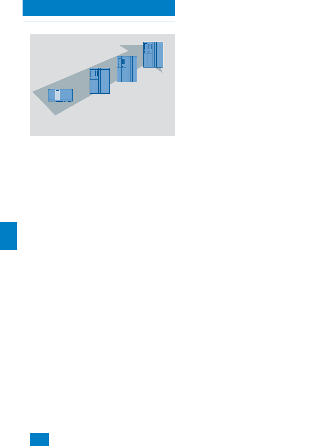
Automation systems
Introduction
10/2 Siemens ST PCS 7 · Update November 2008
10
■
Overview
Scalable automation systems, overview
The SIMATIC PCS 7 process control system offers a wide range
of automation systems whose performances are finely matched
to one another within wide limits. This results in fine scaling of the
automation performance over the complete performance range.
The automation systems offered can be differentiated according
to various criteria. In accordance with the design, they are cate-
gorized as:
• Microbox automation system with software controller
• Modular automation systems of the S7-400 range with hard-
ware controller
■
Application
Microbox automation system
The SIMATIC PCS 7 AS RTX Microbox automation system repre-
sents the starter system in the lower performance range of
SIMATIC PCS 7. As a result of its exceptional physical properties
and small dimensions, it is particularly suitable for use at plant
level in industrial applications.
Modular automation systems of the S7-400 range
In these "Automation system bundles", selected components of
the SIMATIC S7-400 are combined together.
The following characteristics make the SIMATIC S7-400 predes-
tined for use as a SIMATIC PCS 7 automation system:
7Modular design without fans
7High expansion capability and ruggedness
7Single or redundant design
7Comprehensive communication facilities
7Integral system functions
7Integrable safety functions (Safety Integrated)
7Simple linking of central or distributed I/O
In accordance with their functionalities, the modular automation
systems of the S7-400 range can be classified into:
• Standard automation systems
• Fault-tolerant automation systems
• Safety-related automation systems
Various automation systems are available with a price/perfor-
mance ratio which can be tailored to your system requirements.
The CPU of the automation systems is already equipped as stan-
dard with an onboard PROFIBUS DP fieldbus connection.
Depending on the type of CPU, 1 or 2 further PROFIBUS DP in-
terfaces are possible using additional IF 964-DP interface mod-
ules. PROFIBUS communication modules can be additionally fit-
ted if required.
■
Design
Microbox automation system
The compact and rugged automation system based on the
SIMATIC Microbox PC 427B has been designed for mainte-
nance-free 24-hour continuous operation at ambient tempera-
tures up to 55 °C. Since there are no fans or rotating storage me-
dia, it is resistant to vibration and shock.
The Windows XP Embedded operating system, the WinAC RTX
controller software, and the SIMATIC PC DiagMonitor diagnos-
tics software are preinstalled on the supplied 2-GB Compact-
Flash card. The scope of delivery also includes an AS runtime
license for 250 POs.
Modular automation systems of the S7-400 range
The SIMATIC PCS 7 automation systems of the S7-400 range
are delivered as preassembled and tested all-in-one systems
(AS bundles) at no extra charge. Each of these AS bundles is
already combined with a SIMATIC PCS 7 AS Runtime license for
100 process objects (PO).
The configuration of the AS bundles and their Order Nos. can be
individually combined by selecting preconfigured ordering
units. System-specific ordering configurations are available for
this purpose in the Sections "Standard automation systems",
"Fault-tolerant automation systems" and "Safety-related automa-
tion systems". In order to facilitate selection of preferred configu-
rations, these are additionally listed with their complete Order
Nos.
As an alternative to this catalog for ordering the AS bundles,
a configurator offered in the catalog & online ordering system
"A&D Mall" (www.siemens.com/automation/mall) can also be
used.
Depending on the configuration as Single Station or Redundant
Station, an AS bundle is equipped with the following compo-
nents:
• 1 or 2 racks with 9 or 18 slots
• 1 or 2 SIMATIC S7-400 CPUs
• 1, 2 or 4 PS 405 (24 V DC) or PS 407 (120/230 V AC/DC)
power supplies, without backup batteries in each case
• 1 or 2 x RAMs from 768 KB to 30 MB
• 1 or 2 memory cards with 2 to 16 MB RAM
• 1, 2 or 4 interface modules for Industrial Ethernet plant bus
(via CP or integrated in CPU)
• Additive PROFIBUS communications processors (by means
of configurator up to 4 per Single Station, up to 8 per Redun-
dant Station)
• 4 sync modules for a range up to 10 m or 10 km and 2 fiber-
optic sync cables, 1 m (longer lengths can be ordered sepa-
rately)
SIMATIC PCS 7 AS RTX
AS 414
AS 416
AS 417
Microbox
automation system
with software controller
Standard automation systems
of S7-400 series with
hardware controller
© Siemens AG 2008
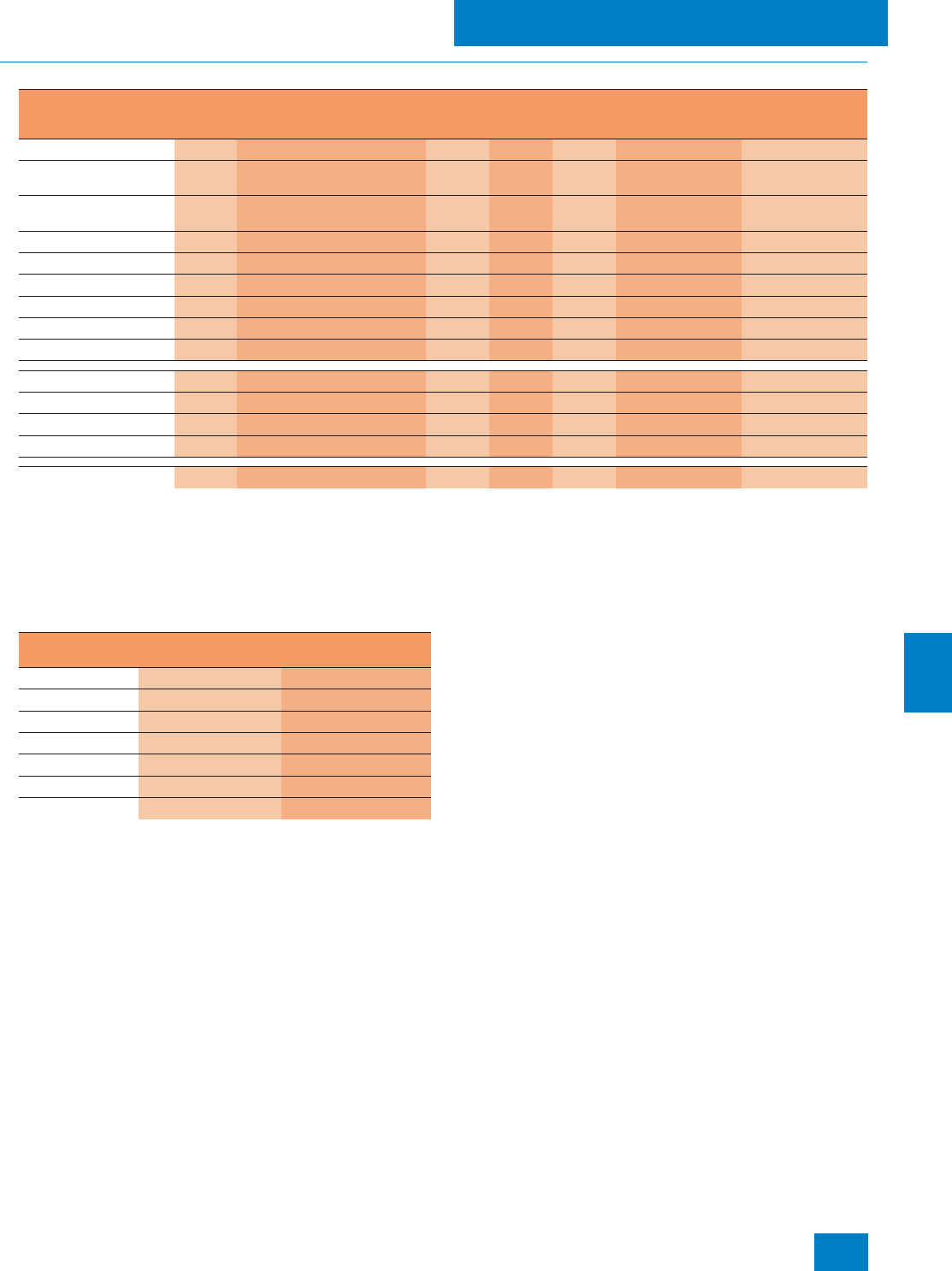
Automation systems
Introduction
10/3
Siemens ST PCS 7 · Update November 2008
10
■
Technical specifications
Typical mixed quantity frameworks for SIMATIC PCS 7 S7-400 automation systems
Note:
The values quoted here are not AS-specific maximum values for the par-
ticular item but represent a typical distribution of the available total ca-
pacity of the AS during mixed operation of all the items of an assembled
block.
Comparison of main memory and processing time of the
S7-400 automation systems
AS
412
H/F/FH
AS
414-3IE AS
414-3 AS
414
H/F/FH
AS
416-2 AS
416-3 AS
416-3IE AS
417-4 AS
417
H/F/FH
AS
417-4 AS
417
H/F/FH
Memory card [in MB] 22/4 48/16 16 416
Analog value measure-
ments 10 35 125 125 125 150 700
Digital value measure-
ments 15 110 350 350 350 400 1.200
PID controls 635 110 110 110 130 300
Motors 10 50 125 125 125 150 450
Valves 10 50 125 125 125 150 450
SFC 015 40 40 40 50 200
Steps 0150 400 400 400 500 2.000
Dosing 0 3 15 15 15 15 45
Digital inputs DI 50 220 800 800 800 850 2.000
Digital outputs DO 25 110 300 300 300 315 1.000
Analog inputs AI 20 80 250 250 250 275 800
Analog outputs AO 10 40 110 110 110 130 400
Process objects (PO) 50 283 890 890 890 995 3.145
AS type Integrated main
memory in MB Processing time
in ns
AS 414-3/414-3IE 2,8 45
AS 416-2 5,6 30
AS 416-3/416-3IE 11,2 30
AS 417-4 30 18
AS 412H/F/FH 0,768 75
AS 414H/F/FH 2,8 45
AS 417H/F/FH 30 18
© Siemens AG 2008
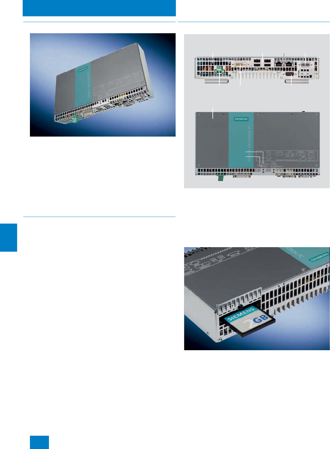
Automation systems
Microbox automation system
10/4 Siemens ST PCS 7 · Update November 2008
10
■
Overview
SIMATIC PCS 7 AS RTX
With consideration of the scalable automation performance, the
SIMATIC PCS 7 AS RTX Microbox automation system represents
the starter system in the bottom performance range of SIMATIC
PCS 7.
The compact and rugged design as well as the complete ab-
sence of fans and rotating storage media mean that it resistant
to vibration and shock, and make it highly suitable for mainte-
nance-free 24-hour continuous operation at ambient tempera-
tures up to 55 °C. Particularly with small applications, it is an ex-
ceptionally good alternative to standard automation systems of
S7-400 design.
■
Application
As a result of its exceptional physical properties and small di-
mensions, the SIMATIC PCS 7 AS RTX Microbox automation sys-
tem is exceptionally suitable for industrial use at plant level. Just
like the runtime systems (AS plus OS) and complete systems
(AS plus OS and ES) based on SIMATIC PCS 7 BOX, it can be
used for:
• Small production applications
• Package units
• Laboratory automation
SIMATIC PCS 7 AS RTX can also be combined with SIMATIC
PCS 7 BOX or automation systems of S7-400 design within a
plant.
■
Design
Design of the SIMATIC PCS 7 AS RTX
The SIMATIC PCS 7 AS RTX Microbox automation system is
based on a SIMATIC Microbox PC 427B with a system-specific
configuration. The following are preinstalled on the supplied
2-GB CompactFlash card:
• Windows XP Embedded operating system
• WinAC RTX controller software
• SIMATIC PC DiagMonitor diagnostics software
Microbox automation system with CompactFlash card
The SIMATIC PCS 7 AS RTX has an integral power supply with
electrical isolation and mains buffering. Process data can be
safely saved by a buffered 2-MB SRAM.
Parameterizable monitoring functions (program execution/
watchdog, processor and board temperatures) as well as en-
hanced diagnostics/messages (e.g. operating hours counter,
hard disk/system status) can be recorded via SIMATIC PC
DiagMonitor and the maintenance station (PCS 7 asset manage-
ment), and evaluated or signaled by LED (power/watchdog).
4 x USB 2.0
COM1
Cooling slots
All-metal enclosure
Interface inscriptions
Displays:
Power
Watchdog
24 V DC
power supply
DVI-I connection
(DVI/VGA combined)
2 x Gigabit
Ethernet
PROFIBUS
12 Mbit/s
© Siemens AG 2008

Automation systems
Microbox automation system
10/5
Siemens ST PCS 7 · Update November 2008
10
Two Ethernet interfaces 10/100/1000 Mbit/s (RJ45) are inte-
grated in the SIMATIC PCS 7 AS RTX for plant bus communica-
tion with SIMATIC PCS 7 subsystems such as operator system,
engineering system or maintenance station.
ET 200M, ET 200ISP and ET 200S I/O stations can be linked
over a PROFIBUS DP interface to a comprehensive range of low-
cost signal/function modules as well as intelligent field/process
devices on the PROFIBUS PA.
The SIMATIC PCS 7 AS RTX is configured using the central en-
gineering system of the SIMATIC PCS 7 process control system.
The engineering system also administers the AS Runtime li-
censes of the SIMATIC PCS 7 AS RTX. The scope of delivery
of the SIMATIC PCS 7 AS RTX already includes an AS Runtime
license for 250 POs. This can be expanded by further AS Run-
time licenses for 100 POs. The process objects of additional
AS Runtime licenses are then added to process objects which
already exist.
■
Technical specifications
SIMATIC PCS 7 AS RTX
Design and equipment features
Design DIN rail or wall mounting;
horizontal (preferred) or vertical
Degree of protection to EN 60529
(front/rear) IP20
CPU
• Processor Intel Pentium M 1.4 GHz
• Front Side Bus 400 MHz
• Second Level Cache 2 MB
Chipset Intel Alviso 910GML
Main memory 1 GB DDR2-SDRAM (SO-DIMM
modules)
Graphics
• Graphics controller Intel 2D/3D GMA900, integrated
in chipset
• Graphics memory Dynamic video memory 8 to
128 MB
• Resolutions/colors/frequencies
-CRT Up to 1600 x 1200 / 32 bit colors /
60 to 120 Hz
- DVI Up to 1600 x 1200 / 32 bit colors
Drives
• Flash drive For CompactFlash card, 2 GB
• CD-ROM / DVD-RW / diskette Connectable via USB (not
included in scope of delivery)
Interfaces
• PROFIBUS/MPI 12 Mbit/s (electrically isolated,
CP 5611-compatible), 9-contact
Sub-D socket
• Ethernet 2 x 10/100/1000 Mbit/s (RJ 45),
two independent controllers
•USB 4 x USB 2.0/high-speed
• Serial 1 x COM1 (V.24), 9-contact Sub-D
connector
• Parallel -
• Graphics connection 1 x DVI-I (DVI/VGA combined):
• DVI: digital
• VGA analog
• Keyboard/mouse Connectable via USB (not
included in scope of delivery)
LED displays • Power
• Watchdog
Operating system / basic software
Operating system Windows XP Embedded prein-
stalled on CompactFlash card
(CF card) 2 GB, no activation
required
System-tested SIMATIC industrial
software WinAC RTX
DiagMonitor
Monitoring/diagnostics functions
Watchdog • Monitoring of program execution
• Restart can be parameterized
following faults
• Monitoring time adjustable in the
software
Temperature • Processor
• Motherboard
(via SIMATIC PC DiagMonitor and
SIMATIC PCS 7 Asset Manage-
ment)
Operating hours counter (via SIMATIC PC DiagMonitor and
SIMATIC PCS 7 Asset Manage-
ment)
Safety
Protection class Protection class I compliant with
IEC 61140
Safety directives EN 60950-1; UL 60950;
CAN/CSA-C22.2 No. 60950-1;
UL 508; CAN/CSA-C22.2 No. 142
or CAN/CSA-C22.2 No. 14-05
Noise level
Operation < 40 dB (A) to DIN 45635-1
■
Technical specifications
© Siemens AG 2008

Automation systems
Microbox automation system
10/6 Siemens ST PCS 7 · Update November 2008
10
B) Subject to export regulations: AL: N, ECCN: EAR99H
Electromagnetic compatibility (EMC)
Emitted interference EN 55022 Class B; FCC Class A
Immunity to conducted interference
on the supply lines
± 2 kV (to IEC 61000-4-4; burst)
± 1 kV (to IEC 61000-4-5; sym-
metrical surge)
± 2 kV (to IEC 61000-4-5; asym-
metrical surge)
Immunity to interference on signal
lines
± 1 kV (to IEC 61000-4-4; burst;
length < 3 m)
± 2 kV (to IEC 61000-4-4; burst;
length > 3 m)
± 2 kV (to IEC 61000-4-5; surge;
length > 30 m)
Immunity to static discharge ± 6 kV contact discharge (to
IEC 61000-4-2)
± 8 kV air discharge (to
IEC 61000-4-2)
Immunity to high-frequency irradia-
tion 10 V/m, 80 to 1000 MHz and
1.4 to 2 GHz, 80 % AM (to
IEC 61000-4-3)
1 V/m, 2 to 2.7 GHz, 80 % AM
(to IEC 61000-4-3)
10 V, 10 kHz to 80 MHz, 80 % AM
(to IEC 61000-4-6)
Immunity to magnetic fields 100 A/m, 50/60 Hz (to
IEC 61000-4-8)
Climatic conditions
Temperature Tested according to
IEC 60068-2-1, IEC 60068-2-2,
IEC 60068-2-14
• Operation Horizontal mounting:
• 0 to +50 °C
• 0 to +55 °C (reduced perfor-
mance)
Vertical mounting:
• 0 to +45 °C
• Storage/transport -20 to +60 °C
• Gradient Operation: max. 10 °C/h; stor-
age: 20 °C/h, no condensation
Relative humidity Tested according to
IEC 60068-2-78, IEC 60068-2-30
• Operation 5 to 80 % at 25 °C (no condensa-
tion)
• Storage/transport 5 to 95 % at 25 °C (no condensa-
tion)
Mechanical environmental conditions
Vibrations Tested according to
IEC 60068-2-6
• Operation 10 to 58 Hz: 0.075 mm,
58 to 500 Hz: 9.8 m/s²
• Storage/transport 5 to 9 Hz: 3.5 mm,
9 to 500 Hz: 9.8 m/s²
Shock Tested according to
IEC 60068-2-27, IEC 60068-2-29
• Operation 150 m/s², 11 ms
• Storage/transport 250 m/s², 6 ms
■
Technical specifications
Approvals
CE living accommodation
• Emitted interference EN 61000-6-3: 2001
• Noise immunity EN 61000-6-1: 2001
CE industrial environment
• Emitted interference EN 61000-6-4: 2001
• Noise immunity EN 61000-6-2: 2005
cULus UL 60950-1, Report E11 5352
and CAN/CSA-C22.2
No. 60950-1; UL 508 and
CAN/CSA-C22.2 No. 142;
CAN/CSA-C22.2 No. 14-05
Power supply (electrically isolated)
Power supply 24 V DC (20.4 to 28.8 V)
Short-term voltage dip Max. 10 ms at 0.85 nominal sup-
ply voltage (max. 10 events per
hour; recovery time min. 1 s)
Max. current consumption (at 24 V
DC) 2.5 A
Power failure signaling Power Fail signal
Dimensions and weights
Dimensions (W x H x D) in mm 262 x 133 x 47
Weight Approx. 2 kg
■
Selection and Ordering Data Order No.
SIMATIC PCS 7 AS RTX
Assembled and preinstalled auto-
mation system on the basis of the
SIMATIC Microbox PC 427B with
Windows XP Embedded operat-
ing system, WinAC RTX controller
software and SIMATIC PC
DiagMonitor diagnostics software
on 2-GB CompactFlash card
SIMATIC PCS 7 AS Runtime
license V7.0 for 250 POs
6ES7 654-0UC11-0XX0
Additional and expansion components
SIMATIC PCS 7 AS Runtime
license (can be added to exist-
ing licenses)
7 languages (German, English,
French, Italian, Spanish, Chi-
nese, Japanese), executes with
Windows XP Professional, single
license for 1 installation
Type of delivery:
License key disk, certificate of
license, terms and conditions
•100 POs 6ES7 653-2BA00-0XB5
Individual components
(included in scope of delivery of SIMATIC PCS 7 AS RTX)
SIMATIC PC CompactFlash
card
•2 GB 6ES7 648-2BF01-0XF0 B)
■
Technical specifications
© Siemens AG 2008
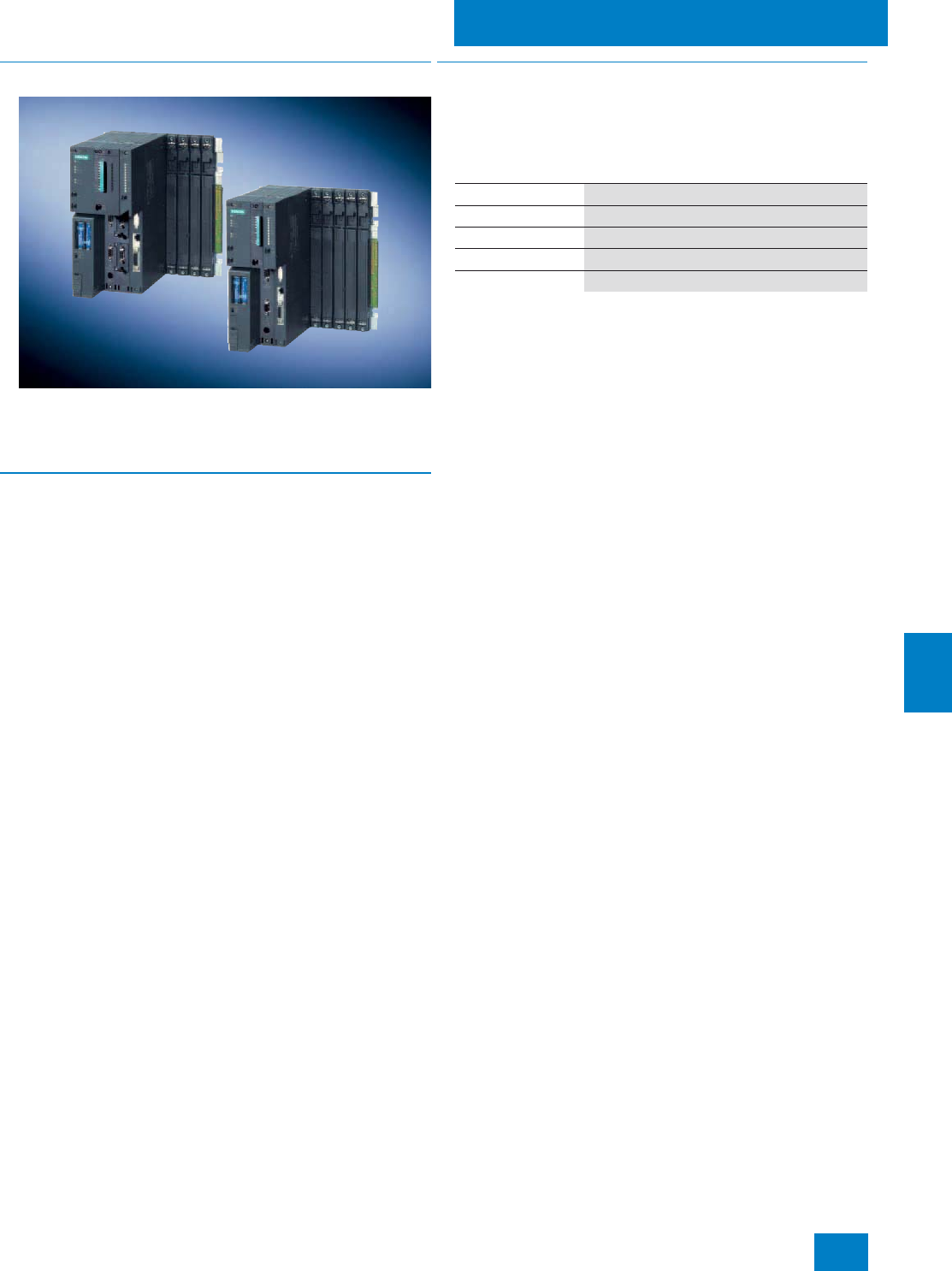
Automation systems
Standard automation systems
10/7
Siemens ST PCS 7 · Update November 2008
10
■
Overview
The AS 414-3 / 414-3IE, AS 416-2, AS 416-3 / 416-3IE and
AS 417-4 standard automation systems are extremely robust,
and feature high processing and communications perfor-
mances.
■
Application
The AS 414-3 / 414-3IE automation systems are tailored for small
applications with small quantity frameworks. They therefore fulfill
the requirements for a low-cost starter solution with a modular
and scalable system based on the S7-400 controller range.
Larger quantity frameworks can be implemented using the
AS 416-2, AS 416-3 / 416-3IE and AS 417-4 automation sys-
tems. These systems are preferred for medium-sized systems
and bigger.
Automation systems with integral Industrial Ethernet
interface
In addition to the AS 414-3 and AS 416-3 systems with Industrial
Ethernet connection via CP 443-1, two automation systems are
now offered where the Industrial Ethernet interface is integrated
in the CPU. These AS 414-3IE and AS 416-3IE systems are a
little cheaper than the comparable AS 414-3 and AS 416-3 sys-
tems with the same performance, but differ in their time synchro-
nization (NTP instead of S7). When using the AS 414-3IE and
AS 416-3IE systems, there are therefore two separate time syn-
chronization circuits within the SIMATIC PCS 7 system. This re-
sults in two alternatives for users:
• Create two different servers as masters for NTP and S7 time
synchronization, and tolerate any time differences which may
result
• Use a SICLOCK central plant clock as the common time mas-
ter
■
Design
The standard automation systems for SIMATIC PCS 7 are avail-
able as preassembled and tested all-in-one systems (AS bun-
dles) at no extra charge.
Depending on the type of automation system, the RAM of these
AS bundles varies as follows:
The firmware of the standard automation systems listed in this
catalog can be updated in two ways:
• Per Flash-EPROM memory card (8 MB)
• From the central engineering system via the Industrial Ether-
net plant bus
Runtime licenses
The SIMATIC PCS 7 AS Runtime license for 100 POs already in-
tegrated in each AS bundle can be expanded by additional
Runtime licenses for 100, 1000 or 10000 POs. The process ob-
jects of additional Runtime licenses can be added to process
objects which already exist. The number and type (e.g. 100 or
1000) of additional Runtime licenses are irrelevant with regard to
the implementable quantity framework. The AS Runtime licenses
are administered in the engineering system of the SIMATIC
PCS 7 process control system (on an engineering station or in
the SIMATIC PCS 7 BOX).
Individual configuration of AS bundles
The equipment of the standard automation systems as well as
their Order Nos. can be individually compiled by selecting pre-
configured ordering units. System-specific ordering configura-
tions are available for this purpose in the Section "Selection and
ordering data".
The recommended preferred configurations are additionally
listed with their complete Order Nos.
As an alternative to the ordering data in this catalog, the
configurator offered in the catalog & online ordering system
"A&D Mall" (www.siemens.com/automation/mall) can also be
used to select and order the standard automation systems for
SIMATIC PCS 7.
AS type Main memory
AS 414-3 / 414-3IE 2.8 MB (1.4 MB each for program and data)
AS 416-2 5.6 MB (2.8 MB each for program and data)
AS 416-3 / 416-3IE 11.2 MB (5.6 MB each for program and data)
AS 417-4 30 MB (15 MB each for program and data)
© Siemens AG 2008

Automation systems
Standard automation systems
10/8 Siemens ST PCS 7 · Update November 2008
10
1) With the UR2 rack in combination with a redundant power supply, the
number of additive CP 443-5 Extended is limited to 2
1) With the UR2 rack in combination with a redundant power supply, the
number of additive CP 443-5 Extended is limited to 3
Selection and Ordering Data Order No.
AS 414-3
with SIMATIC PCS 7 AS Runtime license for
100 POs
CPU with 3 interfaces (MPI/DP, DP and slot for
IF module)
2.8 MB RAM (1.4 MB each for program and
data)
6ES7 654-
7 7 7 7 7 -7 7 B7
Type of delivery
• Preassembled and tested 8
Memory card
• Memory card 2 MB RAM (up to approx.
180 POs) B
• Memory card 4 MB RAM (up to approx.
300 POs) C
CPU type
• CPU 414-3 (up to approx. 250 POs) C
Additive IF 964-DP interface module
• Without additive IF 964-DP 0
• 1 x IF 964-DP 1
Interface module to
Industrial Ethernet plant bus
• 1 x CP 443-1 1
Rack
• UR2 (9 slots), aluminum 3
• UR2 (9 slots), steel 4
• UR1 (18 slots), aluminum 5
• UR1 (18 slots), steel 6
Power supply (without backup batteries)
• 1 x PS 407, 10 A for 120/230 V AC/DC B
• 1 x PS 407, 10 A for 120/230 V AC/DC, redun-
dancy possible C
• 1 x PS 407, 20 A for 120/230 V AC/DC D
• 2 x PS 407, 10 A for 120/230 V AC/DC, redun-
dancy possible E
• 1 x PS 405, 10 A for 24 V DC G
• 1 x PS 405, 10 A for 24 V DC, redundancy
possible H
• 1 x PS 405, 20 A for 24 V DC J
• 2 x PS 405, 10 A for 24 V DC, redundancy
possible K
Additive PROFIBUS DP interface modules1)
• Without CP 443-5 Extended 0
• 1 x CP 443-5 Extended 1
• 2 x CP 443-5 Extended 2
• 3 x CP 443-5 Extended1) 3
• 4 x CP 443-5 Extended1) 4
Selection and Ordering Data Order No.
AS 416-2
with SIMATIC PCS 7 AS Runtime license for
100 POs
CPU with 2 interfaces (MPI/DP and DP)
5.6 MB RAM (2.8 MB each for program and
data)
6ES7 654-
7 7 7 7 7 -7 7 B7
Type of delivery
• Preassembled and tested 8
Memory card
• Memory card 4 MB RAM (up to approx.
300 POs) C
• Memory card 8 MB RAM (up to approx.
800 POs) D
CPU type
• CPU 416-2 (up to approx. 800 POs) G
Additive IF 964-DP interface module
• Without additive IF 964-DP 0
Interface module to
Industrial Ethernet plant bus
• 1 x CP 443-1 1
Rack
• UR2 (9 slots), aluminum 3
• UR2 (9 slots), steel 4
• UR1 (18 slots), aluminum 5
• UR1 (18 slots), steel 6
Power supply (without backup batteries)
• 1 x PS 407, 10 A for 120/230 V AC/DC B
• 1 x PS 407, 10 A for 120/230 V AC/DC, redun-
dancy possible C
• 1 x PS 407, 20 A for 120/230 V AC/DC D
• 2 x PS 407, 10 A for 120/230 V AC/DC, redun-
dancy possible E
• 1 x PS 405, 10 A for 24 V DC G
• 1 x PS 405, 10 A for 24 V DC, redundancy
possible H
• 1 x PS 405, 20 A for 24 V DC J
• 2 x PS 405, 10 A for 24 V DC, redundancy
possible K
Additive PROFIBUS DP interface modules1)
• Without CP 443-5 Extended 0
• 1 x CP 443-5 Extended 1
• 2 x CP 443-5 Extended 2
• 3 x CP 443-5 Extended 3
• 4 x CP 443-5 Extended1) 4
© Siemens AG 2008

Automation systems
Standard automation systems
10/9
Siemens ST PCS 7 · Update November 2008
10
1) With the UR2 rack in combination with a redundant power supply, the
number of additive CP 443-5 Extended is limited to 2
1) With the UR2 rack in combination with a redundant power supply, the
number of additive CP 443-5 Extended is limited to 2
Selection and Ordering Data Order No.
AS 416-3
with SIMATIC PCS 7 AS Runtime license for
100 POs
CPU with 3 interfaces (MPI/DP, DP and slot for
IF module)
11.2 MB RAM (5.6 MB each for program and
data)
6ES7 654-
7 7 7 7 7 -7 7 B7
Type of delivery
• Preassembled and tested 8
Memory card
• Memory card 4 MB RAM (up to approx.
300 POs) C
• Memory card 8 MB RAM (up to approx.
800 POs) D
• Memory card 16 MB RAM (up to approx.
3,000 POs) E
CPU type
• CPU 416-3 (up to approx. 900 POs) H
Additive IF 964-DP interface module
• Without additive IF 964-DP 0
• 1 x IF 964-DP 1
Interface module to
Industrial Ethernet plant bus
• 1 x CP 443-1 1
Rack
• UR2 (9 slots), aluminum 3
• UR2 (9 slots), steel 4
• UR1 (18 slots), aluminum 5
• UR1 (18 slots), steel 6
Power supply (without backup batteries)
• 1 x PS 407, 10 A for 120/230 V AC/DC B
• 1 x PS 407, 10 A for 120/230 V AC/DC, redun-
dancy possible C
• 1 x PS 407, 20 A for 120/230 V AC/DC D
• 2 x PS 407, 10 A for 120/230 V AC/DC, redun-
dancy possible E
• 1 x PS 405, 10 A for 24 V DC G
• 1 x PS 405, 10 A for 24 V DC, redundancy
possible H
• 1 x PS 405, 20 A for 24 V DC J
• 2 x PS 405, 10 A for 24 V DC, redundancy
possible K
Additive PROFIBUS DP interface modules1)
• Without CP 443-5 Extended 0
• 1 x CP 443-5 Extended 1
• 2 x CP 443-5 Extended 2
• 3 x CP 443-5 Extended1) 3
• 4 x CP 443-5 Extended1) 4
Selection and Ordering Data Order No.
AS 417-4
with SIMATIC PCS 7 AS Runtime license for
100 POs
CPU with 4 interfaces (MPI/DP, DP and 2 slots
for IF modules)
30 MB RAM (15 MB each for program and
data)
6ES7 654-
7 7 7 7 7 -7 7 B7
Type of delivery
• Preassembled and tested 8
Memory card
• Memory card 4 MB RAM (up to approx.
300 POs) C
• Memory card 8 MB RAM (up to approx.
800 POs) D
• Memory card 16 MB RAM (up to approx.
3,000 POs) E
CPU type
• CPU 417-4 (up to approx. 3,000 POs) K
Additive IF 964-DP interface module
• Without additive IF 964-DP 0
• 1 x IF 964-DP 1
• 2 x IF 964-DP 2
Interface module to
Industrial Ethernet plant bus
• 1 x CP 443-1 1
Rack
• UR2 (9 slots), aluminum 3
• UR2 (9 slots), steel 4
• UR1 (18 slots), aluminum 5
• UR1 (18 slots), steel 6
Power supply (without backup batteries)
• 1 x PS 407, 10 A for 120/230 V AC/DC B
• 1 x PS 407, 10 A for 120/230 V AC/DC, redun-
dancy possible C
• 1 x PS 407, 20 A for 120/230 V AC/DC D
• 2 x PS 407, 10 A for 120/230 V AC/DC, redun-
dancy possible E
• 1 x PS 405, 10 A for 24 V DC G
• 1 x PS 405, 10 A for 24 V DC, redundancy
possible H
• 1 x PS 405, 20 A for 24 V DC J
• 2 x PS 405, 10 A for 24 V DC, redundancy
possible K
Additive PROFIBUS DP interface modules1)
• Without CP 443-5 Extended 0
• 1 x CP 443-5 Extended 1
• 2 x CP 443-5 Extended 2
• 3 x CP 443-5 Extended1) 3
• 4 x CP 443-5 Extended1) 4
© Siemens AG 2008

Automation systems
Standard automation systems
10/10 Siemens ST PCS 7 · Update November 2008
10
1) With the UR2 rack in combination with a redundant power supply, the
number of additive CP 443-5 Extended is limited to 3
1) With the UR2 rack in combination with a redundant power supply, the
number of additive CP 443-5 Extended is limited to 3
Selection and Ordering Data Order No.
AS 414-3IE
with SIMATIC PCS 7 AS Runtime license for
100 POs
CPU with 2 DP interfaces (MPI/DP and slot for
IF module)
2.8 MB RAM (1.4 MB each for program and
data)
6ES7 654-
7 7 7 7 7 -7 7 B7
Type of delivery
• Preassembled and tested 8
Memory card
• Memory card 2 MB RAM (up to approx.
180 POs) B
• Memory card 4 MB RAM (up to approx.
300 POs) C
CPU type
• CPU 414-3 PN/DP (up to approx. 250 POs) D
Additive IF 964-DP interface module
• Without additive IF 964-DP 0
• 1 x IF 964-DP 1
Interface module to
Industrial Ethernet plant bus
• Integrated, without CP 443-1 0
Rack
• UR2 (9 slots), aluminum 3
• UR2 (9 slots), steel 4
• UR1 (18 slots), aluminum 5
• UR1 (18 slots), steel 6
Power supply (without backup batteries)
• 1 x PS 407, 10 A for 120/230 V AC/DC B
• 1 x PS 407, 10 A for 120/230 V AC/DC, redun-
dancy possible C
• 1 x PS 407, 20 A for 120/230 V AC/DC D
• 2 x PS 407, 10 A for 120/230 V AC/DC, redun-
dancy possible E
• 1 x PS 405, 10 A for 24 V DC G
• 1 x PS 405, 10 A for 24 V DC, redundancy
possible H
• 1 x PS 405, 20 A for 24 V DC J
• 2 x PS 405, 10 A for 24 V DC, redundancy
possible K
Additive PROFIBUS DP interface modules1)
• Without CP 443-5 Extended 0
• 1 x CP 443-5 Extended 1
• 2 x CP 443-5 Extended 2
• 3 x CP 443-5 Extended 3
• 4 x CP 443-5 Extended1) 4
Selection and Ordering Data Order No.
AS 416-3IE
with SIMATIC PCS 7 AS Runtime license for
100 POs
CPU with 2 DP interfaces (MPI/DP and slot for
IF module)
11.2 MB RAM (5.6 MB each for program and
data)
6ES7 654-
7 7 7 7 7 -7 7 B7
Type of delivery
• Preassembled and tested 8
Memory card
• Memory card 4 MB RAM (up to approx.
300 POs) C
• Memory card 8 MB RAM (up to approx.
800 POs) D
• Memory card 16 MB RAM (up to approx.
3,000 POs) E
CPU type
• CPU 416-3 PN/DP (up to approx. 900 POs) J
Additive IF 964-DP interface module
• Without additive IF 964-DP 0
• 1 x IF 964-DP 1
Interface module to
Industrial Ethernet plant bus
• Integrated, without CP 443-1 0
Rack
• UR2 (9 slots), aluminum 3
• UR2 (9 slots), steel 4
• UR1 (18 slots), aluminum 5
• UR1 (18 slots), steel 6
Power supply (without backup batteries)
• 1 x PS 407, 10 A for 120/230 V AC/DC B
• 1 x PS 407, 10 A for 120/230 V AC/DC, redun-
dancy possible C
• 1 x PS 407, 20 A for 120/230 V AC/DC D
• 2 x PS 407, 10 A for 120/230 V AC/DC, redun-
dancy possible E
• 1 x PS 405, 10 A for 24 V DC G
• 1 x PS 405, 10 A for 24 V DC, redundancy
possible H
• 1 x PS 405, 20 A for 24 V DC J
• 2 x PS 405, 10 A for 24 V DC, redundancy
possible K
Additive PROFIBUS DP interface modules1)
• Without CP 443-5 Extended 0
• 1 x CP 443-5 Extended 1
• 2 x CP 443-5 Extended 2
• 3 x CP 443-5 Extended 3
• 4 x CP 443-5 Extended1) 4
© Siemens AG 2008

Automation systems
Standard automation systems
10/11
Siemens ST PCS 7 · Update November 2008
10
Recommended preferred types
■
Selection and Ordering Data Order No.
SIMATIC PCS 7 standard automation systems with Industrial Ether-
net interfacing via CP, recommended preferred types
AS 414-3 automation system
with SIMATIC PCS 7
AS Runtime license for 100 POs
Preassembled and tested, without
additive IF 964-DP and without
CP 443-5 Extended, comprising:
CPU 414-3 with 3 interfaces
(MPI/DP, DP and slot for IF mod-
ule), 2.8 MB RAM (1.4 MB each
for program and data), CP 443-1
communications processor for
connection to Industrial Ethernet
plant bus as well as
• Aluminum UR1 rack (18 slots):
- PS 407 power supply; 20 A for
120/230 V AC/DC, without
backup batteries, memory
card 2 MB RAM
6ES7 654-8BC01-5DB0 B)
- PS 407 power supply; 20 A for
120/230 V AC/DC, without
backup batteries, memory
card 4 MB RAM
6ES7 654-8CC01-5DB0 B)
- PS 405 power supply; 20 A for
24 V DC, without backup bat-
teries, memory card 2 MB
RAM
6ES7 654-8BC01-5JB0 B)
- PS 405 power supply; 20 A for
24 V DC, without backup bat-
teries, memory card 4 MB
RAM
6ES7 654-8CC01-5JB0 B)
• Aluminum UR2 rack (9 slots):
- PS 407 power supply; 10 A for
120/230 V AC/DC, without
backup batteries, memory
card 2 MB RAM
6ES7 654-8BC01-3BB0 B)
- PS 407 power supply; 10 A for
120/230 V AC/DC, without
backup batteries, memory
card 4 MB RAM
6ES7 654-8CC01-3BB0 B)
- PS 405 power supply; 10 A for
24 V DC, without backup bat-
teries, memory card 2 MB
RAM
6ES7 654-8BC01-3GB0 B)
- PS 405 power supply; 10 A for
24 V DC, without backup bat-
teries, memory card 4 MB
RAM
6ES7 654-8CC01-3GB0 B)
AS 416-2 automation system
with SIMATIC PCS 7
AS Runtime license for 100 POs
Preassembled and tested, without
additive IF 964-DP and without
CP 443-5 Extended, comprising:
CPU 416-2 with 2 interfaces
(MPI/DP and DP), 5.6 MB RAM
(2.8 MB each for program and
data), CP 443-1 communications
processor for connection to
Industrial Ethernet plant bus as
well as
• Aluminum UR1 rack (18 slots):
- PS 407 power supply; 20 A for
120/230 V AC/DC, without
backup batteries, memory
card 4 MB RAM
6ES7 654-8CG01-5DB0 B)
- PS 407 power supply; 20 A for
120/230 V AC/DC, without
backup batteries, memory
card 8 MB RAM
6ES7 654-8DG01-5DB0 B)
- PS 405 power supply; 20 A for
24 V DC, without backup bat-
teries, memory card 4 MB
RAM
6ES7 654-8CG01-5JB0 B)
- PS 405 power supply; 20 A for
24 V DC, without backup bat-
teries, memory card 8 MB
RAM
6ES7 654-8DG01-5JB0 B)
• Aluminum UR2 rack (9 slots):
- PS 407 power supply; 10 A for
120/230 V AC/DC, without
backup batteries, memory
card 4 MB RAM
6ES7 654-8CG01-3BB0 B)
- PS 407 power supply; 10 A for
120/230 V AC/DC, without
backup batteries, memory
card 8 MB RAM
6ES7 654-8DG01-3BB0 B)
- PS 405 power supply; 10 A for
24 V DC, without backup bat-
teries, memory card 4 MB
RAM
6ES7 654-8CG01-3GB0 B)
- PS 405 power supply; 10 A for
24 V DC, without backup bat-
teries, memory card 8 MB
RAM
6ES7 654-8DG01-3GB0 B)
B) Subject to export regulations: AL: N, ECCN: EAR99H
■
Selection and Ordering Data Order No.
© Siemens AG 2008

Automation systems
Standard automation systems
10/12 Siemens ST PCS 7 · Update November 2008
10
AS 416-3 automation system
with SIMATIC PCS 7
AS Runtime license for 100 POs
Preassembled and tested, without
additive IF 964-DP and without
CP 443-5 Extended, comprising:
CPU 416-3 with 3 interfaces
(MPI/DP, DP and slot for IF mod-
ule), 11.2 MB RAM (5.6 MB each
for program and data), CP 443-1
communications processor for
connection to Industrial Ethernet
plant bus as well as
• Aluminum UR1 rack (18 slots):
- PS 407 power supply; 20 A for
120/230 V AC/DC, without
backup batteries, memory
card 8 MB RAM
6ES7 654-8DH01-5DB0 B)
- PS 407 power supply; 20 A for
120/230 V AC/DC, without
backup batteries, memory
card 16 MB RAM
6ES7 654-8EH01-5DB0 B)
- PS 405 power supply; 20 A for
24 V DC, without backup bat-
teries, memory card 8 MB
RAM
6ES7 654-8DH01-5JB0 B)
- PS 405 power supply; 20 A for
24 V DC, without backup bat-
teries, memory card 16 MB
RAM
6ES7 654-8EH01-5JB0 B)
• Aluminum UR2 rack (9 slots):
- PS 407 power supply; 10 A for
120/230 V AC/DC, without
backup batteries, memory
card 8 MB RAM
6ES7 654-8DH01-3BB0 B)
- PS 407 power supply; 10 A for
120/230 V AC/DC, without
backup batteries, memory
card 16 MB RAM
6ES7 654-8EH01-3BB0 B)
- PS 405 power supply; 10 A for
24 V DC, without backup bat-
teries, memory card 8 MB
RAM
6ES7 654-8DH01-3GB0 B)
- PS 405 power supply; 10 A for
24 V DC, without backup bat-
teries, memory card 16 MB
RAM
6ES7 654-8EH01-3GB0 B)
■
Selection and Ordering Data Order No.
AS 417-4 automation system
with SIMATIC PCS 7
AS Runtime license for 100 POs
Preassembled and tested, without
additive IF 964-DP and without
CP 443-5 Extended, comprising:
CPU 417-4 with 4 interfaces
(MPI/DP, DP and 2 slots for IF
modules), 30 MB RAM (15 MB
each for program and data),
CP 443-1 communications pro-
cessor for connection to Industrial
Ethernet plant bus as well as
• Aluminum UR1 rack (18 slots):
- PS 407 power supply; 20 A for
120/230 V AC/DC, without
backup batteries,
memory card 4 MB RAM
6ES7 654-8CK01-5DB0 B)
- PS 407 power supply; 20 A for
120/230 V AC/DC, without
backup batteries,
memory card 16 MB RAM
6ES7 654-8EK01-5DB0 B)
- PS 405 power supply; 20 A for
24 V DC, without backup bat-
teries,
memory card 4 MB RAM
6ES7 654-8CK01-5JB0 B)
- PS 405 power supply; 20 A for
24 V DC, without backup bat-
teries,
memory card 16 MB RAM
6ES7 654-8EK01-5JB0 B)
• Aluminum UR2 rack (9 slots):
- PS 407 power supply; 10 A for
120/230 V AC/DC, without
backup batteries,
memory card 4 MB RAM
6ES7 654-8CK01-3BB0 B)
- PS 407 power supply; 10 A for
120/230 V AC/DC, without
backup batteries,
memory card 16 MB RAM
6ES7 654-8EK01-3BB0 B)
- PS 405 power supply; 10 A for
24 V DC, without backup bat-
teries,
memory card 4 MB RAM
6ES7 654-8CK01-3GB0 B)
- PS 405 power supply; 10 A for
24 V DC, without backup bat-
teries,
memory card 16 MB RAM
6ES7 654-8EK01-3GB0 B)
B) Subject to export regulations: AL: N, ECCN: EAR99H
■
Selection and Ordering Data Order No.
© Siemens AG 2008
Automation systems
Standard automation systems
10/13
Siemens ST PCS 7 · Update November 2008
10
Individual components
SIMATIC PCS 7 standard automation systems with integral Indus-
trial Ethernet interface module, recommended preferred types
AS 414-3IE automation system
with SIMATIC PCS 7
AS Runtime license for 100 POs
Preassembled and tested, without
CP 4435 Extended, comprising:
CPU 414-3 PN/DP with 2 DP inter-
faces (MPI/DP and preassembled
IF 964-DP module), 2.8 MB RAM
(1.4 MB each for program and
data), as well as
• Aluminum UR2 rack (9 slots):
- PS 407 power supply; 10 A for
120/230 V AC/DC, without
backup batteries, memory
card 2 MB RAM
6ES7 654-8BD10-3BB0 B)
- PS 407 power supply; 10 A for
120/230 V AC/DC, without
backup batteries, memory
card 4 MB RAM
6ES7 654-8CD10-3BB0 B)
- PS 405 power supply; 10 A for
24 V DC, without backup bat-
teries, memory card 2 MB
RAM
6ES7 654-8BD10-3GB0 B)
- PS 405 power supply; 10 A for
24 V DC, without backup bat-
teries, memory card 4 MB
RAM
6ES7 654-8CD10-3GB0 B)
AS 416-3IE automation system
with Runtime license for
100 POs
Preassembled and tested, without
CP 443-5 Extended, comprising:
CPU 416-3 PN/DP with 2 DP inter-
faces (MPI/DP and preassembled
IF 964-DP module), 11.2 MB RAM
(5.6 MB each for program and
data), as well as
• Aluminum UR2 rack (9 slots):
- PS 407 power supply; 10 A for
120/230 V AC/DC, without
backup batteries, memory
card 4 MB RAM
6ES7 654-8CJ10-3BB0 B)
- PS 407 power supply; 10 A for
120/230 V AC/DC, without
backup batteries, memory
card 16 MB RAM
6ES7 654-8EJ10-3BB0 B)
- PS 405 power supply; 10 A for
24 V DC, without backup bat-
teries, memory card 4 MB
RAM
6ES7 654-8CJ10-3GB0 B)
- PS 405 power supply; 10 A for
24 V DC, without backup bat-
teries, memory card 16 MB
RAM
6ES7 654-8EJ10-3GB0 B)
■
Selection and Ordering Data Order No.
Runtime licenses for SIMATIC PCS 7 automation systems (can be
added to existing licenses)
SIMATIC PCS 7 AS Runtime
license
6 languages (German, English,
French, Italian, Spanish, Chi-
nese), executes in the engineer-
ing system with Windows
XP Professional, floating license
for 1 installation
Type of delivery:
License key disk, certificate of
license, terms and conditions
•100 POs 6ES7 653-2BA00-0XB5
• 1,000 POs 6ES7 653-2BB00-0XB5
• 10,000 POs 6ES7 653-2BC00-0XB5
■
Selection and Ordering Data Order No.
Individual components for standard SIMATIC PCS 7 automation
systems
CPU 414-3
RAM 2.8 MB (1.4 MB each for
program and data);
module occupies 2 slots
6ES7 414-3XM05-0AB0 B)
CPU 416-2
RAM 5.6 MB (2.8 MB each for
program and data);
module occupies 1 slot
6ES7 416-2XN05-0AB0 B)
CPU 416-3
RAM 11.2 MB (5.6 MB each for
program and data);
module occupies 2 slots
6ES7 416-3XR05-0AB0 B)
CPU 417-4
RAM 30 MB (15 MB each for pro-
gram and data);
module occupies 2 slots
6ES7 417-4XT05-0AB0
CPU 414-3 PN/DP
RAM 2.8 MB (1.4 MB each for
program and data);
module occupies 2 slots
6ES7 414-3EM05-0AB0 B)
CPU 416-3 PN/DP
RAM 11.2 MB (5.6 MB each for
program and data);
module occupies 2 slots
6ES7 416-3ER05-0AB0 B)
Memory card RAM
•2 MB 6ES7 952-1AL00-0AA0
•4 MB 6ES7 952-1AM00-0AA0
•8 MB 6ES7 952-1AP00-0AA0
•16 MB 6ES7 952-1AS00-0AA0
•64 MB 6ES7 952-1AY00-0AA0
Memory Card Flash-EPROM
Only required to update firmware
•8 MB 6ES7 952-1KP00-0AA0
B) Subject to export regulations: AL: N, ECCN: EAR99H
■
Selection and Ordering Data Order No.
© Siemens AG 2008
Automation systems
Standard automation systems
10/14 Siemens ST PCS 7 · Update November 2008
10
B) Subject to export regulations: AL: N, ECCN: EAR99H
CP 443-1
Communications processor for
connection of SIMATIC S7-400 to
Industrial Ethernet through
TCP/IP, ISO and UDP; for S7 com-
munication, S5-compatible com-
munication (SEND/RECEIVE) with
FETCH/WRITE with or without
RFC 1006, diagnostics expan-
sion, Multicast, commissioning
through LAN 10/100 Mbit/s, with
electronic manual on CD-ROM
6GK7 443-1EX11-0XE0
CP 443-5 Extended
Communications processor for
connection of SIMATIC S7-400 to
PROFIBUS as DP master or for S7
communication, for increasing the
number of DP lines, for data set
routing with SIMATIC PDM and for
10-ms time stamp,
electronic manual on CD;
module occupies 1 slot
6GK7 443-5DX04-0XE0
IF 964-DP
Interface module for connection
of another PROFIBUS DP line, for
plugging into a free DP module
slot of the CPU
6ES7 964-2AA04-0AB0
PS 407 power supply module;
4A
120/230 V AC/DC; 5 V DC/4 A,
24 V DC/0.5 A;
with battery compartment for
1 backup battery, module occu-
pies 1 slot
6ES7 407-0DA02-0AA0
PS 407 power supply module;
10 A
120/230 V AC/DC; 5 V DC/10 A,
24 V DC/1 A;
with battery compartment for
2 backup batteries, module occu-
pies 2 slots
6ES7 407-0KA02-0AA0
PS 407 power supply module;
10 A, redundant design possi-
ble
120/230 V AC/DC; 5 V DC/10 A,
24 V DC/1 A;
with battery compartment for
2 backup batteries, module occu-
pies 2 slots
6ES7 407-0KR02-0AA0
PS 407 power supply module;
20 A
120/230 V AC/DC; 5 V DC/20 A,
24 V DC/1 A;
with battery compartment for
2 backup batteries, module occu-
pies 2 slots
6ES7 407-0RA02-0AA0
PS 405 power supply module;
4A
24 V DC; 5 V DC/4 A, 24 V
DC/0.5 A;
with battery compartment for
1 backup battery, module occu-
pies 1 slot
6ES7 405-0DA02-0AA0
PS 405 power supply module;
10 A
24 V DC; 5 V DC/10 A, 24 V
DC/1 A;
with battery compartment for
2 backup batteries, module occu-
pies 2 slots
6ES7 405-0KA02-0AA0
■
Selection and Ordering Data Order No.
PS 405 power supply module;
10 A, redundant design possi-
ble
24 V DC; 5 V DC/10 A, 24 V
DC/1 A;
with battery compartment for
2 backup batteries, module occu-
pies 2 slots
6ES7 405-0KR02-0AA0 B)
PS 405 power supply module;
20 A
24 V DC; 5 V DC/20 A, 24 V
DC/1 A;
with battery compartment for
2 backup batteries, module occu-
pies 2 slots
6ES7 405-0RA02-0AA0
Backup battery
Type AA, 2.3 Ah 6ES7 971-0BA00
Aluminum UR1 rack
18 slots 6ES7 400-1TA11-0AA0 B)
Aluminum UR2 rack
9 slots 6ES7 400-1JA11-0AA0
Aluminum CR3 rack
4 slots 6ES7 401-1DA01-0AA0
Steel UR1 rack
18 slots 6ES7 400-1TA01-0AA0
Steel UR2 rack
9 slots 6ES7 400-1JA01-0AA0
■
Selection and Ordering Data Order No.
© Siemens AG 2008
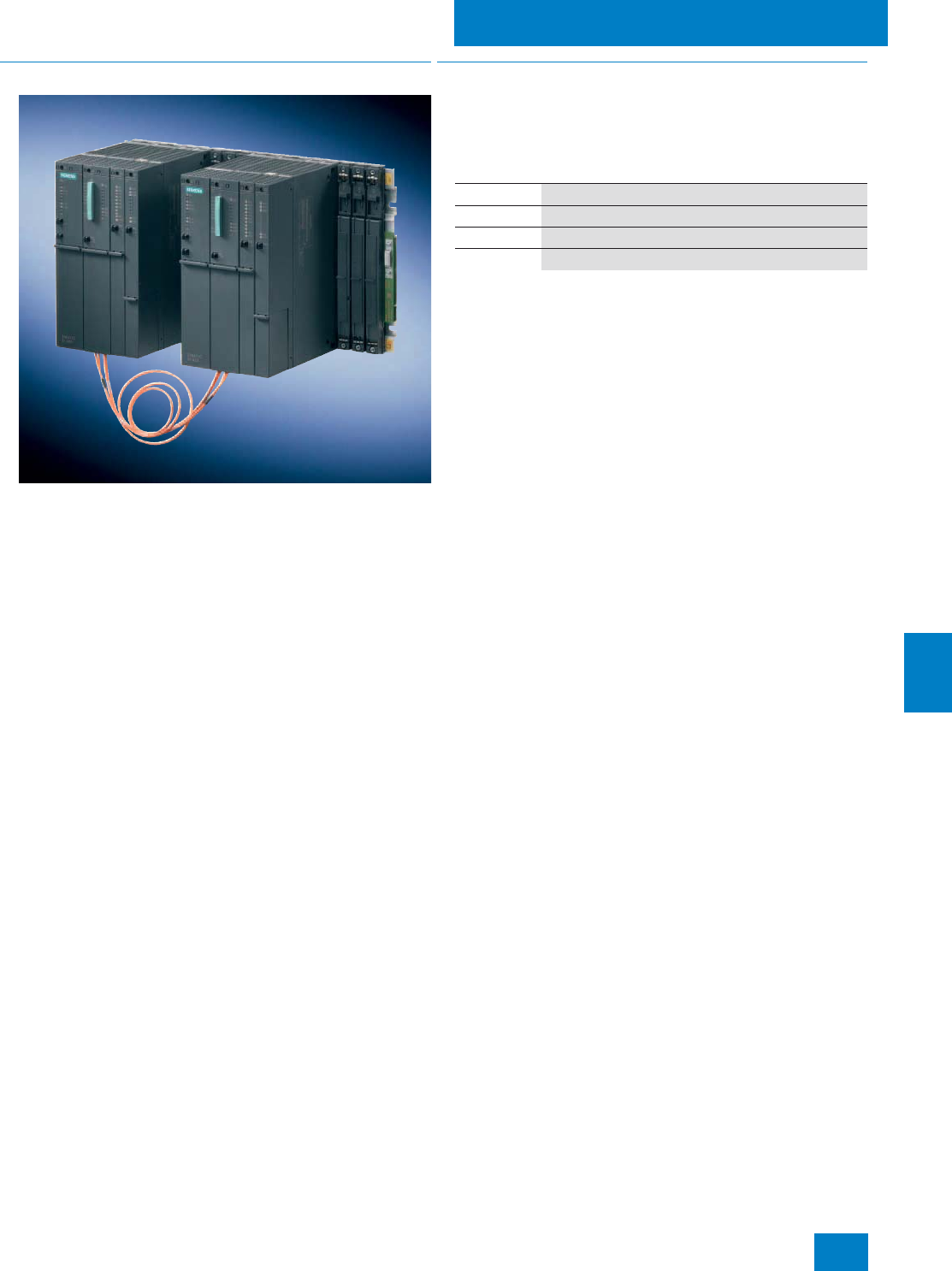
Automation systems
Fault-tolerant automation systems
10/15
Siemens ST PCS 7 · Update November 2008
10
■
Overview
Fault-tolerant automation systems are used to reduce the risk of
production failures. The higher investment costs for fault-tolerant
automation systems are frequently negligible compared to the
costs resulting from production failures. The higher the costs of
a production failure, the more worthwhile it is to use a fault-toler-
ant system.
Fault-tolerant automation systems can be mounted in a UR2-H
compact rack with divided backplane bus or in two separate
racks (UR1 or UR2). The design in two racks allows physical
separation of the redundant subsystems, e.g. by a fireproof par-
tition.
Fault-tolerant automation systems can be used on their own in a
plant configuration, or together with standard and safety-related
automation systems.
■
Design
Fault-tolerant automation systems for SIMATIC PCS 7 are avail-
able as preassembled and tested all-in-one systems (AS bun-
dles) at no extra charge.
Depending on the type of automation system, the RAM of these
AS bundles varies as follows:
Runtime licenses
Each AS bundle is already provided as standard with the
SIMATIC PCS 7 AS Runtime license for 100 process objects
(PO). The number of process objects can be extended by addi-
tional Runtime licenses for 100, 1000 or 10000 POs. The process
objects of additional Runtime licenses can be added to process
objects which already exist. The number and type (e.g. 100 or
1000) of additional Runtime licenses are irrelevant. The AS Run-
time licenses are administered on a SIMATIC PCS 7 engineering
system or in the SIMATIC PCS 7 BOX.
Connection of process I/Os
Several PROFIBUS DP lines with distributed process I/Os can be
operated on each sub-AS through the internal PROFIBUS DP in-
terface or by using additional communications processors.
• The ET 200M remote I/O stations are connected via two
IM 153-2 High Feature interface modules on a special bus
module to two redundant PROFIBUS DP segments.
• The intelligent field devices on the PROFIBUS PA are con-
nected over a DP/PA link to two redundant IM 153-2 High
Feature interface modules.
• Non-redundant PROFIBUS DP devices, e.g. ET 200S
distributed I/O devices, can be connected to the redundant
PROFIBUS DP over the Y-link.
These configurations can also be mixed together.
Communication over the plant bus
The AS 412H, AS 414H and AS 417H automation systems are
connected as standard by one communications processor per
sub-AS to the plant bus.
The plant bus can be implemented in the form of a ring structure,
which can also be configured with redundant architecture if the
availability requirements are high. When there are two redundant
rings it makes sense to use two communications processors
per sub-AS and to distribute their connections between the two
rings (4-way connection). Double faults such as failure of the
OSM/SCALANCE switch on ring 1 with simultaneous interruption
in the bus cable on ring 2 can thus be tolerated.
AS type Main memory
AS 412H 768 KB (512 KB for program and 256 KB for data)
AS 414H 2.8 MB (1.4 MB each for program and data)
AS 417H 30 MB (15 MB each for program and data)
© Siemens AG 2008

Automation systems
Fault-tolerant automation systems
10/16 Siemens ST PCS 7 · Update November 2008
10
Individual configuration of AS bundles
The equipment of the fault-tolerant automation systems as well
as their Order Nos. can be individually compiled by selecting
preconfigured ordering units. System-specific ordering configu-
rations are available for this purpose in the following Section
"Selection and ordering data".
These are divided into:
• Single stations: AS 412-3-1H, AS 414-4-1H and AS 417-4-1H
with only one CPU, e.g. for the following cases:
- Subsequent expansion to a redundant system
- Redundant configuration on UR1 racks, comprising 2 Single
Stations, 4 sync modules and 2 sync fiber-optic cables
• Redundant stations: AS 412-3-2H, AS 414-4-2H and
AS 417-4-2H with two redundant CPUs, mounted on one com-
mon rack (UR2-H) or two separate racks (UR2)
In order to rapidly access the recommended preferred configu-
rations, these are additionally listed with their complete Order
Numbers.
As an alternative to the ordering data in this catalog, the
configurator offered in the catalog & online ordering system
"A&D Mall" (www.siemens.com/automation/mall) can also be
used to select and order fault-tolerant automation systems for
SIMATIC PCS 7.
Ordering information:
For a redundant configuration based on 2 Single Stations, you
additionally require 4 sync modules (up to 10 m or 10 km) and
2 fiber-optic sync cables. Their selection depends on the dis-
tance between the two Single Stations.
The AS 412H (AS 412-3-1H/AS 412-3-2H) automation systems
currently only support sync modules with a range up to 10 m.
Fiber-optic sync cables longer than 1 m must always be ordered
separately (2 of each required).
■
Function
The fault-tolerant automation systems of SIMATIC PCS 7 are
based on the 1-out-of-2 principle. In the event of a fault, they
switch over to the standby system. These systems use a com-
pletely redundant design to maximize availability. Therefore all
important system components are present twice, such as:
• Central processing unit
• Power supply
• Hardware for linking the two CPUs
Which other components are also made available in pairs in the
interest of availability depends on the application-specific sys-
tem architecture.
The two subsystems of a redundant automation system are elec-
trically isolated from one another. This increases the system sta-
bility with respect to electromagnetic interference.
The firmware of the fault-tolerant automation systems can be up-
dated in two ways:
• Per Flash-EPROM memory card (8 MB)
• From the central engineering system via the Industrial Ether-
net plant bus
© Siemens AG 2008

Automation systems
Fault-tolerant automation systems
10/17
Siemens ST PCS 7 · Update November 2008
10
1) Up to 5 CPs can be plugged into the UR2 rack with a single power
supply, or up to 3 with a redundant power supply.
1) Up to 5 CPs can be plugged into the UR2 rack with a single power
supply, or up to 3 with a redundant power supply.
Selection and ordering data Order No.
AS 412-3-1H (Single Station)
with SIMATIC PCS 7 AS Runtime license for
100 POs
CPU with 1 interface (MPI/DP master)
768 KB RAM (512 KB for program and 256 KB
for data)
6ES7 654-
7 7 7 7 7 -7 7 B7
Type of delivery
• Preassembled and tested 8
Memory card
• Memory card 1 MB RAM (up to approx.
50 POs) A
• Memory card 2 MB RAM (up to approx.
180 POs) B
CPU type
• CPU 412-3H (up to approx. 50 POs) A
Additive IF 964-DP interface module
• Without additive IF 964-DP 0
Interface module to
Industrial Ethernet plant bus1)
• 1 x CP 443-11) 1
• 2 x CP 443-1 for redundant interface module1) 2
Rack
• UR2 (9 slots), aluminum 3
• UR2 (9 slots), steel 4
• UR1 (18 slots), aluminum 5
• UR1 (18 slots), steel 6
Power supply (without backup batteries)
• 1 x PS 407, 10 A for 120/230 V AC/DC B
• 1 x PS 407, 10 A for 120/230 V AC/DC, redun-
dant design possible C
• 1 x PS 407, 20 A for 120/230 V AC/DC D
• 2 x PS 407, 10 A for 120/230 V AC/DC, redun-
dant design possible E
• 1 x PS 405, 10 A for 24 V DC G
• 1 x PS 405, 10 A for 24 V DC, redundant de-
sign possible H
• 1 x PS 405, 20 A for 24 V DC J
• 2 x PS 405, 10 A for 24 V DC, redundant de-
sign K
Additive PROFIBUS DP interface modules1)
• Without CP 443-5 Extended 0
• 1 x CP 443-5 Extended 1
• 2 x CP 443-5 Extended1) 2
• 3 x CP 443-5 Extended1) 3
• 4 x CP 443-5 Extended1) 4
Selection and ordering data Order No.
AS 414-4-1H (Single Station)
with SIMATIC PCS 7 AS Runtime license for
100 POs
CPU with 2 interfaces (MPI/DP master and DP
master)
2.8 MB RAM (1.4 MB each for program and
data)
6ES7 654-
7 7 7 7 7 -7 7 B7
Type of delivery
• Preassembled and tested 8
Memory card
• Memory card 2 MB RAM (up to approx.
180 POs) B
• Memory card 4 MB RAM (up to approx.
300 POs) C
CPU type
• CPU 414-4H (up to approx. 250 POs) E
Additive IF 964-DP interface module
• Without additive IF 964-DP 0
Interface module to
Industrial Ethernet plant bus1)
• 1 x CP 443-11) 1
• 2 x CP 443-1 for redundant interface module1) 2
Rack
• UR2 (9 slots), aluminum 3
• UR2 (9 slots), steel 4
• UR1 (18 slots), aluminum 5
• UR1 (18 slots), steel 6
Power supply (without backup batteries)
• 1 x PS 407, 10 A for 120/230 V AC/DC B
• 1 x PS 407, 10 A for 120/230 V AC/DC, redun-
dant design C
• 1 x PS 407, 20 A for 120/230 V AC/DC D
• 2 x PS 407, 10 A for 120/230 V AC/DC, redun-
dant design E
• 1 x PS 405, 10 A for 24 V DC G
• 1 x PS 405, 10 A for 24 V DC, redundant de-
sign H
• 1 x PS 405, 20 A for 24 V DC J
• 2 x PS 405, 10 A for 24 V DC, redundant de-
sign K
Additive PROFIBUS DP interface modules1)
• Without CP 443-5 Extended 0
• 1 x CP 443-5 Extended 1
• 2 x CP 443-5 Extended1) 2
• 3 x CP 443-5 Extended1) 3
• 4 x CP 443-5 Extended1) 4
© Siemens AG 2008

Automation systems
Fault-tolerant automation systems
10/18 Siemens ST PCS 7 · Update November 2008
10
1) Up to 5 CPs can be plugged into the UR2 rack with a single power
supply, or up to 3 with a redundant power supply.
1) Up to 5 CPs can be plugged in per subsystem with a single power
supply, or up to 3 with a redundant power supply.
Selection and ordering data Order No.
AS 417-4-1H (Single Station)
with SIMATIC PCS 7 AS Runtime license for
100 POs
CPU with 2 interfaces (MPI/DP master and DP
master)
30 MB RAM (15 MB each for program and
data)
6ES7 654-
7 7 7 7 7 -7 7 B7
Type of delivery
• Preassembled and tested 8
Memory card
• Memory card 4 MB RAM (up to approx.
300 POs) C
• Memory card 8 MB RAM (up to approx.
800 POs) D
• Memory card 16 MB RAM (up to approx.
3,000 POs) E
CPU type
• CPU 417-4H (up to approx. 2,500 POs) M
Additive IF 964-DP interface module
• Without additive IF 964-DP 0
• 1 x IF 964-DP 1
Interface module to
Industrial Ethernet plant bus1)
• 1 x CP 443-11) 1
• 2 x CP 443-1 for redundant interface module1) 2
Rack
• UR2 (9 slots), aluminum 3
• UR2 (9 slots), steel 4
• UR1 (18 slots), aluminum 5
• UR1 (18 slots), steel 6
Power supply (without backup batteries)
• 1 x PS 407, 10 A for 120/230 V AC/DC B
• 1 x PS 407, 10 A for 120/230 V AC/DC, redun-
dant design C
• 1 x PS 407, 20 A for 120/230 V AC/DC D
• 2 x PS 407, 10 A for 120/230 V AC/DC, redun-
dant design E
• 1 x PS 405, 10 A for 24 V DC G
• 1 x PS 405, 10 A for 24 V DC, redundant de-
sign H
• 1 x PS 405, 20 A for 24 V DC J
• 2 x PS 405, 10 A for 24 V DC, redundant de-
sign K
Additive PROFIBUS DP interface modules1)
• Without CP 443-5 Extended 0
• 1 x CP 443-5 Extended 1
• 2 x CP 443-5 Extended1) 2
• 3 x CP 443-5 Extended1) 3
• 4 x CP 443-5 Extended1) 4
Selection and ordering data Order No.
AS 412-3-2H (Redundant Station)
with SIMATIC PCS 7 AS Runtime license for
100 POs
2 x CPU with 1 interface each (MPI/DP master)
2 x 768 KB RAM (512 KB each for program
and 256 KB each for data)
6ES7 656-
7 7 7 7 7 -7 7 B7
Type of delivery
• Preassembled and tested 8
Memory card
• 2 x memory card 1 MB RAM (up to approx.
50 POs) A
• 2 x memory card 2 MB RAM (up to approx.
180 POs) B
CPU type
• 2 x CPU 412-3H (up to approx. 50 POs) A
Sync modules and cables
• 2 x 2 sync modules for distances up to 10 m
and 2 x FO sync cable, 1 m 3
Interface module to
Industrial Ethernet plant bus1)
• 2 x CP 443-1 for redundant interface module1) 1
• 2 x 2 CP 443-1 for 4-way connection1) 2
Rack
• 1 x UR2-H (2 x 9 slots), aluminum 1
• 1 x UR2-H (2 x 9 slots), steel 2
• 2 x UR2 (9 slots), aluminum 3
• 2 x UR2 (9 slots), steel 4
Power supply (without backup batteries)
• 2 x PS 407, 10 A for 120/230 V AC/DC B
• 2 x PS 407, 10 A for 120/230 V AC/DC, redun-
dant design C
• 2 x PS 407, 20 A for 120/230 V AC/DC D
• 2 x 2 PS 407, 10 A for 120/230 V AC/DC, re-
dundant design E
• 2 x PS 405, 10 A for 24 V DC G
• 2 x PS 405, 10 A for 24 V DC, redundant de-
sign H
• 2 x PS 405, 20 A for 24 V DC J
• 2 x PS 405, 10 A for 24 V DC, redundant de-
sign K
Additive PROFIBUS DP interface modules1)
• Without CP 443-5 Extended 0
• 2 x CP 443-5 Extended 1
• 2 x 2 CP 443-5 Extended1) 2
• 2 x 3 CP 443-5 Extended1) 3
• 2 x 4 CP 443-5 Extended1) 4
© Siemens AG 2008

Automation systems
Fault-tolerant automation systems
10/19
Siemens ST PCS 7 · Update November 2008
10
1) Up to 5 CPs can be plugged in per subsystem with a single power
supply, or up to 3 with a redundant power supply.
1) Up to 5 CPs can be plugged in per subsystem with a single power
supply, or up to 3 with a redundant power supply.
Selection and ordering data Order No.
AS 414-4-2H (Redundant Station)
with SIMATIC PCS 7 AS Runtime license for
100 POs
2 x CPU with 2 interfaces (MPI/DP master and
DP master)
2 x 2.8 MB RAM (1.4 MB each for program and
data)
6ES7 656-
7 7 7 7 7 -7 7 B7
Type of delivery
• Preassembled and tested 8
Memory card
• 2 x memory card 2 MB RAM (up to approx.
180 POs) B
• 2 x memory card 4 MB RAM (up to approx.
300 POs) C
CPU type
• 2 x CPU 414-4H (up to approx. 250 POs) E
Sync modules and cables
• 2 x 2 sync modules for distances up to 10 m
and
2 x FO sync cable, 1 m
3
• 2 x 2 sync modules for up to 10 km and
2 x FO sync cable, 1 m, for testing 4
Interface module to
Industrial Ethernet plant bus1)
• 2 x CP 443-1 for redundant interface module1) 1
• 2 x 2 CP 443-1 for 4-way connection1) 2
Rack
• 1 x UR2-H (2 x 9 slots), aluminum 1
• 1 x UR2-H (2 x 9 slots), steel 2
• 2 x UR2 (9 slots), aluminum 3
• 2 x UR2 (9 slots), steel 4
Power supply (without backup batteries)
• 2 x PS 407, 10 A for 120/230 V AC/DC B
• 2 x PS 407, 10 A for 120/230 V AC/DC, redun-
dant design C
• 2 x PS 407, 20 A for 120/230 V AC/DC D
• 2 x 2 PS 407, 10 A for 120/230 V AC/DC, re-
dundant design E
• 2 x PS 405, 10 A for 24 V DC G
• 2 x PS 405, 10 A for 24 V DC, redundant de-
sign H
• 2 x PS 405, 20 A for 24 V DC J
• 2 x PS 405, 10 A for 24 V DC, redundant de-
sign K
Additive PROFIBUS DP interface modules1)
• Without CP 443-5 Extended 0
• 2 x CP 443-5 Extended 1
• 2 x 2 CP 443-5 Extended1) 2
• 2 x 3 CP 443-5 Extended1) 3
• 2 x 4 CP 443-5 Extended1) 4
Selection and ordering data Order No.
AS 417-4-2H (Redundant Station)
with SIMATIC PCS 7 AS Runtime license for
100 POs
2 x CPU with 2 interfaces (MPI/DP master and
DP master)
2 x 30 MB RAM (15 MB each for program and
data)
6ES7 656-
7 7 7 7 7 -7 7 B7
Type of delivery
• Preassembled and tested 8
Memory card
• 2 x memory card 4 MB RAM (up to approx.
300 POs) C
• 2 x memory card 8 MB RAM (up to approx.
800 POs) D
• 2 x memory card 16 MB RAM (up to approx.
3,000 POs) E
CPU type
• 2 x CPU 417-4H (up to approx. 2,500 POs) M
Sync modules and cables
• 2 x 2 sync modules for distances up to 10 m
and
2 x FO sync cable, 1 m
3
• 2 x 2 sync modules for up to 10 km and
2 x FO sync cable, 1 m, for testing 4
Interface module to
Industrial Ethernet plant bus1)
• 2 x CP 443-1 for redundant interface module1) 1
• 2 x 2 CP 443-1 for 4-way connection1) 2
Rack
• 1 x UR2-H (2 x 9 slots), aluminum 1
• 1 x UR2-H (2 x 9 slots), steel 2
• 2 x UR2 (9 slots), aluminum 3
• 2 x UR2 (9 slots), steel 4
Power supply (without backup batteries)
• 2 x PS 407, 10 A for 120/230 V AC/DC B
• 2 x PS 407, 10 A for 120/230 V AC/DC, redun-
dant design C
• 2 x PS 407, 20 A for 120/230 V AC/DC D
• 2 x 2 PS 407, 10 A for 120/230 V AC/DC, re-
dundant design E
• 2 x PS 405, 10 A for 24 V DC G
• 2 x PS 405, 10 A for 24 V DC, redundant de-
sign H
• 2 x PS 405, 20 A for 24 V DC J
• 2 x PS 405, 10 A for 24 V DC, redundant de-
sign K
Additive PROFIBUS DP interface modules1)
• Without CP 443-5 Extended 0
• 2 x CP 443-5 Extended 1
• 2 x 2 CP 443-5 Extended1) 2
• 2 x 3 CP 443-5 Extended1) 3
• 2 x 4 CP 443-5 Extended1) 4
© Siemens AG 2008

Automation systems
Fault-tolerant automation systems
10/20 Siemens ST PCS 7 · Update November 2008
10
Recommended preferred types
■
Selection and Ordering Data Order No.
Fault-tolerant SIMATIC PCS 7 automation systems -
Single Stations, recommended preferred types
AS 412-3-1H automation sys-
tem with SIMATIC PCS 7
AS Runtime license for 100 POs
Preassembled and tested, without
CP 443-5 Extended, without sync
modules and cables, comprising:
1 x CPU 412-3H with one inte-
grated interface (MPI/DP mas-
ter), 768 KB main memory
(512 KB for program and 256 KB
for data), CP 443-1 communica-
tions processor for connection to
Industrial Ethernet plant bus as
well as
• UR2 aluminum rack (9 slots)
- PS 407 power supply; 10 A for
120/230 V AC/DC, redundant
design, without backup batter-
ies, memory card 2 MB RAM
6ES7 654-8BA01-3CB0 B)
- PS 405 power supply; 10 A for
24 V DC, without backup bat-
teries, memory card 2 MB
RAM
6ES7 654-8BA01-3GB0 B)
AS 414-4-1H automation sys-
tem with SIMATIC PCS 7
AS Runtime license for 100 POs
Preassembled and tested, without
CP 443-5 Extended, without sync
modules and cables, comprising:
1 x CPU 414-4H with 2 integrated
interfaces (MPI/DP master and
DP master), 2.8 MB main memory
(1.4 MB each for program and
data), CP 443-1 communications
processor for connection to
Industrial Ethernet plant bus as
well as
• UR2 aluminum rack (9 slots)
- PS 407 power supply; 10 A for
120/230 V AC/DC, redundant
design, without backup batter-
ies, memory card 2 MB RAM
6ES7 654-8BE01-3CB0 B)
- PS 407 power supply; 10 A for
120/230 V AC/DC, redundant
design, without backup batter-
ies, memory card 4 MB RAM
6ES7 654-8CE01-3CB0 B)
- PS 405 power supply; 10 A for
24 V DC, without backup bat-
teries, memory card 2 MB
RAM
6ES7 654-8BE01-3GB0 B)
- PS 405 power supply; 10 A for
24 V DC, without backup bat-
teries, memory card 4 MB
RAM
6ES7 654-8CE01-3GB0 B)
AS 417-4-1H automation sys-
tem with SIMATIC PCS 7
AS Runtime license for 100 POs
Preassembled and tested, without
CP 443-5 Extended, without sync
modules and cables, comprising:
1 x CPU 417-4H with 2 integrated
interfaces (MPI/DP master and
DP master), 30 MB main memory
(15 MB each for program and
data), CP 443-1 communications
processor for connection to
Industrial Ethernet plant bus as
well as
• UR2 aluminum rack (9 slots)
- PS 407 power supply; 10 A for
120/230 V AC/DC, redundant
design, without backup batter-
ies, memory card 4 MB RAM
6ES7 654-8CM01-3CB0 B)
- PS 407 power supply; 10 A for
120/230 V AC/DC, redundant
design, without backup batter-
ies, memory card 16 MB RAM
6ES7 654-8EM01-3CB0 B)
- PS 405 power supply; 10 A for
24 V DC, without backup bat-
teries, memory card 4 MB
RAM
6ES7 654-8CM01-3GB0 B)
- PS 405 power supply; 10 A for
24 V DC, without backup bat-
teries, memory card 16 MB
RAM
6ES7 654-8EM01-3GB0 B)
Fault-tolerant SIMATIC PCS 7 automation systems -
Redundant stations, recommended preferred types
AS 412-3-2H automation sys-
tem with SIMATIC PCS 7
AS Runtime license for 100 POs
Preassembled and tested, without
CP 443-5 Extended, comprising:
2 x CPU 412-3H with 2 x
1 integrated interface (MPI/DP
master), 2 x 768 KB main memory
(512 KB each for program and
256 KB each for data), two
CP 443-1 communications pro-
cessors for connection to Indus-
trial Ethernet plant bus as well as
• Aluminium UR2-H rack
(2 x 9 slots),
4 sync modules for distances up
to 10 m and 2 fiber-optic sync
cables, 1 m
- Two PS 407 power supplies;
10 A for 120/230 V AC/DC, re-
dundant design, without back-
up batteries, 2 memory cards
of 2 MB RAM each
6ES7 656-8BA31-1CB0 B)
- Two PS 405 power supplies;
10 A for 24 V DC, without
backup batteries, 2 memory
cards of 2 MB RAM each
6ES7 656-8BA31-1GB0 B)
B) Subject to export regulations: AL: N, ECCN: EAR99H
■
Selection and Ordering Data Order No.
© Siemens AG 2008

Automation systems
Fault-tolerant automation systems
10/21
Siemens ST PCS 7 · Update November 2008
10
B) Subject to export regulations: AL: N, ECCN: EAR99H
AS 414-4-2H automation sys-
tem with SIMATIC PCS 7
AS Runtime license for 100 POs
Preassembled and tested, without
CP 443-5 Extended, comprising:
2 x CPU 414-4H with 2 x
2 integrated interfaces (MPI/DP
master and DP master),
2 x 2.8 MB main memory (1.4 MB
each for program and data),
2 x CP 443-1 communications
processors for connection to
Industrial Ethernet plant bus as
well as
• Aluminium UR2-H rack
(2 x 9 slots),
4 sync modules for distances up
to 10 m and 2 fiber-optic sync
cables, 1 m
- Two PS 407 power supplies;
10 A for 120/230 V AC/DC, re-
dundant design, without back-
up batteries, 2 memory cards
of 2 MB RAM each
6ES7 656-8BE31-1CB0 B)
- Two PS 407 power supplies;
10 A for 120/230 V AC/DC, re-
dundant design, without back-
up batteries, 2 memory cards
of 4 MB RAM each
6ES7 656-8CE31-1CB0 B)
- Two PS 405 power supplies;
10 A for 24 V DC, without
backup batteries, 2 memory
cards of 2 MB RAM each
6ES7 656-8BE31-1GB0 B)
- Two PS 405 power supplies;
10 A for 24 V DC, without
backup batteries, 2 memory
cards of 4 MB RAM each
6ES7 656-8CE31-1GB0 B)
■
Selection and Ordering Data Order No.
AS 417-4-2H automation sys-
tem with SIMATIC PCS 7
AS Runtime license for 100 POs
Preassembled and tested, without
CP 443-5 Extended, comprising:
2 x CPU 417-4H with 2 x
2 integrated interfaces (MPI/DP
master and DP master), 2 x
30 MB RAM (15 MB each for pro-
gram and data), 2 x CP 443-1
communications processors for
connection to Industrial Ethernet
plant bus as well as
• Aluminium UR2-H rack
(2 x 9 slots),
4 sync modules for distances up
to 10 m and 2 fiber-optic sync
cables, 1 m
- Two PS 407 power supplies;
10 A for 120/230 V AC/DC, re-
dundant design, without back-
up batteries, 2 memory cards
of 4 MB RAM each
6ES7 656-8CM31-1CB0 B)
- Two PS 407 power supplies;
10 A for 120/230 V AC/DC, re-
dundant design, without back-
up batteries, 2 memory cards
of 8 MB RAM each
6ES7 656-8DM31-1CB0 B)
- Two PS 407 power supplies;
10 A for 120/230 V AC/DC, re-
dundant design, without back-
up batteries, 2 memory cards
of 16 MB RAM each
6ES7 656-8EM31-1CB0 B)
- Two PS 405 power supplies;
10 A for 24 V DC, without
backup batteries, 2 memory
cards of 4 MB RAM each
6ES7 656-8CM31-1GB0 B)
- Two PS 405 power supplies;
10 A for 24 V DC, without
backup batteries, 2 memory
cards of 8 MB RAM each
6ES7 656-8DM31-1GB0 B)
- Two PS 405 power supplies;
10 A for 24 V DC, without
backup batteries, 2 memory
cards of 16 MB RAM each
6ES7 656-8EM31-1GB0 B)
Runtime licenses for SIMATIC PCS 7 automation systems
(can be added to existing licenses)
SIMATIC PCS 7 AS Runtime
license
6 languages (German, English,
French, Italian, Spanish, Chi-
nese), executes in the engineer-
ing system with Windows
XP Professional, floating license
for 1 installation
Type of delivery:
License key disk, certificate of
license, terms and conditions
•100 POs 6ES7 653-2BA00-0XB5
• 1,000 POs 6ES7 653-2BB00-0XB5
• 10,000 POs 6ES7 653-2BC00-0XB5
■
Selection and Ordering Data Order No.
© Siemens AG 2008
Automation systems
Fault-tolerant automation systems
10/22 Siemens ST PCS 7 · Update November 2008
10
Individual components
■
Selection and Ordering Data Order No.
Individual components of the fault-tolerant SIMATIC PCS 7
automation systems
CPU 412-3H
RAM 768 KB (512 KB for program
and 256 KB for data)
Module occupies 2 slots
6ES7 412-3HJ14-0AB0 B)
CPU 414-4H
RAM 2.8 MB (1.4 MB each for
program and data)
Module occupies 2 slots
6ES7 414-4HM14-0AB0 B)
CPU 417-4H
RAM 30 MB (15 MB each for pro-
gram and data)
Module occupies 2 slots
6ES7 417-4HT14-0AB0 B)
Sync set
For linking the two redundant 412-
3H, 414-4H or 417-4H CPUs;
for distances up to
• 10 m, consisting of 4 sync mod-
ules for up to 10 m and 2 fiber-
optic sync cables, 1 m each
6ES7 656-7XX30-0XX0
• 10 km, consisting of 4 sync mod-
ules for up to 10 km
Note: please order fiber-optic
sync cables (2 units) in the re-
quired length separately.
6ES7 656-7XX40-0XX0
Sync module
For linking the two CPUs 412-3H,
414-4H or 417-4H;
two modules required per CPU
For distances of up to
• 10 m 6ES7 960-1AA04-0XA0
• 10 km 6ES7 960-1AB04-0XA0
Sync cable (fiber-optic cable)
For connecting the two 412-3H,
414-4H or 417-4H CPUs;
each redundant automation sys-
tem requires 2 cables
•1 m 6ES7 960-1AA04-5AA0
•2 m 6ES7 960-1AA04-5BA0
• 10 m 6ES7 960-1AA04-5KA0
Other lengths auf Anfrage
Memory Card RAM
•1 MB 6ES7 952-1AK00-0AA0
•2 MB 6ES7 952-1AL00-0AA0
•4 MB 6ES7 952-1AM00-0AA0
•8 MB 6ES7 952-1AP00-0AA0
• 16 MB 6ES7 952-1AS00-0AA0
• 64 MB 6ES7 952-1AY00-0AA0
Memory Card Flash-EPROM
Only required to update firmware.
Alternative: firmware update via
the engineering system
•8 MB 6ES7 952-1KP00-0AA0
CP 443-1
Communications processor for
connection of SIMATIC S7-400 to
Industrial Ethernet through
TCP/IP, ISO and UDP; for S7 com-
munication, S5-compatible com-
munication (SEND/RECEIVE) with
FETCH/WRITE with or without
RFC 1006, diagnostics expan-
sion, Multicast, commissioning
through LAN 10/100 Mbit/s, with
electronic manual on CD-ROM
6GK7 443-1EX11-0XE0
CP 443-5 Extended
Communications processor for
connection of SIMATIC S7-400 to
PROFIBUS as DP master or for
S7 communication, for increasing
the number of DP lines, for data
set routing with SIMATIC PDM
and for 10-ms time stamp,
electronic manual on CD;
module occupies 1 slot
6GK7 443-5DX04-0XE0
PS 407 power supply module;
10 A
120/230 V AC/DC; 5 V DC/10 A,
24 V DC/1 A;
with battery compartment for
2 backup batteries, module occu-
pies 2 slots
6ES7 407-0KA02-0AA0
PS 407 power supply module;
10 A, redundant design
120/230 V AC/DC; 5 V DC/10 A,
24 V DC/1 A;
with battery compartment for
2 backup batteries, module occu-
pies 2 slots
6ES7 407-0KR02-0AA0
PS 407 power supply module;
20 A
120/230 V AC/DC; 5 V DC/20 A,
24 V DC/1 A;
with battery compartment for
2 backup batteries, module occu-
pies 2 slots
6ES7 407-0RA02-0AA0
PS 405 power supply module;
10 A
24 V DC; 5 V DC/10 A, 24 V
DC/1 A;
with battery compartment for
2 backup batteries, module occu-
pies 2 slots
6ES7 405-0KA02-0AA0
PS 405 power supply module;
10 A, redundant design
24 V DC; 5 V DC/10 A, 24 V
DC/1 A;
with battery compartment for
2 backup batteries, module occu-
pies 2 slots
6ES7 405-0KR02-0AA0 B)
PS 405 power supply module;
20 A
24 V DC; 5 V DC/20 A, 24 V
DC/1 A;
with battery compartment for
2 backup batteries, module occu-
pies 2 slots
6ES7 405-0RA02-0AA0
Backup battery
Type AA, 2.3 Ah 6ES7 971-0BA00
B) Subject to export regulations: AL: N, ECCN: EAR99H
■
Selection and Ordering Data Order No.
© Siemens AG 2008

Automation systems
Fault-tolerant automation systems
10/23
Siemens ST PCS 7 · Update November 2008
10
B) Subject to export regulations: AL: N, ECCN: EAR99H
■
Options
Y-Link
• Bus coupler for transition from a redundant PROFIBUS DP
master system to a single-channel PROFIBUS DP master sys-
tem
• For connecting devices with only one PROFIBUS DP interface
to the redundant PROFIBUS DP master system AS 412H /
AS 414H / AS 417H
The Y-link comprises:
• Two IM 153-2 High Feature interface modules for extended
temperature range
• One Y-coupler incl. RS 485 repeater
• One IM157 (IM/IM) bus module for two IM 153-2 High Feature
modules, for extended temperature range
• One BM Y-coupler bus module
Evaluation of the Y-Link diagnostics (and hence indirectly of the
connected DP standard slaves) is supported by driver blocks.
Aluminum UR1 rack
18 slots 6ES7 400-1TA11-0AA0 B)
Aluminum UR2 rack
9 slots 6ES7 400-1JA11-0AA0
Aluminum UR2-H rack
For divided central controllers;
2 x 9 slots
6ES7 400-2JA10-0AA0
Steel UR1 rack
18 slots 6ES7 400-1TA01-0AA0
Steel UR2 rack
9 slots 6ES7 400-1JA01-0AA0
Steel UR2-H rack
For divided central controllers;
2 x 9 slots
6ES7 400-2JA00-0AA0
Y-Link
Y-Link
For connection of devices with
only one PROFIBUS DP interface
to a fault-tolerant automation sys-
tem
6ES7 197-1LA11-0XA0 B)
■
Selection and Ordering Data Order No.
© Siemens AG 2008
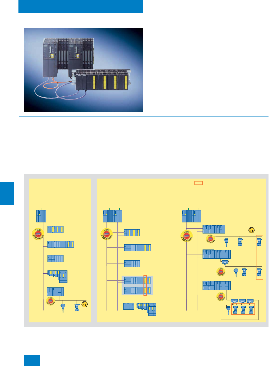
Automation systems
Safety-related automation systems
10/24 Siemens ST PCS 7 · Update November 2008
10
■
Overview
Safety-related automation systems are used for critical applica-
tions where a fault could endanger life or result in damage to the
plant or the environment. These F/FH systems frequently re-
ferred to as "fail-safe automation systems" detect both faults in
the process and their own internal faults in association with the
safety-related F modules of the ET 200 distributed I/O systems
or fail-safe transmitters connected directly via the fieldbus. They
automatically transfer the plant to a safe state in the event of a
fault.
■
Design
In general, two design versions are differentiated across all ar-
chitectural levels of a system based on Safety Integrated for
Process Automation:
• Single-channel, non-redundant design
• Redundant, fault-tolerant design
These two design versions are highly variable and offer a wide
scope for design with regard to different customer requirements.
Standard (basic process control) and safety-related functions
can be combined flexibly, not only in the area of distributed I/O.
Even at the controller level, they can be combined in one system
or separated. In addition, there are numerous possibilities aris-
ing from the use of flexible modular redundancy.
At the individual architectural levels (controller, fieldbus, distrib-
uted I/O) the configuration alternatives shown in the figure are
available depending on the distributed I/O used (ET 200M and
ET 200S remote I/O stations or PROFIBUS PA devices accord-
ing to Profile 3.0).
Design versions for safety-related systems
ET 200M
ET 200M
ET 200M
ET 200M
ET 200M
ET 200M
PROFIBUS PA
PROFIBUS PA
PROFIBUS PA
PROFIBUS PA
ET 200S
ET 200S
ET 200M
AS 412F/
AS 414F/
AS 417F
AS 412FH/
AS 414FH/
AS 417FH
AS 412FH/
AS 414FH/
AS 417FH
PROFIBUS DP
PROFIBUS DP
PROFIBUS DP
F-modules
F-modules
Active field
splitter
Active field distributors
F- and standard modules
F- and standard modules
Flexible Modular Redundancy
at module or device level
F- and standard modules
F- and
standard
modules
Standard modules
Standard modules
Module or channel
redundancy over
several separate
stations
DP/PA Link
DP/PA Link
with redundant
DP/PA couplers
DP/PA Link
with redundant
DP/PA couplers
PROFIBUS PA
DP/PA Link
Y-Link
Distributed I/O and
direct fieldbus interfacing
Direct fieldbus interfacing Distributed I/O
Redundant, high-availability
and fault-tolerant configuration
Single-channel,
non-redundant configuration
© Siemens AG 2008

Automation systems
Safety-related automation systems
10/25
Siemens ST PCS 7 · Update November 2008
10
The safety-related SIMATIC PCS 7 automation systems at the
controller level are categorized in accordance with the two de-
sign versions as follows:
•Single stations
AS 412F, AS 414F and AS 417F with only one CPU (safety-
related)
•Redundant stations
AS 412FH, AS 414FH and AS 417FH with two redundant
CPUs (safety-related and fault-tolerant)
Single stations and redundant stations are available as preas-
sembled and tested all-in-one systems (AS bundles) without
extra charge. They are based on the hardware of the AS 412H,
AS 414H or AS 417H fault-tolerant automation systems ex-
panded by safety functions with S7 F Systems.
Similar to the fault-tolerant systems used as a basis, the RAM of
the safety-related AS bundles varies as follows:
All F/FH systems are TÜV-certified and comply with the safety
requirements up to SIL 3 according to IEC 61508.
In the systems with multitasking capability, several programs
can be executed simultaneously in one CPU – basic process
control (BPCS) applications or also safety-related applications.
The programs are reaction-free, i.e. faults in BPCS applications
have no effect on safety-related applications, and vice versa.
Special tasks with very short response times can also be imple-
mented.
The redundant FH systems operating according to the 1-out-of-
2 principle consist of two subsystems of identical design. These
are electrically isolated from each other to achieve optimum
EMC, and are synchronized with each other via fiber-optic ca-
bles. A bumpless switchover is made from the active subsystem
to the standby subsystem in the event of a fault. The two sub-
systems can be present in the same rack or separated by up to
10 km. The spatial separation provides additional security in the
case of extreme influences in the environment of the active sub-
system, e.g. resulting from a fire.
The redundancy of the FH systems is only used to increase the
availability. It is not relevant to processing of the safety functions
and the associated fault detection.
Runtime licenses
Each AS bundle is already provided as standard with the
SIMATIC PCS 7 AS Runtime license for 100 process objects
(PO). The number of process objects can be extended by addi-
tional Runtime licenses for 100, 1000 or 10000 POs. The process
objects of additional Runtime licenses can be added to process
objects which already exist. The number and type (e.g. 100 or
1000) of additional Runtime licenses are irrelevant. The
AS Runtime licenses are administered on a SIMATIC PCS 7
engineering system or in the SIMATIC PCS 7 BOX.
Communication over the plant bus
The safety-related automation systems are connected as stan-
dard to the plant bus using one communications processor per
AS (F-systems) or sub-AS (FH-systems).
The plant bus can be implemented in the form of a ring structure,
which can also be configured with redundant architecture if the
availability requirements are high. When there are two redundant
rings it makes sense to use two communications processors per
AS (F-systems) or sub-AS (FH-systems) and to distribute their
connections between the two rings(4-way connection). Double
faults such as failure of the OSM/SCALANCE switch on ring 1
with simultaneous interruption in the bus cable on ring 2 can thus
be tolerated.
Individual configuration of AS bundles
The equipment of the safety-related automation systems as well
as their Order Nos. can be individually compiled by selecting
preconfigured ordering units. System-specific ordering configu-
rations are available for this purpose in the following Section
"Selection and ordering data".
These are divided into:
• Single stations: AS 412F, AS 414F and AS 417F with only one
CPU
• Redundant stations: AS 412FH, AS 414FH and AS 417FH with
two redundant CPUs, mounted on one common rack (UR2-H)
or two separate racks (UR2)
In order to rapidly access the recommended preferred configu-
rations, these are additionally listed with their complete order
numbers.
As an alternative to the ordering data in this catalog, the
configurator offered in the catalog & online ordering system
"A&D Mall" (www.siemens.com/automation/mall) can also be
used to select and order safety-related automation systems for
SIMATIC PCS 7.
Ordering information
The AS 412F/FH automation systems currently only support
sync modules with a range up to 10 m. Fiber-optic sync cables
longer than 1 m must always be ordered separately (2 of each
required).
AS type RAM
AS 412F/FH 768 KB (512 KB for program and 256 KB for data)
AS 414F/FH 2.8 MB (1.4 MB each for program and data)
AS 417F/FH 30 MB (15 MB each for program and data)
© Siemens AG 2008

Automation systems
Safety-related automation systems
10/26 Siemens ST PCS 7 · Update November 2008
10
■
Function
Safety functions
The safety functions of an application are implemented by the
safety-related program executed in the CPU of the F/FH systems
together with the safety-related F-modules of the ET 200 distrib-
uted I/O systems or directly by failsafe transmitters connected
via the fieldbus.
The PROFIsafe profile is used for the safe PROFIBUS DP com-
munication between CPU and process I/O. PROFIsafe expands
the message frames by additional information with which the
PROFIsafe communications partners can recognize and com-
pensate transmission errors such as delays, incorrect se-
quences, repetitions, losses, faulty addressing or data falsifica-
tion.
Standard modules can be used in F/FH systems in addition to
safety-related F-modules - mixed in a remote I/O station or in
separate stations, in a common PROFIBUS segment or in sepa-
rate PROFIBUS segments. Basic process control (BPCS) appli-
cations and safety applications can be automated in such mixed
configurations with one and the same system and configured
with uniform standard tools.
One CPU processes BPCS and safety functions in parallel.
Mutual interference during processing is prevented by ensuring
that the BPCS programs and the safety-related programs are
kept strictly separate and that the data exchange is by means of
special conversion function blocks. The safety functions are pro-
cessed twice in different sections of a CPU by means of redun-
dant, diverse instruction processing. Potential errors are de-
tected by the system during the subsequent comparison of
results.
The S7 F Systems engineering tool as a component of the
SIMATIC Manager allows parameterization of the F/FH systems
and the safety-related F-modules from the ET 200 series. It sup-
ports configuration by means of functions for:
• Comparison of safety-related F-programs
• Recognition of changes in the F-program using the checksum
• Separation of safety-related and standard functions.
Access to the F-functions can be password-protected.
The F-block library integrated in S7 F Systems contains pre-
defined function blocks for generation of safety-related applica-
tions with the CFC or the SIMATIC Safety Matrix based on it. The
certified F-blocks are extremely robust and intercept program-
ming errors such as division by zero or out-of-range values. They
avoid the need for diverse programming tasks for detecting and
reacting to errors.
■
Options
Ordering information
An AS 412H, AS 414H or AS 417H system is required as the
hardware for a safety-related automation system.
The following H systems can be used depending on the type
and structure of the safety-related automation system:
• For single-channel AS 412F, AS 414F or AS 417F safety-re-
lated systems: one each of AS 412-3-1H, AS 414-4-1H or
AS 417-4-1H
• For fault-tolerant and safety-related AS 412FH, AS 414FH or
AS 417FH systems:
- With both subsystems in one rack: one each of AS 412-3-2H,
AS 414-4-2H or AS 417-4-2H
- With the two subsystems in different racks: two each of
AS 412-3-1H, AS 414-4-1H or AS 417-4-1H
You require the following components in addition:
• S7 F Systems
F programming tool with F block library for programming
safety-related user programs on the engineering system (see
Chapter "Engineering system")
• F Runtime license
For processing safety-related user programs, for one
AS 412F/FH, AS 414F/FH or AS 417F/FH system
• Option: SIMATIC Safety Matrix
The convenient safety lifecycle tool for configuration of opera-
tion and servicing (see Chapter "Engineering system")
© Siemens AG 2008

Automation systems
Safety-related automation systems
10/27
Siemens ST PCS 7 · Update November 2008
10
1) Up to 5 CPs can be plugged into the UR2 rack with a single power
supply, or up to 3 with a redundant power supply.
1) Up to 5 CPs can be plugged into the UR2 rack with a single power
supply, or up to 3 with a redundant power supply.
Selection and ordering data Order No.
AS 412F (Single Station)
with SIMATIC PCS 7 AS Runtime license for
100 POs
CPU with 1 interface (MPI/DP master)
768 KB RAM (512 KB for program and 256 KB
for data)
6ES7 654-
7 7 7 7 7 -7 7 B7
Type of delivery
• Preassembled and tested 8
Memory card
• Memory card 1 MB RAM (up to approx.
50 POs) A
• Memory card 2 MB RAM (up to approx.
180 POs) B
CPU type
• CPU 412-3H with S7 F Systems RT license
(up to approx. 50 POs) B
Additive interface modules
• Without additive interface module 0
Interface module to
Industrial Ethernet plant bus1)
• 1 x CP 443-11) 1
• 2 x CP 443-1 for redundant interface module1) 2
Rack
• UR2 (9 slots), aluminum 3
• UR2 (9 slots), steel 4
• UR1 (18 slots), aluminum 5
• UR1 (18 slots), steel 6
Power supply (without backup batteries)
• 1 x PS 407, 10 A for 120/230 V AC/DC B
• 1 x PS 407, 10 A for 120/230 V AC/DC, redun-
dancy possible C
• 1 x PS 407, 20 A for 120/230 V AC/DC D
• 2 x PS 407, 10 A for 120/230 V AC/DC, redun-
dancy possible E
• 1 x PS 405, 10 A for 24 V DC G
• 1 x PS 405, 10 A for 24 V DC, redundancy
possible H
• 1 x PS 405, 20 A for 24 V DC J
• 2 x PS 405, 10 A for 24 V DC, redundancy
possible K
Additive PROFIBUS DP interface modules1)
• Without CP 443-5 Extended 0
• 1 x CP 443-5 Extended 1
• 2 x CP 443-5 Extended1) 2
• 3 x CP 443-5 Extended1) 3
• 4 x CP 443-5 Extended1) 4
Selection and ordering data Order No.
AS 414F (Single Station)
with SIMATIC PCS 7 AS Runtime license for
100 POs
CPU with 2 interfaces (MPI/DP master and
DP master)
2.8 MB RAM (1.4 MB each for program and
data)
6ES7 654-
7 7 7 7 7 -7 7 B7
Type of delivery
• Preassembled and tested 8
Memory card
• Memory card 2 MB RAM (up to approx.
180 POs) B
• Memory card 4 MB RAM (up to approx.
300 POs) C
CPU type
• CPU 414-4H with S7 F Systems RT license
(up to approx. 250 POs) F
Additive interface modules
• Without additive interface module 0
Interface module to
Industrial Ethernet plant bus1)
• 1 x CP 443-11) 1
• 2 x CP 443-1 for redundant interface module1) 2
Rack
• UR2 (9 slots), aluminum 3
• UR2 (9 slots), steel 4
• UR1 (18 slots), aluminum 5
• UR1 (18 slots), steel 6
Power supply (without backup batteries)
• 1 x PS 407, 10 A for 120/230 V AC/DC B
• 1 x PS 407, 10 A for 120/230 V AC/DC, redun-
dancy possible C
• 1 x PS 407, 20 A for 120/230 V AC/DC D
• 2 x PS 407, 10 A for 120/230 V AC/DC, redun-
dancy possible E
• 1 x PS 405, 10 A for 24 V DC G
• 1 x PS 405, 10 A for 24 V DC, redundancy
possible H
• 1 x PS 405, 20 A for 24 V DC J
• 2 x PS 405, 10 A for 24 V DC, redundancy
possible K
Additive PROFIBUS DP interface modules1)
• Without CP 443-5 Extended 0
• 1 x CP 443-5 Extended 1
• 2 x CP 443-5 Extended1) 2
• 3 x CP 443-5 Extended1) 3
• 4 x CP 443-5 Extended1) 4
© Siemens AG 2008

Automation systems
Safety-related automation systems
10/28 Siemens ST PCS 7 · Update November 2008
10
1) Up to 5 CPs can be plugged into the UR2 rack with a single power
supply, or up to 3 with a redundant power supply.
1) Up to 5 CPs can be plugged in per subsystem with a single power
supply, or up to 3 with a redundant power supply.
Selection and ordering data Order No.
AS 417F (Single Station)
with SIMATIC PCS 7 AS Runtime license for
100 POs
CPU with 2 interfaces (MPI/DP master and DP
master)
30 MB RAM (15 MB each for program and
data)
6ES7 654-
7 7 7 7 7 -7 7 B7
Type of delivery
• Preassembled and tested 8
Memory card
• Memory card 4 MB RAM (up to approx.
300 POs) C
• Memory card 8 MB RAM (up to approx.
800 POs) D
• Memory card 16 MB RAM (up to approx.
3,000 POs) E
CPU type
• CPU 417-4H with S7 F Systems RT license
(up to approx. 2,500 POs) N
Additive interface modules
• Without additive interface module 0
• 1 x IF 964-DP 1
Interface module to
Industrial Ethernet plant bus1)
• 1 x CP 443-11) 1
• 2 x CP 443-1 for redundant interface module1) 2
Rack
• UR2 (9 slots), aluminum 3
• UR2 (9 slots), steel 4
• UR1 (18 slots), aluminum 5
• UR1 (18 slots), steel 6
Power supply (without backup batteries)
• 1 x PS 407, 10 A for 120/230 V AC/DC B
• 1 x PS 407, 10 A for 120/230 V AC/DC, redun-
dancy possible C
• 1 x PS 407, 20 A for 120/230 V AC/DC D
• 2 x PS 407, 10 A for 120/230 V AC/DC,
redundancy possible E
• 1 x PS 405, 10 A for 24 V DC G
• 1 x PS 405, 10 A for 24 V DC, redundancy
possible H
• 1 x PS 405, 20 A for 24 V DC J
• 2 x PS 405, 10 A for 24 V DC, redundancy
possible K
Additive PROFIBUS DP interface modules1)
• Without CP 443-5 Extended 0
• 1 x CP 443-5 Extended 1
• 2 x CP 443-5 Extended1) 2
• 3 x CP 443-5 Extended1) 3
• 4 x CP 443-5 Extended1) 4
Selection and ordering data Order No.
AS 412FH (Redundant Station)
with SIMATIC PCS 7 AS Runtime license for
100 POs
2 x CPU with 1 interface each (MPI/DP master)
2 x 768 KB RAM (512 KB each for program
and 256 KB each for data)
6ES7 656-
7 7 7 7 7 -7 7 B7
Type of delivery
• Preassembled and tested 8
Memory card
• 2 x memory card 1 MB RAM (up to approx.
50 POs) A
• 2 x memory card 2 MB RAM (up to approx.
180 POs) B
CPU type
• 2 x CPU 412-3H with S7 F Systems RT license
(up to approx. 50 POs) B
Sync modules and cables
• 2 x 2 sync modules for distances up to 10 m
and 2 x FO sync cable, 1 m 3
Interface module to
Industrial Ethernet plant bus1)
• 2 x CP 443-1 for redundant interface module1) 1
• 2 x 2 CP 443-1 for 4-way connection1) 2
Rack
• 1 x UR2-H (2 x 9 slots), aluminum 1
• 1 x UR2-H (2 x 9 slots), steel 2
• 2 x UR2 (9 slots), aluminum 3
• 2 x UR2 (9 slots), steel 4
Power supply (without backup batteries)
• 2 x PS 407, 10 A for 120/230 V AC/DC B
• 2 x PS 407, 10 A for 120/230 V AC/DC, redun-
dancy possible C
• 2 x PS 407, 20 A for 120/230 V AC/DC D
• 2 x 2 PS 407, 10 A for 120/230 V AC/DC,
edundancy possible E
• 2 x PS 405, 10 A for 24 V DC G
• 2 x PS 405, 10 A for 24 V DC, redundancy
possible, H
• 2 x PS 405, 20 A for 24 V DC J
• 2 x PS 405, 10 A for 24 V DC, redundancy
possible K
Additive PROFIBUS DP interface modules1)
• Without CP 443-5 Extended 0
• 2 x CP 443-5 Extended 1
• 2 x 2 CP 443-5 Extended1) 2
• 2 x 3 CP 443-5 Extended1) 3
• 2 x 4 CP 443-5 Extended1) 4
© Siemens AG 2008

Automation systems
Safety-related automation systems
10/29
Siemens ST PCS 7 · Update November 2008
10
1) Up to 5 CPs can be plugged in per subsystem with a single power
supply, or up to 3 with a redundant power supply.
1) Up to 5 CPs can be plugged in per subsystem with a single power
supply, or up to 3 with a redundant power supply.
Selection and ordering data Order No.
AS 414FH (Redundant Station)
with SIMATIC PCS 7 AS Runtime license for
100 POs
2 x CPU with 2 interfaces (MPI/DP master and
DP master)
2 x 2.8 MB RAM (1.4 MB each for program and
data)
6ES7 656-
7 7 7 7 7 -7 7 B7
Type of delivery
• Preassembled and tested 8
Memory card
• 2 x memory card 2 MB RAM (up to approx.
180 POs) B
• 2 x memory card 4 MB RAM (up to approx.
300 POs) C
CPU type
• 2 x CPU 414-4H with S7 F Systems RT license
(up to approx. 250 POs) F
Sync modules and cables
• 2 x 2 sync modules for distances up to 10 m
and 2 x FO sync cable, 1 m 3
• 2 x 2 sync modules for up to 10 km and
2 x FO sync cable, 1 m, for testing 4
Interface module to
Industrial Ethernet plant bus1)
• 2 x CP 443-1 for redundant interface module1) 1
• 2 x 2 CP 443-1 for 4-way connection1) 2
Rack
• 1 x UR2-H (2 x 9 slots), aluminum 1
• 1 x UR2-H (2 x 9 slots), steel 2
• 2 x UR2 (9 slots), aluminum 3
• 2 x UR2 (9 slots), steel 4
Power supply (without backup batteries)
• 2 x PS 407, 10 A for 120/230 V AC/DC B
• 2 x PS 407, 10 A for 120/230 V AC/DC, redun-
dancy possible C
• 2 x PS 407, 20 A for 120/230 V AC/DC D
• 2 x 2 PS 407, 10 A for 120/230 V AC/DC,
redundancy possible E
• 2 x PS 405, 10 A for 24 V DC G
• 2 x PS 405, 10 A for 24 V DC, redundancy
possible H
• 2 x PS 405, 20 A for 24 V DC J
• 2 x PS 405, 10 A for 24 V DC, redundancy
possible K
Additive PROFIBUS DP interface modules1)
• Without CP 443-5 Extended 0
• 2 x CP 443-5 Extended 1
• 2 x 2 CP 443-5 Extended1) 2
• 2 x 3 CP 443-5 Extended1) 3
• 2 x 4 CP 443-5 Extended1) 4
Selection and ordering data Order No.
AS 417FH (Redundant Station)
with SIMATIC PCS 7 AS Runtime license for
100 POs
2 x CPU with 2 interfaces (MPI/DP master and
DP master)
2 x 30 MB RAM (15 MB each for program and
data)
6ES7 656-
7 7 7 7 7 -7 7 B7
Type of delivery
• Preassembled and tested 8
Memory card
• 2 x memory card 4 MB RAM (up to approx.
300 POs) C
• 2 x memory card 8 MB RAM (up to approx.
800 POs) D
• 2 x memory card 16 MB RAM (up to approx.
3,000 POs) E
CPU type
• 2 x CPU 417-4H with S7 F Systems RT license
(up to approx. 2,500 POs) N
Sync modules and cables
• 2 x 2 sync modules for distances up to 10 m
and 2 x FO sync cable, 1 m 3
• 2 x 2 sync modules for up to 10 km and
2 x FO sync cable, 1 m, for testing 4
Interface module to
Industrial Ethernet plant bus1)
• 2 x CP 443-1 for redundant interface module1) 1
• 2 x 2 CP 443-1 for 4-way connection1) 2
Rack
• 1 x UR2-H (2 x 9 slots), aluminum 1
• 1 x UR2-H (2 x 9 slots), steel 2
• 2 x UR2 (9 slots), aluminum 3
• 2 x UR2 (9 slots), steel 4
Power supply (without backup batteries)
• 2 x PS 407, 10 A for 120/230 V AC/DC B
• 2 x PS 407, 10 A for 120/230 V AC/DC, redun-
dancy possible C
• 2 x PS 407, 20 A for 120/230 V AC/DC D
• 2 x 2 PS 407, 10 A for 120/230 V AC/DC,
redundancy possible E
• 2 x PS 405, 10 A for 24 V DC G
• 2 x PS 405, 10 A for 24 V DC, redundancy
possible H
• 2 x PS 405, 20 A for 24 V DC J
• 2 x PS 405, 10 A for 24 V DC, redundancy
possible K
Additive PROFIBUS DP interface modules1)
• Without CP 443-5 Extended 0
• 2 x CP 443-5 Extended 1
• 2 x 2 CP 443-5 Extended1) 2
• 2 x 3 CP 443-5 Extended1) 3
• 2 x 4 CP 443-5 Extended1) 4
© Siemens AG 2008

Automation systems
Safety-related automation systems
10/30 Siemens ST PCS 7 · Update November 2008
10
Recommended preferred types
■
Selection and Ordering Data Order No.
Safety-related SIMATIC PCS 7 automation systems -
Single Stations, recommended preferred types
AS 412F automation system
with SIMATIC PCS 7
AS Runtime license for 100 POs
Preassembled and tested, without
CP 443-5 Extended, without sync
modules and cables, comprising:
1 x CPU 412-3H with one inte-
grated interface (MPI/DP master)
and S7 F Systems RT license,
768 KB RAM (512 KB for program
and 256 KB for data) as well as
• UR2 aluminum rack (9 slots)
- PS 407 power supply; 10 A for
120/230 V AC/DC, without
backup batteries, memory
card 1 MB RAM, 1 x CP 443-1
communications processor for
connection to plant bus
6ES7 654-8AB01-3BB0 B)
- PS 407 power supply; 10 A for
120/230 V AC/DC, without
backup batteries, memory
card 1 MB RAM, 2 x CP 443-1
communications processor for
connection to plant bus
6ES7 654-8AB02-3BB0 B)
- PS 405 power supply; 10 A for
24 V DC, without backup bat-
teries, memory card 1 MB
RAM, 1 x CP 443-1 communi-
cations processor for connec-
tion to plant bus
6ES7 654-8AB01-3GB0 B)
- PS 405 power supply; 10 A for
24 V DC, without backup bat-
teries, memory card 1 MB
RAM, 2 x CP 443-1 communi-
cations processor for connec-
tion to plant bus
6ES7 654-8AB02-3GB0 B)
AS 414F automation system
with SIMATIC PCS 7
AS Runtime license for 100 POs
Preassembled and tested, without
CP 443-5 Extended, without sync
modules and cables, comprising:
1 x CPU 414-4H with 2 integrated
interfaces (MPI/DP master and
DP master) and S7 F Systems RT
license, 2.8 MB RAM (1.4 MB
each for program and data) as
well as
• UR2 aluminum rack (9 slots)
- PS 407 power supply; 10 A for
120/230 V AC/DC, without
backup batteries, memory
card 4 MB RAM, 1 x CP 443-1
communications processor for
connection to plant bus
6ES7 654-8CF01-3BB0 B)
- PS 407 power supply; 10 A for
120/230 V AC/DC, without
backup batteries, memory
card 4 MB RAM, 2 x CP 443-1
communications processor for
connection to plant bus
6ES7 654-8CF02-3BB0 B)
- PS 405 power supply; 10 A for
24 V DC, without backup bat-
teries, memory card 4 MB
RAM, 1 x CP 443-1 communi-
cations processor for connec-
tion to plant bus
6ES7 654-8CF01-3GB0 B)
- PS 405 power supply; 10 A for
24 V DC, without backup bat-
teries, memory card 4 MB
RAM, 2 x CP 443-1 communi-
cations processor for connec-
tion to plant bus
6ES7 654-8CF02-3GB0 B)
B) Subject to export regulations: AL: N, ECCN: EAR99H
■
Selection and Ordering Data Order No.
© Siemens AG 2008

Automation systems
Safety-related automation systems
10/31
Siemens ST PCS 7 · Update November 2008
10
AS 417F automation system
with SIMATIC PCS 7
AS Runtime license for 100 POs
Preassembled and tested, without
CP 443-5 Extended, without sync
modules and cables, comprising:
1 x CPU 417-4H with 2 integrated
interfaces (MPI/DP master and
DP master) and S7 F Systems RT
license, 30 MB RAM (15 MB each
for program and data) as well as
• UR2 aluminum rack (9 slots)
- PS 407 power supply; 10 A for
120/230 V AC/DC, without
backup batteries, memory
card 16 MB RAM, 1 x CP 443-
1 communications processor
for connection to plant bus
6ES7 654-8EN01-3BB0 B)
- PS 407 power supply; 10 A for
120/230 V AC/DC, without
backup batteries, memory
card 16 MB RAM, 2 x CP 443-
1 communications processor
for connection to plant bus
6ES7 654-8EN02-3BB0 B)
- PS 405 power supply; 10 A for
24 V DC, without backup bat-
teries, memory card 16 MB
RAM, 1 x CP 443-1 communi-
cations processor for connec-
tion to plant bus
6ES7 654-8EN01-3GB0 B)
- PS 405 power supply; 10 A for
24 V DC, without backup bat-
teries, memory card 16 MB
RAM, 2 x CP 443-1 communi-
cations processor for connec-
tion to plant bus
6ES7 654-8EN02-3GB0 B)
■
Selection and Ordering Data Order No.
Safety-related SIMATIC PCS 7 automation systems -
Redundant Stations, recommended preferred types
AS 412FH automation system
with SIMATIC PCS 7
AS Runtime license for 100 POs
Preassembled and tested, without
CP 443-5 Extended, comprising:
2 x CPU 412-3H, each with inte-
grated interface (MPI/DP master)
and S7 F Systems RT license,
2 x 768 KB RAM (512 KB each for
program and 256 KB each for
data) as well as
• Aluminium UR2-H rack
(2 x 9 slots),
4 sync modules for distances up
to 10 m and 2 fiber-optic sync
cables, 1 m
- 2 x 2 PS 407 power supplies;
10 A for 120/230 V AC/DC, re-
dundancy possible, without
backup batteries, 2 memory
cards with 1 MB RAM each,
2 x CP 443-1 communications
processor for connection to
plant bus
6ES7 656-8AB31-1EB0 B)
- 2 x 2 PS 407 power supplies;
10 A for 120/230 V AC/DC, re-
dundancy possible, without
backup batteries, 2 memory
cards with 1 MB RAM each,
2 x 2 CP 443-1 communica-
tions processors for connec-
tion to plant bus
6ES7 656-8AB32-1EB0 B)
- 2 PS 405 power supplies; 10 A
for 24 V DC, without backup
batteries, 2 memory cards with
1 MB RAM each, 2 x CP 443-1
communications processors
for connection to plant bus
6ES7 656-8AB31-1GB0 B)
- 2 PS 405 power supplies; 10 A
for 24 V DC, without backup
batteries, 2 memory cards with
1 MB RAM each, 2 x 2 CP 443-
1 communications processors
for connection to plant bus
6ES7 656-8AB32-1GB0 B)
B) Subject to export regulations: AL: N, ECCN: EAR99H
■
Selection and Ordering Data Order No.
© Siemens AG 2008

Automation systems
Safety-related automation systems
10/32 Siemens ST PCS 7 · Update November 2008
10
B) Subject to export regulations: AL: N, ECCN: EAR99H
AS 414FH automation system
with SIMATIC PCS 7
AS Runtime license for 100 POs
Preassembled and tested, without
CP 443-5 Extended, comprising:
2 x CPU 414-4H, each with
2 integrated interfaces (MPI/DP
master and DP master) and
S7 F Systems RT license, 2 x
2.8 MB RAM (1.4 MB each for
program and data) as well as
• Aluminium UR2-H rack
(2 x 9 slots),
4 sync modules for distances up
to 10 m and 2 fiber-optic sync
cables, 1 m
- 2 x 2 PS 407 power supplies;
10 A for 120/230 V AC/DC, re-
dundancy possible, without
backup batteries, 2 memory
cards with 4 MB RAM each,
2 x CP 443-1 communications
processor for connection to
plant bus
6ES7 656-8CF31-1EB0 B)
- 2 x 2 PS 407 power supplies;
10 A for 120/230 V AC/DC, re-
dundancy possible, without
backup batteries, 2 memory
cards with 4 MB RAM each,
2 x 2 CP 443-1 communica-
tions processors for connec-
tion to plant bus
6ES7 656-8CF32-1EB0 B)
- 2 PS 405 power supplies; 10 A
for 24 V DC, without backup
batteries, 2 memory cards with
4 MB RAM each, 2 x CP 443-1
communications processors
for connection to plant bus
6ES7 656-8CF31-1GB0 B)
- 2 PS 405 power supplies; 10 A
for 24 V DC, without backup
batteries, 2 memory cards with
4 MB RAM each, 2 x 2 CP 443-
1 communications processors
for connection to plant bus
6ES7 656-8CF32-1GB0 B)
■
Selection and Ordering Data Order No.
AS 417FH automation system
with SIMATIC PCS 7
AS Runtime license for 100 POs
Preassembled and tested, without
CP 443-5 Extended, comprising:
2 x CPU 417-4H, each with
2 integrated interfaces (MPI/DP
master and DP master) and
S7 F Systems RT license, 2
x 30 MB RAM (15 MB each for
program and data) as well as
• Aluminium UR2-H rack
(2 x 9 slots),
4 sync modules for distances up
to 10 m and 2 fiber-optic sync
cables, 1 m
- 2 x 2 PS 407 power supplies;
10 A for 120/230 V AC/DC, re-
dundancy possible, without
backup batteries, 2 memory
cards with 16 MB RAM each,
2 x CP 443-1 communications
processor for connection to
plant bus
6ES7 656-8EN31-1EB0 B)
- 2 x 2 PS 407 power supplies;
10 A for 120/230 V AC/DC, re-
dundancy possible, without
backup batteries, 2 memory
cards 16 MB RAM, 2 x 2
CP 443-1 communications
processors for connection to
plant bus
6ES7 656-8EN32-1EB0 B)
- 2 PS 405 power supplies; 10 A
for 24 V DC, without backup
batteries, 2 memory cards with
16 MB RAM each, 2 x CP 443-
1 communications processors
for connection to plant bus
6ES7 656-8EN31-1GB0 B)
- 2 PS 405 power supplies; 10 A
for 24 V DC, without backup
batteries, 2 memory cards with
16 MB RAM each, 2 x 2
CP 443-1 communications
processors for connection to
plant bus
6ES7 656-8EN32-1GB0 B)
Runtime licenses for SIMATIC PCS 7 automation systems (can be
added to existing licenses)
SIMATIC PCS 7 AS Runtime
license
6 languages (German, English,
French, Italian, Spanish, Chi-
nese), executes in the engineer-
ing system with Windows
XP Professional, floating license
for 1 installation
Type of delivery:
License key disk, certificate of
license, terms and conditions
•100 POs 6ES7 653-2BA00-0XB5
• 1,000 POs 6ES7 653-2BB00-0XB5
• 10,000 POs 6ES7 653-2BC00-0XB5
AS 412F/FH, AS 414F/FH and AS 417F/FH engineering
(see Chapter "Engineering System", Section "Engineering Process
Safety")
■
Selection and Ordering Data Order No.
© Siemens AG 2008
Automation systems
Safety-related automation systems
10/33
Siemens ST PCS 7 · Update November 2008
10
Individual components
■
Selection and Ordering Data Order No.
Individual components of the safety-related SIMATIC PCS 7
automation systems
S7 F Systems RT License
For processing safety-related
application programs, for one
AS 412F/FH, AS 414F/FH or
AS 417F/FH system
6ES7 833-1CC00-6YX0
CPU 412-3H
RAM 768 KB (512 KB for program
and 256 KB for data)
Module occupies 2 slots
6ES7 412-3HJ14-0AB0 B)
CPU 414-4H
RAM 2.8 MB (1.4 MB each for
program and data)
Module occupies 2 slots
6ES7 414-4HM14-0AB0 B)
CPU 417-4H
RAM 30 MB (15 MB each for pro-
gram and data)
Module occupies 2 slots
6ES7 417-4HT14-0AB0 B)
Sync set
For linking the two redundant
412-3H, 414-4H or 417-4H CPUs;
for distances up to
• 10 m, consisting of 4 sync mod-
ules for up to 10 m and 2 fiber-
optic sync cables, 1 m each
6ES7 656-7XX30-0XX0
• 10 km, consisting of 4 sync mod-
ules for up to 10 km
Note: please order fiber-optic
sync cables (2 units) in the re-
quired length separately.
6ES7 656-7XX40-0XX0
Sync module
For linking the two 412-3H,
414-4H or 417-4H CPUs; two
modules required per CPU
For distances of up to
• 10 m 6ES7 960-1AA04-0XA0
• 10 km 6ES7 960-1AB04-0XA0
Sync cable (fiber-optic cable)
For connecting the two 412-3H,
414-4H or 417-4H CPUs;
each redundant automation sys-
tem requires 2 cables
•1 m 6ES7 960-1AA04-5AA0
•2 m 6ES7 960-1AA04-5BA0
• 10 m 6ES7 960-1AA04-5KA0
Other lengths auf Anfrage
Memory Card RAM
•1 MB 6ES7 952-1AK00-0AA0
•2 MB 6ES7 952-1AL00-0AA0
•4 MB 6ES7 952-1AM00-0AA0
•8 MB 6ES7 952-1AP00-0AA0
•16 MB 6ES7 952-1AS00-0AA0
•64 MB 6ES7 952-1AY00-0AA0
Memory Card Flash-EPROM
Only required to update firmware;
alternative: firmware update via
the engineering system
•8 MB 6ES7 952-1KP00-0AA0
CP 443-1
Communications processor for
connection of SIMATIC S7-400 to
Industrial Ethernet through
TCP/IP, ISO and UDP; for S7 com-
munication, S5-compatible com-
munication (SEND/RECEIVE) with
FETCH/WRITE with or without
RFC 1006, diagnostics expan-
sion, Multicast, commissioning
through LAN 10/100 Mbit/s, with
electronic manual on CD-ROM
6GK7 443-1EX11-0XE0
CP 443-5 Extended
Communications processor for
connection of SIMATIC S7-400 to
PROFIBUS as DP master or for S7
communication, for increasing the
number of DP lines, for data set
routing with SIMATIC PDM and for
10-ms time stamp,
electronic manual on CD;
module occupies 1 slot
6GK7 443-5DX04-0XE0
PS 407 power supply module;
10 A
120/230 V AC/DC; 5 V DC/10 A,
24 V DC/1 A;
with battery compartment for
2 backup batteries, module occu-
pies 2 slots
6ES7 407-0KA02-0AA0
PS 407 power supply module;
10 A, redundant design possi-
ble
120/230 V AC/DC; 5 V DC/10 A,
24 V DC/1 A;
with battery compartment for
2 backup batteries, module occu-
pies 2 slots
6ES7 407-0KR02-0AA0
B) Subject to export regulations: AL: N, ECCN: EAR99H
■
Selection and Ordering Data Order No.
© Siemens AG 2008
Automation systems
Safety-related automation systems
10/34 Siemens ST PCS 7 · Update November 2008
10
B) Subject to export regulations: AL: N, ECCN: EAR99H
PS 407 power supply module;
20 A
120/230 V AC/DC; 5 V DC/20 A,
24 V DC/1 A;
with battery compartment for
2 backup batteries, module occu-
pies 2 slots
6ES7 407-0RA02-0AA0
PS 405 power supply module;
10 A
24 V DC; 5 V DC/10 A, 24 V
DC/1 A;
with battery compartment for
2 backup batteries, module occu-
pies 2 slots
6ES7 405-0KA02-0AA0
PS 405 power supply module;
10 A, redundant design possi-
ble
24 V DC; 5 V DC/10 A, 24 V
DC/1 A;
with battery compartment for
2 backup batteries, module occu-
pies 2 slots
6ES7 405-0KR02-0AA0 B)
PS 405 power supply module;
20 A
24 V DC; 5 V DC/20 A, 24 V
DC/1 A;
with battery compartment for
2 backup batteries, module occu-
pies 2 slots
6ES7 405-0RA02-0AA0
Backup battery
Type AA, 2.3 Ah 6ES7 971-0BA00
■
Selection and Ordering Data Order No.
Aluminum UR1 rack
18 slots 6ES7 400-1TA11-0AA0 B)
Aluminum UR2 rack
9 slots 6ES7 400-1JA11-0AA0
Aluminum UR2-H rack
For divided central controllers;
2 x 9 slots
6ES7 400-2JA10-0AA0
Steel UR1 rack
18 slots 6ES7 400-1TA01-0AA0
Steel UR2 rack
9 slots 6ES7 400-1JA01-0AA0
Steel UR2-H rack
For divided central controllers;
2 x 9 slots
6ES7 400-2JA00-0AA0
■
Selection and Ordering Data Order No.
© Siemens AG 2008
Siemens ST PCS 7 · November 2007
11/2 Introduction
11/4 Central I/O
11/4 Central I/O modules
11/5 Expansion units for central I/O
11/6 SIMATIC PCS 7 MTA
terminal module
11/9 ET 200M distributed I/O
11/9 Introduction
11/10 Power supply
11/11 Interface modules
11/12 ET 200M accessories
11/13 Bundles
11/14 DI - digital input modules
11/16 DO - digital output modules
11/18 DI/DO - digital input/output
modules
11/19 AI - analog input modules
11/21 AO - analog output modules
11/22 Ex modules [EEi xb]
11/23 Modules with HART
11/25 F modules
11/27 Closed-loop control modules
11/29 Counter modules
11/30 ET 200iSP distributed I/O
11/30 Introduction
11/32 ET 200iSP power supply unit
11/33 IM 152-1 interface module
11/34 Electronics modules and
watchdog module
11/37 RS 485-IS coupler
11/38 Stainless steel wall enclosure
11/39 ET 200S distributed I/O
11/39 Introduction
11/41 Terminal modules
11/43 Interface modules
11/44 Power modules
11/45 Digital electronics modules
11/47 Analog electronics modules
11/49 Motor starters
11/53 SIGUARD safety technology
11/56 ET 200pro distributed I/O
11/56 Introduction
11/59 Interface module IM 154-2 DP
High Feature
11/60 Digital electronics modules
EM 141, EM 142
11/61 Analog electronics modules
EM 144, EM 145
11/63 Safety-related electronics modules
11/64 Power module PM-E
Process I/O
© Siemens AG 2007
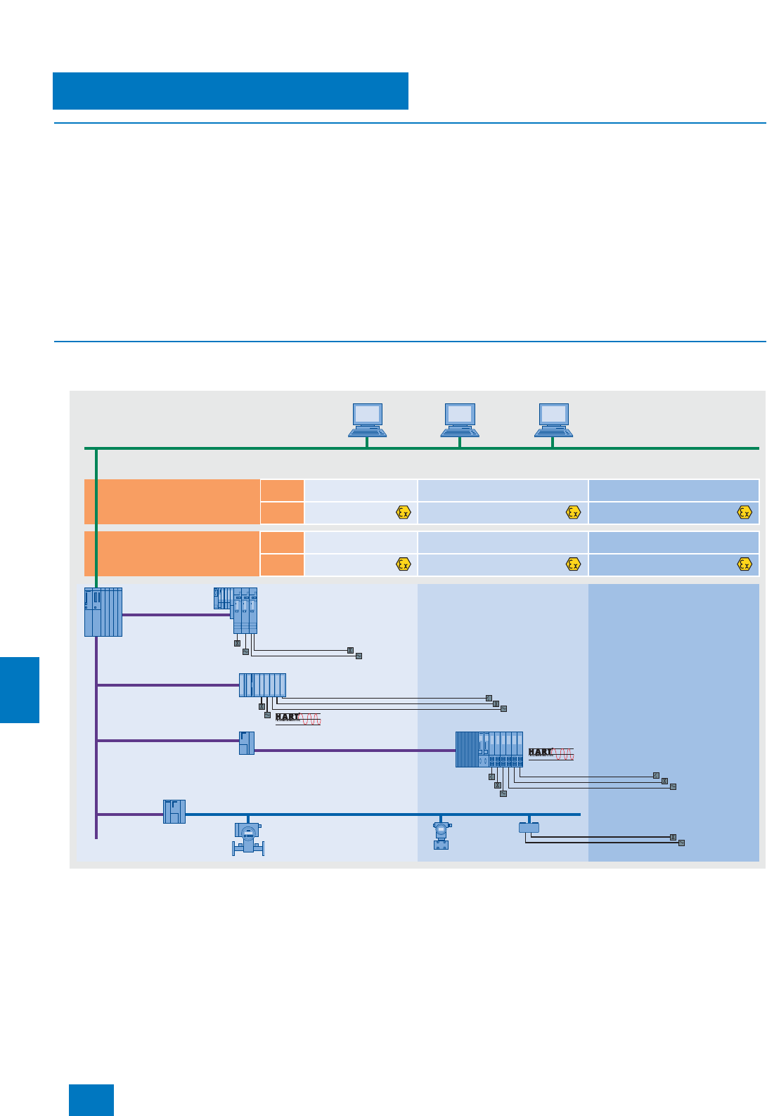
Process I/O
Introduction
11/2 Siemens ST PCS 7 · November 2007
11
■
Overview
The SIMATIC PCS 7 process control system offers various pos-
sibilities for connecting I/O devices and for detecting and emit-
ting process signals through sensors and actuators:
• Analog and digital I/O modules of the SIMATIC S7-400 oper-
ated centrally in the automation system
• ET 200M, ET 200S, ET 200iSP and ET 200pro remote I/O sta-
tions with an extensive range of cost-effective signal and func-
tion modules, connected through PROFIBUS DP to the auto-
mation system (AS)
• Direct AS connection of intelligent, distributed field/process
devices and operator terminals through PROFIBUS DP/PA (re-
dundant or in hazardous zones 0, 1, 2 or 20, 21, 22 also pos-
sible)
Signal groups of the SIMATIC S7-400 can be operated centrally
in the automation system and are mainly used in small applica-
tions or systems of limited distributed expansion.
Distributed process I/Os are mainly used nowadays: ET 200
remote I/Os in conjunction with classical field/process devices
and HART field devices or intelligent field/process devices di-
rectly on PROFIBUS. Decisive for this are properties such as:
• Modularity and consistency
• Flexible adaptability to the plant structure
• Minimum cabling and engineering requirements
• Low commissioning, servicing and lifecycle costs
• Wide technical bandwidth
■
Design
Integration of I/O modules in the hazardous area
ET 200 in explosive gas and dust atmospheres
1) Dust atmospheres: installation of components always in an enclosure with IP6x degree of protection.
2) With 10 A DC standard power supply
3) Also complies with FM/UL according to Class I Division 2
The diagram shows the various interfacing possibilities for the
distributed I/Os of SIMATIC PCS 7 with consideration of various
ambient conditions.
012
FM/UL
ATEX
ATEX
Zone 2 Zone 1 Zone 0
Class I Zone 2 Class I Zone 1 Class I Zone 0
ET 200M
S7-400
ET 200S
ET 200iSP
SITRANS F SITRANS P
Industrial Ethernet
PROFIBUS DP
PROFIBUS PA
Zone 22 Zone 21 Zone 20
Class II Zone 2 Class II Zone 1 Class II Zone 0
FM/UL
1)
1)
1)
1)
2)
1) 3)
Ex e, Ex d
Ex i, Ex e, Ex d
Ex i
DUST
GAS
Process control system
Fieldbus
Isolating Transformer
Hazardous area
Actuators/
sensors
Actuators/
sensors
Actuators/
sensors
DP/PA link
Actuators/
sensors
© Siemens AG 2007

Process I/O
Introduction
11/3
Siemens ST PCS 7 · November 2007
11
Ex I/O modules from the ET 200M range
The ET 200M can be run in Ex zone 2/22. The actuators/sensors
can be positioned in Ex zone 1/21 when suitable Ex input/output
modules are used. Hot swapping of I/O modules within Ex zone
2 is allowed with the right permit (e.g. fire certificate). FM ap-
provals: Class I, Division 2 and Class I, Zone 2.
Field devices with PROFIBUS PA capability
Using PROFIBUS it is possible to integrate field/process devices
directly in Ex zones 1, 2, 21 or 22, and sensors/actuators can
also be integrated in zone 0 or 20. FM approvals: Class I,
Division 1 and Class I, Zone 0.
Integration of actuators/sensors using ET 200iSP
The ET 200iSP appropriate for gaseous and dusty atmospheres
can be installed, according to CENELEC II 2 G (1) GD Eex d e
[ib/ia] IIC T4 directly in the Ex zones 1, 2, 21 or 22 as well as in
non-hazardous areas. The intrinsically-safe sensors, actuators
and HART field devices can also be located in zone 0 or 20 if
necessary.
Intrinsically-safe operator control unit
An intrinsically safe PC operator control unit can be used in haz-
ardous areas, zone 1, 2, 21 or 22, if required. For further details
on this operator control unit, see Catalog "Add Ons for the SI-
MATIC PCS 7 Process Control System".
■
Function
Possible online modifications among the process I/Os
ET 200M • Adding of ET 200M stations
• Adding of I/O modules for the station
• Reparameterization of I/O modules
• Parameterization of connected HART field
devices with SIMATIC PDM
ET 200iSP • Adding of ET 200iSP stations
• Adding of modules for the station
• Reparameterization of modules
ET 200S • Adding of ET 200S stations
PROFIBUS DP,
PROFIBUS PA • Adding of PROFIBUS DP stations
• Adding of DP/PA links and field devices
• Parameterization of field devices with
SIMATIC PDM
© Siemens AG 2007
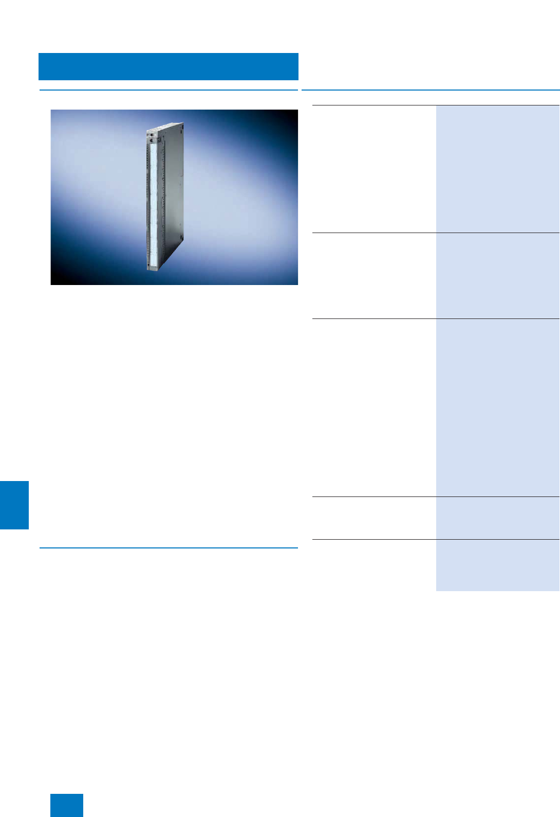
Process I/O
Central I/O
Central I/O modules
11/4 Siemens ST PCS 7 · November 2007
11
■
Overview
Signal modules from the SIMATIC S7-400 range can be used in
the SIMATIC PCS 7 automation system if necessary. These are
primarily an alternative to use of distributed I/Os in the case of
small applications or systems with a small distributed configura-
tion.
For SIMATIC PCS 7, the I/O modules listed in the Ordering data
have been selected from the range of S7-400 signal modules.
Notes:
Apart from these selected modules it is also possible to use -
with limitations in functions - all other I/O modules from the cur-
rent range of S7-400 signal modules.
All process data from the I/O are available for PCS 7 engineering
in the CFC, and can be graphically interconnected to the signal
name in the signal list. Diagnostics information is generated au-
tomatically when using the I/O modules listed here.
When using other I/O modules, integration in SIMATIC PCS 7
is limited to the process data, i.e. the full scope of diagnostics
functions is not automatically available. These modules can
therefore only be used meaningfully in SIMATIC PCS 7 if the
diagnostics capability can be omitted.
Online modifications and redundancy are not supported by the
central I/O.
■
Technical specifications
You can find the detailed technical data of the S7-400 modules
at the following points:
• Catalog ST 70 or
• on the Mall/CA 01 under "Industrial automation systems / Con-
trollers / SIMATIC S7"
B) Subject to export regulations: AL: N, ECCN: EAR99H
■
Selection and Ordering Data Order No.
SM 421 Digital Input Modules
• 32 inputs, 24 V DC 6ES7 421-1BL01-0AA0
• 32 inputs, 120 V AC/DC 6ES7 421-1EL00-0AA0
• 16 inputs, 24 V DC,
with process/diagnostics inter-
rupt
6ES7 421-7BH01-0AB0
• 16 inputs, 24 to 60 V AC/DC,
with process/diagnostics inter-
rupt
6ES7 421-7DH00-0AB0
• 16 inputs, 120/230 V AC/DC,
inputs according to IEC 1131-2
Type 2
6ES7 421-1FH20-0AA0
SM 422 Digital Output Modules
• 32 outputs; 24 V DC, 0.5 A 6ES7 422-1BL00-0AA0
• 32 outputs, 24 V DC, 0.5 A;
with diagnostics 6ES7 422-7BL00-0AB0
• 16 outputs, 24 V DC; 2 A 6ES7 422-1BH11-0AA0
• 16 outputs; relay contacts 6ES7 422-1HH00-0AA0
• 16 outputs, 120/230 V AC; 2 A 6ES7 422-1FH00-0AA0
SM 431 Analog Input Modules
• 16 inputs, non-floating, 13 bit 6ES7 431-0HH00-0AB0
• 8 inputs, floating, 13 bit 6ES7 431-1KF00-0AB0
• 8 inputs, floating, 14 bit, with
linearization (RTD/TC) 6ES7 431-1KF10-0AB0
• 8 inputs, floating, 14 bit 6ES7 431-1KF20-0AB0
• 16 inputs, floating, 16 bit; pro-
cess interrupt capability, with
diagnostics interrupt
6ES7 431-7QH00-0AB0
• 8 inputs, floating, 16 bit; process
interrupt capability, for thermo-
couples, with diagnostics inter-
rupt
6ES7 431-7KF00-0AB0
• 8 inputs, floating, 16 bit; process
interrupt capability, for thermal
resistors, with diagnostics inter-
rupt
6ES7 431-7KF10-0AB0
SM 432 Analog Output Modules
• 8 outputs, floating, 13 bit; for
±10 V, 0 to 10 V, 1 to 5 V,
± 20 mA, 0 to 20 mA, 4 to 20 mA
6ES7 432-1HF00-0AB0
Front Connector (1 unit)
• With screw contacts 6ES7 492-1AL00-0AA0
• With spring clamps 6ES7 492-1BL00-0AA0
• With crimp contacts 6ES7 492-1CL00-0AA0 B)
© Siemens AG 2007
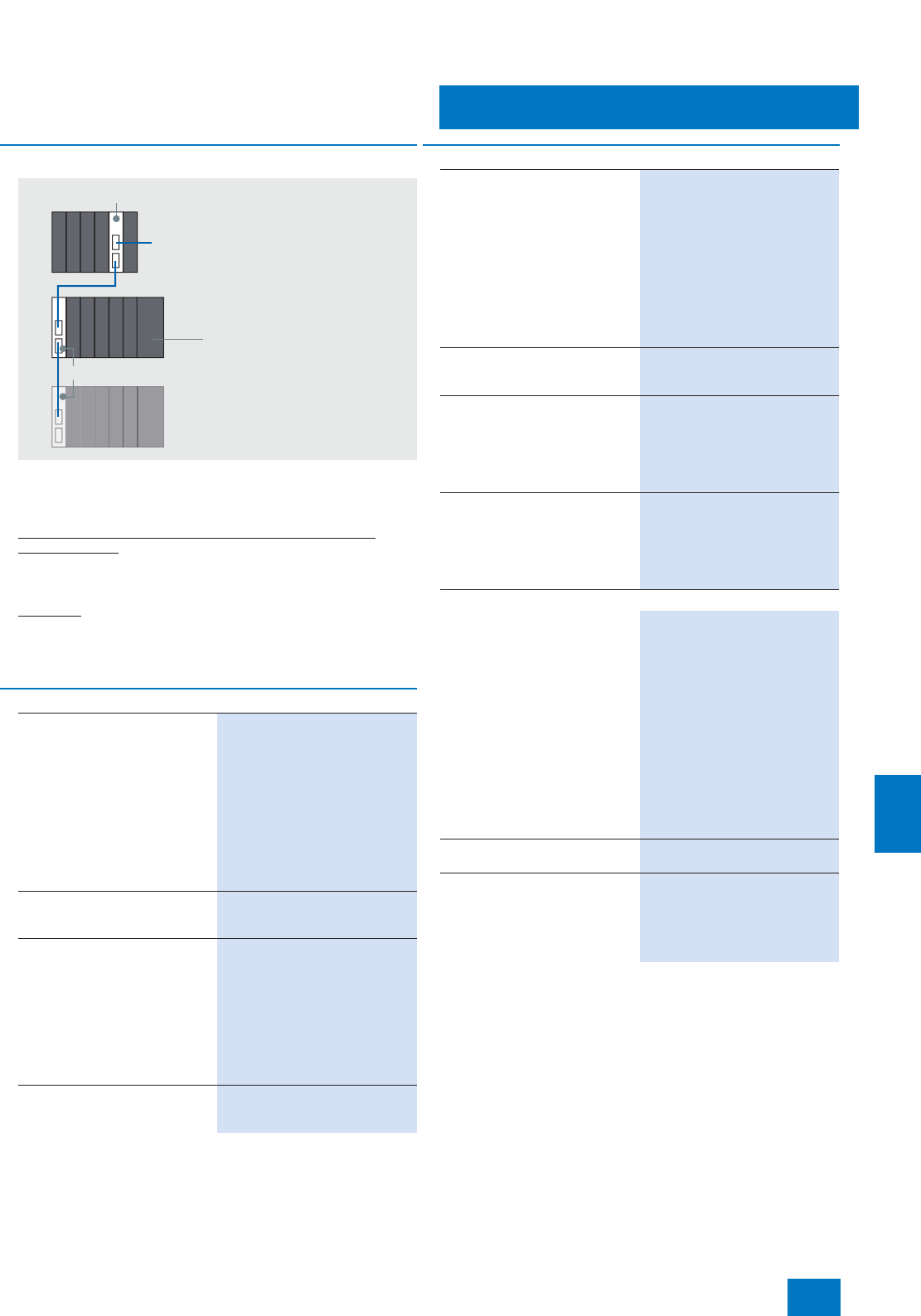
Process I/O
Central I/O
Expansion units for central I/O
11/5
Siemens ST PCS 7 · November 2007
11
■
Overview
Expansion units can be used for the distributed expansion of the
SIMATIC S7-400. The IM 460-x interface modules are used as
the interface for these expansion units.
Restrictions compared to standard I/O modules from the
ET 200M range
• No redundant interfacing of expansion units
• No configuration during normal operation
Subracks
The universal racks (UR) are used for SIMATIC PCS 7. They can
be used as central racks and as expansion racks. Other racks:
see Catalog ST 70.
■
Selection and Ordering Data Order No.
IM 460-0 interface module
• Transmitter module for central
controller
• Without transmission of voltage
to the expansion unit
• Cable up to 5 m long
• With K-bus for communication
with CPs and FMs in the expan-
sion unit
• For connecting as many as 8 ex-
pansion units
6ES7 460-0AA01-0AB0
IM 461-0 interface module
Corresponding receiver module
for the expansion unit
6ES7 461-0AA01-0AA0
IM 460-1 interface module
• Transmitter module for central
controller
• With transmission of the 5 V sup-
ply for I/O modules
• Cable up to 1.5 m long
• Without transmission of the
K-bus, hence solely for commu-
nication from I/O modules
6ES7 460-1BA01-0AB0
IM 461-1 interface module
Corresponding receiver module
for the expansion unit
6ES7 461-1BA01-0AA0
Central controller
IM 460-x
IM 461-x
Expansion units
I/O modules,
CP and FM
PS
CPU
IM 460-3 interface module
• Transmitter module for central
controller
• Without transmission of voltage
to the expansion unit
• Cable up to 100 m long
• With K-bus for communication
with CPs and FMs in the expan-
sion unit
• For connecting as many as 8 ex-
pansion units
6ES7 460-3AA01-0AB0
IM 461-3 interface module
Corresponding receiver module
for the expansion unit
6ES7 461-3AA01-0AA0
UR1 rack
for central controllers and expan-
sion units
•18 slots
• Suitable for redundant power
supply
6ES7 400-1TA01-0AA0
UR2 rack
for central controllers and expan-
sion units
•9 slots
• Suitable for redundant power
supply
6ES7 400-1JA01-0AA0
Accessories
468-1 connecting cable
for connecting IM 460-0 and
IM 461-0; IM 460-3 and IM 461-3
•0.75 m 6ES7 468-1AH50-0AA0
•1.5 m 6ES7 468-1BB50-0AA0
•5 m 6ES7 468-1BF00-0AA0
Additional lengths for connecting
IM 460-3 and IM 461-3
•10 m 6ES7 468-1CB00-0AA0
•25 m 6ES7 468-1CC50-0AA0
•50 m 6ES7 468-1CF00-0AA0
•100 m 6ES7 468-1DB00-0AA0
Terminator
for IM 461-0 6ES7 461-0AA00-7AA0
468-3 connecting cable
for connecting IM 460-1 and
IM 461-1
•0.75 m 6ES7 468-3AH50-0AA0
•1.5 m 6ES7 468-3BB50-0AA0
■
Selection and Ordering Data Order No.
© Siemens AG 2007
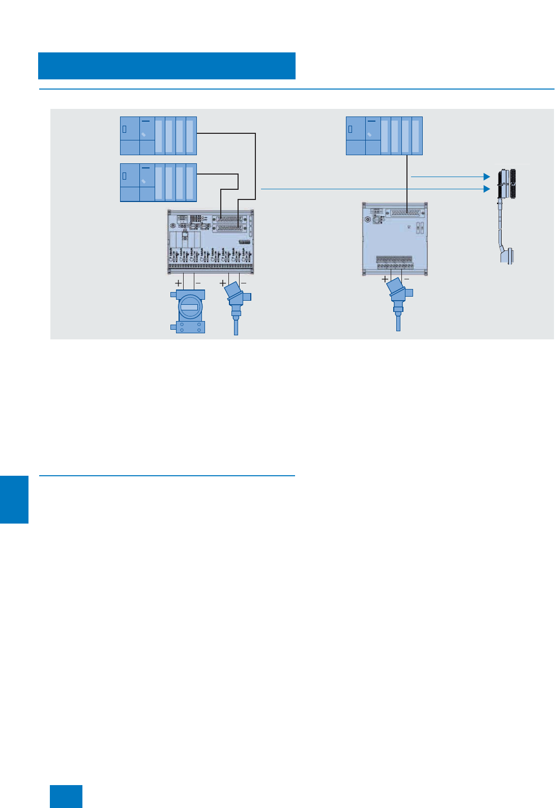
Process I/O
SIMATIC PCS 7 MTA terminal module
11/6 Siemens ST PCS 7 · November 2007
11
■
Overview
The terminal modules SIMATIC PCS 7 MTA (Marshaled Termina-
tion Assemblies) enable simple, fast and reliable connection of
field devices, sensors and actuators to the I/O modules of the
ET 200M remote I/O stations. They can be used to significantly
reduce the costs and required work for cabling and commission-
ing, and prevent wiring errors.
The individual SIMATIC PCS 7 MTAs are each tailored to specific
I/O modules from the ET 200M range (see design for assignment
table). MTA versions are available for standard I/O modules as
well as for redundant and safety-related I/O modules.
The SIMATIC PCS 7 MTAs are connected to the I/O modules us-
ing 3 m or 8 m long preassembled cables.
■
Design
• SIMATIC PCS 7 MTA in versions for standard, redundant and
safety-related I/O modules of the ET 200M distributed I/O sys-
tem
• Redundant 24 V DC supply
• 3 or 8 m long preassembled cables for connecting SIMATIC
PCS 7 MTA and ET 200M module, in each case with:
- 50/25-pole Sub-D socket or 25-pole Sub-D connector, for
connection to SIMATIC PCS 7 MTA
- 40/20-pole Siemens front connector, female version, for con-
nection to ET 200M module
• Screw terminals for the 1:1 connection of field devices, sen-
sors and actuators
• Fuse assembly with LED for each input/output channel
• Test and release as SIMATIC PCS 7 system component with
corresponding approvals (FM, UL, CE, ATEX, TÜV)
ET 200M
redundant
ET 200M
single
Preassembled
cable with
front connector
MTA
MTA
© Siemens AG 2007
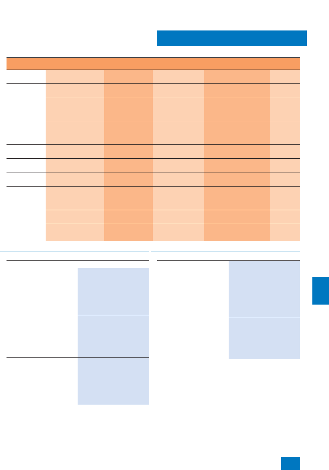
Process I/O
SIMATIC PCS 7 MTA terminal module
11/7
Siemens ST PCS 7 · November 2007
11
Product overview with information on combinable ET 200M modules and connection cables
MTA type Input/output area. Order No. of MTA Order No. of ET 200M
module Order No. of connecting cable I/O
redundancy
8 channels, AI 1 - 5 V
0/4 - 20 mA
6ES7 650-1AA51-2XX0 6ES7 331-7NF00-0AB0
(from product version 5) 6ES7 922-3BD00-0AS0 (3 m)
6ES7 922-3BJ00-0AS0 (8 m)
yes
8 channels, AO 4 to 20 mA 6ES7 650-1AB51-2XX0 6ES7 332-5HF00-0AB0
(from product version 3) 6ES7 922-3BD00-0AS0 (3 m)
6ES7 922-3BJ00-0AS0 (8 m)
yes
8 channels, AI TC Thermocouple types B, C,
N, E, R, S, J, L, T, K, U 6ES7 650-1AF51-2XX0 6ES7 331-7PF10-0AB0
(from product version 4)
and
6ES7 331-7PF11-0AB0
6ES7 922-3BD00-0AS0 (3 m)
6ES7 922-3BJ00-0AS0 (8 m)
no
8 channels, AI
RTD Resistance thermometers
Pt100, Pt200, Pt500, Pt1000,
Ni100, Ni120, Ni200, Ni500,
Ni1000, Cu10
6ES7 650-1AG51-2XX0 6ES7 331-7PF00-0AB0
(from product version 8)
and
6ES7 331-7PF01-0AB0
6ES7 922-3BD00-0AS0 (3 m)
6ES7 922-3BJ00-0AS0 (8 m)
no
16 channels, DO 24 V DC, 0.5 A 6ES7 650-1AD10-2XX0 6ES7 322-8BH01-0AB0 6ES7 922-3BD00-0AT0 (3 m)
6ES7 922-3BJ00-0AT0 (8 m)
yes
6 channels F-AI
(safety-related) 4 to 20 mA 6ES7 650-1AH51-5XX0 6ES7 336-1HE00-0AB0
(from product version 6) 6ES7 922-3BD00-0AS0 (3 m)
6ES7 922-3BJ00-0AS0 (8 m)
yes
16 channels, DI 24 V DC 6ES7 650-1AC11-3XX0 6ES7 321-7BH01-0AB0
(from product version 2) 6ES7 922-3BD00-0AM0 (3 m)
6ES7 922-3BJ00-0AM0 (8 m)
yes
24 channels F-DI
(safety-related) 24 V DC 6ES7 650-1AK11-7XX0 6ES7 326-1BK00-0AB0
and
6ES7 326-1BK01-0AB0
(from product version 1)
6ES7 922-3BD00-0AS0 (3 m)
6ES7 922-3BJ00-0AS0 (8 m)
yes
10 channels F-DO
(safety-related) 24 V DC, 2 A 6ES7 650-1AL11-6XX0 6ES7 326-2BF01-0AB0
(from product version 2) 6ES7 922-3BD00-0AN0 (3 m)
6ES7 922-3BJ00-0AN0 (8 m)
yes
10 channels F-DO
relay (safety-
related)
110 - 220 V AC, 5 A;
24 V DC, 5 A
6ES7 650-1AM31-6XX0 6ES7 326-2BF01-0AB0
(from product version 2) 6ES7 922-3BD00-0AS0 (3 m)
6ES7 922-3BJ00-0AS0 (8 m)
yes
■
Selection and Ordering Data Order No.
SIMATIC PCS 7 MTA
SIMATIC PCS 7 MTA AI,
8-channel
Terminal module for connection of
field devices/sensors to a single
or two redundant ET 200M analog
input modules
6ES7 331-7NF00-0AB0
Input range: 1 ... 5 V and
0/4 ... 20 mA
6ES7 650-1AA51-2XX0
SIMATIC PCS 7 MTA AO,
8-channel
Terminal module for connection of
field devices/actuators to a
single or two redundant ET 200M
analog output modules
6ES7 332-5HF00-0AB0
Output range: 4 ... 20 mA
6ES7 650-1AB51-2XX0
SIMATIC PCS 7 MTA AI TC,
8-channel
Terminal module for connection of
field devices/sensors to a single
ET 200M analog input module
6ES7 331-7PF10-0AB0 or
6ES7 331-7PF11-0AB0
Input range: Thermocouple types
B, C, N, E, R, S, J, L, T, K, U
6ES7 650-1AF51-2XX0 B)
SIMATIC PCS 7 MTA AI RTD,
8-channel
Terminal module for connection of
field devices/sensors to a single
ET 200M analog input module
6ES7 331-7PF00-0AB0 or
6ES7 331-7PF01-0AB0
Measuring range: Resistance
thermometers Pt100, Pt200,
Pt500, Pt1000, Ni100, Ni120,
Ni200, Ni500, Ni1000, Cu10
6ES7 650-1AG51-2XX0
SIMATIC PCS 7 MTA DO,
16-channel
Terminal module for connection of
field devices/sensors to a single
or two redundant ET 200M digital
output modules
6ES7 322-8BH01-0AB0
Output range: 24 V DC, 0.5 A
6ES7650-1AD10-2XX0 B)
B) Subject to export regulations: AL: N, ECCN: EAR99H
■
Selection and Ordering Data Order No.
© Siemens AG 2007

Process I/O
SIMATIC PCS 7 MTA terminal module
11/8 Siemens ST PCS 7 · November 2007
11
B) Subject to export regulations: AL: N, ECCN: EAR99H
SIMATIC PCS 7 MTA F-AI,
6-channel
Terminal module for connection of
field devices/sensors to a single
or two redundant safety-related
ET 200M analog input modules
6ES7 336-1HE00-0AB0
Input range: 4 to 20 mA
Accessories included:
• One 5.6 V Zener diode board for
MTA F-AI, 6-channel,
6ES7 650-1BB51-0XX0
• One 6.2 V Zener diode board for
MTA F-AI, 6-channel,
6ES7 650-1BC51-0XX0
• Two FET switch adapters for
MTA F-AI, 6-channel,
6ES7 650-1BD51-0XX0
6ES7 650-1AH51-5XX0 B)
SIMATIC PCS 7 MTA DI,
16-channel
Terminal module for connection of
field devices/sensors to a single
or two redundant ET 200M digital
input modules
6ES7 321-7BH01-0AB0
Input range: 24 V DC
6ES7 650-1AC11-3XX0
SIMATIC PCS 7 MTA F-DI,
24-channel
Terminal module for connection of
field devices/sensors to a single
or two redundant safety-related
ET 200M digital input modules
6ES7 326-1BK00-0AB0 or
6ES7 326-1BK01-0AB0
Input range: 24 V DC
6ES7 650-1AK11-7XX0
SIMATIC PCS 7 MTA F-DO,
10-channel
Terminal module for connection of
field devices/actuators to a
single or two redundant safety-
related ET 200M digital output
modules 6ES7 326-2BF01-0AB0
Output range: 24 V DC, 2 A
6ES7 650-1AL11-6XX0
SIMATIC PCS 7 MTA F-DO relay,
10-channel
Terminal module for connection of
field devices/actuators to a
single or two redundant safety-
related ET 200M digital output
modules 6ES7 326-2BF01-0AB0
Output range: 110 ... 220 V AC,
5A; 24VDC, 5A
Notice:
Available with 12/2007
6ES7 650-1AM31-6XX0 B)
■
Selection and Ordering Data Order No.
Preassembled cable for connection of ET 200 module and SIMATIC
PCS 7 MTA
Connecting cable with 40-pole
front connector for ET 200M
and 50-pole Sub-D connector
(female) for MTA
Lengths:
•3 m 6ES7 922-3BD00-0AS0
•8 m 6ES7 922-3BJ00-0AS0
Connecting cable with 40-pole
front connector for ET 200M
and 25-pole Sub-D connector
for MTA
Lengths:
•3 m 6ES7 922-3BD00-0AT0
•8 m 6ES7 922-3BJ00-0AT0
Connecting cable with 40-pole
front connector for ET 200M
and 25-pole Sub-D connector
(female) for MTA
Lengths:
•3 m 6ES7 922-3BD00-0AN0
•8 m 6ES7 922-3BJ00-0AN0
Connecting cable with 20-pole
front connector for ET 200M
and 25-pole Sub-D connector
(female) for MTA
Lengths:
•3 m 6ES7 922-3BD00-0AM0
•8 m 6ES7 922-3BJ00-0AM0
Accessories
Power monitor board (PMB)
for display of status of redundant
MTA power supply
6ES7 650-1BA01-0XX0
Boards and adapter for
SIMATIC PCS 7 MTA F-AI,
6-channel
• 5.6 V Zener diode board 6ES7 650-1BB51-0XX0 B)
• 6.2 V Zener diode board 6ES7 650-1BC51-0XX0 B)
• FET switch adapter 6ES7 650-1BD51-0XX0 B)
■
Selection and Ordering Data Order No.
© Siemens AG 2007
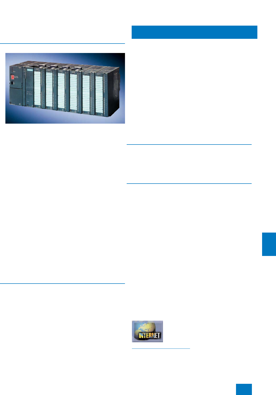
Process I/O
ET 200M distributed I/O
Introduction
11/9
Siemens ST PCS 7 · November 2007
11
■
Overview
Within the ET 200 range, ET 200M represents the main series
of distributed I/O systems for process control applications with
SIMATIC PCS 7.
The ET 200M has a versatile range of I/O modules of S7-300 de-
sign, including ones with special I&C functions.
• Standard analog and digital modules
• Redundant I/O modules (DI 16 x DC 24 V, with diagnostics
capability; DO 32 x DC 24 V/0.5 A; AI 8 x 12 bit)
• I/O modules with enhanced diagnostics capability
• Ex I/O modules
• Controller and counter modules
• HART modules
• F-modules for safety-related applications
When using active bus modules, faulty I/O modules can be re-
placed while the plant is in operation (RUN) without influencing
adjacent modules (hot swapping function).
The following actions are possible with the automation system in
RUN:
• Addition of new modules within a station
• Reparameterization of modules
• Addition of ET 200M stations
The connected HART field devices can be parameterized using
SIMATIC PDM.
Note:
Apart from these selected modules it is also possible to use - with limita-
tions in functions - all other I/O modules from the current range of S7-300
signal modules.
■
Design
An ET 200M remote I/O station comprises:
• 1 or 2 (redundant) power supply modules (can be omitted in
the case of a central 24 V DC supply for the plant)
• 1 or 2 (redundant) IM 153 interface modules for connection via
PROFIBUS DP with transmission rates of up to 12 Mbit/s
• Up to 12 I/O modules for connection of sensors/actuators
All I/O modules have optical electrical isolation from the back-
plane bus. Up to 12 I/O modules can be connected to an
IM 153-2 High Feature interface module, or up to 8 to an IM 153-
2 FO High Feature interface module. The interface modules can
also have a redundant design if required.
In addition to the standard SIMATIC S7 I/O modules, special
I/O modules with diagnostics capability offer the following func-
tions, among others:
• Channel-based diagnostics, e.g. open-circuit, short-circuit,
limit violations
• Internal module monitoring, e.g. parameterization error, RAM
error, tripped fuse
• Flatter monitoring for sensors
• Pulse stretching
• Output of a selectable substitute value on failure of the central
processing unit
In the event of a fault, the modules with diagnostics capability
automatically pass on the corresponding message to the opera-
tor station, permitting fast and simple troubleshooting.
The ET 200M can be used in standard environments and also in
Ex zones 2 and 22. The actuators/sensors can be positioned in
Ex zones 1 and 21 when suitable Ex input/output modules are
used. Hot swapping of I/O modules within Ex zone 2 and 22 is
allowed with the right permit (e.g. fire certificate).
■
Technical specifications
You can find detailed technical data on the ET 200M and S7-300
I/O modules
• in Catalog ST 70 or
• in the Mall / Catalog CA 01 under "Industrial automation sys-
tems / Controllers / SIMATIC S7"
■
Options
SIPLUS extreme range for extended temperature ranges and
corrosive environments
The "standard" properties of an individual device or system are
often insufficient for harsh environmental conditions, applica-
tions in corrosive environments or extreme temperature ranges.
Depending on the location of use, the result could be limitations
in functionality or operational safety or even total failure of the
plant.
The SIPLUS extreme range offers individually adapted standard
products which permit retention of the functionality of your plant
or process even under extreme conditions of use. These in-
clude:
• Ambient temperature range from -25 to +60/+70 °C
• Condensation, high humidity
• Increased mechanical stress
• Extreme loading by media, e.g. toxic atmospheres
• Voltage ranges deviating from the standard
• Increased degree of protection (dust, water)
You can find a summary of the available range of products clas-
sified according to their special properties on the Internet. The
corresponding SIPLUS product is assigned there to the stan-
dard product. Note: SIPLUS products are also included in the
Catalog ST 70.
Additional information is available in the Internet under:
http://www.siemens.com/siplus
© Siemens AG 2007

Process I/O
ET 200M distributed I/O
Power supply
11/10 Siemens ST PCS 7 · November 2007
11
■
Overview
You can use the PS 307 or PS 305 load power supplies as the
power supply module for the ET 200M. You can select different
input voltages and output currents (120/230 V AC with 2 A, 5 A
or 10 A or 24 to 110 V DC with 2 A) depending on the applica-
tion.
With a redundant ET 200M configuration, it is also recommend-
able to have a redundant 24 V DC supply, e.g. with two PS 307 /
PS 305 load power supplies.
■
Selection and Ordering Data Order No.
PS 307 Load Power Supply
Including connection assembly;
• 120/230 V AC; 24 V DC
- 2 A; 50 mm wide 6ES7 307-1BA00-0AA0
- 5 A; 80 mm wide 6ES7 307-1EA00-0AA0
- 5 A, extended temperature
range; 80 mm wide 6ES7 307-1EA80-0AA0
- 10 A, 200 mm wide 6ES7 307-1KA01-0AA0
PS 305 Load Power Supply
Including connection assembly;
• 24/48/60/110 V DC; 24 V DC
- 2 A, extended temperature
range; 80 mm wide 6ES7 305-1BA80-0AA0
© Siemens AG 2007
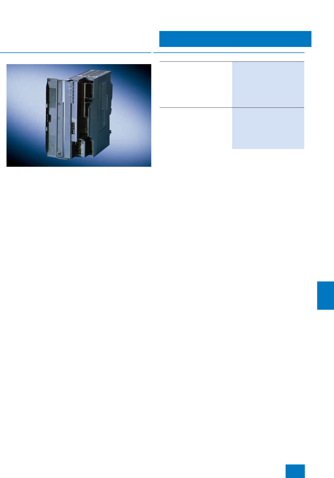
Process I/O
ET 200M distributed I/O
Interface modules
11/11
Siemens ST PCS 7 · November 2007
11
■
Overview
The IM 153-2 High Feature interface module (electrical
PROFIBUS DP transmission) or IM 153-2 FO High Feature inter-
face module (optical PROFIBUS DP transmission) is required to
connect the ET 200M remote I/O station to the PROFIBUS DP
fieldbus. Depending on the fieldbus configuration (single/redun-
dant), the ET 200M remote I/O station can be connected via one
single or two redundant interface modules.
The IM 153-2 High Feature supports the following functions:
7HART configuring of intelligent field devices
7Configuration of ET 200M I/Os in RUN mode of the automation
system
7Connection to redundant AS 412H / AS 414H / AS 417H auto-
mation systems
7Use of ET 200M function modules (controller and counter
modules)
7Operation of up to 12 I/O modules per remote I/O station
7Time stamping (SOE) with the safety-related SM 326F digital
input module (F-DI24)
7Transmission of additional values with HART secondary vari-
ables of the HART SM 331 and SM 332 analog modules (up to
4 per channel or up to 8 per module)
On the other hand, the fiber-optic (FO) version IM 153-2 FO High
Feature provides the following functions:
7HART configuring of intelligent field devices
7Configuration of ET 200M I/Os in RUN mode of the automation
system
7Connection to redundant AS 412H, AS 414H and AS 417H
automation systems
7Use of ET 200M function modules (controller and counter
modules)
7Operation of up to 8 I/O modules per remote I/O station
Notes:
In order to use the hot swapping function, it is necessary to use the active
bus modules and the DIN rail for hot swapping (refer to page 11/12).
When using the IM 153-2 FO, additional plastic FOCs and an assembly
set for Simplex connectors are required (refer to page 9/40).
B) Subject to export regulations: AL: N, ECCN: EAR99H
■
Selection and Ordering Data Order No.
IM 153-2 High Feature
Slave interface module for con-
nection of an ET 200M to
PROFIBUS DP, with time stamp
(accuracy 1 ms), support of
HART functionality, F modules,
FM modules, "Configuration in
RUN" function; also for use in
redundant systems
6ES7 153-2BA02-0XB0 B)
IM 153-2 FO High Feature
Slave interface module for con-
nection of an ET 200M to optical
PROFIBUS DP; support of HART
functionality, F modules, FM mod-
ules, "Configuration in RUN" func-
tion; also for use in redundant
systems
6ES7 153-2BB00-0XB0 B)
© Siemens AG 2007
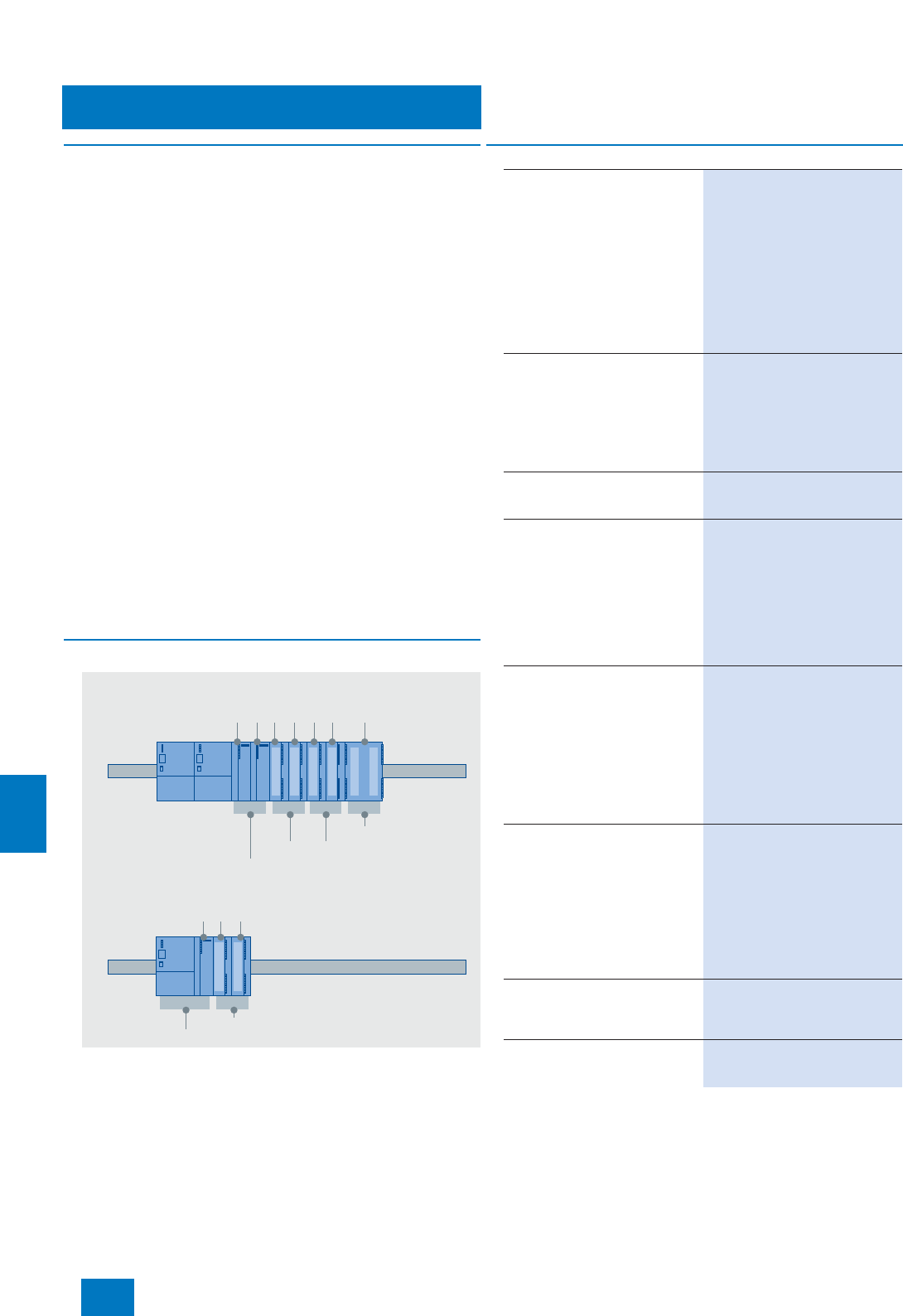
Process I/O
ET 200M distributed I/O
ET 200M accessories
11/12 Siemens ST PCS 7 · November 2007
11
■
Overview
Following components are available as accessories for the
ET 200M:
• Bus modules for hot swapping
• DIN rail for hot swapping
• Covers for backplane bus and bus modules
• Front connectors
• Ex partition for ET 200M
• LK 393 cable duct
• DM 370 dummy module
Ex partition
A mechanical isolation is required between the IM 153 interface
module and the first Ex I/O module. For the hot swapping func-
tion, an Ex partition is installed which guarantees the prescribed
isolation distance between non-intrinsically-safe and intrinsi-
cally-safe areas of an ET 200M remote I/O station.
LK 393 cable duct
The LK 393 cable duct provides the prescribed isolation be-
tween the load voltage input and the intrinsically safe inputs/out-
puts. The cable duct is easy to fit following insertion of the load
voltage inputs L+.
DM 370 dummy module
• Reservation of slots for unconfigured I/O modules
• Retention of design and address assignment when replacing
by I/O module
■
Design
The figure shows use of the various bus modules for hot swap-
ping - at the top for a redundant connection, at the bottom for a
non-redundant connection.
ET 200M
standard
modules
Redundant
IM 153-2
High Feature
Special modules,
80 mm wide,
e.g. FM 355
Bus module BM 1x80
Bus module BM 2x40
Bus module IM 153/IM 153
ET 200M
standard modules
IM 153-2
High Feature
Bus module PS/IMBus module BM 2x40
Redundant
connection
Singular
connection
■
Selection and Ordering Data Order No.
Bus modules for hot swapping
• BM PS/IM for load power supply
and IM 153,
incl. 1 bus module cover
6ES7 195-7HA00-0XA0
• BM 2x40 for 2 modules, each
40 mm wide 6ES7 195-7HB00-0XA0
• BM 1x80 for 1 module, 80 mm
wide 6ES7 195-7HC00-0XA0
• BM IM/IM
for two IM 153-2/-2 FOs for de-
sign of redundant systems
6ES7 195-7HD10-0XA0
Profile rail for hot swapping
• 482 mm long (19 inches) 6ES7 195-1GA00-0XA0
•530 mm long 6ES7 195-1GF30-0XA0
•630mm long 6ES7 195-1GG30-0XA0
• 2000 mm long, for vertical instal-
lation 6ES7 195-1GC00-0XA0
Covers
Pack with 4 backplane bus
covers and 1 bus module cover
6ES7 195-1JA00-0XA0
Front connector (1 unit)
• 20-pin, with screw contacts 6ES7 392-1AJ00-0AA0
• 20-pin, with spring contacts 6ES7 392-1BJ00-0AA0
• 40-pin, with screw contacts 6ES7 392-1AM00-0AA0
• 40-pin, with spring contacts 6ES7 392-1BM01-0AA0
• 20-pin, FastConnect 6ES7 392-1CJ00-0AA0 B)
• 40-pin, FastConnect 6ES7 392-1CM00-0AA0 B)
Front connector for Ex analog
input module
6ES7 331-7SF00-0AB0 (1 unit)
• 20-pin, with screw contacts
Enables an accuracy of ± 1.5 °K
for the internal cold junction tem-
perature when taking thermocou-
ple temperature measurements in
the measuring mode "internal
compensation" at ambient tem-
peratures of 0 ... 60 °C
6ES7 392-1AJ20-0AA0
Ex partition for ET 200M
• Separation of IM 153 and down-
stream Ex modules within an
ET 200M line
• Mixed operation of non-Ex and
Ex modules within an ET 200M
line
• For supporting the hot swapping
function in connection with
IM 153-2
6ES7 195-1KA00-0XA0
LK 393 cable duct
[EEx ib] IIC-conform routing of
load voltage cable in front plug,
5units
6ES7 393-4AA00-0AA0
DM 370 dummy module
including bus connector, labeling
strips
6ES7 370-0AA01-0AA0
B) Subject to export regulations: AL: N, ECCN: EAR99H
© Siemens AG 2007

Process I/O
ET 200M distributed I/O
Bundles
11/13
Siemens ST PCS 7 · November 2007
11
■
Overview
The following preassembled bundles are available for the
ET 200M:
• I/O subsystem for ET 200M stations with up to 8 I/O modules
suitable for hot swapping, comprising:
- DIN rail for active bus modules, 482 mm long (19 inches)
- PS/IM bus module
- PROFIBUS DP IM 153-2 High Feature interface module
• I/O subsystem Extended for ET 200M stations with up to
12 I/O modules suitable for hot swapping, comprising:
- DIN rail for active bus modules, 630 mm long
- PS/IM bus module
- PROFIBUS DP IM 153-2 High Feature interface module
• IM 153 redundancy bundle
for operation of the ET 200M on the AS 412H / AS 414H /
AS 417H fault-tolerant automation system, comprising:
- 2 PROFIBUS DP IM 153-2 High Feature interface modules
- 1 IM/IM active bus module
B) Subject to export regulations: AL: N, ECCN: EAR99H
■
Selection and Ordering Data Order No.
I/O subsystem for ET 200M
for ET 200M stations with up to
8 I/O modules, suitable for hot
swapping, comprising:
• DIN rail for active bus modules,
482 mm long (19 inches)
• PS/IM bus module
• PROFIBUS DP IM 153-2 High
Feature interface module
6ES7 654-0XX08-1XA0 B)
I/O subsystem extended for
ET 200M
for ET 200M stations with up to
12 I/O modules, suitable for hot
swapping, comprising:
• DIN rail for active bus modules,
630 mm long
• PS/IM bus module
• PROFIBUS DP IM 153-2 High
Feature interface module
6ES7 654-0XX08-1XB0 B)
IM 153 redundancy bundle
for operation of a ET 200M station
on the AS 412H, AS 414H or
AS 417H fault-tolerant automa-
tion system, comprising:
• 2 PROFIBUS DP IM 153-2 High
Feature interface modules
• 1 IM/IM active bus module
6ES7 153-2AR03-0XA0 B)
© Siemens AG 2007
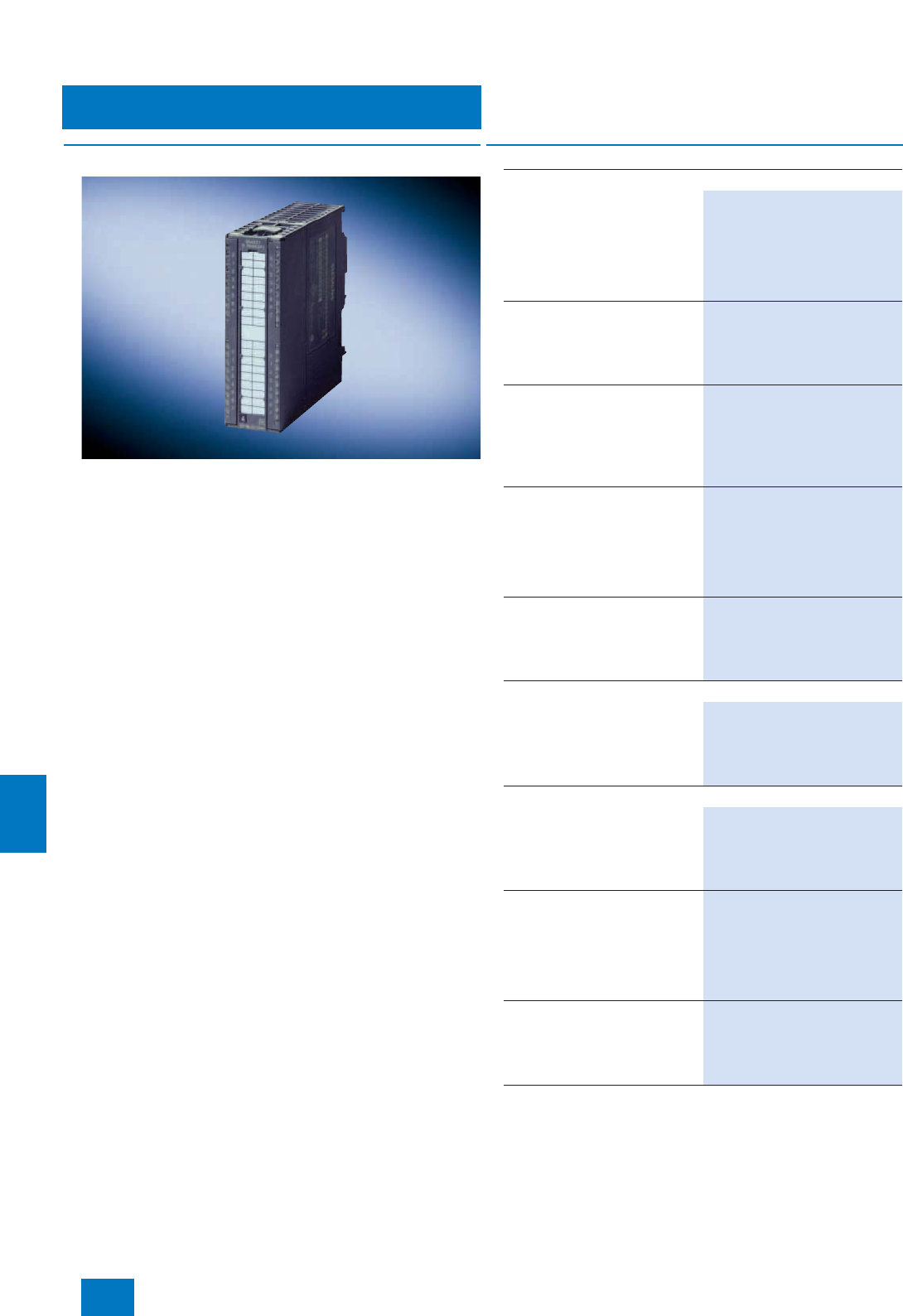
Process I/O
ET 200M distributed I/O
DI - digital input modules
11/14 Siemens ST PCS 7 · November 2007
11
■
Overview
The digital input modules described here break down into
• simple signal modules for direct and alternating voltage, and
• modules with diagnostics capability that automatically output
a corresponding message to the operator system in the event
of a fault.
■
Selection and Ordering Data Order No.
SM 321 for floating contacts (supply with DC voltage)
16 inputs, 24 V DC
Redundant design possible
(module redundancy)
• Electrically isolated in groups
of 16
• Front connector required:
20-contact
6ES7 321-1BH02-0AA0
16 inputs, 24 V DC
• Electrically isolated in groups
of 16; active low
• Front connector required:
20-contact
6ES7 321-1BH50-0AA0
16 inputs, 24 V DC, high-speed
• Electrically isolated in groups
of 16
• 0.05 ms input delay
• Front connector required:
20-contact
6ES7 321-1BH10-0AA0
32 inputs, 24 V DC
Redundant design possible
(module redundancy)
• Electrically isolated in groups
of 16
• Front connector required:
40-contact
6ES7 321-1BL00-0AA0
16 inputs, 48 to 125 V DC
• Electrically isolated in groups
of 8
• Front connector required:
20-contact
6ES7 321-1CH20-0AA0 B)
SM 321 for floating contacts (supply with DC/AC voltage)
16 inputs, 24 to 48 V AC/DC
• Electrically isolated in groups
of 1
• Front connector required:
40-contact
6ES7 321-1CH00-0AA0 B)
SM 321 for floating contacts (supply with AC voltage)
32 inputs, 120 V AC
• Electrically isolated in groups
of 8
• Front connector required:
40-contact
6ES7 321-1EL00-0AA0 B)
8 inputs, 120/230 V AC
Redundant design possible
(module redundancy)
• Electrically isolated in groups
of 2
• Front connector required:
20-contact
6ES7 321-1FF01-0AA0 B)
16 inputs, 120/230 V AC
• Electrically isolated in groups
of 4
• Front connector required:
20-contact
6ES7 321-1FH00-0AA0 B)
B) Subject to export regulations: AL: N, ECCN: EAR99H
© Siemens AG 2007

Process I/O
ET 200M distributed I/O
DI - digital input modules
11/15
Siemens ST PCS 7 · November 2007
11
B) Subject to export regulations: AL: N, ECCN: EAR99H
SM 321 for non-floating contacts (supply with AC voltage)
8 inputs, 120/230 V AC
• Electrically isolated in groups
of 1
• Front connector required:
40-contact
6ES7 321-1FF10-0AA0 B)
SM 321 modules with diagnostics capability
(IM 153-2 High Feature interface module required)
for floating contacts (supply with DC voltage)
16 inputs, 24 V DC
Redundant design possible
(module and channel redun-
dancy)
• Electrically isolated in groups
of 16
•Time stamping in association
with IM 153-2 High Feature, ac-
curacy 5 ms, rising or falling
edge, can be parameterized
channel-granular
• Two short-circuit-proof sensor
supplies for 8 channels each
• Sensor supply by the module,
additional external redundant
sensor supply possible
• Diagnostics of missing sensor
supply for channel group
(8 channels)
• Diagnostics inside module
• Wire break monitoring
• Front connector required:
20-contact
6ES7 321-7BH01-0AB0
■
Selection and Ordering Data Order No.
16 inputs, NAMUR
Redundant design possible
(module redundancy)
• Electrically isolated in groups
of 8
•Time stamping in association
with IM 153-2 High Feature, ac-
curacy 5 ms, rising or falling
edge, can be parameterized
channel-granular
• Two sensor supplies (8.2 V DC
or 18 V DC each)
• Connection of NAMUR sensors
or contacts with resistor circuit
• Pulse stretching
• Channel-granular diagnostics
(short-circuit, open-circuit, chat-
ter monitoring, discrepancy with
changeover contacts)
• Diagnostics inside module
• Front connector required:
40-contact
6ES7 321-7TH00-0AB0
■
Selection and Ordering Data Order No.
© Siemens AG 2007
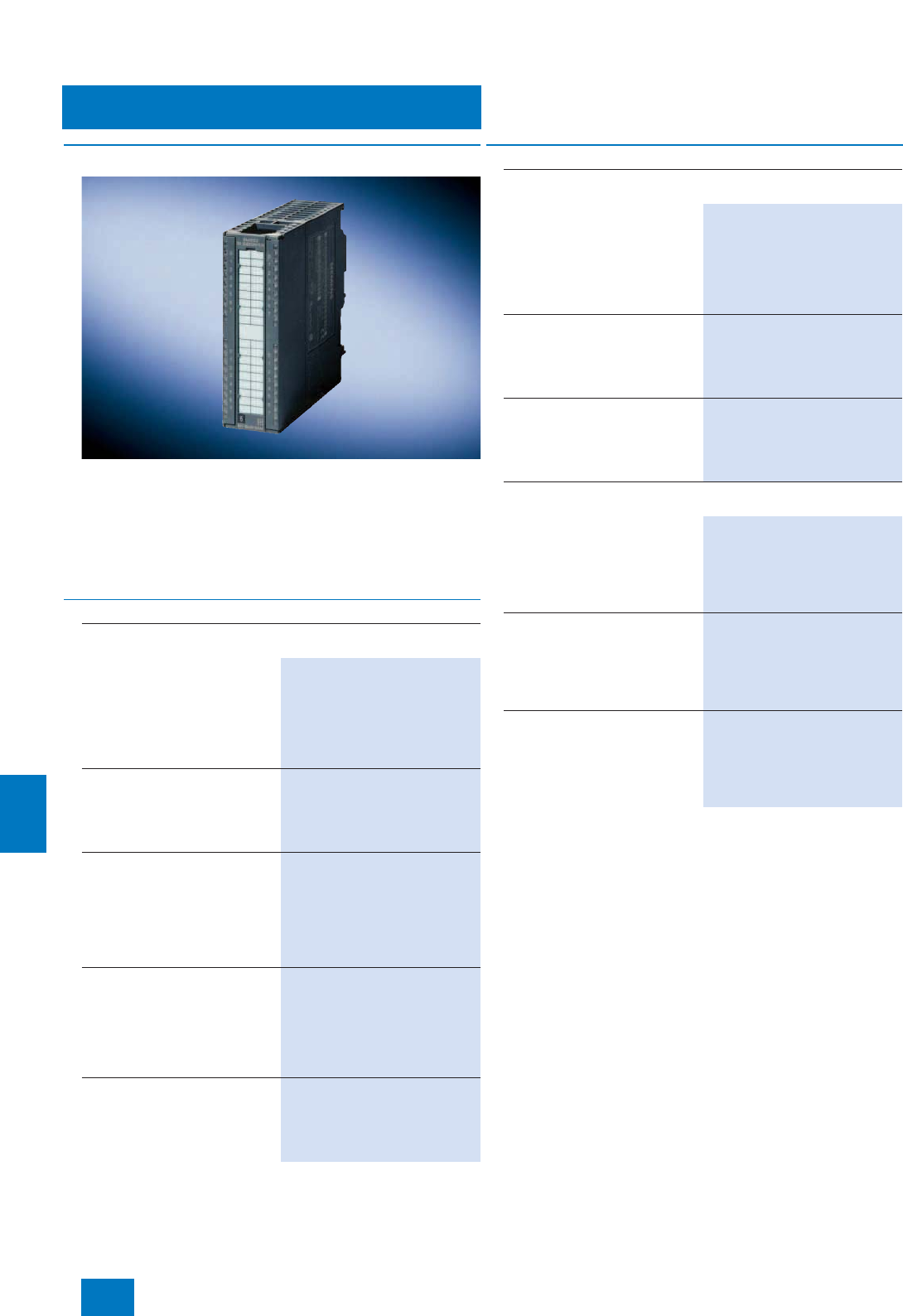
Process I/O
ET 200M distributed I/O
DO - digital output modules
11/16 Siemens ST PCS 7 · November 2007
11
■
Overview
The digital output modules described here break down into
• simple signal modules for DC and AC voltage with different
output currents per channel, with a selection of relay modules
available for higher output currents and voltages,
• modules with diagnostics capability that supply data for trou-
bleshooting and enable parameterizable reactions to a failure
of the automation system.
■
Selection and Ordering Data Order No.
SM 322 for DC voltage (suitable for solenoid valves, contactors,
indicator lights etc.)
8 outputs, 24 V DC / 2 A
Redundant design possible
(module redundancy)
• Electrically isolated in groups
of 4
• Front connector required:
20-contact
6ES7 322-1BF01-0AA0
16 outputs, 24 V DC / 0.5 A
• Electrically isolated in groups
of 8
• Front connector required:
20-contact
6ES7 322-1BH01-0AA0
16 outputs, 24 V DC / 0.5 A,
high-speed
• Electrically isolated in groups
of 8
• Output delay max. 0.2 ms
• Front connector required:
20-contact
6ES7 322-1BH10-0AA0
32 outputs, 24 V DC / 0.5 A
Redundant design possible
(module redundancy)
• Electrically isolated in groups
of 8
• Front connector required:
40-contact
6ES7 322-1BL00-0AA0
8 outputs, 48 to 125 V DC / 1.5 A
• Electrically isolated in groups
of 4
• Front connector required:
20-contact
6ES7 322-1CF00-0AA0 B)
SM 322 for AC voltage (suitable for AC coils, contactors, motor
starters, small motors and indicator lights)
8 outputs, 120/230 V AC / 2 A
Redundant design possible
(module redundancy)
• Electrically isolated in groups
of 4
• Front connector required:
20-contact
6ES7 322-1FF01-0AA0 B)
16 outputs, 120/230 V AC / 1 A
• Electrically isolated in groups
of 8
• Front connector required:
20-contact
6ES7 322-1FH00-0AA0 B)
32 outputs, 120/230 V AC / 1 A
• Electrically isolated in groups
of 8
• Front connector required: 2 x
20-contact
6ES7 322-1FL00-0AA0 B)
SM 322 for relay output (suitable for AC/DC solenoid valves,
contactors, motor starters, small motors and indicator lights)
8 outputs, 24 to 120 V DC,
48 to 230 V AC, max. 2 A
• Electrically isolated in groups
of 2
• Front connector required:
20-contact
6ES7 322-1HF01-0AA0
8 outputs, 24 to 120 V DC,
48 to 230 V AC, max. 5 A
• Electrically isolated in groups
of 1
• Front connector required:
40-contact
6ES7 322-1HF10-0AA0
16 outputs, 24 to 120 V DC,
48 to 230 V AC, max. 2 A
• Electrically isolated in groups
of 8
• Front connector required:
20-contact
6ES7 322-1HH01-0AA0
B) Subject to export regulations: AL: N, ECCN: EAR99H
■
Selection and Ordering Data Order No.
© Siemens AG 2007

Process I/O
ET 200M distributed I/O
DO - digital output modules
11/17
Siemens ST PCS 7 · November 2007
11
SM 322 modules with diagnostics capability
(with channel and module diagnostics)
for DC voltage (suitable for solenoid valves, DC contactors and
indicator lights)
8 outputs, 24 V DC / 0.5 A
Redundant design possible
(module redundancy)
• Electrically isolated in groups
of 8
• 2 connections per output (with
and without series diode)
• Connection of a default value by
channel in the event of CPU stop
(parameterizable)
• Wire break monitoring per chan-
nel
• Load voltage monitoring per
channel
• Short-circuit monitoring to M/L+
per channel
• Module-internal diagnostics
functions
• Front connector required:
20-contact
6ES7 322-8BF00-0AB0
16 outputs, 24 V DC / 0.5 A
Redundant design possible
(module and channel redun-
dancy)
• Electrically isolated in groups
of 4
• Connection of a default value by
channel in the event of CPU stop
(parameterizable)
• Wire break monitoring per chan-
nel (with 0 and 1 signals)
• Signaling of output overload
• Load voltage monitoring or
ground monitoring per channel
group
• Short-circuit monitoring to M/L+
per channel group
• Module-internal diagnostics
functions
• Front connector required:
40-contact
6ES7 322-8BH01-0AB0
■
Selection and Ordering Data Order No.
for AC voltage (suitable for AC coils, contactors, motor starters,
small motors and indicator lights)
8 outputs, 120/230 V AC / 2 A
• Electrically isolated in groups
of 1
• Connection of a default value by
channel in the event of CPU stop
(parameterizable)
• Module-internal diagnostics
functions
• Front connector required:
40-contact
6ES7 322-5FF00-0AB0 B)
16 outputs, 24/48 V AC/DC /
0.5 A
• Electrically isolated in groups
of 1
• Connection of a default value by
channel in the event of CPU stop
(parameterizable)
• Module-internal diagnostics
functions
• Front connector required:
40-contact
6ES7 322-5GH00-0AB0 B)
for relay output (suitable for AC/DC coils, contactors, motor
starters, small motors and indicator lights)
8 outputs, 24 to 120 V DC, 24 to
230 V AC / max. 5 A
• Electrically isolated in groups
of 1
• With RC suppressor element for
protection of contacts per chan-
nel
• Connection of a default value by
channel in the event of CPU stop
(parameterizable)
• Module-internal diagnostics
functions
• Front connector required:
40-contact
6ES7 322-5HF00-0AB0 B)
B) Subject to export regulations: AL: N, ECCN: EAR99H
■
Selection and Ordering Data Order No.
© Siemens AG 2007
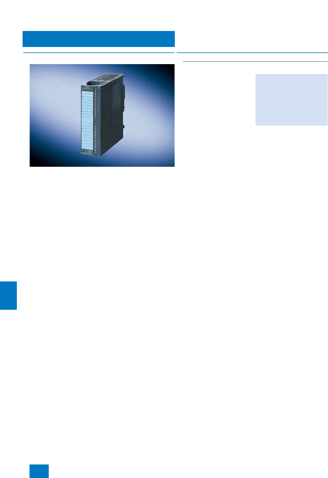
Process I/O
ET 200M distributed I/O
DI/DO - digital input/output modules
11/18 Siemens ST PCS 7 · November 2007
11
■
Overview
• Standard signal module for DC voltage (24 V DC) with
8 digital inputs and 8 digital outputs
• For connection of switches, 2-wire proximity switches (BERO),
solenoid valves, contactors, signal lamps
■
Selection and Ordering Data Order No.
SM 323 for DC voltage (suitable for switches, BERO proximity
switches, solenoid valves, contactors, indicator lights etc.)
• 8 inputs 24 V DC
- Suitable for connection of
2-wire proximity switches
(BERO) as sensors
• 8 outputs, 24 V DC / 0.5 A
• Inputs and outputs electrically
isolated in groups of 8
• Front connector required:
20-contact
6ES7323-1BH01-0AA0
© Siemens AG 2007
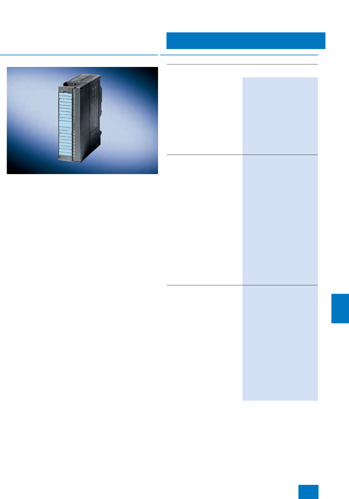
Process I/O
ET 200M distributed I/O
AI - analog input modules
11/19
Siemens ST PCS 7 · November 2007
11
■
Overview
The analog input modules described here break down into
• multi-function modules for current, voltage and temperature
measurements, and
• special, highly accurate modules for current and voltage mea-
surements or temperature measurements.
All modules automatically supply channel-specific and module-
internal diagnostics data, except module 6ES7 331-1KF01-
0AB0. With the latter module, channel failure is identified by the
PCS 7 analog driver block.
The individual channels of the analog input modules can be pa-
rameterized in groups independently of each other.
■
Selection and Ordering Data Order No.
SM 331 modules for current, voltage and temperature measure-
ments
8 inputs, individually parame-
terizable
• Resolution 12 bit + sign
• Current measurement 0/4 to
20 mA (8 channels; 2 wires with
external supply or 4 wires)
• Voltage measurement
(8 channels)
• Resistance thermometer Pt100,
Ni100, Ni1000, LG-Ni1000
(8 channels; 2, 3 or 4 wires)
• Front connector required:
40-contact
6ES7 331-1KF01-0AB0
8 inputs in 4 channel groups
Redundant design possible
(module redundancy)
• Changeover of measurement
type by range module per chan-
nel group
• Resolution 14 bit + sign
• Current measurement 0/4 to
20 mA (8 channels; 2 or 4 wires)
• Voltage measurement
(8 channels)
• Resistance thermometer Pt100,
Ni100 (4 channels, 2 or 4 wires)
• Thermocouples type E, N, J, K, L
(8 channels),
internal compensation or exter-
nal compensation with compen-
sating box or 0 °C cold junction
• Wire break monitoring
• Diagnostics inside module
• Front connector required:
20-contact
6ES7 331-7KF02-0AB0
2 inputs in 1 channel group
• Changeover of measurement
type by range module
• Resolution 14 bit + sign
• Current measurement 0/4 to
20 mA (2 channels; 2 or 4 wires)
• Voltage measurement
(2 channels)
• Resistance thermometer Pt100,
Ni100 (1 channel, 2 or 4 wires)
• Thermocouples type E, N, J, K, L
(2 channels),
internal compensation or exter-
nal compensation with compen-
sating box or 0 °C cold junction
• Wire break monitoring
• Diagnostics inside module
• Front connector required:
20-contact
6ES7 331-7KB02-0AB0 B)
B) Subject to export regulations: AL: N, ECCN: EAR99H
© Siemens AG 2007

Process I/O
ET 200M distributed I/O
AI - analog input modules
11/20 Siemens ST PCS 7 · November 2007
11
B) Subject to export regulations: AL: N, ECCN: EAR99H
SM 331 modules for current and voltage measurements
8 inputs in 4 channel groups,
high-speed
• Resolution 13 bit + sign
• Measurement type and range
selection adjustable per channel
group
• Current measurement 0/4 to
20 mA (2 or 4 wires)
• Voltage measurement
• Limit monitoring adjustable for
2 channels
• Fast updating of measured val-
ue
• Supporting of isochronous
mode
• Diagnostics inside module
• Front connector required:
20-contact
6ES7 331-7HF01-0AB0
8 inputs in 4 channel groups
Redundant design possible
(module and channel redun-
dancy)
• Resolution 15 bit + sign
• Current measurement 0/4 to
20 mA (8 channels; 2 or 4 wires)
• Voltage measurement
(8 channels)
• Wire break monitoring
• Diagnostics inside module
• Front connector required:
40-contact
6ES7 331-7NF00-0AB0 B)
8 inputs in 4 channel groups
• Resolution 15 bit + sign
• Fast module cycle (min. 10 ms
for 4 channels)
• Current measurement 0/4 to
20 mA (8 channels; 2 wires with
external supply or 4 wires)
• Voltage measurement
(8 channels)
• Wire break monitoring
• Short-circuit-proof
• Isolation between channel
groups
• Diagnostics inside module
• Front connector required:
40-contact
6ES7 331-7NF10-0AB0 B)
■
Selection and Ordering Data Order No.
SM 331 modules for temperature measurement
8 inputs in 4 channel groups
• Resolution 15 bit
• Resistance thermometer
Pt100 ... 1000, Ni100 ... 1000,
Cu10 (8 channels; 2, 3 or
4wires)
• Short-circuit-proof
• Wire break monitoring
• Diagnostics inside module
• Front connector required:
40-contact
6ES7 331-7PF01-0AB0 B)
8 inputs in 4 channel groups
• Resolution 15 bit
• Thermocouples type B, C, N, E,
R, S, J, L, T, K, U (8 channels),
internal compensation; external
compensation with Pt100
through separate inputs possi-
ble
• Fast module cycle (10 ms for
4 channels)
• Short-circuit-proof
• Wire break monitoring
• Diagnostics inside module
• Front connector required:
40-contact
6ES7 331-7PF11-0AB0
■
Selection and Ordering Data Order No.
© Siemens AG 2007
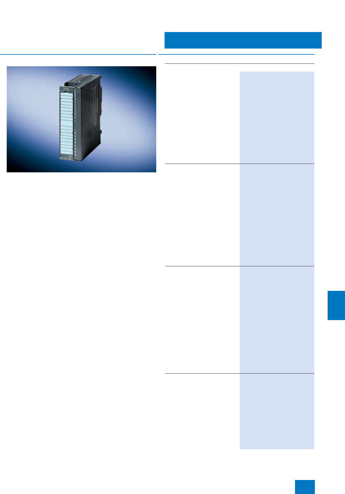
Process I/O
ET 200M distributed I/O
AO - analog output modules
11/21
Siemens ST PCS 7 · November 2007
11
■
Overview
The analog output modules for voltage and current described
here break down into
• modules with 12 bit resolution and various numbers of chan-
nels, and
• a high-precision module with 15 bit resolution.
The analog output modules can be parameterized in groups in-
dependently of each other and automatically supply all channel-
specific and module-internal diagnostics data.
B) Subject to export regulations: AL: N, ECCN: EAR99H
■
Selection and Ordering Data Order No.
SM 332 modules for current and voltage outputs
2 outputs in 2 channel groups
• Resolution 12 bit + sign
• Voltage 0/1 to 5/10 V; ±10 V
(2 channels; 2 or 4 wires)
• Current 0/4 to 20 mA; ±20 mA
(2 channels; 2 wires)
• Parameterizable substitute val-
ue output in case of CPU stop
• Broken wire monitoring (only for
current)
• Short circuit monitoring (only for
voltage)
• Diagnostics inside module
• Front connector required:
20-contact
6ES7 332-5HB01-0AB0
4 outputs in 4 channel groups
Redundant design possible
(module redundancy)
• Resolution 12 bit + sign
• Voltage 0/1 to 5/10 V; ±10 V
(4 channels; 4 wires)
• Current 0/4 to 20 mA; ±20 mA
(4 channels; 2 wires)
• Parameterizable substitute val-
ue output in case of CPU stop
• Broken wire monitoring (only for
current)
• Short circuit monitoring (only for
voltage)
• Diagnostics inside module
• Front connector required:
20-contact
6ES7 332-5HD01-0AB0
8 outputs in 8 channel groups
Redundant design possible
(module and channel redun-
dancy)
• Resolution 12 bit + sign
• Voltage 0/1 to 5/10 V; ±10 V
(8 channels; 4 wires)
• Current 0/4 to 20 mA; ±20 mA
(8 channels; 2 wires)
• Parameterizable substitute val-
ue output in case of CPU stop
• Broken wire monitoring (only for
current)
• Short circuit monitoring (only for
voltage)
• Diagnostics inside module
• Front connector required:
40-contact
6ES7 332-5HF00-0AB0
4 outputs in 4 channel groups
• Resolution 15 bit + sign
• Voltage 0/1 to 5/10 V; ±10 V
(4 channels; 4 wires)
• Current 0/4 to 20 mA; ±20 mA
(4 channels; 2 wires)
• Parameterizable substitute val-
ue output in case of CPU stop
• Isolated by channel
• Diagnostics inside module
• Front connector required:
20-contact
6ES7 332-7ND02-0AB0 B)
© Siemens AG 2007
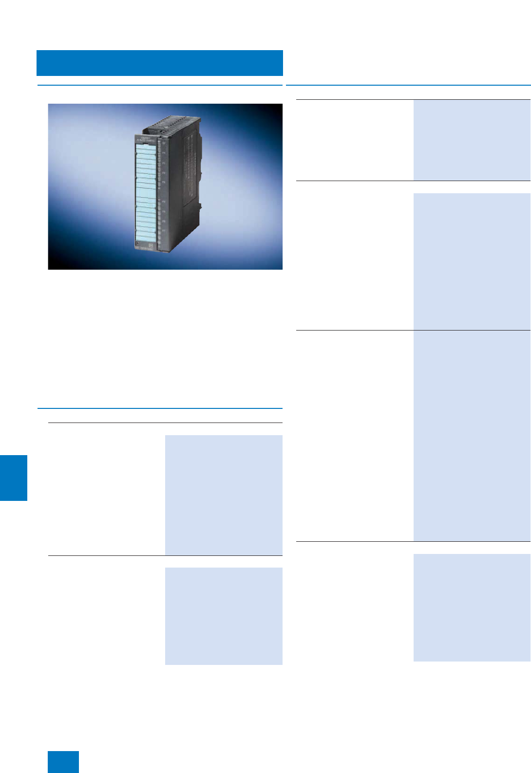
Process I/O
ET 200M distributed I/O
Ex modules [EEi xb]
11/22 Siemens ST PCS 7 · November 2007
11
■
Overview
The following analog and digital I/O modules are suitable for use
in hazardous plants. They separate the non-intrinsically safe
electrical circuits of the automation system and the intrinsically
safe electrical circuits of the process. Sensors and actuators
suitable for placing in zone 1 or 21 and 2 or 22 hazardous areas
as well as intrinsically safe equipment compliant with DIN 50020
and [EEx ib] IIC can be operated on these modules.
All Ex modules come with diagnostics capability (channel and
module diagnostics).
Ex modules identified by "redundant design possible"
(6ES7 321-7RD00-0AB0, 6ES7 322-5SD00-0AB0, 6ES7 331-
7RD00-0AB0, 6ES7 332-5RD00-0AB0) can also be configured
redundant when used in non-hazardous plants.
For additional Ex modules, refer to page 11/23.
■
Selection and Ordering Data Order No.
Ex digital input module
4 NAMUR inputs in 4 channel
groups
Redundant design possible
(module redundancy)
• Voltage supply to sensors 8.2 V
• Individually floating channels
• Wire break and short-circuit
monitoring (directly at the con-
tact for contacts with external
resistor circuit)
• Diagnostics inside module
• Front connector required:
20-contact
6ES7 321-7RD00-0AB0
Ex digital output module
4 outputs, 24 V DC / 10 mA in
4 channel groups
Redundant design possible
(module redundancy)
• Individually floating channels
• Wire break monitoring
• Short-circuit monitoring
• Diagnostics inside module
• Front connector required:
20-contact
6ES7 322-5SD00-0AB0
4 outputs, 15 V DC / 20 mA in
4 channel groups
• Individually floating channels
• Wire break monitoring
• Short-circuit monitoring
• Diagnostics inside module
• Front connector required:
20-contact
6ES7 322-5RD00-0AB0
Ex analog input module
4 inputs, 0/4 to 20 mA in
4 channel groups
Redundant design possible
(module redundancy)
• Individually floating channels
• Resolution 15 bit + sign
• Connection of 2-wire or 4-wire
transmitters possible
• Wire break monitoring
• Measurement range monitoring
• Short-circuit-proof
• Diagnostics inside module
• Front connector required:
20-contact
6ES7 331-7RD00-0AB0
8 inputs in 4 channel groups
• Resolution 15 bit + sign
• Thermocouples type T, U, E, J,
L, K, N, R, S, B (8 channels)
Internal compensation; external
compensation with Pt100
(2 channels), compensating box
or 0/50 °C cold junction
• Resistance thermometer Pt100,
Pt200, Ni100 (4 channels; 2-wire
or 4-wire, 3-wire Pt100 on
request)
• Wire break monitoring
• Diagnostics inside module
• Front connector required:
20-contact
Note:
A special front connector for the
Ex analog input module 6ES7
331-7SF00-0AB0 enables greater
accuracy when taking thermo-
couple temperature measure-
ments in "internal compensation"
mode (see page 11/12).
6ES7 331-7SF00-0AB0
Ex analog output module
4 outputs, 0/4 to 20 mA in
4 channel groups
Redundant design possible
(module redundancy)
• Individually floating channels
• Resolution 15 bit
• For 2-wire transmitters
• Wire break monitoring
• Diagnostics inside module
• Front connector required:
20-contact
6ES7 332-5RD00-0AB0
■
Selection and Ordering Data Order No.
© Siemens AG 2007
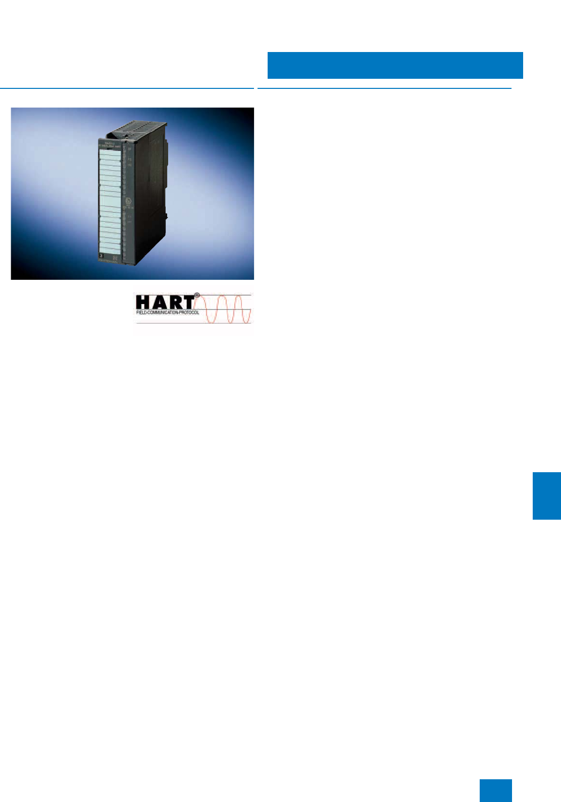
Process I/O
ET 200M distributed I/O
Modules with HART
11/23
Siemens ST PCS 7 · November 2007
11
■
Overview
The modules with HART (High-
way Addressable Remote
Transducer) which can be
used in ET 200M remote I/O
stations (with IM 153-2 High
Feature interface module) per-
mit connection of HART de-
vices to SIMATIC PCS 7 automation systems.
All transmitters or HART actuators certified for digital communi-
cation using the HART protocol can be connected via these
modules.
Conventional transmitters with 4 to 20 mA technology without
HART protocol can also be connected.
All modules with HART come with diagnostics capability (chan-
nel and module diagnostics). The diagnostics and monitoring
functions are directly available in SIMATIC PCS 7. They require
no additional engineering. Plain text messages output on the op-
erator station provide information on faults or changes in the
HART parameter settings.
Homogenous integration in the SIMATIC Process Device Man-
ager (PDM) and the PCS 7 Asset Management permit intuitive
online diagnostics and parameterization of all connected field
devices from a central position.
■
Function
HART is a serial transmission procedure with which additional
parameter data such as measuring ranges, attenuation etc. can
be sent to transmitters and actuators over a 4 to 20-mA current
loop. The HART jobs for each channel can be remotely initiated
over the PROFIBUS DP. This usually takes place from the central
engineering system of the SIMATIC PCS 7 process control sys-
tem per SIMATIC PDM.
The modules with HART have the following features:
• Connections compatible with the conventional analog mod-
ules of the ET 200M
• Additional communications possibility over the current loop
• 8 analog channels per module (2 analog channels with Ex
modules)
• Each channel is a primary master of the HART protocol
• Selectable input range per channel (AI):
- 0 to 20 mA (without HART function)
-± 20 mA (without HART function, not with Ex module)
- 4 to 20 mA (with/without HART function)
• Selectable output range per channel (AO):
- 0 to 20 mA (with/without HART function; in the case of
Ex module, only without HART function)
- 4 to 20 mA (with/without HART function)
Additional functions of the HART analog modules
6ES7 331-7TF01-0AB0 and 6ES7 332-8TF01-0AB0:
• Supplementary HART variables (up to 4 per channel, up to
8 per module) allow the transmission of additional values
from/to the HART devices
• Modules can be operated in redundant mode (module and
channel redundancy)
Parameterization
• For the analog input modules (AI), it is possible to parameter-
ize e.g. conversion time, input range, limits, alarms, smooth-
ing of measured values
• For the analog output modules (AO), it is possible to parame-
terize e.g. output range, response on stoppage of AS (CPU),
diagnostics
• Remote parameterization (per PROFIBUS DP) of the HART
transmitters and actuators with SIMATIC PDM
• It is still possible to parameterize the HART devices using an
operator terminal (handheld).
© Siemens AG 2007

Process I/O
ET 200M distributed I/O
Modules with HART
11/24 Siemens ST PCS 7 · November 2007
11
■
Technical specifications
You can find the detailed technical data of the modules with
HART at the following points:
• Catalog IK PI (Catalog Section "Distributed I/Os") or
• on the Mall/CA 01 under "Distributed I/Os / ET 200M"
B) Subject to export regulations: AL: N, ECCN: EAR99H
■
Selection and Ordering Data Order No.
SM 331 HART analog input
module
Redundant design possible
(module and channel redun-
dancy)
8 inputs, 0/4 to 20 mA or ±20 mA
• Resolution: 15 bit + sign
• Connection of 2-wire or 4-wire
transmitters possible
• HART (2-wire or 4-wire)
• Wire break monitoring
• Short-circuit-proof
• Front connector required:
20-contact
6ES7 331-7TF01-0AB0 B)
SM 332 HART analog output
module
Redundant design possible
(module and channel redun-
dancy)
8 outputs, 0/4 to 20 mA
• Resolution: 15 bit + sign
• For 2-wire actuators
•HART (2-wire)
• Wire break monitoring
• Front connector required:
20-contact
6ES7 332-8TF01-0AB0 B)
Ex analog input module with
HART [EEx ib]
2 inputs, 0/4 to 20 mA in
2 channel groups
• Individually floating channels
• Resolution: 15 bit + sign
• Connection of 2-wire or 4-wire
transmitters possible
• Wire break monitoring
• Short-circuit-proof
• HART (2-wire or 4-wire)
• Front connector required:
20-contact
6ES7 331-7TB00-0AB0 B)
Ex analog output module with
HART [EEx ib]
2 outputs, 0/4 to 20 mA in
2 channel groups
• Individually floating channels
• Resolution: 12 bit + sign
• For 2-wire actuators
• Wire break monitoring
•HART
• Front connector required:
20-contact
6ES7 332-5TB00-0AB0 B)
© Siemens AG 2007
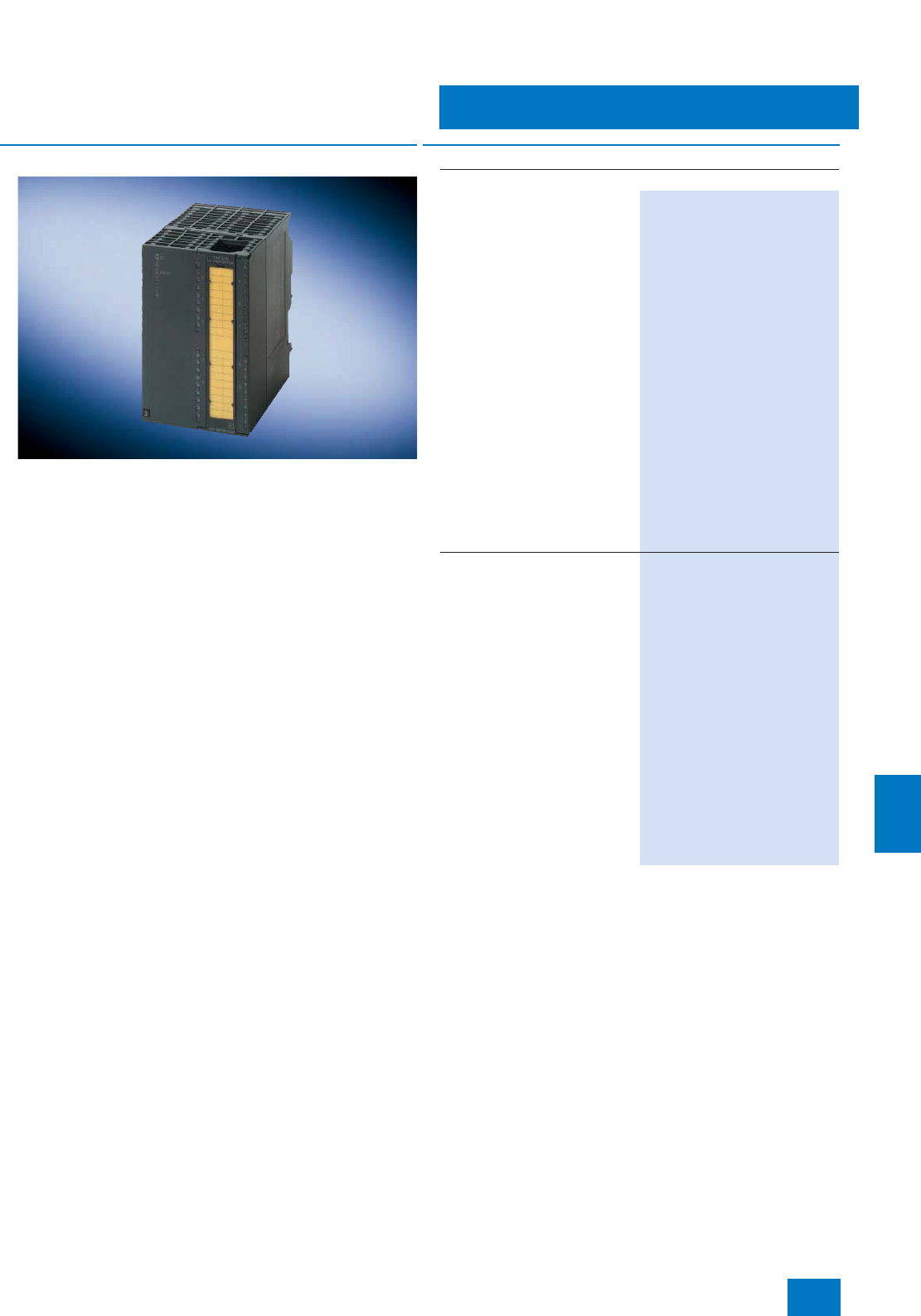
Process I/O
ET 200M distributed I/O
F modules
11/25
Siemens ST PCS 7 · November 2007
11
■
Overview
The safety functions of the AS 414F/FH and AS 417F/FH automa-
tion systems are matched to the safety-related I/O modules
(F-modules) of the ET 200M distributed I/O system. The F-signal
modules (DI/DO/AI) in the ET 200M remote I/O stations are able
to guarantee plant safety even in the event of a CPU failure. They
are of redundant design, and can diagnose both internal and ex-
ternal faults. They carry out self-tests for this purpose, e.g. for
short-circuit or wire breakage, and automatically monitor the dis-
crepancy time defined in the parameter settings. They comply
with the requirements up to SIL 3 (IEC 61508) or AK 6
(VDE 0801).
The input modules operate internally with single-channel evalu-
ation (SIL 2 sensors), 2-out-of-2 evaluation (SIL 3 sensors) or
2-out-of-3 channel evaluation (only F-AI module). A safety re-
sponse is triggered immediately there are any differences. The
type of evaluation influences the number of usable inputs (chan-
nels). For example, only half of the existing inputs are available
in the case of 2-out-of-2 channel evaluation.
The digital output modules enable safe disconnection through a
second disconnect path in the event of a faulty output.
■
Selection and Ordering Data Order No.
SM 326F failsafe digital input module for floating contacts
24 inputs, 24 V DC
Electrically isolated in groups
of 12
Redundant design possible
(module redundancy)
• 4 short-circuit-proof sensor
power supplies, each for
6 channels, isolated in groups
of 3
• External sensor power supply
possible
• SIL 2: single-channel evaluation,
24 channels
• SIL 3: 2-out-of-2 evaluation on
the module, 12 channels
(adjustable discrepancy time)
• Short-circuit monitoring to L+
• Discrepancy monitoring
• Supports time stamping (SOE)
• Diagnostics inside module
• PROFIsafe telegram
• Front connector required:
40-contact
6ES7 326-1BK01-0AB0
8 inputs, NAMUR [EEx ib]
Isolated by channel
Redundant design possible
(module redundancy)
• 8 short-circuit-resistant sensor
power supplies, each for
1 channel, mutually isolated
• SIL 2: single-channel evaluation,
8 channels
• SIL 3: 2-out-of-2 evaluation on
the module, 4 channels
(adjustable discrepancy time)
• Wire break and short-circuit
monitoring (for contacts with
external resistor circuit)
• Discrepancy monitoring
• Diagnostics inside module
• PROFIsafe telegram
• Front connector required:
40-contact
6ES7 326-1RF00-0AB0
© Siemens AG 2007
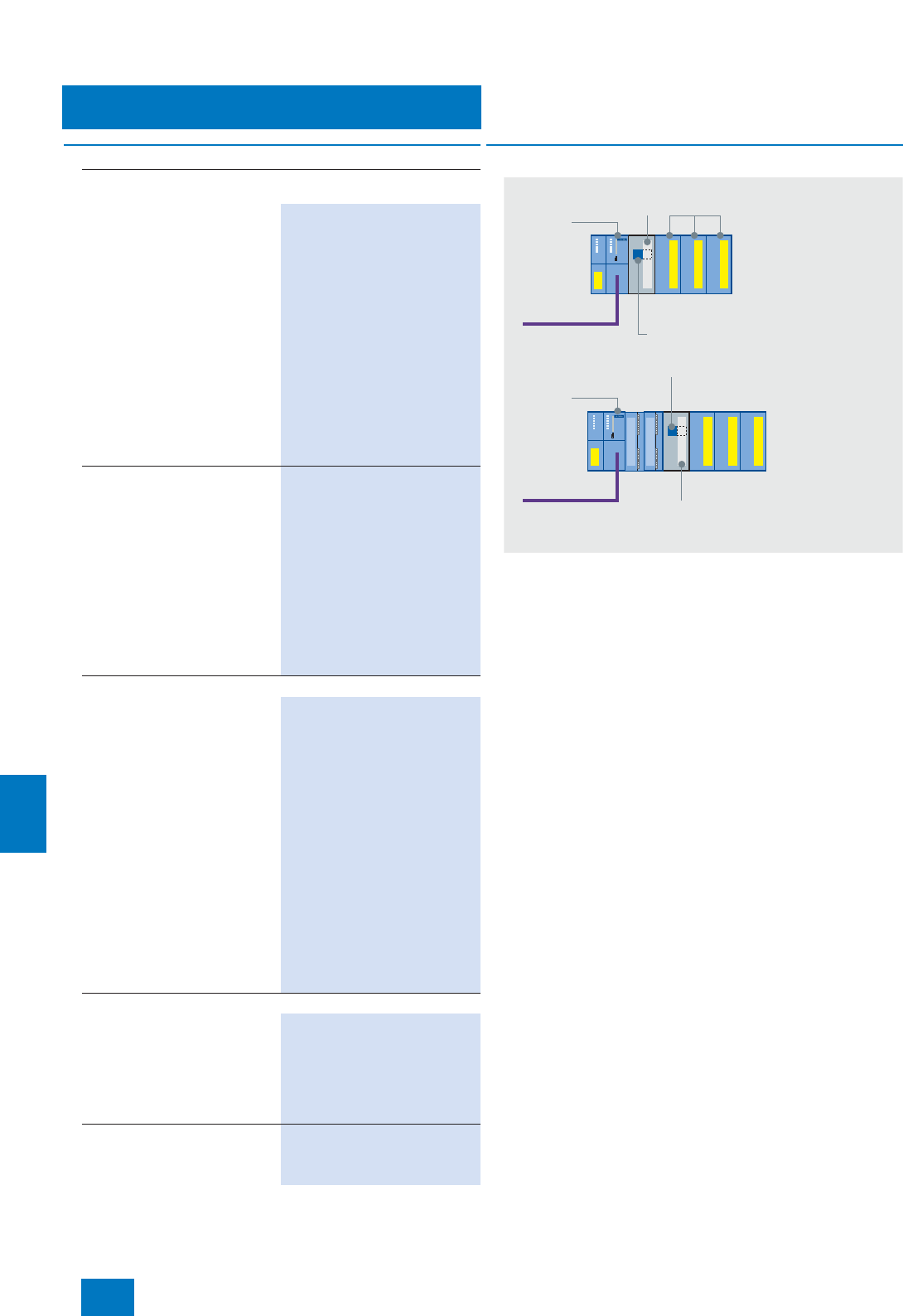
Process I/O
ET 200M distributed I/O
F modules
11/26 Siemens ST PCS 7 · November 2007
11
■
Options
Isolating module
The following components are available as accessories for the
F modules:
• Isolating module
- For isolation of F and standard modules in an ET 200M re-
mote I/O station
- For signal isolation when using a copper bus connection
(only F modules in an ET 200M remote I/O station with
IM 153-2)
• Isolating bus submodule for isolating module, when using an
active backplane bus
Note:
The isolating module for F modules and the isolating bus sub-
module can only be used together. The 40-mm wide gap cannot
be used for other modules.
SM 326F failsafe digital output,
suitable for solenoid valves, DC contactors and signal lamps
10 outputs, 24 V DC, 2 A
Electrically isolated in groups of 5
(outputs with internal diode)
Redundant design possible
(module and channel redun-
dancy)
• SIL 2, SIL 3 parameterizable
(10 channels)
• P/P-switching (for non-floating
loads; ground and earth con-
nected together)
• Wire break and short-circuit
monitoring
• Diagnostics inside module
• PROFIsafe telegram
• Front connector required:
40-contact
6ES7 326-2BF01-0AB0
8 outputs, 24 V DC, 2 A
Electrically isolated in groups of 4
• SIL 2, SIL 3 parameterizable
(8 channels)
• P/M-switching (for floating
loads; ground and earth sepa-
rate)
• Wire break and short-circuit
monitoring
• Diagnostics inside module
• PROFIsafe telegram
• Front connector required:
40-contact
6ES7 326-2BF40-0AB0
SM 336F failsafe analog input module
6 inputs, 4 to 20 mA
Redundant design possible
(module redundancy)
• Resolution 13 bit + sign
• Isolated from the backplane bus
• 2-wire or 4-wire connection
• SIL 2: two-channel evaluation,
6sensors
• SIL 3: two-channel evaluation,
12 sensors (adjustable toler-
ance window)
• Wire break monitoring
• Tolerance monitoring between
2 sensors (SIL 3)
• Diagnostics inside module
• PROFIsafe telegram
• Front connector required:
40-contact
6ES7 336-1HE00-0AB0
Options
Isolating module
For F modules, 40 mm wide
• For isolation of F and standard
modules in an ET 200M rack
• For signal isolation when using a
copper bus connection (only F
modules in a rack with IM 153-2)
6ES7 195-7KF00-0XA0
Isolating bus module
80 mm wide, for isolating module,
when using an active backplane
bus
6ES7 195-7HG00-0XA0
■
Selection and Ordering Data Order No.
F-modules
ET 200 rack
only for SIL 3 operation,
SIL 2 also possible
without isolating module
ET 200 rack
Isolating bus submodule
for active
backplane bus
Isolating module for isolation of
standard and F-modules
PROFIBUS
copper connection
PROFIBUS
copper connection
or fiber-optic cable
IM 153-2
IM 153-2
Isolating
module
© Siemens AG 2007
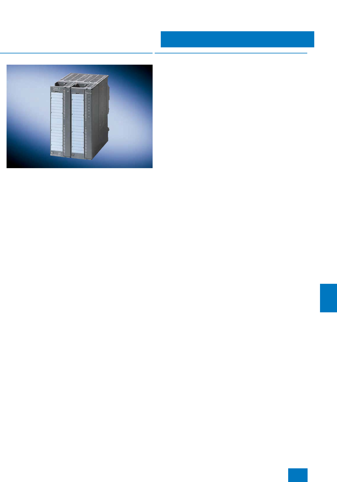
Process I/O
ET 200M distributed I/O
Closed-loop control modules
11/27
Siemens ST PCS 7 · November 2007
11
■
Overview
The FM 355 is an intelligent 4-channel controller module for uni-
versal control tasks. It can be used to control temperature, pres-
sure and flow.
The following versions of the FM 355 are available:
• FM 355 C
Continuous-action controller with 4 analog outputs for control-
ling analog actuators
• FM 355 S
Step or pulse controller with 8 digital outputs for controlling
motor-driven (integrating) actuators or binary controlled actu-
ators (e.g. electrical heating strips and cartridges)
• FM 355-2 C/S
Specially optimized for temperature controls with user-friendly
online self-optimization integrated
■
Function
The FM 355 / FM 355-2 modules have four separate control
channels. These controllers have the following features:
• Predefined controller structures for
- fixed-setpoint control,
- cascade control,
- ratio control,
- 3-component control
• Various operating modes:
- automatic mode,
- manual mode,
- safety mode,
- follow-up mode,
- backup mode
• Sampling interval (dependent on the resolution of the analog
inputs and the compensation input):
- at 12 bit: 20 ms to 100 ms (only FM 355-2)
- at 14 bit: 100 ms to 500 ms (dependent on the number of en-
abled analog inputs)
• 2 control algorithms:
- self-optimized temperature control algorithm,
- PID algorithm
• Integrated online self-optimization without configuration (only
FM 355-2)
- for faster adoption of the operating point
• User-friendly controller optimization
• Backup mode: The controller can maintain its control function
in the event of CPU failure or CPU stop. Programmable safety
setpoint values or safety manipulated variables are set for this
purpose.
• Feedforward control: The analog inputs can be optionally
used for feedforward control as well as for actual value acqui-
sition.
© Siemens AG 2007
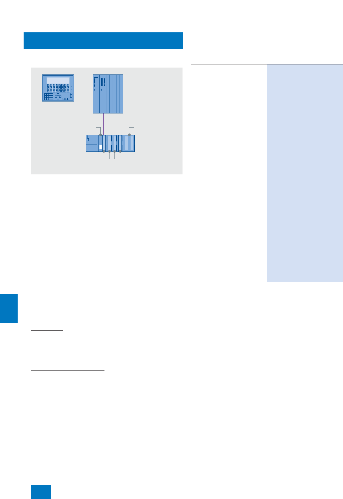
Process I/O
ET 200M distributed I/O
Closed-loop control modules
11/28 Siemens ST PCS 7 · November 2007
11
■
Integration
Use in SIMATIC PCS 7
The FM 355 / FM 355-2 modules can be used to implement con-
trol tasks outside the SIMATIC PCS 7 automation system. The
modules have not only controller structures but also analog and
digital channels, thus eliminating the need for additional mod-
ules to detect the setpoint/actual value or to control the actuator.
On the one hand this reduces the work load for the CPU, on the
other hand it enables backup mode with which the control sys-
tem continues to work even if the CPU fails. In this case the
FM 355 module can be operated further with an OP operator
panel (does not apply to FM 355-2).
The operator panel is connected to the PROFIBUS DP fieldbus
for this purpose. The CPU of the automation system can surren-
der input privilege to the operator panel in normal operation as
well. The parameters that can be accessed with the operator
panel are the setpoint and manipulated variable. If the FM 355
module is operated from the operator panel, the automation sys-
tem reads back the values accessible from the operator panel
after the input privilege is withdrawn or recovered again. Bump-
less continuation of the operations is thus assured.
IM 153-2 High Feature interface modules are needed for the
PROFIBUS DP connection when the FM 355 / FM 355-2 control-
ler modules are used in ET 200M.
PCS 7 blocks
CFC blocks with OS faceplates for all FM 355 modules are in-
cluded in the scope of supply of the standard SIMATIC PCS 7 li-
brary (part of engineering software). These blocks are integrated
into the PCS 7 driver concept. This guarantees homogenous
system integration (including automatic diagnostics messages).
Parameterization in HW-Config
A configuration package containing all parameterization masks
required for configuring, parameterizing and commissioning is
included in the scope of supply of the FM 355 controller mod-
ules.
Note:
In the case of the FM 355 C and FM 355 S controller modules, the chan-
nels are not electrically isolated from one another
IM 153-2
OP
FM-355 module
(80 mm wide)
Standard
modules
Automation
system
ET 200 Rack
■
Selection and Ordering Data Order No.
FM 355 C controller module
With 4 analog outputs for
4 continuous-action controllers
Required front connector:
2x20-pin
Incl. multi-lingual configuration
package, manual and Getting
Started (German, English,
French, Italian) on CD-ROM
6ES7 355-0VH10-0AE0
FM 355 S controller module
With 8 digital outputs for 4 step or
pulse controllers
Required front connector:
2x20-pin
Incl. multi-lingual configuration
package, manual and Getting
Started (German, English,
French, Italian) on CD-ROM
6ES7 355-1VH10-0AE0
FM 355-2 C temperature con-
troller module
With 4 analog outputs for
4 continuous-action controllers
Required front connector:
2x20-pin
Incl. multi-lingual configuration
package, manual and Getting
Started (German, English,
French, Italian) on CD-ROM
6ES7 355-2CH00-0AE0
FM 355-2 S temperature con-
troller module
With 8 digital outputs for 4 step or
pulse controllers
Required front connector:
2x20-pin
Incl. multi-lingual configuration
package, manual and Getting
Started (German, English,
French, Italian) on CD-ROM
6ES7 355-2SH00-0AE0
© Siemens AG 2007
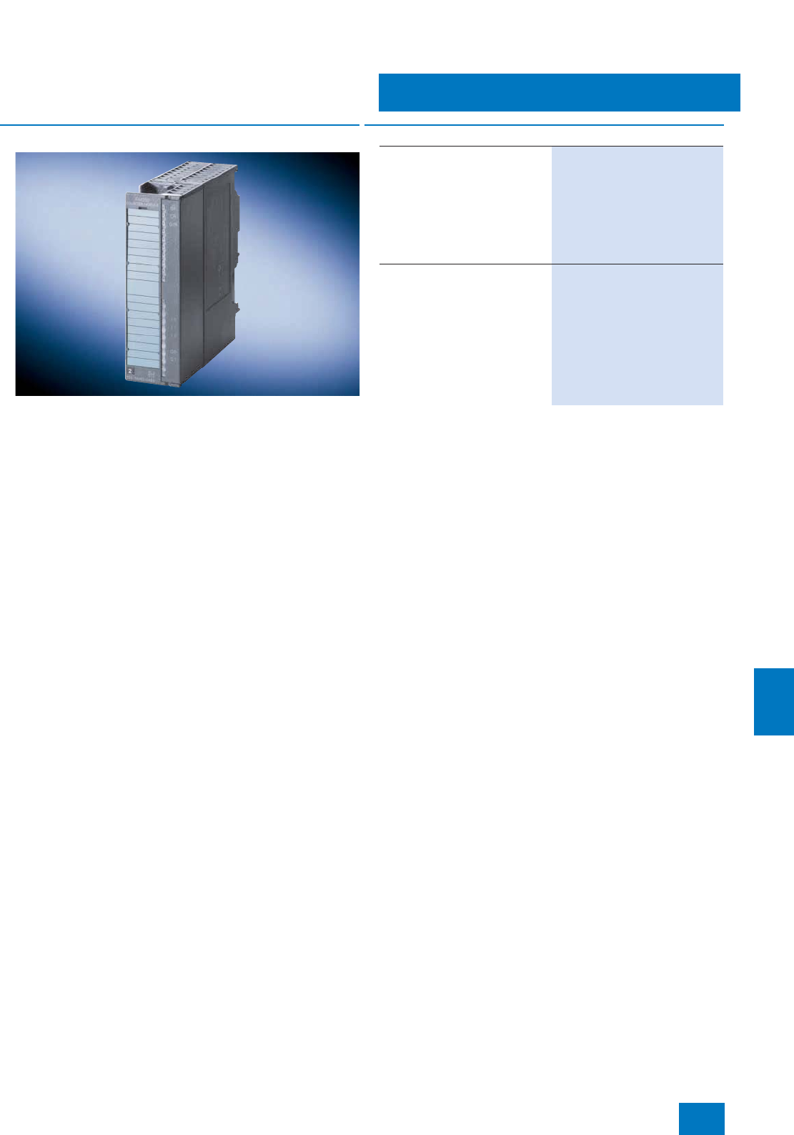
Process I/O
ET 200M distributed I/O
Counter modules
11/29
Siemens ST PCS 7 · November 2007
11
■
Overview
The FM 350-1 counter module is a single-channel intelligent
counter module for simple counting tasks, suitable for the direct
connection of incremental encoders. It provides a comparison
function with 2 preselectable reference values, as well as inte-
grated digital outputs for outputting a reaction upon reaching the
reference value.
The FM 350-2 counter module is an eight-channel intelligent
counter module for universal counting and measuring tasks, as
well as for simple positioning jobs (max. 4 axes).
■
Selection and Ordering Data Order No.
FM 350-1 counter module
Counting functions up to 500 kHz
1 channel for the connection of
5 V and 24 V incremental encod-
ers
Required front connector:
1x20-pin
incl. configuration package on
CD-ROM
6ES7 350-1AH03-0AE0
FM 350-2 counter module
8 channels with max. 20 kHz
counting frequency; for 24 V
encoders, for the following tasks:
counting, frequency measure-
ment, speed measurement,
period measurement, dosing
Required front connector:
1x40-pin
incl. configuration package on
CD-ROM
6ES7 350-2AH00-0AE0
© Siemens AG 2007
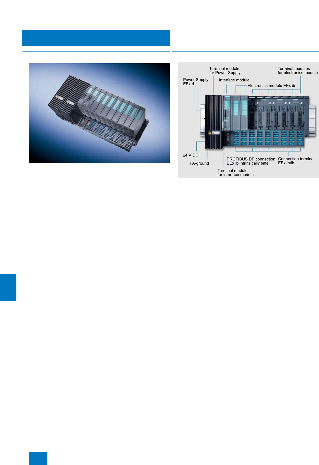
Process I/O
ET 200iSP distributed I/O
Introduction
11/30 Siemens ST PCS 7 · November 2007
11
■
Overview
The ET 200iSP is a modular, intrinsically-safe I/O system in IP30
degree of protection, and can be configured with up to
32 electronics modules (4/8-channel). The range of electronics
modules covers:
• 8-channel digital input module DI, can also be used as
counter or frequency meter
• 4-channel digital output module DO with external actuator
switch-off via High or Low signal (H/L switch-off)
• 4-channel analog input modules AI for temperature measure-
ments with resistance thermometer or thermocouple
• 4-channel analog input modules AI for connection of 2/4-wire
transmitters with or without HART functionality
• 4-channel analog output module AO for connection of field de-
vices with or without HART functionality
The ET 200iSP suitable for gas and dust atmospheres according
to the ATEX directive 94/9/EU can be installed directly in the Ex
zones 1, 2, 21 or 22 as well as in non-hazardous areas. The in-
trinsically-safe sensors, actuators and HART field devices can
also be located in zone 0 or 20 if necessary.
■
Design
The ET 200iSP consists of the following components:
• Carrier system with terminal modules for prewiring, and also
for inserting power supply, interface and electronics modules,
mounted on an S7-300 rail
• 1 or 2 (redundant) power supply modules PS with pressurized
enclosure
• 1 or 2 (redundant) IM 152 interface modules for PROFIBUS DP
• Up to 32 electronics modules (4/8-channel) in any combina-
tion, including watchdog module
• Terminating module (included in scope of delivery of terminal
modules for the PROFIBUS interface)
Assembly is quick and easy:
• Latching of terminal modules onto the S7-300 rail
• Prewiring of process signal cables on the terminal modules
using spring-loaded or screw-type connections
• Plugging-in of power supply, interface and electronics mod-
ules without the need for additional tools
The maximum number of electronics modules which can be
used per station may be limited depending on the current con-
sumption of the modules required to solve the automation task.
However, up to 16 electronics modules can be used without lim-
itation.
If the ET 200iSP is used in a hazardous area, it must be installed
in an appropriate Ex housing which at least corresponds to the
IP54 degree of protection. Appropriate versions of an IP65 hous-
ing are offered in the Section "Stainless steel wall housings".
Exceptional features of the ET 200iSP architecture
• Installation and testing of the wiring is possible in advance
without the electronics module
• Isolation of the mechanical and electronic systems, in con-
junction with the independent process wiring, permits fast and
easy replacement of the electronics modules
• Mechanical coding which is carried out when an electronics
module is plugged onto a terminal module for the first time
prevents the connection of incorrect replacement modules
• Hot swapping of the power supply modules and electronics
modules is possible without a fire certificate
© Siemens AG 2007

Process I/O
ET 200iSP distributed I/O
Introduction
11/31
Siemens ST PCS 7 · November 2007
11
■
Integration
Distributed ET 200iSP stations are connected to the SIMATIC
PCS 7 automation systems (controllers) via the PROFIBUS DP,
which can be routed intrinsically-safe into Ex zone 1 using an
isolating transformer (RS485-iS coupler) as barrier. Data transfer
rates of up to 1.5 Mbit/s are possible.
The modern architecture with independent wiring and automatic
slot coding supports simple and reliable hot swapping of individ-
ual modules without a fire certificate. To increase plant availabil-
ity, both the power supply and the PROFIBUS DP interface can
be of redundant design.
The ET 200iSP is integrated into SIMATIC PCS 7 using standard
driver blocks. You can therefore configure and parameterize the
ET 200iSP in the SIMATIC Manager of the engineering system
extremely simply using HW Config. The system function CiR
(Configuration in Run) is also supported, and permits the follow-
ing changes to be made to the configuration during runtime:
• Adding of an ET 200iSP station
• Adding of a module in an ET 200iSP station
• Reparameterization of modules.
Vendor-specific information and maintenance data are saved
powerfail-proof on the electronics modules.
The existing standard diagnostics drivers preprocess the diag-
nostics messages generated by internal or external faults (e.g.
wire breakage or short-circuit) as well as status messages of the
connected HART field devices for the host operator system and
the maintenance station of the PCS 7 asset management. The
ET 200iSP and the HART field devices can also be parameter-
ized using SIMATIC PDM (process device manager). With SI-
MATIC PDM you can directly access the HART field devices on
the ET 200iSP by routing via PROFIBUS DP.
■
Technical specifications
For detailed technical specifications, especially on individual
components such as power supply module, interface module or
electronics modules, see:
• Catalog IK PI
• Mall/CA 01 under "Distributed I/Os / ET 200iSP"
Degree of protection IP30
Ambient temperature -20 ... +70 °C
Loading of media According to ISA-S71.04 severity level G1; G2; G3 (except for NH3, only level G2 in this case)
EMC Electromagnetic compatibility according to NE21
Vibration resistance 0.5 g continuously, 1 g occasionally
Approvals, standards
•ATEX II 2 G (1) GD
I M2 Ex de [ia/ib] IIC T4
Ex de [ia/ib] I
•IECEx Zone 1 Ex de [ia/ib] IIC T4
• cFMus Class I,II,II NI Division 2, Groups A, B, C, D, E, F, G T4
AIS Division 1, Groups A, B, C, D, E, F, G
Class I Zone 1, AEx de [ia/ib] IIC T4
•cULus Class I,II,II Division 2, Groups A, B, C, D, E, F, G T4
providing int. safe circuits for Division 1, Groups A, B, C, D, E, F, G
Class I Zone 1, AEx de [ia/ib] IIC T4
• PROFIBUS EN 50170, Volume 2
•IEC IEC 61131, Part 2
•CE According to 94/9/EU (ATEX 100a), 89/336/EEC and 73/23/EEC
• Shipbuilding approval Classification companies
• ABS (American Bureau of Shipping)
• BV (Bureau Veritas)
• DNV (Det Norske Veritas)
• GL (Germanischer Lloyd)
• LRS (Lloyds Register of Shipping)
• Class NK (Nippon Kaiji Kyokai)
© Siemens AG 2007
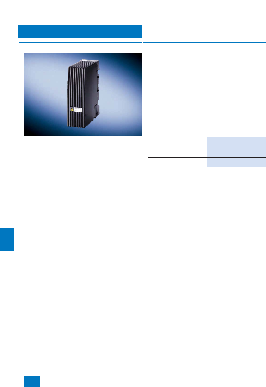
Process I/O
ET 200iSP distributed I/O
ET 200iSP power supply unit
11/32 Siemens ST PCS 7 · November 2007
11
■
Overview
ET 200iSP power supply unit is the designation for the combina-
tion of one (standard) or two redundant power supply modules
PS with the matching terminal module:
• Standard: TM-PS-A terminal module
• Redundancy: TM-PS-B terminal module (additionally)
Power supply modules and terminal modules must each be or-
dered separately.
Functions of the power supply modules
• They provide the ET 200iSP with the safely isolated operating
voltages for
- logic (via the backplane bus),
- PROFIBUS DP interface (IM 152-1),
- power bus (for powering the electronics modules).
• They handle the safety-related limitation of the output voltage.
• They have a pressurized metal enclosure (explosion protec-
tion EEx d).
• They can be operated in redundant mode.
■
Design
Depending on the operating mode (standard or redundant), one
or two power supply modules are plugged onto the correspond-
ing terminal modules. Hot swapping is also possible in the haz-
ardous area.
The operating status of the power supply modules is displayed
on two LEDs on the IM 152 interface module (one for each mod-
ule).
The 24 V DC supply for the station is provided via EX e terminals
on the terminal module of the power supply unit. This connection
must not be removed in the hazardous area. The feeding power
supply must be installed in the non-hazardous area.
The ET 200iSP must be terminated on the right-hand side (fol-
lowing the last electronics module) by a terminating module. The
terminating module is included in the scope of delivery of the
IM 152.
B) Subject to export regulations: AL: N, ECCN: EAR99H
■
Selection and Ordering Data Order No.
Power supply module PS for
ET 200iSP 6ES7 138-7EA01-0AA0
TM-PS-A terminal module
for standard operation 6ES7 193-7DA10-0AA0 B)
TM-PS-B terminal module
for redundant operation 6ES7 193-7DB10-0AA0 B)
© Siemens AG 2007
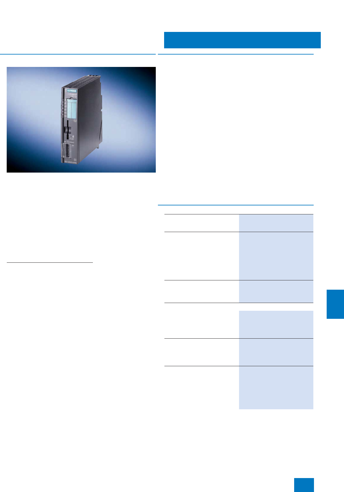
Process I/O
ET 200iSP distributed I/O
IM 152-1 interface module
11/33
Siemens ST PCS 7 · November 2007
11
■
Overview
The IM 152 interface module connects the ET 200iSP to the
PROFIBUS DP with intrinsically-safe RS 485-iS transmission
technology with transmission rates up to 1.5 Mbit/s. A redundant
connection is also possible. In this case the ET 200iSP is con-
nected via two interface modules to two redundant
PROFIBUS DP segments of a fault-tolerant automation system.
The IM 152 is plugged onto a special terminal module (to be or-
dered separately). The following terminal modules are available:
• TM-IM/EM60 terminal module for one interface module and
one electronics module (with screw-type or spring-loaded ter-
minals)
• TM-IM/IM terminal module for two interface modules (for re-
dundant PROFIBUS DP connection)
Tasks of the IM 152 interface module
• Connection of ET 200iSP to the intrinsically-safe
PROFIBUS DP
• Autonomous communication with the host automation system
• Preparation of data for the fitted electronic modules
• Saving of parameters of the electronics modules
• The IM 152 can assign a 20-ms time stamp to digital process
signals.
The maximum address space of the interface module is
244 bytes for inputs, and 244 bytes for outputs.
■
Design
The terminal module of the IM 152 (TM-IM/EM or TM-IM/IM) is
connected directly next to the power supply unit on the DIN rail.
The PROFIBUS DP connection of the IM 152 is made using the
standard Sub-D socket on the terminal module. The matching
connection element we provide is a special terminating plug with
selectable terminating resistance. The terminating resistance
must be activated on the last ET 200iSP station of each
PROFIBUS DP segment.
Hot swapping of the IM 152 and the PROFIBUS connector is per-
missible under hazardous conditions.
A terminating module is provided together with the IM 152, and
must be fitted at the right end of each ET 200iSP station following
the last electronics module.
The IM 152 has a slot for micro memory cards (MMC). The firm-
ware can therefore be updated either via the PROFIBUS DP or
using MMCs.
The PROFIBUS addresses can be set using DIL switches at the
front which are protected by a cover.
LEDs on the front of the IM 152 signal the supply voltage, group
faults, bus faults, the active IM with redundant operation, and the
operating state of the fitted power supply modules.
B) Subject to export regulations: AL: N, ECCN: EAR99H
For further accessories such as labeling strips or plates, see Catalog
IK PI or the A&D Mall/CA 01 under "ET 200iSP distributed I/O".
■
Selection and Ordering Data Order No.
IM 152-1 interface module for
ET 200iSP
incl. terminating module
6ES7 152-1AA00-0AB0
TM-IM/EM60 terminal module
for ET 200iSP
for one IM 152 module and one
electronics module
• TM-IM/EM60S (screw-type
terminals) 6ES7 193-7AA00-0AA0 B)
• TM-IM/EM60S (spring-loaded
terminals) 6ES7 193-7AA10-0AA0 B)
TM-IM/IM terminal module for
ET 200iSP
for two IM 152 modules
(redundant operation)
6ES7 193-7AB00-0AA0
Accessories
PROFIBUS connector with
selectable terminating resistor
for connection of IM 152 to
PROFIBUS DP with RS 485-iS
transmission technology
6ES7 972-0DA60-0XA0 B)
RS 485-IS coupler
Isolating transformer for connec-
tion of PROFIBUS DP segments
with RS 485 and RS 485-iS trans-
mission technologies
6ES7 972-0AC80-0XA0
S7-300 rails
• 585 mm long, suitable for
assembly of ET 200iSP in a
650-mm wide wall housing
6ES7 390-1AF85-0AA0
• 885 mm long, suitable for
assembly of ET 200iSP in a
950-mm wide wall housing
6ES7 390-1AJ85-0AA0
© Siemens AG 2007
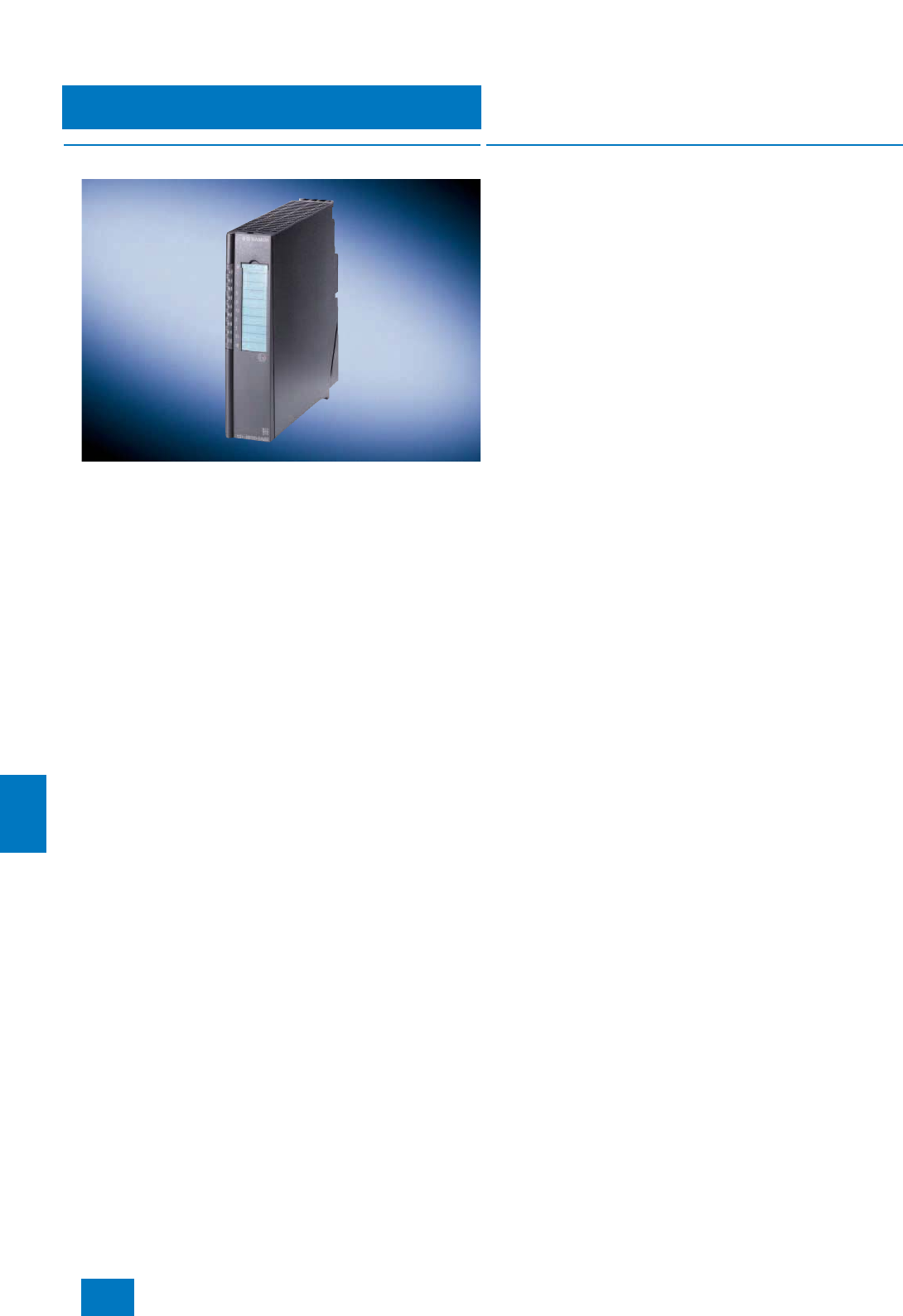
Process I/O
ET 200iSP distributed I/O
Electronics modules and watchdog module
11/34 Siemens ST PCS 7 · November 2007
11
■
Overview
Electronics modules
The current range of electronics modules covers:
• 8-channel digital input module DI NAMUR, can also be used
as counter or frequency meter
• 4-channel digital output module DO with external actuator
switch-off via High or Low signal (H/L switch-off)
• 4-channel analog input modules AI for temperature measure-
ments with resistance thermometer (RTD) or thermocouple
(TC)
• 4-channel analog input modules AI for connection of 2/4-wire
transmitters with or without HART functionality
• 4-channel analog output module AO for connection of field de-
vices with or without HART functionality
A TC sensor module for internal temperature compensation is
provided with the 4 AI TC module, and is fitted on the corre-
sponding terminals of the associated terminal module. External
compensation is possible for the 4 AI RTD module by connect-
ing a Pt100.
The DO modules have a switch-off function which is triggered by
an external signal (High or Low) from a switch-off device in the
hazardous area. This permits implementation of an external
switch-off independent of the automation system (controller). It
is also possible to combine several DO modules into a switch-off
group for this purpose. The intrinsically-safe power supply for
the switch-off device is either via the watchdog module or a sep-
arate intrinsically-safe source.
Watchdog module
The watchdog module has two fundamental functions:
• Monitoring of the ET 200iSP remote I/O station for hardware
failures (hardware lifebeat); external, applicative failure moni-
toring is also possible via an I/O address area of the module
• Intrinsically-safe power supply for external actuator switch-off
The watchdog module must be plugged onto a terminal module
(order separately). The first slot directly next to the interface
module is provided for the watchdog module. You can use the
same terminal modules for the watchdog module as for the elec-
tronics modules.
■
Design
• The electronics modules are plugged as planned onto the cor-
responding terminal modules using screw-type systems
(TM-EM/EM60S) or spring-loaded systems (TM-EM/EM60C).
The terminal modules must be ordered in addition.
• The mechanical coding of the terminal module which is car-
ried out when an electronics module is plugged on for the first
time prevents the connection of incorrect replacement mod-
ules.
• Hot swapping of individual modules is possible under hazard-
ous conditions.
• The process signals are connected to the terminals of the ter-
minal modules assigned according to the plan, using either
conventional screw-type or spring-loaded systems (conduc-
tor cross-sections 0.14 to max. 2.5 mm²) depending on the
type of module.
• All electronics modules are implemented in the EEx i "intrinsi-
cally safe" degree of protection and can be easily replaced
under hazardous conditions (hot swapping).
• Using a spare module plugged onto a terminal module for
electronics modules (TM-EM/EM60S/ TM-EM/EM60C), you
can reserve a slot for any electronics modules or close a gap
resulting from the design. The spare module can be simply re-
placed by the electronics module at a later point in time.
© Siemens AG 2007

Process I/O
ET 200iSP distributed I/O
Electronics modules and watchdog module
11/35
Siemens ST PCS 7 · November 2007
11
■
Selection and Ordering Data Order No.
Digital electronics modules
Digital input modules
8 DI NAMUR
For evaluation of NAMUR sen-
sors, connected/non-connected
contacts, as well as for recording
counter pulses or measuring fre-
quencies
• 8 x NAMUR (NAMUR sensor
on/off, NAMUR changeover
contact) or connected/
non-connected inputs
(single/changeover contact)
• 2 channels optionally usable as
counters (max. 5 kHz) or fre-
quency meters (1 Hz ... 5 kHz)
• Time tagging 5 ms, rising or fall-
ing edge
• Wire break monitoring
• Short-circuit monitoring
• Sensor power supply monitoring
• Flutter monitoring
6ES7 131-7RF00-0AB0 B)
Digital output module with
H switch-off
(external actuator switch-off via
H-signal);
for switching of solenoid valves,
DC relays, signal lamps, actua-
tors
4 DO DC 23.1 V/20 mA
• 4 channels with 20 mA each
• Short-circuit monitoring
• Wire break monitoring
• Parameterizable connection of
substitute value in case of CPU
failure
• Load-free switching of outputs
via external intrinsically-safe
signal
6ES7 132-7RD01-0AB0 B)
4 DO DC 17.4 V/27 mA
• 4 channels with 27 mA each or
• 2 outputs connected in parallel
with 54 mA each
• Short-circuit monitoring
• Wire break monitoring
• Parameterizable connection of
substitute value in case of CPU
failure
• Load-free switching of outputs
via external intrinsically-safe sig-
nal
6ES7 132-7RD11-0AB0
4 DO DC 17.4 V/40 mA
• 4 channels with 40 mA each or
• 2 outputs connected in parallel
with 80 mA each
• Short-circuit monitoring
• Wire break monitoring
• Parameterizable connection of
substitute value in case of CPU
failure
• Load-free switching of outputs
via external intrinsically-safe sig-
nal
6ES7 132-7RD21-0AB0
Digital output module with
L switch-off
(external actuator switch-off via
L-signal);
for switching of solenoid valves,
DC relays, signal lamps, actua-
tors
4 DO DC 23.1 V/20 mA
• 4 channels with 20 mA each
• Short-circuit monitoring
• Wire break monitoring
• Parameterizable connection of
substitute value in case of CPU
failure
• Load-free switching of outputs
via external intrinsically-safe
signal
6ES7 132-7GD00-0AB0 B)
4 DO DC 17.4 V/27 mA
• 4 channels with 27 mA each or
• 2 outputs connected in parallel
with 54 mA each
• Short-circuit monitoring
• Wire break monitoring
• Parameterizable connection of
substitute value in case of CPU
failure
• Load-free switching of outputs
via external intrinsically-safe sig-
nal
6ES7 132-7GD10-0AB0
4 DO DC 17.4 V/40 mA
• 4 channels with 40 mA each or
• 2 outputs connected in parallel
with 80 mA each
• Short-circuit monitoring
• Wire break monitoring
• Parameterizable connection of
substitute value in case of CPU
failure
• Load-free switching of outputs
via external intrinsically-safe sig-
nal
6ES7 132-7GD20-0AB0
B) Subject to export regulations: AL: N, ECCN: EAR99H
■
Selection and Ordering Data Order No.
© Siemens AG 2007
Process I/O
ET 200iSP distributed I/O
Electronics modules and watchdog module
11/36 Siemens ST PCS 7 · November 2007
11
B) Subject to export regulations: AL: N, ECCN: EAR99H
For further accessories such as labeling strips or plates, see Catalog
IK PI or the A&D Mall/CA 01 under "ET 200iSP distributed I/O".
Analog electronics modules
Analog input modules
4 AI I 2 WIRE HART
For measuring currents with
2-wire transmitters with/without
HART functionality
• 4 x 4 ... 20 mA, HART, 2-wire
transmitter
• Transmitter load: max. 750 Ω
• Resolution 12 bit + sign
• Short-circuit monitoring
• Wire break monitoring
6ES7 134-7TD00-0AB0 B)
4 AI I 4 WIRE HART
For measuring currents with
4-wire transmitters with/without
HART functionality
• 4 x 0/4 ... 20 mA, HART, 4-wire
transmitter
• Transmitter load: max. 750 Ω
• Resolution 12 bit + sign
• Wire break monitoring
6ES7 134-7TD50-0AB0
4 AI RTD
For measuring resistances as well
as for temperature measurements
with resistance thermometers
• 4 x RTD, resistance thermometer
Pt100/Ni100
• 2-, 3-, 4-wire
• Resolution 15 bit + sign
• Short-circuit monitoring
• Wire break monitoring
6ES7 134-7SD50-0AB0
4 AI TC
For measuring thermal e.m.f. as
well as for temperature measure-
ments with thermocouples
• 4 x TC (thermocouples)
• Type B [PtRh-PtRh]
• Type N [NiCrSi-NiSi]
• Type E [NiCr-CuNi]
• Type R [PtRh-Pt]
• Type S [PtPh-Pt]
• Type J [Fe-CuNi]
• Type L [Fe-CuNi]
• Type T [Cu-CuNi]
• Type K [NiCr-Ni]
• Type U [Cu-CuNi]
• Resolution 15 bit + sign
• Internal temperature compensa-
tion possible using TC sensor
module (included in scope of
delivery of module)
• External temperature compen-
sation via PT100 connected to
RTD module of same ET 200iSP
station
• Wire break monitoring
6ES7 134-7SD00-0AB0
■
Selection and Ordering Data Order No.
Analog output modules
4 AO I HART
For output of currents to field
devices with/without HART func-
tionality
• 4 x 0/4 ... 20 mA, HART
(max. load 750 Ω)
• Resolution 14 bit
• Short-circuit monitoring
• Wire break monitoring
• Parameterizable substitute val-
ue in case of CPU failure
6ES7 135-7TD00-0AB0 B)
Watchdog module
For failure monitoring and for the
intrinsically-safe power supply of
an external actuator switch-off
6ES7 138-7BB00-0AB0 B)
Terminal modules
TM-EM/EM60S terminal module
for ET 200iSP
For two electronics modules,
screw terminals
6ES7 193-7CA00-0AA0 B)
TM-EM/EM60C terminal module
for ET 200iSP
For two electronics modules,
spring-loaded terminals
6ES7 193-7CA10-0AA0 B)
Accessories
Reserve module
For any electronics module 6ES7 138-7AA00-0AA0 B)
S7-300 rail
• 585 mm long, suitable for
assembly of ET 200iSP in a
650-mm wide wall housing
6ES7 390-1AF85-0AA0
• 885 mm long, suitable for
assembly of ET 200iSP in a
950-mm wide wall housing
6ES7 390-1AJ85-0AA0
■
Selection and Ordering Data Order No.
© Siemens AG 2007
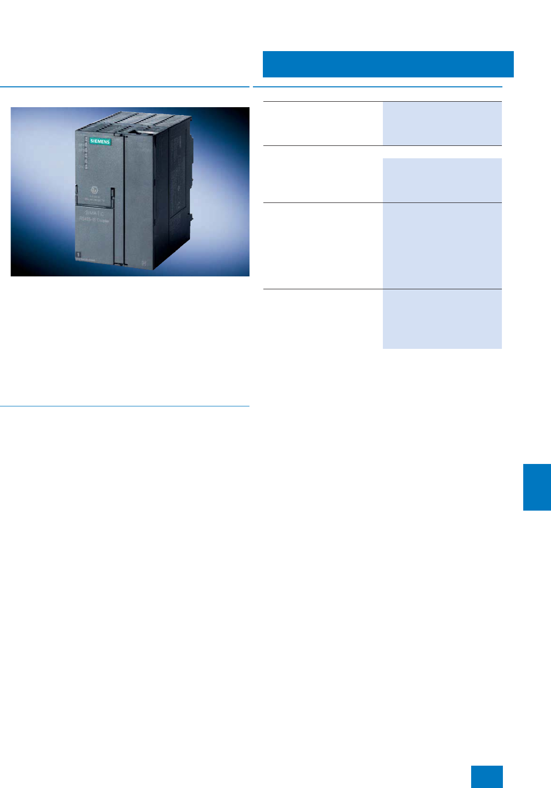
Process I/O
ET 200iSP distributed I/O
RS 485-IS coupler
11/37
Siemens ST PCS 7 · November 2007
11
■
Overview
Tasks of the RS 485-iS coupler
• Conversion of the electrical PROFIBUS DP RS 485 transmis-
sion technology into the intrinsically-safe RS 485-iS transmis-
sion technology with a transmission rate of 1.5 Mbit/s
• Required to connect intrinsically-safe PROFIBUS DP stations,
e.g. ET 200iSP, ET 200iS or devices from other vendors with
Ex i DP connection
• Functionality as a safety barrier
• Additional use as a repeater in the hazardous area
• Passive bus station (no configuration necessary)
• Certified according to ATEX 100a
■
Design
• The RS 485-iS coupler is an open unit; assembly is only per-
missible in housings, cabinets or rooms for electrical equip-
ment.
• The RS 485-iS coupler is approved for use in hazardous areas
of zone 2.
It must be fitted in a housing which at least corresponds to the
IP54 degree of protection. A manufacturer’s declaration for
zone 2 (according to EN 50021) is required for the housing
and the necessary cable glands.
• The RS 485-iS coupler can be used in a horizontal or vertical
position.
• Installation is on a SIMATIC S7-300 rail.
• Diagnostics LEDs on the front panel signal the operating sta-
tus.
Connection to PROFIBUS DP
• Connection to standard PROFIBUS DP via standard Sub-D
socket (at the bottom on the RS 485-iS coupler, behind the
right front door).
Integral bus connection for PROFIBUS DP with RS 485-iS
transmission technology
• Connection of PROFIBUS DP with RS 485-iS transmission
technology via screw terminals (at the top of the RS 485-iS
coupler, behind the right front door)
• The last bus station on the intrinsically-safe PROFIBUS DP
segment (not further RS 485-iS couplers) must be terminated
by a selectable resistance using the connector, Order No.
6ES7 972-0DA60-0XA0.
B) Subject to export regulations: AL: N, ECCN: EAR99H
■
Selection and Ordering Data Order No.
RS 485-IS coupler
Isolating transformer for connec-
tion of PROFIBUS DP segments
with RS 485 and RS 485-iS trans-
mission technologies
6ES7 972-0AC80-0XA0
Accessories
PROFIBUS connector with
selectable terminating resistor
For connection of IM 152 to
PROFIBUS DP with RS 485-iS
transmission technology
6ES7 972-0DA60-0XA0 B)
S7-300 rails
Lengths:
•160 mm 6ES7 390-1AB60-0AA0
•482 mm 6ES7 390-1AE80-0AA0
•530 mm 6ES7 390-1AF30-0AA0
•830 mm 6ES7 390-1AJ30-0AA0
• 2000 mm 6ES7 390-1BC00-0AA0
PROFIBUS Fast Connect bus
cable
Standard type with special design
for fast mounting, 2-core,
shielded, cut-to-length; max.
delivery unit 1000 m, minimum
ordering quantity 20 m
6XV1 830-0EH10
© Siemens AG 2007
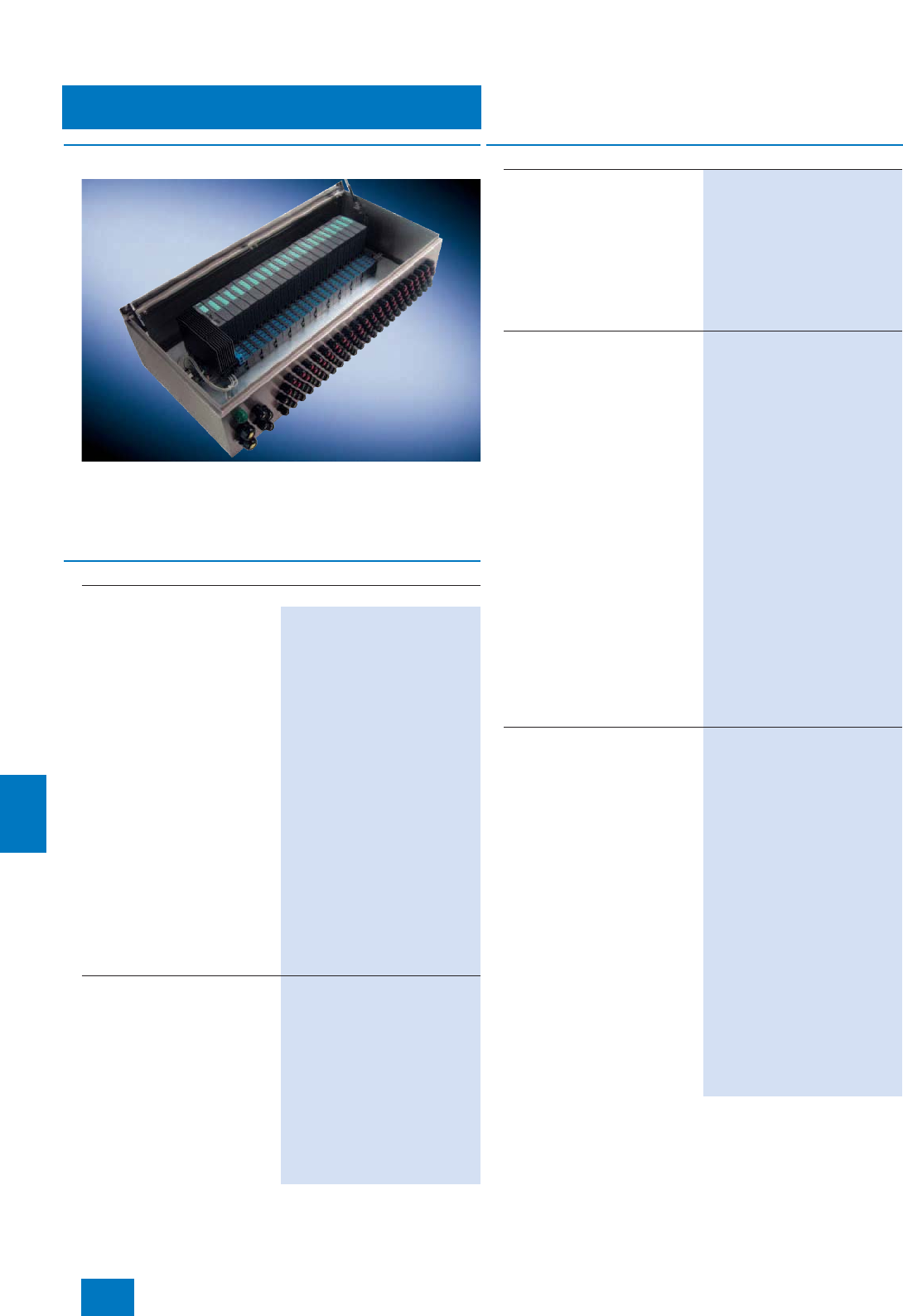
Process I/O
ET 200iSP distributed I/O
Stainless steel wall enclosure
11/38 Siemens ST PCS 7 · November 2007
11
■
Design
ET 200iSP modules can also be installed in stainless steel wall
housings designed to meet more exacting protection require-
ments. The housings are available in three different sizes. They
comply with degree of protection IP65 and can also be used in
Ex zone 1.
1) The ET 200iSP components have to be ordered separately
■
Selection and Ordering Data Order No.
Stainless steel housing IP65 for Ex zone 1 in protection class EEx e
Empty housing without installa-
tion of modules, for use in gas-
eous area, IP65
• Wall housing 650 x 450 x 230, for
installation of max. 15 ET 200iSP
modules, for use in gaseous ar-
ea, with 3 rows of M16 cable
glands (total 41) and 2 rows of
blanking plugs
6DL2 804-0AD30
• Wall housing 650 x 450 x 230, for
installation of max. 15 ET 200iSP
modules, for use in gaseous ar-
ea, with 5 rows of M16 cable
glands (total 66)
6DL2 804-0AD50
• Wall housing 950 x 450 x 230, for
installation of max. 25 ET 200iSP
modules, for use in gaseous ar-
ea, with 3 rows of M16 cable
glands (total 68) and 2 rows of
blanking plugs
6DL2 804-0AE30
• Wall housing 950 x 450 x 230, for
installation of max. 25 ET 200iSP
modules, for use in gaseous ar-
ea, with 5 rows of M16 cable
glands (total 111)
6DL2 804-0AE50
Empty housing without installa-
tion of modules, for use in
dusty area, IP65
• Wall housing 650 x 450 x 230, for
installation of max. 15 ET 200iSP
modules, for use in dusty area,
with 3 rows of M16 cable glands
(total 41) and 2 rows of blanking
plugs
6DL2 804-0DD30
• Wall housing 650 x 450 x 230, for
installation of max. 15 ET 200iSP
modules, for use in dusty area,
with 5 rows of M16 cable glands
(total 66)
6DL2 804-0DD50
• Wall housing 950 x 450 x 230, for
installation of max. 25 ET 200iSP
modules, for use in dusty area,
with 3 rows of M16 cable glands
(total 68) and 2 rows of blanking
plugs
6DL2 804-0DE30
• Wall housing 950 x 450 x 230, for
installation of max. 25 ET 200iSP
modules, for use in dusty area,
with 5 rows of M16 cable glands
(total 111)
6DL2 804-0DE50
Housing with installation of ET
200iSP modules, for use in gas-
eous area, IP65 (IP54 when
using an air-conditioning noz-
zle) 1)
• Wall housing 650 x 450 x 230, for
installation of max. 15 ET 200iSP
modules, for use in gaseous ar-
ea, with 3 rows of M16 cable
glands (total 41) and 2 rows of
blanking plugs
6DL2 804-1AD30
• Wall housing 650 x 450 x 230, for
installation of max. 15 ET 200iSP
modules, for use in gaseous ar-
ea, with 5 rows of M16 cable
glands (total 66)
6DL2 804-1AD50
• Wall housing 950 x 450 x 230, for
installation of max. 25 ET 200iSP
modules, for use in gaseous ar-
ea, with 3 rows of M16 cable
glands (total 68) and 2 rows of
blanking plugs
6DL2 804-1AE30
• Wall housing 950 x 450 x 230, for
installation of max. 25 ET 200iSP
modules, for use in gaseous ar-
ea, with 5 rows of M16 cable
glands (total 111)
6DL2 804-1AE50
Housing with installation of
modules, for use in dusty area,
IP65 1)
• Wall housing 650 x 450 x 230, for
installation of max. 15 ET 200iSP
modules, for use in dusty area,
with 3 rows of M16 cable glands
(total 41) and 2 rows of blanking
plugs
6DL2 804-1DD30
• Wall housing 650 x 450 x 230, for
installation of max. 15 ET 200iSP
modules, for use in dusty area,
with 5 rows of M16 cable glands
(total 66)
6DL2 804-1DD50
• Wall housing 950 x 450 x 230, for
installation of max. 25 ET 200iSP
modules, for use in dusty area,
with 3 rows of M16 cable glands
(total 68) and 2 rows of blanking
plugs
6DL2 804-1DE30
• Wall housing 950 x 450 x 230, for
installation of max. 25 ET 200iSP
modules, for use in dusty area,
with 5 rows of M16 cable glands
(total 111)
6DL2 804-1DE50
■
Selection and Ordering Data Order No.
© Siemens AG 2007
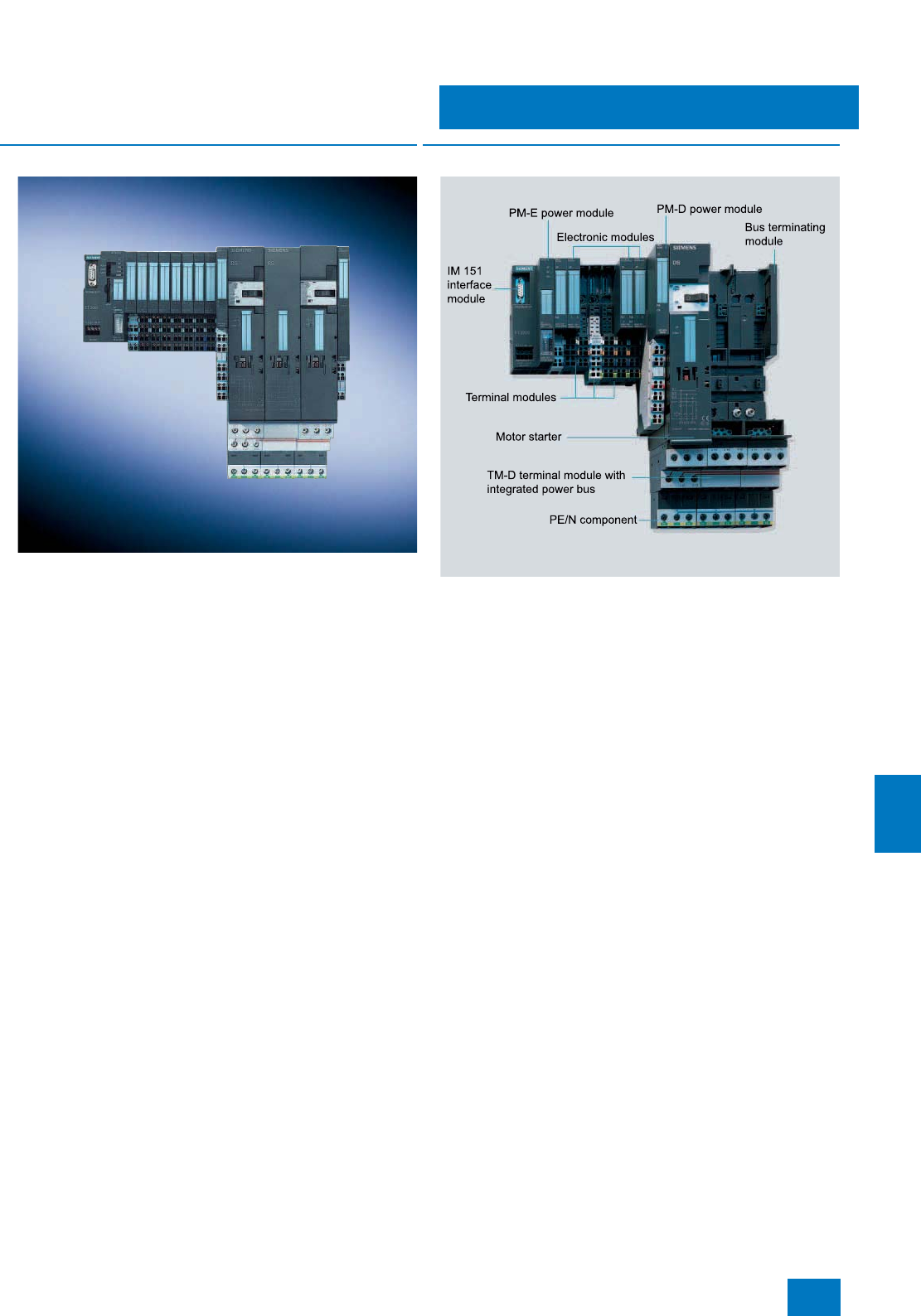
Process I/O
ET 200S distributed I/O
Introduction
11/39
Siemens ST PCS 7 · November 2007
11
■
Overview
The ET 200S is a bit-modular distributed I/O system in IP 20 de-
gree of protection and is approved for operation in Ex zone 2
or 22 (except for operation with motor starters). It is designed
with independent wiring that supports the hot swapping of I/O
modules (with fire certificate).
The range of I/Os that can be used with SIMATIC PCS 7 includes
power modules for electronics modules and motor starters, ana-
log and digital signal modules, and motor starters up to 7.5 kW.
The implementation of safety engineering applications is sup-
ported by:
• Safety-related F-components which are integrated in the SI-
MATIC Safety Integrated System, e.g. terminal, power and
electronics modules as well as motor starters
• SIGUARD safety engineering for motor starter applications
with conventional safety logic in plants of safety categories
2 to 4 (EN 954-1)
Note:
In addition to the selected modules, all other current ET 200S
electronics modules can be used, but with limited functionality.
Use of components from the SIPLUS extreme range in extended
temperature ranges and under medial loading on request.
■
Design
Main components of the ET 200S distributed I/O system:
•Terminal modules enable the electrical and mechanical con-
nection of the I/O modules and carry the terminals for the pro-
cess wiring:
- TM-P terminal modules for power modules
- TM-E terminal modules for electronics modules
- TM-DS/TM-RS terminal modules for motor starters and
TM-xB expansion modules
•IM 151 interface module for connecting the PROFIBUS DP to
the ET 200S station. The terminal module is included in the
scope of delivery.
•Power modules for PM-E electronics modules and PM-D mo-
tor starters
- Individual grouping of load and sensor supply voltages and
their monitoring, as well as
for the safe shutting down of digital output modules
- Supplying and monitoring the auxiliary voltages for motor
starters, as well as for the shutting down of a complete group
of motor starters
•Electronics modules for process data exchange
- Digital electronics modules for connecting digital sensors
and actuators
- Analog electronics modules for connecting analog sensors
and actuators
•Motor starter modules for switching and protecting any
three-phase loads
•Accessories
- Reserve module for reserving a slot for any electronics mod-
ule
- Label sheets for printing ID labels on a laser printer
- Shield connection: shield connecting element, shield termi-
nal, ground terminal, copper voltage bus 3 x 10 mm;
components for the low-impedance connection of cable
shielding at low cost of installation
© Siemens AG 2007

Process I/O
ET 200S distributed I/O
Introduction
11/40 Siemens ST PCS 7 · November 2007
11
Mounting
The terminal modules that can be mounted on a DIN rail (35 x
15 x 7.5 or 15 mm) form the carrier system for the I/O modules.
They are used for the process wiring and enable the electrical
and mechanical connection of the I/O modules. The terminal
modules can be prewired and tested without the I/O modules.
The I/O modules are simply plugged in place later. Terminal
modules are available with screw connections, spring-loaded
terminals or FastConnect design for fast mounting.
The automatic coding of the I/O modules reliably prevents the
risk of injury to persons and/or destruction of modules through
accidental mounting of the wrong module.
Expansion limits
Depending on the IM 151 interface module used, the expansion
of an ET 200S station is subject to the following limits:
• A maximum total of 63 I/O modules per station can be inserted
between interface module and terminating module
• The maximum permissible width of an ET 200S station is 2 m
• The maximum address volume of all the inserted I/O modules
is 244 byte for input data and 244 byte for output data
• The maximum number of parameters is restricted to 244 byte
per station
ET 200S configuration
The SIMATIC ET 200 configurator can be used to compile an
ET 200S station rapidly and simply. It knows the configuration
rules, and supports selection of all components and associated
accessories in interactive mode. The SIMATIC ET 200 is avail-
able in the current CD-ROM Catalog CA 01 and on the Internet.
Additional information is available in the Internet under:
http://www.siemens.com/et200
■
ATechnical specifications
Detailed technical data on the ET 200S can be found
• in the IK PI catalog or
• in the Mall / CA 01 at "Distributed I/Os / ET 200S“
© Siemens AG 2007
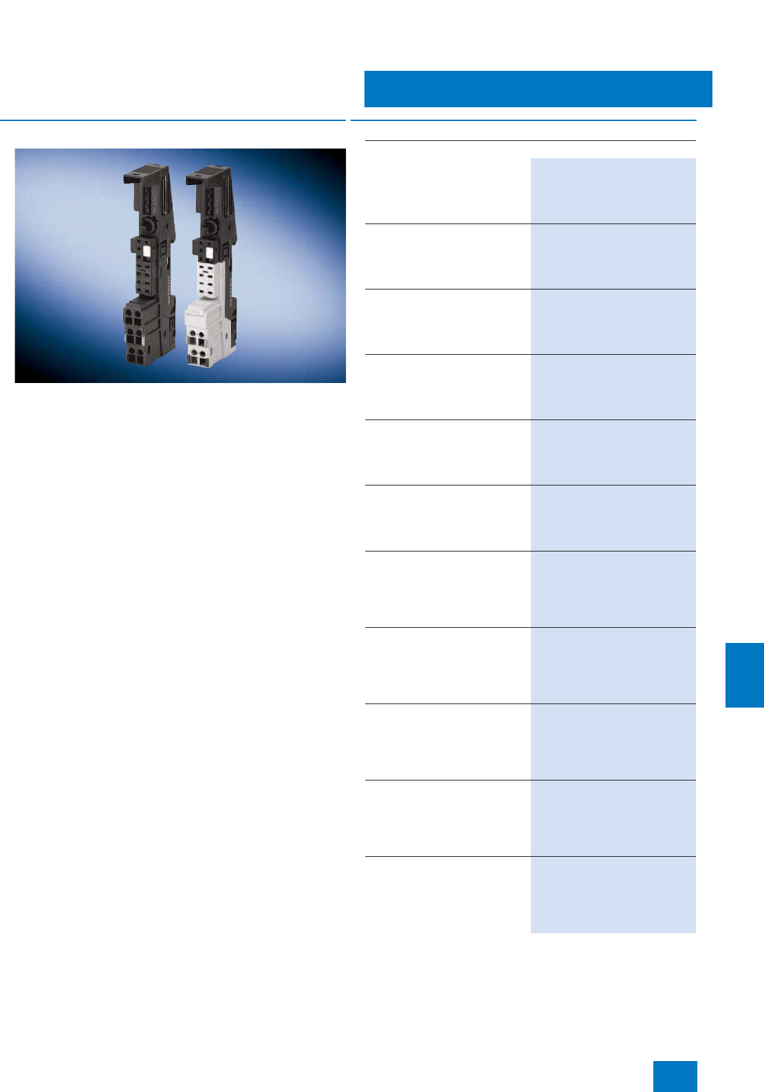
Process I/O
ET 200S distributed I/O
Terminal modules
11/41
Siemens ST PCS 7 · November 2007
11
■
Overview
• Terminal modules are mechanical modules for integrating the
power and electronics modules as well as the motor starters
and expansion modules (Ordering data of the terminal mod-
ules for motor starters and expansion modules can be found
under "Motor starters")
• For constructing the independent wiring using self-assem-
bling voltage buses
• Alternatively with screw-type or spring-loaded terminals and
Fast Connect design
• Replaceable terminal box
• Automatic coding of the electronics modules
• Build-as-you-go shielding of the backplane bus for high data
security
• Optional plug-in shield connection
• Color coding facility for the terminals and for identifying the
slot numbers
■
Selection and Ordering Data Order No.
Terminal Modules TM-P for Power Modules
TM-P15S23-A1 Terminal Module
2 x 3 terminals, terminal access to
AUX1 bus, AUX1 interconnected
to the left, screw-type terminals
Ordering unit 1 piece
6ES7 193-4CC20-0AA0
TM-P15C23-A1 Terminal Module
2 x 3 terminals, terminal access to
AUX1 bus, AUX1 interconnected
to the left, spring-type terminals
Ordering unit 1 piece
6ES7 193-4CC30-0AA0
TM-P15N23-A1 Terminal Module
2 x 3 terminals, terminal access to
AUX1 bus, AUX1 interconnected
to the left, Fast Connect
Ordering unit 1 piece
6ES7 193-4CC70-0AA0
TM-P15S23-A0 Terminal Module
2 x 3 terminals, terminal access to
AUX1 bus, AUX1 interrupted to
the left, screw-type terminals
Ordering unit 1 piece
6ES7 193-4CD20-0AA0
TM-P15C23-A0 Terminal Module
2 x 3 terminals, terminal access to
AUX1 bus, AUX1 interrupted to
the left, spring-type terminals
Ordering unit 1 piece
6ES7 193-4CD30-0AA0
TM-P15N23-A0 Terminal Module
2 x 3 terminals, terminal access to
AUX1 bus, AUX1 interrupted to
the left, Fast Connect
Ordering unit 1 piece
6ES7 193-4CD70-0AA0
TM-P15S22-01 Terminal Module
2 x 2 terminals, no terminal
access to AUX1 bus, AUX1 inter-
connected to the left, screw-type
terminals
Ordering unit 1 piece
6ES7 193-4CE00-0AA0
TM-P15C22-01 Terminal Module
2 x 2 terminals, no terminal
access to AUX1 bus, AUX1 inter-
connected to the left, spring-
loaded terminals
Ordering unit 1 piece
6ES7 193-4CE10-0AA0
TM-P15N22-01 Terminal Module
2 x 2 terminals, no terminal
access to AUX1 bus, AUX1 inter-
connected to the left, Fast Con-
nect
Ordering unit 1 piece
6ES7 193-4CE60-0AA0
TM-P30S44-A0 Terminal Module
7 x 2 terminals, terminal access to
AUX1 bus, AUX1 interrupted to
the left, screw-type terminals for
PM-E F PROFIsafe
Ordering unit 1 piece
6ES7 193-4CK20-0AA0
TM-P30C44-A0 Terminal Module
7 x 2 terminals, terminal access to
AUX1 bus, AUX1 interrupted to
the left, spring-loaded terminals
for PM-E F PROFIsafe
Ordering unit 1 piece
6ES7 193-4CK30-0AA0
© Siemens AG 2007
Process I/O
ET 200S distributed I/O
Terminal modules
11/42 Siemens ST PCS 7 · November 2007
11
Accessories for the terminal modules, see the IK PI catalog or
A&D Mall / CA 01 at "Distributed I/Os / ET 200S"
TM-E Terminal Modules for Electronic Modules
TM-E15S24-A1 Terminal Module
2 x 4 terminals, terminal access to
AUX1 bus, AUX1 interconnected
to the left, screw-type terminals
Ordering unit 5 pieces
6ES7 193-4CA20-0AA0
TM-E15C24-A1 Terminal Module
2 x 4 terminals, terminal access to
AUX1 bus, AUX1 interconnected
to the left, spring-type terminals
Ordering unit 5 pieces
6ES7 193-4CA30-0AA0
TM-E15N24-A1 Terminal Module
2 x 4 terminals, terminal access to
AUX1 bus, AUX1 interconnected
to the left, Fast Connect
Ordering unit 5 pieces
6ES7 193-4CA70-0AA0
TM-E15S24-01 Terminal Module
2 x 4 terminals, no terminal
access to AUX1 bus, AUX1 inter-
connected to the left, screw-type
terminals
Ordering unit 5 pieces
6ES7 193-4CB20-0AA0
TM-E15C24-01 Terminal Module
2 x 4 terminals, no terminal
access to AUX1 bus, AUX1 inter-
connected to the left, spring-
loaded terminals
Ordering unit 5 pieces
6ES7 193-4CB30-0AA0
TM-E15N24-01 Terminal Module
2 x 4 terminals, no terminal
access to AUX1 bus, AUX1 inter-
connected to the left, Fast Con-
nect
Ordering unit 5 pieces
6ES7 193-4CB70-0AA0
TM-E15S23-01 Terminal Module
2 x 3 terminals, no terminal
access to AUX1 bus, AUX1 inter-
connected to the left, screw-type
terminals
Ordering unit 5 pieces
6ES7 193-4CB00-0AA0
TM-E15C23-01 Terminal Module
2 x 3 terminals, no terminal
access to AUX1 bus, AUX1 inter-
connected to the left, spring-
loaded terminals
Ordering unit 5 pieces
6ES7 193-4CB10-0AA0
TM-E15N23-01 Terminal Module
2 x 3 terminals, no terminal
access to AUX1 bus, AUX1 inter-
connected to the left, Fast Con-
nect
Ordering unit 5 pieces
6ES7 193-4CB60-0AA0
TM-E15N26-A1 Terminal Module
2 x 6 terminals, terminal access to
AUX1 bus, AUX1 interconnected
to the left, Fast Connect
Ordering unit 5 pieces
6ES7 193-4CA80-0AA0
TM-E15S26-A1 Terminal Module
2 x 6 terminals, terminal access to
AUX1 bus, AUX1 interconnected
to the left, screw-type terminals
Ordering unit 5 pieces
6ES7 193-4CA40-0AA0
TM-E15C26-A1 Terminal Module
2 x 6 terminals, terminal access to
AUX1 bus, AUX1 interconnected
to the left, spring-type terminals
Ordering unit 5 pieces
6ES7 193-4CA50-0AA0
■
Selection and Ordering Data Order No.
TM-E30S44-01 Terminal Module
4 x 4 terminals, no terminal
access to AUX1 bus, AUX1 inter-
connected to the left, screw-type
terminals
Ordering unit 1 piece
6ES7 193-4CG20-0AA0
TM-E30C44-01 Terminal Module
4 x 4 terminals, no terminal
access to AUX1 bus, AUX1 inter-
connected to the left, spring-
loaded terminals
Ordering unit 1 piece
6ES7 193-4CG30-0AA0
TM-E30S46-A1 Terminal Module
4 x 6 terminals, terminal access to
AUX1 bus, AUX1 interconnected
to the left, screw-type terminals
Ordering unit 1 piece
6ES7 193-4CF40-0AA0
TM-E30C46-A1 Terminal Module
4 x 6 terminals, terminal access to
AUX1 bus, AUX1 interconnected
to the left, spring-type terminals
Ordering unit 1 piece
6ES7 193-4CF50-0AA0
TM-E15S24-AT Terminal Module
For internal temperature compen-
sation with 2AI TC High Feature,
screw-type terminals
Ordering unit 1 piece
6ES7 193-4CL20-0AA0
TM-E15C24-AT Terminal Module
For internal temperature compen-
sation with 2AI TC High Feature,
spring-loaded terminals
Ordering unit 1 piece
6ES7 193-4CL30-0AA0
■
Selection and Ordering Data Order No.
© Siemens AG 2007
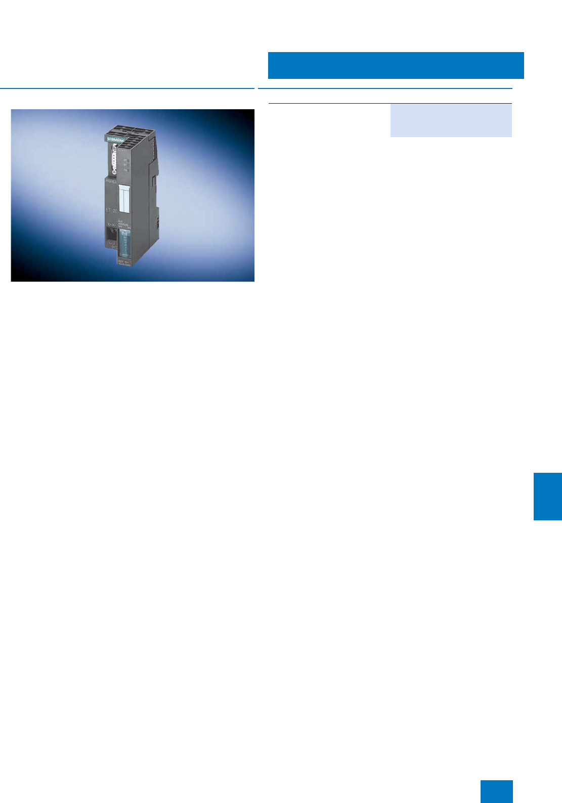
Process I/O
ET 200S distributed I/O
Interface modules
11/43
Siemens ST PCS 7 · November 2007
11
■
Overview
• IM 151-1 high feature (RS 485)
• Interface module for electrical connection of the ET 200S to
PROFIBUS DP using copper bus cables
• Handles all data exchange with the PROFIBUS DP master
■
Selection and Ordering Data Order No.
IM151-1 interface module
for ET 200S, High Feature 6ES7 151-1BA02-0AB0 B)
B) Subject to export regulations: AL: N, ECCN: EAR99H
© Siemens AG 2007
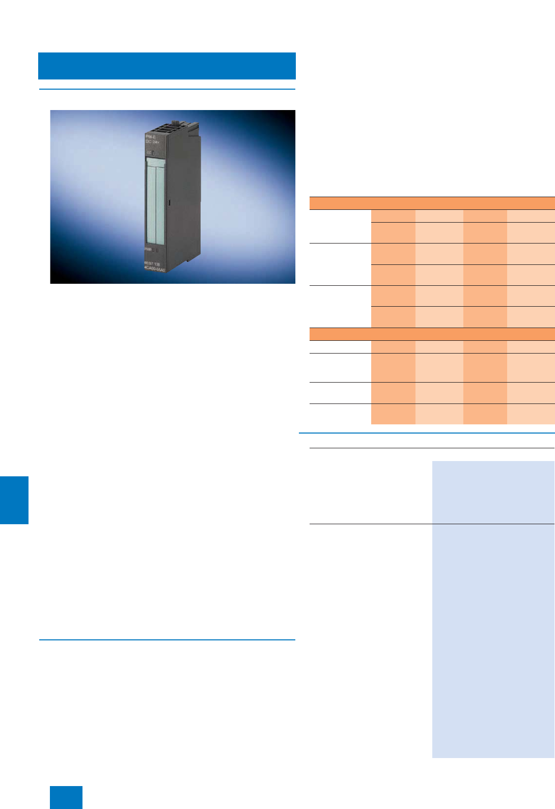
Process I/O
ET 200S distributed I/O
Power modules
11/44 Siemens ST PCS 7 · November 2007
11
■
Overview
PM-E power modules
• For all types of electronic modules (including safety-oriented
electronic modules); limitations resulting from power supply
with PM-E DC 24 V
• For monitoring and, depending on the version, fusing the volt-
age to electronic modules provided via the TM-P terminal
module (load and sensor supply voltage)
• Diagnostics message for voltage and blown fuse (can be
switched off per configuration)
• Two versions with different supply voltages:
- PM-E DC 24 V (not for 2 DI AC 120 V, 2 DI AC 230 V and
2 DO AC 24 to 230 V)
- PM-E DC 24 to 48 V; AC 24 to 230 V; with additional fuse
PM-E F power modules
• For all non-safety-oriented types of electronic modules with
24 V DC supply
• For monitoring the voltage to electronic modules provided via
the TM-P terminal module (load and sensor supply voltage)
• For safe switching off of series-connected standard digital
output modules 24 V DC (up to 10 A) via relay contacts (up to
Cat. 3 according to EN 954 or SIL 2 according to IEC 61508):
- 2 DO / 0.5 A standard, 6ES7 132-4BB01-0AA0
- 2 DO / 2 A standard, 6ES7 132-4BB31-0AA0
- 2 DO / 0.5 A high feature, 6ES7 132-4BB01-0AB0
- 2 DO / 2 A high feature, 6ES7 132-4BB31-0AB0
- 4 DO / 0.5 A standard, 6ES7 132-4BD01-0AA0
- 4 DO / 2 A standard, 6ES7 132-4BD31-0AA0
• Two versions:
- PM-E F pm DC 24 V PROFIsafe for ungrounded loads (sep-
arate ground and earth); with two additional safety-oriented
digital outputs (p/m switching, up to Cat. 4 / SIL 3)
- PM-E F pp DC 24 V PROFIsafe for grounded loads (ground
and earth connected), e.g. actuators for connection to a
central ground
■
Design
Depending on the possible combinations listed in the table, the
power modules are plugged onto corresponding TM-P terminal
modules. Power modules are suitable for dividing the ET 200S
into potential groups. A power module must be provided at the
beginning of each potential group. In addition, the first module
following the IM 151-1 High Feature interface module must al-
ways be a power module.
The TM-P terminal module of the power module interrupts the
voltage buses (P1/P2) and therefore opens up a new potential
group. All sensor and load supplies of the downstream electron-
ics modules are fed from the TM-P and monitored by the power
module. The total current of all modules of a potential group is
limited by the maximum current carrying capacity of the power
module (up to 10 A depending on the voltage and temperature
range; for details, refer to the technical specifications of the
power modules in Catalog IK PI).
Possible combinations of the TM-P terminal modules and
PM-E power modules
TM-P terminal modules for power modules
Screw-type
terminal
6ES7 193-...
15S23-A1 15S23-A0 15S22-01 30S44-A0
...4CC20 -
0AA0 ...4CD20 -
0AA0 ...4CE00-
0AA0 ...4CK20-
0AA0
Spring terminal
6ES7 193-...
TM-
P15C23-A1 TM-
P15C23-A0 TM-
P15C22-01 TM-
P30C44-A0
...4CC30 -
0AA0 ...4CD30 -
0AA0 ...4CE10-
0AA0 ...4CK30-
0AA0
Fast Connect
6ES7 193-...
TM-
P15N23-A1 TM-
P15N23-A0 TM-
P15N22-01 --
...4CC70 -
0AA0 ...4CD70 -
0AA0 ...4CE60-
0AA0
Power modules
PM-E DC 24 V • • •
PM-E
DC 24 ... 48 V/
AC 24 ... 230 V
• • •
PM-E F DC 24 V
PROFIsafe •
PM-D F DC 24 V
PROFIsafe •
■
Selection and Ordering Data Order No.
Power module PM-E for electronics modules
Power module PM-E
• 24 V DC / 10 A
- Monitoring of the load voltage 6ES7 138-4CA01-0AA0 B)
• 24 ... 48 V DC; 24 ... 230 V AC
- Monitoring of the fuse
- Monitoring of the load voltage
6ES7 138-4CB11-0AB0 B)
Power module PM-E F
• PM-E F pm DC 24 V PROFIsafe
- 1 x relay 24 V DC/10 A,
P/M-switching, for switching-
off series-connected standard
digital output modules (up to
AK 4, SIL 2)
- 2 x 24 V DC/2 A, P/M-switch-
ing, with wire breakage moni-
toring by channel
(with "1" signal)
- Safe monitoring of communi-
cation with PROFIsafe
- Diagnostics inside module
- Overload diagnostics by chan-
nel
6ES7 138-4CF02-0AB0 B)
• PM-E F pp DC 24 V PROFIsafe
- 1 x relay 24 V DC/10 A,
P/P-switching, for switching-off
series-connected standard
digital output modules (up to
AK 4, SIL 2)
- Safe monitoring of communi-
cation with PROFIsafe
- Diagnostics inside module
- Overload diagnostics by chan-
nel
6ES7 138-4CF41-0AB0 B)
B) Subject to export regulations: AL: N, ECCN: EAR99H
© Siemens AG 2007
Process I/O
ET 200S distributed I/O
Digital electronics modules
11/45
Siemens ST PCS 7 · November 2007
11
■
Overview
• 2- and 4-channel digital inputs and outputs for the ET 200S
• Can be plugged onto TM-E terminal modules with automatic
coding.
• High-feature versions for enhanced plant availability, addi-
tional functions and comprehensive diagnostics
• Hot swapping of modules possible
• Safety-related digital input module 4/8 F-DI PROFIsafe
• Safety-related digital output module 4 F-DO PROFIsafe
24 V DC/2 A
• Isolated from the backplane bus
■
Design
Possible combinations of the TM-E terminal modules and digital modules
1) See Manual "ET 200S failsafe modules" in the documentation packages "S7 F Systems" and "S7 Distributed Safety"
TM-E terminal modules for electronics modules
Screw-type terminal
Order No. 6ES7 193...
TM-E15S26-
A1
…4CA40-
0AA0
TM-E15S24-
A1
…4CA20-
0AA0
TM-E15S24-
01
…4CB20-
0AA0
TM-E15S23-
01
…4CB00-
0AA0
TM-E15S24-
AT
…4CL20-0AA0
TM-E30S44-
01
…4CG20-
0AA0
TM-E30S46-
A1
…4CF40-0AA0
Spring terminal
Order No. 6ES7 193...
TM-E15C26-
A1
…4CA50-
0AA0
TM-E15C24-
A1
…4CA30-
0AA0
TM-E15C24-
01
…4CB30-
0AA0
TM-E15C23-
01
…4CB10-
0AA0
TM-E15C24-
AT
…4CL30-0AA0
TM-E30C44-
01
…4CG30-
0AA0
TM-E30C46-
A1
…4CF50-0AA0
Fast Connect
Order No. 6ES7 193...
TM-E15N26-
A1
…4CA80-
0AA0
TM-E15N24-
A1
…4CA70-
0AA0
TM-E15N24-
01
…4CB70-
0AA0
TM-E15N23-
01
…4CB60-
0AA0
-- -- --
Electronics modules
2DI 24 V DC Standard
2DI 24 V DC High Feature
4DI 24 V DC Standard
4DI 24 V DC High Feature
• • • •
4DI 24 … 48 V AC/DC High
Feature • • • •
4 DI NAMUR • • • •
2DI 120 V AC Standard • • • •
2DI 230 V AC Standard • • • •
2 DO 24 V DC/0.5 A Standard
2 DO 24 V DC/0.5 A High
Feature
4 DO 24 V DC/0.5 A Standard
• • • •
2 DO 24 V DC/2 A Standard
2 DO 24 V DC/2 A High Feature
4 DO 24 V DC/2 A Standard
• • • •
2 DO 24 … 230 V AC/2 A • • • •
2RO, 24 … 120 V DC/5 A,
24 … 230 V AC/5 A
2RO, 24 … 48 V DC/5 A,
24 … 230 V AC/5 A
• • • •
4/8 failsafe DI 24 V DC1) • •
4 failsafe DO 24 V DC/2 A1) • •
Reserve (width 15 mm) • • • • •
Reserve (width 30 mm) • •
© Siemens AG 2007

Process I/O
ET 200S distributed I/O
Digital electronics modules
11/46 Siemens ST PCS 7 · November 2007
11
B) Subject to export regulations: AL: N, ECCN: EAR99H
■
Selection and Ordering Data Order No.
Digital inputs for floating contacts
DI 2 x 24 V DC, standard
Ordering unit 5 items
6ES7 131-4BB01-0AA0 B)
DI 4 x 24 V DC, standard
Ordering unit 5 items
6ES7 131-4BD01-0AA0 B)
DI 2 x 24 V DC, High Feature;
with diagnostics
• Short-circuit monitoring
Ordering unit 5 items
6ES7 131-4BB01-0AB0 B)
DI 4 x 24 V DC, High Feature;
with diagnostics
• Short-circuit monitoring
Ordering unit 5 items
6ES7 131-4BD01-0AB0
DI 4 x 24 to 48 V AC/DC, High
Feature; with diagnostics
• Wire break monitoring (external
resistance circuit required)
• Monitoring of the fuse
• Monitoring of the load voltage
Ordering unit 5 items
6ES7 131-4CD00-0AB0 B)
DI 4 x 24 V DC, NAMUR
Ordering unit 1 item
6ES7 131-4RD00-0AB0 B)
DI 2 x 120 V AC, standard
Ordering unit 5 items
6ES7 131-4EB00-0AB0 B)
DI 2 x 230 V AC, standard
Ordering unit 5 items
6ES7 131-4FB00-0AB0 B)
Failsafe digital input
4/8 F-DI 24 V DC PROFIsafe
8 DI safety-related SIL 2 or 4 DI
safety-related SIL 3, with diagnos-
tics
• Cyclic short-circuit test
• Discrepancy monitoring of
2 channels for SIL 3 (adjustable
discrepancy time)
• Safe monitoring of communica-
tion with PROFIsafe
Ordering unit 1 item
6ES7 138-4FA03-0AB0 B)
Digital outputs for DC voltage (suitable for solenoid valves,
DC contactors, indicator lights etc.)
DO 2 x 24 V DC/0.5 A, standard
Ordering unit 5 items
6ES7 132-4BB01-0AA0 B)
DO 2 x 24 V DC/2 A, standard
Ordering unit 5 items
6ES7 132-4BB31-0AA0
DO 2 x 24 V DC/0.5 A, High
Feature, with diagnostics
• Connection of a default value by
channel in the event of CPU fail-
ure (parameterizable)
• Short-circuit monitoring by
channel
• Broken wire monitoring by chan-
nel (when "1" signal)
Ordering unit 5 items
6ES7 132-4BB01-0AB0 B)
DO 2 x 24 V DC/2 A, High Fea-
ture, with diagnostics
• Connection of a default value by
channel in the event of CPU fail-
ure (parameterizable)
• Short-circuit monitoring by
channel
• Broken wire monitoring by chan-
nel (when "1" signal)
Ordering unit 5 items
6ES7 132-4BB31-0AB0 B)
DO 4 x 24 V DC/0.5 A, standard
Ordering unit 5 items
6ES7 132-4BD01-0AA0
DO 4 x 24 V DC/2 A, standard
Ordering unit 5 items
6ES7 132-4BD32-0AA0 B)
Digital output for AC voltage (suitable for solenoid valves,
AC contactors, indicator lights etc.)
DO 2 x 24 to 230 V AC, 2 A
• Connection of a default value by
channel in the event of CPU fail-
ure (parameterizable)
Ordering unit 5 items
6ES7 132-4FB01-0AB0 B)
Relay output (suitable for solenoid valves, contactors, motor
starters, miniature motors and indicator lights)
2 x RO, NO contact
24 to 120 V DC/5 A
24 to 230 V AC/5 A
• Connection of a default value by
channel in the event of CPU fail-
ure (parameterizable)
Ordering unit 5 items
6ES7 132-4HB01-0AB0
2 x RO, changeover contact
24 to 48 V DC/5 A
24 to 230 V AC/5 A
• Connection of a default value by
channel in the event of CPU fail-
ure (parameterizable)
Ordering unit 5 items
6ES7 132-4HB10-0AB0 B)
Failsafe digital output
4 F-DO 24 V DC/2 A PROFIsafe
Safety-related up to SIL 3, with
diagnostics, switching to low/high
• Short-circuit monitoring by
channel
• Overload monitoring by channel
• Broken wire monitoring by chan-
nel (when "1" signal)
• Safe monitoring of communica-
tion with PROFIsafe
• Diagnostics inside module
Ordering unit 1 item
6ES7 138-4FB02-0AB0 B)
Accessories
Reserve modules for ET 200S
for reserving unused slots for any
electronics module
• 15 mm wide (Ordering unit
5items) 6ES7 138-4AA01-0AA0 B)
• 30 mm wide (Ordering unit
1item) 6ES7 138-4AA11-0AA0 B)
For further accessories, e.g. for
labeling, see Catalog IK PI
■
Selection and Ordering Data Order No.
© Siemens AG 2007
Process I/O
ET 200S distributed I/O
Analog electronics modules
11/47
Siemens ST PCS 7 · November 2007
11
■
Overview
• Analog inputs and outputs for the ET 200S
• Can be plugged onto TM-E terminal modules with automatic
coding.
• High-feature variants with enhanced accuracy and resolution
• Hot swapping of modules possible
■
Design
Possible combinations of the TM-E terminal modules and analog modules
TM-E terminal modules for electronics modules
Screw-type terminal
Order No. 6ES7 193...
TM-E15S26-A1
…4CA40-0AA0
TM-E15S24-A1
…4CA20-0AA0
TM-E15S24-01
…4CB20-0AA0
TM-E15S23-01
…4CB00-0AA0
TM-E15S24-AT
…4CL20-0AA0
Spring terminal
Order No. 6ES7 193...
TM-E15C26-A1
…4CA50-0AA0
TM-E15C24-A1
…4CA30-0AA0
TM-E15C24-01
…4CB30-0AA0
TM-E15C23-01
…4CB10-0AA0
TM-E15C24-AT
…4CL30-0AA0
Fast Connect
Order No. 6ES7 193...
TM-E15N26-A1
…4CA80-0AA0
TM-E15N24-A1
…4CA70-0AA0
TM-E15N24-01
…4CB70-0AA0
TM-E15N23-01
…4CB60-0AA0
--
Electronics modules
2AI U Standard
2AI U High Feature
• • • •
2AI I 2WIRE Standard • • • •
2AI I 2/4WIRE High Feature • •
2 AI I 4WIRE Standard • •
2AI RTD Standard • •
2AI RTD High Feature • • • •
2 AI TC Standard • • • •
2 AI TC High Feature •
2AO U Standard
2AO U High Feature
• •
2 AO I Standard
2AO I High Feature
• • • •
© Siemens AG 2007

Process I/O
ET 200S distributed I/O
Analog electronics modules
11/48 Siemens ST PCS 7 · November 2007
11
B) Subject to export regulations: AL: N, ECCN: EAR99H
■
Selection and Ordering Data Order No.
Analog input
•AI 2 x U (±5V, 1...5V, ±10 V) /
13 bit, standard
- Module-internal diagnostics
- Overflow/underflow diagnos-
tics
6ES7 134-4FB01-0AB0
• AI 2 x I, 2-wire transmitter
(4 ... 20 mA) / 13 bit, standard
- Module-internal diagnostics
- Overflow/underflow diagnos-
tics
- Wire break monitoring
6ES7 134-4GB01-0AB0 B)
• AI 2 x I, 4-wire transmitter
(±20 mA, 4 ... 20 mA) / 13 bit,
standard
- Module-internal diagnostics
- Overflow/underflow diagnos-
tics
- Wire break monitoring
6ES7 134-4GB11-0AB0 B)
• AI 2 x TC / 15 bit, standard
- Module-internal diagnostics
- Overflow/underflow diagnos-
tics
- Wire break monitoring
- Compensation through exter-
nal Pt100 in the same station
with AI 2 x RTD standard
6ES7 134-4JB00-0AB0 B)
• AI 2 x RTD / 15 bit, standard
- Module-internal diagnostics
- Overflow/underflow diagnos-
tics
- Wire break monitoring
- Resistance thermometer
Pt100, Ni100 (2, 3 or 4 wires)
6ES7 134-4JB50-0AB0 B)
• AI 2 x U (1...5 V, ±5V, ±10 V) /
15 bit, High Feature
- Module-internal diagnostics
- Overflow/underflow diagnos-
tics
6ES7 134-4LB02-0AB0 B)
• AI 2 x I, 2/4-wire transmitter
(±20 mA, 4 ... 20 mA) / 15 bit,
high feature
- Module-internal diagnostics
- Overflow/underflow diagnos-
tics
- Wire break monitoring
6ES7 134-4MB02-0AB0 B)
• AI 2 x TC / 15 bit, high feature
- Module-internal diagnostics
- Overflow/underflow diagnos-
tics
- Wire break monitoring
- Internal temperature compen-
sation with TM-E15S24-AT or
TM-E15C24-AT terminal mod-
ule
6ES7 134-4NB01-0AB0 B)
• AI 2 x RTD / 15 bit, high feature
- Module-internal diagnostics
- Overflow/underflow diagnos-
tics
- Wire break monitoring
- Resistance thermometer
Pt100/200/500/1000,
Ni100/1000 (2, 3 or 4 wires)
- Temperature in Celsius or
Fahrenheit
6ES7 134-4NB51-0AB0 B)
Analog output
• AO 2 x U (1...5 V / 12 bit, ±10 V /
13 bit), standard
- Module-internal diagnostics
- Connection of substitute value
in event of CPU stop (parame-
terizable)
- Short-circuit monitoring
6ES7 135-4FB01-0AB0 B)
•AO 2 x I (±20 mA, 4 ... 20 mA) /
13 bit, standard
- Module-internal diagnostics
- Connection of substitute value
in event of CPU stop (parame-
terizable)
- Wire break monitoring
6ES7 135-4GB01-0AB0 B)
• AO 2 x U (1 ... 5 V, ±10 V) /
15 bit, high feature
- Module-internal diagnostics
- Connection of substitute value
in event of CPU stop (parame-
terizable)
- Short-circuit monitoring
6ES7 135-4LB02-0AB0 B)
•AO 2 x I (±20 mA, 4 ... 20 mA) /
15 bit, high feature
- Module-internal diagnostics
- Connection of substitute value
in event of CPU stop (parame-
terizable)
- Wire break monitoring
6ES7 135-4MB02-0AB0 B)
Accessories
Reserve modules for ET 200S
for reserving unused slots for any
electronics module
• 15 mm wide (5 units) 6ES7 138-4AA01-0AA0 B)
• 30 mm wide (1 unit) 6ES7 138-4AA11-0AA0 B)
For further accessories, e.g. for
labeling, see Catalog IK PI
■
Selection and Ordering Data Order No.
© Siemens AG 2007
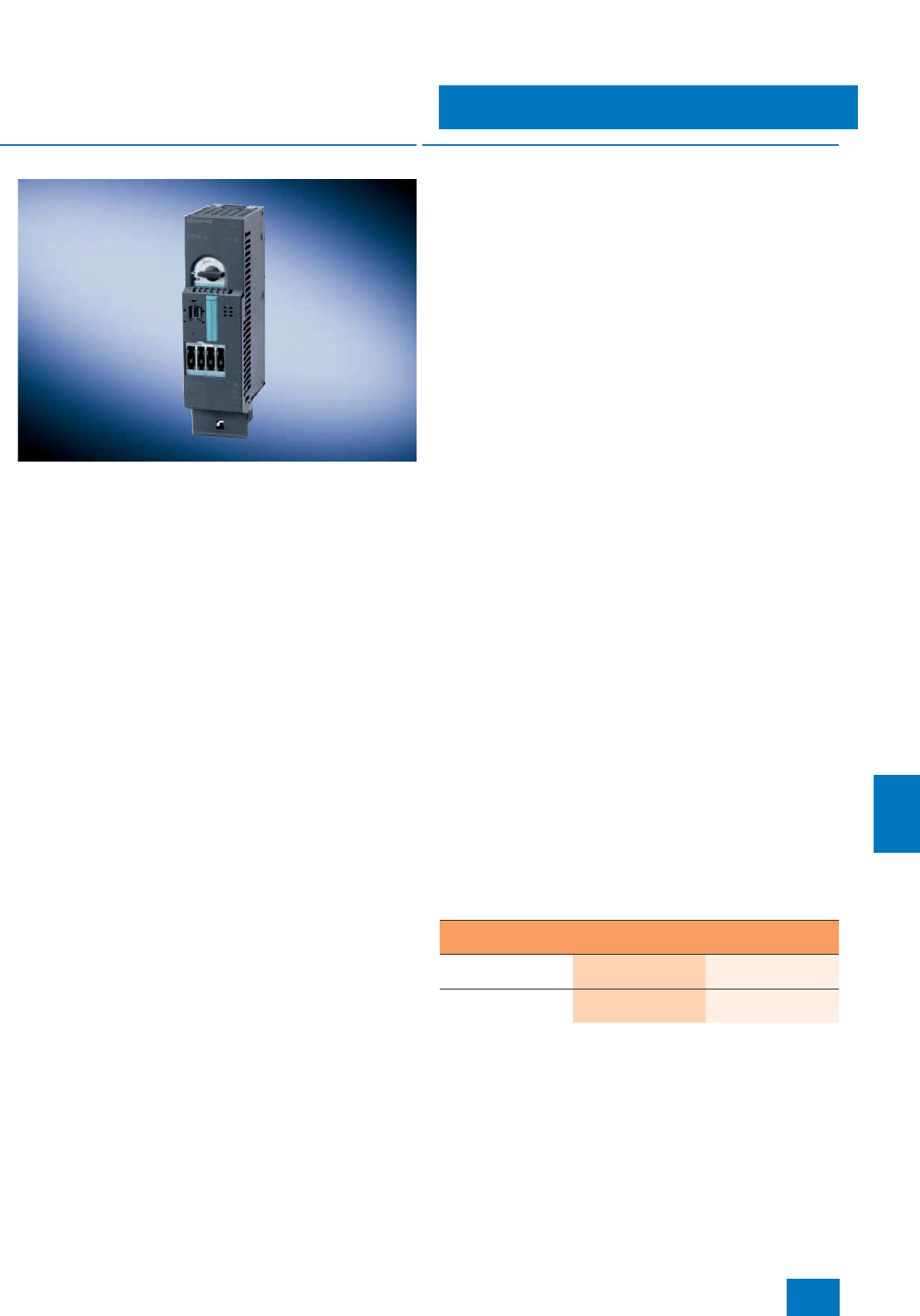
Process I/O
ET 200S distributed I/O
Motor starters
11/49
Siemens ST PCS 7 · November 2007
11
■
Overview
• Completely factory-wired motor starters for switching and pro-
tecting any three-phase loads
• Can be used as a direct-on-line, reversing or soft starter
• High Feature motor starter with a combination comprising
starter circuit breaker, solid-state overload protection and con-
tactor or soft starter up to 7.5 kW
• Safety-oriented motor starters based on the High Feature mo-
tor starters (direct-on-line and reversing starters) with integral
redundancy function for shutdown reliability up to Category 4
(EN 954-1)
• With self-assembling 50 A power bus, i.e. the load current is
only supplied once for a group of motor starters
• Hot swapping is permissible
• Inputs and outputs for activating and signaling the states have
been integrated
• Diagnostics capability for active monitoring of the switching
and protection functions
• Can be combined with brake control module for controlling
electromechanical brakes in three-phase motors
■
Design
Power modules and motor starters are operated on the terminal
modules which are assigned to them in the tables in the sections
"High Feature motor starters" and "Safety-oriented motor start-
ers". The terminal modules are a carrier system which is simulta-
neously used for the power supply to the motor starters (elec-
tronics: 24 V DC and load: 400 V AC).
24 V DC for the electronics is provided by the power module in-
serted to the left of the first motor starter. The power module and
the downstream motor starters constitute a potential group
whose scope is limited by the current carrying capacity of the
power module. When this limit is reached, a new potential group
must be established with a further power module.
The load current is applied to the first (left) TM-xxxxS32 motor
starter terminal module, and reaches the other motor starters via
the power bus of the adjacent TM-xxxxS31 terminal modules.
The power bus is designed for loads up to 50 A. When this limit
is reached, a new load group must be started with a further
TM-xxxxS32 terminal module, and provided with load current.
Brake control modules for motor starters
High Feature and safety-oriented motor starters can be ex-
panded by a brake control module for controlling electrome-
chanical brakes in three-phase motors. The following modules
are available:
• For brakes with external supply 24 V DC/4 A:
- xB3 (with two optional inputs for special functions)
-xB1
• For brakes with internal supply 500 V DC/0.7 A:
- xB4 (with two optional inputs for special functions)
-xB2
The externally supplied 24 V DC brakes can be released inde-
pendent of the switching status of the motor starter. The 500 V
DC brakes, on the other hand, are generally supplied direct from
the junction plate of the motor via a rectifier module and cannot
be released if the motor starter is switched off. These brakes
cannot be used in conjunction with the DSS1e-x motor starter
(direct-on-line soft starter).
The outputs of the brake control modules can also be used for
other purposes e.g. for controlling DC valves. Independent spe-
cial functions can be implemented with the help of two optional
local inputs each on a brake control module xB3 or xB4 and a
control module 2DI of the High Feature motor starter. These op-
erate independently of the bus and higher-level control, e.g. to
implement rapid stop functions for slide controls.
Brake control modules are operated on different terminal mod-
ules depending on the design:
Brake control
modul Terminal module for brake control module
xB1 oder xB2 TM-xB15S24-01
3RK1 903-0AG00 --
xB3 oder xB4 -- TM-xB215S24-01
3RK1 903-0AG01
© Siemens AG 2007
Process I/O
ET 200S distributed I/O
Motor starters
11/50 Siemens ST PCS 7 · November 2007
11
High Feature motor starters
The High Feature motor starters are used together with the PM-D
power module. Combined with a terminal module according to
the table, a PM-D power module opens up a new potential
group. The scope of the group is limited in that the value speci-
fied for the current carrying capacity of the power module (10 A
for PM-D) must not be exceeded by the total current of all mod-
ules in a potential group.
The PM-D handles the following tasks for the motor starters in a
potential group:
• Supply of voltages for the electronics via the voltage buses of
the terminal modules
• Monitoring of voltages for the electronics and contactors
Safety-oriented motor starters
In EMERGENCY STOP applications, safety-oriented motor start-
ers can be shut down selectively by means of the upstream
PM-D F PROFIsafe power module. Up to 6 shut-down groups
can be formed per power module. The PM-D F PROFIsafe ob-
tains the shut-down signal from the F/FH automation system via
the interface module of the ET 200S.
Combined with a terminal module according to the table, a
PM-D F PROFIsafe power module opens up a new potential
group. The scope of the group is limited in that the total current
of all modules in a potential group must not exceed the current
carrying capacity of the power module (with PM-D F PROFIsafe:
inrush current 10 A; continuous current 5 A).
Supplementary/expansion modules for safety-oriented motor
starter applications
The PM-D F X1 power/expansion module permits selective shut-
down of 1 to 6 shut-down groups through external safety de-
vices (e.g. safety relay or AS-i safety monitor). The PM-D F X1
uses the safety-oriented shut-down signals connected to the
module to trigger the downstream failsafe motor starters which
then safely switch off the assigned motors.
In addition, external safety devices can also be powered by a
safe 24 V DC voltage V1 via the safety-oriented PM-D F X1
power/expansion module.
The F-CM contact multiplier equipped with four safe floating
contacts (NO contacts) can be used together with the PM-D F
PROFIsafe or the PM-D F X1 as an interface to plants with con-
ventional safety engineering. It has internal diagnostics func-
tions, and can be set to one of 6 shut-down groups.
Terminal modules for
motor starters and power modules
With power bus supply
for one load group,
including 3 caps for ter-
mination of power bus
TM-DS65-
S32
3RK1 903-
0AK00
TM-RS130-
S32
3RK1 903-
0AL00
--
With power bus bushing TM-DS65-
S31
3RK1 903-
0AK10
TM-RS130-
S31
3RK1 903-
0AL10
--
With screw terminals -- -- TM-P15-S27-
01
3RK1 903-
0AA00
Power module
PM-D 24 V DC •
Motor starters
DS1e-x
High Feature direct-on-
line starter
•
DSS1e-x
High Feature direct-on-
line soft starter
•
RS1e-x
High Feature reversing
starter
•
Terminal modules for motor
starters, power modules and
supplementary/expansion modules
With power bus supply
for one load group,
including 3 caps for
termination of power bus
TM-FD65-
S32
3RK1 903-
3AC00
TM-FRS130-
S32
3RK1 903-
3AD00
--
With power bus bushing TM-FD65-
S31
3RK1 903-
3AC10
TM-FRS130-
S31
3RK1 903-
3AD10
--
With screw terminals -- -- TM-
PF30S47-F0
3RK1 903-
3AA00
Power module
PM-D F PROFIsafe •
Motor starters
F-DS1e-x
High Feature
direct-on-line starter
•
F-RS1e-x
High Feature reversing
starter
•
Terminal modules for
supplementary/expansion modules
Without supply from left
(as power module) TM-PFX30 S47-
G1
3RK1 903-3AE00
--
With supply from left
(for expansion) TM-PFX30 S47-
G0
3RK1 903-3AE10
--
-- TM-FCM30-S47
3RK1 903-3AB10
Additional/expansion modules
PM-D F X1
safety-oriented power/
expansion module
•
F-CM
safety-oriented contact
multiplier
•
© Siemens AG 2007

Process I/O
ET 200S distributed I/O
Motor starters
11/51
Siemens ST PCS 7 · November 2007
11
■
Selection and Ordering Data Order No.
High Feature motor starters
With diagnostics, expandable with brake control module
DS1e-x direct-on-line starters
Mechanical switching, electronic
overload protection
• Up to 1.1 kW/400 V; 0.3 to 3.0 A 3RK1 301-0AB10-0AA4
• Up to 3.0 kW/400 V; 2.4 to 8.0 A 3RK1 301-0BB10-0AA4
• Up to 7.5 kW/400 V;
2.4to16.0A 3RK1 301-0CB10-0AA4
DSS1e-x soft starters
Electronic switching, electronic
overload protection
• Up to 1.1 kW/400 V; 0.3 to 3.0 A 3RK1 301-0AB20-0AA4
• Up to 3.0 kW/400 V; 2.4 to 8.0 A 3RK1 301-0BB20-0AA4
• Up to 7.5 kW/400 V;
2.4to16.0A 3RK1 301-0CB20-0AA4
RS1e-x reversing starters
Mechanical switching, electronic
overload protection
• Up to 1.1 kW/400 V; 0.3 to 3.0 A 3RK1 301-0AB10-1AA4
• Up to 3.0 kW/400 V; 2.4 to 8.0 A 3RK1 301-0BB10-1AA4
• Up to 7.5 kW/400 V;
2.4to16.0A 3RK1 301-0CB10-1AA4
Accessories
Terminal modules for motor
starters
• TM-DS65-S32
for DS1e-x, DSS1e-x direct start-
ers with supply connection for
power bus, incl. 3 caps for ter-
minating the power bus
3RK1 903-0AK00 A)
• TM-DS65-S31
for DS1e-x, DSS1e-x direct start-
ers without supply connection
for power bus
3RK1 903-0AK10 A)
• TM-RS130-S32
for RS1e-x reversing starter with
supply connection for power
bus, incl. 3 caps for connecting
the power bus
3RK1 903-0AL00 A)
• TM-RS130-S31
for RS1e-x reversing starter with-
out supply connection for power
bus
3RK1 903-0AL10 A)
PM-D power module
for direct and reversing starters;
24 V DC, with diagnostics
3RK1 903-0BA00 A)
Terminal module for PM-D
power module
TM-P15-S27-01
3RK1 903-0AA00
Jumper modules
• M15-PEN
Terminal block PE/N, 15 mm
wide, for jumpering a 15-mm
module
3RK1 903-0AH00
• M30-PEN
Terminal block PE/N, 30 mm
wide, for jumpering a 30-mm
module
3RK1 903-0AJ00
• M15-L123
Terminal block L1/L2/L3, 15 mm
wide, for jumpering a 15-mm
module
3RK1 903-0AE00
• M30-L123
Terminal block L1/L2/L3, 30 mm
wide, for jumpering a 30-mm
module
3RK1 903-0AF00
Control modules
• Control module 2DI COM
DC 24 V
Digital input module with two in-
puts for parameterizable motor
starters, for mounting on front of
motor starter, with PC connec-
tion (LOGO! PC cable 6ED1057-
1AA00-0AB0 required)
3RK1 903-0CH10 A)
• Control module 2DI LC COM
DC 24 V
Like control module 2DI COM,
plus input for switching to manu-
al local mode
3RK1 903-0CH20 A)
M65-PEN-F infeed module
65 mm wide, incl. two caps,
in combination with TM-DS65-
32/TM-RS130-S32
3RK1 903-2AC00
M65-PEN-S connection module
65 mm wide, in combination with
TM-DS65-31/TM-RS130-S31
3RK1 903-2AC10
Brake control expansion
module
For motors with mechanical brake
•xB1
24 V DC / 4 A 3RK1 903-0CB00 A)
•xB2
500 V DC / 0.7 A 3RK1 903-0CC00
•xB3
24 V DC / 4 A, DI 2 x 24 V DC
with two optional inputs
3RK1 903-0CE00 A)
•xB4
500 V DC / 0.7 A, DI 2 x 24 V DC
with two optional inputs
3RK1 903-0CF00 A)
Terminal modules for brake
control expansion module
• TM-xB15S24-01
for xB1 or xB2 3RK1 903-0AG00
• TM-xB215S24-01
for xB3 or xB4 3RK1 903-0AG01 A)
A) Subject to export regulations: AL: N, ECCN: EAR99
■
Selection and Ordering Data Order No.
© Siemens AG 2007

Process I/O
ET 200S distributed I/O
Motor starters
11/52 Siemens ST PCS 7 · November 2007
11
A) Subject to export regulations: AL: N, ECCN: EAR99
Note:
For color-coded labels and further accessories for ET 200S configura-
tions with High Feature motor starters and for ET 200S configurations with
safety-related motor starters, refer to "Distributed I/Os / ET 200S" in the
A&D Mall or in the Catalogs IK PI and CA 01.
Safety-related motor starters
With diagnostics, expandable with brake control module
F-DS1e-x safety-related direct
starter
Mechanical switching, electronic
overload protection
• Up to 1.1 kW/400 V; 0.3 to 3.0 A 3RK1 301-0AB13-0AA4
• Up to 3.0 kW/400 V; 2.4 to 8.0 A 3RK1 301-0BB13-0AA4
• Up to 7.5 kW/400 V;
2.4to16.0A 3RK1 301-0CB13-0AA4
F-RS1e-x safety-related
reversing starter
Mechanical switching, electronic
overload protection
• Up to 1.1 kW/400 V; 0.3 to 3.0 A 3RK1 301-0AB13-1AA4
• Up to 3.0 kW/400 V; 2.4 to 8.0 A 3RK1 301-0BB13-1AA4
• Up to 7.5 kW/400 V;
2.4to16.0A 3RK1 301-0CB13-1AA4
Accessories
Terminal modules for safety-
related motor starters
• For F-DS1e-x direct starter, with
coding
-TM-FDS65-S32 with supply
connection for power bus 3RK1 903-3AC00 A)
-TM-FDS65-S31 without supply
connection for power bus 3RK1 903-3AC10 A)
• For F-RS1e-x reversing starter,
with coding
-TM-FRS130-S32 with supply
connection for power bus 3RK1 903-3AD00 A)
-TM-FRS130-S31 without sup-
ply connection for power bus 3RK1 903-3AD10 A)
PM-D F PROFIsafe power
module
for direct and reversing starters;
24 V DC, with diagnostics
3RK1 903-3BA01 A)
Terminal module for
PM-D F PROFIsafe power
module
TM PF30 S47-F0
3RK1 903-3AA00 A)
Jumper modules and control
modules
See under High Feature motor
starters
M65-PEN-F infeed module
65 mm wide, incl. two caps, in
combination with TM-DS65-32 /
TM-RS130-S32
3RK1 903-2AC00
M65-PEN-S connection module
65 mm wide, in combination with
TM-DS65-31/TM-RS130-S31
3RK1 903-2AC10
■
Selection and Ordering Data Order No.
Brake control expansion
module
For motors with mechanical brake
•xB3
24 V DC / 4 A, DI 2 x 24 V DC
with two optional inputs
3RK1 903-0CE00 A)
•xB4
500 V DC / 0.7 A, DI 2 x 24 V DC
with two optional inputs
3RK1 903-0CF00 A)
Terminal modules for brake
control expansion module
TM-xB215S24-01 for xB3 or xB4
3RK1 903-0AG01 A)
PM-D F X1 power module
For power supply of emergency
stop signals of external safety
units; for 6 switch-off groups,
24 V DC
3RK1 903-3DA00 A)
Terminal module for PM-D F X1
power module
•TM-PFX30 S47-G0
With infeed on left 3RK1 903-3AE10 A)
•TM-PFX30 S47-G1
Without infeed on left 3RK1 903-3AE00 A)
F-CM contact multiplexer
With 4 safe floating contacts 3RK1 903-3CA00
Terminal module for F-CM
contact multiplexer
TM-FCM30 S47-F01
3RK1 903-3AB10
■
Selection and Ordering Data Order No.
© Siemens AG 2007
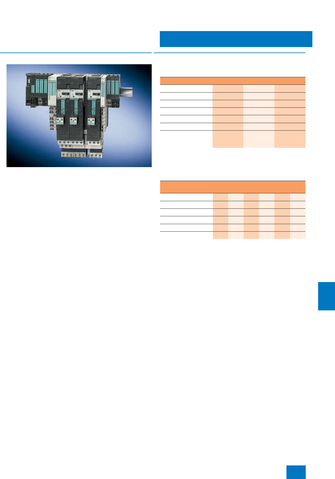
Process I/O
ET 200S distributed I/O
SIGUARD safety technology
11/53
Siemens ST PCS 7 · November 2007
11
■
Overview
The SIGUARD safety system is based on special terminal and
power modules that can be combined with the ET 200S motor
starters and a failsafe kit to achieve the highest safety category
4 (according to EN 954-1). It enables the evaluation of emer-
gency stop circuits, the monitoring of protective doors or the im-
plementation of time-delayed shut-downs. The costs involved in
the configuration and wiring of conventional safety systems are
no longer incurred. All standard safety applications can be cov-
ered with SIGUARD (see the ET 200S manual for examples of
applications).
■
Design
Components required for applications with safety require-
ments
1) PM-D F3 power module only approved up to Category 3
2) F kit required for standard motor starter only; already integrated in high
feature motor starter
Possible combinations of power and terminal modules
1) For F1 or F2 in higher-level or individual safety group (voltage group)
2) For F1 or F2 in lower-level cascaded safety group (partial voltage group)
3) For expansion with F3 or F4 in separate ET 200S station (voltage group)
4) For expansion with F3 or F4 in the same ET 200S station (partial voltage
group)
Components required Safety category acc. to EN 954-1
2 3 4
PM-D F1...5 • • • 1)
TM-PF30 S47-.. • • •
F-Kit 1/2 •2) • 2) • 2)
PM-X • • •
TM-X15 S27-01 • • •
Redundantly
switching, external
infeed contactor
• •
PM-D
F1 PM-D
F2 PM-D
F3 PM-D
F4 PM-D
F5 PM-X
TM-PF30 S47-B1 1) • •
TM-PF30 S47-B0 2) • •
TM-PF30 S47-C1 3) • •
TM-PF30 S47-C0 4) • •
TM-PF30 S47-D0 •
TM-X15 S27-01 •
© Siemens AG 2007

Process I/O
ET 200S distributed I/O
SIGUARD safety technology
11/54 Siemens ST PCS 7 · November 2007
11
Terminal modules for SIGUARD power modules
The terminal modules integrate the SIGUARD power modules.
Using different terminal modules it is possible to separate vari-
ous safety circuits by function or else to cascade them. Each
such group has to be terminated with a SIGUARD PM-X connec-
tion module.
• The TM-PF30 S47-B1 terminal module always stands at the
beginning of a safety segment and integrates either the
PM-D F1 power module for emergency stop applications or
the PM-D F2 power module for protective door monitoring.
The 2-channel connection of the safety sensor (e.g. emer-
gency stop button) as well as the 24 V DC supply for the elec-
tronics (V1) and the contactor supply (V2) of the motor starters
have to be connected to this terminal module. Connections for
the ON button (enable) and the safe output of the power mod-
ule are also available.
• The TM-PF30 S47-B0 terminal module is used for the cascad-
ing of subordinate safety segments and integrates either the
PM-D F1 power module for emergency stop applications or
the PM-D F2 power module for protective door monitoring. No
additional auxiliary voltage has to be connected to this termi-
nal module. The supply is fed through the terminal module
voltage buses from the preceding PM-D F1 or PM-D F2 power
module. Switching off the voltage of the preceding power
module means that the terminal module has no voltage either.
• The TM-PF30 S47-C1 terminal module always stands at the
beginning of an expansion of a safety segment in a new sta-
tion, e.g. in an interlaced configuration. It integrates the PM-D
F3 power module for time-delayed shut-down or the PM-D F4
power module for direct shut-down in physically separated
ET 200S stations. The 24-V voltages for the electronics (V1)
and for the contactor supply (V2) are provided again. The
shut-down command of a preceding ET 200S station is inte-
grated through a safe input. Separate terminals are available
for connecting the feedback circuit to the upstream ET 200S
station. It is not possible to connect safety sensors to this ter-
minal module.
• The TM-PF30 S47-C0 terminal module is used to cascade
subordinate safety segments and integrates either the PM-
DF3 power module for time-delayed shut-down or the PM-DF4
power module. Only the supply voltage V2 for the contactor
supply need be connected on this terminal module. The sup-
ply with V1 is via the voltage buses of the terminal modules of
the previous power modules (partial voltage group). It is not
possible to connect safety sensors to this terminal module.
• The TM-PF30 S47-D0 terminal module is used to integrated
the PM-D F5 power module. At this terminal module it is pos-
sible to forward safe signals to external systems through four
groups, each with two safety relay contacts in redundant con-
figuration. The terminal module must always be positioned be-
tween one of the above mentioned terminal modules and a ter-
minal module for the TM-X connection module. It is not
possible to connect safety sensors to this terminal module.
TM-X terminal module for SIGUARD connection module
For connecting an external incoming supply contactor (second
shut-down option) in Categories 3 and 4. The SIGUARD con-
nection module is inserted to the right of the last motor starter in
a safety segment. The terminals for connecting the positively
driven NC contact of the contactor are located alongside the ter-
minals for connecting the contactor coil on the TM-X terminal
module. If no redundant contactor is required in Category 2
(EN 954-1), for example, the feedback circuit has to be closed
at these terminals by a jumper. This arrangement is also used in-
stead of SIGUARD power module as an interface to the external
safety relay when external safety relays are used.
SIGUARD PM-D F1/F2/F3/F4/F5 power modules
The following SIGUARD PM-D power modules are available for
selection:
• PM-D F1 for evaluating emergency stop circuits with the func-
tion "Monitored start".
• PM-D F2 for monitoring safety doors with the function "Auto-
matic start".
• PM-D F3 as expansion for PM-D F1/F2 for time-delayed trip-
ping.
• PM-D F4 for expanding safety circuits with other ET200S mo-
tor starters, e.g. on a different tier.
• PM-D F5 for transmitting the status of PM-D F1...4 over four
floating relay circuits to external safety devices (contact multi-
pliers)
No additional PM-S power module is required when using the
SIGUARD power modules. SIGUARD PM-D F1/F2/F3/F4 power
modules monitor auxiliary voltages and contain the complete
functionality of a safety relay. The PM-D F1 and PM-D F2 mod-
ules can be combined with the PM-D F3 or PM-D F4 modules.
A PM-D F5 can be arranged in any position between
PM-D F1...4 and a PM-X.
Every safety circuit, starting with a PM-D F1 ... 4, has to be ter-
minated with a PM-X.
Failsafe kit
Every standard motor starter in a safety segment has to be sup-
plemented by the failsafe kit (F-kit) in order to monitor the switch-
ing function. F-kit 1 supplements the DS1-x direct-on-line starter,
F-kit 2 the RS1-x reversing starter.
The F-kits comprise
• contact carriers for the terminal modules,
• one or two auxiliary switch blocks for the contactor(s) of the
motor starter and
• connecting lines.
High feature motor starters and their terminal modules come
equipped with the F-kit functions.
© Siemens AG 2007

Process I/O
ET 200S distributed I/O
SIGUARD safety technology
11/55
Siemens ST PCS 7 · November 2007
11
A) Subject to export regulations: AL: N, ECCN: EAR99
■
Selection and Ordering Data Order No.
SIGUARD Terminal Modules
PM-PF30 S47 B1 Terminal
Module
For PM-D F1/2 power modules
with U1/U2 incoming supply and
sensor connection
3RK1 903-1AA00 A)
PM-PF30 S47 B0 Terminal
Module
For PM-D F1/2 power modules
with sensor connection
3RK1 903-1AA10 A)
PM-PF30 S47 C1 Terminal
Module
For PM-D F3/4 power modules
with U1/U2 incoming supply and
IN+/IN- control input
3RK1 903-1AC00 A)
PM-PF30 S47 C0 Terminal
Module
For PM-D F3/4 power modules
with U2 incoming supply
3RK1 903-1AC10
PM-PF30 S47 D0 Terminal
Module
For PM-D F5 power modules
3RK1 903-1AD10
PM-X15 S27 01 Terminal Module
For SIGUARD connection module
3RK1 903-1AB00 A)
SIGUARD Power Modules
PM-D F1 SIGUARD Power
Module
EMERGENCY STOP; monitored
start; 2-channel
3RK1 903-1BA00
PM-D F2 SIGUARD Power
Module
Protective door; autostart;
2-channel
3RK1 903-1BB00
PM-D F3 SIGUARD Power
Module
Expansion to F1/2 for an addi-
tional voltage group;
time-delayed
3RK1 903-1BD00
PM-D F4 SIGUARD Power
Module
Expansion to F1/2 for an addi-
tional voltage group
3RK1 903-1BC00
PM-D F5 SIGUARD Power
Module
Expansion to PM-D F1 up to
PM-D F4, contact multiplier
3RK1 903-1BE00
Accessories
PM-X SIGUARD
Connection module for incoming-
feeder contactor; external safety
circuits
3RK1 903-1CB00 A)
Failsafe kit 1
Failsafe kit for DS1-x standard
motor starter (not necessary for
High Feature motor starter)
3RK1 903-1CA00 A)
Failsafe kit 2
Failsafe kit for RS1-x standard
motor starter (not necessary for
High Feature motor starter)
3RK1 903-1CA01 A)
■
Selection and Ordering Data Order No.
© Siemens AG 2007
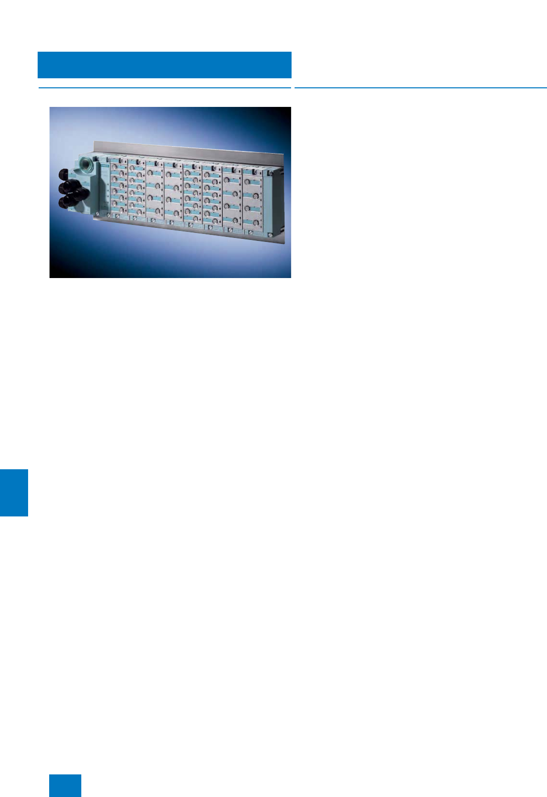
Process I/O
Dezentrale Peripherie ET 200pro
Introduction
11/56 Siemens ST PCS 7 · November 2007
11
■
Overview
SIMATIC ET 200pro is a modular I/O system with high IP65/66/67
protection suitable for use at machine level outside the control
cabinet. As a result of the innovative design, the ET 200pro has
a relatively small size and can be flexibly adapted to the require-
ments of the respective automation task with regard to the con-
nection system and I/Os. Summary of the most important fea-
tures of the SIMATIC ET 200pro:
• Distributed I/O system with IP65/67 protection for use without
a control cabinet at machine level
• Small, multi-functional complete solution: analog and digital
I/O modules as well as safety-related digital I/O modules
• Communication over PROFIBUS DP, transmission rate up to
12 Mbit/s
• Mixed design of fail-safe and standard modules possible in
the same station
• Free selection of connection system: direct, ECOFAST or
M12 7/8"
• Power module for simple implementation of load groups
• Hot swapping of modules
• Simple assembly and independent wiring
• Comprehensive diagnostics: exact to the module or channel
■
Design
The architecture of the ET 200pro is based on the proven sepa-
ration of modules from the bus/power supply connection system.
This permits the T functionality for bus and 24 V DC power sup-
ply for the interface module, and prewiring of sensor/actuator
connections for the electronics modules (independent wiring).
When servicing, the independent wiring permits hot swapping of
an electronics module without having to switch off the remaining
station. This can continue without interruption during the re-
placement. When replacing an electronics module, the com-
plete I/O wiring remains on the connection module, and need be
neither labeled nor removed.
Up to 16 electronics modules can be arranged in any order be-
tween the interface module (left) and the terminating module
(right limit).
Modules of an ET 200pro station
The ET 200pro modules are usually designed in two or three
parts. Interface and power modules as well as digital and analog
electronics modules comprise:
• Bus module as mechanical and electrical connection element
of the individual ET 200pro modules (they form the backplane
bus of the system)
• Electronics or interface module
• Connection module
The ET 200pro modules are fitted when delivered on the associ-
ated bus module.
An ET 200pro station comprises:
• Module support
• Interface module for PROFIBUS DP
• Connection module for the PROFIBUS DP interface module
- CM IM DP direct with up to 6 M20 cable glands
- CM IM DP ECOFAST Cu
- CM IM DP M12 7/8"
• Max. 16 electronics modules with associated connection
modules which may be assembled up to a station width of 1 m
• Terminating module (included in scope of delivery of interface
module)
Expansion modules
The following expansion modules are available:
• Digital electronics modules
• Analog electronics modules
• Safety-related electronics modules
• I/O connection modules
- CM IO 4 x M12 for digital or analog electronics modules
- CM IO 8 x M12 for digital electronics modules
- CM IO 12 x M12 for 4/8 F-DI/4 F-DO
- CM IO 16 x M12 for 8/16 F-DI
• Power module electronics PM-E
• Connection modules for power module
- CM PM-E direct with up to 2 M20 cable glands
- CM PM-E ECOFAST Cu
- CM PM-E 7/8"
© Siemens AG 2007
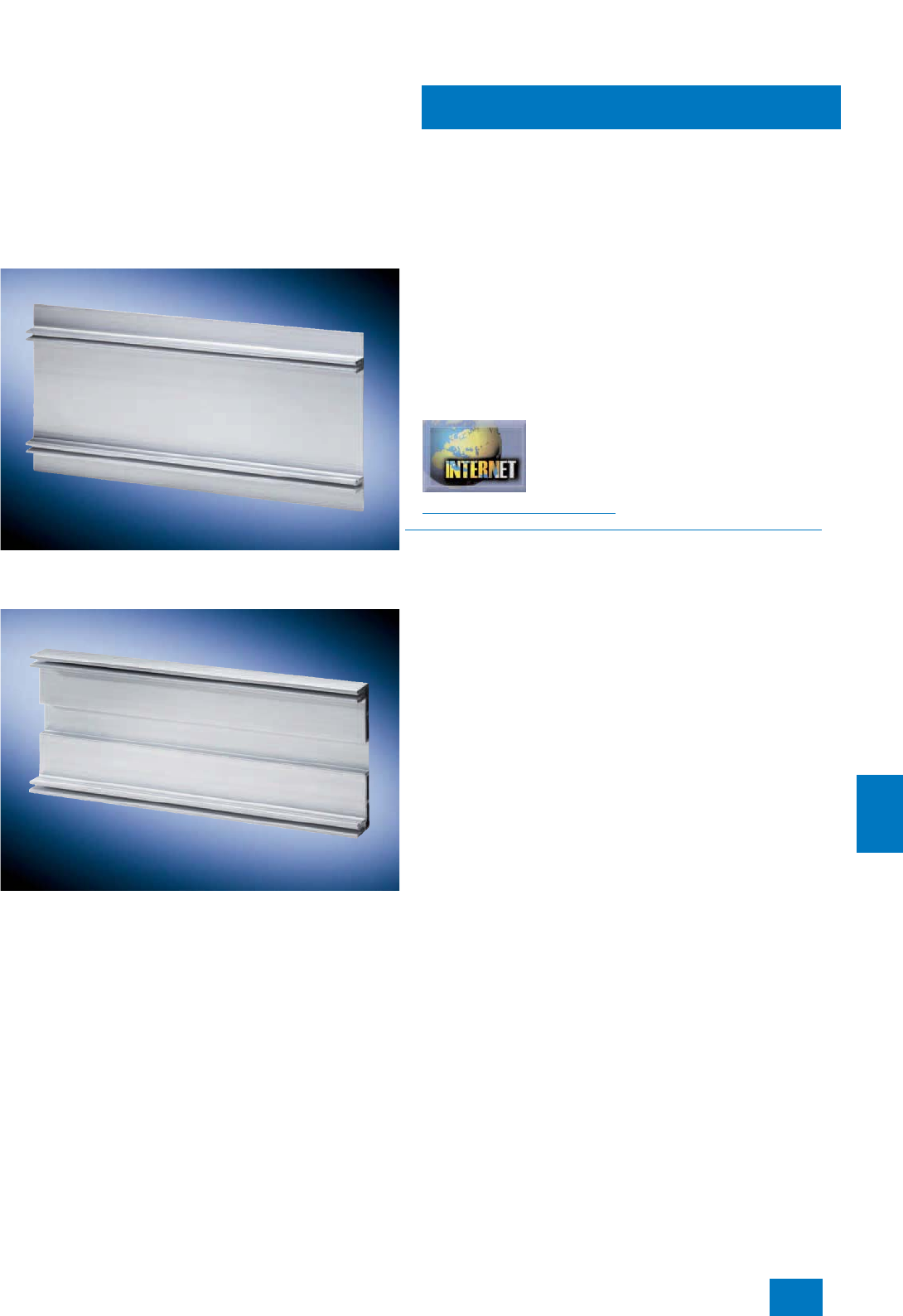
Process I/O
Dezentrale Peripherie ET 200pro
Introduction
11/57
Siemens ST PCS 7 · November 2007
11
Module support
Various module supports are available for mounting the
ET 200pro:
• Narrow module support
The narrow module support permits complete preassembly
on a workbench as a result of two mounting flanges outside
the ET 200pro station.
• Compact-narrow module support
The compact-narrow module support permits the most space-
saving design.
Expansion limits
• Number of electronics modules per station (between interface
module and terminating module): up to 16
• Max. width (without module support): 1 m
• Electronics/sensor supply 1L+ max. 5 A per ET 200pro station
• Load voltage supply 2L+ max. 10 A per potential group
• Maximum address range of an ET 200pro station: 244 bytes
for inputs and 244 bytes for outputs
ET 200pro configuration
The SIMATIC ET 200 configurator can be used to compile an
ET 200pro station rapidly and simply. It knows the configuration
rules, and supports selection of all components and associated
accessories in interactive mode. The SIMATIC ET 200 is avail-
able in the current CD-ROM Catalog CA 01 and on the Internet.
Additional information is available in the Internet under:
http://www.siemens.com/et200
■
Integration
The distributed ET 200pro system is connected to SIMATIC
PCS 7 automation systems (controllers) over PROFIBUS DP.
Data transfer rates of up to 12 Mbit/s are possible.
The ET 200pro is integrated into SIMATIC PCS 7 using standard
driver blocks. You can therefore configure and parameterize the
ET 200pro in the SIMATIC Manager of the engineering system
extremely simply using HW-Config.
© Siemens AG 2007

Process I/O
Dezentrale Peripherie ET 200pro
Introduction
11/58 Siemens ST PCS 7 · November 2007
11
■
Technical specifications
For detailed technical specifications, especially for individual
components such as interface module, power module and elec-
tronics modules, see:
• Catalog IK PI
• Mall/CA 01 under "Distributed I/Os / ET 200pro"
General technical specifications
Electronics modules • Digital inputs/outputs
• Analog inputs/outputs
• Safety-related digital inputs/
outputs
Connection system for actuator/
sensor M12 round plug connection with
standard assignments for
actuator/sensor
Data transfer rate, max. 12 Mbit/s (PROFIBUS DP)
Power supply 24 V DC
Current consumption of an ET
200pro (internal and sensor supply,
non-switched voltage), up to 55 °C,
max.
≤ 5 A
Load current for ET 200pro per
incoming supply (IM, PM, switched
voltage), up to 55 °C, max.
10 A
For total configuration with looping
through (several ET 200pro), up to
55 °C, max.
16 A (with direct connection
module)
Degree of protection IP65/66/IP67 for interface, digital
and analog modules
Material Thermoplast (glass-fiber
reinforced)
Ambient conditions
Temperature 0 ... 55 °C (-25 °C on request)
Relative humidity 5 ... 100 %
Atmospheric pressure 795 ... 1080 hPa
Mechanical stress
Vibrations Vibration test according to
IEC 60068, Part 2-6 (sinusoidal)
• Constant acceleration 5 g,
occasionally 10 g, for interface,
digital and analog modules
• 2 g for motor starters
Shock • Shock test according to
IEC 680068 Part 2-27, half-sine,
30 g, 18 ms duration for inter-
face, digital and analog mod-
ules
• 15 g, 11 ms duration for motor
starters
Approvals UL, CSA and cULus
© Siemens AG 2007
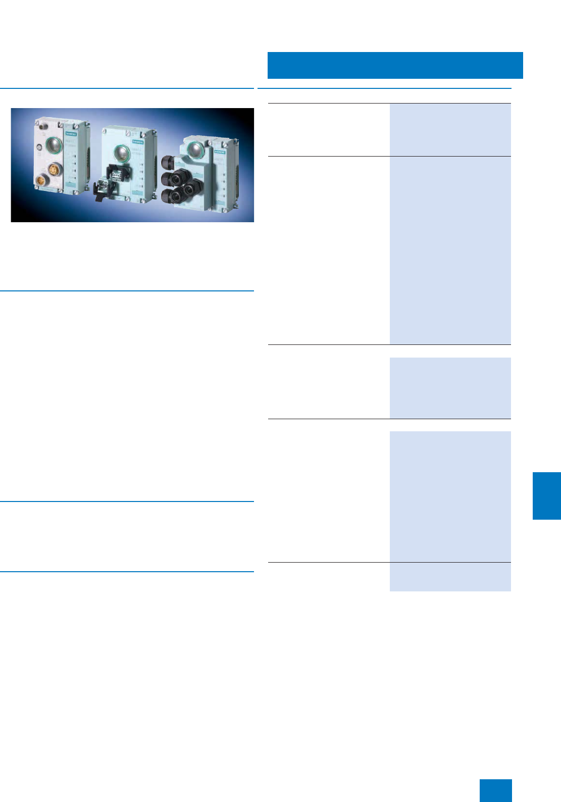
Process I/O
Dezentrale Peripherie ET 200pro
Interface module IM 154-2 DP High Feature
11/59
Siemens ST PCS 7 · November 2007
11
■
Overview
The IM 154-2 DP High Feature interface module is responsible
for PROFIBUS communication between the ET 200pro station
and the host automation system (controller) as PROFIBUS DP
master. The scope of delivery of the interface module also in-
cludes a terminating module which is plugged in following the
last electronics module of the station.
■
Function
Features of the IM 154-2 DP High Feature interface module
• Mounted on delivery on the bus module
• Connects the ET 200pro station to the PROFIBUS DP via the
connection module
• Prepares the data for the connected electronics modules
• Max. 16 electronics modules can be operated on an interface
module - also safety-related
• PROFIBUS DP address of the ET 200pro station can be set on
the connection module
• Terminating resistor of the PROFIBUS DP can be switched on
and off on the connection module
• Maximum address range: 244 bytes for inputs and 244 bytes
for outputs
• Powers the ET 200pro station via the connection module with
the sensor/electronics supply 1L+ and the load power supply
2L+
• Integral power module for the load power supply 2L+
■
Technical specifications
For detailed technical specifications of the interface module,
see:
• Catalog IK PI
• Mall/CA 01 under "Distributed I/Os / ET 200pro"
■
Accessories
Connection modules
The connection module for the IM 154-2 DP High Feature inter-
face module (to be ordered separately) is available in three dif-
ferent connection versions:
• CM IM DP direct
• CM IM DP ECOFAST Cu
• CM IM DP M12 7/8"
The PROFIBUS address can be set on the connection module
per DIL switch. The segmenting terminating resistor can be con-
nected using a further DIL switch.
■
Selection and Ordering Data Order No.
IM154-2 High Feature interface
module
for ET 200pro; for communication
between ET 200pro and host
masters over PROFIBUS DP; sup-
port of PROFIsafe
6ES7 154-2AA00-0AB0 B)
Connection module for IM154-2
High Feature interface module
• CM IM DP ECOFAST connection
module
for connection of PROFIBUS DP
and 24 V DC power supply to
PROFIBUS interface modules,
2 ECOFAST Cu connections
6ES7 194-4AA00-0AA0 B)
• CM IM DP direct connection
module
for direct connection of
PROFIBUS DP and 24 V DC
power supply to PROFIBUS in-
terface modules, up to six M20
cable glands
6ES7 194-4AC00-0AA0 B)
• CM IM DP M12 7/8" connection
module
for connection of PROFIBUS DP
and 24 V DC power supply to
PROFIBUS interface modules,
2 x M12 and 2 x 7/8"
6ES7 194-4AD00-0AA0 B)
Cables and further accessories
For cables and further accesso-
ries for CM IM DP ECOFAST,
CM IM DP direct and CM IM DP
M12 7/8" connection modules,
see Catalog IK PI or Mall/CA 01
under "Distributed I/O /
ET 200pro"
General accessories
ET 200pro module support
• Narrow, for interface, electronics
and power modules
-500 mm 6ES7 194-4GA00-0AA0
- 1000 mm 6ES7 194-4GA60-0AA0
- 2000 mm, can be cut to length 6ES7 194-4GA20-0AA0
• Compact-narrow, for interface,
electronics and power modules
-500 mm 6ES7 194-4GC70-0AA0
- 1000 mm 6ES7 194-4GC60-0AA0
- 2000 mm, can be cut to length 6ES7 194-4GC20-0AA0
Spare fuse
12.5 A fast-blow, for interface and
power modules, 10 units per pack
6ES7 194-4HB00-0AA0
B) Subject to export regulations: AL: N, ECCN: EAR99H
© Siemens AG 2007
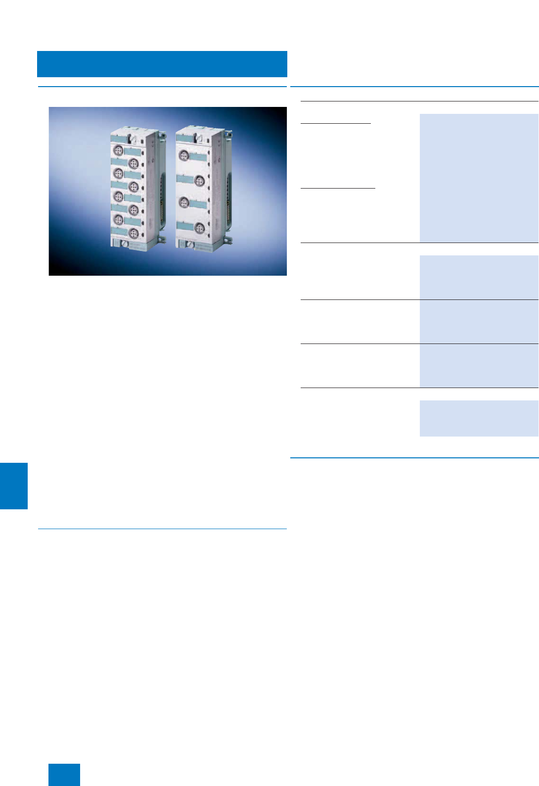
Process I/O
Dezentrale Peripherie ET 200pro
Digital electronics modules EM 141, EM 142
11/60 Siemens ST PCS 7 · November 2007
11
■
Overview
The following digital electronics modules can be used for con-
necting actuators/sensors in the context of SIMATIC PCS 7:
Digital input modules
• EM 8 DI DC 24 V High Feature
- Digital electronics module with eight inputs
- Suitable for standard switches and proximity switches
(BEROs)
- Rated input voltage 24 V DC
- Diagnostics "Short-circuit of sensor supply to ground" per
channel
- Diagnostics "Open-circuit" per channel
- Process alarm
- Parameterizable input delay
Digital output modules
• EM 4 DO DC 24 V; 2 High Feature
- Digital electronics module with four outputs
- Suitable for solenoid valves, DC contactors and indicator
lights
- Output current 2 A per output
- Rated load voltage 24 V DC
- Diagnostics "Short-circuit of outputs to ground" per channel
- Diagnostics "Short-circuit of outputs to P" per channel
- Diagnostics "Open-circuit in outputs" per channel
- Diagnostics "Load voltage missing" per module
- Parameterizable substitute value
■
Technical specifications
For detailed technical specifications of the digital electronics
modules, see:
• Catalog IK PI
• Mall/CA 01 under "Distributed I/Os / ET 200pro"
B) Subject to export regulations: AL: N, ECCN: EAR99H
■
Accessories
Connection modules
Actuators and sensors are connected using commercially-avail-
able 5-contact M12 plugs on the connection module. The con-
nection module is plugged onto the electronics module, and
screwed to the latter. The following connection modules (to be
ordered separately) are available for the above-mentioned elec-
tronics modules:
• CM IO 4x M12 (for EM DI and EM DO)
• CM IO 8x M12 (for EM DI)
Depending on the selected connection module, each plug for
the 8-channel digital input module has one or two channels:
• 4 x M12 round plug connections with 2 channels per plug
(double assignment)
• 8 x M12 round plug connections with 1 channel per plug
(single assignment)
■
Selection and Ordering Data Order No.
Digital electronics modules
Digital input modules
Digital input module 8 DI High
Feature
24 V DC, with channel diagnos-
tics, including bus module. Con-
nection module must be ordered
separately
6ES7 141-4BF00-0AB0 B)
Digital output modules
Digital output module 4 DO
High Feature
24 V DC, 2 A, with channel diag-
nostics, including bus module.
Connection module must be
ordered separately
6ES7 142-4BD00-0AB0 B)
Accessories
Connection module CM IO
4xM12
4 M12 sockets for connecting
digital or analog sensors/actua-
tors to ET 200pro
6ES7 194-4CA00-0AA0 B)
Connection module CM IO
8xM12
8 M12 sockets for connecting
digital sensors/actuators to
ET 200pro
6ES7 194-4CB00-0AA0 B)
Module labels
for color-coded identification of
the CM IOs in white, red, blue and
green; pack with 100 units of
each color
6ES7 194-4HA00-0AA0
Further accessories
For plugs, cables and further
accessories, see Catalog IK PI or
Mall/CA 01 under "Distributed I/O
/ ET 200pro"
© Siemens AG 2007
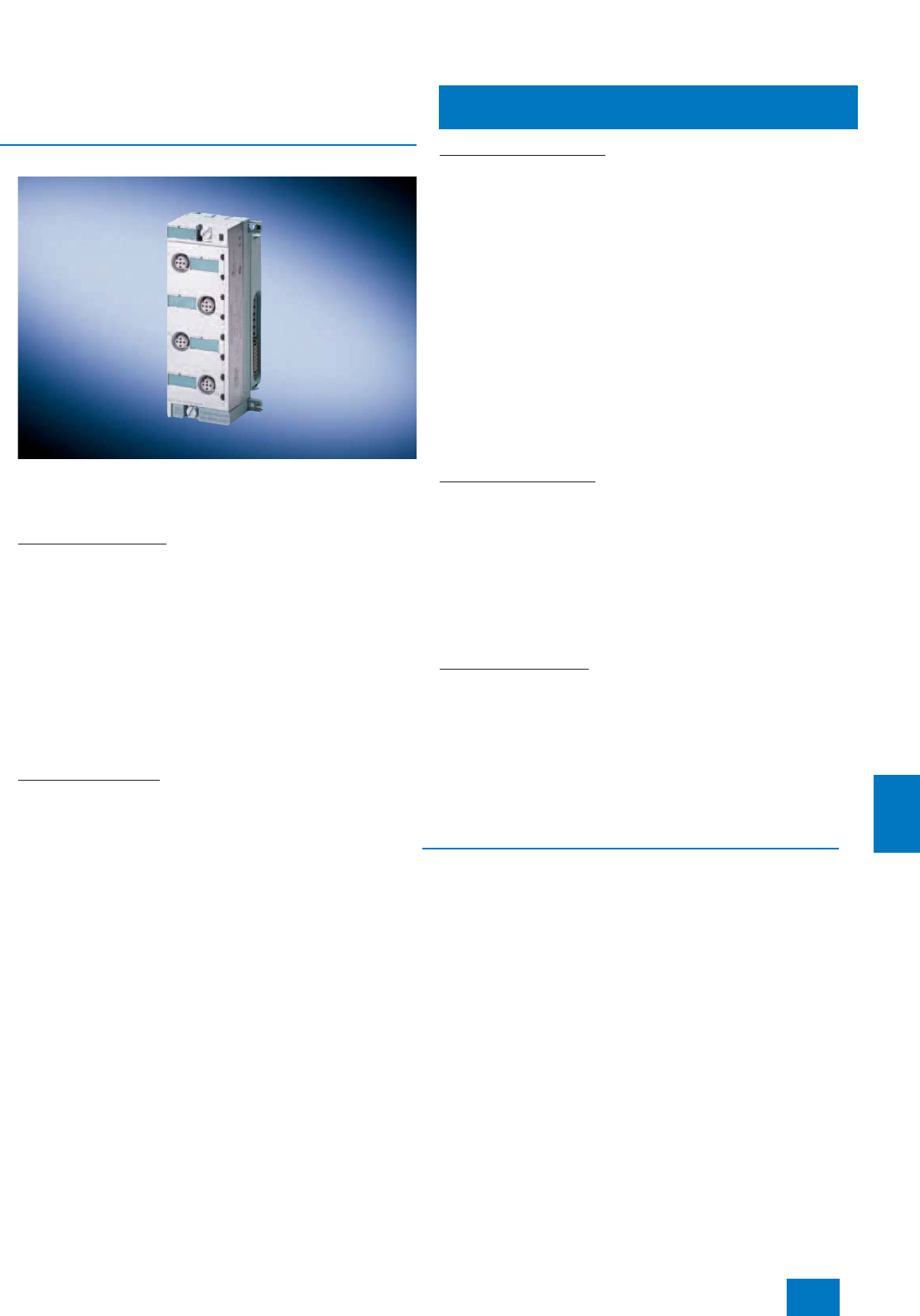
Process I/O
Dezentrale Peripherie ET 200pro
Analog electronics modules EM 144, EM 145
11/61
Siemens ST PCS 7 · November 2007
11
■
Overview
The following analog electronics modules can be used for con-
necting actuators/sensors in the context of SIMATIC PCS 7:
Analog input modules
EM 4 AI U High Feature
• 4 inputs for voltage measurements
• Input ranges:
-± 10 V, resolution 15 bit + sign
-± 5 V, resolution 15 bit + sign
- 0 to 10 V, resolution 15 bit
- 1 to 5 V, resolution 15 bit
• Electrically isolated from load voltage 2L+
• Diagnostics "Short-circuit of sensor supply to M" per module
• Diagnostics "Short-circuit, open-circuit" per channel (depend-
ing on measuring range)
• Process interrupt with limit violation on channel 0
• Permissible common-mode voltage 5 Vpp AC
EM 4 AI I High Feature
• 4 inputs for current measurements
• Input ranges:
-± 20 mA, resolution 15 bit + sign
- 0 to 20 mA, resolution 15 bit
- 4 to 20 mA, resolution 15 bit
• Two-wire and four-wire transmitters can be connected
• Electrically isolated from load voltage 2L+
• Diagnostics "Short-circuit of sensor supply to M" per module
• Diagnostics "Short-circuit, open-circuit" per channel (depend-
ing on measuring range)
• Process interrupt with limit violation on channel 0
• Permissible common-mode voltage 5 Vpp AC
EM 4 AI RTD High Feature
• 4 inputs for isolated (floating) resistance measurements or
resistance thermometers with 2-, 3- and 4-wire connections
• Input ranges:
- Resistance measurement: 150 Ω; 300 Ω; 600 Ω; 3000 Ω;
resolution 15 bit
- Resistance thermometer: Pt100; Ni100; Ni120; Pt200; Ni200;
Pt500; Ni500; Pt1000; Ni1000; resolution 15 bit + sign
• Automatic compensation of line resistances with 3- and 4-wire
connections
• Parameterizable temperature coefficient with resistance-type
sensors
• Electrically isolated from load voltage supply 1L+ and 2L+
• Linearization of sensor characteristics
• Diagnostics "Open-circuit" per channel (terminals 1 and 3 are
monitored for open-circuit)
• Permissible common-mode voltage 10 Vpp AC
Analog output modules
EM 4 AO U High Feature
• 4 outputs for voltage output
• Output ranges:
-± 10 V, resolution 15 bit + sign
- 1 to 5 V, resolution 14 bit
- 0 to 10 V, resolution 15 bit
• Electrically isolated from sensor supply voltage 1L+
• Diagnostics "Short-circuit of sensor supply to M" per module
• Diagnostics "Open-circuit in outputs" per channel
• Substitute value output
EM 4 AO I High Feature
• 4 outputs for current output
• Output ranges:
-± 20 mA, resolution 15 bit + sign
- 4 to 20 mA, resolution 14 bit
- 0 to 20 mA, resolution 15 bit
• Electrically isolated from sensor supply voltage 1L+
• Diagnostics "Short-circuit of sensor supply to M" per module
• Diagnostics "Open-circuit" per channel
• Substitute value output
■
Technical specifications
For detailed technical specifications of the analog electronics
modules, see:
• Catalog IK PI
• Mall/CA 01 under "Distributed I/Os / ET 200pro"
© Siemens AG 2007

Process I/O
Dezentrale Peripherie ET 200pro
Analog electronics modules EM 144, EM 145
11/62 Siemens ST PCS 7 · November 2007
11
B) Subject to export regulations: AL: N, ECCN: EAR99H
■
Accessories
Connection modules
Actuators and sensors are connected using commercially-avail-
able 5-contact M12 plugs on the connection module. The con-
nection module is plugged onto the electronics module, and
screwed to the latter. The connection module CM IO 4 x M12 (to
be ordered separately) is available for the above-mentioned
electronics modules:
■
Selection and Ordering Data Order No.
Analog electronics modules
Analog input modules
Analog input module 4 AI U
High Feature, ±10 V; ±5V; 0to
10 V; 1 to 5 V, channel diagnos-
tics, including bus module. Con-
nection module must be ordered
separately
6ES7 144-4FF00-0AB0 B)
Analog input module 4 AI I
High Feature, ±20 mA; 0 to
20 mA; 4 to 20 mA, channel diag-
nostics, including bus module.
Connection module must be
ordered separately
6ES7 144-4GF00-0AB0 B)
Analog input module 4 AI RTD
High Feature; resistances: 150,
300, 600 and 3000 Ohm; resis-
tance thermometers: Pt100, 200,
500, 1000, Ni100, 120, 200, 500
and 1000; channel diagnostics,
including bus module. Connec-
tion module must be ordered sep-
arately
6ES7 144-4JF00-0AB0 B)
Analog output modules
Analog output module 4 AO U
High Feature, ±10 V; 0 to 10 V;
1 to 5 V, channel diagnostics,
including bus module. Connec-
tion module must be ordered sep-
arately
6ES7 145-4FF00-0AB0 B)
Analog output module 4 AO I
High Feature, ±20 mA; 0 to
20 mA; 4 to 20 mA, channel diag-
nostics, including bus module.
Connection module must be
ordered separately
6ES7 145-4GF00-0AB0 B)
Accessories
Connection module CM IO
4xM12
4 M12 sockets for connecting
digital or analog sensors/actua-
tors to ET 200pro
6ES7 194-4CA00-0AA0 B)
Module labels
for color-coded identification of
the CM IOs in white, red, blue and
green; pack with 100 units of
each color
6ES7 194-4HA00-0AA0
Further accessories
For plugs, cables and further
accessories, see Catalog IK PI or
Mall/CA 01 under "Distributed
I/O / ET 200pro"
© Siemens AG 2007
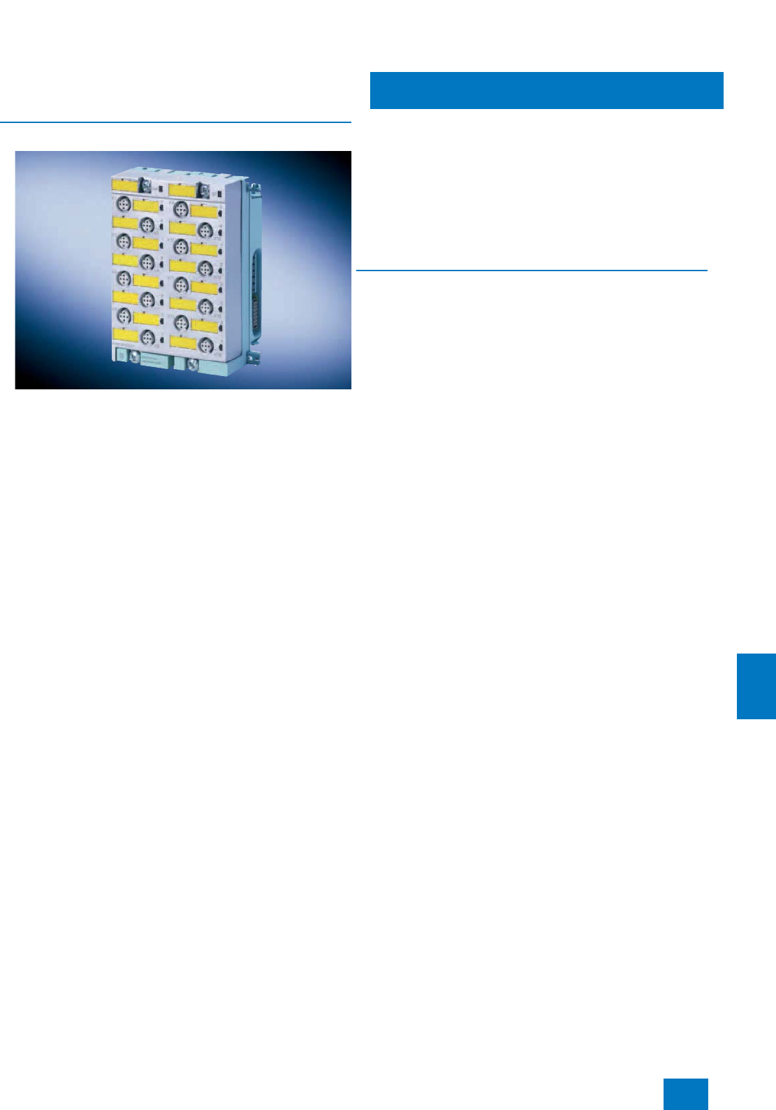
Process I/O
Dezentrale Peripherie ET 200pro
Safety-related electronics modules
11/63
Siemens ST PCS 7 · November 2007
11
■
Overview
In combination with the safety-related automation systems of the
SIMATIC PCS 7 process control system, the safety-related elec-
tronics modules of SIMATIC ET 200pro can be used to imple-
ment safety applications. The safety-related digital inputs record
the signal statuses from safety-related sensors, and generate
corresponding safety telegrams for the automation system. De-
pending on the safety telegrams of the automation system, the
safety-related digital outputs trigger safe shut-down procedures.
They are also responsible for monitoring short-circuits and
cross-circuits up to the actuator. The safe communication with
the automation systems is carried out over PROFIBUS with
PROFIsafe.
All modules are certified up to SIL 3 (IEC 61508) and Cat. 4
(EN954-1).
The following modules are available:
Safety-related digital input module EM 8/16 F-DI PROFIsafe
• 16 inputs (SIL2/Cat.3) or 8 inputs (SIL3/Cat.3 or Cat.4)
• Suitable for standard switches and 3/4-wire proximity switches
(BEROs)
• Rated input voltage 24 V DC
• 4 short-circuit-proof sensor supplies for 4 inputs each
• External sensor power supply possible
• Group fault display (SF; red LED)
• Fault display for each sensor power supply (Vs1F to Vs4F) is
output on the VsF LED and the associated channels
• Status and fault displays per input (dual-color green/red LED)
• Identification data
• Parameterizable diagnostics
• Can only be operated in safety mode
Safety-related digital input/output module EM 4/8 F-DI,
4 F-DO 2 A
• Inputs
- 8 inputs (SIL 2/Cat. 3) or 4 inputs (SIL 3/Cat. 3 or Cat. 4)
- Suitable for standard switches and 3/4-wire proximity
switches (BEROs)
- Rated input voltage 24 V DC
- 2 short-circuit-proof sensor supplies for 4 inputs each
- External sensor power supply possible
•Outputs
- 4 outputs, current sourcing/sinking
- Output current 2 A
- Rated load voltage 24 V DC
- Suitable for solenoid valves, DC contactors and indicator
lights
• Group fault display (SF; red LED)
• Fault display for each sensor power supply (Vs1F to Vs2F) is
output on the VsF LED and the associated channels
• Status and fault displays per input/output (dual-color
green/red LED)
• Identification data
• Parameterizable diagnostics
• Achievable safety class SIL 3
• Can only be operated in safety mode
■
Technical specifications
For detailed technical specifications of the safety-related elec-
tronics modules, see:
• Catalog IK PI
• Mall/CA 01 under "Distributed I/Os / ET 200pro"
© Siemens AG 2007

Process I/O
Dezentrale Peripherie ET 200pro
Safety-related electronics modules
11/64 Siemens ST PCS 7 · November 2007
11
B) Subject to export regulations: AL: N, ECCN: EAR99H
■
Accessories
Connection modules
Actuators and sensors are connected using commercially-avail-
able 5-contact M12 plugs on the connection module. The con-
nection module is plugged onto the electronics module, and
screwed to the latter. One of the following connection modules
(to be ordered separately) is required for each of the above-
mentioned electronics modules:
• Connection module CM IO 16 x M12
for the electronics module 8/16 F-DI, 24 V DC/2 A
• Connection module CM IO 12 x M12
for the electronics module 4/8 F-DI/4 F DO, 24 V DC/2 A
■
Selection and Ordering Data Order No.
Safety-related electronics modules
Safety-related digital input
module
Safety-related digital input
module 8/16 F-DI PROFIsafe
24 V DC, including bus module.
Connection module must be
ordered separately
6ES7 148-4FA00-0AB0 B)
Safety-related digital input/output
module
Safety-related digital input/out-
put module 4/8 F-DI, 4 F-DO 2 A
24 V DC, including bus module.
Connection module must be
ordered separately
6ES7 148-4FC00-0AB0 B)
Accessories
Connection module
• CM IO 16 x M12 for the electron-
ics module 8/16 F-DI,
24 V DC/2 A
6ES7 194-4DD00-0AA0 B)
• CM IO 12 x M12 for the electron-
ics module 4/8 F-DI/4 F DO,
24 V DC/2 A
6ES7 194-4DC00-0AA0 B)
Further accessories
For plugs, cables and further
accessories, see Catalog IK PI or
Mall/CA 01 under "Distributed I/O/
ET 200pro"
© Siemens AG 2007
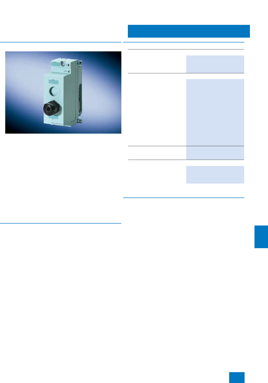
Process I/O
Dezentrale Peripherie ET 200pro
Power module PM-E
11/65
Siemens ST PCS 7 · November 2007
11
■
Overview
The power module PM-E DC 24 V is used within an ET 200pro
station when generating 24 V DC load voltage groups for elec-
tronics modules.
You can position power modules in an ET 200pro station any-
where to the right of the interface module. The first power mod-
ule is already integrated in the interface module.
Each power module which you install in the ET 200pro station in-
terrupts the load voltage busbar, and opens up a new potential
group (common potential) for the load voltage supply 2L+. All
subsequent load voltages of the electronics modules are fed
from this power module. Each power module has a replaceable
fuse for protecting the device. Only line protection according to
DIN VDE 0100 need be provided externally in addition.
The electronics/sensor supply 1L+ is not interrupted by the
power module, it is looped through.
The power module is fitted on the associated bus module when
delivered.
■
Technical specifications
For detailed technical specifications of the power module PM-E,
see:
• Catalog IK PI
• Mall/CA 01 under "Distributed I/Os / ET 200pro"
B) Subject to export regulations: AL: N, ECCN: EAR99H
■
Accessories
Connection module
The connection module for the power module PM-E is used to
connect the load voltage 2L+. It is fitted on the power module.
The module must be ordered separately, and is available with
the following types of connection:
• CM PM-E direct
•CMPM-EECOFAST
• CM PM-E 7/8"
■
Selection and Ordering Data Order No.
Power module
Power module PM-E DC 24 V
For generating 24 V DC load volt-
age groups for electronics mod-
ules within an ET 200pro station.
6ES7148-4CA00-0AA0 B)
Accessories
Connection modules for power
module
• Connection module CM PM-E
ECOFAST
for supply of 24 V DC load volt-
age, 1 ECOFAST Cu connection
6ES7 194-4BA00-0AA0 B)
• Connection module CM PM-E
direct
for supply of 24 V DC load volt-
age, up to two M20 cable
glands
6ES7 194-4BC00-0AA0 B)
• Connection module CM PM-E
7/8"
for supply of 24 V DC load volt-
age, 1 x 7/8"
6ES7 194-4BD00-0AA0 B)
Spare fuse
12.5 A fast-blow, for interface and
power modules, 10 units per pack
6ES7 194-4HB00-0AA0
Further accessories
For plugs, cables and further
accessories, see Catalog IK PI or
Mall/CA 01 under "Distributed
I/O / ET 200pro"
© Siemens AG 2007

Process I/O
11/66 Siemens ST PCS 7 · November 2007
11
© Siemens AG 2007

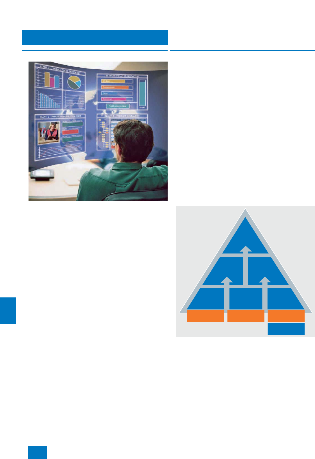
IT world
SIMATIC IT
12/2 Siemens ST PCS 7 · November 2007
12
■
Overview
Integration and synchronization of all business processes
with SIMATIC IT
In order to remain competitive, manufacturers must shorten their
product launch times, increase production transparency and
flexibility, optimize planning and scheduling, and reduce waste,
storage costs and downtimes. At the same time, directives and
high-quality standards must be observed in the global produc-
tion locations, and maximum productivity and optimum costs
must be guaranteed.
Manufacturing Execution Systeme (MES), such as SIMATIC IT
from Siemens, permit effective integration of product processes
and material management systems, and support the coordina-
tion of all equipment and applications relevant to production dur-
ing all phases.
SIMATIC IT can be used to model the complete production
know-how, to precisely define the operating processes, and to
record data in real-time from the ERP and production levels. It is
then possible to control corporate processes more effectively, to
minimize downtimes, production waste and postprocessing, to
optimize stockkeeping, and to react rapidly and flexibly to
changing customer requirements.
■
Design
SIMATIC IT consists of various components designed for differ-
ent tasks which can all be coordinated by the SIMATIC IT Pro-
duction Modeler.
The basic functions are implemented using SIMATIC IT compo-
nents. These are available in the form of the following product
bundles:
• SIMATIC IT Plant Intelligence (formally known as MIS - Man-
agement Information System)
Defines key performance indicators conforming to the plant
model. SIMATIC IT Plant Intelligence allows realistic assess-
ment of the plant performance.
• SIMATIC IT Genealogy Management
For materials management in the entire company, taking into
account the legal terms and conditions. Typical tasks are re-
verse and forwards genealogy, fundamental material monitor-
ing, and synchronization of material master data with the ERP
system.
• SIMATIC IT Order Management
For job management from planning to execution, including
scheduling, materials planning, new planning of sequence,
monitoring and recording of execution.
Further bundles are available, e.g. SIMATIC IT Basic Tracking &
Tracing, SIMATIC IT Basic Production Management or
SIMATIC IT Production Suite, providing a fully-scaled product
portfolio.
Summary of SIMATIC IT bundles
Each of these product bundles contains the optional SIMATIC IT
Client Application Builder (CAB) which provides the GUI for the
MES applications in a complete Web-based environment. Pat-
ented functions for optimization of image updating are available
based on standard technology. The SIMATIC IT Client Applica-
tion Builder offers complete support for operator stations which
require practically no administrative overhead (so-called zero
administration cost clients).
Production
Suite
Basic
Production
Management
Order
Management
Genealogy
Management
Basic
Tracking
& Tracing
MIS
Order
Management
Material
Management
Data
Management
Historian
© Siemens AG 2007

IT world
SIMATIC IT
12/3
Siemens ST PCS 7 · November 2007
12
Additional options can be separately purchased for each
bundle:
• SIMATIC IT PDS-I (Predictive Detailed Scheduler - Interactive)
is the detailed scheduling component of SIMATIC IT. It coordi-
nates and processes the job list coming from the ERP (Enter-
prise Resources Planning) or APS (Advanced Planning Sys-
tem) with consideration of all available resources in real-time.
An advanced, dedicated interface even allows users who
have no IT or scheduling experience to produce optimum pro-
duction job planning. A number of predefined steps addition-
ally support users in selection of the best planning scenario.
• SIMATIC IT Report Manager
offers comprehensive reporting functions. It provides valuable
knowledge concerning the company and supports users in
complying with statutory requirements for ad hoc reporting
(e.g. EU directive EC 178/2002 for Europe, US bioterrorism
act for North America).
• SIMATIC IT OEE-DTM Option (Overall Equipment Efficiency /
Down Time Management)
offers support for the dedicated configuration for downtime
management and efficient utilization of the overall equipment
through various predefined KPIs for evaluation of perfor-
mance and efficiency. It also allows customized performance
calculations as well as real and consistent efficiency analysis
using graphic objects. Thanks to integration within the com-
plete SIMATIC IT infrastructure, it supports the implementation
of corrective and/or preventive actions for avoiding reductions
in quality.
• SIMATIC IT SPC (Statistical Process Control)
is used for the dedicated configuration of statistical process
control through various predefined KPIs for evaluation with the
most common control charts (e.g. Nelson and Western Elec-
tric). It also allows customized KPI calculations as well as con-
sistent statistical analyses with application of graphic objects.
Thanks to integration within the complete SIMATIC IT infra-
structure, it supports the implementation of corrective and/or
preventive actions for avoiding reductions in quality.
The MES product range of SIMATIC IT is completed by the fol-
lowing components for special ISA-95 functions (also offered as
stand-alone products):
• SIMATIC IT Unilab
Laboratory Information System / Laboratory Information Man-
agement System (LIMS) for management and control of labo-
ratory data and processes.
• SIMATIC IT Interspec
Specifications Management System for support of product
lifecycle / Product Lifecycle Management (PLM) for manage-
ment and control of production specifications in the entire
company.
• SIMATIC IT XHQ
provides decision-makers in a company with a tool for making
better, faster and more sound decisions at all levels through
the assistance of role-based Web views, thus increasing the
company’s total performance. This allows manufacturers to
positively influence the production result through early and
qualified decisions concerning the production sequence. As
a result of the complete overview of all critical business and
operating data from various sources within the company, op-
erators and managers are able to check the true performance
compared to corporate targets. SIMATIC IT XHQ is initially fo-
cused on the chemical and oil & gas industries.
■
Function
SIMATIC IT from Siemens offers significant advantages. The
model of the business and production processes is transparent,
understandable, and independent of the control systems. Even
complex business and production processes are easy to model.
Subsequent modifications can be incorporated efficiently and
without problem.
Modeling of the business and production processes with
SIMATIC IT allows complete documentation as well as effective
protection of know-how.
The plant and production models can be saved in libraries, and
then used again in other projects. In this manner, they can be
used at any company location for standardization of procedures.
Best practices are therefore available everywhere. This prevents
implementation errors, provides investment safeguarding, re-
duces launch and maintenance costs, and results in a signifi-
cant shortening in the project duration.
The product architecture and functionality of SIMATIC IT are in
conformance with ISA-95, the internationally recognized stan-
dard for Manufacturing Execution Systems and Manufacturing
Operation Management.
■
Integration
Integration of SIMATIC IT and SIMATIC PCS 7
The Product Integration Pack is available for joint projects with
SIMATIC IT und SIMATIC PCS 7, and includes two data media
(one each for the two target systems SIMATIC IT and SIMATIC
PCS 7). These contain the software updates required for inte-
grated configurations.
A user manual is also enclosed which provides information and
important notes for persons planning, developing and imple-
menting integration projects.
The integration pack can be obtained using the SIMATIC IT pur-
chasing methods.
■
More information
Contact partners
Marketing Germany
Andreas Kempenich
E-mail: andreas.kempenich@siemens.com
Europe Helpline: +49 (0) 180 5050 111
Siemens Automation and Drives
Automation Solutions MES
Viale Cembrano, 11
I-16148 Genua, Italy
Tel.: +39 010 3434-1
Fax: +39 010 383 115
E-mail: marketing.simatic-it@siemens.com
Additional information is available in the Internet under:
http://www.siemens.com/simatic-it
© Siemens AG 2007

IT world
12/4 Siemens ST PCS 7 · November 2007
12
© Siemens AG 2007


Migration to SIMATIC PCS 7
Introduction
13/2 Siemens ST PCS 7 · November 2007
13
■
Overview
Migration strategy
Globalization and incessantly increasing competitive pressures
are forcing companies to continuously increase productivity and
shorten product time to market. To this end, it is necessary to
continuously optimize engineering procedures and the process,
and to simultaneously consider new industrial requirements and
directives.
Today, many systems and plants must be expanded and mod-
ernized to ensure that companies can continue to provide prod-
ucts meeting market requirements. However, since the installed
basis of hardware, application software and know-how of the op-
erating and maintenance engineers represents an enormous
value, the safeguarding of investments for companies operating
the plants is always assigned a high priority during all modern-
ization plans.
Experience has shown that the success of migration is largely
determined by providing a technical solution that optimally
matches the customer requirements and the customer’s plant.
Minimization of the technical and financial risks together with
safeguarding of investments for as long a period as possible are
always fundamental aspects. The different lifecycles of the vari-
ous system components must also be considered, which cur-
rently vary from 5 years for PC-based workstations, 15 years for
controllers, up to 25 years or more for input/output components
and wiring. Therefore Siemens does not consider its task to sim-
ply be the complete replacement of an existing system, but in
close collaboration together with customers and their system in-
tegrators of an individual, future-oriented solution based on the
state-of-the-art SIMATIC PCS 7 process control system - always
under the directives:
7Step-by-step system innovation
7Adaptable to the specific conditions of the plant
7Flexible according to production requirements
System
aspects
HMI/batch
- Replaces old HMI
- Replaces batch
system
Controller/network
- Replaces controller
- Gateway to
SIMATIC PCS 7
I/O field connection
- Further use of I/Os
- Field connection
elements for SIMATIC
PCS 7
Strategy
- Plant/product future
- Planned modernization
(revamping)
Cost reduction
- Maintenance budget
- Investment budget
Time-to-Market
- Production time
- Available downtime
Innovation pressure
- Improved process
control
- IT integration
- Advanced process
control &
asset management
Lifecycle phases
- Maintenance &
modernization
- Expansion &
improvement
- Renewal/replacement
with state-of-the-art
technology
Siemens migration strategy
Plant
aspects
Production
aspects
Innovative technologies
FlexibleAdaptableStep-by-step
© Siemens AG 2007
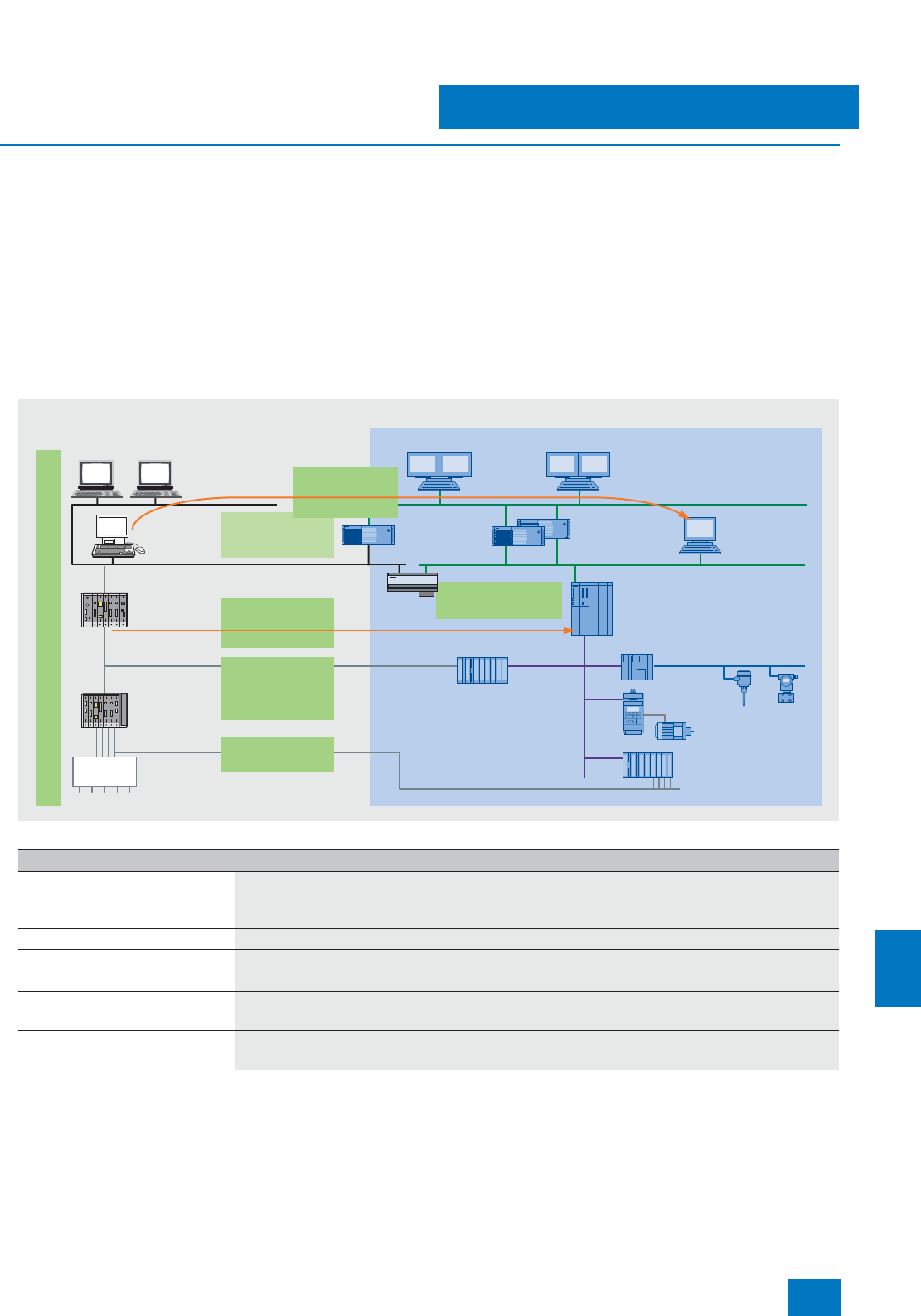
Migration to SIMATIC PCS 7
Introduction
13/3
Siemens ST PCS 7 · November 2007
13
■
Function
Portfolio of the migration products
Early on Siemens recognized the significance of migration for
process automation, and for many years has offered a wide
range of innovative migration products and solutions for its glo-
bally proven systems. Right from the beginning, the maxim of
Siemens’ migration strategy is to modernize the existing in-
stalled basis in steps without completely changing the system;
and where possible without or with minimal plant downtime.
Siemens has the products to support customers’ endeavors to
achieve long-term safeguarding of investments together with
maximization of their return on assets, even for legacy systems
from other vendors.
Siemens’ know-how in the migration sector has continuously
grown as time has passed. The experience gained in numerous
migration projects has been incorporated into new products and
technologies which are even more efficient. For example, "Data-
base Automation" (DBA) is available for engineering of operation
and monitoring systems. Using DBA and a plug-in interface, it is
possible to download the configuration data, and to display and
configure them using a standardized user interface. DBA allows
system-based migration of operator system data from different
output systems in standardized form, thus providing uniform
software quality, security and understandability.
The migration products can be categorized as follows:
Step-by-step migration with the right products and services
ET 200M
PROFIBUS PA
HMI
SIMATIC PCS 7
SIMATIC IT
PROFIBUS DP
S7-400 S, H, HF
controller
Motor
I/O
interface
I/O
Controller
Engineering
Station Engineering
System
Wiring
rack
Server Server
Gateway
Importing of
engineering data
of old OS
Importing of
controller
engineering
Linking
of existing
I/O modules to
PCS 7/AS
Migration services in every step of migration project
Gateway to
data coupling
Field Termination
Adapter
OS replacement
by server for
PCS 7/OS
Clients
Legacy system
Migration component Description
OS migration products • Interface from SIMATIC PCS 7 OS Server to system bus of legacy system
• OS conversion tool (e.g. DBA)
• Faceplate library
Services for OS migration Tools/services for conversion of process displays
Services for AS migration Tools/services for function-based conversion of AS engineering data to SIMATIC PCS 7
BATCH migration components Enables existing system to use SIMATIC BATCH
Gateway • Gateway between system bus of legacy system and SIMATIC PCS 7 (mainly for AS-AS communication)
• Engineering tool for gateway
Reuse of legacy system I/Os or Field
Termination Assembly (FTA) • Reuse of I/Os (connection of old I/Os to SIMATIC PCS 7 automation systems, mostly for Siemens systems)
• Field Termination Assemblies (FTAs) for field cabling
© Siemens AG 2007

Migration to SIMATIC PCS 7
Introduction
13/4 Siemens ST PCS 7 · November 2007
13
Typical migration scenarios
The migration path that a user takes depends on the specific
technical and economical factors of each migration project. The
migration products offer the modularity and flexibility required to
implement different scenarios. The following are typical migra-
tion scenarios which can be implemented using these migration
products:
Scenario 1: Replacement of existing HMI system by a SIMATIC
PCS 7 operator system
If the HMI (Human Machine Interface) system is technically ob-
solete, if the stocking of spare parts is too expensive, if it no
longer complies with current directives and standards for oper-
ator workstations, or if functional expansions are required (e.g.
IT integration), it is possible to simply replace the existing HMI
system by a SIMATIC PCS 7 operator system. The controller with
application software and the process I/O are retained.
The benefits of these migration step are:
• Minimum costs
• Clear risk
• Lengthening of service life of complete plant
• New application possibilities
• Opening of system for IT world
Scenario 2: Expansion of existing plant
The existing plant is initially retained, and is modernized by ex-
panding with further sections/units with SIMATIC PCS 7.
The benefits of these migration step are:
• Simple, step-by-step increase in production capacity
• Clear risk
• Introduction of new technologies (e.g. PROFIBUS fieldbus,
HMI)
• Opening of system for IT world
• Together with scenario 1, enables process control using a uni-
form operator system
Scenario 3: Comprehensive modernization
Bottlenecks in the provision of spare parts, insufficient support,
and the necessity for functional expansions (e.g. fieldbus tech-
nology or IT integration) can also force comprehensive modern-
ization of the old system using the future-oriented SIMATIC
PCS 7 process control system. Conversion may also be possible
during operation. Further use of the existing I/O level is sup-
ported, and the investments made for wiring, hardware compo-
nents or application engineering are safeguarded.
The benefits of these migration step are:
• Increase in performance
• Introduction of new technologies (e.g. PROFIBUS fieldbus,
HMI)
• Opening of system for IT world
• Lengthening of service life of complete plant
• Reduction in number of system suppliers
• Elimination of bottlenecks
© Siemens AG 2007
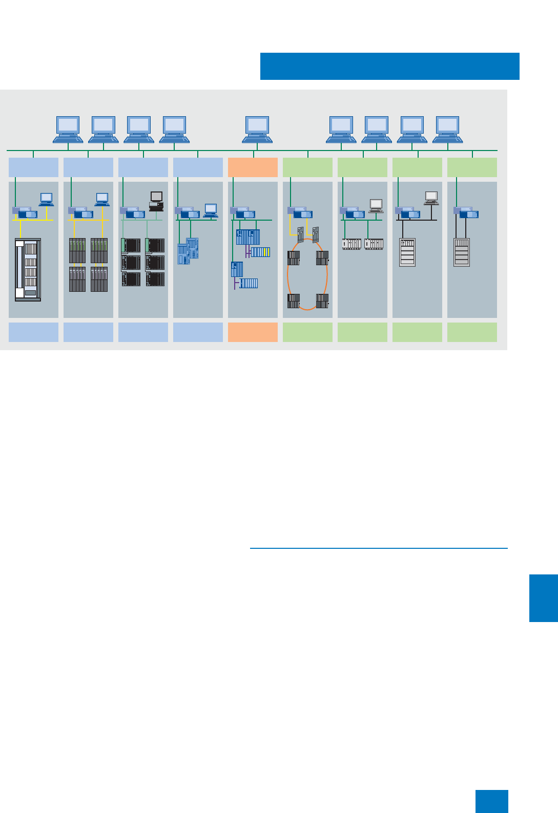
Migration to SIMATIC PCS 7
Introduction
13/5
Siemens ST PCS 7 · November 2007
13
Migration spectrum
The migration of our own process control systems to SIMATIC
PCS 7 is a matter of course for Siemens, and a significant
component of the continued supplier/customer relationship.
Siemens is additionally able to offer migration solutions for pro-
cess control systems from other vendors, e.g. for systems from
ABB, Honeywell or Emerson.
Siemens can work closely with the customer’s system integrators
when implementing migration projects, for they have the know-
how gained over many years of working with the user and ex-
actly know the plant as well as the customer’s requirements. This
partnership is a guarantee for the companies operating plants
that they will receive an optimum migration solution. A further im-
portant aspect is that Siemens supports the migration products
as well as the standard products by means of product updating
and customer support. A special strength of Siemens compared
to other suppliers of migration solutions is the ability to offer cus-
tomers long-term support through know-how, servicing and pro-
vision of components, spare parts and upgrades.
With the future-oriented SIMATIC PCS 7 process control system,
innovative migration solutions and services, many years of
know-how in process automation and migration, as well as con-
tinuous worldwide servicing, Siemens demonstrates its exper-
tise and offers the security of a reliable partner.
Migration Support Center
Siemens has established several global Migration Support Cen-
ters which offer customers further support for migration projects
in addition to product support:
• Migration concepts
• Quotation preparation
• Engineering/project management
Development of further migration products and tools
Through the development of flexible migration solutions and ser-
vices, comprehensive sector know-how, migration experience
developed over many years, and worldwide support, Siemens
has laid the foundation for the development of migration solu-
tions for third-party control systems. This allows users of third-
party control systems to take advantage of the globally leading
SIMATIC technology in order to safeguard their investments in
new automation technology for the future.
■
More information
For further information, see the Chapter “Additional migration
products and solutions”.
SIMATIC PCS 7
OS clients
SIMATIC PCS 7
OS clients
SIMATIC PCS 7
Engineering
PCS 7
OS server
PCS 7/
third-party OS
Other
systems
MBUS
PROVOX
Controller
and I/O
Third-party
control system
SIMATIC IT
Management
Console
APT
ES
AS 235
CS 275
4-mation
H1 TF Ethernet
Control
Builder F
Envox
Bailey
Infi/Net 90
ABB
Freelance
Bailey Plant
Loop/
INFI-NET
PCS 7/TM OS PCS 7/505 OS PCS 7/90 OS PCS 7/F2K OS PCS 7/PVX OS
PCS 7/
APACS+ OS
PCS 7/
OPMC OS
TELEPERM M SIMATIC 505 Emerson
PROVOX
OpenPMC
APACS+/
QUADLOG
SIMATIC
PCS 7
OpenPMC
Controller S7-41x
S7-
417H
AC 800F
Data
Highway
© Siemens AG 2007

Migration to SIMATIC PCS 7
13/6 Siemens ST PCS 7 · November 2007
13
© Siemens AG 2007
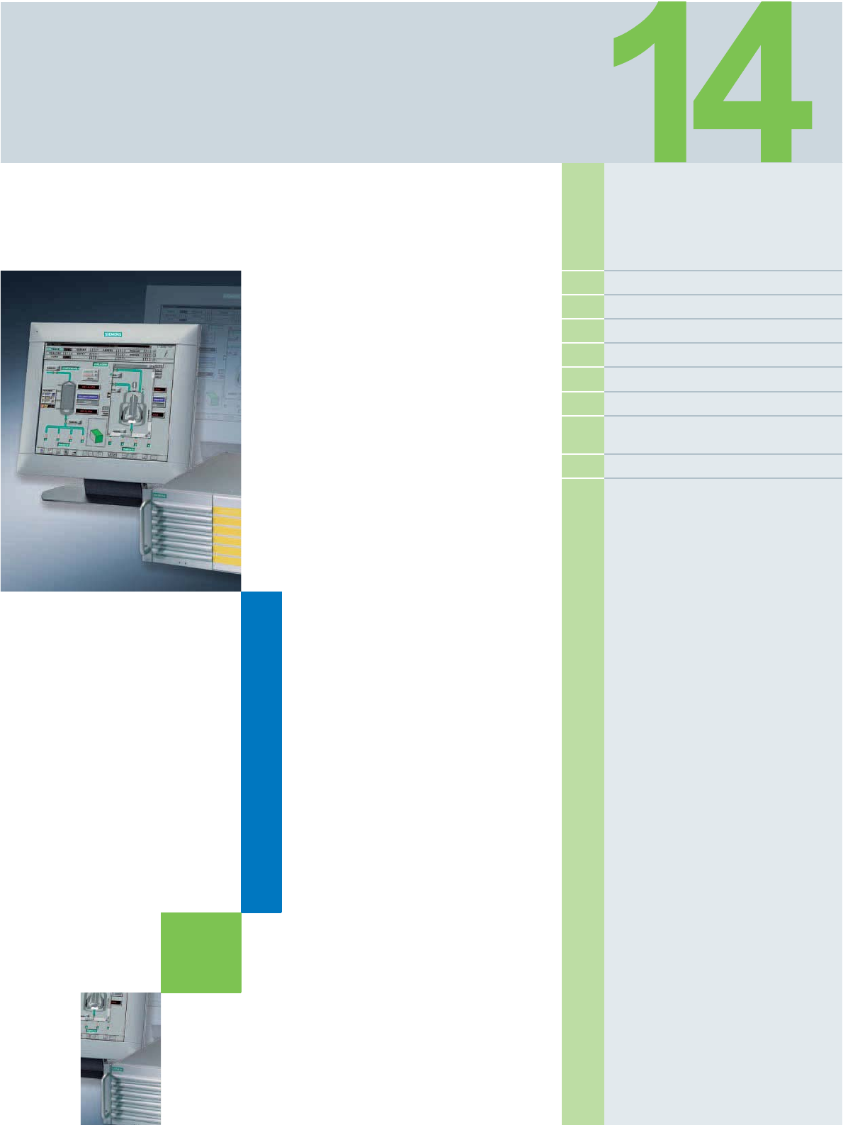
Siemens ST PCS 7 · November 2007
14/2 Basic hardware V6.1
14/4 Starter systems V6.1
14/5 ES software V6.1
14/9 OS software V6.1
14/13 SIMATIC BATCH Software V6.1
14/14 Route Control Software V6.1
14/15 Asset Management Software
V6.1
14/16 PROFIBUS PA components
14/17 Automation systems
Ordering data for
previous version
SIMATIC PCS 7 V6.1
© Siemens AG 2007

Ordering data for previous version SIMATIC PCS 7 V6.1
Basic hardware V6.1
14/2 Siemens ST PCS 7 · November 2007
14
■
Selection and Ordering Data Order No.
Single station
SIMATIC PC in rack of 19" design,
Pentium 4 3.4 GHz, 1 GB RAM
(2 x 512 MB), sound, SATA-RAID
1 with 2 hard disks of 120 GB,
graphics controller on board with
dynamic video memory, DVD
writer DVD±RW IDE, 3.5" diskette
drive, optical mouse,
FastEthernet RJ45 on board for
connection to OS-LAN,
without monitor, keyboard and
printer,
SIMATIC PCS 7 software pre-
installed and 2 restore DVDs
Windows 2000 Professional MUI
operating system
(German, English, French, Italian,
Spanish, Chinese, Japanese)
• SIMATIC PCS 7 ES/OS IL43
BCE W2K
Connection to plant bus through
Basic Communication Ethernet
(BCE) with FastEthernet RJ45 net-
work card (PCI card)
6ES7 650-0LC16-0YX0 D)
•SIMATIC PCS 7 ES/OS IL43 IE
W2K
Connection to plant bus via
Industrial Ethernet with CP 1613
A2 communications processor
6ES7 650-0LC16-0YX1 D)
Windows XP Professional MUI
operating system
(German, English, French, Italian,
Spanish, Chinese, Japanese)
•SIMATIC PCS 7 ES/OS IL43
BCE WXP
Connection to plant bus through
Basic Communication Ethernet
(BCE) with FastEthernet RJ45 net-
work card (PCI card)
6ES7 650-0LF16-0YX0 D)
•SIMATIC PCS 7 ES/OS IL43 IE
WXP
Connection to plant bus via
Industrial Ethernet with CP 1613
A2 communications processor
6ES7 650-0LF16-0YX1 D)
Server
SIMATIC PC in rack of 19" design,
Pentium 4 3.4 GHz, 1 GB RAM
(2 x 512 MB), sound, SATA-RAID
1 with 2 hard disks of 120 GB,
graphics controller on board with
dynamic video memory, DVD-
ROM IDE, 3.5" diskette drive, opti-
cal mouse,
FastEthernet RJ45 on board for
connection to OS-LAN,
without monitor, keyboard and
printer,
SIMATIC PCS 7 software pre-
installed and 2 restore DVDs
Windows 2000 Server MUI
operating system
(German, English, French, Italian,
Spanish, Chinese, Japanese)
•SIMATIC PCS 7 OS Server
IL43 BCE W2K
Connection to plant bus through
Basic Communication Ethernet
(BCE) with FastEthernet RJ45 net-
work card (PCI card)
6ES7 650-0LE16-0YX0 D)
•SIMATIC PCS 7 OS Server
IL43 IE W2K
Connection to plant bus via
Industrial Ethernet with
CP 1613 A2 communications pro-
cessor
6ES7 650-0LE16-0YX1 D)
Windows Server 2003 MUI
operating system
(German, English, French, Italian,
Spanish, Chinese, Japanese)
•SIMATIC PCS 7 OS Server
IL43 BCE SRV03
Connection to plant bus through
Basic Communication Ethernet
(BCE) with FastEthernet RJ45
network card (PCI card)
6ES7 650-0LH16-0YX0 D)
•SIMATIC PCS 7 OS Server
IL43 IE SRV03
Connection to plant bus via
Industrial Ethernet with CP 1613
A2 communications processor
6ES7 650-0LH16-0YX1 D)
D) Subject to export regulations: AL: N, ECCN: 5D992B1
■
Selection and Ordering Data Order No.
© Siemens AG 2007

Ordering data for previous version SIMATIC PCS 7 V6.1
Basic hardware V6.1
14/3
Siemens ST PCS 7 · November 2007
14
1) The PCS 7 systems are delivered as standard with a "European power
cable". The country-specific versions listed above are required for some
countries.
Client
SIMATIC PC in rack of 19" design,
Pentium 4 3.4 GHz, 512 MB RAM
(2 x 256 MB), SATA hard disk 120
GB, graphics controller on board
with dynamic video memory,
DVD-ROM IDE, 3.5" diskette
drive, optical mouse,
FastEthernet RJ45 on board for
connection to OS-LAN,
without monitor, keyboard and
printer,
SIMATIC PCS 7 preinstalled and
2 restore DVDs
Windows 2000 Professional MUI
operating system
(German, English, French, Italian,
Spanish, Chinese, Japanese)
•SIMATIC PCS 7 OS Client
IL43 W2K 6ES7 650-0LD16-0YX0 D)
Windows XP Professional MUI
operating system
(German, English, French, Italian,
Spanish, Chinese, Japanese)
•SIMATIC PCS 7 OS Client
IL43 WXP 6ES7 650-0LG16-0YX0 D)
■
Selection and Ordering Data Order No.
Additional and expansion components
Memory modules for expanding
the main memory
• 512 MB memory expansion kit
for SIMATIC Rack PC IL 43
(2 x 256 MB) for dual channel
6ES7 648-2AF30-0GB0 B)
• 1 GB memory expansion kit for
SIMATIC Rack PC IL 43
(2 x 512 MB) for dual channel
6ES7 648-2AF40-0GB0 B)
• 2 GB memory expansion kit for
SIMATIC Rack PC IL 43
(2 x 1 GB) for dual channel
6ES7 648-2AF50-0GB0 B)
SIMATIC PC keyboard
(USB connection)
• International key assignment 6ES7 648-0CB00-0YA0
Tower kit for SIMATIC PCS 7
Industrial Workstations
based on Rack PC 547B and
IL 43
• Tower kit for conversion of a
Rack PC into an industrial Tower
PC
6ES7 648-1AA00-0XC0
3-m power cable for Rack PC 1)
• For Great Britain 6ES7 900-0BA00-0XA0
• For Switzerland 6ES7 900-0CA00-0XA0
• For USA 6ES7 900-0DA00-0XA0
• For Italy 6ES7 900-0EA00-0XA0
B) Subject to export regulations: AL: N, ECCN: EAR99H
D) Subject to export regulations: AL: N, ECCN: 5D992B1
■
Selection and Ordering Data Order No.
© Siemens AG 2007

Ordering data for previous version SIMATIC PCS 7 V6.1
Starter systems V6.1
14/4 Siemens ST PCS 7 · November 2007
14
SIMATIC PCS 7 BOX PCS 7 Basic Package
D) Subject to export regulations: AL: N, ECCN: 5D992B1
■
Selection and Ordering Data Order No.
SIMATIC PCS 7 BOX complete
system (ES, OS and AS)
assembled and preinstalled,
comprising:
• SIMATIC Box PC 627, 24 V DC,
with WinAC Slot 416 and
Windows XP Professional MUI
(German, English, French, Ital-
ian, Spanish)
• Memory card 2 MB
• Backup battery
• Mouse
• SIMATIC PCS 7 Engineering
Software V6.1 for AS/OS, 250
POs/RC 8K,
3 languages (German, English,
French), floating license for
1user
• PCS 7 Library Blocks V6.1,
3 languages (German, English,
French), runtime license for
1 automation system
6ES7 650-2MA16-0YX0 D)
SIMATIC PCS 7 BOX runtime
system (OS and AS)
assembled and preinstalled,
comprising:
• SIMATIC Box PC 627, 24 V DC,
with WinAC Slot 416 and
Windows XP Professional MUI
(German, English, French, Ital-
ian, Spanish)
• Memory card 2 MB
• Backup battery
• Mouse
• SIMATIC PCS 7 OS Software
Single Station V6.1,
250POs/RT8K,
3 languages (German, English,
French), single license for
1 installation
• PCS 7 Library Blocks V6.1,
3 languages (German, English,
French), runtime license for 1
automation system
6ES7 650-2MB16-0YX0 D)
■
Selection and Ordering Data Order No.
PCS 7 Basic Package V6.1
comprising:
• 1 x AS 416-3 with
- PS 407 power supply; 10 A for
120/230 V AC/DC
- UR2 rack (9 slots)
- Memory card 8 MB
- CP 443-1EX11
- CP443-5 Extended
• 1 x engineering station with
- Basic device SIMATIC PCS 7
ES/OS IL 43 BCE WXP
- PCS 7 engineering software
for AS/OS; 1000 POs/RC 32K,
floating license
- SFC Visualization, floating
license
- PCS 7 Import/Export Assis-
tant, floating license
- SIMATIC PDM PCS 7, floating
license
• 1 x OS Single Station
- Basic device SIMATIC PCS 7
ES/OS IL 43 BCE WXP
- PCS 7 OS Software Single
Station for 1000 POs/RT 32K,
single license
- SFC Visualization, floating
license
6ES7 650-3GD16-0YX0 D)
© Siemens AG 2007

Ordering data for previous version SIMATIC PCS 7 V6.1
ES software V6.1
14/5
Siemens ST PCS 7 · November 2007
14
Standard engineering software
■
Selection and Ordering Data Order No.
SIMATIC PCS 7 Engineering
Software V6.1
3 languages (German, English,
French), executes with Windows
2000 Professional/ 2000 Server or
Windows XP Professional/
Server 2003, floating license for
1user
Electronic documentation on
PCS 7 toolset DVD
Type of delivery:
License key disk, emergency key
disk, certificate of license, terms
and conditions;
PCS 7 V6.1 toolset DVD,
Microsoft SQL Server including
EULA, PC Anywhere Host and
supplementary CDs/DVDs (e.g.
Microsoft ServicePacks and tools)
Engineering software for AS
• 250 POs (process objects) 6ES7 658-1AA16-0YA5
• 1000 POs 6ES7 658-1AB16-0YA5
• 2000 POs 6ES7 658-1AC16-0YA5
• 3000 POs 6ES7 658-1AD16-0YA5
• 5000 POs 6ES7 658-1AE16-0YA5
• Unlimited POs 6ES7 658-1AF16-0YA5
Engineering software for OS
• 250 POs/RC 8K 6ES7 658-2DA16-0YA5
• 1000 POs/RC 32K 6ES7 658-2DB16-0YA5
• 2000 POs/RC 64K 6ES7 658-2DC16-0YA5
• 3000 POs/RC 100K 6ES7 658-2DD16-0YA5
• 5000 POs/RC 150K 6ES7 658-2DE16-0YA5
• 8500 POs/RC 256K 6ES7 658-2DF16-0YA5
Engineering software for AS/OS
• 250 POs/RC 8K 6ES7 658-5AA16-0YA5
• 1000 POs/RC 32K 6ES7 658-5AB16-0YA5
• 2000 POs/RC 64K 6ES7 658-5AC16-0YA5
• 3000 POs/RC 100K 6ES7 658-5AD16-0YA5
• 5000 POs/RC 150K 6ES7 658-5AE16-0YA5
• Unlimited POs/RC 256K 6ES7 658-5AF16-0YA5
SIMATIC PCS 7 Engineering
Software V6.1 Rental License
3 languages (German, English,
French), executes with Windows
2000 Professional/ 2000 Server or
Windows XP Professional/
Server 2003
Rental license for 50 hours
Type of delivery:
License key disk, emergency key
disk, certificate of license, terms
and conditions;
PCS 7 V6.1 toolset DVD,
Microsoft SQL Server including
EULA, PC Anywhere Host and
supplementary CDs/DVDs (e.g.
Microsoft ServicePacks and tools)
• For AS, 2000 POs 6ES7 658-1AC16-0YA6
• For OS, 2000 POs/RC 64K 6ES7 658-2DC16-0YA6
SIMATIC PCS 7 PowerPacks for engineering software
SIMATIC PCS 7 PowerPack
Engineering Software AS
for extending the engineering
software for AS
3 languages (German, English,
French), executes with Windows
2000 Professional/ 2000 Server or
Windows XP Professional/
Server 2003, floating license for
1user
Type of delivery:
License key disk, emergency key
disk, certificate of license, terms
and conditions
• From 250 POs to 1000 POs 6ES7 658-1AB16-0YD5
• From 1000 POs to 2000 POs 6ES7 658-1AC16-0YD5
• From 2000 POs to 3000 POs 6ES7 658-1AD16-0YD5
• From 3000 POs to 5000 POs 6ES7 658-1AE16-0YD5
• From 5000 POs to unlimited POs 6ES7 658-1AF16-0YD5
SIMATIC PCS 7 PowerPack
Engineering Software OS
for extending the engineering
software for OS
3 languages (German, English,
French), executes with Windows
2000 Professional/ 2000 Server or
Windows XP Professional/
Server 2003, floating license for
1user
Type of delivery:
License key disk, emergency key
disk, certificate of license, terms
and conditions
• From 250 POs/RC 8K to
1000 POs/RC 32K 6ES7 658-2DB16-0YD5
• From 1000 POs/RC 32K to
2000 POs/RC 64K 6ES7 658-2DC16-0YD5
• From 2000 POs/RC 64K to
3000 POs/RC 100K 6ES7 658-2DD16-0YD5
• From 3000 POs/RC 100K to
5000 POs/RC 150K 6ES7 658-2DE16-0YD5
• From 5000 POs/RC 150K to
8500 POs/RC 256K 6ES7 658-2DF16-0YD5
SIMATIC PCS 7 PowerPack
Engineering Software AS/OS
for extending the engineering
software for AS/OS
3 languages (German, English,
French), executes with Windows
2000 Professional/ 2000 Server or
Windows XP Professional/
Server 2003, floating license for
1user
Type of delivery:
License key disk, emergency key
disk, certificate of license, terms
and conditions
• From 250 POs/RC 8K to
1000 POs/RC 32K 6ES7 658-5AB16-0YD5
• From 1000 POs/RC 32K to
2000 POs/RC 64K 6ES7 658-5AC16-0YD5
• From 2000 POs/RC 64K to
3000 POs/RC 100K 6ES7 658-5AD16-0YD5
• From 3000 POs/RC 100K to
5000 POs/RC 150K 6ES7 658-5AE16-0YD5
• From 5000 POs/RC 150K to
unlimited POs/RC 256K 6ES7 658-5AF16-0YD5
■
Selection and Ordering Data Order No.
© Siemens AG 2007

Ordering data for previous version SIMATIC PCS 7 V6.1
ES software V6.1
14/6 Siemens ST PCS 7 · November 2007
14
Version Cross Checker
Version Trail
Import/Export Assistant
Route Control Engineering
Engineering F/FH Systems
Note:
With a S7 F Systems Upgrade from V5.x to V6.0, the type of S7 F Systems
license changes from single license to floating license.
Safety Matrix
■
Selection and Ordering Data Order No.
SIMATIC Version Cross Checker
V6.1
3 languages (German, English,
French), executes with Windows
2000 Professional or Windows
XP Professional, floating license
for 1 user
Type of delivery:
License key disk, emergency key
disk, certificate of license, terms
and conditions
6ES7 658-1CX16-2YB5
■
Selection and Ordering Data Order No.
SIMATIC Version Trail V6.1
5 languages (German, English,
French, Spanish, Italian),
executes with Windows 2000
Professional, Windows
XP Professional or Windows
Server 2003, floating license for
1user
Type of delivery: License key
disk, emergency key disk,
certificate of license, terms and
conditions
6ES7 658-1FX16-2YB5
■
Selection and Ordering Data Order No.
SIMATIC PCS 7 Import/Export
Assistant V6.1
3 languages (German, English,
French), executes with Windows
2000 Professional/ 2000 Server or
Windows XP Professional/
Server 2003, floating license for
1user
Type of delivery:
License key disk, emergency key
disk, certificate of license, terms
and conditions
6ES7 658-1DX16-2YB5
■
Selection and Ordering Data Order No.
SIMATIC Route Control
Engineering V6.1
3 languages (German, English,
French), executes with Windows
2000 Professional/ 2000 Server or
Windows XP Professional/
Server 2003
Type of delivery: License key
disk, emergency key disk, certifi-
cate of license, terms and condi-
tions
• Floating license for 1 user 6ES7 658-7DX16-0YB5
■
Selection and Ordering Data Order No.
S7 F Systems V6.0
Programming and configuration
environment for creating and
using safety-related STEP 7 pro-
grams for a target system based
on S7-400H
2 languages (German, English),
executes with Windows
XP Professional SP2, Windows
Server 2003 SP1/SP2 and
Windows 2000 SP4, floating
license for 1 user
Type of delivery:
Certificate of license as well as
software and electronic docu-
mentation on CD
6ES7 833-1CC01-0YA5
S7 F Systems Upgrade from
V5.x to V6.0
2 languages (German, English),
executes with Windows
XP Professional SP2, Windows
Server 2003 SP1/SP2 and
Windows 2000 SP4, floating
license for 1 user
Type of delivery:
Certificate of license as well as
software and electronic docu-
mentation on CD
6ES7 833-1CC01-0YE5
■
Selection and Ordering Data Order No.
SIMATIC Safety Matrix Tool
Creation, configuration, compila-
tion, loading and online monitor-
ing of the Safety Matrix in a
SIMATIC PCS 7 environment
Including SIMATIC Safety Matrix
Viewer for SIMATIC PCS 7, for
operation and monitoring of the
Safety Matrix in a SIMATIC PCS 7
environment with several operator
control levels
2 languages (German, English),
executes with Windows 2000
Professional, Windows XP
Professional or Windows 2003
Server, single license for
1 installation
Type of delivery: Certificate of
license and authorization diskette
for Safety Matrix Tool and Safety
Matrix Viewer; software and elec-
tronic documentation on CD
6ES7 833-1SM00-0YA5 C)
SIMATIC Safety Matrix Editor
Creation and checking of the
Safety Matrix logic on an external
computer without a SIMATIC
PCS 7/ STEP 7 environment
2 languages (German, English),
executes with Windows 2000
Professional, Windows XP
Professional or Windows 2003
Server, single license for
1 installation
Type of delivery: Certificate of
license and authorization dis-
kette; software and electronic
documentation on CD
6ES7 833-1SM40-0YA5 C)
C) Subject to export regulations: AL: N, ECCN: EAR99S
© Siemens AG 2007

Ordering data for previous version SIMATIC PCS 7 V6.1
ES software V6.1
14/7
Siemens ST PCS 7 · November 2007
14
SIMATIC PDM
■
Selection and Ordering Data Order No.
SIMATIC PDM Single Point
SIMATIC PDM Single Point V6.0
for operation and parameteriza-
tion of one field device; communi-
cation via PROFIBUS DP/PA or
HART modem, including 1 TAG,
cannot be expanded with respect
to functions or with TAG
option/PowerPack
5 languages (German, English,
French, Spanish, Italian), exe-
cutes with Windows
2000 Professional or Windows
XP Professional
Floating license for 1 user
Type of delivery:
License key disk, emergency key
disk, certificate of license, terms
and conditions;
2 CDs with SIMATIC PDM V6.0
and device library as well as sup-
plementary DVD with Microsoft
ServicePacks and tools
6ES7 658-3HX06-0YA5
SIMATIC PDM Basic
SIMATIC PDM Basic V6.0
for operation and parameteriza-
tion of field devices and compo-
nents, communication via
PROFIBUS DP/PA, HART
modem/interface, RS 232,
Modbus, SIREC bus, SIPART DR,
including 4 TAGs
5 languages (German, English,
French, Spanish, Italian), exe-
cutes with Windows
2000 Professional or Windows
XP Professional
Type of delivery:
License key disk, emergency key
disk, certificate of license, terms
and conditions;
2 CDs with SIMATIC PDM V6.0
and device library as well as sup-
plementary DVD with Microsoft
ServicePacks and tools
• Floating license for 1 user 6ES7 658-3AX06-0YA5
• Rental license for 50 hours 6ES7 658-3AX06-0YA6
Functional options for SIMATIC PDM V6.0
Integration in STEP 7 /
SIMATIC PCS 7
Only required if integration of
SIMATIC PDM into HW-Config is
to be used
5 languages (German, English,
French, Spanish, Italian), exe-
cutes with Windows
2000 Professional or Windows
XP Professional
Type of delivery:
License key disk, emergency key
disk, certificate of license, terms
and conditions
• Floating license for 1 user 6ES7 658-3BX06-2YB5
Routing through S7-400
5 languages (German, English,
French, Spanish, Italian), exe-
cutes with Windows
2000 Professional or Windows
XP Professional
Type of delivery:
License key disk, emergency key
disk, certificate of license, terms
and conditions
• Floating license for 1 user 6ES7 658-3CX06-2YB5
Communication via standard
HART multiplexer
5 languages (German, English,
French, Spanish, Italian), exe-
cutes with Windows
2000 Professional or Windows
XP Professional
Type of delivery:
License key disk, emergency key
disk, certificate of license, terms
and conditions
• Floating license for 1 user 6ES7 658-3EX06-2YB5
TAG options / PowerPacks
SIMATIC PDM TAG option
for TAG expansion, additive to
SIMATIC PDM Basic V6.0
5 languages (German, English,
French, Spanish, Italian), exe-
cutes with Windows
2000 Professional or Windows
XP Professional
Floating license for 1 user
Type of delivery:
License key disk, certificate of
license, terms and conditions
• Up to 128 TAGs 6ES7 658-3XA06-2YB5
• Up to 512 TAGs 6ES7 658-3XB06-2YB5
• Up to 1024 TAGs 6ES7 658-3XC06-2YB5
• Up to 2048 TAGs 6ES7 658-3XD06-2YB5
SIMATIC PDM PowerPack
for subsequent TAG expansion of
all SIMATIC PDM V6.0 product
configurations
5 languages (German, English,
French, Spanish, Italian), exe-
cutes with Windows
2000 Professional or Windows
XP Professional
Floating license for 1 user
Type of delivery:
License key disk, certificate of
license, terms and conditions
• From 128 TAGs to 512 TAGs 6ES7 658-3XB06-2YD5
• From 512 TAGs to 1024 TAGs 6ES7 658-3XC06-2YD5
• From 1024 TAGs to 2048 TAGs 6ES7 658-3XD06-2YD5
• From 2048 TAGs to unlimited
TAGs 6ES7 658-3XH06-2YD5
■
Selection and Ordering Data Order No.
© Siemens AG 2007

Ordering data for previous version SIMATIC PCS 7 V6.1
ES software V6.1
14/8 Siemens ST PCS 7 · November 2007
14
Controller optimization
Simulation with S7-PLCSIM
Predefined SIMATIC PDM V6.0 product configurations for special
applications
SIMATIC PDM Service V6.0
Complete package for stand-
alone users for servicing, with
• SIMATIC PDM Basic V6.0
• Option "128 TAGs"
5 languages (German, English,
French, Spanish, Italian), exe-
cutes with Windows 2000
Professional or Windows
XP Professional, floating license
for 1 user
Type of delivery:
License key disk, emergency key
disk, certificate of license, terms
and conditions;
2 CDs with SIMATIC PDM V6.0
and device library as well as sup-
plementary DVD with Microsoft
ServicePacks and tools
6ES7 658-3JX06-0YA5
SIMATIC PDM S7 V6.0
Complete package for use in a
SIMATIC S7 configuration envi-
ronment, with
• SIMATIC PDM Basic V6.0
• Option "Integration in
STEP 7/PCS 7"
• Option "128 TAGs"
5 languages (German, English,
French, Spanish, Italian), exe-
cutes with Windows 2000
Professional or Windows
XP Professional, floating license
for 1 user
Type of delivery:
License key disk, emergency key
disk, certificate of license, terms
and conditions;
2 CDs with SIMATIC PDM V6.0
and device library as well as sup-
plementary DVD with Microsoft
ServicePacks and tools
6ES7 658-3KX06-0YA5
SIMATIC PDM PCS 7 V6.0
Complete package for integra-
tion into the engineering toolset of
the SIMATIC PCS 7 engineering
system
Floating license for 1 user, with
• SIMATIC PDM Basic
• Option "Integration in
STEP 7/PCS 7"
• Option "Routing through S7-400"
• Option "128 TAGs"
5 languages (German, English,
French, Spanish, Italian), exe-
cutes with Windows
2000 Professional or Windows
XP Professional
Type of delivery:
License key disk, emergency key
disk, certificate of license, terms
and conditions;
2 CDs with SIMATIC PDM V6.0
and device library as well as sup-
plementary DVD with Microsoft
ServicePacks and tools
6ES7 658-3LX06-0YA5
■
Selection and Ordering Data Order No.
■
Selection and Ordering Data Order No.
SIMATIC PCS 7 PID Tuner V6.1
Controller optimization; option
package for CFC
3 languages (German, English,
French), executes with Windows
2000 Professional/ 2000 Server or
Windows XP Professional/
Server 2003
Floating license for 1 user
Type of delivery:
License key disk, emergency key
disk, certificate of license, terms
and conditions
6ES7 653-0SP16-2YB5
■
Selection and Ordering Data Order No.
S7-PLCSIM V5.3
Functional testing of programs
which were created with
CFC/SFC, on PC/PG
5 languages (German, English,
French, Spanish, Italian), exe-
cutes with Windows 2000
Professional/ 2000 Server or
Windows XP Professional/
Server 2003
Type of delivery: License key
disk, certificate of license, terms
and conditions
• Floating license for 1 user 6ES7 841-0CC04-0YA5
© Siemens AG 2007

Ordering data for previous version SIMATIC PCS 7 V6.1
OS software V6.1
14/9
Siemens ST PCS 7 · November 2007
14
OS standard software for single station / server / client
1) A process object (PO) is a synonym for an operable and observable block
with approx. 30 variables.
■
Selection and Ordering Data Order No.
OS Software Single Station
SIMATIC PCS 7 OS Software
Single Station V6.1
3 languages (German, English,
French), executes with Windows
2000 Professional or Windows
XP Professional, single license for
1 installation
Electronic documentation on
PCS 7 toolset DVD
Type of delivery:
License key disk, emergency key
disk, certificate of license, terms
and conditions;
PCS 7 V6.1 toolset DVD,
Microsoft SQL Server including
EULA, PC Anywhere Host and
supplementary CDs/DVDs (e.g.
Microsoft ServicePacks and tools)
• 250 POs/RT 8K 1) 6ES7 658-2AA16-0YA0
• 1000 POs/RT 32K 6ES7 658-2AB16-0YA0
• 2000 POs/RT 64K 6ES7 658-2AC16-0YA0
• 3000 POs/RT 100K 6ES7 658-2AD16-0YA0
• 5000 POs/RT 150K 6ES7 658-2AE16-0YA0
SIMATIC PCS 7 PowerPack
OS Software Single Station
V6.1
for extending the OS software for
a single station
3 languages (German, English,
French), executes with Windows
2000 Professional or Windows
XP Professional, single license for
1 installation
Type of delivery:
License key disk, emergency key
disk, certificate of license, terms
and conditions
• From 250 POs/RT 8K to 1000
POs/RT 32K 6ES7 658-2AB16-0YD0
• From 1000 POs/RT 32K to 2000
POs/RT 64K 6ES7 658-2AC16-0YD0
• From 2000 POs/RT 64K to 3000
POs/RT 100K 6ES7 658-2AD16-0YD0
• From 3000 POs/RT 100K to 5000
POs/RT 150K 6ES7 658-2AE16-0YD0
OS Software Server
SIMATIC PCS 7 OS Software
Server V6.1
3 languages (German, English,
French), executes with Windows
2000 Server or Windows Server
2003, single license for
1 installation
Electronic documentation on
PCS 7 toolset DVD
Type of delivery:
License key disk, emergency key
disk, certificate of license, terms
and conditions;
PCS 7 V6.1 toolset DVD,
Microsoft SQL Server including
EULA, PC Anywhere Host and
supplementary CDs/DVDs (e.g.
Microsoft ServicePacks and tools)
• 250 POs/RT 8K 6ES7 658-2BA16-0YA0
• 1000 POs/RT 32K 6ES7 658-2BB16-0YA0
• 2000 POs/RT 64K 6ES7 658-2BC16-0YA0
• 3000 POs/RT 100K 6ES7 658-2BD16-0YA0
• 5000 POs/RT 150K 6ES7 658-2BE16-0YA0
• 8500 POs/RT 256K 6ES7 658-2BF16-0YA0
SIMATIC PCS 7 PowerPack
OS Software Server V6.1
for extending the OS Software
Server
3 languages (German, English,
French), executes with Windows
2000 Server or Windows Server
2003, single license for
1 installation
Type of delivery:
License key disk, emergency key
disk, certificate of license, terms
and conditions
• From 250 POs/RT 8K to 1000
POs/RT 32K 6ES7 658-2BB16-0YD0
• From 1000 POs/RT 32K to 2000
POs/RT 64K 6ES7 658-2BC16-0YD0
• From 2000 POs/RT 64K to 3000
POs/RT 100K 6ES7 658-2BD16-0YD0
• From 3000 POs/RT 100K to 5000
POs/RT 150K 6ES7 658-2BE16-0YD0
• From 5000 POs/RT 150K to 8500
POs/RT 256K 6ES7 658-2BF16-0YD0
OS Software Client
SIMATIC PCS 7 OS Software
Client V6.1
3 languages (German, English,
French), executes with Windows
2000 Professional or Windows
XP Professional, floating license
for 1 user
Electronic documentation on
PCS 7 toolset DVD
Type of delivery:
License key disk, emergency key
disk, certificate of license, terms
and conditions;
PCS 7 V6.1 toolset DVD,
Microsoft SQL Server including
EULA, PC Anywhere Host and
supplementary CDs/DVDs (e.g.
Microsoft ServicePacks and tools)
6ES7 658-2CX16-0YA5
■
Selection and Ordering Data Order No.
© Siemens AG 2007

Ordering data for previous version SIMATIC PCS 7 V6.1
OS software V6.1
14/10 Siemens ST PCS 7 · November 2007
14
OS archiving
SFC Visualization
SIMATIC Safety Matrix Viewer
Connectivity Pack and Client Access Licenses
■
Selection and Ordering Data Order No.
Expansion of integral high-performance cyclic buffer archive
(512 variables) of OS Single Station and OS Server
SIMATIC PCS 7 PowerPack
OS Archive V6.1
3 languages (German, English,
French), executes with Windows
2000 Professional/ 2000 Server or
Windows XP Professional/
Server 2003, single license for
1 installation
Type of delivery:
License key disk, emergency key
disk, certificate of license, terms
and conditions
• For expansion from 512 to
1500 variables 6ES7 658-2EA16-2YD0
• For expansion from 1500 to
5000 variables 6ES7 658-2EB16-2YD0
• For expansion from 5000 to
10000 variables 6ES7 658-2EE16-2YD0
SIMATIC PCS 7 Bundle
OS Archive V6.1
3 languages (German, English,
French), executes with Windows
2000 Professional/ 2000 Server or
Windows XP Professional/
Server 2003, single license for
1 installation
Type of delivery:
4 license key disks, emergency
key disk, certificate of license,
terms and conditions
• 4 x 5000 variables for 4 stations
each (Single Station/Server) 6ES7 652-1EA16-2YB0
■
Selection and Ordering Data Order No.
SIMATIC PCS 7
SFC Visualization V6.1
for displaying and operating SFC
sequence controls on an operator
station
3 languages (German, English,
French), executes with Windows
2000 Professional or Windows
XP Professional, floating license
for 1 user
Type of delivery:
License key disk, emergency key
disk, certificate of license, terms
and conditions
6ES7 652-0XD16-2YB5
SIMATIC PCS 7 Upgrade
SFC Visualization V5.x to V6.1
3 languages (German, English,
French),
executes with Windows 2000
Professional or Windows
XP Professional, floating license
for 1 user
Type of delivery:
License key disk, emergency key
disk, certificate of license, terms
and conditions
6ES7 652-0XD16-2YF5
■
Selection and Ordering Data Order No.
SIMATIC Safety Matrix Viewer
for SIMATIC PCS 7
Operation and monitoring of the
safety matrix in the SIMATIC
PCS 7 environment with several
operating levels
2 languages (German, English),
executes with Windows 2000
Professional, Windows XP
Professional or Windows 2003
Server, single license for
1 installation
Type of delivery: Certificate of
license and authorization dis-
kette; software and electronic
documentation on CD
6ES7 833-1SM60-0YA5 C)
■
Selection and Ordering Data Order No.
WinCC/Connectivity Pack
Single license for 1 installation 6AV6 371-1DR06-1AX0
WinCC/Client Access License
for access of (office) computers
(without WinCC installation) to
archive and alarm data of an
operator station (OS single sta-
tion/OS server) per OPC HDA,
OPC A&E or OLE-DB
Single license for 1 installation
6AV6 371-1ES06-0AX0
WinCC/Client Access License
per Prozessor
for access of client to archive and
alarm data of an operator station
(OS single station/OS server) per
OPC HDA, OPC A&E or OLE-DB
License for any number of clients
per processor
6AV6 371-1ES06-0CX0
C) Subject to export regulations: AL: N, ECCN: EAR99S
© Siemens AG 2007

Ordering data for previous version SIMATIC PCS 7 V6.1
OS software V6.1
14/11
Siemens ST PCS 7 · November 2007
14
OS redundancy OS long-term archiving
■
Selection and Ordering Data Order No.
Design of redundant OS single stations
WinCC/Redundancy V6.0 SP3
for alignment of archives following
OS restart; single license for
2 installations
Installation required on each of
the two redundant OS single sta-
tions
6AV6 371-1CF06-0DX0
Design of redundant OS servers
SIMATIC PCS 7 Server
Redundancy V6.1
3 languages (German, English,
French), executes with Windows
2000 Server or Windows Server
2003, single license for
2 installations
with OS Software Server und
WinCC/Redundancy as well as
RS 232 connecting cable, 10 m
Type of delivery:
2 license key disks, emergency
key disk, certificate of license,
terms and conditions;
PCS 7 V6.1 toolset DVD,
Microsoft SQL Server including
EULA, PC Anywhere Host and
supplementary CDs/DVDs (e.g.
Microsoft ServicePacks and tools)
• 250 POs/RT 8K 6ES7 652-3XA16-2YA0
• 2000 POs/RT 64K 6ES7 652-3XC16-2YA0
• 3000 POs/RT 100K 6ES7 652-3XD16-2YA0
• 5000 POs/RT 150K 6ES7 652-3XE16-2YA0
• 8500 POs/RT 256K 6ES7 652-3XF16-2YA0
PowerPacks for PO expansion:
see OS Software Server
PowerPack V6.1 (2 PowerPacks
each required)
■
Selection and Ordering Data Order No.
SIMATIC StoragePlus V1.1
Software for long-term archiving
of data from the SIMATIC PCS 7
process control system; for up to
4 single stations, servers or pairs
of servers
3 languages (German, English,
French), executes with Windows
2000 Professional/ 2000 Server or
Windows XP Professional/
Server 2003, single license for
1 installation
Type of delivery:
License key disk, emergency key
disk, certificate of license, terms
and conditions
6ES7 652-0XC11-2YB0
SIMATIC PCS 7 Central Archive
Server V6.1
Software for long-term archiving
of data from the SIMATIC PCS 7
process control system; for up to
11 servers or pairs of servers
3 languages (German, English,
French), executes with Windows
Server 2003, single license for
1 installation
Type of delivery:
License key disk, emergency key
disk, certificate of license, terms
and conditions
6ES7 658-2FX16-0YB0
© Siemens AG 2007

Ordering data for previous version SIMATIC PCS 7 V6.1
SIMATIC BATCH Software V6.1
14/12 Siemens ST PCS 7 · November 2007
14
PCS 7 Web Server
1) Deviating from the specification in the ordering data, the license of the
OS Software Client V6.1 in this special application is also enabled for the
Microsoft Windows Server 2003 operating system.
■
Selection and Ordering Data Order No.
SIMATIC PCS 7 Web Server
V6.1
3 languages (German, English,
French), executes with Windows
Server 2003, single license for
1 installation
Type of delivery:
License key disk, emergency key
disk, certificate of license, terms
and conditions
• For 3 clients 6ES7 658-2GA16-2YB0
• For 10 clients 6ES7 658-2GB16-2YB0
• For 25 clients 6ES7 658-2GC16-2YB0
• For 50 clients 6ES7 658-2GD16-2YB0
SIMATIC PCS 7 PowerPack Web
Server V6.1
3 languages (German, English,
French), executes with Windows
Server 2003, single license for
1 installation
Type of delivery:
License key disk, emergency key
disk, certificate of license, terms
and conditions
For expansion of PCS 7 Web
server license
• From 3 to up to 10 clients 6ES7 658-2GB16-2YD0
• From 10 to up to 25 clients 6ES7 658-2GC16-2YD0
• From 25 to up to 50 clients 6ES7 658-2GD16-2YD0
OS Software Client
SIMATIC PCS 7 OS Software
Client V6.1 1)
3 languages (German, English,
French), executes with Windows
2000 Professional or Windows
XP Professional, floating license
for 1 user
Electronic documentation on
PCS 7 toolset DVD
Type of delivery:
• License key disk, emergency
key disk, certificate of license,
terms and conditions
• PCS 7 V6.1 toolset DVD,
Microsoft SQL Server including
EULA and supplementary
CDs/DVDs (e.g. Microsoft
ServicePacks and tools)
6ES7 658-2CX16-0YA5
SIMATIC PCS 7 Web Diagnos-
tics Client V6.1
3 languages (German, English,
French), executes with Windows
Server 2003, single license for
1 installation
Type of delivery:
License key disk, emergency key
disk, certificate of license, terms
and conditions
6ES7 658-2JX16-2YB0
SIMATIC PCS 7 Web Diagnos-
tics Server V6.1
3 languages (German, English,
French), executes with Windows
Server 2003, single license for
1 installation
Type of delivery:
License key disk, emergency key
disk, certificate of license, terms
and conditions
6ES7 658-2HX16-2YB0
■
Selection and Ordering Data Order No.
■
Selection and Ordering Data Order No.
SIMATIC BATCH
Server Basic Package V6.1
(PO 150)
For single station or client/server
configuration, comprising
• Batch server for 150 batch POs
1)
• Recipe System
• Batch Control Center (BatchCC)
3 languages (German, English,
French), executes with Windows
2000 Professional/ 2000 Server or
Windows XP Professional/
Server 2003, single license for
1 installation
Type of delivery:
License key disk, certificate of
license, terms and conditions
6ES7 657-0SA16-0YB0 SIMATIC BATCH
PO Options V6.1
For expansion of the SIMATIC
BATCH Server Basic Package
3 languages (German, English,
French), executes with Windows
2000 Professional/ 2000 Server or
Windows XP Professional/
Server 2003, single license for
1 installation
Type of delivery:
License key disk, certificate of
license, terms and conditions
• To batch with 300 POs 6ES7 657-0XE16-2YB0
• To batch with 600 POs 6ES7 657-0XB16-2YB0
• To batch with 1800 POs 6ES7 657-0XC16-2YB0
• To batch with unlimited POs 6ES7 657-0XD16-2YB0
■
Selection and Ordering Data Order No.
© Siemens AG 2007

Ordering data for previous version SIMATIC PCS 7 V6.1
Route Control Software V6.1
14/13
Siemens ST PCS 7 · November 2007
14
1) Whereas process objects (PO) represent operable and observable blocks
with approx. 30 variables, batch process objects (batch POs) represent
instances of plant units and equipment modules (EPH/EOP).
SIMATIC BATCH
PowerPacks V6.1
For expansion of batch POs
3 languages (German, English,
French), executes with Windows
2000 Professional/ 2000 Server or
Windows XP Professional/
Server 2003, single license for
1 installation
Type of delivery:
License key disk, certificate of
license, terms and conditions
• From batch with 300 POs to
batch with 600 POs 6ES7 657-0XB16-2YD0
• From batch with 600 POs to
batch with 1800 POs 6ES7 657-0XC16-2YD0
• From batch with 1800 POs to
batch with unlimited POs 6ES7 657-0XD16-2YD0
SIMATIC BATCH
BatchCC V6.1
3 languages (German, English,
French), executes with Windows
2000 Professional/ 2000 Server or
Windows XP Professional/
Server 2003, floating license for
1user
Type of delivery: License key
disk, certificate of license, terms
and conditions
6ES7 657-0LX16-2YB5
SIMATIC BATCH
Recipe System V6.1
3 languages (German, English,
French), executes with Windows
2000 Professional/ 2000 Server or
Windows XP Professional/
Server 2003, floating license for
1user
Type of delivery: License key
disk, certificate of license, terms
and conditions
6ES7 657-0AX16-2YB5
SIMATIC BATCH
Batch Planning V6.1
3 languages (German, English,
French), executes with Windows
2000 Professional/ 2000 Server or
Windows XP Professional/
Server 2003, floating license for
1user
Type of delivery: License key
disk, certificate of license, terms
and conditions
6ES7 657-0BX16-2YB5
SIMATIC BATCH
Hierarchical Recipe V6.1
3 languages (German, English,
French), executes with Windows
2000 Professional/ 2000 Server or
Windows XP Professional/
Server 2003, single license for
1 installation
Type of delivery: License key
disk, certificate of license, terms
and conditions
6ES7 657-0FX16-2YB0
SIMATIC BATCH
ROP Library V6.1
3 languages (German, English,
French), executes with Windows
2000 Professional/ 2000 Server or
Windows XP Professional/
Server 2003, single license for
1 installation
Type of delivery: License key
disk, certificate of license, terms
and conditions
6ES7 657-0GX16-2YB0
■
Selection and Ordering Data Order No.
SIMATIC BATCH
Separation Procedures/
Formulas V6.1
3 languages (German, English,
French), executes with Windows
2000 Professional/ 2000 Server or
Windows XP Professional/
Server 2003, single license for
1 installation
Type of delivery: License key
disk, certificate of license, terms
and conditions
6ES7 657-0HX16-2YB0
SIMATIC BATCH API V6.1
1 language (English), executes
with Windows 2000 Professional/
2000 Server or Windows XP
Professional/ Server 2003, single
license for 1 installation
Type of delivery: License key
disk, certificate of license, terms
and conditions
6ES7 657-0MX16-2YB0
■
Selection and Ordering Data Order No.
SIMATIC Route Control Server
V6.1
for up to 30 simultaneous
material transports
For single station and cli-
ent/server configuration
3 languages (German, English,
French), executes with Windows
2000 Server or Windows Server
2003,
single license for 1 installation
Type of delivery: License key
disk, emergency key disk, certifi-
cate of license, terms and condi-
tions
6ES7 658-7FA16-0YB0
SIMATIC Route Control Server
PowerPack V6.1
for expansion of SIMATIC Route
Control Server
3 languages (German, English,
French), executes with Windows
2000 Server or Windows Server
2003,
single license for 1 installation
Type of delivery: License key
disk, emergency key disk, certifi-
cate of license, terms and condi-
tions
• From 30 to up to 100 simulta-
neous material transports 6ES7 658-7FB16-0YD0
• From 100 to up to 300 simulta-
neous material transports 6ES7 658-7FC16-0YD0
■
Selection and Ordering Data Order No.
© Siemens AG 2007

Ordering data for previous version SIMATIC PCS 7 V6.1
Asset Management Software V6.1
14/14 Siemens ST PCS 7 · November 2007
14
SIMATIC Route Control Center
V6.1
3 languages (German, English,
French), executes with Windows
2000 Professional or Windows
XP Professional,
floating license for 1 user
Type of delivery: License key
disk, emergency key disk, certifi-
cate of license, terms and condi-
tions
6ES7 658-7EX16-0YB5
SIMATIC Route Control Engi-
neering V6.1
3 languages (German, English,
French), executes with Windows
2000 Professional/ 2000 Server or
Windows XP Professional/
Server 2003
Type of delivery: License key
disk, emergency key disk, certifi-
cate of license, terms and condi-
tions
• Floating license for 1 user 6ES7 658-7DX16-0YB5
■
Selection and Ordering Data Order No.
■
Selection and Ordering Data Order No.
SIMATIC PCS 7 Asset Runtime
V6.1
incl. 128 asset TAGs1) and one
OPC server license
For installation on SIMATIC PCS 7
BOX, single station or client
3 languages (German, English,
French), executes with Windows
2000 Professional/ 2000 Server or
Windows XP Professional/
Server 2003, single license for
1 installation
Type of delivery:
License key disk, emergency key
disk, certificate of license, terms
and conditions
6ES7 658-7GA16-0YB0
SIMATIC PCS 7 PowerPack
Asset Runtime V6.1
for expanding the TAGs of
SIMATIC PCS 7 Asset Runtime
V6.1
3 languages (German, English,
French), executes with Windows
2000 Professional/ 2000 Server or
Windows XP Professional/
Server 2003, single license for
1 installation
Type of delivery:
License key disk, emergency key
disk, certificate of license, terms
and conditions
• From 128 to 512 asset TAGs,
incl. one OPC server license 6ES7 658-7GB16-0YD0
• From 512 to 1024 asset TAGs 6ES7 658-7GC16-0YD0
• From 1024 to 2048 asset TAGs 6ES7 658-7GD16-0YD0
• From 2048 to unlimited asset
TAGs 6ES7 658-7GH16-0YD0
© Siemens AG 2007

Ordering data for previous version SIMATIC PCS 7 V6.1
PROFIBUS PA components
14/15
Siemens ST PCS 7 · November 2007
14
1) With asset TAGs, the number of asset objects monitored in SIMATIC PCS 7
is licensed. An asset object represents individual hardware components
within a SIMATIC PCS 7 project, e.g.
- measuring devices, positioners, switchgear or remote I/Os monitored per
EDD or
- basic devices or Ethernet components monitored in the maintenance sta-
tion via an OPC link.
In conjunction with PowerPacks, licenses are available for 128, 512, 1024,
2048 and unlimited asset TAGs.
Asset Engineering
SIMATIC PCS 7 Asset Engineer-
ing V6.1
For installation on SIMATIC PCS 7
BOX, single station or client
3 languages (German, English,
French), executes with Windows
2000 Professional/ 2000 Server or
Windows XP Professional/
Server 2003, floating license for
1user
Type of delivery:
License key disk, emergency key
disk, certificate of license, terms
and conditions
6ES7 658-7GX16-0YB5
■
Selection and Ordering Data Order No.
■
Selection and Ordering Data Order No.
DP/PA Coupler
For transition from RS 485 to MBP
•Ex version 6ES7 157-0AD82-0XA0
• Non-Ex version 6ES7 157-0AC82-0XA0
IM 153-2 High Feature
Interface module for DP/PA Link
and Y-Link
6ES7 153-2BA81-0XB0 B)
Accessories
PS 307 Load Power Supply
Including connection assembly;
120/230 V AC; 24 V DC
• 2 A; 50 mm wide 6ES7 307-1BA00-0AA0
• 5 A; 80 mm wide 6ES7 307-1EA00-0AA0
• 5 A, extended temperature
range; 80 mm wide 6ES7 307-1EA80-0AA0
• 10 A, 200 mm wide 6ES7 307-1KA01-0AA0
PS 305 Load Power Supply
24/48/60/110 V DC; 24 V DC
• 2 A, extended temperature
range; 80 mm wide 6ES7 305-1BA80-0AA0
Standard profile rails
(without hot swapping function)
• 482 mm wide (19 inches) 6ES7 390-1AE80-0AA0
• 530 mm wide 6ES7 390-1AF30-0AA0
B) Subject to export regulations: AL: N, ECCN: EAR99H
© Siemens AG 2007

Ordering data for previous version SIMATIC PCS 7 V6.1
PROFIBUS PA components
14/16 Siemens ST PCS 7 · November 2007
14
Components for hot swapping and for redundant design
Active bus modules for hot
swapping
• BM IM 157
For two IM 153-2 High Feature
modules, for redundant and
non-redundant configuration, for
extended temperature range, for
hot swapping function,
permissible operating tempera-
ture -25 ... +60 °C
6ES7 195-7HD80-0XA0
• BM DP/PA
For one DP/PA coupler,
for extended temperature range,
for hot swapping function,
permissible operating tempera-
ture -25 ... +60 °C
6ES7 195-7HF80-0XA0
Profile rail for hot swapping
For max. 5 active bus modules
• 482 mm wide (19 inches) 6ES7 195-1GA00-0XA0
• 530 mm wide 6ES7 195-1GF30-0XA0
• 620 mm wide 6ES7 195-1GG30-0XA0
■
Selection and Ordering Data Order No.
© Siemens AG 2007

Ordering data for previous version SIMATIC PCS 7 V6.1
Automation systems
14/17
Siemens ST PCS 7 · November 2007
14
Standard automation systems (bundles)
■
Selection and Ordering Data Order No.
Ordering units for SIMATIC PCS 7 standard automation systems
with Industrial Ethernet interfacing via CP
AS 414-3 automation system
comprising:
SIMATIC PCS 7 AS Runtime
license for 100 POs (applies to
SIMATIC PCS 7 V6.1 also as
Runtime license PCS 7 Library
Blocks)
Controller type 414-3 with
3 interfaces (MPI/DP, DP and slot
for IF module), 2.8 MB main
memory (1.4 MB each for pro-
gram and data), CP 443-1 com-
munications processor for
connection to Industrial Ethernet
plant bus as well as
• Aluminum UR1 rack (18 slots):
- PS 407 power supply; 20 A for
120/230 V AC/DC, 2 backup
batteries, memory card 2 MB
RAM
6ES7 654-3QD48-0XX0
- PS 407 power supply; 20 A for
120/230 V AC/DC, 2 backup
batteries, memory card 4 MB
RAM
6ES7 654-3QE48-0XX0 B)
- PS 405 power supply; 20 A for
24 V DC, 2 backup batteries,
memory card 2 MB RAM
6ES7 654-6QD48-0XX0
- PS 405 power supply; 20 A for
24 V DC, 2 backup batteries,
memory card 4 MB RAM
6ES7 654-6QE48-0XX0 B)
- Without power supply, without
backup batteries, without
memory card
6ES7 654-0QX48-0XX0
• Aluminum UR2 rack (9 slots):
- PS 407 power supply; 10 A for
120/230 V AC/DC, 2 backup
batteries, memory card 2 MB
RAM
6ES7 654-1QD58-0XX0
- PS 407 power supply; 10 A for
120/230 V AC/DC, 2 backup
batteries, memory card 4 MB
RAM
6ES7 654-1QE58-0XX0 B)
- PS 405 power supply; 10 A for
24 V DC, 2 backup batteries,
memory card 2 MB RAM
6ES7 654-4QD58-0XX0
- PS 405 power supply; 10 A for
24 V DC, 2 backup batteries,
memory card 4 MB RAM
6ES7 654-4QE58-0XX0 B)
- Without power supply, without
backup batteries, without
memory card
6ES7 654-0QX58-0XX0
AS 416-2 automation system
comprising:
SIMATIC PCS 7 AS Runtime
license for 100 POs (applies to
SIMATIC PCS 7 V6.1 also as
Runtime license PCS 7 Library
Blocks)
Controller type 416-2 with
2 interfaces (MPI/DP and DP),
5.6 MB main memory (2.8 MB
each for program and data),
CP 443-1 communications pro-
cessor for connection to Industrial
Ethernet plant bus as well as
• Aluminum UR1 rack (18 slots):
- PS 407 power supply; 20 A for
120/230 V AC/DC, 2 backup
batteries, memory card 4 MB
RAM
6ES7 654-3JE48-0XX0
- PS 407 power supply; 20 A for
120/230 V AC/DC, 2 backup
batteries, memory card 8 MB
RAM
6ES7 654-3JF48-0XX0 B)
- PS 405 power supply; 20 A for
24 V DC, 2 backup batteries,
memory card 4 MB RAM
6ES7 654-6JE48-0XX0
- PS 405 power supply; 20 A for
24 V DC, 2 backup batteries,
memory card 8 MB RAM
6ES7 654-6JF48-0XX0 B)
- Without power supply, without
backup batteries, without
memory card
6ES7 654-0JX48-0XX0
• Aluminum UR2 rack (9 slots):
- PS 407 power supply; 10 A for
120/230 V AC/DC, 2 backup
batteries, memory card 4 MB
RAM
6ES7 654-1JE58-0XX0
- PS 407 power supply; 10 A for
120/230 V AC/DC, 2 backup
batteries, memory card 8 MB
RAM
6ES7 654-1JF58-0XX0 B)
- PS 405 power supply; 10 A for
24 V DC, 2 backup batteries,
memory card 4 MB RAM
6ES7 654-4JE58-0XX0
- PS 405 power supply; 10 A for
24 V DC, 2 backup batteries,
memory card 8 MB RAM
6ES7 654-4JF58-0XX0 B)
- Without power supply, without
backup batteries, without
memory card
6ES7 654-0JX58-0XX0
B) Subject to export regulations: AL: N, ECCN: EAR99H
■
Selection and Ordering Data Order No.
© Siemens AG 2007

Ordering data for previous version SIMATIC PCS 7 V6.1
Automation systems
14/18 Siemens ST PCS 7 · November 2007
14
AS 416-3 automation system
comprising:
SIMATIC PCS 7 AS Runtime
license for 100 POs (applies to
SIMATIC PCS 7 V6.1 also as
Runtime license PCS 7 Library
Blocks)
Controller type 416-3 with
3 interfaces (MPI/DP, DP and slot
for IF module), 11,2 MB main
memory (5,6 MB each for pro-
gram and data), CP 443-1 com-
munications processor for
connection to Industrial Ethernet
plant bus as well as
• Aluminum UR1 rack (18 slots):
- PS 407 power supply; 20 A for
120/230 V AC/DC, 2 backup
batteries, memory card 8 MB
RAM
6ES7 654-3KF48-0XX0
- PS 407 power supply; 20 A for
120/230 V AC/DC, 2 backup
batteries, memory card 16 MB
RAM
6ES7 654-3KG48-0XX0 B)
- PS 405 power supply; 20 A for
24 V DC, 2 backup batteries,
memory card 8 MB RAM
6ES7 654-6KF48-0XX0
- PS 405 power supply; 20 A for
24 V DC, 2 backup batteries,
memory card 16 MB RAM
6ES7 654-6KG48-0XX0 B)
- Without power supply, without
backup batteries, without
memory card
6ES7 654-0KX48-0XX0
• Aluminum UR2 rack (9 slots):
- PS 407 power supply; 10 A for
120/230 V AC/DC, 2 backup
batteries, memory card 8 MB
RAM
6ES7 654-1KF58-0XX0
- PS 407 power supply; 10 A for
120/230 V AC/DC, 2 backup
batteries, memory card 16 MB
RAM
6ES7 654-1KG58-0XX0 B)
- PS 405 power supply; 10 A for
24 V DC, 2 backup batteries,
memory card 8 MB RAM
6ES7 654-4KF58-0XX0
- PS 405 power supply; 10 A for
24 V DC, 2 backup batteries,
memory card 16 MB RAM
6ES7 654-4KG58-0XX0 B)
- Without power supply, without
backup batteries, without
memory card
6ES7 654-0KX58-0XX0
■
Selection and Ordering Data Order No.
AS 417-4 automation system
comprising:
SIMATIC PCS 7 AS Runtime
license for 100 POs (applies to
SIMATIC PCS 7 V6.1 also as
Runtime license PCS 7 Library
Blocks)
Controller type 417-4 with
4 interfaces (MPI/DP, DP and
2 slots for IF modules), 30 MB
main memory (15 MB each for
program and data), CP 443-1
communications processor for
connection to Industrial Ethernet
plant bus as well as
• Aluminum UR1 rack (18 slots):
- PS 407 power supply; 20 A for
120/230 V AC/DC, 2 backup
batteries,
memory card 4 MB RAM
6ES7 654-3LE48-0XX0
- PS 407 power supply; 20 A for
120/230 V AC/DC, 2 backup
batteries,
memory card 16 MB RAM
6ES7 654-3LG48-0XX0
- PS 405 power supply; 20 A for
24 V DC, 2 backup batteries,
memory card 4 MB RAM
6ES7 654-6LE48-0XX0
- PS 405 power supply; 20 A for
24 V DC, 2 backup batteries,
memory card 16 MB RAM
6ES7 654-6LG48-0XX0
- Without power supply, without
backup batteries, without
memory card
6ES7 654-0LX48-0XX0
• Aluminum UR2 rack (9 slots):
- PS 407 power supply; 10 A for
120/230 V AC/DC, 2 backup
batteries,
memory card 4 MB RAM
6ES7 654-1LE58-0XX0
- PS 407 power supply; 10 A for
120/230 V AC/DC, 2 backup
batteries,
memory card 16 MB RAM
6ES7 654-1LG58-0XX0
- PS 405 power supply; 10 A for
24 V DC, 2 backup batteries,
memory card 4 MB RAM
6ES7 654-4LE58-0XX0
- PS 405 power supply; 10 A for
24 V DC, 2 backup batteries,
memory card 16 MB RAM
6ES7 654-4LG58-0XX0
- Without power supply, without
backup batteries, without
memory card
6ES7 654-0LX58-0XX0
B) Subject to export regulations: AL: N, ECCN: EAR99H
■
Selection and Ordering Data Order No.
© Siemens AG 2007

Ordering data for previous version SIMATIC PCS 7 V6.1
Automation systems
14/19
Siemens ST PCS 7 · November 2007
14
Fault-tolerant/safety-related automation systems (bundles)
■
Selection and Ordering Data Order No.
AS 414-4-1H automation
system
Prepared system with one CPU
414-4H for physically separated
redundant systems, for F systems
or for later upgrading to a redun-
dant system
comprising:
SIMATIC PCS 7 AS Runtime
license for 100 POs (applies to
SIMATIC PCS 7 V6.1 also as
Runtime license PCS 7 Library
Blocks)
Controller type 414-4-1H with
2 integrated interfaces (MPI/DP
master and DP master), 2.8 MB
main memory (1.4 MB each for
program and data), CP 443-1
communications processor for
connection to Industrial Ethernet
plant bus as well as
• Aluminum UR1 rack (18 slots),
without sync modules
- Without power supply, without
backup batteries, without
memory card
6ES7 654-0MX48-0XX0
• Aluminum UR2 rack (9 slots),
without sync modules
- PS 407 power supply; 10 A for
120/230 V AC/DC, redundant
design possible, 2 backup
batteries, memory card 2 MB
RAM
6ES7 654-2MD58-0XX0
- PS 407 power supply; 10 A for
120/230 V AC/DC, redundant
design possible, 2 backup
batteries, memory card 4 MB
RAM
6ES7 654-2ME58-0XX0
- PS 405 power supply; 10 A for
24 V DC, 2 backup batteries,
memory card 2 MB RAM
6ES7 654-4MD58-0XX0
- PS 405 power supply; 10 A for
24 V DC, 2 backup batteries,
memory card 4 MB RAM
6ES7 654-4ME58-0XX0
- Without power supply, without
backup batteries, without
memory card
6ES7 654-0MX58-0XX0
AS 414-4-2H automation
system
Complete fault-tolerant system
with two CPUs 414-4H
comprising:
SIMATIC PCS 7 AS Runtime
license for 100 POs (applies to
SIMATIC PCS 7 V6.1 also as
Runtime license PCS 7 Library
Blocks)
Controller type 414-4-2H with
2 x 2 integrated interfaces
(MPI/DP master and DP master),
2 x 2.8 MB main memory (1.4 MB
each for program and data), two
CP 443-1 communications pro-
cessors for connection to Indus-
trial Ethernet plant bus as well as
• Aluminium UR2-H rack
(2 x 9 slots),
with 4 sync modules for distanc-
es up to 10 m and 2 fiber-optic
sync cables, 1 m
- Two PS 407 power supplies;
10 A for 120/230 V AC/DC,
redundant design possible,
4 backup batteries, 2 memory
cards of 2 MB RAM each
6ES7 654-2ND68-0XC0
- Two PS 407 power supplies;
10 A for 120/230 V AC/DC,
redundant design possible,
4 backup batteries, 2 memory
cards of 4 MB RAM each
6ES7 654-2NE68-0XC0
- Two PS 405 power supplies;
10 A for 24 V DC, 4 backup
batteries, 2 memory cards of
2 MB RAM each
6ES7 654-4ND68-0XC0
- Two PS 405 power supplies;
10 A for 24 V DC, 4 backup
batteries, 2 memory cards of
4 MB RAM each
6ES7 654-4NE68-0XC0
- Without power supply, without
backup batteries, without
memory card
6ES7 654-0NX68-0XC0
■
Selection and Ordering Data Order No.
© Siemens AG 2007

Ordering data for previous version SIMATIC PCS 7 V6.1
Automation systems
14/20 Siemens ST PCS 7 · November 2007
14
S7 F Systems Runtime License
AS 417-4-1H automation
system
Prepared system with one CPU
417-4H for physically separated
redundant systems, for F systems
or for later upgrading to a redun-
dant system
comprising:
SIMATIC PCS 7 AS Runtime
license for 100 POs (applies to
SIMATIC PCS 7 V6.1 also as
Runtime license PCS 7 Library
Blocks)
Controller type 417-4-1H with
2 integrated interfaces (MPI/DP
master and DP master), 30 MB
main memory (15 MB each for
program and data), CP 443-1
communications processor for
connection to Industrial Ethernet
plant bus as well as
• Aluminum UR1 rack (18 slots),
without sync modules
- Without power supply, without
backup batteries, without
memory card
6ES7 654-0RX48-0XX0
• Aluminum UR2 rack (9 slots),
without sync modules
- PS 407 power supply; 10 A for
120/230 V AC/DC, redundant
design possible, 2 backup
batteries, memory card 4 MB
RAM
6ES7 654-2RE58-0XX0
- PS 407 power supply; 10 A for
120/230 V AC/DC, redundant
design possible, 2 backup
batteries, memory card 16 MB
RAM
6ES7 654-2RG58-0XX0
- PS 405 power supply; 10 A for
24 V DC, 2 backup batteries,
memory card 4 MB RAM
6ES7 654-4RE58-0XX0
- PS 405 power supply; 10 A for
24 V DC, 2 backup batteries,
memory card 16 MB RAM
6ES7 654-4RG58-0XX0
- Without power supply, without
backup batteries, without
memory card
6ES7 654-0RX58-0XX0
■
Selection and Ordering Data Order No.
AS 417-4-2H automation
system
Complete fault-tolerant system
with two CPUs 417-4H
comprising:
SIMATIC PCS 7 AS Runtime
license for 100 POs (applies to
SIMATIC PCS 7 V6.1 also as
Runtime license PCS 7 Library
Blocks)
Controller type 417-4-2H with
2 x 2 integrated interfaces
(MPI/DP master and DP master),
2 x 30 MB main memory (15 MB
each for program and data), two
CP 443-1 communications pro-
cessors for connection to
Industrial Ethernet plant bus as
well as
• Aluminium UR2-H rack
(2 x 9 slots),
with 4 sync modules for distanc-
es up to 10 m and 2 fiber-optic
sync cables, 1 m
- Two PS 407 power supplies;
10 A for 120/230 V AC/DC,
redundant design possible,
4 backup batteries, 2 memory
cards of 4 MB RAM each
6ES7 654-2PE68-0XC0
- Two PS 407 power supplies;
10 A for 120/230 V AC/DC,
redundant design possible,
4 backup batteries, 2 memory
cards of 8 MB RAM each
6ES7 654-2PF68-0XC0 B)
- Two PS 407 power supplies;
10 A for 120/230 V AC/DC,
redundant design possible,
4 backup batteries, 2 memory
cards of 16 MB RAM each
6ES7 654-2PG68-0XC0
- Two PS 405 power supplies;
10 A for 24 V DC, 4 backup
batteries, 2 memory cards of
4 MB RAM each
6ES7 654-4PE68-0XC0
- Two PS 405 power supplies;
10 A for 24 V DC, 4 backup
batteries, 2 memory cards of
8 MB RAM each
6ES7 654-4PF68-0XC0
- Two PS 405 power supplies;
10 A for 24 V DC, 4 backup
batteries, 2 memory cards of
16 MB RAM each
6ES7 654-4PG68-0XC0
- Without power supply, without
backup batteries, without
memory card
6ES7 654-0PX68-0XC0
B) Subject to export regulations: AL: N, ECCN: EAR99H
■
Selection and Ordering Data Order No.
S7 F Systems RT License
For processing safety-related
application programs, for one
AS 414F/FH or AS 417F/
FH system
6ES7 833-1CC00-6YX0
■
Selection and Ordering Data Order No.
© Siemens AG 2007
Siemens ST PCS 7 · November 2007
15/2 Software Update Service
15/4 Software/licenses for system com-
munication via Industrial Ethernet
15/6 SIMATIC PDM upgrades
15/7 Upgrades for engineering system
15/8 Upgrades for operator system
15/10 Upgrades for SIMATIC BATCH
15/11 Upgrades for SIMATIC Route
Control
15/12 Upgrades for Asset Management
15/13 SIMATIC PCS 7 upgrades V4.02
to V6.1
15/13 SIMATIC PCS 7 upgrades
V5.x/V6.0 to V6.1
15/16 SIMATIC PCS 7 upgrades V4.02 to
V5.2
Update/
upgrade packages
© Siemens AG 2007
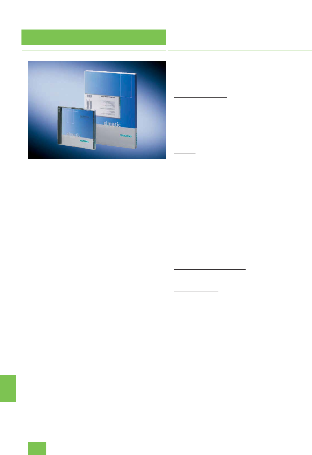
Update/upgrade packages
Software Update Service
15/2 Siemens ST PCS 7 · November 2007
15
■
Overview
Software Update Service for SIMATIC PCS 7
Siemens offers a low-cost Software Update Service (SUS) for the
SIMATIC PCS 7 software. If you utilize this service, you partici-
pate in the further development of the SIMATIC PCS 7 software
you are using, and are always in possession of the latest release
versions. You can participate in the Software Update Service for
SIMATIC PCS 7 by purchasing SUS packages, and is only pos-
sible on the basis of the current software versions at the time of
purchase.
The SUS packages represent a structural division of the
SIMATIC PCS 7 software product range using functional and
system-specific aspects. The number and composition of the
package components identified as list elements are mainly
characterized by license aspects (see "Design" for structure and
contents). A list element can represent a single software product
or also be a synonym for several products of the same type.
When purchasing one SUS package, you automatically receive
all upgrades and ServicePacks for the software referred to in this
SUS package for one year. Within this period of one year, you are
therefore authorized to update one corresponding license from
your stock for each list element in this package. The total num-
ber of SUS packages of one type which you require is therefore
determined by the list element which includes most of the soft-
ware licenses you use.
Delivery is to the address entered in the order. An SUS is auto-
matically extended for a further year unless canceled no later
than 3 months prior to expiration. Cancellation must be made in
writing, and must be sent to the dispatch center with reference
to the contract number.
Software Update Service for TIA products
In addition to the SUS for the SIMATIC PCS 7 process control
system, there is also an SUS for SIMATIC PCS 7 products used
in a different context (CFC, SIMATIC PDM) within the scope of
Totally Integrated Automation (TIA). In the case of SIMATIC PDM,
this is identical to the SUS PDM package for the Software Up-
date Service for SIMATIC PCS 7.
The SUS range is rounded-off by the SUS for SIMATIC S7 prod-
ucts used in the context of SIMATIC PCS 7, e.g. SUS
S7-PLCSIM.
■
Design
Structure and content of the SUS packages for the SIMATIC
PCS 7 Software Update Service
Note:
Each item of an SUS package (list element) represents one soft-
ware license.
SUS Engineering AS/OS
• PCS 7 Engineering AS/OS from 250 POs to unlimited POs
• PCS 7 Import/Export Assistant
• PCS 7 PID-Tuner
• Version Cross Manager
• Version Trail
• PCS 7 SFC Visualization
•PCS7 BCE
SUS PDM
• PDM Single Point, 1 TAG
• PDM Basic from 4 TAGs to unlimited TAGs
PDM Service from 128 TAGs to unlimited TAGs
PDM S7 from 128 TAGs to unlimited TAGs
PDM PCS 7 from 128 TAGs to unlimited TAGs
PDM Integration in STEP 7/PCS 7
PDM Routing S7 400
• PDM Standard HART Multiplexer
SUS Runtime OS
• PCS 7 OS Software Single Station from 250 POs to 5000 POs
OS Software Server from 250 POs to 8500 POs
• PCS 7 OS Archive
• StoragePlus, PCS 7 Central Archive Server (CAS)
• PCS 7 OpenPCS 7 Server/OS Client (multi-functional)
• PCS 7 OpenPCS 7 Server (stand-alone)
•PCS7 BCE
• PCS 7 SFC Visualization
SUS OS Client, SFC Visualization
• PCS 7 OS Software Client
• PCS 7 SFC Visualization
SUS OS Web Server
• PCS 7 OS Web Server from 3 clients to 50 clients
• PCS 7 OS Web Diagnostics Server
• PCS 7 OS Web Diagnostics Client
SUS Asset Management
• PCS 7 Asset Engineering
• PCS 7 Asset Runtime
• PCS 7 Asset Runtime Basic Package including 100 TAGs
© Siemens AG 2007

Update/upgrade packages
Software Update Service
15/3
Siemens ST PCS 7 · November 2007
15
SUS SIMATIC BATCH Server
• PCS 7 SIMATIC BATCH Server Basic Package from 10 UNITs
to unlimited UNITs
• PCS 7 SIMATIC BATCH Hierarchical Recipe
• PCS 7 SIMATIC BATCH ROP Library
• PCS 7 SIMATIC BATCH Separation Procedures/Formulas
• PCS 7 SIMATIC BATCH API
SUS SIMATIC BATCH Client
• PCS 7 SIMATIC BATCH Recipe System
• PCS 7 SIMATIC BATCH BatchCC
• PCS 7 SIMATIC BATCH Batch Planning
SUS SIMATIC Route Control
• PCS 7 SIMATIC Route Control Engineering
• PCS 7 SIMATIC Route Control Center
• PCS 7 SIMATIC Route Control Server: 30 to 300 simultaneous
material transports
•PCS7 BCE
■
Selection and Ordering Data Order No.
SIMATIC PCS 7 Software
Update Service
Subscription for 1 year with auto-
matic extension; requirement:
current software version
• PCS 7 Software Update Service
for Engineering AS/OS 6ES7 658-1XX00-0YL8
• PCS 7 Software Update Service
for PDM 6ES7 658-3XX00-0YL8
• PCS 7 Software Update Service
for Runtime OS 6ES7 658-2XX00-0YL8
• PCS 7 Software Update Service
for OS Client, SFC Visualization 6ES7 658-2CX00-0YL8
• PCS 7 Software Update Service
for OS Web Server 6ES7 658-2GX00-2YL8
• PCS 7 Software Update Service
for Asset Management 6ES7 658-7GX00-0YL8
• PCS 7 Software Update Service
for SIMATIC BATCH Server 6ES7 657-0SA00-0YL8
• PCS 7 Software Update Service
for SIMATIC BATCH Client 6ES7 657-0XX00-2YL8
• PCS 7 Software Update Service
for Route Control 6ES7 658-7DX00-0YL8
Software Update Service for
TIA products
(SIMATIC PCS 7 products used in
a different context as well as
SIMATIC S7 products used with
SIMATIC PCS 7)
Subscription for 1 year with auto-
matic extension; requirement:
current software version
• CFC Software Update Service 6ES7 658-1EX00-2YL8
• SIMATIC PDM Software Update
Service 6ES7 658-3XX00-0YL8
• S7-PLCSIM Software Update
Service 6ES7 841-0CA01-0YX2
© Siemens AG 2007

Update/upgrade packages
Software/licenses for system communication via
Industrial Ethernet
15/4 Siemens ST PCS 7 · November 2007
15
■
Overview
With SIMATIC PCS 7, communications software and licenses of
SIMATIC NET are used for the system communication via Indus-
trial Ethernet. Their version cycle is not usually synchronous with
that of SIMATIC PCS 7.
Whereas SIMATIC PCS 7 V7.0 communicates with SIMATIC NET
products V6.4 (Edition 2006), the system components of
SIMATIC PCS 7 V6.x only work together with SIMATIC NET prod-
ucts V6.3 (Edition 2005). Therefore the following ordering data
again shows a comparison of the two versions.
When upgrading from SIMATIC PCS 7 V6.x to V7.0, it must be
observed that a separate upgrade from V6.3 (Edition 2005) to
V6.4 (Edition 2006) is only required for the S7-REDCONNECT
communications software. For the other products, the version
upgrade is implemented during the SIMATIC PCS 7 upgrade
with the SIMATIC PCS 7 Upgrade Packages V6.x to V7.0.
■
Selection and Ordering Data Order No.
Communications software/licenses for SIMATIC PCS 7 V7.0
SIMATIC NET S7-1613/2006
(V6.4) for Industrial Ethernet
S7 communications software for
CP 1613,
runtime software, in 2 languages
(German, English), executes with
Windows 2000 Professional/
2000 Server/ XP Professional/
Server 2003, single license for
1 installation,
software and electronic manual
on CD-ROM, license key on dis-
kette
6GK1 716-1CB64-3AA0
SIMATIC NET S7-
REDCONNECT/2006 (V6.4)
Software for fail-safe S7 commu-
nication over redundant networks,
for CP 1613, runtime software, in
2 languages (German, English),
executes with Windows
2000 Professional/ 2000 Server/
XP Professional/ Server 2003, sin-
gle license for 1 installation, soft-
ware and electronic manual on
CD-ROM, license key on diskette
6GK1 716-0HB64-3AA0
SIMATIC NET S7-
REDCONNECT/2006 (V6.4)
Upgrade
Software for expansion of
S7-1613 to S7-REDCONNECT,
runtime software, in 2 languages
(German, English), executes with
Windows 2000 Professional/
2000 Server/ XP Professional/
Server 2003, single license for
1 installation,
software and electronic manual
on CD-ROM, license key on dis-
kette
6GK1 716-0HB64-3AC0
Upgrade of S7-REDCONNECT communications software V6.3
(edition 2005) to V6.4 (edition 2006)
SIMATIC NET S7-REDCONNECT
Upgrade from V6.3 to V6.4
Software for upgrading
S7-REDCONNECT, runtime soft-
ware, 2 languages (German, Eng-
lish), executes with Windows
2000 Professional/ 2000 Server/
XP Professional/ Server 2003, sin-
gle license for 1 installation,
software and electronic manual
on CD-ROM, license key on dis-
kette
6GK1 716-0HB64-3AE0
BCE license
PCS 7 BCE V7.0
Runtime license for plant bus
communication via standard net-
work card and Basic Communica-
tion Ethernet; already integrated
in SIMATIC PCS 7 Industrial Work-
stations,
in 3 languages (German, English,
French), executes with Windows
XP Professional or Windows
Server 2003, floating license for
1user
Type of delivery: License key
disk, certificate of license, terms
and conditions
6ES7 650-1CD07-2YB5
© Siemens AG 2007

Update/upgrade packages
Software/licenses for system communication via
Industrial Ethernet
15/5
Siemens ST PCS 7 · November 2007
15
D) Subject to export regulations: AL: N, ECCN: 5D992B1
Communications software/licenses for SIMATIC PCS 7 V6.x
SIMATIC NET S7-1613/2005
(V6.3) for Industrial Ethernet
S7 communications software for
CP 1613,
runtime license without software,
in 2 languages (German, Eng-
lish), executes with Windows
2000 Professional/ 2000 Server/
XP Professional/ Server 2003, sin-
gle license for 1 installation,
license key on diskette;
software and electronic manual
available on separate SIMATIC
NET CD Edition 2005
6GK1 716-1CB63-3AB0
SIMATIC NET S7-REDCONNECT/
2005 (V6.3)
for CP 1613, runtime license with-
out software, for fail-safe S7 com-
munication over redundant
networks, in 2 languages
(German, English), executes with
Windows 2000 Professional/
2000 Server/ XP Professional/
Server 2003, single license for
1 installation, license key on dis-
kette;
software and electronic manual
available on separate SIMATIC
NET CD Edition 2005
6GK1 716-0HB63-3AB0
SIMATIC NET S7-
REDCONNECT/2005 (V6.3)
Upgrade
Runtime license without software,
for expansion of S7-1613 to
S7-REDCONNECT, in 2 lan-
guages (German, English), exe-
cutes with Windows
2000 Professional/ 2000 Server/
XP Professional/ Server 2003, sin-
gle license for 1 installation,
license key on diskette;
software and electronic manual
available on separate SIMATIC
NET CD Edition 2005
6GK1 716-0HB63-3AD0
■
Selection and Ordering Data Order No.
BCE license
SOFTNET-S7/2005 for Indus-
trial Ethernet
Runtime license for plant bus
communication via standard net-
work card and Basic Communica-
tion Ethernet; already integrated
with SIMATIC PCS 7 basic
devices ES/OS/BATCH/IT, single
license for 1 installation, license
key on diskette;
software and electronic manual
available on separate SIMATIC
NET CD Edition 2005
6GK1 704-1CW63-3AB0
SIMATIC NET CD Edition 2005
Runtime software for SIMATIC
NET products, Edition 2005
(V6.3), in 2 languages (German,
English), executes with Windows
2000 Professional/ 2000 Server/
XP Professional/ Server 2003,
software and electronic manual
on CD
6GK1 704-0AA07-3AA0 D)
■
Selection and Ordering Data Order No.
© Siemens AG 2007

Update/upgrade packages
SIMATIC PDM upgrades
15/6 Siemens ST PCS 7 · November 2007
15
■
Overview
SIMATIC PDM can be integrated in the engineering system, i.e.
in the configuration environment of SIMATIC PCS 7, or operated
in stand-alone mode. Since the version cycle of SIMATIC PDM is
different from that of SIMATIC PCS 7, the upgrade information is
summarized here in a separate paragraph "Upgrades of
SIMATIC PDM".
■
Selection and Ordering Data Order No.
SIMATIC PDM upgrade/update service
SIMATIC PDM Upgrade from
V5.x to V6.0
for all product versions and com-
binations
5 languages (German, English,
French, Spanish, Italian), exe-
cutes with Windows 2000
Professional or Windows
XP Professional, floating license
for 1 user
Type of delivery:
License key disk, emergency key
disk, certificate of license, terms
and conditions; 2 CDs with
SIMATIC PDM V6.0 and device
library as well as supplementary
DVD with Microsoft ServicePacks
and tools
6ES7 651-5CX06-0YE5
SIMATIC PDM Software Update
Service
Subscription for 1 year with auto-
matic extension
Requirement: current software
version
6ES7 658-3XX00-0YL8
© Siemens AG 2007

Update/upgrade packages
SIMATIC PCS 7 upgrades V6.x to V7.0
Upgrades for engineering system
15/7
Siemens ST PCS 7 · November 2007
15
■
Overview
SIMATIC PCS 7 engineering systems with Engineering Software
V6.0 or V6.1 can be upgraded to Version 7.0 using the SIMATIC
PCS 7 Engineering Upgrade Package.
It may also be necessary to upgrade the S7-REDCONNECT
communications software from V6.3 (edition 2005) to V6.4 (edi-
tion 2006). S7-REDCONNECT is only required in combination
with fault-tolerant automation systems.
Engineering Upgrade Package V6.x to V7.0
The licenses included in the Engineering Upgrade Package V6.x
to V7.0 apply to the following software components of SIMATIC
PCS 7 version 6.0/6.1:
• PCS 7 Engineering AS (all PO versions)
• PCS 7 Engineering OS (all PO versions)
• Version Cross Checker
• Version Trail
• Import/Export Assistant
• PCS 7 PID-Tuner
• SIMATIC Logon
• WinCC Redundancy
• SFC Visualization
• BCE License
• SIMATIC NET S7-1613 for Industrial Ethernet
Upgrade of S7-REDCONNECT communications software
If fault-tolerant automation systems are used, the engineering
station requires the S7-REDCONNECT communications soft-
ware in addition to the CP 1613 (A2) communications processor
for the bus communication. This is available as:
• S7-REDCONNECT
• S7-REDCONNECT Upgrade (additive to existing S7-1613
communications software)
The SIMATIC NET S7-REDCONNECT V6.3 communications soft-
ware is used in the engineering software with SIMATIC PCS 7
V6.x, on the other hand the SIMATIC NET S7-REDCONNECT
V6.4 with SIMATIC PCS 7 V7.0. When upgrading the engineering
station to SIMATIC PCS 7 V7.0, an upgrade of the
S7-REDCONNECT communications software to V6.4 is therefore
also required.
Upgrade of SIMATIC PDM
SIMATIC PDM can be integrated in the engineering system, i.e.
in the configuration environment of SIMATIC PCS 7, or operated
in stand-alone mode.
Since the version cycle of SIMATIC PDM is different from that of
SIMATIC PCS 7, the upgrade information is summarized in a
separate section "Upgrades of SIMATIC PDM" directly before
this section.
Upgrade of S7-PLCSIM simulation software
S7-PLCSIM can be integrated in the engineering system, i.e. in
the configuration environment of SIMATIC PCS 7. However, the
version cycle of S7-PLCSIM is not always synchronous with the
version cycle of SIMATIC PCS 7:
• SIMATIC PCS 7 V6.1 corresponds to S7-PLCSIM V5.3
• SIMATIC PCS 7 V7.0 + ServicePack 1 corresponds to the cur-
rent program version S7-PLCSIM V5.4
Engineering software
Communications software
S7-PLCSIM simulation software
■
Selection and Ordering Data Order No.
Upgrade of engineering software from V6.0/V6.1 to V7.0
SIMATIC PCS 7 Engineering
Upgrade Package V6.x to V7.0
for AS/OS engineering
3 languages (German, English,
French),
executes with Windows XP
Professional, floating license for
1user
Type of delivery:
License key disks, emergency
key disk, certificate of license,
terms and conditions;
PCS 7 V7.0 toolset DVDs,
Microsoft SQL Server 2005
including EULA and supplemen-
tary CDs/DVDs (e.g. Microsoft
ServicePacks and tools)
6ES7 651-5AX07-0YE5
■
Selection and Ordering Data Order No.
Upgrade of S7-REDCONNECT communications software from V6.3
(edition 2005) to V6.4 (edition 2006)
SIMATIC NET S7-REDCONNECT
Upgrade from V6.3 to V6.4
Software for upgrading
S7-REDCONNECT, runtime soft-
ware, 2 languages (German, Eng-
lish), executes with Windows
2000 Professional/ 2000 Server/
XP Professional/ Server 2003, sin-
gle license for 1 installation,
software and electronic manual
on CD-ROM, license key on dis-
kette
6GK1 716-0HB64-3AE0
■
Selection and Ordering Data Order No.
S7-PLCSIM upgrade from V3.x,
V4.x, V5.0, V5.2 or V5.3 to V5.4
5 languages (German, English,
French, Italian, Spanish), exe-
cutes with Windows 2000
Professional or Windows
XP Professional, floating license
for 1 user
Type of delivery: Authorization
diskette, certificate of license,
terms and conditions; software
and electronic documentation on
CD
6ES7 841-0CC05-0YE5
S7-PLCSIM Software Update
Service
Subscription for 1 year with auto-
matic extension; requirement:
current software version
6ES7 841-0CA01-0YX2
© Siemens AG 2007

Update/upgrade packages
SIMATIC PCS 7 upgrades V6.x to V7.0
Upgrades for operator system
15/8 Siemens ST PCS 7 · November 2007
15
■
Overview
Upgrades combined in packages permit upgrading of existing
operator systems V6.0 or V6.1 to V7.0.
Upgrades of OS software
The upgrades for all PO versions of the OS software from
V6.0/V6.1 to V7.0 are distributed between the following two OS
upgrade packages:
SIMATIC PCS 7 OS Runtime Upgrade Package V6.0/V6.1 to V7.0
for OS single stations/OS servers (including archive servers),
with:
• PCS 7 OS Software Single Station (all PO versions)
• PCS 7 OS Software Server (all PO versions as well as archives)
• SFC Visualization
• StoragePlus
• WinCC Redundancy
• SIMATIC Logon
• PCS 7 BCE
• SIMATIC NET S7-1613 for Industrial Ethernet
SIMATIC PCS 7 OS Client / SFC Visualization Upgrade Package
V6.0/V6.1 to V7.0
for OS Clients, with:
• PCS 7 OS Software Client
• SFC Visualization
• SIMATIC Logon
Upgrade of S7-REDCONNECT communications software
If fault-tolerant automation systems are used, the OS single
stations/OS servers require the S7-REDCONNECT communica-
tions software in addition to the CP 1613 (A2) communications
processor for the bus communication. This is available as:
• S7-REDCONNECT
• S7-REDCONNECT Upgrade (additive to existing S7-1613
communications software)
The SIMATIC NET S7-REDCONNECT V6.3 communications soft-
ware is used in OS single stations/OS servers with SIMATIC
PCS 7 V6.x, on the other hand the SIMATIC NET
S7-REDCONNECT V6.4 with SIMATIC PCS 7 V7.0. When up-
grading the OS single stations/OS servers to SIMATIC PCS 7
V7.0, an upgrade of the S7-REDCONNECT communications
software to V6.4 is therefore required.
Upgrade of OS long-term archiving
SIMATIC Upgrade StoragePlus V1.0/V1.1 to V1.2
Note:
The SIMATIC Upgrade StoragePlus V1.0/V1.1 to V1.2 is part of
the SIMATIC PCS 7 OS Runtime Upgrade Package V6.0/V6.1 to
V7.0
Central Archive Server (CAS) Upgrade V6.0/V6.1 to V7.0
Note:
The upgrade of the central archive server (CAS) based on the
OS software server and additive OS Archive PowerPacks from
V6.0/V6.1 to V7.0 is part of the SIMATIC PCS 7 OS Runtime Up-
grade Package V6.0/V6.1 to V7.0
SIMATIC PCS 7 OS Web upgrade
Using the SIMATIC PCS 7 OS Web Server Upgrade Package,
you can upgrade the SIMATIC PCS 7 Web server, SIMATIC
PCS 7 Web diagnostics server and SIMATIC PCS 7 Web diag-
nostics clients from V6.1 to V7.0.
© Siemens AG 2007

Update/upgrade packages
SIMATIC PCS 7 upgrades V6.x to V7.0
Upgrades for operator system
15/9
Siemens ST PCS 7 · November 2007
15
OS software
Communications software
OS long-term archiving
OS Web upgrade package
■
Selection and Ordering Data Order No.
Upgrades of OS software from V6.0/V6.1 to V7.0
OS upgrade packages
for upgrading all PO versions
from V6.0/V6.1 to V7.0
SIMATIC PCS 7 OS Runtime
Upgrade Package V6.0/V6.1 to
V7.0
for OS single station, OS server
and archive server, 5-languages
(German, English, French, Italian,
Spanish), executes with Windows
XP Professional or Windows
Server 2003, single license for
1 installation
Type of delivery:
License key disk, emergency key
disk, certificate of license, terms
and conditions;
PCS 7 V7.0 toolset DVDs,
Microsoft SQL Server 2005
including EULA and supplemen-
tary CDs/DVDs (e.g. Microsoft
ServicePacks and tools)
6ES7 652-5AX07-0YE0
SIMATIC PCS 7 OS Client/
SFC Visualization Upgrade
Package V6.0/V6.1 to V7.0
5 languages (German, English,
French, Italian, Spanish), exe-
cutes with Windows
XP Professional, floating license
for 1 user
Type of delivery:
License key disk, emergency key
disk, certificate of license, terms
and conditions;
PCS 7 V7.0 toolset DVDs,
Microsoft SQL Server 2005
including EULA and supplemen-
tary CDs/DVDs (e.g. Microsoft
ServicePacks and tools)
6ES7 652-5CX07-0YE5
■
Selection and Ordering Data Order No.
Upgrade of S7-REDCONNECT communications software from V6.3
(edition 2005) to V6.4 (edition 2006)
SIMATIC NET S7-REDCONNECT
Upgrade from V6.3 to V6.4
Software for upgrading
S7-REDCONNECT, runtime soft-
ware, 2 languages (German, Eng-
lish), executes with Windows
2000 Professional/ 2000 Server/
XP Professional/ Server 2003, sin-
gle license for 1 installation,
software and electronic manual
on CD-ROM, license key on dis-
kette
6GK1 716-0HB64-3AE0
■
Selection and Ordering Data Order No.
SIMATIC Upgrade StoragePlus
V1.0/V1.1 to V1.2
Note:
The SIMATIC Upgrade
StoragePlus V1.1 to V1.2 is part of
the SIMATIC PCS 7 OS Runtime
Upgrade Package V6.0/V6.1 to
V7.0
Central Archive Server (CAS)
Upgrade V6.0/V6.1 to V7.0
Note:
The upgrade of the central
archive server (CAS) from
V6.0/V6.1 to V7.0 is part of the
SIMATIC PCS 7 OS Runtime
Upgrade Package V6.0/V6.1 to
V7.0
■
Selection and Ordering Data Order No.
SIMATIC PCS 7 OS Web Server
Upgrade Package V6.1 to V7.0
for SIMATIC PCS 7 Web server,
SIMATIC PCS 7 Web diagnostics
server, SIMATIC PCS 7 Web diag-
nostics client, 3 languages (Ger-
man, English, French), executes
with Windows Server 2003, sin-
gle license for 1 installation
Type of delivery:
License key disk, emergency key
disk, certificate of license, terms
and conditions
6ES7 652-5DX07-0YF0
© Siemens AG 2007

Update/upgrade packages
SIMATIC PCS 7 upgrades V6.x to V7.0
Upgrades for SIMATIC BATCH
15/10 Siemens ST PCS 7 · November 2007
15
■
Overview
SIMATIC BATCH packages for upgrading from V6.0/V6.1 to
V7.0
The upgrades for all PO versions of the SIMATIC BATCH soft-
ware from V6.0/V6.1 to V7.0 are distributed between the follow-
ing two SIMATIC BATCH upgrade packages:
SIMATIC BATCH Client upgrade package
The SIMATIC BATCH Client upgrade package contains upgrade
licenses for:a
• SIMATIC BATCH Recipe System
• SIMATIC BATCH Batch Planning
• SIMATIC BATCH BatchCC
• SIMATIC Logon
SIMATIC BATCH Server upgrade package
The SIMATIC BATCH Server upgrade package contains up-
grade licenses for:
• SIMATIC BATCH Server Basic Package (including all PO op-
tions and PowerPacks)
• SIMATIC BATCH Hierarchical Recipe
• SIMATIC BATCH ROP Library
• SIMATIC BATCH Separation Procedures/Formulas
• SIMATIC BATCH API
• SIMATIC Logon
■
Selection and Ordering Data Order No.
SIMATIC BATCH Client Upgrade
Package V6.0/V6.1 to V7.0
3 languages (German, English,
French), executes with Windows
XP Professional or Windows
Server 2003,
floating license for 1 user
Type of delivery:
License key disk, certificate of
license, terms and conditions
6ES7 657-5XX07-0YF5
SIMATIC BATCH Server
Upgrade Package V6.0/V6.1 to
V7.0
3 languages (German, English,
French), executes with Windows
XP Professional or Windows
Server 2003,
single license for 1 installation
Type of delivery:
License key disk, certificate of
license, terms and conditions
6ES7 657-5XX07-0YF0
© Siemens AG 2007

Update/upgrade packages
SIMATIC PCS 7 upgrades V6.x to V7.0
Upgrades for SIMATIC Route Control
15/11
Siemens ST PCS 7 · November 2007
15
■
Overview
SIMATIC Route Control upgrade package
The SIMATIC Route Control upgrade package comprises all
components for upgrading the Route Control Engineering, Route
Control Server and Route Control Client software from V6.0/V6.1
to V7.0. Also involved are SIMATIC Logon, the BCE license
PCS 7 BCE and SIMATIC NET S7-1613 for Industrial Ethernet.
Upgrade of S7-REDCONNECT communications software
If fault-tolerant automation systems are used together with
SIMATIC Route Control, the RC single stations/RC servers re-
quire the S7-REDCONNECT communications software in addi-
tion to the CP 1613 (A2) communications processor for the bus
communication. This is available as:
• S7-REDCONNECT
• S7-REDCONNECT Upgrade (additive to existing S7-1613
communications software)
The SIMATIC NET S7-REDCONNECT V6.3 communications soft-
ware is used in OS single stations/OS servers with SIMATIC
PCS 7 V6.x, on the other hand the SIMATIC NET
S7-REDCONNECT V6.4 with SIMATIC PCS 7 V7.0. When up-
grading the OS single stations/OS servers to SIMATIC PCS 7
V7.0, an upgrade of the S7-REDCONNECT communications
software to V6.4 is therefore required.
Communications software
■
Selection and Ordering Data Order No.
SIMATIC Route Control upgrade packages
SIMATIC Route Control
Upgrade Package V6.0/V6.1 to
V7.0
for Route Control Engineering,
Route Control Server and Route
Control Center, suitable for single
station and client/server configu-
ration
3 languages (German, English,
French), executes with Windows
XP Professional or Windows
Server 2003, single license for
1 installation
Type of delivery: License key
disk, emergency key disk, certifi-
cate of license, terms and condi-
tions
6ES7 652-5BX07-0YF0
Software Update Service
SIMATIC Route Control
See Section "Software Update
Service"
■
Selection and Ordering Data Order No.
Upgrade of S7-REDCONNECT communications software from V6.3
(edition 2005) to V6.4 (edition 2006)
SIMATIC NET S7-REDCONNECT
Upgrade from V6.3 to V6.4
Software for upgrading
S7-REDCONNECT, runtime soft-
ware, 2 languages (German, Eng-
lish), executes with Windows
2000 Professional/ 2000 Server/
XP Professional/ Server 2003, sin-
gle license for 1 installation,
software and electronic manual
on CD-ROM, license key on dis-
kette
6GK1 716-0HB64-3AE0
© Siemens AG 2007

Update/upgrade packages
SIMATIC PCS 7 upgrades V6.x to V7.0
Upgrades for Asset Management
15/12 Siemens ST PCS 7 · November 2007
15
■
Overview
SIMATIC PCS 7 Asset upgrade
With the SIMATIC PCS 7 Asset upgrade package you can up-
grade SIMATIC PCS 7 Asset Engineering as well as all TAG ver-
sions of SIMATIC PCS 7 Asset Runtime from V6.1 to V7.0. The
SNMP OPC server license is also involved.
■
Selection and Ordering Data Order No.
SIMATIC PCS 7 Asset upgrade
SIMATIC PCS 7 Asset Upgrade
Package V6.1 to V7.0
for Asset Engineering and Asset
Runtime, 3 languages (German,
English, French), executes with
Windows XP Professional or
Windows Server 2003, single
license for 1 installation
Type of delivery:
License key disk, certificate of
license, terms and conditions
6ES7 652-5FX07-0YF0
© Siemens AG 2007

Update/upgrade packages
SIMATIC PCS 7 upgrades V4.02 to V6.1
SIMATIC PCS 7 upgrades V5.x/V6.0 to V6.1
15/13
Siemens ST PCS 7 · November 2007
15
■
Overview
This section provides an overview of the upgrade packages with
which existing systems based on SIMATIC PCS 7 V5.x or V6.0
can be upgraded to V6.1. The upgrade packages are grouped
as follows:
• Engineering system
• Operator system
• SIMATIC BATCH
• SIMATIC Route Control
Engineering system
■
Selection and Ordering Data Order No.
Upgrade of engineering software from V6.0 to V6.1
PCS 7 AS/OS Engineering
Upgrade Package
for AS/OS upgrade from V6.0 to
V6.1
3 languages (German, English,
French),
executes with Windows 2000
Professional/ 2000 Server or
Windows XP Professional/
Server 2003, floating license for
1user
Type of delivery:
License key disk, emergency key
disk, certificate of license, terms
and conditions;
PCS 7 V6.1 toolset DVD, Microsoft
SQL Server including EULA,
PC Anywhere Host and supple-
mentary CDs/DVDs (e.g.
Microsoft ServicePacks and tools)
6ES7 651-5AX16-0YE5
Upgrade of SIMATIC Version Cross Checker from V6.0 to V6.1
The Version Cross Checker
upgrade is included in the PCS 7
AS/OS Engineering Upgrade
Package V6.0 to V6.1 (see above)
Upgrades of engineering software from V5.x to V6.1
Upgrade PCS 7 Starter Package
from V5.x to V6.1
3 languages (German, English,
French),
executes with Windows 2000
Professional/ 2000 Server or
Windows XP Professional/
Server 2003, floating license for
1user
Type of delivery:
License key disk, emergency key
disk, certificate of license, terms
and conditions;
PCS 7 V6.1 toolset DVD, Microsoft
SQL Server including EULA,
PC Anywhere Host and supple-
mentary CDs/DVDs (e.g.
Microsoft ServicePacks and tools)
• AS/OS upgrade for 250 POs/
RC 8K 6ES7 658-5AA16-0YE5
Upgrade AS Software Engineer-
ing from V5.x to V6.1
3 languages (German, English,
French),
executes with Windows 2000
Server or Windows Server 2003,
single license for 1 installation
Type of delivery:
License key disk, emergency key
disk, certificate of license, terms
and conditions;
PCS 7 V6.1 toolset DVD, Microsoft
SQL Server including EULA,
PC Anywhere Host and supple-
mentary CDs/DVDs (e.g.
Microsoft ServicePacks and tools)
• AS upgrade for 3000 POs 6ES7 658-1AD16-0YE5
• AS upgrade for unlimited POs 6ES7 658-1AF16-0YE5
Upgrade OS Software Engineer-
ing from V5.x to V6.1
3 languages (German, English,
French),
executes with Windows 2000
Server or Windows Server 2003,
single license for 1 installation
Type of delivery:
License key disk, emergency key
disk, certificate of license, terms
and conditions;
PCS 7 V6.1 toolset DVD, Microsoft
SQL Server including EULA,
PC Anywhere Host and supple-
mentary CDs/DVDs (e.g.
Microsoft ServicePacks and tools)
• OS upgrade for 2000 POs/
RC 64K 6ES7 658-2DC16-0YE5
• OS upgrade for 5000 POs/
RC 150K 6ES7 658-2DE16-0YE5
■
Selection and Ordering Data Order No.
© Siemens AG 2007

Update/upgrade packages
SIMATIC PCS 7 upgrades V4.02 to V6.1
SIMATIC PCS 7 upgrades V5.x/V6.0 to V6.1
15/14 Siemens ST PCS 7 · November 2007
15
Operator system
1) The OS Software Single Station and OS Software Server upgrades support
a high-performance archive system for up to 512 variables. To implement
larger archives, this volume can be extended using additive OS Archive
V6.1 PowerPacks/bundles (see OS archiving).
■
Selection and Ordering Data Order No.
Upgrades of OS software from V6.0 to V6.1
OS upgrade packages
for upgrading all PO versions
from V6.0 to V6.1
•SIMATIC PCS 7 Upgrade Pack-
age Runtime OS V6.0 to V6.1
for OS single station, OS server
and archive server, 3 languages
(German, English, French),
executes with Windows 2000
Professional / 2000 Server or
Windows XP Professional /
Server 2003, single license for
1 installation
Type of delivery:
License key disk, emergency
key disk, certificate of license,
terms and conditions;
PCS 7 V6.1 toolset DVD,
Microsoft SQL Server including
EULA, PC Anywhere Host and
supplementary CDs/DVDs (e.g.
Microsoft ServicePacks and
tools)
6ES7 652-5AX16-0YE0
•SIMATIC PCS 7 Upgrade Pack-
age OS Client/
SFC Visualization V6.0 to V6.1
3 languages (German, English,
French),
executes with Windows
2000 Professional or Windows
XP Professional, floating license
for 1 user
Type of delivery:
License key disk, emergency
key disk, certificate of license,
terms and conditions;
PCS 7 V6.1 toolset DVD,
Microsoft SQL server including
EULA, PC Anywhere Host and
supplementary CDs/DVDs (e.g.
Microsoft ServicePacks and
tools)
6ES7 652-5CX16-0YE5
Upgrades of OS software from V5.x to V6.1
SIMATIC PCS 7 Upgrade
OS Software Single Station
V5.x to V6.1
3 languages (German, English,
French),
executes with Windows 2000
Professional or Windows
XP Professional, single license for
1 installation
Type of delivery:
License key disk, emergency key
disk, certificate of license, terms
and conditions;
PCS 7 V6.1 toolset DVD, Microsoft
SQL Server including EULA,
PC Anywhere Host and supple-
mentary CDs/DVDs (e.g.
Microsoft ServicePacks and tools)
• 2000 POs/RT 64K1) 6ES7 658-2AC16-0YE0
• 5000 POs/RT 150K1) 6ES7 658-2AE16-0YE0
SIMATIC PCS 7 Upgrade
OS Software Server V5.x to V6.1
3 languages (German, English,
French),
executes with Windows 2000
Server or Windows Server 2003,
single license for 1 installation
Type of delivery:
License key disk, emergency key
disk, certificate of license, terms
and conditions;
PCS 7 V6.1 toolset DVD, Microsoft
SQL Server including EULA,
PC Anywhere Host and supple-
mentary CDs/DVDs (e.g.
Microsoft ServicePacks and tools)
• 2000 POs/RT 64K 1) 6ES7 658-2BC16-0YE0
• 5000 POs/RT 150K 1) 6ES7 658-2BE16-0YE0
SIMATIC PCS 7 Upgrade
OS Software Client V5.x to V6.1
3 languages (German, English,
French),
executes with Windows 2000
Professional or Windows
XP Professional, floating license
for 1 user
Type of delivery:
License key disk, emergency key
disk, certificate of license, terms
and conditions;
PCS 7 V6.1 toolset DVD, Microsoft
SQL Server including EULA,
PC Anywhere Host and supple-
mentary CDs/DVDs (e.g.
Microsoft ServicePacks and tools)
6ES7 658-2CX16-0YE5
Upgrade of SFC Visualization
SIMATIC PCS 7 Upgrade
SFC Visualization V5.x to V6.1
3 languages (German, English,
French),
executes with Windows 2000
Professional or Windows
XP Professional, floating license
for 1 user
Type of delivery:
License key disk, emergency key
disk, certificate of license, terms
and conditions
6ES7 652-0XD16-2YF5
Upgrade of SIMATIC StoragePlus
SIMATIC Upgrade StoragePlus
V1.0 to V1.1
Type of delivery:
License key disk, emergency key
disk, certificate of license, terms
and conditions
6ES7 652-0XC11-2YF0
■
Selection and Ordering Data Order No.
© Siemens AG 2007

Update/upgrade packages
SIMATIC PCS 7 upgrades V4.02 to V6.1
SIMATIC PCS 7 upgrades V5.x/V6.0 to V6.1
15/15
Siemens ST PCS 7 · November 2007
15
SIMATIC BATCH SIMATIC Route Control upgrade packages
■
Selection and Ordering Data Order No.
SIMATIC BATCH Upgrade from
BATCH flexible V4.02 to
SIMATIC BATCH V6.1
3 languages (German, English,
French), executes with Windows
2000 Professional/ 2000 Server or
Windows XP Professional/
Server 2003,
floating license for 1 user
Type of delivery:
License key disk, certificate of
license, terms and conditions
6ES7 657-0XX16-0YF0
SIMATIC BATCH Upgrade
Package
BATCH Client from V6.0 to V6.1
3 languages (German, English,
French), executes with Windows
2000 Professional/ 2000 Server or
Windows XP Professional/
Server 2003,
floating license for 1 user
Type of delivery:
License key disk, certificate of
license, terms and conditions
6ES7 657-5XX16-0YF5
SIMATIC BATCH Upgrade
Package
BATCH Server from V6.0 to V6.1
3 languages (German, English,
French), executes with Windows
2000 Professional/ 2000 Server or
Windows XP Professional/
Server 2003,
single license for 1 installation
Type of delivery:
License key disk, certificate of
license, terms and conditions
6ES7 657-5XX16-0YF0
■
Selection and Ordering Data Order No.
SIMATIC Route Control
Runtime Upgrade Package V6.0
to V6.1
For single station and client/
server configuration
3 languages (German, English,
French), executes with Windows
2000 Server or Windows Server
2003, single license for
1 installation
Type of delivery: License key
disk, emergency key disk, certifi-
cate of license, terms and condi-
tions
6ES7 652-5BX16-0YF0
SIMATIC Route Control Center
Upgrade V6.0 to V6.1
3 languages (German, English,
French), executes with Windows
2000 Professional or Windows
XP Professional, floating license
for 1 user
Type of delivery: License key
disk, emergency key disk, certifi-
cate of license, terms and condi-
tions
6ES7 658-7EX16-0YF5
SIMATIC Route Control Engi-
neering Upgrade V6.0 to V6.1
3 languages (German, English,
French), executes with Windows
2000 Professional/ 2000 Server or
Windows XP Professional/
Server 2003, floating license for
1user
Type of delivery: License key
disk, certificate of license, terms
and conditions
6ES7 658-7DX16-0YF5
© Siemens AG 2007

Update/upgrade packages
SIMATIC PCS 7 upgrades V4.02 to V6.1
SIMATIC PCS 7 upgrades V4.02 to V5.2
15/16 Siemens ST PCS 7 · November 2007
15
■
Overview
This section summarizes the upgrade software which is required
to upgrade the engineering station and operator stations of the
SIMATIC PCS 7 process control system from V4.02 to V5.2.
Engineering system
Operator system
■
Selection and Ordering Data Order No.
Engineering software upgrade for AS engineering
PCS 7 Engineering Toolset
Upgrade V4.02 to V5.2
for max. 3000 process objects,
executes with Windows NT 4.0
Workstation
Type of delivery:
• CD with the components: STEP
7, CFC, SFC, S7-SCL, Techno-
logical Hierarchy, Import/Export
Assistant, DOCPRO and I&C
Library
• Software licenses on authoriza-
tion diskette
6ES7 658-1AB05-0YC4
Engineering software upgrade for OS engineering
If the engineering station is used
for OS engineering, you require
an OS Software Upgrade from
V4.02 to V5.02 for the OS engi-
neering software package.
■
Selection and Ordering Data Order No.
OS software upgrade
PCS 7 OS Software Upgrade
V4.02 to V5.2
for OS Software Single Station,
OS Software Server, OS Software
Terminal and OS Software Engi-
neering (1 upgrade package
required for each), executes with
Windows NT 4.0 Workstation
Type of delivery:
• CD with OS I&C software
• BCE license and software li-
censes on authorization diskette
6ES7 658-2XB05-0YC4
© Siemens AG 2007
Siemens ST PCS 7 · November 2007
16/2 Training
16/3 Siemens Contacts Worldwide
16/4 A&D Online Services
16/5 Customer Support
16/7 Siemens Solution Partner
Automation and
Power Distribution
16/8 Software Licenses
16/9 Subject index
16/11 Order no. index
16/16 Conditions of sale and delivery
Export regulations
Appendix
© Siemens AG 2007
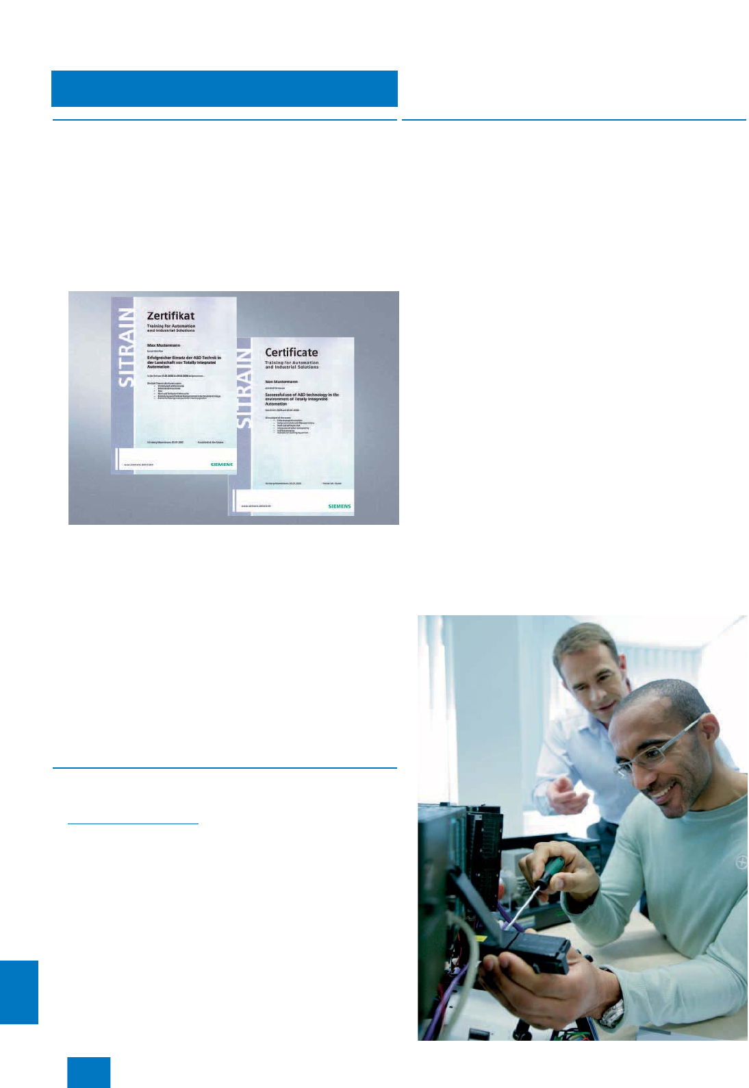
Appendix
Training
16/2 Siemens ST PCS 7 · November 2007
16
■
Faster and more applicable know-how:
Hands-on training from the manufacturer
SITRAIN® – the Siemens Training for Automation and Industrial
Solutions – provides you with comprehensive support in solving
your tasks.
Training by the market leader in automation and plant engineer-
ing enables you to make independent decisions with confi-
dence. Especially where the optimum and efficient use of prod-
ucts and plants are concerned. You can eliminate deficiencies in
existing plants, and exclude expensive faulty planning right from
the beginning.
First-class know-how directly pays for itself: In shorter star-
tup times, high-quality end products, faster troubleshooting
and reduced downtimes. In other words, increased profits
and lower costs.
Achieve more with SITRAIN
• Shorter times for startup, maintenance and servicing
• Optimized production operations
• Reliable configuration and startup
• Minimization of plant downtimes
• Flexible plant adaptation to market requirements
• Compliance with quality standards in production
• Increased employee satisfaction and motivation
• Shorter familiarization times following changes in technology
and staff
■
Contact
Visit our site on the Internet at:
www.siemens.com/sitrain
or let us advise you personally. You can request our latest train-
ing catalog from:
SITRAIN Customer Support Germany:
Phone:+49 (0)1805 / 23 56 11
(0.14 /min from the German landline network)
Fax: +49 (0)1805 / 23 56 12
■
SITRAIN highlights
Top trainers
Our trainers are skilled teachers with direct practical experience.
Course developers have close contact with product develop-
ment, and directly pass on their knowledge to the trainers.
Practical experience
The practical experience of our trainers enables them to teach
theory effectively. But since theory can be pretty drab, we attach
great importance to practical exercises which can comprise up
to half of of the course time. You can therefore immediately im-
plement your new knowledge in practice. We train you on state-
of-the-art methodically/didactically designed training equip-
ment. This training approach will give you all the confidence you
need.
Wide variety
With a total of about 300 local attendance courses, we train the
complete range of A&D products as well as interaction of the
products in systems. Telecourses, teach-yourself software and
seminars with a presenter on the Web supplement our classic
range of courses.
Tailor-made training
We are only a short distance away. You can find us at more than
50 locations in Germany, and in 62 countries worldwide. You
wish to have individual training instead of one of our
300 courses? Our solution: We will provide a program tailored
exactly to your personal requirements. Training can be carried
out in our Training Centers or at your company.
The right mixture: Blended learning
"Blended learning" means a combination of various training me-
dia and sequences. For example, a local attendance course in
a Training Center can be optimally supplemented by a teach-
yourself program as preparation or follow-up. Additional effect:
Reduced traveling costs and periods of absence.
© Siemens AG 2007
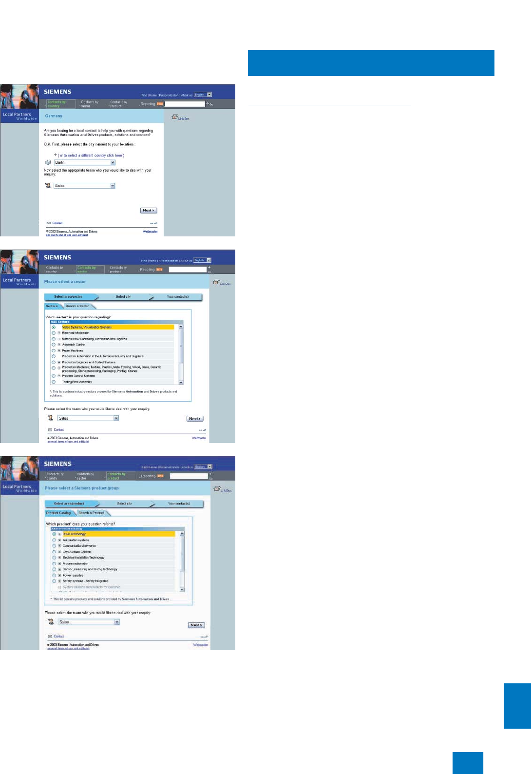
Appendix
Siemens Contacts Worldwide
16/3
Siemens ST PCS 7 · November 2007
16
At
http://www.siemens.com/automation/partner
you can find details of Siemens contact partners worldwide
responsible for particular technologies.
You can obtain in most cases a contact partner for
• Technical Support,
• Spare parts/repairs,
• Service,
• Training,
• Sales or
• Consultation/engineering.
You start by selecting a
• Country,
• Product or
• Sector.
By further specifying the remaining criteria you will find exactly
the right contact partner with his/her respective expertise.
© Siemens AG 2007
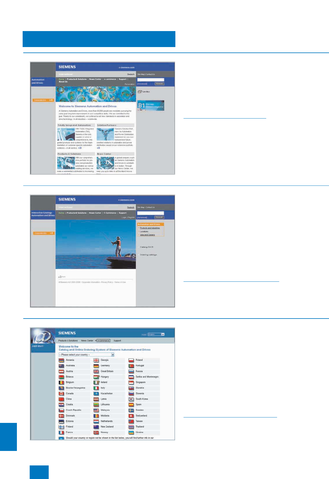
Appendix
A&D Online Services
Information and Ordering
in the Internet and on CD-ROM
16/4 Siemens ST PCS 7 · November 2007
16
■
A&D in the WWW
A detailed knowledge of the range of products and services
available is essential when planning and configuring automation
systems. It goes without saying that this information must always
be fully up-to-date.
The Siemens Automation and Drives Group (A&D) has therefore
built up a comprehensive range of information in the World Wide
Web, which offers quick and easy access to all data required.
Under the address
http://www.siemens.com/automation
you will find everything you need to know about products, sys-
tems and services.
■
Product Selection Using the Offline Mall of Automation and Drives
Detailed information together with convenient interactive
functions:
The Offline Mall CA 01 covers more than 80,000 products and
thus provides a full summary of the Siemens Automation and
Drives product base.
Here you will find everything that you need to solve tasks in the
fields of automation, switchgear, installation and drives.
All information is linked into a user interface which is easy to
work with and intuitive.
After selecting the product of your choice you can order at the
press of a button, by fax or by online link.
Information on the Offline Mall CA 01 can be found in the Internet
under
http://www.siemens.com/automation/ca01
or on CD-ROM or DVD.
■
Easy Shopping with the A&D Mall
The A&D Mall is the virtual department store of Siemens AG in
the Internet. Here you have access to a huge range of products
presented in electronic catalogs in an informative and attractive
way.
Data transfer via EDIFACT allows the whole procedure from
selection through ordering to tracking of the order to be carried
out online via the Internet.
Numerous functions are available to support you.
For example, powerful search functions make it easy to find the
required products, which can be immediately checked for avail-
ability. Customer-specific discounts and preparation of quotes
can be carried out online as well as order tracking and tracing.
Please visit the A&D Mall on the Internet under:
http://www.siemens.com/automation/mall
© Siemens AG 2007
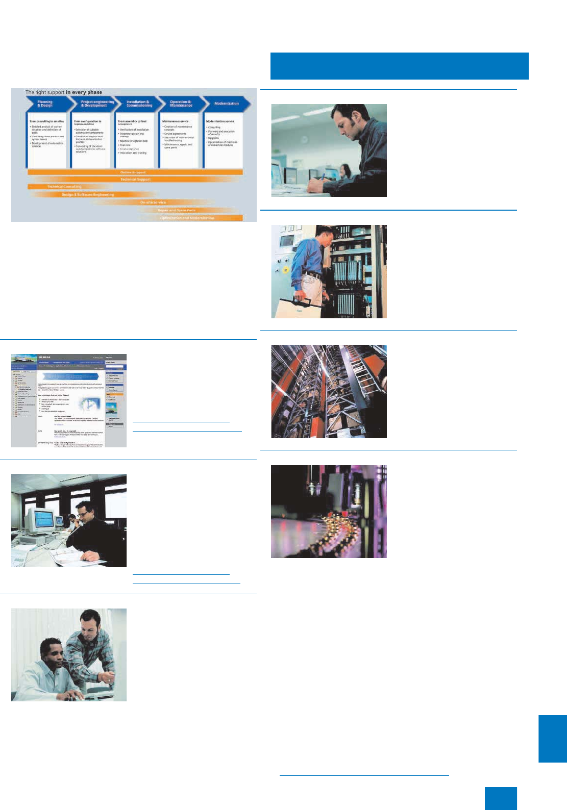
Appendix
Customer Support
Our Services for Every Phase of Your Project
16/5
Siemens ST PCS 7 · November 2007
16
.I
In the face of harsh competition you need optimum conditions to
keep ahead all the time:
A strong starting position. A sophisticated strategy and team for
the necessary support - in every phase.
Service & Support from Siemens provides this support with a
complete range of different services for automation and drives.
In every phase: from planning and startup to maintenance and
upgrading.
Our specialists know when and where to act to keep the produc-
tivity and cost-effectiveness of your system running in top form.
■
Online Support
The comprehensive information
system available round the
clock via Internet ranging from
Product Support and Service &
Support services to Support
Tools in the Shop.
http://www.siemens.com/
automation/service&support
■
Technical Support
Competent consulting in techni-
cal questions covering a wide
range of customer-oriented ser-
vices for all our products and
systems.
Tel.: +49 (0)180 50 50 222
Fax: +49 (0)180 50 50 223
(0.14 /min from the German
fixed network)
http://www.siemens.com/
automation/support-request
■
Technical Consulting
Support in the planning and de-
signing of your project from de-
tailed actual-state analysis,
target definition and consulting
on product and system ques-
tions right to the creation of the
automation solution.1)
■
Configuration and Software Engineering
Support in configuring and de-
veloping with customer-oriented
services from actual configura-
tion to implementation of the au-
tomation project.1)
■
Service On Site
With Service On Site we offer
services for startup and mainte-
nance, essential for ensuring
system availability.
In Germany
0180 50 50 4441)
(0.14 /min from the German
fixed network)
■
Repairs and Spare Parts
In the operating phase of a ma-
chine or automation system we
provide a comprehensive repair
and spare parts service ensur-
ing the highest degree of oper-
ating safety and reliability.
In Germany
0180 50 50 4461)
(0.14 /min from the German
fixed network)
■
Optimization and Upgrading
To enhance productivity and
save costs in your project we of-
fer high-quality services in opti-
mization and upgrading.1)
1) For country-specific telephone numbers go to our Internet site at:
http://www.siemens.com/automation/service&support
© Siemens AG 2007
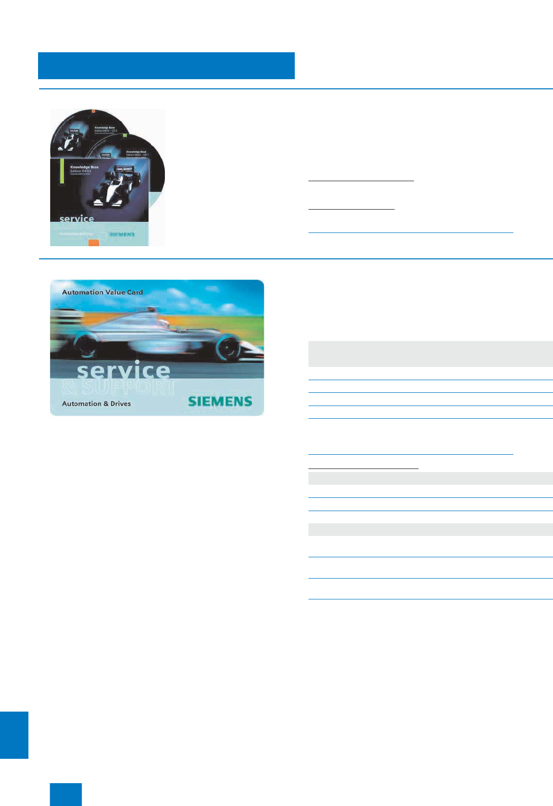
Appendix
Customer Support
16/6 Siemens ST PCS 7 · November 2007
16
■
Knowledge Base on CD-ROM
For locations without online con-
nections to the Internet there are
excerpts of the free part of the
information sources available on
CD-ROM (Service & Support
Knowledge Base). This
CD-ROM contains all the latest
product information at the time
of production (FAQs, Down-
loads, Tips and Tricks, Updates)
as well as general information
on Service and Technical Sup-
port.
The CD-ROM also includes a
full-text search and our Knowl-
edge Manager for targeted searches for solutions. The CD-ROM
will be updated every 4 months.
Just the same as our online offer in the Internet, the Service &
Support Knowledge Base on CD comes complete in 5 lan-
guages (German, English, French, Italian, Spanish).
You can order the Service & Support Knowledge Base CD
from your Siemens contact.
Order no. 6ZB5310-0EP30-0BA2
Orders via the Internet
(with Automation Value Card or credit card) at:
http://www.siemens.com/automation/service&support
in the Shop domain.
■
Automation Value Card
Small card - great support
The Automation Value Card is an integral component of the com-
prehensive service concept with which Siemens Automation and
Drives will accompany you in each phase of your automation
project.
It doesn't matter whether you want just specific services from our
Technical Support or want to purchase high-quality Support
Tools in our Online Shop, you can always pay with your Automa-
tion Value Card. No invoicing, transparent and safe. With your
personal card number and associated PIN you can view the
state of your account and all transactions at any time.
Services on card. This is how it's done.
Card number and PIN are on the back of the Automation Value
Card. When delivered, the PIN is covered by a scratch field,
guaranteeing that the full credit is on the card.
By entering the card number and PIN you have full access to the
Service & Support services being offered. The charge for the
services procured is debited from the credits on your Automa-
tion Value Card.
All the services offered are marked in currency-neutral credits,
so you can use the Automation Value Card worldwide.
Detailed information on the services offered is available on our
Internet site at:
http://www.siemens.com/automation/service&support
Service & Support à la Card: Examples
Automation Value Card order numbers
Credits Order no.
200 6ES7 997-0BA00-0XA0
500 6ES7 997-0BB00-0XA0
1000 6ES7 997-0BC00-0XA0
10000 6ES7 997-0BG00-0XA0
Technical Support
”Priority“ Priority processing for urgent cases
”24 h“ Availability round the clock
„Extended“ Technical consulting for complex questions
Support Tools in the Support Shop
”System Utili-
ties“ Tools that can be used directly for configuration, anal-
ysis and testing
”Applications“ Complete topic solutions including ready-tested soft-
ware
”Functions &
Samples“ Adaptable blocks for accelerating your developments
© Siemens AG 2007

Appendix
Siemens Solution Partner
Automation and Power Distribution
16/7
Siemens ST PCS 7 · November 2007
16
■
Overview
Products and systems from Siemens Automation and Drives
provide the ideal platform for all automation tasks.
Siemens Solution Partners offer customized future-proof solu-
tions with products and systems from Siemens Automation and
Drives. The basis: qualified product and system knowledge cou-
pled with a high degree of solutions and industry-related exper-
tise.
In the Siemens Solution Partner Program you are certain to find
the optimum partner for your specific requirements. Since more
than 570 companies worldwide belong to the program, you can
be sure to get expert support at your location.
The Solution Partner Finder, available to you on the Internet, is a
comprehensive database in which all Solution Partners, together
with their performance profiles, present themselves.
In addition to the search criteria Technology, Sector and Country,
you can also search by Company and ZIP Code. From there it is
only a small step to making the first contact.
Call up the Solution Partner Finder as follows:
• CA 01 on CD-ROM:
On the start page via "Contacts & Partners; Siemens Solution
Partner Automation and Power Distribution"
• CA 01 online:
Go directly to the Solution Partner Finder:
www.siemens.com/automation/partnerfinder
Additional information about the Siemens Solution Partner
Program is available in the Internet at:
www.siemens.com/automation/solutionpartner
Solution Partner
Automation
s
Solution Partner
Power Distributions
© Siemens AG 2007

Appendix
Software Licenses
16/8 Siemens ST PCS 7 · November 2007
16
■
Overview
Software types
Software requiring a license is categorized into types.
The following software types have been defined:
• Engineering software
• Runtime software
Engineering software
This includes all software products for creating (engineering)
user software, e.g. for configuring, programming, parameteriz-
ing, testing, commissioning or servicing.
Data generated with engineering software and executable
programs can be duplicated for your own use or for use by third-
parties free-of-charge.
Runtime software
This includes all software products required for plant/machine
operation, e.g. operating system, basic system, system expan-
sions, drivers, etc.
The duplication of the runtime software and executable pro-
grams created with the runtime software for your own use or for
use by third-parties is subject to a charge.
You can find information about license fees according to use in
the ordering data (e.g. in the catalog). Examples of categories of
use include per CPU, per installation, per channel, per instance,
per axis, per control loop, per variable, etc.
Information about extended rights of use for parameteriza-
tion/configuration tools supplied as integral components of the
scope of delivery can be found in the readme file supplied with
the relevant product(s).
License types
Siemens Automation & Drives offers various types of software
license:
• Floating license
• Single license
• Rental license
• Trial license
Floating license
The software may be installed for internal use on any number of
devices by the licensee. Only the concurrent user is licensed.
The concurrent user is the person using the program. Use
begins when the software is started.
A license is required for each concurrent user.
Single license
Unlike the floating license, a single license permits only one
installation of the software.
The type of use licensed is specified in the ordering data and
in the Certificate of License (CoL). Types of use include for
example per device, per axis, per channel, etc.
One single license is required for each type of use defined.
Rental license
A rental license supports the "sporadic use" of engineering
software. Once the license key has been installed, the software
can be used for a specific number of hours (the operating hours
do not have to be consecutive).
One license is required for each installation of the software.
Trial license
A trial license supports "short-term use" of the software in a non-
productive context, e.g. for testing and evaluation purposes.
It can be transferred to another license.
Factory license
With the Factory License the user has the right to install and use
the software at one permanent establishment only. The perma-
nent establishment is defined by one address only.The number
of hardware devices on which the software may be installed
results from the order data or the Certificate of License (CoL).
Certificate of license
The Certificate of License (CoL) is the licensee's proof that the
use of the software has been licensed by Siemens. A CoL is
required for every type of use and must be kept in a safe place.
Downgrading
The licensee is permitted to use the software or an earlier ver-
sion/release of the software, provided that the licensee owns
such a version/release and its use is technically feasible.
Delivery versions
Software is constantly being updated.
The following delivery versions
• PowerPack
• Upgrade
can be used to access updates.
Existing bug fixes are supplied with the ServicePack version.
PowerPack
PowerPacks can be used to upgrade to more powerful software.
The licensee receives a new license agreement and CoL
(Certificate of License) with the PowerPack. This CoL, together
with the CoL for the original product, proves that the new soft-
ware is licensed.
A separate PowerPack must be purchased for each original
license of the software to be replaced.
Upgrade
An upgrade permits the use of a new version of the software on
the condition that a license for a previous version of the product
is already held.
The licensee receives a new license agreement and CoL with
the upgrade. This CoL, together with the CoL for the previous
product, proves that the new version is licensed.
A separate upgrade must be purchased for each original license
of the software to be upgraded.
ServicePack
ServicePacks are used to debug existing products.
ServicePacks may be duplicated for use as prescribed accord-
ing to the number of existing original licenses.
License key
Siemens Automation & Drives supplies software products with
and without license keys.
The license key serves as an electronic license stamp and
is also the "switch" for activating the software (floating license,
rental license, etc.).
The complete installation of software products requiring license
keys includes the program to be licensed (the software) and the
license key (which represents the license).
Detailed explanations concerning license conditions can be
found in the “Terms and Conditions of Siemens AG” or under
http://www.siemens.com/automation/mall
(A&D Mall Online-Help System)
A&D/Software licenses/En 03.08.06
© Siemens AG 2007

Appendix
Subject index
16/9
Siemens ST PCS 7 · November 2007
16
■
A
Access Point ........................................ 9/31
Active Field Distributor......................... 9/49
Administration ........................................ 2/3
Advanced Process Control (APC)
functions................................................. 4/8
Alarms.................................................. 5/10
Archive Server...................................... 5/23
AS-Interface ......................................... 9/51
Asset Management ................................ 8/2
Automation systems............................. 10/2
B
Batch automation................................... 6/2
Batch Control Center ............................. 6/8
Batch Planning..................................... 6/10
Branch & Merge..................................... 4/6
C
Cable duct ......................................... 11/12
Central Archive Server......................... 5/23
Central I/O............................................ 11/4
Chipcard reader..................................... 2/5
Clock synchronization.......................... 5/11
Closed-loop control modules............. 11/27
Component view .................................... 4/6
Concurrent Engineering......................... 4/6
Configurator ......................................... 2/18
ConPerMon ............................................ 4/8
Continuous Function Chart (CFC).......... 4/7
Counter modules................................ 11/29
CP 1613 ............................................... 9/28
CP 443-5 Extended.............................. 9/41
D
DOCPRO................................................ 4/9
DP/PA link and DP/PA coupler ............. 9/45
Dummy module.................................. 11/12
E
Electrical Switch Modules ESM............ 9/21
Electronic Device Description.............. 4/17
Electronic Signature............................... 2/3
Engineering F/FH systems ................... 4/22
Engineering system ............................... 4/2
ES software ............................................ 4/4
ET 200iSP........................................... 11/30
ET 200M............................................... 11/9
ET 200pro........................................... 11/56
ET 200S.............................................. 11/39
Ex modules ........................................ 11/22
Ex partition ......................................... 11/12
Expansion units.................................... 11/5
F
F modules...........................................11/25
Faceplate Designer ................................4/9
FastConnect .........................................9/23
FastConnect/SpliTConnect...................9/50
Fault-tolerant automation systems......10/15
Fiber-optic cables.................................9/26
G
Glas fiber-optic cables .........................9/39
Graphics Designer .................................4/9
H
HART ..................................................11/23
Hazardous area ....................................11/2
Hierarchical Recipe..............................6/11
I
I&C libraries............................................4/8
I/O subsystem for ET 200M ................11/13
IF 964-DP..............................................9/41
Import/Export Assistant ........................4/12
Industrial Ethernet ..................................9/3
Industrial Ethernet Switches ...................9/6
Industrial Security.................................9/33
Industrial Wireless LAN ........................9/30
Industrial Workstation .............................2/6
Interface module ................................11/11
ITP cables and connectors ..................9/25
K
Keyboards ............................................2/15
L
Libraries..................................................4/8
Long-term archiving .............................5/21
M
Maintenance station ...............................8/4
Media converter ...................................9/21
Messages .............................................5/10
Microbox automation system................10/4
Microsoft SQL Server..............................4/4
Migration...............................................13/2
Modbus ................................................9/52
Motor starters .....................................11/49
MTA.......................................................11/6
Multi project engineering........................4/6
Multi-VGA graphics cards ....................2/16
Multi-VGA operation ...............................2/6
O
OpenPCS 7 .......................................... 5/27
Operating system................................... 2/6
Operator system .................................... 5/2
Optical Switch Modules OSM .............. 9/21
OS archiving ........................................ 5/19
OS hardware .......................................... 5/4
OS redundancy.................................... 5/16
OS software.......................................... 5/12
OS variables........................................... 5/3
OS-LAN.................................................. 9/4
P
PID-Tuner ............................................... 4/8
Plant bus ................................................ 9/4
Plastic fiber-optic cables...................... 9/40
Power supply cable for Rack PC ......... 2/15
Process Device Manager..................... 4/13
Process I/O .......................................... 11/2
Process monitors ................................. 2/17
Process object ....................................... 5/3
Process object view............................... 4/6
PROFIBUS............................................ 9/35
PROFIBUS DP...................................... 9/36
PROFIBUS PA ...................................... 9/43
Programming Instructions
Driver Blocks.......................................... 2/2
R
Recipe system ....................................... 6/9
ROP Library ......................................... 6/12
Route Control ......................................... 7/2
Route Control Center ............................. 7/6
Route Control Server.............................. 7/6
Routing................................................. 4/16
Runtime Basic Packages..................... 3/13
© Siemens AG 2007

Appendix
Subject index
16/10 Siemens ST PCS 7 · November 2007
16
S
S5 Manual Collection ............................. 2/2
S7 F ConfigurationPack ....................... 4/22
S7 Manual Collection ............................. 2/2
S7-PLCSIM........................................... 4/26
S7-REDCONNECT ............................... 9/29
Safety ES Packages............................. 4/25
Safety Matrix ........................................ 4/23
Safety Matrix Viewer............................. 5/15
Safety-related automation systems.... 10/24
Scalability............................................. 1/11
SCALANCE S ....................................... 9/34
SCALANCE X ......................................... 9/6
Script languages.................................. 5/11
Separation Procedures/Formulas ........ 6/12
Sequential Function Chart (SFC) ........... 4/7
Server Basic Package............................ 6/7
SFC Visualization ................................. 5/14
Short-term archiving............................. 5/20
Signal module ........................................ 5/8
Sign-of-life monitoring.......................... 5/11
SIGUARD ........................................... 11/53
SIMATIC BATCH..................................... 6/2
SIMATIC BATCH API ............................ 6/12
SIMATIC IT ........................................... 12/2
SIMATIC Logon ............................... 2/3, 4/5
SIMATIC Manager........................... 4/2, 4/5
SIMATIC NET.......................................... 9/2
SIMATIC PCS 7 BOX.............................. 3/2
SIMATIC PCS 7 Industrial Workstation... 2/6
SIMATIC PCS 7 MTA ............................ 11/6
SIMATIC PDM....................................... 4/13
SIMATIC PDM PCS 7............................ 4/15
SIMATIC PDM S7 ................................. 4/15
SIMATIC PDM Service.......................... 4/15
SIMATIC PDM Single Point................... 4/14
SIMATIC Route Control .......................... 7/2
SIMATIC Safety Matrix.......................... 4/23
Simulation............................................. 4/26
SIPLUS ................................................. 11/9
SM 321 ............................................... 11/14
SM 322 ............................................... 11/16
SM 323 ............................................... 11/18
SM 331 ............................................... 11/19
SM 332 ............................................... 11/21
SM 421, SM 422, SM 431, SM 432 ...... 11/4
Starter systems ...................................... 3/2
StoragePlus.......................................... 5/21
Switches................................................. 9/6
System architecture ............................. 1/10
System documentation .......................... 2/2
T
TELEPERM M Manual Collection............2/2
Terminal bus ...........................................9/4
Terminal modules ......................11/6, 11/41
Totally Integrated Automation...............1/10
Tower Kit ...............................................2/15
Trends...................................................5/10
V
Version Cross Manager ........................4/10
Version Trail ..........................................4/11
W
Web Server...........................................5/25
WinAC Slot416........................................3/9
Wireless LAN ........................................9/30
Y
Y-Link ....................................................9/42
© Siemens AG 2007

Appendix
Order no. index
16/11
Siemens ST PCS 7 · November 2007
16
■
3RK1 301-0.... ........................................ 11/51
3RK1 903-0.... ............................. 11/51, 11/52
3RK1 903-1.... ........................................ 11/55
3RK1 903-2.... ............................. 11/51, 11/52
3RK1 903-3.... ........................................ 11/52
6AV6 371-1CF06-0DX0 .......................... 14/11
6AV6 371-1CF06-2AX0 ................... 5/18, 5/24
6AV6 371-1DR06-1AX0 .......................... 14/10
6AV6 371-1ES06-0AX0 ................. 5/28, 14/10
6AV6 371-1ES06-0CX0 ................. 5/28, 14/10
6AV8 107-..... ........................................... 2/17
6DL2 804-..... ......................................... 11/38
6DL5 900-..... ............................................. 2/3
6DS1 916-... ............................................... 5/8
6EP1 ... ..................................................... 3/12
6ES5 ... ....................................................... 2/3
6ES7 131-4.... ........................................ 11/46
6ES7 131-7.... ........................................ 11/35
6ES7 132-4.... ........................................ 11/46
6ES7 132-7.... ........................................ 11/35
6ES7 134-4.... ........................................ 11/48
6ES7 134-7.... ........................................ 11/36
6ES7 135-4.... ........................................ 11/48
6ES7 135-7.... ........................................ 11/36
6ES7 138-4.... ............................. 11/46, 11/48
6ES7 138-7A... ....................................... 11/36
6ES7 138-7B... ....................................... 11/36
6ES7 138-7E... ....................................... 11/32
6ES7 141-4.... ........................................ 11/60
6ES7 142-4.... ........................................ 11/60
6ES7 144-4.... ........................................ 11/62
6ES7 145-4.... ........................................ 11/62
6ES7 148-4.... ............................. 11/63, 11/64
6ES7 151-1.... ........................................ 11/43
6ES7 152-1.... ........................................ 11/33
6ES7 153-2AR03-0XA0 .......................... 11/13
6ES7 153-2BA02-0XB0 .......................... 11/11
6ES7 153-2BA81-0XB0 .......................... 14/16
6ES7 153-2BA82-0XB0 ............................ 9/48
6ES7 153-2BB00-0XB0 .......................... 11/11
6ES7 154-2.... ........................................ 11/59
6ES7 157-0.... ...................... 9/48, 9/49, 14/16
6ES7 193-4CA.. ..................................... 11/42
6ES7 193-4CB.. ..................................... 11/42
6ES7 193-4CC.. ..................................... 11/41
6ES7 193-4CD.. ..................................... 11/41
6ES7 193-4CE......................................... 11/41
6ES7 193-4CF.. ...................................... 11/42
6ES7 193-4CG.. ..................................... 11/42
6ES7 193-4CK.. ..................................... 11/41
6ES7 193-4CL.. ...................................... 11/42
6ES7 193-7AA.. ...................................... 11/33
6ES7 193-7AB.. ...................................... 11/33
6ES7 193-7CA.. ...................................... 11/36
6ES7 193-7DA.. ..................................... 11/32
6ES7 193-7DB.. ..................................... 11/32
6ES7 194-4A... ....................................... 11/59
6ES7 194-4B... ....................................... 11/64
6ES7 194-4C... ............................ 11/60, 11/62
6ES7 194-4D... ....................................... 11/63
6ES7 194-4G... ....................................... 11/59
6ES7 194-4HA.. .......................... 11/60, 11/62
6ES7 194-4HB.. .......................... 11/59, 11/64
6ES7 195-1B... .........................................9/40
6ES7 195-1G... ................... 9/48, 11/12, 14/16
6ES7 195-1J... ........................................ 11/12
6ES7 195-1K... .......................................11/12
6ES7 195-7HA.. ............................. 9/48, 11/12
6ES7 195-7HB.. ...................................... 11/12
6ES7 195-7HC.. ......................................11/12
6ES7 195-7HD.. ..................9/48, 11/12, 14/16
6ES7 195-7HF.. .............................. 9/48, 14/16
6ES7 195-7HG.. ............................9/48, 11/26
6ES7 195-7KF.. ....................................... 11/26
6ES7 197-1LA.. .............................9/42, 10/23
6ES7 305-1.... ............ 9/42, 9/48, 11/10, 14/16
6ES7 307-1.... ............ 9/42, 9/48, 11/10, 14/16
6ES7 321-1B.... ......................................11/14
6ES7 321-1C... ....................................... 11/14
6ES7 321-1E... ........................................11/14
6ES7 321-1FF01-.... ................................11/14
6ES7 321-1FF10-.... ................................11/15
6ES7 321-1FH00-.... ............................... 11/14
6ES7 321-7BH.. ...................................... 11/15
6ES7 321-7RD.. ...................................... 11/22
6ES7 321-7TH.. ...................................... 11/15
6ES7 322-1.... ......................................... 11/16
6ES7 322-5F... ........................................11/17
6ES7 322-5G... ....................................... 11/17
6ES7 322-5H... ....................................... 11/17
6ES7 322-5R... .......................................11/22
6ES7 322-5S............................................11/22
6ES7 322-8B... .......................................11/17
6ES7 323-1B... ............................11/18, 11/25
6ES7 326-1R... .......................................11/25
6ES7 326-2B... .......................................11/26
6ES7 331-1.... ......................................... 11/19
6ES7 331-7.... ......... 11/19, 11/20, 11/22,11/24
6ES7 332-5.... ................... 11/21, 11/22, 11/24
6ES7 332-7.... ......................................... 11/21
6ES7 332-8.... ......................................... 11/24
6ES7 336-1.... ......................................... 11/26
6ES7 341-1.... ........................................... 9/52
6ES7 350-..... .......................................... 11/29
6ES7 355-..... .......................................... 11/28
6ES7 370-..... .......................................... 11/12
6ES7 390-1AB.. ............................. 9/38, 11/37
6ES7 390-1AE.. ......... 9/38, 9/48, 11/37, 14/16
6ES7 390-1AF.. .......... 9/38, 9/48, 11/37, 14/16
6ES7 390-1AF85-..... ................... 11/33, 11/36
6ES7 390-1AJ30-.... ......................9/38, 11/37
6ES7 390-1AJ85-.... ....................11/33, 11/36
6ES7 390-1BC.. ............................. 9/38, 11/37
6ES7 392-1AJ.. ..............................9/51, 11/12
6ES7 392-1AJ.. .......................................11/12
6ES7 392-1AM.. .....................................11/12
6ES7 392-1BJ.. .......................................11/12
6ES7 392-1BM.. .....................................11/12
6ES7 392-1CJ.. ......................................11/12
6ES7 392-1CM.. ..................................... 11/12
6ES7 393-4AA.. ...................................... 11/12
6ES7 400-1JA01-.... .................................11/5
6ES7 400-1TA01-.... .................................. 11/5
6ES7 421-1.... ........................................... 11/4
6ES7 421-7.... ........................................... 11/4
6ES7 422-1.... ........................................... 11/4
6ES7 422-7.... ........................................... 11/4
6ES7 431-0.... ...........................................11/4
6ES7 431-1.... ...........................................11/4
6ES7 431-7.... ...........................................11/4
6ES7 432-1.... ...........................................11/4
6ES7 460-..... ............................................11/5
6ES7 461-..... ............................................11/5
6ES7 468-..... ............................................11/5
6ES7 492-..... ............................................11/4
6ES7 648-0.... ..................2/15, 3/7, 3/12, 14/3
6ES7 648-1AA.. ...............................2/15, 14/3
6ES7 648-2AF.. ................................2/15, 14/3
6ES7 648-2BF.. .........................................10/6
6ES7 650-0L... .................................14/2, 14/3
6ES7 650-0NF.. .............2/14, 4/3, 5/6, 6/4, 7/5
6ES7 650-0NG.. ...................2/14, 5/6, 6/4, 7/5
6ES7 650-0NH.. ...................2/14, 5/6, 6/4, 7/5
6ES7 650-1A... .................................11/7, 11/8
6ES7 650-1B... ..........................................11/8
6ES7 650-1C... .................................9/29, 15/4
6ES7 650-2M... .........................................14/4
6ES7 650-2P... ...........................................3/11
6ES7 650-2Q... ...........................................3/7
6ES7 650-3G... .........................................14/4
6ES7 650-3X... .................................3/13, 3/14
6ES7 651-5AX.. ..............................15/7, 15/13
6ES7 651-5CX.. ......................4/18, 4/19, 15/6
6ES7 651-6A..............................................4/25
6ES7 651-6B..............................................4/25
6ES7 652-0XC.. ..................5/22, 14/11, 15/14
6ES7 652-0XD.. ..................5/14, 14/10, 15/14
6ES7 652-0XX.. ................2/5, 2/16, 5/18, 9/29
6ES7 652-1EA.. .......................................14/10
6ES7 952-1KP.. ........................................10/22
6ES7 652-3A... ..........................................5/17
6ES7 652-3B... ..........................................5/18
6ES7 652-3X... ........................................14/11
6ES7 652-5A... ...............................15/9, 15/14
6ES7 652-5B... .............................15/11, 15/15
6ES7 652-5C... ...............................15/9, 15/14
6ES7 652-5D... ..........................................15/9
6ES7 652-5F... .........................................15/12
6ES7 652-6.... ............................................5/15
6ES7 653-0S... ..........................................14/8
6ES7 653-1X... ............................................2/3
6ES7 653-2B... ..............3/7, 3/12, 10/6, 10/13,
......................................................10/21, 10/32
6ES7 654-0JX.. .......................................14/17
6ES7 654-0KX.. .......................................14/18
6ES7 654-0LX.. .......................................14/18
6ES7 654-0MX.. ......................................14/19
6ES7 654-0NX.. ......................................14/19
6ES7 654-0PX.. .......................................14/20
6ES7 654-0QX.. ......................................14/17
6ES7 654-0RX.. .......................................14/20
6ES7 654-0UC.. ........................................10/6
6ES7 654-0XX.. .......................................11/13
6ES7 654-1J... ........................................14/17
6ES7 654-1K... ........................................14/18
6ES7 654-1L... ........................................14/18
6ES7 654-1Q... .......................................14/17
© Siemens AG 2007

Appendix
Order no. index
16/12 Siemens ST PCS 7 · November 2007
16
■
6ES7 654-2M... ...................................... 14/19
6ES7 654-2N... ....................................... 14/19
6ES7 654-2P... ........................................ 14/20
6ES7 654-2R... ....................................... 14/20
6ES7 654-3J... ........................................ 14/17
6ES7 654-3K... ....................................... 14/18
6ES7 654-3L... ....................................... 14/18
6ES7 654-3Q... ....................................... 14/17
6ES7 654-4J... ........................................ 14/17
6ES7 654-4K... ....................................... 14/18
6ES7 654-4L... ....................................... 14/18
6ES7 654-4M... ...................................... 14/19
6ES7 654-4N... ....................................... 14/19
6ES7 654-4P... ........................................ 14/20
6ES7 654-4Q... ....................................... 14/17
6ES7 654-4R... ....................................... 14/20
6ES7 654-6J... ........................................ 14/17
6ES7 654-6K... ....................................... 14/18
6ES7 654-6L... ....................................... 14/18
6ES7 654-6Q... ....................................... 14/17
6ES7 654-7.... ...... 10/13, 10/14, 10/22, 10/23,
..................................................... 10/33, 10/34
6ES7 654-8.... ...... 10/11, 10/12, 10/13, 10/20,
..................................................... 10/30, 10/31
6ES7 656-7.... .............................. 10/22, 10/33
6ES7 656-8.... ....... 10/20, 10/21, 10/31, 10/32
6ES7 657-0AX.. ............................... 6/9, 14/13
6ES7 657-0BX.. .............................. 6/10,14/13
6ES7 657-0FX.. .............................. 6/11,14/13
6ES7 657-0GX.. ............................. 6/12,14/13
6ES7 657-0HX.. ............................. 6/12, 14/13
6ES7 657-0LX.. ............................... 6/8, 14/13
6ES7 657-0MX.. ............................ 6/12, 14/13
6ES7 657-0SA.. ...................... 6/7, 14/13, 15/3
6ES7 657-0XB.. ............................... 6/7, 14/13
6ES7 657-0XC.. ............................... 6/7, 14/13
6ES7 657-0XD.. ............................... 6/7, 14/13
6ES7 657-0XE.. ............................... 6/7, 14/13
6ES7 657-0XX.. ............................. 15/3, 15/15
6ES7 657-5XX.. ........................... 15/10, 15/15
6ES7 658-0GX07-2YB0 ............................ 5/28
6ES7 658-0HX07-2YB0 ............................ 5/28
6ES7 658-1AA16-0YA5 ............................ 14/5
6ES7 658-1AB05-0YC4 .......................... 15/16
6ES7 658-1AB16-.... ................................ 14/5
6ES7 658-1AC16-.... ................................ 14/5
6ES7 658-1AD16-0YA5 ............................ 14/5
6ES7 658-1AD16-0YD5 ........................... 14/5
6ES7 658-1AD16-0YE5 .......................... 15/13
6ES7 658-1AE16-.... ................................. 14/5
6ES7 658-1AF07-.... ................................... 4/9
6ES7 658-1AF16-.... ................................. 14/5
6ES7 658-1AF16-0YE5 .......................... 15/13
6ES7 658-1CX07-.... ................................ 4/10
6ES7 658-1CX16-.... ................................ 14/6
6ES7 658-1DX07-.... ................................ 4/12
6ES7 658-1DX16-.... ................................ 14/6
6ES7 658-1EX00-.... ................................. 15/3
6ES7 658-1FX07-.... ................................. 4/11
6ES7 658-1FX16-.... ................................. 14/6
6ES7 658-1XX00-.... ................................. 15/3
6ES7 658-2AA07-.... ................................ 5/12
6ES7 658-2AA16-.... ................................ 14/9
6ES7 658-2AB07-0YA0 ............................ 5/12
6ES7 658-2AB07-0YD0 ............ 3/7, 3/12, 5/12
6ES7 658-2AB16-.... ................................ 14/9
6ES7 658-2AC07-0YA0 ............................ 5/12
6ES7 658-2AC07-0YD0 ........... 3/7, 3/12, 5/12
6ES7 658-2AC16-0YA0 ............................ 14/9
6ES7 658-2AC16-0YD0 ........................... 14/9
6ES7 658-2AC16-0YE0 .......................... 15/14
6ES7 658-2AD07-.... ................................ 5/12
6ES7 658-2AD16-.... ................................ 14/9
6ES7 658-2AE07-.... ................................. 5/12
6ES7 658-2AE16-0YA0 ............................ 14/9
6ES7 658-2AE16-0YD0 ............................ 14/9
6ES7 658-2AE16-0YE0 .......................... 15/14
6ES7 658-2BA07-0YA0 ............................. 5/13
6ES7 658-2BA16-0YA0 ............................. 14/9
6ES7 658-2BB07-.... ................................. 5/13
6ES7 658-2BB16-.... ................................. 14/9
6ES7 658-2BC07-.... .................................5/13
6ES7 658-2BC16-0YA0 ............................14/9
6ES7 658-2BC16-0YD0 ............................ 14/9
6ES7 658-2BC16-0YE0 .......................... 15/14
6ES7 658-2BD07-.... .................................5/13
6ES7 658-2BD16-.... .................................14/9
6ES7 658-2BE07-.... ................................. 5/13
6ES7 658-2BE16-0YA0 .............................14/9
6ES7 658-2BE16-0YD0 ............................ 14/9
6ES7 658-2BE16-0YE0 ...........................15/14
6ES7 658-2BF07-.... ................................. 5/13
6ES7 658-2BF16-.... ................................. 14/9
6ES7 658-2CX00-0YL8 .............................15/3
6ES7 658-2CX07-0YA5 ............................. 5/13
6ES7 658-2CX07-0YA5 ............................. 5/26
6ES7 658-2CX16-0YA5 ........................... 14/12
6ES7 658-2CX16-0YA5 ............................. 14/9
6ES7 658-2CX16-0YE5 ..........................15/14
6ES7 658-2DA.. ........................................ 14/5
6ES7 658-2DB.. ........................................ 14/5
6ES7 658-2DC16-0YA5 ............................14/5
6ES7 658-2DC16-0YA6 ............................14/5
6ES7 658-2DC16-0YD5 ............................14/5
6ES7 658-2DC16-0YE5 .......................... 15/13
6ES7 658-2DD.. ........................................14/5
6ES7 658-2DE16-0YA5 ............................. 14/5
6ES7 658-2DE16-0YD5 ............................ 14/5
6ES7 658-2DE16-0YE5 ..........................15/13
6ES7 658-2DF07-.... ................................... 4/9
6ES7 658-2DF16-.... ................................. 14/5
6ES7 658-2EA07-2YB0 ...................5/20, 5/24
6ES7 658-2EA16-2YD0 .......................... 14/10
6ES7 658-2EB07-2YB0 ...................5/20, 5/24
6ES7 658-2EB07-2YD0 ................... 5/20, 5/24
6ES7 658-2EB16-2YD0 .......................... 14/10
6ES7 658-2EC07-2YB0 ................... 5/20, 5/24
6ES7 658-2EC07-2YD0 ................... 5/20, 5/24
6ES7 658-2ED07-.... ................................. 5/24
6ES7 658-2EE07-.... ................................. 5/24
6ES7 658-2EE16-.... ............................... 14/10
6ES7 658-2EF07-.... .................................5/24
6ES7 658-2FA07-.... ................................. 5/24
6ES7 658-2FX16-.... ...............................14/11
6ES7 658-2GA07-.... ................................5/26
6ES7 658-2GA16-.... ..............................14/12
6ES7 658-2GB07-.... ................................5/26
6ES7 658-2GB16-.... ..............................14/12
6ES7 658-2GC07-.... ................................ 5/26
6ES7 658-2GC16-.... .............................. 14/12
6ES7 658-2GD07-2YB0 ............................5/26
6ES7 658-2GD07-2YD0 ...........................5/26
6ES7 658-2GD16-.... .............................. 14/12
6ES7 658-2GX00-.... .................................15/3
6ES7 658-2HX07-.... ................................. 5/26
6ES7 658-2HX16-.... ............................... 14/12
6ES7 658-2JX07-.... ................................14/12
6ES7 658-2XB05-.... ............................... 15/16
6ES7 658-2XX00-.... ................................. 15/3
6ES7 658-3AX06-.... ................................. 14/7
6ES7 658-3AX06-0YA5 .............................4/18
6ES7 658-3AX06-0YA6 ....................4/18, 14/7
6ES7 658-3BX06-2YB5 ...................4/19, 14/7
6ES7 658-3CX06-2YB5 ................... 4/19, 14/7
6ES7 658-3EX06-2YB5 ....................4/19, 14/7
6ES7 658-3GX06-0YC8 ................... 4/18, 4/19
6ES7 658-3HX06-0YA5 .................... 4/18, 14/7
6ES7 658-3JX06-0YA5 ....................4/18, 14/8
6ES7 658-3KX06-0YA5 ....................4/18, 14/8
6ES7 658-3LX06-0YA5 .... 3/7, 3/12, 4/17, 14/8
6ES7 658-3XA06-2YB5 ...................4/19, 14/7
6ES7 658-3XB06-2YB5 ...................4/19, 14/7
6ES7 658-3XB06-2YD5 .......... 4/17, 4/19, 14/7
6ES7 658-3XC06-2YB5 ................... 4/19, 14/7
6ES7 658-3XC06-2YD5 .......... 4/17, 4/19, 14/7
6ES7 658-3XD06-2YB5 ....................4/19, 14/7
6ES7 658-3XD06-2YD5 ...........4/17, 4/19, 14/7
6ES7 658-3XH06-2YD5 ...........4/17, 4/19, 14/7
6ES7 658-3XX00-0YL8 ..4/18, 4/19, 15/3, 15/6
6ES7 658-5AA07-0YA5 ...............................4/9
6ES7 658-5AA16-0YA5 .............................14/5
6ES7 658-5AA16-0YE5 ...........................15/13
6ES7 658-5AB07-0YA5 ...............................4/9
6ES7 658-5AB07-0YD5 ..............3/7, 3/12, 4/9
6ES7 658-5AB16-0YA5 .............................14/5
6ES7 658-5AB16-0YD5 ............................14/5
6ES7 658-5AC07-0YA5 ...............................4/9
6ES7 658-5AC07-0YD5 ..............3/7, 3/12, 4/9
6ES7 658-5AC16-.... .................................14/5
6ES7 658-5AD16-.... .................................14/5
6ES7 658-5AE16-.... .................................14/5
6ES7 658-5AF07-.... ....................................4/9
6ES7 658-5AF16-.... ..................................14/5
6ES7 658-7BX41-.... ...................................2/5
6ES7 658-7DX00-.... .................................15/3
6ES7 658-7DX07-.... ...................................7/9
6ES7 658-7DX16-0YB5 ..................14/6, 14/14
6ES7 658-7DX16-0YF5 ...........................15/15
6ES7 658-7EX07-0YB5 ...............................7/7
6ES7 658-7EX16-0YB5 ...........................14/14
6ES7 658-7EX16-0YF5 ...........................15/15
6ES7 658-7FA07-0YB0 ...............................7/7
6ES7 658-7FA16-0YB0 ...........................14/14
6ES7 658-7FB07-0YD0 ...............................7/7
6ES7 658-7FB16-0YD0 ...........................14/14
6ES7 658-7FC07-0YD0 ...............................7/7
6ES7 658-7FC16-0YD0 ...........................14/14
6ES7 658-7GA07-2YB0 ..............................8/5
6ES7 658-7GA16-0YB0 ..........................14/15
6ES7 658-7GB07-0YB0 ..............................8/5
6ES7 658-7GB07-2YB0 ..............................8/5
6ES7 658-7GB16-0YD0 ..........................14/15
6ES7 658-7GC07-2YB0 ..............................8/5
6ES7 658-7GC16-0YD0 ..........................14/15
6ES7 658-7GD16-0YD0 ..........................14/15
6ES7 658-7GH16-0YD0 ..........................14/15
6ES7 658-7GX00-0YL8 .............................15/3
6ES7 658-7GX07-0YB5 ..............................8/5
6ES7 658-7GX16-0YB5 ..........................14/15
6ES7 833-1CC00-.... ....................10/33, 14/20
6ES7 833-1CC01-.... ........................4/22, 14/6
6ES7 833-1SM00-0YA5 ....................4/24, 14/6
6ES7 833-1SM40-0YA5 ....................4/24, 14/6
6ES7 833-1SM60-0YA5 ...........................14/10
© Siemens AG 2007

Appendix
Order no. index
16/13
Siemens ST PCS 7 · November 2007
16
■
6ES7 841-0CA01-0YX2 .......... 4/26, 15/3, 15/7
6ES7 841-0CC04-0YA5 ............................ 14/8
6ES7 841-0CC05-0YA5 ............................ 4/26
6ES7 841-0CC05-0YE5 ................... 4/26, 15/7
6ES7 870-..... ........................................... 9/52
6ES7 900-0.... ................................. 2/15, 14/3
6ES7 902-1AB00-0AA0 ............................ 9/52
6ES7 902-1AC00-0AA0 ......... 5/18, 5/24, 9/52
6ES7 902-1AD00-0AA0 ........................... 9/52
6ES7 902-2.... .......................................... 9/52
6ES7 902-3.... .......................................... 9/52
6ES7 922-..... ........................................... 11/8
6ES7 952-1KP.. ............................ 10/13, 10/33
6ES7 960-1AA.............................. 10/22, 10/33
6ES7 964-2AA04-0AB0 ............................ 9/41
6ES7 972-0AA01-0XA0 ............................ 9/38
6ES7 972-0AB01-0XA0 ............................ 9/38
6ES7 972-0AC80-0XA0 ...... 9/38, 11/33, 11/37
6ES7 972-0BA50-0XA0 ............................ 9/38
6ES7 972-0BB50-0XA0 ............................ 9/38
6ES7 972-0DA00-0AA0 ........................... 9/38
6ES7 972-0DA60-0XA0 ...... 9/38, 11/33, 11/37
6ES7 998-..... ............................................. 2/3
6GF6 220-..... ........................................... 2/17
6GK1 105-..... ........................................... 9/22
6GK1 161-..... ........................... 5/7, 5/18, 9/29
6GK1 415-..... ........................................... 9/51
6GK1 500-0.... .......................................... 9/38
6GK1 500-3.... .......................................... 9/40
6GK1 503-3.... .......................................... 9/39
6GK1 704-0AA07-3AA0 ........................... 15/5
6GK1 704-1CW63-3AB0 .......................... 15/5
6GK1 716-0HB63-3AB0 ........................... 15/5
6GK1 716-0HB63-3AD0 .......................... 15/5
6GK1 716-0HB64-3AA0 ......... 5/18, 9/29, 15/4
6GK1 716-0HB64-3AC0 ........ 5/18, 9/29, 15/4
6GK1 716-0HB64-3AE0 15/4, 15/7, 15/9, 15/11
6GK1 716-1CB63-.... ............................... 15/5
6GK1 716-1CB64-.... ...... 5/7, 5/18, 9/29, 15/4
6GK1 900-0AB00 ..................................... 9/20
6GK1 900-0AB00 ..................................... 9/34
6GK1 901-0CA00-0AA0 ........................... 9/25
6GK1 901-0CA01-0AA0 ........................... 9/25
6GK1 901-0DA20-0AA0 ........................... 9/27
6GK1 901-0DA20-0AA0 ........................... 9/39
6GK1 901-0FB00-0AA0 ........................... 9/40
6GK1 901-1BB10-.... ................................ 9/24
6GK1 901-1BB20-.... ................................ 9/24
6GK1 901-1BE00-0AA1 ........................... 9/24
6GK1 901-1BE00-0AA2 ........................... 9/24
6GK1 901-1BE00-0AA3 ........................... 9/32
6GK1 901-1FC00-.... ................................ 9/24
6GK1 901-1G... ........................................ 9/24
6GK1 905-0A... ........................................ 9/50
6GK1 905-6AA00 ............................ 9/38, 9/50
6GK1 905-6AB00 ............................ 9/38, 9/50
6GK1 905-6PA10 ..................................... 9/40
6GK1 907-0.... .......................................... 9/32
6GK1 970-1.... .......................................... 9/24
6GK1 971-2.... .......................................... 9/51
6GK5 101-..... ........................................... 9/22
6GK5 2.. ................................................... 9/20
6GK5 3.. ................................................... 9/20
6GK5 4.. ................................................... 9/20
6GK5 6.. ................................................... 9/34
6GK5 7.. ................................................... 9/32
6GK7 343-2.... .......................................... 9/51
6GK7 443-1.... .......................................... 9/29
6GK7 443-5.... .......................................... 9/41
6XV1 820-5BH10 ............................. 9/27, 9/39
6XV1 820-5BH30 ...................................... 9/27
6XV1 820-5BH50 ............................. 9/27, 9/39
6XV1 820-5BN10 ............................. 9/27, 9/39
6XV1 820-5BN20 ............................. 9/27, 9/39
6XV1 820-5BN50 ............................. 9/27, 9/39
6XV1 820-5BT10 .............................9/27, 9/39
6XV1 820-5BT20 ......................................9/27
6XV1 820-5BT30 ......................................9/27
6XV1 821-0AH10 ...................................... 9/40
6XV1 821-2AN50 ...................................... 9/40
6XV1 830-0EH10 ........................... 9/38, 11/37
6XV1 830-0EN20 ...................................... 9/38
6XV1 830-0EN50 ...................................... 9/38
6XV1 830-0ET10 .......................................9/38
6XV1 830-0ET20 .......................................9/38
6XV1 830-0ET50 .......................................9/38
6XV1 830-0EU10 ...................................... 9/38
6XV1 830-5EH10 ...................................... 9/50
6XV1 830-5FH10 ...................................... 9/50
6XV1 840-2AH10 ............................. 9/24, 9/32
6XV1 840-2AU10 ...................................... 9/24
6XV1 850-..... ............................................ 9/25
6XV1 870-2E .............................................9/24
6XV1 870-2J ............................................. 9/32
6XV1 873-..... ............................................ 9/27
6XV2 175-..... .............................................. 5/8
A5E00504378 ...........................................5/18
A5E00504378 .............................................6/4
A5E00504378 ...........................................9/29
© Siemens AG 2007

Appendix
Notes
16/14 Siemens ST PCS 7 · November 2007
16
■
© Siemens AG 2007

Appendix
Notes
16/15
Siemens ST PCS 7 · November 2007
16
■
© Siemens AG 2007

Appendix
Conditions of sale and delivery
Export regulations
16/16 Siemens ST PCS 7 · November 2007
16
■
Terms and Conditions of Sale and Delivery
By using this catalog you can acquire hardware and software
products described therein from Siemens AG subject to the fol-
lowing terms. Please note! The scope, the quality and the condi-
tions for supplies and services, including software products, by
any Siemens entity having a registered office outside of Ger-
many, shall be subject exclusively to the General Terms and
Conditions of the respective Siemens entity. The following terms
apply exclusively for orders placed with Siemens AG.
For customers with a seat or registered office in Germany
The “General Terms of Payment” as well as the “General Condi-
tions for the Supply of Products and Services of the Electrical
and Electronics Industry” shall apply.
For software products, the “General License Conditions for Soft-
ware Products for Automation and Drives for Customers with a
Seat or registered Office in Germany” shall apply.
For customers with a seat or registered office outside of
Germany
The “General Terms of Payment” as well as the “General Condi-
tions for Supplies of Siemens, Automation and Drives for Cus-
tomers with a Seat or registered Office outside of Germany” shall
apply.
For software products, the “General License Conditions for Soft-
ware Products for Automation and Drives for Customers with a
Seat or registered Office outside of Germany” shall apply.
General
The dimensions are in mm. In Germany, according to the Ger-
man law on units in measuring technology, data in inches only
apply to devices for export.
Illustrations are not binding.
Insofar as there are no remarks on the corresponding pages,
- especially with regard to data, dimensions and weights given -
these are subject to change without prior notice.
The prices are in (Euro) ex works, exclusive packaging.
The sales tax (value added tax) is not included in the prices.
It shall be debited separately at the respective rate according to
the applicable legal regulations.
Prices are subject to change without prior notice. We will debit
the prices valid at the time of delivery.
Surcharges will be added to the prices of products that contain
silver, copper, aluminum, lead and/or gold if the respective basic
official prices for these metals are exceeded. These surcharges
will be determined based on the official price and the metal fac-
tor of the respective product.
The surcharge will be calculated on the basis of the official price
on the day prior to receipt of the order or prior to the release
order.
The metal factor determines the official price as of which the
metal surcharges are charged and the calculation method used.
The metal factor, provided it is relevant, is included with the price
information of the respective products.
An exact explanation of the metal factor and the text of the
Comprehensive Terms and Conditions of Sale and Delivery are
available free of charge from your local Siemens business office
under the following Order Nos.:
• 6ZB5310-0KR30-0BA1
(for customers based in Germany)
• 6ZB5310-0KS53-0BA1
(for customers based outside Germany)
or download them from the Internet
http://www.siemens.com/automation/mall
(Germany: A&D Mall Online-Help System)
■
Export regulations
The products listed in this catalog / price list may be subject to
European / German and/or US export regulations.
Therefore, any export requiring a license is subject to approval
by the competent authorities.
According to current provisions, the following export regulations
must be observed with respect to the products featured in this
catalog / price list:
Even without a label or with an “AL: N” or “ECCN: N”, authoriza-
tion may be required due to the final destination and purpose for
which the goods are to be used.
The deciding factors are the AL or ECCN export authorization
indicated on order confirmations, delivery notes and invoices.
Errors excepted and subject to change without prior notice.
A&D/VuL_ohne MZ/En 05.09.06
AL Number of the German Export List
Products marked other than “N” require an export
license.
In the case of software products, the export des-
ignations of the relevant data medium must also
be generally adhered to.
Goods labeled with an “AL“ not equal to “N” are
subject to a European or German export authori-
zation when being exported out of the EU.
ECCN Export Control Classification Number
Products marked other than “N” are subject to a
reexport license to specific countries.
In the case of software products, the export
designations of the relevant data medium must
also be generally adhered to.
Goods labeled with an “ECCN“ not equal to “N”
are subject to a US re-export authorization.
© Siemens AG 2007

Catalogs of the
Automation and Drives Group (A&D)
Further information can be obtained from our branch offices listed
in the appendix or at www.siemens.com/automation/partner
A&D/3U/En 26.11.07
Automation and Drives Catalog
Interactive catalog on CD-ROM and on DVD
• The Offline Mall of Automation and Drives CA 01
Automation Systems for Machine Tools
SINUMERIK & SIMODRIVE NC 60
SINUMERIK & SINAMICS NC 61
Drive Systems
Variable-Speed Drives
SINAMICS G110/SINAMICS G120
Inverter Chassis Units
SINAMICS G120D
Distributed Frequency Inverters
D11.1
SINAMICS G130 Drive Converter Chassis Units,
SINAMICS G150 Drive Converter Cabinet Units
D11
SINAMICS GM150/SINAMICS SM150
Medium-Voltage Converters
D12
SINAMICS S120 Drive Converter Systems D21.1
SINAMICS S150 Drive Converter Cabinet Units D21.3
Asynchronous Motors Standardline D 86.1
Synchronous Motors with Permanent-Magnet
Technology, HT-direct
D 86.2
DC Motors DA 12
SIMOREG DC MASTER 6RA70 Digital Chassis
Converters
DA 21.1
SIMOREG K 6RA22 Analog Chassis Converters DA 21.2
PDF: SIMOREG DC MASTER 6RM70 Digital Converter
Cabinet Units DA 22
SIMOVERT PM Modular Converter Systems DA 45
SIEMOSYN Motors DA 48
MICROMASTER 410/420/430/440 Inverters DA 51.2
MICROMASTER 411/COMBIMASTER 411 DA 51.3
SIMOVERT MASTERDRIVES Vector Control DA 65.10
SIMOVERT MASTERDRIVES Motion Control DA 65.11
Synchronous and asynchronous servomotors for
SIMOVERT MASTERDRIVES
DA 65.3
SIMODRIVE 611 universal and POSMO DA 65.4
Low-Voltage Three-Phase-Motors
IEC Squirrel-Cage Motors D 81.1
IEC Squirrel-Cage Motors · New Generation 1LE1 D 81.1 N
PDF: Geared Motors M 15
Automation Systems for Machine Tools SIMODRIVE NC 60
• Main Spindle/Feed Motors
• Converter Systems SIMODRIVE 611/POSMO
Automation Systems for Machine Tools SINAMICS NC 61
• Main Spindle/Feed Motors
• Drive System SINAMICS S120
Drive and Control Components for Hoisting Equipment HE 1
Electrical Installation Technology
PDF: ALPHA Small Distribution Boards and
Distribution Boards, Terminal Blocks ET A1
PDF: ALPHA 8HP Molded-Plastic Distribution System ET A3
PDF: BETA Low-Voltage Circuit Protection ET B1
PDF: DELTA Switches and Socket Outlets ET D1
GAMMA Building Controls ET G1
Human Machine Interface Systems SIMATIC HMI ST 80
PDF: These catalogs are only available as pdf files.
Industrial Communication for
Automation and Drives
Catalog
IK PI
Low-Voltage
Controls and Distribution –
SIRIUS, SENTRON, SIVACON
LV 1
Controls and Distribution –
Technical Information
SIRIUS, SENTRON, SIVACON
LV 1 T
SIDAC Reactors and Filters LV 60
SIVENT Fans LV 65
SIVACON 8PS Busbar Trunking Systems LV 70
Motion Control System SIMOTION PM 10
Process Instrumentation and Analytics
Field Instruments for Process Automation
Measuring Instruments for Pressure,
Differential Pressure, Flow, Level and Temperature,
Positioners and Liquid Meters
FI 01
PDF: Indicators for panel mounting MP 12
SIREC Recorders and Accessories MP 20
SIPART, Controllers and Software MP 31
SIWAREX Weighing Systems WT 01
Continuous Weighing and Process Protection WT 02
Process Analytical Instruments PA 01
PDF: Process Analytics,
Components for the System Integration PA 11
SIMATIC Industrial Automation Systems
SIMATIC PCS Process Control System ST 45
Products for Totally Integrated Automation and
Micro Automation
ST 70
SIMATIC PCS 7 Process Control System ST PCS 7
Add-ons for the SIMATIC PCS 7
Process Control System
ST PCS 7.1
Migration solutions with the SIMATIC PCS 7
Process Control System
ST PCS 7.2
pc-based Automation ST PC
SIMATIC Control Systems ST DA
SIMATIC Sensors
Sensors for Factory Automation FS 10
Systems Engineering
Power supplies SITOP power KT 10.1
System cabling SIMATIC TOP connect KT 10.2
System Solutions
Applications and Products for Industry are part of the
interactive catalog CA 01
TELEPERM M Process Control System
PDF: AS 488/TM automation systems PLT 112
© Siemens AG 2007

Order No. E86060-K4678-A111-B3-7600
Siemens AG
Automation and Drives
Industrial Automation Systems
Postfach 48 48
90327 NÜRNBERG
GERMANY
www.siemens.com/automation
The information provided in this catalog contains descriptions or
characteristics of performance which in case of actual use do not always
apply as described or which may change as a result of further development
of the products. An obligation to provide the respective characteristics shall
only exist if expressly agreed in the terms of contract. Availability and
technical specifications are subject to change without notice.
All product designations may be trademarks or product names of
Siemens AG or supplier companies whose use by third parties for their own
purposes could violate the rights of the owners.
Subject to change without prior notice | DISPO 09508 | KG 1107 10. BD 340 En / 815070 | Printed in Germany | © Siemens AG 2007
p
www.siemens.com/simatic-pcs7
© Siemens AG 2007
