Siemens W700-1-V1 2.4/5 GHz IEEE 802.11a/b/g WLAN Access Point User Manual for Manuals
Siemens AG 2.4/5 GHz IEEE 802.11a/b/g WLAN Access Point for Manuals
UserManual.wiki
>
Siemens
>
W700 1 V1 User Manual
Users Manual
Navigation menu
Upload a User Manual
Namespaces
Wiki Guide
HTML
PDF
Info
Views
User Manual
Discussion / Help
Navigation
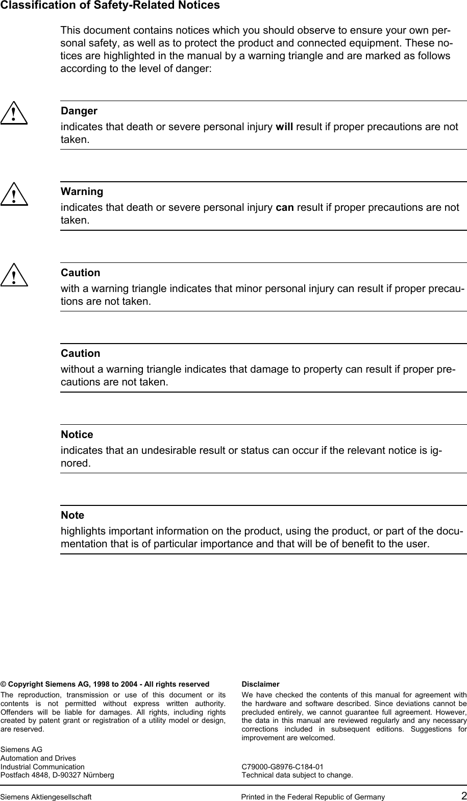

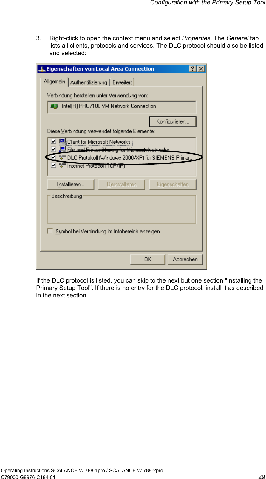
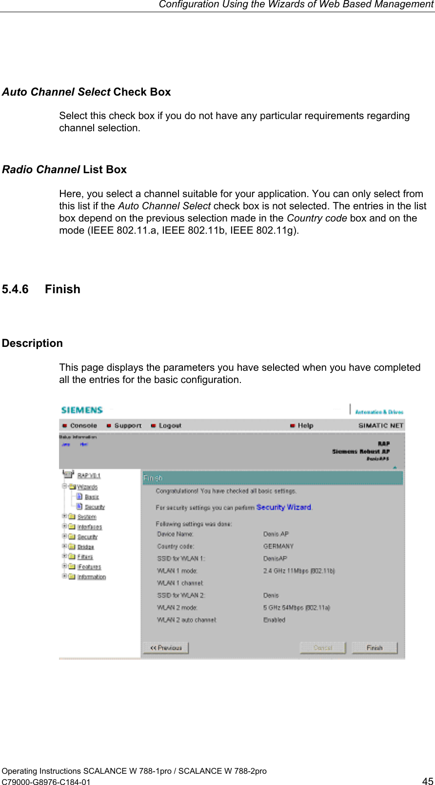
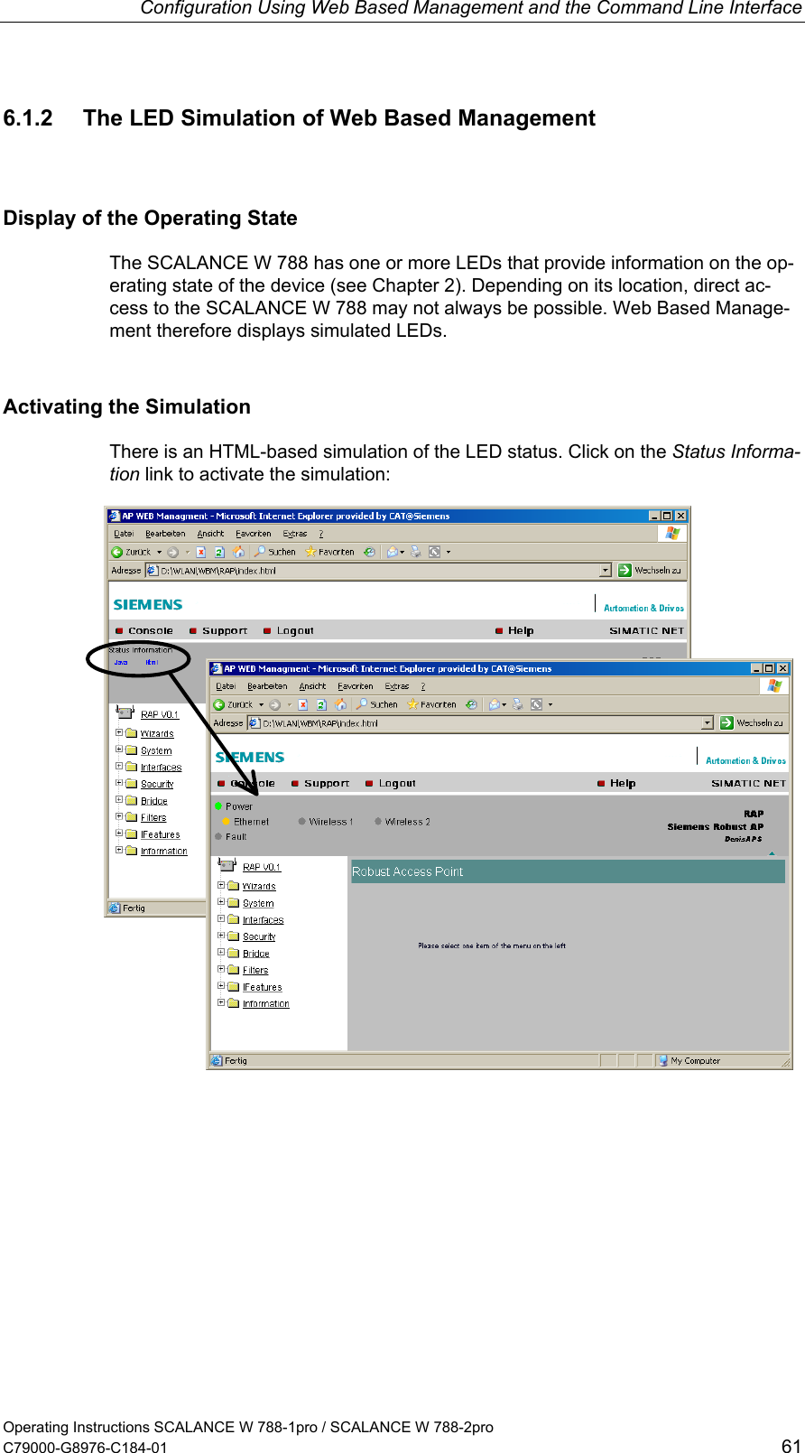
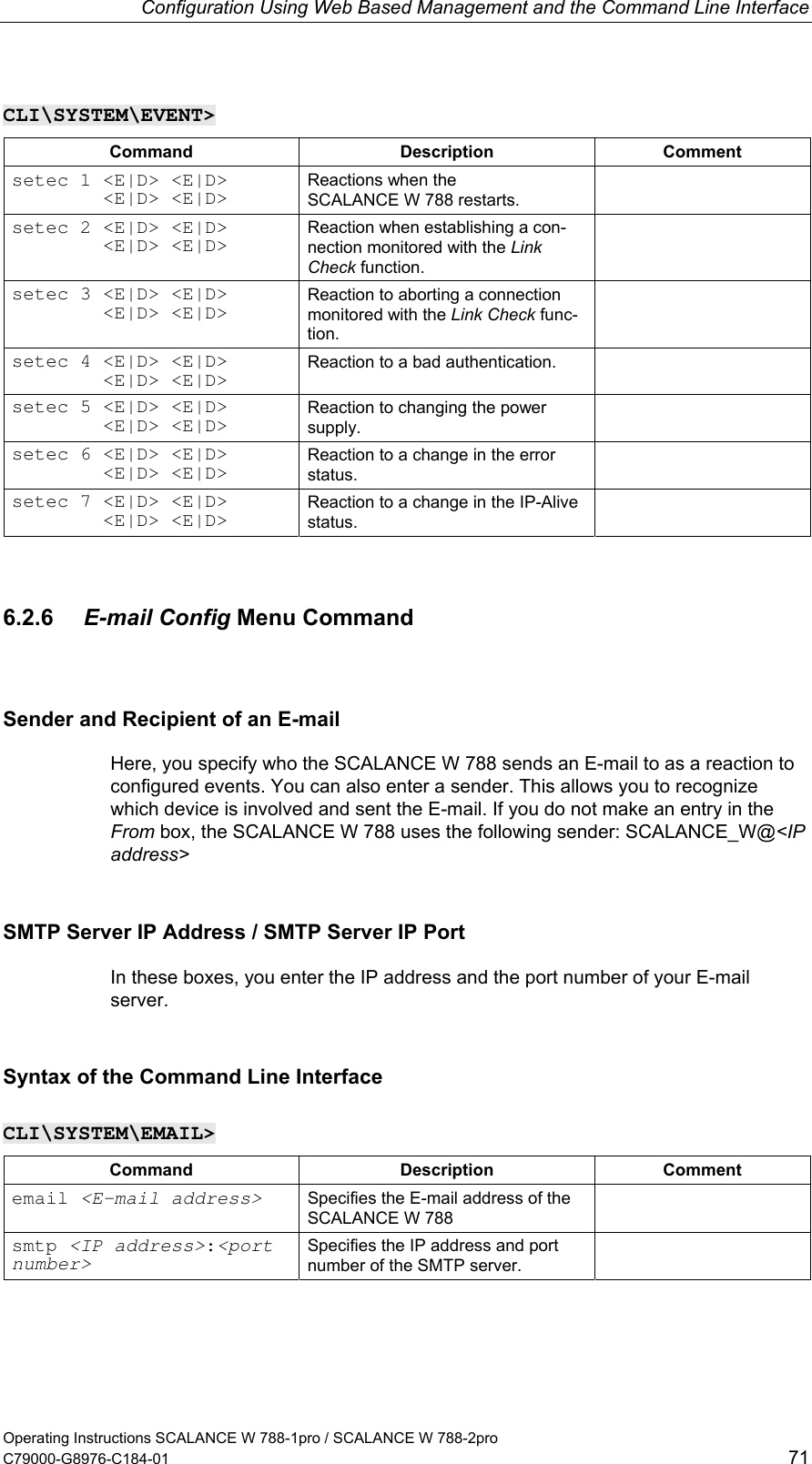
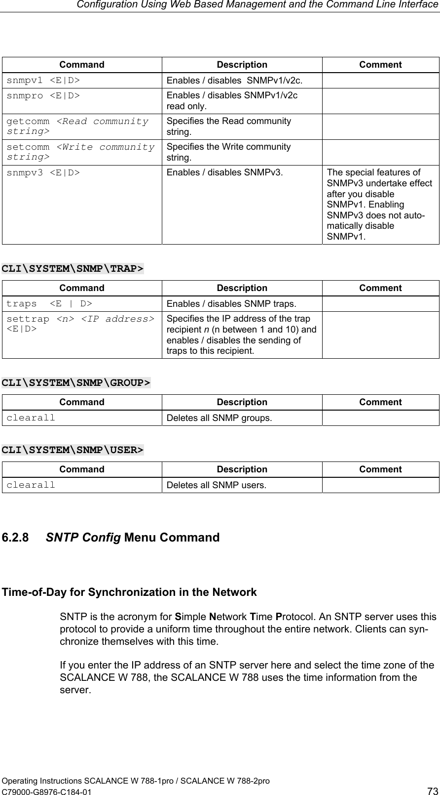
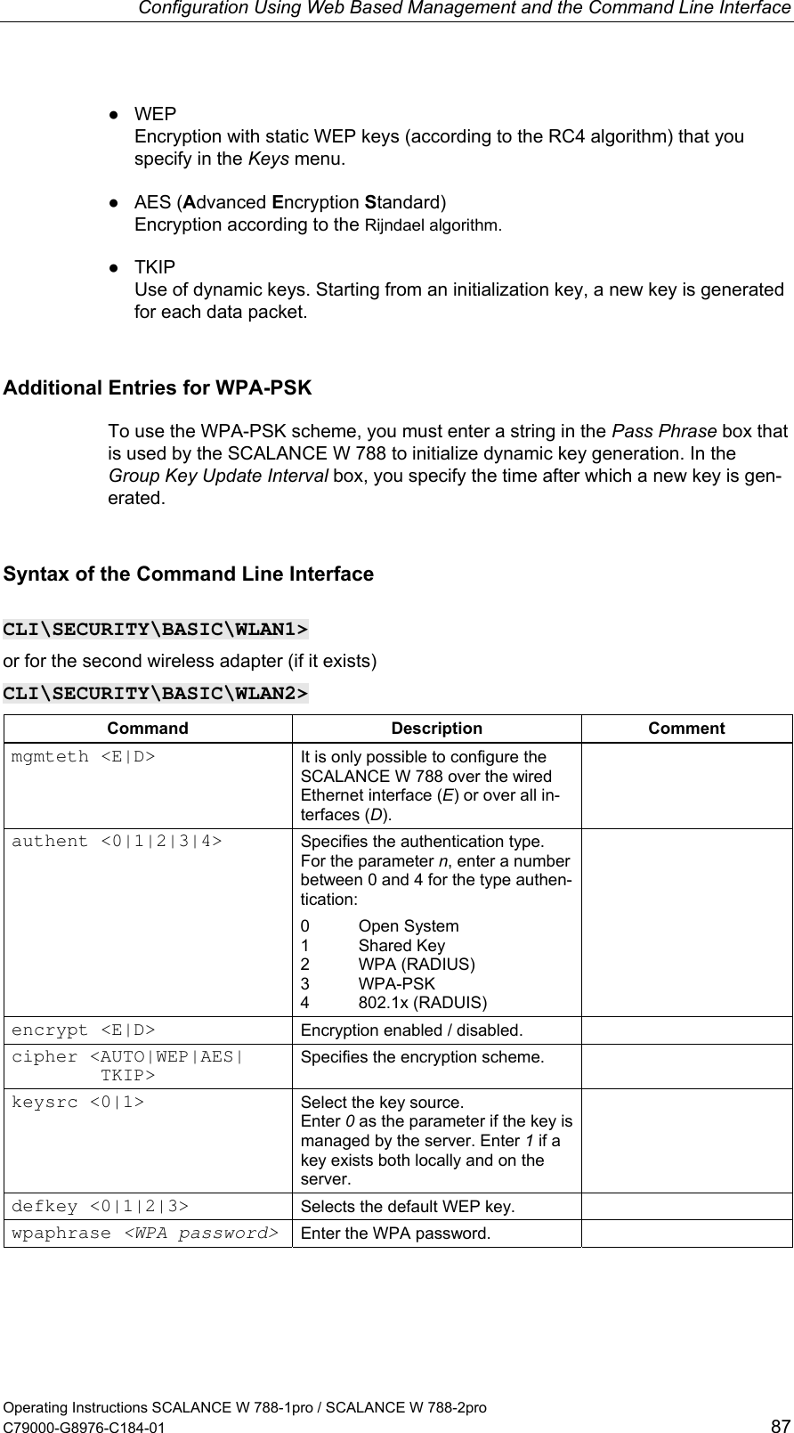
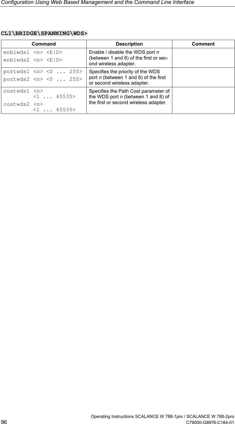
![Configuration with the Primary Setup Tool Operating Instructions SCALANCE W 788-1pro / SCALANCE W 788-2pro C79000-G8976-C184-01 33 3. Decide how the device will obtain its IP address: ● Dynamically from a DHCP server: Select the Obtain IP address from DHCP server option button. ● Manual assignment by the user: Select the Assign IP parameters option button. 4.[a] In the Client ID box, enter a unique identifier for the SCALANCE W 788 if you have selected dynamic assignment of the IP address. This string can be a maximum of 63 characters long; special characters are not permitted. 4.[b] Make the following entries if you have decided to assign the IP address manu-ally: ● Enter the IP address for the device in the IP Address box. In each part of the address separated by the periods, you can enter a number between 0 and 255; the program does not accept any other numbers. ● Enter the subnet mask in the Subnet Mask box. ● If necessary, select the Use router check box and enter the IP address of the router in the text box. Router information is necessary if the computer on which you are creating the configuration is not in the same subnet as the SCALANCE W 788. Downloading to the Module Follow the steps below to transfer the configuration data to the device: 1. Select the module to which you will download the configuration data in the left-hand pane of the program window. As long as an interface is selected and the input dialog for the configuration data is displayed, no download is possible. 2. Start the download with the steps outlined below: ● Select the Module > Download menu command. ● Click the second icon from the left in the toolbar (S7 modules with yellow arrow).](https://usermanual.wiki/Siemens/W700-1-V1/User-Guide-440898-Page-33.png)
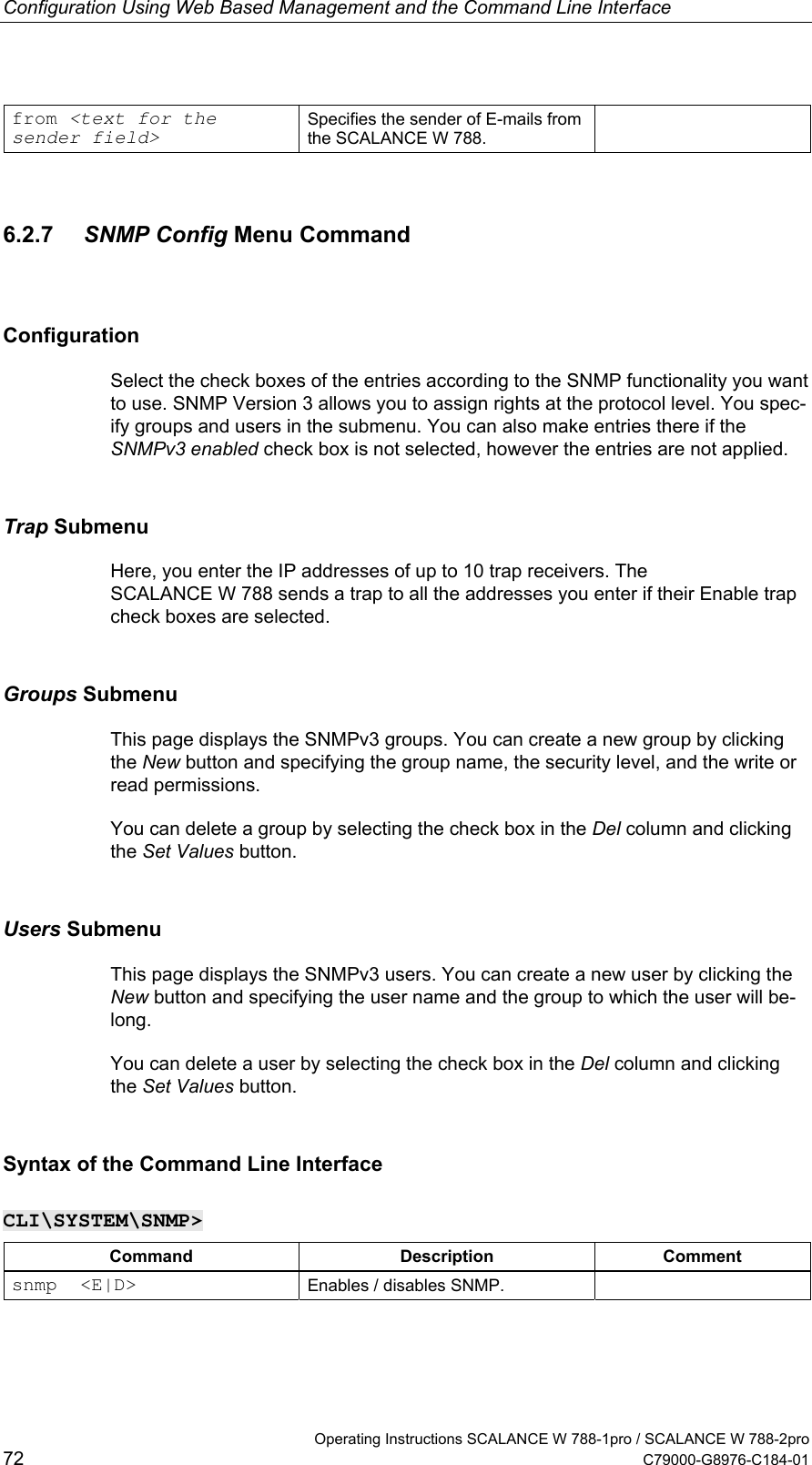
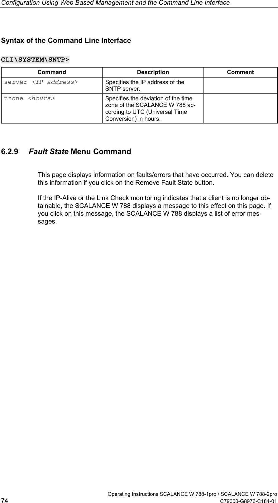
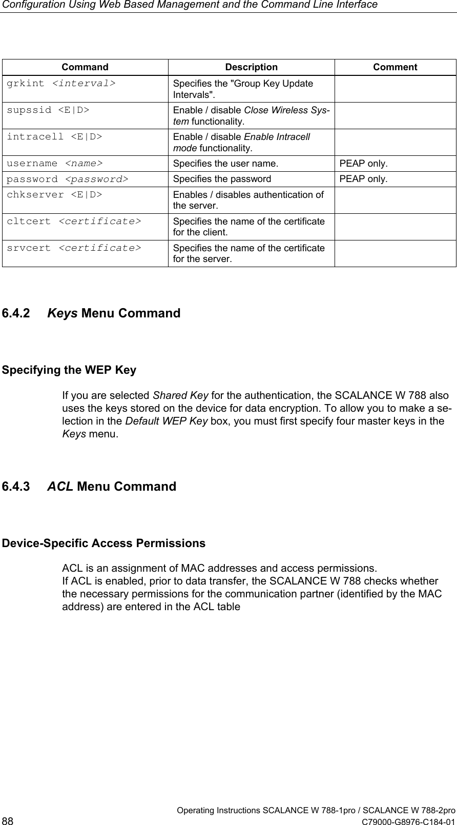
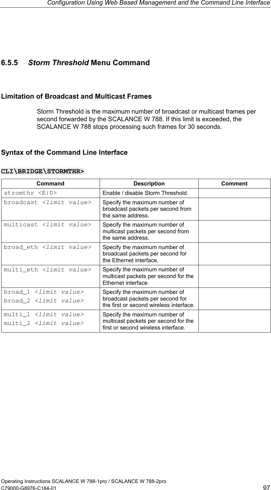
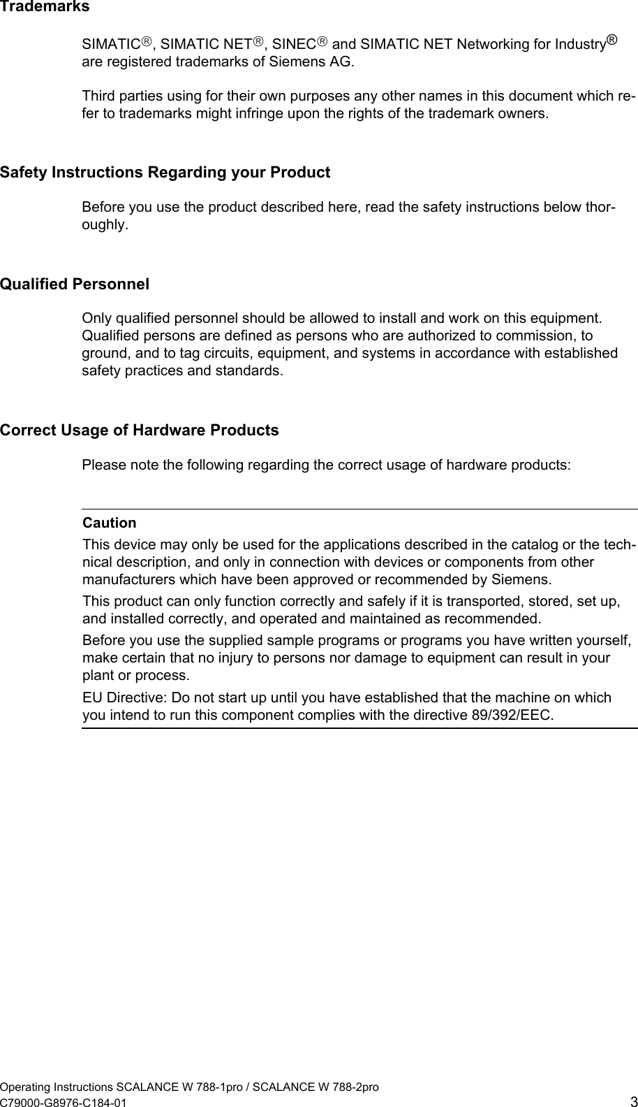
![Configuration with the Primary Setup Tool Operating Instructions SCALANCE W 788-1pro / SCALANCE W 788-2pro C79000-G8976-C184-01 35 4.5 Primary Setup Tool via the Command Line Syntax You can also use the Primary Setup Tool from the command line of a DOS prompt. The syntax is as follows; optional parameters are shown in square brackets: s7wnpstx MAC address -DHCP[=client ID] s7wnpstx MAC address -RESET s7wnpstx MAC address IP address subnet mask [router address] The following table explains the parameters: Command Description Comment MAC address The MAC address of the module to be configured. -DHCP Specifies whether or not the IP ad-dress is obtained from a DHCP server. client ID A unique identifier for the device. If this parameter is not specified, the Primary Setup Tool uses the MAC address as the ID. Optional. -RESET Sets the IP address to 0.0.0.0 . IP address The IP address of the module to be configured. subnet mask Subnet mask of the module to be configured. Router address The IP address of the default router. Optional.](https://usermanual.wiki/Siemens/W700-1-V1/User-Guide-440898-Page-35.png)