Siemens W700-1-V1 2.4/5 GHz IEEE 802.11a/b/g WLAN Access Point User Manual for Manuals
Siemens AG 2.4/5 GHz IEEE 802.11a/b/g WLAN Access Point for Manuals
Siemens >
Users Manual

SIMATIC NET Preface, Contents
Basic Information on Wireless
LAN Communication 1
Description of the
SCALANCE W 700 2
Commissioning 3
Configuration with the Primary
Setup Tool 4
Configuration Using the
Wizards of
Web Based Management
5
Configuration Using Web
Based Management and the
Command Line Interface
6
Technical Specifications 7
Glossary, Index, Certificates
and Approvals, Support
Operating Instructions
SCALANCE W 744-1pro
(Client Module)
SCALANCE W 788-1pro
(Access Point)
SCALANCE W 788-2pro
(Dual Access Point)
C79000-G8976-C184-01
Release 02/2004

© Copyright Siemens AG, 1998 to 2004 - All rights reserved
The reproduction, transmission or use of this document or its
contents is not permitted without express written authority.
Offenders will be liable for damages. All rights, including rights
created by patent grant or registration of a utility model or design,
are reserved.
Disclaimer
We have checked the contents of this manual for agreement with
the hardware and software described. Since deviations cannot be
precluded entirely, we cannot guarantee full agreement. However,
the data in this manual are reviewed regularly and any necessar
Classification of Safety-Related Notices
This document contains notices which you should observe to ensure your own per-
sonal safety, as well as to protect the product and connected equipment. These no-
tices are highlighted in the manual by a warning triangle and are marked as follows
according to the level of danger:
!
Danger
indicates that death or severe personal injury will result if proper precautions are not
taken.
!
Warning
indicates that death or severe personal injury can result if proper precautions are not
taken.
!
Caution
with a warning triangle indicates that minor personal injury can result if proper precau-
tions are not taken.
Caution
without a warning triangle indicates that damage to property can result if proper pre-
cautions are not taken.
Notice
indicates that an undesirable result or status can occur if the relevant notice is ig-
nored.
Note
highlights important information on the product, using the product, or part of the docu-
mentation that is of particular importance and that will be of benefit to the user.
y
corrections included in subsequent editions. Suggestions fo
r
improvement are welcomed.
Siemens AG
Automation and Drives
Industrial Communication
Postfach 4848, D-90327 Nürnberg
C79000-G8976-C184-01
Technical data subject to change.
Siemens Aktiengesellschaft Printed in the Federal Republic of Germany 2

Operating Instructions SCALANCE W 788-1pro / SCALANCE W 788-2pro
C79000-G8976-C184-01 3
Trademarks
SIMATIC, SIMATIC NET, SINEC and SIMATIC NET Networking for Industry®
are registered trademarks of Siemens AG.
Third parties using for their own purposes any other names in this document which re-
fer to trademarks might infringe upon the rights of the trademark owners.
Safety Instructions Regarding your Product
Before you use the product described here, read the safety instructions below thor-
oughly.
Qualified Personnel
Only qualified personnel should be allowed to install and work on this equipment.
Qualified persons are defined as persons who are authorized to commission, to
ground, and to tag circuits, equipment, and systems in accordance with established
safety practices and standards.
Correct Usage of Hardware Products
Please note the following regarding the correct usage of hardware products:
Caution
This device may only be used for the applications described in the catalog or the tech-
nical description, and only in connection with devices or components from other
manufacturers which have been approved or recommended by Siemens.
This product can only function correctly and safely if it is transported, stored, set up,
and installed correctly, and operated and maintained as recommended.
Before you use the supplied sample programs or programs you have written yourself,
make certain that no injury to persons nor damage to equipment can result in your
plant or process.
EU Directive: Do not start up until you have established that the machine on which
you intend to run this component complies with the directive 89/392/EEC.

Operating Instructions SCALANCE W 788-1pro / SCALANCE W 788-2pro
4 C79000-G8976-C184-01
Correct Usage of Software Products
Please note the following regarding the correct usage of software products:
Caution
This software may only be used for the applications described in the catalog or the
technical description, and only in connection with software products, devices, or com-
ponents from other manufacturers which have been approved or recommended by
Siemens.
Before you use the supplied sample programs or programs you have written yourself,
make certain that no injury to persons nor damage to equipment can result in your
plant or process.
Prior to Startup
Before putting the product into operation, note the following warning:
Caution
Prior to startup you must observe the instructions in the relevant documentation. For
ordering data of the documentation please refer to the catalogs or contact your local
SIEMENS representative.
Preface
Purpose of the Manual
This manual is intended to provide you with the information you require to install,
commission and operate the SCALANCE W 788 correctly. It explains how to con-
figure the SCALANCE W 788 and how to integrate the SCALANCE W 788 in a
WLAN network.
Scope of this Manual
This manual describes the products SCALANCE W 744-1pro, SCALANCE W 788-
1pro and SCALANCE W 788-2pro. Where the description applies to all products,
the name SCALANCE W 700 is used. Where the description applies to a specific
product, the full name of the product is used.
This manual applies to the following software versions:
● SCALANCE W 700 firmware as of Version 1.0
● Primary Setup Tool as of Version 2.0.10
Operating Instructions SCALANCE W 788-1pro / SCALANCE W 788-2pro
C79000-G8976-C184-01 5

Preface
Orientation in the Documentation
Apart from the operating instructions you are currently reading, the following docu-
mentation is also available from SIMATIC NET on the topic of Industrial Wireless
LANs:
● Operating Instructions (compact) SCALANCE W 788-1pro /
SCALANCE W 788-2pro
This document is supplied on paper with the device and contains an abridged
version of the most important information required to work with the
SCALANCE W 788.
● System Manual Wireless LAN Basics
This includes not only the description of the physical basics and an outline of
the most important IEEE standards but also information on data security and a
description of industrial uses of wireless LAN.
You should read this manual if you want to set up WLAN networks with a more
complex structure (not only connections between two devices).
● Operating Instructions SCALANCE W 744-1pro
This is the comprehensive user documentation on the SCALANCE W 744-1pro
with all the information required for installation, commissioning and operation of
this device.
The SCALANCE W 744-1pro is connected to a PC / PLC by an Ethernet cable
and allows the attachment of these devices to a wireless network; in other
words, it is a gateway from a wired to a wireless network.
● Operating Instructions (compact) SCALANCE W 744-1pro
This document is supplied on paper with the device and contains an abridged
version of the most important information required to work with the
SCALANCE W 744-1pro.
● Operating Instructions CP 7515
The comprehensive user documentation for the CP 7515 communications proc-
essor with all the information required to operate this device.
The CP 7515 is inserted in a PCMCIA slot and allows attachment of the PC/PG
to a wireless network.
● Operating Instructions (compact) CP 7515
This document is supplied with the device on paper and contains a concise
summary of the most important information required to use the CP 7515.
Operating Instructions SCALANCE W 788-1pro / SCALANCE W 788-2pro
6 C79000-G8976-C184-01

Preface
Biological Compatibility
The question as to whether electromagnetic fields (for example in connection with
high-frequency mobile radio) can be detrimental to human health is taken seriously
by Siemens. The protection of the population, customers and employees is of ma-
jor importance and must come before commercial interest.
The products are subject to and comply with the currently valid limit values recom-
mended on the basis of numerous scientific studies. These limit values are well be-
low the field strengths that must be exceeded before their effects are considered
relevant to health.
The products are assessed by authorized official bodies. If these limit values are
adhered to, risk of damage to health can be excluded according to the opinion of
independent scientific committees and the current state of knowledge.
Today's wireless LAN systems are significantly below these required limit values.
Wireless LAN systems have a maximum power output of 0.1 W, while the output
power of a commercial mobile phone is up to 2 W.
Notes on Working with Wireless LAN Products
When working with wireless LAN products, you may find the following notes help-
ful:
● Restrict exposure to high-frequency electromagnetic fields to a minimum time
and amount
● Obtain regular information on the latest state of the technology, available in lit-
erature from Siemens A&D
● Show particular consideration to people with sensitive health including children
and adolescents
● Show particular consideration to persons with heart pacemakers and hearing
aids
Maintain a minimum clearance of 0.5 m between antennas and people whenever
possible. This does not imply that clearances less than this distance will lead to
impairment of health.
FFC approval
This device complies with Part 15 of the FCC Rules and with RSS-210 of Industry
Canada.
Operation is subject to the following two conditions:
(1) this device my not cause harmful interference, and
(2) this device must accept any interference received, including interference that
may cause undesired operation.
Operating Instructions SCALANCE W 788-1pro / SCALANCE W 788-2pro
C79000-G8976-C184-01 7

Preface
Notice
Changes or modifications made to this equipment not expressly approved by
SIEMENS may void the FCC authorization to operate this equipment.
This equipment has been tested and found to comply with the limits for a Class B
digital device, pursuant to Part 15 of the FCC Rules. These limits are designed to
provide reasonable protection against harmful interference in a residential installa-
tion. This equipment generates, uses and can radiate radio frequency energy and,
if not installed and used in accordance with the instructions, may cause harmful in-
terference to radio communications. However, there is no guarantee that interfer-
ence will not occur in a particular installation. If this equipment does cause harmful
interference to radio or television reception, which can be determined by turning
the equipment off and on, the user is encouraged to try to correct the interference
by one or more of the following measures:
• Reorient or relocate the receiving antenna.
• Increase the separation between the equipment and receiver.
• Connect the equipment into an outlet on a circuit different from that to which the
receiver is connected.
Consult the dealer or an experienced radio/TV technician for help.
Notice
FCC Radiation Exposure Statement:
This equipment complies with FCC radiation exposure limits set forth for an uncon-
trolled environment. This equipment should be installed and operated with minimum
distance 20cm between the radiator and your body.
This transmitter must not be co-located or operating in conjunction with any other
antenna or transmitter.
Operating Instructions SCALANCE W 788-1pro / SCALANCE W 788-2pro
8 C79000-G8976-C184-01

Preface
Operating Instructions SCALANCE W 788-1pro / SCALANCE W 788-2pro
C79000-G8976-C184-01 9
Contents
1 Basic Information on Wireless LAN Communication............................................... 12
1.1 Network Structure .............................................................................................. 12
2 Description of the SCALANCE W 700 ........................................................................ 18
3 Commissioning............................................................................................................. 22
4 Configuration with the Primary Setup Tool ............................................................... 28
4.1 Introduction ........................................................................................................ 28
4.2 Installing the DLC Protocol ................................................................................ 30
4.3 Installing the Primary Setup Tool....................................................................... 31
4.4 Working with the Primary Setup Tool ................................................................ 31
4.5 Primary Setup Tool via the Command Line....................................................... 35
5 Configuration Using the Wizards of Web Based Management ............................... 36
5.1 Introduction ........................................................................................................ 36
5.2 Starting Web Based Management and Logging On.......................................... 37
5.3 Selecting the Wizards........................................................................................ 38
5.4 Basic Wizard...................................................................................................... 39
5.4.1 IP Settings ......................................................................................................... 39
5.4.2 Device Name ..................................................................................................... 41
5.4.3 Country Code..................................................................................................... 42
5.4.4 Wireless Settings ............................................................................................... 43
5.4.5 Channel Settings ............................................................................................... 44
5.4.6 Finish ................................................................................................................. 45
5.5 Security Wizard.................................................................................................. 47
5.5.1 Security Settings................................................................................................ 48
5.5.2 Security Settings for Management Interfaces ................................................... 49
5.5.3 Security Settings for SNMP Protocol................................................................. 50
5.5.4 Security Settings for WLAN (Page 1) ................................................................ 51
5.5.5 Security Settings for WLAN (Page 2) ................................................................ 52
5.5.6 Settings for the Security Level Low ................................................................... 54
5.5.7 Settings for the Security Level Middle ............................................................... 55
5.5.8 Settings for the Security Level High .................................................................. 56
5.5.9 Settings for the Security Level Highest ............................................................. 56
5.5.10 Following Settings Were Made.......................................................................... 57
5.5.11 Finish ................................................................................................................. 58
6 Configuration Using Web Based Management and the Command Line Interface 60
6.1 General Information on Web Based Management and the Command Line
Interface............................................................................................................. 60
6.1.1 Introduction ........................................................................................................ 60
6.1.2 The LED Simulation of Web Based Management............................................. 61
6.1.3 Working with Web Based Management ............................................................ 62
6.1.4 Command Line Interface ................................................................................... 63
Operating Instructions SCALANCE W 788-1pro / SCALANCE W 788-2pro
C79000-G8976-C184-01 10

Contents
Operating Instructions SCALANCE W 788-1pro / SCALANCE W 788-2pro
C79000-G8976-C184-01 11
6.2 The System Menu.............................................................................................. 65
6.2.1 System Information Menu Command ................................................................ 65
6.2.2 IP Settings Menu Command.............................................................................. 66
6.2.3 Services Menu Command ................................................................................. 66
6.2.4 Restart Menu Command ................................................................................... 68
6.2.5 Event Config Menu Command .......................................................................... 70
6.2.6 E-mail Config Menu Command ......................................................................... 71
6.2.7 SNMP Config Menu Command ......................................................................... 72
6.2.8 SNTP Config Menu Command .......................................................................... 73
6.2.9 Fault State Menu Command.............................................................................. 74
6.2.10 Load & Save Menu Command .......................................................................... 75
6.3 The Interfaces Menu.......................................................................................... 77
6.3.1 Ethernet Menu Command ................................................................................. 77
6.3.2 WLAN Menu Command..................................................................................... 78
6.3.3 Advanced Submenu .......................................................................................... 79
6.3.4 Advanced G Submenu ...................................................................................... 82
6.4 The Security Menu............................................................................................. 85
6.4.1 Basic Wireless Menu Command ....................................................................... 85
6.4.2 Keys Menu Command ....................................................................................... 88
6.4.3 ACL Menu Command ........................................................................................ 88
6.4.4 RADIUS Server Menu Command...................................................................... 89
6.4.5 Access Menu Command ................................................................................... 90
6.5 The Bridge Menu ............................................................................................... 91
6.5.1 WDS Menu Command....................................................................................... 92
6.5.2 Learn Table Menu Command............................................................................ 92
6.5.3 ARP Table Menu Command.............................................................................. 93
6.5.4 Spanning Tree Menu Command ....................................................................... 93
6.5.5 Storm Threshold Menu Command .................................................................... 97
6.6 The Filters Menu................................................................................................ 98
6.6.1 MAC Filter Menu Command .............................................................................. 98
6.6.2 Protocol Filter Menu Command......................................................................... 98
6.7 The I-Features Menu ....................................................................................... 100
6.7.1 iQoS Menu Command ..................................................................................... 100
6.7.2 Link Check Menu Command ........................................................................... 100
6.7.3 Redundancy Menu Command......................................................................... 101
6.7.4 IP-Alive Menu Command................................................................................. 102
6.8 The Information Menu...................................................................................... 104
7 Technical Specifications ........................................................................................... 106
Appendix Private MIB Variables of the SCALANCE W 700.............................................. 108
Glossary ................................................................................................................................... 110
Index 112
Basic Information on Wireless LAN
Communication 1
1.1 Network Structure
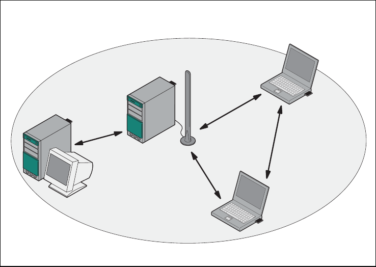
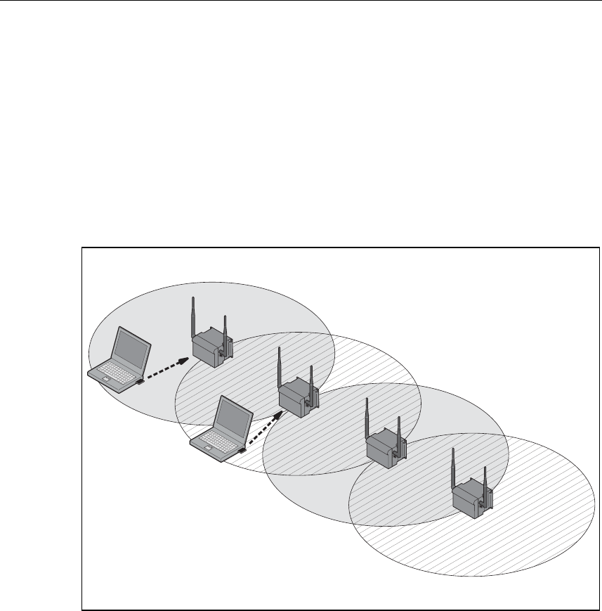
Ad Hoc Networks
In the ad hoc mode, nodes communicate directly with the server (connections 1
through 3 in the graphic below) without involving a SCALANCE W 788 or with each
other (connection 4). The nodes access common resources (files or even devices,
for example a printer) of the server. This is, of course, only possible when the
nodes are within the wireless range of the server or within each other's range.
1
2
3
4
Figure 1-1 Ad Hoc Network without SCALANCE W 788
Operating Instructions SCALANCE W 788-1pro / SCALANCE W 788-2pro
C79000-G8976-C184-01 12
Basic Information on Wireless LAN Communication
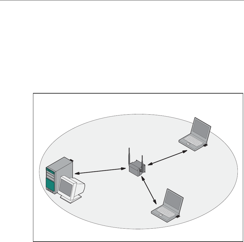
Standalone Configuration with the SCALANCE W 788
This configuration does not require a server and the SCALANCE W 788 does not
have a connection to a wired Ethernet. Within its transmission range, the
SCALANCE W 788 forwards data from one WLAN node to another.
The wireless network has a unique name. All the devices exchanging data within
this network must be configured with this name.
Figure 1-2 Standalone Configuration of a SCALANCE W 788. The gray area indicates
the wireless transmission range of the SCALANCE W 788.
Operating Instructions SCALANCE W 788-1pro / SCALANCE W 788-2pro
C79000-G8976-C184-01 13
Basic Information on Wireless LAN Communication
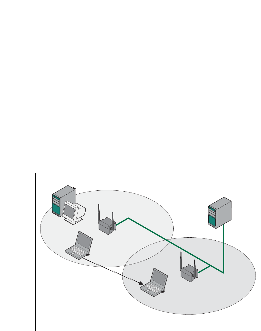
Wireless Access to a Wired Ethernet Network
If one (or more) SCALANCE W 788 access points have access to wired Ethernet,
the following applications are possible:
● A single SCALANCE W 788 as gateway:
A computer equipped only with an Ethernet adapter can be integrated in the cli-
ent mode in a wireless network over the SCALANCE W 788-1pro.
● Span of wireless coverage for the wireless network with several
SCALANCE W 788 access points:
The SCALANCE W 788 access points are all configured with the same unique
SSID (network name). All nodes that want to communicate over this network
must also be configured with this SSID.
If a mobile station moves from the coverage range (cell) of one
SCALANCE W 788 to the coverage range (cell) of another SCALANCE W 788,
the wireless connection is maintained (this is called roaming).
Figure 1-3 Connecting Two SCALANCE W 788 Access Points to a Wired Ethernet
Operating Instructions SCALANCE W 788-1pro / SCALANCE W 788-2pro
14 C79000-G8976-C184-01
Basic Information on Wireless LAN Communication
Multichannel Configuration
If neighboring SCALANCE W 788 access points use the same frequency channel,
the response times are longer due to the collisions that occur. If the configuration
shown in Figure 1-4 is implemented as a single-channel system, computers A and
B cannot communicate at the same time with the SCALANCE W 788-1pro access
points in their cells.
If neighboring SCALANCE W 788 access points are set up for different frequen-
cies, this leads to a considerable improvement in performance. As a result, neigh-
boring cells each have their own medium and the delays resulting from time-offset
transmission no longer occur.
Channel spacing should be as large as possible; a practical value would be 25
MHz (five channels). Even in a multichannel configuration, all SCALANCE W 788
access points can be configured with the same network name.
1
1
7
7
A
B
Figure 1-4 Multichannel Configuration on Channels 1 and 7 with four
SCALANCE W 788 Access Points
Operating Instructions SCALANCE W 788-1pro / SCALANCE W 788-2pro
C79000-G8976-C184-01 15
Basic Information on Wireless LAN Communication
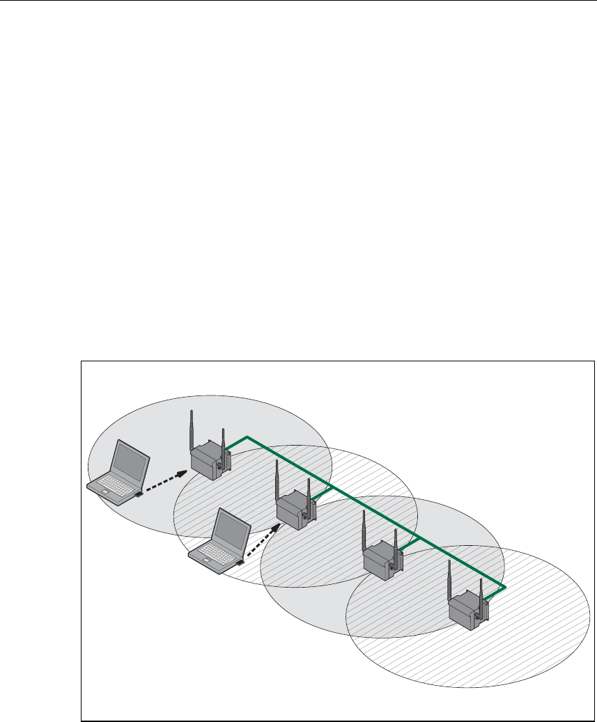
Wireless Distribution System (WDS)
WDS allows direct connections between SCALANCE W 788 access points. These
are used to create a wireless backbone or to connect an individual
SCALANCE W 788 to a network that cannot be connected directly to the cable in-
frastructure due to its location.
Two alternative configurations are possible. The WDS partner can be configured
both using its name and its MAC address.
1
1
7
7
A
B
Figure 1-5 Implementation of WDS with four SCALANCE W 788 Access Points
Operating Instructions SCALANCE W 788-1pro / SCALANCE W 788-2pro
16 C79000-G8976-C184-01

Basic Information on Wireless LAN Communication
Operating Instructions SCALANCE W 788-1pro / SCALANCE W 788-2pro
C79000-G8976-C184-01 17
Description of the SCALANCE W 700 2
Components of the Product
The following components are supplied with the SCALANCE W 700:
● SCALANCE W 744-1pro, SCALANCE W 788-1pro or SCALANCE W 788-2pro
● 2 OMNI antennas
● 1 Harting RJ-45 hybrid cable connector
● 1 dummy plug for the M12 socket
● 2 (or 4 for the SCALANCE W 788-2pro) dummy plugs for the R-SMA sockets
● 1 SIMATIC NET Industrial Wireless LAN CD
● These Operating Instructions for the SCALANCE W 700
Please check that the consignment you have received is complete. If it is not com-
plete, please contact your supplier or your local Siemens office.
Requirements for Installation and Operation
There must be a network attachment available for the SCALANCE W 788 since the
device is configured over the Ethernet interface. If no DHCP server is available, a
PC on which the Primary Setup Tool is installed and can be used is necessary for
the initial assignment of an IP address to the SCALANCE W 788. For the other
configuration settings, a computer with Telnet or an Internet browser is necessary.
Operating Instructions SCALANCE W 788-1pro / SCALANCE W 788-2pro
C79000-G8976-C184-01 18

Description of the SCALANCE W 700
Possible Applications of the SCALANCE W 788
The SCALANCE W 788 is equipped with an Ethernet interface and a wireless LAN
interface (SCALANCE W 788-2pro: two WLAN interfaces). This makes the device
suitable for the following applications:
● The SCALANCE W 788 forwards data within its transmission range from one
node to another without a connection to wired Ethernet.
● The SCALANCE W 788 is used as a gateway from a wired to a wireless net-
work.
● The SCALANCE W 788 can be used as a bridge between two networks.
Due to its second WLAN interface, the SCALANCE W 788-2pro can also be used
to implement a redundant wireless connection between two SCALANCE W 788-
2pro devices.
Properties of the SCALANCE W 788
● The Internet interface supports 10 Mbps and 100 Mbps, full duplex and half du-
plex in both cases.
● The wireless interface is compatible with the standards IEEE 802.11a,
IEEE 802.11b and IEEE 802.11g. In the 802.1a- and 802.1g modes, the trans-
mission rate is up to 54 Mbps.
● Operation in the 2.4 GHz and 5 GHz frequency bands.
● Support of the authentication standards WPA, WPA-PSK and
IEEE 802.1x and WEP, AES and TKIP encryption schemes.
● Suitable for inclusion of a RADIUS server for authentication.
● Device-related and application-related monitoring of the wireless connection.
Ports
The SCALANCE W 788 has the following ports:
● A Harting RJ-45 hybrid socket on the front panel of the housing for connection
of an Ethernet cable and for the power supply (hybrid connector for power over
Ethernet).
● An M12 socket for the power supply.
● Two R-SMA sockets (four R-SMA sockets on the SCALANCE W 788-2pro) for
the attachment of antennas on the sides of the device.
Note
In the version for USA/Canada, two fixed antennas are fitted. On the
SCALANCE W 788-2pro, the antennas of the second wireless card can be
detached. The second wireless card can only be operated at 2.4 GHz
Operating Instructions SCALANCE W 788-1pro / SCALANCE W 788-2pro
C79000-G8976-C184-01 19
Description of the SCALANCE W 700
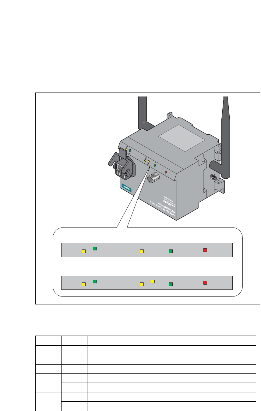
LED Display
On the front of the housing, several LEDs provide information on the operating
status of the SCALANCE W 788:
P 1
L 2
R 1
R 2
L 1
F
P 1
L 2
R 1
L 1
F
S C A L A N C E W 7 8 8 - 1 p r o
S C A L A N C E W 7 8 8 - 2 p r o
Figure 2-1 The LEDs of the SCALANCE W 788
The LEDs have the following significance:
LED Color Meaning
Yellow Data transfer over the Ethernet interface.
P1
Green There is a connection over the Ethernet interface.
L2 Green Power supply over hybrid connector.
Yellow Data transfer over the first WLAN interface.
R1
Green There is a connection over the first WLAN interface.
Yellow Data transfer over the second WLAN interface.
R2
Green There is a connection over the second WLAN interface.
Operating Instructions SCALANCE W 788-1pro / SCALANCE W 788-2pro
20 C79000-G8976-C184-01

Description of the SCALANCE W 700
L1 Green Power supply over the M12 connector.
F Red An error occurred during operation with the SCALANCE W 788.
Configuration Information on the C Plug
The C Plug is used to transfer the configuration of the old device to the new device
when a device is replaced. When the new device starts up, it continues with ex-
actly the same configuration as the old device. The only exception to this can be
the IP configuration if it is set over DHCP and the DHCP server has not been re-
configured accordingly.
Replacing the C Plug
Follow the steps below to replace a C Plug in a SCALANCE W 788:
1. Remove the old SCALANCE W 788 from its mounting and open the sealing
screw on the rear with a coin or broad screwdriver.
2. Remove the C Plug.
3. Open the sealing screw of the new device in the same way and insert the C
Plug of the old device.
4. Replace the sealing screws of both devices.
If a new C Plug is inserted in a SCALANCE W 788-1pro, the configuration stored
locally on the SCALANCE W 788-1pro is saved to the C Plug. If an incorrect C
Plug (for example from another device or a damaged plug) is inserted, the
SCALANCE W 788 signals an error with the red LED. The user then has the
choice of either removing the C Plug again or selecting the option to reformat the C
Plug and use it.
Operating Instructions SCALANCE W 788-1pro / SCALANCE W 788-2pro
C79000-G8976-C184-01 21

Commissioning 3
Lightning Protection
!
Warning
Antennas installed outdoors must be within the area covered by a lightning protec-
tion system. Make sure that all conducting systems entering from outdoors can be
protected by a lightning protection potential equalization system.
When implementing your lightning protection concept, make sure you adhere to
the VDE 0182 or IEC 62305 standard.
Securing the Housing
There are three ways of securing the housing:
● Use the holes in the housing to screw the device to the wall or on a horizontal
surface.
● There are clips on the rear of the device for securing it to a DIN rail.
● Fit the SCALANCE W 788 into a mounting channel
Operating Instructions SCALANCE W 788-1pro / SCALANCE W 788-2pro
C79000-G8976-C184-01 22
Commissioning
Operating Instructions SCALANCE W 788-1pro / SCALANCE W 788-2pro
C79000-G8976-C184-01 23
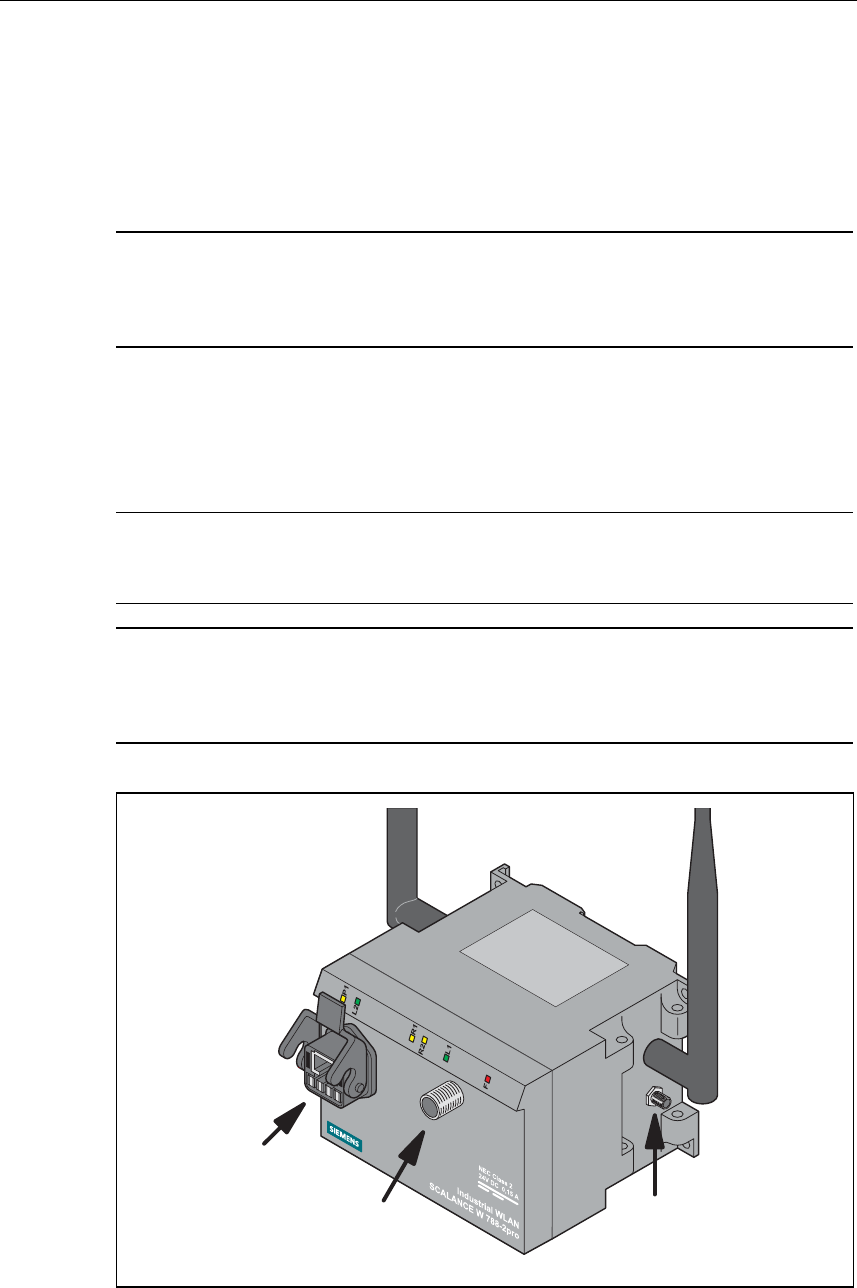
Connectors for the Power Supply and for Ethernet
The SCALANCE W 788 is attached to Ethernet via a hybrid socket on the front of
the housing (position A in Figure 3.1). This port also has contacts for the operating
voltage.
Note
If you do not use the hybrid socket, this must be covered with a protective cap,
otherwise IP65 protection is lost. A suitable protective cap is available as an ac-
cessory.
As an alternative or in addition to this, you can also use the M12 socket for the
power supply (position B in Figure 3.1).
You can fit additional antennas to the sides of the SCALANCE W 788-2pro (posi-
tion C in Figure 3.1).
Note
The distance between a pair of antennas for the first and second WLAN interface
should be at least 0.5 m.
Note
In the version for USA/Canada, two fixed antennas are fitted. On the
SCALANCE W 788-2pro, the antennas of the second wireless card can be de-
tached. The second wireless card can only be operated at 2.4 GHz
A
BC
Figure 3-1 Connectors of the SCALANCE W 788
Commissioning
Operating Instructions SCALANCE W 788-1pro / SCALANCE W 788-2pro
24 C79000-G8976-C184-01
Assembling the Hybrid Connector
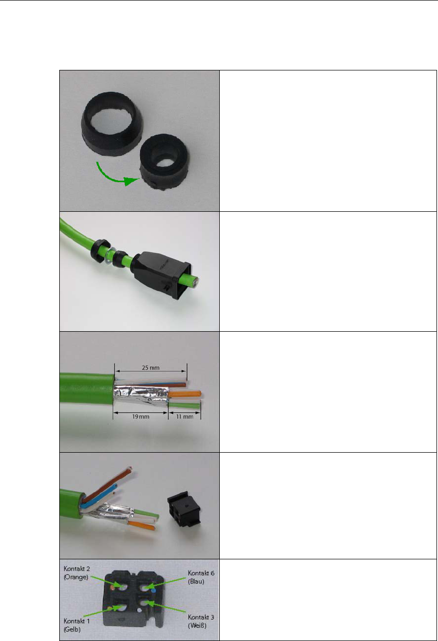
Remove the two inner shells of the universal
sealing ring to adapt it to the diameter of the
hybrid cable.
Push the bushing, washer, adapted univer-
sal sealing ring and the housing over the
cable jacket.
Strip the cable jacket and braid shield to the
correct lengths.
25 mm for the power leads.
30 mm (jacket) for the data leads (shorten
the braid by 11 mm).
Arrange the data leads according to the
color code on the splice element.
Refer to the table below for the assignment.
Contact and color assignment of the splice
element.
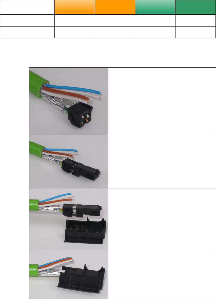
Wire color code (stan-
dard)
White /
orange * Orange White /
Green * Green
Connector color code
(Siemens IE) White Blue Yellow Orange
Siemens IE FC RJ-45
j
ack (reference) 3 6 1 2
* White wire of the colored pair.
Insert all the data leads at the same time up
to the end of the splice element.
Fit the splice element onto the RJ-45-data
module and click in place.
Insert the data module and splice element
into the supplied IDC assembly tool.
Press the data module and IDC assembly
tool together so that the insulation piercing
connection is established.
Operating Instructions SCALANCE W 788-1pro / SCALANCE W 788-2pro
C79000-G8976-C184-01 25
Commissioning
Operating Instructions SCALANCE W 788-1pro / SCALANCE W 788-2pro
26 C79000-G8976-C184-01
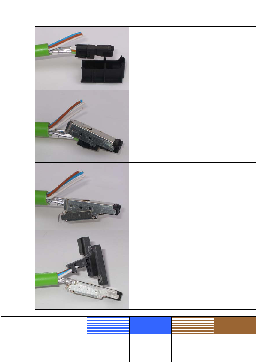
Remove the assembled data module from
the IDC assembly tool.
Fit the upper shield plate and press it over
the cable shield.
Then fit the lower shield plate and snap it
into the upper plate (there should be an au-
dible click).
Arrange the power leads and insert them to
the end of the hinged elements of the insu-
lator body.
Refer to the table below for the assignment.
Wire color code (standard) White /
Blue * Blue White /
Brown * Brown
24 V 24 V Ground Ground
Power supply
insert 1 2 3 4
Commissioning
Operating Instructions SCALANCE W 788-1pro / SCALANCE W 788-2pro
C79000-G8976-C184-01 27
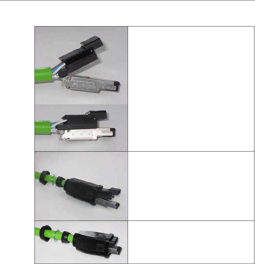
Press the hinged elements and the inte-
grated IDC contact together individually.
Recommendation: Use a small slotted
screwdriver (max. 3.5 mm) as a lever.
Push the housing over assembled data
module and the insulator body until they
lock together (there should be an audible
click).
Tighten the bushing. We recommend an
open ring key with a size of 21 mm.
Configuration with the Primary Setup Tool 4
4.1 Introduction
Initial Assignment of an IP Address
An initial IP address for the SCALANCE W 788 cannot be assigned using Web
Based Management or the Command Line Interface because these configuration
tools require that an IP address already exists.
The initial IP address can be obtained over DHCP or assigned using the Primary
Setup Tool. The Primary Setup Tool is capable of assigning such an address to
unconfigured devices without an IP address. The only condition is that the devices
can be reached over Ethernet.
Operating Systems Supported
The Primary Setup Tool can be installed and used with the following operating sys-
tems:
● Windows XP Professional
● Windows 2000 Professional SP2
DLC Protocol
The Primary Setup Tool uses the DLC protocol for communication with the mod-
ules. This protocol is not supplied with Windows XP and must be installed extra for
this operating system.
Follow the steps below to check whether or not the DLC protocol exists on your
computer:
1. Select the menu command Start > Settings > Control Panel >Network and
Dial-Up Connections.
2. Select the connection to your Ethernet communication module.
Operating Instructions SCALANCE W 788-1pro / SCALANCE W 788-2pro
C79000-G8976-C184-01 28
Configuration with the Primary Setup Tool
Operating Instructions SCALANCE W 788-1pro / SCALANCE W 788-2pro
C79000-G8976-C184-01 29
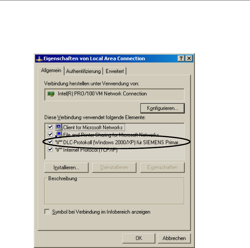
3. Right-click to open the context menu and select Properties. The General tab
lists all clients, protocols and services. The DLC protocol should also be listed
and selected:
If the DLC protocol is listed, you can skip to the next but one section "Installing the
Primary Setup Tool". If there is no entry for the DLC protocol, install it as described
in the next section.

Configuration with the Primary Setup Tool
Operating Instructions SCALANCE W 788-1pro / SCALANCE W 788-2pro
30 C79000-G8976-C184-01
4.2 Installing the DLC Protocol
Extracting the Archive File
The files for installing the DLC protocol are in the self-extracting ZIP archive
pst_xp_install.exe. Follow the steps below to extract the files from the archive:
1. Double-click on the file name pst_xp_install.exe in the Windows Explorer or
start the program using the Windows menu command Start > Run.
2. In the dialog box of the extraction program, select the folder into which you
want to extract the files and click on the Unzip button.
Installation
Follow the steps below to install the DLC protocol on your computer:
1. Select the menu command Start > Settings > Control Panel >Network and
Dial-Up Connections.
2. Select the connection to your Ethernet communication module.
3. Right-click to open the context menu and select Properties.
4. Click on the Install... button in the General tab.
5. In the Select Network Component Type dialog, select the entry Protocol and
click the Add... button.
6. In the Network Protocol dialog, click the Have Disk... button.
7. In the Install from Disk dialog, click the Browse... button.
8. In the file list box, change to the folder with the extracted installation files, se-
lect the netdlc.inf file and click the Open button.
9. In the Install from Disk dialog, click OK. The protocol is installed; the list box in
the properties dialog of the communication module now includes the entry
DLC Protocol (Windows 2000/XP) for Siemens Primary Setup Tool.
10. Close the properties dialog by clicking the OK button.

Configuration with the Primary Setup Tool
Operating Instructions SCALANCE W 788-1pro / SCALANCE W 788-2pro
C79000-G8976-C184-01 31
4.3 Installing the Primary Setup Tool
Procedure
The files of the Primary Setup Tools are in the self-extracting ZIP archive
pst_install.exe. Follow the steps below to install the files of the archive:
1. Double-click on the file name pst_install.exe in the Windows Explorer or start
the program using the Windows menu command Start > Run.
2. In the dialog box of the extraction program, select the folder into which you
want to extract the files; the default is c:\siemens\pst.
3. Click the Unzip button. After extraction, the folder you selected contains sev-
eral files including s7wnpstx.exe. Start the Primary Setup Tool by double-
clicking on this file.
4.4 Working with the Primary Setup Tool
Selecting the Language
After starting the Primary Setup Tool, a dialog opens in which you select the lan-
guage for the program. You can also set the language in the Settings > Language
menu.
Selecting the Network Adapter
If there is more than one network adapter in your computer, you can open the Set-
tings > Network Adapter menu and specify which adapter is used by the Primary
Setup Tool. This menu displays a maximum of four network adapters, however
only those for which the DLC protocol is activated are shown.
Configuration with the Primary Setup Tool
Operating Instructions SCALANCE W 788-1pro / SCALANCE W 788-2pro
32 C79000-G8976-C184-01
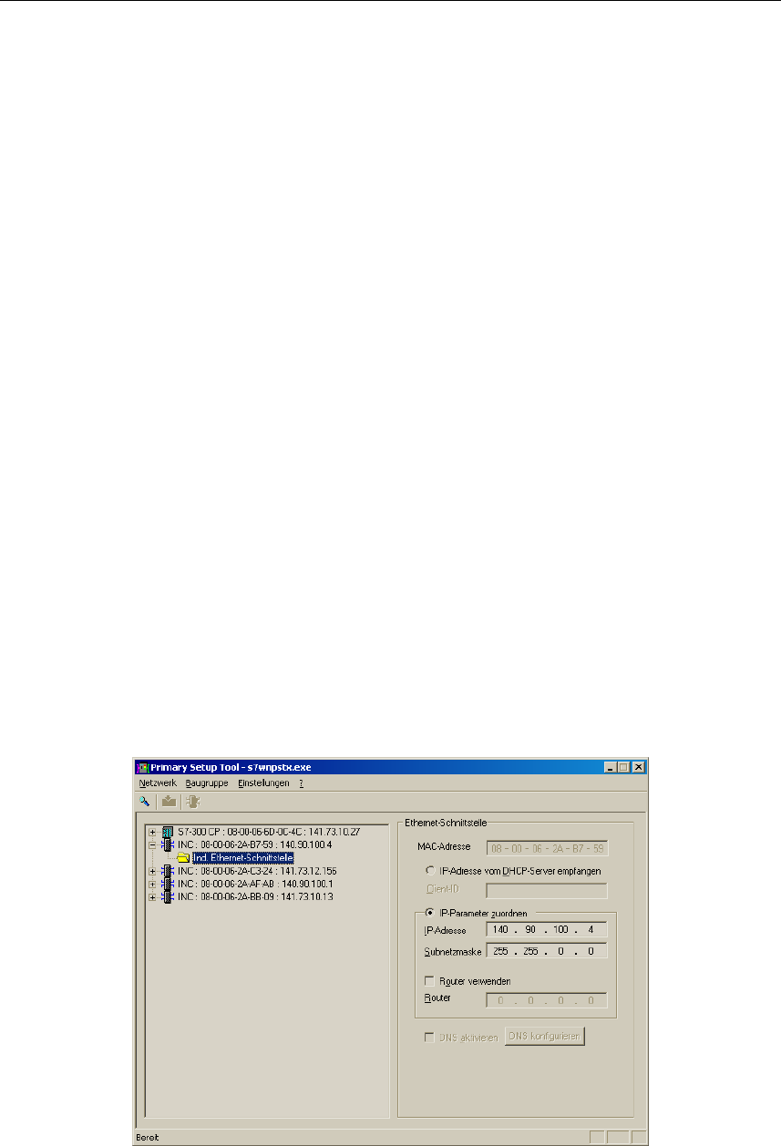
Browsing the Network
Before you assign IP addresses with the PST, you must first locate the configur-
able devices in the network. Start this search with the steps outlined below:
● Select the Network > Browse menu command.
● Click on the magnifier icon in the toolbar below the menu bar.
While the Primary Setup Tool browses the network, the Browse Network dialog is
displayed with a progress bar. On completion of the search, the Primary Setup
Tool displays a list with all the devices it has found in the left-hand pane.
Configuring a Module
If you click an entry in the list, the Primary Setup Tool displays information on the
selected device in the right-hand pane.
Follow the steps below to configure a device:
1. Click on the plus symbol in front of the device symbol or double-click on the
device symbol to display all interfaces of the device.
2. Click on the interface you want to configure. The Primary Setup Tool displays
the input dialog for the configuration data in the right-hand pane of the pro-
gram window. Depending on the selected settings, some text boxes or check
boxes may be disabled. The MAC address box is always disabled because
this address is a property of the device that cannot be modified. The Client ID
parameter is also not supported by the SCALANCE W 788.

Configuration with the Primary Setup Tool
Operating Instructions SCALANCE W 788-1pro / SCALANCE W 788-2pro
C79000-G8976-C184-01 33
3. Decide how the device will obtain its IP address:
● Dynamically from a DHCP server:
Select the Obtain IP address from DHCP server option button.
● Manual assignment by the user:
Select the Assign IP parameters option button.
4.[a] In the Client ID box, enter a unique identifier for the SCALANCE W 788 if you
have selected dynamic assignment of the IP address. This string can be a
maximum of 63 characters long; special characters are not permitted.
4.[b] Make the following entries if you have decided to assign the IP address manu-
ally:
● Enter the IP address for the device in the IP Address box. In each part of
the address separated by the periods, you can enter a number between 0
and 255; the program does not accept any other numbers.
● Enter the subnet mask in the Subnet Mask box.
● If necessary, select the Use router check box and enter the IP address of
the router in the text box. Router information is necessary if the computer
on which you are creating the configuration is not in the same subnet as
the SCALANCE W 788.
Downloading to the Module
Follow the steps below to transfer the configuration data to the device:
1. Select the module to which you will download the configuration data in the left-
hand pane of the program window. As long as an interface is selected and the
input dialog for the configuration data is displayed, no download is possible.
2. Start the download with the steps outlined below:
● Select the Module > Download menu command.
● Click the second icon from the left in the toolbar (S7 modules with yellow
arrow).
Configuration with the Primary Setup Tool
Operating Instructions SCALANCE W 788-1pro / SCALANCE W 788-2pro
34 C79000-G8976-C184-01
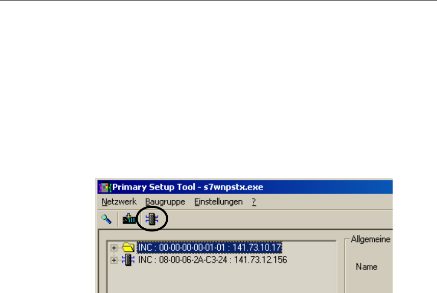
Starting Web Based Management
INCs (Industrial Network Components) such as the SCALANCE W 788 include
Web Based Management. Select the device you want to configure with Web Based
Management and follow the steps below to start Web Based Management:
● Select the menu command Module -> Start INC Browser.
● Click on the third icon from the left in the toolbar (module with four blue
wires).
If the Module > Start INC Browser and the module icon are disabled, there is no
Web Based Management for the selected module.
Removing a Module
You can remove a module from the list in the left-hand part of the program window
by selecting the Module > Remove Module menu command. Using this menu
command has no effect on the existence of a module in the network; if you browse
the network again, all modules are displayed again.

Configuration with the Primary Setup Tool
Operating Instructions SCALANCE W 788-1pro / SCALANCE W 788-2pro
C79000-G8976-C184-01 35
4.5 Primary Setup Tool via the Command Line
Syntax
You can also use the Primary Setup Tool from the command line of a DOS prompt.
The syntax is as follows; optional parameters are shown in square brackets:
s7wnpstx MAC address -DHCP[=client ID]
s7wnpstx MAC address -RESET
s7wnpstx MAC address IP address subnet mask [router address]
The following table explains the parameters:
Command Description Comment
MAC address The MAC address of the module to
be configured.
-DHCP Specifies whether or not the IP ad-
dress is obtained from a DHCP
server.
client ID A unique identifier for the device. If
this parameter is not specified, the
Primary Setup Tool uses the MAC
address as the ID.
Optional.
-RESET Sets the IP address to 0.0.0.0 .
IP address The IP address of the module to be
configured.
subnet mask Subnet mask of the module to be
configured.
Router address The IP address of the default router. Optional.
Configuration Using the Wizards of
Web Based Management 5
5.1 Introduction
Principle of Web Based Management
The SCALANCE W 788 has an integrated HTTP server for Web Based Manage-
ment. If the SCALANCE W 788 is accessed by an Internet browser, it returns
HTML pages to the client computer depending on user input.
Users enter the configuration data in the HTML pages sent by the
SCALANCE W 788. The SCALANCE W 788 evaluates this information and gener-
ates response pages dynamically.
The great advantage of this method is that apart from a Web browser, no special
software is required on the client.
Requirements for Web Based Management
Once you have assigned an IP address with the Primary Setup Tool, you can con-
tinue to configure the device with Web Based Management.
To use Web Based Management, you should ideally have a wired network connec-
tion between the SCALANCE W 788 and the client computer. In principle, it is pos-
sible to use Web Based Management over a wireless network, however the
SCALANCE W 788 can be set so that access over a wireless network is disabled.
We recommend that you use the Microsoft Internet Explorer Version 5.5 or higher
or Netscape Navigator Version 6.1 or higher.
All the pages of Web Based Management require JavaScript. Make sure that your
browser settings allow this.
Web Based Management is HTTP-based, so you must also enable access to port
80 if you have a firewall installed.
Operating Instructions SCALANCE W 788-1pro / SCALANCE W 788-2pro
C79000-G8976-C184-01 36
Configuration Using the Wizards of Web Based Management
Operating Instructions SCALANCE W 788-1pro / SCALANCE W 788-2pro
C79000-G8976-C184-01 37
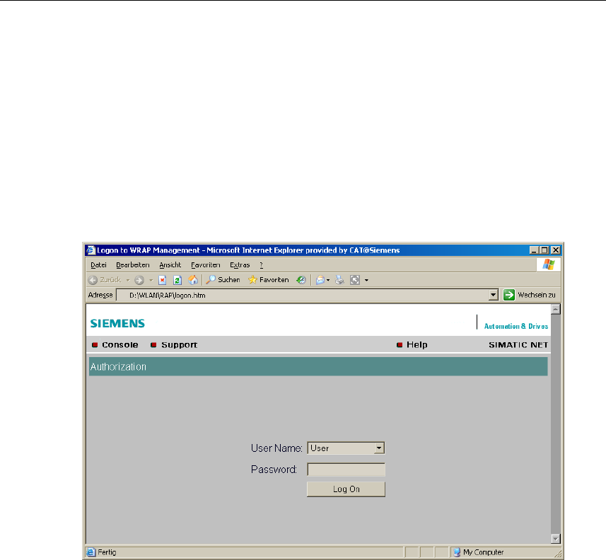
5.2 Starting Web Based Management and Logging On
Procedure
1. In the address box of the Web browser, enter the IP address or the URL of the
SCALANCE W 788. If there is a problem-free connection to the
SCALANCE W 788, the Logon dialog of Web Based Management is displayed:
2. In the "User Name" list box, select the "Admin" entry if you want to change set-
tings of the SCALANCE W 788 (read and write access). If you select the "User" en-
try, you only have read access to the configuration data of the SCALANCE W 788.
3. Enter your password. If you have not yet set a password, the default passwords
as shipped apply: Enter admin if you selected "admin" as the user name or user if
you selected "user".
4. Click on the "Log On" button to start the logon.
Configuration Using the Wizards of Web Based Management
Operating Instructions SCALANCE W 788-1pro / SCALANCE W 788-2pro
38 C79000-G8976-C184-01
5.3 Selecting the Wizards
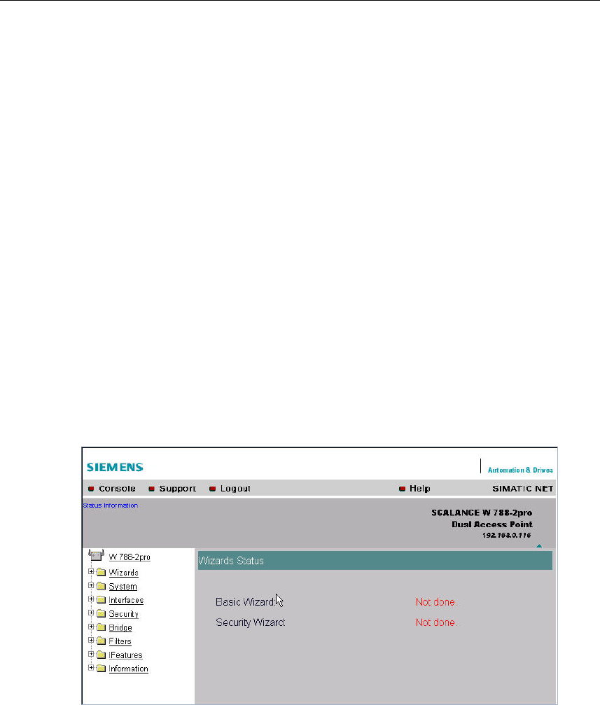
Basic Wizard and Security Wizard
Web Based Management provides two wizards that allow straightforward commis-
sioning without detailed knowledge of wireless technology. A wizard consists of a
series of dialogs in which you enter the basic configuration data.
There is a wizard for general settings and a second wizard for configuring security
settings. After working through the two wizards, you have completed the settings
for the basic functionality of the SCALANCE W 788.
Wizard Status
After selecting the "Wizards" menu on the left-hand side of the dialog, the status of
the wizards is displayed. If you have worked through a wizard completely, Done is
displayed as the status. If you have worked through both wizards, the Wizards en-
try moves to the bottom end of the menu.
Configuration Using the Wizards of Web Based Management
Operating Instructions SCALANCE W 788-1pro / SCALANCE W 788-2pro
C79000-G8976-C184-01 39
5.4 Basic Wizard
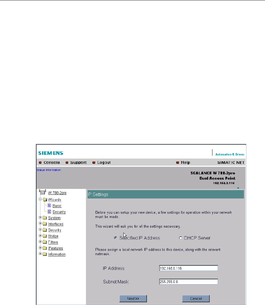
5.4.1 IP Settings
Description
One of the basic steps in configuration of an Ethernet device is setting the IP ad-
dress. The IP address identifies a device in the network uniquely. On this page,
you enter the information for IP configuration of the SCALANCE W 788.
Specified IP Address / DHCP Server Option Buttons
There are two methods of assigning IP addresses to devices: The IP address can
be set as a fixed permanent address or can be obtained dynamically from a DHCP
server. Select "Specified IP Address" if you do not use a DHCP server.
IP Address Input Box
The IP address of the SCALANCE W 788. Here, you enter an address that is
unique within the network.

Configuration Using the Wizards of Web Based Management
Operating Instructions SCALANCE W 788-1pro / SCALANCE W 788-2pro
40 C79000-G8976-C184-01
Subnet Mask Input Box
The subnet mask specifies the range of addresses within which communication
can take place.
The four numbers of an IP address separated by periods are interpreted as a bit
pattern. If a one is set at a bit position within the subnet mask, this means that only
devices with an IP address the matches the IP address of the SCALANCE W 788
at this bit position can communicate with the SCALANCE W 788.
Example
Let us assume that the IP address of the SCALANCE W 788 is set to
192.168.147.189 and the subnet mask is set to 255.255.255.0. The bit pattern for
255 is 1111 1111. This means that the bit pattern of the first number of the IP ad-
dress of a communication partner must match the bit pattern of the SCALANCE W
788 exactly at this point. The same applies to the second and third parts of the IP
address. The IP address of a communication partner must therefore start with
192.168.147. The bit pattern for 0 is 0000 0000. This means that the bit pattern of
the last part of the IP address of the partner device does not need to match the ad-
dress of the SCALANCE W 788 at any point; in other words, it can be any number.
Configuration Using the Wizards of Web Based Management
Operating Instructions SCALANCE W 788-1pro / SCALANCE W 788-2pro
C79000-G8976-C184-01 41
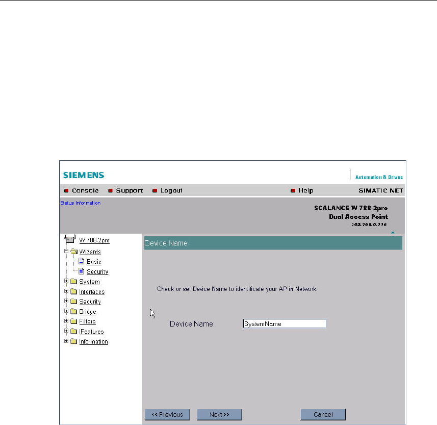
5.4.2 Device Name
Description
The device name also identifies a network node but means more to the user than
the IP address.
Device Name Text Box
In this box, you enter the device name for your SCALANCE W 788. This parameter
corresponds to the sysName SNMP parameter.
Configuration Using the Wizards of Web Based Management
Operating Instructions SCALANCE W 788-1pro / SCALANCE W 788-2pro
42 C79000-G8976-C184-01
5.4.3 Country Code
Description
Some countries have different frequency band divisions for WLAN communication.
The regulations for maximum output power also differ from country to country.
When you configure the SCALANCE W 788, you must specify which local regula-
tions are relevant for your location. You do this with the Country code parameter.
Country code List Box
In this list box, you select the country in which the SCALANCE W 788 will be oper-
ated. You do not need to know the data for the specific country, the channel divi-
sion and output power are set by the SCALANCE W 788 according to the country
you select.
Note
In the version for USA/Canada, you cannot select a country. The frequency bands
for these countries are already preset.
Configuration Using the Wizards of Web Based Management
Operating Instructions SCALANCE W 788-1pro / SCALANCE W 788-2pro
C79000-G8976-C184-01 43
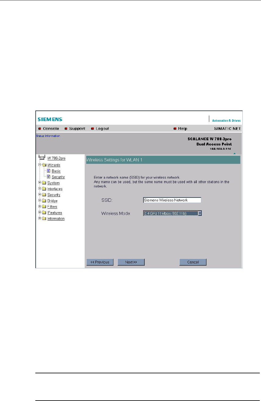
5.4.4 Wireless Settings
Description
On this page, you specify the configuration of the wireless network. This includes
the network name and the transmission mode. If you are configuring the
SCALANCE W 788-2pro model, this page appears a second time to allow you to
configure the second wireless adapter. You can make different settings for
"WLAN1" and "WLAN2".
SSID Text Box
Enter the name of your network in this box. The SCALANCE W 788 allows all char-
acters except the percent character for the SSID. To ensure compatibility with part-
ner devices, you should, however, not use any characters that are peculiar to a
particular language (for example German umlauts ä, ö etc.).
Wireless Mode List Box
Select a wireless mode that is supported by all partner devices. On the
SCALANCE W 788-2pro, it may be a practical to set a different transmission mode
for each wireless adapter to allow optimum support of different clients.
Note
In the version for USA/Canada, it is only possible to set a wireless mode operating
at 2.4 GHz.
Configuration Using the Wizards of Web Based Management
Operating Instructions SCALANCE W 788-1pro / SCALANCE W 788-2pro
44 C79000-G8976-C184-01
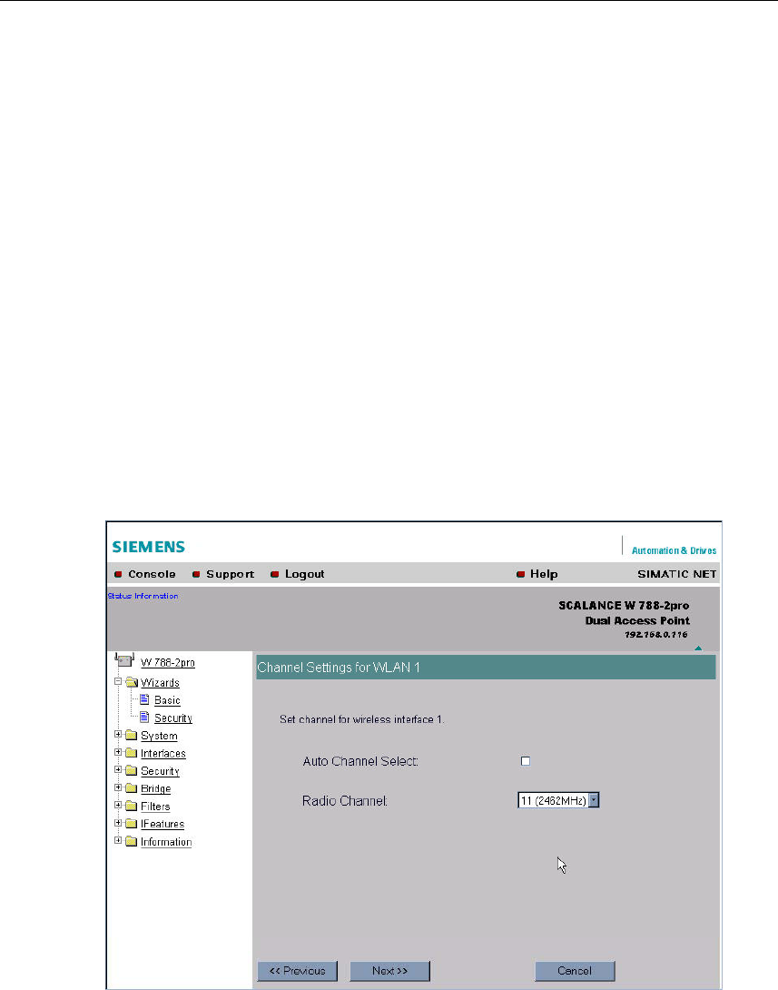
5.4.5 Channel Settings
Description
The SCALANCE W 788 uses a specific channel within the frequency band for
communication. You can either set this channel specifically or configure the
SCALANCE W 788 so that the channel is selected automatically. A specific chan-
nel must be set, for example, in the following situations:
● Communication suffers from interference from another device (for example mi-
crowaves) or another wireless network.
● Use of the redundancy function. In this case, two well spaced channels or two
different frequency bands must be selected.
● Use of WDS. In this case, two well spaced channels or two different frequency
bands must be selected.
Configuration Using the Wizards of Web Based Management
Operating Instructions SCALANCE W 788-1pro / SCALANCE W 788-2pro
C79000-G8976-C184-01 45
Auto Channel Select Check Box
Select this check box if you do not have any particular requirements regarding
channel selection.
Radio Channel List Box
Here, you select a channel suitable for your application. You can only select from
this list if the Auto Channel Select check box is not selected. The entries in the list
box depend on the previous selection made in the Country code box and on the
mode (IEEE 802.11.a, IEEE 802.11b, IEEE 802.11g).
5.4.6 Finish
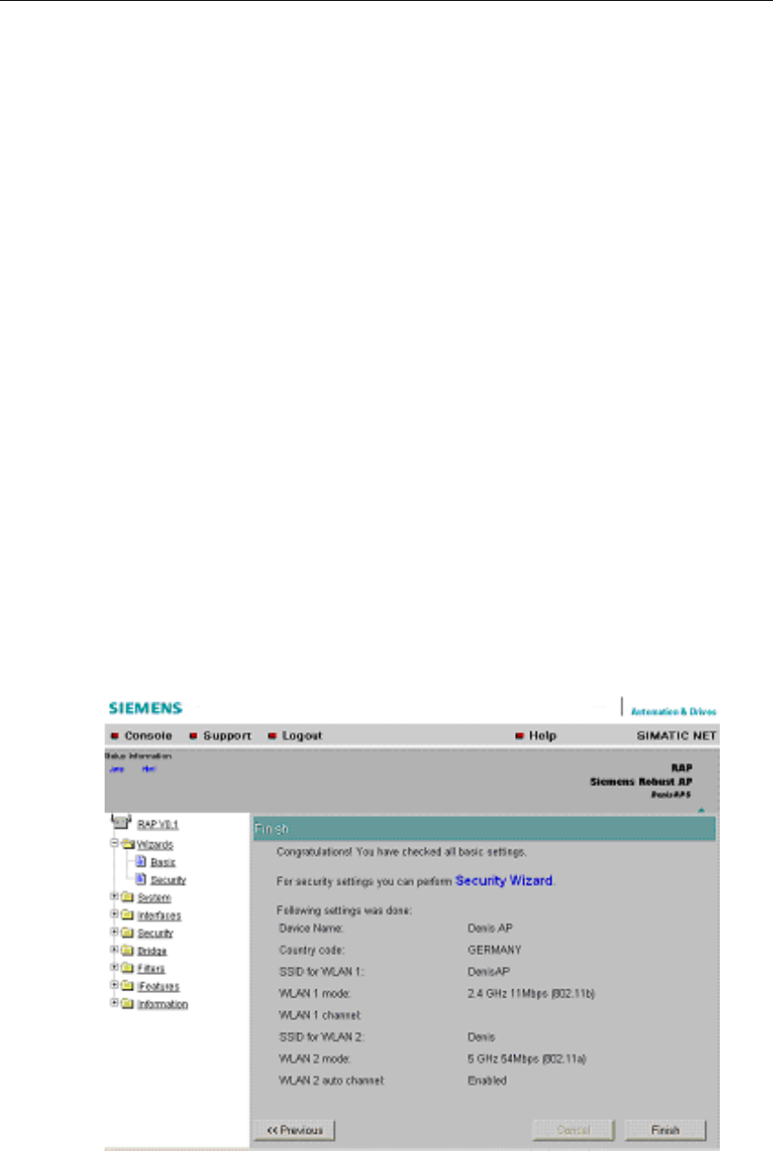
Description
This page displays the parameters you have selected when you have completed
all the entries for the basic configuration.

Configuration Using the Wizards of Web Based Management
Operating Instructions SCALANCE W 788-1pro / SCALANCE W 788-2pro
46 C79000-G8976-C184-01
Finish Button
Click this button to close the Basic Wizard. Alternatively, click on the Security Wiz-
ard link to change to the security settings.

Configuration Using the Wizards of Web Based Management
Operating Instructions SCALANCE W 788-1pro / SCALANCE W 788-2pro
C79000-G8976-C184-01 47
5.5 Security Wizard
Introduction
With the Security Wizard, you can specify security-related parameters without de-
tailed knowledge of security technology in wireless networks.
Note
The SCALANCE W 788 can be operated even if you do not set the security pa-
rameters. Depending on the properties of your network, there is then, however, an
increased risk of unauthorized access. You should therefore work through all the
pages of the Security Wizard, so that you have at least basic security functions.
Configuration Using the Wizards of Web Based Management
Operating Instructions SCALANCE W 788-1pro / SCALANCE W 788-2pro
48 C79000-G8976-C184-01
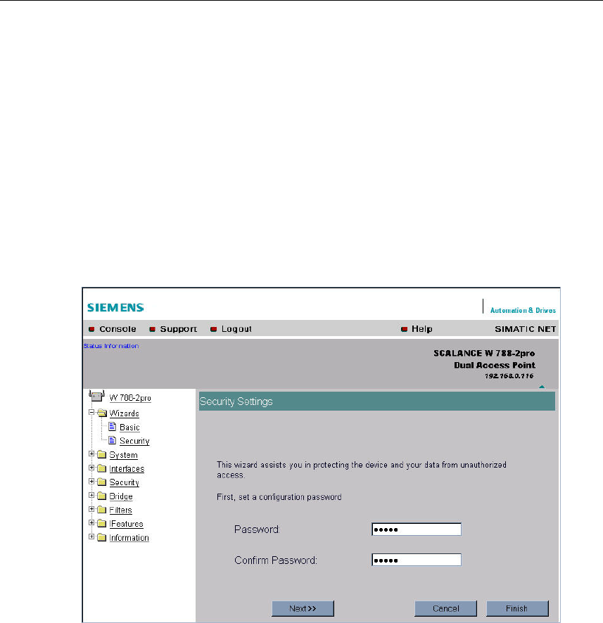
5.5.1 Security Settings
Password
First, set a new admin password. Enter the string twice in the text boxes of this
page.
Until you set a password, the defaults set in the factory apply: The default pass-
word for the admin user is admin. You can use the wizards only if you log on as
administrator.
Configuration Using the Wizards of Web Based Management
Operating Instructions SCALANCE W 788-1pro / SCALANCE W 788-2pro
C79000-G8976-C184-01 49
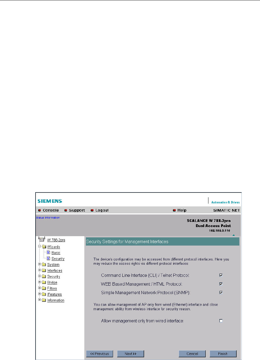
5.5.2 Security Settings for Management Interfaces
Protocols for Configuration
In this page, you specify the protocols with which you can access the configuration
of the SCALANCE W 788. All protocols with a selected check box can be used for
configuration. You should only select protocols that you actually use.
The protocol settings only take effect after exiting the Security Wizard and restart-
ing. Even after selecting the Web Based Management entry, you still have the op-
tion of returning to earlier pages or exiting the wizard.
Specifying the Network Type for Configuration
It is easier to restrict access to a wired network than to a wireless network. Web
Based Management allows access to the SCALANCE W 788 for configuration to
be restricted to computers linked to the SCALANCE W 788 with a cable. If you re-
quire this, check the box at the bottom of the page.
Configuration Using the Wizards of Web Based Management
Operating Instructions SCALANCE W 788-1pro / SCALANCE W 788-2pro
50 C79000-G8976-C184-01
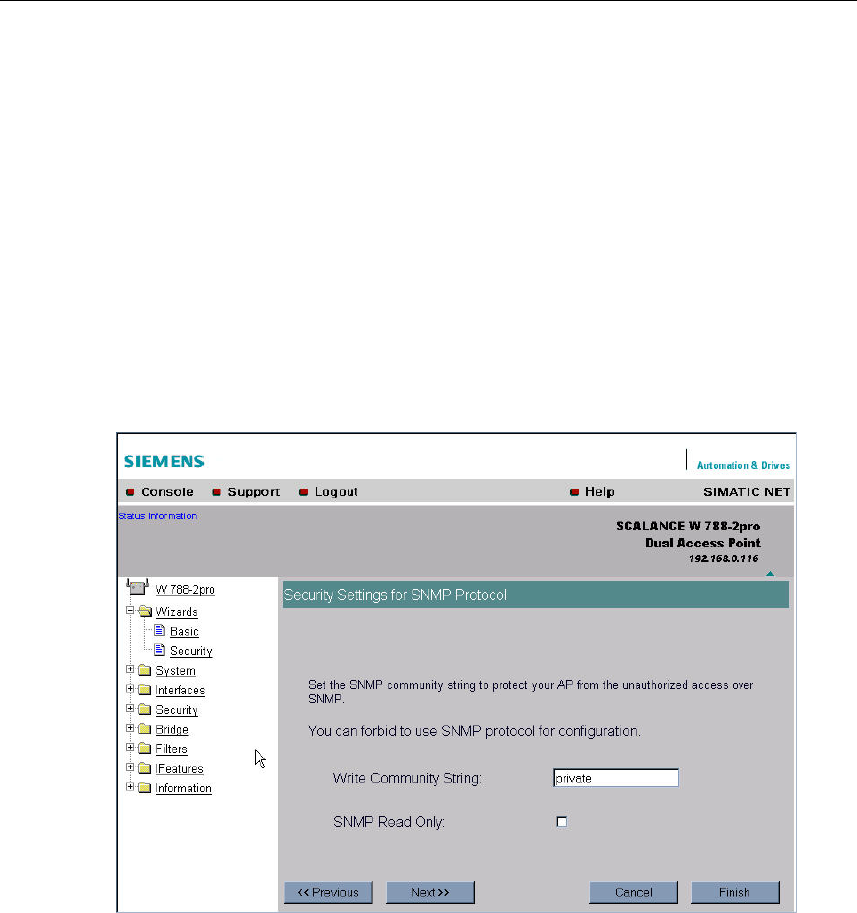
5.5.3 Security Settings for SNMP Protocol
Access Permissions using the SNMP Protocol
When using the SNMP protocol, you specify access permissions by means of
community strings. A community string effectively combines the function of user
name and password in one string; different community strings are defined for read
and write permissions. More complex and more secure authentications are possi-
ble only in some SNMPv2 variants and in SNMPv3.
To preserve security, you should not use the default values public or private.
Write Community String Text Box
Here, you enter the Write Community String for the SNMP protocol.
SNMP Read Only Check Box
If you select this check box, only read access is possible with the SNMP protocol.
Configuration Using the Wizards of Web Based Management
Operating Instructions SCALANCE W 788-1pro / SCALANCE W 788-2pro
C79000-G8976-C184-01 51
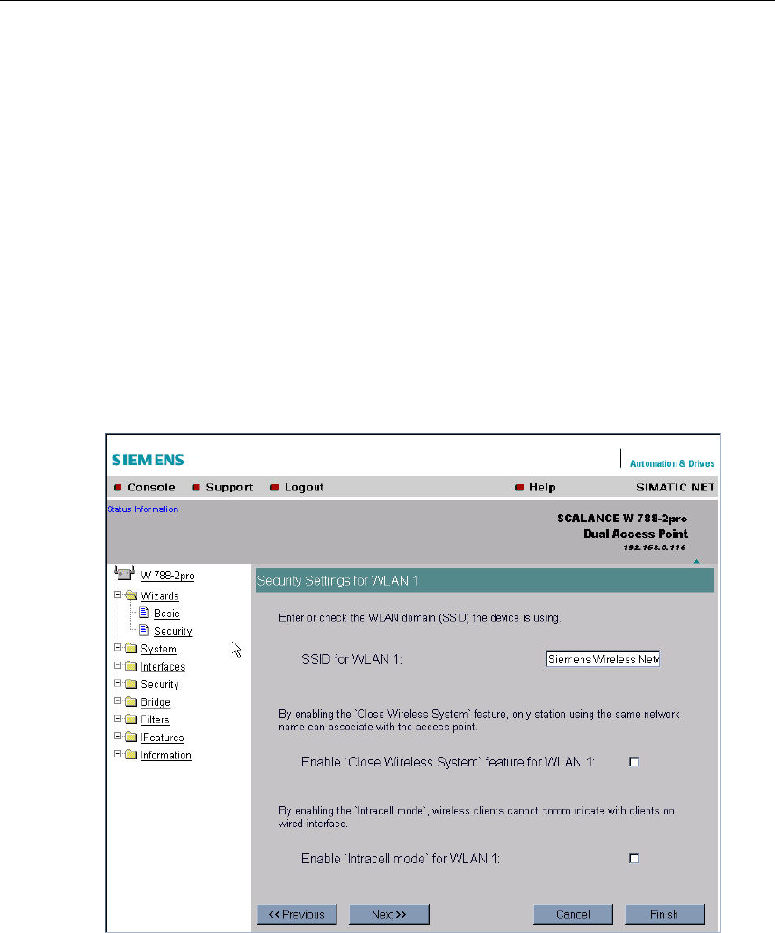
5.5.4 Security Settings for WLAN (Page 1)
Network-Specific Security Settings
On the first page of the security settings, you select settings that apply regardless
of protocol-specific restrictions. The basic measures for securing a network against
unauthorized access involve
● restricting communication with the SCALANCE W 788 to specific clients (only
those with the same network name (SSID)).
● excluding clients that communicate over wireless connections from the wired
part of the network.
SSID Text Box
Enter the name of your network in this box. To avoid any possible conflicts with
settings for a specific locale on the computer, the name should not include any
German umlauts (ö, ä etc.).
Enable `Close Wireless System` feature for WLAN Check Box
If you select this check box, on the stations with the same network name as the
SCALANCE W 788 can connect to the SCALANCE W 788.

Configuration Using the Wizards of Web Based Management
Operating Instructions SCALANCE W 788-1pro / SCALANCE W 788-2pro
52 C79000-G8976-C184-01
Enable `Intracell mode` for WLAN 1 Check Box
In intracell mode, clients connected to the network over a radio link cannot com-
municate with clients in the wired network. Selecting this check box enables the in-
tracell mode.
5.5.5 Security Settings for WLAN (Page 2)
Predefined Security Levels
Authentication and encryption are tried and tested methods for increasing security
in networks. Web Based Management provides five predefined security levels that
specify suitable methods. The following table indicates what the various security
levels involve.

Configuration Using the Wizards of Web Based Management
Operating Instructions SCALANCE W 788-1pro / SCALANCE W 788-2pro
C79000-G8976-C184-01 53
Level Authentication Encryption Cipher Encryption Key
Source
Lowest without disabled without not applicable
Low Shared Key enabled AUTO local
Middle 802.1x enabled WEP Server
High WPA (preshared
key)
enabled TKIP local
Highest WPA (Radius) enabled TKIP Server
Authentication
Authentication basically means that some form of identification is required. In the
case of network communications, authentication methods include those listed be-
low:
● Shared Key
A key must be specified for authentication.
● Authentication according to IEEE 802.1x
The authentication information is located on an external authentication server.
● WPA-PSK (Wi-Fi Protected Access - Preshared Key)
This method is based on a dynamic exchange of keys with the authentication
information being provided by the keywords used.
● WPA (Radius)
Implementation of the WPA method for use of an external radius server.
Encryption
The following schemes are used for data encryption:
● WEP (Wired Equivalent Privacy)
Symmetrical stream cipher (same key for encryption and decryption) with 40 or
104 bit long keys. Modification of the key must be done manually.
● AES (Advanced Encryption Standard)
Symmetrical block encryption scheme with 128, 192 or 256 bit long keys.
● TKIP (Temporal Key Integrity Protocol)
Symmetrical scheme in which new keys are generated cyclically.
Configuration Using the Wizards of Web Based Management
Operating Instructions SCALANCE W 788-1pro / SCALANCE W 788-2pro
54 C79000-G8976-C184-01
Security Level for WLAN List Box
Select a security level that is supported by all clients. The content of the next page
depends on the selected security level. If you select the security level None, there
is no following page since neither encryption nor authentication will be used.
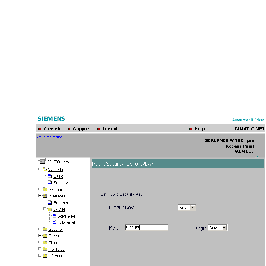
5.5.6 Settings for the Security Level Low
WEP Key List Box
Select the WEP key you want to define.
Key Text Box
Enter the character string for the key here.
Length List Box
Select the key length you want to use here. If the string in the Key text box is
longer than the selected key length, the string is either truncated or an error mes-
sage is displayed.
Configuration Using the Wizards of Web Based Management
Operating Instructions SCALANCE W 788-1pro / SCALANCE W 788-2pro
C79000-G8976-C184-01 55
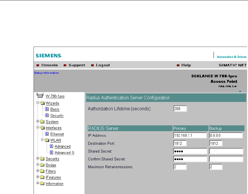
5.5.7 Settings for the Security Level Middle
Authorization Lifetime Text Box
Enter the period of validity of the authentication in seconds. The minimum period is
15 minutes and the maximum period is 12 hours. The default setting is two hours.
RADIUS Server Table
You can enter the data for two RADIUS servers; the information in the Backup col-
umn is used if the server defined in the Primary column is not available.
In addition to the IP address and the port, you must also specify a password and
confirm it in a second box. In the Maximum Retransmissions text box, you enter
the maximum number of transmission attempts.
Configuration Using the Wizards of Web Based Management
Operating Instructions SCALANCE W 788-1pro / SCALANCE W 788-2pro
56 C79000-G8976-C184-01
5.5.8 Settings for the Security Level High
Pass Phrase for WLAN Text Box
Here, you enter a WPA key. The key must be at least 8 characters long, the maxi-
mum length is 63 ASCII characters or 64 hexadecimal characters.
5.5.9 Settings for the Security Level Highest
The options you can set correspond to those of the Middle security level.
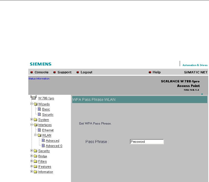
Pass Phrase for WLAN Text Box
Here, you enter your key. This initialization key must be known on both the client
and the SCALANCE W 788 and is entered by the user at both ends.
Configuration Using the Wizards of Web Based Management
Operating Instructions SCALANCE W 788-1pro / SCALANCE W 788-2pro
C79000-G8976-C184-01 57
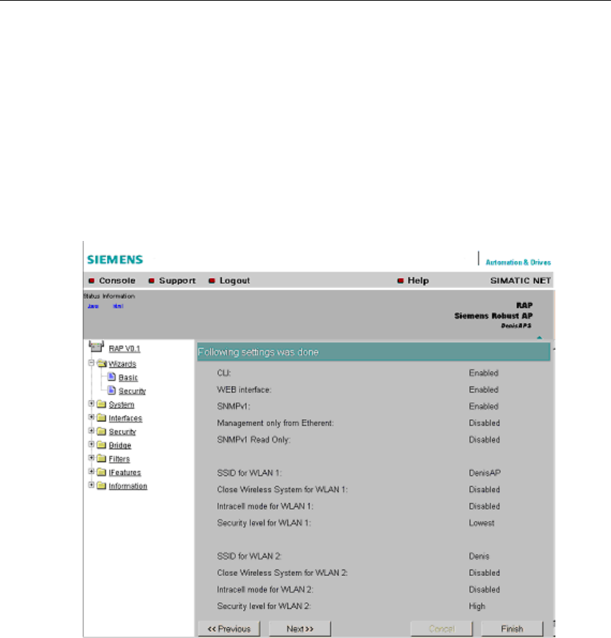
5.5.10 Following Settings Were Made
Overview of the Selected Settings
This page contains an overview of the selected security settings. If you want to
change a setting, you can click on the << Previous button to return to a previous
page where you can enter a different value or make a different selection.
Configuration Using the Wizards of Web Based Management
Operating Instructions SCALANCE W 788-1pro / SCALANCE W 788-2pro
58 C79000-G8976-C184-01
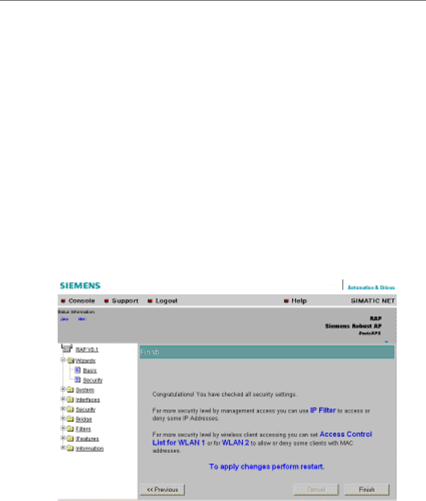
5.5.11 Finish
Exiting the Wizard
The last page of the wizard indicates other security measures that you can take. If
you still want to make final modifications, you can open the relevant pages by click-
ing on the texts highlighted in blue:
● IP Filter
opens the Security > Access page.
● Access Control List for WLAN 1 (WLAN 2)
opens the Security > ACL page for wireless adapter 1 or 2.
● To apply changes perform restart
opens the System > Restart page.
Finish Button
Click the Finish button to exit the Wizard. Your settings only take effect after you
have restarted (System > Restart menu).

Configuration Using the Wizards of Web Based Management
Operating Instructions SCALANCE W 788-1pro / SCALANCE W 788-2pro
C79000-G8976-C184-01 59
Configuration Using Web Based
Management and the Command Line
Interface 6
6.1 General Information on Web Based Management and the
Command Line Interface
6.1.1 Introduction
Contents of This Chapter
Web Based Management provides you with configuration options way beyond
those described in the previous chapter. This chapter explains the possible set-
tings for the SCALANCE W 788. For a detailed description of the individual ele-
ments of a page, refer to the online help.
As an alternative, you can also configure the device using the Command Line In-
terface (CLI). This allows remote configuration over Telnet.
This chapter describes both configuration methods together because the menu
structure of Web Based Management is the same as the structure of the CLI com-
mands.
Required Experience
To be able to use the information in this chapter effectively, you should have a
thorough knowledge of network technology and WLANs.
Operating Instructions SCALANCE W 788-1pro / SCALANCE W 788-2pro
C79000-G8976-C184-01 60
Configuration Using Web Based Management and the Command Line Interface
6.1.2 The LED Simulation of Web Based Management
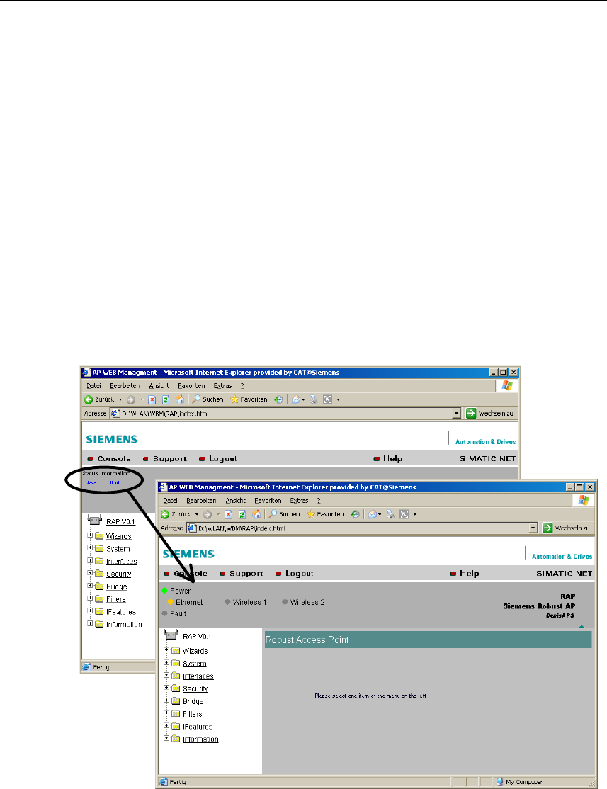
Display of the Operating State
The SCALANCE W 788 has one or more LEDs that provide information on the op-
erating state of the device (see Chapter 2). Depending on its location, direct ac-
cess to the SCALANCE W 788 may not always be possible. Web Based Manage-
ment therefore displays simulated LEDs.
Activating the Simulation
There is an HTML-based simulation of the LED status. Click on the Status Informa-
tion link to activate the simulation:
Operating Instructions SCALANCE W 788-1pro / SCALANCE W 788-2pro
C79000-G8976-C184-01 61

Configuration Using Web Based Management and the Command Line Interface
6.1.3 Working with Web Based Management
Navigation Bar
The upper menu bar of WBM contains the following links:
● Console
This link opens a console window in which you can enter CLI commands.
● Support
When you click this link, you open a SIEMENS AG support page.
● Logout
Close the current Web Based Management session by clicking on this link. The
logon dialog is then displayed again.
● Help
Clicking on this link opens the online help of Web Based Managements in a
separate browser window.
Updating the Display with Refresh
Web Based Management pages have a Refresh button at the lower edge of the
page. Click this button to request up-to-date information from the
SCALANCE W 788.
Saving Entries with Set Values
Pages in which you can make configuration settings have a Set Value button at the
lower edge. Click this button to save the configuration data you have entered on
the SCALANCE W 788.
Operating Instructions SCALANCE W 788-1pro / SCALANCE W 788-2pro
62 C79000-G8976-C184-01

Configuration Using Web Based Management and the Command Line Interface
6.1.4 Command Line Interface
Starting the CLI in a Windows Console
Follow the steps outlined below to start the Command Line Interface in a Windows
console:
● Open a Windows console and type in the command telnet followed by the IP
address of the SCALANCE W 788:
C:\>telnet <IP address>
● Enter your login and password.
Starting the CLI in Web Based Management
Click on the Console entry in the upper menu bar of Web Based Management. A
console window opens in which you can enter CLI commands directly. The IP ad-
dress is adopted by Web Based Management and you already entered the logon
data to start WBM.
Shortcuts for Commands
As an alternative, instead of entering full CLI commands, you can simply enter the
first letter or the first few letters and then press the Tab key. The Command Line
Interface then displays a command starting with the letter or letters you typed in. If
the command displayed is not the command you require, press the Tab key again
to display the next command.
Directory Structure
Before you can enter a command in the Command Line Interface, you must first
open the required menu or submenu. This section lists the commands of each
menu in a separate table. The menu itself is shown above the table on a gray
background. The table lists only the commands themselves.
Operating Instructions SCALANCE W 788-1pro / SCALANCE W 788-2pro
C79000-G8976-C184-01 63

Configuration Using Web Based Management and the Command Line Interface
Symbols for Representing CLI Commands
CLI commands generally have one or more parameters that are represented in the
syntax description as follows:
● Mandatory parameters are shown in pointed brackets.
Example: <IP address>
If you omit a mandatory parameter, most commands output the set value.
● Alternative input values are separated by the pipe character ( | ). In this case,
you specify one of the listed values as the parameter.
Example: <E|D>
you enter either E or D.
● If a numeric value is required as a mandatory parameter, you can also specify a
range of values:
Example: <0 ... 255>
You must enter a value between 0 and 255.
Cross-menu Commands
You can use the commands in the following table in any menu.
CLI\ ... >
Command Description Comment
/ Moves you one menu level higher.
? Displays the commands available in
the menu.
exit Closes the CLI/TELNET session.
trace <Mod> <+|->
<Level> Enables / disables the trace function.
restart Restarts the SCALANCE W 788
info Displays information on the current
menu item.
Operating Instructions SCALANCE W 788-1pro / SCALANCE W 788-2pro
64 C79000-G8976-C184-01

Configuration Using Web Based Management and the Command Line Interface
6.2 The System Menu
6.2.1 System Information Menu Command
Mode and Locale Setting
On this page, you make several basic settings for the SCALANCE W 788, for ex-
ample, the country and mode for the device (SCALANCE W 744-1pro or
SCALANCE W 788-1pro).
Syntax of the Command Line Interface
CLI\SYSTEM>
Command Description Comment
apmode <E|D> This specifies the mode for the
SCALANCE W 788:
E Access Point
D Client
Not available for the
SCALANCE W 744-1pro.
country <AR|AT|AU|BE|BR|
CA|CH|CL|CN|CZ|DE|DK|ES|
FI|FR|GB|GR|HK|HU|IE|IT|
JP|KR|KW|LU|MX|NL|NO|PL|
PT|RU|SE|SG|TR|TW|US|ZA>
Specifies properties for specific
countries. The country codes comply
with ISO 639, however the
SCALANCE W 788 supports only
the codes listed in the left-hand col-
umn.
In the version for
USA/Canada, this com-
mand has no effect be-
cause the frequency
bands suitable for these
countries are preset.
name <device name> Assigns a value to the sysName MIB
variable.
location <location> Assigns a value to the sysLocation
MIB variable.
contact <name> Assigns a value to the sysContact
MIB variable.
password <admin|user>
<password> Specifies a password for access to
the SCALANCE W 788.
Operating Instructions SCALANCE W 788-1pro / SCALANCE W 788-2pro
C79000-G8976-C184-01 65

Configuration Using Web Based Management and the Command Line Interface
6.2.2 IP Settings Menu Command
Configuration
Here, you decide whether you will use a DHCP server or whether you want to as-
sign a fixed IP address to the SCALANCE W 788. You can also set the IP address
of a router and the default TTL. The TTL (time to live) parameter specifies the
maximum number of routers passed through by a data packet before it is dis-
carded.
Syntax of the Command Line Interface
CLI\SYSTEM\IP>
Command Description Comment
dhcp <E|D> Enable / disable DHCP server.
ip <IP address> Specifies the IP address for the
SCALANCE W 788.
subnet <subnet mask> Specifies the subnet mask.
gateway <IP address> Specifies the IP address of the
router.
ttl <TTL value> Sets the TTL (Time To Live) pa-
rameter.
6.2.3 Services Menu Command
Configuration
Here, you select the services with which access to the SCALANCE W 788 will be
possible. If, for example, the SNMP Enabled check box is not selected, neither
write nor read access is possible using the SNMP protocol. You can, nevertheless,
configure SNMP traps regardless of the setting.
To improve security, you should only enable the services that you actually use.
Notes on WEB Enabled
The check box for the WEB Enabled entry is selected and inactive because con-
figuration with Web Based Management is no longer possible without the option of
access with HTTP.
Operating Instructions SCALANCE W 788-1pro / SCALANCE W 788-2pro
66 C79000-G8976-C184-01

Configuration Using Web Based Management and the Command Line Interface
If you want to deactivate the option of configuration with Web Based Management,
you can do this in the Security Wizard. Any settings you make there only take ef-
fect after you restart the SCALANCE W 788.
Syntax of the Command Line Interface
CLI\SYSTEM\SERVICES>
Command Description Comment
telnet <E|D> Enable / disable configuration of the
SCALANCE W 788 over Telnet.
ttimeout <E|D> Enables / disables the time restric-
tion for a Telnet session.
ttimeout <time in s> Specifies the time after which a Tel-
net section is closed if there is no
further input.
web <E|D> Enable / disable configuration of the
SCALANCE W 788 over Web Based
Management.
snmp <E | D> Enable / disable SNMP.
psu <E|D> Enable / disable access to the
SCALANCE W 788 with the Primary
Setup Tool. If this access option is
deactivated, configuration data can
only be read with the Primary Setup
Tool.
Operating Instructions SCALANCE W 788-1pro / SCALANCE W 788-2pro
C79000-G8976-C184-01 67

Configuration Using Web Based Management and the Command Line Interface
CLI\SYSTEM\SERVICES\TRAPS>
Command Description Comment
traps <E | D> Enable / disable traps.
CLI\SYSTEM\SERVICES\EMAIL>
Command Description Comment
mail <E|D> Enable / disable SCALANCE W 788
sending mail.
6.2.4 Restart Menu Command
Restart Button
Click this button to restart the SCALANCE W 788. You must confirm the restart in a
dialog box. During a restart, the SCALANCE W 788 is reinitialized, the internal
firmware is reloaded and the SCALANCE W 788 runs a self-test. The entries that
have been learned in the address table of the SCALANCE W 788 are deleted. You
can leave the browser window open while the SCALANCE W 788 restarts.
Memory Reset Button
Click on this button to restore the factory configuration settings. The following pa-
rameters (protected defaults) are not restored:
● IP address
● Subnet mask
● Gateway address
● SSID
● IP address of the default router
● DHCP flag
● System name
● System location
● System contact
● Device mode
● Country code
Operating Instructions SCALANCE W 788-1pro / SCALANCE W 788-2pro
68 C79000-G8976-C184-01

Configuration Using Web Based Management and the Command Line Interface
There is no automatic restart. This allows you to enter data using Web Based Man-
agement before the restart. The changes take effect only after a restart.
In User mode, this button is not visible.
Reset to memory defaults and restart Button
Click on this button to restore the factory configuration settings. The protected de-
faults (see above) are also reset. An automatic restart is triggered.
Note
By resetting all the defaults, the IP address is also lost. The SCALANCE W 788
can then only be accessed using the Primary Setup Tool unless the IP address is
obtained over DHCP.
In User mode, this button is not visible.
Syntax of the Command Line Interface
CLI\SYSTEM\RESTARTS>
Command Description Comment
restart Restarts the SCALANCE W 788. The restart command can
be invoked in all menus.
memreset Resets the factory settings and trig-
gers a restart (the protected settings
are also deleted).
defaults Resets the factory settings and trig-
gers a restart (the protected settings
are not deleted).
Operating Instructions SCALANCE W 788-1pro / SCALANCE W 788-2pro
C79000-G8976-C184-01 69

Configuration Using Web Based Management and the Command Line Interface
6.2.5 Event Config Menu Command
System Events of the SCALANCE W 788
On this page, you specify how the SCALANCE W 788 reacts to system events.
You can configure the reaction of the SCALANCE W 788-1pro to the following
events:
● Startup of the SCALANCE W 788
● Connection establishment to and disconnection from the SCALANCE W 788.
● Error in authentication.
● Changing the power supply of the SCALANCE W 788.
Evaluation of this event is only useful when using a redundant power supply.
● Change in the error status
● IP-Alive state change (application-specific connection monitoring)
● Link Check state change (device-specific connection monitoring)
Reaction to System Events
The following alternatives are possible:
● The SCALANCE W 788 sends an E-mail.
● The SCALANCE W 788 triggers an SNMP trap.
● The SCALANCE W 788 writes an entry in the log file.
● The SCALANCE W 788 indicates an error (the error LED lights up).
By selecting the appropriate check boxes, you specify which events trigger which
reactions on the SCALANCE W 788. With the check box in the Functions enabled
row, you enable or disable the sending of E-mails or triggering of SNMP traps.
Syntax of the Command Line Interface
For each of the four possible reactions E-mail, trap, log and fault, either E (En-
abled, setting is enabled) or D (Disabled, setting is disabled) must be entered as
the parameter. If, for example, an E-mail is sent when the SCALANCE W 788 re-
starts (first parameter 1) and an entry is made in the log table but neither a trap nor
an error is generated, the following command must be entered:
setec 1 E D E D
Operating Instructions SCALANCE W 788-1pro / SCALANCE W 788-2pro
70 C79000-G8976-C184-01

Configuration Using Web Based Management and the Command Line Interface
CLI\SYSTEM\EVENT>
Command Description Comment
setec 1 <E|D> <E|D>
<E|D> <E|D> Reactions when the
SCALANCE W 788 restarts.
setec 2 <E|D> <E|D>
<E|D> <E|D> Reaction when establishing a con-
nection monitored with the Link
Check function.
setec 3 <E|D> <E|D>
<E|D> <E|D> Reaction to aborting a connection
monitored with the Link Check func-
tion.
setec 4 <E|D> <E|D>
<E|D> <E|D> Reaction to a bad authentication.
setec 5 <E|D> <E|D>
<E|D> <E|D> Reaction to changing the power
supply.
setec 6 <E|D> <E|D>
<E|D> <E|D> Reaction to a change in the error
status.
setec 7 <E|D> <E|D>
<E|D> <E|D> Reaction to a change in the IP-Alive
status.
6.2.6 E-mail Config Menu Command
Sender and Recipient of an E-mail
Here, you specify who the SCALANCE W 788 sends an E-mail to as a reaction to
configured events. You can also enter a sender. This allows you to recognize
which device is involved and sent the E-mail. If you do not make an entry in the
From box, the SCALANCE W 788 uses the following sender: SCALANCE_W@<IP
address>
SMTP Server IP Address / SMTP Server IP Port
In these boxes, you enter the IP address and the port number of your E-mail
server.
Syntax of the Command Line Interface
CLI\SYSTEM\EMAIL>
Command Description Comment
email <E-mail address> Specifies the E-mail address of the
SCALANCE W 788
smtp <IP address>:<port
number> Specifies the IP address and port
number of the SMTP server.
Operating Instructions SCALANCE W 788-1pro / SCALANCE W 788-2pro
C79000-G8976-C184-01 71

Configuration Using Web Based Management and the Command Line Interface
from <text for the
sender field> Specifies the sender of E-mails from
the SCALANCE W 788.
6.2.7 SNMP Config Menu Command
Configuration
Select the check boxes of the entries according to the SNMP functionality you want
to use. SNMP Version 3 allows you to assign rights at the protocol level. You spec-
ify groups and users in the submenu. You can also make entries there if the
SNMPv3 enabled check box is not selected, however the entries are not applied.
Trap Submenu
Here, you enter the IP addresses of up to 10 trap receivers. The
SCALANCE W 788 sends a trap to all the addresses you enter if their Enable trap
check boxes are selected.
Groups Submenu
This page displays the SNMPv3 groups. You can create a new group by clicking
the New button and specifying the group name, the security level, and the write or
read permissions.
You can delete a group by selecting the check box in the Del column and clicking
the Set Values button.
Users Submenu
This page displays the SNMPv3 users. You can create a new user by clicking the
New button and specifying the user name and the group to which the user will be-
long.
You can delete a user by selecting the check box in the Del column and clicking
the Set Values button.
Syntax of the Command Line Interface
CLI\SYSTEM\SNMP>
Command Description Comment
snmp <E|D> Enables / disables SNMP.
Operating Instructions SCALANCE W 788-1pro / SCALANCE W 788-2pro
72 C79000-G8976-C184-01

Configuration Using Web Based Management and the Command Line Interface
Command Description Comment
snmpv1 <E|D> Enables / disables SNMPv1/v2c.
snmpro <E|D> Enables / disables SNMPv1/v2c
read only.
getcomm <Read community
string> Specifies the Read community
string.
setcomm <Write community
string> Specifies the Write community
string.
snmpv3 <E|D> Enables / disables SNMPv3. The special features of
SNMPv3 undertake effect
after you disable
SNMPv1. Enabling
SNMPv3 does not auto-
matically disable
SNMPv1.
CLI\SYSTEM\SNMP\TRAP>
Command Description Comment
traps <E | D> Enables / disables SNMP traps.
settrap <n> <IP address>
<E|D> Specifies the IP address of the trap
recipient n (n between 1 and 10) and
enables / disables the sending of
traps to this recipient.
CLI\SYSTEM\SNMP\GROUP>
Command Description Comment
clearall Deletes all SNMP groups.
CLI\SYSTEM\SNMP\USER>
Command Description Comment
clearall Deletes all SNMP users.
6.2.8 SNTP Config Menu Command
Time-of-Day for Synchronization in the Network
SNTP is the acronym for Simple Network Time Protocol. An SNTP server uses this
protocol to provide a uniform time throughout the entire network. Clients can syn-
chronize themselves with this time.
If you enter the IP address of an SNTP server here and select the time zone of the
SCALANCE W 788, the SCALANCE W 788 uses the time information from the
server.
Operating Instructions SCALANCE W 788-1pro / SCALANCE W 788-2pro
C79000-G8976-C184-01 73

Configuration Using Web Based Management and the Command Line Interface
Syntax of the Command Line Interface
CLI\SYSTEM\SNTP>
Command Description Comment
server <IP address> Specifies the IP address of the
SNTP server.
tzone <hours> Specifies the deviation of the time
zone of the SCALANCE W 788 ac-
cording to UTC (Universal Time
Conversion) in hours.
6.2.9 Fault State Menu Command
This page displays information on faults/errors that have occurred. You can delete
this information if you click on the Remove Fault State button.
If the IP-Alive or the Link Check monitoring indicates that a client is no longer ob-
tainable, the SCALANCE W 788 displays a message to this effect on this page. If
you click on this message, the SCALANCE W 788 displays a list of error mes-
sages.
Operating Instructions SCALANCE W 788-1pro / SCALANCE W 788-2pro
74 C79000-G8976-C184-01

Configuration Using Web Based Management and the Command Line Interface
6.2.10 Load & Save Menu Command
Saving and Loading Device Data
Clicking the Load & Save menu command first opens a page with the current firm-
ware version. The HTTP and TFTP submenus allow you to save device data in ex-
ternal files or to transfer data from external files to the SCALANCE W 788.
You can save the following device data in external files:
● the configuration data of the SCALANCE W 788
● the content of the log table
● the firmware of the SCALANCE W 788
You can transfer the following data from external files to the SCALANCE W 788:
● the configuration data of the SCALANCE W 788
● the firmware of the SCALANCE W 788
Reusing Configuration Data
Saving and reading in configuration data reduces the effort if several SCALANCE
W 788 devices have the same configuration and when IP addresses are obtained
over DHCP. Save the configuration data on a PC after you have configured a
SCALANCE W 788. Download this file to all other SCALANCE W 788 devices you
want to configure. In some cases, you may need to assign an IP address to the
SCALANCE W 788 first using the Primary Setup Tool and any other individual set-
tings you require must be made online.
How to Load or Save Data over HTTP
1. Specify the name of the file from which the data will be taken or where the data
will be saved in the relevant text box for the configuration data or firmware.
As an alternative, you can also use a file selection dialog that opens after you
click the Browse... button.
2. Start the save function by clicking the Save button. Start the load from file func-
tion by clicking the Load button.
Operating Instructions SCALANCE W 788-1pro / SCALANCE W 788-2pro
C79000-G8976-C184-01 75

Configuration Using Web Based Management and the Command Line Interface
How to Load or Save Data over TFTP
1. Enter the IP address of the FTP server in the TFTP Server IP text box.
2. Enter the port of the FTP server in the Port text box.
3. Click on the Set Values button before you enter any further information for sav-
ing the data.
4. Specify the name of the file (maximum 32 characters) from which the data will
be taken or where the data will be saved in the relevant text box for the configu-
ration data or firmware.
5. Start the save function by clicking the Save button. Start the load from file func-
tion by clicking the Load button.
Syntax of the Command Line Interface
CLI\SYSTEM\LOADSAVE>
Command Description Comment
fwname <file name> Specifies the name of a file from
which the firmware will be loaded or
in which the firmware will be saved.
This name can be a maximum of 32
characters long.
fwload Loads the firmware from a file.
fwsave Saves the firmware in a file.
cfgname <file name> Specifies the name of a file from
which the configuration data will be
loaded or in which the configuration
data will be saved.
cfgload Loads the configuration data from
the file
cfgsave Saves the configuration data in a
file.
logname <file name> Specifies the name of a file in which
the log table will be saved.
logsave Saves the log table in a file.
server <IP ad-
dress>:<port number> Specifies the IP address and the
port of the TFTP server.
Operating Instructions SCALANCE W 788-1pro / SCALANCE W 788-2pro
76 C79000-G8976-C184-01

Configuration Using Web Based Management and the Command Line Interface
6.3 The Interfaces Menu
Introduction
The SCALANCE W 788 has one Ethernet interface and up to two WLAN interfaces
that can be configured separately. In the pages of this menu, you can configure
both the wired Ethernet interface and the WLAN interface.
6.3.1 Ethernet Menu Command
Transmission Speed and Mode
For a wired Ethernet interface, you only need to specify the transmission speed
and mode parameters. When you select the entry Auto in the Speed / Mode list
box, the SCALANCE W 788 sets a suitable speed and mode depending on the
other network nodes.
Operating Instructions SCALANCE W 788-1pro / SCALANCE W 788-2pro
C79000-G8976-C184-01 77

Configuration Using Web Based Management and the Command Line Interface
Syntax of the Command Line Interface
CLI\INTERFACES\ETHERNET>
Command Description Comment
ethspeed <A|100F|100H|
10F|10H> Specifies the transmission speed
and mode of the Ethernet interface:
A automatic selection
by the SCALANCE W
788
100F 100 Mbps full duplex
100H 100 Mbps half duplex
10F 10 Mbps full duplex
10H 10 Mbps half duplex
6.3.2 WLAN Menu Command
Network Name and Transmission Mode
In the SSID text box, you specify the network name and in the Wireless Mode list
box, you select the transmission mode. If you have worked through the Basic Wiz-
ard, values are already entered for these two parameters.
Channel Selection
Select the Auto Channel Select check box if you want the SCALANCE W 788 to
search for a free channel itself. If you want to set a specific channel, do not select
Auto Channel Select and you can then select a suitable channel in the Radio
Channel list box.
Syntax of the Command Line Interface
CLI\INTERFACES\WLAN1>
or for the second wireless adapter (if it exists)
CLI\INTERFACES\WLAN2>
Command Description Comment
port <E|D> Enable / disable wireless port.
ssid <network name> Assignment of a network name.
Operating Instructions SCALANCE W 788-1pro / SCALANCE W 788-2pro
78 C79000-G8976-C184-01

Configuration Using Web Based Management and the Command Line Interface
mode <A|B|G> Select the transmission standard
802.11a / 802.11b / 802.11g.
In the version for
USA/Canada, the
802.11a and 802.11g
standards cannot be se-
lected for the second
wireless adapter.
autoch <E|D> Enable / disable the channel selec-
tion by the SCALANCE W 788.
channel <1 ... 11> Specifies the wireless channel.
adopt <MAC address> Assigns a MAC address to the
Ethernet port of the
SCALANCE W 744-1pro. As the
parameter, specify the MAC address
of the network adapter by which the
computer is connected to the
SCALANCE W 744-1pro.
RCM only
autoadopt <E|D> Enables / disables the automatic
adoption of the MAC address of the
computer by the SCALANCE W 744-
1pro.
RCM only
adhoc <E|D> Enables / disables the ad hoc net-
work mode for a SCALANCE W 744-
1pro. If this is enabled for two
SCALANCE W 744-1pro devices,
these devices can communicate with
each other without an additional ac-
cess point.
RCM only
anyssid <E|D> Enables / disables the any SSID. RCM only
bkscan <E|D> Enables / disables the scan for
SCALANCE W 788 devices.
RCM only
CLI\INTERFACES\WLAN1\SSID>
Command Description Comment
add <network name> Specifies the network name for a
SCALANCE W 744-1pro.
RCM only
6.3.3 Advanced Submenu
Configuring Transmission Characteristics
On this page, you can specify details of the transmission characteristics. You only
need to adapt the parameters on this page if the SCALANCE W 788 cannot be
used as it is intended with the default settings.
Operating Instructions SCALANCE W 788-1pro / SCALANCE W 788-2pro
C79000-G8976-C184-01 79

Configuration Using Web Based Management and the Command Line Interface
Operation Outdoors
In some countries, there are special wireless channels for data transmission out-
doors. Depending on the country setting you have made, you can select the En-
able 5GHz Outdoor Channels check box to use these wireless channels.
IEEE 802.11b
Select the Enable Basic 11b Mode check box if the SCALANCE W 788 will only
use the transmission rates 1 Mbps and 2 Mbps.
Date Rate
Select a data rate suitable for your application in the Data Rate list box. Restricting
the data rate avoids the additional network load resulting from calculating the best
possible data rate.
Transmit Power
In the Transmit Power list box, you can specify the output power of the
SCALANCE W 788. It may be necessary to reduce the transmit power when using
antennas to avoid exceeding the maximum legal transmit power. Reducing the
transmit power effectively reduces cell size. In some situations, this can have a
positive influence on the transmission quality.
Beacons
Beacons are packets that are sent cyclically by a SCALANCE W 788 to inform cli-
ents of its existence. In the Beacon Interval text box, you specify the interval at
which the SCALANCE W 788 sends beacons.
The DTIM parameter (Delivery Traffic Indication Map) specifies how often the
SCALANCE W 788 sends multicast packets over the wireless interface. If you en-
ter 1 in this box, the SCALANCE W 788 transmits multicast packets directly after
each beacon (recommended setting for normal network environments). The value
5 would mean that the SCALANCE W 788 collects the multicast packets and
sends them after every fifth beacon.
RTS/CTS
RTS/CTS (Ready To Send/Clear To Send) is a method of avoiding collisions
based on an exchange of status information prior to sending the actual data. To
minimize network load resulting from the additional protocol exchange, this method
is used only when a packet size that you select with the RTS/CTS Threshold is ex-
ceeded.
Operating Instructions SCALANCE W 788-1pro / SCALANCE W 788-2pro
80 C79000-G8976-C184-01

Configuration Using Web Based Management and the Command Line Interface
Enable iQOS
QOS is the action for Quality of Service. QOS is an application-specific configura-
tion monitoring system that you can enable by selecting the Enable QOS check
box.
Roaming in the Absence of an Ethernet Interface
If the wired Ethernet interface is no longer available (cable break, connector re-
moved), a client connected over the wireless network is not aware of this. The
SCALANCE W 788 can then force the logged on WLAN clients to roam by deacti-
vating its WLAN interface. The client then attempts to log on at a different
SCALANCE W 788. You enable this feature by selecting the Force roaming if link
down on ethernet interface check box.
Syntax of the Command Line Interface
CLI\INTERFACES\WLAN1\ADVANCED>
Command Description Comment
outdoor <E|D> Enable / disable channels for opera-
tion outdoors.
basic11b <E|D> Enable / disable "Basic 11b" mode.
datarate <best|1|2|5.5> Specifies the data rate:
best Best data rate
1 1 Mbps
2 2 Mbps
5.5 5.5 Mbps
power <0|1|2|3|4> Specifies by how many dB the
transmit power will be reduced com-
pared with full power:
0 Full power
1 -3 dB
2 -6 dB
3 -9 dB
4 Minimum power
beacon <20 ... 1000> Specifies the beacon interval in milli-
seconds.
dtim <1 ... 255> Specifies the data beacon rate.
rtsthr <1 ... 2346> Specifies the packet size as of which
RTS/CTS is used.
fragthr <256 ... 2346> Specifies the size as of which pack-
ets are fragmented.
qos <E|D> Enables / disables QOS functional-
ity.
force <E|D> Enables / disables roaming if the
Ethernet link is down.
aifs <0|1|2|3|4> Specifies the slot times between
data packets.
Operating Instructions SCALANCE W 788-1pro / SCALANCE W 788-2pro
C79000-G8976-C184-01 81

Configuration Using Web Based Management and the Command Line Interface
Command Description Comment
caltime <0 ... 65535> Specifies the time in seconds after
which the chipset is calibrated.
preamb <E|D> Enables / disables the short pream-
ble.
swretry <E|D> Enables / disables the software retry
functionality.
swretno <0 ... 15> Specifies the number of software
retries.
The default is 3.
hwretno <0 ... 15> Specifies the number of software
retries.
The default is 4.
antenna <A|B|D> Specifies which antennas are used:
A First wireless adapter port
B Second wireless adapter port
D Both ports
6.3.4 Advanced G Submenu
Properties of the 802.11g Standard
The IEEE 802.11g is upwards compatible with IEEE 802.11b, both use the 2.4
GHz band. In contrast to 802.11b that specifies data rates up to 11 Mbps, 802.11g
provides for data rates up to 54 Mbps. The 802.11g standard also uses the OFDM
modulation scheme.
Special Options for 802.11g Settings
The options you can set in the Advanced G submenu relate to the way in which
management and control data (RTS/CTS frames, beacons) are sent in the 802.11g
mode. You can also specify that the SCALANCE W 788 only supports 802.11g-
compatible devices.
Operating Instructions SCALANCE W 788-1pro / SCALANCE W 788-2pro
82 C79000-G8976-C184-01

Configuration Using Web Based Management and the Command Line Interface
Syntax of the Command Line Interface
CLI\INTERFACES\WLAN1\802.11G>
or for the second wireless adapter (if it exists)
CLI\INTERFACES\WLAN2\802.11G >
Command Description Comment
ctsmode <0|1|2> Specifies whether CTS is used for
802.11g management information:
0 Do not use CTS.
1 Always use CTS.
2 Use CTS depending on the
packet size.
ctsrate <0|1|2|3> Specifies the data rate for 802.11g
CTS frames:
0 1 Mbps
1 2 Mbps
2 5.5 Mbps
3 11 Mbps
ctstype <0|1> Specifies the method for avoiding
collisions for 802.11g management
information:
0 CTS only
1 RTS/CTS
sslot <E|D> Enables / disables short slot times
between data packets.
basic<0|1|2|3|4> Transmission of management infor-
mation of the SCALANCE W 788 is
compatible with the selected stan-
dard:
0 802.11 (max. 2 Mbps)
1 802.11b (max. 11 Mbps)
2 802.11g (max. 54 Mbps)
3 OFDM
beacon <0|1|2|3|4|5|6> Specifies the maximum data rate for
beacons in the 802.11g mode:
0 max. 1 Mbps
1 max. 2 Mbps
2 max. 5.5 Mbps
3 max. 11 Mbps
4 max. 6 Mbps
5 max. 12 Mbps
6 max. 24 Mbps
only11g <E|D> Enables / disables the OFDM modu-
lation scheme.
overlap <E|D> Enables / disables beacons from the
SCALANCE W 788 on all channels.
draft5 <E|D> Enables / disables Draft 5-
compatibility of the
SCALANCE W 788.
Operating Instructions SCALANCE W 788-1pro / SCALANCE W 788-2pro
C79000-G8976-C184-01 83

Configuration Using Web Based Management and the Command Line Interface
Command Description Comment
optimize <1|2|3|4> Specifies the optimization level for
802.11g devices.
Operating Instructions SCALANCE W 788-1pro / SCALANCE W 788-2pro
84 C79000-G8976-C184-01

Configuration Using Web Based Management and the Command Line Interface
6.4 The Security Menu
Introduction
In this menu, you configure the security settings with which you want to operate
your SCALANCE W 788. Apart from selecting the authentication and encryption
scheme, this also includes the decision as to whether or not an external Radius
server is used and whether access is restricted based on MAC addresses (ACL).
Syntax of the Command Line Interface
CLI\SECURITY>
Command Description Comment
mgmteth <E|D> It is only possible to configure the
SCALANCE W 788 over the wired
Ethernet interface (E) or over all in-
terfaces (D).
6.4.1 Basic Wireless Menu Command
WEP
WEP (Wired Equivalence Privacy) is an optional part of the IEEE 802.11 standard.
WEP specifies methods of authentication and encryption working with fixed keys
stored on the device. All devices that want to access a network in which WEP is
used must first be supplied with the same keys. The keys can only be changed
manually.
WPA
WPA (Wi-Fi Protected Access) cancels out some of the disadvantages of WEP by
using dynamic key exchange. A string specified by the user simply serves as an
initial value for generating the keys. WPA is downwards compatible with WEP.
IEEE 802.1x (Radius)
The heart of the standard is the use of a Radius server as the authentication
server. In addition to this, in IEEE 802.1x, the entire communication is encrypted.
Operating Instructions SCALANCE W 788-1pro / SCALANCE W 788-2pro
C79000-G8976-C184-01 85

Configuration Using Web Based Management and the Command Line Interface
Authentication
You can set the following options in the Authentication Type box:
● Open System
There is no authentication.
● Shared Key
WEP authentication with keys stored on the device. In this case, you must
specify four master keys in the Keys menu.
● WPA (Radius)
WPA authentication over an external RADIUS server.
To use this scheme, you must provide information on the authentication server
in the RADIUS Server menu.
● WPA-PSK
WPA authentication without Radius server.
● 802.1x
Port-related access control with a Radius server. Two ports are assigned to one
physical interface. One port is freely accessible and can be used for authentica-
tion, the other port is only accessible after successful authentication.
To use this scheme, you must provide information on the authentication server
in the RADIUS Server menu.
Encryption
You can only disable encryption (deselect the Encryption check box) if you have
selected Open System for the authentication. All other security methods include
both authentication and encryption.
Encryption Methods for WPA
If you have selected WPA authentication (both PSK and Radius), you have the fol-
lowing alternatives in the Cipher box:
Operating Instructions SCALANCE W 788-1pro / SCALANCE W 788-2pro
86 C79000-G8976-C184-01

Configuration Using Web Based Management and the Command Line Interface
● WEP
Encryption with static WEP keys (according to the RC4 algorithm) that you
specify in the Keys menu.
● AES (Advanced Encryption Standard)
Encryption according to the Rijndael algorithm.
● TKIP
Use of dynamic keys. Starting from an initialization key, a new key is generated
for each data packet.
Additional Entries for WPA-PSK
To use the WPA-PSK scheme, you must enter a string in the Pass Phrase box that
is used by the SCALANCE W 788 to initialize dynamic key generation. In the
Group Key Update Interval box, you specify the time after which a new key is gen-
erated.
Syntax of the Command Line Interface
CLI\SECURITY\BASIC\WLAN1>
or for the second wireless adapter (if it exists)
CLI\SECURITY\BASIC\WLAN2>
Command Description Comment
mgmteth <E|D> It is only possible to configure the
SCALANCE W 788 over the wired
Ethernet interface (E) or over all in-
terfaces (D).
authent <0|1|2|3|4> Specifies the authentication type.
For the parameter n, enter a number
between 0 and 4 for the type authen-
tication:
0 Open System
1 Shared Key
2 WPA (RADIUS)
3 WPA-PSK
4 802.1x (RADUIS)
encrypt <E|D> Encryption enabled / disabled.
cipher <AUTO|WEP|AES|
TKIP> Specifies the encryption scheme.
keysrc <0|1> Select the key source.
Enter 0 as the parameter if the key is
managed by the server. Enter 1 if a
key exists both locally and on the
server.
defkey <0|1|2|3> Selects the default WEP key.
wpaphrase <WPA password> Enter the WPA password.
Operating Instructions SCALANCE W 788-1pro / SCALANCE W 788-2pro
C79000-G8976-C184-01 87

Configuration Using Web Based Management and the Command Line Interface
Command Description Comment
grkint <interval> Specifies the "Group Key Update
Intervals".
supssid <E|D> Enable / disable Close Wireless Sys-
tem functionality.
intracell <E|D> Enable / disable Enable Intracell
mode functionality.
username <name> Specifies the user name. PEAP only.
password <password> Specifies the password PEAP only.
chkserver <E|D> Enables / disables authentication of
the server.
cltcert <certificate> Specifies the name of the certificate
for the client.
srvcert <certificate> Specifies the name of the certificate
for the server.
6.4.2 Keys Menu Command
Specifying the WEP Key
If you are selected Shared Key for the authentication, the SCALANCE W 788 also
uses the keys stored on the device for data encryption. To allow you to make a se-
lection in the Default WEP Key box, you must first specify four master keys in the
Keys menu.
6.4.3 ACL Menu Command
Device-Specific Access Permissions
ACL is an assignment of MAC addresses and access permissions.
If ACL is enabled, prior to data transfer, the SCALANCE W 788 checks whether
the necessary permissions for the communication partner (identified by the MAC
address) are entered in the ACL table
Operating Instructions SCALANCE W 788-1pro / SCALANCE W 788-2pro
88 C79000-G8976-C184-01

Configuration Using Web Based Management and the Command Line Interface
Syntax of the Command Line Interface
CLI\SECURITY\ACL\WLAN1>
Command Description Comment
aclmode <E|D> Enable / disable access control list.
6.4.4 RADIUS Server Menu Command
Authentication over an External Server
The concept of RADIUS is based on an external authentication server. A client can
only access the network after the SCALANCE W 788 has verified the logon data of
the client with the authentication server. Both the client and the authentication
server must support the EAP protocol (Extensive Authentification Protocol).
Syntax of the Command Line Interface
CLI\SECURITY\RADIUS>
Command Description Comment
server <IP address> Specifies the IP address of the pri-
mary RADIUS server.
server B <IP address> Specifies the IP address of the
backup RADIUS server.
port <port> Specifies the port of the primary
RADIUS server.
port B <port> Specifies the port of the backup
RADIUS server.
secret <password> Specifies the password for the pri-
mary RADIUS server.
secret B <password> Specifies the password for the
backup RADIUS server.
maxreq <max. number> Maximum number of queries to the
RADIUS server.
maxreq B <max. number> Maximum number of queries to the
RADIUS server. (backup server)
authprd <time in s > Period for repeating authentication. The default is 3600 s.
Operating Instructions SCALANCE W 788-1pro / SCALANCE W 788-2pro
C79000-G8976-C184-01 89

Configuration Using Web Based Management and the Command Line Interface
6.4.5 Access Menu Command
Access Permissions for IP Addresses
In this menu, you specify the access permissions for IP addresses. You can decide
whether management access is possible only with the defined addresses or
whether management access is possible with all IP addresses that are not con-
tained in the list.
Syntax of the Command Line Interface
CLI\SECURITY\ACCESS>
Command Description Comment
clearall Clears the access control list.
access <E|D> Enable / disable access control list.
statmgmt <A|D> It is possible to access or not possi-
ble to access the IP addresses of
the access control list (Accessed /
Denied).
Operating Instructions SCALANCE W 788-1pro / SCALANCE W 788-2pro
90 C79000-G8976-C184-01

Configuration Using Web Based Management and the Command Line Interface
6.5 The Bridge Menu
Introduction
A bridge is a computer that connects two networks. A bridge is not dependent on
the protocol; management of the data packages is based on the physical address
of the network nodes (MAC address).
The SCALANCE W 788 provides bridge functionality because it handles data ex-
change between wired and wireless Ethernet. The following sections describe the
functions that are available and how you configure and use them.
Deleting Aged Bridge Information
The SCALANCE W 788 saves the information about which IP address can be
reached over which port in a learn table. Entries in this list are deleted automati-
cally when there is no further data transfer for the corresponding IP addresses.
You can decide the length of time after which addresses are deleted if no data is
sent using the Aging Time parameter on the start page of the Bridge menu
Syntax of the Command Line Interface
CLI\BRIDGE\>
Command Description Comment
aging <E | D> Enables / disables automatic dele-
tion of information on the assign-
ment of IP addresses and ports.
aging <period> Specifies the period after which en-
tries are deleted from the learn table
when no data is sent.
Operating Instructions SCALANCE W 788-1pro / SCALANCE W 788-2pro
C79000-G8976-C184-01 91

Configuration Using Web Based Management and the Command Line Interface
6.5.1 WDS Menu Command
Communication between SCALANCE W 788 Devices
In normal operation, the SCALANCE W 788 is used as a server and communicates
with clients. There are, however, situations in which SCALANCE W 788 devices
need to communicate with each other, for example to extend wireless coverage or
to set up a wireless backbone. This mode is possible with WDS (Wireless Distrib-
uted System).
Configuration
In the MAC / sysName column, enter the MAC address or the sysName parameter
of the SCALANCE W 788 with which you want to communicate. If you select the
Enc check box, encryption is used.
Note
In WDS mode, the following restrictions apply:
● All SCALANCE W 788 devices that will communicate with each other must
use the same channel.
● You can only use the encryption schemes WEP and AES.
To enable the entry, you must select the Sel check box.
6.5.2 Learn Table Menu Command
Assignment of IP Address and Port
The learn table contains the information about whether an IP address can be
reached over the wired Ethernet interface or over the wireless interfaces. The
SCALANCE W 788 obtains this information from the active data exchange.
Operating Instructions SCALANCE W 788-1pro / SCALANCE W 788-2pro
92 C79000-G8976-C184-01

Configuration Using Web Based Management and the Command Line Interface
6.5.3 ARP Table Menu Command
Assignment of MAC Address and IP Address
The ARP protocol (Address Resolution Protocol) obtains the corresponding MAC
address of a known IP address. The page of this menu command also indicates
the interface over which a computer can be reached. The last column indicates
how the information was obtained (for example dynamic if it was obtained from ac-
tive data exchange).
6.5.4 Spanning Tree Menu Command
Avoiding Redundant Network Structures
The Spanning Tree protocol identifies physically redundant network structures and
prevents loops occurring by turning off redundant paths. It does this by evaluating
the distance and performance of a connection or by evaluating user settings. Data
is then only exchanged on the remaining connection paths.
If the preferred data path fails, the Spanning Tree algorithm looks for the most effi-
cient path possible with the remaining network nodes.
Root Bridge and Bridge Priority
The identification of the most efficient connection is always related to the root
bridge, a computer that can be considered as a root element of a tree-like network
structure. With the Bridge Priority parameter, you can influence the selection of the
root bridge. The computer with the lowest value for this parameter automatically
becomes the root bridge. If two computers have the same priority value, the com-
puter with the lower MAC address becomes the root bridge.
Response to Changes in the Network Topology
If nodes are added to a network or removed from it, this can influence the selection
of the optimum path for the data packets. To keep on top of this situation, the root
bridge sends configuration messages at regular intervals. You can set the interval
between two configuration messages with the Hello Time parameter.
Operating Instructions SCALANCE W 788-1pro / SCALANCE W 788-2pro
C79000-G8976-C184-01 93

Configuration Using Web Based Management and the Command Line Interface
Age of the Configuration Information
With the Max Age parameter, you specify the maximum age of configuration infor-
mation. If a bridge receives configuration information older than specified in Max
Age, it discards the message and starts a new calculation of the paths.
New configuration data is not used immediately by a bridge but only after the pe-
riod specified in the Forward Delay parameter. This ensures that operation is only
started with the new topology after all the bridges have the required information.
Configuration
Select the Enable Spanning Tree check box if you want to use the spanning tree
algorithm. If necessary, modify the following parameters to specify how the span-
ning tree algorithm operates:
● Bridge Priority
You can enter a value between 0 and 65535. A suitable setting is 32768. You
can assign the same priority to several computers, however, such computers do
not normally become the root bridge.
● Hello Time
A valid value is between 1 and 10 seconds. A time of 2 seconds is recom-
mended. Shortening this time makes the protocol more robust particularly if
configuration packets are lost. If the Hello Time is set to higher values, this re-
duces the effort required for the algorithm because configuration packets are
sent less frequently.
● Max Age
A valid value is between 6 and 40 seconds. A time of 20 seconds is recom-
mended. If the value for Max Age is set too low, the paths are recalculated un-
necessarily when there are temporary breaks on connections.
● Forward Delay
A valid value is between 4 and 30 seconds. A time of 15 seconds is recom-
mended. If the value is too low, some bridges do not yet have up-to-date con-
figuration information and this leads to a recalculation of the topology. A higher
value leads to longer pauses following reconfiguration.
● Priority
With this parameter, you specify the priority of the ports of a bridge. With the
SCALANCE W 788, you can specify the priority of the Ethernet interface and
the wireless interface. You can specify values between 0 and 255. The default
is 128.
Operating Instructions SCALANCE W 788-1pro / SCALANCE W 788-2pro
94 C79000-G8976-C184-01

Configuration Using Web Based Management and the Command Line Interface
● PathCost
This parameter is used to specify the preferred data paths between the root
bridge and other bridges and the value should be based on the transmission
speed. The faster a connection, the lower the value for PathCost should be.
You can specify values between 0 and 65535. The default is 100. The spanning
tree algorithm selects the transmission path for which the sum of all individual
values is the lowest.
Syntax of the Command Line Interface
CLI\BRIDGE\SPANNING>
Command Description Comment
spanning <E|D> Enable / disable spanning tree func-
tionality.
bridge <0 ... 65535> Specify bridge priority of the
SCALANCE W 788.
maxage <6 ... 40> Specify the maximum age of the
configuration information.
hellotm <1 ... 10> Specify the interval between configu-
ration information.
fwd_delay <4 ... 30> Specify the Forward Delay period.
enable_e <E|D> Enable / disable the spanning tree
algorithm for the Ethernet interface.
port_eth <0 ... 255> Specify the port priority for the
Ethernet interface.
cost_eth <0 ... 65535> Specify the Path Cost parameter for
the Ethernet interface.
enable_w1 <E|D>
enable_w2 <E|D>
Enable / disable the spanning tree
algorithm for the first or second wire-
less interface.
port_w1 <0 ... 255>
port_w2 <0 ... 255>
Specify the port priority for the first
or second wireless interface.
cost_w1 <0 ... 65535>
cost_w2 <0 ... 65535>
Specify Path Cost for the first or
second wireless interface.
enable_red <E|D> Enables / disables the redundancy
function for redundant connections
port_red <0 ... 255> Specifies the port priority of the re-
dundant connections.
cost_red <1 ... 65535> Specifies the Path Cost parameter of
the redundant connections.
Operating Instructions SCALANCE W 788-1pro / SCALANCE W 788-2pro
C79000-G8976-C184-01 95

Configuration Using Web Based Management and the Command Line Interface
CLI\BRIDGE\SPANNING\WDS>
Command Description Comment
enblwds1 <n> <E|D>
enblwds2 <n> <E|D>
Enable / disable the WDS port n
(between 1 and 8) of the first or sec-
ond wireless adapter.
portwds1 <n> <0 ... 255>
portwds2 <n> <0 ... 255>
Specifies the priority of the WDS
port n (between 1 and 8) of the first
or second wireless adapter.
costwds1 <n>
<1 ... 65535>
costwds2 <n>
<1 ... 65535>
Specifies the Path Cost parameter of
the WDS port n (between 1 and 8) of
the first or second wireless adapter.
Operating Instructions SCALANCE W 788-1pro / SCALANCE W 788-2pro
96 C79000-G8976-C184-01

Configuration Using Web Based Management and the Command Line Interface
6.5.5 Storm Threshold Menu Command
Limitation of Broadcast and Multicast Frames
Storm Threshold is the maximum number of broadcast or multicast frames per
second forwarded by the SCALANCE W 788. If this limit is exceeded, the
SCALANCE W 788 stops processing such frames for 30 seconds.
Syntax of the Command Line Interface
CLI\BRIDGE\STORMTHR>
Command Description Comment
stromthr <E|D> Enable / disable Storm Threshold.
broadcast <limit value> Specify the maximum number of
broadcast packets per second from
the same address.
multicast <limit value> Specify the maximum number of
multicast packets per second from
the same address.
broad_eth <limit value> Specify the maximum number of
broadcast packets per second for
the Ethernet interface.
multi_eth <limit value> Specify the maximum number of
multicast packets per second for the
Ethernet interface.
broad_1 <limit value>
broad_2 <limit value>
Specify the maximum number of
broadcast packets per second for
the first or second wireless interface.
multi_1 <limit value>
multi_2 <limit value>
Specify the maximum number of
multicast packets per second for the
first or second wireless interface.
Operating Instructions SCALANCE W 788-1pro / SCALANCE W 788-2pro
C79000-G8976-C184-01 97

Configuration Using Web Based Management and the Command Line Interface
6.6 The Filters Menu
6.6.1 MAC Filter Menu Command
Blocking the Data Traffic between MAC Addresses
For communication partners that use the SCALANCE W 788 as a bridge, it is pos-
sible to filter according to their MAC address. You enter the source and target de-
vices between which you want to prevent communication in the Bridge MAC Ad-
dresses Filter list.
Syntax of the Command Line Interface
CLI\FILTERS\MAC2FLT>
Command Description Comment
clearall Deletes all entries for the MAC filter.
fltmac2 <E|D> Enable / disable the MAC filter.
6.6.2 Protocol Filter Menu Command
Protocol Selection
Without protocol filtering, the SCALANCE W 788 processes all data packets re-
gardless of the protocol being used. To increase data security and to reduce load,
it can nevertheless be useful to prevent communication using certain protocols.
Here, you are not restricted to the protocols included in the list in this menu. If nec-
essary, you can add your own entries to this list.
Operating Instructions SCALANCE W 788-1pro / SCALANCE W 788-2pro
98 C79000-G8976-C184-01

Configuration Using Web Based Management and the Command Line Interface
Syntax of the Command Line Interface
CLI\FILTERS\PROTO>
Command Description Comment
clearall Deletes all entries for the protocol
filter.
statprot <F|B> The selected protocols are for-
warded / not forwarded.
fltprot <E|D> Enable / disable the protocol filter.
Operating Instructions SCALANCE W 788-1pro / SCALANCE W 788-2pro
C79000-G8976-C184-01 99

Configuration Using Web Based Management and the Command Line Interface
6.7 The I-Features Menu
6.7.1 iQoS Menu Command
Client-Specific Bandwidth Reservation
iQoS (Quality of Service) is technique with which clients are assigned a certain
bandwidth. Due to this assignment, there is a high probability that data transmis-
sion to these clients will be within a defined period. This technique can be useful
when response times must be guaranteed.
Response Time
In the Response Time text box, you enter the required response time of the
SCALANCE W 788 over the wireless interface. Remember that this value repre-
sents the transmission time for the data from the SCALANCE W 788 to the client.
Syntax of the Command Line Interface
CLI\IFEATURES\IQOS\WLAN1>
or for the second wireless adapter (if it exists)
CLI\IFEATURES\IQOS\WLAN2>
Command Description Comment
iqos <E|D> Enables / disables iQOS functional-
ity.
guarant <response time> Specifies the response time for a
client with bandwidth reservation.
6.7.2 Link Check Menu Command
Device-Related Connection Monitoring
The Link Check function provides device-related connection monitoring for the
wireless interfaces of the SCALANCE W 788. You specify a monitoring time for a
device specified by its MAC address. When half this time has elapsed, the
SCALANCE W 788 automatically checks whether or not there is a wireless con-
nection to this device.
Operating Instructions SCALANCE W 788-1pro / SCALANCE W 788-2pro
100 C79000-G8976-C184-01

Configuration Using Web Based Management and the Command Line Interface
System Event for Connection Abort
You can specify how the SCALANCE W 788 reacts to a connection abort (or to the
reestablishment of a connection) in the System > Event Config menu.
Syntax of the Command Line Interface
CLI\IFEATURES\LINKCHECK>
Command Description Comment
linkchk <E|D> Enable / disable device-related con-
nection monitoring.
add <E|D> <MAC address>
<timeout> Adds a new MAC address to the
connection monitoring and enables /
disables monitoring for this MAC
address.
clearall Deletes all entries for connection
monitoring.
6.7.3 Redundancy Menu Command
Note
The redundancy function described here is available only for the
SCALANCE W 788 with two wireless adapters (model name SCALANCE W 788-
2pro).
Redundant Connection between two SCALANCE W 788-2pro Devices
Two SCALANCE W 788 devices each with two wireless interfaces can be config-
ured so that there is a redundant wireless connection. The redundancy function
automatically switches to the second wireless interface is no data transfer is possi-
ble over the first wireless interface. The following settings must be made on both
devices.
Operating Instructions SCALANCE W 788-1pro / SCALANCE W 788-2pro
C79000-G8976-C184-01 101

Configuration Using Web Based Management and the Command Line Interface
Syntax of the Command Line Interface
CLI\IFEATURES\REDUNDANCY>
Command Description Comment
redun <E|D> Enables / disables the redundancy
function
wep <E|D> Enables / disables WEP encryption.
mac1 <MAC address> Specifies the device that will be op-
erated redundantly along with the
first wireless adapter.
mac2 <MAC address> Specifies the device that will be op-
erated redundantly along with the
second wireless adapter.
wepkey1 Specifies the WEP key of the device
that will be operated redundantly
along with the first wireless adapter.
wepkey2 Specifies the WEP key of the device
that will be operated redundantly
along with the second wireless
adapter.
6.7.4 IP-Alive Menu Command
Application-Related Connection Monitoring
The IP-Alive function provides application-related connection monitoring of the
wireless link.
With IP-Alive, you specify a monitoring time for an IP address and a port. In con-
trast to the Link Check, the SCALANCE W 788 does not start any checks until the
monitoring time has elapsed. In contrast to the Link Check, the SCALANCE W 788
does not actively monitor the connection. The SCALANCE W 788 checks passively
whether communication took place during the specified monitoring period.
System Event for Connection Abort
You can specify how the SCALANCE W 788 reacts to change in the IP-Alive status
in the System > Event Config menu.
Operating Instructions SCALANCE W 788-1pro / SCALANCE W 788-2pro
102 C79000-G8976-C184-01

Configuration Using Web Based Management and the Command Line Interface
Syntax of the Command Line Interface
CLI\IFEATURES\IP_ALIVE>
Command Description Comment
ipalive <E|D> Enables / disables application-
related connection monitoring.
add <E|D> <IP address>:
<Port> <timeout> Adds a new IP address to the con-
nection monitoring and enables /
disables monitoring for this IP ad-
dress.
clearall Deletes all entries for connection
monitoring.
Operating Instructions SCALANCE W 788-1pro / SCALANCE W 788-2pro
C79000-G8976-C184-01 103

Configuration Using Web Based Management and the Command Line Interface
6.8 The Information Menu
System Events and Information on the Protocols
The pages of this menu display tables contain information on system events and
on the behavior of the protocols (IP, TCP, UDP, and ICMP. SNMP).
Updating the Display
Most pages have the Refresh button at the bottom edge with which you can update
the display. The Client List menu command also allows you to update automati-
cally. To activate this, select the Update check box.
Syntax of the Command Line Interface
CLI\ ... >
Command Description Comment
info Displays information on the current
menu item.
This can be called in
every submenu.
Operating Instructions SCALANCE W 788-1pro / SCALANCE W 788-2pro
104 C79000-G8976-C184-01

Configuration Using Web Based Management and the Command Line Interface
Operating Instructions SCALANCE W 788-1pro / SCALANCE W 788-2pro
C79000-G8976-C184-01 105

Technical Specifications 7
Data Transmission
Transmission rate for Ethernet 10/100 Mbps
Transmission rate for wireless 1 ... 54 Mbps
Supported standards for wireless 802.11a, 802.11b, 802.11g
Supported standards for energy supply 802.3 af (Power over Ethernet)
Interfaces
Energy M12 Binder series 713
(exists twice)
Harting RJ-45 hybrid (energy contacts)
Data Harting RJ-45 hybrid (RJ-45 jack)
R-SMA antenna socket
(exists twice)
Electrical Data
Power supply 20 ... 57 V d.c. voltage
90 ... 265 V a.c. voltage
(only when using a power pack)
Power consumption < 10 W
Construction
Dimensions without antennas (W x H x L) 125 mm x 88 mm x 108 mm
Weight approx. 500 g
Permitted Ambient Conditions
Operating temperature -20° ... 70° C
Transport and storage temperature -40° ... 70° C
Relative humidity 95%
Operating Instructions SCALANCE W 788-1pro / SCALANCE W 788-2pro
C79000-G8976-C184-01 106

Technical Specifications SCALANCE W 788
Operating Instructions SCALANCE W 788-1pro / SCALANCE W 788-2pro
C79000-G8976-C184-01 107

Appendix
Private MIB Variables of the
SCALANCE W 700
OID
The private MIB variables of the SCALANCE W 700 have the following object iden-
tifiers:
iso(1).org(3).dod(6).internet(1).private(4).enterprises(1).
ad(4196).adProductMibs(1).simaticNet(1).iRxm(4).iRxmMib(100)
Variables
The following table shows the private MIB variables of the SCALANCE W 788:
Name OID Description Number of
Objects
snDownload 1.3.6.1.4.1.4196.1.1.4.100.1.5
Download information and control
variables for image, configuration
file, events table.
8
snNvLog 1.3.6.1.4.1.4196.1.1.4.100.1.6 Log for events. 8
snTrapInfo 1.3.6.1.4.1.4196.1.1.4.100.1.7 Information on traps. 6
snGen 1.3.6.1.4.1.4196.1.1.4.100.1.8 General information, not conform-
ing with MIB-2.
20
snTcpip 1.3.6.1.4.1.4196.1.1.4.100.1.10 IP address, Subnet mask, Default
gateway, DHCP status…
5
snCommonRxm 1.3.6.1.4.1.4196.1.1.4.100.2.1 WRAP-specific settings. 24
snFilterRxm 1.3.6.1.4.1.4196.1.1.4.100.2.4 Filter and bridge settings.
snClientsRxm 1.3.6.1.4.1.4196.1.1.4.100.2.5 List of all clients currently "associ-
ated“ or connected and information
on them.
50
18
Operating Instructions SCALANCE W 788-1pro / SCALANCE W 788-2pro
C79000-G8976-C184-01 108

Appendix
Private MIB Variables of the SCALANCE W 700 SCALANCE W 788
Operating Instructions SCALANCE W 788-1pro / SCALANCE W 788-2pro
C79000-G8976-C184-01 109
Glossary
ACL Access Control List with MAC addresses with the right to access the
wireless network
Ad hoc network Wireless network between individual devices (point-to-point)
AES Advanced Encryption Standard. New standard of cryptography of data
in WLANs.
EAP Extensive Authentification Protocol. Authentication protocol.
Hidden node prob-
lem
Two nodes are arranged in a wireless cell so that they are outside
their own transmission range. If they both access the medium at the
same time, collisions result.
IEEE Institute of Electrical and Electronics Engineers
IEEE 802.11 Standard for wireless networks in the 2.4 GHz range with transmis-
sion rates of up to 2 Mbps.
IEEE 802.11a Standard for wireless networks in the 5 GHz range with transmission
rates of up to 54 Mbps.
IEEE 802.11b Standard for wireless networks in the 2.4 GHz range with transmis-
sion rates of up to 11 Mbps.
IEEE 802.11g Standard for wireless networks in the 2.4 GHz range with transmis-
sion rates of up to 54 Mbps.
RADIUS Remote Authentication Dial - In User Service for secure communica-
tion networks
Operating Instructions SCALANCE W 788-1pro / SCALANCE W 788-2pro
C79000-G8976-C184-01 110

Glossary
Roaming Free movement of wireless LAN nodes even beyond the boundaries
of an access point's cell. The nodes and can move from one cell to
the next without any noticeable interruption.
RTS/CTS Request to send/Clear to send. Scheme for avoidance of collisions.
SNMP Simple Network Management Protocol. Standardized protocol for
transporting network management information.
TKIP Temporal Key Integrity Protocol. Scheme for cyclic changing of keys
in WLANs.
WBM Web Based Management. HTTP-based configuration method in which
an HTTP server is used in the SCALANCE W 788.
WDS Wireless Distribution System. Radio links for connecting the access
points for an extended service set (ESS)
WEP Wired Equivalent Privacy. Encryption scheme in WLANs.
Wi-Fi Wireless Fidelity. Specification for wireless networks.
WPA Wi-Fi Protected Access. Authentication scheme based on dynamic
key exchange.
Operating Instructions SCALANCE W 788-1pro / SCALANCE W 788-2pro
C79000-G8976-C184-01 111
Index
A
ACL.......................................................... 87
Ad Hoc networks ..................................... 11
ARP table ................................................ 92
Authentication.................................... 52, 85
B
Basic Wizard ........................................... 38
Beacon .................................................... 79
Bridge ...................................................... 90
C
C Plug...................................................... 20
CLI commands
Shortcuts for commands.....................62
Symbolic representation .....................63
Command Line Interface ......................... 62
D
DHCP server ........................................... 65
DLC protocol ........................................... 27
Installation...........................................29
E
E-mail ...................................................... 70
Encryption.......................................... 52, 85
H
Help function ........................................... 61
I
IEEE 802.11b .......................................... 79
IEEE 802.11g .......................................... 81
IEEE 802.1x............................................. 84
IP address ............................................... 27
IP-Alive .................................................. 101
iQoS......................................................... 99
L
Learn table............................................... 91
LED simulation ........................................ 60
Link Check .............................................100
Locale setting...........................................64
M
Multichannel configuration .......................14
P
Power supply ...........................................22
Primary Setup Tool ..................................27
Installation .......................................... 30
Via command line............................... 34
R
RADIUS ...................................................88
Redundant connection...........................101
Refresh ....................................................61
RTS/CTS..................................................79
S
Security settings.......................................50
Security Wizard........................................46
Set values ................................................61
SMTP .......................................................70
SNMP.......................................................71
SNTP .......................................................73
Spanning Tree .........................................92
Standalone configuration .........................12
Storm threshold........................................96
T
Transmit power ........................................79
TTL...........................................................65
W
WDS.........................................................91
Web Based Management ........................35
WEP.........................................................84
Wireless access .......................................13
WPA.........................................................84
❏
Operating Instructions SCALANCE W 788-1pro / SCALANCE W 788-2pro
C79000-G8976-C184-01 112

Index
Operating Instructions SCALANCE W 788-1pro / SCALANCE W 788-2pro
C79000-G8976-C184-01 113