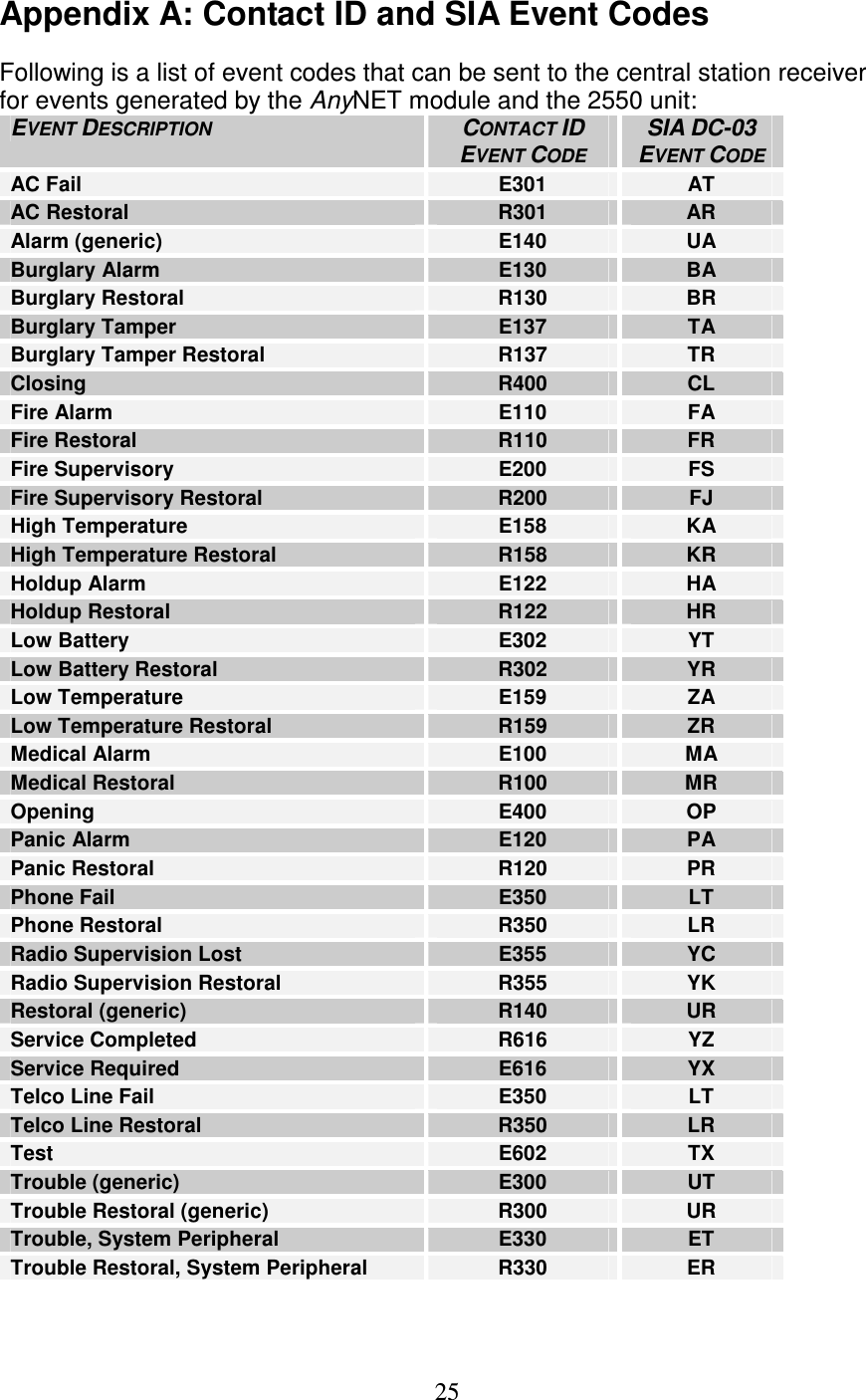
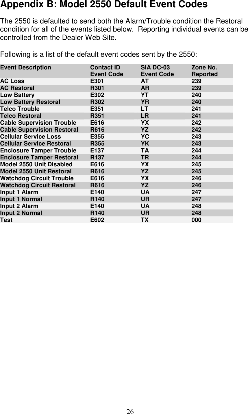
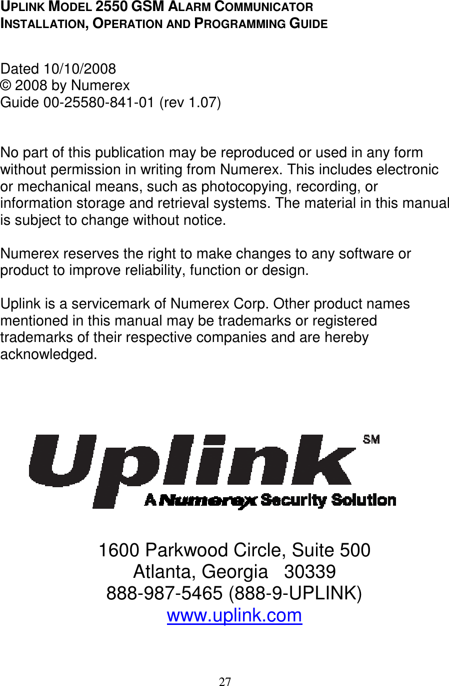
Sierra Wireless 192513384X Uplink 2550 Radio Module User Manual

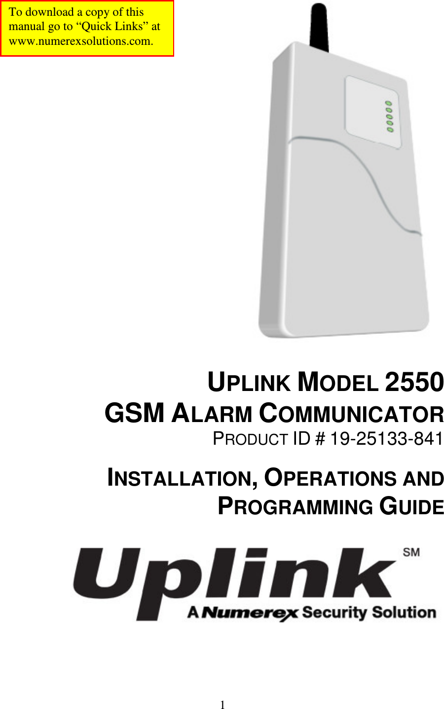
Numerex Corporation Uplink 2550 Radio Module Users Manual

Users Manual

  1                                     UPLINK MODEL 2550 GSM ALARM COMMUNICATOR PRODUCT ID # 19-25133-841  INSTALLATION, OPERATIONS AND PROGRAMMING GUIDE    To download a copy of this manual go to “Quick Links” at  www.numerexsolutions.com.
  2 Table of Contents  1. Introduction .......................................................................4 2. Key Features.....................................................................4 A. Full Event Reporting ................................................. 4 B. Telephone Line Supervision .....................................4 C. Panel to MODEL 2550 Cable Supervision ............... 4 D. Zone Inputs .............................................................. 4 E. Three Relay Outputs ................................................ 4 F. Power Source Monitoring (AC & Low Battery Reporting) ..................................................................... 5 G. Automated Testing ................................................... 5 H. GSM Network Supervision ....................................... 5 I. Status/Received Signal Strength LEDs ..................... 5 J. Easy Service Initiation............................................... 5 K. Web-based Services ................................................5 L. UL Listed ................................................................... 5 3. Warranty Information and Liability Waiver ........................ 6 TERMS and CONDITIONS ........................................... 6 LIMITED WARRANTY .................................................. 6 INDEMNIFICATION ...................................................... 7 LIMITATIONS of LIABILITY .......................................... 7 4. FCC and Industry Canada Regulatory Compliance .......... 7 Part 15........................................................................... 7 Part 68........................................................................... 8 5. FCC RF Exposure Information.......................................... 9 6. Technical Support ........................................................... 10 7. Installation ....................................................................... 10 A. General Considerations.......................................... 10 B. DIP Switch Settings ................................................ 10 C. LEDs.......................................................................11 D. Locating and Installing The 2550 Unit .................... 13 E. Connecting The 2550 to the Alarm Panel and Telephone Jack...........................................................16 F. Activating The 2550 Unit......................................... 17
  3 G. Programming and Central Station Reporting ......... 18 H. Default Event/Email Messages .............................. 20 I. Completing the Installation and Testing................... 20 8. UL COMPLIANCE SECTION.......................................... 21 A. Household Fire  (UL 985 - Category UTOU) .......... 21 B. Household Burglary  (UL 1023 - Category NBSX, and evaluated to UL 1635 - Category AMCX) ............ 22 9. Specifications .................................................................. 23 Appendix A: Contact ID and SIA Event Codes ................... 25 Appendix B: Model 2550 Default Event Codes ................... 26
  4 1. Introduction  Uplink’s MODEL 2550 GSM Alarm Communicator is a UL Listed alarm communicator designed to interface with most manufacturer’s alarm panels that incorporate a digital telephone dialer. A key feature of the 2550 is a “dialer capture” interface to the alarm panel.  If the alarm panel’s TELCO connection is compromised, or if no TELCO connection is present, the 2550 will “intercept ” the alarm panel’s digital dialer output when the panel has an event to report, and communicate with the panel as if it were a central station alarm receiver.  Once the 2550 communicates with the alarm panel, it transmits the alarm information to the central station receiver in either Contact ID (SIA-DC05) or SIA (SIA-DC03) format.  The 2550 uses GSM technology to send event information to the central station.  It can be used as the primary or backup communications path.  The 2550 is perfect for residential and small business burglary and fire installations. (Please refer to the UL Compliance section of this manual for detailed requirements on compliance with various UL Standards.)  2. Key Features  A. Full Event Reporting.  Compatible with most alarm panels using Contact ID (SIA DC-05 Standard) or SIA FSK Level 1 (SIA DC-03 Standard) digital dialer formats.  All event information sent by the alarm panel in either format (Account number, zone information, User IDs, etc.) will be sent to the central station by the 2500 using the GSM network.  B. Telephone Line Supervision.  Features a built-in telephone line monitoring circuit designed to detect voltage (in the On-Hook state) or voltage and current (in the Off-Hook state).  If sufficient voltage or current is not detected, a relay is activated causing the unit to “intercept” (or “capture”) the alarm panel’s digital dialer output and substitute the GSM cellular network instead of the Public Switched Telephone Network (PSTN) as the communications path for sending event information.  C. Panel to 2550 Cable Supervision.  Monitors continuity of the cable connecting the panel’s telephone dialer to the 2550.  This feature is activated through the web site www.numerexsolutions.com or by calling Uplink Customer Service at 1-888-9-UPLINK (1-888-987-5465).  D. Two Zone Inputs.  Reports programmed events to the central station.  Programmable for Normally Opened or Normally Closed.  E. Three Relay Outputs.  Programmable to activate upon the occurrence of one or more of the following Trouble conditions: •  Cellular Network Loss •  No Central Station Acknowledgement
  5 •  AC Loss •  Low or Missing Battery •  Telco Line Loss •  Panel/MODEL 2550 Cable Supervision Trouble •  Activation of Input(s) •  Unit Disabled by Dealer Command •  Watchdog Circuit Activation •  Catastrophic Failure Condition  F. Power Source Monitoring (AC & Low Battery Reporting).  Reports low battery conditions to the central station when voltage drops below 10.2 VDC.  Reports Low Battery Restoral at 11.4 VDC.  It can also be programmed to report Loss of AC power to the central station.  This occurs at 102 VAC and restores at 107 VAC.   G. Automated Testing.  Sends an automated test signal to the central station on a monthly, weekly or daily interval as programmed.  H. GSM Network Supervision.  Supervises the local GSM network.   If the unit no longer locates the local GSM network, one of its output relays activates to report this trouble condition.  I. Status/Received Signal Strength LEDs.  The five LEDs indicate the current operational status and are visible from outside the enclosure.  These LEDs can be placed into Received Signal Strength Indication mode (RSSI) to assist in selecting the optimal mounting location for transmitting and receiving cellular radio signals.   J. Easy Service Initiation.  Ships with an active SIM card, with easy activations available via the Web at www.numerexsolutions.com or by calling Uplink Customer Service at 1-888-9-UPLINK (1-888-987-5465).  Requires the central station receiver phone number and/or its IP address and Port number.  K. Web-based Services.  Available at www.numerexsolutions.com and include: a.  immediate, real-time activation  b.  history of past event transmissions c.  initiation of a test report d.  the ability to query the unit and receive a real-time radio report status including a Received Signal Strength reading e.  programming inputs and other internally generated events  L. UL Listed.  UL listing for certificated installations including Household Fire, Household Burglary and Combination Household Fire/Burglary.  It is also UL Listed for Supplemental Use.  (See the UL Compliance Section of this manual for complete details.)
  6 3. Warranty Information and Liability Waiver TERMS and CONDITIONS  These terms and conditions are a legal contact between you and the Company and supplement (but do not supersede) the terms and conditions of any master agreement between you and Uplink Security, Inc. (the “Company”) governing your purchase of the Product from the Company. By using, marketing, or selling the Product, you agreement to these terms and conditions. In the event of any conflict with the master agreement, the terms and conditions of the master agreement will control.   LIMITED WARRANTY  Subject to the limitations and disclaimers set forth below, the Company warrants that for one year following the date on which first activated (the “Warranty Period”), the Product purchased under this Agreement will be free of defects in materials and workmanship when installed, used, serviced, and operated in strict accordance with the Company’s requirements. If the Product fails to operate because of a defect in materials or workmanship within the Warranty Period, the Company will repair or replace, or arrange for the repair or replacement, at its sole option and at no charge to you, the Product or any component thereof that proves to have such a defect. The Company’s agreement to repair or replace the Product or any part thereof found to be defective in materials or workmanship is the exclusive remedy provided herein; this remedy will not be deemed to have failed of its essential purpose so long as the Company is willing and able to repair or replace any such defective Product or any component thereof or, at the Company’s sole option, to refund the purchase price paid. Prior to returning any Product alleged to be defective, you must request and receive a Return Merchandise Authorization (“RMA”) form from the Company for completion. Restocking fees may apply.   THE WARRANTY SET FORTH ABOVE IS LIMITED. THE COMPANY MAKES NO OTHER WARRANTIES, EXPRESS OR IMPLIED, INCLUDING, WITHOUT LIMITATION, IMPLIED WARRANTIES OF MERCHANTABILITY, FITNESS FOR A PARTICULAR PURPOSE, NON-INFRINGEMENT, AND TITLE IN CONNECTION WITH THE PRODUCT, AND ANY SUCH WARRANTIES ARE HEREBY DISCLAIMED. TO THE MAXIMUM EXTENT PERMITTED BY APPLICABLE LAW, THE COMPANY DOES NOT WARRANT OR REPRESENT, AND SPECIFICALLY DISCLAIMS, ANY WARRANTY OR REPRESENTATION, THAT THE PRODUCT WILL MEET YOUR REQUIREMENTS OR THAT THE OPERATION OF THE PRODUCT WILL BE UNINTERRUPTED OR ERROR-FREE. THE WARRANTY FURTHERMORE DOES NOT COVER (A) PRODUCTS THAT HAVE BEEN TAMPERED WITH OR SERVICED WITHOUT THE COMPANY’S AUTHORIZATION; (B) PRODUCTS WITH IDENTIFYING INFORMATION OR LABELING ALTERED OR REMOVED; OR (C) PRODUCTS SUBJECTED TO ABUSE, MISUSE, OR NEGLECT INCLUDING, WITHOUT LIMITATION, USE IN A HOSTILE OPERATING ENVIRONMENT UNLESS EXPRESSLY APPROVED BY THE COMPANY FOR SUCH USE.
  7 INDEMNIFICATION  You agree to defend, hold harmless, and indemnify the Company and its affiliates and their respective officers, directors, employees, and agents from and against any and all damages, liability, costs, and expenses (including, without limitation, reasonable attorneys’ fees) arising out of or relating to (a) any claim for breach of this Agreement by you; (b) any claim for negligence, intentional misconduct, or any other act or omission on the part of you or your employees, agents, or representatives; (c) personal injury, death, or property damage allegedly or impliedly caused by you or your employees, agents, or representatives in connection with this Agreement; or (d) any claim that an application of the Product or your actions in distributing the Product or integrating it with other hardware, software, or systems infringe the intellectual property rights of a third party.   LIMITATIONS of LIABILITY  THE COMPANY SHALL NOT BE LIABLE FOR ANY ACTS OR OMISSIONS OF YOU, YOUR CUSTOMERS, END USERS OF THE PRODUCT, OR ANY THIRD PARTY INCLUDING, WITHOUT LIMITATION, ANY ENTITY FURNISHING EQUIPMENT, SOFTWARE, FIRMWARE, OR SERVICES TO THE COMPANY, YOU, YOUR CUSTOMERS, OR END USERS OF THE PRODUCT, NOR SHALL THE COMPANY BE LIABLE FOR ANY DAMAGES ATTRIBUTABLE, IN WHOLE OR IN PART, TO THE FAILURE OF SAID EQUIPMENT, SOFTWARE, FIRMWARE, OR SERVICES. THE COMPANY SHALL NOT BE LIABLE FOR INTERRUPTIONS IN, OR INTERFERENCE WITH, THIRD PARTY TELECOMMUNICATIONS CARRIERS’ TRANSMISSIONS OVER WHICH THE COMPANY HAS NO CONTROL, I.E., FOR INTERRUPTIONS OR INTERFERENCE CAUSED BY NETWORK CONGESTION, WEATHER CONDITIONS, TERRAIN, BUILDINGS, LOCALIZED “GAPS” IN TELECOMMUNICATIONS NETWORK COVERAGE, AND OTHER NATURAL OR ARTIFICIAL CONDITIONS OVER WHICH THE COMPANY HAS NO CONTROL. THE COMPANY SHALL NOT BE LIABLE FOR ANY INDIRECT, INCIDENTAL, SPECIAL, EXEMPLARY, PUNITIVE, OR CONSEQUENTIAL DAMAGES, INCLUDING, WITHOUT LIMITATION, LOST REVENUES, DATA, OR PROFITS, REGARDLESS OF WHETHER THE COMPANY WAS ADVISED OF, OR COULD HAVE REASONABLY FORESEEN, THE POSSIBILITY OF SUCH DAMAGES. THE COMPANY SHALL NOT BE LIABLE IN THE EVENT THAT FUTURE TECHNOLOGICAL CHANGES IMPLEMENTED BY ANY THIRD PARTY OR GOVERNMENTAL ENTITY RENDER THE PRODUCT WHOLLY OR PARTIALLY INOPERABLE. OTHER LIMITATIONS OF LIABILITY MAY APPLY AS PROVIDED BY THE MASTER AGREEMENT, IF ANY, GOVERNING YOUR PURCHASE OF THE PRODUCT FROM THE COMPANY.  4. FCC and Industry Canada Regulatory Compliance Part 15 This device complies with Part 15 of the FCC Rules. Operation is subject to the following two conditions: (1) this device may not cause harmful interference, and (2) this device must accept any interference received, including interference that may cause undesired operation. This equipment has been tested and found to comply with the limits for a Class B digital device, pursuant to Part 15 of the FCC Rules. These limits are designed to provide reasonable protection against harmful interference in a residential
  8 installation. This equipment generates, uses and can radiate radio frequency energy and, if not installed and used in accordance with the instructions, may cause harmful interference to radio communications. However, there is no guarantee that interference will not occur in a particular installation. If this equipment does cause harmful interference to radio or television reception, which can be determined by turning the equipment off and on, the user is encouraged to try to correct the interference by one or more of the following measures: •  Reorient or relocate the receiving antenna. •  Increase the separation between the equipment and receiver. •  Connect the equipment into an outlet on a circuit different from that to which the receiver is connected. •  Consult the dealer or an experienced technician for help.   Part 68  This  equipment  complies  with  Part  68  of  the  FCC  rules  and  the  requirements adopted  by  the  ACTA.    On  the  side  of  the  cover  of  the  2550  is  a  label  that contains  the  product  identifier,  US:  3F0MO00BANYNETFDM.  If  requested,  this number must be provided to the telephone company.  The 2550 employs two USOC RJ31X jacks.  The RJ31X plug and jack used to connect this equipment to the premises wiring and telephone network must comply with the applicable FCC Part 68 rules and requirements  adopted  by  the  ACTA.  A  compliant  telephone  cord  and  modular plug is provided with this product. It is designed to be connected to a compatible modular jack that is also compliant.   The  Ringer  Equivalence  Number  (REN)  is  used  to  determine  the  number  of devices  that  may  be  connected  to  a  telephone  line.  Excessive  RENs  on  a telephone line may result in the devices not ringing in response  to an incoming call. In most but not all areas, the sum of RENs should not exceed five (5.0). To be  certain  of  the  number  of  devices  that  may  be  connected  to  a  line,  as determined by the total RENs, contact your local telephone company. The REN for  this  product  is  part  of  the  product  identifier  that  has  the  format US:AAAEQ##TXXXX.  The  digits  represented  by  ##  are  the  REN  without  a decimal point (e.g., 03 is a REN of 0.3).  If  the  2550  causes  harm  to  the  telephone  network,  the  telephone  company  will notify you in advance that temporary discontinuance of service may be required. But  if  advance  notice  is  not  practical,  the  telephone  company  will  notify  the
  9 customer  as  soon  as  possible.  Also,  you  will  be  advised  of  your  right  to  file  a complaint with the FCC if you believe it is necessary.  The  telephone  company  may  make  changes  in  its  facilities,  equipment, operations or procedures that could affect the operation of the equipment. If this happens, the telephone company will provide advance notice in order for you to make necessary modifications to maintain uninterrupted service.  If trouble is experienced with the 2550, please contact Uplink Technical Support at  888-9-UPLINK  (888-987-5465)  for  Repair  and  Warranty  service.    If  the equipment  is  causing  harm  to  the  telephone  network,  the  telephone  company may request that you disconnect the equipment until the problem is resolved.  The 2550 is not  designed to be repaired in the field by an Installer.  Repairs to this unit should only be undertaken by qualified Uplink Security personnel.  The 2550 should not be used on a party line.  Connection to party line service is subject to state tariffs. Contact the state public utility commission, public service commission or corporation commission for additional information.  If  your  home  has  specially  wired  alarm  equipment  connected  to  the  telephone line, ensure the installation of The 2550 does not disable your alarm equipment. If  you  have  questions  about  what  will  disable  alarm  equipment,  consult  your telephone company or your alarm company.  5. FCC RF Exposure Information   In August 1996 the Federal Communications Commission (FCC) of the United States with its action in Report and Order FCC 96-326 adopted an updated safety standard for human exposure to radio frequency electromagnetic energy emitted by FCC regulated transmitters. Those guide-lines are consistent with the safety standard previously set by both U.S. and international standards bodies. The design of this module complies with the FCC guidelines and these international standards. The FCC ID of this unit is TWV192513384X. For more information about RF exposure, please visit the FCC website at www.fcc.gov.  The term “IC” before the certification/registration number only signifies that the Industry Canada Technical Specifications were met. The external antennas used for this module must provide a separation distance of at least 20cm from all persons and must not be co-located or operating in conjunction with any other antenna or transmitter.
  10 6. Technical Support  Technical support is available Monday through Friday, 8:00 AM to 8:00 PM ET excluding holidays. Before calling technical support please ensure to have read the installation guide completely. Technical support requires the caller to provide: • Login name  • Password  • Serial number of the 2550   UPLINK Technical Support  1600 Parkwood Circle, Suite 500  Atlanta, GA 30339  888-9-Uplink (888-987-5465)  Fax: 770-693-3501   For Customer Support, call 888-987-5465, or visit www.uplink.com.  7. Installation  A. General Considerations  Determine where to mount the unit.  Keep the following in mind: a.  Obtain the best transmitted and received signal strength for the cellular radio. (If a very strong cellular signal is not available, first power the unit with the AC power and turn on S4 to test for the location that provides the best signal strength. b.  Plug in the AC transformer. c.  Proximity to the alarm panel and where to route the 2550 unit’s relay outputs that connect to the alarm panel unit’s inputs, and vice versa.  (These wires will need to be in conduit for a UL certificated installation.  See the UL Compliance Section.) d.  Proximity to the RJ31X Telco jack from the telephone system. B. DIP Switch Settings  The 2550 has a four-position dipswitch.  The dipswitches function as follows:
  11 SWITCH NO.  SETTING  FUNCTION OFF  Normal Operations S1: Default         Load  ON  Load defaults OFF  CID protocol S2: Panel         Protocol  ON  SIA (Level 1 & partial Level 2) OFF  Normal Operation S3: Battery  Mode Override  ON  Battery Mode Override enabled OFF  Normal Operations S4: LED        Function  ON  RSSI Measurements  Battery Mode is a low current default that extends battery life to its maximum in accordance with UL requirements. In this mode, the amp-hour rating of the battery is approximately equivalent to the number of days that the unit will operate in standby before the battery is depleted. (E.G. a 1.4 AH battery will operate the unit on standby for approximately 1.4 days.)  Sometimes it is convenient to allow full power operation while on Battery (such as finding the optimum location to install using the RSSI function).   S3 will allow the user to override the battery mode. This switch must be returned to the OFF position for normal operation, and for a proper UL installation.  C. LEDs  Normal Mode: Upon initial power up, the 5 LEDs on The 2550 will begin to function as follows:  LED LED STATUS  LED MEANING POWER LED      (#1) OFF    No AC power is present On  AC Power is present GREEN Flashing  Operating on Battery power only (all other LEDs are disabled) RED  Flashing  Operating on Battery power and the battery voltage is lower than 10.2 V (all other LEDs are disabled). TELCO LED       (#2) OFF    Phone line is not monitored    On  Phone line is OK (Telco primary mode), Panel or Extension is on-hook GREEN Flashing  Panel or Extension Line is off-hook RED  On  Phone line Trouble Condition
  12 TROUBLE LED (#3) Green  On  All 3 Output Relays Normal Red  On  One or more Output Relay Off-Normal GSM COMM LED (#4) On  Unit registered on the network Green Flashing  Waiting for an ACK from the Central Station Red  On  Unit not registered or No Cellular Network HEARTBEAT LED (#5) Green  Flashing  Unit is functioning normally Red  Flashing  S1 is ON after reset  RSSI Mode: When the 2550 is placed in Received Signal Strength Indicator (RSSI) Mode by turning Dipswitch S4 to ON, the five LEDs indicate the follow signal strength information:  Received Signal Strength  Appearance of LEDs (#1 thru #5) ≥   -40 dBm   ●●●●● #1: green, solid; #2: green, solid;               #3: green, solid; #4: green, solid;               #5: green, solid ≥   -50 dBm  ○●●●● #1: off; #2: green, solid; #3: green, solid;     #4: green, solid;  #5: green, solid ≥   -60 dBm  ○○●●● #1: off; #2: off; #3: green, solid;                    #4: green, solid; #5: green, solid  ≥   -70 dBm  ○○○●● #1: off; #2: off; #3: off; #4: green, solid;  #5: green, solid ≥   -80 dBm  ○○○○● #1: off; #2: off; #3: off; #4: off; #5: green, solid ≥  -90 dBm                ○○○○☼ #1: off, #2: off; #3: off; #4: off; #5: green, flash  ≥ -110 dBm  ○○○○● #1: off; #2: off; #3: off; #4: off; #5: red, solid ≤ -111 dBm                  ○○○○☼ #1: off, #2: off, #3: off, #4: off, #5: red, flash  No signal   ○○○○○ All OFF
  13 D. Locating and Installing the 2550  The 2550 is housed in a plastic enclosure and requires an additional 16.5 VAC – 40VA transformer (Recommended Transformers: Ademco 1361, MG Electronics Model MGT1640 or equivalent) and backup 1.4 AH battery (Recommended Battery: Powersonic PS-1212 or equivalent).  The recommended battery measures 3.8 inches long by 2.3 inches high by 1.7 inches wide. A battery wider than 1.7 inches will not allow for proper closure of the Uplink 2550 case.  After carefully considering all issues outlined in Section B (General Considerations), proceed as follows:  1.  Separate the top and bottom of the enclosure by depressing the tab on the bottom of the unit and tilting the bottom of the plastic top outward and up.   2.  Connect the supplied antenna with the 2550. The Antenna supplied may differ from the ones depicted in the figures in this manual.  3.  Go to the red, 4-position Dipswitch as shown in Figure 1 and set the dipswitch as appropriate for this installation.  (See Section 7B.)  4.  Place Dipswitch #4 (S4) in the ON position.  The LEDs are now operating in RSSI Mode.  Locate a good mounting position based on a good Received Signal Strength Indication (RSSI).  It is recommended that the installation location demonstrate an RSSI of at least -60 dBm (3 solid green LEDs).   The minimum acceptable RSSI is -80 dBm (1 solid green LED). If the minimum acceptable RSSI cannot be achieved with the supplied antenna at the installation location, contact customer service.
  14                              Figure 1:  Parts on the 2550 PC Board
  15 Position the bottom of the 2550 enclosure where it will be installed.  Use four (4) #6 screws and mount the unit using the four holes in the enclosure’s plastic bottom.  The 2550 unit’s dimensions are shown in Figure 2.               Figure 2: Inside & Outside Mounting Dimensions for the 2550    5.  Make sure the unit’s antenna is connected, then place the backup battery in its location in the bottom of the plastic enclosure.    6.  Connect the positive (+) and negative (-) terminals of the battery to terminals 13 (BAT+) and 14 (BAT -) respectively on the 2550 JP10 terminal strip.  7.  Connect the wires from the 120 to 16.5 VAC, 40 VA transformer to terminal strip positions 11 and 12 (designated as “AC”) on the unit’s JP10 terminal strip.   Plug the transformer into a 120 VAC non-switched outlet.  Use 18 to 14 gauge wire for wire lengths of 10 to 25 feet respectively.  For wire lengths longer than 25 feet, contact Uplink Technical Support.  8.  Double check to make sure that the RSSI is still showing a good signal strength level.  9.  Before connecting the alarm panel and the 2550, first: a.  Return Dipswitch #4 (S4) to the OFF position. b.  Disconnect the AC transformer from its power outlet.
  16 c.  Disconnect the Positive and Negative connections to the battery.  E. Connecting The 2550 to the Alarm Panel and Telephone Jack   IMPORTANT: Make all connections to the 2550 in the powered down state.  Once all connections have been established, turn power on.  1.Remove AC and battery power from the 2550, then proceed as follows:  2. Dialer & Telco Connections. a.  Use the dual modular plug telephone cable provided with the 2550 to connect it to the premises’ RJ31X jack.  On the 2550’s side, one end of the cable should be plugged into Jack JP4 (the Jack closer to the Antenna). The other end of the cable should be plugged into the RJ31X unit’s modular jack.    b.  Connect the alarm panel’s telephone output to the 2550 with an appropriate cable.  On the 2550’s side, the cable should use an RJ45 plug and be connected into Jack JP3 (the Jack closer to the Terminal Strip).    3. Inputs The 2550 has two EOLR supervised inputs that report to the central station when activated.  These inputs are disabled in the default state and must be enabled via the Dealer Web Site.  The EOL resistors should be 2.2 kohms.  Connect activation devices into terminal strip JP10, terminals 7 (IN 1+) and 8 (IN 1-) for Input 1, and terminals 9 (IN 2+) and 10 (IN 2-) for Input 2 as needed.  Both inputs are Normally Open.  Note: It is recommended that Input 1 be used as a “Summary Alarm” input from the alarm panel if the panel is capable of providing such an output.  This will provide the system with additional protection by reporting an alarm to the central station in the unlikely event that the Telephone Line Supervision Circuit has been circumvented by a perpetrator.    4. Outputs The 2550 has three relay outputs that can be used to activate inputs on the alarm panel or for other local purposes.  Decide on how to use these outputs, then wire them to terminal strip JP10 as follows:    Output #1  Terminals 1 (OUT 1+) and 2 (OUT 1-)   Output #2  Terminals 3 (OUT 2+) and 4 (OUT 2-)   Output #3  Terminals 5 (OUT 3+) and 6 (OUT 3-)
  17 The default states for these 3 Outputs are as follows:  Output  Default State  Default Definition #1  Energized closed (N.O.)  Loss of cellular service #2  Energized closed (N.O.)  Failure to receive ACK from Central Station #3  Energized open (N.C.)  Total failure of Model 2550  See Figure 3 as an example of how to connect the 2550 to the alarm panel and the telephone line.        Figure 3: Connections Between the 2550 and the Alarm Panel  F. Activating The 2550 Unit  The 2550 is programmed OTA (Over-the-Air) by accessing the Uplink Dealer web site or by calling Uplink Customer Service at 1-888-987-5465.  New Dealer 2550 Activation:  For new dealers/customers, establish an account with Uplink by visiting the Numerex/Uplink web site (www.numerexsolutions.com).  a.  Click on Set up a new account .
  18 b.  Read the UPLINK Security Inc. Dealer Agreement, then click Accept Agreement. c.  A box will appear saying “You hereby accept the Uplink Security Dealer Agreement?”  Click OK. d.  A box will appear saying “If you want monthly service billed to a 3rd party such as a central monitoring station then you should NOT request an account – please contact Uplink Sales at 888-987-5465.”  Click OK. e.  At this point there will be a screen entitled “Step 2. Rapid Signup – please provide Login & Contact Information”.  Fill out this form, then click Sign Up. f.  Go back to the Login page and use the newly created Login Name and Password to sign into the web site.  Wait about 20 seconds for the next web page to completely install. g.  Go to Configure. h.  Go to Activate Unit. i.  Put in the Unit Serial #. j.  Choose a Service Plan. k.  Choose an Activation Type. l.  Click Activate Unit. m. Now see “ Model 2550 Serial # <ten digit number>_ successfully activated → Click here to configure unit ”. n.  Click Click here to configure unit. o.  There will now be a page entitled “Send MT – Model 2550”. Fill in all the options, then click Send All.  Existing Dealer 2550 Activation:  For dealers/customers who already have an account with Uplink, go to the Numerex/Uplink web site (www.numerexsolutions.com).  a.  Enter the Login Name and Password.  Wait about 20 seconds for the next web page to completely install. b.  Go to Configure. c.  Go to Activate Unit. d.  Put in the Unit Serial #. e.  Choose a Service Plan. f.  Choose an Activation Type. g.  Click Activate Unit. h.  Now see “Model 2550 Serial #<ten digit number>_ successfully activated → Click here to configure unit ”. i.  Click on Click here to configure unit. j.  There will now be a page entitled “Send MT – Model 2550”. Fill in all the options, and then click Send All.  G. Programming and Central Station Reporting
  19 Programming requires the telephone number of the monitoring central station’s alarm receiver and/or its IP address and Port number. Determine whether to use the default settings for the events to be reported customize them by completing the following:   Use this web site to program: a.  Whether alarms will be sent to the central station via an IP connection or via a telephone dialer b.  The telephone number or IP address and Port number of the central station receiver where all of the signals should be sent c.  The account number to be sent to the central station for events generated by the 2550 d.  What event codes should be sent for the 2 Inputs/zones (for both the normal and alarm states) e.  What event codes should be sent for Low Battery and Low Battery Restoral f.  Whether alarm events should also be sent to an email account, and the email account’s address  The following parameters can be configured from the Dealer Web Site;  1.  Dialer Intercept Mode Status (Default = Intercept determined by Line Monitor) The 2550 normally uses its built-in Telephone Line Monitoring circuit to determine whether the unit should intercept the alarm panel’s digital dialer or leave it connected to the premises telephone line.  However, the unit can be programmed to permanently intercept the panel’s dialer (RF Only Mode) or never intercept the panel’s dialer from the Dealer Web Site.  2.  Automated and On Demand Test Signals (Default = Weekly) The Automated Test signal interval can be changed to Daily or Monthly from the Dealer Web Site.  In addition, an immediate test signal can be generated.  3. Activate/Deactivate Output Relays Output relays #1, #2 and #3 can be activated or deactivated from the Dealer Web Site.  This feature allows immediate testing of the correct operation of these outputs when connected to the alarm panel.  4. Normal State of Output Relays (Default = #1 Closed, #2 Closed, #3 Open) The normal state of each of the three Output Relays can be changed from the Dealer Web Site.  5. Normal State of Inputs (Default = #1 N.O., reports Alarms & Troubles, #2 N.O., reports Alarms & Troubles)  The normal state of each of the two Inputs can be programmed from the Dealer Web Site as Normally Open/Normally Closed, and whether the unit will send Alarms and Troubles, or Alarms only.
  20 6. Definition of Output Relays (Default = #1 Loss of Cellular Service, #2 Central Station ACK Failure, #3 Total Unit Failure) There are 11 Trouble states that be declared by the 2550, and each of these states can be programmed from the Dealer Web Site to activate one of the three Output Relays.  The 11 Trouble states are: •  AC Power Loss •  Low Battery •  Telco Trouble •  Cable Supervision Trouble (Panel to Model 2550) •  Loss of Cellular Service  •  Model 2550 Unit Disabled (via Web Site command) •  Failure to receive ACK from Central Station •  Watchdog Circuit Trouble •  Input 1 Off-Normal •  Input 2 Off-Normal •  Total Unit Failure (defined as Loss of AC power and battery voltage below 8.0 volts)  7. Send Trouble Condition to Central Station (Default = Low Battery and Telco Trouble only) Any or all of the Trouble Conditions detectable by the 2550 can be programmed to report that condition (and its Restoral) to the monitoring Central Station.  See Appendix A for a list of Contact ID format and SIA format event codes generated by the 2550 that can be sent to the central station receiver.  See Appendix B for a list of the default event codes transmitted by the 2550.   H. Default Event/Email Messages  Email and Text Messaging will only be available for Status events (e.g., Low Battery, Test, etc.) and state transitions on the 2 Inputs of the 2550.  Events transmitted from the premises alarm panel via the 2550’s dialer capture function will not be sent out by email or text messaging.  The information sent to the programmed email address(es) will be the raw Contact ID or SIA Event Code data plus the Zone number.  I. Completing the Installation and Testing  Once the physical installation is completed, the unit is activated from the Dealer Web Site, and programming changes are made, test the 2550 along with the alarm panel to ensure everything is functioning properly.
  21  Test the following: a.  Check to see that all 5 LEDs are green.  The first 4 LEDs should be solid green, and the 5th LED should be flashing green. b.  Disconnect the Telco Line, wait the appropriate period of time, then check to see that 1) the Telco LED has turned solid red, and b) a Telco Trouble condition has been reported to the monitoring central station (if this feature is active). c.  With the Telco Line still disconnected, trip an alarm on the alarm panel.  Check that the 2550 has correctly intercepted the panel’s digital dialer output and reported the event to the central monitoring station. d.  If using one or both of the inputs on the 2550, check to ensure both are properly activated and report to the central station. e.  If using one or more of the Output Relays on the 2550, reconnect the Telco Line, then go back to the Dealer Web Site and use the Switch Output Relay command to test each relay.   Make sure the alarm panel properly detects the relay’s change of state and reports the proper event to the central station. f.  Remove AC power and Battery Power from the 2550, then trip an alarm on the alarm panel.  Confirm the panel’s digital dialer properly sends this event to the central station.   8. UL COMPLIANCE SECTION  For installations which are intended to meet UL certification requirements, the following items must be adhered to during the installation for each stated certificate category.  A. Household Fire (UL 985 - Category UTOU)   1. The 2550 must be connected to an alarm panel that also holds a current UL 985 Listing.  2. Power to the 2550 must be supplied from a 16.5 VAC – 40 VA UL Listed wall transformer.  (Recommended Transformers: Ademco 1361, MG Electronics Model MGT1640 or equivalent)  3. Use a 12V, 1.4 Ampere hour rated sealed lead-acid or gel cell type rechargeable battery with the 2550. (Recommended Battery: Powersonic PS-1212 or equivalent)  4. The 2550 must be located within 20 feet of the alarm panel.  5. The wiring between the 2550 and the alarm panel must be in conduit.
  22 6. All power-limited wiring must be secured a minimum of ¼ inch away from all non-power-limited high voltage wiring, and all non-power-limited high voltage wiring must be routed through a different conduit than any of the power-limited wiring or cable.  7. The 2550 can be used in conjunction with the alarm panel’s DACT, or it can be the only means of off-premises communication for the alarm panel.  8. The 2550 must be programmed to send a Test signal to the central station a minimum of once every 24 hours.  9. The 2550 Output Relay #1 must be programmed for Loss of Cellular Service (i.e., Network Trouble Supervision),  must be connected to a reporting zone on the alarm panel, and the zone must be set up as closed in the normal state and open in the off-normal state .  Activation of this zone must annunciate locally.  10. The 2550 Output Relay #2 must be programmed for Failure to Receive ACK from the Central Station (i.e., Communications Failure), must be connected to a reporting zone on the alarm panel, and the zone must be set up as closed in the normal state and open in the off-normal state.  Activation of this zone must annunciate locally.  B. Household Burglary (UL 1023 - Category NBSX, and evaluated to UL 1635 - Category AMCX) 1. The 2550 must be connected to an alarm panel that also holds a current UL 1023 Listing.  2. Power to the 2550 must be supplied from a 16.5 VAC – 40 VA UL Listed wall transformer. (Recommended Transformer: Ademco 1361, MG Electronics Model MGT1640 or equivalent)  3. Use a 12V, 1.4 Ampere hour rated sealed lead-acid or gel cell type rechargeable battery with the 2550. (Recommended Battery: Powersonic PS-1212 or equivalent)  4. The 2550 must be located within 20 feet of the alarm panel.  5. The wiring between the 2550 and the alarm panel must be in conduit.  6. All power-limited wiring must be secured a minimum of ¼ inch away from all non-power-limited high voltage wiring, and all non-power-limited high voltage wiring must be routed through a different conduit than any of the power-limited wiring or cable.  7. The 2550 can be used in conjunction with the alarm panel’s DACT, or it can be the only means of off-premises communication for the alarm panel.
  23 8. The 2550 must be programmed to send a Test signal to the central station a minimum of once every 24 hours.  9. The 2550 Output Relay #1 must be programmed for Loss of Cellular Service (i.e., Network Trouble Supervision),  must be connected to a reporting zone on the alarm panel, and the zone must be set up as closed in the normal state and open in the off-normal state .  Activation of this zone must annunciate locally.  10. The 2550 Output Relay #2 must be programmed for Failure to Receive ACK from the Central Station (i.e., Communications Failure), must be connected to a reporting zone on the alarm panel, and the zone must be set up as closed in the normal state and open in the off-normal state.  Activation of this zone must annunciate locally.   9. Specifications Panel to Model 2550 Interface    - Line Voltage  48 VDC On-Hook    - Dial tone  350 + 440 Hz +/- 0.2%    - Distortion  All tones less than 2.0%    - DTMF twist accuracy  +/- 1 dB    - Panel tones  +/- 0.2%    - Receive level minimum  - 45 dBm    - Receive S/N minimum  20 dB    - Line impedance  600 ohms    - Ringer Equivalence  0.3 REN    - Mode  Loop start.  26 mA typical Phone Line Monitor    - On-Hook voltage  8 - 50 VDC     - Off-Hook current  ≥ 10.0 mA  Power    - AC Supply  16 V  40VA    - Normal Current (On Hook)  125 mA     - Maximum Current (Off Hook)  450 mA     - Battery standby current  20 mA    - Battery  12V, 1.4 AH Radio   -  Frequencies  850/900/1800/1900   -  Avg. Current  215-250 mA   -  Peak Current   1.3 – 1.5 A   -  DC Voltage    3.3- 4.5 V D.C.   - Sensitivity   -106 dB (typical) Environmental         - Temperature Range  -30o to +70o C    - Humidity  0 to 95% non-condensing
  24 Physical    - Height    2.5 inches    - Width    5.4 inches    - Depth  10.5 inches
  25 Appendix A: Contact ID and SIA Event Codes  Following is a list of event codes that can be sent to the central station receiver for events generated by the AnyNET module and the 2550 unit: EVENT DESCRIPTION  CONTACT ID EVENT CODE SIA DC-03 EVENT CODE AC Fail  E301  AT AC Restoral  R301  AR Alarm (generic)  E140  UA Burglary Alarm  E130  BA Burglary Restoral  R130  BR Burglary Tamper  E137  TA Burglary Tamper Restoral  R137  TR Closing  R400  CL Fire Alarm  E110  FA Fire Restoral  R110  FR Fire Supervisory  E200  FS Fire Supervisory Restoral  R200  FJ High Temperature  E158  KA High Temperature Restoral  R158  KR Holdup Alarm  E122  HA Holdup Restoral  R122  HR Low Battery  E302  YT Low Battery Restoral  R302  YR Low Temperature  E159  ZA Low Temperature Restoral  R159  ZR Medical Alarm  E100  MA Medical Restoral  R100  MR Opening  E400  OP Panic Alarm  E120  PA Panic Restoral  R120  PR Phone Fail  E350  LT Phone Restoral  R350  LR Radio Supervision Lost  E355  YC Radio Supervision Restoral  R355  YK Restoral (generic)  R140  UR Service Completed  R616  YZ Service Required  E616  YX Telco Line Fail  E350  LT Telco Line Restoral  R350  LR Test  E602  TX Trouble (generic)  E300  UT Trouble Restoral (generic)  R300  UR Trouble, System Peripheral  E330  ET Trouble Restoral, System Peripheral  R330  ER
  26 Appendix B: Model 2550 Default Event Codes  The 2550 is defaulted to send both the Alarm/Trouble condition the Restoral condition for all of the events listed below.  Reporting individual events can be controlled from the Dealer Web Site.  Following is a list of the default event codes sent by the 2550:  Event Description  Contact ID Event Code SIA DC-03 Event Code Zone No. Reported AC Loss  E301  AT  239 AC Restoral  R301  AR  239 Low Battery  E302  YT  240 Low Battery Restoral  R302  YR  240 Telco Trouble  E351  LT  241 Telco Restoral  R351  LR  241 Cable Supervision Trouble  E616  YX  242 Cable Supervision Restoral  R616  YZ  242 Cellular Service Loss  E355  YC  243 Cellular Service Restoral  R355  YK  243 Enclosure Tamper Trouble  E137  TA  244 Enclosure Tamper Restoral  R137  TR  244 Model 2550 Unit Disabled  E616  YX  245 Model 2550 Unit Restoral  R616  YZ  245 Watchdog Circuit Trouble  E616  YX  246 Watchdog Circuit Restoral  R616  YZ  246 Input 1 Alarm  E140  UA  247 Input 1 Normal  R140  UR  247 Input 2 Alarm  E140  UA  248 Input 2 Normal  R140  UR  248 Test  E602  TX  000
  27   UPLINK MODEL 2550 GSM ALARM COMMUNICATOR INSTALLATION, OPERATION AND PROGRAMMING GUIDE   Dated 10/10/2008  © 2008 by Numerex  Guide 00-25580-841-01 (rev 1.07)   No part of this publication may be reproduced or used in any form without permission in writing from Numerex. This includes electronic or mechanical means, such as photocopying, recording, or information storage and retrieval systems. The material in this manual is subject to change without notice.   Numerex reserves the right to make changes to any software or product to improve reliability, function or design.   Uplink is a servicemark of Numerex Corp. Other product names mentioned in this manual may be trademarks or registered trademarks of their respective companies and are hereby acknowledged.       1600 Parkwood Circle, Suite 500 Atlanta, Georgia   30339 888-987-5465 (888-9-UPLINK) www.uplink.com

Navigation menu