Sierra Wireless AR8550 Wireless Modem User Manual
Sierra Wireless Inc. Wireless Modem
User manual

Preliminary
0.6
December 10, 2010
AirPrime AR Series
Product Specification

Preliminary Rev 0.6 December 10, 2010 2
Product Specification
Important Notice
Due to the nature of wireless communications, transmission and reception of data can never be
guaranteed. Data may be delayed, corrupted (i.e., have errors) or be totally lost. Although significant
delays or losses of data are rare when wireless devices such as the Sierra Wireless modem are used
in a normal manner with a well-constructed network, the Sierra Wireless modem should not be used
in situations where failure to transmit or receive data could result in damage of any kind to the user or
any other party, including but not limited to personal injury, death, or loss of property. Sierra Wireless
accepts no responsibility for damages of any kind resulting from delays or errors in data transmitted or
received using the Sierra Wireless modem, or for failure of the Sierra Wireless modem to transmit or
receive such data.
Safety and Hazards
Do not operate the Sierra Wireless modem in areas where blasting is in progress, where explosive
atmospheres may be present, near medical equipment, near life support equipment, or any equipment
which may be susceptible to any form of radio interference. In such areas, the Sierra Wireless modem
MUST BE POWERED OFF. The Sierra Wireless modem can transmit signals that could interfere with
this equipment. Do not operate the Sierra Wireless modem in any aircraft, whether the aircraft is on
the ground or in flight. In aircraft, the Sierra Wireless modem MUST BE POWERED OFF. When
operating, the Sierra Wireless modem can transmit signals that could interfere with various onboard
systems.
Note: Some airlines may permit the use of cellular phones while the aircraft is on the ground and the door is
open. Sierra Wireless modems may be used at this time.
The driver or operator of any vehicle should not operate the Sierra Wireless modem while in control of
a vehicle. Doing so will detract from the driver or operator’s control and operation of that vehicle. In
some states and provinces, operating such communications devices while in control of a vehicle is an
offence.
Limitations of Liability
This manual is provided “as is”. Sierra Wireless makes no warranties of any kind, either expressed or
implied, including any implied warranties of merchantability, fitness for a particular purpose, or
noninfringement. The recipient of the manual shall endorse all risks arising from its use.
The information in this manual is subject to change without notice and does not represent a
commitment on the part of Sierra Wireless. SIERRA WIRELESS AND ITS AFFILIATES
SPECIFICALLY DISCLAIM LIABILITY FOR ANY AND ALL DIRECT, INDIRECT, SPECIAL,
GENERAL, INCIDENTAL, CONSEQUENTIAL, PUNITIVE OR EXEMPLARY DAMAGES INCLUDING,
BUT NOT LIMITED TO, LOSS OF PROFITS OR REVENUE OR ANTICIPATED PROFITS OR
REVENUE ARISING OUT OF THE USE OR INABILITY TO USE ANY SIERRA WIRELESS
PRODUCT, EVEN IF SIERRA WIRELESS AND/OR ITS AFFILIATES HAS BEEN ADVISED OF THE
POSSIBILITY OF SUCH DAMAGES OR THEY ARE FORESEEABLE OR FOR CLAIMS BY ANY
THIRD PARTY.
Notwithstanding the foregoing, in no event shall Sierra Wireless and/or its affiliates aggregate liability
arising under or in connection with the Sierra Wireless product, regardless of the number of events,
occurrences, or claims giving rise to liability, be in excess of the price paid by the purchaser for the
Sierra Wireless product.
Preliminary
Rev
0.6
December 10, 2010
3
Product Specification
Patents
This product may contain technology developed by or for Sierra Wireless Inc.
This product includes technology licensed from QUALCOMM
®
3G.
Manufactured or sold by Sierra Wireless Inc. or its Licensees under one or more patents licensed
from InterDigital Group.
Copyright
© 2010 Sierra Wireless. All rights reserved.
Trademarks
AirCard
®
and Watcher
®
are registered trademarks of Sierra Wireless. Sierra Wireless
™
, AirPrime
™
,
AirLink
™
, AirVantage
™
and the Sierra Wireless logo are trademarks of Sierra Wireless.
, ,
®
, inSIM
®
, WAVECOM
®
, WISMO
®
, Wireless Microprocessor
®
,
Wireless CPU
®
, Open AT
®
are filed or registered trademarks of Sierra Wireless S.A. in France and/or
in other countries.
Windows
®
and Windows Vista
®
are registered trademarks of Microsoft Corporation.
Macintosh and Mac OS are registered trademarks of Apple Inc., registered in the U.S. and other
countries.
QUALCOMM
®
is a registered trademark of QUALCOMM Incorporated. Used under license.
Other trademarks are the property of the respective owners.
Contact Information
Sales Desk:
Phone: 1-604-232-1488
Hours: 8:00 AM to 5:00 PM Pacific Time
E-mail:
sales@sierrawireless.com
Post:
Sierra Wireless
13811 Wireless Way
Richmond, BC
Canada V6V 3A4
Fax: 1-604-231-1109
Web:
www.sierrawireless.com
Consult our website for up-to-date product descriptions, documentation, application notes, firmware
upgrades, troubleshooting tips, and press releases: www.sierrawireless.com
Preliminary Rev 0.6 December 10, 2010 4
Product Specification
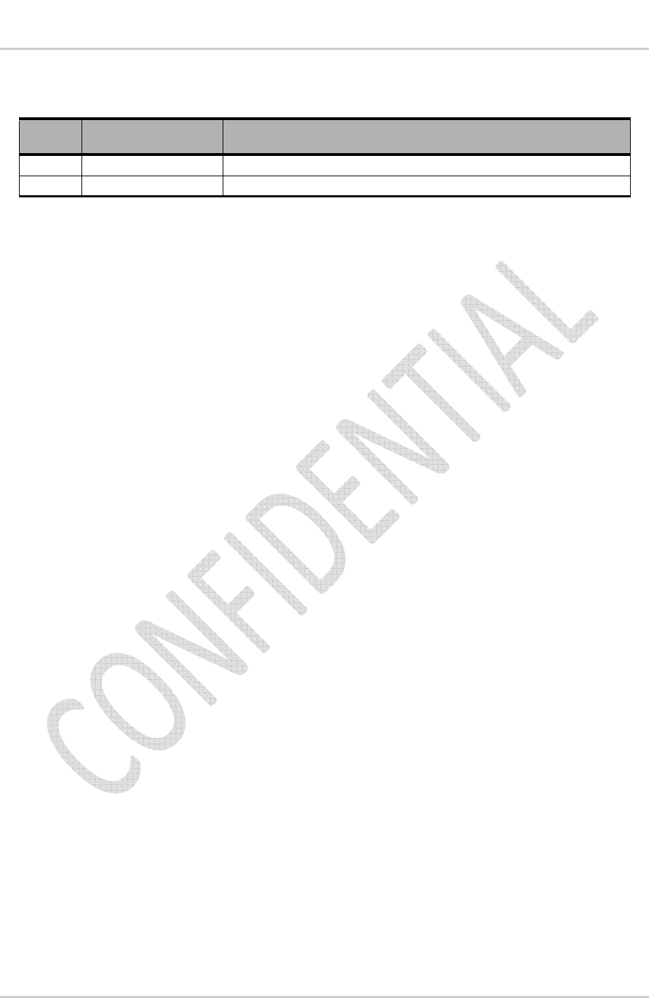
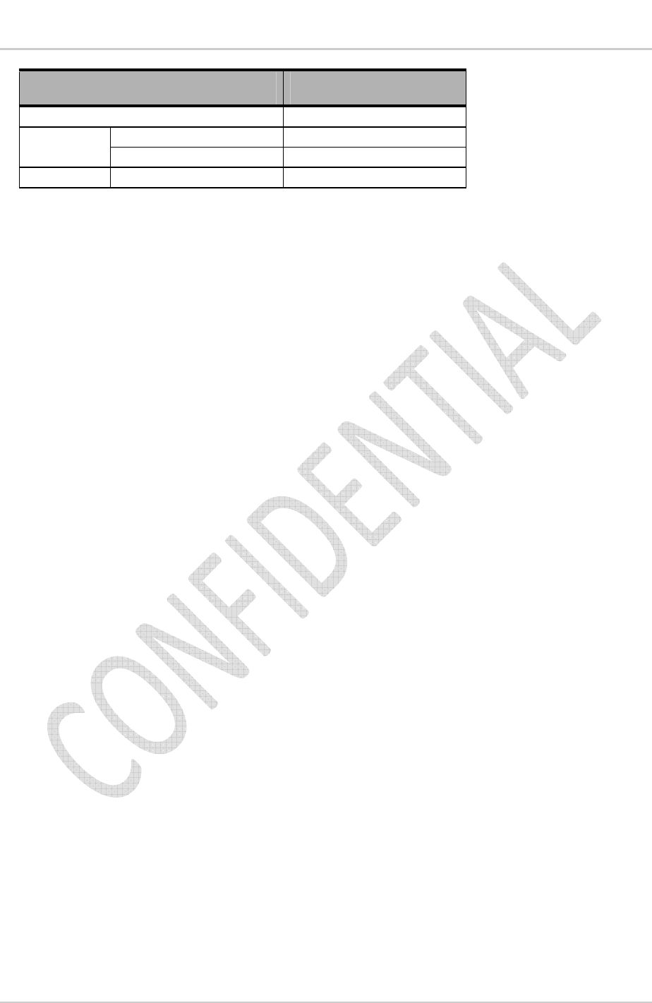
Document History
Version Date Updates
0.1 December 9, 2009 Creation
0.2 December 14, 2009 Updates for Preliminary release

Preliminary Rev 0.6 December 10, 2010 5
Contents
1.
OVERVIEW .......................................................................................................... 8
1.1.
Introduction ........................................................................................................................ 8
1.2.
Reference Specifications ................................................................................................... 8
2.
FEATURES .......................................................................................................... 9
2.1.
Modes of Operation ........................................................................................................... 9
2.2.
Communications Functions ............................................................................................... 9
3.
HARDWARE SPECIFICATION .......................................................................... 11
3.1.
Environmental Specification ............................................................................................ 11
3.2.
ESD Specification ............................................................................................................ 11
3.3.
Absolute Maximum Ratings ............................................................................................. 11
4.
RF SPECIFICATION .......................................................................................... 12
4.1.
GSM/WCDMA Interface .................................................................................................. 12
4.1.1.
GSM/WCDMA Antenna Interface ............................................................................ 12
5.
GNSS SPECIFICATION ..................................................................................... 13
5.1.
GPS ................................................................................................................................. 13
6.
BASEBAND SPECIFICATION ........................................................................... 14
6.1.
Power Supply .................................................................................................................. 14
6.2.
Current Consumption ...................................................................................................... 14
6.3.
USB ................................................................................................................................. 14
7.
RF CIRCUIT ROUTING CONSTRAINTS ........................................................... 16
7.1.
General recommendations .............................................................................................. 16
8.
REGULATORY APPROVAL .............................................................................. 18

Preliminary Rev 0.6 December 10, 2010 6
List of Figures
Figure 1.
AR8550/8552 Block Diagram ............................................ Error! Bookmark not defined.
Figure 2.
Recommended UIM holder implementation .................................................................... 15
Figure 3.
AppCAD screenshot for MicroStrip design power mode diagram ................................... 16
Figure 4.
RF routing examples ....................................................................................................... 17
Figure 5.
Coplanar clearance example ........................................................................................... 17
Figure 6.
Antenna microstrip routing example ................................................................................ 17

Preliminary Rev 0.6 December 10, 2010 7
List of Tables
Table 1: AirPrime AR Series Intelligent Embedded Modules .......................................................... 8
Table 2: Reference specifications ................................................................................................... 8
Table 3: AR8552 modes of operation .............................................................................................. 9
Table 4: AR8550 modes of operation .............................................................................................. 9
Table 5: Communications functions ................................................................................................ 9
Table 6: Environmental specifications ........................................................................................... 11
Table 7: ESD ratings ..................................................................................................................... 11
Table 8: Absolute Maximum ratings .............................................................................................. 11
Table 9: GSM/WCDMA antenna characteristics – AR8550 .......................................................... 12
Table 10: GSM/WCDMA antenna characteristics – AR8552 .......................................................... 12
Table 11: Power supply requirements ............................................................................................. 14
Table 12: Power supply pad ............................................................................................................ 14
Table 13: USB pad details ............................................................................................................... 14
Table 14: USB characteristics ......................................................................................................... 15
Preliminary Rev 0.6 December 10, 2010 8
1. Overview
1.1. Introduction
This document is the Hardware Product Specification for the AirPrime AR Series of Intelligent
Embedded Modules. It defines the high level product features and illustrates the interfaces for these
features. This document is intended to cover the hardware aspects of the product series, including
electrical and mechanical.
The AirPrime AR Series of Intelligent Embedded Modules are designed for the automotive industry
and any market with similar quality and life-time support requirements. They support several air
interface standards but share a common form-factor and electrical interface. All versions also have
Global Navigation Satellite System (GNSS) capabilities via GPS.
The AirPrime AR series of intelligent embedded modules are based on the Qualcomm MDM6200 and
MDM6600 wireless chipsets. The term AirPrime AR series addresses all of the following specific
products.
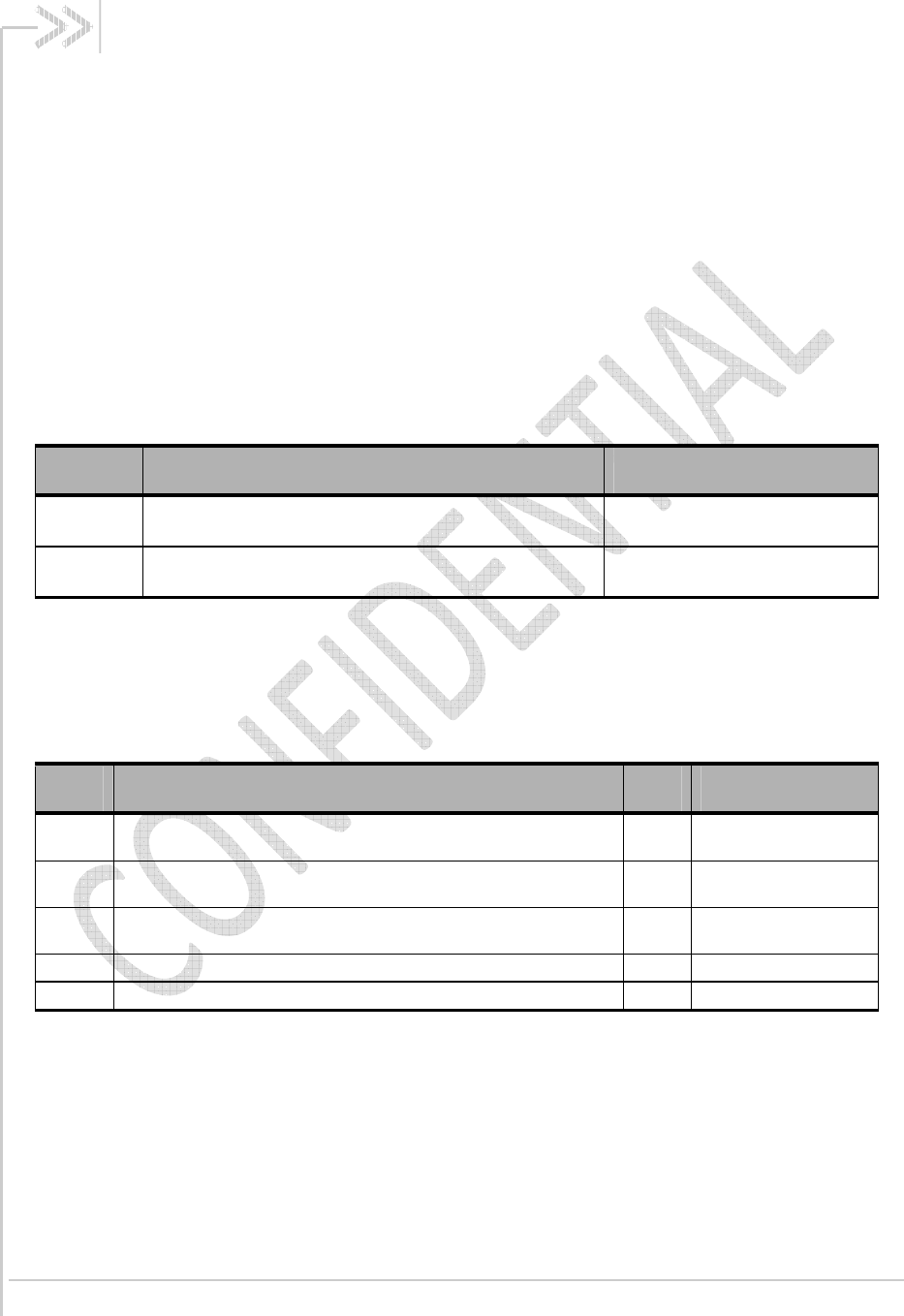
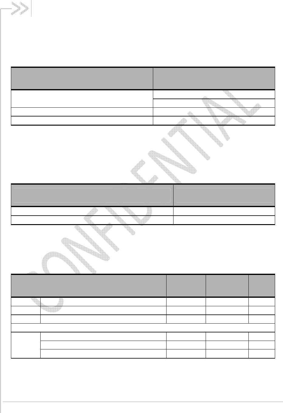
Table 1: AirPrime AR Series Intelligent Embedded Modules
Product Description Band Support
AR8550 WCDMA/HSPA/GSM Intelligent Embedded Module 3G – BAND II, IV, V
2G – 850/900/1800/1900
AR8552 WCDMA/HSPA/GSM Intelligent Embedded Module 3G – BAND I, VIII, VI
2G – 850/900/1800/1900
1.2. Reference Specifications
The table below lists the reference specifications for this product.
Table 2: Reference specifications
Ref Title Rev Issuer
[3] Universal Serial Bus Specification 2.0 USB Implementers
Forum
[4] Universal Serial Bus CDC Subclass Specification for Wireless
Mobile Communication Devices 1.0 USB Implementers
Forum
[5] Universal Serial Bus Class Definitions for Communication Devices 1.1 USB Implementers
Forum
[6] AirPrime AR Series LGA Specification 0.5 Sierra Wireless
[7] AirPrime AR Series AT Command Interface Specification 006 Sierra Wireless
Preliminary Rev 0.6 December 10, 2010 9
2. Features
This chapter highlights the features of the AirPrime AR Series of Intelligent Embedded Modules.
2.1. Modes of Operation
The AR8550 supports quad band GSM operation and WCDMA/HSPA operation in Band II, IV and V.
The AR8552 supports quad band GSM operation and WCDMA/HSPA operation in Band I, VI and VIII.
All models also support Standalone GNSS operation. For complete details, refer to the tables below.
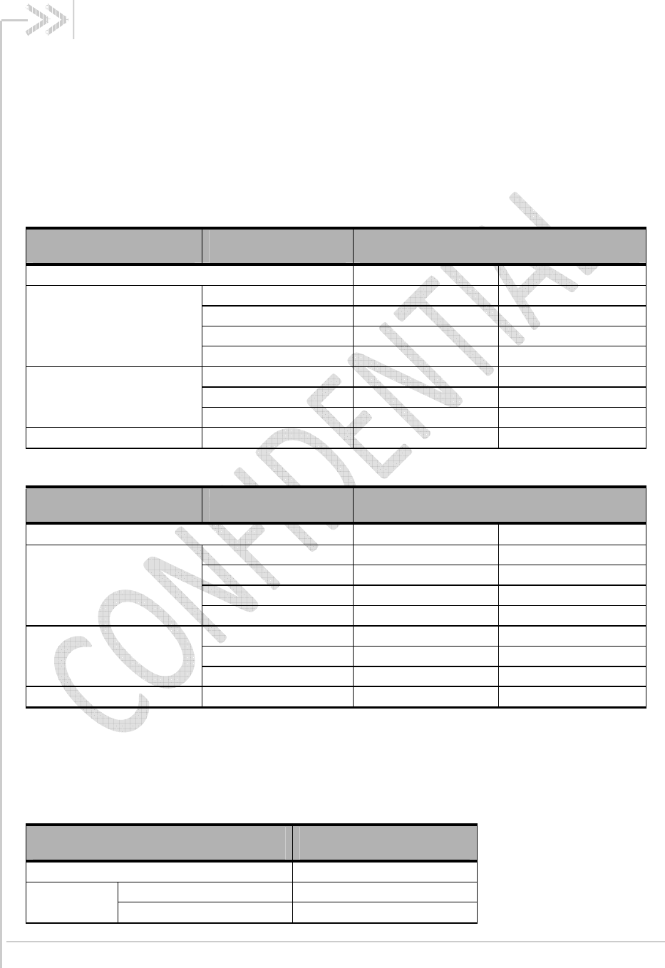
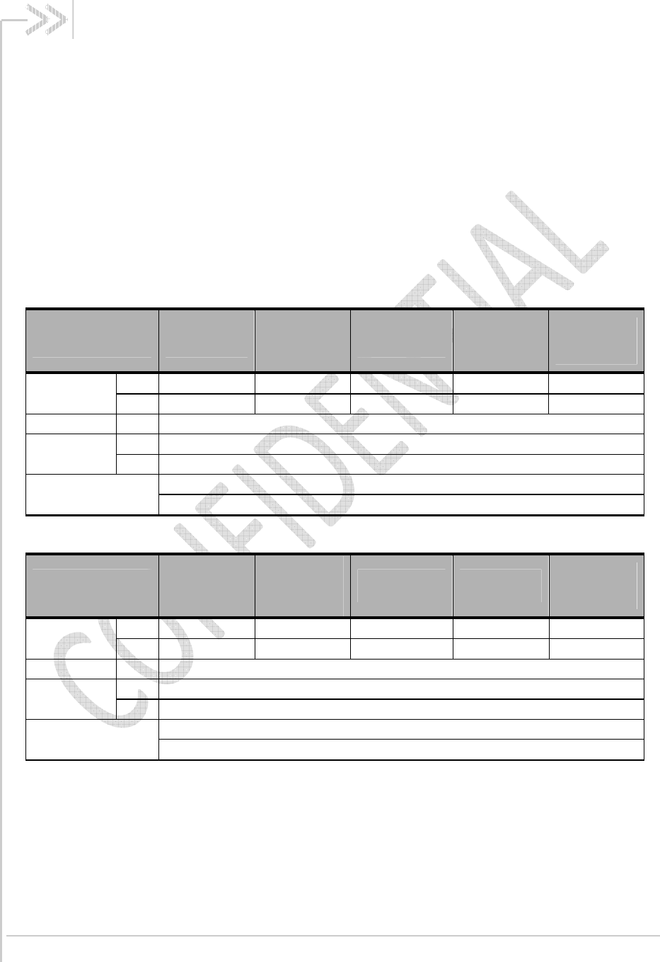
Table 3: AR8552 modes of operation
Mode Band Frequency (MHz)
RX TX
GSM/GPRS/EDGE
850 869 – 894 824 – 849
900 925 – 960 880 – 915
1800 1805 – 1880 1710 – 1785
1900 1930 – 1990 1850 – 1910
WCDMA/HSPA
I (2100/IMT) 2110 – 2170 1920 – 1980
VI (800) 875 – 885 830 – 840
VIII (900/GSM) 925 – 960 880 – 915
GNSS GPS L1 1574.42 – 1576.42 ---
Table 4: AR8550 modes of operation
Mode Band Frequency (MHz)
RX TX
GSM/GPRS/EDGE
850 869 – 894 824 – 849
900 925 – 960 880 – 915
1800 1805 – 1880 1710 – 1785
1900 1930 – 1990 1850 – 1910
WCDMA/HSPA
II (1900/PCS) 1930 – 1990 1850 – 1910
IV (1700/AWS) 2110 – 2155 1710 – 1755
V (850/CELL) 869 – 894 824 – 849
GNSS GPS L1 1574.42 – 1576.42 ---
2.2. Communications Functions
The AirPrime AR series provides the following communications functions via the CDMA, GSM and/or
UMTS networks.
Table 5: Communications functions
Communications Function AR8550/AR8552
Voice FR, EFR, HR, AMR, AMR-WB
Data Circuit Switch (CSD)
Packet
Preliminary Rev 0.6 December 10, 2010 10
Product Specification Features
Communications Function AR8550/AR8552
Short Message Service (SMS)
OTA OTAPA
OTASP
DTMF Forward link only
Preliminary Rev 0.6 December 10, 2010 11
3. Hardware Specification
3.1. Environmental Specification
The environmental specification for both operating and storage are defined in the table below.
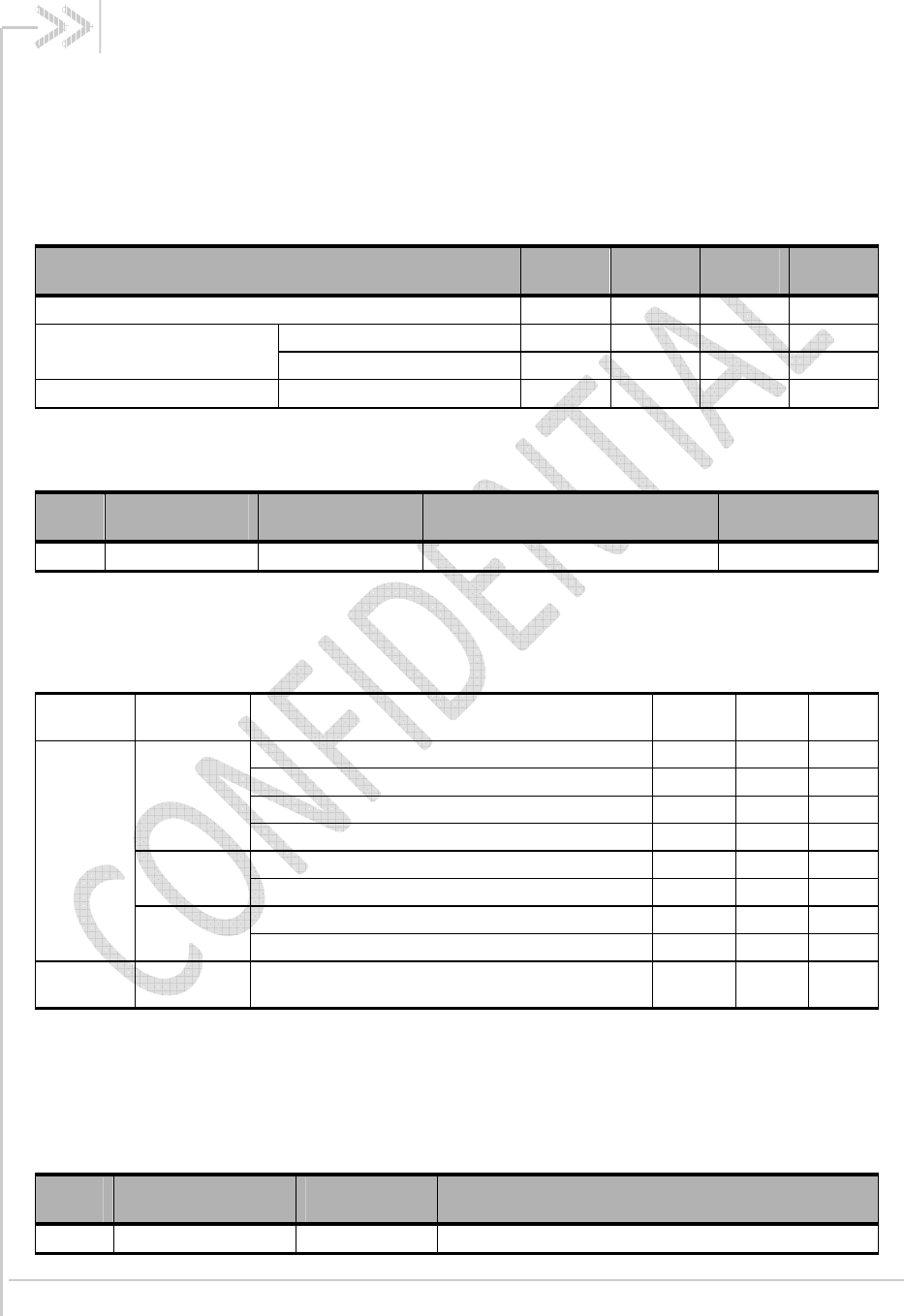
Table 6: Environmental specifications
Parameter Temperature Range
Ambient Operating Temperature -30°C to +75°C (Class A)
-40°C to +85°C (Class B)
Ambient Storage Temperature -40°C to +90°C
Ambient Humidity 95% or less
3.2. ESD Specification
The AirPrime AR series devices are sensitive to Electrostatic Discharge. ESD countermeasures and
handling methods must be used when handling the AirPrime AR series devices.
Table 7: ESD ratings
Signal Pads ESD Rating
Primary, Diversity and GNSS antenna pads 8 kV Contact
All other signal pads 1.5 kV Contact
3.3. Absolute Maximum Ratings
This section defines the Absolute Maximum Ratings of the AirPrime AR series devices. If these
parameters are exceeded, even momentarily, damage may occur to the device.
Table 8: Absolute Maximum ratings
Parameter Min Max Units
VBATT Power Supply Input - 5.0 V
VIN Voltage on any digital input or output pin - VCC_1v8+0.5 V
IIN Latch-up current -100 100 mA
Maximum Voltage applied to antenna interface pins
VANT
Primary Antenna - 30 V
Diversity Antenna - 25 V
GNSS Antenna - 25 V
Preliminary Rev 0.6 December 10, 2010 12
4. RF Specification
The section presents the RF interface of the AirPrime AR series intelligent embedded module. The
specifications for the CDMA and GSM/WCDMA interfaces are defined.
4.1. GSM/WCDMA Interface
This section presents the GSM/GPRS/EDGE/WCDMA RF Specification for the AirPrime AR8550 and
AR8552.
4.1.1. GSM/WCDMA Antenna Interface
The specification for the GSM/WCDMA Antenna Interface is defined in the table below.
Table 9: GSM/WCDMA antenna characteristics – AR8550
Characteristics GSM900
GSM850 –
WCDMA
Band V
GSM1800
GSM1900 –
WCDMA
Band II
WCDMA
Band IV
Frequency
(MHz)
TX 880 – 915 824-849 1710 – 1785 1850-1910 1710 – 1755
RX 925 – 960 869-894 1805 – 1880 1930-1990 2110 – 2155
Impedance RF 50 Ohm
VSWR max RX 1.5: 1
TX 1.5: 1
Maximum Voltage Primary Antenna – 30 Volts
Diversity Antenna – 25 Volts
Table 10: GSM/WCDMA antenna characteristics – AR8552
Characteristics
GSM900 –
WCDMA
Band VIII
GSM850 –
WCDMA
Band VI
GSM1800 GSM1900 WCDMA
Band I
Frequency
(MHz)
TX 880 – 915 824-849 1710 – 1785 1850-1910 1920 – 1980
RX 925 – 960 869-894 1805 – 1880 1930-1990 2110 – 2170
Impedance RF 50 Ohm
VSWR max RX 1.5: 1
TX 1.5: 1
Maximum Voltage Primary Antenna – 30 Volts
Diversity Antenna – 25 Volts

Preliminary Rev 0.6 December 10, 2010 13
5. GNSS Specification
The AirPrime AR series intelligent embedded module includes optional Global Navigation Satellite
System (GNSS) capabilities via the Qualcomm gpsOne Gen8 Engine, capable of operation in
assisted and stand-alone GPS modes.
5.1. GPS
The GPS implementation supports GPS L1 operation centered at 1575.42 MHz (+/- 1 MHz).
Preliminary Rev 0.6 December 10, 2010 14
6. Baseband Specification
6.1. Power Supply
The AirPrime AR series is powered via a single regulated DC power supply, 4.0V +5/-10%. The
power supply requirements can be found in the following table.
Table 11: Power supply requirements
Power Supply Min Typ Max Units
Main DC Power Input Range 3.6 4.0 4.2 V
Power Supply Ripple 0 to 1kHz 200 mVpp
>1kHz 50 mVpp
Maximum Current draw AR8550/8552 2.5 A
AirPrime AR series does not support USB self powered operation.
Table 12: Power supply pad
Pad Name Direction Function If Unused
S20 VBATT Input Power Supply Input Required
6.2. Current Consumption
The table below summarizes some key current consumption values for varies modes of the AR series
devices.
Device Mode Parameter Typical
Max Units
AR8550 /
AR8552
On Call
Maximum TX Output – WCDMA - 800 mA
+0dBm TX Output – WCDMA tbd - mA
GSM Low Band TX – PL5 - tbd mA
GSM High Band TX – PL - tbd mA
Scan Searching for network – WCDMA 46 - mA
Searching for network – GSM 43 - mA
Sleep Mode On-network, "listening" for page – WCDMA - 2 mA
On-network, "listening" for page – GSM - 2 mA
All AR
Series Off Power OFF Current 3.6 10 µA
6.3. USB
The AirPrime AR series has a High Speed USB2.0 compliant, peripheral only interface.
Table 13: USB pad details
Pad Name Direction Function
R1 USB_VBUS Input USB Power Supply
Preliminary Rev 0.6 December 10, 2010 15
Product Specification Baseband Specification
Pad Name Direction Function
V1 USB_D_P In/Out Differential data interface positive
T1 USB_D_M In/Out Differential data interface negative
The AirPrime AR series will not be damaged if a valid USB_VBUS is supplied while the main DC
power is not supplied.
Table 14: USB characteristics
USB Value Units
USB_VBUS
Voltage range 2.0 – 5.25 V
Maximum Current draw 1 mA
Maximum Input Capacitance (Min ESR = 50 mOhm) 10 µF
Figure 1. Recommended UIM holder implementation
Preliminary
Rev
0.6
December 10, 2010
16
7. RF Circuit Routing Constraints
7.1. General recommendations
To route the RF antenna signals, the following recommendations must be observed for PCB layout:
The RF signals must be routed using traces with a 50
Ω
characteristic impedance.
Basically, the characteristic impedance depends on the dielectric constant (
ε
r) of the material used,
trace width (W), trace thickness (T), and height (H) between the trace and the reference ground plane.
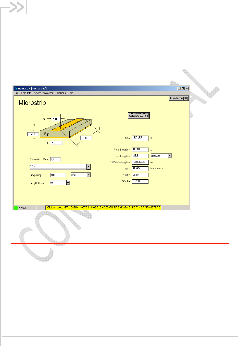
In order to respect this constraint, Sierra Wireless recommends that a MicroStrip structure be used
and trace width be computed with a simulation tool (such as AppCAD, shown in the figure below and
available free of charge at http://www.avagotech.com).
Figure 2. AppCAD screenshot for MicroStrip design power mode diagram
The trace width should be wide enough to maintain reasonable insertion loss and manufacturing
reliability. Cutting out inner layers of ground under the trace will increase the effective substrate
height; therefore, increasing the width of the RF trace.
Caution:
It is critical that no other signals (digital, analog, or supply) cross under the RF path. The figure below
shows a generic example of good and poor routing techniques.
Preliminary
Rev
0.6
December 10, 2010
17
Product Specification RF Circuit Routing Constraints
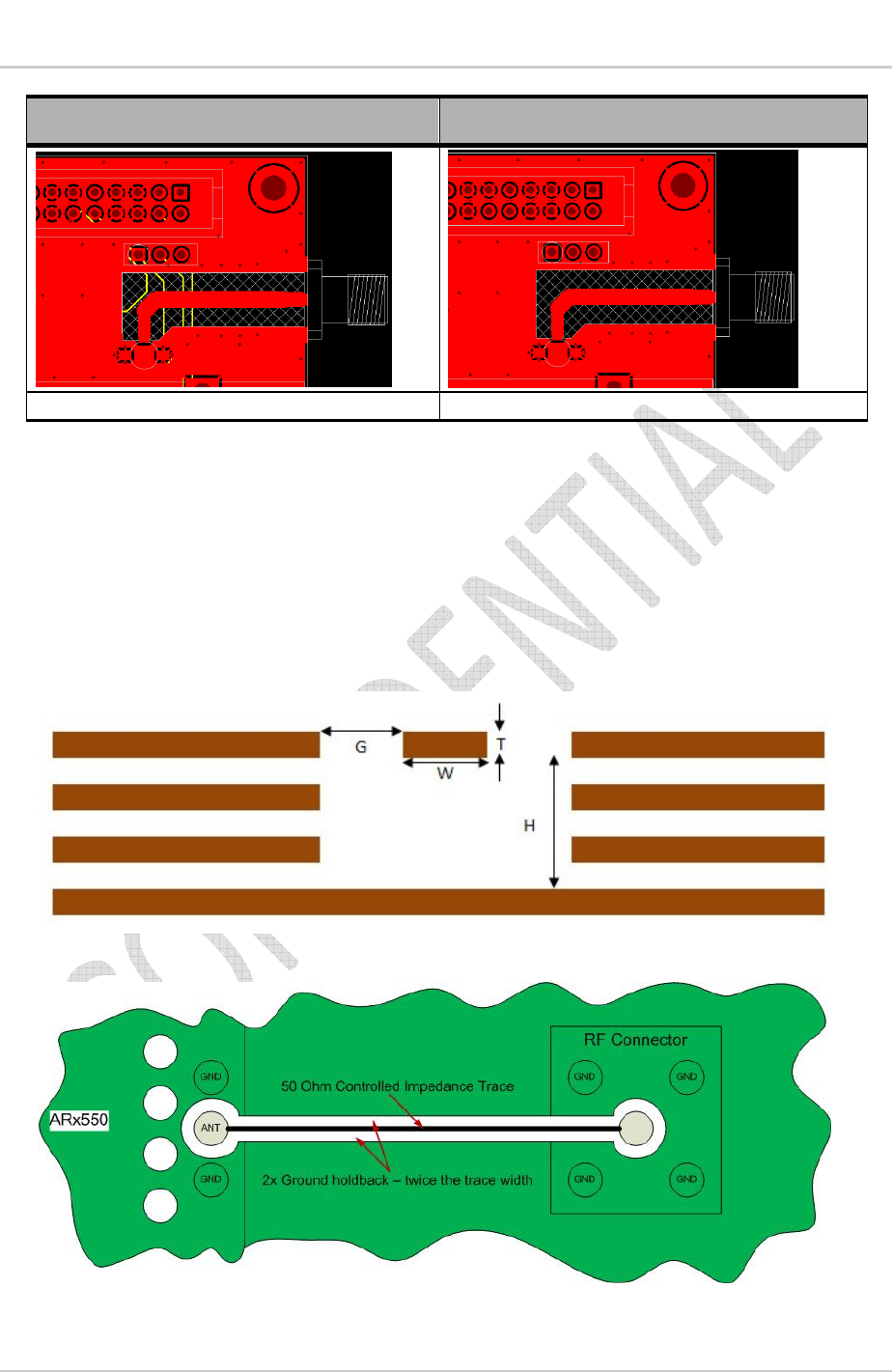
Poor routing Correct routing
The yellow traces cross the RF trace. There is no signal around the RF path.
Figure 3. RF routing examples
•
Fill the area around the RF traces with ground and ground vias to connect inner ground layers
for isolation.
•
Cut out ground fill under RF signal pads to reduce stray capacitance losses.
•
Avoid routing RF traces with sharp corners. A smooth radius is recommended.
•
The ground reference plane should be a solid continuous plane under the trace.
•
The coplanar clearance (G, below) from the trace to the ground should be at least the trace
width (W) and at least twice the height (H). This reduces the parasitic capacitance, which
potentially alters the trace impedance and increases the losses. Note the figure below shows
several internal ground layers cutout, which may not be necessary for every application.
Figure 4. Coplanar clearance example
Figure 5. Antenna microstrip routing example

Preliminary
Rev
0.6
December 10, 2010
8. Regulatory Approval
Important Notice
Because of the nature of wireless communications, transmission and reception of data can
never be guaranteed. Data may be delayed, corrupted (i.e., have errors) or be totally lost.
Although significant delays or losses of data are rare when wireless devices such as the Sierra
Wireless modem are used in a normal manner with a well-constructed network, the Sierra
Wireless modem should not be used in situations where failure to transmit or receive data could
result in damage of any kind to the user or any other party, including but not limited to personal
injury, death, or loss of property. Sierra Wireless and its affiliates accept no responsibility for
damages of any kind resulting from delays or errors in data transmitted or received using Sierra
Wireless modem, or for failure of the Sierra Wireless modem to transmit or receive such data.
Safety and Hazards
Do not operate you AR8550 modem:
•
In areas where blasting is in progress
•
Where explosive atmospheres may be present including refueling points, fuel
depots, and chemical plants
•
Near medical equipment, life support equipment, or any equipment which may be
susceptible to any form of radio interference. In such areas, the AR8550 modem
MUST BE POWERED OFF
. Otherwise, the AR8550 modem can transmit
signals that could interfere with this equipment
•
In an aircraft, the AR8550 modem
MUST BE POWERED OFF.
Otherwise, the
AR8550 modem can transmit signals that could interfere with various onboard
systems and may be dangerous to the operation of the aircraft or disrupt the
cellular network. Use of cellular phone in aircraft is illegal in some jurisdictions.
Failure to observe this instruction may lead to suspension or denial of cellular
telephone services to the offender, or legal action or both.
•
Some airlines may permit the use of cellular phones while the aircraft is on the
ground and the door is open. The AR8550 modem may be used normally at this
time.
Important Compliance Information for USA OEM
Integrators
The AR8550 modem is granted with a modular approval for mobile applications. Integrators
may use the AR8550 modem in their final products without additional FCC/IC (Industry
Canada) certification if they meet the following conditions. Otherwise, additional FCC/IC
approvals must be obtained.
1. At least 20cm separation distance between the antenna and the user’s body must be
maintained at all times.
2. To comply with FCC/IC regulations limiting both maximum RF output power and human
exposure to RF radiation, the maximum antenna gain including cable loss in a mobile-
only exposure condition must not exceed 5dBi for Cellular band and 3.7dBi for CDMA
PCS band.
3. The AR8550 modem and the antenna must not be co-located or operating in
conjunction with any other transmitter or antenna within a host device.

Preliminary Rev 0.6
December 10, 2010
Product Specification
4. A label must be affixed to the outside of the end product into which the AR8550 modem
is incorporated, with a statement similar to the following:
This device contains FCC ID: N7NAR8550
Contains transmitter module IC: 2417C-AR8550
where 2417C-AR8550 is the module’s certification number.
A user manual with the end product must clearly indicate the operating requirements and
conditions that must be observed to ensure compliance with current FCC/IC RF exposure
guidelines.
The end product with an embedded AR8550 modem may also need to pass the FCC Part 15
unintentional emission testing requirements and be properly authorized.
Note: If this module is intended for use in a portable device, you are responsible for separate
approval to satisfy the SAR requirements of FCC Part 2.1093 and IC RSS-102.