Sierra Wireless EM8781 850/900/1800/1900/2100 MHz Multi-band Module User Manual
Sierra Wireless Inc. 850/900/1800/1900/2100 MHz Multi-band Module
User Manual
2130851
Rev 1.0
GSM Embedded Modules
Hardware Integration Guide
Proprietary and Confidential
EM8780/
EM8781
Preface
Rev 1.0 Apr.07 3
Limitation of
Liability
Theinformationinthismanualissubjecttochangewithout
noticeanddoesnotrepresentacommitmentonthepartof
SierraWireless.SIERRAWIRELESSANDITSAFFILIATES
SPECIFICALLYDISCLAIMLIABILITYFORANYANDALL
DIRECT,INDIRECT,SPECIAL,GENERAL,INCIDENTAL,
CONSEQUENTIAL,PUNITIVEOREXEMPLARYDAMAGES
INCLUDING,BUTNOTLIMITEDTO,LOSSOFPROFITSOR
REVENUEORANTICIPATEDPROFITSORREVENUE
ARISINGOUTOFTHEUSEORINABILITYTOUSEANY
SIERRAWIRELESSPRODUCT,EVENIFSIERRAWIRELESS
AND/ORITSAFFILIATESHASBEENADVISEDOFTHE
POSSIBILITYOFSUCHDAMAGESORTHEYARE
FORESEEABLEORFORCLAIMSBYANYTHIRDPARTY.
Notwithstandingtheforegoing,innoeventshallSierra
Wirelessand/oritsaffiliatesaggregateliabilityarisingunderor
inconnectionwiththeSierraWirelessproduct,regardlessof
thenumberofevents,occurrences,orclaimsgivingriseto
liability,beinexcessofthepricepaidbythepurchaserforthe
SierraWirelessproduct.
Patents Portionsofthisproductmaybecoveredbysomeorallofthe
followingUSpatents:
5,515,013 5,629,960 5,845,216 5,847,553 5,878,234
5,890,057 5,929,815 6,169,884 6,191,741 6,199,168
6,339,405 6,359,591 6,400,336 6,516,204 6,561,851
6,643,501 6,653,979 6,697,030 6,785,830 6,845,249
6,847,830 6,876,697 6,879,585 6,886,049 6,968,171
6,985,757 7,023,878 7,053,843 7,106,569 D442,170
D459,303
andotherpatentspending.
Thisproductincludes
technologylicensedfrom:
LicensedbyQUALCOMMIncorporatedunderoneormoreof
thefollowingUnitedStatespatentsand/ortheircounterparts
inothernations:
4,901,307 5,056,109 5,101,501 5,109,390 5,228,054
5,267,261 5,267,262 5,337,338 5,414,796 5,416,797
5,490,165 5,504,773 5,506,865 5,511,073 5,535,239
5,544,196 5,568,483 5,600,754 5,657,420 5,659,569
5,710,784 5,778,338
ManufacturedorsoldbySierraWirelessoritslicenseesunder
oneormorepatentslicensedfromInterDigitalGroup.
Copyright ©2007SierraWireless.Allrightsreserved.
GSM Embedded Modems Hardware Integration Guide
42130851
Trademarks AirCardand“HeartoftheWirelessMachine”areregistered
trademarksofSierraWireless.
SierraWireless,theSierraWirelesslogo,theredwavedesign,
andWatcheraretrademarksofSierraWireless.
Windows®isaregisteredtrademarkofMicrosoftCorporation.
QUALCOMM®isaregisteredtrademarkofQUALCOMM
Incorporated.Usedunderlicense.
Othertrademarksarethepropertyoftherespectiveowners.
Contact
Information
Consultourwebsiteforup‐to‐dateproductdescriptions,
documentation,applicationnotes,firmwareupgrades,trouble‐
shootingtips,andpressreleases:
www.sierrawireless.com
Sales Desk: Phone: 1-604-232-1488
Hours: 8:00 AM to 5:00 PM Pacific Time
E-mail: sales@sierrawireless.com
Post: Sierra Wireless
13811 Wireless Way
Richmond, BC
Canada V6V 3A4
Fax: 1-604-231-1109
Web: www.sierrawireless.com

Rev 1.0 Apr.07 5
Table of Contents
Introduction . . . . . . . . . . . . . . . . . . . . . . . . . . . . . . . . . . . . . . . . . . . . . . .7
The Lab Adapter Board . . . . . . . . . . . . . . . . . . . . . . . . . . . . . . . . . . . . . . . . . . . . . 7
Required connectors . . . . . . . . . . . . . . . . . . . . . . . . . . . . . . . . . . . . . . . . . . . . . . . 7
Guide organization . . . . . . . . . . . . . . . . . . . . . . . . . . . . . . . . . . . . . . . . . . . . . . . . . 8
Related documents. . . . . . . . . . . . . . . . . . . . . . . . . . . . . . . . . . . . . . . . . . . . . . . . . 9
Power Interface . . . . . . . . . . . . . . . . . . . . . . . . . . . . . . . . . . . . . . . . . . .11
Overview of operation. . . . . . . . . . . . . . . . . . . . . . . . . . . . . . . . . . . . . . . . . . . . . . 11
Power signals . . . . . . . . . . . . . . . . . . . . . . . . . . . . . . . . . . . . . . . . . . . . . . . . . 11
Electrostatic discharge (ESD) . . . . . . . . . . . . . . . . . . . . . . . . . . . . . . . . . . . 11
Module power states . . . . . . . . . . . . . . . . . . . . . . . . . . . . . . . . . . . . . . . . . . . . . . 12
Off state . . . . . . . . . . . . . . . . . . . . . . . . . . . . . . . . . . . . . . . . . . . . . . . . . . . . . . 12
Normal state . . . . . . . . . . . . . . . . . . . . . . . . . . . . . . . . . . . . . . . . . . . . . . . . . . 12
Low power mode . . . . . . . . . . . . . . . . . . . . . . . . . . . . . . . . . . . . . . . . . . . . . . 12
Usage models . . . . . . . . . . . . . . . . . . . . . . . . . . . . . . . . . . . . . . . . . . . . . . . . . 13
RF Integration . . . . . . . . . . . . . . . . . . . . . . . . . . . . . . . . . . . . . . . . . . . .15
RF connection . . . . . . . . . . . . . . . . . . . . . . . . . . . . . . . . . . . . . . . . . . . . . . . . . . . . 15
Ground connection . . . . . . . . . . . . . . . . . . . . . . . . . . . . . . . . . . . . . . . . . . . . . . . . 16
Shielding . . . . . . . . . . . . . . . . . . . . . . . . . . . . . . . . . . . . . . . . . . . . . . . . . . . . . 16
Antenna and cabling . . . . . . . . . . . . . . . . . . . . . . . . . . . . . . . . . . . . . . . . . . . 17
Interference and sensitivity . . . . . . . . . . . . . . . . . . . . . . . . . . . . . . . . . . . . . . . . . 18
Power supply noise . . . . . . . . . . . . . . . . . . . . . . . . . . . . . . . . . . . . . . . . . . . . 18
Interference from other wireless devices . . . . . . . . . . . . . . . . . . . . . . . . . . 18
Device-generated RF . . . . . . . . . . . . . . . . . . . . . . . . . . . . . . . . . . . . . . . . . . . 19
Regulatory Information . . . . . . . . . . . . . . . . . . . . . . . . . . . . . . . . . . . .21
Important notice . . . . . . . . . . . . . . . . . . . . . . . . . . . . . . . . . . . . . . . . . . . . . . . . . . 21

GSM Embedded Modems Hardware Integration Guide
62130851
Safety and hazards . . . . . . . . . . . . . . . . . . . . . . . . . . . . . . . . . . . . . . . . . . . . . . . . 21
Important compliance information for North American users . . . . . . . . . . . 22
Acronyms and Definitions . . . . . . . . . . . . . . . . . . . . . . . . . . . . . . . . . 23
Index . . . . . . . . . . . . . . . . . . . . . . . . . . . . . . . . . . . . . . . . . . . . . . . . . . . . 25

1
Rev 1.0 Apr.07 7
1: Introduction
SierraWireless’embeddedmodulesformtheradiocomponent
fortheproductsinwhichtheyareembedded.Theembedded
modulesareavailableforuseonGSMnetworks,andinclude
theseproducts:
Note: Throughout this
document, EM878x refer to the
entire suite of GSM embedded
modules.
•EM8780andEM8781—operate onGSMnetworksusingthe
GSM/GPRS/EDGE/UMTS/HSDPAnetworkstandards
Purpose of this guide
ThisguideaddressesissuesthataffecttheintegrationofSierra
Wirelessmodulesintohostproducts,andincludesdesign
recommendationsforthehostproducts.
Note: An understanding of network technology and experience in
integrating hardware components into electronic equipment is
assumed.
The Lab Adapter Board
SierraWirelessmanufacturesaLabAdapterBoardthatfacili‐
tatesallphasesoftheintegrationprocess.
TheLabAdapterBoardisahardwaredevelopmentplatform
thatisdesignedtosupportmultiplemembersoftheWireless
EmbeddedModuleproductfamily.Itcontainsthehardware
componentsthataretypicallynecessaryforevaluatingand
developingwiththemodule,including:
•LabAdapterBoard
•Cables
•Antennas
•Otheraccessories
Required connectors
Note: Contact the vendors
before you choose your
connectors — the numbers
included here are for reference
only. Choose connectors that are
appropriate to your design.
Whenintegratingthesemodulesintoyourhostdevice,you
needthefollowingconnectortypes:
•RFcablethatmateswithIPEXMHF‐A13connector(model
20428‐001R)
•IPEX15pinCABLINEcableconnector(partnumber
20347‐015E‐01).
•Industry‐standardUSIM/RUIMconnector—theactual
connectoryouusedependsonhowyourdeviceexposesthe

GSM Embedded Modems Hardware Integration Guide
82130851
USIM/RUIMsocket.Forexample,theUSIM/RUIM
connectorusedontheLabAdapterBoardisanITT
CCM03‐3518.
Guide organization
Thisguideincludesthefollowingsections:
1. Introduction(thissection)
2. Power Interface(page11)
Describespowercontrolsignalsusedbythemoduleand
discussesdesignissuesrelatedtopowersupply
integration.
3. RF Integration(page15)
Describesantennaconnectionmethodsandgroundingissues,
RFinterferenceanddesenseissues.
4. Regulatory Information(page21)
Describesregulatoryapprovalsandregulatoryinformation
requirements.
5. Acronyms and Definitions(page23)
Listsacronymsanddefinitionsusedthroughoutthisguide.
6. Index(page101)
Note: The term "host" always refers to the host device.
Introduction
Rev 1.0 Apr.07 9
Related documents
Thisguidedealsspecificallywithhardwareintegrationissues
thatareuniquetotheEM878xmodules.
Table1‐1listsotherdocumentsreferencedinthisguide.
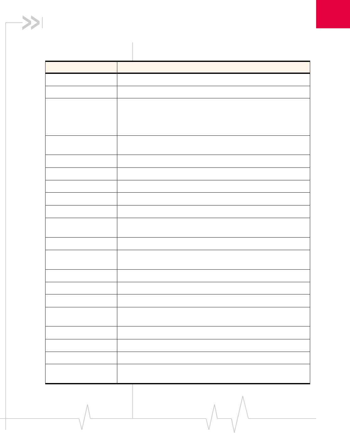
Table 1-1: Related documentation
Document title Description
AT Command Set for User
Equipment (UE) (Release 6) This 3GPP technical specification describes standard AT
commands for GSM / UMTS devices.
Download this document (3GPP TS 27.007) from
www.3gpp.org.
FCC Regulations - Part 15 -
Radio Frequency Devices This section of the FCC Code of Federal Regulations, Title
47 deals with radio frequency devices, including shielding
requirements for embedded modules.
Download this regulation from http://wireless.fcc.gov.
IEC-61000-4-2 level 3 Techniques for testing and measuring electrostatic
discharge (ESD) immunity.
Order this document from www.iec.ch.
EM8780/EM8781 Product
Specification (Document
2130TBD)
Features, mechanical and electrical specifications, and
standards compliance of the EM8780 / EM8781.
MC87xx Modem CnS Reference
(Document 2130602) This document describes the CnS (Control and Status)
messages supported by the EM8780/EM8781.
MC87xx Modem Extended AT
Command Reference
(Document 2130616)
Proprietary AT commands for the EM878x.
Mobile Station (MS)
Conformance Specification;
Part 4: Subscriber Interface
Module
This 3GPP technical specification describes SIM testing
methods.
Download this document (3GPP TS 11.10-4) from
www.3gpp.org.
UMTS Modems Supported AT
Command Reference
(Document 2130617)
This document describes proprietary, basic AT commands
for the EM878x.
Universal Serial Bus
Specification, Rev 2.0 Download this specification from www.usb.org.


2
Rev 1.0 Apr.07 11
Values in this guide are summarized from the product specification documents (PSDs) - the PSD takes precedence.
2: Power Interface
Overview of operation
Themoduleisdesignedtousea5.0V(nominal)powersupply,
providedbythehost.Itisthehost’sresponsibilitytoprovide
safeandcontinuouspowertothemoduleatalltimes;the
moduledoesNOThaveanindependentpowersupply,or
protectioncircuitstoguardagainstelectricalissues.
Themodule’spowerstateiscontrolledbythehost’ssupplyof
the5.0Vpowerrail.Whenthisrailispoweredup,themodem
isintheONstate.Whenthisrailispowereddown,the
modemisintheOFFstate.
Power signals
Themodulemustbeconnectedtoa5.0Vpowersupply.
Fordetailedpinoutandvoltage/currentrequirementsofthese
modules,seetheProductSpecificationDocumentforyour
embeddedmodule.
Electrostatic discharge (ESD)
Youareresponsibleforensuringthatthehosthasadequate
ESDprotectionondigitalcircuitsandantennaports:
•(Operational)RFport(antennalaunchandRFconnector):
IEC‐61000‐4‐2—Level(ElectrostaticDischargeImmunityTest)
•(Non‐operational)Hostconnectorinterface:
JESD22‐A114‐B+/‐1kVHumanBodyModeland
JESD22‐C101+/‐125VChargedDeviceModel
Specificrecommendationsareprovidedwhereneededinthis
guide;however,thelevelofprotectionrequireddependson
yourapplication.
Note: ESD protection is highly recommended for the USIM / RUIM
connector at the point where the contacts are exposed, and for any
other signals from the host interface that would be subjected to ESD
by the user of the product.

GSM Embedded Modems Hardware Integration Guide
12 2130851
Values in this guide are summarized from the product specification documents (PSDs) - the PSD takes precedence.
Module power states
Note: The module unit defaults
to the Normal state when 5.0V is
first applied.
Themodulehasthreepowerstates:
•Off
Nopowertothemodule.
•Normal
Powerissuppliedtothemodule.Themoduleisactive.
Severalmodesarepossible(Receive,Transmit,Sleep,
Shutdown).
•Low power (“airplane mode”)
Powerissuppliedtothemodule.Themoduleisactive,but
RFisdisabled.
Astatemachineisimplementedinthemoduletomonitorthe
operatingtemperature.
Off state
Thisstateoccurswhenthereisnopowertothemodule—the
hostpowersourceisdisconnectedfromthemodule,andall
voltagesassociatedwiththemoduleareat0V.
Whetherthehostdeviceisalsopoweredoffdependsonthe
powerraildesign.Iftheconnectionbetweenthepowerrail
andthemoduleiscontrolledbythehost,thehostcanstay
poweredonandcutthepowertoputthemodemintothe
disconnectedstate.Ifthepowerrailissharedbetweenthehost
deviceandthemodule,thehostispoweredoffwhenthe
moduleispoweredoff.
Normal state
Note: This is the default state
when 5.0V is first applied.
Thisistheactivestateofthemodule.Inthisstate:
•Themoduleisfullypowered.
•Themoduleiscapableofplacing/receivingcallsorestab‐
lishingdataconnectionsonthewirelessnetwork.
•TheUSBinterfaceisfullyactive.
Low power mode
Inthisstate,RF(bothRxandTx)isdisabledinthemodule,but
theUSBinterfaceisstillactive.Thislowpowermode
(ʺairplanemodeʺ)iscontrolledbysoftwarecommands
throughthehostinterface.
Forinstructionsonusingthecommands,referto:
•ATCommandSetforUserEquipment(UE)(Release6)
(+CFUN=0command),
Power Interface
Rev 1.0 Apr.07 13
Values in this guide are summarized from the product specification documents (PSDs) - the PSD takes precedence.
•MC87xxModemCnSReference(Document2130602)(Disable
Modemcommand).
Usage models
Usagemodelscanbeusedtocalculateexpectedcurrent
consumption.AsampleusagemodelisprovidedinTable2‐1.
Thisexamplemodelappliestoabattery‐operateddevice.In
practice,becausethemoduleisisolatedfromthebattery(the
hostdevicemanagesthepowersource),themAhratings
dependonthedevice’ssupplyefficiency.
Themoduleautomaticallyentersslottedsleepmodewhen
thereisnotransmissionorreceptionoccurring(SCI=2).
Transmitpowerisassumedtobe+3dBm.
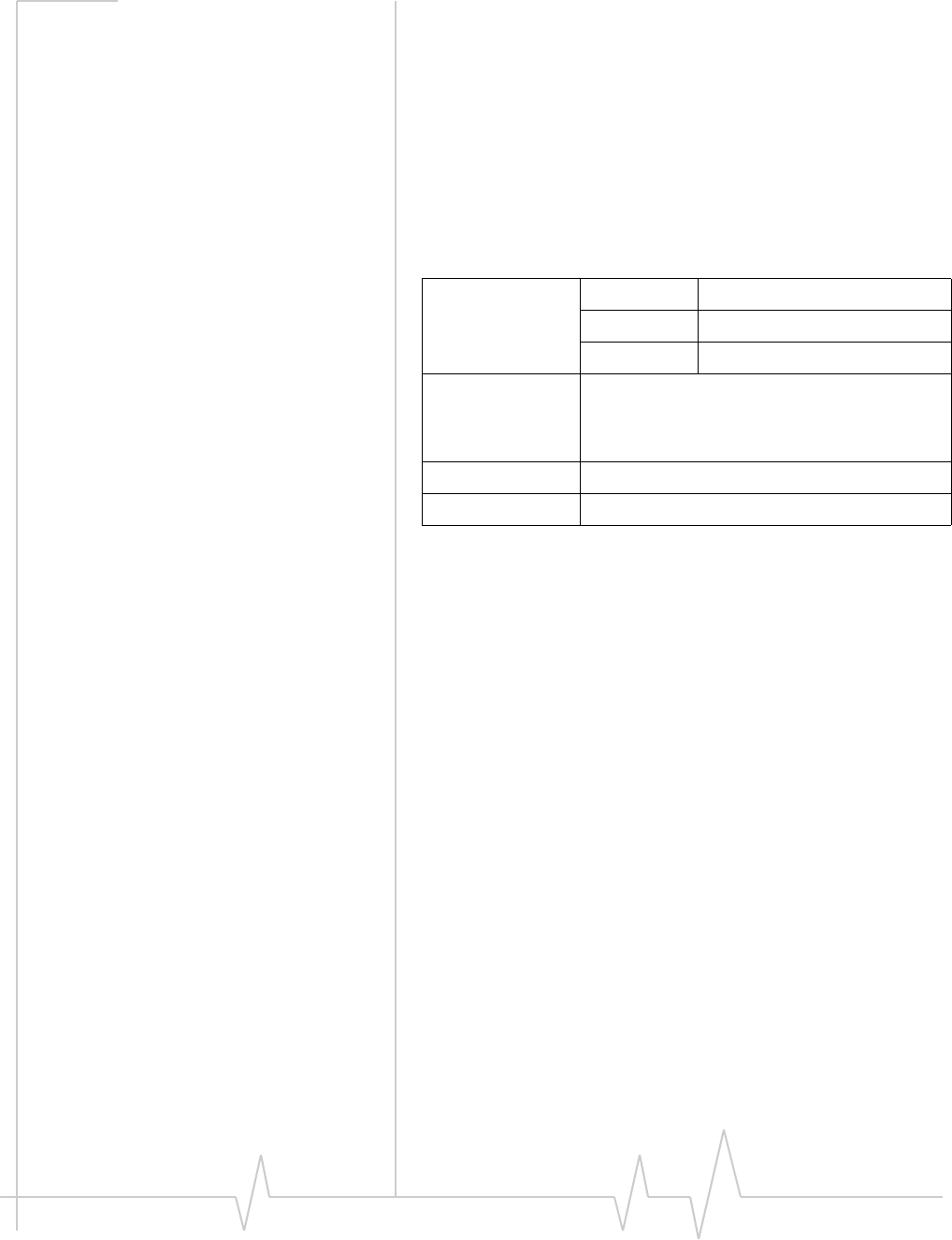
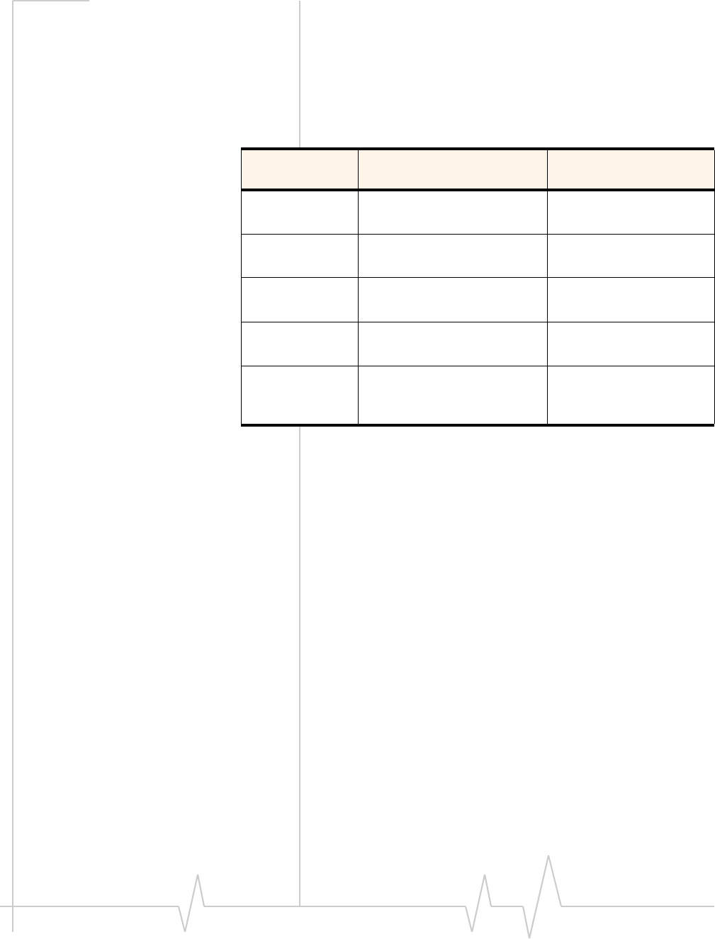
Table 2-1: Power consumption of a sample application
Used by a field worker
(data only) Used for remote data
logging
Upload
(module Tx) 1000 kB/day 40 kB/h
Download
(module Rx) 500 kB/day 100 kB/day
Coverage / data
rate 1X / 80 kbps IS-95 / 14.4 kbps
Hours of
operation 8 / day (off 16 hrs / day) 24 / day
Total power
consumed over
24 hours
66 mAh 220 mAh

GSM Embedded Modems Hardware Integration Guide
14 2130851
Values in this guide are summarized from the product specification documents (PSDs) - the PSD takes precedence.
3
Rev 1.0 Apr.07 15
Values in this guide are summarized from the product specification documents (PSDs) - the PSD takes precedence.
3: RF Integration
TheEM878xoperatesonthefrequenciesdetailedinTable3‐1.
RF connection
Whenattachinganantennatothemodule:
Note: To disconnect the
antenna, make sure you use the
IPEX MHF connector removal
tool (P/N TBD) to prevent
damage to the module or coaxial
cable assembly.
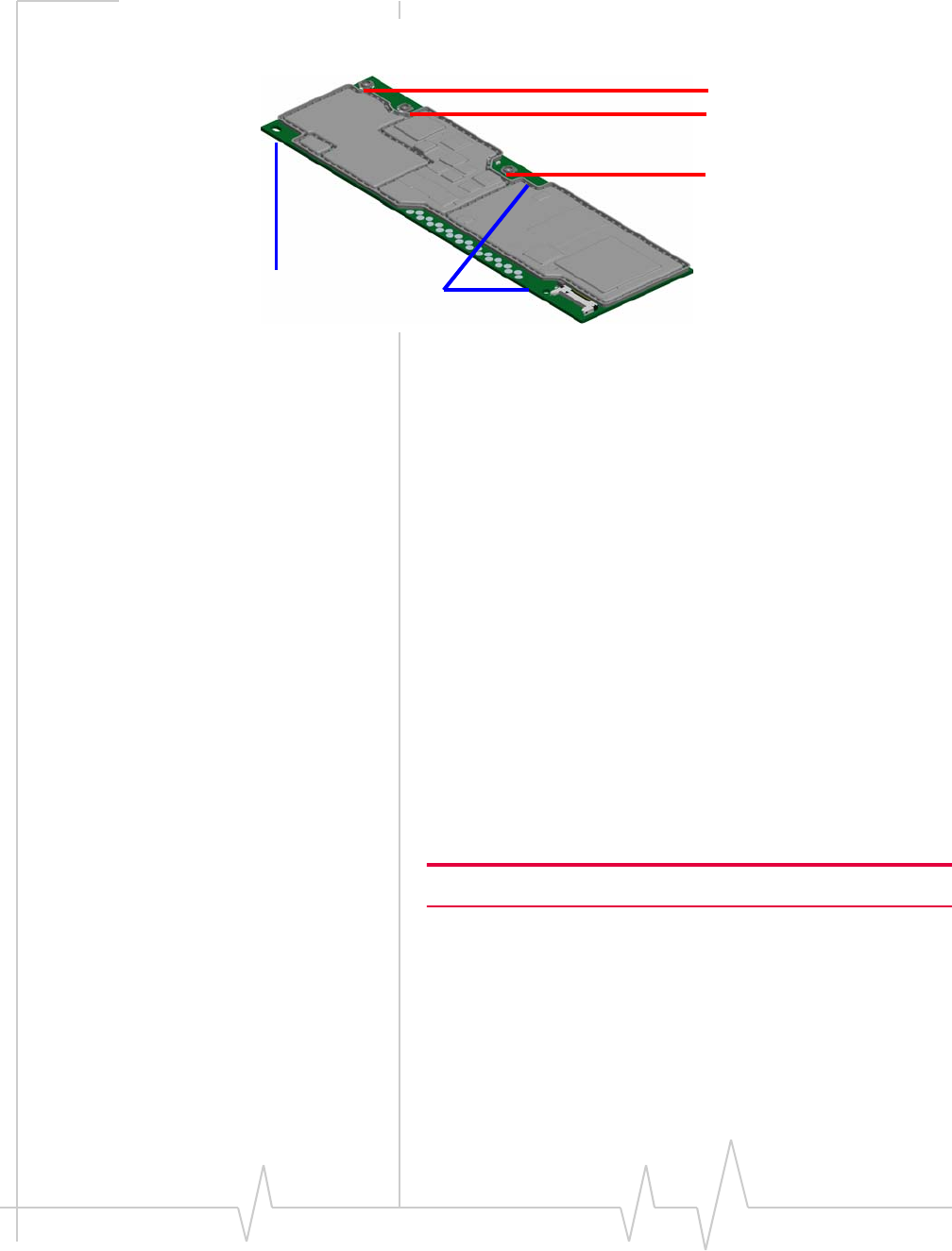
•UseanIPEXMHFconnector(modelMHFA13‐7G‐113‐60‐
SW)toattachanantennatoaconnectionpointonthe
module,asshowninFigure3‐1below.
•Matchcoaxialconnectionsbetweenthemoduleandthe
antennato50Ω.
•MinimizeRFcablelossestotheantenna;therecommended
maximumcablelossforantennacablingis0.5dB.
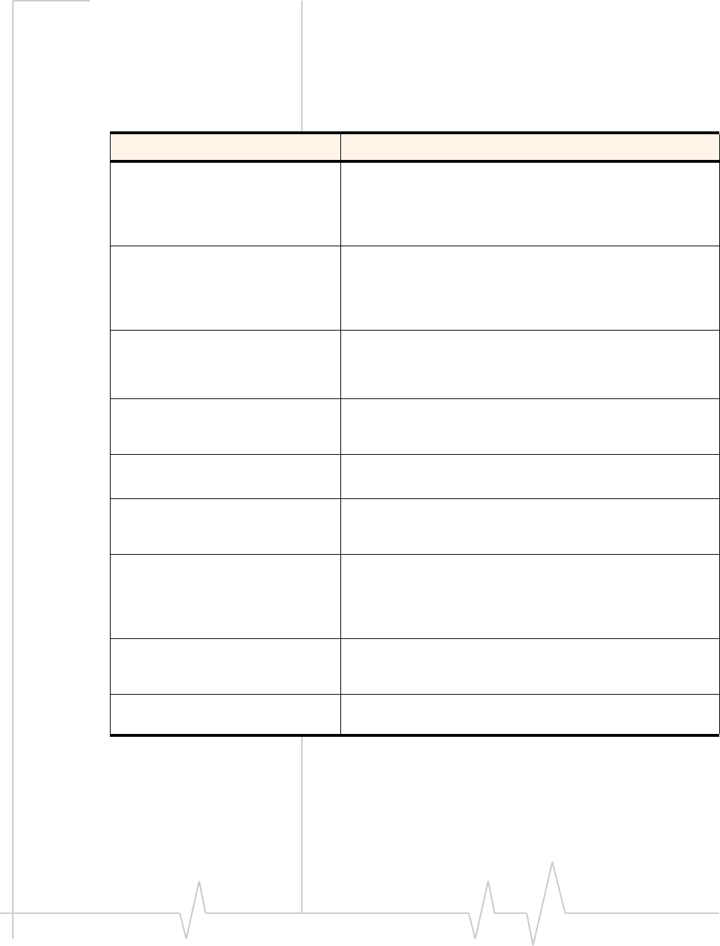
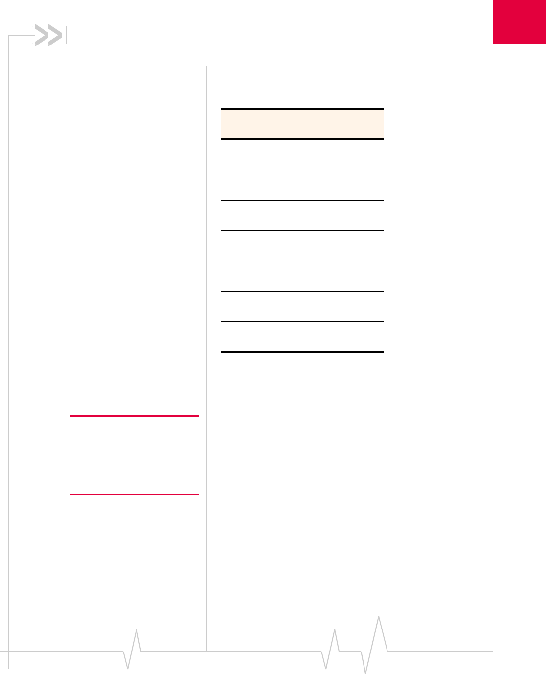
Table 3-1: EM878x — Supported frequencies
Band Frequencies
(MHz)
GSM 850 Tx: 824–849
Rx: 869-894
EGSM 900 Tx: 880-915
Rx: 925-960
DCS 1800 Tx: 1710-1785
Rx: 1805-1880
PCS 1900 Tx: 1850-1910
Rx: 1930-1990
Band I
UMTS 2100 Tx: 1920–1980
Rx: 2110–2170
Band II
UMTS 1900 Tx: 1850–1910
Rx: 1930–1990
Band V
UMTS 850 Tx: 824–849
Rx: 869–894
GSM Embedded Modems Hardware Integration Guide
16 2130851
In the event of a discrepancy in values between this guide and the Product Specification Document (PSD), the PSD takes precedence.
Figure 3-1: Antenna connection points and mounting tabs/clip
Ground connection
Whenconnectingthemoduletosystemground:
•Preventnoiseleakagebyestablishingaverygoodground
connectiontothemodulethroughthehostconnector.
•Connecttosystemgroundusingthemountingtabsatthe
topandbottomofthemodule(asshowninFigure3‐1on
page16).
•MinimizegroundnoiseleakageintotheRF.
Dependingonthehostboarddesign,noisecouldpotentially
becoupledtothemodulefromthehostboard.Thisis
mainlyanissueforhostdesignsthathavesignalstraveling
alongthelengthofthemodule,orcircuitryoperatingat
bothendsofthemoduleinterconnects.
Shielding
ThemoduleisfullyshieldedtoprotectagainstEMIandto
ensurecompliancewithFCCPart15‐“RadioFrequency
Devices”(orequivalentregulationsinotherjurisdictions).
Note: The module shields must NOT be removed.
EM8780/8781:
GPS connector
Diversity RF connector
Main RF connector
Mounting tabs/clip

RF Integration
Rev 1.0 Apr.07 17
Values in this guide are summarized from the product specification documents (PSDs) - the PSD takes precedence.
Antenna and cabling
Note: Values in this guide are
taken from the appropriate
product specification documents
(PSDs) (listed in
Related
documents
, page 9). In the case
of a discrepancy between this
document and the relevant PSD,
use the value listed in the PSD.
Whenselectingtheantennaandcable,itiscriticaltoRFperfor‐
mancetomatchantennagainandcableloss.
Choosing the correct antenna and cabling
Considerthefollowingpointsforpropermatchingofantennas
andcabling:
•Theantenna(andassociatedcircuitry)shouldhavea
nominalimpedanceof50Ωwithareturnloss≤ 10dB
acrosseachfrequencybandofoperation.
•Thesystemgainvalueaffectsbothradiatedpowerand
regulatory(FCC,IC,CE,etc.)testresults.
Developing custom antennas
Considerthefollowingpointswhendevelopingcustom‐
designedantennas:
•AskilledRFengineershoulddothedevelopmenttoensure
thattheRFperformanceismaintained.
•Identifythebandsthatneedtobesupported.
Determining the antenna’s location
Considerthefollowingpointswhendecidingwheretoputthe
antenna:
•AntennalocationmayaffectRFperformance.Althoughthe
moduleisshieldedtopreventinterferenceinmostapplica‐
tions,theplacementoftheantennaisstillveryimportant—
ifthehostdeviceisinsufficientlyshielded,highlevelsof
broadbandorspuriousnoisecandegradethemodule’s
performance.
•Connectingcablesbetweenthemoduleandtheantenna
musthave50Ωimpedance.Iftheimpedanceofthemodule
ismismatched,RFperformanceisreducedsignificantly.
•Antennacablesshouldberouted,ifpossible,awayfrom
noisesources(switchingpowersupplies,LCDassemblies,
etc.).Ifthecablesarenearthenoisesources,thenoisemay
becoupledintotheRFcableandintotheantenna.
Disabling the diversity antenna
Ifyourhostdeviceisnotdesignedtousethemodule’s
diversityantenna,terminatetheinterfacewitha50Ω ohm
load.

GSM Embedded Modems Hardware Integration Guide
18 2130851
In the event of a discrepancy in values between this guide and the Product Specification Document (PSD), the PSD takes precedence.
Interference and sensitivity
Note: These modules are based
on ZIF (Zero Intermediate
Frequency) technologies; when
performing EMC
(Electromagnetic Compatibility)
tests, there are no IF
(Intermediate Frequency)
components from the module to
consider.
SeveralsourcesofinterferencecanaffecttheRFperformance
ofthemodule(RFdesense).Commonsourcesincludepower
supplynoiseanddevice‐generatedRF.
RFdesensecanbeaddressedthroughacombinationof
mitigationtechniquesandradiatedsensitivitymeasurement.
Power supply noise
NoiseinthepowersupplycanleadtonoiseintheRFsignal.
Note: Values in this guide are
taken from the appropriate
product specification documents
(PSDs) (listed in
Related
documents
, page 9). In the case
of a discrepancy between this
document and the relevant PSD,
use the value listed in the PSD.
Thepowersupplyripplelimitforthemoduleisnomorethan
200mVp‐p1Hzto100kHz.Thislimitincludesvoltageripple
duetotransmitterburstactivity.
Interference from other wireless devices
Wirelessdevicesoperatinginsidethehostdevicecancause
interferencethataffectsthemodule.
Todeterminethemostsuitablelocationsforantennasonyour
hostdevice,evaluateeachwirelessdevice’sradiosystem,
consideringthefollowing:
•Anyharmonics,sub‐harmonics,orcross‐productsofsignals
generatedbywirelessdevicesthatfallinthemodule’sRx
rangemaycausespuriousresponse,resultingindecreased
Rxperformance.
•TheTxpowerandcorrespondingbroadbandnoiseofother
wirelessdevicesmayoverloadorincreasethenoisefloorof
themodule’sreceiver,resultinginRxdesense.
Theseverityofthisinterferencedependsontheclosenessof
theotherantennastothemodule’santenna.Todetermine
suitablelocationsforeachwirelessdevice’santenna,
thoroughlyevaluateyourhostdevice’sdesign.

RF Integration
Rev 1.0 Apr.07 19
Values in this guide are summarized from the product specification documents (PSDs) - the PSD takes precedence.
Device-generated RF
Note: The module can cause
interference with other devices
such as hearing aids and on-
board speakers.
Wireless devices such as the
embedded module transmit in
bursts (pulse transients) for set
durations (RF burst frequencies).
Hearing aids and speakers
convert these burst frequencies
into audible frequencies,
resulting in audible noise.
AllelectroniccomputingdevicesgenerateRFinterferencethat
cannegativelyaffectthereceivesensitivityofthemodule
(RFdesense).
Theproximityofhostelectronicstotheantennainwireless
devicescancontributetoRFdesense.Componentsthatare
mostlikelytocauseRFdesenseinclude:
•Microprocessorandmemory
•Displaypanelanddisplaydrivers
•Switching‐modepowersupplies
Theseandotherhigh‐speeddevices(inparticular,the
processor)cancauseRFdesensebecausetheyrunat
frequenciesoftensofMHz.Therapidriseandfallofthese
clocksignalsgenerateshigher‐orderharmonicsthatoftenfall
withintheoperatingfrequencybandofthemodule,causing
RFdesense.
Example
Onasub‐systemrunningat40MHz,the22ndharmonicfalls
at880MHz,whichiswithinthecellularreceivefrequency
band.
Note: In practice, there are usually numerous interfering frequencies
and harmonics. The net effect can be a series of desensitized receive
channels.

GSM Embedded Modems Hardware Integration Guide
20 2130851
In the event of a discrepancy in values between this guide and the Product Specification Document (PSD), the PSD takes precedence.

4
Rev 1.0 Apr.07 21
4: Regulatory Information
Important notice
Becauseofthenatureofwirelesscommunications,trans‐
missionandreceptionofdatacanneverbeguaranteed.Data
maybedelayed,corrupted(i.e.,haveerrors)orbetotallylost.
Althoughsignificantdelaysorlossesofdataarerarewhen
wirelessdevicessuchastheSierraWirelessmodemareusedin
anormalmannerwithawell‐constructednetwork,theSierra
Wirelessmodemshouldnotbeusedinsituationswherefailure
totransmitorreceivedatacouldresultindamageofanykind
totheuseroranyotherparty,includingbutnotlimitedto
personalinjury,death,orlossofproperty.SierraWirelessand
itsaffiliatesacceptnoresponsibilityfordamagesofanykind
resultingfromdelaysorerrorsindatatransmittedorreceived
usingtheSierraWirelessmodem,orforfailureoftheSierra
Wirelessmodemtotransmitorreceivesuchdata.
Safety and hazards
DonotoperateyourEM8780/EM8781modem:
•Inareaswhereblastingisinprogress
•Whereexplosiveatmospheresmaybepresentincluding
refuellingpoints,fueldepots,andchemicalplants
•Nearmedicalequipment,lifesupportequipment,orany
equipmentwhichmaybesusceptibletoanyformofradio
interference.Insuchareas,theEM8780/EM8781modem
MUSTBEPOWEREDOFF.Otherwise,theEM878x
modemcantransmitsignalsthatcouldinterferewiththis
equipment.
Inanaircraft,theEM8780/EM8781modemMUSTBE
POWEREDOFF.Otherwise,theEM8780/EM8781modemcan
transmitsignalsthatcouldinterferewithvariousonboard
systemsandmaybedangeroustotheoperationoftheaircraft
ordisruptthecellularnetwork.Useofacellularphoneinan
aircraftisillegalinsomejurisdictions.Failuretoobservethis
instructionmayleadtosuspensionordenialofcellular
telephoneservicestotheoffender,orlegalactionorboth.
Someairlinesmaypermittheuseofcellularphoneswhilethe
aircraftisonthegroundandthedoorisopen.TheEM8780/
EM8781modemmaybeusednormallyatthistime.

GSM Embedded Modems Hardware Integration Guide
22 2130851
Important compliance
information for North American
users
TheEM8780/EM8781modemhasbeengrantedmodular
approvalformobileapplications.Integratorsmayusethe
EM8780/EM8781modemintheirfinalproductswithout
additionalFCC/IC(IndustryCanada)certificationifthey
meetthefollowingconditions.Otherwise,additionalFCC/IC
approvalsmustbeobtained.
1. Atleast20cmseparationdistancebetweentheantennaand
theuser’sbodymustbemaintainedatalltimes.
2. TocomplywithFCC/ICregulationslimitingbothmaximum
RFoutputpowerandhumanexposuretoRFradiation,the
maximumantennagainincludingcablelossinamobile‐only
exposureconditionmustnotexceed:
·5dBiintheCellularbandand4dBiinthePCSbandforthe
EM8780/EM8781modem
3. TheEM8780/EM8781modemanditsantennamustnotbe
co‐locatedoroperatinginconjunctionwithanyother
transmitterorantennawithinahostdevice.
4. Alabelmustbeaffixedtotheoutsideoftheendproductinto
whichtheEM8780/EM8781modemisincorporated,witha
statementsimilartothefollowing:
·ForEM8780:
ThisdevicecontainsFCCID:N7NEM8780
·ForEM8781:
ThisdevicecontainsFCCID:N7NEM8781
Thisequipmentcontainsequipmentcertifiedunder
IC:2417C‐EM8781
5. Ausermanualwiththeendproductmustclearlyindicatethe
operatingrequirementsandconditionsthatmustbeobserved
toensurecompliancewithcurrentFCC/ICRFexposure
guidelines.
TheendproductwithanembeddedEM8780/EM8781modem
mayalsoneedtopasstheFCCPart15unintentionalemission
testingrequirementsandbeproperlyauthorizedperFCCPart
15whereapplicable.
Note:Ifthismoduleisintendedforuseinaportabledevice,
youareresponsibleforseparateapprovaltosatisfytheSAR
requirementsofFCCPart2.1093andICRSS‐102.
A
Rev 1.0 Apr.07 23
A: Acronyms and Definitions
.
Table A-1: Acronyms and definitions
Acronym or term Definition
BER Bit Error Rate — a measure of receive sensitivity
BLER Block Error Rate
dB Decibel = 10 x log10 (P1/P2)
P1 is calculated power; P2 is reference power
Decibel = 20 x log10 (V1/V2)
V1 is calculated voltage, V2 is reference voltage
dBm Decibels, relative to 1 mW - Decibel(mW) = 10 x log10 (Pwr (mW)/
1mW)
EDGE Enhanced Data rates for GSM Evolution
EM Embedded Module
EM8780/EM8781 Sierra Wireless embedded modules used on GSM networks
ESD ElectroStatic Discharge
GPRS General Packet Radio Services
GPS Global Positioning System — a system that uses a series of 24
geosynchronous satellites to provide navigational data.
GSM Global System for Mobile communications
HSDPA High Speed Download Packet Access. An add-on data service to
GSM mobile phone networks.
Hz Hertz = 1 cycle/second
IS-95 2G radio standards targeted for voice (cdmaONE)
MHz MegaHertz = 10E6 Hertz (Hertz = 1 cycle/second)
PCS Personal Communication System — PCS spans the 1.9 GHz radio
spectrum
RF Radio Frequency
RUIM Removable User Identity Module
SCI Slot Cycle Index
Sensitivity (RF) Measure of lowest power signal at the receiver input that can
provide a prescribed BER/BLER/SNR value at the receiver output.
GSM Embedded Modems Hardware Integration Guide
24 2130851
SIM Subscriber Identity Module
SNR Signal to Noise Ratio
UMTS Universal Mobile Telecommunications System. See also WCDMA.
USB Universal Serial Bus
USIM Universal Subscriber Identity Module
WCDMA Wideband Code Division Multiple Access. In this document, the
term “UMTS” is used instead of “WCDMA”.
Table A-1: Acronyms and definitions
Acronym or term Definition

Rev 1.0 Apr.07 25
Index
A
acronymsanddefinitions 23–24
airplanemode 12
antenna
connectionandmountingpoints 16
connectionconsiderations 15
custom,considerations 17
diversityantenna,disabling 17
limit,matchingcoaxialconnections 15
location,considerations 17
matching,considerations 17
maximumcableloss 15
ATcommands
3GPPspecification,details 9
lowpowermode,setting 12
ATcommands,extended
EM878x,reference 9
ATcommands,standard
EM878x,reference 9
C
cableloss
antenna,maximum 15
CnS
EM878xreference 9
connection
grounding 16
connectors,required
host‐module 7–8
RF,IPEX 7
USIM/RUIM 7
current
consumption 13
usagemodels 13
D
DCS1800
RFparameters,EM878x 15
desense.SeeRF
diversityantenna
disabling 17
E
EGSM900
RFparameters,EM878x 15
electrostaticdischarge.SeeESD
EM878x
ATreference(extended) 9
ATreference(standard) 9
CnSreference, 9
productspecification 9
RFparameters 15
ESD
protectionrequirements 11
testingtechniquesdocument(IEC‐61000‐4‐2) 9
F
FCC
regulations,relevantsection 9
G
grounding
connectionconsiderations 16
GSM850
RFparameters,EM878x 15
I
impedance
module‐antenna 17
interference
devicegenerated 19
powersupplynoise 18
wirelessdevices 18
L
LabAdapterBoard 7
lowpowermode
setting,ATcommands 12
lowpower,modulepowerstate 12
M
module
powerstates 12
N
noise
leakage,minimizing 16
RFinterference,powersupply 18
normal,modulepowerstate 12
O
off,modulepowerstate 12

GSM Embedded Modems Hardware Integration Guide
26 2130851
P
PCS1900
RFparameters,EM878x 15
power
defaultstate 12
disconnected,characteristics 12
normal,characteristics 12
signals,overview 11
state,lowpower 12
state,normal 12
state,off 12
supply,RFinterference 18
supply,ripplelimit 18
powerinterface 11–13
PSD
EM878x 9
R
regulatoryinformation 21–22
FCC 22
limitationofliability 21
safetyandhazards 21
RF
antennacableloss,maximum 15
antennaconnection,considerations 15
cabletype,required 7
desense
device‐generated 19
integration 15–19
interference
otherdevices 19
powersupply 18
wirelessdevices 18
parameters
DCS1800 15
EGSM900 15
EM878x 15
GSM850 15
PCS1900 15
UMTS1900 15
UMTS2100 15
UMTS850 15
S
shielding
module,compliance 16
SIM
testingmethods,MSconformancespecification 9
SIM.SeeUSIM/RUIM
T
testing
ESDimmunity,techniquesdocument(IEC‐61000‐
4‐2) 9
U
UMTS1900
RFparameters,EM878x 15
UMTS2100
RFparameters,EM878x 15
UMTS850
RFparameters,EM878x 15
UniversalSerialBus.SeeUSB
usagemodels
currentconsumption 13
USB
specification 9
USIM/RUIM
connectortype,required 7
Z
ZIF(ZeroIntermediateFrequency) 18
