Sierra Wireless HL7548 Module User Manual
Sierra Wireless Inc. Module
UserManual.wiki
>
Sierra Wireless
>
HL7548 User Manual
User Manual
Navigation menu
Upload a User Manual
Namespaces
Wiki Guide
HTML
PDF
Info
Views
User Manual
Discussion / Help
Navigation
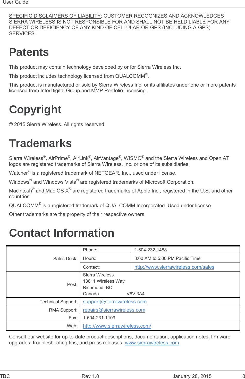
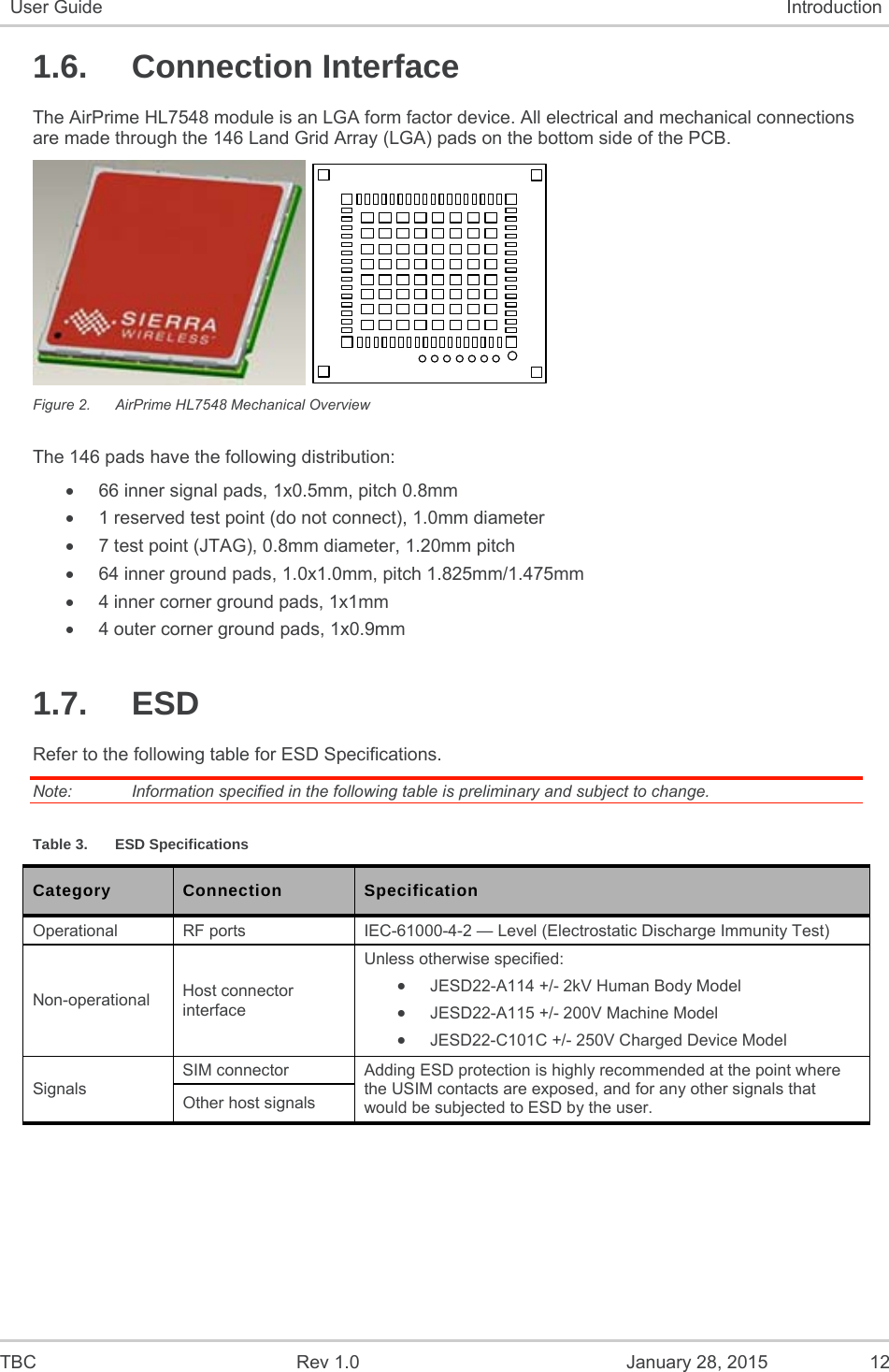
![TBC Rev 1.0 January 28, 2015 14 User Guide Introduction electrical and electronic equipment put on the market does not contain lead, mercury, cadmium, hexavalent chromium, polybrominated biphenyls (PBB) or polybrominated diphenyl ethers (PBDE)”. 1.8.4. Disposing of the Product This electronic product is subject to the EU Directive 2012/19/EU for Waste Electrical and Electronic Equipment (WEEE). As such, this product must not be disposed of at a municipal waste collection point. Please refer to local regulations for directions on how to dispose of this product in an environmental friendly manner. 1.8.5. References [1] AirPrime HL Series Customer Process Guidelines Reference Number: 4114330 [2] AirPrime HL7519, HL7548 and HL7588 AT Commands Interface Guide Reference Number: TBC](https://usermanual.wiki/Sierra-Wireless/HL7548/User-Guide-2528636-Page-14.png)