Sierra Wireless MC8301 Multi-band Radio Module User Manual HW Integration Guide
Sierra Wireless Inc. Multi-band Radio Module HW Integration Guide
Manual

2130114
Rev 1.12.5
CDMA and GSM / UMTS Mini Card
Hardware Integration Guide
Proprietary and Confidential
Includes:
MC5725 MC8301V
MC5725V MC8775
MC5727 MC8775V
MC5727V MC8780
MC5728V MC8781
MC8790
MC8790V
MC8791V
MC8792V
MC8795V
MC8700

Preface
Rev 1.12.5 Jan.10 Proprietary and Confidential 3
In the event of a discrepancy in values between this guide and the Product Specification Document (PSD), the PSD takes precedence.
Important Notice Duetothenatureofwirelesscommunications,transmission
andreceptionofdatacanneverbeguaranteed.Datamaybe
delayed,corrupted(i.e.,haveerrors)orbetotallylost.
Althoughsignificantdelaysorlossesofdataarerarewhen
wirelessdevicessuchastheSierraWirelessmodemareusedin
anormalmannerwithawell‐constructednetwork,theSierra
Wirelessmodemshouldnotbeusedinsituationswherefailure
totransmitorreceivedatacouldresultindamageofanykind
totheuseroranyotherparty,includingbutnotlimitedto
personalinjury,death,orlossofproperty.SierraWireless
acceptsnoresponsibilityfordamagesofanykindresulting
fromdelaysorerrorsindatatransmittedorreceivedusingthe
SierraWirelessmodem,orforfailureoftheSierraWireless
modemtotransmitorreceivesuchdata.
Safety and Hazards DonotoperatetheSierraWirelessmodeminareaswhere
blastingisinprogress,whereexplosiveatmospheresmaybe
present,nearmedicalequipment,nearlifesupportequipment,
oranyequipmentwhichmaybesusceptibletoanyformof
radiointerference.Insuchareas,theSierraWirelessmodem
MUSTBEPOWEREDOFF.TheSierraWirelessmodemcan
transmitsignalsthatcouldinterferewiththisequipment.
DonotoperatetheSierraWirelessmodeminanyaircraft,
whethertheaircraftisonthegroundorinflight.Inaircraft,the
SierraWirelessmodemMUSTBEPOWEREDOFF.When
operating,theSierraWirelessmodemcantransmitsignalsthat
couldinterferewithvariousonboardsystems.
Note: Some airlines may permit the use of cellular phones while the
aircraft is on the ground and the door is open. Sierra Wireless
modems may be used at this time.
Thedriveroroperatorofanyvehicleshouldnotoperatethe
SierraWirelessmodemwhileincontrolofavehicle.Doingso
willdetractfromthedriveroroperatorʹscontrolandoperation
ofthatvehicle.Insomestatesandprovinces,operatingsuch
communicationsdeviceswhileincontrolofavehicleisan
offence.
Limitation of
Liability
Theinformationinthismanualissubjecttochangewithout
noticeanddoesnotrepresentacommitmentonthepartof
SierraWireless.SIERRAWIRELESSANDITSAFFILIATES
SPECIFICALLYDISCLAIMLIABILITYFORANYANDALL
DIRECT,INDIRECT,SPECIAL,GENERAL,INCIDENTAL,
CONSEQUENTIAL,PUNITIVEOREXEMPLARYDAMAGES
INCLUDING,BUTNOTLIMITEDTO,LOSSOFPROFITSOR

CDMA and GSM / UMTS Mini Card Hardware Integration Guide
4 Proprietary and Confidential 2130114
In the event of a discrepancy in values between this guide and the Product Specification Document (PSD), the PSD takes precedence.
REVENUEORANTICIPATEDPROFITSORREVENUE
ARISINGOUTOFTHEUSEORINABILITYTOUSEANY
SIERRAWIRELESSPRODUCT,EVENIFSIERRAWIRELESS
AND/ORITSAFFILIATESHASBEENADVISEDOFTHE
POSSIBILITYOFSUCHDAMAGESORTHEYARE
FORESEEABLEORFORCLAIMSBYANYTHIRDPARTY.
Notwithstandingtheforegoing,innoeventshallSierra
Wirelessand/oritsaffiliatesaggregateliabilityarisingunderor
inconnectionwiththeSierraWirelessproduct,regardlessof
thenumberofevents,occurrences,orclaimsgivingriseto
liability,beinexcessofthepricepaidbythepurchaserforthe
SierraWirelessproduct.
Patents Portionsofthisproductmaybecoveredbysomeorallofthe
followingUSpatents:
5,515,013 5,629,960 5,845,216 5,847,553 5,878,234
5,890,057 5,929,815 6,169,884 6,191,741 6,199,168
6,339,405 6,359,591 6,400,336 6,516,204 6,561,851
6,643,501 6,653,979 6,697,030 6,785,830 6,845,249
6,847,830 6,876,697 6,879,585 6,886,049 6,968,171
6,985,757 7,023,878 7,053,843 7,106,569 7,145,267
7,200,512 7,295,171 7,287,162 D442,170 D459,303
D599,256 D560,911
andotherpatentspending.
Thisproductincludestechnologylicensedfrom
QUALCOMM®3G.
ManufacturedorsoldbySierraWirelessoritslicenseesunder
oneormorepatentslicensedfromInterDigitalGroup.
Copyright ©2010SierraWireless.Allrightsreserved.
Trademarks AirCard®and“HeartoftheWirelessMachine®”areregistered
trademarksofSierraWireless.Watcher®isatrademarkof
SierraWireless,registeredintheEuropeanCommunity.
SierraWireless,theSierraWirelesslogo,theredwavedesign,
andthered‐tippedantennaaretrademarksofSierraWireless.
Windows®isaregisteredtrademarkofMicrosoftCorporation.
QUALCOMM®isaregisteredtrademarkofQUALCOMM
Incorporated.Usedunderlicense.
Linux®isaregisteredtrademarkofLinusTorvalds.
Othertrademarksarethepropertyoftherespectiveowners.

Preface
Rev 1.12.5 Jan.10 Proprietary and Confidential 5
In the event of a discrepancy in values between this guide and the Product Specification Document (PSD), the PSD takes precedence.
Contact
Information
Consultourwebsiteforup‐to‐dateproductdescriptions,
documentation,applicationnotes,firmwareupgrades,trouble‐
shootingtips,andpressreleases:
www.sierrawireless.com
Sales Desk: Phone: 1-604-232-1488
Hours: 8:00 AM to 5:00 PM Pacific Time
E-mail: sales@sierrawireless.com
Post: Sierra Wireless
13811 Wireless Way
Richmond, BC
Canada V6V 3A4
Fax: 1-604-231-1109
Web: www.sierrawireless.com

CDMA and GSM / UMTS Mini Card Hardware Integration Guide
6 Proprietary and Confidential 2130114
In the event of a discrepancy in values between this guide and the Product Specification Document (PSD), the PSD takes precedence.

Rev 1.12.5 Jan.10 Proprietary and Confidential 7
In the event of a discrepancy in values between this guide and the Product Specification Document (PSD), the PSD takes precedence.
Table of Contents
Introduction . . . . . . . . . . . . . . . . . . . . . . . . . . . . . . . . . . . . . . . . . . . . . . .9
The Universal Development Kit . . . . . . . . . . . . . . . . . . . . . . . . . . . . . . . . . . . . . . 9
Required connectors . . . . . . . . . . . . . . . . . . . . . . . . . . . . . . . . . . . . . . . . . . . . . . 10
Guide organization . . . . . . . . . . . . . . . . . . . . . . . . . . . . . . . . . . . . . . . . . . . . . . . . 10
Related documents. . . . . . . . . . . . . . . . . . . . . . . . . . . . . . . . . . . . . . . . . . . . . . . . 11
Power Interface . . . . . . . . . . . . . . . . . . . . . . . . . . . . . . . . . . . . . . . . . . .15
Overview of operation. . . . . . . . . . . . . . . . . . . . . . . . . . . . . . . . . . . . . . . . . . . . . . 15
Power signals . . . . . . . . . . . . . . . . . . . . . . . . . . . . . . . . . . . . . . . . . . . . . . . . . 15
Electrostatic discharge (ESD) . . . . . . . . . . . . . . . . . . . . . . . . . . . . . . . . . . . 15
Module power states . . . . . . . . . . . . . . . . . . . . . . . . . . . . . . . . . . . . . . . . . . . . . . 16
Disconnected state . . . . . . . . . . . . . . . . . . . . . . . . . . . . . . . . . . . . . . . . . . . . 16
Off state . . . . . . . . . . . . . . . . . . . . . . . . . . . . . . . . . . . . . . . . . . . . . . . . . . . . . . 17
Normal state . . . . . . . . . . . . . . . . . . . . . . . . . . . . . . . . . . . . . . . . . . . . . . . . . . 17
Low power mode . . . . . . . . . . . . . . . . . . . . . . . . . . . . . . . . . . . . . . . . . . . . . . 17
Usage models . . . . . . . . . . . . . . . . . . . . . . . . . . . . . . . . . . . . . . . . . . . . . . . . . 17
RF Integration . . . . . . . . . . . . . . . . . . . . . . . . . . . . . . . . . . . . . . . . . . . .19
RF connection . . . . . . . . . . . . . . . . . . . . . . . . . . . . . . . . . . . . . . . . . . . . . . . . . . . . 20
Ground connection . . . . . . . . . . . . . . . . . . . . . . . . . . . . . . . . . . . . . . . . . . . . . . . . 21
Shielding . . . . . . . . . . . . . . . . . . . . . . . . . . . . . . . . . . . . . . . . . . . . . . . . . . . . . 22
Antenna and cabling . . . . . . . . . . . . . . . . . . . . . . . . . . . . . . . . . . . . . . . . . . . 22
Interference and sensitivity . . . . . . . . . . . . . . . . . . . . . . . . . . . . . . . . . . . . . . . . . 23
Power supply noise . . . . . . . . . . . . . . . . . . . . . . . . . . . . . . . . . . . . . . . . . . . . 23
Interference from other wireless devices . . . . . . . . . . . . . . . . . . . . . . . . . . 23
Device-generated RF . . . . . . . . . . . . . . . . . . . . . . . . . . . . . . . . . . . . . . . . . . . 24
Audio Interface . . . . . . . . . . . . . . . . . . . . . . . . . . . . . . . . . . . . . . . . . . .25

CDMA and GSM / UMTS Mini Card Hardware Integration Guide
8 Proprietary and Confidential 2130114
In the event of a discrepancy in values between this guide and the Product Specification Document (PSD), the PSD takes precedence.
System block diagrams . . . . . . . . . . . . . . . . . . . . . . . . . . . . . . . . . . . . . . . . . 26
Modes of operation . . . . . . . . . . . . . . . . . . . . . . . . . . . . . . . . . . . . . . . . . . . . 29
Sidetone support . . . . . . . . . . . . . . . . . . . . . . . . . . . . . . . . . . . . . . . . . . . . . . 29
Echo cancellation support . . . . . . . . . . . . . . . . . . . . . . . . . . . . . . . . . . . . . . 30
Audio signal interface . . . . . . . . . . . . . . . . . . . . . . . . . . . . . . . . . . . . . . . . . . 31
Audio function partitioning . . . . . . . . . . . . . . . . . . . . . . . . . . . . . . . . . . . . . 32
Host / Module Interfaces . . . . . . . . . . . . . . . . . . . . . . . . . . . . . . . . . . 35
LED output . . . . . . . . . . . . . . . . . . . . . . . . . . . . . . . . . . . . . . . . . . . . . . . . . . . 35
Regulatory Information . . . . . . . . . . . . . . . . . . . . . . . . . . . . . . . . . . . 37
Important notice . . . . . . . . . . . . . . . . . . . . . . . . . . . . . . . . . . . . . . . . . . . . . . . . . . 37
Safety and hazards . . . . . . . . . . . . . . . . . . . . . . . . . . . . . . . . . . . . . . . . . . . . . . . . 37
Important compliance information for North American users . . . . . . . . . . . 38
EU regulatory conformity. . . . . . . . . . . . . . . . . . . . . . . . . . . . . . . . . . . . . . . . . . . 39
Brazil ANATEL homologation . . . . . . . . . . . . . . . . . . . . . . . . . . . . . . . . . . . . . . . 40
Acronyms and Definitions . . . . . . . . . . . . . . . . . . . . . . . . . . . . . . . . . 41
Index . . . . . . . . . . . . . . . . . . . . . . . . . . . . . . . . . . . . . . . . . . . . . . . . . . . . 45

1
Rev 1.12.5 Jan.10 Proprietary and Confidential 9
In the event of a discrepancy in values between this guide and the Product Specification Document (PSD), the PSD takes precedence.
1: Introduction
SierraWireless’MiniCardmodulesformtheradiocomponent
fortheproductsinwhichtheyareembedded.MiniCardsare
availableforuseonCDMAandGSMnetworks,including:
Note: Throughout this
document, MC57xx and MC8xxx
refer to the entire suites of
CDMA and GSM Mini Cards
respectively.
•MC5725/MC5725V/MC5727/MC5727V/MC5728V—Operate
onCDMAnetworksusingtheCDMAIS‐95A,1X,and
1xEV‐DO(IS‐856)networkstandards,andsupportGPS.
•MC8775 / MC8775V—OperateonGSMnetworksusingthe
GSM/GPRS/EDGE/UMTS/HSDPAnetworkstandards,
andsupportStandaloneGPSfunctionality.
•MC8301V / MC8780 / MC8781 / MC8790 / MC8790V / MC8791V /
MC8792V / MC8795V—OperateonGSMnetworksusingthe
GSM/GPRS/EDGE/UMTS/HSDPA/HSUPAnetwork
standards,andsupportStandaloneGPS,gpsOneXTRA™,
A‐GPS,selectedenhancedNavigation2.0features,andfive
NMEAsentences.
•MC8700—OperatesonGSMnetworksusingtheGSM/
GPRS/EDGE/UMTS/HSDPA/HSUPA/HSPA+network
standards.
Purpose of this guide
ThisguideaddressesissuesthataffecttheintegrationofSierra
Wirelessmodulesintohostproducts,andincludesdesign
recommendationsforthehostproducts.
Note: An understanding of network technology and experience in
integrating hardware components into electronic equipment is
assumed.
The Universal Development Kit
SierraWirelessmanufacturesaUniversalDevelopmentKit
(UDK)thatfacilitatesallphasesoftheintegrationprocess.
Thiskitisahardwaredevelopmentplatformthatisdesigned
tosupportmultiplemembersofthewirelessembedded
moduleproductfamily.Itcontainsthehardwarecomponents
thataretypicallynecessaryforevaluatinganddevelopingwith
themodule,including:
•Developmentboard
•Cables
•Antennas
•Otheraccessories

CDMA and GSM / UMTS Mini Card Hardware Integration Guide
10 Proprietary and Confidential 2130114
In the event of a discrepancy in values between this guide and the Product Specification Document (PSD), the PSD takes precedence.
ForinstructionsonsettinguptheUDK,seePCIExpressMini
CardDevKitQuickStartGuide(Document2130705).
Required connectors
Note: Contact vendors before
choosing your connectors — the
numbers included here are for
reference only. Choose
connectors that are appropriate
to your design.
Whenintegratingthesemodulesintoyourhostdevice,you
needthefollowingconnectortypes:
•RFcablesthatmatewithHiroseU.FLconnectors(model
U.FL#CL331‐0471‐0‐10).Modulesincludeoneortwo
connectorjacksdependingonindividualmodulesupport
fordiversityorGPSfunctionality.
•Industry‐standardmatingconnectorfor52‐pinEDGE—
somemanufacturersincludeTyco,Foxconn,andMolex.For
example,theconnectorusedontheMiniCardDevKit
boardisaMolex67910‐0001.
•Industry‐standardUSIMconnector(MC8xxxonly)—the
actualconnectoryouusedependsonhowyourdevice
exposestheUSIMsocket.Forexample,theUSIMconnector
usedontheMiniCardDevKitboardisanITTCCM03‐
3518.
Guide organization
Thisguideincludesthefollowingsections:
1. Introduction(thissection)
2. Power Interface(p.15)
Describespowercontrolsignalsusedbythemoduleand
discussesdesignissuesrelatedtopowersupply
integration.
3. RF Integration(p.19)
Describesantennaconnectionmethodsandgroundingissues,
RFinterferenceanddesenseissues.
4. Audio Interface(p.25)
Describessupportedaudiomodesandrelateddetails.
5. Host / Module Interfaces(p.35)
DescribestheUSBinterfaceforhost/modulecommunication,
andtheUSIMinterfaceforhost/moduleintegration.
6. Regulatory Information(p.37)
Describesregulatoryapprovalsandregulatoryinformation
requirements.
7. Acronyms and Definitions(p.41)
Listsacronymsanddefinitionsusedthroughoutthisguide.
8. Index(p.121)
Note: The term "host" always refers to the host device.

Introduction
Rev 1.12.5 Jan.10 Proprietary and Confidential 11
In the event of a discrepancy in values between this guide and the Product Specification Document (PSD), the PSD takes precedence.
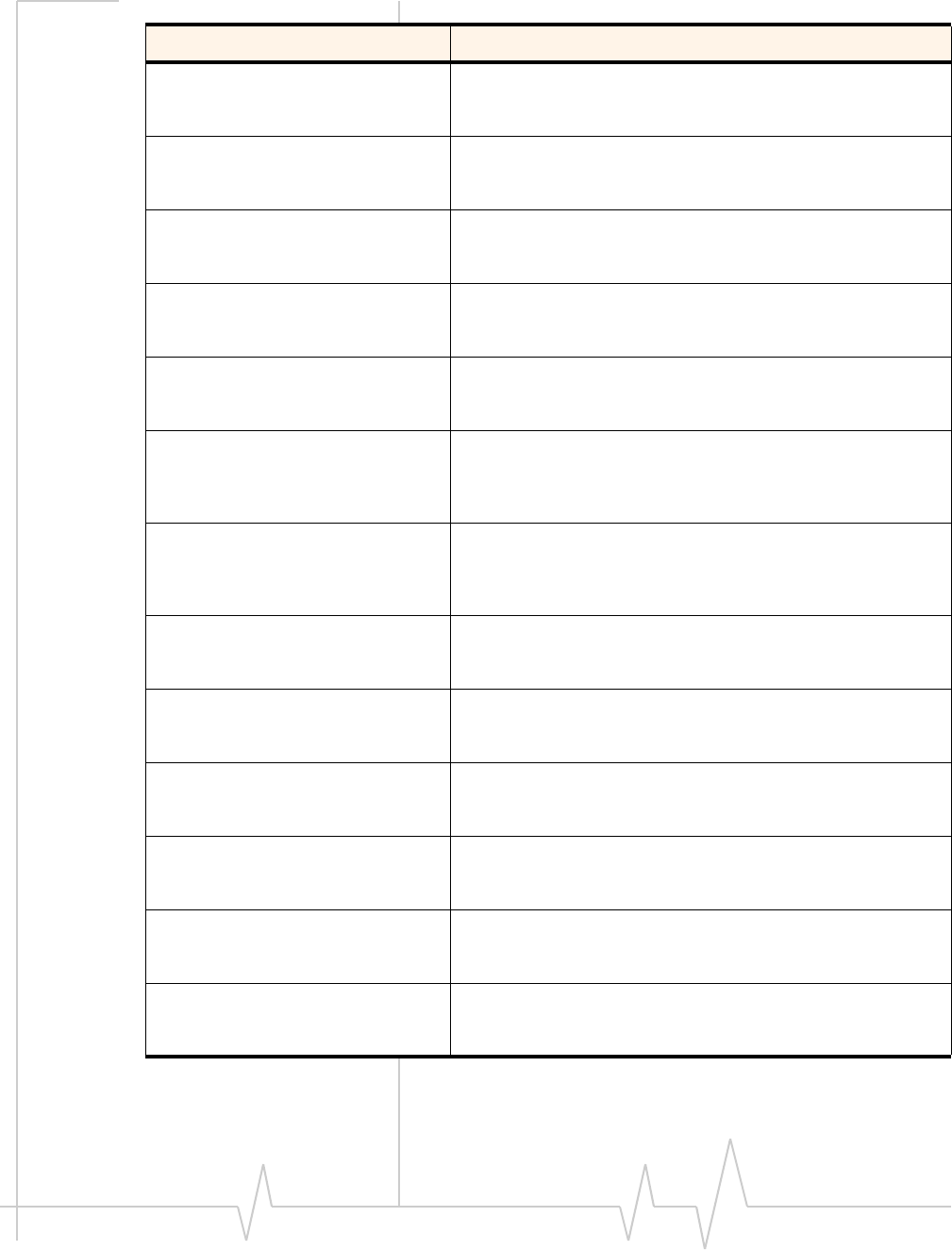
Related documents
Thisguidedealsspecificallywithhardwareintegrationissues
thatareuniquetotheMC57xxandMC8xxxmodules.
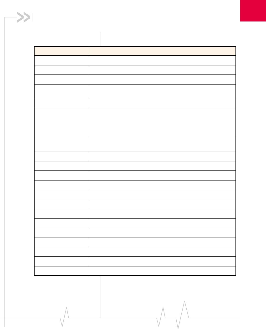
Table1‐1listsotherdocumentsreferencedinthisguide.
Table 1-1: Related documentation
Document title Description
AT Command Set for User
Equipment (UE) (Release 6) Standard AT commands for GSM / UMTS devices.
Download this document (3GPP TS 27.007) from
www.3gpp.org.
CDMA 1X Standard Technical requirements for CDMA systems, including
details on sleep cycle index (SCI) values.
Order this document, CDMA 2000 Series Release A
(2000) (document # TIA/EIA/IS-2000 Series, Release A)
from www.tiaonline.org.
CDMA CnS Reference
(Document 2130754) CnS (Control and Status) messages that are supported by
the MC5725 / MC5725V / MC5727 / MC5727V /
MC5728V.
CDMA AT Command Reference
(Document 2130620) Proprietary, basic AT commands for the MC5725 /
MC5725V / MC5727 / MC5727V / MC5728V.
For MC8xxx-specific commands, see UMTS Modems
Supported AT Command Reference (Document 2130617).
CDMA Extended AT Command
Reference (Document
2130621)
Proprietary AT commands for the MC5725 / MC5725V /
MC5727 / MC5727V / MC5728V.
For MC8xxx-specific commands, see MC87xx Modem
Extended AT Command Reference (Document 2130616).
FCC Regulations - Part 15 -
Radio Frequency Devices This section of the FCC Code of Federal Regulations, Title
47 deals with radio frequency devices, including shielding
requirements for embedded modules.
Download this regulation from http://wireless.fcc.gov.
IEC-61000-4-2 level 3 Techniques for testing and measuring electrostatic
discharge (ESD) immunity.
Order this document from www.iec.ch.
MC5725 Mini Card Product
Specification (Document
2130663)
Features, mechanical and electrical specifications, and
standards compliance of the MC5725.
MC5725V Mini Card Product
Specification (Document
2130671)
Features, mechanical and electrical specifications, and
standards compliance of the MC5725V.
CDMA and GSM / UMTS Mini Card Hardware Integration Guide
12 Proprietary and Confidential 2130114
In the event of a discrepancy in values between this guide and the Product Specification Document (PSD), the PSD takes precedence.
MC5727 Mini Card Product
Specification (Document
2130958)
Features, mechanical and electrical specifications, and
standards compliance of the MC5727.
MC5727V Mini Card Product
Specification (Document
2131023)
Features, mechanical and electrical specifications, and
standards compliance of the MC5727V.
MC5728V Mini Card Product
Specification (Document
2111350)
Features, mechanical and electrical specifications, and
standards compliance of the MC5728V.
MC8301V PCI Express Mini
Card Product Specification
(Document 2131326)
Features, mechanical and electrical specifications, and
standards compliance of the MC8301V.
MC8775 PCI Express Mini Card
Product Specification
(Document 2130697)
Features, mechanical and electrical specifications, and
standards compliance of the MC8775.
MC8775V with Audio PCI
Express Mini Card Product
Specification (Document
2130700)
Features, mechanical and electrical specifications, and
standards compliance of the MC8775V.
MC8780 / MC8781 PCI Express
Mini Card Product
Specification (Document
2130782)
Features, mechanical and electrical specifications, and
standards compliance of the MC8780 / MC8781.
MC8790 PCI Express Mini Card
Product Specification
(Document 2111279)
Features, mechanical and electrical specifications, and
standards compliance of the MC8790.
MC8790V PCI Express Mini
Card Product Specification
(Document 2111280)
Features, mechanical and electrical specifications, and
standards compliance of the MC8790V.
MC8791V PCI Express Mini
Card Product Specification
(Document 2131032)
Features, mechanical and electrical specifications, and
standards compliance of the MC8791V.
MC8792V PCI Express Mini
Card Product Specification
(Document 2131033)
Features, mechanical and electrical specifications, and
standards compliance of the MC8792V.
MC8795V PCI Express Mini
Card Product Specification
(Document 2131276)
Features, mechanical and electrical specifications, and
standards compliance of the MC8795V.
MC8700 PCI Express Mini Card
Product Specification
(Document 2131202)
Features, mechanical and electrical specifications, and
standards compliance of the MC8700.
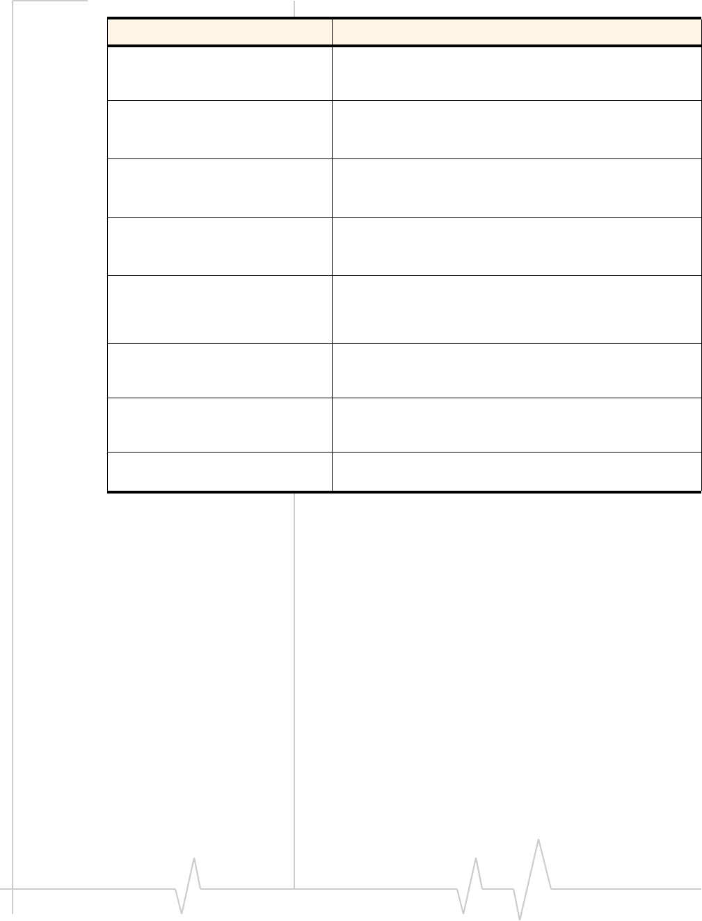
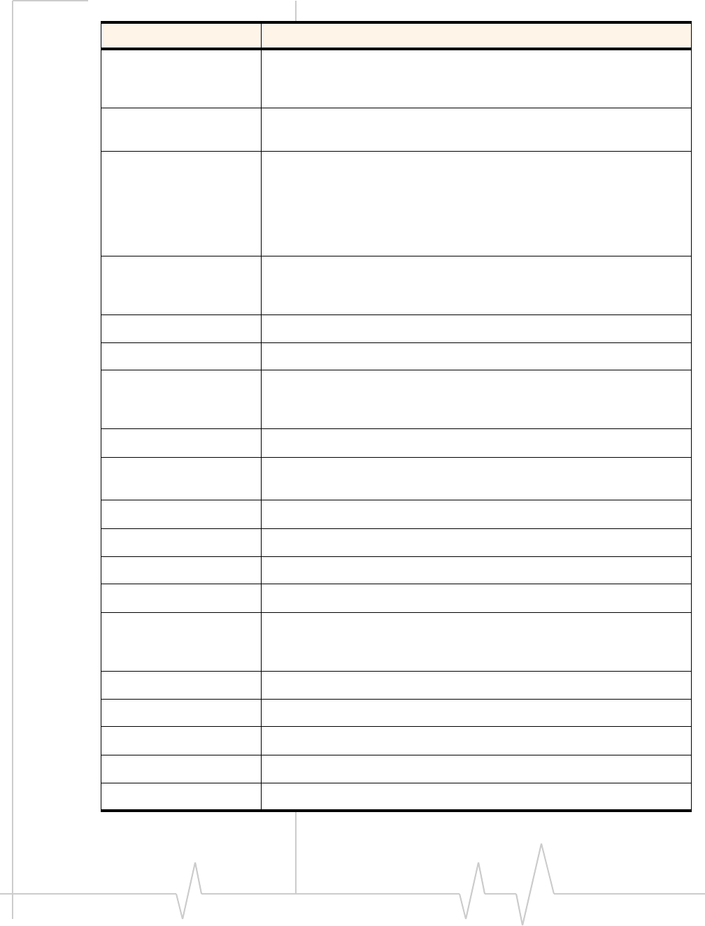
Table 1-1: Related documentation (Continued)
Document title Description
Introduction
Rev 1.12.5 Jan.10 Proprietary and Confidential 13
In the event of a discrepancy in values between this guide and the Product Specification Document (PSD), the PSD takes precedence.
MC87XX Modem CnS
Reference (Document
2130602)
CnS (Control and Status) messages supported by the
MC8xxx series of modems.
MC87xx Modem CnS Reference
(Voice) (Document 2130817) Voice-related CnS (Control and Status) messages
supported by the MC8301V, MC8775V,
MC8790V,MC8791V, and MC8792V, and MC8795V.
UMTS Modems Supported AT
Command Reference
(Document 2130617)
Proprietary, basic AT commands for the MC8xxx. For
MC57xx-specific commands, see the CDMA AT
Command Reference (Document 2130620).
MC87xx Modem Extended AT
Command Reference
(Document 2130616)
Proprietary AT commands for the MC8xxx. For MC57xx-
specific commands, see the CDMA Extended AT
Command Reference (Document 2130621).
Mobile Station (MS)
Conformance Specification;
Part 4: Subscriber Interface
Module
SIM testing methods.
Download this document (3GPP TS 11.10-4) from
www.3gpp.org.
PCI Express Mini Card Dev Kit
Quick Start Guide (Document
2130705)
Setup and configuration of modules.
PCI Express Mini Card
Electromechanical
Specification Revision 1.1
Download this document from www.pcisig.com.
Universal Serial Bus
Specification, Rev 2.0 Download this specification from www.usb.org.
Table 1-1: Related documentation (Continued)
Document title Description

CDMA and GSM / UMTS Mini Card Hardware Integration Guide
14 Proprietary and Confidential 2130114
In the event of a discrepancy in values between this guide and the Product Specification Document (PSD), the PSD takes precedence.

2
Rev 1.12.5 Jan.10 Proprietary and Confidential 15
In the event of a discrepancy in values between this guide and the Product Specification Document (PSD), the PSD takes precedence.
2: Power Interface
Overview of operation
Note: This chapter contains information for CDMA (MC57xx) and
GSM (MC8xxx) modules.
Information that is unique to specific module types is clearly
identified.
Themoduleisdesignedtousea3.3V(nominal)powersupply,
providedbythehost.Itisthehost’sresponsibilitytoprovide
safeandcontinuouspowertothemoduleatalltimes;the
moduledoesNOThaveanindependentpowersupply,or
protectioncircuitstoguardagainstelectricalissues.
Themodule’spowerstateiscontrolledbythehost’sassertion/
de‐assertionoftheW_Disable#signal.Themodulealso
monitorsitssupplyvoltageandrequestsshutdownifthe
supplyisinsufficient.
Power signals
Themodulemustbeconnectedtoa3.3Vpowersupply(as
describedinPCIExpressMiniCardElectromechanicalSpecifi‐
cationRevision1.1).
TheMC8xxxhasmorepowerpinsthantheMC57xxdueto
higherpeakcurrentrequirementsforGSMdevices.
Fordetailedpinoutandvoltage/currentrequirementsofthese
modules,seetheProductSpecificationDocumentforyour
MiniCard.
Electrostatic discharge (ESD)
Youareresponsibleforensuringthatthehosthasadequate
ESDprotectionondigitalcircuitsandantennaports:
•(Operational)RFport(antennalaunchandRFconnector):
IEC‐61000‐4‐2—Level(ElectrostaticDischargeImmunityTest)
•(Non‐operational)Hostconnectorinterface:
JESD22‐A114‐B+/‐1kVHumanBodyModeland
JESD22‐C101+/‐125VChargedDeviceModel
•MC5728Vonly:(Non‐operational)Hostconnectorinterface:
JESD22‐A114‐B+/‐200VHumanBodyModeland
JESD22‐C101+/‐250VChargedDeviceModel

CDMA and GSM / UMTS Mini Card Hardware Integration Guide
16 Proprietary and Confidential 2130114
In the event of a discrepancy in values between this guide and the Product Specification Document (PSD), the PSD takes precedence.
MC5728VhasplaceholdersforadditionalESDdevices,for
caseswherethedevicemust,percustomerrequirements,
meetthehigherHumanBodyModel(+/‐1kV)ESDrating.
Specificrecommendationsareprovidedwhereneededinthis
guide,however,thelevelofprotectionrequireddependson
yourapplication.
Note: ESD protection is highly recommended for the USIM connector
at the point where the contacts are exposed, and for any other signals
from the host interface that would be subjected to ESD by the user of
the product.
Module power states
Note: The module unit defaults
to the Normal state when
VCC3.3 is first applied in the
absence of W_Disable# control.
Themodulehasfourpowerstates:
•Disconnected
Nopowertothemodule.
•Off
Powertothemodule,butthemoduleispoweredoff.
•Normal
Themoduleisactive.Severalmodesarepossible(Receive,
Transmit,Sleep,Shutdown).
•Low power (“airplane mode”)
Themoduleisactive,butRFisdisabled.
Statemachinesareimplementedinthemoduletomonitorthe
powersupplyandoperatingtemperature.
Disconnected state
Note: The difference between
the Disconnected and Off states
is that, in the Off state, the
module is still connected to the
power source and draws minimal
current.
Thisstateoccurswhenthereisnopowertothemodule—the
hostpowersourceisdisconnectedfromthemoduleandall
voltagesassociatedwiththemoduleareat0V.
Whetherthehostdeviceisalsopoweredoffdependsonthe
powerraildesign.Iftheconnectionbetweenthepowerrail
andthemoduleiscontrolledbythehost,thehostcanstay
poweredonandcutthepowertoputthemodemintothe
disconnectedstate.Ifthepowerrailissharedbetweenthehost
deviceandthemodule,thehostispoweredoffwhenthe
moduleispoweredoff.
Power Interface
Rev 1.12.5 Jan.10 Proprietary and Confidential 17
In the event of a discrepancy in values between this guide and the Product Specification Document (PSD), the PSD takes precedence.
Off state
Inthisstate,thehostispoweredupandthemoduleis
powereddown(butstillconnectedtothepowersource).
Thehostkeepsthemodulepoweredoffbydrivingthe
W_Disable#signallow.Inthisstate,themoduledrawsminimal
current.
Normal state
Note: This is the default state
when VCC3.3 is first applied in
the absence of W_Disable#
control.
Thisistheactivestateofthemodule.Inthisstate:
•Themoduleisfullypowered.
•Themoduleiscapableofplacing/receivingcallsorestab‐
lishingdataconnectionsonthewirelessnetwork.
•TheUSBinterfaceisfullyactive.
Low power mode
Inthisstate,RF(bothRxandTx)isdisabledinthemodule,but
theUSBinterfaceisstillactive.Thislowpowermode
(ʺairplanemodeʺ)iscontrolledbysoftwarecommands
throughthehostinterface.
Forinstructionsonusingthecommands,refertoATCommand
SetforUserEquipment(UE)(Release6)(+CFUN=0command),
CDMACnSReference(Document2130754)
(CNS_RADIO_POWER[0x1075]command),orMC87XX
ModemCnSReference(Document2130602)(DisableModem
command).
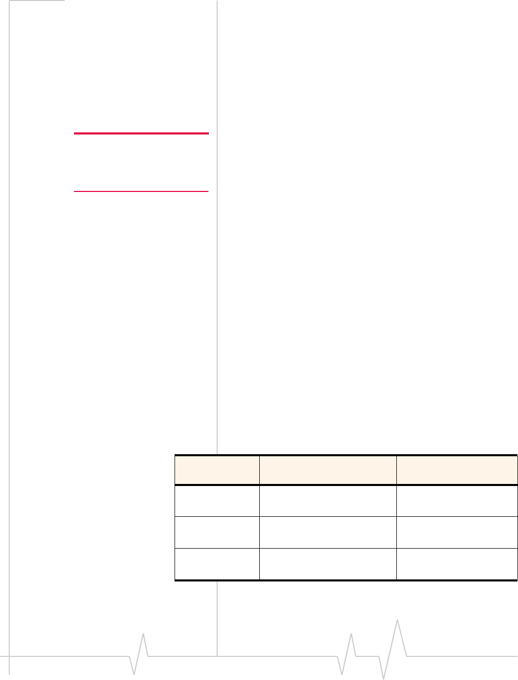
Usage models
Usagemodelscanbeusedtocalculateexpectedcurrent
consumption.AsampleusagemodelisprovidedinTable2‐1.
Table 2-1: Power consumption of a sample application
Used by a field worker
(data only) Used for remote data
logging
Upload (module
Tx) 1000 kB/day 40 kB/h
Download
(module Rx) 500 kB/day 100 kB/day
Coverage / data
rate 1X / 80 kbps IS-95 / 14.4 kbps

CDMA and GSM / UMTS Mini Card Hardware Integration Guide
18 Proprietary and Confidential 2130114
In the event of a discrepancy in values between this guide and the Product Specification Document (PSD), the PSD takes precedence.
Thisexamplemodelappliestoabattery‐operateddevice.In
practice,becausethemoduleisisolatedfromthebattery(the
hostdevicemanagesthepowersource),themAhratings
dependonthedevice’ssupplyefficiency.
Themoduleautomaticallyentersslottedsleepmodewhen
thereisnotransmissionorreceptionoccurring(SCI=2).
Transmitpowerisassumedtobe+3dBm.
Hours of
operation 8/day (off 16 hrs/day) 24/day
Total power
consumed over
24 hours
60 mAh 200 mAh
Table 2-1: Power consumption of a sample application (Continued)
Used by a field worker
(data only) Used for remote data
logging
3
Rev 1.12.5 Jan.10 Proprietary and Confidential 19
In the event of a discrepancy in values between this guide and the Product Specification Document (PSD), the PSD takes precedence.
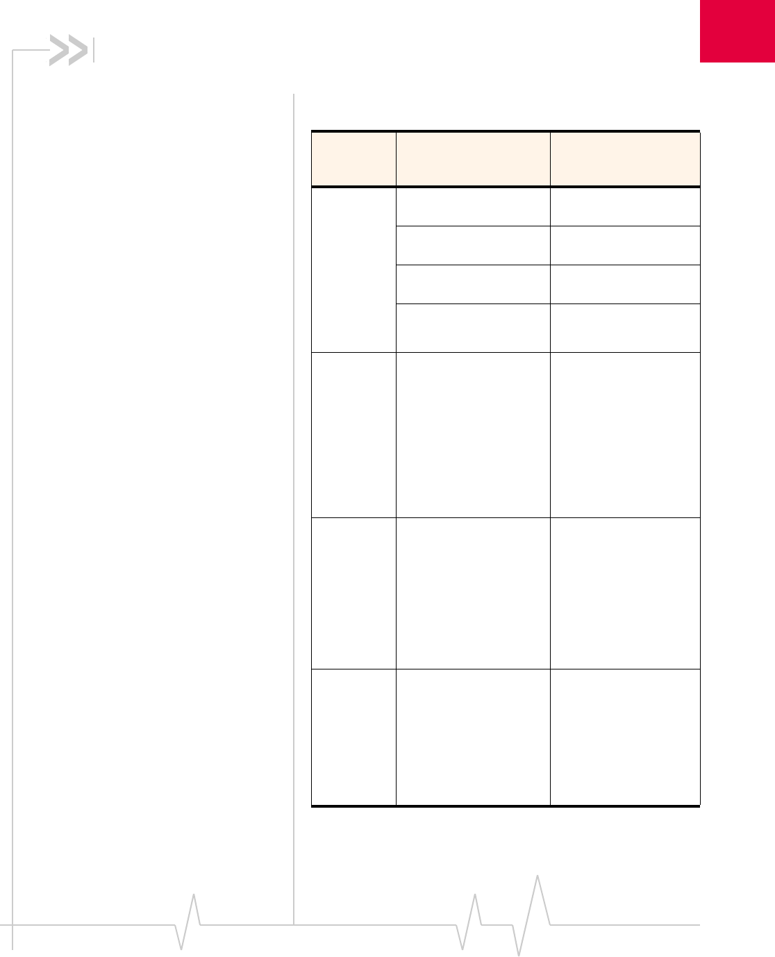
3: RF Integration
TheMC8xxxoperatesonthefrequenciesdetailedinTable3‐1.
Table 3-1: MC8xxx— RF parameters
Product Band Frequencies (MHz)
MC8301V
MC8775
MC8775V
MC8780
MC8781
MC8790
MC8790V
MC8791V
MC8792V
MC8795V
MC8700
GSM 850
(2%) CS Tx: 824–849
Rx: 869-894
EGSM 900
(2%) CS Tx: 880-915
Rx: 925-960
DCS 1800
(2%) CS Tx: 1710-1785
Rx: 1805-1880
PCS 1900
(2%) CS Tx: 1850-1910
Rx: 1930-1990
MC8301V
MC8775
MC8775V
MC8780
MC8781
MC8790
MC8790V
MC8791V
MC8792V
MC8795V
MC8700
Band I
UMTS 2100
(0.1%) 12.2 kbps
Tx: 1920–1980
Rx: 2110–2170
MC8301V
MC8775
MC8775V
MC8780
MC8781
MC8790
MC8790V
MC8792V
MC8795V
MC8700
Band II
UMTS 1900
(0.1%) 12.2 kbps
Tx: 1850–1910
Rx: 1930–1990
MC8301V
MC8775
MC8775V
MC8780
MC8781
MC8790
MC8790V
MC8795V
MC8700
Band V
UMTS 850
(0.1%) 12.2 kbps
(Band VI is included as a
subset of Band V)
Tx: 824–849
Rx: 869–894

CDMA and GSM / UMTS Mini Card Hardware Integration Guide
20 Proprietary and Confidential 2130114
In the event of a discrepancy in values between this guide and the Product Specification Document (PSD), the PSD takes precedence.
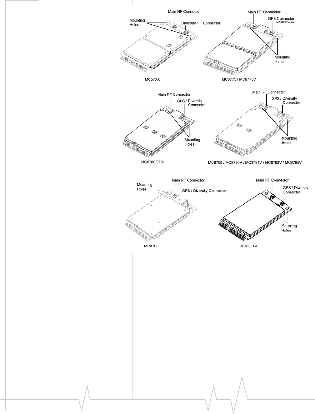
RF connection
Whenattachinganantennatothemodule:
Note: To disconnect the
antenna, make sure you use the
Hirose U.FL connector removal
tool (P/N UFL-LP-N-2(01)) to
prevent damage to the module
or coaxial cable assembly.
•UseaHiroseU.FLconnector(model
U.FL#CL331‐0471‐0‐10)toattachanantennatoa
connectionpointonthemodule,asshowninFigure3‐1(the
mainRFconnectoronthetopside;thediversityRForGPS
connectoronthebottomside).
•Matchcoaxialconnectionsbetweenthemoduleandthe
antennato50Ω.
•MinimizeRFcablelossestotheantenna;therecommended
maximumcablelossforantennacablingis0.5dB.
MC8792V
MC8795V
MC8700
Band VIII
UMTS 900
(0.1%) 12.2 kbps
Tx: 880–915
Rx: 925–960
MC8301V
MC8775V
MC8780
MC8781
MC8790
MC8790V
MC8791V
MC8792V
MC8795V
GPS 1575.42
Table 3-1: MC8xxx— RF parameters (Continued)
Product Band Frequencies (MHz)
RF Integration
Rev 1.12.5 Jan.10 Proprietary and Confidential 21
In the event of a discrepancy in values between this guide and the Product Specification Document (PSD), the PSD takes precedence.
Figure 3-1: Antenna connection points and mounting holes
Ground connection
Whenconnectingthemoduletosystemground:
•Preventnoiseleakagebyestablishingaverygoodground
connectiontothemodulethroughthehostconnector.
•Connecttosystemgroundusingthetwomountingholesat
thetopofthemodule(asshowninFigure3‐1).
•MinimizegroundnoiseleakageintotheRF.
Dependingonthehostboarddesign,noisecouldpotentially
becoupledtothemodulefromthehostboard.Thisis
mainlyanissueforhostdesignsthathavesignalstraveling
alongthelengthofthemodule,orcircuitryoperatingat
bothendsofthemoduleinterconnects.

CDMA and GSM / UMTS Mini Card Hardware Integration Guide
22 Proprietary and Confidential 2130114
In the event of a discrepancy in values between this guide and the Product Specification Document (PSD), the PSD takes precedence.
Shielding
ThemoduleisfullyshieldedtoprotectagainstEMIandto
ensurecompliancewithFCCPart15‐“RadioFrequency
Devices”(orequivalentregulationsinotherjurisdictions).
Note: The module shields must NOT be removed.
Antenna and cabling
Note: Values in this guide are
taken from the appropriate
product specification documents
(PSDs) (listed in
Related
documents
, page 11) — in the
case of a discrepancy between
this document and the relevant
PSD, use the value listed in the
PSD.
Whenselectingtheantennaandcable,itiscriticaltoRFperfor‐
mancetomatchantennagainandcableloss.
Choosing the correct antenna and cabling
Considerthefollowingpointsforpropermatchingofantennas
andcabling:
•Theantenna(andassociatedcircuitry)shouldhavea
nominalimpedanceof50Ωwithareturnloss≤ 10dB
acrosseachfrequencybandofoperation.
•Thesystemgainvalueaffectsbothradiatedpowerand
regulatory(FCC,IC,CE,etc.)testresults.
Developing custom antennas
Considerthefollowingpointswhendevelopingcustom‐
designedantennas:
•AskilledRFengineershoulddothedevelopmenttoensure
thattheRFperformanceismaintained.
•Identifythebandsthatneedtobesupported,particularly
whenboththeMC57xxandMC8xxxwillbeinstalledinthe
sameplatform.Inthiscase,youmaywanttodevelop
separateantennasformaximumperformance.
Determining the antenna’s location
Considerthefollowingpointswhendecidingwheretoputthe
antenna:
•AntennalocationmayaffectRFperformance.Althoughthe
moduleisshieldedtopreventinterferenceinmostapplica‐
tions,theplacementoftheantennaisstillveryimportant—
ifthehostdeviceisinsufficientlyshielded,highlevelsof
broadbandorspuriousnoisecandegradethemodule’s
performance.
•Connectingcablesbetweenthemoduleandtheantenna
musthave50Ωimpedance.Iftheimpedanceofthemodule
ismismatched,RFperformanceisreducedsignificantly.

RF Integration
Rev 1.12.5 Jan.10 Proprietary and Confidential 23
In the event of a discrepancy in values between this guide and the Product Specification Document (PSD), the PSD takes precedence.
•Antennacablesshouldberouted,ifpossible,awayfrom
noisesources(switchingpowersupplies,LCDassemblies,
etc.).Ifthecablesarenearthenoisesources,thenoisemay
becoupledintotheRFcableandintotheantenna.
Disabling the diversity antenna
•MC57xx—Ifyourhostdeviceisnotdesignedtousethe
MC57xxmodule’sdiversityantenna,terminatetheinterface
witha50Ωload.
•MC8301V/MC8780/MC8781/MC8790/MC8790V/
MC8791V/MC8792V/MC8795V/MC8700—UsetheAT
command!RXDEN=0todisablereceivediversityor
!RXDEN=1toenablereceivediversity.
Interference and sensitivity
Note: These modules are based
on ZIF (Zero Intermediate
Frequency) technologies; when
performing EMC
(Electromagnetic Compatibility)
tests, there are no IF
(Intermediate Frequency)
components from the module to
consider.
SeveralsourcesofinterferencecanaffecttheRFperformance
ofthemodule(RFdesense).Commonsourcesincludepower
supplynoiseanddevice‐generatedRF.
RFdesensecanbeaddressedthroughacombinationof
mitigationtechniquesandradiatedsensitivitymeasurement.
Power supply noise
NoiseinthepowersupplycanleadtonoiseintheRFsignal.
Note: Values in this guide are
taken from the appropriate
product specification documents
(PSDs) (listed in
Related
documents
, page 11) — in the
case of a discrepancy between
this document and the relevant
PSD, use the value listed in the
PSD.
Thepowersupplyripplelimitforthemoduleisnomorethan
200mVp‐p1Hzto100kHz.Thislimitincludesvoltageripple
duetotransmitterburstactivity.
Interference from other wireless devices
Wirelessdevicesoperatinginsidethehostdevicecancause
interferencethataffectsthemodule.
Todeterminethemostsuitablelocationsforantennasonyour
hostdevice,evaluateeachwirelessdevice’sradiosystem,
consideringthefollowing:
•Anyharmonics,sub‐harmonics,orcross‐productsofsignals
generatedbywirelessdevicesthatfallinthemodule’sRx
rangemaycausespuriousresponse,resultingindecreased
Rxperformance.
•TheTxpowerandcorrespondingbroadbandnoiseofother
wirelessdevicesmayoverloadorincreasethenoisefloorof
themodule’sreceiver,resultinginRxdesense.

CDMA and GSM / UMTS Mini Card Hardware Integration Guide
24 Proprietary and Confidential 2130114
In the event of a discrepancy in values between this guide and the Product Specification Document (PSD), the PSD takes precedence.
Theseverityofthisinterferencedependsontheclosenessof
theotherantennastothemodule’santenna.Todetermine
suitablelocationsforeachwirelessdevice’santenna,
thoroughlyevaluateyourhostdevice’sdesign.
Device-generated RF
Note: The module can cause
interference with other devices
such as hearing aids and on-
board speakers.
Wireless devices such as the
Mini Card transmit in bursts
(pulse transients) for set
durations (RF burst frequencies).
Hearing aids and speakers
convert these burst frequencies
into audible frequencies,
resulting in audible noise.
AllelectroniccomputingdevicesgenerateRFinterferencethat
cannegativelyaffectthereceivesensitivityofthemodule.
Theproximityofhostelectronicstotheantennainwireless
devicescancontributetodecreasedRxperformance.Compo‐
nentsthataremostlikelytocausethisinclude:
•Microprocessorandmemory
•Displaypanelanddisplaydrivers
•Switching‐modepowersupplies
Theseandotherhigh‐speeddevices(inparticular,the
processor)candecreaseRxperformancebecausetheyrunat
frequenciesoftensofMHz.Therapidriseandfallofthese
clocksignalsgenerateshigher‐orderharmonicsthatoftenfall
withintheoperatingfrequencybandofthemodule,affecting
themodule’sreceivesensitivity.
Example
Onasub‐systemrunningat40MHz,the22ndharmonicfalls
at880MHz,whichiswithinthecellularreceivefrequency
band.
Note: In practice, there are usually numerous interfering frequencies
and harmonics. The net effect can be a series of desensitized receive
channels.
4
Rev 1.12.5 Jan.10 Proprietary and Confidential 25
In the event of a discrepancy in values between this guide and the Product Specification Document (PSD), the PSD takes precedence.
4: Audio Interface
Note: Values in this guide are
taken from the appropriate
product specification documents
(PSDs) (listed in
Related
documents
, page 11) — in the
case of a discrepancy between
this document and the relevant
PSD, use the value listed in the
PSD.
TheMC5725V/MC5727V/MC5728V/MC8301V/MC8775V/
MC8790V/MC8791V/MC8792V/MC8795Vmodulessupport
sixaudiomodesthatmayberequiredbyahostaudiosystem:
•Handset
•Headset
•Carkit
•Speakerphone
•AUX(MC5727V/MC5728Vmodulesarepreconfiguredfor
HAC[HearingAidCompatibility])
•TTY
Themodulessupportbothadifferentialanaloginterfaceand
PCMdigitalaudio,andallowdynamicrun‐timeselectionof
theappropriatemode.
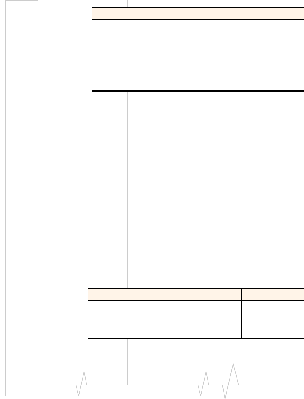
Table4‐1summarizesthekeyaudiofeaturesofthesemodules.
Table 4-1: Audio features
Feature Transmit Receive
Gain (adjustable) MC5725V:
•Up to +16 dB analog gain.
MC5727V:
•MIC_AMP1: Programmable to 0 dB or +24 dB.
•MIC_AMP2: Programmable from -6 dB to
+25.5 dB in steps of 1.5 dB.
MC5728V:
•Programmable to 0 dB or +24 dB.
MC8301V / MC8775V / MC8790V / MC8791V /
MC8792V / MC8795V:
•Up to +48.5 dB analog gain available (when the
analog interface is selected).
Up to +12 dB
Filtering stages Several adjustable high-pass and slope filters High-pass filter
Noise suppression Supported n/a
Echo cancellation Configurable for each audio mode (headset,
handset, speakerphone, and car kit) n/a
Output driver stage n/a Supported
CDMA and GSM / UMTS Mini Card Hardware Integration Guide
26 Proprietary and Confidential 2130114
In the event of a discrepancy in values between this guide and the Product Specification Document (PSD), the PSD takes precedence.
Thesemodulesareintendedtoserveasanintegralcomponent
ofamorecomplexaudiosystem—forexample,aPDAwitha
separatecodecinterfacedtotheHostApplicationprocessor.
Usually,theinterfacebetweenthemoduleandthehostaudio
systemissettoline‐levelamplitudeswithnotransducer
considerations.Theresponsibilityofthemodulecodecorhost
codecforspecialfunctionsisdetailedinTable4‐2.
System block diagrams
Note: When integrating the module into your host platform, make sure
the module has sufficient shielding to prevent RF interference.
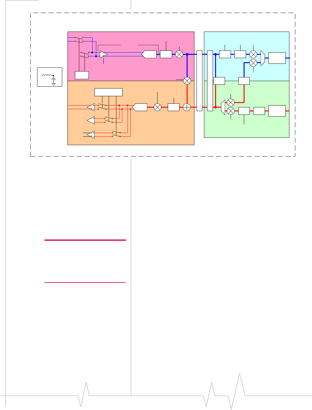
MC5725V / MC5727V system block
Figure4‐1representstheMC5725V/MC5727Vmodule’saudio
systemblock,andincludesthefollowingfeatures:
•Moduleinterconnectsareshownontheleftsideofthe
diagram.Theaudiointerfaceusesthesignals:
·MIC_P/MIC_N
·SPK_P/SPK_N
FIR (Finite Impulse
Response) filtering MC8xxx:
•Option of providing 13 tap FIR filtering for receive and transmit
paths to equalize the acoustic response of the speaker and micro-
phone elements.
Audio pass band 300 Hz–3.4 kHz
Table 4-1: Audio features (Continued)
Feature Transmit Receive
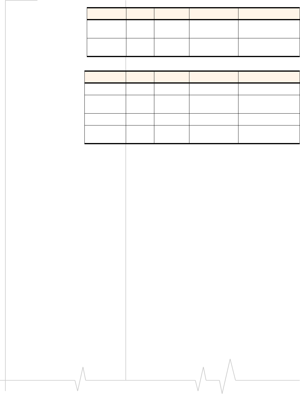
Table 4-2: Functions - responsibility codecs
Function Responsible Codec
Phone oriented (e.g., echo
cancellation, FIR filtering) Module codec
Path-switching Host codec
Transducer interfaces Host codec
Adjustable gain / volume settings Either
DTMF / ringer tone generation Either
Mixing Host codec
Audio Interface
Rev 1.12.5 Jan.10 Proprietary and Confidential 27
In the event of a discrepancy in values between this guide and the Product Specification Document (PSD), the PSD takes precedence.
Note: Make sure the host device
includes DC blocking capacitors
on the Audio In lines – the
module does not include series
capacitors.
•Dynamicrangesforeachprogrammablegainstageare
listed,withthefollowingconstraints:
·MIC_AMP1isprogrammableindiscretestepsonly
·MIC_AMP2(MC5727Vonly)isprogrammablein
discretestepsonly
·CodecSTGain,whensettotheminimumsetting,effec‐
tivelymutessidetoneinthemodulecodec
Figure 4-1: MC5725V / MC5727V Audio system block
MC5728V system block
Figure4‐2representstheMC5728Vmodule’saudiosystem
block,andincludesthefollowingfeatures:
•Moduleinterconnectsareshownontheleftsideofthe
diagram.Theaudiointerfaceusesthesignals:
·MIC_P/MIC_N
·SPK_P/SPK_N
Note: Make sure the host device
includes DC blocking capacitors
on the Audio In lines – the
module does not include series
capacitors.
•Dynamicrangesforeachprogrammablegainstageare
listed,withthefollowingconstraints:
·MIC_AMP1isprogrammableto0dBor+24dBonly
·CodecSTGain,whensettotheminimumsetting,effec‐
tivelymutessidetoneinthemodulecodec
Decoder
RX DAC
EncoderTX ADC
HPF &
Slope
HPF
Echo Cancellation
NS &
AAGC Tx FIR
Rx FIR 13K CELP/
EVRC
Decoder
AAGC
13 bit A/D
13 bit D/A
CodecRxGain
RX_HPF_DIS_N
CodecSTGain
CodecTxGain
TX_HPF_DIS_N
TX_SLOPE_FILT_DIS_N
MIC_AMP1_GAIN
+16dB
+8dB
+6dB
-2dB
nsSwitch TxPCMFilt TxVolume
RxVolume
RxPCMFilt
AMP_SEL
001 010 100
10 01
MIC_SEL
35mW @ +3dBm0
RF Filter
33n
22p
MIC_AMP2_BYP
PCM I/F
+12dB
-25dB
-84dB
+12dB
-3dB
-84dB
+12dB
0dB
-81dB
+12dB
-48dB
-96dB
+12dB
0dB
-84dB
57.3mVrms
@ 0dBm0
SPK_P
SPK_N
MIC_P
MIC_N
13K CELP/
EVRC
Encoder
DTMF
Encoder
DTMF Rx Gain
DTMF Tx Gain
DTMF
Decoder
Audio In
Audio Out
RF
Interface
CDMA and GSM / UMTS Mini Card Hardware Integration Guide
28 Proprietary and Confidential 2130114
In the event of a discrepancy in values between this guide and the Product Specification Document (PSD), the PSD takes precedence.
Figure 4-2: MC5728V Audio system block
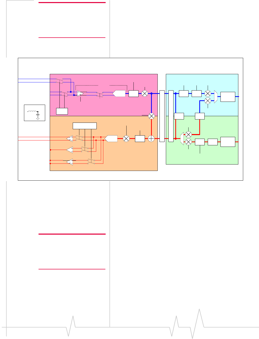
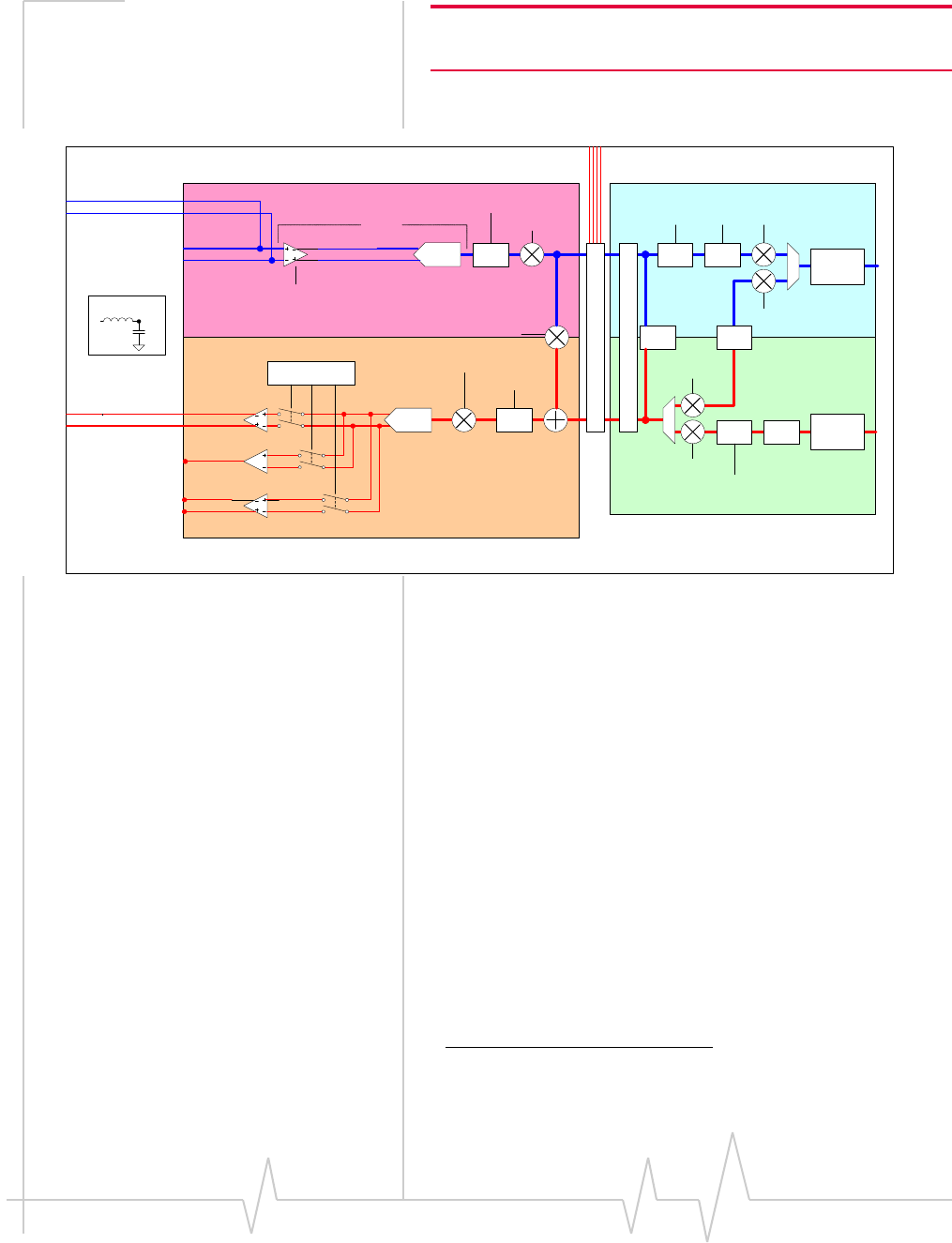
MC8301V / MC8775V / MC8790V / MC8791V / MC8792V /
MC8795V system block
Figure4‐3representstheMC8301V/MC8775V/MC8790V/
MC8791V/MC8792V/MC8795Vmodule’saudiosystemblock,
andincludesthefollowingfeatures:
•Moduleinterconnectsareshownontheleftsideofthe
diagram.Theanalogaudiointerfaceusesthesignals:
·MIC_P/MIC_N
·SPK_P/SPK_N
Note: Make sure the host device
includes DC blocking capacitors
on the analog Audio In lines –
the module does not include
series capacitors.
•ThedigitalPCMaudiointerfaceusesthesignals:
·PCM_CLK
·PCM_DIN
·PCM_DOUT
·PCM_SYNC
•Dynamicrangesforeachprogrammablegainstageare
listed,withthefollowingconstraints:
·MIC_AMP1isprogrammablein1.5dBsteps
·CodecSTGain,whensettotheminimumsetting,effec‐
tivelymutessidetoneinthemodulecodec
•WhenPCMaudioisselected,theRXDACandTXADC
blocksarebypassed—theexternalPCMcodeccontrols
transmitgain,receivegain,andsidetonegain.
Decoder
RX DAC
EncoderTX ADC
HPF &
Slope
HPF
Echo Cancellation
NS &
AAGC Tx FIR
Rx FIR 13K CELP/
EV RC
Decoder
AAGC
13 bit A/D
13 bit D/A
CodecRxGain
RX_HPF_DIS_N
CodecSTGain
CodecTxGain
TX_HPF_DIS_N
TX_SLOPE_FILT_DIS_
N
MIC_ A MP1
0 dB or +24 dB
nsSw itch TxPCMFilt TxVolume
RxV olume
RxPCMFilt
AMP_SEL
MIC_SEL
35mW @ +3dBm0
RF Filter
33n
22
p
PCM I/F
+12dB
-25dB
-84dB
+12dB
-3dB
-84dB
+12dB
0dB
-84dB
0dB
-48dB
-96dB
+12dB
0dB
-84dB
57.3mVrms
@ 0dBm0
g
SPK1N
SPK1P
MIC1P
MIC1N
13K CELP/
EV RC
Encoder
DTMF
Encoder
DTMF Rx Gain
DTMF Tx Gain
DTMF
Decoder
Audio In
Audio Out
RF
Interface
Audio Interface
Rev 1.12.5 Jan.10 Proprietary and Confidential 29
In the event of a discrepancy in values between this guide and the Product Specification Document (PSD), the PSD takes precedence.
Note: Data mixing is not supported. If mixing of voice signal is
required, it must be done by the host processor.
Figure 4-3: MC8301V /MC8775V /MC8790V / MC8791V / MC8792V / MC8795V Audio
system block
Modes of operation
Thesemodulessupportsixoperationalmodes:headset,
handset,carkit,speakerphone,AUX1,andTTY—endproducts
canuseanycombinationofthesemodes.
Thehostdevicemustusehost‐modemmessagingtotellthe
modulewhichmodetouseforeachcall.
Sidetone support
Thesidetonepathmixesthenear‐endtransmitvoicetothe
near‐endreceive.Thisgivesthenear‐endusersomefeedback
thatindicatesthatthecallisupandthattheaudiosystemis
functioning.
ThesidetonepathcanbeenabledineitherthePDAcodecor
theMiniCardmodem—eachpathisequallyvalid.Itshould
notbeaddedtobothdevices,andforspeakerphoneorcarkit
applications,bothsidetonepathsshouldbedisabled.
Decoder
RX DAC
EncoderTX ADC
HPF &
Slope
HPF
Echo Cancellation
NS &
AAGC Tx FIR
Rx FIR 13K CELP/
EVRC
Decoder
AAGC
13 bit A/D
13 bit D/A
CodecRxGain
RX_HPF_DIS_N
CodecSTGain
CodecTxGain
TX_HPF_DIS_N
TX_SLOPE_FILT_DIS_N
MIC_AMP1_GAIN
-6dB to +49.5dB
in 1.5dB steps
nsSwitch TxPCMFilt TxVolume
RxVolume
RxPCMFilt
AMP_SEL
001 010 100
35mW @ +3dBm0
RF Filter
33n
22p
PCM I/F
+12dB
-25dB
-84dB
+12dB
-3dB
-84dB
+12dB
0dB
-81dB
+12dB
-48dB
-96dB
+12dB
0dB
-84dB
57.3mVrms
@ 0dBm0
SPK_P
SPK_N
MIC_P
MIC_N
13K CELP/
EVRC
Encoder
DTMF
Encoder
DTMF Rx Gain
DTMF Tx Gain
DTMF
Decoder
Audio In
Audio Out
RF
Interface
PCM Audio interface
1. (MC5727V/MC5728Vmodulesarepreconfiguredfor
HAC[HearingAidCompatibility]).

CDMA and GSM / UMTS Mini Card Hardware Integration Guide
30 Proprietary and Confidential 2130114
In the event of a discrepancy in values between this guide and the Product Specification Document (PSD), the PSD takes precedence.
Thetypicalhandsetsidetoneis12dBbelowtransmitvoice
levels.
ForHandsetandHeadsetmode,thethresholdofpain
(+120dBSPL)mustnotbeexceededatthemaximumvolume
setting.Agoodtargetforthemediumvolumesettingis
+94dBSPL,asthisisatypicallevelforconversationalspeech.
Mostaudiogainshouldbeaddedtothehostaudiofrontend
(withinthePDAstylecodecgainblocksoramplifiersbetween
thehostcodecandtransducers).RefertotheappropriateMini
CardProductSpecificationDocumentforreferencelevelson
themodemreceiveandtransmitside.
Echo cancellation support
TheMiniCardoffersfourmodesofechocancellationto
supportuniqueend‐unitaudiocapabilities(echocancellation
canalsobeturnedoffcompletely).Allechocancellationis
near‐end(mobileTX)cancellationonly.Thenetworkprovides
someleveloffar‐endechocancellation.
Table 4-3: Echo cancellation details
Mode Details
Handset •Short echo path (<16 ms travel time from speaker to
microphone)
•Handset design requires good isolation between
speaker and microphone
•Echo canceller allows full-duplex conversation with
absolute minimum echo
Headset •Short echo path (<16 ms travel time from speaker to
microphone)
•Headset design may allow higher echo than
handset mode—microphone and speaker are physi-
cally closer
•More aggressive echo canceller algorithm allows
full-duplex conversation on headsets with good
isolation
Car kit •Long echo path (<64 ms travel time from speaker to
microphone)
•Loud echo
•For use with hands-free car kit or speakerphone
applications with mild distortion
Audio Interface
Rev 1.12.5 Jan.10 Proprietary and Confidential 31
In the event of a discrepancy in values between this guide and the Product Specification Document (PSD), the PSD takes precedence.
Audio signal interface
Thedifferentialmicrophoneinputofferssuperiornoise
rejectionperformancetothesingle‐endedapproach.The
terminationofthedifferentialpairrejectscommonsignals
(suchasnoise).Thepairshouldberoutedtogetherforoptimal
noiserejection.SinceMIC_PandMIC_Narehighimpedance
inputs,itisimportanttoisolatethesefrompossiblenoise
sources(togglingdigitallineswithfastedges).
Thespeakerinterfacecanbesingle‐endedordifferential
dependingonproduct.Single‐endedspeakeroutputsrelyon
modemgroundasanaudioreference.
Theaudiopassbandforbothreceiveandtransmitpaths
(speakerandmicrophone)extendsfrom300Hzto3.4kHz.A
programmablesidetonewitharangefrommutetounitygain
isavailableforbothheadsetandmainaudiopaths.Sidetone
shouldbemutedforspeakerphoneuse.
Notethatcertaincarriersnowrequireuseofhearing‐aid
compatibletransducersinahandsetdesign.ThePrimary
audiopathcanbeinterfaceddirectlytosuchdevices.Referto
ANSIC63.19fordetailsregardingreducedRFemissions(ʺU3
ratingʺ)andinductive/telecoilcoupling(ʺU3Tʺrating)
devices.
Speakerphone •Long echo path (<64 ms travel time from speaker to
microphone)
•Loud echo
•For use with speakerphone applications with high
distortion
•Half-duplex algorithm, very aggressive in near-end
Tx muting to eliminate transmitted echo
Off
Table 4-3: Echo cancellation details
Mode Details
Table 4-4: Primary audio signal interface
Signal Pin # Type Directions Description
MIC_P 1Analog Input Non-inverted
microphone input (+)
MIC_N 3Analog Input Inverted microphone
input (-)
CDMA and GSM / UMTS Mini Card Hardware Integration Guide
32 Proprietary and Confidential 2130114
In the event of a discrepancy in values between this guide and the Product Specification Document (PSD), the PSD takes precedence.
Audio function partitioning
Thesephone‐orientedfunctionsareusuallyundermodule
control:
•FIRfilters—bothtransmitandreceivepath
•Noisesuppression—requiredduetohighsensitivityand
gainintransmitpath
•Echocancellation—differentforeachaudiopathand
environment(handset,headset,carkit,speakerphone)
•Highpassfiltering/slopefilteringfunctions—requiredper
phoneacousticrequirements
•AGC(AutomaticGainControl)—normalizesaudio
volumesinvaryingacousticenvironments
•DTMFtones—thegenerationanddetectionofDTMFtones
isrequiredinbothdirectionsofthephoneinterface
•Comfortnoise—lowlevelnoiseinjectedintoreceiverpath
foruserʺconnectionʺexperience
•Simpleringers—digitalandanalogtones,melodyringers,
MIDIwithlimitedmemorystorage
Thesefunctionsaretypicallyperformedinthehostcodec:
•VoiceMemo—performedbythehostifsignificantmemory
storageisrequired
•Polyphonicringtone—hostoftensupportsWAV,MIDI
formatswithsignificantmemorystorage
•Audiopathswitching—turnonaudiopathdependingon
userinterfaceselection,orheadsetdetection
SPK_P 5Analog Output Non-inverted
speaker output (+)
SPK_N 7Analog Output Inverted speaker
output (-)
Table 4-5: PCM digital audio signal interface
Signal Pin # Type Directions Description
PCM_CLK 45 Digital Output PCM clock
PCM_DIN 47 Digital Input (internal
pull-down) PCM data in
PCM_DOUT 49 Digital Output PCM data out
PCM_SYNC 51 Digital Input (internal
pull-down) PCM sync
Table 4-4: Primary audio signal interface
Signal Pin # Type Directions Description

Audio Interface
Rev 1.12.5 Jan.10 Proprietary and Confidential 33
In the event of a discrepancy in values between this guide and the Product Specification Document (PSD), the PSD takes precedence.
•Audiopathmixing—requiredforvoicememorecording
andplaybackviamultipleaudiopaths
•Transducerinterface—hostprovidesacousticdrivers,must
occuroutsideofpathswitchingandmixing
Thesefunctionscanbeperformedineitherhostormodule
codec,dependingonbalanceofcomponentselectionand
engineeringresources:
•Volumesettings—adjustablegainsettingsbasedonuser
interfaceselections
•Sidetone—carefulplacementofsidetonegaincontrolis
requiredtopreventtheneedtoadjustsidetonegainwith
varyingvolumesettings

CDMA and GSM / UMTS Mini Card Hardware Integration Guide
34 Proprietary and Confidential 2130114
In the event of a discrepancy in values between this guide and the Product Specification Document (PSD), the PSD takes precedence.
5
Rev 1.12.5 Jan.10 Proprietary and Confidential 35
In the event of a discrepancy in values between this guide and the Product Specification Document (PSD), the PSD takes precedence.
5: Host / Module Interfaces
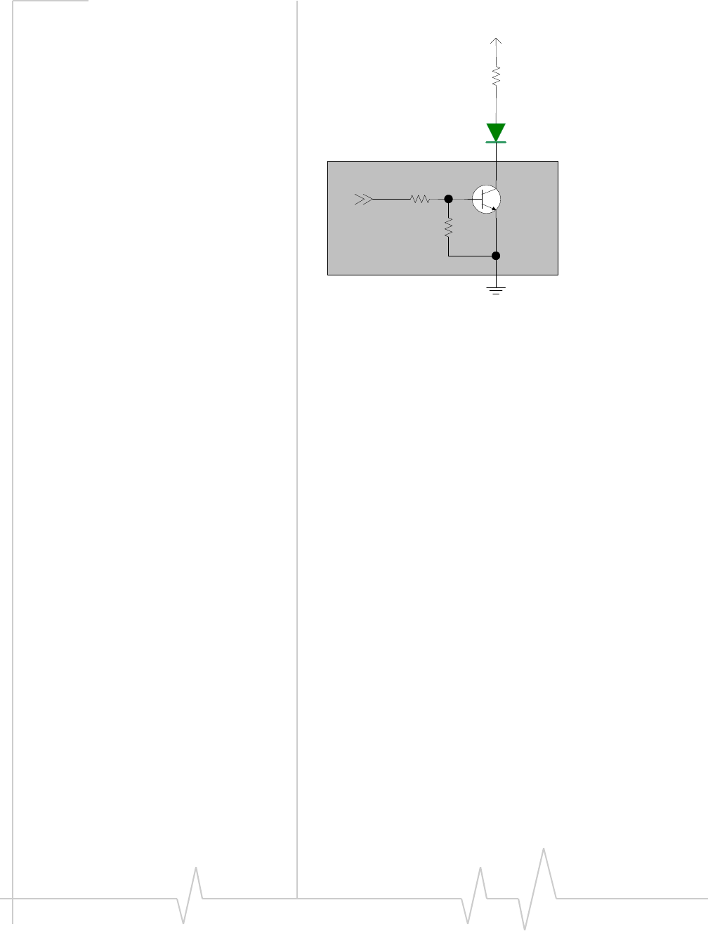
LED output
ThemoduledrivestheLEDoutputaccordingtothePCI‐
ExpressMiniCardspecification(summarizedinTable5‐1,
below).
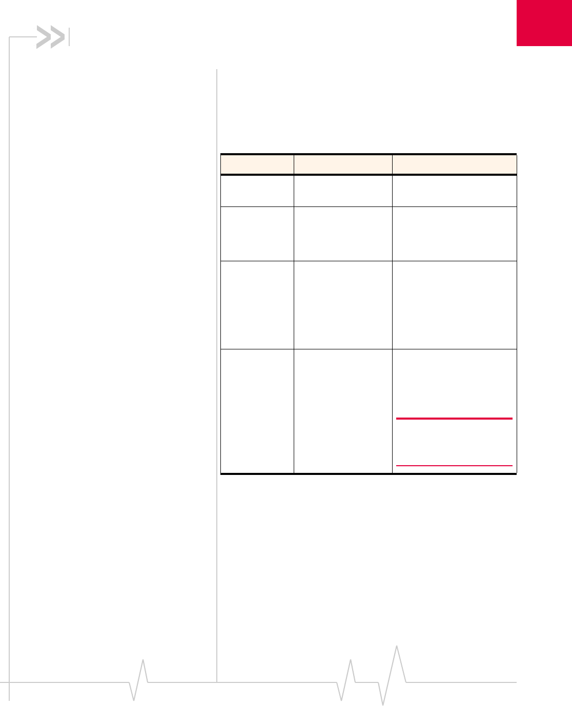
Table 5-1: LED states
State Indicates Characteristics
Off Module is not
powered. Light is off.
On Module is powered
and connected, but
not transmitting or
receiving.
Light is on.
Slow blink Module is powered
and searching for a
connection.
LED is flashing at a
steady, slow rate.
•250 ms ± 25% ON
period
•0.2 Hz ± 25% blink
rate
Faster blink Module is
transmitting or
receiving.
LED is flashing at a
steady, faster rate.
•Approximately 3 Hz
blink rate
Note: MC572x modules
support customer-defined
LED controls.
CDMA and GSM / UMTS Mini Card Hardware Integration Guide
36 Proprietary and Confidential 2130114
In the event of a discrepancy in values between this guide and the Product Specification Document (PSD), the PSD takes precedence.
Figure 5-1: Example LED
Current limiting Resistor
LED
VCC 3.3V
MIO
MiniCard

A
Rev 1.12.5 Jan.10 Proprietary and Confidential 37
In the event of a discrepancy in values between this guide and the Product Specification Document (PSD), the PSD takes precedence.
A: Regulatory Information
Important notice
Becauseofthenatureofwirelesscommunications,trans‐
missionandreceptionofdatacanneverbeguaranteed.Data
maybedelayed,corrupted(i.e.,haveerrors)orbetotallylost.
Althoughsignificantdelaysorlossesofdataarerarewhen
wirelessdevicessuchastheSierraWirelessmodemareusedin
anormalmannerwithawell‐constructednetwork,theSierra
Wirelessmodemshouldnotbeusedinsituationswherefailure
totransmitorreceivedatacouldresultindamageofanykind
totheuseroranyotherparty,includingbutnotlimitedto
personalinjury,death,orlossofproperty.SierraWirelessand
itsaffiliatesacceptnoresponsibilityfordamagesofanykind
resultingfromdelaysorerrorsindatatransmittedorreceived
usingtheSierraWirelessmodem,orforfailureoftheSierra
Wirelessmodemtotransmitorreceivesuchdata.
Safety and hazards
DonotoperateyourMC57xx/MC8xxxmodem:
•Inareaswhereblastingisinprogress
•Whereexplosiveatmospheresmaybepresentincluding
refuellingpoints,fueldepots,andchemicalplants
•Nearmedicalequipment,lifesupportequipment,orany
equipmentwhichmaybesusceptibletoanyformofradio
interference.Insuchareas,theMC57xx/MC8xxxmodem
MUSTBEPOWEREDOFF.Otherwise,theMC57xx/
MC8xxxmodemcantransmitsignalsthatcouldinterfere
withthisequipment.
Inanaircraft,theMC57xx/MC8xxxmodemMUSTBE
POWEREDOFF.Otherwise,theMC57xx/MC8xxxmodem
cantransmitsignalsthatcouldinterferewithvariousonboard
systemsandmaybedangeroustotheoperationoftheaircraft
ordisruptthecellularnetwork.Useofacellularphoneinan
aircraftisillegalinsomejurisdictions.Failuretoobservethis
instructionmayleadtosuspensionordenialofcellular
telephoneservicestotheoffender,orlegalactionorboth.
Someairlinesmaypermittheuseofcellularphoneswhilethe
aircraftisonthegroundandthedoorisopen.TheMC57xx/
MC8xxxmodemmaybeusednormallyatthistime.

CDMA and GSM / UMTS Mini Card Hardware Integration Guide
38 Proprietary and Confidential 2130114
In the event of a discrepancy in values between this guide and the Product Specification Document (PSD), the PSD takes precedence.
Important compliance
information for North American
users
TheMC57xx/MC8xxxmodemhasbeengrantedmodular
approvalformobileapplications.Integratorsmayusethe
MC57xx/MC8xxxmodemintheirfinalproductswithout
additionalFCC/IC(IndustryCanada)certificationifthey
meetthefollowingconditions.Otherwise,additionalFCC/IC
approvalsmustbeobtained.
1. Atleast20cmseparationdistancebetweentheantenna
andtheuser’sbodymustbemaintainedatalltimes.
2. TocomplywithFCC/ICregulationslimitingboth
maximumRFoutputpowerandhumanexposuretoRF
radiation,themaximumantennagainincludingcableloss
inamobile‐onlyexposureconditionmustnotexceed5dBi
inthecellularbandand4dBiinthePCSband.
3. TheMC57xx/MC8xxxmodemanditsantennamustnot
beco‐locatedoroperatinginconjunctionwithanyother
transmitterorantennawithinahostdevice.
4. Alabelmustbeaffixedtotheoutsideoftheendproduct
intowhichtheMC57xx/MC8xxxmodemisincorporated,
withastatementsimilartothefollowing:
·ForMC5725/MC5725V:
ThisdevicecontainsFCCID:N7N‐MC5725
Thisequipmentcontainsequipmentcertifiedunder
IC:2417C‐MC5725
·ForMC5727/MC5727V:
ThisdevicecontainsFCCID:N7N‐MC5727
Thisequipmentcontainsequipmentcertifiedunder
IC:2417C‐MC5727
·ForMC5728V:
ThisdevicecontainsFCCID:N7N‐MC5728
Thisequipmentcontainsequipmentcertifiedunder
IC:2417C‐MC5728
·ForMC8301V:
ThisdevicecontainsFCCID:N7NMC8301
Thisequipmentcontainsequipmentcertifiedunder
IC:2417C‐MC8301
·ForMC8775/MC8775V:
ThisdevicecontainsFCCID:N7NMC8775
Thisequipmentcontainsequipmentcertifiedunder
IC:2417C‐MC8775
·ForMC8780:
ThisdevicecontainsFCCID:N7NMC8780
Regulatory Information
Rev 1.12.5 Jan.10 Proprietary and Confidential 39
In the event of a discrepancy in values between this guide and the Product Specification Document (PSD), the PSD takes precedence.
·ForMC8781:
ThisdevicecontainsFCCID:N7NMC8781
Thisequipmentcontainsequipmentcertifiedunder
IC:2417C‐MC8781
·ForMC8790/MC8790V:
ThisdevicecontainsFCCID:N7NMC8790
Thisequipmentcontainsequipmentcertifiedunder
IC:2417C‐MC8790
·ForMC8792V:
ThisdevicecontainsFCCID:N7NMC8792
Thisequipmentcontainsequipmentcertifiedunder
IC:2417C‐MC8792
·ForMC8795V:
ThisdevicecontainsFCCID:N7NMC8795
Thisequipmentcontainsequipmentcertifiedunder
IC:2417C‐MC8795
·ForMC8700:
ThisdevicecontainsFCCID:N7NMC8700
Thisequipmentcontainsequipmentcertifiedunder
IC:2417C‐MC8700
5. Ausermanualwiththeendproductmustclearlyindicate
theoperatingrequirementsandconditionsthatmustbe
observedtoensurecompliancewithcurrentFCC/ICRF
exposureguidelines.
TheendproductwithanembeddedMC57xx/MC8xxx
modemmayalsoneedtopasstheFCCPart15unintentional
emissiontestingrequirementsandbeproperlyauthorizedper
FCCPart15.
Note:Ifthismoduleisintendedforuseinaportabledevice,
youareresponsibleforseparateapprovaltosatisfytheSAR
requirementsofFCCPart2.1093andICRSS‐102.
EU regulatory conformity
SierraWirelessherebydeclaresthattheMC8301V,MC8775,
MC8775V,MC8780,MC8790,MC8790V,MC8791V,MC8792V,
MC8795V,andMC8700modemsconformwithallessential
requirementsofDirective1999/5/EC.
MC8301V:
MC8775,MC8775V,MC8780,MC8790,MC8790V,MC8791V,
MC8792V:
CDMA and GSM / UMTS Mini Card Hardware Integration Guide
40 Proprietary and Confidential 2130114
In the event of a discrepancy in values between this guide and the Product Specification Document (PSD), the PSD takes precedence.
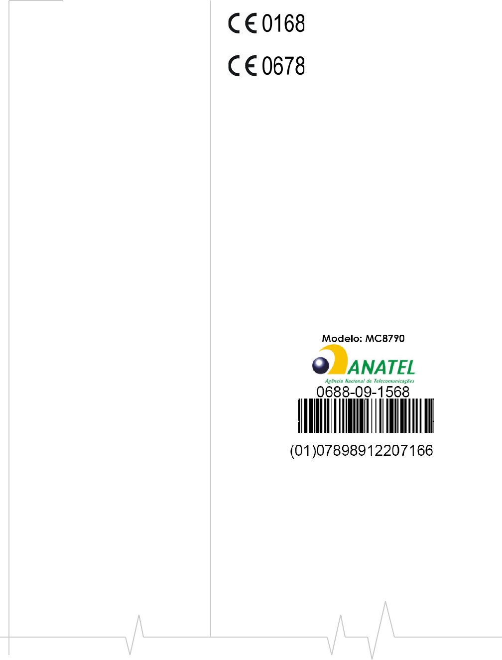
MC8795V:
MC8700:
TheDeclarationofConformitymadeunderDirective1999/5/
ECisavailableforviewingatthefollowinglocationintheEU
community:
SierraWireless(UK),Limited
LakesideHouse
1FurzegroundWay,StockleyParkEast
Uxbridge,Middlesex
UB111BD
England
Brazil ANATEL homologation
(MC8790somente)Esteprodutoestáhomologadopela
ANATEL,deacordocomosprocedimentosregulamentados
pelaResolução242/2000,eatendeaosrequisitostécnicos
aplicados.
Paramaioresinformações,consulteositedaANATEL
www.anatel.gov.br.
B
Rev 1.12.5 Jan.10 Proprietary and Confidential 41
In the event of a discrepancy in values between this guide and the Product Specification Document (PSD), the PSD takes precedence.
B: Acronyms and Definitions
.
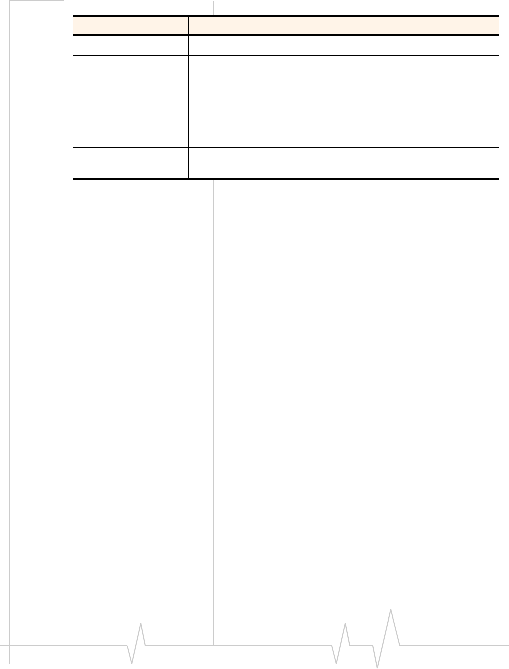
Table B-1: Acronyms and definitions
Acronym or term Definition
AGC Automatic Gain Control
BER Bit Error Rate - a measure of receive sensitivity
BLER Block Error Rate
Call Box Base Station Simulator - Agilent E8285A or 8960, Rohde &
Schwarz CMU200
CDMA Code Division Multiple Access
dB Decibel = 10 x log10 (P1/P2)
P1 is calculated power; P2 is reference power
Decibel = 20 x log10 (V1/V2)
V1 is calculated voltage, V2 is reference voltage
dBm Decibels, relative to 1 mW - Decibel(mW) = 10 x log10 (Pwr (mW)/
1mW)
DUT Device Under Test
EDGE Enhanced Data rates for GSM Evolution
EM Embedded Module
ESD ElectroStatic Discharge
FER Frame Error Rate - a measure of receive sensitivity
GPRS General Packet Radio Services
GPS Global Positioning System
GSM Global System for Mobile communications
Hz Hertz = 1 cycle/second
inrush current Peak current drawn when a device is connected or powered on
IS-2000 3G radio standards for voice and data (CDMA only)
IS-95 2G radio standards targeted for voice (cdmaONE)
LDO Low Drop Out - refers to linear regulator
CDMA and GSM / UMTS Mini Card Hardware Integration Guide
42 Proprietary and Confidential 2130114
In the event of a discrepancy in values between this guide and the Product Specification Document (PSD), the PSD takes precedence.
MC5725 / MC5725V /
MC5727 / MC5727V /
MC5728V
Sierra Wireless Mini Cards used on CDMA networks
MC57xx Any of the following CDMA Mini Cards: MC5725 / MC5725V /
MC5727 / MC5727V / MC5728V
MC8301V / MC8775 /
MC8775V /
MC8780 / MC8781 /
MC8790 / MC8790V /
MC8791V / MC8792V /
MC8795V / MC8700
Sierra Wireless Mini Cards used on GSM / UMTS networks
MC8xxx Any of the following GSM / UMTS Mini Cards: MC8301V / MC8775 /
MC8775V / MC8780 / MC8781 / MC8790 / MC8790V / MC8791V /
MC8792V / MC8795V / MC8700
MHz MegaHertz = 10E6 Hertz (Hertz = 1 cycle/second)
MIO Module Input/Output
MPE Maximum Permissible Exposure — the level of radiation to which a
person may be exposed without hazardous effect or adverse
biological changes
OTA Over-The-Air or Radiated through the antenna
PCS Personal Communication System - PCS spans the 1.9 GHz radio
spectrum
RF Radio Frequency
RMS Root Mean Square
SA Selective Availability
Sensitivity (Audio) Measure of lowest power signal that the receiver can measure
Sensitivity (RF) Measure of lowest power signal at the receiver input that can
provide a prescribed BER / BLER / SNR value at the receiver
output.
SIM Subscriber Identity Module
SNR Signal to Noise Ratio
SOF Start of Frame - a USB function
UART Universal Asynchronous Receiver Transmitter
UDK Universal Development Kit (PCI Express Mini Card Dev Kit)
Table B-1: Acronyms and definitions
Acronym or term Definition
Acronyms and Definitions
Rev 1.12.5 Jan.10 Proprietary and Confidential 43
In the event of a discrepancy in values between this guide and the Product Specification Document (PSD), the PSD takes precedence.
UMTS Universal Mobile Telecommunications System
USB Universal Serial Bus
USIM Universal Subscriber Identity Module
VCC3.3 3.3 V supply voltage
WCDMA Wideband Code Division Multiple Access — In this document, the
term “UMTS” is used instead of “WCDMA”.
XIM In this document, XIM is used as part of the contact identifiers for
the USIM interface (XIM_VCC, XIM_CLK, etc.).
Table B-1: Acronyms and definitions
Acronym or term Definition

CDMA and GSM / UMTS Mini Card Hardware Integration Guide
44 Proprietary and Confidential 2130114
In the event of a discrepancy in values between this guide and the Product Specification Document (PSD), the PSD takes precedence.

Rev 1.12.5 Jan.10 Proprietary and Confidential 45
In the event of a discrepancy in values between this guide and the Product Specification Document (PSD), the PSD takes precedence.
Index
Numerics
1X
CDMAStandard11
A
acronymsanddefinitions41–43
airplanemode17
antenna
connectionandmountingpoints21
connectionconsiderations20
custom,considerations22
diversityantenna,disabling23
limit,matchingcoaxialconnections20
location,considerations22
matching,considerations22
maximumcableloss20
ATcommands
3GPPspecification,details11
lowpowermode,setting17
standard,MC57xx(referencedocument)11
standard,MC8xxx(referencedocument)13
ATcommands,extended
MC57xx,reference11
MC8xxx,reference13
ATcommands,standard
MC57xx,reference11
MC8xxx,reference13
audio
features,summary25
functions,host‐controlled32
functions,module‐controlled32
functions,responsiblecodecs26
interface25–33
pathmixing,host‐controlled33
pathswitching,host‐controlled32
PCMdigital,signalinterface32
primary,signalinterface31
signalinterface31
systemblockdiagram,MC5725V26
systemblockdiagram,MC5727V26
systemblockdiagram,MC5728V27
systemblockdiagram,MC8xxxV28
audiomodes,supported29
audiopassband26
audiopassband,RxandTx31
automaticgaincontrol(AGC)
module‐controlled32
C
cableloss
antenna,maximum20
carkitaudiomode25
carkitmode
echocancellation30
CDMA
1XStandard11
CnS
MC57xxreference11
MC8xxxreference13
voicereference13
codec
foraudiofunctions26
comfortnoise
module‐controlled32
connection
grounding21
connectors,required
EDGEmating(52‐pin)10
host‐module10
RF,Hirose10
USIM10
current
consumption,usagemodels17
D
DCS1800
RFparameters,MC8xxx19
desense.SeeRF
disconnected,modulepowerstate16
diversityantenna
disabling23
DTMF
codec26
module‐controlled32
E
echocancellation
audiofeature25
codec26
details30
module‐controlled32
support,allmodes30
EDGEconnector,manufacturers10
EGSM900
RFparameters,MC8xxx19
electrostaticdischarge.SeeESD
ESD
protectionrequirements15–16
testingtechniquesdocument(IEC‐61000‐4‐2)11
F
FCC

CDMA and GSM / UMTS Mini Card Hardware Integration Guide
46 Proprietary and Confidential 2130114
In the event of a discrepancy in values between this guide and the Product Specification Document (PSD), the PSD takes precedence.
regulations,relevantsection11
filtering
highpass/slopefiltering,module‐controlled32
filteringstages,audio25
FIRfiltering
audiofeature26
codec26
module‐controlled32
G
gain
codec26
distribution,audio30
limits,adjustable25
GPSband
RFparameters,MC8xxx20
grounding
connectionconsiderations21
GSM850
RFparameters,MC8xxx19
H
handsetaudiomode25
handsetmode
echocancellation30
headsetaudiomode25
headsetmode
echocancellation30
I
impedance
module‐antenna22
interface
audiosignal31
interference
devicegenerated24
powersupplynoise23
wirelessdevices23
L
LED
example36
states35
lowpowermode
setting,ATcommands17
lowpower,modulepowerstate17
M
MC5725
ATreference(extended)11
ATreference(standard)11
CnSreference11
networkssupported9
productspecification11
MC5725V
ATreference(extended)11
ATreference(standard)11
audiointerface,supported25
CnSreference11
networkssupported9
productspecification11
MC5727
ATreference(extended)11
ATreference(standard)11
CnSreference11
networkssupported9
productspecification12
MC5727V
ATreference(extended)11
ATreference(standard)11
audiointerface,supported25
CnSreference11
networkssupported9
productspecification12
MC5728V
ATreference(extended)11
ATreference(standard)11
audiointerface,supported25
CnSreference11
networkssupported9
productspecification12
MC8301V
ATreference(extended),andMC8xxx13
ATreference(standard),andMC8xxx13
CnSreference,andMC8xxx13
CnSvoicereference,andMC8xxxV13
networkssupported9
productspecification12
RFparameters19
MC8700
ATreference(extended),andMC8xxx13
ATreference(standard),andMC8xxx13
CnSreference,andMC8xxx13
networkssupported9
productspecification12
RFparameters19
MC8775
ATreference(extended),andMC8xxx13
ATreference(standard),andMC8xxx13
CnSreference,andMC8xxx13
networkssupported9
productspecification12
RFparameters19
MC8775V
ATreference(extended),andMC8xxx13
ATreference(standard),andMC8xxx13
audiointerface,supported25
CnSreference,andMC8xxx13
CnSvoicereference,andMC8xxxV13
networkssupported9
productspecification12

Index
Rev 1.12.5 Jan.10 Proprietary and Confidential 47
In the event of a discrepancy in values between this guide and the Product Specification Document (PSD), the PSD takes precedence.
RFparameters19
MC8780
ATreference(extended),andMC8xxx13
ATreference(standard),andMC8xxx13
CnSreference,andMC8xxx13
networkssupported9
productspecification12
RFparameters19
MC8781
ATreference(extended),andMC8xxx13
ATreference(standard),andMC8xxx13
CnSreference,andMC8xxx13
networkssupported9
productspecification12
RFparameters19
MC8790
ATreference(extended),andMC8xxx13
ATreference(standard),andMC8xxx13
CnSreference,andMC8xxx13
networkssupported9
productspecification12
RFparameters19
MC8790V
ATreference(extended),andMC8xxx13
ATreference(standard),andMC8xxx13
audiointerface,supported25
CnSreference,andMC8xxx13
CnSvoicereference,andMC8xxxV13
networkssupported9
productspecification12
RFparameters19
MC8791V
ATreference(extended),andMC8xxx13
ATreference(standard),andMC8xxx13
audiointerface,supported25
CnSreference,andMC8xxx13
CnSvoicereference,andMC8xxxV13
networkssupported9
productspecification12
RFparameters19
MC8792V
ATreference(extended),andMC8xxx13
ATreference(standard),andMC8xxx13
audiointerface,supported25
CnSreference,andMC8xxx13
CnSvoicereference,andMC8xxxV13
networkssupported9
productspecification12
RFparameters19
MC8795V
ATreference(extended),andMC8xxx13
ATreference(standard),andMC8xxx13
audiointerface,supported25
CnSreference,andMC8xxx13
CnSvoicereference,andMC8xxxV13
networkssupported9
productspecification12
RFparameters19
MiniCard
DevKitQuickStartGuide13
PCIExpressSpecification13
SeealsoMC5725,MC5725V,MC5727,MC5727V,
MC5728V,MC8775,MC8775V,MC8780,
MC8781,MC8790,MC8790V,MC8791V,
MC8792V,MC8795V,MC8700
mixing
codec26
N
networks
supported,bymoduletype9
noise
leakage,minimizing21
RFinterference,powersupply23
noisesuppression
audiofeature25
module‐controlled32
normal,modulepowerstate17
O
off,modulepowerstate17
outputdriverstage,audiofeature25
P
pathswitching
codec26
PCIExpress
MiniCardspecification13
PCMdigitalaudio,signalinterface32
PCS1900
RFparameters,MC8xxx19
polyphonicringtone
host‐controlled32
power
defaultstate17
disconnected,characteristics16
normal,characteristics17
off,characteristics17
requiredsupplyvoltage15
signals,overview15
state,disconnected16
state,lowpower17
state,normal17
state,off17
supply,RFinterference23
supply,ripplelimit23
productspecification(PSD)11,12
PSD(ProductSpecificationDocument)11,12
R
regulatoryinformation37–40
Brazil40

CDMA and GSM / UMTS Mini Card Hardware Integration Guide
48 Proprietary and Confidential 2130114
In the event of a discrepancy in values between this guide and the Product Specification Document (PSD), the PSD takes precedence.
EU39
FCC38
limitationofliability37
safetyandhazards37
RF
antennacableloss,maximum20
antennaconnection,considerations20
cabletype,required10
desense
device‐generated24
interference
otherdevices24
powersupply23
wirelessdevices23
parameters
MC8xxx19
parameters,MC8xxx
DCS180019
EGSM90019
GPS20
GSM85019
PCS190019
UMTS190019
UMTS210019
UMTS85019,20
ringertone
codec26
ringers
module‐controlled32
ringtone,polyphonic
host‐controlled32
S
shielding
module,compliance22
sidetone
responsiblecodec33
support29
SIM
testingmethods,MSconformancespecification13
SeealsoUSIM
speakerphoneaudiomode25
speakerphonemode
echocancellation31
systemblock
MC5725V,audio26
MC5727V,audio26
MC5728V,audio27
MC8xxxV,audio28
T
testing
ESDimmunity,techniquesdocument(IEC‐61000‐
4‐2)11
transducerinterface
host‐controlled33
transducerinterfaces
codec26
U
UDK(UniversalDevelopmentKit)
components,included9
UMTS1900
RFparameters,MC8xxx19
UMTS2100
RFparameters,MC8xxx19
UMTS850
RFparameters,MC8xxx19,20
UniversalDevelopmentKit(UDK)
components,included9
UniversalSerialBus.SeeUSB.
usagemodels
currentconsumption17
USB
specification13
USIM
connectortype,required10
V
voicememo
host‐controlled32
volume,setting
responsiblecodec33
W
W_Disable#
Normalstate17
offstate17
Z
ZIF(ZeroIntermediateFrequency)23
