Sierra Wireless MC8705 GSM/GPRS/EDGE/WCDMA/HSDPA/HSUPA/HSPA+Module User Manual HW Integration Guide
Sierra Wireless Inc. GSM/GPRS/EDGE/WCDMA/HSDPA/HSUPA/HSPA+Module HW Integration Guide
Contents
- 1. Hdw Integration Guide
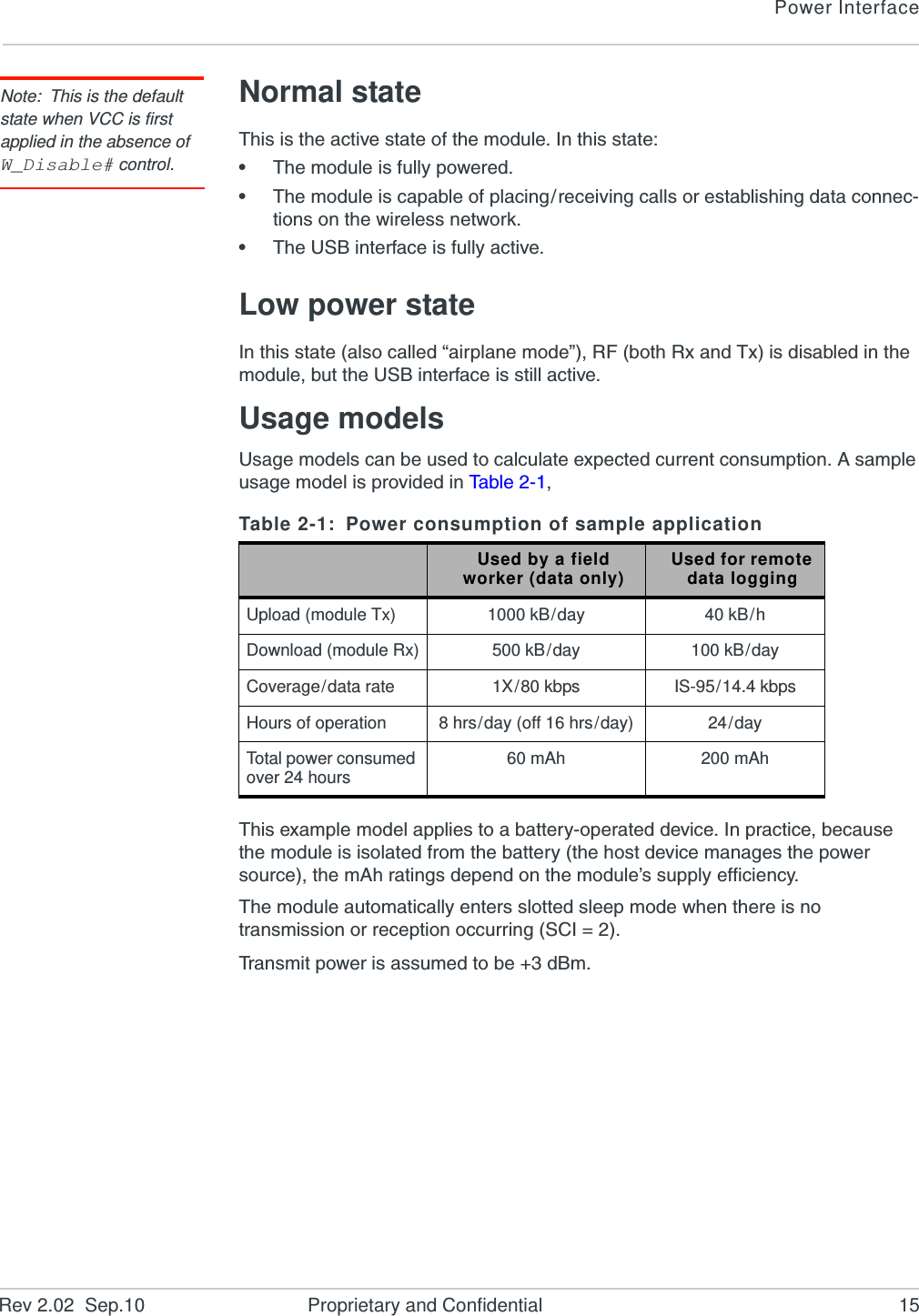
- 2. Photos Test Setup WCDMA
Hdw Integration Guide