Sierra Wireless Q23X8001 Dual-Band CDMA Wireless Module User Manual Wavecom Inc
Sierra Wireless, Inc. Dual-Band CDMA Wireless Module Wavecom Inc
Contents
- 1. Supplemental Response per CRN 24412 revised Users Manual
- 2. Users Manual per CRN 24509
- 3. Revised Users Manual per CRN 24642
Users Manual per CRN 24509
WISMO Quik Q2338 series
User’s Guide
Reference: WM_PRJ_WM2C_UG_001
Level: 001B
Date: 29th December 2002
- Pre-production Draft -
Copyright
Copyright© 2002 Wavecom, Inc. All Rights Reserved.
Trademarks
All trademarks contained in this manual are the property of their respective owners.
About This Manual
This manual is furnished under license and may only be used or copied in accordance with the terms of such license. The information in this
manual is for informational use only, is subject to change without notice, and should not be construed as a commitment by the manufacturer.
The manufacturer assumes no responsibility or liability for any errors or inaccuracies that may appear in this manual.
No part of this manual may be reproduced, stored in a retrieval system, or transmitted, in any form or by any means, electronic, mechanical,
recording, or otherwise, without the prior written permission of Wavecom, Inc.
Licensed by QUALCOMM Incorporated under one or more of the following United States Patents and/or their counterparts in other nations:
All other copyrights, trademarks and patents are the property of their owners.
Document Number
When ordering or referring to this publication, use the following number: Publication/PN WM_PRJ_WM2C_UG_001
WARNING! Read this information before using your phone
FCC & Industry Canada Regulatory Compliance
The Wismo Quik 2338 Series is approved for use with CDMA networks. This device complies with Part 15 of the FCC Rules. Operation is
subject to the following two conditions: (1) this device may not cause harmful interference, and (2) this device must accept any interference
received, including interference that may cause undesired operation.
Your wireless hand-held portable Module is a low power radio transmitter and receiver. When it is ON, it receives and also sends out radio
frequency (RF) signals. In August 1996, the Federal Communications Commission (FCC) adopted RF exposure guidelines with safety levels
for hand-held wireless Modules. Those guidelines are consistent with safety standards previously set by both U.S. and international standards
bodies: American National Standard Institute (ANSI), National Council of Radiation Protection and Measurements (NCRP), and International
Commission on Non-Ionizing Radiation Protection (ICNRP). Those standards were based on comprehensive and periodic evaluations of the
relevant scientific literature. The design of your Module complies with the FCC guidelines and applicable standards.
WARNING: Unauthorized antennas, modifications, or attachments could impair call quality, damage the Module, or result in
violation of FCC regulations. Do not use the Module with a damaged antenna. Please contact your local authorized dealer for antenna
replacement.
WARNING: BODY-WORN OPERATION – This device was tested for typical body-worn operations using the optional belt-
clip/holster to provide a separation distance of 0.8-inches/2.0 cm from the body. To comply with FCC RF exposure requirements, a
minimum separation distance of 0.8 inches/2.0 cm must be maintained between the user’s body and the belt-clip/holster, including the
antenna, whether extended or retracted. Third party belt-clips, holsters, and similar accessories used by this device should not
contain any metallic components. Body-worn accessories that do not meet these requirements may not comply with FCC RF exposure
limits and should be avoided.
FCC RF EXPOSURE INFORMATION
In August 1996 the Federal Communications Commission (FCC) of the United States with its action in Report and Order FCC 96-326
adopted an updated safety standard for human exposure to radio frequency electromagnetic energy emitted by FCC regulated
transmitters. Those guidelines are consistent with the safety standard previously set by both U.S. and international standards bodies.
The design of this phone complies with the FCC guidelines and these international standards.
Operating Requirements
The antennas used for this transmitter must be installed to provide a separation distance of at least 20 cm from all persons and must
not be co-located or operating in conjunction with any other antennas or transmitters. Please maintain 20 cm separation distance from
the antenna to meet FCC RF exposure compliance requirements.
For more information about RF exposure, please visit the FCC website at www.fcc.gov
NOTE: Read the “Safety” section prior to using your WISMO Quik Q2338 Series Module.
Do not use antenna with gains exceeding 3 dBi.
Preface
Your WISMO Quik Q2338 Series Module
Congratulations! Your new WISMO Quik Q2338 Series Module is going to change the way you communicate.
The WISMO QUIK Q2338 is a compact, lightweight, personal communications system with added features for the person on the go. More
than just a mobile phone, the WISMO QUIK Q2338 allows you to:
• Access your voice mail, and text messages
• Review a list of your latest outgoing and incoming calls for reference or call back
• Organize names and numbers
• Go on-line through the Browser (service features depend upon your carrier service) to surf the web, get e-mails, stock
quotes, etc.
• Send and receive text messages via the Short Message Service (carrier service provider dependent)
• Use your WISMO QUIK Q2338 as a wireless modem to send or receive faxes with your laptop computer.
The WISMO QUIK Q2338 is a compact, simple, and affordable solution for your active life style.
This Document is intended to provide the user complete instructions on the capabilities and use of the Wavecom Starter Kit. The Wavecom
Starter Kit is designed to allow the customer to interface to the Wavecom Q2300 and Q2400 CDMA and GSM/GPRS Module families.
Control of the Module is done via AT Commands issued from an external PC running a terminal emulator, such as HyperTerminal. The User
should refer to the Wavecom CDMA AT Commands Interface Specification for more information on supported commands.
[b1]

Table Of Contents
About This Manual ................................................................................................................................................ 2
Document Number ............................................................................................................................................ 2
FCC & Industry Canada Regulatory Compliance ......................................................................................................... 2
Preface............................................................................................................................................................... 3
Your WISMO Quik Q2338 Series Module ................................................................................................................ 3
About CDMA... .................................................................................................................................................... 6
Signal Strength and Module Performance.................................................................................................................. 6
CDMA Advantages............................................................................................................................................ 6
Safety ................................................................................................................................................................ 7
Road Safety Information...................................................................................................................................... 7
Aircraft Safety Information................................................................................................................................... 7
Hospital & Medical Safety Information .................................................................................................................... 7
Blasting and Refueling Safety Information ................................................................................................................ 7
Interference Safety Information.............................................................................................................................. 7
Service Safety Information ................................................................................................................................... 7
Chapter 1: Features ................................................................................................................................................ 8
Features ......................................................................................................................................................... 8
Standard Features .......................................................................................................................................... 8
Advanced Features ........................................................................................................................................ 8
Carrier Service Provider Dependent Features.......................................................................................................... 8
Temperature Range............................................................................................................................................ 8
Functions........................................................................................................................................................ 8
Chapter 2: Starterkit Description ................................................................................................................................9
Physical Description........................................................................................................................................... 9
Wismo Module................................................................................................................................................. 9
Development Board ........................................................................................................................................... 9
Switches and Jumper .................................................................................................................................... 10
Connectors................................................................................................................................................ 10
Audio ...................................................................................................................................................... 11
Receiver....................................................................................................Error! Bookmark not defined.
Headset.................................................................................................................................................... 11
Vibrator ................................................................................................................................................... 11
Buzzer/Ringer ............................................................................................................................................ 12
LED Function ............................................................................................................................................ 12
LED1 ...................................................................................................................................................... 12
LED2 ...................................................................................................................................................... 12
SIM Socket ............................................................................................................................................... 12
Keypad .................................................................................................................................................... 12
GPIO....................................................................................................................................................... 13
RF.......................................................................................................................................................... 13
Unpacking the Module ...................................................................................................................................... 14
Connecting the StarterKits.................................................................................................................................. 14
Installing the WISMO Quik Module...................................................................................................................... 14
Configuring the PC serial port ............................................................................................................................. 15
Removing the WISMO Quik Module..................................................................................................................... 15

Chapter 4: Using the Module................................................................................................................................... 16
Basic Operations ............................................................................................................................................. 16
Power On/Off ............................................................................................................................................ 16
Setting the Time.......................................................................................................................................... 16
Call setup diagram............................................................................................................................................... 16
Voice Call procedure............................................................................................................................................ 17
Prepare to call ................................................................................................................................................ 17
Voice call on cellular band: ................................................................................................................................ 17
To answer a voice call:...................................................................................................................................... 17
Data call procedure .............................................................................................................................................. 17
Make a data call.............................................................................................................................................. 17
Short Message Service (SMS) ................................................................................................................................. 18
Module receives the SMS .................................................................................................................................. 18
Module generates the SMS message ...................................................................................................................... 18
Chapter 4: Advanced Features ................................................................................................................................. 19
Using the WISMO QUIK Q2338 as a Wireless Modem ............................................................................................... 19
Prerequisites .................................................................................................................................................. 19
Using Your Module with Dial-up Networking .......................................................................................................... 20
Under Windows 95/98 .................................................................................................................................. 20
Under Windows NT and 2000 ......................................................................................................................... 20
Using Your Module for Faxing ............................................................................................................................ 21
Receiving a Fax .......................................................................................................................................... 21
Sending a Fax ............................................................................................................................................ 21
Using Your Module for Data File Transfers ............................................................................................................. 22
Sending a Data File...................................................................................................................................... 22
Receiving a Data File ................................................................................................................................... 22
AT Commands ............................................................................................................................................... 23
Chapter 5: Care & Troubleshooting........................................................................................................................... 24
Caring for Your Module .................................................................................................................................... 24
Cleaning Instructions........................................................................................................................................ 24
Basic Troubleshooting Techniques........................................................................................................................ 24
The modem does not answer through the serial link................................................................................................ 24
No RF signal.............................................................................................................................................. 25
The Module does not answer through the serial link................................................................................................ 25
No audio .................................................................................................................................................. 25

About CDMA...
The WISMO QUIK Q2338 is a digital CDMA wireless Module; compatible with digital (CDMA) networks operating at 800 and 1900 MHz.
Code division multiple access (CDMA) is the type of digital wireless transmission that the WISMO Quik Q2338 Series Module employs. The
following sections provide information on CDMA performance and advantages. These sections are designed to help you understand how to
better use your Wavecom Module.
Signal Strength and Module Performance
Like other portable wireless Modules or phones, the surrounding environment of the user affects signal strength. Buildings, parking garages,
elevators, and basements are some examples of structures that reduce signal strength. Problems initializing a call, muting of the audio during a
call, or a call drop are signs of low signal strength. Moving toward a window (if indoors) or open space (if outside) and extending the antenna
fully are ways to optimize signal strength. Traveling in a vehicle through varying terrain, tunnels, or near tall buildings may also cause rapid
changes in signal strength.
CDMA Advantages
Security: Each conversation is digitized and encoded with a separate assigned key to help prevent eavesdropping.
Voice Clarity: Uses digital voice coding techniques to enhance quality and reduce background noise.
Lower Average: Using sophisticated power control, the Module transmits
Transmit Power: The minimum power required to communicate with the base station and actually idles in between spoken
words. This results in much lower average power radiating from the antenna than other technologies.
Increased System: Provides 3-10 times the capacity compared to other Capacity technologies. This results in fewer dropped calls
and system busy signals for the user.
Digital Services: Allows user new services including caller ID, data and fax, text messaging, and simultaneous voice and data.

Safety
Important!
Read these safety guidelines prior to using your Module. Failure to follow these rules and guidelines may be dangerous and/or illegal.
Road Safety Information
Do not use a hand-held Module while driving a vehicle. Talking on the Module while driving is dangerous and illegal in some locations. If
using a hand-held Module, park the vehicle before conversing. Remember – road safety always comes first!
Aircraft Safety Information
Power down your Module prior to boarding an aircraft. Sending and receiving calls on your Module on an aircraft is prohibited by law and
aviation regulations. Using a wireless Module in an aircraft may interfere with aircraft radio communication or navigation equipment, and
disrupt the wireless Module network. When boarding an aircraft, turn your Module OFF.
Hospital & Medical Safety Information
Power down your Module prior to entering hospitals, health care facilities, or when near medical equipment.
Operating any radio transmitting equipment, including digital wireless Modules, may interfere with RF-sensitive medical devices. Follow all
posted regulations while in hospitals and health care facilities regarding the use of your Module.
Blasting and Refueling Safety Information
Do not use your Module near a blasting site. Power down your Module when in any area with a potentially explosive
Atmosphere. Radio transmissions in such areas could cause an explosion or fire, resulting in bodily injury or even death. Obey all posted
signs and instructions regarding the use of wireless Module usage. Observe restrictions on the use of radio equipment in fuel depots (fuel
storage and distribution areas), chemical plants or where blasting operations are in progress.
Interference Safety Information
All mobile Modules are subject to radio frequency interference that may affect the performance of your
Module. Your digital wireless Module is a low power radio transmitter and receiver. The design of your Module complies with the FCC
guidelines and applicable standards. Never rely solely on your Module for essential communications (e.g., medical emergencies). You must
be in a service area with adequate signal strength to use the Module. Emergency calls may not be possible on all wireless Module networks or
when certain network services and/or Module features are in use. Check with your local service provider(s).
Service Safety Information
Only qualified service personnel are authorized to repair your digital wireless Module and equipment. Use only approved accessories. Contact
you sales representative authorized service centers.
Chapter 1: Features
Features
The WISMO Quik Q2338 Series Module is a single mode, dual-band CDMA digital Module with several powerful and useful features not
typically available in a Module as compact and affordable as the WISMO Quik.
Standard Features
• One-touch Voice Mail Access
• Multiple Ringer Settings
• Any-key Call Answering
• Call History
• Key Guard/Module Lock
• Call timer
Advanced Features
• Wireless Modem
• Fax Transmit and Receive
• Text Message Receive
• Multiple Language Support
Carrier Service Provider Dependent Features
• Internet Mini-browser
• Two-way Short Message Service (SMS)
• E-mail Capability
• Call Waiting
• Three-Way Calling
• Call Forwarding
• Caller ID
Temperature Range
• Operating conditions: From -30˚C to +60˚C
• Storage conditions: From -40˚C to +70˚C
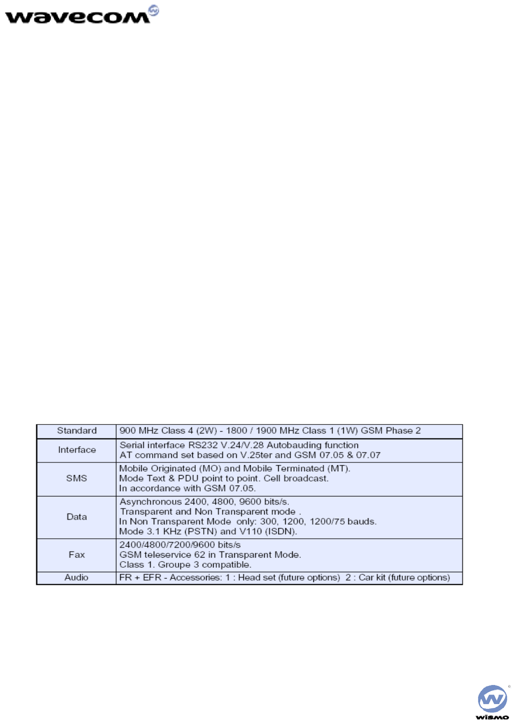
Functions
[b2]
Chapter 2: Starterkit Description
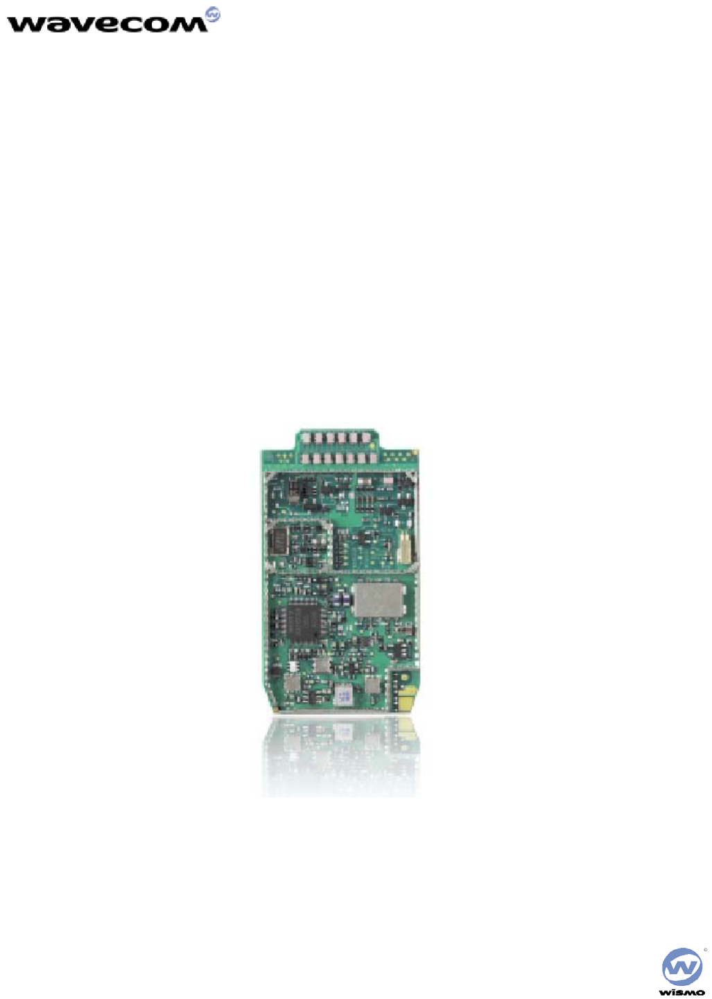
Physical Description
The WISMO QUIK Q2338 is 58 mm long, 32 mm wide and has a thickness of less than 5.9 mm. It weighs only XXX grams.
The physical features of the WISMO QUIK Q2338 are identified in the following picture:
Dimensions 58 x 32 x 5.9 mm
Weight < 80 grams
Volume
Housing Aluminum Profiled
[b3]
Wismo Module
[b4]
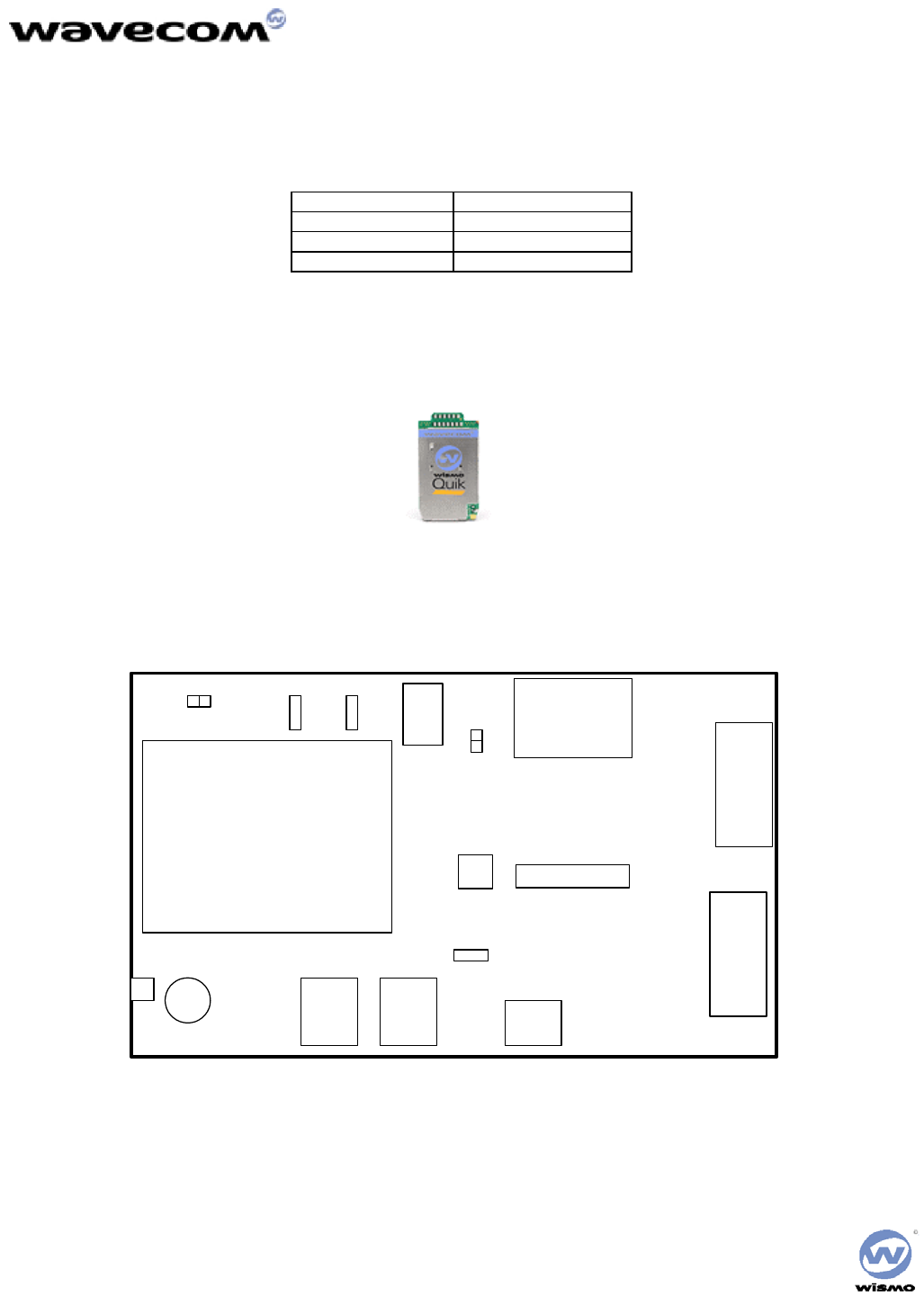
Development Board
The board diagram shows the relative position of all switches, connectors and jumpers that are discussed below.
MODULE
DM
DB-9 DATA
DB-9
SIM
SOCKET
RF HEADSET HANDSET
HEADSET
JTAG
POWER
INPUT
RESET
SNGL/DIFF
LED 1
VIBRARINGER
OFF/ON
BOOT
LED 2

Power Supply
A standard DC Power Jack is provided on the Interface Board. The included Power Adapter can be used to supply the Module and Interface
Board via this jack. Alternatively a lab power supply capable of supplying at least 3.8Vdc at 2.0Amps can be used. The advantage of the lab
power supply is in allowing the user to monitor the current drain of the Module to help determine its operating state. The Power Jack has a
center positive connection, if a lab supply or other external source is used. A cable for this purpose is available.
The Power Adapter supplies 4.0 Volts DC and a maximum of 2.0 Amps. It can be plugged into a 110 Volt or 220 Volt Mains input. If a lab
power supply is used instead, it should be set for 3.8 Volts DC with a minimum current limit of 2.0 Amps.
Switches and Jumper
RESET There is a master push button reset switch, SW100, located in the middle of the Interface Board that when
depressed will pull the RESET/ line of the Module to Ground, causing a full Module microprocessor reset.
PWR – ON There is a slide switch, SW101, located on the back edge of the Interface Board. This switch interfaces directly
to the ON/OFF control line of the Module, via pin 6 of the board-to-board connector. Sliding the switch in the
“OFF” direction will pull the line low, causing the Module to shut off. Sliding the switch in the “ON” direction
will pull the line high, turning on the Module and keeping it in the ON state.
Boot A second slide switch, SW102, is located on the back edge of the Interface Board, beside the ON/OFF switch.
The function of this switch depends on if a CDMA Module or GSM/GPRS Module is being used. For normal
operation of the GSM Module, this switch must be in the HI position upon power up or reset. This switch when
in the LO position will put the GSM Module into its BOOT Mode. This allows software upgrades to the
embedded code within the Module, via the serial interface of the Interface Board and an application such as the
Wavecom DWLWin program. Note that the switch must be in the LO state upon power up or reset. Once the
embedded code is executing, the status of the BOOT input is no longer monitored
For the CDMA Modules, there is no need for this BOOT functionality. Thus this switch is for test purposes
only and is connected to GPIO 42 of the Module. The input can be pulled LO or HI and monitored via AT
Command Queries if needed
SNGL/DIFF Jumper A four-pin jumper, J303, is located near the Audio connectors. This is used to configure the Headset Audio for
either a single ended or differential speaker drive circuit. Silkscreen on the Interface Board indicates the jumper
positions required for either case. For Differential, one jumper should be placed across pins 2 and 3. For Single
Ended, two jumpers should be placed; one across pins 1 and 2, and the other across pins 3 and 4. Refer to
Error! Reference source not found. for more details on the functionality of this jumper block.
Connectors
Power Input The Power Connector provides input voltage to the board from the Power Cube provided in the Kit.
Data DB-9 The Data Connector provides for connection to the Host PC.
DM DB-9 This Connector is not available to the customer.
Serial Interface
Data
The DATA Interface provides a full 8 wire RS-232 interface with the PC. This interface supports the AT Commands; the Diagnostic (DM)
information; and high speed data.
Light Emitting Diodes (LEDs) for this port are included on the Interface Board on the RX, TX, DTR, DSR, RTS, CTS and DCD lines to
indicate the state of the line. The red LED indicates a negative voltage on the RS-232 (Logic 1) and the green LED indicates a positive
voltage on the RS-232 (Logic 0).
DM
The DM Interface provides a 2 wire RS-232 interface for Diagnostic information only. The typical customer application should not require
this interface as all functionality of the DM Interface is now supported through the DATA Interface as well.
Light Emitting Diodes (LEDs) for this port are included on the Interface Board on both the RX and TX lines to indicate the state of the line.
The red LED indicates a negative voltage on the RS-232 (Logic 1) and the green LED indicates a positive voltage on the RS-232 (Logic 0).
Audio
There are two unique audio paths provided for on the Interface Board, and supported by the Module.
Receiver
Handest-1 The Receiver Jack (J300) supports fully differential microphone and speaker signals. The microphone is also biased and
filtered on the Interface Board. The Receiver included in the Starter Kit can be used with this port.
This Receiver audio path is considered Path 1 in the AT Command Set.
Headset
Headset-1 The connector provides the user a single-ended MIC and Speaker RJ11 connection point.
Headset-2 The connector provides the user a single-ended MIC and Speaker standard 2.5mm Headset connection point.
The Headset Jack (J301) supports a biased differential microphone however the speaker path is either single or differential for GSM/GPRS or
single ended only for CDMA. This difference is due to limitations of the CDMA design, allowing for only one fully differential speaker path.
Jumpers on J303 configure the path for single (SNGL) or differential (DIFF) audio. The Receiver included in the Starter Kit can be used with
this port.
There is an additional audio jack included on the Interface Board that supports the use of a standard 2.5mm three-wire cell phone headset (not
included). This jack (J302) supports only single ended microphone and speaker signals, and is wired in parallel with the Headset Jack, J301.
Only J301 or J302 can be used at once, and the jumpers on J303 must be set for single ended operation to use J302. Note the single ended
audio does result in an increased noise floor, especially when the Starter Kit is used with a GSM or GPRS Module. Careful filtering and
attention to layout is required in a customer application to minimize this noise.
These Headset audio paths are considered Path 0 in the AT Command Set.
Vibrator
The Interface Board includes vibrator driver circuitry that will allow the customer to plug in an optional external vibration motor for testing.
The connection is made via test points TP500. A standard 1.6V to 3.0V cell phone vibration motor can be used.
Alternatively, for test purposes a red LED has been added to indicate the state of the line, and is located near the “VIBRA” label on the board.
Buzzer/Ringer
The Interface Board includes ringer driver circuitry that will allow the customer to plug in an optional external buzzer/ringer for testing. The
connection is made via test points TP501. A standard 2.0V to 3.0V cell phone ringer can be used.
Alternatively, for test purposes a green LED has been added to indicate the state of the line, and is located near the “RINGER” label on the
board.
LED Function
There are two general status indicators, LED1 and LED2, on the Interface Board. The drive circuits for these are controlled directly from the
Module, via the 60 pin board-to-board connector. Both LEDs are located near the Power Jack on the Interface Board.
Additional indicators are included for the Vibrator and Ringer driver circuits, and for the DM and DATA Interface ports. Refer to these
headings for more details of their function.
LED1
This LED is red when illuminated, and provides the user with an indication of the Module status according to the following table:
LED1 Status Module Status
OFF In download mode or OFF
ON: Permanent ON but not registered on a network
ON: Slow Flash
- 200mS ON, 2S OFF ON and registered on a network
ON: Quick Flash
- 200mS ON, 600mS OFF
ON, registered on a network and communication
in progress
LED2
This LED is green when illuminated. The functionality of this LED can be defined to provide a method of test and debug by the user via AT
Commands. It is connected via pin 54 of the board-to-board connector and is driven by GPIO 8 on the CDMA Modules, and GPIO 4 on the
GSM/GPRS Modules.
SIM Socket
SIM socket is provided for use with the RUIM (CDMA) or SIM (GSM/GPRS) card. The Interface Board supports the low voltage cards,
having a supply of 2.8Vdc from the Module. The RUIM card is not yet required for North American CDMA modules.
Keypad
For testing purposes, an optional keypad can be installed on the Interface Board that will provide the customer a 5x4 matrix of keys for test
and debug. The keypad should be a Grayhill 88JB2 and can be purchased in North America through Digikey with a GH5020-ND part
number. The Module itself can support a bigger matrix, however the keypad chosen was the largest standard keypad that could be found.
Note that for the CDMA Module, the JTAG and Keypad share the same Module interface pins thus cannot be used at the same time.
Additionally, the CDMA Module itself requires a different hardware population to implement each path. The default population
configuration for the CDMA module enables the Keypad, not the JTAG Interface.
JTAG
Included on the Interface Board for debugging purposes is a JTAG Header (J202). The connector, when needed, should be soldered to the
bottom side of the Interface Board. This connector will not be required in a customer application, and is therefore not normally populated on
the board.
Note that only the CDMA Module supports a JTAG interface. The JTAG and Keypad Interfaces share the same Module interface pins thus
cannot be used at the same time. Additionally, the CDMA Module itself requires a different hardware population to implement each path.
The default population configuration for the CDMA module enables the Keypad, not the JTAG Interface.

GPIO
Included in the design are Test Points to allow the customer to access all unused General Purpose Input/Outputs (GPIOs) provided by the
Module. These are direct from the Module, with no circuitry added. They are located next to the Reset switch in the middle of the Interface
Board, and are labeled according to the CDMA Module schematic pin name. Two of these lines are Analog to Digital inputs to the Module
microprocessor, if required for testing.
Note that for the GSM Module design, the test point names do not apply and the user will have to refer to the GSM schematic to determine
the correct test point location for a given line.
RF
There are two RF connection points on the Interface Board, both used to provide an RF path from the Module to the Interface Board mounted
RF jack.
The Module will be supplied with an RF “pigtail” cable assembly. This pigtail is soldered to the module and terminates in a bulkhead style
RF SMA connector. This can be mounted on the Interface Board through the ground ring labeled “RF”, and the supplied Antenna screwed
onto this connector. This is the preferred method of connecting the RF Antenna.
Alternatively, under the Module there are pads where an optional surface mount connector can be soldered that will mate with similar pads on
the Module. A connector such as the Radiall R107.064.000 is suggested (see Note below). The RF signal would then be passed to J500,
which supports a connector such as the AMP/TYCO 221790-1 Right Angle PCB Mount SMA Connector (not included). The Antenna
included in the Starter Kit can attach to this jack.
Note: The Radiall connector has not been fully tested or characterized for either CDMA or GSM/GPRS. It is not recommended for customer
testing or customer use in a final design. Some versions of the Module may not support the use of a surface mount RF connector.
Expected antenna gain for the Low band 3dB and for High Band 0 dB
To connect the antenna to the starter kit simply attached the SMA connector to the provide SMA pigtail connector. For the final application
or if the connector has changed refer to the connecting instructions provided by the connector vendor and user’s guide of the finished
product.
Chapter 3: Unpacking & Setup the Module
Unpacking the Module
Your WISMO QUIK Q2338 package includes the following:
• WISMO Quik Q2338 Series Module
• WISMO Quik Development Board
• AC/DC Power connector
• (2) Serial Cables
• Dual band Antenna
• Antenna connector
• CD-ROM: Which contains the User’s Guide (this manual), H/W and S/W specifications, and the AT Command document
If you are missing any of these items, please return this package to your point of purchase and request a complete kit.
The following gives a description of the connections and configurations required to bring up the Module. Be sure to consider these
recommendations before applying power to the Interface Board and Module.
Connecting the StarterKits
To connect the StarterKits:
1. Connect the data port of the StarterKits to COM 2 of your PC or laptop using the DB9 serial cable.
2. Connect the dm port of the StarterKits to COM 1 of your PC or laptop using the DB9 serial cable.
3. Connect the AC/DC converter to an open wall socket at one end and the StarterKits at the other.
Installing the WISMO Quik Module
To install the WISMO:
1. Install the WISMO to the development board. Check the alignment of the board-to-board connector and the ground pins of the
Module.
2. When the alignment is correct, firmly press on the WISMO until you hear a soft snap.
3. Insert the barrel jack connector of the power adapter plug into the power port on the development board.
4. Move the power switch to the on position.
5. Solder the four ground posts to the through holes in the PCB of the development board (Optional)
When power is applied, the Module will illuminate and transition to a blinking LED
[b5]

Configuring the PC serial port
To configure the serial port:
1. Set the bits per second to: 115200 bps
2. Set the data bits to: 8 bits
3. Set the stop bit to: 1 bit
4. Set the flow control to: None
Removing the WISMO Quik Module
To remove the WISMO:
1. Move the power switch to the off position.
2. Disconnect the cabling from the StarterKits.
3. Unsolder the (4) ground posts (Depends if step 5 was completed above)
4. Gently pull the top of the Module up and away from the development board
Chapter 4: Using the Module
This chapter contains basic instructions on how to use specific functions of your Module. For more detailed instructions please refer to the AT
Command specification.
Basic Operations
Basic operations are the fundamental operating functions that you must know to successfully begin using the WISMO QUIK Q2338.
Power On/Off
• To turn the power ON, slide the ON/OFF switch to the ON position and watch for the LED power light go on.
• To turn the power OFF, slide the ON/OFF switch to the OFF position and watch for the LED power light go off.
Setting the Time
There is no need to set the time on your WISMO Quik Q2338 Series Module. The Module receives a time signal from your service provider.
Please note that your clock will go blank when you leave your service area, but will again display the correct time when you re-enter your
service area.
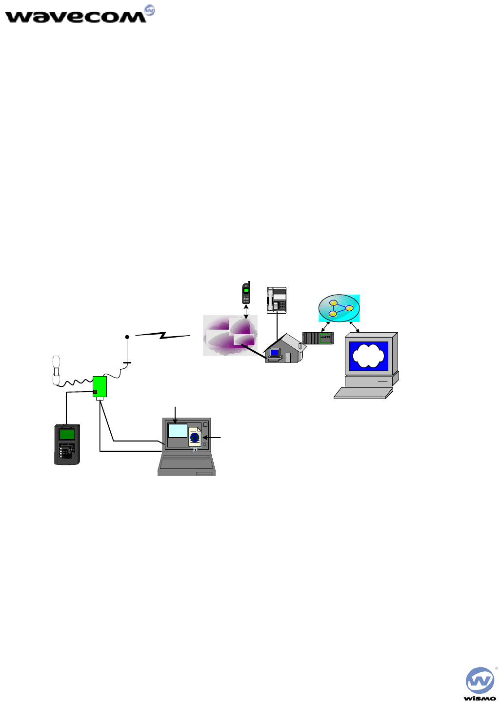
Call setup diagram
serial connections
port speed:11520
Site Link
Bridge
PRINT
HELP
ALPHA
SHIFT
ENTER
RUN
D
GE
RF
I
A
JB
KC
L
7
M8
N9
O
D
GD
GD
G
D
G T 3
U
0
V.
WXYZ
TAB
% UTILIZATION
HUB/MAU NIC
2
BNC
4Mb/s
Power supply
Lap Top PC
Data - COM2
DM - COM1
Antenna
WISMOQ
CDMA 1x module
123
456
789
*8#
Modem Ba nk
+3.7 v
Web Browser
Hyper terminal
wireless network
PTSN
dial-up
Modem pool
Web Server
Tools loaded:
- UDM
- PST
- Flash downloader
Fig. 1. Call set up with WISMOQ CDMA 2000 1x module

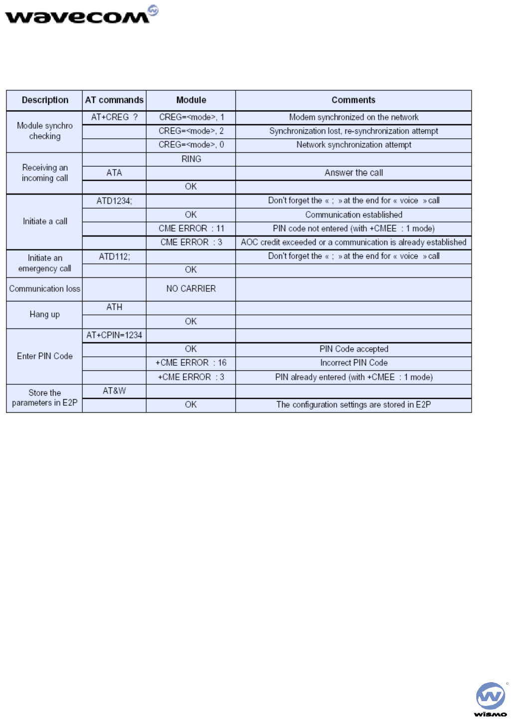
Voice Call procedure
Note:
• The following procedures can work on both cellular band and PCS band, just use different phone or roaming to the other system.
• The calling phone # is just an example.
• For local dialing, the area code is not necessary.
Prepare to call
After the above set up is done and the module has a valid phone number and a good roaming list,
• Make sure the switch 1 close to the “reset” button is in “on” position and the other is in “OFF” position on the testing board
• Power up the testing board
• Launch UDM to see that the module is active and in “Idle” state.
Voice call on cellular band:
• Open a preset hyper terminal
• Enter “AT”, it should respond “OK”
• Enter “ATD 18583620101; // The “;” is necessary for voice call
• Pick up the Receiver, start conversation
• When finished the conversion, enter “ATH” to hang up.
To answer a voice call:
• From the hyper terminal, when see “RING” and “+CLIP:’8583620101’”
• Enter “ATA” to answer the call
• When finished conversation, enter “ATH” or wait for other party hang up.
Data call procedure
Note:
• The computer must have been installed an IE internet browser and two serial ports
• The active phone number should have data service,
• Before the procedure, user needs to set a dial-up network terminal to an active ISP. It is better to ask an IT person to set it up for
you.
Make a data call
• Make sure the data port (COM2) is free (close hyper terminal)
• Launch the dial-up network to the ISP
• After the connection is established, launch IE
• In IE, enter an valid web page address and to browse the internet
• When finished, disconnect the dial-up connection

Short Message Service (SMS)
Note:
• Currently, the SMS functions are limited in our CDMA1x module, but later we will add more functions
• For module generated SMS, the fixed test string will be used. So only the phone number can be dialed.
Module receives the SMS
• Open the hyper terminal (e.g. Call Terminal)
• Go to another computer with the internet connection
• Use internet browser and go to web site:
• For Sprint phone number: http://www.messaging.sprintpcs.com/smswmgr/BMG/index.jsp
• For Verizon phone number: http://www.vtext.com/
• Enter the module phone number and text message, then send
• When the “+CMTI: 1” pomp up, enter “AT+CMGR=1” to read the message.
• Then enter “AT+CMGD=1” to delete the message.
Module generates the SMS message
Note:
• Currently, only Verizon phone can support the mobile generated SMS.
• The Verizon mobile number “8583956021” is an example.
• Currently, no user text can be entered. It is a fixed string for test only.
• With the Verizon phone number module, in the hyper terminal, enter: AT+CMGS=”18583956021” // the “ “
is necessary in the command
• The module should response in sequence: +WORG; +WMOS: 1; +WMOS: 0;
• The receiving mobile should beep after a few seconds.
• In the receiving mobile, it will display the fixed message “This is a test of MO SMS”.

Chapter 4: Advanced Features
Using the WISMO QUIK Q2338 as a Wireless Modem
The procedures in this section will help you set up and use your WISMO QUIK Q2338 Module as a wireless modem. To perform the
procedures in this chapter, you must connect your Wavecom Module to your PC or Laptop using your data cable. There are three general
functions discussed in this section:
• Dial-up Networking
• Faxing
• Data Transfer
Although the procedures are similar for each function, they differ slightly depending on what you are using the Module/modem for. Read
each section thoroughly before beginning the procedures.
Prerequisites
Operating System Windows 95 or newer required. Windows 2000 or XP is recommended for best performance.
Modem Program The following programs have been tested and found compatible for use with the WISMO QUIK Q2338:
• The Modem program contained in the Windows OS
• Procomm Plus Version 4.7
• WinFAX Pro Version 9.0
You may find that other programs will work when using the WISMO QUIK Q2338 as a modem. You use these programs at your
own risk.
NOTE: If your Module has already been configured for use as a wireless modem, skip to the next section. If your Module has not
been setup for use as a wireless modem, perform the following procedure:
1. From your PC, click on the Windows START button.
2. Select SETTINGS.
3. Open CONTROL PANEL.
4. Open MODEMS.
5. Click on ADD... from Modems Properties window.
6. Select “Don't detect my modem; I will select it from a list.”
7. Click on NEXT.
8. Select Standard Modem Types for Manufacturers and Standard 19200 bps Modem for Models.
9. Click on NEXT.
10. Select the correct COM port and Click on NEXT.
11. Click on FINISH. Close all applications and restart your PC.
12. Once your PC restarts, open CONTROL PANEL again.
13. Open MODEMS.
14. Click on PROPERTIES.
15. Verify the following settings are entered:
General Tab
- Maximum speed = 19,200
Connection Tab
- Data bits = 8
- Parity = None
- Stop bits = 1
16. Click on ADVANCED... and ensure that Flow Control = Hardware (RTS/CTS)
17. Click OK.
18. Click on CLOSE to exit the program.
NOTE: For Windows 95 users, the next step requires you to specify the modem type; select “Other” (not PCMCIA card).
Your Module is now ready to function as a wireless modem.

Using Your Module with Dial-up Networking
Your Module can be used with Dial-Up Networking to access network resources for sending and receiving e-mails or connecting to the
Internet. Before you use Dial-Up Networking, be sure that your Module is correctly installed as a standard 19200 modem (See “Setting Up
Your Module as a Modem” that Dial-Up Networking is installed and that your network protocols have been properly configured. Consult
your Internet Service Provider if you need assistance. The procedures for using Dial-Up Networking may differ; depending on the version of
Windows you are running. Follow the instructions for your operating system.
Under Windows 95/98
If you have previously used Dial-Up Networking with another modem under Windows 95 or 98:
1. Launch the Dial-Up Networking application.
2. Select the existing Dial-Up Networking configuration.
3. Right click your mouse and select Properties.
4. Select the Standard 19200 Modem and click on OK.
5. If you have never used Dial-Up Networking previously with another modem, you need to create a new connection in Windows
95/98.
6. Click Start, and then select Programs, Accessories and Dial-Up Networking.
7. Double click on Make a New Connection.
8. Enter the connection name.
9. Choose Standard 19200 Modem from the Select a Modem list (Select a Device in Windows 98).
10. Click Next.
11. Enter the area code, Module number and country code for the number you wish to dial.
12. Click Next.
13. Click Finish to complete the connection.
Under Windows NT and 2000
If you have previously used Dial-Up Networking with another modem under Windows NT, you need to select the Wavecom modem.
1. Run Dial-Up Networking.
2. Click more on the Dial-Up Networking menu and select Edit Entry and Modem Properties.
3. Select the Standard 19200 Modem from the listings and click OK.
If you have not previously used Dial-Up Networking with another modem, you will need to create a Module book Entry in Windows NT.
1. Click Start, and then select Programs, Accessories, and Dial-Up Networking.
2. Click New and follow the instructions provided by the Module book Entry Wizard.
3. Enter the name for the new Module book Entry and click next.
4. On the Server Dialog screen, check only those items required by your dial-up server, then click next.
5. Select the Standard 19200 Modem from the listings and click next.
6. Enter the Module number you need to dial to reach your server. If the server has more than one number, click Alternates to enter
all of them, then click next.
7. When you’ve finished setting up your Module book Entry with the wizard, click Finish.
8. Click more and select Edit Module book Entry.
9. Click the Server tab and select the proper type (PPP, Windows NT, Windows 95, Internet, etc.) for your dial-up server. If you are
unsure, contact your ISP for more information.
10. Check the box beside the network protocol (such as TCP/IP) used by your dial-up server. If you are unsure, contact your ISP for
more information.
11. If you selected TCP/IP as a protocol in Step 10, click on TCP/IP Settings and enter the proper specifications. If you are unsure,
contact your ISP for more information. Click OK when you are finished.
12. If your server requires you to run a login script, click the Script tab to enter the required information. If you are unsure, contact
your ISP for more information.
13. Click the Security tab to specify security information if it is required by your dial-up server.
14. Click OK to exit Edit Module book Entry.
15. Click Location on Dial-Up Networking if you need to change the location from which you are dialing.
You are now ready to use Dial-Up networking to access remote servers with your Module.

Using Your Module for Faxing
The following section provides information required for setting up your fax program and using your Module as a modem to send/receive a
fax. Refer to your fax program documentation for specific setup instructions. Note that the Module is defined as a class 2.0 modem.
Verify the following modem properties when setting up your fax program:
1. Baud Rate: 19200 bps (default)
2. Data Bits: 8
3. Stop Bits: 1
4. Parity: None
5. Flow Control: Hardware (RTS/CTS)
Receiving a Fax
Ensure that the WISMO QUIK Q2338 is connected to your PC and is powered ON.
In your PC’s fax program, you need to setup the Answer mode. Click on RECEIVE and select one of the following:
- Automatic Receive (recommended)
- Manual Receive
Your Module is now ready to receive an incoming fax.
Sending a Fax
To send a fax, refer to your fax program documentation for specific faxing instructions.

Using Your Module for Data File Transfers
The following section provides information required for setting up your data transfer program and use your Module as a modem to
send/receive a data file. Refer to your data transfer program documentation for specific setup and data transfer instructions.
Sending a Data File
On Your Module:
1. Ensure that the WISMO QUIK Q2338 is connected to your PC and is powered ON.
2. Press [Preferences] (Soft Key 1).
3. Scroll to Features and press OK.
4. Scroll to Data/FAX and press OK.
5. Scroll through the choices using the Soft Keys until Data until Off is displayed with a check mark.
Refer to your data transfer program documentation for specific instructions on receiving a data file.
On Your PC/Laptop:
1. Start Procomm Plus™ in Data Terminal mode. Refer to the Procomm Plus documentation for specific instructions on how to use
their software.
2. Select the COM port matching the serial port that your Module’s data cable is connected to.
3. Under Options> System Options> Modem Connection, click on the
4. Modem Connection Properties button and verify the settings as noted below:
5. Baud Rate: 19200 bps (default)
• Data Bits: 8
• Stop Bits: 1
• Parity: None
• Flow Control: Hardware (RTS/CTS)
6. Dial the number you wish to send a file to.
7. After a connection is established, select Data> Send File.
8. In the window that appears, locate and select the file you want to send.
9. Click on OK. The file transfer will begin.
10. After the file transfer is complete, select Data> Disconnect. The call will terminate.
Receiving a Data File
On Your Module:
1. Ensure that the WISMO QUIK Q2338 is connected to your PC and is powered ON.
2. .[b6]
On Your PC/Laptop:
1. Start Procomm Plus in Data Terminal mode. Refer to the Procomm Plus documentation for specific instructions on how to use their
software.
2. Select the COM port matching the serial port that your Module’s data cable is connected to.
• Under Options> System Options> Modem Connection, click on the Modem Connection Properties button and verify the
settings as noted below:
• Baud Rate: 19200 bps (default)
• Data Bits: 8
• Stop Bits: 1
• Parity: None
• Flow Control: Hardware (RTS/CTS)
3. Dial the number or accept the incoming call from the number from which you will be receiving the file.
4. Select Data> Receive File. The file transfer will begin.
5. After the file transfer is complete, select Data> Disconnect. The call will terminate.
AT Commands
Transferring data files may require you to use AT commands. The following tables list some of the more common AT Commands, S-
Registers, and Basic Action Commands. For more AT commands, refer to your data transfer program documentation[b7].
[b8][b9]
Chapter 5: Care & Troubleshooting
Caring for Your Module
• Keep your Module clean.
• Keep your Module dry. Humidity and liquids may cause your Module to fail and will corrode the internal circuits.
• Protect your Module from temperature extremes. High temperatures may damage the batteries, shorten the life of electronic
components, and warp or melt certain plastics.
• Do not attempt to open or access the internal components of your Module. If your Module is not functioning properly, take it to the
point of purchase.
• Do not drop, shake, or handle your Module in a rough manner - it can damage the Module
Cleaning Instructions
1. Turn the power off on your Module prior to cleaning.
NOTE: Do not apply cleaning liquids directly to your Module. Avoid using harsh chemicals, strong detergents, and petroleum-based
solvents to clean your Module. Some household cleaners contain chemicals that may damage your Module.
2. Apply the cleaning liquid to a soft cloth or towelette and gently wipe the external surfaces of your Module until it is clean.
3. Let the surfaces dry.
4. Turn the power on.
5. The Module is now ready to use.
Basic Troubleshooting Techniques
The following table describes possible problems and their resolution:
The modem does not answer through the serial link
1. Is the modem correctly powered on?
• If not, the correct power supply is 4V.
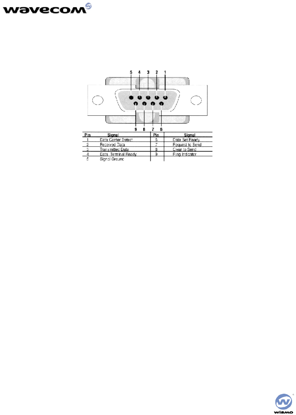
2. Is the serial cable suitable and adjusted in the modem and PC sockets?
• A suitable cable must follow pin assignment described on figure 6. [b10]Check in particular, that Rx & Tx are properly
connected.
3. Check that your communication program is properly configured:
• Modem factory setting for the character framing are:
• Data Bits: 8
• Parity: None
• Stop Bits: 1
• The factory setting for baud rate is auto-bauding mode.
4. Does any other program interfere with your communication program (conflict on communication port access)?
• If yes, close any application likely to interfere (e.g. mouse or printer driver).
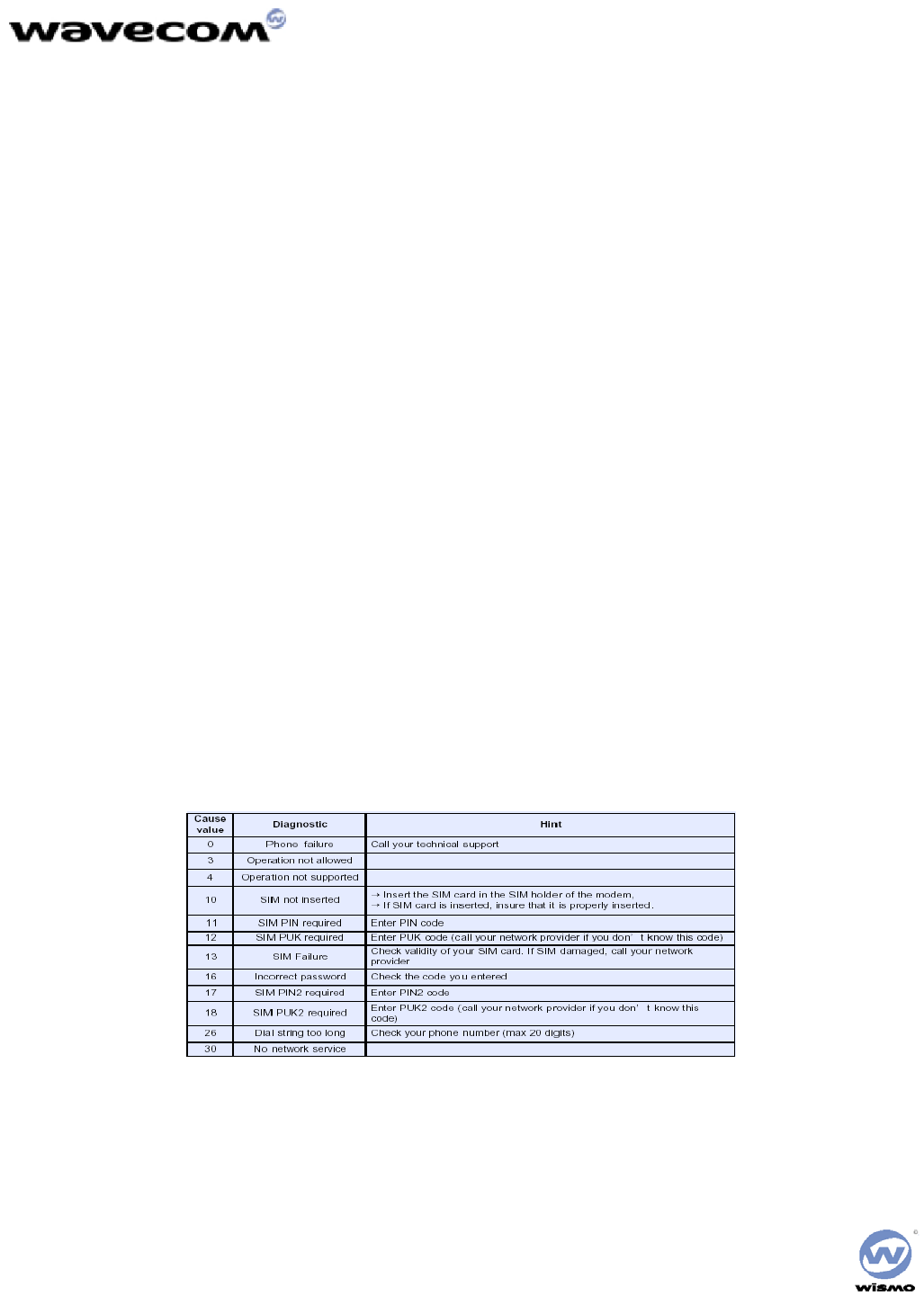
5. Issue AT+CMEE=1 to have extended error cause and retry
[b11]
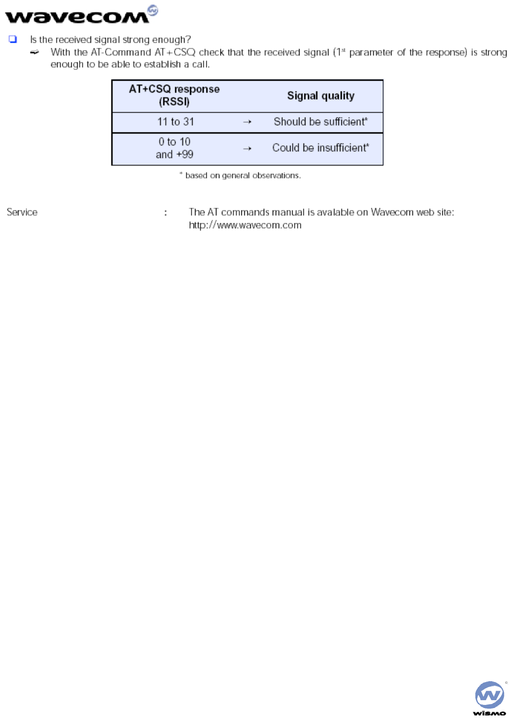
No RF signal
• Verify the Antenna is correctly connected to the Module. Verify the position of the Antenna is in a strong signal location.
The Module does not answer through the serial link
• No or incorrect power is being supplied to the Module. Verify the Power Supply and ON/OFF Switch position.
• The Module is not adequately assembled onto the Interface Board. Verify that proper grounding (ideally solder) is provided.
• The wrong DB-9 connector is being used. Verify that the DATA Port is connected to the controlling PC.
• The terminal emulator application, HyperTerminal for example, is not correctly configured for the Module. Verify the Baud rate. It
is possible that the Module has been configured for a different default Baud rate, so it may be necessary to try different rates in
HyperTerminal.
No audio
• The wrong Audio Path has been selected. Try the other Audio Jack, or issue the AT Command to verify/select the correct path.
• The SNGL/DIFF Jumper is not correctly installed. This only affects the Headset Audio Path.