Sierra Wireless RED Open-Source Hardware Development Platform User Manual mangOH Red Developer s Guide

Sierra Wireless Inc. Open-Source Hardware Development Platform mangOH Red Developer s Guide

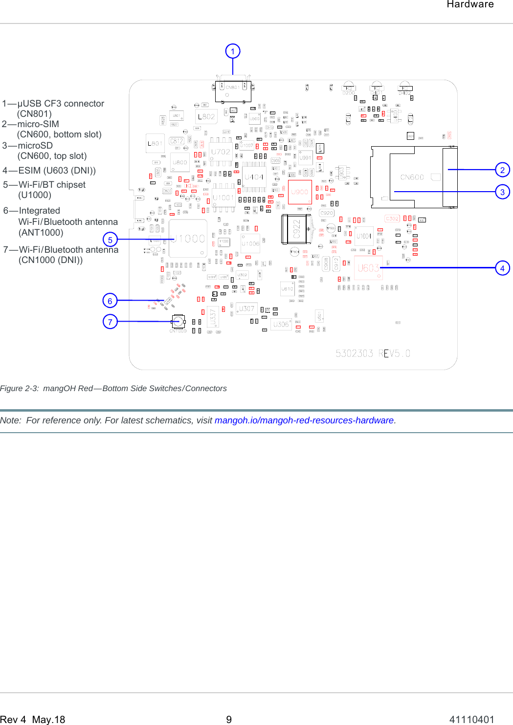
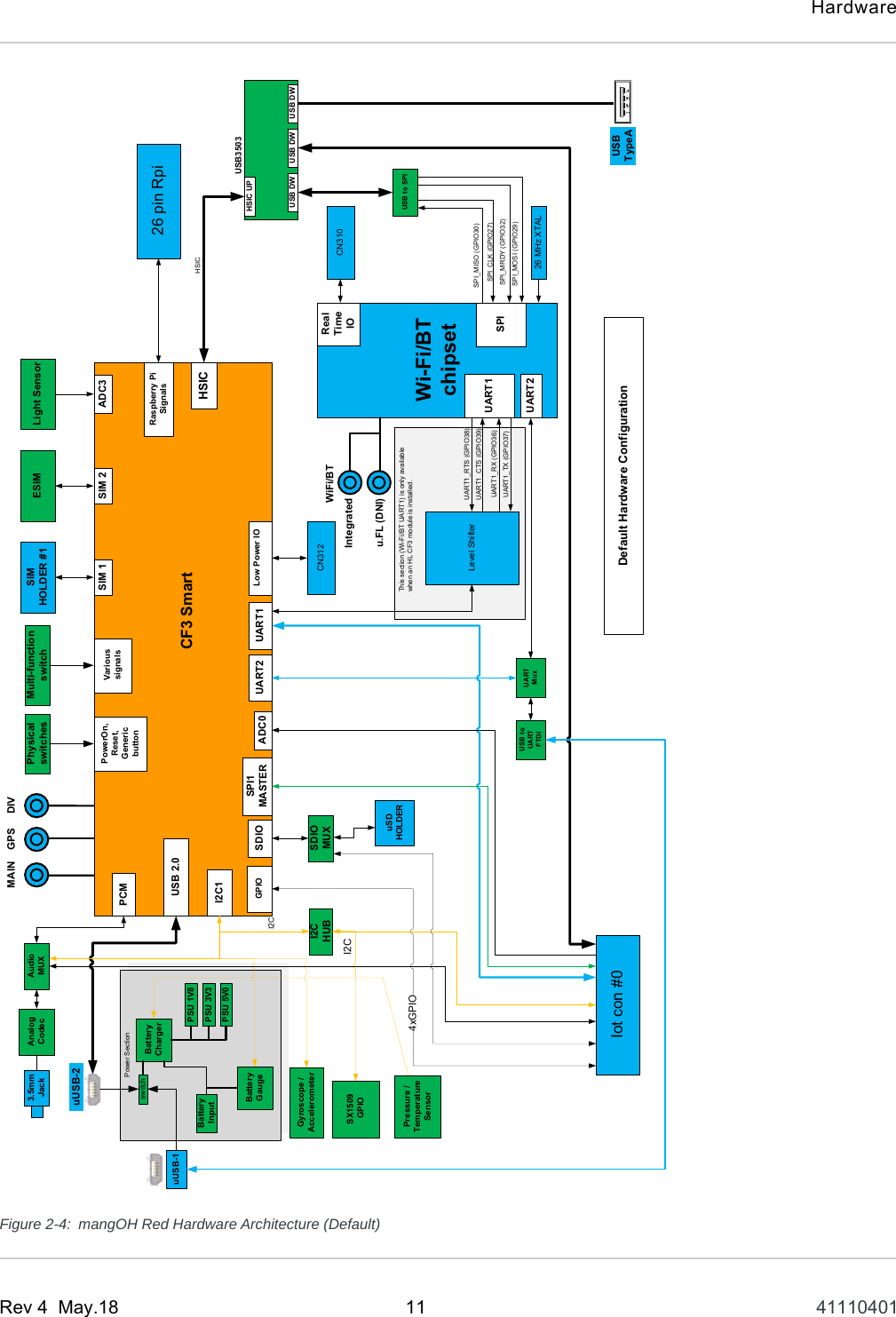
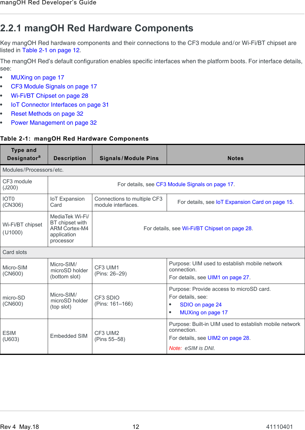
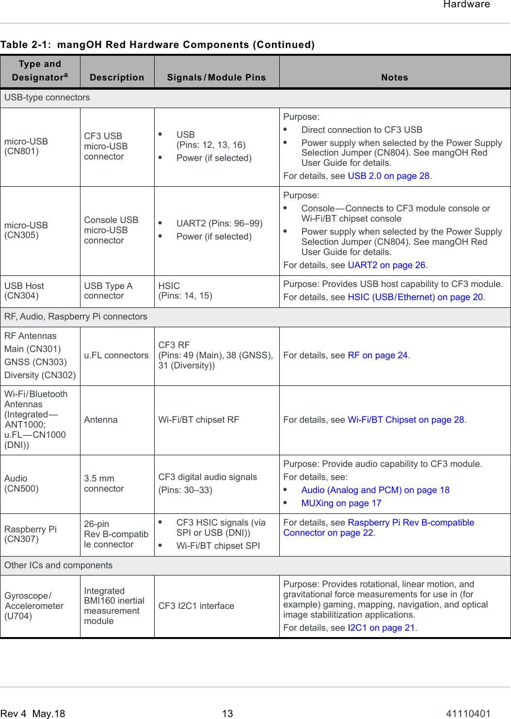
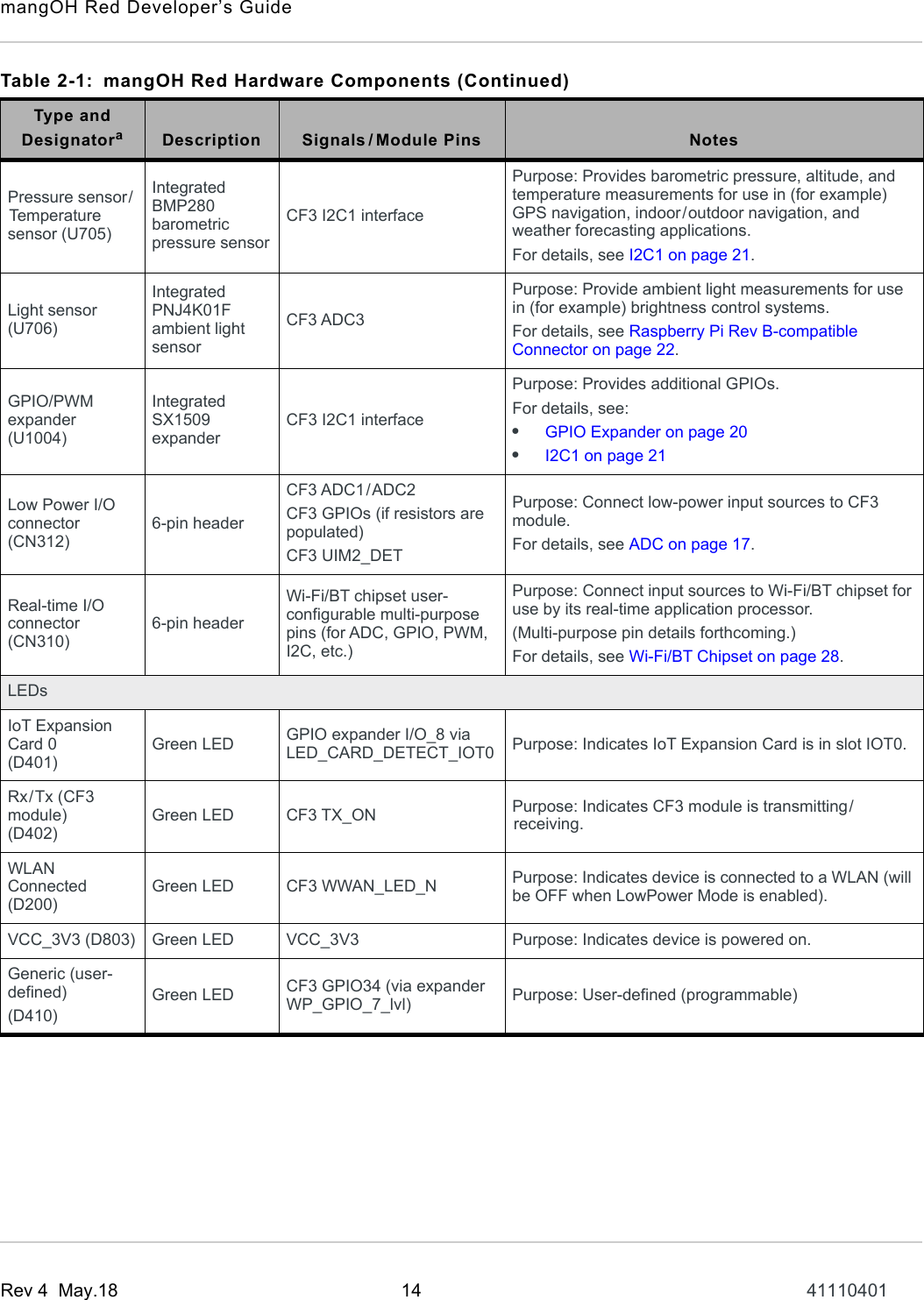
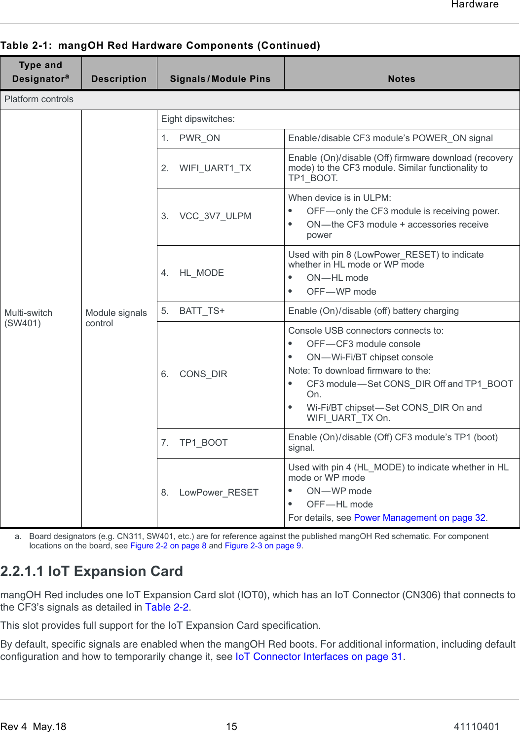
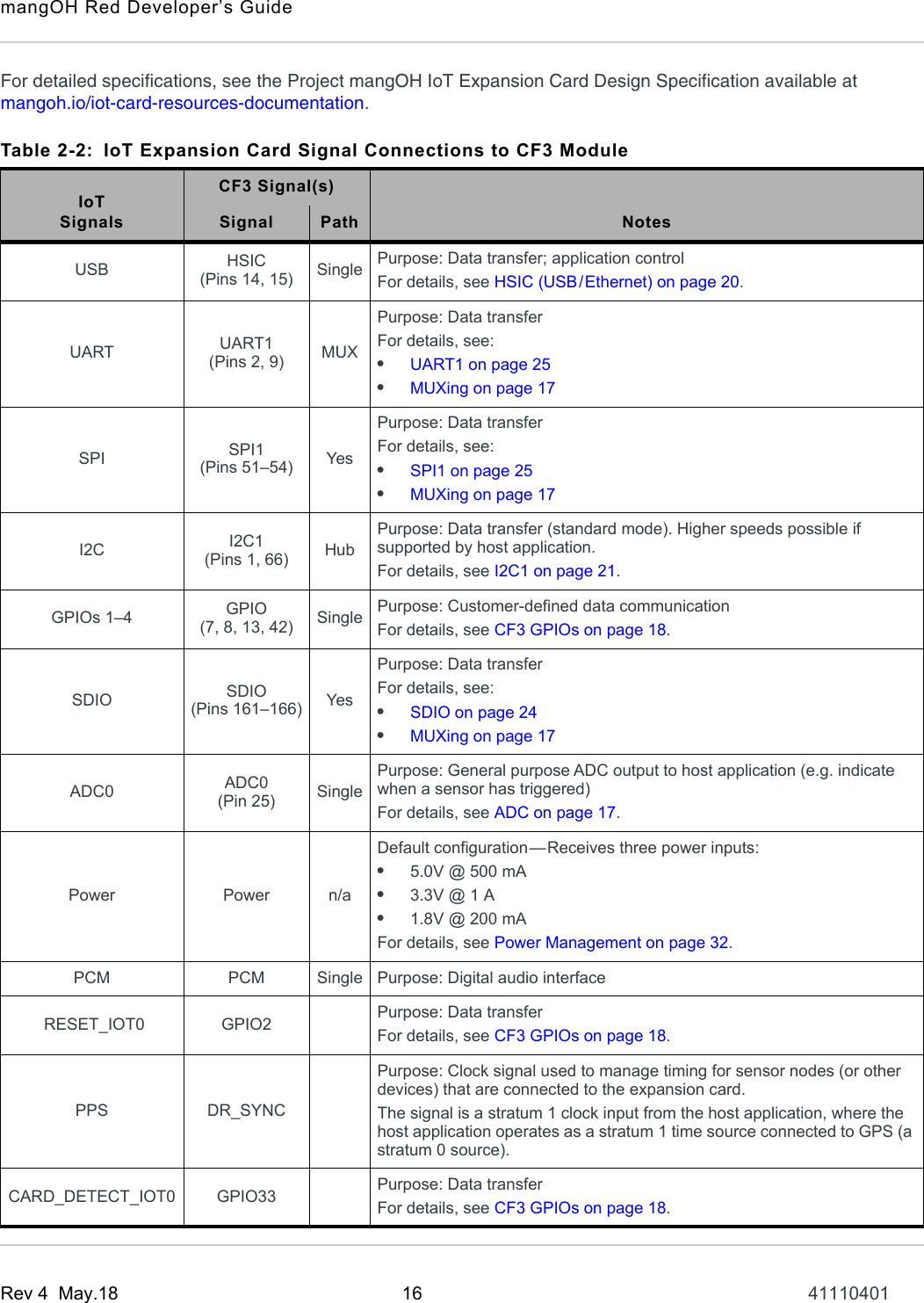
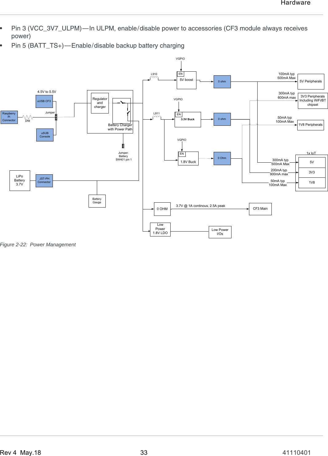
41110401 mangOH Red Developers Guide r4

mangOH™ RedDeveloper’s Guide41110401Rev 4
mangOH Red Developer’s GuideRev 4  May.18 2 41110401Important NoticeDue to the nature of wireless communications, transmission and reception of data can never be guaranteed. Data may be delayed, corrupted (i.e., have errors) or be totally lost. Although significant delays or losses of data are rare when wireless devices such as the Sierra Wireless modem are used in a normal manner with a well-constructed network, the Sierra Wireless modem should not be used in situations where failure to transmit or receive data could result in damage of any kind to the user or any other party, including but not limited to personal injury, death, or loss of property. Sierra Wireless accepts no responsibility for damages of any kind resulting from delays or errors in data transmitted or received using the Sierra Wireless modem, or for failure of the Sierra Wireless modem to transmit or receive such data.Safety and HazardsDo not operate the Sierra Wireless modem in areas where blasting is in progress, where explosive atmospheres may be present, near medical equipment, near life support equipment, or any equipment which may be susceptible to any form of radio interference. In such areas, the Sierra Wireless modem MUST BE POWERED OFF. The Sierra Wireless modem can transmit signals that could interfere with this equipment.Do not operate the Sierra Wireless modem in any aircraft, whether the aircraft is on the ground or in flight. In aircraft, the Sierra Wireless modem MUST BE POWERED OFF. When operating, the Sierra Wireless modem can transmit signals that could interfere with various onboard systems.Note: Some airlines may permit the use of cellular phones while the aircraft is on the ground and the door is open. Sierra Wireless modems may be used at this time.The driver or operator of any vehicle should not operate the Sierra Wireless modem while in control of a vehicle. Doing so will detract from the driver or operator's control and operation of that vehicle. In some states and provinces, operating such communications devices while in control of a vehicle is an offence.Limitation of LiabilityThe information in this manual is subject to change without notice and does not represent a commitment on the part of Sierra Wireless. SIERRA WIRELESS AND ITS AFFILIATES SPECIFICALLY DISCLAIM LIABILITY FOR ANY AND ALL DIRECT, INDIRECT, SPECIAL, GENERAL, INCIDENTAL, CONSEQUENTIAL, PUNITIVE OR EXEMPLARY DAMAGES INCLUDING, BUT NOT LIMITED TO, LOSS OF PROFITS OR REVENUE OR ANTICIPATED PROFITS OR REVENUE ARISING OUT OF THE USE OR INABILITY TO USE ANY SIERRA WIRELESS PRODUCT, EVEN IF SIERRA WIRELESS AND/OR ITS AFFILIATES HAS BEEN ADVISED OF THE POSSIBILITY OF SUCH DAMAGES OR THEY ARE FORESEEABLE OR FOR CLAIMS BY ANY THIRD PARTY.Notwithstanding the foregoing, in no event shall Sierra Wireless and/or its affiliates aggregate liability arising under or in connection with the Sierra Wireless product, regardless of the number of events, occurrences, or claims giving rise to liability, be in excess of the price paid by the purchaser for the Sierra Wireless product.
PrefaceRev 4  May.18 3 41110401Patents This document contains information which is proprietary to Sierra Wireless Inc. and is licensed pursuant to Creative Commons Attribution 4.0 International License.Document detailsTitle: mangOH Red Developer’s GuideAuthor: Sierra WirelessSource: https://mangoh.ioCopyright ©  2018 Sierra Wireless. Licensed under the Creative Commons Attribution 4.0 license, http://creativecommons.org/licenses/by/4.0/Disclaimer Indicate any modifications made to the original document.Trademarks mangOH™ and the mangOH logo are trademarks of Sierra Wireless.Other trademarks are the property of their respective owners.Revision HistoryRevision numberRelease date Changes1May 2017 Document created2June 2017 Updated image to DV3 board3April 2018 Updated image to DV5 boardAdded Wi-Fi/BT RF specificationsAdded Regulatory chapterMinor corrections4May 2018 Updated 2.5 Wi-Fi/BT Chipset—indicated supported RF
Rev 4  May.18 4 41110401ContentsIntroduction . . . . . . . . . . . . . . . . . . . . . . . . . . . . . . . . . . . . . . . . . . . . . . . . . . . . . . . . . . . . . . .  6Hardware . . . . . . . . . . . . . . . . . . . . . . . . . . . . . . . . . . . . . . . . . . . . . . . . . . . . . . . . . . . . . . . . .  7mangOH Red Hardware Overview  . . . . . . . . . . . . . . . . . . . . . . . . . . . . . . . . . . . . . . . . . . .  7mangOH Red Hardware Architecture  . . . . . . . . . . . . . . . . . . . . . . . . . . . . . . . . . . . . . . . .  10mangOH Red Hardware Components . . . . . . . . . . . . . . . . . . . . . . . . . . . . . . . . . . . . . .12MUXing  . . . . . . . . . . . . . . . . . . . . . . . . . . . . . . . . . . . . . . . . . . . . . . . . . . . . . . . . . . . . . . .  17CF3 Module Signals. . . . . . . . . . . . . . . . . . . . . . . . . . . . . . . . . . . . . . . . . . . . . . . . . . . . . .  17ADC . . . . . . . . . . . . . . . . . . . . . . . . . . . . . . . . . . . . . . . . . . . . . . . . . . . . . . . . . . . . . . . .17Audio (Analog and PCM) . . . . . . . . . . . . . . . . . . . . . . . . . . . . . . . . . . . . . . . . . . . . . . . .18CF3 GPIOs  . . . . . . . . . . . . . . . . . . . . . . . . . . . . . . . . . . . . . . . . . . . . . . . . . . . . . . . . . .18GPIO Expander  . . . . . . . . . . . . . . . . . . . . . . . . . . . . . . . . . . . . . . . . . . . . . . . . . . . . . . .20HSIC (USB/Ethernet)  . . . . . . . . . . . . . . . . . . . . . . . . . . . . . . . . . . . . . . . . . . . . . . . . . .20I2C1 . . . . . . . . . . . . . . . . . . . . . . . . . . . . . . . . . . . . . . . . . . . . . . . . . . . . . . . . . . . . . . . .21Light Sensor   . . . . . . . . . . . . . . . . . . . . . . . . . . . . . . . . . . . . . . . . . . . . . . . . . . . . . . . . .22Raspberry Pi Rev B-compatible Connector . . . . . . . . . . . . . . . . . . . . . . . . . . . . . . . . . .22RF  . . . . . . . . . . . . . . . . . . . . . . . . . . . . . . . . . . . . . . . . . . . . . . . . . . . . . . . . . . . . . . . . .24SDIO  . . . . . . . . . . . . . . . . . . . . . . . . . . . . . . . . . . . . . . . . . . . . . . . . . . . . . . . . . . . . . . .24SPI1 . . . . . . . . . . . . . . . . . . . . . . . . . . . . . . . . . . . . . . . . . . . . . . . . . . . . . . . . . . . . . . . .25UART1 . . . . . . . . . . . . . . . . . . . . . . . . . . . . . . . . . . . . . . . . . . . . . . . . . . . . . . . . . . . . . .25UART2 . . . . . . . . . . . . . . . . . . . . . . . . . . . . . . . . . . . . . . . . . . . . . . . . . . . . . . . . . . . . . .26UART Console Connections  . . . . . . . . . . . . . . . . . . . . . . . . . . . . . . . . . . . . . . . . . . . . .26UIM Signals  . . . . . . . . . . . . . . . . . . . . . . . . . . . . . . . . . . . . . . . . . . . . . . . . . . . . . . . . . .27USB 2.0  . . . . . . . . . . . . . . . . . . . . . . . . . . . . . . . . . . . . . . . . . . . . . . . . . . . . . . . . . . . . .28Wi-Fi/BT Chipset . . . . . . . . . . . . . . . . . . . . . . . . . . . . . . . . . . . . . . . . . . . . . . . . . . . . . . . .  28Wi-Fi RF   . . . . . . . . . . . . . . . . . . . . . . . . . . . . . . . . . . . . . . . . . . . . . . . . . . . . . . . . . . . .30Bluetooth RF  . . . . . . . . . . . . . . . . . . . . . . . . . . . . . . . . . . . . . . . . . . . . . . . . . . . . . . . . .30IoT Connector Interfaces . . . . . . . . . . . . . . . . . . . . . . . . . . . . . . . . . . . . . . . . . . . . . . . . . .  31Reset Methods. . . . . . . . . . . . . . . . . . . . . . . . . . . . . . . . . . . . . . . . . . . . . . . . . . . . . . . . . .  32Power Management. . . . . . . . . . . . . . . . . . . . . . . . . . . . . . . . . . . . . . . . . . . . . . . . . . . . . .  32
ContentsRev 4  May.18 5 41110401Regulatory Compliance  . . . . . . . . . . . . . . . . . . . . . . . . . . . . . . . . . . . . . . . . . . . . . . . . . . . .  34Important Compliance Information for North American Users . . . . . . . . . . . . . . . . . . . . . .  34USA  . . . . . . . . . . . . . . . . . . . . . . . . . . . . . . . . . . . . . . . . . . . . . . . . . . . . . . . . . . . . . . . .34Canada  . . . . . . . . . . . . . . . . . . . . . . . . . . . . . . . . . . . . . . . . . . . . . . . . . . . . . . . . . . . . .34
Rev 4  May.18 6 4111040111: IntroductionThe mangOH Red open-source hardware development platform for CF3 modules incorporates several hardware interfaces and a standardized IoT Expansion Card slot for expanded functionality.This developer’s guide describes the mangOH Red’s architecture and provides details on how to develop applications for CF3 modules.For the full mangOH Red documentation suite, refer to mangoh.io/mangoh-red-resources.
Rev 4  May.18 7 4111040122: HardwareThis chapter describes the mangOH Red platform’s hardware components and interfaces.2.1 mangOH Red Hardware OverviewFigure 2-1 provides an overview of the mangOH Red’s hardware components relative to the CF3 module, and Figure 2-2 on page 8 and Figure 2-3 on page 9 show their physical locations.For additional details, see the following documents:•Available at mangoh.io/mangoh-red-resources:·mangOH Red User Guide—Instructions on setting up the hardware components•Available at source.sierrawireless.com:·Sierra Wireless CF3 module-specific Product Technical Specification documents·AirPrime Embedded Module Common Flexible Form Factor (CF3) SpecificationFigure 2-1: mangOH Red Hardware Components OverviewCF3 ModuleSDIOWi-Fi/BT chipsetIoT ConnectormicroSD /uSIM Holder ESIMMainDiversityGPSWi-Fi + BTLEDs3.7V @ 1000mAPower_ONResetAudiouUSB ConnectoruUSB ConnectorType AUSB ConnectorLow Power I/OReal-time I/OGeneric buttonRaspberry Pi ConnectorDNIIntegrated u.FLGyroscope /AccelerometerPressure /Temperature SensorLight Sensor
mangOH Red Developer’s GuideRev 4  May.18 8 41110401Figure 2-2: mangOH Red—Top Side Switches/ConnectorsNote: For reference only. For latest schematic, visit mangoh.io/mangoh-red-resources-hardware.1—Pluggable IoT connector2—Power supply select (CN804)3—Battery connector (CN802)4—Signals control (SW401)5—Main antenna (CN301)6—GNSS antenna (CN303)7—Diversity antenna (CN302)8—Wi-Fi/Bluetooth antenna9—USB Host (CN304)10—Audio (CN500)11—µUSB Console connector12—Raspberry PI RevB-compatible13—Generic button (SW200)142111314981214—PWR_ON switch (SW402)310156 515—Reset switch (SW400)16—CF3 module socket (J200)        header (CN307)7      (ANT1000)        (CN305)1617—Real Time I/O (CN310)18—Low Power I/O (CN312)18 17      (CN306 (IOT0))
HardwareRev 4  May.18 9 41110401Figure 2-3: mangOH Red—Bottom Side Switches/ConnectorsNote: For reference only. For latest schematics, visit mangoh.io/mangoh-red-resources-hardware.1—µUSB CF3 connector2—micro-SIM3—microSD4—ESIM (U603 (DNI))1234      (CN600, bottom slot)      (CN600, top slot)      (CN801)55—Wi-Fi/BT chipset      (U1000)6—Integrated      (ANT1000)767—Wi-Fi/Bluetooth antenna      (CN1000 (DNI))      Wi-Fi/Bluetooth antenna
mangOH Red Developer’s GuideRev 4  May.18 10 411104012.2 mangOH Red Hardware ArchitectureThe mangOH Red platform provides several hardware components, including:•CF3 module socket•Wi-Fi/BT chipset (MediaTek Wi-Fi+Bluetooth)•Pluggable IoT Connector (socket for IoT Expansion Card)•Raspberry Pi Rev B-compatible 26-pin connector•Several I/O connectors (SIM, SD, Audio, USB, etc.)Figure 2-4 illustrates the mangOH Red’s hardware architecture (connectors and signals). The following sections describe these features in greater detail:•mangOH Red Hardware Components on page 12—Components available to the CF3 module and Wi-Fi/BT chipset.•CF3 Module Signals on page 17—CF3 module connections to hardware components.•Wi-Fi/BT Chipset on page 28—Wi-Fi/BT chipset connections to hardware components.•IoT Connector Interfaces on page 31—IoT Expansion Card signal connections to the hardware components.
HardwareRev 4  May.18 11 41110401Figure 2-4: mangOH Red Hardware Architecture (Default)This section (Wi-Fi/BT UART1) is only availablewhen an HL CF3 module is installed.Power SectionUART2CF3 SmartHSICUSB3503SPI1MASTERSDIOuSDHOLDERCtrlGPIOIot con #0I2CHUBI2C4xGPIOUART1SDIOMUXI2CHSIC UPUSB DW USB DWGPIOUSBTypeAUSB toUARTFTDIUSB to SPIWi-Fi/BTchipsetHSICMAINUSB 2.0I2C1GPSBatteryChargerPowerOn,Reset,GenericbuttonPCMAudioMUXAnalogCodecuUSB-1BatteryInputPSU 1V8PSU 3V3PSU 5V0switchPhysicalswitchesuUSB-2Gyroscope /AccelerometerSX1509GPIOBatteryGaugeSIM 2Raspberry PiSignalsESIMSIM 1SIMHOLDER #1SPI_MRDY (GPIO32)SPI_CLK (GPIO27)SPI_MISO (GPIO30)SPI_MOSI (GPIO29)USB DWSPIUART1UART1_RTS (GPIO38)UART1_CTS (GPIO39)UART1_RX (GPIO36)UART1_TX (GPIO37)RealTimeIODIVUART2UARTMux26 pin RpiLow Power IOCN312CN310Pressure /TemperatureSensorLevel ShifterWiFi/BTADC3Light SensorVarioussignalsMulti-functionswitchIntegratedu.FL (DNI)3.5mmJackADC0Default Hardware Configuration26 MHz XTAL
mangOH Red Developer’s GuideRev 4  May.18 12 411104012.2.1 mangOH Red Hardware ComponentsKey mangOH Red hardware components and their connections to the CF3 module and/or Wi-Fi/BT chipset are listed in Table 2-1 on page 12.The mangOH Red’s default configuration enables specific interfaces when the platform boots. For interface details, see:•MUXing on page 17•CF3 Module Signals on page 17•Wi-Fi/BT Chipset on page 28•IoT Connector Interfaces on page 31•Reset Methods on page 32•Power Management on page 32 Table 2-1: mangOH Red Hardware ComponentsType and DesignatoraDescription Signals / Module Pins NotesModules/Processors/etc.CF3 module(J200) For details, see CF3 Module Signals on page 17.IOT0(CN306)IoT Expansion CardConnections to multiple CF3 module interfaces. For details, see IoT Expansion Card on page 15.Wi-Fi/BT chipset(U1000)MediaTek Wi-Fi/BT chipset with ARM Cortex-M4 application processorFor details, see Wi-Fi/BT Chipset on page 28.Card slotsMicro-SIM(CN600)Micro-SIM/microSD holder (bottom slot)CF3 UIM1(Pins: 26–29)Purpose: UIM used to establish mobile network connection.For details, see UIM1 on page 27.micro-SD(CN600)Micro-SIM/microSD holder (top slot)CF3 SDIO(Pins: 161–166)Purpose: Provide access to microSD card.For details, see:•SDIO on page 24•MUXing on page 17ESIM(U603) Embedded SIM CF3 UIM2(Pins 55–58)Purpose: Built-in UIM used to establish mobile network connection.For details, see UIM2 on page 28.Note: eSIM is DNI.
HardwareRev 4  May.18 13 41110401USB-type connectorsmicro-USB(CN801)CF3 USB micro-USB connector•USB(Pins: 12, 13, 16)•Power (if selected)Purpose:•Direct connection to CF3 USB•Power supply when selected by the Power Supply Selection Jumper (CN804). See mangOH Red User Guide for details.For details, see USB 2.0 on page 28.micro-USB(CN305)Console USB micro-USB connector•UART2 (Pins: 96–99)•Power (if selected)Purpose:•Console—Connects to CF3 module console or Wi-Fi/BT chipset console•Power supply when selected by the Power Supply Selection Jumper (CN804). See mangOH Red User Guide for details.For details, see UART2 on page 26.USB Host(CN304)USB Type A connectorHSIC(Pins: 14, 15)Purpose: Provides USB host capability to CF3 module.For details, see HSIC (USB/Ethernet) on page 20.RF, Audio, Raspberry Pi connectorsRF AntennasMain (CN301)GNSS (CN303)Diversity (CN302)u.FL connectorsCF3 RF(Pins: 49 (Main), 38 (GNSS), 31 (Diversity))For details, see RF on page 24.Wi-Fi/Bluetooth Antennas (Integrated—ANT1000; u.FL—CN1000 (DNI))Antenna Wi-Fi/BT chipset RF For details, see Wi-Fi/BT Chipset on page 28.Audio(CN500)3.5 mm connectorCF3 digital audio signals(Pins: 30–33)Purpose: Provide audio capability to CF3 module.For details, see:•Audio (Analog and PCM) on page 18•MUXing on page 17Raspberry Pi (CN307)26-pin Rev B-compatible connector•CF3 HSIC signals (via SPI or USB (DNI))•Wi-Fi/BT chipset SPIFor details, see Raspberry Pi Rev B-compatible Connector on page 22.Other ICs and componentsGyroscope/Accelerometer(U704)Integrated BMI160 inertial measurement moduleCF3 I2C1 interfacePurpose: Provides rotational, linear motion, and gravitational force measurements for use in (for example) gaming, mapping, navigation, and optical image stabilitization applications.For details, see I2C1 on page 21.Table 2-1: mangOH Red Hardware Components (Continued)Type and DesignatoraDescription Signals / Module Pins Notes
mangOH Red Developer’s GuideRev 4  May.18 14 41110401Pressure sensor/Temperature sensor (U705)Integrated BMP280 barometric pressure sensorCF3 I2C1 interfacePurpose: Provides barometric pressure, altitude, and temperature measurements for use in (for example) GPS navigation, indoor/outdoor navigation, and weather forecasting applications.For details, see I2C1 on page 21.Light sensor (U706)Integrated PNJ4K01F ambient light sensorCF3 ADC3Purpose: Provide ambient light measurements for use in (for example) brightness control systems.For details, see Raspberry Pi Rev B-compatible Connector on page 22.GPIO/PWM expander (U1004)Integrated SX1509 expanderCF3 I2C1 interfacePurpose: Provides additional GPIOs.For details, see:•GPIO Expander on page 20•I2C1 on page 21Low Power I/O connector (CN312)6-pin headerCF3 ADC1/ADC2CF3 GPIOs (if resistors are populated)CF3 UIM2_DETPurpose: Connect low-power input sources to CF3 module.For details, see ADC on page 17.Real-time I/O connector (CN310)6-pin headerWi-Fi/BT chipset user-configurable multi-purpose pins (for ADC, GPIO, PWM, I2C, etc.)Purpose: Connect input sources to Wi-Fi/BT chipset for use by its real-time application processor.(Multi-purpose pin details forthcoming.)For details, see Wi-Fi/BT Chipset on page 28.LEDsIoT Expansion Card 0(D401)Green LED GPIO expander I/O_8 via LED_CARD_DETECT_IOT0 Purpose: Indicates IoT Expansion Card is in slot IOT0.Rx/Tx (CF3 module)(D402)Green LED CF3 TX_ON Purpose: Indicates CF3 module is transmitting/receiving.WLAN Connected(D200)Green LED CF3 WWAN_LED_N Purpose: Indicates device is connected to a WLAN (will be OFF when LowPower Mode is enabled).VCC_3V3 (D803) Green LED VCC_3V3 Purpose: Indicates device is powered on.Generic (user-defined)(D410)Green LED CF3 GPIO34 (via expander WP_GPIO_7_lvl) Purpose: User-defined (programmable)Table 2-1: mangOH Red Hardware Components (Continued)Type and DesignatoraDescription Signals / Module Pins Notes
HardwareRev 4  May.18 15 411104012.2.1.1 IoT Expansion CardmangOH Red includes one IoT Expansion Card slot (IOT0), which has an IoT Connector (CN306) that connects to the CF3’s signals as detailed in Table 2-2.This slot provides full support for the IoT Expansion Card specification.By default, specific signals are enabled when the mangOH Red boots. For additional information, including default configuration and how to temporarily change it, see IoT Connector Interfaces on page 31.Platform controlsMulti-switch (SW401)Module signals controlEight dipswitches:1. PWR_ON Enable/disable CF3 module’s POWER_ON signal2. WIFI_UART1_TXEnable (On)/disable (Off) firmware download (recovery mode) to the CF3 module. Similar functionality to TP1_BOOT.3. VCC_3V7_ULPMWhen device is in ULPM:•OFF—only the CF3 module is receiving power.•ON—the CF3 module + accessories receive power4. HL_MODEUsed with pin 8 (LowPower_RESET) to indicate whether in HL mode or WP mode•ON—HL mode•OFF—WP mode5. BATT_TS+ Enable (On)/disable (off) battery charging6. CONS_DIRConsole USB connectors connects to:•OFF—CF3 module console•ON—Wi-Fi/BT chipset consoleNote: To download firmware to the:•CF3 module—Set CONS_DIR Off and TP1_BOOT On.•Wi-Fi/BT chipset—Set CONS_DIR On and WIFI_UART_TX On.7. TP1_BOOT Enable (On)/disable (Off) CF3 module’s TP1 (boot) signal.8. LowPower_RESETUsed with pin 4 (HL_MODE) to indicate whether in HL mode or WP mode•ON—WP mode•OFF—HL modeFor details, see Power Management on page 32.a. Board designators (e.g. CN311, SW401, etc.) are for reference against the published mangOH Red schematic. For component locations on the board, see Figure 2-2 on page 8 and Figure 2-3 on page 9.Table 2-1: mangOH Red Hardware Components (Continued)Type and DesignatoraDescription Signals / Module Pins Notes
mangOH Red Developer’s GuideRev 4  May.18 16 41110401For detailed specifications, see the Project mangOH IoT Expansion Card Design Specification available at mangoh.io/iot-card-resources-documentation. Table 2-2: IoT Expansion Card Signal Connections to CF3 ModuleIoTSignalsCF3 Signal(s)NotesSignal PathUSB HSIC(Pins 14, 15) Single Purpose: Data transfer; application controlFor details, see HSIC (USB/Ethernet) on page 20.UART UART1(Pins 2, 9) MUXPurpose: Data transferFor details, see:•UART1 on page 25•MUXing on page 17SPI SPI1(Pins 51–54) YesPurpose: Data transferFor details, see:•SPI1 on page 25•MUXing on page 17I2C I2C1(Pins 1, 66) HubPurpose: Data transfer (standard mode). Higher speeds possible if supported by host application.For details, see I2C1 on page 21.GPIOs 1–4 GPIO(7, 8, 13, 42) Single Purpose: Customer-defined data communicationFor details, see CF3 GPIOs on page 18.SDIO SDIO(Pins 161–166) YesPurpose: Data transferFor details, see:•SDIO on page 24•MUXing on page 17ADC0 ADC0(Pin 25) SinglePurpose: General purpose ADC output to host application (e.g. indicate when a sensor has triggered)For details, see ADC on page 17.Power Power n/aDefault configuration—Receives three power inputs:•5.0V @ 500 mA•3.3V @ 1 A•1.8V @ 200 mAFor details, see Power Management on page 32.PCM PCM Single Purpose: Digital audio interface RESET_IOT0 GPIO2 Purpose: Data transferFor details, see CF3 GPIOs on page 18.PPS DR_SYNCPurpose: Clock signal used to manage timing for sensor nodes (or other devices) that are connected to the expansion card.The signal is a stratum 1 clock input from the host application, where the host application operates as a stratum 1 time source connected to GPS (a stratum 0 source).CARD_DETECT_IOT0 GPIO33 Purpose: Data transferFor details, see CF3 GPIOs on page 18.
HardwareRev 4  May.18 17 411104012.3 MUXingSeveral interfaces use MUXing (simple switches) to associate multiple hardware connectors with a single signal from the CF3 module, or multiple signals with a single hardware connector.The following sections describe these MUX implementations•MUX·Audio (Analog and PCM) on page 18·SDIO on page 24·UART2 on page 26•Hubs·HSIC (USB/Ethernet) on page 20·I2C1 on page 212.4 CF3 Module SignalsThis section describes how CF3 module signals connect to the platform hardware (described in mangOH Red Hardware Components on page 12).Important: CF3 module signal availability depends on the module type—some modules may not implement certain Extension signals from the CF3 specification.2.4.1 ADCThe mangOH Red supports four CF3 module ADC (Analog to Digital converter) signal sources (ADC0-ADC3).The ADC signals connect to the following sources, as shown in Figure 2-5:•ADC0—IoT Connector 0 (CN1000, slot IOT0), pin 20•ADC1, ADC2—Low Power I/O (CN312), pins 4 and 5•ADC3—Light sensor (U706), pin 6Figure 2-5: ADC ConfigurationCF3ADC0 IoT Connector #0(CN306, slot IOT0)ADC0ADC1 Low Power I/O(CN312)ADC2ADC3 Light sensor(U706)
mangOH Red Developer’s GuideRev 4  May.18 18 411104012.4.2 Audio (Analog and PCM)The mangOH Red supports the CF3 module PCM (digital) audio signals. The signals connect via a Mux (analog switch) to the following sources, as shown in Figure 2-6:•3.5 mm analog audio jack (Default configuration)•IoT connector (Alternate configuration)The audio interface configuration can be modified as described in Table 2-3.Figure 2-6: Audio Configuration2.4.3 CF3 GPIOsThe mangOH Red supports several CF3 module GPIOs, as shown in Figure 2-7.Notes:•Six GPIOs connect to the IoT slot (for card detect, card reset, and four for use as GPIOs).•One GPIO (GPIO32) connects to the NINT (active low interrupt) output signal from a GPIO expander (U1004).Note: The mangOH Red uses a GPIO expander for additional I/O functions. See GPIO Expander on page 20.Table 2-3: Audio Interface Configuration ChangesChange type Change effect Method Change durationHardware Mux—Use default or alternate configurationPopulate/depopulate resistors on the Mux:•R508 pulls signal low (default configuration)•R520 pulls signal high (alternate configuration)Selected configuration used every time device boots up.CF3 PCMDigital-AnalogCodec3.5mmJack (CN500)IoT Connector #0(CN306, slot IOT0)Note: Default configuration — Solid lines          Alternate configuration — Dashed linesMux
HardwareRev 4  May.18 19 41110401Figure 2-7: GPIO ConfigurationCF3GPIO42GPIO13GPIO7GPIO8IoT Connector #0(CN306, slot IOT0)IOT0_GPIO1IOT0_GPIO2IOT0_GPIO3IOT0_GPIO4GPIO33GPIO2CARD_DETECT_IOT0RESET_IOT0SW401GPIO6 LowPower_RESETLevel Shifter (U307)GPIO25 RESET_WIFI_1V8 RESET_WIFI_3V3GPIO Expander (U1004)GPIO32 NINTGPIO21Low Power I/O (CN312)GPIO36 WP_GPIO_5_wakeableGPIO22Raspberry PiConnector(CN307)WP_GPIO_1_lvlLevel Shifter (U306)WP_GPIO_1GPIO23 WP_GPIO_2_lvlWP_GPIO_2GPIO24 WP_GPIO_3_lvlWP_GPIO_3EXT_GPS_LNA_EN PWM_OUT_3V3PWM_OUTGPIO35 WP_GPIO_8_lvlWP_GPIO_8LED (D410)GPIO34 WP_GPIO_7Wi-Fi module(U1000)SYS_RST_NGPIO59SPI2_SRDY_WIFI_1V8SPI2_SRDY_WIFI_3V3Note: Default configuration — Solid lines          Alternate configuration — Dashed lines
mangOH Red Developer’s GuideRev 4  May.18 20 411104012.4.4 GPIO ExpanderThe mangOH Red includes one SX1509 16-channel GPIO/PWM expander (U1004), as detailed in Table 2-4. The expander provides additional GPIOs (carried over the CF3 module’s I2C1 interface) that are used for internal I/O functions such as driving LEDs, resetting board components, etc.For detailed specifications, see the mangOH Red schematics at mangoh.io/mangoh-red-resources-hardware. 2.4.5 HSIC (USB/Ethernet)The mangOH Red supports CF3 module HSIC signals, which connect through a USB hub controller to the following sources, as shown in Figure 2-8:•SPI interface:·Wi-Fi/BT chipset (U1000) and Raspberry Pi Connector (CN307), via USB to SPI bridge (U1006).Note: The Wi-Fi/BT chipset uses SPI2_CS0, and Raspberry Pi connector uses SPI2_CS1/SPI2_CS2.Table 2-4: GPIO Expander (U1004) SignalsPin Signal Name PurposeI/O 0 BOARD_REV1 Reserved for future use.I/O 1 BOARD_REV2 Reserved for future use.I/O 2 BOARD_REV3 Reserved for future use.I/O 3 GPIO_EXP_RPI_1 Raspberry Pi connector, pin 16I/O_4 GPIO_EXP_RPI_2 Raspberry Pi connector, pin 18I/O_5 MTK_TO_WP_UART_EN Enable MTK recovery mode from WP (0), or connects CF3 UART1 to Wi-Fi/BT chipset UART0 (1)I/O_6 WIFI_UART1_TXWi-Fi/BT chipset UART Tx—Normal (0), or MTK recovery mode (1) for firmware downloads/recovery(Note: DNI—R754 must be populated to access this signal.)I/O_7 GPIO_EXP_RPI_3 Raspberry PI connector, pin 22I/O_8 LED_CARD_DETECT_IOT0 Indicates whether IoT expansion card is presentI/O_9 SDIO_SEL Connect SD interface to IoT0 (0) or SD card (1)I/O_10 Power_Fail_Indicator Indicate power failI/O_11 SENSOR_INT1 Accelerometer/gyroscope sensor interruptI/O_12 SENSORT_INT2 Accelerometer/gyroscope sensor interruptI/O_13 PCM_EXP1_SEL Connect PCM interface to IoT0 or to PCM codec (audio)I/O_14 Generic_Push_Button SW200 generic pushbuttonI/O_15 CONS_DIR Use with MTK_TO_WP_UART_EN to choose UART source -- CF3 module or Wi-Fi/BT chipset
HardwareRev 4  May.18 21 41110401•USB interface:·IoT Connector 0 (CN306)or(DNI) Raspberry Pi Connector (CN307)·USB Host connector (CN304)Figure 2-8: HSIC Configuration2.4.6 I2C1The mangOH Red supports CF3 module I2C1 signals, which connect to the following sources (directly or via an expander), as shown in Figure 2-9:•Audio codec (U500)•Pressure sensor (U705)—Accessible via API commands.•Accelerometer/Gyroscope/Temperature sensor (U704)—Accessible via API commands.•Battery charger (U800)—Accessible via API commands.•Battery gauge (U801)—Accessible via API commands.•IoT Connector 0 (CN306)•Raspberry Pi connector (CN307)•GPIO/PWM expander (U1004)—Used internally on the mangOH Red for I/O functions such as driving LEDs, resetting board components, etc. (see GPIO Expander on page 20)For detailed information, refer to mangOH Red schematics available at mangoh.io/mangoh-red-resources-hardware.•USB Hub controller (U701)All signal sources are enabled by default.Note: The mangOH Red I2C interface operates in a single-master/multi-slave setup.CF3 HSICUSB3503Hub(U701)HSICUp USB DWUSB DWUSB DWUSB Host Type A Connector (CN304)USB to SPI bridge(U1006)DNIRaspberry Pi Connector (CN307)USBIoT Connector #0(CN306, slot IOT0)USBWi-Fi/BT chipset(U1000)SPISPINote: Default configuration — Solid lines          Alternate configuration — Dashed lines
mangOH Red Developer’s GuideRev 4  May.18 22 41110401Note: By default, the CF3 I2C interface is connected as shown in Figure 2-9. The board can be modified to connect the Wi-Fi/BT chipset I2C interface to the I2C expander and gyroscope/accelerometer sensor by populating/depopulating appropriate resistors.Figure 2-9: I2C1 Configuration2.4.7 Light SensorThe mangOH Red provides a light sensor (U706) that connects to the CF3 module’s ADC3 signal, as shown in Figure 2-5 on page 17.2.4.8 Raspberry Pi Rev B-compatible ConnectorThe mangOH Red provides a 26-pin Raspberry Pi RevB-compatible connector (CN307).The mangOH Red provides the Raspberry Pi primary signals (alternate Raspberry Pi signals are not supported) as shown in Figure 2-10 on page 23. These signals connect the mangOH Red’s hardware components to a Raspberry Pi attached to the connector, as shown in Figure 2-11 on page 23.R793/R794R460/R461CF3 I2C1Pressure / Temperature Sensor (U705)Gyroscope/Accelerometer Sensor (U704)I2CExpander(U404)IoT Connector #0(CN306, slot IOT0)GPIO Expander (U1004)USB3503 Hub (U701)Audio Codec (U500)Battery Charger (U800)Battery Gauge (U801)Raspberry Pi Connector (CN307)R795/R796R345/R346Wi-Fi/BTchipset(U1000)I2C13.5mm jack (CN500)Note: Populate/depopulate identified resistors to          choose alternate configurations.Note: Default configuration — Solid lines          Alternate configuration — Dashed lines
HardwareRev 4  May.18 23 41110401Figure 2-10: Raspberry Pi Signal GroupsFigure 2-11: Raspberry Pi Connections1 23 45 67 891011 1213 1415 1617 1819 2021 2223 2425 26Power3.3V (Pins 1/17)5.0V (Pins 2/4)I2C(Pins 3/5)GPIO (CF3)(Pins 7/11/13/15)SPI(Pins 19/21/23/24/26)GPIO (Expander)(Pins 16/18/22)PWM(Pin 12)UART(Pins 8/10)Ground(Pins 6/9/14/20/25)Raspberry PiConnectorCN307UART1 Level shifterCF3UART1PWM EXT_GPS_LNA_EN(4) GPIO GPIOSPI2 SPI bridge Wi-Fi/BT chipset(U1000)GPIOGPIO expander(3) GPIOI2C hubI2C5.0VLevel shifterUSB hubR371R382VCC_5V0USB_VBUSNote: Default configuration — Solid lines          Alternate configuration — Dashed lines
mangOH Red Developer’s GuideRev 4  May.18 24 411104012.4.9 RFThe mangOH Red provides u.FL connectors that connect to the CF3 module’s RF signals:•RF_MAIN—CN301•RF_GPS—CN303•RF_DIV—CN302Power for these signals can be enabled/disabled as described in Table 2-5. Figure 2-12: CF3 module RF Connections2.4.10 SDIOThe mangOH Red supports the CF3 module SDIO signals, which connect via a MUX to the following sources, as shown in Figure 2-13:•microSD holder (CN600)—Default configuration•IOT Connector 0 (CN306)The SDIO interface configuration can be modified as detailed in Table 2-6. Table 2-5: CF3 GPIO Interface Configuration ChangesChange type Change effect Method Change durationSoftware Enable/disable RF power for CF3 moduleAT commandLegato APITable 2-6: SDIO Interface Configuration ChangesChange type Change effect Method Change durationSoftware •Use default or alternate configuration. API command Selected configuration used every time device boots up.CF3RF_MAINRF_DIVRF_GPSMain(CN301)GPS(CN303)DIversity(CN302)
HardwareRev 4  May.18 25 41110401Figure 2-13: SDIO Configuration2.4.11 SPI1The mangOH Red supports the CF3 module SPI1 signals, which connect to the following source, as shown in Figure 2-14:•IOT Connector 0 (CN306)Figure 2-14: SPI1 Configuration2.4.12 UART1The mangOH Red supports the CF3 module’s UART1 signals, which connect to the following sources, as shown in Figure 2-15: •IoT Connector 0 (CN306)—Default configuration•Raspberry Pi connector (CN307)•Wi-Fi/BT chipset (Note, the level shifter must be ON. In the default board configuration, the level shifter is OFF.)Note: At any one time, use only the IoT expansion card UART or the Raspberry Pi UART, not both.uSD Holder(CN600)CF3 SDIOIoT Connector #0(CN306, slot IOT0)MuxNote: Default configuration — Solid lines          Alternate configuration — Dashed linesCF3 SPI1 IoT Connector #0(CN306, slot IOT0)SPI
mangOH Red Developer’s GuideRev 4  May.18 26 41110401Figure 2-15: UART1 Configuration2.4.13 UART2The mangOH Red supports the CF3 module’s UART2 signals, which connect via a MUX to the following sources, as shown in Figure 2-16:•Console USB connector (CN305)—UART2 connects to the physical Console USB connector when both MTK_TO_WP_UART_EN and CONS_DIR are low.•Wi-Fi/BT chipset’s UART signal (U1000)—CF3 module’s UART2 and Wi-Fi/BT chipset’s UART0 are linked when MTK_TO_WP_UART_EN signal is pulled high.2.4.14 UART Console ConnectionsThe mangOH Red supports the following console connections for the CF3 module (UART2) and Wi-Fi/BT chipset (UART0), as shown in Figure 2-16:•CF3 module UART2 to Console USB connector (CN305)•Wi-Fi/BT chipset UART0 to Console USB connector (CN305)•Direct connect between CF3 module UART2 and Wi-Fi/BT chipset UART0Table 2-7: UART Console Connection OptionsConnection CONS_DIR (SW401 pin 6) MTK_TO_WP_UART_EN (API)CF3 module UART2 to Console USB Pull low (Pin OFF) Pull lowWi-Fi/BT chipset UART0 to Console USB Pull high (Pin ON) Pulll lowCF3 module UART2 to Wi-Fi/BT chipset UART0 n/a Pull highCF3 UART1IoT Connector #0(CN306, slot IOT0)UARTRaspberry PiConnector (CN307)UARTLevelshifterWi-Fi/BT chipset(U1000)UARTLevelshifterNote: Default configuration — Solid lines          Alternate configuration — Dashed lines
HardwareRev 4  May.18 27 41110401Figure 2-16: UART Console Connections2.4.15 UIM SignalsThe mangOH Red supports both CF3 module UIM interfaces (UIM1, UIM2), where UIM1 is a removable SIM, and UIM2 is an embedded SIM (DNI).The default boot configuration is shown in Figure 2-17.Note: Throughout this document, ‘UIM’ is used to refer to UIM, USIM, SIM, UICC.Figure 2-17: SIM Interfaces Configuration2.4.15.1 UIM1The CF3 module’s UIM1 signal connects to the micro-SIM holder (CN600).Note: The CF3 module’s UIM1_DET signal indicates when a SIM is present in the holder.                         CF3 UART2Wi-Fi/BTchipset UART0Level shifterUSB-UARTFTDIConsoleUSBCONS_DIRMTK_TO_WP_UART_ENUART buffer                         MuxNote: Default configuration — Solid lines          Alternate configurations — Dashed linesSIM Holder (CN600)(DNI)eSIM (U603)CF3UIM1UIM2Note: Default configuration — Solid lines          Alternate configuration — Dashed lines
mangOH Red Developer’s GuideRev 4  May.18 28 411104012.4.15.2 UIM2Note: The mangOH Red does not ship with an eSIM (the component is DNI). For details, refer to the mangOH Red schematics available at mangoh.io/mangoh-red-resources-hardware.The CF3 module’s UIM2 signal connects to the eSIM (U603).Note: The corresponding UIM2_DET signal pin is reserved for future use.2.4.16 USB 2.0The CF3 module’s USB signal connects directly to the mangOH Red’s CF3 USB micro-USB connector (CN305) as shown in Figure 2-18, for control by a connected computer.Note: The micro-USB connector also acts as a power source, if selected. See Power Management on page 32.The USB 2.0 interface configuration can be modified as detailed in Table 2-8. Figure 2-18: USB_2.0 Configuration2.5 Wi-Fi/BT ChipsetThe mangOH Red incorporates a Wi-Fi/BT chipset (MediaTek Wi-Fi+Bluetooth) that provides the following functionality:•RF:·Wi-Fi/Bluetooth/WLAN connections via an integrated 2.4 GHz antenna·Supports 2.4GHz Wi-Fi (802.11b/g/nHT20) and 2.4GHz BLE (Bluetooth Low Energy)•IOT0 connection via Wi-Fi/BT chipset’s UART1•Application processor—Real-time application processing using the mangOH Red’s real-time I/O connector, via GPIO, ADC, and I2C interfaces.Table 2-8: USB 2.0 Interface Configuration MethodsChange type Change effect Method Change durationHardware •Jumper on pins closest to CF3 USB—Select CF3 USB power•Jumper on pins closest to Console USB—Select Console USB power•Jumper off—Use battery if connected, otherwise no power suppliedPosition jumper on CN804 to choose CF3 USB or CONSOLE USB connector to supply power.Note: mangOH Red ships with CF3 USB power selected (jumper on pins closest to CF3 USB connector).mangOH Red uses the selected power supply until the jumper changes.CF3 USBUSB2.0 micro-USB connector(CN305)CF3 USB
HardwareRev 4  May.18 29 41110401•Access to mangOH Red’s accelerometer/gyroscope/temperature sensor via GPIO interface•Access to Raspberry Pi connector via SPI interface•Wi-Fi/BT chipset console connection to either the Console USB connector or the CF3 module console, including ability to receive firmware downloads from either source.•Optional debug connector (CN400, DNI) to use for serial wire debuggingThe Wi-Fi/BT chipset can connect to several components on the mangOH Red, as show in Figure 2-19.Figure 2-19: Wi-Fi/BT Chipset ConnectionsWi-Fi/BT chipsetUART0SPI2SPI1 32Mb Flash MemoryGPIOReal-time I/OADCI2CUART1 Level shifterCF3UART1RF Integrated antenna(ANT1000)U.FL connector(CN1000)Wi-Fi/BT/WLANI2C ExpanderR460/R461HSICSPI Bridge USB USB HubRaspberry PiSPI2_CS2Off (default)SPI2_CS0SPI2_CS1I2CR345/R346SW401Pin 4: HL_MODENote: Default configuration — Solid lines          Alternate configuration — Dashed linesRefer to Figure 2-16 for UART0 details.Note: Populate/depopulate identified resistors to          connect either the CF3 module or the           Wi-Fi/BT chipset to the I2C expander.
mangOH Red Developer’s GuideRev 4  May.18 30 411104012.5.1 Wi-Fi RFThe mangOH Red supports 2.4GHz Wi-Fi (802.11b/g/nHT20).Table 2-9 describes the mangOH Red’s Wi-Fi RF average output power.For Wi-Fi 2.4 GHz RF receiver specifications, refer to the MediaTek MT7697 Datasheet, version 1.01.2.5.2 Bluetooth RFThe mangOH Red supports 2.4GHz BLE (Bluetooth Low Energy).Table 2-10 describes the mangOH Red’s Bluetooth RF average output power.For Bluetooth 2.4 GHz RF receiver specifications, refer to the MediaTek MT7697 Datasheet, version 1.01.Table 2-9: Maximum Wi-Fi RF Average Output PowerMode FrequencyAverage Power (dBm)802.11b 802.11g 802.11n-HT202.4 GHz WLAN2412 11.5 12.0 11.52437 11.5 13.0 14.02462 10.5 11.5 11.0Parameter Description Min (dB) Max (dB)Output power variation•TSSI closed-loop control across all temperature range and channels and VWSR  1.5:1•VCC_3V3 voltage is within ±5% of typical value-1.5 1.5Table 2-10: Maximum Bluetooth RF Average Output PowerMode Average Power (dBm)Bluetooth LE, GFSK 8.5
HardwareRev 4  May.18 31 411104012.6 IoT Connector InterfacesThe mangOH Red provides one IoT Connector (CN306, slot IOT0), which supports the signals defined in the Project mangOH IoT Expansion Card Design Specification, as detailed in Table 2-2 on page 16.The default configuration (enabled signals) for the IoT Connector is shown in Figure 2-20.The IoT Connector interface configuration can be modified as detailed in Table 2-11. Figure 2-20: IoT Connector ConfigurationTable 2-11: IoT Connector Interface Configuration ChangesChange type Change effect Method Change durationSoftware Enable/disable identified signal(s) on a specific IoT Connector.API command Modifies running configuration until device reboots or another change is made.CF3IoT Connector #0(CN306, slot IOT0)UARTPCMSPISDIOUSBI2CADC0PPSGPIO(1-4)n_RESETn_CARD_DETECTNote: Default configuration — Solid lines          Alternate configuration — Dashed lines
mangOH Red Developer’s GuideRev 4  May.18 32 411104012.7 Reset MethodsThe mangOH Red supports hardware and software resets of the entire board or certain components of the board, as shown in Figure 2-21:For detailed specifications showing how full or partial resets are enabled, see the mangOH Red schematics available at mangoh.io/mangoh-red-resources-hardware.Figure 2-21: Reset Methods2.8 Power ManagementThe mangOH Red has two primary power supplies (CF3 USB connector and CONSOLE USB connector), and a rechargeable backup battery power supply option.Figure 2-22 illustrates these power supplies, their voltage/current specifications, and how they supply various components on the mangOH Red platform.A multi-function switch (SW401) controls some power-related features (see Multi-switch (SW401) on page 15), including:•Pin 1 (PWR_ON)—Enable/disable CF3 module’s POWER_ON_signalTable 2-12: Reset MethodsBoard Components to Reset Reset MethodEntire board, including CF3 module (WP or HL) Press Reset button (SW400)IOT Expansion Card CF3_IOT0_RESETorUse an API command to trigger the CF3 module signal GPIO_IOT0_RESET.Wi-Fi/BT chipset CF3_GPIO_WIFI_RESETBattery ChargerMain CF3USB HUB(USB3503)GPIO Expander(SX1509)IoT #1Reset IoT #1RESET_WIFI_1V8System_resetDNINCP303POR reset3.0VReset(open drain out)3V7ResetButton47kCF3_IOT0_RESETCF3_GPIO_WIFI_RESETRESET_WIFI_3V3CP2130MTD7697DVCC_1V810kSW401.pin8WP= ONHL=OFFSW401.pin4WP= OFFHL=ONTCA9546WP_LowPower_ResetLowPower_Reset47kVCC_1V8Level ShiftU307100k
HardwareRev 4  May.18 33 41110401•Pin 3 (VCC_3V7_ULPM)—In ULPM, enable/disable power to accessories (CF3 module always receives power)•Pin 5 (BATT_TS+)—Enable/disable backup battery chargingFigure 2-22: Power ManagementVbattLiPoBattery3.7V0 OHM1.8V Buck5V Peripherals1V8 Peripherals50mA typ100mA MaxBattery Charger with Power Path100mA typ500mA Max5V boostRegulator and charger3.3V Buck3V3 PeripheralsIncluding WiFi/BTchipset300mA typ600mA max1V83V35V1x IoT0 ohm300mA typ500mA Max200mA typ900mA max50mA typ100mA Max4.5V to 5.5V3.7V @ 1A continous, 2.5A peak CF3 MainuUSB CF3uSUBConsoleJST-PHConnectorJumperBatteryGaugeJumper:BatterySW401SLQEN0 ohm0 OhmENENVGPIOVGPIOVGPIOLow Power 1.8V LDO Low Power I/OsRaspberry PiConnector DNIL910L911
Rev 4  May.18 34 4111040133: Regulatory Compliance3.1 Important Compliance Information for North American Users3.1.1 USACaution: Changes or modifications not expressly approved by Sierra Wireless could void the user's authority to operate the equipment.This device complies with part 15 of the FCC Rules. Operation is subject to the following two conditions: (1) This device may not cause harmful interference, and (2) this device must accept any interference received, including interference that may cause undesired operation.Note: This equipment has been tested and found to comply with the limits for a Class B digital device, pursuant to part 15 of the FCC Rules. These limits are designed to provide reasonable protection against harmful interference in a residential installation. This equipment generates, uses and can radiate radio frequency energy and, if not installed and used in accordance with the instructions, may cause harmful interference to radio communications. However, there is no guarantee that interference will not occur in a particular installation. If this equipment does cause harmful interference to radio or television reception, which can be determined by turning the equipment off and on, the user is encouraged to try to correct the interference by one or more of the following measures:·Reorient or relocate the receiving antenna.·Increase the separation between the equipment and receiver.·Connect the equipment into an outlet on a circuit different from that to which the receiver is connected.·Consult the dealer or an experienced radio/TV technician for help.3.1.2 CanadaThis device complies with Industry Canada's licence-exempt RSSs. Operation is subject to the following two conditions:1) This device may not cause interference; and2) This device must accept any interference, including interference that may cause undesired operation of the device.Le présent appareil est conforme aux CNR d'Industrie Canada applicables aux appareils radio exempts de licence. L'exploitation est autorisée aux deux conditions suivantes :1) l'appareil ne doit pas produire de brouillage;2) l'appareil doit accepter tout brouillage radioélectrique subi, même si le brouillage est susceptible d'en com-promettre le fonctionnement.

Navigation menu