Sierra Wireless RED Open-Source Hardware Development Platform User Manual mangOH Red Developer s Guide
Sierra Wireless Inc. Open-Source Hardware Development Platform mangOH Red Developer s Guide
41110401 mangOH Red Developers Guide r4
mangOH™ Red
Developer’s Guide
41110401
Rev 4

mangOH Red Developer’s Guide
Rev 4 May.18 2 41110401
Important
Notice
Due to the nature of wireless communications, transmission and reception of data can
never be guaranteed. Data may be delayed, corrupted (i.e., have errors) or be totally
lost. Although significant delays or losses of data are rare when wireless devices such
as the Sierra Wireless modem are used in a normal manner with a well-constructed
network, the Sierra Wireless modem should not be used in situations where failure to
transmit or receive data could result in damage of any kind to the user or any other
party, including but not limited to personal injury, death, or loss of property. Sierra
Wireless accepts no responsibility for damages of any kind resulting from delays or
errors in data transmitted or received using the Sierra Wireless modem, or for failure
of the Sierra Wireless modem to transmit or receive such data.
Safety and
Hazards
Do not operate the Sierra Wireless modem in areas where blasting is in progress,
where explosive atmospheres may be present, near medical equipment, near life
support equipment, or any equipment which may be susceptible to any form of radio
interference. In such areas, the Sierra Wireless modem MUST BE POWERED OFF.
The Sierra Wireless modem can transmit signals that could interfere with this
equipment.
Do not operate the Sierra Wireless modem in any aircraft, whether the aircraft is on
the ground or in flight. In aircraft, the Sierra Wireless modem MUST BE POWERED
OFF. When operating, the Sierra Wireless modem can transmit signals that could
interfere with various onboard systems.
Note: Some airlines may permit the use of cellular phones while the aircraft is on the ground
and the door is open. Sierra Wireless modems may be used at this time.
The driver or operator of any vehicle should not operate the Sierra Wireless modem
while in control of a vehicle. Doing so will detract from the driver or operator's control
and operation of that vehicle. In some states and provinces, operating such
communications devices while in control of a vehicle is an offence.
Limitation of
Liability
The information in this manual is subject to change without notice and does not
represent a commitment on the part of Sierra Wireless. SIERRA WIRELESS AND ITS
AFFILIATES SPECIFICALLY DISCLAIM LIABILITY FOR ANY AND ALL DIRECT,
INDIRECT, SPECIAL, GENERAL, INCIDENTAL, CONSEQUENTIAL, PUNITIVE OR
EXEMPLARY DAMAGES INCLUDING, BUT NOT LIMITED TO, LOSS OF PROFITS
OR REVENUE OR ANTICIPATED PROFITS OR REVENUE ARISING OUT OF THE
USE OR INABILITY TO USE ANY SIERRA WIRELESS PRODUCT, EVEN IF
SIERRA WIRELESS AND/OR ITS AFFILIATES HAS BEEN ADVISED OF THE
POSSIBILITY OF SUCH DAMAGES OR THEY ARE FORESEEABLE OR FOR
CLAIMS BY ANY THIRD PARTY.
Notwithstanding the foregoing, in no event shall Sierra Wireless and/or its affiliates
aggregate liability arising under or in connection with the Sierra Wireless product,
regardless of the number of events, occurrences, or claims giving rise to liability, be in
excess of the price paid by the purchaser for the Sierra Wireless product.
Preface
Rev 4 May.18 3 41110401
Patents This document contains information which is proprietary to Sierra Wireless Inc. and is
licensed pursuant to Creative Commons Attribution 4.0 International License.
Document
details
Title: mangOH Red Developer’s Guide
Author: Sierra Wireless
Source: https://mangoh.io
Copyright © 2018 Sierra Wireless. Licensed under the Creative Commons Attribution 4.0
license, http://creativecommons.org/licenses/by/4.0/
Disclaimer Indicate any modifications made to the original document.
Trademarks mangOH™ and the mangOH logo are trademarks of Sierra Wireless.
Other trademarks are the property of their respective owners.
Revision
History
Revision
number
Release date Changes
1May 2017 Document created
2June 2017 Updated image to DV3 board
3April 2018 Updated image to DV5 board
Added Wi-Fi/BT RF specifications
Added Regulatory chapter
Minor corrections
4May 2018 Updated 2.5 Wi-Fi/BT Chipset—indicated supported RF

Rev 4 May.18 4 41110401
Contents
Introduction . . . . . . . . . . . . . . . . . . . . . . . . . . . . . . . . . . . . . . . . . . . . . . . . . . . . . . . . . . . . . . . 6
Hardware . . . . . . . . . . . . . . . . . . . . . . . . . . . . . . . . . . . . . . . . . . . . . . . . . . . . . . . . . . . . . . . . . 7
mangOH Red Hardware Overview . . . . . . . . . . . . . . . . . . . . . . . . . . . . . . . . . . . . . . . . . . . 7
mangOH Red Hardware Architecture . . . . . . . . . . . . . . . . . . . . . . . . . . . . . . . . . . . . . . . . 10
mangOH Red Hardware Components . . . . . . . . . . . . . . . . . . . . . . . . . . . . . . . . . . . . . .12
MUXing . . . . . . . . . . . . . . . . . . . . . . . . . . . . . . . . . . . . . . . . . . . . . . . . . . . . . . . . . . . . . . . 17
CF3 Module Signals. . . . . . . . . . . . . . . . . . . . . . . . . . . . . . . . . . . . . . . . . . . . . . . . . . . . . . 17
ADC . . . . . . . . . . . . . . . . . . . . . . . . . . . . . . . . . . . . . . . . . . . . . . . . . . . . . . . . . . . . . . . .17
Audio (Analog and PCM) . . . . . . . . . . . . . . . . . . . . . . . . . . . . . . . . . . . . . . . . . . . . . . . .18
CF3 GPIOs . . . . . . . . . . . . . . . . . . . . . . . . . . . . . . . . . . . . . . . . . . . . . . . . . . . . . . . . . .18
GPIO Expander . . . . . . . . . . . . . . . . . . . . . . . . . . . . . . . . . . . . . . . . . . . . . . . . . . . . . . .20
HSIC (USB/Ethernet) . . . . . . . . . . . . . . . . . . . . . . . . . . . . . . . . . . . . . . . . . . . . . . . . . .20
I2C1 . . . . . . . . . . . . . . . . . . . . . . . . . . . . . . . . . . . . . . . . . . . . . . . . . . . . . . . . . . . . . . . .21
Light Sensor . . . . . . . . . . . . . . . . . . . . . . . . . . . . . . . . . . . . . . . . . . . . . . . . . . . . . . . . .22
Raspberry Pi Rev B-compatible Connector . . . . . . . . . . . . . . . . . . . . . . . . . . . . . . . . . .22
RF . . . . . . . . . . . . . . . . . . . . . . . . . . . . . . . . . . . . . . . . . . . . . . . . . . . . . . . . . . . . . . . . .24
SDIO . . . . . . . . . . . . . . . . . . . . . . . . . . . . . . . . . . . . . . . . . . . . . . . . . . . . . . . . . . . . . . .24
SPI1 . . . . . . . . . . . . . . . . . . . . . . . . . . . . . . . . . . . . . . . . . . . . . . . . . . . . . . . . . . . . . . . .25
UART1 . . . . . . . . . . . . . . . . . . . . . . . . . . . . . . . . . . . . . . . . . . . . . . . . . . . . . . . . . . . . . .25
UART2 . . . . . . . . . . . . . . . . . . . . . . . . . . . . . . . . . . . . . . . . . . . . . . . . . . . . . . . . . . . . . .26
UART Console Connections . . . . . . . . . . . . . . . . . . . . . . . . . . . . . . . . . . . . . . . . . . . . .26
UIM Signals . . . . . . . . . . . . . . . . . . . . . . . . . . . . . . . . . . . . . . . . . . . . . . . . . . . . . . . . . .27
USB 2.0 . . . . . . . . . . . . . . . . . . . . . . . . . . . . . . . . . . . . . . . . . . . . . . . . . . . . . . . . . . . . .28
Wi-Fi/BT Chipset . . . . . . . . . . . . . . . . . . . . . . . . . . . . . . . . . . . . . . . . . . . . . . . . . . . . . . . . 28
Wi-Fi RF . . . . . . . . . . . . . . . . . . . . . . . . . . . . . . . . . . . . . . . . . . . . . . . . . . . . . . . . . . . .30
Bluetooth RF . . . . . . . . . . . . . . . . . . . . . . . . . . . . . . . . . . . . . . . . . . . . . . . . . . . . . . . . .30
IoT Connector Interfaces . . . . . . . . . . . . . . . . . . . . . . . . . . . . . . . . . . . . . . . . . . . . . . . . . . 31
Reset Methods. . . . . . . . . . . . . . . . . . . . . . . . . . . . . . . . . . . . . . . . . . . . . . . . . . . . . . . . . . 32
Power Management. . . . . . . . . . . . . . . . . . . . . . . . . . . . . . . . . . . . . . . . . . . . . . . . . . . . . . 32

Contents
Rev 4 May.18 5 41110401
Regulatory Compliance . . . . . . . . . . . . . . . . . . . . . . . . . . . . . . . . . . . . . . . . . . . . . . . . . . . . 34
Important Compliance Information for North American Users . . . . . . . . . . . . . . . . . . . . . . 34
USA . . . . . . . . . . . . . . . . . . . . . . . . . . . . . . . . . . . . . . . . . . . . . . . . . . . . . . . . . . . . . . . .34
Canada . . . . . . . . . . . . . . . . . . . . . . . . . . . . . . . . . . . . . . . . . . . . . . . . . . . . . . . . . . . . .34

Rev 4 May.18 6 41110401
1
1: Introduction
The mangOH Red open-source hardware development platform for CF3 modules incorporates several hardware
interfaces and a standardized IoT Expansion Card slot for expanded functionality.
This developer’s guide describes the mangOH Red’s architecture and provides details on how to develop
applications for CF3 modules.
For the full mangOH Red documentation suite, refer to mangoh.io/mangoh-red-resources.
Rev 4 May.18 7 41110401
2
2: Hardware
This chapter describes the mangOH Red platform’s hardware components and interfaces.
2.1 mangOH Red Hardware Overview
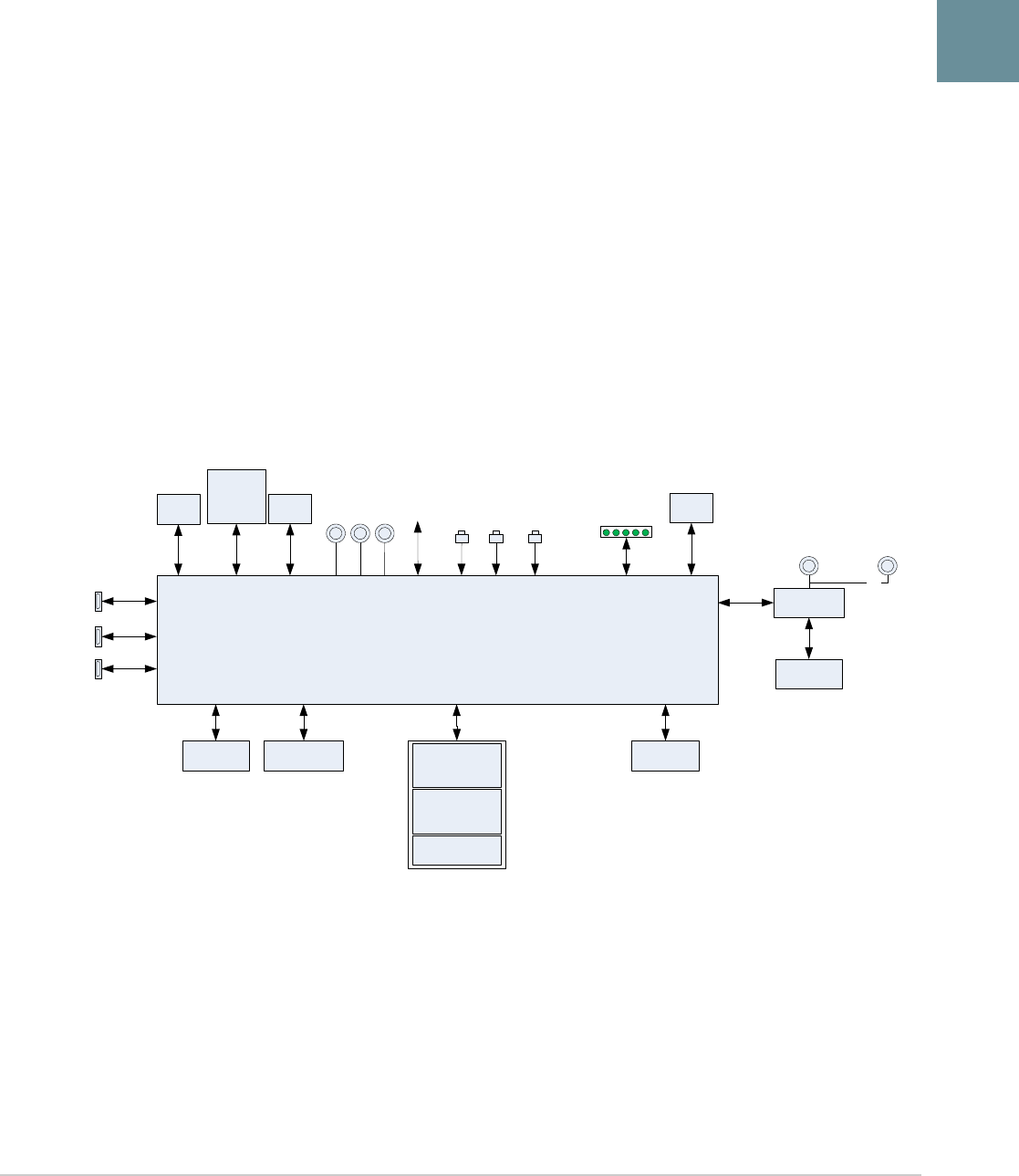
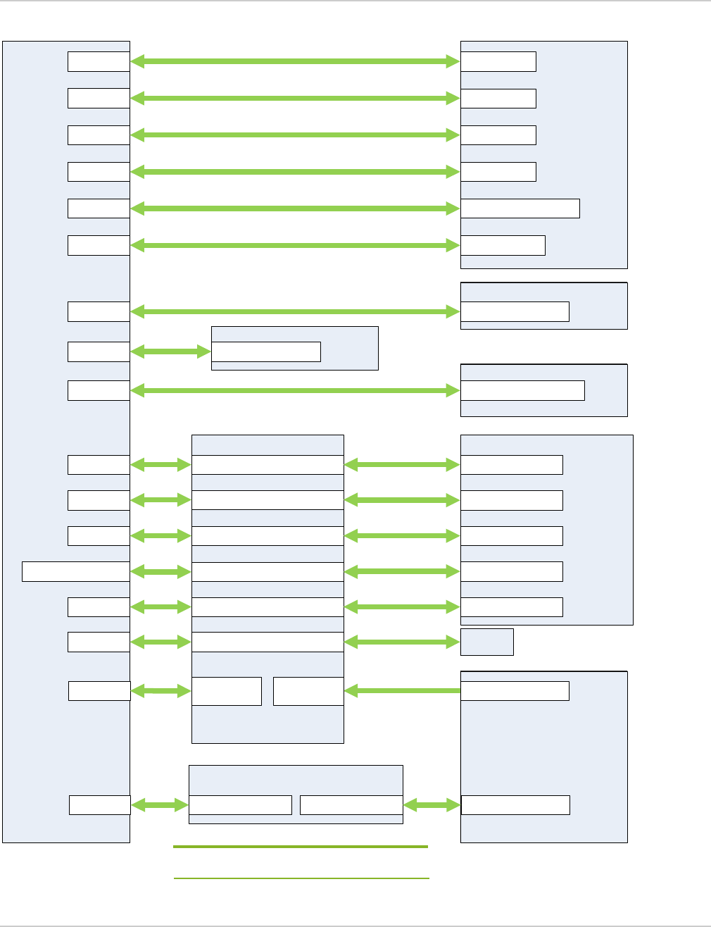
Figure 2-1 provides an overview of the mangOH Red’s hardware components relative to the CF3 module, and
Figure 2-2 on page 8 and Figure 2-3 on page 9 show their physical locations.
For additional details, see the following documents:
•Available at mangoh.io/mangoh-red-resources:
·mangOH Red User Guide—Instructions on setting up the hardware components
•Available at source.sierrawireless.com:
·Sierra Wireless CF3 module-specific Product Technical Specification documents
·AirPrime Embedded Module Common Flexible Form Factor (CF3) Specification
Figure 2-1: mangOH Red Hardware Components Overview
CF3 Module
SDIO
Wi-Fi/BT
chipset
IoT
Connector
microSD
/uSIM
Holder ESIM
Main
Diversity
GPS
Wi-Fi + BT
LEDs
3.7V @ 1000mA
Power_ON
Reset
Audio
uUSB
Connector
uUSB
Connector
Type A
USB Connector
Low
Power I/O
Real-time
I/O
Generic
button
Raspberry Pi
Connector
DNI
Integrated u.FL
Gyroscope /
Accelerometer
Pressure /
Temperature
Sensor
Light Sensor
mangOH Red Developer’s Guide
Rev 4 May.18 8 41110401
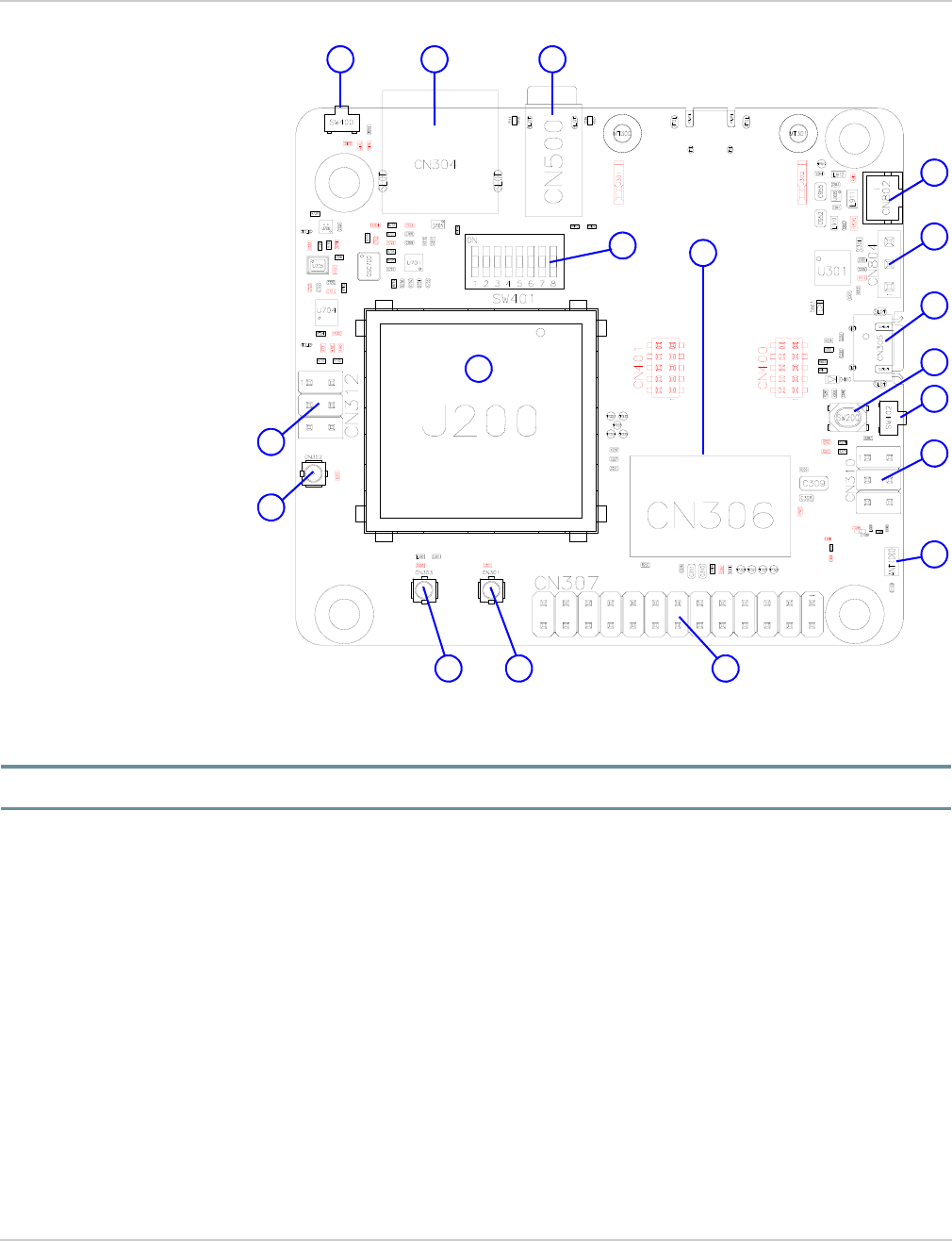
Figure 2-2: mangOH Red—Top Side Switches/Connectors
Note: For reference only. For latest schematic, visit mangoh.io/mangoh-red-resources-hardware.
1—Pluggable IoT connector
2—Power supply select (CN804)
3—Battery connector (CN802)
4—Signals control (SW401)
5—Main antenna (CN301)
6—GNSS antenna (CN303)
7—Diversity antenna (CN302)
8—Wi-Fi/Bluetooth antenna
9—USB Host (CN304)
10—Audio (CN500)
11—µUSB Console connector
12—Raspberry PI RevB-compatible
13—Generic button (SW200)
1
42
11
13
14
9
8
12
14—PWR_ON switch (SW402)
3
1015
6 5
15—Reset switch (SW400)
16—CF3 module socket (J200)
header (CN307)
7
(ANT1000)
(CN305)
16
17—Real Time I/O (CN310)
18—Low Power I/O (CN312)
18 17
(CN306 (IOT0))
Hardware
Rev 4 May.18 9 41110401
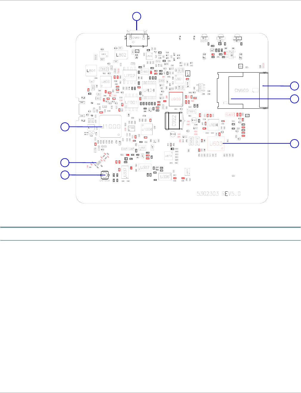
Figure 2-3: mangOH Red—Bottom Side Switches/Connectors
Note: For reference only. For latest schematics, visit mangoh.io/mangoh-red-resources-hardware.
1—µUSB CF3 connector
2—micro-SIM
3—microSD
4—ESIM (U603 (DNI))
1
2
3
4
(CN600, bottom slot)
(CN600, top slot)
(CN801)
5
5—Wi-Fi/BT chipset
(U1000)
6—Integrated
(ANT1000)
7
6
7—Wi-Fi/Bluetooth antenna
(CN1000 (DNI))
Wi-Fi/Bluetooth antenna

mangOH Red Developer’s Guide
Rev 4 May.18 10 41110401
2.2 mangOH Red Hardware Architecture
The mangOH Red platform provides several hardware components, including:
•CF3 module socket
•Wi-Fi/BT chipset (MediaTek Wi-Fi+Bluetooth)
•Pluggable IoT Connector (socket for IoT Expansion Card)
•Raspberry Pi Rev B-compatible 26-pin connector
•Several I/O connectors (SIM, SD, Audio, USB, etc.)
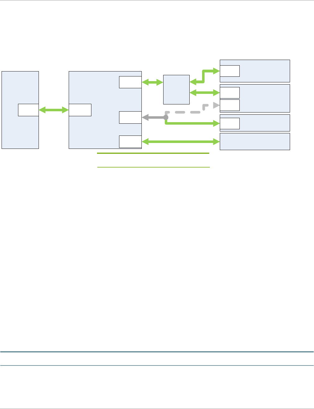
Figure 2-4 illustrates the mangOH Red’s hardware architecture (connectors and signals). The following sections
describe these features in greater detail:
•mangOH Red Hardware Components on page 12—Components available to the CF3 module and Wi-Fi/BT
chipset.
•CF3 Module Signals on page 17—CF3 module connections to hardware components.
•Wi-Fi/BT Chipset on page 28—Wi-Fi/BT chipset connections to hardware components.
•IoT Connector Interfaces on page 31—IoT Expansion Card signal connections to the hardware components.
Hardware
Rev 4 May.18 11 41110401
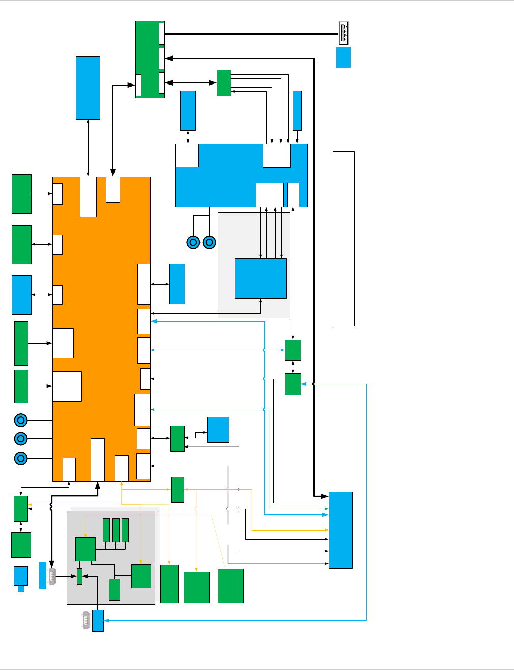
Figure 2-4: mangOH Red Hardware Architecture (Default)
This section (Wi-Fi/BT UART1) is only available
when an HL CF3 module is installed.
Power Section
UART2
CF3 Smart
HSIC
USB3503
SPI1
MASTER
SDIO
uSD
HOLDER
Ctrl
GPIO
Iot con #0
I2C
HUB
I2C
4xGPIO
UART1
SDIO
MUX
I2C
HSIC UP
USB DW USB DW
GPIO
USB
TypeA
USB to
UART
FTDI
USB to SPI
Wi-Fi/BT
chipset
HSIC
MAIN
USB 2.0
I2C1
GPS
Battery
Charger
PowerOn,
Reset,
Generic
button
PCM
Audio
MUX
Analog
Codec
uUSB-1
Battery
Input
PSU 1V8
PSU 3V3
PSU 5V0
switch
Physical
switches
uUSB-2
Gyroscope /
Accelerometer
SX1509
GPIO
Battery
Gauge
SIM 2
Raspberry Pi
Signals
ESIM
SIM 1
SIM
HOLDER #1
SPI_MRDY (GPIO32)
SPI_CLK (GPIO27)
SPI_MISO (GPIO30)
SPI_MOSI (GPIO29)
USB DW
SPI
UART1
UART1_RTS (GPIO38)
UART1_CTS (GPIO39)
UART1_RX (GPIO36)
UART1_TX (GPIO37)
Real
Time
IO
DIV
UART2
UART
Mux
26 pin Rpi
Low Power IO
CN312
CN310
Pressure /
Temperature
Sensor
Level Shifter
WiFi/BT
ADC3
Light Sensor
Various
signals
Multi-function
switch
Integrated
u.FL (DNI)
3.5mm
Jack
ADC0
Default Hardware Configuration
26 MHz XTAL

mangOH Red Developer’s Guide
Rev 4 May.18 12 41110401
2.2.1 mangOH Red Hardware Components
Key mangOH Red hardware components and their connections to the CF3 module and/or Wi-Fi/BT chipset are
listed in Table 2-1 on page 12.
The mangOH Red’s default configuration enables specific interfaces when the platform boots. For interface details,
see:
•MUXing on page 17
•CF3 Module Signals on page 17
•Wi-Fi/BT Chipset on page 28
•IoT Connector Interfaces on page 31
•Reset Methods on page 32
•Power Management on page 32
Table 2-1: mangOH Red Hardware Components
Type and
DesignatoraDescription Signals / Module Pins Notes
Modules/Processors/etc.
CF3 module
(J200) For details, see CF3 Module Signals on page 17.
IOT0
(CN306)
IoT Expansion
Card
Connections to multiple CF3
module interfaces. For details, see IoT Expansion Card on page 15.
Wi-Fi/BT chipset
(U1000)
MediaTek Wi-Fi/
BT chipset with
ARM Cortex-M4
application
processor
For details, see Wi-Fi/BT Chipset on page 28.
Card slots
Micro-SIM
(CN600)
Micro-SIM/
microSD holder
(bottom slot)
CF3 UIM1
(Pins: 26–29)
Purpose: UIM used to establish mobile network
connection.
For details, see UIM1 on page 27.
micro-SD
(CN600)
Micro-SIM/
microSD holder
(top slot)
CF3 SDIO
(Pins: 161–166)
Purpose: Provide access to microSD card.
For details, see:
•SDIO on page 24
•MUXing on page 17
ESIM
(U603) Embedded SIM CF3 UIM2
(Pins 55–58)
Purpose: Built-in UIM used to establish mobile network
connection.
For details, see UIM2 on page 28.
Note: eSIM is DNI.

Hardware
Rev 4 May.18 13 41110401
USB-type connectors
micro-USB
(CN801)
CF3 USB
micro-USB
connector
•USB
(Pins: 12, 13, 16)
•Power (if selected)
Purpose:
•Direct connection to CF3 USB
•Power supply when selected by the Power Supply
Selection Jumper (CN804). See mangOH Red
User Guide for details.
For details, see USB 2.0 on page 28.
micro-USB
(CN305)
Console USB
micro-USB
connector
•UART2 (Pins: 96–99)
•Power (if selected)
Purpose:
•Console—Connects to CF3 module console or
Wi-Fi/BT chipset console
•Power supply when selected by the Power Supply
Selection Jumper (CN804). See mangOH Red
User Guide for details.
For details, see UART2 on page 26.
USB Host
(CN304)
USB Type A
connector
HSIC
(Pins: 14, 15)
Purpose: Provides USB host capability to CF3 module.
For details, see HSIC (USB/Ethernet) on page 20.
RF, Audio, Raspberry Pi connectors
RF Antennas
Main (CN301)
GNSS (CN303)
Diversity (CN302)
u.FL connectors
CF3 RF
(Pins: 49 (Main), 38 (GNSS),
31 (Diversity))
For details, see RF on page 24.
Wi-Fi/Bluetooth
Antennas
(Integrated—
ANT1000;
u.FL—CN1000
(DNI))
Antenna Wi-Fi/BT chipset RF For details, see Wi-Fi/BT Chipset on page 28.
Audio
(CN500)
3.5 mm
connector
CF3 digital audio signals
(Pins: 30–33)
Purpose: Provide audio capability to CF3 module.
For details, see:
•Audio (Analog and PCM) on page 18
•MUXing on page 17
Raspberry Pi
(CN307)
26-pin
Rev B-compatib
le connector
•CF3 HSIC signals (via
SPI or USB (DNI))
•Wi-Fi/BT chipset SPI
For details, see Raspberry Pi Rev B-compatible
Connector on page 22.
Other ICs and components
Gyroscope/
Accelerometer
(U704)
Integrated
BMI160 inertial
measurement
module
CF3 I2C1 interface
Purpose: Provides rotational, linear motion, and
gravitational force measurements for use in (for
example) gaming, mapping, navigation, and optical
image stabilitization applications.
For details, see I2C1 on page 21.
Table 2-1: mangOH Red Hardware Components (Continued)
Type and
DesignatoraDescription Signals / Module Pins Notes

mangOH Red Developer’s Guide
Rev 4 May.18 14 41110401
Pressure sensor/
Temperature
sensor (U705)
Integrated
BMP280
barometric
pressure sensor
CF3 I2C1 interface
Purpose: Provides barometric pressure, altitude, and
temperature measurements for use in (for example)
GPS navigation, indoor/outdoor navigation, and
weather forecasting applications.
For details, see I2C1 on page 21.
Light sensor
(U706)
Integrated
PNJ4K01F
ambient light
sensor
CF3 ADC3
Purpose: Provide ambient light measurements for use
in (for example) brightness control systems.
For details, see Raspberry Pi Rev B-compatible
Connector on page 22.
GPIO/PWM
expander
(U1004)
Integrated
SX1509
expander
CF3 I2C1 interface
Purpose: Provides additional GPIOs.
For details, see:
•GPIO Expander on page 20
•I2C1 on page 21
Low Power I/O
connector
(CN312)
6-pin header
CF3 ADC1/ADC2
CF3 GPIOs (if resistors are
populated)
CF3 UIM2_DET
Purpose: Connect low-power input sources to CF3
module.
For details, see ADC on page 17.
Real-time I/O
connector
(CN310)
6-pin header
Wi-Fi/BT chipset user-
configurable multi-purpose
pins (for ADC, GPIO, PWM,
I2C, etc.)
Purpose: Connect input sources to Wi-Fi/BT chipset for
use by its real-time application processor.
(Multi-purpose pin details forthcoming.)
For details, see Wi-Fi/BT Chipset on page 28.
LEDs
IoT Expansion
Card 0
(D401)
Green LED GPIO expander I/O_8 via
LED_CARD_DETECT_IOT0 Purpose: Indicates IoT Expansion Card is in slot IOT0.
Rx/Tx (CF3
module)
(D402)
Green LED CF3 TX_ON Purpose: Indicates CF3 module is transmitting/
receiving.
WLAN
Connected
(D200)
Green LED CF3 WWAN_LED_N Purpose: Indicates device is connected to a WLAN (will
be OFF when LowPower Mode is enabled).
VCC_3V3 (D803) Green LED VCC_3V3 Purpose: Indicates device is powered on.
Generic (user-
defined)
(D410)
Green LED CF3 GPIO34 (via expander
WP_GPIO_7_lvl) Purpose: User-defined (programmable)
Table 2-1: mangOH Red Hardware Components (Continued)
Type and
DesignatoraDescription Signals / Module Pins Notes

Hardware
Rev 4 May.18 15 41110401
2.2.1.1 IoT Expansion Card
mangOH Red includes one IoT Expansion Card slot (IOT0), which has an IoT Connector (CN306) that connects to
the CF3’s signals as detailed in Table 2-2.
This slot provides full support for the IoT Expansion Card specification.
By default, specific signals are enabled when the mangOH Red boots. For additional information, including default
configuration and how to temporarily change it, see IoT Connector Interfaces on page 31.
Platform controls
Multi-switch
(SW401)
Module signals
control
Eight dipswitches:
1. PWR_ON Enable/disable CF3 module’s POWER_ON signal
2. WIFI_UART1_TX
Enable (On)/disable (Off) firmware download (recovery
mode) to the CF3 module. Similar functionality to
TP1_BOOT.
3. VCC_3V7_ULPM
When device is in ULPM:
•OFF—only the CF3 module is receiving power.
•ON—the CF3 module + accessories receive
power
4. HL_MODE
Used with pin 8 (LowPower_RESET) to indicate
whether in HL mode or WP mode
•ON—HL mode
•OFF—WP mode
5. BATT_TS+ Enable (On)/disable (off) battery charging
6. CONS_DIR
Console USB connectors connects to:
•OFF—CF3 module console
•ON—Wi-Fi/BT chipset console
Note: To download firmware to the:
•CF3 module—Set CONS_DIR Off and TP1_BOOT
On.
•Wi-Fi/BT chipset—Set CONS_DIR On and
WIFI_UART_TX On.
7. TP1_BOOT Enable (On)/disable (Off) CF3 module’s TP1 (boot)
signal.
8. LowPower_RESET
Used with pin 4 (HL_MODE) to indicate whether in HL
mode or WP mode
•ON—WP mode
•OFF—HL mode
For details, see Power Management on page 32.
a. Board designators (e.g. CN311, SW401, etc.) are for reference against the published mangOH Red schematic. For component
locations on the board, see Figure 2-2 on page 8 and Figure 2-3 on page 9.
Table 2-1: mangOH Red Hardware Components (Continued)
Type and
DesignatoraDescription Signals / Module Pins Notes

mangOH Red Developer’s Guide
Rev 4 May.18 16 41110401
For detailed specifications, see the Project mangOH IoT Expansion Card Design Specification available at
mangoh.io/iot-card-resources-documentation.
Table 2-2: IoT Expansion Card Signal Connections to CF3 Module
IoT
Signals
CF3 Signal(s)
NotesSignal Path
USB HSIC
(Pins 14, 15) Single Purpose: Data transfer; application control
For details, see HSIC (USB/Ethernet) on page 20.
UART UART1
(Pins 2, 9) MUX
Purpose: Data transfer
For details, see:
•UART1 on page 25
•MUXing on page 17
SPI SPI1
(Pins 51–54) Yes
Purpose: Data transfer
For details, see:
•SPI1 on page 25
•MUXing on page 17
I2C I2C1
(Pins 1, 66) Hub
Purpose: Data transfer (standard mode). Higher speeds possible if
supported by host application.
For details, see I2C1 on page 21.
GPIOs 1–4 GPIO
(7, 8, 13, 42) Single Purpose: Customer-defined data communication
For details, see CF3 GPIOs on page 18.
SDIO SDIO
(Pins 161–166) Yes
Purpose: Data transfer
For details, see:
•SDIO on page 24
•MUXing on page 17
ADC0 ADC0
(Pin 25) Single
Purpose: General purpose ADC output to host application (e.g. indicate
when a sensor has triggered)
For details, see ADC on page 17.
Power Power n/a
Default configuration—Receives three power inputs:
•5.0V @ 500 mA
•3.3V @ 1 A
•1.8V @ 200 mA
For details, see Power Management on page 32.
PCM PCM Single Purpose: Digital audio interface
RESET_IOT0 GPIO2 Purpose: Data transfer
For details, see CF3 GPIOs on page 18.
PPS DR_SYNC
Purpose: Clock signal used to manage timing for sensor nodes (or other
devices) that are connected to the expansion card.
The signal is a stratum 1 clock input from the host application, where the
host application operates as a stratum 1 time source connected to GPS (a
stratum 0 source).
CARD_DETECT_IOT0 GPIO33 Purpose: Data transfer
For details, see CF3 GPIOs on page 18.
Hardware
Rev 4 May.18 17 41110401
2.3 MUXing
Several interfaces use MUXing (simple switches) to associate multiple hardware connectors with a single signal
from the CF3 module, or multiple signals with a single hardware connector.
The following sections describe these MUX implementations
•MUX
·Audio (Analog and PCM) on page 18
·SDIO on page 24
·UART2 on page 26
•Hubs
·HSIC (USB/Ethernet) on page 20
·I2C1 on page 21
2.4 CF3 Module Signals
This section describes how CF3 module signals connect to the platform hardware (described in mangOH Red
Hardware Components on page 12).
Important: CF3 module signal availability depends on the module type—some modules may not implement certain
Extension signals from the CF3 specification.
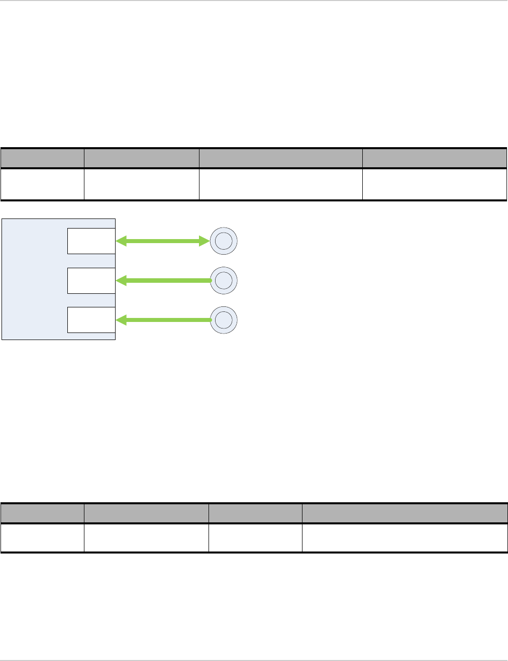
2.4.1 ADC
The mangOH Red supports four CF3 module ADC (Analog to Digital converter) signal sources (ADC0-ADC3).
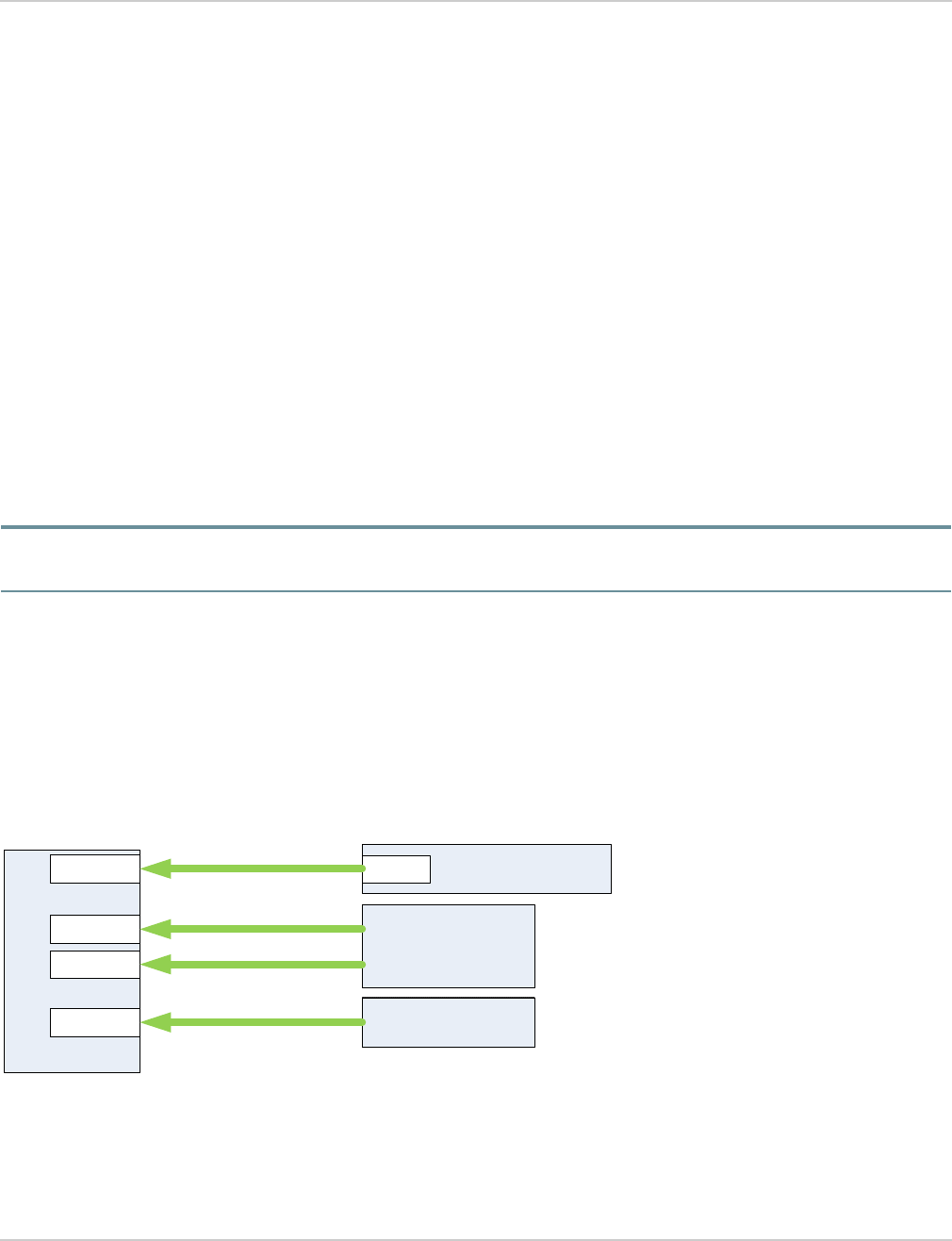
The ADC signals connect to the following sources, as shown in Figure 2-5:
•ADC0—IoT Connector 0 (CN1000, slot IOT0), pin 20
•ADC1, ADC2—Low Power I/O (CN312), pins 4 and 5
•ADC3—Light sensor (U706), pin 6
Figure 2-5: ADC Configuration
CF3
ADC0 IoT Connector #0
(CN306, slot IOT0)
ADC0
ADC1 Low Power I/O
(CN312)
ADC2
ADC3 Light sensor
(U706)
mangOH Red Developer’s Guide
Rev 4 May.18 18 41110401
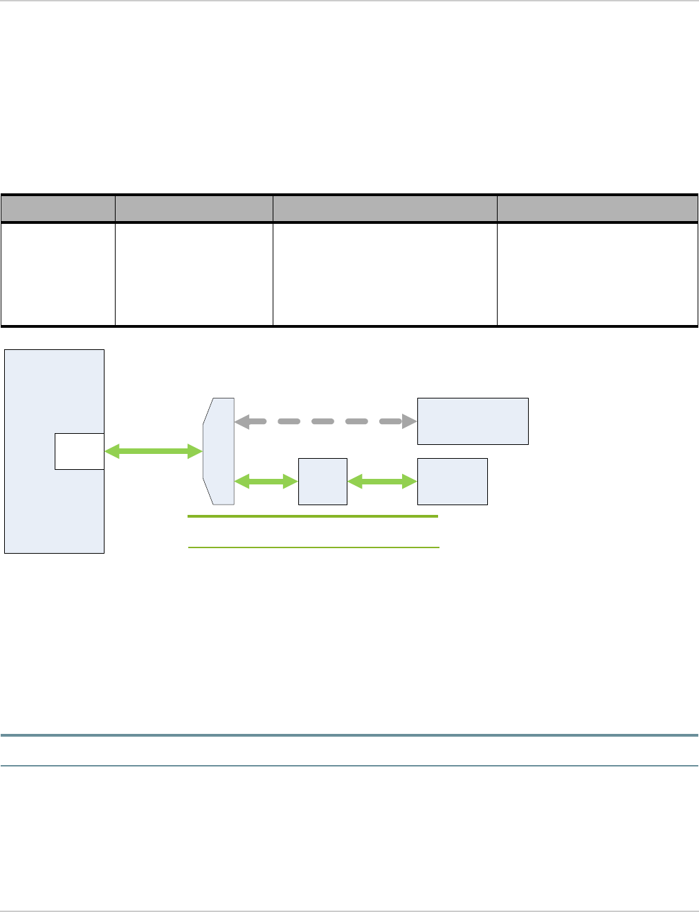
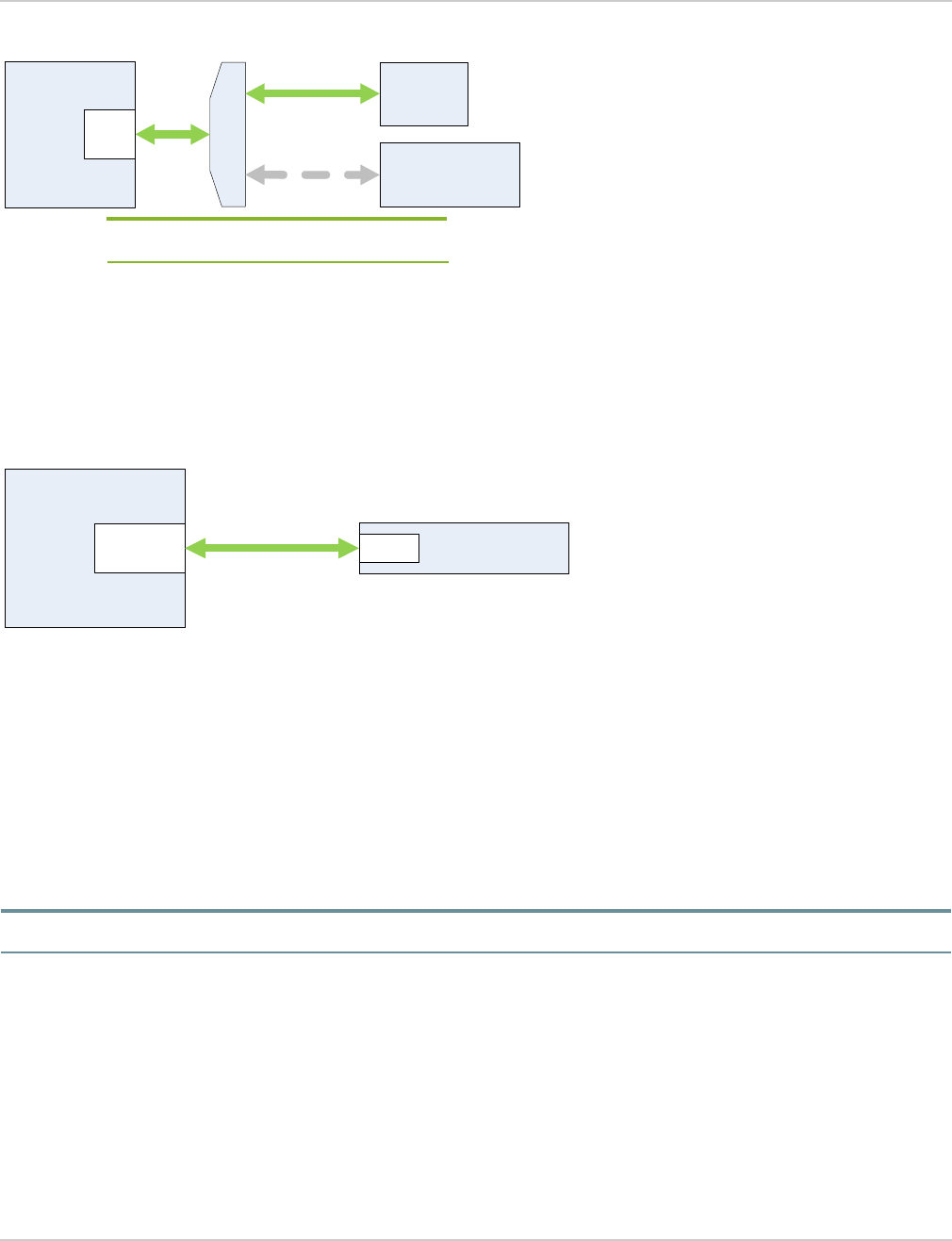
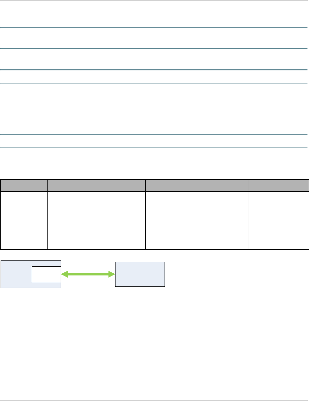
2.4.2 Audio (Analog and PCM)
The mangOH Red supports the CF3 module PCM (digital) audio signals. The signals connect via a Mux (analog
switch) to the following sources, as shown in Figure 2-6:
•3.5 mm analog audio jack (Default configuration)
•IoT connector (Alternate configuration)
The audio interface configuration can be modified as described in Table 2-3.
Figure 2-6: Audio Configuration
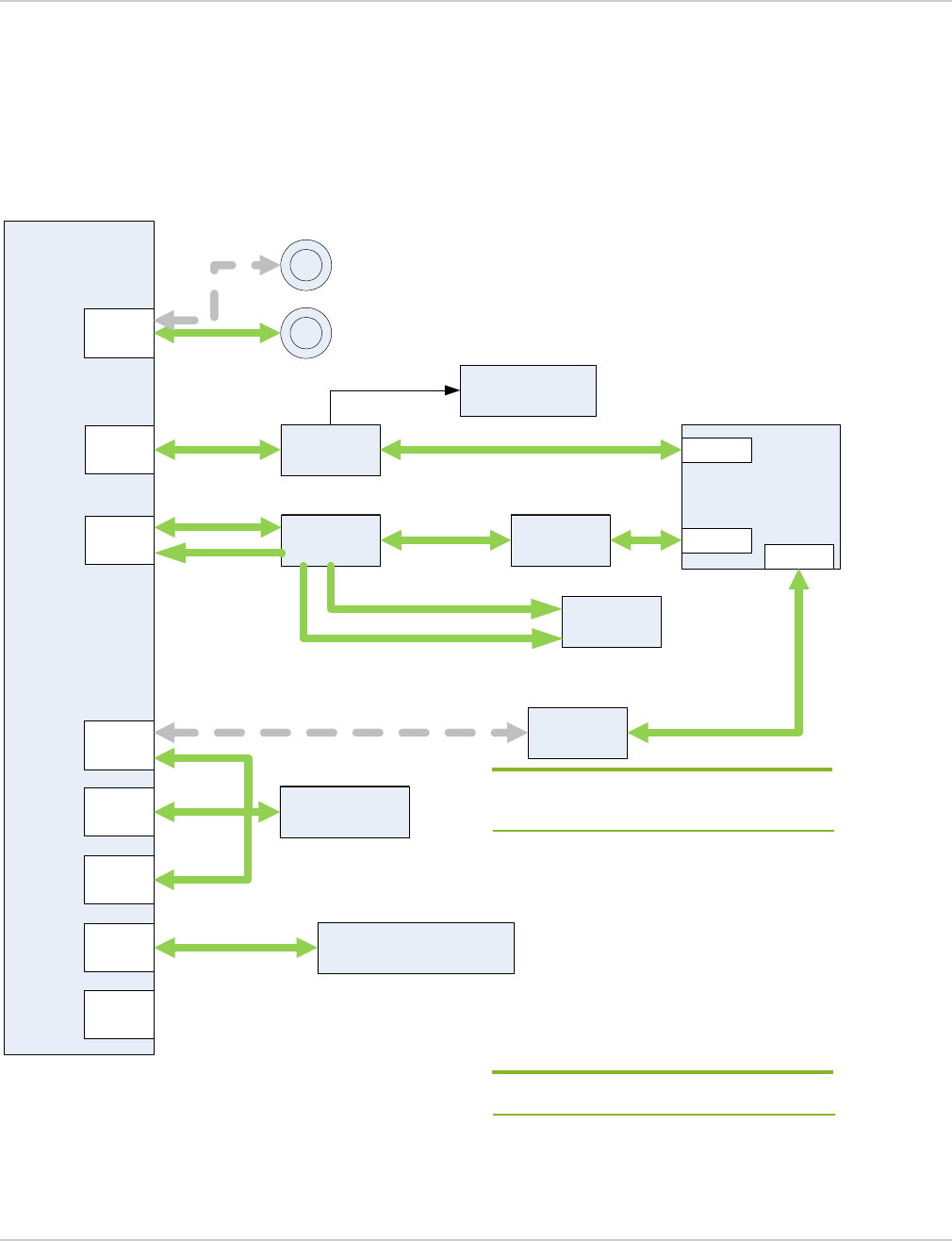
2.4.3 CF3 GPIOs
The mangOH Red supports several CF3 module GPIOs, as shown in Figure 2-7.
Notes:
•Six GPIOs connect to the IoT slot (for card detect, card reset, and four for use as GPIOs).
•One GPIO (GPIO32) connects to the NINT (active low interrupt) output signal from a GPIO expander (U1004).
Note: The mangOH Red uses a GPIO expander for additional I/O functions. See GPIO Expander on page 20.
Table 2-3: Audio Interface Configuration Changes
Change type Change effect Method Change duration
Hardware Mux—Use default or
alternate configuration
Populate/depopulate resistors on the
Mux:
•R508 pulls signal low (default
configuration)
•R520 pulls signal high (alternate
configuration)
Selected configuration used every
time device boots up.
CF3 PCM
Digital-
Analog
Codec
3.5mm
Jack
(CN500)
IoT Connector #0
(CN306, slot IOT0)
Note: Default configuration — Solid lines
Alternate configuration — Dashed lines
Mux
Hardware
Rev 4 May.18 19 41110401
Figure 2-7: GPIO Configuration
CF3
GPIO42
GPIO13
GPIO7
GPIO8
IoT Connector #0
(CN306, slot IOT0)
IOT0_GPIO1
IOT0_GPIO2
IOT0_GPIO3
IOT0_GPIO4
GPIO33
GPIO2
CARD_DETECT_IOT0
RESET_IOT0
SW401
GPIO6 LowPower_RESET
Level Shifter (U307)
GPIO25 RESET_WIFI_1V8 RESET_WIFI_3V3
GPIO Expander (U1004)
GPIO32 NINT
GPIO21
Low Power I/O (CN312)
GPIO36 WP_GPIO_5_wakeable
GPIO22
Raspberry Pi
Connector
(CN307)
WP_GPIO_1_lvl
Level Shifter (U306)
WP_GPIO_1
GPIO23 WP_GPIO_2_lvl
WP_GPIO_2
GPIO24 WP_GPIO_3_lvlWP_GPIO_3
EXT_GPS_LNA_EN PWM_OUT_3V3
PWM_OUT
GPIO35 WP_GPIO_8_lvlWP_GPIO_8
LED
(D410)
GPIO34 WP_GPIO_7
Wi-Fi module
(U1000)
SYS_RST_N
GPIO59
SPI2_SRDY
_WIFI_1V8
SPI2_SRDY
_WIFI_3V3
Note: Default configuration — Solid lines
Alternate configuration — Dashed lines

mangOH Red Developer’s Guide
Rev 4 May.18 20 41110401
2.4.4 GPIO Expander
The mangOH Red includes one SX1509 16-channel GPIO/PWM expander (U1004), as detailed in Table 2-4. The
expander provides additional GPIOs (carried over the CF3 module’s I2C1 interface) that are used for internal I/O
functions such as driving LEDs, resetting board components, etc.
For detailed specifications, see the mangOH Red schematics at mangoh.io/mangoh-red-resources-hardware.
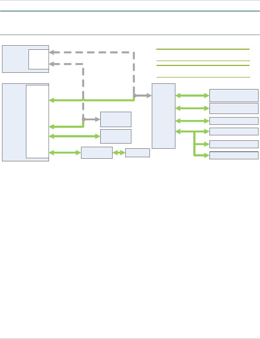
2.4.5 HSIC (USB/Ethernet)
The mangOH Red supports CF3 module HSIC signals, which connect through a USB hub controller to the
following sources, as shown in Figure 2-8:
•SPI interface:
·Wi-Fi/BT chipset (U1000) and Raspberry Pi Connector (CN307), via USB to SPI bridge (U1006).
Note: The Wi-Fi/BT chipset uses SPI2_CS0, and Raspberry Pi connector uses SPI2_CS1/SPI2_CS2.
Table 2-4: GPIO Expander (U1004) Signals
Pin Signal Name Purpose
I/O 0 BOARD_REV1 Reserved for future use.
I/O 1 BOARD_REV2 Reserved for future use.
I/O 2 BOARD_REV3 Reserved for future use.
I/O 3 GPIO_EXP_RPI_1 Raspberry Pi connector, pin 16
I/O_4 GPIO_EXP_RPI_2 Raspberry Pi connector, pin 18
I/O_5 MTK_TO_WP_UART_EN Enable MTK recovery mode from WP (0), or connects CF3 UART1 to
Wi-Fi/BT chipset UART0 (1)
I/O_6 WIFI_UART1_TX
Wi-Fi/BT chipset UART Tx—Normal (0), or MTK recovery mode (1) for
firmware downloads/recovery
(Note: DNI—R754 must be populated to access this signal.)
I/O_7 GPIO_EXP_RPI_3 Raspberry PI connector, pin 22
I/O_8 LED_CARD_DETECT_IOT0 Indicates whether IoT expansion card is present
I/O_9 SDIO_SEL Connect SD interface to IoT0 (0) or SD card (1)
I/O_10 Power_Fail_Indicator Indicate power fail
I/O_11 SENSOR_INT1 Accelerometer/gyroscope sensor interrupt
I/O_12 SENSORT_INT2 Accelerometer/gyroscope sensor interrupt
I/O_13 PCM_EXP1_SEL Connect PCM interface to IoT0 or to PCM codec (audio)
I/O_14 Generic_Push_Button SW200 generic pushbutton
I/O_15 CONS_DIR Use with MTK_TO_WP_UART_EN to choose UART source -- CF3
module or Wi-Fi/BT chipset
Hardware
Rev 4 May.18 21 41110401
•USB interface:
·IoT Connector 0 (CN306)
or
(DNI) Raspberry Pi Connector (CN307)
·USB Host connector (CN304)
Figure 2-8: HSIC Configuration
2.4.6 I2C1
The mangOH Red supports CF3 module I2C1 signals, which connect to the following sources (directly or via an
expander), as shown in Figure 2-9:
•Audio codec (U500)
•Pressure sensor (U705)—Accessible via API commands.
•Accelerometer/Gyroscope/Temperature sensor (U704)—Accessible via API commands.
•Battery charger (U800)—Accessible via API commands.
•Battery gauge (U801)—Accessible via API commands.
•IoT Connector 0 (CN306)
•Raspberry Pi connector (CN307)
•GPIO/PWM expander (U1004)—Used internally on the mangOH Red for I/O functions such as driving LEDs,
resetting board components, etc. (see GPIO Expander on page 20)
For detailed information, refer to mangOH Red schematics available at mangoh.io/mangoh-red-resources-
hardware.
•USB Hub controller (U701)
All signal sources are enabled by default.
Note: The mangOH Red I2C interface operates in a single-master/multi-slave setup.
CF3 HSIC
USB3503
Hub
(U701)
HSIC
Up USB
DW
USB
DW
USB
DW
USB Host Type A Connector
(CN304)
USB to
SPI
bridge
(U1006)
DNI
Raspberry Pi
Connector
(CN307)
USB
IoT Connector #0
(CN306, slot IOT0)
USB
Wi-Fi/BT chipset
(U1000)
SPI
SPI
Note: Default configuration — Solid lines
Alternate configuration — Dashed lines
mangOH Red Developer’s Guide
Rev 4 May.18 22 41110401
Note: By default, the CF3 I2C interface is connected as shown in Figure 2-9. The board can be modified to connect the Wi-Fi/
BT chipset I2C interface to the I2C expander and gyroscope/accelerometer sensor by populating/depopulating appropriate
resistors.
Figure 2-9: I2C1 Configuration
2.4.7 Light Sensor
The mangOH Red provides a light sensor (U706) that connects to the CF3 module’s ADC3 signal, as shown in
Figure 2-5 on page 17.
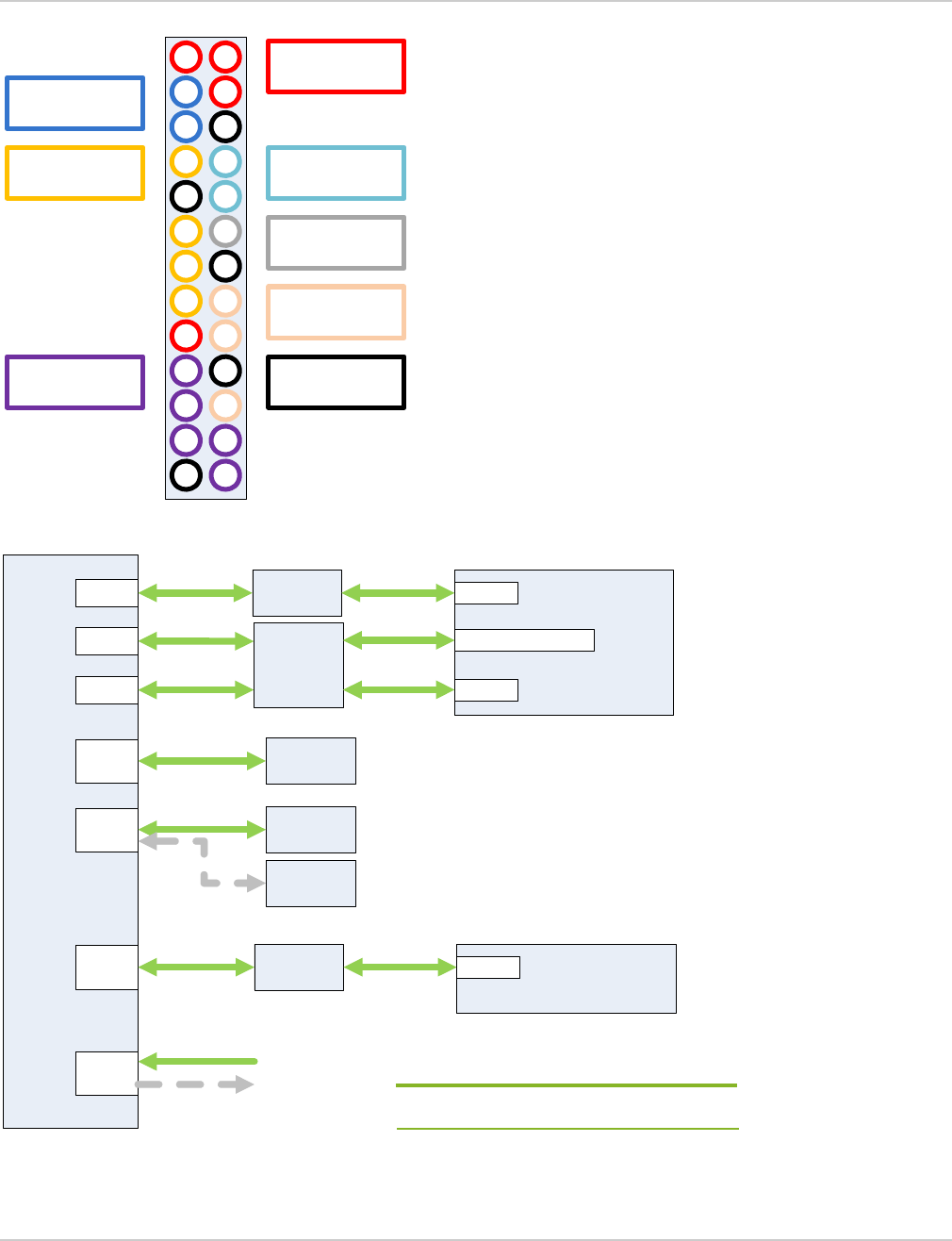
2.4.8 Raspberry Pi Rev B-compatible Connector
The mangOH Red provides a 26-pin Raspberry Pi RevB-compatible connector (CN307).
The mangOH Red provides the Raspberry Pi primary signals (alternate Raspberry Pi signals are not supported)
as shown in Figure 2-10 on page 23. These signals connect the mangOH Red’s hardware components to a
Raspberry Pi attached to the connector, as shown in Figure 2-11 on page 23.
R793/R794
R460/R461
CF3 I2C1
Pressure /
Temperature
Sensor (U705)
Gyroscope/
Accelerometer
Sensor (U704)
I2C
Expander
(U404)
IoT Connector #0
(CN306, slot IOT0)
GPIO Expander (U1004)
USB3503 Hub (U701)
Audio Codec
(U500)
Battery Charger (U800)
Battery Gauge (U801)
Raspberry Pi Connector
(CN307)
R795/R796
R345/R346
Wi-Fi/BT
chipset
(U1000)
I2C1
3.5mm jack
(CN500)
Note: Populate/depopulate identified resistors to
choose alternate configurations.
Note: Default configuration — Solid lines
Alternate configuration — Dashed lines
Hardware
Rev 4 May.18 23 41110401
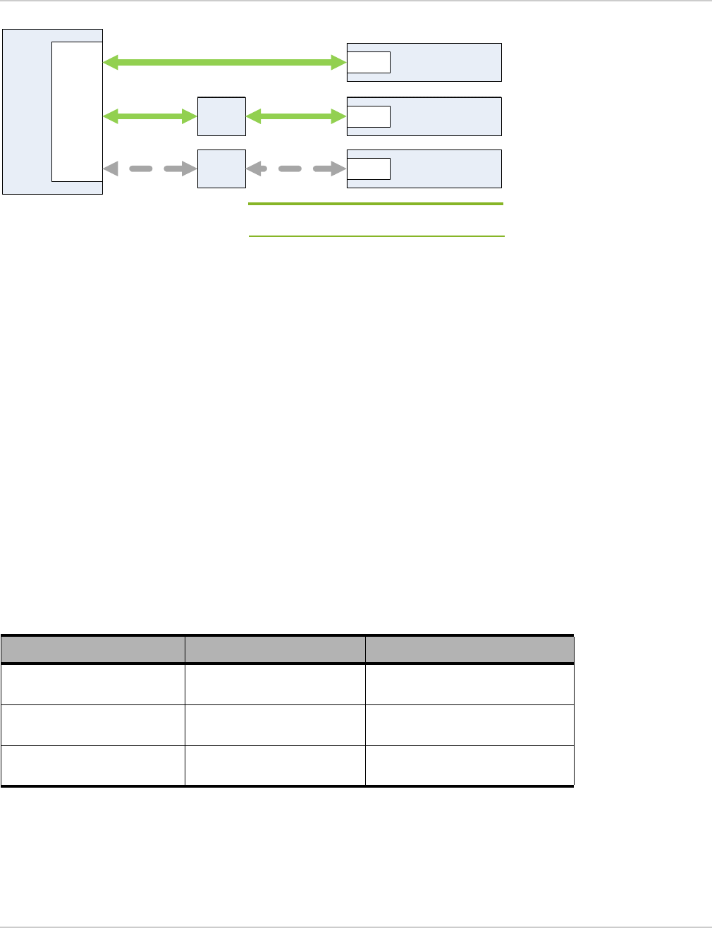
Figure 2-10: Raspberry Pi Signal Groups
Figure 2-11: Raspberry Pi Connections
1 2
3 4
5 6
7 8
910
11 12
13 14
15 16
17 18
19 20
21 22
23 24
25 26
Power
3.3V (Pins 1/17)
5.0V (Pins 2/4)
I2C
(Pins 3/5)
GPIO (CF3)
(Pins 7/11/13/15)
SPI
(Pins 19/21/23/24/26)
GPIO (Expander)
(Pins 16/18/22)
PWM
(Pin 12)
UART
(Pins 8/10)
Ground
(Pins 6/9/14/20/25)
Raspberry Pi
Connector
CN307
UART1 Level shifter
CF3
UART1
PWM EXT_GPS_LNA_EN
(4)
GPIO GPIO
SPI2 SPI bridge Wi-Fi/BT chipset
(U1000)
GPIO
GPIO
expander
(3)
GPIO
I2C hubI2C
5.0V
Level shifter
USB hub
R371
R382
VCC_5V0
USB_VBUS
Note: Default configuration — Solid lines
Alternate configuration — Dashed lines
mangOH Red Developer’s Guide
Rev 4 May.18 24 41110401
2.4.9 RF
The mangOH Red provides u.FL connectors that connect to the CF3 module’s RF signals:
•RF_MAIN—CN301
•RF_GPS—CN303
•RF_DIV—CN302
Power for these signals can be enabled/disabled as described in Table 2-5.
Figure 2-12: CF3 module RF Connections
2.4.10 SDIO
The mangOH Red supports the CF3 module SDIO signals, which connect via a MUX to the following sources, as
shown in Figure 2-13:
•microSD holder (CN600)—Default configuration
•IOT Connector 0 (CN306)
The SDIO interface configuration can be modified as detailed in Table 2-6.
Table 2-5: CF3 GPIO Interface Configuration Changes
Change type Change effect Method Change duration
Software Enable/disable RF power
for CF3 module
AT command
Legato API
Table 2-6: SDIO Interface Configuration Changes
Change type Change effect Method Change duration
Software •Use default or alternate
configuration. API command Selected configuration used every time device
boots up.
CF3
RF_MAIN
RF_DIV
RF_GPS
Main
(CN301)
GPS
(CN303)
DIversity
(CN302)
Hardware
Rev 4 May.18 25 41110401
Figure 2-13: SDIO Configuration
2.4.11 SPI1
The mangOH Red supports the CF3 module SPI1 signals, which connect to the following source, as shown in
Figure 2-14:
•IOT Connector 0 (CN306)
Figure 2-14: SPI1 Configuration
2.4.12 UART1
The mangOH Red supports the CF3 module’s UART1 signals, which connect to the following sources, as shown in
Figure 2-15:
•IoT Connector 0 (CN306)—Default configuration
•Raspberry Pi connector (CN307)
•Wi-Fi/BT chipset (Note, the level shifter must be ON. In the default board configuration, the level shifter is
OFF.)
Note: At any one time, use only the IoT expansion card UART or the Raspberry Pi UART, not both.
uSD Holder
(CN600)
CF3 SDIO
IoT Connector #0
(CN306, slot IOT0)
Mux
Note: Default configuration — Solid lines
Alternate configuration — Dashed lines
CF3 SPI1 IoT Connector #0
(CN306, slot IOT0)
SPI
mangOH Red Developer’s Guide
Rev 4 May.18 26 41110401
Figure 2-15: UART1 Configuration
2.4.13 UART2
The mangOH Red supports the CF3 module’s UART2 signals, which connect via a MUX to the following sources,
as shown in Figure 2-16:
•Console USB connector (CN305)—UART2 connects to the physical Console USB connector when both
MTK_TO_WP_UART_EN and CONS_DIR are low.
•Wi-Fi/BT chipset’s UART signal (U1000)—CF3 module’s UART2 and Wi-Fi/BT chipset’s UART0 are linked
when MTK_TO_WP_UART_EN signal is pulled high.
2.4.14 UART Console Connections
The mangOH Red supports the following console connections for the CF3 module (UART2) and Wi-Fi/BT chipset
(UART0), as shown in Figure 2-16:
•CF3 module UART2 to Console USB connector (CN305)
•Wi-Fi/BT chipset UART0 to Console USB connector (CN305)
•Direct connect between CF3 module UART2 and Wi-Fi/BT chipset UART0
Table 2-7: UART Console Connection Options
Connection CONS_DIR (SW401 pin 6) MTK_TO_WP_UART_EN (API)
CF3 module UART2 to
Console USB Pull low (Pin OFF) Pull low
Wi-Fi/BT chipset UART0 to
Console USB Pull high (Pin ON) Pulll low
CF3 module UART2 to Wi-Fi/
BT chipset UART0 n/a Pull high
CF3 UART1
IoT Connector #0
(CN306, slot IOT0)
UART
Raspberry Pi
Connector (CN307)
UART
Level
shifter
Wi-Fi/BT chipset
(U1000)
UART
Level
shifter
Note: Default configuration — Solid lines
Alternate configuration — Dashed lines
Hardware
Rev 4 May.18 27 41110401
Figure 2-16: UART Console Connections
2.4.15 UIM Signals
The mangOH Red supports both CF3 module UIM interfaces (UIM1, UIM2), where UIM1 is a removable SIM, and
UIM2 is an embedded SIM (DNI).
The default boot configuration is shown in Figure 2-17.
Note: Throughout this document, ‘UIM’ is used to refer to UIM, USIM, SIM, UICC.
Figure 2-17: SIM Interfaces Configuration
2.4.15.1 UIM1
The CF3 module’s UIM1 signal connects to the micro-SIM holder (CN600).
Note: The CF3 module’s UIM1_DET signal indicates when a SIM is present in the holder.
CF3 UART2
Wi-Fi/BT
chipset UART0
Level shifter
USB-UART
FTDI
Console
USB
CONS_DIR
MTK_TO_WP_UART_EN
UART
buffer
Mux
Note: Default configuration — Solid lines
Alternate configurations — Dashed lines
SIM Holder
(CN600)
(DNI)
eSIM (U603)
CF3
UIM1
UIM2
Note: Default configuration — Solid lines
Alternate configuration — Dashed lines
mangOH Red Developer’s Guide
Rev 4 May.18 28 41110401
2.4.15.2 UIM2
Note: The mangOH Red does not ship with an eSIM (the component is DNI). For details, refer to the mangOH Red schematics
available at mangoh.io/mangoh-red-resources-hardware.
The CF3 module’s UIM2 signal connects to the eSIM (U603).
Note: The corresponding UIM2_DET signal pin is reserved for future use.
2.4.16 USB 2.0
The CF3 module’s USB signal connects directly to the mangOH Red’s CF3 USB micro-USB connector (CN305) as
shown in Figure 2-18, for control by a connected computer.
Note: The micro-USB connector also acts as a power source, if selected. See Power Management on page 32.
The USB 2.0 interface configuration can be modified as detailed in Table 2-8.
Figure 2-18: USB_2.0 Configuration
2.5 Wi-Fi/BT Chipset
The mangOH Red incorporates a Wi-Fi/BT chipset (MediaTek Wi-Fi+Bluetooth) that provides the following
functionality:
•RF:
·Wi-Fi/Bluetooth/WLAN connections via an integrated 2.4 GHz antenna
·Supports 2.4GHz Wi-Fi (802.11b/g/nHT20) and 2.4GHz BLE (Bluetooth Low Energy)
•IOT0 connection via Wi-Fi/BT chipset’s UART1
•Application processor—Real-time application processing using the mangOH Red’s real-time I/O connector,
via GPIO, ADC, and I2C interfaces.
Table 2-8: USB 2.0 Interface Configuration Methods
Change type Change effect Method Change duration
Hardware •Jumper on pins closest to CF3
USB—Select CF3 USB power
•Jumper on pins closest to
Console USB—Select Console
USB power
•Jumper off—Use battery if
connected, otherwise no power
supplied
Position jumper on CN804 to choose
CF3 USB or CONSOLE USB connector
to supply power.
Note: mangOH Red ships with CF3
USB power selected (jumper on pins
closest to CF3 USB connector).
mangOH Red uses the
selected power supply
until the jumper
changes.
CF3 USB
USB2.0 micro-USB
connector
(CN305)
CF3 USB
Hardware
Rev 4 May.18 29 41110401
•Access to mangOH Red’s accelerometer/gyroscope/temperature sensor via GPIO interface
•Access to Raspberry Pi connector via SPI interface
•Wi-Fi/BT chipset console connection to either the Console USB connector or the CF3 module console,
including ability to receive firmware downloads from either source.
•Optional debug connector (CN400, DNI) to use for serial wire debugging
The Wi-Fi/BT chipset can connect to several components on the mangOH Red, as show in Figure 2-19.
Figure 2-19: Wi-Fi/BT Chipset Connections
Wi-Fi/BT chipset
UART0
SPI2
SPI1 32Mb Flash Memory
GPIO
Real-time I/OADC
I2C
UART1 Level shifter
CF3
UART1
RF Integrated antenna
(ANT1000)
U.FL connector
(CN1000)
Wi-Fi/BT/WLAN
I2C
Expander
R460/R461
HSICSPI Bridge USB USB Hub
Raspberry
Pi
SPI2_CS2
Off (default)
SPI2_CS0
SPI2_CS1
I2C
R345/R346
SW401
Pin 4: HL_MODE
Note: Default configuration — Solid lines
Alternate configuration — Dashed lines
Refer to Figure 2-16 for UART0 details.
Note: Populate/depopulate identified resistors to
connect either the CF3 module or the
Wi-Fi/BT chipset to the I2C expander.
mangOH Red Developer’s Guide
Rev 4 May.18 30 41110401
2.5.1 Wi-Fi RF
The mangOH Red supports 2.4GHz Wi-Fi (802.11b/g/nHT20).
Table 2-9 describes the mangOH Red’s Wi-Fi RF average output power.
For Wi-Fi 2.4 GHz RF receiver specifications, refer to the MediaTek MT7697 Datasheet, version 1.01.
2.5.2 Bluetooth RF
The mangOH Red supports 2.4GHz BLE (Bluetooth Low Energy).
Table 2-10 describes the mangOH Red’s Bluetooth RF average output power.
For Bluetooth 2.4 GHz RF receiver specifications, refer to the MediaTek MT7697 Datasheet, version 1.01.
Table 2-9: Maximum Wi-Fi RF Average Output Power
Mode Frequency
Average Power (dBm)
802.11b 802.11g 802.11n-HT20
2.4 GHz WLAN
2412 11.5 12.0 11.5
2437 11.5 13.0 14.0
2462 10.5 11.5 11.0
Parameter Description Min (dB) Max (dB)
Output power variation
•TSSI closed-loop control across all
temperature range and channels and
VWSR 1.5:1
•VCC_3V3 voltage is within ±5% of typical
value
-1.5 1.5
Table 2-10: Maximum Bluetooth RF Average Output Power
Mode Average Power (dBm)
Bluetooth LE, GFSK 8.5
Hardware
Rev 4 May.18 31 41110401
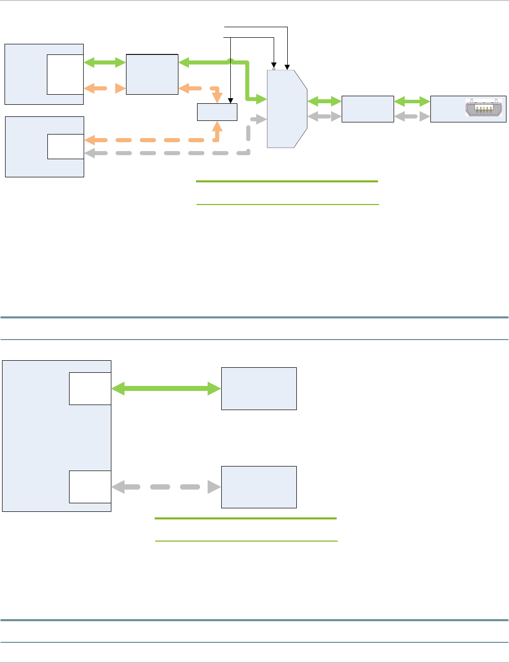
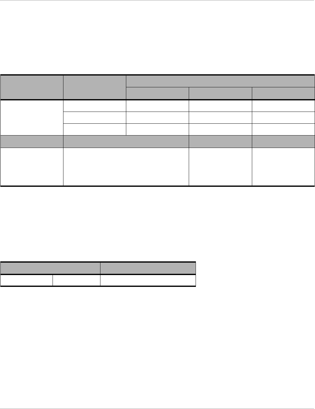
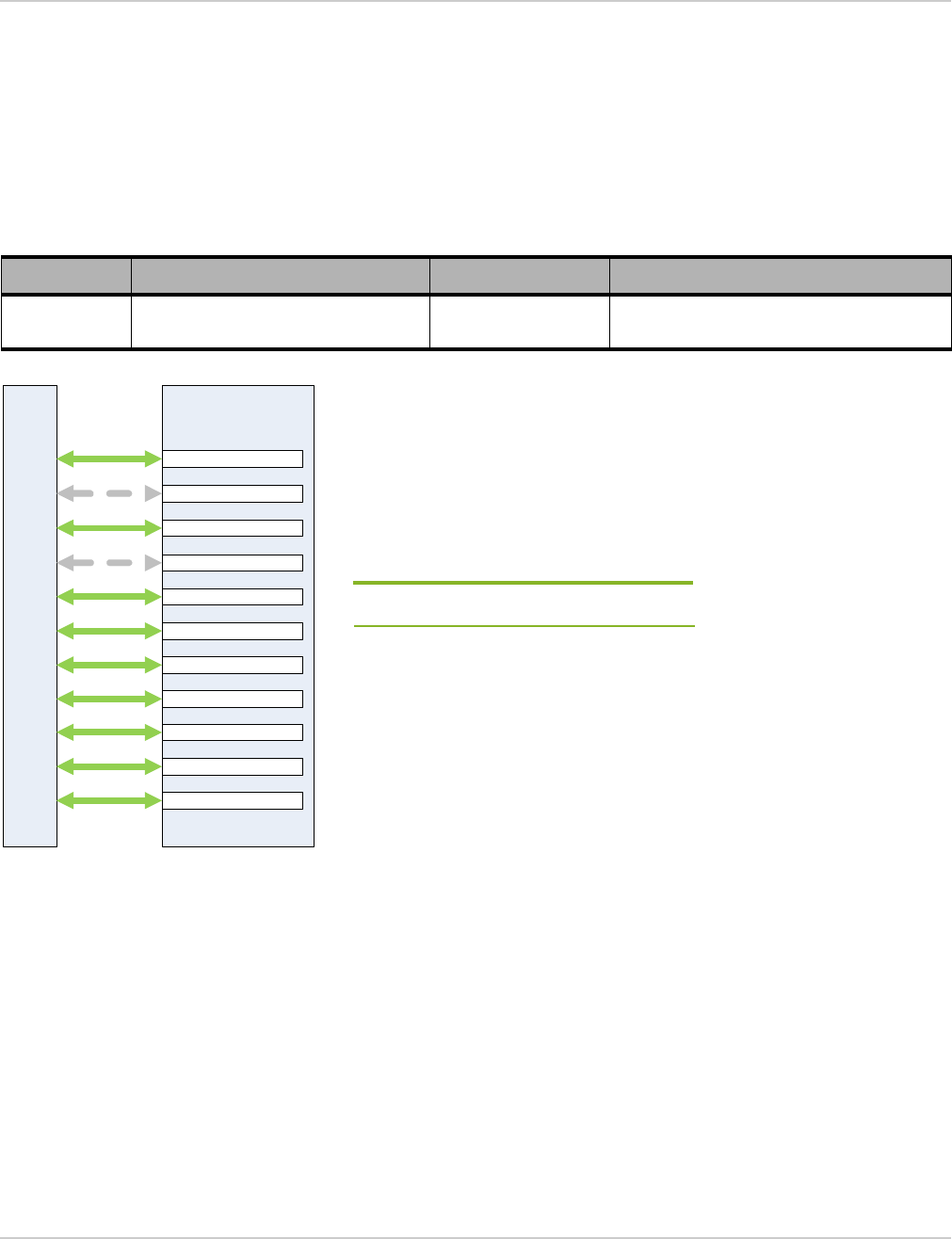
2.6 IoT Connector Interfaces
The mangOH Red provides one IoT Connector (CN306, slot IOT0), which supports the signals defined in the
Project mangOH IoT Expansion Card Design Specification, as detailed in Table 2-2 on page 16.
The default configuration (enabled signals) for the IoT Connector is shown in Figure 2-20.
The IoT Connector interface configuration can be modified as detailed in Table 2-11.
Figure 2-20: IoT Connector Configuration
Table 2-11: IoT Connector Interface Configuration Changes
Change type Change effect Method Change duration
Software Enable/disable identified signal(s) on
a specific IoT Connector.
API command Modifies running configuration until device
reboots or another change is made.
CF3
IoT Connector #0
(CN306, slot IOT0)
UART
PCM
SPI
SDIO
USB
I2C
ADC0
PPS
GPIO(1-4)
n_RESET
n_CARD_DETECT
Note: Default configuration — Solid lines
Alternate configuration — Dashed lines
mangOH Red Developer’s Guide
Rev 4 May.18 32 41110401
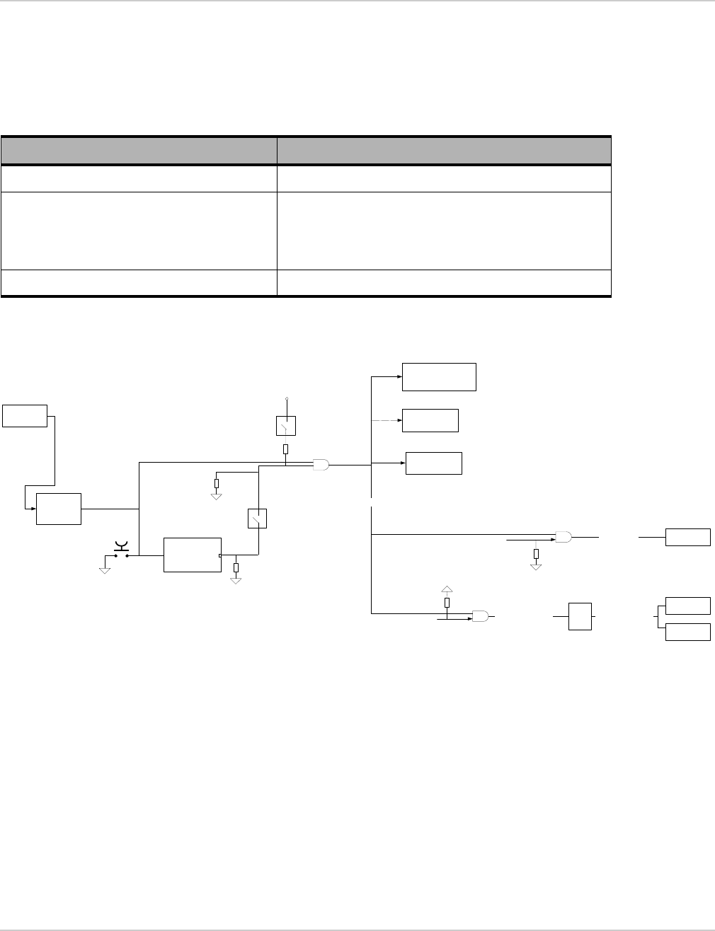
2.7 Reset Methods
The mangOH Red supports hardware and software resets of the entire board or certain components of the board,
as shown in Figure 2-21:
For detailed specifications showing how full or partial resets are enabled, see the mangOH Red schematics
available at mangoh.io/mangoh-red-resources-hardware.
Figure 2-21: Reset Methods
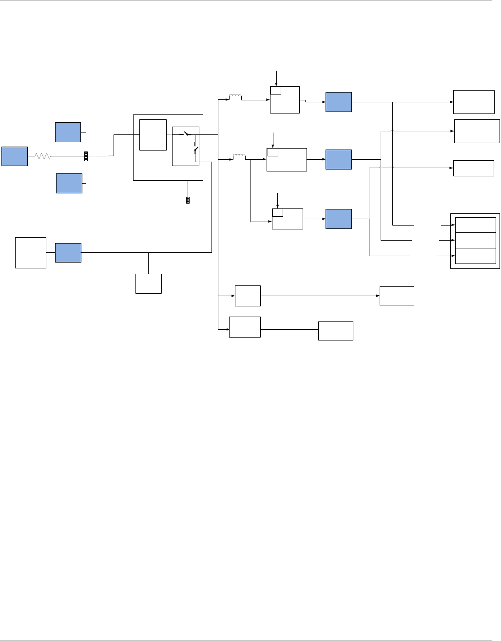
2.8 Power Management
The mangOH Red has two primary power supplies (CF3 USB connector and CONSOLE USB connector), and a
rechargeable backup battery power supply option.
Figure 2-22 illustrates these power supplies, their voltage/current specifications, and how they supply various
components on the mangOH Red platform.
A multi-function switch (SW401) controls some power-related features (see Multi-switch (SW401) on page 15),
including:
•Pin 1 (PWR_ON)—Enable/disable CF3 module’s POWER_ON_signal
Table 2-12: Reset Methods
Board Components to Reset Reset Method
Entire board, including CF3 module (WP or HL) Press Reset button (SW400)
IOT Expansion Card CF3_IOT0_RESET
or
Use an API command to trigger the CF3 module signal
GPIO_IOT0_RESET.
Wi-Fi/BT chipset CF3_GPIO_WIFI_RESET
Battery
Charger
Main CF3
USB HUB
(USB3503)
GPIO
Expander(SX1509)
IoT #1Reset IoT #1
RESET_WIFI_1V8
System_reset
DNI
NCP303
POR reset
3.0V
Reset
(open drain out)
3V7
Reset
Button
47k
CF3_IOT0_RESET
CF3_GPIO_WIFI_RESET
RESET_WIFI_3V3
CP2130
MTD7697D
VCC_1V8
10k
SW401.pin8
WP= ON
HL=OFF
SW401.pin4
WP= OFF
HL=ON
TCA9546
WP_LowPower_Reset
LowPower_Reset
47k
VCC_1V8
Level
Shift
U307
100k
Hardware
Rev 4 May.18 33 41110401
•Pin 3 (VCC_3V7_ULPM)—In ULPM, enable/disable power to accessories (CF3 module always receives
power)
•Pin 5 (BATT_TS+)—Enable/disable backup battery charging
Figure 2-22: Power Management
Vbatt
LiPo
Battery
3.7V
0 OHM
1.8V Buck
5V Peripherals
1V8 Peripherals
50mA typ
100mA Max
Battery Charger
with Power Path
100mA typ
500mA Max
5V boost
Regulator
and
charger
3.3V Buck
3V3 Peripherals
Including WiFi/BT
chipset
300mA typ
600mA max
1V8
3V3
5V
1x IoT
0 ohm
300mA typ
500mA Max
200mA typ
900mA max
50mA typ
100mA Max
4.5V to 5.5V
3.7V @ 1A continous, 2.5A peak CF3 Main
uUSB CF3
uSUB
Console
JST-PH
Connector
Jumper
Battery
Gauge
Jumper:
Battery
SW401SLQ
EN
0 ohm
0 Ohm
EN
EN
VGPIO
VGPIO
VGPIO
Low
Power
1.8V LDO Low Power
I/Os
Raspberry
Pi
Connector DNI
L910
L911

Rev 4 May.18 34 41110401
3
3: Regulatory Compliance
3.1 Important Compliance Information for North American
Users
3.1.1 USA
Caution: Changes or modifications not expressly approved by Sierra Wireless could void the user's authority to operate the
equipment.
This device complies with part 15 of the FCC Rules. Operation is subject to the following two conditions: (1) This
device may not cause harmful interference, and (2) this device must accept any interference received, including
interference that may cause undesired operation.
Note: This equipment has been tested and found to comply with the limits for a Class B digital device, pursuant to
part 15 of the FCC Rules. These limits are designed to provide reasonable protection against harmful interference
in a residential installation. This equipment generates, uses and can radiate radio frequency energy and, if not
installed and used in accordance with the instructions, may cause harmful interference to radio communications.
However, there is no guarantee that interference will not occur in a particular installation. If this equipment does
cause harmful interference to radio or television reception, which can be determined by turning the equipment off
and on, the user is encouraged to try to correct the interference by one or more of the following measures:
·Reorient or relocate the receiving antenna.
·Increase the separation between the equipment and receiver.
·Connect the equipment into an outlet on a circuit different from that to which the receiver is connected.
·Consult the dealer or an experienced radio/TV technician for help.
3.1.2 Canada
This device complies with Industry Canada's licence-exempt RSSs. Operation is subject to the following two
conditions:
1) This device may not cause interference; and
2) This device must accept any interference, including interference that may cause undesired operation of the
device.
Le présent appareil est conforme aux CNR d'Industrie Canada applicables aux appareils radio exempts de licence.
L'exploitation est autorisée aux deux conditions suivantes :
1) l'appareil ne doit pas produire de brouillage;
2) l'appareil doit accepter tout brouillage radioélectrique subi, même si le brouillage est susceptible d'en com-
promettre le fonctionnement.