Sierra Wireless WP76A Radio Module User Manual AirPrime WP7601 Hardware Integration Guide
Sierra Wireless Inc. Radio Module AirPrime WP7601 Hardware Integration Guide
41111210 WP7601 Hardware Integration Guide r1

AirPrime WP7601
Hardware Integration Guide
41111210
Rev 1

Hardware Integration Guide
Rev 1 Jul 17 2 41111210
Important
Notice
Due to the nature of wireless communications, transmission and reception of data
can never be guaranteed. Data may be delayed, corrupted (i.e., have errors) or be
totally lost. Although significant delays or losses of data are rare when wireless
devices such as the Sierra Wireless modem are used in a normal manner with a
well-constructed network, the Sierra Wireless modem should not be used in
situations where failure to transmit or receive data could result in damage of any
kind to the user or any other party, including but not limited to personal injury,
death, or loss of property. Sierra Wireless accepts no responsibility for damages
of any kind resulting from delays or errors in data transmitted or received using
the Sierra Wireless modem, or for failure of the Sierra Wireless modem to
transmit or receive such data.
Safety and
Hazards
Do not operate the Sierra Wireless modem in areas where blasting is in progress,
where explosive atmospheres may be present, near medical equipment, near life
support equipment, or any equipment which may be susceptible to any form of
radio interference. In such areas, the Sierra Wireless modem MUST BE IN
AIRPLANE MODE OR POWERED OFF. The Sierra Wireless modem can
transmit signals that could interfere with this equipment.
Do not operate the Sierra Wireless modem in any aircraft, whether the aircraft is
on the ground or in flight. In aircraft, the Sierra Wireless modem MUST BE IN
AIRPLANE MODE OR POWERED OFF. When operating, the Sierra Wireless
modem can transmit signals that could interfere with various onboard systems.
Note: Some airlines may permit the use of cellular phones while the aircraft is on the
ground and the door is open. Sierra Wireless modems may be used at this time.
The driver or operator of any vehicle should not operate the Sierra Wireless
modem while in control of a vehicle. Doing so will detract from the driver or
operator's control and operation of that vehicle. In some states and provinces,
operating such communications devices while in control of a vehicle is an offence.
Limitation of
Liability
The information in this manual is subject to change without notice and does not
represent a commitment on the part of Sierra Wireless. SIERRA WIRELESS AND
ITS AFFILIATES SPECIFICALLY DISCLAIM LIABILITY FOR ANY AND ALL
DIRECT, INDIRECT, SPECIAL, GENERAL, INCIDENTAL, CONSEQUENTIAL,
PUNITIVE OR EXEMPLARY DAMAGES INCLUDING, BUT NOT LIMITED TO,
LOSS OF PROFITS OR REVENUE OR ANTICIPATED PROFITS OR REVENUE
ARISING OUT OF THE USE OR INABILITY TO USE ANY SIERRA WIRELESS
PRODUCT, EVEN IF SIERRA WIRELESS AND/OR ITS AFFILIATES HAS BEEN
ADVISED OF THE POSSIBILITY OF SUCH DAMAGES OR THEY ARE
FORESEEABLE OR FOR CLAIMS BY ANY THIRD PARTY.
Notwithstanding the foregoing, in no event shall Sierra Wireless and/or its
affiliates aggregate liability arising under or in connection with the Sierra Wireless
product, regardless of the number of events, occurrences, or claims giving rise to
liability, be in excess of the price paid by the purchaser for the Sierra Wireless
product.
Preface
Rev 1 Jul 17 3 41111210
Patents This product may contain technology developed by or for Sierra Wireless Inc. This
product includes technology licensed from QUALCOMM®. This product is
manufactured or sold by Sierra Wireless Inc. or its affiliates under one or more
patents licensed from InterDigital Group and MMP Portfolio Licensing.
Copyright ©2017 Sierra Wireless. All rights reserved.
Trademarks Sierra Wireless®, AirPrime®, AirLink®, AirVantage® and the Sierra Wireless logo
are registered trademarks of Sierra Wireless, Inc.
Windows® and Windows Vista® are registered trademarks of Microsoft
Corporation.
QUALCOMM® is a registered trademark of QUALCOMM Incorporated. Used
under license.
Other trademarks are the property of their respective owners.
Contact
Information
Revision
History
Sales information and technical
support, including warranty and returns Web: sierrawireless.com/company/contact-us/
Global toll-free number: 1-877-687-7795
6:00 am to 6:00 pm PST
Corporate and product information Web: sierrawireless.com
Revision
number Release date Changes
1June 2017 FCC/IC certification

Rev 1 Jul 17 4 41111210
Contents
Introduction . . . . . . . . . . . . . . . . . . . . . . . . . . . . . . . . . . . . . . . . . . . . . . . . . . . . . . . . . . . . .5
Accessories . . . . . . . . . . . . . . . . . . . . . . . . . . . . . . . . . . . . . . . . . . . . . . . . . . . . . . . . . . 5
Power . . . . . . . . . . . . . . . . . . . . . . . . . . . . . . . . . . . . . . . . . . . . . . . . . . . . . . . . . . . . . . . . . .6
Power Supply . . . . . . . . . . . . . . . . . . . . . . . . . . . . . . . . . . . . . . . . . . . . . . . . . . . . . . . . . 6
Module Power States . . . . . . . . . . . . . . . . . . . . . . . . . . . . . . . . . . . . . . . . . . . . . . . . . . . 6
RF Specifications . . . . . . . . . . . . . . . . . . . . . . . . . . . . . . . . . . . . . . . . . . . . . . . . . . . . . . . .7
Conducted Tx power . . . . . . . . . . . . . . . . . . . . . . . . . . . . . . . . . . . . . . . . . . . . . . . . . . 7
Routing Constraints and Recommendations . . . . . . . . . . . . . . . . . . . . . . . . . . . . . . . . . .8
General Rules and Recommendations. . . . . . . . . . . . . . . . . . . . . . . . . . . . . . . . . . . . . . 8
PCB Layout Recommendations . . . . . . . . . . . . . . . . . . . . . . . . . . . . . . . . . . . . . . . . . . . 8
Power Supply . . . . . . . . . . . . . . . . . . . . . . . . . . . . . . . . . . . . . . . . . . . . . . . . . . . . . . . . . 8
Antenna . . . . . . . . . . . . . . . . . . . . . . . . . . . . . . . . . . . . . . . . . . . . . . . . . . . . . . . . . . . . . 9
PCB Specifications for the Application Board. . . . . . . . . . . . . . . . . . . . . . . . . . . . . . . . . 9
Recommended PCB Land Pattern . . . . . . . . . . . . . . . . . . . . . . . . . . . . . . . . . . . . . . . . . 9
Routing Constraints . . . . . . . . . . . . . . . . . . . . . . . . . . . . . . . . . . . . . . . . . . . . . . . . . . . . 9
Power Supply . . . . . . . . . . . . . . . . . . . . . . . . . . . . . . . . . . . . . . . . . . . . . . . . . . . . . . .9
UIM Interface . . . . . . . . . . . . . . . . . . . . . . . . . . . . . . . . . . . . . . . . . . . . . . . . . . . . . .10
RF Circuit . . . . . . . . . . . . . . . . . . . . . . . . . . . . . . . . . . . . . . . . . . . . . . . . . . . . . . . . .10
USB Interface . . . . . . . . . . . . . . . . . . . . . . . . . . . . . . . . . . . . . . . . . . . . . . . . . . . . . .11
Thermal Considerations . . . . . . . . . . . . . . . . . . . . . . . . . . . . . . . . . . . . . . . . . . . . . . . . 11
EMC and ESD Recommendations . . . . . . . . . . . . . . . . . . . . . . . . . . . . . . . . . . . . . . . . 11
Mechanical Integration . . . . . . . . . . . . . . . . . . . . . . . . . . . . . . . . . . . . . . . . . . . . . . . . . 12
Signal Reference Schematics . . . . . . . . . . . . . . . . . . . . . . . . . . . . . . . . . . . . . . . . . . . 13
Regulatory Compliance and Industry Certifications . . . . . . . . . . . . . . . . . . . . . . . . . . .15
Important Notice . . . . . . . . . . . . . . . . . . . . . . . . . . . . . . . . . . . . . . . . . . . . . . . . . . . . . . 15
Safety and Hazards . . . . . . . . . . . . . . . . . . . . . . . . . . . . . . . . . . . . . . . . . . . . . . . . . . . 15
Important Compliance Information for North American Users . . . . . . . . . . . . . . . . . . . 15

Rev 1 Jul 17 5 41111210
1
1: Introduction
The AirPrime WP7601 is an industrial-grade LGA 239-pad module that provides voice
and data connectivity on LTE networks. The module also provides GNSS functionality
as a SKU-configuration.
Accessories
A hardware development kit is available for AirPrime WP-series modules. The kit
contains hardware components for evaluating and developing with the module,
including:
•Development board
•Cables
•Antennas (Additional antennas may be required to support all bands.)
•Other accessories

Rev 1 Jul 17 6 41111210
2
2: Power
Power Supply
The host provides power to the AirPrime WP7601 through multiple power and ground
pins. The host must provide safe and continuous power at all times; the module does
not have an independent power supply, or protection circuits to guard against
electrical issues.
For detailed pinout and voltage/current requirements of this module, see the AirPrime
WP76XX Product Technical Specification.
Module Power States
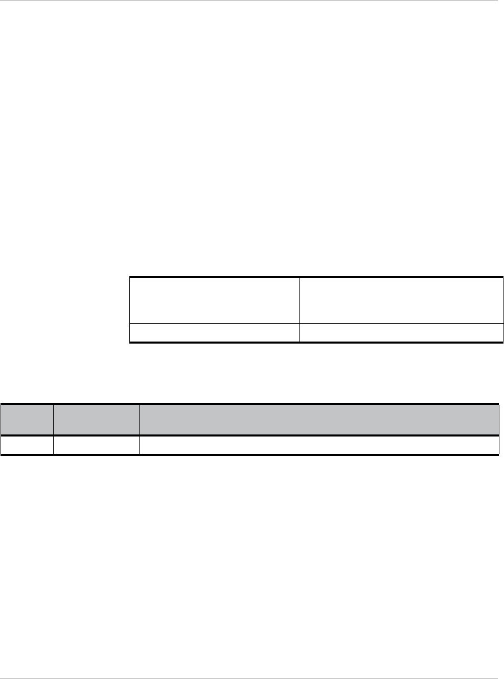
The module has three main power states, as described in Table 2-1.
Table 2-1: Supported Power States
State Description Wake-Up Events
OFF Module is off (no power to the system).
Apply power for system to go to Active state.
Apply power.
Interrupt Simple wakeup sources are configured to interrupt from this
power-saving state to the Active state. An event generated from a state change of
RESET_IN_N or POWER_ON_N, or a
timeout event.
Active The module may be fully functioning (WWAN radio and GNSS
radio active), or be operating in airplane mode (WWAN radio off).
Module actively reduces power consumption by disabling
components that are not in use (for example, stepping down
clock signals, putting USB bus into selective suspend, etc.)
System wakes up (returns to fully active
mode) automatically as required, or can be
woken directly via wakeable GPIOs.
Rev 1 Jul 17 7 41111210
3
3: RF Specifications
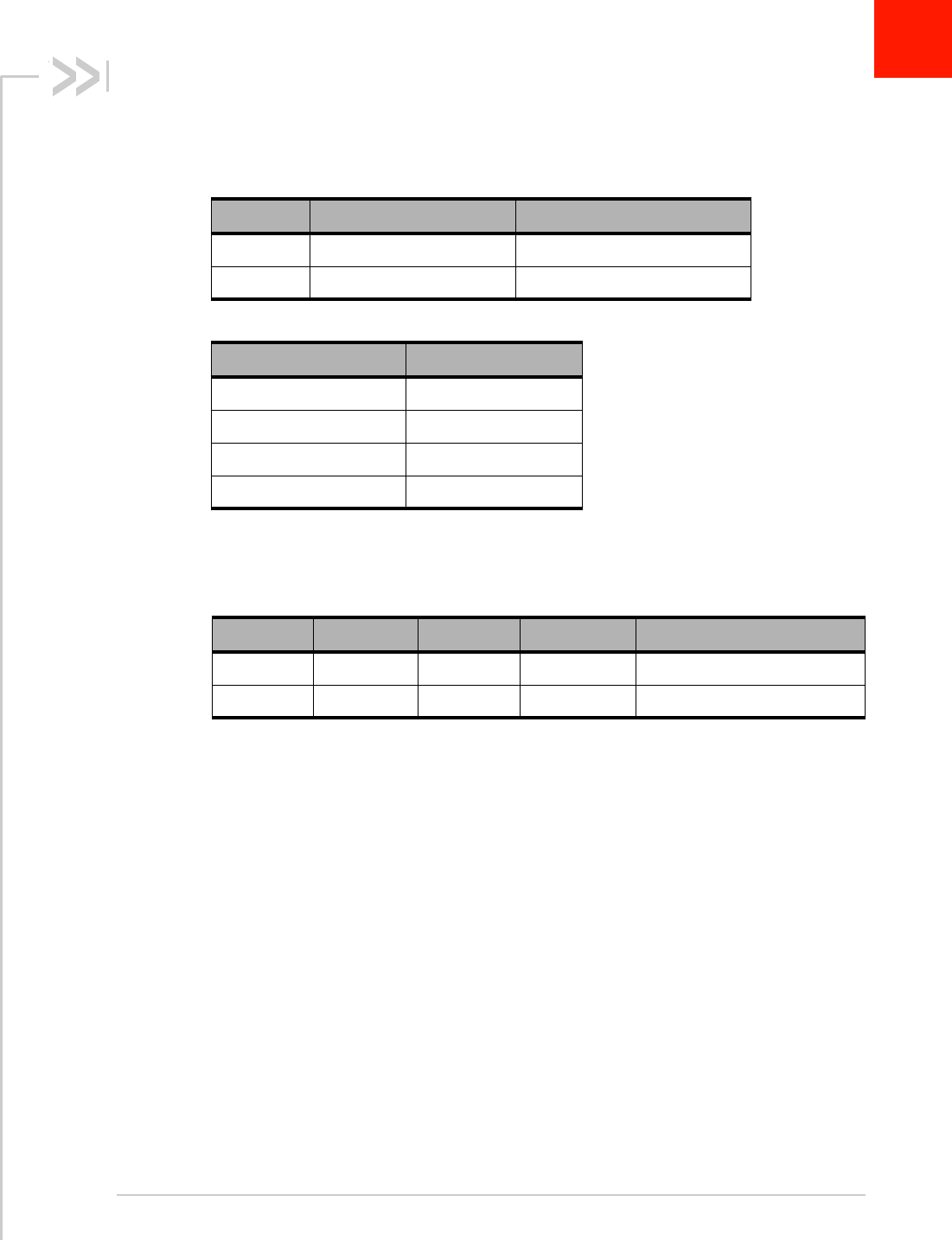
The AirPrime WP7601 operates on the frequency bands listed below.
Conducted Tx power
Table 3-1: LTE Frequency Band Support
Band Frequency (Tx) (MHz) Frequency (Rx) (MHz)
B4 1710–1755 2110–2155
B13 777–787 746–756
Table 3-2: GNSS Frequency Band Support
Band Frequencies (MHz)
GPS 1575.42 ± 1.023
GLONASS 1597.52–1605.92
Galileo 1575.42 ± 2.046
BeiDou 1561.098 ± 2.046
Table 3-3: Conducted Tx Max Output Power Tolerances—LTE
RF band Min (dBm) Typ (dBm) Max (dBm) Notes
B4 22 23 24 Connectorized (Class 3)
B13 22 23 24 Connectorized (Class 3)

Rev 1 Jul 17 8 41111210
4
4: Routing Constraints and Recommen-
dations
This section describes general routing constraints and recommendations for the
AirPrime WP7601 module.
Note: This is a non-exhaustive list of suggested design guidelines. The developer is respon-
sible for deciding whether to implement these guidelines.
General Rules and Recommendations
Clock and other high-frequency digital signals (e.g. serial buses) should be routed as
far as possible from the module’s analog signals.
If the application design makes it possible, all analog signals should be separated
from digital signals by a ground trace on the PCB.
Tip: Avoid routing any signals under the module on the application board.
PCB Layout Recommendations
Ground pads should be re-flowed on to the host PCB with < 30% voiding to allow
effective heat dissipation.
Power Supply
When designing the power supply, make sure that VBAT_BB/VBAT_RF meet the
requirements listed in the AirPrime WP76XX Product Technical Specification.
Careful attention should be paid to the following:
•Power supply quality—PFM, or PSM systems should be avoided; Low ripple,
linear regulation or PWM converters are preferred for low noise.
•Capacity to deliver high current peaks in a short time (for pulsed radio emission)
•VBAT_BB/VBAT_RF must support peak currents with an acceptable voltage
drop that guarantees the minimum required VBAT_BB/VBAT_RF value.
•VBAT_BB/VBAT_RF signal pads must never exceed the maximum required
VBAT_BB/VBAT_RF value, otherwise the module’s power amplifier and GPS
chipset may be severely damaged.
•A weakly-designed (not robust) power supply could affect EMC performance, the
emission spectrum, and the phase error and frequency error.
Routing Constraints and Recommendations
Rev 1 Jul 17 9 41111210
Antenna
Sierra Wireless strongly recommends working with an antenna manufacturer
either to develop an antenna adapted to the application, or to adapt an existing
solution to the application.
For information on routing constraints for the RF circuit, see RF Circuit on
page 10.
PCB Specifications for the Application
Board
Sensitive signals (such as audio, UIM, and clocks) should be protected by ground
planes/fills. Routing sensitive signals close to noisy signals could result in noise
being coupled.
Recommended PCB Land Pattern
Refer to AirPrime WPx5/WP76 Series Customer Process Guidelines, available at
http://source.sierrawireless.com.
Routing Constraints
Power Supply
If the following design recommendations are not followed, phase error (peak) and
power loss could occur.
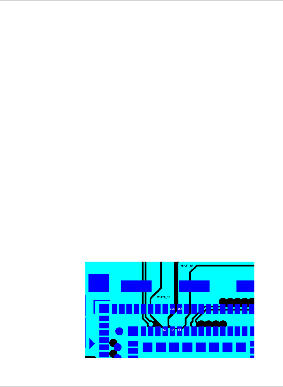
•Since the maximum peak current can reach 2.5 A, Sierra Wireless strongly
recommends having a large width for the layout of the power supply signal (to
avoid voltage loss between the external power supply and VBAT_BB/
VBAT_RF.
Figure 4-1: Power Supply Routing Example

Hardware Integration Guide
Rev 1 Jul 17 10 41111210
Note: Figure 4-1 shows separate traces for VBAT_BB and VBAT_RF. If VBAT_BB and
VBAT_RF share a single power supply, these traces should be connected.
Note: For optimal decoupling, place the capacitors on the underside of the board, directly
under the pins.
•Filtering capacitors (100 nF to 1500 F) are recommended near the module’s
power supply.
•Attention should be paid to the ground trace or the ground plane on the appli-
cation board for the power supply that supplies the module. The ground trace
or ground plane, as well as the VBAT trace, must be able to support current
peaks.
•If the ground trace between the module and the power supply is a copper
plane, make sure it is a solid plane.
•Design routing to make sure total line impedance does not exceed
10 m@217Hz.
Ground Plane Connection
The AirPrime WP7601 module requires a solid, central ground plane (with solder
mask defined pads) located directly under the module. This will:
•Ensure high current signal returns
•Provide heat dissipation under higher operating temperatures
The ground plane should be connected (with vias) to the reference ground layer
of the application board.
UIM Interface
•The length of the tracks between the AirPrime WP7601 and the UIM socket
should be as short as possible. Maximum recommended length is 10cm.
•ESD protection is mandatory on the UIM lines unless there is no physical
access to the UIM.
•The decoupling capacitor(s) should be placed as close as possible to the UIM
card connector for the UIM1_VCC signal.
RF Circuit
The RF signal must be routed on the application board using tracks with a 50
characteristic impedance.
The characteristic impedance depends on the dielectric, the track width and the
ground plane spacing.
It is recommended to use stripline design if the RF path is fairly long (more than
3 cm), since microstrip design is not shielded. Consequently, the RF (transmit)
signal may interfere with neighboring electronic circuits. In the same way, the
neighboring electronics (micro-controllers, etc.) may interfere with the RF
(receive) signal and degrade the reception performance.

Routing Constraints and Recommendations
Rev 1 Jul 17 11 41111210
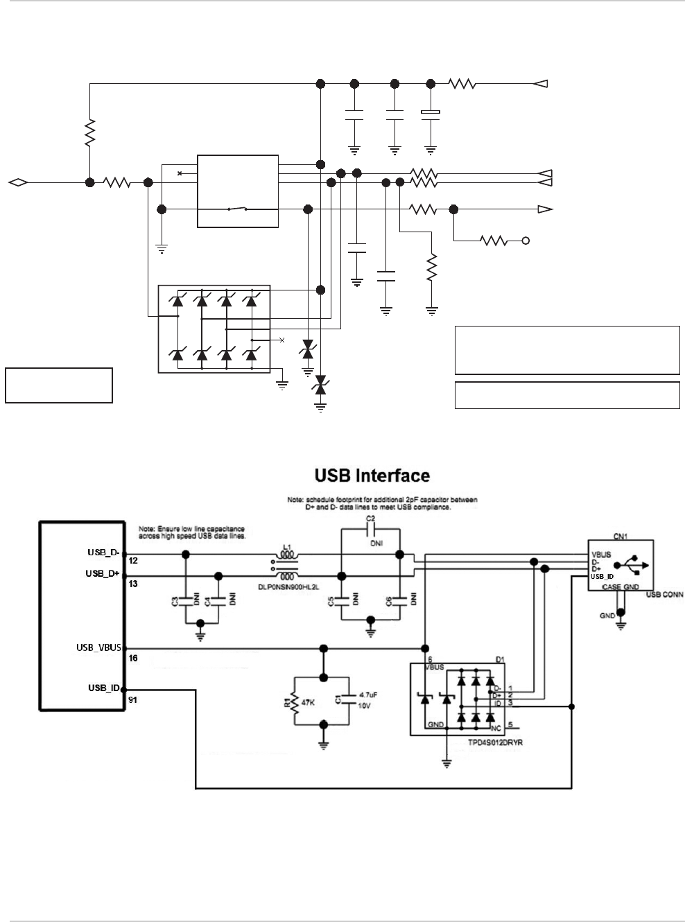
USB Interface
When the USB interface is externally accessible, ESD protection is required on
the USB_VBUS, USB_D+, and USB_D- signals.
Thermal Considerations
When transmitting, the AirPrime WP7601 can generate significant amounts of
heat (due to the internal Power Amplifier) that must be dissipated in the host
device for safety and performance reasons.
The amount of thermal dissipation required depends on the following factors:
•Supply voltage—Maximum power dissipation for these modules can be up to
3 W at voltage supply limits.
•Usage—Typical power dissipation values depend on the location within the
host, amount of data transferred, etc.
To enhance heat dissipation:
•Maximize airflow over / around the module
•Locate the module away from other components that generate heat
•Ensure the module is connected to a solid ground plane
EMC and ESD Recommendations
EMC tests must be performed on the application as soon as possible to detect
any potential problems.
When designing, special attention should be paid to:
•Possible spurious emissions radiated by the application to the RF receiver in
the receiver band
•ESD protection—Typically, ESD protection is mandatory for externally acces-
sible signals, including:
·VBAT_RF/VBAT_BB
·UIM (if accessible from outside)
·Serial link
·USB
·Antennas
•Length of the UIM interface lines (preferably <10 cm)
•Length of the HSIC interface lines (<10 cm, as required by the HSIC specifi-
cation)
•EMC protection on audio input/output (filters against 900 MHz emissions)
•Ground plane: Sierra Wireless recommends a common ground plane for
analog/digital/RF grounds
Note: The AirPrime WP7601 does not include any protection against over-voltage.
The host device must provide adequate ESD protection on digital circuits and
antenna ports as detailed in the following table.

Hardware Integration Guide
Rev 1 Jul 17 12 41111210
Note: The level of protection required depends on your application.
Mechanical Integration
Attention should be paid to:
•Antenna cable integration (bending, length, position, etc)
•Pads of the AirPrime WP7601 to be soldered to the ground plane
•Ensuring proper board layout
•Providing sufficient space around the module for heat dissipation
Table 4-1: ESD specifications a,b
a. ESD specifications are preliminary, subject to change.
b. ESD protection is highly recommended at the point where the UIM contacts are exposed,
and for any other signals that would be subjected to ESD by the user.
Category Connection Specification
Operational RF ports
UIM connector
USB connector
UART connector
IEC-61000-4-2 - Level (Electrostatic Discharge
Immunity Test)
·± 6kV Contact
·± 8kV Air
Non-operational Host connector
interface Unless otherwise specified:
•JESD22-A114 ± 1kV Human Body Model
•JESD22-A115 ± 100V Machine Model
•JESD22-C101C ± 500V Charged Device
Model
Routing Constraints and Recommendations
Rev 1 Jul 17 13 41111210
Signal Reference Schematics
Figure 4-2: UIM Interface
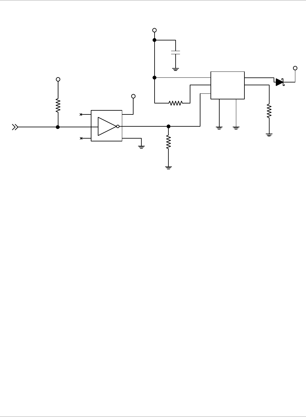
Figure 4-3: USB Interface
0
0
0
0
10nF
0
100nF
10
C3
C2
C1
9
C7
C6
C5 GND
VPP
I/O
SW_A
VCC
RST
CLK
SW_B
DNI
DNI
DNI
VGPIO_1V8
UIM_RESET_N
UIM_DATA UIM_CLK
UIM_VCC
UIM1_DET
UIM1
DNI
SIM2070-6-0-30-00-A
ESD suppressor
Note: Example ESD and SIM connector part numbers
listed. Comparable parts may be used instead.
Note: Capacitor on UIM_CLK is intended to slow down
the clock signal in case of crosstalk.
DNI
DNI
Example ESD suppressor:
STMicroelectronics
DALC208SC6
+
uClamp 3301P
1
2
3
4
6
5
Important: SIM connector must have a ‘Normally
closed’ detection switch.
Hardware Integration Guide
Rev 1 Jul 17 14 41111210
Figure 4-4: USB OTG Interface
2
1
53
4
6
6
4
2
5
7
1
3
51K
5%
51K
5%
51K
5%
470
1%
NC1 VCC
NC2 GND
AY
VCC_1V8
VCC_5V0
USB_ID
DNI
VCC_1V8
10µF
USB_VBUS
VIN VOUT
FLAGB ISET
ON
GND1 GND2
Replace with FPF2163 if Autorestart is required
FPF2164

Rev 1 Jul 17 15 41111210
5
5: Regulatory Compliance and Industry
Certifications
Important Notice
Due to the nature of wireless communications, transmission and reception of data can
never be guaranteed. Data may be delayed, corrupted (i.e., have errors) or be totally
lost. Although significant delays or losses of data are rare when wireless devices such
as the Sierra Wireless modem are used in a normal manner with a well-constructed
network, the Sierra Wireless modem should not be used in situations where failure to
transmit or receive data could result in damage of any kind to the user or any other
party, including but not limited to personal injury, death, or loss of property. Sierra
Wireless accepts no responsibility for damages of any kind resulting from delays or
errors in data transmitted or received using the Sierra Wireless modem, or for failure
of the Sierra Wireless modem to transmit or receive such data.
Safety and Hazards
Do not operate your AirPrime WP7601 Embedded Module:
•In areas where blasting is in progress
•Where explosive atmospheres may be present including refueling points, fuel
depots, and chemical plants
•Near medical equipment, life support equipment, or any equipment which may be
susceptible to any form of radio interference.
In such areas, the AirPrime WP7601 modem MUST BE POWERED OFF. Otherwise,
the AirPrime WP7601 modem can transmit signals that could interfere with this
equipment.
In an aircraft, the AirPrime WP7601 modem MUST BE POWERED OFF. Otherwise,
the AirPrime WP7601 modem can transmit signals that could interfere with various
onboard systems and may be dangerous to the operation of the aircraft or disrupt the
cellular network. Use of a cellular phone in an aircraft is illegal in some jurisdictions.
Failure to observe this instruction may lead to suspension or denial of cellular
telephone services to the offender, or legal action or both.
Some airlines may permit the use of cellular phones while the aircraft is on the ground
and the door is open. The AirPrime WP7601 modem may be used normally at this
time.
Important Compliance Information for North
American Users
The AirPrime WP7601 module has been granted modular approval for mobile
applications. Integrators may use the AirPrime WP7601 module in their end products
without additional FCC/IC (Industry Canada) certification if they meet the following
conditions. Otherwise, additional FCC/IC approvals must be obtained.

Hardware Integration Guide
Rev 1 Jul 17 16 41111210
1. The end product must use the RF trace design approved with the AirPrime
WP7601 module. The Gerber file of the trace design can be obtained from
Sierra Wireless upon request.
2. At least 20 cm separation distance between the antenna and the user’s body
must be maintained at all times.
3. To comply with FCC/IC regulations limiting both maximum RF output power
and human exposure to RF radiation, the maximum antenna gain including
cable loss in a mobile-only exposure condition must not exceed the limits
stipulated in Table 5-1 on page 16.
4. The AirPrime WP7601 module may transmit simultaneously with other collo-
cated radio transmitters within a host device, provided the following conditions
are met:
·Each collocated radio transmitter has been certified by FCC/IC for mobile
application.
·At least 20 cm separation distance between the antennas of the collocated
transmitters and the user’s body must be maintained at all times.
·The radiated power of a collocated transmitter must not exceed the EIRP
limit stipulated in Table 5-2.
5. A label must be affixed to the outside of the end product into which the
AirPrime WP7601 module is incorporated, with a statement similar to the
following:
· This device contains FCC ID: N7NWP76A / IC:2417C-WP76A.
Table 5-1: WP7601 Antenna Gain Specifications
Device Technology Band Frequency
(MHz)
Maximum
antenna gain
(dBi)
AirPrime
WP7601 LTE 41710–1755 6
13 777–787 6
Table 5-2: Collocated Radio Transmitter Specifications
Device Technology Frequency
(MHz) EIRP Limit
(dBm)
Collocated
transmittersa
a. Valid collocated transmitter combinations: WLAN+BT; WiMAX+BT.
(WLAN+WiMAX+BT is not permitted.)
WLAN 2400–2500 25
5150–5850 27
WiMAX 2300–2400 25
2500–2700 25
3300–3800 25
BT 2400–2500 15

Regulatory Compliance and Industry Certifications
Rev 1 Jul 17 17 41111210
6. A user manual with the end product must clearly indicate the operating
requirements and conditions that must be observed to ensure compliance
with current FCC/IC RF exposure guidelines.
The end product with an embedded AirPrime WP7601 module may also need to
pass the FCC Part 15 unintentional emission testing requirements and be
properly authorized per FCC Part 15.
Note: If this module is intended for use in a portable device, you are responsible for
separate approval to satisfy the SAR requirements of FCC Part 2.1093 and IC RSS-102.