Sigma Designs WINDEO Windeo Reference Desisign Module User Manual
Sigma Designs Inc Windeo Reference Desisign Module Users Manual
UserManual.wiki
>
Sigma Designs
>
WINDEO User Manual
>
Users Manual
Contents
1.
Users Manual
2.
OEM Installation Manual
Users Manual
Navigation menu
Upload a User Manual
Namespaces
Wiki Guide
HTML
PDF
Info
Views
User Manual
Discussion / Help
Navigation
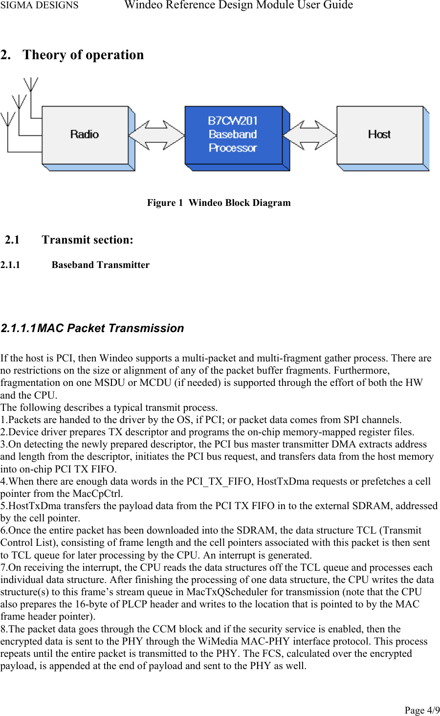
![SIGMA DESIGNS Windeo Reference Design Module User Guide Page 5/9 9.Once the entire packet has been transmitted to the PHY and if no-ACK is indicated, MacTxDma informs CPU of the completion of the transmission. In response, the CPU would pop the queue entry and write the cell pointers to release buffer so that hardware can put them back to free pool of pointers. If IMM-ACK is indicated, then TX_EN is deasserted and RX_EN is asserted. Within a specified time interval, the expected ACK packet should arrive. If not, the frame may be re-transmitted, or an interrupt may be generated and sent to CPU for further action. 2.1.1.2 PHY transmitter The PHY Transmitter is designed to meet the WiMedia PHY standard, version 1.1a. Windeo implements data rates 53.3 through 200 Mbps, with parameters summarized in the following table: Data Rate and Other Parameters Implemented in Windeo (from WiMedia standard) Data Rate (Mb/s) Rate Code (R1-R5) Modulation Code Rate Conjugate Symmetry at IFFT Input Time Spreading Factor (TSF) Overall Spreading Gain Coded Bits/6 OFDM Symbols (NCBP6S) Info Bits/6 OFDM Symbols (NIBP6S) 53.3 00000 QPSK 1/3 Yes 2 4 300 100 80 00001 QPSK 1/2 Yes 2 4 300 150 106.7 00010 QPSK 1/3 No 2 2 600 200 160 00011 QPSK 1/2 No 2 2 600 300 200 00100 QPSK 5/8 No 2 2 600 375 2.1.2 RF transmitter The RFIC transmitter accepts both I and Q differential inputs from a pair of DACs on the B7CW201 processor and contains I and Q base-band filters, up-converters and an on chip PA (Power Amplifier). The transmitter incorporates matched low pass filters in both the I and Q channels. The base-band signal is up converted to an RF frequency through mixers driven by a VCO. As in the receiver, the VCO frequency is selected through the band selection input pins BAND[3:1]. The I and Q channel RF signals are combined in a summing circuit and passed on to the power amplifier. The output of the power amplifier is differential with each output presenting a nominal 50 Ohm impedance. The power amplifier must then be matched to the 50 Ohm antenna load through a 2:1 balun. An external band-pass filter covering the lower three bands of the UWB spectrum (3.1 –t 4.8 passband) is incorporated at the output of the power amplifier. The UWB transmission will be sending to omnidirectional antenna via T/R switch that allows Transceiver to operate in TDD mode.](https://usermanual.wiki/Sigma-Designs/WINDEO.Users-Manual/User-Guide-976638-Page-5.png)
![SIGMA DESIGNS Windeo Reference Design Module User Guide Page 6/9 2.2. Receive section: 2.2.1. RF receiver The B7CW101 contains 3 receive channels. Each of the receiver channels provides both I and Q outputs and contains an LNA (Low Noise Amplifier), down-converters, I and Q base-band filters, variable gain amplifiers (VGA’s) and a final fixed gain block. All inputs and outputs are differential. Each side of the differential RF input is nominally 50 Ohms. So, the RF inputs are driven from an antenna through a 1:2 differential balun. Each side of the RX outputs is a source follower with typically a 1.5mA source current. Each receive channel has typically, • 3.1GHz to 4.8GHz receive bandwidth • Sensitivity of -80dBm • Output capability of 560mV peak to peak for driving an ADC • Independently controlled VGA gains Each receiver LNA incorporates a band-pass filter which covers the lower 3 bands of the UWB spectrum. The RF signal is down converted to a base-band frequency through mixers driven by a VCO. The VCO frequency is selected through the band selection input pins BAND[3:1] on the B7CW101. The base-band signal is then filtered and amplified through the VGA blocks. Each VGA provides a variable gain range of 31dB in 1dB steps. The 2 VGA’s within each receiver channel (I and Q) always have the same gain, although the gain can be different between channels. Each VGA is followed by a fixed gain block to provide a low voltage, differential analog, output signal to an ADC on the B7CW201 Baseband processor. 2.2.2 Baseband Receiver 2.2.2.1 PHY Receiver The Windeo PHY receiver of the Baseband chip features the 3-channel Intelligent Array Radio (IAR) PHY receiver. The front ends and the back end together include all of the signal processing and decoding blocks required for reliable reception of user data. The signal processing and decoding functions implemented in the Windeo PHY receiver include the following: •Packet detection and synchronization •Automatic gain control •Overlap-and-add •Fast Fourier transform for OFDM demodulation •Channel equalization •Carrier frequency offset correction •Sampling frequency offset correction •Despreading, demapping, deinterleaving •Viterbi decoding](https://usermanual.wiki/Sigma-Designs/WINDEO.Users-Manual/User-Guide-976638-Page-6.png)