Signal Communications SCRX-051020 TeleEye RX Series User Manual
Signal Communications Limited TeleEye RX Series
UserManual.wiki
>
Signal Communications
>
SCRX 051020 User Manual
User Manual
Navigation menu
Upload a User Manual
Namespaces
Wiki Guide
HTML
PDF
Info
Views
User Manual
Discussion / Help
Navigation
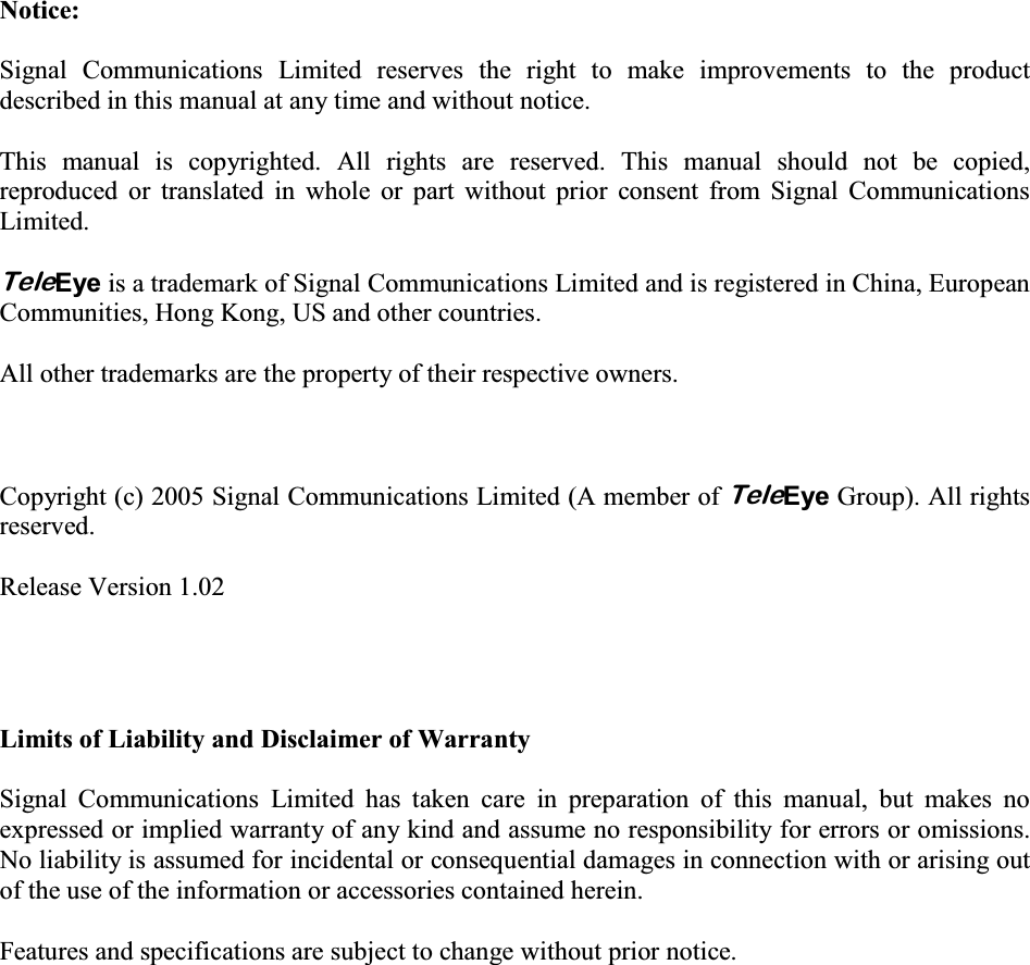
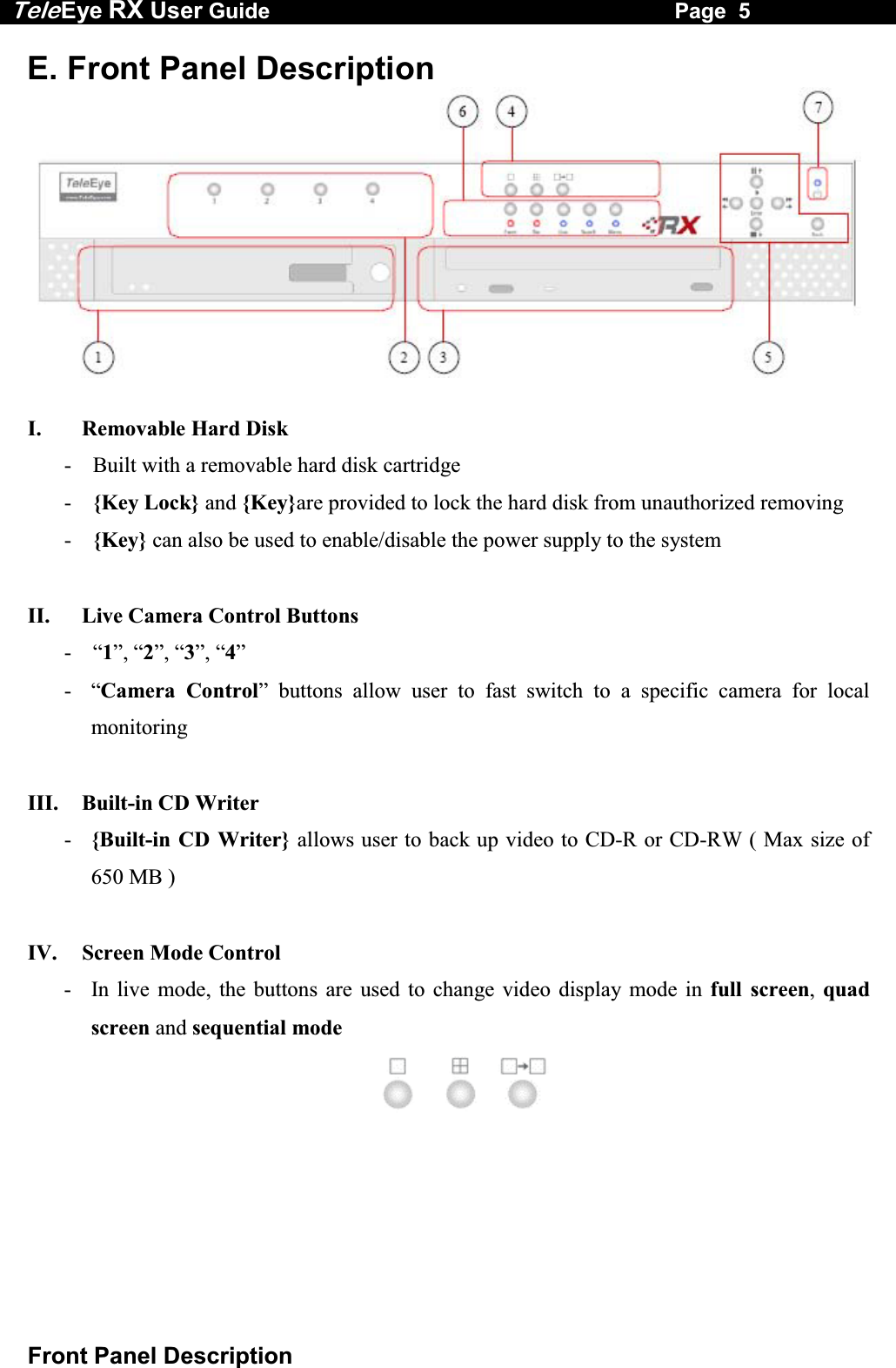
![Tele Eye RX User Guide Page 4 Convention Used in This Manual D. Convention Used in This Manual “ ” : Buttons on the TeleEye RX transmitter front panel { } : Hardware Items on the TeleEye RX transmitter besides buttons [ ] : OSD menu or MS Windows menu ( ) : Refers to other section or page ** : Special remarks](https://usermanual.wiki/Signal-Communications/SCRX-051020/User-Guide-668458-Page-10.png)
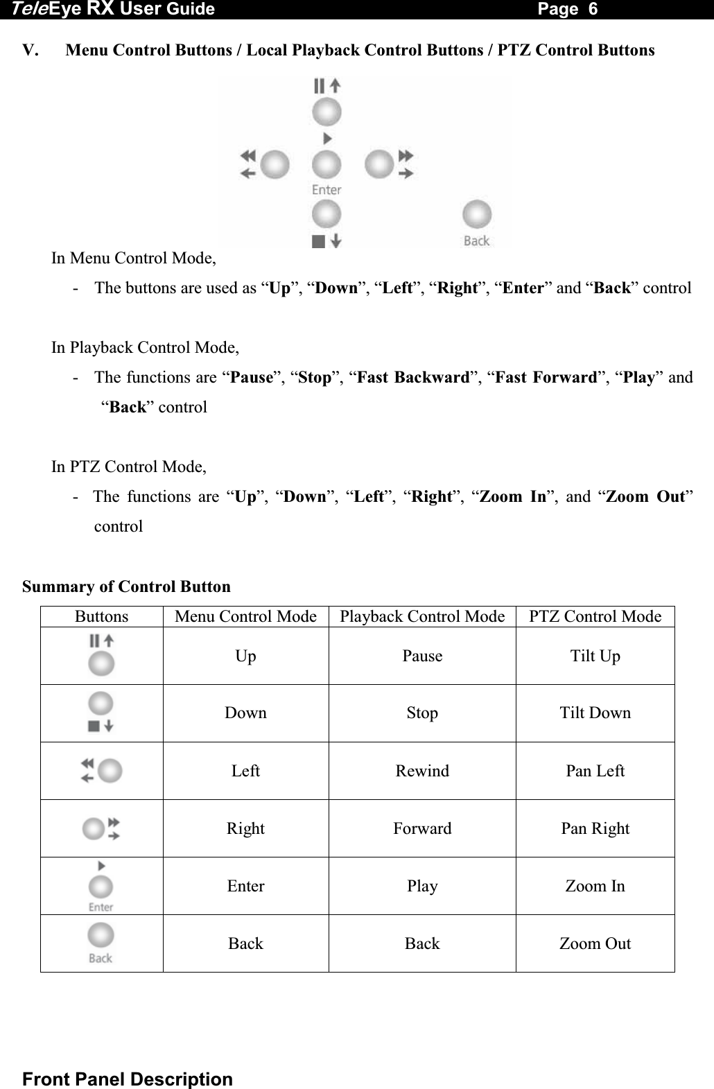

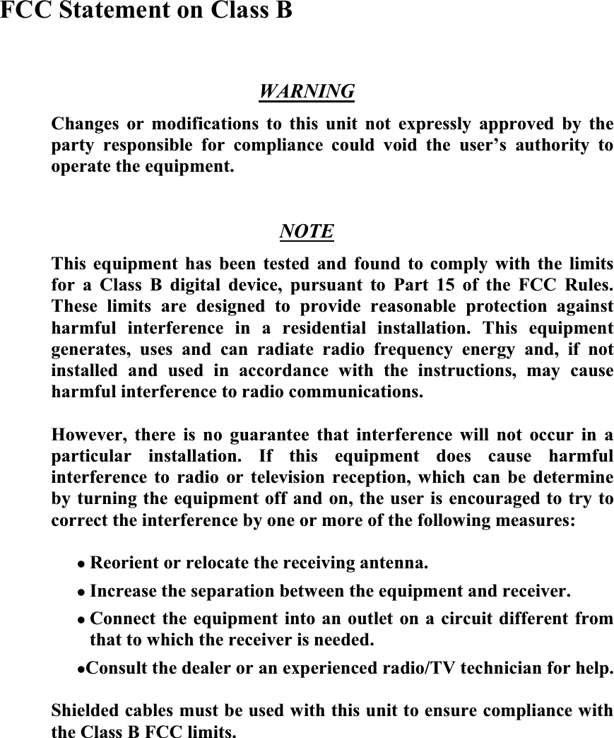
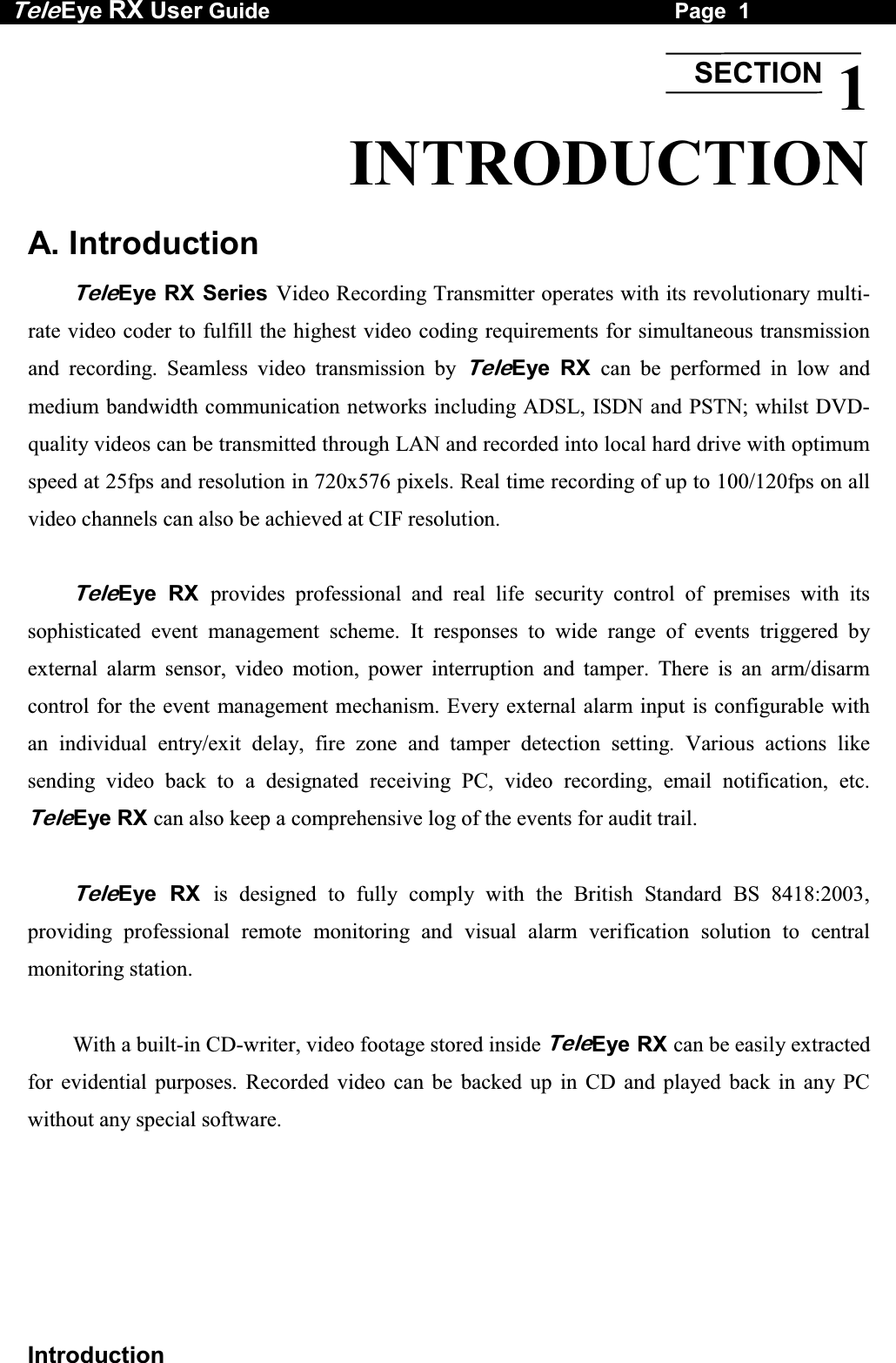
![Tele Eye RX User Guide Page 12 Hard Disk Installation Installation Procedure Turn OFF transmitter Step 1: Press “Menu” button, select [SHUT DOWN] option and press “Enter” button. Step 2: [SHUT DOWN] menu will pop up and select [SHUT DOWN] option and press “Enter” button. Step 3: Select [YES] option and press “Enter” button to turn off the transmitter. Switch OFF the transmitter when the [IT IS NOW SAFE TO TURN OFF RX] message pop up. Note that you MUST turn OFF the transmitter when install or remove Hard disk. Step 4: Pull the active-handle outwards, then use the bundled key provided and insert into the keyhole, turning the key anti-clockwise (position C), then you can pull out the handle. Step 5: Pull the handle outwards to remove the carrier body away from the cartridge frame. Step 6: Push the release latch to slide the top cover backwards and remove.](https://usermanual.wiki/Signal-Communications/SCRX-051020/User-Guide-668458-Page-18.png)
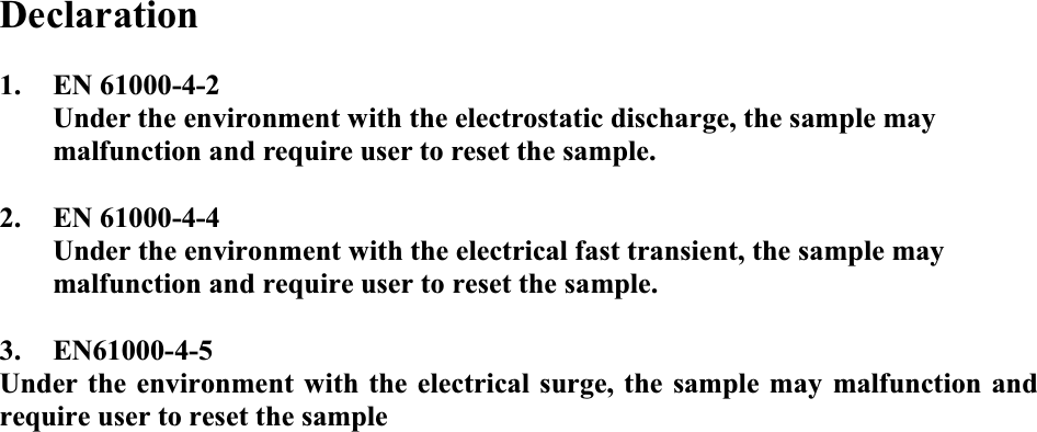
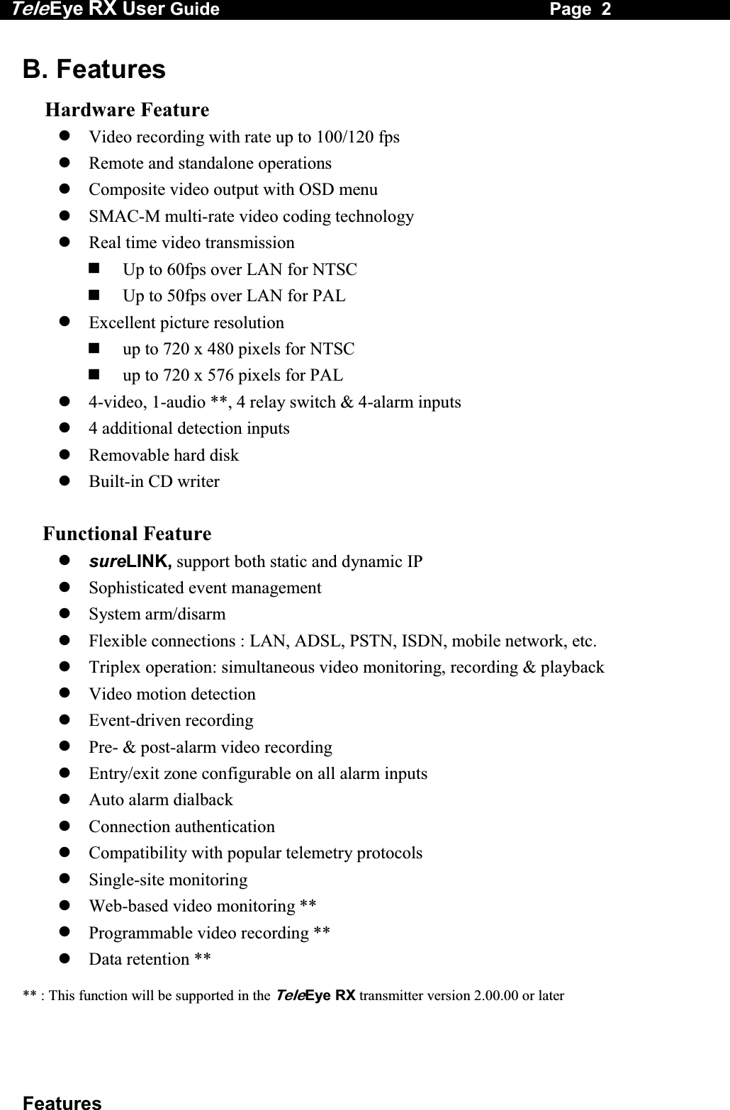
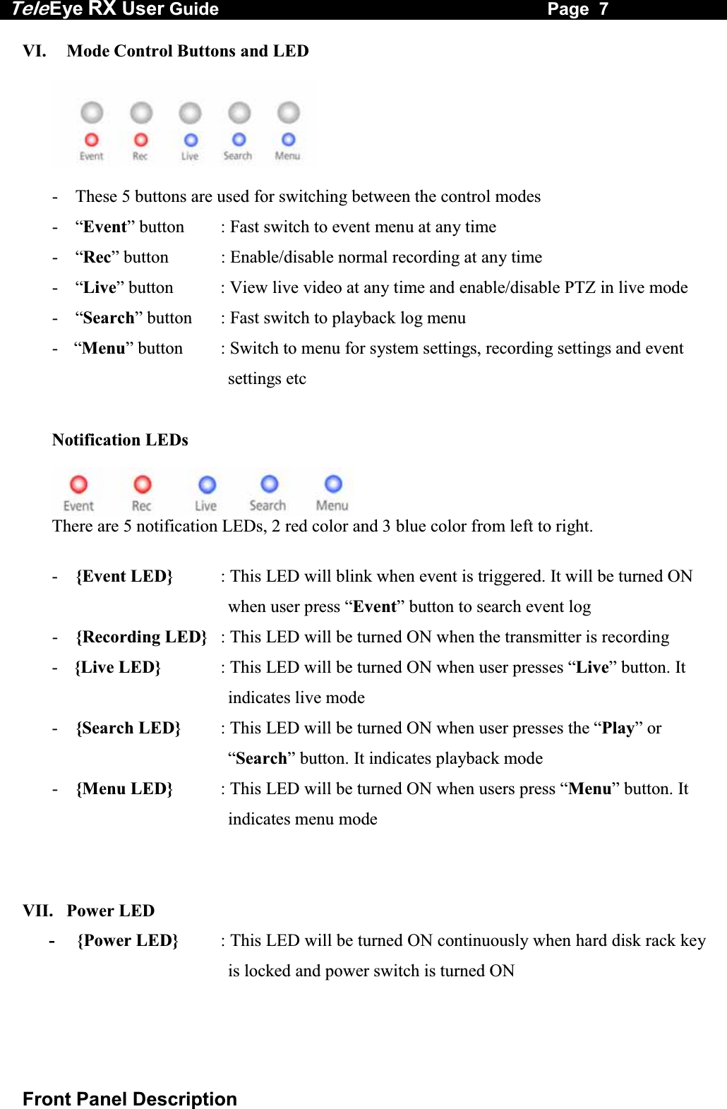
![Tele Eye RX User Guide Page 14 Hard Disk Formatting B. Hard Disk Formatting Hard disk formatting will reconstruct the structure of hard disk so that it is readable by TeleEye RX transmitter. If you have your own hard disk to install to TeleEye RX transmitter, you must perform hard disk formatting. I. New Hard Disk Formatting It will be used if the hard disk format is NOT TeleEye RX transmitter recognized format. Usually, a new hard disk, or a hard disk which has been formatted by MS Windows before needs to do this operation. Procedure Step 1: After booting up TeleEye RX transmitter, OSD menu will pop up [INCORRECT DISK FORMAT] menu. Select [YES] option and press “Enter” button to format new hard disk [FORMAT DISK] message board will pop up to show you about the status. After finishing format process, [SCAN DISK] processing board will pop up to show you about the status. The transmitter will restart. INCORRECT DISK FORMAT FORMAT NOW ? YES NO SCAN DISK \ SCANNING 90% FORMAT DISK \ FORMATTING 90%](https://usermanual.wiki/Signal-Communications/SCRX-051020/User-Guide-668458-Page-20.png)
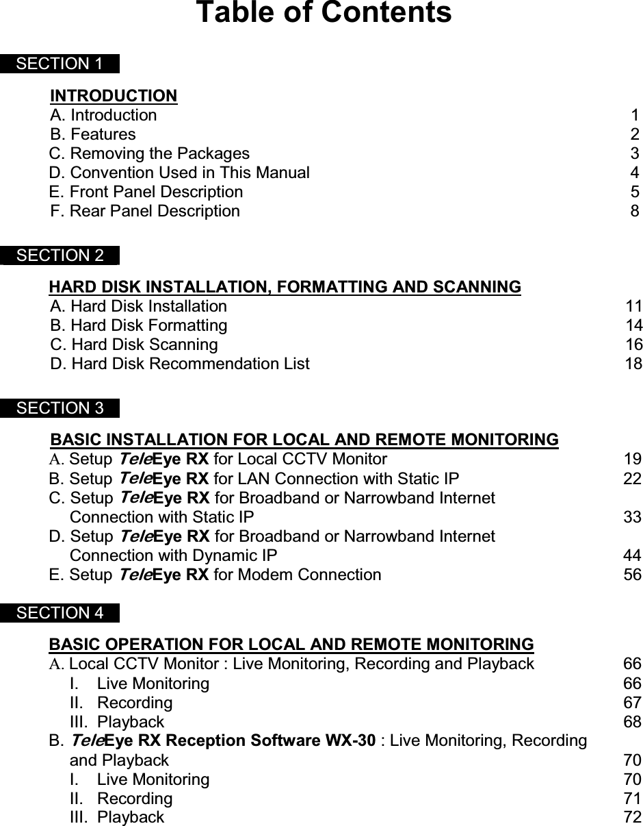
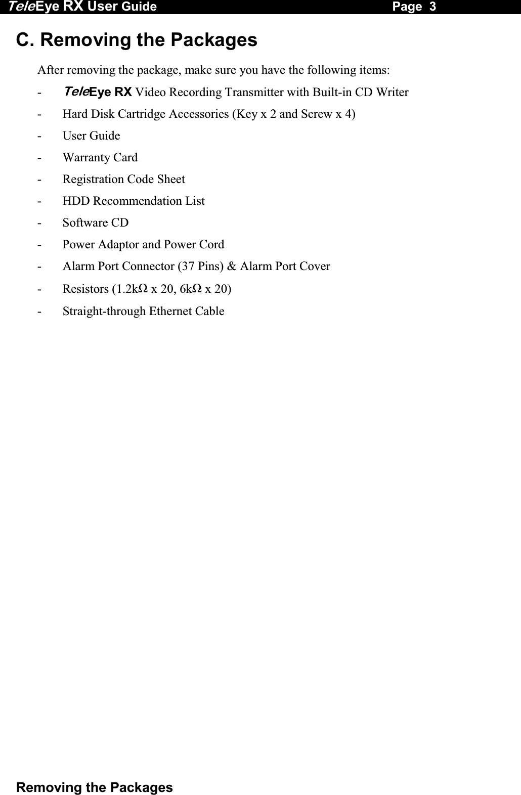
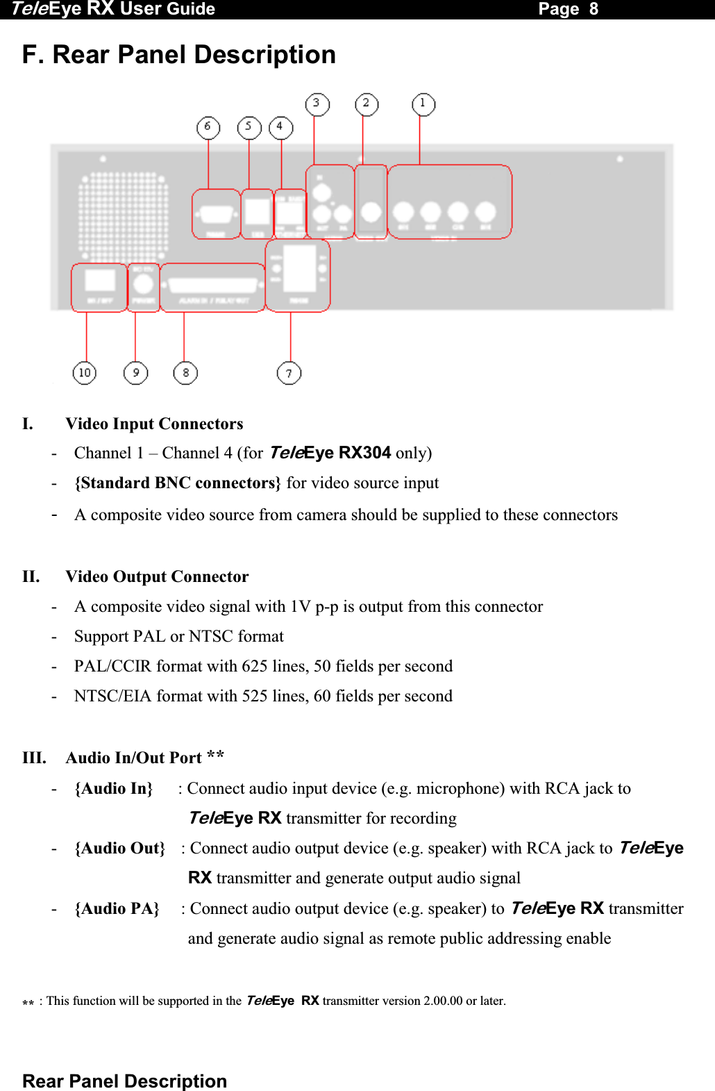
![Tele Eye RX User Guide Page 15 Hard Disk Formatting II. Menu Formatting It will be used if user wants to format the hard disk so as to have a clean recording space and redeem the file allocation. Procedure Step 1: Press “Menu” button, select [SCAN/FORMAT DISK] option and press “Enter” button to enter [SCAN/FORAMAT DISK] sub menu. Step 2: Select [FORMAT] option press “Enter” button. Warning message board will pop up. Step 3: Select [YES] option and press “Enter” button and [FORMAT DISK] board will pop up to show you about hard disk format processing status. Step 4: Press “Enter” button to restart transmitter when [FORMAT FINISHED] message board pop up. The transmitter will restart MAIN MENU SETUP . . . BACKUP TO CD-R . . . SWITCH CONTROL . . . SCAN / FORMAT DISK . . . TRANSMITTER INFO . . . SHUT DOWN ENTER SCAN / FORMAT DISK DEVICE TYPE HDDMODEL NO MAXTOR XXXXSERIAL NO XXXXXXXCAPACITY 41GBDISK USAGE 52%SCANDISK ENTERFORMAT ENTER FORMAT DISK ALL DATA IN DISK WILL BE ERASED , SURE TO PROCEED ? YES NO FORMAT FORMAT FINISHED , SYSTEM WILL RESTART NOW OK](https://usermanual.wiki/Signal-Communications/SCRX-051020/User-Guide-668458-Page-21.png)
![Tele Eye RX User Guide Page 16 Hard Disk Scanning C. Hard Disk Scanning It is a hard disk maintenance function similar to the Scan Disk function provided by the Operating System of your personal computer. TeleEye RX transmitter provides this function so as to rescue the hard disk when errors found, and to enhance its performance and reliability. After scanning, if there is any damaged file, it will be deleted so that the remaining normal videos can playback. It will be used in the following cases: 1. You cannot playback the recorded videos 2. You cannot search the desired video from the recording log. Although you can find it, you cannot play it 3. You wonder if the hard disk has any problem Procedures Step 1: Press “Menu” button, select [SCAN/FORMAT DISK] option and press “Enter” button to enter [SCAN/FORAMT DISK] sub menu. There is information about the hard disk. If not, please check that the hard disk is installed or not. Step 2: Select [SCANDISK] option press “Enter” button. MAIN MENU SETUP . . . BACKUP TO CD-R . . . SWITCH CONTROL . . . SCAN / FORMAT DISK . . . TRANSMITTER INFO . . . SHUT DOWN ENTER SCAN / FORMAT DISK DEVICE TYPE HDDMODEL NO MAXTOR XXXXSERIAL NO XXXXXXXCAPACITY 40GBDISK USAGE 52%SCANDISK ENTER FORMAT ENTER](https://usermanual.wiki/Signal-Communications/SCRX-051020/User-Guide-668458-Page-22.png)
![Tele Eye RX User Guide Page 17 Hard Disk Scanning Warning message board will pop up. Step 3: Select [YES] option and press “Enter” button to start the [SCANDISK] process. Step 4: [SCAN DISK] processing board will pop up to show you about the status. After finishing scan disk, it will return to the [SCAN / FORMAT DISK] menu. SCAN DISK ALL RECORDING WILL STOP DURING SCANDISK SURE TO PROCEED ? YES NO SCAN DISK \ SCANNING 90%](https://usermanual.wiki/Signal-Communications/SCRX-051020/User-Guide-668458-Page-23.png)
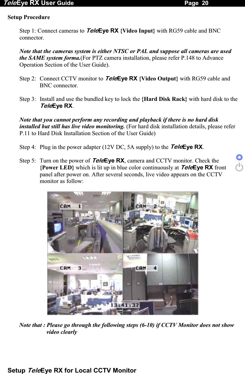
![Tele Eye RX User Guide Page 21 Setup TeleEye RX for Local CCTV Monitor Step 6: Press the “Menu” button to pop up the [MAIN MENU] on OSD. Step 7: Use “Up” or “Down” button to select [SETUP] option and press “Enter” button to enter the [SETUP] sub-menu. Step 8: Use “Up” or Down” button to select [VIDEO] option and press “Enter” button to enter the [VIDEO] sub-menu. Step 9: Select [VIDEO FORMAT] and press “Left” or “Right” button to set either [NTSC] or [PAL] option. (All cameras should have the same video format). Step 10: You can always press “Live” button to exit any menu operation and start live monitoring. MAIN MENU SETUP . . . BACKUP TO CD-R . . . SWITCH CONTROL . . . SCAN / FORMAT DISK . . . TRANSMITTER INFO . . . SHUT DOWN ENTER SETUP MENU VIDEO . . . RECORDING . . . SWITCHES . . . DATE / TIME . . . CONNECTION . . . EVENT HANDLER . . . TRANSMITTER . . . RESTORE FACTORY SETTING ENTER VIDEO CAMERA SETTING . . . LOCAL MONITORING . . . OSD COLOR BLUE VIDEO FORMAT PAL](https://usermanual.wiki/Signal-Communications/SCRX-051020/User-Guide-668458-Page-27.png)
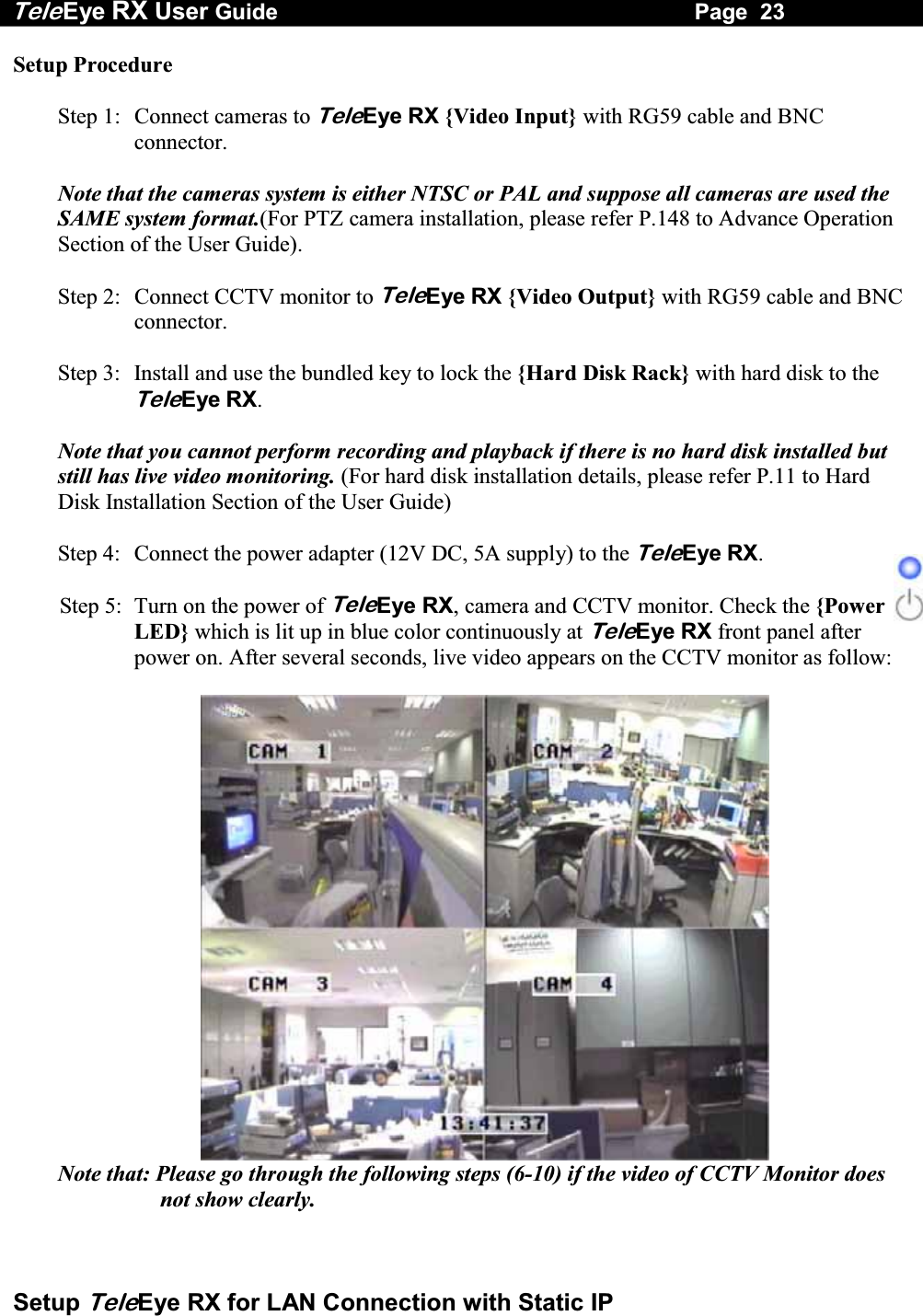
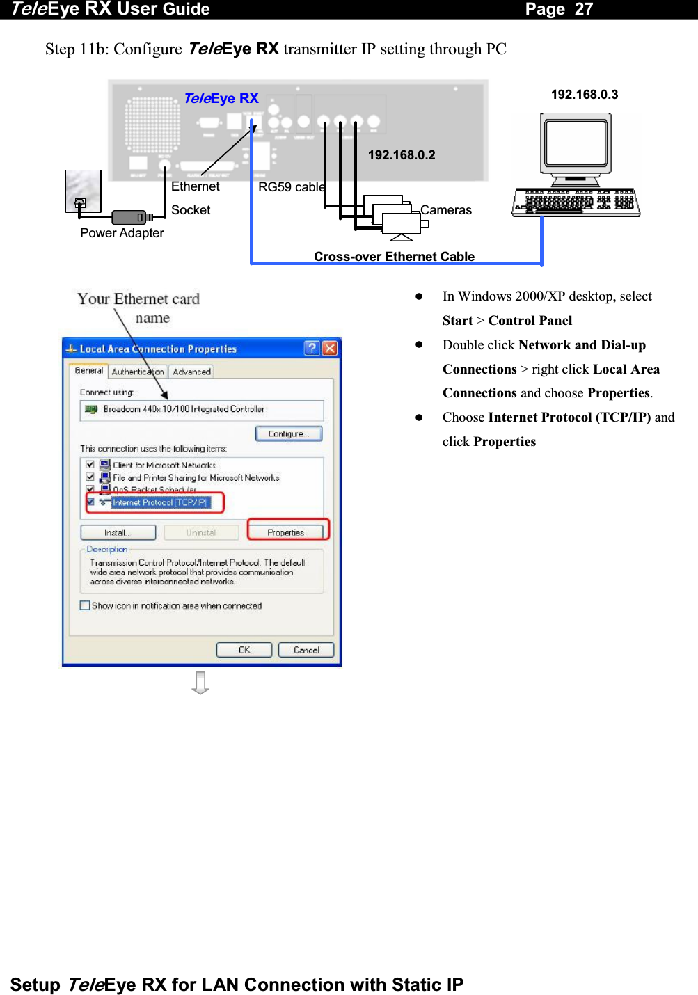
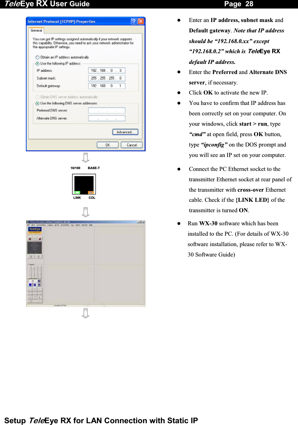
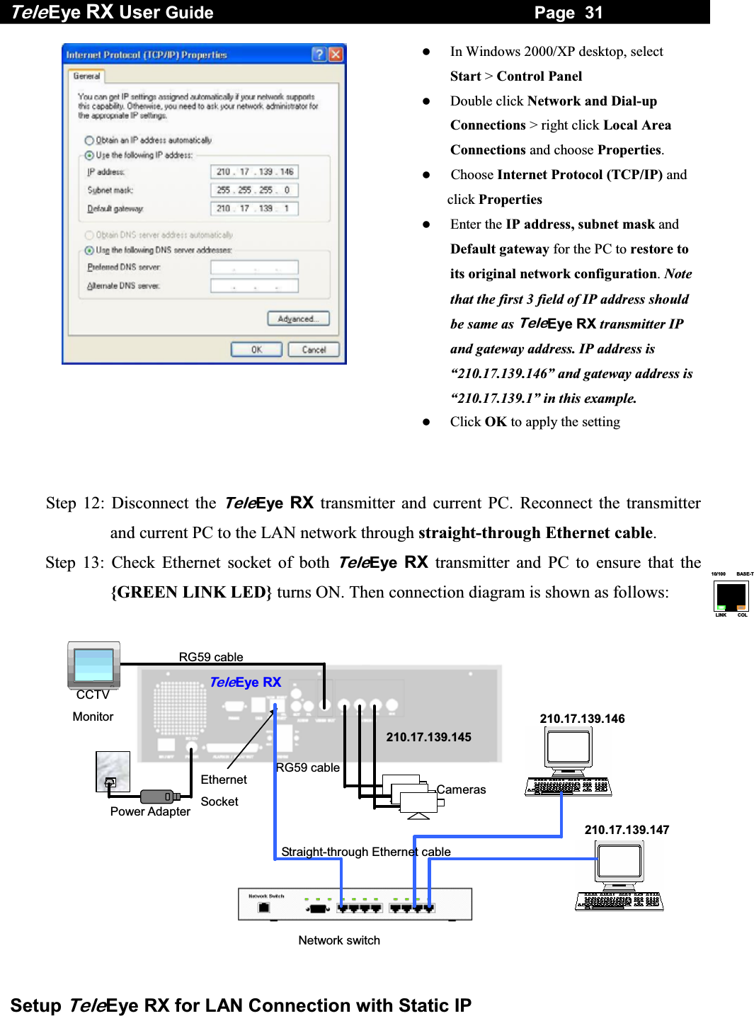
![Tele Eye RX User Guide Page 24 Setup TeleEye RX for LAN Connection with Static IP Step 6: Press the “Menu” button to pop up the [MAIN MENU] on OSD. Step 7: Use “Up” or “Down” button to select [SETUP] option and press “Enter” button to enter the [SETUP] sub-menu.Step 8: Select [VIDEO] option and press “Enter” button to enter the [VIDEO] sub-menu Step 9: Select [VIDEO FORMAT] and press “Left” or “Right” button to set either [NTSC] or [PAL] option. (All cameras should have the same video format). Step 10: You can always press “Live” button to exit any menu operation and start live monitoring. Setup TeleEye RX transmitter IP through CCTV monitor, please go to step 11a. Setup TeleEye RX transmitter IP through PC, through PC, please go to step11b. VIDEO CAMERA SETTING . . . LOCAL MONITORING . . . OSD COLOR BLUE VIDEO FORMAT PAL SETUP MENU VIDEO . . . RECORDING . . . SWITCHES . . . DATE / TIME . . . CONNECTION . . . EVENT HANDLER . . . TRANSMITTER . . . RESTORE FACTORY SETTING ENTER](https://usermanual.wiki/Signal-Communications/SCRX-051020/User-Guide-668458-Page-30.png)
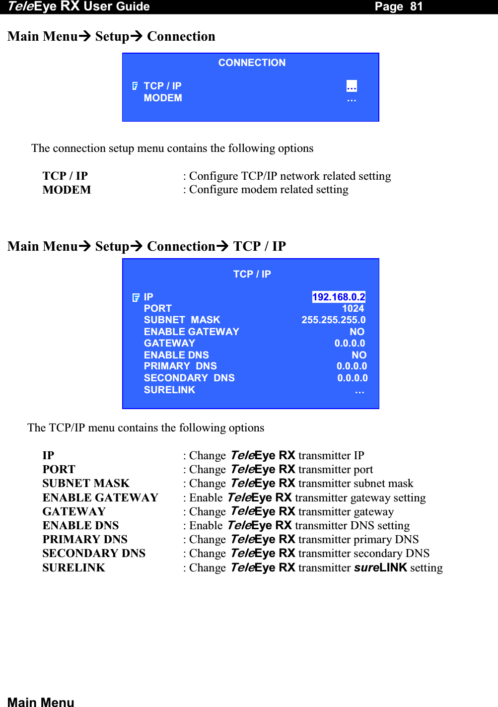
![Tele Eye RX User Guide Page 25 Setup TeleEye RX for LAN Connection with Static IP Step 11a: Configure TeleEye RX transmitter IP setting through CCTV Monitor RG59 cablePower Adapter Ethernet Socket TeleEye RXCameras CCTV Monitor RG59 cable192.168.0.2 Press the “Menu” button such that the OSD main menu opens on the monitor. Use “Up” or “Down” button to select [SETUP] option and press “Enter” button to enter [SETUP] sub menu. Select [CONNECTION] option and press “Enter” button to enter connection setting menu. Select [TCP/IP] option and Press “Enter” button Select [IP] option and press “Enter” button.IP address consists of four fields. Each field can assign a number from 0 to 255 SETUP MENU VIDEO . . .RECORDING . . .SWITCHES . . .DATE / TIME . . .CONNECTION . . .EVENT HANDLER . . .TRANSMITTER . . .RESTORE FACTORY SETTING ENTERCONNECTION TCP / IP … MODEM … TCP / IP IP 192.168.0.2 PORT 1024 SUBNET MASK 255.255.255.0 ENABLE GATEWAY NO GATEWAY 0.0.0.0 ENABLE DNS NO PRIMARY DNS 0.0.0.0 SECONDARY DNS 0.0.0.0 SURELINK …](https://usermanual.wiki/Signal-Communications/SCRX-051020/User-Guide-668458-Page-31.png)
![Tele Eye RX User Guide Page 26 Setup TeleEye RX for LAN Connection with Static IP Use “Left” or “Right” button to select field and use “Up” or “Down” button to set number. Press “Enter” button to save the change and return previous menu. Follow the network setting and assign a valid subnet mask to [SUBNET MASK] and select [ENABLE GATEWAY] option and input [GATEWAY] option in similar way. Note that the DNS setting is optional which is useful for sureLINK, time synchronization** or e-mail notification function**. ʽʽʳˍʳ˧˻˼̆ʳ˹̈́˶̇˼̂́ʳ̊˼˿˿ʳ˵˸ʳ̆̈̃̃̂̅̇˸˷ʳ˼́ʳ̇˻˸ʳTeleEyeʳRXʳ̇̅˴́̆̀˼̇̇˸̅ʳ̉˸̅̆˼̂́ʳ˅ˁ˃˃ˁ˃˃ʳ̂̅ʳ˿˴̇˸̅ʳ Press “Live” button, then [SETTING MODIFIED] message board will pop up. Press “Enter” button to restart the TeleEye RX.IP IP : 210. 17.139.145 TCP / IP IP 210.17.139.145 PORT 1024 SUBNET MASK 255.255.255.0 ENABLE GATEWAY YES GATEWAY 210.17.139.1 ENABLE DNS NO PRIMARY DNS 0.0.0.0 SECONDARY DNS 0.0.0.0 SURELINK … SETTING MODIFIED SETTING WILL TAKE EFFECT AFTER RESTART , PRESS ENTER TO CONTINUE OK](https://usermanual.wiki/Signal-Communications/SCRX-051020/User-Guide-668458-Page-32.png)
![Tele Eye RX User Guide Page 29 Setup TeleEye RX for LAN Connection with Static IP Choose [Transmitter] [Registration] to register the TeleEye RX transmitter. User needs to input transmitter serial number and registration code. For example : Serial No. : VTC12345 Registration Code : 1234567890 Press [Connect] icon to pop up the [Connect Window]. Type and select the following setting : Phone/IP : 192.168.0.2 Connect Using: TCP/IP LAN Password: 000000 IP (192.168.0.2) and Password (000000) are default setting of TeleEye RX Press [Connect] icon to connect your PC to the transmitter. Live video is shown on the WX-30 if success. Otherwise, the [Warning] board will pop up and show you failure message. For failure case, please press [Connect] icon to check that the connection setting is valid or not. Press [Transmitter Setup] icon to show TeleEye RX configuration menu. Select [Connection] and press [Network Settings]icon to](https://usermanual.wiki/Signal-Communications/SCRX-051020/User-Guide-668458-Page-35.png)
![Tele Eye RX User Guide Page 30 Setup TeleEye RX for LAN Connection with Static IP Settings] icon to configure network setting. Change the IP from 192.168.0.2 to 210.17.139.145 (for example). Gateway setting is used for WAN. Primary and Secondary DNS setting are used for sureLINK, time synchronization ** or e-mail notification function **. ** : This function will be supported in the TeleEye RX transmitter version 2.00.00 or later Press [Apply] icon to save the network setting and pop up the message board. After several seconds, the transmitter will restart automatically.](https://usermanual.wiki/Signal-Communications/SCRX-051020/User-Guide-668458-Page-36.png)
![Tele Eye RX User Guide Page 32 Setup TeleEye RX for LAN Connection with Static IP Step 14: Run WX-30 software at any local network PC. (For details of WX-30 software installation, please refer to WX-30 Software Guide) Step 15: Press [Connect] icon to pop up the [Connect Window]. For example, type and select the following setting : Phone/IP : 210.17.139.145 Connect Using: TCP/IP LAN Password: 000000 Step 16: Press [Connect] icon to connect your PC and the transmitter. The video appears on the WX-30 if success. Otherwise, the [Warning] board will pop up and show you failure message. For failure case, please press [Connect] icon to check that the connection setting is valid or not.](https://usermanual.wiki/Signal-Communications/SCRX-051020/User-Guide-668458-Page-38.png)
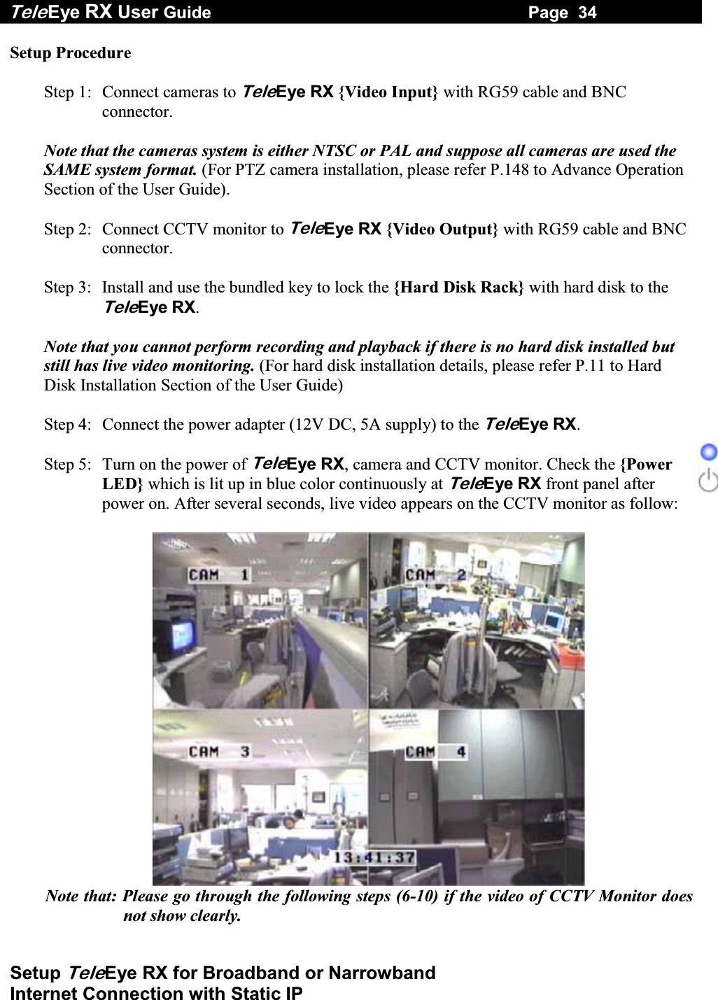
![Tele Eye RX User Guide Page 35 Setup TeleEye RX for Broadband or Narrowband Internet Connection with Static IP Step 6: Press the “Menu” button to pop up the [MAIN MENU] on OSD. Step 7: Use “Up” or “Down” button to select [SETUP] option and press “Enter” button to enter the [SETUP] sub-menu. Step 8: Select [VIDEO] option and press “Enter” button to enter the [VIDEO] sub-menu. Step 9: Select [VIDEO FORMAT] and press “Left” or “Right” button to set either [NTSC] or [PAL] option. (Allcameras should have the same video format). Step 10: You can always press “Live” button to exit any menu operation and start live monitoring. Setup TeleEye RX transmitter IP through CCTV monitor, please go to step 11a. Setup TeleEye RX transmitter IP through PC, through PC, please go to step11b. MAIN MENU SETUP . . . BACKUP TO CD-R . . . SWITCH CONTROL . . . SCAN / FORMAT DISK . . . TRANSMITTER INFO . . . SHUT DOWN ENTER VIDEO CAMERA SETTING . . . LOCAL MONITORING . . . OSD COLOR BLUE VIDEO FORMAT PAL SETUP MENU VIDEO . . . RECORDING . . . SWITCHES . . . DATE / TIME . . . CONNECTION . . . EVENT HANDLER . . . TRANSMITTER . . . RESTORE FACTORY SETTING ENTER](https://usermanual.wiki/Signal-Communications/SCRX-051020/User-Guide-668458-Page-41.png)
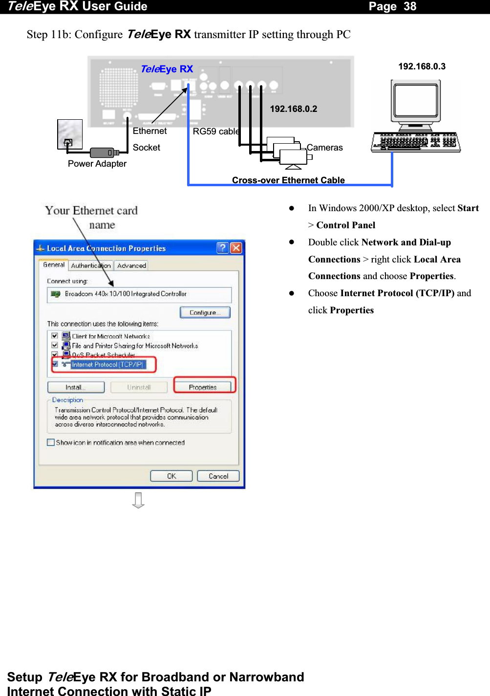
![Tele Eye RX User Guide Page 36 Setup TeleEye RX for Broadband or Narrowband Internet Connection with Static IP Step 11a: Configure TeleEye RX transmitter IP setting through CCTV Monitor RG59 cablePower Adapter Ethernet Socket Te l eEye RXCameras 192.168.0.2CCTV Monitor RG59 cable Press the “Menu” button such that the OSD main menu pops up on the monitor. Use “Up” or “Down” button to select [SETUP] option and press “Enter” button. Select [CONNECTION] option and press “Enter” button Select [TCP/IP] option and Press “Enter” button Select [IP] option and press “Enter” button. IP address consists of four fields. Each field can assign a number from 0 to 255. SETUP MENU VIDEO . . .RECORDING . . .SWITCHES . . .DATE / TIME . . .CONNECTION . . .EVENT HANDLER . . .TRANSMITTER . . .RESTORE FACTORY SETTING ENTERCONNECTION TCP / IP … MODEM … TCP / IP IP 192.168.0.2 PORT 1024 SUBNET MASK 255.255.255.0 ENABLE GATEWAY NO GATEWAY 0.0.0.0 ENABLE DNS NO PRIMARY DNS 0.0.0.0 SECONDARY DNS 0.0.0.0 SURELINK …](https://usermanual.wiki/Signal-Communications/SCRX-051020/User-Guide-668458-Page-42.png)
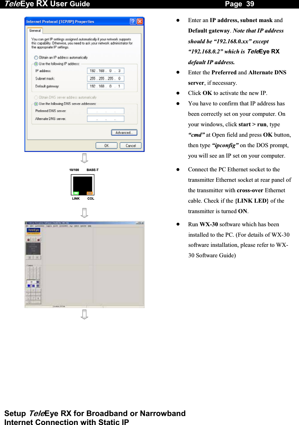
![Tele Eye RX User Guide Page 37 Setup TeleEye RX for Broadband or Narrowband Internet Connection with Static IP Use “Left” or “Right” button to select field and use “Up” or “Down” button to set number. Press “Enter” button to save the change and return previous menu. Follow the network setting and assign valid subnet mask to [SUBNET MASK] and select [ENABLE GATEWAY] option and input [GATEWAY] option in similar way. Set the Gateway value (for example) to 210.17.139.1 Note that the DNS setting is optional which is useful for sureLINK, time synchronization** or e-mail notification function**. ** : This function will be supported in the TeleEye RX transmitter version 2.00.00 or later Press “Live” button and [SETTING MODIFIED] message board will pop up. Press “Enter” button to restart the transmitter. IP IP : 210. 17.139.145 SETTING MODIFIED SETTING WILL TAKE EFFECT AFTER RESTART , PRESS ENTER TO CONTINUE OK TCP / IP IP 210.17.139.145 PORT 1024 SUBNET MASK 255.255.255.0 ENABLE GATEWAY YES GATEWAY 210.17.139.1 ENABLE DNS NO PRIMARY DNS 0.0.0.0 SECONDARY DNS 0.0.0.0 SURELINK …](https://usermanual.wiki/Signal-Communications/SCRX-051020/User-Guide-668458-Page-43.png)
![Tele Eye RX User Guide Page 40 Setup TeleEye RX for Broadband or Narrowband Internet Connection with Static IP Choose [Transmitter] [Registration] to register the TeleEye RX transmitter. User needs to input transmitter serial number and registration code. For example : Serial No. : VTC12345 Registration Code : 1234567890 Press [Connect] icon to pop up the [Connect Window]. Type and select the following setting : Broadband Connection : Phone/IP : 192.168.0.2 Connect Using: TCP/IP Broadband Password: 000000 OR Narrowband Connection : Phone/IP : 192.168.0.2 Connect Using: TCP/IP Narrowband Password: 000000 IP (192.168.0.2) and Password (000000) are default setting of TeleEye RX Press [Connect] icon to connect your PC and the transmitter. The video appears on the WX-30 if success. Otherwise, the [Warning] board will pop up and show you failure message. For failure case, please press [Connect] icon to check that the connection setting is valid or not.](https://usermanual.wiki/Signal-Communications/SCRX-051020/User-Guide-668458-Page-46.png)
![Tele Eye RX User Guide Page 41 Setup TeleEye RX for Broadband or Narrowband Internet Connection with Static IP Press [Transmitter setup] icon to show TeleEye RX configuration menu. Select [Connection] and press [Network Settings] icon to configure network setting. Change the IP from 192.168.0.2 to (for example) 210.17.139.145 and Gateway setting 210.17.139.1 (for example). Primary and Secondary DNS setting (for example) are used for sureLINK, time synchronization** or e-mail notification function **. ** : This function will be supported in the TeleEye RX transmitter version 2.00.00 or later Press [Apply] icon to save the network setting and pop up the message board. After several seconds, the transmitter will restart automatically.](https://usermanual.wiki/Signal-Communications/SCRX-051020/User-Guide-668458-Page-47.png)
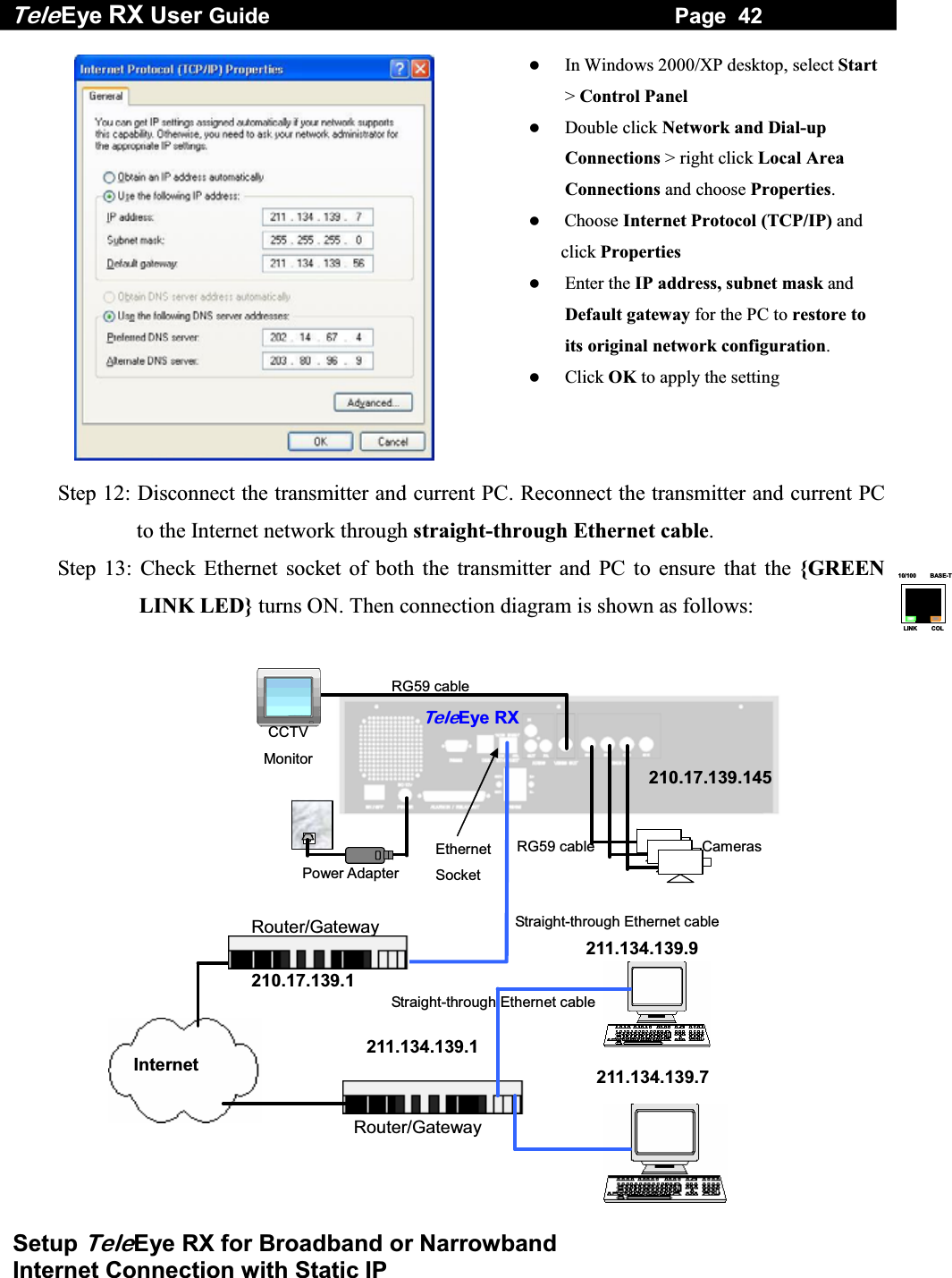
![Tele Eye RX User Guide Page 43 Setup TeleEye RX for Broadband or Narrowband Internet Connection with Static IP Step14: Configure the network setting for TeleEye RX transmitter and your PC if necessary, such as router/gateway port mapping (select router/gateway IP as IP provided by your ISP and the transmitter IP as IP provided by the router/gateway), firewall, etc. (Please refers to the manual of your router/gateway.) Step15: Run WX-30 software at any network PC. (For details of WX-30 software installation, please refer to WX-30 Software Guide) Step 16: Press [Connect] icon to pop up the [Connect Window]. For example, type and select the following setting : Broadband Connection : Phone/IP : 210.17.139.145 Connect Using: TCP/IP Broadband Password: 000000 OR Narrowband Connection : Phone/IP : 210.17.139.145 Connect Using: TCP/IP Narrowband Password: 000000 Step 17: Press [Connect] icon to connect your PC and the transmitter. The video appears on the WX-30 if success. Otherwise, the [Warning] board will pop up and show you failure message. For failure case, please press [Connect] icon to check that the connection setting is valid or not.](https://usermanual.wiki/Signal-Communications/SCRX-051020/User-Guide-668458-Page-49.png)
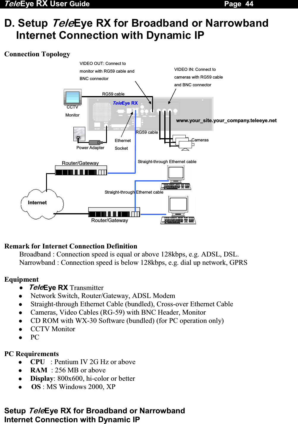
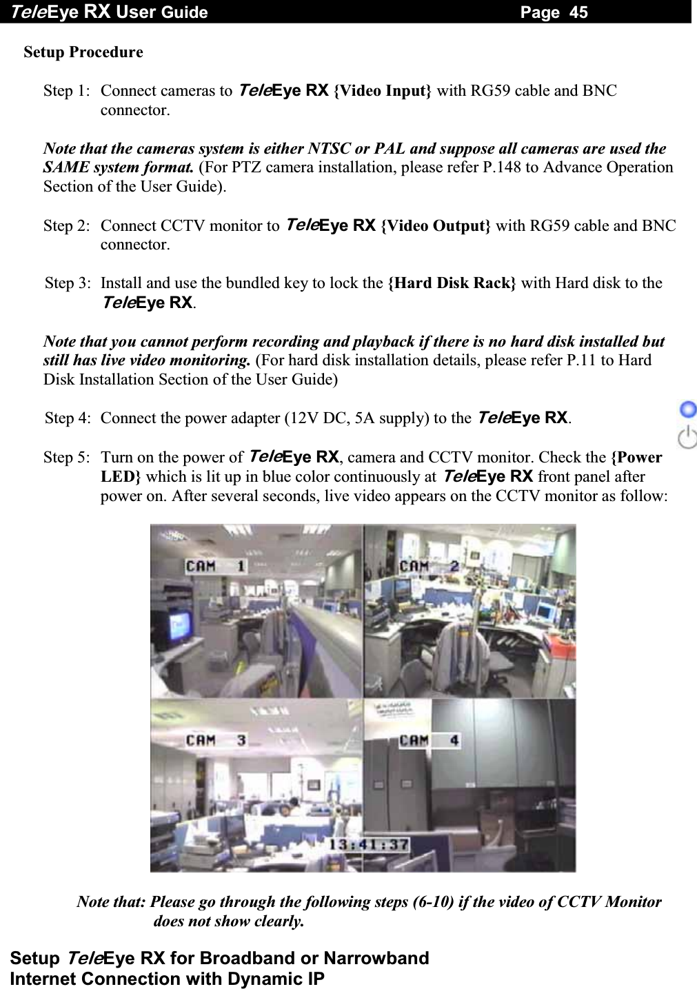
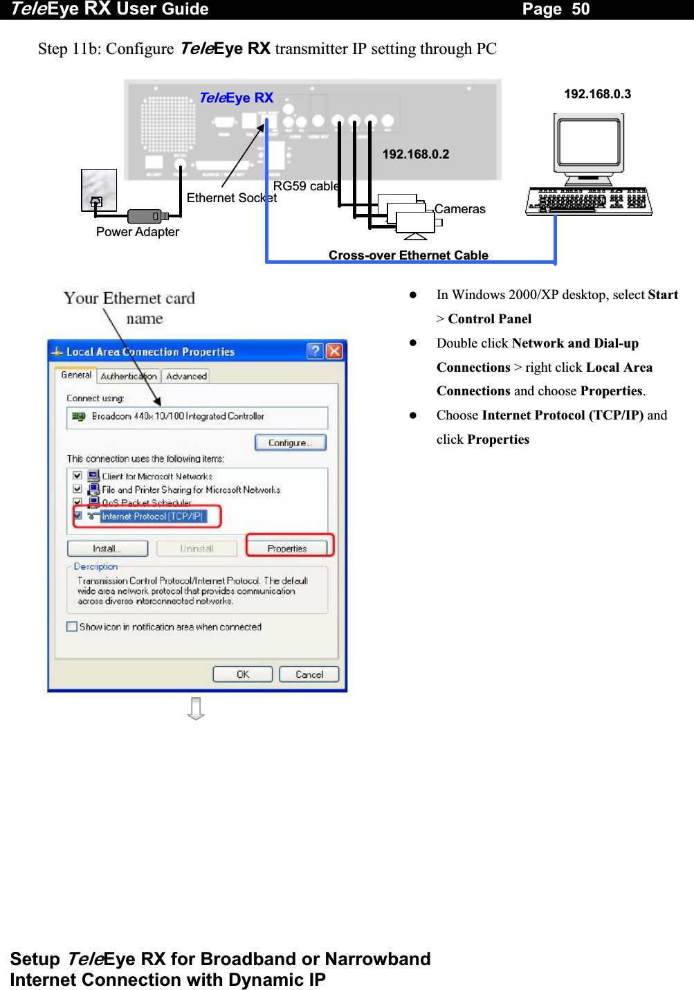
![Tele Eye RX User Guide Page 46 Setup TeleEye RX for Broadband or Narrowband Internet Connection with Dynamic IP Step 6: Press the “Menu” button to pop up the [MAIN MENU] on OSD. Step 7: Use “Up” or “Down” button to select [SETUP] option and press “Enter” button to enter the [SETUP] sub-menu. Step 8: Select [VIDEO] option and press “Enter” button Step 9: Select [VIDEO FORMAT] and press “Left” or “Right” button to set either [NTSC] or [PAL] option. (Allcameras should have the same video format). Step 10: You can always press “Live” button to exit any menu operation and start live monitoring. Setup TeleEye RX transmitter IP through CCTV monitor, please go to step 11a. Setup TeleEye RX transmitter IP through PC, through PC, please go to step11b. SETUP MENU VIDEO . . . RECORDING . . . SWITCHES . . . DATE / TIME . . . CONNECTION . . . EVENT HANDLER . . . TRANSMITTER . . . RESTORE FACTORY SETTING ENTER VIDEO CAMERA SETTING . . . LOCAL MONITORING . . . OSD COLOR BLUE VIDEO FORMAT PAL](https://usermanual.wiki/Signal-Communications/SCRX-051020/User-Guide-668458-Page-52.png)
![Tele Eye RX User Guide Page 47 Setup TeleEye RX for Broadband or Narrowband Internet Connection with Dynamic IP Step 11a: Configure TeleEye RX transmitter IP setting through CCTV Monitor RG59 cablePower Adapter Ethernet Socket Te l eEye RXCameras 192.168.0.2CCTV Monitor RG59 cable Press the “Menu” button such that the OSD main menu pops up on the monitor. Use “Up” or “Down” button to select [SETUP] option and press “Enter” button. Select[CONNECTION]option and press “Enter” button Select [TCP/IP] option and Press “Enter” button Select [IP] option and press “Enter” button. IP address consists of four fields. Each field can assign a number from 0 to 255. SETUP MENU VIDEO . . .RECORDING . . .SWITCHES . . .DATE / TIME . . .CONNECTION . . .EVENT HANDLER . . .TRANSMITTER . . .RESTORE FACTORY SETTING ENTERCONNECTION TCP / IP … MODEM … TCP / IP IP 192.168.0.2 PORT 1024 SUBNET MASK 255.255.255.0 ENABLE GATEWAY NO GATEWAY 0.0.0.0 ENABLE DNS NO PRIMARY DNS 0.0.0.0 SECONDARY DNS 0.0.0.0 SURELINK …](https://usermanual.wiki/Signal-Communications/SCRX-051020/User-Guide-668458-Page-53.png)
![Tele Eye RX User Guide Page 48 Setup TeleEye RX for Broadband or Narrowband Internet Connection with Dynamic IP Use “Left” or “Right” button to select field and use “Up” or “Down” button to set number. Set IP address (for example) to 210.17.139.5 Press “Enter” button to save the change and return previous menu. Follow the network setting and assign valid subnet mask to [SUBNET MASK] and select [ENABLE GATEWAY] option and input [GATEWAY] option in similar way. Assign the Gateway (for example) to 210.17.139.1 Select [ENABLE DNS] option Use “Left” or “Right” button to select [YES] to enable DNS. Assign the Primary DNS (for example) to 202.14.67.4 Assign the Secondary DNS (for example) to 202.14.67.14 IP IP : 210. 17.139. 5 TCP / IP IP 210.17.139.5 PORT 1024 SUBNET MASK 255.255.255.0 ENABLE GATEWAY YES GATEWAY 210.17.139.1 ENABLE DNS NO PRIMARY DNS 0.0.0.0 SECONDARY DNS 0.0.0.0 SURELINK …](https://usermanual.wiki/Signal-Communications/SCRX-051020/User-Guide-668458-Page-54.png)
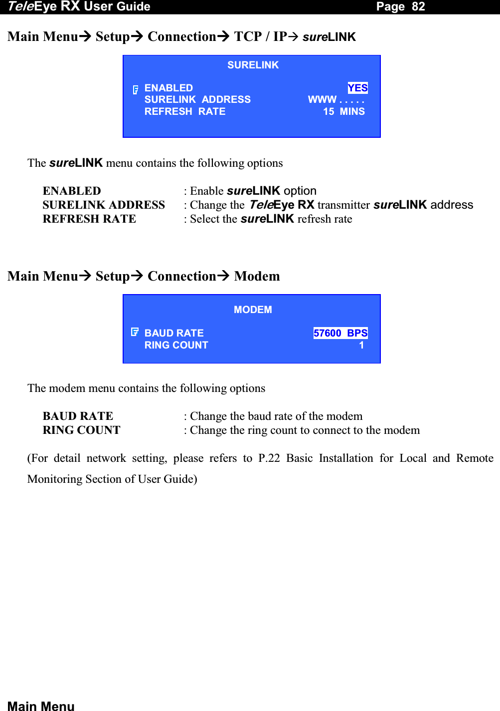
![Tele Eye RX User Guide Page 49 Setup TeleEye RX for Broadband or Narrowband Internet Connection with Dynamic IP Select [SURELINK] option from TCP/IP menu and press “Enter” button to enter the sub menu. Select [ENABLED] option and press “Left” or “Right” button to set [YES] value Select [SURELINK ADDRESS] option and press “Enter” button to sureLINK editing menu. There are two fields for assigning sureLINK address “www.your_site.your_company.teleeye.net” (Refer P.152 to section of getting sureLINK address) Use “Up” or “Down” or “Left” or “Right” button to select values and use “Enter” button to assign value. [BACK] back to previous value or field [NEXT] next to field [CLEAR] clear field [END] finish to assign sureLINK address and exit the editing menu. Press “Live” button and [SETTING MODIFIED] message board will pop up. Press “Enter” button to restart the transmitter. SURELINK ENABLED YES SURELINK ADDRESS www….. REFRESH RATE 1 MINS SURELINK ADDRESS 0 1 2 3 4 5 6 7 8 9 A B C D E F G H I J K L M N O P Q R S T U V W X Y Z BACK NEXT CLEAR END WWW. _ . TELEEYE.NETSETTING MODIFIED SETTING WILL TAKE EFFECT AFTER RESTART , PRESS ENTER TO CONTINUE OK](https://usermanual.wiki/Signal-Communications/SCRX-051020/User-Guide-668458-Page-55.png)

![Tele Eye RX User Guide Page 52 Setup TeleEye RX for Broadband or Narrowband Internet Connection with Dynamic IP Choose [Transmitter] [Registration] to register the TeleEye RX transmitter. User needs to input transmitter serial number and registration code. For example : Serial No. : VTC12345 Registration Code : 1234567890 Press [Connect] icon to pop up the [Connect Window]. Type and select the following setting : Broadband Connection : Phone/IP : 192.168.0.2 Connect Using: TCP/IP Broadband Password: 000000 OR Narrowband Connection : Phone/IP : 192.168.0.2 Connect Using: TCP/IP Narrowband Password: 000000 IP (192.168.0.2) and Password (000000) are default setting of TeleEye RX Press [Connect] icon to connect your PC and the transmitter. The video appears on the WX-30 if success. Otherwise, the [Warning] board will pop up and show you failure message. For failure case, please press [Connect] icon to check that the connection setting is valid or not.](https://usermanual.wiki/Signal-Communications/SCRX-051020/User-Guide-668458-Page-58.png)
![Tele Eye RX User Guide Page 53 Setup TeleEye RX for Broadband or Narrowband Internet Connection with Dynamic IP Press [Transmitter Setup] icon to show TeleEye RX configuration menu. Select [Connection] and press [Network Settings] icon to configure network setting. For example : Assign 210.17.139.5 to IP Assign 210.17.139.1 to Gateway Assign 202.14.67.4 to Primary DNS Assign 202.14.67.14 to Secondary DNS Enable sureLINK Assign “www.your_site.your_company.teleeye.net” (please refer P.152 to sureLINK section to get the address) to text field. Note that The above network setting is an example. Please consult you network administrator to get your network setting information Press [Apply] icon to save the network setting and pop up the message board. After several seconds, the transmitter will restart automatically.](https://usermanual.wiki/Signal-Communications/SCRX-051020/User-Guide-668458-Page-59.png)
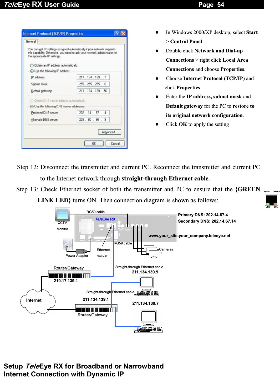
![Tele Eye RX User Guide Page 55 Setup TeleEye RX for Broadband or Narrowband Internet Connection with Dynamic IP Step14: Configure the network setting for TeleEye RX transmitter and your PC if necessary, such as router/gateway port mapping (select router/gateway IP as IP provided by your ISP and the transmitter IP as IP provided by the router/gateway), firewall, etc. (Please refers to the manual of your router/gateway.) Step15: Run WX-30 software at any network PC. (For details of WX-30 software installation, please refer to WX-30 Software Guide) Step 16: Press [Connect] icon to pop up the [Connect Window]. For example, type and select the following setting : Broadband Connection : Phone/IP : www.your_site.your_company.teleeye.net Connect Using: TCP/IP Broadband Password: 000000 OR Narrowband Connection : Phone/IP : www.your_site.your_company.teleeye.net Connect Using: TCP/IP Narrowband Password: 000000 Step 17: Press [Connect] icon to connect your PC and the transmitter. The video appears on the WX-30 if success. Otherwise, the [Warning] board will pop up and show you failure message. For failure case, please press [Connect] icon to check that the connection setting is valid or not.](https://usermanual.wiki/Signal-Communications/SCRX-051020/User-Guide-668458-Page-61.png)
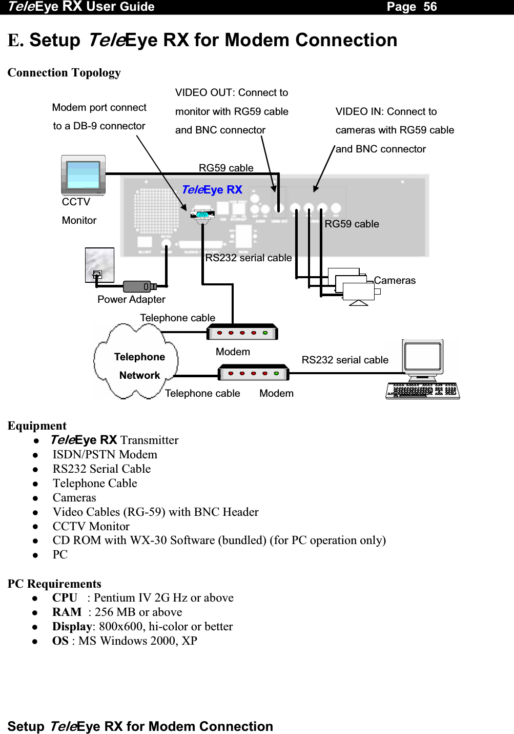
![Tele Eye RX User Guide Page 58 Setup TeleEye RX for Modem Connection Step 6: Press the “Menu” button to pop up the [MAIN MENU] on OSD. Step 7: Use “Up” or “Down” button to select [SETUP] option and press “Enter” button to enter the [SETUP] sub-menu. Step 8: Select [VIDEO] option and press “Enter” button Step 9: Select [VIDEO FORMAT] and press “Left” or “Right” button to set either [NTSC] or [PAL] option. (All cameras should have the same video format). Step 10: You can always press “Live” button to exit any menu operation and start live monitoring. Setup TeleEye RX transmitter IP through CCTV monitor, please go to step 11a. Setup TeleEye RX transmitter IP through PC, through PC, please go to step11b. SETUP MENU VIDEO . . . RECORDING . . . SWITCHES . . . DATE / TIME . . . CONNECTION . . . EVENT HANDLER . . . TRANSMITTER . . . RESTORE FACTORY SETTING ENTER VIDEO CAMERA SETTING . . . LOCAL MONITORING . . . OSD COLOR BLUE VIDEO FORMAT PAL](https://usermanual.wiki/Signal-Communications/SCRX-051020/User-Guide-668458-Page-64.png)
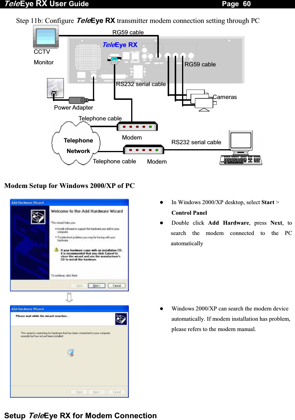
![Tele Eye RX User Guide Page 59 Setup TeleEye RX for Modem Connection Step 11a: Configure TeleEye RX transmitter modem connection setting through CCTV Monitor RG59 cablePower Adapter Ethernet Socket Te l eEye RXCameras 192.168.0.2CCTV Monitor RG59 cable Press the “Menu” button such that the OSD [MAIN MENU] pop up on the monitor. Use “Up” or “Down” button to select [SETUP] option and press “Enter” button and select [CONNECTION] option and press “Enter” button. Use “Up” or “Down” button to select [MODEM] option and press “Enter” button Select [BAUD RATE] and then [RING COUNT] option press “Enter” button Use “Up” or “Down” button to set number. Press “Enter” button to input baud rate and ring count setting SETUP MENU VIDEO . . .RECORDING . . .SWITCHES . . .DATE / TIME . . .CONNECTION . . .EVENT HANDLER . . .TRANSMITTER . . .RESTORE FACTORY SETTING ENTERCONNECTION TCP / IP … MODEM … MODEM BAUD RATE 57600 BPSRING COUNT 1](https://usermanual.wiki/Signal-Communications/SCRX-051020/User-Guide-668458-Page-65.png)
![Tele Eye RX User Guide Page 61 Setup TeleEye RX for Modem Connection After searching the modem, Windows 2000/XP can install the modem driver automatically. Press [Finish] button to exit the menu. The modem is ready to use. Run WX-30 software which has been installed to the PC. (For details of WX-30 software installation, please refer to WX-30 Software Guide) Choose [Transmitter] [Registration] to register the TeleEye RX transmitter. User needs to input transmitter serial number and registration code. For example : Serial No. : VTC12345 Registration Code : 1234567890](https://usermanual.wiki/Signal-Communications/SCRX-051020/User-Guide-668458-Page-67.png)
![Tele Eye RX User Guide Page 62 Setup TeleEye RX for Modem Connection Press [Connect] icon to pop up the [Connect Window]. For example, type and select the following setting : Phone/IP : 29955992 (Phone number of the transmitter) Connect Using : U.S. Robotics 56K Voice EXT PnP (Modem Driver) Password: 000000 Press [Connect] icon to connect your PC and the transmitter. The video appears on the WX-30 if success. Otherwise, the [Warning]board will pop up and show you failure message. For failure case, please press [Connect] iconto check that the connection setting is valid or not. Press [Transmitter setup] icon to show TeleEye RX configuration menu. Select [Connection] and press [Modem Settings] icon to configure network setting.](https://usermanual.wiki/Signal-Communications/SCRX-051020/User-Guide-668458-Page-68.png)
![Tele Eye RX User Guide Page 63 Setup TeleEye RX for Modem Connection Assign modem baud rate in order to adjust modem connection speed. Assign ring count, so modem can connect to the transmitter after that ring count. Press [Apply] icon to save the network setting and pop up the message board. After several seconds, the transmitter will restart automatically. Step 12 : If user setup modem connection by using local CCTV monitor (Step 11a), please install the modem for your PC and connect to the telephone network in order to connect to TeleEye RX transmitter In Windows 2000/XP desktop, select Start > Control Panel Double click Add Hardware, press Next, to search the modem connected to the PC automatically Windows 2000/XP can search the modem device automatically. If modem installation has problem, please refers to the modem manual.](https://usermanual.wiki/Signal-Communications/SCRX-051020/User-Guide-668458-Page-69.png)
![Tele Eye RX User Guide Page 64 Setup TeleEye RX for Modem Connection After searching the modem, Windows 2000/XP can install the modem driver automatically. Press [Finish] button to exit the menu. The modem is ready to use. Run WX-30 software which has been installed to the PC. (For details of WX-30 software installation, please refer to WX-30 Software Guide) Press [Connect] icon to pop up the [Connect Window]. For example, type and select the following setting : Phone/IP : 29955992 (Phone number of the transmitter) Connect Using : U.S. Robotics 56K Voice EXT PnP (Modem Driver) Password: 000000](https://usermanual.wiki/Signal-Communications/SCRX-051020/User-Guide-668458-Page-70.png)
![Tele Eye RX User Guide Page 65 Setup TeleEye RX for Modem Connection Press [Connect] icon to connect your PC and the transmitter. The video appears on the WX-30 if success. Otherwise, the [Warning]board will pop up and show you failure message. For failure case, please press [Connect] iconto check that the connection setting is valid or not.](https://usermanual.wiki/Signal-Communications/SCRX-051020/User-Guide-668458-Page-71.png)
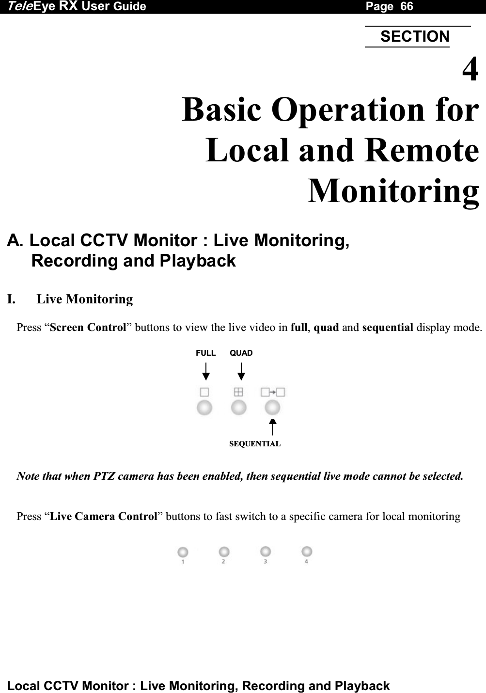
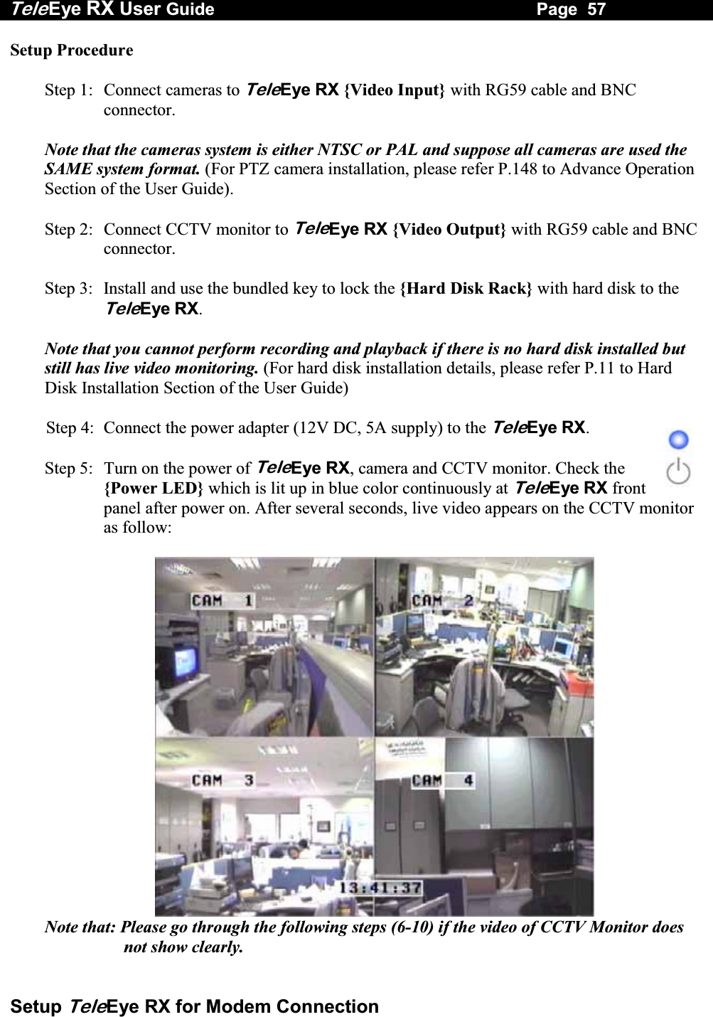
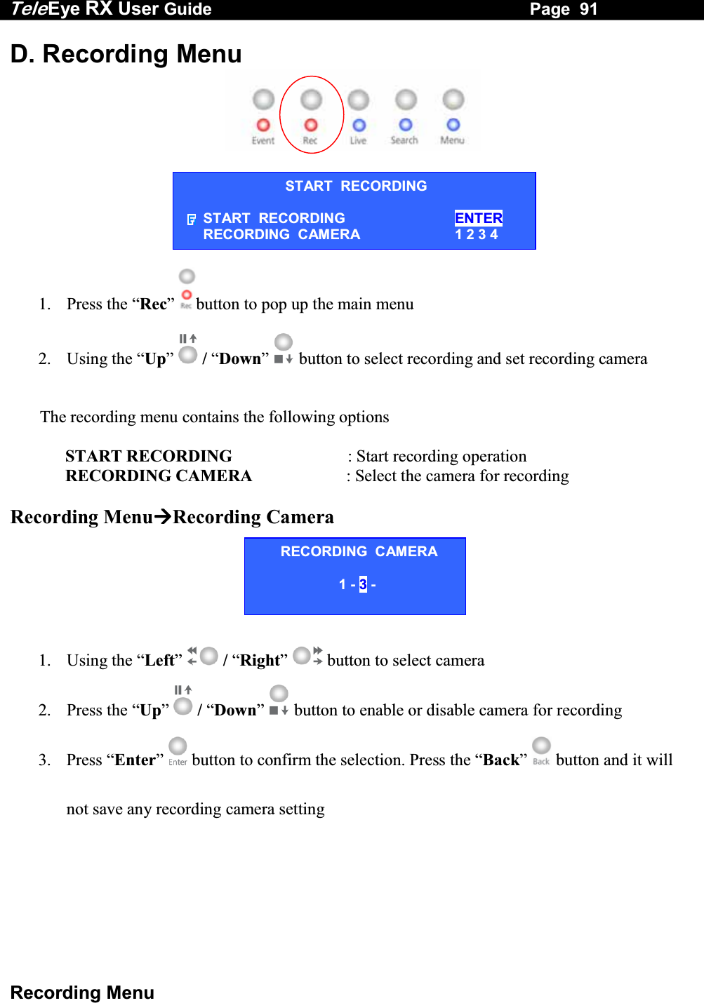
![Tele Eye RX User Guide Page 67 Local CCTV Monitor : Live Monitoring, Recording and Playback II. Recording Step 1: Press “Rec” button and [START RECORDING] menu will pop up. Step 2: Select [RECORDING CAMERA] option and press “Enter” button to enable recording cameras. (e.g. Cam 1 & 3 are enabled, Cam 2 & 4 are disabled) Step 3: Use “Left” or “Right” button to select the recording camera and use “Up” or “Down” button to enable or disable the recording camera. Step 4: After setting the recording cameras, press “Enter” button to save the setting and back to [START RECORDING] menu. Step 5: Select [START RECORDING] option and press “Enter” button for recording. The {Rec LED} will be turned ON (RED Color) which indicates that recording is processing.Step 6: Press “Rec” button again to stop recording function and the {REC LED} will be turned OFF. START RECORDING START RECORDING ENTER RECORDING CAMERA 1 2 3 4 RECORDING CAMERA 1 - 3 - START RECORDING START RECORDING ENTER RECORDING CAMERA 1 - 3 -](https://usermanual.wiki/Signal-Communications/SCRX-051020/User-Guide-668458-Page-73.png)
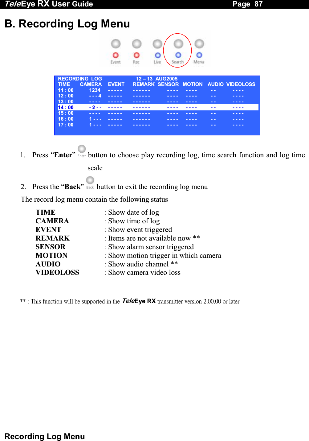
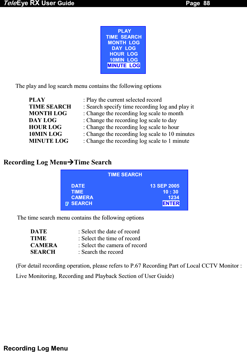
![Tele Eye RX User Guide Page 68 Local CCTV Monitor : Live Monitoring, Recording and Playback III. Playback Step 1: Press “Search” button to pop up [RECORDING LOG] board on OSD. Step 2: Press “Play/Enter” button to show [PLAY] menu. Select [MINUTE LOG] option and press “Enter” button. [RECORDING LOG] board will show the log in minute scale. Step 3: Select a record and press “Enter” button for playback. Then [PLAYBACK] menu will pop up again. Step 4: Select [PLAY] option and press “Enter” button again for playback. RECORDING LOG 12 –13 AUG2005TIME CAMERA EVENT REMARK SENSOR11 : 00 1234 - - - - - - - - - - - - - - -12 : 00 - - - 4 - - - - - - - - - - - - - - ------13 : 00 - - - - - - - - - - - - - - - - - - -14 : 00 - 2 - - - - - - - - - - - - - - - - -15 : 00 - - - - - - - - - - - - - - - - - - -16 : 00 1 - - - - - - - - - - - - - - - - - -17 : 00 1 - - - - - - - - - - - - - - - - - -18 : 00 - - - - - - - - - - - - - - - - - - -PLAYTIME SEARCHMONTH LOG DAY LOG HOUR LOG 10MIN LOG MINUTE LOG RECORDING LOG 12 –13 AUG2005TIME CAMERA EVENT REMARK SENSOR11 : 54 1234 - - - - - - - - - - - - - - -11 : 55 1234 - - - - - - - - - - - - - - ------11 : 56 1234 - - - - - - - - - - - - - - -11 : 57 1234 - - - - - - - - - - - - - - -11 : 58 1234 - - - - - - - - - - - - - - -11 : 59 1234 - - - - - - - - - - - - - - -12 : 00 - - - 4 - - - - - - - - - - - - - - -12 : 01 - - - 4 - - - - - - - - - - - - - - -PLAYTIME SEARCHMONTH LOG DAY LOG HOUR LOG 10MIN LOG MINUTE LOG](https://usermanual.wiki/Signal-Communications/SCRX-051020/User-Guide-668458-Page-74.png)
![Tele Eye RX User Guide Page 70 TeleEye RX Reception Software WX-30 : Live Monitoring, Recording and Playback B. TeleEye RX Reception Software WX-30 : Live Monitoring, Recording and Playback I. Live Monitoring User can view a particular camera by simply clicking the camera button (e.g. 1, 2 or 3) on the camera control panel, or view all cameras, click [All] icon. Screen views in Full screen Screen views in Quarter screen Screen views in Hex screen Auto-arrange can optimise the screen views in order to display as many high-resolution pictures as possible. User can change TeleEye RX Reception Software WX-30 live monitoring quality by following steps. Step 1: Click [Quality] icon at the software front panel to pop up [Quality] setting panel. Step 2: Pull up and down to select the quality items. Pull up is to increase the value and vice versa. : Quality : Brightness : Contrast : Colour Step 3: After changing the setting, press [Close] icon to exit the panel.](https://usermanual.wiki/Signal-Communications/SCRX-051020/User-Guide-668458-Page-76.png)
![Tele Eye RX User Guide Page 71 TeleEye RX Reception Software WX-30 : Live Monitoring, Recording and Playback II. Recording Step 1: Press [Record] icon to setup recording setting. Step 2: Input administrator password (000000 as default password) and press [OK] button. Step 3: Enable recording cameras ( Tick for enable, blank for disable) Step 4: Press [Start Recording] icon to start recording Recordingfunction is running](https://usermanual.wiki/Signal-Communications/SCRX-051020/User-Guide-668458-Page-77.png)
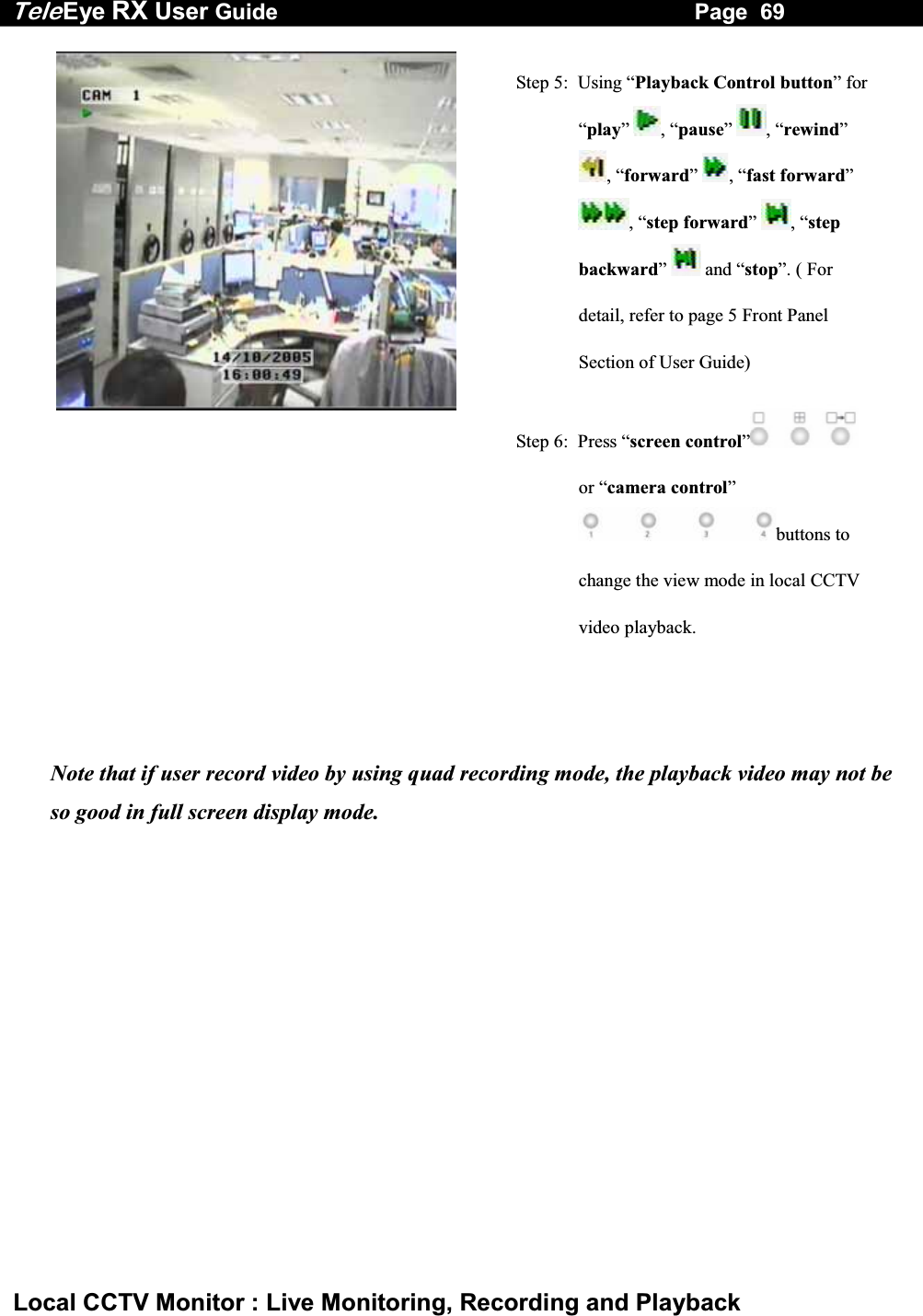
![Tele Eye RX User Guide Page 72 TeleEye RX Reception Software WX-30 : Live Monitoring, Recording and Playback III. Playback Step 1: Press [Play] icon to show playback menu Step 2: Select and input the record date and time for searching and press [Reload] icon. Step 3: Select a time slot record and press [Start Playback] button. Step 4: Use “playback control button” to control playback video such as “play”, “pause”, “forward”, “backward” and “stop” function. Step 5: Press [All] , [Full screen] , [Quarter screen] , [Hex screen] or [Auto-arrange] icon to change the view mode for playback. Note that after pressing “pause” button for 1 minute, reception software WX-30 will continue to playback the video automatically.Note that if user record video by using quad recording mode, the playback video may not be so good in full screen display mode.](https://usermanual.wiki/Signal-Communications/SCRX-051020/User-Guide-668458-Page-78.png)
![Tele Eye RX User Guide Page 73 Main Menu 5 OSD Menu Operation A. Main Menu 1. Press the “Menu” button to open the main menu 2. Using the “Up” / “Down” button to select a sub-menu 3. A selected sub-menu option will be pointed by a hand cursor and highlighted 4. Press “Enter” button to confirm the selection and open the sub-menu 5. If menu option ends with [. . .] indicates sub-menu existing, you can always press the “Enter” button to open the sub-menu. 6. If menu option does not end with [. . .] but provides selection, user can press the “Left” / “Right” button to selection the options. 7. You can press the “Back” button once back to previous menu. SECTIONMAIN MENU SETUP . . . BACKUP TO CD-R . . . SWITCH CONTROL . . . SCAN / FORMAT DISK . . . TRANSMITTER INFO . . . SHUT DOWN ENTER](https://usermanual.wiki/Signal-Communications/SCRX-051020/User-Guide-668458-Page-79.png)
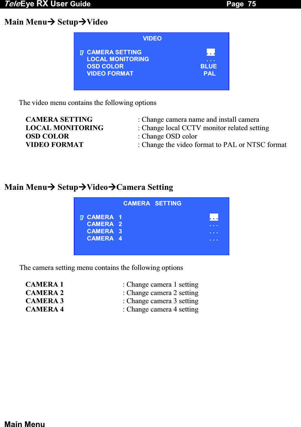
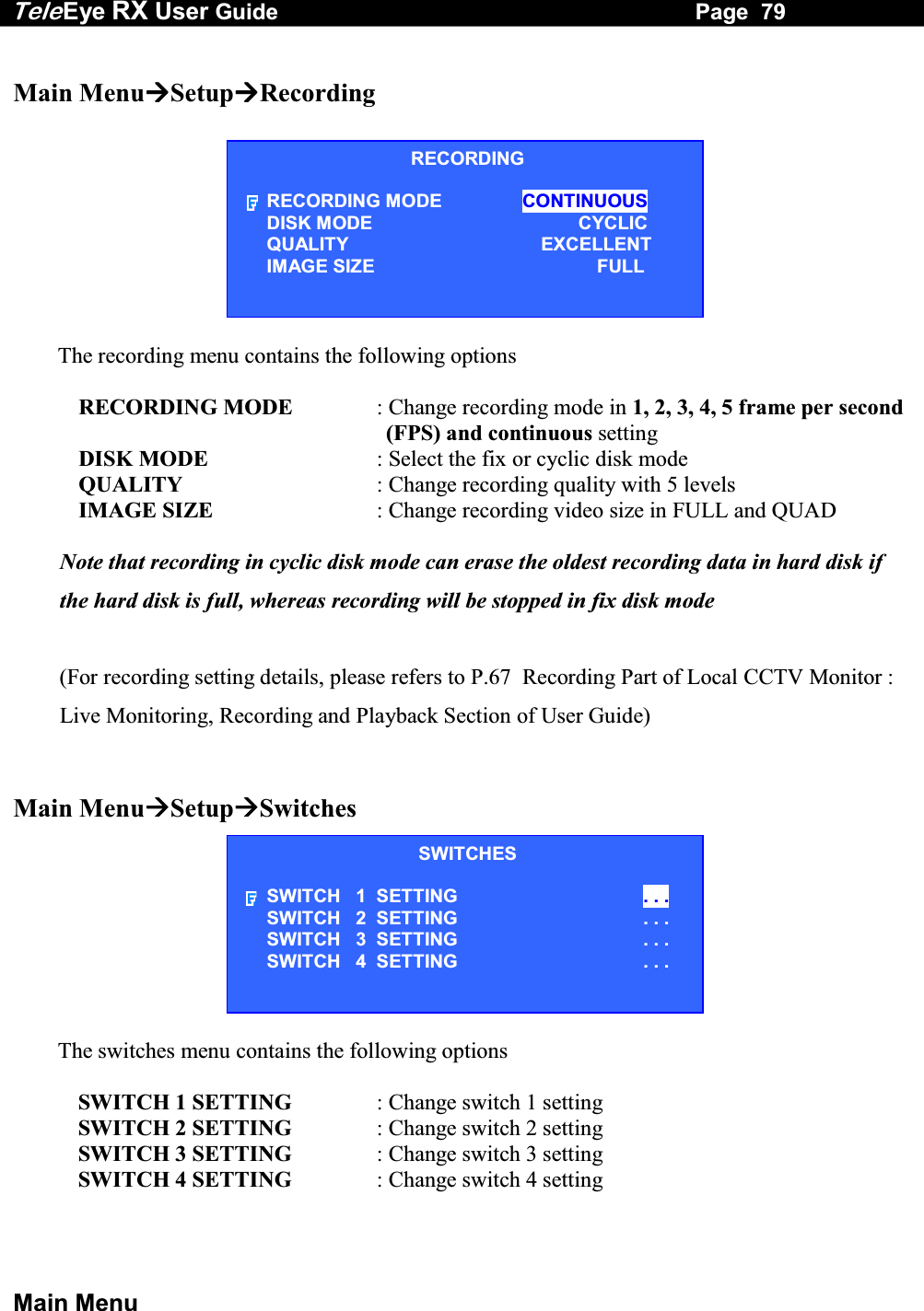
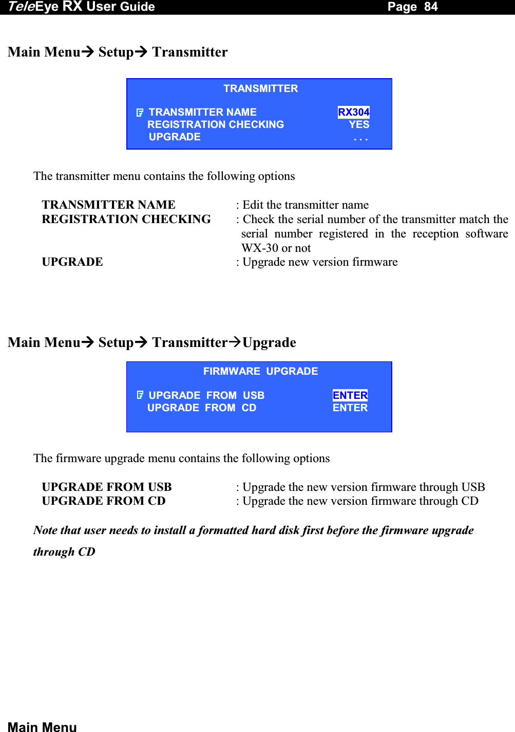
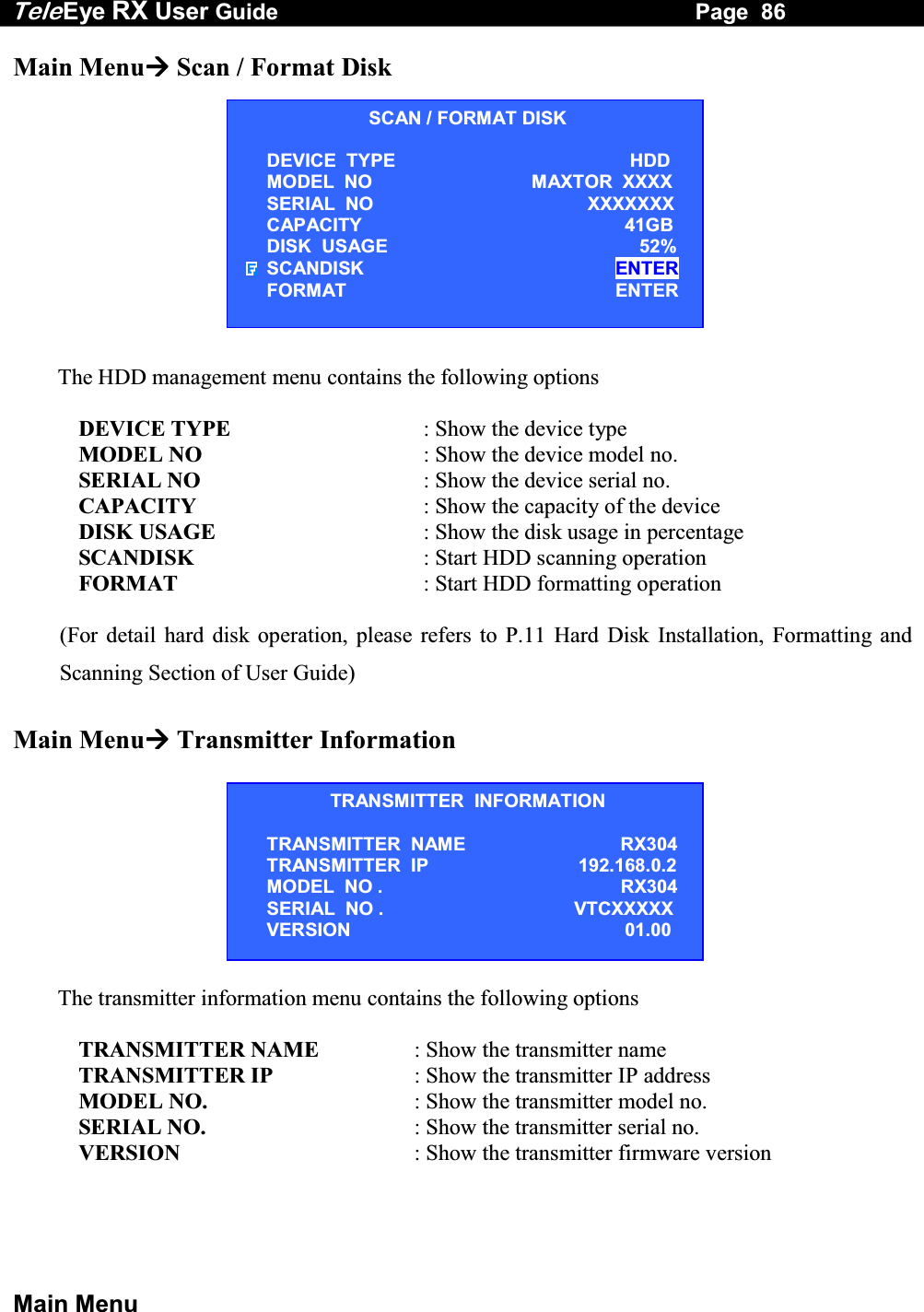
![Tele Eye RX User Guide Page 74 Main Menu 8. Press “Live” button or “Back” button until OSD disappear to exit menu and save the setting. [SETTING SAVED] message will be shown. The main menu contains the following options SETUP : Change the TeleEye RX transmitter setting BACKUP TO CDR : Backup recorded video to CDR or CDRW SWITCH CONTROL : Turn on /off switch 1-4 SCAN / FORMAT DISK : Show the hard disk information, do scandisk and format the hard disk operation TRANSMITTER INFO : Show the TeleEye RX transmitter information SHUT DOWN : Shut down or restart TeleEye RX transmitter Main MenuSetup The setup menu contains the following options VIDEO : Change camera, local monitoring, PTZ setting, OSD color and video format related settings RECORDING : Change recording related settings SWITCHES : Change switches related settings DATE/TIME : Change date and time settings CONNECTION : Change connection and network related settings EVENT HANDLER : Change event related settings TRANSMITTER : Change the transmitter name, registration checking and perform firmware upgrade RESTORE FACTORY SETTING : Restore default factory setting SETUP MENU VIDEO . . . RECORDING . . . SWITCHES . . . DATE / TIME . . . CONNECTION . . . EVENT HANDLER . . . TRANSMITTER . . . RESTORE FACTORY SETTING ENTERSETTING SETTING SAVED](https://usermanual.wiki/Signal-Communications/SCRX-051020/User-Guide-668458-Page-80.png)
![Tele Eye RX User Guide Page 78 Main Menu Main Menu SetupVideoLocal Monitoring The local monitoring menu contains the following options CLOCK POSITION : Change the clock position (Bottom, Top or None) in local CCTV monitor CAMERA NAME POSITION : Change the camera name position (Bottom, Top or None) in local CCTV monitor (Camera name and clock positions are in opposite position) SEQUENTIAL SWITCH TIME : Change the switch time between each live camera display for sequential mode monitoring SEQUENTIAL MODE CAMERAS : Select cameras for sequential mode monitoring DEFAULT DISPLAY MODE : Select default display mode in CCTV monitor after TeleEye RX transmitter boot up HORIZONTAL POSITION : Change horizontal position of local video output VERTICAL POSITION : Change vertical position of local video output HORIZONTAL SCALE : Change horizontal scale of local video output VERTICAL SCALE : Change vertical scale of local video output For [HORIZONTAL POSITION], [VERTICAL POSITON], [HORIZONTAL SCALE] and [VERTICAL SCALE] options, user can change these options if live video position or size display does not fit in the local CCTV monitor.LOCAL MONITORING CLOCK POSITION BOTTOMCAMERA NAME POSITION TOPSEQUENTIAL SWITCH TIME 1SECSEQUENTIAL MODE CAMERAS 1-3-DEFAULT DISPLAY MODE QUADHORIZONTAL POSITION 5VERTICAL POSITION 0HORIZONTAL SCALE 10VERTICAL SCALE 2](https://usermanual.wiki/Signal-Communications/SCRX-051020/User-Guide-668458-Page-84.png)
![Tele Eye RX User Guide Page 80 Main Menu Main Menu Setup Switches Switch X Setting The switch (No.) setting menu contains the following options NAME : Edit the name of the switch TYPE : Change the type of the switch, either latching or push-button type Main Menu Setup Date Time Setup 1. Press “Enter” button to select [DATE TIME] or [TIME] option 2. Press “Left” / “Right” button to select date, month, year for [DATE TIME] or select hour, minutes for [TIME] option 3. Press “Up” / “Down” button to change the value 4. Press “Enter” button to save setting and exit this page of menu The date / time setup menu contains the following options DATE : Set the current date TIME : Set the current time DATE / TIME DATE 24 AUG 2005 TIME 15:18 DATE DATE 24 AUG 2005 TIME TIME 15 : 18 SWITCH X SETTING NAME SWITCH X TYPE LATCHING](https://usermanual.wiki/Signal-Communications/SCRX-051020/User-Guide-668458-Page-86.png)
![Tele Eye RX User Guide Page 89 PTZ Menu C. PTZ Menu 1. During live mode, user presses the “Live” button to pop up the [ENABLE PTZ] menu 2. If user selects [YES] to enable the PTZ, then [PTZ OPTION] menu always pops up when user press the “Live” button again. User selects [DISABLE PTZ] to disable PTZ function 3. Using the “Up” / “Down” button to select each option ENABLE PTZ ? YES NO](https://usermanual.wiki/Signal-Communications/SCRX-051020/User-Guide-668458-Page-95.png)
![Tele Eye RX User Guide Page 90 PTZ Menu PTZ MenuPTZ Option The PTZ option menu contains the following options RECALL PRESET : Move the PTZ camera to the preset position PROGRAM PRESET : Save the current position of the PTZ camera as the preset position RECALL PATROL : Select the preset patrol for the PTZ camera STOP PATROL : Stop the patrol for the PTZ camera AUX CTRL : Control the auxiliary of the PTZ camera IRIS CTRL : Control the iris of the PTZ camera FOCUS CTRL : Control the focus of the PTZ camera ZOOM CTRL : Control the zoom of the PTZ camera AUTO : Rotate the PTZ camera automatically DISABLE PTZ : Disable the PTZ camera control For [AUX CTRL], [IRIS CTRL], [FOCUS CTRL] and [ZOOM CTRL] options, user can press “Enter” or “Back” button to control their respective action. (For detail PTZ camera setting, please refers to P.148 Connection to PTZ Cameras Part of Advance Operation Section of User Guide)PTZ OPTION RECALL PRESET PROGRAM PRESET RECALL PATROL STOP PATROL AUX CTRL IRIS CTRL FOCUS CTRL ZOOM CTRL AUTO DISABLE PTZ](https://usermanual.wiki/Signal-Communications/SCRX-051020/User-Guide-668458-Page-96.png)
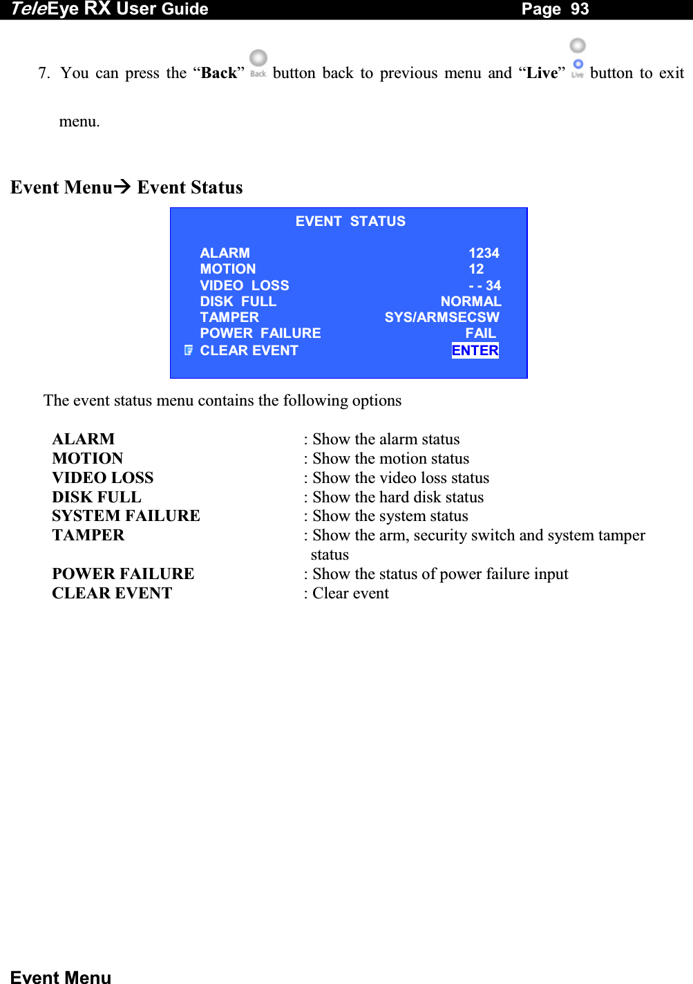
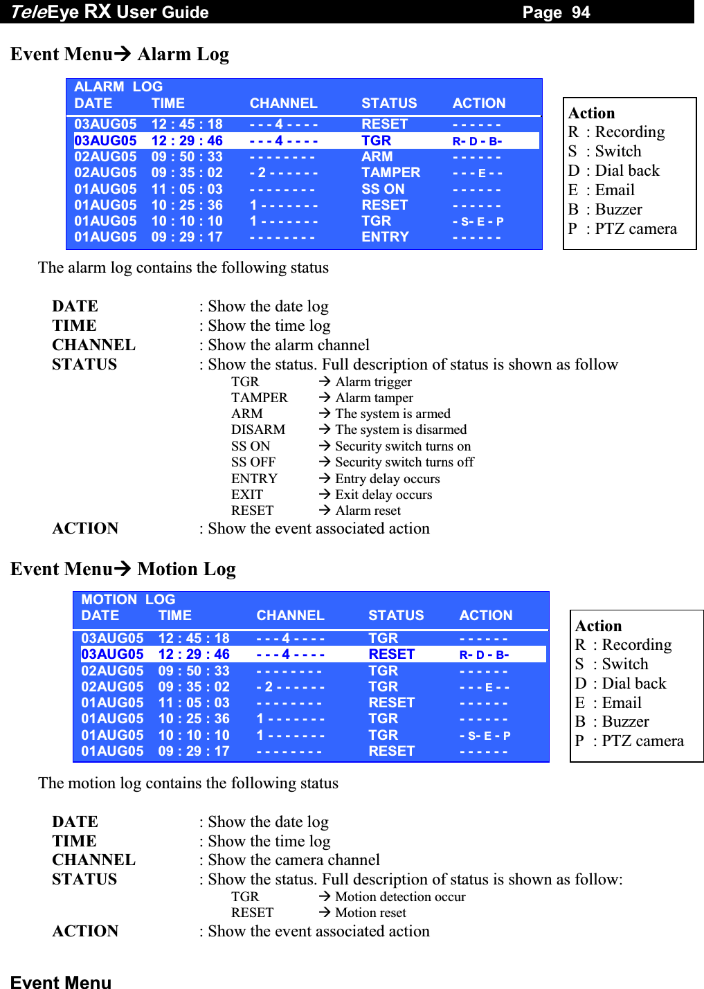
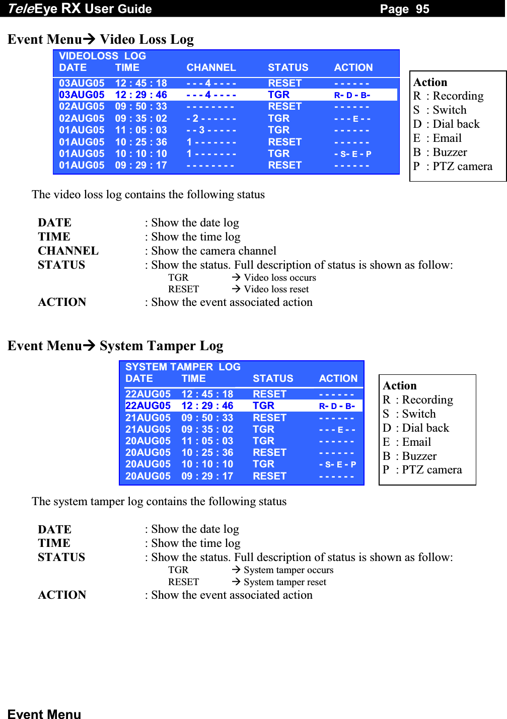
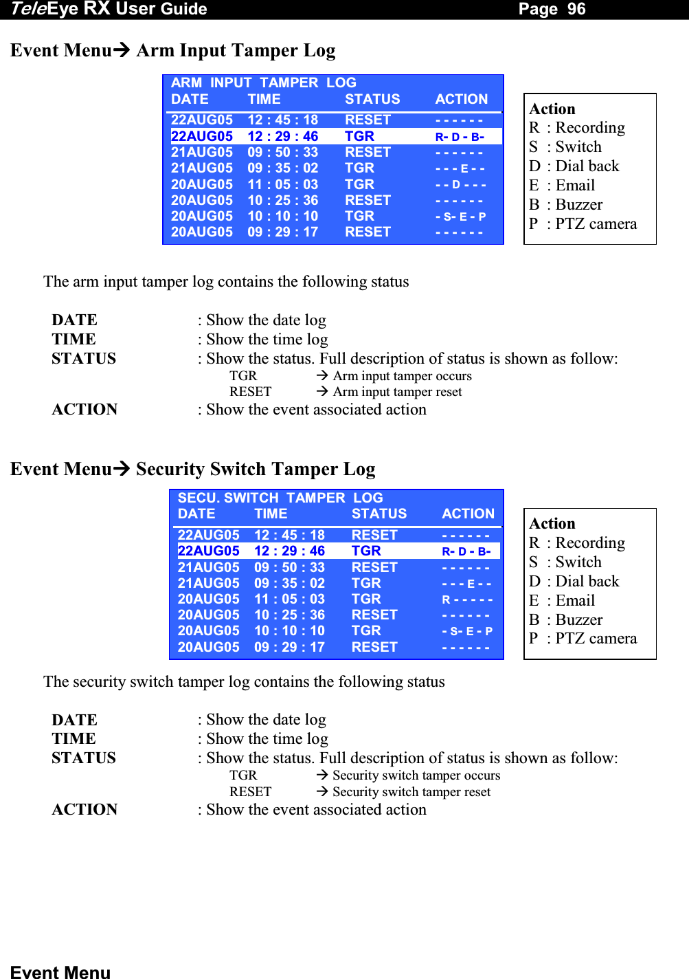
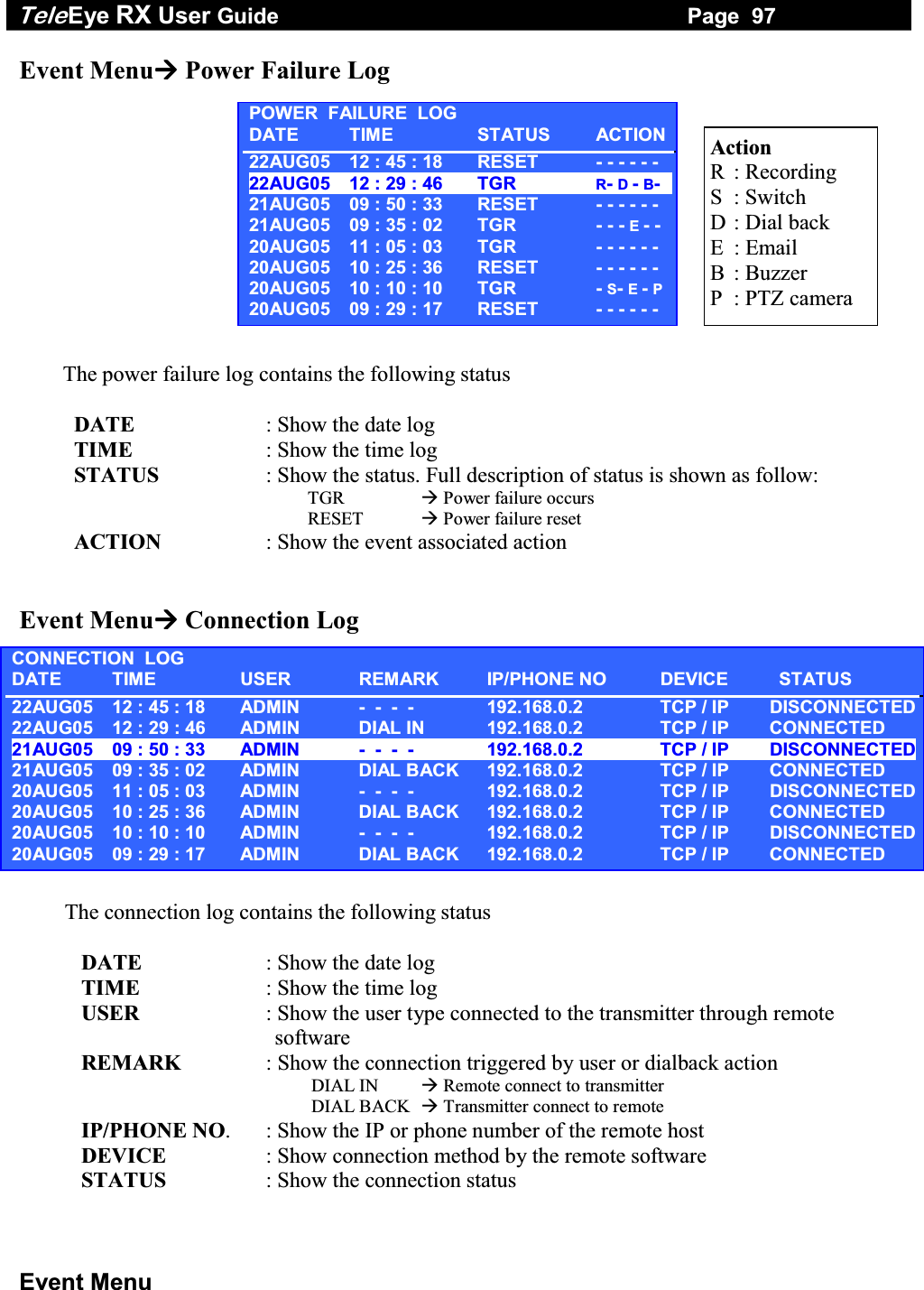
![Tele Eye RX User Guide Page 92 Event Menu E. Event Menu 1. Press the “Event” button to pop up the event menu 2. Using the “Up” / “Down” button to select a sub-menu 3. A selected sub-menu option will be pointed by a hand cursor and highlighted 4. Press “Enter” button to confirm the selection and pop up the sub-menu 5. The event menu contains the following options EVENT STATUS : Show event status ALARM LOG : Show the alarm log MOTION LOG : Show the motion log VIDEOLOSS LOG : Show the video loss log SYSTEM TAMPER LOG : Show the system tamper log ARM DISARM TAMPER LOG : Show the arm/disarm tamper log SECU. SWITCH TAMPER LOG : Show the security switch tamper log POWER FAILURE LOG : Show the power failure log CONNECTION LOG : Show the remote connection log 6. If menu option end with [. . .] indicates sub-menu existing, you can always press “Enter” button to pop up the sub-menu. EVENT MENU EVENT STATUS . . . ALARM LOG . . . MOTION LOG . . . VIDEOLOSS LOG . . . SYSTEM TAMPER LOG . . . ARM DISARM TAMPER LOG . . . SECU. SWITCH TAMPER LOG . . . POWER FAILURE LOG . . . CONNECTION LOG . . .](https://usermanual.wiki/Signal-Communications/SCRX-051020/User-Guide-668458-Page-98.png)
![Tele Eye RX User Guide Page 98 Event Menu SEARCH LOG DATE 20 SEP 2005 TIME 10 : 19 SEARCH ENTER Event Menu XXXX LogSearch Log For each log, you can press “Enter” button to enter the log option, and press “Enter” button in [TIME SEARCH] option to enter search log menu. The connection log contains the following options DATE : Set the search date TIME : Set the search time SEARCH : Search the nearest record according the date and time LOG OPTION TIME SEARCH](https://usermanual.wiki/Signal-Communications/SCRX-051020/User-Guide-668458-Page-104.png)
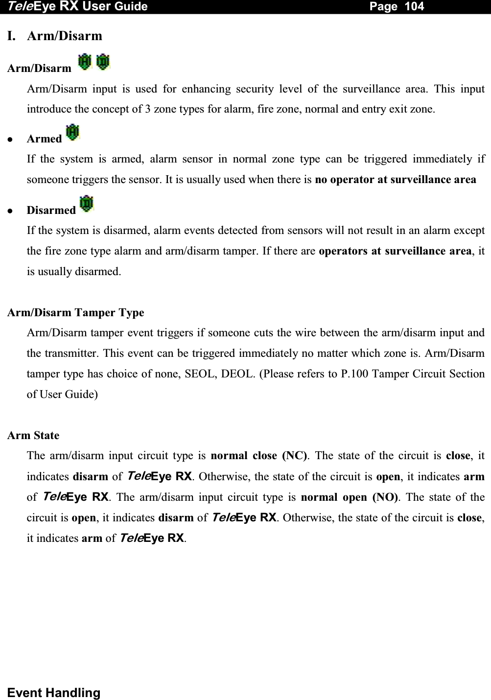
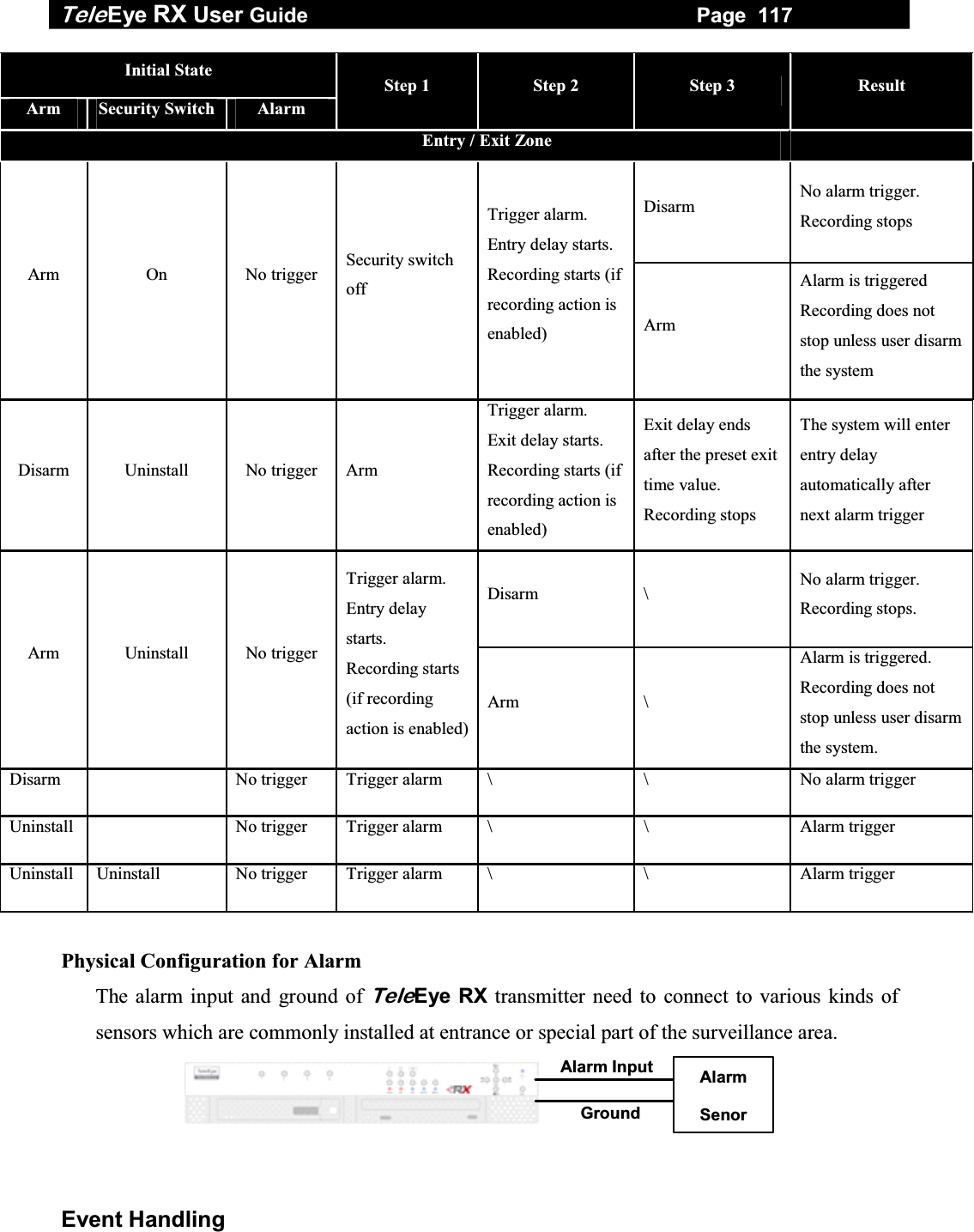
![Tele Eye RX User Guide Page 105 Event Handling Zone Type Although the setting of zone type belongs to alarm menu, it is worth to discuss as below. Fire Zone This zone allows alarms to trigger no matter which arm state of the system is, i.e. armed or disarmed. It is suitable for installation of fire detectors Normal This zone allows alarms to trigger after armed. Entry/Exit Zone This zone allows user to set the delay time for entering or leaving the surveillance area without triggering any alarm event. If alarm recording action is enabled, recording starts at entry or exit time through out the delay. (For detail usage example, please refers to P.111 Alarm Part in Event Handling Section of User Guide.) Physical Configuration for Arm/Disarm The arm/disarm input and ground of TeleEye RX transmitter needs to connect to a control unit which is commonly a switch or password panel for arm/disarm input. Control circuit Arm/Disarm Input Ground Arm/Disarm Setup Procedure Step 1: Press “Menu” button, select [SETUP] option and press “Enter” button to enter [SETUP] sub menu. Select [EVENT HANDLER] option and press “Enter” button. SETUP MENU VIDEO . . . RECORDING . . . SWITCHES . . . DATE / TIME . . . CONNECTION . . . EVENT HANDLER . . . TRANSMITTER . . . SHUT DOWN ENTER](https://usermanual.wiki/Signal-Communications/SCRX-051020/User-Guide-668458-Page-111.png)
![Tele Eye RX User Guide Page 106 Event Handling Step 2: Select [ARM/DISARM] option and press “Enter” button to show arm/disarm setting menu. Step 3: Select [ENABLED] option and use “Left” or “Right” button to enable (i.e. set the value to [YES]) the arm/disarm function. Step 4: Select [ARM STATE] option and use “Left” or “Right” button to choose arm state according to the configuration of TeleEye RX arm/disarm control circuit type. Step 5: Select [TAMPER TYPE] option and use “Left” or “Right” button to choose arm/disarm tamper circuit type according to the configuration of TeleEye RX arm/disarm tamper circuit type. EVENT HANDLER ARM / DISARM . . . SECURITY SWITCH . . . ALARM . . . MOTION . . . VIDEO LOSS . . . SYSTEM TAMPER . . . POWER FAILURE . . . ARM / DISARM ENABLED YES ARM STATE CLOSETAMPER TYPE NONEASSOCIATE SWITCH NOTAMPER EVENT ACTION … ARM / DISARM ENABLED YES ARM STATE CLOSE TAMPER TYPE NONEASSOCIATE SWITCH NOTAMPER EVENT ACTION … ARM / DISARM ENABLED YES ARM STATE CLOSETAMPER TYPE DEOLASSOCIATE SWITCH NOTAMPER EVENT ACTION …](https://usermanual.wiki/Signal-Communications/SCRX-051020/User-Guide-668458-Page-112.png)
![Tele Eye RX User Guide Page 107 Event Handling Step 6: Select [ASSOCIATE SWITCH] option and use “Left” or “Right” button to select [YES] and enable switch 1 only for arm/disarm associate switch. Switch 1 will be ON when TeleEye RX is armed. Switch 1 will be OFF when TeleEye RX is disarmed. Switch 1 cannot be activated by other events any more if it is an associate switch of arm/disarm. Step 7: Select [TAMPER EVENT ACTION]option and press “Enter” button to select arm/disarm tamper action. (For action, please refers to Event Action Part in Advance Operation Section of User Guide) ARM / DISARM ENABLED YES ARM STATE CLOSE TAMPER TYPE DEOL ASSOCIATE SWITCH YES TAMPER EVENT ACTION … ARM / DISARM ENABLED YES ARM STATE CLOSETAMPER TYPE DEOLASSOCIATE SWITCH YESTAMPER EVENT ACTION …](https://usermanual.wiki/Signal-Communications/SCRX-051020/User-Guide-668458-Page-113.png)
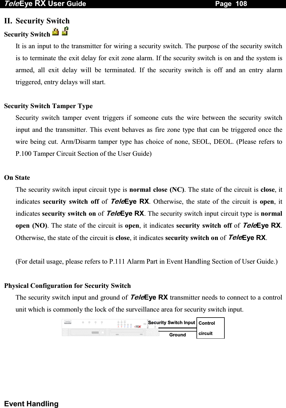
![Tele Eye RX User Guide Page 109 Event Handling Security Switch Setup Procedure Step 1: Press “Menu” button, select [SETUP] option and press “Enter” button to enter [SETUP] sub menu. Select [EVENT HANDLER] option and press “Enter” button. Step 2: Select [SECURITY SWITCH] option and press “Enter” button to show security switch setting menu. Step 3: Select [ENABLED] option and use “Left” or “Right” button to enable (i.e. set the value to [YES]) the security switch function. Step 4: Select [ON STATE] option and use “Left” or “Right” button to choose on state according to the configuration of TeleEye RX security switch control circuit type. SETUP MENU VIDEO . . . RECORDING . . . SWITCHES . . . DATE / TIME . . . CONNECTION . . . EVENT HANDLER . . . TRANSMITTER . . . SHUT DOWN ENTER EVENT HANDLER ARM / DISARM . . . SECURITY SWITCH . . . ALARM . . . MOTION . . . VIDEO LOSS . . . SYSTEM TAMPER . . . POWER FAILURE . . . SECURITY SWITCH ENABLED YES ON STATE OPENTAMPER TYPE NONEASSOCIATE SWITCH NOTAMPER EVENT ACTION … SECURITY SWITCH ENABLED YESON STATE CLOSETAMPER TYPE NONEASSOCIATE SWITCH NOTAMPER EVENT ACTION …](https://usermanual.wiki/Signal-Communications/SCRX-051020/User-Guide-668458-Page-115.png)
![Tele Eye RX User Guide Page 110 Event Handling Step 5: Select [TAMPER TYPE] option and use “Left” or “Right” button to choose security switch tamper circuit type according to the configuration of TeleEye RX security switch tamper circuit type. Step 6: Select [ASSOCIATE SWITCH] option and use “Left” or “Right” button to select [YES] and enable switch 2 only for security switch associate switch. Switch 2 will be ON when the security switch is on. Switch 1 will be OFF when the security switch is off. Switch 2 cannot be activated by other events any more if it is an associate switch of security switch. Step 7: Select [TAMPER EVENT ACTION]option and press “Enter” button to select security switch tamper action. (For action, please refers to Event Action Part in Advance Operation Section of User Guide) SECURITY SWITCH ENABLED YESON STATE CLOSETAMPER TYPE DEOLASSOCIATE SWITCH NOTAMPER EVENT ACTION … SECURITY SWITCH ENABLED YESON STATE CLOSETAMPER TYPE DEOLASSOCIATE SWITCH YES TAMPER EVENT ACTION … SECURITY SWITCH ENABLED YESON STATE CLOSETAMPER TYPE DEOLASSOCIATE SWITCH YES TAMPER EVENT ACTION …](https://usermanual.wiki/Signal-Communications/SCRX-051020/User-Guide-668458-Page-116.png)
![Tele Eye RX User Guide Page 118 Event Handling Alarm Setup Procedure Step 1: Press “Menu” button, select [SETUP] option and press “Enter” button to enter [SETUP] sub menu. Select [EVENT HANDLER] option and press “Enter” button. Step 2: Select [ALARM] option and press “Enter” button to show the alarm selection menu. Select appropriate alarm and press “Enter” button to enter the alarm setting menu. Step 3: Select [ENABLED] option and use “Left” or “Right” button to enable (i.e. set the value to [YES]) alarm. Step 4: Select [SENSOR TYPE] option and use “Left” or “Right” button to choose sensor type according to the configuration of TeleEye RX alarm sensor control circuit type. SETUP MENU VIDEO . . . RECORDING . . . SWITCHES . . . DATE / TIME . . . CONNECTION . . . EVENT HANDLER . . . TRANSMITTER . . . SHUT DOWN ENTER EVENT HANDLER ARM / DISARM . . . SECURITY SWITCH . . . ALARM . . . MOTION . . . VIDEO LOSS . . . SYSTEM TAMPER . . . POWER FAILURE . . . ALARM 1 SETTING ENABLED YES SENSOR NAME ALARM 1 SENSOR TYPE NO SENSOR TAMPER TYPE NONE ZONE TYPE NORMAL ENTRY DELAY 0 SEC EXIT DELAY 0 SEC ACTION … ALARM 1 SETTING ENABLED YES SENSOR NAME ALARM 1 SENSOR TYPE NC SENSOR TAMPER TYPE NONE ZONE TYPE NORMAL ENTRY DELAY 0 SEC EXIT DELAY 0 SEC ACTION …](https://usermanual.wiki/Signal-Communications/SCRX-051020/User-Guide-668458-Page-124.png)
![Tele Eye RX User Guide Page 119 Event Handling Step 5: Select [SENSOR TAMPER TYPE] option and use “Left” or “Right” button to choose alarm sensor tamper circuit type according to the configuration of TeleEye RX alarm sensor tamper circuit type. Step 6: Select [ZONE] option and use “Left” or “Right” button to choose zone type. Select [ENTRY DELAY], [EXIT DELAY] option and use “Left” or “Right” button to choose entry and exit delay Step 7: Select [ACTION] option and press “Enter” button to select alarm trigger or tamper action. (For action, please refers to Event Action Part in Advance Operation Section of User Guide) ALARM 1 SETTING ENABLED YES SENSOR NAME ALARM 1 SENSOR TYPE NC SENSOR TAMPER TYPE DEOL ZONE TYPE NORMAL ENTRY DELAY 0 SEC EXIT DELAY 0 SEC ACTION … ALARM 1 SETTING ENABLED YES SENSOR NAME ALARM 1 SENSOR TYPE NC SENSOR TAMPER TYPE DEOL ZONE TYPE NORMAL ENTRY DELAY 0 SEC EXIT DELAY 0 SEC ACTION … ALARM 1 SETTING ENABLED YES SENSOR NAME ALARM 1 SENSOR TYPE NC SENSOR TAMPER TYPE DEOL ZONE TYPE NORMAL ENTRY DELAY 0 SEC EXIT DELAY 0 SEC ACTION …](https://usermanual.wiki/Signal-Communications/SCRX-051020/User-Guide-668458-Page-125.png)
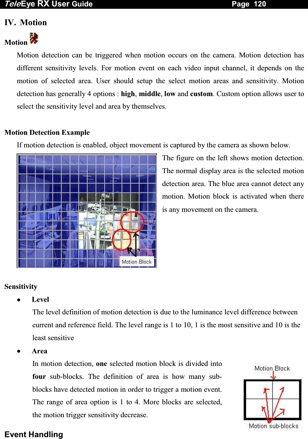
![Tele Eye RX User Guide Page 121 Event Handling Motion Setup Procedure Step 1: Press “Menu” button, select [SETUP] option and press “Enter” button to enter [SETUP] sub menu. Select [EVENT HANDLER] option and press “Enter” button. Step 2: Select [MOTION] option and press “Enter” button to show the motion selection menu. Select motion and press “Enter” button to enter the motion setting menu. Step 3: Select [MOTION DETECTIOR SETTING] option and press “Enter” button to setup motion detection setting. SETUP MENU VIDEO . . .RECORDING . . .SWITCHES . . .DATE / TIME . . .CONNECTION . . .EVENT HANDLER . . .TRANSMITTER . . .RESTORE FACTORY SETTING ENTEREVENT HANDLER ARM / DISARM . . . SECURITY SWITCH . . . ALARM . . ..MOTION . . . VIDEO LOSS . . . SYSTEM TAMPER . . . POWER FAILURE . . . MOTION 1 SETTING MOTION DETECTOR SETTING … ACTION …](https://usermanual.wiki/Signal-Communications/SCRX-051020/User-Guide-668458-Page-127.png)
![Tele Eye RX User Guide Page 122 Event Handling Step 4: Setting motion detection as follow: ENABLED: enable the motion detection of the camera DESELECT: deselect motion area SELECT: select motion area DESELECT ALL: clear all motion block SELECT ALL: select all motion block RESTORE: restore previous motion setting SENS: sensitivity option : LOW, MID, HIGH, CUSTOM OK: finish, save the setting and exit the detection menu Step 5: Select [ACTION] option and press “Enter” button to select alarm trigger or tamper action. (For action, please refers to Event Action Part in Advance Operation Section of User Guide) Deselected Area Selected Area MOTION 1 SETTING MOTION DETECTOR SETTING … ACTION …](https://usermanual.wiki/Signal-Communications/SCRX-051020/User-Guide-668458-Page-128.png)
![Tele Eye RX User Guide Page 123 Event Handling V. Video Loss Video Loss Video loss can be triggered when the video channel input disappears. It will happen if the transmitter receives no signal from the camera. The local CCTV monitor displays a blue screen for video loss condition. Video Loss Setup Procedure Step 1: Press “Menu” button, select [SETUP] option and press “Enter” button to enter [SETUP] sub menu. Select [EVENT HANDLER] option and press “Enter” button. Step 2: Select [VIDEO LOSS] option and press “Enter” button to show the camera selection menu. Select a camera and press “Enter” button to enter the video loss setting menu. Step 3: Select [ENABLED] option and use “Left” or “Right” button to enable (i.e. set the value to [YES]) video loss event handler. SETUP MENU VIDEO . . .RECORDING . . .SWITCHES . . .DATE / TIME . . .CONNECTION . . .EVENT HANDLER . . .TRANSMITTER . . .RESTORE FACTORY SETTING ENTEREVENT HANDLER ARM / DISARM . . . SECURITY SWITCH . . . ALARM . . ..MOTION . . . VIDEO LOSS . . . SYSTEM TAMPER . . . POWER FAILURE . . . VIDEO LOSS X SETTING ENABLED YES ACTION …](https://usermanual.wiki/Signal-Communications/SCRX-051020/User-Guide-668458-Page-129.png)
![Tele Eye RX User Guide Page 124 Event Handling Step 4: Select [ACTION] option and press “Enter” button to select alarm trigger or tamper action. (For action, please refers to Event Action Part in Advance Operation Section of User Guide) VIDEO LOSS X SETTING ENABLED YES ACTION …](https://usermanual.wiki/Signal-Communications/SCRX-051020/User-Guide-668458-Page-130.png)
![Tele Eye RX User Guide Page 125 Event Handling VI. System Tamper System Tamper Input It is an input to the transmitter for wiring a tamper switch of the external cabinet outside the transmitter and its accessories. The purpose of system tamper event is to prevent someone to break into the cabinet and destroy the transmitter. Sensor Type The system tamper input circuit type is normal close (NC). The state of the circuit is close, it indicates normal of TeleEye RX. Otherwise, the state of the circuit is open, it indicates system tamper of TeleEye RX. The system tamper input circuit type is normal open (NO). The state of the circuit is open, it indicates normal of TeleEye RX. Otherwise, the state of the circuit is close, it indicates system tamper of TeleEye RX. Physical Configuration for System Tamper The system tamper input and ground of TeleEye RX transmitter need to connect to an external cabinet which is used for protecting the transmitter and its accessories System Tamper Input External cabinet Ground System Tamper Setup Procedure Step 1: Press “Menu” button, select [SETUP] option and press “Enter” button to enter [SETUP] sub menu. Select [EVENT HANDLER] option and press “Enter” button. SETUP MENU VIDEO . . .RECORDING . . .SWITCHES . . .DATE / TIME . . .CONNECTION . . .EVENT HANDLER . . .TRANSMITTER . . .RESTORE FACTORY SETTING ENTER](https://usermanual.wiki/Signal-Communications/SCRX-051020/User-Guide-668458-Page-131.png)
![Tele Eye RX User Guide Page 126 Event Handling Step 2: Select [SYSTEM TAMPER] option and press “Enter” button to show the system tamper menu and press “Enter” button to enter the System Tamper setting menu. Step 3: Select [ENABLED] option and use “Left” or “Right” button to enable (i.e. set the value to [YES]) System Tamper event handler. Step 4: Select [SENSOR TYPE] option and use “Left” or “Right” button to choose sensor type according to the configuration of TeleEye RX system tamper control circuit type Step 5: Select [ACTION] option and press “Enter” button to select system tamper action. (For action, please refers to Event Action Part in Advance Operation Section of User Guide) EVENT HANDLER ARM / DISARM . . . SECURITY SWITCH . . . ALARM . . ..MOTION . . . VIDEO LOSS . . . SYSTEM TAMPER . . . POWER FAILURE . . . SYSTEM TAMPER ENABLED YES SENSOR TYPE NO ACTION …SYSTEM TAMPER ENABLED YES SENSOR TYPE NC ACTION …SYSTEM TAMPER ENABLED YES SENSOR TYPE NC ACTION …](https://usermanual.wiki/Signal-Communications/SCRX-051020/User-Guide-668458-Page-132.png)
![Tele Eye RX User Guide Page 127 Event Handling VII. Power Failure Power Failure Input It is an input to the transmitter typically used for wiring the output signal pin from UPS. Sensor Type The power failure input circuit type is normal close (NC). The state of the circuit is close, it indicates normal of TeleEye RX. Otherwise, the state of the circuit is open, it indicates power failure of TeleEye RX. The power failure input circuit type is normal open (NO). The state of the circuit is open, it indicates normal of TeleEye RX. Otherwise, the state of the circuit is close, it indicates power failure of TeleEye RX. Physical Configuration for Power Failure Input The power failure input and ground of TeleEye RX transmitter need to connect to a universal power supply circuit UPS, so the transmitter can detect any power failure condition. Note that below UPS circuit setup is used as an example. Not all UPS have signal output. Some UPS have self-test for a period of time, their signal output may toggle during test. UPS Power Failure InputPower from UPS Other Devices Power from UPS UPS provide backup power in certain period and send a power failure signal to RX when the main power does not work. Main PowerGround Power Failure Setup Procedure Step 1: Press “Menu” button, select [SETUP] option and press “Enter” button to enter [SETUP] sub menu. Select [EVENT HANDLER] option and press “Enter” button. SETUP MENU VIDEO . . .RECORDING . . .SWITCHES . . .DATE / TIME . . .CONNECTION . . .EVENT HANDLER . . .TRANSMITTER . . .RESTORE FACTORY SETTING ENTER](https://usermanual.wiki/Signal-Communications/SCRX-051020/User-Guide-668458-Page-133.png)
![Tele Eye RX User Guide Page 128 Event Handling Step 2: Select [POWER FAILURE] option and press “Enter” button to enter the power failure setting menu. Step 3: Select [ENABLED] option and use “Left” or “Right” button to enable (i.e. set the value to [YES]) power failure event handler. Step 4: Select [SENSOR TYPE] option and use “Left” or “Right” button to choose sensor type according to the configuration of TeleEye RX power failure control circuit type Step 5: Select [ACTION] option and press “Enter” button to select power failure action. (For action, please refers to Event Action Part in Advance Operation Section of User Guide) EVENT HANDLER ARM / DISARM . . . SECURITY SWITCH . . . ALARM . . ..MOTION . . . VIDEO LOSS . . . SYSTEM TAMPER . . . POWER FAILURE . . . POWER FAILURE ENABLED YES SENSOR TYPE NO ACTION …POWER FAILURE ENABLED YES SENSOR TYPE NC ACTION …POWER FAILURE ENABLED YES SENSOR TYPE NC ACTION …](https://usermanual.wiki/Signal-Communications/SCRX-051020/User-Guide-668458-Page-134.png)
![Tele Eye RX User Guide Page 129 Event Action D. Event Action TeleEye RX supports event actions such as Recording, Switch, Dial back, Buzzer, Event LED, Live camera and PTZ when event detected from alarm, tamper of alarm, motion, video loss, tamper of arm/disarm, tamper of security switch, power failure and system tamper. Event Action Setup Procedure Step 1: Press “Menu” button, select [SETUP] option and press “Enter” button to enter [SETUP] sub menu. Select [EVENT HANDLER] option and press “Enter” button. Step 2: Select any event option and press “Enter” button to enter the setting menu. Step 3: Select [ENABLED] option and use “Left” or “Right” button to enable (i.e. set the value to [YES]) event handler. Step 4: Select [ACTION] option and press “Enter” button to enter the action menu. SETUP MENU VIDEO . . .RECORDING . . .SWITCHES . . .DATE / TIME . . .CONNECTION . . .EVENT HANDLER . . .TRANSMITTER . . .RESTORE FACTORY SETTING ENTEREVENT HANDLER ARM / DISARM . . . SECURITY SWITCH . . . ALARM . . ..MOTION . . . VIDEO LOSS . . . SYSTEM TAMPER . . . POWER FAILURE . . . XXXXXXX ACTION RECORDING … SWITCH … DIALBACK … BUZZER … EVENT LED … LIVE CAMERA … PTZ …](https://usermanual.wiki/Signal-Communications/SCRX-051020/User-Guide-668458-Page-135.png)
![Tele Eye RX User Guide Page 130 Event Action I. Recording Recording If an event triggers, recording can record the video content at user selected camera with selected recording mode. Pre-Alarm Recording Pre-alarm recording allows to record video before an event trigger. The period of pre-alarm recording is at least 1 minute (not more than 2 minutes) before the event trigger. User can find that there is at least 1 minute more video content in [RECORDING LOG MENU] before event trigger. Duration After Event Clear After event resets, the recording action will stop after this duration time. Recording Mode Event recording provides 2 recording mode, 1 frame per second (1 FPS) and continuous mode. In 1 FPS mode, the recording frame rate is less, so the storage size is small. In continuous mode, the recording frame rate depends on the number of recording camera and more than 1 FPS, so the storage size is larger. Recording Action Setup Procedure Step 1: In the action menu, select [RECORDING] option and press “Enter” button to enter the recording action setting menu. XXXXXXX ACTION RECORDING … SWITCH … DIALBACK … BUZZER … EVENT LED … LIVE CAMERA … PTZ …](https://usermanual.wiki/Signal-Communications/SCRX-051020/User-Guide-668458-Page-136.png)
![Tele Eye RX User Guide Page 131 Event Action Step 2: Select [ENABLED] option and use “Left” or “Right” button to enable (i.e. set the value to [YES]) recording action. Step 3: Select the [DURATION AFTER EVENT CLEAR] and [RECORDING MODE] options and uses the “Left” or “Right” button to choose the suitable setting. Step 4: Select [RECORDING CAMERA] option and press “Enter” button to enter the recording camera menu. Step 5: Use the “Left” or “Right” button to select camera and press the “Up” or “Down” button to enable or disable recording camera. Step 6: Press “Enter” button to save the camera setting and go back to recording action menu. Step 7: You can press “Live” button to exit OSD menu or press “Back” button to enter action menu again. XXXXXXX RECORDING ENABLED YESDURATION AFTER EVENT CLEAR 20 SECRECORDING MODE CONTINUOUSRECORDING CAMERA - - - -RECORDING CAMERA 1 - 3 -](https://usermanual.wiki/Signal-Communications/SCRX-051020/User-Guide-668458-Page-137.png)
![Tele Eye RX User Guide Page 132 Event Action II. Switch Switch allows transmitter to control 4 external relays which are defined by user. Switch Type Switch has 2 types. They are latching or push-button type. In latching type, the switch turns on for a period of time. In push-button type, the switch turns on and off after 1 second. Latching Duration The latch duration period is the time for turning on the switch. Action Delay The delay is the period of time after turning off the switch before next turning on. Latching Duration and Action Delay Example For latch type switch, set latch duration 10sec and action delay 10sec. If an event trigger, the timing of the switch is shown on the right. For push-button type switch, set latch duration 10sec and action delay 10sec. If an event trigger, the timing of the switch is shown on the right. Switch Action setup procedure Step 1: In the action menu, select [SWITCH] option and press “Enter” button to enter the switch action setting menu. XXXXXXX ACTION RECORDING … SWITCH … DIALBACK … BUZZER … EVENT LED … LIVE CAMERA … PTZ …](https://usermanual.wiki/Signal-Communications/SCRX-051020/User-Guide-668458-Page-138.png)
![Tele Eye RX User Guide Page 133 Event Action Step 2: Select [ENABLED] option and use “Left” or “Right” button to enable (i.e. set the value to [YES]) switch action.Step 3: Select [SWITCHES ENABLED] option and press “Enter” button to enable or disable the switches. Step 4: Use the “Left” or “Right” button to select switch and press the “Up” or “Down” button to enable or disable switch. Step 5: Press “Enter” button to save the selection setting and go back to switch action menu. Step 6: Select [GENERAL SWITCH SETTING]option and press “Enter” button to enter the switch setting menu. Step 7: Select [SWITCH (No.)] option and press “Enter” button to enter the switch (No.) setting menu. XXXXXXX SWITCH ENABLED YESSWITCHES ENABLED - - - -GENERAL SWITCH SETTING . . . ASSOCIATE SWITCH 1 - 3 - GENERAL SWITCH SETTING SWITCH 1 . . . SWITCH 2 . . . SWITCH 3 . . . SWITCH 4 . . . LATCH DURATION 10 SEC ACTION DELAY 10 SEC](https://usermanual.wiki/Signal-Communications/SCRX-051020/User-Guide-668458-Page-139.png)
![Tele Eye RX User Guide Page 134 Event Action Step 8: Select [NAME] option and press “Enter” button to edit the name of switch (No.). Step 9: Select [TYPE] option and press the “Left” or “Right” button to choose the switch type. Press the “Back” button to go back the general switch setting menu and save the setting. Step 10: Select [LATCH DURATION] option and press the “Left” or “Right” button to choose the latch duration. Step 11: Select [ACTION DELAY] option and press the “Left” or “Right” button to choose the switch action delay between each on/off. Step 12: You can press “Live” button to exit OSD menu or press “Back” button to enter action menu again. SWITCH X SETTING NAME SWITCH X TYPE LATCHING GENERAL SWITCH SETTING SWITCH 1 . . . SWITCH 2 . . . SWITCH 3 . . . SWITCH 4 . . . LATCH DURATION 10 SEC ACTION DELAY 10 SEC](https://usermanual.wiki/Signal-Communications/SCRX-051020/User-Guide-668458-Page-140.png)
![Tele Eye RX User Guide Page 135 Event Action III. Dialback Dialback Dialback allows the transmitter to connect to one remote PC and displays live video if an event triggers. Therefore, remote operator can recognize what situation is at the surveillance area. Retry Duration The retry duration is the period between each dialback retrial (in second). Retry Count The retry count is the number of dialback retrial if dialback fails. Dialback Action setup procedure Step 1: In the action menu, select [DIALBACK] option and press “Enter” button to enter the dialback action setting menu. Step 2: Select [ENABLED] option and use “Left” or “Right” button to enable (i.e. set the value to [YES]) dialback action. Step 3: Select [GENERAL DIALBACK SETTING] option and press “Enter” button to enter the dialback setting menu. XXXXXXX ACTION RECORDING … SWITCH … DIALBACK … BUZZER … EVENT LED … LIVE CAMERA … PTZ … XXXXXXX DIAL BACK ENABLED YESGENERAL DIALBACK SETTING . . .GENERAL DIALBACK SETTING RETRY DURATION 0 RETRY COUNT 1 PHONE 1 . . . PHONE 2 . . . PHONE 3 . . . PHONE 4 . . .](https://usermanual.wiki/Signal-Communications/SCRX-051020/User-Guide-668458-Page-141.png)
![Tele Eye RX User Guide Page 136 Event Action Step 4: Select [RETRY DURATION] option and press the “Left” or “Right” button to choose the retry duration. Step 5: Select [RETRY COUNT] option and press the “Left” or “Right” button to choose the retry count. Step 6: Select [PHONE (No.)] option and press “Enter” button to enter the dialback IP setting menu. Step 7: Select [IP] option and press “Enter” button to set IP. Use “Left” or “Right” button to select field and use “Up” or “Down” button to set number. Press “Enter” button to save the change and return previous menu. Step 8: Select [PORT] option and press “Enter” button to set port. Use “Left” or “Right” button to select field and use “Up” or “Down” button to set number. Press “Enter” button to save the change and return previous menu. Step 9: You can press “Live” button to exit OSD menu or press “Back” button to enter action menu again. DIALBACK PHONE X SETTING IP 192.168.0.10 PORT 2048 IP IP : 210. 17.139.145 PORT PORT : - 2 0 4 8](https://usermanual.wiki/Signal-Communications/SCRX-051020/User-Guide-668458-Page-142.png)
![Tele Eye RX User Guide Page 137 Event Action Step 10: Run WX-30 software at the local network PC. (For details of WX-30 software installation, please refer to WX-30 Software Guide) Step 11: Press [Alarm Standby] icon for activating dialback action standby Step 12: [Alarm Password] message broad pops up. Enter alarm password and press [OK] icon (Default alarm password of WX-30 is 000000) Step 13: Press the icon to select the connection type for dialback Step 14: Press the icon to enter [Connection Speed] message broad to select bit rate, port number. The port number should be as same as the port number set in step 8Step 15: Press [OK] icon to exit and save the settings](https://usermanual.wiki/Signal-Communications/SCRX-051020/User-Guide-668458-Page-143.png)
![Tele Eye RX User Guide Page 138 Event Action IV. Buzzer Buzzer This buzzer contains inside the TeleEye RX transmitter. It can produce “Beep” sound in order to draw nearby operator attention about an event trigger. Duration Duration is the period for turning on the buzzer. Action Delay Action delay is the period after turning off the buzzer turning on. Buzzer Action setup procedure Step 1: In the action menu, select [BUZZER] option and press “Enter” button to enter the buzzer action setting menu. Step 2: Select [ENABLED] option and use “Left” or “Right” button to enable (i.e. set the value to [YES]) buzzer action. Step 3: Select [GENERAL BUZZER SETTING]option and press “Enter” button to enter the buzzer setting menu. Step 4: Select [DURATION] option and press the “Left” or “Right” button to choose the duration. XXXXXXX ACTION RECORDING … SWITCH … DIALBACK … BUZZER … EVENT LED … LIVE CAMERA … PTZ … XXXXXX X BUZZER ENABLED YESGENERAL BUZZER SETTING . . .GENERAL BUZZER SETTING DURATION 10SEC ACTION DELAY 10SEC](https://usermanual.wiki/Signal-Communications/SCRX-051020/User-Guide-668458-Page-144.png)
![Tele Eye RX User Guide Page 139 Event Action Step 5: Select [ACTION DELAY] option and press the “Left” or “Right” button to choose the action delay Step 6: You can press “Live” button to exit OSD menu or press “Back” button to enter action menu again. GENERAL BUZZER SETTING DURATION 10SEC ACTION DELAY 10SEC](https://usermanual.wiki/Signal-Communications/SCRX-051020/User-Guide-668458-Page-145.png)
![Tele Eye RX User Guide Page 140 Event Action V. Event LED Event LED The event LED is the LED built on the front panel of TeleEye RX transmitter . If an event trigger, the LED is blinking until the event is clear. Event LED Action setup procedure Step 1: In the action menu, select [EVENT LED] option and press “Enter” button to enter the event LED action setting menu. Step 2: Select [ENABLED] option and use “Left” or “Right” button to enable (i.e. set the value to [YES]) event LED action. Step 3: You can press “Live” button to exit OSD menu or press “Back” button to enter action menu again. XXXXXXX ACTION RECORDING … SWITCH … DIALBACK … BUZZER … EVENT LED … LIVE CAMERA … PTZ … XXXXXX X EVENT LED ENABLED YES](https://usermanual.wiki/Signal-Communications/SCRX-051020/User-Guide-668458-Page-146.png)
![Tele Eye RX User Guide Page 141 Event Action VI. Live Camera Live Camera Event associate live camera display real time live video of pre-selected camera if an event triggers, so operator can immediately know what happen from the site. Live camera action can only display live video one time before user clears the event. Live Camera Action setup procedure Step 1: In the action menu, select [LIVE CAMERA] option and press “Enter” button to enter the live camera action setting menu. Step 2: Select [ENABLED] option and use “Left” or “Right” button to enable (i.e. set the value to [YES]) live camera action. XXXXXXX ACTION RECORDING … SWITCH … DIALBACK … BUZZER … EVENT LED … LIVE CAMERA … PTZ … XXXXXX X LIVE CAMERA ENABLED YESASSOICATE CAMERA - - - -](https://usermanual.wiki/Signal-Communications/SCRX-051020/User-Guide-668458-Page-147.png)
![Tele Eye RX User Guide Page 142 Event Action Step 3: Select [ASSOCAITE CAMERA] option and press “Enter” button to enter the live camera action setting menu. Use the “Left” or “Right” button to select camera and press the “Up” or “Down” button to enable or disable camera. Press “Enter” button to save the camera setting and go back to live camera action menu. Step 4: You can press “Live” button to exit OSD menu or press “Back” button to enter action menu again. ASSOCIATE CAMERAS 1 - 3 -](https://usermanual.wiki/Signal-Communications/SCRX-051020/User-Guide-668458-Page-148.png)
![Tele Eye RX User Guide Page 143 Event Action VII. PTZ PTZ Camera PTZ camera action allows the pan tilt zoom camera to go to user preset position for viewing what happen if an event trigger. PTZ Action setup procedure Step 1: In the action menu, select [PTZ] option and press “Enter” button to enter the PTZ action setting menu. Step 2: Select [ENABLED] option and use “Left” or “Right” button to enable (i.e. set the value to [YES]) PTZ action. Step 3: Select [ASSOCAITE CAMERA] option and press “Enter” button to enter the PTZ action setting menu. Use the “Left” or “Right” button to select camera and press the “Up” or “Down” button to enable or disable camera. Press “Enter” button to save the camera setting and go back to PTZ action menu. XXXXXXX ACTION RECORDING … SWITCH … DIALBACK … BUZZER … EVENT LED … LIVE CAMERA … PTZ … XXXXXX X PTZ ENABLED YESASSOICATE CAMERA - - - -RECALL PRESET 1 ASSOCIATE CAMERAS 1 - 3 -](https://usermanual.wiki/Signal-Communications/SCRX-051020/User-Guide-668458-Page-149.png)
![Tele Eye RX User Guide Page 144 Event Action Step 4: Select [RECALL PRESET] option and use the “Left” or “Right” button to select camera and press the “Up” or “Down” button to choose the preset position of the PTZ camera. Step 5: You can press “Live” button to exit OSD menu or press “Back” button to enter action menu again. XXXXXX X PTZ ENABLED YESASSOICATE CAMERA - - - -RECALL PRESET 1](https://usermanual.wiki/Signal-Communications/SCRX-051020/User-Guide-668458-Page-150.png)
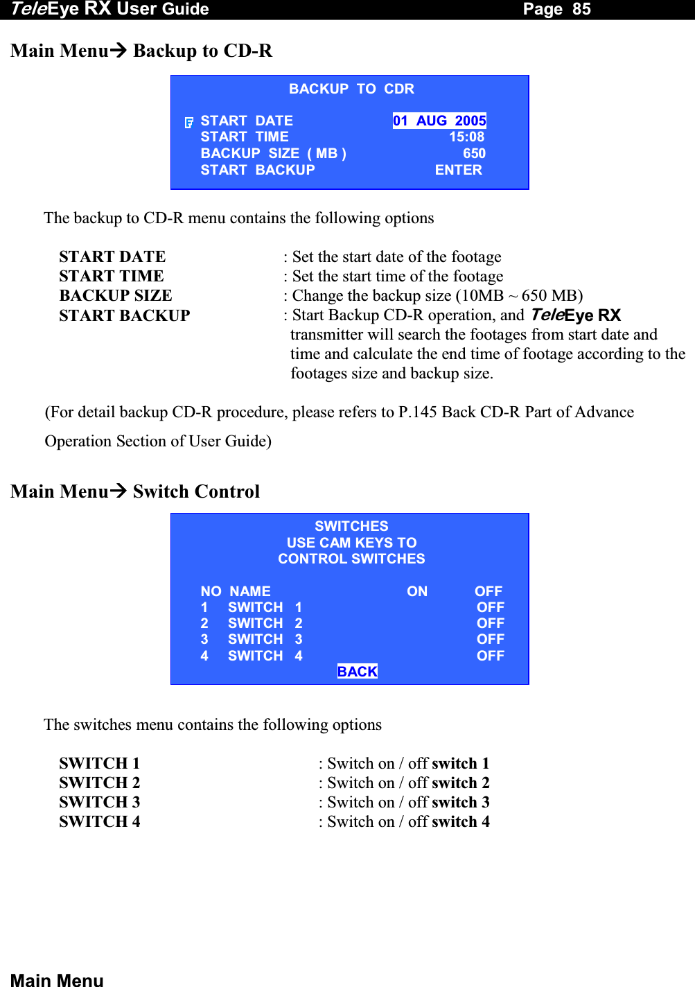
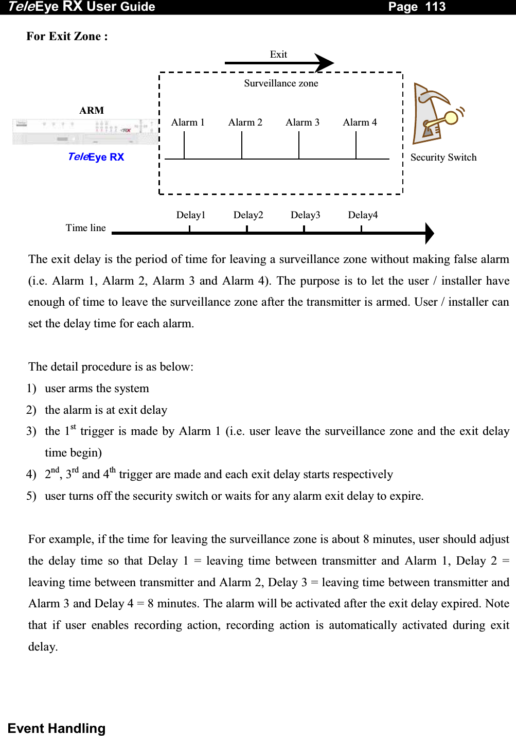
![Tele Eye RX User Guide Page 145 Backup to CD-R E. Backup to CD-R TeleEye RX transmitter supports backup function in a CD-R and provides maximum backup storage size of 650MB. The CD-R will be auto run with the portable player software after inserted into PC. Note that recommended physical size of CD-R should be 120mm / 5.25" Backup to CD-R Setup Procedure Step 1: Press “Menu” button, select [BACKUP TO CD-R] option and press “Enter” button to enter backup to CD-R sub menu. Step 2: Setup the [START DATE], [START TIME] and [BACKUP SIZE] and the transmitter will calculate the end time automatically which depends on backup size and number of camera recorded from the start time. Step 3: Select the above options and press “Enter” button. Use “Up” , “Down” , “Left” and “Right” buttons to set the date, time and size. MAIN MENU SETUP . . . BACKUP TO CD-R . . . SWITCH CONTROL . . . SCAN / FORMAT DISK . . . TRANSMITTER INFO . . . SHUT DOWN ENTERBACKUP TO CDR START DATE 01 AUG 2005 START TIME 15:08 BACKUP SIZE ( MB ) 650 START BACKUP ENTER](https://usermanual.wiki/Signal-Communications/SCRX-051020/User-Guide-668458-Page-151.png)
![Tele Eye RX User Guide Page 146 Backup to CD-R Step 4: Select [START BACKUP] option and press “Enter” button to show [BACKUP RECORDING] message board and it shows user about the end time. Select [YES] option and press “Enter” button to start backup function. Step 5: During the backup preparation, the transmitter will request you to insert a blank CD. Insert a blank CD and press “Enter” button in [YES] option to start the backup process. The transmitter prepares the backup CD file It creates CD Image for burning CD Step 6: After finishing the backup to CD function, press “Enter” button to exit and the CD will be ejected. BACKUP RECORDING START TIME : 18 AUG 2005 10 : 18 END TIME : 18 AUG 2005 12 : 18 START BACKUP ? YES NO BACKUP RECORDING PLEASE INSERT A BLANK CD YES NO BACKUP \ PREPARE CD FILE 30% BACKUP \ CREATE CD IMAGE 30% BACKUP RECORDING BURN CD SUCCESS YES BACKUP \ BURNING CD 30%](https://usermanual.wiki/Signal-Communications/SCRX-051020/User-Guide-668458-Page-152.png)
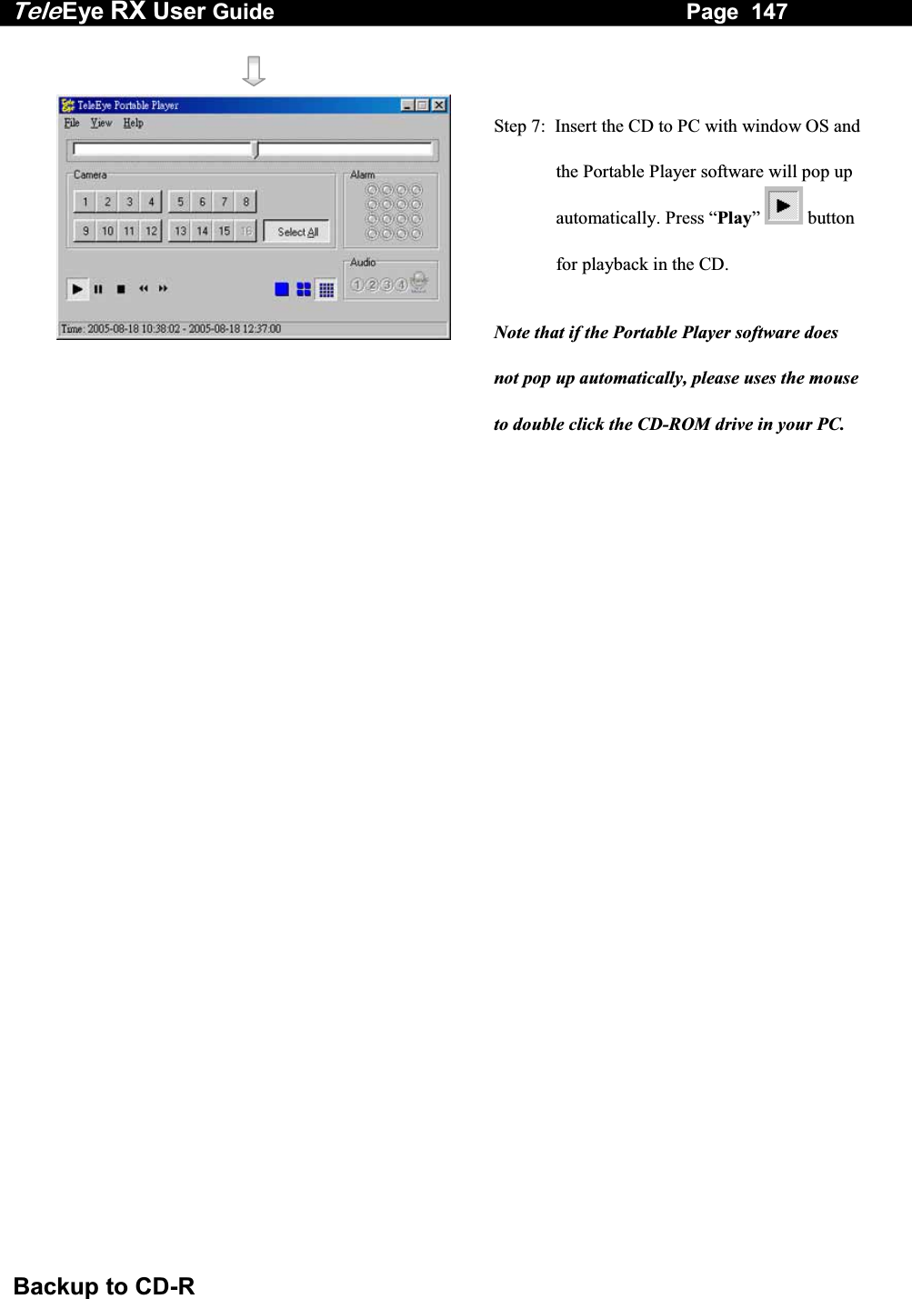
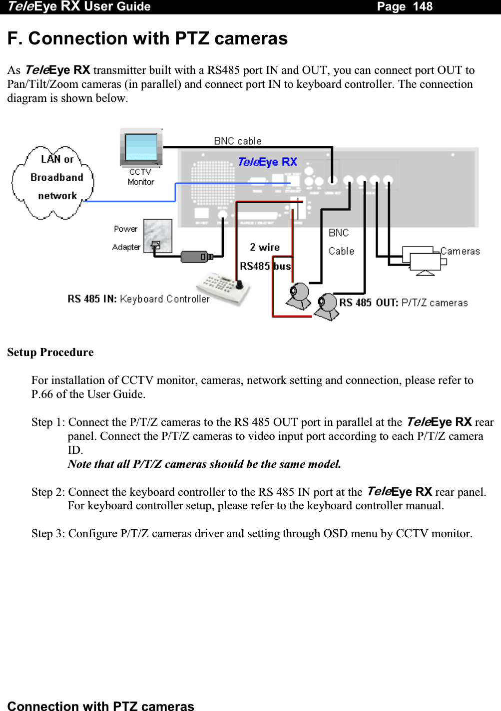
![Tele Eye RX User Guide Page 149 Connection with PTZ cameras Configure P/T/Z cameras driver and setting as follow: Step 4: Press “Menu” button, select [SETUP] option and press “Enter” button to enter [SETUP] sub menu. Select [VIDEO] option and press “Enter” button. Step 5: Select [CAMERA SETTING] option and press “Enter” button to enter the camera setting menu. Select [CAMERA (NO.)] option and press “Enter” button to choose the camera as PTZ camera. Step 6: Select [SUPPORT PTZ] option and use “Left” or “Right” button to choose [YES] option. Select [GENERAL PTZ SETTING] option and press “Enter” button to set the PTZ feature. Step 7: Select [ADVANCED PTZ SETTING] option and press “Enter” button to configure P/T/Z cameras driver and bit rate. SETUP MENU VIDEO . . .RECORDING . . .SWITCHES . . .DATE / TIME . . .CONNECTION . . .EVENT HANDLER . . .TRANSMITTER . . .RESTORE FACTORY SETTING ENTERVIDEO CAMERA SETTING . . . LOCAL MONITORING . . . OSD COLOR BLUE VIDEO FORMAT PAL CAMERA 1 SETTING INSTALL YES NAME CAM 1 SUPPORT PTZ YES GENERAL PTZ SETTING . . . PTZ SETTING PAN SPEED FAST TILT SPEED FAST PTZ MOVEMENT SETTING . . . ADVANCED PTZ SETTING . . .](https://usermanual.wiki/Signal-Communications/SCRX-051020/User-Guide-668458-Page-155.png)
![Tele Eye RX User Guide Page 150 Connection with PTZ cameras Note that if there is no driver to support your P/T/Z cameras, please refer to WX-30 software upload PTZ driver section Step 8: Select [PTZ DRIVER] option and press “Enter” button to select P/T/Z cameras driver. According to the P/T/Z camera model, please select a certain driver for required PTZ camera and press “Enter” button to save the setting. Step 9: Select [BIT RATE] option and use “Left” or “Right” button to set bit rate corresponding to your P/T/Z cameras. Press “Back” button to go to [PTZ SETTING] menu Step 10: Select [PAN SPEED] and [TILT SPEED] options and use “Left” or “Right” button to change the pan (horizontal direction) and tilt (vertical direction) speed of the PTZ camera. Step 11: Select [PTZ MOVEMENT] option and press “Enter” button to change PTZ movement timing setting ADVANCED PTZ SETTING PTZ DRIVER TELEEYE DM S . . . BIT RATE 4800 PTZ SETTING PAN SPEED FAST TILT SPEED FAST PTZ MOVEMENT SETTING . . . ADVANCED PTZ SETTING . . .](https://usermanual.wiki/Signal-Communications/SCRX-051020/User-Guide-668458-Page-156.png)
![Tele Eye RX User Guide Page 151 Connection with PTZ cameras Tilt Up Tilt Down Pan Left Pan Right Zoom In Zoom Out Step 12: User can select different movement direction duration according to whether the PTZ camera support those functions. Step 13: Press “Back” button for several time to exit main menu. Use “Camera Control” buttons (as below) to select the PTZ camera. Step 14: Press “Live” button to show the PTZ Camera Enable menu. You can use “control button” to control PTZ camera. Step 15: Select [YES] option and press “Enter” button to enable PTZ function and the PTZ enable icon shown at the corresponding PTZ camera in CCTV monitor. Step 16: Press “Live” button to enter the PTZ option menu for advance control and disable PTZ camera. PTZ OPTION RECALL PRESET PROGRAM PRESETRECALL PATROL STOP PATROL AUX CTRL IRIS CTRL FOCUS CTRL ZOOM CTRL AUTO DISABLE PTZ ENABLE PTZ ? YES NO PTZ MOVEMENT SETTING PAN DURATION 5 TILT DURATION 5 ZOOM DURATION 3 FOCUS DURATION 3 IRIS DURATION 3 ADDITIONAL DURATION 3 WASHER DURATION 3 WIPER DURATION 3 PATROL SPEED 3 DWELL TIME 2](https://usermanual.wiki/Signal-Communications/SCRX-051020/User-Guide-668458-Page-157.png)