Signal Communications SCRX-051020 TeleEye RX Series User Manual
Signal Communications Limited TeleEye RX Series
User Manual

RX Series
Video Recording Transmitter
RX304
User Guide
Notice:
Signal Communications Limited reserves the right to make improvements to the product
described in this manual at any time and without notice.
This manual is copyrighted. All rights are reserved. This manual should not be copied,
reproduced or translated in whole or part without prior consent from Signal Communications
Limited.
Tele
Eye is a trademark of Signal Communications Limited and is registered in China, European
Communities, Hong Kong, US and other countries.
All other trademarks are the property of their respective owners.
Copyright (c) 2005 Signal Communications Limited (A member of
Tele
Eye Group). All rights
reserved.
Release Version 1.02
Limits of Liability and Disclaimer of Warranty
Signal Communications Limited has taken care in preparation of this manual, but makes no
expressed or implied warranty of any kind and assume no responsibility for errors or omissions.
No liability is assumed for incidental or consequential damages in connection with or arising out
of the use of the information or accessories contained herein.
Features and specifications are subject to change without prior notice.

FCC Statement on Class B
WARNING
Changes or modifications to this unit not expressly approved by the
party responsible for compliance could void the user’s authority to
operate the equipment.
NOTE
This equipment has been tested and found to comply with the limits
for a Class B digital device, pursuant to Part 15 of the FCC Rules.
These limits are designed to provide reasonable protection against
harmful interference in a residential installation. This equipment
generates, uses and can radiate radio frequency energy and, if not
installed and used in accordance with the instructions, may cause
harmful interference to radio communications.
However, there is no guarantee that interference will not occur in a
particular installation. If this equipment does cause harmful
interference to radio or television reception, which can be determine
by turning the equipment off and on, the user is encouraged to try to
correct the interference by one or more of the following measures:
Reorient or relocate the receiving antenna.
Increase the separation between the equipment and receiver.
Connect the equipment into an outlet on a circuit different from
that to which the receiver is needed.
Consult the dealer or an experienced radio/TV technician for help.
Shielded cables must be used with this unit to ensure compliance with
the Class B FCC limits.
Declaration
1. EN 61000-4-2
Under the environment with the electrostatic discharge, the sample may
malfunction and require user to reset the sample.
2. EN 61000-4-4
Under the environment with the electrical fast transient, the sample may
malfunction and require user to reset the sample.
3. EN61000-4-5
Under the environment with the electrical surge, the sample may malfunction and
require user to reset the sample

Table of Contents
SECTION 1
INTRODUCTION
A. Introduction 1
B. Features 2
C. Removing the Packages 3
D. Convention Used in This Manual 4
E. Front Panel Description 5
F. Rear Panel Description 8
SECTION 2
HARD DISK INSTALLATION, FORMATTING AND SCANNING
A. Hard Disk Installation 11
B. Hard Disk Formatting 14
C. Hard Disk Scanning 16
D. Hard Disk Recommendation List 18
SECTION 3
BASIC INSTALLATION FOR LOCAL AND REMOTE MONITORING
A. Setup
Tele
Eye RX for Local CCTV Monitor 19
B. Setup
Tele
Eye RX for LAN Connection with Static IP 22
C. Setup
Tele
Eye RX for Broadband or Narrowband Internet
Connection with Static IP 33
D. Setup
Tele
Eye RX for Broadband or Narrowband Internet
Connection with Dynamic IP 44
E. Setup
Tele
Eye RX for Modem Connection 56
SECTION 4
BASIC OPERATION FOR LOCAL AND REMOTE MONITORING
A. Local CCTV Monitor : Live Monitoring, Recording and Playback 66
I. Live Monitoring 66
II. Recording 67
III. Playback 68
B.
Tele
Eye RX Reception Software WX-30 : Live Monitoring, Recording
and Playback 70
I. Live Monitoring 70
II. Recording 71
III. Playback 72

SECTION 5
OSD MENU OPERATION
A. Main Menu 73
B. Recording Log Menu 87
C. PTZ Menu 89
D. Recording Menu 91
E. Event Menu 92
SECTION 6
ADVANCE OPERATION
A. Install
Tele
Eye RX with Alarm Sensors and Relay Control Port 99
B. Install
Tele
Eye RX with Tamper Circuit and External Resistor 100
C. Event Handling 103
I. Arm/Disarm 104
II. Security Switch 108
III. Alarm 111
IV. Motion 120
V. Videoloss 123
VI. System Tamper 125
VII. Power Failure 127
D. Event Action 129
I. Recording 130
II. Switch 132
III. Dialback 133
IV. Buzzer 138
V. Event LED 140
VI. Live Camera 141
VII. PTZ 143
E. Backup to CD-R 145
F. Connection with PTZ Cameras 148
APPENDIX A
sureLINK TECHNOLOGY 152
How to Apply for sureLINK Address 153
APPENDIX B
GENERAL TERMS DISCUSSION 156
APPENDIX C
SPECIFICATION 157

Tele
Eye RX User Guide Page 1
Introduction
1
INTRODUCTION
A. Introduction
Tele
Eye RX Series Video Recording Transmitter operates with its revolutionary multi-
rate video coder to fulfill the highest video coding requirements for simultaneous transmission
and recording. Seamless video transmission by
Tele
Eye RX can be performed in low and
medium bandwidth communication networks including ADSL, ISDN and PSTN; whilst DVD-
quality videos can be transmitted through LAN and recorded into local hard drive with optimum
speed at 25fps and resolution in 720x576 pixels. Real time recording of up to 100/120fps on all
video channels can also be achieved at CIF resolution.
Tele
Eye RX provides professional and real life security control of premises with its
sophisticated event management scheme. It responses to wide range of events triggered by
external alarm sensor, video motion, power interruption and tamper. There is an arm/disarm
control for the event management mechanism. Every external alarm input is configurable with
an individual entry/exit delay, fire zone and tamper detection setting. Various actions like
sending video back to a designated receiving PC, video recording, email notification, etc.
Tele
Eye RX can also keep a comprehensive log of the events for audit trail.
Tele
Eye RX is designed to fully comply with the British Standard BS 8418:2003,
providing professional remote monitoring and visual alarm verification solution to central
monitoring station.
With a built-in CD-writer, video footage stored inside
Tele
Eye RX can be easily extracted
for evidential purposes. Recorded video can be backed up in CD and played back in any PC
without any special software.
SECTION

Tele
Eye RX User Guide Page 2
Features
B. Features
Hardware Feature
Video recording with rate up to 100/120 fps
Remote and standalone operations
Composite video output with OSD menu
SMAC-M multi-rate video coding technology
Real time video transmission
Up to 60fps over LAN for NTSC
Up to 50fps over LAN for PAL
Excellent picture resolution
up to 720 x 480 pixels for NTSC
up to 720 x 576 pixels for PAL
4-video, 1-audio **, 4 relay switch & 4-alarm inputs
4 additional detection inputs
Removable hard disk
Built-in CD writer
Functional Feature
sureLINK, support both static and dynamic IP
Sophisticated event management
System arm/disarm
Flexible connections : LAN, ADSL, PSTN, ISDN, mobile network, etc.
Triplex operation: simultaneous video monitoring, recording & playback
Video motion detection
Event-driven recording
Pre- & post-alarm video recording
Entry/exit zone configurable on all alarm inputs
Auto alarm dialback
Connection authentication
Compatibility with popular telemetry protocols
Single-site monitoring
Web-based video monitoring **
Programmable video recording **
Data retention **
** : This function will be supported in the
Tele
Eye RX transmitter version 2.00.00 or later

Tele
Eye RX User Guide Page 3
Removing the Packages
C. Removing the Packages
After removing the package, make sure you have the following items:
-
Tele
Eye RX Video Recording Transmitter with Built-in CD Writer
- Hard Disk Cartridge Accessories (Key x 2 and Screw x 4)
- User Guide
- Warranty Card
- Registration Code Sheet
- HDD Recommendation List
- Software CD
- Power Adaptor and Power Cord
- Alarm Port Connector (37 Pins) & Alarm Port Cover
- Resistors (1.2kΩ x 20, 6kΩ x 20)
- Straight-through Ethernet Cable

Tele
Eye RX User Guide Page 4
Convention Used in This Manual
D. Convention Used in This Manual
“ ” : Buttons on the
Tele
Eye RX transmitter front panel
{ } : Hardware Items on the
Tele
Eye RX transmitter besides buttons
[ ] : OSD menu or MS Windows menu
( ) : Refers to other section or page
** : Special remarks
Tele
Eye RX User Guide Page 5
Front Panel Description
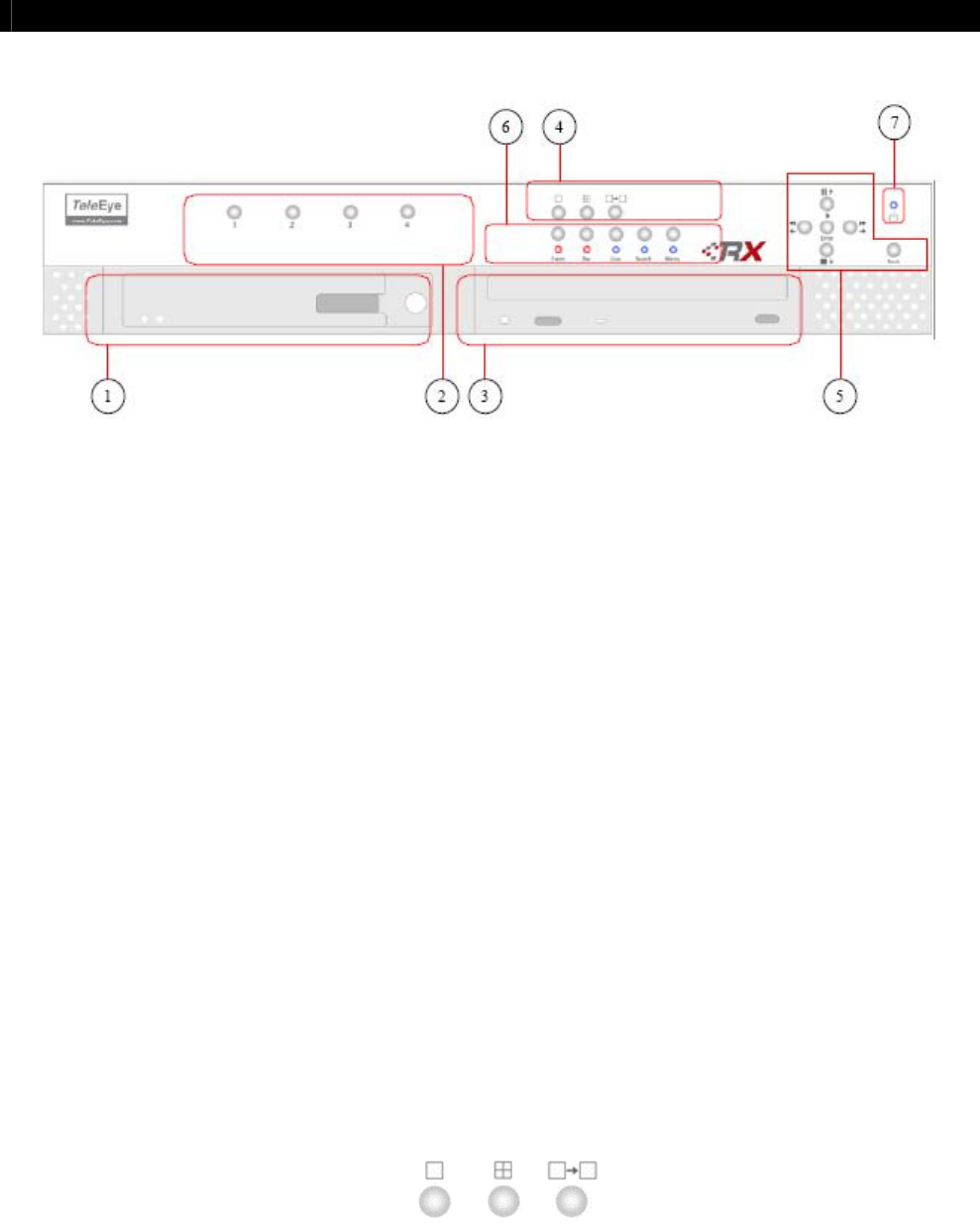
E. Front Panel Description
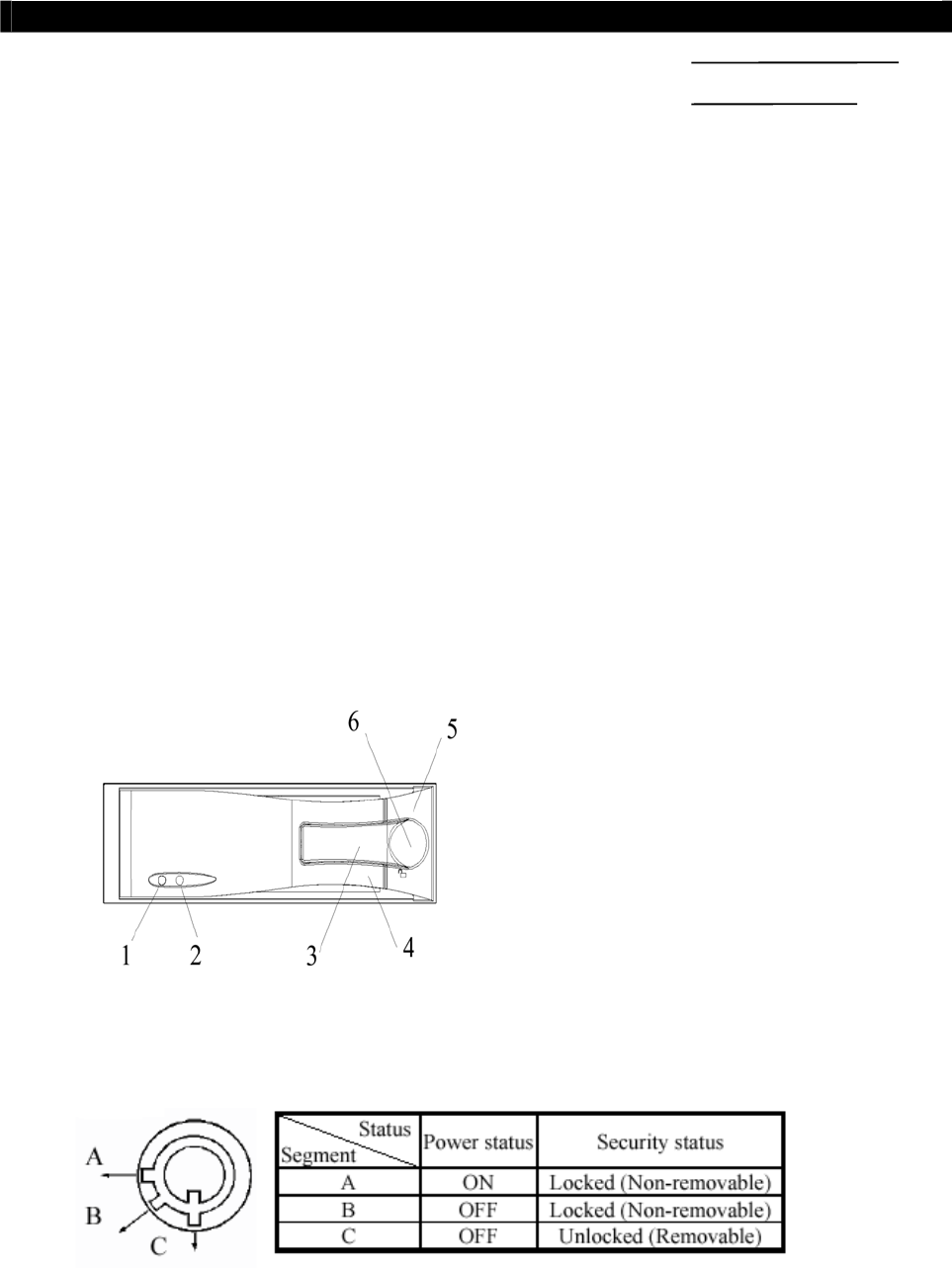
I. Removable Hard Disk
- Built with a removable hard disk cartridge
- {Key Lock} and {Key}are provided to lock the hard disk from unauthorized removing
- {Key} can also be used to enable/disable the power supply to the system
II. Live Camera Control Buttons
- “1”, “2”, “3”, “4”
- “Camera Control” buttons allow user to fast switch to a specific camera for local
monitoring
III. Built-in CD Writer
- {Built-in CD Writer} allows user to back up video to CD-R or CD-RW ( Max size of
650 MB )
IV. Screen Mode Control
- In live mode, the buttons are used to change video display mode in full screen, quad
screen and sequential mode
Tele
Eye RX User Guide Page 6
Front Panel Description
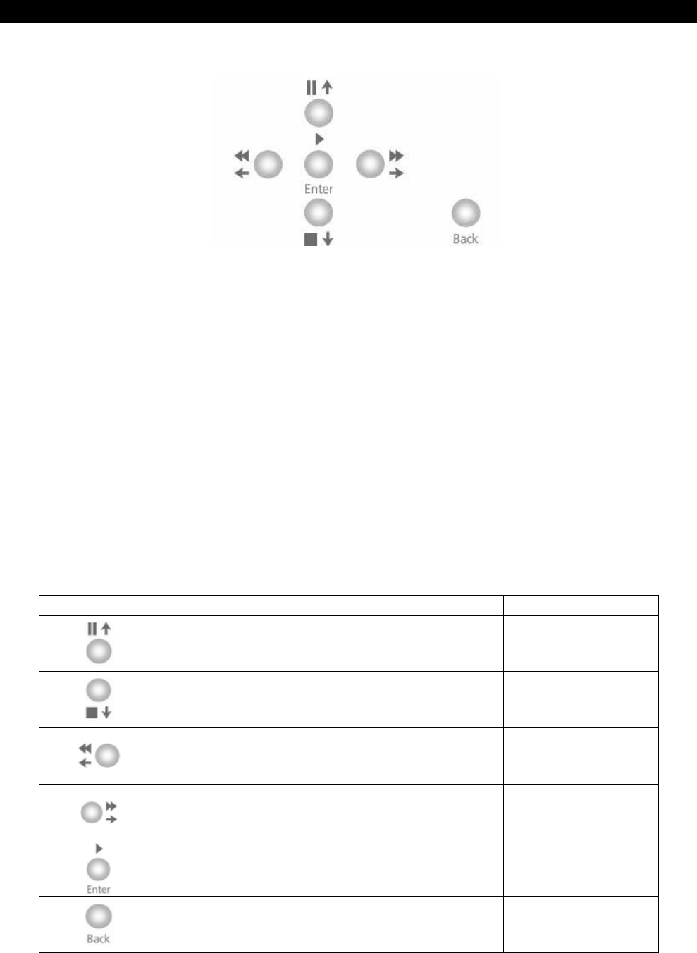
V. Menu Control Buttons / Local Playback Control Buttons / PTZ Control Buttons
In Menu Control Mode,
- The buttons are used as “Up”, “Down”, “Left”, “Right”, “Enter” and “Back” control
In Playback Control Mode,
- The functions are “Pause”, “Stop”, “Fast Backward”, “Fast Forward”, “Play” and
“Back” control
In PTZ Control Mode,
- The functions are “Up”, “Down”, “Left”, “Right”, “Zoom In”, and “Zoom Out”
control
Summary of Control Button
Buttons Menu Control Mode Playback Control Mode PTZ Control Mode
Up Pause Tilt Up
Down Stop Tilt Down
Left Rewind Pan Left
Right Forward Pan Right
Enter Play Zoom In
Back Back Zoom Out
Tele
Eye RX User Guide Page 7
Front Panel Description
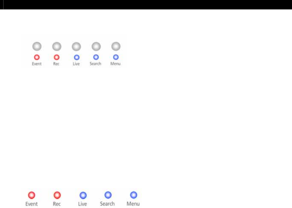
VI. Mode Control Buttons and LED
- These 5 buttons are used for switching between the control modes
- “Event” button : Fast switch to event menu at any time
- “Rec” button : Enable/disable normal recording at any time
- “Live” button : View live video at any time and enable/disable PTZ in live mode
- “Search” button : Fast switch to playback log menu
- “Menu” button : Switch to menu for system settings, recording settings and event
settings etc
Notification LEDs
There are 5 notification LEDs, 2 red color and 3 blue color from left to right.
- {Event LED} : This LED will blink when event is triggered. It will be turned ON
when user press “Event” button to search event log
- {Recording LED} : This LED will be turned ON when the transmitter is recording
- {Live LED} : This LED will be turned ON when user presses “Live” button. It
indicates live mode
- {Search LED} : This LED will be turned ON when user presses the “Play” or
“Search” button. It indicates playback mode
- {Menu LED} : This LED will be turned ON when users press “Menu” button. It
indicates menu mode
VII. Power LED
- {Power LED} : This LED will be turned ON continuously when hard disk rack key
is locked and power switch is turned ON
Tele
Eye RX User Guide Page 8
Rear Panel Description
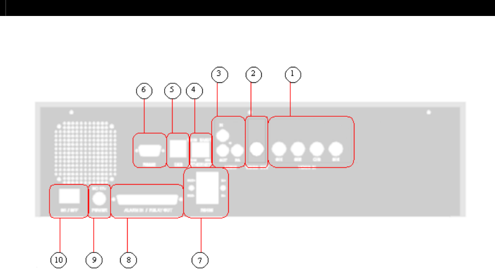
F. Rear Panel Description
I. Video Input Connectors
- Channel 1 – Channel 4 (for
Tele
Eye RX304 only)
- {Standard BNC connectors} for video source input
- A composite video source from camera should be supplied to these connectors
II. Video Output Connector
- A composite video signal with 1V p-p is output from this connector
- Support PAL or NTSC format
- PAL/CCIR format with 625 lines, 50 fields per second
- NTSC/EIA format with 525 lines, 60 fields per second
III. Audio In/Out Port **
- {Audio In} : Connect audio input device (e.g. microphone) with RCA jack to
Tele
Eye RX transmitter for recording
- {Audio Out} : Connect audio output device (e.g. speaker) with RCA jack to
Tele
Eye
RX transmitter and generate output audio signal
- {Audio PA} : Connect audio output device (e.g. speaker) to
Tele
Eye RX transmitter
and generate audio signal as remote public addressing enable
** : This function will be supported in the
Tele
Eye RX transmitter version 2.00.00 or later.

Tele
Eye RX User Guide Page 9
Rear Panel Description
IV. Ethernet Socket (10/100 Base-T)
- This socket is used for connecting
Tele
Eye RX to the corporate computer network (e.g.
LAN)
- This socket includes {COL LED} and {LINK LED}
- {COL LED} : When ON, indicates that collision is occurring on the network
- {LINK LED} : When ON, indicates that
Tele
Eye RX is connecting to the network and
ready to function
V. USB
- For support use only
VI. RS 232 (Modem) Port
- A {DB-9 Male Connector} of DTE format, capable for connecting to DCE such as
modem, ISDN terminal adapter
Pin number Definition Direction
1 CD Input
2 RXD Input
3 TXD Output
4 DTR Output
5 GND –––
6 DSR Input
7 RTS Output
8 CTS Input
9 No use
VII. RS 485 In/Out Port
- {In} : 2-way terminal block for connecting a keyboard controller to
Tele
Eye RX
transmitter in order to control a PTZ camera
- {Out} : 2-way terminal block for connecting a PTZ camera

Tele
Eye RX User Guide Page 10
Rear Panel Description
VIII. Relay Out / Alarm In Port
- 4 relay (also call switch) ports
- 4 alarm ports
- All alarm ports are NC/NO type and none/SEOL/DEOL tamper type input
- All relay ports are latching/push-button type output
IX. Power
- Connect power supply (12V DC, 5A) to
Tele
Eye RX transmitter
X. Switch
- Switch on or off the
Tele
Eye RX transmitter
Tele
Eye RX User Guide Page 11
Hard Disk Installation
1. HDD Activity indicator
2. Power indicator
3. Active-handle
4. Handle
5. Cartridge frame
6. Key lock
2
Hard Disk Installation,
Formatting and Scanning
A. Hard Disk Installation
Tele
Eye RX transmitter supports ATA standard hard disk. User should use the hard disk listed
at the hard disk recommendation list on P.18.
Recommendation : The hard disk is recommended to set to Master Mode. How to set to
Master Mode, please refers to the hard disk case or its manual
Hard Disk Front Panel Description
Key Lock Description
SECTION
Tele
Eye RX User Guide Page 12
Hard Disk Installation
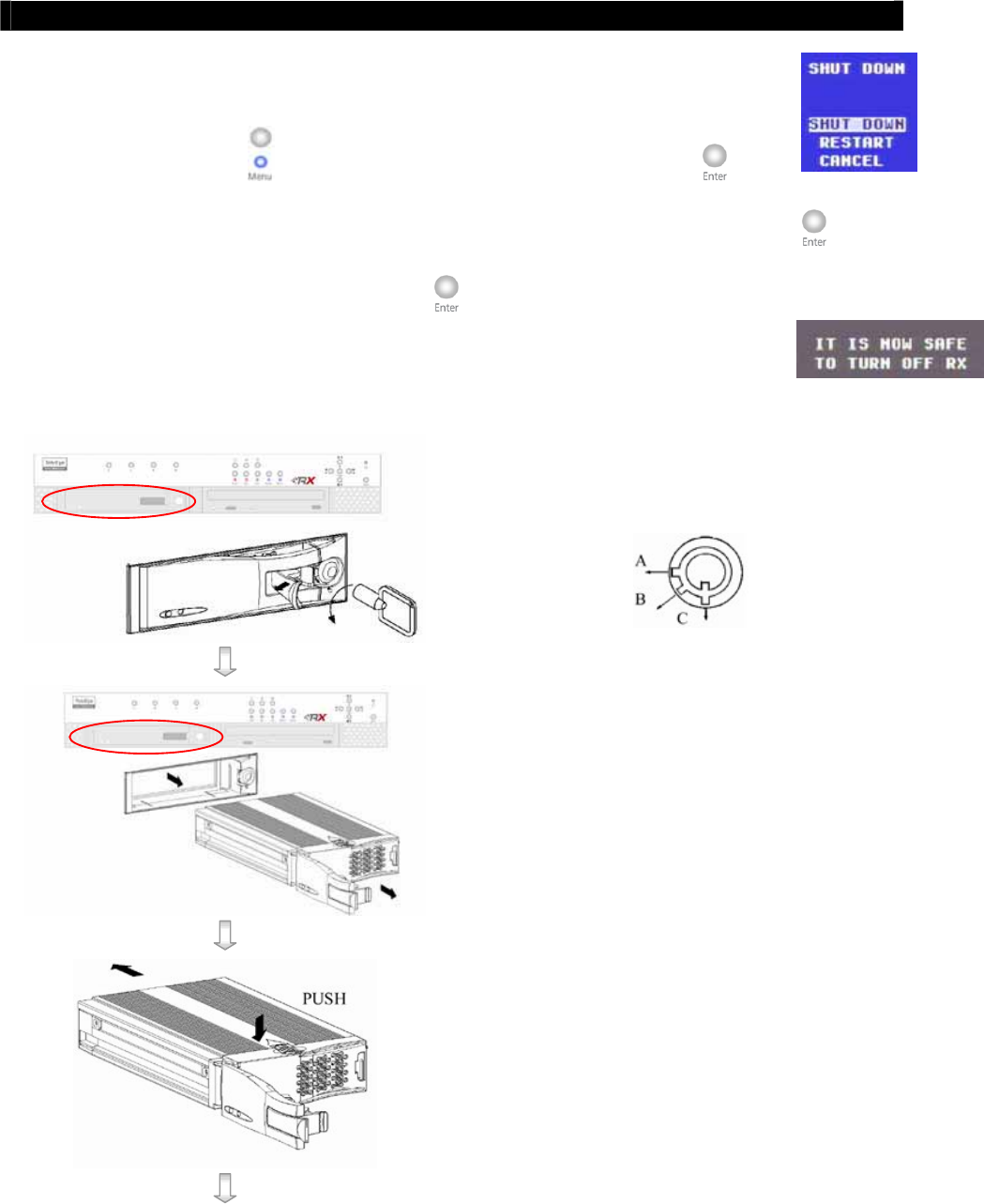
Installation Procedure
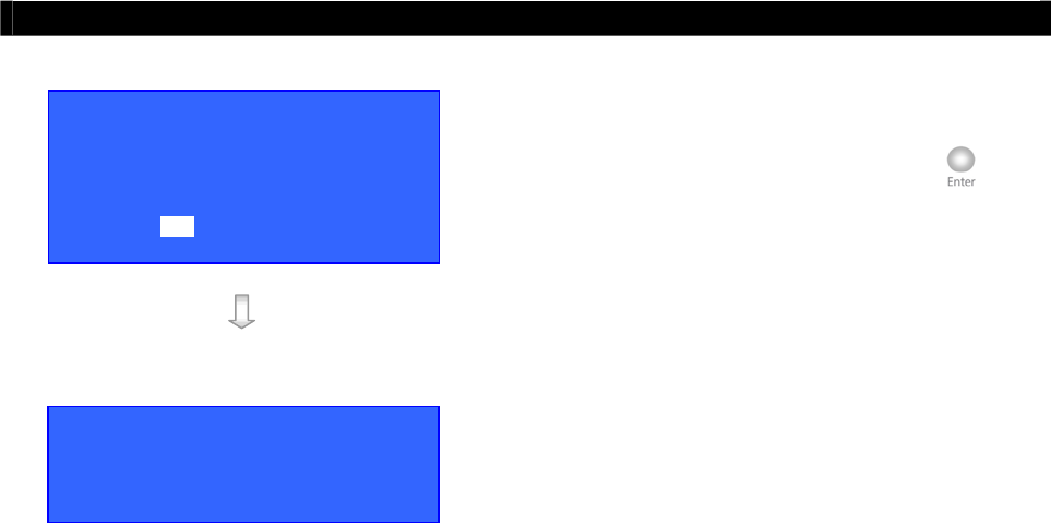
Turn OFF transmitter
Step 1: Press “Menu” button, select [SHUT DOWN] option and press “Enter” button.
Step 2: [SHUT DOWN] menu will pop up and select [SHUT DOWN] option and press “Enter” button.
Step 3: Select [YES] option and press “Enter” button to turn off the transmitter. Switch OFF the
transmitter when the [IT IS NOW SAFE TO TURN OFF RX] message pop up.
Note that you MUST turn OFF the transmitter when install or remove Hard disk.
Step 4: Pull the active-handle outwards, then use the
bundled key provided and insert into the
keyhole, turning the key anti-clockwise
(position C), then you can pull out the handle.
Step 5: Pull the handle outwards to remove the carrier
body away from the cartridge frame.
Step 6: Push the release latch to slide the top cover
backwards and remove.
Tele
Eye RX User Guide Page 13
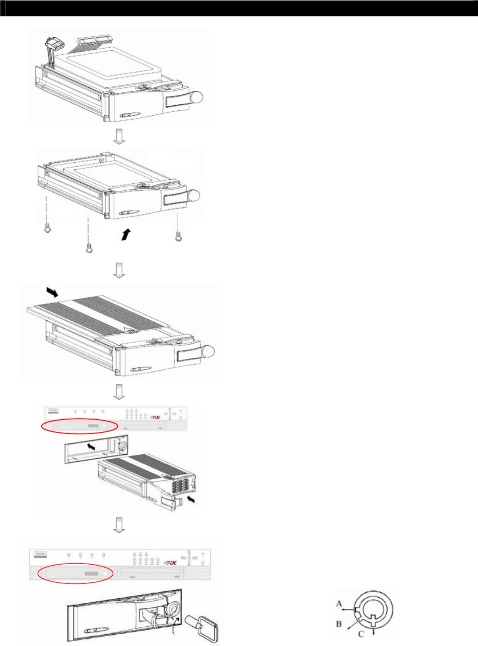
Hard Disk Installation
Step 7: Insert the DC power cable and IDE cable on
the HDD
Step 8: Position the HDD into carrier body and secure
the HDD using the four screws provided.
Step 9: Slide the top cover back to the carrier body by
sliding forward to secure.
Step 10: Slide the carrier body back into the cartridge
frame and push carrier body further into
cartridge frame until fully inserted.
Step 11: Pull the active-handle outwards, then use the
bundled key and insert into the keyhole,
turning the key clockwise (position A) to
secure the handle.

Tele
Eye RX User Guide Page 14
Hard Disk Formatting
B. Hard Disk Formatting
Hard disk formatting will reconstruct the structure of hard disk so that it is readable by
Tele
Eye RX transmitter. If you have your own hard disk to install to
Tele
Eye RX transmitter,
you must perform hard disk formatting.
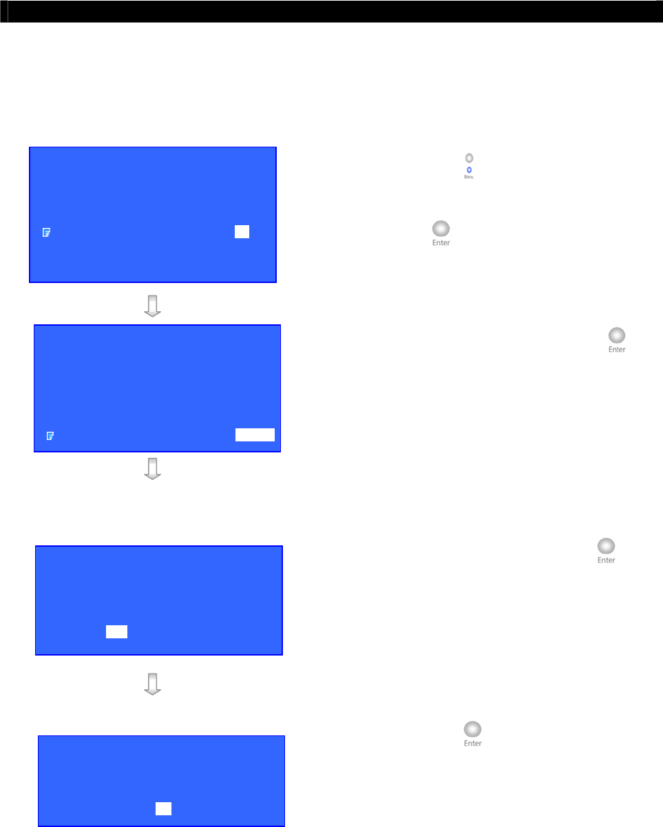
I. New Hard Disk Formatting
It will be used if the hard disk format is NOT
Tele
Eye RX transmitter recognized format.
Usually, a new hard disk, or a hard disk which has been formatted by MS Windows before
needs to do this operation.
Procedure
Step 1: After booting up
Tele
Eye RX transmitter,
OSD menu will pop up [INCORRECT
DISK FORMAT] menu. Select [YES]
option and press “Enter” button to
format new hard disk
[FORMAT DISK] message board will pop up to
show you about the status.
After finishing format process, [SCAN DISK]
processing board will pop up to show you about the
status. The transmitter will restart.
INCORRECT DISK FORMAT
FORMAT NOW ?
YES NO
SCAN DISK
\ SCANNING 90%
FORMAT DISK
\ FORMATTING 90%
Tele
Eye RX User Guide Page 15
Hard Disk Formatting
II. Menu Formatting
It will be used if user wants to format the hard disk so as to have a clean recording space and
redeem the file allocation.
Procedure
Step 1: Press “Menu” button, select
[SCAN/FORMAT DISK] option and press
“Enter” button to enter
[SCAN/FORAMAT DISK] sub menu.
Step 2: Select [FORMAT] option press “Enter”
button.
Warning message board will pop up.
Step 3: Select [YES] option and press “Enter”
button and [FORMAT DISK] board will
pop up to show you about hard disk format
processing status.
Step 4: Press “Enter” button to restart
transmitter when [FORMAT FINISHED]
message board pop up. The transmitter will
restart
MAIN MENU
SETUP . . .
BACKUP TO CD-R . . .
SWITCH CONTROL . . .
SCAN / FORMAT DISK . . .
TRANSMITTER INFO . . .
SHUT DOWN ENTER
SCAN / FORMAT DIS
K
DEVICE TYPE HDD
MODEL NO MAXTOR XXXX
SERIAL NO XXXXXXX
CAPACITY 41GB
DISK USAGE 52%
SCANDISK ENTER
FORMAT ENTER
FORMAT DISK
ALL DATA IN DISK
WILL BE ERASED ,
SURE TO PROCEED ?
YES NO
FORMAT
FORMAT FINISHED ,
SYSTEM WILL RESTART NOW
OK

Tele
Eye RX User Guide Page 16
Hard Disk Scanning
C. Hard Disk Scanning
It is a hard disk maintenance function similar to the Scan Disk function provided by the
Operating System of your personal computer.
Tele
Eye RX transmitter provides this function
so as to rescue the hard disk when errors found, and to enhance its performance and reliability.
After scanning, if there is any damaged file, it will be deleted so that the remaining normal
videos can playback.
It will be used in the following cases:
1. You cannot playback the recorded videos
2. You cannot search the desired video from the recording log. Although you can find it,
you cannot play it
3. You wonder if the hard disk has any problem
Procedures
Step 1: Press “Menu” button, select
[SCAN/FORMAT DISK] option and press
“Enter” button to enter
[SCAN/FORAMT DISK] sub menu.
There is information about the hard disk. If not,
please check that the hard disk is installed or not.
Step 2: Select [SCANDISK] option press “Enter”
button.
MAIN MENU
SETUP . . .
BACKUP TO CD-R . . .
SWITCH CONTROL . . .
SCAN / FORMAT DISK . . .
TRANSMITTER INFO . . .
SHUT DOWN ENTER
SCAN / FORMAT DISK
DEVICE TYPE HDD
MODEL NO MAXTOR XXXX
SERIAL NO XXXXXXX
CAPACITY 40GB
DISK USAGE 52%
SCANDISK ENTER
FORMAT ENTER
Tele
Eye RX User Guide Page 17
Hard Disk Scanning
Warning message board will pop up.
Step 3: Select [YES] option and press “Enter”
button to start the [SCANDISK] process.
Step 4: [SCAN DISK] processing board will pop up
to show you about the status. After finishing
scan disk, it will return to the [SCAN /
FORMAT DISK] menu.
SCAN DISK
ALL RECORDING WILL STOP
DURING SCANDISK
SURE TO PROCEED ?
YES NO
SCAN DISK
\ SCANNING 90%

Tele
Eye RX User Guide Page 18
Hard Disk Recommendation List
D. Hard Disk Recommendation List
Harddisk
Capacity Product Line Model No.
40GB Maxtor DiamondMax 8 (7200 RPM, 2MB Cache) 6E040L0
80GB Maxtor DiamondMax Plus9(7200 RPM, 2MB Cache) 6Y080L0
Maxtor DiamondMax Plus9(7200 RPM, 8MB Cache) 6Y080P0
120GB Maxtor DiamondMax Plus9(7200 RPM, 2MB Cache) 6Y120L0
Maxtor DiamondMax Plus9(7200 RPM, 8MB Cache) 6Y120P0
160GB Maxtor DiamondMax Plus9(7200 RPM, 2MB Cache) 6Y160L0
Maxtor DiamondMax Plus9(7200 RPM, 8MB Cache) 6Y160P0
200GB Maxtor DiamondMax Plus10(7200 RPM, 8MB Cache) 6B200P0
250GB Maxtor MaXLine PlusII(7200 RPM, 8MB Cache) 7Y250P0
Maxtor DiamondMax 10(7200 RPM, 16MB Cache) 6B250R0
300GB Maxtor DiamondMax 10(7200 RPM, 16MB Cache) 6L300R0
400GB Hitachi Deskstar (7200 RPM) HDS724040KLAT80
500GB Hitachi Deskstar (7200 RPM) HDS725050KLAT80
Tele
Eye RX User Guide Page 19
Setup
Tele
Eye RX for Local CCTV Monitor
3
Basic Installation for
Local and Remote
Monitoring
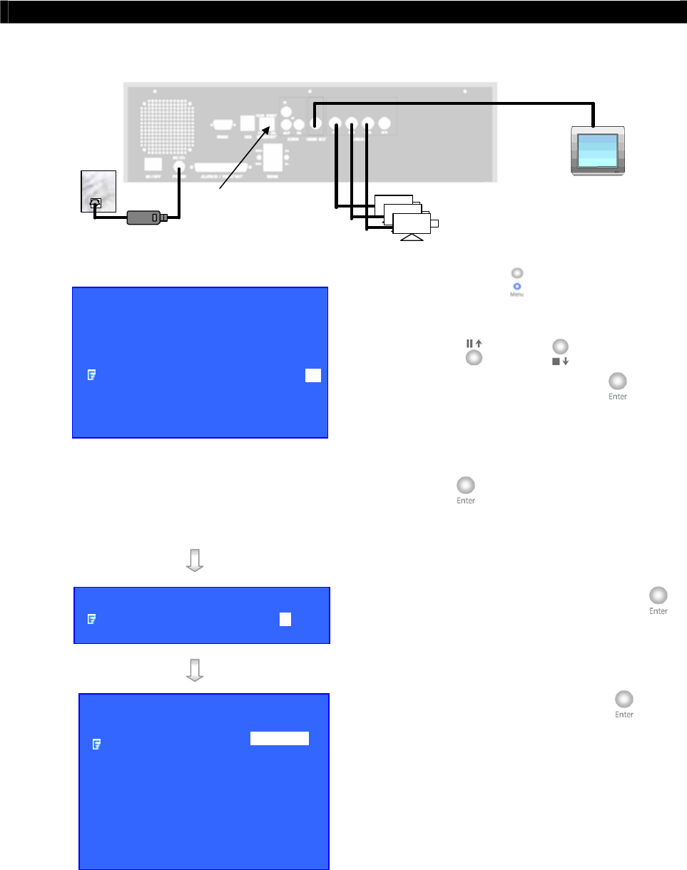
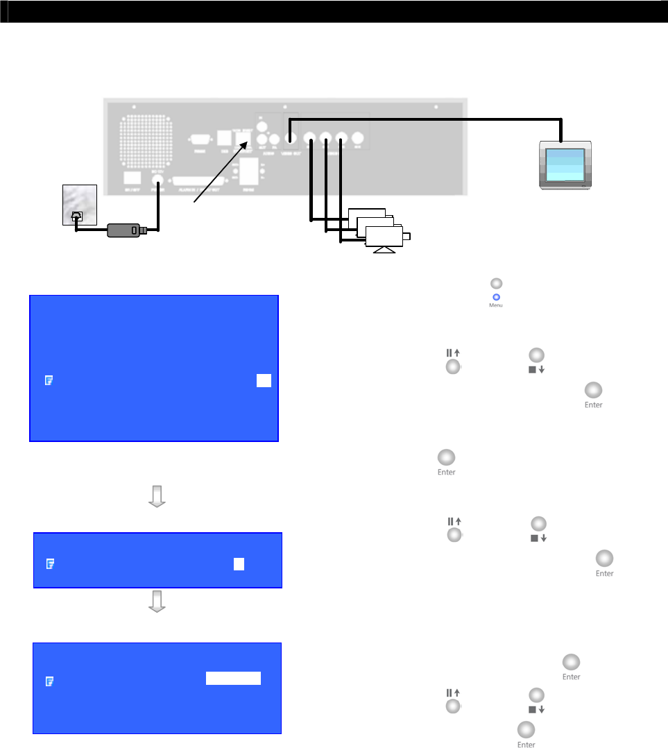
A. Setup
Tele
Eye RX for Local CCTV Monitor
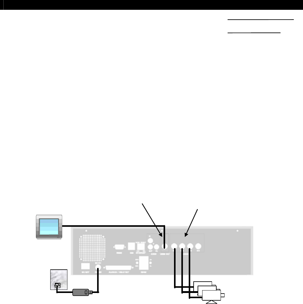
Connection Topology
VIDEO OUT: Connect to
monitor with RG59 cable
and BNC connector
VIDEO IN: Connect to
cameras with RG59 cable
and BNC connector
RG59 cable
RG59 cable
Power Adapter
Tele
Eye RX
Cameras
CCTV
Monitor
Equipment
Tele
Eye RX Transmitter
Cameras
Video Cables (RG-59) with BNC Header
CCTV Monitor
SECTION
Tele
Eye RX User Guide Page 20
Setup
Tele
Eye RX for Local CCTV Monitor
Setup Procedure
Step 1: Connect cameras to
Tele
Eye RX {Video Input} with RG59 cable and BNC
connector.
Note that the cameras system is either NTSC or PAL and suppose all cameras are used
the SAME system forma.(For PTZ camera installation, please refer P.148 to Advance
Operation Section of the User Guide).
Step 2: Connect CCTV monitor to
Tele
Eye RX {Video Output} with RG59 cable and
BNC connector.
Step 3: Install and use the bundled key to lock the {Hard Disk Rack} with hard disk to the
Tele
Eye RX.
Note that you cannot perform any recording and playback if there is no hard disk
installed but still has live video monitoring. (For hard disk installation details, please refer
P.11 to Hard Disk Installation Section of the User Guide)
Step 4: Plug in the power adapter (12V DC, 5A supply) to the
Tele
Eye RX.
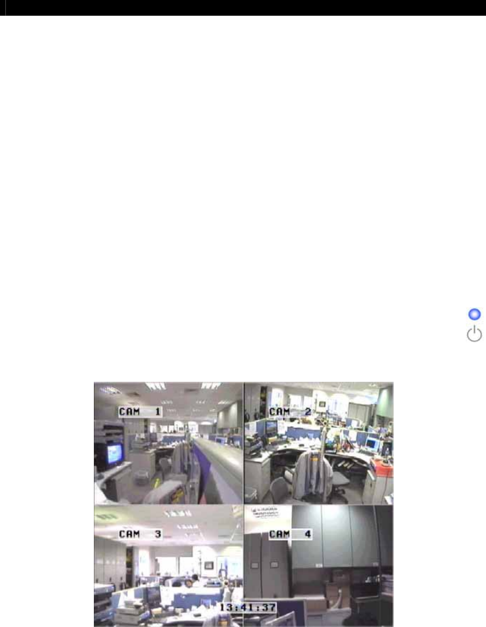
Step 5: Turn on the power of
Tele
Eye RX, camera and CCTV monitor. Check the
{Power LED} which is lit up in blue color continuously at
Tele
Eye RX front
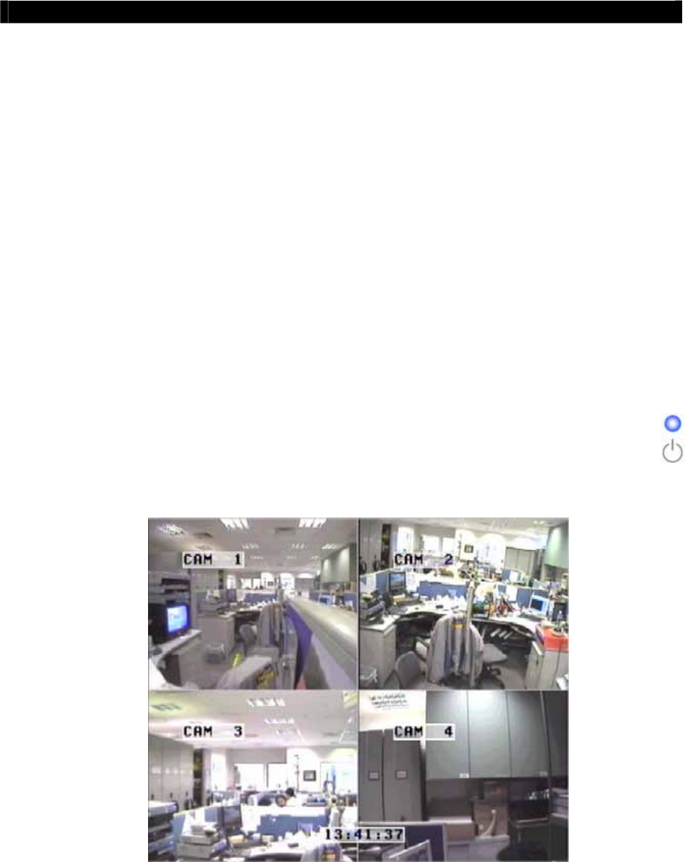
panel after power on. After several seconds, live video appears on the CCTV
monitor as follow:
Note that : Please go through the following steps (6-10) if CCTV Monitor does not show
video clearly
Tele
Eye RX User Guide Page 21
Setup
Tele
Eye RX for Local CCTV Monitor
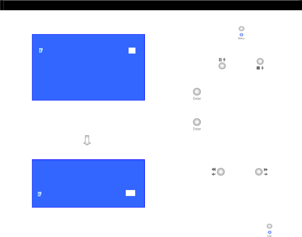
Step 6: Press the “Menu” button to pop up the
[MAIN MENU] on OSD.
Step 7: Use “Up” or “Down” button to select
[SETUP] option and press “Enter” button to
enter the [SETUP] sub-menu.
Step 8: Use “Up” or Down” button to select
[VIDEO] option and press “Enter” button to
enter the [VIDEO] sub-menu.
Step 9: Select [VIDEO FORMAT] and press “Left”
or “Right” button to set either
[NTSC] or [PAL] option. (All cameras should
have the same video format).
Step 10: You can always press “Live” button to exit
any menu operation and start live monitoring.
MAIN MENU
SETUP . . .
BACKUP TO CD-R . . .
SWITCH CONTROL . . .
SCAN / FORMAT DISK . . .
TRANSMITTER INFO . . .
SHUT DOWN ENTER
SETUP MENU
VIDEO . . .
RECORDING . . .
SWITCHES . . .
DATE / TIME . . .
CONNECTION . . .
EVENT HANDLER . . .
TRANSMITTER . . .
RESTORE FACTORY SETTING ENTER
VIDEO
CAMERA SETTING . . .
LOCAL MONITORING . . .
OSD COLOR BLUE
VIDEO FORMAT PAL
Tele
Eye RX User Guide Page 22
Setup
Tele
Eye RX for LAN Connection with Static IP
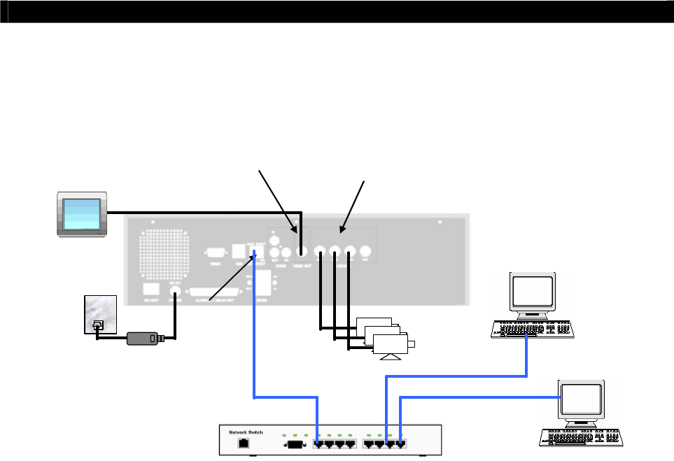
B. Setup
Tele
Eye RX for LAN Connection with Static IP
Connection Topology
VIDEO OUT: Connect to
monitor with RG59 cable
and BNC connector
VIDEO IN: Connect to
cameras with RG59 cable
and BNC connector
RG59 cable
RG59 cable
Power Adapter
Ethernet
Socket
CCTV
Monitor
Tele
Eye RX
Cameras
Network switch
Straight-through Ethernet cable
Equipment
Tele
Eye RX Transmitter
Network Switch
Straight-through Ethernet Cable (bundled)
Cross-over Ethernet Cable
Cameras
Video Cables (RG-59) with BNC Header
CCTV Monitor
CD ROM with WX-30 Software (bundled) (for PC operation only)
PC
PC Requirements
CPU : Pentium IV 2G Hz or above
RAM : 256 MB or above
Display: 800x600, hi-color or better
OS : MS Windows 2000, XP
Tele
Eye RX User Guide Page 23
Setup
Tele
Eye RX for LAN Connection with Static IP
Setup Procedure
Step 1: Connect cameras to
Tele
Eye RX {Video Input} with RG59 cable and BNC
connector.
Note that the cameras system is either NTSC or PAL and suppose all cameras are used the
SAME system format.(For PTZ camera installation, please refer P.148 to Advance Operation
Section of the User Guide).
Step 2: Connect CCTV monitor to
Tele
Eye RX {Video Output} with RG59 cable and BNC
connector.
Step 3: Install and use the bundled key to lock the {Hard Disk Rack} with hard disk to the
Tele
Eye RX.
Note that you cannot perform recording and playback if there is no hard disk installed but
still has live video monitoring. (For hard disk installation details, please refer P.11 to Hard
Disk Installation Section of the User Guide)
Step 4: Connect the power adapter (12V DC, 5A supply) to the
Tele
Eye RX.
Step 5: Turn on the power of
Tele
Eye RX, camera and CCTV monitor. Check the {Power
LED} which is lit up in blue color continuously at
Tele
Eye RX front panel after
power on. After several seconds, live video appears on the CCTV monitor as follow:
Note that: Please go through the following steps (6-10) if the video of CCTV Monitor does
not show clearly.
Tele
Eye RX User Guide Page 24
Setup
Tele
Eye RX for LAN Connection with Static IP
Step 6: Press the “Menu” button to pop up the
[MAIN MENU] on OSD.
Step 7: Use “Up” or “Down” button to
select [SETUP] option and press “Enter”
button to enter the [SETUP] sub-menu.
Step 8: Select [VIDEO] option and press “Enter”
button to enter the [VIDEO] sub-menu
Step 9: Select [VIDEO FORMAT] and press
“Left” or “Right” button to set
either [NTSC] or [PAL] option. (All
cameras should have the same video
format).
Step 10: You can always press “Live” button to
exit any menu operation and start live
monitoring.
Setup
Tele
Eye RX transmitter IP through CCTV monitor, please go to step 11a.
Setup
Tele
Eye RX transmitter IP through PC, through PC, please go to step11b.
VIDEO
CAMERA SETTING . . .
LOCAL MONITORING . . .
OSD COLOR BLUE
VIDEO FORMAT PAL
SETUP MENU
VIDEO . . .
RECORDING . . .
SWITCHES . . .
DATE / TIME . . .
CONNECTION . . .
EVENT HANDLER . . .
TRANSMITTER . . .
RESTORE FACTORY SETTING ENTER
Tele
Eye RX User Guide Page 25
Setup
Tele
Eye RX for LAN Connection with Static IP
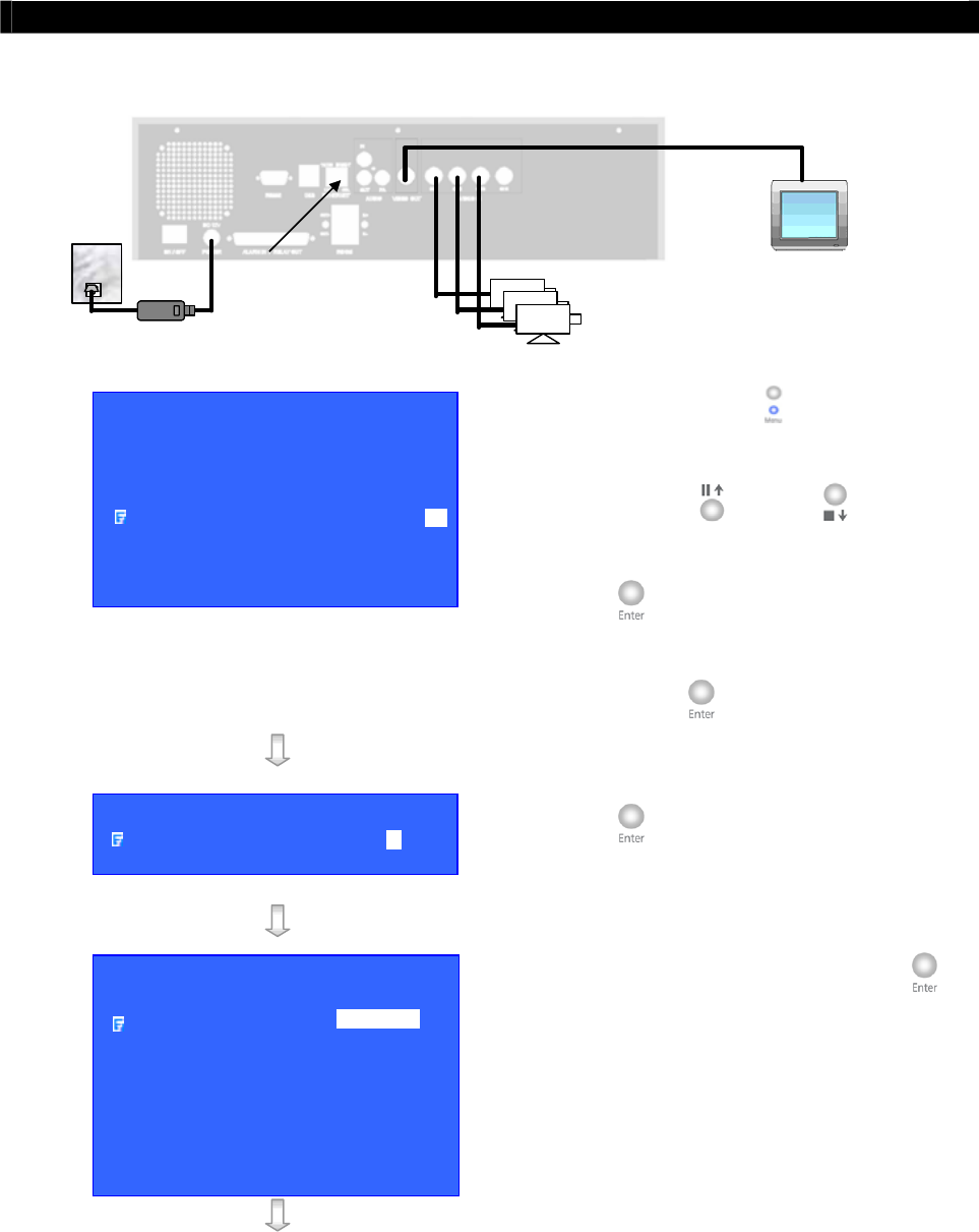
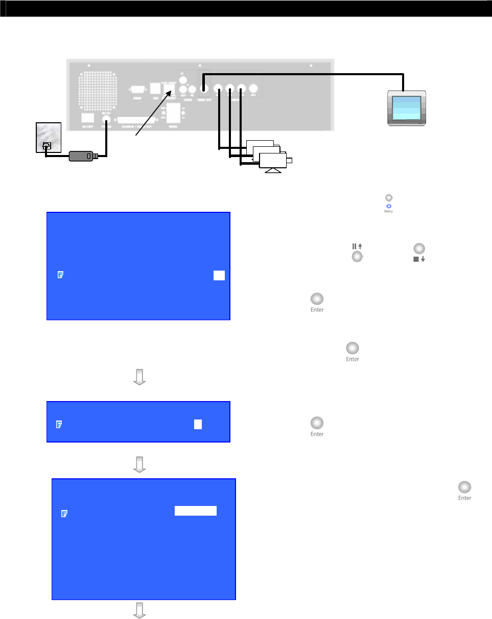
Step 11a: Configure
Tele
Eye RX transmitter IP setting through CCTV Monitor
RG59 cable
Power Adapter
Ethernet
Socket
Tele
Eye RX
Cameras
CCTV
Monitor
RG59 cable
192.168.0.2
Press the “Menu” button such that the OSD
main menu opens on the monitor.
Use “Up” or “Down” button to select
[SETUP] option and press “Enter” button
to enter [SETUP] sub menu.
Select [CONNECTION] option and press
“Enter” button to enter connection setting
menu.
Select [TCP/IP] option and Press “Enter”
button
Select [IP] option and press “Enter” button.
IP address consists of four fields. Each field can
assign a number from 0 to 255
SETUP MENU
VIDEO . . .
RECORDING . . .
SWITCHES . . .
DATE / TIME . . .
CONNECTION . . .
EVENT HANDLER . . .
TRANSMITTER . . .
RESTORE FACTORY SETTING ENTER
CONNECTION
TCP / IP …
MODEM …
TCP / IP
IP 192.168.0.2
PORT 1024
SUBNET MASK 255.255.255.0
ENABLE GATEWAY NO
GATEWAY 0.0.0.0
ENABLE DNS NO
PRIMARY DNS 0.0.0.0
SECONDARY DNS 0.0.0.0
SURELINK …

Tele
Eye RX User Guide Page 26
Setup
Tele
Eye RX for LAN Connection with Static IP
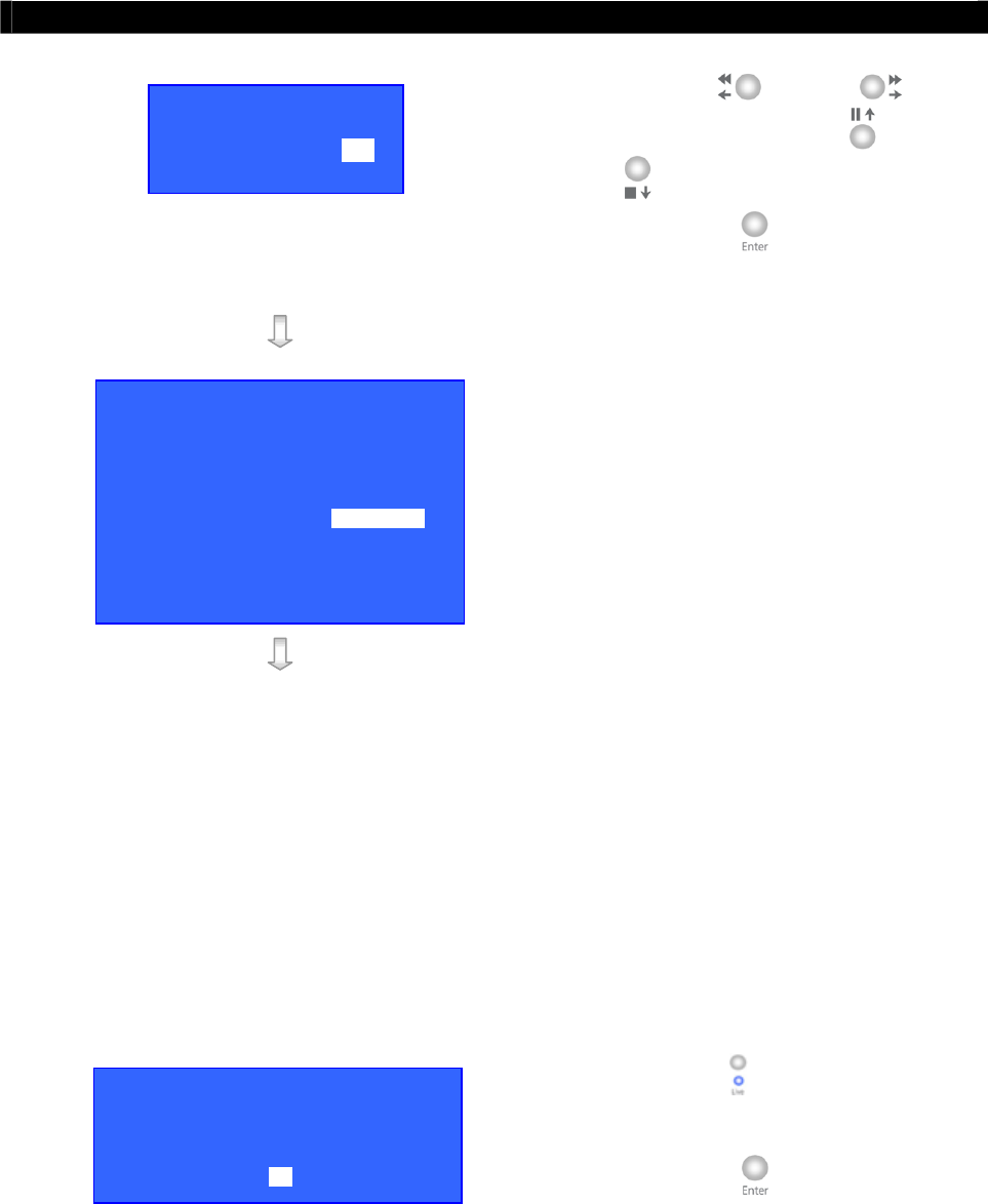
Use “Left” or “Right” button to
select field and use “Up” or “Down”
button to set number.
Press “Enter” button to save the change and
return previous menu.
Follow the network setting and assign a valid
subnet mask to [SUBNET MASK] and select
[ENABLE GATEWAY] option and input
[GATEWAY] option in similar way.
Note that the DNS setting is optional which is
useful for sureLINK, time synchronization**
or e-mail notification function**.
ʽʽʳˍʳ˧˻˼̆ʳ˹̈́˶̇˼̂́ʳ̊˼˿˿ʳ˵˸ʳ̆̈̃̃̂̅̇˸˷ʳ˼́ʳ̇˻˸ʳ
Tele
EyeʳRXʳ̇̅˴́̆̀˼̇̇˸̅ʳ̉˸̅̆˼̂́ʳ˅ˁ˃˃ˁ˃˃ʳ̂̅ʳ˿˴̇˸̅ʳ
Press “Live” button, then [SETTING
MODIFIED] message board will pop up. Press
“Enter” button to restart the
Tele
Eye RX.
IP
IP : 210. 17.139.145
TCP / IP
IP 210.17.139.145
PORT 1024
SUBNET MASK 255.255.255.0
ENABLE GATEWAY YES
GATEWAY 210.17.139.1
ENABLE DNS NO
PRIMARY DNS 0.0.0.0
SECONDARY DNS 0.0.0.0
SURELINK …
SETTING MODIFIED
SETTING WILL TAKE EFFECT
AFTER RESTART ,
PRESS ENTER TO CONTINUE
OK
Tele
Eye RX User Guide Page 27
Setup
Tele
Eye RX for LAN Connection with Static IP
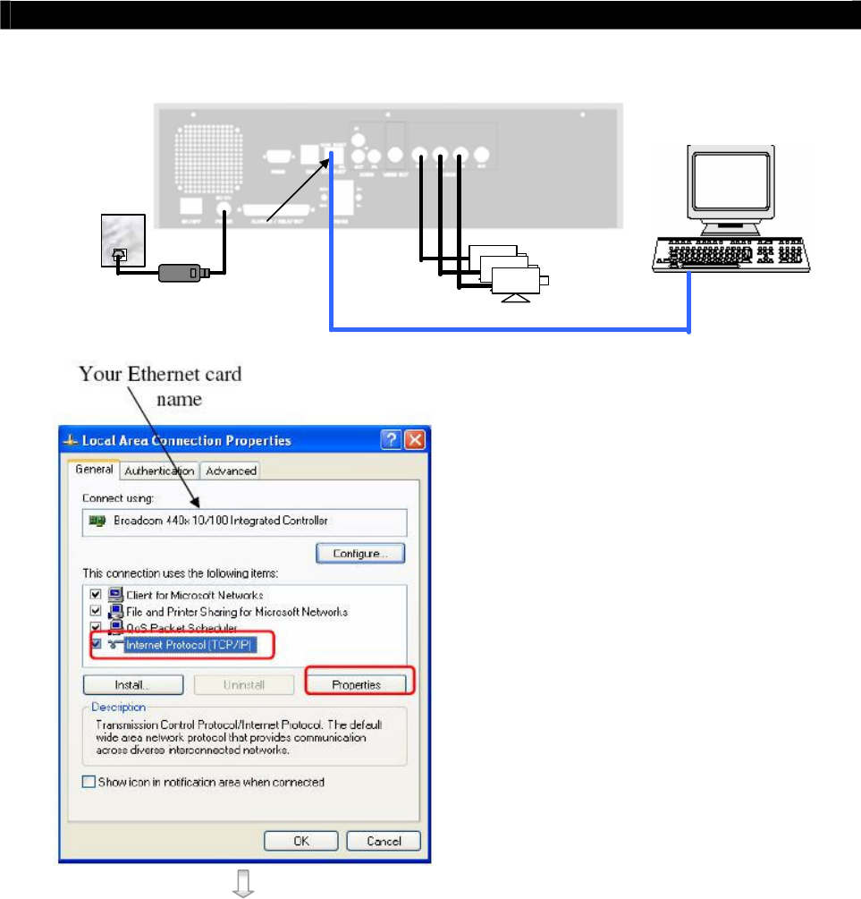
Step 11b: Configure
Tele
Eye RX transmitter IP setting through PC
RG59 cable
Power Adapter
Ethernet
Socket
Te l e
Eye RX
Cameras
192.168.0.2
192.168.0.3
Cross-over Ethernet Cable
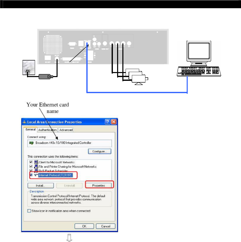
In Windows 2000/XP desktop, select
Start > Control Panel
Double click Network and Dial-up
Connections > right click Local Area
Connections and choose Properties.
Choose Internet Protocol (TCP/IP) and
click Properties

Tele
Eye RX User Guide Page 28
Setup
Tele
Eye RX for LAN Connection with Static IP
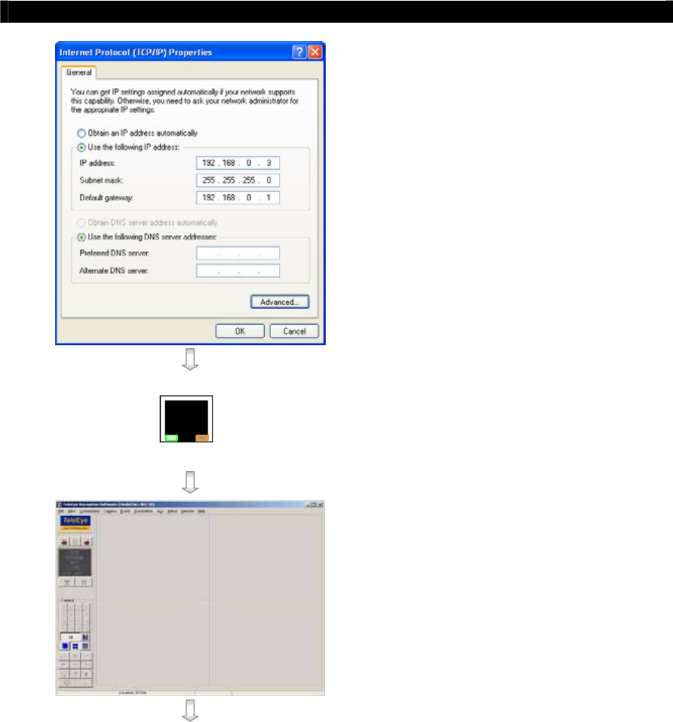
Enter an IP address, subnet mask and
Default gateway. Note that IP address
should be “192.168.0.xx” except
“192.168.0.2” which is
Tele
Eye RX
default IP address.
Enter the Preferred and Alternate DNS
server, if necessary.
Click OK to activate the new IP.
You have to confirm that IP address has
been correctly set on your computer. On
your windows, click start > run, type
“cmd” at open field, press OK button,
type “ipconfig” on the DOS prompt and
you will see an IP set on your computer.
10/100 BASE-T
LINK COL
Connect the PC Ethernet socket to the
transmitter Ethernet socket at rear panel of
the transmitter with cross-over Ethernet
cable. Check if the {LINK LED} of the
transmitter is turned ON.
Run WX-30 software which has been
installed to the PC. (For details of WX-30
software installation, please refer to WX-
30 Software Guide)
Tele
Eye RX User Guide Page 29
Setup
Tele
Eye RX for LAN Connection with Static IP
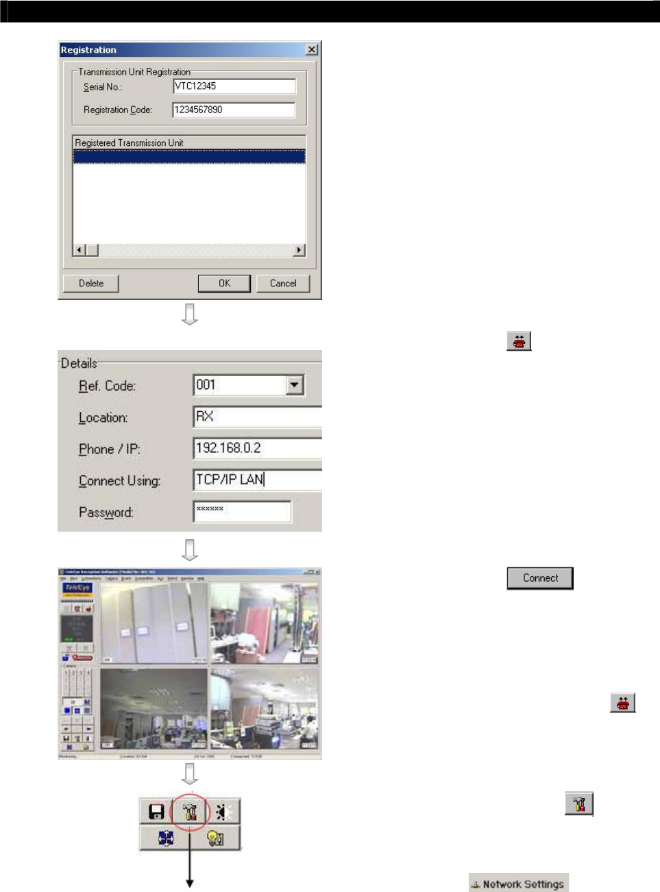
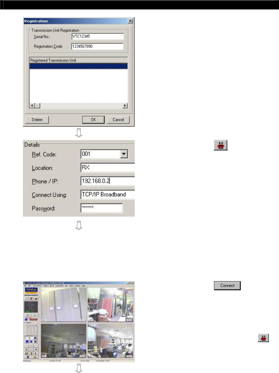
Choose [Transmitter]
[Registration]
to register the
Tele
Eye RX transmitter.
User needs to input transmitter serial
number and registration code.
For example :
Serial No. : VTC12345
Registration Code : 1234567890
Press [Connect] icon to pop up the
[Connect Window]. Type and select the
following setting :
Phone/IP : 192.168.0.2
Connect Using: TCP/IP LAN
Password: 000000
IP (192.168.0.2) and Password (000000)
are default setting of
Tele
Eye RX
Press [Connect] icon to
connect your PC to the transmitter. Live
video is shown on the WX-30 if success.
Otherwise, the [Warning] board will pop
up and show you failure message. For
failure case, please press [Connect]
icon to check that the connection setting is
valid or not.
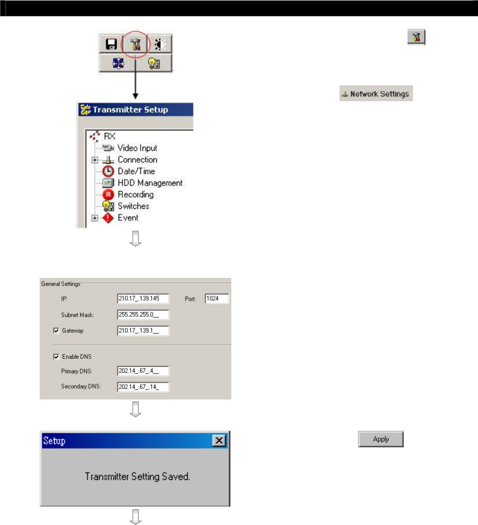
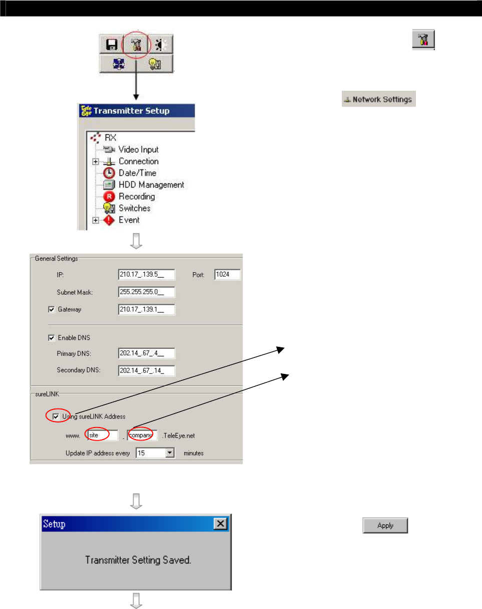
Press [Transmitter Setup] icon to
show
Tele
Eye RX configuration menu.
Select [Connection] and press [Network
Settings
]
icon to
Tele
Eye RX User Guide Page 30
Setup
Tele
Eye RX for LAN Connection with Static IP
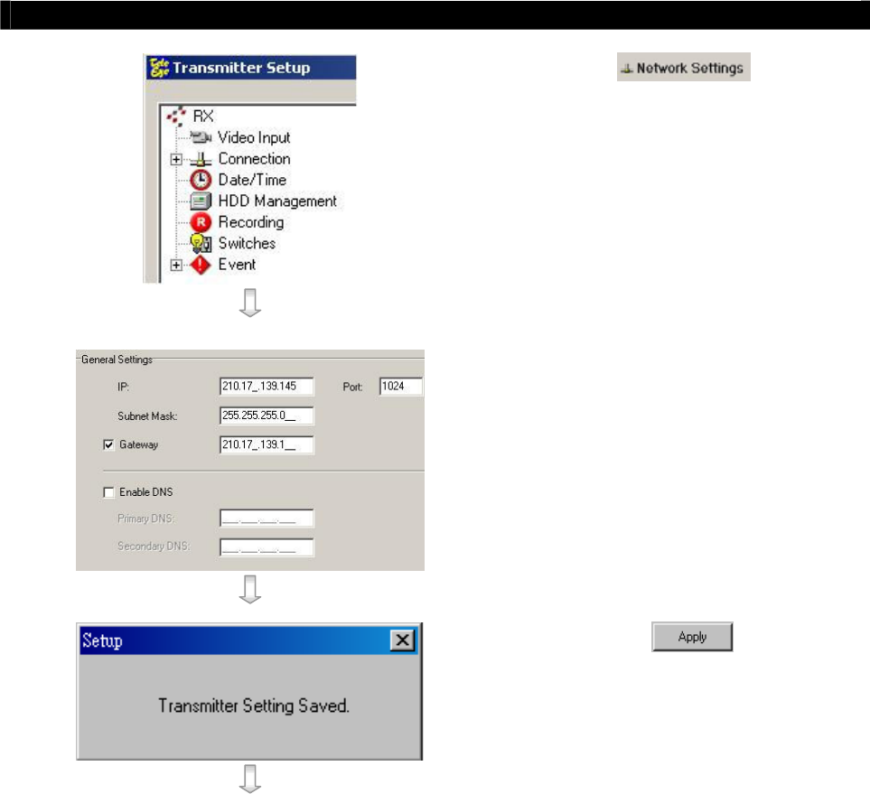
Settings] icon to
configure network setting.
Change the IP from 192.168.0.2 to
210.17.139.145 (for example). Gateway
setting is used for WAN. Primary and
Secondary DNS setting are used for
sureLINK, time synchronization ** or e-
mail notification function **.
** : This function will be supported in the
Tele
Eye RX transmitter version 2.00.00
or later
Press [Apply] icon to save the
network setting and pop up the message
board. After several seconds, the
transmitter will restart automatically.
Tele
Eye RX User Guide Page 31
Setup
Tele
Eye RX for LAN Connection with Static IP
10/100 BASE-T
LINK COL
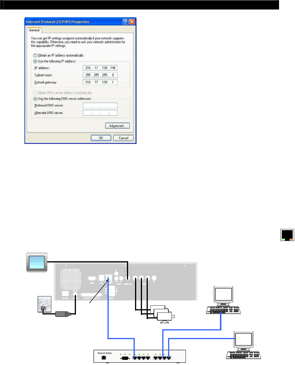
In Windows 2000/XP desktop, select
Start > Control Panel
Double click Network and Dial-up
Connections > right click Local Area
Connections and choose Properties.
Choose Internet Protocol (TCP/IP) and
click Properties
Enter the IP address, subnet mask and
Default gateway for the PC to restore to
its original network configuration. Note
that the first 3 field of IP address should
be same as
Tele
Eye RX transmitter IP
and gateway address. IP address is
“210.17.139.146” and gateway address is
“210.17.139.1” in this example.
Click OK to apply the setting
Step 12: Disconnect the
Tele
Eye RX transmitter and current PC. Reconnect the transmitter
and current PC to the LAN network through straight-through Ethernet cable.
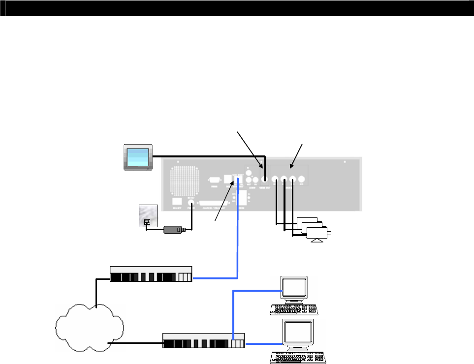
Step 13: Check Ethernet socket of both
Tele
Eye RX transmitter and PC to ensure that the
{GREEN LINK LED} turns ON. Then connection diagram is shown as follows:
RG59 cable
RG59 cable
Power Adapter
Ethernet
Socket
CCTV
Monitor
Tele
Eye RX
Cameras
Network switch
210.17.139.145
210.17.139.146
210.17.139.147
Straight-through Ethernet cable
Tele
Eye RX User Guide Page 32
Setup
Tele
Eye RX for LAN Connection with Static IP
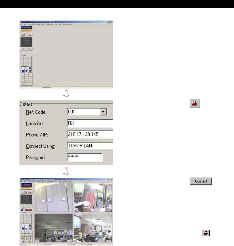
Step 14: Run WX-30 software at any local
network PC. (For details of WX-30
software installation, please refer to
WX-30 Software Guide)
Step 15: Press [Connect] icon to pop up
the [Connect Window]. For
example, type and select the
following setting :
Phone/IP : 210.17.139.145
Connect Using: TCP/IP LAN
Password: 000000
Step 16: Press [Connect] icon to
connect your PC and the transmitter.
The video appears on the WX-30 if
success. Otherwise, the [Warning]
board will pop up and show you
failure message. For failure case,
please press [Connect] icon to
check that the connection setting is
valid or not.
Tele
Eye RX User Guide Page 33
Setup
Tele
Eye RX for Broadband or Narrowband
Internet Connection with Static IP
C. Setup
Tele
Eye RX for Broadband or Narrowband
Internet Connection with Static IP
Connection Topology
VIDEO OUT: Connect to
monitor with RG59 cable and
BNC connector
VIDEO IN: Connect to
cameras with RG59 cable
and BNC connector
RG59 cable
RG59 cable
Power Adapter
Ethernet
Socket
CCTV
Monitor
Tele
Eye RX
Cameras
Internet
Router/Gateway
Router/Gateway
Straight-through Ethernet cable
Straight-through Ethernet cable
Remark for Internet Connection Definition
Broadband : Connection speed is 128kbps or above, e.g. ADSL, DSL.
Narrowband : Connection speed is below 128kbps, e.g. dial up network, GPRS
Equipment
Tele
Eye RX Transmitter
Network Switch, Router/Gateway
Straight-through Ethernet Cable (bundled)
Cross-over Ethernet Cable
Cameras, Video Cables (RG-59) with BNC Header
CCTV Monitor
CD ROM with WX-30 Software (bundled) (for PC operation only)
PC
PC Requirements
CPU : Pentium IV 2G Hz or above
RAM : 256 MB or above
Display: 800x600, hi-color or better
OS : MS Windows 2000, XP
Tele
Eye RX User Guide Page 34
Setup
Tele
Eye RX for Broadband or Narrowband
Internet Connection with Static IP
Setup Procedure
Step 1: Connect cameras to
Tele
Eye RX {Video Input} with RG59 cable and BNC
connector.
Note that the cameras system is either NTSC or PAL and suppose all cameras are used the
SAME system format. (For PTZ camera installation, please refer P.148 to Advance Operation
Section of the User Guide).
Step 2: Connect CCTV monitor to
Tele
Eye RX {Video Output} with RG59 cable and BNC
connector.
Step 3: Install and use the bundled key to lock the {Hard Disk Rack} with hard disk to the
Tele
Eye RX.
Note that you cannot perform recording and playback if there is no hard disk installed but
still has live video monitoring. (For hard disk installation details, please refer P.11 to Hard
Disk Installation Section of the User Guide)
Step 4: Connect the power adapter (12V DC, 5A supply) to the
Tele
Eye RX.
Step 5: Turn on the power of
Tele
Eye RX, camera and CCTV monitor. Check the {Power
LED} which is lit up in blue color continuously at
Tele
Eye RX front panel after
power on. After several seconds, live video appears on the CCTV monitor as follow:
Note that: Please go through the following steps (6-10) if the video of CCTV Monitor does
not show clearly.
Tele
Eye RX User Guide Page 35
Setup
Tele
Eye RX for Broadband or Narrowband
Internet Connection with Static IP
Step 6: Press the “Menu” button to pop up the
[MAIN MENU] on OSD.
Step 7: Use “Up” or “Down” button to
select [SETUP] option and press “Enter”
button to enter the [SETUP] sub-menu.
Step 8: Select [VIDEO] option and press “Enter”
button to enter the [VIDEO] sub-menu.
Step 9: Select [VIDEO FORMAT] and press
“Left” or “Right” button to set
either [NTSC] or [PAL] option. (All
cameras should have the same video
format).
Step 10: You can always press “Live” button to
exit any menu operation and start live
monitoring.
Setup
Tele
Eye RX transmitter IP through CCTV monitor, please go to step 11a.
Setup
Tele
Eye RX transmitter IP through PC, through PC, please go to step11b.
MAIN MENU
SETUP . . .
BACKUP TO CD-R . . .
SWITCH CONTROL . . .
SCAN / FORMAT DISK . . .
TRANSMITTER INFO . . .
SHUT DOWN ENTER
VIDEO
CAMERA SETTING . . .
LOCAL MONITORING . . .
OSD COLOR BLUE
VIDEO FORMAT PAL
SETUP MENU
VIDEO . . .
RECORDING . . .
SWITCHES . . .
DATE / TIME . . .
CONNECTION . . .
EVENT HANDLER . . .
TRANSMITTER . . .
RESTORE FACTORY SETTING ENTER
Tele
Eye RX User Guide Page 36
Setup
Tele
Eye RX for Broadband or Narrowband
Internet Connection with Static IP
Step 11a: Configure
Tele
Eye RX transmitter IP setting through CCTV Monitor
RG59 cable
Power Adapter
Ethernet
Socket
Te l e
Eye RX
Cameras
192.168.0.2
CCTV
Monitor
RG59 cable
Press the “Menu” button such that the
OSD main menu pops up on the monitor.
Use “Up” or “Down” button to
select [SETUP] option and press “Enter”
button.
Select [CONNECTION] option and press
“Enter” button
Select [TCP/IP] option and Press “Enter”
button
Select [IP] option and press “Enter”
button. IP address consists of four fields.
Each field can assign a number from 0 to
255.
SETUP MENU
VIDEO . . .
RECORDING . . .
SWITCHES . . .
DATE / TIME . . .
CONNECTION . . .
EVENT HANDLER . . .
TRANSMITTER . . .
RESTORE FACTORY SETTING ENTER
CONNECTION
TCP / IP …
MODEM …
TCP / IP
IP 192.168.0.2
PORT 1024
SUBNET MASK 255.255.255.0
ENABLE GATEWAY NO
GATEWAY 0.0.0.0
ENABLE DNS NO
PRIMARY DNS 0.0.0.0
SECONDARY DNS 0.0.0.0
SURELINK …
Tele
Eye RX User Guide Page 37
Setup
Tele
Eye RX for Broadband or Narrowband
Internet Connection with Static IP
Use “Left” or “Right” button
to select field and use “Up” or “Down”
button to set number.
Press “Enter” button to save the change
and return previous menu.
Follow the network setting and assign valid
subnet mask to [SUBNET MASK] and
select [ENABLE GATEWAY] option and
input [GATEWAY] option in similar way.
Set the Gateway value (for example) to
210.17.139.1
Note that the DNS setting is optional
which is useful for sureLINK, time
synchronization** or e-mail notification
function**.
** : This function will be supported in the
Tele
Eye RX transmitter version 2.00.00 or
later
Press “Live” button and [SETTING
MODIFIED] message board will pop up.
Press “Enter” button to restart the
transmitter.
IP
IP : 210. 17.139.145
SETTING MODIFIED
SETTING WILL TAKE EFFECT
AFTER RESTART ,
PRESS ENTER TO CONTINUE
OK
TCP / IP
IP 210.17.139.145
PORT 1024
SUBNET MASK 255.255.255.0
ENABLE GATEWAY YES
GATEWAY 210.17.139.1
ENABLE DNS NO
PRIMARY DNS 0.0.0.0
SECONDARY DNS 0.0.0.0
SURELINK …
Tele
Eye RX User Guide Page 38
Setup
Tele
Eye RX for Broadband or Narrowband
Internet Connection with Static IP
Step 11b: Configure
Tele
Eye RX transmitter IP setting through PC
RG59 cable
Power Adapter
Ethernet
Socket
Te l e
Eye RX
Cameras
192.168.0.2
192.168.0.3
Cross-over Ethernet Cable
In Windows 2000/XP desktop, select Start
> Control Panel
Double click Network and Dial-up
Connections > right click Local Area
Connections and choose Properties.
Choose Internet Protocol (TCP/IP) and
click Properties

Tele
Eye RX User Guide Page 39
Setup
Tele
Eye RX for Broadband or Narrowband
Internet Connection with Static IP
Enter an IP address, subnet mask and
Default gateway. Note that IP address
should be “192.168.0.xx” except
“192.168.0.2” which is
Tele
Eye RX
default IP address.
Enter the Preferred and Alternate DNS
server, if necessary.
Click OK to activate the new IP.
You have to confirm that IP address has
been correctly set on your computer. On
your windows, click start > run, type
“cmd” at Open field and press OK button,
then type “ipconfig” on the DOS prompt,
you will see an IP set on your computer.
10/100 BASE-T
LINK COL
Connect the PC Ethernet socket to the
transmitter Ethernet socket at rear panel of
the transmitter with cross-over Ethernet
cable. Check if the {LINK LED} of the
transmitter is turned ON.
Run WX-30 software which has been
installed to the PC. (For details of WX-30
software installation, please refer to WX-
30 Software Guide)

Tele
Eye RX User Guide Page 40
Setup
Tele
Eye RX for Broadband or Narrowband
Internet Connection with Static IP
Choose [Transmitter]
[Registration] to
register the
Tele
Eye RX transmitter. User
needs to input transmitter serial number and
registration code.
For example :
Serial No. : VTC12345
Registration Code : 1234567890
Press [Connect] icon to pop up the
[Connect Window]. Type and select the
following setting :
Broadband Connection :
Phone/IP : 192.168.0.2
Connect Using: TCP/IP Broadband
Password: 000000
OR
Narrowband Connection :
Phone/IP : 192.168.0.2
Connect Using: TCP/IP Narrowband
Password: 000000
IP (192.168.0.2) and Password (000000)
are default setting of
Tele
Eye RX
Press [Connect] icon to
connect your PC and the transmitter. The
video appears on the WX-30 if success.
Otherwise, the [Warning] board will pop
up and show you failure message. For
failure case, please press [Connect]
icon to check that the connection setting is
valid or not.
Tele
Eye RX User Guide Page 41
Setup
Tele
Eye RX for Broadband or Narrowband
Internet Connection with Static IP
Press [Transmitter setup] icon to
show
Tele
Eye RX configuration menu.
Select [Connection] and press [Network
Settings] icon to
configure network setting.
Change the IP from 192.168.0.2 to (for
example) 210.17.139.145 and Gateway
setting 210.17.139.1 (for example).
Primary and Secondary DNS setting (for
example) are used for sureLINK, time
synchronization** or e-mail notification
function **.
** : This function will be supported in the
Tele
Eye RX transmitter version 2.00.00
or later
Press [Apply] icon to save the
network setting and pop up the message
board. After several seconds, the
transmitter will restart automatically.
Tele
Eye RX User Guide Page 42
Setup
Tele
Eye RX for Broadband or Narrowband
Internet Connection with Static IP
10/100 BASE-T
LINK COL
In Windows 2000/XP desktop, select Start
> Control Panel
Double click Network and Dial-up
Connections > right click Local Area
Connections and choose Properties.
Choose Internet Protocol (TCP/IP) and
click Properties
Enter the IP address, subnet mask and
Default gateway for the PC to restore to
its original network configuration.
Click OK to apply the setting
Step 12: Disconnect the transmitter and current PC. Reconnect the transmitter and current PC
to the Internet network through straight-through Ethernet cable.
Step 13: Check Ethernet socket of both the transmitter and PC to ensure that the {GREEN
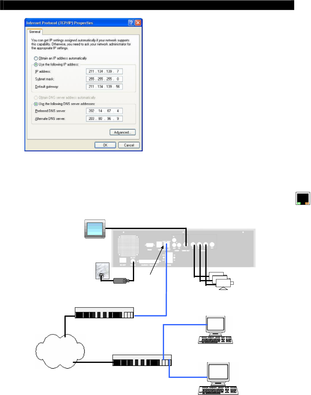
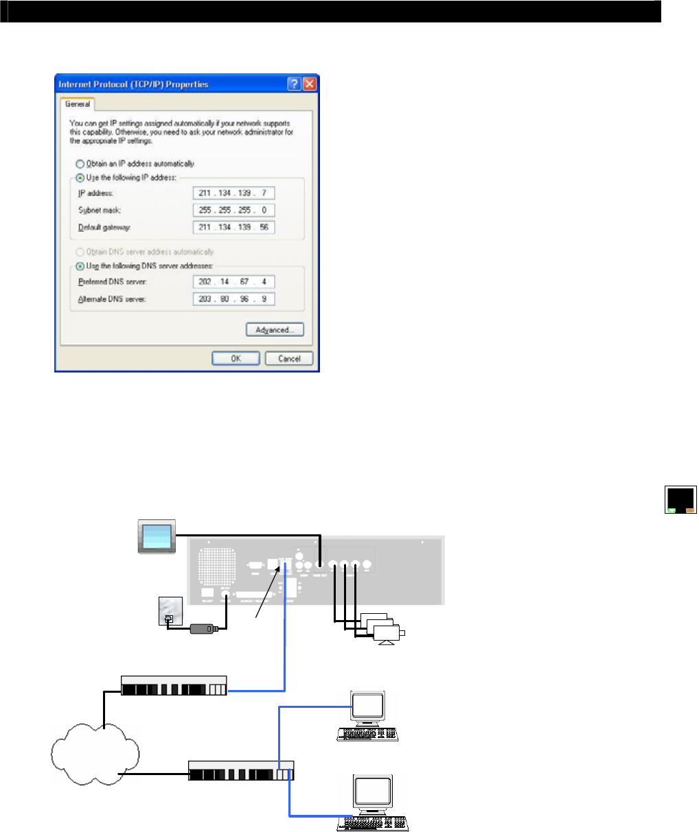
LINK LED} turns ON. Then connection diagram is shown as follows:
RG59 cable
RG59 cable
Power Adapter
Ethernet
Socket
CCTV
Monitor
Tele
Eye RX
Cameras
210.17.139.145
211.134.139.7
211.134.139.9
Internet
210.17.139.1
Router/Gateway
211.134.139.1
Router/Gateway
Straight-through Ethernet cable
Straight-through Ethernet cable

Tele
Eye RX User Guide Page 43
Setup
Tele
Eye RX for Broadband or Narrowband
Internet Connection with Static IP
Step14: Configure the network setting for
Tele
Eye
RX transmitter and your PC if necessary,
such as router/gateway port mapping (select
router/gateway IP as IP provided by your ISP
and the transmitter IP as IP provided by the
router/gateway), firewall, etc. (Please refers
to the manual of your router/gateway.)
Step15: Run WX-30 software at any network PC.
(For details of WX-30 software installation,
please refer to WX-30 Software Guide)
Step 16: Press [Connect] icon to pop up the
[Connect Window]. For example, type and
select the following setting :
Broadband Connection :
Phone/IP : 210.17.139.145
Connect Using: TCP/IP Broadband
Password: 000000
OR
Narrowband Connection :
Phone/IP : 210.17.139.145
Connect Using: TCP/IP Narrowband
Password: 000000
Step 17: Press [Connect] icon to connect
your PC and the transmitter. The video
appears on the WX-30 if success. Otherwise,
the [Warning] board will pop up and show
you failure message. For failure case, please
press [Connect] icon to check that the
connection setting is valid or not.
Tele
Eye RX User Guide Page 44
Setup
Tele
Eye RX for Broadband or Narrowband
Internet Connection with Dynamic IP
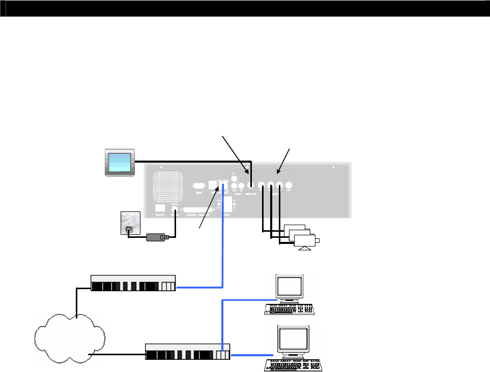
D. Setup
Tele
Eye RX for Broadband or Narrowband
Internet Connection with Dynamic IP
Connection Topology
VIDEO OUT: Connect to
monitor with RG59 cable and
BNC connector
VIDEO IN: Connect to
cameras with RG59 cable
and BNC connector
RG59 cable
RG59 cable
Power Adapter
Ethernet
Socket
CCTV
Monitor
Tele
Eye RX
Cameras
www.your_site.your_company.teleeye.net
Internet
Router/Gateway
Router/Gateway
Straight-through Ethernet cable
Straight-through Ethernet cable
Remark for Internet Connection Definition
Broadband : Connection speed is equal or above 128kbps, e.g. ADSL, DSL.
Narrowband : Connection speed is below 128kbps, e.g. dial up network, GPRS
Equipment
Tele
Eye RX Transmitter
Network Switch, Router/Gateway, ADSL Modem
Straight-through Ethernet Cable (bundled), Cross-over Ethernet Cable
Cameras, Video Cables (RG-59) with BNC Header, Monitor
CD ROM with WX-30 Software (bundled) (for PC operation only)
CCTV Monitor
PC
PC Requirements
CPU : Pentium IV 2G Hz or above
RAM : 256 MB or above
Display: 800x600, hi-color or better
OS : MS Windows 2000, XP
Tele
Eye RX User Guide Page 45
Setup
Tele
Eye RX for Broadband or Narrowband
Internet Connection with Dynamic IP
Setup Procedure
Step 1: Connect cameras to
Tele
Eye RX {Video Input} with RG59 cable and BNC
connector.
Note that the cameras system is either NTSC or PAL and suppose all cameras are used the
SAME system format. (For PTZ camera installation, please refer P.148 to Advance Operation
Section of the User Guide).
Step 2: Connect CCTV monitor to
Tele
Eye RX {Video Output} with RG59 cable and BNC
connector.
Step 3: Install and use the bundled key to lock the {Hard Disk Rack} with Hard disk to the
Tele
Eye RX.
Note that you cannot perform recording and playback if there is no hard disk installed but
still has live video monitoring. (For hard disk installation details, please refer P.11 to Hard
Disk Installation Section of the User Guide)
Step 4: Connect the power adapter (12V DC, 5A supply) to the
Tele
Eye RX.
Step 5: Turn on the power of
Tele
Eye RX, camera and CCTV monitor. Check the {Power
LED} which is lit up in blue color continuously at
Tele
Eye RX front panel after
power on. After several seconds, live video appears on the CCTV monitor as follow:
Note that: Please go through the following steps (6-10) if the video of CCTV Monitor
does not show clearly.
Tele
Eye RX User Guide Page 46
Setup
Tele
Eye RX for Broadband or Narrowband
Internet Connection with Dynamic IP
Step 6: Press the “Menu” button to pop up the
[MAIN MENU] on OSD.
Step 7: Use “Up” or “Down” button to
select [SETUP] option and press “Enter”
button to enter the [SETUP] sub-
menu.
Step 8: Select [VIDEO] option and press
“Enter” button
Step 9: Select [VIDEO FORMAT] and press
“Left” or “Right” button to
set either [NTSC] or [PAL] option. (All
cameras should have the same video
format).
Step 10: You can always press “Live” button to
exit any menu operation and start live
monitoring.
Setup
Tele
Eye RX transmitter IP through CCTV monitor, please go to step 11a.
Setup
Tele
Eye RX transmitter IP through PC, through PC, please go to step11b.
SETUP MENU
VIDEO . . .
RECORDING . . .
SWITCHES . . .
DATE / TIME . . .
CONNECTION . . .
EVENT HANDLER . . .
TRANSMITTER . . .
RESTORE FACTORY SETTING ENTER
VIDEO
CAMERA SETTING . . .
LOCAL MONITORING . . .
OSD COLOR BLUE
VIDEO FORMAT PAL
Tele
Eye RX User Guide Page 47
Setup
Tele
Eye RX for Broadband or Narrowband
Internet Connection with Dynamic IP
Step 11a: Configure
Tele
Eye RX transmitter IP setting through CCTV Monitor
RG59 cable
Power Adapter
Ethernet Socket
Te l e
Eye RX
Cameras
192.168.0.2
CCTV
Monitor
RG59 cable
Press the “Menu” button such that the
OSD main menu pops up on the monitor.
Use “Up” or “Down” button to
select [SETUP] option and press “Enter”
button.
Select[CONNECTION]option and press
“Enter” button
Select [TCP/IP] option and Press “Enter”
button
Select [IP] option and press “Enter”
button. IP address consists of four fields.
Each field can assign a number from 0 to
255.
SETUP MENU
VIDEO . . .
RECORDING . . .
SWITCHES . . .
DATE / TIME . . .
CONNECTION . . .
EVENT HANDLER . . .
TRANSMITTER . . .
RESTORE FACTORY SETTING ENTER
CONNECTION
TCP / IP …
MODEM …
TCP / IP
IP 192.168.0.2
PORT 1024
SUBNET MASK 255.255.255.0
ENABLE GATEWAY NO
GATEWAY 0.0.0.0
ENABLE DNS NO
PRIMARY DNS 0.0.0.0
SECONDARY DNS 0.0.0.0
SURELINK …

Tele
Eye RX User Guide Page 48
Setup
Tele
Eye RX for Broadband or Narrowband
Internet Connection with Dynamic IP
Use “Left” or “Right” button
to select field and use “Up” or “Down”
button to set number. Set IP address
(for example) to 210.17.139.5
Press “Enter” button to save the
change and return previous menu.
Follow the network setting and assign
valid subnet mask to [SUBNET MASK]
and select [ENABLE GATEWAY] option
and input [GATEWAY] option in similar
way. Assign the Gateway (for example) to
210.17.139.1
Select [ENABLE DNS] option Use “Left”
or “Right” button to select
[YES] to enable DNS.
Assign the Primary DNS (for example) to
202.14.67.4
Assign the Secondary DNS (for example)
to 202.14.67.14
IP
IP : 210. 17.139. 5
TCP / IP
IP 210.17.139.5
PORT 1024
SUBNET MASK 255.255.255.0
ENABLE GATEWAY YES
GATEWAY 210.17.139.1
ENABLE DNS NO
PRIMARY DNS 0.0.0.0
SECONDARY DNS 0.0.0.0
SURELINK …

Tele
Eye RX User Guide Page 49
Setup
Tele
Eye RX for Broadband or Narrowband
Internet Connection with Dynamic IP
Select [SURELINK] option from TCP/IP
menu and press “Enter” button to
enter the sub menu.
Select [ENABLED] option and press
“Left” or “Right” button to
set [YES] value
Select [SURELINK ADDRESS] option
and press “Enter” button to
sureLINK editing menu.
There are two fields for assigning sureLINK
address
“www.your_site.your_company.teleeye.net”
(Refer P.152 to section of getting sureLINK
address)
Use “Up” or “Down” or “Left” or “Right”
button to select values and use “Enter”
button to assign value.
[BACK] back to previous value or field
[NEXT] next to field
[CLEAR] clear field
[END] finish to assign sureLINK
address and exit the editing menu.
Press “Live” button and [SETTING
MODIFIED] message board will pop up.
Press “Enter” button to restart the
transmitter.
SURELIN
K
ENABLED YES
SURELINK ADDRESS www…..
REFRESH RATE 1 MINS
SURELINK ADDRESS
0 1 2 3 4 5 6 7 8 9
A B C D E F G H I J
K L M N O P Q R S T
U V W X Y Z BACK NEXT
CLEAR END
WWW. _ . TELEEYE.NET
SETTING MODIFIED
SETTING WILL TAKE EFFECT
AFTER RESTART ,
PRESS ENTER TO CONTINUE
OK

Tele
Eye RX User Guide Page 50
Setup
Tele
Eye RX for Broadband or Narrowband
Internet Connection with Dynamic IP
Step 11b: Configure
Tele
Eye RX transmitter IP setting through PC
RG59 cable
Power Adapter
Ethernet Socket
Te l e
Eye RX
Cameras
192.168.0.2
192.168.0.3
Cross-over Ethernet Cable
In Windows 2000/XP desktop, select Start
> Control Panel
Double click Network and Dial-up
Connections > right click Local Area
Connections and choose Properties.
Choose Internet Protocol (TCP/IP) and
click Properties
Tele
Eye RX User Guide Page 51
Setup
Tele
Eye RX for Broadband or Narrowband
Internet Connection with Dynamic IP
Enter an IP address, subnet mask and
Default gateway. Note that IP address
should be “192.168.0.xx” except
“192.168.0.2” which is
Tele
Eye RX
default IP address.
Enter the Preferred and Alternate DNS
server, if necessary.
Click OK to activate the new IP.
You have to confirm that IP address has
been correctly set on your computer. On
your windows, click start > run, type
“cmd” at Open field and press OK button,
then type “ipconfig” on the DOS prompt,
you will see an IP set on your computer.
10/100 BASE-T
LINK COL
Connect the PC Ethernet socket to the
transmitter Ethernet socket at rear panel of
the transmitter with cross-over Ethernet
cable. Check if the {LINK LED} of the
transmitter is turned ON.
Run WX-30 software which has been
installed to the PC. (For details of WX-30
software installation, please refer to WX-
30 Software Guide)
Tele
Eye RX User Guide Page 52
Setup
Tele
Eye RX for Broadband or Narrowband
Internet Connection with Dynamic IP
Choose [Transmitter]
[Registration] to
register the
Tele
Eye RX transmitter. User
needs to input transmitter serial number and
registration code.
For example :
Serial No. : VTC12345
Registration Code : 1234567890
Press [Connect] icon to pop up the
[Connect Window]. Type and select the
following setting :
Broadband Connection :
Phone/IP : 192.168.0.2
Connect Using: TCP/IP Broadband
Password: 000000
OR
Narrowband Connection :
Phone/IP : 192.168.0.2
Connect Using: TCP/IP Narrowband
Password: 000000
IP (192.168.0.2) and Password (000000)
are default setting of
Tele
Eye RX
Press [Connect] icon to
connect your PC and the transmitter. The
video appears on the WX-30 if success.
Otherwise, the [Warning] board will pop
up and show you failure message. For
failure case, please press [Connect]
icon to check that the connection setting is
valid or not.
Tele
Eye RX User Guide Page 53
Setup
Tele
Eye RX for Broadband or Narrowband
Internet Connection with Dynamic IP
Press [Transmitter Setup] icon to
show
Tele
Eye RX configuration menu.
Select [Connection] and press [Network
Settings] icon to
configure network setting.
For example :
Assign 210.17.139.5 to IP
Assign 210.17.139.1 to Gateway
Assign 202.14.67.4 to Primary DNS
Assign 202.14.67.14 to Secondary DNS
Enable sureLINK
Assign
“www.your_site.your_company.teleeye.net”
(please refer P.152 to sureLINK section to get
the address) to text field.
Note that The above network setting is an
example. Please consult you network
administrator to get your network setting
information
Press [Apply] icon to save the
network setting and pop up the message
board. After several seconds, the
transmitter will restart automatically.
Tele
Eye RX User Guide Page 54
Setup
Tele
Eye RX for Broadband or Narrowband
Internet Connection with Dynamic IP
10/100 BASE-T
LINK COL
In Windows 2000/XP desktop, select Start
> Control Panel
Double click Network and Dial-up
Connections > right click Local Area
Connections and choose Properties.
Choose Internet Protocol (TCP/IP) and
click Properties
Enter the IP address, subnet mask and
Default gateway for the PC to restore to
its original network configuration.
Click OK to apply the setting
Step 12: Disconnect the transmitter and current PC. Reconnect the transmitter and current PC
to the Internet network through straight-through Ethernet cable.
Step 13: Check Ethernet socket of both the transmitter and PC to ensure that the {GREEN
LINK LED} turns ON. Then connection diagram is shown as follows:
RG59 cable
RG59 cable
Power Adapter
Ethernet
Socket
CCTV
Monitor
Tele
Eye RX
Cameras
www.your_site.your_company.teleeye.net
211.134.139.7
211.134.139.9
Internet
210.17.139.1
Router/Gateway
211.134.139.1
Router/Gateway
Primary DNS: 202.14.67.4
Secondary DNS: 202.14.67.14
Straight-through Ethernet cable
Straight-through Ethernet cable
Tele
Eye RX User Guide Page 55
Setup
Tele
Eye RX for Broadband or Narrowband
Internet Connection with Dynamic IP
Step14: Configure the network setting for
Tele
Eye RX
transmitter and your PC if necessary, such as
router/gateway port mapping (select
router/gateway IP as IP provided by your ISP
and the transmitter IP as IP provided by the
router/gateway), firewall, etc. (Please refers to
the manual of your router/gateway.)
Step15: Run WX-30 software at any network PC. (For
details of WX-30 software installation, please
refer to WX-30 Software Guide)
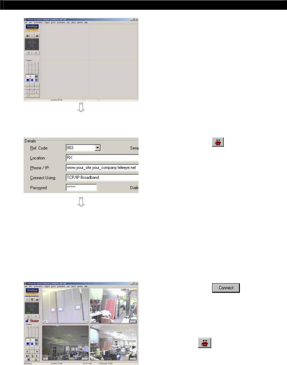
Step 16: Press [Connect] icon to pop up the
[Connect Window]. For example, type and
select the following setting :
Broadband Connection :
Phone/IP :
www.your_site.your_company.teleeye.net
Connect Using: TCP/IP Broadband
Password: 000000
OR
Narrowband Connection :
Phone/IP :
www.your_site.your_company.teleeye.net
Connect Using: TCP/IP Narrowband
Password: 000000
Step 17: Press [Connect] icon to connect
your PC and the transmitter. The video appears
on the WX-30 if success. Otherwise, the
[Warning] board will pop up and show you
failure message. For failure case, please press
[Connect] icon to check that the
connection setting is valid or not.
Tele
Eye RX User Guide Page 56
Setup
Tele
Eye RX for Modem Connection
E. Setup
Tele
Eye RX for Modem Connection
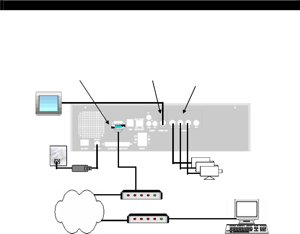
Connection Topology
VIDEO OUT: Connect to
monitor with RG59 cable
and BNC connector
VIDEO IN: Connect to
cameras with RG59 cable
and BNC connector
RG59 cable
RG59 cable
Power Adapter
Tele
Eye RX
Cameras
Modem
RS232 serial cable
Telephone
Network
Modem port connect
to a DB-9 connector
CCTV
Monitor
Modem
RS232 serial cable
Telephone cable
Telephone cable
Equipment
Tele
Eye RX Transmitter
ISDN/PSTN Modem
RS232 Serial Cable
Telephone Cable
Cameras
Video Cables (RG-59) with BNC Header
CCTV Monitor
CD ROM with WX-30 Software (bundled) (for PC operation only)
PC
PC Requirements
CPU : Pentium IV 2G Hz or above
RAM : 256 MB or above
Display: 800x600, hi-color or better
OS : MS Windows 2000, XP

Tele
Eye RX User Guide Page 57
Setup
Tele
Eye RX for Modem Connection
Setup Procedure
Step 1: Connect cameras to
Tele
Eye RX {Video Input} with RG59 cable and BNC
connector.
Note that the cameras system is either NTSC or PAL and suppose all cameras are used the
SAME system format. (For PTZ camera installation, please refer P.148 to Advance Operation
Section of the User Guide).
Step 2: Connect CCTV monitor to
Tele
Eye RX {Video Output} with RG59 cable and BNC
connector.
Step 3: Install and use the bundled key to lock the {Hard Disk Rack} with hard disk to the
Tele
Eye RX.
Note that you cannot perform recording and playback if there is no hard disk installed but
still has live video monitoring. (For hard disk installation details, please refer P.11 to Hard
Disk Installation Section of the User Guide)
Step 4: Connect the power adapter (12V DC, 5A supply) to the
Tele
Eye RX.
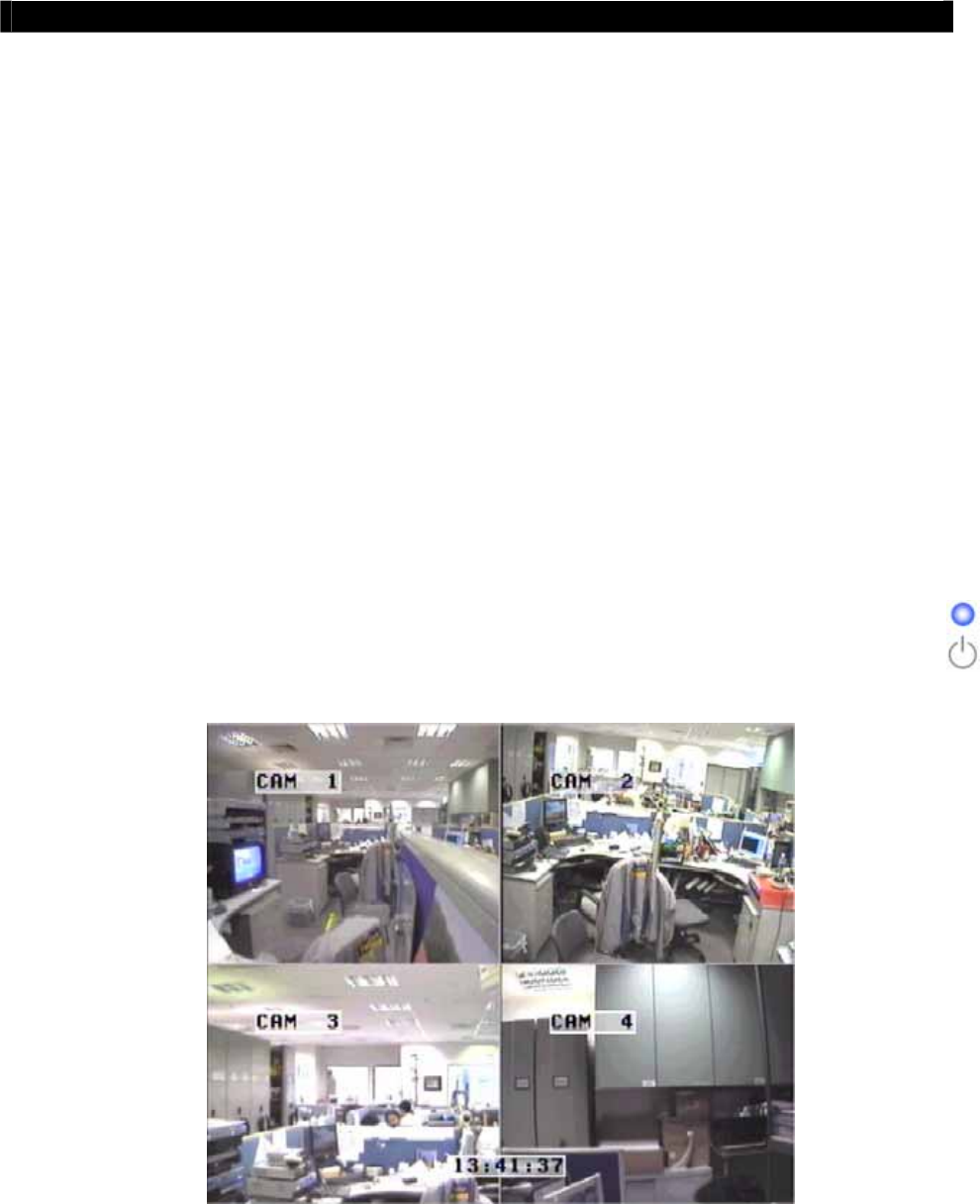
Step 5: Turn on the power of
Tele
Eye RX, camera and CCTV monitor. Check the
{Power LED} which is lit up in blue color continuously at
Tele
Eye RX front
panel after power on. After several seconds, live video appears on the CCTV monitor
as follow:
Note that: Please go through the following steps (6-10) if the video of CCTV Monitor does
not show clearly.
Tele
Eye RX User Guide Page 58
Setup
Tele
Eye RX for Modem Connection
Step 6: Press the “Menu” button to pop up the
[MAIN MENU] on OSD.
Step 7: Use “Up” or “Down” button to
select [SETUP] option and press “Enter”
button to enter the [SETUP] sub-
menu.
Step 8: Select [VIDEO] option and press
“Enter” button
Step 9: Select [VIDEO FORMAT] and press
“Left” or “Right” button to
set either [NTSC] or [PAL] option. (All
cameras should have the same video
format).
Step 10: You can always press “Live” button to
exit any menu operation and start live
monitoring.
Setup
Tele
Eye RX transmitter IP through CCTV monitor, please go to step 11a.
Setup
Tele
Eye RX transmitter IP through PC, through PC, please go to step11b.
SETUP MENU
VIDEO . . .
RECORDING . . .
SWITCHES . . .
DATE / TIME . . .
CONNECTION . . .
EVENT HANDLER . . .
TRANSMITTER . . .
RESTORE FACTORY SETTING ENTER
VIDEO
CAMERA SETTING . . .
LOCAL MONITORING . . .
OSD COLOR BLUE
VIDEO FORMAT PAL
Tele
Eye RX User Guide Page 59
Setup
Tele
Eye RX for Modem Connection
Step 11a: Configure
Tele
Eye RX transmitter modem connection setting through CCTV
Monitor
RG59 cable
Power Adapter
Ethernet
Socket
Te l e
Eye RX
Cameras
192.168.0.2
CCTV
Monitor
RG59 cable
Press the “Menu” button such that the OSD
[MAIN MENU] pop up on the monitor.
Use “Up” or “Down” button to select
[SETUP] option and press “Enter” button
and select [CONNECTION] option and press
“Enter” button.
Use “Up” or “Down” button to select
[MODEM] option and press “Enter” button
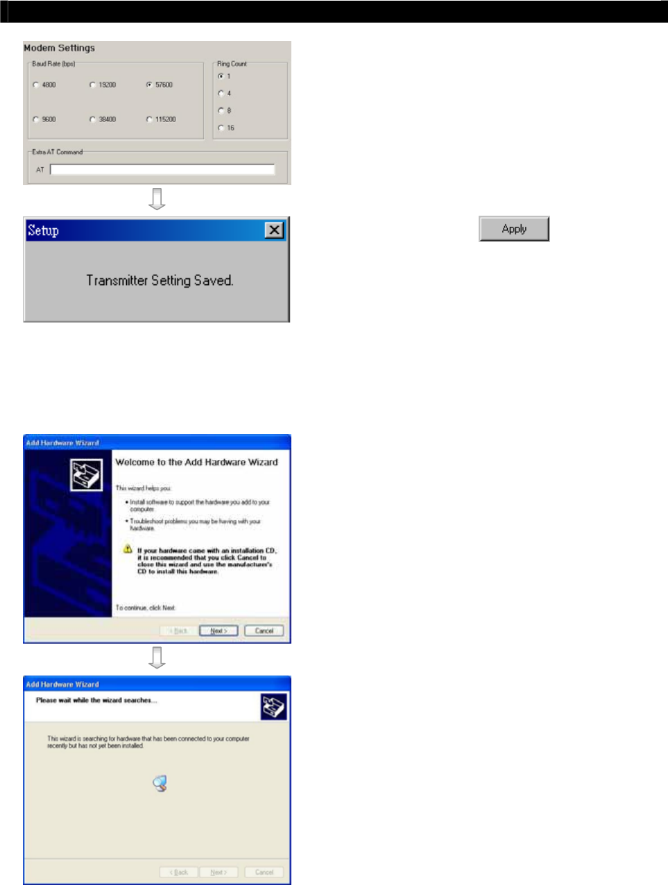
Select [BAUD RATE] and then [RING
COUNT] option press “Enter” button
Use “Up” or “Down” button to set
number. Press “Enter” button to input baud
rate and ring count setting
SETUP MENU
VIDEO . . .
RECORDING . . .
SWITCHES . . .
DATE / TIME . . .
CONNECTION . . .
EVENT HANDLER . . .
TRANSMITTER . . .
RESTORE FACTORY SETTING ENTER
CONNECTION
TCP / IP …
MODEM …
MODEM
BAUD RATE 57600 BPS
RING COUNT 1
Tele
Eye RX User Guide Page 60
Setup
Tele
Eye RX for Modem Connection
Step 11b: Configure
Tele
Eye RX transmitter modem connection setting through PC
RG59 cable
RG59 cable
Power Adapter
Tele
Eye RX
Cameras
Modem
RS232 serial cable
Telephone
Network
CCTV
Monitor
Modem
RS232 serial cable
Telephone cable
Telephone cable
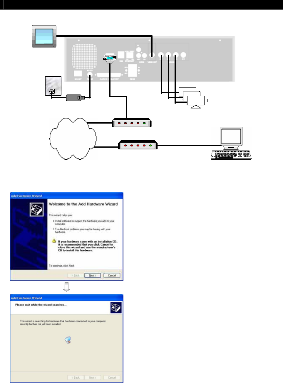
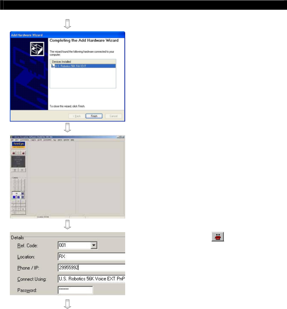
Modem Setup for Windows 2000/XP of PC
In Windows 2000/XP desktop, select Start >
Control Panel
Double click Add Hardware, press Next, to
search the modem connected to the PC
automatically
Windows 2000/XP can search the modem device
automatically. If modem installation has problem,
please refers to the modem manual.
Tele
Eye RX User Guide Page 61
Setup
Tele
Eye RX for Modem Connection
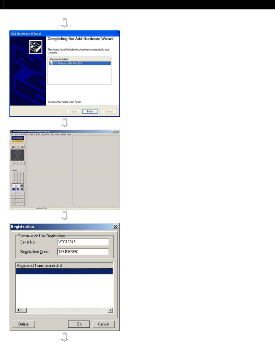
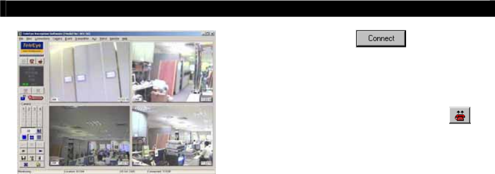
After searching the modem, Windows 2000/XP
can install the modem driver automatically. Press
[Finish] button to exit the menu. The modem is
ready to use.
Run WX-30 software which has been installed to
the PC. (For details of WX-30 software
installation, please refer to WX-30 Software
Guide)
Choose [Transmitter]
[Registration] to
register the
Tele
Eye RX transmitter. User needs
to input transmitter serial number and registration
code.
For example :
Serial No. : VTC12345
Registration Code : 1234567890
Tele
Eye RX User Guide Page 62
Setup
Tele
Eye RX for Modem Connection
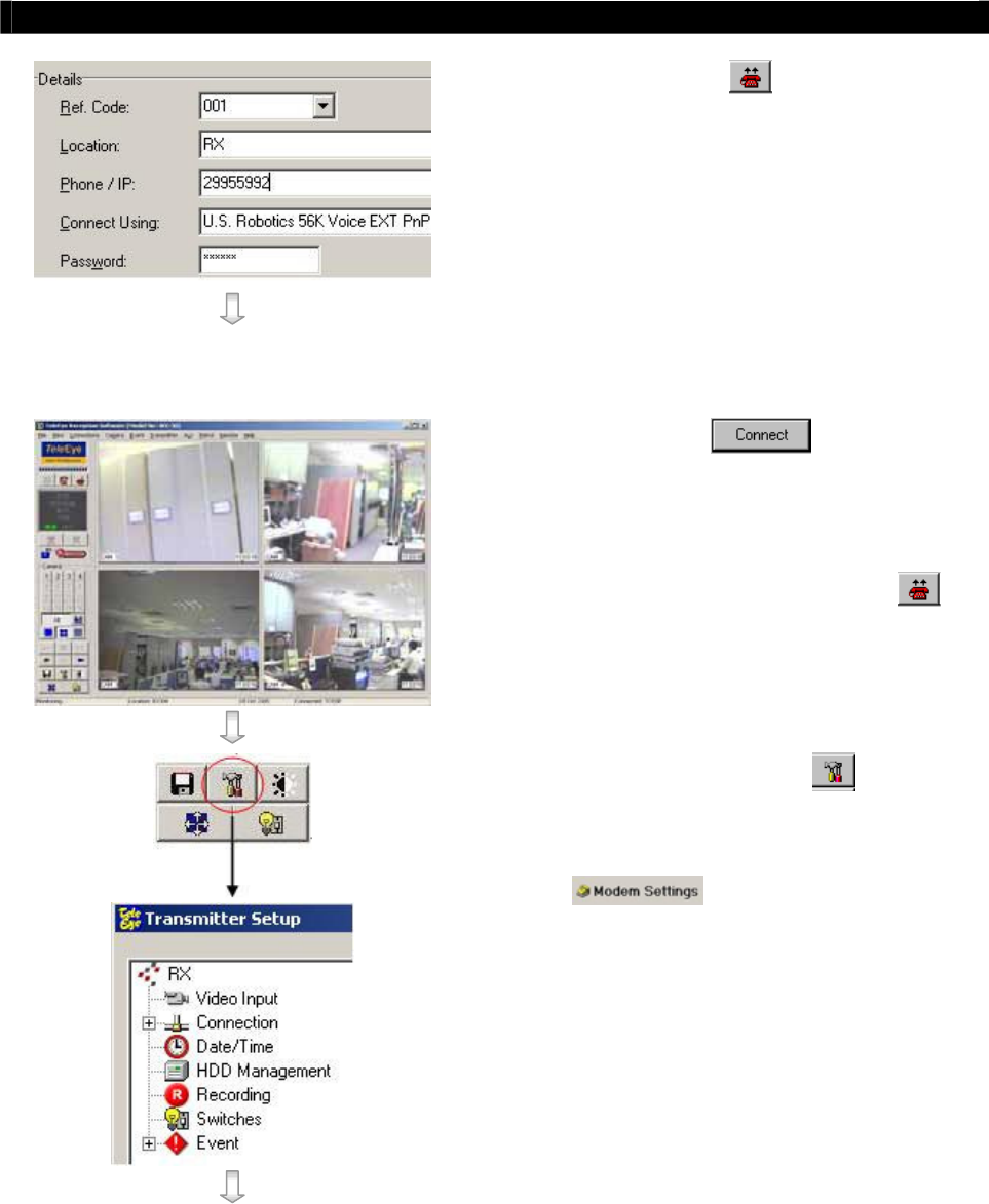
Press [Connect] icon to pop up the
[Connect Window]. For example, type and select
the following setting :
Phone/IP :
29955992 (Phone number of the transmitter)
Connect Using :
U.S. Robotics 56K Voice EXT PnP
(Modem Driver)
Password: 000000
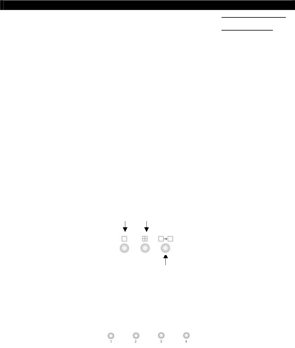
Press [Connect] icon to connect your
PC and the transmitter. The video appears on the
WX-30 if success. Otherwise, the [Warning]
board will pop up and show you failure message.
For failure case, please press [Connect] icon
to check that the connection setting is valid or not.
Press [Transmitter setup] icon to show
Tele
Eye RX configuration menu.
Select [Connection] and press [Modem Settings]
icon to configure network setting.
Tele
Eye RX User Guide Page 63
Setup
Tele
Eye RX for Modem Connection
Assign modem baud rate in order to adjust
modem connection speed.
Assign ring count, so modem can connect to the
transmitter after that ring count.
Press [Apply] icon to save the
network setting and pop up the message board.
After several seconds, the transmitter will restart
automatically.
Step 12 : If user setup modem connection by using local CCTV monitor (Step 11a), please
install the modem for your PC and connect to the telephone network in order to
connect to
Tele
Eye RX transmitter
In Windows 2000/XP desktop, select Start >
Control Panel
Double click Add Hardware, press Next, to
search the modem connected to the PC
automatically
Windows 2000/XP can search the modem device
automatically. If modem installation has problem,
please refers to the modem manual.
Tele
Eye RX User Guide Page 64
Setup
Tele
Eye RX for Modem Connection
After searching the modem, Windows 2000/XP
can install the modem driver automatically. Press
[Finish] button to exit the menu. The modem is
ready to use.
Run WX-30 software which has been installed to
the PC. (For details of WX-30 software
installation, please refer to WX-30 Software
Guide)
Press [Connect] icon to pop up the
[Connect Window]. For example, type and select
the following setting :
Phone/IP :
29955992 (Phone number of the transmitter)
Connect Using :
U.S. Robotics 56K Voice EXT PnP
(Modem Driver)
Password: 000000
Tele
Eye RX User Guide Page 65
Setup
Tele
Eye RX for Modem Connection
Press [Connect] icon to connect your
PC and the transmitter. The video appears on the
WX-30 if success. Otherwise, the [Warning]
board will pop up and show you failure message.
For failure case, please press [Connect] icon
to check that the connection setting is valid or not.
Tele
Eye RX User Guide Page 66
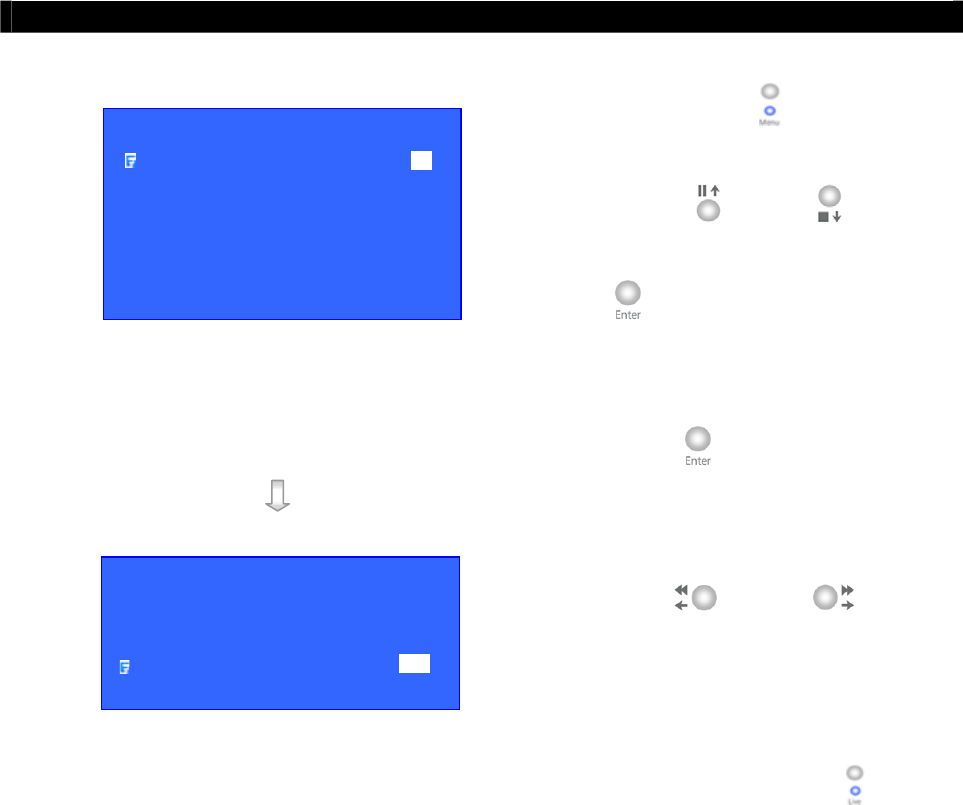
Local CCTV Monitor : Live Monitoring, Recording and Playback
FULL QUAD
SEQUENTIAL
4
Basic Operation for
Local and Remote
Monitoring
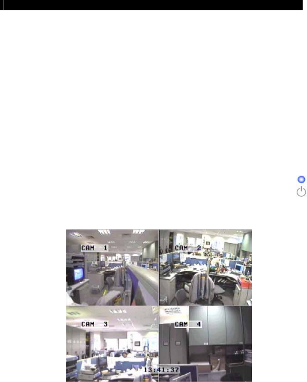
A. Local CCTV Monitor : Live Monitoring,
Recording and Playback
I. Live Monitoring
Press “Screen Control” buttons to view the live video in full, quad and sequential display mode.
Note that when PTZ camera has been enabled, then sequential live mode cannot be selected.
Press “Live Camera Control” buttons to fast switch to a specific camera for local monitoring
SECTION
Tele
Eye RX User Guide Page 67
Local CCTV Monitor : Live Monitoring, Recording and Playback
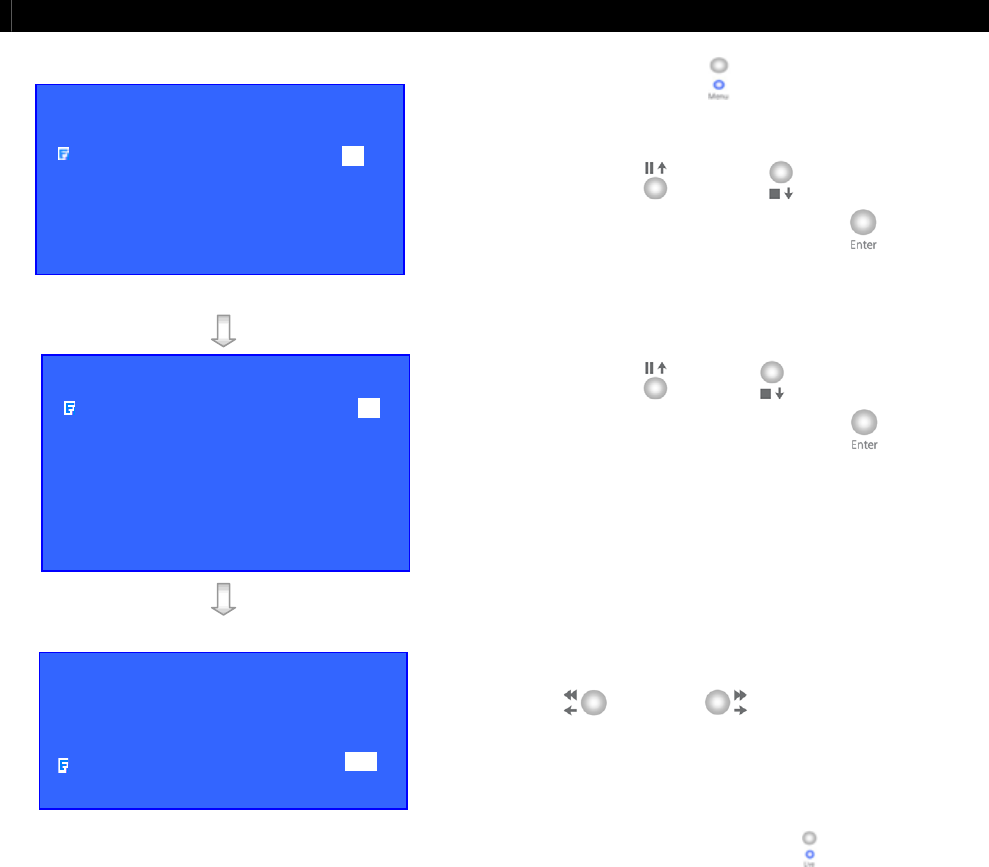
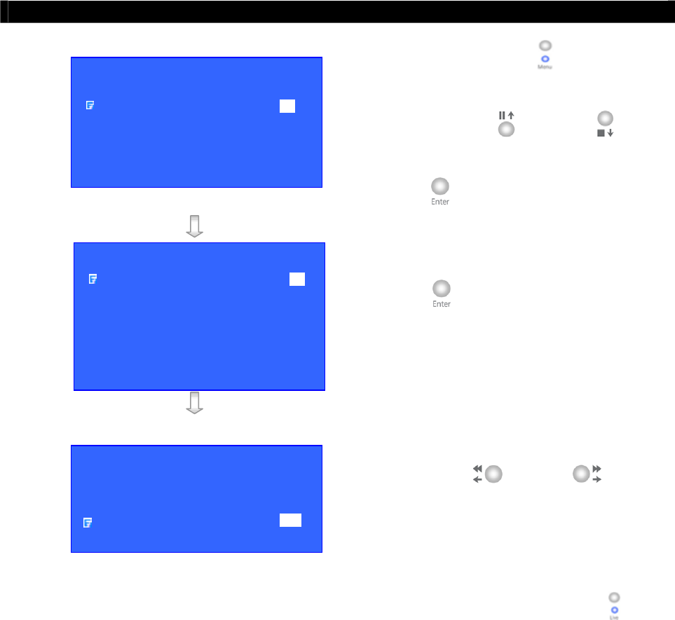
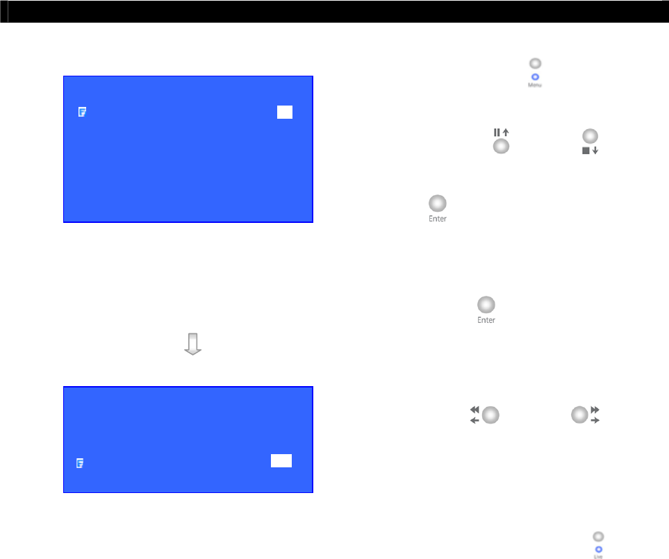
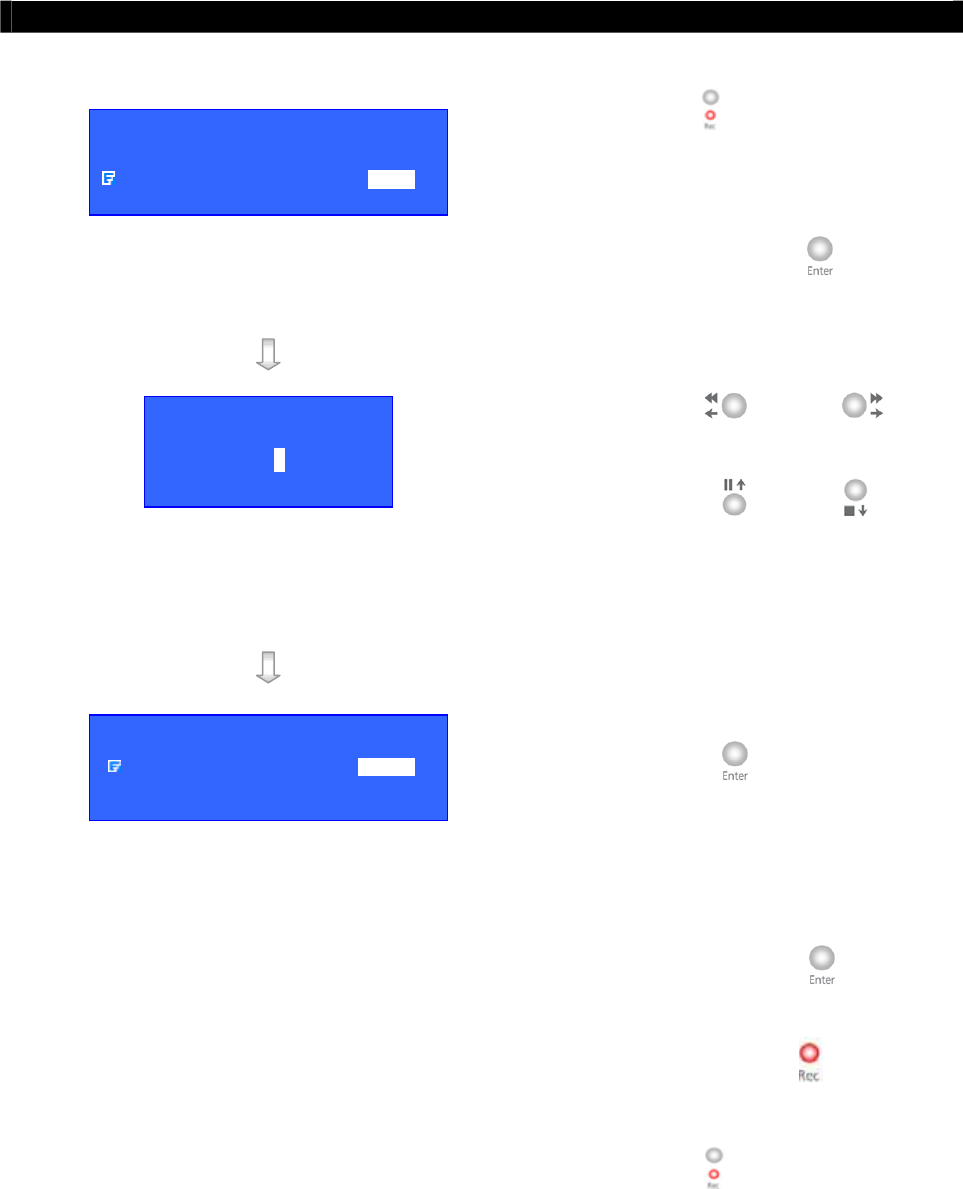
II. Recording
Step 1: Press “Rec” button and [START
RECORDING] menu will pop up.
Step 2: Select [RECORDING CAMERA]
option and press “Enter” button to
enable recording cameras.
(e.g. Cam 1 & 3 are enabled, Cam 2 & 4 are
disabled)
Step 3: Use “Left” or “Right”
button to select the recording camera
and use “Up” or “Down”
button to enable or disable the
recording camera.
Step 4: After setting the recording cameras,
press “Enter” button to save the
setting and back to [START
RECORDING] menu.
Step 5: Select [START RECORDING]
option and press “Enter” button
for recording. The {Rec LED} will be
turned ON (RED Color) which
indicates that recording is processing.
Step 6: Press “Rec” button again to stop
recording function and the {REC
LED} will be turned OFF.
START RECORDING
START RECORDING ENTER
RECORDING CAMERA 1 2 3 4
RECORDING CAMER
A
1 - 3 -
START RECORDING
START RECORDING ENTER
RECORDING CAMERA 1 - 3 -

Tele
Eye RX User Guide Page 68
Local CCTV Monitor : Live Monitoring, Recording and Playback
III. Playback
Step 1: Press “Search” button to pop up
[RECORDING LOG] board on OSD.
Step 2: Press “Play/Enter” button to show
[PLAY] menu.
Select [MINUTE LOG] option and
press “Enter” button.
[RECORDING LOG] board will show the log
in minute scale.
Step 3: Select a record and press “Enter”
button for playback.
Then [PLAYBACK] menu will pop up again.
Step 4: Select [PLAY] option and press
“Enter” button again for
playback.
RECORDING LOG 12
–
13 AUG2005
TIME CAMERA EVENT REMARK SENSOR
11 : 00 1234 - - - - - - - - - - - - - - -
12 : 00 - - - 4 - - - - - - - - - - - - - - ------
13 : 00 - - - - - - - - - - - - - - - - - - -
14 : 00 - 2 - - - - - - - - - - - - - - - - -
15 : 00 - - - - - - - - - - - - - - - - - - -
16 : 00 1 - - - - - - - - - - - - - - - - - -
17 : 00 1 - - - - - - - - - - - - - - - - - -
18 : 00 - - - - - - - - - - - - - - - - - - -
PL
A
Y
TIME SEARCH
MONTH LOG
DAY LOG
HOUR LOG
10MIN LOG
MINUTE LOG
RECORDING LOG 12
–
13 AUG2005
TIME CAMERA EVENT REMARK SENSOR
11 : 54 1234 - - - - - - - - - - - - - - -
11 : 55 1234 - - - - - - - - - - - - - - ------
11 : 56 1234 - - - - - - - - - - - - - - -
11 : 57 1234 - - - - - - - - - - - - - - -
11 : 58 1234 - - - - - - - - - - - - - - -
11 : 59 1234 - - - - - - - - - - - - - - -
12 : 00 - - - 4 - - - - - - - - - - - - - - -
12 : 01 - - - 4 - - - - - - - - - - - - - - -
PLAY
TIME SEARCH
MONTH LOG
DAY LOG
HOUR LOG
10MIN LOG
MINUTE LOG
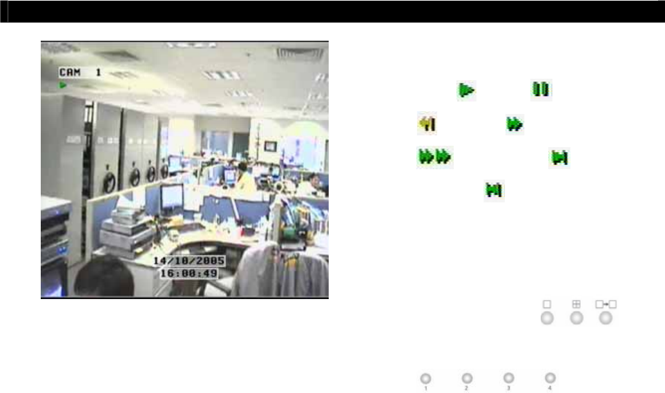
Tele
Eye RX User Guide Page 69
Local CCTV Monitor : Live Monitoring, Recording and Playback
Step 5: Using “Playback Control button” for
“play” , “pause” , “rewind”
, “forward” , “fast forward”
, “step forward” , “step
backward” and “stop”. ( For
detail, refer to page 5 Front Panel
Section of User Guide)
Step 6: Press “screen control”
or “camera control”
buttons to
change the view mode in local CCTV
video playback.
Note that if user record video by using quad recording mode, the playback video may not be
so good in full screen display mode.
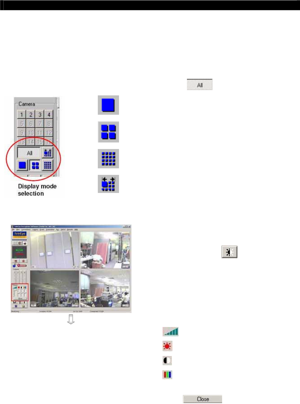
Tele
Eye RX User Guide Page 70
Tele
Eye RX Reception Software WX-30 : Live Monitoring,
Recording and Playback
B.
Tele
Eye RX Reception Software WX-30 : Live
Monitoring, Recording and Playback
I. Live Monitoring
User can view a particular camera by simply clicking the camera button (e.g. 1, 2 or 3) on
the camera control panel, or view all cameras, click [All] icon.
Screen views in Full screen
Screen views in Quarter screen
Screen views in Hex screen
Auto-arrange can optimise the screen views in order
to display as many high-resolution pictures as
possible.
User can change
Tele
Eye RX Reception Software
WX-30 live monitoring quality by following steps.
Step 1: Click [Quality] icon at the software
front panel to pop up [Quality] setting panel.
Step 2: Pull up and down to select the quality items.
Pull up is to increase the value and vice versa.
: Quality
: Brightness
: Contrast
: Colour
Step 3: After changing the setting, press [Close]
icon to exit the panel.
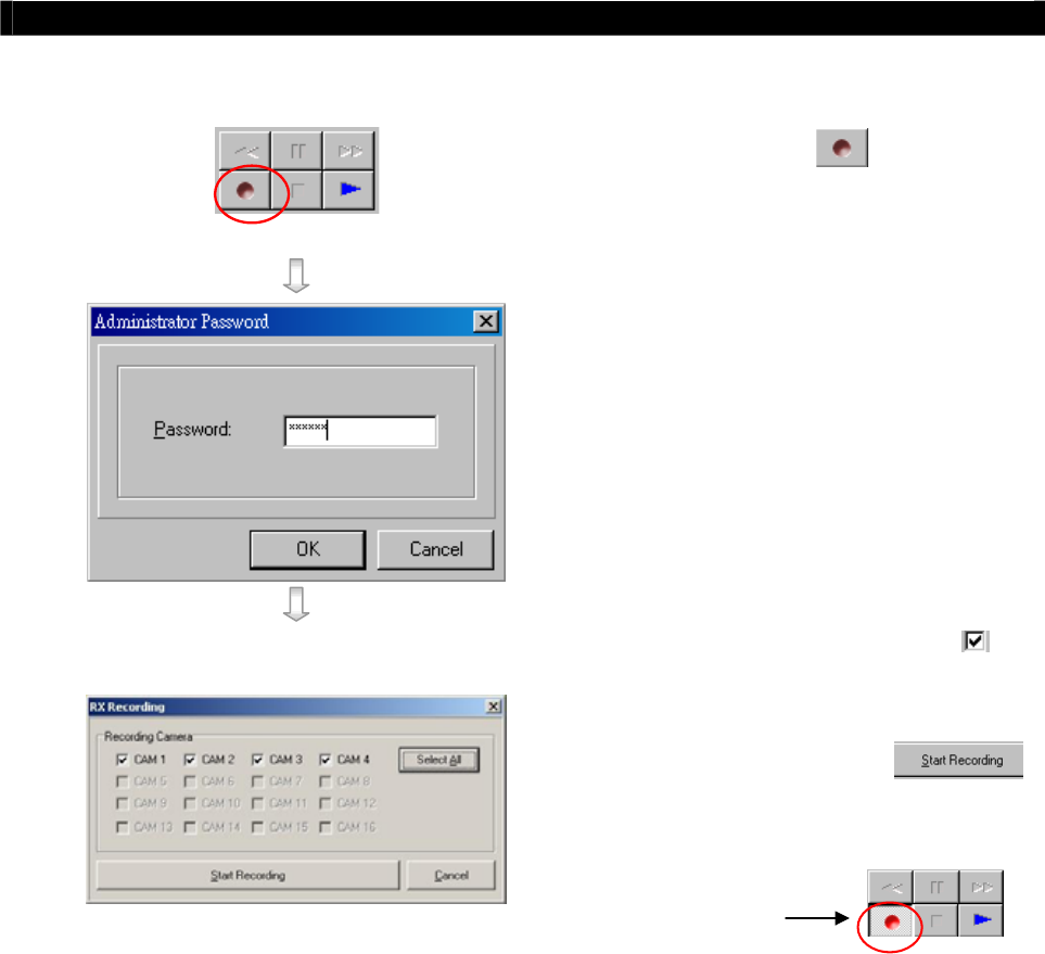
Tele
Eye RX User Guide Page 71
Tele
Eye RX Reception Software WX-30 : Live Monitoring,
Recording and Playback
II. Recording
Step 1: Press [Record] icon to setup
recording setting.
Step 2: Input administrator password (000000
as default password) and press [OK]
button.
Step 3: Enable recording cameras ( Tick for
enable, blank for disable)
Step 4: Press [Start Recording]
icon to start recording
Recording
function is running
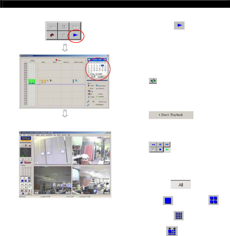
Tele
Eye RX User Guide Page 72
Tele
Eye RX Reception Software WX-30 : Live Monitoring,
Recording and Playback
III. Playback
Step 1: Press [Play] icon to show
playback menu
Step 2: Select and input the record date and
time for searching and press [Reload]
icon.
Step 3: Select a time slot record and press
[Start Playback]
button.
Step 4: Use “playback control button”
to control playback video
such as “play”, “pause”, “forward”,
“backward” and “stop” function.
Step 5: Press [All] , [Full
screen] , [Quarter screen] ,
[Hex screen] or [Auto-
arrange] icon to change the view
mode for playback.
Note that after pressing “pause” button for 1 minute, reception software WX-30 will
continue to playback the video automatically.
Note that if user record video by using quad recording mode, the playback video may not be
so good in full screen display mode.
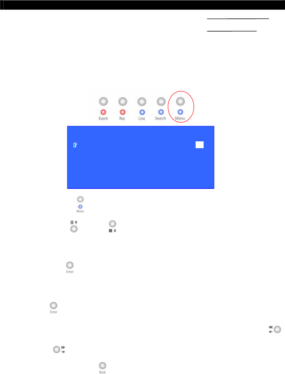
Tele
Eye RX User Guide Page 73
Main Menu
5
OSD Menu Operation
A. Main Menu
1. Press the “Menu” button to open the main menu
2. Using the “Up” / “Down” button to select a sub-menu
3. A selected sub-menu option will be pointed by a hand cursor and highlighted
4. Press “Enter” button to confirm the selection and open the sub-menu
5. If menu option ends with [. . .] indicates sub-menu existing, you can always press the
“Enter” button to open the sub-menu.
6. If menu option does not end with [. . .] but provides selection, user can press the “Left”
/ “Right” button to selection the options.
7. You can press the “Back” button once back to previous menu.
SECTION
MAIN MENU
SETUP . . .
BACKUP TO CD-R . . .
SWITCH CONTROL . . .
SCAN / FORMAT DISK . . .
TRANSMITTER INFO . . .
SHUT DOWN ENTER

Tele
Eye RX User Guide Page 74
Main Menu
8. Press “Live” button or “Back” button until OSD disappear to exit menu and save the
setting. [SETTING SAVED] message will be shown.
The main menu contains the following options
SETUP : Change the
Tele
Eye RX transmitter setting
BACKUP TO CDR : Backup recorded video to CDR or CDRW
SWITCH CONTROL : Turn on /off switch 1-4
SCAN / FORMAT DISK : Show the hard disk information, do scandisk and
format the hard disk operation
TRANSMITTER INFO : Show the
Tele
Eye RX transmitter information
SHUT DOWN : Shut down or restart
Tele
Eye RX transmitter
Main Menu
Setup
The setup menu contains the following options
VIDEO : Change camera, local monitoring, PTZ setting,
OSD color and video format related settings
RECORDING : Change recording related settings
SWITCHES : Change switches related settings
DATE/TIME : Change date and time settings
CONNECTION : Change connection and network related settings
EVENT HANDLER : Change event related settings
TRANSMITTER : Change the transmitter name, registration checking
and perform firmware upgrade
RESTORE FACTORY SETTING : Restore default factory setting
SETUP MENU
VIDEO . . .
RECORDING . . .
SWITCHES . . .
DATE / TIME . . .
CONNECTION . . .
EVENT HANDLER . . .
TRANSMITTER . . .
RESTORE FACTORY SETTING ENTER
SETTING
SETTING SAVED

Tele
Eye RX User Guide Page 75
Main Menu
Main Menu
Setup
Video
The video menu contains the following options
CAMERA SETTING : Change camera name and install camera
LOCAL MONITORING : Change local CCTV monitor related setting
OSD COLOR : Change OSD color
VIDEO FORMAT : Change the video format to PAL or NTSC format
Main Menu
Setup
Video
Camera Setting
The camera setting menu contains the following options
CAMERA 1 : Change camera 1 setting
CAMERA 2 : Change camera 2 setting
CAMERA 3 : Change camera 3 setting
CAMERA 4 : Change camera 4 setting
VIDEO
CAMERA SETTING . . .
LOCAL MONITORING . . .
OSD COLOR BLUE
VIDEO FORMAT PAL
CAMERA SETTING
CAMERA 1 . . .
CAMERA 2 . . .
CAMERA 3 . . .
CAMERA 4 . . .

Tele
Eye RX User Guide Page 76
Main Menu
Main Menu
Setup
Video
Camera Setting
Camera X Setting
The camera setting menu contains the following options
INSTALLED : Install the camera
NAME : Edit the camera name
SUPPORT PTZ : Enable the PTZ camera
GENERAL PTZ SETTING : Change PTZ camera setting
Main Menu
Setup
Video
Camera Setting
Camera X Setting
General PTZ Setting
The general PTZ setting menu contains the following options
PAN SPEED : Select the pan (horizontal direction) speed of the
PTZ camera
TILT SPEED : Select the tilt (vertical direction) speed of the PTZ
camera
PTZ MOVEMENT SETTING : Change the PTZ camera movement duration and
timing
ADVANCE PTZ SETTING : Change the PTZ camera driver and baud rate
CAMERA X SETTING
INSTALLED YES
NAME CAMERA X
SUPPORT PTZ YES
GENERAL PTZ SETTING . . .
GENERAL PTZ SETTING
PAN SPEED FAST
TILT SPEED FAST
PTZ MOVEMENT SETTING . . .
ADVANCE PTZ SETTING . . .

Tele
Eye RX User Guide Page 77
Main Menu
Main Menu
Setup
Video
Camera Setting
Camera X Setting
General PTZ Setting
PTZ Movement Setting
The PTZ movement setting menu contains the following options
PAN DURATION : Select the PTZ camera pan duration
TILT DURATION : Select the PTZ camera tilt duration
ZOOM DURATION : Select the PTZ camera zoom duration
FOCUS DURATION : Select the PTZ camera focus duration
IRIS DURATION : Select the PTZ camera iris duration
ADDITIONAL DURATION : Select the PTZ camera additional duration if any
WASHER DURATION : Select the PTZ camera washer duration
WIPER DURATION : Select the PTZ camera wiper duration
PATROL SPEED : Select the PTZ camera patrol speed
DWELL TIME : Select the PTZ camera dwell time
Main Menu
Setup
Video
Camera Setting
Camera X Setting
General PTZ Setting
Advance PTZ Setting
The advance PTZ setting
PTZ DRIVER : Select the PTZ camera driver
BIT RATE : Select the PTZ camera bit rate
(For PTZ camera setting details, please refers to P.148 Connection to PTZ Cameras Part of
Advance Operation Section of User Guide)
PTZ MOVEMENT SETTING
PAN DURATION 5
TILT DURATION 5
ZOOM DURATION 3
FOCUS DURATION 3
IRIS DURATION 3
ADDITIONAL DURATION 3
WASHER DURATION 3
WIPER DURATION 3
PATROL SPEED 3
DWELL TIME 2
A
DVANCE PTZ SETTING
PTZ DRIVER TELEEYE DM4 . . .
BIT RATE 9600

Tele
Eye RX User Guide Page 78
Main Menu
Main Menu
Setup
Video
Local Monitoring
The local monitoring menu contains the following options
CLOCK POSITION : Change the clock position (Bottom, Top or None)
in local CCTV monitor
CAMERA NAME POSITION : Change the camera name position (Bottom, Top or
None) in local CCTV monitor (Camera name and
clock positions are in opposite position)
SEQUENTIAL SWITCH TIME : Change the switch time between each live camera
display for sequential mode monitoring
SEQUENTIAL MODE CAMERAS : Select cameras for sequential mode monitoring
DEFAULT DISPLAY MODE : Select default display mode in CCTV monitor
after
Tele
Eye RX transmitter boot up
HORIZONTAL POSITION : Change horizontal position of local video output
VERTICAL POSITION : Change vertical position of local video output
HORIZONTAL SCALE : Change horizontal scale of local video output
VERTICAL SCALE : Change vertical scale of local video output
For [HORIZONTAL POSITION], [VERTICAL POSITON], [HORIZONTAL SCALE]
and [VERTICAL SCALE] options, user can change these options if live video position or
size display does not fit in the local CCTV monitor.
LOCAL MONITORING
CLOCK POSITION BOTTOM
CAMERA NAME POSITION TOP
SEQUENTIAL SWITCH TIME 1SEC
SEQUENTIAL MODE CAMERAS 1-3-
DEFAULT DISPLAY MODE QUAD
HORIZONTAL POSITION 5
VERTICAL POSITION 0
HORIZONTAL SCALE 10
VERTICAL SCALE 2

Tele
Eye RX User Guide Page 79
Main Menu
Main Menu
Setup
Recording
The recording menu contains the following options
RECORDING MODE : Change recording mode in 1, 2, 3, 4, 5 frame per second
(FPS) and continuous setting
DISK MODE : Select the fix or cyclic disk mode
QUALITY : Change recording quality with 5 levels
IMAGE SIZE : Change recording video size in FULL and QUAD
Note that recording in cyclic disk mode can erase the oldest recording data in hard disk if
the hard disk is full, whereas recording will be stopped in fix disk mode
(For recording setting details, please refers to P.67 Recording Part of Local CCTV Monitor :
Live Monitoring, Recording and Playback Section of User Guide)
Main Menu
Setup
Switches
The switches menu contains the following options
SWITCH 1 SETTING : Change switch 1 setting
SWITCH 2 SETTING : Change switch 2 setting
SWITCH 3 SETTING : Change switch 3 setting
SWITCH 4 SETTING : Change switch 4 setting
RECORDING
RECORDING MODE CONTINUOUS
DISK MODE CYCLIC
QUALITY EXCELLENT
IMAGE SIZE FULL
SWITCHES
SWITCH 1 SETTING . . .
SWITCH 2 SETTING . . .
SWITCH 3 SETTING . . .
SWITCH 4 SETTING . . .

Tele
Eye RX User Guide Page 80
Main Menu
Main Menu
Setup
Switches
Switch X Setting
The switch (No.) setting menu contains the following options
NAME : Edit the name of the switch
TYPE : Change the type of the switch, either latching or push-button
type
Main Menu
Setup
Date Time Setup
1. Press “Enter” button to select [DATE TIME] or [TIME] option
2. Press “Left” / “Right” button to select date, month, year for [DATE TIME] or
select hour, minutes for [TIME] option
3. Press “Up” / “Down” button to change the value
4. Press “Enter” button to save setting and exit this page of menu
The date / time setup menu contains the following options
DATE : Set the current date
TIME : Set the current time
DATE / TIME
DATE 24 AUG 2005
TIME 15:18
DATE
DATE 24 AUG 2005
TIME
TIME 15 : 18
SWITCH X SETTING
NAME SWITCH X
TYPE LATCHING

Tele
Eye RX User Guide Page 81
Main Menu
Main Menu
Setup
Connection
The connection setup menu contains the following options
TCP / IP : Configure TCP/IP network related setting
MODEM : Configure modem related setting
Main Menu
Setup
Connection
TCP / IP
The TCP/IP menu contains the following options
IP : Change
Tele
Eye RX transmitter IP
PORT : Change
Tele
Eye RX transmitter port
SUBNET MASK : Change
Tele
Eye RX transmitter subnet mask
ENABLE GATEWAY : Enable
Tele
Eye RX transmitter gateway setting
GATEWAY : Change
Tele
Eye RX transmitter gateway
ENABLE DNS : Enable
Tele
Eye RX transmitter DNS setting
PRIMARY DNS : Change
Tele
Eye RX transmitter primary DNS
SECONDARY DNS : Change
Tele
Eye RX transmitter secondary DNS
SURELINK : Change
Tele
Eye RX transmitter sureLINK setting
CONNECTION
TCP / IP …
MODEM …
TCP / IP
IP 192.168.0.2
PORT 1024
SUBNET MASK 255.255.255.0
ENABLE GATEWAY NO
GATEWAY 0.0.0.0
ENABLE DNS NO
PRIMARY DNS 0.0.0.0
SECONDARY DNS 0.0.0.0
SURELINK …

Tele
Eye RX User Guide Page 82
Main Menu
Main Menu
Setup
Connection
TCP / IP sureLINK
The sureLINK menu contains the following options
ENABLED : Enable sureLINK option
SURELINK ADDRESS : Change the
Tele
Eye RX transmitter sureLINK address
REFRESH RATE : Select the sureLINK refresh rate
Main Menu
Setup
Connection
Modem
The modem menu contains the following options
BAUD RATE : Change the baud rate of the modem
RING COUNT : Change the ring count to connect to the modem
(For detail network setting, please refers to P.22 Basic Installation for Local and Remote
Monitoring Section of User Guide)
MODEM
BAUD RATE 57600 BPS
RING COUNT 1
SURELINK
ENABLED YES
SURELINK ADDRESS WWW . . . . .
REFRESH RATE 15 MINS

Tele
Eye RX User Guide Page 83
Main Menu
Main Menu
Setup
Event Handler
The event handler menu contains the following options
ARM / DISARM : Enable arm/disarm function, change its relative setting and
change the event associated action
SECURITY SWITCH : Enable security switch function, change its relative setting and
change the event associated action if arm/disarm function is
enabled
ALARM : Enable alarm function, change its relative setting and change
the event associated action
MOTION : Enable motion detection for a particular camera, change its
relative setting and change the event associated action
VIDEO LOSS : Enable video loss detection for a particular camera, change its
relative setting and change the event associated action
SYSTEM TAMPER : Enable system tamper function, change its relative setting and
change the event associated action
POWER FAILURE : Enable power failure function, change its relative setting and
change the event associated action
(For event handler detail setting, please refers to P.103 Event Handler Part of Advance
Operation Section of User Guide)
EVENT HANDLER
ARM / DISARM . . .
SECURITY SWITCH . . .
ALARM . . .
MOTION . . .
VIDEO LOSS . . .
SYSTEM TAMPER . . .
POWER FAILURE . . .

Tele
Eye RX User Guide Page 84
Main Menu
Main Menu
Setup
Transmitter
The transmitter menu contains the following options
TRANSMITTER NAME : Edit the transmitter name
REGISTRATION CHECKING : Check the serial number of the transmitter match the
serial number registered in the reception software
WX-30 or not
UPGRADE : Upgrade new version firmware
Main Menu
Setup
TransmitterUpgrade
The firmware upgrade menu contains the following options
UPGRADE FROM USB : Upgrade the new version firmware through USB
UPGRADE FROM CD : Upgrade the new version firmware through CD
Note that user needs to install a formatted hard disk first before the firmware upgrade
through CD
TRANSMITTER
TRANSMITTER NAME RX304
REGISTRATION CHECKING YES
UPGRADE . . .
FIRMWARE UPGRADE
UPGRADE FROM USB ENTER
UPGRADE FROM CD ENTER

Tele
Eye RX User Guide Page 85
Main Menu
Main Menu
Backup to CD-R
The backup to CD-R menu contains the following options
START DATE : Set the start date of the footage
START TIME : Set the start time of the footage
BACKUP SIZE : Change the backup size (10MB ~ 650 MB)
START BACKUP : Start Backup CD-R operation, and
Tele
Eye RX
transmitter will search the footages from start date and
time and calculate the end time of footage according to the
footages size and backup size.
(For detail backup CD-R procedure, please refers to P.145 Back CD-R Part of Advance
Operation Section of User Guide)
Main Menu
Switch Control
The switches menu contains the following options
SWITCH 1 : Switch on / off switch 1
SWITCH 2 : Switch on / off switch 2
SWITCH 3 : Switch on / off switch 3
SWITCH 4 : Switch on / off switch 4
BACKUP TO CDR
START DATE 01 AUG 2005
START TIME 15:08
BACKUP SIZE ( MB ) 650
START BACKUP ENTER
SWITCHES
USE CAM KEYS TO
CONTROL SWITCHES
NO NAME ON OFF
1 SWITCH 1 OFF
2 SWITCH 2 OFF
3 SWITCH 3 OFF
4 SWITCH 4 OFF
BACK

Tele
Eye RX User Guide Page 86
Main Menu
Main Menu
Scan / Format Disk
The HDD management menu contains the following options
DEVICE TYPE : Show the device type
MODEL NO : Show the device model no.
SERIAL NO : Show the device serial no.
CAPACITY : Show the capacity of the device
DISK USAGE : Show the disk usage in percentage
SCANDISK : Start HDD scanning operation
FORMAT : Start HDD formatting operation
(For detail hard disk operation, please refers to P.11 Hard Disk Installation, Formatting and
Scanning Section of User Guide)
Main Menu
Transmitter Information
The transmitter information menu contains the following options
TRANSMITTER NAME : Show the transmitter name
TRANSMITTER IP : Show the transmitter IP address
MODEL NO. : Show the transmitter model no.
SERIAL NO. : Show the transmitter serial no.
VERSION : Show the transmitter firmware version
SCAN / FORMAT DISK
DEVICE TYPE HDD
MODEL NO MAXTOR XXXX
SERIAL NO XXXXXXX
CAPACITY 41GB
DISK USAGE 52%
SCANDISK ENTER
FORMAT ENTER
TRANSMITTER INFORMATION
TRANSMITTER NAME RX304
TRANSMITTER IP 192.168.0.2
MODEL NO . RX304
SERIAL NO . VTCXXXXX
VERSION 01.00
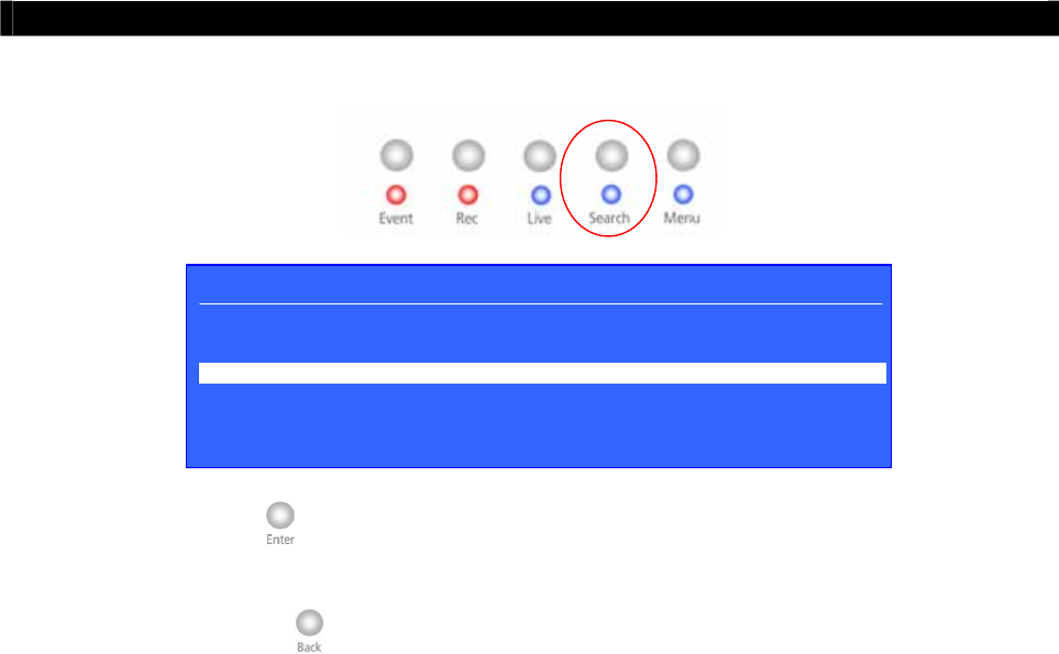
Tele
Eye RX User Guide Page 87
Recording Log Menu
B. Recording Log Menu
1. Press “Enter” button to choose play recording log, time search function and log time
scale
2. Press the “Back” button to exit the recording log menu
The record log menu contain the following status
TIME : Show date of log
CAMERA : Show time of log
EVENT : Show event triggered
REMARK : Items are not available now **
SENSOR : Show alarm sensor triggered
MOTION : Show motion trigger in which camera
AUDIO : Show audio channel **
VIDEOLOSS : Show camera video loss
ʽʽʳˍʳ˧˻˼̆ʳ˹̈́˶̇˼̂́ʳ̊˼˿˿ʳ˵˸ʳ̆̈̃̃̂̅̇˸˷ʳ˼́ʳ̇˻˸ʳ
Tele
EyeʳRXʳ̇̅˴́̆̀˼̇̇˸̅ʳ̉˸̅̆˼̂́ʳ˅ˁ˃˃ˁ˃˃ʳ̂̅ʳ˿˴̇˸̅ʳ
RECORDING LOG 12
–
13 AUG2005
TIME CAMERA EVENT REMARK SENSOR MOTION AUDIO VIDEOLOSS
11 : 00 1234 - - - - - - - - - - - - - - - - - - - - - - - - -
12 : 00 - - - 4 - - - - - - - - - - - - - - - - - - - - - - - - -
13 : 00 - - - - - - - - - - - - - - - - - - - - - - - - - - - - -
14 : 00 - 2 - - - - - - - - - - - - - - - - - - - - - - - - - - ----------
15 : 00 - - - - - - - - - - - - - - - - - - - - - - - - - - - - -
16 : 00 1 - - - - - - - - - - - - - - - - - - - - - - - - - - - -
17 : 00 1 - - - - - - - - - - - - - - - - - - - - - - - - - - - -

Tele
Eye RX User Guide Page 88
Recording Log Menu
TIME SEARCH
DATE 13 SEP 2005
TIME 10 : 30
CAMERA 1234
SEARCH ENTER
The play and log search menu contains the following options
PLAY : Play the current selected record
TIME SEARCH : Search specify time recording log and play it
MONTH LOG : Change the recording log scale to month
DAY LOG : Change the recording log scale to day
HOUR LOG : Change the recording log scale to hour
10MIN LOG : Change the recording log scale to 10 minutes
MINUTE LOG : Change the recording log scale to 1 minute
Recording Log Menu
Time Search
The time search menu contains the following options
DATE : Select the date of record
TIME : Select the time of record
CAMERA : Select the camera of record
SEARCH : Search the record
(For detail recording operation, please refers to P.67 Recording Part of Local CCTV Monitor :
Live Monitoring, Recording and Playback Section of User Guide)
PLAY
TIME SEARCH
MONTH LOG
DAY LOG
HOUR LOG
10MIN LOG
MINUTE LOG
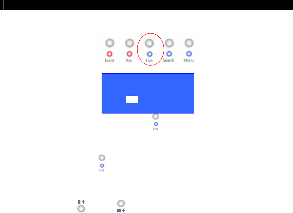
Tele
Eye RX User Guide Page 89
PTZ Menu
C. PTZ Menu
1. During live mode, user presses the “Live” button to pop up the [ENABLE PTZ] menu
2. If user selects [YES] to enable the PTZ, then [PTZ OPTION] menu always pops up when
user press the “Live” button again. User selects [DISABLE PTZ] to disable PTZ
function
3. Using the “Up” / “Down” button to select each option
ENABLE PTZ ?
YES NO

Tele
Eye RX User Guide Page 90
PTZ Menu
PTZ Menu
PTZ Option
The PTZ option menu contains the following options
RECALL PRESET : Move the PTZ camera to the preset position
PROGRAM PRESET : Save the current position of the PTZ camera as the preset position
RECALL PATROL : Select the preset patrol for the PTZ camera
STOP PATROL : Stop the patrol for the PTZ camera
AUX CTRL : Control the auxiliary of the PTZ camera
IRIS CTRL : Control the iris of the PTZ camera
FOCUS CTRL : Control the focus of the PTZ camera
ZOOM CTRL : Control the zoom of the PTZ camera
AUTO : Rotate the PTZ camera automatically
DISABLE PTZ : Disable the PTZ camera control
For [AUX CTRL], [IRIS CTRL], [FOCUS CTRL] and [ZOOM CTRL] options, user can
press “Enter” or “Back” button to control their respective action.
(For detail PTZ camera setting, please refers to P.148 Connection to PTZ Cameras Part of
Advance Operation Section of User Guide)
PTZ OPTION
RECALL PRESET
PROGRAM PRESET
RECALL PATROL
STOP PATROL
AUX CTRL
IRIS CTRL
FOCUS CTRL
ZOOM CTRL
AUTO
DISABLE PTZ
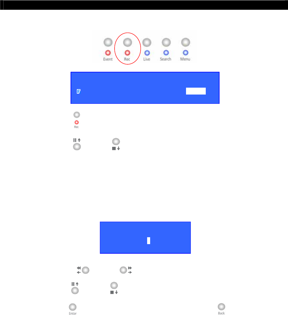
Tele
Eye RX User Guide Page 91
Recording Menu
START RECORDING
START RECORDING ENTER
RECORDING CAMERA 1 2 3 4
D. Recording Menu
1. Press the “Rec” button to pop up the main menu
2. Using the “Up” / “Down” button to select recording and set recording camera
The recording menu contains the following options
START RECORDING : Start recording operation
RECORDING CAMERA : Select the camera for recording
Recording Menu
Recording Camera
1. Using the “Left” / “Right” button to select camera
2. Press the “Up” / “Down” button to enable or disable camera for recording
3. Press “Enter” button to confirm the selection. Press the “Back” button and it will
not save any recording camera setting
RECORDING CAMER
A
1 - 3 -

Tele
Eye RX User Guide Page 92
Event Menu
E. Event Menu
1. Press the “Event” button to pop up the event menu
2. Using the “Up” / “Down” button to select a sub-menu
3. A selected sub-menu option will be pointed by a hand cursor and highlighted
4. Press “Enter” button to confirm the selection and pop up the sub-menu
5. The event menu contains the following options
EVENT STATUS : Show event status
ALARM LOG : Show the alarm log
MOTION LOG : Show the motion log
VIDEOLOSS LOG : Show the video loss log
SYSTEM TAMPER LOG : Show the system tamper log
ARM DISARM TAMPER LOG : Show the arm/disarm tamper log
SECU. SWITCH TAMPER LOG : Show the security switch tamper log
POWER FAILURE LOG : Show the power failure log
CONNECTION LOG : Show the remote connection log
6. If menu option end with [. . .] indicates sub-menu existing, you can always press “Enter”
button to pop up the sub-menu.
EVENT MENU
EVENT STATUS . . .
ALARM LOG . . .
MOTION LOG . . .
VIDEOLOSS LOG . . .
SYSTEM TAMPER LOG . . .
ARM DISARM TAMPER LOG . . .
SECU. SWITCH TAMPER LOG . . .
POWER FAILURE LOG . . .
CONNECTION LOG . . .
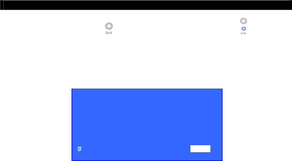
Tele
Eye RX User Guide Page 93
Event Menu
7. You can press the “Back” button back to previous menu and “Live” button to exit
menu.
Event Menu
Event Status
The event status menu contains the following options
ALARM : Show the alarm status
MOTION : Show the motion status
VIDEO LOSS : Show the video loss status
DISK FULL : Show the hard disk status
SYSTEM FAILURE : Show the system status
TAMPER : Show the arm, security switch and system tamper
status
POWER FAILURE : Show the status of power failure input
CLEAR EVENT : Clear event
EVENT STATUS
ALARM 1234
MOTION 12
VIDEO LOSS - - 34
DISK FULL NORMAL
TAMPER SYS/ARMSECSW
POWER FAILURE FAIL
CLEAR EVENT ENTER

Tele
Eye RX User Guide Page 94
Event Menu
Event Menu
Alarm Log
The alarm log contains the following status
DATE : Show the date log
TIME : Show the time log
CHANNEL : Show the alarm channel
STATUS : Show the status. Full description of status is shown as follow
TGR Alarm trigger
TAMPER Alarm tamper
ARM The system is armed
DISARM The system is disarmed
SS ON Security switch turns on
SS OFF Security switch turns off
ENTRY Entry delay occurs
EXIT Exit delay occurs
RESET Alarm reset
ACTION : Show the event associated action
Event Menu
Motion Log
The motion log contains the following status
DATE : Show the date log
TIME : Show the time log
CHANNEL : Show the camera channel
STATUS : Show the status. Full description of status is shown as follow:
TGR Motion detection occur
RESET Motion reset
ACTION : Show the event associated action
Action
R : Recording
S : Switch
D : Dial back
E : Email
B : Buzzer
P : PTZ camera
Action
R : Recording
S : Switch
D : Dial back
E : Email
B : Buzzer
P : PTZ camera
ALARM LOG
DATE TIME CHANNEL STATUS ACTION
03AUG05 12 : 45 : 18 - - - 4 - - - - RESET - - - - - -
03AUG05 12 : 29 : 46 - - - 4 - - - - TGR R- D - B- --------
02AUG05 09 : 50 : 33 - - - - - - - - ARM - - - - - -
02AUG05 09 : 35 : 02 - 2 - - - - - - TAMPER - - - E - -
01AUG05 11 : 05 : 03 - - - - - - - - SS ON - - - - - -
01AUG05 10 : 25 : 36 1 - - - - - - - RESET - - - - - -
01AUG05 10 : 10 : 10 1 - - - - - - - TGR - S- E - P
01AUG05 09 : 29 : 17 - - - - - - - - ENTRY - - - - - -
MOTION LOG
DATE TIME CHANNEL STATUS ACTION
03AUG05 12 : 45 : 18 - - - 4 - - - - TGR - - - - - -
03AUG05 12 : 29 : 46 - - - 4 - - - - RESET R- D - B- --------
02AUG05 09 : 50 : 33 - - - - - - - - TGR - - - - - -
02AUG05 09 : 35 : 02 - 2 - - - - - - TGR - - - E - -
01AUG05 11 : 05 : 03 - - - - - - - - RESET - - - - - -
01AUG05 10 : 25 : 36 1 - - - - - - - TGR - - - - - -
01AUG05 10 : 10 : 10 1 - - - - - - - TGR - S- E - P
01AUG05 09 : 29 : 17 - - - - - - - - RESET - - - - - -

Tele
Eye RX User Guide Page 95
Event Menu
Event Menu
Video Loss Log
The video loss log contains the following status
DATE : Show the date log
TIME : Show the time log
CHANNEL : Show the camera channel
STATUS : Show the status. Full description of status is shown as follow:
TGR Video loss occurs
RESET Video loss reset
ACTION : Show the event associated action
Event Menu
System Tamper Log
The system tamper log contains the following status
DATE : Show the date log
TIME : Show the time log
STATUS : Show the status. Full description of status is shown as follow:
TGR System tamper occurs
RESET System tamper reset
ACTION : Show the event associated action
Action
R : Recording
S : Switch
D : Dial back
E : Email
B : Buzzer
P : PTZ camera
Action
R : Recording
S : Switch
D : Dial back
E : Email
B : Buzzer
P : PTZ camera
VIDEOLOSS LOG
DATE TIME CHANNEL STATUS ACTION
03AUG05 12 : 45 : 18 - - - 4 - - - - RESET - - - - - -
03AUG05 12 : 29 : 46 - - - 4 - - - - TGR R- D - B- --------
02AUG05 09 : 50 : 33 - - - - - - - - RESET - - - - - -
02AUG05 09 : 35 : 02 - 2 - - - - - - TGR - - - E - -
01AUG05 11 : 05 : 03 - - 3 - - - - - TGR - - - - - -
01AUG05 10 : 25 : 36 1 - - - - - - - RESET - - - - - -
01AUG05 10 : 10 : 10 1 - - - - - - - TGR - S- E - P
01AUG05 09 : 29 : 17 - - - - - - - - RESET - - - - - -
SYSTEM TAMPER LOG
DATE TIME STATUS ACTION
22AUG05 12 : 45 : 18 RESET - - - - - -
22AUG05 12 : 29 : 46 TGR R- D - B- -
21AUG05 09 : 50 : 33 RESET - - - - - -
21AUG05 09 : 35 : 02 TGR - - - E - -
20AUG05 11 : 05 : 03 TGR - - - - - -
20AUG05 10 : 25 : 36 RESET - - - - - -
20AUG05 10 : 10 : 10 TGR - S- E - P
20AUG05 09 : 29 : 17 RESET - - - - - -

Tele
Eye RX User Guide Page 96
Event Menu
Event Menu
Arm Input Tamper Log
The arm input tamper log contains the following status
DATE : Show the date log
TIME : Show the time log
STATUS : Show the status. Full description of status is shown as follow:
TGR Arm input tamper occurs
RESET Arm input tamper reset
ACTION : Show the event associated action
Event Menu
Security Switch Tamper Log
The security switch tamper log contains the following status
DATE : Show the date log
TIME : Show the time log
STATUS : Show the status. Full description of status is shown as follow:
TGR Security switch tamper occurs
RESET Security switch tamper reset
ACTION : Show the event associated action
Action
R : Recording
S : Switch
D : Dial back
E : Email
B : Buzzer
P : PTZ camera
Action
R : Recording
S : Switch
D : Dial back
E : Email
B : Buzzer
P : PTZ camera
A
RM INPUT TAMPER LOG
DATE TIME STATUS ACTION
22AUG05 12 : 45 : 18 RESET - - - - - -
22AUG05 12 : 29 : 46 TGR R- D - B- ---
21AUG05 09 : 50 : 33 RESET - - - - - -
21AUG05 09 : 35 : 02 TGR - - - E - -
20AUG05 11 : 05 : 03 TGR - - D - - -
20AUG05 10 : 25 : 36 RESET - - - - - -
20AUG05 10 : 10 : 10 TGR - S- E - P
20AUG05 09 : 29 : 17 RESET - - - - - -
SECU. SWITCH TAMPER LOG
DATE TIME STATUS ACTION
22AUG05 12 : 45 : 18 RESET - - - - - -
22AUG05 12 : 29 : 46 TGR R- D - B---
21AUG05 09 : 50 : 33 RESET - - - - - -
21AUG05 09 : 35 : 02 TGR - - - E - -
20AUG05 11 : 05 : 03 TGR R - - - - -
20AUG05 10 : 25 : 36 RESET - - - - - -
20AUG05 10 : 10 : 10 TGR - S- E - P
20AUG05 09 : 29 : 17 RESET - - - - - -

Tele
Eye RX User Guide Page 97
Event Menu
Event Menu
Power Failure Log
The power failure log contains the following status
DATE : Show the date log
TIME : Show the time log
STATUS : Show the status. Full description of status is shown as follow:
TGR Power failure occurs
RESET Power failure reset
ACTION : Show the event associated action
Event Menu
Connection Log
The connection log contains the following status
DATE : Show the date log
TIME : Show the time log
USER : Show the user type connected to the transmitter through remote
software
REMARK : Show the connection triggered by user or dialback action
DIAL IN Remote connect to transmitter
DIAL BACK Transmitter connect to remote
IP/PHONE NO. : Show the IP or phone number of the remote host
DEVICE : Show connection method by the remote software
STATUS : Show the connection status
Action
R : Recording
S : Switch
D : Dial back
E : Email
B : Buzzer
P : PTZ camera
POWER FAILURE LOG
DATE TIME STATUS ACTION
22AUG05 12 : 45 : 18 RESET - - - - - -
22AUG05 12 : 29 : 46 TGR R- D - B---
21AUG05 09 : 50 : 33 RESET - - - - - -
21AUG05 09 : 35 : 02 TGR - - - E - -
20AUG05 11 : 05 : 03 TGR - - - - - -
20AUG05 10 : 25 : 36 RESET - - - - - -
20AUG05 10 : 10 : 10 TGR - S- E - P
20AUG05 09 : 29 : 17 RESET - - - - - -
CONNECTION LOG
DATE TIME USER REMARK IP/PHONE NO DEVICE STATUS
22AUG05 12 : 45 : 18 ADMIN - - - - 192.168.0.2 TCP / IP DISCONNECTED
22AUG05 12 : 29 : 46 ADMIN DIAL IN 192.168.0.2 TCP / IP CONNECTED
21AUG05 09 : 50 : 33 ADMIN - - - - 192.168.0.2 TCP / IP DISCONNECTED
21AUG05 09 : 35 : 02 ADMIN DIAL BACK 192.168.0.2 TCP / IP CONNECTED
20AUG05 11 : 05 : 03 ADMIN - - - - 192.168.0.2 TCP / IP DISCONNECTED
20AUG05 10 : 25 : 36 ADMIN DIAL BACK 192.168.0.2 TCP / IP CONNECTED
20AUG05 10 : 10 : 10 ADMIN - - - - 192.168.0.2 TCP / IP DISCONNECTED
20AUG05 09 : 29 : 17 ADMIN DIAL BACK 192.168.0.2 TCP / IP CONNECTED
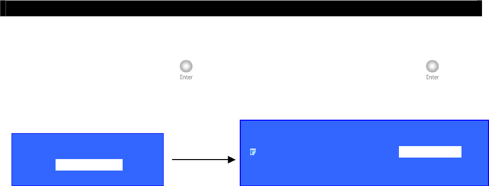
Tele
Eye RX User Guide Page 98
Event Menu
SEARCH LOG
DATE 20 SEP 2005
TIME 10 : 19
SEARCH ENTER
Event Menu
XXXX Log
Search Log
For each log, you can press “Enter” button to enter the log option, and press “Enter” button
in [TIME SEARCH] option to enter search log menu.
The connection log contains the following options
DATE : Set the search date
TIME : Set the search time
SEARCH : Search the nearest record according the date and time
LOG OPTION
TIME SEARCH
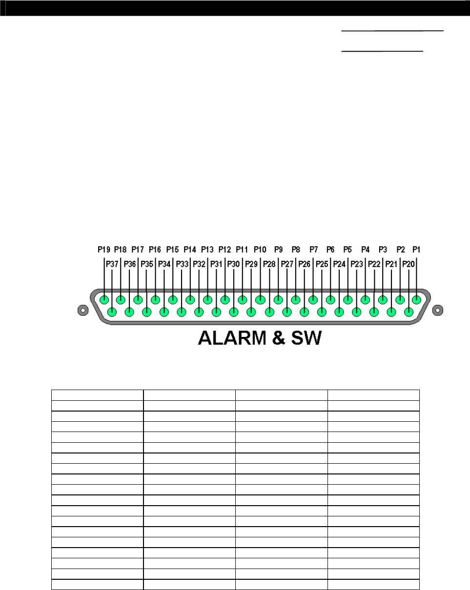
Tele
Eye RX User Guide Page 99
Install
Tele
Eye RX with Alarm Sensors
and Relay Control Port
6
Advanced Operation
A. Install
Tele
Eye RX with Alarm Sensors and Relay
Control Port
Tele
Eye RX304 supports up to 4 alarm ports with tamper detection for connecting with
alarm sensors, 4 additional input sensors and 4 relay ports for control. The definitions of alarm
and relay control ports are shown in the following diagram.
Pin assignment for
Tele
Eye RX304
Pin 1 ALARM 1 Pin 20 GND
Pin 2 ALARM 2 Pin 21 GND
Pin 3 ALARM 3 Pin 22 GND
Pin 4 ALARM 4 Pin 23 GND
Pin 5 N/A Pin 24 GND
Pin 6 N/A Pin 25 GND
Pin 7 N/A Pin 26 GND
Pin 8 N/A Pin 27 GND
Pin 9 N/A Pin 28 ARM/DISARM
Pin 10 N/A Pin 29 SECURITY SWITCH
Pin 11 N/A Pin 30 POWER FAILURE
Pin 12 N/A Pin 31 SYSTEM TAMPER
Pin 13 N/A Pin 32 N/A
Pin 14 N/A Pin 33 N/A
Pin 15 RELAY 0a Pin 34 RELAY 0b
Pin 16 RELAY 1a Pin 35 RELAY 1b
Pin 17 RELAY 2a Pin 36 RELAY 2b
Pin 18 RELAY 3a Pin 37 RELAY 3b
Pin 19 N/A
SECTION
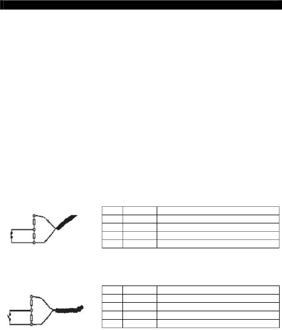
Tele
Eye RX User Guide Page 100
Install
Tele
Eye RX with Tamper Circuit and External Resistors
B. Install
Tele
Eye RX with Tamper Circuit and External
Resistors
Tele
Eye RX supports tamper detection (DEOL and SEOL) on all alarm inputs, arm/disarm
input, security switch input, system tamper and power failure input.
DEOL : Dual End of Line termination with NC and NO connection
SEOL : Single End of Line termination with NC and NO connection
NC/NO : Alarm and other input ports without tamper detection circuit
connection
For example, by connecting the tamper circuit with DEOL, the circuit with the normal closed
condition if the resistance between point A and B detect 1.2kΩ (shown as below), or the
circuit with the normal open condition if the resistance between point A and B (shown as
below) detect 7.2kΩ.The resistance transition from 1.2kΩ to 7.2kΩ is generated an alarm
tamper event for normal close circuit. The setup configuration of those alarms and input ports
are shown in the following diagram. The circuit debouncing time between each sensor is 20
millisecond.
Dual End of Line Configuration
Normal Close (NC)
Normal Open (NO)
Term Status Description
S/C TAMPER Wire short (point A and B)
LoZ NORMAL Sensor drive output close (point B and C)
HiZ ALARM Sensor drive output open (point B and C)
O/C TAMPER Wire open (point A and B)
Term Status Description
S/C TAMPER Wire short (point A and B)
LoZ ALARM Sensor drive output close (point B and C)
HiZ NORMAL Sensor drive output open (point B and C)
O/C TAMPER Wire open (point A and B)
wire
sensor
drive
output
A
B
C
wire
sensor
drive
output
A
B
C
R1.2K
R6K
R1.2K
R6K
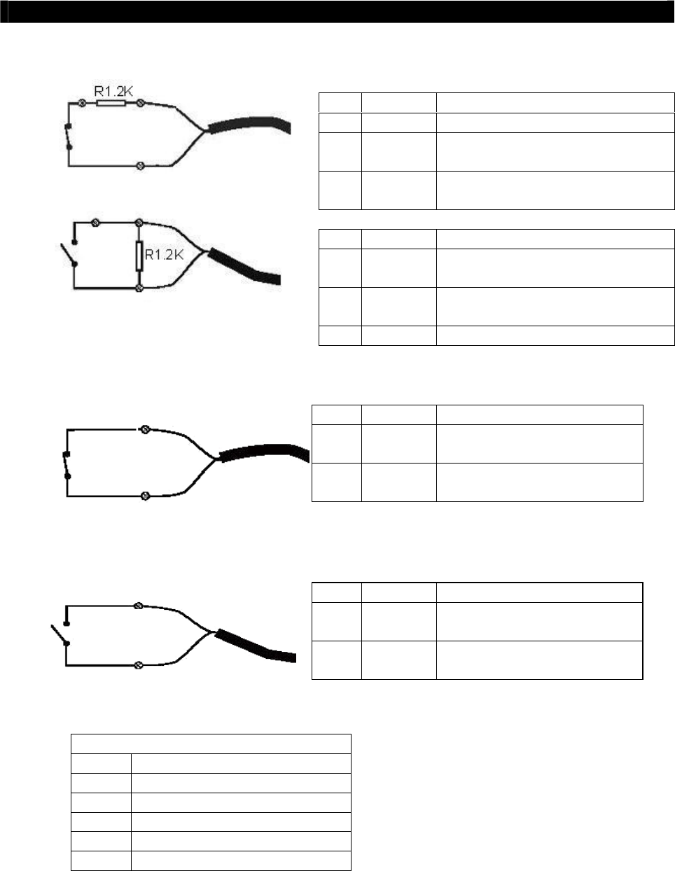
Tele
Eye RX User Guide Page 101
Install
Tele
Eye RX with Tamper Circuit and External Resistors
Single End of Line Configuration
Normal Close (NC)
Normal Open (NO)
Without Tamper Detection Circuit Configuration
Normal Close (NC)
Normal Open (NO)
LEGEND
NO Normally Open Alarm
NC Normally Closed Alarm
O/C Open Circuit
S/C Short Circuit
LoZ Low Impedance
HiZ High Impedance
Term Status Description
S/C TAMPER Wire short (point A and B)
LoZ NORMAL Sensor drive output close (point B
and C)
O/C ALARM Sensor drive output open (point B
and C)
Term Status Description
S/C ALARM Sensor drive output close (point A
and B)
LoZ NORMAL Sensor drive output open (point A
and B)
O/C TAMPER Wire open (point A and B)
Term Status Description
S/C NORMAL Sensor drive output close
(point A and B)
O/C ALARM Sensor drive output open
(point A and B)
Term Status Description
S/C ALARM Sensor drive output close
(point A and B)
O/C NORMAL Sensor drive output open
(point A and B)
sensor
drive
output
A
B
wire
sensor
drive
output
B
A
wire
C
sensor
drive
output
wire
A
B
sensor
drive
output
wire
B
A
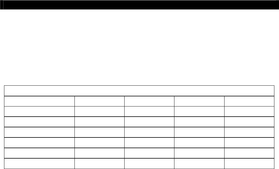
Tele
Eye RX User Guide Page 102
Install
Tele
Eye RX with Tamper Circuit and External Resistors
Notes:
The below table shows the summary between the resistance network and the condition result. Note
that this table is used as a reference. There may be a 10% tolerance for the resistance value in the
below table.
Resistance (Ω)
Condition 0~400 401~2780 2781~29.5k 29.5k~Infinity
DEOL (Normal Close) Tamper Short Normal (Close) Alarm (Open) Tamper Open
DEOL (Normal Open) Tamper Short Alarm (Close) Normal (Open) Tamper Open
SEOL (Normal Close) Tamper Short Normal (Close) Alarm (N/A) Alarm (Open)
SEOL (Normal Open) Alarm (Close) Normal (Open) Alarm (N/A) Tamper Open
NC without tamper Normal (Close) Alarm (N/A) Alarm (N/A) Alarm (Open)
NO without tamper Alarm (Close) Alarm (N/A) Alarm (N/A) Normal (Open)
Alarm (N/A): Alarm with not applicable.
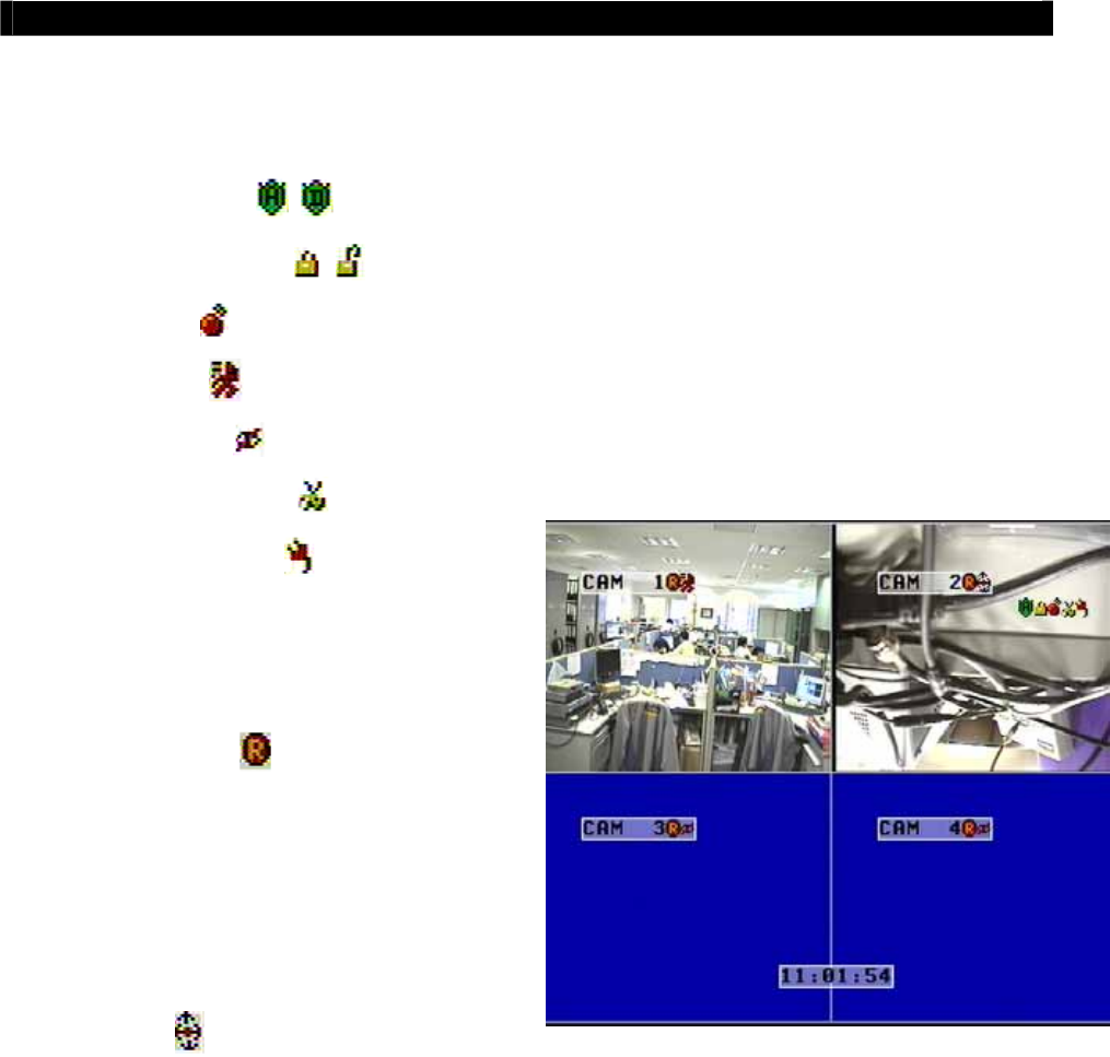
Tele
Eye RX User Guide Page 103
Event Handling
C. Event Handling
Tele
Eye RX transmitter supports 7 events and their icons are as follows.
1. Arm/Disarm
2. Security Switch
3. Alarm
4. Motion
5. Videoloss
6. System Tamper
7. Power Failure
Tele
Eye RX supports 7 actions which can be
activated by any events as above.
1. Recording
2. Switch
3. Dialback
4. Buzzer
5. Event LED
6. Live Camera
7. PTZ
Event and Action Icons in Local CCTV Monitor
The icons of the 7 events are shown as above. If an event is triggering, its respective icon is
flashing on the top right corner (for events : arm/disarm, security switch, alarm, power
failure, system tamper) or next to the camera name (for events : motion, videoloss). If an
event has been triggered before without clear, its icon remains static on its original position.
Full event and action icons are shown as the above figure.

Tele
Eye RX User Guide Page 104
Event Handling
I. Arm/Disarm
Arm/Disarm
Arm/Disarm input is used for enhancing security level of the surveillance area. This input
introduce the concept of 3 zone types for alarm, fire zone, normal and entry exit zone.
Armed
If the system is armed, alarm sensor in normal zone type can be triggered immediately if
someone triggers the sensor. It is usually used when there is no operator at surveillance area
Disarmed
If the system is disarmed, alarm events detected from sensors will not result in an alarm except
the fire zone type alarm and arm/disarm tamper. If there are operators at surveillance area, it
is usually disarmed.
Arm/Disarm Tamper Type
Arm/Disarm tamper event triggers if someone cuts the wire between the arm/disarm input and
the transmitter. This event can be triggered immediately no matter which zone is. Arm/Disarm
tamper type has choice of none, SEOL, DEOL. (Please refers to P.100 Tamper Circuit Section
of User Guide)
Arm State
The arm/disarm input circuit type is normal close (NC). The state of the circuit is close, it
indicates disarm of
Tele
Eye RX. Otherwise, the state of the circuit is open, it indicates arm
of
Tele
Eye RX. The arm/disarm input circuit type is normal open (NO). The state of the
circuit is open, it indicates disarm of
Tele
Eye RX. Otherwise, the state of the circuit is close,
it indicates arm of
Tele
Eye RX.
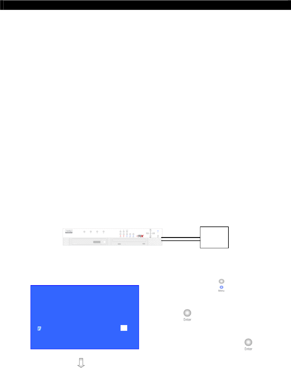
Tele
Eye RX User Guide Page 105
Event Handling
Zone Type
Although the setting of zone type belongs to alarm menu, it is worth to discuss as below.
Fire Zone
This zone allows alarms to trigger no matter which arm state of the system is, i.e. armed or
disarmed. It is suitable for installation of fire detectors
Normal
This zone allows alarms to trigger after armed.
Entry/Exit Zone
This zone allows user to set the delay time for entering or leaving the surveillance area without
triggering any alarm event. If alarm recording action is enabled, recording starts at entry or exit
time through out the delay.
(For detail usage example, please refers to P.111 Alarm Part in Event Handling Section of User
Guide.)
Physical Configuration for Arm/Disarm
The arm/disarm input and ground of
Tele
Eye RX transmitter needs to connect to a control unit
which is commonly a switch or password panel for arm/disarm input.
Control
circuit
Arm/Disarm Input
Ground
Arm/Disarm Setup Procedure
Step 1: Press “Menu” button, select
[SETUP] option and press “Enter”
button to enter [SETUP] sub
menu. Select [EVENT HANDLER]
option and press “Enter” button.
SETUP MENU
VIDEO . . .
RECORDING . . .
SWITCHES . . .
DATE / TIME . . .
CONNECTION . . .
EVENT HANDLER . . .
TRANSMITTER . . .
SHUT DOWN ENTER
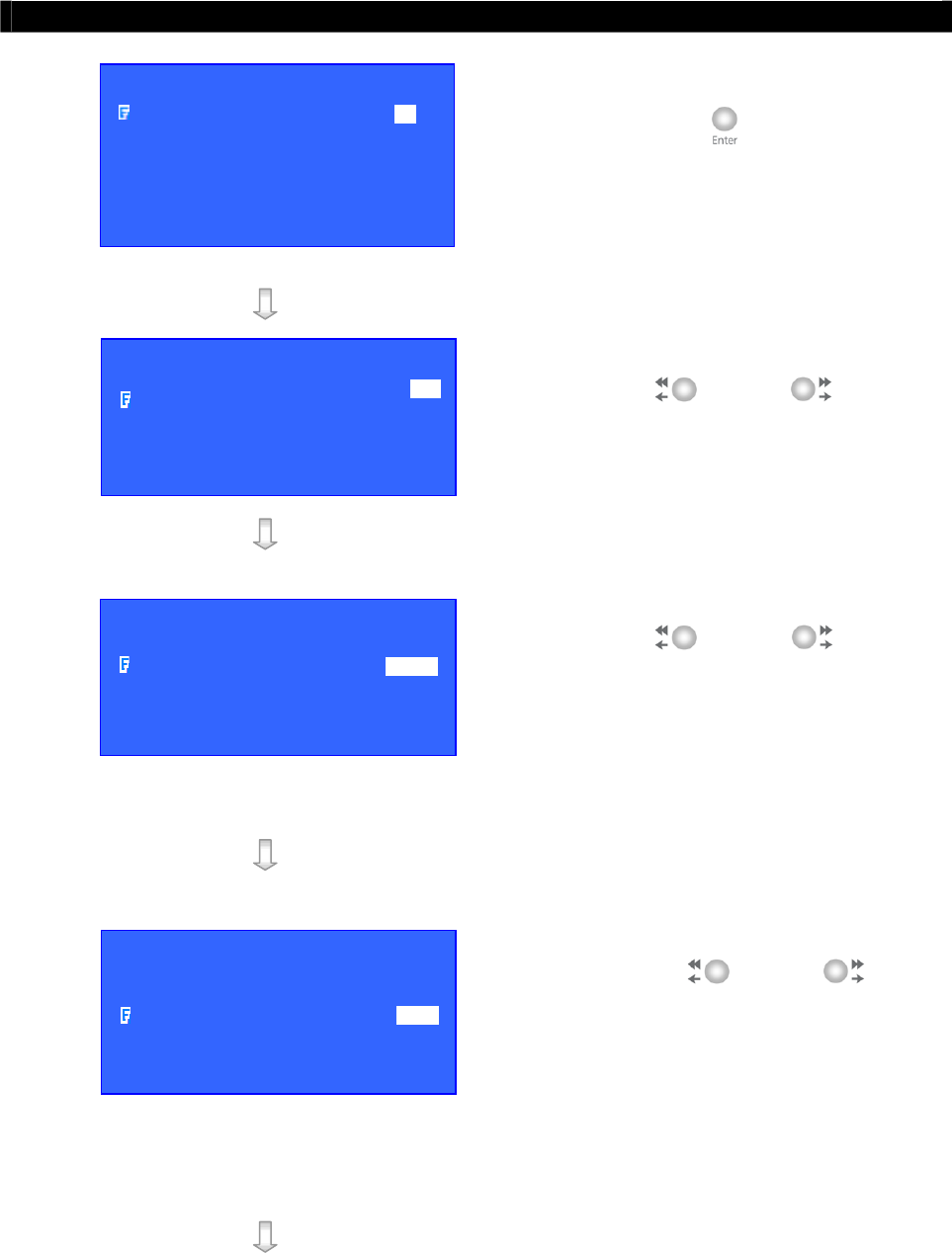
Tele
Eye RX User Guide Page 106
Event Handling
Step 2: Select [ARM/DISARM] option and
press “Enter” button to show
arm/disarm setting menu.
Step 3: Select [ENABLED] option and use
“Left” or “Right” button
to enable (i.e. set the value to [YES])
the arm/disarm function.
Step 4: Select [ARM STATE] option and use
“Left” or “Right” button
to choose arm state according to the
configuration of
Tele
Eye RX
arm/disarm control circuit type.
Step 5: Select [TAMPER TYPE] option and
use “Left” or “Right”
button to choose arm/disarm tamper
circuit type according to the
configuration of
Tele
Eye RX
arm/disarm tamper circuit type.
EVENT HANDLER
ARM / DISARM . . .
SECURITY SWITCH . . .
ALARM . . .
MOTION . . .
VIDEO LOSS . . .
SYSTEM TAMPER . . .
POWER FAILURE . . .
A
RM / DISARM
ENABLED YES
ARM STATE CLOSE
TAMPER TYPE NONE
ASSOCIATE SWITCH NO
TAMPER EVENT ACTION …
A
RM / DISARM
ENABLED YES
ARM STATE CLOSE
TAMPER TYPE NONE
ASSOCIATE SWITCH NO
TAMPER EVENT ACTION …
A
RM / DISARM
ENABLED YES
ARM STATE CLOSE
TAMPER TYPE DEOL
ASSOCIATE SWITCH NO
TAMPER EVENT ACTION …
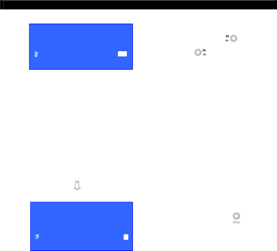
Tele
Eye RX User Guide Page 107
Event Handling
Step 6: Select [ASSOCIATE SWITCH]
option and use “Left” or
“Right” button to select [YES]
and enable switch 1 only for
arm/disarm associate switch. Switch 1
will be ON when
Tele
Eye RX is
armed. Switch 1 will be OFF when
Tele
Eye RX is disarmed. Switch 1
cannot be activated by other events any
more if it is an associate switch of
arm/disarm.
Step 7: Select [TAMPER EVENT ACTION]
option and press “Enter” button to
select arm/disarm tamper action. (For
action, please refers to Event Action
Part in Advance Operation Section of
User Guide)
A
RM / DISARM
ENABLED YES
ARM STATE CLOSE
TAMPER TYPE DEOL
ASSOCIATE SWITCH YES
TAMPER EVENT ACTION …
A
RM / DISARM
ENABLED YES
ARM STATE CLOSE
TAMPER TYPE DEOL
ASSOCIATE SWITCH YES
TAMPER EVENT ACTION …
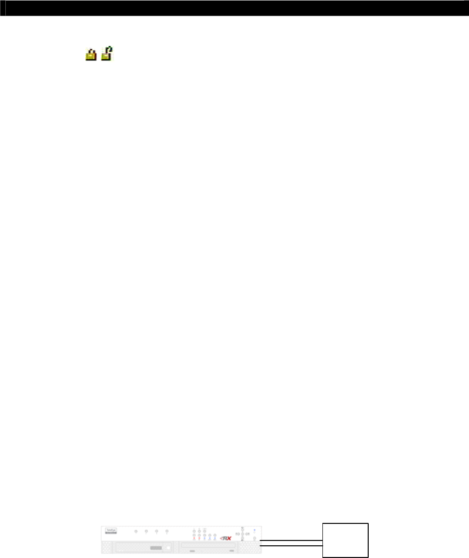
Tele
Eye RX User Guide Page 108
Event Handling
II. Security Switch
Security Switch
It is an input to the transmitter for wiring a security switch. The purpose of the security switch
is to terminate the exit delay for exit zone alarm. If the security switch is on and the system is
armed, all exit delay will be terminated. If the security switch is off and an entry alarm
triggered, entry delays will start.
Security Switch Tamper Type
Security switch tamper event triggers if someone cuts the wire between the security switch
input and the transmitter. This event behaves as fire zone type that can be triggered once the
wire being cut. Arm/Disarm tamper type has choice of none, SEOL, DEOL. (Please refers to
P.100 Tamper Circuit Section of the User Guide)
On State
The security switch input circuit type is normal close (NC). The state of the circuit is close, it
indicates security switch off of
Tele
Eye RX. Otherwise, the state of the circuit is open, it
indicates security switch on of
Tele
Eye RX. The security switch input circuit type is normal
open (NO). The state of the circuit is open, it indicates security switch off of
Tele
Eye RX.
Otherwise, the state of the circuit is close, it indicates security switch on of
Tele
Eye RX.
(For detail usage, please refers to P.111 Alarm Part in Event Handling Section of User Guide.)
Physical Configuration for Security Switch
The security switch input and ground of
Tele
Eye RX transmitter needs to connect to a control
unit which is commonly the lock of the surveillance area for security switch input.
Control
circuit
Security Switch Input
Ground
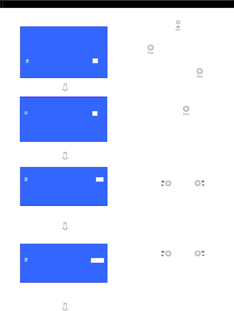
Tele
Eye RX User Guide Page 109
Event Handling
Security Switch Setup Procedure
Step 1: Press “Menu” button, select
[SETUP] option and press “Enter”
button to enter [SETUP] sub
menu. Select [EVENT HANDLER]
option and press “Enter” button.
Step 2: Select [SECURITY SWITCH] option
and press “Enter” button to show
security switch setting menu.
Step 3: Select [ENABLED] option and use
“Left” or “Right” button
to enable (i.e. set the value to [YES])
the security switch function.
Step 4: Select [ON STATE] option and use
“Left” or “Right” button
to choose on state according to the
configuration of
Tele
Eye RX security
switch control circuit type.
SETUP MENU
VIDEO . . .
RECORDING . . .
SWITCHES . . .
DATE / TIME . . .
CONNECTION . . .
EVENT HANDLER . . .
TRANSMITTER . . .
SHUT DOWN ENTER
EVENT H
A
NDLER
ARM / DISARM . . .
SECURITY SWITCH . . .
ALARM . . .
MOTION . . .
VIDEO LOSS . . .
SYSTEM TAMPER . . .
POWER FAILURE . . .
SECURITY SWITCH
ENABLED YES
ON STATE OPEN
TAMPER TYPE NONE
ASSOCIATE SWITCH NO
TAMPER EVENT ACTION …
SECURITY SWITCH
ENABLED YES
ON STATE CLOSE
TAMPER TYPE NONE
ASSOCIATE SWITCH NO
TAMPER EVENT ACTION …
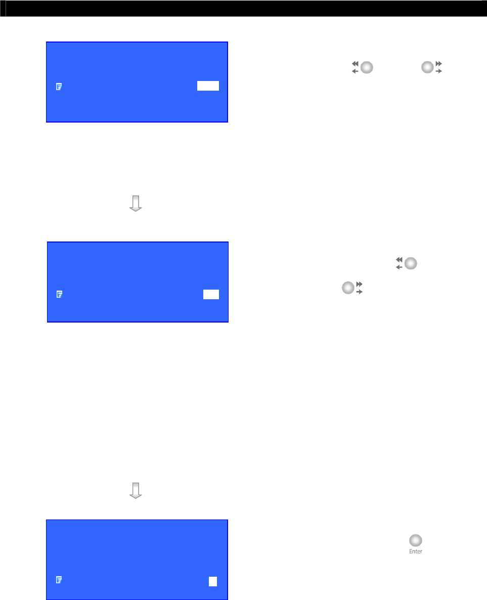
Tele
Eye RX User Guide Page 110
Event Handling
Step 5: Select [TAMPER TYPE] option and
use “Left” or “Right”
button to choose security switch
tamper circuit type according to the
configuration of
Tele
Eye RX security
switch tamper circuit type.
Step 6: Select [ASSOCIATE SWITCH]
option and use “Left” or
“Right” button to select [YES]
and enable switch 2 only for security
switch associate switch. Switch 2 will
be ON when the security switch is on.
Switch 1 will be OFF when the
security switch is off. Switch 2 cannot
be activated by other events any more
if it is an associate switch of security
switch.
Step 7: Select [TAMPER EVENT ACTION]
option and press “Enter” button to
select security switch tamper action.
(For action, please refers to Event
Action Part in Advance Operation
Section of User Guide)
SECURITY SWITCH
ENABLED YES
ON STATE CLOSE
TAMPER TYPE DEOL
ASSOCIATE SWITCH NO
TAMPER EVENT ACTION …
SECURITY SWITCH
ENABLED YES
ON STATE CLOSE
TAMPER TYPE DEOL
ASSOCIATE SWITCH YES
TAMPER EVENT ACTION …
SECURITY SWITCH
ENABLED YES
ON STATE CLOSE
TAMPER TYPE DEOL
ASSOCIATE SWITCH YES
TAMPER EVENT ACTION …

Tele
Eye RX User Guide Page 111
Event Handling
III. Alarm
Alarm
It is an input to the transmitter from external alarm sensors. Alarm can be used to detect many
events occur at the surveillance area, such as fire and illegal entering by someone. The alarm
event supports BS 8418:2003 which has arm/disarm and security switch function.
Sensor Tamper Type
Alarm tamper event triggers if someone cuts the wire between the alarm input and the
transmitter. This event behaves as fire zone type that can be triggered once the wire being cut.
Alarm tamper type has choice of none, SEOL, DEOL. (Please refers to P.100 Tamper Circuit
Section of User Guide)
Sensor Type
The alarm sensor input circuit type is normal close (NC). The state of the circuit is close, it
indicates normal of
Tele
Eye RX. Otherwise, the state of the circuit is open, it indicates alarm
trigger of
Tele
Eye RX. The alarm sensor input circuit type is normal open (NO). The state of
the circuit is open, it indicates normal of
Tele
Eye RX. Otherwise, the state of the circuit is
close, it indicates alarm trigger of
Tele
Eye RX.
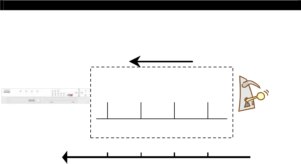
Tele
Eye RX User Guide Page 112
Event Handling
Example of Entry/Exit Zone WITH Security Switch Usage
For Entry Zone :
The entry delay is the period of time between entering the surveillance zone and reaching the
transmitter. In order to disarm the system for maintenance or repair, user / installer needs to turn
off the security switch and enter the surveillance zone. However, the delay time starts from the
1st trigger by the 1st alarm sensor (i.e. Alarm 4). Note that if user enables recording action,
recording action is automatically activated during entry delay.
The detail procedure is as below:
1) user turns off security switch
2) the alarm is at entry delay
3) the 1st trigger is made by Alarm 4 (i.e. user enter the surveillance zone and the entry delay
time begin)
4) 2nd, 3rd and 4th trigger are made and each entry delay starts respectively
5) user disarms the system for maintenance
For example: If the time for going from security switch to transmitter is about 8 minutes, Delay
1 should be longer than 8 minutes, while Delay 2 should be longer than the time for going from
security switch to Alarm 2, and so on.
Alarm 4Alarm 3Alarm 2Alarm 1
Entry
Security Switch
Surveillance zone
Delay4Delay3Delay2Delay1
Time line
Tel
e
Eye RX
DISARM
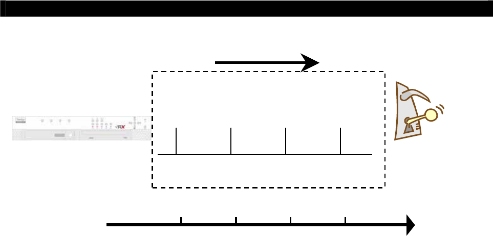
Tele
Eye RX User Guide Page 113
Event Handling
For Exit Zone :
The exit delay is the period of time for leaving a surveillance zone without making false alarm
(i.e. Alarm 1, Alarm 2, Alarm 3 and Alarm 4). The purpose is to let the user / installer have
enough of time to leave the surveillance zone after the transmitter is armed. User / installer can
set the delay time for each alarm.
The detail procedure is as below:
1) user arms the system
2) the alarm is at exit delay
3) the 1st trigger is made by Alarm 1 (i.e. user leave the surveillance zone and the exit delay
time begin)
4) 2nd, 3rd and 4th trigger are made and each exit delay starts respectively
5) user turns off the security switch or waits for any alarm exit delay to expire.
For example, if the time for leaving the surveillance zone is about 8 minutes, user should adjust
the delay time so that Delay 1 = leaving time between transmitter and Alarm 1, Delay 2 =
leaving time between transmitter and Alarm 2, Delay 3 = leaving time between transmitter and
Alarm 3 and Delay 4 = 8 minutes. The alarm will be activated after the exit delay expired. Note
that if user enables recording action, recording action is automatically activated during exit
delay.
Alarm 4Alarm 3Alarm 2Alarm 1
Security Switch
Exit
Delay4Delay3Delay2Delay1
Surveillance zone
Time line
Tel
e
Eye RX
ARM
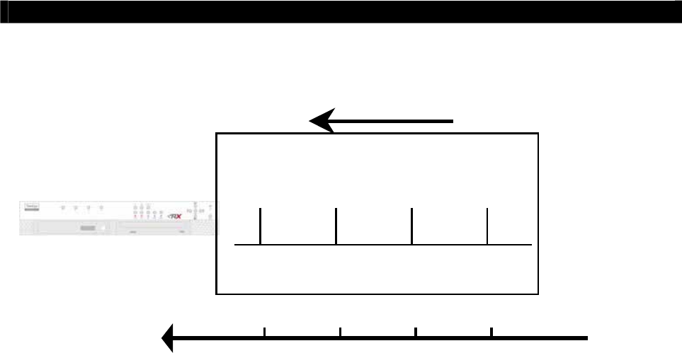
Tele
Eye RX User Guide Page 114
Event Handling
Example of Entry/Exit Zone WITHOUT Security Switch Usage
For Entry Zone :
The entry delay is the period of time between entering the surveillance zone and reaching the
transmitter. In order to disarm the system for maintenance or repair, user / installer enters the
surveillance zone, and the delay time starts from the 1st trigger by the 1st alarm sensor (i.e.
Alarm 4) automatically. Note that if user enables recording action, recording action is
automatically activated during entry delay.
The detail procedure is as below:
1) the alarm is at entry delay
2) the 1st trigger is made by Alarm 4 (i.e. user enter the surveillance zone and the entry delay
time begin)
3) 2nd, 3rd and 4th trigger are made and each entry delay starts respectively
4) user disarms the system for maintenance
For example: If the time for going from Alarm 4 to transmitter is about 8 minutes, Delay 1
should be longer than 8 minutes, while Delay 2 should be longer than the time for going from
security switch to Alarm 2, and so on.
Tel
e
Eye RX
DISARM
Surveillance zone
Entry
Alarm 4Alarm 3Alarm 2Alarm 1
Delay4Delay3Delay2Delay1
Time line
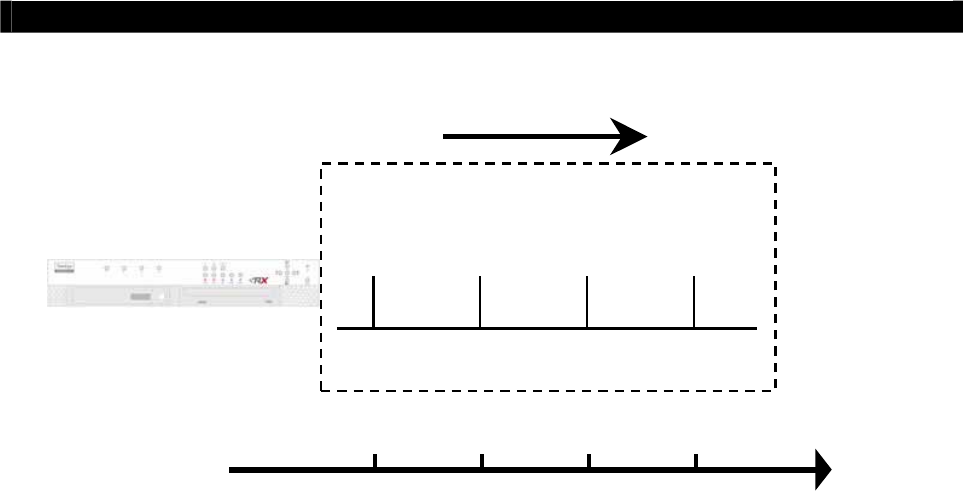
Tele
Eye RX User Guide Page 115
Event Handling
For Exit Zone :
The exit delay is the period of time for leaving a surveillance zone without making false alarm
(i.e. Alarm 1, Alarm 2, Alarm 3 and Alarm 4). The purpose is to let the user / installer have
enough of time to leave the surveillance zone after the transmitter is armed. User / installer can
set the delay time for each alarm.
The detail procedure is as below:
1) user arms the system
2) the alarm moves to exit delay
3) the 1st trigger is made by Alarm1 (i.e. user leave the surveillance zone and the exit delay
time begin)
4) 2nd, 3rd and 4th trigger are made and each exit delay starts respectively
5) user waits for any alarm exit delay to expire.
For example, if the time for leaving the surveillance zone is about 8 minutes, user should adjust
the delay time so that Delay 1 = leaving time between transmitter and Alarm 1, Delay 2 =
leaving time between transmitter and Alarm 2, Delay 3 = leaving time between transmitter and
Alarm 3 and Delay 4 = 8 minutes. The alarm will be activated after the exit delay expired. Note
that if user enables recording action, recording action is automatically activated during exit
delay.
Tel
e
Eye RX
ARM
Surveillance zone
Alarm 4Alarm 3Alarm 2Alarm 1
Delay4Delay3Delay2Delay1
Exit
Time line

Tele
Eye RX User Guide Page 116
Event Handling
Different Combination Cases of Arm/Disarm, Security Switch and Alarm for the 3 Zone Type
Initial State
Arm Security Switch Alarm
Step 1 Step 2 Step 3 Result
Fire Zone
Arm On No trigger
Trigger alarm \ \ Alarm trigger
Arm Off No trigger Trigger alarm \ \ Alarm trigger
Arm Uninstall No trigger Trigger alarm \ \ Alarm trigger
Disarm \ No trigger Trigger alarm \ \ Alarm trigger
Uninstall \ No trigger Trigger alarm \ \ Alarm trigger
Uninstall Uninstall No trigger Trigger alarm \ \ Alarm trigger
Normal
Arm On No trigger
Trigger alarm \ \ Alarm trigger
Arm Off No trigger Trigger alarm \ \ Alarm trigger
Arm Uninstall No trigger Trigger alarm \ \ Alarm trigger
Disarm \ No trigger Trigger alarm \ \ No alarm trigger
Uninstall \ No trigger Trigger alarm \ \ Alarm trigger
Uninstall Uninstall No trigger Trigger alarm \ \ Alarm trigger
Entry / Exit Zone
Arm On No trigger
Trigger alarm \ \ Alarm trigger
Security switch on.
Exit delay ends.
Recording stops
Alarm can be triggered
any time after that
Disarm Off No trigger Arm
Trigger alarm.
Exit delay starts.
Recording starts (if
recording action is
enabled)
Security switch off.
Exit delay ends
after the preset exit
time value.
Recording stops
Alarm can be triggered
any time after that
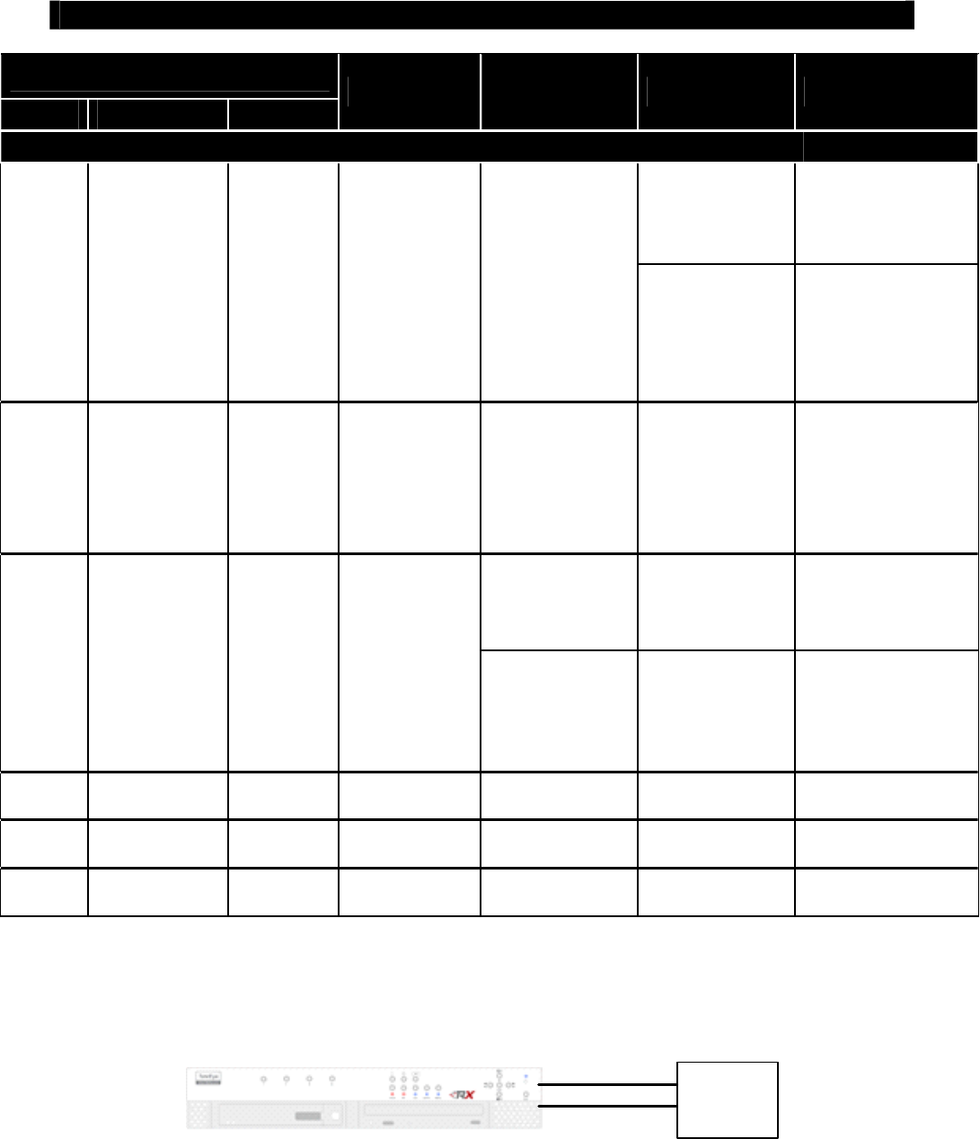
Tele
Eye RX User Guide Page 117
Event Handling
Initial State
Arm Security Switch Alarm
Step 1 Step 2 Step 3 Result
Entry / Exit Zone
Disarm No alarm trigger.
Recording stops
Arm On No trigger
Security switch
off
Trigger alarm.
Entry delay starts.
Recording starts (if
recording action is
enabled) Arm
Alarm is triggered
Recording does not
stop unless user disarm
the system
Disarm Uninstall No trigger Arm
Trigger alarm.
Exit delay starts.
Recording starts (if
recording action is
enabled)
Exit delay ends
after the preset exit
time value.
Recording stops
The system will enter
entry delay
automatically after
next alarm trigger
Disarm \ No alarm trigger.
Recording stops.
Arm Uninstall No trigger
Trigger alarm.
Entry delay
starts.
Recording starts
(if recording
action is enabled)
Arm \
Alarm is triggered.
Recording does not
stop unless user disarm
the system.
Disarm No trigger Trigger alarm \ \ No alarm trigger
Uninstall No trigger Trigger alarm \ \ Alarm trigger
Uninstall Uninstall No trigger Trigger alarm \ \ Alarm trigger
Physical Configuration for Alarm
The alarm input and ground of
Tele
Eye RX transmitter need to connect to various kinds of
sensors which are commonly installed at entrance or special part of the surveillance area.
Alarm
Senor
Alarm Input
Ground
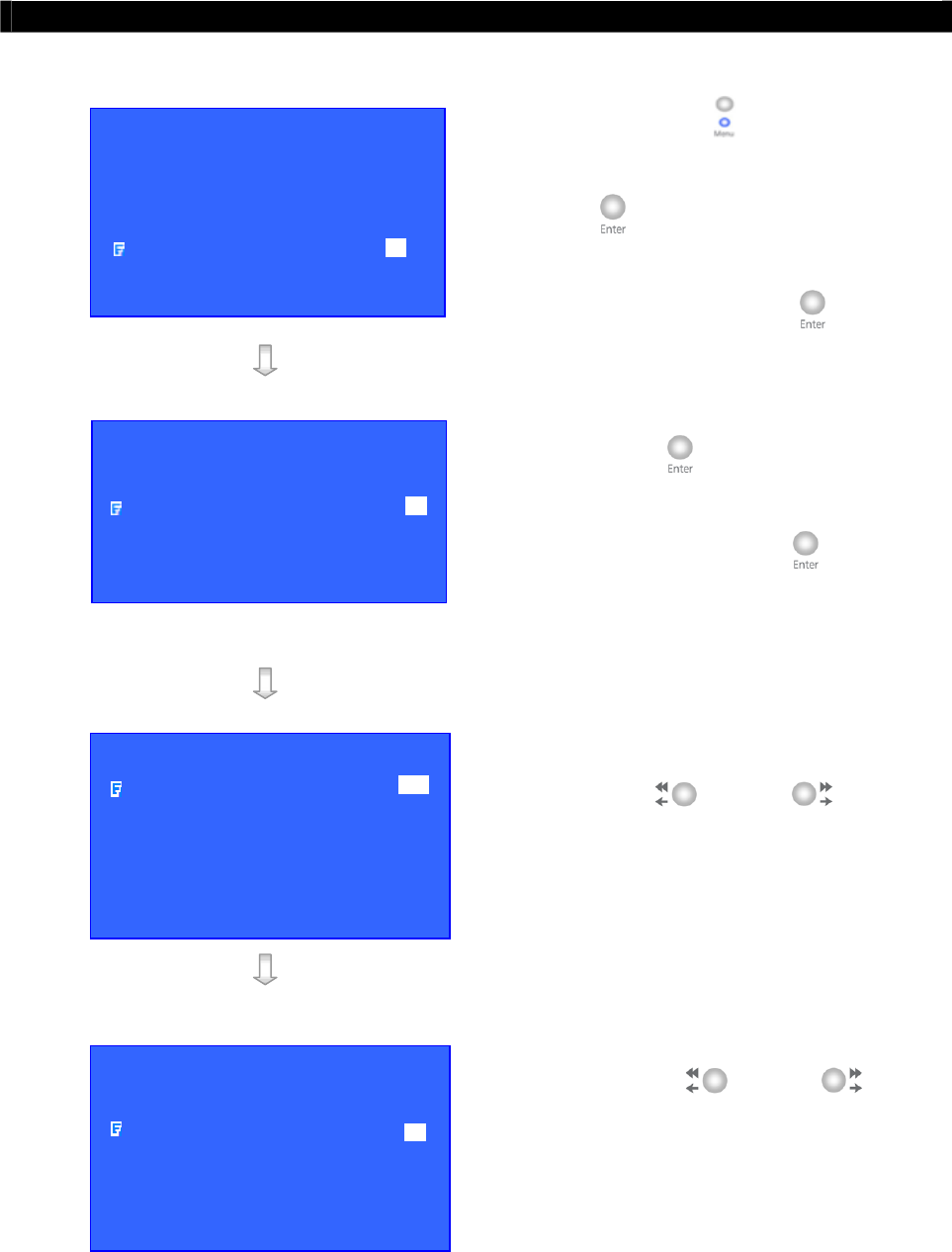
Tele
Eye RX User Guide Page 118
Event Handling
Alarm Setup Procedure
Step 1: Press “Menu” button, select
[SETUP] option and press “Enter”
button to enter [SETUP] sub
menu. Select [EVENT HANDLER]
option and press “Enter” button.
Step 2: Select [ALARM] option and press
“Enter” button to show the alarm
selection menu. Select appropriate
alarm and press “Enter” button to
enter the alarm setting menu.
Step 3: Select [ENABLED] option and use
“Left” or “Right” button
to enable (i.e. set the value to [YES])
alarm.
Step 4: Select [SENSOR TYPE] option and
use “Left” or “Right”
button to choose sensor type according
to the configuration of
Tele
Eye RX
alarm sensor control circuit type.
SETUP MENU
VIDEO . . .
RECORDING . . .
SWITCHES . . .
DATE / TIME . . .
CONNECTION . . .
EVENT HANDLER . . .
TRANSMITTER . . .
SHUT DOWN ENTER
EVENT HANDLER
ARM / DISARM . . .
SECURITY SWITCH . . .
ALARM . . .
MOTION . . .
VIDEO LOSS . . .
SYSTEM TAMPER . . .
POWER FAILURE . . .
A
LARM 1 SETTING
ENABLED YES
SENSOR NAME ALARM 1
SENSOR TYPE NO
SENSOR TAMPER TYPE NONE
ZONE TYPE NORMAL
ENTRY DELAY 0 SEC
EXIT DELAY 0 SEC
ACTION …
A
LARM 1 SETTING
ENABLED YES
SENSOR NAME ALARM 1
SENSOR TYPE NC
SENSOR TAMPER TYPE NONE
ZONE TYPE NORMAL
ENTRY DELAY 0 SEC
EXIT DELAY 0 SEC
ACTION …
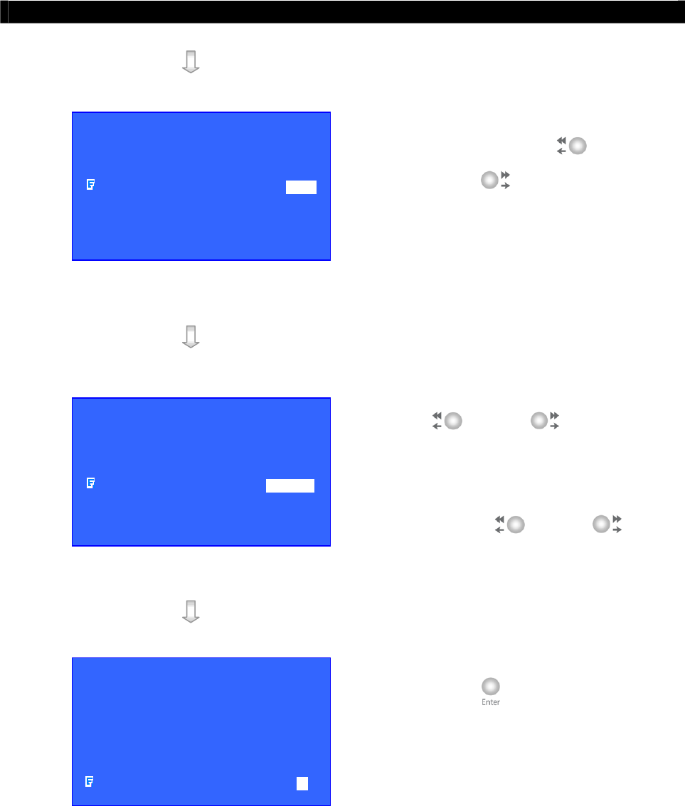
Tele
Eye RX User Guide Page 119
Event Handling
Step 5: Select [SENSOR TAMPER TYPE]
option and use “Left” or
“Right” button to choose alarm
sensor tamper circuit type according to
the configuration of
Tele
Eye RX
alarm sensor tamper circuit type.
Step 6: Select [ZONE] option and use “Left”
or “Right” button to
choose zone type. Select [ENTRY
DELAY], [EXIT DELAY] option and
use “Left” or “Right”
button to choose entry and exit delay
Step 7: Select [ACTION] option and press
“Enter” button to select alarm
trigger or tamper action. (For action,
please refers to Event Action Part in
Advance Operation Section of User
Guide)
A
LARM 1 SETTING
ENABLED YES
SENSOR NAME ALARM 1
SENSOR TYPE NC
SENSOR TAMPER TYPE DEOL
ZONE TYPE NORMAL
ENTRY DELAY 0 SEC
EXIT DELAY 0 SEC
ACTION …
A
LARM 1 SETTING
ENABLED YES
SENSOR NAME ALARM 1
SENSOR TYPE NC
SENSOR TAMPER TYPE DEOL
ZONE TYPE NORMAL
ENTRY DELAY 0 SEC
EXIT DELAY 0 SEC
ACTION …
A
LARM 1 SETTING
ENABLED YES
SENSOR NAME ALARM 1
SENSOR TYPE NC
SENSOR TAMPER TYPE DEOL
ZONE TYPE NORMAL
ENTRY DELAY 0 SEC
EXIT DELAY 0 SEC
ACTION …
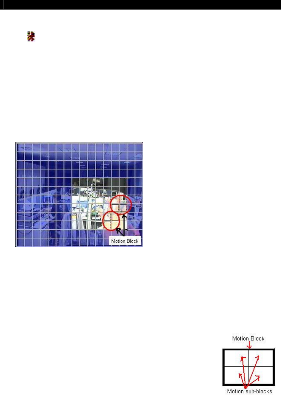
Tele
Eye RX User Guide Page 120
Event Handling
IV. Motion
Motion
Motion detection can be triggered when motion occurs on the camera. Motion detection has
different sensitivity levels. For motion event on each video input channel, it depends on the
motion of selected area. User should setup the select motion areas and sensitivity. Motion
detection has generally 4 options : high, middle, low and custom. Custom option allows user to
select the sensitivity level and area by themselves.
Motion Detection Example
If motion detection is enabled, object movement is captured by the camera as shown below.
The figure on the left shows motion detection.
The normal display area is the selected motion
detection area. The blue area cannot detect any
motion. Motion block is activated when there
is any movement on the camera.
Sensitivity
Level
The level definition of motion detection is due to the luminance level difference between
current and reference field. The level range is 1 to 10, 1 is the most sensitive and 10 is the
least sensitive
Area
In motion detection, one selected motion block is divided into
four sub-blocks. The definition of area is how many sub-
blocks have detected motion in order to trigger a motion event.
The range of area option is 1 to 4. More blocks are selected,
the motion trigger sensitivity decrease.
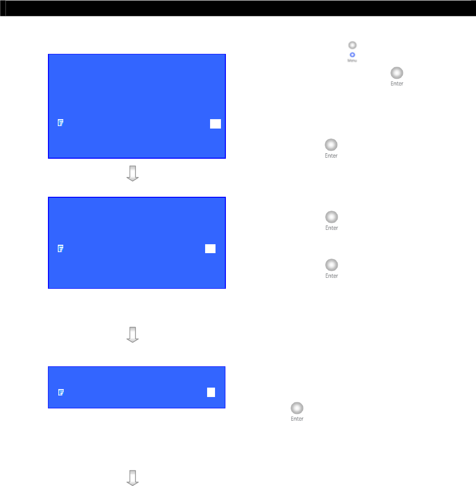
Tele
Eye RX User Guide Page 121
Event Handling
Motion Setup Procedure
Step 1: Press “Menu” button, select [SETUP]
option and press “Enter” button to
enter [SETUP] sub menu. Select
[EVENT HANDLER] option and press
“Enter” button.
Step 2: Select [MOTION] option and press
“Enter” button to show the motion
selection menu. Select motion and press
“Enter” button to enter the motion
setting menu.
Step 3: Select [MOTION DETECTIOR
SETTING] option and press “Enter”
button to setup motion detection
setting.
SETUP MENU
VIDEO . . .
RECORDING . . .
SWITCHES . . .
DATE / TIME . . .
CONNECTION . . .
EVENT HANDLER . . .
TRANSMITTER . . .
RESTORE FACTORY SETTING ENTER
EVENT HANDLER
ARM / DISARM . . .
SECURITY SWITCH . . .
ALARM . . ..
MOTION . . .
VIDEO LOSS . . .
SYSTEM TAMPER . . .
POWER FAILURE . . .
MOTION 1 SETTING
MOTION DETECTOR SETTING …
ACTION …
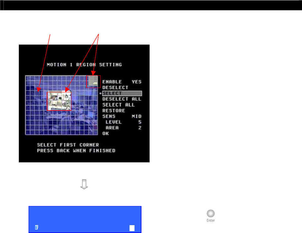
Tele
Eye RX User Guide Page 122
Event Handling
Step 4: Setting motion detection as follow:
ENABLED: enable the motion detection of the
camera
DESELECT: deselect motion area
SELECT: select motion area
DESELECT ALL: clear all motion block
SELECT ALL: select all motion block
RESTORE: restore previous motion setting
SENS: sensitivity option : LOW, MID, HIGH,
CUSTOM
OK: finish, save the setting and exit the detection
menu
Step 5: Select [ACTION] option and press
“Enter” button to select alarm
trigger or tamper action. (For action,
please refers to Event Action Part in
Advance Operation Section of User
Guide)
Deselected Area Selected Area
MOTION 1 SETTING
MOTION DETECTOR SETTING …
ACTION …
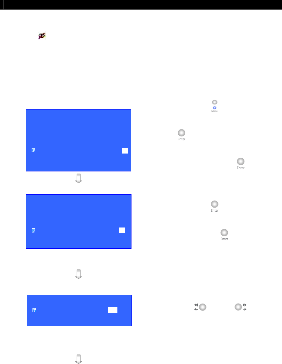
Tele
Eye RX User Guide Page 123
Event Handling
V. Video Loss
Video Loss
Video loss can be triggered when the video channel input disappears. It will happen if the
transmitter receives no signal from the camera. The local CCTV monitor displays a blue screen
for video loss condition.
Video Loss Setup Procedure
Step 1: Press “Menu” button, select
[SETUP] option and press “Enter”
button to enter [SETUP] sub
menu. Select [EVENT HANDLER]
option and press “Enter” button.
Step 2: Select [VIDEO LOSS] option and
press “Enter” button to show the
camera selection menu. Select a camera
and press “Enter” button to enter
the video loss setting menu.
Step 3: Select [ENABLED] option and use
“Left” or “Right” button
to enable (i.e. set the value to [YES])
video loss event handler.
SETUP MENU
VIDEO . . .
RECORDING . . .
SWITCHES . . .
DATE / TIME . . .
CONNECTION . . .
EVENT HANDLER . . .
TRANSMITTER . . .
RESTORE FACTORY SETTING ENTER
EVENT HANDLER
ARM / DISARM . . .
SECURITY SWITCH . . .
ALARM . . ..
MOTION . . .
VIDEO LOSS . . .
SYSTEM TAMPER . . .
POWER FAILURE . . .
VIDEO LOSS X SETTING
ENABLED YES
ACTION …

Tele
Eye RX User Guide Page 124
Event Handling
Step 4: Select [ACTION] option and press
“Enter” button to select alarm
trigger or tamper action. (For action,
please refers to Event Action Part in
Advance Operation Section of User
Guide)
VIDEO LOSS X SETTING
ENABLED YES
ACTION …

Tele
Eye RX User Guide Page 125
Event Handling
VI. System Tamper
System Tamper Input
It is an input to the transmitter for wiring a tamper switch of the external cabinet outside the
transmitter and its accessories. The purpose of system tamper event is to prevent someone to
break into the cabinet and destroy the transmitter.
Sensor Type
The system tamper input circuit type is normal close (NC). The state of the circuit is close, it
indicates normal of
Tele
Eye RX. Otherwise, the state of the circuit is open, it indicates
system tamper of
Tele
Eye RX. The system tamper input circuit type is normal open (NO).
The state of the circuit is open, it indicates normal of
Tele
Eye RX. Otherwise, the state of the
circuit is close, it indicates system tamper of
Tele
Eye RX.
Physical Configuration for System Tamper
The system tamper input and ground of
Tele
Eye RX transmitter need to connect to an
external cabinet which is used for protecting the transmitter and its accessories
System Tamper Input
External cabinet
Ground
System Tamper Setup Procedure
Step 1: Press “Menu” button, select [SETUP]
option and press “Enter” button to
enter [SETUP] sub menu. Select
[EVENT HANDLER] option and press
“Enter” button.
SETUP MENU
VIDEO . . .
RECORDING . . .
SWITCHES . . .
DATE / TIME . . .
CONNECTION . . .
EVENT HANDLER . . .
TRANSMITTER . . .
RESTORE FACTORY SETTING ENTER
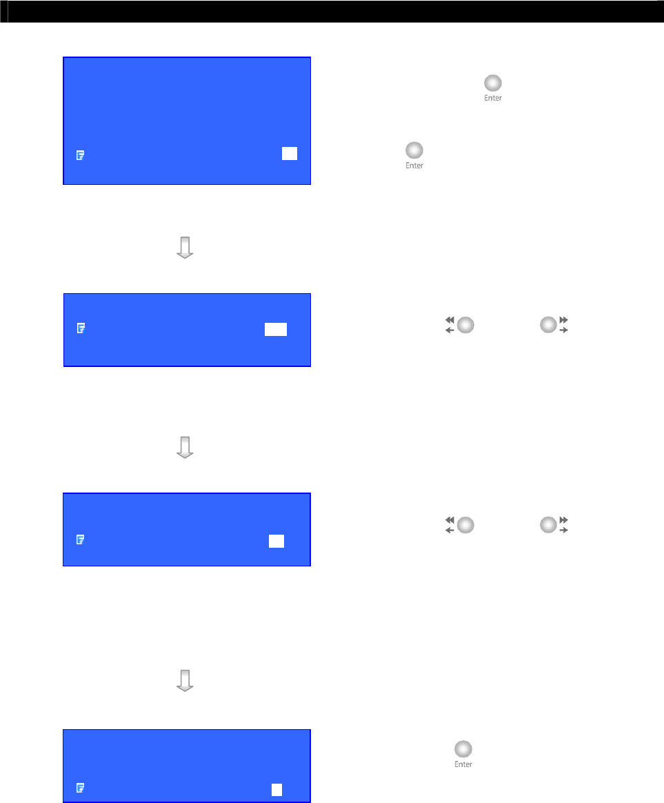
Tele
Eye RX User Guide Page 126
Event Handling
Step 2: Select [SYSTEM TAMPER] option and
press “Enter” button to show the
system tamper menu and press “Enter”
button to enter the System Tamper
setting menu.
Step 3: Select [ENABLED] option and use
“Left” or “Right” button to
enable (i.e. set the value to [YES])
System Tamper event handler.
Step 4: Select [SENSOR TYPE] option and use
“Left” or “Right” button to
choose sensor type according to the
configuration of
Tele
Eye RX system
tamper control circuit type
Step 5: Select [ACTION] option and press
“Enter” button to select system
tamper action. (For action, please refers
to Event Action Part in Advance
Operation Section of User Guide)
EVENT HANDLER
ARM / DISARM . . .
SECURITY SWITCH . . .
ALARM . . ..
MOTION . . .
VIDEO LOSS . . .
SYSTEM TAMPER . . .
POWER FAILURE . . .
SYSTEM TAMPER
ENABLED YES
SENSOR TYPE NO
ACTION …
SYSTEM TAMPER
ENABLED YES
SENSOR TYPE NC
ACTION …
SYSTEM TAMPER
ENABLED YES
SENSOR TYPE NC
ACTION …
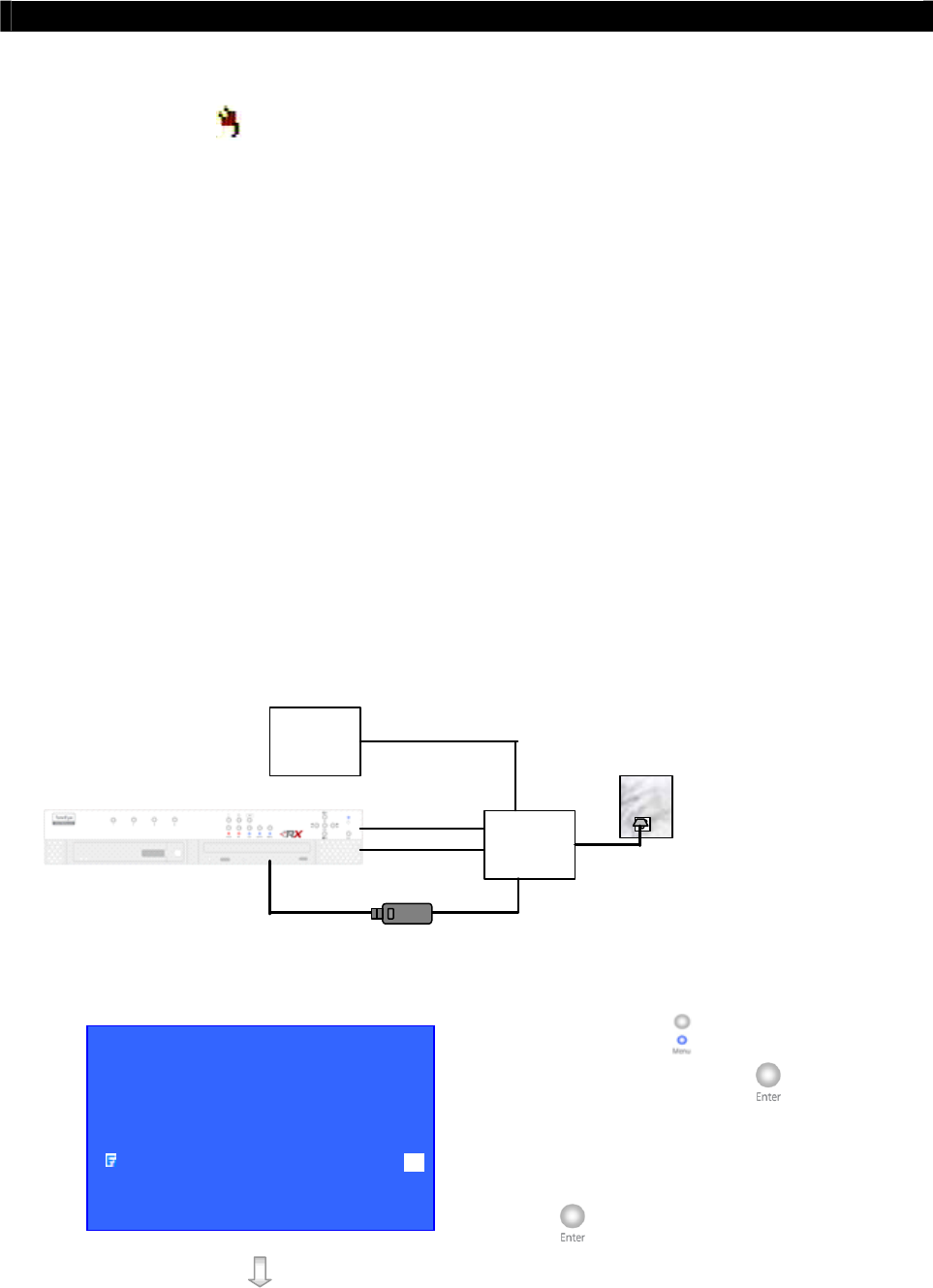
Tele
Eye RX User Guide Page 127
Event Handling
VII. Power Failure
Power Failure Input
It is an input to the transmitter typically used for wiring the output signal pin from UPS.
Sensor Type
The power failure input circuit type is normal close (NC). The state of the circuit is close, it
indicates normal of
Tele
Eye RX. Otherwise, the state of the circuit is open, it indicates
power failure of
Tele
Eye RX. The power failure input circuit type is normal open (NO). The
state of the circuit is open, it indicates normal of
Tele
Eye RX. Otherwise, the state of the
circuit is close, it indicates power failure of
Tele
Eye RX.
Physical Configuration for Power Failure Input
The power failure input and ground of
Tele
Eye RX transmitter need to connect to a
universal power supply circuit UPS, so the transmitter can detect any power failure condition.
Note that below UPS circuit setup is used as an example. Not all UPS have signal output.
Some UPS have self-test for a period of time, their signal output may toggle during test.
UPS
Power Failure Input
Power from UPS
Other
Devices Power from UPS
UPS provide backup
power in certain period
and send a power failure
signal to RX when the
main power does not
work.
Main Power
Ground
Power Failure Setup Procedure
Step 1: Press “Menu” button, select [SETUP]
option and press “Enter” button to
enter [SETUP] sub menu. Select [EVENT
HANDLER] option and press “Enter”
button.
SETUP MENU
VIDEO . . .
RECORDING . . .
SWITCHES . . .
DATE / TIME . . .
CONNECTION . . .
EVENT HANDLER . . .
TRANSMITTER . . .
RESTORE FACTORY SETTING ENTER
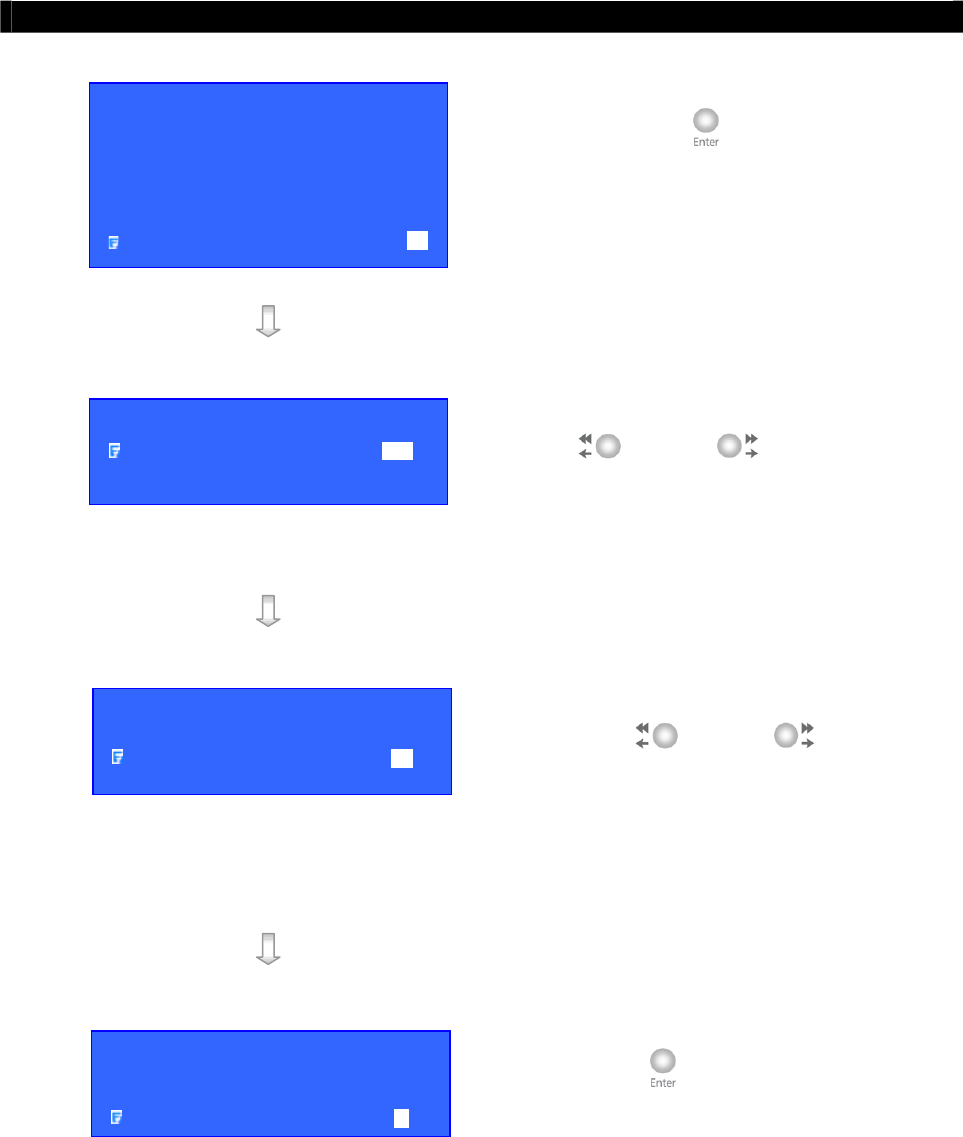
Tele
Eye RX User Guide Page 128
Event Handling
Step 2: Select [POWER FAILURE] option and
press “Enter” button to enter the
power failure setting menu.
Step 3: Select [ENABLED] option and use “Left”
or “Right” button to enable
(i.e. set the value to [YES]) power failure
event handler.
Step 4: Select [SENSOR TYPE] option and use
“Left” or “Right” button to
choose sensor type according to the
configuration of
Tele
Eye RX power
failure control circuit type
Step 5: Select [ACTION] option and press
“Enter” button to select power failure
action. (For action, please refers to Event
Action Part in Advance Operation Section
of User Guide)
EVENT HANDLER
ARM / DISARM . . .
SECURITY SWITCH . . .
ALARM . . ..
MOTION . . .
VIDEO LOSS . . .
SYSTEM TAMPER . . .
POWER FAILURE . . .
POWER FAILURE
ENABLED YES
SENSOR TYPE NO
ACTION …
POWER FAILURE
ENABLED YES
SENSOR TYPE NC
ACTION …
POWER FAILURE
ENABLED YES
SENSOR TYPE NC
ACTION …
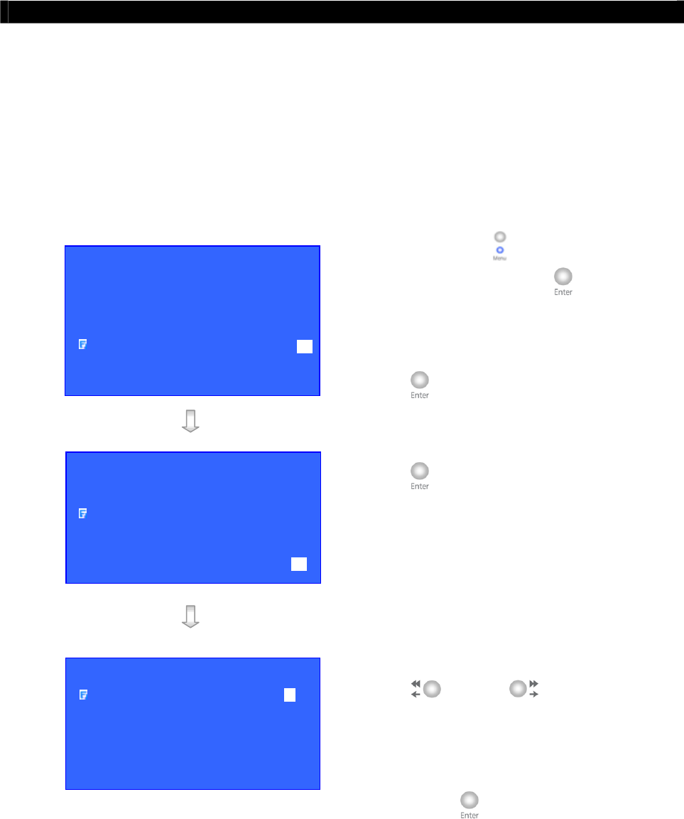
Tele
Eye RX User Guide Page 129
Event Action
D. Event Action
Tele
Eye RX supports event actions such as Recording, Switch, Dial back, Buzzer, Event LED,
Live camera and PTZ when event detected from alarm, tamper of alarm, motion, video loss,
tamper of arm/disarm, tamper of security switch, power failure and system tamper.
Event Action Setup Procedure
Step 1: Press “Menu” button, select [SETUP]
option and press “Enter” button to
enter [SETUP] sub menu. Select [EVENT
HANDLER] option and press “Enter”
button.
Step 2: Select any event option and press “Enter”
button to enter the setting menu.
Step 3: Select [ENABLED] option and use “Left”
or “Right” button to enable
(i.e. set the value to [YES]) event handler.
Step 4: Select [ACTION] option and press
“Enter” button to enter the action
menu.
SETUP MENU
VIDEO . . .
RECORDING . . .
SWITCHES . . .
DATE / TIME . . .
CONNECTION . . .
EVENT HANDLER . . .
TRANSMITTER . . .
RESTORE FACTORY SETTING ENTER
EVENT HANDLER
ARM / DISARM . . .
SECURITY SWITCH . . .
ALARM . . ..
MOTION . . .
VIDEO LOSS . . .
SYSTEM TAMPER . . .
POWER FAILURE . . .
XXXXXXX ACTION
RECORDING …
SWITCH …
DIALBACK …
BUZZER …
EVENT LED …
LIVE CAMERA …
PTZ …

Tele
Eye RX User Guide Page 130
Event Action
I. Recording
Recording
If an event triggers, recording can record the video content at user selected camera with
selected recording mode.
Pre-Alarm Recording
Pre-alarm recording allows to record video before an event trigger. The period of pre-alarm
recording is at least 1 minute (not more than 2 minutes) before the event trigger. User can find
that there is at least 1 minute more video content in [RECORDING LOG MENU] before
event trigger.
Duration After Event Clear
After event resets, the recording action will stop after this duration time.
Recording Mode
Event recording provides 2 recording mode, 1 frame per second (1 FPS) and continuous
mode. In 1 FPS mode, the recording frame rate is less, so the storage size is small. In
continuous mode, the recording frame rate depends on the number of recording camera and
more than 1 FPS, so the storage size is larger.
Recording Action Setup Procedure
Step 1: In the action menu, select
[RECORDING] option and press “Enter”
button to enter the recording action
setting menu.
XXXXXXX ACTION
RECORDING …
SWITCH …
DIALBACK …
BUZZER …
EVENT LED …
LIVE CAMERA …
PTZ …
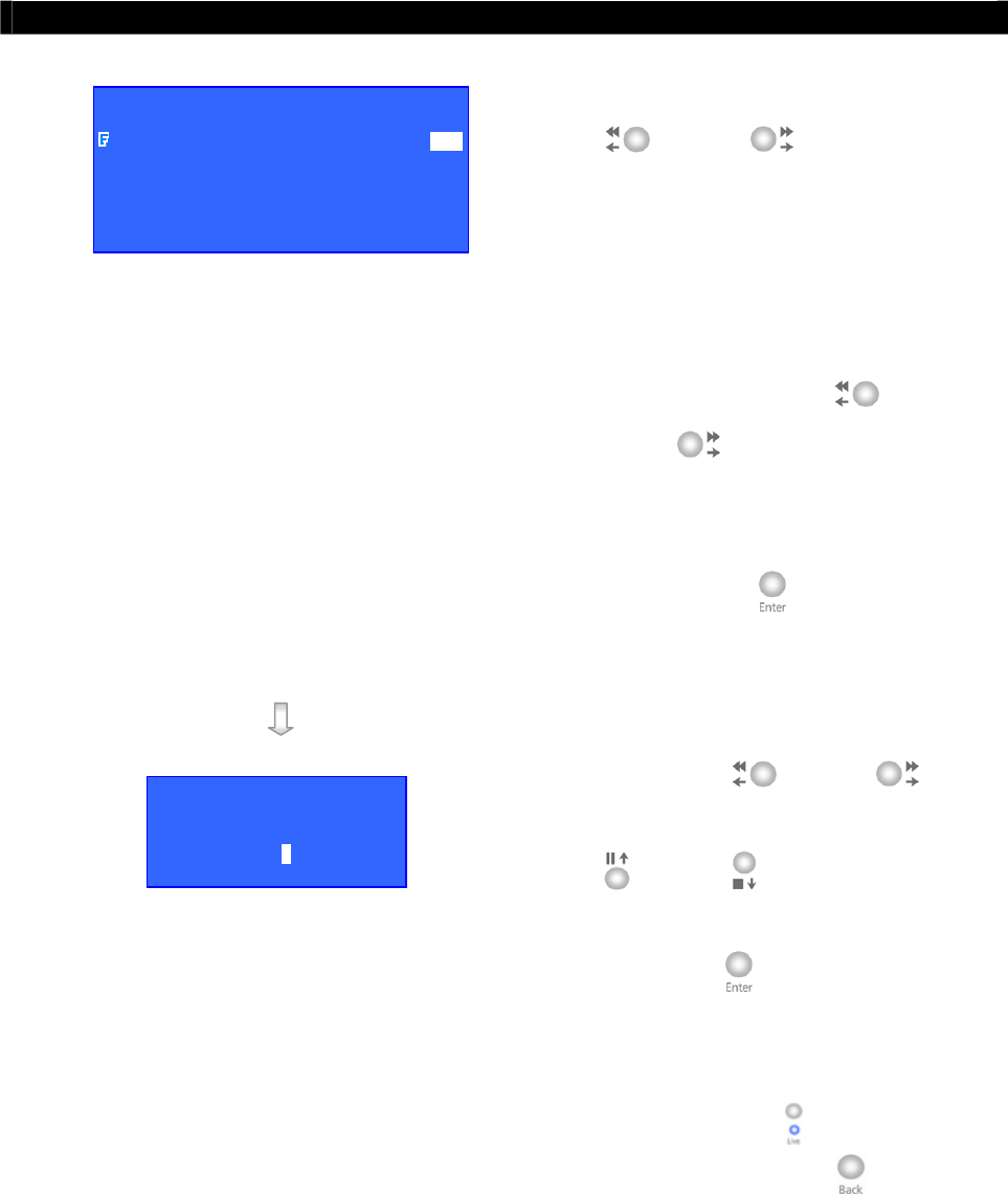
Tele
Eye RX User Guide Page 131
Event Action
Step 2: Select [ENABLED] option and use “Left”
or “Right” button to enable
(i.e. set the value to [YES]) recording
action.
Step 3: Select the [DURATION AFTER EVENT
CLEAR] and [RECORDING MODE]
options and uses the “Left” or
“Right” button to choose the
suitable setting.
Step 4: Select [RECORDING CAMERA] option
and press “Enter” button to enter the
recording camera menu.
Step 5: Use the “Left” or “Right”
button to select camera and press the “Up”
or “Down” button to enable or
disable recording camera.
Step 6: Press “Enter” button to save the
camera setting and go back to recording
action menu.
Step 7: You can press “Live” button to exit
OSD menu or press “Back” button to
enter action menu again.
XXXXXXX RECORDING
ENABLED YES
DURATION AFTER EVENT CLEAR 20 SEC
RECORDING MODE CONTINUOUS
RECORDING CAMERA - - - -
RECORDING CAMERA
1 - 3 -
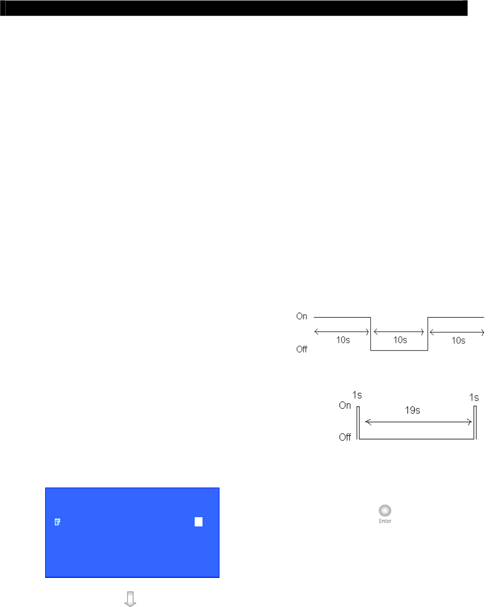
Tele
Eye RX User Guide Page 132
Event Action
II. Switch
Switch allows transmitter to control 4 external relays which are defined by user.
Switch Type
Switch has 2 types. They are latching or push-button type. In latching type, the switch turns
on for a period of time. In push-button type, the switch turns on and off after 1 second.
Latching Duration
The latch duration period is the time for turning on the switch.
Action Delay
The delay is the period of time after turning off the switch before next turning on.
Latching Duration and Action Delay Example
For latch type switch, set latch duration 10sec and
action delay 10sec. If an event trigger, the timing of the
switch is shown on the right.
For push-button type switch, set latch duration 10sec and action
delay 10sec. If an event trigger, the timing of the switch is shown
on the right.
Switch Action setup procedure
Step 1: In the action menu, select [SWITCH]
option and press “Enter” button to
enter the switch action setting menu.
XXXXXXX ACTION
RECORDING …
SWITCH …
DIALBACK …
BUZZER …
EVENT LED …
LIVE CAMERA …
PTZ …
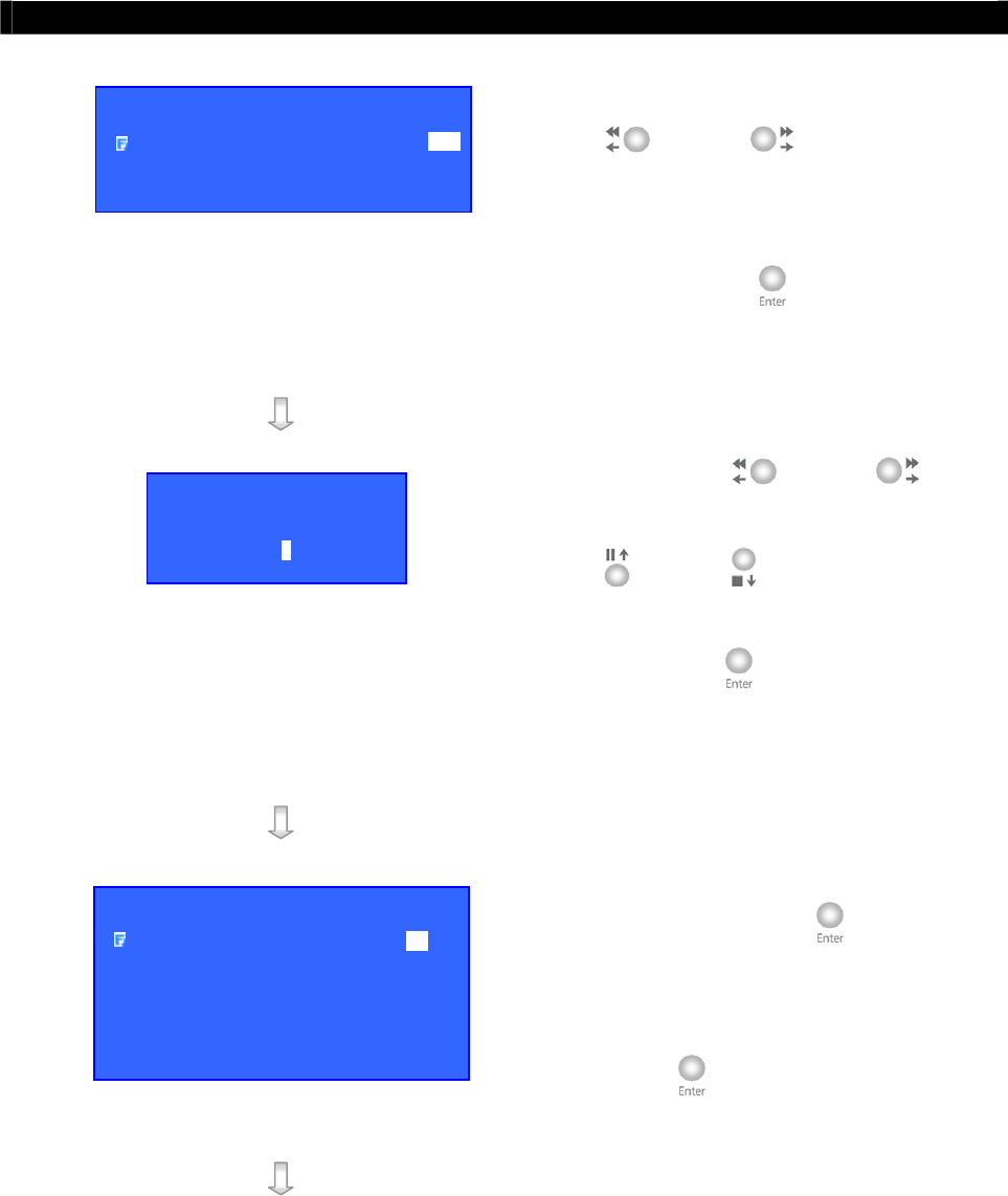
Tele
Eye RX User Guide Page 133
Event Action
Step 2: Select [ENABLED] option and use “Left”
or “Right” button to enable
(i.e. set the value to [YES]) switch action.
Step 3: Select [SWITCHES ENABLED] option
and press “Enter” button to enable or
disable the switches.
Step 4: Use the “Left” or “Right”
button to select switch and press the “Up”
or “Down” button to enable or
disable switch.
Step 5: Press “Enter” button to save the
selection setting and go back to switch
action menu.
Step 6: Select [GENERAL SWITCH SETTING]
option and press “Enter” button to
enter the switch setting menu.
Step 7: Select [SWITCH (No.)] option and press
“Enter” button to enter the switch
(No.) setting menu.
XXXXXXX SWITCH
ENABLED YES
SWITCHES ENABLED - - - -
GENERAL SWITCH SETTING . . .
ASSOCIATE SWITCH
1 - 3 -
GENERAL SWITCH SETTING
SWITCH 1 . . .
SWITCH 2 . . .
SWITCH 3 . . .
SWITCH 4 . . .
LATCH DURATION 10 SEC
ACTION DELAY 10 SEC
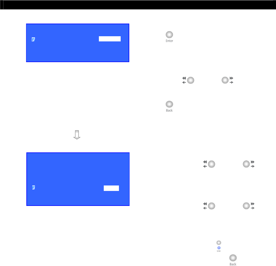
Tele
Eye RX User Guide Page 134
Event Action
Step 8: Select [NAME] option and press “Enter”
button to edit the name of switch
(No.).
Step 9: Select [TYPE] option and press the
“Left” or “Right” button to
choose the switch type. Press the “Back”
button to go back the general switch
setting menu and save the setting.
Step 10: Select [LATCH DURATION] option and
press the “Left” or “Right”
button to choose the latch duration.
Step 11: Select [ACTION DELAY] option and
press the “Left” or “Right”
button to choose the switch action delay
between each on/off.
Step 12: You can press “Live” button to exit
OSD menu or press “Back” button to
enter action menu again.
SWITCH X SETTING
NAME SWITCH X
TYPE LATCHING
GENERAL SWITCH SETTING
SWITCH 1 . . .
SWITCH 2 . . .
SWITCH 3 . . .
SWITCH 4 . . .
LATCH DURATION 10 SEC
ACTION DELAY 10 SEC

Tele
Eye RX User Guide Page 135
Event Action
III. Dialback
Dialback
Dialback allows the transmitter to connect to one remote PC and displays live video if an event
triggers. Therefore, remote operator can recognize what situation is at the surveillance area.
Retry Duration
The retry duration is the period between each dialback retrial (in second).
Retry Count
The retry count is the number of dialback retrial if dialback fails.
Dialback Action setup procedure
Step 1: In the action menu, select [DIALBACK]
option and press “Enter” button to
enter the dialback action setting menu.
Step 2: Select [ENABLED] option and use “Left”
or “Right” button to enable
(i.e. set the value to [YES]) dialback
action.
Step 3: Select [GENERAL DIALBACK
SETTING] option and press “Enter”
button to enter the dialback setting menu.
XXXXXXX ACTION
RECORDING …
SWITCH …
DIALBACK …
BUZZER …
EVENT LED …
LIVE CAMERA …
PTZ …
XXXXXXX DIAL BACK
ENABLED YES
GENERAL DIALBACK SETTING . . .
GENERAL DIALBACK SETTING
RETRY DURATION 0
RETRY COUNT 1
PHONE 1 . . .
PHONE 2 . . .
PHONE 3 . . .
PHONE 4 . . .
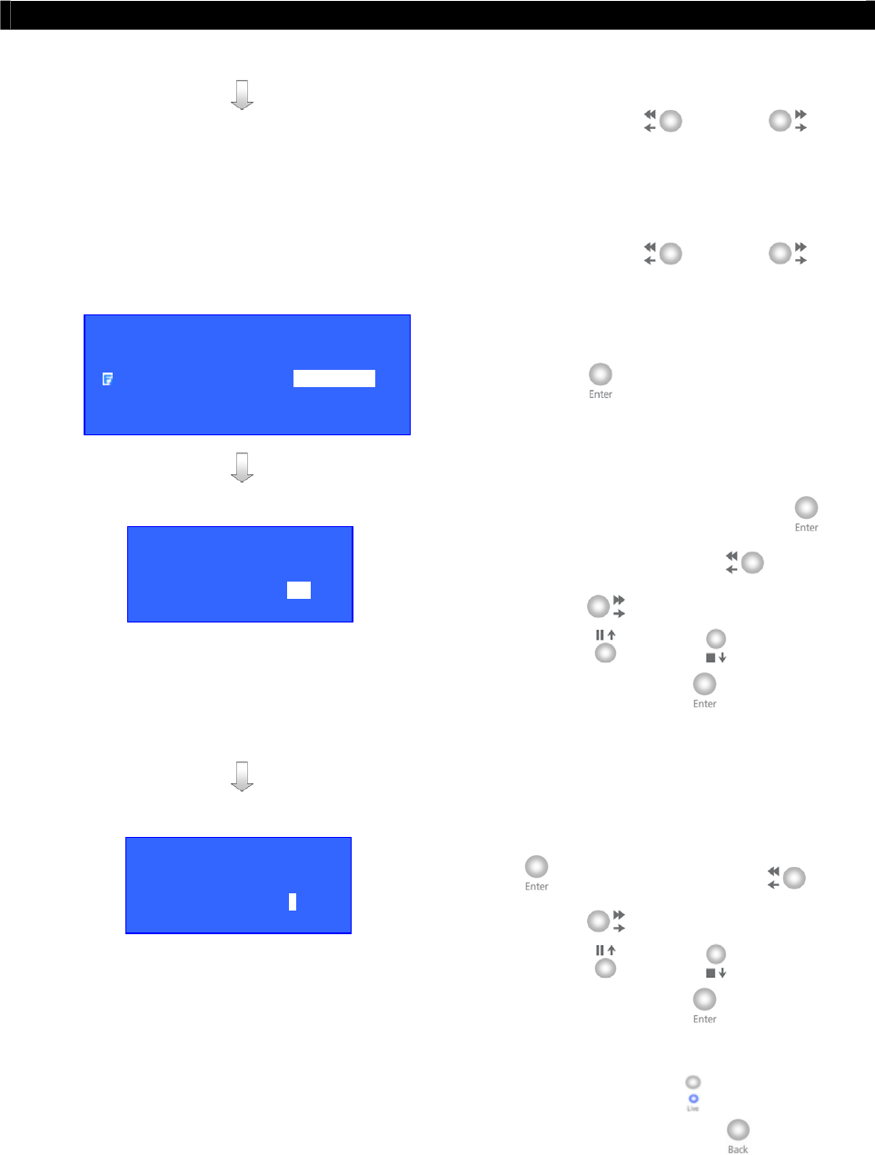
Tele
Eye RX User Guide Page 136
Event Action
Step 4: Select [RETRY DURATION] option and
press the “Left” or “Right”
button to choose the retry duration.
Step 5: Select [RETRY COUNT] option and
press the “Left” or “Right”
button to choose the retry count.
Step 6: Select [PHONE (No.)] option and press
“Enter” button to enter the dialback IP
setting menu.
Step 7: Select [IP] option and press “Enter”
button to set IP. Use “Left” or
“Right” button to select field and
use “Up” or “Down” button to set
number. Press “Enter” button to save
the change and return previous menu.
Step 8: Select [PORT] option and press “Enter”
button to set port. Use “Left” or
“Right” button to select field and
use “Up” or “Down” button to set
number. Press “Enter” button to save
the change and return previous menu.
Step 9: You can press “Live” button to exit
OSD menu or press “Back” button to
enter action menu again.
DIALBACK PHONE X SETTING
IP 192.168.0.10
PORT 2048
IP
IP : 210. 17.139.145
PORT
PORT : - 2 0 4 8
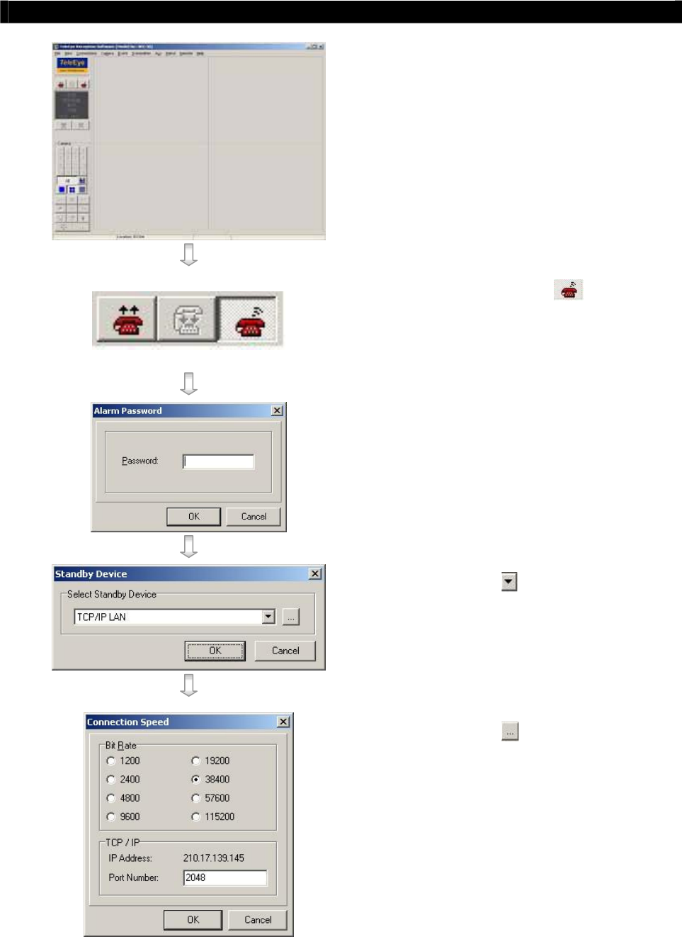
Tele
Eye RX User Guide Page 137
Event Action
Step 10: Run WX-30 software at the local network
PC. (For details of WX-30 software
installation, please refer to WX-30
Software Guide)
Step 11: Press [Alarm Standby] icon for
activating dialback action standby
Step 12: [Alarm Password] message broad pops
up. Enter alarm password and press [OK]
icon
(Default alarm password of WX-30 is 000000)
Step 13: Press the icon to select the
connection type for dialback
Step 14: Press the icon to enter [Connection
Speed] message broad to select bit rate,
port number. The port number should be
as same as the port number set in step 8
Step 15: Press [OK] icon to exit and save the
settings
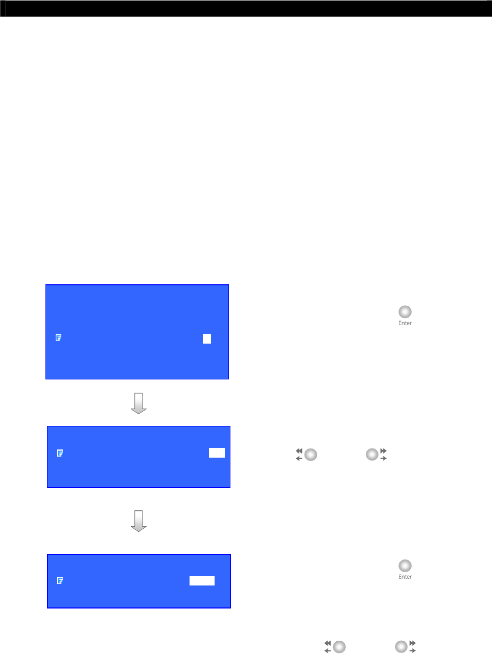
Tele
Eye RX User Guide Page 138
Event Action
IV. Buzzer
Buzzer
This buzzer contains inside the
Tele
Eye RX transmitter. It can produce “Beep” sound in
order to draw nearby operator attention about an event trigger.
Duration
Duration is the period for turning on the buzzer.
Action Delay
Action delay is the period after turning off the buzzer turning on.
Buzzer Action setup procedure
Step 1: In the action menu, select [BUZZER]
option and press “Enter” button to
enter the buzzer action setting menu.
Step 2: Select [ENABLED] option and use “Left”
or “Right” button to enable
(i.e. set the value to [YES]) buzzer action.
Step 3: Select [GENERAL BUZZER SETTING]
option and press “Enter” button to
enter the buzzer setting menu.
Step 4: Select [DURATION] option and press the
“Left” or “Right” button to
choose the duration.
XXXXXXX ACTION
RECORDING …
SWITCH …
DIALBACK …
BUZZER …
EVENT LED …
LIVE CAMERA …
PTZ …
XXX
X
XX X BUZZER
ENABLED YES
GENERAL BUZZER SETTING . . .
GENERAL BUZZER SETTING
DURATION 10SEC
ACTION DELAY 10SEC
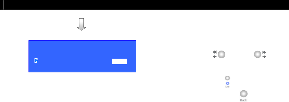
Tele
Eye RX User Guide Page 139
Event Action
Step 5: Select [ACTION DELAY] option and
press the “Left” or “Right”
button to choose the action delay
Step 6: You can press “Live” button to exit
OSD menu or press “Back” button to
enter action menu again.
GENERAL BUZZER SETTING
DURATION 10SEC
ACTION DELAY 10SEC
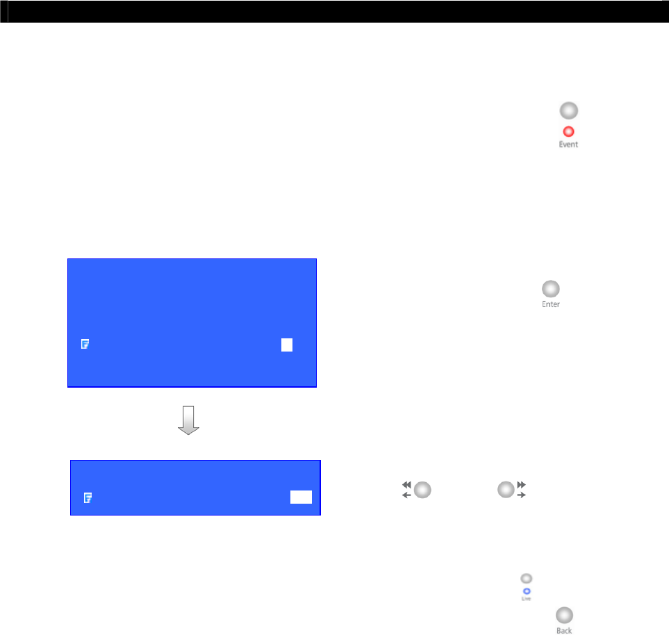
Tele
Eye RX User Guide Page 140
Event Action
V. Event LED
Event LED
The event LED is the LED built on the front panel of
Tele
Eye RX transmitter . If an event
trigger, the LED is blinking until the event is clear.
Event LED Action setup procedure
Step 1: In the action menu, select [EVENT LED]
option and press “Enter” button to
enter the event LED action setting menu.
Step 2: Select [ENABLED] option and use “Left”
or “Right” button to enable
(i.e. set the value to [YES]) event LED
action.
Step 3: You can press “Live” button to exit
OSD menu or press “Back” button to
enter action menu again.
XXXXXXX ACTION
RECORDING …
SWITCH …
DIALBACK …
BUZZER …
EVENT LED …
LIVE CAMERA …
PTZ …
XXXXXX X EVENT LED
ENABLED YES
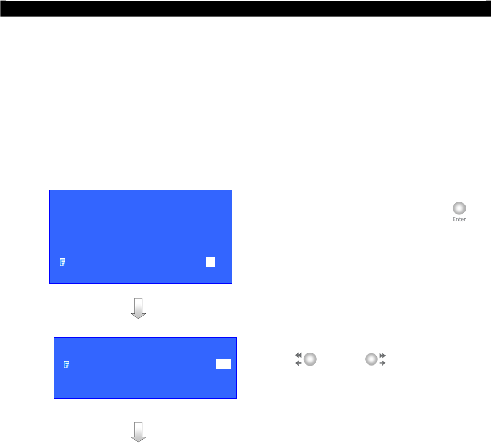
Tele
Eye RX User Guide Page 141
Event Action
VI. Live Camera
Live Camera
Event associate live camera display real time live video of pre-selected camera if an event
triggers, so operator can immediately know what happen from the site. Live camera action
can only display live video one time before user clears the event.
Live Camera Action setup procedure
Step 1: In the action menu, select [LIVE
CAMERA] option and press “Enter”
button to enter the live camera action
setting menu.
Step 2: Select [ENABLED] option and use “Left”
or “Right” button to enable
(i.e. set the value to [YES]) live camera
action.
XXXXXXX ACTION
RECORDING …
SWITCH …
DIALBACK …
BUZZER …
EVENT LED …
LIVE CAMERA …
PTZ …
XXXXXX X LIVE CAMER
A
ENABLED YES
ASSOICATE CAMERA - - - -
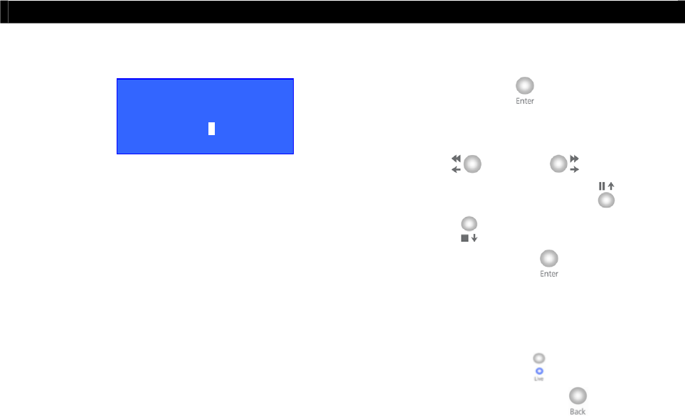
Tele
Eye RX User Guide Page 142
Event Action
Step 3: Select [ASSOCAITE CAMERA] option
and press “Enter” button to enter the
live camera action setting menu. Use the
“Left” or “Right” button to
select camera and press the “Up” or
“Down” button to enable or disable
camera. Press “Enter” button to save
the camera setting and go back to live
camera action menu.
Step 4: You can press “Live” button to exit
OSD menu or press “Back” button to
enter action menu again.
ASSOCIATE CAMERAS
1 - 3 -
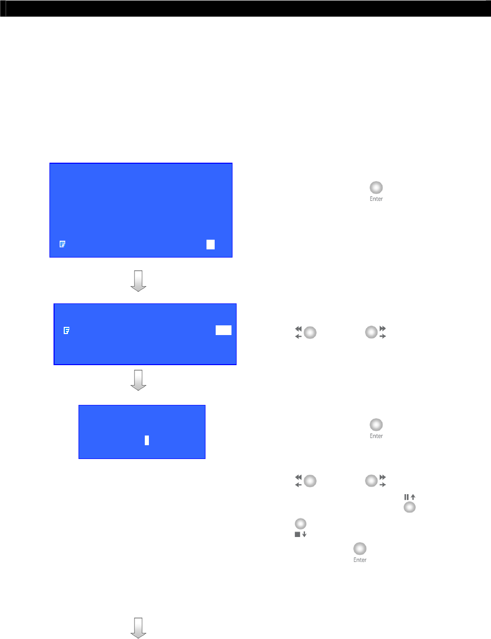
Tele
Eye RX User Guide Page 143
Event Action
VII. PTZ
PTZ Camera
PTZ camera action allows the pan tilt zoom camera to go to user preset position for viewing
what happen if an event trigger.
PTZ Action setup procedure
Step 1: In the action menu, select [PTZ] option
and press “Enter” button to enter the
PTZ action setting menu.
Step 2: Select [ENABLED] option and use “Left”
or “Right” button to enable
(i.e. set the value to [YES]) PTZ action.
Step 3: Select [ASSOCAITE CAMERA] option
and press “Enter” button to enter the
PTZ action setting menu. Use the “Left”
or “Right” button to select
camera and press the “Up” or “Down”
button to enable or disable camera.
Press “Enter” button to save the
camera setting and go back to PTZ action
menu.
XXXXXXX ACTION
RECORDING …
SWITCH …
DIALBACK …
BUZZER …
EVENT LED …
LIVE CAMERA …
PTZ …
XXXXXX X PTZ
ENABLED YES
ASSOICATE CAMERA - - - -
RECALL PRESET 1
ASSOCIATE CAMERAS
1 - 3 -
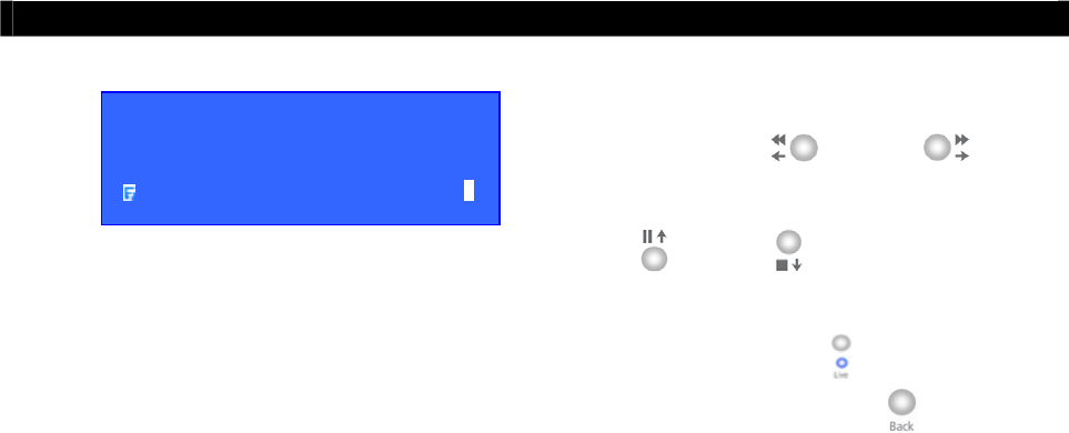
Tele
Eye RX User Guide Page 144
Event Action
Step 4: Select [RECALL PRESET] option and
use the “Left” or “Right”
button to select camera and press the “Up”
or “Down” button to choose the
preset position of the PTZ camera.
Step 5: You can press “Live” button to exit
OSD menu or press “Back” button to
enter action menu again.
XXXXXX X PTZ
ENABLED YES
ASSOICATE CAMERA - - - -
RECALL PRESET 1
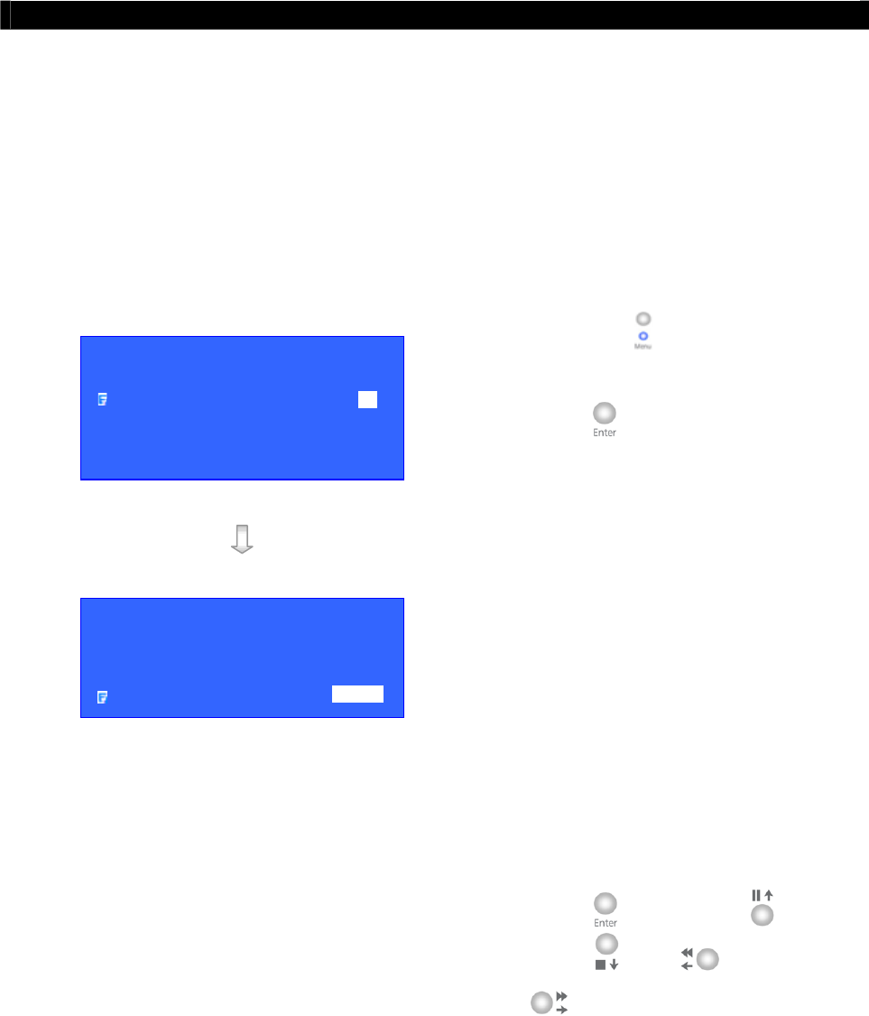
Tele
Eye RX User Guide Page 145
Backup to CD-R
E. Backup to CD-R
Tele
Eye RX transmitter supports backup function in a CD-R and provides maximum backup
storage size of 650MB. The CD-R will be auto run with the portable player software after
inserted into PC.
Note that recommended physical size of CD-R should be 120mm / 5.25"
Backup to CD-R Setup Procedure
Step 1: Press “Menu” button, select
[BACKUP TO CD-R] option and press
“Enter” button to enter backup to
CD-R sub menu.
Step 2: Setup the [START DATE], [START
TIME] and [BACKUP SIZE] and the
transmitter will calculate the end time
automatically which depends on backup
size and number of camera recorded from
the start time.
Step 3: Select the above options and press
“Enter” button. Use “Up” ,
“Down” , “Left” and “Right”
buttons to set the date, time and
size.
MAIN MENU
SETUP . . .
BACKUP TO CD-R . . .
SWITCH CONTROL . . .
SCAN / FORMAT DISK . . .
TRANSMITTER INFO . . .
SHUT DOWN ENTER
BACKUP TO CDR
START DATE 01 AUG 2005
START TIME 15:08
BACKUP SIZE ( MB ) 650
START BACKUP ENTER

Tele
Eye RX User Guide Page 146
Backup to CD-R
Step 4: Select [START BACKUP] option and
press “Enter” button to show
[BACKUP RECORDING] message
board and it shows user about the end
time. Select [YES] option and press
“Enter” button to start backup
function.
Step 5: During the backup preparation, the
transmitter will request you to insert a
blank CD. Insert a blank CD and press
“Enter” button in [YES] option to
start the backup process.
The transmitter prepares the backup CD file
It creates CD Image for burning CD
Step 6: After finishing the backup to CD function,
press “Enter” button to exit and the CD
will be ejected.
BACKUP RECORDING
START TIME : 18 AUG 2005 10 : 18
END TIME : 18 AUG 2005 12 : 18
START BACKUP ?
YES NO
BACKUP RECORDING
PLEASE INSERT A BLANK CD
YES NO
BACKUP
\ PREPARE CD FILE 30%
BACKUP
\ CREATE CD IMAGE 30%
BACKUP RECORDING
BURN CD SUCCESS
YES
BACKUP
\ BURNING CD 30%
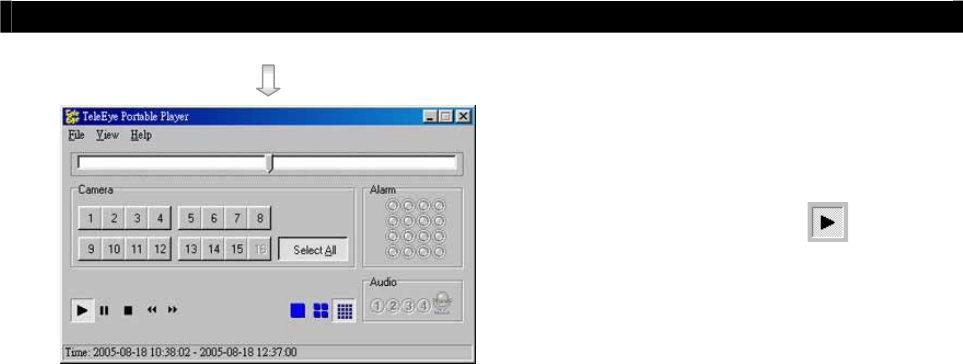
Tele
Eye RX User Guide Page 147
Backup to CD-R
Step 7: Insert the CD to PC with window OS and
the Portable Player software will pop up
automatically. Press “Play” button
for playback in the CD.
Note that if the Portable Player software does
not pop up automatically, please uses the mouse
to double click the CD-ROM drive in your PC.
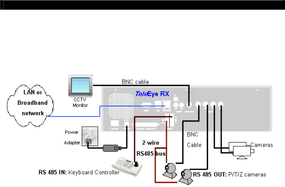
Tele
Eye RX User Guide Page 148
Connection with PTZ cameras
F. Connection with PTZ cameras
As
Tele
Eye RX transmitter built with a RS485 port IN and OUT, you can connect port OUT to
Pan/Tilt/Zoom cameras (in parallel) and connect port IN to keyboard controller. The connection
diagram is shown below.
Setup Procedure
For installation of CCTV monitor, cameras, network setting and connection, please refer to
P.66 of the User Guide.
Step 1: Connect the P/T/Z cameras to the RS 485 OUT port in parallel at the
Tele
Eye RX rear
panel. Connect the P/T/Z cameras to video input port according to each P/T/Z camera
ID.
Note that all P/T/Z cameras should be the same model.
Step 2: Connect the keyboard controller to the RS 485 IN port at the
Tele
Eye RX rear panel.
For keyboard controller setup, please refer to the keyboard controller manual.
Step 3: Configure P/T/Z cameras driver and setting through OSD menu by CCTV monitor.
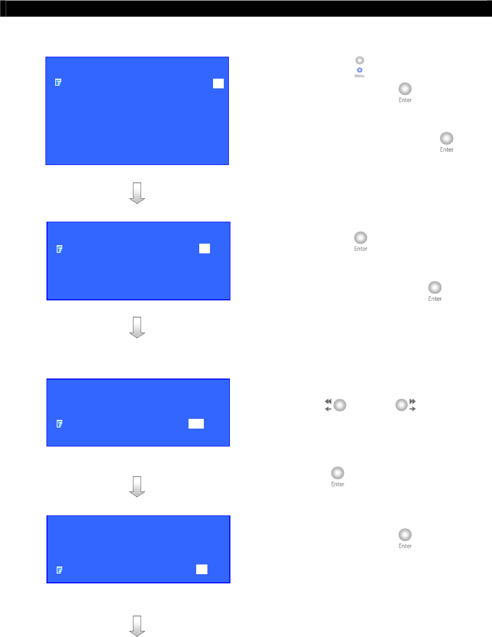
Tele
Eye RX User Guide Page 149
Connection with PTZ cameras
Configure P/T/Z cameras driver and setting as follow:
Step 4: Press “Menu” button, select [SETUP]
option and press “Enter” button to
enter [SETUP] sub menu. Select
[VIDEO] option and press “Enter”
button.
Step 5: Select [CAMERA SETTING] option and
press “Enter” button to enter the
camera setting menu. Select [CAMERA
(NO.)] option and press “Enter”
button to choose the camera as PTZ
camera.
Step 6: Select [SUPPORT PTZ] option and use
“Left” or “Right” button to
choose [YES] option. Select [GENERAL
PTZ SETTING] option and press
“Enter” button to set the PTZ feature.
Step 7: Select [ADVANCED PTZ SETTING]
option and press “Enter” button to
configure P/T/Z cameras driver and bit
rate.
SETUP MENU
VIDEO . . .
RECORDING . . .
SWITCHES . . .
DATE / TIME . . .
CONNECTION . . .
EVENT HANDLER . . .
TRANSMITTER . . .
RESTORE FACTORY SETTING ENTER
VIDEO
CAMERA SETTING . . .
LOCAL MONITORING . . .
OSD COLOR BLUE
VIDEO FORMAT PAL
CAMERA 1 SETTING
INSTALL YES
NAME CAM 1
SUPPORT PTZ YES
GENERAL PTZ SETTING . . .
PTZ SETTING
PAN SPEED FAST
TILT SPEED FAST
PTZ MOVEMENT SETTING . . .
ADVANCED PTZ SETTING . . .

Tele
Eye RX User Guide Page 150
Connection with PTZ cameras
Note that i
f
there is no driver to su
pp
ort
y
our P/T/Z
cameras, please refer to WX-30 software upload
PTZ driver section
Step 8: Select [PTZ DRIVER] option and press
“Enter” button to select P/T/Z
cameras driver. According to the P/T/Z
camera model, please select a certain
driver for required PTZ camera and press
“Enter” button to save the setting.
Step 9: Select [BIT RATE] option and use “Left”
or “Right” button to set bit
rate corresponding to your P/T/Z cameras.
Press “Back” button to go to [PTZ
SETTING] menu
Step 10: Select [PAN SPEED] and [TILT
SPEED] options and use “Left” or
“Right” button to change the pan
(horizontal direction) and tilt (vertical
direction) speed of the PTZ camera.
Step 11: Select [PTZ MOVEMENT] option and
press “Enter” button to change PTZ
movement timing setting
A
DVANCED PTZ SETTING
PTZ DRIVER TELEEYE DM S . . .
BIT RATE 4800
PTZ SETTING
PAN SPEED FAST
TILT SPEED FAST
PTZ MOVEMENT SETTING . . .
ADVANCED PTZ SETTING . . .
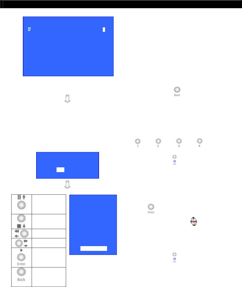
Tele
Eye RX User Guide Page 151
Connection with PTZ cameras
Tilt Up
Tilt Down
Pan Left
Pan Right
Zoom In
Zoom Out
Step 12: User can select different movement
direction duration according to whether the
PTZ camera support those functions.
Step 13: Press “Back” button for several time
to exit main menu. Use “Camera
Control” buttons (as below) to select the
PTZ camera.
Step 14: Press “Live” button to show the PTZ
Camera Enable menu.
You can use “control button” to control PTZ
camera.
Step 15: Select [YES] option and press “Enter”
button to enable PTZ function and
the PTZ enable icon shown at the
corresponding PTZ camera in CCTV
monitor.
Step 16: Press “Live” button to enter the PTZ
option menu for advance control and
disable PTZ camera.
PTZ OPTION
RECALL PRESET
PROGRAM PRESET
RECALL PATROL
STOP PATROL
AUX CTRL
IRIS CTRL
FOCUS CTRL
ZOOM CTRL
AUTO
DISABLE PTZ
ENABLE PTZ ?
YES NO
PTZ MOVEMENT SETTING
PAN DURATION 5
TILT DURATION 5
ZOOM DURATION 3
FOCUS DURATION 3
IRIS DURATION 3
ADDITIONAL DURATION 3
WASHER DURATION 3
WIPER DURATION 3
PATROL SPEED 3
DWELL TIME 2

Tele
Eye RX User Guide Page 152
sureLINK Technology
A
sureLINK TECHNOLOGY
sureLINK technology is available in
Tele
Eye RX, which enables you to connect to the transmitter
with broadband dynamic IP Internet connection. If you can only use broadband dial-up account to
connect to the Internet through your computer, sureLINK provides a solution for sharing the
Internet connection between your computer and the transmitter.
sureLINK is a group of additional functions, services and software provided for the transmitter so
as to make it to connect to the Internet in any connection methods. Such function can only be used
if you have applied for this service. After you have done so, you also need to configure the
transmitter to make sureLINK available. This section will help you to configure and use it.
By using of sureLINK technology, the powerful
Tele
Eye RX can work on broadband Internet
economically, a cost effective and convenient remote live video monitoring anytime and anywhere.
sureLINK Address
You can apply for a sureLINK address (domain name), such as
www.hkpublic.teleeye.teleeye.net, for your transmitter. You can use this name to login or
browse the built-in web server **. One of the advantages is that you are not required to
memorize the IP address (e.g. 210.177.50.156) of the transmitter. Since the sureLINK address
is fixed while the IP address may change periodically (in case when dynamic IP is used), you
do not need to worry about the expiration of the IP address. The sureLINK address can also be
used in transmitter web browsing to see live video on standard web browser (e.g. IE, Netscape).
Refreshing Rate
When sureLINK address feature is enabled, the transmitter will periodically update its
current IP address to our database to ensure that the sureLINK address is always
forwarded to a valid IP. You can set this update period through OSD menu.
DNS Services:
Assigned when the transmitter can directly access the Internet without the help of
Tele
Eye
Proxy Server
ʽʽʳˍʳ˧˻˼̆ʳ˹̈́˶̇˼̂́ʳ̊˼˿˿ʳ˵˸ʳ̆̈̃̃̂̅̇˸˷ʳ˼́ʳ
Tele
EyeʳRXʳ̇̅˴́̆̀˼̇̇˸̅ʳ̉˸̅̆˼̂́ʳ˅ˁ˃˃ˁ˃˃ʳ̂̅ʳ˿˴̇˸̅ʳ
A
PPENDI
X
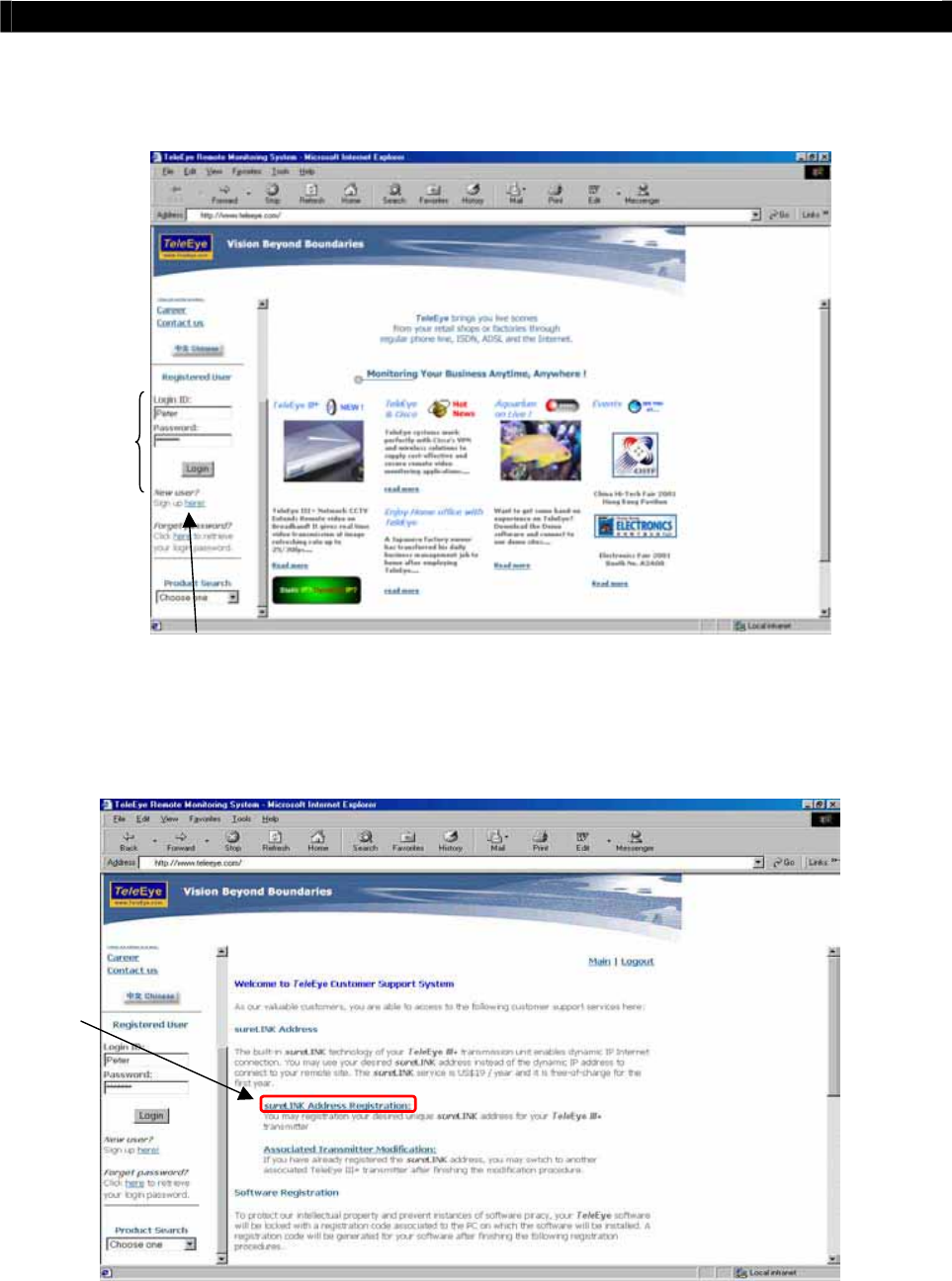
Tele
Eye RX User Guide Page 153
sureLINK Technology
How to Apply for sureLINK Address
You can apply for sureLINK by visiting our web site at http://www.TeleEye.com
Step 1: Sign up to create your user account
Step 2: Login the page using your registered name and password.
Step 3: Click sureLINK Address Registration button
ʳ
ʳ
ʳ
ʳ
ʳ
ʳ
ʳ
ʳ
ʳ
Step 3
Step 2
Step 1
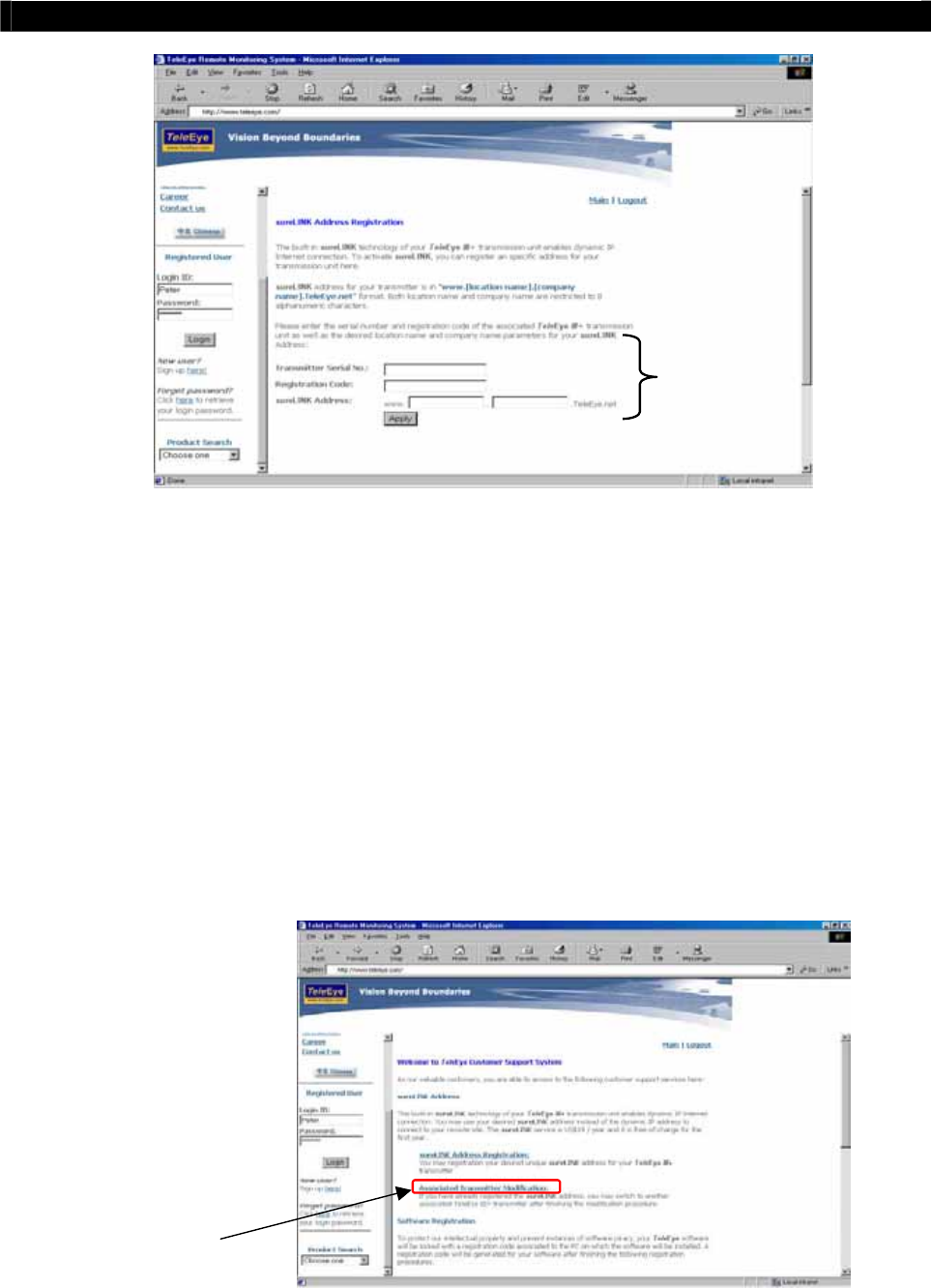
Tele
Eye RX User Guide Page 154
sureLINK Technology
ʳ
ʳ
ʳ
ʳ
ʳ
ʳ
ʳ
ʳ
ʳ
Step 4: Enter a sureLINK address (Domain Name), your Transmitter Serial No. and
Registration Code in the fields provided respectively. Then click the Apply button. The
process is then completed.
After we received your domain name registration for your transmitter, your application will be
processed. Normally, it requires about 2 to 3 working days to activateʳsureLINK for your
transmitter. You will receive a notification mail when your sureLINK service is ready.
ʳ
Transmitter Modification
Since the sureLINKʳ
ʳʳʳ(Domain name) address corresponds to a single transmitter, if you change
from one transmitter to another one, you have to inform us to update our database record. To do this,
you can visit ourʳ
Tele
Eye Product Support again and follow the steps below:
Step 1: Transmitter Modification > Select a sureLINK address (Domain Name) you want to
modify
Step 1
Step 4
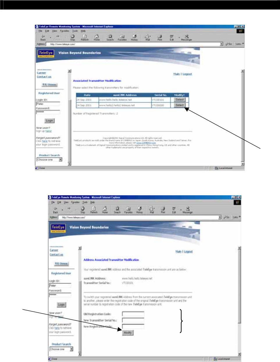
Tele
Eye RX User Guide Page 155
sureLINK Technology
ʳ
ʳ
ʳ
ʳ
ʳ
ʳ
ʳ
ʳ
ʳ
ʳʳʳ
ʳ
ʳʳʳ
ʳ
ʳʳʳ
ʳ
ʳʳʳ
ʳ
ʳʳʳ
Step 2: Enter the Old Registration Code, New Transmitter Serial Number and New
Registration Code at each field provided. Click Modify button to submit the form.
ʳ
ʳ
ʳ
ʳ
ʳ
ʳ
ʳ
ʳ
ʳ
ʳ
If the above procedure is completed successfully, theʳsureLINKʳwill be effective immediately.
Step 2
Step 3
Step 4

Tele
Eye RX User Guide Page 156
General Team Discussion
B
GENERAL TERMS DISCUSSION
Before you start to configure the transmitter, you may need to know some of the terms and
information used in the transmitter.
Registration Checking
Users need to do the registration in the
Tele
Eye Reception Software WX-30 for
authorization before the transmitter can be used when such feature is enabled in the
Tele
Eye
RX. This option can be applied to improve the security protection for the organization when
higher security level is required. If the transmitter is decided to open for public use, you can
disable this feature so that public users do not need to register for viewing live video from the
Tele
Eye Reception Software WX-30.
Site Monitoring Method
There are mainly four methods to link up with the transmitter to see video:
Telephone Line (Public Telephone Network/ISDN)
TCP/IP in LAN
TCP/IP on the Internet using Broadband and Internet Router
TCP/IP on the Internet using Broadband with Dial-up Software
You have to choose one of the connection methods in Section 3 to configure the transmitter
before use so as to make it function properly.
The
Tele
Eye Reception Software WX-30 contains all the settings for different remote
video monitoring method. Different connection methods may have different settings, and
some of the setting configured in one connection method is not applicable to other method. In
this case, you can refer to one of the following configuration procedures for the connection
method you will use.
ʳ
ʳ
It is recommended that the above items should be configured before the first time you use the
transmitter no matter which connection method you use. The steps to set the above items are
discussed in Section 3 : Basic Installation for Local and Remote Monitoring.
A
PPENDI
X

Tele
Eye RX User Guide Page 157
Specification
C
SPECIFICATIONS
VIDEO INPUT
STANDARD
(P): PAL/CCIR, 625 lines, 25 frames per second
(N): NTSC/EIA, 525 lines, 30 frames per second
composite video, 1 Vp-p, BNC
NO. OF CHANNELS 4
VIDEO OUTPUT
STANDARD
(P): PAL/CCIR, 625 lines, 25 frames per second
(N): NTSC/EIA, 525 lines, 30 frames per second
composite video, 1 Vp-p, BNC
NO. OF CHANNELS 1
DISPLAY SCREEN full screen, quad screen
DISPLAY FRAME RATE 25/30fps D1, 100/120fps CIF
STANDALONE OPERATION
TYPE System configuration, operation, audit trail
AUDIO **
INPUT 1 channel, RCA, line level
Input impedance : 30k, frequency : 200-3500Hz
OUTPUT
PA output : 1 channel, RCA, line level;
Output impedance : 600ohm, frequency : 200-3500Hz
Local input : 1 channel, RCA, line level;
Output impedance : 600ohm, frequency : 200-3500Hz
COMMUNICATION
NETWORK RJ-45, 10/100Base-T Ethernet (auto-sensing)
CONCURRENT USERS 6
sureLINK support Internet connection assigned with dynamic IP address
MODEM PORT RS-232C: DB-9 male, asynchronous, 8 data bits,
1 stop bit, no parity, 9.6k-115.2kbps, hardware flow control
TELEMETRY CONTROL
Keyboard port: RS-422/485: 2-way terminal, asynchronous,
8 data bits, 1 stop bit, no parity, 2.4-19.2kbps
Camera port: RS-422/485: 2-way terminal, asynchronous,
8 data bits, 1 stop bit, no parity, 2.4-19.2kbps
RECORDING
MODE manual, programmable, event-driven
HD TYPE IDE interface, removable
MAX. RECORDING RATE#(P) : 25fps at 720 X 576 pixels; 100fps at 360 X 288 pixels
(N) : 30fps at 720 X 480 pixels; 120fps at 360 X 240 pixels
EVENT TYPE
EVENT HANDLING external alarm, tamper, video motion detection, video loss,
disk full, power interruption, system fail
ACTION TYPE buzzer, dial back, recording,
relay control, email notification **
EXTERNAL INPUTS 4x NC/NO
A
PPENDI
X

Tele
Eye RX User Guide Page 158
Specification
RELAY SWITCH
NO. OF CHANNELS 4
MAX. RATING 24V AC, 1000mA
POWER
VOLTAGE 12V DC
MAX. RATING 50W
OPERATING ENVIRONMENT
AMBIENT TEMPERATURE 5oC – 45oC
RELATIVE HUMIDITY <85% (no condensation)
MECHANICAL DESIGN
DIMENSION 403x370x125 (mmxmmxmm)
WEIGHT 3.5kg
ʽʽʳˍʳ˧˻˼̆ʳ˹̈́˶̇˼̂́ʳ̊˼˿˿ʳ˵˸ʳ̆̈̃̃̂̅̇˸˷ʳ˼́ʳ̇˻˸ʳ
Tele
EyeʳRXʳ̇̅˴́̆̀˼̇̇˸̅ʳ̉˸̅̆˼̂́ʳ˅ˁ˃˃ˁ˃˃ʳ̂̅ʳ˿˴̇˸̅ʳ
This is the END of the User Guide