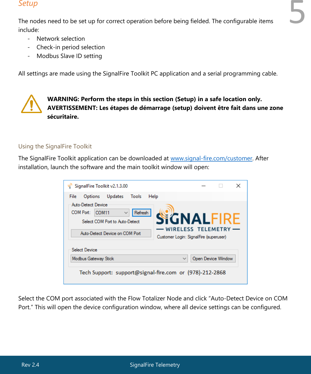
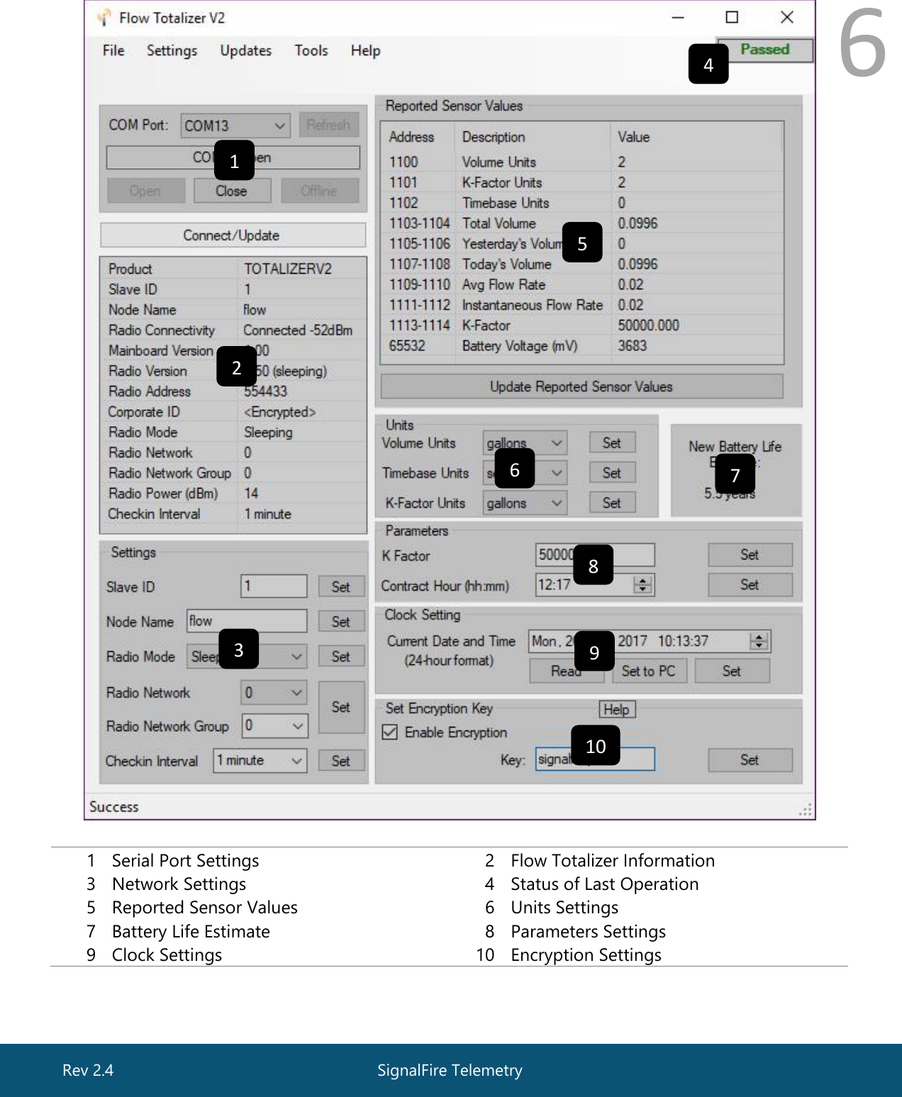
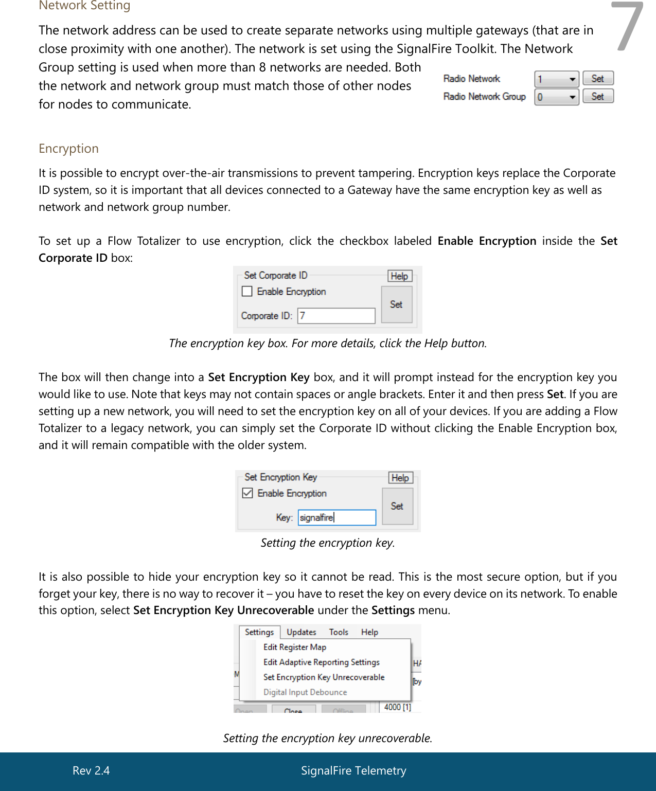
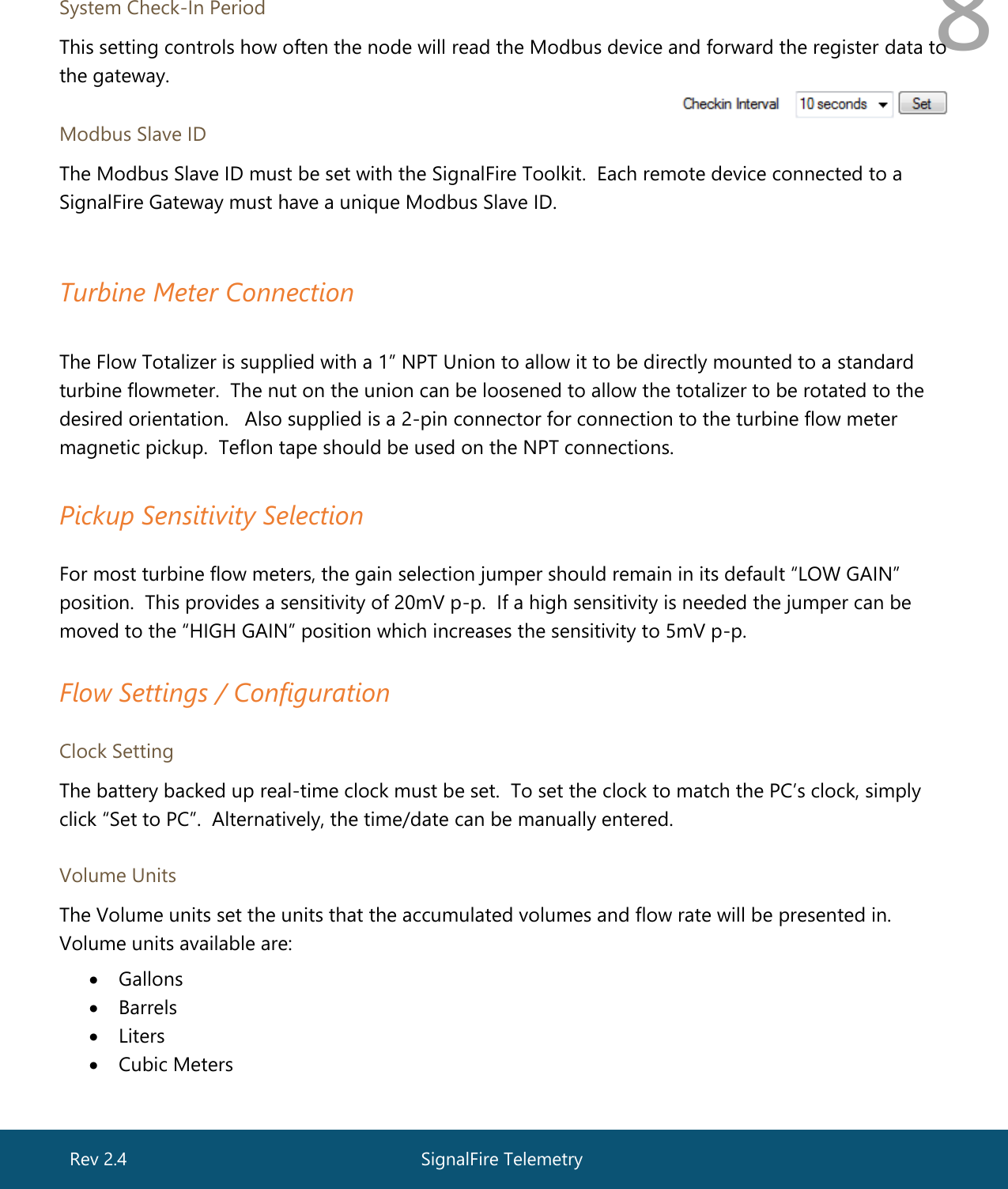
SignalFire Telemetry FT Flow Totalizer User Manual Rev 2 4

SignalFire Telemetry, Inc. Flow Totalizer Rev 2 4

User Manual Rev 2_4.pdf

 1       Interface Manual  Flow Totalizer  SignalFire Model: SFTotalizer-1BIS  The SignalFire Flow Totalizer is an Intrinsically Safe (pending) device with the following features: - Frequency range 1Hz – 4kHz (low gain), 1Hz – 2kHz (high gain) - Input Sensitivity of 20mV or 5mV peak-to-peak (jumper selectable)  - Provides grand total, yesterday’s total, and today’s total to individual Modbus registers - Real time clock for daily contract hour setting - Configurable K factor - Flow rate reporting  - Display showing flow rates and flow totals  - Low power operation from an Intrinsically Safe (pending) high capacity lithium primary battery pack - Sends data to a SignalFire Buffered Modbus Gateway - On-board logging of 30 days of flow totals  SignalFire Telemetry Rev 2.4
 2 Specifications  Overall Size 9.8” tall  ×  4.4” wide  ×  3.6” deep Power Source Internal IS lithium battery pack SignalFire Part Number: 810-0030-01 (1BIS)   Temperature Rating -40°C  to  +60°C / -40°F  to  +140°F Radio Frequency  FCC ID  IC ID  902-928MHz Ism Band, FHSS radio  W8V-FT  8373A-FT Compliance   Turbine Input Certified for use in Class I, Division 1 groups C and D. EXia. FCC/IC Certified. (Pending)  Sensitivity: 5mV peak-to-peak (high gain), 20mV peak-to-peak (low gain) Input Frequency: 1Hz to 2kHz (high gain), 1Hz-4kHz (low gain) 1” NPT swivel union connector.  Includes standard 2-pin pickup connector   Battery Life  The table below gives battery life estimites assuming a new battery and good radio link.    Check in Interval LCD Off LCD Always on 5 Seconds 1.25 Years 1.0 Years 15 Seconds 3.0 Years 2.25 Years 1 Minute 5.5 Years 4.0 Years 2 Minutes 6.75 Years 4.5 Years 5 Minutes 7.5 Years 5.0 Years 10 Minutes 8.5 Years 5.25 Years 30 Minutes 9.0 Years 5.5 Years 60 Minutes 9.5 Years 5.75 Years    SignalFire Telemetry Rev 2.4
 3  WARNING: Use of this equipment in a manner not specified by the manufacturer may impair the protection provided by the equipment.  AVERTISSEMENT: L’utilisation et l’implémentation de cet équipement d’une manière non spécifiée part le manufacturier peut affecter son intégrité ainsi que sa protection   WARNING: The use of any parts not supplied by the manufacturer violates the safety rating of the equipment.  AVERTISSEMENT: L’utilisation de composantes ne provenant pas du manufacturier compromette la sécurité et la certification du produit.    The associated apparatus provides Intrinsically Safe (pending) outputs. L’appareil associé fournit des sorties à sécurité intrinsèque (en attente).  Refer to control drawing 960-0087-01 for requirements when used in a Class I Division 1 area.   SignalFire Telemetry Rev 2.4
 4 Connections and Components  Radio LEDs - The Radio TX LED (green) flashes each time a radio packet is sent. This LED will blink rapidly while searching for the radio network. - The Radio RX LED (red) blinks on each received radio packet.  Status LEDs - The STATUS LED (green) Currently not implemented – for future use.   - The ERROR LED (red) will blink to indicate an error condition.  Checkin Button - If this button is pressed the Flow Totalizer will perform a check-in and send the current readings to the gateway.   SignalFire Telemetry Rev 2.4
 5 Setup  The nodes need to be set up for correct operation before being fielded. The configurable items include: - Network selection - Check-in period selection - Modbus Slave ID setting  All settings are made using the SignalFire Toolkit PC application and a serial programming cable.      Using the SignalFire Toolkit The SignalFire Toolkit application can be downloaded at www.signal-fire.com/customer. After installation, launch the software and the main toolkit window will open:    Select the COM port associated with the Flow Totalizer Node and click “Auto-Detect Device on COM Port.” This will open the device configuration window, where all device settings can be configured.      WARNING: Perform the steps in this section (Setup) in a safe location only. AVERTISSEMENT: Les étapes de démarrage (setup) doivent être fait dans une zone sécuritaire. SignalFire Telemetry Rev 2.4
 6   1 Serial Port Settings 2 Flow Totalizer Information 3 Network Settings 4 Status of Last Operation 5 Reported Sensor Values 6 Units Settings 7 Battery Life Estimate 8 Parameters Settings 9 Clock Settings 10 Encryption Settings   1 2 3 5 6 7 8 9 10 4 SignalFire Telemetry Rev 2.4
 7 Network Setting The network address can be used to create separate networks using multiple gateways (that are in close proximity with one another). The network is set using the SignalFire Toolkit. The Network  Group setting is used when more than 8 networks are needed. Both the network and network group must match those of other nodes for nodes to communicate.  Encryption It is possible to encrypt over-the-air transmissions to prevent tampering. Encryption keys replace the Corporate ID system, so it is important that all devices connected to a Gateway have the same encryption key as well as network and network group number.  To  set  up  a  Flow  Totalizer  to  use  encryption,  click  the  checkbox  labeled  Enable  Encryption inside  the  Set Corporate ID box:  The encryption key box. For more details, click the Help button.  The box will then change into a Set Encryption Key box, and it will prompt instead for the encryption key you would like to use. Note that keys may not contain spaces or angle brackets. Enter it and then press Set. If you are setting up a new network, you will need to set the encryption key on all of your devices. If you are adding a Flow Totalizer to a legacy network, you can simply set the Corporate ID without clicking the Enable Encryption box, and it will remain compatible with the older system.    Setting the encryption key.  It is also possible to hide your encryption key so it cannot be read. This is the most secure option, but if you forget your key, there is no way to recover it – you have to reset the key on every device on its network. To enable this option, select Set Encryption Key Unrecoverable under the Settings menu.   Setting the encryption key unrecoverable.  SignalFire Telemetry Rev 2.4
 8  System Check-In Period This setting controls how often the node will read the Modbus device and forward the register data to the gateway. Modbus Slave ID The Modbus Slave ID must be set with the SignalFire Toolkit.  Each remote device connected to a SignalFire Gateway must have a unique Modbus Slave ID.   Turbine Meter Connection  The Flow Totalizer is supplied with a 1” NPT Union to allow it to be directly mounted to a standard turbine flowmeter.  The nut on the union can be loosened to allow the totalizer to be rotated to the desired orientation.   Also supplied is a 2-pin connector for connection to the turbine flow meter magnetic pickup.  Teflon tape should be used on the NPT connections.    Pickup Sensitivity Selection   For most turbine flow meters, the gain selection jumper should remain in its default “LOW GAIN” position.  This provides a sensitivity of 20mV p-p.  If a high sensitivity is needed the jumper can be moved to the “HIGH GAIN” position which increases the sensitivity to 5mV p-p.   Flow Settings / Configuration   Clock Setting The battery backed up real-time clock must be set.  To set the clock to match the PC’s clock, simply click “Set to PC”.  Alternatively, the time/date can be manually entered.   Volume Units The Volume units set the units that the accumulated volumes and flow rate will be presented in. Volume units available are:  • Gallons • Barrels • Liters  • Cubic Meters  SignalFire Telemetry Rev 2.4
 9 Timebase Units The Timebase units configure the units used for the flow rates.  For example, if the volume units are set to ‘gallons’, and the timebase units are set to ‘minute’, the flow rates will be reported as gallons/minute.  Timebase units available are:  • Seconds • Minutes • Hours • Days  K-Factor Units / K-Factor The K-factor units set the units that the flow meter uses for its k-factor.  For example, if the turbine flow meter has a stated k-factor of 50,000 pulses/gallon, select ‘gallons’ for the K-Factor units, and enter 50000 for the k-factor.   Contact Hour The contract hour setting controls when the volume accumulated for today, rolls over to yesterday’s volume.  The contract hour is set in hh:mm in the 24-hour format.  For example, 2:30pm would be entered as 14:30.    30 Day Logging   The Flow Totalizer also keeps an on-board log of the last 30 days of flow totals.  This log can be accessed using the SignalFire ToolKit.  From the Tools Menu, select ‘Daily Log’.  On the daily log window click ‘Refresh’ to read the log file.  The log can be saved as a .csv file.   Flow Rate Reporting  The Flow totalizer reports two flow rates, average flow rate, and instantaneous flow rate.   The average flow rate is the flow rate over the configured check-in period.  For example,  if the check-in period is configured as 2-minutes, each check-in will contain the average flow rate over the 2-minues.   The Instantaneous flow rate is calculated every 2-seconds.  At check-in the most recent instantaneous calculated flow rate will be reported.       SignalFire Telemetry Rev 2.4
 10 Local Display  The Flow Totalizer has a local LCD display (with back-light) that allows for easy viewing of the  flow totals and flow rates.  The display is powered on only when the button under the display  is pressed.  Pressing the button when the display is on, cycles through the various information screens.  The display and backlight will automatically turn itself off after 30 seconds.    LCD Always on The default operation of the LCD is for it to time out and turn off after 30 seconds.  It will come back on when the front button is pressed.  If it is desired that the LCD remain on always, this can be selected from the ‘Settings’ menu.  Leaving the LCD always on will impact the system battery life, see the table on page 2 for details. Note that the LCD backlight will still turn off after 30 seconds.                          SignalFire Telemetry Rev 2.4
 11 Remote Modbus Register Mapping  The Flow Totalizer sends data to a SignalFire Telemetry Modbus Gateway. The data that is sent  To the gateway is available at the gateway in registers where it can then be read by a Modbus RTU. Consequently, the node needs to have a unique (to the network it is in) Modbus slave ID which the gateway will use to store its unique data.  Modbus Registers Every check-in period, the sensors are read and data is sent to the gateway. The gateway will save the data under the set Modbus ID in 16-bit registers.  The register map for this system is below.  Register Map Register Number Register Address Description Data Type 41101 1100 Volume Units (2 = gallons; 3 = barrels) Int 41102 1101 K-Factor Units (2 = gallons; 3 = barrels) Int 41103 1102 Time Base Units(3=day, 2=hour, 1=min, 0=second) Int 41104 1103 Flow Total  (High Word) Float 41105 1104 Flow Total (Low Word) Float 41106 1105 Yesterday's Flow Total (High Word) Float 41107 1106 Yesterday's Day Flow Total (Low Word) Float 41108 1107 Current Day Flow Total (High Word) Float 41109 1108 Current Day Flow Total (Low Word) Float 41110 1109 Avg Flow Rate  (High Word) Float 41111 1110 Avg Flow Rate (Low Word) Float 41112 1111 Instantaneous Flow Rate  (High Word) Float 41113 1112 Instantaneous Flow Rate (Low Word) Float 41114 1113 Gear Meter K Factor (High Word) Float 41115 1114 Gear Meter K Factor (Low Word) Float 49988 9987 or 65524 Major revision number for the mainboard Int 49989 9988 or 65525 Minor revision number for the mainboard Int 49990 9989 or 65526 Major revision number for the radio Int 49991 9990 or 65527 Minor revision number for the radio Int 49995 9991 or 65528 Received signal strength of last packet from the slave Signed Int 49996 9992 or 65529 Battery voltage, in millivolts Int 49997 9993 or 65530 Minutes until this slave will time out, unless new data is received Int 49998 9994 or 65531 Number of registers cached for this slave device Int 49999 9995 or 65532 Remote device type. 60 for Flow Totalizer Int  SignalFire Telemetry Rev 2.4
 12  Internal Lithium Battery Replacement Battery Packs can be changed with the node in place.  1 Open the cover. 2 Slide the power switch to the off position 3 Unplug the battery from the PCB, by depressing the locking clip on the connector. 4 Remove the battery from the clip and replace with new battery. 5 Connect the battery to the main PCB battery connector. 6 Slide the power switch to the on position. 7 Close and snap shut the enclosure cover.    WARNING: Use of any battery other than the SignalFire part number 810-0030-01 (1BIS) will impair the protection provided by the equipment. AVERTISSEMENT:  La sécurité intrinsèque et la protection du produit seront compromis par l’utilisation de batteries autres que celle fournie par SignalFire ayant comme numéro de pièce 810-0030-01(1BIS).   Coin Cell Battery Replacement The coin cell is used to backup the real time clock in the event that the main battery pack is unplugged.  The battery is a CR2032 coin cell battery    WARNING: Use of any battery other than a Panasonic CR2032 coin cell battery will impair the protection provided by the equipment. AVERTISSEMENT:  La sécurité intrinsèque et la protection du produit seront compromis par l’utilisation de batteries autres que celle fournie par SignalFire ayant comme numéro de pièce Panasonic CR2032.          SignalFire Telemetry Rev 2.4
 13 Cleaning Instructions The outside of the enclosure may be cleaned with water, mild soap, and a damp cloth as needed. High pressure washing is not recommended.    WARNING: Electrostatic Discharge Hazard! Care must be taken to avoid the potential of creating a change on the enclosure or antenna. Do not wipe with a dry cloth. Do not brush against the enclosure with clothing or gloves. AVERTISSEMENT: Danger de décharges électrostatiques! Utilisez les précautions nécessaires pour éviter l’accumulation d’électricité statique sur l’antenne. Ne pas nettoyer l’antenne avec un linge sec. Ne pas frotter le boitier avec des vêtements ou des gants.    SignalFire Telemetry Rev 2.4
 14 Configuration / Debug    WARNING: Only connect to the debug port in a safe area!  Ensure that the maximum voltage applied to the configuration port is less than 5 VDC!  AVERTISSEMENT: Branchez le port de déboggage que dans une zone secure. Assurez-vous que la tension électrique sur le port de configuration soit moins de 5 volt DC.   Debug and configuration information is available if a connection is made via the debug port on the main board. A USB converter cable (available from SignalFire) must be used for this interface.  Debug and configuration is done using the SignalFire Toolkit PC application.   Technical Support and Contact Information SignalFire Telemetry 43 Broad St C-300 Hudson, MA 01752 (978) 212-2868 support@signal-fire.com  Revision History          Revision Date Changes/Updates 1.0 6/26/17 Initial release 2.0 7/11/17 Added units info, updated ToolKit screenshot 2.1 7/17/17 Minor edits  2.2 8/8/17 Added battery life table, added detail on LCD always on setting 2.3 8/15/17 Updated warnings  2.4 8/28/17 Added FCC/IC details SignalFire Telemetry Rev 2.4 SignalFire Telemetry
 15 APPENDIX - FCC and IC Statements  Changes or modifications not expressly approved by SignalFire Telemetry, Inc could void the user’s  authority to operate the equipment. This device complies with Part 15 of the FCC Rules. Operation is subject to the following two conditions:  (1) this device may not cause harmful interference, and (2) this device must accept any interference received, including interference that may cause undesired operation.  This equipment has been tested and found to comply with the limits for a Class B digital device, pursuant to Part 15 of the FCC Rules.  These limits are designed to provide reasonable protection against harmful interference in a residential installation. This equipment generates, uses and can radiate radio frequency energy and, if not installed and used in accordance with the instructions, may cause harmful interference to radio communications.  However, there is no guarantee that interference will not occur in a particular installation.  If this equipment does cause harmful interference to radio or television reception, which can be determined by turning the equipment off and on, the user is encouraged to try to correct the interference by one of the following measures: -- Reorient or relocate the receiving antenna. -- Increase the separation between the equipment and receiver. -- Connect the equipment into an outlet on a circuit different from that to which the receiver is connected. -- Consult the dealer or an experienced radio/TV technician for help.  This device has been designed to operate with the antenna listed below, and having a maximum gain of 5.8 dBi.  Antennas not included in this list or having a gain greater than 5.8 dBi are strictly prohibited for use with this device.  The required antenna impedance is 50 ohms. San Jose Technology Inc. Model EEH-915  To reduce potential radio interference to other users, the antenna type and its gain should be so chosen that the equivalent isotropically radiated power (e.i.r.p.) is not more than that permitted for successful communication.  To comply with FCC’s and IC’s RF radiation exposure requirements, the antenna(s) used for this transmitter must be installed such that a minimum separation distance of 20cm is maintained between the radiator (antenna) & user’s/nearby person’s body at all times and must not be co-located or operating in conjunction with any other antenna or transmitter.  This device complies with Industry Canada’s licence-exempt RSSs. Operation is subject to the following two conditions:(1) This device may not cause interference; and (2) This device must accept any interference, including interference that may cause undesired operation of the device.  Le présent appareil est conforme aux CNR d'Industrie Canada applicables aux appareils radio exempts de licence. L'exploitation est autorisée aux deux conditions suivantes : (1) l'appareil ne doit pas produire de brouillage, et (2) l'appareil doit accepter tout brouillage radioélectrique subi, même si le brouillage est susceptible d'en compromettre le fonctionnement.  Rev 2.4 SignalFire Telemetry

Navigation menu