SignalFire Telemetry PS Pressure Scout User Manual
SignalFire Telemetry, Inc. Pressure Scout
UserManual.wiki
>
SignalFire Telemetry
>
PS User Manual
User Manual
Navigation menu
Upload a User Manual
Namespaces
Wiki Guide
HTML
PDF
Info
Views
User Manual
Discussion / Help
Navigation
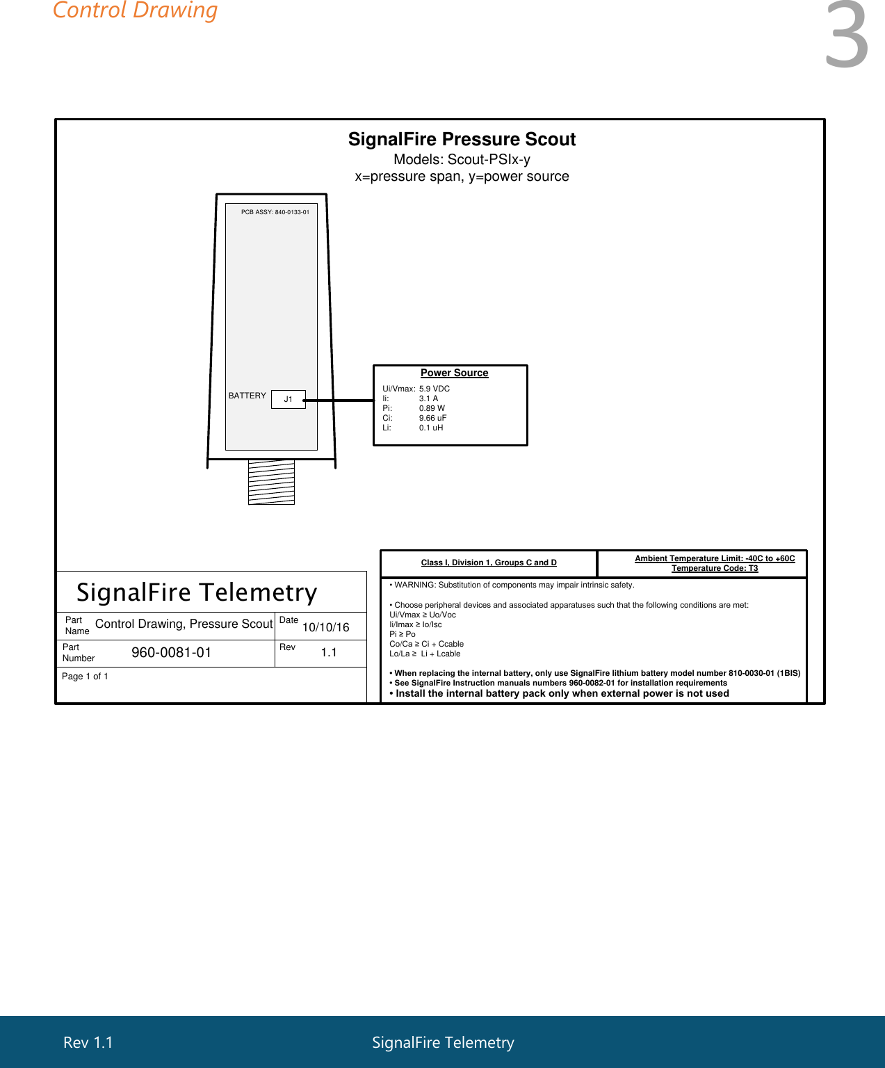
![2 Specifications Enclosure Size 7.25” tall × 2.75” diameter Power Source Internal IS Lithium battery pack SignalFire Part Number: 810-0008-02 External Solar battery system SignalFire Part Number: SENTINEL-SOLAR-xxx Other external power supply meeting the power entity parameters from the control drawing. Temperature Rating -40°C to +60°C Radio Frequency 902-928MHz Ism Band, FHSS radio, internal antenna FCC ID: W8V-PS IC: 8373A-PS Compliance Certified for use in Class I, Division 1 groups C and D. EXi [EXi] FCC/IC Certified. WARNING: Use of this equipment in a manner not specified by the manufacturer may impair the protection provided by the equipment. WARNING: The use of any parts not supplied by the manufacturer violates the safety rating of the equipment. Refer to control drawing 960-0081-01 for requirements when used in a Class I Division 1 area. SignalFire Telemetry Rev 1.1](https://usermanual.wiki/SignalFire-Telemetry/PS/User-Guide-3192553-Page-2.png)