SignalFire Telemetry PS Pressure Scout User Manual
SignalFire Telemetry, Inc. Pressure Scout
User Manual
1
Manual
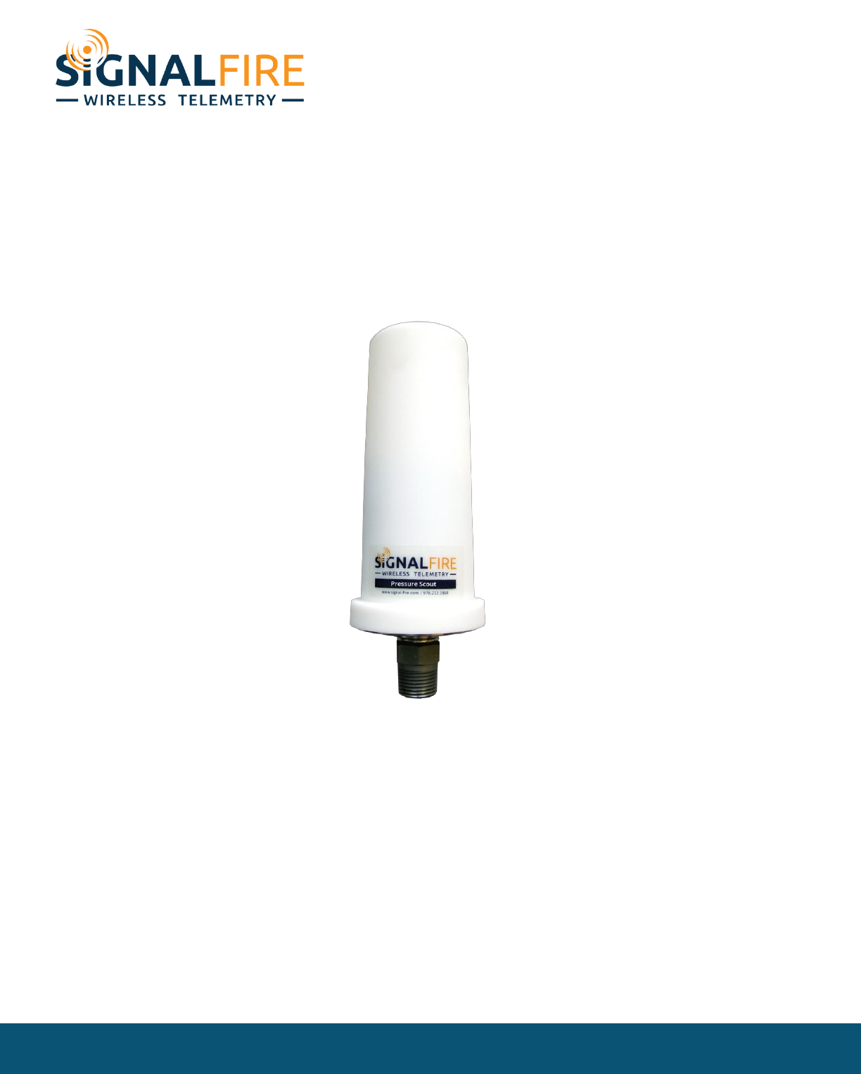
Pressure Scout
SignalFire Model: Scout-PSIx-y
The SignalFire Pressure Scout is an Intrinsically Safe wireless pressure sensor with the following features:
- Powers integrated pressure sensor and radio for years with an internal battery
- Rapid pressure sampling with configurable alarms and report by exception
- Available in standard pressure ranges
- Pushbutton or remote zeroing
- Optional solar battery system for routing nodes or rapid data collection
- Sends data to a SignalFire Buffered Modbus Gateway
- Compact and simple to install and maintain
- AES 128bit Encryption
SignalFire Telemetry
Rev 1.1

2
Specifications
Enclosure Size
7.25” tall × 2.75” diameter
Power Source
Internal IS Lithium battery pack
SignalFire Part Number: 810-0008-02
External Solar battery system
SignalFire Part Number: SENTINEL-SOLAR-xxx
Other external power supply meeting the power entity parameters from the
control drawing.
Temperature Rating
-40°C to +60°C
Radio Frequency
902-928MHz Ism Band, FHSS radio, internal antenna
FCC ID: W8V-PS
IC: 8373A-PS
Compliance
Certified for use in Class I, Division 1 groups C and D. EXi [EXi] FCC/IC Certified.
WARNING: Use of this equipment in a manner not specified by the manufacturer may impair the
protection provided by the equipment.
WARNING: The use of any parts not supplied by the manufacturer violates the safety rating of the
equipment.
Refer to control drawing 960-0081-01 for requirements when used in a Class I Division 1 area.
SignalFire Telemetry
Rev 1.1
3
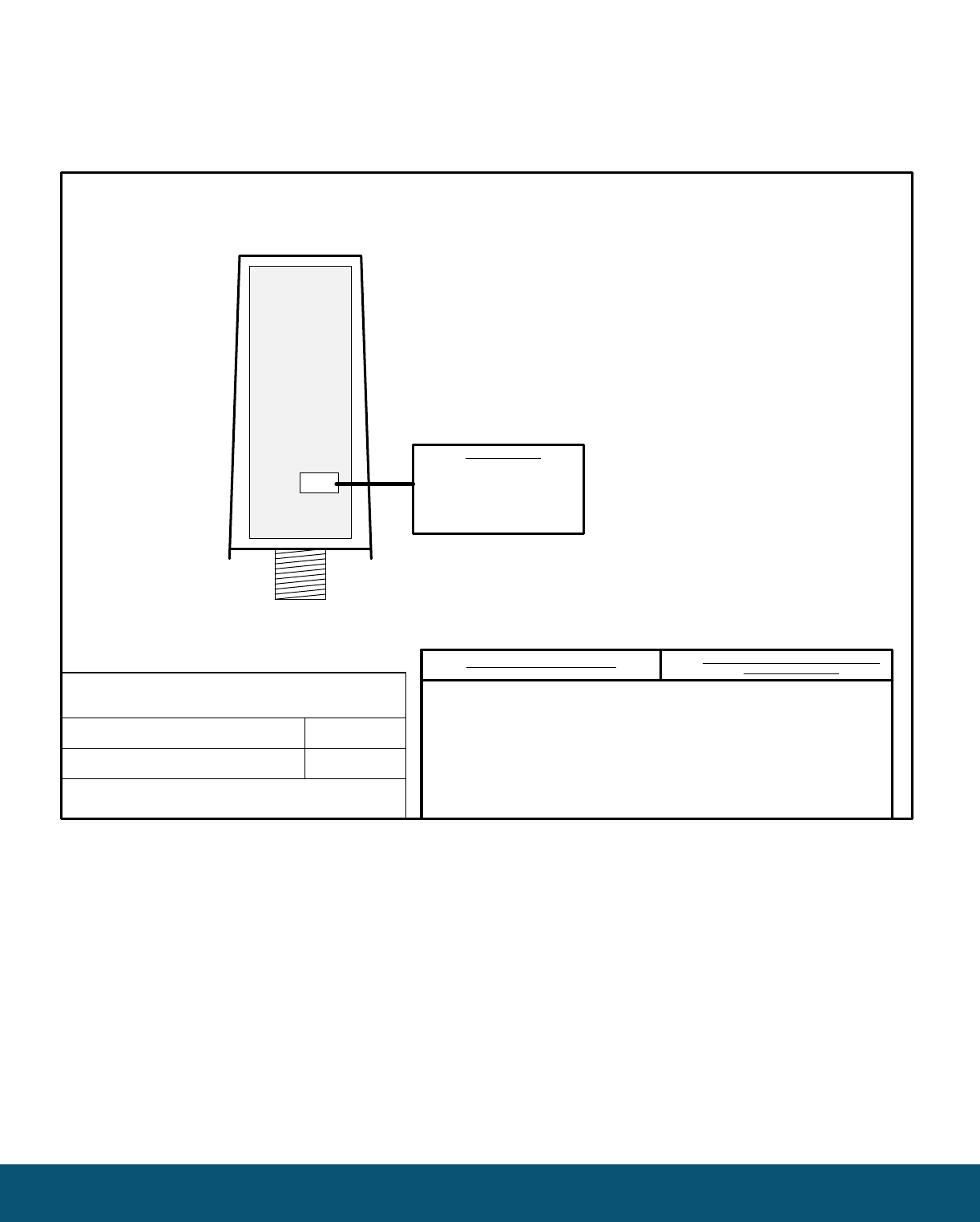
Control Drawing
Control Drawing, Pressure Scout
SignalFire Telemetry
Part
Name
Part
Number
Date
Page 1 of 1
960-0081-01
10/10/16
Rev 1.1
• WARNING: Substitution of components may impair intrinsic safety.
• Choose peripheral devices and associated apparatuses such that the following conditions are met:
Ui/Vmax ≥ Uo/Voc
Ii/Imax ≥ Io/Isc
Pi ≥ Po
Co/Ca ≥ Ci + Ccable
Lo/La ≥ Li + Lcable
• When replacing the internal battery, only use SignalFire lithium battery model number 810-0030-01 (1BIS)
• See SignalFire Instruction manuals numbers 960-0082-01 for installation requirements
• Install the internal battery pack only when external power is not used
J1
SignalFire Pressure Scout
Models: Scout-PSIx-y
x=pressure span, y=power source
Ambient Temperature Limit: -40C to +60C
Temperature Code: T3
Class I, Division 1, Groups C and D
BATTERY Ui/Vmax: 5.9 VDC
Ii: 3.1 A
Pi: 0.89 W
Ci: 9.66 uF
Li: 0.1 uH
Power Source
PCB ASSY: 840-0133-01
SignalFire Telemetry
Rev 1.1

4
Connections and Components
Radio LEDs
- The Radio TX LED (green) flashes each time a radio packet is sent. This LED will blink rapidly while
searching for the radio network and at boot up.
- The Radio RX LED (red) blinks on each received radio packet.
Status LEDs
- The STATUS LED (green) will blink on when the pressure sensor is sampled.
- The ERROR LED (red) will blink to indicate an error condition.
Checkin Button
- If this button is pressed the Scout will take a reading from the integrated pressure sensor and send the
data to the gateway.
Zero Button
- Allows the pressure sensor to be zeroed. Hold the ‘Zero’ button down for 3 seconds to zero the
pressure sensor. The status LED will come on and then blink twice to indicate that the sensor has been
zeroed.
SignalFire Telemetry
Rev 1.1
5
Setup
The Pressure Scout needs to be set up for correct operation before being fielded. The configurable items
include:
- Network selection
- Check-in period selection
- Modbus Slave ID setting
- Optional alarm thresholds and scaling
All settings are made using the SignalFire Toolkit PC application and a USB-serial programming cable available
from SignalFire.
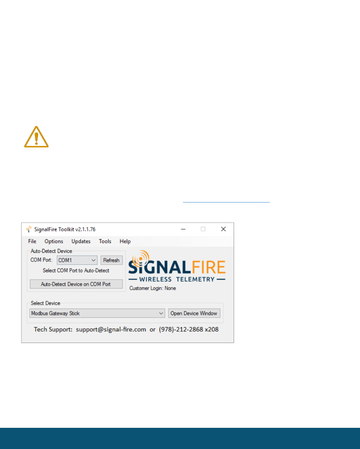
Using the SignalFire Toolkit
The SignalFire Toolkit application can be downloaded at www.signal-fire.com/customer. After installation,
launch the software and the main toolkit window will open:
Select the COM port associated with the Pressure Scout and click “Auto-Detect Device on COM Port.” This will
open the device configuration window, where all device settings can be configured.
WARNING: Perform the steps in this section (Setup) in a safe location only.
SignalFire Telemetry
Rev 1.1
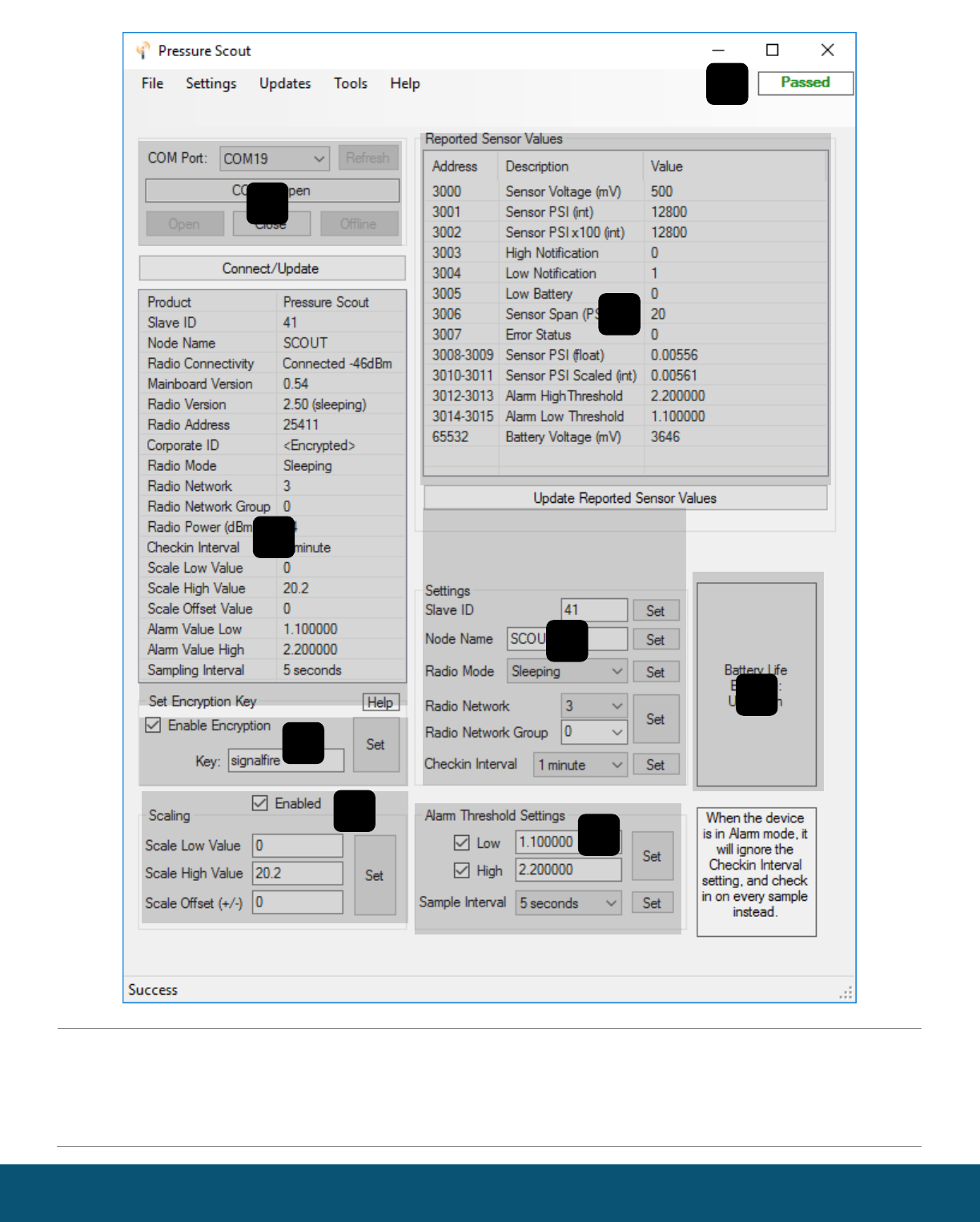
6
1
Serial Port Settings
2
Scout Information
3
Set Corporate ID / Encryption Key
4
Status of Last Operation
5
Reported Sensor Values
6
Scout Settings
7
Battery Life Estimate
8
Custom Sensor Scaling
9
Pressure Alarm Settings
SignalFire Telemetry
Rev 1.1
1
2
3
4
5
6
7
8
9
7
Network Setting
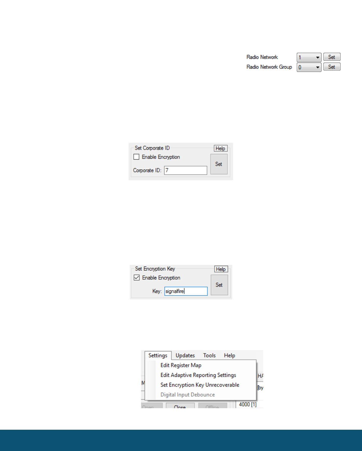
The network is set using the SignalFire Toolkit. The network, network group, and corporate ID (replaced
with Encryption) settings must match those of the gateway (and other nodes) in order for them to
communicate
Encryption
Starting with firmware version 0.50, it is possible to encrypt over-the-air transmissions to prevent tampering.
Encryption keys replace the Corporate ID system, so it is important that all devices connected to a Gateway
have the same encryption key as well as network and network group number.
To set up a Pressure Scout to use encryption, click the checkbox labeled Enable Encryption inside the Set
Corporate ID box:
The encryption key box. For more details, click the Help button.
The box will then change into a Set Encryption Key box, and it will prompt instead for the encryption key (6 to
16 characters) you would like to use. Note that keys may not contain spaces or angle brackets. Enter it and then
press Set. This will cause the Scout to drop its network, and only attempt to join networks that use the same
encryption key. If you are setting up a new network, you will need to set the encryption key on all of your devices.
If you are adding a Scout to a legacy network, you can simply set the Corporate ID without clicking the Enable
Encryption box, and it will remain compatible with the older system.
Setting the encryption key.
It is also possible to hide your encryption key so it cannot be read. This is the most secure option, but if you
forget your key, there is no way to recover it – you have to reset the key on every device on its network. To enable
this option, select Set Encryption Key Unrecoverable under the Settings menu.
Setting the encryption key unrecoverable.
SignalFire Telemetry
Rev 1.1
8
Modbus Slave ID
The Modbus Slave ID can be set with the SignalFire Toolkit. Each remote device connected to the gateway
must have a unique Modbus Slave ID (1-240).
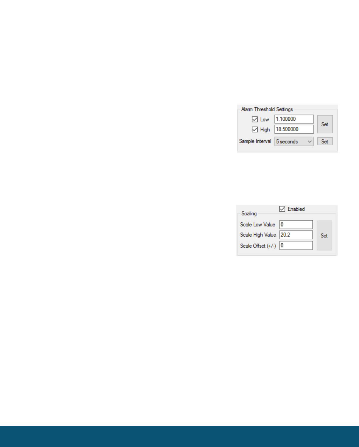
Alarm Threshold Settings
Optional alarm threshold settings are available which allow for rapid pressure sample interval (5 or 15 seconds)
and will cause the Pressure Scout to check-in immediately if the threshold is crossed. While above the high
alarm threshold (or below the low alarm threshold) the Scout will checkin at the configured sample interval.
The Low and High alarm thresholds can be enabled individually.
Custom Scaling
The reported pressure can be optionally scaled to a custom range. This can be used to scale PSI to inches of
H2O for example. If custom scaling is enabled, a Scale Low Value and Scale High Value must be configured. In
addition, an optional Scale Offset can be set. The Scale Offset will be added (or subtracted) to the reported
scaled value.
SignalFire Telemetry
Rev 1.1

9
Remote Modbus Register Mapping
The Scout Node sends data to a SignalFire Telemetry Modbus Gateway. The data that is
sent to the gateway is available at the gateway in registers where it can then be read by a Modbus RTU.
Consequently, the node needs to have a unique (to the network it is in) Modbus slave ID which the gateway
will use to store its unique data.
Modbus Registers
Every check-in period, the sensors are read and data is sent to the gateway. The gateway will save the data
under the set Modbus ID in 16-bit registers. The register map for this system is below.
Register Map
Register
Number
Register
Address
(Offset)
Description
43001
3000
Sensor Voltage (mV) (500mV to 2500mV is normal range)
43002
3001
Sensor PSI Reading (int)
43003
3002
Sensor PSI Reading x 100 (int) (only valid for pressures up to 650psi)
43004
3003
High Alarm Notification (0 = no alarm, 1 = high alarm active)
43005
3004
Low Alarm Notification (0 = no alarm, 1 = low alarm active)
43006
3005
Low Battery Alarm (0 = battery above 3.0V, 1 = battery below 3.0V)
43007
3006
Sensor Span (PSI)
43008
3007
Sensor Error Status (0=no errors, 1=sensor out of range low, 2=sensor out
of range high)
43009-43010
3008-3009
Sensor PSI Reading (float)
43011-43012
3010-3011
Custom Scaled Sensor Reading (float)
43013-43014
3012-3013
Alarm High Threshold Setting (float)
43015-43016
3014-3015
Alarm Low Threshold Setting (float)
49988
9987 or 65524
Major revision number for the mainboard
49989
9988 or 65525
Minor revision number for the mainboard
49990
9989 or 65526
Major revision number for the radio
49991
9990 or 65527
Minor revision number for the radio
49992
9991 or 65528
High 16 bits of SFTS node address
49993
9992 or 65529
Low 16 bits of SFTS node address (the radio ID)
49994
9993 or 65530
Slave ID readback
49995
9994 or 65531
Received signal strength of last packet from the slave
49996
9995 or 65532
Battery voltage of the Modbus client, in millivolts
49997
9996 or 65533
Minutes until this slave will time out, unless new data is received
49998
9997 or 65534
Number of registers cached for this slave device
49999
9998 or 65535
Remote device type. ?? for Pressure Scout
SignalFire Telemetry
Rev 1.1

10
Mounting and Care
The Pressure Scout unit comes with an integrated pressure sensor with a ½” MNPT process fitting.
The Scout is mounted directly to the pressure source. It is important to mount the Scout so it is vertically
orientated with the pressure fitting facing down.
Internal Lithium Battery Replacement
Battery Packs can be changed with the node in place.
1 Unscrew the cover from the base.
2 Unplug the battery from the PCB, by depressing the locking clip on the connector.
3 Remove/replace battery
4 Connect the battery to the main PCB battery connector.
5 Install the enclosure cover.
WARNING: Use of any battery other than the SignalFire part number 810-0030-01 (1BIS) will
impair the protection provided by the equipment.
Cleaning Instructions
The outside of the enclosure may be cleaned with water, mild soap, and a damp cloth as needed. High pressure
washing is not recommended.
WARNING: Electrostatic Discharge Hazard! Care must be taken to avoid the potential of creating a
change on the enclosure or antenna. Do not wipe with a dry cloth. Do not brush against the
enclosure with clothing or gloves.
SignalFire Telemetry
Rev 1.1

11
Configuration / Debug
WARNING: Only connect to the debug port in a safe area!
Debug and configuration information is available if a connection is made via the debug port on the main
board. A USB converter cable (available from SignalFire) must be used for this interface.
Debug and advanced configuration may be done using the SignalFire Toolkit PC application.
Technical Support and Contact Information
SignalFire Telemetry
43 Broad St C-300
Hudson, MA 01752
(978) 212-2868
support@signal-fire.com
Revision
Date
Changes/Updates
1.0
10/1/16
Initial release
1.1
10/10/16
Updated control drawing, Edits to register map
SignalFire Telemetry
Rev 1.1
12
APPENDIX - FCC and IC Statements
Changes or modifications not expressly approved by SignalFire Telemetry, Inc could void the user’s authority to operate the equipment.
This device complies with Part 15 of the FCC Rules. Operation is subject to the following two conditions: (1) this device may not cause harmful
interference, and (2) this device must accept any interference received, including interference that may cause undesired operation.
This equipment has been tested and found to comply with the limits for a Class B digital device, pursuant to Part 15 of the FCC Rules. These limits
are designed to provide reasonable protection against harmful interference in a residential installation. This equipment generates, uses and can radiate
radio frequency energy and, if not installed and used in accordance with the instructions, may cause harmful interference to radio communications.
However, there is no guarantee that interference will not occur in a particular installation. If this equipment does cause harmful interference to radio
or television reception, which can be determined by turning the equipment off and on, the user is encouraged to try to correct the interference by one
of the following measures:
-- Reorient or relocate the receiving antenna.
-- Increase the separation between the equipment and receiver.
-- Connect the equipment into an outlet on a circuit different from that to which the receiver is connected.
-- Consult the dealer or an experienced radio/TV technician for help.
WARNING!
FCC and IC Radiation Exposure Statement:
This equipment complies with FCC’s and IC’s RF radiation exposure limits set forth for an uncontrolled environment under the following conditions:
1. This equipment should be installed and operated such that a minimum separation distance of 20cm is maintained between the radiator
(antenna) & user’s/nearby person’s body at all times.
2. This transmitter must not be co-located or operating in conjunction with any other antenna or transmitter.
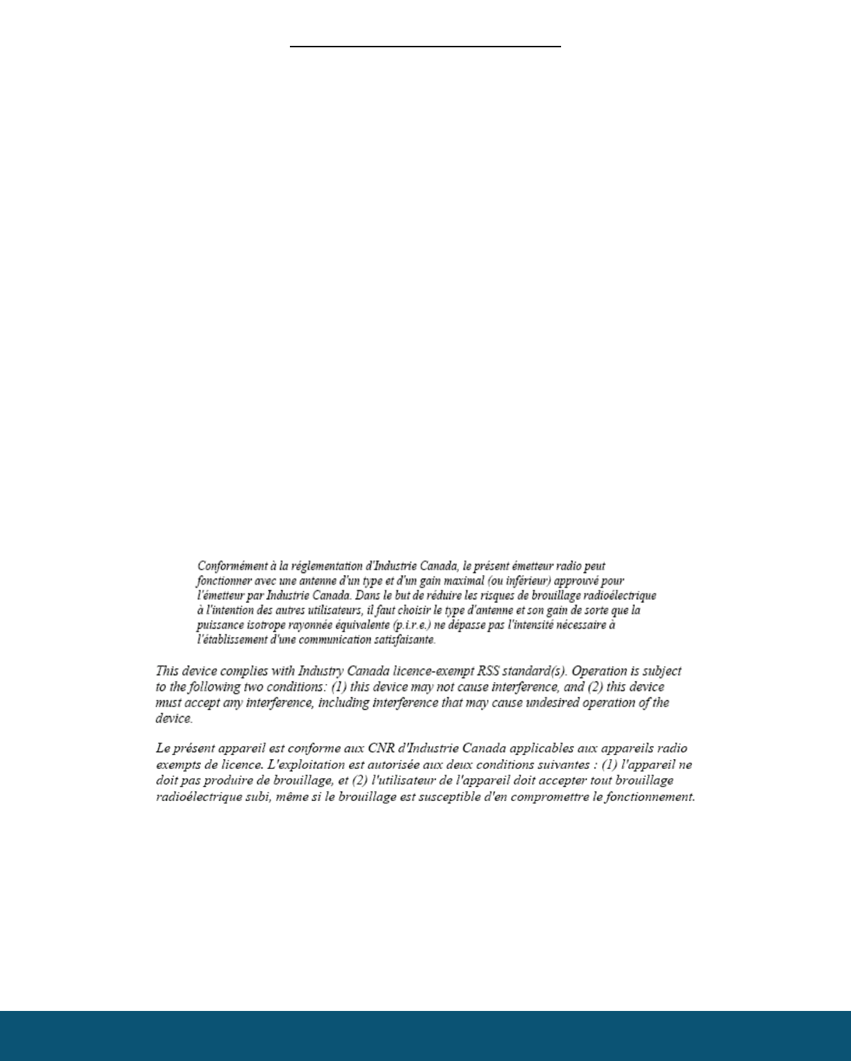
Under Industry Canada regulations, this radio transmitter may only operate using an antenna of a maximum (or lesser) gain approved for this
transmitter by Industry Canada. To reduce potential radio interference to other users, the antenna type and its gain should be so chosen that the
equivalent isotropically radiated power (e.r.i.p.) is not more than that necessary for successful communication.
SignalFire Telemetry
Rev 1.1