SignalFire Telemetry TS Tilt Scout User Manual 960 0084 01 SignalFire Tilt Scout Manual Rev 1 4
SignalFire Telemetry, Inc. Tilt Scout 960 0084 01 SignalFire Tilt Scout Manual Rev 1 4
User manual_960-0084-01 SignalFire Tilt Scout Manual Rev 1_4.pdf
1
Interface Manual
Tilt Scout
SignalFire Model: Scout-TILT-3AABIS
The SignalFire Tilt Scout is an Intrinsically Safe (certification pending) wireless
Inclinometer used for Hatch and Pump Jack monitoring:
- Thief Hatch state reporting – Closed, Cracked, Open (Thief Hatch Mode).
- Pump Jack Status reporting - Running/Not Running (Pump Jack Mode)
- Easy to install
- Internal long life battery, 5+ years of operation
- Patent pending sensor technology
- Sends data to a SignalFire Gateway
- AES 128bit Encryption
- Pushbutton zeroing
- Report on state change
SignalFire Telemetry
Rev 1.4
2
Specifications
Enclosure Size
3.5” wide × 3.1” tall × 2.3” deep
Power Source
Internal AA IS Lithium battery pack
SignalFire Part Number: 810-0031-01
Temperature Rating
Operating range: -40°C to +80°C
C1D1 certified operating range: -40°C to +60°C
Radio
40mW, 902-928MHz Ism Band, FHSS radio, internal antenna
Compliance
Standards
Resolution
Reporting Frequency
Class I, Division 1 groups C and D. EXia = Intrinsically Safe Apparatus (
Appareil à sécurité intrinsèque). Radio FCC and IC certified.
Intrinsically Safe Apparatus and Associated Apparatus For Use In Class 1,
2, 3, Division 1, Hazardous (Classified) Locations [UL 913:2013
Ed.8+R:16Oct2015]
Intrinsically Safe And Non-Incendive Equipment For Use In Hazardous
Locations (R2016) [CSAC22.2#157:1992 Ed.3+G1;U2]
<0.1 degree
Sends data every 10 minutes or immediately after a state change
4003827
Exia Class I, Div 1 Groups C, D. T3
Ambient Temp: ºC to +60ºC
Install per Manual (Installer par manuel):960-0084-01
FCC ID:W8V-TS
IC:8373A-TS
SN:TSxxxxxx
BARCODE
TILTScout
SignalFire Telemetry
Rev 1.4

3
WARNING: Use of this equipment in a manner not specified by the manufacturer
may impair the protection provided by the equipment.
AVERTISSEMENT: L’utilisation et l’implémentation de cet équipement d’une manière
non spécifiée part le manufacturier peut affecter son intégrité ainsi que sa
protection
WARNING: The use of any parts not supplied by the manufacturer violates the
safety rating of the equipment.
AVERTISSEMENT: L’utilisation de composantes ne provenant pas du manufacturier
compromette la sécurité et la certification du produit.
Rev 1.4
SignalFire Telemetry
4
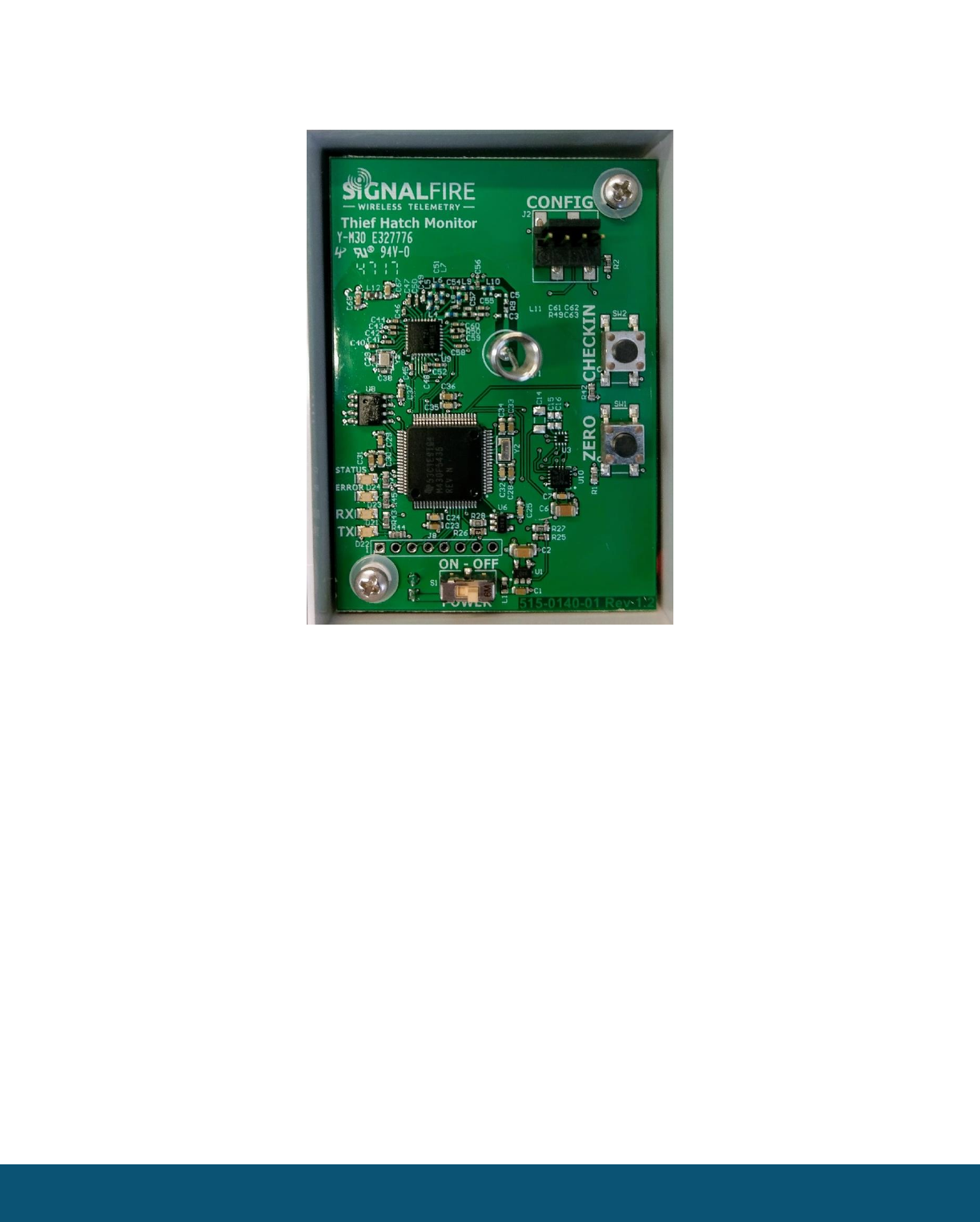
Connections and Components
Radio LEDs
- The Radio TX LED (green) flashes each time a radio packet is sent. This LED will blink rapidly
while searching for the radio network.
- The Radio RX LED (red) blinks on each received radio packet.
Status LEDs
- The Active LED (green) will blink at boot up and will blink quickly when the sensor is being
read.
- The ERROR LED (red) will blink to indicate an error condition.
Zero Button
- The Zero button allows the sensor to be zeroed when the unit is installed, and the hatch is in
the closed position. This is only used in Thief Hatch mode
Checkin Button
- If this button is pressed the Tilt Scout will take a sensor reading and send the data to the
gateway.
SignalFire Telemetry
Rev 1.4
SignalFire Telemetry
5
Setup
The Tilt Scout must be configured for correct operation before being fielded. The configurable items
include:
- Tilt Scout Mode
- Modbus Slave ID
- Network selection
- Corporate ID or Encryption
- Node Name
All settings are made using the SignalFire Toolkit PC application and SignalFire 4-pin USB cable
(Serial-4PIN).
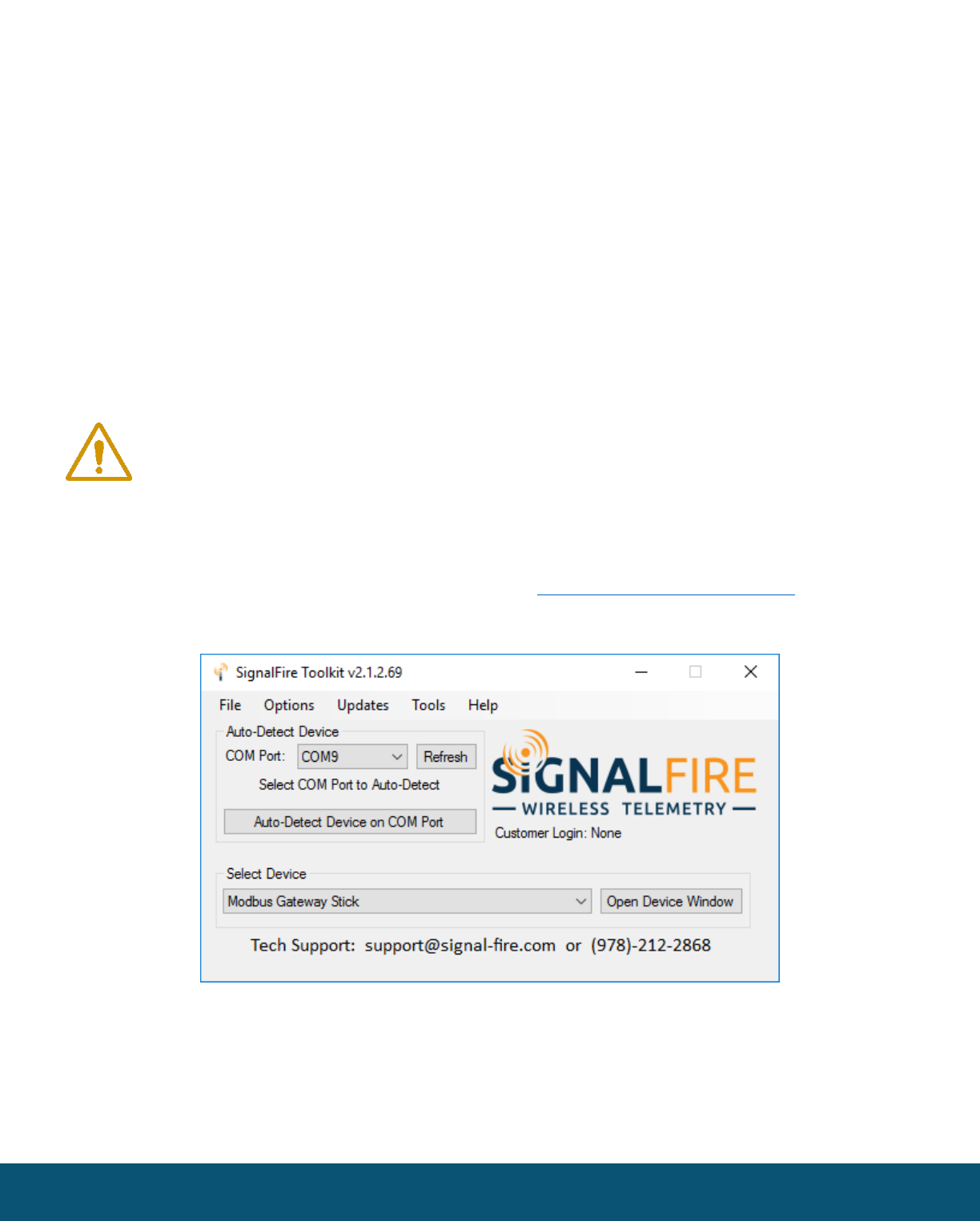
Using the SignalFire Toolkit
The SignalFire Toolkit application can be downloaded at www.signal-fire.com/customer. After
installation, launch the software and the main toolkit window will open:
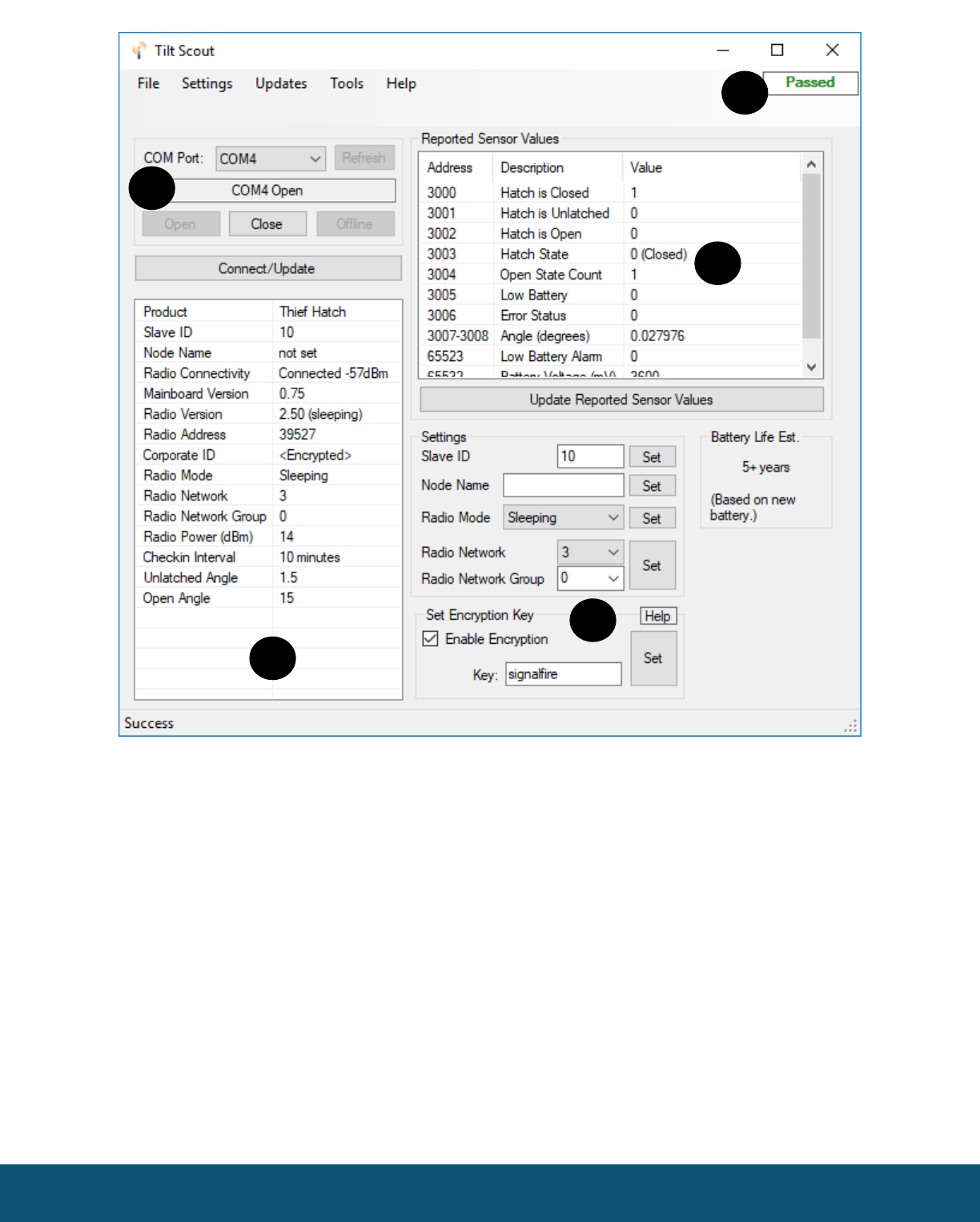
Select the COM port associated with the Tilt Scout and click “Auto-Detect Device on COM Port.” This
will open the device configuration window, where all device settings can be configured.
WARNING: Perform the steps in this section (Setup) in a safe location only.
AVERTISSEMENT: Les étapes de démarrage (setup) doivent être fait dans une zone
sécuritaire.
SignalFire Telemetry
Rev 1.4
6
❶
COM Settings
❹
Command successfully passed to node
(displays fail if unsuccessful)
❷
Node Information
❺
Current readings
❸
Configurable node settings
SignalFire Telemetry
Rev 1.4
1
2
3
4
5
7
Tilt Scout Mode
The default operation mode for the Tilt Scout is “Thief Hatch Mode”. When the Tilt Scout is to be
used for Pump Jack Monitoring the mode must be changed. From the ‘Settings’ menu, select ‘Mode’,
then select ‘Pump Jack Mode’. Note that the device Modbus register map changes with the
configured mode setting.
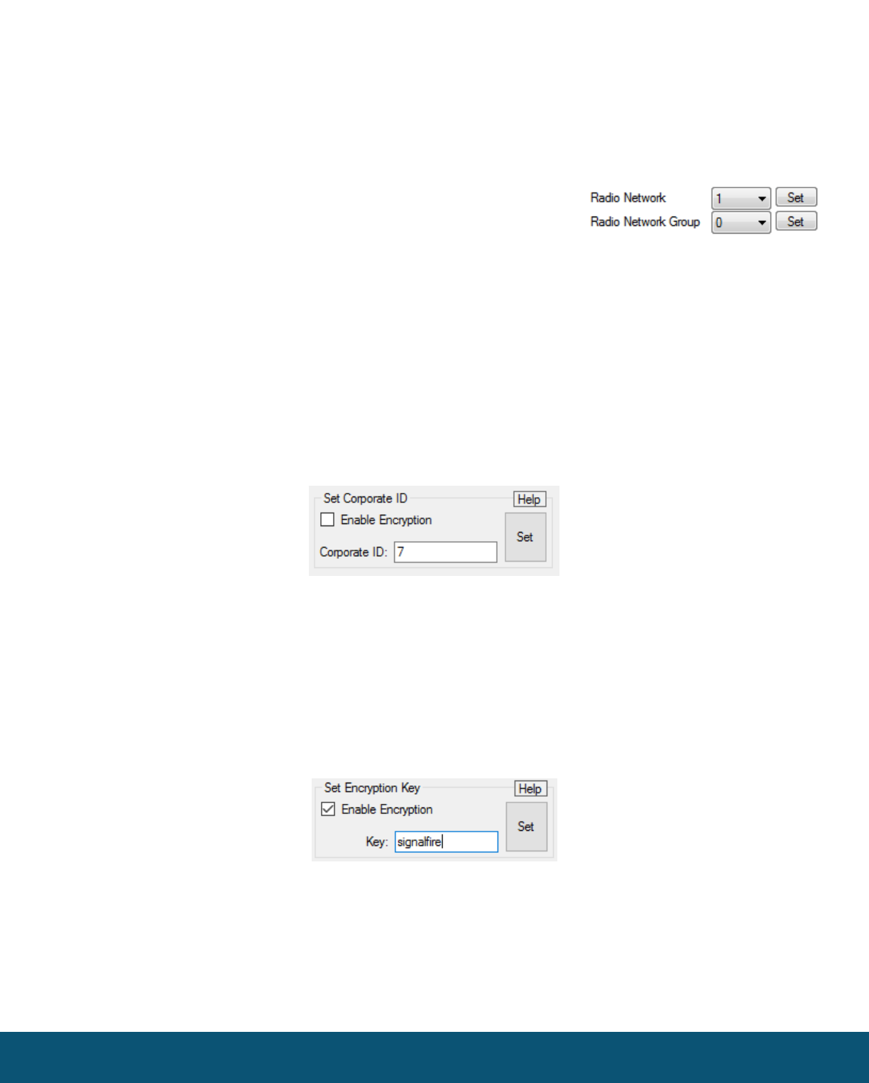
Network Setting
The network is set using the SignalFire Toolkit. The network, network
group, and corporate ID
settings must match those of the gateway (and other nodes) in order for them to communicate
Encryption
It is possible to encrypt over-the-air transmissions to prevent tampering. Encryption keys replace the Corporate
ID system, so it is important that all devices connected to a Gateway have the same encryption key as well as
network and network group number.
To set up a device to use encryption, click the checkbox labeled Enable Encryption inside the Set Corporate ID
box:
The encryption key box. For more details, click the Help button.
The box will then change into a Set Encryption Key box, and it will prompt instead for the encryption key you
would like to use. Note that keys may not contain spaces or angle brackets. Enter it and then press Set. This will
cause the Sentinel to drop its network, and only attempt to join networks that use the same encryption key. If
you are setting up a new network, you will need to set the encryption key on all of your devices. If you are adding
a Sentinel to a legacy network, you can simply set the Corporate ID without clicking the Enable Encryption box,
and it will remain compatible with the older system.
Setting the encryption key.
It is also possible to hide your encryption key, so it cannot be read. This is the most secure option, but if you
forget your key, there is no way to recover it – you will have to reset the key on every device on its network. To
enable this option, select Set Encryption Key Unrecoverable under the Settings menu.
SignalFire Telemetry
Rev 1.4
8
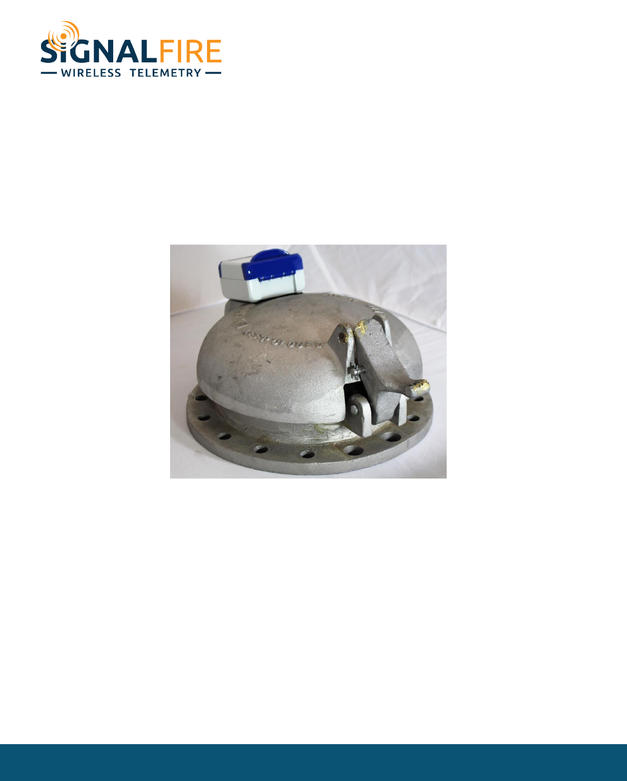
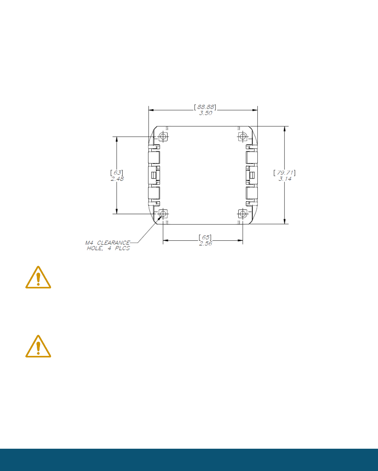
Mounting Requirements
The sensor technology used does not require a specific orientation for installation, the device can be
installed in any orientation or angle.
A suitable bracket must be used to adapt the Tilt Scout to a hatch cover or to the arm of a pump jack.
The drawing below shows the dimension of the mounting holes available.
WARNING: The Tilt Scout must be mounted in a location free of high vibrations.
Over time vibrations can damage the Tilt Scout or battery pack, which could impair
its safety ratings. Do not mount directly to continuous vibrating equipment such as
pumps or compressors.
AVERTISSEMENT: Le Tilt Scout doit être monté dans un endroit sans vibrations
élevées. Au fil du temps, les vibrations peuvent endommager le Flux Totalizer ou la
batterie, ce qui pourrait nuire à ses cotes de sécurité. Ne pas monter directement sur
des équipements vibrants continus tels que des pompes ou des compresseurs.
WARNING: The Tilt Scout must be securely mounted such that it cannot sustain a
fall. Failure to do this may impact the safety rating of the device
AVERTISSEMENT: Le Tilt Scout doit être solidement fixé de sorte qu'il ne puisse pas
supporter une chute. Ne pas le faire peut affecter la cote de sécurité de l'appareil
SignalFire Telemetry
Rev 1.4

9
Sensor Zeroing – Thief Hatch Mode Only
Once the monitor has been secured to the hatch, its angle sensor must be calibrated. The hatch must
be fully closed and latched before zeroing. Press and hold the ZERO button for about 2 seconds (until
the status LED turns on), then release. Wait approx. 5 seconds for the sensor to go through its
internal calibration and zeroing process. If successful, the status LED will blink 3 times. If the
calibration fails (due to movement), the red error LED will blink 3 times, if this happens the zero
process must be done again.
Remote Modbus Register Mapping
The Tilt Scout sends data to a SignalFire Telemetry Modbus Gateway, available at the gateway in
registers where it can then be read by a Modbus RTU.
This data is accessible at same Slave ID that was configured for the Tilt Scout.
Thief Hatch Mode
Register
Number
Register
Address
(Offset)
Description
43001
3000
Hatch Closed State. 1=Closed, 0=Not closed
43002
3001
Hatch Unlatched State. 1=Unlatched, 0=Not unlatched
43003
3002
Hatch Open State. 1=Open, 0=Not Open
43004
3003
Hatch State. 0=Closed, 1=Unlatched, 2=Open
43005
3004
Hatch Open Count. Total number of hatch openings
43006
3005
Low battery alarm. 1=Low battery
43007
3006
Error Status. 0 = no errors, 1 = sensor error
43008-43009
3007-3008
Measured Angle (32Bit Float)
Pump Jack Mode
Register
Number
Register
Address
(Offset)
Description
43001
3000
Pump Jack Status. 1=Running, 0=Not Running
43002
3001
Error Status. 0 = no errors, 1 = sensor error
SignalFire Telemetry
Rev 1.4

10
Common Registers (Available in both Thief Hatch and Pump Jack Modes)
Register
Number
Register
Address
(Offset)
Description
49988
9987 or 65524
Major revision number for the mainboard
49989
9988 or 65525
Minor revision number for the mainboard
49990
9989 or 65526
Major revision number for the radio
49991
9990 or 65527
Minor revision number for the radio
49992
9991 or 65528
High 16 bits of SFTS node address
49993
9992 or 65529
Low 16 bits of SFTS node address (the radio ID)
49994
9993 or 65530
Slave ID readback
49995
9994 or 65531
Received signal strength of last packet from the slave (Signed INT)
49996
9995 or 65532
Battery voltage of the Modbus client, in millivolts
49997
9996 or 65533
Minutes until this slave will time out, unless new data is received
49998
9997 or 65534
Number of registers cached for this slave device
49999
9998 or 65535
Remote device type. 57 = Thief Hatch Mode, 61 = Pump Jack Mode
SignalFire Telemetry
Rev 1.4

11
Internal Lithium Battery Replacement
Battery Packs can be changed with the node in place.
1 Open the cover from the enclosure.
2 Switch the power switch to the OFF position
3 Remove the two screws that hold the PCB in place
4 Unplug the battery from the PCB, by depressing the locking clip on the connector.
5 Install new battery pack
6 Connect the battery to the PCB battery connector.
7 Reinstall the PCB assembly
WARNING: Use of any battery other than the SignalFire part number 810-0031-01
will impair the protection provided by the equipment.
AVERTISSEMENT: La sécurité intrinsèque et la protection du produit seront
compromis par l’utilisation de batteries autres que celle fournie par SignalFire ayant
comme numéro de pièce 810-0031-01.
Cleaning Instructions
The outside of the enclosure may be cleaned with water, mild soap, and a damp cloth as needed.
High pressure washing is not recommended.
WARNING: Electrostatic Discharge Hazard! Care must be taken to avoid the
potential of creating a charge on the enclosure or antenna. Do not wipe with a dry
cloth. Do not brush against the enclosure with clothing or gloves.
AVERTISSEMENT: Danger de décharges électrostatiques! Utilisez les précautions
nécessaires pour éviter l’accumulation d’électricité statique sur l’antenne. Ne pas
nettoyer l’antenne avec un linge sec. Ne pas frotter le boitier avec des vêtements ou
des gants.
SignalFire Telemetry
Rev 1.4
12
Configuration / Debug
WARNING: Only connect to the debug port in a safe area! Ensure that the
maximum voltage applied to the configuration port is less than 5 VDC!
AVERTISSEMENT: Branchez le port de déboggage que dans une zone secure.
Assurez-vous que la tension électrique sur le port de configuration soit moins de 5
volt DC.
Debug and configuration information is available if a connection is made via the debug port on the
main board. USB to 4-pin serial cable must be used for this interface.
Technical Support and Contact Information
SignalFire Telemetry
43 Broad St C-300
Hudson, MA 01752
(978) 212-2868
support@signal-fire.com
Revision History
Revision
Date
Changes/Updates
1.0
5/17/17
Initial release
1.1
1/3/18
Updates for latest hardware revision
1.2
1/13/18
Updated for Tilt Scout Name. Added Pump Jack Mode
1.3
2/1/18
Updated mounting requirements, updated certification details
1.4
3/14/18
Added certification details
SignalFire Telemetry
Rev 1.4

13
APPENDIX - FCC and IC Statements
Changes or modifications not expressly approved by SignalFire Telemetry, Inc could void the user’s
authority to operate the equipment.
This device complies with Part 15 of the FCC Rules. Operation is subject to the following two conditions:
(1) this device may not cause harmful interference, and (2) this device must accept any interference received,
including interference that may cause undesired operation.
This equipment has been tested and found to comply with the limits for a Class B digital device, pursuant to
Part 15 of the FCC Rules. These limits are designed to provide reasonable protection against harmful
interference in a residential installation. This equipment generates, uses and can radiate radio frequency energy
and, if not installed and used in accordance with the instructions, may cause harmful interference to radio
communications. However, there is no guarantee that interference will not occur in a particular installation. If
this equipment does cause harmful interference to radio or television reception, which can be determined by
turning the equipment off and on, the user is encouraged to try to correct the interference by one of the
following measures:
-- Reorient or relocate the receiving antenna.
-- Increase the separation between the equipment and receiver.
-- Connect the equipment into an outlet on a circuit different from that to which the receiver is connected.
-- Consult the dealer or an experienced radio/TV technician for help.
This device has been designed to operate with the permanently soldered antenna. No other antenna may be
used.
To comply with FCC’s and IC’s RF radiation exposure requirements, the antenna(s) used for this transmitter
must be installed such that a minimum separation distance of 20cm is maintained between the radiator
(antenna) & user’s/nearby person’s body at all times and must not be co-located or operating in conjunction
with any other antenna or transmitter.
This device complies with Industry Canada’s license-exempt RSSs. Operation is subject to the following two
conditions:(1) This device may not cause interference; and (2) This device must accept any interference,
including interference that may cause undesired operation of the device.
Le présent appareil est conforme aux CNR d'Industrie Canada applicables aux appareils radio exempts
de licence. L'exploitation est autorisée aux deux conditions suivantes : (1) l'appareil ne doit pas
produire de brouillage, et (2) l'appareil doit accepter tout brouillage radioélectrique subi, même si le
brouillage est susceptible d'en compromettre le fonctionnement.
SignalFire Telemetry
Rev 1.4
SignalFire Telemetry
Rev 1.3