Siklu Communication SK-MH60GE-A1 Point-to-Multipoint Wireless V-band link User Manual
Siklu Communication Ltd. Point-to-Multipoint Wireless V-band link Users Manual
UserManual.wiki
>
Siklu Communication
>
SK MH60GE A1 User Manual
Users Manual
Navigation menu
Upload a User Manual
Namespaces
Wiki Guide
HTML
PDF
Info
Views
User Manual
Discussion / Help
Navigation

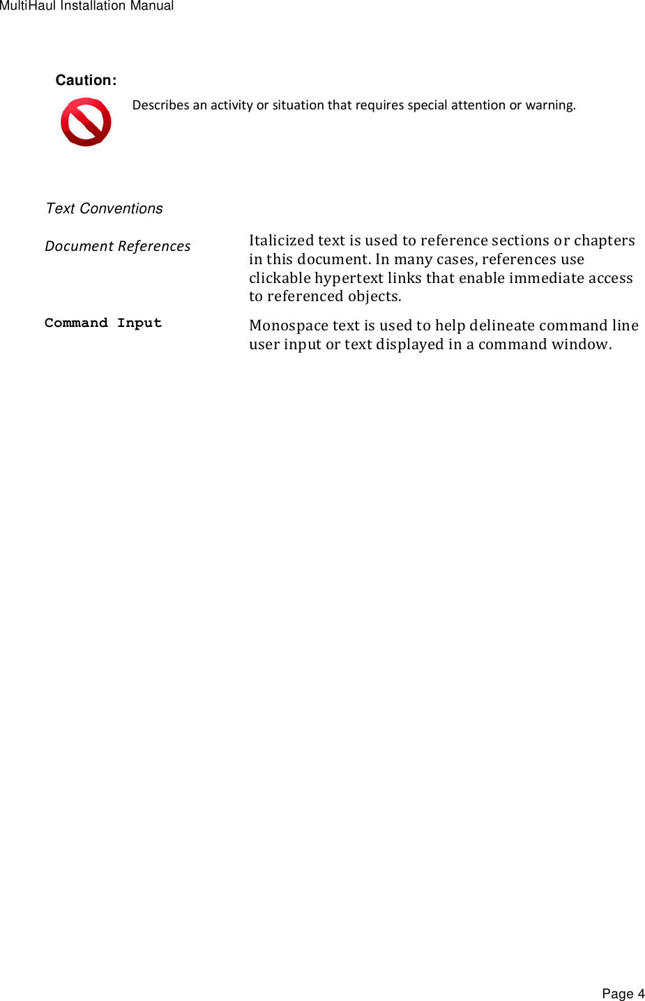


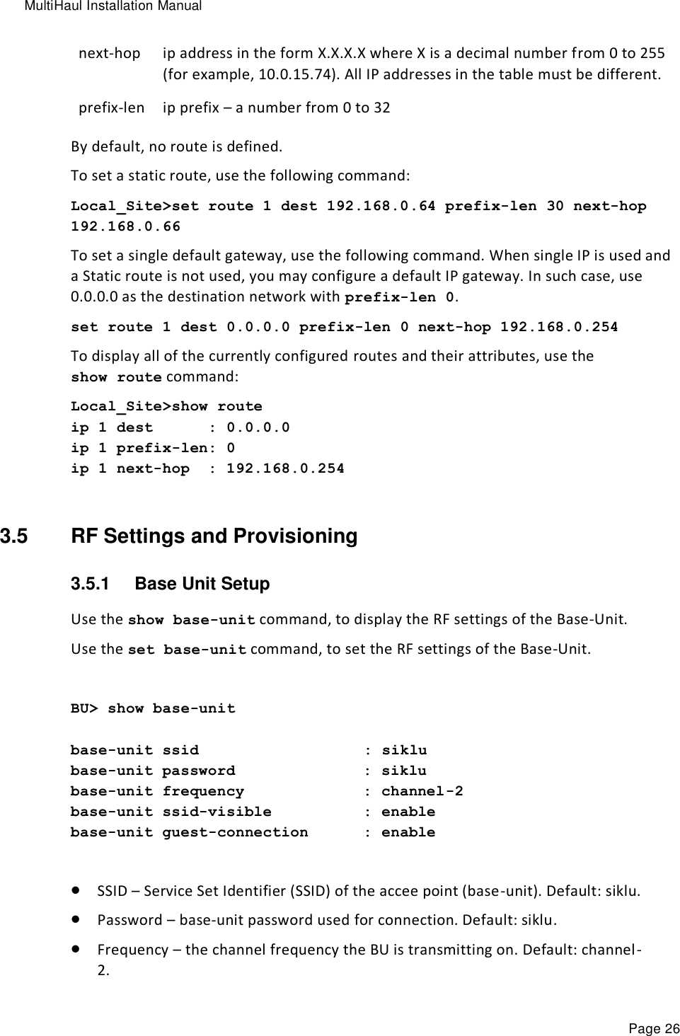
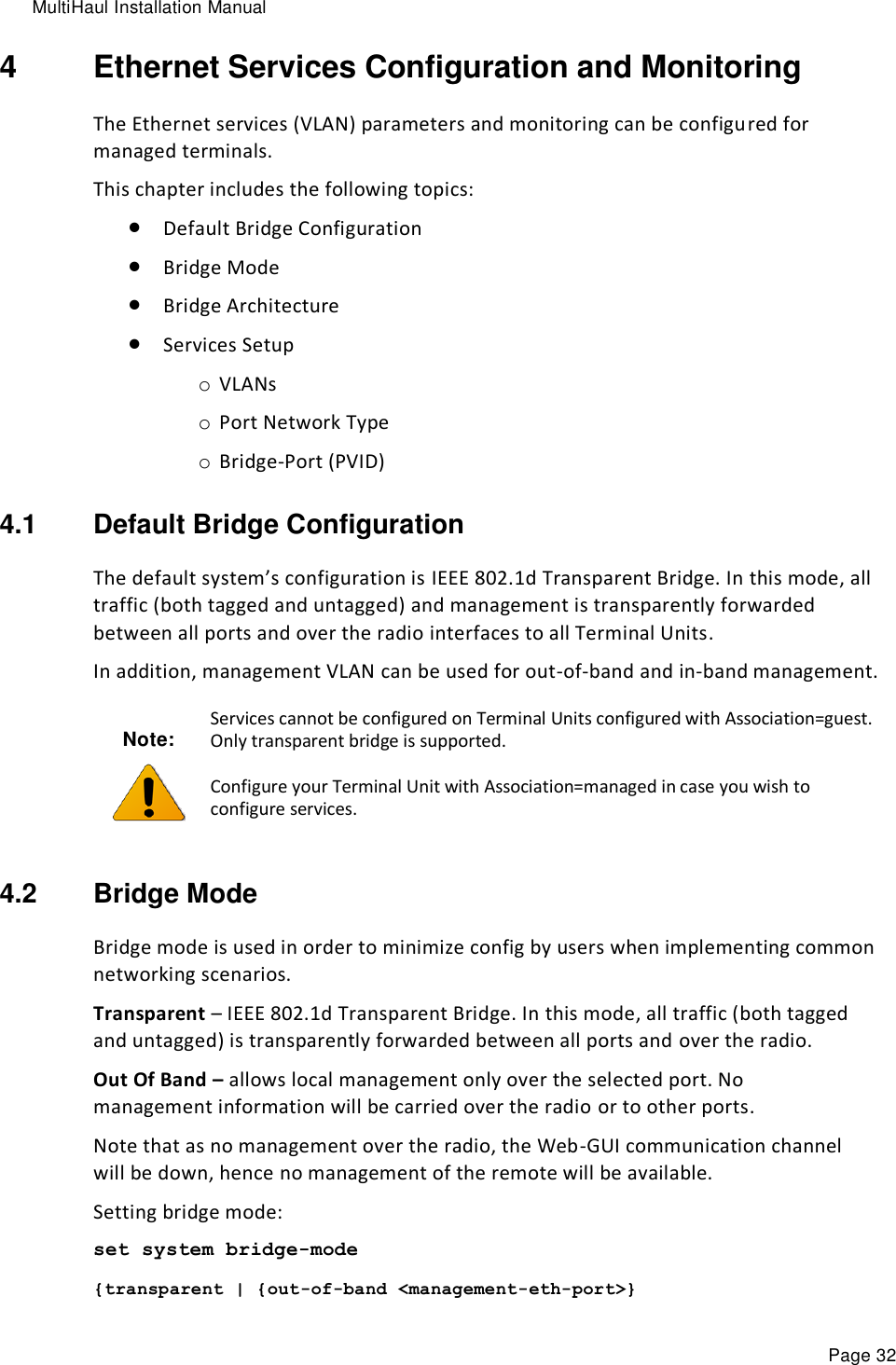
![MultiHaul Installation Manual Page 24 SnmpID – SNMP ID for Siklu products (R/O). System Uptime – R/O field. Time elapsed from last power on. Contact – text string. Name – text string. Enter a unique name to identify your system. Location – text string. Voltage – input voltage and indication DC or PoE (R/O). Temperature – system temperature in C⁰ (R/O). Date & Time – Date [YYYY.MM.DD], Time [HH:MM:SS] Cli-timeout – timeout for auto-logoff. Loopback-permission – controls the permission to perform system loopbacks o Enabled (default): all loops allowed. o Disabled: no loops allowed. o MAC-SWAP: only loops with MAC-SWAP allowed. Bridge-mode – system’s supported bridge modes: o Transparent – forward all traffic to all ports. o Out of band – carry management traffic from a specified port only. Use the set system name command to set the ODU’s name. Once you set the ODU’s name, a prompt appears with the name you just set, the date, and the time. Default> set system name Local_Site Local_Site> To set system date & time, use the following command: Local_Site> set system date 2016.01.12 time 15:08:00 3.4 Configuring System IP Addresses Using the CLI The MultiHaul ODU supports up to four IP addresses that can be on different subnets and associated with different VLANs. You can assign a static route to each IP address. The Default IP-Gateway is defined as a static route. By default, one IP address is defined (IP #1): IP Address – 192.168.0.1 IP network Prefix – 24 VLAN – 0 (not defined) Default Gateway – 0.0.0.0 (by default, no route is defined).](https://usermanual.wiki/Siklu-Communication/SK-MH60GE-A1/User-Guide-3278199-Page-24.png)
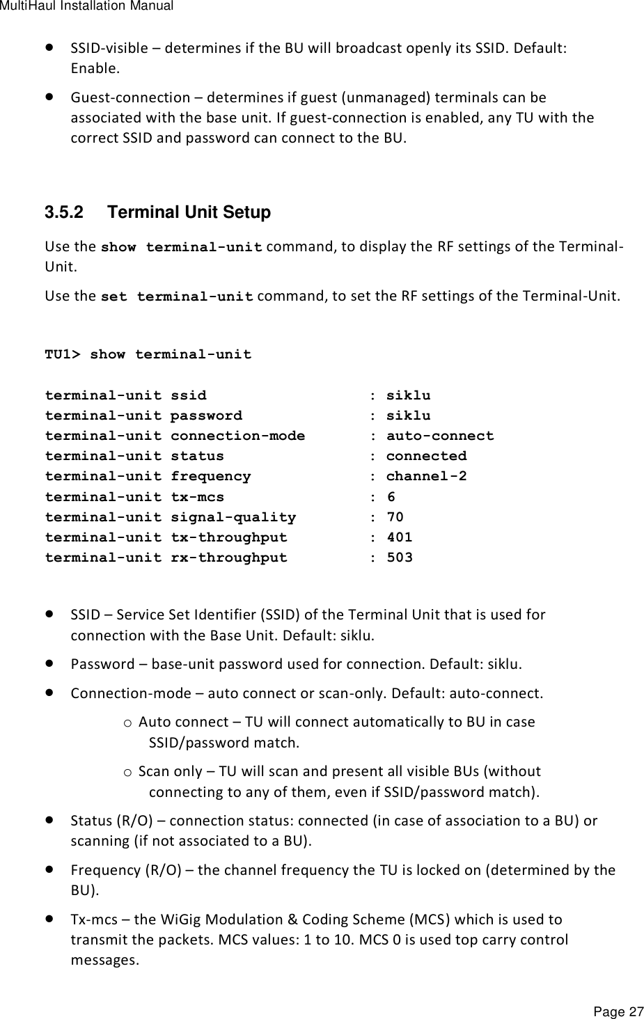
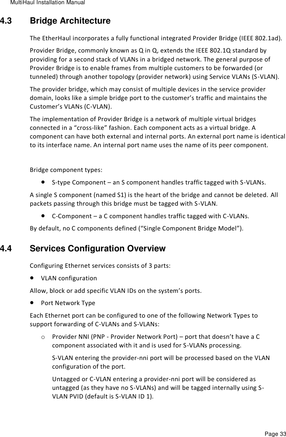
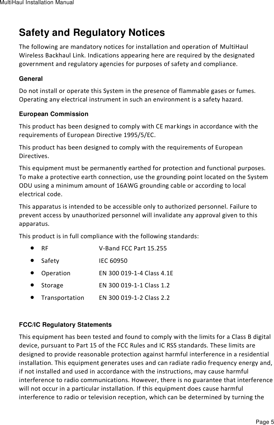
![MultiHaul Installation Manual Page 25 Use the set ip command to change or add an IP address. The command must be followed by the index number of the IP address you want to add or change. Use the index number 1 to change the default IP address. For example: set ip <ip-index> ip-addr <value> [prefix-len <value>] [vlan <value>] <ip-index> : integer 1..4 Local_Site>set ip 1 ip-addr 192.168.0.11 prefix-len 24 If the IP entry does not already exist, the set ip command creates it and assigns the attributes specified. If the interface address or the default router address is not explicitly specified, the entry is created with the default value that has been defined for the VLAN. If the IP entry already exists, the set ip command replaces the attributes that are currently defined for the entry with the values specified in the command. Up to four IP addresses can be specified on the command line. A set ip command fails if the route specified is not within the subnet that has been defined by mask. Note: If you change the default IP address, your connection to the ODU will be lost. To re-establish a connection, launch an Internet browser and connect using the new IP address. To display all of the currently configured IP addresses and their attributes, use the show ip command: For example: Local_Site>show ip ip 1 ip-addr : 192.168.0.11 ip 1 prefix-len : 24 ip 1 vlan : 0 ip 1 default-gateway : 0.0.0.0 To delete IP entries, use the clear ip command: clear ip <index> To create and modify an IP Route and Default Gateway, use the set route command: set route <idx> [dest <ip-address>] [prefix-len 0..32] [next-hop <ip-address>] idx number 1 to 10 dest ip address in the form X.X.X.X where X is a decimal number from 0 to 255 (for example, 10.0.15.74).](https://usermanual.wiki/Siklu-Communication/SK-MH60GE-A1/User-Guide-3278199-Page-25.png)