Siklu Communication SK-MH60GE-A1 Point-to-Multipoint Wireless V-band link User Manual
Siklu Communication Ltd. Point-to-Multipoint Wireless V-band link Users Manual
Users Manual

© ALL RIGHTS RESERVED TO SIKLU COMMUNICATION LTD.
MultiHaul™
Point to Multipoint Gigabit Ethernet Wireless Solution
Installation Manual
MH-INST-01, Issue 2
Jan 2017
MultiHaul Installation Manual
Page 2
Trademarks
Siklu, the Siklu logo, and MultiHaul are all trademarks of Siklu Communication Ltd.
All other product names and trademarks mentioned in this document are trademarks or
registered trademarks of their respective companies.
Copyrights
Copyright © 2016 Siklu Communication Ltd. All rights reserved.
No part of this publication may be reproduced or distributed in a ny form or by any
means, or stored in a database or retrieval system, without the prior written consent of
Siklu.
Disclaimers
The information contained in this document is subject to change without notice.
Siklu assumes no responsibility for any errors that may appear. Siklu makes no
warranties, expressed or implied, by operation of law or otherwise, relating to this
document, the products or the computer software programs described herein.
This document was originally written in English. Please refer to the English language
version for a full and accurate description of all products and services described herein.

MultiHaul Installation Manual
Page 3
About this Document
This document is the Installation Manual for the point-to-multipoint wireless Link.
It provides product overview and details the installation, setup and monitoring.
Note:
Features and functionality described in this document may be available for specific
product models or starting from specific SW version.
Please review the individual product’s release notes to verify if a specific feature is
supported in the product you use.
Applicable Products and Releases
V-Band Wigig-based
o MultiHaul, minimum SW release 0.9.0
Audience
This document assumes a working knowledge of wireless backhaul platforms and their
operating environments.
This document is intended for use by all persons who are involved in planning, installing,
configuring, and using the MultiHaul system.
Conventions
The following conventions are used in this document in order to make locating, reading,
and using information easier.
Special Attention
Hint:
Informs you of a helpful optional activity that may be performed at the current
operating stage.
Note:
Provides important and useful information or describes an activity or situation that
may or will interrupt normal operation of the MultiHaul system, one of its
components, or the network.

MultiHaul Installation Manual
Page 4
Caution:
Describes an activity or situation that requires special attention or warning.
Text Conventions
Document References
Italicized text is used to reference sections or chapters
in this document. In many cases, references use
clickable hypertext links that enable immediate access
to referenced objects.
Command Input
Monospace text is used to help delineate command line
user input or text displayed in a command window.
MultiHaul Installation Manual
Page 5
Safety and Regulatory Notices
The following are mandatory notices for installation and operation of MultiHaul
Wireless Backhaul Link. Indications appearing here are required by the designated
government and regulatory agencies for purposes of safety and compliance.
General
Do not install or operate this System in the presence of flammable gases or fumes.
Operating any electrical instrument in such an environment is a safety hazard.
European Commission
This product has been designed to comply with CE markings in accordance with the
requirements of European Directive 1995/5/EC.
This product has been designed to comply with the requirements of European
Directives.
This equipment must be permanently earthed for protection and functional purposes.
To make a protective earth connection, use the grounding point located on the System
ODU using a minimum amount of 16AWG grounding cable or according to local
electrical code.
This apparatus is intended to be accessible only to authorized personnel. Failure to
prevent access by unauthorized personnel will invalidate any approval given to this
apparatus.
This product is in full compliance with the following standards:
RF V-Band FCC Part 15.255
Safety IEC 60950
Operation EN 300 019-1-4 Class 4.1E
Storage EN 300 019-1-1 Class 1.2
Transportation EN 300 019-1-2 Class 2.2
FCC/IC Regulatory Statements
This equipment has been tested and found to comply with the limits for a Class B digital
device, pursuant to Part 15 of the FCC Rules and IC RSS standards. These limits are
designed to provide reasonable protection against harmful interference in a residential
installation. This equipment generates uses and can radiate radio frequency energy and,
if not installed and used in accordance with the instructions, may cause harmful
interference to radio communications. However, there is no guarantee that interference
will not occur in a particular installation. If this equipment does cause harmful
interference to radio or television reception, which can be determined by turning the

MultiHaul Installation Manual
Page 6
equipment off and on, the user is encouraged to try to correct the interference by one
or more of the following measures:
Reorient or relocate the receiving antenna.
Increase the separation between the equipment and receiver.
Connect the equipment into an outlet on a circuit different from that to
which the receiver is connected.
Consult the dealer or an experienced radio/TV technician for help.
Note:
Changes or modifications to this equipment not expressly approved by Siklu LTD or
the party responsible for compliance could void the user's authority to operate the
equipment.
Caution:
Outdoor units and antennas should be installed ONLY by experienced installation
professionals who are familiar with local building and safety codes and, wherever
applicable, are licensed by the appropriate government regulatory authorities.
Failure to do so may void the product warranty and may expose the end user or the
service provider to legal and financial liabilities. Siklu LTD and its resellers or
distributors are not liable for injury, damage or violation of regulations associated
with the installation of outdoor units or antennas.
Prudence: Les unités extérieures et les antennes doivent être installés que par des professionnels
expérimentés d'installation qui sont familiers avec les norms locales et les codes de
sécurité et, si applicable, sont agréées par les autorités gouvernementales de
réglementation compétents. Ne pas le faire peut annuler la garantie du produit et
peuvent exposer l'utilisateur final ou le fournisseur de services d'obligations juridiques
et financiers.Revendeurs ou distributeurs de ces équipements ne sont pas responsables
des blessures, des dommages ou violation des règlements liés à l'installation des unités
extérieures ou des antennes. L'installateur doit configurer le niveau de puissance de
sortie des antennes conformément aux réglementations nationales et le type d'antenne.
MultiHaul Installation Manual
Page 7
TABLE OF CONTENTS
1 Introduction to the MultiHaul System ........................................................10
1.1 Functional Description .............................................................................................. 10
1.2 Technical Specifications............................................................................................ 11
1.3 Management ............................................................................................................. 12
2 Installing the MultiHaul System ..................................................................13
2.1 Preparing the Site ...................................................................................................... 14
2.1.1 Physical and Environmental Requirements.................................................... 14
2.1.2 Cabling Requirements................................................................................... 15
2.2 MultiHaul Package Content....................................................................................... 16
2.3 Unpacking the MultiHaul .......................................................................................... 16
2.4 Required Tools.......................................................................................................... 16
2.5 Mounting the MultiHaul ............................................................................................ 17
2.6 Connecting the Cables ............................................................................................... 18
2.6.1 Power Options .............................................................................................. 18
2.6.2 Grounding the MultiHaul .............................................................................. 19
2.6.3 Preparing the Cables ..................................................................................... 20
2.7 System LEDs ............................................................................................................ 20
2.8 Link Up Verification ................................................................................................. 21
3 Setup and Monitoring Using the Command Line Interface ......................22
3.1 Establishing a CLI Session with the ODU ................................................................. 22
3.2 General Configuration Commands: Save, Reset, Rollback ......................................... 23
3.3 Configuring and Displaying System Information Using the CLI ................................ 23
3.4 Configuring System IP Addresses Using the CLI....................................................... 24
3.5 RF Settings and Provisioning .................................................................................... 26
3.5.1 Base Unit Setup ............................................................................................ 26
3.5.2 Terminal Unit Setup ..................................................................................... 27
3.5.3 Remote Terminal Units Setup and Monitoring .............................................. 28
3.6 Configuring Ethernet Interfaces Using the CLI .......................................................... 29
3.6.1 Displaying Interface Status ........................................................................... 30
3.6.2 Configuring Interface Parameters .................................................................. 31
4 Ethernet Services Configuration and Monitoring .....................................32
4.1 Default Bridge Configuration .................................................................................... 32
4.2 Bridge Mode ............................................................................................................. 32
4.3 Bridge Architecture ................................................................................................... 33
MultiHaul Installation Manual
Page 9
TABLE OF FIGURES
Figure 1-1 MultiHaul Functional Block Diagram ................................................................ 10
Figure 2-1 Mounting Bracket .............................................................................................. 17
Figure 2-2 Connection Panel Details ................................................................................... 18
Figure 2-3 Grounding Scheme ............................................................................................ 19
Figure 2-4 All-Weather Connecting Cable Shell Assembly ................................................. 20
Figure 3-1 Launching CLI ................................................................................................... 22
MultiHaul Installation Manual
Page 10
1 Introduction to the MultiHaul System
This chapter provides a brief overview of the MultiHaul product line.
Siklu MultiHaul™ is the culmination of innovation for point to multipoint carrier-class
systems operating in the uncongested unlicensed V-band, delivering very high adaptive
bandwidth. It features unique self-aligning antennas for quick installation and long
reach operations, in an outdoor yet eye-pleasing industrial design.
1.1 Functional Description
The MultiHaul is P2MP system based on WiGig 802.11ad chipset. The key features of the
system are:
P2MP wireless connectivity in the un-licensed 60GHz band, for up to 8 stations
Scanning antenna, to simplify the alignment process of the units
P2P wireless connectivity in the un-licensed 60GHz band
There are two options for this system, functionally wise. A system can serve as an access
point (“Base Unit” – BU) or as an end-point station (“Terminal Unit” – TU).
The RF Chip is connected to an array of 32-64 dipole antennas, depending on product
version.
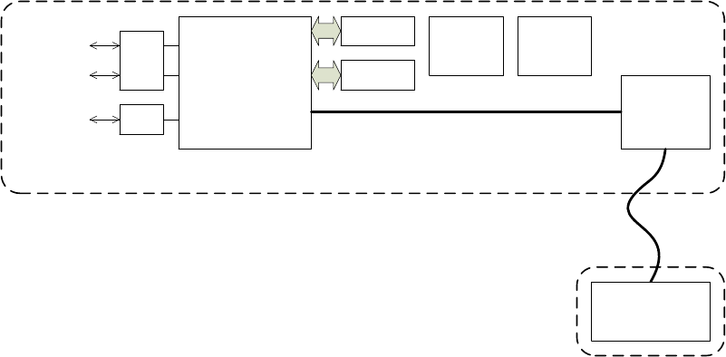
NPU
DRAM
FLASH
WiGig BB
1Gbps
ports
1G/2.5Gbps
port
DC
(POE) DC
(PSE)
PCIe lane
Baseband section
RF section
WiGig RF +
Antenna
Coax
PHY
PHY
Figure 1-1 MultiHaul Functional Block Diagram

MultiHaul Installation Manual
Page 11
1.2 Technical Specifications
For detailed technical specifications please refer to the datasheet.
For detailed supported features list please refer to the product’s release notes.
MH-BU
MH-TU
Topologies
Point to Multi-point
Point to Point
Built-in Antenna
Horizontal scanning: 90°
Vertical beam-width: 20°
Frequency & Duplexing
57-64GHz
Channels
2160MHz wide, 3 non-overlapping
channels
Modulation & Adaptive rate
10 level of hitless adaptive bandwidth,
coding and modulation
Line Rate (Mbps) (1)
Line rate up to
3080
3080
System Gain (link budget)
125dB (including antenna)
Interfaces
3x GbE
SFP supports 1GbE & 2.5GbE
2x RJ-45
1x SFP
Up to 3x
RJ-45
Terminal Units (TU)
Up to 8 Terminal Units
-
Ethernet Features
IEEE 802.1d transparent bridging
VLAN & VLAN stacking
Jumbo frames
Encryption
AES 128-bits
Management &
Provisioning
Zero-touch turn up; In-band, out-of-band
management
Web GUI (one-click configuration of local
and remote units) & Embedded CLI
SNMPv2/3, TACACS+, RADIUS
Conformance
Radio: FCC Part 15.255
EMC: FCC 47CFR.part 15
Safety: UL 60950
Power Supply
PoE (IEEE 802.3af/at)+,
10W without PoE-Out,
50W with PoE-Out.
PoE-Out
ETH2: 26W, 802.3at
ETH3: 13W, 802.3af
(SFP)
Environmental
Operating Temperature: -30÷+55°C
Page 11
1
Actual throughput varies with traffic patterns to/from the Terminal Units

MultiHaul Installation Manual
Page 12
(optional -49° to +131°F)
Ingress Protection Rating: IP65 (optional
IP67)
Dimensions (HxWxD)
11.4 x 5.2 x 3.5 in.
Weight
3 lbs. (including mounting kit)
1.3 Management
You can manage MultiHaul system using a Web-Based Element Management System
(Web EMS) or a Command Line Interface (CLI). The CLI is compatible with SNMP.
Advanced network features must be managed using the CLI.
The MultiHaul system features a wide range of built-in indicators and diagnostic tools
for advanced OAM functionality. The system is designed to enable quick evaluation,
identification, and resolution of operating faults.
Note:
Web-Management GUI support depends on product SW version. If not available, CLI
should be used for managing each end separately.
MultiHaul Installation Manual
Page 13
2 Installing the MultiHaul System
This chapter describes how to install and perform the installation of a MultiHaul
outdoor unit (Base Unit or Terminal Unit), including:
Preparing the Site
MultiHaul Package Content
Unpacking the MultiHaul
Required Tools
Mounting the MultiHaul
Connecting the Cables
System LEDs
Link Up Verification
The installation of the MultiHaul system is followed by initial system setup that will be
described in the next chapter.

MultiHaul Installation Manual
Page 14
Caution:
Avertissement:
The installation and maintenance of the MultiHaul link should only be done by
service personnel who are properly trained and certified to carry out such
activities.
L'installation et l'entretien de la liaison MultiHaul ne doivent être effectués par
du personnel de service qui sont formés et accrédités pour mener à bien ces
activités.
It is the responsibility of the installer to insure that when using the outdoor
antenna kits in the United States (or where FCC rules apply), only those
antennas certified with the product are used. The use of any antenna other
than those certified with the product is expressly forbidden in accordance to
FCC rules CFR47 part 15.204.
Il est de la responsabilité de l'installateur de s'assurer que lorsque vous utilisez
les kits d'antennes extérieures, seules les antennes certifiés avec le produit sont
utilisés. L'utilisation d'une antenne autre que ceux qui sont certifiés avec le
produit est expressément interdite par la réglementation FCC partie 47 CFR
15.204 et IC normes RSS.
Minimum safe distance from antenna while radiating is 30cm
(according to calculation done based on "Environmental evaluation
and exposure limit according to FCC CFR 47part 1, 1.1307, 1.1310;
RSS-102, Safety Code6).
Distance de sécurité minimum de l'antenne tout en rayonnant est
30cm (selon le calcul fait sur la base de "l'évaluation
environnementale et la limite d'exposition selon FCC CFR 47part 1,
1,1307, 1,1310, RSS-102, CODE6 sécurité).
2.1 Preparing the Site
Carefully select and prepare each MultiHaul ODU site to make device installation and
configuration as simple and trouble-free as possible. During site selection and
preparation, always consider the long-term needs of both your network and your
applications.
2.1.1 Physical and Environmental Requirements
Each MultiHaul ODU site should adhere to the following requirements:
There must be a clear, unobstructed line-of-sight between ODU.
The MultiHaul ODU should be mounted on a fixed, stable, permanent
structure. A reinforced steel mounting pole is required, with a diameter
measuring from 2-4 inches (recommended). Note the radio can be mounted
on poles from 1.5-12 inches using the provided steel worm-clamps.

MultiHaul Installation Manual
Page 15
Caution:
Do not mount the MultiHaul device on a structure that is temporary or easily moved.
Doing so may result in poor service or equipment damage.
You must mount the MultiHaul ODU in a site that is easily accessible to
authorized personnel, and only authorized personnel.
Operating temperature: between -45° and +55°C.
Relative humidity: 0 to 100%.
Maximum altitude: 4,500m.
2.1.2 Cabling Requirements
Install the MultiHaul ODU where network connections and optional power
cabling are ready for operation and easily accessible.
All cabling connected to the ODU should be outdoor-grade, with UV
protection.
PoE input – Connect Ethernet cable to Eth1
PSE Output – The voltage output at the PSE port is following the voltage at
the PoE input port. The cable length from the PSE port (ETH#2) to the
powered device (PD) should not exceed 40 meter, even if the PSE option is
disabled.
You should use shielded outdoor Cat5e cables terminated with metallic RJ45
connectors.
In order to protect indoor equipment, you must install surge protection
circuits on all copper cables on their entrance to the building.
Install the MultiHaul ODU in a location where proper electrical outdoor
grounding is readily available. Typically, the grounding connection is
attached directly to the mounting pole. If not already present, then suitable
structure-to-earth grounding connections must be created before
installation. Ground the ODU using a minimum quantity of 16AWG
grounding cable or according to local electrical code.
Caution:
Improper electrical grounding can result in excessive electromagnetic interference or
electrical discharge.
Siklu will not be held responsible for any malfunction or damage in the event that the
ODU is not properly grounded.

MultiHaul Installation Manual
Page 16
2.2 MultiHaul Package Content
MultiHaul link consists of a Base Unit (BU) and 1 to 8 Terminal Units (TU). The unit’s
mounting kit is included.
The MultiHaul packages include the following components:
Package
Description
Quantity
MultiHaul ODU
MultiHaul ODU (integrated
antenna)
1
Connecting cable All-
Weather shells
3
Unit grounding cable (90
cm)
1
MultiHaul mounting
assembly (attached to the
ODU)
1
Steel Worm Clamps
2
2.3 Unpacking the MultiHaul
The MultiHaul package content should be examined carefully before installation.
When you unpack the components of the MultiHaul, it is important to use care so as to
avoid damaging or scratching the antenna radome.
2.4 Required Tools
Ensure that you have the following tools with you when performing a MultiHaul
installation:
Philips screwdriver, medium size head
Flat-head screwdriver, medium size (5mm) head
7mm Hex socket driver
Standard open-end wrench, 13 millimeter for the ports’ caps
Cable ties (for securing network and optional power cables)
Cutter
Cable labeling
MultiHaul Installation Manual
Page 17
2.5 Mounting the MultiHaul
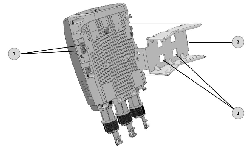
1. Elevation Lock Bolts (2 additional bolts at opposite side of the ODU)
2. Mounting Kit
3. Worm Clamp fixing points
Figure 2-1 Mounting Bracket
1. Mount the ODU and the Mounting Bracket on a fixed reinforced steel mounting
pole with 2-4 inches diameter.
2. Use worm clamps (steel bands) to secure the bracket to the mounting pole.
3. In order to allow free movement when pointing the antenna, unlock the
Elevation Lock Bolts.
4. Verify visually that the ODU is pointing to remote site. Optimize the Azimuth
alignment by turning the mounting bracket (make sure the worm clamps are not
tightened) and change the Elevation alignment by moving the ODU up and
down.
5. Once optimum achieved, fasten the worm-clamp to secure the bracket to the
mounting pole and tighten the Elevation Lock Bolts.
Alignment is now completed. The system’s scanning antenna will automatically alig n
the beam for optimal performance.
MultiHaul Installation Manual
Page 18
2.6 Connecting the Cables
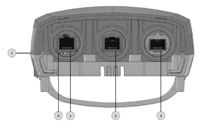
1. Electrical Ground Point(GND)
2. Ethernet RJ45 Eth#1 (PoE in)
3. Ethernet RJ45 Eth#2 (PoE Out)
4. Ethernet SFP Eth#3
5. Reboot push-button. Restore Factory
Default (is pushed for more than 8 seconds)
Figure 2-2 Connection Panel Details
2.6.1 Power Options
To power up the MultiHaul using PoE, connect the cable to Eth#1.
You may use direct DC (input range: 36÷57Vdc) by using an RJ45-DC Adapter (can be
obtained from Siklu). In this case, port ETH#1 will be used for power only.
MultiHaul Installation Manual
Page 19
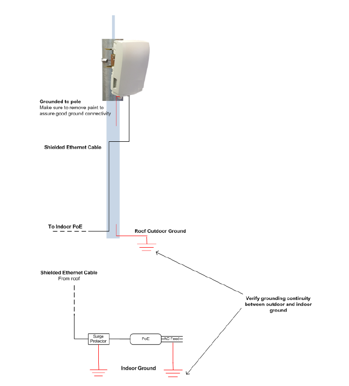
2.6.2 Grounding the MultiHaul
1. Connect one end of the grounding cable to the ground outlet on the left side of
the ODU using the grounding cable lug.
2. Tighten the lug securely in place.
3. Connect the opposite end of the grounding cable to the earth connection,
typically located on the mounting pole. If the earth connection is out of reach of
the grounding cable, install an alternative cable.
To make a protective earth connection, use the grounding point located on the Syst em
ODU using a minimum amount of 16AWG grounding cable or according to local
electrical code.
It is recommended to use Lightning Surge Protector on every Ethernet cable to protect
the indoor networking equipment. The Lightning Surge Arrestor should be installed
indoor next to the cable’s point-of-entry and should be properly grounded.
Figure 2-3 Grounding Scheme
MultiHaul Installation Manual
Page 20
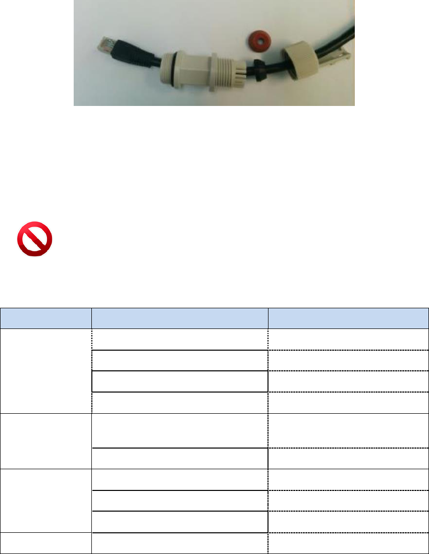
2.6.3 Preparing the Cables
Before inserting a cable connector into the ODU, you must first enclose the cable
connector in a protective All-Weather shell. Three sets of All-Weather shells are
provided with the ODU for the ODU interfaces.
Figure 2-4 All-Weather Connecting Cable Shell Assembly
The provided protective All-Weather Shells fit cables from 3.5mm to 9.0mm diameter.
1. Thread the cable and tight the shell to the ODU firmly by hand (do not use tools).
2. Insert the rubber gasket snugly and tight the connector lock.
Caution:
To avoid accidental damage to the connector, when removing the All-Weather Shell,
unlock the gland first.
2.7 System LEDs
LED
Color
Description
PWR (Power)
Green – Power ON
Blink Green – booting up
Orange – Booting up (2 seconds)
Boot failure if continues)
Red – Power Failure
Off – No Power
RF
Green – At least one station
associated
Device under association, no
station yet associated
Off – Link Down
ETH1/2/3:
Green – Link 1G
Orange – Link 10/100
Off – No Link (Carrier)
BT
For future use
MultiHaul Installation Manual
Page 21
2.8 Link Up Verification
1. Verify that RF LED is green, indicating association with at least one station.
The MultiHaul link can now pass traffic and management between the ports and over
the radio link.
Use the Command Line Interface for radio link configuration and monitoring.
MultiHaul Installation Manual
Page 22
3 Setup and Monitoring Using the Command Line
Interface
This chapter explains how to perform basic configuration tasks using the CLI.
3.1 Establishing a CLI Session with the ODU
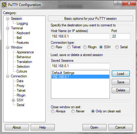
1. Launch standard SSH client. You can use any common, open source SSH client
program, such as PuTTY, available for download from the web.
Open an SSH session to the system’s IP address. The system’s default IP address
is 192.168.0.1.
Figure 3-1 Launching CLI
2. PuTTY configuration (Recommended):
a. Go to category: Terminal -> Keyboard
Set Backspace key = Control-H
Set The function keys and keypad = Linux
b. Go to category: Window
Set Lines of Scrollback = 100000
c. Save the session and configuration. Give it a name and Click Save. The session
will be stored under the Saved Sessions.
3. When prompted, enter the username and password. Default: admin and admin.
login as: admin
MH, S/N: F626500012, Ver: 0.9.0 64311
admin@192.168.0.15's password:
MultiHaul Installation Manual
Page 23
3.2 General Configuration Commands: Save, Reset, Rollback
Whenever you make changes to the ODU configuration, you must save the configuration
changes to the startup configuration. If you do not save the configuration, the changes
will be lost the next time the system is reset. Use the following command to save
configuration changes to the startup configuration:
Local_Site> copy running-configuration startup-configuration
To reset the system, use the reset system command. You must reset the system
whenever you exit Alignment mode.
Local_Site> reset system
Rollback is a safety measure that allows recovering from system configuration changes
that caused loss of communication.
When Rollback is used, a timer runs (and restarts) whenever command is entered. In the
event that no command is entered within the timeout period, the system automatically
reboots and comes up with the saved startup configuration.
A Rollback timeout is especially recommended when configuring remote elements that
are being managed over the link.
To specify the Rollback timeout period, use the following command:
set rollback timeout <duration-in-seconds>
3.3 Configuring and Displaying System Information Using the CLI
Use the show system command to display basic information about the ODU.
Local_Site>show system
system description : MultiHaul
system snmpid : .1.3.6.1.4.1.31926
system uptime : 0000:04:51:32
system contact : undefined
system name : BU
system location : undefined
system voltage : 45 poe
system temperature : 34
system date : 2016.01.12
system time : 21:37:18
system cli-timeout : 15
system loop-permission : enabled
system bridge-mode : transparent
Description – model description (R/O).
MultiHaul Installation Manual
Page 24
SnmpID – SNMP ID for Siklu products (R/O).
System Uptime – R/O field. Time elapsed from last power on.
Contact – text string.
Name – text string. Enter a unique name to identify your system.
Location – text string.
Voltage – input voltage and indication DC or PoE (R/O).
Temperature – system temperature in C⁰ (R/O).
Date & Time – Date [YYYY.MM.DD], Time [HH:MM:SS]
Cli-timeout – timeout for auto-logoff.
Loopback-permission – controls the permission to perform system loopbacks
o Enabled (default): all loops allowed.
o Disabled: no loops allowed.
o MAC-SWAP: only loops with MAC-SWAP allowed.
Bridge-mode – system’s supported bridge modes:
o Transparent – forward all traffic to all ports.
o Out of band – carry management traffic from a specified port only.
Use the set system name command to set the ODU’s name. Once you set the ODU’s
name, a prompt appears with the name you just set, the date, and the time.
Default> set system name Local_Site
Local_Site>
To set system date & time, use the following command:
Local_Site> set system date 2016.01.12 time 15:08:00
3.4 Configuring System IP Addresses Using the CLI
The MultiHaul ODU supports up to four IP addresses that can be on different subnets
and associated with different VLANs. You can assign a static route to each IP address.
The Default IP-Gateway is defined as a static route.
By default, one IP address is defined (IP #1):
IP Address – 192.168.0.1
IP network Prefix – 24
VLAN – 0 (not defined)
Default Gateway – 0.0.0.0 (by default, no route is defined).

MultiHaul Installation Manual
Page 25
Use the set ip command to change or add an IP address. The command must be
followed by the index number of the IP address you want to add or change. Use the
index number 1 to change the default IP address. For example:
set ip <ip-index> ip-addr <value> [prefix-len <value>] [vlan
<value>]
<ip-index> : integer 1..4
Local_Site>set ip 1 ip-addr 192.168.0.11 prefix-len 24
If the IP entry does not already exist, the set ip command creates it and assigns the
attributes specified. If the interface address or the default router address is not
explicitly specified, the entry is created with the default value that has been defined for
the VLAN.
If the IP entry already exists, the set ip command replaces the attributes that are
currently defined for the entry with the values specified in the command.
Up to four IP addresses can be specified on the command line.
A set ip command fails if the route specified is not within the subnet that has been
defined by mask.
Note:
If you change the default IP address, your connection to the ODU will be lost. To re-
establish a connection, launch an Internet browser and connect using the new IP
address.
To display all of the currently configured IP addresses and their attributes, use the
show ip command:
For example:
Local_Site>show ip
ip 1 ip-addr : 192.168.0.11
ip 1 prefix-len : 24
ip 1 vlan : 0
ip 1 default-gateway : 0.0.0.0
To delete IP entries, use the clear ip command:
clear ip <index>
To create and modify an IP Route and Default Gateway, use the set route command:
set route <idx> [dest <ip-address>] [prefix-len 0..32] [next-hop
<ip-address>]
idx
number 1 to 10
dest
ip address in the form X.X.X.X where X is a decimal number from 0 to 255
(for example, 10.0.15.74).
MultiHaul Installation Manual
Page 26
next-hop
ip address in the form X.X.X.X where X is a decimal number from 0 to 255
(for example, 10.0.15.74). All IP addresses in the table must be different.
prefix-len
ip prefix – a number from 0 to 32
By default, no route is defined.
To set a static route, use the following command:
Local_Site>set route 1 dest 192.168.0.64 prefix-len 30 next-hop
192.168.0.66
To set a single default gateway, use the following command. When single IP is used and
a Static route is not used, you may configure a default IP gateway. In such case, use
0.0.0.0 as the destination network with prefix-len 0.
set route 1 dest 0.0.0.0 prefix-len 0 next-hop 192.168.0.254
To display all of the currently configured routes and their attributes, use the
show route command:
Local_Site>show route
ip 1 dest : 0.0.0.0
ip 1 prefix-len: 0
ip 1 next-hop : 192.168.0.254
3.5 RF Settings and Provisioning
3.5.1 Base Unit Setup
Use the show base-unit command, to display the RF settings of the Base-Unit.
Use the set base-unit command, to set the RF settings of the Base-Unit.
BU> show base-unit
base-unit ssid : siklu
base-unit password : siklu
base-unit frequency : channel-2
base-unit ssid-visible : enable
base-unit guest-connection : enable
SSID – Service Set Identifier (SSID) of the accee point (base-unit). Default: siklu.
Password – base-unit password used for connection. Default: siklu.
Frequency – the channel frequency the BU is transmitting on. Default: channel-
2.
MultiHaul Installation Manual
Page 27
SSID-visible – determines if the BU will broadcast openly its SSID. Default:
Enable.
Guest-connection – determines if guest (unmanaged) terminals can be
associated with the base unit. If guest-connection is enabled, any TU with the
correct SSID and password can connect to the BU.
3.5.2 Terminal Unit Setup
Use the show terminal-unit command, to display the RF settings of the Terminal-
Unit.
Use the set terminal-unit command, to set the RF settings of the Terminal-Unit.
TU1> show terminal-unit
terminal-unit ssid : siklu
terminal-unit password : siklu
terminal-unit connection-mode : auto-connect
terminal-unit status : connected
terminal-unit frequency : channel-2
terminal-unit tx-mcs : 6
terminal-unit signal-quality : 70
terminal-unit tx-throughput : 401
terminal-unit rx-throughput : 503
SSID – Service Set Identifier (SSID) of the Terminal Unit that is used for
connection with the Base Unit. Default: siklu.
Password – base-unit password used for connection. Default: siklu.
Connection-mode – auto connect or scan-only. Default: auto-connect.
o Auto connect – TU will connect automatically to BU in case
SSID/password match.
o Scan only – TU will scan and present all visible BUs (without
connecting to any of them, even if SSID/password match).
Status (R/O) – connection status: connected (in case of association to a BU) or
scanning (if not associated to a BU).
Frequency (R/O) – the channel frequency the TU is locked on (determined by the
BU).
Tx-mcs – the WiGig Modulation & Coding Scheme (MCS) which is used to
transmit the packets. MCS values: 1 to 10. MCS 0 is used top carry control
messages.

MultiHaul Installation Manual
Page 28
Signal-quality – the signal’s quality indication. Values: 0 to 100.
Tx-throughput – the transmitted throughput over the RF interface (in Mbps).
Rx-throughput – the received throughput over the RF interface (in Mbps).
Note:
Tx-mcs and signal-quality will present its value only in case of traffic. When no
packets transmitted/received, value will be 0.
3.5.3 Remote Terminal Units Setup and Monitoring
From the Base Unit you can provision the conncted Terminal Units.
Use the show remote-terminal-unit command, to display the RF settings of the
connected TUs (1 to 8) and their settings.
Use the set remote-terminal-unit command, to set the RF settings of the
connected TUs.
BU> show remote-terminal-unit
remote-terminal-unit 1 eth-port : eth-tu1
remote-terminal-unit 1 mac : 00:24:a4:07:5d:0c
remote-terminal-unit 1 name : undefined
remote-terminal-unit 1 status : connected
remote-terminal-unit 1 association : guest
remote-terminal-unit 1 tx-mcs : 6
remote-terminal-unit 1 signal-quality : 75
remote-terminal-unit 1 tx-throughput : 501
remote-terminal-unit 1 rx-throughput : 402
Eth-port – name of the RF port that is used to connect to the TU.
Mac – MAC address of the remote TU.
Name – text string. Set the name of the remote TU. Default: undefined.
Association – guest or managed.
o Guest – TUs that are connected as ‘guest’ do not require setting on
the BU side. An RF port will be created in case TU is connected.
No services configuration is supported for ‘guest’ TUs (transparent
bridge only).
o Managed – TUs that are set to ‘managed’ reserve their RF port
settings and will allow settings of services.

MultiHaul Installation Manual
Page 29
Note:
TUs connected as ‘guests’ will be displayed only in case they are connected.
TUs connected as ‘managed’ will be displayed even if they are down.
Tx-mcs – the WiGig Modulation & Coding Scheme (MCS) which is used to
transmit the packets. MCS values: 1 to 10. MCS 0 is used top carry control
messages.
Signal-quality – the signal’s quality indication. Values: 0 to 100.
Tx-throughput – the transmitted throughput over the RF interface (in Mbps).
Rx-throughput – the received throughput over the RF interface (in Mbps).
Note:
Tx-mcs and signal-quality will present its value only in case of traffic. When no
packets transmitted/received, value will be 0.
3.6 Configuring Ethernet Interfaces Using the CLI
The MultiHaul system has up to four fixed Ethernet interfaces:
Host – Management interface
Eth1 – ODU interface, port 1
Eth2 – ODU interface, port 2
Eth3 – ODU interface, port 3
On Base Units, RF interfaces are created when remote TUs are connected or set.
The Ethernet RF interfaces are named Eth-tu1, Eth-tu2…Eth-tu8.
On a Terminal Unit, RF interface is available. The Ethernet RF interface is named Eth-
bu1.
You can change the default values of the ODU interfaces, and display the port status of a
specific interface.
MultiHaul Installation Manual
Page 30
3.6.1 Displaying Interface Status
Use the show eth command, followed by the name of the interface, to display the
Ethernet port status for a specific interface.
The following is an example of an Ethernet interface (Eth1) status display.
Local_Site> show eth eth1
eth eth1 description : Eth 1
eth eth1 mtu : 16384
eth eth1 mac-addr : 00:24:a4:07:47:11
eth eth1 admin : up
eth eth1 operational : up
eth eth1 last-change : 0000:00:13:17
eth eth1 name : Eth1
eth eth1 alias :
eth eth1 eth-type : 1000fd
eth eth1 eth-act-type : 1000fd
eth eth1 auto-neg : enabled
eth eth1 loopback-mode : disabled
eth eth1 loopback-timeout : 60
eth eth1 connector-type : rj45
eth eth1 network-type : customer-nni
MTU – R/O field to indicate the Maximum Transmission Unit of the port.
Mac-addr – MAC address of the port.
Admin – port enable/disable.
Operational – port up/down status.
Last-change – time elapsed since last port status changed.
Name – text field.
Alias – text field.
Eth-type – configured Speed/Duplex: speed (10/100/1000) and duplex (half/full)
setting.
o When Auto Negotiation Disabled – manual configuration of the speed and
duplex (for RJ45 ports: 10HD, 10FD, 100HD, 100FD, 1000HD or 1000FD; for
SFP ports: 1000XHD or 1000XFD).
Eth-act-type – actual Speed/Duplex negotiated (if Auto-Neg enabled).
Auto-neg – Auto megotiation enable/disable.
MultiHaul Installation Manual
Page 31
Loopback-mode – enable and configure loopback on the port. External (towards
the line side) or Internal (towards the radio side) loopback are available, with or
without MAC addresses swap.
Loopback Timeout – in seconds. Loopback will clear when timeout expires.
Connector-type – RJ45 or SFP based on the physical port.
Network-type – bridge port settings: customer-nni (transparent bridge),
customer-uni (C-Vlans settings) or provider-nni (S-Vlan settings).
3.6.2 Configuring Interface Parameters
Use the set eth command, followed by the name of the interface to change the
default values of an Ethernet interface.
For example, use the following command to set Ethernet port 1 to SFP mode:
set eth eth1 eth-type 1000xfd

MultiHaul Installation Manual
Page 32
4 Ethernet Services Configuration and Monitoring
The Ethernet services (VLAN) parameters and monitoring can be configured for
managed terminals.
This chapter includes the following topics:
Default Bridge Configuration
Bridge Mode
Bridge Architecture
Services Setup
o VLANs
o Port Network Type
o Bridge-Port (PVID)
4.1 Default Bridge Configuration
The default system’s configuration is IEEE 802.1d Transparent Bridge. In this mode, all
traffic (both tagged and untagged) and management is transparently forwarded
between all ports and over the radio interfaces to all Terminal Units.
In addition, management VLAN can be used for out-of-band and in-band management.
Note:
Services cannot be configured on Terminal Units configured with Association=guest.
Only transparent bridge is supported.
Configure your Terminal Unit with Association=managed in case you wish to
configure services.
4.2 Bridge Mode
Bridge mode is used in order to minimize config by users when implementing common
networking scenarios.
Transparent – IEEE 802.1d Transparent Bridge. In this mode, all traffic (both tagged
and untagged) is transparently forwarded between all ports and over the radio.
Out Of Band – allows local management only over the selected port. No
management information will be carried over the radio or to other ports.
Note that as no management over the radio, the Web-GUI communication channel
will be down, hence no management of the remote will be available.
Setting bridge mode:
set system bridge-mode
{transparent | {out-of-band <management-eth-port>}
MultiHaul Installation Manual
Page 33
4.3 Bridge Architecture
The EtherHaul incorporates a fully functional integrated Provider Bridge (IEEE 802.1ad).
Provider Bridge, commonly known as Q in Q, extends the IEEE 802.1Q standard by
providing for a second stack of VLANs in a bridged network. The general purpose of
Provider Bridge is to enable frames from multiple customers to be forwarded (or
tunneled) through another topology (provider network) using Service VLANs (S-VLAN).
The provider bridge, which may consist of multiple devices in the service provider
domain, looks like a simple bridge port to the customer’s traffic and maintains the
Customer’s VLANs (C-VLAN).
The implementation of Provider Bridge is a network of multiple virtual bridges
connected in a “cross-like” fashion. Each component acts as a virtual bridge. A
component can have both external and internal ports. An external port name is identical
to its interface name. An internal port name uses the name of its peer component.
Bridge component types:
S-type Component – an S component handles traffic tagged with S-VLANs.
A single S component (named S1) is the heart of the bridge and cannot be deleted. All
packets passing through this bridge must be tagged with S-VLAN.
C-Component – a C component handles traffic tagged with C-VLANs.
By default, no C components defined (“Single Component Bridge Model”).
4.4 Services Configuration Overview
Configuring Ethernet services consists of 3 parts:
VLAN configuration
Allow, block or add specific VLAN IDs on the system’s ports.
Port Network Type
Each Ethernet port can be configured to one of the following Network Types to
support forwarding of C-VLANs and S-VLANs:
o Provider NNI (PNP - Provider Network Port) – port that doesn’t have a C
component associated with it and is used for S-VLANs processing.
S-VLAN entering the provider-nni port will be processed based on the VLAN
configuration of the port.
Untagged or C-VLAN entering a provider-nni port will be considered as
untagged (as they have no S-VLANs) and will be tagged internally using S-
VLAN PVID (default is S-VLAN ID 1).
MultiHaul Installation Manual
Page 34
o Customer UNI (CEP - Customer Edge Port): port that has a C component
associated with it and is used for C-VLANs processing.
C-VLAN entering a customer-uni port will be processed based on the VLAN
configuration on the ports.
Untagged or S-VLAN entering a customer-uni port will be considered as
untagged (as they have no C-VLANs) and will be tagged internally using C-
VLAN PVID (default is C-VLAN ID 1).
o Customer NNI (CNP - Customer Network Port): port that doesn’t have a C
component associated with it but presents a simplified model for C-VLANs
processing and transparent bridge implementation.
As in provider-nni, untagged or C-VLAN entering a customer-nni port will be
considered as untagged (as they have no S-VLANs) and will be tagged
internally using S-VLAN PVID (default is S-VLAN ID 1).
Processing of specific C-VLANs is done by mapping them to specific S-VLAN
IDs using C-VLANs Registration.
By default, all Ethernet ports are configured as Customer NNI ports. That means all
untagged and C-VLANs are carried transparently to all ports.
Bridge-Port (PVID)
A VLAN ID which will be assigned to an untagged frame or a priority-tagged frame, (the
VID is set to 0 indicating that the frame does not belong to any VLAN and only PCP field
is relevant), which enters to the bridge through this port. The special value “undef”
cannot be used as PVID.
o The default PVID is 1 with priority 0:
o Untagged frame entering the S1 component (or provider-nni) will be tagged
with S-VLAN ID 1.
o Untagged frame entering a C component (or customer-uni) will be tagged
with C-VLAN ID 1.