Silicon Controls SC441001 Gas Tank Telemetry Device User Manual SC441 Request for confidentiality R2
Silicon Controls Pty Ltd Gas Tank Telemetry Device SC441 Request for confidentiality R2
UserManual.wiki
>
Silicon Controls
>
SC441001 User Manual
>
user manual
Contents
1.
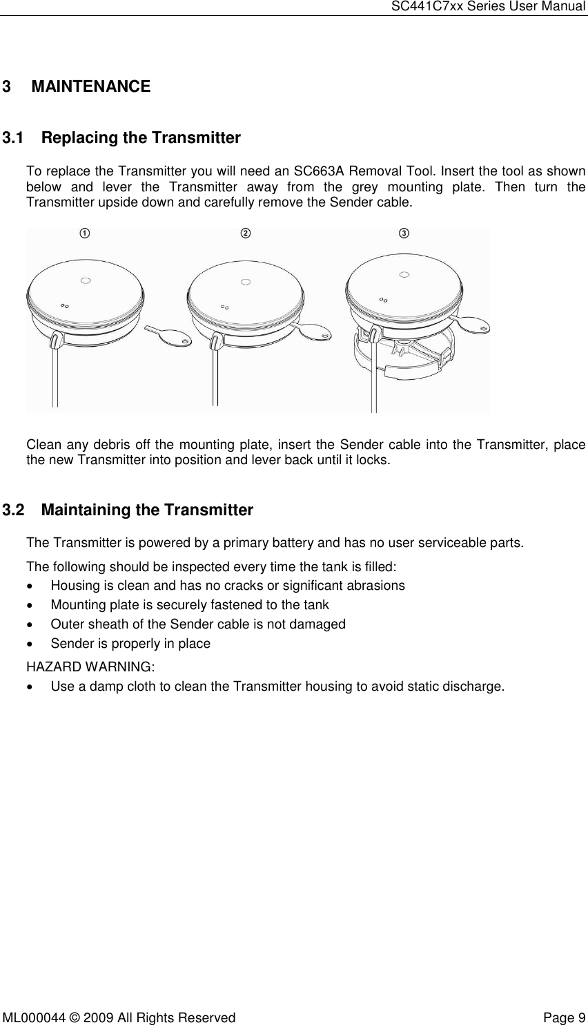
User manual
2.
user manual
user manual
Navigation menu
Upload a User Manual
Namespaces
Wiki Guide
HTML
PDF
Info
Views
User Manual
Discussion / Help
Navigation