Silicon Controls SC441001 Gas Tank Telemetry Device User Manual SC441 Request for confidentiality R2
Silicon Controls Pty Ltd Gas Tank Telemetry Device SC441 Request for confidentiality R2
Contents
- 1. User manual
- 2. user manual
user manual

USER MANUAL
SC441C7xx TRANSMITTERS
Unit 14A 2 Eden Park Drive
North Ryde NSW 2113 Australia
ACN 054 993 529
Phone 61 2 8877 6000
Fax 61 2 8877 6099
Document: ML000044 Rev 1
Copyright© 2009 Silicon Controls Pty Ltd

SC441C7xx Series User Manual
ML000044 © 2009 All Rights Reserved Page 2
DISCLAIMER
All material contained in this document is furnished pursuant to the terms and conditions of a duly
executed Program Product Licence ("Licence") and/or a duly executed Agreement to Purchase or
Lease Equipment ("Agreement").
All terms, conditions, warranties, undertakings, inducements or representations, whether express,
implied, statutory or otherwise, relating in any way to the products the subject of the Licence
and/or the Agreement are excluded, other than:
1. terms, conditions or warranties expressly provided for in the Licence and/or the Agreement;
and
2. terms, conditions or warranties implied by any Act of Parliament which may not be excluded
provided that Silicon Controls Pty Ltd liability for any breach of any such term, condition or
warranty shall, subject to the Licence and/or Agreement, be limited at the option of Silicon
Controls Pty Ltd to any one or more of the following:
(a) if the breach relates to goods:
i. the replacement of the goods or the supply of the equivalent goods;
ii. the repair of the goods;
iii. the payment of the cost of replacing the goods or of acquiring equivalent goods;
or
iv. the payment of the costs of having the goods repaired; and
(b) if the breach relates to services:
i. the supplying of the services again; or
ii. the payment of the cost of having the services supplied again.
Without limiting the generality hereof, Silicon Controls Pty Ltd shall not be under any liability to
any person in respect of any loss or damage, including consequential loss or damage and
however caused, which may be suffered or incurred or which may arise directly or indirectly from
the use of the material contained in this document or any other material furnished pursuant to the
Licence and/or the Agreement.
All the users of the material contained in this document or any other material furnished pursuant
to the Licence and/or the Agreement should ensure that the material is used in compliance with
the laws, rules and regulations of the jurisdictions in which the material is used.
The material contained within is subject to change without notice and Silicon Controls Pty Ltd
may issue revised documents containing any such changes.

SC441C7xx Series User Manual
ML000044 © 2009 All Rights Reserved Page 3
CHANGE HISTORY
Rev Description Date Changed
By Approved
By
1 First Release 29/11/2009 TC JH
Note some sections of this document contain controlled content that is subject to regulatory body
approval. If modifying sections marked as controlled content, check that approval body
requirements are still met.

SC441C7xx Series User Manual
ML000044 © 2009 All Rights Reserved Page 4
TABLE OF CONTENTS
DISCLAIMER ................................................................................................................................... 2
CHANGE HISTORY ........................................................................................................................ 3
TABLE OF CONTENTS .................................................................................................................. 4
1
PRODUCT DESCRIPTION ...................................................................................................... 5
1.1
Connectors ...................................................................................................................... 6
2
INSTALLATION ........................................................................................................................ 7
2.1
Positioning the Transmitter .............................................................................................. 7
2.2
Installing Sensors and Cabling ........................................................................................ 7
Securing the Transmitter ............................................................................................................. 8
2.2.1
Fixing the Transmitter to a Horizontal Tank................................................................. 8
3
MAINTENANCE ....................................................................................................................... 9
3.1
Replacing the Transmitter ............................................................................................... 9
3.2
Maintaining the Transmitter ............................................................................................. 9
3.3
FCC PART 15 COMPLIANCE ....................................................................................... 10
4
Warranty ................................................................................................................................. 11
SC441C7xx Series User Manual
ML000044 © 2009 All Rights Reserved Page 5
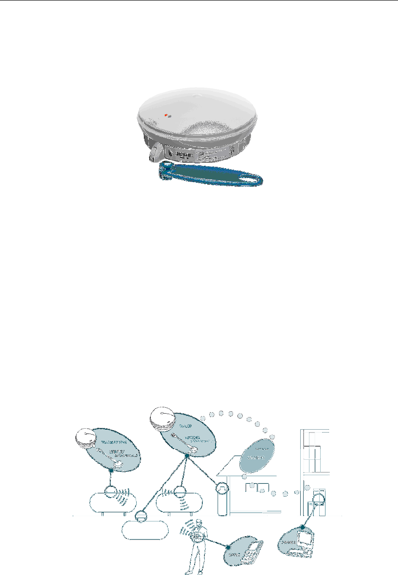
1 PRODUCT DESCRIPTION
The SC441 Transmitter Series is specifically designed to be mounted on gas tanks and
connect to existing tank float gauges and gas meters, eliminating the need for expensive
intrinsic safety barriers and wiring to the tank or meter. Each site must have a dialer and the
SC441 periodically communicates with the site dialer using low power radio transmissions in
the ISM band, and the dialer then transfers the collected tank levels and gas usage data to
the GASLOG Server.
SC441 transmitters are typically used on a GASLOG telemetry site where:
• there are more appliances than can be directly connected to the site dialer,
• the appliances are physically separated from one another, and/or
• the dialer must be located away from the appliances in order to get adequate GSM
coverage or connect to the PSTN fixed telephone network.
The SC441 is powered by an internal lithium battery and under normal operating conditions
will give many years of operation on the original battery. To achieve this, the SC441 is
normally in a powered down state and only wakes up for short periods to take measurements
and to communicate with the site dialer.
Figure 1 : GASLOG Telemetry Site

SC441C7xx Series User Manual
ML000044 © 2009 All Rights Reserved Page 6
1.1 Connectors
On the underside of the SC441 transmitter there are 2 connectors labelled A and B. A variety
of Silicon Controls sensors and senders can be inserted into these connectors including
SC645 tank level senders.
Figure 2 : SC645 Tank Level Sender
SC441C7xx Series User Manual
ML000044 © 2009 All Rights Reserved Page 7
2 INSTALLATION
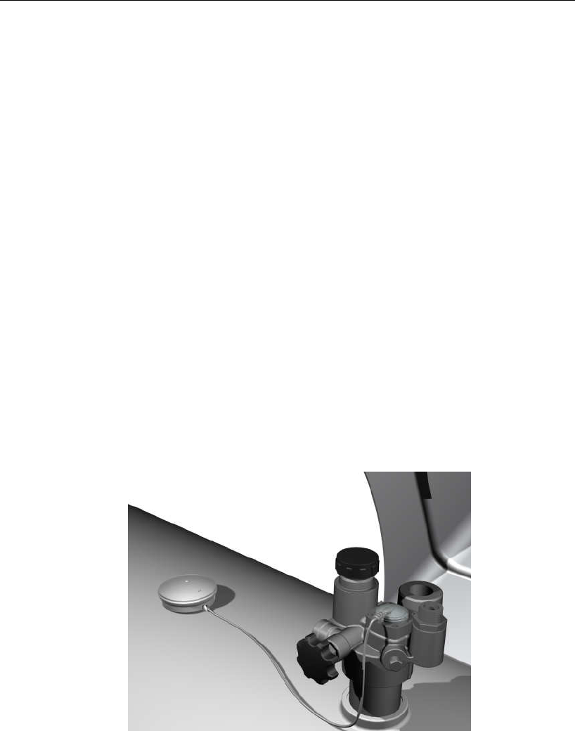
2.1 Positioning the Transmitter
The prime consideration when positioning the SC441 is the radio performance.
The main factors that affect the performance of radio communications between the dialer and
the transmitter are the transmission distance and the presence of obstacles in the path
between them. Ideally there should be a direct line of sight between the dialer to the
transmitter. However this is sometimes not achievable. Obstacles that can affect performance
include items such as vehicles, garages, trees, posts, brick walls etc.
Choose a position for the SC441 where you can conveniently make the cable connections to
the monitored appliances and that is not close to pipes, metalwork or other obstacles. If you
are monitoring a gas tank, then the best position is generally on top of the tank.
Place the transmitter in the chosen position but DO NOT glue it into position at this stage.
NOTES:
• The SC441 should preferably be mounted horizontally on a surface wider than
0.4m (such as the top of the tank).
• The SC441 should not be positioned closer than 0.5 meter from a SC414 dialer. At
such short range radio performance may be unreliable or not work at all.
• The SC441 contains a radio antenna which should not be covered or obstructed by
any metallic objects – doing so may significantly reduce the effective radio range.
Figure 3 : Ideal position for a SC441 on a horizontal tank
2.2 Installing Sensors and Cabling
During this step, the connections are made from the appliances being monitored and the
SC441 transmitter.
Detach the bracket of the transmitter, connect the Sender and reattach the base.
SC441C7xx Series User Manual
ML000044 © 2009 All Rights Reserved Page 8
Securing the Transmitter
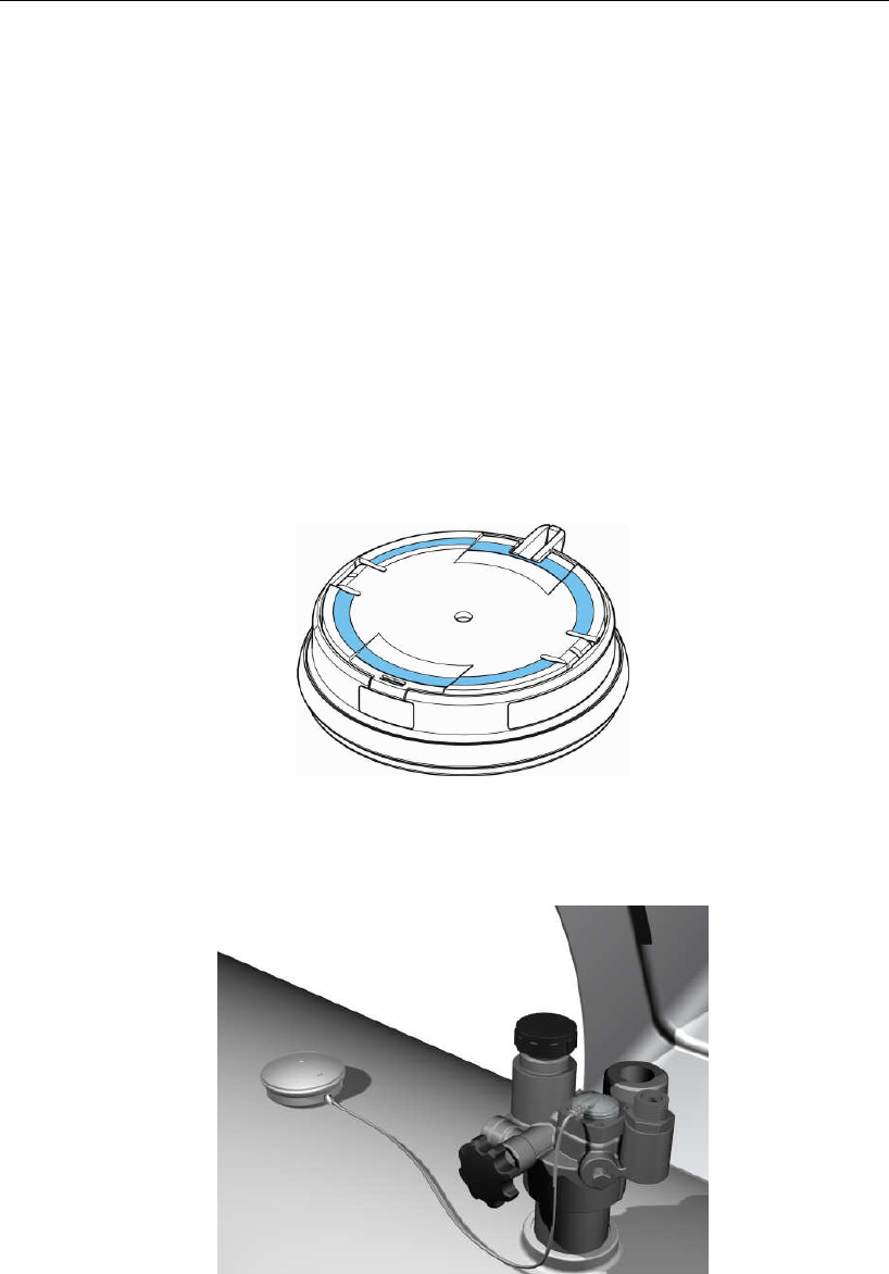
2.2.1 Fixing the Transmitter to a Horizontal Tank
• Clean the relevant section of the tank with primer.
• Lay out the cable so that there is no slack - excess cable should be neatly coiled and not
dangling.
• Turn the transmitter upside down and apply a 3mm bead of adhesive around its base.
• Fix transmitter to the tank in the location and direction determined during testing.
• Once fixed in position the transmitter must not be moved.
NOTE
Do not disturb the Transmitter once in position, this will allow the adhesive to cure and
secure the Transmitter to the tank. In adverse weather conditions the adhesive may
take up to 48 hours to cure.
Figure 4 : Applying adhesive to transmitter base
Figure 5 : SC441 on a horizontal tank
SC441C7xx Series User Manual
ML000044 © 2009 All Rights Reserved Page 9
3 MAINTENANCE
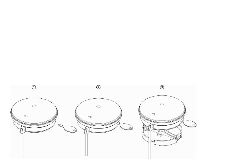
3.1 Replacing the Transmitter
To replace the Transmitter you will need an SC663A Removal Tool. Insert the tool as shown
below and lever the Transmitter away from the grey mounting plate. Then turn the
Transmitter upside down and carefully remove the Sender cable.
Clean any debris off the mounting plate, insert the Sender cable into the Transmitter, place
the new Transmitter into position and lever back until it locks.
3.2 Maintaining the Transmitter
The Transmitter is powered by a primary battery and has no user serviceable parts.
The following should be inspected every time the tank is filled:
• Housing is clean and has no cracks or significant abrasions
• Mounting plate is securely fastened to the tank
• Outer sheath of the Sender cable is not damaged
• Sender is properly in place
HAZARD WARNING:
• Use a damp cloth to clean the Transmitter housing to avoid static discharge.

SC441C7xx Series User Manual
ML000044 © 2009 All Rights Reserved Page 10
3.3 FCC PART 15 COMPLIANCE
The following instructions apply to SC441C7xx equipment:
GASLOG equipment has been tested and found to comply with part 15 of the FCC Rules.
Operation is subject to the following two conditions: (1) This device may not cause harmful
interference, and (2) this device must accept any interference received, including interference that
may cause undesired operation.
This equipment has been tested and found to comply with the limits for a Class B digital device,
pursuant to part 15 of the FCC Rules. These limits are designed to provide reasonable protection
against harmful interference in a residential installation.
GASLOG equipment generates, uses and can radiate radio frequency energy and, if not installed
and used in accordance with the installation manual, may cause harmful interference with radio
communications. However, there is no guarantee that interference will not occur in a particular
installation. If this equipment does cause harmful interference to radio or television reception,
which can be determined by turning the equipment off and on, the user may try to correct the
interference by one or more of the following:
o Reorient or relocate the receiving antenna of the radio or television.
o Increase the separation between the equipment and the receiver.
o Connect the equipment onto an outlet on a different branch circuit than that of the receiver.
o Consult the dealer or an experienced radio/TV technician.
The user may find the following booklet helpful:
o How to Identify and Resolve Radio-TV Interference Problems
This booklet is available from the US Government Printing Office, Washington, D.C. 20402.
WARNING: changes or modifications to GASLOG equipment not expressly approved by Silicon
Controls could void the user's authority to operate the equipment.

SC441C7xx Series User Manual
ML000044 © 2009 All Rights Reserved Page 11
4 WARRANTY
Silicon Controls Pty Limited ("Silicon Controls") warrants this product against defects in materials
and workmanship for a period of 12 months from the original date of purchase to the original
purchaser only. This warranty shall not apply in the event that the product has been used prior
to its sale to the original purchaser.
During the warranty period, Silicon Controls will repair or replace (at its option) at no charge any
components that prove to be defective, provided the defective component is returned (shipping
prepaid and properly packed) to Silicon Controls. Proof of purchase date must accompany any
request for warranty service.
This warranty does not apply if, in the opinion of Silicon Controls, the product has been damaged
by accident, misuse, neglect or subjected to modifications other than those prescribed in this
guide.
This warranty is in lieu of all other express or implied warranties, statements or representations
except those warranties implied by statute, the restriction or modification of which would be void
pursuant to that statute.
In the event that this product should prove defective, your sole remedy shall be the repair or
replacement of the defective components as stated above. Silicon Controls will not be liable for
any direct or indirect damages including but not limited to any lost profits or other incidental or
consequential damages arising from use of this product. Some statutes do not allow the
exclusion or limitation of incidental or consequential damages for breach of warranty implied by
those statutes, so the above limitation may not apply to you.