Silicon Laboratories Finland 0D06E BT 4.0 module User Manual Heading 1
ACKme Networks Inc BT 4.0 module Heading 1
user manual
AMS00x • Embedded Bluetooth Low Energy Solutions
ADS-MS00x-100D4 • Preliminary Data Sheet October 22, 2014
©2014 ACKme Networks. http://ack.me
AMS001
AMS002
Data Sheet

AMS00x • Embedded Bluetooth Low Energy Solution
ADS-MS00x-100D4 • Preliminary Data Sheet Page | i
©2014 ACKme Networks. http://ack.me October 22, 2014
Disclaimer
While the information provided in this document is be-
lieved to be accurate, it is under development and
ACKme Networks reserves the right to make changes
without further notice to the product described herein
to improve reliability, function, or design, and makes no
guarantee or warranty concerning the accuracy of said
information, nor shall it be responsible for any loss or
damage of whatever nature resulting from the use of,
or reliance upon, such information. ACKme Networks
makes no warranties of any kind, whether express, im-
plied or arising by custom or course of trade or perfor-
mance, and specifically disclaims the implied warranties
of title, non-infringement, merchantability, or fitness for
a particular purpose.
No part of this document may be copied, reproduced,
stored in a retrieval system, or transmitted, in any form
or by any means, electronic, mechanical, photographic,
or otherwise, or used as the basis for manufacture or
sale of any items without the prior written consent of
ACKme Networks.
Trademarks
ACKme Networks and the ACKme Networks logo are
trademarks of ACKme Networks. WICED™ is a trade-
mark of Broadcom® Corporation, Inc. Bluetooth® is a
trademark of the Bluetooth SIG. Other trademarks in
this document belong to their respective owners.
Copyright © 2014 ACKme Networks.
All rights reserved.
Document Number: ADS-MS00x-1xx
Release Date: TBA
Contact
http://ack.me/contact
About this Data Sheet
This document provides information on the family of
AMS00x Bluetooth Low Energy (Bluetooth Smart) mod-
ules from ACKme Networks.
Organization
This data sheet is organized into the following sections:
Features & Applications
General Description, Section 1
Block Diagram, Section 2
Electrical Specifications, Section 3
Bluetooth RF Specifications, Section 4
Pinout and Signal Descriptions, Section 5
Design Guidelines, Section 6
Regulatory Certification, Section 7
Packaging, Handling & Storage, RoHS, Section 8
Ordering Information, Section 9
Revision History & Glossary, Section 10

ADS-MS00x-100D4 • Preliminary Data Sheet Page | ii
©2014 ACKme Networks. http://ack.me October 22, 2014
AMS00x Family Data Sheet
Embedded Bluetooth Low Energy Solution
Features
Bluetooth Low Energy (Bluetooth Smart) modules
fully certified to meet Bluetooth version 4.1.
Integrated SPI-serial flash supports firmware up-
dates and multiple on-board applications
On-board PCB-style antenna
ARM® Cortex™ M3-based microprocessor core
Programmable RF transmit power control
Operation directly from a battery or mains supply
Small size enables integration into most sensor
products and applications
Secure Over-the-Air (OTA) software update using
industry-standard AES-128 security
On-board Bluetooth Low Energy stack supports
multiple Bluetooth Smart Use Cases including Bat-
tery status, Blood pressure monitor, Proximity,
Thermometer, Glucose meter plus many more
Easily integrated into existing or new products us-
ing TruConnect, ACKme’s configurable Bluetooth
Low Energy application (pre-installed on every
module)
Supports custom application development using
the Broadcom WICED Smart Software Develop-
ment System.
Interfaces*
A/D converter: 8 channels with 4 modes providing
variable resolution (10-13 ENOBs), sampling rate
(5.9-187 kHz) and conversion latency (5-171 µs)
USART: 2 x 4-wire up to 1.5 Mbit/s
SPI: 1 x master/slave, 1 x slave-only at ≤12 Mbit/s
I2C: 1 x I2C master interface up to 1 MHz
GPIO: Up to 15 GPIOs (overlaid with peripherals),
programmable pull-up/pull-down resistors with up
to 16 mA drive strength at 3.3V (2 mA standard).
4 x PWM channels each with a 10-bit counter
clocked at 128 kHz, 1 MHz or 8 MHz.
Infrared: Modulator and IR learning
Wake-up: Wake from timer, UART or GPIOs for ul-
tra-low power operation
Serial-wire Debug interface
*Some interfaces share module pins
Operational & Radio
Operational voltage : 1.8V - 3.6V
Operational Temperature Range: -30°C to +85°C
Size : 17.6 x 11.4 x 2.3mm (0.70” x 0.45” x 0.09”)
Weight : 0.04 oz (1.2g)
Current consumption @ 3.0V, 25°C
- Deep Sleep : 0.65 µA
- Sleep : 12 µA
- AMS001
Active Receive : 12.8 mA
Active Transmit : 12.1 mA
- AMS002
Active Receive : 24.5 mA
Active Transmit : 22.8 mA
RF Transmit Power: +4 dBm
Receive Sensitivity : -94 dBm
Applications
Health & Fitness
- Fitness Equipment
- Heart rate monitors
- Weight scales
- Thermometers
- Pedometers
- Glucose meters
- Blood pressure monitoring
Retail
- Advertising and Beaconing
- Proximity detection
- Point-of-sale
Home & Industrial Control and Automation
- Appliance control and monitoring
- Doors/Window monitoring
- Alarms
- Wireless cable replacement
- Environmental & Energy monitoring
- Wireless sensing, remote data logging
Consumer
- Toys
- Robots
Remote controls
AMS00x • Embedded Bluetooth Low Energy Solution
ADS-MS00x-100D4 • Preliminary Data Sheet Page | iii
©2014 ACKme Networks. http://ack.me October 22, 2014
Contents
1 General Description ............................................... 1
2 Block Diagram ........................................................ 2
3 Electrical Specifications .......................................... 3
3.1 Absolute Maximum Ratings ............................ 3
3.2 Recommended Operating Conditions ............ 3
DC Operating Conditions ........................ 3
Environmental Conditions ...................... 3
3.3 Power Consumption ....................................... 4
3.4 ADC Specifications .......................................... 4
4 Bluetooth RF Specifications ................................... 5
4.1 Summary RF Specifications ............................. 5
4.2 Receiver Specifications ................................... 5
4.3 Transmitter Specifications .............................. 6
5 Pinout and Signal Descriptions .............................. 7
5.1 Pinout.............................................................. 7
5.2 Pin Description ................................................ 7
6 Design Guidelines ................................................... 9
6.1 Recommended PCB Footprint ........................ 9
6.2 Routing Recommendations ............................ 9
6.3 Soldering Information ................................... 10
6.4 AMS00x Photograph ..................................... 10
6.5 Application Examples .................................... 10
Operation using TruConnect................. 10
7 Regulatory Certification ....................................... 11
7.1 United States ................................................ 11
Labeling and User Information
Requirements ....................................................... 11
RF Exposure .......................................... 12
External Antenna .................................. 12
Further Information .............................. 12
7.2 Canada .......................................................... 12
Labeling and User Information
Requirements....................................................... 12
External Antenna Types ........................ 13
Further Information .............................. 13
7.3 Europe .......................................................... 14
Labeling and User Information
Requirements....................................................... 14
External Antenna Requirements .......... 14
Further Information .............................. 14
7.4 Australia ........................................................ 16
External Antenna Requirements .......... 16
Further Information .............................. 16
7.5 New Zealand ................................................. 16
External Antenna Requirements .......... 16
Further Information .............................. 16
8 Packaging, Handling & Storage, RoHS ................. 17
8.1 Packaging ...................................................... 17
8.2 Handling & Storage ....................................... 17
8.3 RoHS Directive .............................................. 17
9 Ordering Information ........................................... 18
10 Revision History & Glossary ................................. 19
10.1 Revision History ............................................ 19
10.2 Glossary ........................................................ 19

AMS00x • Embedded Bluetooth Low Energy Solution
General Description, Section 1
ADS-MS00x-100D4 • Preliminary Data Sheet Page | 1
©2014 ACKme Networks. http://ack.me October 22, 2014
1 General Description
The family of AMS00x modules from ACKme Networks
is based on an ultra-low power Bluetooth Low Energy
(Bluetooth Smart) SoC from Broadcom Corporation. All
modules incorporate serial-flash memory and a printed
antenna to provide a state-of-the-art fully-certified
Bluetooth 4.1 solution.
An integrated solution avoids difficult RF layout and
enables designers to rapidly embed Bluetooth Low En-
ergy into virtually any device.
Modules ship with ACKme TruConnect, an easy-to-use
application enabling control and configuration via a
UART-serial interface. TruConnect virtually eliminates
difficult and time-consuming software development
effort and vastly reduces product development cycles.
If required, custom applications may also be developed
using the Broadcom WICED Smart Software Develop-
ment Kit.
With dimensions of just 17.6 x 11.4 mm, a wide tem-
perature range, and an ultra-low power version, the
module is suitable for integration into any battery-
powered embedded wireless application.
The Bluetooth Low Energy SoC from Broadcom is pur-
pose-designed to support the entire spectrum of Blue-
tooth Smart use cases for medical, home automation,
accessory, sensor, retail and wearable market seg-
ments. Superior receive sensitivity, an integrated RF
transmit power amplifier and transmit/receive switch,
along with the on-board antenna, provide extended
range and full compatibility with all Bluetooth 4.1 de-
vices.
At the heart of all AMS00x modules is a Bluetooth Low
Energy SoC with a high-performance ARM® 32-bit Cor-
tex™-M3 core operating at a frequency of 48MHz. The
SoC includes is configured to boot applications stored in
the 512xkB serial flash memory available on-board the
module.
Each module provides an extensive array of I/O and
peripheral interfaces. The following list of interfaces are
available, many of which are accessible with I/O multi-
plexing and alternate function capabilities.
8 x A/D converter channels
2 x 4-Wire UART interfaces
1 x SPI master/slave, 1 x SPI slave bus
1 x I2C interface
1 x Infrared Modulator / IR learning input
15 x ultra-low power wake inputs
32kHz crystal interface
The module may be powered directly from a battery
supply in the range 1.8-3.6V including 2xAAA, 2xAA, or
a single Lithium coin cell.
Internal power domains are automatically adjusted to
minimise power dissipation based on user activity. Var-
ious power modes, including an ultra-low power deep
sleep mode, are provided to minimize total average
power consumption and maximize battery life.
The module may be woken from deep sleep mode by
various events including a level transition on any GPIO,
the UART or an internal timer.
An internal 32kHz low-power oscillator is available by
default for non-critical timing requirements. Applica-
tions requiring an accurate real-time clock may connect
an (optional) external 32kHz crystal.
Application debugging with a software debugger such
as gdb is enabled via a standard Serial Wire Debug in-
terface.
All versions of the module have Bluetooth BQB SIG cer-
tification, and FCC & IC modular approval for use in the
United States and Canada, and CE approval for use in
Europe and other countries.
AMS00x • Embedded Bluetooth Low Energy Solution
Block Diagram, Section 2
ADS-MS00x-100D4 • Preliminary Data Sheet Page | 2
©2014 ACKme Networks. http://ack.me October 22, 2014
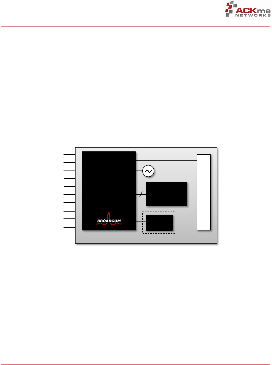
2 Block Diagram
Figure 1 is a block diagram showing the architecture of
AMS00x Bluetooth Low Energy modules. The major
components are a Bluetooth Low Energy SoC from
Broadcom Corporation, 24MHz crystal, 512xkbyte serial
flash and a PCB-style antenna. The AMS001 version also
includes a high-efficiency DC-DC switching regulator to
minimize active mode power consumption.
The Bluetooth SoC is powered by an ARM Cortex M3-
based RISC processor running at 48 MHz with 60 kB
RAM. The SoC is driven by a 24 MHz crystal, an on-
board real-time clock may be (optionally) enabled by
connecting an external 32kHz crystal.
The 512 kByte serial flash memory is used to store mul-
tiple applications and to enable secure Over-the-Air
(OTA) wireless firmware updates. The integrated PCB
antenna simplifies RF integration into end products.
An extensive array of analog and digital peripherals in-
cluding ADCs, GPIOs, PWMs and multiple serial inter-
faces such as UART, SPI, I2C and Infrared are accessible
via module pins.
The module is powered by a single-rail battery or mains
supply.
Figure 1. AMS00x Architecture
VDD
32kHz XTAL
ADC
SPI
UART
GPIO
I2C
IR
SWD
Reset
512 kByte
Serial Flash
Bobcat
Antenna
DC-DC
AMS001
Only
24MHz
Bluetooth
Low Energy
SoC
ARM Cortex M3
AMS00x • Embedded Bluetooth Low Energy Solution
Electrical Specifications, Section 3
ADS-MS00x-100D4 • Preliminary Data Sheet Page | 3
©2014 ACKme Networks. http://ack.me October 22, 2014
3 Electrical Specifications
3.1 Absolute Maximum Ratings
CAUTION! The absolute maximum ratings in Table 1 and Table 2 indicate levels where permanent damage to the de-
vice can occur, even if these limits are exceeded for only a brief duration. Functional operation is not guaranteed un-
der these conditions. Operation at absolute maximum conditions for extended periods can adversely affect long-
term reliability of the device.
Table 1. Absolute Maximum Voltage Ratings
Symbol
Ratings
Min.
Max.
Unit
VDDmax
DC supply voltage applied to VDD pin
GND-0.3
3.8
V
Table 2. Absolute Maximum Environmental Ratings
Characteristic
Note
Min.
Max.
Unit
Storage Temperature
–
-40
+125
°C
Relative Humidity
Non-condensing (storage)
–
65
%
3.2 Recommended Operating Conditions
Functional operation is not guaranteed outside the limits shown in Table 3 and Table 4, and operation outside these
limits for extended periods can adversely affect long-term reliability of the device.
DC Operating Conditions
Table 3. Recommended DC Operating Conditions
Symbol
Ratings1
Min.2
Typical
Max.
Unit
VDD
DC supply voltage applied to VDD pin
On-board serial flash read-only
1.8
–
3.63
V
On-board serial flash read and write
2.2
–
3.63
V
Notes:
1. Overall performance degrades beyond minimum and maximum supply voltages.
Environmental Conditions
Table 4. Recommended Environmental Conditions
Characteristic
Note
Min.
Max.
Unit
Ambient Temperature
-30
+85
°C
Relative Humidity
Non-condensing (operating)
–
85
%
AMS00x • Embedded Bluetooth Low Energy Solution
Electrical Specifications, Section 3
ADS-MS00x-100D4 • Preliminary Data Sheet Page | 4
©2014 ACKme Networks. http://ack.me October 22, 2014
3.3 Power Consumption
The AMS00x automatically adjusts power dissipation based on user activity to minimize power usage. The power
consumption in each state, and for each version of the module, is specified in Table 5.
Table 5. Power Consumption (@3.0V, 25°C)
Operational State
Note
Typical
Max.
Unit
Deep sleep
Wake on interrupt
0.65
–
µA
Sleep
Wake in <5 ms
12.0
19.2
µA
Active Receive1
Receiver is enabled and operating at 100% duty cycle
12.8
13.0
mA
Active Transmit1
Transmitter is enabled and operating at 100% duty cycle
12.1
12.3
mA
Active Receive2
Receiver is enabled and operating at 100% duty cycle
24.5
25.0
mA
Active Transmit2
Transmitter is enabled and operating at 100% duty cycle
22.8
23.3
mA
Notes:
1. AMS001 version
2. AMS002 version
3.4 ADC Specifications
Table 6. ADC Specifications (@ 25°C)
Parameter
Symbol
Conditions
Min.
Typ.
Max.
Unit
Input Channels
–
–
8
–
–
Channel Switching Rate
fch
–
133.33
–
kch/s
Input signal range
Vinp
0
–
3.63
V
Reference settling time
–
7.5
–
–
µS
Input resistance
Rin
Effective, single ended
–
500
–
kΩ
Input capacitance
Cin
–
–
5
pF
Conversion rate
Rc
5.859
–
187
kHz
Conversion time
Tc
5.35
–
170.7
µS
Effective Number of Bits
ENOB
10
–
13
bits
Abs. Voltage Meas. Error
–
–
±2
–
%
Current
I
–
–
1
mA
Leakage Current
Ileakage
–
–
100
nA
Power-up time
Tpup
–
–
200
µS
Integral nonlinearity
INL
LSBs at the 10-bit level
-1
–
1
LSB
Differential nonlinearity
DNL
LSBs at the 10-bit level
-1
–
1
LSB
AMS00x • Embedded Bluetooth Low Energy Solution
Bluetooth RF Specifications, Section 4
ADS-MS00x-100D4 • Preliminary Data Sheet Page | 5
©2014 ACKme Networks. http://ack.me October 22, 2014
4 Bluetooth RF Specifications
Unless otherwise stated, the specifications in this section apply when the operating conditions are within the limits
specified in Section 3.2, Recommended Operating Conditions. Functional operation outside these limits is not guar-
anteed.
All specifications are measured with a coax pigtail soldered to the PCB antenna feed point, with VDD = 3.0V and at a
room temperature of 25°C.
4.1 Summary RF Specifications
Table 7. Summary RF Specifications
Feature Supported
Description
Bluetooth Standard
Version 4.0
Frequency Band
2.402 GHz – 2.480 GHz
Channels (2MHz spacing)
3 x Advertising channels @ 2402 / 2426 / 2480 MHz
36 x Data channels
Maximum Raw Data Rate
1 Mbit/s
Maximum Application Data Rate
0.27 Mbit/s
Modulation Type
DSSS: GFSK (modulation index = 0.5)
Maximum RF Input
-10 dBm
Typical Receive Sensitivity
-94 dBm
Maximum RF Tx Output Power
+4 dBm
Carrier Frequency Accuracy
±20 ppm (24 MHz crystal, ±20 ppm stability @ 25°C)
4.2 Receiver Specifications
Table 8. Receiver Performance Specifications
Parameter
Condition/Notes
Min.
Typical
Max.
Unit
Frequency Range
–
2402
–
2480
MHz
Operating Temperature
–
-30
–
+85
°C
Receive Sensitivity
200 x 37-byte packets with 30.8% PER
–
-94
–
dBm
Maximum Receive Level
-10
–
–
dBm
AMS00x • Embedded Bluetooth Low Energy Solution
Bluetooth RF Specifications, Section 4
ADS-MS00x-100D4 • Preliminary Data Sheet Page | 6
©2014 ACKme Networks. http://ack.me October 22, 2014
4.3 Transmitter Specifications
Table 9. Transmitter Performance Specifications
Parameter
Condition/Notes
Min
Typical
Max
Unit
Frequency Range
–
2402
–
2480
MHz
Operating Temperature
–
-30
–
+85
°C
Transmit power2
–
–
4.0
–
dBm
Transmit power variation
Process dependent
–
2.0
–
Transmit Power Range
Adjustable via software control
-20
4
dBm
Channel Spacing
–
2
–
MHz
AMS00x • Embedded Bluetooth Low Energy Solution
Pinout and Signal Descriptions, Section 5
ADS-MS00x-100D4 • Preliminary Data Sheet Page | 7
©2014 ACKme Networks. http://ack.me October 22, 2014
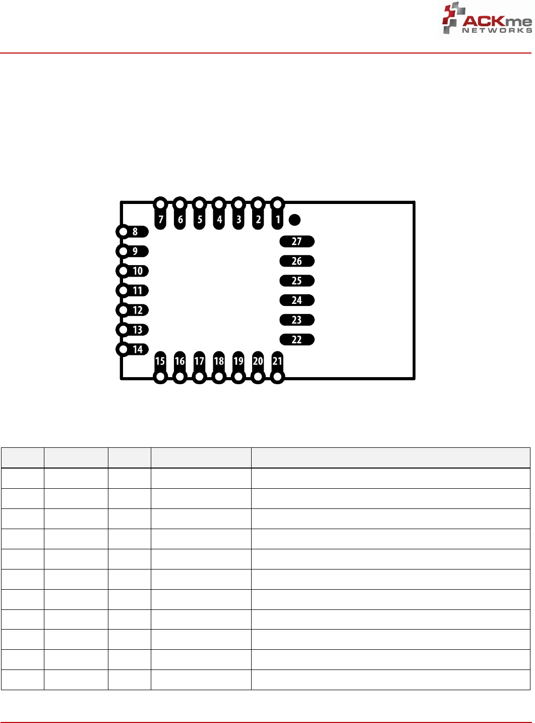
5 Pinout and Signal Descriptions
5.1 Pinout
A top view of the AMS00x pinout is depicted in Figure 2.
All dimensions are in thousands of an inch. A recom-
mended PCB footprint is provided in Section 6.1.
Figure 2. AMS00x Pinout (TOP View – Pins NOT visible from top!)
5.2 Pin Description
Table 10. AMS00x Pin Definitions
Pin
Name
Type1
Primary Function
Alternate & Other Function(s)
1
GND
S
Ground
-
2
UART1_RX
I/O
UART1 Rx (Debug)
-
3
UART1_TX
I/O
UART1 Tx (Debug)
-
4
GPIO_03
I/O
SPI1_MOSI
I2C_SDA, UART0_CTS, GPIO
5
GPIO_13
I/O
SPI1_CLK
I2C_SCL, UART0_RTS, GPIO
6
GPIO_2
I/O
UART0_TX (User)
SPI2_MOSI (M/S), IR_RX, ADC0, GPIO
7
GPIO_3
I/O
UART0_RTS (User)
SPI2_MISO (M/S), IR_TX, ADC1, GPIO
8
RESET_N
I
System Reset
-
9
GPIO_4
I/O
UART0_CTS (User)
SPI2_CLK (M/S), GPIO
10
GPIO_5
I/O
UART0_RX (User)
SPI2_CS (M), SPI2_MOSI (M), GPIO
11
GPIO_6
I/O
GPIO
UART0_RX, SPI2_MOSI (M/S), IR_TX
AMS00x • Embedded Bluetooth Low Energy Solution
Pinout and Signal Descriptions, Section 5
ADS-MS00x-100D4 • Preliminary Data Sheet Page | 8
©2014 ACKme Networks. http://ack.me October 22, 2014
Pin
Name
Type1
Primary Function
Alternate & Other Function(s)
12
GPIO_7
I/O
SPI1_MISO (M)
UART0_TX, SPI2_CS (S), ADC2, ACLK0
13
GPIO_8
I/O
GPIO
UART0_RX, SPI2_MISO (M/S)
14
GPIO_9
I/O
GPIO
UART0_TX, SPI2_CLK (M/S), SPI1_MISO (M)
15
GPIO_104
I/O
GPIO
IR_TX, ADC3, PWM3
16
GPIO_11
I/O
GPIO
SPI2_MOSI (M/S), ADC4, PWM2, IR_TX
17
GPIO_12
I/O
GPIO
ADC5, IR_RX
18
GPIO_134
I/O
XOSC32_OUT
SPI2_CS (S), ADC6, PWM0, GPIO
19
GND
S
Ground
-
20
GPIO_144
I/O
XOSC32K_IN
ADC7, PWM1, GPIO
21
VDD
S
VDD
-
22-27
GND
S
Ground
-
Notes:
1. I = Input, O = Output, S = Supply
2. All GPIO pins (except GPIO1, GPIO2) are initialized to ‘input floating’ after Power-on-Reset.
3. The drive strength of standard GPIOs is 2mA, the drive strength of this GPIO is 16mA.
AMS00x • Embedded Bluetooth Low Energy Solution
Design Guidelines, Section 6
ADS-MS00x-100D4 • Preliminary Data Sheet Page | 9
©2014 ACKme Networks. http://ack.me October 22, 2014
6 Design Guidelines
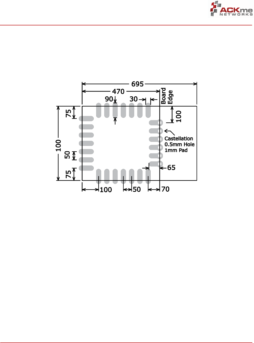
6.1 Recommended PCB Footprint
All dimensions in Figure 3 are in thousands of an inch unless otherwise marked.
Figure 3. AMS00x Recommended Footprint (Top)
6.2 Routing Recommendations
When designing a carrier board, the addition of ground
fill directly underneath the module, rather than signal
or power traces, is strongly advised. All ground pads
adjacent to antenna pins must be connected to a solid
ground plane. Failure to comply with these recommen-
dations will almost certainly result in degraded perfor-
mance of the radio receiver and/or transmitter.
AMS00x • Embedded Bluetooth Low Energy Solution
Design Guidelines, Section 6
ADS-MS00x-100D4 • Preliminary Data Sheet Page | 10
©2014 ACKme Networks. http://ack.me October 22, 2014
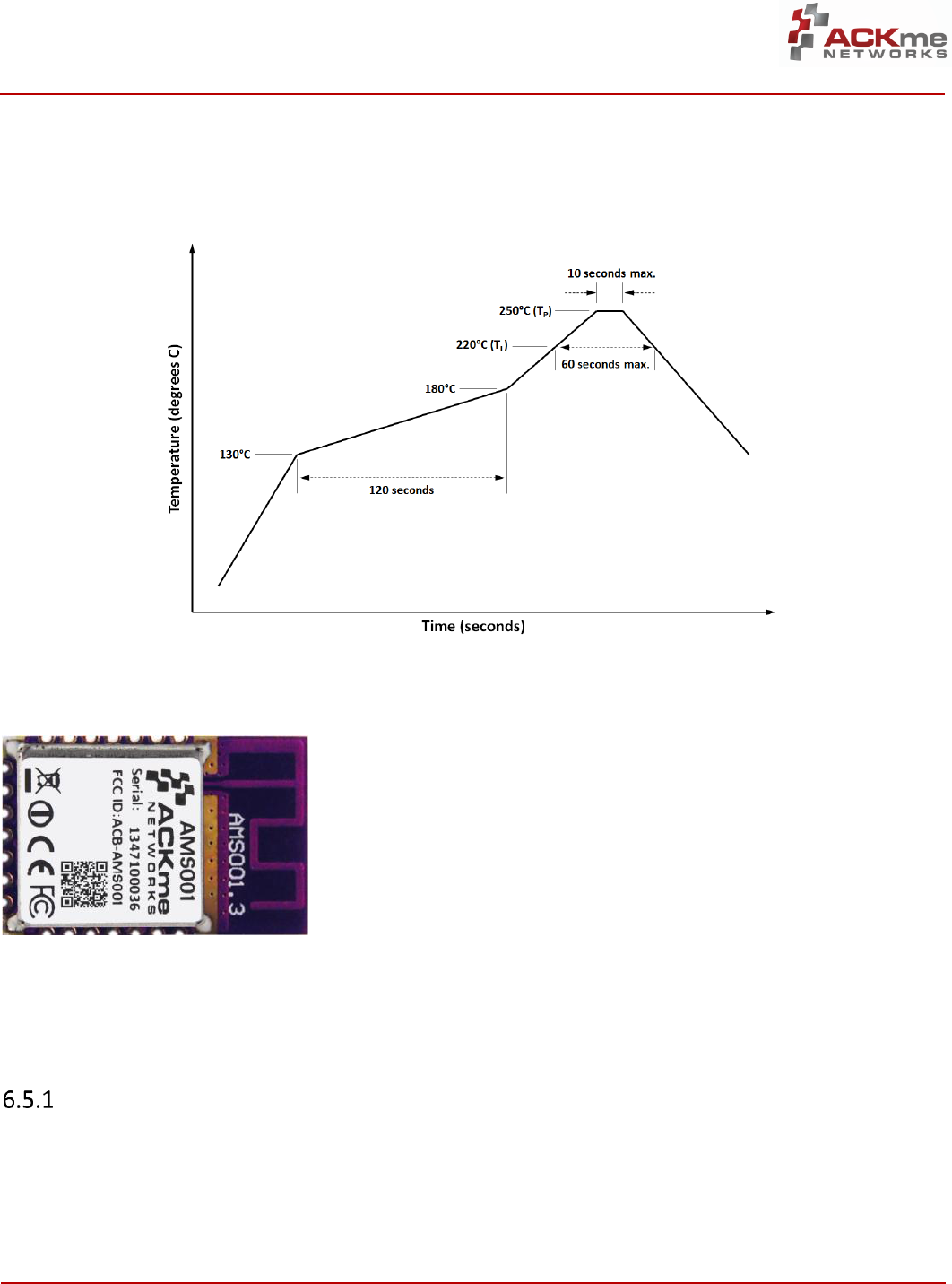
6.3 Soldering Information
Figure 4. Recommended solder reflow profile
6.4 AMS00x Photograph
Figure 5. AMS00x Photograph (Top)
6.5 Application Examples
TBD
Operation using TruConnect
TBD
AMS-00x • Embedded Bluetooth Low Energy Solution
Regulatory Certification, Section 7
ADS-MS00x-100D4 • Preliminary Data Sheet Page | 11
©2014 ACKme Networks. http://ack.me October 22, 2014
7 Regulatory Certification
The AMS00x family of modules has been certified for
operation in various regulatory domains. This section
outlines certification information specific to the follow-
ing countries and regions:
United States
Canada
Europe
Australia
New Zealand
Should you require regulatory certification for the
AMS00x module in a country or region not listed, please
contact your local ACKme Networks sales office or cre-
ate a support request via our website at
http://ack.me/contact.
7.1 United States
The ACKme Networks AMS-00x module has received
Federal Communications Commission (FCC) CFR47 Tele-
communications, Part 15 Sub-part C “Intentional Radia-
tors” modular approval in accordance with Part 15.212
Modular Transmitter approval. Modular approval al-
lows the end user to integrate the AMS-00x module
into a finished product without obtaining subsequent
and separate FCC approvals for intentional radiation,
provided no changes or modifications are made to the
module circuitry. Changes or modifications could void
the user’s authority to operate the equipment. The end
user must comply with all of the instructions provided
by the Grantee which indicate installation and/or oper-
ating conditions necessary for compliance.
The finished product is required to comply with all ap-
plicable FCC equipment authorization, regulations, re-
quirements, and equipment functions not associated
with the transmitter module portion. For example,
compliance must be demonstrated to regulations for
other transmitter components within the host product;
to requirements for unintentional radiators (Part 15
Sub-part B “Unintentional Radiators”), such as digital
devices, computer peripherals, radio receivers, etc.; and
to additional authorization requirements for non-
transmitter functions on the transmitter module (i.e.
Verification, or Declaration of Conformity) (e.g., trans-
mitter modules may also contain digital logic functions)
as appropriate.
Labeling and User Information
Requirements
The AMS-00x module has been labelled with a unique
FCC ID number, and if the FCC ID is not visible when the
module is installed inside another device, then the out-
side of the finished product into which the module is
installed must also display a label referring to the en-
closed module. This exterior label can use wording as
follows:
The user manual for the product should include the fol-
lowing statement:
Contains FCC ID: 2ABPY-BB4EA
This device complies with Part 15 of the FCC Rules.
Operation is subject to the following two conditions:
(1) this device may not cause harmful interference,
and (2) this device must accept any interference
received, including interference that may cause un-
desired operation.
This equipment has been tested and found to com-
ply with the limits for a Class B digital device, pursu-
ant to part 15 of the FCC Rules. These limits are de-
signed to provide reasonable protection against
harmful interference in a residential installation.
This equipment generates, uses and can radiate ra-
dio frequency energy and if not installed and used in
accordance with the instructions, may cause harm-
ful interference to radio communications. However,
there is no guarantee that interference will not oc-
cur in a particular installation. If this equipment
does cause harmful interference to radio or televi-
sion reception, which can be determined by turning
the equipment off and on, the user is encouraged to
try to correct the interference by one or more of the
following measures:
Reorient or relocate the receiving antenna.
Increase the separation between the equip-
ment and receiver.
Connect the equipment into an outlet on a cir-
cuit different from that to which the receiver is
connected.
Consult the dealer or an experienced radio/TV
technician for help.
AMS-00x • Embedded Bluetooth Low Energy Solution
Regulatory Certification, Section 7
ADS-MS00x-100D4 • Preliminary Data Sheet Page | 12
©2014 ACKme Networks. http://ack.me October 22, 2014
Additional information on labeling and user information
requirements for Part 15 devices can be found in KDB
Publication 784748 available at the FCC Office of Engi-
neering and Technology (OET) Laboratory Division
Knowledge Database (KDB) at the following website:
https://apps.fcc.gov/oetcf/kdb/index.cfm
RF Exposure
All transmitters regulated by FCC must comply with RF
exposure requirements. OET Bulletin 65, Evaluating
Compliance with FCC Guidelines for Human Exposure to
Radio Frequency Electromagnetic Fields, provides assis-
tance in determining whether proposed or existing
transmitting facilities, operations or devices comply
with limits for human exposure to Radio Frequency (RF)
fields adopted by the Federal Communications Com-
mission (FCC). The bulletin offers guidelines and sugges-
tions for evaluating compliance.
If appropriate, compliance with exposure guidelines for
mobile and unlicensed devices can be accomplished by
the use of warning labels and by providing users with
information concerning minimum separation distances
from transmitting structures and proper installation of
antennas.
The following statement must be included as a CAU-
TION statement in manuals and OEM products to alert
users of FCC RF exposure compliance:
If the AMS-00x module is used in a portable application
(i.e., the antenna is less than 20 cm from persons dur-
ing operation), the integrator is responsible for per-
forming Specific Absorption Rate (SAR) testing in ac-
cordance with FCC rules 2.1091.
External Antenna
Modular approval in the United States is permitted with
the use of the integrated antenna ONLY. If an external
antenna is used with the AMS-00x module, additional
testing of the end product is needed to meet FCC re-
quirements.
Further Information
Additional information regarding FCC certification and
use of the AMS-00x module in the United States is
available from the following sources.
Federal Communications Commission (FCC)
http://www.fcc.gov.au
FCC Office of Engineering and Technology (OET)
Laboratory Division Knowledge Database (KDB)
http://apps.fcc.gov/oetcf/kdb/index.cfm
7.2 Canada
The AMS-00x module has been certified for use in Can-
ada under Industry Canada (IC) Radio Standards Specifi-
cation (RSS) RSS-210 and RSSGen. Modular approval
permits the installation of a module in a host device
without the need to recertify the device.
Labeling and User Information
Requirements
Labeling Requirements for the Host Device (from Sec-
tion 3.2.1, RSS-Gen, Issue 3, December 2010): The host
device shall be properly labeled to identify the module
within the host device.
The Industry Canada certification label of a module
shall be clearly visible at all times when installed in the
host device, otherwise the host device must be labeled
to display the Industry Canada certification number of
the module, preceded by the words “Contains transmit-
ter module”, or the word “Contains”, or similar wording
expressing the same meaning, as follows:
User Manual Notice for License-Exempt Radio Appa-
ratus (from Section 7.1.3 RSS-Gen, Issue 3, December
2010): User manuals for license-exempt radio appa-
To satisfy FCC RF Exposure requirements for mobile
and base station transmission devices, a separation
distance of 20 cm or more should be maintained
between the antenna of this device and persons
during operation. To ensure compliance, operation
at closer than this distance is not recommended.
The antenna(s) used for this transmitter must not
be co-located or operating in conjunction with any
other antenna or transmitter
Contains transmitter module IC: 11685A-61F8D
AMS-00x • Embedded Bluetooth Low Energy Solution
Regulatory Certification, Section 7
ADS-MS00x-100D4 • Preliminary Data Sheet Page | 13
©2014 ACKme Networks. http://ack.me October 22, 2014
ratus shall contain the following or equivalent notice in
a conspicuous location in the user manual or alterna-
tively on the device or both:
Transmitter Antenna Notification (from Section 7.1.2
RSS-Gen, Issue 3, December 2010): User manuals for
transmitters shall display the following notice in a con-
spicuous location:
The above notice may be affixed to the device instead
of displayed in the user manual.
User manuals for transmitters equipped with detach-
able antennas shall also contain the following notice in
a conspicuous location:
Immediately following the above notice, the manufac-
turer shall provide a list of all antenna types approved
for use with the transmitter, indicating the maximum
permissible antenna gain (in dBi) and required imped-
ance for each.
External Antenna Types
Transmitter Antenna (from Section 7.1.2 RSS-Gen, Issue
3, December 2010):
The AMS-00x module can only be operated with the on-
board antenna with which it was approved without ad-
ditional testing.
If an external antenna is used with the AMS-00x mod-
ule, additional testing of the end product is needed to
meet IC requirements as described in the previous sec-
tion.
Further Information
Additional information may be obtained from the In-
dustry Canada website at http://www.ic.gc.ca
This device complies with Industry Canada license-
exempt RSS standard(s). Operation is subject to the
following two conditions: (1) this device may not
cause interference, and (2) this device must accept
any interference, including interference that may
cause undesired operation of the device.
Le présent appareil est conforme aux CNR d'Indus-
trie Canada applicables aux appareils radio exempts
de licence. L'exploitation est autorisée aux deux
onditions suivantes: (1) l'appareil ne doit pas
produire de brouillage, et (2) l'utilisateur de l'appa-
reil doit accepter tout brouillage radioélectrique
subi, meme si le brouillage est susceptible d'en
compromettre le fonctionnement.
Under Industry Canada regulations, this radio
transmitter may only operate using an antenna of a
type and maximum (or lesser) gain approved for the
transmitter by Industry Canada. To reduce potential
radio interference to other users, the antenna type
and its gain should be so chosen that the equivalent
isotropically radiated power (EIRP) is not more than
that necessary for successful communication.
Conformément à la réglementation d'Industrie Can-
ada, le présent émetteur radio peut fonctionner
avec une antenne d'un type et d'un gain maximal
(ou inférieur) approuvé pour l'émetteur par Indus-
trie Canada. Dans le but de réduire les risques de
brouil-lage radioélectrique à l'intention des autres
utilisa-teurs, il faut choisir le type d'antenne et son
gain de sorte que la puissance isotrope rayonnée
équivalente (p.i.r.e.) ne dépasse pas l'intensité
nécessaire à l'établissement d'une communication
satisfaisante.
This radio transmitter (identify the device by certifi-
cation number, or model number if Category II) has
been approved by Industry Canada to operate with
the antenna types listed below with the maximum
permissible gain and required antenna impedance
for each antenna type indicated. Antenna types not
included in this list, having a gain greater than the
maximum gain indicated for that type, are strictly
prohibited for use with this device.
Le présent émetteur radio (identifier le dispositif
par son numéro de certification ou son numéro de
modèle s'il fait partie du matériel de catégorie I) a
été approuvé par Industrie Canada pour fonctionner
avec les types d'antenne énumérés ci-dessous et
ayant un gain admissible maximal et l'impédance
requise pour chaque type d'antenne. Les types d'an-
tenne non inclus dans cette liste, ou dont le gain est
supérieur au gain maximal indiqué, sont strictement
interdits pour l'exploitation de l'émetteur.
AMS-00x • Embedded Bluetooth Low Energy Solution
Regulatory Certification, Section 7
ADS-MS00x-100D4 • Preliminary Data Sheet Page | 14
©2014 ACKme Networks. http://ack.me October 22, 2014
7.3 Europe
The AMS-00x module is an R&TTE Directive assessed
radio module that is CE marked and has been manufac-
tured and tested with the intention of being integrated
into a final product.
The AMS-00x module has been tested to R&TTE Di-
rective 1999/5/EC Essential Requirements for Health
and Safety Article 3.1(a), Electromagnetic Compatibility
(EMC) Article 3.1(b), and Radio Article 3.2 and the re-
sults are summarized in Table 11. A Notified Body Opin-
ion has also been issued. All AMS-00x test reports are
available on the ACKme Networks website at
http://ack.me/contact.
The R&TTE Compliance Association provides guidance
on modular devices in the document titled Technical
Guidance Note 01 available on the website at
http://www.rtteca.com/html/download_area.htm.
Labeling and User Information
Requirements
The label on the final product which contains the AMS-
00x module must follow CE marking requirements. The
R&TTE Compliance Association Technical Guidance
Note 01 provides guidance on final product CE marking
External Antenna Requirements
From R&TTE Compliance Association document Tech-
nical Guidance Note 01:
Provided the integrator installing an assessed radio
module with an integral or specific antenna and in-
stalled in conformance with the radio module manufac-
turer’s installation instructions requires no further
evaluation under Article 3.2 of the R&TTE Directive and
does not require further involvement of an R&TTE Di-
rective Notified Body for the final product. [Section
2.2.4]
The European Compliance Testing listed in Table 11 was
performed using the AMS-00x on-board antenna.
Further Information
A document that can be used as a starting point in un-
derstanding the use of Short Range Devices (SRD) in
Europe is the European Radio Communications Com-
mittee (ERC) Recommendation 70-03 E, which can be
downloaded from the European Radio Communications
Office (ERO) at: http://www.ero.dk.
Further information may be obtained from the follow-
ing websites:
Radio and Telecommunications Terminal Equip-
ment (R&TTE)
http://ec.europa.eu/enterprise/rtte/index_en.htm
European Conference of Postal and Telecommuni-
cations Administrations (CEPT)
http://www.cept.org
European Telecommunications Standards Institute
(ETSI)
http://www.etsi.org
European Radio Communications Office (ERO)
http://www.ero.dk
The Radio and Telecommunications Terminal
Equipment Compliance Association (R&TTE CA)
http://www.rtteca.com/
NOTE: To maintain conformance to the testing
listed in Table 11, the module shall be installed in
accordance with the installation instructions in this
data sheet and shall not be modified.
When integrating a radio module into a completed
product the integrator becomes the manufacturer
of the final product and is therefore responsible for
demonstrating compliance of the final product with
the essential requirements of the R&TTE Directive.
AMS00x • Embedded Bluetooth Low Energy Solution
Regulatory Certification, Section 7
ADS-MS00x-100D4 • Preliminary Data Sheet Page | 16
©2014 ACKme Networks. http://ack.me October 22, 2014
7.4 Australia
Australian radio regulations do not provide a modular
approval policy similar to the United States (FCC) and
Canada (IC). However, AMS-00x module test reports
may be used in part to demonstrate compliance in ac-
cordance with ACMA Radio communications “Short
Range Devices” Standard 2004 which references Aus-
tralia/New Zealand industry standard AS/NZS-
4268:2012. AMS-00x RF transmitter test reports may be
used as part of the product certification and compliance
folder. For further information regarding the availability
of RF test reports, please contact ACKme Networks via
our website at http://ack.me/contact.
External Antenna Requirements
The compliance test reports provided in Table 11 were
performed using the AMS-00x on-board antenna. If an
external antenna is used with the AMS-00x module,
additional testing of the end product is needed to meet
Australian regulatory requirements.
Further Information
Additional information may be obtained from the Aus-
tralian Communications and Media Authority website
at http://www.acma.gov.au.
7.5 New Zealand
New Zealand radio regulations do not provide a modu-
lar approval policy similar to the United States (FCC)
and Canada (IC). However, AMS-00x module test re-
ports may be used in part to demonstrate compliance
with the New Zealand “General User Radio License for
Short Range Devices”. New Zealand Radio communica-
tions (Radio Standards) Notice 2010 references Austral-
ia/New Zealand industry standard AS/NZS-4268:2012.
AMS-00x RF transmitter test reports may be used as
part of the product certification and compliance folder.
For further information regarding the availability of RF
test reports, please contact ACKme Networks via our
website at http://ack.me/contact.
External Antenna Requirements
The compliance test reports provided in Table 11 were
performed using the AMS-00x on-board antenna. If an
external antenna is used with the AMS-00x module,
additional testing of the end product is needed to meet
New Zealand regulatory requirements.
Further Information
Additional information may be obtained from the New
Zealand Radio Spectrum Ministry of Economic Devel-
opment website at http://www.rsm.govt.nz.
AMS00x • Embedded Bluetooth Low Energy Solution
Packaging, Handling & Storage, RoHS, Section 8
ADS-MS00x-100D4 • Preliminary Data Sheet Page | 17
©2014 ACKme Networks. http://ack.me October 22, 2014
8 Packaging, Handling &
Storage, RoHS
8.1 Packaging
AMS00x modules are shipped in a moisture resistant
sealed bag. The shelf life of the sealed bag is 12 months
at 40°C and <90% Relative Humidity (RH). Please refer
to the bag seal date.
8.2 Handling & Storage
CAUTION
MSL3 Sensitive Device!
AMS00x modules are moisture sensitive devices rated
at Moisture Sensitive Level 3 (MSL3) per IPC/JEDEC J-
STD-20.
After opening the moisture sealed storage bag, mod-
ules that will be subjected to reflow solder or other
high temperature processes must be:
1. mounted to a circuit board within 168 hours at
factory conditions (≤30°C and <60% RH)
OR
2. continuously stored per IPC/JEDEC J-STD-033
Modules that have been exposed to moisture and envi-
ronmental conditions exceeding packaging and storage
conditions MUST be baked before mounting according
to IPC/JEDEC J-STD-033.
Failure to meet packaging and storage conditions will
result in irreparable damage to modules during solder
reflow.
8.3 RoHS Directive
Each AMS00x module is produced according to the
RoHS (Restriction of the use of certain Hazardous Sub-
stances in electrical and electronic equipment) directive
and complies with the directive.
AMS00x • Embedded Bluetooth Low Energy Solution
Ordering Information, Section 9
ADS-MS00x-100D4 • Preliminary Data Sheet Page | 18
©2014 ACKme Networks. http://ack.me October 22, 2014
9 Ordering Information
AMS00x modules are available individually or in a bulk tray of TBD units as described in Table 12.
Table 12. Ordering Information
Part Number
Description
AMS001/S
1 x AMS001 module with TruConnect pre-installed. Each module is individually packaged in an
ESD and MSL3-rated moisture sensitive bag.
AMS002/S
1 x AMS002 module with TruConnect pre-installed. Each module is individually packaged in an
ESD and MSL3-rated moisture sensitive bag.
AMS001/T
A single tray containing TBD x AMS001 modules, each with TruConnect pre-installed. The en-
tire tray is packaged in an ESD and MSL3-rated moisture sensitive bag.
AMS002/T
A single tray containing TBD x AMS002 modules, each with TruConnect pre-installed. The en-
tire tray is packaged in an ESD and MSL3-rated moisture sensitive bag.
AMS00x • Embedded Bluetooth Low Energy Solution
Revision History & Glossary, Section 10
ADS-MS00x-100D4 • Preliminary Data Sheet Page | 19
©2014 ACKme Networks. http://ack.me October 22, 2014
10 Revision History & Glossary
10.1 Revision History
Table 13: Document Revision History
Revision
Date
Change Description
ADS-MS00x-100D4
22-Oct-2014
Section 7 Regulatory Certification
10.2 Glossary
In most cases, acronyms and abbreviations are defined on first use. A comprehensive list of acronyms and other
terms used in ACKme Networks documents are provided on the ACKme Networks website at
http://ack.me/FAQs/Glossary.

AMS00x • Embedded Bluetooth Low Energy Solution
ACKme reserves the right to make changes without further notice to any products or data herein to improve reliability, function, or design.
Information furnished by ACKme is believed to be accurate and reliable. However, ACKme does not assume any liability arising out of the
application or use of this information, nor the application or use of any product described herein, neither does it convey any license under
its patent rights nor the rights of others.
ACKme
Networks
US Headquarters: Australian Office:
2 North Santa Cruz Ave Level 21, Tower 2
Suite #207 201 Sussex St
Los Gatos CA 95030 Sydney NSW 2000
© 2014 ACKme Networks Inc. All rights reserved.
ADS-MS00x-100D4 • Preliminary Data Sheet
October 22, 2014
Contact Information
+1 (408) 402 5708
http://ack.me/contact
Phone: