Silicon Laboratories Finland EM358X Zigbee Module User Manual TG PM 0524 ETRX358USB r0 4 EN
Telegesis (UK) Ltd Zigbee Module TG PM 0524 ETRX358USB r0 4 EN
Contents
- 1. User manual
- 2. User Guide
User Guide
ETRX358USB
Zigbee & Thread Compatible Radio for IoT Applications
In a USB Stick Form Factor
The
ETRX358USB
is a USB
-
compliant
device
peripheral designed to enable USB host devices
to connect to the Internet of Things over
802.15.4 Networks. The in-field upgradeable
firmware allows interaction with either ZigBee
®
or THREAD wireless mesh networks.
Featuring the Telegesis™ ETRX3588 wireless
mesh networking module (based on the
EM3588 System-on-Chip (SOC) from Silicon
Labs
Inc.), the ETRX358USB takes advantage of
a powerful 32-bit ARM
®
processor with 512 kB
of flash memory and 64 kB of RAM. A link
budget of up to 110 dB is ideal for typical
ZigBee and THREAD applications.
The devices make use of the standard USB
communication device class (CDC) allowing the
best possible native driver support across a
wide range of operating systems.
Typical Applications
• Home Automation
• Smart Metering
• Industrial Automation (Industry 4.0)
• Commercial Building Automation
Complete IoT
Capable Device
• 32-bit ARM® Cortex M3 Processor
• 24 MHz CPU operation
• 2.4 GHz IEEE 802.15.4-2003
transceiver & lower MAC
• 512 kB Flash with read protection
• 64 kB RAM memory
• AES128 encryption accelerator
• General purpose timers
• USB 2.0 Full Speed communication
Excellent RF Performance
• Normal Mode Link budget up to 110
dB
• –100 dBm nominal receiver sensitivity
• –102 dBm max receiver sensitivity (1%
PER, 20 Byte packet)
• +8 dBm max transmit power
• Robust Wi-Fi & Bluetooth co-existence
• Integrated high performance chip
antenna
Flexible Form Factor
• Discrete small form factor and design
• Monolithic PCB style integrated USB
connector
• Integrated bright activity white LED
configurable for application
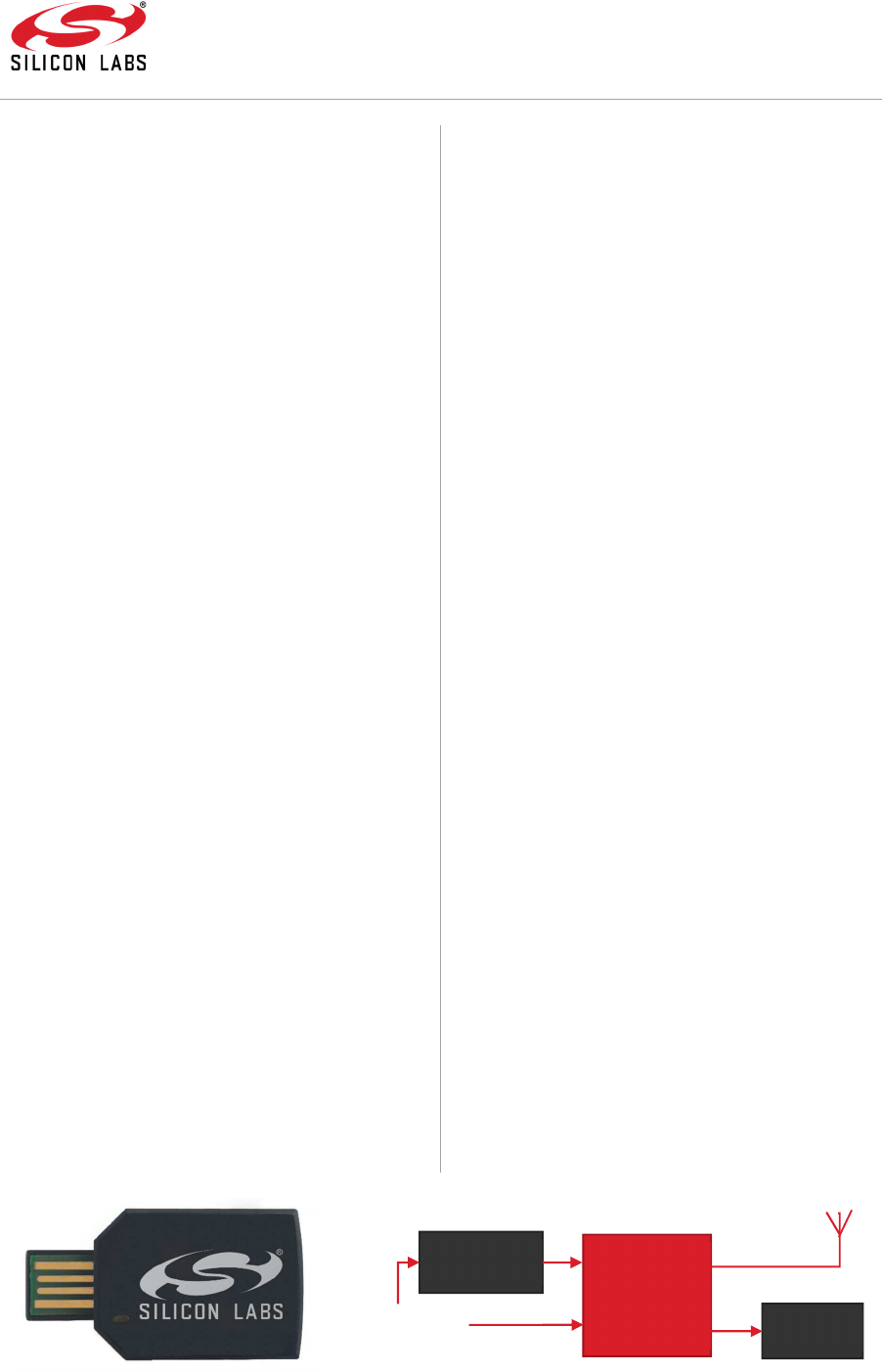
Figure 1.1 - Block Diagram
EM3588
User LED
LDO Voltage
Regulator
USB Interface
Chip
Antenna

ETRX358USB
Page 2 of 12 R e v i s i o n – 0 . 3
Table of Contents
1. Absolute Maximum Ratings ........................................................................................... 3
2. Recommended Operating Conditions ............................................................................ 3
3. Electrical characteristics ................................................................................................. 3
4. Mechanical Properties.................................................................................................... 3
5. Transmit Power Characteristics ..................................................................................... 4
6. OS & Driver support ....................................................................................................... 5
7. Bootloading Firmware .................................................................................................... 5
8. Product Labelling ........................................................................................................... 6
9. Packaging Information ................................................................................................... 6
10. Regulatory Information ............................................................................................... 7
United States of America (FCC) ........................................................................................ 7
Canada (Industry Canada) ................................................................................................ 8
European Compliance ....................................................................................................... 9
Taiwan Statement ............................................................................................................. 9
Thailand Statement ........................................................................................................... 9
Other ............................................................................................................................... 10
11. Document Change list .............................................................................................. 11
Revision 0.1..................................................................................................................... 12
Revision 0.2..................................................................................................................... 12
12. Contact Information ..................................................... Error! Bookmark not defined.
Table of Figures
Figure 1.1 - Block Diagram.................................................................................................... 1
Figure 5.1 - Output Power vs. Power Setting ........................................................................ 4
Figure 5.2 - Transmit Power vs Power Setting ...................................................................... 4
Figure 8.1 - Label dimensions ............................................................................................... 6
Figure 8.2 - Product labelling ................................................................................................ 6
Figure 9.1 - QR Code Label (Above) ..................................................................................... 6
Figure 9.2 - Individual packaging (Left) ................................................................................. 6
Table 1-1 - Absolute Maximum Ratings................................................................................. 3
Table 2-1 - Recommended Operation ................................................................................... 3
Table 3-1 - Electrical Characteristics ..................................................................................... 3
Table 10-1 - FCC TX Power Limits ........................................................................................ 7
Table 10-2 - IC TX Power Limits ........................................................................................... 8
Table 10-3 - European TX Power Limits................................................................................ 9
ETRX358USB
Page 3 of 12 R e v i s i o n – 0 . 3
1. Absolute Maximum Ratings
Parameter Min. Max.
USB Supply Voltage (V
USB
) –0.3 V 6.5 V
USB Data Line Voltage –0.3 V 3.6 V
Storage Temperature Range –40 °C 85 °C
ESD on any pin (Human Body Model) — 2 kV
Table 1-1 - Absolute Maximum Ratings
The absolute maximum ratings given above should under no circumstances be violated.
Exceeding one or more of the limiting values may cause permanent damage to the device.
2. Recommended Operating Conditions
Parameter Min. Typ. Max.
USB Supply Voltage (V
USB
) — 5 V -
USB Data Voltage 0 V — 3.3 V
Operating Ambient Temperature –40 °C — 85 °C
Table 2-1 - Recommended Operation
3. Electrical characteristics
Characteristics (V
USB
= 5V & T
AMB
= 25˚C) Minimum Typical Maximum
Operating Current (Quiescent)
—
14.6 mA
—
Operating Current (Quiescent + LED)
—
15.9 mA
—
Operating Current (RX On)
—
30.1 mA
—
Operating Current (TX One Packet per 25mS)
—
33.8 mA
—
Radio Frequency Range 2400 MHz — 2500 MHz
Receiver Sensitivity
—
–100 dBm –102 dBm *
Packet Error Rate
—
— 1%
Output Transmit Power 0 dBm 3 dBm 8 dBm *
Carrier Frequency Error –40 ppm — 40 ppm
Table 3-1 - Electrical Characteristics
For advanced radio characteristics, refer to the Silicon Labs EM358x Product data sheet.
* Indicates “Boost mode” Selectable in software.
4. Mechanical Properties
• Device Width: 25 mm
• Device Length: 46 mm
• Device Depth: 8 mm
• Weight: 7g (Without packaging)
• USB Connector Length: 12mm (According to USB Specification)
• Case Material: Polycarbonate (Black)
• Light guide material: Polycarbonate (Clear)
ETRX358USB
Page 4 of 12 R e v i s i o n – 0 . 3
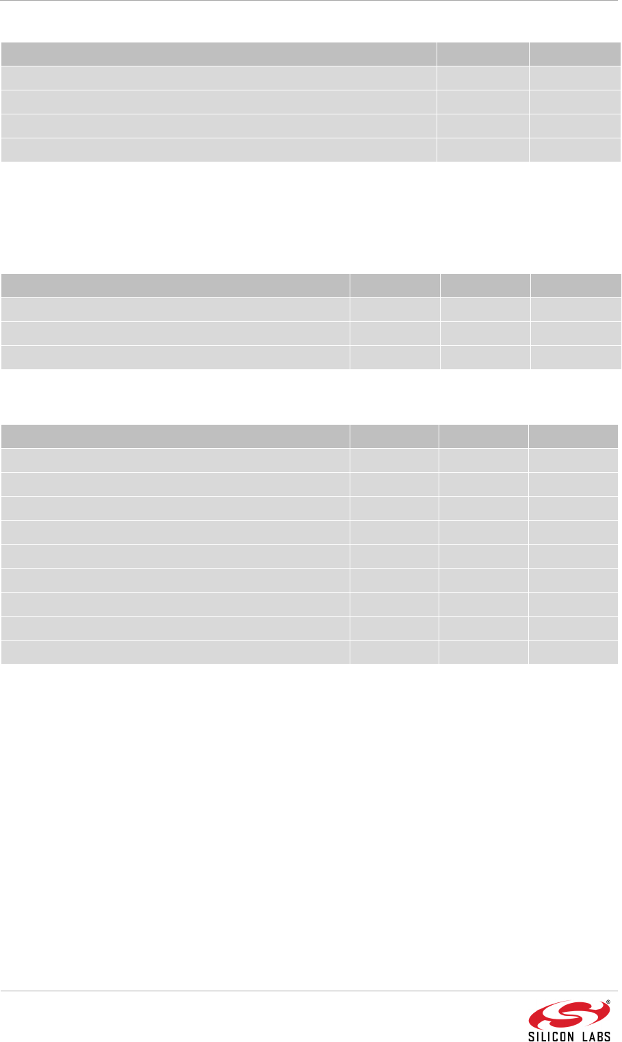
5. Transmit Power Characteristics
The diagrams below show the typical output power and current in dependency on power
setting. Power settings above 3 dBm have Boost Mode enabled. Note that the output power
is independent of the supply voltage as the radio is supplied by an internally regulated
voltage.
Figure 5.1 - Output Power vs. Power Setting
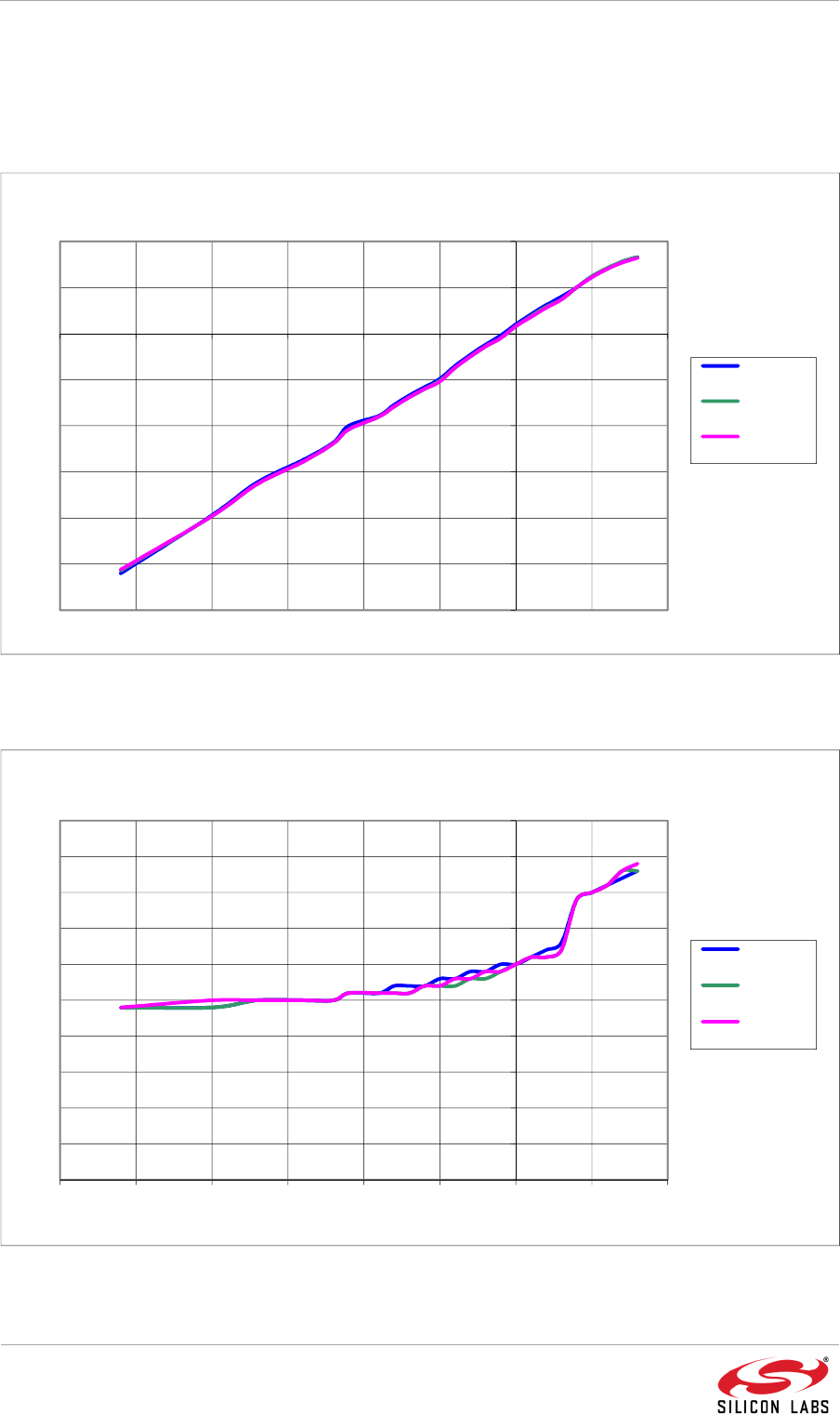
Figure 5.2 - Transmit Power vs Power Setting
-30,0
-25,0
-20,0
-15,0
-10,0
-5,0
0,0
5,0
10,0
-30 -25 -20 -15 -10 -5 0 5 10
Transmit Power [dBm]
Power Setting
Output Power vs. Power Setting at 25°C
Channel
11
Channel
19
Channel
26
0
5
10
15
20
25
30
35
40
45
50
-30 -25 -20 -15 -10 -5 0 5 10
Transmit Current [mA]
Power Setting
Transmit Current vs. Power Setting at 25°C
Channel
11
Channel
19
Channel
26

ETRX358USB
Page 5 of 12 R e v i s i o n – 0 . 3
6. OS & Driver support
The USB stick uses the SiLabs
®
CDC Driver to allow for virtual COM port communication over
USB. These drivers are required for proper device enumeration and are available for Windows
(Vista/7/8/10) and Linux from the Silicon Laboratories
®
website:
http://www.silabs.com/product-ETRX358USB
Information regarding Zigbee & Thread Mesh networking firmware can be found at:
https://www.silabs.com/products/wireless/Pages/mesh-networking-software-tools.aspx
7. Bootloading Firmware
Bootloading allows the user to change or upgrade the device firmware via USB serial using
the XMODEM protocol.
If no application is present on the device, the device will automatically start into bootloader
mode. If the device already contains an AT-Command style application firmware, the
bootloader may be accessed using the AT+BLOAD command.
Once the device is powered, connect to the device using suitable terminal software such as
HyperTerminal, PuTTy or Telegesis Terminal.
• Baud rate: 19,200 baud
• Parity: No
• Flow Control: No
• Data bits: 8
Sending a Carriage Return character (ASCII: 0x0D) will display the bootloader command
prompt. The white LED will also be lit.
ETRX3588 Serial Bootloader v0000.06.03
EUI:000D6F000C0A91D7
1. upload ebl
2. run
3. ebl info
BL >
Press 1. to begin uploading a valid .ebl binary file. An XMODEM (128 Byte) protocol is required
to upload the file. Once the upload is complete, pressing 2. will run the application. Note that,
if the application does not upload correctly, or the application does not support
bootloading, the bootloader will no longer be accessible.
ETRX358USB
Page 6 of 12 R e v i s i o n – 0 . 3
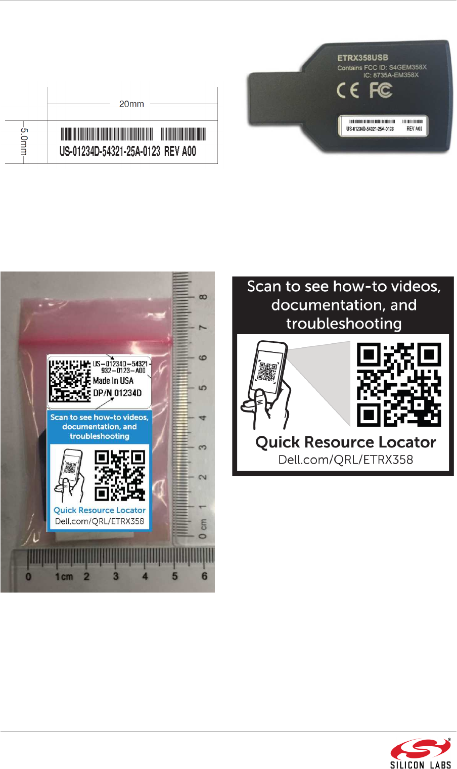
8. Product Labelling
The ETRX358USB device exhibits a small
label with two barcodes displaying serial
number and product revision.
Figure 8.1 -
Label dimensions
Figure 8.2 -
Product labelling
9. Packaging Information
Figure 9.1 - QR Code Label (Above)
Figure 9.2 - Individual packaging (Left)
A further label on the individual product
package displays the same information and QR
code link to online resources.

ETRX358USB
Page 7 of 12 R e v i s i o n – 0 . 3
10. Regulatory Information
United States of America (FCC)
This device complies with part 15 of the FCC Rules. Operation is subject to the following two
conditions:
1. This device may not cause harmful interference, and
2. This device must accept any interference received, including interference that may
cause undesired operation.
Note that this equipment has been tested and found to comply with the limits for a Class B
digital device, pursuant to part 15 of the FCC Rules. These limits are designed to provide
reasonable protection against harmful interference in a residential installation. This equipment
generates, uses and can radiate radio frequency energy and, if not installed and used in
accordance with the instructions, may cause harmful interference to radio communications.
However, there is no guarantee that interference will not occur in a particular installation. If
this equipment does cause harmful interference to radio or television reception, which can be
determined by turning the equipment off and on, the user is encouraged to try to correct the
interference by one or more of the following measures:
1. Reorient or relocate the receiving antenna.
2. Increase the separation between the equipment and receiver.
3. Connect the equipment into an outlet on a circuit different from that to which the
receiver is connected.
4. Consult the dealer or an experienced radio/TV technician for help.
Modifications not expressly approved by the manufacturer could void the user's authority to
operate the equipment under FCC rules. An FCC declaration of conformity is available
separately from Silicon Labs.
The ETRX358USB contains a modular radio transmitter with the FCC ID S4GEM358X. For
FCC compliant use, the device should be configured as shown in Table 10-1.
Channels 11 - 18 19 - 24 25 26
Maximum Output Transmit
Power 8 dBm 8 dBm 7 dBm -8 dBm
Table 10-1 - FCC TX Power Limits
This equipment complies with FCC portable radiation exposure limits set forth for an
uncontrolled environment.

ETRX358USB
Page 8 of 12 R e v i s i o n – 0 . 3
Canada (Industry Canada)
This device complies with Industry Canada licence-exempt RSS standard(s). Operation is
subject to the following two conditions:
1. this device may not cause interference, and
2. this device must accept any interference, including interference that may cause
undesired operation of the device.
This equipment complies with IC RSS-102 radiation exposure limits set forth for an
uncontrolled environment.
Cet appareil est conforme au(x) standard(s) RSS exempt(s) de licence d’Industrie Canada.
Son fonctionnement est sujet aux deux conditions suivantes:
1. cet appareil ne doit pas occasionner d’interférence et
2. cet appareil doit supporter toutes les interférences, y compris celles qui pourraient
provoquer un mauvais fonctionnement de cet appareil.
Cet appareil est conforme aux limitations de la norme IC RSS-102 concernant l’exposition aux
radiations dans un environnement non contrôlé.
The ETRX358USB contains a modular radio transmitter with the IC ID 8735A-EM358X. For
IC compliant use, the device should be configured as shown in Table 10-2.
Channels 11 - 18 19 – 24 25 26
Maximum Output Transmit
Power 8 dBm 8 dBm 7 dBm -8 dBm
Table 10-2 - IC TX Power Limits
ETRX358USB
Page 9 of 12 R e v i s i o n – 0 . 3
European Compliance
The ETRX358USB fulfil the requirements of the R&TTE directive 1999/5/EG and the
ROHS2 directive 2011/65/EU. The devices conform to the following harmonized
standard(s):
•
EN300 328 V1.9.1 –
Electromagnetic Compatibility and Radio
spectrum Matters (ERM); Wideband transmission systems;
Data
Transmission equipment operating in the 2.4GHz ISM band
and
using wide band modulation techniques
• EN301 489-17 V2.2.1 – Electromagnetic compatibility and R
adio
spectrum Matters (ERM); Electromagnetic Compatibility (EMC)
standard for radio equipment and services
• IEC 60950-1:2005 (Second Edition); Am1:2009 + Am2:2013
–
Safety
For European use, the device should be configured as shown in Table 10-3Error!
Reference source not found..
Channels 11 - 18 19 - 24 25 26
Maximum Output Transmit
Power 8 dBm 8 dBm 8 dBm 8 dBm
Table 10-3 - European TX Power Limits
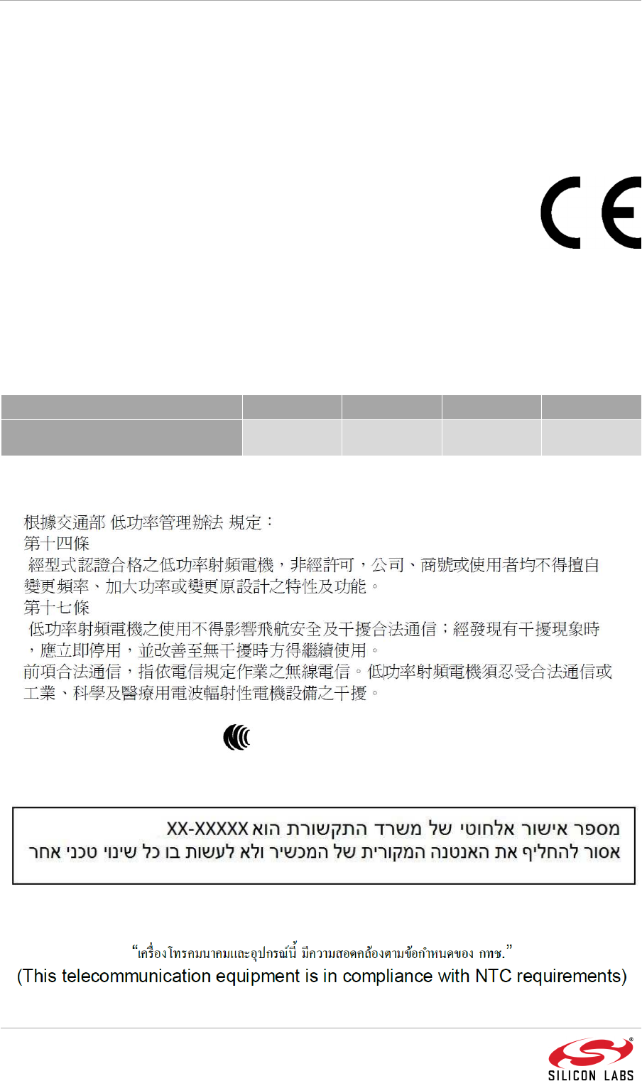
Taiwan Statement
CC XX xx YY yyy Z z W
Israel Statement
Thailand Statement
ETRX358USB
Page 10 of 12 R e v i s i o n – 0 . 3
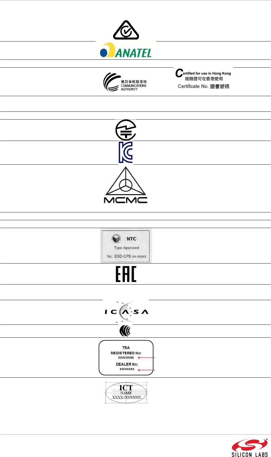
Other
Australia & New Zealand
R-NZ
XYYYY
Brazil
XXXXX-XX-XXXXX
China CMIIT ID: XXXXYZNNNN
Hong Kong ZZZZZYYXXXXX
Indonesia [certificate number]
[PLG ID number]
Israel
Japan
CODE
Korea
MSPID
Malaysia
ABCD12345678
Mexico
Morocco MR 11583 ANRT 2016
Philippines
Russia
Singapore Complies with IDA standards
[Dealers Licence number]
South Africa
TA XXXX-YYYY
Taiwan
CC XX xx YY yyy Z z W
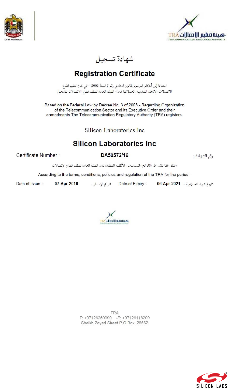
UAE
TRA REGISTERED No:
nnnnnnn
DEALER No: xxxxxxx
Vietnam
ETRX358USB
Page 11 of 12 R e v i s i o n – 0 . 3

ETRX358USB
Page 12 of 12 R e v i s i o n – 0 . 3
11. Document Change list
Revision 0.1
• First draft
• Specification details
• Power consumption section
Revision 0.2
• Current consumption values
• Regulatory information
• Packaging information
• Standards
Revision 0.3
• Added UAE statement
Revision 0.4
• Modified FCC and IC statement