Silicon Laboratories Finland WRAP2022-1-B2B Bluetooth Board-to-Board Module User Manual WRAP THOR Manual
Silicon Laboratories Finland Oy Bluetooth Board-to-Board Module WRAP THOR Manual
UserManual.wiki
>
Silicon Laboratories Finland
>
WRAP2022-1-B2B User Manual
>
WRAP THOR Manual
Contents
1.
AI Manual
2.
WRAP THOR Manual
WRAP THOR Manual
Navigation menu
Upload a User Manual
Namespaces
Wiki Guide
HTML
PDF
Info
Views
User Manual
Discussion / Help
Navigation

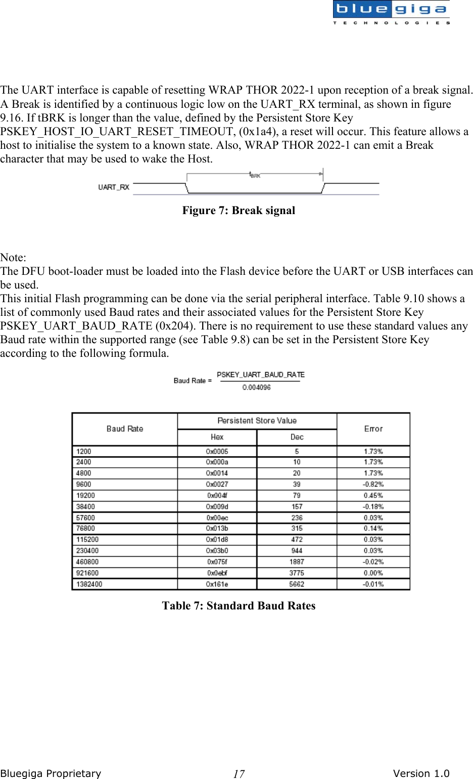
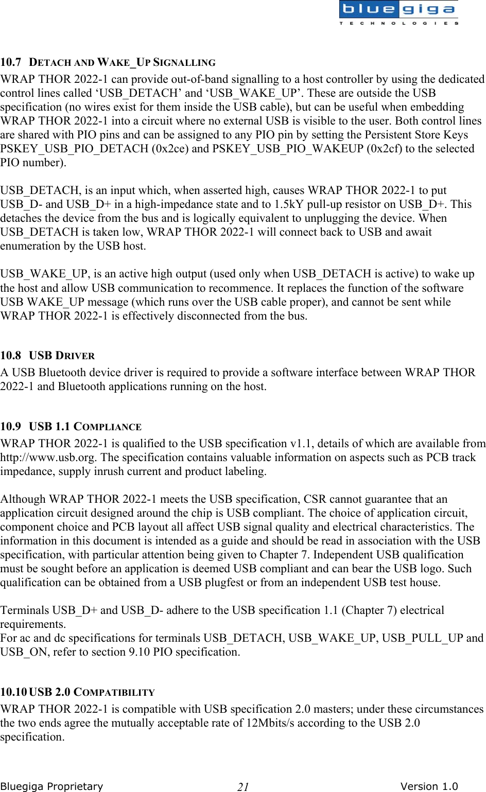
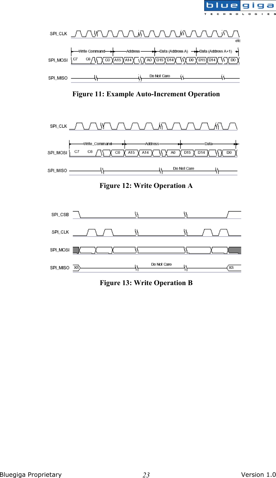
![Bluegiga Proprietary Version 1.0 2211 SERIAL PERIPHERAL INTERFACE WRAP THOR 2022-1 uses 16-bit data and 16-bit address during serial peripheral interface transactions. Such transactions will occur whether the internal processor is running or is stopped. This section details the considerations required when interfacing to WRAP THOR 2022-1 via the four dedicated serial peripheral interface terminals. Data may be written or read one word at a time or the auto-increment feature may be used to access blocks. 11.1 INSTRUCTION CYCLE Before WRAP THOR 2022-1 can be addressed, SPI_CSB must be taken low (SPI_CSB = 0). Data on SPI_MOSI is then clocked into WRAP THOR 2022-1 on the rising edge of the clock line SPI_CLK. When reading, WRAP THOR 2022-1 will reply to the Master on MISO (the data being valid on the falling edge of the SPI_CLK). The Master provides the clocking. 11.2 SINGLE-CYCLE OPERATION After a serial peripheral interface transaction completes, the Master toggles SPI_CLK with SPI_CSB high to initiate a new transaction. SPI_CSB must be high for at least two SPI_CLK cycles. 11.3 MULTI-SLAVE OPERATION WRAP THOR 2022-1 should not be connected in a multi-slave arrangement by simple parallel connection of slave MISO lines. When WRAP THOR 2022-1 is deselected (SPI_CSB = 1), the SPI_MISO line does not float. Instead, WRAP THOR 2022-1 outputs 0 if the processor is running or 1 if it is stopped. 11.4 WRITING TO WRAP THOR 2022-1 To write to WRAP THOR 2022-1, the 8-bit write command (00000010) is sent first (C[7:0]) followed by a 16-bit address (A[15:0]). After that, 16-bits of data (D[15:0]) are sent. 11.5 AUTO-INCREMENT OPERATION Sending a command word and the address of a register every time it is to be read or written can be a significant overhead, especially when large amounts of data are to be transferred. To overcome this WRAP THOR 2022-1 offers increased data transfer efficiency via an auto-increment operation. During operation, WRAP THOR 2022-1 increments the address automatically. Only the data is transmitted or received over the serial peripheral interface. WRAP THOR 2022-1 keeps the previous command word. Auto-increment mode is invoked by keeping SPI_CSB low after the last bit of a read or write operation, while providing an extra 16 clock cycles. If the previous command was a write, continuous 16-bit words of data may then be written to the WRAP THOR 2022-1 without the need to send the address or command word. Similarly, if the previous command was a read, then data may be read. T[15:0] are not returned after the first read, just D[15:0].](https://usermanual.wiki/Silicon-Laboratories-Finland/WRAP2022-1-B2B.WRAP-THOR-Manual/User-Guide-471859-Page-22.png)
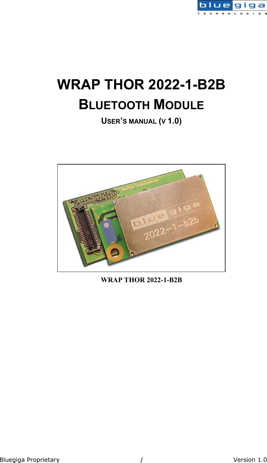
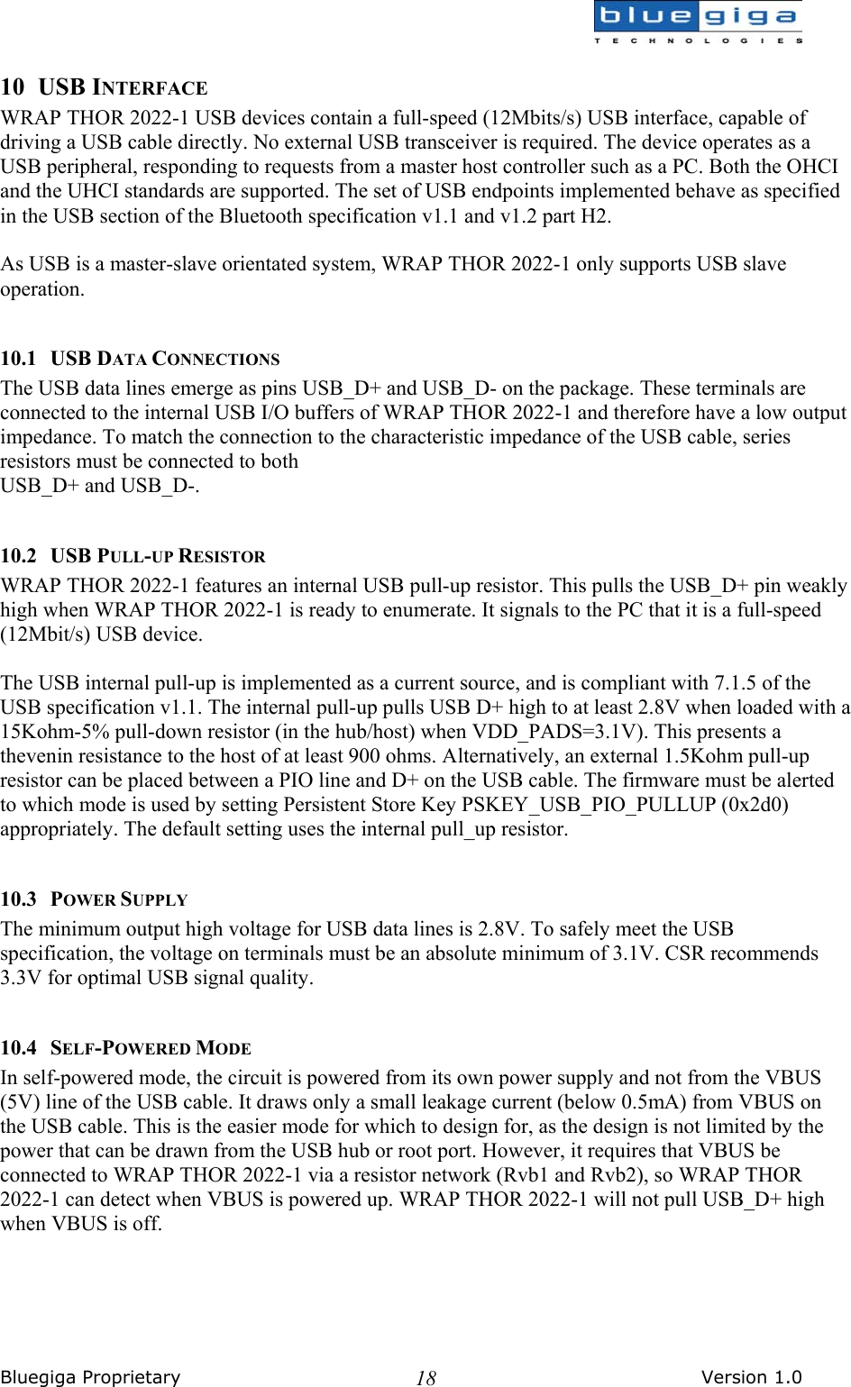
![Bluegiga Proprietary Version 1.0 24 11.6 READING FROM WRAP THOR 2022-1 Reading from WRAP THOR 2022-1 is similar to writing to it. An 8-bit read command (00000011) is sent first, followed by the address of the location to be read. WRAP THOR 2022-1 then outputs the 16-bit contents of the location on MISO with a check-word during T[15:0] and data during bits D[15:0]. The check-word is composed of {command, address [15:8]}. The check-word may be used to confirm a read operation to a memory location. This overcomes the problems encountered with typical serial peripheral interface slaves, whereby it is impossible to determine whether the data returned by a read operation is valid data or the result of the slave device not responding. Figure 14: Read Operation A Figure 15: Read Operation B](https://usermanual.wiki/Silicon-Laboratories-Finland/WRAP2022-1-B2B.WRAP-THOR-Manual/User-Guide-471859-Page-24.png)
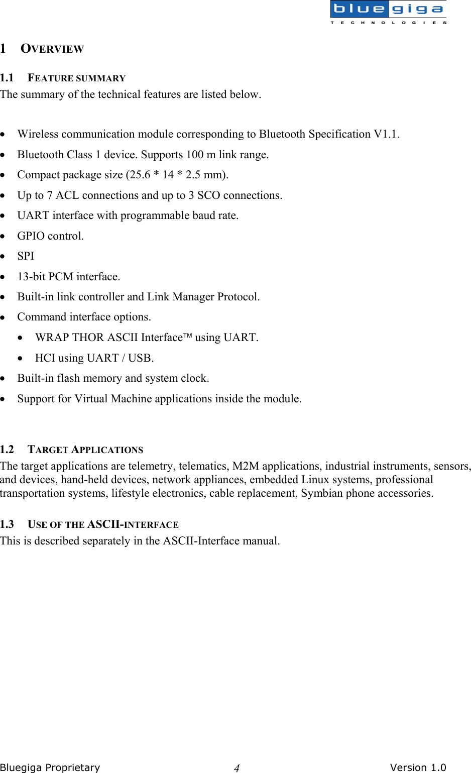
![Bluegiga Proprietary Version 1.0 3313 PIO The Parallel Input Output (PIO) Port is a general-purpose I/O interface to WRAP THOR 2022-1. The port consists of six programmable, bi-directional I/O lines, PIO[2:7]. Programmable I/O lines can be accessed either via an embedded application running on WRAP THOR 2022-1 or via private channel or manufacturer-specific HCI commands. PIO[2]/USB_PULL_UP (1) This is a multifunction terminal. The function depends on whether WRAP THOR 2022-1 is a USB or UART capable version. On UART versions, this terminal is a programmable I/O. On USB versions, it can drive a pull-up resistor on USB_D+. For application using external RAM this terminal may be programmed for chip select. PIO[3]/USB_WAKE_UP (1) This is a multifunction terminal. On UART versions of WRAP THOR 2022-1 this terminal is a programmable I/O. On USB versions, its function is selected by setting the Persistent Store Key PSKEY_USB_PIO_WAKEUP (0x2cf) either as a programmable I/O or as a USB_WAKE_UP function. PIO[4]/USB_ON (1) This is a multifunction terminal. On UART versions of WRAP THOR 2022-1 this terminal is a programmable I/O. On USB versions, the USB_ON function is also selectable (see USB Interface section 9.6). PIO[5]/USB_DETACH (1) This is a multifunction terminal. On UART versions of WRAP THOR 2022-1 this terminal is a programmable I/O. On USB versions, the USB_DETACH function is also selectable (see USB Interface section 9.6). PIO[6]/CLK_REQ This is multifunction terminal, its function is determined by Persistent Store Keys. Using PSKEY_CLOCK_REQUEST_ENABLE, (0x246) this terminal can be configured to be low when WRAP THOR 2022-1 is in deep sleep and high when a clock is required. The clock must be supplied within 4ms of the rising edge of PIO[6] to avoid losing timing accuracy in certain Bluetooth operating modes. PIO[7] Programmable I/O terminal. Note: (1) USB functions can be software mapped to any PIO terminal.](https://usermanual.wiki/Silicon-Laboratories-Finland/WRAP2022-1-B2B.WRAP-THOR-Manual/User-Guide-471859-Page-33.png)