Silicon Labs MS32018 802.11 b/g/n Wi-Fi MODULE User Manual MS32018 UserManual
Redpine Signals Inc 802.11 b/g/n Wi-Fi MODULE MS32018 UserManual
UserManual.wiki
>
Silicon Labs
>
MS32018 User Manual
Manual
Navigation menu
Upload a User Manual
Namespaces
Wiki Guide
HTML
PDF
Info
Views
User Manual
Discussion / Help
Navigation
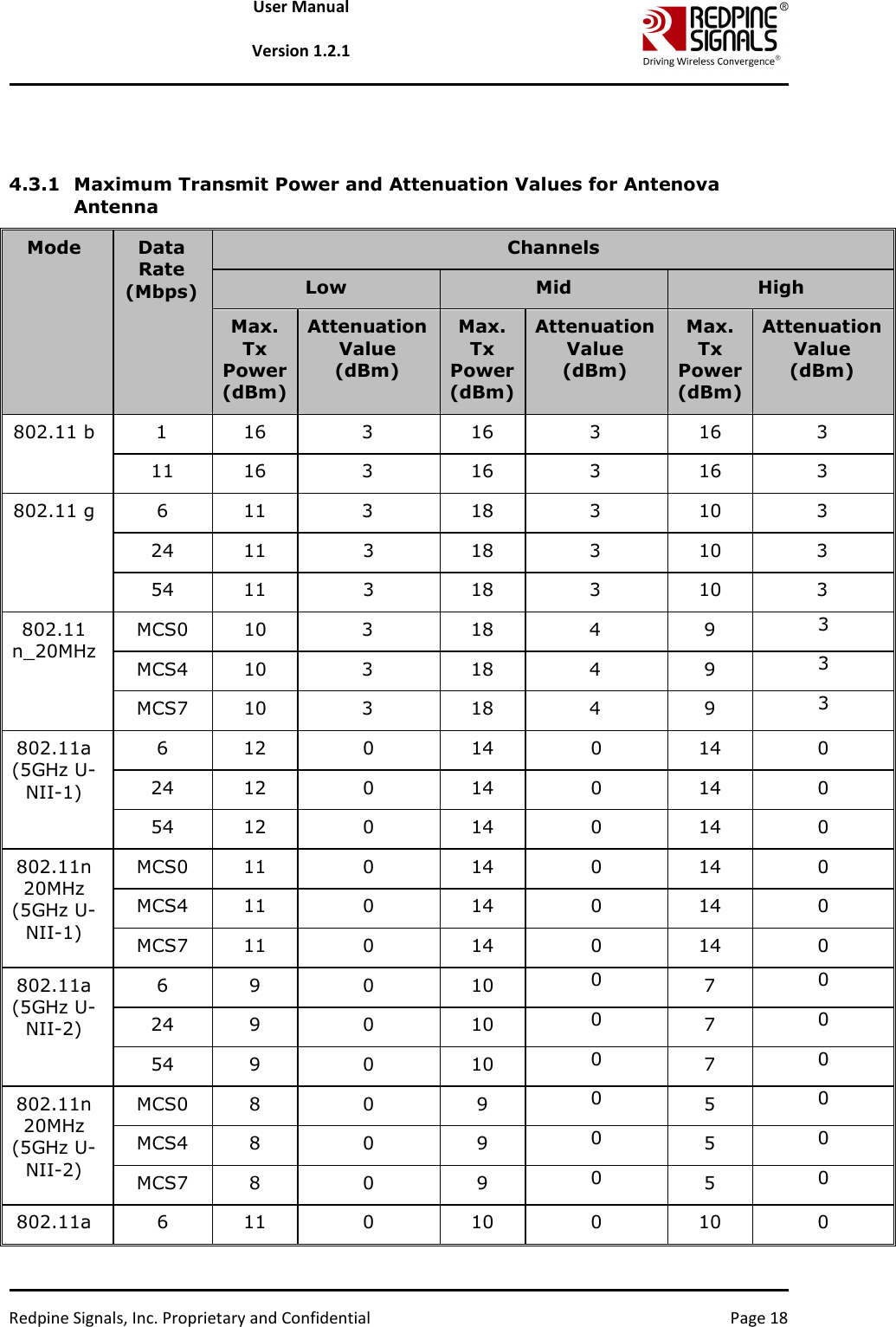
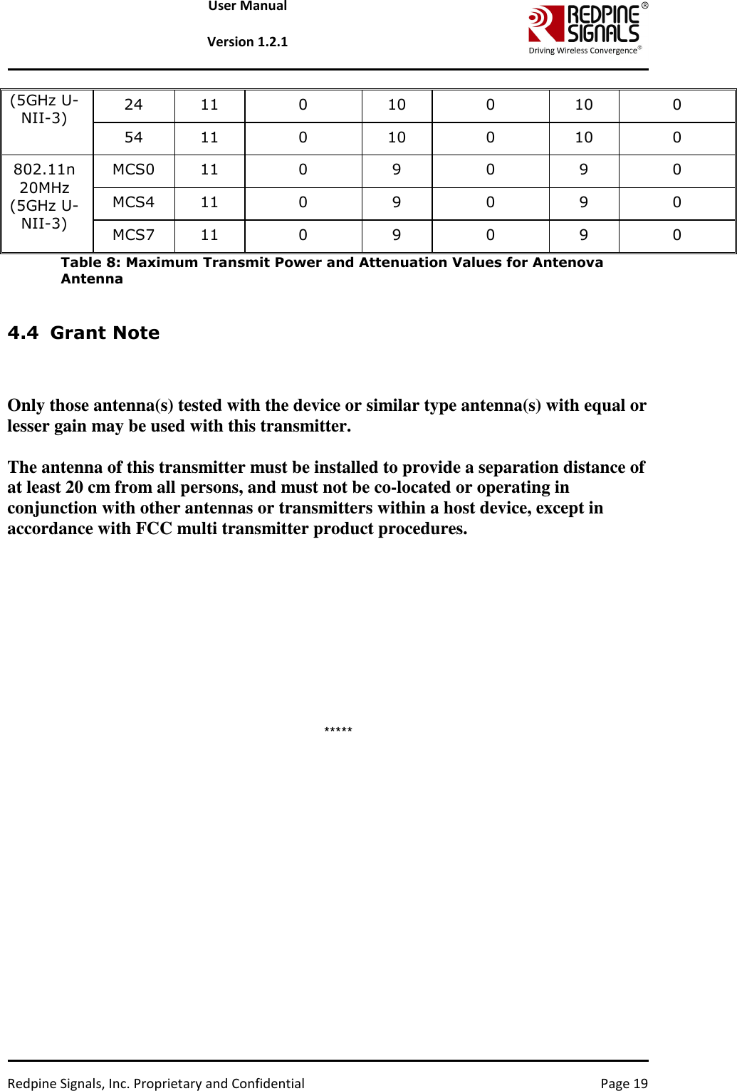
![Redpine Signals, Inc. Proprietary and Confidential Page 9 User Manual Version 1.2.1 Band (GHz) Bandwidth (MHz) Channel Number Center Frequency (MHz) 5 20 136 5680 5 20 140 5700 5 20 149 5745 5 20 153 5765 5 20 157 5785 5 20 161 5805 5 20 165 5825 Table 1: Channel Numbers and Corresponding Center Frequencies <expa>: Enable/Disable External PA. This parameter is not supported in the current release. <rf>: Rate Flags. This parameter is used to enable/disable Short GI and Greenfield and also to set the channel width of the transmitted packets. The table below explains the flags that can be enabled and disabled. Multiple flags can be set at a time. Bit Description 0 Short GI 0 – Disable Short GI 1 – Enable Short GI 1 Greenfield transmission 0 – Disable Greenfield transmission 1 – Enable Greenfield transmission [4:2] Operating bandwidth of the channel (3 bits) 0 – 20MHz 2 (Bit 3 is set) – NA 4 (Bit 4 is set) – NA 6 (Bits 3 and 4 are set) – NA Table 2: Rate Flags for Transmit Tests <aggr>: Enable/Disable Aggregation. Enter 0 to disable aggregation and 1 to enable aggregation. The packet length is divided into chunks of size 1792 bytes and aggregated. This parameter applies only to the Burst mode transmission and is ignored in the case of Continuous mode of transmission.](https://usermanual.wiki/Silicon-Labs/MS32018/User-Guide-3236303-Page-9.png)