Silicon Labs MS32018 802.11 b/g/n Wi-Fi MODULE User Manual MS32018 UserManual
Redpine Signals Inc 802.11 b/g/n Wi-Fi MODULE MS32018 UserManual
Manual

Redpine Signals, Inc. Proprietary and Confidential
User Manual
Version 1.2.1
October 2016
Redpine Signals, Inc.
2107 N. First Street, #680
San Jose, CA 95131.
Tel: (408) 748-3385
Fax: (408) 705-2019
Email: info@redpinesignals.com
Website: www.redpinesignals.com

Redpine Signals, Inc. Proprietary and Confidential Page 2
User Manual
Version 1.2.1
About this Document
This document describes the usage of the MS32018 n-Link® Driver for testing
transmit & receive Performance for Wi-Fi protocols.
Disclaimer:
The information in this document pertains to information related to Redpine Signals,
Inc. products. This information is provided as a service to our customers, and may
be used for information purposes only.
Redpine assumes no liabilities or responsibilities for errors or omissions in this
document. This document may be changed at any time at Redpine’s sole discretion
without any prior notice to anyone. Redpine is not committed to updating this
document in the future.
Copyright © 2016 Redpine Signals, Inc. All rights reserved.

Redpine Signals, Inc. Proprietary and Confidential Page 3
User Manual
Version 1.2.1
Table Of Contents
1 Introduction .................................................................................................. 4
1.1 Getting Started .................................................................................................4
2 WLAN Performance Test Application Usage ................................... 6
2.1 Transmit Tests ..................................................................................................6
2.1.1 Transmit Command ......................................................................................................... 7
2.1.2 Transmit Command Description ................................................................................. 7
2.1.3 Examples ........................................................................................................................... 10
2.2 Receive Tests .................................................................................................. 11
2.2.1 Receive Command ......................................................................................................... 11
2.2.2 Receive Command Description ................................................................................. 11
2.2.3 Examples ........................................................................................................................... 12
3 FCC and IC Declaration ........................................................................... 13
4 Confirmation on Unlawful Usage of TX power with respect to
Certified Antennas .......................................................................................... 15
4.1 Commands to Program Antenna Type ................................................. 15
4.1.1 Command to Program Antenna Type for Wi-Fi ................................................... 15
4.2 Commands to Program Transmit Power ............................................. 16
4.2.1 Command to Program Transmit Power for Wi-Fi ............................................... 16
4.3 Maximum Transmit Power and Attenuation Values ....................... 17
4.3.1 Maximum Transmit Power and Attenuation Values for Antenova Antenna
18
4.4 Grant Note ........................................................................................................ 19
Table of Figures
No table of figures entries found.
Table of Tables
Table 1: Channel Numbers and Corresponding Center Frequencies .................... 9
Table 2: Rate Flags for Transmit Tests ................................................................................ 9
Table 3: Regulatory Domain Input in Transmit Tests ....... Error! Bookmark not defined.
Table 4: Channel Width Values ............................................................................................. 11
Table 8: List of Antennas Used for MS32018 FCC/IC Certification ..................... 15
Table 9: Command to Program Antenna Type for Wi-Fi ........................................... 16
Table 12: Command to Program Transmit Power for Wi-Fi .................................... 17
Table 15: Low, Mid and High Channel Frequencies for Wi-Fi ................................. 17
Table 16: Maximum Transmit Power and Attenuation Values for Redpine
signals Antenna ..................................................................................................................... 19
Redpine Signals, Inc. Proprietary and Confidential Page 4
User Manual
Version 1.2.1
1 Introduction
The software provided for the MS32018 n-Link® modules is named
OneBox-Mobile. The software currently supports performance testing for
Wi-Fi.
The subsequent sections explain the use of OneBox-Mobile software on
an x86 platform. Installation and operation of the driver on specific
representative processor platforms have been explained in the Appendix
sections.
1.1 Getting Started
1. Login to user “test” with password “test123”
2. Open a Terminal
3. Type command “su” and press enter key
4. Enter password “test123”
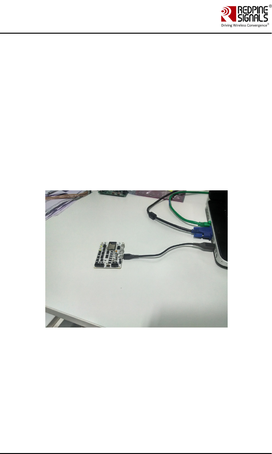
5. Connect EUT to Laptop with USB cable as shown below
Redpine Signals, Inc. Proprietary and Confidential Page 5
User Manual
Version 1.2.1
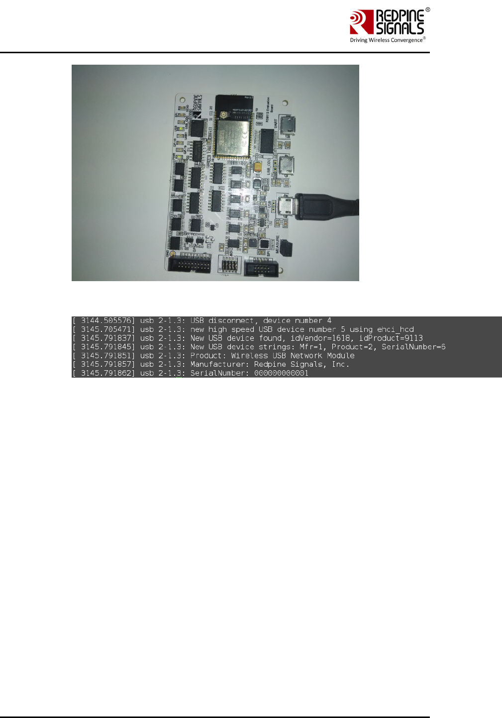
6. Please type “dmesg” on the terminal and press enter key and
check for the below print
7. Please go to directory /work/Regulatory_test/host/releases
8. Please read section 2 for performing WLAN Tests
Redpine Signals, Inc. Proprietary and Confidential Page 6
User Manual
Version 1.2.1
2 WLAN Performance Test Application Usage
The OneBox-Mobile software provides applications to test Transmit and
Receive performance of the module. The Band of operation of the module
needs to be configured before performing any tests.
NOTE: Open the common_insert.sh file present in the “release” folder
using an editor like vim. Ensure that the DRIVER_MODE is set as below:
DRIVER_MODE = 2
COEX_MODE = 1
Run the following command to install the Driver in Performance Test
mode:
# sh wlan_insert.sh
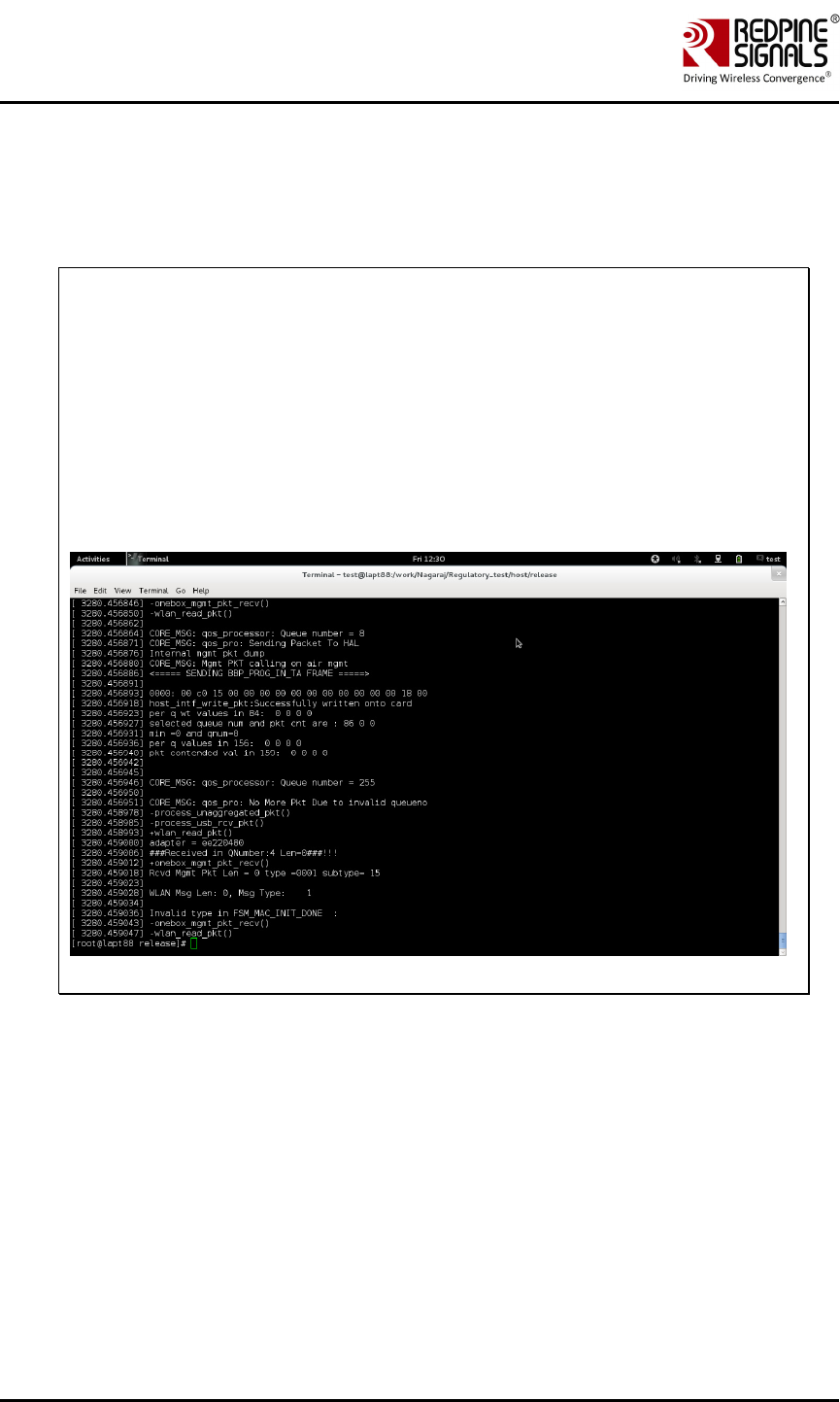
Please type “dmesg” in the terminal and press enter key and check for
the below print for check if driver has been loaded properly.
Next, follow the instructions below to run the Transmit and Receive tests.
2.1 Transmit Tests
The “transmit” utility, present in the “release” folder allows the
configuration of the following parameters and starts the transmission of
packets.
1) Transmit Power
2) Transmit Data Rate
3) Packet Length
4) Transmit Mode
5) Channel Number

Redpine Signals, Inc. Proprietary and Confidential Page 7
User Manual
Version 1.2.1
6) External PA Enable/Disable1
7) Rate Flags like Short GI, Greenfield, etc.
8) Enable/Disable Aggregation
9) Number of packets to be transmitted in Burst Mode
10) Delay between packets in Burst Mode
11) Regulatory Domain
2.1.1 Transmit Command
./transmit
<tpow><rate><len><mode><chan><expa><rf><aggr><num><delay
><reg>
2.1.2 Transmit Command Description
The command usage is explained below.
<tpow>: Transmit power in dBm for controlling transmit power. To set
the transmit power value, enter a value either between -7 and18.If a
value of 127 is entered, the packet will be transmitted at the maximum
power from the Transmit power table in the module.
<rate>: Transmit Data Rate. To set the transmit data rate, select a value
from 1, 2, 5.5, 11, 6, 9, 12, 18, 24, 36, 48, 54, mcs0, mcs1, mcs2,
mcs3, mcs4, mcs5, mcs6 and mcs7.
<len>: Transmit packet length in bytes. Enter a value between 24 and
1536 when aggregation is not enabled and between 24 and 30000 when
aggregation is enabled.
<mode>: Transmit mode. Enter 0 for Burst mode and 1 for Continuous
mode.
<chan>: Transmit channel number2. The following table maps the
channel numbers to the center frequencies for 20MHz and 40MHz
bandwidth modes in 2.4GHz and 5GHz band.
Band
(GHz)
Bandwidth
(MHz)
Channel
Number
Center Frequency (MHz)
2.4 20 1 2412
2.4 20 2 2417
2.4 20 3 2422
2.4 20 4 2427
1 This is not supported in the current release.
2 On-air testing in DFS channels should be avoided till the module is certified for DFS. Cabled tests can be
run in these channels.

Redpine Signals, Inc. Proprietary and Confidential Page 8
User Manual
Version 1.2.1
Band
(GHz)
Bandwidth
(MHz)
Channel
Number
Center Frequency (MHz)
2.4 20 5 2432
2.4 20 6 2437
2.4 20 7 2442
2.4 20 8 2447
2.4 20 9 2452
2.4 20 10 2457
2.4 20 11 2462
2.4 20 12 2467
2.4 20 13 2472
2.4 20 14 2484
5 20 36 5180
5 20 40 5200
5 20 44 5220
5 20 48 5240
5 20 52 5260
5 20 56 5280
5 20 60 5300
5 20 64 5320
5 20 100 5500
5 20 104 5520
5 20 108 5540
5 20 112 5560
5 20 116 5580
5 20 120 5600
5 20 124 5620
5 20 128 5640
5 20 132 5660

Redpine Signals, Inc. Proprietary and Confidential Page 9
User Manual
Version 1.2.1
Band
(GHz)
Bandwidth
(MHz)
Channel
Number
Center Frequency (MHz)
5 20 136 5680
5 20 140 5700
5 20 149 5745
5 20 153 5765
5 20 157 5785
5 20 161 5805
5 20 165 5825
Table 1: Channel Numbers and Corresponding Center Frequencies
<expa>: Enable/Disable External PA. This parameter is not supported in
the current release.
<rf>: Rate Flags. This parameter is used to enable/disable Short GI and
Greenfield and also to set the channel width of the transmitted packets.
The table below explains the flags that can be enabled and disabled.
Multiple flags can be set at a time.
Bit Description
0 Short GI
0 – Disable Short GI
1 – Enable Short GI
1 Greenfield transmission
0 – Disable Greenfield transmission
1 – Enable Greenfield transmission
[4:2] Operating bandwidth of the channel (3 bits)
0 – 20MHz
2 (Bit 3 is set) – NA
4 (Bit 4 is set) – NA
6 (Bits 3 and 4 are set) – NA
Table 2: Rate Flags for Transmit Tests
<aggr>: Enable/Disable Aggregation. Enter 0 to disable aggregation and
1 to enable aggregation. The packet length is divided into chunks of size
1792 bytes and aggregated. This parameter applies only to the Burst
mode transmission and is ignored in the case of Continuous mode of
transmission.

Redpine Signals, Inc. Proprietary and Confidential Page 10
User Manual
Version 1.2.1
<num>: Number of packets to be transmitted in Burst mode. The
transmission stops after the number of packets specified by this
parameter are transmitted in the Burst mode. If this value is 0, then the
transmission will not stop until the user gives the “./transmit 0” command
to stop the transmissions. This parameter is ignored in the case of
Continuous mode of transmission.
<delay>: Delay between packets in Burst mode. This parameter is used
to introduce a delay between any two packets. The delay has to be
specified in microseconds. If this value is 0, then the packets will be
transmitted without any delay. This parameter is ignored in the case of
Continuous mode of transmission.
<reg>: Regulatory Domain.
NOTE: After the transmission starts, the following commands need to be
given to stop the transmissions.
Burst Mode: ./transmit 0
Continuous Mode: ./transmit 0
2.1.3 Examples
#./transmit 2 54 1000 1 11 0 0 0 0 0 255
The above command starts continuous transmission with the following
configuration:
Transmit gain – 2dbm
Data rate – 54Mbps
Packet Length – 1000 bytes
Transmit mode – 1 (continuous mode).
Channel number – 11
External PA – disabled
Rate flags – 0
Aggregation – disabled (ignored in continuous mode)
Number of packets to be transmitted – 0(ignored in continuous mode)
Delay between the packets – 0(ignored in continuous mode)
Regulatory Domain is set to – World Domain
# ./transmit 12 36 1000 0 6 0 25 0 0 1000 0 0
The above command starts burst mode transmission with the following
configuration:
Transmit gain – 12dBm
Data rate – 36Mbps

Redpine Signals, Inc. Proprietary and Confidential Page 11
User Manual
Version 1.2.1
Packet Length – 1000 bytes
Transmit mode – 0 (Burst mode).
Channel number – 6
External PA – disabled
Rate flags – 25 (Short GI with Full 40MHz Channel width)
Aggregation – disabled
Number of packets to be transmitted – 1000
Delay between the packets – 0
Regulatory Domain is set to – World Domain
2.2 Receive Tests
The “receive” utility, present in the “release” folder, can be invoked for
displaying the following information
• Total number of CRC PASS packets
• Total number of CRC FAIL packets and
• Total number of FALSE CCAs
2.2.1 Receive Command
# ./receive <filename><channel_number><start/stop><channel_width>
2.2.2 Receive Command Description
<filename>: Name of the file into which the statistics will be logged, in
addition to being displayed on the console.
<channel_number>3: Channel number in which the statistics need to be
logged. Refer to the Table 1 in Section 2.1.2 for more details.
<start/stop>: Parameter to start or stop logging the statistics. Enter 0 to
start logging and 1 to stop logging.
<channel_width>: Operating bandwidth of the channel. Refer to the table
below.
Value Channel Width
0 20MHz
2 NA
4 NA
6 NA
Table 3: Channel Width Values
3 On-air testing in DFS channels should be avoided till the module is certified for DFS. Cabled tests can be
run in these channels.

Redpine Signals, Inc. Proprietary and Confidential Page 12
User Manual
Version 1.2.1
2.2.3 Examples
# ./receive stats 6 0 0
The above command starts the receive utility and logs statistics with the
following parameters.
Filename – stats
Channel number – 6
Channel Width – 20MHz
The test utility displays the following information:
• Total number of packets received with correct CRC.
• Total number of packets received with incorrect CRC.
• Total number of False CCA’s received.
# ./receive stats 6 1 0
The above command will stop the receive application

Redpine Signals, Inc. Proprietary and Confidential Page 13
User Manual
Version 1.2.1
3 FCC and IC Declaration
This device complies with Part 15 of the FCC Rules.
Operation is subject to the following two conditions:
(1) This device may not cause harmful interference, and
(2) This device must accept any interference received, including
interference that may cause undesired operation.
NOTE: This equipment has been tested and found to comply with the
limits for a Class B digital device, pursuant to part 15 of the FCC Rules.
These limits are designed to provide reasonable protection against
harmful interference when the equipment is operated in a commercial
environment. This equipment generates, uses, and can radiate radio
frequency energy and, if not installed and used in accordance with the
instruction manual, may cause harmful interference to radio
communications. Operation of this equipment in a residential area is
likely to cause harmful interference in which case the user will be
required to correct the interference at his own expense.
This Class B digital apparatus complies with Canadian ICES-003.
Cet appareil numérique de la classe A est conforme à la norme NMB-003
du Canada.
This device complies with Industry Canada license-exempt
RSSstandard(s).Operation is subject to the Following two conditions:(1)
This device may notcause interference, and(2) This device must accept
any interference, including interference that may cause undesired
operation of the device.
Le présent appareil est conforme aux CNR d'Industrie Canada applicables
aux appareils radio exempts de licence.
L'exploitation est autorisée aux deux conditions suivantes:(1) l'appareil
ne doit pas produire de brouillage, et (2) l'utilisateur de l'appareil doit
accepter tout brouillage radioélectrique subi, même si le brouillage est
susceptibled'en compromettre le fonctionnement.
CAUTION: Any changes or modifications not expressly approved by the
party responsible for compliance could void the user’s authority to
operate the equipment.
This equipment should be installed and operated with minimum distance
20 cm between the radiator & your body.
End Product Labeling
This Module is labeled with its own FCC ID. If the FCC ID Certification
Number is not visible while installed inside another device, then the
device should display the label on it referring the enclosed module. In
that case, the final end product must be labeled in a visible area with the
following:

Redpine Signals, Inc. Proprietary and Confidential Page 14
User Manual
Version 1.2.1
“Contains Transmitter Module FCC ID: XF6-MS32018”
OR
“Contains FCC ID: XF6-MS32018”
The OEM should not provide information to the end user regarding
installation or removal of this RF module or change RF related parameters
in the user manual of the end product.
The OEM integrator is still responsible for testing their end-product for
any additional compliance requirements required with this module
installed (for example, digital device emissions, PC peripheral
requirements, etc.).
énoncé de la FCC (états-Unis seulement) Cet équipement a été testé et
jugé conforme aux limites de Classe B pour un appareil numérique, en
vertu de l’article 15 de la réglementation de la FCC. Ces limites ont été
instaurées our fournir une rotection raisonnable contre toute interférence
nuisible dans une installation résidentielle. Cet équipement génère, utilise
et peut émettre de l’énergie radiofréquence. S’il n’est pas installé et
utilisé conformément aux instructions, il peut provoquer des interférences
sur les communications radio. Cependant, il n’est pas garanti que des
interférences ne se produiront pas dans certaines installations. Si cet
équipement cause des interférences à la reception radio ou télévisée (ce
qui peut être vérifi é en éteignant l’appareil puis en le remettant sous
tension),
l’utilisateur peut enter de ésoudre en suivant une ou plusieurs des
mesures ci-après :
Réorienter ou déplacer l’antenne réceptrice.
ugmenter l’espace entre l’appareil et le récepteur. Brancher l’appareil à
une prise de courant différente de celle sur laquelle le récepteur est
branché. Pour obtenir de l’aide, contacter le vendeur ou un technician
radio/television expérimenté.
REMARQUE: Toute modifi cation non autorisée expressément par le
fabricant responsable de la onformité peut annuler le droit de l’utilisateur
à faire fonctionner le produit.
This Module is labeled with its own IC ID. If the IC ID Certification
Number is not visible while installed inside another device, then the
device should display the label on it referring the enclosed module. In
that case, the final end product must be labeled in a visible area with the
following:
“Contains Transmitter Module IC ID: 8407A-MS32018”
OR
“Contains IC ID: 8407A-MS32018”

Redpine Signals, Inc. Proprietary and Confidential Page 15
User Manual
Version 1.2.1
4 Confirmation on Unlawful Usage of TX power with
respect to Certified Antennas
This is to confirm that Redpine Signals, Inc., will ensure that the following
information is included in the MS32018 (FCC ID: XF6-MS32018, IC ID:
8407A-MS32018) Module’s Programming Manual for customers who use
this module with different antennas to help them comply with the FCC/IC
regulatory requirements for products which use the module’s modular
approval.
The list of antennas with which the module has been tested with and
certified for FCC/IC are given in Table 1 below.
Antenna Make Model/Part # Antenna Gain at
2.4GHz (dBi)
Antenna Gain
at 5GHz (dBi)
Type of
Antenna
Antenova CU5006-2
2.36 5 Internal mount
and Cable
connection
Table 4: List of Antennas Used for MS32018 FCC/IC Certification
The MS32018 Module’s Programming Reference Manual will include the
information listed below. The Manual is provided to customers as part of
the module’s collateral which also includes the module’s software and
firmware. The module’s firmware applies the attenuations required to
comply with the regulatory requirements based on the type of antenna
programmed. The commands required to program the transmit power
and the antenna type and the attenuations applied are given in the tables
that follow.
1) Commands to program the antenna being used for Wi-Fi – see Table
9.
2) Commands to set transmit power of the module for Wi-Fi– see Table
12.
3) Transmit power and attenuation values used during testing with
Antenova Antenna – see Tables 16.
4.1 Commands to Program Antenna Type
4.1.1 Command to Program Antenna Type for Wi-Fi
Command Name Program Antenna Type for Wi-Fi
Description This command is used to program antenna
being used by the module for Wi-Fi out of
the list of certified antennas. This command
needs to be given before creating the VAP
in the normal mode and before the
“./transmit” command in the Wi-Fi

Redpine Signals, Inc. Proprietary and Confidential Page 16
User Manual
Version 1.2.1
Performance Test mode.
Default Value 0
Input Parameters Base Interface (string like rpine0)
Integer value mapped as follows:
3- Antenova Antenna
Output Parameter None
Reset Required No
Usage #
./onebox_util<base_interface>ant_type<a
ntenna_type>
Example The command below sets the Antenna type
to Fractus Antenna for Wi-Fi:
# ./onebox_util rpine0 ant_type 3
Table 5: Command to Program Antenna Type for Wi-Fi
4.2 Commands to Program Transmit Power
4.2.1 Command to Program Transmit Power for Wi-Fi
Description This command is used to program the
transmit power of the module for Wi-Fi. If
the value of transmit power exceeds the
maximum allowed power supported by the
channel specified by the regulatory domain,
then the minimum of the two values will be
used.
Default Value -
Input Parameters VAP Name (string like wifi0, wifi1, etc.)
Integer value in dBm
Output Parameter None
Reset Required No.
Usage #
iwconfig<vap_name>txpower<val_in_dBm
>
Example The command below sets the Wi-Fi

Redpine Signals, Inc. Proprietary and Confidential Page 17
User Manual
Version 1.2.1
transmit power to 15dBm:
# iwconfig wifi0 txpower 15
Output Parameter None
Table 6: Command to Program Transmit Power for Wi-Fi
4.3 Maximum Transmit Power and Attenuation Values
The transmit power and attenuation value settings in the following tables are mentioned
for IEEE 802.11a/b/g/n for the Low, Mid and High channel frequencies. The table below lists
the actual frequencies for each technology corresponding to the Low, Mid and High
columns in subsequent tables.
Technology Low
Channel
Frequency
(MHz)
Mid
Channel
Frequency
(MHz)
High
Channel
Frequency
(MHz)
802.11b 2412 2437 2462
802.11g 2412 2437 2462
802.11n 20MHz
Bandwidth
2412 2437 2462
802.11a (5GHz
U-NII- 1)
5180 5200 5240
802.11n 20MHz
Bandwidth(5GHz
U-NII- 1)
5180 5200 5240
802.11a (5GHz
U-NII- 2)
5260 5500 5720
802.11n 20MHz
Bandwidth(5GHz
U-NII- 2)
5260 5500 5720
802.11a (5GHz
U-NII- 3)
5745 5785 5825
802.11n 20MHz
Bandwidth (U-
NII- 3)
5745 5785 5825
Table 7: Low, Mid and High Channel Frequencies for Wi-Fi

Redpine Signals, Inc. Proprietary and Confidential Page 18
User Manual
Version 1.2.1
4.3.1 Maximum Transmit Power and Attenuation Values for Antenova
Antenna
Mode Data
Rate
(Mbps)
Channels
Low Mid High
Max.
Tx
Power
(dBm)
Attenuation
Value
(dBm)
Max.
Tx
Power
(dBm)
Attenuation
Value
(dBm)
Max.
Tx
Power
(dBm)
Attenuation
Value
(dBm)
802.11 b 1 16 3 16 3 16 3
11 16 3 16 3 16 3
802.11 g
6 11 3 18 3 10 3
24 11 3 18 3 10 3
54 11 3 18 3 10 3
802.11
n_20MHz
MCS0 10 3 18 4 9 3
MCS4 10 3 18 4 9 3
MCS7 10 3 18 4 9 3
802.11a
(5GHz U-
NII-1)
6 12 0 14 0 14 0
24 12 0 14 0 14 0
54 12 0 14 0 14 0
802.11n
20MHz
(5GHz U-
NII-1)
MCS0 11 0 14 0 14 0
MCS4 11 0 14 0 14 0
MCS7 11 0 14 0 14 0
802.11a
(5GHz U-
NII-2)
6 9 0 10 0 7 0
24 9 0 10 0 7 0
54 9 0 10 0 7 0
802.11n
20MHz
(5GHz U-
NII-2)
MCS0 8 0 9 0 5 0
MCS4 8 0 9 0 5 0
MCS7 8 0 9 0 5 0
802.11a 6 11 0 10 0 10 0

Redpine Signals, Inc. Proprietary and Confidential Page 19
User Manual
Version 1.2.1
(5GHz U-
NII-3) 24 11 0 10 0 10 0
54 11 0 10 0 10 0
802.11n
20MHz
(5GHz U-
NII-3)
MCS0 11 0 9 0 9 0
MCS4 11 0 9 0 9 0
MCS7 11 0 9 0 9 0
Table 8: Maximum Transmit Power and Attenuation Values for Antenova
Antenna
4.4 Grant Note
Only those antenna(s) tested with the device or similar type antenna(s) with equal or
lesser gain may be used with this transmitter.
The antenna of this transmitter must be installed to provide a separation distance of
at least 20 cm from all persons, and must not be co-located or operating in
conjunction with other antennas or transmitters within a host device, except in
accordance with FCC multi transmitter product procedures.
*****