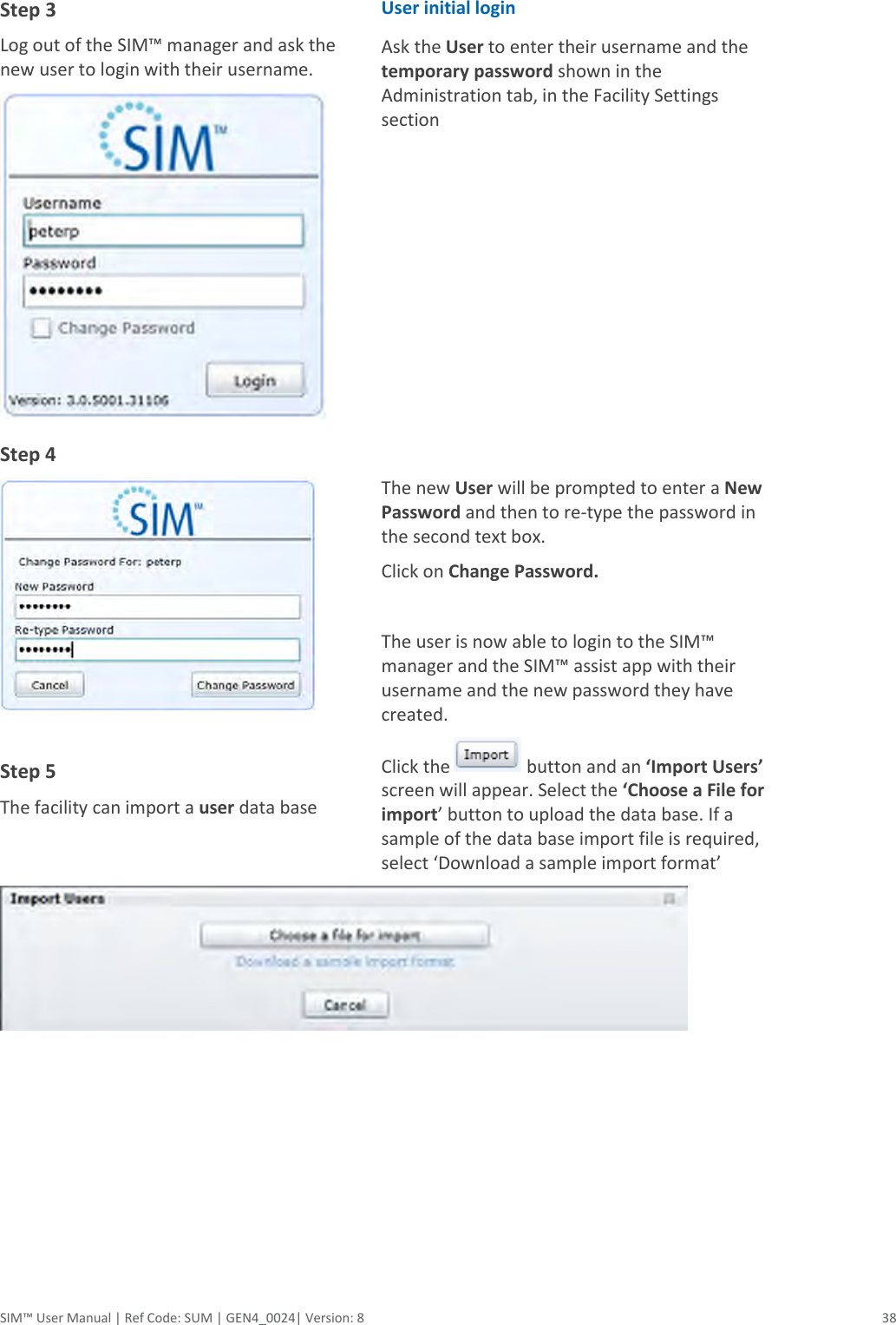
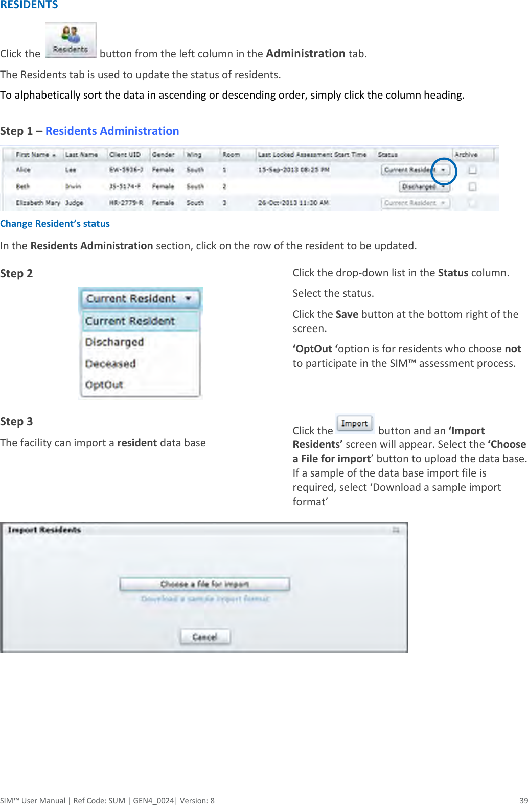
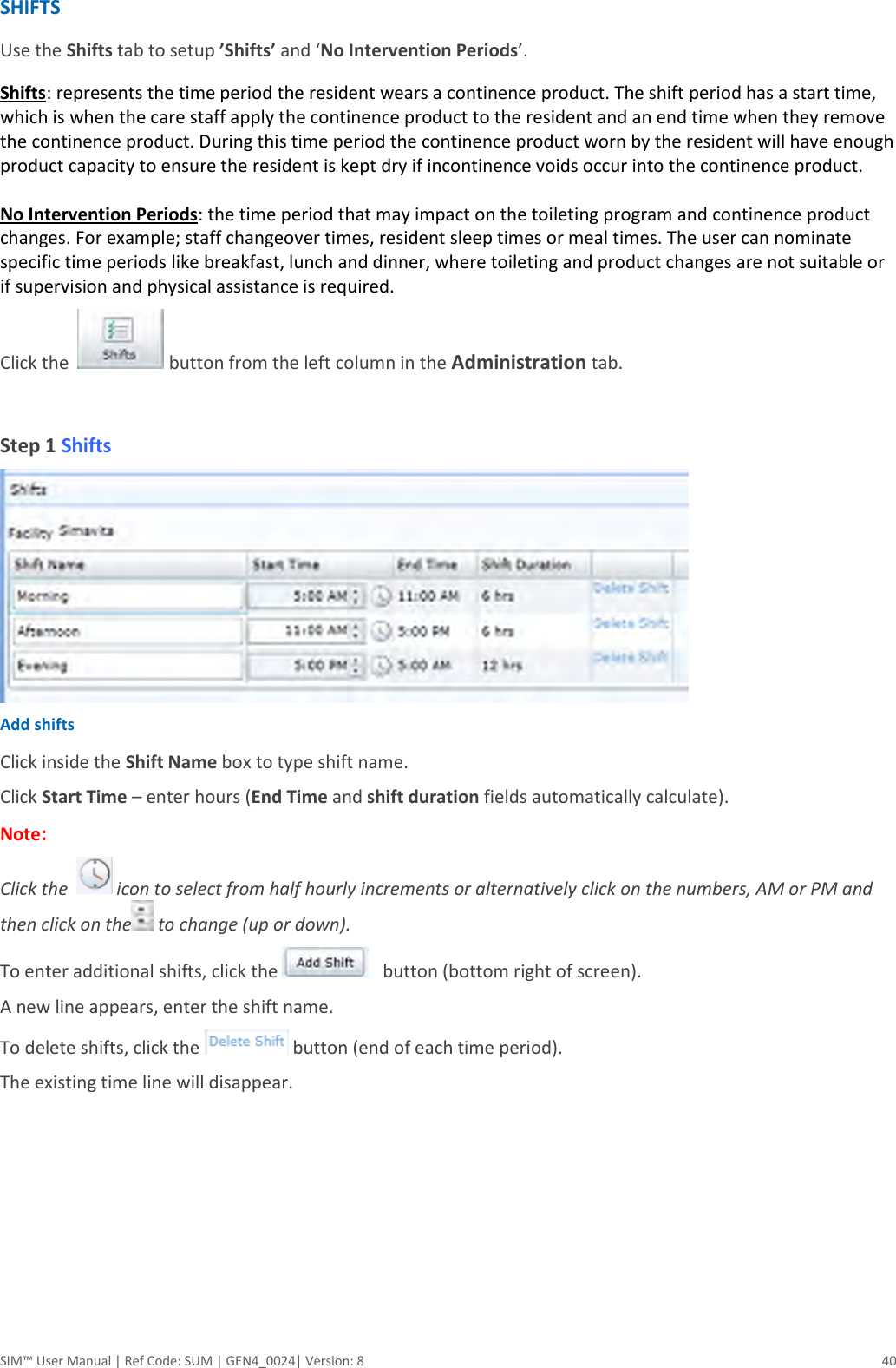
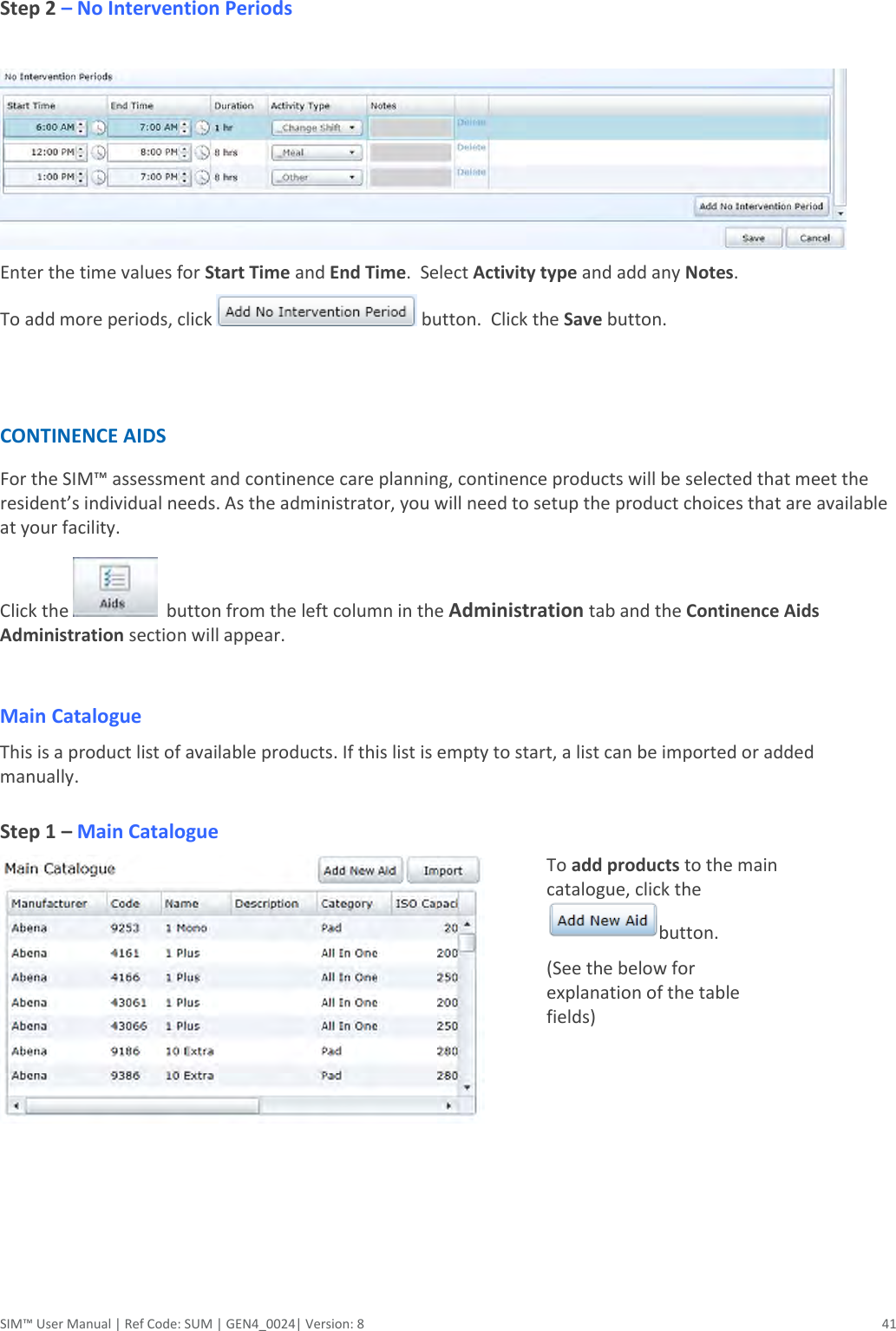
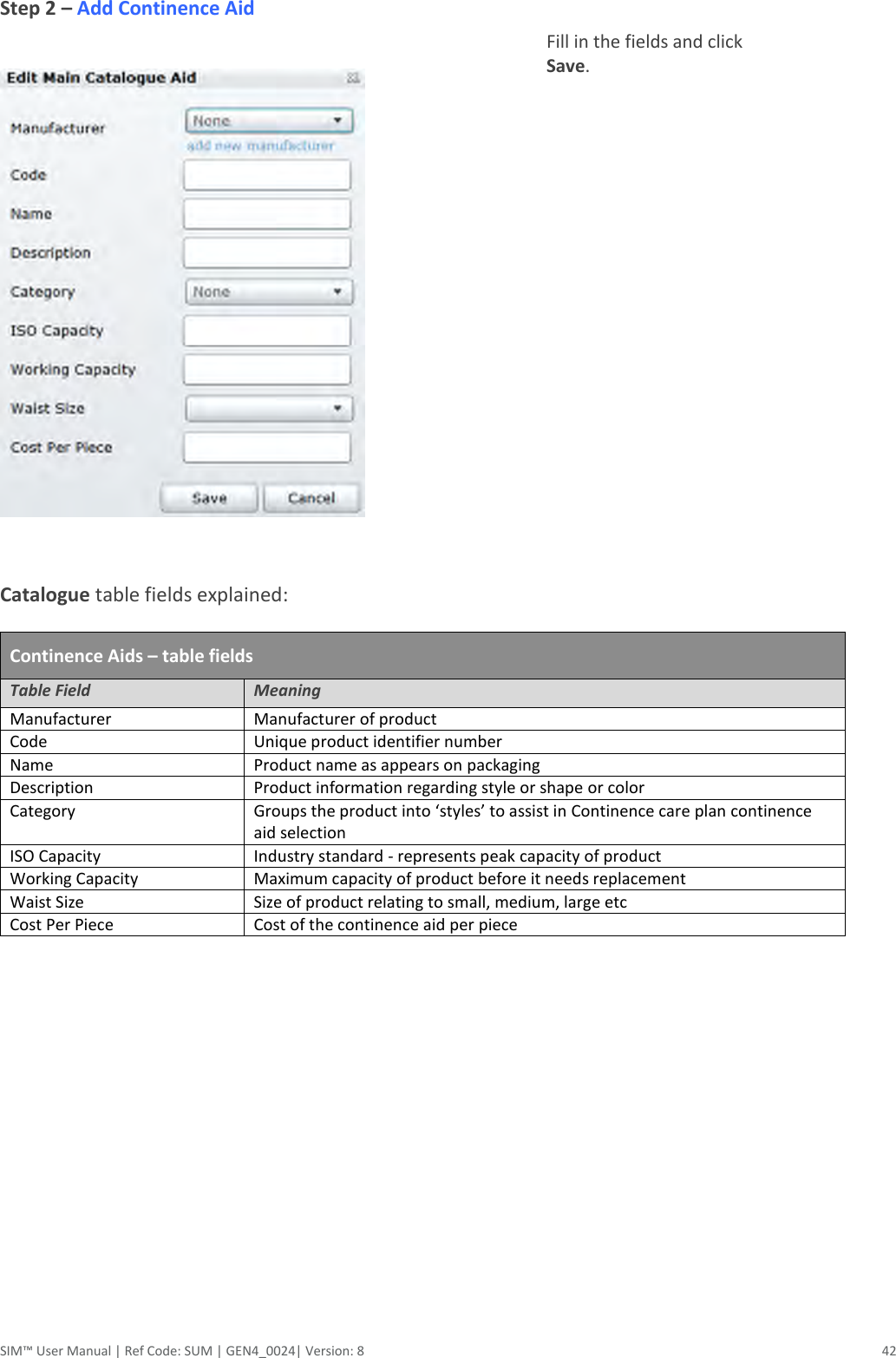
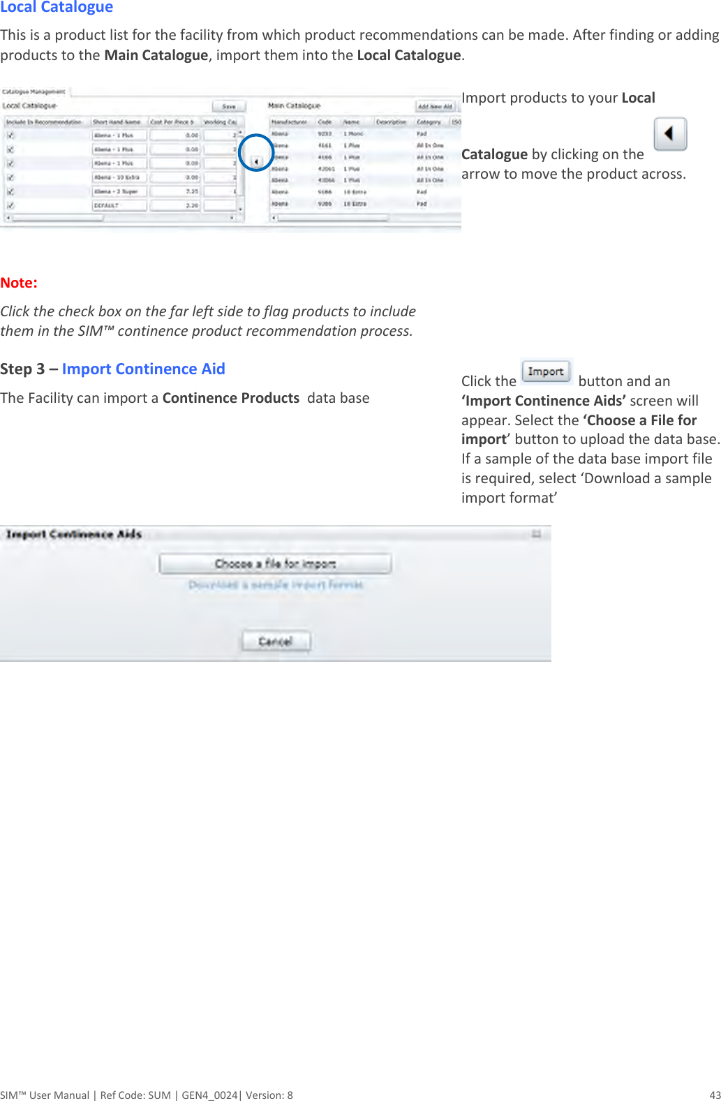
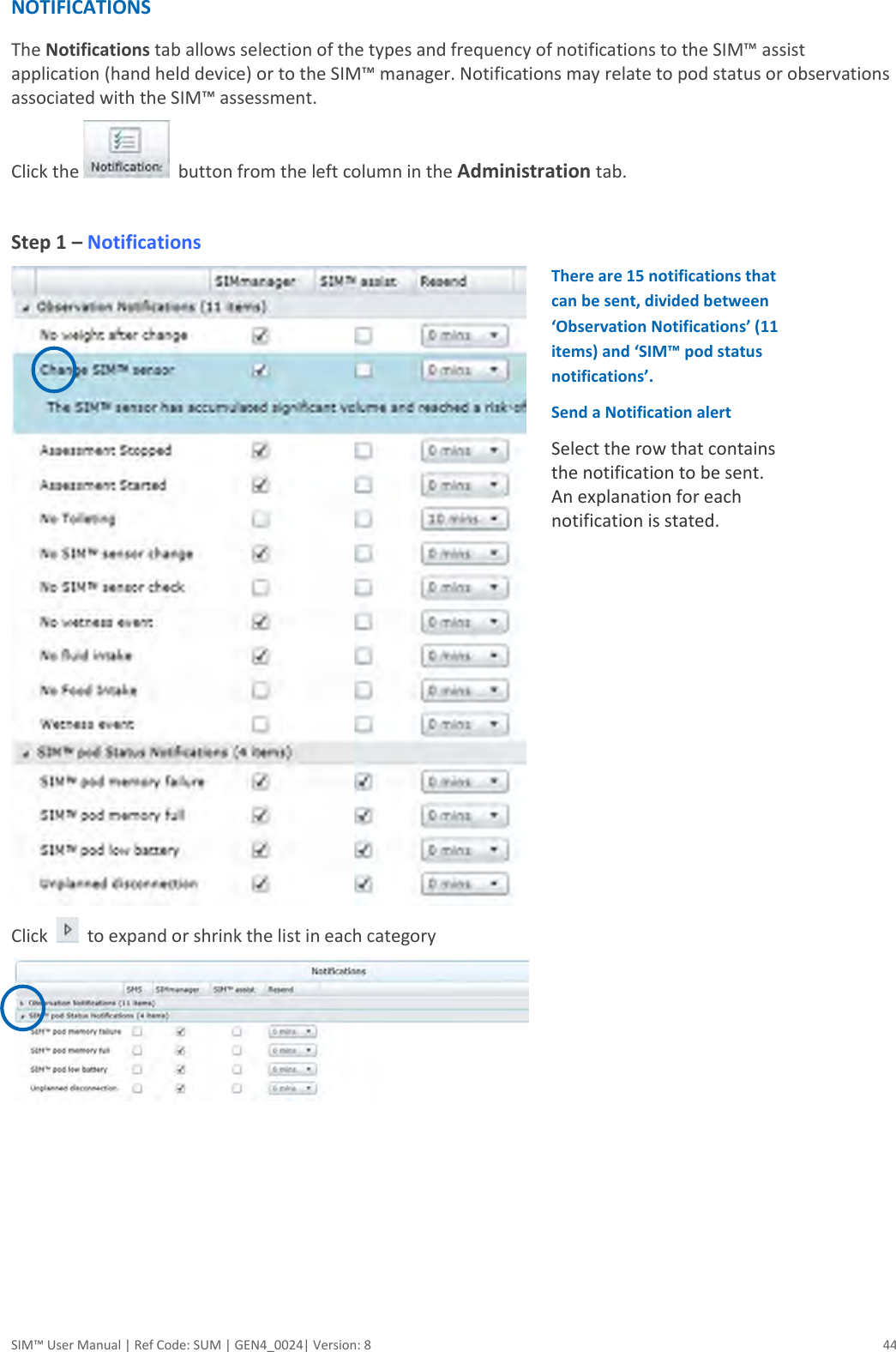
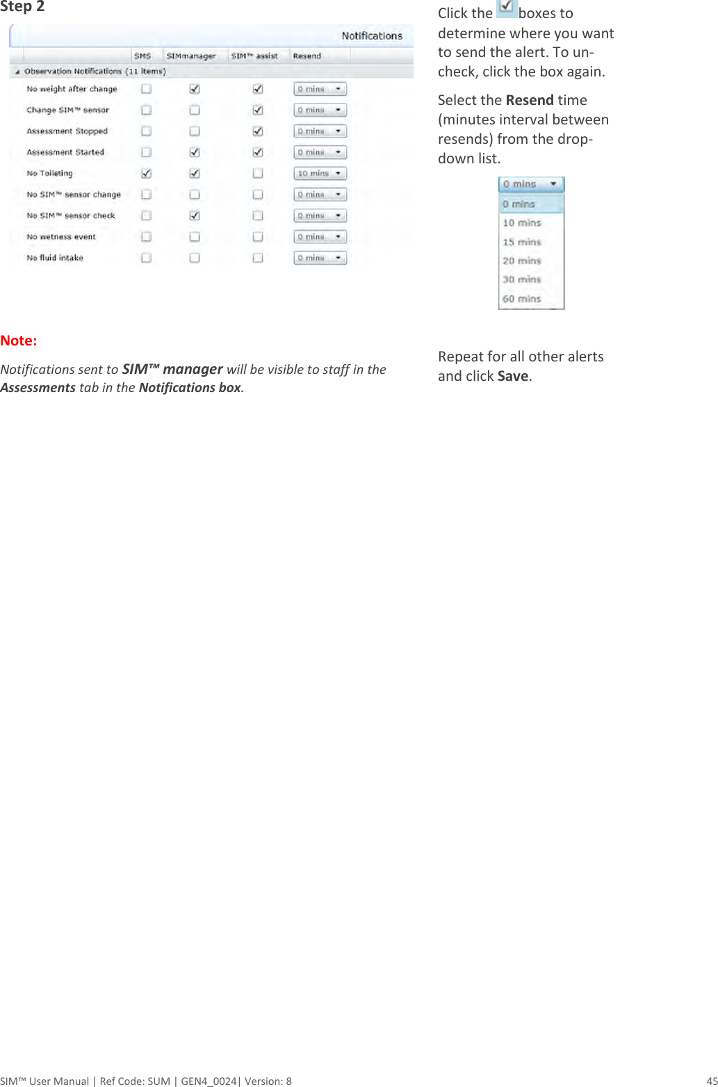
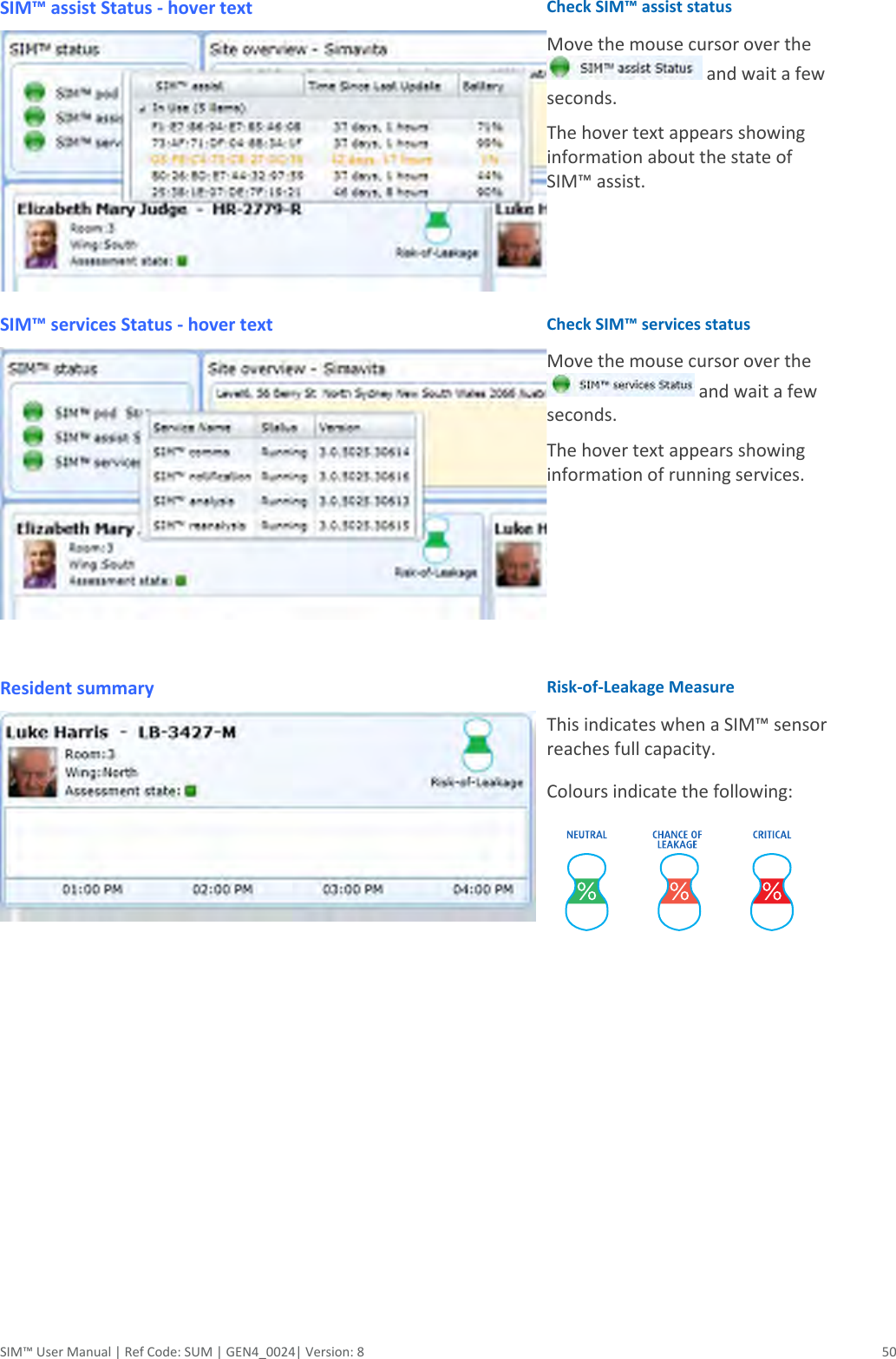
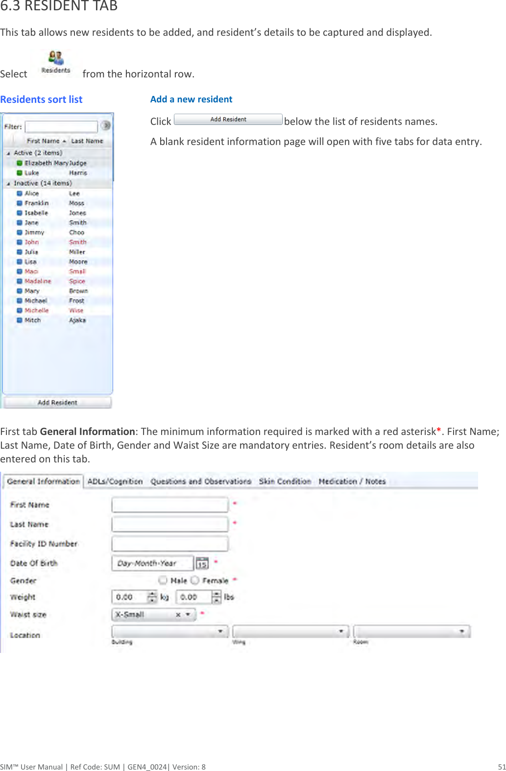
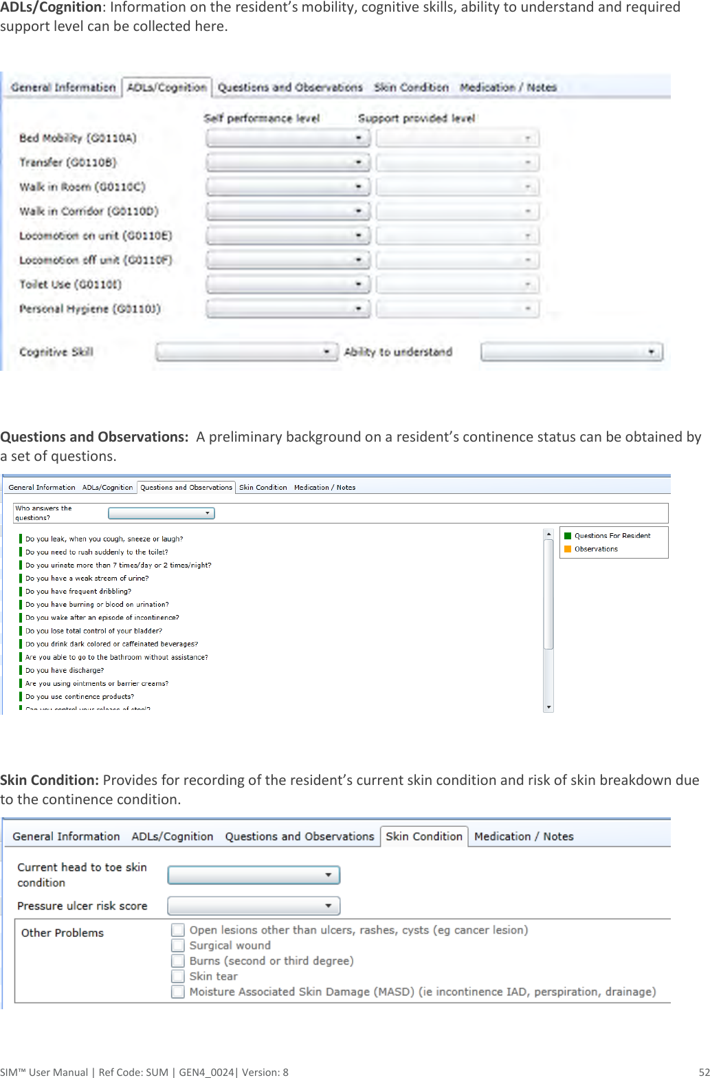
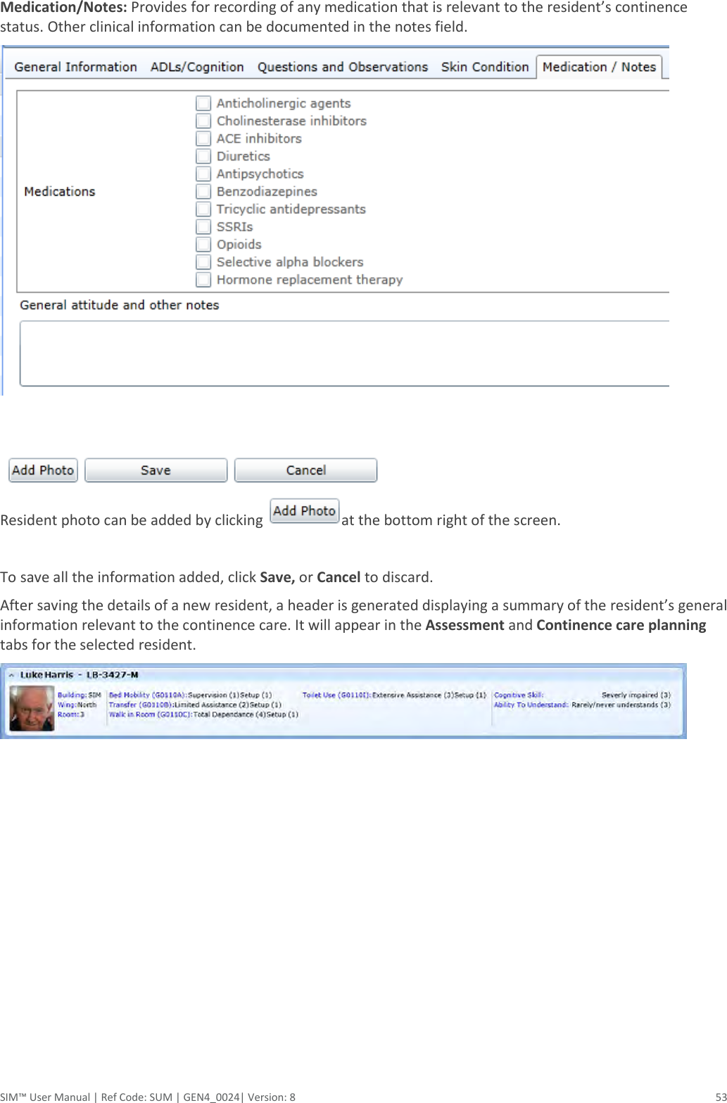
Silicon Labs RS9110N1122 Smart Incontinence Management Device User Manual SIM V14 0
Redpine Signals Inc Smart Incontinence Management Device SIM V14 0
UserManual.wiki
>
Silicon Labs
>
RS9110N1122 User Manual
User Manual
Navigation menu
Upload a User Manual
Namespaces
Wiki Guide
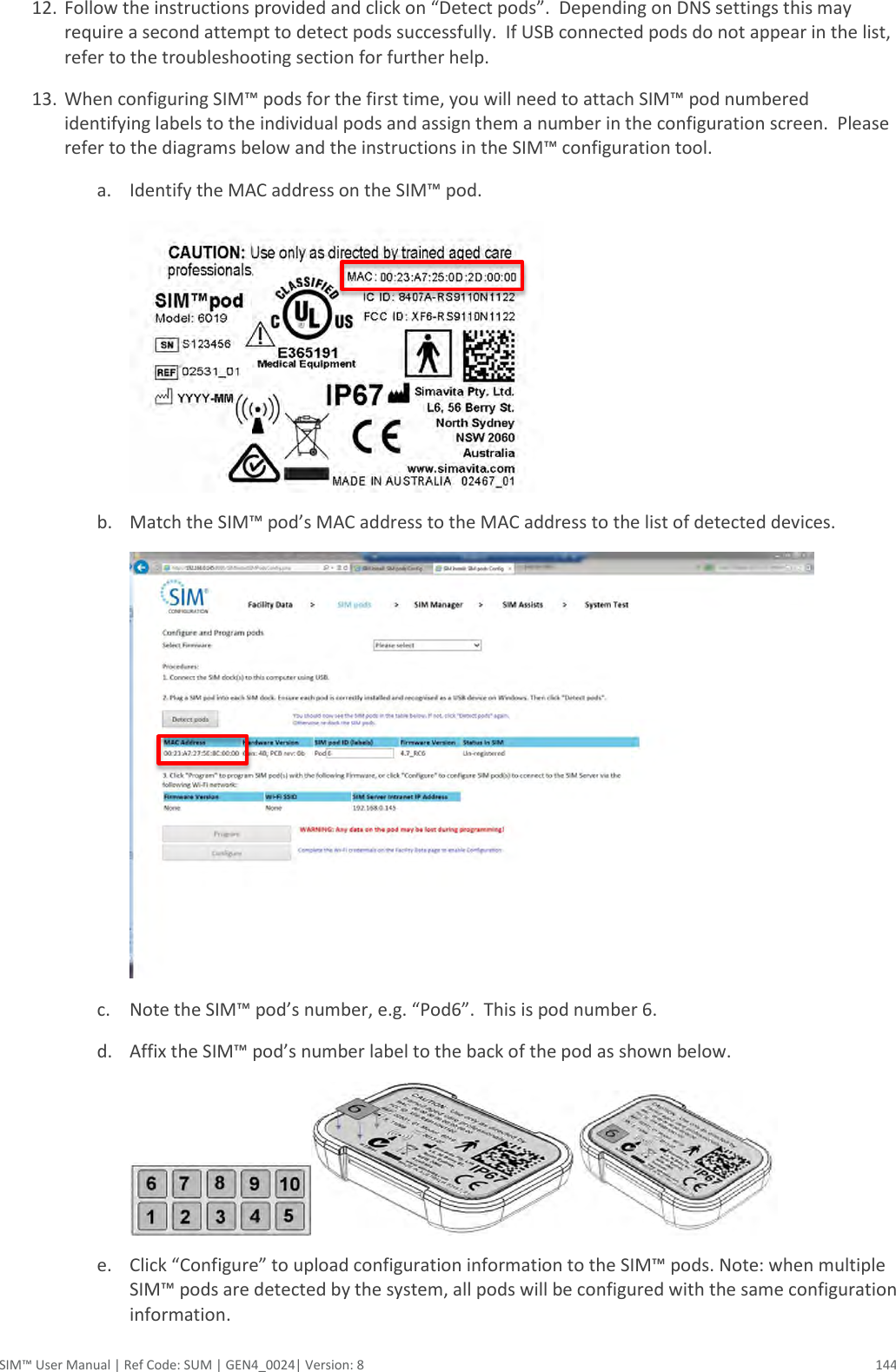
HTML
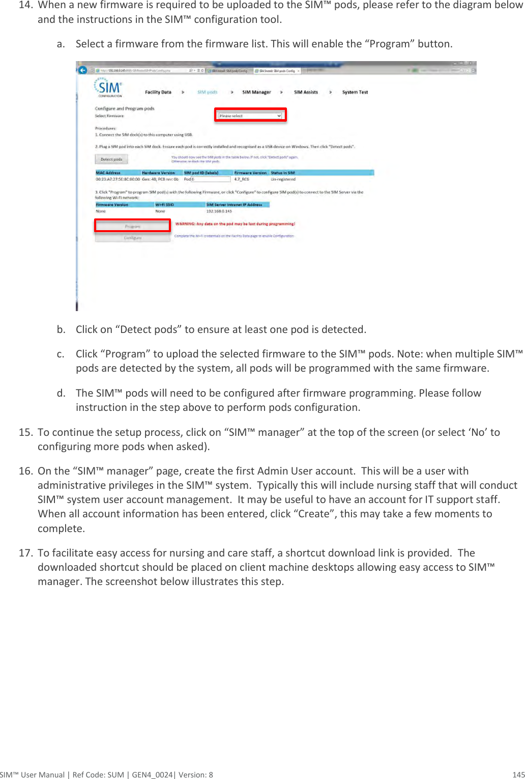
PDF
Info
Views
User Manual
Discussion / Help
Navigation


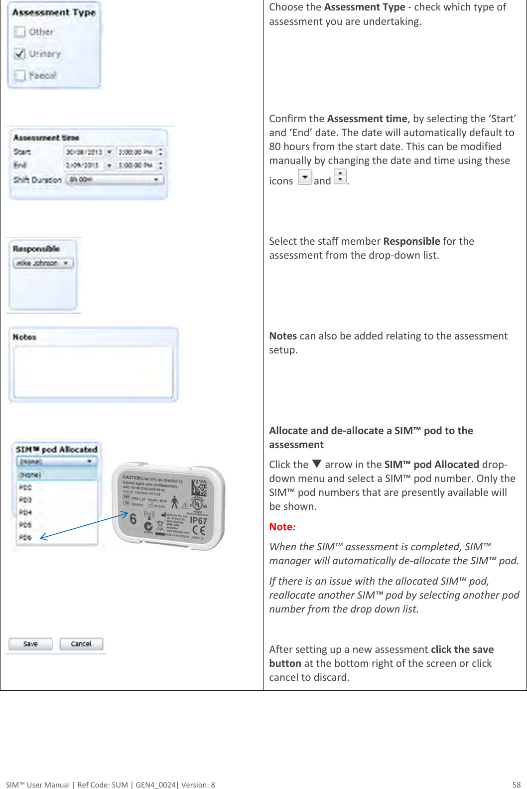
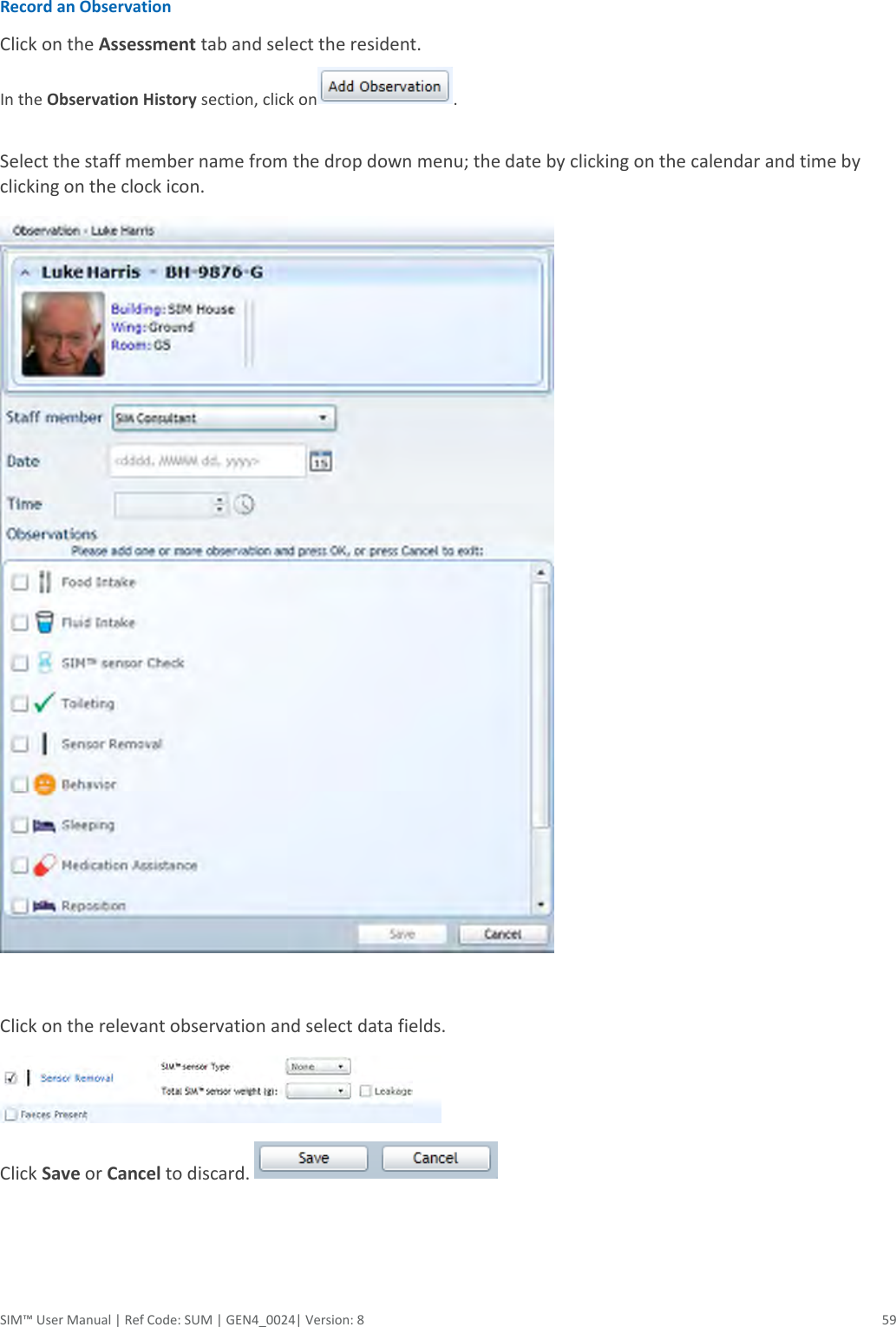
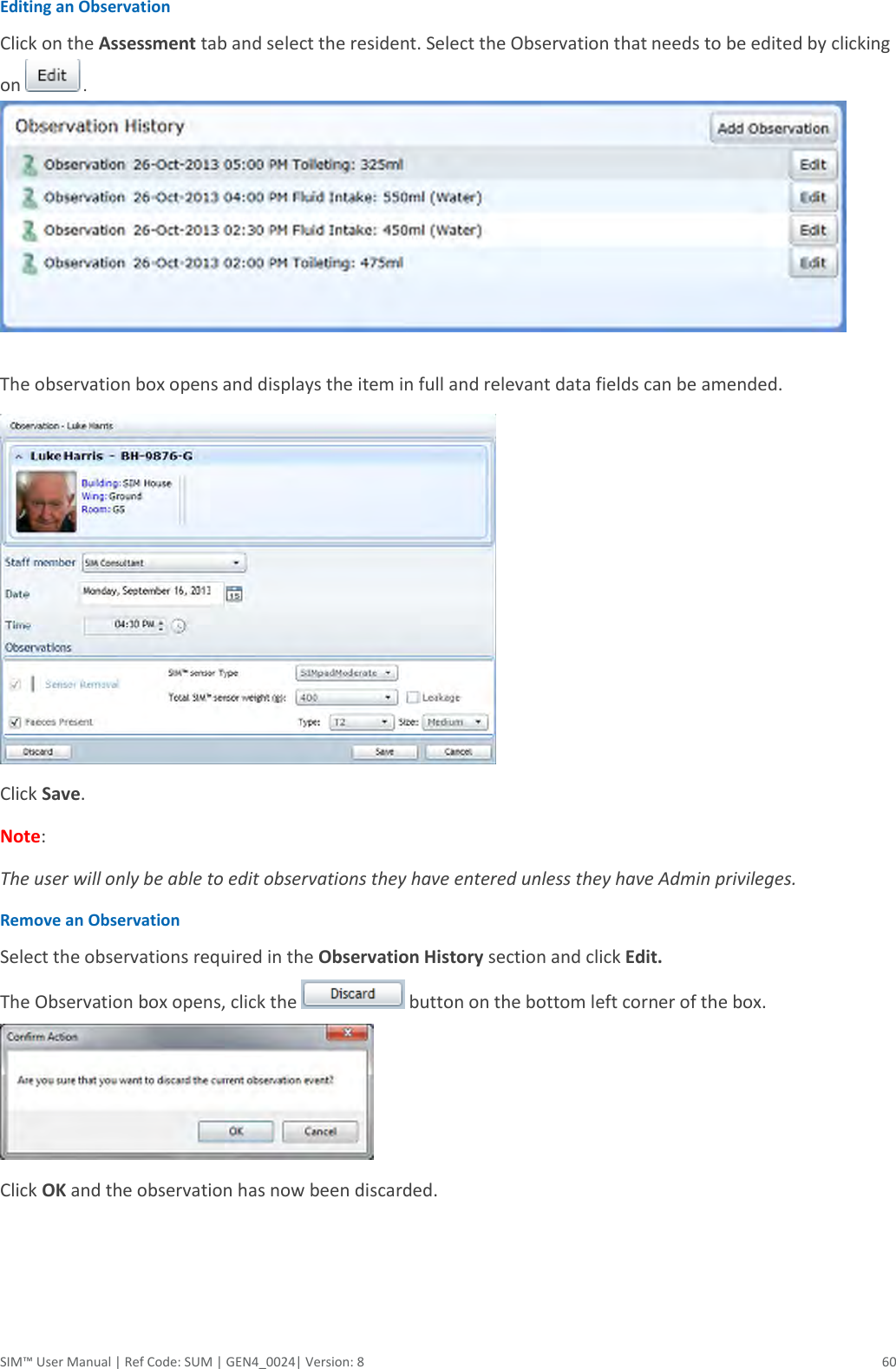
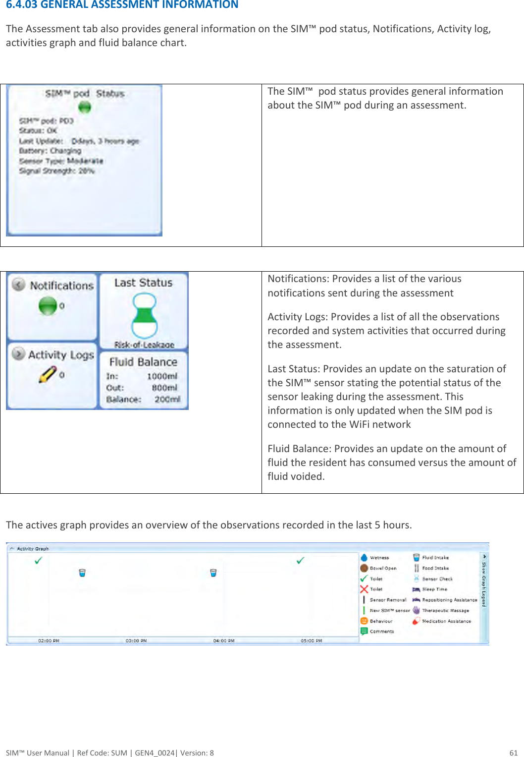


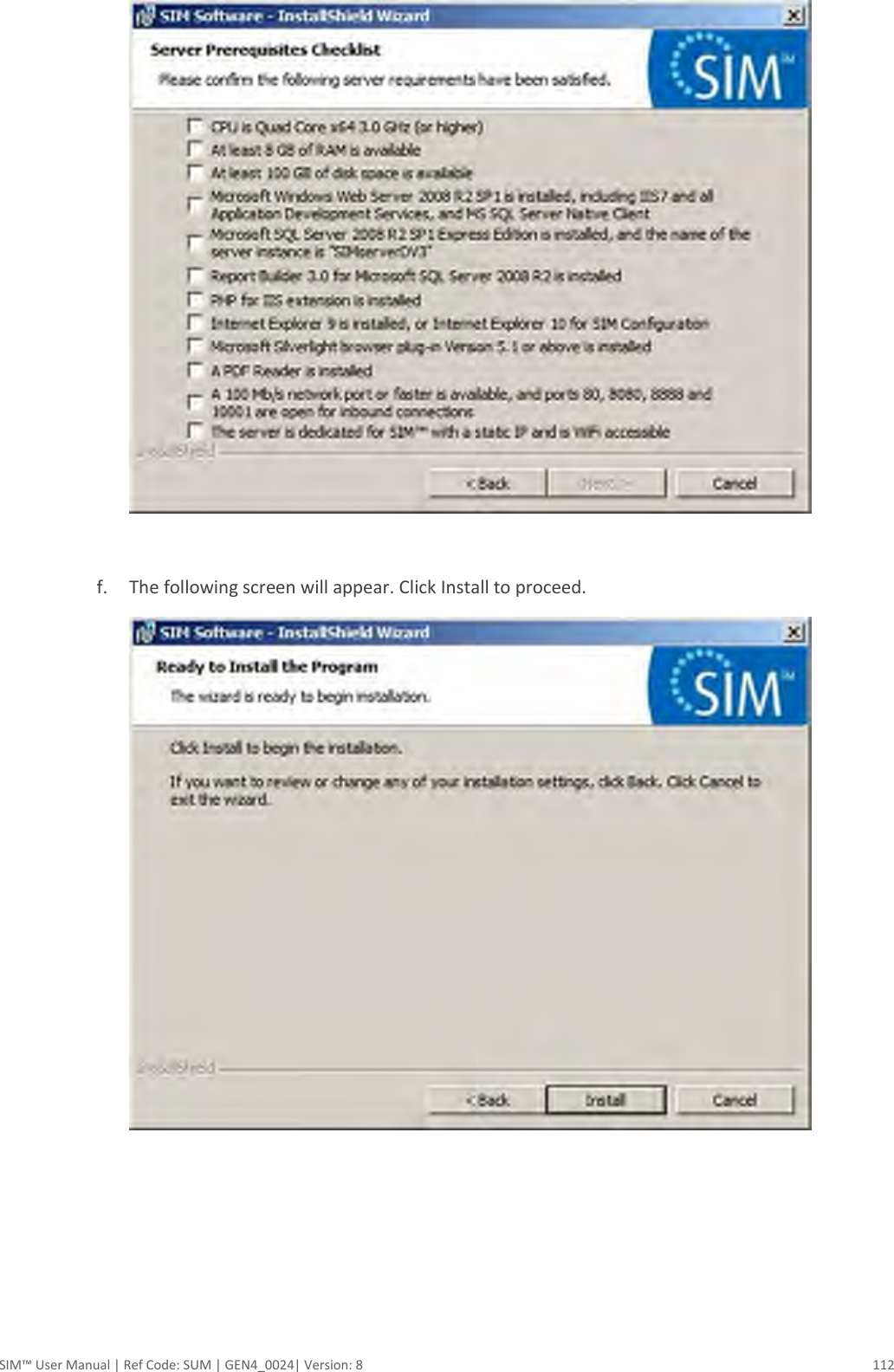
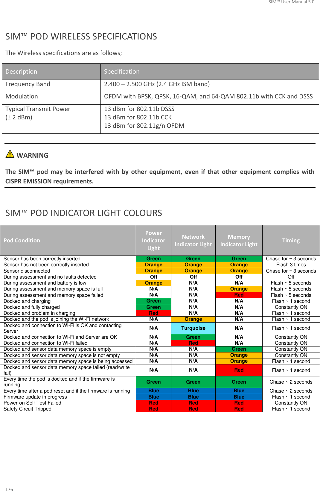
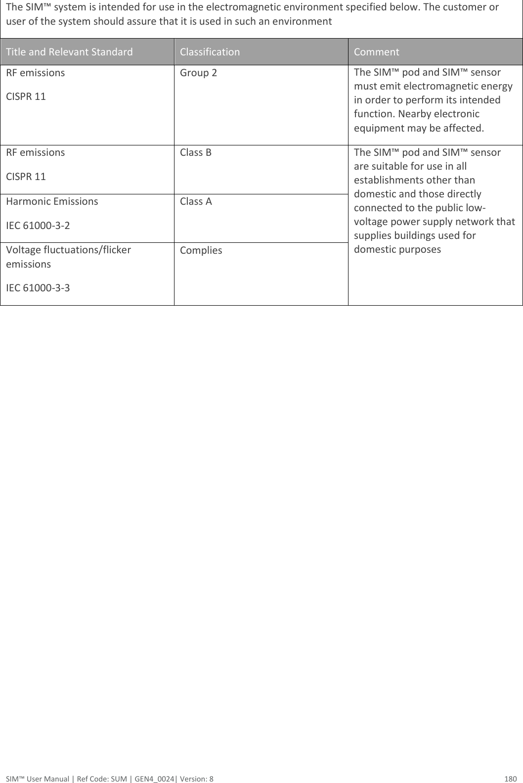
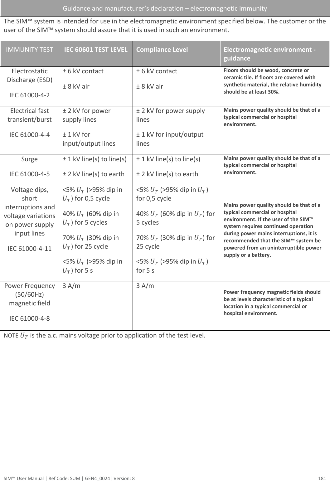
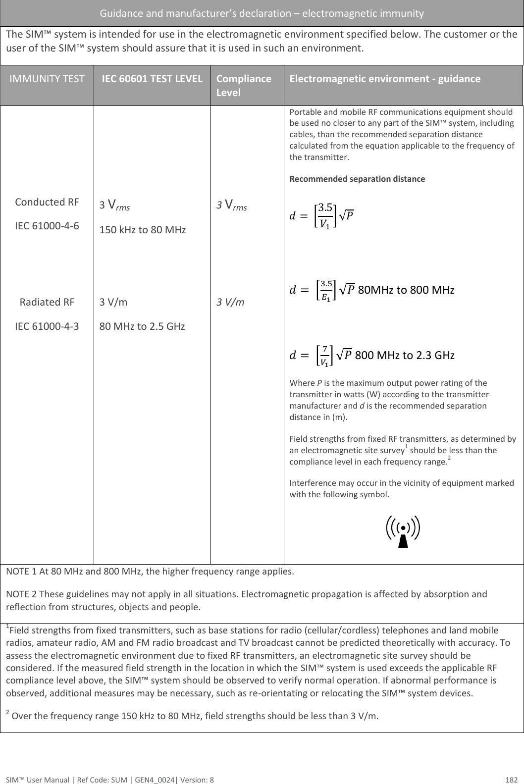
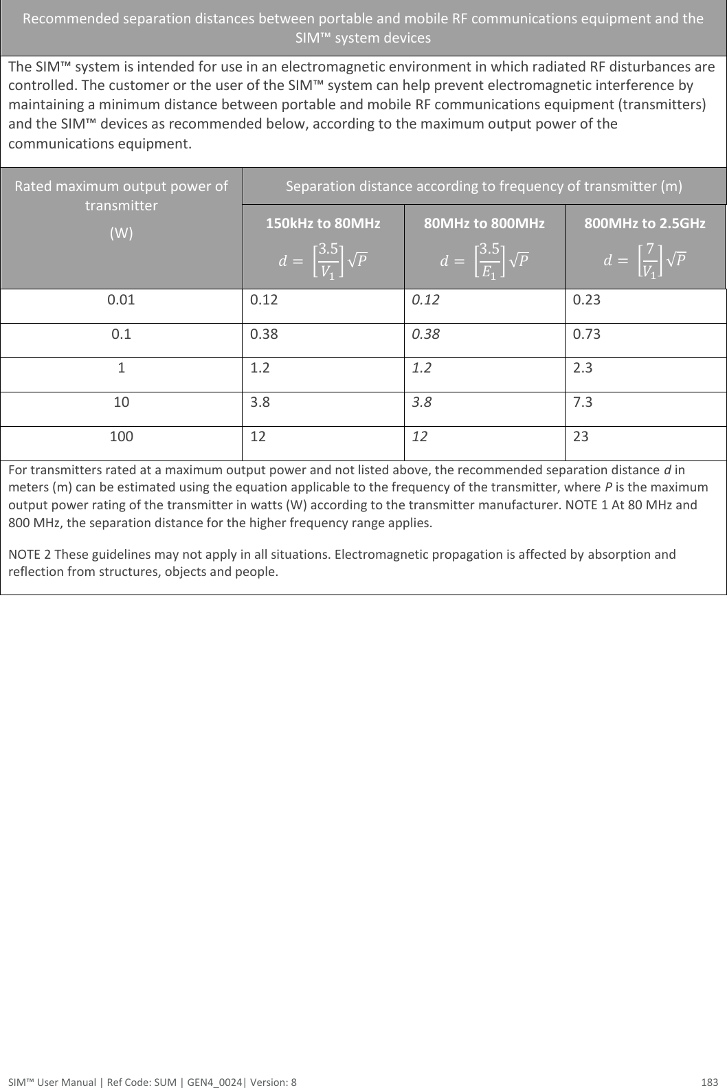
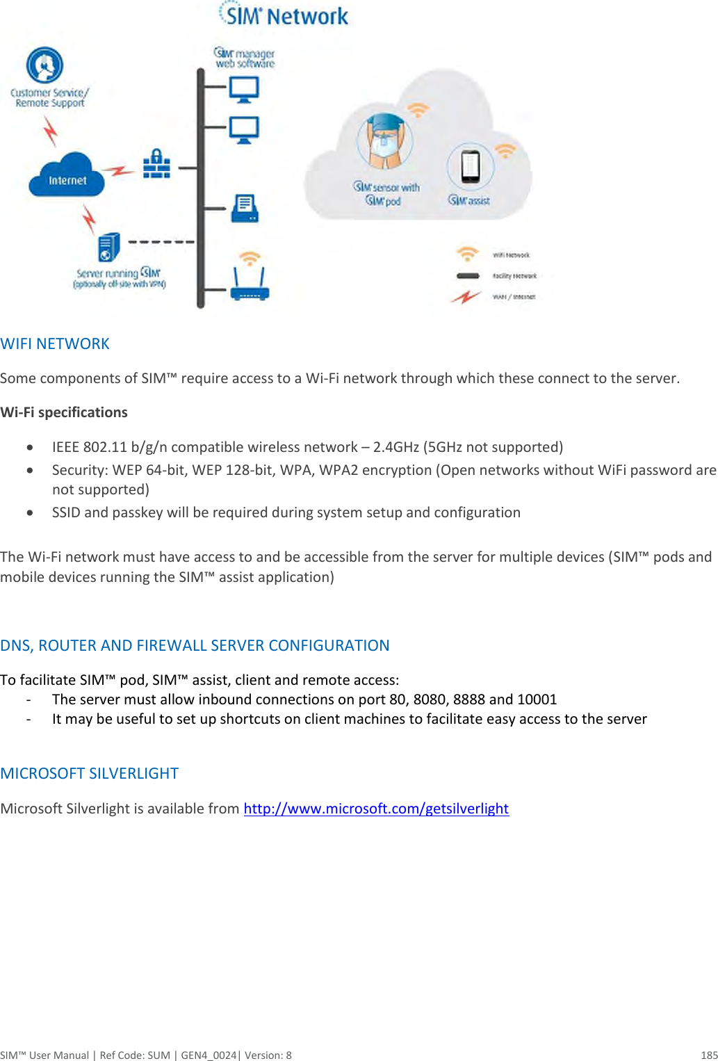
![SIM™ User Manual | Ref Code: SUM | GEN4_0024| Version: 8 179 SIM™ MANUFACTURERS DECLARATION The following tables contain the manufacturer’s declarations for the SIM™ system electromagnetic emissions, electromagnetic immunity, and recommended separation distances between the SIM™ system and portable and mobile RF communications equipment as well as a list of compliant cables. FCC COMPLIANCE STATEMENT This device complies with Part 15 of the Federal Communications Commission (FCC) Rules. The FCC ID for this device is XF6-RS9110N1122. Operation is subject to the following two conditions: (1) this device may not cause harmful interference, and (2) this device must accept any interference received, including interference that may cause undesired operation. CAUTION: Changes or modifications to this unit not expressly approved by the party responsible for compliance could void the user’s authority to operate this equipment. This equipment has been tested and found to comply with the limits for a Class B digital device, pursuant to Part 15 of the FCC Rules. These limits are designed to provide reasonable protection against harmful interference in a residential installation. This equipment generates, uses and can radiate radio frequency energy and, if not installed and used in accordance with the manufacturer’s instructions, may cause interference harmful to radio communications. There is no guarantee, however, that interference will not occur in a particular installation. If this equipment does cause harmful interference to radio or television reception, which can be determined by turning the equipment off and on, the user is encouraged to try to correct the interference by one or more of the following measures: (1) reorient or relocate the receiving antenna, (2) increase the separation between the equipment and receiver, (3) connect the equipment to an outlet on a circuit different from that to which the receiver is connected, and (4) consult the dealer or an experienced radio or TV technician for help. The SIM™ pod with FCC ID XF6-RS9110N1122 is subject to Part 15 Subpart C. This transmitter must not be co-located or operated in conjunction with any other antenna or transmitter. The available scientific evidence does not show that any health problems are associated with using low power wireless devices. There is no proof, however, that these low power wireless devices are absolutely safe. Low power Wireless devices emit low levels of radio frequency energy (RF) in the microwave range while being used. Whereas high levels of RF can produce health effects (by heating tissue), exposure of low-level RF that does not produce heating effects causes no known adverse health effects. Many studies of low-level RF exposures have not found any biological effects. Some studies have suggested that some biological effects might occur, but such findings have not been confirmed by additional research. [SIM™ pod] has been tested and found to comply with FCC radiation exposure limits set forth for an uncontrolled environment and meets the FCC radio frequency (RF) Exposure Guidelines in Supplement C to OET65.Changes or modifications not expressly approved by the party responsible for compliance could void the user’s authority to operate the equipment. WARNING Portable and mobile RF communications equipment can affect the performance of the SIM™ system. Install and use the system according to the information contained in this manual.](https://usermanual.wiki/Silicon-Labs/RS9110N1122/User-Guide-2190748-Page-183.png)