Silicon Labs RSWC301 802.11 abgn WiSeConnect MODULE User Manual Overview
Redpine Signals Inc 802.11 abgn WiSeConnect MODULE Overview
UserManual.wiki
>
Silicon Labs
>
RSWC301 User Manual
Manual
Navigation menu
Upload a User Manual
Namespaces
Wiki Guide
HTML
PDF
Info
Views
User Manual
Discussion / Help
Navigation

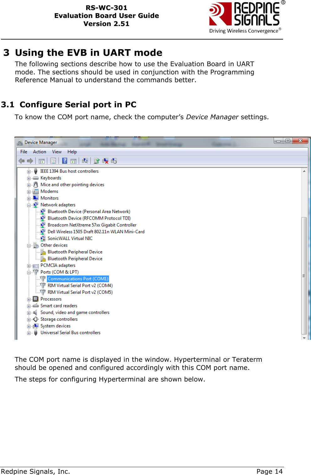
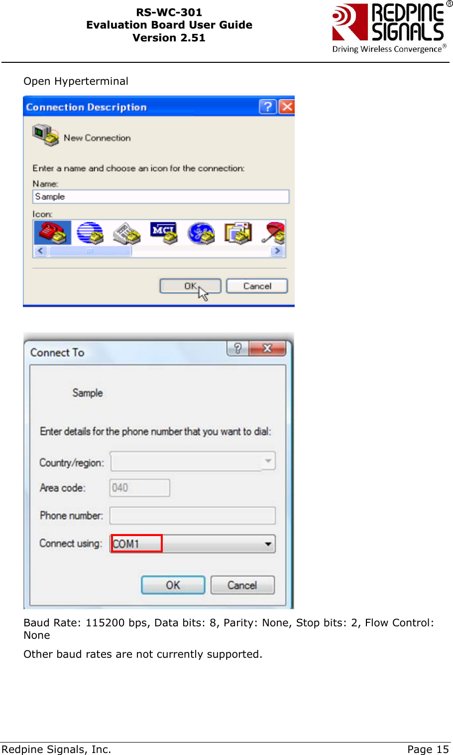
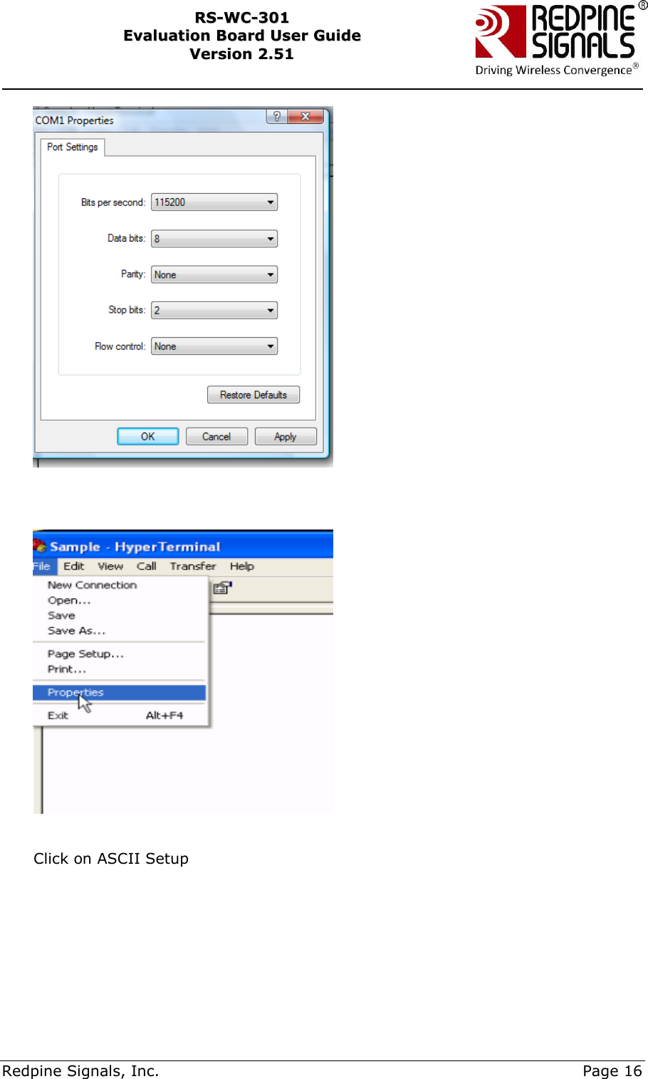
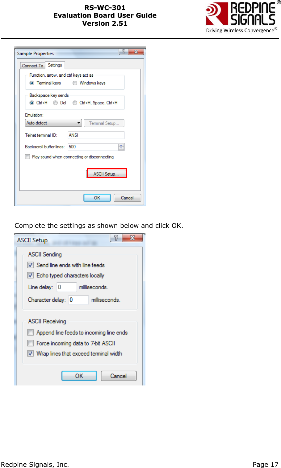
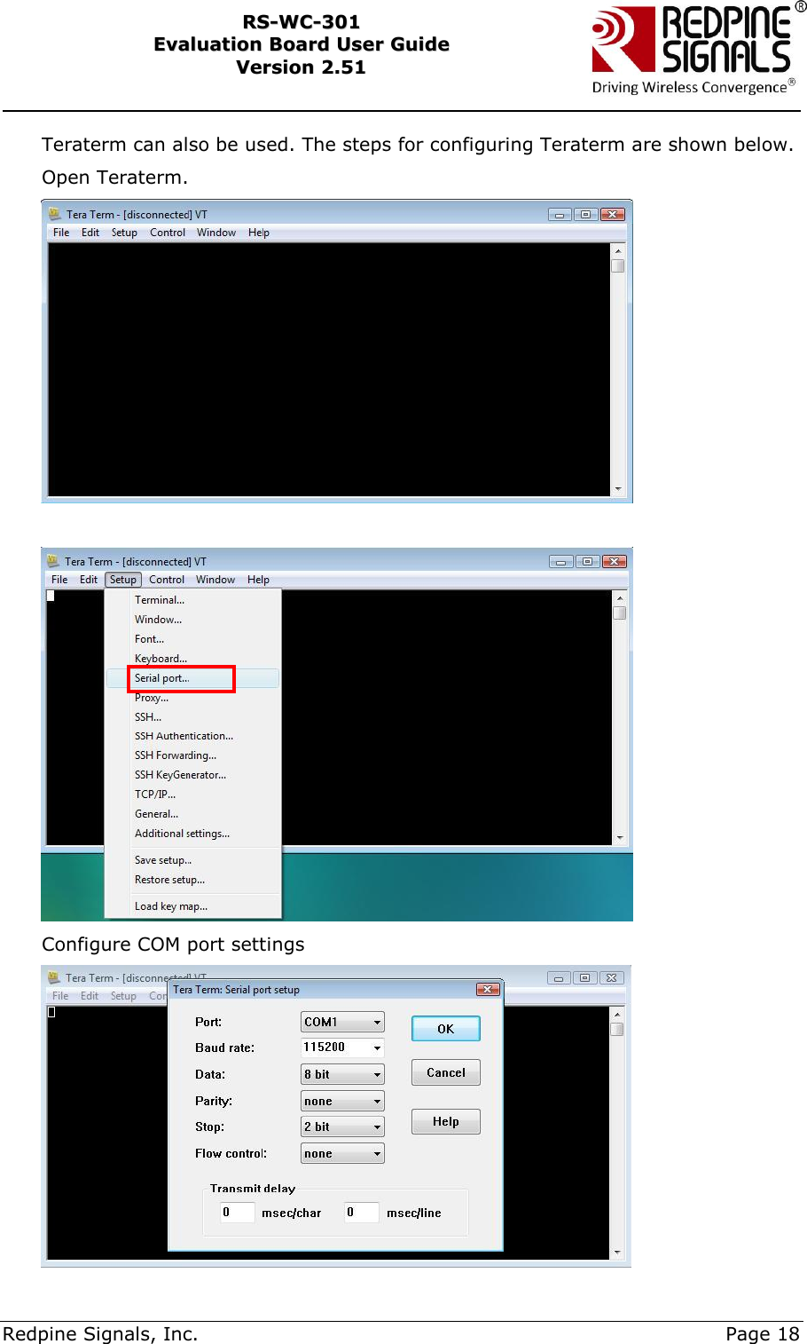
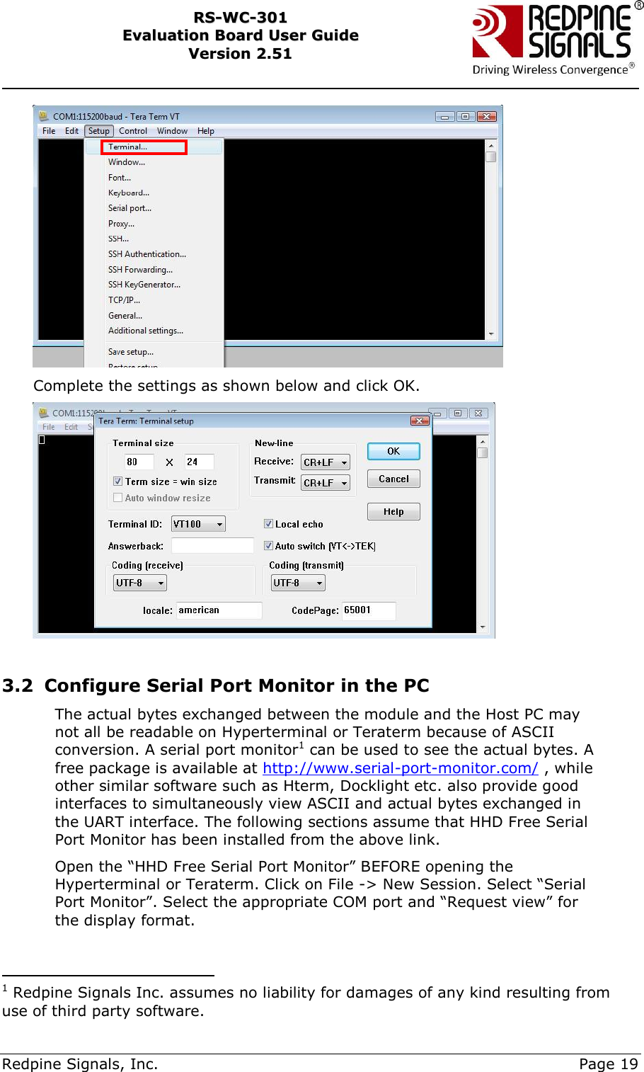
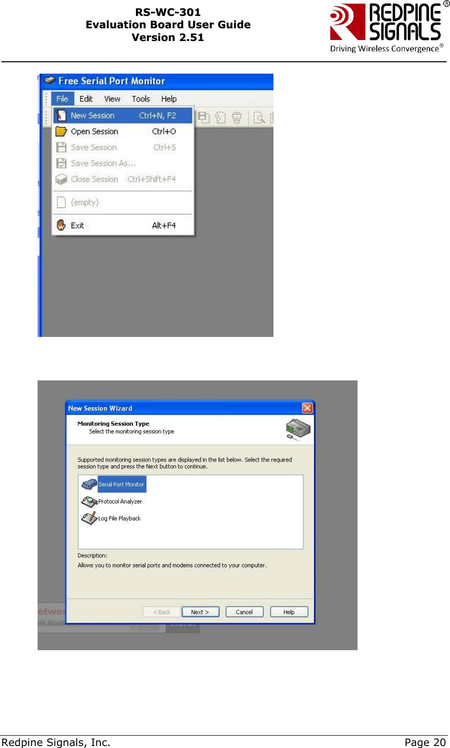
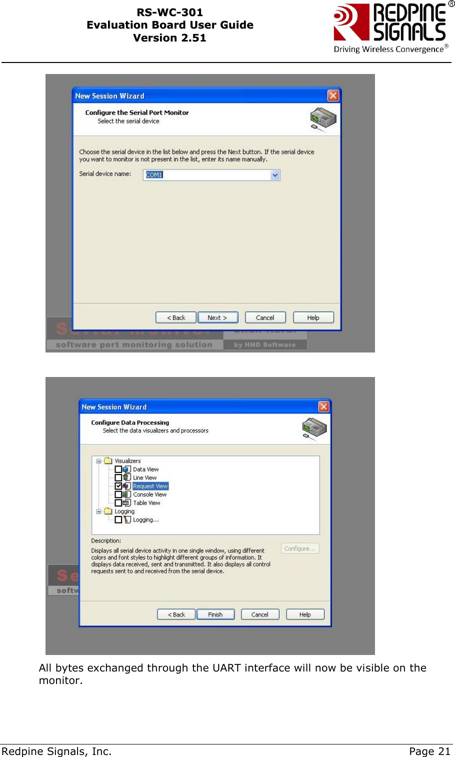
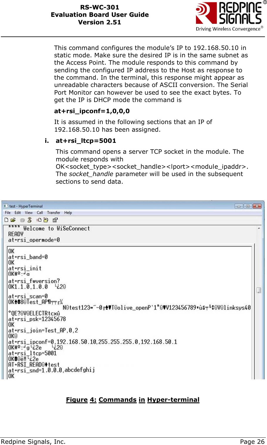
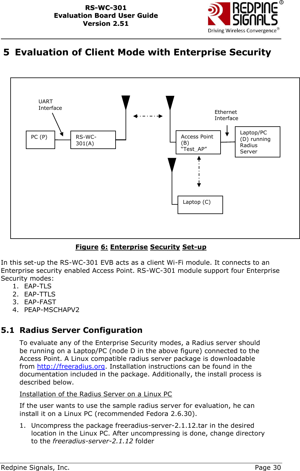
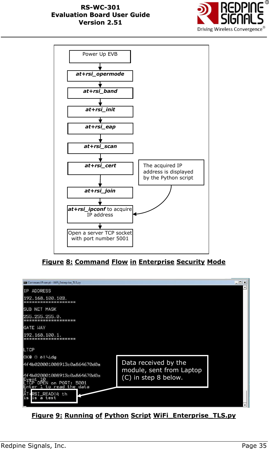
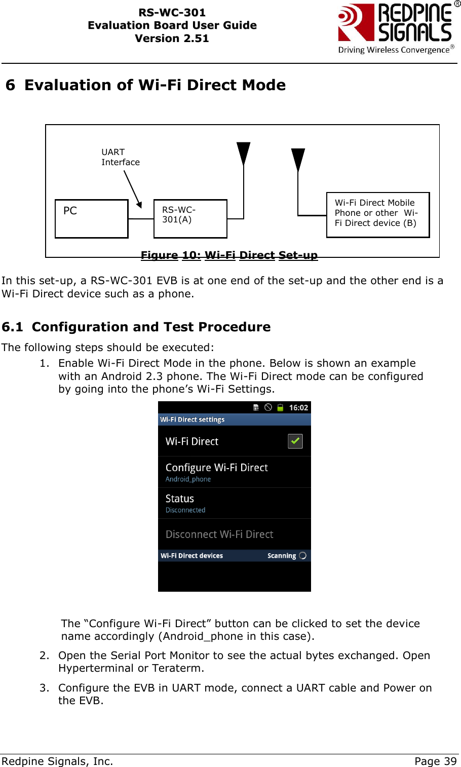
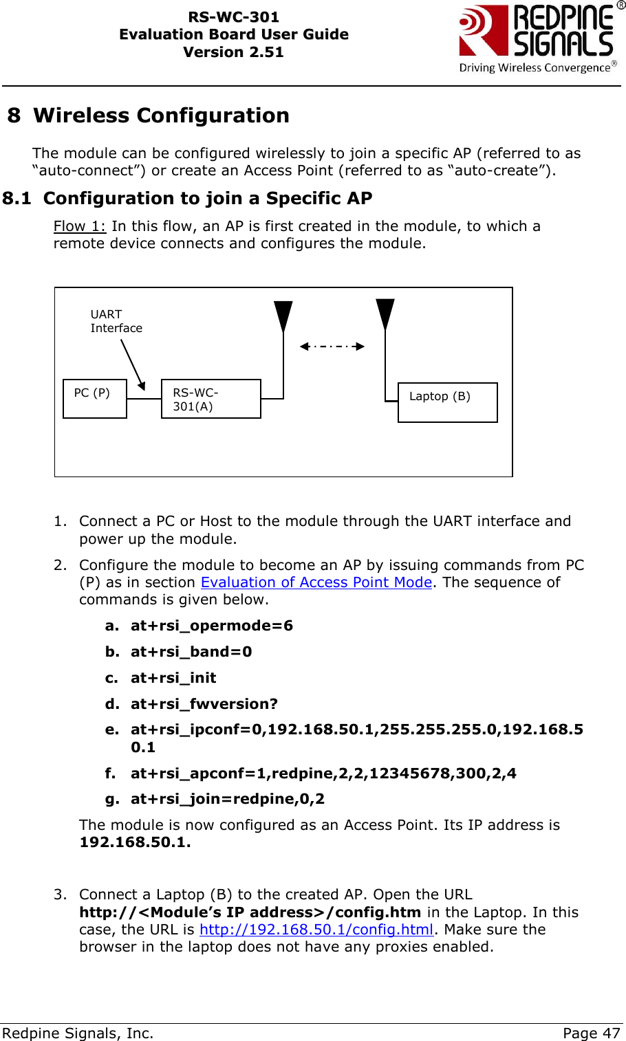
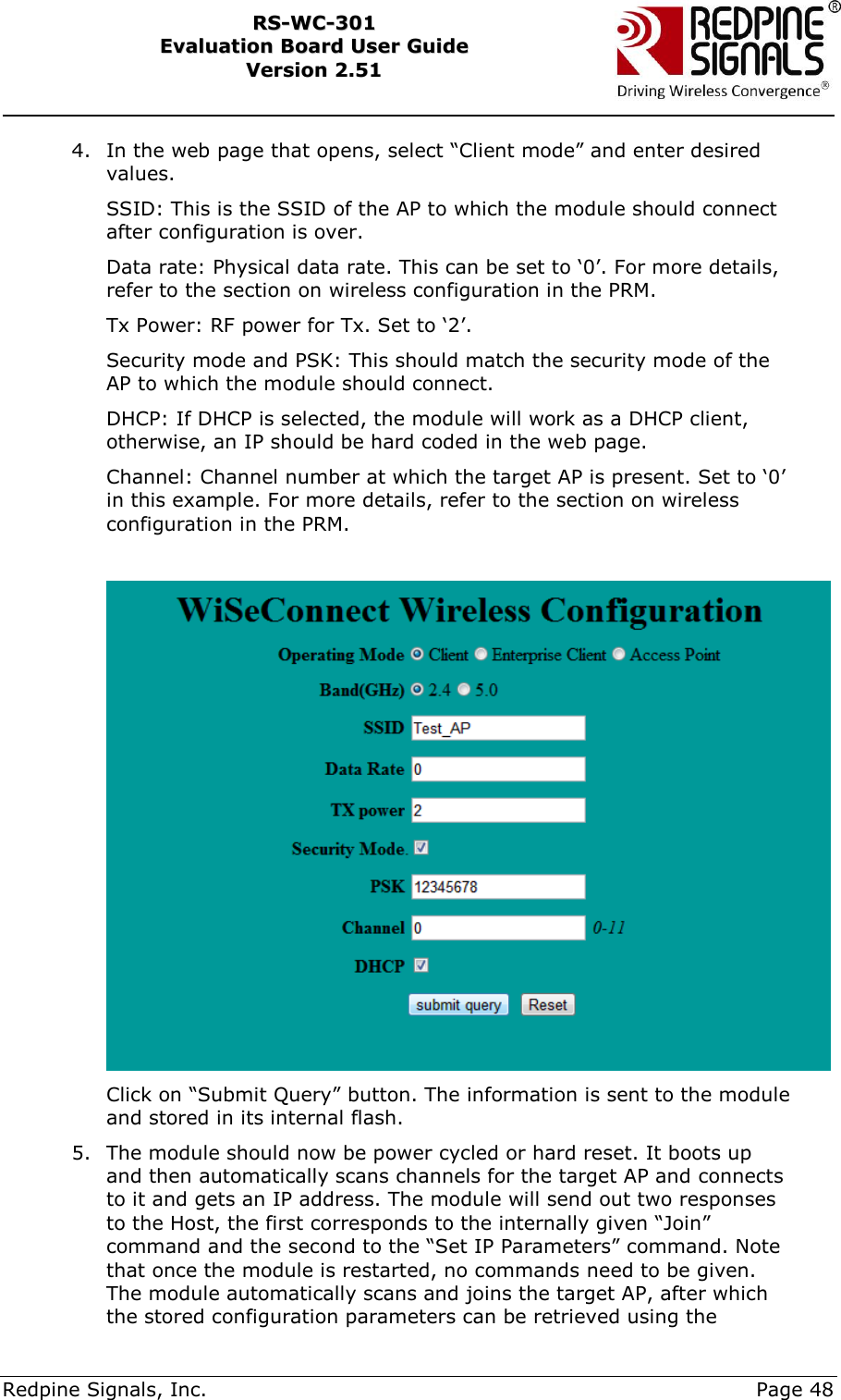
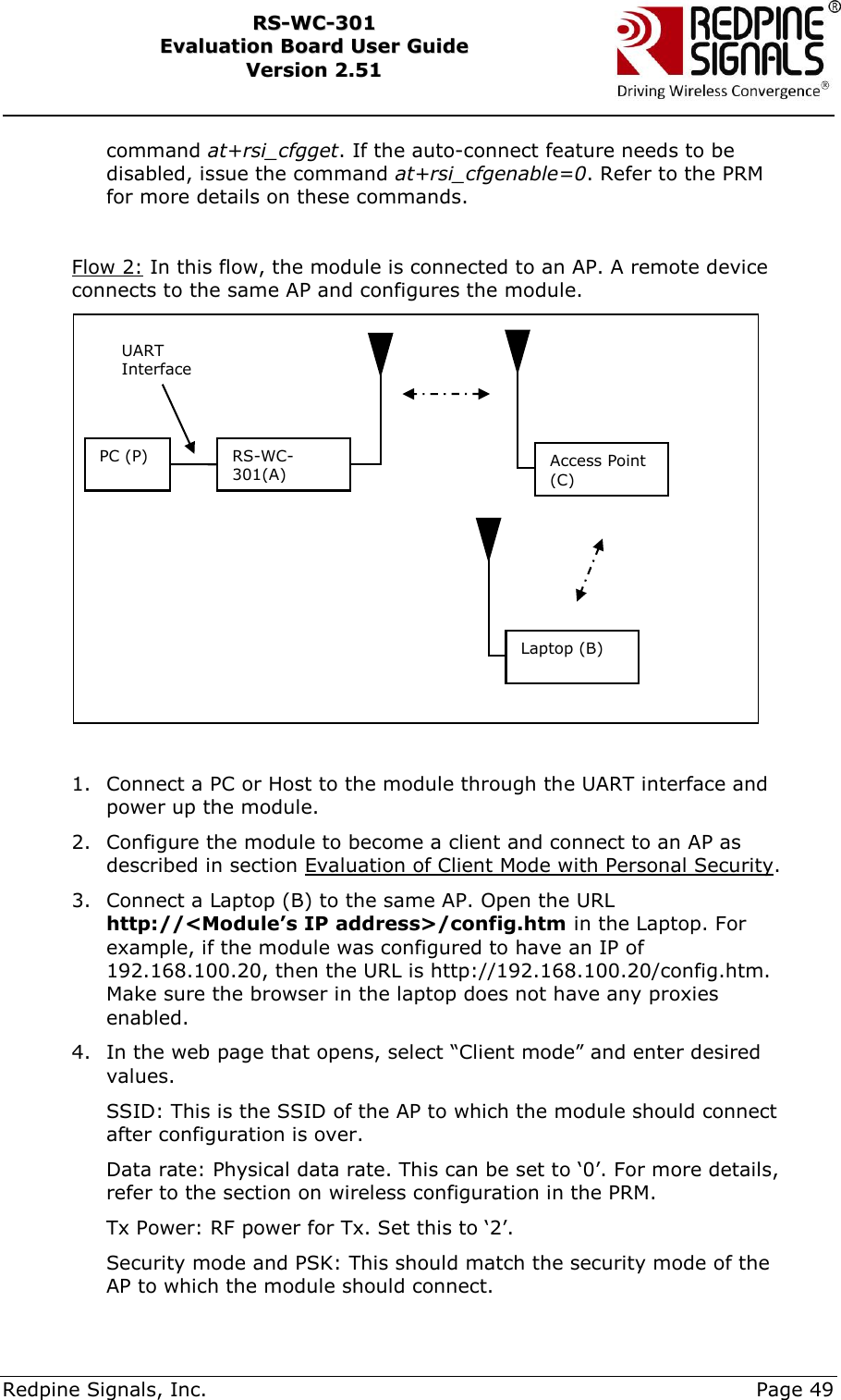
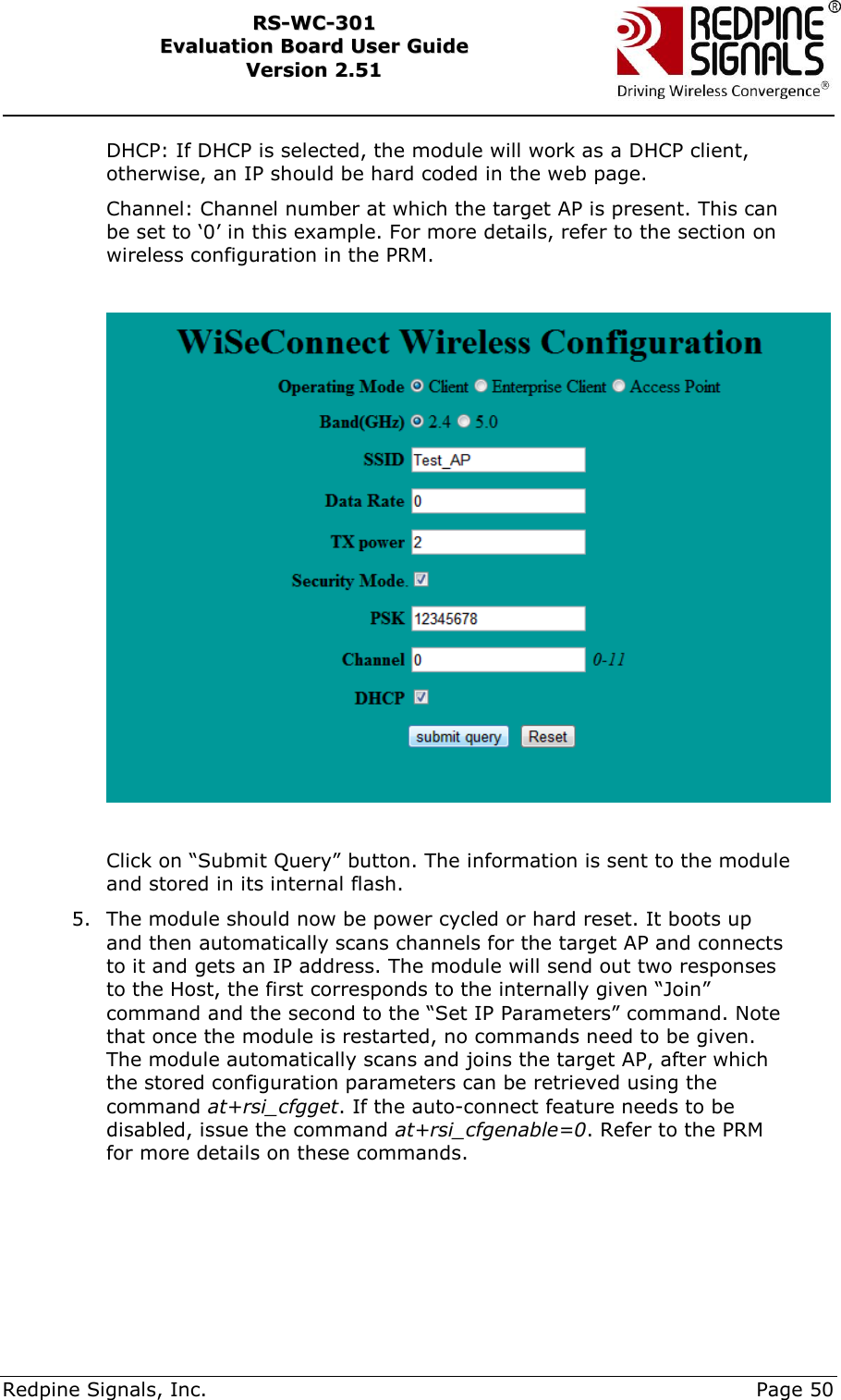
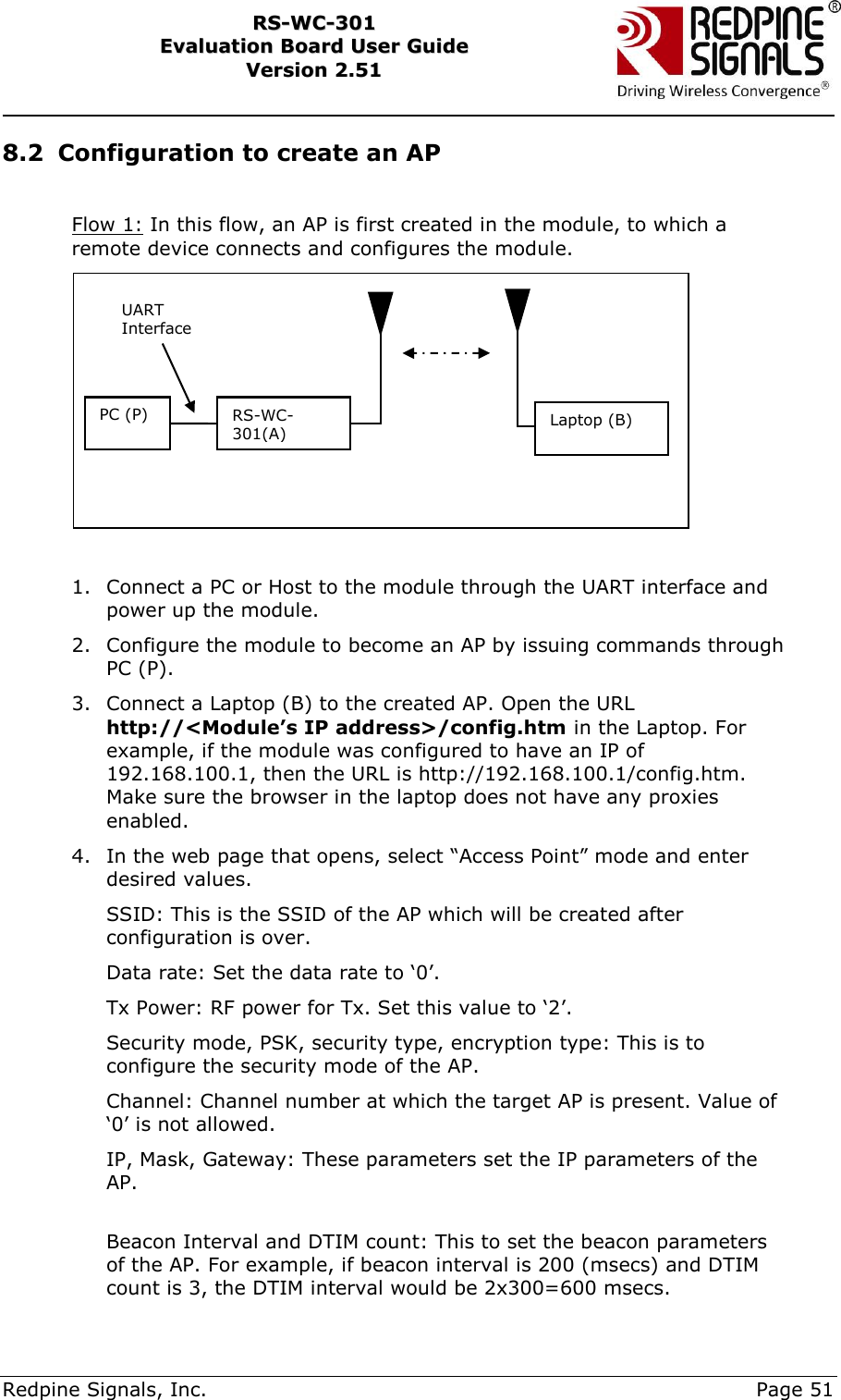
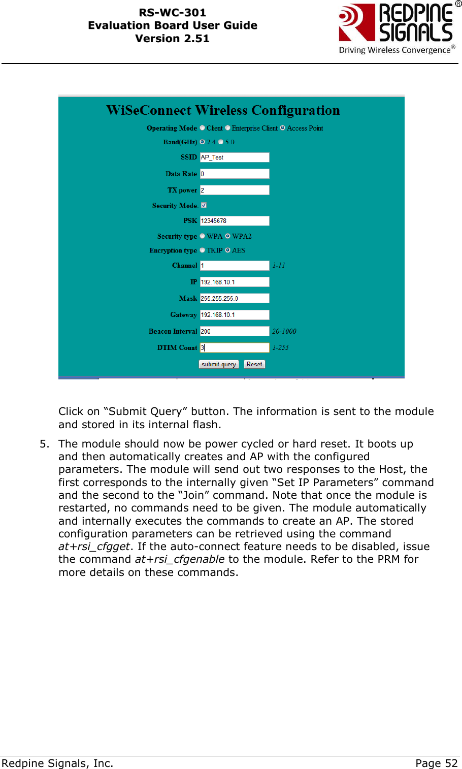
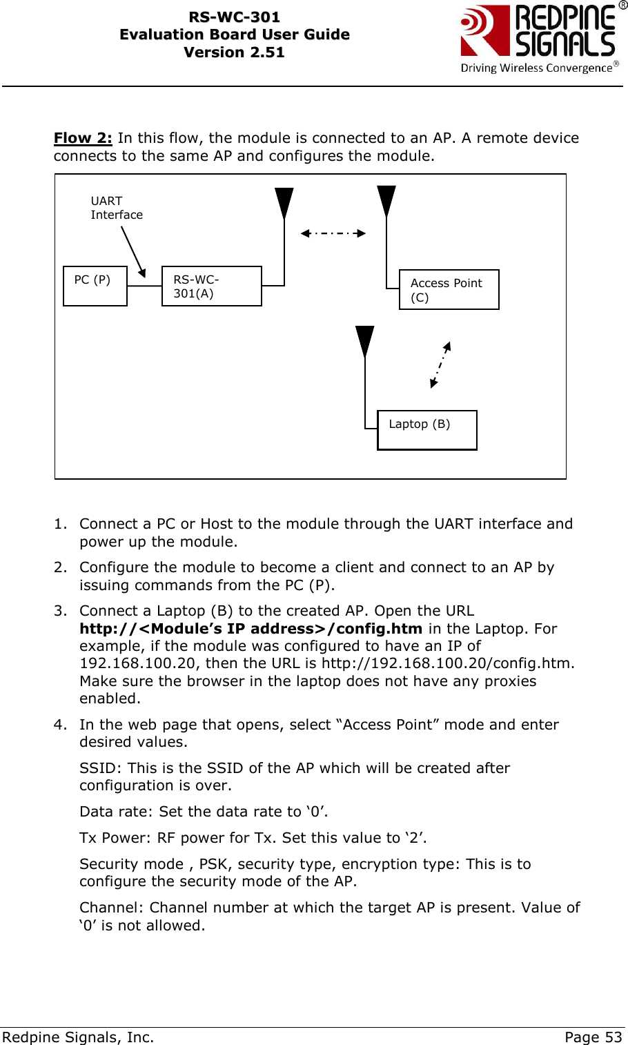
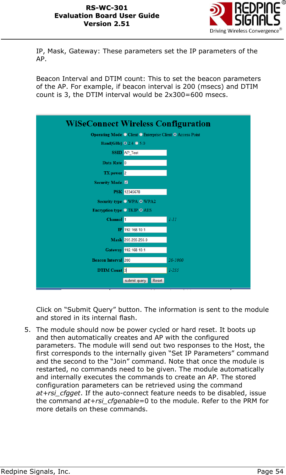
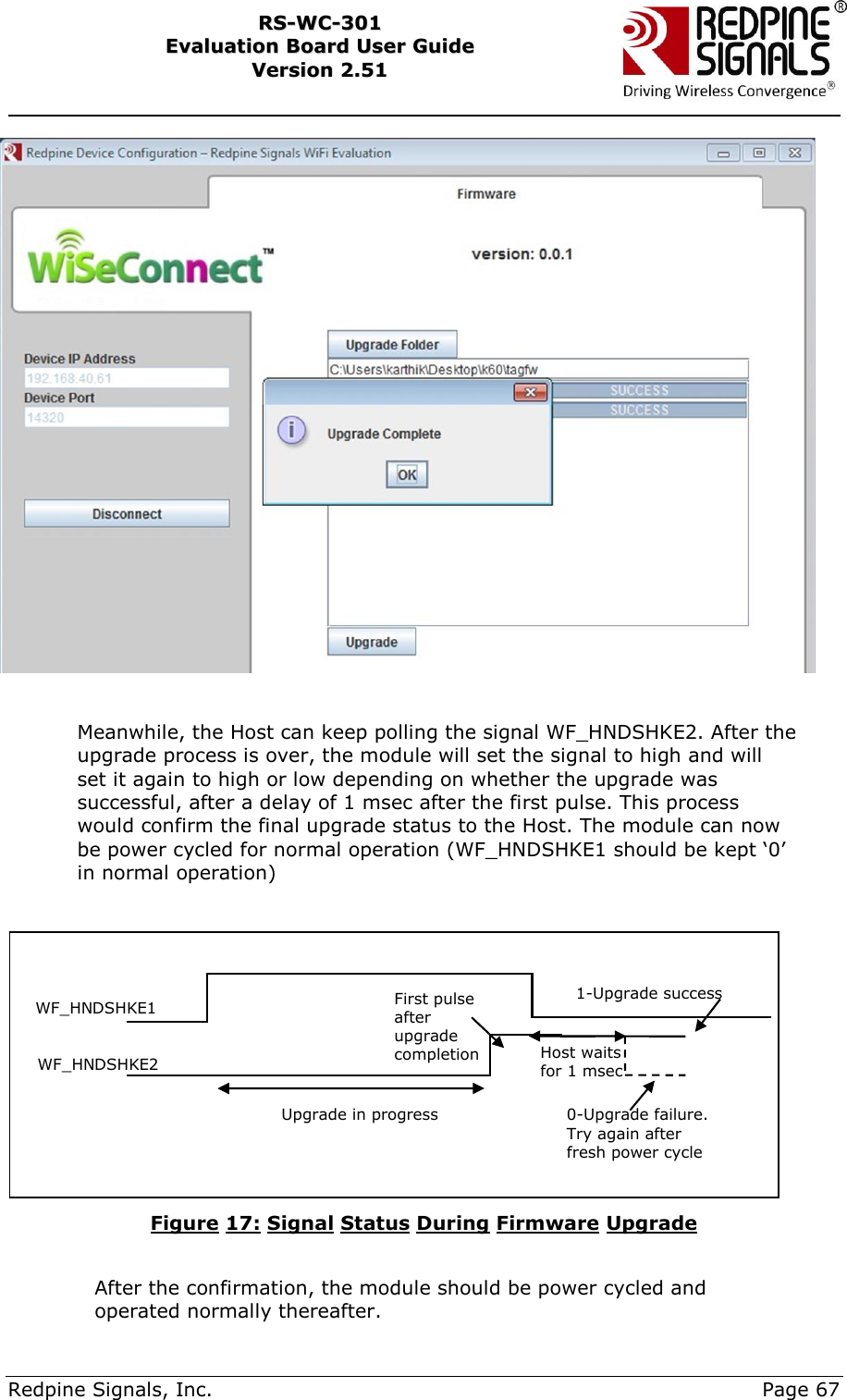
![Redpine Signals, Inc. Page 34 RRSS--WWCC--330011 EEvvaalluuaattiioonn BBooaarrdd UUsseerr GGuuiiddee VVeerrssiioonn 22..5511 5.3 Evaluating EAP-TLS Mode To verify the EAP-TLS mode, a security certificate file should be loaded into the module. A Python based flow is provided to verify this mode as loading of certificate files cannot be done through Hyper-terminal or Teraterm. 1. Enable WPA2-Enterprise in the Access Point settings and start the Radius Server in the Laptop (D) connected to the AP. 2. Install Python on PC(P). The “pyserial” package should be included in the installation to access the serial port. 3. Configure the EVB in UART mode, connect a UART cable between the PC and the EVB and power up the EVB. 4. Make sure the following things are configured accordingly in the Python script RS.WSC.x.x.GENR.x.x.x.x.x.x\Resources\UART\Python\WiFi_Enterprise_TLS.py a. Path of the certificate file [f3=open(“<Path>\\RS.WSC.x.x.GENR.x.x.x.x.x.x\\Resources\\Applications\\Radius_server\\raddb\\certs\\wifiuser.pem”,’r+’)] b. SSID of the Access Point at rsi_ssid. It should reflect the SSID of the AP you want to connect to. c. Values for parameters user_identity and security_key should match the values in the file <radius server path>\raddb\users d. Parameter oper_mode should be „2‟ e. COM port name (called param1 in the script) should match the name of the COM port name in PC. f. rsi_band should be configured according to the settings of the AP. 5. Open Windows Command Line in the PC (P) and run the script WiFi_Enterprise_TLS.py. Power cycle or reset the module before every fresh run of the script. The script sends AT commands to the module from the PC and makes the module connect to the Access Point. The sequence of commands executed in the script is shown below. NOTE: It is strongly recommended that the user downloads the latest software package inside www.redpinesignals.com/OpenKM (inside Wi-Fi Modules/WiSeConnect/Software folder. The software package contains the latest raddb folder and also the latest Python script that is used in this illustration.](https://usermanual.wiki/Silicon-Labs/RSWC301/User-Guide-2004510-Page-34.png)