Silicon Labs RSWC301 802.11 abgn WiSeConnect MODULE User Manual Overview
Redpine Signals Inc 802.11 abgn WiSeConnect MODULE Overview
Manual

Redpine Signals, Inc. Proprietary and Confidential.
RS-WC-301
E
Ev
va
al
lu
ua
at
ti
io
on
n
B
Bo
oa
ar
rd
d
U
Us
se
er
r
G
Gu
ui
id
de
e
V
Ve
er
rs
si
io
on
n
2
2.
.5
51
1
December 2012
Redpine Signals, Inc.
2107 N. First Street, #680
San Jose, CA 95131.
Tel: (408) 748-3385
Fax: (408) 705-2019
Email: info@redpinesignals.com
Website: www.redpinesignals.com
Redpine Signals, Inc.
2107 N. First Street, #680
San Jose, CA 95131.
Tel: (408) 748-3385
Fax: (408) 705-2019
Email: info@redpinesignals.com
Website: www.redpinesignals.com

Redpine Signals, Inc. Page 2
R
RS
S-
-W
WC
C-
-3
30
01
1
E
Ev
va
al
lu
ua
at
ti
io
on
n
B
Bo
oa
ar
rd
d
U
Us
se
er
r
G
Gu
ui
id
de
e
V
Ve
er
rs
si
io
on
n
2
2.
.5
51
1
Table of Contents
RS-WC-301 ............................................................................... 1
1 Introduction ........................................................................ 6
2 Components on the EVB ....................................................... 7
2.1 Test Setup ........................................................................... 13
3 Using the EVB in UART mode ............................................. 14
3.1 Configure Serial port in PC .................................................. 14
3.2 Configure Serial Port Monitor in the PC ............................... 19
4 Evaluation of Client Mode with Personal Security .............. 23
4.1 Configuration and Test Procedure ....................................... 25
5 Evaluation of Client Mode with Enterprise Security ............ 30
5.1 Radius Server Configuration ............................................... 30
5.2 AP Settings ......................................................................... 33
5.3 Evaluating EAP-TLS Mode ................................................... 34
5.4 Evaluating EAP-TTLS, EAP-FAST and PEAP Modes ............... 36
6 Evaluation of Wi-Fi Direct Mode ......................................... 39
6.1 Configuration and Test Procedure ....................................... 39
7 Evaluation of Access Point Mode ........................................ 44
7.1 Configuration and Test Procedure ....................................... 44
8 Wireless Configuration ...................................................... 47
8.1 Configuration to join a Specific AP ...................................... 47
8.2 Configuration to create an AP ............................................. 51
9 Using the Module in USB Mode ........................................... 55
10 Using the Module in SPI Mode ......................................... 57
10.1 Sample flow for evaluating SPI mode ................................. 58
11 Upgrading Firmware Through the UART Interface ........... 60
12 Wireless Firmware Upgrade ............................................ 64
12.1 Users of Firmware Lower than version 2.1.0.1.2.5 .............. 64
12.2 Upgrading Firmware Wirelessly .......................................... 64

Redpine Signals, Inc. Page 3
R
RS
S-
-W
WC
C-
-3
30
01
1
E
Ev
va
al
lu
ua
at
ti
io
on
n
B
Bo
oa
ar
rd
d
U
Us
se
er
r
G
Gu
ui
id
de
e
V
Ve
er
rs
si
io
on
n
2
2.
.5
51
1
Table of Figures
Figure 5: RS-WC-301-EVB ............................................................................ 7
Figure 6: Client Mode Set-up with Personal Security .................................. 23
Figure 7: Access Point Settings (Personal Security Mode) .......................... 24
Figure 8: Commands in Hyper-terminal ...................................................... 26
Figure 9: Execution of TCP.exe in Laptop C ................................................ 28
Figure 10: Enterprise Security Set-up ........................................................ 30
Figure 11: Access Point Settings (Enterprise Security Mode) ..................... 33
Figure 12: Command Flow in Enterprise Security Mode .............................. 35
Figure 13: Running of Python Script WiFi_Enterprise_TLS.py .................... 35
Figure 14: Wi-Fi Direct Set-up .................................................................... 39
Figure 15: Messages in Hyper-terminal ...................................................... 41
Figure 16: Command Flow in Wi-Fi Direct Mode ......................................... 42
Figure 17: Access Point Set-up ................................................................... 44
Figure 20: Interface between Module and Host .......................................... 57
Figure 21: Flow of Commands in SPI mode ................................................ 59
Figure 22: Set-up for Wireless Firmware Upgrade ...................................... 64
Figure 23: Signal Status During Firmware Upgrade .................................... 67

Redpine Signals, Inc. Page 4
R
RS
S-
-W
WC
C-
-3
30
01
1
E
Ev
va
al
lu
ua
at
ti
io
on
n
B
Bo
oa
ar
rd
d
U
Us
se
er
r
G
Gu
ui
id
de
e
V
Ve
er
rs
si
io
on
n
2
2.
.5
51
1
List of Tables
Table 1:UART Header (RS-WC-301).............................................................. 8
Table 2: Interface Selection ......................................................................... 8
Table 3: General Purpose Header (RS-WC-301-EVB) .................................. 10
Table 4: General Purpose Header(RS-WC-301-EVB) ................................... 11
Table 5: SPI Header Pins ............................................................................ 12
Table 6: Sensor Interface Header ............................................................... 13

Redpine Signals, Inc. Page 5
R
RS
S-
-W
WC
C-
-3
30
01
1
E
Ev
va
al
lu
ua
at
ti
io
on
n
B
Bo
oa
ar
rd
d
U
Us
se
er
r
G
Gu
ui
id
de
e
V
Ve
er
rs
si
io
on
n
2
2.
.5
51
1

Redpine Signals, Inc. Page 6
R
RS
S-
-W
WC
C-
-3
30
01
1
E
Ev
va
al
lu
ua
at
ti
io
on
n
B
Bo
oa
ar
rd
d
U
Us
se
er
r
G
Gu
ui
id
de
e
V
Ve
er
rs
si
io
on
n
2
2.
.5
51
1
1 Introduction
This document describes how to use the RS-WC-301 EVB. It describes the
sequence of commands and set-up requirements to quickly evaluate the
major functions of the modules. The document should be used in
conjunction with the Programming Reference Manual (PRM) where all
commands to configure and operate the modules are described in detail.
Even if the user does not plan to use the UART interface, it is
recommended to go through the UART sections because all the set-ups to
evaluate different functionalities of the module in UART mode are directly
reusable in the SPI and USB modes also.
Redpine Signals, Inc. Page 7
R
RS
S-
-W
WC
C-
-3
30
01
1
E
Ev
va
al
lu
ua
at
ti
io
on
n
B
Bo
oa
ar
rd
d
U
Us
se
er
r
G
Gu
ui
id
de
e
V
Ve
er
rs
si
io
on
n
2
2.
.5
51
1
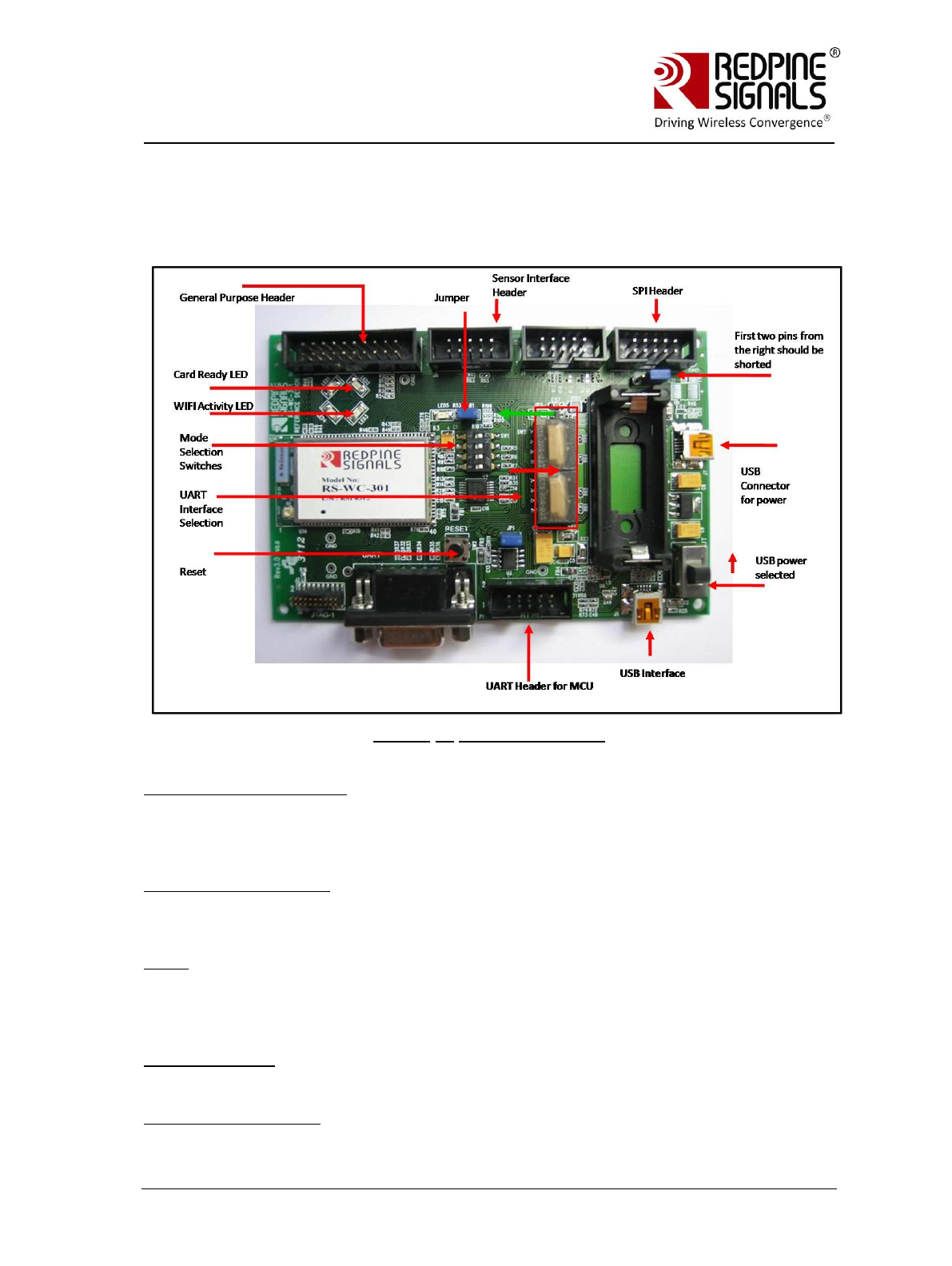
2 Components on the EVB
The RS-WC-301 EVB has various switches and headers to enable the user to
configure it for different scenarios.
Figure 1: RS-WC-301-EVB
USB Connector for Power
The power for the board can be supplied through this connector. Note that this
connector is used only for supplying power. For actual communication using
USB, the USB interface described below is used.
Power Selection Switch
The power selection switch should be put in the position shown in the figures
above so that the board receives power from the USB connector.
Reset
Push button reset for the board. Note that there is a power-on reset circuit on
the board that generates the necessary reset. This additional push-button is to
reset the module during normal operation.
UART Connector
A DB9 connector is provided to interface the UART port.
UART Header for MCU

Redpine Signals, Inc. Page 8
R
RS
S-
-W
WC
C-
-3
30
01
1
E
Ev
va
al
lu
ua
at
ti
io
on
n
B
Bo
oa
ar
rd
d
U
Us
se
er
r
G
Gu
ui
id
de
e
V
Ve
er
rs
si
io
on
n
2
2.
.5
51
1
If the EVB needs to be connected to the serial interface of an MCU platform, this
header can be used. The voltage level of the UART Tx and Rx pins of this header
is 3.3V. The Ground pin should be connected to a corresponding ground signal of
the MCU board. For RS-WC-301 the header assignment is shown below
Pin
number
Pin name
Direction
Description
1
NC
-
This pin must be left
unconnected
2
NC
-
This pin must be left
unconnected
3
NC
-
This pin must be left
unconnected
4
UART-RX
Input
UART Rx pin of the module
5
UART-TX
Output
UART Tx pin of the module
6
UART-CTS
-
Not used in current
firmware. Should be left
unconnected
7
UART-RTS
-
Not used in current
firmware. Should be left
unconnected
8
GND
-
Ground
9
GND
-
Ground
10
GND
-
Ground
Table 1:UART Header (RS-WC-301)
Mode Selection Switches
To select the interface in the EVB, configure the individual switches of Mode
Selection Switch bank as shown in the below table.
Switch #
UART Mode
SPI Mode
USB
1
ON
ON
ON
2
ON
OFF
ON
3
ON
ON
OFF
4
ON
ON
ON
Table 2: Interface Selection
Card Ready
The Card Ready LED glows after the module has booted up successfully. It is an
indication that the EVB is ready to accept commands from the Host.
WIFI Activity

Redpine Signals, Inc. Page 9
R
RS
S-
-W
WC
C-
-3
30
01
1
E
Ev
va
al
lu
ua
at
ti
io
on
n
B
Bo
oa
ar
rd
d
U
Us
se
er
r
G
Gu
ui
id
de
e
V
Ve
er
rs
si
io
on
n
2
2.
.5
51
1
The LED indicates that wireless data transfer activity is in progress. This LED is
not used in the current firmware.
General Purpose Header
Pin
number
Pin name
Direction
Description
1
SPI_READY
Output
Handshake signal used in SPI
mode and connected to a GPIO
pin of the Host MCU. In other
modes, this signal can be left
open
2
NC
-
No connect
3
RESET_N
Input
Active low reset input. This can
be connected to the Host MCU to
reset the module from the Host.
If not used, should be left open
4
NC
-
No connect
5
WAKEUP
Input
The module wakes up from sleep
if a logic high is driven into this
pin. Used only in SPI mode,
should be left open in UART
mode
6
PT_GPIO2
Output
Pass through output pin
controllable by Host software.
Not used in current firmware,
should be left open
7
ADC2
Input
Analog input to internal ADC. Not
used in current firmware, should
be left open
8
PT_GPIO1
Output
Pass through output pin
controllable by Host software.
Not used in current firmware,
should be left open
9
GND
-
Ground
10
VCC
Power
3.3V power supply. If the USB
port for power supply is not
used, this pin can be used to
drive power to the EVB from the
Host MCU platform. The direction
of the “Power Selection” switch is
ignored in this case. The
maximum current sourcing
capacity of the Host should be
500mA. If not used, this pin
should be left open
11
ADC1
Input
Analog input to internal ADC. Not
used in current firmware, should

Redpine Signals, Inc. Page 10
R
RS
S-
-W
WC
C-
-3
30
01
1
E
Ev
va
al
lu
ua
at
ti
io
on
n
B
Bo
oa
ar
rd
d
U
Us
se
er
r
G
Gu
ui
id
de
e
V
Ve
er
rs
si
io
on
n
2
2.
.5
51
1
be left open
12
NC
-
No connect
13
BT_PRIORITY
Input
Used to indicate through logic
high that BT is transmitting high
priority traffic. When BT
coexistence is not used, this pin
should be grounded
14
NC
-
No connect
15
WLAN_ACTIVE
Output
Used for BT Coexistence. It
indicates with logic high that
WLAN activity is in progress.
When low, BT device has the
opportunity to transmit. Not used
in current firmware, should be
left open
16
NC
-
No connect
17
NC
-
No connect
18
NC
-
No connect
19
NC
-
No connect
20
GND
-
Ground
Table 3: General Purpose Header (RS-WC-301-EVB)
Pin
number
Pin name
Direction
Description
1
SPI_READY
Output
Handshake signal used in SPI
mode and connected to a GPIO
pin of the Host MCU. In other
modes, this signal can be left
open
2
NC
-
No connect
3
RESET_N
Input
Active low reset input. This can be
connected to the Host MCU to
reset the module from the Host. If
not used, should be left open
4
NC
-
No connect
5
WAKEUP
Input
The module wakes up from sleep
if a logic high is driven into this
pin. Used only in SPI mode,
should be left open in UART mode
6
PT_GPIO2
Output
Pass through output pin
controllable by Host software. Not
used in current firmware, should
be left open
7
NC
-
No connect
8
PT_GPIO1
Output
Pass through output pin
controllable by Host software. Not
used in current firmware, should

Redpine Signals, Inc. Page 11
R
RS
S-
-W
WC
C-
-3
30
01
1
E
Ev
va
al
lu
ua
at
ti
io
on
n
B
Bo
oa
ar
rd
d
U
Us
se
er
r
G
Gu
ui
id
de
e
V
Ve
er
rs
si
io
on
n
2
2.
.5
51
1
be left open
9
GND
-
Ground
10
VCC
Power
3.3V power supply. If the USB
port for power supply is not used,
this pin can be used to drive
power to the EVB from the Host
MCU platform. The direction of the
“Power Selection” switch is
ignored in this case. The
maximum current sourcing
capacity of the Host should be
500mA. If not used, this pin
should be left open
11
NC
-
No connect
12
NC
-
No connect
13
BT_PRIORITY
Input
Used to indicate through logic
high that BT is transmitting high
priority traffic. When BT
coexistence is not used, this pin
should be grounded
14
NC
-
No connect
15
WLAN_ACTIVE
Output
Used for BT Coexistence. It
indicates with logic high that
WLAN activity is in progress.
When low, BT device has the
opportunity to transmit. Not used
in current firmware, should be left
open
16
NC
-
No connect
17
NC
-
No connect
18
NC
-
No connect
19
NC
-
No connect
20
GND
-
Ground
Table 4: General Purpose Header(RS-WC-301-EVB)
SPI Header
The SPI header is used to connect the SPI interface of the module to a Host
MCU.
Pin
Number
Pin Name
Direction
Description
1
NC
-
No connect
2
SPI_CS
Input
SPI slave select. Active low.
3
GND
-
Ground
4
NC
-
This pin must be left unconnected
5
SPI_CLK
Input
SPI clock. Max frequency of 12.5

Redpine Signals, Inc. Page 12
R
RS
S-
-W
WC
C-
-3
30
01
1
E
Ev
va
al
lu
ua
at
ti
io
on
n
B
Bo
oa
ar
rd
d
U
Us
se
er
r
G
Gu
ui
id
de
e
V
Ve
er
rs
si
io
on
n
2
2.
.5
51
1
MHz
6
GND
-
Ground
7
SPI_MOSI
Input
SPI data input
8
SPI_MISO
Output
SPI data output
9
INTERRUPT
Output
Active high, level triggered
interrupt, used in SPI mode. The
interrupt is raised by the module
to indicate there is data to be
read by the Host, or to indicate
the module has woken up from
sleep. In UART mode, it can be
left open
10
NC
-
No connect
Table 5: SPI Header Pins
UART Interface Selection
These switches are present in RS-WC-301-EVB. If both the switches are
put in the direction shown by the green arrow, the DB9 connector for
UART is selected. If the switches are put in the direction shown by the
red arrow, the “UART Header for MCU” is selected.
Sensor Interface Header
This header is present RS-WC-301-EVB.
Pin
Number
Pin Name
Direction
Description
1
NC
-
No connect
2
NC
-
No connect
3
GND
-
Ground
4
NC
-
This pin must be left unconnected
5
ADC2
Input
Analog input to internal ADC. Not
used in current firmware, should
be left open
6
GND
-
Ground
7
ADC1
Input
Analog input to internal ADC. Not
used in current firmware, should
be left open
8
WF_HNDSHKE1
Input
Handshake signal for wireless
firmware upgrade. Should be
connected to a GPIO pin of the
Host MCU
9
NC
-
No connect
10
WF_HNDSHKE2
Ouput
Handshake signal for wireless
firmware upgrade. Should be
connected to a GPIO pin of the
Host MCU

Redpine Signals, Inc. Page 13
R
RS
S-
-W
WC
C-
-3
30
01
1
E
Ev
va
al
lu
ua
at
ti
io
on
n
B
Bo
oa
ar
rd
d
U
Us
se
er
r
G
Gu
ui
id
de
e
V
Ve
er
rs
si
io
on
n
2
2.
.5
51
1
Table 6: Sensor Interface Header
USB Interface
This is a USB 2.0 interface and is supported in firmware version
2.0.0.1.2.4 and above.
Jumper
The jumper shown in some versions of the EVBs can be used for
measurement of current consumed by the module.
NOTE: EVB Versions below 3.1 do not support Power Save Mode 3 (Refer to
Programming Reference Manual version 1.9 or higher for definition of this mode).
2.1 Test Setup
The following additional components (not included with the EVB) are
required to complete the procedures described here.
1. PC with an available serial port, and running Windows XP. The PC
would be interfaced to the UART port of the EVB.
2. An 802.11a, 11b, 11g, or 11n Access Point with administrative
access to change its settings
3. A RADIUS server for operation in enterprise security mode (see
section Evaluation of Client Mode with Enterprise Security for
details)
4. A Wi-Fi Direct™ compatible mobile phone or laptop (see section
Evaluation of Wi-Fi Direct Mode )
5. A third party client device, such as a laptop or Wi-Fi phone, for
evaluating the EVB in the Access Point mode.
Redpine Signals, Inc. Page 14
R
RS
S-
-W
WC
C-
-3
30
01
1
E
Ev
va
al
lu
ua
at
ti
io
on
n
B
Bo
oa
ar
rd
d
U
Us
se
er
r
G
Gu
ui
id
de
e
V
Ve
er
rs
si
io
on
n
2
2.
.5
51
1
3 Using the EVB in UART mode
The following sections describe how to use the Evaluation Board in UART
mode. The sections should be used in conjunction with the Programming
Reference Manual to understand the commands better.
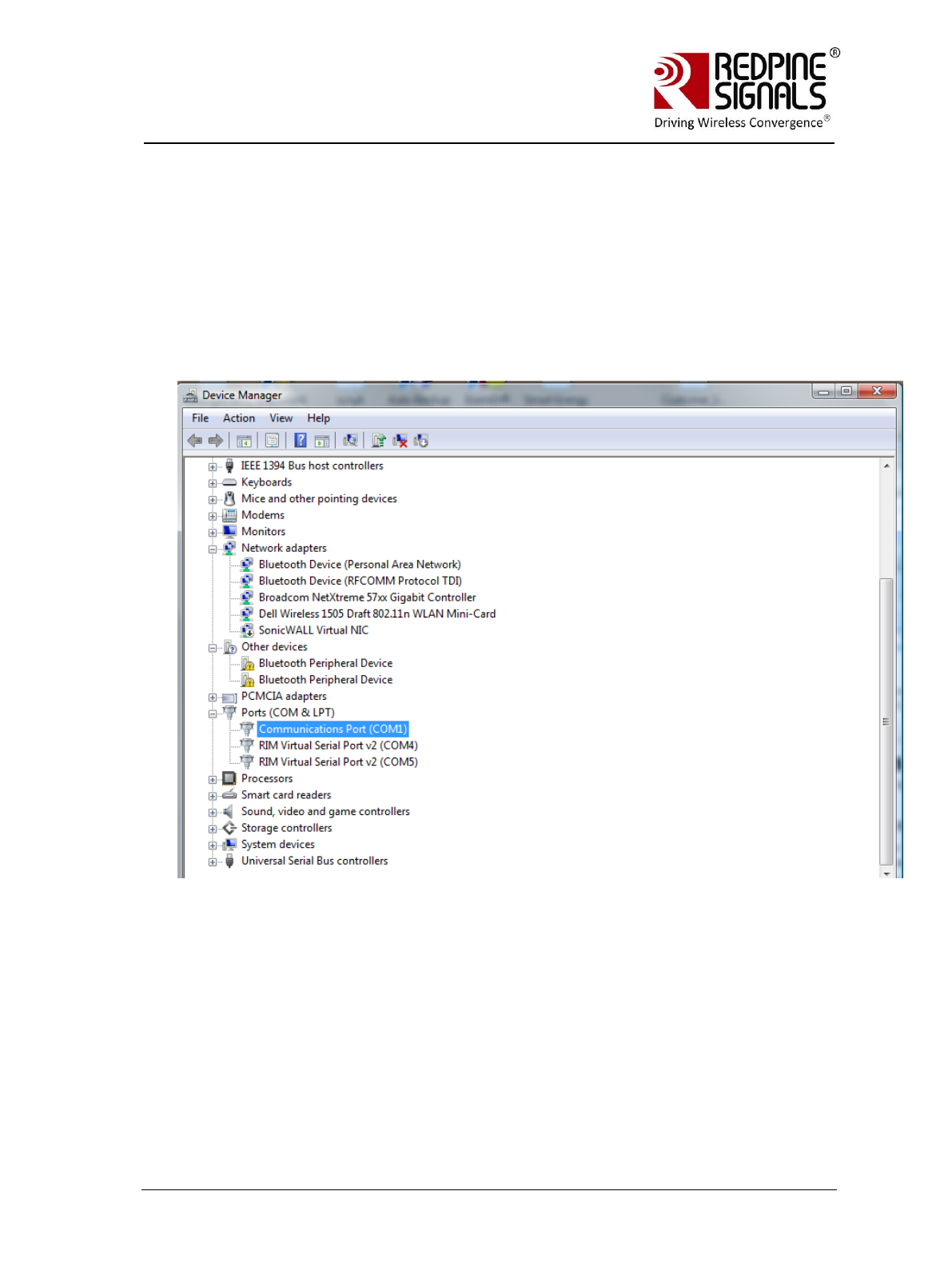
3.1 Configure Serial port in PC
To know the COM port name, check the computer‟s Device Manager settings.
The COM port name is displayed in the window. Hyperterminal or Teraterm
should be opened and configured accordingly with this COM port name.
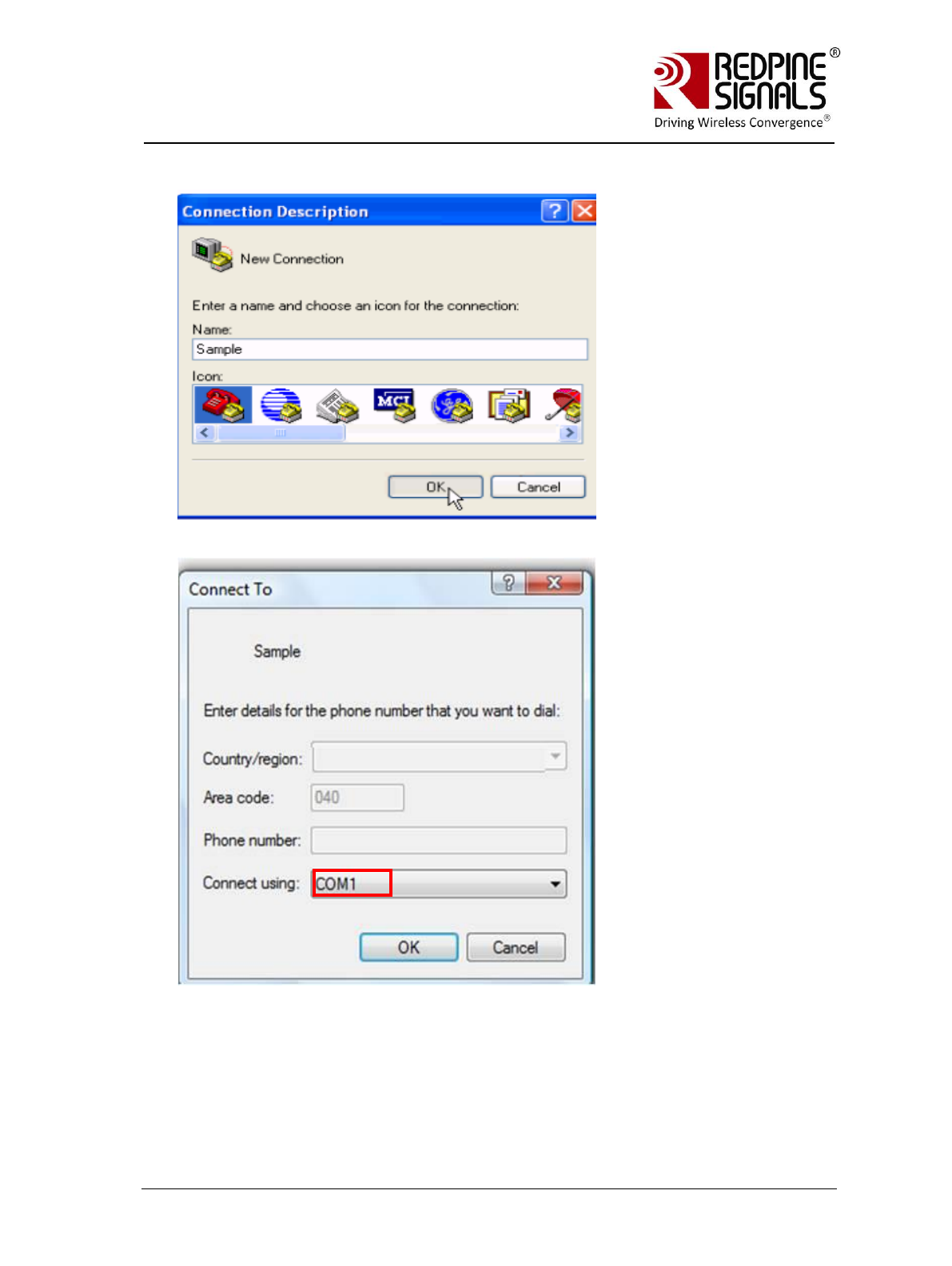
The steps for configuring Hyperterminal are shown below.
Redpine Signals, Inc. Page 15
R
RS
S-
-W
WC
C-
-3
30
01
1
E
Ev
va
al
lu
ua
at
ti
io
on
n
B
Bo
oa
ar
rd
d
U
Us
se
er
r
G
Gu
ui
id
de
e
V
Ve
er
rs
si
io
on
n
2
2.
.5
51
1
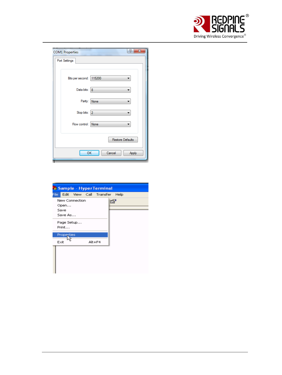
Open Hyperterminal
Baud Rate: 115200 bps, Data bits: 8, Parity: None, Stop bits: 2, Flow Control:
None
Other baud rates are not currently supported.
Redpine Signals, Inc. Page 16
R
RS
S-
-W
WC
C-
-3
30
01
1
E
Ev
va
al
lu
ua
at
ti
io
on
n
B
Bo
oa
ar
rd
d
U
Us
se
er
r
G
Gu
ui
id
de
e
V
Ve
er
rs
si
io
on
n
2
2.
.5
51
1
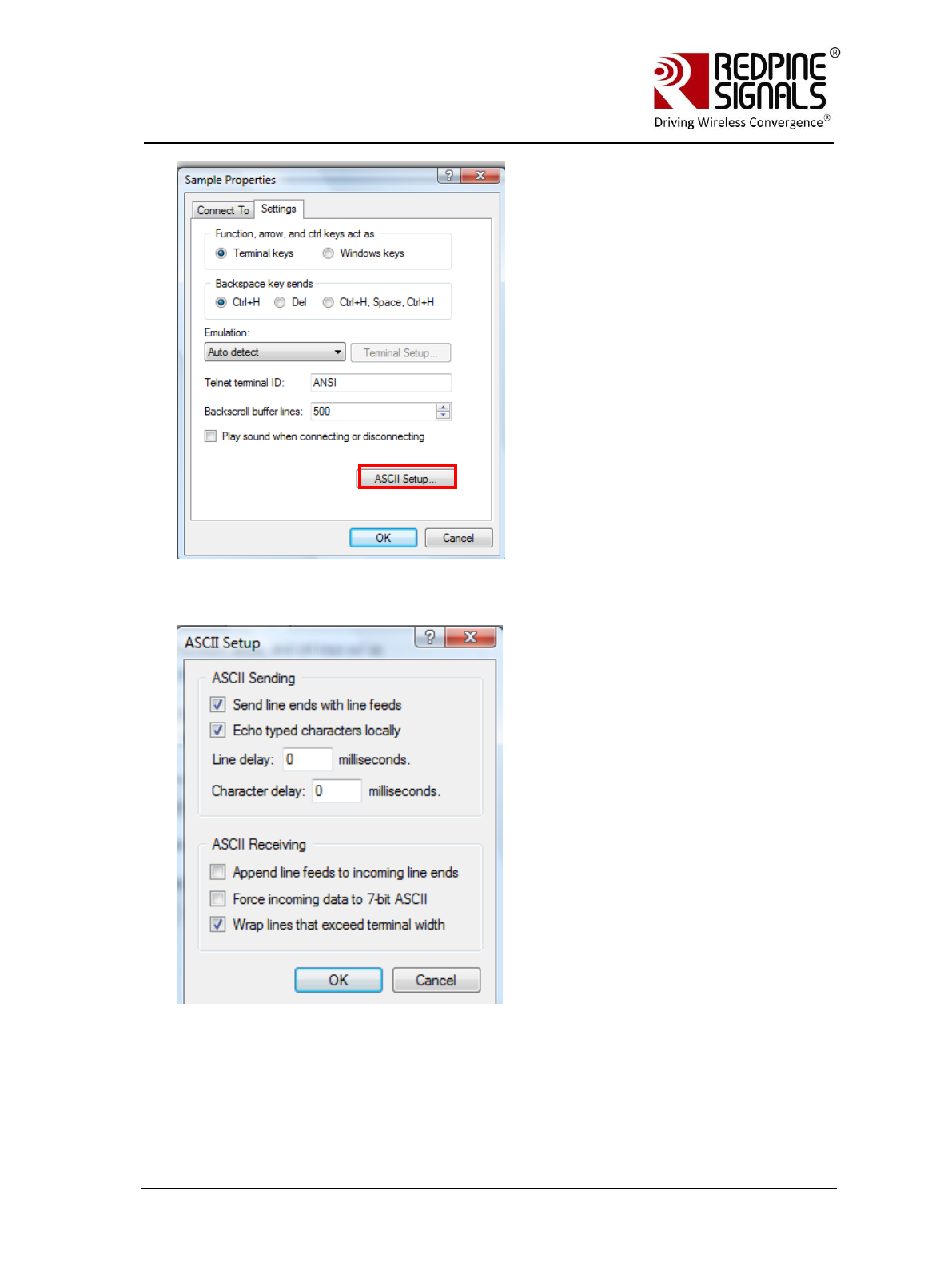
Click on ASCII Setup
Redpine Signals, Inc. Page 17
R
RS
S-
-W
WC
C-
-3
30
01
1
E
Ev
va
al
lu
ua
at
ti
io
on
n
B
Bo
oa
ar
rd
d
U
Us
se
er
r
G
Gu
ui
id
de
e
V
Ve
er
rs
si
io
on
n
2
2.
.5
51
1
Complete the settings as shown below and click OK.
Redpine Signals, Inc. Page 18
R
RS
S-
-W
WC
C-
-3
30
01
1
E
Ev
va
al
lu
ua
at
ti
io
on
n
B
Bo
oa
ar
rd
d
U
Us
se
er
r
G
Gu
ui
id
de
e
V
Ve
er
rs
si
io
on
n
2
2.
.5
51
1
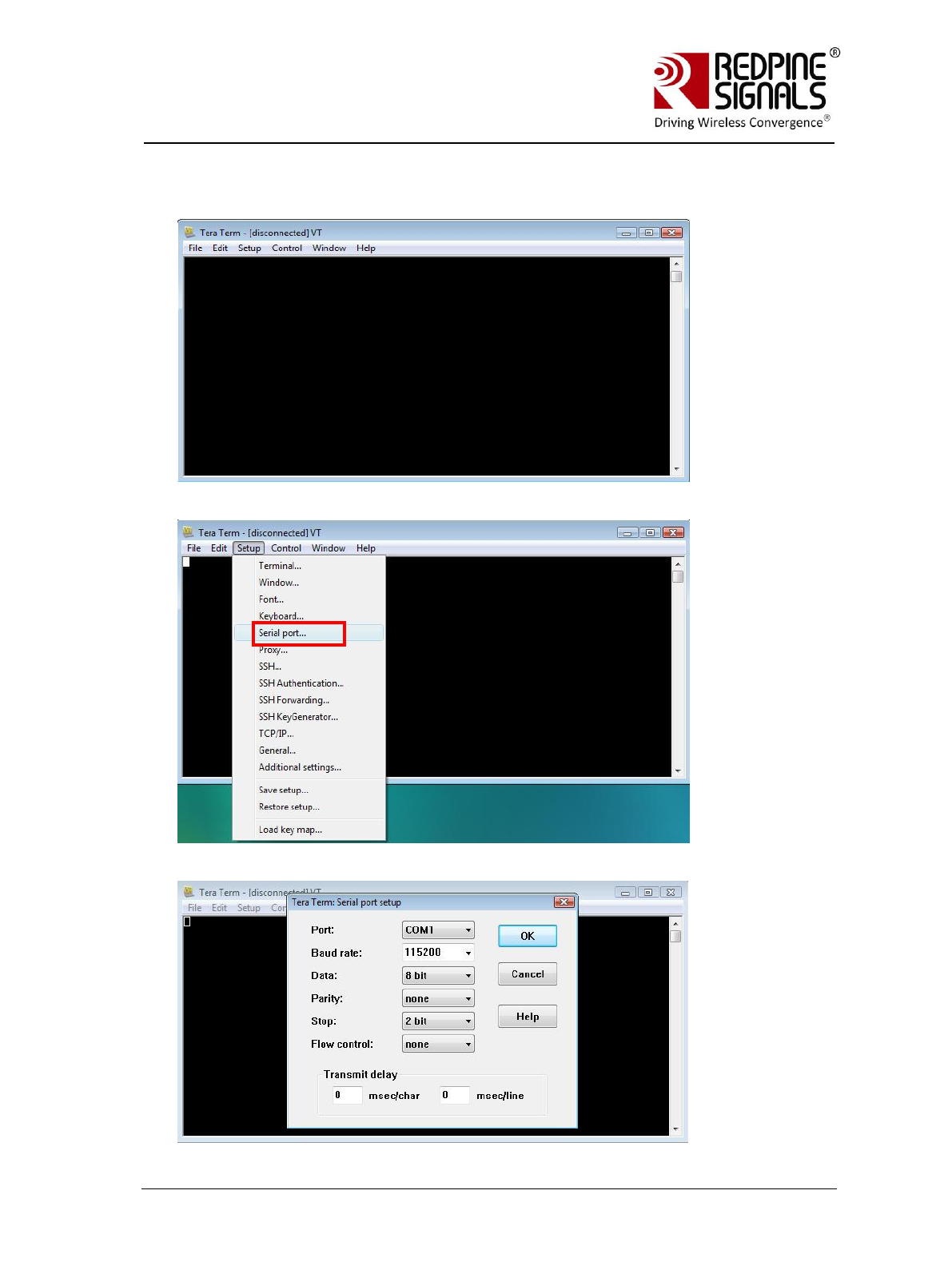
Teraterm can also be used. The steps for configuring Teraterm are shown below.
Open Teraterm.
Configure COM port settings
Redpine Signals, Inc. Page 19
R
RS
S-
-W
WC
C-
-3
30
01
1
E
Ev
va
al
lu
ua
at
ti
io
on
n
B
Bo
oa
ar
rd
d
U
Us
se
er
r
G
Gu
ui
id
de
e
V
Ve
er
rs
si
io
on
n
2
2.
.5
51
1
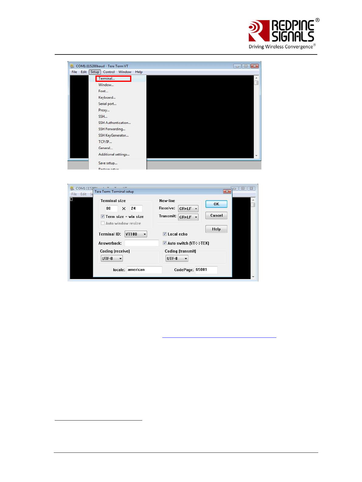
Complete the settings as shown below and click OK.
3.2 Configure Serial Port Monitor in the PC
The actual bytes exchanged between the module and the Host PC may
not all be readable on Hyperterminal or Teraterm because of ASCII
conversion. A serial port monitor
1
can be used to see the actual bytes. A
free package is available at http://www.serial-port-monitor.com/ , while
other similar software such as Hterm, Docklight etc. also provide good
interfaces to simultaneously view ASCII and actual bytes exchanged in
the UART interface. The following sections assume that HHD Free Serial
Port Monitor has been installed from the above link.
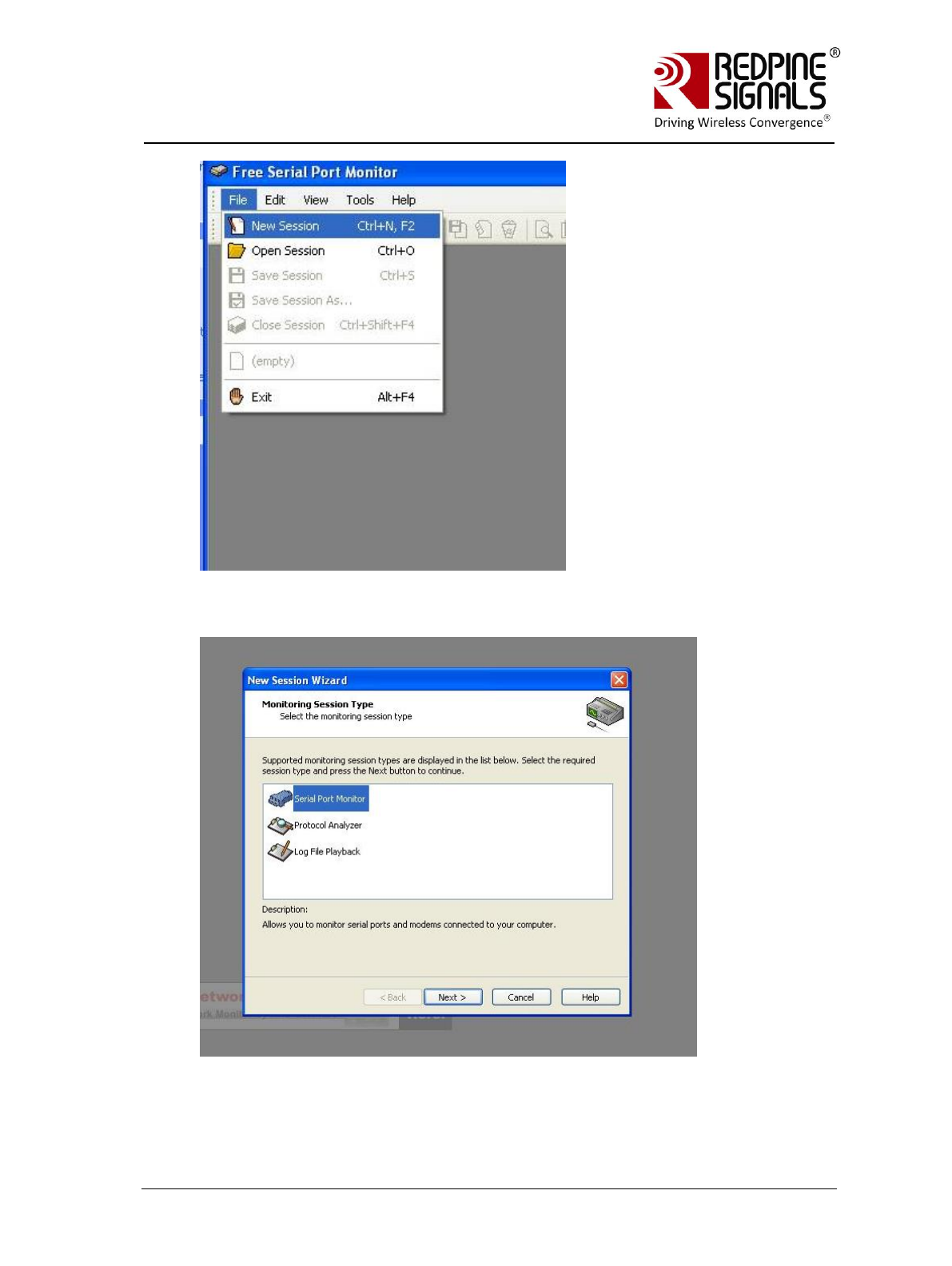
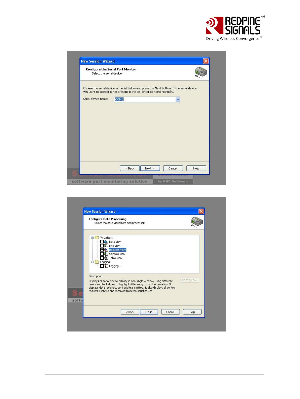
Open the “HHD Free Serial Port Monitor” BEFORE opening the
Hyperterminal or Teraterm. Click on File -> New Session. Select “Serial
Port Monitor”. Select the appropriate COM port and “Request view” for
the display format.
1
Redpine Signals Inc. assumes no liability for damages of any kind resulting from
use of third party software.
Redpine Signals, Inc. Page 20
R
RS
S-
-W
WC
C-
-3
30
01
1
E
Ev
va
al
lu
ua
at
ti
io
on
n
B
Bo
oa
ar
rd
d
U
Us
se
er
r
G
Gu
ui
id
de
e
V
Ve
er
rs
si
io
on
n
2
2.
.5
51
1
Redpine Signals, Inc. Page 21
R
RS
S-
-W
WC
C-
-3
30
01
1
E
Ev
va
al
lu
ua
at
ti
io
on
n
B
Bo
oa
ar
rd
d
U
Us
se
er
r
G
Gu
ui
id
de
e
V
Ve
er
rs
si
io
on
n
2
2.
.5
51
1
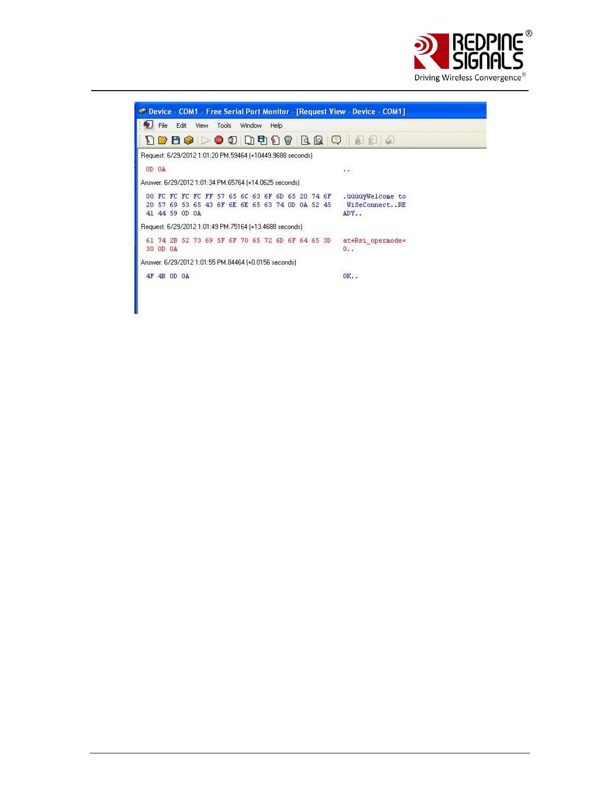
All bytes exchanged through the UART interface will now be visible on the
monitor.
Redpine Signals, Inc. Page 22
R
RS
S-
-W
WC
C-
-3
30
01
1
E
Ev
va
al
lu
ua
at
ti
io
on
n
B
Bo
oa
ar
rd
d
U
Us
se
er
r
G
Gu
ui
id
de
e
V
Ve
er
rs
si
io
on
n
2
2.
.5
51
1
Redpine Signals, Inc. Page 23
R
RS
S-
-W
WC
C-
-3
30
01
1
E
Ev
va
al
lu
ua
at
ti
io
on
n
B
Bo
oa
ar
rd
d
U
Us
se
er
r
G
Gu
ui
id
de
e
V
Ve
er
rs
si
io
on
n
2
2.
.5
51
1
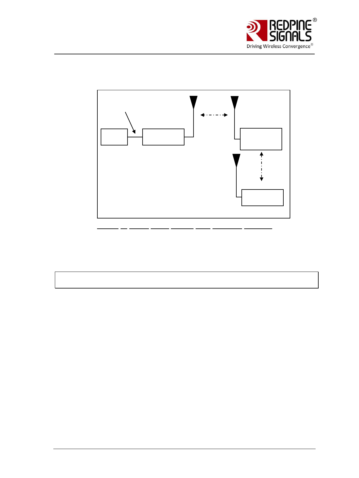
4 Evaluation of Client Mode with Personal Security
Figure 2: Client Mode Set-up with Personal Security
In this set-up the module acts as a client Wi-Fi module. It connects to an
Access Point with WPA2-PSK security. It is assumed, in this example, that the
SSID of the AP is Test_AP and IP of the AP is 192.168.50.1.
Note: The Serial Port Monitor mentioned in the document works reliably in Windows
XP machines
PC (P)
RS-WC-
301(A)
UART
Interface
Access Point
(B)
“Test_AP”
Laptop (C)
Redpine Signals, Inc. Page 24
R
RS
S-
-W
WC
C-
-3
30
01
1
E
Ev
va
al
lu
ua
at
ti
io
on
n
B
Bo
oa
ar
rd
d
U
Us
se
er
r
G
Gu
ui
id
de
e
V
Ve
er
rs
si
io
on
n
2
2.
.5
51
1
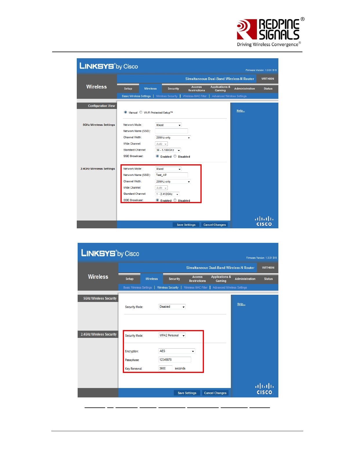
Figure 3: Access Point Settings (Personal Security Mode)

Redpine Signals, Inc. Page 25
R
RS
S-
-W
WC
C-
-3
30
01
1
E
Ev
va
al
lu
ua
at
ti
io
on
n
B
Bo
oa
ar
rd
d
U
Us
se
er
r
G
Gu
ui
id
de
e
V
Ve
er
rs
si
io
on
n
2
2.
.5
51
1
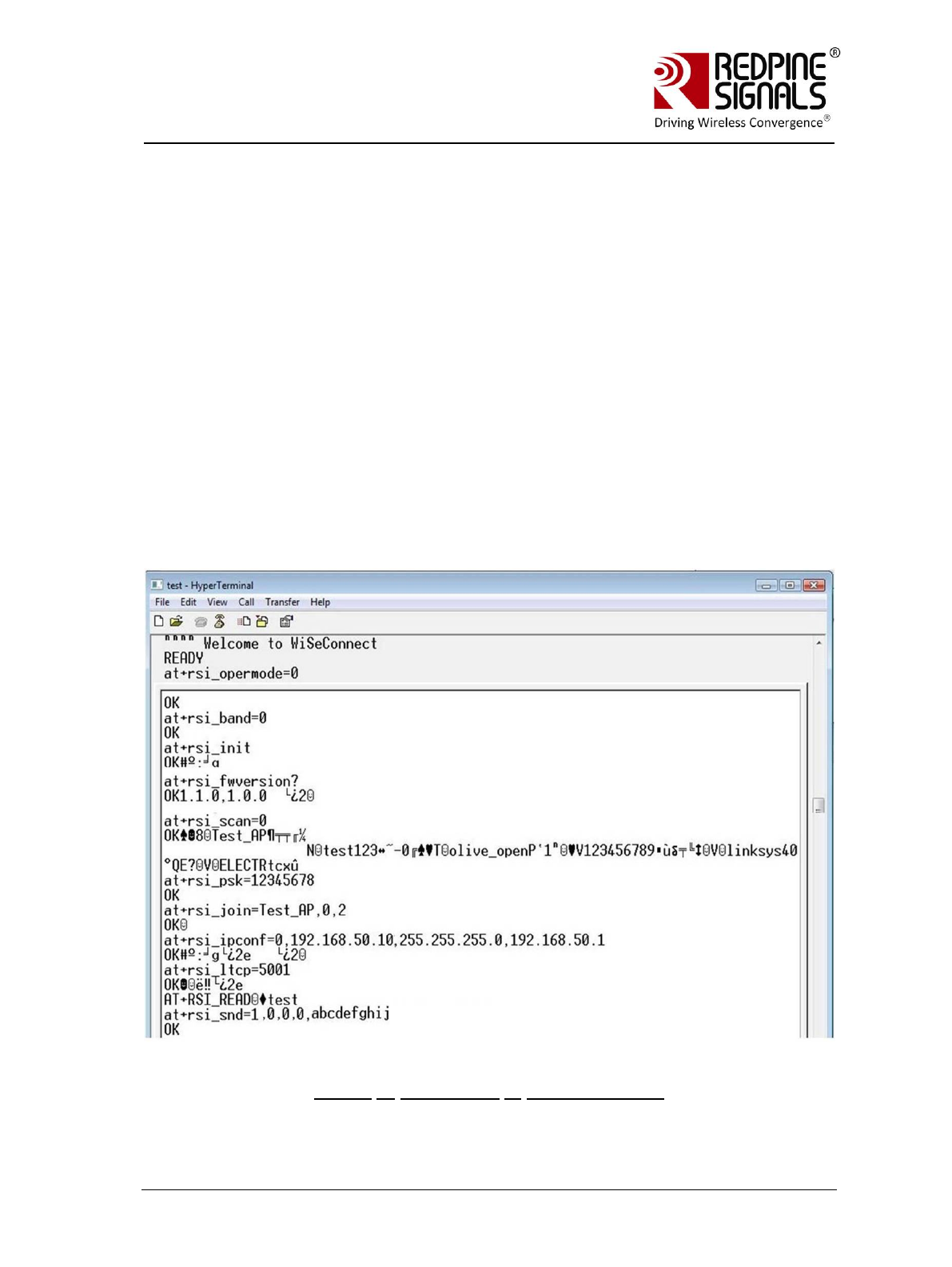
4.1 Configuration and Test Procedure
1. Configure the EVB in UART mode and connect a UART cable between
the PC and the EVB.
2. Open the Serial Port Monitor to see the actual bytes exchanged. Open
Hyperterminal or Teraterm with the settings described in section
Configure Serial port in PC.
3. Supply power to the EVB through the USB connector and put the
“Power Selection Switch” to the position as shown in the figure Error!
Reference source not found..
4. The terminal will show the message “Welcome To WiSeConnect”. The
module boots up. Card Ready (LED2) glows on successful completion
of boot-up and a string “READY” is sent from module to Host. The
following commands can now be issued. Please refer to the
Programming Reference Manual for detailed description of the
commands and their responses. A command should not be sent until
the response of the previous command is received.
a. at+rsi_opermode=0
This configures the EVB to function in client mode. The module
responds with “OK”
b. at+rsi_band=0
This configures the operating band of the EVB. The module
responds with “OK”
c. at+rsi_init
This initializes the Wi-Fi module in the EVB. The module
responds with OK<MAC_Address>
d. at+rsi_fwversion?
Optional command to report the firmware version in use.
e. at+rsi_scan=0
This makes the module scan for available networks. The
module responds with information of the APs scanned.
f. at+rsi_psk=12345678
This configures the PSK of the module to connect to a security
enabled AP.
g. at+rsi_join=Test_AP,0,2
This commands the module to join to the AP “Test_AP”. On
successful association, the module responds with
OK<GO_status>. The GO_status parameter can be ignored.
h. at+rsi_ipconf=0,192.168.50.10,255.255.255.0,192.168.
50.1
Redpine Signals, Inc. Page 26
R
RS
S-
-W
WC
C-
-3
30
01
1
E
Ev
va
al
lu
ua
at
ti
io
on
n
B
Bo
oa
ar
rd
d
U
Us
se
er
r
G
Gu
ui
id
de
e
V
Ve
er
rs
si
io
on
n
2
2.
.5
51
1
This command configures the module‟s IP to 192.168.50.10 in
static mode. Make sure the desired IP is in the same subnet as
the Access Point. The module responds to this command by
sending the configured IP address to the Host as response to
the command. In the terminal, this response might appear as
unreadable characters because of ASCII conversion. The Serial
Port Monitor can however be used to see the exact bytes. To
get the IP is DHCP mode the command is
at+rsi_ipconf=1,0,0,0
It is assumed in the following sections that an IP of
192.168.50.10 has been assigned.
i. at+rsi_ltcp=5001
This command opens a server TCP socket in the module. The
module responds with
OK<socket_type><socket_handle><lport><module_ipaddr>.
The socket_handle parameter will be used in the subsequent
sections to send data.
Figure 4: Commands in Hyper-terminal

Redpine Signals, Inc. Page 27
R
RS
S-
-W
WC
C-
-3
30
01
1
E
Ev
va
al
lu
ua
at
ti
io
on
n
B
Bo
oa
ar
rd
d
U
Us
se
er
r
G
Gu
ui
id
de
e
V
Ve
er
rs
si
io
on
n
2
2.
.5
51
1
5. Connect the Laptop C (Windows XP/Vista/Windows7) to the Access
Point. It is assumed for the rest of this section that the Laptop has
acquired an IP address of 192.168.50.20.
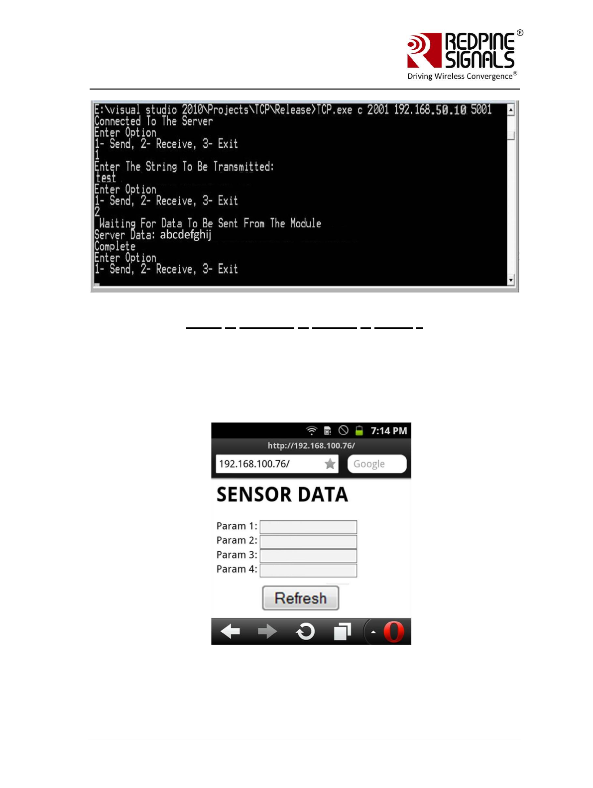
6. Exchanging data between the module and the Laptop C
Using TCP Sockets
a. Open a TCP socket in the Laptop C by typing the below command
in the Windows command line interface. Make sure that any
firewalls, that might prevent opening of sockets, are disabled.
TCP.exe c 2001 192.168.50.10 5001
The application is found in the path
RS.WSC.x.x.GENR.x.x.x.x.x.x\Resources\Applications\Peer\Windo
ws\ .
b. The command line window will display three options: 1 (Send), 2
(Receive) and 3 (Exit). Type 1 to send data to the Wi-Fi module.
On being prompted “Enter the string to be Transmitted”, type any
string from the Keyboard (“test” in this example). On pressing
“Enter” key on the keyboard, the data is sent from the Laptop C to
the module and the terminal displays it with the AT+RSI_READ
message.
c. To send data from the Wi-Fi module, first type Option 2 in Laptop
C and then type the below command in the module
at+rsi_snd=1,0,0,0,abcdefghij
The first parameter in the command is the socket_handle. It is 1
in this case. It is returned as the response of the command
at+rsi_ltcp and can be observed in the Serial Port Monitor. Refer
to the Programming Reference Manual for more details. The data
sent will be displayed in the Laptop C.
Usage of PC applications:
TCP.exe <s for server> <lport> <dipaddr> <dport>
TCP.exe <c for client> <lport> <dipaddr> <dport>
s – to open a server TCP socket
c – to open a client TCP socket
lport – Local port number
dipaddr – IP address of the destination
dport – Port number of the destination
UDP.exe is also used in the same way.
Redpine Signals, Inc. Page 28
R
RS
S-
-W
WC
C-
-3
30
01
1
E
Ev
va
al
lu
ua
at
ti
io
on
n
B
Bo
oa
ar
rd
d
U
Us
se
er
r
G
Gu
ui
id
de
e
V
Ve
er
rs
si
io
on
n
2
2.
.5
51
1
Figure 5: Execution of TCP.exe in Laptop C
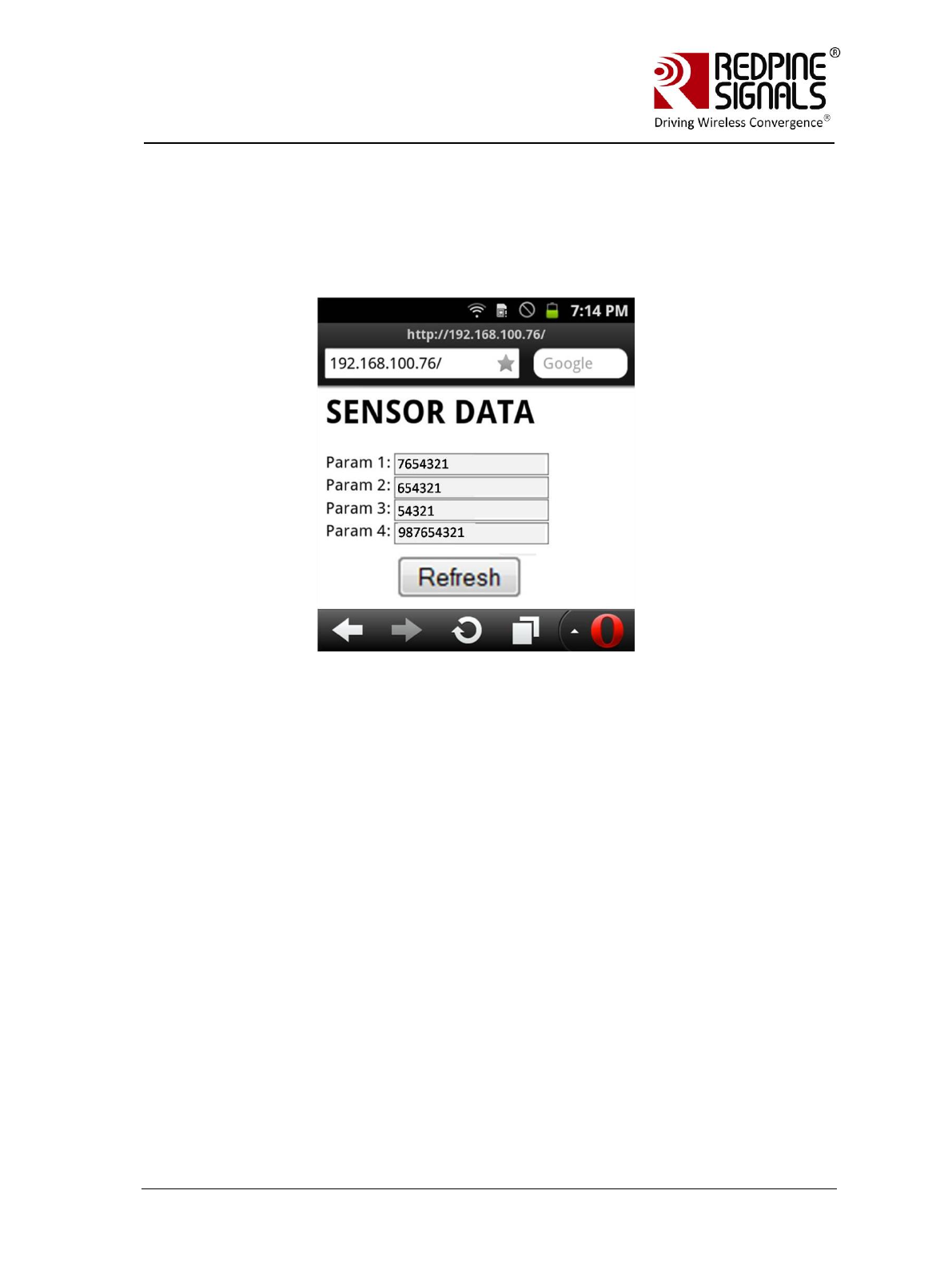
7. HTTP server access: The firmware of the module comes with a pre-loaded
webpage. Open the webpage in Laptop C by typing
http://192.168.50.10 in the browser of the Laptop. 192.168.50.10 is the
IP address of the module in this example.
The source code of the default page is provided in
RS.WSC.x.x.GENR.x.x.x.x.x.x\
Resources\Applications\WebPage\webpage.html
Redpine Signals, Inc. Page 29
R
RS
S-
-W
WC
C-
-3
30
01
1
E
Ev
va
al
lu
ua
at
ti
io
on
n
B
Bo
oa
ar
rd
d
U
Us
se
er
r
G
Gu
ui
id
de
e
V
Ve
er
rs
si
io
on
n
2
2.
.5
51
1
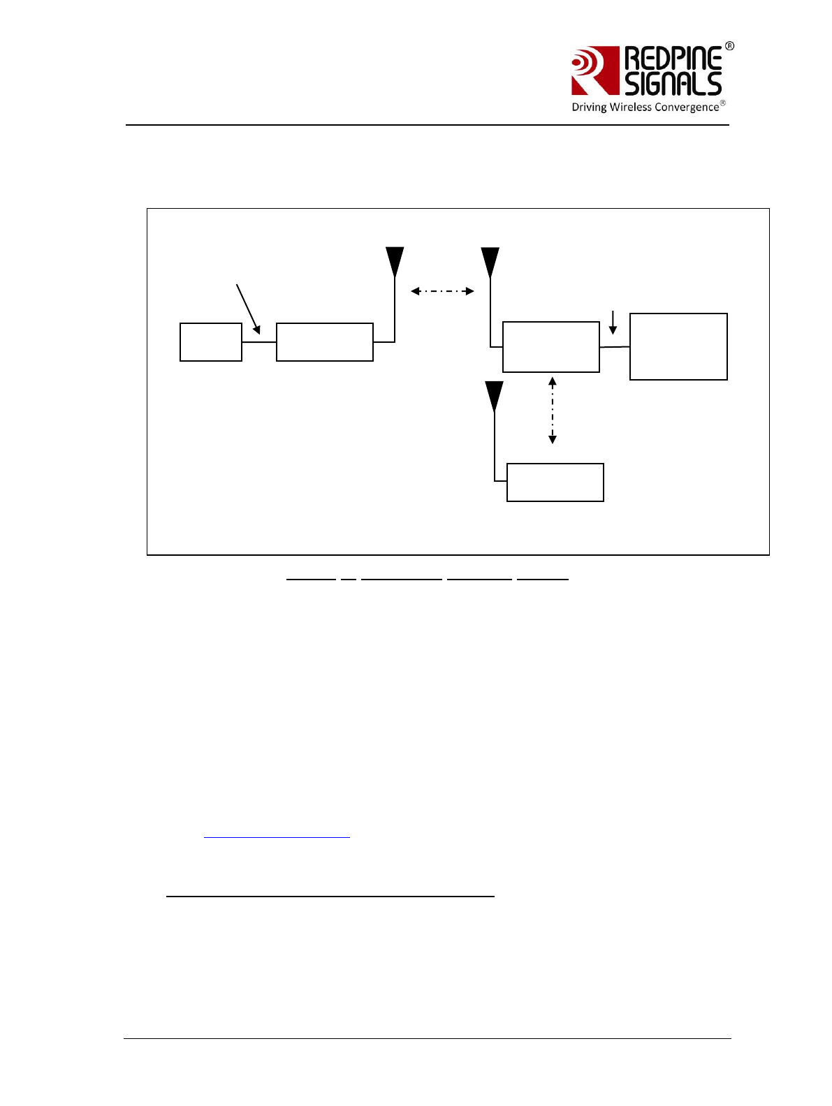
The values of the parameters can be updated dynamically (for
example to 7654321,654321,54321 and 987654321 respectively)
using the command
at+rsi_webfields=1;7654321,2;654321,3;54321,4;987654321 .
Refer to the command “Load Web Fields” in the Programming
reference manual for more details.
A new webpage can also be loaded into the module. It will overwrite
the previously existing webpage. For example, below is given the
source code of a reference page (91 characters in total).
<html><head><title>Untitled
Document</title></head><body><h1>Hello
World</h1></body></html>
This can be loaded into the module with the below command
at+rsi_webpage=91,<html><head><title>Untitled
Document</title></head><body><h1>Hello
World</h1></body></html>
Refer to the command “Load Web Page in Module” in the Programming
Reference Manual for more details.
Redpine Signals, Inc. Page 30
R
RS
S-
-W
WC
C-
-3
30
01
1
E
Ev
va
al
lu
ua
at
ti
io
on
n
B
Bo
oa
ar
rd
d
U
Us
se
er
r
G
Gu
ui
id
de
e
V
Ve
er
rs
si
io
on
n
2
2.
.5
51
1
5 Evaluation of Client Mode with Enterprise Security
Figure 6: Enterprise Security Set-up
In this set-up the RS-WC-301 EVB acts as a client Wi-Fi module. It connects to an
Enterprise security enabled Access Point. RS-WC-301 module support four Enterprise
Security modes:
1. EAP-TLS
2. EAP-TTLS
3. EAP-FAST
4. PEAP-MSCHAPV2
5.1 Radius Server Configuration
To evaluate any of the Enterprise Security modes, a Radius server should
be running on a Laptop/PC (node D in the above figure) connected to the
Access Point. A Linux compatible radius server package is downloadable
from http://freeradius.org. Installation instructions can be found in the
documentation included in the package. Additionally, the install process is
described below.
Installation of the Radius Server on a Linux PC
If the user wants to use the sample radius server for evaluation, he can
install it on a Linux PC (recommended Fedora 2.6.30).
1. Uncompress the package freeradius-server-2.1.12.tar in the desired
location in the Linux PC. After uncompressing is done, change directory
to the freeradius-server-2.1.12 folder
PC (P)
RS-WC-
301(A)
UART
Interface
Laptop/PC
(D) running
Radius
Server
Access Point
(B)
“Test_AP”
Ethernet
Interface
Laptop (C)

Redpine Signals, Inc. Page 31
R
RS
S-
-W
WC
C-
-3
30
01
1
E
Ev
va
al
lu
ua
at
ti
io
on
n
B
Bo
oa
ar
rd
d
U
Us
se
er
r
G
Gu
ui
id
de
e
V
Ve
er
rs
si
io
on
n
2
2.
.5
51
1
2. Issue the following commands:
./configure
make
make install
3. The radius server is now installed in the PC (D). A folder “raddb” is
created inside /usr/local/etc. Replace this folder with the raddb folder
provided inside Redpine‟s software package
RS.WSC.x.x.GENR.x.x.x.x.x.x\ Software\Applications\Radius_server\
4. To start the Radius Server, issue the below command on the Linux
terminal
radiusd –X
NOTE: The user can use other Radius Server software also for evaluation. This
radius server is provided for reference.
Important files for the Radius_Server:
1. RS.WSC.x.x.GENR.x.x.x.x.x.x\Software\Applications\Radius_server\raddb
\certs\ wifiuser.pem
This is the default certificate file provided with the software package. The
file used for the parameter < certificate> in the command at+rsi_cert,
when EAP-TLS mode is used in the module. This certificate file should be
present in PC(P).
NOTE: To generate a new certificate, the below process may be used in the Linux
PC where freeradius-server was installed.
Create Normal Certificate
mkdir new_certs
cd new_certs/
mkdir sslcert
chmod 0700 sslcert
cd sslcert
mkdir certs private
echo „100001‟ >serial
touch certindex.txt
vi openssl.cnf
/* CA root */
openssl req –new –x509 –extensions v3_ca –keyout private/cakey.pem –out
cacert.pem –days 365 –config ./openssl.cnf
/* Certificates Request */
openssl req –new –nodes –out redpine-req.pem –keyout private/redpine-key.pem –

Redpine Signals, Inc. Page 32
R
RS
S-
-W
WC
C-
-3
30
01
1
E
Ev
va
al
lu
ua
at
ti
io
on
n
B
Bo
oa
ar
rd
d
U
Us
se
er
r
G
Gu
ui
id
de
e
V
Ve
er
rs
si
io
on
n
2
2.
.5
51
1
days 365 –config ./openssl.cnf
<openssl.cnf is the configuration file used to generate the certificate. A sample file
is provided at
RS.WSC.x.x.GENR.x.x.x.x.x.x\Software\Applications\Radius_server\openssl.cnf>
/* Signing the certificates with ca root certificate generated in section CA root */
openssl ca –out redpine-cert.pem –days 365 –config ./openssl.cnf –infiles redpine-
req.pem
Finally concatenate the redpine-key.pem, redpine-cert.pem cacert.pem
cat redpine-key.pem >> redpine-cert.pem >> cacert.pem.
File redpine-key.pem is the new certificate.
Create Encrypted Certificate
mkdir new_certs
cd new_certs/
mkdir sslcert
chmod 0700 sslcert
cd sslcert
mkdir certs private
echo '100001' >serial
touch certindex.txt
vi openssl.cnf
/* CA root */
openssl req -new -x509 -extensions v3_ca -keyout private/cakey.pem -out
cacert.pem -days 365
-config ./openssl.cnf
/*Encrypt Private Key - use this encrypted key (private/cakey1.pem ) in
openssl.cnf*/
openssl pkcs8 -in private/cakey.pem -topk8 -out private/cakey1.pem
/* Certificates Request */
openssl req -new -nodes -out redpine-req.pem -keyout private/redpine-key.pem -
days 365 -config
./openssl.cnf
/* Signing the certificates with ca root certificate generated in section CA root */
openssl ca -out redpine-cert.pem -days 365 -config ./openssl.cnf -infiles redpine-
req.pem /*Encrypt Key*/
Redpine Signals, Inc. Page 33
R
RS
S-
-W
WC
C-
-3
30
01
1
E
Ev
va
al
lu
ua
at
ti
io
on
n
B
Bo
oa
ar
rd
d
U
Us
se
er
r
G
Gu
ui
id
de
e
V
Ve
er
rs
si
io
on
n
2
2.
.5
51
1
openssl pkcs8 -in private/redpine-key.pem -topk8 -out private/redpine-key1.pem
/*Finally concatenate the redpine-key1.pem, redpine-cert.pem cacert.pem in the
order */
cat redpine-key1.pem redpine-cert.pem cacert.pem > cert.pem
2. RS.WSC.x.x.GENR.x.x.x.x.x.x\Software\Applications\Radius_server\raddb
\users
This file contains the user id and password, to be used in <user_identity>
and <password> fields of the command at+rsi_eap
3. RS.WSC.x.x.GENR.x.x.x.x.x.x\Software\Applications\Radius_server\raddb
\eap.conf
This file is used to select the EAP methods. The password “wifi”
(<private_key_password = wifi> inside the file) should be used for the
field <key_password> in the command at+rsi_cert.
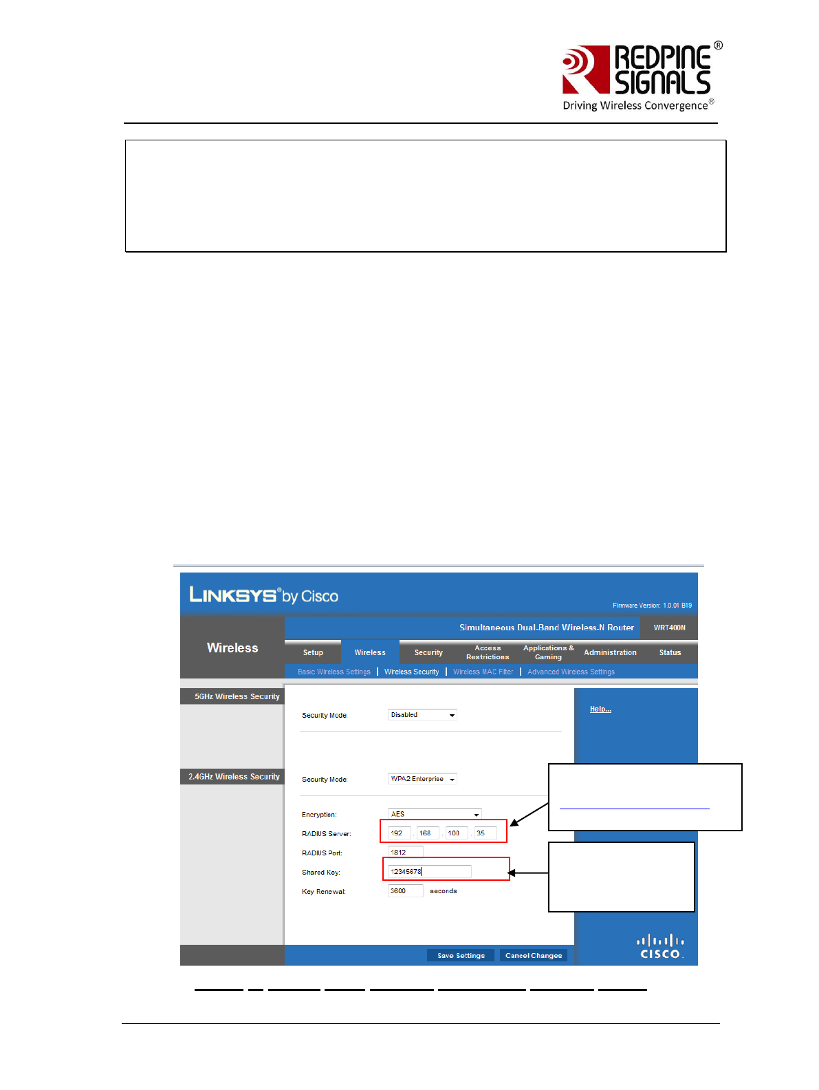
5.2 AP Settings
A snapshot is shown for AP Settings to work in Enterprise Security mode.
A Linksys AP (model no. WRT400N) is used for illustration.
Figure 7: Access Point Settings (Enterprise Security Mode)
This should match IP Address
of the PC (D) in figure
Enterprise Security Set-up
running the Radius Server
This should match the
parameter “secret” in
file clients.conf inside
raddb folder

Redpine Signals, Inc. Page 34
R
RS
S-
-W
WC
C-
-3
30
01
1
E
Ev
va
al
lu
ua
at
ti
io
on
n
B
Bo
oa
ar
rd
d
U
Us
se
er
r
G
Gu
ui
id
de
e
V
Ve
er
rs
si
io
on
n
2
2.
.5
51
1
5.3 Evaluating EAP-TLS Mode
To verify the EAP-TLS mode, a security certificate file should be loaded into the
module. A Python based flow is provided to verify this mode as loading of
certificate files cannot be done through Hyper-terminal or Teraterm.
1. Enable WPA2-Enterprise in the Access Point settings and start the
Radius Server in the Laptop (D) connected to the AP.
2. Install Python on PC(P). The “pyserial” package should be included in
the installation to access the serial port.
3. Configure the EVB in UART mode, connect a UART cable between the
PC and the EVB and power up the EVB.
4. Make sure the following things are configured accordingly in the
Python script
RS.WSC.x.x.GENR.x.x.x.x.x.x\Resources\UART\Python\WiFi_Enterpris
e_TLS.py
a. Path of the certificate file
[f3=open(“<Path>\\RS.WSC.x.x.GENR.x.x.x.x.x.x\\Resources\
\Applications\\Radius_server\\raddb\\certs\\wifiuser.pem”,’r+’
)]
b. SSID of the Access Point at rsi_ssid. It should reflect the SSID
of the AP you want to connect to.
c. Values for parameters user_identity and security_key should
match the values in the file <radius server path>\raddb\users
d. Parameter oper_mode should be „2‟
e. COM port name (called param1 in the script) should match the
name of the COM port name in PC.
f. rsi_band should be configured according to the settings of the
AP.
5. Open Windows Command Line in the PC (P) and run the script
WiFi_Enterprise_TLS.py. Power cycle or reset the module before every
fresh run of the script.
The script sends AT commands to the module from the PC and makes
the module connect to the Access Point. The sequence of commands
executed in the script is shown below.
NOTE: It is strongly recommended that the user downloads the latest software
package inside www.redpinesignals.com/OpenKM (inside Wi-Fi
Modules/WiSeConnect/Software folder. The software package contains the latest
raddb folder and also the latest Python script that is used in this illustration.
Redpine Signals, Inc. Page 35
R
RS
S-
-W
WC
C-
-3
30
01
1
E
Ev
va
al
lu
ua
at
ti
io
on
n
B
Bo
oa
ar
rd
d
U
Us
se
er
r
G
Gu
ui
id
de
e
V
Ve
er
rs
si
io
on
n
2
2.
.5
51
1
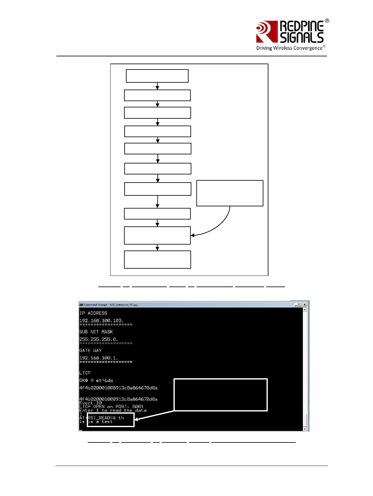
Figure 8: Command Flow in Enterprise Security Mode
Figure 9: Running of Python Script WiFi_Enterprise_TLS.py
Power Up EVB
at+rsi_opermode
at+rsi_band
at+rsi_scan
at+rsi_cert
at+rsi_join
at+rsi_init
at+rsi_ipconf to acquire
IP address
Open a server TCP socket
with port number 5001
The acquired IP
address is displayed
by the Python script
at+rsi_eap
Data received by the
module, sent from Laptop
(C) in step 8 below.

Redpine Signals, Inc. Page 36
R
RS
S-
-W
WC
C-
-3
30
01
1
E
Ev
va
al
lu
ua
at
ti
io
on
n
B
Bo
oa
ar
rd
d
U
Us
se
er
r
G
Gu
ui
id
de
e
V
Ve
er
rs
si
io
on
n
2
2.
.5
51
1
After opening the Server TCP socket, the script prompts to enter „1‟ to
receive data. Enter „1‟ and proceed to step 6 below.
6. Connect Laptop C, as shown in the figure Enterprise Security Set-up.
It should have proper security credentials to connect to the AP.
7. A “ping
2
” can be issued from Laptop C to the Wi-Fi module to verify
connectivity through the AP.
8. Exchanging data between the module and the Laptop (C)
a. Open a client TCP socket on the Laptop C by typing the below
command in the command line:
TCP.exe c 2001 <Module’s IP address> 5001
The IP address of the module is displayed in the command window
in Laptop (D) where the Python script was invoked. A server
socket is already opened in the module by the Python script.
b. The command line window in Laptop C will display three options: 1
(Send), 2 (Receive) and 3 (Exit). Enter „1‟ to send data to the Wi-
Fi module. On being prompted “Enter the string to be
transmitted”, type any string from the Keyboard. On pressing
“Enter” key on the keyboard, the data is sent from the Laptop(B)
to the module and the terminal displays it with the
AT+RSI_READ message as shown in figure Running of Python
Script WiFi_Enterprise_TLS.py.
9. HTTP server access: To access the HTTP server, the step #7 in section
Configuration and Test Procedure should be used. The URL
http://<module‟s IP Address> should be opened in a browser in
Laptop C.
5.4 Evaluating EAP-TTLS, EAP-FAST and PEAP Modes
These modes can be evaluated using the Hyperterminal or Teraterm. The
same set-up as shown in the figure Enterprise Security Set-up can be
used.
1. Run the radius server in the Laptop (D). Power up the module and
issue the following commands.
a. at+rsi_opermode=2
This configures the EVB to function in client mode with
Enterprise Security. The module responds with “OK”.
b. at+rsi_band=0
2
The module can respond to a ping request sent from a remote terminal. There is no
command to send a ping request from the module. This is true in all the modes-
Client, AP and Wi-Fi Direct.

Redpine Signals, Inc. Page 37
R
RS
S-
-W
WC
C-
-3
30
01
1
E
Ev
va
al
lu
ua
at
ti
io
on
n
B
Bo
oa
ar
rd
d
U
Us
se
er
r
G
Gu
ui
id
de
e
V
Ve
er
rs
si
io
on
n
2
2.
.5
51
1
This configures the operating band of the EVB. The module
responds with “OK”.
c. at+rsi_init
This initializes the Wi-Fi module in the EVB. The module
responds with OK<MAC_Address>
d. at+rsi_fwversion?
Optional command to report the firmware version in use.
e. at+rsi_eap=TTLS,MSCHAPV2,user1,password1
This configures the EAP mode of the module. In case of PEAP
mode, change “TTLS” to “PEAP”. The module responds with
“OK”.
f. at+rsi_scan=0
This makes the module scan for available networks. The
module responds with information of the Aps scanned.
g. at+rsi_join=Test_AP,0,2
This commands the module to join to the AP “Test_AP”. On
successful association, the module responds with
OK<GO_status>. The GO_status parameter can be ignored.
h. at+rsi_ipconf=0,<desired IP>,<subnet>,<gateway>
This command configures the module‟s IP in static mode (not
DHCP). Make sure the desired IP is in the same subnet as the
Access Point. The module responds to this command by
sending the configured IP address to the Host as response to
the command. In the terminal, this response might appear as
unreadable characters because of ASCII conversion. The Serial
Port Monitor can however be used to see the exact bytes. To
get the IP is DHCP mode the command is
at+rsi_ipconf=1,0,0,0
i. at+rsi_ltcp=5001
This command opens a server TCP socket with port number
5001, in the module. The module responds with
OK<socket_type><socket_handle><lport><module_ipaddr>.
The socket_handle parameter will be used in the subsequent
sections to send data.
2. Connect Laptop C, as shown in the figure Enterprise Security Set-up.
It should have proper security credentials to connect to the AP
a. Open a client TCP socket on the Laptop C by typing the below
command in the command line:
TCP.exe c 2001 <Module’s IP address> 5001
The application is found in the path
RS.WSC.x.x.GENR.x.x.x.x.x.x\Resources\Applications\Peer\Windo

Redpine Signals, Inc. Page 38
R
RS
S-
-W
WC
C-
-3
30
01
1
E
Ev
va
al
lu
ua
at
ti
io
on
n
B
Bo
oa
ar
rd
d
U
Us
se
er
r
G
Gu
ui
id
de
e
V
Ve
er
rs
si
io
on
n
2
2.
.5
51
1
ws\ . The IP address of the module is displayed in the command
window in Laptop (D) where the Python script was invoked.
b. The command line window will display three options: 1 (Send), 2
(Receive) and 3 (Exit). Type 1 to send data to the Wi-Fi module.
On being prompted “Enter the string to be sent”, type any string
from the Keyboard. On pressing “Enter” key on the keyboard, the
data is sent from the Laptop(B) to the module and the
Hyperterminal displays it with the AT+RSI_READ message.
c. To send data from the Wi-Fi module, type Option 2 in Laptop C
and then type the below command in the module
at+rsi_snd=<socket_handle>,0,0,0,abcdefgh
socket_handle is the parameter returned when the TCP socket is
opened in the module. Refer to the programming reference
manual for more details.
3. HTTP server access: To access the HTTP server, the step #7 in section
Configuration and Test Procedure should be used. The URL
http://<module‟s IP Address> should be opened in a browser in
Laptop C.
Redpine Signals, Inc. Page 39
R
RS
S-
-W
WC
C-
-3
30
01
1
E
Ev
va
al
lu
ua
at
ti
io
on
n
B
Bo
oa
ar
rd
d
U
Us
se
er
r
G
Gu
ui
id
de
e
V
Ve
er
rs
si
io
on
n
2
2.
.5
51
1
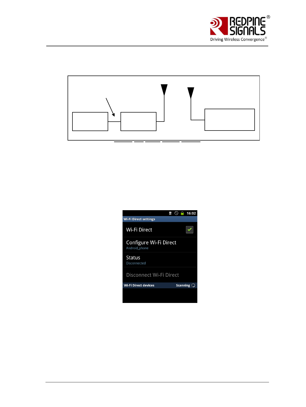
6 Evaluation of Wi-Fi Direct Mode
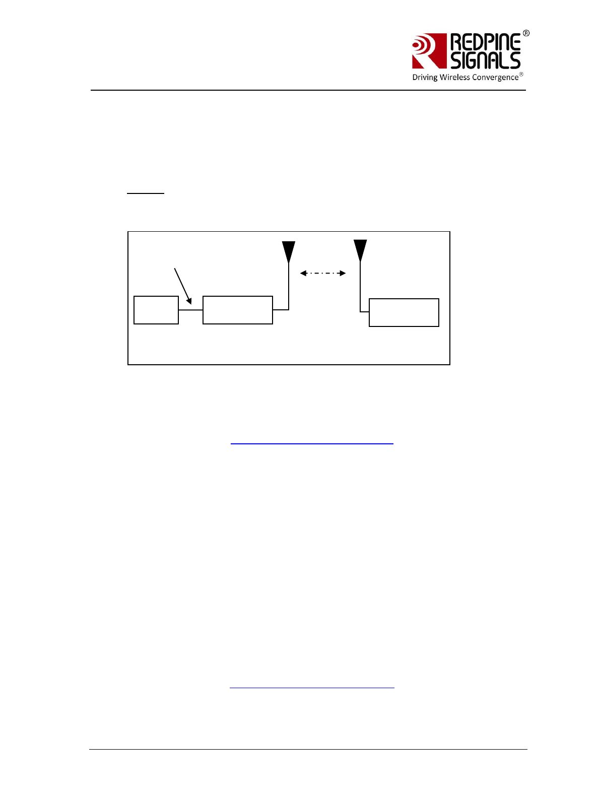
Figure 10: Wi-Fi Direct Set-up
In this set-up, a RS-WC-301 EVB is at one end of the set-up and the other end is a
Wi-Fi Direct device such as a phone.
6.1 Configuration and Test Procedure
The following steps should be executed:
1. Enable Wi-Fi Direct Mode in the phone. Below is shown an example
with an Android 2.3 phone. The Wi-Fi Direct mode can be configured
by going into the phone‟s Wi-Fi Settings.
The “Configure Wi-Fi Direct” button can be clicked to set the device
name accordingly (Android_phone in this case).
2. Open the Serial Port Monitor to see the actual bytes exchanged. Open
Hyperterminal or Teraterm.
3. Configure the EVB in UART mode, connect a UART cable and Power on
the EVB.
PC
RS-WC-
301(A)
UART
Interface
Wi-Fi Direct Mobile
Phone or other Wi-
Fi Direct device (B)

Redpine Signals, Inc. Page 40
R
RS
S-
-W
WC
C-
-3
30
01
1
E
Ev
va
al
lu
ua
at
ti
io
on
n
B
Bo
oa
ar
rd
d
U
Us
se
er
r
G
Gu
ui
id
de
e
V
Ve
er
rs
si
io
on
n
2
2.
.5
51
1
4. The terminal will show the message “Welcome to WiSeConnect”. The
module boots up. Card Ready (LED2) glows on successful completion
of boot-up and a string “READY” is sent from module to host.
5. Enter the following commands
3
. A command should be entered only
after getting the response of the previous command
a. at+rsi_opermode=1
This configures the EVB to function in Wi-Fi Direct mode. The
module responds with “OK”.
b. at+rsi_band=0
This configures the operating band of the EVB. The module
responds with “OK”.
c. at+rsi_init
This initializes the Wi-Fi module in the EVB. The module
responds with OK<MAC_Address>.
d. at+rsi_fwversion?
Optional command to report the firmware version in use.
e. at+rsi_wfd=15,RED,1,wiseconnect,12345678
This starts the Wi-Fi Direct functionality in the module.
The first parameter in this command is called the
Group_Owner_Intent. It gives the willingness of the module to
become a Group Owner. It has been set to the highest value of
15 in this case. Refer to the Programming Reference Manual
for more details. The module responds with “OK”.
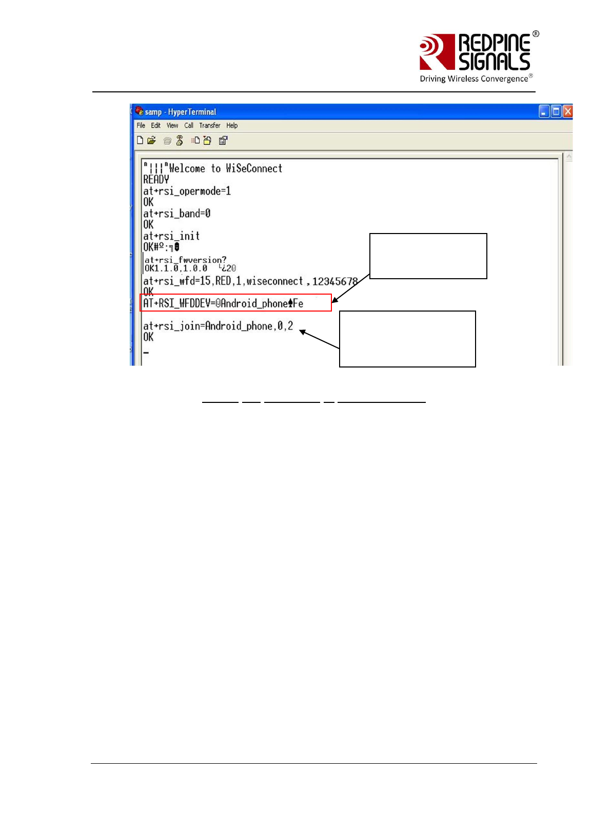
6. After issuing the last command, the module starts scanning for Wi-Fi
Direct devices, and reports any that are found through the
asynchronous message AT+RSI_WFDDEV
7. After the module reports Wi-Fi Direct devices, issue the Join
command to connect.
at+rsi_join=Android_phone,0,2
In this example, it is assumed that the device name of the phone is
configured as “Android_phone”. The phone should also display the
device name of the module (RED in this example). Within about 10
secs of issuing the Join command in the module, click “Connect” on
the phone as well to connect to the module. On successful
connection, the module responds with OK and the Phone displays
“Connected”
3
Please refer to the Programming Reference Manual for detailed descriptions of all
the commands.
Redpine Signals, Inc. Page 41
R
RS
S-
-W
WC
C-
-3
30
01
1
E
Ev
va
al
lu
ua
at
ti
io
on
n
B
Bo
oa
ar
rd
d
U
Us
se
er
r
G
Gu
ui
id
de
e
V
Ve
er
rs
si
io
on
n
2
2.
.5
51
1
Figure 11: Messages in Hyper-terminal
8. If the module has NOT become a GO (Group Owner), issue the below
command to get an IP address from the phone. If the module has
become a GO, this command need not be issued.
at+rsi_ipconf=1,0,0,0
The acquired IP address is returned to the Host and can be observed
in Serial Port Monitor.
Please refer to the description for the command Join in the
Programming Reference Manual. The parameter GO_Status returned
with the OK response of the Join command is used to determine
whether the module became a GO or not. If the module becomes the
GO, it will internally assign itself the IP 192.168.100.76 and will act
as a DHCP server. The Wi-Fi Direct phone will acquire an IP address
from the module automatically (assuming DHCP client is enabled in
the phone). Since the Group_Owner_Intent in point #5 above has
been set to the highest value, there is a very strong chance the
module will become a Group Owner.
Issue “Connect” on the
Phone also when the
“Join” command is issued
in the module.
Module reported the
device name of the
Phone
Redpine Signals, Inc. Page 42
R
RS
S-
-W
WC
C-
-3
30
01
1
E
Ev
va
al
lu
ua
at
ti
io
on
n
B
Bo
oa
ar
rd
d
U
Us
se
er
r
G
Gu
ui
id
de
e
V
Ve
er
rs
si
io
on
n
2
2.
.5
51
1
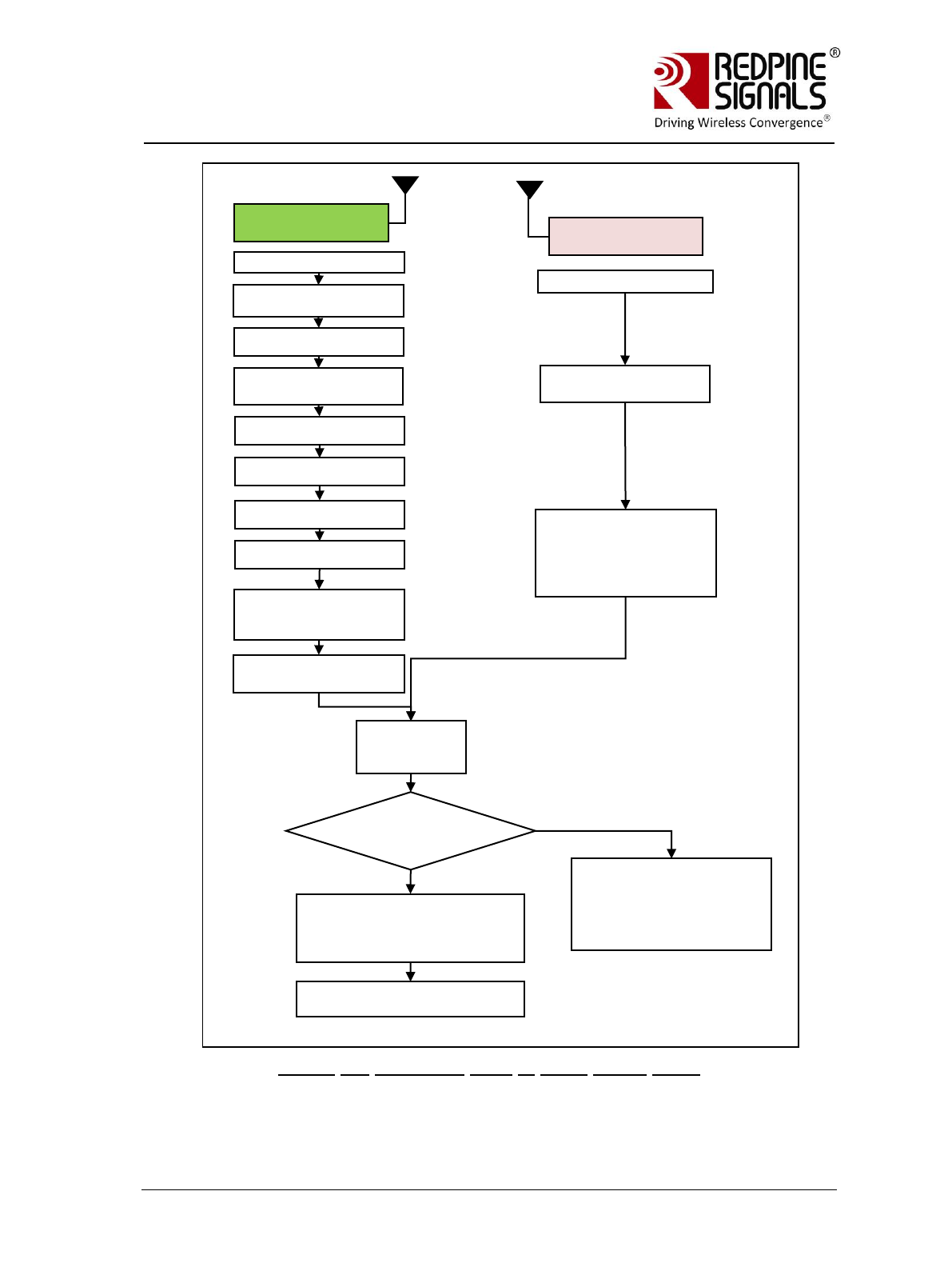
Figure 12: Command Flow in Wi-Fi Direct Mode
RS-WC-301 (A)
Wi-Fi Direct phone or
other device (B)
GO Negotiation
starts between
the two devices
“Welcome to Wise
Connect”
at+rsi_opermode = 1
at+rsi_band
at+rsi_init
at+rsi_wfd
at+rsi_join with target
device name
Scan for Wi-Fi Direct
devices
Issue “join” or “connect”
instruction to the Phone
within 1 minute of issuing
at+rsi_join in the RS-WC-
301 module
Module granted
GO status?
Node (B) is GO (Group Owner).
Module associates to the GO.
WPA2-PSK is the security mode
used.
Module and Node B associate.
The module configures its IP
as 192.168.100.76. Node B
gets IP address from the
DHCP server of the module.
Send at+rsi_ipconf to configure
IP of the module.
Yes
No
Power Up EVB
Power Up Device
Card Ready LED glows
”READY” message sent
from module
Module scans for Wi-Fi
Direct devices and
reports to Host

Redpine Signals, Inc. Page 43
R
RS
S-
-W
WC
C-
-3
30
01
1
E
Ev
va
al
lu
ua
at
ti
io
on
n
B
Bo
oa
ar
rd
d
U
Us
se
er
r
G
Gu
ui
id
de
e
V
Ve
er
rs
si
io
on
n
2
2.
.5
51
1
9. Exchanging Data with the Module
In the following descriptions it is assumed for illustrative purposes
that the module‟s IP address is 192.168.100.76 and the remote peer
(phone) IP address is 192.168.100.77.
Running Ping Application
A ping application can be run from the Wi-Fi Direct Phone, with the
destination address as 192.168.100.76. The module will send the ping
response. Ping based applications are freely available for Android
phones.
Exchanging data through sockets
For exchanging data between the module and the Wi-Fi Direct Phone,
an application may be written by the user at the mobile phone to
open sockets and transmit or receive data. At the module side,
sockets can be opened by using the below commands:
a. To open a server TCP socket in the module, issue the below
command.
at+rsi_ltcp=5001
5001 is the example port number of the socket opened. Once
the socket is opened, a client socket should be opened at the
remote peer (phone) to connect to this socket and establish a
TCP connection. The module responds with
OK<socket_type><socket_handle><lport><module_ipaddr>.
The socket_handle parameter will be used in the subsequent
sections to send data.
b. After the TCP connection is established, data can be exchanged
between the two nodes. To send data from the module, issue
the following command can be typed in Hyperterminal or
Teraterm:
at+rsi_snd=<socket_handle>,0,0,0,abcdefgh where
abcdefgh is the data stream to be transmitted to the remote
Peer. Socket_handle is the parameter returned when the TCP
socket is opened in the module. Refer to the programming
reference manual for more details.
If the remote peer sends data to the module, the module
would receive it and show the data in the terminal with the
message AT+RSI_READ<socket handle><size><Source
IP><Source port><data stream>
10. HTTP server access: To access the HTTP server, the step #7 in section
Configuration and Test Procedure should be used. The URL
http://<module‟s IP Address> should be opened in the connected
phone.
Redpine Signals, Inc. Page 44
R
RS
S-
-W
WC
C-
-3
30
01
1
E
Ev
va
al
lu
ua
at
ti
io
on
n
B
Bo
oa
ar
rd
d
U
Us
se
er
r
G
Gu
ui
id
de
e
V
Ve
er
rs
si
io
on
n
2
2.
.5
51
1
7 Evaluation of Access Point Mode
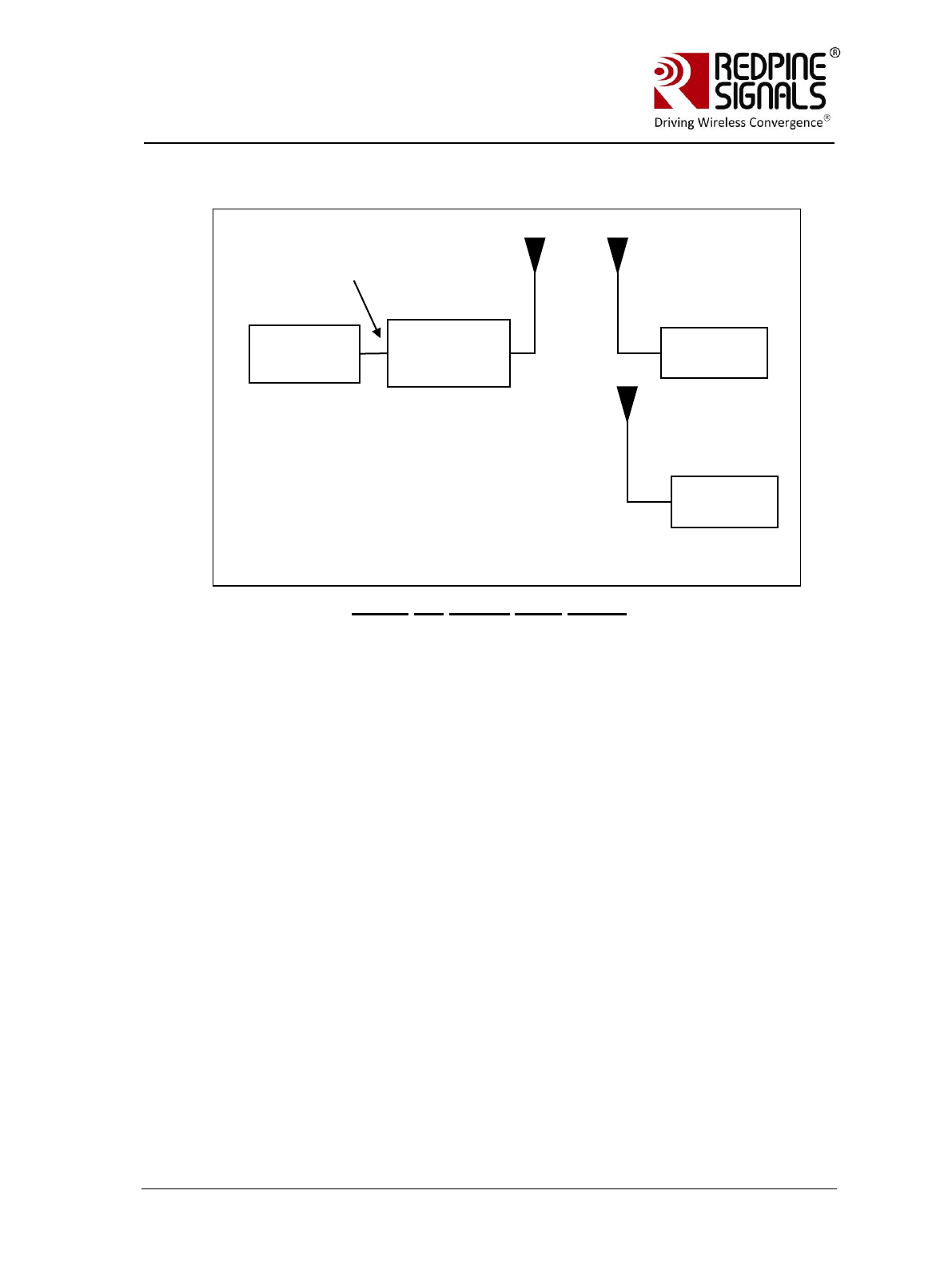
Figure 13: Access Point Set-up
In this set-up, the module is the Access Point and a Laptop is the client. A
maximum of 4 clients can be supported
7.1 Configuration and Test Procedure
The following steps should be executed:
1. Open the Serial Port Monitor to see the actual bytes exchanged. Open
Hyperterminal or Teraterm.
2. Configure the EVB in UART mode, connect a UART cable and Power on
the EVB.
3. The terminal will show the message “Welcome To WiSeConnect”. The
module boots up. Card Ready (LED2) glows on successful completion
of boot-up and a string “READY” is sent from module to host.
4. Enter the following commands. A command should be entered only
after getting the response of the previous command
a. at+rsi_opermode=6
This configures the EVB to function in AP mode. The module
responds with “OK”.
b. at+rsi_band=0
This configures the operating band of the EVB. The module
responds with “OK”.
c. at+rsi_init
PC (P)
RS-WC-301(A)
(Access Point)
Laptop(B)
UART
Interface
Client
Laptop(C)
(Optional)
Client

Redpine Signals, Inc. Page 45
R
RS
S-
-W
WC
C-
-3
30
01
1
E
Ev
va
al
lu
ua
at
ti
io
on
n
B
Bo
oa
ar
rd
d
U
Us
se
er
r
G
Gu
ui
id
de
e
V
Ve
er
rs
si
io
on
n
2
2.
.5
51
1
This initializes the WiFi module in the EVB. The module
responds with OK<mac_address>
d. at+rsi_fwversion?
Optional command to report the firmware version in use.
e. at+rsi_ipconf=0,192.168.50.1,255.255.255.0,192.168.5
0.1
To configure the IP (192.168.50.1 in this example) of the AP.
If this command is not issued, a default IP of 192.168.100.76
will be used.
f. at+rsi_apconf=1,redpine,2,2,12345678,300,2,4
The SSID is configured as “redpine”, to operate in channel 1.
g. at+rsi_join=redpine,0,2
This starts the Access Point functionality in the module.
The module is now configured as an Access Point. Its IP address is
192.168.50.1. A Laptop can now scan for networks and the SSID of
the module, “redpine” will be displayed in the Laptop‟s list of Scanned
APs. After the client Laptop (B) connects to the AP by providing the
correct password (12345678 in this example), it acquires an IP
address. It is assumed for illustrative purposes that the IP of the
Laptop is 192.168.50.2
5. Exchanging data between the client Laptop (B) and the Access Point
a. Open a Listening TCP socket on the module by issuing the
command
at+rsi_ltcp=5001
b. Open a TCP socket on the client Laptop (B) (Windows OS based)
by typing the below command on the command line:
TCP.exe c 2001 192.168.50.1 5001
The application is found in the path
RS.WSC.x.x.GENR.x.x.x.x.x.x\Resources\Applications\Peer\Windo
ws\ . The destination IP (the Access Point in this case) is
192.168.50.1.
c. The command line window will display three options: 1 (Send), 2
(Receive) and 3 (Exit). Type 1 to send data to the Wi-Fi module.
On being prompted “Enter the string to be transmitted”, type any
string from the Keyboard. On pressing “Enter” key on the
keyboard, the data is sent from the Laptop(B) to the module and
the Hyperterminal displays it with the AT+RSI_READ message.
d. To send data from the Wi-Fi module, type Option 2 in Laptop (B)
and then type the below command in the module
at+rsi_snd=<socket_handle>,0,0,0,abcdefgh

Redpine Signals, Inc. Page 46
R
RS
S-
-W
WC
C-
-3
30
01
1
E
Ev
va
al
lu
ua
at
ti
io
on
n
B
Bo
oa
ar
rd
d
U
Us
se
er
r
G
Gu
ui
id
de
e
V
Ve
er
rs
si
io
on
n
2
2.
.5
51
1
<socket_handle> is the parameter returned by the module when a
socket is opened in the module. Refer to the programming
reference manual for more details.
A second Laptop I can also be connected to the module‟s AP and
data transfers can be done between it and Laptop (B).
6. HTTP server access: To access the HTTP server, the step #7 in section
Configuration and Test Procedure should be used. The URL
http://<module‟s IP Address> should be opened in any of the
connected client devices.
Redpine Signals, Inc. Page 47
R
RS
S-
-W
WC
C-
-3
30
01
1
E
Ev
va
al
lu
ua
at
ti
io
on
n
B
Bo
oa
ar
rd
d
U
Us
se
er
r
G
Gu
ui
id
de
e
V
Ve
er
rs
si
io
on
n
2
2.
.5
51
1
8 Wireless Configuration
The module can be configured wirelessly to join a specific AP (referred to as
“auto-connect”) or create an Access Point (referred to as “auto-create”).
8.1 Configuration to join a Specific AP
Flow 1: In this flow, an AP is first created in the module, to which a
remote device connects and configures the module.
1. Connect a PC or Host to the module through the UART interface and
power up the module.
2. Configure the module to become an AP by issuing commands from PC
(P) as in section Evaluation of Access Point Mode. The sequence of
commands is given below.
a. at+rsi_opermode=6
b. at+rsi_band=0
c. at+rsi_init
d. at+rsi_fwversion?
e. at+rsi_ipconf=0,192.168.50.1,255.255.255.0,192.168.5
0.1
f. at+rsi_apconf=1,redpine,2,2,12345678,300,2,4
g. at+rsi_join=redpine,0,2
The module is now configured as an Access Point. Its IP address is
192.168.50.1.
3. Connect a Laptop (B) to the created AP. Open the URL
http://<Module’s IP address>/config.htm in the Laptop. In this
case, the URL is http://192.168.50.1/config.html. Make sure the
browser in the laptop does not have any proxies enabled.
PC (P)
RS-WC-
301(A)
UART
Interface
Laptop (B)

Redpine Signals, Inc. Page 48
R
RS
S-
-W
WC
C-
-3
30
01
1
E
Ev
va
al
lu
ua
at
ti
io
on
n
B
Bo
oa
ar
rd
d
U
Us
se
er
r
G
Gu
ui
id
de
e
V
Ve
er
rs
si
io
on
n
2
2.
.5
51
1
4. In the web page that opens, select “Client mode” and enter desired
values.
SSID: This is the SSID of the AP to which the module should connect
after configuration is over.
Data rate: Physical data rate. This can be set to „0‟. For more details,
refer to the section on wireless configuration in the PRM.
Tx Power: RF power for Tx. Set to „2‟.
Security mode and PSK: This should match the security mode of the
AP to which the module should connect.
DHCP: If DHCP is selected, the module will work as a DHCP client,
otherwise, an IP should be hard coded in the web page.
Channel: Channel number at which the target AP is present. Set to „0‟
in this example. For more details, refer to the section on wireless
configuration in the PRM.
Click on “Submit Query” button. The information is sent to the module
and stored in its internal flash.
5. The module should now be power cycled or hard reset. It boots up
and then automatically scans channels for the target AP and connects
to it and gets an IP address. The module will send out two responses
to the Host, the first corresponds to the internally given “Join”
command and the second to the “Set IP Parameters” command. Note
that once the module is restarted, no commands need to be given.
The module automatically scans and joins the target AP, after which
the stored configuration parameters can be retrieved using the
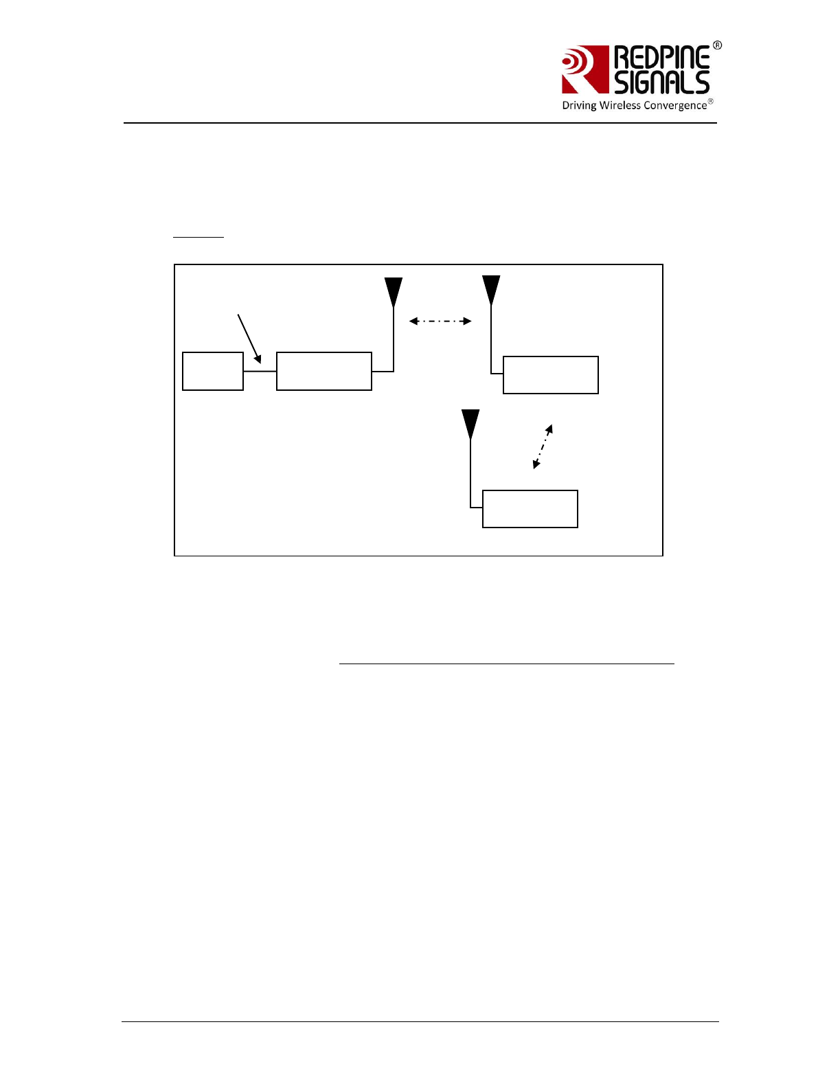
Redpine Signals, Inc. Page 49
R
RS
S-
-W
WC
C-
-3
30
01
1
E
Ev
va
al
lu
ua
at
ti
io
on
n
B
Bo
oa
ar
rd
d
U
Us
se
er
r
G
Gu
ui
id
de
e
V
Ve
er
rs
si
io
on
n
2
2.
.5
51
1
command at+rsi_cfgget. If the auto-connect feature needs to be
disabled, issue the command at+rsi_cfgenable=0. Refer to the PRM
for more details on these commands.
Flow 2: In this flow, the module is connected to an AP. A remote device
connects to the same AP and configures the module.
1. Connect a PC or Host to the module through the UART interface and
power up the module.
2. Configure the module to become a client and connect to an AP as
described in section Evaluation of Client Mode with Personal Security.
3. Connect a Laptop (B) to the same AP. Open the URL
http://<Module’s IP address>/config.htm in the Laptop. For
example, if the module was configured to have an IP of
192.168.100.20, then the URL is http://192.168.100.20/config.htm.
Make sure the browser in the laptop does not have any proxies
enabled.
4. In the web page that opens, select “Client mode” and enter desired
values.
SSID: This is the SSID of the AP to which the module should connect
after configuration is over.
Data rate: Physical data rate. This can be set to „0‟. For more details,
refer to the section on wireless configuration in the PRM.
Tx Power: RF power for Tx. Set this to „2‟.
Security mode and PSK: This should match the security mode of the
AP to which the module should connect.
PC (P)
RS-WC-
301(A)
UART
Interface
Access Point
(C)
Laptop (B)
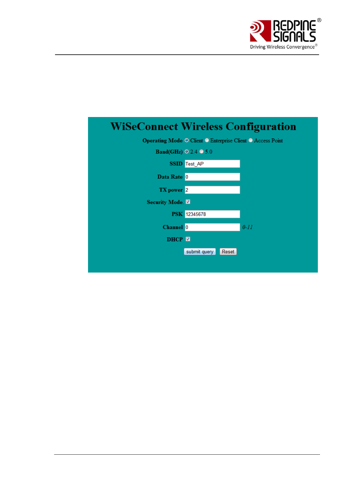
Redpine Signals, Inc. Page 50
R
RS
S-
-W
WC
C-
-3
30
01
1
E
Ev
va
al
lu
ua
at
ti
io
on
n
B
Bo
oa
ar
rd
d
U
Us
se
er
r
G
Gu
ui
id
de
e
V
Ve
er
rs
si
io
on
n
2
2.
.5
51
1
DHCP: If DHCP is selected, the module will work as a DHCP client,
otherwise, an IP should be hard coded in the web page.
Channel: Channel number at which the target AP is present. This can
be set to „0‟ in this example. For more details, refer to the section on
wireless configuration in the PRM.
Click on “Submit Query” button. The information is sent to the module
and stored in its internal flash.
5. The module should now be power cycled or hard reset. It boots up
and then automatically scans channels for the target AP and connects
to it and gets an IP address. The module will send out two responses
to the Host, the first corresponds to the internally given “Join”
command and the second to the “Set IP Parameters” command. Note
that once the module is restarted, no commands need to be given.
The module automatically scans and joins the target AP, after which
the stored configuration parameters can be retrieved using the
command at+rsi_cfgget. If the auto-connect feature needs to be
disabled, issue the command at+rsi_cfgenable=0. Refer to the PRM
for more details on these commands.
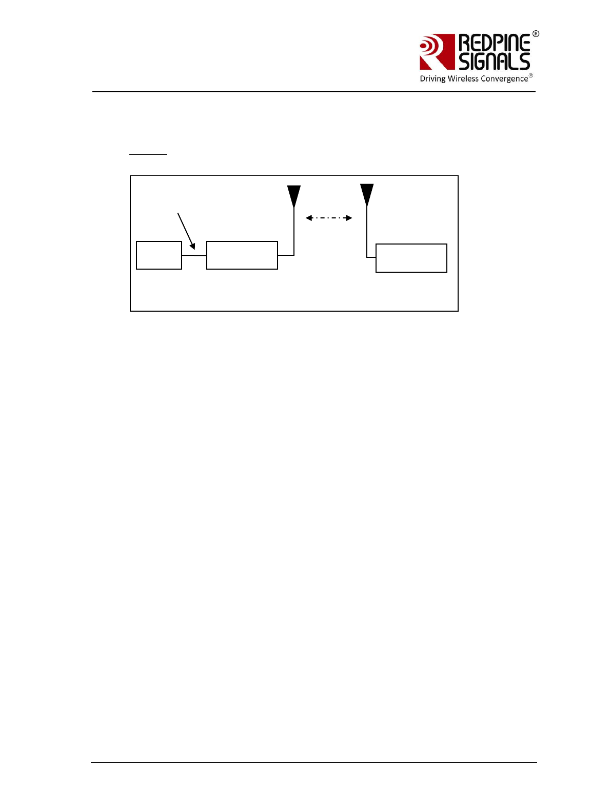
Redpine Signals, Inc. Page 51
R
RS
S-
-W
WC
C-
-3
30
01
1
E
Ev
va
al
lu
ua
at
ti
io
on
n
B
Bo
oa
ar
rd
d
U
Us
se
er
r
G
Gu
ui
id
de
e
V
Ve
er
rs
si
io
on
n
2
2.
.5
51
1
8.2 Configuration to create an AP
Flow 1: In this flow, an AP is first created in the module, to which a
remote device connects and configures the module.
1. Connect a PC or Host to the module through the UART interface and
power up the module.
2. Configure the module to become an AP by issuing commands through
PC (P).
3. Connect a Laptop (B) to the created AP. Open the URL
http://<Module’s IP address>/config.htm in the Laptop. For
example, if the module was configured to have an IP of
192.168.100.1, then the URL is http://192.168.100.1/config.htm.
Make sure the browser in the laptop does not have any proxies
enabled.
4. In the web page that opens, select “Access Point” mode and enter
desired values.
SSID: This is the SSID of the AP which will be created after
configuration is over.
Data rate: Set the data rate to „0‟.
Tx Power: RF power for Tx. Set this value to „2‟.
Security mode, PSK, security type, encryption type: This is to
configure the security mode of the AP.
Channel: Channel number at which the target AP is present. Value of
„0‟ is not allowed.
IP, Mask, Gateway: These parameters set the IP parameters of the
AP.
Beacon Interval and DTIM count: This to set the beacon parameters
of the AP. For example, if beacon interval is 200 (msecs) and DTIM
count is 3, the DTIM interval would be 2x300=600 msecs.
PC (P)
RS-WC-
301(A)
UART
Interface
Laptop (B)

Redpine Signals, Inc. Page 52
R
RS
S-
-W
WC
C-
-3
30
01
1
E
Ev
va
al
lu
ua
at
ti
io
on
n
B
Bo
oa
ar
rd
d
U
Us
se
er
r
G
Gu
ui
id
de
e
V
Ve
er
rs
si
io
on
n
2
2.
.5
51
1
Click on “Submit Query” button. The information is sent to the module
and stored in its internal flash.
5. The module should now be power cycled or hard reset. It boots up
and then automatically creates and AP with the configured
parameters. The module will send out two responses to the Host, the
first corresponds to the internally given “Set IP Parameters” command
and the second to the “Join” command. Note that once the module is
restarted, no commands need to be given. The module automatically
and internally executes the commands to create an AP. The stored
configuration parameters can be retrieved using the command
at+rsi_cfgget. If the auto-connect feature needs to be disabled, issue
the command at+rsi_cfgenable to the module. Refer to the PRM for
more details on these commands.
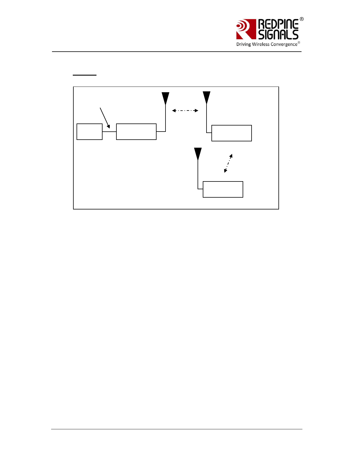
Redpine Signals, Inc. Page 53
R
RS
S-
-W
WC
C-
-3
30
01
1
E
Ev
va
al
lu
ua
at
ti
io
on
n
B
Bo
oa
ar
rd
d
U
Us
se
er
r
G
Gu
ui
id
de
e
V
Ve
er
rs
si
io
on
n
2
2.
.5
51
1
Flow 2: In this flow, the module is connected to an AP. A remote device
connects to the same AP and configures the module.
1. Connect a PC or Host to the module through the UART interface and
power up the module.
2. Configure the module to become a client and connect to an AP by
issuing commands from the PC (P).
3. Connect a Laptop (B) to the created AP. Open the URL
http://<Module’s IP address>/config.htm in the Laptop. For
example, if the module was configured to have an IP of
192.168.100.20, then the URL is http://192.168.100.20/config.htm.
Make sure the browser in the laptop does not have any proxies
enabled.
4. In the web page that opens, select “Access Point” mode and enter
desired values.
SSID: This is the SSID of the AP which will be created after
configuration is over.
Data rate: Set the data rate to „0‟.
Tx Power: RF power for Tx. Set this value to „2‟.
Security mode , PSK, security type, encryption type: This is to
configure the security mode of the AP.
Channel: Channel number at which the target AP is present. Value of
„0‟ is not allowed.
PC (P)
RS-WC-
301(A)
UART
Interface
Access Point
(C)
Laptop (B)

Redpine Signals, Inc. Page 54
R
RS
S-
-W
WC
C-
-3
30
01
1
E
Ev
va
al
lu
ua
at
ti
io
on
n
B
Bo
oa
ar
rd
d
U
Us
se
er
r
G
Gu
ui
id
de
e
V
Ve
er
rs
si
io
on
n
2
2.
.5
51
1
IP, Mask, Gateway: These parameters set the IP parameters of the
AP.
Beacon Interval and DTIM count: This to set the beacon parameters
of the AP. For example, if beacon interval is 200 (msecs) and DTIM
count is 3, the DTIM interval would be 2x300=600 msecs.
Click on “Submit Query” button. The information is sent to the module
and stored in its internal flash.
5. The module should now be power cycled or hard reset. It boots up
and then automatically creates and AP with the configured
parameters. The module will send out two responses to the Host, the
first corresponds to the internally given “Set IP Parameters” command
and the second to the “Join” command. Note that once the module is
restarted, no commands need to be given. The module automatically
and internally executes the commands to create an AP. The stored
configuration parameters can be retrieved using the command
at+rsi_cfgget. If the auto-connect feature needs to be disabled, issue
the command at+rsi_cfgenable=0 to the module. Refer to the PRM for
more details on these commands.

Redpine Signals, Inc. Page 55
R
RS
S-
-W
WC
C-
-3
30
01
1
E
Ev
va
al
lu
ua
at
ti
io
on
n
B
Bo
oa
ar
rd
d
U
Us
se
er
r
G
Gu
ui
id
de
e
V
Ve
er
rs
si
io
on
n
2
2.
.5
51
1
9 Using the Module in USB Mode
The module supports the USB 2.0 interface. It corresponds to the CDC-
ACM class and presents itself as a USB Device to the Host USB. A file is
provided with the software package that the user should install in the
Host platform, in order to communicate with the module. A sample flow is
provided below to use the module with a PC‟s USB interface.
The parameters corresponding to the device after the USB is detected
are:
Device Descriptor:
bcdUSB: 0x0200
bDeviceClass: 0x02
bDeviceSubClass: 0x00
bDeviceProtocol: 0x00
bMaxPacketSize0: 0x10 (16)
idVendor: 0x041B
idProduct: 0x0102
bcdDevice: 0x0002
iManufacturer: 0x01
NOTE: It is essential to read all the previous sections of the document that
describes how to use the module in UART mode. The steps t use the module in USB
mode are the same.
1. Configure the EVB in USB mode (Interface Selection) and connect the
USB interface of a PC to that of the module. The PC prompts for
installing the driver. Install the file from
RS.WSC.2.0.GENR.x.x.x.x.x.x\Resources\USB\rsi_usbcdc. The
installation needs to be done only once.
2. Power cycle the module. Check the list in “Ports” in the Device
Manager Settings of the PC. It should show the device as “RSI WSC
Virtual Com Port”.
3. Open Hyper-terminal and follow the steps in section Configure Serial
Port Monitor in the PC to configure the Hyperterminal. The COM port
number (COM3 in the above example) should be supplied to the
Hyperterminal. Set “Flow Control” to “None”. Baud rate, Data bits,
Parity and Stops bits for “Don‟t care” fields in USB mode.
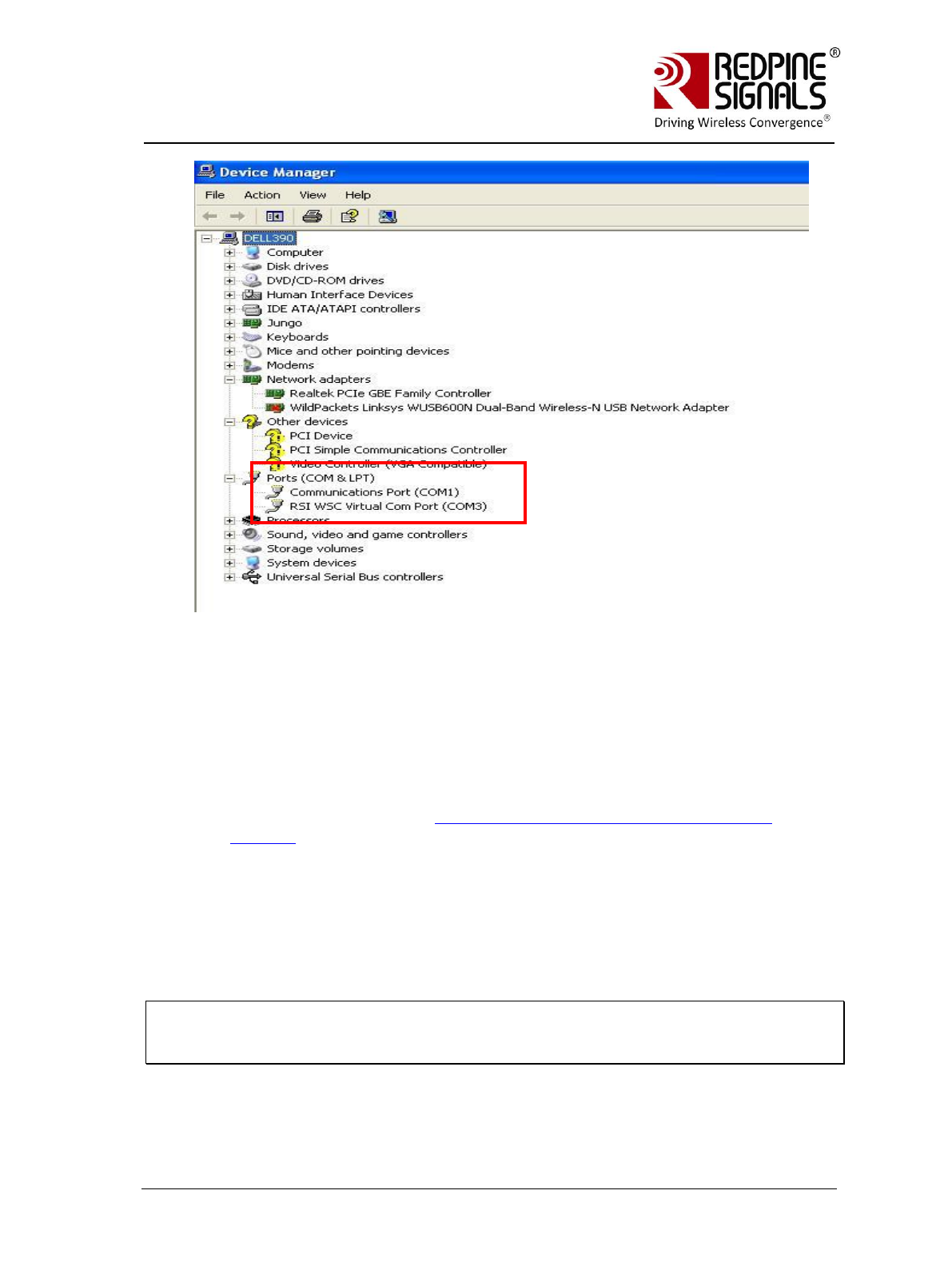
Redpine Signals, Inc. Page 56
R
RS
S-
-W
WC
C-
-3
30
01
1
E
Ev
va
al
lu
ua
at
ti
io
on
n
B
Bo
oa
ar
rd
d
U
Us
se
er
r
G
Gu
ui
id
de
e
V
Ve
er
rs
si
io
on
n
2
2.
.5
51
1
4. The module sends the message ““Welcome to WiSeConnect” and then
“READY”. Now, AT commands can be issued from at+rsi_opermode
onwards, through the virtual Com port (follow sections 4, 5, 6 and 7
of the document). The behavior of the module, commands, command
responses, error codes and flow of commands are exactly same as in
the UART mode except for a few exceptions described in the
Programming Reference Manual. Python scripts can also be run to
configure and operate the module. A sample script is given for EAP-
TLS mode ( refer section Evaluation of Client Mode with Enterprise
Security) inside
RS.WSC.x.x.GENR.x.x.x.x.x.x\Resources\USB\WiFi_Enterprise_TLS_F
or_USB.py can be run in the USB mode.
The USB interface of the module supports the full speed USB mode
(12 Mbps physical data rate).
NOTE: If after one session of testing, the user wants to reset the EVB and start
over again, he should open a fresh Hyperterminal session and make sure the newly
assigned COM port is supplied to the Hyperterminal.

Redpine Signals, Inc. Page 57
R
RS
S-
-W
WC
C-
-3
30
01
1
E
Ev
va
al
lu
ua
at
ti
io
on
n
B
Bo
oa
ar
rd
d
U
Us
se
er
r
G
Gu
ui
id
de
e
V
Ve
er
rs
si
io
on
n
2
2.
.5
51
1
10 Using the Module in SPI Mode
To evaluate the module in SPI mode, the following steps should be
followed:
1. SPI interface of the EVB should be interfaced with the Host MCU.
Figure 14: Interface between Module and Host
Signal Integrity Guidelines for SPI interface: Glitches in the SPI clock may take the
SPI interface out of synchronization. The quality and integrity of the clock line
should be maintained. The following steps are recommended. This is not an
exhaustive list of guidelines and depending on individual cases additional steps may
be needed.
1. Avoid using long cables to connect the Host platform with the EVB‟s SPI
interface. If a cable is used, minimize its length to as small as possible, preferably
to within two inches.
2. Increase the number of ground connections between the Wi-Fi PCB and the MCU
PCB
3. Add a series resistor into the clock line. Choice of value is mentioned in the
Module Integration Guide.
4. If the SPI clock line is mapped to a programmable I/O on the MCU, configure
that I/O to an output with as high a drive as is available.
5. Ensure that the EVB‟s reset input is mapped to a MCU controllable line, so that
the system can recover through a hard reset.
Host MCU
SPI MOSI (SPI Header)
SPI MISO (SPI Header)
SPI CLK (SPI Header
SPI CS (SPI Header)
INTERRUPT (SPI Header Pins)
SPI_READY (General Purpose Header)
RS-WC-301
SPI MOSI
SPI MISO
SPI CLK
SPI CS
INTERRUPT
GPIO
RESET_N (General Purpose Header)
RESET_N
GPIO
WAKEUP

Redpine Signals, Inc. Page 58
R
RS
S-
-W
WC
C-
-3
30
01
1
E
Ev
va
al
lu
ua
at
ti
io
on
n
B
Bo
oa
ar
rd
d
U
Us
se
er
r
G
Gu
ui
id
de
e
V
Ve
er
rs
si
io
on
n
2
2.
.5
51
1
2. The DIP switches should be configured to put the EVB in SPI mode
according to table Interface Selection.
3. The source code of a sample driver, API set and application is
provided with the Software Package. The developer should port the
source code into the target platform. Appropriate HAL changes may
be required for porting.
a. The Driver source code is present in the software package
inside RS.WSC.x.x.GENR.x.x.x.x.x.x\Resources\SPI\Driver\
b. The porting guidelines to port the driver are present in the
document RS-WC-301_Software_PRM.pdf in the section
“Driver Porting Guide for SPI”
c. The section “RS-WC-301 in SPI mode” in RS-WC-
301_Software_PRM.pdf should be carefully read to understand
all the commands to configure and operate the module.
4. The following settings should be observed to use the SPI interface
a. SPI CPOL=0
b. SPI CPHASE=0
c. Max SPI Clock = 12.5 Mhz (For detailed timing information on
the SPI signals, please refer to the Datasheet).
d. The Interrupt output from the module is active high, level
triggered.
10.1 Sample flow for evaluating SPI mode
The set-ups described in the previous sections describing the UART
interface (Client Mode with Personal Security, Client Mode with Enterprise
Security, Wi-Fi Direct Mode and Access Point mode can be used to
evaluate the module in SPI mode. A sample flow for evaluating the
module in different modes is given below. The Application running in the
Host should execute this flow by calling the different APIs provided.

Redpine Signals, Inc. Page 59
R
RS
S-
-W
WC
C-
-3
30
01
1
E
Ev
va
al
lu
ua
at
ti
io
on
n
B
Bo
oa
ar
rd
d
U
Us
se
er
r
G
Gu
ui
id
de
e
V
Ve
er
rs
si
io
on
n
2
2.
.5
51
1
Figure 15: Flow of Commands in SPI mode
Power up
Module boots up and
sends Interrupt
Host Executes CARD READY
Operation (refer PRM)
Set Operating Mode
Operating Mode=0
(Client Mode Set-
up with Personal
Security)
Operating Mode=2
(Enterprise
Security Set-up)
Operating Mode=1
(Wi-Fi Direct Set-
up)
Operating
Mode=6(Access
Point Set-up)
Band
Init
Query Firmware
Version
Scan
Set PSK
Join
Set IP Parameters
Open a Server TCP
Socket
Open a Client
socket at the
remote terminal
(using TCP.exe)
and transfer data
Band
Init
Set EAP
Query Firmware
Version
Scan
Set Certificate (if
TLS mode is used)
Join
Set IP Parameters
Open a Server TCP
Socket
Open a Client
socket at the
remote terminal
(using TCP.exe)
and transfer data
Band
Init
Configure WFD P2P
(GOIntent ≤15)
Query Firmware
Version
Join
Set IP Parameters
if module is not a
Group Owner
Open a Server TCP
Socket
Open a Client
socket at the
remote terminal
and transfer data
Band
Init
Configure AP Mode
Query Firmware
Version
Join
Connect clients to
the AP
Open a Server TCP
Socket in module
Open a Client
socket at the
remote terminal
(using TCP.exe)
and transfer data
AP is now created
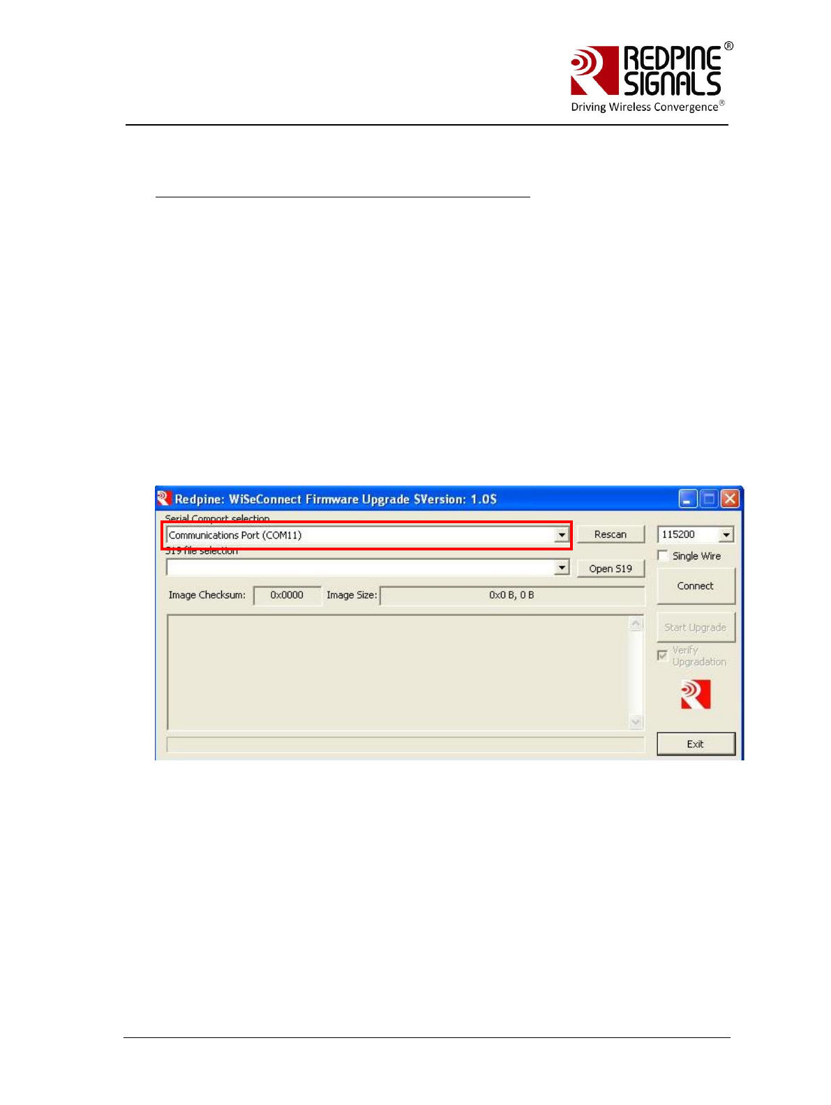
Redpine Signals, Inc. Page 60
R
RS
S-
-W
WC
C-
-3
30
01
1
E
Ev
va
al
lu
ua
at
ti
io
on
n
B
Bo
oa
ar
rd
d
U
Us
se
er
r
G
Gu
ui
id
de
e
V
Ve
er
rs
si
io
on
n
2
2.
.5
51
1
11 Upgrading Firmware Through the UART Interface
For Users of Firmware Version lower than 2.1.0.1.2.5
This section is for users who want to upgrade from Version x to Version y, both x
and y being less than 2.1.0.1.2.5
The firmware of the module can be upgraded using the UART interface.
Upgrading of firmware using the SPI interface is not supported. However,
upgrading firmware using the wireless interface is supported. If the user wants
to the upgrade the firmware of the module with a newer version, the following
flow should be used.
1.Connect a PC to the Module through the UART interface, using a UART cable.
2.Open the application
RS.WSC.x.x.GENR.x.x.x.x.x.x\Resources\UART\Firmware_upgrade\WSC
_FW_Upgrade_Util.exe in the PC. This application can be found in the
software release package. The application will automatically scan for UART ports
in the PC and display the appropriate port.
2.From the drop-down box, select the COM port that is connected to the
module‟s UART interface.
3.Click “Open S19” button. Select the file
RS.WSC.x.x.GENR.x.x.x.x.x.x\Firmware\WiSe_WLAN.S19. Now press
“Connect” button.
4.Within 10 secs of pressing the “Connect” button, give a hard-reset to the
module.
5.The message window of the GUI will prompt to start the upgrade. Click on
“Start Upgrade” button.
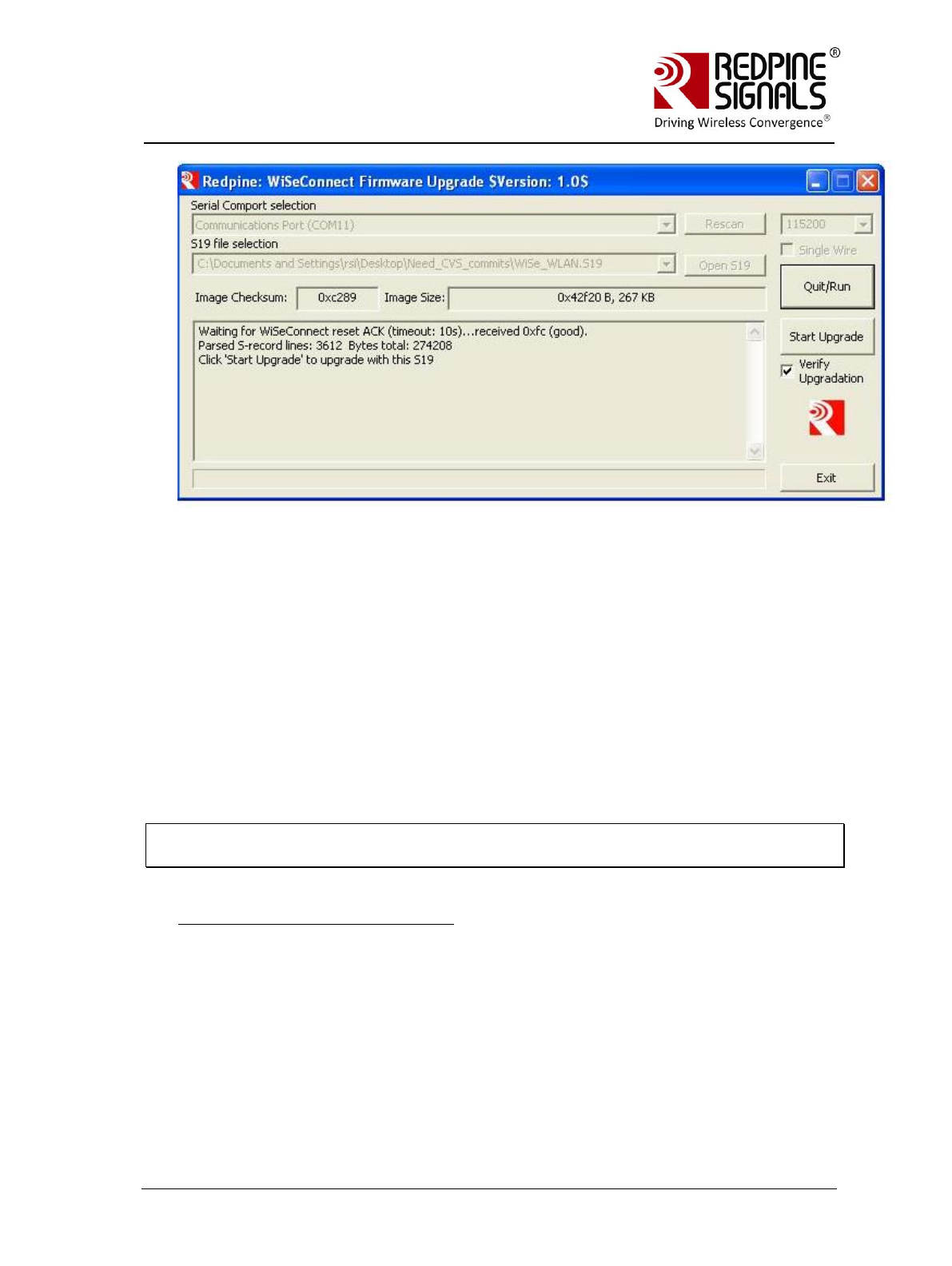
Redpine Signals, Inc. Page 61
R
RS
S-
-W
WC
C-
-3
30
01
1
E
Ev
va
al
lu
ua
at
ti
io
on
n
B
Bo
oa
ar
rd
d
U
Us
se
er
r
G
Gu
ui
id
de
e
V
Ve
er
rs
si
io
on
n
2
2.
.5
51
1
6.The Message window prompts “Upgradation Completed”. Card_Ready (LED2)
glows. It may take up to 1.5 mins for it to glow.
7. Click “Open S19” button. Select the file
RS.WSC.x.x.GENR.x.x.x.x.x.x\Firmware\WiSe_Control.S19. Now press
“Connect” button. Within 10 secs of pressing the “Connect” button, give a hard-
reset to the module or power cycle the module.
8. The message window of the GUI will prompt to start the upgrade. Click on
“Start Upgrade” button.
9. The Message window prompts “Upgradation Completed”. This completed the
Firmware Upgrade Process. The module should now be reset or power cycled to
operate in normal mode.
NOTE: The utility WSC_FW_Upgrade_Util.exe is not compatible with Windows 7 64-
bit systems.
For Users migrating to 2.1.0.1.2.5
This section is for users who want to upgrade from Version x to Version
2.1.0.1.2.5, x being lower than 2.1.0.1.2.5.
1.Connect a PC to the module through the UART interface, using a UART cable.
2.Open the application
RS.WSC.x.x.GENR.2.1.0.1.2.5\Resources\UART\Firmware_upgrade\WS
C_FW_Upgrade_Util.exe in the PC. This application can be found in the
software release package. The application will automatically scan for UART ports
in the PC and display the appropriate port.

Redpine Signals, Inc. Page 62
R
RS
S-
-W
WC
C-
-3
30
01
1
E
Ev
va
al
lu
ua
at
ti
io
on
n
B
Bo
oa
ar
rd
d
U
Us
se
er
r
G
Gu
ui
id
de
e
V
Ve
er
rs
si
io
on
n
2
2.
.5
51
1
2.From the drop-down box, select the COM port that is connected to the
module‟s UART interface.
3.Click “Open S19” button. Select the file
RS.WSC.x.x.GENR.2.1.0.1.2.5\Firmware\WFU\WFU_Control.S19. Now
press “Connect” button.
4. Within 10 secs of pressing the “Connect” button, give a hard-reset to the
module.
5.The message window of the GUI will prompt to start the upgrade. Click on
“Start Upgrade” button.
6.The Message window prompts “Upgradation Completed”.
7. Click “Open S19” button. Select the file
RS.WSC.x.x.GENR.2.1.0.1.2.5\Firmware\WFU\WLAN_Config.S19. Now
press “Connect” button. Within 10 secs of pressing the “Connect” button, give a
hard-reset to the module or power cycle the module.
8. The message window of the GUI will prompt to start the upgrade. Click on
“Start Upgrade” button.
9. The Message window prompts “Upgradation Completed”. Card_Ready (LED2)
goes “Low”. It may take up to 1 min for the pin to go low.
10.From the drop-down box, select the COM port that is connected to the
module‟s UART interface. Click “Open S19” button. Select the file
RS.WSC.x.x.GENR.2.1.0.1.2.5\Firmware\WiSe_WLAN.S19. Now press
“Connect” button.
11.Within 10 secs of pressing the “Connect” button, give a hard-reset to the
module.
12.The message window of the GUI will prompt to start the upgrade. Click on
“Start Upgrade” button.
13.The Message window prompts “Upgradation Completed”. Card_Ready (LED2)
goes “Low”. It may take up to 1 min for the pin to go low.
14. Click “Open S19” button. Select the file
RS.WSC.x.x.GENR.2.1.0.1.2.5\Firmware\WiSe_Control.S19. Now press
“Connect” button. Within 10 secs of pressing the “Connect” button, give a hard-
reset to the module or power cycle the module.
15. The message window of the GUI will prompt to start the upgrade. Click on
“Start Upgrade” button.
16. The Message window prompts “Upgradation Completed”. This completed the
Firmware Upgrade Process. Close the application in the PC and power cycle the
module
For Users migrating to versions higher than 2.1.0.1.2.5
This section is for users migrating from version x to version y, both x and y
being equal to or greater than 2.1.0.1.2.5. There are two options available:
1. Wireless firmware upgrade. For this option follow the section Wireless
Firmware Upgrade.

Redpine Signals, Inc. Page 63
R
RS
S-
-W
WC
C-
-3
30
01
1
E
Ev
va
al
lu
ua
at
ti
io
on
n
B
Bo
oa
ar
rd
d
U
Us
se
er
r
G
Gu
ui
id
de
e
V
Ve
er
rs
si
io
on
n
2
2.
.5
51
1
2. Wired firmware upgrade using the UART interface. For this option, follow
the process in the sub-section: For Users of Firmware Version lower than
2.1.0.1.2.5. The process for upgrade is same as listed in that section.
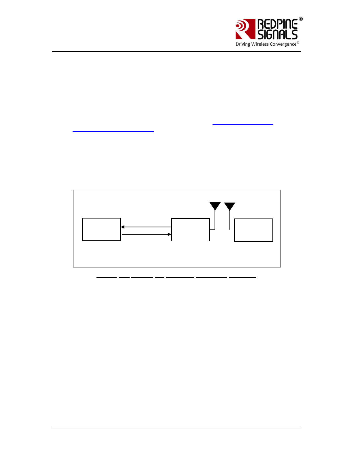
Redpine Signals, Inc. Page 64
R
RS
S-
-W
WC
C-
-3
30
01
1
E
Ev
va
al
lu
ua
at
ti
io
on
n
B
Bo
oa
ar
rd
d
U
Us
se
er
r
G
Gu
ui
id
de
e
V
Ve
er
rs
si
io
on
n
2
2.
.5
51
1
12 Wireless Firmware Upgrade
The firmware of the module can be upgraded wirelessly. This feature is available
from firmware version 2.1.0.1.2.5 onwards. The following sections describe the
process.
12.1 Users of Firmware Lower than version 2.1.0.1.2.5
The user should first upgrade to version 2.1.0.1.2.5 to use the feature of
wireless firmware upgrade. Refer to the section Upgrading Firmware
Through the UART Interface.
12.2 Upgrading Firmware Wirelessly
If the user already has firmware version 2.1.0.1.2.5 or above in the
module, this section should be followed. To upgrade the firmware of the
module, pins WF_HNDSHKE1 and WF_HNDSHKE2 should be connected to
corresponding GPIO pins of the Host.
Figure 16: Set-up for Wireless Firmware Upgrade
The steps are mentioned below:
1. Set WF_HNDSHKE1 to logic „1‟ from the Host
2. Power up the module
3. Module boots up and comes up as an Access Point in open mode with
with SSID REDPINE_<MAC> where <MAC> are the last 3 bytes of
the MAC address of the module. The default IP address of the module
is found 192.168.40.61.
4. Connect a Laptop to the Access Point
5. Open the application RS.WSC.x.x.GENR.x.x.x.x.x.x\Firmware\WFU
WiSeConfigGUI.exe in the Laptop
Host
RS-WC-
301
Laptop
WF_HNDSHKE2
WF_HNDSHKE1
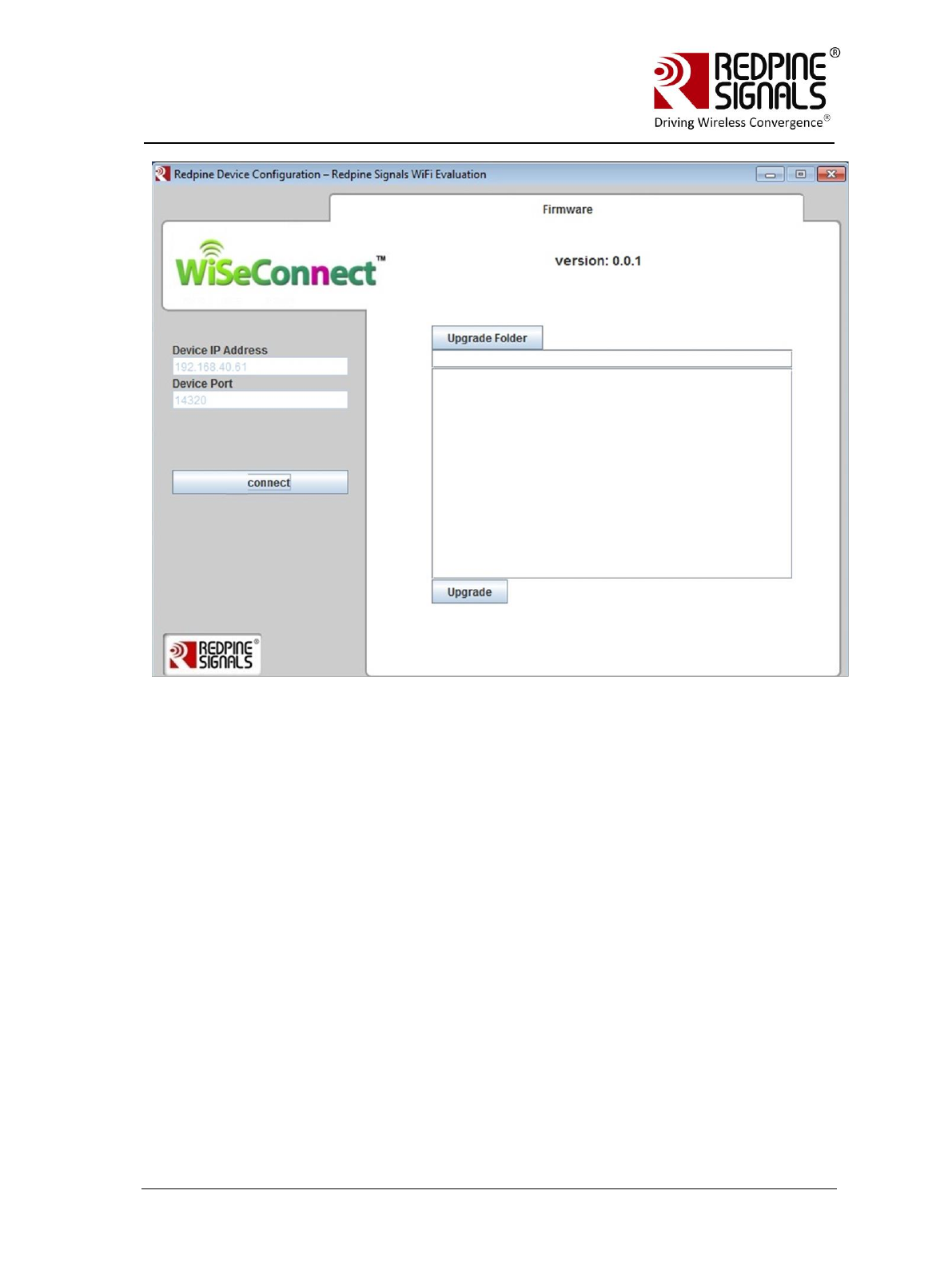
Redpine Signals, Inc. Page 65
R
RS
S-
-W
WC
C-
-3
30
01
1
E
Ev
va
al
lu
ua
at
ti
io
on
n
B
Bo
oa
ar
rd
d
U
Us
se
er
r
G
Gu
ui
id
de
e
V
Ve
er
rs
si
io
on
n
2
2.
.5
51
1
6. Click on the “Connect” button. Then click on the button “Upgrade
Folder”. Select the files
RS.WSC.x.x.GENR.x.x.x.x.x.x\Firmware\WFU\control_file.rps and
RS.WSC.x.x.GENR.x.x.x.x.x.x\Firmware\WFU\wlan_file.rps in the
browsing window that comes up.
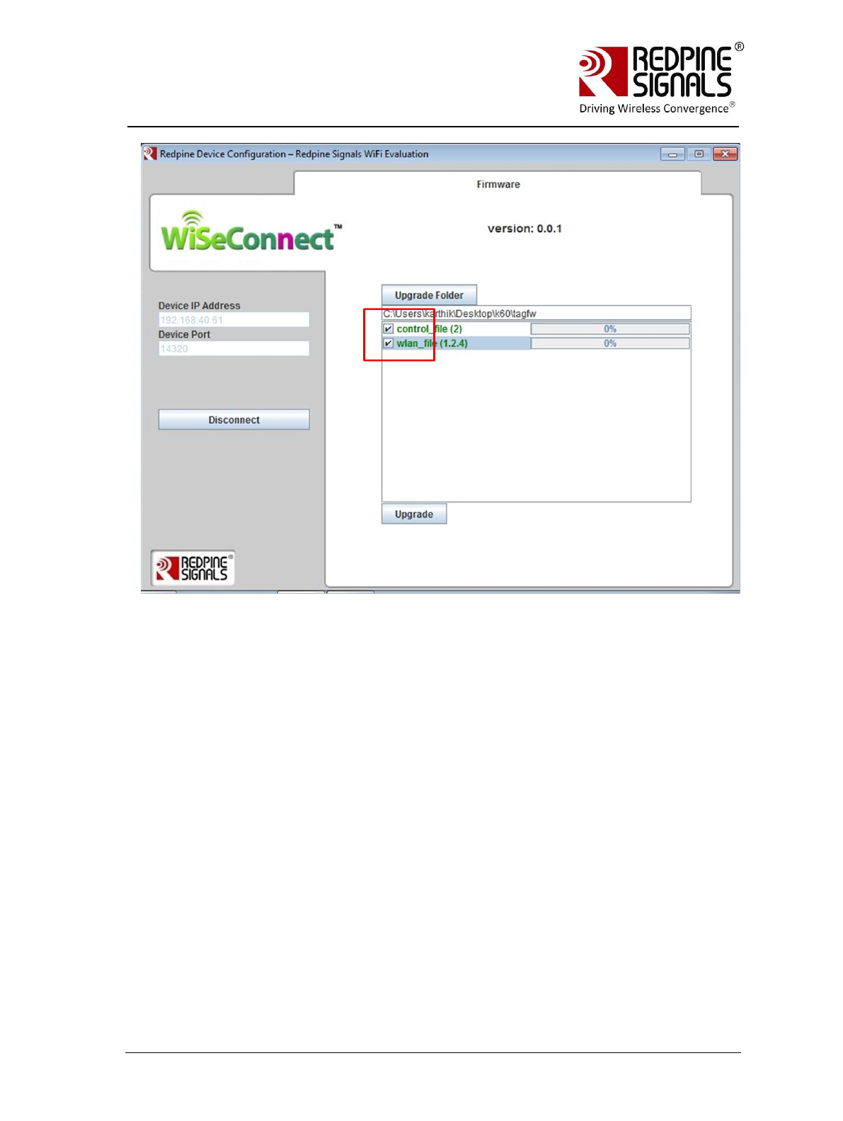
Redpine Signals, Inc. Page 66
R
RS
S-
-W
WC
C-
-3
30
01
1
E
Ev
va
al
lu
ua
at
ti
io
on
n
B
Bo
oa
ar
rd
d
U
Us
se
er
r
G
Gu
ui
id
de
e
V
Ve
er
rs
si
io
on
n
2
2.
.5
51
1
7. Tick the check boxes and click on the “Upgrade” button. The progress
of the upgrade is shown in the progress bars. After the files are
transferred, it may take up to 1 min for the final upgrade confirmation
to come in as shown below.
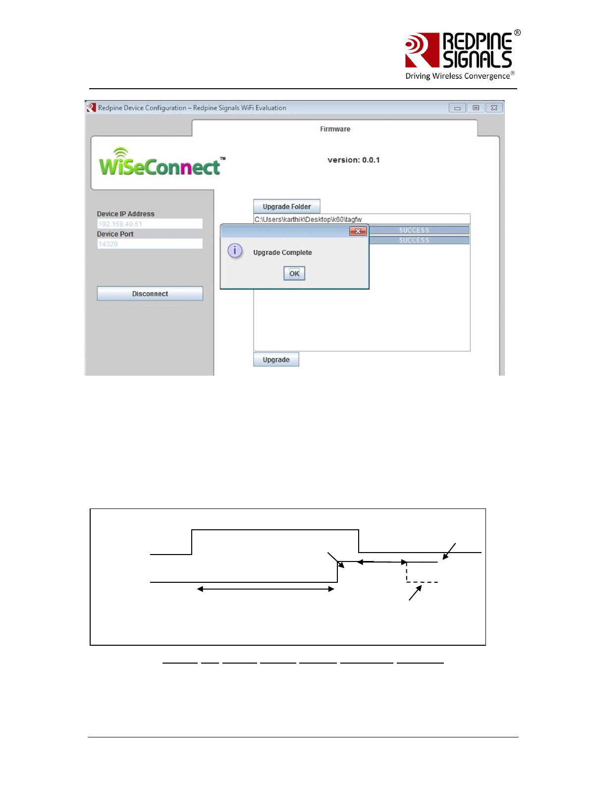
Redpine Signals, Inc. Page 67
R
RS
S-
-W
WC
C-
-3
30
01
1
E
Ev
va
al
lu
ua
at
ti
io
on
n
B
Bo
oa
ar
rd
d
U
Us
se
er
r
G
Gu
ui
id
de
e
V
Ve
er
rs
si
io
on
n
2
2.
.5
51
1
Meanwhile, the Host can keep polling the signal WF_HNDSHKE2. After the
upgrade process is over, the module will set the signal to high and will
set it again to high or low depending on whether the upgrade was
successful, after a delay of 1 msec after the first pulse. This process
would confirm the final upgrade status to the Host. The module can now
be power cycled for normal operation (WF_HNDSHKE1 should be kept „0‟
in normal operation)
Figure 17: Signal Status During Firmware Upgrade
After the confirmation, the module should be power cycled and
operated normally thereafter.
WF_HNDSHKE1
WF_HNDSHKE2
1-Upgrade success
0-Upgrade failure.
Try again after
fresh power cycle
Upgrade in progress
First pulse
after
upgrade
completion
Host waits
for 1 msec

Redpine Signals, Inc. Page 68
R
RS
S-
-W
WC
C-
-3
30
01
1
E
Ev
va
al
lu
ua
at
ti
io
on
n
B
Bo
oa
ar
rd
d
U
Us
se
er
r
G
Gu
ui
id
de
e
V
Ve
er
rs
si
io
on
n
2
2.
.5
51
1
NOTE:
If a user is using firmware version 2.1.0.1.2.5 or above in the module, during
normal operation of the module the pin WF_HNDSHKE1 should be set to „0‟. The
ONLY scenario where this signal should be set to „1‟ is when the user wants to
upgrade the module‟s firmware wirelessly.
The feature of Wireless Firmware Upgrade is not dependent on the interface
(UART/SPI/USB).
The file RS.WSC.x.x.GENR.x.x.x.x.x.x\Firmware\WFU\control_file.rps is exactly
same as RS.WSC.x.x.GENR.x.x.x.x.x.x\Firmware\WiSe_Control.S19. The former is
in a different format and is used to wirelessly upgrade the firmware, while the latter
is used to upgrade the firmware using the UART interface. Same is the case with
RS.WSC.x.x.GENR.x.x.x.x.x.x\Firmware\WFU\wlan_file.rps and
RS.WSC.x.x.GENR.x.x.x.x.x.x\Firmware\Wise_WLAN.S19
*****

Redpine Signals, Inc. Page 69
R
RS
S-
-W
WC
C-
-3
30
01
1
E
Ev
va
al
lu
ua
at
ti
io
on
n
B
Bo
oa
ar
rd
d
U
Us
se
er
r
G
Gu
ui
id
de
e
V
Ve
er
rs
si
io
on
n
2
2.
.5
51
1
13 FCC and IC Declaration
This device complies with Part 15 of the FCC Rules.
Operation is subject to the following two conditions:
(1) This device may not cause harmful interference, and
(2) This device must accept any interference received, including interference that
may cause undesired operation.
NOTE: This equipment has been tested and found to comply with the limits for a
Class B digital device, pursuant to part 15 of the FCC Rules. These limits are
designed to provide reasonable protection against harmful interference when the
equipment is operated in a commercial environment. This equipment generates,
uses, and can radiate radio frequency energy and, if not installed and used in
accordance with the instruction manual, may cause harmful interference to radio
communications. Operation of this equipment in a residential area is likely to cause
harmful interference in which case the user will be required to correct the
interference at his own expense.
This Class B digital apparatus complies with Canadian ICES-003.
Cet appareil numérique de la classe A est conforme à la norme NMB-003 du Canada.
This device complies with Industry Canada license-exempt RSS standard(s).
Operation is subject to the Following two conditions :( 1) this device may not cause
interference, and (2) This device must
accept any interference, including interference that may cause undesired operation
of the device.
Le présent appareil est conforme aux CNR d'Industrie Canada applicables aux
appareils radio exempts de licence.
L'exploitation est autorisée aux deux conditions suivantes : (1) l'appareil ne doit pas
produire de brouillage, et
(2) l'utilisateur de l'appareil doit accepter tout brouillage radioélectrique subi, même
si le brouillage est susceptibled'en compromettre le fonctionnement.
CAUTION: Any changes or modifications not expressly approved by the party
responsible for compliance could void the user‟s authority to operate the equipment.
This equipment should be installed and operated with minimum distance 20 cm
between the radiator & your body.
End Product Labelling
This Module is labelled with its own FCC ID. If the FCC ID Certification Number is not
visible while installed inside another device, then the device should display the label
on it referring the enclosed module. In that case, the final end product must be
labelled in a visible area with the following:
“Contains Transmitter Module FCC ID: XF6-RSWC201”
OR
“Contains FCC ID: XF6-RSWC201”
The OEM should not provide information to the end user regarding installation or
removal of this RF module or change RF related parameters in the user manual of
the end product.
The OEM integrator is still responsible for testing their end-product for any additional
compliance requirements required with this module installed (for example, digital
device emissions, PC peripheral requirements, etc.).

Redpine Signals, Inc. Page 70
R
RS
S-
-W
WC
C-
-3
30
01
1
E
Ev
va
al
lu
ua
at
ti
io
on
n
B
Bo
oa
ar
rd
d
U
Us
se
er
r
G
Gu
ui
id
de
e
V
Ve
er
rs
si
io
on
n
2
2.
.5
51
1
The end user shall declare in the user manual that: “The band 5150 - 5250 MHz is
for indoor use only"
énoncé de la FCC (états-Unis seulement) Cet équipement a été testé et jugé conforme aux
limites de Classe B pour un appareil numérique, en vertu de l’article 15 de la réglementation de la
FCC. Ces limites ont été instaurées our fournir une rotection raisonnable contre toute interférence
nuisible dans une installation résidentielle. Cet équipement génère, utilise et peut émettre de
l’énergie radiofréquence. S’il n’est pas installé et utilisé conformément aux instructions, il peut
provoquer des interférences sur les
communications radio. Cependant, il n’est pas garanti que des interférences ne se produiront pas
dans certaines installations. Si cet équipement cause des interférences à la reception radio ou
télévisée (ce qui peut être vérifi é en éteignant l’appareil puis en le remettant sous tension),
l’utilisateur peut enter de ésoudre en suivant une ou plusieurs des mesures ci-après : Réorienter
ou déplacer l’antenne réceptrice.
ugmenter l’espace entre l’appareil et le récepteur. Brancher l’appareil à une prise de courant
différente de celle sur laquelle le récepteur est branché. Pour obtenir de l’aide, contacter le
vendeur ou un technician radio/television expérimenté.
REMARQUE: Toute modifi cation non autorisée expressément par le fabricant responsable de la
onformité peut annuler le droit de l’utilisateur à faire fonctionner le produit.